Hydrides in zirconium alloys.
76
University of Windsor University of Windsor Scholarship at UWindsor Scholarship at UWindsor Electronic Theses and Dissertations Theses, Dissertations, and Major Papers 1-1-1979 Hydrides in zirconium alloys. Hydrides in zirconium alloys. Daniel Teong Heng Lim University of Windsor Follow this and additional works at: https://scholar.uwindsor.ca/etd Recommended Citation Recommended Citation Lim, Daniel Teong Heng, "Hydrides in zirconium alloys." (1979). Electronic Theses and Dissertations. 6728. https://scholar.uwindsor.ca/etd/6728 This online database contains the full-text of PhD dissertations and Masters’ theses of University of Windsor students from 1954 forward. These documents are made available for personal study and research purposes only, in accordance with the Canadian Copyright Act and the Creative Commons license—CC BY-NC-ND (Attribution, Non-Commercial, No Derivative Works). Under this license, works must always be attributed to the copyright holder (original author), cannot be used for any commercial purposes, and may not be altered. Any other use would require the permission of the copyright holder. Students may inquire about withdrawing their dissertation and/or thesis from this database. For additional inquiries, please contact the repository administrator via email ([email protected]) or by telephone at 519-253-3000ext. 3208.
-
Upload
khangminh22 -
Category
Documents
-
view
0 -
download
0
Transcript of Hydrides in zirconium alloys.
University of Windsor University of Windsor
Scholarship at UWindsor Scholarship at UWindsor
Electronic Theses and Dissertations Theses, Dissertations, and Major Papers
1-1-1979
Hydrides in zirconium alloys. Hydrides in zirconium alloys.
Daniel Teong Heng Lim University of Windsor
Follow this and additional works at: https://scholar.uwindsor.ca/etd
Recommended Citation Recommended Citation Lim, Daniel Teong Heng, "Hydrides in zirconium alloys." (1979). Electronic Theses and Dissertations. 6728. https://scholar.uwindsor.ca/etd/6728
This online database contains the full-text of PhD dissertations and Masters’ theses of University of Windsor students from 1954 forward. These documents are made available for personal study and research purposes only, in accordance with the Canadian Copyright Act and the Creative Commons license—CC BY-NC-ND (Attribution, Non-Commercial, No Derivative Works). Under this license, works must always be attributed to the copyright holder (original author), cannot be used for any commercial purposes, and may not be altered. Any other use would require the permission of the copyright holder. Students may inquire about withdrawing their dissertation and/or thesis from this database. For additional inquiries, please contact the repository administrator via email ([email protected]) or by telephone at 519-253-3000ext. 3208.
HYDRIDES IN ZIRCONIUM ALLOYS
by
Daniel Teong Heng Lim
A ThesisSubmitted to the Faculty of Graduate Studies
Through the Department of Engineering Materials in Partial Fulfilment of the Requirements for
the Degree of Master of Applied Science at The University of Windsor
Windsor, Ontario 1979
Reproduced with permission of the copyright owner. Further reproduction prohibited without permission.
UMI Number: EC54713
INFORMATION TO USERS
The quality of this reproduction is dependent upon the quality of the copy
submitted. Broken or indistinct print, colored or poor quality illustrations
and photographs, print bleed-through, substandard margins, and improper
alignment can adversely affect reproduction.
In the unlikely event that the author did not send a complete manuscript
and there are missing pages, these will be noted. Also, if unauthorized
copyright material had to be removed, a note will indicate the deletion.
UMI Microform EC54713 Copyright 2010 by ProQuest LLC
All rights reserved. This microform edition is protected against unauthorized copying under Title 17, United States Code.
ProQuest LLC 789 East Eisenhower Parkway
P.O. Box 1346 Ann Arbor, Ml 48106-1346
Reproduced with permission of the copyright owner. Further reproduction prohibited without permission.
/f/6- / • s/s/ s
^ Daniel Teong Heng Lim 1979
4 1953 ohd
Reproduced with permission of the copyright owner. Further reproduction prohibited without permission.
ABSTRACT
This paper summarises the results of a metallo- graphic (optical, electron and x-ray) study to determine the nature of the hydride in Zr-2.5wt%Nb pressure tube material and the effects of hydrogen content and cooling rate from a temperature where the hydrogen is in solution. As the hydrogen content increases and/or the cooling rate decreases, there is an increase in the size of the hydride and a greater tendency to form the equilibrium 6-hydride (ZrH, rather than the metastable y
I. DO
hydride (ZrH). Two different structures of radial hydride are detected in the high hydrogen content alloy. One form of radial hydride precipitates as a blocky agglomerate which is monolithic in nature while the other form exists as circumferential striations whilst growing in the radial direction. The large hydride particles which are often interconnected, if precipitated in the radial direction could provide a ready crack path in the reactor. A 'memory effect' has been shown to be present for the material with low hydrogen content (7 ppm) which is not evident at higher contents. The presence or absence of this memory effect has been shown to be related to the nature of the original and final (after solution and reprecipitation) form of the hydride, the memory effect detected being present where both the original and final hydrides are the y-hY^ride.
iReproduced with permission of the copyright owner. Further reproduction prohibited without permission.

ACKNOWLEDGEMENTS
The author wishes to express his sincere gratitude to Dr. D.O. Northwood for his invaluable guidance and supervision throughout the course of this project.He is indebted to both Ontario Hydro and Atomic Energy of Canada Limited for the supply of the pressure tube materials. He would also like to thank J.W. Robinson and G. Vazsonyi for assistance with electron and optical metallography, and R.A. Herring and D.G. Ivey for assistance with the hydriding. Finally, acknowledgement is due to the Natural Sciences and Engineering Research Council of Canada for the provision of a research grant (#A4391) without which this work would not have been possible.
ii
Reproduced with permission of the copyright owner. Further reproduction prohibited without permission.

TABLE OF CONTENTSPAGE
ABSTRACT............................................... iACKNOWLEDGEMENTS..................................... iiTABLE OF CONTENTS..................................... iiiLIST OF FIGURES..................................... .. ivLIST OF TABLES........................................ viCHAPTER I INTRODUCTION.......................... 1CHAPTER II LITERATURE REVIEW.................... 5CHAPTER III EXPERIMENTAL METHODS................. 11
3.1 Material........................ 113.2 Hydriding....................... 113.3 Thermal Treatment.............. 133.4 Metallography ....... 13
CHAPTER IV RESULTS................................ 174.1 X-Ray Diffraction Analysis.... 174.2 Optical Metallography......... 174.3 Thin Foil Electron Metallo
graphy........................... 18CHAPTER V DISCUSSION............................. 22CHAPTER VI CONCLUSIONS........................... 26CHAPTER VII FUTURE WORK...................... 28REFERENCES................ 30APPENDIX............... .* 62VITA AUCTORIS......................................... 66
Reproduced with permission of the copyright owner. Further reproduction prohibited without permission.
LIST OF FIGURESFIGURE PAGE
1 The Zr-H Phase Diagram As OriginallyProposed by Beck...............................38
2 CANDU-PHW Reactor Assembly..................... 393 Schematic of a Fuel Channel...................404 Rolled Joint Arrangement in Pickering
" CANDU Reactor.................................. 415 Pickering Rolled Joint Showing a)
Relative Position of Rolling Tool During Installation, b) Position of Radial Hydrides and Cracks in a Poor Joint and c) Residual Hoop Stress Distribution on the Inner Wall of a Goodand Poor Joint................................. 42
6 Phase Boundary For the Formation of y-Hydride in the Zr-H EquilibriumDiagram......................................... 43
7 Thin Foil Electron Micrographs ShowingStructure of As-Received Zr-2.5wt%Nb Pressure Tube Material Containing 7ppm Hydrogen........................... 44
8 Electrolytic Cell for HydridingSpecimens............ 45
9 Example of an Isolated Hydride ReflectionWhich Was Detected............... 46
10 Grinding Jig for Rough Grinding ParallelSurfaces on Specimen.......................... 47
11 Top: Specimen Mounted on a Glass Slideis Masked Off With ThermoplasticCement.......................................... 49Bottom: After Further Chemical Polishing Only Areas Masked By Cement Remained............................... . i . . . . 49
12 Electrolytic Set-Up For Final Thinningof Specimens................................... 50
ivReproduced with permission of the copyright owner. Further reproduction prohibited without permission.

F I G U R E P A G E
13 Close-Up View of Jetting Position............ 5114 Optical Micrographs Showing Effect of
Cooling Rate on Morphology of Hydride in Zr-2.5wt%Nb Pressure Tube Material Containing 4 6 ppm Hydrogen. All Micrographs are of the Transverse Section of the Tube, i.e., LookingEnd On........................................... 52
15 Optical Micrographs Showing Effect ofCooling Rate on the Morphology of the Hydride in Material Containing 300 ppm Hydrogen.........................................53
16 Optical Micrographs Showing Effect ofCooling Rate on the Morphology of the Hydride in Material Containing 7 ppm Hydrogen.......... 54
17 Acicular and Flake-Like Hydrides ........... 5518 Twinning of the Hydride........................5619 Blocky Form of Radial Hydride in 300
ppm Hydrogen Alloy Which Has BeenFurnace Cooled..................................57
20 Striated Form of Radial Hydride in 300ppm Hydrogen Alloy which Has BeenFurnace Cooled..................................58
21 Dislocation Network Generated by a6-Hydride....................................... 59
2 2 Schematic Time-Temperature Transformation Curves For Zirconium-2.5wt%Nb- Hydrogen Alloys................................ 60
23 Determination of the Terminal SolidSolubility Temperature for the 4 6ppm Hydrogen Material.................... . 61
v
Reproduced with permission of the copyright owner. Further reproduction prohibited without permission.
LIST OF TABLESTABLE PAGE
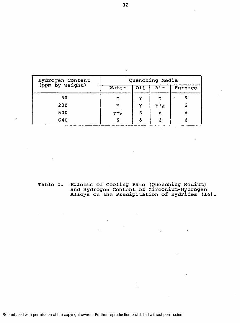
I Effects of Cooling Rate (QuenchingMedium) And Hydrogen Content of Zirconium-Hydrogen Alloys on the Precipitation of Hydrides.....................32
II Chemical Analysis of As-ReceivedZr-2.5wt%Nb Pressure Tubing.................. 33
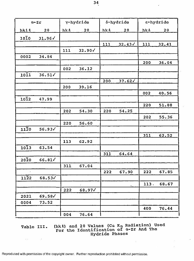
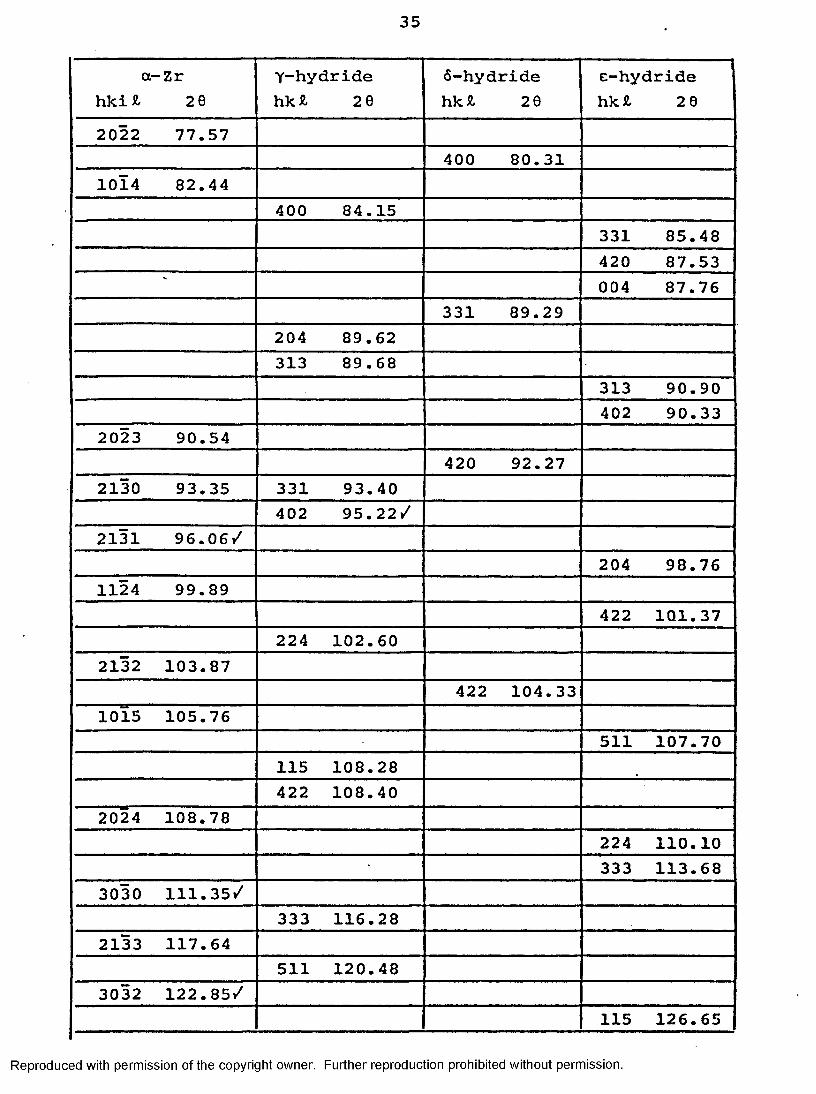
III ' The 20 Values Used for the Identification of a-Zr and The HydridePhases...........................................34
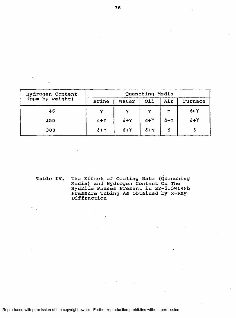
IV The Effect of Cooling Rate (QuenchingMedia) and Hydrogen Content on the Hydride Phases Present in Zr-2.5wt%Nb Pressure Tubing as Obtained by X-Ray Diffraction......................... 36
V The Effect of Cooling Rate (QuenchingMedia) and Hydrogen Content on the Hydride Phases Present in Zr-2.5wt%Nb Pressure Tubing as Obtained by Selected Area Diffraction.....................37
vi
Reproduced with permission of the copyright owner. Further reproduction prohibited without permission.
CHAPTER I INTRODUCTION
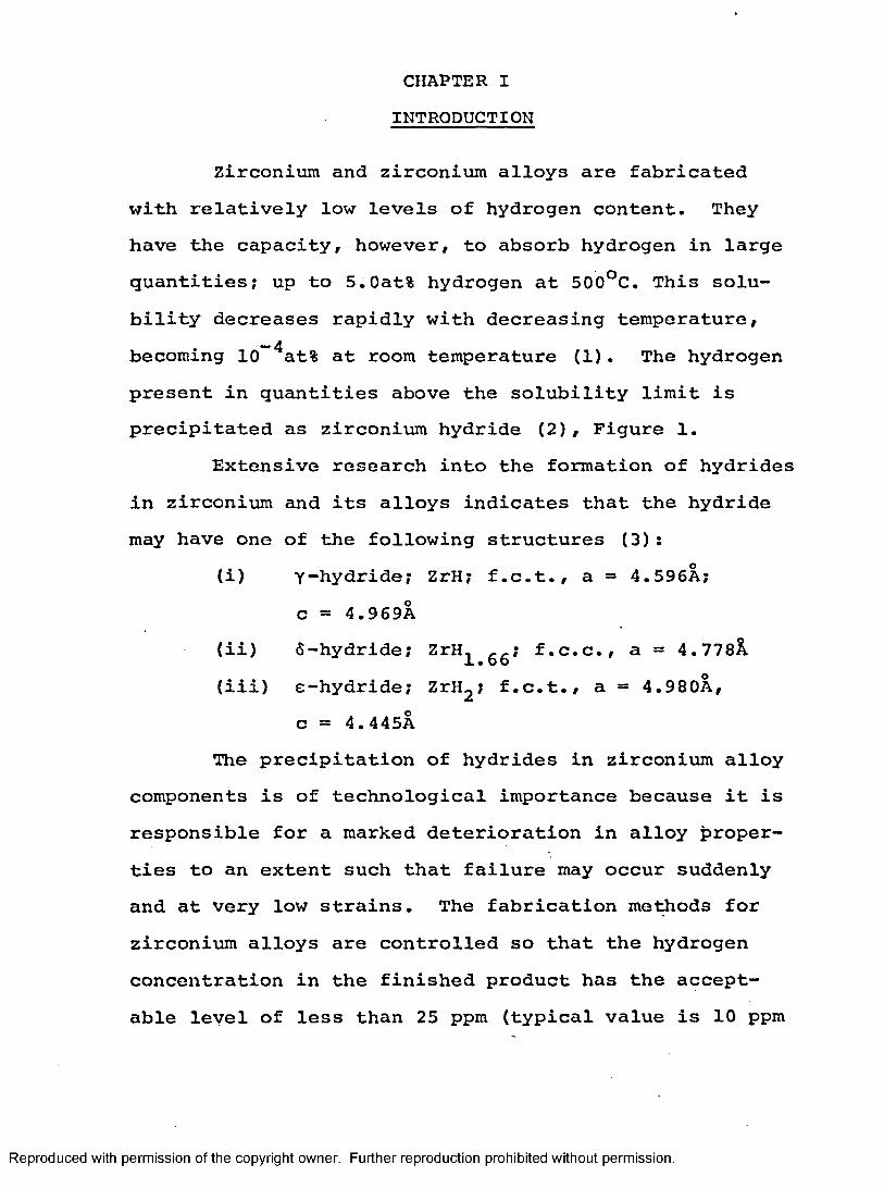
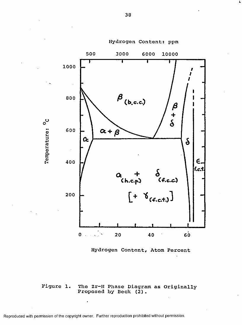
Zirconium and zirconium alloys are fabricated with relatively low levels of hydrogen content. They have the capacity, however, to absorb hydrogen in large quantities; up to 5.0at% hydrogen at 500°C. This solubility decreases rapidly with decreasing temperature, becoming 10~4at% at room temperature (1). The hydrogen present in quantities above the solubility limit is precipitated as zirconium hydride (2), Figure 1.
Extensive research into the formation of hydrides in zirconium and its alloys indicates that the hydride may have one of the following structures (3):
(i) y-hydride; ZrH; f.c.t., a =* 4.596A; c = 4.969A
(ii) 6-hydride; ZrH, f.c.c., a = 4.778)1ItOQ
(iii) e-hydride; ZrH2 ; f.c.t., a = 4.980A, c = 4.445A
The precipitation of hydrides in zirconium alloy components is of technological importance because it is responsible for a marked deterioration in alloy properties to an extent such that failure may occur suddenly and at very low strains. The fabrication methods for zirconium alloys are controlled so that the hydrogen concentration in the finished product has the acceptable level of less than 25 ppm (typical value is 10 ppm
Reproduced with permission of the copyright owner. Further reproduction prohibited without permission.
2
- 20 ppm hydrogen).In power reactor use, the zirconium alloys com
monly pick up deuterium from corrosion in heavy water or hydrogen from corrosion in light water. At the elevated working temperature of the reactor (2 80-300°C>, the hydrogen evolved by the corrosion reaction readily diffuses into the zirconium alloy thus increasing the concentration of hydrogen quite substantially. During periods of low temperatures (around 77°C) encountered during shut-down of the reactor, the presence of hydrogen in excess of the solubility limit results in the precipitation of the zirconium hydrides.
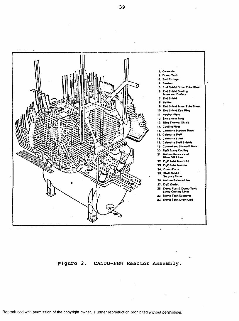
In the Canadian CANDU-PHW reactors. Figure 2, there is extensive usage of Zircaloy-2 (zirconium-tin), and Zirconium-2.5wt%Nb alloys as pressure tubes. The power reactor basically consists of a calandria, which is a large tank containing the heavy water moderator, end shields, and an array of identical fuel channels which project through the end shields and calandria.The principal components of a fuel channel are the pressure tube, calandria tube, central spacers and the end fittings, Figure 3. The pressure tubes contain the fuel and heavy water coolant at about 9.0 MPa (1300 psi) and 293°C. Cold worked Zirconiura-2.5wt%Nb with a design stress of 158 MPa (23,000 psi) at 300°C is the pressure tube material for current CANDU reactors. The ends of the tubes are rigidly joined to end fittings of stainless
Reproduced with permission of the copyright owner. Further reproduction prohibited without permission.

3
steel by rolled joints. Figure 4 shows the cross-section of a rolled joint.
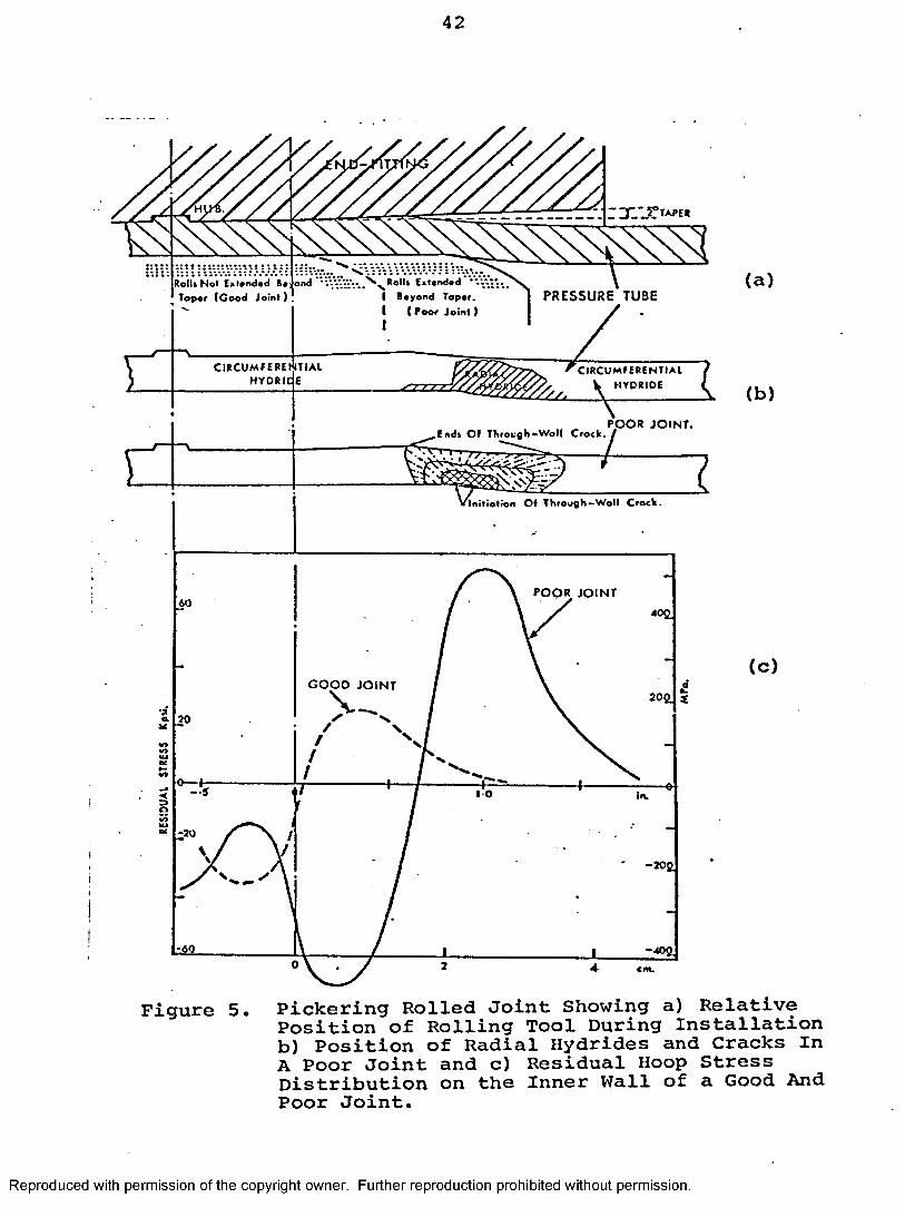
Recently some of the Zirconium-2.5wt%Nb pressure tubes from the Canadian Pickering-3 and -4 reactors have cracked in service. Subsequent examination of the cracked Zr-2.5wt%Nb pressure tubes has shown that a combination of high stresses due to improper installation and thermal cycling had led to the formation of through wall hydrides which subsequently cracked by a process of delayed hydrogen cracking (4). It was later concluded that during the installation of the pressure tubes, the pressure tube end fitting joints were inadvertently overrolled resulting in high residual hoop stresses in the surrounding area, Figure 5. In the regions of high stress (i.e., immediately adjacent to the rolled joint) it was found that the hydride reoriented in the radial direction so as to reduce the ductility in the direction of the tensile stress. The cracks propagated when the reactor was cold by a stress-induced precipitation mechanism (5).
In this mechanism, hydrogen diffuses to the region of high stress at the crack tip and precipitates as a hydride at right angles to the stress. When sufficient hydride is present at the crack tip, the crack advances through the brittle hydride phase. The hydrogen again diffuses to the new crack tip and the process repeats.
In order to better model this process of hydrogen- induced delayed cracking, and hopefully prevent any
Reproduced with permission of the copyright owner. Further reproduction prohibited without permission.
4
future occurrences of this problem, much data was needed on hydrogen and hydrides in zirconium alloys, particularly for the zirconium-2.5wt%Nb alloy. It is essential to know accurately the terminal solubility of hydrogen and its variation with such environmental factors such as temperature and stress, and the effects of such variables as hydrogen content, thermal treatment and stress on the morphology and crystal structure of the hydride, since this could have a profound effect on the fracture properties of the hydride. Since the first leaking of zirconium- 2.5wt%Nb pressure tube was detected in Pickering Unit-3 in August 19 74, a large development program has been in progress at a number of laboratories to determine (1) the reasons for such failures, (2) the mechanism of failure and (3) corrective measures that could be applied in design, construction and reactor operation. This paper summarizes further results of this ongoing metallo- graphic (optical, electron and x-ray) study of the nature of the hydride in Zirconium-2.5wt%Nb pressure tubes with particular emphasis on the effects of hydrogen content and cooling rate from the temperature where the hydrogen is in solution.
Reproduced with permission of the copyright owner. Further reproduction prohibited without permission.
CHAPTER II LITERATURE REVIEW
There has been much disagreement in the literature as to whether the f.c.t. Y-hydride, which is based on the composition ZrH, is a metastable precipitate or an equilibrium phase. The equilibrium diagram established by Beck(2) has been widely accepted. As originally proposed by him, Y-hydride is a metastable hydride that can exist together with a-zirconium and the f.c.c. 6-hydride. Recently, however, Mishra et al (6), as a result of x-ray and dilatometric studies on alloys containing for the most part, high hydrogen levels (10-60 at%), have proposed that a stable y-hydride is formed by the peritectoid reaction:
255 Ca-Zr + 6-hydride % y-hydride
Barraclough and Beevers (7) and Ostberg et al (8) have also supported this peritectoid reaction. However, Barraclough and Beevers quote a temperature of 5S240°C above which the y-hydride is not stable. The existence of this peritectoid transformation has been questioned by other workers (9-12) who have provided strong'experimental evidence to support their case. Electron metallo- graphic studies of low hydrogen concentration alloys have shown that the y-hydride is not a stable phase resulting from a peritectoid reaction around 240-255°C but is instead a metastable phase produced by a marten- sitic shear transformation. Nath et al (11) showed that
Reproduced with permission of the copyright owner. Further reproduction prohibited without permission.

6
the ageing of quenched specimens which initially contained Y”hydrides resulted in the replacement of this phase by 6-hydrides at a rate which was dependent on temperature, while ageing of the furnace cooled specimens, which initially contained only 6-hydrides did not result in a change in the type of hydrides present.The hydrogen concentration of the alloys studied were considerably lower (<500 ppm or 4.33 at%) than those used by Mishra et al (6). In an earlier study, Vaughan and Bridge (9) found from their high temperature diffraction work that the y_hydrides could be eliminated by ageing at 500°C for 48 hours.
Although there was little or no information on the morphology and crystal structure of hydrides in the Zr-2.5wt%Nb alloy, there has been quite a considerable amount of information on hydrides in zirconium and the Zircaloys. These studies were made mainly by optical microscopy and x-ray diffraction and have been critically reviewed by Ells (13). For most of the recent information we are indebted to Lorimer and his coworkers (3,11,14) who have studied systematically the combined effects of cooling rate and hydrogen concentration on the hydride type and precipitate distribution. They have identified two types of hydrides: the stable f.c.c.6-hydride (ZrH^ 6{.) and the f.c.t. Y”hydride (ZrH) which forms under conditions of moderate to fast cooling rates and is believed to be the metastable, intermediate phase.
Reproduced with permission of the copyright owner. Further reproduction prohibited without permission.

7
In addition to the metastable Y-hydride (ZrH) and the equilibrium hydride (ZrH^ gg) zirconium can form another equilibrium hydride, the f.c.t. E-hydride (ZrH2 , c/a<l) with a higher hydrogen content. However in the studies of zirconium and Zircaloy-2 containing up to 640 ppm H2 (5.4 at%) there was no evidence for the presence of any e-hydride. In the case of zirconium and Zircaloy-2, it was found (3,11) that an increase in the cooling rate led to more of the metastable f.c.t. y-hydride being formed and less of the stable 6-hydride, Table I. Hydrogen may precipitate on cooling at moderate to high rates to form y-ZrH needles parallel to <1120> matrix direction (3,15). A more extensive optical and electron microscopic study (14) on reactor grade zirconium containing 50-640 ppm H2 showed that the average size of hydrides, the proportion of hydrides located at grain boundaries, and the proportion of the equilibrium <5-hydride increased as the hydrogen concentration was increased and/or the rate of cooling was decreased. The 6-hydride precipitates with a range of orientation relationships all of which have a common close-packed direction relationship of [I10]6//[ll20]a .
Nath et al (14) proposed a separate solvus as the metastable phase boundary for the y-hydride. Figure6. On rapid cooling, the equilibrium hydrogen concentration cannot be maintained and supersaturation results. In dilute alloys, the lower diffusivity of hydrogen at
Reproduced with permission of the copyright owner. Further reproduction prohibited without permission.
the lower temperatures involved allows the alloy to undercool the metastable a a + y solvus and the y- hydride then precipitates. They suggested that the reaction a + a + 6 is relatively sluggish and that the 6-hydride has a higher nucleation energy than the y- phase.
The only x-ray investigations of the occurrence of the y phase at the low hydrogen end of the system are due to Bailey (15) and Ferguson et al (16). Bailey prepared samples by cooling at various rates from the 3-Zr phase field and found that the quantity of y~hydride in the quenched sample increases as the hydrogen content increases. Ferguson et al using a special x-ray diffraction technique to detect small amounts of hydride found that for sponge zirconium containing 100-600 ppm H2 cooled at various rates, both y and 6-hydrides were formed with quenching (i.e., fast cooling) favouring the formation of Y”hydride.
In the precipitation of zirconium hydrides in alloys with low hydrogen content, there is a strong tendency for the size, distribution and morphology of the hydrides present before a thermal cycle to a temperature above the solvus, to influence the same factors in the reprecipitation of the hydrides. Cameron and Duncan (17) studied the memory effect (i.e., preferential precipitation) of hydrides in cold worked Zr-2.5 wt%Nb and suggest that preferential precipitation may
Reproduced with permission of the copyright owner. Further reproduction prohibited without permission.
9
result from favourable dislocation configurations generated during the initial hydride precipitation sequence. They found this effect to be very persistant and annealing times in the thousands of hours were required to avoid it. Extensive examination by Carpenter and Watters (18) and Nath et al (14) showed that the dislocation debris with which hydride precipitates are always associated, often in the form of needles, appear to have nucleated at the dislocations remaining after the dissolution of larger needles. When composition and cooling conditions are such that Y~hydride is formed, a significant fraction of the dislocation are not annihilated during the heating cycle up to temperatures of 400°C (18). However, earlier studies by Bailey (15) who followed the dissolution of y-ZrH in-situ in an electron microscope using beam heating and hot stage technique on thinner foil samples showed that most of the hydride dislocations were annihilated when the hydrides were dissolved by heating above the solvus temperature.
The adjacent precipitation of hydrides in close proximity occurs frequently (3,19) due either to nuclea- tion at the associated dislocations or in the surrounding strain fields. Bradbrook et al (3) suggested that the autocatalytic nucleation of hydrides on punched out dislocations and elastic strain fields during hydride growth often produce long 'stringers' of hydrogen which often appear as a single hydride at low magnification. Because
Reproduced with permission of the copyright owner. Further reproduction prohibited without permission.
10
of the low supersaturation and low nucleation rate in slowly cooled specimens the autocatalytic effect can predominate causing a pronounced alignment of the hydrides. On the other hand, high quenching rate will lead to a high supersaturation and high nucleation rate, and under these conditions autocatalytic effects will be difficult to observe. Furthermore, if a crystallo- graphic texture has been developed (e.g., in reactor tubing) this could lead to very marked alignment of the hydride precipitates favouring the circumferential formation.
Reproduced with permission of the copyright owner. Further reproduction prohibited without permission.
CHAPTER III EXPERIMENTAL METHODS
3.1 MaterialThe starting material was a section cut from an
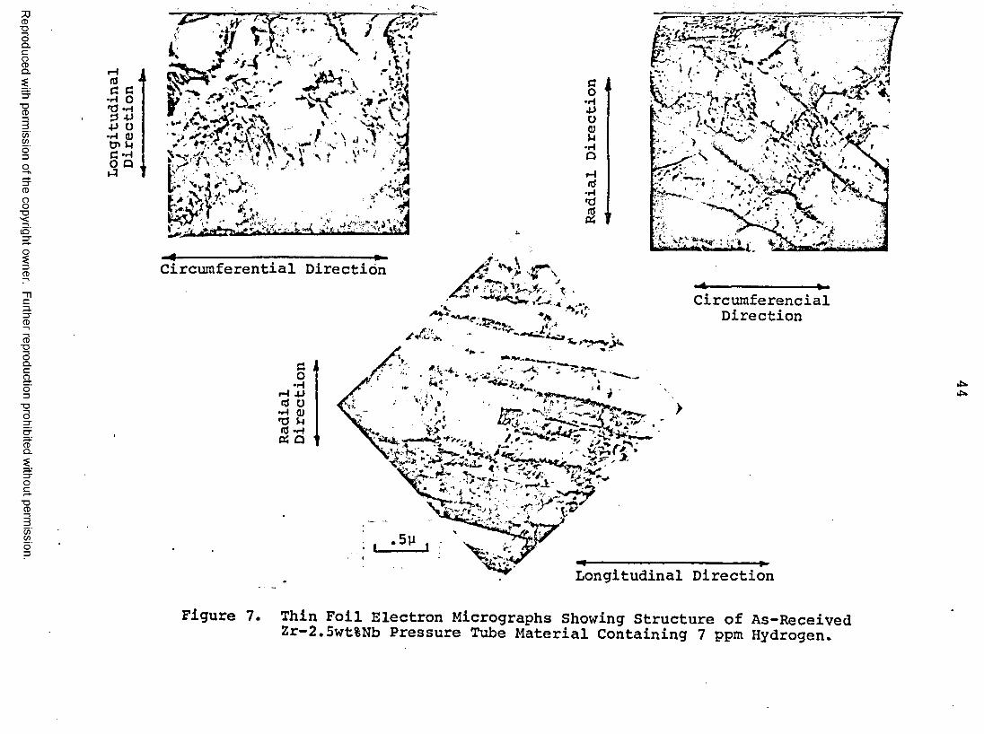
as-fabricated pressure tube that was surplus to the requirements for the Bruce Reactor. The chemical analysis is given in Table II. The tube is in the cold-worked plus stress relieved condition. The structure of this particular pressure tube was typical of production tubes (20) including the Pickering pressure tubes that had cracked, consisting of long elongated grains of h.c.p. a-Zr with filaments of a b.c.c. 3-phase at the grain boundaries. The ct-Zr grains are heavily dislocated, Figure7. The a-Zr grains have a thickness of 0.25-0.75 ym, a width of about 5 to 10 times this minimum dimension and a length up to 50 times the thickness.
- 3«2 HydridingThe as-received material contained 7 ppm ^ and
other samples were hydrided to levels of 46, 150 and 300 ppm using the technique of electrolysis-anneal originally developed for hydriding Zircaloy-2 (21). In this hydriding process the Zr-2.5wt%Nb specimen acts as the cathode in the electrolytic cell. Hydrogen is evolved at the specimen and enters the zirconium as hydrogen atoms. The diffused hydrogen combines with the zirconium to form an e-hydride layer around the surface of the specimen. The size and
Reproduced with permission of the copyright owner. Further reproduction prohibited without permission.
12
uniformity of this layer is dependent on the temperature current density and strength of electrolyte used in the cell.
Transverse sections of approximately 2 cm x 5 cm were obtained from the pressure tube. They were cleaned by pickling in a solution of 5% nitric acid - 10% hydrofluoric acid - 45% distilled water. The experimental apparatus consists of two beakers, one placed inside the other, Figure 8. Cold water flowing through the space between the two beakers served to control the electrolyte temperature. The sections were suspended on a platinum wire cathode surrounded by a platinum 'cage' anode and immersed in an electrolyte of 0.5% aqueous solution of sulphuric acid maintained at 80-90°C. Electrolysis was carried out at a current density of 100-200 mA/cm2 and was continued until a hydride layer of the required thickness was deposited on the surface. This thickness was determined both by weighing the sample and by optical metallography. X-ray diffraction analysis showed this hydride layer to be principally the e-hydride (ZrH2>. The main problem was in obtaining a relatively even hydriding and in certain instances * sunburst* hydriding occurred. Each specimen was then sealed in an evacuated Vycor tube and annealed at the temperature required to bring all the hydrogen in solution. This temperature was estimated using the terminal solid solubility data of Daniel (22). The
Reproduced with permission of the copyright owner. Further reproduction prohibited without permission.

13
specimens were then furnace cooled to room temperature and broken out of the capsules.
3.3 Thermal TreatmentSpecimens were heat treated in several different
ways in an effort to determine the effect of cooling rate and hydrogen supersaturation on the structure and morphology of the hydride. Each specimen of a nominal hydrogen content was first sectioned into five and each piece was sealed into a separate evacuated Vycor capsule. The specimens were then heated to an elevated temperature (400°C for 7, 46 and 150 ppm 465°C for 300 ppm H2)and held for a sufficient time (24 hours) to bring all the hydrogen into solution. The samples were then furnace cooled, air cooled, or quenched into oil, water or brine.For the quenched samples the Vycor capsules were broken on contact with the quenchant to ensure optimum quenching rate.
3.4 MetallographyThe sequence of study for the heat treated samples
was x-ray diffraction analysis, followed by optical microscopy and finally thin foil electron microscopy.
A Philips vertical powder diffractometer using proportional counter detection head was used for the x-ray diffraction analysis. Graphite monochromated Cu Kq radiation at 30 kV and 20 mA was employed. The detection and identification of the hydrides using these more conventional x-ray diffraction techniques is difficult because of the
Reproduced with permission of the copyright owner. Further reproduction prohibited without permission.

14
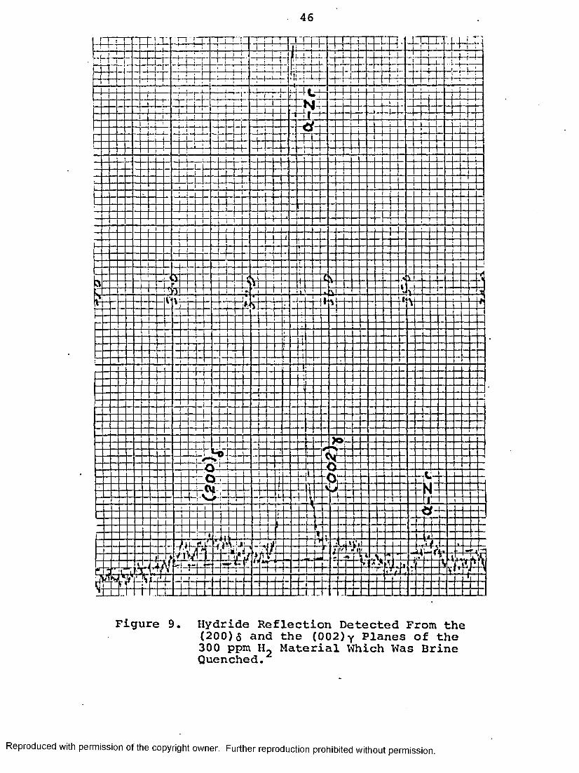
poor diffracting power of the hydrides and because of the overlap and interference of the diffraction peaks from the hydrides and those of the a-Zr phase (see Table III for a listing of the diffraction peaks from the various phases). However by looking for certain hydride reflections that were isolated from the a-Zr reflections, Figure 2, we' were able to identify the hydrides in all specimens except those containing 7 ppm T^e reflections usedfor this identification were as follows: (111)^; (200)g;(111)Y ; (022) J (222)Y and (402)y .
For metallographic examination, specimens were first cold mounted. It is essential to use cold mounting rather than the more conventional hot mounting in order to avoid any subsequent redistribution of the hydrogen due to dissolution and reprecipitation. Specimens were then polished down to 600 grit and swab etched using a solution of 30 parts sulphuric acid, 30 parts nitric acid, 30 parts distilled water and 10 parts hydrofluoric acid. Specimens were examined in both bright field and polarized light illumination.
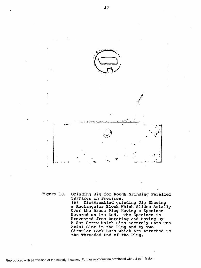
Thin foils for electron microscopy were made by cutting sections about 0.5 mm thick using a slow-speed diamond wheel. The cut sections are mounted on a brass jig (Figure 10) using a thermoplastic cement and then ground on Sic paper to ensure parallel surfaces (i.e., section is repeatedly removed, turned over, remounted and ground). Equal amounts are removed from each face
Reproduced with permission of the copyright owner. Further reproduction prohibited without permission.

15
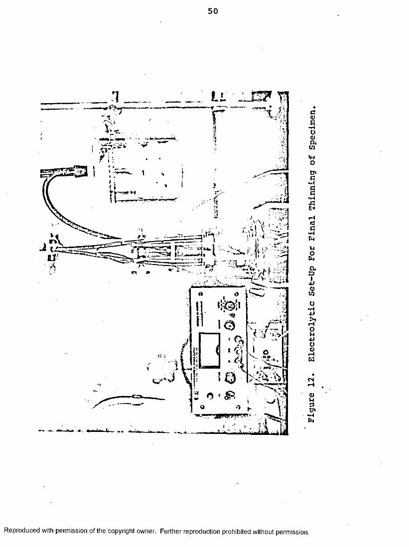
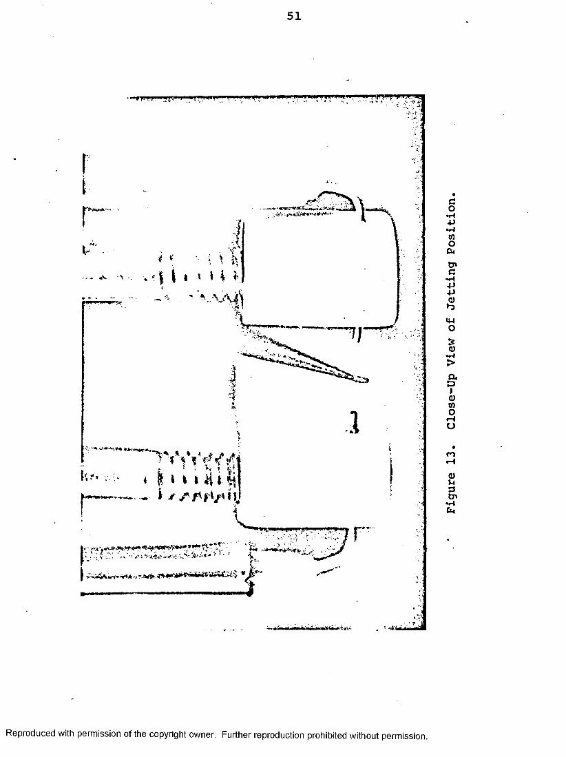
to bring the thickness down to about 0.25 mm. The section is then cemented to a microscope slide and chemically polished by swabbing with a solution of 45 parts 1^0, 45 parts HNO^ and 5 parts HF to remove approximately half the thickness of the specimen. Repeated turning over and polishing of the specimen are carried out until the section is reduced to 0.05 mm thickness. Discs of about2.5 mm diameter are marked off on the polished surface and chemical polishing continued until only the masked discs remained, Figure 11. Final electropolishing was taken to perforation at a potential of 12 volts using a 1:4 perchloric acid-ethyl alcohol mixture maintained at -20 to -30°C by means of a test tube filled with dry ice (23). Figure 12 shows the set-up of the apparatus used for the final thinning. It consists of an electrolyte reservoir connected by polythene tubing to two jets. The reservoir is pressurized by a low pressure air line. The jets are made from hypodermic needles and are mounted approximately 8 mm apart directly opposite one another in a Teflon block. Figure 13. Two stainless steel support rods threaded into the teflon block hold the two jet tips in place. These rods provide electrical contacts and make the needles the cathodes of the cell. A D.C. variable power supply is used to provide power for the cell. The reservoir and polishing cell are filled with the electrolyte. Dry ice is packed around the reservoir and the temperature of the polishing cell is brought down to below -20°C by immersing a test
Reproduced with permission of the copyright owner. Further reproduction prohibited without permission.
16
tube filled with dry ice in the electrolyte. The specimen is adjusted so that the jets flowing from the pressurized reservoir impinge right on the center of the disc. The polishing jets are supported just below the surface of the electrolyte and the polishing circuit is completed with a microswitch applying 12 volts across the cell. As soon as the specimen is perforated, the circuit is broken and the disc immediately washed in a stream of cold ethyl alcohol to minimize the formation of oxides. The foil is then dried and examined in a Hitachi HU12 electron microscope operated at 100 kV.
Reproduced with permission of the copyright owner. Further reproduction prohibited without permission.

CHAPTER IV RESULTS
4.1 X-Ray Diffraction AnalysisThe results of the x-ray diffraction analysis
indicating the hydride phases found to be present are summarised in Table IV. As mentioned previously, no data are available for the material containing 7 ppm H2 since the hydride reflections were not of sufficient intensity to be detected. The fact that for certain specimens only one hydride phase was detected does not necessarily mean that the second hydride phase was not present, but rather that it could have existed in quantities below the detection limit of the x-ray diffraction technique which was about 5wt%. In general, however, it is readily apparent that as the cooling rate was increased and the hydrogen content decreased, there was an increasing tendency to form the Y-hydride at the expense of the 6-hydride.
4.2 Optical MetallographyIn agreement with the work on reactor grade zirconium
(14), there was a reduction in the size of the hydrides as the cooling rate increased. This is illustrated in Figure 14 for the case of the material containing 46 ppm Thegreatest reduction in size occurs at rate of cooling between that of the furnace and air with very little change in size on quenching at faster rates. This was generally true or all hydrogen contents although for the material containing 300 ppm the largest reduction in size occurred between
Reproduced with permission of the copyright owner. Further reproduction prohibited without permission.
18
the air cooled and oil quenched specimens, Figure 15. However, for the material containing 7 ppm H2 , there was not much change in hydride size with quenching rate, Figure 16. This is in agreement with the work of Cann et al (24) on Zr-2.5wt%Nb containing 9 ppm H2 , and Cameron and Duncan (17) on Zr-2.5wt%Nb containing 8 ppm H2.
Also in agreement with the work on reactor grade zirocnium there was a reduction in hydride size with a decrease in hydrogen content. This effect can be seen by comparing Figures 14-16.
For the higher hydrogen contents and slower cooling rates, the larger plate-like hydrides join together to form very large composite hydrides which provide ready crack paths for brittle failure (e.g., see furnace cooled, 300 ppm H2 sample in Figure 15).
4.3 Thin Foil Electron MetallographyThin foil electron metallography of samples contain
ing the hydride is difficult for a number of reasons. Firstly, the hydride etches away faster than the zirconium matrix leaving holes in the foil. Secondly, the hydrides, at least if they are oriented circumferentially, are merely ct-Zr filled up with hydrogen to the required composition (25,26) and they are difficult to distinguish from the a-Zr grains. Thirdly, in material containing both 6 and y- hydrides, precipitates of Y-hydride can be found around the periphery of the 6-hydride (24) and this often gave difficulty in positive identification of the hydride due to the
Reproduced with permission of the copyright owner. Further reproduction prohibited without permission.
19
interference of one type of pattern over the other.The crystallographic details for the face-
centered cubic, face-centered tetragonal and the closed- packed hexagonal systems can be found in the Appendix.The identification of the hydrides was carried out by measurements of spot spacings of the diffraction patterns from the hydride precipitates. This identification was further confirmed by measurements of the interplanar angles .
Table V summarises the results obtained in the identification of the hydride phases. Generally the results are in agreement with the results obtained by x-ray diffraction with the exception of the air-cooled,46 ppm H£ material which was found to contain some 6- hydrides. The hydride identified in all the as-received (7 ppm I^) material was the y-hydride.
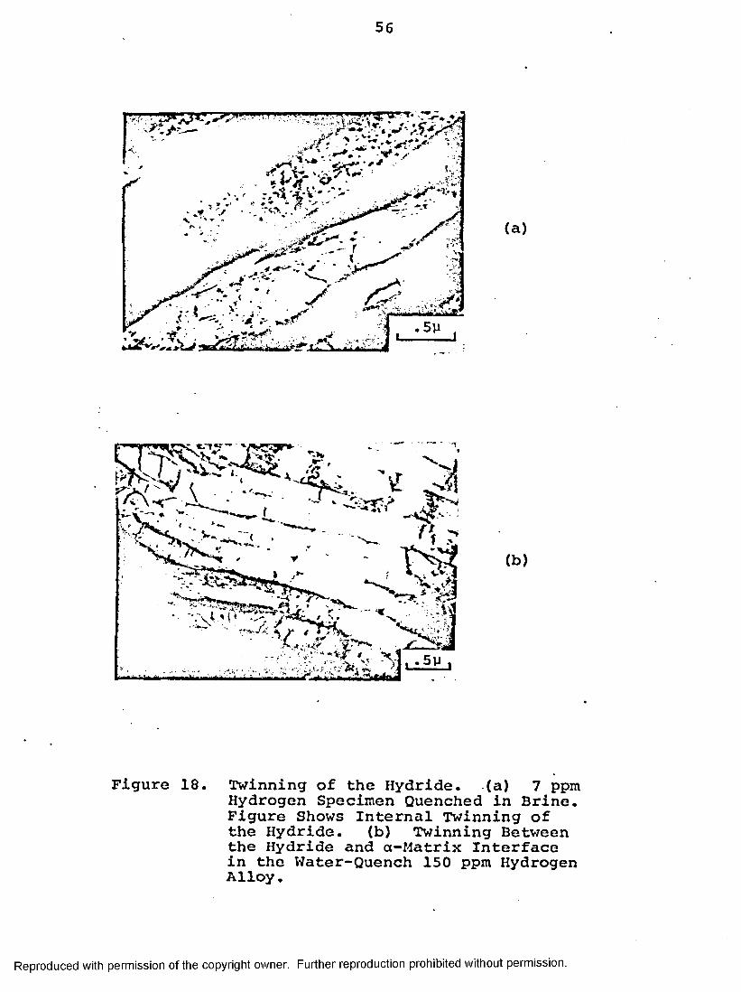
Generally with lower hydrogen content and/or faster cooling rate, the hydrides tend to be accicular or flakelike in nature, Figure 17. The hydrides had a distinct relationship with the original structure in that they form as plates or needles at sites of what were the flat elongated a-grains and were usually bounded by the 3-phase. As the cooling rate increased twinning became more prominent within the hydride structure itself, and also between the hydride and the a-matrix interface, Figure 18. As the hydrogen content increased and/or the cooling rate decreased, the hydride tends to precipitate as stringers
Reproduced with permission of the copyright owner. Further reproduction prohibited without permission.
20
occupying two or three a-grains. These chains appear to have a particular orientation and consisted of numerous individual plates within the chain each of which could vary significantly from the apparent chain orientation.In the higher hydrogen content material, the hydrides tend to agglomerate into 'blobs or blocks' which are monolithic in nature. These 'blobs' sometimes do not fill up circumferentially along the whole a-grains but instead tend to run off in the radial direction. Two types of radial hydride formation were observed in the 300 ppm material. Figure 19(a) shows the blocky form of hydride with a region of high contrast (potentially a crack path) running radially through the center of the hydride whilst Figure 20(b) shows an existing crack which had run along the hydride following a path similar to that of the potential crack shown in Figure 1 9 (a). The region of high contrast could have been the result of dislocation pile- up (27) generated by two separate radial hydrides running on both sides of the region. The other form of radial hydride is made up of striated platelets having a common direction in its growth, which is across the alpha grains. Figure 20(a) and (b).
For intermediate hydrogen content (46 ppm and 150 ppm I^) and/or intermediate cooling rate, both the 6-hydrides and the y“hydrides were detected in the material. The precipitation of these two phases can occur close together with the yhydrides precipitating around the ;periphery of
Reproduced with permission of the copyright owner. Further reproduction prohibited without permission.

21
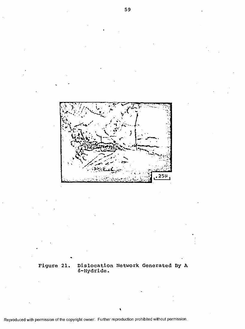
the 6-hydride. Generally the 6-hydride showed no evidence of twinning but did appear to contain a large number of dislocations. Figure 21 shows an array of dislocations associated with the 6-hydride. The dislocation network are similar to those observed by Carpenter et al (19) in other zirconium alloys. Most of these dislocations could have been generated during the growth of the 6-hydride because of the large misfit beteeen the 6-hydride and the zirconium lattice (28).
Reproduced with permission of the copyright owner. Further reproduction prohibited without permission.
CHAPTER VDISCUSSION
The results obtained indicating that the hydride phases present are sensitive to the cooling rate and/or hydrogen concentration of the specimens, with the y-hydride more predominant at the faster cooling rates and lower hydrogen concentrations, are in agreement with the work of Nath et al (14) on zirconium. Figure 22 shows the schematic time-temperature transformation curves for Zr-2.5wt%Nb alloys having hydrogen contents of 300 ppm, 150 ppm, 46 ppm and 7 ppm. This figure shows certain similarities to Figure 6 of Nath et al (14). The curve for the transformation of the 6-phase is shifted towards longer times with decreasing hydrogen concentration. In the 46 ppm H2 material, the 6-finish curve is shifted further towards the right than the similar curve for the zirconium hydrogen alloy containing 50 ppm hydrogen. Comparing Tables I and V it is noted that Nath et al did not detect any 6-hydride in 200 ppm H2 water and oil quenched material. However in this study 6-hydride was detected in all the 150 ppm H 2 samples quenched in oil, water and brine. Cann et al (24) found that for zirconium, only y-hydride was formed at hydrogen contents of 50 ppm and below, whereas in these studies on Zr-2.5wt%Nb we have found 6-hydride in material containing 46 ppm hydrogen. This is not surprising since the niobium in the Zr-2.5wt%Nb alloy is believed to be a 6-stabilizer (24).
Reproduced with permission of the copyright owner. Further reproduction prohibited without permission.
23
Generally the theory as set forth by Nath et al for the nucleation of the 6- and y-phases would seem to equally well apply for Zr-2.5wt%Nb alloy as for sponge zirconium. This agrees with the observations that the terminal solid solubility of hydrogen in Zr-2.5wt%Nb is similar to that for zirconium or Zircaloy (22,29). To check the terminal solid solubility of hydrogen in Zr- 2.5wt%Nb alloy, the 46 ppm H2 material was taken up to a range of annealing temperatures between 250°C to 350°C and quenched in water. By optical microscopy the hydrogen solvus was determined when complete dissolution of the original coarse hydride occurred, Figure 23. This temperature was found to be 290°C, which is in good agreement with the data obtained by Kearns (1) and Cann et al (24) .
The main difference between our results for Zr- 2.5wt%Nb and Nath et al's (9) for zirconium, is that for furnace cooled specimens, Nath et al only noted 6-hydrides whereas we have found y-hydride to be present also. In this respect, we are in better agreement with other results on zirconium, e.g., Cann et al (24) found large amounts of y-hydride for furnace cooled specimens containing 99,160 and 230 ppm H2 and Gill et al (10) and Ferguson et al (16) also found both y- and 6-hydrides for furnace cooled specimens containing 100, 250 and 600 ppm. Neither Sidhu et al (30) nor Bailey (15) found any 6-hydride in zirconium of low hydrogen content which had been slowly cooled from 800°C. Bailey concluded that the equilibrium hydride was
Reproduced with permission of the copyright owner. Further reproduction prohibited without permission.

24
of face-centred tetragonal structure and probably Y-hydride. However, in a later article Bailey (31) noted the marked effect of cooling rate on alloy constitution and showed that the formation of 6- and Y“hydrides was favoured by slow and fast cooling respectively. It is probable that the higher temperatures of homogenization in these latter studies may have accounted for the presence of the y- hydride (29).
The other main difference between Zr-2.5wt%Nb and zirconium is that for the material containing 7 ppm H2 there was little effect of quenching rate after solution on the size of the hydride precipitates. Even though there was a few radial hydrides detected under the transmission electron microscope in the furnace cooled sample, which were not found to be present in the faster cooled alloys, the present results would still agree with previous work on Zr-2.5wt%Nb containing 8-9 ppm H2 by Cann et al (24) and Cameron and Duncan (17). Cameron and Duncan suggested that the hydride had a 'memory' effect,i.e., preferential precipitation, resulting from favourable dislocation configurations generated during the initial hydride precipitation sequence. This dislocation configuration would be expected to be significantly more stable in the cold-worked Zr-2.5wt%Nb pressure tube material than in pure zirconium, and thus the Zr-2.5wt%Nb alloy is more likely to show this memory effect. The results of this present study have demonstrated that this memory effect does not appear to be present in the Zr-2.5wt%Nb
Reproduced with permission of the copyright owner. Further reproduction prohibited without permission.

25
material with the higher hydrogen contents (>46 ppm) and that for these material faster cooling causes a drastic change in the morphology of the hydride. The results of the present x-ray and selected area diffraction examination have presented a possible reason for this difference in behaviour between the low and high hydrogen content material. In the low (7 ppm) hydrogen content material, the hydride in the starting material (fairly slow cooled) is the y-hydride. After resolution and quenching, Y-hydride is again formed which could well reprecipitate at the original sites of the y-hydride. However, at the higher hydrogen contents (e.g., 300 ppm) the original hydride is mainly the 6-hydride. After resolution and reprecipitation through quenching a large portion of the hydride is the y-hydride and this does not appear to want to precipitate at the original 6-hydride sites.
The larger hydrides which are interconnected,and are formed at the slow cooling rates precipitate inlarge quantities in the high hydrogen content alloys.These are predominantly the 6-hydride. It is these
»
hydrides when precipitated at critical orientations (32) that could provide the crack paths for brittle failure of the pressure tubes.
Reproduced with permission of the copyright owner. Further reproduction prohibited without permission.
CHAPTER VICONCLUSIONS
The following are the findings of this study on the variation of hydride formation in the Zr-2.5wt%Nb alloy tubing with hydrogen content and cooling rate:
- 1. As the hydrogen content increases and/or the cooling rate decreases there is a greater tendency to form the equilibrium 6-hydride (ZrH^ gg) rather than the metastable Y“hydride (ZrH).
2. At the slow cooling rate there is a tendency for the formation of radial hydrides. These hydrides precipitate intragranularly in a monolithic 'blocky' form or as fine striations.
3. The large hydride particles, which are often interconnected and appear as 'stringers' at low magnification^are the equilibrium 6-hydride phase.
4. Compared to previous results for zirconium there appears to be a greater.tendency to form the 5-hydride in the Zr-2.5wt%Nb alloy, with the presence of 6-hydride being confirmed in material with hydrogen contentsas low as 46 ppm.
5. The presence of a 'memory effect' has been
Reproduced with permission of the copyright owner. Further reproduction prohibited without permission.

27
shown for the material containing 7 ppm H2 with no apparent change in size of the hydride precipitates with cooling rate from solution. At higher hydrogen contents no such 'memory effect' is evident and this is thought to be due to the fact that at high hydrogen contents the original hydrides is the 6-phase which on quenching after solution reprecipitates as y -hydride, whereas for material containing 7 ppm H2 both the original and reprecipitated hydride are the Y-phase.
6. To avoid the formation of large interconnecting hydride stringers and the formation of radial hydrides, both of which could provide a ready crack path in reactor usage, the reactor should be shut down (cooled down) fairly fast. This however is not practical. The alternative is to keep the reactor temperature high ('-300°C) so that hydrogen remains in solution and does not precipitate as hydride.
Reproduced with permission of the copyright owner. Further reproduction prohibited without permission.

CHAPTER VII FUTURE WORK
Further progress in the understanding of zirconium hydrides in Zr-2.5wt%Nb can be gained from studies in some of these suggested areas:
1. Dynamic observations, using in-situ electron microscopy techniques^ to follow the dissolution and reprecipitation of the hydride can be performed on samples with greater than7 ppm H2 to determine if the 6-hydride also has a 'memory effect' associated with its reprecipitation.
2. In the preparation of the thin foils, the hydrides are preferentially etched away.As a result of this thinning process there can be changes occurring to the local stress field and dislocation networks around the hydride. Thus the use of a HVEM would be advantageous in the study of the bulk characteristics of the hydrides.
3. The present hydriding process, is adequate for current studies because the hydrides form on cooling and this is similar to the conditions under which the hydrides formin the reactor. However in the later stages of reactor usage, more and more hydrogen
Reproduced with permission of the copyright owner. Further reproduction prohibited without permission.
29
will have been absorbed by the pressure tubes as a result of the corrosion process. The hydrogen content will then be in excess of the terminal solid solubility at the reactor operating temperature and this will result in the precipitation of hydrides at an elevated temperature. Thus to study the long term effects of hydrides in Zr- 2.5wt%Nb tubes containing higher hydrogen contents (i.e., >46 ppm), a more realistic approach would be to modify the present hydriding process. The hydriding procedure as suggested by Murgatroyd and Winton (33) using lithium hydroxide solution for the high temperature corrosion of Zircaloy-2 could be a good substitute for the present process.
Reproduced with permission of the copyright owner. Further reproduction prohibited without permission.

REFERENCES
1. J.J. Kearns, J. Nucl. Mater. 22_ (1967) 292.2. R.L. Beck, Trans. ASM 5j> (1962) 542.3. J.S. Bradbrook, G.W. Lorimer and N. Ridley,
J. Nucl. Mater. 42 (1972) 142.4. P.A. Ross-Ross, J.T. Dunn, A.B. Mitchell, G.R.
Towgood and T.A. Hunter, Atomic Energy of Canada Limited Report AECL-5261 (1976).
5. C.J. Simpson and C.E. Ells, J. Nucl. Mater. JS2 (1974) 289.
6. S. Mishra, K.S. Sivaramakrishnan and M.K. Asundi,J. Nucl. Mater. 45 (1972/73) 235.
7. K.G. Barraclough and C.J. Beevers, J. Less-Common Metals 35 (1974) 177.
8. G. Ostberg, H. Bergquist, K. Pettersson, R. Attermo K. Noorgard, L-G. Jansson and K. Malen, Ab. Atomenergi, Stockholm Rapp. AE-499, Oct., 1974.
9. D.A. Vaughan and J.R. Bridge, J. Metals, 8 (1956) 528.
10. B.J. Gill, P. Cotterill and J.E. Bailey, J. Less- Common Metals 39_ (1975) 189.
11. B. Nath, G.W. Lorimer and N. Ridley, J. Nucl.Mater. 49_ (1973/74) 262.
12. D.O. Northwood, J. Less-Common Metals, 4£ (1976) 173.
13. C.E. Ells, J. Nucl. Mater. 2£ (1968) 129.14. B. Nath, G.W. Lorimer and N. Ridley, J. Nucl. Mater
58 (1975) 153.15. J.E. Bailey, Acta Met. 11 (1963) 267.16. I.F. Ferguson, J.E. Bailey and B.J. Gill, J. Appl.
Cryst. ,6 (1973) 351.17. D.J. Cameron and R.G. Duncan, J. Nucl. Mater. 6J3
(1977) 340.18. G.J.C. Carpenter and J.F. Watters, J. Nucl. Mater.
73 (1978) 190.
Reproduced with permission of the copyright owner. Further reproduction prohibited without permission.
31
19. G.J.C. Carpenter, J.F. Watters and R.W. Gilbert, J. Nucl. Hater. £8 (1973) 267.
20. S.A. Aldridge and B.A. Cheadle, J. Nucl. Mater.42 (1972) 32.
21. A. Sawatzky, Atomic Energy of Canada Limited Report AECL-1046 (June 1960).
22. A.R. Daniel, Atomic Energy of Canada Limited Report AECL-2453 (June 1966).
23. D.'O. Northwood and R.W. Gilbert, J. Aust. Inst. Met. 18 (1973) 158.
24. C.D. Cann, A. Atrens, E.E. Sexton, F. Havelock, I.G. Ritchie and K. Sprungmann, Atomic Energy of Canada Limited Report AECL-5996 (May 1978).
25. D.O. Northwood and R.W. Gilbert, J. Nucl. Mater. 78 (1978) 112.
26. D.O. Northwood, Paper presented at Symposium on "Environmental Sensitive Fracture of Engineering Materials," Chicago, October 24-26, 1977. To be published in book form by AIME, 1978.
27. C.E. Coleman and D. Hardie, J. Less-Common Metals 10 (1966) 12.
28. G.J.C. Carpenter, J. Nucl. Mater. £8^ (1973) 264.29. A. Sawatzky and B.J.S. Wilkins, J. Nucl. Mater.
£2 (1967) 304.30.- S.S. Sidhu, N.S. Satya Murthy, L.P. Campos andD.D. Zauberis. Advan. in Chem. Series No. 39,
Amer. Soc. Metals (1963) .31. J.E. Bailey, J. Inst. Metals 97 (1969) 60.32. R.P. Marshall and M.R. Louthan, Jr., Trans. ASM
56 (1963) 693.33. R.A. Murgatroyd and J. Win ton, J. Nucl. Mater. j23
(1967) 249.
Reproduced with permission of the copyright owner. Further reproduction prohibited without permission.
Hydrogen Content Quenching Mediaippm oy weigfi'cj Water Oil Air Furnace
50 Y Y Y 6200 Y Y Y+5 6500 Y+<5 6 5 6640 6 6 6 6
Table I. Effects of Cooling Rate (Quenching Medium) and Hydrogen Content of Zirconium-Hydrogen Alloys on the Precipitation of Hydrides (14).
Reproduced with permission of the copyright owner. Further reproduction prohibited without permission.

33
Weight PercentNb2.50
Fe O 0.055 0.123
Impurity Analysis (Parts Per Million By Weight)Al B C Cd Cr Co Cu H Hf35 <o.:2 120 <0.2 74 <10 30 7 44
Impurity Analysis (Parts Per Million By Weight)Mg Mn Mo N Ni Pb Si Sn Ta<10 <25 <25 50 <35 <50 59 15 <200
Impurity Analysis (Parts Per Million By Weight)Ti Li V W
<50 <0.5 <25 25
Table II. Chemical Analysis of As-Received Zr-2.5wt%Nb Pressure Tubing.
Reproduced with permission of the copyright owner. Further reproduction prohibited without permission.
34
a-Zrhki SL 2 0
Y-hydride hkJl 2 0
6-hydride hk£ 2 0
e-hydride hkJl 2 0
1010 31.96/111 32.43/ 111 32.41
111 32.90/0002 34.84
200 36.04002 36.12
1011 36.51/200 37.62/
200 39.16002 40.56
1012 47.99220 51.88
202 54.30 220 54.25202 55.36
220 56.601120 56.93/
311 62.52113 62.92
1013 63.54311 64.64
2020 66.81/311 67.04
222 67.90 222 67.851122 68.53/
- 113. 68.67222 68.97/
2021 69.58/0004 73.52
400 76.44004 76.64
Table III. (hki) and 2 0 Values (Cu K a Radiation) UsedFor the Identification of a-Zr And The
Hydride Phases
Reproduced with permission of the copyright owner. Further reproduction prohibited without permission.
35
a-Zr hkiI 2 6
Y~hydride hk£ 2 6
5-hydride hk£ 26
e-hydride hkJl 2 0
2022 77.57400 80.31
1014 82.44400 84.15
331 85.48420 87.53004 87.76
331 89.29204 89.62313 89.68
313 90.90402 90.33
2023 90.54420 92.27
2130 93.35 331 93.40402 95.22/
2131 96.06/204 98.76
1124 99.89422 101.37
224 102.602132 103.87
422 104.331015 105.76
511 107.70115 108.28422 108.40
2024 108.78224 110.10333 113.68
3030 111.35/333 116.28
2133 117.64511 120.48
3032 122.85/115 126.65
Reproduced with permission of the copyright owner. Further reproduction prohibited without permission.
36
Hydrogen Content (ppm by weight)
Quenching MediaBrine Water Oil Air Furnace
46 Y Y Y Y 6+Y150 6+Y 6+Y 6+Y 6+Y 6+Y300 6+Y 6+Y 6+y 6 6
Table IV. The Effect of Cooling Rate (Quenching Media) and Hydrogen Content On The Hydride Phases Present in Zr-2.5wt%Nb Pressure Tubing As Obtained by X-Ray Diffraction
Reproduced with permission of the copyright owner. Further reproduction prohibited without permission.

Hydrogen Content (ppm by weight)
Quenching MediaBrine Water Oil Air Furnace
7 Y Y Y Y Y46 Y Y Y Y+6 6+Y
150 6+Y 6+Y 6+Y 6+Y 6+Y300 6+Y 6+Y 6+Y 6 6
Table V. The Effect of Cooling Rate (Quenching Media) And Hydrogen Content on the Hydride Phases Present in Zr-2.5wt%Nb Pressure Tubing As
Obtained by Selected Area Diffraction.
Reproduced with permission of the copyright owner. Further reproduction prohibited without permission.
Temp
erat
ure:
Hydrogen Content: ppm
500 3000 6000 10000
1000
800 (b.c.c.)
600
400
200
600 4020
Hydrogen Content, Atom Percent
Figure 1. The Zr-H Phase Diagram as Originally Proposed by Beck (2).
Reproduced with permission of the copyright owner. Further reproduction prohibited without permission.
39
K
m
I
n
1. Calandria2. Dump Tank3. End Fittings4. Faadars5. End Shield Outer Tube Sheet6. End Shield Cooling
Inleu and Outlets7. End Shield8. Baffles9. End Shield Inner Tube Sheet10. End Shield Key Ring11. Anchor Plate12. End Shield Ring13. Ring Thermal Shield14. Cooling Pipes15. Calandria Support Rods16. Calandria Shell17. Calandria Tubes18. Calandria Shell Shields19. Control and Shut-off Rods20. D 2O Spray Cooling21. Halium Balance and
Blow OH Unas22. D 2O Inlet Manifold23. DjO Inlet Noxzles24. Dump Ports25. Shell Shield
Support Plates26. Helium Balance Line27. DjjO Outlet28. Dump Port & Dump Tank
Spray Cooling Lines29. Dump Tank Supporu30. Dump Tank Drain Une
Figure 2. CANDU-PHW Reactor Assembly.
Reproduced with permission of the copyright owner. Further reproduction prohibited without permission.

40
iCAS —' ANNUlUS
F U C t 4 C O O LA N T
MOO CNATO C f N O - SHICLI
Figure 3. Schematic of a Fuel Channel.
Reproduced with permission of the copyright owner. Further reproduction prohibited without permission

41
ENO -‘SHIELD
^ ^ c >
O C J I'NERPRESSURE TUftEROLLED JOINT
GAS ANNULUSEND PITTING
CALANDRIA TUSE
.A
Figure 4. Rolled Joint Arrangement in Pickering CANDU Reactor.
Reproduced with permission of the copyright owner. Further reproduction prohibited without permission.
42
^^Rolt* Extended ** I B«yon<| Toper. I ( Poor Joint )
ondRolls Not Extended Be; Toper (Good Joint) PRESSURE TUBE
CIRCUMFERENTIALHYDRlde
CIRCUMFERENTIAL V HYDRIDE
PO O R JO IN T .Ends Of Through •Wall Crock
^ ___________(Initiation Of Through-Woll Crock.
P O O R J O IN T
402.
G O O D J O IN T 20Q.
10 in.o-20
-20£t
-60 402.
(a)
(b)
(c)
Figure 5, Pickering Rolled Joint Showing a) Relative Position of Rolling Tool During Installation b) Position of Radial Hydrides and Cracks In A Poor Joint and c) Residual Hoop Stress Distribution on the Inner Wall of a Good And Poor Joint.
Reproduced with permission of the copyright owner. Further reproduction prohibited without permission.

43
Equilibrium Solvus
Metastable Solvus
Hydrogen Concentration
Figure 6. Phase Boundary For The Formation of y-Hydride in the Zr-H Equilibrium Diagram. (14)
Reproduced with permission of the copyright owner. Further reproduction prohibited without permission.
Reproduced
with perm
ission of the
copyright ow
ner. Further
reproduction prohibited
without
permission.
4J O•r4 CU
"■> , - ;
i.~, ,v/> £9 .- -I* nA % V x ♦ v1'; >■’ it / % ■ 1 • * ' f i
^ r < v • %-4 --- ■- ■■— .... ■■■ »-Circumferential Direction
c: o•H+» o<D•f4Qrtflf'Od *« 7
.4“ . »- >*f\j/* ^
. ..v
$■*r-:t ... <v~- - - 1:v**‘
Co•HfH 4Jta o•H <D •O Fl<a *h « Q
k . ^ T t f C l ' « - *K \ jJXSh. r: W
> -'S ?A'~. • ••'
• ' iV*\* ' ** A-'V vA i..' ► U% ‘♦itw J+ •«
CircumferencialDirection
. ^ rA*
r-3&- ^■ ■ -r ^ ^
•u
Longitudinal Direction
Figure 7. Thin Foil Electron Micrographs Showing Structure of As-Received Zr-2.5wt%Nb Pressure Tube Material Containing 7 ppm Hydrogen.

45
Thermometer
0
Level of ElectrolytePlatinumAnode
BeakersSpecimen
Stirrer
Hot Plate
Figure 8. Electrolytic Cell For Hydriding Specimens
Reproduced with permission of the copyright owner. Further reproduction prohibited without permission.
46
>o.
Figure 9. Hydride Reflection Detected From the (200)5 and the (002)y Planes of the 300 ppm H2 Material Which Was Brine Quenched.
Reproduced with permission of the copyright owner. Further reproduction prohibited without permission.
47
Figure 10. Grinding Jig for Rough Grinding Parallel Surfaces on Specimen.(a) Disassembled grinding Jig Showing a Rectangular Block Which Slides Axially Over the Brass Plug Having a Specimen Mounted on its End. The Specimen is Prevented from Rotating and Moving By A Set Screw Which Sits Securely Onto The Axial Slot in the Plug and by Two Circular Lock Nuts which Are Attached to the Threaded End of the Plug.
Reproduced with permission of the copyright owner. Further reproduction prohibited without permission.

48
: i iinprwwfa i fin i.gi
H. *
)*y.I 'I I h\ *' . &
i i $•I: ftl! * j: ’"t 'TTT
i lljwrff Tlr»idWwi««ili4 »■ J.
~«t. ! * N .
•.-, i jy
Figure 10(b) End View of the Jig Showing theSpecimen Protruding Slightly from the Surface of the Block.
Reproduced with permission of the copyright owner. Further reproduction prohibited without permission.

Figure 11. Top: Specimen Mounted on a Glass Slideis Masked Off With Thermoplastic Cement. Bottom: Only Areas Masked by CementRemain After Further Chemical Polishing.
Reproduced with permission of the copyright owner. Further reproduction prohibited without permission.
50
i x r :
,3ip/• • - - ' ■» *-* /Z' f
1 ©
V Js\/ V \*■- II V."WWW!y!.
Reproduced with permission of the copyright owner. Further reproduction prohibited without permission.
Figure
12.
Electrolytic
Set-Up
For
Final
Thinning
of Sp
ecim
en.
51
*75■P -H* J
*„ -Pf-V - *
:--t '-■J:-i(c: • ; % V ^ * * • - *
Reproduced with permission of the copyright owner. Further reproduction prohibited without permission.
Figure
13.
Close-Up
View
of Jetting
Posi
tion

(a) Furnace Cool (b) Air Cool
(c) Oil Quench . - (d) Water Quench
(e) Brine Quench
Figure 14. Optical Micrographs Showing Effect of Cooling Rate On Morphology Of Hydride in Zr-2.5wt%Nb Pressure Tube Material Containing 46 ppm Hydrogen. All Micrographs Are of the Transverse Section of the Tube, i.e., Looking End On.
Reproduced with permission of the copyright owner. Further reproduction prohibited without permission.
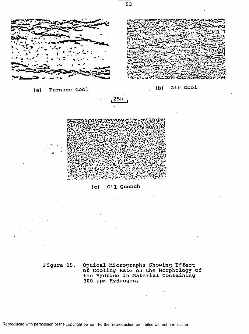
53
(c) Oil Quench
Figure 15. Optical Micrographs Showing Effectof Cooling Rate on the Morphology of the Hydride in Material Containing 300 ppm Hydrogen.
Reproduced with permission of the copyright owner. Further reproduction prohibited without permission.

54
(c) Oil Quench (d) Water Quench1.2,5V i
(e) Brine Quench
Figure 16. Optical Micrographs Showing Effect of Cooling Rate on the Morphology of the Hydride in Material Containing 7 ppm Hydrogen.
Reproduced with permission of the copyright owner. Further reproduction prohibited without permission.

• ''imepp
v i'f j j j ifk-to ifv». •>
Figure 17. Thin Foil Electron Micrograph Showing the Hydrides Formed at Low Hydrogen Content or Fast Quenching Rate.(a) Accicular Hydrides in 7 ppm Hydrogen Material Quenched in Brine.(b) Flake-like Formation of Hydride in 7 ppm Material Cooled in Air. Diffraction Pattern» Obtained From Hydride at Top Righthand Corner of the Picture, is From the [110] Zone Axis.
Reproduced with permission of the copyright owner. Further reproduction prohibited without permission.
56
■ *** -. *&?***• , jV>*‘*,r <,; xl'>: i
^.di . «.a..r«r IrfiMfM
Figure 18. Twinning of the Hydride. (a) 7 ppraHydrogen Specimen Quenched in Brine. Figure Shows Internal Twinning of the Hydride. (b) Twinning Between the Hydride and a-Matrix Interface in the Water-Quench 150 ppm Hydrogen Alloy.
Reproduced with permission of the copyright owner. Further reproduction prohibited without permission.

57
(a)
Figure 19. Blocky Form of Radial Hydride Formed In 300 ppm Hydrogen Alloy Which Has Been Furnace Cooled. (a) Shows a Potential Crack Path Running Along the Radial Hydride. Diffraction Pattern From the [110]5 Zone Axis Indicates the Possibility of Two Separate 6-Hydrides. (b) A Crack Running Right Through the Radial Hydride.
Reproduced with permission of the copyright owner. Further reproduction prohibited without permission.

.V- .r*~ -- 7 - V ^ r^ ■- rvf*
V'7:>> .5V,
•jr£ v «-
— * V -i 'fc~J | ^ ■*. V ’*"•
*7 * < < «'sSi/,,-: •'» A * ? *• - ‘ - »* " V r - ..
,***:* >*?Vi*j
...... ■ * t'v.V' ’' . ~. « '■» '•*_ ' * 'x *-- ,.~<s* r* .:r2 is h ± k *± L r . r 'UlM*
(b)
Figure 20. Striated Form of Radial Hydride FoundIn 300 ppm Hydrogen Alloy Which Has Been Furnace Cooled. Note the Intragranular Nature of the Hydride Precipitates In Both Micrographs. Figure (b) Shows That the Hydrides Can Precipitate Transversely Through a Large Number of Grains.
Reproduced with permission of the copyright owner. Further reproduction prohibited without permission.
59
Figure 21. Dislocation Network Generated By A 6-Hydride.
Reproduced with permission of the copyright owner. Further reproduction prohibited without permission.

60
ou3-PUo£VEh
300 ppm
150 ppm
46 ppm
7 ppm
Log. Time
Figure 22. Schematic Time-Temperature Transformation Curves For Zirconium-2.5wt%Nb Material Containing 7 ppm-300 ppm Hydrogen. F.C. , A.C. , O.Q. , W.Q. , B.Q.
Reproduced with permission of the copyright owner. Further reproduction prohibited without permission.

61
Figure 23. Determination of the Terminal SolidSolubility Temperature for the 46 ppm Hydrogen Material By Noting the Dissolution of the Coarse Hydride. (a)At Temperatures <290°C Coarse Hydrides Still Exist. (b) At Temperatures Around 290°C the Dissolution of the Coarse Hydrides had Occurred. (c)At Temperatures >300°C There is No Further Change in Morphology of the Hydrides.
Reproduced with permission of the copyright owner. Further reproduction prohibited without permission.

APPENDIX
Reproduced with permission of the copyright owner. Further reproduction prohibited without permission.
63
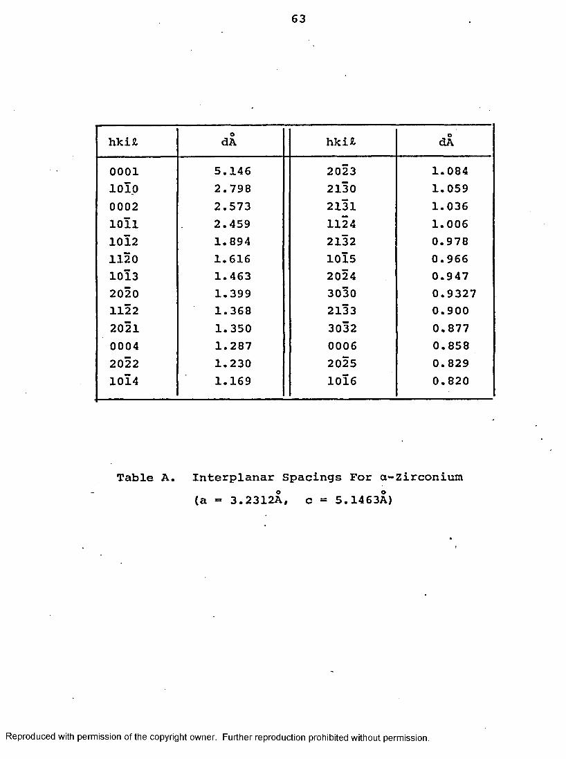
hkiJl OdA hki* OdA
0001 5.146 2023 1.0841010 2.798 2130 1.0590002 2.573 2131 1.0361011 2.459 1124 1.0061012 1.894 2132 0.9781120 1.616 1015 0.9661013 1.463 2024 0.9472020 1.399 3030 0.93271122 1.368 2133 0.9002021 1.350 3032 0.8770004 1.287 0006 0.8582022 1.230 2025 0.8291014 1.169 1016 0.820
Table A. Interplanar Spacings For a-zirconium (a » 3.2312A, c = 5.1463A)
Reproduced with permission of the copyright owner. Further reproduction prohibited without permission.
64
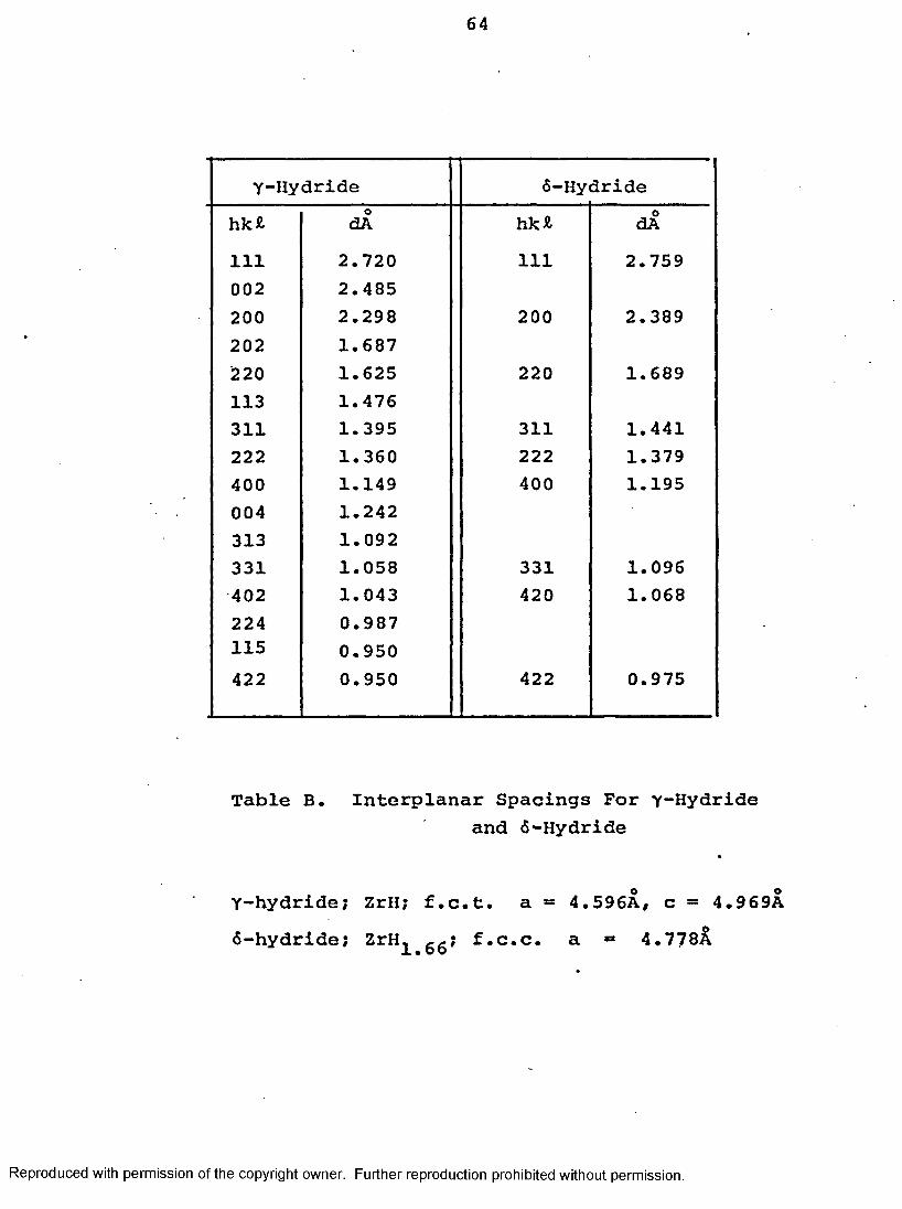
Y-Hydride 6-Hy dridehk£ OdA hk* OdA111 2.720 111 2.759002 2.485200 2.298 200 2.389202 1.687220 1.625 220 1.689113 1.476311 1.395 311 1.441222 1.360 222 1.379400 1.149 400 1.195004 1.242313 1.092331 1.058 331 1.096402 1.043 420 1.068224 0.987115 0.950422 0.950 422 0.975
Table B. Interplanar Spacings For yHydrideand 6-Hydride
Y-hydride; ZrH; f.c.t. a *» 4.596A, c = 4.969A 6-hydride; ZrH^ gg; f.c.c. a «* 4.778A
Reproduced with permission of the copyright owner. Further reproduction prohibited without permission.

Zone Axis [hkJt] 6-Hydride y-Hydride
110 002 111 220 111
54° 44’ 35° 16’
56° 48' 32° 12'
031 200 113 113 113
72° 27' 35° 6'
71° 17' 36 42'
001 020 022 45° 42° 47'
Table C. Interplanar Angles Between anc* h 2 c2*'2Planes for 6-Hydride and y-Hydride
Reproduced with permission of the copyright owner. Further reproduction prohibited without permission.
VITA AUCTORIS
TheOctober 6,
Education:
Societies:
author was born in Penang, Malaysia on 1946.
Diploma in Technology (1967) in Materials Technology obtained at Northern Alberta Institute of Technology, Edmonton, Alberta.
Certificate from College of Education (Dept, of Technical & Industrial Arts) in 1968, University of Toronto, Toronto, Ontario.
B.A.Sc. (1977) in Engineering Materials obtained at University of Windsor, Windsor, Ontario.
American Society for Metals.
66
Reproduced with permission of the copyright owner. Further reproduction prohibited without permission.