
Hydrogen ordering and H-induced phase transformations in Zr-based intermetallic hydrides
14
L Journal of Alloys and Compounds 293–295 (1999) 74–87 Hydrogen ordering and H-induced phase transformations in Zr-based intermetallic hydrides a,b, a,c d a b a,c * ˚ V.A. Yartys , H. Fjellvag , I.R. Harris , B.C. Hauback , A.B. Riabov , M.H. Sørby , b I.Yu. Zavaliy a Institute for Energy Technology, P .O. Box 40, Kjeller N-2027, Norway b Metal Hydrides Department, Karpenko Physico-Mechanical Institute of the National Academy of Sciences of Ukraine, 5, Naukova Str., Lviv 290601, Ukraine c Department of Chemistry, University of Oslo, N-0315 Oslo, Norway d School of Metallurgy and Materials, The University of Birmingham, Edgbaston, Birmingham B15 2TT, UK Abstract Crystal chemistry aspects of hydrogen behaviour in the zirconium–iron intermetallic deuterides (hydrides), Zr FeD , 2 1.80–5.00 Zr FeD and Zr Fe O H , were studied with a focus on the application of high resolution powder neutron diffraction. The 3 1.27–6.70 4 2 0.6 7.80 effects of crystal structure, chemical composition of the metal matrices, temperature and hydrogen contents on preferences in the interstices occupation and H ordering were investigated and discussed in relation to the H absorption–desorption properties. The Hydrogenation–Disproportionation–Desorption–Recombination process was successfully applied to all materials studied, including the first reported example of an oxygen-containing compound, Zr Fe O . 1999 Elsevier Science S.A. All rights reserved. 4 2 0.6 Keywords: Hydrides; Zirconium; Iron; Powder neutron diffraction; Crystal structure; Hydrogenation–Disproportionation–Desorption–Recombination 1. Introduction successfully applied to Zr Fe [4] and Zr Fe [7]. The route 2 3 provides a complete recovery of the original intermetallic phase and its H-sorption characteristics. Furthermore, it Zirconium-containing alloys are attractive as hydrogen provides the possibility to synthesise these compounds in a storage alloys (HSA), hydrogen getters and metal hydride microcrystalline state which is favourable for H-storage battery electrode materials. Zirconium–iron HSA, and in applications. particular Zr-rich alloys with more than 50 at.% Zr, meet Powder neutron diffraction studies of the saturated the requirements of effective hydrogen getters. The ST 198 deuterides Zr FeD [3], Zr FeD [7] and Zr FeAl D Zr–Fe alloy (SAES Getters) is one type of such a 2 5.0 3 6.7 6 2 10 [10] showed completely ordered hydrogen sublattices with hydrogen getter which contains the Zr Fe intermetallic 2 ˚ compound as its major constituent. all D–D distances exceeding 2.0 A. The deuterium atoms A number of publications describe hydrogenation prop- occupy interstices formed either exclusively by zirconium erties of Zr–Fe intermetallics (Zr Fe [1–4], Zr Fe [5–7], atoms (Zr -tetrahedra in Zr FeD , Zr FeD and 2 3 4 2 5.0 3 6.7 Zr Fe O [8,9], Zr FeAl [10]). Dependent on the ap- Zr FeAl D ) or by zirconium and iron atoms (Zr Fe- 4 2 0.6 6 2 6 2 10 3 plied hydrogenation conditions, either hydrides of intersti- tetrahedra in Zr FeD ; Zr Fe-tetrahedra and Zr Fe 2 5.0 3 3 2 tial type or materials disproportionated into Zr dihydride trigonal bipyramids in Zr FeD and Zr FeAl D ). 3 6.7 6 2 10 can be formed on hydrogen absorption by the binary Zr Fe This work focuses on H-ordering and H-induced phase 2 and Zr Fe intermetallics [1–7]. The irreversibility of the transformations in binary and ternary intermetallics formed 3 disproportionation of Zr Fe was pointed out in Ref. [2], by zirconium and iron, i.e., Zr Fe, Zr Fe and Zr Fe O , 2 2 3 4 2 0.6 and was considered to limit the performance of the over a wide range of H / D contents in the metal matrices. material. However, recently the Hydrogenation–Dispropor- Despite the rather small variation in Zr content of the tionation–Desorption–Recombination (HDDR) route was metal matrices, ranging from 60.6 (Zr Fe O ) to 75.0 4 2 0.6 at.% (Zr Fe), there are significant differences in their 3 properties as hydrogen storage materials. This fact will be *Corresponding author. Tel.: 147-6380-6453; fax: 147-6381-0920. discussed in relation to characteristic features of the crystal E-mail address: [email protected] (V.A. Yartys) 0925-8388 / 99 / $ – see front matter 1999 Elsevier Science S.A. All rights reserved. PII: S0925-8388(99)00304-7
Transcript of Hydrogen ordering and H-induced phase transformations in Zr-based intermetallic hydrides
LJournal of Alloys and Compounds 293–295 (1999) 74–87
Hydrogen ordering and H-induced phase transformations in Zr-basedintermetallic hydrides
a,b , a,c d a b a,c* ˚V.A. Yartys , H. Fjellvag , I.R. Harris , B.C. Hauback , A.B. Riabov , M.H. Sørby ,bI.Yu. Zavaliy
aInstitute for Energy Technology, P.O. Box 40, Kjeller N-2027, NorwaybMetal Hydrides Department, Karpenko Physico-Mechanical Institute of the National Academy of Sciences of Ukraine, 5, Naukova Str., Lviv 290601,
UkrainecDepartment of Chemistry, University of Oslo, N-0315 Oslo, Norway
dSchool of Metallurgy and Materials, The University of Birmingham, Edgbaston, Birmingham B15 2TT, UK
Abstract
Crystal chemistry aspects of hydrogen behaviour in the zirconium–iron intermetallic deuterides (hydrides), Zr FeD ,2 1.80–5.00
Zr FeD and Zr Fe O H , were studied with a focus on the application of high resolution powder neutron diffraction. The3 1.27–6.70 4 2 0.6 7.80
effects of crystal structure, chemical composition of the metal matrices, temperature and hydrogen contents on preferences in theinterstices occupation and H ordering were investigated and discussed in relation to the H absorption–desorption properties. TheHydrogenation–Disproportionation–Desorption–Recombination process was successfully applied to all materials studied, including thefirst reported example of an oxygen-containing compound, Zr Fe O . 1999 Elsevier Science S.A. All rights reserved.4 2 0.6
Keywords: Hydrides; Zirconium; Iron; Powder neutron diffraction; Crystal structure; Hydrogenation–Disproportionation–Desorption–Recombination
1. Introduction successfully applied to Zr Fe [4] and Zr Fe [7]. The route2 3
provides a complete recovery of the original intermetallicphase and its H-sorption characteristics. Furthermore, itZirconium-containing alloys are attractive as hydrogenprovides the possibility to synthesise these compounds in astorage alloys (HSA), hydrogen getters and metal hydridemicrocrystalline state which is favourable for H-storagebattery electrode materials. Zirconium–iron HSA, and inapplications.particular Zr-rich alloys with more than 50 at.% Zr, meet
Powder neutron diffraction studies of the saturatedthe requirements of effective hydrogen getters. The ST 198deuterides Zr FeD [3], Zr FeD [7] and Zr FeAl DZr–Fe alloy (SAES Getters) is one type of such a 2 5.0 3 6.7 6 2 10
[10] showed completely ordered hydrogen sublattices withhydrogen getter which contains the Zr Fe intermetallic2˚compound as its major constituent. all D–D distances exceeding 2.0 A. The deuterium atoms
A number of publications describe hydrogenation prop- occupy interstices formed either exclusively by zirconiumerties of Zr–Fe intermetallics (Zr Fe [1–4], Zr Fe [5–7], atoms (Zr -tetrahedra in Zr FeD , Zr FeD and2 3 4 2 5.0 3 6.7
Zr Fe O [8,9], Zr FeAl [10]). Dependent on the ap- Zr FeAl D ) or by zirconium and iron atoms (Zr Fe-4 2 0.6 6 2 6 2 10 3
plied hydrogenation conditions, either hydrides of intersti- tetrahedra in Zr FeD ; Zr Fe-tetrahedra and Zr Fe2 5.0 3 3 2
tial type or materials disproportionated into Zr dihydride trigonal bipyramids in Zr FeD and Zr FeAl D ).3 6.7 6 2 10
can be formed on hydrogen absorption by the binary Zr Fe This work focuses on H-ordering and H-induced phase2
and Zr Fe intermetallics [1–7]. The irreversibility of the transformations in binary and ternary intermetallics formed3
disproportionation of Zr Fe was pointed out in Ref. [2], by zirconium and iron, i.e., Zr Fe, Zr Fe and Zr Fe O ,2 2 3 4 2 0.6
and was considered to limit the performance of the over a wide range of H/D contents in the metal matrices.material. However, recently the Hydrogenation–Dispropor- Despite the rather small variation in Zr content of thetionation–Desorption–Recombination (HDDR) route was metal matrices, ranging from 60.6 (Zr Fe O ) to 75.04 2 0.6
at.% (Zr Fe), there are significant differences in their3
properties as hydrogen storage materials. This fact will be*Corresponding author. Tel.: 147-6380-6453; fax: 147-6381-0920.discussed in relation to characteristic features of the crystalE-mail address: [email protected] (V.A. Yartys)
0925-8388/99/$ – see front matter 1999 Elsevier Science S.A. All rights reserved.PI I : S0925-8388( 99 )00304-7
V.A. Yartys et al. / Journal of Alloys and Compounds 293 –295 (1999) 74 –87 75
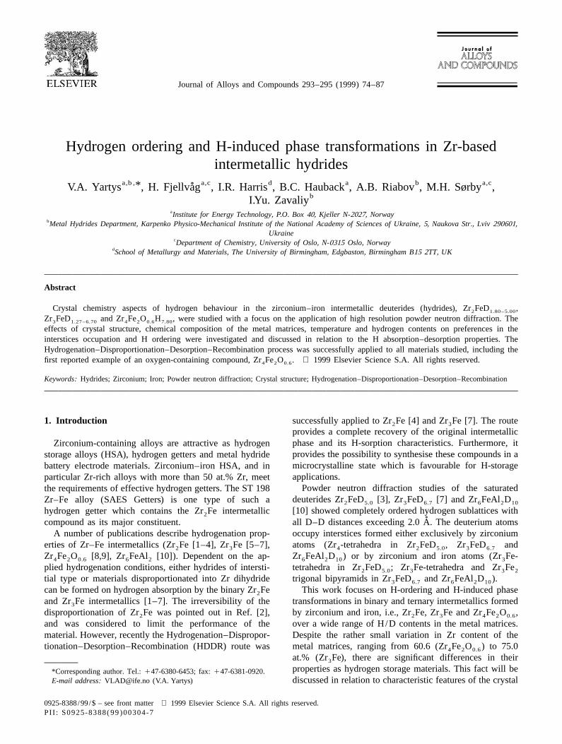
Fig. 1. (a) Crystal structure of Zr Fe (Re B type). Note Fe-centred Zr -trigonal prisms and the four types of interstices occupied by D atoms in Zr FeD :3 3 6 3 6.7
D1 (Zr Fe ), D2 (Zr Fe), D3 (Zr ) and D4 (Zr ). (b) Crystal structure of Zr Fe (CuAl type). Note Fe-centred Zr -tetragonal antiprisms and three types of3 2 3 4 4 2 2 8
interstices occupied by D atoms in Zr FeD : Zr (D1), Zr Fe (D2), Zr (D3) and vacant interstice Zr Fe . Chains of Fe atoms perpendicular to2 3.39–5.00 4 3 4 2 2
paper plane, along [001]. (c) Crystal structure of Zr Fe O (Fe W C type). Fe -tetrahedra and Zr -octahedra centred by O-atoms are shown.4 2 0.6 3 3 4 6
Table 1Crystallographic data for the Zr FeD (x51.27; 2.54; 5.04; 6.70) deuterides3 x
3 3˚ ˚ ˚ ˚ ˚Compound a, A b, A c, A V, A Da /a, % Db /b, % Dc /c, % DV/V, % DV/at.D, A
Zr Fe 3.324(2) 10.974(5) 8.821(3) 321.77(45) – – – – –3
Zr FeD 3.3261(4) 11.268(1) 8.999(1) 337.27(11) 0.06 2.68 2.02 4.8 3.053 1.27
Zr FeD 3.3536(4) 11.317(1) 9.200(1) 349.16(12) 0.89 3.13 4.30 8.5 2.703 2.54
Zr FeD 3.4524(1) 11.2333(5) 9.4846(4) 367.44(4) 3.86 2.36 7.55 14.2 2.273 5.04
Zr FeD 3.5803(3) 11.059(1) 9.6486(8) 382.03(9) 7.71 0.77 9.38 18.7 2.253 6.70
76 V.A. Yartys et al. / Journal of Alloys and Compounds 293 –295 (1999) 74 –87
Table 2Crystallographic data for the Zr FeD (x51.80; 2.91; 3.39; 4.66; 5.00) deuterides2 x
3 3˚ ˚ ˚ ˚Compound T, K a, A c, A V, A Da /a, % Dc /c, % DV/V, % DV/at.D, A
Zr Fe 293 6.3787(9) 5.5988(6) 227.80(9) – – – –2
Zr FeD 293 6.7301(4) 5.4298(4) 245.94(4) 5.51 23.02 8.0 2.522 1.80
Zr FeD 293 6.8785(5) 5.5087(5) 260.64(6) 7.84 21.61 14.4 2.822 2.91
Zr FeD 673 6.9213(9) 5.5657(10) 266.62(10) 8.51 20.59 17.0 2.862 3.39
Zr FeD 473 6.959(1) 5.6222(9) 272.30(13) 9.10 0.42 19.5 2.392 4.66
Zr FeD 298 6.93566(8) 5.62061(8) 270.370(6) 8.73 0.39 18.7 2.132 5.00
Table 3Selected crystal structure data for the Zr FeD (x51.27; 2.54; 5.04; 6.70) deuterides derived from powder neutron diffraction experiments at 293 K3 x
˚Compound Interstices and their occupation, % Mean Zr–D distances, A
Zr Fe (D1) Zr Fe (D2) Zr (I) (D3) Zr (II) (D4) Zr Fe (D1) Zr Fe (D2) Zr (I) (D3) Zr (II) (D4)3 2 3 4 4 3 2 3 4 4
c c c cZr Fe – – – – 2.053 1.997 2.026 2.0033a c c cZr FeD – – – 63.5(15) 2.043 2.034 2.041 2.0643 1.27a c cZr FeD – – 47.5(24) 79.3(20) 2.029 2.062 2.062 2.0993 2.54aZr FeD 36.0(13) 48.3(15) 91.9(11) 93.7(11) 2.103 2.105 2.082 2.1133 5.04bZr FeD 91.1(10) 90.7(8) 92.9(8) 92.7(8) 2.159 2.098 2.103 2.1323 6.70
a 2 2Reliability factors: Zr FeD : R 50.059; R 50.076; x 53.01. Zr FeD : R 50.059; R 50.077; x 55.11. Zr FeD : R 50.044; R 50.056;3 1.27 p wp 3 2.54 p wp 3 5.04 p wp2
x 52.96. Complete refinement results are published elsewhere [15].b In the structure of saturated (1 bar D ) Zr FeD deuteride (space group Cmcm; No. 63) at 293 K atoms fill the following positions [7]: 4 Zr1 in 4c:2 3 6.70
2 2 2˚ ˚ ˚0; 0.4214(4); 1 /4; B 50.74(8) A ; 8 Zr2 in 8f : 0; 0.1392(3); 0.0500(3); B 51.19(7) A ; 4 Fe in 4c: 0; 0.7161(3); 1 /4; B 51.23(7) A ; D1 in 4c: 0;iso iso iso2 2 2˚ ˚ ˚0.2222(5); 1 /4; B 51.49(6) A ; D2 in 8f : 0; 0.4094(3); 0.6458(4); B 51.66(8) A ; D3 in 8f : 0; 0.3275(3); 0.0558(4); B 51.66(8) A ; D4 in 8f : 0;iso iso iso
2˚0.9622(4); 0.1288(3); B 51.69(9) A .isoc Empty interstices. Distances between the Zr atoms and the centre of the interstice are given.
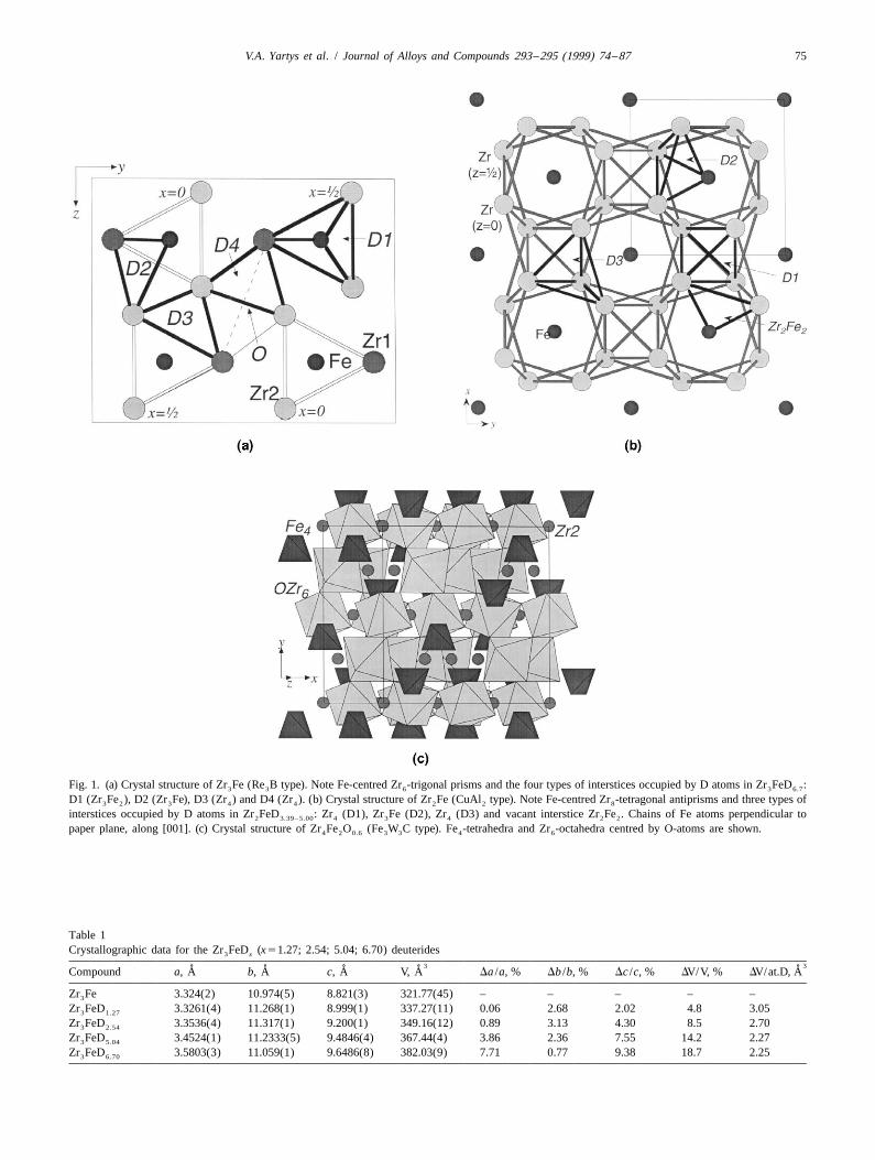
Fig. 2. Stacking of tetragonal antiprisms ZrD in Zr FeD viewed along [010].8 2 5

V.A. Yartys et al. / Journal of Alloys and Compounds 293 –295 (1999) 74 –87 77
were melted on a water-cooled copper pad in an argon arcfurnace. Zr Fe was studied in the as cast state. The2
samples of Zr Fe and Zr Fe O were respectively an-3 4 2 0.6
nealed at 1123 K (6 weeks) and 1273 K (4 weeks), beforebeing quenched into ice water. Powder X-ray diffraction(PXD) data (Siemens D 5000 diffractometer; CuKa1
radiation, Bragg Brentano geometry, position sensitivedetector) indicated the presence of nearly single phasematerials. Trace amounts of impurities were found for theZr Fe (ZrFe and a-Zr) and Zr Fe (ZrFe , Zr Fe and3 2 2 2 3
a-Zr) samples. The derived unit cell parameters from PXD˚[Zr Fe: a53.324(2); b510.974(5); c58.821(3) A), Zr Fe:3 2
˚a56.3787(9), c55.5988(6) A and Zr Fe O : a54 2 0.6˚12.180(1) A] agreed well with literature data [11].
Deuterium gas (99.8% purity) was used in syntheses ofFig. 3. Volume expansion vs deuterium content for Zr FeD and Zr FeD the deuterides. The formation of the deuterides Zr FeD2 x 3 x 3 6.7at 293 K. and Zr FeD and the Zr Fe OH hydride was moni-2 5.0 4 2 7.50
tored by volumetric measurements. Deuterides with lowerstructure of the intermetallic compounds and their corre- D-contents were obtained from the saturated Zr FeD3 6.7
sponding hydrides, as derived from powder diffraction and Zr FeD deuterides by application of secondary2 5.0
studies utilising conventional X-ray, synchrotron X-ray vacuum at selected desorption temperatures. Theand neutron sources. Zr FeD and Zr FeD deuterides were synthesised at3 5.04 2 2.91
433 K, Zr FeD and Zr FeD at 573 K and3 2.54 2 1.80
Zr FeD at 673 K.3 1.27
2. Experimental Hydrogen absorption and desorption properties werestudied by Temperature Pressure Analysis (TPA), Hydro-
The initial alloys were prepared from high purity gen Differential Thermal Analysis (HDTA) and Thermalzirconium (99.9%), iron (99.9) and iron oxide Fe O Desorption Spectroscopy (TDS) techniques. Constant heat-2 3
(99.9%). Stoichiometric mixtures of these components ing rates of 2 K/min (TDS) and 5 K/min (TPA and
Fig. 4. Observed (1), calculated (upper line) and difference (lower line) powder neutron diffraction profile for Zr FeD at 293 K. PUS instrument,3 5.04˚l51.5554 A. Positions of the peaks for the constituent phases are marked (from bottom to top): Zr FeD , ZrD , ZrFe , Zr Fe OD . [Zr2D ] 9-vertexes3 5.04 2 2 4 2 x 9
polyhedra (inlet).
78 V.A. Yartys et al. / Journal of Alloys and Compounds 293 –295 (1999) 74 –87
Table 4Selected crystal structure data for the Zr FeD (x51.80; 2.91; 3.39; 4.66; 5.00) deuterides derived from powder neutron diffraction experiments at 293,2 x
298, 473 and 673 K
˚Compound T, K Space group Interstices and their occupation, % Mean Zr–D distances, A
Zr (4b; D1) Zr Fe (D2) Zr Zr Zr Fe Zr4 3 4 4 3 4
16g 32m (16l; D3) (4b; D1) (16g/32m; D2) (16l; D3)c c cZr Fe – I4/mcm – – – – 2.078 1.965 2.0542
aZr FeD 293 K I4/mcm 39.3(19) – 3.3(8) 28.4(8) 2.096 2.030 2.0932 1.80a cZr FeD 293 K P4/ncc 88.6(19) 50.8(8) – – 2.115 2.053 2.1282 2.91aZr FeD 673 K I4/mcm 60.0(10) – 26.0(5) 17.7(6) 2.134 2.077 2.1452 3.39a cZr FeD 473 K P4/ncc 100 91.6(6) – – 2.132 2.095 2.1562 4.66b cZr FeD 298 K P4/ncc 100 100 – – 2.117 2.091 2.1492 5.00
a 2 2Reliability factors: Zr FeD : R 50.050; R 50.065; x 51.48. Zr FeD : R 50.051; R 50.066; x 51.38. Zr FeD : R 50.033; R 50.045;2 1.80 p wp 2 2.91 p wp 2 3.39 p wp2 2
x 58.94. Zr FeD : R 50.032; R 50.043; x 59.03. Complete refinement results will be published elsewhere [16,17].2 4.66 p wpb In the structure of saturated (1 bar D ) Zr FeD deuteride (space group P4/ncc; No. 130) at 298 K atoms fill the following positions [3]: 8 Zr in 8f :2 2 5
2 2 2˚ ˚ ˚0.4114(2); 0.5886(2); 1 /4; B 50.80(2) A ; 4 Fe in 4c: 1 /4; 1 /4’; 0.0109(3); B 51.10(4) A ; D1 in 4b: 3 /4; 1 /4; 0; B 51.95(3) A ; D2 in 16g:iso iso iso2˚0.0320(2); 0.1657(2); 0.0760(2); B 51.95(3) A .iso
c Empty interstices. Distances between the Zr atoms and the centre of the interstice are given.
HDTA) were used. The alloys and the hydrogenated samples were contained in a sealed, cylindrical vanadiumintermetallics were studied by standard SEM (JEOL 6300) holder with 5 mm inner diameter (Kjeller) or, for the inand by high resolution SEM (HRSEM-Hitachi S-4000 FE). situ studies at Studsvik, inside a quartz tube under a
Synchrotron (SR) PXD data were collected at the deuterium pressure of 1 bar. The GSAS (General StructureSwiss–Norwegian Beam Line, BM1, at ESRF, Grenoble, Analysis System) software [12] was used in the Rietveld
˚ type profile refinements. Nuclear scattering lengths b 5using monochromatic X-rays (l50.65015 A) obtained Zr
7.16, b 59.50 and b 56.67 fm were taken from Ref.from Si(111). The Zr FeD sample was kept in a rotating Fe D2 2.9
[13].0.3 mm sealed glass capillary and was heated by means ofa heat-blower. Diffraction data were collected at 293, 353,408, 453, 503, 548 and 568 K.
3. Results and discussionPowder neutron diffraction (PND) data were collected˚with the PUS instrument (l51.5554 A; 2Q510–1308;
3.1. Zr–Fe intermetallics as possible hydrogenD2Q50.058; T5293 K) at Institute for Energy Technolo-absorbersgy, Kjeller, Norway and at Studsvik Neutron Research
˚Laboratory (l51.116 A; 2Q53.8–1378; D2Q50.18; T5
The architecture of the crystal structures of Zr Fe293 K; 473 K; 673 K; 873 K; 1073 K), Sweden. The 3
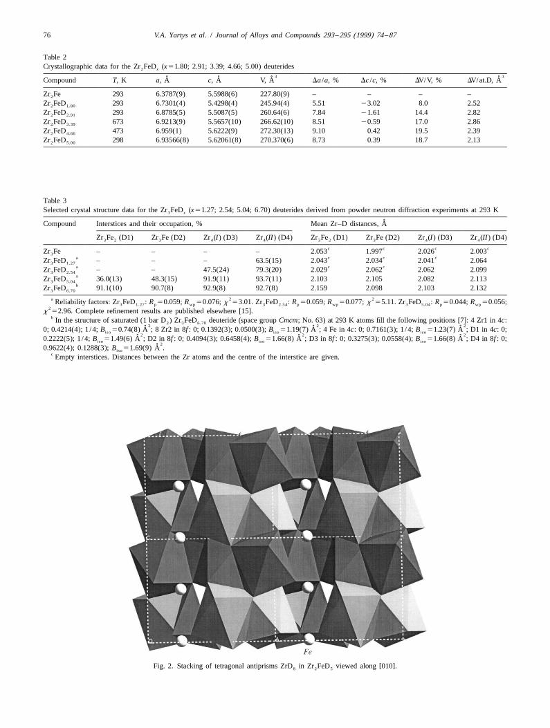
Fig. 5. Site occupancy for D-atoms in interstices of Zr FeD .3 x
V.A. Yartys et al. / Journal of Alloys and Compounds 293 –295 (1999) 74 –87 79
(orthorhombic; Re B-type), Zr Fe (tetragonal; CuAl -type) found in Zr Fe (Fig. 1(b)). In Zr Fe (Fig. 1(a)) no direct3 2 2 2 3
and Zr Fe O (cubic; Fe W C-type) differ in many Fe–Fe bonds are present, and consistent with this fact, the4 2 0.6 3 3
respects. In all these zirconium-rich phases, Zr atoms form only Fe-containing tetrahedral interstices are Zr Fe tetra-3
the major part of the structure skeleton and its building hedra. The other compounds, Zr Fe and Zr Fe O ,2 4 2 0.6
units (Fig. 1(a–c)). The skeletons are composed of differ- contain interstices with more than 25 at% Fe.ent units: Fe-centred trigonal prisms Zr (Zr Fe), tetragon-6 3
al antiprisms Zr (Zr Fe) and octahedra Zr , both normal 3.2. Hydrogen ordering in Zr Fe- and Zr Fe-based8 2 6 2 3
and O-centred (Zr Fe O ). All these compounds contain hydrides; saturated deuterides4 2 0.6
a number of Zr-rich interstices suitable for hydrogenabsorption. On the other hand, the Fe–Fe bonding is The metal sublattices of Re B- and CuAl -types for3 2
significantly different. Separate Fe tetrahedra exist in Zr Fe and Zr Fe, respectively, are preserved on hydro-4 3 2
Zr Fe O (Fig. 1(c)), whereas chains of Fe atoms are genation. In both cases, the formation of the saturated4 2 0.6
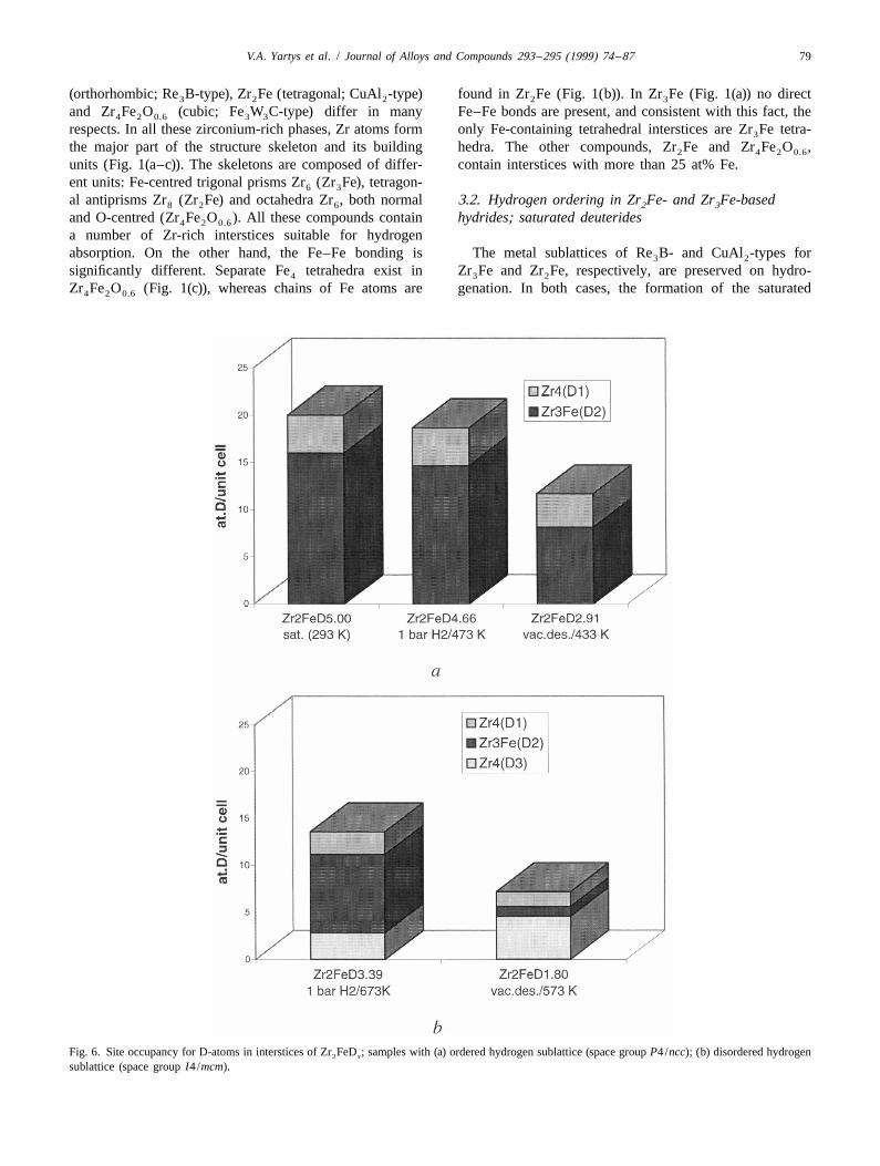
Fig. 6. Site occupancy for D-atoms in interstices of Zr FeD ; samples with (a) ordered hydrogen sublattice (space group P4/ncc); (b) disordered hydrogen2 x
sublattice (space group I4/mcm).
80 V.A. Yartys et al. / Journal of Alloys and Compounds 293 –295 (1999) 74 –87
deuterides with a D/(Zr1Fe) ratio of 1.67, i.e., Zr FeD ordered way. Note that the majority of filled sites contain3 6.7
[7] and Zr FeD [3], are accompanied by an anisotropic Fe-surrounding atoms (16 out of 20 filled interstices) and2 5.0
volume expansion of 18.7%. The main expansion occurs in that an alternative, possible model for site-filling inthe ac-plane for the orthorhombic Zr FeD (Table 1) Zr FeD , with D-atoms in Zr -tetrahedra (16/unit cell;3 6.70 2 5 4
˚and in the ab-plane for the tetragonal Zr FeD (Table 2), r50.55 A) and in 25% of the Zr Fe tetrahedra (4 /unit2 5.0 2 2˚with additional, rather small elongations of b and c, cell; r50.38 A), is not realised. Again, as in case of
respectively. Zr FeD , it should be noted that the occupied interstices3 6.70˚In Zr Fe there are 10 crystallographically different have similar radii range of 0.48–0.52 A.3
interstices (76 interstices /unit cell; Z54) including eighttypes of tetrahedra [five types Zr Fe (48/unit cell; r53 3.3. Hydrogen sublattice˚0.40–0.53 A); three types Zr (20/unit cell; r50.50–0.624˚ ˚A)], a trigonal bipyramid Zr Fe (4 /unit cell; r50.52 A)3 2 In the crystal structures for Zr FeD and Zr FeD the2 5.0 3 6.7˚and one octahedron Zr (4 /unit cell; r50.80 A). Zr FeD6 3 6.7 coordination polyhedra for the occupied interstices shareexhibits an ordered structure with nearly complete
common edges and vertices. All D–D separations fulfil thedeuterium filling of four different types of interstices (see ˚so-called ‘‘rule of 2 A’’ [14] [shortest D–D distances areFig. 1(a)), one Zr Fe -, one Zr Fe- and two Zr -interstices.3 2 3 4 ˚2.01 (Zr FeD [7]) and 2.08 A (Zr FeD [3])]. In both3 6.7 2 5.0The occupied intertices have radii filling a narrow rangecases the hydrogen sublattices can be presented as built˚0.49–0.53 A. When being outside that range, they becomefrom polyhedra formed by deuterium atoms surroundingempty. The main part of the occupied interstices, i.e., 16Zr-atoms. In Zr FeD the D-sublattice consists of de-3 6.7out of 28 per unit cell, are formed solely by zirconiumformed cubes (ZrD ) and deformed cubes with an addi-8atoms.tional ninth vertex (ZrD ). In Zr FeD the coordination9 2 5.0One point concerning the deuterium distribution inpolyhedron is a tetragonal antiprism (ZrD ). For both8Zr FeD should be noted in addition. An alternative way3 6.7 structure types these polyhedra form a spatial frameworkof filling the interstices, which would allow a maximalby sharing vertices and edges (see Fig. 2 where theD/(Zr1Fe) ratio of eight is not realised. In that model (24D-sublattice in Zr FeD is given as an example).2 5.0D in Zr Fe- and 8 D in Zr -tetrahedra) 75% of the relevant3 4
interstices include Fe in their surroundings. This is appar-ently a less favourable bonding situation for the H(D) 3.4. Lower deuteridesatoms than the observed model with hydrogen mainlysituated in Zr -tetrahedra [7]. Over the whole range of D-contents 0,D/Me,1.674
For Zr Fe the unit cell contains 68 tetrahedral interstices PXD studies of the Zr Fe–D and Zr Fe–D systems2 3 2 2 2
of four non-equivalent types; two types Zr tetrahedra (4 show that deuterides, Zr FeD and Zr FeD ,4 3 1.27–6.70 2 1.80–5.00
and 16/unit cell), one Zr Fe tetrahedron (32/unit cell) and are formed with the metal matrix retaining the original3
one Zr Fe tetrahedron (16/unit cell;). In Zr FeD two Re B and CuAl structure types.2 2 2 5.0 3 2˚of these tetrahedral interstices [Zr Fe (r50.48 A) and Zr3 4
˚(r50.52 A)] are occupied by deuterium atoms in an
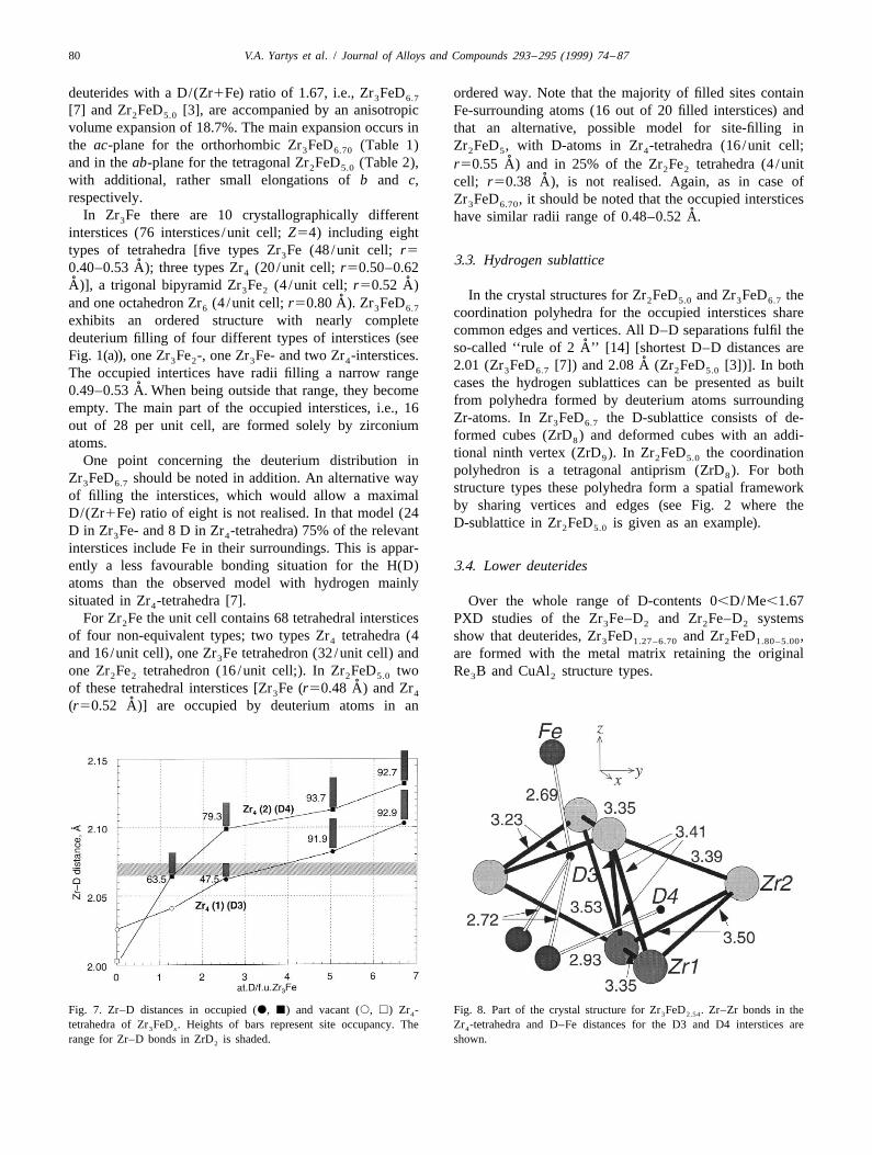
Fig. 7. Zr–D distances in occupied (d, j) and vacant (s, h) Zr - Fig. 8. Part of the crystal structure for Zr FeD . Zr–Zr bonds in the4 3 2.54
tetrahedra of Zr FeD . Heights of bars represent site occupancy. The Zr -tetrahedra and D–Fe distances for the D3 and D4 interstices are3 x 4
range for Zr–D bonds in ZrD is shaded. shown.2
V.A. Yartys et al. / Journal of Alloys and Compounds 293 –295 (1999) 74 –87 81
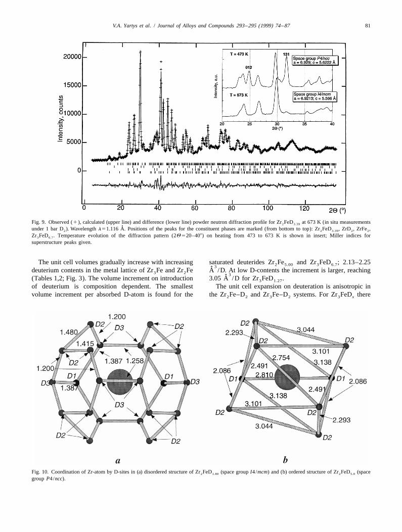
Fig. 9. Observed (1), calculated (upper line) and difference (lower line) powder neutron diffraction profile for Zr FeD at 673 K (in situ measurements2 3.39˚under 1 bar D ). Wavelength l51.116 A. Positions of the peaks for the constituent phases are marked (from bottom to top): Zr FeD , ZrD , ZrFe ,2 2 3.39 2 2
Zr FeD . Temperature evolution of the diffraction pattern (2Q 520–408) on heating from 473 to 673 K is shown in insert; Miller indices for3 6.7
superstructure peaks given.
The unit cell volumes gradually increase with increasing saturated deuterides Zr Fe and Zr FeD ; 2.13–2.252 5.00 3 6.73˚deuterium contents in the metal lattice of Zr Fe and Zr Fe A /D. At low D-contents the increment is larger, reaching3 2 3˚(Tables 1,2; Fig. 3). The volume increment on introduction 3.05 A /D for Zr FeD .3 1.27
of deuterium is composition dependent. The smallest The unit cell expansion on deuteration is anisotropic involume increment per absorbed D-atom is found for the the Zr Fe–D and Zr Fe–D systems. For Zr FeD there2 2 3 2 3 x
Fig. 10. Coordination of Zr-atom by D-sites in (a) disordered structure of Zr FeD (space group I4/mcm) and (b) ordered structure of Zr FeD (space2 1.80 2 5.0
group P4/ncc).

82 V.A. Yartys et al. / Journal of Alloys and Compounds 293 –295 (1999) 74 –87
is a gradual, continuous expansion in [100] and [001] with the D-atoms occupying Zr Fe -trigonal bipyramids3 2
increasing D-content. The variation in Db /b (see Table 1) (Zr FeD ) and the Zr Fe-tetrahedra (Zr FeD and3 x 3 3 x
is unsystematic, and actually the saturated deuteride has Zr FeD ) to be weaker bonded to the metal matrix. The2 x
the smallest Db /b shift relative to the initial alloy. For two types of Zr -tetrahedra in Zr FeD remain nearly4 3 x
Zr FeD the expansion of the tetragonal unit cell proceeds completely occupied for D/M.0.60–0.65. For lower D/M2 x
exclusively in the ab-plane and is accompanied by a ratios, the two Zr -sites start to become differently oc-4
shrinkage of the c-axis, most notably for the lowest cupied and for Zr FeD the Zr (I)-site (D3) has 48%3 2.54 4
deuteride studied, i.e., Zr FeD , see Table 2. occupancy compared to 79% for D4 in the Zr (II)-site. In2 1.80 4
The anisotropic expansion can be related to preferred the lowest studied deuteride, Zr FeD , only the Zr (II)-3 1.80 4
occupation of hydrogen atoms in certain interstices and to site is partially occupied (64%). In general, a reducedrepulsive D–D interactions. One example is the trans- occupancy of a certain site appears to correlate withformation Zr FeD →Zr FeD (Fig. 4). In Zr FeD , shortening of the Zr /Fe–D bond distances. The reduced3 5.04 3 6.70 3 5.04
the Zr Fe interstices (D2-sites) have a partial occupancy of occupancy of the Zr (I)-site (D3) correlates with (a)3 4
around 50%, which in average allows a short distance shorter D3–Zr bond distances compared to that of the˚between the sites (1.54 A). However, in the saturated more completely filled D4 position (Fig. 7); (b) slightly
deuteride these sites are almost completely occupied. This shorter Zr–Zr distances in the surrounding Zr -tetrahedron4˚requires a considerably longer D2–D2 distance (2.01 A) in (Fig. 8); (c) short separations from the Zr (I)-interstice to4
˚order to fulfil the ‘‘rule of 2 A’’ [14]. The anisotropic unit the next nearest Fe neighbouring atoms (three distances at˚cell expansion can therefore be related to D2-D2 repulsion 2.69–2.72 A) in contrast to one Fe neighbour for the
˚along [001] (see Table 1). occupied Zr (II)-interstice (D4) at a distance of 2.93 A4
Similar arguments hold for the anisotropic expansion of (Fig. 8).the tetragonal unit cell of Zr FeD . The shortest D–D For Zr FeD , deuterium is mainly released from the2 5.00 2 x
˚distances (2.08 A) are located within the ab-plane and the Zr Fe-interstices (Fig. 6). For the lowest deuteride studied3
expansion on deuteration occurs mainly within this plane. here, Zr FeD , the D-sublattice is no longer ordered.2 1.80
However, the anisotropy is already considerable at low Instead a change in space group symmetry occurs (fromD-contents. In these, a major part of the D-sites separated P4/ncc to I4/mcm) implying distribution of D-atoms overby the shortest D–D distances (Table 4) are empty, and a three types of interstices (Fig. 6(b)).more complex explanation involving local D–D repulsions The observed Zr–D bond lengths for the occupied Zr -4
is probably needed. tetrahedra in Zr FeD and Zr FeD correspond well to3 x 2 x
those of similar Zr -tetrahedra in binary zirconium4
3.5. H /D site preferences deuterides. In intermetallic deuterides these tetrahedrabecome filled up with D-atoms until the Zr–D distances
On decreasing D-content, the deuterium is preferentially exceed those in ZrD (see Tables 3,4). When the contrac-2
withdrawn from Fe-containing interstices, as evident from tion of the Zr -tetrahedra proceeds for the lower deuterides4
Figs. 5,6 and Tables 3,4. In that respect one may consider and the Zr–D distances become shorter than those charac-
Fig. 11. Hydrogen desorption traces for Zr–Fe-based hydrides.

V.A. Yartys et al. / Journal of Alloys and Compounds 293 –295 (1999) 74 –87 83
˚teristic for ZrD (2.065–2.073 A), the Zr–D bonding tion proceeds continuously over a wide temperature range22x
appears to become unstable, and complete D-desorption for both the Zr FeD and Zr FeD deuterides. The2 5.00 3 6.70
proceeds from at temperatures significantly lower than for desorption is completed at 923 K (Fig. 11). For Zr FeD3 x
ZrD . one then observes a reversible formation of the initial2
intermetallic compound.3.6. Order–disorder transition for Zr FeD The CuAl -type metal lattice of Zr Fe seems to become2 52x 2 2
substantially stabilised subsequent on hydrogen absorption.During in situ PND studies, the saturated Zr FeD Note that the Zr Fe intermetallic itself exists in the narrow2 5.00 2
deuteride was heated under 1 bar D gas pressure from 293 temperature range of 1048–1247 K [18]. No signs of2
to 1073 K in steps of 200 K. At 473 K the hydrogen disproportionation were seen by in situ PXD (SR) studiessublattice corresponds to the tetragonal structure observed of Zr FeD at 560 K (Fig. 12). However, the high2 2.91
for Zr FeD (space group P4/ncc) at 298 and 4.2 K [3]. resolution diffractograms clearly revealed that the initial2 5.00
A partial deuterium desorption, reducing the D/M ratio normal thermal expansion was followed by decreased unitfrom 5.00 to 4.66, is limited to a small D-release from the cell dimensions owing to deuterium desorption, before oneZr Fe-interstices, whereas the Zr -sites remain completely3 4
occupied. There is no significant change in the relativeamounts of the three minor impurity phases (ZrFe , ZrD2 2
and Zr FeD ) on heating from 293 to 473 K. This3 6.70
clearly shows that no disproportionation of Zr FeD2 52x
takes place at modest operating temperatures.On heating further up to 673 K, a more considerable
deuterium desorption takes place. For the material withrefined composition Zr FeD an order–disorder transi-2 3.39
tion has obviously occurred. The transition implies anincreased symmetry from space group P4/ncc to I4/mcm(the latter corresponds to that of Zr Fe) as evidenced by2
the disappearance of a few strong PND reflections (see Fig.9). In the ‘‘low temperature’’ structure (P4/ncc) twointerstices, Zr and Zr Fe, are filled by D atoms in an4 3
ordered way. At and above 673 K, the D-atoms in Zr Fe-3
interstices are distributed over 32 sites /unit cell, whereasat 473 K one subgroup of 16 sites is filled, another iscompletely empty.
In the disordered model, Zr is surrounded by 22 D-sites(see Fig. 10(a)) with neighbour–neighbour distances less
˚than 1.4 A. In the saturated deuteride, only eight of these22 sites are occupied, and the deformed tetragonal antipris-matic coordination polyhedron (Fig. 10(b)) provides D–D
˚separations above 2.085 A.
3.7. Hydrogen absorption–desorption properties
The successful deuteration of Zr Fe at very mild con-2
ditions, i.e., at room temperature, p(D ),0.25 bar and2
without preliminary activation, confirms its excellent H-getter properties. Also for Zr Fe, absorption of deuterium3
is possible at room temperature and p(D ),1 bar, how-2
ever, a preliminary activation is required. In contrast,hydrogenation of the oxygen-containing intermetallic,Zr Fe O , is significantly different. Zr Fe O has to be4 2 0.6 4 2 0.6
heated up to 620–670 K (1 bar H ) to initiate hydrogen2
absorption, which results in an interstitial type hydrideFig. 12. Temperature evolution of selected part of powder X-ray diffrac-
Zr Fe O H with expanded cubic unit cell (DV/V5 ˚4 2 0.6 7.80 tion (SR) pattern (l50.65015 A; Miller indices given) of the Zr FeD2 2.9117.8%). deuteride (293–568 K) together with corresponding changes in unit cell
Under secondary vacuum conditions, hydrogen desorp- parameters (insert).

84 V.A. Yartys et al. / Journal of Alloys and Compounds 293 –295 (1999) 74 –87
Fig. 13. Temperature–pressure analysis trace for Zr Fe O heated in H up to 1213 K.4 2 0.6 2
at 503 K observed the formation of a two-phase mixture of Oxygen insertion into the metal matrix of Zr Fe sig-2
closely related deuterides with different D/M contents. nificantly decreases both hydrogen absorption capacityAfter deuterium absorption, it is possible for Zr FeD to (down to 1.3 H/M) and the thermal stability of the2 x
undertake a reversible absorption–desorption cycle. The corresponding hydrides. For Zr Fe O H hydrogen4 2 0.6 7.80
CuAl -type metal sublattice is retained up to about 783 K, desorption is already complete at 573 K, with a distinct2
i.e., 265 K below the lower temperature stability limit for peak at 488 K (Fig. 11). The lower stability ofZr Fe [18]. At 783 K the unit cell dimensions (a5 Zr Fe O H can be associated with the fact that Zr -2 4 2 0.6 7.80 4
˚6.373(2); c55.579(2) A; measured for cooled sample at tetrahedra are absent and that the hydrogen atoms therefore298 K) corresponds to those characteristic for the initial only can enter Fe-containing interstices.
˚Zr Fe intermetallic (a56.3787(9), c55.5988(6) A), in-2
dicating complete D-desorption. PXD shows increasedamounts of the admixtural phase constituents, Zr Fe and 3.8. The hydrogenation–disproportionation–desorption–3
ZrFe , indicating a partial disproportionation according to recombination process2
the scheme:In addition to the formation of interstitial type hydrides4 Zr FeD 1 (1 2 2x) D → 2 Zr Fe 1 ZrFe 1 ZrD2 x 2 3 2 2 described above, the studied compounds undergo two more
Fig. 14. X-ray diffraction pattern of Zr Fe O after heating in H up to 1213 K.4 2 0.6 2
V.A. Yartys et al. / Journal of Alloys and Compounds 293 –295 (1999) 74 –87 85
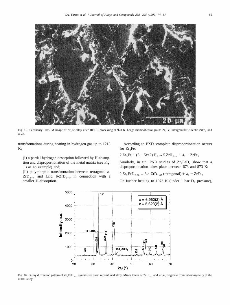
Fig. 15. Secondary HRSEM image of Zr Fe-alloy after HDDR processing at 923 K. Large rhombohedral grains Zr Fe, intergranular eutectic ZrFe and2 3 2
a-Zr.
transformations during heating in hydrogen gas up to 1213 According to PXD, complete disproportionation occursK; for Zr Fe:3
2 Zr Fe 1 (5 2 5x /2) H → 5 ZrH 1 l 2 ZrFe3 2 22x 2 2(i) a partial hydrogen desorption followed by H-absorp-Similarly, in situ PND studies of Zr FeD show that ation and disproportionation of the metal matrix (see Fig. 2 x
disproportionation takes place between 673 and 873 K:13 as an example) and;(ii) polymorphic transformation between tetragonal ´- 2 Zr FeD → 3 ´-ZrD (tetragonal) 1 l 2 ZrFe2 2.80 1.87 2 2ZrD and f.c.c. d-ZrD in connection with a22x 22x
smaller H-desorption. On further heating to 1073 K (under 1 bar D pressure),2
Fig. 16. X-ray diffraction pattern of Zr FeH synthesised from recombined alloy. Minor traces of ZrH and ZrFe originate from inhomogeneity of the2 52x 22x 2
initial alloy.
86 V.A. Yartys et al. / Journal of Alloys and Compounds 293 –295 (1999) 74 –87
´-ZrD partially looses deuterium. The D/Zr ratio is nation into Zr Fe. This is evident from the PXD data in22x 2
reduced from 0.933 for ´-ZrD at 873 K to 0.75 for the Fig. 16 for Zr FeH being synthesised under mild22x 2 52x
formed cubic d-ZrD at 1073 K. condition from a recombined material subjected to several22x
Under the same conditions, the h-oxide Zr Fe O also full HDDR cycles. With basis in the present phase-structur-4 2 0.6
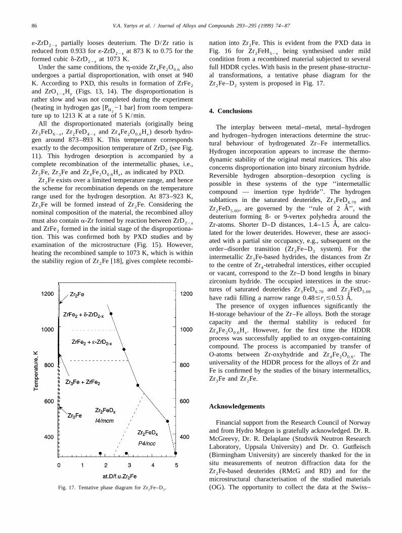
undergoes a partial disproportionation, with onset at 940 al transformations, a tentative phase diagram for theK. According to PXD, this results in formation of ZrFe Zr Fe–D system is proposed in Fig. 17.2 2 2
and ZrO H (Figs. 13, 14). The disproportionation is12x y
rather slow and was not completed during the experiment(heating in hydrogen gas [P |1 bar] from room tempera-H2 4. Conclusionsture up to 1213 K at a rate of 5 K/min.
All the disproportionated materials (originally being The interplay between metal–metal, metal–hydrogenZr FeD , Zr FeD and Zr Fe O H ) desorb hydro-3 62x 2 42x 4 2 0.6 x and hydrogen–hydrogen interactions determine the struc-gen around 873–893 K. This temperature corresponds tural behaviour of hydrogenated Zr–Fe intermetallics.exactly to the decomposition temperature of ZrD (see Fig.2 Hydrogen incorporation appears to increase the thermo-11). This hydrogen desorption is accompanied by a dynamic stability of the original metal matrices. This alsocomplete recombination of the intermetallic phases, i.e., concerns disproportionation into binary zirconium hydride.Zr Fe, Zr Fe and Zr Fe O H , as indicated by PXD.2 3 4 2 0.6 x Reversible hydrogen absorption–desorption cycling is
Zr Fe exists over a limited temperature range, and hence2 possible in these systems of the type ‘‘intermetallicthe scheme for recombination depends on the temperature compound — insertion type hydride’’. The hydrogenrange used for the hydrogen desorption. At 873–923 K, sublattices in the saturated deuterides, Zr FeD and3 6.70Zr Fe will be formed instead of Zr Fe. Considering the3 2 ˚Zr FeD , are governed by the ‘‘rule of 2 A’’, with2 5.00nominal composition of the material, the recombined alloy
deuterium forming 8- or 9-vertex polyhedra around themust also contain a-Zr formed by reaction between ZrD22x ˚Zr-atoms. Shorter D–D distances, 1.4–1.5 A, are calcu-and ZrFe formed in the initial stage of the disproportiona-2 lated for the lower deuterides. However, these are associ-tion. This was confirmed both by PXD studies and by
ated with a partial site occupancy, e.g., subsequent on theexamination of the microstructure (Fig. 15). However,
order–disorder transition (Zr Fe–D system). For the2 2heating the recombined sample to 1073 K, which is withinintermetallic Zr Fe-based hydrides, the distances from Zr3the stability region of Zr Fe [18], gives complete recombi-2 to the centre of Zr -tetrahedral interstices, either occupied4
or vacant, correspond to the Zr–D bond lengths in binaryzirconium hydride. The occupied interstices in the struc-tures of saturated deuterides Zr FeD and Zr FeD3 6.70 2 5.00
˚have radii filling a narrow range 0.48#r #0.53 A.i
The presence of oxygen influences significantly theH-storage behaviour of the Zr–Fe alloys. Both the storagecapacity and the thermal stability is reduced forZr Fe O H . However, for the first time the HDDR4 2 0.6 x
process was successfully applied to an oxygen-containingcompound. The process is accompanied by transfer ofO-atoms between Zr-oxyhydride and Zr Fe O . The4 2 0.6
universality of the HDDR process for the alloys of Zr andFe is confirmed by the studies of the binary intermetallics,Zr Fe and Zr Fe.3 2
Acknowledgements
Financial support from the Research Council of Norwayand from Hydro Megon is gratefully acknowledged. Dr. R.McGreevy, Dr. R. Delaplane (Studsvik Neutron ResearchLaboratory, Uppsala University) and Dr. O. Gutfleisch(Birmingham University) are sincerely thanked for the insitu measurements of neutron diffraction data for theZr Fe-based deuterides (RMcG and RD) and for the2
microstructural characterisation of the studied materialsFig. 17. Tentative phase diagram for Zr Fe–D . (OG). The opportunity to collect the data at the Swiss–2 2
V.A. Yartys et al. / Journal of Alloys and Compounds 293 –295 (1999) 74 –87 87
˚[7] V.A. Yartys, H. Fjellvag, B.C. Hauback, A.B. Riabov, M.H. Sørby, J.Norwegian Beamline, ESRF is sincerely appreciated. WeAlloys Compds. 278 (1–2) (1998) 252.thank Dr. K. Schenk (Universite de Lausanne) for lending
[8] I.Yu. Zavaliy, A.B. Riabov,V.A. Yartys, G. Wiesinger, H. Michor, G.us the heat-blower).Hilscher, J. Alloys Compds. 265 (1998) 6.
[9] I.Yu. Zavaliy, M.V. Lototzky, A.B. Riabov, V.A. Yartys, J. AlloysCompds. 219 (1995) 34.
References [10] F. Gingl, K. Yvon, I.Yu. Zavaliy, V.A. Yartys, P. Fischer, J. AlloysCompds. 226 (1995) 1.
[11] P. Villars, L.D. Calvert, Pearson’s Handbook of Crystallographic[1] P. Raj, P. Suryanarayana, A. Satnyamoothy, H. Shashikale, R.M.Data for Intermetallic Phases, 2nd ed., ASM International, MaterialsIyer, J. Alloys Compds. 178 (1992) 393.Park, OH, 1991.[2] A. Nobile, W.C. Mosley, J.C. Holder, K.N. Brooks, J. Alloys
[12] A.C. Larson, R.B. von Dreele, General Structure Analysis System,Compds. 206 (1994) 83.LANL, 1994.˚[3] V.A. Yartys, H. Fjellvag, B.C. Hauback, A.B. Riabov, J. Alloys
[13] V.F. Sears, Neutron News 3 (1992) 26.Compds. 274 (1998) 217.[14] A.C. Switendik, Z. Phys. Chem. NF 117 (1979) 89.[4] V.A. Yartys, I.Yu. Zavaliy, A.B. Riabov P.W. Guegan, J.C. Clarke,,
˚[15] V.A. Yartys, H. Fjellvag, B.C. Hauback, A.B. Riabov, J. Alloys˚I.R. Harris, B.C. Hauback, H. Fjellvag, Hydrogen power: theoreticalComp. 287 (1999) 189.and engineering solutions, in: T.O. Saetre (Ed.), Proceedings of the
˚[16] V.A. Yartys, H. Fjellvag, B.C. Hauback, A.B. Riabov, to beInternational Symposium HYPOTHESIS II, Grimstad, Norway, 18–published.22 August 1997, Kluwer Academic Publishers, The Netherlands,
˚[17] V.A. Yartys, R. Delaplane, H. Fjellvag, B.C. Hauback, R. McGreevy,1998, 303.A.B. Riabov, to be published.[5] F. Aubertin, U. Gonser, S.J. Campbell, J. Phys. F. Met. Phys. 14
(1984) 2213. [18] D. Arias, J.C. Abriata, in: T.B. Massalski et al. (Ed.), 2nd ed, Binary[6] F. Aubertin, G.L. Whittle, S.J. Campbell, U. Gonser, Phys. Stat. Sol. Alloys Phase Diagrams, Vol. 2, ASM International, USA, 1990, p.
(a) 104 (1987) 397. 1798.