NickelGallium Intermetallic Nanocrystal Catalysts in the ...
8
DOI: 10.1002/cctc.201300813 Nickel–Gallium Intermetallic Nanocrystal Catalysts in the Semihydrogenation of Phenylacetylene Changming Li, Yudi Chen, Shitong Zhang, Junyao Zhou, Fei Wang, Shan He, Min Wei,* David G. Evans, and Xue Duan [a] Introduction Phenylacetylene removal in styrene feedstocks through semi- hydrogenation is an important industrial process owing to its serious poisoning effect on styrene polymerization catalysts, and the selective hydrogenation of phenylacetylene to styrene has been commonly used. [1] The main challenge in this process is to develop effective catalysts with satisfactory activity and high selectivity to avoid the complete hydrogenation of phe- nylacetylene to ethylbenzene. Palladium-based catalysts have received considerable attention owing to their good hydroge- nation selectivity toward alkene (e.g., in the dispersed col- loids [2] and supported systems [3] ). Although great progress has been made, the limited resource and high cost of noble Pd limit their practical applications in the industry. Therefore, the design and fabrication of efficient and cost-effective substi- tutes are desirable and remain a challenging goal. Intermetallic compounds (IMCs) with their unique electronic structures and geometries [4] have attracted extensive research interest in catalysis, for instance, hydrogenation of unsaturated aldehydes on RuTi or NiSn IMCs, [5] methanol synthesis and methanol steam reforming on PdGa and PdZn IMCs, [6] and fuel electrocatalytic oxidation over Pt 3 Ti or PtPb IMCs. [7] Armbrɒster et al. recently developed a series of IMCs (e.g., PdGa IMC [8] and Al 13 Fe 4 IMC [9] ) as effective catalysts for the selective hydrogena- tion of acetylene to ethylene, the improved catalytic selectivity of which is attributed to the combination of the electronic structure and site-isolation effect. Although considerable effort has been devoted to the preparation of IMCs by using chemi- cal colloidal methods, [10] and their desirable catalytic behavior has been demonstrated, they still inevitably require expensive noble metals and costly and toxic organic reagents, damaged activity by capping reagents, or serious self-agglomeration in the reaction process. Therefore, it is highly essential to develop facile and green strategies for the synthesis of IMCs serving as efficient catalysts. Layered double hydroxides (LDHs) are a class of naturally oc- curring and synthetic materials generally expressed by the for- mula [M 1x 2 + M x 3 + (OH) 2 ](A n ) x/n ·m H 2 O, in which M 2 + and M 3 + cations disperse in an ordered and uniform manner in brucite- like layers. [11] Considerable interest has been focused on LDH materials as heterogeneous catalysts on the basis of their ver- satility in chemical composition and structural architecture. [12] A topotactic transformation of LDH materials to uniformly dis- persed metal nanoparticles (NPs) supported on metal oxide matrix occurs under reducing conditions. [13] Inspired by the structural merits of LDH materials, we explored the idea of in- corporating highly active but lowly selective Ni and inactive but more electropositive Ga species into the LDH precursors followed by a reduction process to fabricate non-noble Ni–Ga IMC (e.g., Ni 3 Ga, Ni 5 Ga 3 , and NiGa) catalysts for the selective hydrogenation of phenylacetylene. This strategy would possess the following desirable features: 1) the atomic scale intersper- sion of Ni and Ga species in the LDH precursors would facili- tate the formation of highly dispersed Ni–Ga IMCs under mod- The chemoselective hydrogenation of alkyne is of great impor- tance in the chemical industry, in which intermetallic com- pounds (IMCs) have attracted extensive interest as efficient cat- alysts. Herein, we demonstrate the preparation of several sup- ported Ni–Ga IMCs (Ni 3 Ga, Ni 5 Ga 3 , and NiGa) via a facile in situ reduction of layered double hydroxide (LDH) precursors, which demonstrate significantly improved catalytic activity and selec- tivity for the selective hydrogenation of phenylacetylene to styrene. The composition and particle size of Ni–Ga IMCs can be tuned by adjusting the Ni/Ga ratio or reduction tempera- ture during the topotactic transformation process of LDHs, and the best catalytic behavior can be obtained over the Ni 3 Ga IMC with a styrene yield of 87.7 % (particle size = 7.2 nm at 40 8C and 0.3 MPa), which is better than that of most of the reported Ni catalysts. The X-ray absorption fine-structure characteriza- tion and DFT calculations reveal the electron transfer from Ga to Ni and active-site isolation by Ga in Ni–Ga IMCs, which ac- count for the excellent hydrogenation selectivity. The signifi- cantly improved catalytic performance makes Ni–Ga IMC cata- lysts promising candidates for the selective hydrogenation of alkyne. [a] Dr. C. Li, Y. Chen, Dr. S. Zhang, J. Zhou, Dr. F. Wang, Dr. S. He, Prof. M. Wei, Prof. D. G. Evans, Prof. X. Duan State Key Laboratory of Chemical Resource Engineering Beijing University of Chemical Technology Beijing 100029 (P.R. China) Fax: (+ 86) 10-64425385 E-mail : [email protected] Supporting information for this article is available on the WWW under http://dx.doi.org/10.1002/cctc.201300813. # 2014 Wiley-VCH Verlag GmbH & Co. KGaA, Weinheim ChemCatChem 2014, 6, 824 – 831 824 CHEMCATCHEM FULL PAPERS
-
Upload
khangminh22 -
Category
Documents
-
view
1 -
download
0
Transcript of NickelGallium Intermetallic Nanocrystal Catalysts in the ...
DOI: 10.1002/cctc.201300813
Nickel–Gallium Intermetallic Nanocrystal Catalysts in theSemihydrogenation of PhenylacetyleneChangming Li, Yudi Chen, Shitong Zhang, Junyao Zhou, Fei Wang, Shan He, Min Wei,*David G. Evans, and Xue Duan[a]
Introduction
Phenylacetylene removal in styrene feedstocks through semi-hydrogenation is an important industrial process owing to itsserious poisoning effect on styrene polymerization catalysts,and the selective hydrogenation of phenylacetylene to styrenehas been commonly used.[1] The main challenge in this processis to develop effective catalysts with satisfactory activity andhigh selectivity to avoid the complete hydrogenation of phe-nylacetylene to ethylbenzene. Palladium-based catalysts havereceived considerable attention owing to their good hydroge-nation selectivity toward alkene (e.g. , in the dispersed col-loids[2] and supported systems[3]). Although great progress hasbeen made, the limited resource and high cost of noble Pdlimit their practical applications in the industry. Therefore, thedesign and fabrication of efficient and cost-effective substi-tutes are desirable and remain a challenging goal.
Intermetallic compounds (IMCs) with their unique electronicstructures and geometries[4] have attracted extensive researchinterest in catalysis, for instance, hydrogenation of unsaturatedaldehydes on RuTi or NiSn IMCs,[5] methanol synthesis andmethanol steam reforming on PdGa and PdZn IMCs,[6] and fuelelectrocatalytic oxidation over Pt3Ti or PtPb IMCs.[7] Armbr�steret al. recently developed a series of IMCs (e.g. , PdGa IMC[8] and
Al13Fe4 IMC[9]) as effective catalysts for the selective hydrogena-tion of acetylene to ethylene, the improved catalytic selectivityof which is attributed to the combination of the electronicstructure and site-isolation effect. Although considerable efforthas been devoted to the preparation of IMCs by using chemi-cal colloidal methods,[10] and their desirable catalytic behaviorhas been demonstrated, they still inevitably require expensivenoble metals and costly and toxic organic reagents, damagedactivity by capping reagents, or serious self-agglomeration inthe reaction process. Therefore, it is highly essential to developfacile and green strategies for the synthesis of IMCs serving asefficient catalysts.
Layered double hydroxides (LDHs) are a class of naturally oc-curring and synthetic materials generally expressed by the for-mula [M1�x
2+Mx3 +(OH)2](An�)x/n·m H2O, in which M2 + and M3 +
cations disperse in an ordered and uniform manner in brucite-like layers.[11] Considerable interest has been focused on LDHmaterials as heterogeneous catalysts on the basis of their ver-satility in chemical composition and structural architecture.[12]
A topotactic transformation of LDH materials to uniformly dis-persed metal nanoparticles (NPs) supported on metal oxidematrix occurs under reducing conditions.[13] Inspired by thestructural merits of LDH materials, we explored the idea of in-corporating highly active but lowly selective Ni and inactivebut more electropositive Ga species into the LDH precursorsfollowed by a reduction process to fabricate non-noble Ni–GaIMC (e.g. , Ni3Ga, Ni5Ga3, and NiGa) catalysts for the selectivehydrogenation of phenylacetylene. This strategy would possessthe following desirable features: 1) the atomic scale intersper-sion of Ni and Ga species in the LDH precursors would facili-tate the formation of highly dispersed Ni–Ga IMCs under mod-
The chemoselective hydrogenation of alkyne is of great impor-tance in the chemical industry, in which intermetallic com-pounds (IMCs) have attracted extensive interest as efficient cat-alysts. Herein, we demonstrate the preparation of several sup-ported Ni–Ga IMCs (Ni3Ga, Ni5Ga3, and NiGa) via a facile in situreduction of layered double hydroxide (LDH) precursors, whichdemonstrate significantly improved catalytic activity and selec-tivity for the selective hydrogenation of phenylacetylene tostyrene. The composition and particle size of Ni–Ga IMCs canbe tuned by adjusting the Ni/Ga ratio or reduction tempera-ture during the topotactic transformation process of LDHs, and
the best catalytic behavior can be obtained over the Ni3Ga IMCwith a styrene yield of 87.7 % (particle size = 7.2 nm at 40 8Cand 0.3 MPa), which is better than that of most of the reportedNi catalysts. The X-ray absorption fine-structure characteriza-tion and DFT calculations reveal the electron transfer from Gato Ni and active-site isolation by Ga in Ni–Ga IMCs, which ac-count for the excellent hydrogenation selectivity. The signifi-cantly improved catalytic performance makes Ni–Ga IMC cata-lysts promising candidates for the selective hydrogenation ofalkyne.
[a] Dr. C. Li, Y. Chen, Dr. S. Zhang, J. Zhou, Dr. F. Wang, Dr. S. He, Prof. M. Wei,Prof. D. G. Evans, Prof. X. DuanState Key Laboratory of Chemical Resource EngineeringBeijing University of Chemical TechnologyBeijing 100029 (P.R. China)Fax: (+ 86) 10-64425385E-mail : [email protected]
Supporting information for this article is available on the WWW underhttp://dx.doi.org/10.1002/cctc.201300813.
� 2014 Wiley-VCH Verlag GmbH & Co. KGaA, Weinheim ChemCatChem 2014, 6, 824 – 831 824
CHEMCATCHEMFULL PAPERS
erate reduction conditions, and 2) the catalytic performance ofNi–Ga IMCs can be tuned by changing the Ni/Ga ratio in LDHprecursors.
Herein, we report the fabrication of several supported Ni–GaIMCs (Ni3Ga, Ni5Ga3, and NiGa) with tunable particle size byusing the LDH precursor method and demonstrate their appli-cation as efficient catalysts for the selective hydrogenation ofphenylacetylene. The composition and particle size of the sup-ported Ni–Ga IMCs can be tuned by changing the Ni/Ga ratioor reduction temperature during the topotactic transformationof LDHs. The X-ray absorption fine-structure (XAFS) characteri-zation demonstrates the relatively low Ni K-edge X-ray absorp-tion near-edge structure (XANES) absorption edge and low co-ordination number in Ni–Ga IMCs compared with the Ni foil,implying the charge transfer from Ga to Ni and active-site iso-lation by Ga, which were confirmed by DFT calculations. Theresulting materials demonstrate significantly improved catalyticselectivity for the hydrogenation of phenylacetylene to styrene,and the best catalytic behavior was obtained over the Ni3GaIMC with a styrene yield of 87.7 % (particle size = 7.2 nm at40 8C and 0.3 MPa), which is better than that of most of the re-ported Ni catalysts. The remarkably increased hydrogenationselectivity can be attributed to the observed Ni–Ga synergisticeffect. Our approach holds significant promise for Ni–Ga IMCsas efficient catalysts for the selective hydrogenation of phenyl-acetylene.
Results and Discussion
Structure and morphology of NixMgyGaz LDH precursors
NixMgyGaz LDH precursors were prepared by using the copreci-pitation method. The XRD patterns of NixMgyGaz LDHs withvarious Ni/Mg/Ga ratios, all of which can be indexed as a rhom-bohedral structure with the typical (0 0 3), (0 0 6), (0 1 2), (0 1 3),(11 0), and (11 3) reflections at 2 q�11.2, 22.7, 34.2, 38.5, 59.8,and 61.28 for LDH materials, respectively, are shown inFigure 1. No other crystalline phase was detected, which indi-cated the high purity of these LDH materials. The small differ-ence in the 2 q reflections among the four LDH precursors is
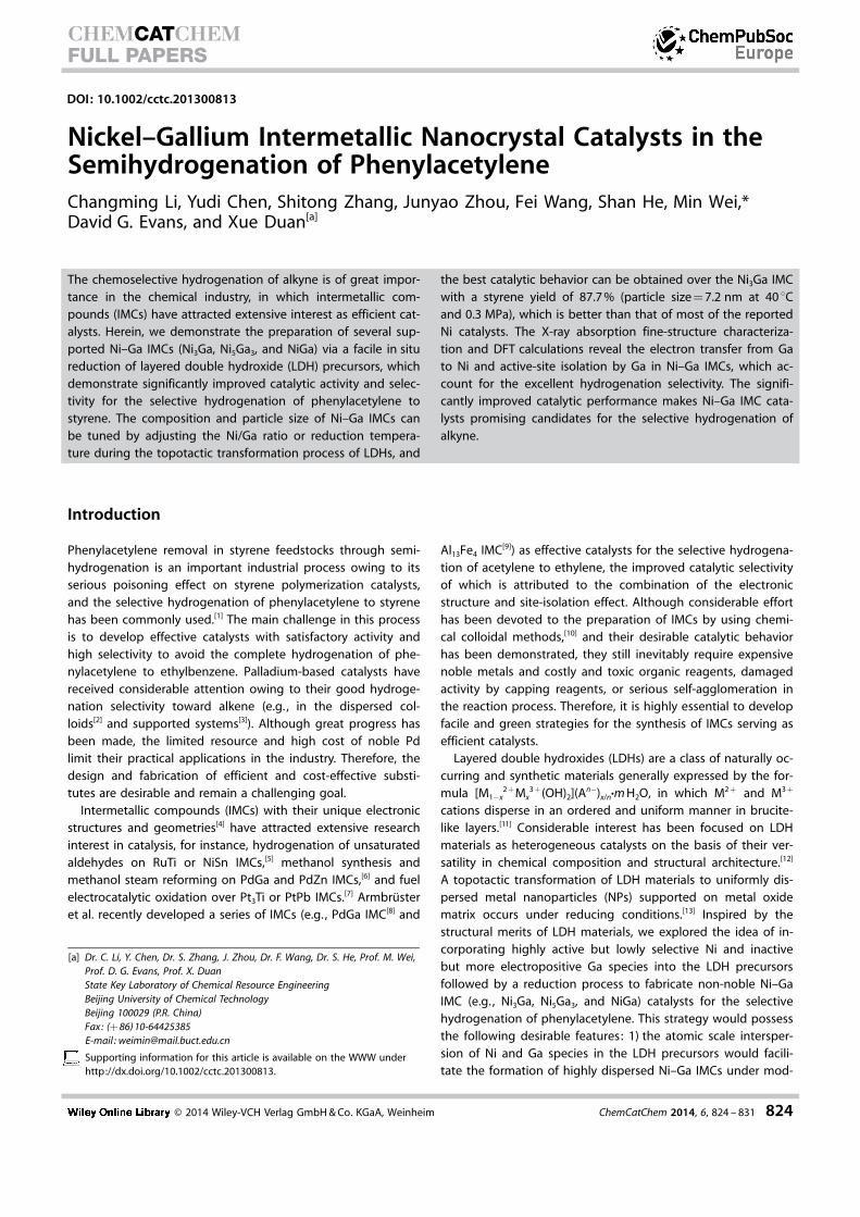
due to their different metal proportion and ionic radius. The in-itial and the resulting metal ratios of the products determinedfrom inductively coupled plasma atomic emission spectroscopyanalysis are summarized in Table S1, which indicates that themetal ratios in these products are similar to those in the feedintake. The SEM images (Figure 2) of NixMgyGaz LDHs showthat all the LDH precursors demonstrate a typical nanoplateletmorphology with a diameter of 30–100 nm, which indicatestheir proper crystallization.
Topotactic transformation from LDH materials to supportedNi–Ga IMCs
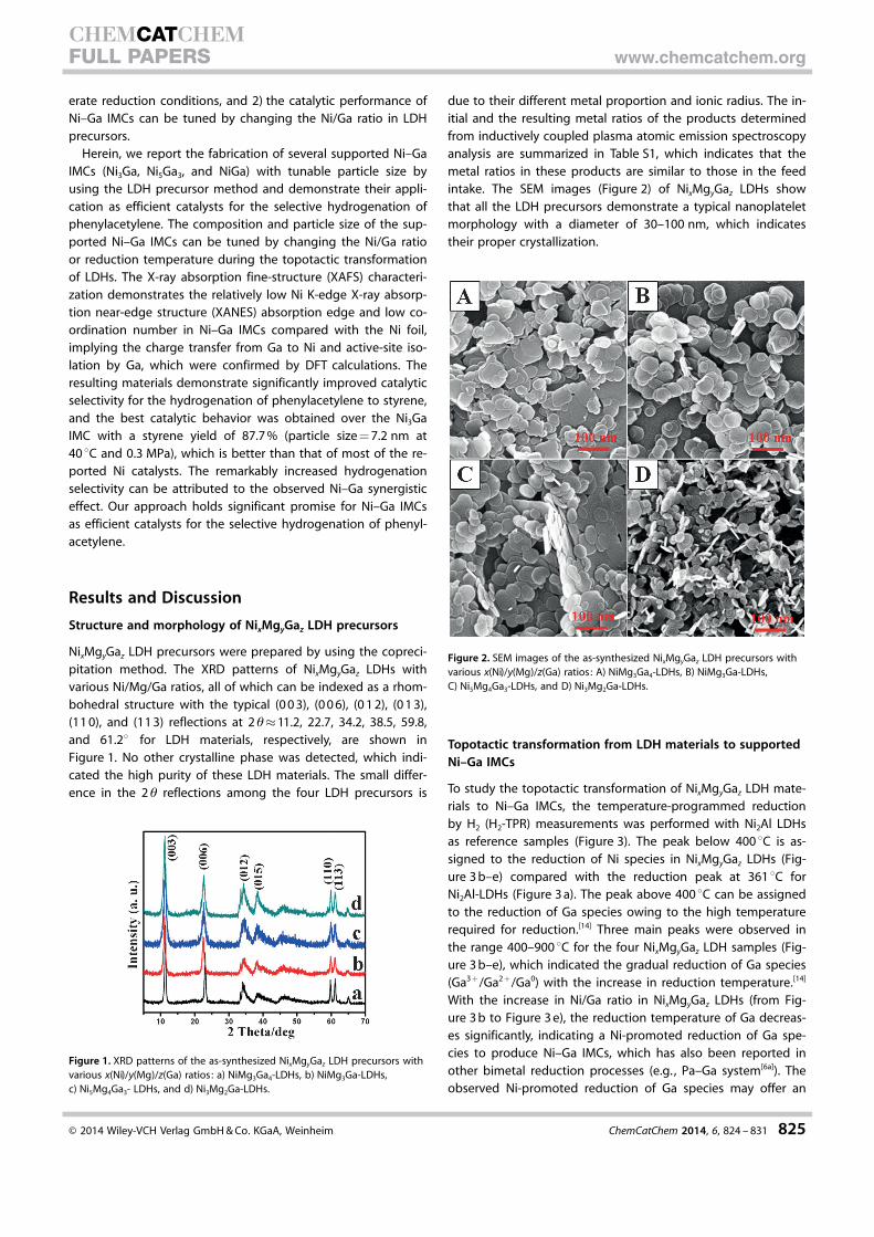
To study the topotactic transformation of NixMgyGaz LDH mate-rials to Ni–Ga IMCs, the temperature-programmed reductionby H2 (H2-TPR) measurements was performed with Ni2Al LDHsas reference samples (Figure 3). The peak below 400 8C is as-signed to the reduction of Ni species in NixMgyGaz LDHs (Fig-ure 3 b–e) compared with the reduction peak at 361 8C forNi2Al-LDHs (Figure 3 a). The peak above 400 8C can be assignedto the reduction of Ga species owing to the high temperaturerequired for reduction.[14] Three main peaks were observed inthe range 400–900 8C for the four NixMgyGaz LDH samples (Fig-ure 3 b–e), which indicated the gradual reduction of Ga species(Ga3 +/Ga2 +/Ga0) with the increase in reduction temperature.[14]
With the increase in Ni/Ga ratio in NixMgyGaz LDHs (from Fig-ure 3 b to Figure 3 e), the reduction temperature of Ga decreas-es significantly, indicating a Ni-promoted reduction of Ga spe-cies to produce Ni–Ga IMCs, which has also been reported inother bimetal reduction processes (e.g. , Pa–Ga system[6a]). Theobserved Ni-promoted reduction of Ga species may offer an
Figure 1. XRD patterns of the as-synthesized NixMgyGaz LDH precursors withvarious x(Ni)/y(Mg)/z(Ga) ratios: a) NiMg3Ga4-LDHs, b) NiMg3Ga-LDHs,c) Ni5Mg4Ga3- LDHs, and d) Ni3Mg2Ga-LDHs.
Figure 2. SEM images of the as-synthesized NixMgyGaz LDH precursors withvarious x(Ni)/y(Mg)/z(Ga) ratios: A) NiMg3Ga4-LDHs, B) NiMg3Ga-LDHs,C) Ni5Mg4Ga3-LDHs, and D) Ni3Mg2Ga-LDHs.
� 2014 Wiley-VCH Verlag GmbH & Co. KGaA, Weinheim ChemCatChem 2014, 6, 824 – 831 825
CHEMCATCHEMFULL PAPERS www.chemcatchem.org
opportunity for the controlled synthesis of Ni–Ga IMCs withtunable composition.
We first performed the reduction of NixMgyGaz LDHs at500 8C for 4 h (labeled as NixMgyGaz-500) to obtain Ni–Ga IMCs;the XRD patterns of the resulting products are shown inFigure 4. The MgO phase at 2 q�36.7, 43.1, and 62.38 is ob-
served for all the four samples, which is derived from the calci-nation of a Mg source in the LDH precursors. The 2 q at�43.88, 50.94, and 75.258 can be indexed to a Ni3Ga IMCphase (PDF 65-0141). For the NiMg3Ga4-500 sample, a weak re-flection intensity of Ni3Ga was observed (Figure 4 a). With theincrease in Ni/Ga ratio in NixMgyGaz LDHs, the intensity ofNi3Ga IMC increases in the following order: NiMg3Ga4-500<NiMg3Ga-500<Ni5Mg4Ga3-500<Ni3Mg2Ga-500 (Figure 4 a–d).This result suggests that a higher Ni/Ga ratio facilitates the re-duction of Ga and the formation of Ni3Ga species with largercrystal size, which is responsible for the better defined XRDpattern. This observation will be further demonstrated by TEMimages.
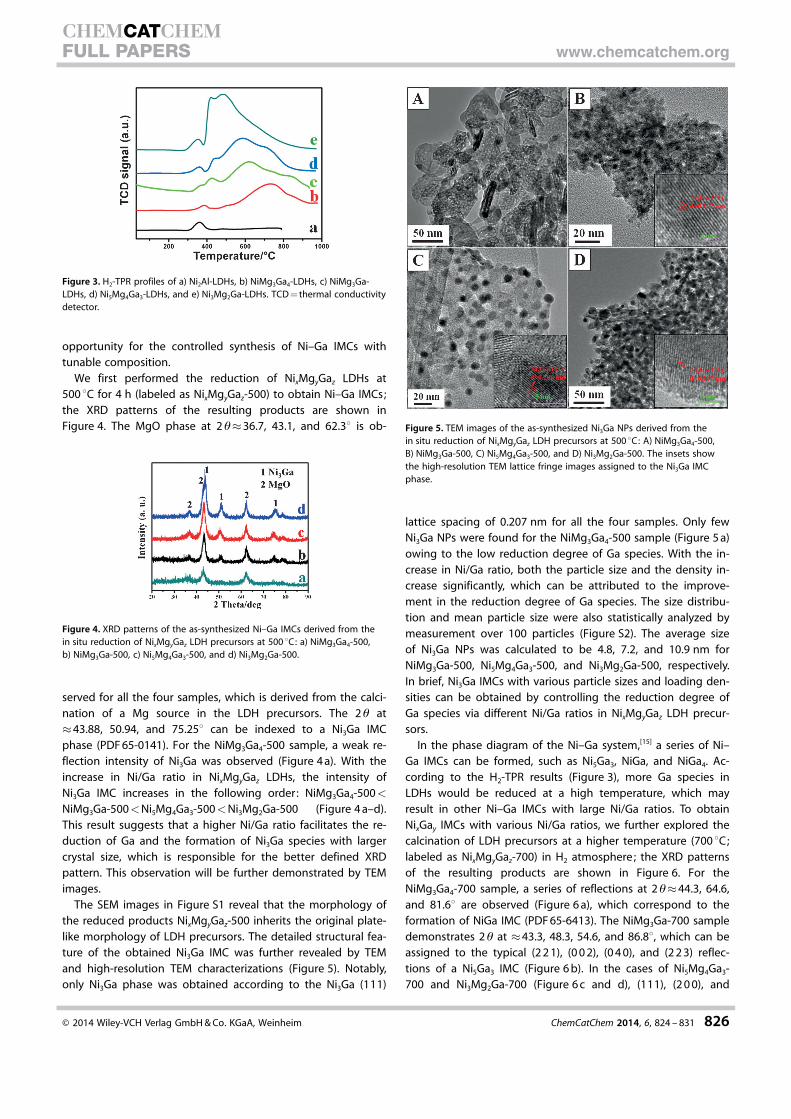
The SEM images in Figure S1 reveal that the morphology ofthe reduced products NixMgyGaz-500 inherits the original plate-like morphology of LDH precursors. The detailed structural fea-ture of the obtained Ni3Ga IMC was further revealed by TEMand high-resolution TEM characterizations (Figure 5). Notably,only Ni3Ga phase was obtained according to the Ni3Ga (111)
lattice spacing of 0.207 nm for all the four samples. Only fewNi3Ga NPs were found for the NiMg3Ga4-500 sample (Figure 5 a)owing to the low reduction degree of Ga species. With the in-crease in Ni/Ga ratio, both the particle size and the density in-crease significantly, which can be attributed to the improve-ment in the reduction degree of Ga species. The size distribu-tion and mean particle size were also statistically analyzed bymeasurement over 100 particles (Figure S2). The average sizeof Ni3Ga NPs was calculated to be 4.8, 7.2, and 10.9 nm forNiMg3Ga-500, Ni5Mg4Ga3-500, and Ni3Mg2Ga-500, respectively.In brief, Ni3Ga IMCs with various particle sizes and loading den-sities can be obtained by controlling the reduction degree ofGa species via different Ni/Ga ratios in NixMgyGaz LDH precur-sors.
In the phase diagram of the Ni–Ga system,[15] a series of Ni–Ga IMCs can be formed, such as Ni5Ga3, NiGa, and NiGa4. Ac-cording to the H2-TPR results (Figure 3), more Ga species inLDHs would be reduced at a high temperature, which mayresult in other Ni–Ga IMCs with large Ni/Ga ratios. To obtainNixGay IMCs with various Ni/Ga ratios, we further explored thecalcination of LDH precursors at a higher temperature (700 8C;labeled as NixMgyGaz-700) in H2 atmosphere; the XRD patternsof the resulting products are shown in Figure 6. For theNiMg3Ga4-700 sample, a series of reflections at 2 q�44.3, 64.6,and 81.68 are observed (Figure 6 a), which correspond to theformation of NiGa IMC (PDF 65-6413). The NiMg3Ga-700 sampledemonstrates 2 q at �43.3, 48.3, 54.6, and 86.88, which can beassigned to the typical (2 2 1), (0 0 2), (0 4 0), and (2 2 3) reflec-tions of a Ni5Ga3 IMC (Figure 6 b). In the cases of Ni5Mg4Ga3-700 and Ni3Mg2Ga-700 (Figure 6 c and d), (111), (2 0 0), and
Figure 3. H2-TPR profiles of a) Ni2Al-LDHs, b) NiMg3Ga4-LDHs, c) NiMg3Ga-LDHs, d) Ni5Mg4Ga3-LDHs, and e) Ni3Mg2Ga-LDHs. TCD = thermal conductivitydetector.
Figure 4. XRD patterns of the as-synthesized Ni–Ga IMCs derived from thein situ reduction of NixMgyGaz LDH precursors at 500 8C: a) NiMg3Ga4-500,b) NiMg3Ga-500, c) Ni5Mg4Ga3-500, and d) Ni3Mg2Ga-500.
Figure 5. TEM images of the as-synthesized Ni3Ga NPs derived from thein situ reduction of NixMgyGaz LDH precursors at 500 8C: A) NiMg3Ga4-500,B) NiMg3Ga-500, C) Ni5Mg4Ga3-500, and D) Ni3Mg2Ga-500. The insets showthe high-resolution TEM lattice fringe images assigned to the Ni3Ga IMCphase.
� 2014 Wiley-VCH Verlag GmbH & Co. KGaA, Weinheim ChemCatChem 2014, 6, 824 – 831 826
CHEMCATCHEMFULL PAPERS www.chemcatchem.org
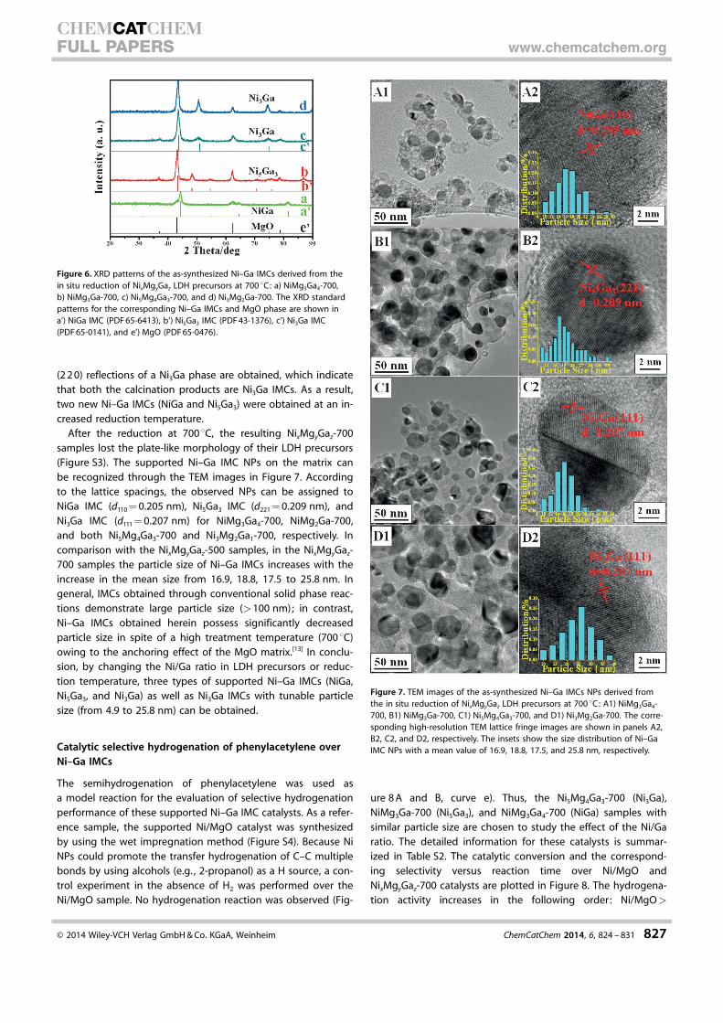
(2 2 0) reflections of a Ni3Ga phase are obtained, which indicatethat both the calcination products are Ni3Ga IMCs. As a result,two new Ni–Ga IMCs (NiGa and Ni5Ga3) were obtained at an in-creased reduction temperature.
After the reduction at 700 8C, the resulting NixMgyGaz-700samples lost the plate-like morphology of their LDH precursors(Figure S3). The supported Ni–Ga IMC NPs on the matrix canbe recognized through the TEM images in Figure 7. Accordingto the lattice spacings, the observed NPs can be assigned toNiGa IMC (d110 = 0.205 nm), Ni5Ga3 IMC (d221 = 0.209 nm), andNi3Ga IMC (d111 = 0.207 nm) for NiMg3Ga4-700, NiMg2Ga-700,and both Ni5Mg4Ga3-700 and Ni3Mg2Ga1-700, respectively. Incomparison with the NixMgyGaz-500 samples, in the NixMgyGaz-700 samples the particle size of Ni–Ga IMCs increases with theincrease in the mean size from 16.9, 18.8, 17.5 to 25.8 nm. Ingeneral, IMCs obtained through conventional solid phase reac-tions demonstrate large particle size (>100 nm); in contrast,Ni–Ga IMCs obtained herein possess significantly decreasedparticle size in spite of a high treatment temperature (700 8C)owing to the anchoring effect of the MgO matrix.[13] In conclu-sion, by changing the Ni/Ga ratio in LDH precursors or reduc-tion temperature, three types of supported Ni–Ga IMCs (NiGa,Ni5Ga3, and Ni3Ga) as well as Ni3Ga IMCs with tunable particlesize (from 4.9 to 25.8 nm) can be obtained.
Catalytic selective hydrogenation of phenylacetylene overNi–Ga IMCs
The semihydrogenation of phenylacetylene was used asa model reaction for the evaluation of selective hydrogenationperformance of these supported Ni–Ga IMC catalysts. As a refer-ence sample, the supported Ni/MgO catalyst was synthesizedby using the wet impregnation method (Figure S4). Because NiNPs could promote the transfer hydrogenation of C–C multiplebonds by using alcohols (e.g. , 2-propanol) as a H source, a con-trol experiment in the absence of H2 was performed over theNi/MgO sample. No hydrogenation reaction was observed (Fig-
ure 8 A and B, curve e). Thus, the Ni5Mg4Ga3-700 (Ni3Ga),NiMg3Ga-700 (Ni5Ga3), and NiMg3Ga4-700 (NiGa) samples withsimilar particle size are chosen to study the effect of the Ni/Garatio. The detailed information for these catalysts is summar-ized in Table S2. The catalytic conversion and the correspond-ing selectivity versus reaction time over Ni/MgO andNixMgyGaz-700 catalysts are plotted in Figure 8. The hydrogena-tion activity increases in the following order: Ni/MgO>
Figure 6. XRD patterns of the as-synthesized Ni–Ga IMCs derived from thein situ reduction of NixMgyGaz LDH precursors at 700 8C: a) NiMg3Ga4-700,b) NiMg3Ga-700, c) Ni5Mg4Ga3-700, and d) Ni3Mg2Ga-700. The XRD standardpatterns for the corresponding Ni–Ga IMCs and MgO phase are shown ina’) NiGa IMC (PDF 65-6413), b’) Ni5Ga3 IMC (PDF 43-1376), c’) Ni3Ga IMC(PDF 65-0141), and e’) MgO (PDF 65-0476).
Figure 7. TEM images of the as-synthesized Ni–Ga IMCs NPs derived fromthe in situ reduction of NixMgyGaz LDH precursors at 700 8C: A1) NiMg3Ga4-700, B1) NiMg3Ga-700, C1) Ni5Mg4Ga3-700, and D1) Ni3Mg2Ga-700. The corre-sponding high-resolution TEM lattice fringe images are shown in panels A2,B2, C2, and D2, respectively. The insets show the size distribution of Ni–GaIMC NPs with a mean value of 16.9, 18.8, 17.5, and 25.8 nm, respectively.
� 2014 Wiley-VCH Verlag GmbH & Co. KGaA, Weinheim ChemCatChem 2014, 6, 824 – 831 827
CHEMCATCHEMFULL PAPERS www.chemcatchem.org
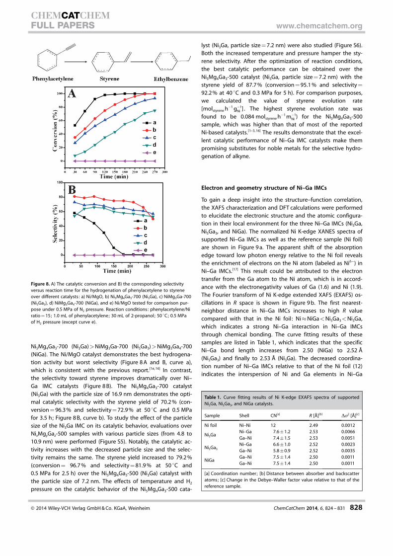
Ni5Mg4Ga3-700 (Ni3Ga)>NiMg3Ga-700 (Ni5Ga3)>NiMg3Ga4-700(NiGa). The Ni/MgO catalyst demonstrates the best hydrogena-tion activity but worst selectivity (Figure 8 A and B, curve a),which is consistent with the previous report.[1e, 16] In contrast,the selectivity toward styrene improves dramatically over Ni–Ga IMC catalysts (Figure 8 B). The Ni5Mg4Ga3-700 catalyst(Ni3Ga) with the particle size of 16.9 nm demonstrates the opti-mal catalytic selectivity with the styrene yield of 70.2 % (con-version = 96.3 % and selectivity = 72.9 % at 50 8C and 0.5 MPafor 3.5 h; Figure 8 B, curve b). To study the effect of the particlesize of the Ni3Ga IMC on its catalytic behavior, evaluations overNixMgyGaz-500 samples with various particle sizes (from 4.8 to10.9 nm) were performed (Figure S5). Notably, the catalytic ac-tivity increases with the decreased particle size and the selec-tivity remains the same. The styrene yield increased to 79.2 %(conversion = 96.7 % and selectivity = 81.9 % at 50 8C and0.5 MPa for 2.5 h) over the Ni5Mg4Ga3-500 (Ni3Ga) catalyst withthe particle size of 7.2 nm. The effects of temperature and H2
pressure on the catalytic behavior of the Ni5Mg4Ga3-500 cata-
lyst (Ni3Ga, particle size = 7.2 nm) were also studied (Figure S6).Both the increased temperature and pressure hamper the sty-rene selectivity. After the optimization of reaction conditions,the best catalytic performance can be obtained over theNi5Mg4Ga3-500 catalyst (Ni3Ga, particle size = 7.2 nm) with thestyrene yield of 87.7 % (conversion = 95.1 % and selectivity =
92.2 % at 40 8C and 0.3 MPa for 5 h). For comparison purposes,we calculated the value of styrene evolution rate[molstyrene h�1 g�1
Ni ] . The highest styrene evolution rate wasfound to be 0.084 molstyrene h�1 m�1
Ni ) for the Ni5Mg4Ga3-500sample, which was higher than that of most of the reportedNi-based catalysts.[1–3, 16] The results demonstrate that the excel-lent catalytic performance of Ni–Ga IMC catalysts make thempromising substitutes for noble metals for the selective hydro-genation of alkyne.
Electron and geometry structure of Ni–Ga IMCs
To gain a deep insight into the structure–function correlation,the XAFS characterization and DFT calculations were performedto elucidate the electronic structure and the atomic configura-tion in their local environment for the three Ni–Ga IMCs (Ni3Ga,Ni5Ga3, and NiGa). The normalized Ni K-edge XANES spectra ofsupported Ni–Ga IMCs as well as the reference sample (Ni foil)are shown in Figure 9 a. The apparent shift of the absorptionedge toward low photon energy relative to the Ni foil revealsthe enrichment of electrons on the Ni atom (labeled as Nid�) inNi–Ga IMCs.[17] This result could be attributed to the electrontransfer from the Ga atom to the Ni atom, which is in accord-ance with the electronegativity values of Ga (1.6) and Ni (1.9).The Fourier transform of Ni K-edge extended XAFS (EXAFS) os-cillations in R space is shown in Figure 9 b. The first nearest-neighbor distance in Ni–Ga IMCs increases to high R valuecompared with that in the Ni foil : Ni�NiGa<Ni5Ga3<Ni3Ga,which indicates a strong Ni–Ga interaction in Ni–Ga IMCsthrough chemical bonding. The curve fitting results of thesesamples are listed in Table 1, which indicates that the specificNi–Ga bond length increases from 2.50 (NiGa) to 2.52 �(Ni5Ga3) and finally to 2.53 � (Ni3Ga). The decreased coordina-tion number of Ni–Ga IMCs relative to that of the Ni foil (12)indicates the interspersion of Ni and Ga elements in Ni–Ga
Figure 8. A) The catalytic conversion and B) the corresponding selectivityversus reaction time for the hydrogenation of phenylacetylene to styreneover different catalysts: a) Ni/MgO, b) Ni5Mg4Ga3-700 (Ni3Ga), c) NiMg3Ga-700(Ni5Ga3), d) NiMg3Ga4-700 (NiGa), and e) Ni/MgO tested for comparison pur-pose under 0.5 MPa of N2 pressure. Reaction conditions: phenylacetylene/Niratio = 15; 1.0 mL of phenylacetylene; 30 mL of 2-propanol; 50 8C; 0.5 MPaof H2 pressure (except curve e).
Table 1. Curve fitting results of Ni K-edge EXAFS spectra of supportedNi3Ga, Ni5Ga3, and NiGa catalysts.
Sample Shell CN[a] R [�][b] Ds2 [�][c]
Ni foil Ni–Ni 12 2.49 0.0012
Ni3GaNi–Ga 7.6�1.2 2.53 0.0066Ga–Ni 7.4�1.5 2.53 0.0051
Ni5Ga3
Ni–Ga 6.6�1.0 2.52 0.0023Ga–Ni 5.8�0.9 2.52 0.0035
NiGaGa–Ni 7.5�1.4 2.50 0.0011Ga–Ni 7.5�1.4 2.50 0.0011
[a] Coordination number; [b] Distance between absorber and backscatteratoms; [c] Change in the Debye–Waller factor value relative to that of thereference sample.
� 2014 Wiley-VCH Verlag GmbH & Co. KGaA, Weinheim ChemCatChem 2014, 6, 824 – 831 828
CHEMCATCHEMFULL PAPERS www.chemcatchem.org
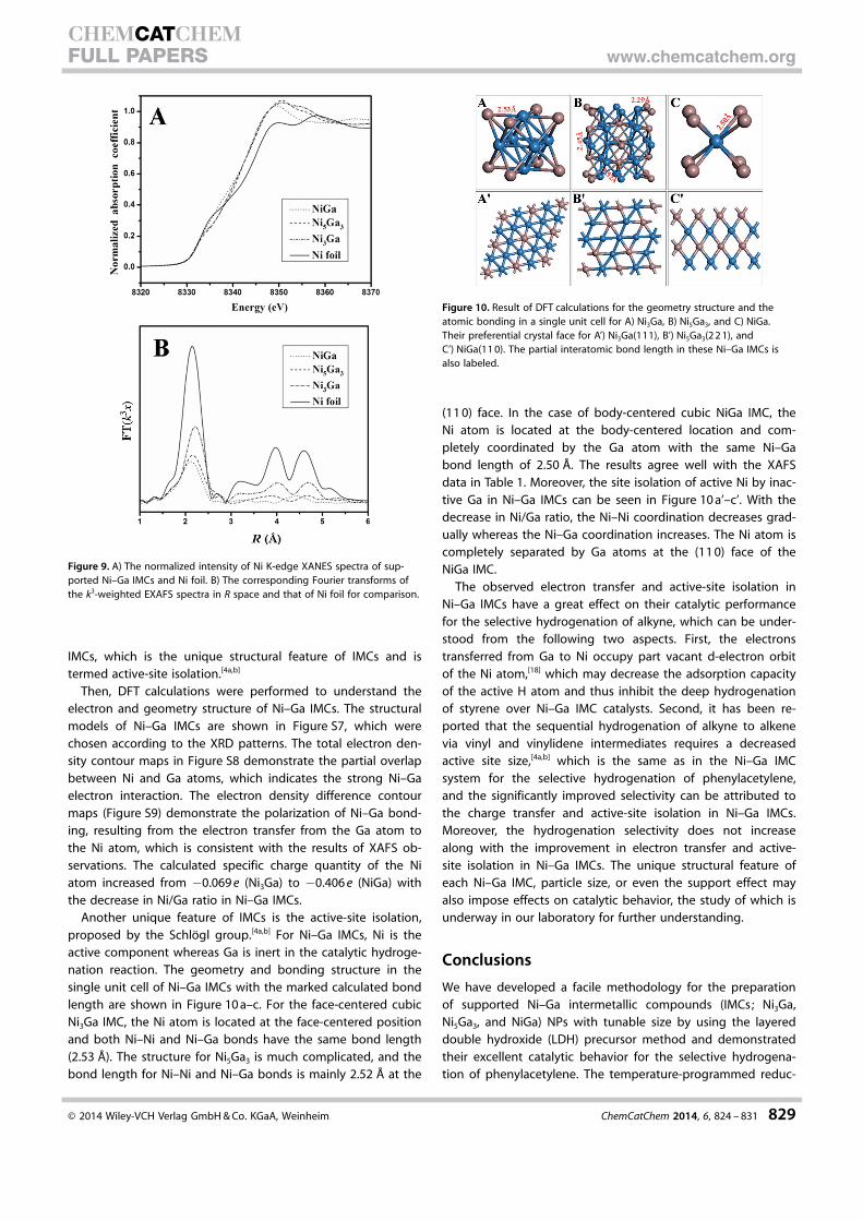
IMCs, which is the unique structural feature of IMCs and istermed active-site isolation.[4a,b]
Then, DFT calculations were performed to understand theelectron and geometry structure of Ni–Ga IMCs. The structuralmodels of Ni–Ga IMCs are shown in Figure S7, which werechosen according to the XRD patterns. The total electron den-sity contour maps in Figure S8 demonstrate the partial overlapbetween Ni and Ga atoms, which indicates the strong Ni–Gaelectron interaction. The electron density difference contourmaps (Figure S9) demonstrate the polarization of Ni–Ga bond-ing, resulting from the electron transfer from the Ga atom tothe Ni atom, which is consistent with the results of XAFS ob-servations. The calculated specific charge quantity of the Niatom increased from �0.069 e (Ni3Ga) to �0.406 e (NiGa) withthe decrease in Ni/Ga ratio in Ni–Ga IMCs.
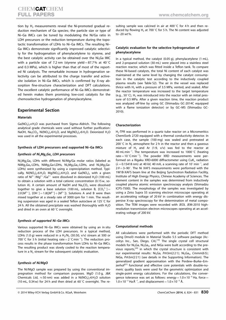
Another unique feature of IMCs is the active-site isolation,proposed by the Schlçgl group.[4a,b] For Ni–Ga IMCs, Ni is theactive component whereas Ga is inert in the catalytic hydroge-nation reaction. The geometry and bonding structure in thesingle unit cell of Ni–Ga IMCs with the marked calculated bondlength are shown in Figure 10 a–c. For the face-centered cubicNi3Ga IMC, the Ni atom is located at the face-centered positionand both Ni–Ni and Ni–Ga bonds have the same bond length(2.53 �). The structure for Ni5Ga3 is much complicated, and thebond length for Ni–Ni and Ni–Ga bonds is mainly 2.52 � at the
(11 0) face. In the case of body-centered cubic NiGa IMC, theNi atom is located at the body-centered location and com-pletely coordinated by the Ga atom with the same Ni–Gabond length of 2.50 �. The results agree well with the XAFSdata in Table 1. Moreover, the site isolation of active Ni by inac-tive Ga in Ni–Ga IMCs can be seen in Figure 10 a’–c’. With thedecrease in Ni/Ga ratio, the Ni–Ni coordination decreases grad-ually whereas the Ni–Ga coordination increases. The Ni atom iscompletely separated by Ga atoms at the (11 0) face of theNiGa IMC.
The observed electron transfer and active-site isolation inNi–Ga IMCs have a great effect on their catalytic performancefor the selective hydrogenation of alkyne, which can be under-stood from the following two aspects. First, the electronstransferred from Ga to Ni occupy part vacant d-electron orbitof the Ni atom,[18] which may decrease the adsorption capacityof the active H atom and thus inhibit the deep hydrogenationof styrene over Ni–Ga IMC catalysts. Second, it has been re-ported that the sequential hydrogenation of alkyne to alkenevia vinyl and vinylidene intermediates requires a decreasedactive site size,[4a,b] which is the same as in the Ni–Ga IMCsystem for the selective hydrogenation of phenylacetylene,and the significantly improved selectivity can be attributed tothe charge transfer and active-site isolation in Ni–Ga IMCs.Moreover, the hydrogenation selectivity does not increasealong with the improvement in electron transfer and active-site isolation in Ni–Ga IMCs. The unique structural feature ofeach Ni–Ga IMC, particle size, or even the support effect mayalso impose effects on catalytic behavior, the study of which isunderway in our laboratory for further understanding.
Conclusions
We have developed a facile methodology for the preparationof supported Ni–Ga intermetallic compounds (IMCs; Ni3Ga,Ni5Ga3, and NiGa) NPs with tunable size by using the layereddouble hydroxide (LDH) precursor method and demonstratedtheir excellent catalytic behavior for the selective hydrogena-tion of phenylacetylene. The temperature-programmed reduc-
Figure 9. A) The normalized intensity of Ni K-edge XANES spectra of sup-ported Ni–Ga IMCs and Ni foil. B) The corresponding Fourier transforms ofthe k3-weighted EXAFS spectra in R space and that of Ni foil for comparison.
Figure 10. Result of DFT calculations for the geometry structure and theatomic bonding in a single unit cell for A) Ni3Ga, B) Ni5Ga3, and C) NiGa.Their preferential crystal face for A’) Ni3Ga(111), B’) Ni5Ga3(2 2 1), andC’) NiGa(11 0). The partial interatomic bond length in these Ni–Ga IMCs isalso labeled.
� 2014 Wiley-VCH Verlag GmbH & Co. KGaA, Weinheim ChemCatChem 2014, 6, 824 – 831 829
CHEMCATCHEMFULL PAPERS www.chemcatchem.org
tion by H2 measurements reveal the Ni-promoted gradual re-duction mechanism of Ga species; the particle size or type ofNi–Ga IMCs can be tuned by modulating the Ni/Ga ratio inLDH precursors or the reduction temperature during the topo-tactic transformation of LDHs to Ni–Ga IMCs. The resulting Ni–Ga IMCs demonstrate significantly improved catalytic selectivi-ty for the hydrogenation of phenylacetylene to styrene, andthe best catalytic activity can be obtained over the Ni3Ga IMCwith a particle size of 7.2 nm (styrene yield = 87.7 % at 40 8Cand 0.3 MPa), which is higher than that of most of the report-ed Ni catalysts. The remarkable increase in hydrogenation se-lectivity can be attributed to the charge transfer and active-site isolation in Ni–Ga IMCs, which is confirmed by X-ray ab-sorption fine-structure characterization and DFT calculations.The excellent catalytic performance of Ni–Ga IMCs demonstrat-ed herein makes them promising low-cost catalysts for thechemoselective hydrogenation of phenylacetylene.
Experimental Section
Materials
Ga(NO3)3·x H2O was purchased from Sigma–Aldrich. The followinganalytical grade chemicals were used without further purification:NaOH, Na2CO3, Ni(NO3)2·6 H2O, and Mg(NO3)2·6 H2O. Deionized H2Owas used in all the experimental processes.
Synthesis of LDH precursors and supported Ni–Ga IMCs
Synthesis of NixMgyGaz LDH precursors
NixMgyGaz LDHs with different Ni/Mg/Ga molar ratios (labeled asNiMg3Ga4-LDHs, NiMg3Ga-LDHs, Ni5Mg4Ga3-LDHs, and Ni3Mg2Ga-LDHs) were synthesized by using a coprecipitation method. Typi-cally, Ni(NO3)2·6 H2O, Mg(NO3)2·6 H2O, and Ga(NO3)3 with a givenratio of Ni2 +/Mg2 +/Ga3 + were dissolved in deionized H2O (100 mL)to obtain a solution with a total cationic concentration (0.15 m, so-lution A). A certain amount of NaOH and Na2CO3 were dissolvedtogether to give a base solution (100 mL, solution B, [CO3
2�] =2.0 [M3 +] , [OH�] = 1.8([M2+] + [M3+]). Solutions A and B were thenmixed together at a steady rate of 3000 rpm for 1 min. The result-ing suspension was aged in a sealed Teflon autoclave at 125 8C for24 h. All the obtained precipitate was washed thoroughly with H2Oand dried in an oven at 60 8C overnight.
Synthesis of supported Ni–Ga IMCs
Various supported Ni–Ga IMCs were obtained by using an in situreduction process of the LDH precursors. In a typical method,LDHs (1.0 g) were reduced in a H2/N2 (50:50, v/v) stream at 500 or700 8C for 5 h (initial heating rate = 2 8C min�1). The reduction pro-cess results in the phase transformation from LDHs to Ni–Ga IMCs.The resulting product was slowly cooled to the reaction tempera-ture in a N2 stream for the subsequent catalytic evaluation.
Synthesis of Ni/MgO
The Ni/MgO sample was prepared by using the conventional im-pregnation method for comparison purposes. MgO (1.0 g, J&KChemicals Ltd, �50 nm) was added in a Ni(NO3)2·6 H2O solution(10 mL, 0.34 m) for 24 h and then dried at 60 8C overnight. The re-
sulting sample was calcined in air at 400 8C for 4 h and then re-duced by flowing H2 at 700 8C for 5 h. The Ni content was adjustedto ·20 wt %.
Catalytic evaluation for the selective hydrogenation ofphenylacetylene
In a typical method, the catalyst (0.05 g), phenylacetylene (1 mL),and 2-propanol solution (30 mL) were placed into a stainless steelreaction reactor, which was fitted inside a Teflon tank. To comparethese Ni-based catalysts, the total Ni content of each catalyst wasmaintained at the same level by changing the catalyst consump-tion in the catalytic test according to the inductively coupledplasma results (see Table S2). The air in the vessel was replacedthrice with H2 with a pressure of 3.5 MPa, vented, and sealed. Afterthe reactor temperature was increased to the target temperature(e.g. , 50 8C), H2 was introduced into the reactor with an initial pres-sure of 0.5 MPa. After a given reaction time, the reaction productwas analyzed off-line by using GC (Shimadzu GC-2014C equippedwith a flame ionization detector) or by GC–MS (Shimadzu GC-2010).
Characterization
H2-TPR was performed in a quartz tube reactor on a MicromeriticsChemiSorb 2720 equipped with a thermal conductivity detector. Ineach case, the sample (100 mg) was sealed and pretreated at200 8C in N2 atmosphere for 2 h in the reactor and then a gaseousmixture of H2 and Ar (1:9, v/v) was fed to the reactor at40 mL min�1. The temperature was increased to 1000 8C (heatingrate = 10 8C min�1). The powder XRD measurements were per-formed on a Rigaku XRD-6000 diffractometer using CuKa radiation(l= 0.15418 nm) at 40 kV, 40 mA, a scanning rate of 108min�1, and2 q= 3–908. The Ni XAFS measurements were performed with the1W1B-XAFS beam line at the Beijing Synchrotron Radiation Facility,Institute of High Energy Physics, Chinese Academy of Sciences. Theelement content in the samples was determined from inductivelycoupled plasma atomic emission spectroscopy analysis (ShimadzuICPS-7500). The morphology of the samples was investigated byusing a Zeiss Supra 55 scanning electron microscope operating atan accelerating voltage of 20 kV in combination with energy dis-persive X-ray spectroscopy for the determination of metal compo-sition. The TEM images were recorded with JEOL JEM-2010 high-resolution transmission electron microscopes operating at an accel-erating voltage of 200 kV.
Computational methods
All calculations were performed with the periodic DFT methodusing Dmol3 module in Material Studio 5.5 software package (Ac-celrys Inc. , San, Diego, CA).[19] The single crystal cell structuralmodels for Ni3Ga, Ni5Ga3, and NiGa were built according to the pre-vious reports,[20] in which the crystal structure is consistent withour experimental results: Ni3Ga, Pm̄3m(2 2 1); Ni5Ga3, Cmmm(6 5) ;NiGa, Pm̄3m(2 2 1) (see details in the Supporting Information). Thegeneralized gradient approximation with the Perdew–Burke–Ern-zerhof[21] functional and effective core potentials with double-nu-meric quality basis were used for the geometric optimization andsingle-point energy calculations. For the calculations, the conver-gence tolerance was set as follows: energy = 1.0 � 10�6 Ha, force =1.0 � 10�3 Ha ��1, and displacement = 1.0 � 10�3 �.
� 2014 Wiley-VCH Verlag GmbH & Co. KGaA, Weinheim ChemCatChem 2014, 6, 824 – 831 830
CHEMCATCHEMFULL PAPERS www.chemcatchem.org

Acknowledgements
This work was supported by the 973 Program (grant no.2011CBA00504), the National Natural Science Foundation ofChina, the Scientific Fund from Beijing Municipal Commission ofEducation (20111001002), and the Fundamental Research Fundsfor the Central Universities (ZD1303). M.W. appreciates the finan-cial aid received from the China National Funds for DistinguishedYoung Scientists of the National Natural Science Foundation ofChina.
Keywords: hydrogenation · intermetallic phases · gallium ·nanoparticles · nickel
[1] a) B. R. Maurer, M. Galobardes, US Pat. 4822936, 1989 ; b) T. Vergunst, F.Kapteijn, J. A. Moulijn, Ind. Eng. Chem. Res. 2001, 40, 2801; c) Z. F. Shao,C. Li, X. Chen, M. Pang, X. K. Wang, C. H. Liang, ChemCatChem 2010, 2,1555; d) W. Liu, C. O. Arean, S. Bordiga, E. Groppo, A. Zecchina, Chem-CatChem 2011, 3, 222; e) J. Chung, C. Kim, H. Jeong, T. Yu, H. Binh, J.Jang, J. Lee, B. M. Kim, B. Lim, Chem. Asian J. 2013, 8, 919; f) M. P.Conley, R. M. Drost, M. Baffert, D. Gajan, C. Elsevier, W. T. Franks, H. Os-chkinat, L. Veyre, A. Zagdoun, A. Rossini, M. Lelli, A. Lesage, G. Casano,O. Ouari, P. Tordo, L. Emsl�y, C. Coperet, C. Thieuleux, Chem. Eur. J.2013, 19, 12234; g) Y. Yabe, Y. Sawama, T. Yamada, S. Nagata, Y. Mongu-chi, H. Sajiki, ChemCatChem 2013, 5, 2360; h) X. Chen, A. Q. Zhao, Z. F.Shao, Z. Q. Ma, C. H. Liang, Stud. Surf. Sci. Catal. 2010, 175, 77.
[2] S. Dom�nguez-Dom�nguez, �. Berenguer-Murcia, D. Cazorla-Amors, �.Linares-Solano, J. Catal. 2006, 243, 74.
[3] a) S. Dom�nguez-Dom�nguez, �. Berenguer-Murcia, B. K. Pradhan, �. Li-nares-Solano, D. Cazorla-Amors, J. Phys. Chem. C 2008, 112, 3827; b) S.Dom�nguez-Dom�nguez, �. Berenguer-Murcia, �. Linares-Solano, D. Ca-zorla-Amors, J. Catal. 2008, 257, 87; c) P. Weerachawanasak, O. Mekasu-wandumrong, M. Arai, S. I. Eujita, P. Praserthdam, J. Panpranot, J. Catal.2009, 262, 199; d) N. Tiengchad, O. Mekasuwandumrong, C. Na-Chiang-mai, P. Weerachawanasak, J. Panpranot, Catal. Commun. 2011, 12, 910.
[4] a) J. Osswald, R. Giedigkeit, R. E. Jentoft, M. Armbr�ster, F. Girgsdies, K.Kovnir, T. Ressler, Yu. Grin, R. Schlçgl, J. Catal. 2008, 258, 210; b) J. Oss-wald, K. Kovnir, M. Armbr�ster, R. Giedigkeit, R. E. Jentoft, U. Wild, Yu.Grin, R. Schlçgl, J. Catal. 2008, 258, 219; c) L. D. Li, B. S. Zhang, E.Kunkes, K. Fçttinger, M. Armbr�ster, D. S. Su, W. Wei, R. Schlçgl, M. Beh-rens, ChemCatChem 2012, 4, 1764; d) M. Armbr�ster, M. Behrens, F. Cin-quini, K. Fçttinger, Y. Luo, A. Haghofer, B. Klçtzer, A. Knop-Geriche, H.Lorenz, A. Ota, S. Penner, J. Prinz, C. Rameshan, Z. R�vay, D. Rosenthal,G. Rupprechter, P. Sautet, R. Schlçgl, L. D. Shao, L. Szentmiklsi, D.Teschner, D. Torres, R. Wagner, R. Widmer, G. Wowsnick, ChemCatChem2012, 4, 1048; e) P. P. Sun, G. Siddiqi, M. F. Chi, A. T. Bell, J. Catal. 2010,274, 192; f) P. P. Sun, G. Siddiqi, W. C. Vining, M. F. Chi, A. T. Bell, J. Catal.2011, 282, 165.
[5] a) J. Ruiz-Mart�nez, Y. Fukui, T. Komatsu, A. Sep�lveda-Escribano, J. Catal.2008, 150, 70; b) K. S. Rodiansono, T. Hara, N. Ichikuni, S. Shimazu, Catal.Sci. Technol. 2012, 2, 2139.
[6] a) A. Ota, E. L. Kunkes, I. Kasatkin, E. Groppo, D. Ferri, B. Poceiro, R. M. N.Yerga, M. Behrens, J. Catal. 2012, 293, 27; b) S. E. Collins, J. J. Delgado,C. Mira, J. J. Calvino, S. Bernal, D. L. Chiavassa, M. A. Baltans, A. L. Boni-vardi, J. Catal. 2012, 292, 90.
[7] a) H. Abe, F. Matsumoto, L. R. Alden, S. C. Warren, H. D. AbruÇa, F. J. Dis-alvo, J. Am. Chem. Soc. 2008, 130, 5452; b) E. Casado-Rivera, D. J. Volpe,L. Alden, C. Lind, C. Downie, T. Vazquez-Alvrez, A. C. D. Angelo, F. J. Dis-alvo, H. D. AbruÇa, J. Am. Chem. Soc. 2004, 126, 4043.
[8] a) M. Armbr�ster, G. Wowsnick, M. Friedrich, M. Heggen, R. Cardoso-Gil,J. Am. Chem. Soc. 2011, 133, 9112; b) M. Armbr�ster, K. Kovnir, M. Beh-rens, D. Teschner, Yu. Grin, R. Schlçgl, J. Am. Chem. Soc. 2010, 132,14745; c) R. Leary, F. D. L. PeÇa, J. S. Barnard, Y. Luo, M. Armbr�ster,S. J. M. Thomass, P. A. Midgley, ChemCatChem 2013, 5, 2599.
[9] M. Armbr�ster, K. Kovnir, M. Friedrich, D. Teschner, G. Wowsnick, M.Hahne, P. Gille, L. Szentmiklsi, M. Feuerbacher, M. Heggen, F. Girgsdies,D. Dosenthal, R. Schlçgl, Yu. Grin, Nat. Mater. 2012, 11, 690.
[10] a) J. W. Lekse, T. J. Stagger, J. A. Aitken, Chem. Mater. 2007, 19, 3601;b) N. H. Chou, R. E. Schaak, J. Am. Chem. Soc. 2007, 129, 7339.
[11] a) G. R. Williams, D. O’Hare, J. Mater. Chem. 2006, 16, 3065; b) A. M.Fogg, A. L. Rohl, G. M. Parkinson, D. O’Hare, Chem. Mater. 1999, 11,1194; c) S. He, S. T. Zhang, J. Lu, Y. F. Zhao, J. Ma, M. Wei, D. G. Evans, X.Duan, Chem. Commun. 2011, 47, 10797; d) L. Li, Y. Feng, Y. Li, W. Zhao, J.Shi, Angew. Chem. 2009, 121, 6002; Angew. Chem. Int. Ed. 2009, 48,5888.
[12] a) H. C. Liu, E. Z. Min, Green Chem. 2006, 8, 657; b) K. H. Goh, T. T. Lim,Z. L. Dong, Water Res. 2008, 42, 1343.
[13] a) M. Q. Zhao, Q. Zhang, W. Zhang, G. Q. Huang, Y. H. Zhang, D. S. Su, F.Wei, J. Am. Chem. Soc. 2010, 132, 14739; b) S. He, Z. An, M. Wei, D. G.Evans, X. Duan, Chem. Commun. 2013, 49, 5912; c) S. He, C. M. Li, H.Chen, D. S. Su, B. S. Zhang, X. Z. Cao, B. Y. Wang, M. Wei, D. G. Evans, X.Duan, Chem. Mater. 2013, 25, 1040; d) C. M. Li, Y. D. Chen, S. T. Zhang,S. M. Xu, J. Y. Zhou, F. Wang, M. Wei, D. G. Evans, X. Duan, Chem. Mater.2013, DOI: 10.1021/cm4021832.
[14] S. Collins, G. Finos, R. Alcntara, E. D. Rio, S. Bernal, A. Bonivardi, Appl.Catal. A 2010, 388, 202.
[15] H. Okamoto, J. Phase Equilib. Diffus. 2008, 29, 296.[16] X. Chen, A. Zhao, Z. F. Shao, C. Li, C. T. Williams, C. H. Liang, J. Phys.
Chem. C 2010, 114, 16525.[17] a) S. Alayoglu, P. Zavalij, B. Eichhorn, Q. Wang, A. I. Frenkel, P. Chupas,
ACS Nano 2009, 3, 3127; b) A. Onda, T. Komatsu, T. Yashima, J. Catal.2004, 221, 378.
[18] L.-S. Hsu, A. I. Nesvizhskii, J. Phys. Chem. Solids 2001, 62, 1103.[19] a) M. D. Segall, P. J. D. Lindan, M. J. Probert, J. Pickard, P. J. Hasnip, S. J.
Clark, M. C. Payne, J. Phys. Condens. Matter 2002, 14, 2717; b) B. Delley,J. Chem. Phys. 1990, 92, 508.
[20] a) Y. Mishima, S. Ochiai, T. Suzuki, Acta Metall. 1985, 33, 1161; b) S. Bhan,K. Schubert, J. Less-Common Met. 1969, 17, 73; c) R. Guerin, A. Guivarc’h,J. Appl. Phys. 1989, 66, 2122.
[21] P. J. Sideris, U. G. Nielsen, Z. Gan, C. P. Grey, Science 2008, 321, 113.
Received: September 24, 2013
Revised: December 8, 2013
Published online on February 12, 2014
� 2014 Wiley-VCH Verlag GmbH & Co. KGaA, Weinheim ChemCatChem 2014, 6, 824 – 831 831
CHEMCATCHEMFULL PAPERS www.chemcatchem.org