Insights into ZnO-based doped porous nanocrystal frameworks
18
Insights into ZnO-based doped porous nanocrystal frameworks Buzuayehu Abebe * and H. C. Ananda Murthy * Colloidal nanocrystals play a vital role in several applications. The doping of cations in the nanocrystal matrix enhances the optical, electrical, and magnetic properties. The number and well-defined distribution of the dopant are crucial to protect the nanocrystal from clustering. The XRD, XPS, and XAS instruments reveal the change in the lattice parameters, chemical states, and local coordination environment information. In addition of detecting the position and distribution of the dopant, the 4D-STEM detector mode gathers all types of real-space atomic-resolution images by collecting all diffraction datasets from each electron probe with high-speed and efficient detection. Dopant–host ligand type, reactions conditions, and reaction time optimization during synthesis are critical for the host and dopant reactivity balance. Pearson's hard/soft acids/bases theory would be a base for balancing the solubility of the dopant–host in the given solvents/ surfactant. In addition, tuning the colloidal nanocrystals to secondary structures, which enhances the mass-/ ions transport, can contribute a combination of properties that do not exist in the original constituents. Dr Buzuayehu Abebe is currently working at Adama Science and Technology University Adama, Ethiopia, East Africa. He is doing his research on the synthesis of nanoscale mate- rials, specically nanocomposite materials for photocatalysis and antimicrobial application. Buzuayehu Abebe has published more than 20 research articles in Web of Science indexed journals and presented many papers in national as well as international conferences. He is also a review editor of Frontiers in Catalysis journal. Dr H. C. Ananda Murthy has been a sincere, committed, and dedi- cated faculty member at various prestigious universities in India, Tanzania, and Ethiopia for the last 24 years. He is currently working as Associate Professor, Department of Applied Chem- istry, Adama Science and Tech- nology University, Adama, Ethiopia, East Africa. Prof. Ananda has authored a number of books, compendia, book chap- ters, published more than 100 research articles in journals of inter- national repute, and has presented many papers in national as well as international conferences. He has been a guest editor for Journal of Nanomaterials and Journal of Renewable Materials. He is also a review editor of Frontiers in Catalysis journal and editorial board member of Annals of Applied Science journal. He has 4 patents to his credit. He has delivered many invited talks at various platforms. He has taught various chemistry courses at the UG, PG, and PhD level of the universities, and supervised 7 MSc and 1 PhD students. He is currently guiding 2 MSc and 7 PhD students (1 awarded). He has successfully completed 2 projects sanctioned by Adama Science and Technology University, Ethiopia and National Innovation Founda- tion of India (NIFI). He is currently associated with research projects related to the green synthesis of metal and metal oxide nanoparticles/ nanocomposites for multifunctional applications. Adama Science and Technology University, Department of Applied Chemistry, 1888, Adama, Ethiopia. E-mail: [email protected]; [email protected] Cite this: RSC Adv. , 2022, 12, 5816 Received 18th December 2021 Accepted 1st February 2022 DOI: 10.1039/d1ra09152b rsc.li/rsc-advances 5816 | RSC Adv. , 2022, 12, 5816–5833 © 2022 The Author(s). Published by the Royal Society of Chemistry RSC Advances REVIEW Open Access Article. Published on 16 February 2022. Downloaded on 3/28/2022 9:03:56 PM. This article is licensed under a Creative Commons Attribution-NonCommercial 3.0 Unported Licence. View Article Online View Journal | View Issue
-
Upload
khangminh22 -
Category
Documents
-
view
3 -
download
0
Transcript of Insights into ZnO-based doped porous nanocrystal frameworks

RSC Advances
REVIEW
Ope
n A
cces
s A
rtic
le. P
ublis
hed
on 1
6 Fe
brua
ry 2
022.
Dow
nloa
ded
on 3
/28/
2022
9:0
3:56
PM
. T
his
artic
le is
lice
nsed
und
er a
Cre
ativ
e C
omm
ons
Attr
ibut
ion-
Non
Com
mer
cial
3.0
Unp
orte
d L
icen
ce.
View Article OnlineView Journal | View Issue
Insights into ZnO
DwTEdsrmaBmWa
national as well as international ceditor of Frontiers in Catalysis jou
Adama Science and Technology University, D
Adama, Ethiopia. E-mail: [email protected]
Cite this: RSC Adv., 2022, 12, 5816
Received 18th December 2021Accepted 1st February 2022
DOI: 10.1039/d1ra09152b
rsc.li/rsc-advances
5816 | RSC Adv., 2022, 12, 5816–583
-based doped porous nanocrystalframeworks
Buzuayehu Abebe * and H. C. Ananda Murthy *
Colloidal nanocrystals play a vital role in several applications. The doping of cations in the nanocrystal matrix
enhances the optical, electrical, and magnetic properties. The number and well-defined distribution of the
dopant are crucial to protect the nanocrystal from clustering. The XRD, XPS, and XAS instruments reveal the
change in the lattice parameters, chemical states, and local coordination environment information. In
addition of detecting the position and distribution of the dopant, the 4D-STEM detector mode gathers all
types of real-space atomic-resolution images by collecting all diffraction datasets from each electron probe
with high-speed and efficient detection. Dopant–host ligand type, reactions conditions, and reaction time
optimization during synthesis are critical for the host and dopant reactivity balance. Pearson's hard/soft
acids/bases theory would be a base for balancing the solubility of the dopant–host in the given solvents/
surfactant. In addition, tuning the colloidal nanocrystals to secondary structures, which enhances the mass-/
ions transport, can contribute a combination of properties that do not exist in the original constituents.
r Buzuayehu Abebe is currentlyorking at Adama Science andechnology University Adama,thiopia, East Africa. He isoing his research on theynthesis of nanoscale mate-ials, specically nanocompositeaterials for photocatalysis andntimicrobial application.uzuayehu Abebe has publishedore than 20 research articles ineb of Science indexed journalsnd presented many papers inonferences. He is also a reviewrnal.
Dr H. C. AnandaMurthy has beena sincere, committed, and dedi-cated faculty member at variousprestigious universities in India,Tanzania, and Ethiopia for thelast 24 years. He is currentlyworking as Associate Professor,Department of Applied Chem-istry, Adama Science and Tech-nology University, Adama,Ethiopia, East Africa. Prof.Ananda has authored a numberof books, compendia, book chap-
ters, published more than 100 research articles in journals of inter-national repute, and has presented many papers in national as wellas international conferences. He has been a guest editor for Journal ofNanomaterials and Journal of Renewable Materials. He is alsoa review editor of Frontiers in Catalysis journal and editorial boardmember of Annals of Applied Science journal. He has 4 patents to hiscredit. He has delivered many invited talks at various platforms. Hehas taught various chemistry courses at the UG, PG, and PhD level ofthe universities, and supervised 7 MSc and 1 PhD students. He iscurrently guiding 2 MSc and 7 PhD students (1 awarded). He hassuccessfully completed 2 projects sanctioned by Adama Science andTechnology University, Ethiopia and National Innovation Founda-tion of India (NIFI). He is currently associated with research projectsrelated to the green synthesis of metal andmetal oxide nanoparticles/nanocomposites for multifunctional applications.
epartment of Applied Chemistry, 1888,
3 © 2022 The Author(s). Published by the Royal Society of Chemistry

Table 1 Experimental hardness (h) values of cations and ligands/basesthat can be used in cation-exchange (CE) reactions25
Lewis acid h Lewis base h
Cu(I) 6.3 Aniline (C6H5NH2) 4.4Pd(II) 6.8 Benzenethiol (C6H5SH) 4.6Ag(I) 7.0 Phenolate (C6H5OH) 4.8Fe(II) 7.2 Pyridine (C5H5N) 5.0Hg(II) 7.7 Acetone (CH3COCH3) 5.6Sn(II) 7.9 Acetaldehyde (CH3CHO) 5.7Pt(II) 8.0 Dimethylformamide (DMF) 5.8Co(II) 8.2 Trimethylphosphine ((CH3)3P) 5.9Cu(II) 8.3 Phosphine (PH3) 6.0Au(III) 8.4 Dimethyl sulde ((CH3)2S) 6.0Pb(II) 8.5 Formaldehyde (CH2O) 6.2Co(III) 8.9 Formamide (HCONH2) 6.2Mn(II) 9.0 Trimethylamine ((CH3)3N) 6.3Ge(II) 9.1 Methyl formate (HCO2CH3) 6.4Cd(II) 10.3 Acetonitrile (CH3CN) 7.5Zn(II) 10.9 Chloromethane (CH3Cl) 7.5Fe(III) 12.1 Dimethyl ether ((CH3)2O) 8.0In(III) 13.0 Ammonia (NH3) 8.2
Review RSC Advances
Ope
n A
cces
s A
rtic
le. P
ublis
hed
on 1
6 Fe
brua
ry 2
022.
Dow
nloa
ded
on 3
/28/
2022
9:0
3:56
PM
. T
his
artic
le is
lice
nsed
und
er a
Cre
ativ
e C
omm
ons
Attr
ibut
ion-
Non
Com
mer
cial
3.0
Unp
orte
d L
icen
ce.
View Article Online
1. Introduction
Nanotechnology is a progressive area of science used formanufacturing nanoscale materials.1 Among different nano-materials, semiconductor metal oxides are highly stable, non-toxic, inexpensive, and have superior catalytic properties. ZnO,a wide bandgap semiconductor (3.37 eV), has all the above-mentioned properties; however, it cannot degrade pollutantsunder visible light.2 The photocatalytic properties of the mate-rials could be further enhanced by doping noble metals as anelectron reservoir.3 Industrially, the incorporation of impuritiesin the host matrix for improved device functionality isexpensive.4,5
The unique properties of nanoscale materials (NMs) such aselectronic density, charge distribution, and lattice distortionhave great impacts on their applications.6 The effective dopingof metal or metal ions, which creates either an n-type or p-typedopant, is one of the main ways to tune the optical, magnetic,and optical properties. Besides, the incorporation of impuritiesalso increases the surface-to-volume ratios, creates crystaldefects, and traps charge carriers.7–9 However, the dopantshould substitute the host atoms effectively so that decentdopant–host balance reactivity occurs. The selection of suitablehost–dopant type, synthetic approach, solvent, and surfactantare crucial parameters for balancing the reactivity. For thesuccessful incorporation of the dopant in the host lattice, thehost–dopant type is essential. According to Pearson's hard/soacids/bases (HSAB) theory, for the successful diffusion of thedopant ions into the host lattice, the hardness of the dopantshould be less than that of the host in a hard base solvent suchas water.10,11
The doping process may be under the control of eitherkinetic or thermodynamic equilibrium.12–14 Compared to theformer, the latter synthetic equilibrium process creates stableand efficiently doped nanocomposites.15 Several syntheticapproaches such as single-source precursors, nucleation-doping, growth-doping, and cation diffusion follow either thethermodynamic or kinetic equilibrium process. Nowadays, thecation diffusion technique is a progressive approach.16
The properties of the doped materials can be understoodusing advanced analytical techniques. The XRD patternconrms the formation of a local heterojunction and interstitialor/and substitutional incorporation depending on the angleshi. The optical properties of the doped materials wereunderstood from the DRS/UV-vis and PL techniques. So Lewisacid dopants (such as Ag and Cu) improve the light absorptionefficiency and also condense the bandgap by creating an inter-band between the valence band (VB) and conduction band (CB)of the host.17 Intensity reduction in the PL spectra is an indi-cation of the electron–hole recombination diminishing prop-erties of the materials,18 which enhances its application,especially in photocatalysis. XPS and XAS techniques give thecomposition, chemical state, local coordination environment,and oxidation states of the doped material.19,20 In addition,a radical instruments such as ADF-STEM and EELS-STEM detect
© 2022 The Author(s). Published by the Royal Society of Chemistry
the atomic level incorporated dopants based on thecontrasts.21,22
In addition, tuning the material to have a secondary struc-ture during synthesis (ordered porous crystalline frameworks)boosts the mass-/ion-transports of the materials toward preciseapplications such as energy devices.10,23 For the development ofdecent ordered porous crystalline frameworks, selecting a suit-able solvent, reaction temperature, nanocrystal tethering, andpore generating architecture-directing agent (ADA) is vital.Herein, this review also provides awareness about the dopant–host reactivity balance, characterization techniques for thedoped materials, and porous crystalline frameworks. The paperalso gives detailed insight into Cu- and Ag-doped and co-dopedZnO-based materials using crucial analytical techniques.Besides, the photocatalytic and antibacterial activities of thedoped materials, and the mechanisms involved in these activ-ities have also been discussed.
2. Dopant–host reactivity balances
The host–dopant reactivity balance is highly dependent onsufficient time for effective dopant trapping, surfacemorphology, shape, dopant host ligand type, and reactionconditions.16 The HSAB theory helps in tuning the solubilitybalance by the careful selection of metal ions to the ligands/solvents affinity.24 According to the HSAB theory, hard acidsfavor hard bases, while so acids favor so bases to bind andyield ionic and covalent complexes, respectively. The HSABabsolute hardness (h) of some cations and ligands are given inTable 1. Besides, Fig. 1 also groups the so, borderline, andhard acids/bases and molecular recognition based on the HSABtheory. Hard/borderline Lewis acids such as Zn(II) ion are easilyexchanged with so acids such as Cu(I) and Ag(I) ion when hardbase solvents (alcohols and water) are used. On the other hand,
Ga(III) 17.0 Fluoromethane (CH3F) 9.4Al(III) 45.8 Water (H2O) 9.5
RSC Adv., 2022, 12, 5816–5833 | 5817

Scheme 1 General synthetic approaches for colloidal nanocrystals'doping. The single-source precursors (a), nucleation-dopingapproaches (b), the growth-doping (c), the tuning of ligand–metalbond strength (d), and cation diffusion (e).16
RSC Advances Review
Ope
n A
cces
s A
rtic
le. P
ublis
hed
on 1
6 Fe
brua
ry 2
022.
Dow
nloa
ded
on 3
/28/
2022
9:0
3:56
PM
. T
his
artic
le is
lice
nsed
und
er a
Cre
ativ
e C
omm
ons
Attr
ibut
ion-
Non
Com
mer
cial
3.0
Unp
orte
d L
icen
ce.
View Article Online
so acids cations are spontaneously exchanged with harder acidcations if so bases are used.10,11,25 In the presence of a hardbase (water as a solvent) and poly(vinyl alcohol) surfactant, thenon-inclusion of the manganese hard Lewis acid in the ZnOlattice was veried in our recent study.26 In its place, the localheterojunction was formed between manganese oxide and zincoxide aer the oxidation of the adsorbed manganese ion on thesurface of zinc oxide at 500 �C.
As reported by Buonsanti and Milliron,16 the commonapproaches used for balancing the reactivity of the dopant andhost precursors are: (i) single-source precursors, (ii) nucleation-doping, (ii) the growth-doping, (iii) tuning of ligand–metal bondstrength, and (vi) cation diffusion (Scheme 1). A single-sourceprecursor is effective in controlling the nal stoichiometry ofthe constituents and easily forms a direct chemical bondbetween the host matrix and the dopant. Still, stronger attrac-tion among the elements composing the cluster is a require-ment compared to the ligands and the cluster. If the attractionamong the elements is not strong enough and, if the otherattraction dominates, a complex decomposition takes place anddiminishes the dopant concentration. Using chimie doucesingle-source molecular precursors approach, mixing of similarzinc- and copper-ketoacidooximates precursors, Pashchankaet al. synthesized a ‘green body’ nanorod arrays morphology ofCu(II)-doped ZnO.27 In this study, chemical processing tech-niques (dichloromethane (CH2Cl2)) were used to remove thepolycarbonate lm template-forming agent.
During the nucleation-doping method, in which the dopantand the host precursors are mixed once, their reactivity isregulated so that the dopant nucleates rst, followed by itsovercoating by the host shell. On the other hand, in the growth-dopingmethod, the dopant precursors are added to the growing
Fig. 1 Periodic element table for grouping hard, soft, and borderlineacids/bases and molecular recognition based on the hard–soft–acid–base theory.24
5818 | RSC Adv., 2022, 12, 5816–5833
host shell by controlling the reaction conditions/temperature toreach the required size so that the dopant is encapsulated by theovergrowing host matrix shell and connes the dopant in thecore. In general, the growth process of the host materials iscontrolled by decreasing the temperature of the reaction. Inaddition, using a reactive host precursor, and decreasing theovercoating temperature were reported in several studies,15,28,29
which also prevents the diffusion of the dopant from the core athigh temperatures.
From the concept of HSAB theory, appropriate ligand–metalbond strength classication is also used to balance the host anddopant reactivity. For successful dopant incorporation into thezinc oxide semiconductor, so Lewis acid dopant cation (lowpositive charge and large size) such as Cu and Ag are chosen.The soness and hardness of the coordinating ligands and thesize of the cations also affect the dopant–host reactivity. If thedopant cation is a harder Lewis acid compared to the hostcation, more reactive dopant coordinating ligands are requiredfor successful incorporation.30 In addition, if a comparable sizeof the host and dopant cations is used, the reactivity becomesless for dopant integration.31 Besides, similar coordinatingligands can also be used if the host and dopant cations havesimilar reactivity.32,33 Similarities in reactivity and ionic radiiwere also reported34 for improved dopant concentrationinsertion.
The nal approach described by Buonsanti and Milliron16
that was used for the incorporation of both cationic and anionicdopants was ion diffusion. This approach allows ions of thedopant to be exchanged within a few seconds in the pre-shapedhost matrix. The ion diffusion approach exchanges the cation
© 2022 The Author(s). Published by the Royal Society of Chemistry

Review RSC Advances
Ope
n A
cces
s A
rtic
le. P
ublis
hed
on 1
6 Fe
brua
ry 2
022.
Dow
nloa
ded
on 3
/28/
2022
9:0
3:56
PM
. T
his
artic
le is
lice
nsed
und
er a
Cre
ativ
e C
omm
ons
Attr
ibut
ion-
Non
Com
mer
cial
3.0
Unp
orte
d L
icen
ce.
View Article Online
with remarkable speeds under kinetic control at low tempera-tures. The host–dopant cations were exchanged withoutaffecting the crystal framework.35 The (a) association anddissociation process of the crystals, which is dened in terms oflattice energy (lattice enthalpy) and surface energy, and (b) thesolvation and desolvation process of the ions leads toa successful cation-exchange procedure.35 The association anddissociation process of the crystal measures the strength of thechemical bonding, while the solvation and desolvation processof the ions depends on the number of ions solvated from thehost precursor and ions desolvated from the dopant precursor.If the number of ions solvated is greater than the ions des-olvated, the reaction is favored by increasing the overall entropyof the system and such a reaction does not take place unlessa careful choice of the solvents and so Lewis bases/ligands isused.10,36,37
In addition to the thermodynamic factors, the cation-exchange tactic is also dependent on the kinetic factor of thereaction process such as ions diffusivity or/and activationenergy barriers.38 Actually, the cation-exchange process is alsoreported to occur during the growth of the host matrix.4 Thediffusion of the dopant into the host cell is also dependent onthe dopant concentrations, the type of the coordinating ligandsused, and temperature.15,35 The process of dopant adsorption,diffusion, and ejection in the host lattice is similarly dependenton the optimization of the critical temperature of the overallsynthetic process.15
2.1. Silver-doped ZnO nanocrystals
Silver ion has a larger ionic size (0.126 nm) compared to zinc ion(0.074 nm); thus, the doping of silver into the ZnO lattice createsa doped band, which shis the Fermi level toward the VB (deepacceptor level) and induces a p-type property.39,40 Besides, theinterstitial and substitutional incorporation of Ag into the ZnOlattice causes quantiable higher and lower angle shis,respectively.41–46 However, the segregation or formation ofa local heterojunction47 between Ag and ZnO does not result inany peak shi in XRD.48,49 In fact, the formation of a local het-erojunction, and interstitial and substitutional defects weredependent on the synthetic approach, cation hardness, andsurfactant or/and solvent type. To indicate this, Yıldırım et al.42
showed an XRD pattern lower degree shi due to the substitu-tion of Ag+ into the ZnO lattice and a higher degree shi wasshown by Modwi et al.46 due to the interstitial sites' doping. Theformation of deep-level acceptor and stability improvementwere proved by density functional theory calculations within thegeneralized gradient approximation analysis.50
The detailed procedure for the synthesis of tri-ethanolamine(C6H15NO3) surfactant-assisted Ag-doped ZnO nanocomposites(sol–gel-based synthetic approach) was proposed in the study bySagadevan et al.51 The composite was synthesized by the drop-wise addition of AgNO3 in an aqueous solution of Zn(CH3-COO)2$2H2O, possibly following the growth-doping typedopant–host reactivity balance approach. The addition of excessNH4OH solution results in the precipitation of the acetate ion toammonium acetate (NH4CH3COO) and the development of
© 2022 The Author(s). Published by the Royal Society of Chemistry
metal hydroxide colloidal particles (Zn(OH)2 and AgOH).Ammonium acetate was removed by washing with deionizedwater, and then it was washed with acetone to remove water.Lastly, the nal product was calcined at 300 �C to oxidize themetal hydroxides (removal of water of crystallization) to stablemetal oxide or/and doped metal oxide nanocomposites.
Using the hydrothermal approach, Jin et al.43 proposed thesubstitution of Ag in the ZnO lattice. The experiment was con-ducted by the dropwise addition of ammonia in the mixture ofzinc and silver solution. With the continuous addition ofammonia, rst, a milky colored zinc hydroxide (Zn(OH)2), thenthe Zn complex (Zn(OH)4
2�, and nally, a clear solution wasformed when the molar ratio of zinc ion and ammonia basereached 1 : 4. In this process, the nal solutions, which containZnAg(OH)2 and ZnAg(OH)4
2� , were allowed to oxidize in anautoclave to form Ag-doped ZnO (ZnAgO). A related solvothermalsynthetic approach was also reported in Zheng et al.’s study bythe dropwise addition of NaOH in silver and zinc solutionmixture.52
Using digital mechanoelectrospinning direct-writing forpolyethylene oxide template deposition, a hydrothermalmethod for ZnO nanoarray growth and photoreduction fordoping silver approaches were reported; aligned hierarchicalAg-deposited ZnO nanoheterostructure arrays with highnitrogen dioxide gas sensing performance were synthesized byYin et al.53 The formation of more than zero-dimensionalnanomaterials was stated to enhance the surface area and gassensing properties of the materials; a related surface areaimprovement interpretation was also given in Singhet al.’swork.39 From the results,53 a hexagonal wurtzite ZnO and face-centered cubic Ag structure with d spacing values of 0.26 nmand 0.23 nm, respectively, were obtained using the HRTEMimage analysis, with no ZnO lattice distortion. Besides, thedeposition of Ag NPs on the surface of the ZnO nanorods wasfurther conrmed from a highly sensitive HAADF-STEM image.
The non-incorporation of Ag in the ZnO lattice was alsoconrmed by Ansari et al.48 (Fig. 2(A)) and Alharthi et al.49 InAnsari et al.’s work, the Ag-anchored ZnO material wassynthesized by a biogenic approach using an electrochemicallyactive biolm.48 The deposition of Ag on the surface of ZnO wasalso indirectly understood from DRS analysis (Fig. 2(C)), whichshows Ag localized surface plasmon resonance (LSPR) bandcharacteristics in the wavelength range of 400–550 nm. TheLSPR features of the materials occurred when frequencymatching between the conduction bands conned the electronoscillation and the incident light exits.54 This LSPR effect is alsoreported in other works55–57 and is attributed to the intense lightabsorption and scattering reection behavior of the doped Agclusters. Besides, with an increase in the amount of AgNO3,higher energy plasmon peak shi and intensity heighteningwere noticed due to the presence of silver on the surface andincrease in the cluster size, respectively.56
Besides, Ziashahabi et al.57 reported the lower wavelengthplasmonic peak shi on aged Ag/ZnO samples due to silveroxidation, which was not observed on the freshly synthesizedAg/ZnO sample. The HR-TEM images (Fig. 2(B)) and XPS anal-ysis also conrmed the presence of strong interaction between
RSC Adv., 2022, 12, 5816–5833 | 5819

Fig. 2 (A) XRD patterns of pure-ZnO and Ag–ZnO. The peaks markedwith (*) represent the signals of Ag and the remaining peaks representthe signals from pure-ZnO. The inset shows the broadening of the Agpeak, (B) HR-TEM images of pure-ZnO (a and b), and Ag–ZnO (c andd), (C) UV-vis diffuse absorption spectra of pure-ZnO and Ag–ZnO, (D)photoluminescence spectra of pure-ZnO and Ag–ZnO.48
Fig. 3 Photogenerated electron transfer in Ag/ZnO nanocatalystduring the catalytic process. EF: Fermi level; V
��
O: ø: work function;oxygen vacancy; VB: valence band; CB: conduction band; m: metal;vac: vacuum level; and s: semiconductor.52
RSC Advances Review
Ope
n A
cces
s A
rtic
le. P
ublis
hed
on 1
6 Fe
brua
ry 2
022.
Dow
nloa
ded
on 3
/28/
2022
9:0
3:56
PM
. T
his
artic
le is
lice
nsed
und
er a
Cre
ativ
e C
omm
ons
Attr
ibut
ion-
Non
Com
mer
cial
3.0
Unp
orte
d L
icen
ce.
View Article Online
Ag and ZnO in Ansari et al.’s work, and a reliable claricationwas also reported.58 The shi in the binding energy of Ag 3d5/2for the doped composite toward a lower binding energy and 6 eVsplitting difference between Ag 3d5/2 and Ag 3d3/2 (high-resolution scans) conrm the existence of interaction betweenAg and ZnO, which leads to the Fermi level tuning and thereduction of Ag+ to Ag metal, respectively. Comparable XPSbinding energy shi and splitting values were also reported inthe literature.42,43,49,56,58–60 The lower energy shi is ascribed tothe binding energy difference between Ag(0) and Ag(I), in whichAg(I) has much greater binding energy than Ag(I).
Besides, in Ansari et al.’s work, the formation of localcontact/composite between Ag and ZnO, which enhances elec-tron transfer without recombination, was also furtherconrmed via PL analysis (Fig. 2(D)); the smaller the peakintensity, the lower the electron–hole recombination activity.18
Similar explanations were also given in other studies and re-ported to be due to the occurrence of metal–semiconductorSchottky contact.3,40,49 This electron transfer without recombi-nation was described by the band energy difference between Ag(more positive band energy) and ZnO (Fig. 3), which leads tocontinuous electron transfer from ZnO to Ag until their Fermilevel values become equivalent.3,42 The electron–hole separationis dependent on the Ag disparity, the concentration of the Ag–ZnO interface, and vacancy defects.52 As seen in Fig. 3, duringthe irradiation of the doped photocatalyst in the presence ofvacancies, the electron transfer follows either path I (towarddoped Ag) or path II (toward the created ZnO vacancy). Themethod used to synthesize Ag-doped ZnO material, reagents,substrate or/and surfactants used, and the morphology of thesynthesized material is also given in Table 2.
5820 | RSC Adv., 2022, 12, 5816–5833
2.2. Copper-doped ZnO nanocrystals
Zinc and copper have similar electronic congurations andcomparable atomic radii but different structures, which limitsthe stability of the doped copper toward dissolution. Doping ofcopper into the ZnO host improves the optical, electrical, andmagnetic properties, which is not observed in isolated constit-uents. A higher bandgap semiconductor metal oxide such aszinc oxide, ZnO, has outstanding thermal, optical, and electricalproperties. ZnO also has higher light spectrum absorptionefficiency and lower production cost.61 However, the numberand exact position of the dopant should be achieved to preventthe clustering of dopant atoms that have a damaging effect.62
The oxidation states of copper (Cu, Cu(I), or Cu(II)) in the ZnOmatrix is contentious and seems to be dependent on variousparameters such as dopant concentration, temperature, andtype of synthetic approach.19,27 The general host–dopantmolecular precursor's decomposition and reaction process fornitrate precursor (as an example) are given in eqn (1) for ZnOand eqn (2) for copper-doped ZnO, where x is the dopingamount and d is the spillover valence of oxygen.63
9[Zn(NO3)2$6H2O] + 10[NH2CH2COOH] (fuel) /
9ZnO + 20CO2 + 14N2 + 79H2O (1)
xCu(NO3)2$3H2O + (1 � x)Zn(NO3)2$6H2O + oxidant /
CuxZn(1�x)O(2�d) + gaseous products (2)
The solution combustion process enables the nal productsof the nanomaterials with precise stoichiometric ratio,pronounced disparity, and uniform composition.64 Fig. 4 showsthe solution combustion synthetic process accompanied by theheating of the fuel and oxidant to its ignition temperature.When a mixture of the metal nitrate precursors (which acts asoxidizer) and the urea fuel (as reducer) is heated to its ignitiontemperature, the metal ion–fuel complex starts to undergocombustion and form oxides. The combustion process is a self-propagation process, which could be controlled only byadjusting the ratio of reducing and oxidizing valances. Further
© 2022 The Author(s). Published by the Royal Society of Chemistry

Table 2 Ag-doped ZnO material: approach, precursors and reagents, substrate/surfactants, and the morphology of the doped material
Approach
Reagents
Morphology Ref.Precursor Solvent Surfactant/substrate/other
Hydrothermal and seed-mediated growth ZnCl2 andAgNO3
Ethanol Cetyl trimethylammonium bromidetriethyl- amine
Hybrid core–shellnanorods
3
3-Aminopropyl-trimethoxysilanePrecipitation Zn(aca)2$2H2O Water, ethylene
glycolPolyvinylpyrrolidone — 42
C2H3AgO2
Hydrothermal Zn(aca)2$2H2O Water Flower-shapedstructures
43AgNO3
Electrospinning Zn(NO3)2$6H2O Ethanol Polyvinylpyrrolidone Nanober 44AgNO3
Biogenic synthesis Nano ZnO Water — Spherical 48AgNO3
Deposition–precipitation solvothermalmethod coprecipitation
Zn(aca)2$2H2O Ethanol — Porous 52C2H3AgO2
Photodeposition Zn(aca)2$2H2O Water and ethylalcohol
Polyethylene oxide Film, ribbon, andnanowires
53AgNO3
Combustion Zn(NO3)2$6H2O Polyethyleneglycol fuel
THF and thermoplastic polyurethane Agglomeratedspherical NPs
56AgNO3
Chemical reduction Zinc rodsAgNO3
Water Trisodium citrate (reducing agent) Spherical 57
Polyacrylamide gel Zn(NO3)2 Water Acrylamide and N,N0-methylene-bisacrylamide
Quasispherical 58AgNO3
Facile surfactant-free Zn(NO3)2$6H2O Ethanol Ethylene glycol (reducing agent) Nanorods 60AgNO3
a Acetate (CH3COO).
Review RSC Advances
Ope
n A
cces
s A
rtic
le. P
ublis
hed
on 1
6 Fe
brua
ry 2
022.
Dow
nloa
ded
on 3
/28/
2022
9:0
3:56
PM
. T
his
artic
le is
lice
nsed
und
er a
Cre
ativ
e C
omm
ons
Attr
ibut
ion-
Non
Com
mer
cial
3.0
Unp
orte
d L
icen
ce.
View Article Online
calcination and reduction may help to stabilize the structureand reduce the metal as needed.
Gupta et al. synthesized highly porous dopedmaterials usinga simple combustion approach in the presence of glycine asa fuel.63 The combustion method is one of the methods thatcreate pores/voids within the nanoparticles by releasing gas dueto the exothermic reactions.65 The fuel/reducer has a prominentrole in facilitating the combustion process by creating anexothermic reaction and change in the morphology of the NPs.However, the porous materials synthesized by this approachexist in a disordered form rather than an ordered form, whichcan be synthesized by choosing appropriate nanocrystal teth-ering and pore-generating domain surfactants.
Nowadays, several approaches such as sol–gel, Pechini,coprecipitation, solid-state reaction, hydrothermal, sol-vothermal, successive ionic layer adsorption and reaction,
Fig. 4 Schematic diagram of the synthetic process of catalysts by the s
© 2022 The Author(s). Published by the Royal Society of Chemistry
chemical bath deposition, plasma-enhanced chemical vapordeposition, spray pyrolysis, pulsed laser deposition, ball-milling, and sonochemical method are being employed forsynthesizing transition metal-doped ZnO materials.66 In thesol–gel and Pechini approaches, the pH of the solution, aging,and annealing temperature are the major parameters affectingthe particle size, the nucleation and growth units, and themorphology of the NMs.67 The coprecipitation technique isapplied by the dropwise addition of the precipitating agent inthe precursor solution, and calcinating the product at hightemperature. The coprecipitation method is suitable for theatomic-level mixing of the host and dopant at low temperature;however, it is difficult to control the nanocrystals' (NCs) geom-etry.66 Both the solid-state reaction and coprecipitation tech-nique present a decent stoichiometry of the product, in whichthe former needs higher temperature than the latter. The solid-
olution combustion approach.64
RSC Adv., 2022, 12, 5816–5833 | 5821

RSC Advances Review
Ope
n A
cces
s A
rtic
le. P
ublis
hed
on 1
6 Fe
brua
ry 2
022.
Dow
nloa
ded
on 3
/28/
2022
9:0
3:56
PM
. T
his
artic
le is
lice
nsed
und
er a
Cre
ativ
e C
omm
ons
Attr
ibut
ion-
Non
Com
mer
cial
3.0
Unp
orte
d L
icen
ce.
View Article Online
state reaction follows the homogeneous mixing of oxides andcalcination at high temperatures. The synthesis of NMs by thehydrothermal and solvothermal techniques employs an auto-clave with stepwise heating and cooling in the temperaturerange between 100 and 300 �C and then storing for several days.The solvothermal method uses a different solvent than that inthe hydrothermal method, which uses only water as a solvent.The spray pyrolysis and pulsed laser deposition methods areused to deposit thin lms. Ball-milling is a simple process butneeds high annealing temperature and consumes more time.68
Various concentrations of Cu(II) ion-doped ZnO lms weresynthesized by sputter chamber deposition techniques with thehelp of sapphire as the substrate.19 From the XRD pattern,a contraction of the lattice due to the smaller size of Cu(I) andCu(II) compared to the Zn(II) ion was noticed. Increasing thedopant concentration showed decreasing intensity andincreasing FWHM values, which corroborates the reduction ofboth the crystallite size and crystallinity of the composite.Similarly, the observed shi in the peak position towarda higher 2q value, decreasing peak intensity, and peak broad-ening were also reported in various works69–73 and explained tobe due to the contraction of the c lattice due to the doping of Cuatoms into the ZnO lattice. No impurity peak conforming tocopper was found, which indicates the absence of structuraldistortion in the ZnO lattice, although the XRD technique is notsensitive to small doped particles.
Transmission electron microscopy (TEM) can directlyobserve the doped nanocrystal; however, it cannot give thecorrect oxidation state. Based on the HTEM image analysis,Pashchanka et al. interpreted the effective doping of copperions into the ZnO lattice.27 The experimentally obtained latticefringe for Cu-doped ZnO (0.254 nm) is smaller compared to thenormal ZnO interplanar spacing,74 which conrms the substi-tution of copper ion (which has an ionic radius of 0.057 nm)with zinc ions (which has an ionic radius of 0.060 nm).
An element-specic sensitive technique such as XAS (con-taining XANES and EXAFS) reveals the detailed informationabout the dopant oxidation state. Liu et al. reported that the XAStechnique can be effectively used to study the local order,electronic environment, position, and distribution of dopedcopper.19 As indicated, the edge change is due to the incorpo-ration of Cu at the Zn site, which causes minor disorder butdoes not affect the ZnO structure. From the background-subtracted and normalized Cu K edge XANES spectra, thedetected pre-edge peaks, ca. 8977.5 eV and 8981 eV show thepresence of Cu(II) and trace amount of Cu(I) oxidation state,respectively. Related XAS interpretation was also given on thebullet-like morphologies of Cu-doped ZnO crystal synthesizedby the sol–gel route.75 The shoulder at 9000.5 eV in all the dopedlms is due to the substitution of Cu in the Zn lattice. Also, thelikenesses of the oscillations and magnitude of the Zn K-edgek3-weighted EXAFS spectra for both bare ZnO and doped lmsshow the substitution of Zn by Cu without distortion. Thesimilarities between Zn and Cu K-edge in EXAFS analysis showthe development of ZnO-like wurtzite structure around the Cuatom with Cu(II) oxidation state.
5822 | RSC Adv., 2022, 12, 5816–5833
Agarwal et al.17 synthesized copper-doped ZnO by neutralbeam sputtering techniques and reported the absence of anystructural distortion at low dopant concentration. However,increasing the dopant concentration results in the developmentof the copper peaks on the XRD pattern. From the opticalproperties obtained by UV-vis spectral analysis, the bandgapenergy of Cu-doped ZnO (15%) was obtained to be smaller (2.8eV) than the ZnO bandgap energy (3.4 eV). This is probably dueto the interband transition within the Zn 4s and Cu 3d bands. Asis well interpreted on the surface plasmon resonance analysis,at a lower concentration, the doped material reveals the hostbehavior. On increasing above the optimum value, the materialcan exhibit dual behavior. With the help of XANES spectra, thesubstitution of empty ZnO d states by Cu(II) with trace amountsof Cu(I) was conrmed. A consistent XAS-based XANES Cu(I)substitution result was interpreted in another work.72 In addi-tion to XANES, the substitution of cuprous state (Cu(I)) in theZnO lattice was conrmed by XPS analysis.76 The sealedmicrospheres/semispherical shell morphology of the Cu-dopedZnO composite was synthesized by chemical vapor depositiontechniques.
In addition to XAS, XPS analysis was also used to understandthe doped copper oxidation states.20 Herein, the Cu-doped ZnOmaterial was synthesized by radiofrequency magnetron sput-tering technique from ZnO and CuO powders. XPS analysisrevealed the presence of both Cu(II) and Cu(I) oxidation stateswith Cu(I) in the interstitial position. Besides, increasing thedopant concentration results in a reduction in the amount ofCu(II) oxidation state and increasing the Cu(I) oxidation state.The ZnO and CuO powders were also used to synthesize Cu-doped ZnO lms deposited using pulsed laser depositiontechnique under an oxygen partial pressure of 10�3 and 10�5
torr.77 The composition, chemical state, and oxidation states ofdoped copper were analyzed by XPS analysis. In the oxygen-decient sample (10�3 torr partial pressure), the Cu(I) state isdominant, while the Cu(II) state is in the oxygen-rich sample(10�5 torr partial pressure). The method used to synthesize Cu-doped ZnO material, reagent, substrate, or surfactants, and thedopped Cu oxidation state are given in Table 3.
2.3. Bi-metallic/co-doped ZnO
The precise position and distribution of the dopant can createshallow defect levels in the host matrix and tune the propertiesof the materials toward a specic application. Recently, twokinds of element doping into the semiconductor lattice haveattracted substantial interest as it could result in unusualcharacteristics compared with one element doping.18 p-typedoping and n-type doping were found to be difficult for lowVB maximum and high CB minimum energy, respectively.78
Thus, concurrently integrating the n-type and p-type dopantscan be a feasible solution for the aforementioned problems.Also, co-doping increases the activation rate, dopant solubility,and carrier mobility. The Cu–Bi codoped ZnO nanospheres weresynthesized by sol–gel-assisted hydrothermal method.79 Fromthe XRD pattern, the doping of Bi and Cu separately showeda lower angle and higher angle diffraction peak shi owing to
© 2022 The Author(s). Published by the Royal Society of Chemistry
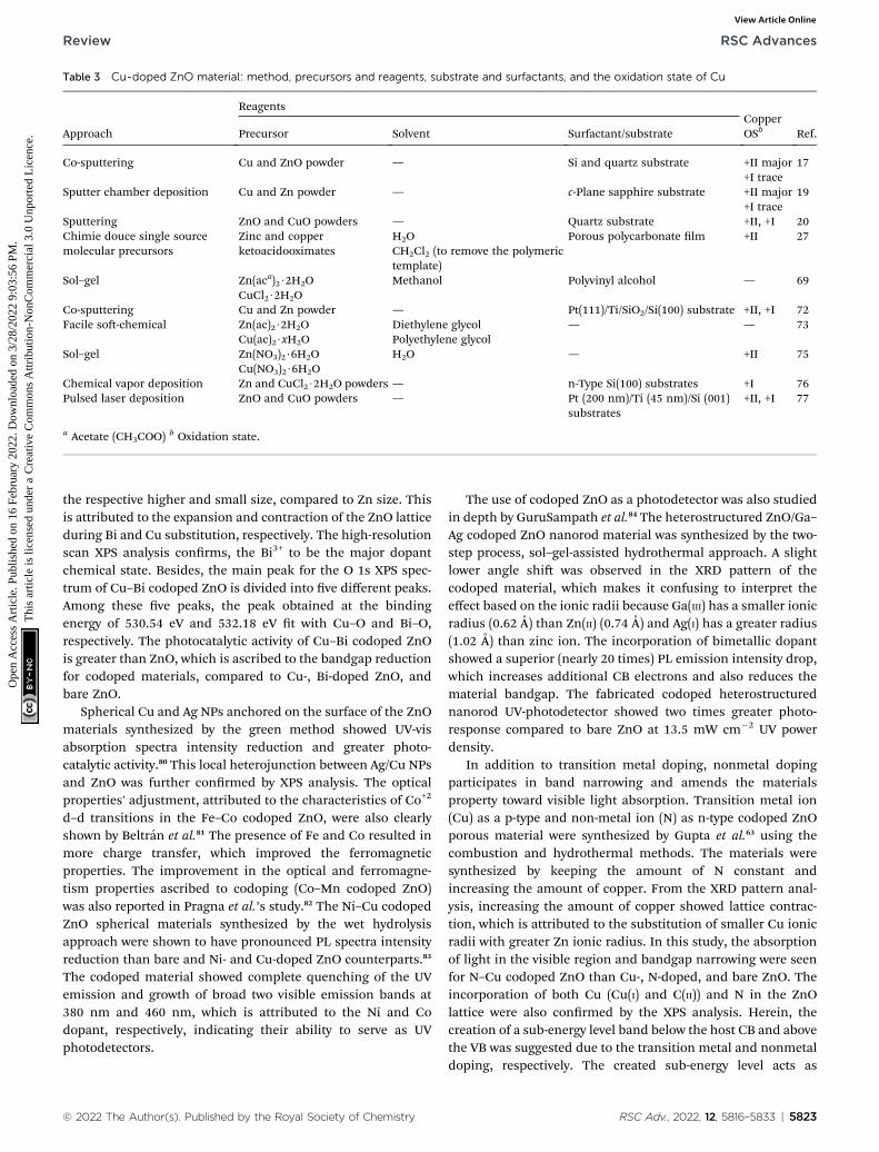
Table 3 Cu-doped ZnO material: method, precursors and reagents, substrate and surfactants, and the oxidation state of Cu
Approach
ReagentsCopperOSb Ref.Precursor Solvent Surfactant/substrate
Co-sputtering Cu and ZnO powder — Si and quartz substrate +II major 17+I trace
Sputter chamber deposition Cu and Zn powder — c-Plane sapphire substrate +II major 19+I trace
Sputtering ZnO and CuO powders — Quartz substrate +II, +I 20Chimie douce single sourcemolecular precursors
Zinc and copperketoacidooximates
H2O Porous polycarbonate lm +II 27CH2Cl2 (to remove the polymerictemplate)
Sol–gel Zn(aca)2$2H2O Methanol Polyvinyl alcohol — 69CuCl2$2H2O
Co-sputtering Cu and Zn powder — Pt(111)/Ti/SiO2/Si(100) substrate +II, +I 72Facile so-chemical Zn(ac)2$2H2O Diethylene glycol — — 73
Cu(ac)2$xH2O Polyethylene glycolSol–gel Zn(NO3)2$6H2O H2O — +II 75
Cu(NO3)2$6H2OChemical vapor deposition Zn and CuCl2$2H2O powders — n-Type Si(100) substrates +I 76Pulsed laser deposition ZnO and CuO powders — Pt (200 nm)/Ti (45 nm)/Si (001)
substrates+II, +I 77
a Acetate (CH3COO)b Oxidation state.
Review RSC Advances
Ope
n A
cces
s A
rtic
le. P
ublis
hed
on 1
6 Fe
brua
ry 2
022.
Dow
nloa
ded
on 3
/28/
2022
9:0
3:56
PM
. T
his
artic
le is
lice
nsed
und
er a
Cre
ativ
e C
omm
ons
Attr
ibut
ion-
Non
Com
mer
cial
3.0
Unp
orte
d L
icen
ce.
View Article Online
the respective higher and small size, compared to Zn size. Thisis attributed to the expansion and contraction of the ZnO latticeduring Bi and Cu substitution, respectively. The high-resolutionscan XPS analysis conrms, the Bi3+ to be the major dopantchemical state. Besides, the main peak for the O 1s XPS spec-trum of Cu–Bi codoped ZnO is divided into ve different peaks.Among these ve peaks, the peak obtained at the bindingenergy of 530.54 eV and 532.18 eV t with Cu–O and Bi–O,respectively. The photocatalytic activity of Cu–Bi codoped ZnOis greater than ZnO, which is ascribed to the bandgap reductionfor codoped materials, compared to Cu-, Bi-doped ZnO, andbare ZnO.
Spherical Cu and Ag NPs anchored on the surface of the ZnOmaterials synthesized by the green method showed UV-visabsorption spectra intensity reduction and greater photo-catalytic activity.80 This local heterojunction between Ag/Cu NPsand ZnO was further conrmed by XPS analysis. The opticalproperties' adjustment, attributed to the characteristics of Co+2
d–d transitions in the Fe–Co codoped ZnO, were also clearlyshown by Beltran et al.81 The presence of Fe and Co resulted inmore charge transfer, which improved the ferromagneticproperties. The improvement in the optical and ferromagne-tism properties ascribed to codoping (Co–Mn codoped ZnO)was also reported in Pragna et al.’s study.82 The Ni–Cu codopedZnO spherical materials synthesized by the wet hydrolysisapproach were shown to have pronounced PL spectra intensityreduction than bare and Ni- and Cu-doped ZnO counterparts.83
The codoped material showed complete quenching of the UVemission and growth of broad two visible emission bands at380 nm and 460 nm, which is attributed to the Ni and Codopant, respectively, indicating their ability to serve as UVphotodetectors.
© 2022 The Author(s). Published by the Royal Society of Chemistry
The use of codoped ZnO as a photodetector was also studiedin depth by GuruSampath et al.84 The heterostructured ZnO/Ga–Ag codoped ZnO nanorod material was synthesized by the two-step process, sol–gel-assisted hydrothermal approach. A slightlower angle shi was observed in the XRD pattern of thecodoped material, which makes it confusing to interpret theeffect based on the ionic radii because Ga(III) has a smaller ionicradius (0.62 A) than Zn(II) (0.74 A) and Ag(I) has a greater radius(1.02 A) than zinc ion. The incorporation of bimetallic dopantshowed a superior (nearly 20 times) PL emission intensity drop,which increases additional CB electrons and also reduces thematerial bandgap. The fabricated codoped heterostructurednanorod UV-photodetector showed two times greater photo-response compared to bare ZnO at 13.5 mW cm�2 UV powerdensity.
In addition to transition metal doping, nonmetal dopingparticipates in band narrowing and amends the materialsproperty toward visible light absorption. Transition metal ion(Cu) as a p-type and non-metal ion (N) as n-type codoped ZnOporous material were synthesized by Gupta et al.63 using thecombustion and hydrothermal methods. The materials weresynthesized by keeping the amount of N constant andincreasing the amount of copper. From the XRD pattern anal-ysis, increasing the amount of copper showed lattice contrac-tion, which is attributed to the substitution of smaller Cu ionicradii with greater Zn ionic radius. In this study, the absorptionof light in the visible region and bandgap narrowing were seenfor N–Cu codoped ZnO than Cu-, N-doped, and bare ZnO. Theincorporation of both Cu (Cu(I) and C(II)) and N in the ZnOlattice were also conrmed by the XPS analysis. Herein, thecreation of a sub-energy level band below the host CB and abovethe VB was suggested due to the transition metal and nonmetaldoping, respectively. The created sub-energy level acts as
RSC Adv., 2022, 12, 5816–5833 | 5823

Table 4 Ag and Cu co-doped ZnO material: method, precursors and reagents, substrate/surfactants, and the morphology of the dopedmaterials
Approach
Reagents
Morphology Ref.Host precursor Dopant precursor Solvent Surfactant/substrate
Solvothermal Zn(NO3)2$6H2O Ce(NH4)2(SO4)4$2H2O Water Oxalic acid dihydrate Hexagonal 18AgNO3
Sol–gel Zn(aca)2$2H2O Cu(NO3)2$5H2O AgNO3 Methanol Tartaric acid Quasi-spherical (Cu–ZnO), spherical(Ag@Cu–ZnO)
46CombustionHydrothermal Zn(NO3)2$6H2O Cu(NO3)2$3H2O
triethanolamineWater Glycine (fuel) Porous spherical 63
Sol–gel aidedhydrothermal
Zn(aca)2$2H2O Bi(NO3)3$5H2O Ethyl alcohol Cotton fabrics Spherical 79Zn(NO3)2$6H2O Cu(NO3)2$3H2O
Green (Acacia caesia) ZnO powder AgNO3, and CuNO3 Water Flower extract Spherical Ag and Cu anchored on ZnO 80Sol–gel Zn(NO3)2$6H2O Co(NO3)2$6H2O Ethylene glycol Citric acid — 81
Fe(NO3)3$9H2OCombustion Zn(NO3)2$6H2O Co(NO3)2$6H2O
Mn(aca)2$4H2OWater Polyethylene glycol Spherical 82
Hydrolysis Zn(aca)2$2H2O Nickel nitrate copperchloride
Water Poly(vinyl alcohol) Spherical 83
Sol–gel-aidedhydrothermal
Zn(aca)2$2H2O Ga(NO3)2$H2O 2-Methoxyethanol
Monoethanolamine(stabilizer)
Hexagonal nanorods 84ZnCl2 AgNO3
One-pothydrothermal
Zn(aca)2$2H2O HAuCl4 Water — Nanorods 85Zn(NO3)2$6H2O AgNO3
a Acetate (CH3COO).
RSC Advances Review
Ope
n A
cces
s A
rtic
le. P
ublis
hed
on 1
6 Fe
brua
ry 2
022.
Dow
nloa
ded
on 3
/28/
2022
9:0
3:56
PM
. T
his
artic
le is
lice
nsed
und
er a
Cre
ativ
e C
omm
ons
Attr
ibut
ion-
Non
Com
mer
cial
3.0
Unp
orte
d L
icen
ce.
View Article Online
a photogenerated electron–hole sink, thus prolonging electron–hole recombination.
Besides, Ce–Ag codoped-ZnO material prepared by the sol-vothermal method also showed a superior surface area andoptical property improvement.18 Compared to bare ZnO, thecodoped-ZnO material showed approximately ve times lesseraverage crystallite size. The greater the surface area, the higherthe sorption properties and the greater the photon-assisteddegradation. The redshi in the optical spectra occurred dueto a new energy level in the DRS spectra, which is attributed tothe existence of noble contact between the host and the dopant(Ag–ZnO–Ce). Besides, the lower PL intensity for the codopedsample compared to the bare ZnO also shows the lessening ofelectron–hole recombination. The smaller the recombination,the higher the Naphthol Blue Black dye degradation in aqueoussolution under solar light irradiation. The photo-generatedelectron transfer from the ZnO CB to both the doped Ce andAg metals was also reported by reducing the electron–holerecombination synergistically.
In addition to the magnetic and optical properties, theelectrical properties of ZnO were also boosted by the doping ofCu in the ZnO lattice and further decorating it with differentpercentages of Ag (Ag@Cu–ZnO). Small peaks ascribed to Cuand Ag and higher angle shi owing to interstitial site impurityincorporation were detected in the XRD pattern. The increase inthe average crystallite size with increasing Ag amount wasattributed to the replacement of greater size Ag ion (1.26 A) withsmaller size Zn ion (0.74 A). In this study, the incorporation ofCu into the ZnO lattice was understood from the FTIR bandshi. The method used to synthesize Ag–Cu codoped ZnO
5824 | RSC Adv., 2022, 12, 5816–5833
material, reagents, substrate/surfactants, and the morphologyof the synthesized material are also given in Table 4.
3. Characterization techniques
A combination of characterization techniques should beapplied for understanding the efficient doping of the dopantinto the host lattice. The optical, compositional, crystallinephase change analyses are common to study the dopant char-acteristics. X-ray diffraction (XRD), UV-vis/DRS, and inductivelycoupled plasma-atomic emission spectroscopy or mass spec-trometry (ICP-AES/MS) are normally used for understanding thechange in the lattice parameters, bandgap modications, andatomic percentage, respectively. The changes in the latticeparameters, such as contraction/expansion, which occurred dueto the difference in the size of the host and the dopant, furthercreates a change in the electronic structure of the host mate-rials. However, using the XRD pattern, the visualization of theevenly distributed doped materials is impossible. Besides,characterization techniques such as electron paramagneticresonance spectroscopy (EPR), X-ray photoelectron spectros-copy (XPS), photoluminescence spectroscopy (PLS), and X-rayabsorption (XAS), including X-ray absorption ne structure(EXAFS) and X-ray absorption near-edge structure spectroscopy,are used for understanding the local coordination environment(chemical states), optical properties, andmagnetic properties ofthe dopant.86,87 The near-edge structure (XANES) and extendedX-ray absorption ne structure (EXAFS) indicates the dopantsubstitution and bond distance between the dopant and thehost, respectively.19 Since all elements have characteristics ofcore binding energy, EXAFS is used for analyzing the local
© 2022 The Author(s). Published by the Royal Society of Chemistry

Review RSC Advances
Ope
n A
cces
s A
rtic
le. P
ublis
hed
on 1
6 Fe
brua
ry 2
022.
Dow
nloa
ded
on 3
/28/
2022
9:0
3:56
PM
. T
his
artic
le is
lice
nsed
und
er a
Cre
ativ
e C
omm
ons
Attr
ibut
ion-
Non
Com
mer
cial
3.0
Unp
orte
d L
icen
ce.
View Article Online
structure of all the elements. In addition, the development ofthe atomic-resolution characterization technique helps in theprecise imaging of dopant atoms' location and distribution.
Advanced hyphenated instruments such as annular dark-eld scanning transmission electron microscopy (ADF-STEM)22 and EELS-STEM62 provide the actual three-dimensionallocation and distribution, as well as element-specic analysis ofthe isolated impurities in the host matrix. ADF-STEM is anadvanced instrument, which works by scanning the surface ofthe sample by focused electron beam and collecting the scat-tered electron by the annular dark-eld detector. Higher atomicnumber impurities, which have different contrast compared tothe host, can be detected as an image, which is difficult forsmall atomic number elements. Based on the characteristiccore-edge electron-energy-loss signal, the single-atom sensitiveEELS technique is also used to detect the dopant.22 Postica et al.used the high angle annular dark-eld (HAADF)-STEM imagingtechnique for exact Ag-doped size measurement.21
3.1. STEM with different detectors
Controlling the position and distribution of doped light andheavymetal elements improves the device application potential.Besides, noticing the dopant-induced defects (point or/andextended) and heterogeneities89 gives information for tailoringthe properties of the material. The 0D defects (dopants andvacancies), 1D defects (inclusion and dislocations), grainboundaries, and van der Waals gaps are the main dopant-induced structural disorders.90 This position, distribution, anddisorder in materials, which affect the characteristics of thematerials, can be identied by STEM analytical technique with
Fig. 5 Electron energy loss spectroscopy and monochromation: (a)schematic of electron energy-loss spectroscopy (EELS) experiment ina scanning transmission electron microscope (STEM), (b) schematic ofmonochromation of an electron beam (occurring between the elec-tron gun and the condenser lenses).88
© 2022 The Author(s). Published by the Royal Society of Chemistry
atomic resolution.91 The working principle of the STEM tech-nique is based on the idea of the angular selection of the scat-tered signal, in which the detector collects only the electronsscattered to large angles and avoids the Bragg reections.92 Asshown in Fig. 5(a), the various lenses assist the magnetic eldsand the aberration corrector passes the beam to the EELS andother various modes of STEM detectors without affecting itsenergy. Fig. 5(b) show the electron beam monochromation, inwhich the transmitted beam is dispersed on the prism anddetected on the EELS detector.88 The STEM technique detectsboth the small atomic number and large atomic numberelements by annular dark-eld (ADF-STEM) as bright spots andannular bright-eld (ABF-STEM) as dark spots imaging,respectively. The BF-STEM has small-, middle-, and large-anglecategories, in which the middle angle bright-eld STEM (MABF-STEM) is used for detecting low atomic number elements withhigh accuracy.
Bazioti et al. used a STEM technique to validate the role ofnitrogen doping in the evolution of point (vacancies and inter-stitials) and extended (stacking faults) defects.93 Multipledetectors (ABF, ADF, and HAADF) were used to simultaneouslydetect the chemical information and atomic structure of thematerial. The common HAADF detector correlated to the Z-contrast detects the Z-contrast image scattered from the dopedheavy metals. The ADF detector gives information based on thestrong diffraction contrast by selecting the angular range of thescattered electrons. Here, in the ADF detector, the existence ofan extended defect is easily sensed. The BF detector can be usedfor the detection of light and heavy elements simultaneously byaligning the detector with all/part of the unscattered probe. TheABF detector operates by removing the circle from the center ofthe detector. The electronic and compositional information iscollected using the EELS spectroscopic technique.93,94 Currently,the 4D-STEM modes of imaging detector, commonly known asscanning electron nanodiffraction, is an advanced technologyused for crystal orientation mapping of any dopant. It gathersall types of real-space atomic-resolution images by collecting alldiffraction datasets from each electron probe with high-speedand efficient detection.95
In Tang et al.’s study, the in situ substitution and distributionof niobium on the surface of transition metal dichalcogenidesfor the modication of the electronic structure was clearlyvisualized in the HAADF-STEM images.96 Strontium dopant-induced tetragonal phase to cubic phase structural transitionon barium titanate was conrmed from powder XRD analysis.97
This solid result obtained from the XRD pattern was furtherconrmed from HAADF-STEM, in which the phase changeresults from the substantial compositional and microstructuralinhomogeneities. Wen et al. detected both the low Z-C atomsand high Z-Mo atoms simultaneously by the ADF-STEM tech-niques. Remarkably, the 2D pixelated electron detector wasused here to capture the low Z-number atoms convergent beamelectron diffraction patterns in a 4D STEM geometry. From theADF (LAADF), BF, and ABF STEM modes, the atomic sites inbright contrast to MoS2 and WS2 and the holes in dark contrastdue to the carbon-based contamination, which result from
RSC Adv., 2022, 12, 5816–5833 | 5825
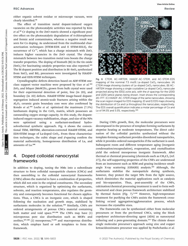
Fig. 6 CTEM, AC-HRTEM, HAADF-AC-STEM, and AC-STEM-EDSmapping of the nominal 7.5 mol% La-doped CeO2 nanocubes: (A)CTEM image showing clusters of La-doped CeO2 nanocubes, (B) AC-HRTEM image showing a single crystalline La-doped CeO2 nanocubeprojected along the [001] zone axis, with the d-spacings for the (200)and (220) lattice planes being shown. Inset shows the corresponding2D-FFT. (C) HAADF-AC-STEM image of the same nanocubes, showingthe scan region imaged for EDSmapping, (D and E) EDSmaps showingthe distribution of Ce and La throughout the nanocubes, respectively.The EDS overall quantification indicates a molar percentage of Ce andLa of 94.5% and 5.5%, respectively.100
RSC Advances Review
Ope
n A
cces
s A
rtic
le. P
ublis
hed
on 1
6 Fe
brua
ry 2
022.
Dow
nloa
ded
on 3
/28/
2022
9:0
3:56
PM
. T
his
artic
le is
lice
nsed
und
er a
Cre
ativ
e C
omm
ons
Attr
ibut
ion-
Non
Com
mer
cial
3.0
Unp
orte
d L
icen
ce.
View Article Online
either organic solvent residue or microscope vacuum, wereclearly identied.98
The effect of transition metal dopant-induced oxygenvacancies on the photocatalytic activities was reported by Kimet al.99 Cr doping in the ZnO matrix showed a signicant posi-tive effect on the photocatalytic degradation of 4-chlorophenoland formic acid contaminates, whereas a negative result wasseen for Co doping. As understood from the multimodal char-acterization techniques (STEM-EDX and E STEM-EELS), theoccurrence of Cr+3, which has a charge mismatch with ZnO,induces higher vacancies in the ZnO crystal. The chargemismatch between two transition metal ions boosts the chargetransfer properties. The doping of bismuth (Bi) in the tin oxide(SnOx) for fascinating catalytic properties was also reported.101
The Bi dopant position and distribution in Bi–SnOx synthesizedfrom SnCl2 and BiI3 precursors were investigated by HAADF-STEM and EDX-STEM techniques.
Crystallographic defects detection based on ADF-STEM one-class support vector machine were proposed by Guo et al.102
ZrO2 and bilayer (MoW)Te2 grown from bulk crystal were usedfor their experimental detection of point, line (in 2D), andboundary (in 3D) defects. HAADF-STEM image-based dopant-segregation induced atomic-scale fractures arising within theAl2O3 ceramic grain boundary core were also conrmed byKondo et al.103 Loche et al. optimized the maximum (7.5%)lanthanum doping in the CeO2 matrix, which possesses anoutstanding oxygen storage capacity. In this study, the dopant-induced oxygen vacancy stabilization, shape, and size of the NPswere optimized using a surfactant-mediated hydro-solvothermal synthetic approach. Fig. 6 shows the conven-tional TEM, HRTEM, aberration-corrected HAADF-STEM, andEDS-STEM image of La-doped CeO2. From these characteriza-tion techniques, the cubic shape and d-spacing conrm thematerial authenticity, homogeneous distribution of La, andamounts of La.100
4. Doped colloidal nanocrystalframeworks
In addition to doping, tuning the NMs into a subordinatestructure to form colloidal nanoparticle clusters (CNCs) andthen assembling to the colloidal nanocrystal frameworks(CNFs) allows the material to have a combination of properties,which did not exist in the original constituents. The secondarystructure, which is organized by optimizing the surfactants,solvents, and reaction temperatures, also regulates the geom-etry and consequently becomes functional for chosen applica-tions. Thus, a CNCs is an inorganic core, which is shapedfollowing the nucleation and growth steps, stabilized bysurfactants molecules in the solution.104 Similarly, CNFs areordered arrangements of porous CNCs material containingboth matter and void space.105,106 The CNFs may have (1)microporous pore size distribution such as MOFs andzeolites,107,108 (2) mesoporous,23,109 and macroporous distribu-tion, which employs hard or so templates to form theframework.
5826 | RSC Adv., 2022, 12, 5816–5833
During CNFs growth, rst, the molecular precursors weredecomposed in the presence of template-forming surfactants bystepwise heating at moderate temperatures. The direct calci-nation of the colloidal particles synthesized without thetemplate-forming surfactant provides disordered nanoparticles,while it provides ordered nanoparticles if the surfactant is used.Subsequent room and different temperature aging (inorganiccondensation/encapsulation), evaporation, and crystallizationyield the ordered mesoporous inorganic framework. Aerthermal or chemical processing (chemicals such as CH2Cl2 (ref.27)), the self-supporting properties of the CNFs are understoodfrom an instrument such as SEM and grazing incidence small-angle X-ray scattering (GISAXS) analysis.105 Although, thesurfactants stabilize the nanoparticle during synthesis,however, they protect the target NPs from the light source,which diminishes the material applications such as catalysisand bio-separation. Thus, post-assembly of the CNFs,calcination/chemical processing treatment is used to form well-structured and clean porous framework architecture stabilizedby thermal fusion (Fig. 7).5,110 However, high-temperaturetreatment for purifying the CNFs assists the framework cross-linking or/and aggregation/agglomeration process, whichincreases the crystallite sizes.
The frameworks can be synthesized either from molecularprecursors or from the pre-formed CNCs, using the blockcopolymer architecture-directing agent (ADA) as nanocrystaltethering and a pore-generating domain.111 The chimie doucesingle molecular precursor's approach using zinc and copperketoacidooximates precursor was applied by Pashchanka et al.
© 2022 The Author(s). Published by the Royal Society of Chemistry

Fig. 7 Colloidal nanocrystal frameworks formation steps: (a) nanocrystal formation by the decomposition of molecular precursors, (b) stepsshow an ordered nanocrystal formation in the presence of surfactant and disordered nanocrystal formation in the absence of surfactant, (c–e)steps show the condensation and evaporation upon heating at low temperature and crystallization upon calcination at higher temperature toproduce an ordered porous framework.
Review RSC Advances
Ope
n A
cces
s A
rtic
le. P
ublis
hed
on 1
6 Fe
brua
ry 2
022.
Dow
nloa
ded
on 3
/28/
2022
9:0
3:56
PM
. T
his
artic
le is
lice
nsed
und
er a
Cre
ativ
e C
omm
ons
Attr
ibut
ion-
Non
Com
mer
cial
3.0
Unp
orte
d L
icen
ce.
View Article Online
to dope Cu ion into the ZnO host matrix.27 From differentspectroscopic and microscopic examinations, the oxidationstate of copper was found to be Cu(II).
Advanced methods such as sol–gel and solvo-/hydrothermalwere reported112 to control the size, shape, dispersity, andgeometry of the framework. During the synthesis, the interac-tion between the CNCs and ADA needs to be electrostatic ratherthan van der Waals or hydrogen bonding, which can resistthermal processing.113–115 The thermal treatment applied totransfer the precursor to active atomic or molecular species maygo to up to 320 �C, and be grown to the NMs, then assembledinto cluster. The layer-by-layer (LBL), liquid–liquid interface(LLI), and evaporation-induced self-assembly (EISA) are some ofthe approaches used to assemble the pre-formed NPs.Frequently, the EISA that follows the evaporation of the solventin the presence of block copolymer utilizes crystalline NPsinstead of molecular precursors.116,117 The LBL approach is theprocess of adsorption of the NPs on the surface of sub-micrometer beads.118 The LLI is formed at the interface of twoimmiscible liquids.119
The size can be controlled by changing the concentrationof the ligands or precursors and stopping the growth atdifferent steps, while the shape can be controlled by theselective adhesion of ligands to specic crystalline facets.104
Compared to ligand-coated NCs copolymer ADA interaction,the ligand-stripped NCs are suggested to avoid the stabilityissue.120 From a surface chemistry perspective, copolymerssuch as poly(4-vinyl pyridine) (P4VP) are promising towardorganic–organic interaction,121 while the surface charge onthe NCs and the type of the copolymer is reported104,106 to bethe most important consideration for copolymer selection
© 2022 The Author(s). Published by the Royal Society of Chemistry
toward organic–inorganic interaction. For instance, anordered mesoporous structure was synthesized by Buon-santi et al. using poly(N,N-dimethyl acrylamide) and poro-genic polystyrene block copolymer structure-directingagents.114 During synthesis, different block copolymerratios and molecular weights were taken to optimize themesoporosity. The group used the reversible addition–fragmentation chain transfer polymerization ligand-stripped NCs approach.
The residual surface charge on molecular precursors (metalcation or/and hydroxyl-terminated metal oxide NCs) can begenerated by solvothermal or sol–gel methods.106 Thermallyheating the assembled composite led to the formation ofhexagonal phase-segregated morphology and then well-orderedCNFs on further thermal processing.113 In this regard, thedistinctive recyclability/stability and rate performance of metaloxide semiconductor-based CNFs make them a suitablechoice.114
5. Applications5.1. Bacterial activity
Nowadays, several conventional antibiotic resistant-bacteriahave been emerging, leading to enhanced infections inhuman beings. Thus, searching for safe and effective antimi-crobial agents for therapeutic and non-therapeutic purposeshas been continuously encouraged. In recent decades, nano-materials such as metal oxides have shown novel bactericidalpotential. The antibacterial action is believed to have takenplace when the negatively charged bacterial cells electrostati-cally interact with the positively charged metal oxides NPs.122
The cell wall of Gram-negative (GN) bacteria is complex and has
RSC Adv., 2022, 12, 5816–5833 | 5827

Fig. 8 Schematic of the antibacterial mechanism of the SiO2–Agcomposites.131
RSC Advances Review
Ope
n A
cces
s A
rtic
le. P
ublis
hed
on 1
6 Fe
brua
ry 2
022.
Dow
nloa
ded
on 3
/28/
2022
9:0
3:56
PM
. T
his
artic
le is
lice
nsed
und
er a
Cre
ativ
e C
omm
ons
Attr
ibut
ion-
Non
Com
mer
cial
3.0
Unp
orte
d L
icen
ce.
View Article Online
a higher negative potential due to the presence of the lipo-polysaccharide layer, compared to the Gram-positive (GP)bacteria.123 This complex structure and negatively chargedbehavior of the GN bacteria shield the negatively chargedreactive oxygen species (ROS) and avoid their absorption.124
The bactericidal mechanism of NPs is limited, although thedirect and indirect interactions were reported as the mainmechanisms.125 The direct mechanism occurs by the directinteraction of the positively charged NPs with negativelycharged microorganisms.126 The indirect mechanism occursthrough the interaction of the NPs with the intercellularspace.127 The direct and indirect mechanism can damage thebacterial cell through the generation of ROS, by the release ofions, and NPs interaction with the cell membrane.128–130 TheROS generation is dependent on the interaction of the NPs withlight that results in the generation of electrons and holes. Thephoto-induced electrons and holes further react with oxygenand water to form a highly oxidizing agent, hydroxyl radical(OHc). Photocatalytic ROS generation under visible light irra-diation for the inactivation of E. coli by Ag-doped ZnO has beenreported in different works.132,133
The three important features that play a vital role in thegeneration of ROS are active redox cycling, the presence of pro-oxidant functional groups on the surface of NPs, and cell–particle interactions.134 The change in the electronic propertiesand reduction in the particle size produce reactive groups onthe surface of the NPs. These reactive sites are the center ofinteraction between molecular oxygen and electron donor/acceptor active sites, which result in the formation of O2
��.The generated O2
�� damage the iron–sulfur (Fe–S) clusters inthe electron transport chain, releasing more ferrous ions, andthese ferrous ions are oxidized by the Fenton reaction forgenerating moreOHc.135,136 Antibacterial activity through therelease of Ag+ ions from Ag–SiO2 NCs was proposed by Cui et al.As seen in Fig. 8, the electrostatic force of interaction betweenthe positively charged NCs and negatively charged bacterialcells led to the release of Ag+ ions and transported them to thecytoplasm. The direct interaction of Ag+ with the mitochondriaresults in the generation of ROS by the Fenton reaction andinhibits DNA replication. Aer the interaction of the NCs andbacterial cells, the disruption of the membrane/cell wall andchange in the bacterial cell morphology from cylindrical tospherical shape was also observed in the TEM analysis.131
ZnO NPs have good antibacterial performance against bothGP and GN bacteria. In addition, the antibacterial activities ofcopper and silver were also reported,137 although the bacteri-cidal activities of Ag NPs would be diminished as a result of itsoxidation and aggregation behavior.131 In Wang et al.’s study138
signicant antibacterial activities of Ag-doped ZnO were re-ported, compared to the single ZnO NPs, which results from thesynergistic effect of both Ag and ZnO. In this work, since novisible/UV light was applied during the antibacterial study,bacterial damage by the release of Zn+2/Ag+ ions or/and Ag/ZnONPs interaction with cell membrane was proposed to be theprobable mechanism for bacterial death. Similar synergisticeffect antibacterial activities owing to the band structuremodication through dopant inclusion were also proposed in
5828 | RSC Adv., 2022, 12, 5816–5833
Zare et al.’s139 studies. The disruption of the bacterial cellmembrane at a cellular level and the inhibition of DNA/proteinsat a molecular level by either Zn2+/Ag+ ions or ROS formationwere proposed in Matai et al.’s140 study. Herein, cell membraneshrinkage due to disruption, followed by the leakage of intra-cellular materials, was clearly supported by FE-SEM, AFM, andTEM analysis. Hydrothermally synthesized Cu-doped ZnO byKhalid et al.141 also veried the synergistic antibacterial effect,especially on GP bacteria (results of structural differencesamong GP and GN bacteria) with a superior zone of inhibition.ROS generation by the Fenton-type reaction following therelease of ions (Zn2+, Cu, Cu+, and Cu2+) is a probable mecha-nism for the bacterial inactivation/death in this study.
5.2. Photocatalytic activity
The rapid photo-induced electron–hole recombination andnarrow light-absorption range are believed to diminish thephotocatalytic efficiency of ZnO.142 The doping of metal reducesthe electron–hole recombination by forming a Schottky junc-tion, also improves the crystalline transformation, visible lightabsorption, and materials' surface area-to-volume ratio.143 Suchdoping also affects the optical, electrical, and magnetic prop-erties. Yang et al. synthesized Ag-doped ZnO in the presence ofhigher surface area zeolitic imidazolate framework-8. Thedoped Ag metal acts as an electron capture site from the CB ofZnO and helps to improve the electron–hole separation, andthis in turn enhances the photocatalytic degradation of rhoda-mine B dye.144 The electron capturing properties of Ag in Ag–ZnO resulted due to the establishment of the Ag/ZnO Fermilevel between the CB and Fermi level of pure ZnO, which isknown as a Schottky junction (more negative Fermi levelpotential for Ag–ZnO than bare ZnO).145,146
© 2022 The Author(s). Published by the Royal Society of Chemistry

Review RSC Advances
Ope
n A
cces
s A
rtic
le. P
ublis
hed
on 1
6 Fe
brua
ry 2
022.
Dow
nloa
ded
on 3
/28/
2022
9:0
3:56
PM
. T
his
artic
le is
lice
nsed
und
er a
Cre
ativ
e C
omm
ons
Attr
ibut
ion-
Non
Com
mer
cial
3.0
Unp
orte
d L
icen
ce.
View Article Online
The doping of copper also creates an electron acceptor leveland modies the ZnO crystal band structure, and it furtherenhances the visible light absorption efficiency of the material.Using hydrated zinc and copper acetate precursors in thepresence of citrate and the dropwise addition of NaOH, Ma et al.synthesized porous Cu-doped ZnO NCs for MB dye degradation.The improved degradation behavior of Cu-doped ZnO than bareZnO was reasonably explained as the occurrence of interfacialcharge transfer from ZnO to Cu dopant (Fig. 9(c) and (d)). Forsingle ZnO, aer the excitation of the photo-induced electron tothe CB, it directly returns to the VB and recombines with a hole(Fig. 9(c)). However, the excited electron on the Cu–ZnO nano-composite would be accepted by Cu+2 and then reduced to Cu+,which further extends the life span of the hole in the VB(Fig. 9(d)).142 As a result, the reduction of oxygen by electron andoxidation of water by the hole occurred.
Thus, an intermediate oxidizing agent and hydroxyl radicalare generated.
To understand the detailed photocatalytic dye degradationmechanism, testing the existence of ROS and a free hole isimportant. Karthik et al.147 used isopropyl alcohol and 1,4-benzoquinone as a O2
�� and OHc trapper, and ammoniumoxalate as a hole trapper on the surface of Cu-doped ZnO NCs.In the presence of a hole trapper, greater than 85% dye degra-dation took place, whereas only about <20% degradation tookplace in the presence of ROS trapper. Hence, the ROS is themain degradation species of the dyes (MB, indigo carmine, andrhodamine B) compared to the hole under UV light irradiation.Here, in this work, the 3% and 5% dopant concentrationsshowed better degradation activity compared to the 7% and 9%doped NCs. The reason for the diminishing photocatalyticactivities with an increase in the dopant amount is the devel-opment of CuO that covers the ZnO surface, which signicantlyshields the UV absorption capacity of the material. The
Fig. 9 (a and b) Photocatalytic naphthol blue-black dye degradationmechanism of Ce–Ag co-doped ZnO,18 (c and d) photocatalyticmethylene blue dye degradation mechanism of Cu-doped ZnO hier-archical nanostructures.142
© 2022 The Author(s). Published by the Royal Society of Chemistry
development of CuO also acts as a photo-induced electron–holerecombination center. This shielding and recombination centerproperties of the developed CuO (doping above 5%) were alsoexplained by Kuriakose et al.148 The improvement in thedegradation of the MB dye with increasing Cu percentage up to5% was reported by Okeke et al. Herein, the degradation on thedoped nanocomposite resulted from the occurrence of ZnObandgap shrinkage and developments of different types ofdefects in the ZnO matrix during Cu doping.149
Simultaneously doping two metals generates special char-acteristics and results in a higher photodegradation activity.18
Subash et al. synthesized Ce and Ag co-doped ZnO superstruc-tures for the photocatalytic degradation of naphthol blue-blackdye under solar light irradiation. Both the adsorption andphotocatalytic activities of Ag and Ce co-doped ZnO NCs arehigher than those of bare ZnO NPs, Ce–ZnO, and Ag–ZnO NCs.This indicates that co-doping results in increased surface activesites by increasing the overall surface area and photocatalyticactivity resulting from the interfacial charge transfer from ZnOto Ce and Ag dopant as shown in Fig. 9(a) and (b).18 MB dyedegradation and bactericidal activities' improvement as a resultof synergistic effect (Sn/Cu co-doped ZnO), interfacial chargetransfer, and creation of extrinsic defects were also reported byShanmugam et al.150 The ve cycle recyclability test also provedthe stability of the Sn/Cu-co-doped ZnO materials with aninsignicant potential reduction in the 5th cycle. These Sn/Cu-co-doped ZnO materials synthesized by microwave-assistedcoprecipitation approach also showed superior antibacterialactivity against GN and GP bacteria. In addition to antibacterialand photocatalytic applications, tuning the materials to have aninterconnected porous framework improves the mass- or ion-transport properties in several elds such as adsorption,151
capacitors/storage,152 electrocatalysis,153 windows,154 andsensors.155
6. Conclusions and future outlook
Nanotechnology is a fundamental eld for producing advancedmaterials with interesting properties and unusual applicationpotentials. Nanocrystals synthesized by common approacheshave had essential applications for several years. Preciseinclusion and good distribution of the impurities in the nano-crystal semiconductor materials further advance the materialproperties toward a particular application. For the preciseinclusion and distribution of the dopant, controlling severalconditions such as host–dopant and surfactant hardness,reaction time, and synthetic approach are signicant. Commoninstruments (XRD, TEM, XAS, and XPS) can give informationabout the properties of the doped materials. In addition,advanced imaging modes of the STEM technique have beenvalued in direct atomic level defect and visualization of heter-ointerfaces and their impact on the properties of materials.Thus, the detection of the defects position, distribution,composition, and level of defects has received attention andshould also be future viewpoints, especially in the case of in situSTEM control. In addition, forming a secondary structure,a colloidal nanocrystals framework can enhance the mass-/ion
RSC Adv., 2022, 12, 5816–5833 | 5829
RSC Advances Review
Ope
n A
cces
s A
rtic
le. P
ublis
hed
on 1
6 Fe
brua
ry 2
022.
Dow
nloa
ded
on 3
/28/
2022
9:0
3:56
PM
. T
his
artic
le is
lice
nsed
und
er a
Cre
ativ
e C
omm
ons
Attr
ibut
ion-
Non
Com
mer
cial
3.0
Unp
orte
d L
icen
ce.
View Article Online
transport properties. Thus, tuning the crucial parameters underthe control of advanced instruments and modifying the nano-crystals to the secondary structure should be the nonstopevolution for the future.
Abbreviations
HSAB
5830 | RSC
Pearson's hard/so acids/bases
NMs Nanoscale materials ADF-STEMAnnular dark-eld scanning transmission electronmicroscopy
EELS-STEM
Electron energy loss spectroscopy-scanningtransmission electron microscope
XRD
X-ray diffraction XPS X-ray photoelectron spectroscopy XAS X-ray absorption EXAFS X-ray absorption ne structure EXAFS Extended X-ray absorption ne structure ADA Architecture-directing agent CNCs Colloidal nanoparticle clusters CNFs Colloidal nanocrystal frameworks; ROS Reactive oxygen species; GP Gram-positive GN Gram-negative CB Conduction band VB Valence band MB Methylene blueAuthor contributions
This review manuscript is written by Buzuayehu Abebe. Thewrite-up improvement was done by H. C. Ananda Murthy. Bothauthors contributed to the study's conception and design.
Conflicts of interest
There are no conicts to declare.
Acknowledgements
This work was supported by Adama Science and TechnologyUniversity.
References
1 T. A. Saleh, Environ. Technol. Innovation, 2020, 20, 101067.2 R. Ebrahimi, K. Hossienzadeh, A. Maleki, R. Ghanbari,R. Rezaee, M. Safari, B. Shahmoradi, H. Daraei, A. Jafari,K. Yetilmezsoy and S. H. Puttaiah, J. Environ. Health Sci.Eng., 2019, 17, 479–492.
3 V. P. Dinesh, P. Biji, A. Ashok, S. K. Dhara, M. Kamruddin,A. K. Tyagi and B. Raj, RSC Adv., 2014, 4, 58930–58940.
4 J. Zhang, Q. Di, J. Liu, B. Bai, J. Liu, M. Xu and J. Liu, J. Phys.Chem. Lett., 2017, 8, 4943–4953.
5 Z. Lu and Y. Yin, Chem. Soc. Rev., 2012, 41, 6874.6 E. Roduner, Chem. Soc. Rev., 2006, 35, 583.
Adv., 2022, 12, 5816–5833
7 Y. Jun, J. Choi and J. Cheon, Angew. Chem., Int. Ed., 2006, 45,3414–3439.
8 R. Buonsanti, V. Grillo, E. Carlino, C. Giannini, T. Kipp,R. Cingolani and P. D. Cozzoli, J. Am. Chem. Soc., 2008,130, 11223–11233.
9 M. M. Rahman, H. B. Balkhoyor and A. M. Asiri, New J.Chem., 2019, 43, 18848–18859.
10 L. De Trizio and L. Manna, Chem. Rev., 2016, 116, 10852–10887.
11 J. Gui, M. Ji, J. Liu, M. Xu, J. Zhang and H. Zhu, Angew.Chem., 2015, 127, 3754–3758.
12 G. M. Dalpian and J. R. Chelikowsky, Phys. Rev. Lett., 2006,96, 226802.
13 F. V. Mikulec, M. Kuno, M. Bennati, D. A. Hall, R. G. GriffinandM. G. Bawendi, J. Am. Chem. Soc., 2000, 122, 2532–2540.
14 S. C. Erwin, L. Zu, M. I. Hael, A. L. Efros, T. A. Kennedy andD. J. Norris, Nature, 2005, 436, 91–94.
15 D. Chen, R. Viswanatha, G. L. Ong, R. Xie,M. Balasubramaninan and X. Peng, J. Am. Chem. Soc.,2009, 131, 9333–9339.
16 R. Buonsanti and D. J. Milliron, Chem. Mater., 2013, 25,1305–1317.
17 D. C. Agarwal, U. B. Singh, S. Gupta, R. Singhal,P. K. Kulriya, F. Singh, A. Tripathi, J. Singh, U. S. Joshiand D. K. Avasthi, Sci. Rep., 2019, 9, 6675.
18 B. Subash, B. Krishnakumar, R. Velmurugan,M. Swaminathan and M. Shanthi, Catal. Sci. Technol.,2012, 2, 2319.
19 H. Liu, F. Zeng, S. Gao, G. Wang, C. Song and F. Pan, Phys.Chem. Chem. Phys., 2013, 15, 13153–13161.
20 N. Ali, A. R. Vijaya, Z. A. Khan, K. Tarafder, A. Kumar,M. K. Wadhwa, B. Singh and S. Ghosh, Sci. Rep., 2019, 9,20039.
21 V. Postica, A. Vahl, D. Santos-Carballal, T. Dankwort,L. Kienle, M. Hoppe, A. Cadi-Essadek, N. H. de Leeuw,M.-I. I. Terasa, R. Adelung, F. Faupel and O. Lupan, ACSAppl. Mater. Interfaces, 2019, 11, 31452–31466.
22 A. A. Gunawan, A. Wills, A. Mkhoyan, M. G. Thomas andD. J. Norris, Microsc. Microanal., 2012, 18, 298–299.
23 Y. Deng, J. Wei, Z. Sun and D. Zhao, Chem. Soc. Rev., 2013,42, 4054–4070.
24 H. Hu, H. He, J. Zhang, X. Hou and P. Wu, Nanoscale, 2018,10, 5035–5046.
25 R. G. Pearson, Inorg. Chem., 1988, 27, 734–740.26 B. Abebe, E. A. Zereffa and H. C. A. Murthy, ACS Omega,
2021, 6, 954–964.27 M. Pashchanka, R. C. Hoffmann, A. Gurlo, J. C. Swarbrick,
J. Khanderi, J. Engstler, A. Issanin and J. J. Schneider,Dalton Trans., 2011, 40, 4307.
28 N. Pradhan, D. Goorskey, J. Thessing and X. Peng, J. Am.Chem. Soc., 2005, 127, 17586–17587.
29 S. K. Panda, S. G. Hickey, H. V. Demir and A. Eychmuller,Angew. Chem., Int. Ed., 2011, 50, 4432–4436.
30 S. Sarkar, N. S. Karan and N. Pradhan, Angew. Chem., 2011,123, 6189–6193.
31 Y. Yang, Y. Jin, H. He, Q. Wang, Y. Tu, H. Lu and Z. Ye, J. Am.Chem. Soc., 2010, 132, 13381–13394.
© 2022 The Author(s). Published by the Royal Society of Chemistry

Review RSC Advances
Ope
n A
cces
s A
rtic
le. P
ublis
hed
on 1
6 Fe
brua
ry 2
022.
Dow
nloa
ded
on 3
/28/
2022
9:0
3:56
PM
. T
his
artic
le is
lice
nsed
und
er a
Cre
ativ
e C
omm
ons
Attr
ibut
ion-
Non
Com
mer
cial
3.0
Unp
orte
d L
icen
ce.
View Article Online
32 R. A. Gilstrap, C. J. Capozzi, C. G. Carson, R. A. Gerhardtand C. J. Summers, Adv. Mater., 2008, 20, 4163–4166.
33 S. Il Choi, K. M. Nam, B. K. Park, W. S. Seo and J. T. Park,Chem. Mater., 2008, 20, 2609–2611.
34 I. Bilecka, L. Luo, I. Djerdj, M. D. Rossell, M. Jagodic,Z. Jaglicic, Y. Masubuchi, S. Kikkawa andM. Niederberger, J. Phys. Chem. C, 2011, 115, 1484–1495.
35 J. B. Rivest and P. K. Jain, Chem. Soc. Rev., 2013, 42, 89–96.36 G. D. Moon, S. Ko, Y. Xia and U. Jeong, ACS Nano, 2010, 4,
2307–2319.37 S. E. Wark, C.-H. Hsia and D. H. Son, J. Am. Chem. Soc.,
2008, 130, 9550–9555.38 B. J. Beberwyck, Y. Surendranath and A. P. Alivisatos, J.
Phys. Chem. C, 2013, 117, 19759–19770.39 S. K. Singh, D. Dutta, A. Dhar, S. Das, M. C. Paul and
T. K. Gangopadhyay, Phys. Status Solidi A, 2019, 216,1900141.
40 S. M. Hosseini, I. A. Sarsari, P. Kameli and H. Salamati, J.Alloys Compd., 2015, 640, 408–415.
41 C. Karunakaran, V. Rajeswari and P. Gomathisankar, J.Alloys Compd., 2010, 508, 587–591.
42 O. A. Yıldırım, H. E. Unalan and C. Durucan, J. Am. Ceram.Soc., 2013, 96, 766–773.
43 Y. Jin, Q. Cui, K. Wang, J. Hao, Q. Wang and J. Zhang, J.Appl. Phys., 2011, 109, 053521.
44 Y. Ning, Z. Zhang, F. Teng and X. Fang, Small, 2018, 14,1703754.
45 S. Kaenphakdee, S. Yodyingyong, J. Leelawattanachai,W. Triampo, N. Sanpo, J. Jitputti and D. Triampo, Mater.Sci. Forum, 2020, 1007, 143–147.
46 A. Modwi, K. K. Taha, L. Khezami, M. Boudina, M. Khairy,O. K. Al-Duaij and S. Talab, Z. Phys. Chem., 2021, 235,745–767.
47 Y. Liu, Q. Zhang, M. Xu, H. Yuan, Y. Chen, J. J. Zhang,K. Luo, J. J. Zhang and B. You, Appl. Surf. Sci., 2019, 476,632–640.
48 S. A. Ansari, M. M. Khan, M. O. Ansari, J. Lee andM. H. Cho,J. Phys. Chem. C, 2013, 117, 27023–27030.
49 F. A. Alharthi, A. A. Alghamdi, N. Al-Zaqri, H. S. Alanazi,A. A. Alsyahi, A. El Marghany and N. Ahmad, Sci. Rep.,2020, 10, 20229.
50 S. Masoumi, E. Nadimi and F. Hossein-Babaei, Phys. Chem.Chem. Phys., 2018, 20, 14688–14693.
51 S. Sagadevan, K. Pal, Z. Z. Chowdhury and M. E. Hoque, J.Sol-Gel Sci. Technol., 2017, 83, 394–404.
52 Y. Zheng, C. Chen, Y. Zhan, X. Lin, Q. Zheng, K. Wei andJ. Zhu, J. Phys. Chem. C, 2008, 112, 10773–10777.
53 Z. Yin, X. Wang, F. Sun, X. Tong, C. Zhu, Q. Lv, D. Ye,S. Wang, W. Luo and Y. Huang, Sci. Rep., 2017, 7, 12206.
54 S. T. Kochuveedu, Y. H. Jang and D. H. Kim, Chem. Soc. Rev.,2013, 42, 8467.
55 Y. Wei, J. Kong, L. Yang, L. Ke, H. R. Tan, H. Liu, Y. Huang,X. W. Sun, X. Lu and H. Du, J. Mater. Chem. A, 2013, 1, 5045–5052.
56 R. J. V. Michael, B. Sambandam, T. Muthukumar,M. J. Umapathy and P. T. Manoharan, Phys. Chem. Chem.Phys., 2014, 16, 8541.
© 2022 The Author(s). Published by the Royal Society of Chemistry
57 A. Ziashahabi, M. Prato, Z. Dang, R. Poursalehi andN. Naseri, Sci. Rep., 2019, 9, 11839.
58 Q. Zhang, G. Xie, M. Xu, Y. Su, H. Tai, H. Du and Y. Jiang,Sens. Actuators, B, 2018, 259, 269–281.
59 O. Lupan, V. Cretu, V. Postica, M. Ahmadi, B. R. Cuenya,L. Chow, I. Tiginyanu, B. Viana, T. Pauporte andR. Adelung, Sens. Actuators, B, 2016, 223, 893–903.
60 J. Ding, J. Zhu, P. Yao, J. Li, H. Bi and X. Wang, Ind. Eng.Chem. Res., 2015, 54, 8947–8953.
61 B. Abebe, H. A. Murthy and E. Amare, Environ. Nanotechnol.Monit. Manag., 2020, 14, 100336.
62 M. D. Rossell, Q. M. Ramasse, S. D. Findlay, F. Rechberger,R. Erni and M. Niederberger, ACS Nano, 2012, 6, 7077–7083.
63 R. Gupta, N. KrishnaRao Eswar, J. M. Modak andG. Madras, RSC Adv., 2016, 6, 85675–85687.
64 Y. Gao, F. Meng, X. Li, J. Z. Wen and Z. Li, Catal. Sci.Technol., 2016, 6, 7800–7811.
65 K. Nagaveni, G. Sivalingam, M. Hegde and G. Madras, Appl.Catal., B, 2004, 48, 83–93.
66 P. Singh, R. Kumar and R. K. Singh, Ind. Eng. Chem. Res.,2019, 58, 17130–17163.
67 S. S. Alias, A. B. Ismail and A. A. Mohamad, J. Alloys Compd.,2010, 499, 231–237.
68 O. M. Lemine, T. Almusidi, M. B. Kanoun, S. Goumri-Said,M. Alshammari, N. Abdel All, A. Z. Alanzi, F. S. Alghamdiand A. Alyamani, J. Mater. Sci.: Mater. Electron., 2019, 30,19833–19840.
69 A. Mahmoud, M. Echabaane, K. Omri, J. Boudon, L. Saviot,N. Millot and R. Ben Chaabane, Molecules, 2021, 26, 929.
70 Y.-C. Chang, P.-S. Lin, F.-K. Liu, J.-Y. Guo and C.-M. Chen, J.Alloys Compd., 2016, 688, 242–251.
71 C. Xu, K. Yang, L. Huang and H. Wang, J. Chem. Phys., 2009,130, 124711.
72 H. Liu, Y. Wang, J. Wu, G. Zhang and Y. Yan, Phys. Chem.Chem. Phys., 2015, 17, 9098–9105.
73 S. Chomean, S. Ingkananth, M. Kiatchaipar and C. Kaset,Anal. Chim. Acta, 2017, 1180, 338884.
74 S. Thakur and S. K. Mandal, Mater. Adv., 2021, 2, 511–524.75 R. Bhardwaj, A. Bharti, J. P. Singh, K. H. Chae and N. Goyal,
Nanoscale Adv., 2020, 2, 4450–4463.76 D. H. Xu andW. Z. Shen, J. Phys. Chem. C, 2012, 116, 13368–
13373.77 X. Luo, L. T. Tseng, W. T. Lee, T. T. Tan, N. N. Bao, R. Liu,
J. Ding, S. Li, V. Lauter and J. B. Yi, Sci. Rep., 2017, 7, 6341.78 J. Zhang, K. Tse, M. Wong, Y. Zhang and J. Zhu, Front. Phys.,
2016, 11, 117405.79 L. Cao, L. Wang, L. Xu, Y. Shen, M. Xie and H. Hao, RSC
Adv., 2021, 11, 29416–29425.80 G. Manjari, S. Saran, S. Radhakrishanan, P. Rameshkumar,
A. Pandikumar and S. P. Devipriya, J. Environ. Manage.,2020, 262, 110282.
81 J. J. Beltran, J. A. Osorio, C. A. Barrero, C. B. Hanna andA. Punnoose, J. Appl. Phys., 2013, 113, 17C308.
82 E. Pragna, M. Ramanadha, A. Sudharani and K. S. Kumar, J.Supercond. Novel Magn., 2021, 34, 1507–1516.
RSC Adv., 2022, 12, 5816–5833 | 5831

RSC Advances Review
Ope
n A
cces
s A
rtic
le. P
ublis
hed
on 1
6 Fe
brua
ry 2
022.
Dow
nloa
ded
on 3
/28/
2022
9:0
3:56
PM
. T
his
artic
le is
lice
nsed
und
er a
Cre
ativ
e C
omm
ons
Attr
ibut
ion-
Non
Com
mer
cial
3.0
Unp
orte
d L
icen
ce.
View Article Online
83 R. Priya, P. Sahay, N. Saxena, P. Rajput, V. Chawla,R. Sharma, O. P. Sinha and R. Krishna, J. Mater. Sci.:Mater. Electron., 2021, 32, 2011–2025.
84 A. GuruSampath Kumar, X. Li, Y. Du, Y. Geng and X. Hong,Appl. Surf. Sci., 2020, 509, 144770.
85 V. Fauzia, A. Yudiana, Y. Yulizar, M. A. Dwiputra, L. Rozaand I. Soegihartono, J. Phys. Chem. Solids, 2021, 154,110038.
86 R. Beaulac, P. I. Archer, S. T. Ochsenbein andD. R. Gamelin, Adv. Funct. Mater., 2008, 18, 3873–3891.
87 R. W. Meulenberg, T. van Buuren, K. M. Hanif, T. M. Willey,G. F. Strouse and L. J. Terminello, Nano Lett., 2004, 4, 2277–2285.
88 J. A. Hachtel, A. R. Lupini and J. C. Idrobo, Sci. Rep., 2018, 8,5637.
89 A. Kumar, J. N. Baker, P. C. Bowes, M. J. Cabral, S. Zhang,E. C. Dickey, D. L. Irving and J. M. LeBeau, Nat. Mater.,2021, 20, 62–67.
90 H. Li, C. Yoo, T.-J. Ko, J. H. Kim and Y. Jung, Mater. Adv.,2022, 3, 1401–1414.
91 Y. Kotaka, Appl. Phys. Lett., 2012, 101, 133107.92 J. Y. Zhang, J. Hwang, B. J. Isaac and S. Stemmer, Sci. Rep.,
2015, 5, 12419.93 C. Bazioti, A. Azarov, K. M. Johansen, B. G. Svensson,
L. Vines, A. Y. Kuznetsov and Ø. Prytz, J. Phys. Chem. Lett.,2019, 10, 4725–4730.
94 C. Ophus, Microsc. Microanal., 2019, 25, 563–582.95 D. Reifsnyder Hickey and K. A. Mkhoyan, APL Mater., 2020,
8, 070902.96 L. Tang, R. Xu, J. Tan, Y. Luo, J. Zou, Z. Zhang, R. Zhang,
Y. Zhao, J. Lin, X. Zou, B. Liu and H. Cheng, Adv. Funct.Mater., 2021, 31, 2006941.
97 H. Jiang, J. Qi, D. Wu, W. Lu, J. Qian, H. Qu, Y. Zhang,P. Liu, X. Liu and L. Chen, Nano Res., 2021, 14, 4802–4807.
98 Y. Wen, C. Ophus, C. S. Allen, S. Fang, J. Chen, E. Kaxiras,A. I. Kirkland and J. H. Warner, Nano Lett., 2019, 19,6482–6491.
99 Y.-H. Kim, S. Kim, K. Kim, C. Kim, J. H. Jang, Y.-M. Kim andH. Lee, J. Mater. Chem. A, 2020, 8, 25345–25354.
100 D. Loche, L. M. Morgan, A. Casu, G. Mountjoy, C. O'Regan,A. Corrias and A. Falqui, RSC Adv., 2019, 9, 6745–6751.
101 Q. Yang, Q. Wu, Y. Liu, S. Luo, X. Wu, X. Zhao, H. Zou,B. Long, W. Chen, Y. Liao, L. Li, P. K. Shen, L. Duan andZ. Quan, Adv. Mater., 2020, 32, 2002822.
102 Y. Guo, S. V. Kalinin, H. Cai, K. Xiao, S. Krylyuk,A. V. Davydov, Q. Guo and A. R. Lupini, npj Comput.Mater., 2021, 7, 180.
103 S. Kondo, A. Ishihara, E. Tochigi, N. Shibata and Y. Ikuhara,Nat. Commun., 2019, 10, 2112.
104 Y. Yin and A. P. Alivisatos, Nature, 2005, 437, 664–670.105 T. E. Williams, D. Ushizima, C. Zhu, A. Anders,
D. J. Milliron and B. A. Helms, Chem. Commun., 2017, 53,4853–4856.
106 B. A. Helms, T. E. Williams, R. Buonsanti and D. J. Milliron,Adv. Mater., 2015, 27, 5820–5829.
107 M. O'Keeffe, Chem. Soc. Rev., 2009, 38, 1215.
5832 | RSC Adv., 2022, 12, 5816–5833
108 O. M. Yaghi, M. O'Keeffe, N. W. Ockwig, H. K. Chae,M. Eddaoudi and J. Kim, Nature, 2003, 423, 705–714.
109 Y. Wan and D. Zhao, Chem. Rev., 2007, 107, 2821–2860.110 Z. Lu, M. Ye, N. Li, W. Zhong and Y. Yin, Angew. Chem., Int.
Ed. Engl., 2010, 49, 1862–1866.111 J. Yin, Y. Huang, S. Hameed, R. Zhou, L. Xie and Y. Ying,
Nanoscale, 2020, 12, 17571–17589.112 T. Brezesinski, J. Wang, J. Polleux, B. Dunn and
S. H. Tolbert, J. Am. Chem. Soc., 2009, 131, 1802–1809.113 S. C. Warren, L. C. Messina, L. S. Slaughter,
M. Kamperman, Q. Zhou, S. M. Gruner, F. J. DiSalvo andU. Wiesner, Science, 2008, 320, 1748–1752.
114 R. Buonsanti, T. E. Pick, N. Krins, T. J. Richardson,B. A. Helms and D. J. Milliron, Nano Lett., 2012, 12, 3872–3877.
115 I. E. Rauda, V. Augustyn, B. Dunn and S. H. Tolbert, Acc.Chem. Res., 2013, 46, 1113–1124.
116 A. Corma, P. Atienzar, H. Garcıa and J.-Y. Chane-Ching,Nat. Mater., 2004, 3, 394–397.
117 A. Deshpande, N. Pinna, B. Smarsly, M. Antonietti andM. Niederberger, Small, 2005, 1, 313–316.
118 D. E. Gomez, I. Pastoriza-Santos and P. Mulvaney, Small,2005, 1, 238–241.
119 Y. Lin, A. Boker, H. Skaff, D. Cookson, A. D. Dinsmore,T. Emrick and T. P. Russell, Langmuir, 2005, 21, 191–194.
120 A. Dong, X. Ye, J. Chen, Y. Kang, T. Gordon, J. M. Kikkawaand C. B. Murray, J. Am. Chem. Soc., 2011, 133, 998–1006.
121 Y. Zhao, K. Thorkelsson, A. J. Mastroianni, T. Schilling,J. M. Luther, B. J. Rancatore, K. Matsunaga, H. Jinnai,Y. Wu, D. Poulsen, J. M. J. Frechet, A. Paul Alivisatos andT. Xu, Nat. Mater., 2009, 8, 979–985.
122 P. K. Stoimenov, R. L. Klinger, G. L. Marchin andK. J. Klabunde, Langmuir, 2002, 18, 6679–6686.
123 I. Kim, K. Viswanathan, G. Kasi, S. Thanakkasaranee,K. Sadeghi and J. Seo, Food Rev. Int., 2020, 1–29.
124 T. Gordon, B. Perlstein, O. Houbara, I. Felner, E. Banin andS. Margel, Colloids Surf., A, 2011, 374, 1–8.
125 N. Thakur, P. Manna and J. Das, J. Nanobiotechnol., 2019,17, 84.
126 N. M. Zholobak, V. K. Ivanov and A. B. Shcherbakov, inNanobiomaterials in Antimicrobial Therapy, Elsevier, 2016,pp. 419–450.
127 S. K. Kannan and M. Sundrarajan, Int. J. Nanosci., 2014, 13,1450018.
128 B. Abebe, E. A. Zereffa, A. Tadesse and H. C. A. Murthy,Nanoscale Res. Lett., 2020, 15, 190.
129 B. Das, S. K. Dash, D. Mandal, T. Ghosh, S. Chattopadhyay,S. Tripathy, S. Das, S. K. Dey, D. Das and S. Roy, Arabian J.Chem., 2017, 10, 862–876.
130 S. Jiang, K. Lin and M. Cai, Front. Chem., 2020, 8, 1–5.131 J. Cui, Y. Liang, D. Yang and Y. Liu, Sci. Rep., 2016, 6, 21423.132 S. Adhikari, A. Banerjee, N. K. Eswar, D. Sarkar and
G. Madras, RSC Adv., 2015, 5, 51067–51077.133 Y. Zhang, X. Gao, L. Zhi, X. Liu, W. Jiang, Y. Sun and J. Yang,
J. Inorg. Biochem., 2014, 130, 74–83.134 A. Nel, Science, 2006, 311, 622–627.
© 2022 The Author(s). Published by the Royal Society of Chemistry
Review RSC Advances
Ope
n A
cces
s A
rtic
le. P
ublis
hed
on 1
6 Fe
brua
ry 2
022.
Dow
nloa
ded
on 3
/28/
2022
9:0
3:56
PM
. T
his
artic
le is
lice
nsed
und
er a
Cre
ativ
e C
omm
ons
Attr
ibut
ion-
Non
Com
mer
cial
3.0
Unp
orte
d L
icen
ce.
View Article Online
135 S. Jagadeeshan and R. Parsanathan, AdvancedNanostructured Materials for Environmental Remediation,2019, pp. 59–90.
136 A. Raghunath and E. Perumal, Int. J. Antimicrob. Agents,2017, 49, 137–152.
137 W. Fang, C. X. Chaofa Xu, J. Zheng, G. Chen and K. Jiang,RSC Adv., 2015, 5, 39612–39619.
138 L. Wang, Z. Z. Wang, Z. Z. Wang, C. Zhang, Y. Wu andH. Zheng, RSC Adv., 2021, 11, 33883–33889.
139 M. M. Zare, K. Namratha, S. Alghamdi,Y. H. E. Mohammad, A. Hezam, M. M. Zare,Q. A. Drmosh, K. Byrappa, B. N. Chandrashekar,S. Ramakrishna and X. Zhang, Sci. Rep., 2019, 9, 8303.
140 I. Matai, A. Sachdev, P. Dubey, S. Uday Kumar, B. Bhushanand P. Gopinath, Colloids Surf., B, 2014, 115, 359–367.
141 A. Khalid, P. Ahmad, A. I. Alharthi, S. Muhammad,M. U. Khandaker, M. R. I. Faruque, I. U. Din,M. A. Alotaibi and A. Khan, PLoS One, 2021, 16, e0251082.
142 Q. Ma, X. Yang, X. Lv, H. Jia and Y. Wang, J. Mater. Sci.:Mater. Electron., 2019, 30, 2309–2315.
143 K. S. Ahmad and S. B. Jaffri, Open Chem., 2018, 16, 556–570.144 X. Yang, L. Qiu and X. Luo, RSC Adv., 2018, 8, 4890–4894.
© 2022 The Author(s). Published by the Royal Society of Chemistry
145 R. Kumar, D. Rana, A. Umar, P. Sharma, S. Chauhan andM. S. Chauhan, Talanta, 2015, 137, 204–213.
146 R. S. Sabry, W. J. Aziz andM. I. Rahmah, J. Inorg. Organomet.Polym. Mater., 2020, 30, 4533–4543.
147 K. V. Karthik, A. V. Raghu, K. R. Reddy, R. Ravishankar,M. Sangeeta, N. P. Shetti and C. V. Reddy, Chemosphere,2022, 287, 132081.
148 S. Kuriakose, B. Satpati and S. Mohapatra, Phys. Chem.Chem. Phys., 2015, 17, 25172–25181.
149 I. Okeke, K. Agwu, A. Ubachukwu, M. Maaza and F. Ezema,J. Nanopart. Res., 2020, 22, 272.
150 V. Shanmugam and K. S. Jeyaperumal, Appl. Surf. Sci., 2018,449, 617–630.
151 J. M. Yang, R. J. Ying, C. X. Han, Q. T. Hu, H. M. Xu, J. H. Li,Q. Wang andW. Zhang, Dalton Trans., 2018, 47, 3913–3920.
152 X. Zhao, F. Gong, Y. Zhao, B. Huang, D. Qian, H.-E. Wang,W. Zhang and Z. Yang, Chem. Eng. J., 2020, 392, 123675.
153 W. Zhang, Z.-Y. Wu, H.-L. Jiang and S.-H. Yu, J. Am. Chem.Soc., 2014, 136, 14385–14388.
154 E. L. Runnerstrom, A. Llordes, S. D. Lounis andD. J. Milliron, Chem. Commun., 2014, 50, 10555–10572.
155 H. Shiozawa, B. C. Bayer, H. Peterlik, J. C. Meyer, W. Langand T. Pichler, Sci. Rep., 2017, 7, 2439.
RSC Adv., 2022, 12, 5816–5833 | 5833