El mito del zombi en la actualidad: desmembramiento sacrificial colectivo
Upload
independentCategory
view
2download
0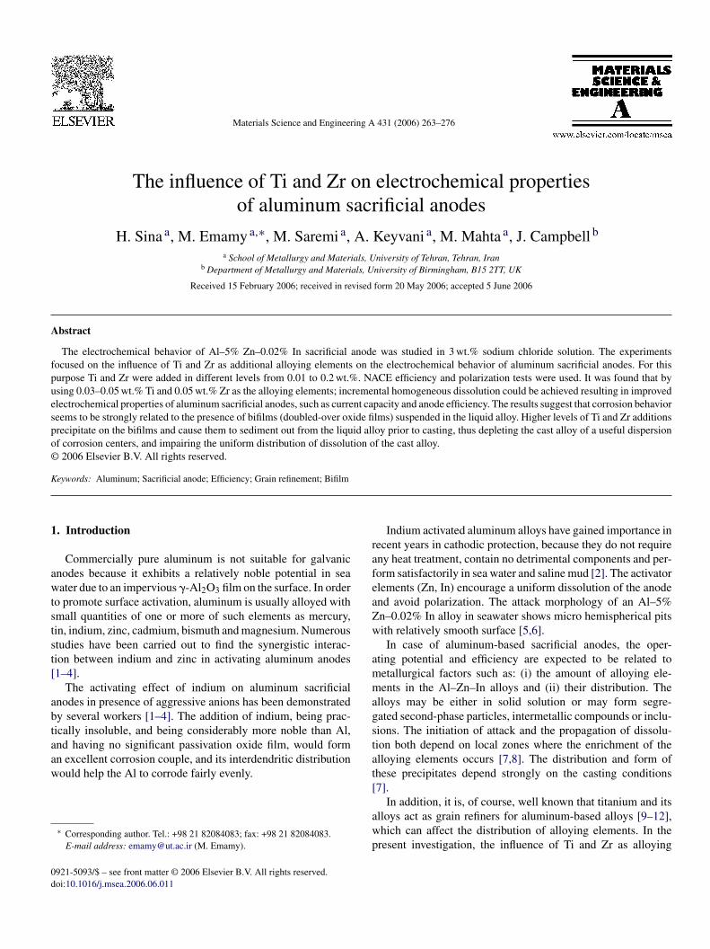
A
fpuespo©
K
1
awtstst[
abtaaw
0d
Materials Science and Engineering A 431 (2006) 263–276
The influence of Ti and Zr on electrochemical propertiesof aluminum sacrificial anodes
H. Sina a, M. Emamy a,∗, M. Saremi a, A. Keyvani a, M. Mahta a, J. Campbell b
a School of Metallurgy and Materials, University of Tehran, Tehran, Iranb Department of Metallurgy and Materials, University of Birmingham, B15 2TT, UK
Received 15 February 2006; received in revised form 20 May 2006; accepted 5 June 2006
bstract
The electrochemical behavior of Al–5% Zn–0.02% In sacrificial anode was studied in 3 wt.% sodium chloride solution. The experimentsocused on the influence of Ti and Zr as additional alloying elements on the electrochemical behavior of aluminum sacrificial anodes. For thisurpose Ti and Zr were added in different levels from 0.01 to 0.2 wt.%. NACE efficiency and polarization tests were used. It was found that bysing 0.03–0.05 wt.% Ti and 0.05 wt.% Zr as the alloying elements; incremental homogeneous dissolution could be achieved resulting in improvedlectrochemical properties of aluminum sacrificial anodes, such as current capacity and anode efficiency. The results suggest that corrosion behavior
eems to be strongly related to the presence of bifilms (doubled-over oxide films) suspended in the liquid alloy. Higher levels of Ti and Zr additionsrecipitate on the bifilms and cause them to sediment out from the liquid alloy prior to casting, thus depleting the cast alloy of a useful dispersionf corrosion centers, and impairing the uniform distribution of dissolution of the cast alloy.2006 Elsevier B.V. All rights reserved.
rafeaZw
ammagst
eywords: Aluminum; Sacrificial anode; Efficiency; Grain refinement; Bifilm
. Introduction
Commercially pure aluminum is not suitable for galvanicnodes because it exhibits a relatively noble potential in seaater due to an impervious �-Al2O3 film on the surface. In order
o promote surface activation, aluminum is usually alloyed withmall quantities of one or more of such elements as mercury,in, indium, zinc, cadmium, bismuth and magnesium. Numeroustudies have been carried out to find the synergistic interac-ion between indium and zinc in activating aluminum anodes1–4].
The activating effect of indium on aluminum sacrificialnodes in presence of aggressive anions has been demonstratedy several workers [1–4]. The addition of indium, being prac-ically insoluble, and being considerably more noble than Al,nd having no significant passivation oxide film, would form
n excellent corrosion couple, and its interdendritic distributionould help the Al to corrode fairly evenly.∗ Corresponding author. Tel.: +98 21 82084083; fax: +98 21 82084083.E-mail address: [email protected] (M. Emamy).
at[
awp
921-5093/$ – see front matter © 2006 Elsevier B.V. All rights reserved.oi:10.1016/j.msea.2006.06.011
Indium activated aluminum alloys have gained importance inecent years in cathodic protection, because they do not requireny heat treatment, contain no detrimental components and per-orm satisfactorily in sea water and saline mud [2]. The activatorlements (Zn, In) encourage a uniform dissolution of the anodend avoid polarization. The attack morphology of an Al–5%n–0.02% In alloy in seawater shows micro hemispherical pitsith relatively smooth surface [5,6].In case of aluminum-based sacrificial anodes, the oper-
ting potential and efficiency are expected to be related toetallurgical factors such as: (i) the amount of alloying ele-ents in the Al–Zn–In alloys and (ii) their distribution. The
lloys may be either in solid solution or may form segre-ated second-phase particles, intermetallic compounds or inclu-ions. The initiation of attack and the propagation of dissolu-ion both depend on local zones where the enrichment of thelloying elements occurs [7,8]. The distribution and form ofhese precipitates depend strongly on the casting conditions7].
In addition, it is, of course, well known that titanium and itslloys act as grain refiners for aluminum-based alloys [9–12],hich can affect the distribution of alloying elements. In theresent investigation, the influence of Ti and Zr as alloying
2 nd En
es
2
agog0mr
3ft
TC
ZISFCCPA
Fo
tatfams
baddt
64 H. Sina et al. / Materials Science a
lements on aluminum sacrificial anode performance has beentudied.
. Experimental procedure
The chemical composition of Al–5% Zn–0.02% In sacrificialnode is shown in Table 1. Twelve melts studied in two mainroups were based on this composition. Only the concentrationf Ti and Zr was varied between 0.01 and 0.2 wt.%. These tworain refining elements were added at levels varying from 0.01 to.2%. Elements were added to the alloy by means of commercialaster alloys of composition: Al–5% Ti–1% B and Al–10% Zr,
espectively.
The alloy ingots were cut, dried, weighed and melted in a00 g capacity clay–graphite crucible in an electrical resistanceurnace. The temperature was vigilantly controlled and moni-ored using a K-type thermocouple. When the melt reached the
able 1hemical composition (wt.%) of Al–Zn–In alloy used
n 5.097n 0.021i 0.088e 0.150u 0.009d 0.002b 0.040l Rem.
ig. 1. Current capacity and efficiency values of anodes with different amountsf Ti and Zr.
fpmattso5ct
C
A
wcwa
c0esdrp
f
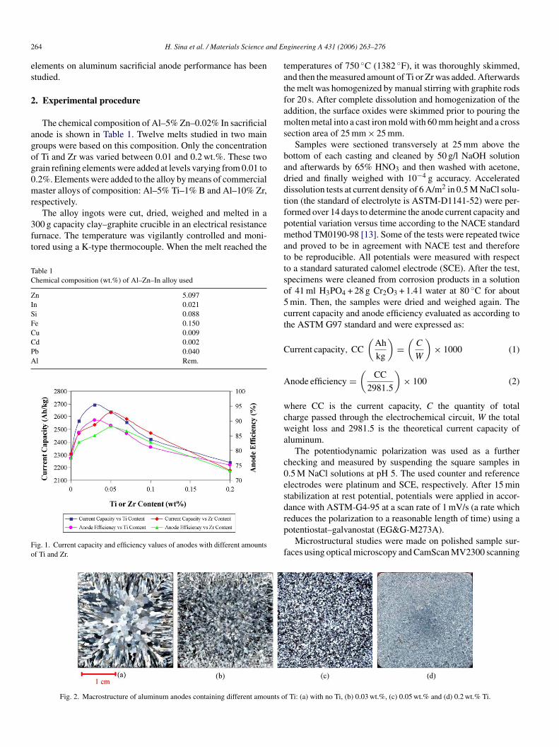
Fig. 2. Macrostructure of aluminum anodes containing different amounts o
gineering A 431 (2006) 263–276
emperatures of 750 ◦C (1382 ◦F), it was thoroughly skimmed,nd then the measured amount of Ti or Zr was added. Afterwardshe melt was homogenized by manual stirring with graphite rodsor 20 s. After complete dissolution and homogenization of theddition, the surface oxides were skimmed prior to pouring theolten metal into a cast iron mold with 60 mm height and a cross
ection area of 25 mm × 25 mm.Samples were sectioned transversely at 25 mm above the
ottom of each casting and cleaned by 50 g/l NaOH solutionnd afterwards by 65% HNO3 and then washed with acetone,ried and finally weighed with 10−4 g accuracy. Acceleratedissolution tests at current density of 6 A/m2 in 0.5 M NaCl solu-ion (the standard of electrolyte is ASTM-D1141-52) were per-ormed over 14 days to determine the anode current capacity andotential variation versus time according to the NACE standardethod TM0190-98 [13]. Some of the tests were repeated twice
nd proved to be in agreement with NACE test and thereforeo be reproducible. All potentials were measured with respecto a standard saturated calomel electrode (SCE). After the test,pecimens were cleaned from corrosion products in a solutionf 41 ml H3PO4 + 28 g Cr2O3 + 1.4 l water at 80 ◦C for aboutmin. Then, the samples were dried and weighed again. Theurrent capacity and anode efficiency evaluated as according tohe ASTM G97 standard and were expressed as:
urrent capacity, CC
(Ah
kg
)=
(C
W
)× 1000 (1)
node efficiency =(
CC
2981.5
)× 100 (2)
here CC is the current capacity, C the quantity of totalharge passed through the electrochemical circuit, W the totaleight loss and 2981.5 is the theoretical current capacity of
luminum.The potentiodynamic polarization was used as a further
hecking and measured by suspending the square samples in.5 M NaCl solutions at pH 5. The used counter and referencelectrodes were platinum and SCE, respectively. After 15 mintabilization at rest potential, potentials were applied in accor-ance with ASTM-G4-95 at a scan rate of 1 mV/s (a rate which
educes the polarization to a reasonable length of time) using aotentiostat–galvanostat (EG&G-M273A).Microstructural studies were made on polished sample sur-aces using optical microscopy and CamScan MV2300 scanning
f Ti: (a) with no Ti, (b) 0.03 wt.%, (c) 0.05 wt.% and (d) 0.2 wt.% Ti.
nd Engineering A 431 (2006) 263–276 265
ea
3
3
aZbT0
ibtbioadmht
wpmuu
i0apbcaa
Ia
Ff
swvoa
H. Sina et al. / Materials Science a
lectron microscope (SEM) equipped with energy dispersivenalysis (EDX) to identify various phases.
. Results and discussion
.1. Electrochemical studies
In the accelerated dissolution tests, the influence of Ti and Zrddition on the anode efficiency and current capacity of Al–5%n–0.02% In sacrificial anode are shown in Fig. 1. It is seen thatoth Ti and Zr in the Al anode can affect the current capacity.he maximum efficiency is achieved by either 0.03 wt.% Ti or.05 wt.% Zr.
Considering the Al–Zn binary system, zinc is concentratedn interdendritic or grain boundaries. Although the effect maye reduced by grain refinement of the alloy [7,14,15] the reduc-ion is, in practice, negligible. However, numerous theories haveeen proposed in order to explain the activating influence ofndium and zinc on the dissolution of aluminum in chloride aque-us media (for instance [16]). The attack initiation of Al–Zn–Inlloys is related to indium- and zinc-rich zones located at inter-endritic and grain boundary sites due to the normal action oficrosegregation [17]. So, it may be expected that uniform and
omogenous distribution of these elements would cause the reac-ion to proceed uniformly over the entire exposed surface.
Addition of titanium can produce TiAl3 particles in the melt,hich are known to be excellent nucleation sites for the solidhase [18]. The grain refining action produces a finer uniformicrostructure that is shown in Figs. 2 and 3. A finer and more
niform structure would normally be expected to promote a moreniform dissolution.
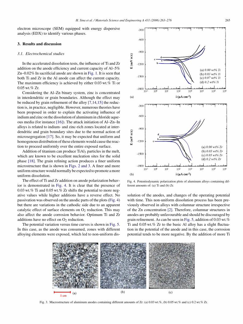
The effect of Ti and Zr addition on anode polarization behav-or is demonstrated in Fig. 4. It is clear that the presence of.03 wt.% Ti and 0.05 wt.% Zr shifts the potential to more neg-tive values while higher additions have a reverse effect. Noassivation was observed on the anodic parts of the plots (Fig. 4)ut there are variations in the cathodic side due to an apparentatalytic effect of surface elements on O2 reduction. This maylso affect the anode corrosion behavior. Optimum Ti and Zr
dditions have no effect on O2 reduction.The potential variation versus time curves is shown in Fig. 5.n this case, as the anode was consumed, zones with differentlloying elements were exposed, which led to non-uniform dis-
gTtp
Fig. 3. Macrostructure of aluminum anodes containing different am
ig. 4. Potentiodynamic polarization plots of aluminum alloys containing dif-erent amounts of: (a) Ti and (b) Zr.
olution of the anodes, and changes of the operating potentialith time. This non-uniform dissolution process has been pre-iously observed in alloys with columnar structure irrespectivef the Zn concentration [2]. Therefore, columnar structures innodes are probably unfavourable and should be discouraged by
rain refinement. As can be seen in Fig. 5, addition of 0.03 wt.%i and 0.05 wt.% Zr to the basic Al alloy has a slight fluctua-ion in the potential of the anode and in this case, the corrosionotential tends to be more negative. By the addition of more Ti
ounts of Zr: (a) 0.03 wt.%, (b) 0.05 wt.% and (c) 0.2 wt.% Zr.
266 H. Sina et al. / Materials Science and Engineering A 431 (2006) 263–276
anod
aaataeaZ
3
a
csrc
pmsi
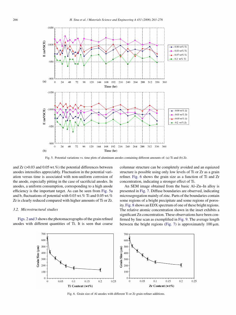
Fig. 5. Potential variations vs. time plots of aluminum
nd Zr (>0.03 and 0.05 wt.%) the potential differences betweennodes intensifies appreciably. Fluctuation in the potential vari-tion versus time is associated with non-uniform corrosion ofhe anode, especially pitting in the case of sacrificial anodes. Innodes, a uniform consumption, corresponding to a high anodefficiency is the important target. As can be seen from Fig. 5and b, fluctuations of potential with 0.03 wt.% Ti and 0.05 wt.%r is clearly reduced compared with higher amounts of Ti or Zr.
.2. Microstructural studies
Figs. 2 and 3 shows the photomacrographs of the grain refinednodes with different quantities of Ti. It is seen that coarse
Tsfib
Fig. 6. Grain size of Al anodes with diffe
es containing different amounts of: (a) Ti and (b) Zr.
olumnar structure can be completely avoided and an equiaxedtructure is possible using only low levels of Ti or Zr as a grainefiner. Fig. 6 shows the grain size as a function of Ti and Zroncentration, indicating a stronger effect of Ti.
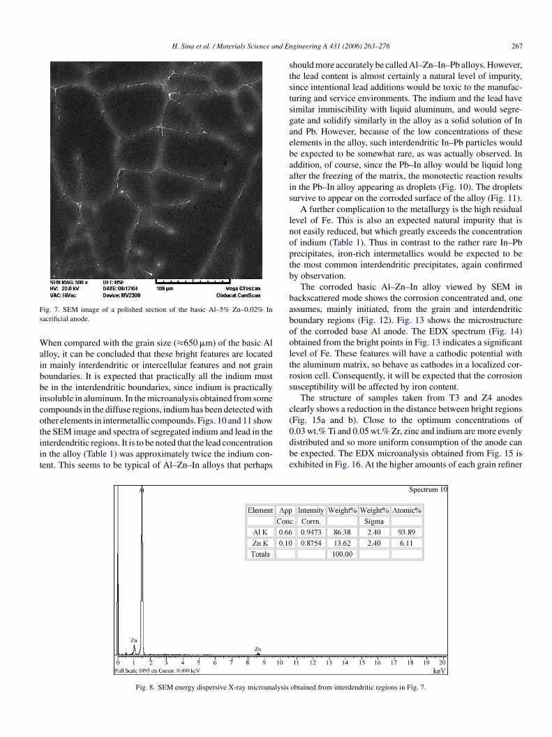
An SEM image obtained from the basic Al–Zn–In alloy isresented in Fig. 7. Diffuse boundaries are observed, indicatingicrosegregation mainly of zinc. Parts of the boundaries contain
ome regions of a bright precipitate and some regions of poros-ty. Fig. 8 shows an EDX spectrum of one of these bright regions.
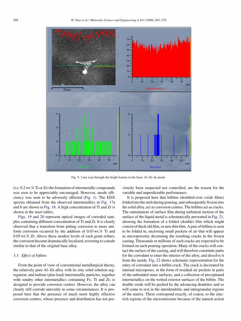
he relative atomic concentration shown in the inset exhibits aignificant Zn concentration. These observations have been con-rmed by line scan as exemplified in Fig. 9. The average lengthetween the bright regions (Fig. 7) is approximately 100 �m.rent Ti or Zr grain refiner additions.
H. Sina et al. / Materials Science and En
Fs
Waibbicotiit
ststsgaebaais
lnoptb
babooltrs
c(
ig. 7. SEM image of a polished section of the basic Al–5% Zn–0.02% Inacrificial anode.
hen compared with the grain size (≈650 �m) of the basic Allloy, it can be concluded that these bright features are locatedn mainly interdendritic or intercellular features and not grainoundaries. It is expected that practically all the indium muste in the interdendritic boundaries, since indium is practicallynsoluble in aluminum. In the microanalysis obtained from someompounds in the diffuse regions, indium has been detected withther elements in intermetallic compounds. Figs. 10 and 11 show
he SEM image and spectra of segregated indium and lead in thenterdendritic regions. It is to be noted that the lead concentrationn the alloy (Table 1) was approximately twice the indium con-ent. This seems to be typical of Al–Zn–In alloys that perhaps0dbe
Fig. 8. SEM energy dispersive X-ray microanalysis
gineering A 431 (2006) 263–276 267
hould more accurately be called Al–Zn–In–Pb alloys. However,he lead content is almost certainly a natural level of impurity,ince intentional lead additions would be toxic to the manufac-uring and service environments. The indium and the lead haveimilar immiscibility with liquid aluminum, and would segre-ate and solidify similarly in the alloy as a solid solution of Innd Pb. However, because of the low concentrations of theselements in the alloy, such interdendritic In–Pb particles woulde expected to be somewhat rare, as was actually observed. Inddition, of course, since the Pb–In alloy would be liquid longfter the freezing of the matrix, the monotectic reaction resultsn the Pb–In alloy appearing as droplets (Fig. 10). The dropletsurvive to appear on the corroded surface of the alloy (Fig. 11).
A further complication to the metallurgy is the high residualevel of Fe. This is also an expected natural impurity that isot easily reduced, but which greatly exceeds the concentrationf indium (Table 1). Thus in contrast to the rather rare In–Pbrecipitates, iron-rich intermetallics would be expected to behe most common interdendritic precipitates, again confirmedy observation.
The corroded basic Al–Zn–In alloy viewed by SEM inackscattered mode shows the corrosion concentrated and, onessumes, mainly initiated, from the grain and interdendriticoundary regions (Fig. 12). Fig. 13 shows the microstructuref the corroded base Al anode. The EDX spectrum (Fig. 14)btained from the bright points in Fig. 13 indicates a significantevel of Fe. These features will have a cathodic potential withhe aluminum matrix, so behave as cathodes in a localized cor-osion cell. Consequently, it will be expected that the corrosionusceptibility will be affected by iron content.
The structure of samples taken from T3 and Z4 anodeslearly shows a reduction in the distance between bright regionsFig. 15a and b). Close to the optimum concentrations of
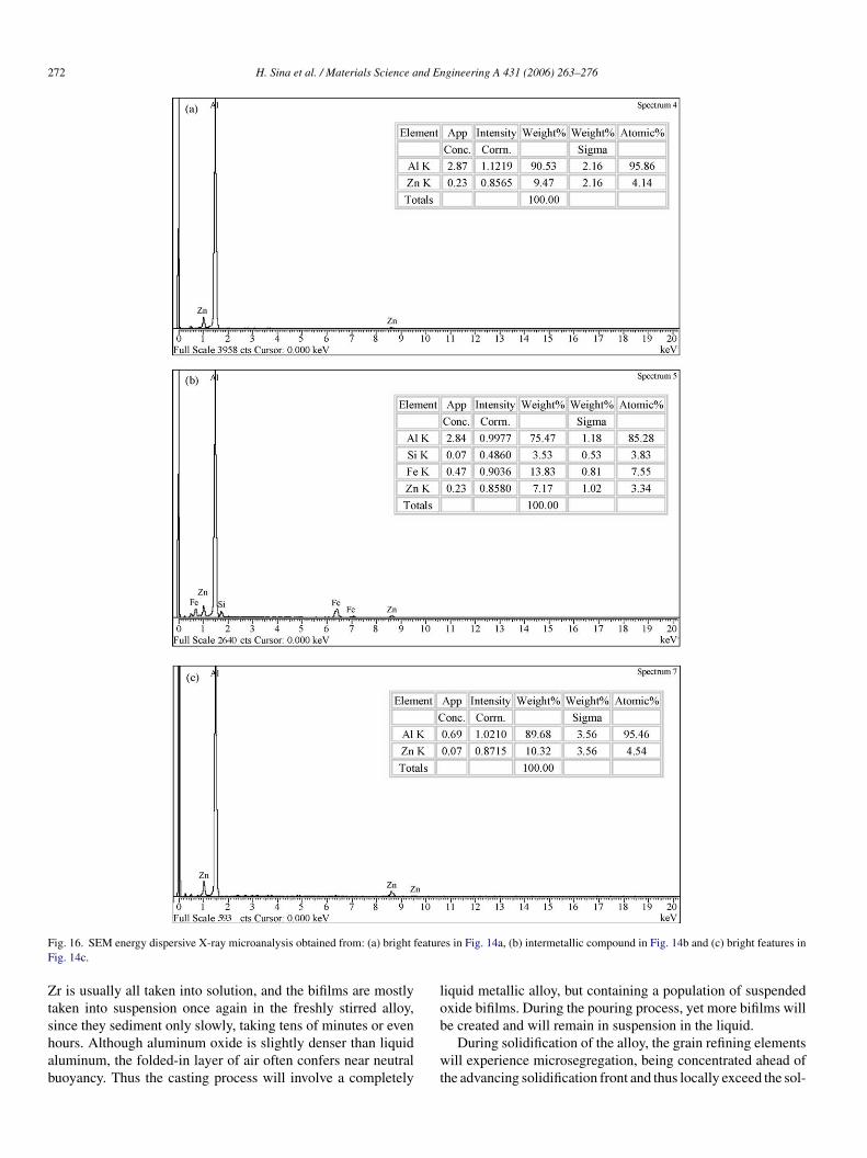
.03 wt.% Ti and 0.05 wt.% Zr, zinc and indium are more evenlyistributed and so more uniform consumption of the anode cane expected. The EDX microanalysis obtained from Fig. 15 isxhibited in Fig. 16. At the higher amounts of each grain refinerobtained from interdendritic regions in Fig. 7.
268 H. Sina et al. / Materials Science and Engineering A 431 (2006) 263–276
ht fea
(wcsas
pof0ts
3
trwdcpc
vv
ftTssctacftffeioi
Fig. 9. Line scan through the brig
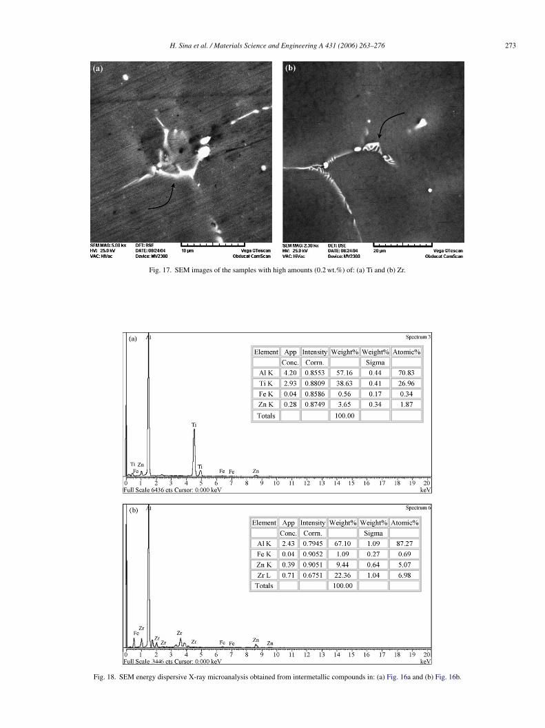
i.e. 0.2 wt.% Ti or Zr) the formation of intermetallic compoundsas seen to be appreciably encouraged. However, anode effi-
iency was seen to be adversely affected (Fig. 1). The EDXpectra obtained from the observed intermetallics in Fig. 17and b are shown in Fig. 18. A high concentration of Ti and Zr ishown in the inset tables.
Figs. 19 and 20 represent optical images of corroded sam-les containing different concentration of Ti and Zr. It is clearlybserved that a transition from pitting corrosion to more uni-orm corrosion occurred by the addition of 0.03 wt.% Ti and.05 wt.% Zr. Above these modest levels of each grain refiner,he corrosion became dramatically localized, reverting to a modeimilar to that of the original base alloy.
.3. Effect of bifilms
From the point of view of conventional metallurgical theory,he relatively pure Al–Zn alloy with its zinc solid solution seg-egation, and indium (plus lead) intermetallic particles, togetherith sundry other intermetallics containing Fe, Ti and Zr, is
esigned to provide corrosion centres. However, the alloy canlearly still corrode unevenly in some circumstances. It is pro-osed here that the presence of much more highly effectiveorrosion centres, whose presence and distribution has not pre-dwor
ture in the basic Al–Zn–In anode.
iously been suspected nor controlled, are the reason for theariable and unpredictable performance.
It is proposed here that bifilms (doubled-over oxide films)olded into the melt during pouring, and subsequently frozen intohe solid alloy, act as corrosion centres. The bifilms act as cracks.he entrainment of surface film during turbulent motion of theurface of the liquid metal is schematically presented in Fig. 21,howing the formation of a folded (double) film which mightonsist of thick old film, or new thin film. A pair of bifilms is seeno be folded in, enclosing small pockets of air that will appears microporosity decorating the resulting cracks in the frozenasting. Thousands or millions of such cracks are expected to beormed on such pouring operation. Many of the cracks will con-act the surface of the casting, and will therefore constitute pathsor the corrodant to enter the interior of the alloy, and dissolve itrom the inside. Fig. 22 shows schematic representation for thentry of corrodant into a bifilm crack. The crack is decorated bynternal micropores, in the form of residual air pockets in partsf the unbonded inner surfaces, and a collection of precipitatedntermetallics on the wetted exterior surfaces of the bifilm. The
ouble oxide will be pushed by the advancing dendrites and soill come to rest in the interdendritic and intergranular regionsf the matrix. These correspond exactly, of course, to the zinc-ich regions of the microstructure because of the natural action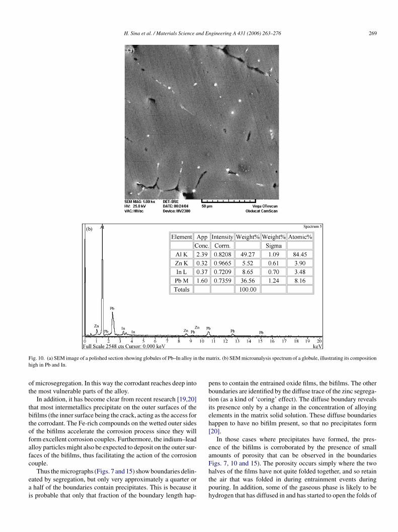
H. Sina et al. / Materials Science and Engineering A 431 (2006) 263–276 269
F the mh
ot
tbtofafc
eai
pbtieh[
eaF
ig. 10. (a) SEM image of a polished section showing globules of Pb–In alloy inigh in Pb and In.
f microsegregation. In this way the corrodant reaches deep intohe most vulnerable parts of the alloy.
In addition, it has become clear from recent research [19,20]hat most intermetallics precipitate on the outer surfaces of theifilms (the inner surface being the crack, acting as the access forhe corrodant. The Fe-rich compounds on the wetted outer sidesf the bifilms accelerate the corrosion process since they willorm excellent corrosion couples. Furthermore, the indium–leadlloy particles might also be expected to deposit on the outer sur-aces of the bifilms, thus facilitating the action of the corrosionouple.
Thus the micrographs (Figs. 7 and 15) show boundaries delin-ated by segregation, but only very approximately a quarter orhalf of the boundaries contain precipitates. This is because it
s probable that only that fraction of the boundary length hap-
htph
atrix. (b) SEM microanalysis spectrum of a globule, illustrating its composition
ens to contain the entrained oxide films, the bifilms. The otheroundaries are identified by the diffuse trace of the zinc segrega-ion (as a kind of ‘coring’ effect). The diffuse boundary revealsts presence only by a change in the concentration of alloyinglements in the matrix solid solution. These diffuse boundariesappen to have no bifilm present, so that no precipitates form20].
In those cases where precipitates have formed, the pres-nce of the bifilms is corroborated by the presence of smallmounts of porosity that can be observed in the boundariesigs. 7, 10 and 15). The porosity occurs simply where the two
alves of the films have not quite folded together, and so retainhe air that was folded in during entrainment events duringouring. In addition, some of the gaseous phase is likely to beydrogen that has diffused in and has started to open the folds of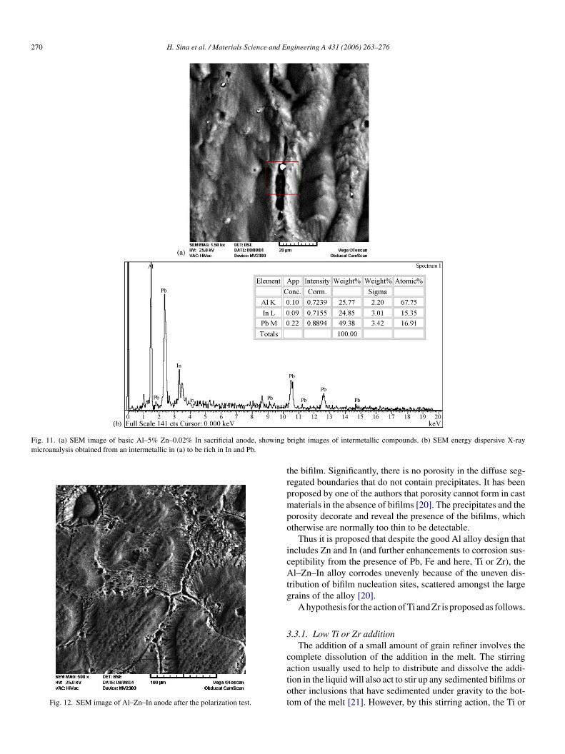
270 H. Sina et al. / Materials Science and Engineering A 431 (2006) 263–276
Fig. 11. (a) SEM image of basic Al–5% Zn–0.02% In sacrificial anode, showingmicroanalysis obtained from an intermetallic in (a) to be rich in In and Pb.
Fig. 12. SEM image of Al–Zn–In anode after the polarization test.
trpmpo
icAtg
3
catot
bright images of intermetallic compounds. (b) SEM energy dispersive X-ray
he bifilm. Significantly, there is no porosity in the diffuse seg-egated boundaries that do not contain precipitates. It has beenroposed by one of the authors that porosity cannot form in castaterials in the absence of bifilms [20]. The precipitates and the
orosity decorate and reveal the presence of the bifilms, whichtherwise are normally too thin to be detectable.
Thus it is proposed that despite the good Al alloy design thatncludes Zn and In (and further enhancements to corrosion sus-eptibility from the presence of Pb, Fe and here, Ti or Zr), thel–Zn–In alloy corrodes unevenly because of the uneven dis-
ribution of bifilm nucleation sites, scattered amongst the largerains of the alloy [20].
A hypothesis for the action of Ti and Zr is proposed as follows.
.3.1. Low Ti or Zr additionThe addition of a small amount of grain refiner involves the
omplete dissolution of the addition in the melt. The stirring
ction usually used to help to distribute and dissolve the addi-ion in the liquid will also act to stir up any sedimented bifilms orther inclusions that have sedimented under gravity to the bot-om of the melt [21]. However, by this stirring action, the Ti or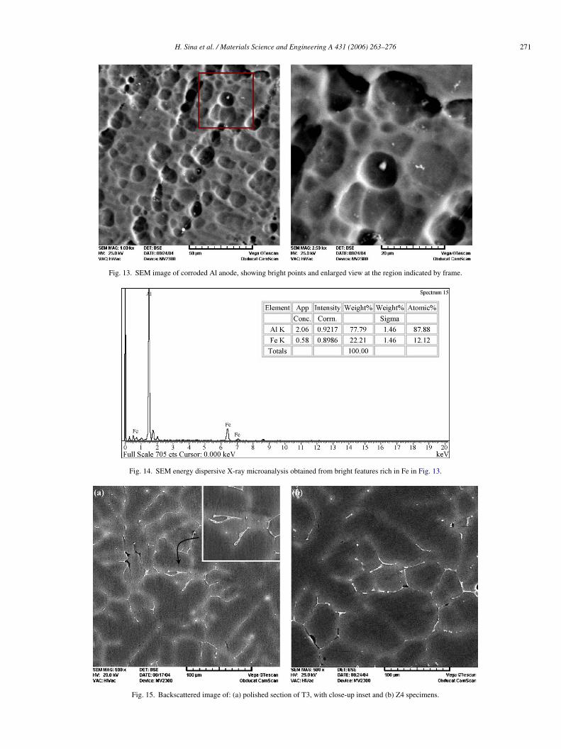
H. Sina et al. / Materials Science and Engineering A 431 (2006) 263–276 271
Fig. 13. SEM image of corroded Al anode, showing bright points and enlarged view at the region indicated by frame.
Fig. 14. SEM energy dispersive X-ray microanalysis obtained from bright features rich in Fe in Fig. 13.
Fig. 15. Backscattered image of: (a) polished section of T3, with close-up inset and (b) Z4 specimens.
272 H. Sina et al. / Materials Science and Engineering A 431 (2006) 263–276
F eaturF
Ztshab
lo
ig. 16. SEM energy dispersive X-ray microanalysis obtained from: (a) bright fig. 14c.
r is usually all taken into solution, and the bifilms are mostlyaken into suspension once again in the freshly stirred alloy,
ince they sediment only slowly, taking tens of minutes or evenours. Although aluminum oxide is slightly denser than liquidluminum, the folded-in layer of air often confers near neutraluoyancy. Thus the casting process will involve a completelyb
wt
es in Fig. 14a, (b) intermetallic compound in Fig. 14b and (c) bright features in
iquid metallic alloy, but containing a population of suspendedxide bifilms. During the pouring process, yet more bifilms will
e created and will remain in suspension in the liquid.During solidification of the alloy, the grain refining elementsill experience microsegregation, being concentrated ahead of
he advancing solidification front and thus locally exceed the sol-
H. Sina et al. / Materials Science and Engineering A 431 (2006) 263–276 273
Fig. 17. SEM images of the samples with high
Fig. 18. SEM energy dispersive X-ray microanalysis obtained from
amounts (0.2 wt.%) of: (a) Ti and (b) Zr.
intermetallic compounds in: (a) Fig. 16a and (b) Fig. 16b.

274 H. Sina et al. / Materials Science and Engineering A 431 (2006) 263–276
Fig. 19. The optical images of corroded Al–Zn–In anodes after 14 days of polarization test and containing different amounts of Ti: (a) with no Ti, (b) 0.03 wt.% and(c) 0.2 wt.% Ti.
F test. A0
uwwcsaopsloat
Fm
Tp(oiF
3
ig. 20. The optical images of corroded Al anodes after 14 days of polarization.05 wt.% and (c) 0.2 wt.% Zr.
bility of TiAl3 or other grain refining compounds. The TiAl3ill then precipitate if a suitable substrate is available; other-ise it will remain in supersaturated solution. Bifilms are, of
ourse, pushed ahead of the advancing solidification front ando are automatically precisely in the appropriate location to acts substrates. Thus the TiAl3 will be expected to precipitaten the backs of bifilms together with iron-rich phases, In–Pbhases, and silicon eutectic particles if any [20]. At this latetage in solidification the extensive dendrite mesh prevents anyarge scale movement of bifilms and their associated Ti-, Zr-
r Fe-rich precipitates. The bifilms are no longer able to swimround or sink, but are entrapped between the dendrites. Thushe precipitates are evenly distributed in interdendritic regions.ig. 21. Schematic representation of entrainment of oxide film during turbulentotion of the surface of the liquid.
eaai
l–5% Zn–0.02% In and containing different amounts of Zr: (a) 0.03 wt.%, (b)
he bifilms and their associated precipitates, now nicely dis-ersed, now act as initiation sites for corrosion by providing:i) an open channel for the ingress of corrodant into the interiorf the Zn-rich regions of the microstructure and (ii) associatedntermetallic precipitates that include, among other elements,e, In and Pb.
.3.2. High Ti or Zr additionThe addition of larger amounts of grain refiner would be
xpected result in a quite different outcome. At quantities ofddition approaching the limit of solubility for the addition, theddition will tend to precipitate onto bifilms well before thenstant of casting. The bifilms will be expected to be present in
Fig. 22. Schematic view of the entry of corrodant into a bifilm crack.
nd En
scmifagacatataltw
rbdnsfpbsmpotro
bctccctTsc
wmttif
bln
t
ip
cotcass
4
istd
(
(
(
(
(
(
pouring of the casting).
H. Sina et al. / Materials Science a
uspension in the liquid alloy in their hundreds or millions, andonstituting various populations of sizes from micrometers toillimeters. Early precipitation onto bifilms will certainly occur
f the amount of addition exceeds its solubility (limit 0.15 wt.%or Ti). However, it will probably also occur to some extent event levels of addition under the limit, because the addition of therain refiner is made effectively at 100%, and has to dissolvend disperse in the bulk melt. Thus during the dissolution pro-ess parts of the melt will greatly exceed the solubility limit,nd will therefore tend to experience precipitation. Althoughhis early precipitation will, in principle, be reversible when thelloy becomes homogeneous, in fact the dissolution back intohe bulk melt takes time, and so, in normal conditions of alloyingnd casting, is expected to occur partially. (However, of course, aonger dwell time prior to pouring would be expected to counterhis disadvantage to some extent. Naturally, however, such delayould not be popular for the production of a commercial alloy.)Prior to casting therefore, large quantities of Ti-rich (or Zr-
ich) compounds such as TiAl3 will deposit on the backs of theifilms. Because of the relatively large volume of these heavyeposits, the buoyancy of the bifilms will be changed from nearlyeutral, to heavy, and will drop to the bottom of the melt liketones. This behavior has been observed directly by Mount-ord and Calvert [21], looking into the melt using ultrasonicrobes. They observed a fog of suspended material (interpretedy Campbell [20] as bifilms) that, as soon as the melt becameupersaturated with Ti (by reducing temperature in their experi-ents), precipitated to the bottom, becoming a sludge of Ti-rich
articles and oxides. The precipitation to the bottom of furnacesf a sludge of Ti and oxides is well known in the casting indus-ry, and requires melting and holding furnaces to be cleaned outegularly. This precipitation behavior occurs quickly, and is allver in seconds or minutes.
The melt is now relatively free from bifilms since they haveeen sedimented out of suspension prior to the pouring of theasting. Thus the new corrosion behavior is similar to that athe starting point for the base Al–Zn–In alloy. It seems that theorrosion sites have become fewer and more poorly distributed,orresponding to the observation that dissolution of the sacrifi-ial alloy has become badly distributed. The polarization plots ofhe base alloy and the high Ti alloy are nearly the same (Fig. 4).hus the start and end conditions of the experiment are closelyimilar. This clearly happens despite the continuation of the suc-essful grain refining effect.
The grain refinement continues to be successful because thereill still be sufficient Ti or Zr in solution to effect grain refine-ent (only the excess above the solubility limit precipitates in
he liquid state prior to pouring). Thus although the microstruc-ure appears to be fine and the distribution of active elementss therefore expected to be nicely uniform, the corrosion is farrom uniform.
The principle corrosion site therefore is proposed to be theifilm, the only component of the microstructure that remains
argely invisible because of its thinness, and the only componentot so far benefiting from normal metallurgical control.Having identified the bifilm as, possibly, the most likely fea-ure responsible for the principal corrosion action in the alloy,
A
o
gineering A 431 (2006) 263–276 275
t is now possible to propose an explanation of the well-knownoor corrosion action of columnar structures.
As columnar grains grow from the wall into the centre of theasting, they will push bifilms ahead, depleting the outer layersf the casting of these highly active corrosion sites, and concen-rating such sites in the inaccessible and, of course, ineffectiveentre of the casting. In contrast, the optimal grain refinementction retains the uniform distribution of bifilms originally inuspension in the liquid, thus conferring more uniform corro-ion behavior of the solid alloy.
. Conclusions
Electrochemical analysis of Al–Zn–In sacrificial anodes hav-ng different Ti or Zr contents as a grain refinement agent wastudied with the objective of establishing the optimum concen-ration of each grain refiner. The main conclusions that can berawn are:
1) The microstructure of sacrificial Al–Zn–In alloy anode cast-ings was observed to change from columnar to equiaxedwith 0.03 wt.% Ti or 0.05 wt.% Zr.
2) The principal corrosion sites are proposed to be bifilms (theremnants of the folded-in oxide on the liquid surface duringthe pouring of the alloy). These are expected to act by pro-viding an open path for the corrodant to enter the Zn-richregions of the microstructure, and by providing adjacentprecipitation of corrosion couple intermetallics containingFe, Ti, Zr, In and Pb.
3) Without the presence of bifilms in the structure, the alloy isto some extent corrosion resistant, despite the presence offavourable metallurgical conditions such as fine grain sizeand correct alloy composition.
4) The effects of iron may be beneficial in the alloy, precipitat-ing on the bifilm and acting as a corrosion couple, assistingthe bifilm to be a preferential corrosion site. Titanium andzirconium would be expected to behave analogously in thisway.
5) Higher amounts of Ti and Zr grain refiners were found tobe counter-productive. It is proposed that the bifilms areprecipitated prematurely from the liquid alloy by the excessTi or Zr prior to pouring, depleting the alloy of its fine anduniform distribution of corrosion sites.
6) Columnar grains are proposed to segregate bifilms into thecentre of the casting, and thus depleting surface regions ofcorrosion sites. Grain refinement is valuable to retain theuniform distribution of bifilms (provided too much of thegrain refining element is not added to cause premature pre-cipitation on, and sedimentation of, the bifilms prior to the
cknowledgement
The authors wish to acknowledge the financial contributionf University of Tehran.
2 nd E
R
[
[[[
[[[[[
76 H. Sina et al. / Materials Science a
eferences
[1] G. Bruzzone, A. Burbacci, G. Cerisola, J. Alloy Compd. 247 (1997)210.
[2] A.G. Kulkarni, I. Gurrappa, Br. Corros. J. 28 (1993) 67.[3] J.T. Reding, J.J. Newport, Mater. Protect 5 (1966) 15.[4] A. Tamada, Y. Tamaura, Corros. Sci. 34 (1993) 1099.[5] A.G. Munoz, S.B. Saidman, J.B. Bessone, Corros. Sci. 36 (1994) 85.[6] J.B. Bessone, R.A. Suarez Baldo, S.M. De Micheli, Corrosion 37 (1981)
533.
[7] D.R. Salinas, S.G. Garcia, J.B. Bessone, J. Appl. Electrochem. 29 (1999)1063.[8] A.G. Munoz, S.B. Saidman, J.B. Bessone, Corros. Sci. 44 (2002) 2171.[9] I. Maxwell, A. Hellawell, Acta Metall. 23 (1975) 229.10] I. Maxwell, A. Hellawell, Acta Metall. 23 (1975) 901.
[
[
[
ngineering A 431 (2006) 263–276
11] A. Cibula, J. Inst. Met. 76 (1950) 321.12] I. Pearson, M.E.J. Birth, J. Met. 28 (1979) 27.13] Standard Test Method Impressed Current Laboratory Testing of Alu-
minum Alloy Anodes, NACE Standard, TM0190-98, 1998.14] J. Morgan, Cathodic Protection, NACE, 1995, p. 113 (Chapter 4).15] L.L. Shreir, Corrosion 2 (1978) 11.16] A.G. Manoz, S.B. Saidman, J.B. Bessone, Corros. Sci. 43 (2001) 1245.17] A. Venucupal, V.S. Raja, Corros. Sci. 39 (1997) 2053.18] M. Emamy, M. Mahta, J. Rasizadeh, Compos. Sci. Technol. 66 (2006)
1063–1066.
19] M. Mahta, M. Emamy, A. Daman, A. Keyvani, J. Campbell, Int. J. CastMet. Res. 18 (2005) 73–79.20] J. Campbell, Castings, 2nd ed., Butterworth Heinemann, Oxford, UK,
2003.21] N.D.G. Mountford, R. Calvert, J. Inst. Met. 88 (1959–1960) 121–127.
Copyright © 2022 FDOKUMEN


![;R^ZR WZcZ_X hYZad fa a`]] WVgVc - Daily Pioneer](https://static.fdokumen.com/doc/165x107/6313be3f6ebca169bd0a9577/rzr-wzczx-hyzad-fa-a-wvgvc-daily-pioneer.jpg)