Conducting coatings as anodes in cathodic protection
10
Conducting Coatings as Anodes in Cathodic Protection K. Darowicki, J. Orlikowski, S. Cebulski *) , S. Krakowiak Technical University of Gdansk, Department of Anticorrosion Technology 80-952 Gdansk, ul. G. Narutowicza 11/12, Poland *) Oliva Paint Factory, 81-571,Gdynia ul. Chwaszczyńska 129-149, Poland Key words: conducting coatings, cathodic protection, EIS Abstract: Results have been presented of electrochemical measurements of conductive organic coatings, obtained by admixing with carbon material. On the basis of impedance measurements electrochemical parameters of conducting coatings have been calculated. Simultaneously electric and electrochemical parameters have been determined of investigated coatings during long-term anodic polarisation. Results were subjected to statistical analysis and the scatter level of experimental results was determined. It has been shown that investigated coatings can be used in cathodic protection of objects whilst maintaining assigned electric and electrochemical parameters. Introduction Corrosion of reinforced concrete structures causes substantial financial losses [1]. The direct cause of destruction is increase of volume of steel reinforcement as the result of corrosion product formation. This causes increase of stress and cracking of concrete [2,3]. In the case of bridge structures an additional factor increases the rate of cracking, namely vibrations and oscillations of the structure as the result of mechanical loads [4]. The hazard concerns particularly bridges, viaducts or hydrotechnical structures [5-7]. Cathodic protection is one of the common methods of anticorrosion protection reinforced concrete structures. Impressed current, as well as sacrificial anode protection are applied [8-10]. In the case of classical sacrificial protection zinc, magnesium and aluminium anodes are used. Parthiban et al. [11] stated that application of novel aluminium alloy production technologies allows achieving significantly better sacrificial protection parameters. Genesc et al. [12] confirmed that best working parameters of magnesium sacrificial anodes can be achieved if magnesium (II) hydroxide is formed on the protector surface. Metal spraying of the concrete surface is another form of sacrificial protection. As shown by Brousseau et al. [13], good protective properties are obtained by metal spraying with zinc, contrary to aluminium coatings, application of which does not yield the expected effects. The protection effectiveness of a metallised coating, as shown by Covino et al. [14], depends on application parameters of the spray coating connected with: the outflow rate, the particle size, the spraying pressure and physical and electrochemical parameters such as processes occurring on the anode-concrete phase interface and the water penetration rate. Sagues and Powers [15] in turn emphasise the great importance of moisture content in concrete. A better protective current distribution in the concrete structure has been confirmed by Bennett and Firlotte [16], who used a hydrogel improving the moisture content on the zinc-concrete phase boundary. Also, improvement of the protection
Transcript of Conducting coatings as anodes in cathodic protection
Conducting Coatings as Anodes in Cathodic Protection
K. Darowicki, J. Orlikowski, S. Cebulski*), S. Krakowiak
Technical University of Gdansk, Department of Anticorrosion Technology 80-952 Gdansk, ul. G. Narutowicza 11/12, Poland
*) Oliva Paint Factory, 81-571,Gdynia ul. Chwaszczyńska 129-149, Poland
Key words: conducting coatings, cathodic protection, EIS
Abstract: Results have been presented of electrochemical measurements of conductive organic coatings, obtained by admixing with carbon material. On the basis of impedance measurements electrochemical parameters of conducting coatings have been calculated. Simultaneously electric and electrochemical parameters have been determined of investigated coatings during long-term anodic polarisation. Results were subjected to statistical analysis and the scatter level of experimental results was determined. It has been shown that investigated coatings can be used in cathodic protection of objects whilst maintaining assigned electric and electrochemical parameters. Introduction
Corrosion of reinforced concrete structures causes substantial financial losses [1]. The direct cause of destruction is increase of volume of steel reinforcement as the result of corrosion product formation. This causes increase of stress and cracking of concrete [2,3]. In the case of bridge structures an additional factor increases the rate of cracking, namely vibrations and oscillations of the structure as the result of mechanical loads [4]. The hazard concerns particularly bridges, viaducts or hydrotechnical structures [5-7]. Cathodic protection is one of the common methods of anticorrosion protection reinforced concrete structures. Impressed current, as well as sacrificial anode protection are applied [8-10]. In the case of classical sacrificial protection zinc, magnesium and aluminium anodes are used. Parthiban et al. [11] stated that application of novel aluminium alloy production technologies allows achieving significantly better sacrificial protection parameters. Genesc et al. [12] confirmed that best working parameters of magnesium sacrificial anodes can be achieved if magnesium (II) hydroxide is formed on the protector surface. Metal spraying of the concrete surface is another form of sacrificial protection. As shown by Brousseau et al. [13], good protective properties are obtained by metal spraying with zinc, contrary to aluminium coatings, application of which does not yield the expected effects. The protection effectiveness of a metallised coating, as shown by Covino et al. [14], depends on application parameters of the spray coating connected with: the outflow rate, the particle size, the spraying pressure and physical and electrochemical parameters such as processes occurring on the anode-concrete phase interface and the water penetration rate. Sagues and Powers [15] in turn emphasise the great importance of moisture content in concrete. A better protective current distribution in the concrete structure has been confirmed by Bennett and Firlotte [16], who used a hydrogel improving the moisture content on the zinc-concrete phase boundary. Also, improvement of the protection
effectiveness, as shown by Brousseau et al. [17], can be obtained by activating the concrete surface with cobalt oxide. Impressed current cathodic protection is realised by installing anodes inside or on the concrete surface [18-19]. Insoluble anodes are most frequently used such as: platinised titanium and titanium covered with active oxides [20]. Development of impressed current cathodic protection methods is concentrated on the power supplies and changes in the installation of the anodic system. Kessler et al. [21] proposed an interesting solution of applying solar-powered cathodic protection systems of piles immersed in sea water. Brousse and Pye [22] point to advantageous aspects of application of carbon fibres as an element limiting the delamination process of platinised titanium anodes from the concrete surface. Most applied solutions of impressed current cathodic protection require installation of anodes in strictly determined points. The main disadvantage of such a solution is a poor protective current distribution, mainly due to a limited surface of the anodes. Also, installation of anodes requires relatively expensive construction works connected with making of openings and removal of the exterior concrete layer. Possible damage to anodes during assembly also is a problem. Application of conducting coatings as anodes is a method of avoiding of most problems. The different approach to this problem creates a possibility of simultaneous realisation of coating and cathodic protection additionally increasing the protection effectiveness. This solution has the following advantages: ease of installation, possibility of protection of places not easily accessible and ensuring of a large anodic system surface allowing uniform distribution of the protective current. Also cathodic protection system installation costs are greatly reduced (application of coatings is much less expensive than installation of classical anodes).
The aim of this work was performing electric and electrochemical measurements of specially prepared conducting coatings to evaluate their suitability as anodes in cathodic protection of reinforced concrete structures. The most important aim was choice of optimum contents of the conducting component in the epoxy coating, to ensure optimal anode working parameters. Measurements Samples for coating investigations were prepared of epoxy resin of medium molecular weight, admixed with graphite with 25-60% contents by weight. The coating was applied on St3 carbon steel, cleaned by abrasive blasting, by a paint brush in four layers of 300 µm total thickness. Application of the paint, intervals between applying subsequent coatings were in accordance with the determined schedule. Each time measurements were performed on five samples, for each graphite content. Resistance measurements of coatings were performed by measuring impedance in a two-electrode system with the use of a mercury electrode. The setup was made of a SCHLUMBERGER SI 1255 transmittance analyser with an ATLAS 9181 attachment for high-impedance measurements. Long-term investigations were based on galvanostatic polarisation of conducting coatings placed in a 1% NaCl electrolyte solution. On the surface of the coatings measurement cells were attached, in which sodium chloride solution was placed. The exposed area was equal to 1.8 cm2. Polarisation of coatings was performed in the anodic direction with a 20 mA/m2 current density. The measuring system was made up of three electrodes. The surface of the conducting coating limited by the measurement cell was the investigated electrode. A platinised titanium mesh was the auxiliary electrode, while the silver chloride electrode was the reference electrode. The electrolytic environment was chosen to simulate sea water of 10 Ωm resistivity. The exposure time of coatings under the anodic current load was 56 days. The electrode potential was measured in 48-hour intervals, while every 14 days impedance
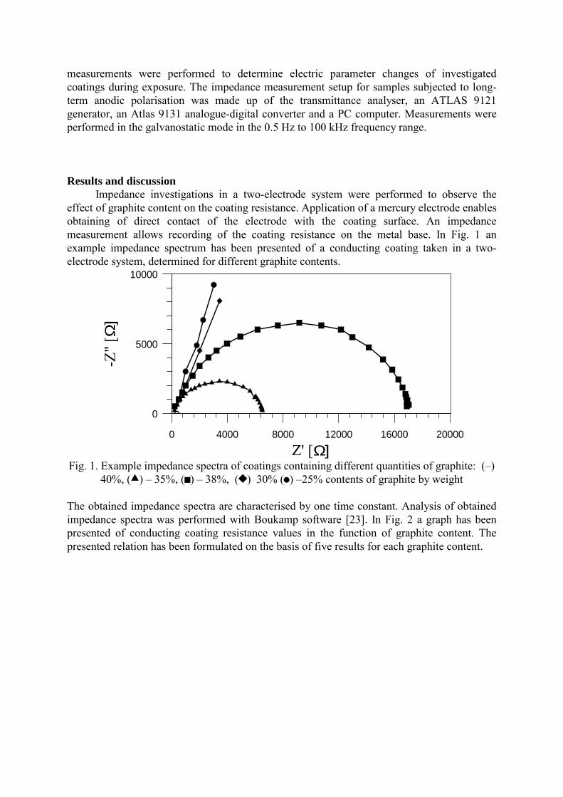
measurements were performed to determine electric parameter changes of investigated coatings during exposure. The impedance measurement setup for samples subjected to long-term anodic polarisation was made up of the transmittance analyser, an ATLAS 9121 generator, an Atlas 9131 analogue-digital converter and a PC computer. Measurements were performed in the galvanostatic mode in the 0.5 Hz to 100 kHz frequency range. Results and discussion Impedance investigations in a two-electrode system were performed to observe the effect of graphite content on the coating resistance. Application of a mercury electrode enables obtaining of direct contact of the electrode with the coating surface. An impedance measurement allows recording of the coating resistance on the metal base. In Fig. 1 an example impedance spectrum has been presented of a conducting coating taken in a two-electrode system, determined for different graphite contents.
0 4000 8000 12000 16000 20000
Z' [Ω]
0
5000
10000
-Z" [
Ω]
Fig. 1. Example impedance spectra of coatings containing different quantities of graphite: ()
40%, ( ) 35%, ( ) 38%, ( ) 30% ( ) 25% contents of graphite by weight
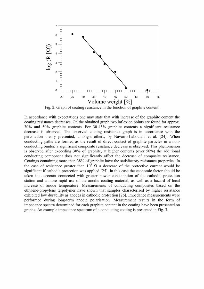
The obtained impedance spectra are characterised by one time constant. Analysis of obtained impedance spectra was performed with Boukamp software [23]. In Fig. 2 a graph has been presented of conducting coating resistance values in the function of graphite content. The presented relation has been formulated on the basis of five results for each graphite content.
20 25 30 35 40 45 50 55 60 65
Volume weight [%]
0
1
2
3
4
5
6
7
log
(R [ Ω
])
Fig. 2. Graph of coating resistance in the function of graphite content.
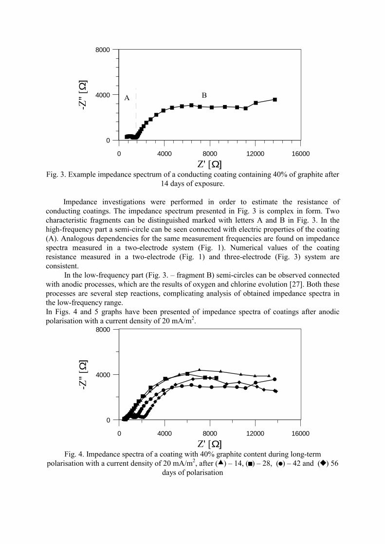
In accordance with expectations one may state that with increase of the graphite content the coating resistance decreases. On the obtained graph two inflexion points are found for approx. 30% and 50% graphite contents. For 30-45% graphite contents a significant resistance decrease is observed. The observed coating resistance graph is in accordance with the percolation theory presented, amongst others, by Navarro-Laboulais et al. [24]. When conducting paths are formed as the result of direct contact of graphite particles in a non-conducting binder, a significant composite resistance decrease is observed. This phenomenon is observed after exceeding 30% of graphite, at higher contents (over 50%) the additional conducting component does not significantly affect the decrease of composite resistance. Coatings containing more then 38% of graphite have the satisfactory resistance properties. In the case of resistance greater than 104 Ω a decrease of the protective current would be significant if cathodic protection was applied [25]. In this case the economic factor should be taken into account connected with greater power consumption of the cathodic protection station and a more rapid use of the anodic coating material, as well as a hazard of local increase of anode temperature. Measurements of conducting composites based on the ethylene-propylene terpolymer have shown that samples characterised by higher resistance exhibited low durability as anodes in cathodic protection [26]. Impedance measurements were performed during long-term anodic polarisation. Measurement results in the form of impedance spectra determined for each graphite content in the coating have been presented on graphs. An example impedance spectrum of a conducting coating is presented in Fig. 3.
0 4000 8000 12000 16000
Z' [Ω]
0
4000
8000
-Z" [
Ω]
A B
Fig. 3. Example impedance spectrum of a conducting coating containing 40% of graphite after
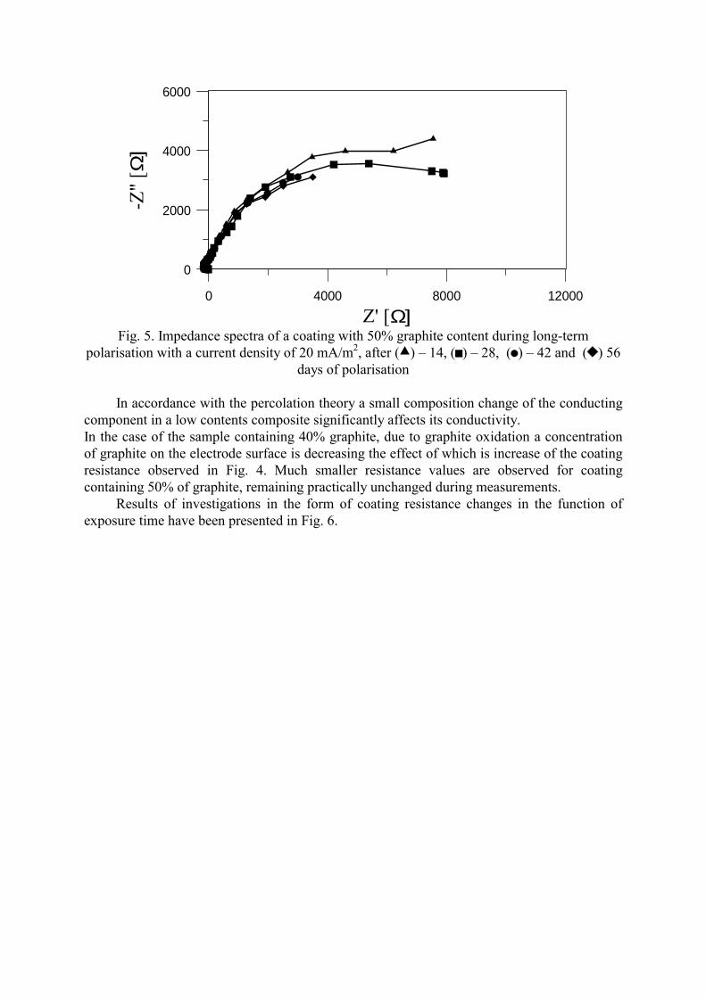
14 days of exposure. Impedance investigations were performed in order to estimate the resistance of conducting coatings. The impedance spectrum presented in Fig. 3 is complex in form. Two characteristic fragments can be distinguished marked with letters A and B in Fig. 3. In the high-frequency part a semi-circle can be seen connected with electric properties of the coating (A). Analogous dependencies for the same measurement frequencies are found on impedance spectra measured in a two-electrode system (Fig. 1). Numerical values of the coating resistance measured in a two-electrode (Fig. 1) and three-electrode (Fig. 3) system are consistent. In the low-frequency part (Fig. 3. fragment B) semi-circles can be observed connected with anodic processes, which are the results of oxygen and chlorine evolution [27]. Both these processes are several step reactions, complicating analysis of obtained impedance spectra in the low-frequency range. In Figs. 4 and 5 graphs have been presented of impedance spectra of coatings after anodic polarisation with a current density of 20 mA/m2.
0 4000 8000 12000 16000
Z' [Ω]
0
4000
8000
-Z" [
Ω]
Fig. 4. Impedance spectra of a coating with 40% graphite content during long-term
polarisation with a current density of 20 mA/m2, after ( ) 14, ( ) 28, ( ) 42 and ( ) 56 days of polarisation
0 4000 8000 12000
Z' [Ω]
0
2000
4000
6000
-Z" [
Ω]
Fig. 5. Impedance spectra of a coating with 50% graphite content during long-term
polarisation with a current density of 20 mA/m2, after ( ) 14, ( ) 28, ( ) 42 and ( ) 56 days of polarisation
In accordance with the percolation theory a small composition change of the conducting component in a low contents composite significantly affects its conductivity. In the case of the sample containing 40% graphite, due to graphite oxidation a concentration of graphite on the electrode surface is decreasing the effect of which is increase of the coating resistance observed in Fig. 4. Much smaller resistance values are observed for coating containing 50% of graphite, remaining practically unchanged during measurements. Results of investigations in the form of coating resistance changes in the function of exposure time have been presented in Fig. 6.
0 10 20 30 40 50 60Time [d]
0.0
0.5
1.0
1.5
2.0
2.5
3.0
3.5
4.0
4.5
5.0
log
(R [Ω
])
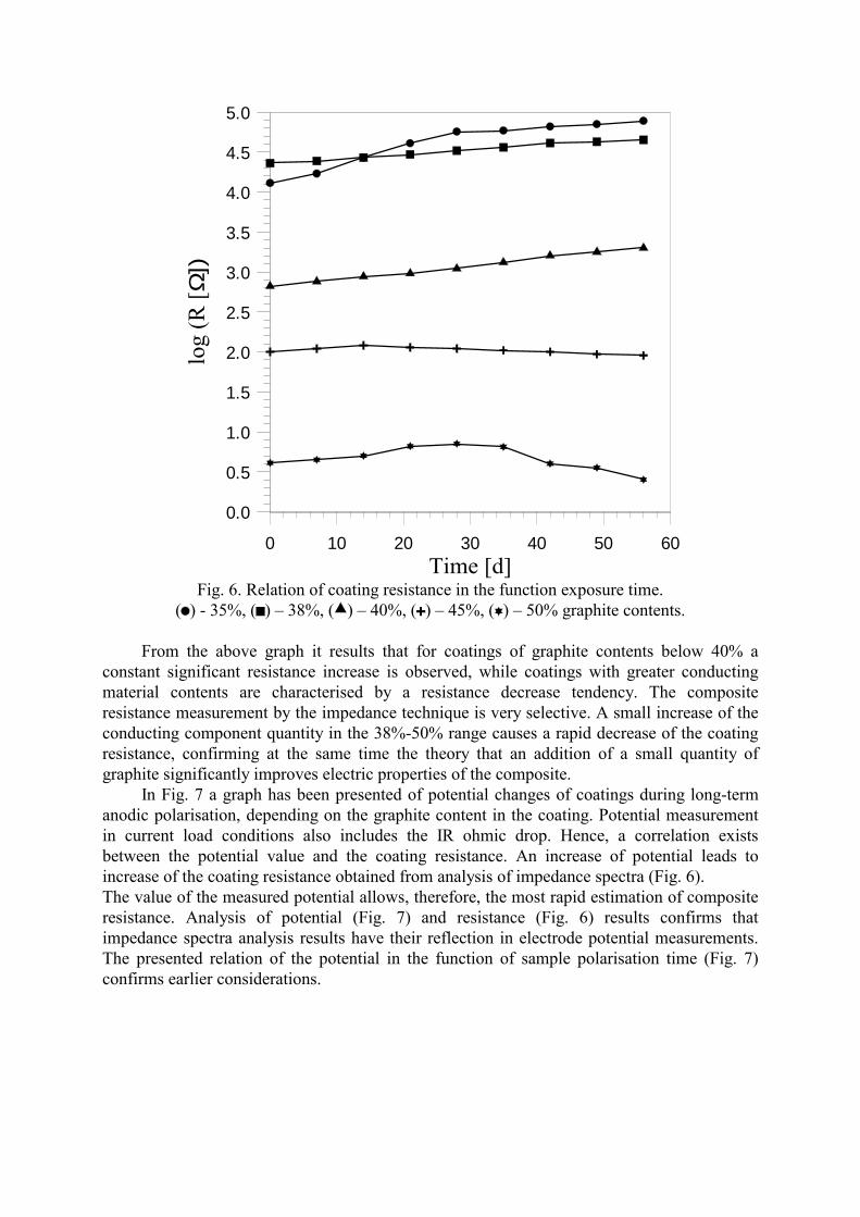
Fig. 6. Relation of coating resistance in the function exposure time.
( ) - 35%, ( ) 38%, ( ) 40%, ( ) 45%, ( ) 50% graphite contents.
From the above graph it results that for coatings of graphite contents below 40% a constant significant resistance increase is observed, while coatings with greater conducting material contents are characterised by a resistance decrease tendency. The composite resistance measurement by the impedance technique is very selective. A small increase of the conducting component quantity in the 38%-50% range causes a rapid decrease of the coating resistance, confirming at the same time the theory that an addition of a small quantity of graphite significantly improves electric properties of the composite. In Fig. 7 a graph has been presented of potential changes of coatings during long-term anodic polarisation, depending on the graphite content in the coating. Potential measurement in current load conditions also includes the IR ohmic drop. Hence, a correlation exists between the potential value and the coating resistance. An increase of potential leads to increase of the coating resistance obtained from analysis of impedance spectra (Fig. 6). The value of the measured potential allows, therefore, the most rapid estimation of composite resistance. Analysis of potential (Fig. 7) and resistance (Fig. 6) results confirms that impedance spectra analysis results have their reflection in electrode potential measurements. The presented relation of the potential in the function of sample polarisation time (Fig. 7) confirms earlier considerations.
0 10 20 30 40 50 60Time [d]
0
1
2
3
4
5
6
7
E [V
]
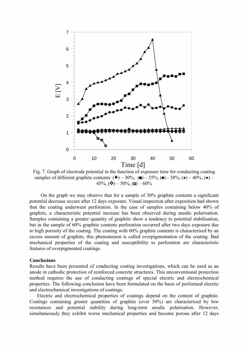
Fig. 7. Graph of electrode potential in the function of exposure time for conducting coating samples of different graphite contents: ( ) 30%, ( ) 35%, ( ) - 38%, ( ) 40%, ( )
45%, ( ) 50%, ( ) 60%
On the graph we may observe that for a sample of 30% graphite contents a significant potential decrease occurs after 12 days exposure. Visual inspection after exposition had shown that the coating underwent perforation. In the case of samples containing below 40% of graphite, a characteristic potential increase has been observed during anodic polarisation. Samples containing a greater quantity of graphite show a tendency to potential stabilisation, but in the sample of 60% graphite contents perforation occurred after two days exposure due to high porosity of the coating. The coating with 60% graphite contents is characterised by an excess amount of graphite, this phenomenon is called overpigmentation of the coating. Bad mechanical properties of the coating and susceptibility to perforation are characteristic features of overpigmented coatings. Conclusions Results have been presented of conducting coating investigations, which can be used as an anode in cathodic protection of reinforced concrete structures. This unconventional protection method requires the use of conducting coatings of special electric and electrochemical properties. The following conclusion have been formulated on the basis of performed electric and electrochemical investigations of coatings: Electric and electrochemical properties of coatings depend on the content of graphite. Coatings containing greater quantities of graphite (over 50%) are characterised by low resistances and potential stability during long-term anodic polarisation. However, simultaneously they exhibit worse mechanical properties and become porous after 12 days
exposure. Hence, coatings of high graphite contents cannot be used for protection of concrete, in spite of good electric properties. For coatings of small graphite contents (35% and less) the resistance and potential rapidly increase during long-term anodic polarisation, also their barrier properties are lower. The porosity of these coatings can be stated by a large decrease of the electrode potential as the result of formation of the steel-graphite cell. The performed investigations have shown that the optimal graphite content in coatings used for concrete protection should be in the 40 to 45% range, as these coatings are characterised by low potentials and rarely undergo perforation. At present long-term operation investigations and measurements are being performed of the effectiveness of the cathodic protection of reinforced concrete with application of conducting coatings as anodes applied directly on the concrete surface. The obtained results confirm the possibility of using conducting coatings as anodes in cathodic protection systems of reinforced concrete structures. However there are still to be solved many technological problems connected with, e.g., ageing of coatings, the state of the electric joints of the coating and possibility of coating delamination due to gas liberation as the result of occurring electrochemical processes.
Acknowledgements
This work has been suported by grant No. 7 T08C 059 19 from Polish Comittee for Scientific Reasearch. References
1. D.R. Jackson, Corrosion 82/80, Nace, Houston, Tx. 2. N. Gowripalan, V. Sirivivatnanon, C. C. Lim, Cement And Concrete Research 30
(2000) 725-730. 3. Y.P. Liu, R.E. Weyers, Aci Mater. J. 95 (1998) 675-681. 4. D. Cusson, W.L. Repette, Aci Mater. J. 97 (2000) 438-446. 5. D.M. Frangopol, K.Y. Lin, A. C. Estes, J. of Struct. Eng.-Asce 123 (1997) 286-297. 6. R.E. Weyers, Aci Mater. J. 95 (1998) 445-453. 7. G.E. Sgouros, T.E. Webster, N.M. Hennegan, J. of Waterway Port Coastal and Ocean
Eng.-Asce 122 (1996) 165-171. 8. M. Delucchi, A. Barbucci, G. Cerisola, Prog. in Org. Coatings 33 (1998) 76-82. 9. M. Delucchi, A. Barbucci G. Cerisola, Constr. and Build. Mater. 11 (1997) 365-371. 10. D.L. Chung, J. of Mater. Eng. and Perform. 9 (2000) 585-588. 11. G.T. Parthiban, V. Saraswathy, N.S. Rengaswamy, Bull. of Electrochem. 16 (2000)
253-257. 12. I. Genesca, L. Betancourt, L. Jerade, C. Rodriguez, F.J. Rodriguez, Electrochem.
Meth. in Corr. Research 6 (1988) 1275-1288. 13. R. Brousseau, M. Arnott, B. Baldock, Corros. Preven. & Control 43 (1996) 119. 14. B.S. Covino, S.D. Cramer, S.J. Bullard, G.R. Holcomb, W.K. Collins, G.E. McGill
Mater. Perform. 38 (1999). 15. A.A. Sagues, R.G. Powers, Corros. 52 (1996) 508-522. 16. J. Bennett, C. Firlotte, Mater. Perform. 36 (1997) 14-20. 17. R. Brousseau, B. Arsenault, S. Dallaire, D. Rogers, T. Mumby D. Dong, J. of Thermal
Spray Techn. 7 (1998) 193-196. 18. C.L. Page, G. Sergi, J. of Mater. in Civil Eng. 12 (2000) 8-15. 19. A.M. Hassanein, G.K. Glass, N.R. Buenfeld. Corros. 55 (1999) 840-850. 20. M. Ali, H.A. Al-Ghannam, Mater. Perform. 37 (1998) 11-16.

21. R.J. Kessler, R.G. Powers, I.R. Lasa, Mater. Perform. 37 (1998) 14-19. 22. R.J. Brousseau, G.B. Pye, Aci Mater. J. 94 (1997) 306-310. 23. B.A. Boukamp, Solid State Ionics, 31(1986) 20. 24. J. Navarro-Laboulais, J. Trijueque, J.J. Garcia-Jareno, D. Benito, F. Vicente,
J. of Electroan. Chem. 444 (1998) 173-186. 25. K. Darowicki, S. Janicki, J. Orlikowski, J. Appl. Electrochem. 30 (2000) 333-337. 26. K. Darowicki, J. Orlikowski, J. Walaszkowski, Bull. Electrochem. 16 (2000) 85-88.