NACE Cathodic Protection Specialist Level 4 Theory Exam
23
Copyright © 2019 by NACE International Institute. All rights reserved. NACE Cathodic Protection Specialist Level 4 Theory Exam Exam Preparation Guide August 2019
-
Upload
khangminh22 -
Category
Documents
-
view
0 -
download
0
Transcript of NACE Cathodic Protection Specialist Level 4 Theory Exam
Copyright © 2019 by NACE International Institute. All rights reserved.
NACE Cathodic Protection Specialist Level 4 Theory Exam Exam Preparation Guide August 2019
2 Copyright © 2019 by NACE International Institute. All rights reserved.
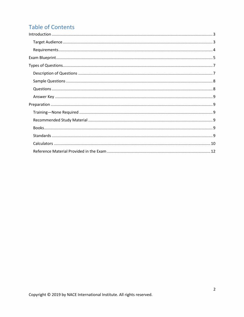
Table of Contents Introduction .................................................................................................................................................. 3
Target Audience ........................................................................................................................................ 3
Requirements ............................................................................................................................................ 4
Exam Blueprint .............................................................................................................................................. 5
Types of Questions ........................................................................................................................................ 7
Description of Questions .......................................................................................................................... 7
Sample Questions ..................................................................................................................................... 8
Questions .................................................................................................................................................. 8
Answer Key ............................................................................................................................................... 9
Preparation ................................................................................................................................................... 9
Training—None Required ......................................................................................................................... 9
Recommended Study Material ................................................................................................................. 9
Books ......................................................................................................................................................... 9
Standards .................................................................................................................................................. 9
Calculators .............................................................................................................................................. 10
Reference Material Provided in the Exam .............................................................................................. 12
3 Copyright © 2019 by NACE International Institute. All rights reserved.
Introduction
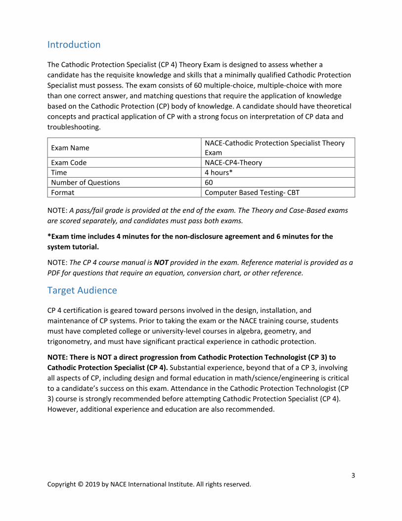
The Cathodic Protection Specialist (CP 4) Theory Exam is designed to assess whether a candidate has the requisite knowledge and skills that a minimally qualified Cathodic Protection Specialist must possess. The exam consists of 60 multiple-choice, multiple-choice with more than one correct answer, and matching questions that require the application of knowledge based on the Cathodic Protection (CP) body of knowledge. A candidate should have theoretical concepts and practical application of CP with a strong focus on interpretation of CP data and troubleshooting.
Exam Name NACE-Cathodic Protection Specialist Theory Exam
Exam Code NACE-CP4-Theory Time 4 hours* Number of Questions 60 Format Computer Based Testing- CBT
NOTE: A pass/fail grade is provided at the end of the exam. The Theory and Case-Based exams are scored separately, and candidates must pass both exams.
*Exam time includes 4 minutes for the non-disclosure agreement and 6 minutes for the system tutorial.
NOTE: The CP 4 course manual is NOT provided in the exam. Reference material is provided as a PDF for questions that require an equation, conversion chart, or other reference.
Target Audience
CP 4 certification is geared toward persons involved in the design, installation, and maintenance of CP systems. Prior to taking the exam or the NACE training course, students must have completed college or university-level courses in algebra, geometry, and trigonometry, and must have significant practical experience in cathodic protection.
NOTE: There is NOT a direct progression from Cathodic Protection Technologist (CP 3) to Cathodic Protection Specialist (CP 4). Substantial experience, beyond that of a CP 3, involving all aspects of CP, including design and formal education in math/science/engineering is critical to a candidate’s success on this exam. Attendance in the Cathodic Protection Technologist (CP 3) course is strongly recommended before attempting Cathodic Protection Specialist (CP 4). However, additional experience and education are also recommended.
4 Copyright © 2019 by NACE International Institute. All rights reserved.
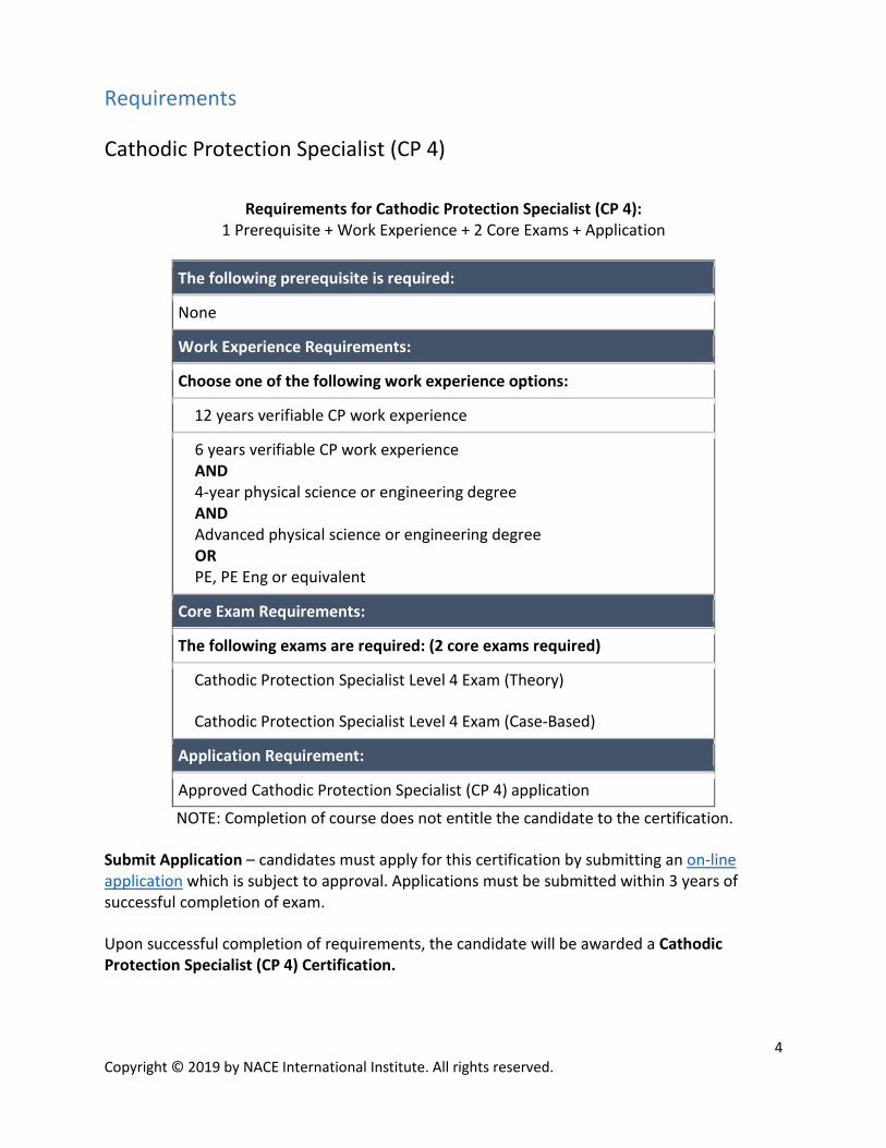
Requirements
Cathodic Protection Specialist (CP 4)
Requirements for Cathodic Protection Specialist (CP 4): 1 Prerequisite + Work Experience + 2 Core Exams + Application
The following prerequisite is required:
None
Work Experience Requirements:
Choose one of the following work experience options:
12 years verifiable CP work experience
6 years verifiable CP work experience AND 4-year physical science or engineering degree AND Advanced physical science or engineering degree OR PE, PE Eng or equivalent
Core Exam Requirements:
The following exams are required: (2 core exams required)
Cathodic Protection Specialist Level 4 Exam (Theory)
Cathodic Protection Specialist Level 4 Exam (Case-Based)
Application Requirement:
Approved Cathodic Protection Specialist (CP 4) application
NOTE: Completion of course does not entitle the candidate to the certification.
Submit Application – candidates must apply for this certification by submitting an on-line application which is subject to approval. Applications must be submitted within 3 years of successful completion of exam.
Upon successful completion of requirements, the candidate will be awarded a Cathodic Protection Specialist (CP 4) Certification.
5 Copyright © 2019 by NACE International Institute. All rights reserved.
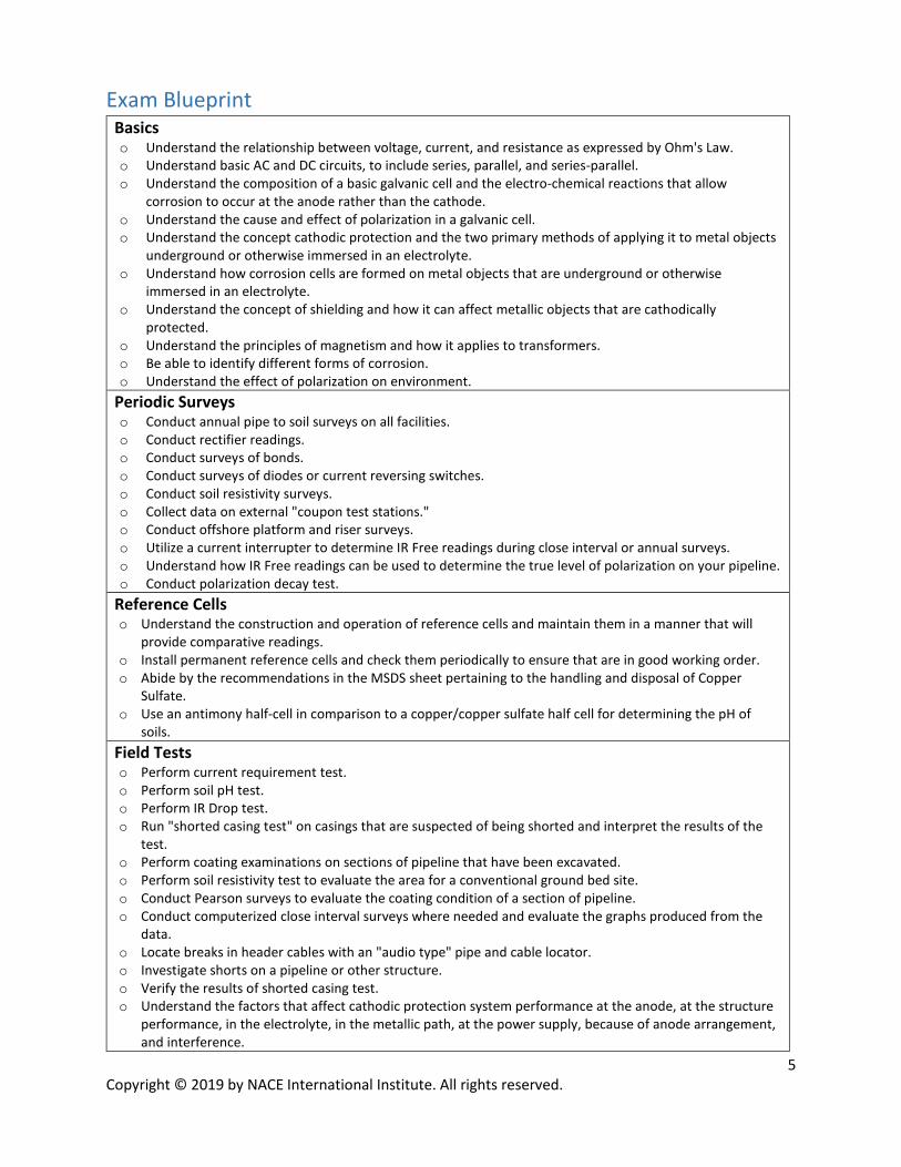
Exam Blueprint Basics o Understand the relationship between voltage, current, and resistance as expressed by Ohm's Law. o Understand basic AC and DC circuits, to include series, parallel, and series-parallel. o Understand the composition of a basic galvanic cell and the electro-chemical reactions that allow
corrosion to occur at the anode rather than the cathode. o Understand the cause and effect of polarization in a galvanic cell. o Understand the concept cathodic protection and the two primary methods of applying it to metal objects
underground or otherwise immersed in an electrolyte. o Understand how corrosion cells are formed on metal objects that are underground or otherwise
immersed in an electrolyte. o Understand the concept of shielding and how it can affect metallic objects that are cathodically
protected. o Understand the principles of magnetism and how it applies to transformers. o Be able to identify different forms of corrosion. o Understand the effect of polarization on environment.
Periodic Surveys o Conduct annual pipe to soil surveys on all facilities. o Conduct rectifier readings. o Conduct surveys of bonds. o Conduct surveys of diodes or current reversing switches. o Conduct soil resistivity surveys. o Collect data on external "coupon test stations." o Conduct offshore platform and riser surveys. o Utilize a current interrupter to determine IR Free readings during close interval or annual surveys. o Understand how IR Free readings can be used to determine the true level of polarization on your pipeline. o Conduct polarization decay test.
Reference Cells o Understand the construction and operation of reference cells and maintain them in a manner that will
provide comparative readings. o Install permanent reference cells and check them periodically to ensure that are in good working order. o Abide by the recommendations in the MSDS sheet pertaining to the handling and disposal of Copper
Sulfate. o Use an antimony half-cell in comparison to a copper/copper sulfate half cell for determining the pH of
soils. Field Tests o Perform current requirement test. o Perform soil pH test. o Perform IR Drop test. o Run "shorted casing test" on casings that are suspected of being shorted and interpret the results of the
test. o Perform coating examinations on sections of pipeline that have been excavated. o Perform soil resistivity test to evaluate the area for a conventional ground bed site. o Conduct Pearson surveys to evaluate the coating condition of a section of pipeline. o Conduct computerized close interval surveys where needed and evaluate the graphs produced from the
data. o Locate breaks in header cables with an "audio type" pipe and cable locator. o Investigate shorts on a pipeline or other structure. o Verify the results of shorted casing test. o Understand the factors that affect cathodic protection system performance at the anode, at the structure
performance, in the electrolyte, in the metallic path, at the power supply, because of anode arrangement, and interference.

6 Copyright © 2019 by NACE International Institute. All rights reserved.
o Perform advanced cathodic protection testing using correct measurement techniques to monitor CP system performance and accurately interpret the data collected to ensure optimum cp system performance.
o Based on data collected, determine if correction/modifications to system components are necessary. o Identify errors in data collection/CP measurements including contact resistance errors, voltage drop
errors, and reference electrode errors. o Utilize the instruments required to accomplish advanced cathodic protection testing and collection of
cathodic protection systems measurements. o Conduct cathodic protection surveys, including close interval surveys and DCVG, where needed or required
and evaluate the graphs produced from the data collected during the surveys. o Troubleshoot rectifiers and make corrections/repair as necessary. o Perform efficiency test on rectifiers. o Install new rectifiers. o Understand the use of external CP coupons and be able to identify if the use of external coupons is needed
for a CP system. o Understand in-line and direct inspection (understand and be able to implement ECDA).
DC Stray Current Interference o Conduct and document interference tests where stray currents are suspected. o Once interference tests have been run, suggest method of control that will mitigate the effects of the stray
current. o Understand how IR Drop test stations can be used to evaluate stray current. o Understand how Coupon Test stations can be used to determine the presence of and the mitigation of
stray current. o Calculate the resistance required to provide the amount of current drain desired at a resistance bond
installation. o Understand the causes (sources) and the effects of interference. o Understand the methods available to mitigate interference.
AC Mitigation o Understand the safety requirements when installing test stations under high voltage power lines. o Take appropriate steps to mitigate the effects of excessive AC voltage induced on underground
structures. Corrosion Theory o Understand the composition of a basic galvanic cell and the electrochemical reactions that allow
corrosion to occur at the anode rather than the cathode. o Describe the characteristics of anodic and cathodic reactions. o Understand and apply the principles of electricity and electrical circuits (series, parallel, and series-parallel
circuits) (including the application of Ohm’s and Kirchhoff’s Laws to electrical circuits.) Polarization o Understand the cause and effect of polarization in a galvanic cell. o Understand activation, concentration, and resistance polarization and the mathematical expressions of
these concepts. o Understand the factors that affect polarization (area, temperature, relative movement, ion concentration,
oxygen concentration). o Perform calculations using Ohm’s Law and calculations related to series and parallel circuits. o Understand how corrosion cells are formed on metal objects that are underground or otherwise
immersed in an electrolyte. o Understand Faraday’s Law and perform calculations using Faraday’s law to determine required anode
weight for cathodic protection.
7 Copyright © 2019 by NACE International Institute. All rights reserved.
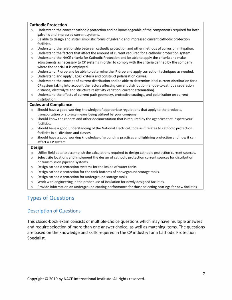
Cathodic Protection o Understand the concept cathodic protection and be knowledgeable of the components required for both
galvanic and impressed current systems. o Be able to design and install simplistic forms of galvanic and impressed current cathodic protection
facilities. o Understand the relationship between cathodic protection and other methods of corrosion mitigation. o Understand the factors that affect the amount of current required for a cathodic protection system. o Understand the NACE criteria for Cathodic Protection and be able to apply the criteria and make
adjustments as necessary to CP systems in order to comply with the criteria defined by the company where the specialist is employed.
o Understand IR drop and be able to determine the IR drop and apply correction techniques as needed. o Understand and apply E Log I criteria and construct polarization curves. o Understand the concept of current distribution and be able to determine ideal current distribution for a
CP system taking into account the factors affecting current distribution (anode-to-cathode separation distance, electrolyte and structure resistivity variation, current attenuation).
o Understand the effects of current path geometry, protective coatings, and polarization on current distribution.
Codes and Compliance o Should have a good working knowledge of appropriate regulations that apply to the products,
transportation or storage means being utilized by your company. o Should know the reports and other documentation that is required by the agencies that inspect your
facilities. o Should have a good understanding of the National Electrical Code as it relates to cathodic protection
facilities in all divisions and classes. o Should have a good working knowledge of grounding practices and lightning protection and how it can
affect a CP system. Design o Utilize field data to accomplish the calculations required to design cathodic protection current sources. o Select site locations and implement the design of cathodic protection current sources for distribution
or transmission pipeline systems o Design cathodic protection systems for the inside of water tanks o Design cathodic protection for the tank bottoms of aboveground storage tanks. o Design cathodic protection for underground storage tanks o Work with engineering in the proper use of insulation for newly designed facilities. o Provide information on underground coating performance for those selecting coatings for new facilities
Types of Questions Description of Questions
This closed-book exam consists of multiple-choice questions which may have multiple answers and require selection of more than one answer choice, as well as matching items. The questions are based on the knowledge and skills required in the CP industry for a Cathodic Protection Specialist.

8 Copyright © 2019 by NACE International Institute. All rights reserved.
Sample Questions
The sample questions are included to illustrate the formats and types of questions that will be on the exam. Your performance on the sample questions should not be viewed as a predictor of your performance on the actual exam. Questions
1. Which of the following statements describe the magnitude of geomagnetically induced voltage on a pipeline? SELECT ALL THAT APPLY A. Directly proportional to coating resistance B. Inversely proportional to pipe length C. Dependent on the pipeline’s location relative to the geomagnetic poles D. Varies with the time of day
2. Which of the following electrical interference situations causes adverse effects? A. Stray DC current pick-up on a bare low carbon steel pipe B. Stray AC current density of <2 mA / cm2 on steel C. Stray current discharge from a cast iron pipe D. Polarized potential on steel shifted from -1080 mVCSE to -880 mVCSE

9 Copyright © 2019 by NACE International Institute. All rights reserved.
Answer Key
1. A, C, and D
2. C
Preparation
Training—None Required
NACE Cathodic Protection Specialist—Course CP 4 (Available)
NACE Cathodic Protection Technologist—Course CP 3 (Available)
NACE Cathodic Protection Technician—Course CP 2 (Available)
NACE Cathodic Protection Tester— Course CP 1 (Available)
Recommended Study Material Books
Peabody, A. W. (2001). Peabody's control of pipeline corrosion (No. Ed. 2). NACE international.
NACE Cathodic Protection Specialist—CP 4 course material
Standards
NACE International SP 0207 (2007). “Performing Close Interval Potential Surveys and DC Surface Potential Gradient Surveys on Buried or Submerged Metallic Pipelines.” NACE International. NACE International SP 0169 (2013). “Control of External Corrosion on Underground of Submerged Metallic Piping Systems.” NACE International. NACE International SP 0177 (2014). “Mitigation of Alternating Current and Lightning Effects on Metallic Structures and Corrosion Control Systems.” NACE International.
10 Copyright © 2019 by NACE International Institute. All rights reserved.
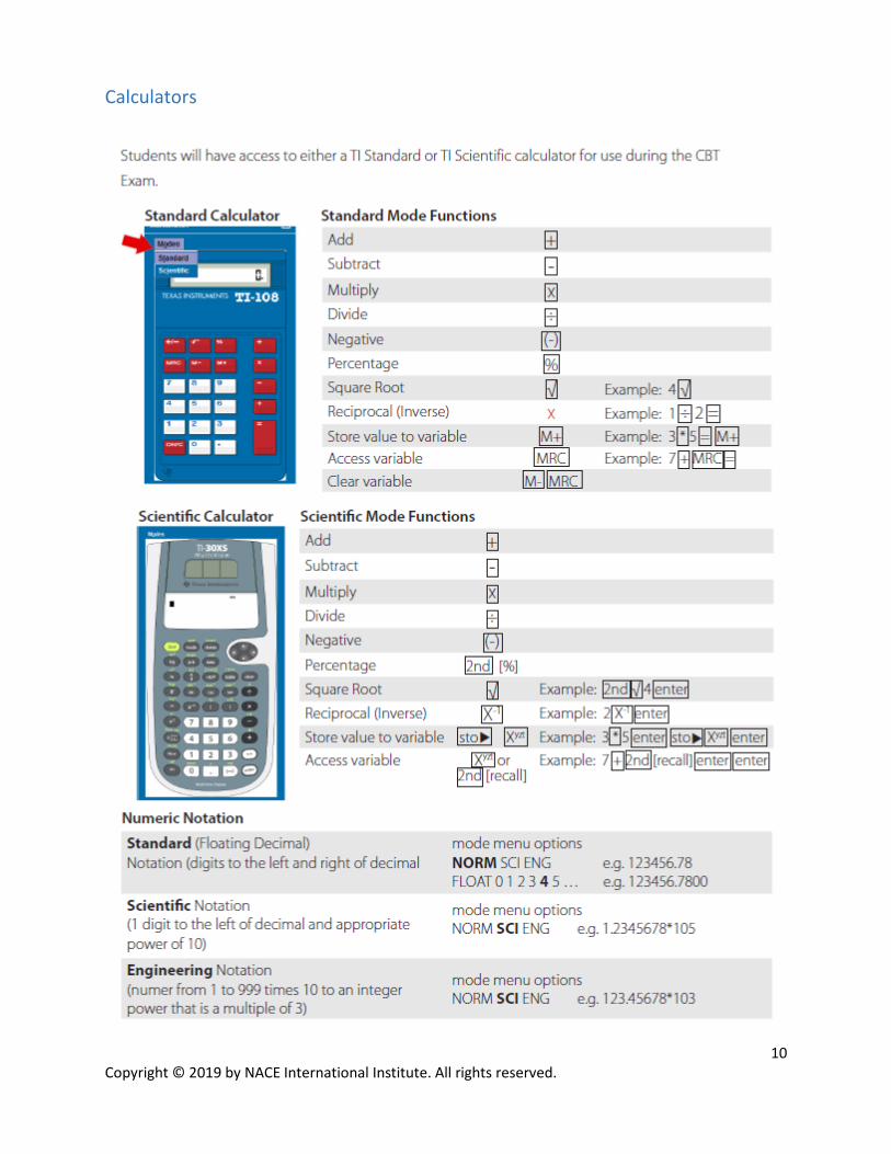
Calculators
11 Copyright © 2019 by NACE International Institute. All rights reserved.
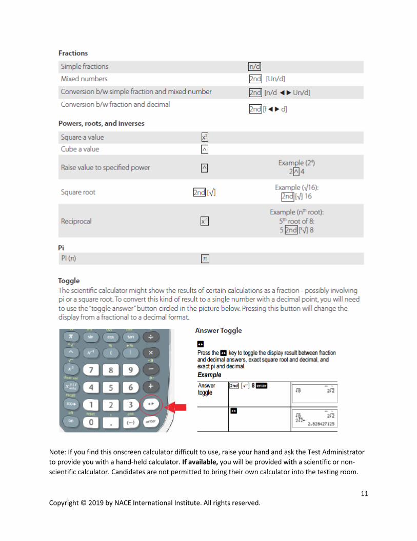
Note: If you find this onscreen calculator difficult to use, raise your hand and ask the Test Administrator to provide you with a hand-held calculator. If available, you will be provided with a scientific or non-scientific calculator. Candidates are not permitted to bring their own calculator into the testing room.
Copyright © 2019 by NACE International Institute. All rights reserved.
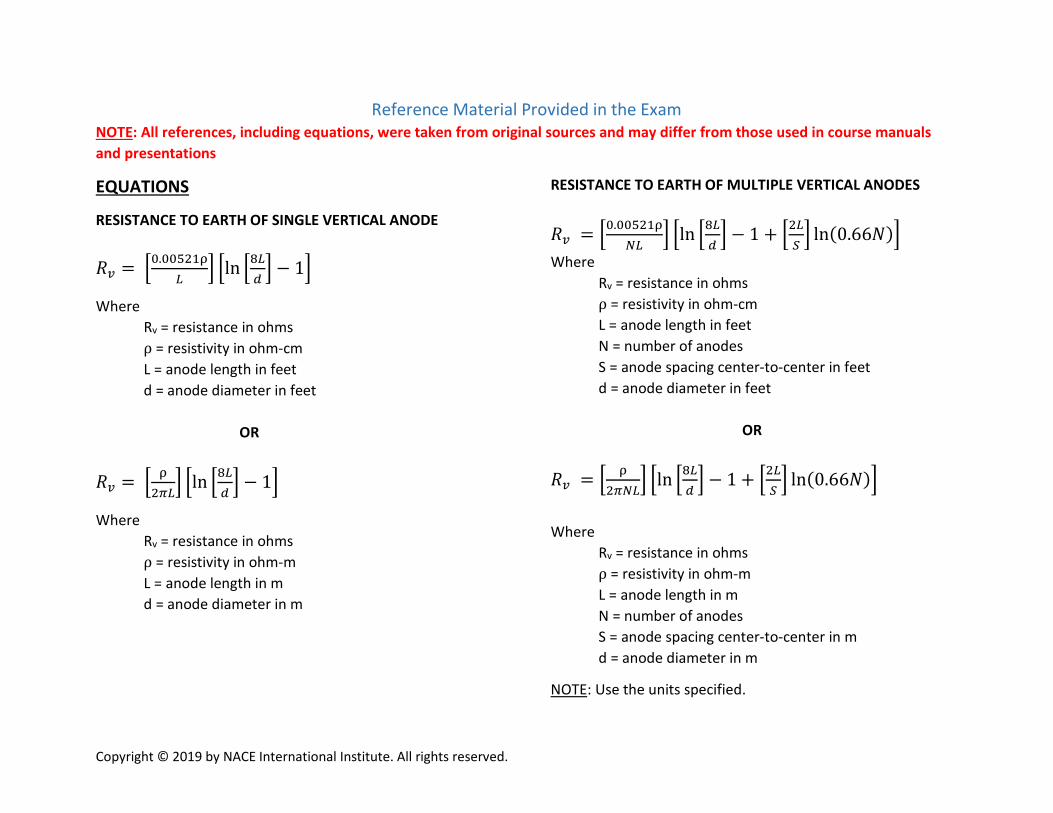
Reference Material Provided in the Exam NOTE: All references, including equations, were taken from original sources and may differ from those used in course manuals and presentations
EQUATIONS
RESISTANCE TO EARTH OF SINGLE VERTICAL ANODE
𝑅𝑅𝑣𝑣 = 0.00521ρ𝐿𝐿
ln 8𝐿𝐿𝑑𝑑 − 1
Where Rv = resistance in ohms ρ = resistivity in ohm-cm L = anode length in feet d = anode diameter in feet
OR
𝑅𝑅𝑣𝑣 = ρ2𝜋𝜋𝐿𝐿
ln 8𝐿𝐿𝑑𝑑 − 1
Where Rv = resistance in ohms ρ = resistivity in ohm-m L = anode length in m d = anode diameter in m
RESISTANCE TO EARTH OF MULTIPLE VERTICAL ANODES
𝑅𝑅𝑣𝑣 = 0.00521ρ𝑁𝑁𝐿𝐿
ln 8𝐿𝐿𝑑𝑑 − 1 + 2𝐿𝐿
𝑆𝑆 ln(0.66𝑁𝑁)
Where Rv = resistance in ohms ρ = resistivity in ohm-cm L = anode length in feet N = number of anodes S = anode spacing center-to-center in feet d = anode diameter in feet
OR
𝑅𝑅𝑣𝑣 = ρ2𝜋𝜋𝑁𝑁𝐿𝐿
ln 8𝐿𝐿𝑑𝑑 − 1 + 2𝐿𝐿
𝑆𝑆 ln(0.66𝑁𝑁)
Where Rv = resistance in ohms ρ = resistivity in ohm-m L = anode length in m N = number of anodes S = anode spacing center-to-center in m d = anode diameter in m
NOTE: Use the units specified.

13 Copyright © 2019 by NACE International Institute. All rights reserved.
RESISTANCE TO EARTH OF SINGLE HORIZONTAL ANODE
𝑅𝑅𝐻𝐻 = 0.00521ρ𝐿𝐿
ln 4𝐿𝐿2+4𝐿𝐿√𝑆𝑆2+𝐿𝐿2
𝑑𝑑𝑆𝑆 + 𝑆𝑆
𝐿𝐿− √𝑆𝑆2+𝐿𝐿2
𝐿𝐿− 1
Where
RH = resistance in ohms ρ = resistivity in ohm-cm
L = anode length in feet S = twice the anode depth in feet d = anode diameter in feet
OR
𝑅𝑅𝐻𝐻 = ρ2𝜋𝜋𝐿𝐿
ln 4𝐿𝐿2+4𝐿𝐿√𝑆𝑆2+𝐿𝐿2
𝑑𝑑𝑆𝑆 + 𝑆𝑆
𝐿𝐿− √𝑆𝑆2+𝐿𝐿2
𝐿𝐿− 1
Where
RH = resistance in ohms ρ = resistivity in ohm-m
L = anode length in m S = twice the anode depth in m d = anode diameter in m
RESISTANCE TO EARTH OF MULTIPLE HORIZONTAL ANODES
𝑅𝑅𝑇𝑇 =𝑅𝑅𝐻𝐻𝑁𝑁 𝐹𝐹
Where RT = resistance of multiple horizontal anodes in ohms F = Anode Interference or Crowding Factor RH = resistance of single horizontal anode in ohms
N = number of anodes COUPLING FACTOR
R = ΔV ∕ ΔI Where R = coupling factor in mV / A ΔV= pipe-to-soil potential shift in mV ΔI = applied current A ANODE INTERFERENCE BETWEEN ANODES (Crowding Factor)
𝐹𝐹 = 1 +𝜌𝜌
𝜋𝜋𝜋𝜋𝑅𝑅𝐻𝐻𝑙𝑙𝑙𝑙0.66𝑁𝑁
Where F = Anode Interference or Crowding Factor ρ = resistivity in ohm-m RH = resistance of single horizontal anode in ohms
N = number of anodes S = distance between anodes in m
14 Copyright © 2019 by NACE International Institute. All rights reserved.
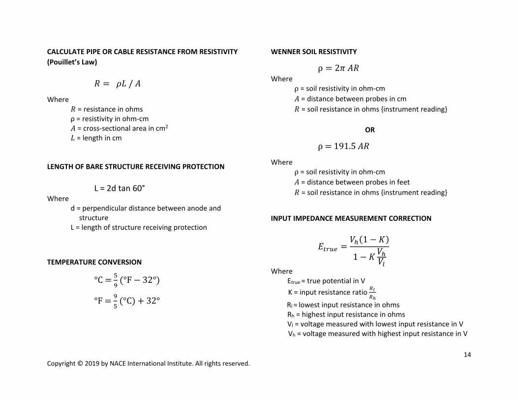
CALCULATE PIPE OR CABLE RESISTANCE FROM RESISTIVITY (Pouillet’s Law) 𝑅𝑅 = 𝜌𝜌𝜌𝜌 / 𝐴𝐴
Where 𝑅𝑅 = resistance in ohms ρ = resistivity in ohm-cm 𝐴𝐴 = cross-sectional area in cm2 𝜌𝜌 = length in cm LENGTH OF BARE STRUCTURE RECEIVING PROTECTION
L = 2d tan 60°
Where d = perpendicular distance between anode and structure L = length of structure receiving protection
TEMPERATURE CONVERSION
°C = 59 (°F − 32°)
°F = 95 (°C) + 32°
WENNER SOIL RESISTIVITY
ρ = 2𝜋𝜋 𝐴𝐴𝑅𝑅 Where ρ = soil resistivity in ohm-cm 𝐴𝐴 = distance between probes in cm 𝑅𝑅 = soil resistance in ohms instrument reading OR
ρ = 191.5 𝐴𝐴𝑅𝑅
Where ρ = soil resistivity in ohm-cm 𝐴𝐴 = distance between probes in feet 𝑅𝑅 = soil resistance in ohms instrument reading
INPUT IMPEDANCE MEASUREMENT CORRECTION
𝐸𝐸𝑡𝑡𝑡𝑡𝑡𝑡𝑡𝑡 =𝑉𝑉ℎ(1 − 𝐾𝐾)
1 − 𝐾𝐾𝑉𝑉ℎ𝑉𝑉𝑙𝑙
Where Etrue = true potential in V K = input resistance ratio 𝑅𝑅𝑙𝑙
𝑅𝑅ℎ
Rl = lowest input resistance in ohms
Rh = highest input resistance in ohms Vl = voltage measured with lowest input resistance in V Vh = voltage measured with highest input resistance in V

15 Copyright © 2019 by NACE International Institute. All rights reserved.
ATTENUATION
Where
IS = current at sending end in Amps
Es = potential at sending end in mV
y = number of unit lengths from sending end
x = number of unit lengths from receiving end
Ir = current at receiving end in Amps
Er = potential at receiving end in mV
𝐸𝐸 = 𝐸𝐸𝑡𝑡 cosh(𝛼𝛼𝛼𝛼) + 𝑅𝑅𝐺𝐺𝐼𝐼𝑡𝑡 sinh(𝛼𝛼𝛼𝛼) 𝐸𝐸 = 𝐸𝐸𝑠𝑠 cosh(𝛼𝛼𝛼𝛼) − 𝑅𝑅𝐺𝐺𝐼𝐼𝑠𝑠 sinh(𝛼𝛼𝛼𝛼)
𝐼𝐼 = 𝐼𝐼𝑡𝑡 cosh(𝛼𝛼𝛼𝛼) +𝐸𝐸𝑡𝑡𝑅𝑅𝐺𝐺
sinh(𝛼𝛼𝛼𝛼)
𝐼𝐼 = 𝐼𝐼𝑆𝑆 cosh(𝛼𝛼𝛼𝛼) −𝐸𝐸𝑠𝑠𝑅𝑅𝐺𝐺
sinh(𝛼𝛼𝛼𝛼)
𝛼𝛼 = 𝑟𝑟𝑟𝑟
Where α = attenuation constant r = longitudinal resistance of structure in ohms g = conductance to earth in S
𝑟𝑟′ = 𝑅𝑅𝐿𝐿𝐴𝐴𝑆𝑆 Where r’ = specific leakage resistance in ohm-m2 (ohm-ft2) R L = average total leakage resistance in ohms AS = total surface area in m2 (ft2)
𝑅𝑅𝐺𝐺 = 𝑟𝑟𝑟𝑟
Where 𝑅𝑅𝐺𝐺 = characteristic resistance r = longitudinal resistance of structure in ohms g = conductance to earth in S
𝑅𝑅𝑆𝑆𝑆𝑆 = 𝑅𝑅𝐺𝐺coth (𝛼𝛼𝛼𝛼) Where RSO = Resistance looking into open line in ohms
𝑅𝑅𝐺𝐺 = 𝑅𝑅𝑆𝑆𝑆𝑆𝑅𝑅𝑆𝑆𝑆𝑆 Where
RSS = Resistance looking into open line in ohms
16 Copyright © 2019 by NACE International Institute. All rights reserved.
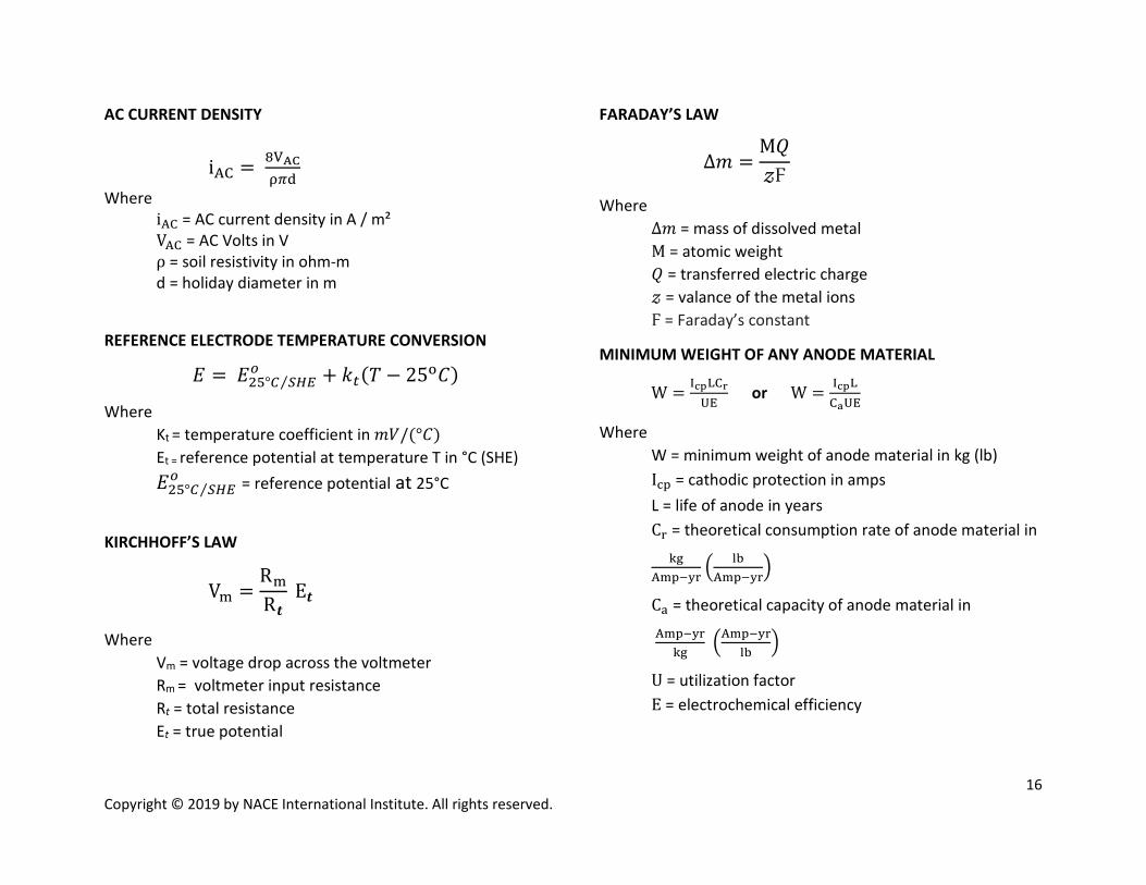
AC CURRENT DENSITY
iAC = 8VACρ𝜋𝜋d
Where iAC = AC current density in A / m² VAC = AC Volts in V ρ = soil resistivity in ohm-m d = holiday diameter in m
REFERENCE ELECTRODE TEMPERATURE CONVERSION
𝐸𝐸 = 𝐸𝐸25°𝐶𝐶 𝑆𝑆𝐻𝐻𝑆𝑆⁄𝑜𝑜 + 𝑘𝑘𝑡𝑡(𝑇𝑇 − 25o𝐶𝐶)
Where Kt = temperature coefficient in 𝑚𝑚𝑉𝑉/(°𝐶𝐶) Et = reference potential at temperature T in °C (SHE) 𝐸𝐸25°𝐶𝐶 𝑆𝑆𝐻𝐻𝑆𝑆⁄
𝑜𝑜 = reference potential at 25°C
KIRCHHOFF’S LAW
Vm =Rm
R𝒕𝒕 E𝒕𝒕
Where Vm = voltage drop across the voltmeter Rm = voltmeter input resistance Rt = total resistance Et = true potential
FARADAY’S LAW
Δ𝑚𝑚 =Μ𝑄𝑄𝓏𝓏Ϝ
Where Δ𝑚𝑚 = mass of dissolved metal Μ = atomic weight 𝑄𝑄 = transferred electric charge 𝓏𝓏 = valance of the metal ions Ϝ = Faraday’s constant
MINIMUM WEIGHT OF ANY ANODE MATERIAL
W = IcpLCrUE
or W = IcpLCaUE
Where W = minimum weight of anode material in kg (lb) Icp = cathodic protection in amps L = life of anode in years
Cr = theoretical consumption rate of anode material in kg
Amp−yr lbAmp−yr
Ca = theoretical capacity of anode material in
Amp−yrkg
Amp−yrlb
U = utilization factor E = electrochemical efficiency
17 Copyright © 2019 by NACE International Institute. All rights reserved.
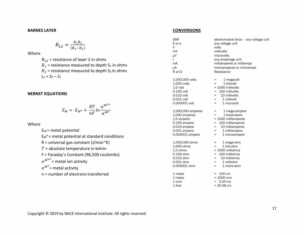
BARNES LAYER
𝑅𝑅L2 = 𝑅𝑅1𝑅𝑅2(𝑅𝑅1−𝑅𝑅2)
Where
𝑅𝑅L2 = resistance of layer 2 in ohms 𝑅𝑅1 = resistance measured to depth S1 in ohms 𝑅𝑅2 = resistance measured to depth S2 in ohms L2 = S2 – S1
NERNST EQUATIONS
𝐸𝐸𝑀𝑀 = 𝐸𝐸𝑀𝑀𝑜𝑜 + 𝑅𝑅𝑇𝑇𝑙𝑙𝐹𝐹
𝑙𝑙𝑙𝑙𝛼𝛼𝑀𝑀𝑛𝑛+
𝛼𝛼𝑀𝑀𝑜𝑜
Where EM = metal potential EMo = metal potential at standard conditions R = universal gas constant (J/mol-°K) 𝑇𝑇 = absolute temperature in kelvin F = Faraday’s Constant (96,500 coulombs)
𝛼𝛼𝑀𝑀𝑛𝑛+= metal ion activity 𝛼𝛼𝑀𝑀𝑜𝑜= metal activity n = number of electrons transferred
CONVERSIONS EMF electromotive force – any voltage unit E or e any voltage unit V volts mV millivolts µV microvolts I any amperage unit mA milliamperes or milliamps µA microamperes or microamps R or Ω Resistance 1,000,000 volts = 1 megavolt 1,000 volts = 1 kilovolt 1.0 volt = 1000 millivolts 0.100 volt = 100 millivolts 0.010 volt = 10 millivolts 0.001 volt = 1 millivolt 0.000001 volt = 1 microvolt 1,000,000 amperes = 1 mega-ampere 1,000 amperes = 1 kiloampere 1.0 ampere = 1000 milliamperes 0.100 ampere = 100 milliamperes 0.010 ampere = 10 milliamperes 0.001 ampere = 1 milliampere 0.000001 ampere = 1 microampere 1,000,000 ohms = 1 mega-ohm 1,000 ohms = 1 kilo-ohm 1.0 ohms = 1000 milliohms 0.100 ohm = 100 milliohms 0.010 ohm = 10 milliohms 0.001 ohm = 1 milliohm 0.000001 ohm = 1 micro-ohm 1 meter = 100 cm 1 meter = 1000 mm 1 inch = 2.54 cm 1 foot = 30.48 cm
Copyright © 2019 by NACE International Institute. All rights reserved.
19 Copyright © 2019 by NACE International Institute. All rights reserved.
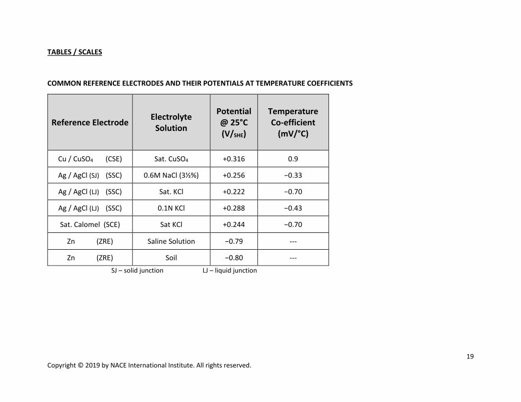
TABLES / SCALES
COMMON REFERENCE ELECTRODES AND THEIR POTENTIALS AT TEMPERATURE COEFFICIENTS
SJ – solid junction LJ – liquid junction
Reference Electrode Electrolyte Solution
Potential @ 25°C (V/SHE)
Temperature Co-efficient
(mV/°C)
Cu / CuSO4 (CSE) Sat. CuSO4 +0.316 0.9
Ag / AgCl (SJ) (SSC) 0.6M NaCl (3½%) +0.256 −0.33
Ag / AgCl (LJ) (SSC) Sat. KCl +0.222 −0.70
Ag / AgCl (LJ) (SSC) 0.1N KCl +0.288 −0.43
Sat. Calomel (SCE) Sat KCl +0.244 −0.70
Zn (ZRE) Saline Solution −0.79 ---
Zn (ZRE) Soil −0.80 ---
20 Copyright © 2019 by NACE International Institute. All rights reserved.
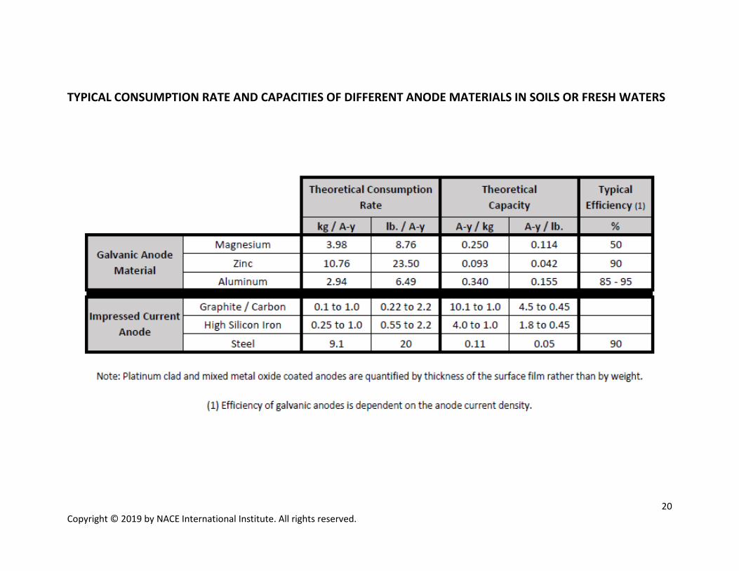
TYPICAL CONSUMPTION RATE AND CAPACITIES OF DIFFERENT ANODE MATERIALS IN SOILS OR FRESH WATERS

Copyright © 2019 by NACE International Institute. All rights reserved.
22 Copyright © 2019 by NACE International Institute. All rights reserved.
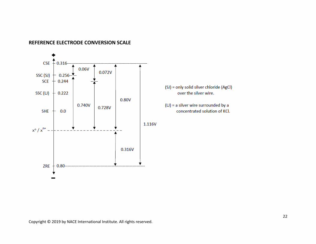
REFERENCE ELECTRODE CONVERSION SCALE

Copyright © 2019 by NACE International Institute. All rights reserved.
REFERENCES & STANDARDS USED TO DEVELOP THE REFERENCE MATERIAL Peabody's Control of Pipeline Corrosion (No. Ed 2). Peabody, A.W. (2001). NACE International.
• Derived from equations in “Calculation of Resistance to Ground,” by H.B. Dwight. Electrical Engineering, (1936).
• Derived from equations in “Earth Conduction Effects in Transmission Systems,” by Erling D., Sunde. D. Van Nostrand Co., Inc. (1949).
Corrosion Tests and Standards: Application and Interpretation–Second Edition. (2005). Baboian, R. ASTM. Handbook of Cathodic Corrosion Protection–Third Edition. Von Baeckmann, W., Schwenk, W., Prinz, W. (1997) Gulf Professional Publishing. Atlas of Electrochemical Equilibria in Aqueous Solutions. Pourbaix, M. (1974). NACE. NACE Corrosion Engineers Reference Handbook, Baboian, 3rd Edition (2002) Pipe Line Corrosion and Cathodic Protection, Parker, M.E. 3rd Edition (1999) Deep Anode Systems: Design, Installation, and Operation, Lewis, T.H. (2000). NACE.
“A Comparison of Anodes for Impressed Current Systems,” Jakobs, J.A., NACE Canadian Region, Western Conference. (1980) “Soil Investigation Employing a New Method of Layer-Value Determination for Earth Resistivity Interpretation,” Barnes, H.E. (1952). Michigan State Highway Department “Improved Pipe-to-Soil Potential Survey Methods, PRCI Final Report,” PR-186-807. Thompson, N.G., Lawson, K.M. (1991) “American National Standard for Use of the International System of Units (SI): The Modern Metric System” ASTM SI 10. (2002). ASTM NACE International SP 0169 (2013). “Control of External Corrosion on Underground of Submerged Metallic Piping Systems.” NACE International.
NACE International SP 0200 (2014). “Steel-Case Pipeline Practices.” NACE International.
NACE International SP 0575 (2007). “Internal Cathodic Protection (CP) Systems in Oil-Treating Vessels.” NACE International.
NACE International TM 0102 (2002). “Measurement of Protective Coating Conductance on Underground Pipelines.” NACE International.