Concrete & Masonry: SSPC-SP13/NACE 6, or ICRI ... - BidNet
20
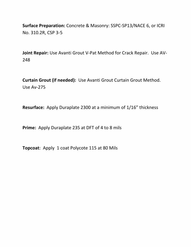
Surface Preparation: Concrete & Masonry: SSPC-SP13/NACE 6, or ICRI No. 310.2R, CSP 3-5 Joint Repair: Use Avanti Grout V-Pat Method for Crack Repair. Use AV- 248 Curtain Grout (if needed): Use Avanti Grout Curtain Grout Method. Use Av-275 Resurface: Apply Duraplate 2300 at a minimum of 1/16” thickness Prime: Apply Duraplate 235 at DFT of 4 to 8 mils Topcoat: Apply 1 coat Polycote 115 at 80 Mils
-
Upload
khangminh22 -
Category
Documents
-
view
1 -
download
0
Transcript of Concrete & Masonry: SSPC-SP13/NACE 6, or ICRI ... - BidNet
Surface Preparation: Concrete & Masonry: SSPC-SP13/NACE 6, or ICRI
No. 310.2R, CSP 3-5
Joint Repair: Use Avanti Grout V-Pat Method for Crack Repair. Use AV-
248
Curtain Grout (if needed): Use Avanti Grout Curtain Grout Method.
Use Av-275
Resurface: Apply Duraplate 2300 at a minimum of 1/16” thickness
Prime: Apply Duraplate 235 at DFT of 4 to 8 mils
Topcoat: Apply 1 coat Polycote 115 at 80 Mils
• • •

V-PAT Technical Manual Page 8
Variable Pressure Application Technique
V-PATFor Repair of Water Leakage Through Concrete
TM
REV. 12/14
The data, information and statements contained herein are believed to be reliable, but are not construed as a warranty representation for which AVANTI INTERNATIONAL assumes any legal responsibility. Since field conditions vary widely, users must undertake sufficient verification and testing to determine the suitability of any product or process mentioned in this or any other written material from AVANTI INTERNATIONAL for their own particular use.
NO WARRANTY OF SUITABILITY OR FITNESS FOR A PARTICULAR PURPOSE IS MADE.
Nothing in this or any other document from AVANTI INTERNATIONAL is to be taken as permission, inducement or recommendation to practice any patented invention without a license.
Copyright 2014 by Avanti International. All rights reserved. Printed in the United States of America. Except as permitted under the United States Copyright Act of 1976, no part of this publication may be reproduced or distributed in any form or by any means, or stored in a database or retrieval system, without prior explicit written permission from Avanti International.
Warranty Statement
C
V-PAT Technical Manual Page 1
V-PAT Technical Manual Page 2
Variable Pressure Application Technique Summary: Field Guide
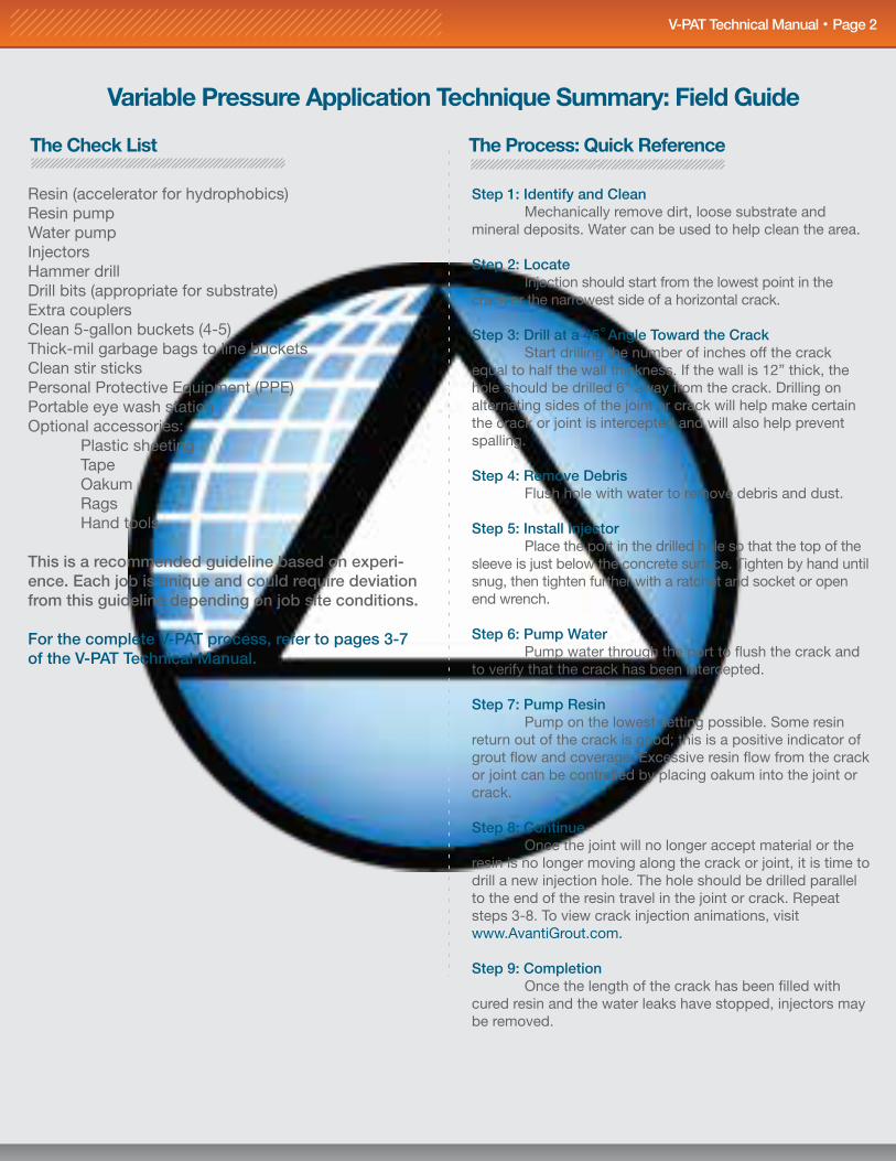
Step 1: Identify and Clean Mechanically remove dirt, loose substrate and mineral deposits. Water can be used to help clean the area.
Step 2: Locate Injection should start from the lowest point in the crack or the narrowest side of a horizontal crack.
Step 3: Drill at a 45 Angle Toward the Crack Start drilling the number of inches off the crack equal to half the wall thickness. If the wall is 12” thick, the hole should be drilled 6” away from the crack. Drilling on alternating sides of the joint or crack will help make certain the crack or joint is intercepted and will also help prevent spalling.
Step 4: Remove Debris Flush hole with water to remove debris and dust.
Step 5: Install Injector Place the port in the drilled hole so that the top of the sleeve is just below the concrete surface. Tighten by hand until snug, then tighten further with a ratchet and socket or open end wrench.
Step 6: Pump Water Pump water through the port to flush the crack and to verify that the crack has been intercepted.
Step 7: Pump Resin Pump on the lowest setting possible. Some resin return out of the crack is good; this is a positive indicator of grout flow and coverage. Excessive resin flow from the crack or joint can be controlled by placing oakum into the joint or crack.
Step 8: Continue Once the joint will no longer accept material or the resin is no longer moving along the crack or joint, it is time to drill a new injection hole. The hole should be drilled parallel to the end of the resin travel in the joint or crack. Repeat steps 3-8. To view crack injection animations, visit www.AvantiGrout.com.
Step 9: Completion Once the length of the crack has been filled with cured resin and the water leaks have stopped, injectors may be removed.
The Process: Quick Reference
Resin (accelerator for hydrophobics)Resin pumpWater pumpInjectorsHammer drillDrill bits (appropriate for substrate)Extra couplersClean 5-gallon buckets (4-5)Thick-mil garbage bags to line bucketsClean stir sticksPersonal Protective Equipment (PPE)Portable eye wash stationOptional accessories: Plastic sheeting Tape Oakum Rags Hand tools
This is a recommended guideline based on experi-ence. Each job is unique and could require deviation from this guideline depending on job site conditions.
For the complete V-PAT process, refer to pages 3-7 of the V-PAT Technical Manual.
The Check List
V-PAT Technical Manual Page 7
Step 5: Apply Outer Joint SealWith the inner seal in place, and flow temporarily controlled, proceed to installation of the temporary outer seal. Several materials may be used, but hydraulic cement has been used successfully and economically. Remember that resin develops expansion pressures as it cures. If the outer seal is not secure, you may spring a leak during injection. Such a leak is inconvenient at best, and wastes time and resin while you clean up and start over.
Step 6: Resin InjectionResin injection for expansion joints proceeds as outlined for crack sealing. However, any pressures above the minimums required to open injector ports will seldom be needed. Special care should be taken as not to rupture the outer seal. Begin at the lowest injector and work your way up. Once pumping starts, best results are obtained by methodically proceeding to the end of the joint without stopping. Continuity helps assure uniform density of the cured foam, thus material containment and compression, as rapidly as practical.
Continue to pump each injector until relatively pure resin flows from the next port before moving up. When the last injector has been pumped, go back to the first port and work through the series again - adding a small amount of resin at each. Watch your outer seal carefully. A little resin is usually enough. After curing overnight, the expansion joint is "better than new" and is ready for service.
NOTE: Stainless steel needles are available from Avanti for re-injec-tion of any EGP, resin rod, or double-dam method seals which may need additional resin.
Basic Equipment for Sealing Fine Cracks
1. Resin
2. Accelerator (for hydrophobics)
3. Pneumatic or electric hammer drill with appropriate drill bit
4. Injectors (plastic or mechanical)
5. High pressure pump capable of a pressure ranges of 200-3,000 PSI (preferably a positive displacement design). The pump must have a capacity of 0.50 to 2.0 gpm. It can be powered by either electric, air or hydraulics. All internal seals must be resistant to solvents such as acetone. There are a wide variety of pumps from which to choose. Call Avanti for assistance in choosing the pump to fit your application.
6. Hoses used in conjunction with pump must be moisture resistant.
7. Injection gun should be capable of 3,000 PSI and have the capability of metering the resin through the injectors to achieve variable rates (not just on or off). However, normal injection pressures are between 800 and 1,200 PSI. Pressures above 1,500 PSI significantly increase the chance of hydraulic fracturing of the concrete structure.
Safety Procedures
For safety procedures, please refer to the MSDS. Product MSDS can be found online 24/7 at www.AvantiGrout.com.
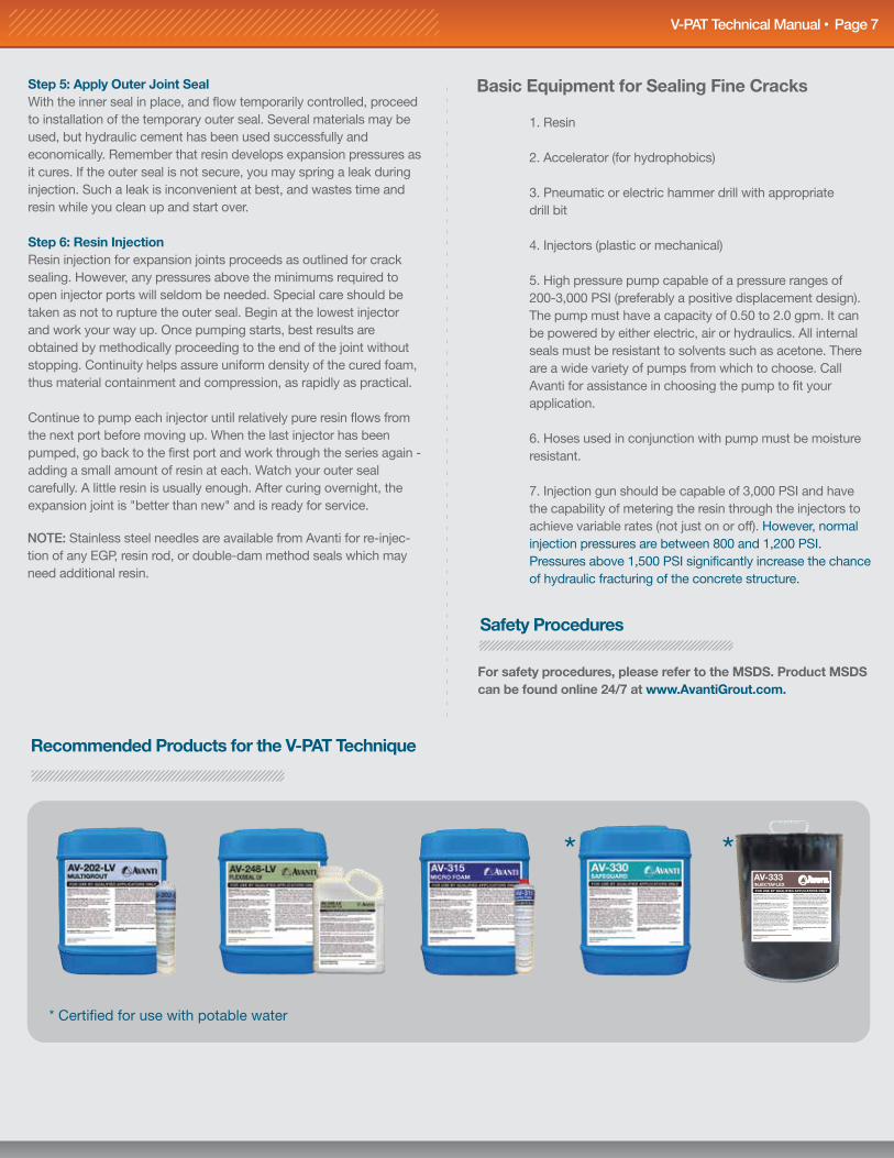
Recommended Products for the V-PAT Technique
* Certified for use with potable water
*IN CASE OF SPILL: Notify safety personnel. Eliminate all ignition sources and evacuate spill area. Provide adequate ventilation. Wear respiratory and other protective equipment during clean-up. For small spills, absorb with sand or other absorbents and place in suitable container. For large spills, dike ahead for later disposal or reclamation. Do not contaminate water or allow product to enter drains. Dispose of product in accordance with federal, state, and local regulations.
IMPORTANT NOTICE TO PURCHASER: Avanti warrants that the product conforms to the chemical description on the label. No other warranty is made, expressed, or implied, including the warranty of fitness for a particular purpose. Avanti’s only obligation shall be to replace such quantity of the product proved to be defective. Avanti shall not be liable for any injury, loss, or damage—direct, indirect, incidental, or consequential—arising from using or from the inability to use the product. Before using, user shall determine the suitability of the product for the intended use and assumes all risk and liability whatsoever in connection therewith. The foregoing may not be changed except by an agreement signed by officers of Avanti.
IMPORTANT: READ MATERIAL SAFETY DATA SHEET BEFORE USING.
FOR USE BY QUALIFIED APPLICATORS ONLYPRECAUTIONS: Keep away from heat, sparks, and open flames. Avoid breathing vapors. Use only in areas sufficiently ventilated to keep vapor concentrations below their limit values. Avoid eye contact. Avoid prolonged or repeated skin contact.
STORAGE AND HANDLING: Store in a cool, dry area not to exceed 86°F (30°C). Keep out of direct sunlight. Keep container tightly closed when not in use. Moisture will affect performance if allowed to collect inside container. Prevent physical damage to container.
SUGGESTED FIRST AID: EYE CONTACT- Immediately flush eyes with plenty of water. Contact a physician. SKIN CONTACT- Quickly remove contaminated clothing. Wash thoroughly with soap and water. A soothing ointment may be applied to irritated skin after thorough cleansing. Consult a physician. INHALATION- Remove to fresh air. If breathing difficulties occur, administer oxygen. Seek immediate medical attention. INGESTION- Do not induce vomiting. Give 1-2 cups of milk or water to drink. If vomiting is inevitable, prevent aspiration by keeping person’s head below the knees. Seek immediate medical attention. Note: Never give anything by mouth to an unconscious person.
IN CASE OF FIRE: For small fires, use CO2 or dry chemical. For large fires, use fog or regular foam.
AV-333INJECTAFLEX
PL-AV275-9x8-09/2011
AVANTI INTERNATIONAL 800.877.2570
*
V-PAT Technical Manual Page 6 V-PAT Technical Manual Page 3
Background
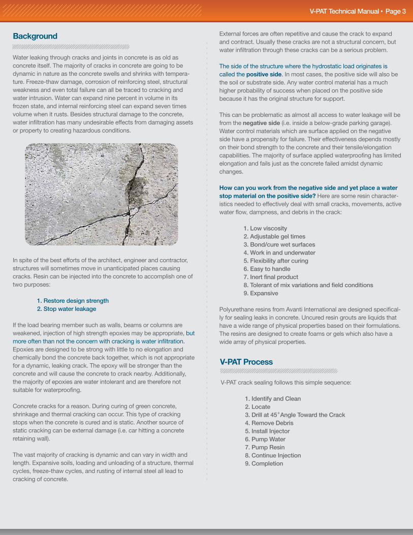
Water leaking through cracks and joints in concrete is as old as concrete itself. The majority of cracks in concrete are going to be dynamic in nature as the concrete swells and shrinks with tempera-ture. Freeze-thaw damage, corrosion of reinforcing steel, structural weakness and even total failure can all be traced to cracking and water intrusion. Water can expand nine percent in volume in its frozen state, and internal reinforcing steel can expand seven times volume when it rusts. Besides structural damage to the concrete, water infiltration has many undesirable effects from damaging assets or property to creating hazardous conditions.
In spite of the best efforts of the architect, engineer and contractor, structures will sometimes move in unanticipated places causing cracks. Resin can be injected into the concrete to accomplish one of two purposes:
1. Restore design strength 2. Stop water leakage
If the load bearing member such as walls, beams or columns are weakened, injection of high strength epoxies may be appropriate, but more often than not the concern with cracking is water infiltration. Epoxies are designed to be strong with little to no elongation and chemically bond the concrete back together, which is not appropriate for a dynamic, leaking crack. The epoxy will be stronger than the concrete and will cause the concrete to crack nearby. Additionally, the majority of epoxies are water intolerant and are therefore not suitable for waterproofing.
Concrete cracks for a reason. During curing of green concrete, shrinkage and thermal cracking can occur. This type of cracking stops when the concrete is cured and is static. Another source of static cracking can be external damage (i.e. car hitting a concrete retaining wall).
The vast majority of cracking is dynamic and can vary in width and length. Expansive soils, loading and unloading of a structure, thermal cycles, freeze-thaw cycles, and rusting of internal steel all lead to cracking of concrete.
External forces are often repetitive and cause the crack to expand and contract. Usually these cracks are not a structural concern, but water infiltration through these cracks can be a serious problem.
The side of the structure where the hydrostatic load originates is called the positive side. In most cases, the positive side will also be the soil or substrate side. Any water control material has a much higher probability of success when placed on the positive side because it has the original structure for support.
This can be problematic as almost all access to water leakage will be from the negative side (i.e. inside a below-grade parking garage). Water control materials which are surface applied on the negative side have a propensity for failure. Their effectiveness depends mostly on their bond strength to the concrete and their tensile/elongation capabilities. The majority of surface applied waterproofing has limited elongation and fails just as the concrete failed amidst dynamic changes.
How can you work from the negative side and yet place a water stop material on the positive side? Here are some resin character-istics needed to effectively deal with small cracks, movements, active water flow, dampness, and debris in the crack: 1. Low viscosity 2. Adjustable gel times 3. Bond/cure wet surfaces 4. Work in and underwater 5. Flexibility after curing 6. Easy to handle 7. Inert final product 8. Tolerant of mix variations and field conditions 9. Expansive
Polyurethane resins from Avanti International are designed specifical-ly for sealing leaks in concrete. Uncured resin grouts are liquids that have a wide range of physical properties based on their formulations. The resins are designed to create foams or gels which also have a wide array of physical properties.
V-PAT Process
V-PAT crack sealing follows this simple sequence:
1. Identify and Clean 2. Locate 3. Drill at 45 Angle Toward the Crack 4. Remove Debris 5. Install Injector 6. Pump Water 7. Pump Resin 8. Continue Injection 9. Completion
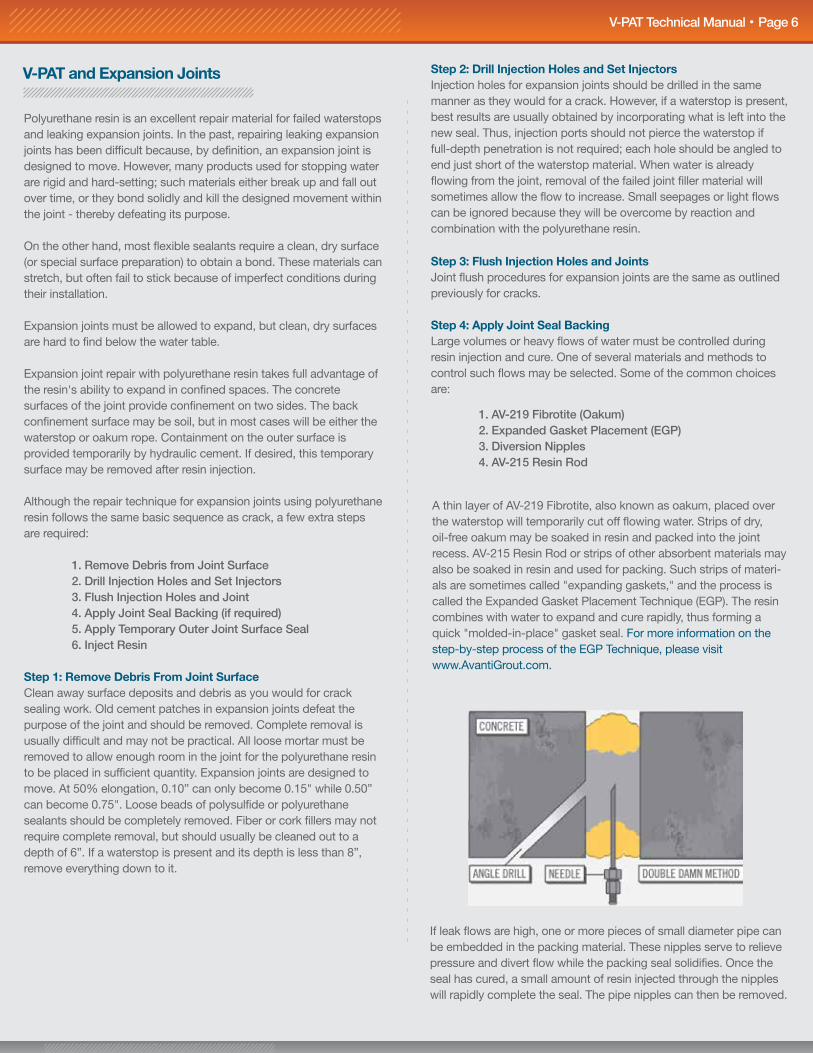
If leak flows are high, one or more pieces of small diameter pipe can be embedded in the packing material. These nipples serve to relieve pressure and divert flow while the packing seal solidifies. Once the seal has cured, a small amount of resin injected through the nipples will rapidly complete the seal. The pipe nipples can then be removed.
Step 3: Flush Injection Holes and JointsJoint flush procedures for expansion joints are the same as outlined previously for cracks.
Step 4: Apply Joint Seal BackingLarge volumes or heavy flows of water must be controlled during resin injection and cure. One of several materials and methods to control such flows may be selected. Some of the common choices are:
1. AV-219 Fibrotite (Oakum) 2. Expanded Gasket Placement (EGP) 3. Diversion Nipples 4. AV-215 Resin Rod
Step 2: Drill Injection Holes and Set InjectorsInjection holes for expansion joints should be drilled in the same manner as they would for a crack. However, if a waterstop is present, best results are usually obtained by incorporating what is left into the new seal. Thus, injection ports should not pierce the waterstop if full-depth penetration is not required; each hole should be angled to end just short of the waterstop material. When water is already flowing from the joint, removal of the failed joint filler material will sometimes allow the flow to increase. Small seepages or light flows can be ignored because they will be overcome by reaction and combination with the polyurethane resin.
V-PAT and Expansion Joints
Polyurethane resin is an excellent repair material for failed waterstops and leaking expansion joints. In the past, repairing leaking expansion joints has been difficult because, by definition, an expansion joint is designed to move. However, many products used for stopping water are rigid and hard-setting; such materials either break up and fall out over time, or they bond solidly and kill the designed movement within the joint - thereby defeating its purpose.
On the other hand, most flexible sealants require a clean, dry surface (or special surface preparation) to obtain a bond. These materials can stretch, but often fail to stick because of imperfect conditions during their installation.
Expansion joints must be allowed to expand, but clean, dry surfaces are hard to find below the water table.
Expansion joint repair with polyurethane resin takes full advantage of the resin's ability to expand in confined spaces. The concrete surfaces of the joint provide confinement on two sides. The back confinement surface may be soil, but in most cases will be either the waterstop or oakum rope. Containment on the outer surface is provided temporarily by hydraulic cement. If desired, this temporary surface may be removed after resin injection.
Although the repair technique for expansion joints using polyurethane resin follows the same basic sequence as crack, a few extra steps are required:
1. Remove Debris from Joint Surface 2. Drill Injection Holes and Set Injectors 3. Flush Injection Holes and Joint 4. Apply Joint Seal Backing (if required) 5. Apply Temporary Outer Joint Surface Seal 6. Inject Resin
Step 1: Remove Debris From Joint SurfaceClean away surface deposits and debris as you would for crack sealing work. Old cement patches in expansion joints defeat the purpose of the joint and should be removed. Complete removal is usually difficult and may not be practical. All loose mortar must be removed to allow enough room in the joint for the polyurethane resin to be placed in sufficient quantity. Expansion joints are designed to move. At 50% elongation, 0.10” can only become 0.15" while 0.50” can become 0.75". Loose beads of polysulfide or polyurethane sealants should be completely removed. Fiber or cork fillers may not require complete removal, but should usually be cleaned out to a depth of 6”. If a waterstop is present and its depth is less than 8”, remove everything down to it.
A thin layer of AV-219 Fibrotite, also known as oakum, placed over the waterstop will temporarily cut off flowing water. Strips of dry, oil-free oakum may be soaked in resin and packed into the joint recess. AV-215 Resin Rod or strips of other absorbent materials may also be soaked in resin and used for packing. Such strips of materi-als are sometimes called "expanding gaskets," and the process is called the Expanded Gasket Placement Technique (EGP). The resin combines with water to expand and cure rapidly, thus forming a quick "molded-in-place" gasket seal. For more information on the step-by-step process of the EGP Technique, please visit www.AvantiGrout.com.
The same kind of pump used for resin injection can also be used to flush the crack. However, special caution is required if the same pump is used for flushing as well as resin injection. All water must be completely removed from the pump before charging with resin. Failure to remove all the water will cause resin to cure in the pump. The pump may not be permanently damaged, but can lead to extended down time. Avanti recommends a separate pump to be used for each operation so that clean-up and the possibility of mistakes is minimized.
The flow of flush water into the crack is critical. If water does not travel under pressure from the injection hole through the crack, then there is no connectivity and no need to inject resin into that port. The injector should be removed from such locations and the hole plugged with quick-setting cement. Do not try and pump a “blind” or non-connective hole.
You will need to raise pressure and volume levels slowly. Flush the crack with the highest flow volume that is practical without exceeding permissible pressure. For cold weather applications (50 F and below), please contact Avanti. Epoxy resin injection sometimes calls for the use of muriatic or hydrochloric acid as flushing agents. Do not use these materials when working with urethane resins. Such agents are difficult to completely remove from the crack and are not needed by the resin system.
Step 7: Pump ResinFlush the pump with solvent to remove moisture that might be in the pump or hose. When all preparation work is completed, charge the pump, hose, and gun. Pull the trigger on the gun to allow all solvent to pass into a trash bucket while watching for the resin to appear. Keep the resin covered in wet environments, especially if water is dripping from overhead - a cover that you can see through is best. Begin the injection of resin at the lowest point on a vertical crack or at the narrowest side of the horizontal crack.
Patience is important in resin injection work - slow is better. Always start injecting with the pump set at the lowest setting.
V-PAT Technical Manual Page 5V-PAT Technical Manual Page 4
The best way to determine the distance between ports is to monitor the resin flow. The termination point of resin travel is the best location for the next port. As the crack gets wider, the space between ports can increase. Eight to twenty-four inches will be the most common spacing. Ports should always be staggered from one side of the crack to the opposite side, making a zigzag or stitch pattern. Using injection ports on alternating sides of the crack helps to prevent spalling and helps ensure interception of the crack. No two cracks behave alike. In some instances, a crack can be sealed using few injection ports. Others may require many ports.
Step 4: Remove DebrisFlush hole with water to remove any debris and dust.
Step 5: Install InjectorsPlace the port in the drilled hole so that the top of the sleeve is just below the concrete surface. Tighten by hand until snug, then tighten further with a ratchet and socket or open end wrench.
Step 6: Pump WaterUse the water pump to flush the port and crack. Flushing the crack with water prior to resin injection is very important. The water flush removes debris and drilling dust, and improves subsequent penetra-tion of the resin. Water left in the concrete pores will aid in curing the resin. The flushing operation also helps the technician determine how the crack will behave during resin injection. Flush water should flow from the crack face.
Step 1: Identify and CleanExamination of the crack after cleaning tells the technician where the crack goes and how wide it is. This gives a firsthand impression of how the crack will behave when grout is pumped. The surface can be cleaned mechanically. Loose debris or patches should be removed to reveal the crack. To maximize results, it is best to inject an actively leaking crack.
Step 2: Drill Injection HolesInjection should start from the lowest point of the crack or the narrowest side of a horizontal crack. The angle and depth of injection holes (ports) can be predetermined and specified using a hammer drill.
Step 3: Drill at 45 Angle Toward the CrackThe injection hole should be placed at a distance away from the crack equal to half the wall thickness. For example, if the wall is 12” thick, the hole should be drilled 6” from the crack. This forms an isosceles right triangle with the drilling depth being the hypotenuse (H=L x √2). Drilling into the concrete more than 18” is usually not required - even if the concrete is more than 36” thick - as long as adequate pumping pressure is available. At a 45 angle, drill toward the crack.
If the concrete thickness is 6” or less, do not attempt angle drilling. Set the ports straight into the face of the crack. This procedure will help minimize spalling of the concrete. The drill bit size will corre-spond with the injector size. Use 1/2” drill bit if you are using a 1/2” injector.
5/8” EZ-1
5/8” EZ-3P
5/8” EZ-4
Mechanical Injectors / Packers
3/8” Bang-In Injectors
1/2”
5/8”
Hold pressure constant for several minutes. If flow still does not occur, raise the pressure slowly. An extra minute or two can make the difference between 95% and 100% crack filling. Sudden applications of high pressure may help unintentionally open the crack. If in doubt, slower is better. As soon as flow is established, decrease pressure as much as possible consistent with desired flow rate.
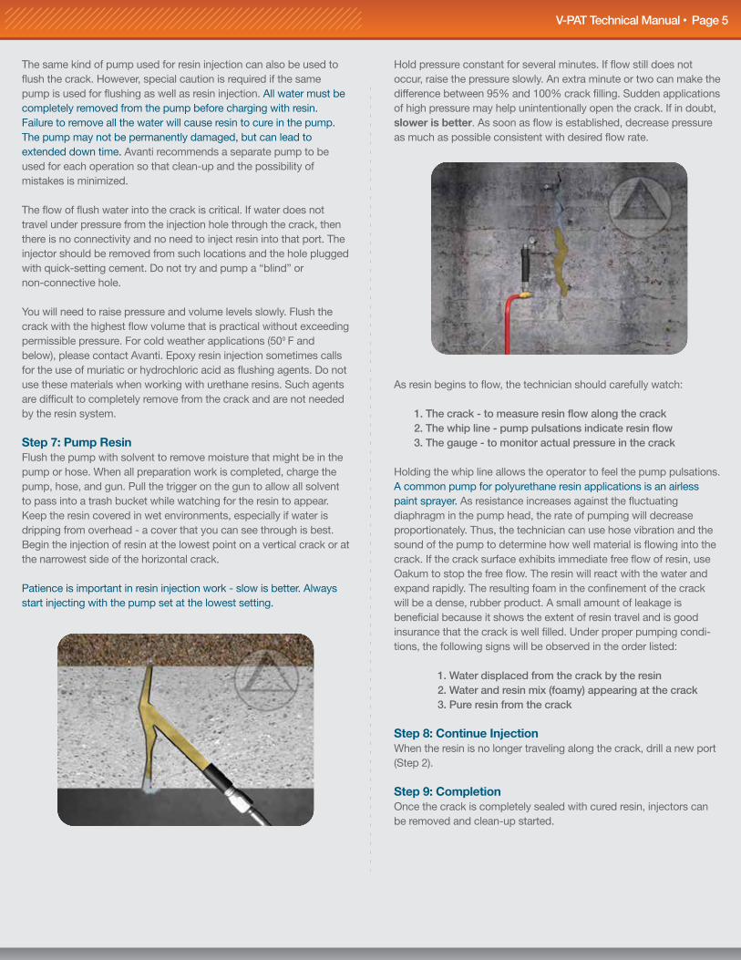
As resin begins to flow, the technician should carefully watch: 1. The crack - to measure resin flow along the crack 2. The whip line - pump pulsations indicate resin flow 3. The gauge - to monitor actual pressure in the crack
Holding the whip line allows the operator to feel the pump pulsations. A common pump for polyurethane resin applications is an airless paint sprayer. As resistance increases against the fluctuating diaphragm in the pump head, the rate of pumping will decrease proportionately. Thus, the technician can use hose vibration and the sound of the pump to determine how well material is flowing into the crack. If the crack surface exhibits immediate free flow of resin, use Oakum to stop the free flow. The resin will react with the water and expand rapidly. The resulting foam in the confinement of the crack will be a dense, rubber product. A small amount of leakage is beneficial because it shows the extent of resin travel and is good insurance that the crack is well filled. Under proper pumping condi-tions, the following signs will be observed in the order listed:
1. Water displaced from the crack by the resin 2. Water and resin mix (foamy) appearing at the crack 3. Pure resin from the crack
Step 8: Continue InjectionWhen the resin is no longer traveling along the crack, drill a new port (Step 2).
Step 9: CompletionOnce the crack is completely sealed with cured resin, injectors can be removed and clean-up started.
The same kind of pump used for resin injection can also be used to flush the crack. However, special caution is required if the same pump is used for flushing as well as resin injection. All water must be completely removed from the pump before charging with resin. Failure to remove all the water will cause resin to cure in the pump. The pump may not be permanently damaged, but can lead to extended down time. Avanti recommends a separate pump to be used for each operation so that clean-up and the possibility of mistakes is minimized.
The flow of flush water into the crack is critical. If water does not travel under pressure from the injection hole through the crack, then there is no connectivity and no need to inject resin into that port. The injector should be removed from such locations and the hole plugged with quick-setting cement. Do not try and pump a “blind” or non-connective hole.
You will need to raise pressure and volume levels slowly. Flush the crack with the highest flow volume that is practical without exceeding permissible pressure. For cold weather applications (50 F and below), please contact Avanti. Epoxy resin injection sometimes calls for the use of muriatic or hydrochloric acid as flushing agents. Do not use these materials when working with urethane resins. Such agents are difficult to completely remove from the crack and are not needed by the resin system.
Step 7: Pump ResinFlush the pump with solvent to remove moisture that might be in the pump or hose. When all preparation work is completed, charge the pump, hose, and gun. Pull the trigger on the gun to allow all solvent to pass into a trash bucket while watching for the resin to appear. Keep the resin covered in wet environments, especially if water is dripping from overhead - a cover that you can see through is best. Begin the injection of resin at the lowest point on a vertical crack or at the narrowest side of the horizontal crack.
Patience is important in resin injection work - slow is better. Always start injecting with the pump set at the lowest setting.
V-PAT Technical Manual Page 5V-PAT Technical Manual Page 4
The best way to determine the distance between ports is to monitor the resin flow. The termination point of resin travel is the best location for the next port. As the crack gets wider, the space between ports can increase. Eight to twenty-four inches will be the most common spacing. Ports should always be staggered from one side of the crack to the opposite side, making a zigzag or stitch pattern. Using injection ports on alternating sides of the crack helps to prevent spalling and helps ensure interception of the crack. No two cracks behave alike. In some instances, a crack can be sealed using few injection ports. Others may require many ports.
Step 4: Remove DebrisFlush hole with water to remove any debris and dust.
Step 5: Install InjectorsPlace the port in the drilled hole so that the top of the sleeve is just below the concrete surface. Tighten by hand until snug, then tighten further with a ratchet and socket or open end wrench.
Step 6: Pump WaterUse the water pump to flush the port and crack. Flushing the crack with water prior to resin injection is very important. The water flush removes debris and drilling dust, and improves subsequent penetra-tion of the resin. Water left in the concrete pores will aid in curing the resin. The flushing operation also helps the technician determine how the crack will behave during resin injection. Flush water should flow from the crack face.
Step 1: Identify and CleanExamination of the crack after cleaning tells the technician where the crack goes and how wide it is. This gives a firsthand impression of how the crack will behave when grout is pumped. The surface can be cleaned mechanically. Loose debris or patches should be removed to reveal the crack. To maximize results, it is best to inject an actively leaking crack.
Step 2: Drill Injection HolesInjection should start from the lowest point of the crack or the narrowest side of a horizontal crack. The angle and depth of injection holes (ports) can be predetermined and specified using a hammer drill.
Step 3: Drill at 45 Angle Toward the CrackThe injection hole should be placed at a distance away from the crack equal to half the wall thickness. For example, if the wall is 12” thick, the hole should be drilled 6” from the crack. This forms an isosceles right triangle with the drilling depth being the hypotenuse (H=L x √2). Drilling into the concrete more than 18” is usually not required - even if the concrete is more than 36” thick - as long as adequate pumping pressure is available. At a 45 angle, drill toward the crack.
If the concrete thickness is 6” or less, do not attempt angle drilling. Set the ports straight into the face of the crack. This procedure will help minimize spalling of the concrete. The drill bit size will corre-spond with the injector size. Use 1/2” drill bit if you are using a 1/2” injector.
5/8” EZ-1
5/8” EZ-3P
5/8” EZ-4
Mechanical Injectors / Packers
3/8” Bang-In Injectors
1/2”
5/8”
Hold pressure constant for several minutes. If flow still does not occur, raise the pressure slowly. An extra minute or two can make the difference between 95% and 100% crack filling. Sudden applications of high pressure may help unintentionally open the crack. If in doubt, slower is better. As soon as flow is established, decrease pressure as much as possible consistent with desired flow rate.
As resin begins to flow, the technician should carefully watch: 1. The crack - to measure resin flow along the crack 2. The whip line - pump pulsations indicate resin flow 3. The gauge - to monitor actual pressure in the crack
Holding the whip line allows the operator to feel the pump pulsations. A common pump for polyurethane resin applications is an airless paint sprayer. As resistance increases against the fluctuating diaphragm in the pump head, the rate of pumping will decrease proportionately. Thus, the technician can use hose vibration and the sound of the pump to determine how well material is flowing into the crack. If the crack surface exhibits immediate free flow of resin, use Oakum to stop the free flow. The resin will react with the water and expand rapidly. The resulting foam in the confinement of the crack will be a dense, rubber product. A small amount of leakage is beneficial because it shows the extent of resin travel and is good insurance that the crack is well filled. Under proper pumping condi-tions, the following signs will be observed in the order listed:
1. Water displaced from the crack by the resin 2. Water and resin mix (foamy) appearing at the crack 3. Pure resin from the crack
Step 8: Continue InjectionWhen the resin is no longer traveling along the crack, drill a new port (Step 2).
Step 9: CompletionOnce the crack is completely sealed with cured resin, injectors can be removed and clean-up started.
V-PAT Technical Manual Page 6 V-PAT Technical Manual Page 3
Background
Water leaking through cracks and joints in concrete is as old as concrete itself. The majority of cracks in concrete are going to be dynamic in nature as the concrete swells and shrinks with tempera-ture. Freeze-thaw damage, corrosion of reinforcing steel, structural weakness and even total failure can all be traced to cracking and water intrusion. Water can expand nine percent in volume in its frozen state, and internal reinforcing steel can expand seven times volume when it rusts. Besides structural damage to the concrete, water infiltration has many undesirable effects from damaging assets or property to creating hazardous conditions.
In spite of the best efforts of the architect, engineer and contractor, structures will sometimes move in unanticipated places causing cracks. Resin can be injected into the concrete to accomplish one of two purposes:
1. Restore design strength 2. Stop water leakage
If the load bearing member such as walls, beams or columns are weakened, injection of high strength epoxies may be appropriate, but more often than not the concern with cracking is water infiltration. Epoxies are designed to be strong with little to no elongation and chemically bond the concrete back together, which is not appropriate for a dynamic, leaking crack. The epoxy will be stronger than the concrete and will cause the concrete to crack nearby. Additionally, the majority of epoxies are water intolerant and are therefore not suitable for waterproofing.
Concrete cracks for a reason. During curing of green concrete, shrinkage and thermal cracking can occur. This type of cracking stops when the concrete is cured and is static. Another source of static cracking can be external damage (i.e. car hitting a concrete retaining wall).
The vast majority of cracking is dynamic and can vary in width and length. Expansive soils, loading and unloading of a structure, thermal cycles, freeze-thaw cycles, and rusting of internal steel all lead to cracking of concrete.
External forces are often repetitive and cause the crack to expand and contract. Usually these cracks are not a structural concern, but water infiltration through these cracks can be a serious problem.
The side of the structure where the hydrostatic load originates is called the positive side. In most cases, the positive side will also be the soil or substrate side. Any water control material has a much higher probability of success when placed on the positive side because it has the original structure for support.
This can be problematic as almost all access to water leakage will be from the negative side (i.e. inside a below-grade parking garage). Water control materials which are surface applied on the negative side have a propensity for failure. Their effectiveness depends mostly on their bond strength to the concrete and their tensile/elongation capabilities. The majority of surface applied waterproofing has limited elongation and fails just as the concrete failed amidst dynamic changes.
How can you work from the negative side and yet place a water stop material on the positive side? Here are some resin character-istics needed to effectively deal with small cracks, movements, active water flow, dampness, and debris in the crack: 1. Low viscosity 2. Adjustable gel times 3. Bond/cure wet surfaces 4. Work in and underwater 5. Flexibility after curing 6. Easy to handle 7. Inert final product 8. Tolerant of mix variations and field conditions 9. Expansive
Polyurethane resins from Avanti International are designed specifical-ly for sealing leaks in concrete. Uncured resin grouts are liquids that have a wide range of physical properties based on their formulations. The resins are designed to create foams or gels which also have a wide array of physical properties.
V-PAT Process
V-PAT crack sealing follows this simple sequence:
1. Identify and Clean 2. Locate 3. Drill at 45 Angle Toward the Crack 4. Remove Debris 5. Install Injector 6. Pump Water 7. Pump Resin 8. Continue Injection 9. Completion
If leak flows are high, one or more pieces of small diameter pipe can be embedded in the packing material. These nipples serve to relieve pressure and divert flow while the packing seal solidifies. Once the seal has cured, a small amount of resin injected through the nipples will rapidly complete the seal. The pipe nipples can then be removed.
Step 3: Flush Injection Holes and JointsJoint flush procedures for expansion joints are the same as outlined previously for cracks.
Step 4: Apply Joint Seal BackingLarge volumes or heavy flows of water must be controlled during resin injection and cure. One of several materials and methods to control such flows may be selected. Some of the common choices are:
1. AV-219 Fibrotite (Oakum) 2. Expanded Gasket Placement (EGP) 3. Diversion Nipples 4. AV-215 Resin Rod
Step 2: Drill Injection Holes and Set InjectorsInjection holes for expansion joints should be drilled in the same manner as they would for a crack. However, if a waterstop is present, best results are usually obtained by incorporating what is left into the new seal. Thus, injection ports should not pierce the waterstop if full-depth penetration is not required; each hole should be angled to end just short of the waterstop material. When water is already flowing from the joint, removal of the failed joint filler material will sometimes allow the flow to increase. Small seepages or light flows can be ignored because they will be overcome by reaction and combination with the polyurethane resin.
V-PAT and Expansion Joints
Polyurethane resin is an excellent repair material for failed waterstops and leaking expansion joints. In the past, repairing leaking expansion joints has been difficult because, by definition, an expansion joint is designed to move. However, many products used for stopping water are rigid and hard-setting; such materials either break up and fall out over time, or they bond solidly and kill the designed movement within the joint - thereby defeating its purpose.
On the other hand, most flexible sealants require a clean, dry surface (or special surface preparation) to obtain a bond. These materials can stretch, but often fail to stick because of imperfect conditions during their installation.
Expansion joints must be allowed to expand, but clean, dry surfaces are hard to find below the water table.
Expansion joint repair with polyurethane resin takes full advantage of the resin's ability to expand in confined spaces. The concrete surfaces of the joint provide confinement on two sides. The back confinement surface may be soil, but in most cases will be either the waterstop or oakum rope. Containment on the outer surface is provided temporarily by hydraulic cement. If desired, this temporary surface may be removed after resin injection.
Although the repair technique for expansion joints using polyurethane resin follows the same basic sequence as crack, a few extra steps are required:
1. Remove Debris from Joint Surface 2. Drill Injection Holes and Set Injectors 3. Flush Injection Holes and Joint 4. Apply Joint Seal Backing (if required) 5. Apply Temporary Outer Joint Surface Seal 6. Inject Resin
Step 1: Remove Debris From Joint SurfaceClean away surface deposits and debris as you would for crack sealing work. Old cement patches in expansion joints defeat the purpose of the joint and should be removed. Complete removal is usually difficult and may not be practical. All loose mortar must be removed to allow enough room in the joint for the polyurethane resin to be placed in sufficient quantity. Expansion joints are designed to move. At 50% elongation, 0.10” can only become 0.15" while 0.50” can become 0.75". Loose beads of polysulfide or polyurethane sealants should be completely removed. Fiber or cork fillers may not require complete removal, but should usually be cleaned out to a depth of 6”. If a waterstop is present and its depth is less than 8”, remove everything down to it.
A thin layer of AV-219 Fibrotite, also known as oakum, placed over the waterstop will temporarily cut off flowing water. Strips of dry, oil-free oakum may be soaked in resin and packed into the joint recess. AV-215 Resin Rod or strips of other absorbent materials may also be soaked in resin and used for packing. Such strips of materi-als are sometimes called "expanding gaskets," and the process is called the Expanded Gasket Placement Technique (EGP). The resin combines with water to expand and cure rapidly, thus forming a quick "molded-in-place" gasket seal. For more information on the step-by-step process of the EGP Technique, please visit www.AvantiGrout.com.
V-PAT Technical Manual Page 2
Variable Pressure Application Technique Summary: Field Guide
Step 1: Identify and Clean Mechanically remove dirt, loose substrate and mineral deposits. Water can be used to help clean the area.
Step 2: Locate Injection should start from the lowest point in the crack or the narrowest side of a horizontal crack.
Step 3: Drill at a 45 Angle Toward the Crack Start drilling the number of inches off the crack equal to half the wall thickness. If the wall is 12” thick, the hole should be drilled 6” away from the crack. Drilling on alternating sides of the joint or crack will help make certain the crack or joint is intercepted and will also help prevent spalling.
Step 4: Remove Debris Flush hole with water to remove debris and dust.
Step 5: Install Injector Place the port in the drilled hole so that the top of the sleeve is just below the concrete surface. Tighten by hand until snug, then tighten further with a ratchet and socket or open end wrench.
Step 6: Pump Water Pump water through the port to flush the crack and to verify that the crack has been intercepted.
Step 7: Pump Resin Pump on the lowest setting possible. Some resin return out of the crack is good; this is a positive indicator of grout flow and coverage. Excessive resin flow from the crack or joint can be controlled by placing oakum into the joint or crack.
Step 8: Continue Once the joint will no longer accept material or the resin is no longer moving along the crack or joint, it is time to drill a new injection hole. The hole should be drilled parallel to the end of the resin travel in the joint or crack. Repeat steps 3-8. To view crack injection animations, visit www.AvantiGrout.com.
Step 9: Completion Once the length of the crack has been filled with cured resin and the water leaks have stopped, injectors may be removed.
The Process: Quick Reference
Resin (accelerator for hydrophobics)Resin pumpWater pumpInjectorsHammer drillDrill bits (appropriate for substrate)Extra couplersClean 5-gallon buckets (4-5)Thick-mil garbage bags to line bucketsClean stir sticksPersonal Protective Equipment (PPE)Portable eye wash stationOptional accessories: Plastic sheeting Tape Oakum Rags Hand tools
This is a recommended guideline based on experi-ence. Each job is unique and could require deviation from this guideline depending on job site conditions.
For the complete V-PAT process, refer to pages 3-7 of the V-PAT Technical Manual.
The Check List
V-PAT Technical Manual Page 7
Step 5: Apply Outer Joint SealWith the inner seal in place, and flow temporarily controlled, proceed to installation of the temporary outer seal. Several materials may be used, but hydraulic cement has been used successfully and economically. Remember that resin develops expansion pressures as it cures. If the outer seal is not secure, you may spring a leak during injection. Such a leak is inconvenient at best, and wastes time and resin while you clean up and start over.
Step 6: Resin InjectionResin injection for expansion joints proceeds as outlined for crack sealing. However, any pressures above the minimums required to open injector ports will seldom be needed. Special care should be taken as not to rupture the outer seal. Begin at the lowest injector and work your way up. Once pumping starts, best results are obtained by methodically proceeding to the end of the joint without stopping. Continuity helps assure uniform density of the cured foam, thus material containment and compression, as rapidly as practical.
Continue to pump each injector until relatively pure resin flows from the next port before moving up. When the last injector has been pumped, go back to the first port and work through the series again - adding a small amount of resin at each. Watch your outer seal carefully. A little resin is usually enough. After curing overnight, the expansion joint is "better than new" and is ready for service.
NOTE: Stainless steel needles are available from Avanti for re-injec-tion of any EGP, resin rod, or double-dam method seals which may need additional resin.
Basic Equipment for Sealing Fine Cracks
1. Resin
2. Accelerator (for hydrophobics)
3. Pneumatic or electric hammer drill with appropriate drill bit
4. Injectors (plastic or mechanical)
5. High pressure pump capable of a pressure ranges of 200-3,000 PSI (preferably a positive displacement design). The pump must have a capacity of 0.50 to 2.0 gpm. It can be powered by either electric, air or hydraulics. All internal seals must be resistant to solvents such as acetone. There are a wide variety of pumps from which to choose. Call Avanti for assistance in choosing the pump to fit your application.
6. Hoses used in conjunction with pump must be moisture resistant.
7. Injection gun should be capable of 3,000 PSI and have the capability of metering the resin through the injectors to achieve variable rates (not just on or off). However, normal injection pressures are between 800 and 1,200 PSI. Pressures above 1,500 PSI significantly increase the chance of hydraulic fracturing of the concrete structure.
Safety Procedures
For safety procedures, please refer to the MSDS. Product MSDS can be found online 24/7 at www.AvantiGrout.com.
Recommended Products for the V-PAT Technique
* Certified for use with potable water
*IN CASE OF SPILL: Notify safety personnel. Eliminate all ignition sources and evacuate spill area. Provide adequate ventilation. Wear respiratory and other protective equipment during clean-up. For small spills, absorb with sand or other absorbents and place in suitable container. For large spills, dike ahead for later disposal or reclamation. Do not contaminate water or allow product to enter drains. Dispose of product in accordance with federal, state, and local regulations.
IMPORTANT NOTICE TO PURCHASER: Avanti warrants that the product conforms to the chemical description on the label. No other warranty is made, expressed, or implied, including the warranty of fitness for a particular purpose. Avanti’s only obligation shall be to replace such quantity of the product proved to be defective. Avanti shall not be liable for any injury, loss, or damage—direct, indirect, incidental, or consequential—arising from using or from the inability to use the product. Before using, user shall determine the suitability of the product for the intended use and assumes all risk and liability whatsoever in connection therewith. The foregoing may not be changed except by an agreement signed by officers of Avanti.
IMPORTANT: READ MATERIAL SAFETY DATA SHEET BEFORE USING.
FOR USE BY QUALIFIED APPLICATORS ONLYPRECAUTIONS: Keep away from heat, sparks, and open flames. Avoid breathing vapors. Use only in areas sufficiently ventilated to keep vapor concentrations below their limit values. Avoid eye contact. Avoid prolonged or repeated skin contact.
STORAGE AND HANDLING: Store in a cool, dry area not to exceed 86°F (30°C). Keep out of direct sunlight. Keep container tightly closed when not in use. Moisture will affect performance if allowed to collect inside container. Prevent physical damage to container.
SUGGESTED FIRST AID: EYE CONTACT- Immediately flush eyes with plenty of water. Contact a physician. SKIN CONTACT- Quickly remove contaminated clothing. Wash thoroughly with soap and water. A soothing ointment may be applied to irritated skin after thorough cleansing. Consult a physician. INHALATION- Remove to fresh air. If breathing difficulties occur, administer oxygen. Seek immediate medical attention. INGESTION- Do not induce vomiting. Give 1-2 cups of milk or water to drink. If vomiting is inevitable, prevent aspiration by keeping person’s head below the knees. Seek immediate medical attention. Note: Never give anything by mouth to an unconscious person.
IN CASE OF FIRE: For small fires, use CO2 or dry chemical. For large fires, use fog or regular foam.
AV-333INJECTAFLEX
PL-AV275-9x8-09/2011
AVANTI INTERNATIONAL 800.877.2570
*
V-PAT Technical Manual Page 8
Variable Pressure Application Technique
V-PATFor Repair of Water Leakage Through Concrete
TM
REV. 12/14
The data, information and statements contained herein are believed to be reliable, but are not construed as a warranty representation for which AVANTI INTERNATIONAL assumes any legal responsibility. Since field conditions vary widely, users must undertake sufficient verification and testing to determine the suitability of any product or process mentioned in this or any other written material from AVANTI INTERNATIONAL for their own particular use.
NO WARRANTY OF SUITABILITY OR FITNESS FOR A PARTICULAR PURPOSE IS MADE.
Nothing in this or any other document from AVANTI INTERNATIONAL is to be taken as permission, inducement or recommendation to practice any patented invention without a license.
Copyright 2014 by Avanti International. All rights reserved. Printed in the United States of America. Except as permitted under the United States Copyright Act of 1976, no part of this publication may be reproduced or distributed in any form or by any means, or stored in a database or retrieval system, without prior explicit written permission from Avanti International.
Warranty Statement
C
V-PAT Technical Manual Page 1
• • •

If there are multiple cracks or leaks in a wall or underground structure, simply filling the individual crack may have you spending a great deal of time chasing the water from crack to crack.
The curtain grouting technique enables you to stop several leaks at the same time and protect the structure long-term by encapsulating it and/or preventing groundwater from touching the structure in the future. It is an especially usefully technique on brick/block manholes where you have a significant amount of joints through which water can penetrate. Curtain grouting can be done successfullywith expansive foams or with non-expansive acrylic gel grouts. To Curtain Grout a structure you will need: 1. The chemical grout, catalyst, initiator and/or water. 2. A grout pump: acrylic grouts typically use a dual
component, stainless steel pump (air powered) while expansive foams utilize single component electric airless spray equipment. Each pump should be fitted with hoses rated for the specific type of pump/grout.
3. Tanks or buckets for mixing. 4. Proper Personal Protective Equipment (PPE’s)
according to the manufacturer’s MSDS.5. Confined space equipment as needed for entering
the underground structure.6. Injection tools: wand, wall spears or injection ports. 7. Quick setting non-shrink mortar. 8. Cleaning solutions – soap & water for gels and
solvents for foams.9. Hammer drill.
Here is a quick glance at the steps you would take to curtain grout a structure: 1. Drill holes through the wall of the structure to the
soil. Holes should be spaced equally around the entire structure, typically drilled 2-3 feet above, below and to the sides of the initial hole so that movement of the grout will be evident.
2. For acrylic grouts consider adding different colored dyes to the grout tanks A & B: The most common combination is blue dye in Tank A (the grout tank) and yellow dye in Tank B (the catalyst tank). The dyes enable the grouter to quickly discern if liquids coming into the structure are from Tank A, Tank B, a combination of both, or merely ground water. The gel will also be easier to see as a green color.
3. Keep the tank and the hoses out of direct sunlight and away from heat to avoid pre-polymerization.
4. Inject the grout at the appropriate ratio into the lowest injection hole.
5. When material comes out of the nearby hole to the left or right, move to that hole and repeat process for all holes at the lowest level.
6. Move up to the next row of holes and repeat. 7. After all the holes are grouted, patch each one with
a small handful of quick set mortar.8. When finished, be sure to clean your equipment
and hoses for storage.
Curtain Grouting is simply another effective technique in the contractor’s arsenal of tools for fighting water intrusion. Among other benefits, it will save time from having to chase water and will protect the outside of the structure for the long term. For more helpful information, please visit NASSCO’s website at www.nassco.org.
curtain grouting manholes and under-ground structures
Tech Tips by NASSCO is a bi-monthly article on trends, best practices
and industry advice from NASSCO’s trenchless
technology membership professionals.
By NASSCO member Daniel Magill, President, Avanti International
Picture this: You’re standing in a brick manhole that is 50 years old and leaking extensively all around you. You’ve already been working for over an hour and for every leak you stop, several new leaks pop up. Now what? When it comes to stopping leaks in manholes or underground structures there are two schools of thought: “crack injection” and “curtain grouting”. In crack injection the contractor injects a resin into the leaking hole, crack, or joint that reacts to moisture by creating a strong mechanical, compressive, and adhesive seal that will move with any future movement of the structure. In curtain grouting the contractor drills through the structure and injects grout into the soil which surrounds it creating a gel/soil matrix that prevents water from getting to the structure – permanently. While both methods can be effective, this Tech Tip will focus on the Curtain Grouting technique.
Edition 4 // October 2010 www.nassco.org
the curtain grouting technique enables
you to stop several leaks at the same
time and protect the structure long-term
Revised: September 23, 2013
DURA-PLATE® 235MULTI-PURPOSE EPOXY
PART A B67-235 SERIES COLORS PART B B67V235 HARDENER
Protective &
MarineCoatings
4.67
www.sherwin-williams.com/protective
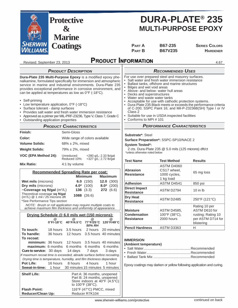
PRODUCT DESCRIPTION
Dura-Plate 235 Multi-Purpose Epoxy is a modifi ed epoxy phe-nalkamine, formulated specifi cally for immersion and atmospheric service in marine and industrial environments. Dura-Plate 235 provides exceptional performance in corrosive environment, and can be applied at temperatures as low as 0°F (-18°C).
• Self-priming• Low temperature application, 0°F (-18°C)• Surface tolerant - damp surfaces• Provides salt water and fresh water immersion resistance• Approved as a primer per MIL-PRF-23236, Type V, Class 7, Grade C• Outstanding application properties
PRODUCT CHARACTERISTICSFinish: Semi-Gloss
Color: Wide range of colors availableVolume Solids: 68% ± 2%, mixed Weight Solids: 79% ± 2%, mixed VOC (EPA Method 24): Unreduced: <280 g/L; 2.33 lb/gal Reduced 10%: <327 g/L; 2.72 lb/gal
Mix Ratio: 4:1 by volume
Recommended Spreading Rate per coat:Minimum Maximum
Wet mils (microns) 6.0 (150) 12.0 (300)Dry mils (microns) 4.0* (100) 8.0* (200)~Coverage sq ft/gal (m2/L) 136 (3.3) 272 (6.6)Theoretical coverage sq ft/gal (m2/L) @ 1 mil / 25 microns dft 1088 (26.6)*See Performance Tips section
NOTE: Brush or roll application may require multiple coats to achieve maximum fi lm thickness and uniformity of appearance.
Drying Schedule @ 6.0 mils wet (150 microns):@
0°F/-18°C@
40°F/4.5°C@
77°F/25°C@
120°F/49°C50% RH
To touch: 18 hours 3.5 hours 2 hours 20 minutesTo handle: 36 hours 12 hours 3.5 hours 40 minutesTo recoat:
minimum: 36 hours 12 hours 3.5 hours 40 minutesmaximum: 6 months 6 months 6 months 6 months
Cure to service: 30 days 14 days 7 days 3 daysIf maximum recoat time is exceeded, abrade surface before recoating.
Drying time is temperature, humidity, and fi lm thickness dependent.Pot Life: 16 hours 8 hours 4 hours 1 hourSweat-in-time: 1 hour 30 minutes 15 minutes 5 minutes
Shelf Life: Part A: 36 months, unopenedPart B: 24 months, unopenedStore indoors at 40°F (4.5°C) to 100°F (38°C).
Flash Point: 116°F (47°C) PMCC, mixedReducer/Clean Up: Reducer R7K104
continued on back
RECOMMENDED USESFor use over prepared steel and masonry surfaces.• Salt water and fresh water immersion resistance• Ballast tanks, offshore and marine structures• Bilges and wet void areas• Above- and below- water hull areas• Decks and superstructures• Water and waste water tanks• Acceptable for use with cathodic protection systems.• Dura-Plate 235 Black meets or exceeds the performance criteria
of C-200; SSPC Paint 16; and Mil-P-23236B(SH) Type I or IV Class 2
• Suitable for use in USDA inspected facilities• Conforms to MPI # 101
PERFORMANCE CHARACTERISTICS
Substrate*: SteelSurface Preparation*: SSPC-SP10/NACE 2System Tested*:
2 cts. Dura-Plate 235 @ 5.0 mils (125 microns) dft/ct*unless otherwise noted below
Test Name Test Method Results
Abrasion Resistance
ASTM D4060 CS17 wheel, 1000 cycles, 1 kg load
65 mg loss
Adhesion ASTM D4541 850 psiDirect Impact Resistance ASTM D2794 10 in lb
Dry Heat Resistance ASTM D2485 250°F (121°C)
Moisture Condensation Resistance
ASTM D4585, 100°F (38°C), 2000 hours
Rating 10 per ASTM D610 for rusting; Rating 10 per ASTM D714 for blistering
Pencil Hardness ASTM D3363 H
IMMERSION(Ambient temperature)• Salt Water ................................................Recommended• Fresh Water .............................................Recommended• Ballast Tank Mix ......................................Recommended
Epoxy coatings may darken or yellow following application and curing.
4.67
DURA-PLATE® 235MULTI-PURPOSE EPOXY
PART A B67-235 SERIES COLORS PART B B67V235 HARDENER
Protective &
MarineCoatings
www.sherwin-williams.com/protective
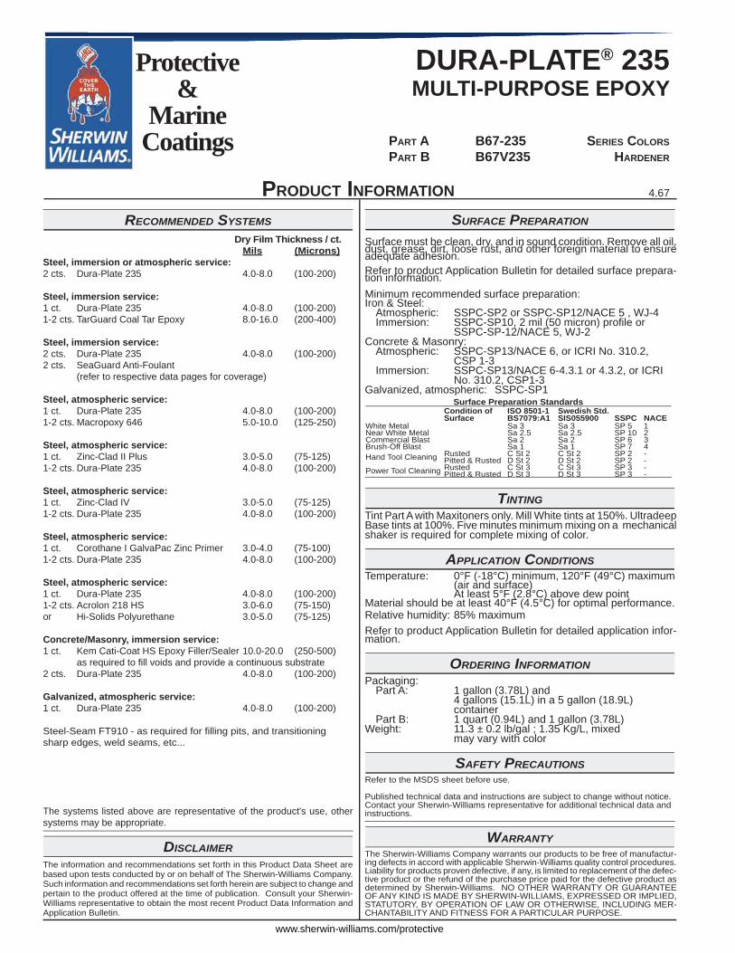
SURFACE PREPARATION
Surface must be clean, dry, and in sound condition. Remove all oil, dust, grease, dirt, loose rust, and other foreign material to ensure adequate adhesion.Refer to product Application Bulletin for detailed surface prepara-tion information.Minimum recommended surface preparation:Iron & Steel: Atmospheric: SSPC-SP2 or SSPC-SP12/NACE 5 , WJ-4 Immersion: SSPC-SP10, 2 mil (50 micron) profi le or SSPC-SP-12/NACE 5, WJ-2Concrete & Masonry: Atmospheric: SSPC-SP13/NACE 6, or ICRI No. 310.2, CSP 1-3 Immersion: SSPC-SP13/NACE 6-4.3.1 or 4.3.2, or ICRI No. 310.2, CSP1-3Galvanized, atmospheric: SSPC-SP1
Surface Preparation StandardsCondition of Surface
ISO 8501-1BS7079:A1
Swedish Std.SIS055900 SSPC NACE
White Metal Sa 3 Sa 3 SP 5 1Near White Metal Sa 2.5 Sa 2.5 SP 10 2Commercial Blast Sa 2 Sa 2 SP 6 3Brush-Off Blast Sa 1 Sa 1 SP 7 4Hand Tool Cleaning Rusted C St 2 C St 2 SP 2 -
Pitted & Rusted D St 2 D St 2 SP 2 -Power Tool Cleaning Rusted C St 3 C St 3 SP 3 -
Pitted & Rusted D St 3 D St 3 SP 3 -
TINTINGTint Part A with Maxitoners only. Mill White tints at 150%. Ultradeep Base tints at 100%. Five minutes minimum mixing on a mechanical shaker is required for complete mixing of color.
APPLICATION CONDITIONSTemperature: 0°F (-18°C) minimum, 120°F (49°C) maximum (air and surface) At least 5°F (2.8°C) above dew pointMaterial should be at least 40°F (4.5°C) for optimal performance.Relative humidity: 85% maximumRefer to product Application Bulletin for detailed application infor-mation.
ORDERING INFORMATIONPackaging: Part A: 1 gallon (3.78L) and 4 gallons (15.1L) in a 5 gallon (18.9L) container Part B: 1 quart (0.94L) and 1 gallon (3.78L)Weight: 11.3 ± 0.2 lb/gal ; 1.35 Kg/L, mixed may vary with color
SAFETY PRECAUTIONSRefer to the MSDS sheet before use.
Published technical data and instructions are subject to change without notice. Contact your Sherwin-Williams representative for additional technical data and instructions.
WARRANTYThe Sherwin-Williams Company warrants our products to be free of manufactur-ing defects in accord with applicable Sherwin-Williams quality control procedures. Liability for products proven defective, if any, is limited to replacement of the defec-tive product or the refund of the purchase price paid for the defective product as determined by Sherwin-Williams. NO OTHER WARRANTY OR GUARANTEE OF ANY KIND IS MADE BY SHERWIN-WILLIAMS, EXPRESSED OR IMPLIED, STATUTORY, BY OPERATION OF LAW OR OTHERWISE, INCLUDING MER-CHANTABILITY AND FITNESS FOR A PARTICULAR PURPOSE.
PRODUCT INFORMATION
RECOMMENDED SYSTEMS Dry Film Thickness / ct. Mils (Microns)Steel, immersion or atmospheric service:2 cts. Dura-Plate 235 4.0-8.0 (100-200)
Steel, immersion service:1 ct. Dura-Plate 235 4.0-8.0 (100-200)1-2 cts. TarGuard Coal Tar Epoxy 8.0-16.0 (200-400)
Steel, immersion service:2 cts. Dura-Plate 235 4.0-8.0 (100-200)2 cts. SeaGuard Anti-Foulant (refer to respective data pages for coverage)
Steel, atmospheric service:1 ct. Dura-Plate 235 4.0-8.0 (100-200)1-2 cts. Macropoxy 646 5.0-10.0 (125-250)
Steel, atmospheric service:1 ct. Zinc-Clad II Plus 3.0-5.0 (75-125)1-2 cts. Dura-Plate 235 4.0-8.0 (100-200)
Steel, atmospheric service:1 ct. Zinc-Clad IV 3.0-5.0 (75-125)1-2 cts. Dura-Plate 235 4.0-8.0 (100-200)
Steel, atmospheric service:1 ct. Corothane I GalvaPac Zinc Primer 3.0-4.0 (75-100)1-2 cts. Dura-Plate 235 4.0-8.0 (100-200)
Steel, atmospheric service:1 ct. Dura-Plate 235 4.0-8.0 (100-200)1-2 cts. Acrolon 218 HS 3.0-6.0 (75-150)or Hi-Solids Polyurethane 3.0-5.0 (75-125)
Concrete/Masonry, immersion service:1 ct. Kem Cati-Coat HS Epoxy Filler/Sealer 10.0-20.0 (250-500) as required to fi ll voids and provide a continuous substrate2 cts. Dura-Plate 235 4.0-8.0 (100-200)
Galvanized, atmospheric service:1 ct. Dura-Plate 235 4.0-8.0 (100-200)
Steel-Seam FT910 - as required for fi lling pits, and transitioningsharp edges, weld seams, etc...
The systems listed above are representative of the product's use, other systems may be appropriate.
DISCLAIMERThe information and recommendations set forth in this Product Data Sheet are based upon tests conducted by or on behalf of The Sherwin-Williams Company. Such information and recommendations set forth herein are subject to change and pertain to the product offered at the time of publication. Consult your Sherwin-Williams representative to obtain the most recent Product Data Information and Application Bulletin.
Revised: September 23, 2013
DURA-PLATE® 235MULTI-PURPOSE EPOXY
PART A B67-235 SERIES COLORS PART B B67V235 HARDENER
Protective &
MarineCoatings
4.67
www.sherwin-williams.com/protective
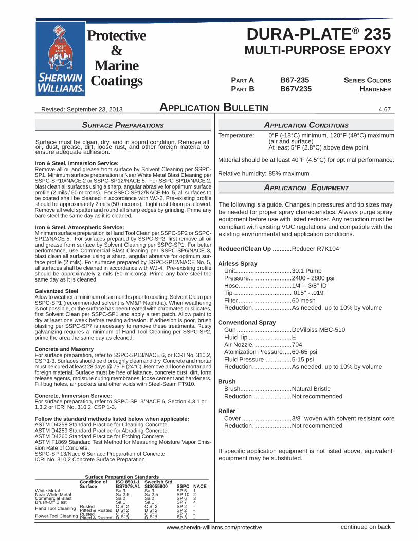
SURFACE PREPARATIONS
Surface must be clean, dry, and in sound condition. Remove all oil, dust, grease, dirt, loose rust, and other foreign material to ensure adequate adhesion.
Iron & Steel, Immersion Service:Remove all oil and grease from surface by Solvent Cleaning per SSPC-SP1. Minimum surface preparation is Near White Metal Blast Cleaning per SSPC-SP10/NACE 2 or SSPC-SP12/NACE 5. For SSPC-SP10/NACE 2, blast clean all surfaces using a sharp, angular abrasive for optimum surface profi le (2 mils / 50 microns). For SSPC-SP12/NACE No. 5, all surfaces to be coated shall be cleaned in accordance with WJ-2. Pre-existing profi le should be approximately 2 mils (50 microns). Light rust bloom is allowed. Remove all weld spatter and round all sharp edges by grinding. Prime any bare steel the same day as it is cleaned.
Iron & Steel, Atmospheric Service:Minimum surface preparation is Hand Tool Clean per SSPC-SP2 or SSPC-SP12/NACE 5. For surfaces prepared by SSPC-SP2, fi rst remove all oil and grease from surface by Solvent Cleaning per SSPC-SP1. For better performance, use Commercial Blast Cleaning per SSPC-SP6/NACE 3, blast clean all surfaces using a sharp, angular abrasive for optimum sur-face profi le (2 mils). For surfaces prepared by SSPC-SP12/NACE No. 5, all surfaces shall be cleaned in accordance with WJ-4. Pre-existing profi le should be approximately 2 mils (50 microns). Prime any bare steel the same day as it is cleaned.
Galvanized SteelAllow to weather a minimum of six months prior to coating. Solvent Clean per SSPC-SP1 (recommended solvent is VM&P Naphtha). When weathering is not possible, or the surface has been treated with chromates or silicates, fi rst Solvent Clean per SSPC-SP1 and apply a test patch. Allow paint to dry at least one week before testing adhesion. If adhesion is poor, brush blasting per SSPC-SP7 is necessary to remove these treatments. Rusty galvanizing requires a minimum of Hand Tool Cleaning per SSPC-SP2, prime the area the same day as cleaned.
Concrete and MasonryFor surface preparation, refer to SSPC-SP13/NACE 6, or ICRI No. 310.2, CSP 1-3. Surfaces should be thoroughly clean and dry. Concrete and mortar must be cured at least 28 days @ 75°F (24°C). Remove all loose mortar and foreign material. Surface must be free of laitance, concrete dust, dirt, form release agents, moisture curing membranes, loose cement and hardeners. Fill bug holes, air pockets and other voids with Steel-Seam FT910.
Concrete, Immersion Service:For surface preparation, refer to SSPC-SP13/NACE 6, Section 4.3.1 or 1.3.2 or ICRI No. 310.2, CSP 1-3.
Follow the standard methods listed below when applicable:ASTM D4258 Standard Practice for Cleaning Concrete.ASTM D4259 Standard Practice for Abrading Concrete.ASTM D4260 Standard Practice for Etching Concrete.ASTM F1869 Standard Test Method for Measuring Moisture Vapor Emis-sion Rate of Concrete.SSPC-SP 13/Nace 6 Surface Preparation of Concrete.ICRI No. 310.2 Concrete Surface Preparation.
Surface Preparation StandardsCondition of Surface
ISO 8501-1BS7079:A1
Swedish Std.SIS055900 SSPC NACE
White Metal Sa 3 Sa 3 SP 5 1Near White Metal Sa 2.5 Sa 2.5 SP 10 2Commercial Blast Sa 2 Sa 2 SP 6 3Brush-Off Blast Sa 1 Sa 1 SP 7 4Hand Tool Cleaning Rusted C St 2 C St 2 SP 2 -
Pitted & Rusted D St 2 D St 2 SP 2 -Power Tool Cleaning Rusted C St 3 C St 3 SP 3 -
Pitted & Rusted D St 3 D St 3 SP 3 -
APPLICATION BULLETIN
APPLICATION CONDITIONSTemperature: 0°F (-18°C) minimum, 120°F (49°C) maximum (air and surface) At least 5°F (2.8°C) above dew point
Material should be at least 40°F (4.5°C) for optimal performance.
Relative humidity: 85% maximum
APPLICATION EQUIPMENT
The following is a guide. Changes in pressures and tip sizes may be needed for proper spray characteristics. Always purge spray equipment before use with listed reducer. Any reduction must be compliant with existing VOC regulations and compatible with the existing environmental and application conditions.
Reducer/Clean Up ...........Reducer R7K104
Airless Spray Unit.................................30:1 Pump Pressure.........................2400 - 2800 psi Hose...............................1/4" - 3/8" ID Tip ...................................015" - .019" Filter ...............................60 mesh Reduction .......................As needed, up to 10% by volume
Conventional Spray Gun ................................DeVilbiss MBC-510 Fluid Tip .........................E Air Nozzle.......................704 Atomization Pressure .....60-65 psi Fluid Pressure ................5-15 psi Reduction .......................As needed, up to 10% by volume
Brush Brush..............................Natural Bristle Reduction .......................Not recommended
Roller Cover .............................3/8" woven with solvent resistant core Reduction .......................Not recommended
If specifi c application equipment is not listed above, equivalent equipment may be substituted.
continued on back
4.67
DURA-PLATE® 235MULTI-PURPOSE EPOXY
PART A B67-235 SERIES COLORS PART B B67V235 HARDENER
Protective &
MarineCoatings
www.sherwin-williams.com/protective
APPLICATION BULLETIN
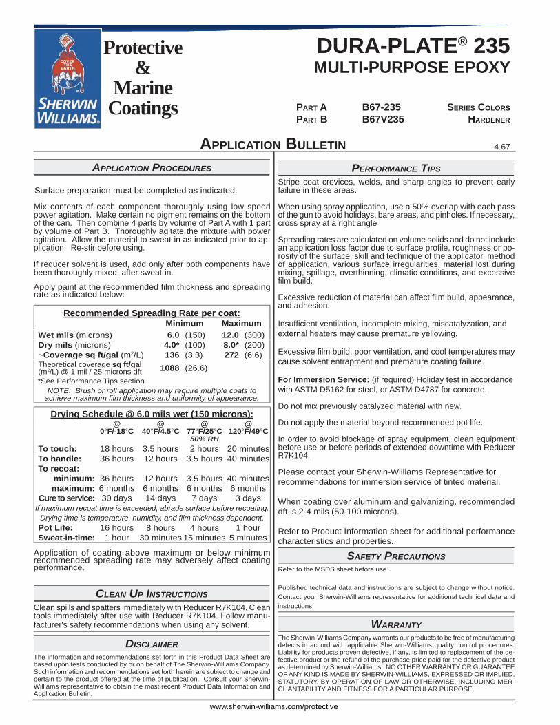
APPLICATION PROCEDURES
Surface preparation must be completed as indicated.
Mix contents of each component thoroughly using low speed power agitation. Make certain no pigment remains on the bottom of the can. Then combine 4 parts by volume of Part A with 1 part by volume of Part B. Thoroughly agitate the mixture with power agitation. Allow the material to sweat-in as indicated prior to ap-plication. Re-stir before using.
If reducer solvent is used, add only after both components have been thoroughly mixed, after sweat-in.
Apply paint at the recommended fi lm thickness and spreading rate as indicated below:
Recommended Spreading Rate per coat:Minimum Maximum
Wet mils (microns) 6.0 (150) 12.0 (300)Dry mils (microns) 4.0* (100) 8.0* (200)~Coverage sq ft/gal (m2/L) 136 (3.3) 272 (6.6)Theoretical coverage sq ft/gal (m2/L) @ 1 mil / 25 microns dft 1088 (26.6)*See Performance Tips section
NOTE: Brush or roll application may require multiple coats to achieve maximum fi lm thickness and uniformity of appearance.
Drying Schedule @ 6.0 mils wet (150 microns):@
0°F/-18°C@
40°F/4.5°C@
77°F/25°C@
120°F/49°C50% RH
To touch: 18 hours 3.5 hours 2 hours 20 minutesTo handle: 36 hours 12 hours 3.5 hours 40 minutesTo recoat:
minimum: 36 hours 12 hours 3.5 hours 40 minutesmaximum: 6 months 6 months 6 months 6 months
Cure to service: 30 days 14 days 7 days 3 daysIf maximum recoat time is exceeded, abrade surface before recoating.
Drying time is temperature, humidity, and fi lm thickness dependent.Pot Life: 16 hours 8 hours 4 hours 1 hourSweat-in-time: 1 hour 30 minutes 15 minutes 5 minutes
Application of coating above maximum or below minimum recommended spreading rate may adversely affect coating performance.
CLEAN UP INSTRUCTIONSClean spills and spatters immediately with Reducer R7K104. Clean tools immediately after use with Reducer R7K104. Follow manu-facturer's safety recommendations when using any solvent.
DISCLAIMERThe information and recommendations set forth in this Product Data Sheet are based upon tests conducted by or on behalf of The Sherwin-Williams Company. Such information and recommendations set forth herein are subject to change and pertain to the product offered at the time of publication. Consult your Sherwin-Williams representative to obtain the most recent Product Data Information and Application Bulletin.
PERFORMANCE TIPSStripe coat crevices, welds, and sharp angles to prevent early failure in these areas.
When using spray application, use a 50% overlap with each pass of the gun to avoid holidays, bare areas, and pinholes. If necessary, cross spray at a right angle
Spreading rates are calculated on volume solids and do not include an application loss factor due to surface profi le, roughness or po-rosity of the surface, skill and technique of the applicator, method of application, various surface irregularities, material lost during mixing, spillage, overthinning, climatic conditions, and excessive fi lm build.
Excessive reduction of material can affect fi lm build, appearance, and adhesion.
Insuffi cient ventilation, incomplete mixing, miscatalyzation, and external heaters may cause premature yellowing.
Excessive fi lm build, poor ventilation, and cool temperatures may cause solvent entrapment and premature coating failure.
For Immersion Service: (if required) Holiday test in accordance with ASTM D5162 for steel, or ASTM D4787 for concrete.
Do not mix previously catalyzed material with new.
Do not apply the material beyond recommended pot life.
In order to avoid blockage of spray equipment, clean equipment before use or before periods of extended downtime with Reducer R7K104.
Please contact your Sherwin-Williams Representative for recommendations for immersion service of tinted material.
When coating over aluminum and galvanizing, recommended dft is 2-4 mils (50-100 microns).
Refer to Product Information sheet for additional performance characteristics and properties.
SAFETY PRECAUTIONSRefer to the MSDS sheet before use.
Published technical data and instructions are subject to change without notice. Contact your Sherwin-Williams representative for additional technical data and instructions.
WARRANTYThe Sherwin-Williams Company warrants our products to be free of manufacturing defects in accord with applicable Sherwin-Williams quality control procedures. Liability for products proven defective, if any, is limited to replacement of the de-fective product or the refund of the purchase price paid for the defective product as determined by Sherwin-Williams. NO OTHER WARRANTY OR GUARANTEE OF ANY KIND IS MADE BY SHERWIN-WILLIAMS, EXPRESSED OR IMPLIED, STATUTORY, BY OPERATION OF LAW OR OTHERWISE, INCLUDING MER-CHANTABILITY AND FITNESS FOR A PARTICULAR PURPOSE.
POLY-COTE™ 115 Part a B65V115 Isocyanate Part B B65-115 serIes B65-K115 FIeld rePaIr KIt
Protective &
MarineCoatings
5.57Revised: November 29, 2017
www.sherwin-williams.com/protective
NSF®
Certified toNSF/ANSI 61
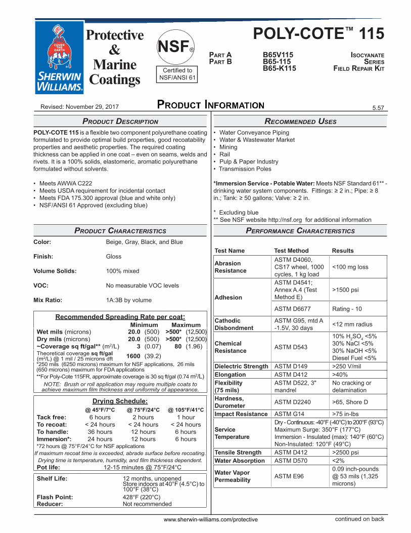
Product descriPtion
POLY-COTE 115 is a flexible two component polyurethane coating formulated to provide optimal build properties, good recoatability properties and aesthetic properties. The required coating thickness can be applied in one coat – even on seams, welds and rivets. It is a 100% solids, elastomeric, aromatic polyurethane formulated without solvents.
• Meets AWWA C222• Meets USDA requirement for incidental contact• Meets FDA 175.300 approval (blue and white only)• NSF/ANSI 61 Approved (excluding blue)
Product characteristics
Color: Beige, Gray, Black, and Blue
Finish: Gloss
Volume Solids: 100% mixed
VOC: No measurable VOC levels
Mix Ratio: 1A:3B by volume
Recommended Spreading Rate per coat:Minimum Maximum
Wet mils (microns) 20.0 (500) >500* (12,500)Dry mils (microns) 20.0 (500) >500* (12,500)~Coverage sq ft/gal** (m2/L) 3 (0.07) 80 (1.96)Theoretical coverage sq ft/gal (m2/L) @ 1 mil / 25 microns dft 1600 (39.2)*250 mils (6250 microns) maximum for NSF applications, 26 mils (650 microns) maximum for FDA applications**For Poly-Cote 115FR, approximate coverage is 30 sq ft/gal (0.74 m2/L)
NOTE: Brush or roll application may require multiple coats to achieve maximum film thickness and uniformity of appearance.
Drying Schedule:@ 45°F/7°C @ 75°F/24°C @ 105°F/41°C
Tack free: 6 hours 2 hours 1 hourTo recoat: < 24 hours < 24 hours < 24 hoursTo handle: 36 hours 12 hours 6 hoursImmersion*: 24 hours 12 hours 6 hours*72 hours @ 75°F/24°C for NSF applications
If maximum recoat time is exceeded, abrade surface before recoating.Drying time is temperature, humidity, and film thickness dependent.Pot life: 12-15 minutes @ 75°F/24°C
Shelf Life: 12 months, unopenedStore indoors at 40°F (4.5°C) to 100°F (38°C)
Flash Point: 428°F (220°C)Reducer: Not recommended
continued on back
recommended uses
• Water Conveyance Piping• Water & Wastewater Market• Mining• Rail• Pulp & Paper Industry• Transmission Poles
*Immersion Service - Potable Water: Meets NSF Standard 61** -drinking water system components. Fittings: ≥ 2 in.; Pipe: ≥ 8in.; Tank: ≥ 50 gallons; Valve: ≥ 2 in.
* Excluding blue** See NSF website http://nsf.org for additional information
Performance characteristics
Test Name Test Method Results
Abrasion Resistance
ASTM D4060,CS17 wheel, 1000cycles, 1 kg load
<100 mg loss
Adhesion
ASTM D4541; Annex A.4 (Test Method E)
>1500 psi
ASTM D6677 Rating - 10
CathodicDisbondment
ASTM G95, mtd A-1.5V, 30 days <12 mm radius
Chemical Resistance ASTM D543
10% H2SO4 <5%30% NaCl <5%30% NaOH <5%Diesel Fuel <5%
Dielectric Strength ASTM D149 >250 V/milElongation ASTM D412 >40%Flexibility(75 mils)
ASTM D522, 3" mandrel
No cracking ordelamination
Hardness, Durometer ASTM D2240 >65, Shore D
Impact Resistance ASTM G14 >75 in-lbs
Service Temperature
Dry - Continuous: -40°F (-40°C) to 200°F (93°C)Maximum Surge: 350°F (177°C)Immersion - Insulated (max): 140°F (60°C)Non-Insulated: 120°F (49°C)
Tensile Strength ASTM D412 >2500 psiWater Absorption ASTM D570 <2%
Water Vapor Permeability ASTM E96
0.09 inch-pounds @ 53 mils (1,325 microns)
POLY-COTE™ 115 Part a B65V115 Isocyanate Part B B65-115 serIes B65-K115 FIeld rePaIr KIt
Protective &
MarineCoatings
5.57Revised: November 29, 2017
www.sherwin-williams.com/protective
NSF®
Certified toNSF/ANSI 61
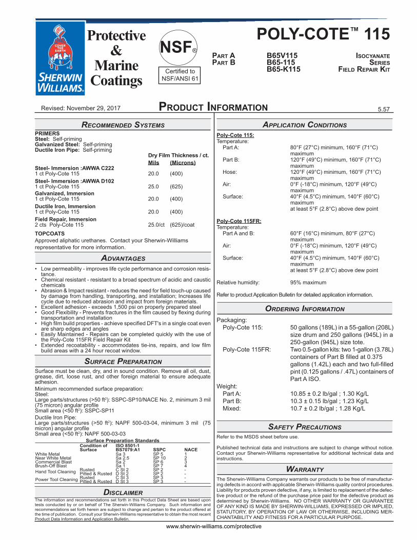
aPPlication conditionsPoly-Cote 115:Temperature: Part A: 80°F (27°C) minimum, 160°F (71°C) maximum Part B: 120°F (49°C) minimum, 160°F (71°C) maximum Hose: 120°F (49°C) minimum, 160°F (71°C) maximum Air: 0°F (-18°C) minimum, 120°F (49°C) maximum Surface: 40°F (4.5°C) minimum, 140°F (60°C) maximum at least 5°F (2.8°C) above dew point
Poly-Cote 115FR:Temperature: Part A and B: 60°F (16°C) minimum, 80°F (27°C) maximum Air: 0°F (-18°C) minimum, 120°F (49°C) maximum Surface: 40°F (4.5°C) minimum, 140°F (60°C) maximum at least 5°F (2.8°C) above dew point
Relative humidity: 95% maximum
Refer to product Application Bulletin for detailed application information.
ordering information
Packaging: Poly-Cote 115: 50 gallons (189L) in a 55-gallon (208L) size drum and 250 gallons (945L) in a 250-gallon (945L) size tote. Poly-Cote 115FR: Two 0.5-gallon kits: two 1-gallon (3.78L) containers of Part B filled at 0.375 gallons (1.42L) each and two full-filled pint (0.125 gallons / .47L) containers of Part A ISO.Weight: Part A: 10.85 ± 0.2 lb/gal ; 1.30 Kg/L Part B: 10.3 ± 0.15 lb/gal ; 1.23 Kg/L Mixed: 10.7 ± 0.2 lb/gal ; 1.28 Kg/L
safety PrecautionsRefer to the MSDS sheet before use.
Published technical data and instructions are subject to change without notice. Contact your Sherwin-Williams representative for additional technical data and instructions.
WarrantyThe Sherwin-Williams Company warrants our products to be free of manufactur-ing defects in accord with applicable Sherwin-Williams quality control procedures. Liability for products proven defective, if any, is limited to replacement of the defec-tive product or the refund of the purchase price paid for the defective product as determined by Sherwin-Williams. NO OTHER WARRANTY OR GUARANTEE OF ANY KIND IS MADE BY SHERWIN-WILLIAMS, EXPRESSED OR IMPLIED, STATUTORY, BY OPERATION OF LAW OR OTHERWISE, INCLUDING MER-CHANTABILITY AND FITNESS FOR A PARTICULAR PURPOSE.
Product InFormatIon
recommended systemsPRIMERSSteel: Self-primingGalvanized Steel: Self-primingDuctile Iron Pipe: Self-priming Dry Film Thickness / ct. Mils (Microns)Steel- Immersion :AWWA C2221 ct Poly-Cote 115 20.0 (400)Steel- Immersion :AWWA D1021 ct Poly-Cote 115 25.0 (625)Galvanized, Immersion1 ct Poly-Cote 115 20.0 (400)Ductile Iron, Immersion1 ct Poly-Cote 115 20.0 (400)Field Repair, Immersion2 cts Poly-Cote 115 25.0/ct (625)/coatTOPCOATSApproved aliphatic urethanes. Contact your Sherwin-Williams representative for more information.
advantages• Low permeability - improves life cycle performance and corrosion resis-
tance.• Chemical resistant - resistant to a broad spectrum of acidic and caustic
chemicals • Abrasion & Impact resistant - reduces the need for field touch-up caused
by damage from handling, transporting, and installation; Increases life cycle due to reduced abrasion and impact from foreign materials.
• Excellent adhesion - exceeds 1,500 psi on properly prepared steel• Good Flexibility - Prevents fractures in the film caused by flexing during
transportation and installation• High film build properties - achieve specified DFT's in a single coat even
are sharp edges and angles• Easily Maintained - Repairs can be completed quickly with the use of
the Poly-Cote 115FR Field Repair Kit• Extended recoatability - accommodates tie-ins, repairs, and low film
build areas with a 24 hour recoat window.
surface PreParationSurface must be clean, dry, and in sound condition. Remove all oil, dust, grease, dirt, loose rust, and other foreign material to ensure adequate adhesion.Minimum recommended surface preparation:Steel:Large parts/structures (>50 ft2): SSPC-SP10/NACE No. 2, minimum 3 mil (75 micron) angular profileSmall area (<50 ft2): SSPC-SP11Ductile Iron Pipe:Large parts/structures (>50 ft2): NAPF 500-03-04, minimum 3 mil (75 micron) angular profileSmall area (<50 ft2): NAPF 500-03-03
Surface Preparation StandardsCondition of Surface
ISO 8501-1BS7079:A1 SSPC NACE
White Metal Sa 3 SP 5 1Near White Metal Sa 2.5 SP 10 2Commercial Blast Sa 2 SP 6 3Brush-Off Blast Sa 1 SP 7 4Hand Tool Cleaning Rusted C St 2 SP 2 -
Pitted & Rusted D St 2 SP 2 -Power Tool Cleaning Rusted C St 3 SP 3 -
Pitted & Rusted D St 3 SP 3 -
disclaimerThe information and recommendations set forth in this Product Data Sheet are based upon tests conducted by or on behalf of The Sherwin-Williams Company. Such information and recommendations set forth herein are subject to change and pertain to the product offered at the time of publication. Consult your Sherwin-Williams representative to obtain the most recent Product Data Information and Application Bulletin.
POLY-COTE™ 115 Part a B65V115 Isocyanate Part B B65-115 serIes B65-K115 FIeld rePaIr KIt
Protective &
MarineCoatings
5.57Revised: November 29, 2017
www.sherwin-williams.com/protective
NSF®
Certified toNSF/ANSI 61
surface PreParationsSurface must be clean, dry, and in sound condition. Remove all oil, dust, grease, dirt, loose rust, and other foreign material to ensure adequate adhesion.Iron & Steel Remove all oil and grease from surface by Solvent Cleaning per SSPC-SP1. The substrate shall not contain soluble salt concen-trations in excess of 3 ppm for chlorides, 5 ppm for nitrates, and 10 ppm for sulfates. Surface with soluble salt concentrations in excess of these values shall be cleaned until satisfactory results are obtained. Minimum surface preparation for large surfaces shall be Near White Metal Blast Cleaning per SSPC-SP10/NACE No. 2. Blast clean all surfaces using sharp, angular abrasive for optimum surface profile (3 mils or greater average, with no individual reading being less than 2.5 mils per NACE RP0287). Small surface areas (<50 sq. ft.) shall be Power Tool Cleaned To Bare metal per SSPC-SP11. Grind all surfaces utilizing mechanical scarification capable of producing the greatest surface profile and shall be performed in a perpendicular pattern to the direction of flow on the substrate. Remove all weld spatter, smooth all rough welds, and round all sharp edges by grinding prior to abrasive blasting.Existing coating shall be feathered 1.5 in. to 3 in. when coating adja-cent bare steel, such as girth welds. Prior to coating, the applicator will tape off, using duct tape, a line between feathered coating and the remaining non-blasted coating and ensure the edge of tape is on the roughened coating.Cleaned surface shall be dry air blasted and either brushed off or vacuumed, in a manner to remove dust and debris prior to coating, and shall be coated before any rust blooming occurs. Any cleaned steel showing rust stains shall be re-prepared prior to coating.Ductile Iron PipeRemove all oil and grease from surface by Solvent Cleaning per NAPF 500-03-01. The substrate shall not contain soluble salt concentrations in excess of 3 ppm for chlorides, 5 ppm for nitrates, and 10 ppm for sulfates. Surface with soluble salt concentrations in excess of these values shall be cleaned until satisfactory results are obtained. Minimum surface preparation for large surfaces shall be Abrasive Blast Cleaning for Ductile Iron Pipe per NAPF 500-03-04. Blast clean all surfaces using sharp, angular abrasive for optimum surface profile (3 mils / 75 microns or greater, with no individual reading being less than 2.5 mils / 63 microns per NACE RP0287). Small surface areas (<50 sq. ft.) shall be Power Tool Cleaned per NAPF 500-03-03. Grind all surfaces utilizing mechanical scarification capable of producing the greatest surface profile and shall be performed in a perpendicular pattern to the direction of flow on the substrate.
Surface Preparation StandardsCondition of Surface
ISO 8501-1BS7079:A1 SSPC NACE
White Metal Sa 3 SP 5 1Near White Metal Sa 2.5 SP 10 2Commercial Blast Sa 2 SP 6 3Brush-Off Blast Sa 1 SP 7 4Hand Tool Cleaning Rusted C St 2 SP 2 -
Pitted & Rusted D St 2 SP 2 -Power Tool Cleaning Rusted C St 3 SP 3 -
Pitted & Rusted D St 3 SP 3 -
aPPlication conditionsPoly-Cote 115:Temperature: Part A: 80°F (27°C) minimum, 160°F (71°C) maximum Part B: 120°F (49°C) minimum, 160°F (71°C) maximum Hose: 120°F (49°C) minimum, 160°F (71°C) maximum Air: 0°F (-18°C) minimum, 120°F (49°C) maximum Surface: 40°F (4.5°C) minimum, 140°F (60°C) maximum at least 5°F (2.8°C) above dew point
aPPlIcatIon BulletIn
continued on back
aPPlication conditions (cont'd)Poly-Cote 115FR:Temperature: Part A and B: 60°F (16°C) minimum, 80°F (27°C) maximum Air: 0°F (-18°C) minimum, 120°F (49°C) maximum Surface: 40°F (4.5°C) minimum, 140°F (60°C) maximum at least 5°F (2.8°C) above dew point
Relative humidity: 95% maximum
aPPlication equiPmentThe following is a guide. Changes in pressures and tip sizes may be needed for proper spray characteristics. Always purge spray equipment before use with listed reducer.
Reducer ............................Not recommendedClean Up ...........................MEK R6K10Purge Solvent ..................MEK R6K10
Recommended Spray Equipment*Pneumatic Spray Pump..............................Graco Hydra-Cat with a King Air
Motor or XP 50 or larger system with remote manifold
Transfer Pumps .............5:1 Graco Monark or larger Pressure.........................2000 psi at gun pressure Hose...............................3/8” Resin, ¼” Isocyanate, ¼” whip
hose from mixing manifold to gun, 25’ maximum whip hose length with 3/8" X 5” static mixing tubes with a 12 ele-ment disposable plastic insert.
Tip ..................................0.021" minimum
Hydraulic Spray Pump..............................Graco/Reactor or HXP3 system with
#120 (resin) and #40 (Activator) cylin-der setup
Transfer Pumps .............5:1 Graco Monark or larger Pressure.........................2000 psi at gun pressure Hose...............................3/8” Resin, ¼” Isocyanate, ¼” whip
hose from mixing manifold to gun, 25’ maximum whip hose length with 3/8" X 5” static mixing tubes with a 12 ele-ment disposable plastic insert.
Tip ..................................0.021" minimum
Conventional Spray .........Not recommended
Brush** .............................Repairs and touch only**
*Application training is required and spray equipment must be approved by Sherwin-Williams Technical Service.
**For touch up and repair utilize Sherwin-William Poly-Cote 115FR.
If specific application equipment is not listed above, equivalent equipment may be substituted and must be approved by Sherwin-Williams Technical Service.
POLY-COTE™ 115 Part a B65V115 Isocyanate Part B B65-115 serIes B65-K115 FIeld rePaIr KIt
Protective &
MarineCoatings
5.57Revised: November 29, 2017
www.sherwin-williams.com/protective
NSF®
Certified toNSF/ANSI 61
aPPlIcatIon BulletIn
aPPlication ProceduresSurface preparation must be completed as indicated.
Mixing Instructions: Agitate components thoroughly before use. Do not thin. Do not mix part A and B together (Except for Poly-Cote 115FR). Caution: Do not agitate at high speed or in a manner that would whip air or moisture in to the product. Both components should be heated to approximately 120°F (49°C) - 160°F (71°C) to achieve spray pattern consistency.
For Poly-Cote 115FR, agitate individual components for 3 min-utes prior to combining them. Add the "B" Component to the "A" component and immediately agitate for 3 minutes. Immediately transfer the material from the container to the surface using the supplied brush like a spatula to get a large volume of material transferred to the substrate and then brush the material to a smooth appearance. Poly-Cote 115FR is intended to be applied in 2 coats. Apply the second coat while the first coat is still sticky but with no transfer of material onto your finger. (2 - 2.5 hours cure @ 75°F (24°C) approximate cure time). Plural component application required for Poly-Cote 115, 1A:3B by volume
Apply paint at the recommended film thickness and spreading rate as indicated below:
Recommended Spreading Rate per coat:Minimum Maximum
Wet mils (microns) 20.0 (500) >500* (12,500)Dry mils (microns) 20.0 (500) >500* (12,500)~Coverage sq ft/gal** (m2/L) 3 (0.07) 80 (1.96)Theoretical coverage sq ft/gal (m2/L) @ 1 mil / 25 microns dft 1600 (39.2)*250 mils (6250 microns) maximum for NSF applications, 26 mils (650 microns) maximum for FDA applications
**For Poly-Cote 115FR, approximate coverage is 30 sq ft/gal (0.74 m2/L)NOTE: Brush or roll application may require multiple coats to
achieve maximum film thickness and uniformity of appearance.
Drying Schedule:@ 45°F/7°C @ 75°F/24°C @ 105°F/41°C
Tack free: 6 hours 2 hours 1 hourTo recoat: < 24 hours < 24 hours < 24 hoursTo handle: 36 hours 12 hours 6 hoursImmersion*: 24 hours 12 hours 6 hours*72 hours @ 75°F/24°C for NSF applications
If maximum recoat time is exceeded, abrade surface before recoating.Drying time is temperature, humidity, and film thickness dependent.Pot life: 12-15 minutes @ 75°F/24°C
Application of coating above maximum or below minimum recommended spreading rate may adversely affect coating performance.
disclaimerThe information and recommendations set forth in this Product Data Sheet are based upon tests conducted by or on behalf of The Sherwin-Williams Company. Such information and recommendations set forth herein are subject to change and pertain to the product offered at the time of publication. Consult your Sherwin-Williams representative to obtain the most recent Product Data Information and Application Bulletin.
Performance tiPs
For immersion applications, a minimum total dry film thickness of 20 mils for steel is required. Always spark test in accordance with NACE SP0188 for steel after application. Repair holidays prior to placing substrate into service using Poly-Cote 115FR.
Use only heated, plural component equipment capable of producing 4,000 psi output consistently.
In order to prevent blockage of spray equipment, clean equipment before use or before extended downtime with MEK R6K10.
While spraying, use 50% overlap with each pass of the gun to avoid holidays, bare areas, and pinholes. All application shall be done in a manner that mitigates runs and sags and provides complete coverage on all surfaces, including difficult to spray areas like welds, seams and angles.
Spreading rates are calculated on volume solids and do not include an application loss factor due to surface profile, roughness, or po-rosity of the surface, skill and technique of the applicator, method of application, various surface irregularities, material lost during mixing, spillage, climatic conditions, and excessive film build.
Do not agitate in a manner that would whip air and moisture in to the product.
Consult you Sherwin-Williams representative for specific application and performance recommendations.
Refer to Product Information sheet for additional performance characteristics and properties.
clean uP instructionsClean spills and spatters immediately with MEK R6K10. Clean tools and equipment immediately after use (including both A and B sides of plural component spray system) with MEK R6K10.
safety PrecautionsRefer to the MSDS sheet before use.
Published technical data and instructions are subject to change without notice. Contact your Sherwin-Williams representative for additional technical data and instructions.
WarrantyThe Sherwin-Williams Company warrants our products to be free of manufacturing defects in accord with applicable Sherwin-Williams quality control procedures. Liability for products proven defective, if any, is limited to replacement of the de-fective product or the refund of the purchase price paid for the defective product as determined by Sherwin-Williams. NO OTHER WARRANTY OR GUARANTEE OF ANY KIND IS MADE BY SHERWIN-WILLIAMS, EXPRESSED OR IMPLIED, STATUTORY, BY OPERATION OF LAW OR OTHERWISE, INCLUDING MER-CHANTABILITY AND FITNESS FOR A PARTICULAR PURPOSE.