CONTRACT DOCUMENTS - BidNet
538
4/20/2020 CONTRACT DOCUMENTS LEON CREEK WRC ELECTRICAL SYSTEM IMPROVEMENTS – PHASE I SAWS Job No. 19-6505 SAWS Solicitation No. CO-00335 April 2020 VOL. 2 OF 2 Reviewed by:_____________ Approved by:_____________
-
Upload
khangminh22 -
Category
Documents
-
view
0 -
download
0
Transcript of CONTRACT DOCUMENTS - BidNet

4/20/2020
CONTRACT DOCUMENTS
LEON CREEK WRC ELECTRICAL SYSTEM IMPROVEMENTS – PHASE I
SAWS Job No. 19-6505 SAWS Solicitation No. CO-00335
April 2020
VOL. 2 OF 2
Reviewed by:_____________
Approved by:_____________

bsako
Snapshot
LEON CREEK WRC ELECTRICAL SYSTEM IMPROVEMENTS – PHASE I 07210-1 APRIL 2020
BUILDING INSULATION
SECTION 07210
BUILDING INSULATION
PART 1 – GENERAL
1.01 DESCRIPTION
A. Scope:
1. CONTRACTOR shall provide all labor, materials, tools, equipment, and incidentals as shown, specified, and required to furnish and install building insulation.
2. Extent of each type of building insulation is shown and indicated in the Contract Documents.
B. Coordination:
1. Review installation procedures under this and other Sections and coordinate installation of items that must be installed with or before building insulation Work.
C. Related Sections:
1. Section 04220, Concrete Unit Masonry.
1.02 REFERENCES
A. Standards referenced in this Section are:
1. ASTM C177, Test Methods for Steady-State Heat Flux Measurements and Thermal Transmission Properties by Means of the Guarded-Hot-Plate Apparatus.
2. ASTM C203, Test Method for Breaking Load and Flexural Properties of Block-Type Thermal Insulation.
3. ASTM C236, Test Methods for Steady-State Thermal Performance of Building Assemblies by Means of a Guarded Hot Box.
4. ASTM C272, Test Method for Water Absorption of Core Materials for Structural Sandwich Constructions.
5. ASTM C303, Test Method for Dimensions and Density of Preformed Block and Board-Type Thermal Insulation.
6. ASTM C518, Test Method for Steady-State Thermal Transmission Properties by Means of the Heat Flow Meter Apparatus.
7. ASTM C520, Test Methods for Density of Granular Loose Fill Insulation.
8. ASTM C531, Test Method for Linear Shrinkage and Coefficient of Thermal Expansion of Chemical-Resistant Mortars and Monolithic Surfacings.
9. ASTM C549, Specification for Perlite Loose Fill Insulation.

LEON CREEK WRC ELECTRICAL SYSTEM IMPROVEMENTS – PHASE I 07210-2 APRIL 2020
BUILDING INSULATION
10. ASTM C553, Specification for Mineral Fiber Blanket Thermal Insulation for Commercial and Industrial Applications.
11. ASTM C578, Specification for Rigid, Cellular Polystyrene Thermal Insulation.
12. ASTM C612, Specification for Mineral Fiber Block and Board Thermal Insulation.
13. ASTM C665, Specification for Mineral-Fiber Blanket Thermal Insulation for Light Frame Construction and Manufactured Housing.
14. ASTM C764, Specification for Mineral Fiber Loose-Fill Thermal Insulation.
15. ASTM D696, Test Method for Coefficient of Linear Thermal Expansion of Plastics between -30 Degrees C and 30 Degrees C with a Vitreous silica dilatometer.
16. ASTM D1621, Test Method for Compressive Properties of Rigid Cellular Plastics.
17. ASTM D2126, Test Method for Response of Rigid Cellular Plastics to Thermal and Humid Aging.
18. ASTM E84, Test Method for Surface Burning Characteristics of Building Materials.
19. ASTM E96, Test Methods for Water Vapor Transmission of Materials.
20. ASTM E119, Test Methods for Fire Tests of Building Construction and Materials.
21. UL 1479, Fire Tests of Through-Penetration Firestops.
1.03 QUALITY ASSURANCE
A. Qualifications:
1. Manufacturers:
a. Obtain building insulations, requiring hydrochlorofluorocarbon blowing agent from manufacturer(s) that manufacture product required using blowing agent acceptable for use until the year 2020 and complying in all respects with Copenhagen Amendments to the Montreal Protocol.
b. Manufacturer shall provide complete technical services including preparation and review of Shop Drawings and submittals, installation methods, and proposed detailing for the Work.
2. Installer: Engage single installer for each type of building insulation. Each installer shall be skilled, trained, and have record of successful experience in applying and installing each product, and possess successful record of performing work in accordance with recommendations and requirements of manufacturer or that can submit written evidence of being acceptable to manufacturer for providing the required Work. Installers shall employ only tradesmen with specific skill and successful experience in each type of Work required. Submit to ENGINEER name and qualifications of each installer with the following information for at least three successful, completed projects per installer:
a. Names and telephone numbers of owner and architect or engineer responsible for each project.

LEON CREEK WRC ELECTRICAL SYSTEM IMPROVEMENTS – PHASE I 07210-3 APRIL 2020
BUILDING INSULATION
b. Approximate contract cost of the building insulation system installed.
c. Quantity (area) of building insulation installed.
B. Regulatory Requirements: Comply with code interpretations by authorities having jurisdiction at the Site.
1.04 SUBMITTALS
A. Action Submittals: Submit the following:
1. Shop Drawings:
a. Drawings showing extent of the building insulation Work and all details required for the Work, referencing system components provided as Samples.
2. Product Data:
a. Material specifications and general recommendations from building insulation manufacturer for each type of building insulation product. Include manufacturer’s data substantiating that materials comply with Contract Documents.
b. Test Reports: Copies of reports of tests on materials being furnished or previously-manufactured, identical materials verifying compliance with physical properties and environmental features specified in the Contract Documents. When requested by ENGINEER, submit qualifications and summary of experience of testing agencies in performing tests similar to those required.
3. Samples:
a. Twelve-inch by twelve-inch Samples of each required type of building insulation.
b. Samples will be reviewed by ENGINEER for color and texture only. Compliance with other requirements is responsibility of CONTRACTOR.
B. Informational Submittals: Submit the following:
1. Certificates: Certificate from manufacturer stating that manufacturer of foam-type rigid board insulation has used an environmentally safe blowing agent complying with specified requirements.
2. Manufacturer’s Instructions: Manufacturer’s installation instructions. Indicate by copy of transmittal form that installer has received copy of manufacturer's installation instructions.
3. Site Quality Control Submittals: Submit results of specified Site quality control tests.
1.05 DELIVERY, STORAGE AND HANDLING
A. Delivery and Handling of Materials:
1. Do not deliver insulation materials to the Site before the time of installation.
2. Deliver materials in sufficient quantities to allow uninterrupted continuity of the Work.

LEON CREEK WRC ELECTRICAL SYSTEM IMPROVEMENTS – PHASE I 07210-4 APRIL 2020
BUILDING INSULATION
3. Handle materials carefully to avoid damage and breakage or compressing of boards to less than their specified thickness, or other damage.
4. Handle materials in manner that prevents inclusion of foreign materials.
5. Conform to Section 01651, Transportation and Handling of Prducts.
B. Storage of Materials:
1. Store materials in dry, enclosed area, off ground and away form possible contact with water, ice, and snow.
2. Prevent damage to materials during storage, including minimizing the time materials are stored at the Site before being incorporated into the Work. Store only sufficient quantity of building insulation materials at the Site required for continuous advancement of the Work without causing delay.
3. Conform to Section 01661, Storage and Protection of Products.
1.06 SITE CONDITIONS
A. Environmental Conditions:
1. Complete the installation and concealment of building insulation materials as rapidly as possible to avoid damage from adjacent construction operations and adverse weather conditions.
2. Install building insulations when weather and temperature conditions comply with building insulations manufacturers’ written recommendations.
3. Install building insulations when damaging environmental condition are not forecasted for the time when exposed systems materials components would be exposed to potential damage from the elements.
4. Install foamed-in-place cementitious insulation when the combination of interior and exterior temperatures is such that temperature at point of application is 40 degrees F and rising during application and the 48-hour initial curing period.
5. If CONTRACTOR advances foamed-in-place cementitious insulation Work when weather conditions are not within manufacturer’s recommended temperature ranges, provide temporary enclosures with temporary heat to maintain manufacturer’s recommended temperatures during the initial curing period. Erecting and maintaining temporary enclosures and providing temporary heating shall be at no additional cost to OWNER.
6. Protect building insulation Work from precipitation, frost, and direct sunlight.
7. Do not apply pressure-sensitive tape when temperature is below 35 degrees F or above 110 degrees F.
8. Record decisions, conditions, and agreements to proceed with the Work when weather conditions may be unfavorable. State reasons for proceeding, along with names of persons involved, and changes or revisions (if any), if required, to allow the Work to proceed.

LEON CREEK WRC ELECTRICAL SYSTEM IMPROVEMENTS – PHASE I 07210-5 APRIL 2020
BUILDING INSULATION
1.07 Scheduling
A. Proceed with building insulation Work when preceding Work is ready to receive the Work of this Section.
B. Proceed with building insulation and associated Work after curbs, blocking, substrate board, nailer strips, vents, drains and other projections through the substrates have been installed, and when substrate construction and framing of openings is complete.
C. Proceed with and complete the Work when materials, equipment and tradesmen required for the installation of building insulation and backfilling operations are at the Site and ready to follow with the Work in manner that does not leave the Work vulnerable to damage or deterioration.
D. Do not advance installation of building insulation beyond that necessary for proper sequencing of the Work. Do not advance the Work when there is no proper and secure protection from damaging weather and construction activities.
PART 2 – PRODUCTS
2.01 SYSTEM PERFORMANCE
A. Performance Criteria:
1. Thermal Conductivity: Thicknesses shown are for thermal conductivity, k-value at 75 degrees F, specified for each material.
2. Provide adjusted thicknesses based on thicknesses shown or specified for building insulations, as required to comply with required thermal resistances for material having different thermal conductivity.
2.02 MATERIALS
A. Foam Plastic Insulations: Provide the following types:
1. General: Rigid, closed-cell, thermally stabilized, extruded, hydrochlorofluro-carbon blown, foam board insulation consisting of 100 percent virgin extruded polystyrene modified resin complying with ASTM C578.
2. Provide blowing agent with lowest available ozone depletion potential, such as HCFC-142b or better. HCFC-141b is not acceptable.
3. Preformed Concrete Masonry Unit Core Insulation: Provide individually molded expanded polystyrene core insulation complying with ASTM C236, and ASTM C578, Standard Type I.
a. Physical Properties:
1) Thermal Conductivity (k), ASTM C177: 0.26 Btu/inch/hour/square foot/degree F.
2) Density, ASTM C303: 0.90 to 1.14 pounds per cubic foot (pcf) minimum.
3) Compressive Strength (psi at 5 percent deformation), ASTM D1621: 10 to 13 pcf.

LEON CREEK WRC ELECTRICAL SYSTEM IMPROVEMENTS – PHASE I 07210-6 APRIL 2020
BUILDING INSULATION
4) Water Vapor Transmission, ASTM E96: 1.4 perm/inch.
5) Dimensional Stability: ASTM D2126: 0.55 percent maximum.
6) Flame Spread, ASTM E84: Five maximum.
7) Smoke Development, ASTM E84: 130 maximum.
b. Products and Manufacturers: Provide one of the following:
1) Korfil Standard U-Shaped Block Insulation by Concrete Block Insulating Systems, Inc, Division of W. R. Grace Construction Products, Inc.
2) Blocfil by Blocfil Company, Division of Patek Investment Corporation.
3) Or equal.
PART 3 – EXECUTION
3.01 INSPECTION
A. CONTRACTOR and installer shall examine substrate and conditions under which building insulation Work will be performed and notify ENGINEER in writing of unsatisfactory conditions. Do not proceed with the Work until unsatisfactory conditions have been corrected.
3.02 PREPARATION
A. Surfaces to receive building insulation shall be clean of all debris, dirt, and other contamination before installation begins.
3.03 INSTALLATION
A. General:
1. Comply with manufacturer’s instructions for particular conditions of installation in each case. If printed instructions are not available or do not apply to Site conditions, before proceeding with the Work obtain from manufacturer and submit to ENGINEER specific installation recommendations from manufacturer.
2. Extend insulations full thickness over entire surface to be insulated. Cut and fit tightly around obstructions. Fill voids with insulation.
3. Apply number of layers of insulation specified, each of required thickness, or required thickness to provide thermal value shown or indicated in the Contract Documents, to make up the total thickness.
B. Unit-type Building Insulation:
1. Apply insulation units of type shown or indicated to substrate by method indicated. If not otherwise indicated and except for units resting on horizontal surfaces, bond units to substrate with adhesive or use mechanical anchorage to provide permanent placement and support of units.

LEON CREEK WRC ELECTRICAL SYSTEM IMPROVEMENTS – PHASE I 07210-7 APRIL 2020
BUILDING INSULATION
C. Correcting Defective Work:
1. System components that are dislodged, damaged, expanded, broken, penetrated, or crushed by subsequent installation operations or damaged by detrimental weather shall be immediately replaced with undamaged material in compliance with the Contract Documents and properly protected as specified.
2. Only original installer shall repair or replace deteriorated or defective Work.
3.04 PROTECTION
A. Protection from Elements:
1. Protect all components of the Work from detrimental weather conditions. Do not allow building insulation materials to become wet or soiled, or covered with ice or snow. Provide continuous protection of materials against damage, wetting and moisture absorption and storing materials as specified
2. Work that cannot, for reasons acceptable to ENGINEER, be covered with complete construction system before onset of weather detrimental to the Work, shall be completely covered and protected in manner that deflects precipitation from building insulations without damaging adjacent Work.
B. Protection During Construction:
1. Protect all components of the Work from construction operations including, but not limited to, backfilling, framing, and sheathing, aluminum siding, and concrete unit masonry Work, until work is completed and acceptable to ENGINEER.
2. Protect building insulations from damage and abuse by other contractors and installers until readiness for final payment.
3. Do not allow building insulations to come into contact with welding operations or other fire or ignition sources.
4. Do not allow construction traffic not associated with installation of building insulation in the area of building insulation Work. Protect the area from access by other installers and contractors until the building insulation Work has been incorporated into finished construction systems.
C. Building insulation that becomes wet, damaged, or deteriorated shall be promptly removed from the Site and replaced with materials conforming to this Section.
+ + END OF SECTION + +

LEON CREEK WRC ELECTRICAL SYSTEM IMPROVEMENTS – PHASE I 07210-8 APRIL 2020
BUILDING INSULATION
THIS PAGE INTENTIONALLY LEFT BLANK

LEON CREEK WRC ELECTRICAL SYSTEM IMPROVEMENTS – PHASE I 07220-1 APRIL 2020
ROOF INSULATION
SECTION 07220
ROOF INSULATION
PART 1 - GENERAL
1.01 DESCRIPTION
A. Scope:
1. CONTRACTOR shall provide all labor, materials, tools, equipment and incidentals as shown, specified and required to furnish and install all roof board insulation.
2. Extent of each type of roof board insulation is shown.
3. Types of products required include the following:
a. Extruded, pentane isomer blown, polyisocyanurate rigid board-type insulation.
b. Miscellaneous materials and accessories.
B. Coordination:
1. Review installation procedures under other Sections and coordinate the installation of items that must be installed with the roof board insulation Work.
2. All framing for openings, edge angles, nailers, curbs and other items shall be in place before start of roof board insulation Work.
3. Field-verify location of all roof penetrations, drain locations, and deck deflections.
C. Related Sections:
1. Section 07550, Modified Bitumen Roofing.
1.02 REFERENCES
A. Standards referenced in this Section are listed below:
1. American Society for Testing and Materials, (ASTM).
a. ASTM C 150, Specification for Portland Cement.
b. ASTM C 177, Test Method for Steady-State Heat Flux Measurements and Thermal Transmission Properties by Means of the Guarded-Hot-Plate Apparatus.
c. ASTM C 203, Test Methods for Breaking Load and Flexural Properties of Block-Type Thermal Insulation.
d. ASTM C 272, Test Method for Water Absorption of Core Materials for Structural Sandwich Constructions.
e. ASTM C 303, Test Method for Dimensions and Density of Preformed Block and Board-Type Thermal Insulation.

LEON CREEK WRC ELECTRICAL SYSTEM IMPROVEMENTS – PHASE I 07220-2 APRIL 2020
ROOF INSULATION
f. ASTM C 495, Test Method for Compressive Strength of Lightweight Insulating Concrete.
g. ASTM C 518, Test Method for Steady-State Thermal Transmission Properties by Means of Heat Flow Meter Apparatus.
h. ASTM C 550, Test Method for Measuring Trueness and Squareness of Rigid Block and Board Thermal Insulation.
i. ASTM C 1289, Specification for Faced Rigid Cellular Polyisocyanurate Thermal Insulation Board.
j. ASTM D 696, Test Method for Coefficient of Linear Thermal Expansion of Plastics between -30 Degrees C and 30 Degrees C with a Vitreous Silica Dilatometer.
k. ASTM D 1621, Test Method for Compressive Properties of Rigid Cellular Plastics.
1. ASTM D 1622, Test Method for Apparent Density of Rigid Cellular Plastics.
m. ASTM D 1623, Test Method for Tensile and Tensile Adhesion Properties of Rigid Cellular Plastics.
n. ASTM E 84, Test Method for Surface Burning Characteristics of Building Materials.
o. ASTM E 96, Test Methods for Water Vapor Transmission of Materials.
2. Factory Mutual, (FM).
a. FM Publication, Loss Prevention Data for Roofing Contractors, 1-29, Above-Deck Roof Components.
b. FM Publication, Approval Guide.
3. Underwriters Laboratories, (UL).
a. UL Building Materials Directory.
1.03 QUALITY ASSURANCE
A. Installer's Qualifications:
1. Roof board insulation Work shall be performed by the installer of the associated roofing for undivided responsibility.
B. Source Quality Control:
1. Obtain extruded polyiscoyanurate rigid board-type insulation from manufacturers who manufacture specified insulation using a blowing agent containing no chlorine-based compounds.
2. Engage a single manufacturer for each type of roofing insulation who shall provide the services of a technical representative to assist CONTRACTOR and ENGINEER by providing technical opinions on the adequacy of materials and methods of installation based on Shop Drawings approved by ENGINEER.
LEON CREEK WRC ELECTRICAL SYSTEM IMPROVEMENTS – PHASE I 07220-3 APRIL 2020
ROOF INSULATION
3. Provide such services during the time of delivery, storage, handling and installation of all roofing insulation.
4. The thicknesses shown are based on the thermal conductivity, k-value at 75°F specified for each material. Thicknesses of roof board insulation materials submitted by CONTRACTOR as "or equal" to specified materials shall have their thicknesses adjusted to provide the same thermal resistance as materials specified.
C. Requirements of Regulatory Agencies: Comply with fire-resistance ratings as required by governing authorities and building codes, and complies with the following roof board insulation requirements:
1. Underwriters Laboratories requirements for roof deck constructions which are rated "UL Class A".
2. Factory Mutual requirements for "Class 1-90" rated construction, for wind resistance.
1.04 SUBMITTALS
A. Action Submittals: Submit the following:
1. Samples:
a. Each fastener to be used in the Work.
b. 12-inch by 12-inch sample of specified extruded and expanded rigid board-type insulation and composite insulation system.
2. Shop Drawings:
a. Field verified locations of all roof penetrations, drain locations, and deck deflections.
b. Complete layout of all roof board insulation showing sizes, placement, number of courses and methods of fastening. Include statement that fastening method, location and density of fasteners have been approved by roof membrane manufacturer and comply with wind uplift requirements specified.
c. Weights of all equipment to be used on roof.
d. All required roof board insulation details approved by the roof board insulation manufacturer and the manufacturer of the respective roofing systems.
3. Product Data:
a. Manufacturer's specifications and installation instructions for each type of roof board insulation required. Include data substantiating that the materials comply with specified requirements.
B. Informational Submittals: Submit the following
1. Certificates:
a. Installer's qualifications.
2 Site Quality Control Submittals:
LEON CREEK WRC ELECTRICAL SYSTEM IMPROVEMENTS – PHASE I 07220-4 APRIL 2020
ROOF INSULATION
a. Submit Job Conditions Report, prepared by composite roof board insulation installer, as specified, and in addition, include a notarized statement from the full-time on-Site technical representative and installer that the composite roof board insulation system was installed according to manufacturer's written recommendations as shown on approved Shop Drawings.
3. Source Quality Control Submittals:
a. Laboratory test results for thermal resistance values based on ASTM C 177 or ASTM C 518 for actual composite roof board insulation system shown and specified.
1.05 DELIVERY, STORAGE AND HANDLING
A. Delivery of Materials:
1. Do not deliver insulation materials to the Site before time of installation.
2. Deliver materials in manufacturer's original, undamaged packages or acceptable bulk containers.
B. Storage of Materials:
1. Do not allow insulation materials to become wet or soiled, or covered with ice or snow.
2. Protect plastic insulation from exposure to sunlight.
3. Protect plastic insulation against ignition.
4. Store packaged materials to protect them from the weather and physical damage.
C. Handling of Materials:
1. Comply with manufacturer's recommendations for handling, storage and protection.
1.06 JOB CONDITIONS
A. Pre-Roofing Conference: Provide both a representative of the composite roof board insulation system manufacturer and the foreman of the installer who will actually work on this Project at the Pre-Roofing Conference specified in Section 07550, Modified Bitumen Roofing .
B. Environmental Requirements:
1. Do not install roof board insulation when weather conditions are such that the deck is not completely dry, there is ice or snow on the deck, or where there is no assurance that the roof board insulation can be completely protected from the weather by the end of the day’s Work.
2. For applications of composite roof board insulation system, when the temperature is expected to fall below 40°F, submit written installation recommendations of the composite insulation system manufacturer confirming acceptability of the conditions encountered. CONTRACTOR shall verify that composite roof board insulation system installed under such adverse weather conditions meet all material and performance requirements specified. Installer shall record actual conditions of installation, including

LEON CREEK WRC ELECTRICAL SYSTEM IMPROVEMENTS – PHASE I 07220-5 APRIL 2020
ROOF INSULATION
intervals between system component placement, weather and temperature conditions, temporary uses of roof (if any) and other pertinent installation factors and include in Job Conditions Report submitted to ENGINEER.
3. Hot water is not available at the Site and shall be supplied by composite roof board insulation installer as required by installation conditions.
4. Potable water is not available at the Site and shall be provided by composite roof board insulation installer.
C. Protection:
1. Do not overload the building structure with the weight of stored materials or use of equipment.
2. Install temporary water cut-offs at the end of each day's Work to protect the roof board insulation. Remove the temporary water cut-offs upon resumption of the Work.
1.07 Sequencing
A. Proceed with and complete the Work only when materials, equipment and tradesmen required for the installation of the roofing membrane over the roof board insulation are at the Site and are ready to follow with this Work immediately (same day) after the roof board insulation Work.
B. Proceed with and complete the Work only when materials, equipment and tradesmen required for the installation of the roofing membrane over the insulation are at the Site; are installing the vapor barrier, and are ready to follow with this Work immediately (same day) behind the roof board insulation Work.
C. Do not install any more rigid board-type roof board insulation each day than can be covered with complete roofing system by the end of that working day.
1.08 GUARANTEE
A. The manufacturer of the composite roof board insulation system shall warrant to OWNER that the roof board insulation will remain in a re-roofable condition, for a period of ten years, should the roof membrane require replacement; that the roof board insulation will remain in place even if the roof membrane sustains wind damage; and that the roof board insulation's actual resistance to heat flow will be at least 80 percent of the installed value, provided the roof remains leak free.
1.09 SUBSTITUTIONS
A. Manufacturer of the primary roofing membrane systems shall be a manufacturer who finds the generic types of insulation specified herein as acceptable and bondable if installed according to the roofing manufacturer's standards for complete product and performance responsibility.
B. The thickness of the composite roof board insulation system, the maximum step between layers of expanded polystyrene rigid board insulation and the minimum slope-to-drain requirements shall not vary from what is shown, specified and approved.

LEON CREEK WRC ELECTRICAL SYSTEM IMPROVEMENTS – PHASE I 07220-6 APRIL 2020
ROOF INSULATION
PART 2 - PRODUCTS
2.01 MATERIALS
A. Extruded Polyisocyanurate Rigid Board Roof board insulation:
1. Rigid, rectangular boards of extruded closed-cell polyisocyanurate complying with ASTM C 1289, Type II, with low water vapor permeability and laminated to heavy black (non-asphaltic) fiber-reinforced felt facers with one side of board containing perforated facers and the other side containing non-perforated facers.
2. Provide a blowing agent with zero ozone depletion potential, such as pentane.
3. Physical Properties: Provide the following:
a. Minimum Compressive Strength, (at 10 percent deformation), ASTM D 1621: 25 psi minimum.
b. Flame Spread, ASTM E 108: Class A.
c. Smoke Development, ASTM E 84: 120 maximum.
d. Vapor Transmission, ASTM E 96: 0.8 perms/inch.
e. Thermal Resistance, ASTM C 518: 7/inch.
f. Maximum Water Absorption, ASTM C 209: 0.10 percent by volume.
4. Size: 48-inches by 96 inches by 2-inch thick.
5. Number of Layers: As required by thickness of roof board insulation shown.
6. Products and Manufacturers: Provide one of the following:
a. ACUltra (Pentane Blown) Hydrocarbon ACFoam - II by Atlas Roofing Corporation.
b. Or equal.
B. Miscellaneous Materials:
1. Adhesive for Bonding Insulation: The type recommended by the roof board insulation manufacturer, and complying with fire-resistance requirements.
2. Mechanical Anchors: The type recommended by the roof board insulation manufacturer for the type of deck used, and complying with fire and insurance rating requirements.
PART 3 - EXECUTION
3.01 INSPECTION
A. CONTRACTOR and installer shall examine the substrate and the conditions under which the roof board insulation Work is to be performed, and notify ENGINEER, in writing, of any unsatisfactory conditions. Do not proceed with the roof board insulation Work until unsatisfactory conditions have been corrected in a manner acceptable to ENGINEER.
LEON CREEK WRC ELECTRICAL SYSTEM IMPROVEMENTS – PHASE I 07220-7 APRIL 2020
ROOF INSULATION
B. Commencement of the Work shall be understood by ENGINEER to mean that all conditions are acceptable to the manufacturer’s technical representative, CONTRACTOR and installer to provide acceptable Work under this Contract.
3.02 PREPARATION
A. Verify that fire-resistant roof board insulation underlayment boards are in place on sloping metal decks and has been installed according to the requirements of FM Approval Guide.
3.03 INSTALLATION
A. General:
1. Comply with manufacturer's instructions for the particular conditions of installation in each case. If printed instructions are not available or do not apply to Site conditions, consult manufacturer's technical representative for specific recommendations before proceeding. Incorporate recommendations into the Work only as approved by ENGINEER. Record all such discussions and the basis for discussions in Job Conditions Report.
2. Coordinate heights of wood blocking to provide flush transition between roof board insulation and perimeter wood blocking.
3. Extend roof board insulation full thickness as shown over entire surface to be insulated.
4. Cut and fit tightly around obstructions, and fill voids with roof board insulation.
B. Board-Type Roof board insulation Units: Install rigid board-type roof board insulation according to FM 1-29 Wind Storm Resistance Classification specified, and as follows:
1. Install wood nailers as required by roofing membrane manufacturer.
2. Prime surface of concrete deck with asphalt primer at the rate of 3/4 gallons per 100 square feet, unless greater weight is required by roofing membrane system manufacturer, and allow primer to dry. Set each layer of roof board insulation in a solid mopping of hot roofing asphalt.
3. Apply two courses of roof board insulation to make up the total required thickness under roofing.
4. Stagger the short-side edges of roof board insulation board in one direction with the two opposite sides of each roof board insulation board continuously supported on steel deck ribs, as close as possible to the center of the rib as practical, and with a minimum bearing width of 1-inch. Trim board edges if they veer off the rib center. Stagger joints in each succeeding layer from joints of previous layer a minimum of 6-inches in each direction.
5. Extend roof board insulation full thickness as shown over entire surface of roofs.

LEON CREEK WRC ELECTRICAL SYSTEM IMPROVEMENTS – PHASE I 07220-8 APRIL 2020
ROOF INSULATION
3.04 PERFORMANCE
A. Roof board insulation Work shall withstand the uplift forces of wind, as defined by the roofing guarantee. Refer to Section 07550, Modified Bitumen Roofing
B. Failures of the roof board insulation Work in bond or anchorage to the substrate, or between courses of roof board insulation, or within the roof board insulation, will be considered failures of materials or workmanship under the Roofing Guarantee.
3.05 FIELD QUALITY CONTROL
A. Test the substrate for moisture content, by suitable means, wherever there is a possibility that exposed substrate has acquired moisture in excess of the maximum content for optimum application of the insulation, as determined by the manufacturer.
3.06 PROTECTION
A. Do not permit construction traffic over completed insulation Work, except as required for roofing.
B. Protect roof board insulation Work from exposure to moisture, damage and deterioration, primarily by prompt installation of roofing Work to be placed over the roof board insulation.
C. Do not expose completed composite roof board insulation Work to prolonged exposure to elements in excess of seven days.
3.07 INSPECTION AND ACCEPTANCE
A. Roof board insulation which has become wet, damaged, or deteriorated, as determined by ENGINEER, shall be promptly removed from the Site, even if already installed.
B. Correct all improperly sloped, chipped, cracked, improperly set, ridged or rough areas in the roof board insulation to provide substrate acceptable to roofing manufacturer and ENGINEER.
C. Final acceptance will be contingent upon the receipt by ENGINEER of a Job Conditions Report certifying conformance of the Work with the requirements of this Section and which includes all information requested by these Specifications.
+ + END OF SECTION + +

LEON CREEK WRC ELECTRICAL SYSTEM IMPROVEMENTS – PHASE I 07290-1 APRIL 2020
CAULKING AND SEALANTS
SECTION 07290
CAULKING AND SEALANTS
PART 1 – GENERAL
1.01 DESCRIPTION
A. Scope:
1. CONTRACTOR shall provide all labor, materials, tools, equipment, and incidentals as shown, specified, and required to furnish and install joint sealants.
2. Extent of each type of calking and sealant is shown or indicated and includes the following:
a. Interior and exterior joints in equipment and construction systems not filled by another material, and that are not required to be open for operation.
b. Exposed-to-view joints of all fire-rated sealants.
c. Joints specified to be recalked.
B. Coordination:
1. Review installation procedures under other Sections and coordinate installation of items to be installed with or before joint sealants.
2. Coordinate final selection of joint sealants so that materials are compatible with all calking and sealant substrates specified.
C. Related Sections:
1. Section 03251, Concrete Joints.
2. Section 07210, Building Insulation.
3. Division 04, Masonry.
1.02 REFERENCES
A. Standards referenced in this Section are:
1. ASTM C510, Test Method for Staining and Color Change of Single- or Multicomponent Joint Sealants.
2. ASTM C661, Test Method for Indentation Hardness of Elastomeric-Type Sealants by Means of a Durometer.
3. ASTM C793, Test Method for Effects of Accelerated Weathering on Elastomeric Joint Sealants.
4. ASTM C794, Test Method for Adhesion-in-Peel of Elastomeric Joint Sealants.

LEON CREEK WRC ELECTRICAL SYSTEM IMPROVEMENTS – PHASE I 07290-2 APRIL 2020
CAULKING AND SEALANTS
5. ASTM C920, Specification for Elastomeric Joint Sealants.
6. ASTM C1021, Practice for Laboratories Engaged in Testing Building Sealants.
7. ASTM C1087, Test method for Determining Compatibility of Liquid-Applied Sealants with Accessories Used in Structural Glazing Systems.
8. ASTM C1193, Guide for Use of Joint Sealants.
9. ASTM C1247, Practice for Durability of Sealants Exposed to Continuous Immersion in Liquids.
10. BAAQMD Regulation 8, Rule 51.
11. FS TT-S-00227, Sealing Compound: Elastomeric Type, Multi-component (for Calking, Sealing, and Glazing in Buildings and Other Structures).
12. FS TT-S-00230 Sealing Compound: Elastomeric Type, Single Component (for Calking, Sealing, and Glazing in Buildings and Other Structures).
13. NSF/ANSI Standard 61, Drinking Water System Components - Health Effects.
14. SCAQMD Rule 1168.
1.03 QUALITY ASSURANCE
A. Qualifications:
1. Installer:
a. Engage a single installer, approved by product manufacturer, regularly engaged in calking and sealant installation and with successful experience in applying types of products required, and who employs only tradesmen with specific skill and successful experience in the type of Work required.
2. Testing Laboratory:
a. Furnish services of independent testing laboratory qualified according to ASTM C1021, for conducting testing required.
B. Component Supply and Compatibility:
1. Obtain materials only from manufacturers who will, if required:
a. Furnish at the Site services of a qualified technical representative to advise installer of proper procedures and precautions for using materials.
b. Test joint sealants for compatibility with substrates for conformance with FS-TT-S-00227, and recommend remedial procedures as required.
2. Before purchasing each sealant, investigate its compatibility with joint surfaces, joint fillers, and other materials in joint system. Provide products that are fully compatible with actual installation condition, verified by manufacturer’s published data or certifica-tion, and as shown on approved Shop Drawings and other approved submittals.

LEON CREEK WRC ELECTRICAL SYSTEM IMPROVEMENTS – PHASE I 07290-3 APRIL 2020
CAULKING AND SEALANTS
C. Product Testing: Provide test results of laboratory pre-construction compatibility and adhesion testing, as specified in Article 3.1 of this Section, by qualified testing laboratory, based on testing of current sealant formulations within a 36-month period preceding the Notice to Proceed for the Work.
1. Test elastomeric joint sealants for compliance with requirements specified by reference to ASTM C920 and, where applicable, to other standard test methods.
2. Test other joint sealants for compliance using specified post-construction field adhesion test.
D. Mock-ups:
1. Prior to installing joint sealant Work but after ENGINEER’s approval of Samples, provide Sample of each type of calking and sealant in areas selected by ENGINEER to show representative installation of calkings and sealants. Obtain ENGINEER’s approval of visual qualities of mock-ups before starting calking and sealant Work. Retain and protect mock-ups during construction as a standard for judging completed calking and sealant Work. Do not alter or destroy mock-ups until so allowed by ENGINEER.
2. Perform the following testing on calking and sealant mock-up, as specified in this Section: Post-construction field adhesion testing and water leak test.
3. Work that does not comply with test requirements on Sample areas will be considered defective.
E. Pre-installation Conference:
1. Prior to installing joint sealants and associated Work, schedule and meet at the Site with calking and sealant installer, calking and sealant manufacturer’s technical representative, other trades involved in coordinating with calking and sealant Work, ENGINEER, and OWNER. Record discussions of pre-installation conference and decisions, agreements, and disagreements, and furnish copy of record to each party attending conference. Review foreseeable methods and procedures related to calking and sealant Work, including reviewing:
a. Required submittals, both completed and yet to be completed.
b. Status of test reports.
c. Mock-up construction results.
d. Status of substrate and similar considerations.
e. Each major calking and sealant application required.
f. Availability of products, tradesmen, equipment, and facilities required for avoiding delays.
2. Reconvene conference at earliest opportunity if additional information must be developed to conclude subjects under consideration.
3. Record revisions or changes agreed upon, reasons therefore, and parties agreeing or disagreeing with them.

LEON CREEK WRC ELECTRICAL SYSTEM IMPROVEMENTS – PHASE I 07290-4 APRIL 2020
CAULKING AND SEALANTS
1.04 SUBMITTALS
A. Action Submittals: Submit the following:
1. Shop Drawings:
a. Schedule of joint sealants installation, indication each specific surface where calking or sealants are to be provided and the material proposed for each application.
2. Product Data:
a. Copies of manufacturer’s data sheets including color charts, specifications, recommendations, and installation instructions for each type of sealant, calking compound, and associated miscellaneous material required. Include manufacturer’s published data, indicating that each product complies with the Contract Documents and is intended for the applications shown or indicated.
b. Product test reports.
3. Samples:
a. Each type of actual cured material of each calking and sealant specified, in each of manufacturer’s standard colors.
b. Samples will be reviewed by ENGINEER for color and texture only. Compliance with other requirements is responsibility of CONTRACTOR.
B. Informational Submittals: Submit the following:
1. Certificates:
a. Certify that materials are suitable for intended use and materials meet or exceed requirements of the Contract Documents.
b. Certification from manufacturer that products furnished are appropriate for surfaces and conditions to which they will be applied.
c. Certify that applicator is approved by manufacturer.
2. Field Quality Control Submittals:
a. Results of tests on job mock-ups.
b. Pre-construction and post-construction field test reports.
c. Compatibility and adhesion test reports.
d. Contractor’s Field Test Report Logs:
1) Indicate time present at the Site.
2) Include observations and results of field tests, and document compliance with manufacturer’s installation instructions and supplemental instructions provided to installers.

LEON CREEK WRC ELECTRICAL SYSTEM IMPROVEMENTS – PHASE I 07290-5 APRIL 2020
CAULKING AND SEALANTS
3. Qualifications: Submit qualifications for:
a. Installer.
b. Testing laboratory
C. Closeout Submittals: Submit the following:
1. Operation and Maintenance Data:
a. Recommended inspection intervals.
b. Instructions for repairing and replacing failed sealant joints.
1.05 DELIVERY, STORAGE AND HANDLING
A. Comply with Section 01651, Transportation and Handling of Products, and Section 01661, Storage and Protection of Products, and the following:
1. Delivery of Products:
a. Deliver products in calking and sealant manufacturer’s original unopened, undamaged containers, indicating compliance with approved Shop Drawings and approved Sample color selections.
b. Include the following information on label:
1) Name of material and Supplier.
2) Formula or Specification Section number, lot number, color and date of manufacture.
3) Mixing instructions, shelf life, and curing time, when applicable.
2. Storage of Products:
a. Do not store or expose materials to temperature above 90 degrees F or store in direct sunlight.
b. Do not use materials that are outdated as indicated by shelf life.
c. Store sealant tape in manner that will not deform tape.
d. In cool or cold weather, store containers for sixteen hours before using in temperature of approximately 75 degrees F.
e. When high temperatures prevail, store mixed sealants in a cool place.
3. Handling:
a. Do not open containers or mix components until necessary preparatory Work and priming are complete.
1.06 JOB CONDITIONS

LEON CREEK WRC ELECTRICAL SYSTEM IMPROVEMENTS – PHASE I 07290-6 APRIL 2020
CAULKING AND SEALANTS
A. Environmental Conditions:
1. Do not install joint sealants under adverse weather conditions, or when temperatures are below or above manufacturer’s recommended limitations for installation.
2. Proceed with the Work when forecasted weather conditions are favorable for proper cure and development of high-early bond strength.
3. Where joint width is affected by ambient temperature variations, install elastomeric sealants when temperatures are in the lower third of manufacturer’s recommended installation temperature range, so that sealant will not be subjected to excessive elongation and bond stress at subsequent low temperatures.
4. When high temperatures prevail, avoid mixing sealants in direct sunlight.
5. Supplemental heat sources required to maintain both ambient and surface temperatures within the range recommended by manufacturer for material applications are not available at the Site.
6. Provide supplemental heat and energy sources, power, equipment, and operating, maintenance, and temperature monitoring personnel.
7. Do not use heat sources that emit carbon dioxide or carbon monoxide into areas of calking, sealants, and painting Work, and areas where OWNER’s personnel or construction personnel may work. Properly locate and vent such heat sources to outdoors so that joint sealants and other Work are unaffected by exhaust.
PART 2 – PRODUCTS
2.01 SYSTEM PERFORMANCE
A. Provide elastomeric joint sealants for interior and exterior joint applications that establish and maintain watertight and airtight continuous joint seals without staining or deteriorating joint substrates.
B. VOC Performance Criteria:
1. VOC content of sealants used shall comply with current VOC content limits of SCAQMD Rule 1168. Sealants used as fillers shall comply with or exceed requirements of BAAQMD Regulation 8, Rule 51.
a. Sealants: 250 g/L.
b. Sealant Primers for Nonporous Substrates: 250 g/L.
c. Sealant Primers for Porous Substrates: 775 g/L.
C. Provide colors selected by ENGINEER from calking and sealant manufacturer’s standard and custom color charts. “Or equal” manufacturers shall provide same generic products and colors as available from manufacturers specified.
2.02 MATERIALS
A. Exterior and Interior Vertical Joints; Non-submerged:

LEON CREEK WRC ELECTRICAL SYSTEM IMPROVEMENTS – PHASE I 07290-7 APRIL 2020
CAULKING AND SEALANTS
1. Two-component Polyurethane Sealant:
a. Products and Manufacturers: Provide one of the following:
1) Sikaflex- 2c NS by Sika Corporation.
2) Dymeric 240 FC by Tremco Sealant/Waterproofing Division of RPM International, Inc.
3) Or equal.
b. Polyurethane based, two-component elastomeric sealant complying with:
1) FS TT-S-00227E: Type II (non-sag) Class A and ASTM C920, Type M, Grade NS, Class 25.
2) Adhesion-in-Peel, FS TT-S-00227E and ASTM C794: (Minimum five pounds per linear inch with no adhesion failure): 10 pounds.
3) Hardness (Standard Conditions), ASTM C661: 25 to 35 (Shore A).
4) Stain and color change, FS TT-S-00227E and ASTM C510: No discoloration or stain.
5) Accelerated Aging, ASTM C793: No change in sealant characteristics after 250 hours in weatherometer.
6) Rheological Vertical Displacement at 120 degrees F, FS TT-S-00227E: No sag.
7) VOC Content: 100 g/L, maximum.
B. Exterior and Interior Horizontal Joints; Non-submerged:
1. Two-component Polyurethane Sealant:
a. Products and Manufacturers: Provide one of the following:
1) Sikaflex- 2c SL by Sika Corporation.
2) THC/900 by Tremco Sealant/Waterproofing Division of RPM International, Inc.
3) Or equal.
b. Polyurethane based, two-component elastomeric, self-leveling sealant complying with the following:
1) FS TT-S-00227E, Type I (self-leveling) Class A. and ASTM C920, Type M, Grade P, Class 25
2) Water Immersion Bond, FS TT-S-00227E: Elongation of 50 percent with no adhesive failure.
3) Hardness (Standard Conditions), ASTM C661: 35 to 45.
4) Stain and Color Change, FS TT-S-00227E and ASTM C510: No discoloration or stain.

LEON CREEK WRC ELECTRICAL SYSTEM IMPROVEMENTS – PHASE I 07290-8 APRIL 2020
CAULKING AND SEALANTS
5) Accelerated Aging, ASTM C793: No change in sealant characteristics after 250 hours in weatherometer.
6) VOC Content: 165 g/L, maximum.
C. Miscellaneous Materials:
1. Joint Cleaner: As recommended by calking and sealant manufacturer.
2. Joint Primer and Sealer: As recommended for compatibility with calking and sealant by calking and sealant manufacturer.
3. Bond Breaker Type: Polyethylene tape or other plastic tape as recommended for compatibility with calking and sealant by calking and sealant manufacturer, to be applied to sealant-contact surfaces where bond to substrate or joint filler must be avoided for proper performance of calking and sealant. Provide self-adhesive tape where applicable.
4. Sealant Backer Rod: Compressible rod stock polyethylene foam, polyethylene jacketed polyurethane foam, butyl rubber foam, neoprene foam or other flexible, permanent, durable nonabsorptive material as recommended for compatibility with calking and sealant by calking and sealant manufacturer. Provide size and shape of rod that will control joint depth for sealant placement, break bond of sealant at bottom of joint, form optimum shape of sealant bead on back side, and provide highly-compressible backer to minimize possibility of sealant extrusion when joint is compressed.
5. Low-temperature Catalyst: As recommended by calking and sealant manufacturer.
D. Products for Other Applications:
1. Compressible Filler: Refer to Section 04090, Masonry Accessories.
PART 3 – EXECUTION
3.01 INSPECTION
A. Examine joint surfaces, substrates, backing, and anchorage of units forming sealant rabbet, and conditions under which caulking and sealant Work will be performed, and notify ENGINEER in writing of conditions detrimental to proper and timely completion of the Work and performance of sealants. Do not proceed with calking and sealant Work until unsatisfactory conditions are corrected.
B. Laboratory Pre-construction Compatibility and Adhesion Testing: Submit to joint sealant manufacturers for testing indicated below samples of materials that will contact or affect joint sealants.
1. Use ASTM C1087 to determine whether priming and other specific joint preparation techniques are required to obtain rapid, optimum adhesion of joint sealants to joint substrates.
2. Submit at least eight pieces of each type of material, including joint substrates, shims, joint sealant backings, secondary seals, and miscellaneous materials.
3. Schedule sufficient time for testing and analyzing results to prevent delaying the Work.

LEON CREEK WRC ELECTRICAL SYSTEM IMPROVEMENTS – PHASE I 07290-9 APRIL 2020
CAULKING AND SEALANTS
4. For products that fail tests, obtain joint-sealant manufacturer’s written instructions for corrective measures including using specially formulated primers.
5. Immersion Testing: ASTM C1247 for potable water and wastewater.
6. Testing will not be required if joint sealant manufacturers submit joint preparation data based on previous testing of current sealant products for adhesion to, and compatibility with, joint substrates and other materials matching those submitted and mock-up field testing is acceptable.
3.02 PREPARATION
A. Protection: Do not allow joint sealants to overflow or spill onto adjoining surfaces, or to migrate into voids of adjoining surfaces including rough textured materials. Use masking tape or other precautionary devices to prevent staining of adjoining surfaces, by either the primer/sealer or calking and sealant materials.
B. Joint Surface Preparation:
1. Clean joint surfaces immediately before installing sealant compound. Remove dirt, weakly adhering coatings, moisture and other substances that would interfere with bonds of sealant compound as recommended in sealant manufacturer’s written instructions as shown on approved Shop Drawings.
2. If necessary, clean porous materials by grinding, sandblasting, or mechanical abrading. Blow out joints with oil-free compressed air or by vacuuming joints prior to applying primer or sealant.
3. Roughen joint surfaces on vitreous coated and similar non-porous materials, when sealant manufacturer’s data indicates lower bond strength than for porous surfaces. Rub with fine abrasive cloth or steel wool to produce a dull sheen.
4. Concrete Joint Preparation: Refer to Section 03251, Concrete Joints
C. Mixing:
1. Comply with sealant manufacturer’s written instructions for mixing multi-component sealants.
2. Thoroughly mix components before use.
3. Add entire contents of activator can to base container. Do not mix partial units.
4. Mix contents for minimum of five minutes or as recommended by sealant manufacturer, until color and consistency are uniform.
3.03 INSTALLATION
A. Install joint sealants after adjacent areas have been cleaned and before joint has been cleaned and primed, to ensure calking and sealant joints will not be soiled. Replace calking and sealant joints soiled after installation.
B. Comply with sealant manufacturer’s written instructions except where more stringent requirements are shown or indicated in the Contract Documents, and except where

LEON CREEK WRC ELECTRICAL SYSTEM IMPROVEMENTS – PHASE I 07290-10 APRIL 2020
CAULKING AND SEALANTS
manufacturer’s technical representative directs otherwise, only as acceptable to ENGINEER.
C. Prime or seal joint surfaces as shown on approved Shop Drawings and approved other submittals. Do not allow primer or sealer to spill or migrate onto adjoining surfaces. Allow primer to dry prior to applying sealants.
D. Apply masking tape before installing primer, in continuous strips in alignment with joint edge to produce sharp, clean interface with adjoining materials. Remove tape immediately after joints have been sealed and tooled as directed.
E. Confirm that compressible filler is installed before installing sealants. Refer to Section 04090, Masonry Accessories, for locations.
F. Do not install sealants without backer rods and bond breaker tape.
G. Roll back-up rod stock into joint to avoid lengthwise stretching. Do not twist, braid, puncture, or prime backer rods.
H. Employ only proven installation techniques that will ensure that sealants are deposited in uniform, continuous ribbons without gaps or air pockets, with complete “wetting” of joint bond surfaces equally on opposite sides. Except as otherwise indicated, fill sealant rabbet to a slightly concave surface slightly below adjoining surfaces. Where horizontal joints are between a horizontal surface and a vertical surface, fill joint to form a slight cove, so that joint will not trap moisture and dirt.
I. Install sealants to depths recommended by sealant manufacturer but within the following general limitations, measured at the center (thin) section of bead.
1. For horizontal joints in sidewalks, pavements, and similar locations sealed with elastomeric sealants and subject to traffic and other abrasion and indentation exposures, fill joints to depth equal to 75 percent of joint width, but not more than 5/8-inch deep or less than 3/8-inch deep.
2. For vertical joints subjected to normal movement and sealed with elastomeric sealants and not subject to traffic, fill joints to a depth equal to 50 percent of joint width, but not more than 1/2-inch deep or less than 1/4-inch deep.
J. Remove excess and spillage of compounds promptly as the Work progresses.
K. Cure calking and sealant compounds in compliance with manufacturer’s instructions and recommendations, to obtain high-early bond strength, internal cohesive strength, and surface durability.
3.04 FIELD QUALITY CONTROL
A. Post-construction Field Adhesion Testing: Before installing elastomeric sealants, field-test joint sealant adhesion to joint substrates as follows:
1. Extent of Testing: Test completed elastomeric sealant joints as follows:
a. Perform ten tests for the first 1,000 feet of joint length for each type of elastomeric sealant and joint substrate.

LEON CREEK WRC ELECTRICAL SYSTEM IMPROVEMENTS – PHASE I 07290-11 APRIL 2020
CAULKING AND SEALANTS
b. Perform one test for each 1,000 feet of joint length thereafter, and minimum of one test per each floor per elevation.
c. Test Method: Test joint sealants according to Method A, Field-applied Sealant Joint Hand Pull Tab, and Method D, Water Immersion in Appendix X1 of ASTM C1193. For joints with dissimilar substrates, verify adhesion to each substrate separately by extending cut along one side and verifying adhesion to opposite side. Repeat procedure for opposite side.
d. Inspect joints for complete fill, absence of voids, and joint configuration complying with specified requirements. Record results in a log of field adhesion tests.
e. Inspect tested joints and report on whether:
1) Sealants in joints connected to pulled-out portion failed to adhere to joint substrates or tore cohesively. Include data on pull distance used to test each type of product and joint substrate. Compare these results to determine if adhesion passes sealant manufacturer’s field-adhesion hand-pull test criteria.
2) Sealants filled the joint cavities and are free of voids.
3) Sealant dimensions and configurations comply with specified requirements.
f. Record test results in a log of field adhesion tests. Include dates when sealants were installed, names of persons who installed sealants, test dates, test locations, whether joints were primed, adhesion results and percent elongations, sealant fill, sealant configuration, and sealant dimensions.
g. Repair sealants pulled from test area by applying new sealants following same procedures used originally to seal joints. Ensure that original sealant surfaces are clean and that new sealant contacts original sealant.
h. Evaluation of Field Test Results: Sealants not evidencing adhesive failure from testing or noncompliance with other requirements will be satisfactory. Remove sealants that fail to adhere to joint substrates during testing or to comply with other requirements. Retest failed applications until test results prove sealants comply with indicated requirements.
i. Do not proceed with installation of elastomeric sealants over joint surfaces that have been painted, lacquered, waterproofed, or treated with water repellent or other treatment or coating unless a laboratory test for durability (adhesion), in compliance with FS TT-S-00227, has successfully demonstrated that sealant bond is not impaired by the coating or treatment. If laboratory test has not been performed or shows bond interference, remove coating or treatment from joint surfaces before installing sealant.
B. Water Leak Testing: Field test for water leaks as follows:
1. Flood the joint exposure with water directed from a 3/4-inch diameter garden hose, without nozzle, held perpendicular to wall face, two feet from joint and connected to water system with 30 psi minimum normal water pressure. Move stream of water along joint at an approximate rate of 20 feet per minute.
2. Test approximately five percent of total joint system, in locations that are typical of every joint condition, and that can be inspected easily for leakage on opposite face.

LEON CREEK WRC ELECTRICAL SYSTEM IMPROVEMENTS – PHASE I 07290-12 APRIL 2020
CAULKING AND SEALANTS
Conduct test in presence of ENGINEER, who will determine actual percentage of joints to be tested and actual period of exposure to water from hose, based on extent of observed leakage or lack of observed leakage.
3. Where nature of observed leaks indicates potential of inadequate joint bond strength, ENGINEER may direct that additional testing be performed at a time when joints are fully cured, and before Substantial Completion.
3.05 ADJUSTING AND CLEANING
A. Where leaks and lack of adhesion are evident, replace sealant.
B. Clean adjacent surfaces of sealant and soiling resulting from the Work. Use solvent or cleaning agent recommended by sealant manufacturer. Leave all finish Work in neat, clean condition.
C. Protect sealants during construction so that they will be without deterioration, soiling, or damage at time of readiness for final payment of the Contract.
3.06 PROTECTION
A. During and after curing period, protect joint sealants from contact with contaminating substances and from damage resulting from construction operations or other causes, so sealants are without deterioration or damage at time of Substantial Completion. If, despite such protection, damage or deterioration occurs, cut out and remove damaged or deteriorated joint sealants immediately so installations with repaired areas are indistinguishable from original Work.
+ + END OF SECTION + +

LEON CREEK WRC ELECTRICAL SYSTEM IMPROVEMENTS – PHASE I 07550-1 APRIL 2020
MODIFIED BITUMEN ROOFING
SECTION 07550
MODIFIED BITUMEN ROOFING
PART 1 - GENERAL
1.01 DESCRIPTION
A. Scope:
1. CONTRACTOR shall provide all labor, materials, equipment and incidentals required to furnish and install modified bitumen roofing with manufacturer’s standard fifteen-year warranty.
2. The extent of modified bituminous protected membrane roofing is shown and includes walkway protection course and other items, if any, embedded in the Work, as specified in this Section.
3. The types of modified bituminous protected membrane roofing required include the following:
a. Styrene-Butadien-Styrene (SBS) roofing system.
b. Asphalt primer.
c. Traffic pads.
d. Base flashing materials.
e. Surfacing materials.
f. Mechanical attachment.
g. Miscellaneous accessories and materials.
h. Vapor barrier.
i. Roof insulation.
B. Coordination:
1. Review installation procedures under other Sections and coordinate the installation of items that must be installed with the modified bituminous protected membrane roofing Work.
2. Coordinate the installation of roof insulation and associated work so as to provide a complete system complying with the combined recommendations of manufacturers and installers involved in the Work.
C. Related Sections:
1. Section 07220, Roof Insulation.
2. Section 07620, Flashing and Trim.

LEON CREEK WRC ELECTRICAL SYSTEM IMPROVEMENTS – PHASE I 07550-2 APRIL 2020
MODIFIED BITUMEN ROOFING
1.02 REFERENCES
A. Standards referenced in this Section are listed below:
1. American Society for Testing and Materials, (ASTM).
a. ASTM D 41, Specification for Asphalt Primer Used in Roofing, Dampproofing and Waterproofing.
b. ASTM D 312, Specification for Asphalt Used in Roofing.
c. ASTM D 6163, Specification for Styrene-Butadiene-Styrene (SBS) Modified Bituminous Sheet Materials using a Glass Fiber Reinforcements.
d. ASTM E 96, Test Methods for Water Vapor Transmission of Materials.
2. American Wood Preservers Bureau, (AWBP).
a. AWPB Standard LP-2, Pressure Treated with Water-Borne Preservatives, Above Ground Use.
3. Factory Mutual, (FM).
a. FM, Approval Guide.
4. National Roofing Contractors Association, (NRCA).
a. NRCA, Roofing and Water Proofing Manual.
b. NRCA, Roofing Materials Guide.
5. Underwriters Laboratories, Incorporated, (UL).
a. UL, Building Materials Directory.
6. 2012 International Building Code.
1.03 QUALITY ASSURANCE
A. Installer’s Qualifications:
1. Engage a single installer skilled, trained and with successful experience in the installation of modified bituminous protected membrane roofing systems, who is a recognized roofing installer with specific skill and successful experience in the type of roofing specified, and equipped to perform workmanship in accordance with the Contract Documents, manufacturer's written instructions for guaranteed construction and the approved Shop Drawings and who agrees to employ only tradesmen with specific skill and successful experience in this type of Work. Submit names and qualifications to ENGINEER along with the following information on a minimum of three successful projects:
a. Names and telephone numbers of owners, architects or engineers responsible for projects.

LEON CREEK WRC ELECTRICAL SYSTEM IMPROVEMENTS – PHASE I 07550-3 APRIL 2020
MODIFIED BITUMEN ROOFING
b. Approximate contract cost of the modified bituminous protected membrane roofing system.
c. Amount of area installed.
2. The roofing installer shall be an approved roofing applicator who has qualified for appointment and has been trained by the manufacturer.
3. Submit proof of acceptability of installer by manufacturer to ENGINEER.
B. Component Supply and Compatibility:
1. Obtain primary roofing membrane from only one manufacturer, who publishes complete information on the specified modified bituminous protected membrane roofing system, and offers to bond the completed roofing installation, as required. Obtain all secondary and associated materials from sources acceptable to the manufacturer of the primary modified bituminous protected membrane roofing materials.
C. Requirements of Regulatory Agencies:
1. Comply with applicable insurance rating bureau requirements as required by the Uniform Building Code, unless more restrictive requirements are specified.
2. Provide materials and roofing systems which have been tested, listed and labeled by Underwriter’s Laboratories Incorporated for Class “A” rating, and bear the UL label on each package or are shipped to the project with a UL certificate of compliance.
3. Provide materials and roofing systems which have been tested, listed and FM labeled for Class "l" rating.
D. Pre-Roofing Meeting:
1. Prior to the installation of the roofing and associated Work, CONTRACTOR shall schedule and meet at the Site with the roofing installer, the installer of each component of associated Work, the installers of deck or substrate construction to receive roofing Work, the installers of other work in and around roofing which must follow the roofing Work, including mechanical work, if any, the ENGINEER and other representatives directly concerned with performance of the Work including where applicable, insurers, test agencies, product manufacturers, governing authorities having jurisdiction and the OWNER. Record the discussions of the Pre-Roofing Meeting and the decisions and agreements (or disagreements) and furnish a copy of the record to each party attending. Review foreseeable methods and procedures related to the roofing Work, including but not necessarily limited to the following:
a. Review project requirements, including Drawings, Specifications and other Contract Documents.
b. Review required submittal, both completed and yet to be completed.
c. Review status of substrate including drying, structural loading limitations and similar considerations.
d. Review availability of materials, tradesmen, equipment and facilities needed to make progress and avoid delays.

LEON CREEK WRC ELECTRICAL SYSTEM IMPROVEMENTS – PHASE I 07550-4 APRIL 2020
MODIFIED BITUMEN ROOFING
e. Review required inspection, testing, certifying and accounting procedures.
f. Review weather and forecasted weather conditions, and procedures for coping with unfavorable conditions.
g. Review regulations concerning code compliance, environmental protection, health, safety, fire and similar considerations.
h. Review procedures needed for protection of roofing during the remainder of the construction period.
2. Reconvene the meeting at the earliest opportunity if additional information must be developed in order to conclude the subjects under consideration.
1.04 SUBMITTALS
A. Action Submittals: Submit the following:
1. Product Data:
a. Copies of specifications, installation instructions and general recommendations from the roofing material’s manufacturer, for each type of roofing product required. Include manufacturer’s data substantiating that the materials comply with the requirements.
B. Informational Submittals: Submit the following:
1. Source Quality Control Submittals:
a. Research or evaluation reports indicating that materials specified meet required ASTM standards and building code requirements in addition to required FM and UL approvals.
2. Qualifications Statements:
a. Installer's qualifications.
3. Certificates:
a. Copies of letter of final inspection, as specified.
C. Closeout Submittals: Submit the following:
1. Warranty:
a. Membrane manufacturer’s representative shall inspect the installation of the modified bituminous protected membrane roofing system and upon approval provide a no-dollar-limit fifteen year warranty. The warranty shall cover full roofing replacement, including materials and labor.
2. Guarantee:
a. Provide two-year roofing guarantee covering the modified bituminous protected membrane roofing system Work indicated, signed by CONTRACTOR and installer.

LEON CREEK WRC ELECTRICAL SYSTEM IMPROVEMENTS – PHASE I 07550-5 APRIL 2020
MODIFIED BITUMEN ROOFING
1.05 DELIVERY, STORAGE AND HANDLING
A. Delivery of Materials:
1. Deliver materials in manufacturer’s original, unopened containers and rolls with labels intact and legible.
2. Materials requiring fire resistance classification shall be delivered to the Site with labels attached and packaged as required by labeling service.
3. Deliver materials in sufficient quantity to allow continuity of the Work.
B. Storage of Materials:
1. Store roofing materials in a dry, well ventilated, weather tight place, and in a manner which will ensure that there is no possibility of significant moisture pick-up. Remove wet material from Site.
2. Store in a manner which complies with fire and safety regulations.
3. Store materials on clean raised platforms with weather protective covering when stored outdoors.
C. Handling of Materials:
1. Select and operate material handling equipment so as not to damage existing construction or applied roofing.
1.06 JOB CONDITIONS
A. Environmental Conditions:
1. Proceed with roofing and associated Work only when weather conditions will permit unrestricted use of materials and quality control of the Work being installed, complying with these Specification requirements and with the recommendations of the roofing materials manufacturers.
a. Proceed only when CONTRACTOR and their installer are willing to guarantee the Work as required and without additional reservations and restrictions.
b. Record decisions, conditions and agreements to proceed with the Work when weather conditions might be unfavorable. State the reasons for proceeding, with the names of the persons involved along with the changes, if any, or revisions, requirements or terms of the Contract.
B. Protection:
1. Provide continuous protection of materials against wetting and moisture absorption.
2. Protect materials against damage by construction traffic.

LEON CREEK WRC ELECTRICAL SYSTEM IMPROVEMENTS – PHASE I 07550-6 APRIL 2020
MODIFIED BITUMEN ROOFING
1.07 Scheduling
A. Proceed with the roofing and associated Work only after curbs, blocking, nailer strips, vents, drains and other projection through the substrate have been installed, and when the substrate construction and framing of openings are completed.
B. Phasing is not acceptable. Install all roofing and associated Work in a manner that will ensure a complete modified bituminous protected membrane roofing system at the end of each days’ work. Do not advance the installation of any one material beyond that which is necessary for proper sequencing of the Work.
1.08 GUARANTEES
A. Provide a roofing guarantee in the form and content specified, covering the roofing and associated Work specified therein, signed by CONTRACTOR and their installer. Provide a two year roofing guarantee period, starting on the date of the OWNER’S Final Acceptance of the completed Work, stating that for the duration of the guarantee CONTRACTOR and installer shall be responsible to fix leaks, replace roofing system and roof insulation components damaged by moisture penetration and other defects caused by improper workmanship or the improper arrangement of the various system components.
B. Warranty:
1. Modified bituminous protected membrane roofing system manufacturer’s representative shall inspect the installation of the roofing assembly and upon approval provide a no-dollar-limit fifteen year warranty. The warranty shall cover full roofing replacement, including materials and labor.
PART 2 - PRODUCTS
2.01 SYSTEM PERFORMANCE REQUIREMENTS
A. General: Install a watertight, modified bituminous protected membrane roofing and base flashing system with compatible components that will not permit the passage of liquid water and will withstand wind loads, thermally induced movement and exposure to weather without failure.
1. Provide modified bituminous protected membrane roofing, base flashings and component materials that meet the requirements of FM 4450 and FM 4470 as part of a roofing system and that are listed in FM’s Approval Guide for Class 1 or non-combustible construction, as applicable. Identify materials with FM markings.
2. Provide materials and roofing systems which have been tested, listed and labeled by Underwriters Laboratories for Class A rating, and bear the UL label on each package of materials or are shipped to the Site with a UL Certificate of Compliance.
3. Provide modified bituminous protected membrane roofing system with Fire/Windstorm classification of Class 1A-90 in compliance with FM standards.
4. Provide a two-ply, hot mopped modified bitumen mineral surfaced roofing system, acceptable for use over manufacturer approved substrates, and on slopes-to-drain up to 3-inches per foot. Approximate installed weight of modified bituminous protected membrane roofing is 255 lbs per square.

LEON CREEK WRC ELECTRICAL SYSTEM IMPROVEMENTS – PHASE I 07550-7 APRIL 2020
MODIFIED BITUMEN ROOFING
2.02 MATERIALS
A. Membrane:
1. First Ply:
a. DynaPly, glass/polyester composite reinforced smooth surface base sheet.
2. Finish Ply:
a. DynaGlas 30 FR, glass mat reinforced granule surface with fire resistant additives for UL Class A rating.
b. Color to match adjacent roof, if applicable.
3. Products and Manufacturers: Provide one of the following:
a. Two-ply hot mopped SBS modified bitumen mineral surfaced roofing system by Johns Manville.
b. Or equal.
B. Related Materials:
1. Asphalt:
a. Asphalt shall be certified for full compliance with the requirements for Type IV asphalt listed in Table 1, ASTM D 312.
b. Each container shall indicate the equiviscous temperature (EVT), the finished blowing temperature (FBT), and the flash point.
2. Asphalt primer shall conform to ASTM D 41.
3. Flashing Materials:
a. Modified bitumen flashing sheet incorporating a fiberglass scrim/polyester mat composite reinforcement.
b. Products and Manufacturers: Provide one of the following:
1) DynaFlex by Johns Manville. 2) Or equal.
4. Mechanical Attachment:
a. Corrosion-resistant fasteners in length and quantity as recommended by the membrane manufacturer.
C. Walkway Pads:
1. Mineral surfaced modified bitumen cap sheet or mineral asphalt plank, ASTM D 517, minimum 3/4-inch thick as recommended by the membrane manufacturer.
D. Calking:

LEON CREEK WRC ELECTRICAL SYSTEM IMPROVEMENTS – PHASE I 07550-8 APRIL 2020
MODIFIED BITUMEN ROOFING
1. Calking type and grade to provide a high performance, long-weathering seal for the surface mount counterflashing as recommended by the membrane manufacturer.
E. Insulation:
1. Insulation shall be compatible with the membrane, as recommended by the membrane manufacturer’s printed instructions, and as specified in Section 07220, Roof Insulation.
F. Cover Board: Provide a premium homogeneous, perlite based, 3/4-inch thick, roof insulation board in addition to roof insulation specified in Section 07720, Roof Insulation, for no-dollar-limit guaranteed construction, as required by modified bituminous protected membrane roofing manufacturer.
PART 3 - EXECUTION
3.01 INSPECTION
A. CONTRACTOR and installer must examine the substrate and the surface conditions to receive roofing and associated Work, and ascertain the conditions under which the Work will be performed, and notify the ENGINEER, in writing, of unsatisfactory conditions. Do not proceed with roofing and associated Work until unsatisfactory conditions have been corrected in a manner acceptable to the ENGINEER.
3.02 PREPARATION
A. General: Comply with membrane manufacturer’s instructions for preparation of substrate to receive roofing assembly.
B. Substrate must be smooth and free of ridges and depressions. Roofing Work shall not proceed until any unacceptable decking has been replaced.
C. Prime the substrate if recommended by the membrane manufacturer in accordance with the manufacturer’s recommendations.
D. Install flashings, cant strips, nailers, vapor barrier, insulation, cover boards and similar items as recommended by the manufacturer of the roofing assembly.
E. Heat roofing asphalt and apply within plus or minus 25°F of equiviscous temperature, unless otherwise recommended by membrane manufacturer. Do not exceed roofing asphalt manufacturer’s recommended temperature limits during roofing asphalt heating. Do not heat roofing asphalt within 25°F of flash point. Discard roofing asphalt maintained at a temperature exceeding 500°F for more than four hours. Keep kettle lid closed, unless adding roofing asphalt.
F. Prevent compounds from entering and clogging drains, conductors, and gutters, and from spilling or migrating onto surfaces of other work.
3.03 INSTALLATION
A. Membrane Installation:
1. Start installation only in the presence of manufacturer’s technical representative.

LEON CREEK WRC ELECTRICAL SYSTEM IMPROVEMENTS – PHASE I 07550-9 APRIL 2020
MODIFIED BITUMEN ROOFING
2. Beginning at the low point of the roof solid mop one ply of DynaPly, or equal, to the insulation surface, lapping sides a minimum of 3-inches and ends a minimum of 4-inches.
3. Beginning at the low point fully mop one ply of DynaGlas 30 FR, or equal, to the DynaPly, or equal, lapping sides and ends a minimum of 4-inches. Stagger laps between plies.
4. All layers of roofing shall be laid free of wrinkles, creases or fishmouths and shall be laid parallel to the slope of the deck.
5. Temporary seal all loose edges to prevent water from infiltrating under the new roof at the end of each days Work.
B. Flashing and Stripping Installation:
1. Perimeter, curb, vents, expansion joints, drains and other details shall be flashed in accordance with the manufacturer’s standard published details.
2. Exercise extreme care to minimize possibility of damage to membrane.
a. Base Flashing: Provide sufficiently wide to extend 4-inches out on the roof over the roofing (measured from the top edge of the cant strip). Prime masonry, concrete and plaster surfaces to receive the flashing with asphalt primer in accordance with manufacturer’s recommendations and allow to dry before application. Mop concrete, masonry and plaster surfaces to receive flashing sheet with hot Type III asphalt. Embed the modified bitumen flashing sheet into the asphalt. End laps of base flashing shall not be less than 4-inches. Fasten the lap 4-inches on center vertically. Apply in accordance with the manufacturer’s recommendations.
b. Strip-In Flashing: Cover sheet metal flanges of pitch pockets, scuppers and flashings for vents and drains with one ply of modified bitumen flashing sheet, laid in hot asphalt extending 4-inches beyond the edges of the underlying metal.
C. Walkway Pads:
1. Traffic pads shall be installed in accordance with the manufacturer’s recommendations and in areas as shown and at the following minimum locations.
a. At perimeters of roof hatches.
b. At perimeters of roof mounted mechanical and electrical equipment.
c. At landings of roof access ladders.
D. Protect roofing and associated Work from damage until Final Completion by OWNER.
3.04 FIELD QUALITY CONTROL
A. CONTRACTOR shall provide the services of a field technical representative authorized by the manufacturer of the roofing system to perform on-Site, in-progress inspections at no additional cost to OWNER.

LEON CREEK WRC ELECTRICAL SYSTEM IMPROVEMENTS – PHASE I 07550-10 APRIL 2020
MODIFIED BITUMEN ROOFING
3.05 INSPECTION AND ACCEPTANCE
A. At the end of the construction period, or at a time when the remaining construction work will in no way affect or endanger the roofing and associated Work, make a final inspection of the Work and prepare a written report to the OWNER and the ENGINEER of deterioration, damage or deficiencies found in the Work.
B. Only the installer shall repair or replace deteriorated or defective Work.
C. Certify that the completed Work is in accordance with these Specifications and without damage or deterioration (except for normal weathering) at time of acceptance.
+ + END OF SECTION + +

LEON CREEK WRC ELECTRICAL SYSTEM IMPROVEMENTS – PHASE I 07620-1 APRIL 2020
FLASHING AND TRIM
SECTION 07620
FLASHING AND TRIM
PART 1 - GENERAL
1.01 DESCRIPTION
A. Scope:
1. CONTRACTOR shall provide all labor, materials, tools, equipment and incidentals as shown, specified and required to furnish and install sheet metal flashing and trim.
2. The Work also includes:
a. Providing openings in sheet metal flashing and trim to accommodate the Work under this and other Sections and building into the sheet metal flashing and trim all items such as sleeves, anchor bolts, inserts and all other items to be embedded in sheet metal flashing and trim for which placement is not specifically provided under other Sections.
3. Extent of the sheet metal flashing and trim is shown.
4. Types of products required include the following:
a. Stainless steel sheet flashing.
b. Lead sheet flashing.
c. Shop-formed, snap-lock metal coping flashing and shop-formed cap flashing requiring no exposed fasteners or splice-plates.
d. Custom shop-fabricated metal coping corner and transition flashings.
e. Miscellaneous flashing not supplied under other Sections.
f. Complete selection of custom and premium custom-blended full-strength, polyvinylidene fluoride finishes and colors with extended life topcoat.
g. Protective strippable film on all surfaces of snap-lock metal coping, extruded aluminum gravel stops, fascia extensions and metal coping corner and transition flashings.
h. Miscellaneous accessories, fasteners, cleats and incidental sheet metal flashing and trim system components necessary for a complete installation.
B. Coordination:
1. Review installation procedures under other Sections and coordinate the installation of items that must be installed with the sheet metal flashing and trim Work.
2. Work advanced without sheet metal flashing and trim items that are specified to be cast-in-place or built-in-place as the Work advances, shall be stopped, demolished
LEON CREEK WRC ELECTRICAL SYSTEM IMPROVEMENTS – PHASE I 07620-2 APRIL 2020
FLASHING AND TRIM
and rebuilt incorporating specified sheet metal flashing and trim Work, at no additional cost to OWNER.
C. Related Sections:
1. Section 03300, Cast-In-Place Concrete.
2. Section 04220, Concrete Unit Masonry.
3. Section 07550, Modified Bitumen Roofing.
4. Section 07710, Roof Drainage Specialties.
5. Section 07290, Caulking and Sealants.
1.02 REFERENCES
A. Standards referenced in this Section are listed below:
1. The Aluminum Association, (AA).
a. AA, ASD-1 - Aluminum Standards and Data.
b. AA, DAF-45 - Designation System for Aluminum Finishes.
c. AA, SAA-46 - Anodized Architectural Aluminum.
2. American Society for Testing and Materials, (ASTM).
a. ASTM A 480, Specification for General Requirements for Flat-Rolled Stainless and Heat-Resisting Steel Plate, Sheet and Strip.
b. ASTM A 666, Specification for Annealed or Cold-Worked Austenitic Stainless Steel, Sheet, Strip, Plate, and Flat Bar.
c. ASTM B 29, Specification for Refined Lead.
d. ASTM B 32, Specification for Solder Metal.
e. ASTM B 101, Specification for Lead-Coated Copper Sheet and Strip for Building Construction.
f. ASTM B 117, Practice for Operating Salt Spray (Fog) Apparatus.
g. ASTM B 209, Specification for Aluminum and Aluminum-Alloy Sheet and Plate.
h. ASTM B 370, Specification for Copper Sheet and Strip for Building Construction.
i. ASTM B 749, Specification for Lead and Lead Alloy Strip, Sheet, and Plate Products.
j. ASTM D 395, Test Methods for Rubber Property-Compression Set.
k. ASTM D 412, Test Methods for Vulcanized Rubber and Thermoplastic Rubbers - Tension.

LEON CREEK WRC ELECTRICAL SYSTEM IMPROVEMENTS – PHASE I 07620-3 APRIL 2020
FLASHING AND TRIM
l. ASTM D 522, Test Methods for Mandrel Bend Test of Attached Organic Coatings.
m. ASTM D 523, Test Method for Specular Gloss.
n. ASTM D 624, Test Method for Tear Strength of Conventional Vulcanized Rubber and Thermoplastic Elastomers.
o. ASTM D 746, Test Method for Brittleness Temperature of Plastics and Elastomers by Impact.
p. ASTM D 968, Test Methods for Abrasion Resistance of Organic Coatings by Falling Abrasive.
q. ASTM D 1308, Test Method for Effect of Household Chemicals on Clear and Pigmented Organic Finishes.
r. ASTM D 2240, Test Method for Rubber Property - Durometer Hardness.
s. ASTM D 2244, Practice for Calculation of Color Tolerances and Color Differences from Instrumentally Measured Color Coordinates.
t. ASTM D 2247, Practice for Testing Water Resistance of Coatings in 100% Relative Humidity.
u. ASTM D 3363, Test Method for Film Hardness by Pencil Test.
v. ASTM D 4214, Test Methods for Evaluating Degree of Chalking of Exterior Paint Films.
3. Factory Mutual Engineering Corporation, (FM).
a. FM Loss Prevention Data for Roofing Contractors, 1-49 - Perimeter Flashing.
4. National Roofing Contractors Association, (NRCA).
a. NRCA, Low-Slope Membrane Roofing Construction Details Manual.
5. Sheet Metal and Air Conditioning Contractors National Association, Incorporated, (SMACNA).
a. SMACNA 1013, Architectural Sheet Metal Manual.
6. The Society for Protective Coatings, (SSPC).
a. SSPC - Paint 12, Cold Applied Asphalt Mastic (Extra Thick Film).
1.03 QUALITY ASSURANCE
A. Installer Qualifications:
1. Engage a single installer who is a recognized flashing and trim installer, skilled and experienced in the type of flashing and trim Work required, and equipped to perform workmanship in accordance with recognized standards so that there will be undivided responsibility for the performance of the Work. Submit name and qualifications to ENGINEER along with at least three successfully completed Projects including names

LEON CREEK WRC ELECTRICAL SYSTEM IMPROVEMENTS – PHASE I 07620-4 APRIL 2020
FLASHING AND TRIM
and telephone numbers of owners, architects and engineers, responsible for the project and the approximate contract price for flashing and trim work.
2. The installer of the sheet metal flashing and trim Work shall be franchised or otherwise accepted in writing by the built-up bituminous roofing materials manufacturer for installation of fully guaranteed built-up bituminous roofing Work in accordance with these Specifications.
B. Source Quality Control:
1. Except as otherwise shown, comply with recommendations of the built-up bituminous roofing manufacturer concerning the installation of flashing and trim that affects the built-up bituminous roofing bond or guarantee.
1.04 SUBMITALS
A. Action Submittals: Submit the following:
1. Samples:
a. 12-inch square samples of specified sheet metal flashing and trim metals.
b. Each item of gravel stop and coping system, demonstrating assembly of system joint components and fasteners, securely mounted to substrate simulating actual installation in the Work.
c. Polyvinylidene fluoride manufacturer’s color samples for final selection by ENGINEER. After initial selection of colors by ENGINEER from manufacturer’s color charts, submit ENGINEER’S preliminary color choices on actual samples of metal substrate for final color selections by ENGINEER.
d. Samples will be reviewed by ENGINEER for color and texture only. Compliance with other requirements is the responsibility of CONTRACTOR.
2. Product Data:
a. Copies of manufacturer's specifications, installation instructions and general recommendations for sheet metal flashing and trim required. Include manufacturer's data substantiating that the materials comply with the requirements.
b. Submit full selection of manufacturer's standard, custom and premium color charts.
3. Shop Drawings:
a. Drawings showing the manner of forming, jointing and securing flashings and trim. Show fully dimensioned joint details and waterproof connections to adjoining Work and details at obstructions and penetrations.
b. Drawings showing the coordination of the Work of this Section with Division 04 Masonry, , and Section 07550, Modified Bitumen Roofing. Provide detailed Shop Drawings showing large scale details of sections and profiles of all sheet metal flashing and trim to be used in the Work, with all items, including fastener locations, cleats and other miscellaneous accessories necessary to complete the
LEON CREEK WRC ELECTRICAL SYSTEM IMPROVEMENTS – PHASE I 07620-5 APRIL 2020
FLASHING AND TRIM
Work, fully dimensioned, properly located, quantified and presented such that sequence of installation is acceptable to each roofing system and adjacent construction material installer.
B. Informational Submittals: Submit the following:
1. Qualifications Statements:
a. Installer’s qualifications
1.05 DELIVERY, STORAGE AND HANDLING
A. Delivery of Materials:
1. Deliver sheet metal flashing and trim materials in manufacturer's original, unopened, and undamaged containers and rolls, with labels intact and legible, indicating compliance with approved Shop Drawings.
2. Items delivered in broken, damaged, rusted, or unlabeled condition shall immediately be removed from Site and not offered again for approval by ENGINEER.
B. Storage of Materials:
1. Store materials in an area undercover and protected from construction traffic.
2. Store materials in same package in which they were shipped, off the ground and on platforms protected from dirt and other contamination.
3. Store in a manner which does not permit water to remain on sheet metal flashing and trim materials and system components.
C. Handling of Materials:
1. Protect sheet metal flashing and trim from dents, scratches, warps and bends.
2. Remove strippable protective film, immediately proceeding installation of each system component.
1.06 JOB CONDITIONS
A. Scheduling:
1. Do not proceed with sheet metal flashing and trim Work until curb and substrate construction, cant strips, blocking, reglets and other construction to receive the Work is completed.
2. Deliver materials to the Site in sufficient quantities to ensure uninterrupted progress of the Work.
3. Schedule the installation of sheet metal flashing and trim to coincide with the installation of built-up bituminous roofing, waterproofing, drains, piping, blocking, nailers, reglets, framing at openings, curbs, parapets and other adjoining and substrate Work.
LEON CREEK WRC ELECTRICAL SYSTEM IMPROVEMENTS – PHASE I 07620-6 APRIL 2020
FLASHING AND TRIM
4. Proceed with and complete the Work only when materials, equipment and knowledgeable tradesmen, required for the installation of sheet metal flashing and trim, are at the Site and are ready to follow, and integrate sheet metal flashing and trim Work with roofing Work, in order to maintain watertight conditions.
PART 2 - PRODUCTS
2.01 SYSTEM PERFORMANCE
A. Performance criteria
1. Sheet metal flashing and trim shall be permanently watertight, and not deteriorate in excess of manufacturer's published limitations.
2. Snap-lock coping shall be detailed, fabricated and installed to provide a minimum of FM 1-90 wind up-lift resistance and require no exposed fasteners of any kind.
3. Comply with fabrication details recommended by FM, SMACNA, NRCA and the requirements of the sheet metal flashing and trim manufacturer, and as shown on approved Shop Drawings.
2.02 MATERIALS
A. Metal Sheet metal flashing and trim:
1. Stainless Steel Sheet metal flashing and trim: Provide 26 gage sheet stainless steel, Type 316, complying with ASTM A 666, with No. 2D dead soft, fully annealed finish, unless required to be harder temper for proper forming and performance for application indicated.
2. Lead Sheet metal flashing and trim: Provide sheet formed from common desilverized pig lead complying with ASTM B 29 and ASTM B 749; weighing 6.0 pounds per square foot.
3. Lead-Coated Copper Flashings and Trim: Provide cold-rolled sheet copper complying with ASTM B 370 of proper temper for application shown and required forming. Provide lead coating complying with ASTM B 101, Type 1, Class A, not less than 0.06 pounds per square foot of lead coating on one side; weighing 1.06 pounds per square foot.
4. Aluminum Sheet metal flashing and trim: Provide aluminum complying with ASTM B 209, alloy 3003, temper H14. Provide sheet aluminum 0.032-inches thick with AA-C22A41 finish.
B. Formed Metal Coping, Caps and Trim: Provide smooth sheet of 16-gage, 5005-H134 aluminum alloy, complying with the following:
1. Provide coping and cap flashings, sized as shown, that provides for independent mounting and full expansion and contraction over prefabricated 6-inch wide aluminum retainers, compression clips mounted 12 feet - 0 inches on centers, and 2-inch wide aluminum retainer plates with single compression pad mounted between dual compression clips.
2. Provide system that incorporates a gutter bar with dual compression gaskets at each joint to drain water.
3. System shall not incorporate exposed sealants.

LEON CREEK WRC ELECTRICAL SYSTEM IMPROVEMENTS – PHASE I 07620-7 APRIL 2020
FLASHING AND TRIM
4. Provide internal face line-up splices at all joints.
5. All coping and cap flashings shall have all corners mitered and continuously heliarc welded watertight prior to shop-painting. Exposed mechanical fasteners, blind rivets and similar methods are not approved for the Work. Reinforce metal at welds as may be required to provide welded seams.
6. Concealed fasteners splice plates and neoprene compression pads shall be as recommended by the manufacturer.
7. Products and Manufacturers: Provide one of the following:
a. Gutter Splice System TITE-LOC Coping by Peterson Aluminum Corporation.
b. Or equal.
C. Miscellaneous Materials:
1. Burning Rod for Lead: Same composition as lead sheet.
2. Solder for Copper: ASTM B 32, 50 percent tin and 50 percent lead, used with rosin flux.
3. Solder for Stainless Steel: ASTM B 32, 60 percent tin and 40 percent lead alloy grade 60A, used with an acid flux of the type recommended by the stainless steel manufacturer. Use a non-corrosive rosin flux over tinned surfaces.
4. Stainless Welding Rods: Type recommended by stainless steel sheet manufacturer for the type of metal sheets furnished.
5. Nails, Screws and Rivets: Same material as flashing sheet, or as recommended by manufacturer of flashing sheet.
6. Cleats: Same metal and gage as sheet being anchored, 2-inches wide, punched for two anchors.
7. Bituminous Coating: SSPC-Paint 12, cold-applied solvent-type bituminous mastic coating for application in dry film thickness of 15-mils per coat.
8. Sealants: Refer to Section 07290, Caulking and Sealants.
9. Roofing Cement: Provide a medium to heavy trowel-grade, cut-back asphalt mastic roof cement reinforced with non-asbestos fibers, and containing petroleum solvents and special mineral stabilizers, complying with ASTM D 4586, Type II.
10. Base Flashing Felts: Asphalt-coated, polyester/glass scrim reinforced flashing sheet or as recommended by the manufacturer of the built-up bituminous roofing.
2.03 FABRICATION
A. Fabricated Metal Flashing: Shop-fabricate metal sheet metal flashing and trim to comply with profiles and sizes shown, and to comply with manufacturer's recommended details. Except as otherwise shown or specified, provide soldered flat-lock seams, and fold back metal to form a hem on the concealed side of exposed edges. Comply with metal producers' recommendations for tinning, soldering and cleaning flux from metal.
LEON CREEK WRC ELECTRICAL SYSTEM IMPROVEMENTS – PHASE I 07620-8 APRIL 2020
FLASHING AND TRIM
B. Fabricated Elastic Flashings: Shop-fabricate elastic flashing to comply with profiles and sizes shown and to comply with elastomeric material manufacturer recommendations.
C. Provide completely shop-fabricated corners and transition sheet metal flashing and trim for all coping, cap flashing and gravel stops; heliarc welded to ensure watertight joints. Grind all welds smooth so as to be indistinguishable from surrounding surfaces. Finish with specified paint system after fabrication.
D. Where fabricator does not recommend grinding welds smooth, comply with SMACNA formed metal details requiring double-lock seamed construction.
2.04 ALUMINUM COPINGS AND CAP FLASHING FINISHES
A. Exposed Aluminum Polyvinylidene Fluoride Based Coating: Apply full strength polyvinylidene fluoride based coatings at the factory by coil coating for sheet material and spray coating for extruded or factory-fabricated material. Provide the following four coat finish system complying with the following:
1. Alkali clean and hot water rinse all surfaces to receive polyvinylidene fluoride based finish.
2. Prepare a chemical conversion coating on the surface, using phosphates or chromates followed by a cold water rinse. Seal with a chromic acid rinse and dry, except where manufacturer recommends another method to achieve greater coating reliability.
3. Apply a base prime coat of epoxy paint to the prepared surface in its coil form, by reverse roller coating. Fully cure in a gas-fired oven to a dry film thickness of 0.2 to 0.4-mils. Follow with a barrier coat, 1.0-mils thick.
4. Apply color coat containing mica pearlescent or metallic flakes over the barrier coat by roller coating for coil material and airless or Ransburg Elastrostatic Hand Spray for extrusions and fuse at a peak metal temperature of 440°F for a dry film thickness of 0.7-mils for coil coating and 1.2-mils for spray coating so that the total dry film is approximately 1.0-mil thick for coil material and 1.5-mils thick for extruded material.
5. Apply clear fluoropolymer top coat to provide a dry film thickness of 0.4 to 0.8-mils. The entire four coat system shall have a dry film thickness of 2.6-mils, minimum.
6. Provide the following physical properties, as proven by appropriate and recognized laboratory test methods acceptable to ENGINEER:
a. Weathering, ASTM D 4214: Chalking, not more than No. 8, after exposure for 5000 hours in Sunshine Arc Weatherometer XWR using 60/60 cycle.
b. Color Change, ASTM D 2244: No greater than 5 NBS units after removal of external deposits and after exposure for 5000 hours in Sunshine Arc Weatherometer XWR using 60/60 cycle.
c. Humidity Resistance, ASTM D 2247; no blisters after 3000 hours.
d. Salt Spray, ASTM B 117: Few scattered blisters no larger than ASTM No. 4, and no more than 1/16-inch creep from areas scribed to bare metal after 3000 hours.
e. Dry Adhesion: No pick-off when tape tested over 1/16-inch cross hatch.

LEON CREEK WRC ELECTRICAL SYSTEM IMPROVEMENTS – PHASE I 07620-9 APRIL 2020
FLASHING AND TRIM
f. Wet Adhesion: No pick-off when tape tested over 1/16-inch cross hatch; extruded material only.
g. Boiling Water Adhesion: No pick-off when tape tested over cross hatch area after one hour immersion in distilled boiling water.
h. Water Immersion: No pick-off when tape tested over cross hatch area after immersion in aerated distilled water 80 ±10°F after 500 hours.
i. Abrasion Resistance, ASTM D 968: Coefficient of abrasion of 67, minimum.
j. Gloss, ASTM D 523: 30±5 reflectivity at 60°F.
k. Pencil Hardness, ASTM D 3363: HB-H minimum.
l. Dry Film Thickness, ASTM D 3363: Primer, 0.2 to 0.4-mils; barrier coat, 1.0-mils; color coating, 0.7 to 1.5-mils; clear topcoat, 0.4 to 0.8-mils.
m. Solvent Resistance: 100 Double MEK rubs minimum.
n. Flexibility, ASTM D 522: No cracking prior to metal fracture.
o. Acid Resistance, ASTM D 1308: 16 hour spot test with five percent hydrochloric acid - no effect.
p. Alkali Resistance, ASTM D 1308: 16 hour spot test with five percent sodium hydroxide - no effect.
B. Colors: Provide the following:
1. Full selection of manufacturer’s standard, custom and premium colors for final selection by ENGINEER.
2. ENGINEER will select custom special extended life premium colors for sheet metal flashing and trim at time of Shop Drawing and sample submission review.
C. Products and Manufacturers: Provide one of the following:
1. Duranar Metallic XL Specialty Color 4-Coat System by PPG Industries Coatings and Resins Division, Incorporated.
2. Or equal.
PART 3 - EXECUTION
3.01 INSPECTION
A. CONTRACTOR and installer shall examine the substrate and the conditions under which the sheet metal flashing and trim Work is to be performed, and notify ENGINEER, in writing, of unsatisfactory conditions. Do not proceed with sheet metal flashing and trim Work until unsatisfactory conditions have been corrected in a manner acceptable to ENGINEER.
3.02 PREPARATION

LEON CREEK WRC ELECTRICAL SYSTEM IMPROVEMENTS – PHASE I 07620-10 APRIL 2020
FLASHING AND TRIM
A. Before installing sheet metal flashing and trim, verify shapes, and dimensions to be covered.
B. Prepare substrates as recommended by the sheet metal manufacturer.
3.03 INSTALLATION
A. General:
1. Separate dissimilar metals from each other by painting each metal surface in the area of contact with a heavy application of bituminous coating, or by other permanent separation as recommended by the manufacturers of the dissimilar metals. Comply with the following:
a. Separate stainless steel from dissimilar metals, including regular steel and iron, and from cementitious materials by a course of roofing felt wherever possible. Where felt application is not possible, coat the stainless steel or the other material with a 15-mil bituminous coating. Where felt is applied under sheets which will be soldered or welded, cover felt with a course of building paper before installing stainless steel. Comply with manufacturer's recommendations for other forms of protection of the stainless steel against corrosion.
b. In addition to bituminous coatings, apply a heavy tinning of solder at locations where lead-coated copper contacts dissimilar metals.
2. Provide thermal expansion for running trim, flashing, valleys, and other items exposed for more than 15 feet-0 inches continuous length. Maintain a watertight installation at expansion seams. Locate expansion seams as shown or, if not shown, at the following maximum spacing for each general flashing use:
a. Valleys: Midway between drains (at high points in slopes), but in no case more than 30 feet-0 inches apart, except as otherwise shown.
b. Sheet metal flashing and trim: At 10 feet-0 inch intervals and 2 feet-0 inch each side of corners and intersections.
3. Fabricate and install Work with lines and corners of exposed units true and accurate. Form exposed faces flat and free of buckles, excessive waves and avoidable tool marks, considering the temper and reflectivity of the metal. Provide uniform, neat flat-locked seams with minimum exposure of solder, welds and sealant. Except as otherwise shown, fold back the sheet metal to form a hem on the concealed side of exposed edges. All exposed edges of all sheet metal flashing shall be hemmed not less than 1/2-inch wide.
4. Conceal fasteners and expansion provisions wherever possible in exposed Work, and locate so as to minimize the possibility of leakage. Cover and seal Work as required for a watertight installation.
a. Provide cleat-type anchorages for metal flashings and trim wherever practical, arranged to relieve stresses from building movement, and thermal expansion and contraction.
5. On vertical surfaces lap two-piece flashings a minimum of 4-inches.

LEON CREEK WRC ELECTRICAL SYSTEM IMPROVEMENTS – PHASE I 07620-11 APRIL 2020
FLASHING AND TRIM
6. On sloping surfaces, for slopes of not less than 6-inches in 12-inches, lap unsealed flashings a minimum of 6-inches. For slopes less than 6-inches in 12-inches use soldered flat locked seams.
7. For embedment of metal flashing flanges in built-up bituminous roofing or composition flashing or stripping, extend flanges for a minimum of 4-inches embedment.
B. Installation of Stainless Steel Sheet metal flashing and trim:
1. Tin the edges of plain stainless steel to be soldered, for a width of 1-1/2-inches, using solder for stainless steel and acid flux. Remove every trace of acid flux residue from the metal promptly after tinning or soldering.
2. Where welded joints are shown, provide upturned, 1/2-inch wide hooked flanges, and weld between adjoining sheets; lay seam flat.
C. Installation of Lead Sheet metal flashing and trim:
1. Where prefabricated units of lead flashing are to be set in felts the under side may be coated with roofing cement.
2. Cut and shape lead sheets in place with minimum of 1-inch lapped joints, and form bends and folds to provide corners and intersections as shown. Shave or wire-brush joint areas immediately before sealing joint.
3. Burn joints in lead sheets to provide true welded construction, exercising care to avoid reduction of sheet thickness.
D. Installation of Aluminum Sheet metal flashing and trim: Bed base members and flashings of aluminum in roofing cement. Comply with manufacturer's instructions for installation and anchorage of units. Provide gasket-type washers under exposed screw and bolt heads. Shim and seal under units as required to provide continuous, level, plumb and true lines.
E. Lead-Coated Copper Sheet metal flashing and trim:
1. Wire brush the edges of the lead-coating copper sheet for a width of 1-1/2-inches.
2. For lead-coated copper sheet metal flashing and trim provide flat-locked seams, with minimum of 1/2-inch wide hooked flanges.
F. Installation of Metal Copings and Fascia Sections:
1. Install metal copings using concealed fasteners and plates in compliance with manufacturer’s written recommendations as shown on approved Shop Drawings.
2. Coping and cap flashings shall be installed with 3/8-inch wide butt joints 12 feet-0 inches on center, unless otherwise shown.
3. Use all items supplied by the manufacturer for a complete, watertight and blow-off resistant installation.
4. Set all flashings straight, level and plumb.
G. Installation of Elastic Sheet metal flashing and trim:

LEON CREEK WRC ELECTRICAL SYSTEM IMPROVEMENTS – PHASE I 07620-12 APRIL 2020
FLASHING AND TRIM
1. Bond elastic sheet metal flashing and trim sheets to vertical substrates and to other surfaces as indicated or recommended by sheet manufacturer, and seam the end joints.
2. On bituminous membranes provide not less than 4-inches of mechanically fastened cover over built-up composition base flashings.
3.04 FIELD QUALITY CONTROL
A. Polyvinylidene Fluoride Based Coatings: Determine conformity of sheet metal flashing and trim Work requiring painted finish to these Specifications as follows:
1. The manufacturer of the sheet metal flashing and trim Work shall set aside and label samples of each component of the sheet metal flashing and trim Work from each production lot for the Project. Protect samples from weather.
2. Make color comparison measurements with a Hunter Tristimulus Color Difference Meter employing methods of computation in use at the National Bureau of Standards conforming to ASTM D 2224.
3.05 ADJUSTMENT AND CLEANING
A. Protect sheet metal flashing and trim until Final Acceptance of the Work.
B. Do not permit workmen, or others, to step directly on flashing sheets in place, or to place or move equipment over sheet metal flashing and trim surfaces. Protect surfaces during installation of permanent covering work and adjoining Work.
C. Neutralize excess flux as the Work progresses with five percent to percent washing soda solution and rinse thoroughly.
D. Clean exposed surfaces of every substance which is visible or might cause corrosion or prevent uniform oxidation of the metal surfaces. Exercise extreme care to remove fluxes and ferrous metal particles, including welding splatter and grinding dust.
+ + END OF SECTION + +

LEON CREEK WRC ELECTRICAL SYSTEM IMPROVEMENTS – PHASE I 07710-1 APRIL 2020
ROOF DRAINAGE SPECIALTIES
SECTION 07710
ROOF DRAINAGE SPECIALTIES
PART 1 - GENERAL
1.01 DESCRIPTION
A. Scope:
1. CONTRACTOR shall provide all labor, materials, equipment and incidentals as shown, specified and required to furnish and install all roof specialties Work.
2. The extent of the roof specialties is shown.
3. The types of roof specialties Work required includes, but is not necessarily limited to, the following:
a. Exposed surface-mounted polyvinylidene fluoride finished aluminum drains, sumps, and downspouts.
b. All miscellaneous straps, fittings and fasteners.
c. Welded miters, end caps, downspout elbows and downspouts.
B. Coordination:
1. Review installation procedures under other Sections and coordinate the installation of items that shall be installed with the roof specialties Work.
C. Related Sections:
1. Section 04220, Concrete Unit Masonry.
2. Section 07550, Modified Bitumen Roofing.
3. Section 07620, Flashing and Trim.
4. Section 09900, Painting.
1.02 REFERENCES
A. Standards referenced in this Section are listed below:
1. Federal Specification, (FS).
a. FS H-C-494, Coating Compound, Bituminous, Solvent Type, Acid Resistant.
1.03 QUALITY ASSURANCE
A. Design Criteria:

LEON CREEK WRC ELECTRICAL SYSTEM IMPROVEMENTS – PHASE I 07710-2 APRIL 2020
ROOF DRAINAGE SPECIALTIES
1. Standards: Comply with applicable standards and recommendations of SMACNA, Architectural Sheet Metal Manual, for the fabrication and installation of roof specialties Work, except to the extent more stringent requirements are specified.
B. Component Supply and Compatibility: Provide roof drains, drainage sumps, and downspouts as a complete unit produced by a single manufacturer specializing in the production of this type of Work, including hardware, accessories, mounting and installation components.
1.04 SUBMITTALS
A. Informational Submittals: Submit the following:
1. Shop Drawings:
a. Shop Drawings showing the manner of forming, jointing and securing the metal to form roof specialties Work. Show expansion joint details and water-proof connections to adjoining work and at obstructions and penetrations.
2. Product Data:
b. Copies of manufacturer's specifications, recommendations and installation instructions for roof specialties applications. Include manufacturer's certification or other data substantiating that the materials comply with the requirements.
1.05 DELIVERY, STORAGE AND HANDLING
A. Deliver, store and handle materials to preclude denting, scratching or otherwise marring the surface and finish of the roof specialties material.
1.06 JOB CONDITIONS
A. Scheduling: Coordinate roof specialties Work with roofing, flashing, trim, and the construction of decks, parapets and other adjoining work, to provide a permanently watertight, leak-proof, secure and non-corrosive installation.
PART 2 - PRODUCTS
2.01 MATERIALS
A. Provide aluminum sheet or strip of 5005-H154 alloy, with smooth finish; downspout thickness of 0.05-inches; sump thickness of 10 gage minimum; wall penetration of 10 gage minimum.
B. Finishes: Provide metallic dark bronze polyvinylidene fluoride finish for all Work.
1. Products and Manufacturers: Provide one of the following:
a. Duranar XL by PPG Industries, Incorporated.
b. Or equal
C. Size and Profile:
1. Downspouts: As shown.

LEON CREEK WRC ELECTRICAL SYSTEM IMPROVEMENTS – PHASE I 07710-3 APRIL 2020
ROOF DRAINAGE SPECIALTIES
2. Drainage Sump: Size as required for proper transition and drainage.
D. Roof, Right Angled Drains, and Overflow Drains: Provide roof and right angled drains constructed of high impact ABS plastic, ultraviolet and extreme weather resistant.
1. Grates: Domed shape, constructed of nylon with ultraviolet inhibitor and integral weir.
2. Flexible Bellows: 3-inch and 4-inch diameter, constructed of thermoplastic rubber with Type 316 stainless steel clamping bands.
E. Miscellaneous Materials:
1. Provide the materials and types of fasteners, solder, welding rods, coatings, separators, aluminum wall penetration, sealants, and accessory items as recommended by the sheet metal manufacturer for roof specialties Work, except as otherwise shown.
2. Cleats and Straps: Same metal as roof specialties Work being anchored or supported.
3. Roofing Cement: Neoprene adhesive, compatible with substrate and adjoining work.
4. Bituminous Coating: Cold-applied asphaltic coating, FS TT-C-494, Type II, compounded for minimum thickness per coat of 15-mils (dry).
F. Products and Manufacturers: Provide one of the following:
1. Drainage Sumps, Type R.O.D. Roof and Overflow Drains, Type S.D. Right Angle Drain with Overflow and Downspouts by W.P. Hickman Aluminum Construction Products.
2. Or equal.
2.02 FABRICATION
A. General:
1. The fabrication requirements for metal drainage sumps and downspout Work apply to both shop-fabricated and on-site-fabricated Work.
2. Manufacturer's Recommendations: Except as otherwise shown or specified, comply with the recommendations and instructions of the manufacturer of the sheet metal being fabricated.
3. Provide for thermal expansion of exposed items. Maintain a water-tight seal at expansion joints. Locate expansion joints at the following maximum spacings:
a. Midpoint of run.
4. Fabricate Work with lines and corners of exposed units true and accurate. Form exposed faces flat and free of buckles, excessive waves and avoidable tool marks, considering the temper and reflectivity of the metal. Provide uniform, neat seams with minimum exposure of solder, welds and sealant. Fold back the sheet metal to form a hem on the concealed side of exposed edges.

LEON CREEK WRC ELECTRICAL SYSTEM IMPROVEMENTS – PHASE I 07710-4 APRIL 2020
ROOF DRAINAGE SPECIALTIES
5. Fabricate drainage sumps and downspouts and supports as shown .
6. Support and Anchorage: Fabricate units with adequate provisions for support and anchorage, of the types required for the indicated method of installation.
B. Aluminum Drainage Sump and Downspouts: Fabricate aluminum sheet using double flat-lock seams. Rivet joints where necessary for strength. Pop rivets are not acceptable.
PART 3 - EXECUTION
3.01 INSPECTION
A. CONTRACTOR and installer shall examine the supporting structure and other elements of the substrate and conditions under which the roof specialties Work is to be performed and notify ENGINEER, in writing, of any conditions detrimental to the proper and timely completion of the Work and performance of the drainage sumps, roof and overflow drains, and downspouts. Do not proceed with the Work until unsatisfactory conditions have been corrected in a manner acceptable to ENGINEER.
3.02 PREPARATION
A. Wherever possible, take field measurements, prior to completion of shop fabrication and finishing of metal drainage sumps and downspout Work. Do not delay job progress. Allow for erection tolerances corresponding with specified tolerances where final dimensions cannot be established before fabrication.
3.03 INSTALLATION
A. Comply with manufacturer's recommendations and installation instructions.
B. Protection of Aluminum from Dissimilar Materials: Coat all aluminum surfaces in contact with dissimilar materials such as concrete, masonry, steel and other metals as specified in Section 09900, Painting.
C. Conceal fasteners and expansion provisions, wherever possible, in exposed Work, and locate so as to minimize the possibility of leakage. Cover and seal Work, as required, for a tight installation.
D. Provide concealed cleat-type anchorages wherever practical and arrange to relieve stresses in the roof specialties Work which result from building movement and thermal expansion.
E. Splice and Expansion Units: Use 0.050-inch thick splice plates.
F. Bed flashing flanges in a bed of roofing cement or other setting compound which is compatible with adjoining work and substrate.
G. On vertical overlaps, lap sheet metal a minimum of 3-inches.
H. On sloping overlaps, of slopes of not less than 6-inches in 12-inches, lap unsealed overlaps a minimum of 6-inches.
I. For embedment of metal flanges in elastic sheet flashing or stripping, extend flanges for a minimum of 4-inches embedment.

LEON CREEK WRC ELECTRICAL SYSTEM IMPROVEMENTS – PHASE I 07710-5 APRIL 2020
ROOF DRAINAGE SPECIALTIES
J. Support and anchor each unit of Work in the manner as shown, but in no case in a manner which would be inadequate for thermal expansion stresses and the normal loading of water, wind and similar loadings.
K. Install units with lines and corners true and accurate in alignment and location. Install drainage sumps to assure positive drainage to downspouts.
3.04 CLEANING AND PROTECTION
A. Protect the roof drains, metal drainage sumps, and downspouts from all damage until Final Completion.
B. Roof drains, drainage sumps and downspouts damaged before Final Completion shall be replaced with new material as specified herein, at no additional cost to OWNER.
C. Clean exposed surfaces of every substance which is visible or might cause corrosion of the metal or deterioration of the finish.
+ + END OF SECTION + +

LEON CREEK WRC ELECTRICAL SYSTEM IMPROVEMENTS – PHASE I 07710-6 APRIL 2020
ROOF DRAINAGE SPECIALTIES
THIS PAGE INTENTIONALLY LEFT BLANK

LEON CREEK WRC ELECTRICAL SYSTEM IMPROVEMENTS – PHASE I 08115-1 APRIL 2020
HOLLOW METAL DOORS AND FRAMES
SECTION 08115
HOLLOW METAL DOORS AND FRAMES
PART 1 - GENERAL
1.01 DESCRIPTION
A. Scope:
1. CONTRACTOR shall provide all labor, materials, tools, equipment and incidentals as shown, specified and required to furnish and install hollow metal doors and frames.
2. Extent of hollow metal doors and frames is shown.
3. Types of products required include the following:
a. Seamless, galvanized steel, paper honeycomb core, internally reinforced, flush doors.
b. Fully welded, galvanized steel, internally reinforced, door frames.
c. Interior stick system window frames, sidelights and partitions.
d. Removable panels.
e. Removable transoms.
f. Miscellaneous supports; special, supplemental and standard finish hardware reinforcements and preparation items; fasteners and accessories; all for high frequency, high-endurance use.
B. Coordination:
1. Review installation procedures under this and other Sections and coordinate the installation of items that must be installed with, or before the hollow metal doors and frames Work.
C. Related Sections:
1. Division 04, Masonry.
2. Section 07290, Caulking and Sealants.
3. Section 08710, Finish Hardware.
4. Section 10200, Louvers and Vents.
5. Section 09900, Painting.
1.02 REFERENCES
A. Standards referenced in this Section are listed below:

LEON CREEK WRC ELECTRICAL SYSTEM IMPROVEMENTS – PHASE I 08115-2 APRIL 2020
HOLLOW METAL DOORS AND FRAMES
1. American National Standards Institute, (ANSI).
a. ANSI in association with Steel Door Institute, ANSI/SDI 100, Steel Doors and Frames.
b. ANSI in association with Door and Hardware Institute, ANSI/A115.1-A115.17/DHI, Specifications for Steel Door and Frame Preparation for Hardware.
c. ANSI A224.1, Test Procedure and Acceptance Criteria for Prime Painted Steel Surfaces for Steel Doors and Frames.
d. ANSI A250.3, Test Procedure and Acceptance Criteria for Factory-Applied Finish Painted Steel Surfaces for Steel Doors and Frames.
e. ANSI A250.4, Test Procedures and Acceptance Criteria for Physical Endurance for Steel Doors and Hardware Reinforcings.
f. ANSI A250.5, Accelerated Physical Endurance Test Procedure for Steel Doors, Frames, and Frame Anchors.
g. ANSI/NFPA 252, Fire Tests of Door Assemblies.
2. American Society for Testing and Materials, (ASTM).
a. ASTM A 153/A 153M, Specification for Zinc Coating (Hot-Dip) on Iron and Steel Hardware.
b. ASTM A 366, Specification for Steel, Carbon, Cold-Rolled Sheet, Commercial Quality.
c. ASTM A 653/A 653M, Specification for Steel Sheet, Zinc Coated (Galvanized) or Zinc-Iron Alloy-Coated (Galvannealed) by The Hot-Dip Process.
d. ASTM B 117, Practice for Operating Salt Spray (Fog) Apparatus.
e. ASTM E 1408, Test Method for Laboratory Measurement of the Sound Transmission Loss of Door Panels and Door Systems.
3. Door and Hardware Institute, (DHI).
a. DHI, Recommended Locations for Architectural Hardware for Standard Steel Doors and Frames.
4. National Fire Protection Association, (NFPA).
a. NFPA 80, Fire Doors and Fire Windows.
5. Steel Door Institute, (SDI/Door).
a. SDI/Door 105, Erection Instructions for Steel Frames.
b. SDI/Door 106, Standard Door Type Nomenclature.
c. SDI/Door 112, Zinc-Coated (Galvanized/Galvannealed) Standard Steel Doors and Frames.

LEON CREEK WRC ELECTRICAL SYSTEM IMPROVEMENTS – PHASE I 08115-3 APRIL 2020
HOLLOW METAL DOORS AND FRAMES
d. SDI/Door 117, Manufacturing Tolerances Standard Steel Doors and Frames.
e. SDI/Door 122, Installation and Troubleshooting Guide for Standard Steel Doors and Frames.
f. SDI/Door 128, Guidelines for Acoustical Performance of Standard Steel Doors and Frames.
6. The Society for Protective Coatings, (SSPC).
a. SSPC Paint 2, Cold Phosphate Surface Treatment.
b. SSPC Paint 27, Basic Zinc Chromate-Vinyl Butyral Wash Primer.
7. Underwriters’ Laboratories Inc., (UL).
a. UL 10B, Fire Tests of Door Assemblies.
1.03 QUALITY ASSURANCE
A. Manufacturer’s Qualifications:
1. Manufacturer shall have a minimum of five years experience producing substantially similar equipment and shall be able to show evidence of at least five installations in satisfactory operation for at least five years.
2. Provide hollow metal doors, frames, and accessories manufactured by a single firm specializing in the production of this type of Work and complying with specified standards of ANSI, NFPA, SDI and UL.
3. Provide hollow metal doors and frames from a manufacturer who is a member of SDI.
B. Component Supply and Compatibility:
1. Obtain all equipment included in this Section regardless of the component manufacturer from a single hollow metal doors and frames manufacturer.
2. The hollow metal doors and frames equipment manufacturer to review and approve or to prepare all Shop Drawings and other submittals for all components furnished under this Section.
3. All components shall be specifically constructed for the specified service conditions and shall be integrated into the overall assembly by the hollow metal doors and frames manufacturer.
1.04 SUBMITTALS
A. Action Submittals: Submit the following:
1. Shop Drawings:
a. Fabrication and installation drawings of hollow metal doors and frames. Include details of each frame type, elevations of each door type, conditions at openings, details of construction, location and installation requirements of finish hardware and reinforcements, and details of joints, connections and every composite

LEON CREEK WRC ELECTRICAL SYSTEM IMPROVEMENTS – PHASE I 08115-4 APRIL 2020
HOLLOW METAL DOORS AND FRAMES
member. Show all door and frame reinforcements, including welds, plate lengths, locations and gauges, identified for each component of finish hardware specified in Section 08710, Finish Hardware.
b. Provide a schedule of doors and frames using same reference numbers for details and openings as those shown.
2. Samples:
a. Pressed metal corner section of frame, 12-inches by 12-inches minimum, showing all special, supplemental and standard reinforcements, attachments, supports and anchors specified. Provide corner sample for each type of frame specified.
b. Stick system components showing corner detail and glazing stops of all types specified, 12-inches by 12-inches, minimum.
c. Cut-away section of all door types specified, showing internal construction, edge details and reinforcements for butts, closers and similar items of finished hardware, 2 foot-0 inches by 2 foot-0 inches minimum. Include louver sections, vision panel and glazing stops.
d. ENGINEER reserves the right to require samples showing fabrication techniques and workmanships of all component parts, and the detailing and fabrication of accessories and auxiliary items for all door and frame Work, before fabrication of the Work proceeds.
B. Informational Submittals: Submit the following:
1. Test and Evaluation Reports:
a. Laboratory test report for required performance and specified feature verification for doors and frames selected at random by ENGINEER for testing.
b. Test reports indicating compliance with ANSI A250.4 and ANSI A250.5.
1.05 DELIVERY, STORAGE AND HANDLING
A. Packing, Shipping, Handling and Unloading:
1. Deliver materials to the Site to ensure uninterrupted progress of the Work. Deliver anchor bolts and anchorage devices which are to be embedded in cast-in-place concrete in ample time to prevent delay of that Work.
2. Deliver hollow metal doors and frames cartoned or crated to provide protection during transit and job storage.
B. Storage and Protection:
1. Store materials to permit easy access for inspection and identification. Keep all material off the ground, using pallets, platforms, or other supports. Protect steel members and packaged materials from corrosion and deterioration.
2. Store doors and frames at the Site under cover.
3. Place units up off floors in a manner that will prevent rust and damage.

LEON CREEK WRC ELECTRICAL SYSTEM IMPROVEMENTS – PHASE I 08115-5 APRIL 2020
HOLLOW METAL DOORS AND FRAMES
4. Avoid the use of non-vented plastic or canvas shelters, which could create a humidity chamber. If cardboard wrapper on the door becomes wet, remove the carton immediately.
5. Provide a 1/4-inch space between stacked doors to promote air circulation.
C. Acceptance at Site:
1. All boxes, crates and packages shall be inspected by CONTRACTOR upon delivery to the Site. CONTRACTOR shall notify ENGINEER, in writing, if any loss or damage exists to equipment or components. Replace loss and repair damage to new condition in accordance with manufacturer's instructions.
PART 2 - PRODUCTS
2.01 SYSTEM PERFORMANCE
A. Design Criteria:
1. Door Classification: Provide hollow metal doors of Grades and Models in accordance with ANSI/SDI 100, and ANSI A250.5 as follows:
a. Grade III, Extra Heavy-Duty, 1-3/4-inches thick (Level A); Model 2A, seamless design.
B. Details of Construction:
1. Provide doors of two outer stretcher-leveled sheets, 16-gauge minimum. Construct doors with smooth, flush surfaces without visible joints or seams on exposed faces or edges, except around glazed or louvered panel inserts. No fillers shall be used. Provide weep hole openings in the bottom of exterior doors to permit the escape of entrapped moisture.
2. Reinforce inside of doors with honeycomb core completely filling the inside of the door and laminated to the inside of both face panels with an adhesive. The honeycomb material shall have a crushing strength not less than 6,000 pounds per square foot and the lamination shall withstand not less than 1,100 pounds per square foot in shear.
C. Frame Construction:
1. Form frames of cold-rolled sheet material, 14-gauge minimum. Provide seamless frames for all Work, unless specifically specified and shown as permitting exposed fasteners.
2. Provide hollow metal frames for doors, transoms, side-lights, borrowed lights, and other openings of size and profile as shown or specified.
3. Provide stick system for interior window frames and partitions, assembled as borrowed lights, sidelights, transom frames, or interior windows assembled from components of same gauge, and of similar profiles to standard hollow metal door frames, as shown.
2.02 MANUFACTURERS

LEON CREEK WRC ELECTRICAL SYSTEM IMPROVEMENTS – PHASE I 08115-6 APRIL 2020
HOLLOW METAL DOORS AND FRAMES
A. Products and Manufacturers: Provide one of the following:
1. Series CH with DURA-WELD seams with Series F 14 Frames by Pioneer Industries, Incorporated.
2. Or equal.
2.03 MATERIALS
A. Door Faces and Frames: Zinc-coated, cold-rolled carbon steel sheets of commercial quality, complying with ASTM A 366, and ASTM A 653/A 653M, G 60 zinc coating, mill-phosphatized.
B. Honeycomb Core: Phenolic resin-impregnated, nominal 1-inch hexagonal cell size, one piece, Kraft fiber core board, with 42 psi minimum crushing strength.
C. Supports and Anchors: Formed sheet metal, hot-dip galvanized after fabrication complying with ASTM A 153/A 153M, Class B, and in compliance with requirements of ANSI A250.5. Provide supports and anchors as follows:
1. Jamb Anchors: 16-gauge minimum, and of the following types:
a. Masonry Construction: Adjustable, corrugated or perforated, T-shaped to suit frame size with leg not less than 2-inches wide by 10-inches long.
b. In-Place Concrete or Masonry Construction: 3/8-inch concealed bolts and expansion shields or inserts.
2. Floor and Head Anchors: 14-gauge minimum, and of the following types:
a. Monolithic Concrete Slabs: Clip-type, with two holes to receive fasteners, welded to bottom of jambs and mullions.
b. Separate Topping Concrete Slabs: Adjustable-type with extension clips, allowing not less than 2-inches height adjustment. Terminate bottom of frames at finish floor surface.
D. Inserts, Bolts and Fasteners: Sheet metal hot-dip galvanized complying with ASTM A 153/A 153M, Class C or D as applicable.
E. Miscellaneous Accessories:
1. Head Strut Supports: 3/8-inch by 2-inch hot-dipped galvanized steel.
2. Structural Reinforcing Members: Provide structural reinforcing members as part of frame assembly, where shown at mullions, transoms, or other locations that are to be built into frame.
3. Head Reinforcing: For frames over 4 feet-0 inch wide, in masonry openings, provide continuous steel channel or angle stiffener, not less than 12-gauge for full width of opening, welded to back of frame at head.
4. Spreader Bars: Provide removable spreader bar across bottom of frames, tack welded to jambs and mullions.
LEON CREEK WRC ELECTRICAL SYSTEM IMPROVEMENTS – PHASE I 08115-7 APRIL 2020
HOLLOW METAL DOORS AND FRAMES
5. Plaster Guards: 26-gauge minimum galvanized steel.
6. Insect Screen: 14 by 18 bronze wire mesh in a rigid, formed metal frame.
2.04 FABRICATION
A. General:
1. Fabricate hollow metal units to be rigid, neat in appearance and free for defects, warp or buckle. Accurately form metal to required sizes and profiles.
2. Wherever practicable, fit and assemble units in the manufacturer's plant. Clearly identify Work that cannot be permanently factory-assembled before shipment, to assure proper assembly at the Site. Weld exposed joints continuously, grind, dress, and make smooth, flush and invisible. Filler to conceal manufacturing defects shall not be acceptable.
3. Exposed Fasteners: Unless otherwise shown or specified, do not use exposed fasteners in the Work. Where exposed fasteners are shown or specified, provide countersunk flat Phillips or Jackson heads for exposed screws and bolts.
B. Doors:
1. Fabricate all hollow metal doors and panels in compliance with ANSI A250.5.
2. Fabricate all doors with flush top and bottom closing channel, without exposed fasteners. Reinforce tops and bottoms of doors with inverted, flush-mounted, minimum 20-gauge, horizontal steel channels fastened to internal reinforcement channel and with 20-gauge closing plate spot-welded to closure channel. Close top and bottom edges to provide weather seal, as integral part of door construction or by addition of inverted steel channels and plates.
3. Hollow Metal Panels:
a. Fabricate hollow metal panels of the same materials, construction, and finish as specified for hollow metal doors.
b. Provide astragal integral with top of door where shown.
4. Edge profiles shall be provided on both stiles of doors beveled 1/8-inch in 2-inches.
C. Frame Construction:
1. Fabricate all hollow metal frames in compliance with ANSI A250.5 and as specified.
2. Fabricate frames with reinforced, mitered corners that are continuously arc-welded for the full depth and width of the frame, with bottom spreader bar; except provide drywall frames as specified.
3. Grind all exposed welds flush and smooth.
4. Knock-down-type frames shall be used for drywall construction only and shall provide the following additional features:
a. Specifically designed for drywall construction.

LEON CREEK WRC ELECTRICAL SYSTEM IMPROVEMENTS – PHASE I 08115-8 APRIL 2020
HOLLOW METAL DOORS AND FRAMES
b. Frames shall be knocked down, designed to be securely installed in the rough opening after the wallboard is applied.
c. Jamb and head connection shall be a neat, flush, miter with head securely locked to top of jamb.
d. Mitered corners shall be reinforced with a concealed corner cup to provide a firm interlock of jamb to head.
e. Provide two anchors at head of frames exceeding 3 foot-6 inches wide.
f. Provide vertical steel head support struts extending from top of frame at each jamb to supporting construction above. Bend top of struts to provide flush contact for securing to supporting construction above. Provide adjustable bolted anchorage to frame jamb members.
5. Mullions and Transom Bars:
a. Provide closed mullions and transom bars where shown. Fasten mullions and transom bars at crossings and to jambs by butt-welding. Reinforce joints between frame members with concealed clip angles or sleeves of same metal and thickness as frame.
6. Head Reinforcing: Where installed in masonry, leave vertical mullions in frames open at the top so they can be filled with grout.
7. Floor Anchors: Provide floor anchors for each jamb and mullion that extends to floor.
8. Head Anchors: Provide two anchors at head of frames exceeding 3 foot-6 inches wide for frames mounted in drywall partitions.
9. Head Strut Supports: Provide vertical steel struts extending from top of frame at each jamb to supporting construction above, unless frame is anchored to masonry or to other structural support at each jamb. Bend top of struts to provide flush contact for securing to supporting construction above. Provide adjustable bolted anchorage to frame jamb members.
10. Rubber Door Silencers: Drill stop to receive three silencers on single-door frames and four silencers on double-door frames. Install plastic plugs to keep holes clear during construction.
11. Plaster Guards: Provide manufacturer’s standard plaster guards or dust cover boxes.
D. Finish Hardware Preparation:
1. General:
a. Prepare hollow metal units to receive mortised and concealed finish hardware, including cutouts, reinforcing, drilling and tapping in accordance with approved Finish Hardware Schedule and templates provided by finish hardware supplier and as specified. Comply with applicable requirements of ANSI/DHI A115.1 to A115.17 and ANSI A250.4. Refer to Section 08710, Finish Hardware.

LEON CREEK WRC ELECTRICAL SYSTEM IMPROVEMENTS – PHASE I 08115-9 APRIL 2020
HOLLOW METAL DOORS AND FRAMES
b. Obtain approved hardware schedule, hardware templates, and samples of finish hardware where necessary to ensure correct detailing and fabrication of the hollow metal doors and frames, from finish hardware supplier.
2. Doors:
a. Preparation includes sinkages, and cut-outs for mortised and concealed finish hardware and reinforcements for both concealed and surface-applied finish hardware.
b. Drill and tap mortise reinforcements at factory, using templates.
c. Detail and fabricate reinforcements with concealed connections designed to develop full strength of reinforcements for high-frequency applications.
d. Reinforce doors for required finish hardware, with minimum gauges of reinforcements provided as follows:
1) Hinges: Steel plate 3/16-inches thick by 1-1/2-inches wide by 6-inches longer than hinge and secured by not less than six spot or projection welds with top hinge further reinforced with a high-frequency back-up reinforcement.
2) Cylinder Locks: 12-gauge steel sheet, secured with not less than two spot or projection welds.
3) Flush Bolts: 12-gauge steel sheet, secured with not less than two spot or projection welds.
4) Surface-Applied Closers and Overhead Stops: 3/16-inch steel plate, not less than 10-inches long, secured with not less than six spot or projection welds.
5) Surface Panic Devices: 16-gauge sheet steel secured with not less than two spot or projection welds.
6) Automatic Door Bottoms: Reinforce for mortise-type units with 14-gauge steel, and 16-gauge for surface-applied units.
3. Frames:
a. Reinforce frames for required finish hardware with minimum gauges as follows:
1) Hinges: Special full width of frame, 3/16-inch thick steel plate by 8-inches longer than hinge, secured to both rabbets by not less than twelve spot or projection welds.
2) Strike Plate Clips: 10-gauge steel plate by 1-1/2-inches wide by 3-inches long with mortar guard boxout secured with not less than six spot or projection welds.
3) Surface-Applied Closers: 3/16-inch steel plate, secured with not less than six spot or projection welds. Coordinate closer function and presence of overhead stops and weather-stripping, with location of reinforcement plate.
4) Concealed Closers: Removable steel access plate, 12-gauge internal reinforcement of size and shape required, and enclosing housing to keep closer pocket free of mortar or other materials.
E. Stops and Moldings:

LEON CREEK WRC ELECTRICAL SYSTEM IMPROVEMENTS – PHASE I 08115-10 APRIL 2020
HOLLOW METAL DOORS AND FRAMES
1. Provide stops and moldings around solid, glazed and louvered panels in hollow metal units and in frames to receive glass.
2. Fabricate fixed stops and moldings integral with frame. Provide fixed stops on inside of hollow metal units exposed to exterior and on corridor side of interior units.
3. Provide removable stops and molds at other locations, formed of not less than galvanized 20-gauge steel sheets. Secure with countersunk machine screws spaced uniformly not more than 12-inches on center. Form corners with butted hairline joints.
4. Coordinate width of rabbet between fixed and removable stops with type of glass or panel and type of installation indicated. Refer to Section 08800, Glass and Glazing.
2.05 SHOP PAINTING
A. Clean, treat and paint exposed surfaces of fabricated hollow metal units, including galvanized surfaces.
B. Clean steel surfaces of mill scale, rust, oil, grease, dirt and other foreign materials before the application of the shop coat of paint.
C. Apply pretreatment to cleaned metal surfaces, using cold phosphate solution (SSPC Paint 2), or basic zinc chromate-vinyl butyral solution (SSPC Paint 27).
D. Refer to Section 09900, Painting, for field-applied primer and finish paint for exterior or interior exposed ferrous, non-ferrous, or galvanized surfaces.
E. Apply shop-coat of prime paint within time limits recommended by pretreatment manufacturer. Apply a smooth coat of even consistency to provide a uniform dry film thickness of not less than 1.5-mils.
F. Finish shall be rust inhibitive primer capable of passing a 500-hour salt spray and a 1,000-hour humidity test in accordance with ASTM B 117 as certified by an independent laboratory.
2.06 Source Quality Control
A. After Shop Drawings approval, manufacturer shall not make any further detailing, fabrication or changes to approved methods of support and anchorage, nor shall doors and frames be brought to the Site, which do not conform, in all ways, to performance criteria specified.
B. Prepare a written report on the testing of up to two hollow metal flush doors and frames, selected at random by ENGINEER from those brought to the Site, for the purpose of verifying, by independent laboratory analysis, the provision of all features specified and indicated on approved Shop Drawings, at no additional cost to OWNER. Any door and frame found failing to comply with specified features shall be cause for ENGINEER to require complete removal of all doors and frames from the Site, and the provision of new units complying with this Section, as confirmed by independent laboratory testing, at no additional cost to OWNER.
C. Allowable Tolerances: Provide door and frame manufacturing tolerances in compliance with SDI 117 and as follows:
1. Nominal Clearance between Door and Frame Head and Jamb: 1/8-inch.

LEON CREEK WRC ELECTRICAL SYSTEM IMPROVEMENTS – PHASE I 08115-11 APRIL 2020
HOLLOW METAL DOORS AND FRAMES
2. Nominal Clearance between Meeting Edges of Pairs of Doors: 1/8-inch.
3. Nominal Clearance at Bottom of Door: 3/4-inch.
4. Nominal Clearance between Face of Door and Door Stop: 1/16-inch.
5. Provide all Work plumb and true to adjoining surfaces with all miters and copes accurately formed.
6. Provide completely water and vapor tight joints.
PART 3 - EXECUTION
3.01 INSPECTION
A. CONTRACTOR shall examine the substrate and conditions under which hollow metal doors and frames are to be installed and notify ENGINEER, in writing, of any conditions detrimental to the proper and timely completion of the Work. Do not proceed with the Work until unsatisfactory conditions have been corrected in a manner acceptable to ENGINEER.
B. Frames that are bowed, twisted or otherwise unacceptable shall be removed from the Site and replaced with properly constructed frames.
3.02 PREPARATION
A. Drilling and tapping for surface-applied, finish hardware may be done at Site.
B. Protective Coating: Protect inside, concealed, faces of door frames in plaster or masonry construction using fibered asphalt emulsion coating. Apply over shop primer approximately 1/8-inches thick and allow to dry before installation.
3.03 INSTALLATION
A. Install hollow metal units and accessories in accordance with approved Shop Drawings, SDI 105 and as shown and specified.
1. Do not install doors and frames until all the Work, which could damage doors and frames, has been completed.
2. Provide temporary doors until construction sequencing allows installation of permanent doors and frames.
3. Do not proceed with the installation of permanent hollow metal doors until CONTRACTOR can provide finished Work complying with all requirements of these Specifications.
4. Protect built-in frame Work with temporary wood protection.
B. Placing Frames:
1. Set frames accurately in position, plumbed, aligned, and braced securely until permanent anchors are set. After wall construction is complete, remove temporary braces and spreaders leaving surfaces smooth and undamaged. Remove spreader bars only after frames have been properly set and secured.

LEON CREEK WRC ELECTRICAL SYSTEM IMPROVEMENTS – PHASE I 08115-12 APRIL 2020
HOLLOW METAL DOORS AND FRAMES
2. Make field splices in frames as detailed on approved Shop Drawings, welded and finished to match factory work.
C. Setting Masonry Anchorage Devices:
1. In masonry construction, building in of anchors and grouting of frames is included in Section 04090, Masonry Accessories.
2. Set anchorage devices opposite each anchor location, in accordance with details on approved Shop Drawings and anchorage device manufacturer's instructions as follows:
a. Masonry Walls: Install at least three jamb anchors per jamb up to 7 feet-6 inches height; four anchors up to 8 feet-0 inch jamb height; one additional anchor for each 2 foot-0 inch or fraction thereof over 8 feet-0 inch height.
b. Cast-In-Place Concrete and Existing Rough Openings: Anchor frame jambs with concealed bolts into expansion shields or inserts at 6-inches from top and bottom and 2 foot-0 inches on center. Apply removable stop to cover anchor bolts.
3. Floor anchors may be set with powder-actuated fasteners instead of masonry anchorage devices and machine screws, if so indicated on approved Shop Drawings.
D. Door Installation:
1. Fit hollow metal doors accurately in their respective frames, with the following clearances:
a. Jambs and Head: 3/32-inch.
b. Meeting Edges, Pairs of Doors: 1/8-inch.
c. Bottom: 3/4-inch, where no threshold or carpet.
d. Bottom: At threshold or carpet, 1/8-inch.
2. Finish hardware installation is specified under Section 08710, Finish Hardware. Locate finish hardware as shown on approved Shop Drawings, in accordance with hardware templates provided by finish hardware manufacturers and in accordance with Door and Hardware Institute, Recommended Locations for Architectural Hardware for Standard Steel Doors and Frames.
3.04 ADJUSTMENT AND CLEANING
A. Check and readjust operating finish hardware items in hollow metal door and frame Work just prior to final inspection. Leave Work in complete and proper operating conditions.
B. Where problems of installation or damage are cause for rejection of hollow metal door and frame Work, consult SDI 122 and the recommendations of the hollow metal door and frame manufacturer, for suggestions concerning required adjustments in the Work. Submit recommendations to ENGINEER for approval. Replace and repair unacceptable Work, as directed by ENGINEER, so that there will be no doubt as to the acceptability of the Work at the time of Substantial Completion.

LEON CREEK WRC ELECTRICAL SYSTEM IMPROVEMENTS – PHASE I 08115-13 APRIL 2020
HOLLOW METAL DOORS AND FRAMES
C. Prime Coat Touch-Up: Immediately after installation, sand smooth all rusted or damaged areas of prime coat and apply touch-up of compatible air-drying primer.
D. Protection: Protect installed hollow metal doors and frames against damage from other construction activities.
+ + END OF SECTION + +

LEON CREEK WRC ELECTRICAL SYSTEM IMPROVEMENTS – PHASE I 08115-14 APRIL 2020
HOLLOW METAL DOORS AND FRAMES
THIS PAGE INTENTIONALLY LEFT BLANK

LEON CREEK WRC ELECTRICAL SYSTEM 08331-1 APRIL 2020 IMPROVEMENTS – PHASE I OVERHEAD ROLLING DOORS
SECTION 08331
OVERHEAD ROLLING DOORS
PART 1- GENERAL
1.01 DESCRIPTION
A. Scope:
1. CONTRACTOR shall provide all labor, materials, tools, equipment and incidentals as shown, specified and required to furnish and install overhead rolling doors. Furnish door hardware for all doors in compliance with these Specifications herein.
2. Section includes the following:
a. Service doors.
b. Operating hardware.
B. Coordination:
1. Review installation procedures under other Sections and coordinate the installation of items that must be installed with, or before, the overhead rolling doors.
2. Coordinate the Work of other Sections to provide clearances and accurate positioning of recessed or cast-in-place items.
C. Related Sections
1. Section 08711, Door Hardware.
1.02 QUALITY ASSURANCE
A. Installer’s Qualifications:
1. Manufacturer's authorized representative who is trained and approved for both installation and maintenance of units required for this Project
1.03 SUBMITTALS
A. Submit under provisions of Section 01330, Submittals.
B. Product Data:
1. Manufacturer’s data sheets on each product to be used.
C. Shop Drawings: For each installation provide, the following:
1. Include plans, elevations, sections, details, and attachment to other Works. Show elevation of walls with minimum scale of ¼” = 1-0”.
2. Provide the following details which shall be a minimum of 1” = 1’-0”:

LEON CREEK WRC ELECTRICAL SYSTEM 08331-2 APRIL 2020 IMPROVEMENTS – PHASE I OVERHEAD ROLLING DOORS
a. Construction head, jamb, and sill details.
3. The use of the architect’s construction drawings incorporated in any form will not be permitted.
D. Samples:
1. Submit two slats, 2 x 12 inch size illustrating shape, and finish texture.
E. Manufacturer’s Instructions:
1. Indicate installation sequence and procedures, adjustment and alignment procedures.
F. Operation and Maintenance Data:
1. Provided information to be specific to the products provided for this project. Generic and materials for other manufacturer’s products will not be accepted.
1.04 DELIVERY, STORAGE, AND HANDLING
A. Packing, Shipping, Handling and Unloading:
1. Deliver all items of door in manufacturer’s original, undamaged packages, bearing accurate representation of the item within each package.
B. Storage and Protection:
1. Store materials to permit easy access for inspection and identification. Keep all material off the ground, using pallets, platforms, or other supports. Protect steel members and packaged materials from corrosion and deterioration.
2. Provide secure storage area for doors, secured by locks and accessible only to door hardware installer, ENGINEER and CONTRACTOR.
3. Store in manufacturers' original packages.
C. Acceptance at Site:
1. All boxes, crates and packages shall be inspected by CONTRACTOR upon delivery to the Site. CONTRACTOR shall notify ENGINEER, in writing, if any loss or damage exists to equipment or components. Items that arrive in a damaged condition shall be removed from the Site and not offered again for acceptance. Replace loss and repair damage to new condition in accordance with manufacturer's instructions.
PART 2 - PRODUCTS
2.01 PERFORMANCE REQUIREMENTS
A. Structural Performance, Exterior Doors: Exterior overhead coiling doors shall withstand the wind loads, the effects of gravity loads, and loads and stresses within limits and under conditions indicated according to SEI/ASCE 7.
1. Wind Loads: Uniform pressure (velocity pressure) of 20 lbf/sq. ft. acting inward and outward.

LEON CREEK WRC ELECTRICAL SYSTEM 08331-3 APRIL 2020 IMPROVEMENTS – PHASE I OVERHEAD ROLLING DOORS
B. Windborne-Debris-Impact-Resistant Performance: Provide overhead coiling doors that pass missile-impact and cyclic-pressure tests when tested according to ASTM E 1886 and ASTM E 1996.
1. Large Missile Test: For overhead coiling doors located within 30 feet of grade.
2. Small Missile Test: For overhead coiling doors located more than 30 feet above grade.
2.02 MANUFACTURERS
A. Overhead Coiling Door - Basis of Design: 1. Cookson Co: www.cooksondoor.com
B. Subject to compliance with requirements, available products that may be incorporated into the Work include, but are not limited to, the following 1. Clopay Building Products Company, Inc.: www.clopay.com. 2. Overhead Door Corp. www.ohd.com 3. Substitutions: See Section 01 60 00 – Material and Equipment.
2.03 DETAILS OF CONSTRUCTION A. Overhead Coiling Service Doors
1. Exterior Coiling Doors: Aluminum slat curtain. a. Cookson Service Door b. Capable of withstanding positive and negative wind loads of 20 psf, without undue
deflection or damage to components. c. Single thickness slats. d. Nominal Slat Size: 2 inches wide x required length. e. Finish: All exposed materials shall be factory anodized aluminum.
i. All other materials shall be either 314 stainless steel or aluminum. No other materials will be accepted.
f. Mounting: Within the existing opening. g. Operation: Chain Hoist
B. Provide manufacturer’s standard horizontal slide latch mechanism to secure door from the interior of the space.
2.04 MATERIALS OF CONSTRUCTION A. Curtain Construction: Interlocking slats.
1. Doors is to be manufactured for service in a highly corrosive atmosphere to include Hydrogen Sulfide gas, methane gas, mild sulfuric acid.
B. Stainless Steel Guides: ASTM A 666, Type 316, rollable temper.
C. Provide appropriate weather seals
D. Hood Enclosure: Internally reinforced to maintain rigidity and shape. 1. Minimum 20 gage.
E. Manual Operation: Chain Hoist operated doors shall open and close with a maximum of 25 pounds of effort utilizing an endless chain and appropriate reduction gears. Provide chain keepers for chain hoist operation.
F. Roller Shaft Counterbalance: Steel pipe and helical steel spring system, capable of producing torque sufficient to ensure smooth operation of curtain from any position and

LEON CREEK WRC ELECTRICAL SYSTEM 08331-4 APRIL 2020 IMPROVEMENTS – PHASE I OVERHEAD ROLLING DOORS
capable of holding position at mid-travel; with adjustable spring tension; requiring 25 lb nominal force to operate.
G. Face of Wall Mounting Condition: Door Installer to supply all necessary supports and fasteners for wall mounted installation.
PART 3 - EXECUTION
3.01 EXAMINIATION
A. Verify that opening sizes, tolerances and conditions are acceptable.
3.02 INSTALLATION
A. Install units in accordance with manufacturer's instructions.
B. Use anchorage devices to securely fasten assembly to wall construction and building framing without distortion or stress.
C. Securely and rigidly brace components suspended from structure. Secure guides to structural members only.
D. Fit and align assembly including hardware; level and plumb, to provide smooth operation.
E. Coordinate installation of sealants and backing materials at frame perimeter as specified in Section 07900 Joint Sealant.
F. Install perimeter trim and closures.
3.03 ERECTION TOLERANCES
A. Maintain dimensional tolerances and alignment with adjacent work.
B. Maximum Variation From Plumb: 1/16 inch.
C. Maximum Variation From Level: 1/16 inch.
D. Longitudinal or Diagonal Warp: Plus or minus 1/8 inch per 10 ft. straight edge.
E. Adjust operating assemblies for smooth and noiseless operation.
3.04 CLEANING
A. Clean installed components.
B. Remove labels and visible markings.
3.05 WARRANTY
A. Provide copies of draft warranties, addressed to the Owner, for all products incorporated into this project.
1. Warranty period for defective parts and products resulting manufacturer, assembly or intended use is two years from beneficial occupancy by the Owner.
+ + END OF SECTION + +

LEON CREEK WRC ELECTRICAL SYSTEM IMPROVEMENTS – PHASE I 08710-1 APRIL 2020
FINISH HARDWARE
SECTION 08710
FINISH HARDWARE
PART 1 - GENERAL
1.01 DESCRIPTION
A. Scope:
1. CONTRACTOR shall provide all labor, materials, tools, equipment and incidentals as shown, specified and required to furnish and install door hardware. Furnish door hardware for all doors in compliance with these Specifications herein.
2. Extent of door hardware is specified. Door hardware is defined to include all items known commercially as door hardware, except special types of unique and non-matching hardware specified in the same Section as the door and door frame.
3. Types of products required include the following:
a. Mortise hinges.
b. Panic exit devices.
c. Overhead, surface-mounted, door closers.
d. Heavy-duty, concealed, adjustable, overhead holders and stops.
e. Automatic flush bolts.
f. Astragals.
g. Dust-proof strikes.
h. Stripping and seals.
i. Thresholds.
j. Silencers.
k. Miscellaneous items and accessories for a complete installation functioning in compliance with the requirements of governing authorities having jurisdiction at the Site.
B. Coordination:
1. Review installation procedures under other Sections and coordinate the installation of items that must be installed with, or before, the door hardware.
2. Coordinate the Work of other Sections to provide clearances and accurate positioning of recessed or cast-in-place items.

LEON CREEK WRC ELECTRICAL SYSTEM IMPROVEMENTS – PHASE I 08710-2 APRIL 2020
FINISH HARDWARE
C. Related Sections:
1. Section 08115, Hollow Metal Doors and Frames.
1.02 REFERENCES
A. Standards referenced in this Section are listed below:
1. American National Standards Institute, (ANSI).
a. ANSI A117.1, Accessible and Usable Buildings and Facilities.
2. American National Standards Institute, (ANSI), in association with Builders Hardware Manufacturers' Association, (ANSI/BHMA).
a. ANSI/BHMA A156.1, Butts and Hinges.
b. ANSI/BHMA A156.3, Exit Devices.
c. ANSI/BHMA A156.4, Door Controls - Closers.
d. ANSI/BHMA A156.6, Architectural Door Trim.
e. ANSI/BHMA A156.7, Template Hinge Dimensions.
f. ANSI/BHMA A156.8, Door Controls - Overhead Stops and Holders.
g. ANSI/BHMA A156.13, Mortise Locks and Latches, Series 1000.
h. ANSI/BHMA A156.16, American National Standard for Auxiliary Hard-ware.
i. ANSI/BHMA A156.18, Hardware - Materials and Finishes.
j. ANSI/BHMA A156.21, Thresholds.
k. ANSI/BHMA A156.22, Door Gasketing and Edge Seal Systems.
3. ANSI, in association with Door and Hardware Institute, (ANSI/DHI).
a. ANSI/DHI A115.1, Preparation of Mortise Locks in 1-3/8-inch and 1-3/4-inch Standard Steel Doors and Frames.
4. ANSI, in association with National Fire Protection Association, (ANSI/NFPA).
a. ANSI/NFPA 252, Standard Methods of Fire Tests of Door Assemblies.
5. ANSI, in association with Underwriters' Laboratories, Inc., (UL).
a. UL 10B, Fire Tests of Door Assemblies.
6. The Americans with Disabilities Act of 1990 (Public Law 101-336), Appendix A to Title 28 Code of Federal Regulations Part 36 (Americans with Disabilities Act Accessibility Guidelines for Buildings and Facilities - ADAAG).

LEON CREEK WRC ELECTRICAL SYSTEM IMPROVEMENTS – PHASE I 08710-3 APRIL 2020
FINISH HARDWARE
7. Door and Hardware Institute, (DHI).
a. DHI, Recommended Locations for Architectural Hardware for Standard Steel Doors and Frames.
b. DHI, Recommended Locations for Builders’ Hardware for Custom Steel Doors and Frames.
c. DHI, Sequencing and Format for the Hardware Schedule.
8. Hollow Metal Manufacturers Association, Division of National Association of Architectural Metal Manufacturers, (HMMA).
a. HMMA 830, Hardware Preparation and Locations for Hollow Metal Doors and Frames.
9. National Fire Protection Association, (NFPA).
a. NFPA 80, Fire Doors and Fire Windows.
10. Steel Door Institute, (SDI).
a. SDI 109, Hardware for Standard Steel Doors and Frames.
b. SDI 118, Basic Fire Door Requirements.
11. Underwriters' Laboratories, Inc., (UL).
a. UL 305, Panic Hardware.
b. UL, Building Materials Directory.
1.03 QUALITY ASSURANCE
A. Manufacturer’s Qualifications:
1. Provide door hardware and accessories manufactured by firms specializing in the production of this type of Work and complying with specified standards of ANSI, BHMA, DHI, NFPA, HMMA, SDI and UL.
2. Provide door hardware from manufacturers who are members of BHMA and participate in BHMA certification programs.
B. Installer’s Qualifications:
1. The door hardware installer shall have in his employ an architectural hardware consultant. The architectural hardware consultant shall be a member of the Door and Hardware Institute, (DHI), who has passed the DHI certification examine and successfully completed an apprenticeship program. The architectural hardware consultant shall be responsible for preparing door hardware schedules and Shop Drawings and be present at the Site for the purpose of checking and supervising the Work of the installer during the time of installation and adjustment of the door hardware Work, and shall prepare a written field report on status of completed door hardware installation as specified.

LEON CREEK WRC ELECTRICAL SYSTEM IMPROVEMENTS – PHASE I 08710-4 APRIL 2020
FINISH HARDWARE
2. Submit name and qualifications of the installer to ENGINEER.
C. Requirements of Regulatory Agencies:
1. Provide door hardware for fire-resistance-rated openings in compliance with NFPA 80.
2. Provide only door hardware that has been tested, listed and labeled by UL for the types and sizes of doors required, and complies with the requirements of the door and door frame labels.
3. Modify features of door hardware items specified, and provide additional accessories and features as required to meet UL and NFPA requirements, at no additional cost to the OWNER.
D. Codes: Comply with applicable requirements of codes.
E. Source Quality Control:
1. Obtain each type of door hardware item from only one manufacturer.
2. Provide door hardware schedule, for submission to, and for approval by, ENGINEER, prepared in compliance with DHI standards.
3. Comply with specified BHMA standards.
1.04 SUBMITTALS
A. Action Submittals: Submit the following:
1. Product Data:
a. Copies of manufacturer's data for each item of door hardware. Include whatever information may be required to show compliance with specified requirements, and include instructions for installation and for maintenance of operating parts and exposed finishes. Include mounting heights and locations for each item of door hardware. Provide ENGINEER with latest complete technical catalogue of all available door hardware manufactured by proposed manufacturers, even if manufacturer specified by ENGINEER is submitted by CONTRACTOR to perform the Work. Furnish templates to fabricators of other Work, which is to receive door hardware.
2. Shop Drawings:
a. Copies of the Door Hardware Schedule in the manner and format specified, complying with the actual construction Progress Schedule requirements (for each draft). Include explanation of abbreviations, symbols, and codes used to present scheduled information.
b. Prepare and submit Door Hardware Schedule in compliance with HDI standards.
c. Based on the door hardware requirements specified, organize the final Door Hardware Schedule into "hardware sets," indicating complete designation of every item required for each door or opening. Furnish initial draft of schedule at the earliest possible date, in order to facilitate the fabrication of other Work (such as hollow metal frames) which may be critical in the Project Schedule. Furnish final

LEON CREEK WRC ELECTRICAL SYSTEM IMPROVEMENTS – PHASE I 08710-5 APRIL 2020
FINISH HARDWARE
draft of schedule after Samples, manufacturer's data sheets, coordination with Shop Drawings for other Work, delivery schedules and similar information have been completed and accepted.
d. Include a separate key schedule, showing clearly how OWNER'S final instructions on keying of locks have been fulfilled.
e. Door Hardware Schedules are intended for coordination of the Work. Review and acceptance by ENGINEER does not relieve CONTRACTOR of responsibility to fulfill the requirements as shown and specified.
2. Samples: Submit the following:
a. Actual unit of each door hardware item specified incorporating all standard and special features and finishes specified, demonstrated and identified by manufacturer's representative to ENGINEER. Samples shall be presented at time of Shop Drawing submittal, as ENGINEER will not review or approve Shop Drawings without concurrent sample submissions.
b. Approved samples may be incorporated into the door hardware Work.
c. ENGINEER’S review will be for appearance and for general compliance with required features. Compliance with all other requirements is the responsibility of CONTRACTOR.
B. Informational Submittals: Submit the following:
1. Test and Evaluation Reports:
a. Certified independent laboratory test reports for BHMA certification program and certification tests for each type of product specified.
2. Qualifications Statements:
a. Installer.
C. Closeout Submittals: Submit the following:
1. Operation and Maintenance Documentation: Upon completion of the Work, furnish five copies of detailed maintenance manuals, including the following information:
a. Product name and manufacturer.
b. Name, address, e-mail address and telephone number of manufacturer and local distributor.
c. Detailed procedure for routine maintenance and cleaning.
d. Detailed procedures for repairs such as dents, scratches and staining.
e. Parts identification manual and maintenance manuals for each piece of door hardware.
1.05 DELIVERY, STORAGE AND HANDLING

LEON CREEK WRC ELECTRICAL SYSTEM IMPROVEMENTS – PHASE I 08710-6 APRIL 2020
FINISH HARDWARE
A. Packing, Shipping, Handling and Unloading:
1. Deliver materials to the Site to ensure uninterrupted progress of the Work. Deliver anchor bolts and anchorage devices which are to be embedded in cast-in-place concrete in ample time to prevent delay of that Work.
2. Deliver all items of door hardware in manufacturer’s original, undamaged packages, bearing accurate representation of the item within each package.
3. Pack each piece of door hardware separately, complete with screws, keying, instructions and templates, tagged to correspond with items submitted on approved Shop Drawings and as specified.
B. Storage and Protection:
1. Store materials to permit easy access for inspection and identification. Keep all material off the ground, using pallets, platforms, or other supports. Protect steel members and packaged materials from corrosion and deterioration.
2. Provide secure storage area for door hardware items, secured by locks and accessible only to door hardware installer, ENGINEER and CONTRACTOR.
3. Store door hardware in manufacturers' original packages.
C. Acceptance at Site:
1. All boxes, crates and packages shall be inspected by CONTRACTOR upon delivery to the Site. CONTRACTOR shall notify ENGINEER, in writing, if any loss or damage exists to equipment or components. Items that arrive in a damaged condition shall be removed from the Site and not offered again for acceptance. Replace loss and repair damage to new condition in accordance with manufacturer's instructions.
PART 2 - PRODUCTS
2.01 SYSTEM PERFORMANCE
A. Description:
1. Where the door, shape, size, fire-resistance-rating, frequency of use, or function of a member receiving door hardware is such as to prevent, or make unsuitable, the types of door hardware specified, furnish similar types having as nearly as practicable the same operation but of type or kind more appropriate to the design intension and requirements of governing authorities having jurisdiction at the Site. Clearly identify and highlight to ENGINEER all such required modifications on Shop Drawings submitted for approval.
2. If door hardware for any location is not specified, provide door hardware equal in design and quality to adjacent door hardware specified for comparable openings at no additional cost to OWNER.
3. Furnish door hardware items of proper design for use on doors and frames of the thickness, profile, swing, security and similar requirements, as necessary for proper installation and function.

LEON CREEK WRC ELECTRICAL SYSTEM IMPROVEMENTS – PHASE I 08710-7 APRIL 2020
FINISH HARDWARE
4. Unless otherwise specified, comply with DHI, Recommended Locations for Architectural Hardware for Standard Steel Doors and Frames and Recommended Locations for Builders’ Hardware for Custom Steel Doors and Frames.
2.02 DETAILS OF CONSTRUCTION
A. General:
1. Hand of Door: The Drawings show the swing or hand of each door leaf (left, right, reverse bevel, etc.). Furnish each item of door hardware for proper installation and operation of the door swing as shown.
2. Manufacturer's Name Plate: Do not use manufacturer's products which have manufacturer's name or trade name displayed in a visible location (omit removable nameplates), except in conjunction with labels required by governing authorities having jurisdiction at the Site.
3. Base Metals: Produce door hardware units of the basic metal and forming method specified, using the manufacturer's standard metal alloy, composition, temper and hardness. Do not substitute materials or forming methods for those specified.
4. Fasteners: Manufacture door hardware to conform to published templates, generally prepared for machine screw installation. Do not provide door hardware, which has been prepared for self-tapping sheet metal screws, except as specifically indicated.
5. Furnish screws for installation, with each door hardware item. Provide Phillips flat-head screws except as otherwise specified. Finish exposed (exposed under any condition) screws to match the hardware finish or, if exposed in surfaces on other Work, to match the finish of such other Work as closely as possible, including "prepared for paint" in surfaces to receive painted finish.
6. Provide fasteners which are compatible with both the unit fastened and the substrate, and which will not cause corrosion or deterioration of door hardware, base material or fastener.
7. Provide concealed fasteners for door hardware units, which are not exposed when the door is closed, except to the extent no standard manufacturer units of the type specified are available with concealed fasteners. Do not use through bolts for installation where the bolt head or the nut on the opposite face is exposed in other Work under any condition, except where it is not possible to adequately reinforce the Work and use machine screws or concealed fasteners of another standard type to satisfactorily avoid the use of through bolts.
8. Tools for Maintenance: Furnish two complete sets of specialized tools as required for OWNER'S continued adjustment, maintenance, removal and replacement of door hardware.
B. Mortise Hinges:
1. Templates and Screws: Provide only template-produced units.
2. Base Metal: Except as otherwise specified, fabricate hinges from stainless steel and finish to match the latch and lock set.

LEON CREEK WRC ELECTRICAL SYSTEM IMPROVEMENTS – PHASE I 08710-8 APRIL 2020
FINISH HARDWARE
3. Number of Hinges: Provide three hinges on each door leaf of less than 60-inches in height; provide one additional hinge for next 30-inches of door height or fraction thereof; provide two additional hinges for each 30-inches, or fraction thereof, for doors above 90-inches tall.
4. Hinge Size: Except as otherwise specified or as required to comply with UL and NFPA, provide hinges of the following sizes:
a. Interior Doors:
1) Average Use, Maximum 36-Inches Wide: 4-1/2-inch standard weight (0.134-inches).
2) Heavy Use, Maximum 36-Inches Wide: 4-1/2-inch heavy-weight (0.180-inches).
b. Exterior Doors, Maximum 36-Inches Wide: 4-1/2-inch heavy-weight (0.180-inch).
c. Wide Exterior and Interior Doors:
1) Maximum 48-inches wide: 5-inch heavyweight (0.190-inch).
2) Over 48-inches wide: 6-inch heavy weight (0.203-inch).
5. Types of Hinges: Provide full-mortise type, ball-bearing hinges, swaged for mortise applications, inner leaf beveled, square cornered, unless manufacturer's recommendations indicate that half-mortise, half-surface, full-surface or other type should be used for the frame and door type or condition.
6. Hinge Pins: Except as otherwise specified, provide hinge pins as follows:
a. Pins: Stainless steel.
b. Exterior Doors: Non-removable pins. Provide set screw in hinge barrel that, when tightened into a groove in hinge pin, prevents removal of pin while door is closed.
c. Tips: Slope ends of hinge barrel.
7. Conform to ANSI/BHMA A156.7.
8. Comply with UL, List of Inspected Fire Protection Equipment and Materials and NFPA 80 requirements.
9. Products and Manufacturers: Provide one of the following:
a. FBB 199 and FBB 191 by Stanley Commercial Hardware, Division of The Stanley Works.
b. T4B3386 and TB3313 by McKinney Products Company, Division of ESSEX Industries, Incorporated.
c. Or equal.

LEON CREEK WRC ELECTRICAL SYSTEM IMPROVEMENTS – PHASE I 08710-9 APRIL 2020
FINISH HARDWARE
C. Panic Exit Devices:
1. Exit Doors: Where required by governing authorities having jurisdiction at the Site, provide panic exit devices, of the type required, including UL labels.
2. Fire Doors: Where shown or specified as a fire-resistance-rated door, provide units listed and labeled by UL, to comply with the fire-resistance-rating and size of door shown.
3. Strikes: Provide manufacturer's standard wrought stainless steel jamb-mounted top latch bolt and bottom latch bolt for each location and use shown to allow independent opening and closing of each leaf of double doors with panic exit devices; complying with UL List of Inspected Fire Protection Equipment and Materials and NFPA 80 requirements.
4. Lock Throws: Provide minimum of 3/4-inch latch bolt throw complying with UL List of Inspected Fire Protection Equipment and Materials and NFPA 80 requirements.
5. Provide concealed vertical rod type exit device and mortise type exit devices as specified.
6. Provide the following features and materials:
a. Latch Bolt: Two-piece; mechanical; anti-friction, stainless steel.
b. Dead Bolt: One-piece, stainless steel with two enclosed hardened-steel roller armor pins.
c. Case: Wrought steel, zinc dichromatized.
d. Cylinders: High-security; brass; pick- and drill-resistant; ANSI/BHMA A156.5 - E09211A.
e. Armor Front: 8-inches by 1-1/4-inches wide, minimum; steel.
f. Escutcheon: 8-inches by 2-1/2-inches wide by 3/16-inches thick, minimum; stainless steel, US 32D.
g. Hubs: Sintered steel, copper infiltrated.
h. Crossbar: Oval, seamless with interlocking expansion collets and roll pins; knurled, satin stainless steel, 0.062-inches minimum thickness, with steel reinforcing tube.
i. Concealed bolts: Minimum 1/2-inch diameter, stainless steel.
7. Backset: Provide minimum backset of 2-3/4-inches.
8. Finish: US 32D satin.
9. ANSI/BHMA: A156.3, Type 3 and Type 8, Grade 1; F08, entrance by lever, key locks or unlocks lever for entrances shown as accessible to people with disabilities as required by ADAAG; and F05, entrance by thumb piece, key locks or unlocks thumb piece.

LEON CREEK WRC ELECTRICAL SYSTEM IMPROVEMENTS – PHASE I 08710-10 APRIL 2020
FINISH HARDWARE
10. Products and Manufacturers: Provide one of the following:
a. 1530-L8 (F) and -T8 (F) Series Mortise Exit Devices and 1520(F) CVR Concealed Vertical Rod Exit Devices; with Escutcheon Trim and Augusta - ASL Lever Handles by Yale Security, Incorporated, Division of Yale Security Group.
b. Or equal.
D. Cylinders and Keying System:
1. Existing System: Grandmaster key or great-grandmaster keys the locks to OWNER'S existing system, with a new master key for the Project.
2. Review the keying system with OWNER’S and provide the type required (master, grandmaster or great grandmaster), either new or integrated with OWNER'S existing system.
3. Furnish all locks with manufacturer's cylinders for interchangeable-core pin tumbler inserts. Furnish only temporary inserts for the construction period, and remove these before Substantial Completion. Construction control keys and cores shall not be part of OWNER’S permanent keying system. Permanent SCHLAGE cores and keys shall be furnished to OWNER prior to Substantial Completion matching and shall match existing system keying requirements.
4. Comply with the OWNER'S instructions for master keying and, except as otherwise specified, provide individual change key for each lock which is not designated to be keyed alike with a group of related locks.
5. Permanent keys and cores shall be stamped with the applicable key mark for identification. These visual key control marks or codes shall not include the actual key cuts. Permanent keys shall also be stamped “DO NOT DUPLICATE”.
6. Cylinder Material: Brass, bronze or Series 300 stainless steels.
7. Cylinder Features: Six pin interchangeable core cylinder.
8. Key Material: Nickel silver.
9. Key Quantity: Furnish three keys for each lock and five keys for each master and grandmaster system. Provide one extra key blank for each lock.
10. Provide a key control system including envelopes, labels, tags with self-locking key clips, receipt forms, three-way visible card index, temporary markers, permanent markers and standard metal cabinet, all as recommended by system manufacturer, with capacity for 150 percent of the number of locks required for the Project. Provide a hinged-panel type cabinet, for wall mounting.
E. Overhead, Surface-Mounted, Door Closers:
1. Provide all doors, unless specially shown or specified as being provided with floor-mounted or concealed overhead closers, with surface-mounted overhead door closers. Provide both active and inactive door leafs with closers.

LEON CREEK WRC ELECTRICAL SYSTEM IMPROVEMENTS – PHASE I 08710-11 APRIL 2020
FINISH HARDWARE
2. Size of Units: Except as otherwise specified, comply with the manufacturer's recommendations for size of door control unit, depending upon size of door, exposure to weather, and anticipated frequency of use.
3. Where parallel arms are specified, and for closers on exterior doors, provide closer unit one size larger than recommended for use with standard arms.
4. Use parallel arm arrangement for doors that would otherwise have the door closer appearing in finished corridors or entries.
5. Comply with UL, Building Materials Directory, and List of Inspected Fire Protection Equipment and Materials, and NFPA 80. Modify closers specified as required.
6. Provide hold open feature for all non-fire-resistant-rated doors, unless otherwise specified.
7. Provide corner bracket mounting on exterior doors. Select all arms to clear weather-stripping, and overhead door holders.
8. Provide long arm to allow door to swing 180 degrees where long arm will eliminate floor-mounted stops.
9. Provide closers with spring power adjustment feature capable of increasing spring power 15 percent minimum in all closer sizes.
10. Provide individual regulating valves for closing and latching speeds, and separate adjustable back check valve.
11. Provide delayed closing action feature on all door closers. Position valve at top of closure.
12. Provide the following materials and features:
a. Full Metal Cover: Aluminum.
b. Case: Cast-iron.
c. Arms: Plated to match full metal covers.
d. Other Parts: Steel.
e. Extreme temperature fluid.
f. Security torx machine screws.
g. Provide manufacturer's optional corrosion protection.
13. Finishes: US 26D satin chrome. Color coordinate all arms and other accessories.
14. Highly Corrosive Atmospheres: Provide all closers with specified manu-facturer's optional corrosion protection.
15. ANSI/BHMA: A156.4, C02011, in compliance with PT 1 and PT 4.
16. Products and Manufacturers: Provide one of the following:

LEON CREEK WRC ELECTRICAL SYSTEM IMPROVEMENTS – PHASE I 08710-12 APRIL 2020
FINISH HARDWARE
a. DC2000DA M71, M73, M74, M75, M87 by Corbin Russwin, Incorporated, Division of Yale Security Group.
b. Or equal.
F. Heavy-Duty, Concealed Overhead Holders and Stops:
1. Provide heavy-duty, concealed overhead holders and stops on all exterior and all interior doors, unless otherwise specified to receive an extra heavy-duty overhead holder and stop in List of Door Hardware Items at end of Part 3. Comply with UL and NFPA requirements for hold-open feature.
2. Provide the following features and materials:
a. Shock Absorber Spring: Heavy tempered steel.
b. Channel: Heavy-gauge brass.
c. All other Parts: Stainless steel.
d. Adjustment: Degree of hold-open and stop shall be adjustable after installation.
3. Finish: US 32D satin.
4. Coordinate placement of concealed overhead holder and stop with overhead closers.
5. ANSI/BHMA: A156.8, C51511.
6. Products and Manufacturers: Provide one of the following:
a. Heavy-Duty 100H (ADJ) Series Concealed Holders and Stops by Glynn-Johnson Part of Worldwide Ingersoll-Rand Corporation.
b. Or equal.
G. Astragals:
1. Provide metal astragal bar, not less than 1/8-inch by 2-inches, for exposed flathead screw mounting on active leaf of all pairs of doors. Comply with UL and NFPA requirements for types and locations of astragals.
2. Provide astragal of cold-rolled steel with prime painted finish.
3. Products and Manufacturers: Provide one of the following:
a. No. 357 Series by Pemko Manufacturing Company.
b. Or equal.
H. Dust-Proof Strikes:
1. Provide brass dust-proof strikes, which incorporate a slotted plunger raised to flush position by spring tension for all flush bolts.

LEON CREEK WRC ELECTRICAL SYSTEM IMPROVEMENTS – PHASE I 08710-13 APRIL 2020
FINISH HARDWARE
2. Provide 5/8-inch inside diameter dust-proof strikes; threshold mounted and surface mounted.
3. Finish: US 26D satin chrome.
4. ANSI/BHMA: A156.16, L14011-L14012.
5. Products and Manufacturers: Provide one of the following:
a. DP-1 and DP-2 by Glynn-Johnson Part of Worldwide Ingersoll-Rand.
b. Or equal.
I. Stripping and Seals:
1. Provide perimeter weather stripping at all exterior doors. Provide stripping and seals for interior doors where scheduled in List of Door Hardware Items at end of Part 3.
2. Continuity of Stripping: Except as otherwise specified, stripping at each opening shall be continuous and without unnecessary interruptions at door corners and hardware.
3. Replaceable Seal Strips: Resilient or flexible seal strip of every unit shall be easily replaceable and readily available from stocks maintained by the manufacturer.
4. Provide bumper-type weather-stripping at jambs and head, including a resilient insert and metal retainer strip, surface-applied, of the following metal, finish and resilient bumper material:
a. Housing: Extruded aluminum with dark bronze anodized finish; 0.062-inch minimum thickness of main walls and flanges.
b. Dimensions: 1-3/8-inches by 7/8-inches, stop-mounted.
c. Seals: Closed-cell extruded silicone.
d. ANSI/BHMA: A156.22, R3E264.
e. Products and Manufacturers: Provide one of the following:
1) No. 350DSPK and 2891 DPK (for parallel arms) by Pemko Manufacturing Company.
2) Or equal.
5. Provide heavy-duty automatic drop-seal sound-stripping door-bottom unit of manufacturer's standard design, with operating seal bar of the following material, retained in an extruded metal bar and capable of operating to close a 3/4-inch gap (from door bottom to floor or threshold). House mechanism and operating bar in the following metal housing, for mounting in doors as follows:
a. Housing: Extruded aluminum, 0.062-inch thick, with mill aluminum finish.
b. Seal: Closed-cell extruded silicone.
c. Mounting: Full-mortise.

LEON CREEK WRC ELECTRICAL SYSTEM IMPROVEMENTS – PHASE I 08710-14 APRIL 2020
FINISH HARDWARE
d. ANSI/BHMA: A156.22, R3E344.
e. Products and Manufacturers: Provide one of the following:
1) No. 434APKL by Pemko Manufacturing Company.
2) Or equal.
J. Thresholds:
1. All exterior and interior doors shall be provided with thresholds.
2. Metal: Mill finish to match door hardware brushed nickle.
3. Surface Pattern: Fluted tread, manufacturer's standard.
4. Provide countersunk stainless steel screws and expansion shields.
5. Width: Five-inches wide and of length sufficient to span full width of rough openings, coped and scribed neatly at and around door frames.
6. Construction:
a. Single-piece, complying with manufacturer's recommendations.
7. Profile: Provide manufacturer's unit, which conforms to the minimum size and profile requirements specified.
a. Floor Drop: Except where no change in floor elevation is shown from one side of threshold to the other, provide profile that accommodates 1/2-inch drop in floor elevation, unless another dimension is shown.
b. For doors equipped with panic hardware, including floor bolts, provide profile with stop bar of proper size and shape to function as the strike plate for the floor bolts.
8. Thickness: 1/2-inch, minimum.
9. ANSI/BHMA: A156.21, J12100.
10. Products and Manufacturers: Provide one of the following:
a. 171B by Pemko Manufacturing Company.
b. Or equal.
K. Sealants: Provide elastomeric sealant complying with FS TT-S-00227, Type 2 (non-sag) Class A for use with thresholds.
2.03 HARDWARE FINISHES
A. Provide matching finishes for door hardware units at each door or opening, to the greatest extent possible in compliance with ANSI/BHMA A156.18.
B. Reduce differences in color and textures as much as commercially possible where the base metal or metal forming process is different for individual units of door hardware exposed at

LEON CREEK WRC ELECTRICAL SYSTEM IMPROVEMENTS – PHASE I 08710-15 APRIL 2020
FINISH HARDWARE
the same door or opening. In general, match all items to the manufacturer's standard finish for the latch and lock set for color and texture.
PART 3 - EXECUTION
3.01 INSPECTION
A. CONTRACTOR shall examine the substrate to receive door hardware, and the conditions under which the Work will be performed, and notify ENGINEER, in writing, of unsatisfactory conditions. Do not proceed with the door hardware Work until unsatisfactory conditions have been corrected in a manner acceptable to ENGINEER.
3.02 PREPARATION
A. Templates: Furnish door hardware templates to each fabricator of doors, frames and other Work to be factory-prepared for the installation of door hardware. Check the Shop Drawings of such other Work, to confirm that adequate provisions are made for the proper installation of the door hardware.
B. Prepare Work to receive door hardware Work in compliance with ANSI/DHI A115.1.
3.03 INSTALLATION
A. Installer shall check and approve the installation before operation. Installer shall assure that the system operates to the OWNER'S satisfaction.
B. Mount door hardware units at heights recommended in, Door and Hardware Institute, “Recommended Locations for Architectural Hardware for Standard Steel Doors and Frames” and “Recommended Locations for Builders’ Hardware for Custom Steel Doors and Frames", except as otherwise specified or required to comply with governing authorities having jurisdiction at the Site, HMMA 830 and ADAAG requirements.
C. Install each door hardware item in compliance with the manufacturer's instructions and recommendations and approved Shop Drawings. Wherever cutting and fitting is required to install door hardware onto or into surfaces that are later to be painted or finished in another way, install each item completely, then remove, and store in a secure place during the finish application. After completion of the finishes, re-install each item. Do not install surface-mounted items until finishes have been completed on the substrate.
D. Set units level, plumb and true to line and location. Adjust and reinforce the attachment substrate as necessary for proper installation and operation.
E. Drill and countersink units that are not factory-prepared for anchorage fasteners. Space fasteners and anchors in accordance with industry standards.
F. Cut and fit threshold and floor covers to profile of door frames, with mitered corners and hair-line joints. Join units with concealed welds or concealed mechanical joints. Cut smooth openings for spindles, bolts and similar items, if any.
G. Screw thresholds to substrate with No. 10 or larger screws, of the proper type for permanent anchorage and of bronze or stainless steel that will not corrode in contact with the threshold metal.

LEON CREEK WRC ELECTRICAL SYSTEM IMPROVEMENTS – PHASE I 08710-16 APRIL 2020
FINISH HARDWARE
H. Set thresholds in a bead of elastomeric sealant to completely fill concealed voids and exclude moisture from every source. Do not plug drainage holes or block weeps. Remove excess sealant before sealant cures to a firm set.
I. Adjust and check each operating item of door hardware and each door, to ensure proper operation or function of every unit. Lubricate moving parts with the type lubrication recommended by manufacturer (graphite-type if no other recommended). Replace units that cannot be adjusted and lubricated to operate freely and smoothly as intended for the application.
J. Final Adjustment: Where door hardware installation is made more than one month prior to Substantial Completion, return to the Work during the week prior to acceptance or occupancy, and make a final check and adjustment of all door hardware items in each space and area. Clean and re-lubricate operating items as necessary to restore proper function and finish of door hardware and doors. Adjust door control devices to compensate for final operating of heating and ventilating equipment.
K. Provide manufacturer’s authorized representative to instruct and train OWNER'S personnel in proper adjustment and maintenance of door hardware during the final adjustment of door hardware.
L. Door hardware, which is blemished or defective, will be rejected even though it was set in place before defects were discovered. Remove and replace with new door hardware. Repair all resultant damage to other Work.
M. Continued Maintenance Service: Approximately six months after the acceptance of door hardware in each area, the installer, accompanied by the representative of the latch and lock manufacturer, shall return to the Project and re-adjust every item of hardware to restore proper function of doors and door hardware. Consult with and instruct OWNER'S personnel in recommended additions to the maintenance procedures. Clean and lubricate operational items wherever required. Replace door hardware items that have deteriorated or failed due to faulty design, materials or installation of door hardware units. Prepare a written report of current and predictable problems (of substantial nature) in the performance or the door hardware.
3.04 FIELD QUALITY CONTROL
A. Provide a written field report, prepared by installer’s architectural hardware consultant, identifying actual condition, location, manufacturer, and product designation for each item of door hardware actually present on each door at the Site, including whether door hardware is adjusted and operating properly, compared with each item referenced to approved Shop Drawings and Contract requirements.
B. Installer’s hardware consultant shall provide opinions to, and assist ENGINEER in determining, acceptability of installation as Work proceeds. All comments and discussions, conversations and meetings with ENGINEER shall be included in written field report for submission to ENGINEER for review and approval at completion of door hardware installation.
C. As part of written field report to be submitted to ENGINEER for approval, recommend remedial actions for Work not in compliance with these Specifications. No payment for Work shall be made until remedial recommendations and actions have been approved by ENGINEER and incorporated into the Work.

LEON CREEK WRC ELECTRICAL SYSTEM IMPROVEMENTS – PHASE I 08710-17 APRIL 2020
FINISH HARDWARE
3.05 LIST OF DOOR HARDWARE ITEMS
A. Scheduled items for each door are generic and rely on information specified above. The listing of hardware functions and types provided are only a general guideline for the final Door Hardware Schedule. CONTRACTOR shall submit a Door Hardware Schedule acceptable to all governing authorities having jurisdiction at the Site.
B. Provide the following door hardware items:
1. Leon Creek WRC Electrical Building:
a. Door Type 1:
1) Mortise Hinges.
2) Panic Exit Device.
3) Overhead, Surface-Mounted Closer.
4) Heavy-duty, Concealed Overhead Holder/Stop.
5) Stripping and Seals.
6) Threshold.
b. Door Type 2:
1) Mortise Hinges.
2) Overhead, Surface-Mounted Closer.
3) Heavy-duty, Concealed Overhead Holder/Stop
+ + END OF SECTION + +

LEON CREEK WRC ELECTRICAL SYSTEM IMPROVEMENTS – PHASE I 08710-18 APRIL 2020
FINISH HARDWARE
THIS PAGE INTENTIONALLY LEFT BLANK

LEON CREEK WRC ELECTRICAL SYSTEM IMPROVEMENTS – PHASE I 09900-1 APRIL 2020
PAINTING
SECTION 09900
PAINTING
PART 1 - GENERAL
1.01 DESCRIPTION
A. Scope:
1. CONTRACTOR shall provide all labor, materials, tools, equipment, and incidentals as shown, specified, and required to furnish and apply paint systems.
a. CONTRACTOR is responsible for surface preparation and painting of all new and existing interior and exterior items and surfaces throughout the Project areas included in the general contract and other contracts described in this Section.
2. Extent of painting includes the Work specified below. Painting shown in schedules may not provide CONTRACTOR with complete indication of all painting Work. Refer to Article 2.2 of this Section where all surfaces of generic types specified are specified for preparation and painting according to their status, intended function, and location, using the painting system for that surface, function, and location as specified, unless specifically identified on the Drawings as a surface not to receive specified painting system.
a. All new and specifically identified existing surfaces and items except where natural finish of material is specified as a corrosion-resistant material not requiring paint; or is specifically shown as indicated by written note, or specified as a surface not to be painted. Where items or surfaces are not specifically mentioned, paint them the same as adjacent similar materials or areas.
B. Coordination:
1. Review installation, removal, and demolition procedures under other Sections and coordinate them with the Work specified in this Section.
2. Coordinate painting of areas that will become inaccessible once equipment and similar fixed items have been installed.
3. Furnish information to ENGINEER on characteristics of finish materials proposed for use and ensure compatibility with prime coats used. Provide barrier coats over incompatible primers or remove and repaint as required. Notify ENGINEER in writing of anticipated problems using specified painting systems with surfaces primed by others. Reprime equipment primed in factory and other factory-primed items that are damaged or scratched.
C. Related Sections:
1. Section 07290, Caulking and Sealants.
D. Work Not Included: The following Work is not included as painting Work, or are included under other Sections or in other contracts:

LEON CREEK WRC ELECTRICAL SYSTEM IMPROVEMENTS – PHASE I 09900-2 APRIL 2020
PAINTING
1. Shop Priming: Shop priming of structural metal, miscellaneous metal fabrications, other metal items and fabricated components such as shop-fabricated or factory-painted process equipment, plumbing equipment, heating and ventilating equipment, electrical equipment, and accessories shall conform to applicable requirements of this Section but are included under other Sections or in other contracts.
2. Pre-finished Items:
a. Items furnished with such finishes as baked-on enamel, porcelain, and polyvinylidene fluoride shall only be touched up at Site by CONTRACTOR using manufacturer's recommended compatible field-applied touchup paint.
b. Items furnished with finishes such as chrome plating or anodizing.
3. Concealed Surfaces: Non-metallic wall or ceiling surfaces in areas not exposed to view, and generally inaccessible areas, such as furred spaces, pipe chases, duct shafts, and elevator shafts.
4. Concrete surfaces below finish floor, unless otherwise shown or specified.
5. Corrosion-Resistant Metal Surfaces: Where the natural oxide of item forms a barrier to corrosion, whether factory- or Site-formed, including such materials as copper, bronze, muntz metal, terne metal, and stainless steel.
6. Operating Parts and Labels:
a. Do not paint moving parts of operating units, mechanical and electrical parts such as valve and damper operators, linkages, sensing devices, interior of motors, and fan shafts.
b. Do not paint over labels required by governing authorities having jurisdiction at Site, or equipment identification, performance rating, nameplates, and nomenclature plates.
c. Cover moving parts and labels during the painting with protective masking. Remove all protective masking upon completion of Work. Remove all paint, coatings, and splatter that comes in contact with such labels.
7. Structural and miscellaneous metals covered with concrete need not receive primers, intermediate, or finish coats of paint.
E. Description of Colors and Finishes:
1. Color Selection:
a. ENGINEER reserves the right to select non-standard colors for paint systems specified within ability of paint manufacturer to produce such non-standard colors. Provide such colors at no additional expense to OWNER.
2. Color Coding of Pipelines, Valves, Equipment, and Ducts:

LEON CREEK WRC ELECTRICAL SYSTEM IMPROVEMENTS – PHASE I 09900-3 APRIL 2020
PAINTING
a. Color-coding of pipelines, valves, equipment and ducts shall comply with applicable standards of ANSI A13.1, ANSI Z535.1, CFR 1910.144, Recommended Standards for Water Works, and Recommended Standards for Wastewater Facilities. For piping and equipment not covered by the above standards, conform to OWNER’s color standards.
b. For equipment located on roofs and equipment that is exposed-to-view, color will be selected by ENGINEER.
3. Color Coding of Pipelines and Equipment:
a. Finish coats of paint for pipelines and equipment shall be coded in basic colors. Colors shall be brilliant, distinctive shades matching the following safety and pipeline colors per ANSI Z535.1, Recommended Standards for Water Works; Recommended Standards for Wastewater Facilities, color specifications for safety colors and other primary colors:
TABLE 09900-A
TABLE OF STANDARD COLORS
Color Designation* Aqua Aqua Sky: 10GN Black Black; 35GR Blue True/Safety Blue; 11SF Brown Terra Cotta; 07RD Charcoal Deep Space; GR34 Dark Blue Old Glory Blue; 78BL Dark Brown Medium Bronze; 85BR Dark Gray Blackthorn; GR31 Gray Gray-ANSI 61; 33GR Green Spearmint/Safety Green; 09SF Light Blue Fontainebleau; 25BL Light Brown Twine; 68BR Light Gray Light Gray; 32GR Light Green Misty Jade; GB38 Olive Clover; 110GN Orange Tangerine/Safety Orange; 04SF Red Candy Apple/Safety Red; 06SF White White; 11WH Yellow Lemon/Safety Yellow; 02SF
*Color designations are provided per Tnemec Company, Inc. paint color numbers and are provided as a standard of quality; equivalent colors matching these colors are acceptable. Provide with Shop Drawing submittal direct color comparisons of color numbers available from manufacturer submitted.
b. General Color Code: Unless otherwise specified, use the following color code per TCEQ regulations:

LEON CREEK WRC ELECTRICAL SYSTEM IMPROVEMENTS – PHASE I 09900-4 APRIL 2020
PAINTING
TABLE 09900-B PIPELINE COLOR TABLE
Pipeline Color WATER Air Conditioning Water Blue Potable Water Light Blue Utility Water Light Blue PROCESS Floor Drains Dark Gray Sump Drains Dark Gray
c. Color of final coats shall match as closely as possible, without custom blending, color tabulated for specific pipeline service.
4. After approval by ENGINEER of colors and Shop Drawings and prior to commencing painting Work, ENGINEER will furnish color schedules for surfaces to be painted.
1.02 REFERENCES
A. Referenced Standards: Standards referenced in this Section are:
1. ANSI A13.1, Scheme for Identification of Piping Systems.
2. ANSI Z535.1, Safety Color Code.
3. ASTM D16, Terminology for Paint, Related Coatings, Materials and Applications.
4. ASTM D2200, Pictoral Surface Preparation Standards for Painting Steel Surfaces.
5. ASTM D4262, Testing Method for pH of Chemically Cleaned or Etched Concrete Surfaces.
6. ASTM D4263, Test Method for Indicating Moisture in Concrete by the Plastic Sheet Method.
7. ASTM D4541, Test Methods for Pull-Off Strength of Coatings Using Portable Adhesion-Testers.
8. ASTM E329, Specification for Agencies Engaged in the Testing and/or Inspection of Materials Used in Construction.
9. Great Lakes Upper Mississippi River Board of Public Health and Environmental Managers (GLUMRB) Recommended Standards for Water Works.

LEON CREEK WRC ELECTRICAL SYSTEM IMPROVEMENTS – PHASE I 09900-5 APRIL 2020
PAINTING
10. GLUMRB, Recommended Standards for Wastewater Facilities.
11. Ozone Transport Commission, (OTC), OTC Model Rule for Architectural and Industrial Maintenance Coatings.
12. SSPC PA 2, Measurement of Dry Coating Thickness with Magnetic Gages.
13. SSPC VIS 1, Visual Standard for Abrasive Blast Cleaned Steel.
14. SSPC VIS 2, Method of Evaluating Degree of Rusting/Painted Steel Surfaces.
15. SSPC Volume 2, Systems and Specifications.
1.03 DEFINITIONS
A. Coating terms defined in ASTM D16 apply to this Section.
1.04 QUALITY ASSURANCE
A. Applicator Qualifications:
1. Engage a single applicator regularly performing installation of painting systems, with documented skill and successful experience in installing types of products required and agrees to employ only tradesmen trained, skilled, and with successful experience in installing types of products specified.
B. Testing Agency Qualifications: Provide independent testing agency with experience and capability to satisfactorily conduct testing specified in accordance with ASTM E329. Testing agency shall be selected by OWNER and paid for by CONTRACTOR.
C. Source Quality Control:
1. Obtain products from manufacturers that will provide services of a qualified manufacturer’s representative at Site at commencement of painting Work to advise on products, mock-ups, installation, and finishing techniques, at completion of the Work to advise ENGINEER on acceptability of completed Work, and during course of Work as requested by ENGINEER.
2. Submit “or equal” products, when proposed, with direct comparison to products specified, including information on durability, adhesion, color and gloss retention, percent solids, VOC’s grams per liter, and recoatability after curing.
3. “Or equal” manufacturers shall furnish same color selection as manufacturers specified, including intense chroma and custom pigmented colors in painting systems.
4. Color Pigments: Provide pure, non-fading, applicable types to suit surfaces and services indicated. Comply with the following:
a. Lead and Chromate: Lead and chromate content shall not exceed amount allowed by authorities having jurisdiction.

LEON CREEK WRC ELECTRICAL SYSTEM IMPROVEMENTS – PHASE I 09900-6 APRIL 2020
PAINTING
b. Through CONTRACTOR, paint manufacturer shall notify ENGINEER of colors that are not suitable for long-term color retention in areas subject to hydrogen sulfide fume exposure.
c. Manufacturer shall identify colors that meet requirements of authorities having jurisdiction at Site for use in locations subject to contact with potable water or water that will be treated to become potable.
d. Comply with paint manufacturers’ recommendations on preventing coating contact with levels of carbon dioxide and carbon monoxide that may cause yellowing during application and initial stages of curing of paint coatings.
D. Regulatory Requirements:
1. Comply with VOC content limits of Ozone Transport Commission (OTC), Model Rule for Architectural and Industrial Maintenance Coatings.
2. Comply with authorities having jurisdiction at Site for blast, cleaning, confined space entry, and disposition of spent abrasive and debris.
3. 29 CFR 1910.144, Safety Color Code for Marking Physical Hazards.
4. 40 CFR, Subpart D-2001, National Volatile Organic Compound Emission Standards for Architectural Coatings.
5. Resource Conservation and Recovery Act of 1976 (RCRA).
6. SW-846, Toxic Characteristic Leaching Procedure (TCLP).
E. Pre-Painting Conference:
1. Conduct a pre-painting conference at the Site to review specified requirements. Meeting attendees shall include painting applicator and its foreman, paint manufacturer’s technical representative, installers of other work in and around painting that must follow painting Work, ENGINEER, and other representatives directly concerned with performance of painting Work. Discussion shall include required inspection, testing, certifying, and quality control procedures.
1.05 SUBMITTALS
A. Action Submittals: Submit the following:
1. Product Data:
a. Copies of manufacturer’s technical data sheets, including surface preparation, number of coats, dry film thickness, test performance data including paint analysis, VOC and chemical component content in comparison to maximum allowed by the Contact Documents, and application instructions for each product proposed for use
b. Submit proof of acceptability of proposed application techniques by paint manufacturer selected.

LEON CREEK WRC ELECTRICAL SYSTEM IMPROVEMENTS – PHASE I 09900-7 APRIL 2020
PAINTING
c. Copies of CONTRACTOR’s proposed protection procedures in each area of the Work explaining methods of protecting adjacent surfaces from splatter, for confining application procedures in a manner that allows other work adjacent to surface preparation and painting Work to proceed safely and without interruption, and for maintaining acceptable application, curing, and environmental conditions during and after painting systems application.
d. List each material and cross-reference to the specific painting system and application, including a list of site-specific surfaces to which painting system will be applied. Identify by manufacturer’s catalog number and general classification. State number of gallons of each product being purchased for delivery to Site and square foot area calculated to be covered by each painting system specified based on theoretical loss of 20 percent. Where actual area to be covered by paint system exceeds area submitted to ENGINEER for that system, proof of additional material purchase shall be provided to ENGINEER. Calculated coverage shall be as specified for each component of each painting system specified. This requirement does not take precedence over CONTRACTOR’s responsibility to provide dry film thickness required for each component of each painting system.
e. Identify maximum exposure times allowable for each paint system component before next coat of paint can be applied. Submit proposed methods for preparing surfaces for subsequent coats if maximum exposure times are exceeded.
f. Information on curing times and environmental conditions that affect curing time of each paint system component and proposed methods for accommodating variations in curing time. Identify this information for each painting system in the Work.
g. Specification for spray equipment with cross-reference to paint manufacturer’s recommended equipment requirements.
2. Samples:
a. Copies of manufacturer's complete color charts for each coating system.
B. Informational Submittals: Submit the following:
1. Certificates:
a. Certificate from paint manufacturer stating that materials meet or exceed Contract Documents requirements.
b. CONTRACTOR shall provide notarized statement verifying that all painting systems are compatible with surfaces specified. All painting systems components shall be reviewed by an authorized technical representative of paint manufacturer for use as a compatible system. Verify that all painting systems are acceptable for exposures specified and that paint manufacturer is in agreement that selected systems are proper, compatible, and are not in conflict with paint manufacturer’s recommended specifications. Show by copy of transmittal form that a copy of letter has been transmitted to paint applicator.

LEON CREEK WRC ELECTRICAL SYSTEM IMPROVEMENTS – PHASE I 09900-8 APRIL 2020
PAINTING
2. Test Reports:
a. Certified laboratory test reports for required performance and analysis testing in compliance with ASTM E329.
b. Adhesion testing plan and procedures.
c. Results of adhesion testing on existing surfaces containing paints or other coatings to be topcoated with paint systems specified. Prior to adhesion testing, submit a testing plan establishing methods, procedures and number of tests in each area where existing coatings are to remain and become substrate for painting Work. Based on results of adhesion testing, recommend methods, procedures, and painting system modifications, if necessary, for proceeding with Work.
d. Locations of and test methods for soil sampling before beginning Work and after Substantial Completion.
e. Proposed methods for testing, handling, and disposal of waste generated during Work.
f. Results of alkalinity and moisture content tests performed per ASTM D4262 and ASTM D4263.
g. Results of film thickness, holidays, and imperfections tests.
3. Manufacturer’s Instructions: Provide paint manufacturer’s storage, handling, and application instructions prior to commencing painting Work at Site.
4. Manufacturer’s Site Reports: Provide report of paint manufacturer’s representative for each visit to Site by paint manufacturer’s representative.
5. Special Procedure Submittals:
a. Proposed protection procedures for each area of Work, explaining methods of protecting adjacent surfaces from splatter, for confining application procedures in a manner that allows other work adjacent to surface preparation and painting Work to proceed safely and without interruption.
b. Site-specific health and safety plan.
c. Procedures for maintaining acceptable application, curing and environmental conditions during and after painting systems application.
d. Procedures for providing adequate lighting, ventilation, and personal protection equipment relative to painting Work.
6. Qualifications:
a. Applicator.
b. Testing laboratory
C. Closeout Submittals: Submit the following:

LEON CREEK WRC ELECTRICAL SYSTEM IMPROVEMENTS – PHASE I 09900-9 APRIL 2020
PAINTING
1. Operations and Maintenance Datal: Upon completion of the painting Work, furnish ENGINEER five copies of detailed maintenance manual including the following information:
a. Complete and updated product catalog of paint manufacturer’s currently available products including complete technical information on each product. Identify product names and numbers of each product used in the painting Work.
b. Name, address, e-mail address and telephone number of manufacturer, local distributor, applicator and technical representative.
c. Detailed procedures for routine maintenance and cleaning.
d. Detailed procedures for light repairs such as dents, scratches and staining.
2. Record Documentaion: Statement of Application: Upon completion of the painting Work, submit a notarized statement to ENGINEER signed by CONTRACTOR and painting applicator stating that Work complies with requirements of the Contract Documents and that application methods, equipment, and environmental conditions were proper and adequate for conditions of installation and use.
1.06 DELIVERY, STORAGE AND HANDLING
A. Product Delivery Requirements: Deliver products to Site in original, new, and unopened packages and containers, accurately and legibly and accurately labeled with the following:
1. Container contents, including name and generic description of product.
2. Manufacturer’s stock number and date of manufacture.
3. Manufacturer’s name.
4. Contents by volume, for major pigment and vehicle constituents.
5. Grams per liter of volatile organic compounds.
6. Thinning instructions, where recommended.
7. Application instructions.
8. Color name and number.
B. Product Storage Requirements:
1. Store acceptable materials at Site.
2. Store in an environmentally controlled location as recommended in paint manufacturer’s written product information. Keep area clean and accessible. Prevent freezing of products.
3. Store products that are not in actual use in tightly covered containers.

LEON CREEK WRC ELECTRICAL SYSTEM IMPROVEMENTS – PHASE I 09900-10 APRIL 2020
PAINTING
4. Comply with health and fire regulations of authorities having jurisdiction at Site.
C. Product Handling Requirements:
1. Handle products in a manner that minimizes the potential for contamination, or incorrect product catalyzation.
2. Do not open containers or mix components until necessary preparatory work has been completed and approved by ENGINEER and painting Work will start immediately.
3. Maintain containers used in storing, mixing, and applying paint in a clean condition, free of foreign materials and residue.
1.07 SITE CONDITIONS
A. Site Facilities:
1. Supplemental heat sources, as required to maintain both ambient and surface temperatures within range recommended by paint manufacturer for paint system applications, are not available at the Site.
2. Provision of supplemental heat energy sources, power, equipment, and operating, maintenance, and temperature-monitoring personnel is CONTRACTOR’s responsibility.
3. Do not use heat sources that emit carbon dioxide or carbon monoxide into areas being painted. Properly locate and vent heat sources to exterior so that paint systems and personnel are unaffected by exhaust products.
B. Environmental Requirements:
1. Comply with manufacturer’s published requirements.
C. Protection:
1. Cover or otherwise protect finished Work of other trades and those surfaces not being painted concurrently and not to be painted.
2. When working with flammable materials, provide fire extinguishers and post temporary signs warning against smoking and open flame.
PART 2 - PRODUCTS
2.01 PAINTING SYSTEM MANUFACTURERS
A. Products and Manufacturers: Where referenced under painting systems, provide painting systems manufactured by the following:
1. Tnemec Company, Incorporated (TCI).
2. The Carboline Company, part of StonCor Group, an RMP Company (TCC).
3. Or equal.

LEON CREEK WRC ELECTRICAL SYSTEM IMPROVEMENTS – PHASE I 09900-11 APRIL 2020
PAINTING
2.02 PAINTING SYSTEMS
A. New and Existing Surfaces; Non-Submerged, OTC Compliant; Exterior:
1. Surface Preparation: Comply with manufacturer’s published recommendations for material and surface condition.
2. Shop Primer:
a. Products: Provide one of the following:
1) Epoxy-based products, number of coats and dry film thickness recommended in manufacturer’s published data sheets for finish coats and surfaces specified.
3. Intermediate:
a. Products: Provide one of the following:
1) Epoxy-based products, number of coats and dry film thickness recommended in manufacturer’s published data sheets for finish coats and surfaces specified.
4. Finish, Metals: Semi-Gloss:
a. Generic Components:
1) Minimum 71-percent solids, aliphatic acrylic polyurethane; 220 grams per liter VOC, maximum.
b. Products and Manufacturers: Provide products of one of the following:
1) Series V73 Endura-Shield (TCI); Carbothane 133 LH (TCC); Hi-Solids Polyurethane (SWC): Two coats, 4.0 dry mils per coat.
5. Finish for All Surfaces Other Than Metals; Semi-Gloss:
a. Generic Components:
1) Minimum 40-percent volume solids, waterborne acrylic coating that can fill and bridge minor hairline cracks; 94 grams per liter VOC, maximum.
b. Product and Manufacturer: Provide products of one of the following:
1) Series 1029 Enduratone (TCI); Flexxide Elastomer (TCC: One coat, 6.0 dry mils.
B. NAOCL Storage Tank Containment Area, Metering Pump Room and Generator Room, Interior:
1. Surface Preparation: Comply with manufacturer’s published recommendations for material and surface condition.
2. Repair for cracks::

LEON CREEK WRC ELECTRICAL SYSTEM IMPROVEMENTS – PHASE I 09900-12 APRIL 2020
PAINTING
a. Generic Components:
1) Minimum 100 percent solids, two component, flexible epoxy; 4 grams per liter VOC , maximum.
b. Products: Provide one of the following:
2) Series 206 Sub-Flex EP ~ 20-53 square feet per gallon.
3. Repairs for Bugholes, voids, surface irregularities, etc.:
a. Generic components:
1) Minimum 100 percent solids, epoxy modified mortar; 40 grams per liter VOC, maximum.
b. Products: Provide one of the following:
2) Series 218 Mortarclad ~ one coat nominal 1/16 inch (62.5 dry mils) thick.
4. Primer:
a. Generic Components:
1) Minimum 100 percent solids, modified novolac polyamine epoxy; 22 grams per liter VOC, maximum.
b. Products and Manufacturers: Provide products of one of the following:
1) Series 239SC ChemTread ~ one coat, 4 – 12 dry mils, 200 – 270 square feet per gallon.
5. Mortar/Slurry Base Coat:
a. Generic Components:
1) Minimum 100 percent solids, modified novolac polyamine epoxy with fumed silica; 22 grams per liter VOC, maximum.
b. Product and Manufacturer: Provide products of one of the following:
1) Series 239SC ChemTread Part C with fumed silica ~ one coat, 60 – 80 dry mils, 20 – 27 square feet per gallon.
6. Reinforcement:
a. Generic Components:
1) Minimum 100 percent solids, modified novolac polyamine epoxy with ¾ ounces chopped strand fiberglass mat; 22 grams per liter VOC, maximum.
b. Product and Manufacturer: Provide products of one of the following:
1) Series 239SC ChemTread Pard D with ¾ ounces chopped strand fiberglass mat.

LEON CREEK WRC ELECTRICAL SYSTEM IMPROVEMENTS – PHASE I 09900-13 APRIL 2020
PAINTING
7. Saturant Coat:
a. Generic Components:
1) Minimum 100 percent solids, modified novolac polyamine epoxy; 22 grams per liter VOC, maximum.
b. Product and Manufacturer: Provide products of one of the following:
1) Series 239 SC ChemTread ~ one coat, 8-12 dry mils, 135-200 square feet per gallon.
8. Finish:
a. Generic Components:
1) Minimum 100 percent solids, polyamine novolac epoxy; 16 grams per liter VOC, maximum.
b. Product and Manufacturer: Provide products of one of the following:
1) Series 282 Tneme-Glaze ~ two coats, 4 – 8 dry mils per coat (vertical), 6 – 12 dry mils per coat (horizontal), 100 – 125 dry mils total, 201 – 401 square feet per gallon (vertical), 134 – 267 square feet per gallon (horizontal).
9. Chemical and UV Resistant Coat:
a. Generic Components:
1) Minimum 67 percent solids, aliphatic polyester polyurethane; 288 grams per liter VOC, maximum.
b. Product and Manufacturer: Provide products of one of the following:
1) Series 290 CRU ~ one coat, 2 – 3 dry mils, 537 – 358 square feet per gallon.
C. New and Existing Aluminum in Contact with Dissimilar Materials:
1. Surface Preparation: Comply with manufacturer’s published recommendations for material and surface condition.
2. Primer/Finish:
a. Generic Components:
1) Minimum 100 percent volume solids, high-build, two-component, polyamido-amine or polyamine epoxy; 49 grams per gallon VOC, maximum.
b. Products and Manufacturers: Provide one of the following:
1) Series 165 Epoxoline 100 (TCI); Carboguard 954 HB (TCC); Dura-Plate UHS (SWC): Two coats, 8.0 to 15.0 dry mils, per coat.

LEON CREEK WRC ELECTRICAL SYSTEM IMPROVEMENTS – PHASE I 09900-14 APRIL 2020
PAINTING
D. New and Existing PVC and CPVC Piping and Fiberglass Insulation Covering; Non-submerged, Interior:
1. Surface Preparation: Comply with manufacturer’s published recommendations for material and surface condition.
2. Primer:
a. Generic Components:
1) Minimum 37 percent volume solids single-component, self-cross linking acrylic primer-sealer; 226 grams per liter VOC, maximum.
b. Products and Manufacturers: Provide one of the following:
1) Series 115 Uni-Bond DF (TCI); Carbocrylic 3358 (TCC); DTM Acrylic Primer/Finish (SWC): One coat, 2.0 to 4.0 dry mils.
3. Finish: Satin:
a. Generic Components:
1) Minimum 37 percent volume solids, single component, self-cross linking acrylic; 226 grams per liter VOC, maximum.
b. Products and Manufacturers: Provide one of the following:
1) Series 116 Uni-Bond (TCI); Carbocrylic 3358 (TCC); DTM Acrylic Primer/Finish (SWC): One coat, 2.0 to 4.0 dry mils.
4. Finish: Color:
a. Color codes shall conform with the color requirements of TCEQ.
E. New and Existing Galvanized Metal, Non-Ferrous Metal, and Fiberglass; Non-submerged, Interior:
1. Surface Preparation: Refer to Paragraphs 1.5.A.2., 3.2.A., 3.2.D., 3.2.E. and 3.2.F.
2. Primer:
a. Generic Components:
1) Minimum, 39 percent volume solids single-component, self-cross linking acrylic primer-sealer, 140 grams per liter VOC, maximum.
b. Products and Manufacturers: Provide one of the following:
1) Series 115 Uni-Bond DF (TCI); Galoseal Wash Primer (TCC); Pro-Cryl Universal Primer (SWC): One coat, 2.0 to 4.0 dry mils.
3. Finish: Satin:
a. Generic Components:

LEON CREEK WRC ELECTRICAL SYSTEM IMPROVEMENTS – PHASE I 09900-15 APRIL 2020
PAINTING
1) Minimum, 41 percent volume solids, single component, self-cross linking acrylic; 208 grams per liter VOC, maximum.
b. Products and Manufacturers: Provide one of the following:
1) Series 116 Uni-Bond (TCI); Carbocrylic 3359 (TCC); DTM Acrylic Coating (SWC): One coat, 2.0 to 4.0 dry mils.
F. New and Existing Ferrous Metals, Structural Steel (With or Without Sprayed Fireproofing), Miscellaneous Ferrous Metals, Exterior Surfaces of Valves, Exterior Surfaces of Ferrous Piping, and Exterior Surfaces of All Ferrous Metal (Both Exposed and to be Later Covered With Insulation); Non-submerged, Interior:
1. Surface Preparation: Refer to Paragraphs 1.5.A.2., 3.2.A., 3.2.C.1., 3.2.C.2.
2. Shop Primer/Field Primer and Touch-Up:
a. Generic Components:
1) Minimum 67 percent volume solids, build, two-component, polyamido-amine epoxy coating; 250 grams per liter VOC, maximum.
b. Products and Manufacturers: Provide one of the following:
1) Series V69 Hi-Build Epoxoline (TCI); Carboguard 890 LT (TCC); Macropoxy HS Epoxy (SWC): Two coats, 4.0 to 6.0 dry mils, per coat.
3. Finish: Gloss:
a. Generic Components:
1) Same as specified above for this system, shop primer/field primer and touch-up.
b. Products and Manufacturers: Provide one of the following:
1) Same as specified above for this system, shop primer/field primer and touch-up.
a) Horizontal Surfaces: Two coats, 3.0 to 6.0 dry mils, per coat. b) Vertical Surfaces: Two coats, 2.0 to 4.0 dry mils, per coat.
2.03 CALKING AND SEALANTS
A. Refer to Section 07290, Caulking and Sealants.
2.04 INSTRUMENTS
A. Instruments:
1. Provide one new dry-film thickness gauge for checking film thickness, one holiday detector to detect holidays or holes in the coating, and one set of visual standards to check surface preparation. Calibrate dry film thickness gauge at Site using Bureau of Standards standard shim blocks. After performing testing, furnish instruments and standards to OWNER.

LEON CREEK WRC ELECTRICAL SYSTEM IMPROVEMENTS – PHASE I 09900-16 APRIL 2020
PAINTING
2. Provide one new dry-film thickness gauge for checking film thickness, one holiday detector to detect holidays or holes in the coating, and one set of visual standards to check surface preparation. Calibrate dry film thickness gauge at Site using Bureau of Standards standard shim blocks.
3. OWNER will provide instruments and perform testing for checking film thickness and other tests on coatings.
4. Products and Manufacturers: Provide the following:
a. Film Thickness Testers: Model FM-III manufactured by Mikrotest, or equal.
b. Holiday detector shall be Model M-1 as manufactured by Tinker & Rasor, or equal.
c. Visual Standards: ASTM D2200, Swedish Standards, SSPC VIS 1.
PART 3 - EXECUTION
3.01 INSPECTION
A. Examine areas and conditions under which painting Work is to be performed and notify ENGINEER in writing of conditions detrimental to proper and timely completion of Work. Do not proceed with Work until unsatisfactory conditions have been corrected in a manner acceptable to ENGINEER.
B. Do not paint over existing paint where there is no assurance that existing paint will provide an acceptable surface for long-term adherence and durability of painting systems specified, or where paint manufacturer requires removal of all existing paint to recommend use of specified painting system.
3.02 SURFACE PREPARATION
A. General:
1. Comply with paint manufacturer’s published recommendations for products, surface condition, and surface preparation.
B. Chemical Resistant Surfaces:
1. Allow new concrete to cure for 28 days. Curing shall be done in accordance with SSPC 13/NACE 6 (Surface Preparation of Concrete).
2. Perform abrasive blast to provide a concrete substrate with a uniform anchor profile that resembles the texture of 50-60 grit sandpaper.
3. Prior to application, the substrate must be clean, dry and sound.
4. Ensure nothing remains on and/or within the substrate that can prevent the penetration and/or adhesion of the applied coating system.

LEON CREEK WRC ELECTRICAL SYSTEM IMPROVEMENTS – PHASE I 09900-17 APRIL 2020
PAINTING
5. Repairs:
a. All cracks shall be routed out and filled. Once filler is applied, fiberglass tape may be embedded for reinforcement if desired. Apply a saturating coat of filler to the embedded fiberglass tape.
b. All bug holes, voids, honey combed areas, and/or surface irregularities shall be filled or the repair area shall be resurfaced by trowel application.
3.03 PROTECTION OF PROPERTY AND STRUCTURES
A. Protect property and structures adjacent to the Work from waste residues resulting from cleaning, surface preparation, and painting Work.
B. Use shrouding, vacuum blasting, or other acceptable methods for cleaning and surface preparation of exterior surfaces.
C. During blast cleaning and surface preparation of interior and exterior surfaces, control exhausting of dust and grit using shrouding, negative-pressure containment/dust collection systems, or other means to protect adjacent property and structures and prevent dust and grit from escaping. Similarly, control removal and temporarily store residues to protect adjacent property and structures.
D. For painting of exterior surfaces, use rollers, shrouding, or other acceptable methods as required to protect adjacent property and structures from wind-blown paint residues.
E. Submit proposed procedures for cleaning, surface preparation, and paint application that describe in detail methods to be used to protect adjacent property and structures from residues. Do not proceed with cleaning, surface preparation, or painting until proposed procedures are accepted by ENGINEER.
3.04 MATERIALS PREPARATION
A. General: Mix and prepare painting products in strict accordance with paint manufacturer's product data sheets.
3.05 APPLICATION
A. General:
1. Apply paint systems by brush, roller, or airless spray per paint manufacturer's recommendations and in compliance with Paint Application Specifications No. 1 in SSPC Volume 2, where applicable, and in strict accordance with paint manufacturer's product data sheets.
2. Surfaces of items not normally exposed-to-view do not require same color as other components of system of which they are a part, but require same painting system specified for exposed surfaces of system.
3. Paint interior surfaces of ducts, where visible through registers or grilles, with a flat, non-specular black paint before final installation of registers or grilles.
4. Paint backs of access panels and removable or hinged covers to match exposed surfaces.

LEON CREEK WRC ELECTRICAL SYSTEM IMPROVEMENTS – PHASE I 09900-18 APRIL 2020
PAINTING
5. Omit field-applied primer on metal surfaces that have been primed in the shop. Touch-up paint to shop-primed coats and pre-finished items only when approved by ENGINEER using compatible primers and paint manufacturer’s recommended compatible field-applied finishes.
6. Welds shall be stripe-coated with intermediate or finish coat of paint after application of prime coat.
B. Minimum/Maximum Paint Film Thickness: Comply with manufacturer’s published recommendations for coating type and surface.
C. Scheduling Surface Preparation and Painting: Comply with manufacturer’s published recommendations for coating type and surface.
D. Prime Coats: Recoat primed and sealed walls and ceilings where there is evidence of suction spots or unsealed areas in first coat, to result in a finish coat with no burn-through or other defects caused by insufficient sealing.
E. Pigmented (Opaque) Finishes: Completely cover to provide an opaque, smooth surface of uniform finish, color, appearance, and coverage.
F. Brush Application:
1. Brush-out and work all brush coats onto the surfaces in an even film. Cloudiness, spotting, holidays, laps, brush marks, runs, sags, ropiness, or other surface imperfections are unacceptable. Neatly draw all glass and color break lines.
2. Brush-apply all primer or first coats, unless otherwise allowed to use mechanical applicators.
G. Mechanical Applicators:
1. Use mechanical methods for applying paint when allowed by applicable ordinances, paint manufacturer, and approved by ENGINEER.
2. Limit roller applications, if approved by ENGINEER, to interior wall finishes for second and third coats. Apply each roller coat to provide equivalent hiding as brush-applied coats.
3. Where spray application is used, apply each coat to provide equivalent hiding of brush-applied coats. Do not double back with spray equipment for purpose of building up film thickness of two coats in one pass.
H. Completed Work: Match approved samples for color, texture, and coverage. Remove, refinish, or repaint Work not in compliance with specified requirements as required by ENGINEER.
3.06 FIELD QUALITY CONTROL
A. ENGINEER reserves right to invoke the following product testing procedure at any time, to a maximum of five times, during field painting Work:
1. CONTRACTOR shall engage service of an independent testing laboratory to sample paints used. Samples of materials delivered to Site shall be taken,
LEON CREEK WRC ELECTRICAL SYSTEM IMPROVEMENTS – PHASE I 09900-19 APRIL 2020
PAINTING
identified, and sealed, and certified as to being the material actually applied to surfaces in each area, in presence of CONTRACTOR.
2. A testing laboratory selected by OWNER and paid by CONTRACTOR at no extra cost to OWNER will perform appropriate tests for any or all of the following characteristics:
a. Abrasion resistance.
b. Apparent reflectivity.
c. Flexibility.
d. Washability.
e. Absorption.
f. Accelerated weathering.
g. Dry opacity.
h. Accelerated yellowness.
i. Recoating.
j. Skinning.
k. Color retention.
l. Alkali resistance.
m. Quantitative materials analysis.
3. If test results show that product being used does not comply with specified requirements, CONTRACTOR may be directed to stop painting and remove non-complying paint; and prepare and repaint surfaces painted with rejected paint with products complying with the Contract Documents.
B. Notify ENGINEER after completing each coat of paint. After inspection and checking of film thickness, holidays, and imperfections, and after acceptance by ENGINEER, proceed with succeeding coat. Provide testing instruments specified in Article 2.4 of this Section for testing by CONTRACTOR. Testing instruments shall become property of OWNER.
1. ENGINEER will witness all testing and shall be notified of scheduled testing at least twenty-four hours in advance.
2. Apply additional coats, if required, to produce specified film thickness and to correct holidays and to completely fill all surface air holes.
C. For magnetic substrates, measure thickness of dry film nonmagnetic coatings following recommendations of SSPC PA-2. These procedures supplement manufacturers’ approved instructions for manual operation of measurement gauges and do not replace such instructions.

LEON CREEK WRC ELECTRICAL SYSTEM IMPROVEMENTS – PHASE I 09900-20 APRIL 2020
PAINTING
3.07 PROTECTION OF NEW FINISHES
A. Provide “Wet Paint” signs as required to protect newly painted finishes. After completing painting Work, remove temporary protective wrappings provided for protection of the Work and work of other contractors.
3.08 ADJUSTING AND CLEANING
A. Correct damage to work of other trades by cleaning, repairing or replacing, and repainting, as acceptable to ENGINEER.
B. During progress of the Work, remove from Site all discarded paint products, rubbish, cans, and rags at end of each workday.
C. Upon completion of painting, clean paint-spattered surfaces. Remove spattered paint by proper methods of washing and scraping, using care not to scratch or otherwise damage finished surfaces.
D. At completion of Work of other trades, touch-up and restore all damaged or defaced painted surfaces as determined by ENGINEER.
+ + END OF SECTION + +

LEON CREEK WRC ELECTRICAL SYSTEM IMPROVEMENTS – PHASE I 10200-1 APRIL 2020
LOUVERS AND VENTS
SECTION 10200 LOUVERS AND VENTS
PART 1 - GENERAL 1.01 DESCRIPTION
A. Scope:
1. CONTRACTOR shall provide all labor, materials, equipment and incidentals as shown, specified and required to furnish and install all louvers and vents Work.
2. Extent of louvers and vents Work is shown.
3. Types of products required include the following:
a. 4-inch fixed, extruded-aluminum louvers.
b. Sill extensions, bird screens, insect screens, and other miscellaneous trim, fasteners, blank-off panels, supports and other accessories.
c. Polyvinylidene fluoride finish.
B. Coordination:
1. Review installation procedures under other Sections and coordinate the installation of items that must be installed with the louvers and vents Work.
2. Verify size, location and placement of louver and vents prior to fabrication, wherever possible. Coordinate field measurements and Shop Drawings with fabrication and shop assembly to minimize field adjustments, splicing, mechanical joints and field assembly of units. Preassemble units in as large sections as practicable.
3. Coordinate louver selections with Section 15950, Automatic Temperature Control System.
C. Related Sections:
1. Section 07290, Caulking and Sealants.
2. Section 08115, Hollow Metal Doors and Frames.
3. Section 15950, Automatic Temperature Control System.
4. Division 16, Electrical (for electrical power connections to motor-operated louvers).
1.02 REFERENCES A. Standards referenced in this Section are listed below:
1. American Society for Testing and Materials, (ASTM).
a. ASTM B 117, Practice for Operating Salt Spray Apparatus.
b. ASTM D 522, Test Methods for Mandrel Bond Test of Attached Organic Coatings.
c. ASTM D 523, Test Method for Specular Gloss.
d. ASTM D 1308, Test Method for Effect of Household Chemicals on Clear and Pigmented Organic Finishes.
e. ASTM D 2244, Test Method for Calculation of Color Differences from Instrumentally Measured Color Coordinates.
f. ASTM D 2247, Practice for Testing Water Resistance of Coatings in 100% Relative Humidity.

LEON CREEK WRC ELECTRICAL SYSTEM IMPROVEMENTS – PHASE I 10200-2 APRIL 2020
LOUVERS AND VENTS
g. ASTM D 3363, Test Method for Film Hardness by Pencil Test.
h. ASTM D 4214, Test Methods for Evaluating Degree of Chalking of Exterior Paint Films.
1.3 QUALITY ASSURANCE A. Performance Criteria: Comply with Sheet Metal and Air Conditioning Contractor's National
Association, Architectural Sheet Metal Manual, recommendations for fabrication, construction details, and installation procedures, except as otherwise shown on the Drawings or specified.
B. Component Supply and Compatibility:
1. Obtain each separate type of louver and vents from a single supplier and from a single manufacturer.
1.04 SUBMITTALS A. Action Submittals: Submit the following
1. Shop Drawings:
a. Include plans, elevations, sections, details and attachments to other work. Show blade profiles, angles and spacing.
2. Product Data:
a. Copies of manufacturer's material specifications, recommended written installation instructions and manufacturer's specifications showing
3. Delegated Design Submittals:
a. For installed louvers and vents indicated to comply with design loads, include structural analysis data signed and sealed by a Registered Professional Engineer licensed in the State of Texas, who is responsible for their preparation.
4. Samples: For units with factory-applied color finishes.
a. Cut-a-way samples of corner section of each type of louver made from 12-inch lengths of full size components and showing the proposed details of joinery, anchorage, movement, glazing, flashing and drainage and with specified finish, prior to fabrication of the Work.
1) Engineer reserves the right to require samples demonstrating design, detailing and fabrication techniques and workmanship for each auxiliary louver component and accessory, before fabrication proceeds.
b. Provide polyvinylidene fluoride coating manufacturer's complete color charts showing all colors and finishes, including custom, special and premium colors, available from the manufacturer.
c. Where normal color and texture variations are to be expected, include three or more 12-inch by 12-inch by 1/16-inch aluminum plates, painted as specified, to show the range of such variations. Provide minimum possible color range variation. Engineer reserves the right to reject material finishes with objectionable variations from the established samples.
d. One of each type fastener employed, with statement of intended use.
e. Samples will be reviewed by ENGINEER for materials, fabrication techniques, proposed system components, workmanship and color. Compliance with other requirements is the responsibility of CONTRACTOR.

LEON CREEK WRC ELECTRICAL SYSTEM IMPROVEMENTS – PHASE I 10200-3 APRIL 2020
LOUVERS AND VENTS
B. Informational Submittals: Submit the following:
1. Source Quality Control Submittals:
a. Comprehensive tests performed by a qualified testing agency or by manufacturer and witnessed by a qualified testing agency, for each type of louver.
1.05 PROJECT CONDITIONS A. Field Measurements: Verify louver openings by field measurements before fabrication and
indicate measurements on Shop Drawings.
PART 2 - PRODUCTS 2.01 LOUVER AND VENTS PERFORMANCE REQUIREMENTS
A. Structural Performance: Provide louvers and vents capable of withstanding the effects of gravity loads and the following loads and stresses within limits and under conditions indicated without permanent deformation of louver components, noise or metal fatigue caused by louver blade rattle or flutter, or permanent damage to fasteners and anchors. Wind pressures shall be considered to act on vertical projection of louvers.
1. Wind Loads: Determine loads based on a uniform pressure of 30 lbf/sq.ft., acting inward or outward.
B. Seismic Performance: Provide louvers capable of withstanding the effects of earthquake motions determined according to the 2012 International Building Code and ASCE 7, “Minimum Design Loads for Buildings and Other Structures”: Section 9, “Earthquake Loads”.
1. Seismic Design Criteria: Comply as indicated on the contract documents.
C. Thermal Movements: Provide louvers that allow for thermal movements resulting from the following maximum change (range) in ambient and surface temperatures by preventing buckling, opening of joints, overstressing of components, failure of connections, and other detrimental effects. Base engineering calculation on surface temperatures of materials due to both solar heat gain and nighttime-sky heat loss.
1. Temperature Change (Range): 20°F, ambient; 120°F, material surfaces.
2.02 MATERIALS A. Aluminum Sheet: ASTM B 209, Alloy 5005 with temper as required for forming or as
otherwise recommended by the metal producer to provide the required finish.
B. Aluminum Extrusions: ASTM B 221, Alloy 6063-T52.
C. Fastenings: Use same material as items fabricated. Provide types, gages and lengths to suit unit installation conditions. Use Phillips flat-head machine screws for exposed fasteners, unless otherwise specified. Use continuous aluminum closure angles on the inside perimeter frame of all louver and vents Work, finished to match louvers and vents.
D. Post-installed Fasteners for Concrete and Masonry: Torque-controlled expansion anchors, made from stainless-steel components, with capability to sustain, without failure, a load equal to four times the loads imposed, for concrete, or six times the loads imposed, for masonry, as determined by testing conforming to ASTM E 488, conducted by a qualified independent testing agency.
E. Protection of aluminum from dissimilar materials shall conform to Section 09900, Painting.
2.03 FABRICATION, GENERAL A. Assemble louvers and vents in factory to minimize field splicing and assembly.
Disassemble units as necessary for shipping and handling limitations. Clearly mark units for reassembly and coordinated installation.
LEON CREEK WRC ELECTRICAL SYSTEM IMPROVEMENTS – PHASE I 10200-4 APRIL 2020
LOUVERS AND VENTS
B. Maintain equal louver blade spacing, including separation between blades and frames at head and sill, to produce uniform appearance.
C. Fabricate frames, including integral sills, to fit in openings of sizes as shown, with allowances made for fabrication and installation tolerances, adjoining material tolerances, and perimeter sealant joints.
1. Frame Type: Channel, unless otherwise shown and as specified.
D. Include supports, anchorages, and accessories required for complete assembly.
E. Where shown, provide subsills made of same material as louvers.
F. Join frame members to each other and to fixed louver blades with fillet welds concealed from view, unless otherwise shown or size of louver assembly makes bolted connections between frame members necessary.
2.04 FIXED, EXTRUDED ALUMINUM LOUVERS A. Furnish 4-inch fixed louvers where shown, or scheduled. Drainable blades shall
incorporate a front lip gutter and recessed second gutter, both of which direct water to jamb and mullion drains.
B. Free Area Velocity: Maximum 960 feet per minute free area velocity at a pressure drop of not more than 0.17-inches water gage carrying less than 0.01 ounces of water per square foot of free area.
C. All blades shall be 0.081-inch thick. Provide all blades with integral drainage trough along edge of blades. Frame shall be 0.125-inches thick. Mullions shall be of the sliding interlock type.
D. Free Area: Not less than 7.3 square feet for a 48-inch by 48-inch high louver.
E. Provide louver supports designed to carry 30 pounds per square foot wind load.
F. Install gravity backdraft damper and louver screen behind the louver.
G. Products and Manufacturers: Provide one of the following:
1. No. A4157 by Construction Specialties, Incorporated.
2. No. K6774 by the Airolite Company.
3. Or equal.
2.05 FINISHES A. Exposed Aluminum Polyvinylidene Fluoride Based Coating: Apply full strength
polyvinylidene fluoride based coatings at the factory by coil coating for sheet material and spray coating for extruded material. Provide the following four coat finish system complying with the following:
1. Alkali clean and hot water rinse all surfaces to receive polyvinylidene fluoride based finish.
2. Prepare a chemical conversion coating on the surface, using phosphates or chromates followed by a cold water rinse. Seal with a chromic acid rinse and dry, except where manufacturer recommends another method to achieve greater coating reliability.
3. Apply a base prime coat of epoxy paint to the prepared surface in its coil form, by reverse roller coating. Fully cure in a gas-fired oven to a dry film thickness of 0.2 to 0.4-mils. Follow with a barrier coat, 1.0-mils thick.
4. Apply color coat containing mica pearlescent or metallic flakes over the barrier coat by roller coating for coil material and airless or Ransburg Elastrostatic Hand Spray for

LEON CREEK WRC ELECTRICAL SYSTEM IMPROVEMENTS – PHASE I 10200-5 APRIL 2020
LOUVERS AND VENTS
extrusions and fuse at a peak metal temperature of 440°F for a dry film thickness of 0.7-mils for coil coating and 1.2-mils for spray coating so that the total dry film is approximately 1.0-mil thick for coil material and 1.5-mils thick for extruded material.
5. Apply clear fluoropolymer topcoat to provide a dry film thickness of 0.4 to 0.8-mils. The entire four coat system shall have a dry film thickness of 2.6- mils, minimum.
6. Provide the following physical properties, as proven by appropriate and recognized laboratory test methods acceptable to ENGINEER:
a. Weathering, ASTM D 4214: Chalking, not more than No. 8, after exposure for 5,000 hours in Sunshine Arc Weatherometer XWR using 60/60 cycle.
b. Color Change, ASTM D 2244: No greater than 5 N.B.S units after removal of external deposits and after exposure for 5,000 hours in Sunshine Arc Weatherometer XWR using 60/60 cycle.
c. Humidity Resistance, ASTM D 2247: No blisters after 3,000 hours.
d. Salt Spray, ASTM B 117: Few scattered blisters no larger than ASTM No. 4, and no more than 1/16-inch creep from areas scribed to bare metal after 3,000 hours.
e. Dry Adhesion: No pick-off when tape tested over 1/16-inch cross hatch.
f. Wet Adhesion: No pick-off when tape tested over 1/16-inch cross hatch; extruded material only.
g. Boiling Water Adhesion: No pick-off when tape tested over cross hatch area after one hour immersion in distilled boiling water.
h. Water Immersion: No pick-off when tape tested over cross hatch area after immersion in aerated distilled water 80±10°F after 500 hours.
i. Abrasion Resistance, ASTM D 968: Coefficient of abrasion of 67, minimum.
j. Glass, ASTM D 523: 30±5 reflectivity at 60°F.
k. Pencil Hardness, ASTM D 3363: HB-H minimum.
l. Dry Film Thickness: Primer, 0.2 to 0.4-mils; barrier coat, 1.0-mils; color coating, 0.7 to 1.5-mils; clear top coat, 0.4 to 0.8-mils.
m. Solvent Resistance: 100 Double MEK rubs, minimum.
n. Flexibility, ASTM D 522: No cracking prior to metal fracture.
o. Acid Resistance, ASTM D 1308: 16 hour spot test with five percent hydrochloric acid - no effect.
p. Alkali Resistance, ASTM D 1308: 16 hour spot test with five percent sodium hydroxide - no effect.
7. Provide the following colors:
a. Full selection of manufacturer's standard, custom and premium colors for final selection by ENGINEER.
b. ENGINEER will select custom special extended life premium colors for louvers and vent Work at time of Shop Drawing and Sample submission review.
8. Products and Manufacturers: Provide one of the following:
a. Duranar Metallic XL Specialty Color 4-System by PPG Industries Coatings and Resins Division, Incorporated.
b. Or equal.

LEON CREEK WRC ELECTRICAL SYSTEM IMPROVEMENTS – PHASE I 10200-6 APRIL 2020
LOUVERS AND VENTS
2.06 LOUVER SCREENS A. Provide removable screens for all louvers.
B. Fabricate screen frames of the same metal and finish as the louver units to which secured. Provide frames consisting of extra heavy duty extruded 0.090-inch aluminum for permanently securing screen mesh. Frames shall be rewirable.
C. Provide bird screen, 1/2-inch square stainless steel wire, 0.063-inch diameter wire.
D. Locate screens on inside face of louvers. Secure screens to louver frames with machine screws, spaced at each corner and at 12-inches on centers.
E. Provide minimum No. 8 stainless steel metal screws, unless larger screws are required by screen size.
F. Provide cross bar screen reinforcement of same material and finish as louver which subdivides screens into maximum area of 50 square feet.
2.07 SILL EXTENSION A. Gage and Finish: Same as louver.
2.08 ATTACHMENT FRAME A. Gage and Finish: Same as louver.
B. Size: As shown on the Drawings.
PART 3 – EXECUTION 3.01 INSPECTION
A. CONTRACTOR and his installer must examine the areas and conditions under which louvers and vents Work and associated items are to be installed and notify ENGINEER, in writing, of conditions detrimental to the proper and timely completion of the Work. Do not proceed with the Work until unsatisfactory conditions have been corrected in a manner acceptable to ENGINEER.
3.02 PREPARATION A. Coordinate setting drawings, diagrams, templates, instructions and directions for the
installation of anchorages which are to be embedded in concrete or masonry construction. Coordinate the delivery of such items to the Site.
3.03 INSTALLATION A. Locate and place louver units plumb, level and in proper alignment with adjacent work.
B. Use stainless steel expansion bolt anchors with stainless steel washers and neoprene gaskets. Use spring clips at all anchors to stop deflection of the louver frame. Provide anchors spaced 2 feet-0 inches on centers. Provide continuous aluminum angles for anchoring all operable louvers.
C. Form tight joints with exposed connections accurately fitted together. Provide reveals and openings for sealants and joint fillers, as shown.
D. Repair finishes damaged by cutting, welding, soldering and grinding operations required for fitting and jointing. Restore finishes and prime coats of paint so that there is no evidence of corrective Work. Return items which cannot be refinished in the field to the shop, make the required alterations, and refinish the entire unit, or provide new units, as determined by ENGINEER.
LEON CREEK WRC ELECTRICAL SYSTEM IMPROVEMENTS – PHASE I 10200-7 APRIL 2020
LOUVERS AND VENTS
E. Protection of Aluminum from Dissimilar Materials: Coat all aluminum surfaces in contact with dissimilar materials such as concrete, masonry, steel and other metals as specified in Section 09900, Painting.
3.04 FIELD QUALITY CONTROL A. Determine conformity of louver polyvinylidene fluoride finish to these Specifications, as
follows:
1. The manufacturer of the louver and vents shall set aside and label samples of the metal from each production lot for the job. Protect samples from weather.
2. Make color comparison measurements with a Hunter Tristimulus Color Difference Meter employing methods of computation in use at the National Bureau of Standards conforming to ASTM D 2224.
3.05 ADJUSTMENT AND CLEANING A. Louvers with dents, warps, gouges or scratches shall be replaced with new louvers, at no
additional cost to OWNER.
+ + END OF SECTION + +

LEON CREEK WRC ELECTRICAL SYSTEM IMPROVEMENTS – PHASE I 10200-8 APRIL 2020
LOUVERS AND VENTS
THIS PAGE INTENTIONALLY LEFT BLANK

LEON CREEK WRC ELECTRICAL SYSTEM IMPROVEMENTS – PHASE I 10400-1 APRIL 2020
IDENTIFICATION DEVICES
SECTION 10400
IDENTIFICATION DEVICES
PART 1 – GENERAL
1.01 DESCRIPTION
A. Scope:
1. CONTRACTOR shall provide all labor, materials, tools, equipment, and incidentals as shown, specified, and required to furnish and install signage.
2. Extent of signage is shown and specified.
3. Types of products required include the following:
a. Room information and directional signs.
b. Health, safety, warning, floor loading and fire extinguisher location signs.
c. Pipe markers, tags, and equipment nameplates.
d. Right-to-know labels, signs and tags.
e. Stainless steel fasteners, supports, very-high-bond high-performance mounting tape, primers and other accessories.
B. Coordination:
1. Coordinate fasteners with mounting surfaces. Review other Sections to ensure compatibility of signage mounting accessories with various surfaces on which signage will be installed.
2. Review installation procedures under this and other Sections and coordinate installation of items to be installed with or before signage Work.
C. Related Sections:
1. Section 03300, Cast-In-Place Concrete.
2. Section 09900, Painting.
3. Section 02315, Excavation and Fill.
1.02 REFERENCES
A. Standards referenced in this Section are:
1. AA DSA-45, Designation System for Aluminum Finishes.
2. ASME A13.1 Scheme for the Identification of Piping Systems.
3. ANSI/ICC A117.1, Accessible and Usable Buildings and Facilities.

LEON CREEK WRC ELECTRICAL SYSTEM IMPROVEMENTS – PHASE I 10400-2 APRIL 2020
IDENTIFICATION DEVICES
4. ANSI Z535.1, Marking Physical Hazards Safety Color Code.
5. ANSI Z535.2, Environmental and Facility Safety Signs.
6. ANSI Z535.3, Criteria for Safety Symbols.
7. ASTM B26/B26M, Specification for Aluminum-Alloy Sand Castings.
8. ASTM B584, Specification for Copper Alloy Sand Castings for General Applications.
9. ASTM E527, Practice for Numbering Metals and Alloys in the Unified Numbering System (UNS).
10. CDA, Properties of Cast Copper Alloys.
11. NFPA 704, System for the Identification of the Hazards of Materials for Emergency Response.
12. UL 924, Safety of Emergency Lighting and Power Equipment.
1.03 QUALITY ASSURANCE
A. Qualifications:
1. Signage Manufacturers:
a. Engage firms specializing in producing types of products specified, in compliance with the Contract Documents, with documented record of successful in-service performance, and that possess sufficient production capacity to avoid delaying the Work.
b. Submit to ENGINEER name and experience record of manufacturers.
B. Component Supply and Compatibility:
1. Obtain each separate type of signage from a single Supplier and from a single manufacturer.
C. Regulatory Requirements: Comply with applicable requirements of the following:
1. OSHA, 29 CFR Part 1910.1200, Hazard Communication Standard.
2. OSHA, 29 CFR Part 1910, Subpart Z, Toxic and Hazardous Substances.
3. OSHA, 29 CFR Part 1910.144, Safety Color Code for Marking Physical Hazards.
4. OSHA, 29 CFR Part 1910. 145, Specification for Accident Prevention Signs and Tags.
5. United States Access Board, Americans with Disabilities Act (ADA) and Architectural Barriers Act (ABA) Accessibility Guidelines.

LEON CREEK WRC ELECTRICAL SYSTEM IMPROVEMENTS – PHASE I 10400-3 APRIL 2020
IDENTIFICATION DEVICES
6. Americans with Disabilities Act (ADA), Public Law 101-36, 28 CFR Part 36, Appendix A, Accessibility Guidelines for Buildings and Facilities (ADAAG), relative to characters and symbols contrast only.
1.04 SUBMITTALS
A. Action Submittals: Submit the following:
1. Shop Drawings:
a. Schedule of all signage required for the Work, indicating signage type location, and other information to demonstrate compliance with the Contract Documents.
b. Fabrication and erection information for each type of signage
c. Valve schedule for small-diameter valves, in accordance with this Section.
d Complete selection of each specified manufacturer's standard and custom graphic layouts and pictograms, colors, and alphabetic/text styles.
e. Full-size graphic layout drawings for plaques and other items where final graphic appearance is necessary prior to signage fabrication, incorporating all required graphic features specified or shown.
f. Mounting and Installation Data:
1) Drawings of and information on anchorages and accessory items.
2) Submit location template drawings for items supported or anchored to permanent construction.
3) Coordinate mounting position, method, and proposed mounting accessories and fasteners with actual Project conditions. Indicate required mounting accessories on plan drawings showing locations of required exit signs based on measurements taken at the Site. Show final location and identify type of mounting surface for each exit sign. Coordinate location of exit signs for non-interference with other Work and as required by authorities having jurisdiction.
2. Product Data:
a. Copies of manufacturer’s technical data, including catalog information and specifications, for each product specified.
3. Samples:
a. Each color and finish of exposed materials and accessories required for signage.
b. Sample Signage:
1) Full-size Sample of each type of permanent informational and directional sign incorporating all features specified.

LEON CREEK WRC ELECTRICAL SYSTEM IMPROVEMENTS – PHASE I 10400-4 APRIL 2020
IDENTIFICATION DEVICES
2) Full-sized Sample of each snap-on pipe marker proposed for use with mounting accessories.
3) Full-sized Sample equipment nameplate, valve tag, pipe tag, and accessories. Stamp valve tag with information shown on valve schedules. When not indicated in the Contract Documents, information on the type of coding system will be furnished to CONTRACTOR by ENGINEER.
4) Full-sized Sample right-to-know signs, labels and tags.
c. ENGINEER's review of Samples will be for color and texture only. Compliance with other requirements is CONTRACTOR's responsibility.
B. Informational Submittals: Submit the following:
1. Manufacturer's Instructions:
a. Templates for anchorages to be installed in concrete or masonry.
b. Manufacturer's instructions and recommendations for support and foundations of signs installed outdoors.
C. Maintenance Material Submittals: Submit the following:
1. Extra Stock Materials:
a. Furnish extra stock materials from the same manufactured lot as the materials installed.
b. Submit documentation of actual quantities of signage installed for the Project and calculations indicating the required quantity of extra stock materials.
c. Furnish the following spare parts and accessories:
1) For every 20 of each type (snap-on only) of pipe markers installed:
2) For every 20 valve tags and pipe tags installed:
a) One stainless steel cable and splice.
PART 2 – PRODUCTS
2.01 SYSTEM PERFORMANCE
A. General:
1. Details shown or indicated for signage, such as alpha-numeric and text type representation, letter spacing, designs of borders, and other graphic features, are generic and intended only to establish text, general positions, and symbols.
2. Colors shall be brilliant, distinctive shades, matching the safety colors specified in ANSI Z535.1 and OSHA 1910.144.
3. Accident prevention signs and tags shall comply with OSHA 1910.145.

LEON CREEK WRC ELECTRICAL SYSTEM IMPROVEMENTS – PHASE I 10400-5 APRIL 2020
IDENTIFICATION DEVICES
4. Health, safety, and warning signs shall comply with ANSI Z535.1, ANSI Z535.2, ANSI Z535.3, OSHA 1910.144, and 1910.145, unless otherwise shown or indicated. Colors shall be as indicated in Table 1 of ANSI Z535.1. In addition to text, safety symbol pictograms shall be incorporated into each sign.
2.02 PANEL SIGNS – INFORMATION AND DIRECTIONAL
A. Products and Manufacturers: Provide one of the following:
1. Graphic Blast MP and FG ADA System and Custom Design ADA Series, by Best Sign Systems, Inc.
2. Blast Etched Fiberglass and Blast Etched Melamine Signs, by Visigraph Corporation.
3. Or equal.
B. Panel Signs – Room Identification, Information, Entry, and Directional:
1. Product Description: Provide unframed signs, surface-etched, 1/32-inch raised tactile lettering and pictograms, sandblasted on an opaque sheet.
2. Materials:
a. Interior Signs: Three-ply, self-extinguishing melamine plastic.
b. Exterior Signs: One-piece fiberglass.
3. Size and Thickness: 0.125-inch thick; eight inches by eight inches with 1/2-inch radiused corners.
4. Graphics and Text: White, Standard Helvetica Medium characters and matching arrow type-face; upper and lower case letters, one-inch high capitals and, in addition, Grade 2 Braille alphabet for room designation, directional, entry, and information signs.
2.03 PANEL SIGNS – HEALTH, SAFETY, WARNING, FLOOR LOADING, AND FIRE EXTINGUISHER LOCATION
A. Product Description: Provide rigid fiberglass reinforced plastic signs with fade-resistant embedded graphics.
B. Products and Manufacturers: Provide one of the following:
1. Graphic Blast Word and Picture Series, by Best Sign Systems, Inc.
2. Blast Etched Fiberglass Signs, by Visigraph Corporation.
3. Or equal.
C. General:
1. Size and Thickness: 0.125-inch thick; 10 inches by 14 inches, unless otherwise shown or indicated.

LEON CREEK WRC ELECTRICAL SYSTEM IMPROVEMENTS – PHASE I 10400-6 APRIL 2020
IDENTIFICATION DEVICES
2. Graphics and Text: Standard Helvetica Medium characters and matching arrow type-face; upper and lower case, one-inch high capitals..
3. Exposure: As recommended by sign manufacturer for both indoor and outdoor use and with an upper service temperature limit of 190degrees F. Average durability for outdoor use shall be 15 years.
D. Safety Instruction Signs: Standard color of sign background shall be white; panel shall be green with white letters and numbers. Letters and numbers used against white background shall be black.
E. Caution Signs: Standard color of sign background shall be yellow; panel shall be black with yellow letters and numbers.
F. Danger Signs: Standard color of sign background shall be white; panel shall be black with red insert with white letters and numbers. Letters and numbers used against white background shall be black.
G. Warning Signs: Standard color of sign background shall be orange; panel shall be black with orange insert with black letters and numbers. Letters and numbers used against orange background shall be black.
H. No Smoking Signs: Standard color of sign background shall be white. Letters and numbers used against white background shall be red.
I. Biohazard Signs: Standard color of sign background shall be white; panel shall be black with white letters. Sign shall include red international biohazard pictogram on white background.
J. Floor Loading Signs: Standard color of sign background shall be white; panel shall be blue with white letters and numbers. Letters and numbers used against white background shall be black.
K. Fire Extinguisher Location Signs (surface-mounted units only): Standard color of sign background shall be red with white letters and numbers. Each sign shall include international fire extinguisher pictogram and directional arrow indicating location of fire extinguisher.
L. Auxiliary Products:
1. Mounting Brackets: Provide sign manufacturer’s standard mounting brackets for installing projected or double-sided signs.
2.04 PIPE MARKERS
A. Description:
1. Provide snap-on pipe markers for each pipeline provided under the Contract, and for other piping indicated to receive pipe markers.
B. Products and Manufacturers: Provide one of the following:
1. Custom High Performance Pipe Markers (B-689), and SnapOn Pipe Markers (B-915), by Brady Worldwide, Inc., Signmark Division.

LEON CREEK WRC ELECTRICAL SYSTEM IMPROVEMENTS – PHASE I 10400-7 APRIL 2020
IDENTIFICATION DEVICES
2. Or equal.
C. Pipe Markers:
1. Lettering of Titles/Legend and Color Field Size:
a. Letter size and color field length shall be as indicated in Table 10400-A of this Section:
TABLE 10400-A, PIPE MARKERS: SIZE OF TEXT AND COLOR FIELD
Outside Diameter of Pipeline or Covering* (inches)
Size of Text (Legend Characters)
Minimum Length of Color Field**
3/4 to 1.25 1/2-inch 8 inches 1.5 to 1-7/8 3/4-inch 8 inches 2 to 5-7/8 1.25-inch 12 inches 6 to 9-7/8 2.5-inch 24 inches
10 and Larger 3.5-inch 32 inches *Outside diameter includes pipe diameter plus insulation and jacketing. **Length of sign and color field shall be as required to accommodate required legend, and shall not be less than minimum length indicated unless required otherwise by space constraints.
b. Text and symbols shall be Standard Helvetica Medium, all upper case. Pipe markers shall include text with separate arrow signs indicating direction of flow of pipeline contents. Pipe markers with arrows shall be located as specified in Part 3 of this Section.
c. Pipe markers indicating pipeline contents shall identify pipeline contents by complete name, as indicated in Table 10400-B of this Section. Obtain from ENGINEER interpretation of required pipe marker text for pipelines provided under the Project that are not listed in Table 10400-B of this Section.
2. Pipe Marker Materials:
a. General: The following are applicable to all types of pipe markers furnished under this Section:
1) Provide pipe markers with ultraviolet light-resistant, sealed, subsurface color graphics, recommended by sign manufacturer, suitable for both indoor and outdoor use.
2) Pipe markers shall be resistant to abrasion, chemical reagents, and physical agitation such as washdowns and wind.
3) Provide manufacturer’s full selection of standard and custom sizes and graphics.
4) Where manufacturer has established minimum order quantities for custom units provide minimum order quantities at no additional cost to OWNER.
b. Materials: Provide the following at CONTRACTOR’s option, suitable for outside diameter of the associated pipe and pipe covering:

LEON CREEK WRC ELECTRICAL SYSTEM IMPROVEMENTS – PHASE I 10400-8 APRIL 2020
IDENTIFICATION DEVICES
1) Snap-on Pipe Markers: Snap-on pipe markers shall be the only pipe markers used. They shall be cylindrically coiled, printed plastic sheets. Pipe marker total thickness for pipe and pipe covering from 3/4-inch to 2-3/8-inch outside diameter shall be not less than 0.020-inch. Pipe marker total thickness for pipe and pipe covering from 2.5-inch through six-inch ourside diameter shall be not less than 0.030-inch. Suitable for service temperature ranging from -40 degrees F to 180 degrees F.
3. Legend for Pipe Markers: Pipe markers shall have the text or abbreviations in the color combinations indicated in Table 10400-B of this Section to identify the pipeline service hazard. Pipe marker colors shall comply with ASME A13.1, unless otherewise indicated.
TABLE 10400-B,
SCHEDULE OF PIPE MARKERS* Pipeline Legend Lettering/Text Color Background Color
Brine Black Tan Softened Water Black Tan Potable Water White Light Blue Utility Water White Light Blue Overflow Black Dark Gray Vent Black Tan Sodium Hypochlorite Black Yellow Blown Air White Light Green Hydrogen Vent Black Orange Sump Drain White Dark Gray Roof Drain White Dark Gray HVAC Condensate White Dark Gray
2.05 EQUIPMENT NAMEPLATES
A. Description:
1. Provide equipment nameplate for each equipment item furnished under the Contract, and for other equipment items indicated to receive nameplates. Equipment nameplates specified in this Article are in addition to equipment manufacturer’s standard nameplate with manufacturer name, model number, serial number, and similar information.
2. Install equipment nameplates as indicated in Part 3 of this Section. Mechanically fasten equipment nameplates to the associated equipment item.
B. Products and Manufacturers: Provide one of the following:
1. Engraved Plastic Tags (B-1), by Brady Worldwide, Inc.
2. Custom Engraved Plastic Nameplates, by Seton Identification Products, a Tricor Direct Company
3. Or equal.

LEON CREEK WRC ELECTRICAL SYSTEM IMPROVEMENTS – PHASE I 10400-9 APRIL 2020
IDENTIFICATION DEVICES
C. Equipment Nameplates:
1. Material: Type 304 or Type 316 stainless steel, 26-gage, with rounded corners. Suitable for temperatures ranging from -40 to 89 degrees C.
2. Provide each equipment nameplate with not less than two holes, each approximately 3/16-inch diameter, for mechanically fastening nameplate to the associated equipment. Provide appropriate stainless steel fasteners.
3. Nameplate Size:
a. Size shall be as required for required text, and shall be not less than one-inch by four inches.
4. Text Engraved on Nameplates:
a. Text Size: Equipment nameplate titles shall have text as large as possible to fit on nameplate; text shall be not less than 1/2-inch high. All text on a given nameplate shall be one size.
b. Text and symbols shall be Standard Helvetica Medium, all upper-case.
c. Left-justify multiple lines of text
d. Where more than one item of the same type of equipment is furnished, consecutively number each associated equipment nameplates as shown or indicated; for example “Pump No. 1”, “Pump No. 2”, “Pump No. 3”, and so on.
5. Legend for Nameplates:
a. Nameplates for equipment, including operating stands for valves and gates, shall be in accordance with the required text and colors indicated in Table 10400-C.
b. Obtain interpretation from ENGINEER for equipment not included in Table 10400-C.

LEON CREEK WRC ELECTRICAL SYSTEM IMPROVEMENTS – PHASE I 10400-10 APRIL 2020
IDENTIFICATION DEVICES
TABLE 10400-C, SCHEDULE OF EQUIPMENT NAMEPLATES*
Legend Color* First Line Second Line Lettering/Text Background
Air Blower ** Air Handling Unit ** Air Conditioning Unit ** Blower Control Cabinet
**
Exhaust Fan ** Metering Pump ** Water Softener ** Brine Pump ** Rectifier ** Harmonic Filter ** Electrolytic Cells ** Brine Tank ** Hypochlorite Storage Tank
**
* Color will be selected by ENGINEER. ** The legend on the indicated nameplates shall also include the appropriate number
designation for such equipment, including valve stands and gate operators as shown on the Process and Instrumentation Drawings or as indicated by ENGINEER.
2.06 VALVE AND PIPELINE TAGS
A. Products and Manufacturers: Provide one of the following:
1. Custom Engraved Stainless Steel Valve Tags, by Brady Worldwide, Inc.
2. Custom Stainless Steel Valve Tags, by Seton Identification Products, a Tricor Direct Company
3. Or equal.
B. Metal Tags:
1. For each valve and for pipelines smaller than 3/4-inch outside diameter, provide permanently-legible, round metal tags, each two-inch diameter, Type 304 or Type 316 stainless steel, with engraved lettering filled with black enamel. Provide tags with 3/16-inch diameter hole located that does not interfere with legend.
2. Legend for Valve Tags:
a. Based on information provided on the Drawings, submit to ENGINEER not less than 14 days before system startup, a valve schedule indicating all required valves.
b. For each valve, the valve schedule shall indicate: location, valve type, valve number, words to identify valve's function, type of operator, and normal operating position.

LEON CREEK WRC ELECTRICAL SYSTEM IMPROVEMENTS – PHASE I 10400-11 APRIL 2020
IDENTIFICATION DEVICES
c. Information presented in the valve schedules shall be coded on tags in a system provided by or acceptable to OWNER. Each valve shall be coded and identified by ENGINEER utilizing a combination of up to twelve letters and numbers.
3. Legend for Small Pipeline Tags: Comply with requirements for pipe markers relative to legend. Where legend is not indicated, obtain interpretation from ENGINEER.
4. Miscellaneous Valve and Small Pipeline Tag Accessories:
a. Stainless Steel Wire: Nylon-coated; 0.048-inch outside diameter.
b. Clamps: Brass.
c. Lead Seals: Monel; four ply, 0.014-inch by 10 inches long; for attaching tags.
d. Hand Sealing Press: As recommended by tag manufacturer for crimping lead seals.
2.07 PANEL SIGNS – RIGHT-TO-KNOW LABELS, SIGNS, AND TAGS
A. Products and Manufacturers: Provide one of the following:
1. Custom B-302 Pressure Sensitive Polyester Right-To-Know Labels, B-120 Fiberglass Chemical Tank Signs, Front No. 1/Back No. 1 B-851 Right-To-Know Accident Prevention Tags and Right-To-Know Pictograms, by Brady Worldwide, Inc.
2. Right-to-Know & HazCom Signs, Labels, and Tags, by Seton Identification Products, a Tricor Direct Company.
3. Or equal.
B. General:
1. Right-to-know signs, labels, and tags shall use NFPA 704 “diamond” hazard identification systems and shall comply with OSHA 1910.1200 and OSHA Subpart Z.
C. Tank Signs:
1. Provide quantity of signs shown or indicated, identifying the chemical stored in the tank, chemical's hazards, required protective equipment in text and pictograms, first-aid for eyes, skin, ingestion and inhalation, information on confined space entry and NFPA 704-required hazard rating system information.
2. Right-to-know fiberglass signs for storage tanks shall have pressure-sensitive adhesive backs and be provided with subsurface numbers, symbols, text, and legends. Labels shall indicate chemical name and chemical abstracts service number, fire and health hazard potential, reactivity, personal protection and target organ legends in compliance with NFPA 704 format and OSHA 1910.1200.

LEON CREEK WRC ELECTRICAL SYSTEM IMPROVEMENTS – PHASE I 10400-12 APRIL 2020
IDENTIFICATION DEVICES
D. Labels: Provide right-to-know polyester labels for each hazardous chemical container. Provide labels seven inches by ten inches with information pre-printed by manufacturer. Provide labels with two-mil polyester overlaminate and with a complete line of all standard and custom pictograms.
E. Tags: Provide 15-mil right-to-know vinyl tags with self-adhering clear polyester overlaminate. Tags shall be laminated plastic and provided with nylon tie fasteners. Provide tags three inches by 5.75 inches with two chamfered corners with reinforced 3/16-inch diameter grommeted hole.
2.08 AUXILIARY MATERIALS
A. Very-High-Bond High-Performance Bonding Tape:
1. Provide all surface-mounted signage with very-high-bond foam tape backing except where specified as requiring mechanical fasteners.
2. Products and Manufacturers: Provide one of the following:
a. Scotch Brand (Very-High-Bond) 4942 VHB Double Coated Acrylic Foam Tape and No. 94 Acrylic Primer, by 3M Industrial Tape and Specialties Division.
b. Or equal.
3. Provide a very-high-bonding pressure sensitive joining system consisting of double-coated conformable acrylic foam tape and release liners.
4. Thickness: 0.045-inch.
5. Tape Width: 1.5 inches.
6. Color: Dark gray.
7. Bonding Adhesive: Acrylic; very-high-bond, solvent and shear resistance.
8. Primer: High-performance tape manufacturers recommended acrylic primer.
B. Fasteners: Provide fasteners of non-magnetic stainless steel of size and type required and recommended by the associated individual signage manufacturer.
C. Anchors and Inserts: Provide nonferrous metal or hot-dipped galvanized anchors and inserts. Provide toothed stainless steel or lead expansion bolts for drilled-in-place anchors.
D. Mounting Brackets:
1. Provide manufacturer’s standard mounting brackets for each of the following sign types: hanging, projected, double-sided.
2. Provide inserts, and mechanical and adhesive anchoring devices as specified in this Article for installation of signage.
2.09 FABRICATION

LEON CREEK WRC ELECTRICAL SYSTEM IMPROVEMENTS – PHASE I 10400-13 APRIL 2020
IDENTIFICATION DEVICES
A. Shop Assembly:
1. Fabricate and preassemble items in the shop to the greatest extent possible.
2. Disassemble units only to extent necessary for shipping and handling limitations.
3. Clearly mark units for reassembly and coordinated installation.
2.10 SOURCE QUALITY CONTROL
A. Fabrication Tolerances:
1. Produce smooth, even, level sign panel surfaces, constructed to remain flat under installed conditions within tolerance of plus or minus 1/16-inch measured diagonally across each sign.
PART 3 – EXECUTION
3.01 INSPECTION
A. Examine substrates and conditions under which signage will be installed and notify ENGINEER in writing of conditions detrimental to the proper and timely completion of the Work. Do not proceed with the Work until unsatisfactory conditions are corrected.
3.02 INSTALLATION
A. General:
1. Location:
a. Install signage and appurtenances at the locations shown or indicated. When locations are not shown or indicated, install signage at locations directed by ENGINEER.
b. Provide exit signs at locations shown or indicated. Surface-mount signs above each point of egress, unless otherwise shown or indicated.
c. Lightly mark and locate position of each sign. Obtain ENGINEER’s acceptance of marked locations before mounting.
2. Installation – General:
a. Install signs level, plumb, and at proper height.
b. Signage shall be securely mounted with concealed, very-high-bond acrylic foam tape, specified adhesives, or mechanical fasteners where specified. Attach signs to surfaces in accordance with sign manufacturer's instructions, unless otherwise shown or indicated.
c. Provide very-high-bond acrylic foam tape on back of signage using a full perimeter of specified tape. Leave no gaps in tape perimeter at back of signage; peel off second release liner and press onto surfaces.

LEON CREEK WRC ELECTRICAL SYSTEM IMPROVEMENTS – PHASE I 10400-14 APRIL 2020
IDENTIFICATION DEVICES
3. Repair or replace damaged units.
B. Panel Signs – Room Identification, Directional, and Information Signs:
1. Where permanent identification is provided for rooms and spaces, install signs on the wall adjacent to the latch side of the door.
2. Where there is no wall space on the latch side of the door, including at double leaf doors, install signs on the nearest adjacent wall.
3. Mounting height shall be in accordance with ADA-ABA Accessibility Guidelines in areas accessible to disabled people. For other areas install signs with five feethes from the finished floor to centerline of sign. Mount such signage so that a person may approach within three inches of the sign without encountering protruding objects or, when reading sign, be forced to stand within the swing of a door.
C. Pipe Markers, Equipment Nameplates, and Pipe and Valve Tags:
1. Location of Pipe Markers and Pipe Tags:
a. Provide pipe markers with text (pipeline contents or service) and adjacent arrow indicating the direction of flow of pipeline contents on each piping system provided under the Project and other piping systems shown or indicated as to receive pipe markers.
b. Locations: Provide pipe markers at each of the following locations:
1) At intervals of not more than 30 linear feet apart
2) Directly adjacent to each side of each penetration by the pipeline of the following: wall, floor, ceiling, roof.
3) Adjacent to each change in flow direction.
4) On each branch where pipes connect together including but not limited to tees, wyes, and crosses.
5) Adjacent to each side of each valve (including but not limited to check valves, isolation valves, control valves, and other valves), strainer cleanouts, and each equipment item along the pipeline.
6) Comply with ASME A13.1.
c. Provide flow-direction arrows at intervals not greater than 15 linear feet. Where flow may be bi-directional, provide arrows adjacent to each other to indicate both directions.
d. Pipe marker locations will be determined by ENGINEER, but in general place pipe markers where personnel view of label is unobstructed. When pipeline is overhead, install label on the two lower quarters of the pipe or pipe covering. Pipe markers shall be clearly visible from personnel operating positions, especially operating positions adjacent to valves and equipment.

LEON CREEK WRC ELECTRICAL SYSTEM IMPROVEMENTS – PHASE I 10400-15 APRIL 2020
IDENTIFICATION DEVICES
e. Provide pipe tags, where specified, at locations as specified for pipe markers.
2. Location of Valve Tags and Valve Nameplates:
a. Valve nampeplates and valve signs for large valves shall be located on or adjacent to the valve.
b. For smaller valves, attach tags to valve bonnet or valve flange bolts.
c. For valves to receive equipment nameplates, as specified in this Section, install nameplate as requied for other equipment nameplates.
d. Do not attach tags, nameplates, or signs to valve handwheels or other valve actuators.
3. Equipment Nameplates:
a. Locate nameplates on equipment bases and on structures at readily-visible elevation in such positions relative to the equipment and structures as to prevent damage to nameplate.
b. Position nameplace for ease of reading by operations and maintenance personnel.
D. Panel Signs – Right-To-Know Signs, Labels, and Tags:
1. Locate tags at intervals of not more than 20 feet center-to-center along chemical pipelines and fill pipelines and on each side of locations where pipelines emerge from penetrations with other materials.
2. Install tank signs on each tank shown or indicated to receive signage at quarter-points on tank circumference, five feet above finished floor.
E. Individual Dimensional Characters:
1. Install characters using standard fastening methods to comply with manufacturer's written instructions for character form, type of mounting, wall construction, and condition of exposure indicated. Provide heavy paper template to establish character spacing and to locate holes for fasteners.
2. Projected Mounting: Install characters at projection distance from wall surface indicated.
3.03 PROTECTION AND CLEANING
A. After installation, clean soiled signage surfaces in accordance with manufacturer’s written instructions.
B. Protect signage from damage until completion of the Work.
+ + END OF SECTION + +

LEON CREEK WRC ELECTRICAL SYSTEM IMPROVEMENTS – PHASE I 10400-16 APRIL 2020
IDENTIFICATION DEVICES
THIS PAGE INTENTIONALLY LEFT BLANK

LEON CREEK WRC ELECTRICAL SYSTEM IMPROVEMENTS – PHASE I 10522-1 APRIL 2020
PORTABLE FIRE PROTECTION EQUIPMENT
SECTION 10522
PORTABLE FIRE PROTECTION EQUIPMENT
PART 1 - GENERAL
1.01 DESCRIPTION
A. Scope:
1. CONTRACTOR shall provide all labor, materials, equipment, and incidentals as shown, specified, and required to furnish and install all fire protection specialties Work.
2. Extent of fire protection specialties Work is shown and specified.
3. Types of fire protection specialties Work required includes:
a. Carbon dioxide extinguishers.
b. Mounting accessories and miscellaneous fasteners.
B. Coordination:
1. Review installation procedures under other Sections and coordinate installation of items that must be installed with or before fire protection specialties.
C. Related Sections:
1. Section 10400, Identification Devices.
1.02 REFERENCES
A. Standards referenced in this Section are:
1. UL Fire Classification Rating.
1.03 QUALITY ASSURANCE
A. Component Supply and Compatibility:
1. Provide fire protection specialties products from one manufacturer.
B. Regulatory Requirements: Provide fire protection specialties approved and labeled by UL.
1.04 SUBMITTALS
A. Action Submittals:
1. Product Data: Submit the following:

LEON CREEK WRC ELECTRICAL SYSTEM IMPROVEMENTS – PHASE I 10522-2 APRIL 2020
PORTABLE FIRE PROTECTION EQUIPMENT
a. Manufacturer’s technical data, certification of UL rating, and installation instructions for fire protection specialties.
PART 2 - PRODUCTS
2.01 FIRE EXTINGUISHERS
A. General: Provide manufacturer’s standard mounting brackets for portable fire extinguishers size as specified.
B. Carbon Dioxide Fire Extinguishers:
1. Ten-pound enameled steel container capacity, for Class B and Class C fires UL rating.
2. Products and Manufacturers: Provide one of the following:
a. Sentinel Model 10 by J.L. Industries.
b. Or equal.
PART 3 - EXECUTION
3.01 INSPECTION
A. Examine substrates and conditions under which fire protection specialties will be installed and notify ENGINEER in writing of conditions detrimental to proper and timely completion of the Work. Do not proceed with Work until unsatisfactory conditions have been corrected in manner acceptable to ENGINEER.
3.02 INSTALLATION OF FIRE EXTINGUISHERS
A. When exact locations of fire protection specialties are not shown on Drawings, locate as directed by ENGINEER.
B. Securely fasten products to structure, square and plumb, per Supplier’s instructions. Mounting heights shall be:
1. Install fire extinguishers with gross weight greater than 40 pounds with top of fire extinguisher no more than 3.5 feet above finished floor.
2. Install fire extinguishers with gross weight less than 40 pounds with top of fire extinguisher no more than 4.0 feet above finished floor.
3. Clearance between bottom of fire extinguisher and finished floor shall be at least four inches.
C. Identification Devices: Provide signs level and plumb directly above surface mounted portable fire extinguishers, securely mounted, attached to substrate per sign manufacturer’s instructions. Signage shall be per Section 10400, Identification Devices.
D. Recharge fire extinguishers provided under this Contract so that most recent inspection date coincides as nearly as possible with date of Substantial
LEON CREEK WRC ELECTRICAL SYSTEM IMPROVEMENTS – PHASE I 10522-3 APRIL 2020
PORTABLE FIRE PROTECTION EQUIPMENT
Completion. Inform OWNER in writing of next required inspection and recharging date.
3.03 FIRE EXTINGUISHER SCHEDULE
A. Type A – Carbon dioxide, wall mounted.
+ + END OF SECTION + +

LEON CREEK WRC ELECTRICAL SYSTEM IMPROVEMENTS – PHASE I 10522-4 APRIL 2020
PORTABLE FIRE PROTECTION EQUIPMENT
THIS PAGE INTENTIONALLY LEFT BLANK

LEON CREEK WRC ELECTRICAL SYSTEM IMPROVEMENTS – PHASE I 15051 -1
APRIL 2020BURIED PIPING INSTALLATION
SECTION 15051
BURIED PIPING INSTALLATION
PART 1 - GENERAL
1.01 DESCRIPTION
A. Scope:
1. CONTRACTOR shall provide all labor, materials, equipment, and incidentals as shown, specified, and required to install and test all buried piping, fittings, and specials. The Work includes the following:
a. All types and sizes of buried piping, except where buried piping installations are specified under other Sections or other contracts.
b. Unless otherwise shown or specified, this Section includes all buried piping Work required, beginning at the outside face of structures or structure foundations, including piping beneath structures, and extending away from structures.
c. Work on or affecting existing buried piping.
d. Installation of all jointing and gasket materials, specials, flexible couplings, mechanical couplings, harnessed and flanged adapters, sleeves, tie rods, cathodic protection, and other Work required for a complete, buried piping installation.
e. Supports, restraints, and thrust blocks.
f. Pipe encasements, with the exception of piping embedded in concrete within a structure or foundation specified under Section 40 05 05, Exposed Piping Installation.
g. Field quality control, including testing.
h. Cleaning and disinfecting.
i. Incorporation of valves, meters, and special items shown or specified into piping systems in accordance with the Contract Documents and as required.
B. Coordination:
1. Review installation procedures under this and other Sections and coordinate installation of items to be installed with or before buried piping Work.
2. Coordinate with appropriate piping Sections of Division 17, Process Integration.
C. Related Sections:
1. Section 03300, Cast-In-Place Concrete.
2. Section 09900, Painting.

LEON CREEK WRC ELECTRICAL SYSTEM IMPROVEMENTS – PHASE I 15051 -2
APRIL 2020BURIED PIPING INSTALLATION
3. Applicable Sections of Division 17 Process Integration.
1.02 REFERENCES
A. Standards referenced in this Section are:
1. ASME Boiler and Pressure Vessel Code.
2. ASME B31.3, Process Piping.
3. American Society for Non-Destructive Testing (ASNT), ASNT-TC-1A, Recommended Practice, Personnel Qualification, and Certification in Non-destructive Testing.
4. ASTM B32, Specification for Solder Metal.
5. ASTM D2774, Practice for Underground Installation of Thermoplastic Pressure Piping.
6. ASTM F2164, Standard Practice for Field Leak Testing of Polyethylene (PE) Pressure Piping Systems Using Hydrostatic Pressure.
7. ANSI/AWWA C105, Polyethylene Encasement for Ductile-Iron Pipe Systems.
8. ANSI/AWWA C206, Field Welding of Steel Water Pipe.
9. ANSI/AWWA C605, Underground Installation of Polyvinyl Chloride (PVC) Pressure Pipe and Fittings for Water.
10. ANSI/AWWA C606, Grooved and Shouldered Joints.
11. ANSI/AWWA C651, Disinfecting Water Mains.
12. AWWA M11, Steel Water Pipe - A Guide for Design and Installation.
13. AWWA M23, PVC Pipe - Design and Installation.
14. American Concrete Pipe Association, Concrete Pipe Handbook.
15. Chlorine Institute, Inc., Piping Systems for Dry Chlorine, Pamphlet No. 6.
16. NFPA 24, Standard for the Installation of Private Fire Service Mains and Their Appurtenances.
1.03 QUALITY ASSURANCE
A. Regulatory Requirements:
1. Comply with requirements and recommendations of authorities having jurisdiction over the Work, including.
a. Texas Commission on Environmental Quality
2. Obtain required permits for Work in roads, rights-of-way, railroads, and other areas of the Work.
1.04 SUBMITTALS

LEON CREEK WRC ELECTRICAL SYSTEM IMPROVEMENTS – PHASE I 15051 -3
APRIL 2020BURIED PIPING INSTALLATION
A. Action Submittals: Submit the following:
1. Shop Drawings:
a. Laying schedules for all piping.
b. Details of piping, specials, joints, harnessing and thrust blocks, and connections to piping, structures, equipment, and appurtenances.
2. Product Data:
a. Manufacturer’s literature and specifications, as applicable, for products specified in this Section.
3. Testing Procedures:
a. Submit proposed testing procedures, methods, apparatus, and sequencing. Obtain ENGINEER’s approval prior to commencing testing.
B. Informational Submittals: Submit the following:
1. Certificates:
a. Certificate signed by manufacturer of each product certifying that product conforms to applicable referenced standards.
2. Field Quality Control Submittals:
a. Results of each specified field quality control test.
C. Closeout Submittals: Submit the following:
1. Record Documentation:
a. Maintain accurate and up-to-date record documents showing modifications made in the field, in accordance with approved submittals, and other Contract modifications relative to buried piping Work. Submittal shall show actual location of all piping Work and appurtenances at same scale as the Drawings.
b. Show piping with elevations referenced to Project datum and dimensions from permanent structures. For each horizontal bend in piping, include dimensions to at least three permanent structures, when possible. For straight runs of piping provide offset dimensions as required to document piping location.
c. Include profile drawings with buried piping record documents when the Contract Documents include piping profile drawings.
d. Conform to Section 01782, Project Record Documents.
1.05 DELIVERY, STORAGE, AND HANDLING
A. Delivery:
1. Deliver materials to the Site to ensure uninterrupted progress of the Work.

LEON CREEK WRC ELECTRICAL SYSTEM IMPROVEMENTS – PHASE I 15051 -4
APRIL 2020BURIED PIPING INSTALLATION
2. Upon delivery inspect pipe and appurtenances for cracking, gouging, chipping, denting, and other damage and immediately remove from Site and replace with acceptable material.
B. Storage:
1. Store materials to allow convenient access for inspection and identification. Store material off ground using pallets, platforms, or other supports. Protect packaged materials from corrosion and deterioration.
2. Pipe and fittings other than PVC and CPVC may be stored outdoors without cover. Cover PVC and CPVC pipe and fittings stored outdoors.
C. Handling:
1. Handle pipe, fittings, specials, and accessories carefully in accordance with pipe manufacturer’s recommendations. Do not drop or roll material off trucks. Do not drop, roll or skid piping.
2. Avoid unnecessary handling of pipe.
3. Keep pipe interiors free from dirt and foreign matter.
4. Protect interior linings and exterior coatings of pipe and fittings from damage. Replace pipe and fittings with damaged lining regardless of cause of damage.
PART 2 - PRODUCTS
2.01 MATERIALS
A. Piping materials are specified in the Buried Piping Schedule at end of this Section. Piping materials shall conform to Specifications for each type of pipe and piping appurtenances in applicable Sections of Division 17, Process Integration.
B. General:
1. Pipe Markings:
a. Factory-mark each length of pipe and each fitting with designation conforming to those on approved laying schedules.
b. Manufacturer shall cast or paint on each length of pipe and each fitting pipe material, diameter, and pressure or thickness class.
C. Polyethylene Encasement:
1. Polyethylene may be supplied in tubes or sheets.
2. Polyethylene encasement materials shall be in accordance with ANSI/AWWA C105.
2.02 BURIED PIPING IDENTIFICATION
A. Polyethylene Underground Warning Tape for Metallic Pipelines:

LEON CREEK WRC ELECTRICAL SYSTEM IMPROVEMENTS – PHASE I 15051 -5
APRIL 2020BURIED PIPING INSTALLATION
1. Tracer tape shall be of inert, acid- and alkali-resistant, polyethylene, four mils thick, six inches wide, suitable for direct burial. Tape shall be capable of stretching to twice its original length.
2. Message shall read, “CAUTION [insert customized name of pipe service, i.e., “POTABLE WATER”, “SANITARY SEWER”, “CHLORINE GAS”, or other service as appropriate, as indicated in the Buried Pipe Schedule at the end of this Section] PIPE BURIED BELOW”, with bold letters approximately two inches high. Messages shall be printed at maximum intervals of two feet. Tape shall be custom colored the same as pipeline colors specified for associated pipe service in Section 09 91 00, Painting.
3. Manufacturer: Provide products of one of the following:
a. Brady Corporation
b. Seton Identification Products
c. Marking Services, Inc.
d. Or equal.
B. Detectable Underground Warning Tape for Non-Metallic Pipelines:
1. Tape shall be of inert, acid- and alkali-resistant, polyethylene, five mils thick, six inches wide, with aluminum backing, and have 15,000 psi tensile strength and 80 percent elongation capability. Tape shall be suitable for direct burial.
2. Message shall read, “CAUTION [insert customized name of pipe service, i.e., “POTABLE WATER”, “SANITARY SEWER”, “CHLORINE GAS”, or other appropriate service, as indicated in the Buried Pipe Schedule at the end of this Section] PIPE BURIED BELOW” with bold letters approximately two inches high. Messages shall be printed at maximum intervals of two feet. Tape shall be custom colored the same as the pipeline colors as specified for the associated pipe service in Section 09 91 00, Painting.
3. Manufacturer: Provide products of one of the following:
a. Brady Corporation
b. Seton Identification Products
c. Marking Services, Inc.
d. Or equal.
PART 3 - EXECUTION
3.01 INSTALLATION
A. General:
1. Install piping as shown, specified, and as recommended by pipe and fittings manufacturer.

LEON CREEK WRC ELECTRICAL SYSTEM IMPROVEMENTS – PHASE I 15051 -6
APRIL 2020BURIED PIPING INSTALLATION
2. In event of conflict between manufacturer’s recommendations and the Contract Documents, request interpretation from ENGINEER before proceeding.
3. ENGINEER may observe excavations and bedding prior to laying pipe by CONTRACTOR. Notify ENGINEER in advance of excavating, bedding, pipe laying, and backfilling operations.
4. Minimum cover over buried piping shall be 4 feet, unless otherwise shown or approved by ENGINEER.
5. Earthwork is specified in Section 02315, Excavation and Fill.
6. Excavation in excess of that required or shown, and that is not authorized by ENGINEER shall be filled at CONTRACTOR’s expense with select fill.
7. Comply with NFPA 24 for “Outside Protection”, where applicable to water piping systems used for fire protection.
B. Separation of Sewers and Potable Water Piping:
1. Horizontal Separation:
a. Where possible, existing potable water mains and service lines, and sanitary, combined, and storm sewers shall be separated horizontally by clear distance of at least ten feet.
b. If local conditions preclude the specified clear horizontal separation, installation will be allowed if potable water main is in separate trench or on undistributed earth shelf on one side of sewer and with bottom of potable water main at least 18 inches above top of sewer.
c. Exception:
1) Where it is not possible to provide minimum horizontal separation described above, construct potable water main of cement-lined steel pipe with welded joints complying with public water supply design standards of authority having jurisdiction. Hydrostatically test water main and sewer as specified in this Section prior to backfilling. Hydrostatic test pressure at crossing shall be at least 150 psi.
2. Vertical Separation:
a. Provide minimum vertical distance of 24 inches between outside of potable water main and outside of sewer when sewer crosses over potable water main.
b. Center a section of potable water main pipe such that each end is equidistant from the centerline of the sewer pipe with a minimum of 9 feet on each side.
C. Plugs:
1. Temporarily plug installed pipe at end of each day of work or other interruption of pipe installation to prevent entry of animals, liquids, and persons into pipe, and entrance or insertion of deleterious materials into pipe.

LEON CREEK WRC ELECTRICAL SYSTEM IMPROVEMENTS – PHASE I 15051 -7
APRIL 2020BURIED PIPING INSTALLATION
2. Install standard plugs in bells at dead ends, tees, and crosses. Cap spigot and plain ends.
3. Fully secure and block plugs, caps, and bulkheads installed for testing to withstand specified test pressure.
4. Where plugging is required for phasing of the Work or subsequent connection of piping, install watertight, permanent type plugs, caps, or bulkhead acceptable to ENGINEER.
D. Bedding Pipe: Bed pipe as specified and in accordance with details on the Drawings.
1. Trench excavation and backfill, and bedding materials shall conform to Section 02315, Excavation and Fill, as applicable.
2. Where ENGINEER deems existing bedding material unsuitable, remove and replace existing bedding with approved granular material furnished, placed, and compacted in accordance with Section 02315, Excavation and Fill. Payment for additional excavation and providing granular material will be made under the unit price payment items in the Contract.
3. Where pipe is installed in rock excavation, provide minimum of three inches of granular bedding material underneath pipe smaller than four-inch nominal diameter, and minimum of six inches of granular bedding material underneath pipes four-inch nominal diameter and larger.
4. Excavate trenches below bottom of pipe by amount shown and indicated in the Contract Documents. Remove loose and unsuitable material from bottom of trench.
5. Carefully and thoroughly compact pipe bedding with hand held pneumatic compactors.
6. Do not lay pipe until ENGINEER approves bedding condition.
7. Do not bring pipe into position until preceding length of pipe has been bedded and secured in its final position.
E. Laying Pipe:
1. Conform to manufacturer’s instructions and requirements of standards and manuals listed below, as applicable:
a. Steel Pipe: ANSI/AWWA C206, AWWA M11.
b. Thermoplastic Pipe: ASTM D2321, ASTM D2774, ANSI/AWWA C605, AWWA M23, AWWA M45, AWWA, M55.
2. Install pipe accurately to line and grade shown and indicated in the Contract Documents, unless otherwise approved by ENGINEER. Remove and reinstall pipes that are not installed correctly.
3. Slope piping uniformly between elevations shown.
4. Keep groundwater level in trench at least 24 inches below bottom of pipe before laying pipe. Do not lay pipe in water. Maintain dry trench conditions until jointing and

LEON CREEK WRC ELECTRICAL SYSTEM IMPROVEMENTS – PHASE I 15051 -8
APRIL 2020BURIED PIPING INSTALLATION
backfilling are complete. Keep clean and protect interiors of pipe, fittings, valves, and appurtenances.
5. Start laying pipe at lowest point and proceed towards higher elevations, unless otherwise approved by ENGINEER.
6. Place bell and spigot-type pipe so that bells face the direction of laying, unless otherwise approved by ENGINEER.
7. Place concrete pipe containing elliptical reinforcement with minor axis of reinforcement in vertical position.
8. Excavate around joints in bedding and lay pipe so that pipe barrel bears uniformly on trench bottom.
9. Deflections at joints shall not exceed 75 percent of amount allowed by pipe manufacturer, unless otherwise approved by ENGINEER.
10. For PVC and CPVC piping with solvent welded joints, 2.5-inch diameter and smaller, and copper tubing, snake piping in trench to compensate for thermal expansion and contraction.
11. Carefully examine pipe, fittings, valves, and specials for cracks, damage, and other defects while suspended above trench before installation. Immediately remove defective materials from the Site and replace with acceptable products.
12. Inspect interior of all pipe, fittings, valves, and specials and completely remove all dirt, gravel, sand, debris, and other foreign material from pipe interior and joint recesses before pipe and appurtenances are moved into excavation. Bell and spigot-type mating surfaces shall be thoroughly wire brushed, and wiped clean and dry immediately before pipe is laid.
13. Field cut pipe, where required, with machine specially designed for cutting the type of pipe being installed. Make cuts carefully, without damage to pipe, coating or lining, and with smooth end at right angles to axis of pipe. Cut ends on push-on joint type pipe shall be tapered and sharp edges filed off smooth. Do not flame-cut pipe.
14. Do not place blocking under pipe, unless specifically approved by ENGINEER for special conditions.
15. Touch up protective coatings in manner satisfactory to ENGINEER prior to backfilling.
16. Notify ENGINEER in advance of backfilling operations.
17. On steep slopes, take measures acceptable to ENGINEER to prevent movement of pipe during installation.
18. Thrust Restraint: Where required, provide thrust restraint conforming to Article 3.3 of this Section.
19. Exercise care to avoid flotation when installing pipe in cast-in-place concrete, and in locations with high groundwater.
F. Jointing Pipe

LEON CREEK WRC ELECTRICAL SYSTEM IMPROVEMENTS – PHASE I 15051 -9
APRIL 2020BURIED PIPING INSTALLATION
1. Thermoplastic Pipe Joints:
a. Solvent Cement Welded Joints:
1) Bevel pipe ends and remove all burrs before making joints. Clean pipe and fittings thoroughly. Do not attempt to make solvent cement joints if temperature is below 40 degrees F. Do not make solvent cement welded joints in wet conditions.
2) Use solvent cement supplied or recommended by pipe manufacturer.
3) Apply joint primer and solvent cement and assemble joints in accordance with recommendations and instructions of manufacturer of joint materials and pipe manufacturer.
4) Take appropriate safety precautions when using joint primers and solvent cements. Allow air to circulate freely through pipelines to allow solvent vapors to escape. Slowly admit water when flushing or filling pipelines to prevent compression of gases within pipes.
b. Bell and Spigot Joints:
1) Bevel pipe ends, remove all burrs, and provide a reference mark at correct distance from pipe end before making joints.
2) Clean spigot end and bell thoroughly before making the joint. Insert O-ring gasket while ensuring that gasket is properly oriented. Lubricate spigot with manufacturer’s recommended lubricant. Do not lubricate bell and O-ring. Insert spigot end of pipe carefully into bell until reference mark on spigot is flush with bell.
G. Backfilling:
1. Conform to applicable requirements of Section 02315, Excavation and Fill.
2. Place backfill as Work progresses. Backfill by hand and use power tampers until pipe is covered by at least one foot of backfill.
H. Connections to Valves and Hydrants:
1. Install valves and hydrants as shown and indicated in the Contract Documents.
2. Provide suitable adapters when valves or hydrants and piping have different joint types.
3. Provide thrust restraint at all hydrants and at valves located at pipeline terminations.
I. Transitions from One Type of Pipe to Another:
1. Provide necessary adapters, specials, and connection pieces required when connecting different types and sizes of pipe or connecting pipe made by different manufacturers.
J. Closures:
1. Provide closure pieces shown or required to complete the Work.

LEON CREEK WRC ELECTRICAL SYSTEM IMPROVEMENTS – PHASE I 15051 -10
APRIL 2020BURIED PIPING INSTALLATION
3.02 TRACER TAPE INSTALLATION
A. Detectable Underground Warning Tape for Non-Metallic Pipelines:
1. Provide polyethylene tracer tape with aluminum backing for buried, non-metallic piping, which includes pipe that is PVC, CPVC, polyethylene, HDPE, FRP, ABS, and vitrified clay.
2. Provide magnetic tracer tape 12 to 18 inches below finished grade, above and parallel to buried pipe.
3. For pipelines buried eight feet or greater below finished grade, provide second line of magnetic tracer tape 2.5 feet above crown of buried pipe, aligned along the pipe centerline.
4. Tape shall be spread flat with message side up before backfilling.
3.03 WORK AFFECTING EXISTING PIPING
A. Location of Existing Underground Facilities:
1. Locations of existing Underground Facilities shown on the Drawings should be considered approximate.
2. Determine the true location of existing Underground Facilities to which connections are to be made, crossed, and that could be disturbed, and determine location of Underground Facilities that could be disturbed during excavation and backfilling operations, or that may be affected by the Work.
B. Taking Existing Pipelines and Underground Facilities Out of Service:
1. Conform to Section 01143, Coordination with Owner’s Operations.
2. Do not take pipelines or Underground Facilities out of service unless specifically listed in Section 01143, Coordination with Owner’s Operations, or approved by ENGINEER.
3. Notify ENGINEER in writing prior to taking pipeline or Underground Facilities out of service. Shutdown notification shall be provided in advance of the shutdown in accordance with the General Conditions and Section 01143, Coordination with Owner’s Operations.
C. Work on Existing Pipelines or Underground Facilities:
1. Cut or tap piping or Underground Facilities as shown or required with machines specifically designed for cutting or tapping pipelines or Underground Facilities, as applicable.
2. Install temporary plugs to prevent entry of mud, dirt, water, and debris into pipe.
3. Provide necessary adapters, sleeves, fittings, pipe, and appurtenances required to complete the Work.
4. Conform to applicable requirements of Section 01143, Coordination with Owner’s Operations, Section 01723, Cutting and Patching, and Section 01724, Connections to Existing Facilities.

LEON CREEK WRC ELECTRICAL SYSTEM IMPROVEMENTS – PHASE I 15051 -11
APRIL 2020BURIED PIPING INSTALLATION
3.04 FIELD QUALITY CONTROL
A. General:
1. Test all piping, except as exempted in the Buried Piping Schedule in this Section.
2. When authorities having jurisdiction are to witness tests, notify ENGINEER and authorities having jurisdiction in writing at least 48 hours in advance of testing.
3. Conduct all tests in presence of ENGINEER.
4. Remove or protect pipeline-mounted devices that could be damaged by testing.
5. Provide all apparatus and services required for testing, including:
a. Test pumps, compressors, hoses, calibrated gages, meters, test containers, valves, fittings, and temporary pumping systems required to maintain OWNER’s operations.
b. Temporary bulkheads, bracing, blocking, and thrust restraints.
6. Provide air if an air test is required, power if pumping is required, and gases if gases are required.
7. Unless otherwise specified, OWNER will provide fluid required for hydrostatic testing. CONTRACTOR shall provide means to convey fluid for hydrostatic testing into piping being tested. CONTRACTOR shall provide fluid for other types of testing required.
8. Repair observed leaks and repair pipe that fails to meet acceptance criteria. Retest after repair.
9. Unless otherwise specified, testing shall include existing piping systems that connect with new piping system. Test existing pipe to nearest valve. Piping not installed by CONTRACTOR and that fails the test shall be repaired upon authorization of OWNER. Unless otherwise included in the Work, repair of existing piping or Underground Facilities will be paid as extra Work.
B. Test Schedule:
1. Refer to the Buried Piping Schedule in this Section for type of test required and required test pressure.
2. Unless otherwise specified, required test pressures are at lowest elevation of pipeline segment being tested.
3. For piping not listed in Buried Piping Schedule in this Section:
a. Hydrostatically test pipe that will convey liquid at a pressure greater than five psig. Provide process air pipe test for pipe that will convey air or gas under pressure or vacuum, except chlorine gas, which requires separate test.
b. Use exfiltration testing, low-pressure air testing, or vacuum testing for other piping.
c. Disinfect for bacteriological testing piping that conveys potable water.

LEON CREEK WRC ELECTRICAL SYSTEM IMPROVEMENTS – PHASE I 15051 -12
APRIL 2020BURIED PIPING INSTALLATION
4. Test Pressure:
a. Use test pressures listed in Buried Piping Schedule in this Section.
b. If test pressure is not listed in Buried Piping Schedule, or if test is required for piping not listed in the Buried Piping Schedule, test pressure will be determined by ENGINEER based on maximum anticipated sustained operating pressure and methods described in applicable ANSI/AWWA manual or standard that applies to the piping system.
C. Exfiltration Testing:
1. Plug and bulkhead ends and lateral connections of pipe segment to be tested and admit fluid until the pipe is full. Admit fluid slowly to minimize air entrapment. Groundwater level shall be below the pipe during exfiltration test.
2. Before measuring leakage, allow fluid to wet pipe interior for the following period:
a. Concrete Pipe: 48 hours.
b. Cement Mortar-lined Pipe: 24 hours.
c. Asbestos-cement Pipe: 24 hours.
d. Other Pipe: Wetting period not required.
3. Maintain hydrostatic head during test to equal an elevation two feet above present and future maximum groundwater elevation at pipe segment tested. ENGINEER will determine test water surface elevation for each pipe segment.
4. Provide minimum hydrostatic head during test of two feet above crown of upstream end of pipe segment tested.
5. Add fluid from test container or from metered supply as required to maintain test water level within three inches of test head throughout the test.
6. Test duration shall be at least two hours.
7. Allowable Leakage Rates:
a. Leakage is defined as the quantity of fluid that must be supplied to pipe segment tested to maintain hydrostatic head within three inches of test head during the test after pipe has been filled and exposed to required wetting period, plus quantity required to refill to original head at end of test.
b. Leakage shall not exceed that allowed by authority having jurisdiction.
D. Examination of Welds:
1. Personnel performing examination of welds shall be qualified to at least Level II in accordance with ASNT SNT-TC-1A.
2. Conform to ASME Boiler and Pressure Vessel Code Section V and applicable articles for examination of welds.

LEON CREEK WRC ELECTRICAL SYSTEM IMPROVEMENTS – PHASE I 15051 -13
APRIL 2020BURIED PIPING INSTALLATION
3. Visually examine all welds, Category D Fluid Service, in conformance with ASME B31.3.
4. Examine at least ten percent of welds using liquid penetrant examination.
5. If defect is detected, all welds shall be examined by liquid penetrant examination.
6. At conclusion of liquid penetrant examination, remove penetrant test materials by flushing, washing, or wiping clean with applicable solvents.
E. Bacteriological Testing:
1. Bacteriological testing for potable water lines, finished water lines, and other piping in accordance with the Buried Piping Schedule, is specified in Article 3.6 of this Section.
3.05 CLEANING AND DISINFECTION
A. Cleaning, General: Clean pipe systems as follows:
1. Thoroughly clean all piping, including flushing with water, dry air, or inert gas as required, in manner approved by ENGINEER, prior to placing in service. Flush chlorine solution and sodium hypochlorite piping with water.
2. Piping 24-inch diameter and larger shall be inspected from inside and debris, dirt and foreign matter removed.
3. For piping that requires disinfection and has not been kept clean during storage or installation, swab each section individually before installation with five percent sodium hypochlorite solution.
B. Disinfection:
1. Disinfect all potable and finished water piping.
2. Suggested procedure for accomplishing complete and satisfactory disinfection is specified below. Other procedures may be considered for acceptance by ENGINEER.
a. Prior to disinfection, clean piping as specified and flush thoroughly.
b. Conform to procedures described in ANSI/AWWA C651. Use continuous feed method of disinfecting, unless alternative method is acceptable to ENGINEER.
3. Water for initial flushing, testing, and disinfection will be furnished by OWNER. CONTRACTOR shall provide all temporary piping, hose, valves, appurtenances, and services required. Cost of water required for redisinfection will be paid by CONTRACTOR to OWNER at water utility’s standard rates.
4. Chlorine shall be provided by CONTRACTOR.
5. Bacteriologic tests will be performed by OWNER. Certified test laboratory report will be provided to CONTRACTOR, if requested.
6. Chlorine concentration in water entering the piping shall be between 50 and 100 ppm, such that minimum residual concentration of 25 mg/L remains after 24-hour retention

LEON CREEK WRC ELECTRICAL SYSTEM IMPROVEMENTS – PHASE I 15051 -14
APRIL 2020BURIED PIPING INSTALLATION
period. Disinfect piping and all related components. Repeat as necessary to provide complete disinfection.
7. After required retention period, flush chlorinated water to closed drain line, unless otherwise acceptable to ENGINEER. Properly dispose of chlorinated water in accordance with Laws and Regulations. Do not discharge chlorinated water to storm sewers, ditches, or overland.
3.06 SCHEDULES
A. Schedules listed below, following the “End of Section” designation, are part of this Specification section.
1. Table 05051-A, Buried Piping Schedule.
+ + END OF SECTION + +

DOS RIOS AND LEON CREEK WRCs ELECTRICAL SYSTEM IMPROVEMENTS – PHASE II 15051-15
MARCH 2019BURIED PIPING INSTALLATION
TABLE 15051-A, BURIED PIPING SCHEDULE
ServiceDiameter
(inch) MaterialInterior Lining
Exterior Coating
Pressure Class/
Thickness Joint Test Remarks
DR 1 PVC - - Sch. 80 BS EX
DR 2 PVC - - Sch. 80 BS EX

DOS RIOS AND LEON CREEK WRCs ELECTRICAL SYSTEM IMPROVEMENTS – PHASE II 15051 -16
MARCH 2019BURIED PIPING INSTALLATION
The following abbreviations are used in the Buried Piping Schedule.
A. Service Abbreviations
Service Abbrev Service Abbrev.
Drain DR
B. Material Abbreviations
Material Abbrev Material Abbrev.
Polyvinyl Chloride PVC
C. Joint Abbreviations
Joint Type Abbrev Joint Type Abbrev.
Bell and Spigot BS

LEON CREEK WRC ELECTRICAL SYSTEM IMPROVEMENTS – PHASE I 15052-1 APRIL 2020
EXPOSED PIPING INSTALLATION
SECTION 15052
EXPOSED PIPING INSTALLATION
PART 1 - GENERAL
1.01 DESCRIPTION
A. Scope:
1. CONTRACTOR shall provide all labor, materials, equipment and incidentals as shown, specified, and required to install and test all exposed piping, fittings, and specials. The Work includes the following:
a. All types and sizes of exposed piping, except where exposed piping installations are specified under other Sections or other contracts.
b. Unless otherwise shown or specified, this Section includes all piping beginning at the outside face of structures or structure foundations and extending into the structure. Piping embedded in concrete within a structure or foundation shall be considered as exposed and is included herein. Piping that is permanently or intermittently submerged, or installed in sub-aqueous environments, is considered as exposed and is included in this Section.
c. Work on or affecting existing exposed piping.
d. Installation of all jointing and gasket materials, specials, flexible couplings, mechanical couplings, harnessed and flanged adapters, sleeves, tie rods, and all Work required for a complete exposed piping installation.
e. Supports, restraints, and other anchors.
f. Field quality control, including testing.
g. Cleaning and disinfecting.
h. Incorporation of valves, meters, and special items shown or specified into the piping systems per the Contract Documents and as required
B. Coordination:
1. Review installation procedures under this and other Sections and coordinate installation of items that must be installed with or before exposed piping Work.
2. Coordinate with appropriate piping Sections of Division 15, Mechanical.
C. Related Sections:
1. Section 09900, Painting.
2. Section 10400, Identification Devices.
3. Section 15055, Pipe Hangers and Supports.

LEON CREEK WRC ELECTRICAL SYSTEM IMPROVEMENTS – PHASE I 15052-2 APRIL 2020
EXPOSED PIPING INSTALLATION
4. Section 15120, Couplings, Adapters, and Specials for Process Piping.
5. Section 15121, Wall Pipes, Floor Pipes and Pipe Sleeves.
1.02 REFERENCES
A. Standards referenced in this Section are:
1. ANSI B16.1, Cast Iron Pipe Flanges and Flanged Fittings
2. ASME Boiler and Pressure Vessel Code.
3. ASME B31.3, Process Piping.
4. American Society for Non-Destructive Testing (ASNT), ASNT-TC-1A, Recommended Practice, Personnel Qualification, and Certification in Non-destructive Testing.
5. ASTM A380, Standard Practice for Cleaning, Descaling, and Passivation of Stainless Steel Parts, Equipment, and Systems
6. ASTM B32, Specification for Solder Metal.
7. ASTM D4161, Standard Specification for Fiberglass (Glass-Fiber-Reinforced Thermosetting-Resin) Pipe Joints Using Flexible Elastomeric Seals
8. ASTM D4174, Standard Practice for Cleaning, Flushing, and Purification of Petroleum Fluid Hydraulic Systems
9. ASTM F2164, Standard Practice for Field Leak Testing of Polyethylene (PE) Pressure Piping Systems Using Hydrostatic Pressure
10. AWS D1.1/D1.1M, Structural Welding Code-Steel.
11. ANSI/AWWA C111, Rubber-Gasket Joints for Ductile-Iron Pressure Pipe and Fittings.
12. ANSI/AWWA C206, Field Welding of Steel Water Pipe.
13. ANSI/AWWA C651, Disinfecting Water Mains.
14. AWWA M11, Steel Pipe - A Guide for Design and Installation.
15. AWWA M23, PVC Piping - Design and Installation.
16. AWWA M41, Ductile-Iron Pipe and Fittings.
17. AWWA M55, PE Pipe - Design and Installation.
18. SAE J1227, Method for Assessing the Cleanliness Level of New Hydraulic Fluid.
1.03 QUALITY ASSURANCE
A. Regulatory Requirements:
1. Comply with requirements and recommendations of authorities having jurisdiction over the Work, including:
LEON CREEK WRC ELECTRICAL SYSTEM IMPROVEMENTS – PHASE I 15052-3 APRIL 2020
EXPOSED PIPING INSTALLATION
a. Texas Commission on Environmental Quality
1.04 SUBMITTALS
A. Action Submittals: Submit the following:
1. Shop Drawings:
a. Detailed drawings in plan and, as applicable, section.
b. Details of piping, valves, supports, accessories, specials, joints, harnessing, and main anchor supports, and connections to existing piping, structures, equipment, and appurtenances.
c. Laying schedules for sanitary sewer lines and piping with restrained joints.
2. Testing Plans, Procedures, and Testing Limitations
a. Submit description of proposed testing methods, procedures, and apparatus, and obtain ENGINEER’s approval prior to testing.
B. Informational Submittals: Submit the following:
1. Certificates:
a. Submit a certificate, signed by manufacturer of each product, certifying that product complies with applicable referenced standards.
b. Welder’s certificate in compliance with Paragraph 3.1.E.7.c of this Section.
2. Source Quality Control Submittals:
a. Submit copies of testing report for each test.
3. Site Quality Control Reports:
a. Submit copies of testing report for each test.
C. Closeout Submittals: Submit the following:
1. Record Documentation:
a. Maintain accurate and up-to-date record documents showing field and Shop Drawing modifications. Record documents for exposed piping Work shall show actual location of all piping and appurtenances on a copy of the Drawings, unless otherwise approved by ENGINEER.
b. Record documents shall show piping with elevations referenced to the project datum and dimensions from permanent structures. For straight runs of pipe provide offset dimensions as required to document pipe location.
c. Include section drawings with exposed piping record documents when the Contract Documents include section Drawings.
d. Conform to Section 01782, Record Documents.

LEON CREEK WRC ELECTRICAL SYSTEM IMPROVEMENTS – PHASE I 15052-4 APRIL 2020
EXPOSED PIPING INSTALLATION
1.05 DELIVERY, STORAGE AND HANDLING
A. Delivery:
1. Deliver products to Site to ensure uninterrupted progress of the Work.
2. Upon delivery, inspect pipe and appurtenances for cracked, gouged, chipped, dented, and other damage and immediately remove damaged products from Site.
3. Conform to requirements of Section 01651, Transportation and Handling of Products.
B. Storage:
1. Store products for convenient access for inspection and identification. Store products off the ground using pallets, platforms, or other supports. Protect packaged products from corrosion and deterioration.
2. Pipe and fittings other than thermoplastic materials may be stored outdoors without cover. Thermoplastic pipe and fittings stored outdoors shall be covered.
3. Conform to requirements of Section 01661, Storage and Protection of Products.
C. Handling:
1. Handle pipe, fittings, specials, and accessories carefully with approved handling devices. Do not drop or roll material of delivery vehicles. Do not otherwise drop, roll, or skid piping.
2. Avoid unnecessary handling of pipe.
3. Keep pipe interiors free of dirt and foreign matter.
4. Protect interior linings and exterior coatings of pipe and fittings from damage. Replace pipe and fittings with damaged lining regardless of cause of damage. Repair damaged coatings.
5. Conform to requirements of Section 01651, Transportation and Handling of Products.
PART 2 - PRODUCTS
2.01 MATERIALS
A. Piping materials are specified in the Exposed Piping Schedule at the end of this Section. Piping materials shall conform to Specification for each type of pipe and piping appurtenances in applicable sections of Division 40, Process Integration.
B. Markings and Identification:
1. Pipe Markings:
a. Clearly mark each piece of pipe or fitting with a designation conforming to that shown on the approved Shop Drawings.
b. Manufacturer shall cast or paint on each length of pipe and each fitting the pipe material, diameter, and pressure or thickness class.

LEON CREEK WRC ELECTRICAL SYSTEM IMPROVEMENTS – PHASE I 15052-5 APRIL 2020
EXPOSED PIPING INSTALLATION
2. Pipe Identification Markers and Arrows: Refer to Section 10400, Identification Devices.
C. Appurtenances: Provide products that comply with:
1. Section 15055, Pipe Hangers and Supports.
2. Section 15121, Wall Pipes, Floor Pipes and Pipe Sleeves.
PART 3 - EXECUTION
3.01 INSPECTION
A. Examine conditions under which the Work is to be installed and notify ENGINEER in writing of conditions detrimental to the proper and timely completion of the Work. Do not proceed with the Work until unsatisfactory conditions have been corrected.
3.02 INSTALLATION
A. General:
1. Install piping as shown, specified and as recommended by the pipe and fittings manufacturer.
2. If there is a conflict between manufacturer's recommendations and the Contract Documents, request in writing instructions from ENGINEER before proceeding.
3. Provide pipe manufacturer’s installation specialist at Site as specified on this Section.
B. Temporary Blind Flanges, Plugs, Caps, and Bulkheads:
1. Temporarily plug installed pipe at the end of each day of work or other interruption of pipe installation to prevent entry of animals, liquids, and persons into pipe, and entrance or insertion of deleterious materials into pipe.
2. Install standard plugs in all bells at dead ends, tees, and crosses. Cap all spigot and plain ends.
3. Fully secure and block blind flanges, plugs, caps, and bulkheads installed for testing, designed to withstand specified test pressure.
4. Where plugging is required for phasing of Work or subsequent connection of piping, install watertight, permanent type blind flanges, plugs, caps, or bulkhead acceptable to ENGINEER.
C. Piping Installation:
1. Conform to manufacturer’s instructions and requirements of standards and manuals listed in this Section, as applicable:
a. Thermoplastic Pipe: AWWA M23
2. Install straight runs true to line and elevation.
3. Install vertical pipe truly plumb in all directions.

LEON CREEK WRC ELECTRICAL SYSTEM IMPROVEMENTS – PHASE I 15052-6 APRIL 2020
EXPOSED PIPING INSTALLATION
4. Install piping parallel or perpendicular to walls of structures. Piping at angles and 45 degree runs across corners of structures will not be accepted unless specifically shown on the Contract Documents or approved by the ENGINEER.
5. Install small diameter piping generally as shown when specific locations and elevations are not indicated. Locate such piping as required to avoid ducts, equipment, beams, and other obstructions.
6. Install piping to leave all corridors, walkways, work areas, and similar spaces unobstructed. Unless otherwise approved by ENGINEER provide a minimum headroom clearance under piping and pipe supports of 7.5 feet. Clearances beneath piping shall be measured from the outermost edge of piping, flanges or other type of joint that extends beyond the nominal outside diameter of piping.
7. Protect and keep clean interiors, fittings, and valves of pipe that will convey potable water, chemicals, and other pipe designated by ENGINEER.
8. Cutting: Cut pipe from measurements verified at Site. Field cut pipe, where required, with a machine specially designed for cutting type of pipe being installed. Make cuts carefully without damage to pipe, coating, or lining, and with a smooth end at right angles to axis of pipe. Cut ends of push-on joint type pipe shall be tapered and sharp edges filed off smooth. Do not flame-cut pipe.
9. Place bell and spigot-type pipe so that bells face the direction of laying, unless otherwise approved by ENGINEER.
10. Deflections at joints shall not exceed 75 percent of amount allowed by pipe manufacturer, unless otherwise approved by the Engineer.
11. Additional General Requirements for Thermoplastic Piping:
a. Utilize wide band supports as recommended by pipe manufacturer and approved by ENGINEER to minimize localized stresses.
b. Provide piping passing through walls with a sleeve of wearing material to prevent abrasion damage to piping.
c. Provide anchored supports at elbows, valves, bends in piping, and at connections to equipment and tanks.
d. Spacing of supports shall be in accordance with the manufacturer's published recommendations at maximum design operating temperature of pipe.
e. Provide U-clamps with wide band circumferential contact.
f. Provide guides on long runs of piping to maintain alignment and reduce chance of elastic failure of pipe. Space guides as recommended by pipe manufacturer.
g. Provide anchored supports to restrain joints that allow expansion. Minimize use of bellows style joints. Where required and approved by the ENGINEER provide bellows style joints with low axial force to take up pipe expansion. Flexible connectors may be used to absorb thermal movement when approved in writing by ENGINEER.
D. Jointing Pipe:

LEON CREEK WRC ELECTRICAL SYSTEM IMPROVEMENTS – PHASE I 15052-7 APRIL 2020
EXPOSED PIPING INSTALLATION
1. General:
a. Make joints in accordance with pipe manufacturer’s recommendations and Contract Documents.
b. Cut piping accurately and squarely and install without forcing or springing.
c. Ream out pipes and tubing to full inside diameter after cutting. Remove all sharp edges on end cuts.
d. Remove all cuttings and foreign matter from inside of pipe and tubing before installation. Thoroughly clean all pipe, fittings, valves, specials, and accessories before installing.
2. Thermoplastic Pipe Joints:
a. Solvent Cement Welded Joints:
1) Bevel pipe ends and remove all burrs before making joint. Clean pipe and fittings thoroughly. Do not make solvent cement joints if temperature is below 40 degrees F. Do not make solvent cement welded joints in wet conditions.
2) Use solvent cement supplied or recommended by pipe manufacturer.
3) Apply joint primer and solvent cement and assemble joints in accordance with recommendations and instructions of manufacturer of joint materials and pipe manufacturer.
4) Implement appropriate safety precautions when using joint primers and solvent cements. Allow air to circulate freely through pipelines to allow solvent vapors to escape. Slowly admit fluid when flushing or filling pipelines to prevent compression of gases within pipes.
b. Threaded Joints:
1) Cut pipe square and smooth and remove burrs or raised edges with a knife or file.
2) Hold pipe firmly in a pipe vise. Protect pipe at the point of grip by inserting a rubber sheet or other material between pipe and vise.
3) Thread pipe in accordance with pipe manufacturer's recommendations. Brush threads clean of chips and ribbons.
4) After threading pipe, starting with second full thread, and continuing over thread length, wrap 100-percent virgin TFE (Teflon) thread tape in direction of threads. Overlap each wrap by one-half width of tape.
5) After application of the TFE thread tape, screw fitting or coupling onto the pipe end to be joined and tighten by hand. Using a strap wrench only, further tighten connection an additional one to two threads past hand tightness.
c. Bell and Spigot Joints:
1) Bevel pipe ends, remove all burrs, and provide a reference mark at correct distance from pipe end before making joint.

LEON CREEK WRC ELECTRICAL SYSTEM IMPROVEMENTS – PHASE I 15052-8 APRIL 2020
EXPOSED PIPING INSTALLATION
2) Clean spigot end and bell thoroughly before making the joint. Insert O-ring gasket while ensuring that gasket is properly oriented. Lubricate spigot with manufacturer’s recommended lubricant. Do not lubricate bell and O-ring. Insert spigot end of pipe carefully into bell until reference mark on spigot is flush with bell.
3. Mechanical Coupling Joints:
a. Mechanical couplings include: sleeve-type flexible couplings, split flexible couplings, ANSI/AWWA C606 grooved or shouldered end couplings, plasticized PVC couplings, and other mechanical couplings used.
b. Prior to installing and assembling mechanical couplings, thoroughly clean joint ends with a wire brush to remove foreign matter.
c. For mechanical couplings that incorporate gaskets, after cleaning apply lubricant to rubber gasket or inside of coupling housing and to joint ends. After lubrication, install gasket around joint end of previously installed piece and mate joint end of subsequent piece to installed piece. Position gasket and place coupling housing around gasket and over grooved or shouldered joint ends. Insert bolts and install nuts tightly by hand. Tighten bolts uniformly to produce an equal pressure on all parts of housing. When housing clamps meet metal to metal, joint is complete and further tightening is not required.
d. For plasticized PVC couplings, loosen the stainless steel clamping bands and remove the clamps from the coupling. Slide the coupling over the plain ends of the pipes to be joined without using lubricants. Place clamps over each end of coupling at grooved section and tighten with a torque wrench to torque recommended by manufacturer.
E. Installing Valves and Accessories:
1. Provide supports for large valves, flow meters, and other heavy items as shown or required to prevent strain on adjoining piping.
2. Position flow measuring devices in pipe lines so that they have the amount of straight upstream and downstream runs recommended by the flow measuring device manufacturer, unless specific location dimensions are shown.
3. Position swing check valves and butterfly valves so that they do not conflict with upstream and downstream elements of the piping system.
F. Unions:
1. Install dielectric unions as specified in Section 40 05 06, Couplings, Adapters, and Specials for Process Piping, where dissimilar metals are connected, except for bronze or brass valves in ferrous piping.
2. Provide a union downstream of each valve with screwed connections.
3. Provide screwed or flanged unions at each piece of equipment, where shown, and where necessary to install or dismantle piping.
G. Transitions from One Type of Pipe to Another:

LEON CREEK WRC ELECTRICAL SYSTEM IMPROVEMENTS – PHASE I 15052-9 APRIL 2020
EXPOSED PIPING INSTALLATION
1. Provide all necessary adapters, specials, and connection pieces required when connecting different types and sizes of pipe or connecting pipe made by different manufacturers.
H. Closures:
1. Provide closure pieces, such as blind flanges and caps, shown or required to complete the Work.
I. Restrained Pipe Joints:
1. Pipe joints shall be restrained by means suitable for the type of pipe being installed.
a. Thermoplastic, FRP and HDPE Joints: Where bell and spigot-type or other non-restrained joints are utilized, provide tie rods across the joint or other suitable joint restraint system, subject to approval of ENGINEER.
3.03 WORK AFFECTING EXISTING PIPING
A. Location of Existing Piping:
1. Locations of existing piping shown on Drawings is approximate.
2. Determine the true location of existing piping to which connections are to be made, crossed, and that could be disturbed, and determine location of other facilities that could be affected by the Work.
B. Taking Existing Pipelines Out of Service:
1. Conform to Section 01143, Coordination with Owner’s Operations.
C. Work on Existing Pipelines:
1. Cut or tap pipes as shown or required with machines and tools specifically designed for cutting or tapping pipelines.
2. Install temporary plugs to prevent entry of mud, dirt, water, and debris into pipe.
3. Provide necessary adapters, sleeves, fittings, pipe, and appurtenances required to complete the Work.
4. Conform to applicable requirements of Section 01143, Coordination with Owner’s Operations and Section 01724, Connections to Existing Facilities.
3.04 PAINTING
A. Field painting shall conform to Section 09900, Painting.
3.05 FIELD QUALITY CONTROL
A. Testing, General:
1. Test all piping, except as exempted in the Exposed Piping Schedule.
2. Notification:

LEON CREEK WRC ELECTRICAL SYSTEM IMPROVEMENTS – PHASE I 15052-10 APRIL 2020
EXPOSED PIPING INSTALLATION
a. Notify ENGINEER at least 48 hours prior to testing.
b. When authorities having jurisdiction are to witness tests, notify ENGINEER and authorities having jurisdiction in writing at least 48 hours in advance of testing.
3. Conduct all tests in presence of ENGINEER.
4. Remove or protect pipeline-mounted devices that could be damaged by testing.
5. Provide all apparatus and services required for testing, including:
a. Test pumps, compressors, hoses, calibrated gages, meters, test containers, valves, fittings, and temporary pumping systems required to maintain OWNER’s operations.
b. Temporary bulkheads, bracing, blocking, and thrust restraints.
6. Provide air if an air test is required, power if pumping is required, and gases if gases are required.
7. Unless otherwise specified, OWNER will provide fluid required for hydrostatic testing. CONTRACTOR shall provide means to convey fluid for hydrostatic testing into the pipe being tested. CONTRACTOR shall provide fluid for other types of testing required.
8. Repair observed leaks and repair pipe that fails to meet acceptance criteria. Retest after repair.
9. Unless otherwise specified, testing shall include existing piping systems that connect with new piping system. Test existing pipe to nearest valve. Piping not installed by CONTRACTOR and that fails the test shall be repaired upon authorization of ENGINEER or OWNER. Repair of existing piping will be paid as extra work unless otherwise specified.
B. Test Schedule:
1. Refer to the Exposed Piping Schedule for type of test required and required test pressure.
2. Unless otherwise specified, the required test pressures are at lowest elevation of pipeline segment being tested.
3. For piping not listed in Exposed Piping Schedule:
a. Hydrostatically test pipe that will convey liquid at a pressure greater than five psig. Provide process air pipe test for pipe that will convey air or gas under pressure or vacuum, except chlorine gas, which requires a separate test.
b. Disinfect for bacteriological testing piping that conveys potable water.
4. Test Pressure:
a. Use test pressures listed in Exposed Piping Schedule.

LEON CREEK WRC ELECTRICAL SYSTEM IMPROVEMENTS – PHASE I 15052-11 APRIL 2020
EXPOSED PIPING INSTALLATION
b. If test pressure is not listed in Exposed Piping Schedule, or if a test is required for piping not listed in the Exposed Piping Schedule, test pressure will be determined by the ENGINEER based on the maximum anticipated sustained operating pressure and the methods described in the applicable ANSI/AWWA manual or standard that applies to the piping system.
C. Hydrostatic Testing:
1. Preparation for Testing:
a. For thermoplastic pipe and FRP pipe, follow procedures described in Section 7 of ANSI/AWWA Standard C605.
b. For steel pipe, follow procedures described in AWWA Manual M11. Wetting period is not required for pipe that is not cement-lined.
c. For other piping follow procedures described in AWWA Manual M9. A wetting period is not required for pipe that is not cement mortar-lined.
d. Prior to testing, ensure that adequate thrust protection is in place and all joints are properly installed.
2. Test Procedure:
a. Fill pipeline slowly to minimize air entrapment and surge pressures. Fill rate shall not exceed one foot of pipe length per second in the pipe being tested.
b. Expel air from pipe as required. Obtain approval of ENGINEER prior to tapping pipe for expelling air.
c. Examine joints and valves, and make repairs to eliminate visible leakage.
d. After specified wetting period, add fluid as required to pressurize line to required test pressure. Maintain test pressure for a stabilization period of ten minutes before beginning test.
e. Timed test period shall not begin until after the pipe has been filled, exposed to the required wetting period, air has been expelled, and pressure stabilized.
f. Timed Test Period: After the stabilization period, maintain test pressure for at least two hours. During timed testing period, add fluid as required to maintain pressure within five psig of required test pressure.
g. Pump from a test container to maintain test pressure. Measure volume of fluid pumped from test container and record on test report. Record pressure at test pump at fifteen minute intervals for duration of test.
3. Allowable Leakage Rates: Leakage is defined as the quantity of fluid supplied to pipe segment being tested to maintain pressure within five psi of the test pressure during timed test period. Allowable leakage rates for piping are:
a. No Leakage: Pipe with flanged, welded, fused, threaded, soldered, or brazed joints.
3.06 CLEANING AND DISINFECTION

LEON CREEK WRC ELECTRICAL SYSTEM IMPROVEMENTS – PHASE I 15052-12 APRIL 2020
EXPOSED PIPING INSTALLATION
A. Cleaning, General: Clean pipe systems as follows:
1. Thoroughly clean all piping, including flushing with water, dry air, or inert gas as required, in a manner approved by ENGINEER, prior to placing in service. Flush chlorine solution and sodium hypochlorite piping with water.
3.07 EXPOSED PIPING SCHEDULE
A. The schedules listed below, following the “End of Section” designation, are a part of this Specification section.
1. Table 15052-A, Exposed Piping Schedule.
+ + END OF SECTION + +
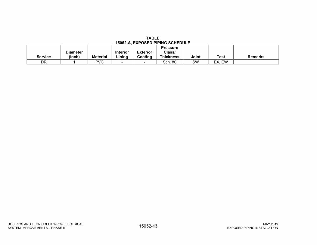
DOS RIOS AND LEON CREEK WRCs ELECTRICAL SYSTEM IMPROVEMENTS – PHASE II 15052-13 MAY 2019
EXPOSED PIPING INSTALLATION
TABLE 15052-A, EXPOSED PIPING SCHEDULE
Service Diameter
(inch) Material Interior Lining
Exterior Coating
Pressure Class/
Thickness Joint Test Remarks DR 1 PVC - - Sch. 80 SW EX, EW

DOS RIOS AND LEON CREEK WRCs ELECTRICAL SYSTEM IMPROVEMENTS – PHASE II 15052-14 MARCH 2019
EXPOSED PIPING INSTALLATION
The following abbreviations are used in the Exposed Piping Schedule.
A. Service Abbreviations
Service Abbrev. Service Abbrev.
Drain DR
B. Material Abbreviations
Material Abbrev
Polyvinyl Chloride PVC
C. Joint Abbreviations
Joint Type Abbrev Joint Type Abbrev.
Solvent Weld SW Bell and Spigot BS
D. Test Abbreviations
Test Abbrev Test Abbrev.
Examination of Welds EW Exfiltration Test EX

LEON CREEK WRC ELECTRICAL SYSTEM IMPROVEMENTS – PHASE I 15055 -1 APRIL 2020
PIPE HANGERS AND SUPPORTS
SECTION 15055
PIPE HANGERS AND SUPPORTS
PART 1 - GENERAL
1.01 DESCRIPTION
A. Scope:
1. CONTRACTOR shall provide all professional services, labor, materials, equipment, and incidentals as shown, specified and required to design, furnish, and install all hangers, supports and appurtenances necessary to complete the Work.
2. The Work excludes:
a. Designing pipe hangers and supports that are shown on the Drawings.
B. Coordination:
1. Review installation procedures under other Sections and coordinate the installation of items that must be installed with the pipe hangers and supports Work.
C. Related Sections:
1. Section 03300, Cast-In-Place Concrete.
2. Section 05051, Anchor Systems.
3. Section 05501, Miscellaneous Metal Fabrications.
4. Section 09900, Painting.
5. Division 15, Mechanical.
1.02 REFERENCES
A. Standards referenced in this Section are listed below:
1. American Society for Testing and Materials, (ASTM).
a. ASTM A 575, Specification for Steel Bars Carbon, Merchant Quality, M-Grades.
b. ASTM E 84, Test Method for Surface Burning Characteristics of Building Materials.
2. Federal Specification, (FS).
a. FS A-A-1192, Hangers, Pipe.
3. Manufacturers Standardization Society of the Valve and Fittings Industry, (MSS).
a. MSS SP 58, Pipe Hangers and Supports-Materials, Design and Manufacture.

LEON CREEK WRC ELECTRICAL SYSTEM IMPROVEMENTS – PHASE I 15055 -2 APRIL 2020
PIPE HANGERS AND SUPPORTS
b. MSS SP 58, Pipe Hangers and Supports - Selection and Application.
1.03 QUALITY ASSURANCE
A. Each type of pipe hanger or support shall be the product of one manufacturer.
B. Component Supply and Compatibility:
1. Obtain all equipment included in this Section regardless of the component manufacturer from a single pipe hangers and supports manufacturer.
2. The pipe hangers and supports equipment manufacturer shall review and approve or shall prepare all Shop Drawings and other submittals for all components furnished under this Section.
3. All components shall be specifically constructed for the specified service conditions and shall be integrated into the overall assembly by the pipe hangers and supports equipment manufacturer.
4. All components shall be chemically compatible with the fluid being conveyed in such pipe being supported.
1.04 SUBMITTALS
A. Action Submittals: Submit the following:
1. Shop Drawings:
a. Detailed drawings showing all hangers and supports for each piping system specified. Shop Drawings shall show location, installation, material, loads or forces, deflection, reaction forces, and selected anchor systems of all hangers and supports.
b. Each pipe system shall be analyzed for all loads and forces on the hangers and supports. Provide calculations of reaction forces to the structure to which they are fastened. Provide confirmation that hanger systems comply with support requirements and codes. Shop Drawings and calculations shall be sealed by a Professional Engineer registered in the State of Texas.
c. Submit and coordinate these with Shop Drawings required for all piping systems.
2. Product Data:
a. Submit manufacturers' catalogs, literature, chemical compatibility and engineering data on all hangers and supports. Load ratings, materials and installation shall be consistent with the recommendations of the MSS SP 58 and Federal Specification A-A-1192.
1.05 DELIVERY, STORAGE AND HANDLING
A. Packing, Shipping, Handling and Unloading:
1. Deliver materials to the Site to ensure uninterrupted progress of the Work. Deliver anchor bolts and anchorage devices which are to be embedded in cast-in-place concrete in ample time to prevent delay of that Work.

LEON CREEK WRC ELECTRICAL SYSTEM IMPROVEMENTS – PHASE I 15055 -3 APRIL 2020
PIPE HANGERS AND SUPPORTS
B. Storage and Protection:
1. Store materials to permit easy access for inspection and identification. Keep all material off the ground, using pallets, platforms, or other supports. Protect steel members and packaged materials from corrosion and deterioration.
2. Store materials in covered storage off the ground and prevent condensation.
C. Acceptance at Site:
1. All boxes, crates and packages shall be inspected by CONTRACTOR upon delivery to the Site. CONTRACTOR shall notify ENGINEER, in writing, if any loss or damage exists to equipment or components. Replace loss and repair damage to new condition in accordance with manufacturer's instructions.
PART 2 - PRODUCTS
2.01 GENERAL
A. Hangers and supports shall meet with the following requirements:
1. Standard and fabricated hangers and supports shall be furnished complete with necessary inserts, bolts, nuts, rods, washers, and other accessories.
2. Generally, run piping in groups where practicable and parallel to building wall. Provide minimum clearance of 1-inch between pipe and other work.
3. Install hangers or supports at all locations where pipe changes direction.
4. All hangers and supports shall be capable of adjustment after placement of piping.
5. Different types of hangers or supports shall be kept to a minimum.
6. All suspended or supported ductile iron pipe shall have a hanger or support adjacent to each hub.
7. Support vertical piping at each floor and between floors by stays or braces to prevent rattling and vibration.
8. Hanger rods shall be straight and vertical. Chain, wire, strap or perforated bar hangers shall not be used. Hangers shall not be suspended from piping.
9. Maximum support spacing unless otherwise shown or approved for standard weight pipe shall be as follows:
Pipe Size (inches)
Maximum Pipe Span 1 (feet)
Steel Copper Plastic 2 Cast/Ductile Iron 4
3/8 to 3/4 5 6 Cont. 3 - 1 6 6 5 -
1-1/4 6 6 5 - 1-1/2 6 6 5 -
2 10 10 5 - 2-1/2 10 10 5 -

LEON CREEK WRC ELECTRICAL SYSTEM IMPROVEMENTS – PHASE I 15055 -4 APRIL 2020
PIPE HANGERS AND SUPPORTS
Pipe Size (inches)
Maximum Pipe Span 1 (feet)
Steel Copper Plastic 2 Cast/Ductile Iron 4
3 10 10 5 - 4 12 12 5 12 feet for
pressure pipe
10 feet for soil pipe
6 12 12 5 8 12 12 5
10 12 - 5 12 12 - 10 14 12 - - 16 12 - - 18 12 - - 20 12 - - 24 12 - -
1Pipe shall not have pockets formed in the span due to sagging of the pipe between supports caused by the weight of the pipe, medium in the pipe, insulation, valves and fittings.
2Span shown is for Schedule 80 CPVC pipe at 100°F. Spans for other plastics, other CPVC pipe Schedules and pipes at higher temperatures shall be shortened in accordance with the pipe manufacturer's recommendations.
3Continuous means pipe shall be in unistrut or similar channel. 4 Pipe hanger and support selection shall be as shown and in this Section.
10. Maximum support spacing, unless otherwise shown for plastic pipe at ambient temperature, shall be one-half of the values specified for steel pipe.
11. Plastic pipe at temperature greater than 130ºF shall be continuously supported in a metal cradle or tray.
12. Where proper hanger or support spacing does not correspond with joist or rib spacing, structural steel channels may be attached to joists or ribs and pipes suspended there from.
13. Supports and hangers shall be of a material that is compatible with the fluid being conveyed in such pipe being supported.
14. Anchors for pipe support systems shall be compatible or protected by a coating system which is compatible with the fluid being conveyed in such pipe being supported.
15. Plastic pipe shall be supported at each bend, in both directions, in addition to maximum spacing indicated above.
B. Expansion compensation shall be designed for individual exposed piping systems with the following Design Criteria:
1. ΔL = L x ΔT x α
a. Where ΔL = pipe length change (inches).
b. L = pipe length between anchors (inches).
c. ΔT = 100 (F).

LEON CREEK WRC ELECTRICAL SYSTEM IMPROVEMENTS – PHASE I 15055 -5 APRIL 2020
PIPE HANGERS AND SUPPORTS
d. α = coefficient of thermal expansion (inches/inches/F).
2. Expansion compensation shall be designed as an integral part of the piping hanger, support and anchorage system.
3. Expansion compensation shall be achieved via expansion joints specified in Section 15120, Couplers, Adapters, and Specials for Process Piping.
2.02 HANGERS AND SUPPORTS
A. Hangers and supports where shown shall be in accordance with detail drawings. Hangers and supports not shown shall be in accordance with MSS SP 58.
B. Products and Manufacturers: Provide one of the following:
1. Anvil International, Inc.
2. Elcen.
3. B-Line.
4. Unistrut Corporation.
5. Or approved equal.
C. Chemical Piping Systems:
1. All pipe supports and fasteners shall be glass fiber-reinforced plastic with a flame spread rating of 25, in accordance with ASTM E 84.
2. Materials shall be manufactured by either the pultrusion or extrusion process.
3. All pipe supports shall have a surface veil over 100 percent of the surface which, along with a filler system, shall protect against degradation from ultra-violet light.
4. All fasteners shall be manufactured from long glass fiber-reinforced polyurethane to ensure strength and corrosion resistance.
5. All-thread rods shall be made from vinylester resin.
6. Manufacturers: Provide products of one of the following:
a. Unistrut Company.
b. Or equal.
2.03 ACCESSORIES
A. Hanger rods shall be made from ASTM A 575, with square head nut on top and running thread on bottom end.
B. Concrete Inserts:
1. Concrete inserts shall be MSS SP 58 malleable Type 18.

LEON CREEK WRC ELECTRICAL SYSTEM IMPROVEMENTS – PHASE I 15055 -6 APRIL 2020
PIPE HANGERS AND SUPPORTS
2. Manufacturers: Provide products of one of the following:
a. Unistrut Corporation, Wayne, Michigan.
b. Elcan Metal Products, Company, Franklin Park, Illinois.
c. B-Line.
d. Anvil International, Inc.
e. Or approved equal.
C. Inserts for Pipe Insulation:
1. Insulated pipe, larger than 1-1/2-inches in diameter, shall be supported by a rigid insert to protect the insulation. A steel metal saddle of sufficient gauge to carry the weight of the pipe and its fluid without deforming shall extend 2-inches minimum on each side of the rigid insert. The joints between insert and insulation shall be sealed before saddle is installed. Sizes up to 6-inches IPS shall be MSS SP 58, Type 40, and for sizes over 10-inches shall be MSS SP 58, Type 39.
D. Brackets:
1. Brackets for wall mounting shall conform to MSS SP 58 Type 32.
2. Brackets for wall mounting shall be type 316 stainless steel.
E. Fabricated Pipe Rack:
1. Pipes shall be supported and anchored to the fabricated pipe rack as shown. Clamps, rollers, and supports for piping shall conform to the general requirements of MSS SP 58.
F. Anchor Systems:
1. Anchor systems shall be as specified in Section 05051, Anchor Systems.
2.04 PAINTING
A. Clean and prime ferrous metal surfaces in the shop in accordance with the requirements of Section 09900, Painting.
B. Field painting shall conform to the requirements of Section 09900, Painting.
PART 3 - EXECUTION
3.01 INSTALLATION
A. Locate hangers, supports, and accessories to support piping, valves, and at all concentrated loads.
B. Locate hangers, supports, and accessories within maximum span lengths specified to support continuous pipeline runs unaffected by concentrated loadings.

LEON CREEK WRC ELECTRICAL SYSTEM IMPROVEMENTS – PHASE I 15055 -7 APRIL 2020
PIPE HANGERS AND SUPPORTS
C. Locate hanger, supports to prevent vibration or swaying and to provide for expansion and contraction.
1. Temperature differential specified in this Section.
2. Support piping independently so that equipment is not stressed by piping weight or expansion.
3. For Uninsulated Copper Pipe or Tubing: Clamps and supports, electroplated copper finish. Instrumentation tubing shall be supported in steel or aluminum troughs with covers. All tubing layout and connections shall be as approved by the manufacturer of the equipment.
4. Uncoated Hangers, Rods and Supports: Dip in zinc chromate primer before installation.
5. Maximum spacing for horizontal piping shall be in accordance with Table provided in Section 2.1:
a. Additional supports shall be provided at:
1) Change in direction.
2) Branch piping and runouts over five feet.
3) Concentrated loads due to valves, strainers or other similar items.
b. Maximum support spacing for plastic pipe at ambient temperature shall be one-half the values provided for steel pipe.
6. Hanger types for horizontal piping, except as noted and shown:
a. Forged steel adjustable clevis type, rod support for all services.
b. Slide Bases:
1) Pipe stand, brackets, trapeze or other equivalent structural support.
2) For piping 2-inches or larger.
c. For pipe and covering provide:
1) Saddles for rollers or slide bases.
2) Protective shields or saddles for all other types of supports.
d. Threaded Steel Rods:
1) Two inch vertical adjustment with two nuts each end for positioning and locking.
2) Size hanger rods according to the schedule below, unless otherwise noted:
Nominal Pipe Rod Diameter (Inches) (Inches) 2 and less 3/8 2-1/2 to 3-1/2 1/2

LEON CREEK WRC ELECTRICAL SYSTEM IMPROVEMENTS – PHASE I 15055 -8 APRIL 2020
PIPE HANGERS AND SUPPORTS
4 5/8 6 3/4 8 through 12 7/8 14 through 18 1 20 through 30 1-1/4
3) For Double Rod Hangers: One size smaller than above.
4) Connection to Structure for Piping to 2-Inches: Concrete inserts, or expansion shields in shear into sides of beams.
5) Connection to Structure for Piping 2-1/2-Inch or Larger: Concrete inserts, beam clamps or suitable bridging.
7. Vertical Piping:
a. Base Support: Base elbow or welded equivalent.
1) Bearing plate on structural support.
b. Guides not to exceed:
1) 25 feet for piping to 2-inches.
2) 36 feet for piping 2-1/2-inches or larger.
c. Top Support:
1) Special hanger or saddle in horizontal connection.
2) Provisions for expansion.
d. Intermediate Supports: Steel pipe clamp at floor.
1) Bolted and welded to pipe.
2) Extension ends bearing on structural steel or bearing plates.
e. For Multiple Pipes: Coordinate guides, bearing plates and accessory steel.
8. Insulated Piping:
a. Horizontal Pipe Shields at Supports:
1) Minimum 120 degree arc.
2) Length equal to diameter of insulation 12-inch minimum.
3) To 6-Inch Pipe Size: No. 18 USSG galvanized steel.
b. Vertical Pipe Shields at Guides:
1) Full 360 degree arc, securely banded.
2) Length equal to diameter of insulation, 12-inch minimum.
3) To 6-Inch Pipe Size: No. 18 USSG galvanized steel.

LEON CREEK WRC ELECTRICAL SYSTEM IMPROVEMENTS – PHASE I 15055 -9 APRIL 2020
PIPE HANGERS AND SUPPORTS
D. Install items to be embedded before concrete placement.
E. Anchor systems shall be installed as indicated in Section 05051, Anchor Systems.
F. Fasten embedded items securely to prevent movement during concrete placement.
G. Install hangers and support units on piping systems in accordance with manufacturer's recommendations.
H. Adjust hangers and supports and place grout for concrete supports to bring pipelines to specified elevations.
I. Bring all pipe systems up to operating pressures and temperatures. Cycle systems to duplicate operating conditions. Correct all support malfunctions.
+ + END OF SECTION + +

LEON CREEK WRC ELECTRICAL SYSTEM IMPROVEMENTS – PHASE I 15055 -10 APRIL 2020
PIPE HANGERS AND SUPPORTS
THIS PAGE INTENTIONALLY LEFT BLANK

LEON CREEK WRC ELECTRICAL SYSTEM IMPROVEMENTS – PHASE I 15121 -1 APRIL 2020
WALL PIPES, FLOOR PIPES, AND PIPE SLEEVES
SECTION 15121
WALL PIPES, FLOOR PIPES, AND PIPE SLEEVES
PART 1 - GENERAL
1.01 DESCRIPTION
A. Scope:
1. CONTRACTOR shall provide all labor, materials, equipment and incidentals as shown, specified and required to furnish and install all floor pipes, pipe sleeves, wall pipes, other wall pieces, and escutcheons to complete the Work.
B. Coordination:
1. Review installation procedures under this and other Sections and coordinate with the installation of floor pipes, pipe sleeves, wall pipes, other wall pieces and escutcheons that must be installed with or within formwork, walls, partitions, ceilings and panels.
C. Related Sections:
1. Section 03300, Cast-In-Place Concrete.
1.02 REFERENCES
A. Standards referenced in this Section are listed below:
1. American National Standards Institute, (ANSI).
a. ANSI B16.1, Cast-Iron Pipe Flanges and Flanged Fittings.
b. ANSI B16.4, Gray-Iron Threaded Fittings.
2. American Water Works Association, (AWWA).
a. AWWA C200, Steel Water Pipe 6-Inches and Larger.
1.03 QUALITY ASSURANCE
A. Component Supply and Compatibility:
1. Obtain all equipment included in this Section regardless of the component manufacturer from a single wall pipes, floor pipes and pipe sleeves manufacturer.
2. The wall pipes, floor pipes and pipe sleeves manufacturer to review and approve or to prepare all Shop Drawings and other submittals for all components furnished under this Section.
3. All components shall be specifically constructed for the specified service conditions and shall be integrated into the overall assembly by the wall pipes, floor pipes and pipe sleeves manufacturer.
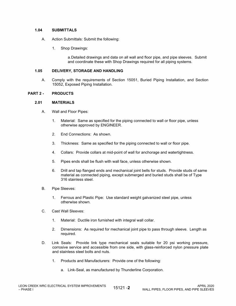
LEON CREEK WRC ELECTRICAL SYSTEM IMPROVEMENTS – PHASE I 15121 -2 APRIL 2020
WALL PIPES, FLOOR PIPES, AND PIPE SLEEVES
1.04 SUBMITTALS
A. Action Submittals: Submit the following:
1. Shop Drawings:
a. Detailed drawings and data on all wall and floor pipe, and pipe sleeves. Submit and coordinate these with Shop Drawings required for all piping systems.
1.05 DELIVERY, STORAGE AND HANDLING
A. Comply with the requirements of Section 15051, Buried Piping Installation, and Section 15052, Exposed Piping Installation.
PART 2 - PRODUCTS
2.01 MATERIALS
A. Wall and Floor Pipes:
1. Material: Same as specified for the piping connected to wall or floor pipe, unless otherwise approved by ENGINEER.
2. End Connections: As shown.
3. Thickness: Same as specified for the piping connected to wall or floor pipe.
4. Collars: Provide collars at mid-point of wall for anchorage and watertightness.
5. Pipes ends shall be flush with wall face, unless otherwise shown.
6. Drill and tap flanged ends and mechanical joint bells for studs. Provide studs of same material as connected piping, except submerged and buried studs shall be of Type 316 stainless steel.
B. Pipe Sleeves:
1. Ferrous and Plastic Pipe: Use standard weight galvanized steel pipe, unless otherwise shown.
C. Cast Wall Sleeves:
1. Material: Ductile iron furnished with integral wall collar.
2. Dimensions: As required for mechanical joint pipe to pass through sleeve. Length as required.
D. Link Seals: Provide link type mechanical seals suitable for 20 psi working pressure, corrosive service and accessible from one side, with glass-reinforced nylon pressure plate and stainless steel bolts and nuts.
1. Products and Manufacturers: Provide one of the following:
a. Link-Seal, as manufactured by Thunderline Corporation.

LEON CREEK WRC ELECTRICAL SYSTEM IMPROVEMENTS – PHASE I 15121 -3 APRIL 2020
WALL PIPES, FLOOR PIPES, AND PIPE SLEEVES
b. Or equal.
E. Wall and Ceiling Plates:
1. Bare pipes passing through walls and ceilings in finished rooms: Provide escutcheon plates of cast brass or cast-iron nickel plated, clevis or split ring and hinged with set screws.
2. Provide plated escutcheon plates of 18-gauge steel for insulated pipes passing through walls and ceilings in finished rooms.
PART 3 - EXECUTION
3.01 INSTALLATION
A. Wall and Floor Pipes: Install as shown and in accordance with approved Shop Drawings.
B. Pipe Sleeves:
1. Use sleeves wherever pipes pass through walls, partitions, floors, and roofs, unless otherwise shown.
2. Extend all sleeves through floor slabs a minimum of 2-inches above finished floor.
3. Anchor sleeves to concrete and masonry walls as shown or otherwise approved.
4. All sleeves through walls shall be flush with wall face.
5. All pipe joints and annular spaces in exterior walls or walls subjected to hydrostatic pressure shall be completely watertight.
6. Use link type seals to seal sleeve against hydrostatic pressure. Size sleeves to provide annular space required to suit the link type mechanical seals that are used.
7. Do not install sleeves and pipes through structural members, unless specifically shown and approved by ENGINEER.
8. Size sleeves to provide annular space as follows:
Sleeve ID Minus Pipe Pipe Size Or Insulation OD Less than 2-inches 1/2-inches to 3/4-inches 2-inches to 4-inches 3/4 inches to 1-1/4-inches. 6-inches to 12-inches 1-1/4 inches to 2-inches Over 12-inches 2-inches to 3-inches
C. Install wall and ceiling plates in accordance with the manufacturer's recommendations and approved Shop Drawings.
+ + END OF SECTION + +

LEON CREEK WRC ELECTRICAL SYSTEM IMPROVEMENTS – PHASE I 15121 -4 APRIL 2020
WALL PIPES, FLOOR PIPES, AND PIPE SLEEVES
THIS PAGE INTENTIONALLY LEFT BLANK

LEON CREEK WRC ELECTRICAL SYSTEM IMPROVEMENTS – PHASE I 15400 -1 APRIL 2020
PLUMBING
SECTION 15400
PLUMBING
PART 1 - GENERAL
1.01 DESCRIPTION
A. Scope:
1. CONTRACTOR shall provide all labor, materials, equipment and incidentals as shown, specified, and required to furnish and install HVAC drainage, and storm drainage systems complete and operational with accessories.
B. Coordination:
1. Review installation procedures under this and other Sections and coordinate the installation of items that must be installed with, or before, the plumbing Work.
C. Related Sections:
1. Section 09900, Painting.
2. Division 15, Mechanical.
1.02 REFERENCES
A. Standards referenced in this Section are listed below:
1. ANSI A21.1, Practice Manual, Computation Strength, Thickness.
2. ANSI A117.1, Accessible and Usable Buildings and Facilities.
3. ANSI B16.9, Factory-Made Wrought Buttwelding Fittings.
4. ANSI B16.18, Cast Copper Alloy Solder Joint Pressure Fittings.
5. ANSI B16.22, Wrought Copper and Copper Alloy Solder Joint Pressure Fittings. (ASME B16.22).
6. ANSI B16.24, Cast Copper Alloy Pipe Flanges and Flanged Fittings, Class 150 and 300 lbs. (ASME B16.24).
7. ANSI B16.26, Cast Copper Alloy Fittings for Flared Copper Tubes.
8. ANSI B16.42, Ductile Iron Pipe Flanges and Flanged Fittings.
9. ANSI B40.1, Gages-Pressure Indicating Dial Type-Elastic Element.
10. ANSI H23.1, Seamless Copper Water Tube, (ASTM B 88).
11. American Society of Sanitary Engineering (ASSE), ASSE 1013, Performance Requirements for Reduced Pressure Principle Backflow Preventers and Reduced Pressure Fire Protection Principle Backflow Preventers.
12. ASTM A 74, Specification for Cast-Iron Soil Pipe and Fittings.
13. ASTM A 307, Specification for Carbon Steel Bolts and Studs, 60,000 PSI Tensile Strength.
14. ASTM A 888, Specification for Hubless Cast-Iron Soil Pipe and Fittings for Sanitary and Storm Drain, Waste and Vent Piping Applications.
15. ASTM B 32, Specification for Solder Metal.
16. ASTM B 88, Specification for Seamless Copper Water Tube.
17. ASTM D 1330, Specification for Rubber Sheet Gaskets.
18. AWWA C511, Reduced-Pressure Principle Backflow Prevention Assembly.

LEON CREEK WRC ELECTRICAL SYSTEM IMPROVEMENTS – PHASE I 15400 -2 APRIL 2020
PLUMBING
19. CISPI 310, Specification for Coupling for use in Connection with Hubless Cast-Iron Soil Pipe and Fittings for Sanitary and Storm Drain, Waste and Vent Piping Applications.
20. CISPI HSN, Specification for Neoprene Rubber Gaskets for Hub and Spigot Cast 300N Soil Pipe and Fittings.
21. FS O-F-506, Flux, Soldering: Paste and Liquid.
22. FS WW-H-171, Hangers and Supports, Pipe.
23. FS QQ-C-40, Calking Lead Wool and Lead Pig.
24. FS WW-P-541/1, Plumbing Fixtures (Water Closet).
25. FS WW-U-516, Unions, Brass or Bronze, Threaded Pipe Connections and Solder-Joint Tube Connections.
26. FS WW-U-531, Unions, Pipe, Steel or Malleable Iron; Threaded Connection.
27. Manufacturers Standardization Society (MSS), MSS SP 69, Pipe Hangers and Supports – Selection and Application.
28. NFPA 54, Nation Fuel Gas Code.
1.03 QUALITY ASSURANCE
A. Installer’s Qualifications:
1. Engage installer regularly engaged in plumbing piping installation and with experience in the installation of the types of materials required; and who agrees to employ only tradesmen with specific skill and experience in this type of Work. Submit name and qualifications to ENGINEER.
2. Engage installers for the entire plumbing piping systems with undivided responsibility for performance and other requirements.
B. Regulatory Requirements: Comply with applicable provisions and recommendations of the following, except as otherwise shown or specified.
1. National Electrical Code, (NEC).
2. City of San Antonio
C. Component Supply and Compatibility:
1. Obtain all equipment included in this Section regardless of the component manufacturer from a single plumbing manufacturer.
2. The plumbing manufacturer to review and approve or to prepare all Shop Drawings and other submittals for all components furnished under this Section.
3. All components shall be specifically constructed for the specified service conditions and shall be integrated into the overall assembly by the plumbing manufacturer.
1.04 SUBMITTALS
A. Action Submittals: Submit the following:
1. Shop Drawings:
a. 1/4-inch scale piping layouts, dimensioned to show length of piping runs, pipe sizes, support spacing and expansion provisions.
b. Details of installation, including piping supports.
c. Submit pipe schedule with laminate construction, sizes, thickness, vacuum pressure, weight per foot pressure, spans, joint type and flange data.
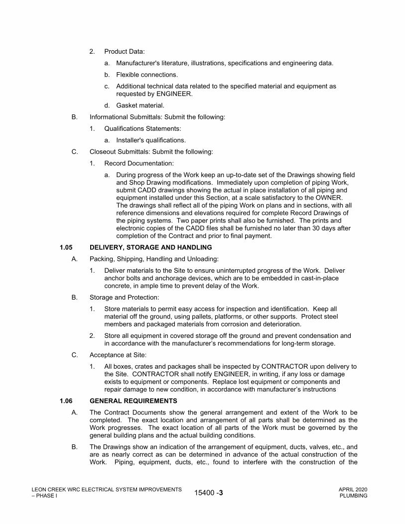
LEON CREEK WRC ELECTRICAL SYSTEM IMPROVEMENTS – PHASE I 15400 -3 APRIL 2020
PLUMBING
2. Product Data:
a. Manufacturer's literature, illustrations, specifications and engineering data.
b. Flexible connections.
c. Additional technical data related to the specified material and equipment as requested by ENGINEER.
d. Gasket material.
B. Informational Submittals: Submit the following:
1. Qualifications Statements:
a. Installer's qualifications.
C. Closeout Submittals: Submit the following:
1. Record Documentation:
a. During progress of the Work keep an up-to-date set of the Drawings showing field and Shop Drawing modifications. Immediately upon completion of piping Work, submit CADD drawings showing the actual in place installation of all piping and equipment installed under this Section, at a scale satisfactory to the OWNER. The drawings shall reflect all of the piping Work on plans and in sections, with all reference dimensions and elevations required for complete Record Drawings of the piping systems. Two paper prints shall also be furnished. The prints and electronic copies of the CADD files shall be furnished no later than 30 days after completion of the Contract and prior to final payment.
1.05 DELIVERY, STORAGE AND HANDLING
A. Packing, Shipping, Handling and Unloading:
1. Deliver materials to the Site to ensure uninterrupted progress of the Work. Deliver anchor bolts and anchorage devices, which are to be embedded in cast-in-place concrete, in ample time to prevent delay of the Work.
B. Storage and Protection:
1. Store materials to permit easy access for inspection and identification. Keep all material off the ground, using pallets, platforms, or other supports. Protect steel members and packaged materials from corrosion and deterioration.
2. Store all equipment in covered storage off the ground and prevent condensation and in accordance with the manufacturer’s recommendations for long-term storage.
C. Acceptance at Site:
1. All boxes, crates and packages shall be inspected by CONTRACTOR upon delivery to the Site. CONTRACTOR shall notify ENGINEER, in writing, if any loss or damage exists to equipment or components. Replace lost equipment or components and repair damage to new condition, in accordance with manufacturer’s instructions
1.06 GENERAL REQUIREMENTS
A. The Contract Documents show the general arrangement and extent of the Work to be completed. The exact location and arrangement of all parts shall be determined as the Work progresses. The exact location of all parts of the Work must be governed by the general building plans and the actual building conditions.
B. The Drawings show an indication of the arrangement of equipment, ducts, valves, etc., and are as nearly correct as can be determined in advance of the actual construction of the Work. Piping, equipment, ducts, etc., found to interfere with the construction of the

LEON CREEK WRC ELECTRICAL SYSTEM IMPROVEMENTS – PHASE I 15400 -4 APRIL 2020
PLUMBING
building, plumbing apparatus and piping, electrical wiring or other obstructions, etc., must be changed in location to clear such obstructions.
C. The connections shown to the various units are intended as an indication only. The actual connections at the time of installation to be made and arranged to suit the requirements of each case, adequately provide for expansion and perfect circulation and minimize the amount of space required for the same.
D. The Drawings show the general arrangement of all systems. Should local conditions necessitate rearrangement of one or more of the systems, CONTRACTOR, before proceeding with the Work, shall prepare and submit complete drawings showing all details of the proposed rearrangement for written approval by the ENGINEER.
E. The Drawings do not show all offsets, fittings, accessories and details, which may be required. CONTRACTOR shall carefully examine all of the General Construction, Electrical, Mechanical, Structural and other Drawings and the respective Specifications for conditions which may affect the installation of the Work, and shall arrange the Work accordingly, furnishing all required items to meet such conditions which are not specified as work “by others”, to complete the systems to the true extent of the Contract Documents.
PART 2 - PRODUCTS
2.01 VALVES AND ACCESSORIES
A. Bronze Body Check Valves:
1. Products and Manufacturers: Provide one of the following:
a. Stockham Valves and Fittings, Fig. No. B-309.
b. Lunkenheimer Company, Fig. No. 2145.
c. Or equal.
2. Type: Swing, regrinding bronze disc, screw-in cap.
3. Materials: Brass and bronze.
4. Rating: 150 lb. SWP.
5. End Connections: Solder joint.
B. Bronze Body Ball Valves:
1. Products and Manufacturers: Provide one of the following:
a. Stockham Valves and Fittings, Fig. S-217 BR-R-T.
b. Lunkenheimer Company, Fig. 707-XLT.
c. Or equal.
2. Type: Non-blowout stem, adjustable packing gland, quarter turn, full port ball valve.
3. Materials:
a. Body: Cast bronze.
b. Ball: Chrome plated brass.
c. Packing and Seats: Teflon.
4. Rating: 150 lb. SWP.
5. End Connection: Screwed. Provide screwed to sweat adapters, where required.
2.02 EQUIPMENT

LEON CREEK WRC ELECTRICAL SYSTEM IMPROVEMENTS – PHASE I 15400 -5 APRIL 2020
PLUMBING
A. Floor Drains:
1. Floor Drain and Hub Drains:
a. Products and Manufacturers: Provide one of the following:
1) Sioux Chief Model 860
2) Or equal.
b. Materials:
1) Body: PVC
2) Collar: PVC
3) Strainer Head: Circular 9” Diameter
c. Outlet Connection: Bottom outlet, solvent welded
d. Rated for 3,500 lb. load.
2. Accessories:
a. Trap primer connection.
B. Trap Primer Assembly (Electronic):
1. Trap primer assembly shall be electronic type, factory assembled, pre-piped and with a single point 120/1/60 power connection, ready for field installation. Assembly shall be complete with integral ball valve, water hammer arrestor, 120V solenoid valve, adjustable timer, manual override switch, vacuum breaker, copper manifold and minimum 5 amp breaker.
2. Entire components shall be housed in a 16 gauge steel enclosure with necessary brackets for surface mounting. Provide with manufacturer’s standard door latch.
3. Provide appropriate sized manifold and assembly to prime number of floor drains as shown on the Plumbing Drawings.
4. Assembly shall be Prime-Time series as manufactured by Precision Plumbing Products, Inc. or approved equal.
C. Roof Drains:
1. Roof Drain: (RD):
a. Products and Manufacturers: Provide one of the following:
1) Zurn Industries Fig. Z-100-ERC
2) Or equal.
b. Materials:
1) Body: Enameled cast-iron.
2) Dome Top: Galvanized cast-iron.
c. Accessories:
1) Sump receiver.
2) Flashing clamp
3) Gravel stop
d. Outlet Connections: Threaded, calk or no-hub, as required.
D. Downspout Nozzle

LEON CREEK WRC ELECTRICAL SYSTEM IMPROVEMENTS – PHASE I 15400 -6 APRIL 2020
PLUMBING
1. Downspout Nozzle:
a. Products and Manufacturers: Provide one of the following:
1) Zurn Industries Fig. Z199
2) Or equal.
b. Materials:
1) Body: Nickel Bronze Body
c. Accessories:
1) PVC Connection
2) Stainless Steel Screen
E. Sidewalk Drain
1. Three to be included, as shown in Contract Drawings.
2.03 PAINTING
A. Piping, equipment and accessories shall be painted in accordance with Section 09900, Painting.
PART 3 - EXECUTION
3.01 INSTALLATION
A. General:
1. Install all items as shown, specified, and as recommended by the manufacturer.
2. Request instructions from ENGINEER, in writing, when there is a conflict between the manufacturer's recommendations and the Contract Documents.
3. Present conflicts to ENGINEER, in writing, who will determine corrective measures to be taken.
4. Do not modify structures to facilitate installation of piping, unless specifically approved by ENGINEER.
5. Installation to conform to the requirements of all local and state codes.
6. Properly plug or cap the open ends of all piping at the end of each day’s Work or other stopping point through construction. Equipment shall be tightly covered and protected against dirt, water, and chemical or mechanical damage.
7. All plumbing piping located beneath building slab shall be concrete encased.
3.02 FIELD QUALITY CONTROL
A. Field Tests:
1. Fill all systems and fully test all equipment, valves, etc. in operation.
2. Check for excessive vibration while all systems are operating.
3. Installed systems and components will not be released to OWNER unless all systems have been tested and approved by the ENGINEER.
B. Inspection:
1. Examine areas to receive equipment, piping, valves and accessories for:

LEON CREEK WRC ELECTRICAL SYSTEM IMPROVEMENTS – PHASE I 15400 -7 APRIL 2020
PLUMBING
a. Defects that adversely affect execution and quality of the Work.
b. Deviations beyond allowable tolerances for equipment, piping, valves and accessories.
c. Start the Work only when conditions are satisfactory.
2. The ENGINEER reserves the right to reject or authorize replacement of equipment, piping, valves and accessories found to be defective, blistered, cracked or deviated from allowable tolerances as described above.
3.03 ADJUSTING AND CLEANING
A. Adjusting:
1. Adjust all controls for proper settings.
2. While system is operable, balance all equipment, valves, dampers, etc. to achieve design conditions.
B. Cleaning:
1. Thoroughly clean all piping, fittings, valves, equipment and accessories prior to installation.
2. Remove all dirt, rust, dust, etc. from piping and equipment in preparation for painting.
3. Remove and dispose of all debris and waste from the Site resulting from installation.
+ + END OF SECTION + +

LEON CREEK WRC ELECTRICAL SYSTEM IMPROVEMENTS – PHASE I 15400 -8 APRIL 2020
PLUMBING
THIS PAGE INTENTIONALLY LEFT BLANK

LEON CREEK WRC ELECTRICAL SYSTEM IMPROVEMENTS – PHASE I 15490 -1 APRIL 2020
INSTALLATION OF PLUMBING PIPING
SECTION 15490
INSTALLATION OF PLUMBING PIPING
PART 1 - GENERAL
1.01 DESCRIPTION
A. Scope:
1. CONTRACTOR shall provide all labor, materials, equipment and incidentals as shown, specified, and required to furnish and install plumbing piping systems complete with accessories.
B. Coordination:
1. Review installation procedures under this and other Sections and coordinate the installation of items that must be installed with, or before, the installation of plumbing piping Work.
C. Related Sections:
1. Section 09900, Painting.
1.02 REFERENCES
A. Standards referenced in this Section are listed below:
1. American National Standards Institute, (ANSI).
a. ANSI B13.1, Code for Pressure Piping.
b. ANSI B31.1, Power Piping.
2. American Society for Testing and Materials, (ASTM).
3. American Welding Society, (AWS).
a. AWS D10.9, Welding Procedures and Welders for Piping and Tubing.
4. Institute of Electrical and Electronic Engineers, (IEEE).
5. National Electrical Code, (NEC).
6. National Electrical Manufacturers' Association, (NEMA).
7. National Fire Protection Association, (NFPA).
8. Underwriters' Laboratories, Incorporated, (UL).
1.03 QUALITY ASSURANCE
A. Installer’s Qualifications:
1. Engage a single installer regularly engaged in plumbing piping installation and with experience in the installation of the types of materials required; and who agrees to employ only tradesmen with specific skill and experience in this type of Work. Submit name and qualifications to ENGINEER.
2. Engage a single installer for the entire plumbing piping system with undivided responsibility for performance and other requirements.
B. Regulatory Requirements: Comply with applicable provisions and recommendations of the following, except as otherwise shown or specified.
1. American National Standards Institute, (ANSI).
2. Institute of Electrical and Electronic Engineers, (IEEE).
3. National Electrical Code, (NEC).

LEON CREEK WRC ELECTRICAL SYSTEM IMPROVEMENTS – PHASE I 15490 -2 APRIL 2020
INSTALLATION OF PLUMBING PIPING
4. National Electrical Manufacturers' Association, (NEMA).
5. National Fire Protection Association, (NFPA).
6. Underwriters’ Laboratories, Incorporated, (UL).
7. Local and State Building Codes and Ordinances.
8. Permits: CONTRACTOR shall obtain and pay for all required permits, fees and inspections.
C. Component Supply and Compatibility:
1. Obtain all equipment included in this Section regardless of the component manufacturer from a single installation of plumbing piping manufacturer.
2. The installation of plumbing piping manufacturer to review and approve or to prepare all Shop Drawings and other submittals for all components furnished under this Section.
3. All components shall be specifically constructed for the specified service conditions and shall be integrated into the overall assembly by the installation of plumbing piping manufacturer.
1.04 SUBMITTALS
A. Action Submittals: Submit the following:
1. Shop Drawings:
a. 1/4-inch scale piping layouts, dimensioned to show length of piping runs, pipe sizes, support spacing and expansion provisions.
b. Details of installation, including piping supports.
c. Submit pipe schedule with laminate construction, sizes, thickness, vacuum pressure, weight per foot pressure, spans, joint type and flange data.
2. Product Data:
a. Manufacturer's literature, illustrations, specifications and engineering data.
b. Flexible connections.
c. Other technical data related to the specified material and equipment as requested by ENGINEER.
d. Gasket material.
B. Informational Submittals: Submit the following:
1. Qualifications Statements:
a. Installer’s qualifications.
C. Closeout Submittals: Submit the following:
1. Record Drawings:
a. During progress of the Work keep an up-to-date set of the Drawings showing field and Shop Drawing modifications. Immediately upon completion of the piping Work submit CADD drawings showing the actual in-place installation of all piping and equipment installed under this Section at a scale satisfactory to the OWNER. The Record Drawings shall show all piping on plans and in sections, with all reference dimensions and elevations required for complete Record Drawings of the piping systems. Two paper prints shall also be furnished. The prints and electronic copies of the CADD files shall be furnished no later than 30 days after completion of the Contract and prior to final payment.
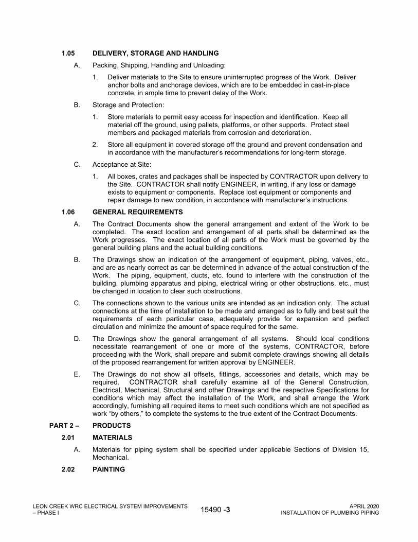
LEON CREEK WRC ELECTRICAL SYSTEM IMPROVEMENTS – PHASE I 15490 -3 APRIL 2020
INSTALLATION OF PLUMBING PIPING
1.05 DELIVERY, STORAGE AND HANDLING
A. Packing, Shipping, Handling and Unloading:
1. Deliver materials to the Site to ensure uninterrupted progress of the Work. Deliver anchor bolts and anchorage devices, which are to be embedded in cast-in-place concrete, in ample time to prevent delay of the Work.
B. Storage and Protection:
1. Store materials to permit easy access for inspection and identification. Keep all material off the ground, using pallets, platforms, or other supports. Protect steel members and packaged materials from corrosion and deterioration.
2. Store all equipment in covered storage off the ground and prevent condensation and in accordance with the manufacturer’s recommendations for long-term storage.
C. Acceptance at Site:
1. All boxes, crates and packages shall be inspected by CONTRACTOR upon delivery to the Site. CONTRACTOR shall notify ENGINEER, in writing, if any loss or damage exists to equipment or components. Replace lost equipment or components and repair damage to new condition, in accordance with manufacturer’s instructions.
1.06 GENERAL REQUIREMENTS
A. The Contract Documents show the general arrangement and extent of the Work to be completed. The exact location and arrangement of all parts shall be determined as the Work progresses. The exact location of all parts of the Work must be governed by the general building plans and the actual building conditions.
B. The Drawings show an indication of the arrangement of equipment, piping, valves, etc., and are as nearly correct as can be determined in advance of the actual construction of the Work. The piping, equipment, ducts, etc. found to interfere with the construction of the building, plumbing apparatus and piping, electrical wiring or other obstructions, etc., must be changed in location to clear such obstructions.
C. The connections shown to the various units are intended as an indication only. The actual connections at the time of installation to be made and arranged as to fully and best suit the requirements of each particular case, adequately provide for expansion and perfect circulation and minimize the amount of space required for the same.
D. The Drawings show the general arrangement of all systems. Should local conditions necessitate rearrangement of one or more of the systems, CONTRACTOR, before proceeding with the Work, shall prepare and submit complete drawings showing all details of the proposed rearrangement for written approval by ENGINEER.
E. The Drawings do not show all offsets, fittings, accessories and details, which may be required. CONTRACTOR shall carefully examine all of the General Construction, Electrical, Mechanical, Structural and other Drawings and the respective Specifications for conditions which may affect the installation of the Work, and shall arrange the Work accordingly, furnishing all required items to meet such conditions which are not specified as work “by others,” to complete the systems to the true extent of the Contract Documents.
PART 2 – PRODUCTS
2.01 MATERIALS
A. Materials for piping system shall be specified under applicable Sections of Division 15, Mechanical.
2.02 PAINTING

LEON CREEK WRC ELECTRICAL SYSTEM IMPROVEMENTS – PHASE I 15490 -4 APRIL 2020
INSTALLATION OF PLUMBING PIPING
A. All equipment and accessories shall be painted in accordance with the requirements of Section 09900, Painting.
PART 3 – EXECUTION
3.01 INSTALLATION
A. General:
1. Install all items as shown, specified, and as recommended by the manufacturer.
2. Request instructions from ENGINEER, in writing, when there is a conflict between the manufacturer's recommendations and the Contract Documents.
3. Present conflicts to ENGINEER, in writing, who will determine corrective measures to be taken.
4. Do not modify structures to facilitate installation of piping, unless specifically approved by ENGINEER.
5. Installation to conform to requirements of all local and state codes.
6. Properly plug or cap the open ends of all piping at the end of each day’s Work or other stopping point through construction. Equipment shall be tightly covered and protected against dirt, water, and chemical or mechanical damage.
7. All PVC drain piping located beneath the building slab shall be encased in concrete.
3.02 FIELD QUALITY CONTROL
A. Field Tests:
1. Fill all systems and fully test all equipment, valves, piping, etc. in operation.
2. Check for excessive vibration while all systems are operating.
3. Installed systems and components will not be released to OWNER unless all systems have been tested and approved by the ENGINEER.
B. Inspection:
1. Examine areas to receive piping, valves and accessories for:
a. Defects that adversely affect execution and quality of the Work.
b. Deviations beyond allowable tolerances for piping, valves and accessories.
c. Start the Work only when conditions are satisfactory.
2. The ENGINEER reserves the right to reject or authorize replacement of piping and accessories found to be defective.
3.03 ADJUSTING AND CLEANING
A. Adjusting:
1. While system is operable, balance all equipment, valves, etc. to achieve design conditions.
B. Cleaning:
1. Thoroughly clean all piping, fittings, valves, and accessories prior to installation.
2. Remove all dirt, rust, dust, etc. from piping in preparation for painting.
3. Remove and dispose of all debris and waste from the Site resulting from installation.

LEON CREEK WRC ELECTRICAL SYSTEM IMPROVEMENTS – PHASE I 15490 -5 APRIL 2020
INSTALLATION OF PLUMBING PIPING
3.04 MATERIAL SCHEDULES
A. Material Schedule shall be as specified under applicable Sections of Division 17, Process Integration.
+ + END OF SECTION + +

LEON CREEK WRC ELECTRICAL SYSTEM IMPROVEMENTS – PHASE I 15490 -6 APRIL 2020
INSTALLATION OF PLUMBING PIPING
THIS PAGE INTENTIONALLY LEFT BLANK

LEON CREEK WRC ELECTRICAL SYSTEM IMPROVEMENTS – PHASE I 15496-1 APRIL 2020
TESTING OF PLUMBING PIPING SYSTEMS
SECTION 15496
TESTING OF PLUMBING PIPING SYSTEMS
PART 1 – GENERAL
1.01 DESCRIPTION
A. Scope:
1. CONTRACTOR shall provide all labor, materials, equipment and incidentals as shown, specified, and required to complete all testing of the plumbing piping systems.
B. Coordination:
1. Review installation procedures under this and other Sections and coordinate the installation of items that must be installed with, or before, the testing of plumbing piping systems Work.
C. Related Sections:
1. Section 09900, Painting.
1.02 REFERENCES
A. Standards referenced in this Section are listed below:
1. American National Standards Institute, (ANSI).
2. American Society for Testing and Materials, (ASTM).
3. Institute of Electrical and Electronics Engineers, (IEEE).
4. National Electrical Code, (NEC).
5. National Electrical Manufacturers' Association, (NEMA).
6. National Fire Protection Association, (NFPA).
a. NFPA 54, National Fuel Gas Code.
b. NFPA 99, Standard for Health Care Facilities.
7. Underwriters' Laboratories, Incorporated, (UL).
1.03 QUALITY ASSURANCE
A. Installer’s Qualifications:
1. Contractor regularly engaged in testing of plumbing piping systems and who agrees to employ only tradesmen with specific skill and experience in this type of Work. Submit name and qualifications to ENGINEER.
B. Regulatory Requirements: Comply with applicable provisions and recommendations of the following, except as otherwise shown or specified.
1. American National Standards Institute, (ANSI).
2. Institute of Electrical and Electronic Engineers, (IEEE).
3. National Electrical Code, (NEC).
4. National Electrical Manufacturers' Association, (NEMA).
5. National Fire Protection Association, (NFPA).
6. Underwriters’ Laboratories, Incorporated, (UL).
7. Local and State Building Codes and Ordinances.

LEON CREEK WRC ELECTRICAL SYSTEM IMPROVEMENTS – PHASE I 15496-2 APRIL 2020
TESTING OF PLUMBING PIPING SYSTEMS
8. Permits: CONTRACTOR shall obtain and pay for all required permits, fees and inspections.
1.04 SUBMITTALS
A. Action Submittals: Submit the following:
1. Product Data:
a. Submit manufacturer’s literature and samples for the valve tags.
2. Testing Plans, Procedures, and Testing Limitations:
a. Description of proposed testing method, procedures, and apparatus to the ENGINEER for approval at least 48 hours in advance of testing.
B. Informational Submittals: Submit the following:
1. Site Quality Control Submittals:
a. Submit a test report for each test to the ENGINEER certifying the test pressure, duration of test, and test performance of all installed piping.
2. Qualifications Statements:
a. Installer’s qualifications.
PART 2 – PRODUCTS
2.01 GENERAL
A. Provide all necessary equipment and materials, including gages and pumps, to perform the testing operations.
PART 3 – EXECUTION
3.01 GENERAL
A. Conduct water, air and smoke tests as required, on all piping systems as specified below.
B. Conduct all tests in the presence of, and in a manner approved by ENGINEER, all state and local authorities having jurisdiction. Repeat test for these authorities if requested by them.
C. Repair and retest all lines, which do not pass the tests as specified herein.
D. Inspect all valves, joints, and specialties for tightness and for proper operation while under test pressure.
E. Properly plug or cap the open ends of all piping at the end of each day’s Work or other stopping point through the testing. Piping shall be tightly covered and protected against contamination.
3.02 FIELD QUALITY CONTROL
A. Water Tests:
1. Drainage and Vent system piping:
a. Perform tests either on the entire system or on successive sections of the system.
b. Tightly close all openings, except the highest opening of the system or section to be tested.
c. Fill the system or section with water to the point of overflow.
d. Test with a head of at least ten feet of water, except for the uppermost ten feet of the system.

LEON CREEK WRC ELECTRICAL SYSTEM IMPROVEMENTS – PHASE I 15496-3 APRIL 2020
TESTING OF PLUMBING PIPING SYSTEMS
e. Allow water to stand in the system for at least 15 minutes before inspecting.
f. Inspect the system or section for leaks, and repair any leaks found.
+ + END OF SECTION + +

LEON CREEK WRC ELECTRICAL SYSTEM IMPROVEMENTS – PHASE I 15496-4 APRIL 2020
TESTING OF PLUMBING PIPING SYSTEMS
THIS PAGE INTENTIONALLY LEFT BLANK

LEON CREEK WRC ELECTRICAL SYSTEM IMPROVEMENTS - PHASE I 15000 -1
APRIL 2020 MECHANICAL-GENERAL PROVISIONS
SECTION 15000
MECHANICAL-GENERAL PROVISIONS
PART 1 - GENERAL
1.01 SCOPE OF WORK
A. All equipment furnished and installed under this contract shall conform to the general stipulations set forth in this section except as otherwise specified in other sections.
B. Contractor shall coordinate all details of equipment with other related parts of the Work, including verification that all structures, piping, wiring, and equipment components are compatible. Contractor shall be responsible for all structural and other alternations in the Work required to accommodate equipment differing in dimensions or other characteristics from that contemplated in the Contract Drawings or Specifications.
C. Related Work Described Elsewhere:
1. General Requirements: Division 1
2. Concrete: Division 3
3. Metals: Divisions 5
4. Paints and Protective Coatings: Division 9
5. Electrical: Division 16
D. General Designs
1. Contract Drawings and Specifications. The Contract Drawings and Specifications shall be considered as complementary, one to the other, so that materials and work indicated, called for, or implied by the one and not by the other shall be supplied and installed as though specifically called for by both. The Contract Drawings are to be considered diagrammatic, not necessarily showing in detail or to scale all of the equipment or minor items. In the event of discrepancies between the Contract Drawings and Specifications, or between either of these and any regulations or ordinances governing work of these regulations of ANSI, OSHA, and local industrial codes. regulations of ANSI, OSHA, and local industrial code specifications, the bidder shall notify the Engineer in ample time to permit revisions.
1.02 QUALITY ASSURANCE
A. Materials and Equipment: Unless otherwise specified, all materials and equipment furnished for permanent installation in the work shall conform to applicable standards and specifications and shall be new, unused, and undamaged when installed or otherwise incorporated in the work. No such material or equipment shall be used by the Contractor for any purpose other than that intended or specified, unless such use is specifically authorized in writing by the Owner.
B. Equivalent Materials and Equipment:
1. Whenever a material or article is specified or described by using the name of a proprietary product or the name of a particular manufacturer or vendor, the specific item mentioned shall be understood as establishing the type, function, and quality desired. Other manufacturers' products will be accepted provided sufficient information is submitted to allow the Engineer to determine that the products proposed are equivalent to those named. Such items shall be submitted for review in accordance with Section 01300 – Submittals.

LEON CREEK WRC ELECTRICAL SYSTEM IMPROVEMENTS - PHASE I 15000 -2
APRIL 2020 MECHANICAL-GENERAL PROVISIONS
2. Requests for review of equivalency will not be accepted from anyone except the Contractor and such requests will not be considered until after the contract has been awarded.
C. Governing Standards: Equipment and appurtenances shall be designed in conformity with ANSI, ASME, ASTM, IEEE, NEMA, OSHA, AGMA, and other generally accepted applicable standards. They shall be of rugged construction and of sufficient strength to withstand all stresses which may occur during fabrication, testing, transportation, installation, and all conditions or operations. All bearings and moving parts shall be adequately protected against wear by bushings or other acceptable means. Provisions shall be made for adequate lubrication with readily accessible means.
D. Clearances: Ample clearances shall be provided for inspection and adjustment. All equipment shall fit the allotted space and shall leave reasonable access room for servicing and repairs. Greater space and room required by substituted equipment shall be provided by the Contractor and at his expense.
E. Testing:
1. When the equipment is specified to be factory tested, the results of the tests shall be submitted to the Engineer and approval of the test results shall be obtained before shipment of the equipment.
2. When an item of equipment, including controls and instrumentation, has been completely erected, the Contractor shall notify the Engineer, who will designate a time to make such tests as required, and operate the item to the satisfaction of the Contractor. All testing shall be done in the presence of the Contractor. "Completely erected" shall mean that the installation is erected, all necessary adjustments have been made, all required utility connections have been made, required lubricants and hydraulic fluid have been added and the unit has been cleaned and painted.
3. All elements within the system that may be damaged by the testing operation shall be removed or otherwise protected during the operation.
4. All defects and leaks observed during the tests shall be corrected and made tight in an approved manner and the tests repeated until the system is proven tight.
5. Repair all damage done to existing or adjacent work or materials due to or on account of the tests.
6. Provide test pumps, gauges, or other instruments and equipment required for the performance of all tests. Provide all temporary bracing, test plugs, additional restraint, and thrust blocking which may be required for test pressures above normal working pressures.
7. All tests shall be maintained for as long a time as required to detect all defects and leaks but not less than the duration specified for each type of pipe or piping system in this Division.
F. Failure of Test:
1. Defects: Any defects in the equipment, or deviations from the guarantees or requirements of the Specifications, shall be promptly corrected by the Contractor by replacements or otherwise. The decision of the Engineer as to whether or not the Contractor has fulfilled his obligations under the Contract shall be final and conclusive. If the Contractor fails to correct any defects or deviations, or if the replaced equipment when tested shall fail again to meet the guarantees or specified requirements, the Owner, notwithstanding his having made partial payment for work and materials which have entered into the manufacturer for such equipment, may reject that equipment and order the Contractor to remove it from the premises at the Contractor's expense.

LEON CREEK WRC ELECTRICAL SYSTEM IMPROVEMENTS - PHASE I 15000 -3
APRIL 2020 MECHANICAL-GENERAL PROVISIONS
2. Rejection of Equipment: In case the Owner rejects a particular item of equipment, then the Contractor hereby agrees to repay to the Owner all sums of money paid to him to deliver to the Contractor a bill of sale of all his rights, title, and interest in and to the rejected equipment provided, however that the equipment shall not be removed from the premises until the Owner obtains from other sources other equipment to take the place of that rejected. The bill of sale shall not abrogate the Owner's right to recover damages for delays, losses or other conditions arising out of the basic Contract. The Owner hereby agrees to obtain the alternate equipment within a reasonable time and the Contractor agrees that the Owner may use the original equipment furnished by him without rental or other charge until the other equipment is obtained.
G. Responsibility During Tests: The Contractor shall be fully responsible for the proper operation of equipment during tests and instruction periods and shall neither have nor make any claim for damage which may occur to equipment prior to the time when the Owner formally takes over the operation thereof.
H. Acceptance of Materials:
1. Only new materials and equipment shall be incorporated in the work. All materials and equipment furnished by the Contractor shall be subject to the inspection and acceptance of the Owner. No material shall be delivered to the work without prior submittal approval of the Engineer.
2. The Contractor shall submit to the Project Manager and Professional Engineer data relating to materials and equipment he proposes to furnish for the work. Such data shall be in sufficient detail to enable the Engineer to identify the particular product and to form an opinion as to its conformity to the specifications.
3. Facilities and labor for handling and inspection of all materials and equipment shall be furnished by the Contractor. If the Engineer requires, either prior to beginning or during the progress of the work, the Contractor shall submit samples of materials for such special test as may be necessary to demonstrate that they conform to the specification. Such sample shall be furnished, stored, packed, and shipped as directed at the Contractor's expense. Except as otherwise noted, the Owner will make arrangements for and pay for tests.
4. The Contractor shall submit data and samples sufficiently early to permit consideration and acceptance before materials are necessary for incorporation in the work.
I. Safety Requirements: In addition to the components shown and specified, all machinery and equipment shall be safeguarded in accordance with the safety features required by the current codes and regulations of ANSI, OSHA, and local industrial codes.
1.03 SUBMITTALS (SEE SECTION 01300: SUBMITTALS)
1.04 PRODUCT DELIVERY, STORAGE AND HANDLING
A. Packaging: All equipment shall be suitably packaged to facilitate handling and protect against damage during transit and storage. All equipment shall be boxed, crated, or otherwise completely enclosed and protected during shipment, handling, and storage. All equipment shall be protected from exposure to the elements and shall be kept thoroughly dry at all times.
B. Protection: All machined surfaces and shafting shall be cleaned and protected from corrosion by the proper type and amount of coating necessary to assure protection during shipment and prior to installation. Painted surfaces shall be protected against impact, abrasion, discoloration, and other damage as specified in Sections 09900 – Paints and Coatings and 09850 – Protective Coatings – Chemical Resistant Coatings. All painted surfaces which are damaged prior to acceptance of equipment shall be repainted to the satisfaction of Engineer.
C. Lubrication: Grease and lubricating oil shall be applied to all bearings and similar items as necessary to prevent damage during shipment and storage.

LEON CREEK WRC ELECTRICAL SYSTEM IMPROVEMENTS - PHASE I 15000 -4
APRIL 2020 MECHANICAL-GENERAL PROVISIONS
D. Marking: Each item of equipment shall be tagged or marked as identified in the delivery schedule or on the Shop Drawings. Complete packing lists and bills of material shall be included with each shipment.
E. Fabricated sub-assemblies, if any, shall be shipped in convenient sections as permitted by carrier regulations and shall be properly match-marked for ease of field erection.
F. Responsibility:
1. The Contractor shall be responsible for all material, equipment, and supplies sold and delivered to the site under this Contract until final inspection of the work and acceptance thereof by the Owner. In the event any such material, equipment, and supplies are lost, stolen, damaged, or destroyed prior to final inspection and acceptance, the Contractor shall replace same without additional cost to the Owner.
2. Should the Contractor fail to take proper action on storage and handling of equipment supplied under this Contract within seven days after written notice to do so has been given, the Owner retains the right to correct all deficiencies noted in previously transmitted written notice and deduct the cost associated with these corrections from the Contractor's Contract. These costs may be comprised of expenditures for labor, equipment usage, administrative, clerical, engineering, and any other costs associated with making the necessary corrections.
G. Delivery: The Contractor shall arrange deliveries of products in accordance with construction schedules and coordinate to avoid conflict with work and condition at the site.
1. The Contractor shall deliver products in undamaged condition, in manufacturer's original containers or packaging, with identifying labels intact and legible.
2. Immediately on delivery, the Contractor shall inspect shipments to assure compliance with requirements of Contract Documents and accepted submittals, and that products are properly protected and undamaged.
3. Under no circumstances shall the Contractor deliver equipment to the site more than one month prior to installation without written authorization from the Engineer. Operation and maintenance data shall be submitted to the Engineer for review prior to shipment of equipment as described in Section 01730 – Operation and Maintenance Data.
H. Storage and Protection of Products:
1. The Contractor shall furnish a covered, weather-protected storage structure providing a clean, dry noncorrosive environment for all mechanical equipment, valves, architectural items, electrical and instrumentation equipment, and special equipment to be incorporated into this project. Storage of equipment shall be in strict accordance with the "Instructions for Storage" of each equipment supplier and manufacturer including connection of space heaters, and placing of storage lubricants in equipment. Corroded, damaged, or deteriorated equipment and parts shall be replaced before acceptance of the project. Equipment and materials not properly stored will not be included in a payment estimate.
a. The Contractor shall store products subject to damage by the elements in weathertight enclosures.
b. The Contractor shall maintain temperature and humidity within the ranges required by manufacturer's instructions.
c. The Contractor shall store fabricated products above the ground, on blocking or skids, to prevent soiling or staining. The Contractor shall cover products which are subject to deterioration with impervious sheet coverings and provide adequate ventilation to avoid condensation.
2. All materials and equipment to be incorporated in the work shall be handled and stored by the Contractor before, during, and after shipment in a manner to prevent warping,

LEON CREEK WRC ELECTRICAL SYSTEM IMPROVEMENTS - PHASE I 15000 -5
APRIL 2020 MECHANICAL-GENERAL PROVISIONS
twisting, bending, breaking, chipping, rusting, and any injury, theft, or damage of any kind whatsoever to the material or equipment.
3. The Contractor shall arrange storage in a manner to provide easy access for inspection. The Contractor shall make periodic inspections of stored products to assure products are maintained under specified conditions, and free from damage or deterioration.
4. Protection After Installation: The Contractor shall provide substantial coverings as necessary to protect installed products from damage from traffic and subsequent construction operations. The Contractor shall remove covering when no longer needed.
I. Extended Storage Requirements For Equipment: Because of the long period allowed for construction, special attention shall be given to extended storage and handling of equipment onsite. As a minimum, the procedure specified herein shall be followed:
1. If equipment will be stored onsite for more than one month prior to incorporation into the Work, the Contractor shall submit a written request to the Engineer outlining any special provision to be made to protect and maintain the equipment while it is being stored. All such provisions shall be acceptable to the Engineer. No equipment shall be stored onsite for more than one month without prior written authorization from the Engineer.
2. All equipment having moving parts including gears, electric motors, and/or instruments shall be stored in a temperature and humidity controlled building accepted by the Engineer, until such time as the equipment is to be installed.
3. All equipment shall be stored fully lubricated with oil and grease unless otherwise instructed by the manufacturer.
4. Manufacturer's storage instructions shall be carefully studied by the Contractor and reviewed by him with the Manufacturer’s Representative. These instructions shall be carefully followed and a written record of this review kept by the Contractor.
5. A maintenance log shall be maintained by the Contractor outlining the schedule of maintenance required for each piece of equipment as well as the date on which the maintenance was actually performed and the initials of the individual performing the work. Submit a copy of the maintenance log monthly with the progress pay application.
1.05 WARRANTY AND GUARANTEES
A. The manufacturer's written warranty shall be submitted for all major pieces of equipment, as specified in Section 01300 – Submittals, paragraph 1.10. The manufacturer's warranty period shall be concurrent with the Contractor's correction period for one (1) year after the time of completion and acceptance.
PART 2 - PRODUCTS
1.06 MATERIALS AND EQUIPMENT
A. Fabrication and Manufacture:
1. Workmanship and Materials:
a. Contractor shall guarantee all equipment against faulty or inadequate design, improper assembly or erection, defective workmanship or materials, and leakage, breakage or other failure. Materials shall be suitable for service conditions.
b. All equipment shall be designed, fabricated, and assembled in accordance with recognized and acceptable engineering and shop practice. Individual parts shall be manufactured to standard sizes and gages so that repair parts, furnished at any time, can be installed in the field. Like parts of duplicate units shall be interchangeable. Equipment shall not have been in service at any time prior to delivery, except as required by tests.

LEON CREEK WRC ELECTRICAL SYSTEM IMPROVEMENTS - PHASE I 15000 -6
APRIL 2020 MECHANICAL-GENERAL PROVISIONS
2. Electric Motors: Unless otherwise specified, motors furnished with equipment shall be rated and constructed as specified in Division 16 – Electrical.
a. Manufacturer's standard motor may be supplied on integrally constructed, packaged assemblies such as appliances, tools, unit heaters, and similar equipment specified by model number, in which case a redesign of the unit would be required to furnish motors of other than the manufacturer's standard design. However, in all cases, totally enclosed motors are preferred and shall be furnished if offered by the manufacturer as a standard option.
b. Variable Speed Drives: Each variable speed drive shall have a service factor of at least 1.75 at maximum speed based on the nameplate horsepower of the drive motor. Unless specifically permitted by the detailed equipment specifications, bracket type mounting will not be acceptable for variable speed drives.
c. V-Belt Drives: Each V-belt drive shall include a sliding base or other suitable tension adjustment. V-belt drives shall have a service factor of at least 1.6 maximum speed based on the nameplate horsepower of the drive motor.
3. Equipment Foundation Supports:
a. All foundations, platforms and hangers required for the proper installation of equipment shall be furnished and installed by the Contractor.
b. Unless otherwise indicated or specified, all equipment shall be installed on reinforced concrete bases at least 6 inches high and shall conform to Section 03300 – Cast-in-Place Concrete. Cast iron or welded steel baseplates shall be provided for pumps, AC units, and other equipment. Each unit and its drive assembly shall be supported on a single baseplate of neat design. Baseplates shall have pads for anchoring all components and adequate grout holes.
c. The Contractor shall furnish, install and protect all necessary guides, bearing plates, anchor and attachment bolts, and all other appurtenances required for the installation of equipment. These shall be of ample size and strength for the purpose intended.
d. Structural supports required for supporting and/or hanging equipment and piping furnished under this Division shall be provided and installed by Contractor.
e. The Contractor shall assume all responsibility for sizes, locations and design of all foundations, anchor pads, curbs and supports.
4. Shop Painting:
a. All steel and iron surfaces shall be protected by suitable paint or coatings applied in the shop. Surfaces which will be inaccessible after assembly shall be protected for the life of the equipment. Coatings shall be suitable for the environment where the equipment is installed.
b. Machined, polished, and nonferrous surfaces which are not to be painted shall be coated with rust-preventive compound, Houghton "Rust Veto 344", Rust-Oleum "R-9", or equal.
5. Nameplates and Labeling:
a. Equipment Nameplates: Contractor shall provide equipment identification nameplates for each item of equipment. Nameplates shall be 1/8-inch Type 304 stainless steel and shall be permanently fastened. Plates shall be fastened using round head metallic drive screws, or where metallic drive screws are impractical, with stainless steel pop rivets. Metallic drive screws shall be stainless steel, Type V and No. 8 by 3/8-inch long. Names and/or equipment designations shall be engraved on the plates and the engraving painted with a primer and black paint system compatible with stainless steel. Contractor shall submit a list of proposed names and designations for review prior to fabrication of nameplates. As a minimum, each nameplate shall

LEON CREEK WRC ELECTRICAL SYSTEM IMPROVEMENTS - PHASE I 15000 -7
APRIL 2020 MECHANICAL-GENERAL PROVISIONS
include equipment manufacturers name, year of manufacture, serial number, manufacturer’s size and type, design capacity, motor horsepower, rpm and power characteristics.
b. Labeling: HVAC Duct Markers: For FRP duct provide semi-rigid plastic markers to fit around duct and which snaps into place around the duct. Reference specification section15900- Corrosion Resistant Ductwork and Accessories.
6. Noise Attenuation and Control:
a. Unless otherwise specified, the maximum permissible noise level for a complete installed piece of equipment located within or outside a structure shall not exceed 85 dB at 3 feet. A complete piece of equipment includes the driver and driven equipment, plus any intermediate couplings, gears, and auxiliaries. All equipment provided herein that is specified to be factory and field tested shall be tested as specified herein for noise generation at the equipment manufacturer's expense.
7. Fire Hazard Rating:
a. All piping, duct work, and equipment insulation, fastener, and jacketing materials shall have a fire hazard rating not to exceed 25 for flame spread, 50 for fuel contributed, and 50 for smoke developed. Rating shall be determined by ASTM Designation E84, "Surface Burning Characteristics of Building Materials". Corresponding ratings determined by Underwriters' Laboratories, Inc., UL-723, "Test Method for Fire Hazard Classification of Building Materials", will also be acceptable.
b. Flame proofing treatments will not be acceptable.
8. Heating, Ventilation and Air Conditioning Equipment:
a. Interchangeability: In all design and purchasing, interchangeability of items of equipment, subassemblies, parts, motors, starters, relays, and other items is essential. All similar items shall be of the same manufacturer, type, model, and dimensions.
1.07 SPARE PARTS
A. Spare parts for certain equipment provided under Divisions 15, and 16 have been specified in the pertinent sections of the specifications. The Contractor shall furnish to the Engineer an inventory listing of all spare parts, the equipment they are associated with, and the name and address of the supplier.
1.08 QUALITY CONTROL
A. Contractor shall follow Manufacturer's and Supplier's recommended product quality control specifics as required for project.
PART 3 - EXECUTION
1.09 PREPARATION (NOT APPLICABLE)
1.10 INSTALLATION
A. Installation: Equipment shall not be installed or operated except by, or with the guidance of, qualified personnel having the knowledge and experience necessary for proper results. When so specified, or when employees of Contractor or his subcontractors are not qualified, such personnel shall be field representatives of the manufacturer of the equipment or materials being installed.
1. The Contractor shall have on site sufficient proper construction equipment and machinery of ample capacity to facilitate the work and to handle all emergencies normally encountered in work of this character. To minimize field erection problems, mechanical units shall be factory assembled when practical.

LEON CREEK WRC ELECTRICAL SYSTEM IMPROVEMENTS - PHASE I 15000 -8
APRIL 2020 MECHANICAL-GENERAL PROVISIONS
2. Equipment shall be erected in a neat and workmanlike manner on the foundations and supports at the locations and elevations shown on the Drawings, unless otherwise directed by the Engineer during installation.
3. All equipment shall be installed in such a manner as to provide access for routine maintenance including lubrication.
B. Tolerances: Precision gauges and levels shall be used in setting all equipment. All piping and equipment shall be perfectly aligned, horizontally and vertically. Tolerances for piping and equipment installation shall be 1/2 inch to 30 ft horizontal and vertically.
C. Contact of Dissimilar Metals: Where the contact of dissimilar metal may cause electrolysis and where aluminum will contact concrete, mortar, or plaster, the contact surface of the metals shall be separated using not less than one coat of zinc chromate primer and one heavy coat of aluminum pigmented asphalt paint on each surface.
D. Cutting and Patching: All cutting and patching necessary for the work shall be performed by the Contractor.
E. Operation: All equipment installed under this Contract, including that furnished by Owner or others under separate contract, shall be placed into successful operation according to the written instructions of the manufacturer or the instructions of the manufacturer's field representative. All required adjustments, tests, operation checks, and other startup activity shall be provided.
1.11 INSPECTION AND TESTING
A. Where the specifications require observation of performance tests by the Engineer, such tests shall comply with the quality assurance paragraph in this section.
1.12 START-UP AND INSTRUCTION
A. Services Furnished Under This Contract: An experienced, competent, and authorized representative of the manufacturer of each item of equipment shall visit the site of the Work and inspect, check, adjust if necessary, and approve the equipment installation. In each case, the manufacturer's representative shall be present when the equipment is placed in operation. The manufacturer's representative shall revisit the jobsite as often as necessary until all trouble is corrected and the equipment installation and operation are satisfactory in the opinion of Engineer.
B. Each manufacturer's representative shall furnish to Engineer, Owner and Contractor, a letter of certification stating that the equipment has been properly installed and lubricated; is in accurate alignment; is free from any undue stress imposed by connecting piping or anchor bolts; and has been operated under full load conditions and that it operated satisfactorily.
C. All costs for field services shall be included in the contract amount.
END OF SECTION

LEON CREEK WRC ELECTRICAL SYSTEM IMPROVEMENTS - PHASE I 15736 -1
APRIL 2020 PACKAGED AIR CONDITIONING UNITS
SECTION 15736
PACKAGED AIR CONDITIONING UNITS
PART 1 - GENERAL
1.01 RELATED DOCUMENTS
A. Drawings and general provisions of the Contract, including General and Supplementary Conditions and Division 1 Specification Sections, apply to this Section.
1.02 SUMMARY
A. This Section includes wall-mounted packaged air conditioning units with the following components and accessories:
1. Direct-expansion cooling.
2. Electric-heating coils.
3. Integral, space temperature controls.
1.03 DEFINITIONS
A. ECM: Electrically commutated motor.
B. Supply-Air Fan: The fan providing supply air to conditioned space. "Supply air" is defined as the air entering a space from air-conditioning, heating, or ventilating apparatus.
C. Supply-Air Refrigerant Coil: Refrigerant coil in the supply-air stream to absorb heat (provide cooling) during cooling operations and to reject heat (provide heating) during heating operations. "Supply air" is defined as the air entering a space from air-conditioning, heating, or ventilating apparatus.
1.04 SUBMITTALS
A. Product Data: Include manufacturer's technical data for each wall-mounted AC unit, including rated capacities, dimensions, required clearances, characteristics, electrical required connections and capacities, furnished specialties, and accessories.
B. Shop Drawings: Detail equipment assemblies and indicate dimensions, weights, loads, required clearances, method of field assembly, components, and location and size of each field connection.
1. Wiring Diagrams: Power, signal, and control wiring.
C. Coordination Drawings: Plans and other details, drawn to scale, on which the following items are shown and coordinated with each other, using input from installers of the items involved:
1. Wall construction to which wall-mounted AC unit will be attached.
2. Wall openings
D. Warranty: Special warranty specified in this Section.
E. Field quality-control test reports.
F. Operation and Maintenance Data: For wall mounted AC units to include in operation, and maintenance manuals.
LEON CREEK WRC ELECTRICAL SYSTEM IMPROVEMENTS - PHASE I 15736 -2
APRIL 2020 PACKAGED AIR CONDITIONING UNITS
1.05 QUALITY ASSURANCE
A. ARI Compliance:
1. Comply with ARI 210/240 and ARI 340/360 for testing and rating energy efficiencies for Packaged Wall-Mounted AC units.
2. Comply with ARI 270 for testing and rating sound performance for Packaged Wall-Mounted AC units.
B. ASHRAE Compliance:
1. Comply with ASHRAE 15 for refrigeration system safety.
2. Comply with ASHRAE 33 for methods of testing cooling and heating coils.
3. Comply with ASHRAE/IESNA 90.1 for minimum efficiency of heating and cooling.
C. NFPA Compliance: Comply with NFPA 90A and NFPA 90B.
D. UL Compliance: Comply with UL 1995.
E. Electrical Components, Devices, and Accessories: Listed and labeled as defined in NFPA 70, Article 100, by a testing agency acceptable to authorities having jurisdiction, and marked for intended use.
1.06 WARRANTY
A. Special Warranty: Manufacturer's standard form in which manufacturer agrees to replace components of Packaged Wall-Mounted AC units that fail in materials or workmanship within specified warranty period.
1. Warranty Period for Compressors: Manufacturer's standard, but not less than five years from date of Substantial Completion.
2. Warranty Period for Solid-State Ignition Modules: Manufacturer's standard, but not less than three years from date of Substantial Completion.
3. Warranty Period for Control Boards: Manufacturer's standard, but not less than three years from date of Substantial Completion.
1.07 EXTRA MATERIALS
A. Furnish extra materials described below that match products installed and that are packaged with protective covering for storage and identified with labels describing contents.
1. Filters: One set of filters for each unit.
PART 2 - PRODUCTS
1.08 MANUFACTURERS
A. Available Manufacturers: Subject to compliance with requirements, manufacturers offering products that may be incorporated into the Work include, but are not limited to, the following:
1. Bard.
2. MarvAir.

LEON CREEK WRC ELECTRICAL SYSTEM IMPROVEMENTS - PHASE I 15736 -3
APRIL 2020 PACKAGED AIR CONDITIONING UNITS
1.09 CASING
A. General Fabrication Requirements for Casings: Formed and reinforced panels, fabricated to allow removal for access to internal parts and components, with joints between sections sealed.
B. Casing Material: Galvanized steel with polyurethane primer with a factory-baked-on enamel finish, with pitched roof panels.
1. Casing Thickness: 0.052 thick.
C. Casing Insulation and Adhesive: Comply with NFPA 90A or NFPA 90B.
1. Materials: ASTM C 1071, Type I.
2. Thickness: 1/2 inch.
3. Liner materials shall have air-stream surface coated with an erosion- and temperature- resistant coating or faced with a plain or coated fibrous mat or fabric.
4. Liner Adhesive: Comply with ASTM C 916, Type I.
D. Condensate Drain Pans: Formed sections of stainless steel sheet, a minimum of 2 inches deep, and complying with ASHRAE 62.
1. Double-Wall Construction: Fill space between walls with foam insulation and seal moisture tight.
2. Drain Connections: Threaded nipple both sides of drain pan.
1.10 FANS
A. Direct-Driven Supply-Air Fans: Twin blowers with multi-speed blower motors. Aluminum or painted-steel wheels, and galvanized- or painted-steel fan scrolls.
B. Condenser-Coil Fan: Mounted on shaft of permanently lubricated motor.
C. Fan Motor: Comply with requirements in Division 15 Section "Motors."
1.11 COILS
A. Supply-Air Refrigerant Coil:
1. Aluminum -plate fin and seamless internally grooved copper tube with phenolic coating.
2. Polymer strip shall prevent all copper coil from contacting steel coil frame or condensate pan.
3. Baked phenolic coating.
B. Electric-Resistance Heating:
1. Open Heating Elements: Resistance wire of 80 percent nickel and 20 percent chromium, supported and insulated by floating ceramic bushings recessed into casing openings, fastened to supporting brackets, and mounted in galvanized-steel frame. Terminate elements in stainless-steel machine-staked terminals secured with stainless-steel hardware.
2. Over-temperature Protection: Disk-type, automatically reset, thermal-cutout, safety device; serviceable through terminal box.
3. Overcurrent Protection: Manual-reset thermal cutouts, factory wired in each heater stage.

LEON CREEK WRC ELECTRICAL SYSTEM IMPROVEMENTS - PHASE I 15736 -4
APRIL 2020 PACKAGED AIR CONDITIONING UNITS
4. Control Panel: Unit mounted with disconnecting means and overcurrent protection. Include the following controls:
a. Magnetic contactors.
b. Step Controller: Pilot lights and override toggle switch for each step.
c. Time-delay relay.
d. Airflow proving switch.
1.12 REFRIGERANT CIRCUIT COMPONENTS
A. Minimum Number of Refrigerant Circuits: One.
B. Compressor: Hermetic, scroll, mounted on vibration isolators; with internal overcurrent and high-temperature protection, internal pressure relief.
C. Refrigeration Specialties:
1. Refrigerant Charge: R-410A.
2. Expansion valve with replaceable thermostatic element.
3. Refrigerant filter/dryer.
4. Manual-reset high-pressure safety switch.
5. Automatic-reset low-pressure safety switch.
6. Minimum off-time relay.
7. Automatic-reset compressor motor thermal overload.
8. Brass service valves installed in compressor suction and liquid lines.
9. Low-ambient kit high-pressure sensor.
1.13 AIR FILTRATION
A. 2 inch pleated, minimum arrestance according to ASHRAE 52.1, and a minimum efficiency reporting value (MERV 8) according to ASHRAE 52.2.
1.14 ELECTRICAL POWER CONNECTION
A. Provide for single connection of power to unit with control-circuit transformer with built-in overcurrent protection.
1.15 CONTROLS
A. Basic Unit Controls:
1. Wall-mounted thermostat with the following features:
a. Heat-cool-off switch.
b. Fan on-auto switch.
c. Fan-speed switch.
d. Automatic changeover.
e. Adjustable deadband.
f. Exposed set point.

LEON CREEK WRC ELECTRICAL SYSTEM IMPROVEMENTS - PHASE I 15736 -5
APRIL 2020 PACKAGED AIR CONDITIONING UNITS
g. Exposed indication.
h. Degree F indication.
1.16 ACCESSORIES
A. Low-ambient kit using staged condenser fans for operation down to 20 deg F.
1.17 CAPACITIES AND CHARACTERISTICS
A. Refer to Packaged Wall-Mounted AC units Schedule.
PART 3 - EXECUTION
2
2.01 EXAMINATION
A. Examine substrates, areas, and conditions, with Installer present, for compliance with requirements for installation tolerances and other conditions affecting performance of Packaged Wall-Mounted AC units.
B. Examine roughing-in for Packaged Wall-Mounted AC units to verify actual locations and sizing of wall openings before equipment installation.
C. Proceed with installation only after unsatisfactory conditions have been corrected.
2.02 CONNECTIONS
A. Install condensate drain, minimum connection size, with trap and indirect connection to outdoor drywell.
2.03 FIELD QUALITY CONTROL
A. Manufacturer's Field Service: Engage a factory-authorized service representative to inspect, test, and adjust components, assemblies, and equipment installations, including connections. Report results in writing.
B. Tests and Inspections:
1. After installing Packaged Wall-Mounted AC units and after electrical circuitry has been energized, test units for compliance with requirements.
2. Inspect for and remove shipping bolts, blocks, and tie-down straps.
3. Operational Test: After electrical circuitry has been energized, start units to confirm proper motor rotation and unit operation.
4. Test and adjust controls and safeties. Replace damaged and malfunctioning controls and equipment.
C. Remove and replace malfunctioning units and retest as specified above.
2.04 STARTUP SERVICE
A. Engage a factory-authorized service representative to perform startup service.

LEON CREEK WRC ELECTRICAL SYSTEM IMPROVEMENTS - PHASE I 15736 -6
APRIL 2020 PACKAGED AIR CONDITIONING UNITS
B. Complete installation and startup checks according to manufacturer's written instructions and do the following:
1. Inspect for visible damage to unit casing.
2. Inspect for visible damage to compressor, coils, and fans.
3. Inspect internal insulation.
4. Verify that labels are clearly visible.
5. Verify that clearances have been provided for servicing.
6. Verify that controls are connected and operable.
7. Verify that filters are installed.
8. Clean condenser coil and inspect for construction debris.
9. Verify lubrication on fan and motor bearings.
10. Inspect fan-wheel rotation for movement in correct direction without vibration and binding.
11. Start unit according to manufacturer's written instructions.
a. Start refrigeration system.
b. Do not operate below recommended low-ambient temperature.
c. Complete startup sheets and attach copy with Contractor's startup report.
12. Operate unit for an initial period as recommended or required by manufacturer.
13. Calibrate thermostats.
14. Start refrigeration system and measure and record the following when ambient is a minimum of 15 deg F above return-air temperature:
a. Coil leaving-air, dry- and wet-bulb temperatures.
b. Coil entering-air, dry- and wet-bulb temperatures.
c. Outdoor-air, dry-bulb temperature.
d. Outdoor-air-coil, discharge-air, dry-bulb temperature.
15. Inspect controls for correct sequencing of heating, mixing dampers, refrigeration, and normal and emergency shutdown.
16. Measure and record the following minimum and maximum airflows. Plot fan volumes on fan curve.
a. Supply-air volume.
b. Return-air volume.
c. Outdoor-air intake volume.
17. Simulate maximum cooling demand and inspect the following:
a. Compressor refrigerant suction and hot-gas pressures.
b. Short circuiting of air through condenser coil or from condenser fans to outdoor-air intake.
18. After startup and performance testing and prior to substantial completion, replace existing
filters with new filters.

LEON CREEK WRC ELECTRICAL SYSTEM IMPROVEMENTS - PHASE I 15736 -7
APRIL 2020 PACKAGED AIR CONDITIONING UNITS
2.05 CLEANING AND ADJUSTING
A. After completing system installation and testing, adjusting, and balancing Packaged Wall-Mounted AC units, clean filter housings and install new filters.
2.06 DEMONSTRATION
A. Engage a factory-authorized service representative to train Owner's maintenance personnel to adjust, operate, and maintain Packaged Wall-Mounted AC units. Refer to Division 1 Section "Demonstration and Training."
2.07 LABELS AND NAMEPLATES
A. Provide each Packaged Wall-mounted AC unit with a stainless steel nameplate permanently attached to the outer casing of the unit at an observable location. Reference specifications Section 15000 – Mechanical-General Provisions, paragraph 2.01, A., 5. “Nameplates and Labeling”.
B. Include the following information on the nameplate;
1. Manufacturer’s name.
2. Equipment tag number
3. Manufacturer’s size and type
4. Serial number
5. Date of manufacture
6. Design capacity: CFM and nominal total cooling capacity (tons).
7. Heating Capacity, KW
8. Motor horsepower and RPM
9. Electrical Characteristics, voltage, phases, amps.
END OF SECTION

LEON CREEK WRC ELECTRICAL SYSTEM IMPROVEMENTS - PHASE I 15736 -8
APRIL 2020 PACKAGED AIR CONDITIONING UNITS
THIS PAGE INTENTIONALLY LEFT BLANK

LEON CREEK WRC ELECTRICAL SYSTEM IMPROVEMENTS - PHASE I 15810 -1
APRIL 2020 HVAC DUCTS AND CASINGS
SECTION 15810
HVAC DUCTS AND CASINGS
PART 1 - GENERAL
1.01 RELATED DOCUMENTS
A. Drawings and general provisions of the Contract, including General and Supplementary Conditions and Division 1 Specification Sections, apply to this Section.
1.02 SUMMARY
A. This Section includes metal ducts for supply, return, outside, and exhaust air-distribution systems in pressure classes from minus 2- to plus 10-inch wg. Metal ducts include the following:
1. Rectangular ducts and fittings.
B. Related Sections include the following:
1. Division 15 Section "Nonmetal Ducts" for fibrous-glass ducts, thermoset FRP ducts, thermoplastic ducts, PVC ducts, and concrete ducts.
2. Division 15 Section "HVAC Casings" for factory- and field-fabricated casings for mechanical equipment.
3. Division 15 Section "Duct Accessories" for dampers, duct-mounting access doors and panels and turning vanes.
1.03 DEFINITIONS
A. FRP: Fiberglass-reinforced plastic.
1.04 SYSTEM DESCRIPTION
A. Duct system design, as indicated, has been used to select size and type of air-moving and - distribution equipment and other air system components. Changes to layout or configuration of duct system must be specifically approved in writing by Engineer. Accompany requests for layout modifications with calculations showing that proposed layout will provide original design results without increasing system total pressure.
1.05 SUBMITTALS
A. Shop Drawings: CAD-generated and drawn to 1/4 inch equals 1foot scale. Show fabrication and installation details for metal ducts.
1. Fabrication, assembly, and installation, including plans, elevations, sections, components, and attachments to other work.
2. Duct layout indicating sizes and pressure classes.
3. Elevations of top and bottom of ducts.
4. Dimensions of main duct runs from building grid lines.
5. Fittings.
6. Reinforcement and spacing.
7. Seam and joint construction.
8. Penetrations through fire-rated and other partitions.
9. Equipment installation based on equipment being used on Project.
10. Duct accessories, including access doors and panels.

LEON CREEK WRC ELECTRICAL SYSTEM IMPROVEMENTS - PHASE I 15810 -2
APRIL 2020 HVAC DUCTS AND CASINGS
11. Hangers and supports, including methods for duct and building attachment, vibration isolation, and seismic restraints.
B. Coordination Drawings: Reflected ceiling plans, drawn to scale, on which the following items are shown and coordinated with each other, based on input from installers of the items involved:
1. Other systems installed in same space as ducts.
2. Ceiling-mounting items, including lighting fixtures, diffusers, grilles, speakers, sprinklers, access panels, and special moldings.
C. Field quality-control test reports.
1.06 QUALITY ASSURANCE
A. NFPA Compliance:
1. NFPA 90A, "Installation of Air Conditioning and Ventilating Systems."
2. NFPA 90B, "Installation of Warm Air Heating and Air Conditioning Systems."
PART 2 - PRODUCTS
2.01 SHEET METAL MATERIALS
A. Comply with SMACNA's "HVAC Duct Construction Standards--Metal and Flexible" for acceptable materials, material thicknesses, and duct construction methods, unless otherwise indicated. Sheet metal materials shall be free of pitting, seam marks, roller marks, stains, discolorations, and other imperfections.
B. Galvanized Sheet Steel: Lock-forming quality; complying with ASTM A 653/A 653M and having G60 coating designation; ducts shall have mill-phosphatized finish for surfaces exposed to view.
C. Reinforcement Shapes and Plates: Galvanized-steel reinforcement where installed on galvanized sheet metal ducts.
D. Tie Rods: Aluminum or stainless steel, 1/4-inch minimum diameter for lengths 36 inches or less; 3/8-inch minimum diameter for lengths longer than 36 inches.
2.02 DUCT LINER
A. Fibrous-Glass Liner: Comply with NFPA 90A or NFPA 90B and with NAIMA AH124.
1. Available Manufacturers:
a. CertainTeed Corp.; Insulation Group.
b. Johns Manville International, Inc.
c. Knauf Fiber Glass GmbH.
d. Owens Corning.
2. Materials: ASTM C 1071; surfaces exposed to airstream shall be coated to prevent erosion of glass fibers.
a. Thickness: 1 inch.
b. Thermal Conductivity (k-Value): 0.26 at 75 deg F mean temperature.
c. Fire-Hazard Classification: Maximum flame-spread index of 25 and smoke- developed index of 50 when tested according to ASTM E 84.
d. Liner Adhesive: Comply with NFPA 90A or NFPA 90B and with ASTM C 916.

LEON CREEK WRC ELECTRICAL SYSTEM IMPROVEMENTS - PHASE I 15810 -3
APRIL 2020 HVAC DUCTS AND CASINGS
e. Mechanical Fasteners: Galvanized steel suitable for adhesive attachment, mechanical attachment, or welding attachment to duct without damaging liner when applied as recommended by manufacturer and without causing leakage in duct.
1) Tensile Strength: Indefinitely sustain a 50-lb-tensile, dead-load test perpendicular to duct wall.
2) Fastener Pin Length: As required for thickness of insulation and without projecting more than 1/8 inch into airstream.
3) Adhesive for Attaching Mechanical Fasteners: Comply with fire-hazard classification of duct liner system.
2.03 SEALANT MATERIALS
A. Joint and Seam Sealants, General: The term "sealant" is not limited to materials of adhesive or mastic nature but includes tapes and combinations of open-weave fabric strips and mastics.
B. Joint and Seam Tape: 2 inches wide; glass-fiber-reinforced fabric.
C. Tape Sealing System: Woven-fiber tape impregnated with gypsum mineral compound and modified acrylic/silicone activator to react exothermically with tape to form hard, durable, airtight seal.
D. Water-Based Joint and Seam Sealant: Flexible, adhesive sealant, resistant to UV light when cured, UL 723 listed, and complying with NFPA requirements for Class 1 ducts.
E. Solvent-Based Joint and Seam Sealant: One-part, nonsag, solvent-release-curing, polymerized butyl sealant formulated with a minimum of 75 percent solids.
F. Flanged Joint Mastic: One-part, acid-curing, silicone, elastomeric joint sealant complying with ASTM C 920, Type S, Grade NS, Class 25, Use O.
G. Flange Gaskets: Butyl rubber or EPDM polymer with polyisobutylene plasticizer.
2.04 HANGERS AND SUPPORTS
A. Building Attachments: Concrete inserts, powder-actuated fasteners, or structural-steel fasteners appropriate for construction materials to which hangers are being attached.
1. Use powder-actuated concrete fasteners for standard-weight aggregate concretes or for slabs more than 4 inches thick.
2. Exception: Do not use powder-actuated concrete fasteners for lightweight-aggregate concretes or for slabs less than 4 inches thick.
B. Hanger Materials: Galvanized sheet steel or threaded steel rod.
1. Hangers Installed in Corrosive Atmospheres: all-thread stainless steel rods with threads.
2. Strap and Rod Sizes: Comply with SMACNA's "HVAC Duct Construction Standards-- Metal and Flexible" for steel sheet width and thickness and for steel rod diameters.
3. Galvanized-steel straps attached to aluminum ducts shall have contact surfaces painted with zinc-chromate primer.
C. Duct Attachments: Sheet metal screws, blind rivets, or self-tapping metal screws; compatible with duct materials.
D. Trapeze and Riser Supports: Steel shapes complying with ASTM A 36/A 36M.
1. Supports for Galvanized-Steel Ducts: Galvanized-steel shapes and plates.
2. Supports for Stainless-Steel Ducts: Stainless-steel support materials.

LEON CREEK WRC ELECTRICAL SYSTEM IMPROVEMENTS - PHASE I 15810 -4
APRIL 2020 HVAC DUCTS AND CASINGS
3. Supports for Aluminum Ducts or FRP Ducts: Aluminum support materials unless materials are electrolytically separated from ducts.
2.05 RECTANGULAR DUCT FABRICATION
A. Fabricate ducts, elbows, transitions, offsets, branch connections, and other construction according to SMACNA's "HVAC Duct Construction Standards--Metal and Flexible" and complying with requirements for metal thickness, reinforcing types and intervals, tie-rod applications, and joint types and intervals.
1. Lengths: Fabricate rectangular ducts in lengths appropriate to reinforcement and rigidity class required for pressure class.
2. Deflection: Duct systems shall not exceed deflection limits according to SMACNA's "HVAC Duct Construction Standards--Metal and Flexible."
B. Transverse Joints: Prefabricated slide-on joints and components constructed using manufacturer's guidelines for material thickness, reinforcement size and spacing, and joint reinforcement.
1. Available Manufacturers:
a. Ductmate Industries, Inc.
b. Nexus Inc.
c. Ward Industries, Inc.
C. Formed-On Flanges: Construct according to SMACNA's "HVAC Duct Construction Standards--Metal and Flexible," Figure 1-4, using corner, bolt, cleat, and gasket details.
1. Available Manufacturers:
a. Ductmate Industries, Inc.
b. Lockformer.
2. Duct Size: Maximum 30 inches wide and up to 2-inch wg pressure class.
3. Longitudinal Seams: Pittsburgh lock sealed with noncuring polymer sealant.
D. Cross Breaking or Cross Beading: Cross break or cross bead duct sides 19 inches and larger and 0.0359 inch thick or less, with more than 10 sq. ft. of nonbraced panel area unless ducts are lined.
2.06 METAL ROUND DUCT AND FITTING FABRICATION
A. Round, Longitudinal- and Spiral Lock-Seam Ducts: Fabricate supply ducts of galvanized steel according to SMACNA's "HVAC Duct Construction Standards--Metal and Flexible."
B. Duct Joints:
1. Ducts up to 20 Inches in Diameter: Interior, center-beaded slip coupling, sealed before and after fastening, attached with sheet metal screws.
2. Ducts 21 to 72 Inches in Diameter: Three-piece, gasketed, flanged joint consisting of two internal flanges with sealant and one external closure band with gasket.
3. Round Ducts: Prefabricated connection system consisting of double-lipped, EPDM rubber gasket. Manufacture ducts according to connection system manufacturer's tolerances.
a. Available Manufacturers:
1) Ductmate Industries, Inc.
2) Lindab Inc.

LEON CREEK WRC ELECTRICAL SYSTEM IMPROVEMENTS - PHASE I 15810 -5
APRIL 2020 HVAC DUCTS AND CASINGS
C. Fabricate elbows using die-formed, gored, pleated, or mitered construction. Bend radius of die- formed, gored, and pleated elbows shall be 1-1/2 times duct diameter. Unless elbow construction type is indicated, fabricate elbows as follows:
1. Mitered-Elbow Radius and Number of Pieces: Welded construction complying with SMACNA's "HVAC Duct Construction Standards--Metal and Flexible," unless otherwise indicated.
2. Round Mitered Elbows: Welded construction with the following metal thickness for pressure classes from minus 2- to plus 2-inch wg
a. Ducts 3 to 36 Inches in Diameter: 0.034 inch
b. Ducts 37 to 50 Inches in Diameter: 0.040 inch
3. Round Mitered Elbows: Welded construction with the following metal thickness for pressure classes from 2- to 10-inch wg:
a. Ducts 3 to 26 Inches in Diameter: 0.034 inch
b. Ducts 27 to 50 Inches in Diameter: 0.040 inch
4. 90-Degree, 2-Piece, Mitered Elbows: Use only for supply systems or for material- handling Class A or B exhaust systems and only where space restrictions do not permit using radius elbows. Fabricate with single-thickness turning vanes.
5. Round Elbows 8 Inches and Less in Diameter: Fabricate die-formed elbows for 45- and 90-degree elbows and pleated elbows for 30, 45, 60, and 90 degrees only. Fabricate nonstandard bend-angle configurations or nonstandard diameter elbows with gored construction.
6. Round Elbows 9 through 14 Inches in Diameter: Fabricate gored or pleated elbows for 30, 45, 60, and 90 degrees unless space restrictions require mitered elbows. Fabricate nonstandard bend-angle configurations or nonstandard diameter elbows with gored construction.
7. Round Elbows Larger Than 14 Inches in Diameter: Fabricate gored elbows unless space restrictions require mitered elbows.
8. Die-Formed Elbows for Sizes through 8 Inches in Diameter and All Pressures 0.040 inch thick with 2-piece welded construction.
9. Round Gored-Elbow Metal Thickness: Same as non-elbow fittings specified above.
10. Pleated Elbows for Sizes through 14 Inches in Diameter and Pressures through 10-Inch wg 0.022 inch
PART 3 - EXECUTION
3.01 DUCT APPLICATIONS
A. Static-Pressure Classes: Unless otherwise indicated, construct ducts according to the following:
1. Supply Ducts: 2-inch wg.
2. Supply Ducts (in Mechanical Equipment Rooms): 3-inch wg.
3. Return Ducts (Negative Pressure): 1-inch wg.
4. Exhaust Ducts (Negative Pressure): 1-inch wg.
3.02 DUCT INSTALLATION
A. Construct and install ducts according to SMACNA's "HVAC Duct Construction Standards-- Metal and Flexible," unless otherwise indicated.

LEON CREEK WRC ELECTRICAL SYSTEM IMPROVEMENTS - PHASE I 15810 -6
APRIL 2020 HVAC DUCTS AND CASINGS
B. Install round and flat-oval ducts in lengths not less than 12 feet unless interrupted by fittings.
C. Install ducts with fewest possible joints.
D. Install fabricated fittings for changes in directions, size, and shape and for connections.
E. Install couplings tight to duct wall surface with a minimum of projections into duct. Secure couplings with sheet metal screws. Install screws at intervals of 12 inches, with a minimum of 3 screws in each coupling.
F. Install ducts, unless otherwise indicated, vertically and horizontally and parallel and perpendicular to building lines; avoid diagonal runs.
G. Install ducts close to walls, overhead construction, columns, and other structural and permanent enclosure elements of building.
H. Install ducts with a clearance of 1 inch, plus allowance for insulation thickness.
I. Conceal ducts from view in finished spaces. Do not encase horizontal runs in solid partitions unless specifically indicated.
J. Coordinate layout with suspended electrical equipment and material, lighting layouts, and similar finished work.
K. Seal all joints and seams. Apply sealant to male end connectors before insertion, and afterward to cover entire joint and sheet metal screws.
L. Electrical Equipment Spaces: Route ducts to avoid passing through transformer vaults and electrical equipment spaces and enclosures.
M. Non-Fire-Rated Partition Penetrations: Where ducts pass through interior partitions and exterior walls and are exposed to view, conceal spaces between construction openings and ducts or duct insulation with sheet metal flanges of same metal thickness as ducts. Overlap openings on 4 sides by at least 1-1/2 inches.
N. Fire-Rated Partition Penetrations: Where ducts pass through interior partitions and exterior walls, install appropriately rated fire dampers, sleeves, and firestopping sealant. Fire and smoke dampers are specified in Division 15 Section "Duct Accessories." Firestopping materials and installation methods are specified in Division 7 Section "Through-Penetration Firestop Systems."
O. Protect duct interiors from the elements and foreign materials until building is enclosed. Follow SMACNA's "Duct Cleanliness for New Construction."
P. Paint interiors of metal ducts, that do not have duct liner, for 24 inches upstream of registers and grilles. Apply one coat of flat, black, latex finish coat over a compatible galvanized-steel primer. Paint materials and application requirements are specified in Division 9 painting Sections.
3.03 HANGING AND SUPPORTING
A. Support horizontal ducts within 24 inches of each elbow and within 48 inches of each branch intersection.
B. Support vertical ducts at maximum intervals of 14 feet and at each floor.
C. Install upper attachments to structures with an allowable load not exceeding one-fourth of failure (proof-test) load.
D. Install concrete inserts before placing concrete.
E. Install powder-actuated concrete fasteners after concrete is placed and completely cured.
1. Do not use powder-actuated concrete fasteners for lightweight-aggregate concretes or for slabs less than 4 inches thick.

LEON CREEK WRC ELECTRICAL SYSTEM IMPROVEMENTS - PHASE I 15810 -7
APRIL 2020 HVAC DUCTS AND CASINGS
3.04 CONNECTIONS
A. Make connections to equipment with flexible connectors according to Division 15 Section 15820 "Duct Accessories."
3.05 FIELD QUALITY CONTROL
A. Perform the following field tests and inspections according to SMACNA's "HVAC Air Duct Leakage Test Manual" and prepare and submit test reports:
1. Disassemble, reassemble, and seal segments of systems to accommodate leakage testing and for compliance with test requirements.
2. Conduct tests at static pressures equal to maximum design pressure of system or section being tested. If pressure classes are not indicated, test entire system at maximum system design pressure. Do not pressurize systems above maximum design operating pressure. Give seven days' advance notice for testing.
3. Maximum Allowable Leakage: Comply with requirements for Leakage Class 3 for round and flat-oval ducts, Leakage Class 12 for rectangular ducts in pressure classes lower than and equal to 2-inch wg (both positive and negative pressures), and Leakage Class 6 for pressure classes from 2- to 10-inch wg.
4. Remake leaking joints and retest until leakage is equal to or less than maximum allowable.
3.06 CLEANING NEW SYSTEMS
A. Mark position of dampers and air-directional mechanical devices before cleaning, and perform cleaning before air balancing.
B. Vent vacuuming system to the outside. Include filtration to contain debris removed from HVAC systems, and locate exhaust down wind and away from air intakes and other points of entry into building.
C. Clean the following metal duct systems by removing surface contaminants and deposits:
1. Air outlets and inlets (grilles, and diffusers).
2. Supply, return, and exhaust fans including fan housings, plenums (except ceiling supply and return plenums), scrolls, blades or vanes, shafts, baffles, dampers, and drive assemblies.
3. Air-handling unit internal surfaces and components including coil section, condensate drain pans, and filters and filter sections.
4. Coils and related components.
5. Return-air ducts, dampers, and actuators.
6. Supply-air ducts and turning vanes.
D. Mechanical Cleaning Methodology:
1. Clean metal duct systems using mechanical cleaning methods that extract contaminants from within duct systems and remove contaminants from building.
2. Use vacuum-collection devices that are operated continuously during cleaning. Connect vacuum device to downstream end of duct sections so areas being cleaned are under negative pressure.
3. Use mechanical agitation to dislodge debris adhered to interior duct surfaces without damaging integrity of metal ducts, duct liner, or duct accessories.
4. Clean fibrous-glass duct liner with HEPA vacuuming equipment; do not permit duct liner to get wet.

LEON CREEK WRC ELECTRICAL SYSTEM IMPROVEMENTS - PHASE I 15810 -8
APRIL 2020 HVAC DUCTS AND CASINGS
5. Clean coils and coil drain pans according to NADCA 1992. Keep drain pan operational. Rinse coils with clean water to remove latent residues and cleaning materials; comb and straighten fins.
E. Cleanliness Verification:
1. Visually inspect metal ducts for contaminants.
2. Where contaminants are discovered, re-clean and reinspect ducts.
END OF SECTION

LEON CREEK WRC ELECTRICAL SYSTEM IMPROVEMENTS - PHASE I 15820 -1
APRIL 2020 AIR DUCT ACCESSORIES
SECTION 15820
AIR DUCT ACCESSORIES
PART 1 - GENERAL
1.01 RELATED DOCUMENTS
A. Drawings and general provisions of the Contract, including General and Supplementary Conditions and Division 1 Specification Sections, apply to this Section.
1.02 SUMMARY
A. This Section includes the following:
1. Backdraft dampers.
2. Volume dampers.
3. Turning vanes.
4. Duct-mounting access doors.
5. Flexible connectors.
6. Duct accessory hardware.
B. Related Sections include the following:
1. Division 13 Section "Fire Alarm" for duct-mounting fire and smoke detectors.
1.03 SUBMITTALS
A. Product Data: For the following:
1. Backdraft dampers.
2. Volume dampers.
3. Turning vanes.
4. Duct-mounting access doors.
5. Flexible connectors.
B. Shop Drawings: Detail equipment assemblies and indicate dimensions, weights, loads, required clearances, method of field assembly, components, and location and size of each field connection.
1. Special fittings.
2. Manual-volume damper installations.
3. Wiring Diagrams: Power, signal, and control wiring.
C. Coordination Drawings: Reflected ceiling plans, drawn to scale and coordinating penetrations and ceiling-mounting items.
1.04 QUALITY ASSURANCE
A. Comply with NFPA 90A, "Installation of Air Conditioning and Ventilating Systems," and NFPA 90B, "Installation of Warm Air Heating and Air Conditioning Systems."
PART 2 - PRODUCTS
2.01 MANUFACTURERS
A. In other Part 2 articles where titles below introduce lists, the following requirements apply to product selection:

LEON CREEK WRC ELECTRICAL SYSTEM IMPROVEMENTS - PHASE I 15820 -2
APRIL 2020 AIR DUCT ACCESSORIES
1. Manufacturers: Subject to compliance with requirements, provide products by one of the manufacturers specified.
2.02 SHEET METAL MATERIALS
A. Comply with SMACNA's "HVAC Duct Construction Standards--Metal and Flexible" for acceptable materials, material thicknesses, and duct construction methods, unless otherwise indicated.
B. Galvanized Sheet Steel: Lock-forming quality; complying with ASTM A 653/A 653M and having G60 coating designation; ducts shall have mill-phosphatized finish for surfaces exposed to view.
C. Aluminum Sheets: ASTM B 209 alloy 3003, temper H14; with mill finish for concealed ducts and standard, 1-side bright finish for exposed ducts.
D. Extruded Aluminum: ASTM B 221 alloy 6063, temper T6.
E. Reinforcement Shapes and Plates: Galvanized-steel reinforcement where installed on galvanized sheet metal ducts; compatible materials for aluminum and stainless-steel ducts.
F. Tie Rods: Galvanized steel, 1/4-inch minimum diameter for lengths 36 inches or less; 3/8-inch minimum diameter for lengths longer than 36 inches.
2.03 BACKDRAFT DAMPERS
A. Available Manufacturers:
1. Air Balance, Inc.
2. American Warming and Ventilating.
3. CESCO Products.
4. Greenheck.
5. Penn Ventilation Company, Inc.
6. Prefco Products, Inc.
7. Ruskin Company.
8. Vent Products Company, Inc.
B. Description: Multiple-blade, parallel action gravity balanced, with center-pivoted blades of maximum 6-inch width, with sealed edges, assembled in rattle-free manner with 90-degree stop, steel ball bearings, and axles; adjustment device to permit setting for varying differential static pressure.
C. Frame: 0.052-inch- thick, galvanized sheet steel, with welded corners and mounting flange.
D. Blades: 0.025-inch- thick, roll-formed aluminum.
E. Blade Seals: Neoprene.
F. Blade Axles: Nonferrous.
G. Tie Bars and Brackets: Aluminum.
H. Return Spring: Adjustable tension.
2.04 VOLUME DAMPERS
A. Available Manufacturers:
1. Air Balance, Inc.
2. American Warming and Ventilating.
3. McGill AirFlow Corporation.

LEON CREEK WRC ELECTRICAL SYSTEM IMPROVEMENTS - PHASE I 15820 -3
APRIL 2020 AIR DUCT ACCESSORIES
4. METALAIRE, Inc.
5. Nailor Industries Inc.
6. Penn Ventilation Company, Inc.
7. Ruskin Company.
8. Vent Products Company, Inc.
B. General Description: Factory fabricated, with required hardware and accessories. Stiffen damper blades for stability. Include locking device to hold single-blade dampers in a fixed position without vibration. Close duct penetrations for damper components to seal duct consistent with pressure class.
1. Pressure Classes of 3-Inch wg or Higher: End bearings or other seals for ducts with axles full length of damper blades and bearings at both ends of operating shaft.
C. Standard Volume Dampers: Multiple- or single-blade, parallel- or opposed-blade design as indicated, standard leakage rating, with linkage outside airstream, and suitable for horizontal or vertical applications.
1. Steel Frames: Hat-shaped, galvanized sheet steel channels, minimum of 0.064 inch thick, with mitered and welded corners; frames with flanges where indicated for attaching to walls and flangeless frames where indicated for installing in ducts.
2. Roll-Formed Steel Blades: 0.064-inch- thick, galvanized sheet steel.
3. Aluminum Frames: Hat-shaped, 0.10-inch- thick, aluminum sheet channels; frames with flanges where indicated for attaching to walls; and flangeless frames where indicated for installing in ducts.
4. Roll-Formed Aluminum Blades: 0.10-inch- thick aluminum sheet.
5. Extruded-Aluminum Blades: 0.050-inch- thick extruded aluminum.
6. Blade Axles: Galvanized steel.
7. Bearings: Stainless-steel sleeve.
8. Tie Bars and Brackets: Aluminum.
9. Tie Bars and Brackets: Galvanized steel.
D. Jackshaft: 1-inch- diameter, galvanized-steel pipe rotating within pipe-bearing assembly mounted on supports at each mullion and at each end of multiple-damper assemblies.
1. Length and Number of Mountings: Appropriate to connect linkage of each damper in multiple-damper assembly.
E. Damper Hardware: Zinc-plated, die-cast core with dial and handle made of 3/32-inch- thick zinc-plated steel, and a 3/4-inch hexagon locking nut. Include center hole to suit damper operating-rod size. Include elevated platform for insulated duct mounting.
2.05 TURNING VANES
A. Fabricate to comply with SMACNA's "HVAC Duct Construction Standards--Metal and Flexible" for vanes and vane runners. Vane runners shall automatically align vanes.
B. Manufactured Turning Vanes: Fabricate 1-1/2-inch- wide, double-vane, curved blades of galvanized sheet steel set 3/4 inch o.c.; support with bars perpendicular to blades set 2 inches o.c.; and set into vane runners suitable for duct mounting.
1. Available Manufacturers:
a. Ductmate Industries, Inc.
b. Duro Dyne Corp.

LEON CREEK WRC ELECTRICAL SYSTEM IMPROVEMENTS - PHASE I 15820 -4
APRIL 2020 AIR DUCT ACCESSORIES
c. METALAIRE, Inc.
d. Ward Industries, Inc.
2.06 DUCT-MOUNTING ACCESS DOORS
A. General Description: Fabricate doors airtight and suitable for duct pressure class.
B. Door: Double wall, duct mounting, and rectangular; fabricated of galvanized sheet metal with insulation fill and thickness as indicated for duct pressure class. Include vision panel where indicated. Include 1-by-1-inch butt or piano hinge and cam latches.
1. Available Manufacturers:
a. American Warming and Ventilating.
b. CESCO Products.
c. Ductmate Industries, Inc.
d. Greenheck.
e. McGill AirFlow Corporation.
f. Nailor Industries Inc.
g. Ward Industries, Inc.
2. Frame: Galvanized sheet steel, with bend-over tabs and foam gaskets.
3. Provide number of hinges and locks as follows:
a. Less Than 12 Inches Square: Secure with two sash locks.
b. Up to 18 Inches Square: Two hinges and two sash locks.
c. Up to 24 by 48 Inches Three hinges and two compression latches with outside and inside handles.
d. Sizes 24 by 48 Inches and Larger: One additional hinge.
2.07 FLEXIBLE CONNECTORS
A. Available Manufacturers:
1. Ductmate Industries, Inc.
2. Duro Dyne Corp.
3. Ventfabrics, Inc.
4. Ward Industries, Inc.
B. General Description: Flame-retardant or noncombustible fabrics, coatings, and adhesives complying with UL 181, Class 1.
C. Metal-Edged Connectors: Factory fabricated with a fabric strip 3-1/2 inches wide attached to two strips of 2-3/4-inch- wide, 0.028-inch- thick, galvanized sheet steel or 0.032-inch- thick aluminum sheets. Select metal compatible with ducts.
D. High-Corrosive-Environment System, Flexible Connectors: Glass fabric with chemical- resistant coating.
1. Minimum Weight: 14 oz./sq. yd.
2. Tensile Strength: 450 lbf/inch in the warp and 340 lbf/inch in the filling.
3. Service Temperature: Minus 67 to plus 500 deg F
2.08 DUCT ACCESSORY HARDWARE

LEON CREEK WRC ELECTRICAL SYSTEM IMPROVEMENTS - PHASE I 15820 -5
APRIL 2020 AIR DUCT ACCESSORIES
A. Instrument Test Holes: Cast iron or cast aluminum to suit duct material, including screw cap and gasket. Size to allow insertion of pitot tube and other testing instruments and of length to suit duct insulation thickness.
B. Adhesives: High strength, quick setting, neoprene based, waterproof, and resistant to gasoline and grease.
PART 3 - EXECUTION
3.01 APPLICATION AND INSTALLATION
A. Provide duct accessories of materials suited to duct materials; use galvanized-steel accessories in galvanized-steel and fibrous-glass ducts, stainless-steel accessories in stainless-steel ducts, and aluminum accessories in aluminum ducts.
B. Install backdraft dampers on exhaust fans or exhaust ducts nearest to outside and where indicated.
C. Install volume dampers in ducts with liner; avoid damage to and erosion of duct liner.
D. Provide balancing dampers at points on supply, and exhaust systems where branches lead from larger ducts as required for air balancing. Install at a minimum of two duct widths from branch takeoff.
E. Provide test holes at fan inlets and outlets and elsewhere as indicated.
F. Install fire dampers, with fusible links, according to manufacturer's UL-approved written instructions.
G. Install duct access doors to allow for inspecting, adjusting, and maintaining accessories and terminal units as follows:
1. Adjacent to fire dampers, providing access to reset or reinstall fusible links.
2. To interior of ducts for cleaning; before and after each change in direction, at maximum 50-foot spacing.
3. On sides of ducts where adequate clearance is available.
H. Install the following sizes for duct-mounting, rectangular access doors:
1. One-Hand or Inspection Access: 8 by 5 inches
2. Two-Hand Access: 12 by 6 inches
3. Head and Hand Access: 18 by 10 inches
I. Install the following sizes for duct-mounting, round access doors:
1. One-Hand or Inspection Access: 8 inches in diameter.
2. Two-Hand Access: 10 inches in diameter.
3. Head and Hand Access: 12 inches in diameter.
J. Label access doors according to Division 15 Section "Mechanical Identification."
K. Install flexible connectors immediately adjacent to equipment in ducts associated with fans and motorized equipment supported by vibration isolators.
L. For fans developing static pressures of 5-inch wg and higher, cover flexible connectors with loaded vinyl sheet held in place with metal straps.
M. Install duct test holes where indicated and required for testing and balancing purposes.
3.02 ADJUSTING
A. Adjust duct accessories for proper settings.

LEON CREEK WRC ELECTRICAL SYSTEM IMPROVEMENTS - PHASE I 15820 -6
APRIL 2020 AIR DUCT ACCESSORIES
B. Adjust fire and smoke dampers for proper action.
C. Final positioning of manual-volume dampers is specified in Division 15 Section "Testing, Adjusting, and Balancing."
END OF SECTION

LEON CREEK WRC ELECTRICAL SYSTEM IMPROVEMENTS - PHASE I 15850 -1
APRIL 2020 AIR OUTLETS AND INLETS
SECTION 15850
AIR OUTLETS AND INLETS
PART 1 - GENERAL
1.01 RELATED DOCUMENTS
A. Drawings and general provisions of the Contract, including General and Supplementary Conditions and Division 1 Specification Sections, apply to this Section.
1.02 SUMMARY
A. This Section includes duct-mounted grilles.
1.03 SUBMITTALS
A. Product Data: For each product indicated, include the following:
1. Data Sheet: Indicate materials of construction and mounting details; and performance data including throw and drop, static-pressure drop, and noise ratings.
2. Grille Schedule: Indicate Drawing designation, room location, quantity, model number, size, and accessories furnished.
PART 2 - PRODUCTS
2.01 MANUFACTURERS
A. Manufacturers: Subject to compliance with requirements, provide products by one of the manufacturers specified.
2.02 GRILLES
A. FRP Ventilation duct application
1. Available Manufacturers
a. Carnes;
b. Krueger;
c. Nailor;
d. Price Industries;
e. Titus
2. Material: 316 stainless steel.
3. Face Arrangement: 1/2-by-1/2-by-1-inch grid core egg crate type for supply air application and 1/2 -by- 1/2 - by-1/2 inch grid core Egg Crate for exhaust air application.
4. Frame: 1-3/8 inches wide.
5. Mounting: Stainless steel countersunk screw.
PART 3 - EXECUTION
3.01 EXAMINATION
A. Examine areas where grilles are to be installed for compliance with requirements for installation tolerances and other conditions affecting performance of equipment.
B. Proceed with installation only after unsatisfactory conditions have been corrected.
3.02 INSTALLATION
A. Install grilles level and plumb.

LEON CREEK WRC ELECTRICAL SYSTEM IMPROVEMENTS - PHASE I 15850 -2
APRIL 2020 AIR OUTLETS AND INLETS
3.03 ADJUSTING
A. After installation, adjust grilles to air patterns indicated, or as directed, before starting air balancing.
END OF SECTION

LEON CREEK WRC ELECTRICAL SYSTEM IMPROVEMENTS - PHASE I 15865 -1
APRIL 2020 AIR FILTRATION AND PRESSURIZATION
SECTION 15865
AIR FILTRATION AND PRESSURIZATION UNITS
PART 1 - GENERAL
1.01 DESCRIPTION
A. Scope:
1. CONTRACTOR shall provide all labor, materials, equipment and incidentals as shown, specified and required to furnish and install an air filtration and pressurization unit motor starters, complete with auxiliary equipment and accessories as shown on the Contract Drawings and specified herein.
B. Related Sections:
1. Division 1, General Requirements.
2. Division 16, Electrical.
1.02 QUALITY ASSURANCE
A. Manufacturer's Qualifications: Manufacturer shall have a minimum of 5 years experience in producing substantially similar equipment and shall show evidence of at least 5 installations in satisfactory operation.
B. Requirements of Regulatory Agencies: Comply with applicable provisions of regulatory agencies below and others having jurisdiction.
1. Underwriters' Laboratories, Incorporated.
2. National Electric Code (NEC).
3. Local and State Building Codes and Ordinances.
C. Reference Standards: Comply with applicable provisions and recommendations of the following, except as otherwise shown or specified.
1. Air Moving and Conditioning Association (AMCA).
2. American Society of Heating, Refrigeration, air Conditioning Association (ASHRAE).
3. National Electrical Manufacturer's Association (NEMA).
4. National Electrical Code (NEC).
5. Applicable Federal, State and local laws and/or ordinances.
1.03 SUBMITTALS
A. Shop Drawings: Submit for approval the following:

LEON CREEK WRC ELECTRICAL SYSTEM IMPROVEMENTS - PHASE I 15865 -2
APRIL 2020 AIR FILTRATION AND PRESSURIZATION
1. Manufacturer's literature, illustrations, specifications, and engineering data including the following:
a. Dimensions.
b. Capacities.
c. Filter and chemical media data.
d. Materials of Construction.
e. Finishes.
f. Motor data and wiring diagrams.
2. Drawings showing fabrication methods, assembly, installation details and accessories.
B. Operation and Maintenance Data: Submit complete manuals including:
1. Copies of all Shop Drawings, test reports, maintenance data and schedules, description of operation, certificates of compliance, and spare parts information.
1.04 QUALITY ASSURANCE AND QUALIFICATIONS
A. Source Quality Control: Air filtration units shall be the product of one (1) manufacturer who shall be solely responsible for the operation of the equipment in conformance with this specification. The manufacturer shall provide a complete and operable system for the equipment specified and shall be responsible for the design, inspection, and operation of the equipment furnished.
B. Manufacturer's Qualifications: Manufacturer shall be a qualified manufacturer of control room air conditioning units shall have experience in designing and producing equipment of similar type, size and complexity, and shall show evidence of at least five (5) successfully operating installations prior to submission of Working Drawings as part of the requirements of Article 5 of the General Conditions. The installation list shall include the names of persons to contact, phone numbers and locations.
C. Affidavit: The manufacturer shall submit an affidavit stating that the equipment, apparatus or process furnished will meet in every way the requirements set forth in this Specification.
D. Equipment Guarantee: As described in Article 24 of the Agreement, the equipment manufacturer shall guarantee all equipment furnished under this Contract against defects in workmanship and material for a period of twelve (12) months from the date of final acceptance of the equipment by the City.
1.05 SPARE PARTS
A. In conformance with Division 1 Detailed Specifications, the spare parts listed below shall be furnished. All spare parts shall be delivered neatly wrapped or boxed, indexed and tagged with complete information for use and reordering.
B. Provide three (3) sets of each filter and media cartridge for each unit. Filters shall be packaged in airtight enclosures and labeled with manufactured date, expiration date, and intended use.

LEON CREEK WRC ELECTRICAL SYSTEM IMPROVEMENTS - PHASE I 15865 -3
APRIL 2020 AIR FILTRATION AND PRESSURIZATION
C. Provide Materials Specification Data sheet (MSDS) for media components.
D. Provide one (1) can of touch up paint, one (1) quart size, for each painted unit.
E. One (1) spare belt for each belt drive.
F. Special tools required for normal operation and maintenance of the equipment shall be furnished with the equipment by the manufacturer.
1.06 TESTING
A. In addition to Preliminary and Final Field Tests required in Detailed Specification 01811, the Contractor shall provide the following tests:
B. Factory Testing:
1. Factory test certification for each unit to insure that the entire package has been properly fabricated and assembled, that all the controls function as specified herein and that the package meets the specified performance requirements including manufacturer’s data report.
1.07 PRODUCT DELIVERY, STORAGE AND HANDLING
A. Store equipment inside and keep clean and free from damage.
B. Handle to prevent damage during installation and storage.
PART 2 - PRODUCTS
2.01 AIR FILTRATION AND PRESSURIZATION UNITS
A. Manufacturer: Provide units of one (1) of the following:
1. Purafil, Incorporated, Model CA
2. Circul-Aire, Division of PM Wright
3. Or approved equal
B. General:
1. Furnish self-contained air filtration and pressurization units installed in vertical position as shown on the Drawings.
2. Unit shall output 750 cfm, with up to 50% being make up air.
C. Cabinet Construction:
1. Housing: Shall be 14 gauge seam welded steel construction.
2. Access Doors: Gasketed with positive locking door latches.
3. Filter tracks shall be extruded aluminum.
LEON CREEK WRC ELECTRICAL SYSTEM IMPROVEMENTS - PHASE I 15865 -4
APRIL 2020 AIR FILTRATION AND PRESSURIZATION
4. Louvers: 4-way deflector type. Upper and lower horizontal supply air outlet and return air inlet respectively.
5. Channel supports with vibration isolators.
6. Finish: Internally and externally coated with corrosion-resistant textured polyurethane enamel. Exterior color to be selected by Engineer. Contractor to furnish manufacturer's color chart for approval.
7. Factory installed vibration isolators for fans and motors.
8. One-inch polyurethane foam on doors and filter section.
9. Mount on minimum 12-inch high floor stand provided by unit manufacturer.
D. Blower Section:
1. Blower shall be backward curved airfoil aluminum wheel with adjustable belt drive.
2. OSHA approved safety belt guard.
E. Motors shall be 460 volt, three phases, 60 HZ, high efficient, TEFC with starter assembly.
F. Air Cleaning Components:
1. Filter efficiency ratings shall be based on Atmospheric Dust Spot Efficiency Method.
2. Pre-filter:
a. 2 Inch pre-filter shall be 35 percent efficient per ASHRAE 52-76.
b. Clean filter resistance shall not exceed 0.20” wg base on a face velocity of 100 feet per minute.
c. Manufacturer: Purafil PP-30 or approved Equal.
3. Module Banks:
a. Two passes of disposable media modules.
b. Media shall be Purafil Odormix SP, or approved equal.
c. The Odormix SP Media shall consist of an equal mix (by volume) of Purafil ESD's Odoroxidant SP Media and Odorkol Media.
d. Odoroxidant SP Media shall be manufactured of generally spherical, porous pellets formed from a combination of powdered activated alumina and other binders, suitably impregnated with sodium permanganate to provide optimum adsorption, absorption, and oxidation of a wide variety of gaseous contaminants. The sodium permanganate shall be applied during pellet formation, such as the impregnant is uniformly distributed throughout the pellet volume and is totally available for reaction. Odoroxidant SP Media shall have the following physical properties:
1) Moisture content: 35% maximum.

LEON CREEK WRC ELECTRICAL SYSTEM IMPROVEMENTS - PHASE I 15865 -5
APRIL 2020 AIR FILTRATION AND PRESSURIZATION
2) Average crush strength: 35% minimum - 70% maximum.
3) Average abrasion: 4.5% maximum.
4) Bulk density: 50 lbs/ft3 (800 kg/m3).
5) Nominal pellet diameter: 1/8" (3.2 mm).
e. Sodium permanganate content: 12% minimum. Odorkol Media shall be a premium grade, activated carbon with a high surface area available for adsorption. Odorkol Media shall have the following physical properties:
1) Moisture content: 5.0% maximum.
2) CTC: 55 minimum.
3) Base material: activated carbon.
4) Bulk density: 30-32 lbs
f. Bulk density: 30-32 lbs/ft3 (480-512 kg/m3). Odormix SP Media shall be UL Class 1 listed and have a bulk density of 40 lbs per cubic foot. Included in blend shall be media life indicator pellets.
g. Media shall be capable of reducing airstream hydrogen sulfide gas concentration to less than 50 parts per billion.
h. Media shall have hydrogen sulfide removal capacity of 35 percent by weight.
i. Media shall be packed in ABS plastic modules with no less than 53 percent free area.
4. Post-filter:
a. 5 Inch post-filter shall be 90 percent efficient per ASHRAE 52-76.
b. Clean filter resistance shall not exceed 0.30” wg base on a face velocity of 100 feet per minute.
c. Manufacturer: Purafil JEL-90 or approved Equal.
G. Differential Pressure Switch with Indicating
1. Filter status indicator and switch shall incorporate gages and switch set point indicator for continuous indication of applied pressure and switch setting(s). Unit shall be diaphragm operated with switching accomplished by phototransistor controlled relays. Set point adjustment shall be controlled by knobs on front of units.
a. Range: 0 to 15 inches water gage.
b. Accuracy: 2 percent of scale.
2. Accessories: Two 1/8-inch NPT plugs, two 1/8-inch NPT pipe thread to rubber tubing adapters and three flush mounting adapters with screws, two static pressure tips, two vent valves with integral compression fittings on tips and valves. Mounting gauge at the Air Filtration Units on bracket shall be provided by Air Filtration Unit manufacturer.

LEON CREEK WRC ELECTRICAL SYSTEM IMPROVEMENTS - PHASE I 15865 -6
APRIL 2020 AIR FILTRATION AND PRESSURIZATION
3. Manufacturer: Provide products of one of the following:
a. Dwyer Instrument, Incorporated Model 3015 Photohelic Pressure Switch/Gauge
b. Or approved equal
H. Controls:
1. All starters, contactors, relays, transformers, and fuses shall be factory wired and unit mounted.
2. Provide factory installed ON-OFF switch with indicating light.
3. Provide differential pressure sensor/gauges for measuring the air flow resistance through filters at all filter sections. The device shall indicate differential pressure at the filter section. High static set point shall be 0.25 inches (adjustable) of static pressure above the air system normal operating static as determined after approval of the air balance report.
4. Provide manual damper for balancing.
PART 3 - EXECUTION
3.01 INSPECTION
A. Rig equipment into place.
B. Make final connections of piping and wiring as detailed on the Drawings and approved Shop Drawings.
3.02 INSTALLATION
A. Examine equipment at time of delivery for damaged or missing components.
B. Do not proceed with installation of equipment until all items found defective upon examination have been corrected.
C. Install equipment in accordance with the manufacturer's instructions and recommendations.
D. Install equipment so that sufficient access and working space is provided for safe operation and maintenance.
3.03 CLEANING
A. Clean tar, cement or other dirt from units.
B. Remove debris and other waste material resulting from installation.
3.04 START-UP AND ADJUSTMENTS
A. Grease bearings if required prior to starting equipment.
B. Check equipment for proper rotation.
C. Check all controls, interlocks and power connections.

LEON CREEK WRC ELECTRICAL SYSTEM IMPROVEMENTS - PHASE I 15865 -7
APRIL 2020 AIR FILTRATION AND PRESSURIZATION
D. Demonstrate equipment performance.
3.05 MANUFACTURER’S FIELD SERVICES
A. The Contractor shall furnish the services of a qualified manufacturer’s service representative to assist in the installation of equipment, check the installation before it is placed into operation, assist in the performance of field tests, observe and assist initial operations and train the plant operations and maintenance staff in the care, operation and maintenance of the equipment.
B. The Contractor shall provide equipment start-up services and training in accordance with Division 1 specifications.
C. Reports: The Contractor shall submit a report from the manufacturer of each visit to the site. The Contractor shall provide complete information on time, schedule, tasks performed, persons contacted, problems corrected, test results, training, instruction, and all other pertinent information.
D. All service representatives shall sign in with the Engineer on each day they are at the construction site.
3.06 LABELING AND NAMEPLATES
A. Provide each Positive Pressurization unit with a stainless steel nameplate permanently attached to the exterior casing of the unit and observable while the unit is in operation.
B. Include the following information on the nameplate;
1. Manufacturer’s name.
2. Equipment tag number
3. Manufacturer’s size and type
4. Serial number
5. Date of manufacture
6. Design capacity, cfm
7. Motor horsepower and RPM
C. Reference 15000 specifications, paragraph 2.01, A, 5. “Nameplates and Labeling”.
END OF SECTION

LEON CREEK WRC ELECTRICAL SYSTEM IMPROVEMENTS - PHASE I 15865 -8
APRIL 2020 AIR FILTRATION AND PRESSURIZATION
THIS PAGE INTENTIONALLY LEFT BLANK

LEON CREEK WRC ELECTRICAL SYSTEM IMPROVEMENTS - PHASE I 15900 -1
APRIL 2020 CORROSION RESISTANT DUCTWORK AND
ACCESSORIES
SECTION 15900
CORROSION RESISTANT DUCTWORK AND ACCESSORIES
PART 1 - GENERAL
1.01 DESCRIPTION
A. Scope:
1. CONTRACTOR shall provide all labor, materials, equipment and incidentals as shown on the Drawings, specified, and required to furnish and install a complete corrosion resistant duct system with all appurtenances required for proper operation.
2. CONTRACTOR shall field verify locations, sizes and elevations for all connections, supports, dampers, test ports, and flexible connections.
3. Items to be furnished and installed under this Section include, but are not limited to the following:
a. Fiberglass Reinforced Plastic (FRP) duct, fittings and accessories.
B. Related Sections: CONTRACTOR shall coordinate the requirements of the Work in this Section along with the requirements of the Sections listed below which includes, but is not necessarily limited to, Work that is directly related to this Section.
1. Division 1, General Requirements.
1.02 QUALITY ASSURANCE
A. Manufacturer’s Qualifications:
1. Engage a single firm, with undivided responsibility for performance and other requirements and components of the corrosion resistant ductwork and accessories.
2. Engage a firm which can demonstrate successful experience in the fabrication and erection of corrosion resistant ductwork systems of at least five systems of the scope and type similar to the required Work.
B. Installer’s Qualifications:
1. Engage a single installer regularly engaged in FRP installation and who agrees to employ only tradesmen with specific skill and experience in this type of Work.
C. Requirements of Regulatory Agencies: Comply with the applicable provisions of regulatory agencies below and others having jurisdiction.
1. International Building Code as supplemented by the City of San Antonio.
2. Underwriters' Laboratories, Incorporated (UL).
3. National Fire Protection Association (NFPA).
D. Reference Standards: Comply with applicable provisions and recommendations of the following, except as otherwise shown or specified.
1. American Society of Heating, Refrigerating and Air Conditioning Engineers (ASHRAE).
2. Sheet Metal and Air Conditioning Contractors National Association (SMACNA).
a. HVAC Duct Construction Standards.
b. Thermoset FRP Duct Construction Manual.
3. ASTM A 774, Specification for As-Welded Wrought Austenitic Stainless Steel Fittings for General Corrosive Service at Low and Moderate Temperatures.
LEON CREEK WRC ELECTRICAL SYSTEM IMPROVEMENTS - PHASE I 15900 -2
APRIL 2020 CORROSION RESISTANT DUCTWORK AND
ACCESSORIES
4. ASTM A 778, Specification for Welded, Un-annealed Austenitic Stainless Steel Tubular Products.
5. ASTM C 581-655 Practice for Determining Chemical Resistance of Thermosetting Resins Used in Glass Fiber Reinforced Structures.
6. ASTM D 2310, Classification for Machine-Made Reinforced Thermosetting Resin Pipe.
7. ASTM D 2996, Specification for Filament-Wound Reinforced Thermosetting Resin Pipe.
8. ASTM D 4024, Specification for Machine Made Fiberglass (Glass Fiber Reinforced Thermosetting Resin) Flanges.
9. International Building Code as supplemented by the City of San Antonio
E. CONTRACTOR shall provide certification that all hardware and appurtenances including screws, bolts, nuts and other support and expansion joint hardware shall be Type 316 stainless steel.
1.03 SUBMITTALS
A. Shop Drawings: Submit for approval the following:
1. 1/4-inch scale duct layouts, dimensioned to show length of duct runs, duct sizes, supports, support spacing and expansion provisions.
2. Details of installation, including duct support loads.
3. Manufacturer's literature, illustrations, specifications and engineering data.
4. Flexible connections.
5. Duct sealants.
6. Specifications for FRP resins and reinforcing material used.
7. Submit color samples of pigmented gel coat to ENGINEER/ OWNER for selection.
8. Specifications for fire-retardant epoxy FRP ductwork coating and reinforcing material used.
9. Submit FRP round duct schedule with laminate construction, sizes, thickness, vacuum pressure, weight per foot pressure, spans, joint type and flange data.
10. Submit FRP rectangular duct schedule with laminate construction, sizes, and thickness, vacuum pressure, weight per foot pressure, spans, joint type and flange data.
11. Gasket material.
12. Deviations from Contract Documents.
B. Submit a letter from the resin manufacturer stating that the resins proposed in the fabrication of the FRP ductwork will provide satisfactory performance under the specified service conditions or a corrosion resistance chart indicating same. The letter will also outline the corrosion barrier make-up required for the intended service.
C. Manufacturer's calculations indicating the laminate sequence meets the proposed pressure and vacuum classification and deflection criteria indicated below.
D. Other calculations, dimensions or materials related to the specified product as requested by ENGINEER.
1.04 PRODUCT DELIVERY, STORAGE AND HANDLING
A. Store equipment and materials so as to keep free from moisture, damage, and deterioration.

LEON CREEK WRC ELECTRICAL SYSTEM IMPROVEMENTS - PHASE I 15900 -3
APRIL 2020 CORROSION RESISTANT DUCTWORK AND
ACCESSORIES
B. Manufacturer shall protect all flange faces and the more fragile appurtenances of the sub-assemblies, with padding between pieces in order to prevent one piece from impacting with another, and by crating or other means for shipment.
C. Duct sub-assemblies shall be unloaded with care and stored in a location where they will be free from damage. Impact of a tool or other heavy object may result in a fracture of the inner lining and affect the service life of the duct or equipment.
D. Large sub-assemblies shall be supported during unloading to prevent excessive deflection and overstressing.
E. Corrosion resistant ductwork shall be protected, by padding or bracing, from banding or ropes used in shipment. No chains are to be used to secure any corrosion resistant ductwork during transportation.
1.05 GENERAL REQUIREMENTS
A. The Drawings show general arrangement and extent of Work to be done, but the exact location and arrangement of all connections, fittings, supports and expansion joints shall be determined as the Work progresses, to conform in the best possible manner with its surroundings. The exact location of all parts of the Work must be governed by the actual building conditions. Ducts, etc. found to interfere with the existing building, plumbing apparatus and piping, electrical wiring or other obstructions, etc. shall be located to clear such obstructions. Connections shown on the Drawings to the various units are intended as an indication only. The actual connections shall be made and to best suit each particular case, provide for expansion, circulation and minimize the amount of space required.
B. Drawings do not show all offsets, fittings, accessories and details which may be required. CONTRACTOR shall examine all the Contract Documents for conditions which may affect the installation of the Work, and shall arrange the Work accordingly. Provide all required items to complete the systems to the extent required by the Contract Documents.
C. If ductwork can be run to better advantage, CONTRACTOR, before proceeding with the Work, shall prepare and submit complete drawings showing all details of the proposed rearrangement for written approval by the ENGINEER.
D. Resin cure for all FRP ductwork shall be checked by Barcol hardness and acetone tests. Hardness shall be within 90 percent of resin manufacturer's specification. Barcol test shall be required for inside and outside surfaces of all fiberglass fabrications in accordance with ASTM D 2583. Acetone test shall be conducted on interior surfaces of ducts. All testing shall be completed at the factory prior to shipping.
E. Prior to final inspection, all surfaces shall be made clean by brushing, wiping, or with a compressed-air blast to remove all loose foreign materials.
F. A thorough inspection of each piece of ductwork will be conducted upon arrival at construction site to inspect for damage incurred in transit. Any damage shall be immediately repaired by respective equipment fabricator's personnel (not a sales representative).
1.06 DUCTWORK FABRICATION
A. FRP ductwork and accessories shall be fabricated in a heated and well ventilated structure protected from weather and temperature extremes. Entire fabrication, curing and assembly process of any piece of FRP equipment shall occur under appropriate temperature and humidity conditions as recommended by the FRP fabricator and resin provider. CONTRACTOR shall submit an affidavit certifying that all FRP equipment shall be fabricated, cured and assembled as described in this Section.
PART 2 - PRODUCTS
PART 1 -
PART 2 -

LEON CREEK WRC ELECTRICAL SYSTEM IMPROVEMENTS - PHASE I 15900 -4
APRIL 2020 CORROSION RESISTANT DUCTWORK AND
ACCESSORIES
2.01 DESIGN CONDITIONS
A. Maximum allowable deflection for any size of corrosion resistant ductwork shall be 0.1-inch between supports and for any side of duct under worse case operating conditions.
B. Tolerances:
1. Out-of-roundness of duct shall be limited to ±1/8-inch or ± one percent of duct inside diameter, whichever is greater for duct sizes 8-inch diameter and greater.
2. Length of all flange pipe sections shall not vary more than ±1/8-inch at 70°F.
3. All un-flanged duct shall be square on the ends in relation to the pipe axis and ±1/8- inch up to and including 24-inch diameter and ±3/16-inch for all diameters greater than 24-inch.
4. Fittings:
a. The tolerance on angles of all fittings shall be ± one degree, up to and including 24-inch diameter and ±1/2 degree for 30-inch diameter and above.
5. Flanges:
a. Flange faces shall be perpendicular to the axis of the duct within 1/2 degree.
b. Flange faces shall be flat to within ±1/32-inch, up to and including 18-inch diameter and flat within ±1/16-inch for 20-inch diameter and larger.
c. Provide custom filler pieces as required to mate flanges squarely.
2.02 FIBERGLASS REINFORCED PLASTIC (FRP) DUCTWORK AND ACCESSORIES
A. The fiberglass reinforced plastic duct system shall be specifically designed, constructed, and installed as shown on the Drawings for the following minimum conditions.
1. Ambient Air Temperature: -10°F to 125°F.
2. Corrosion resistance to hydrogen sulfide, mercaptans and other gases commonly encountered in wastewater treatment plants.
3. Pressure Ratings: See Table in 2.2.N.
B. Fiberglass reinforced plastic (FRP) ductwork shall be of filament wound or hand lay-up construction. FRP ductwork shall be of flame retardant material inside and outside in accordance with NFPA-91. All ducts shall be installed in accordance with manufacturer's recommendations.
C. FRP Duct Construction: Duct shall meet the applicable requirements of ASTM D 2310, Type 1, Grade 1 or 2, with Class "E" liner and be manufactured in accordance with ASTM D 2996. Flanges and bolt drilling circles and diameters shall conform to ASTM D3982 Table I, except that flanges shall be a minimum of 0.75-inches thick. Ductwork shall be fabricated of vinylester resin as specified below. All interior and exterior surfaces of ducts, dampers and FRP accessories shall be coated with a minimum 90 percent resin, five percent antimony trioxide and nexus veil reinforcement. Exterior surfaces shall have a factory applied paraffinated pigmented gel coat finish with ultra-violet inhibitors to match existing duct.
1. Ductwork shall be in accordance with SMACNA Thermoset FRP Duct Construction Manual.
D. Laminates shall consist of a minimum 20 mil chemical resistant liner with a synthetic surfacing veil embedded in a resin rich surface with resin content of 90 percent. The corrosion barrier shall be a minimum of 100 mils and include no less than two layers of 1-1/2 ounce mat with 25 percent glass and 75 percent resin content. The structural layer shall be of sufficient thickness to meet the minimum thickness requirements specified. The exterior surface layer shall be resin rich apertured nexus veil not less than 20 mils thick. Outside

LEON CREEK WRC ELECTRICAL SYSTEM IMPROVEMENTS - PHASE I 15900 -5
APRIL 2020 CORROSION RESISTANT DUCTWORK AND
ACCESSORIES
finish shall have a parrafinated pigmented gel coat finish with an ultra violet inhibitor. Provide standard and custom color chart for color selection. The composition specified for the inner surface and interior layer is intended to achieve optimum chemical resistance.
E. Resins used in the laminate shall be premium corrosion resistant and fire retardant brominated biphenol-A vinylester resins such as Dow Chemical Company, Derakane 510A with five percent antimony trioxide, Reichhold Dion 9300 FR with five percent antimony trioxide or Ashland Chemical Company, Hetron FR 992 with three percent antimony trioxide or equal. The synthetic surfacing veil shall be Veil-Nexus 1012 (apertured) as manufactured by Burlington Industries.
F. All cut edges shall be sealed with a resin coating of the same resin as used in the fabrication. The resin shall contain paraffin.
G. Product and Manufacturer: Provide one of the following:
1. Spunstrand.
2. Belco Manufacturing Company.
3. Bay Products / ECS.
4. Edwards Fiberglass, Inc.
5. Ameron International.
6. Smith Fibercast Company.
7. Viron.
8. Monoxivent
H. Fittings and Joints: All fittings such as elbows, laterals, tees, and reducers shall be of the same resin as and equal or superior in strength to the adjacent duct section and shall have the same internal diameter as the adjacent duct. Round duct joints shall be butt wrapped or bell and spigot joints as shown on the Drawings or required. Bell and spigot joints shall be sealed with a standard butt joint overlay in accordance with PS 15-69. All interior surfaces of joint to be coated with a paraffinated resin-rich gel coat.
I. Total width of overlay for butt-wrap joints shall be not less than 6-inches for diameters from 8-inches up to and including 30-inches, 36-inch and larger shall be not less than 10- inches. Materials for butt-wrap joints shall be precut and clearly labeled.
J. Standard Elbows:
1. Standard elbow centerline radius shall be equal to 1-1/2 times the diameter.
2. Standard elbows up to 24-inch diameter shall be smooth radius molded elbows. Standard elbows 30-inch diameter and greater may be mitered sections as specified below.
3. 0 to 44 elbows shall contain one (1) mitered joint and two (2) sections. Elbows 45 or greater shall have a minimum of two (2) mitered joints and three (3) sections.
4. All square elbows shall have FRP or Type 316 stainless steel double thickness turning vanes with streamlined leading edges.
K. Maximum allowable deflection for any size ductwork shall be 0.5-inch between supports and for any side of duct under worse case operating conditions.
L. Tolerances:
1. Out-of-roundness of duct shall be limited to ±1/8-inch or ± one percent of duct inside diameter; whichever is greater for duct sizes 8-inch diameter and greater.
2. Length of all flange pipe sections shall not vary more than ±1/8-inch at 70°F.

LEON CREEK WRC ELECTRICAL SYSTEM IMPROVEMENTS - PHASE I 15900 -6
APRIL 2020 CORROSION RESISTANT DUCTWORK AND
ACCESSORIES
3. All unflanged duct shall be square on the ends in relation to the pipe axis and ±1/8- inch up to and including 24-inch diameter and ±3/16-inch for all diameters greater than 24-inch.
4. Fittings:
a. The tolerance on angles of all fittings shall be ± one degree, up to and including 24-inch diameter and ±1/2 degree for 30-inch diameter and above.
5. Flanges:
a. Flange faces shall be perpendicular to the axis of the duct within 1/2 degree.
b. Flange faces shall be flat to within ± 1/32-inch, up to and including 18-inch diameter and flat within ± 1/16-inch for 20-inch diameter and larger.
c. Provide custom filler pieces as required to mate flanges squarely.
M. Contractor shall submit wall thickness calculations for review. Calculations shall include the following:
1. Wall thickness determination shall be based on the structural fiberglass reinforced wall only.
2. Wall thickness shall have a safety factor of 10 to 1 for pressure and 5 to 1 for vacuum service.
3. Wall thickness shall be suitable for use up to 120 F in pressure service and vacuum service.
4. Wall thickness shall be based on a 0.50-inch maximum deflection between supports and for any side of duct under worse cast operating conditions.
5. Where ductwork is located outdoors, wall thickness shall be based on the following occurring simultaneously:
a. Wind Load: 25 pounds per square foot.
6. Rectangular duct may be reinforced with fiberglass angles, channels, tees or tubes as required to meet required pressure/vacuum service.
7. All calculations shall be signed and sealed by a Professional Engineer (P.E.) licensed in the State of Texas.
N. All connections to expansion joints, butterfly dampers, fans, or other equipment shall be flanged. Duct flanges shall conform to the FRP Duct Schedule, above. Gaskets shall be EPDM. Bolts, nuts and washers shall be Type 316 stainless steel. Flanges shall be hand laid up to ASTM D 3982 thickness, except that minimum thickness shall be 3/4-inch. The flange shall be hand laid-up anchored to a waxed table to achieve the flatness tolerance outlined in Paragraph 2.4.M.5., above. The face shall be textured for use with full-face gaskets, as specified above, 1/8-inch minimum thickness. Pipe flange drilling shall be ASTM D 3982 Table I. All FRP duct and pipe flange bolt holes shall be pre- drilled and back spot faced for a washer seat by duct manufacturer. All flange bolts shall be torqued to values as recommended by manufacturer. CONTRACTOR to coordinate with FRP duct manufacturer to ensure new FRP duct is integrated to existing ducting.

LEON CREEK WRC ELECTRICAL SYSTEM IMPROVEMENTS - PHASE I 15900 -7
APRIL 2020 CORROSION RESISTANT DUCTWORK AND
ACCESSORIES
MINIMUM FRP ROUND DUCT DIMENSION AND PERFORMANCE SCHEDULE
ID
(in.)
Wall
Thickness (min.) (in.)
Minimum Allowable
Vacuum1 (in. of water)
Minimum Allowable
Pressure1
(in. of) water)
Flange Thickness
(in.)
Bolt Size and No. of Bolt Holes
Maximum Allowable
Span2 (ft)
14 0.250 91 693 3/4 3/8 /12 20
16 0.250 61 693 3/4 3/8 /14 20
18 0.250 44 693 3/4 3/8 /16 20
20 0.250 33 693 3/4 3/8 /16 20
24 0.250 18 693 3/4 1/2 /20 20
O. NOTES:
1. These ratings were suitable for use up to 180°F (82.2°C) in pressure service and ambient atmospheric temperatures on vacuum service. For ratings at high temperatures, consult manufacturer.
2. Based on 1/4-inch span deflection on air conveying systems at 180°F maximum. Also, based on duct systems not subjected to more severe service conditions such as additional weight caused by liquid or solids build-up in duct system, effects of wind loading on outdoor installations, or possible failure of intermediate duct hangers. Provide as a minimum, the number of duct supports as shown on the Drawings. Support continuous at all non-flanged pipe end connections.
3. Minimum wall thickness pertains to structural layer only, does not include corrosion barrier thickness.
4. Submit for approval by the ENGINEER.
P. There shall be not less than a 1/4-inch buildup of FRP over the duct at each support. Each support shall be furnished with a 1/8-inch thick teflon sheet to shield the duct from the support. The teflon sheet shall extend beyond the support plate at least 1/2-inch on all sides.
Q. Furnish flexible connectors as shown on the Drawings and details as a minimum or as shown on the Drawings with anchors and guides. Flexible connections shall be W-design units, one piece construction, constructed of EPDM or Butyl 3/16-inch thick, reinforced with a strong synthetic asbestos-free fabric suitable for corrosive service. Expansion service flexible connections shall be designed to allow 1-inch of contraction and 3.0-inches of expansion. Working length or flange to flange length shall be a minimum of 12-inches. Ends shall be flanged, with flanges conforming to NBS PS 15-69. Corners on rectangular expansion joints shall be molded and free of patches or splices. The flexible connections shall be suitable for outdoor service and temperature ranges from 65 F up to 300 F, and pressure to 5 psig. Specially fabricated split 3/8-inch thick Type 316 stainless steel retaining back-up bars shall be supplied to prevent damage to the EPDM rubber flanges when Type 316 stainless steel bolts are tightened. Flex connectors with band clamps are not acceptable.

LEON CREEK WRC ELECTRICAL SYSTEM IMPROVEMENTS - PHASE I 15900 -8
APRIL 2020 CORROSION RESISTANT DUCTWORK AND
ACCESSORIES
1. Manufacturer: Provide products of one of the following:
a. Holz Rubber Company.
b. Pathway Bellows Incorporated, Darlyn 1100.
c. Mercer Rubber Company.
d. Red Valve.
R. Sleeves shall be Type 316 stainless steel. Install round duct sleeves and mechanical link seals for round duct as required.
S. FRP Transition Pieces:
1. Provide transition pieces as shown on drawings and herein specified.
2. Construction:
a. ¼ inch minimum thickness FRP sheets and thickness not to be less than thickness of adjacent FRP ducting.
b. All exposed hardware shall be Type 316 stainless steel with stainless steel screws, nuts, bolts and washers as required.
c. Flanges shall be designed as required to connect to fan and/or duct work.
3. Pressure Classification: Manufacturer shall design transition pieces so that they shall be free from buckling, pulsing, warpage, sagging and to the following pressure ratings:
a. Vacuum Service: -15 inches Water Gage, minimum.
b. Pressure Service: 15 inches Water Gage, minimum.
T. Tools, Spare Parts and Maintenance Materials:
1. The duct system shall be furnished with the following:
a. Two sets of special tools required to maintain and repair the system.
b. All materials in kit form to make or repair joints. Kits shall be in a number sufficient to repair ten percent of the joints.
c. Names and addresses of all manufacturers of: Fiberglass reinforcements, resins, hardeners and components used to repair and maintain FRP duct system.
2. Spare parts shall be packed in sturdy containers with clear indelible identification markings and shall be stored in a dry, warm location, until transferred to the OWNER at the conclusion of the Project.
U. Duct Markers:
1. For FRP duct provide semi-rigid plastic markers to fit on or around duct and which snaps into place around the duct.
2. Each color-coded marker shall contain:
a. Legend indicating type of service (supply air, exhaust).
b. Air flow direction.
c. Color Code:
(a) Supply Air – blue background with white lettering.
(b) Exhaust Air – yellow background with white lettering.
PART 3 - EXECUTION
3.01 INSTALLATION

LEON CREEK WRC ELECTRICAL SYSTEM IMPROVEMENTS - PHASE I 15900 -9
APRIL 2020 CORROSION RESISTANT DUCTWORK AND
ACCESSORIES
A. Install all ductwork in accordance with manufacturer's recommendations and instructions and as shown on the Drawings and specified.
B. All ductwork shall conform accurately to the dimensions shown on the Drawings, the ducts shall be straight and smooth inside with joints neatly finished; ductwork shall be installed so as to preclude the possibility of vibration under all operating conditions.
C. Elbows shall have a minimum centerline radius of 1-1/2 times the width of the duct. Turning vanes shall be provided at all square elbows. Turning vanes shall be double wall and shall be quiet and free from vibration when the system is in operation.
D. Test holes shall be provided at each duct connection at all air moving equipment. Test holes shall be factory installed with no exposed fibers.
E. Install all ductwork and accessories to provide a system free from buckling, warping, breathing or vibration.
F. All ducts shall be suitably supported at each end by support guides within 12-inches of joint.
G. All ducts at flexible connections with fans shall be supported within 12- inches of flexible connection.
H. Provisions shall be made for supporting all ductwork, and other ductwork accessories, where required.
I. All low points in the corrosion resistant ductwork shall be provided with 1-1/4-inch drains, unless otherwise noted. All drains shall be provided with a “P trap”, unless otherwise noted. Above grade ductwork drains shall be piped as shown on the Drawings.
J. CONTRACTOR shall receive field assistance, if required, from the corrosion resistant ductwork manufacturer to ensure that the corrosion resistant ductwork is installed and jointed correctly.
K. All fittings, expansion joints, specials and similar items shall be supported within 12-inches of the joint, unless otherwise noted.
3.02 ADJUSTMENT
A. Set volume control devices for approximate positions in preparation for final testing and balancing.
B. Start fan system and check for excessive leaks and vibration and correct.
3.03 BALANCING
A. Systems shall be completely tested, adjusted and balanced by a qualified engineer. A complete balancing procedure shall be submitted for approval. All equipment and connections required to balance the systems shall be provided.
B. All duct systems shall be balanced in accordance with Specification Section 15990 – HVAC Testing, Adjusting and Balancing. Test and balance air volume within 5 percent of specified capacity.
3.04 CLEANING
A. Remove all loose materials and obstructions from interior of ducts.
B. Remove debris and waste materials resulting from installation.
3.05 INSPECTION OF DUCTWORK
A. ENGINEER reserves the right to reject any and all ductwork found to have the following: blisters, chips, crazing, exposed glass, dry cracks, burned areas, dry spots, foreign matter, or entrapped air at the laminate surfaces which do not satisfy the tolerances specified in ASTM D 2563, Table I Acceptance Level II inside and outside surfaces. Unacceptable Barcol hardness and acetone sensitivity shall also be cause for rejection.

LEON CREEK WRC ELECTRICAL SYSTEM IMPROVEMENTS - PHASE I 15900 -10
APRIL 2020 CORROSION RESISTANT DUCTWORK AND
ACCESSORIES
3.06 LABELING AND NAMEPLATES
A. Provide semi-rigid plastic duct markers to fit on or around FRP duct, and which snaps into place around duct.
B. Each color-coded duct marker shall contain:
1. Legend indicating service type
a. Supply Air
b. Exhaust Air
2. Air flow direction.
3. Size of letters and arrows: 3.5 inch.
C. Duct color scheme:
1. Supply Air: White letter color/Blue background color.
2. Exhaust Air: White letter color/Yellow background color.
END OF SECTION

LEON CREEK WRC ELECTRICAL SYSTEM IMPROVEMENTS - PHASE I 15950 -1
APRIL 2020 TESTING, ADJUSTING AND BALANCING
SECTION 15950
TESTING, ADJUSTING, AND BALANCING
PART 1 - GENERAL
1.01 RELATED DOCUMENTS
A. Drawings and general provisions of the Contract, including General and Supplementary Conditions and Division 1 Specification Sections, apply to this Section.
1.02 SUMMARY
A. This Section includes TAB to produce design objectives for the following:
1. Ventilation Air Systems:
a. Supply air systems.
b. Exhaust air systems
2. HVAC equipment quantitative-performance settings.
3. Verifying that automatic control devices are functioning properly.
4. Reporting results of activities and procedures specified in this Section.
1.03 DEFINITIONS
A. Adjust: To regulate fluid flow rate and air patterns at the terminal equipment, such as to reduce fan speed or adjust a damper.
B. Balance: To proportion flows within the distribution system, including submains, branches, and terminals, according to indicated quantities.
C. Draft: A current of air, when referring to localized effect caused by one or more factors of high air velocity, low ambient temperature, or direction of airflow, whereby more heat is withdrawn from a person's skin than is normally dissipated.
D. NC: Noise criteria.
E. Procedure: An approach to and execution of a sequence of work operations to yield repeatable results.
F. RC: Room criteria.
G. Report Forms: Test data sheets for recording test data in logical order.
H. System Effect: A phenomenon that can create undesired or unpredicted conditions that cause reduced capacities in all or part of a system.
I. System Effect Factors: Allowances used to calculate a reduction of the performance ratings of a fan when installed under conditions different from those presented when the fan was performance tested.
J. TAB: Testing, adjusting, and balancing.
K. Terminal: A point where the controlled medium, such as fluid or energy, enters or leaves the distribution system.
L. Test: A procedure to determine quantitative performance of systems or equipment.
M. Testing, Adjusting, and Balancing (TAB) Firm: The entity responsible for performing and reporting TAB procedures.
1.04 SUBMITTALS
A. Qualification Data: Within 30 days from Contractor's Notice to Proceed, submit [4] copies of evidence that TAB firm and this Project's TAB team members meet the qualifications

LEON CREEK WRC ELECTRICAL SYSTEM IMPROVEMENTS - PHASE I 15950 -2
APRIL 2020 TESTING, ADJUSTING AND BALANCING
specified in "Quality Assurance" Article.
B. Contract Documents Examination Report: Within 30 days from Contractor's Notice to Proceed, submit 4 copies of the Contract Documents review report as specified in Part 3.
C. Strategies and Procedures Plan: Within 60 days from Contractor's Notice to Proceed, submit 4 copies of TAB strategies and step-by-step procedures as specified in Part 3 "Preparation" Article. Include a complete set of report forms intended for use on this Project.
D. Certified TAB Reports: Submit two copies of reports prepared, as specified in this Section, on approved forms certified by TAB firm.
E. Sample Report Forms: Submit two sets of sample TAB report forms.
F. Warranties specified in this Section.
1.05 QUALITY ASSURANCE
A. TAB Firm Qualifications: Engage a TAB firm certified by either AABC or NEBB.
B. Certification of TAB Reports: Certify TAB field data reports. This certification includes the following:
1. Review field data reports to validate accuracy of data and to prepare certified TAB reports.
2. Certify that TAB team complied with approved TAB plan and the procedures specified and referenced in this Specification.
C. TAB Report Forms: Use standard forms from AABC's "National Standards for Testing and Balancing Heating, Ventilating, and Air Conditioning Systems" or NEBB.
D. Instrumentation Type, Quantity, and Accuracy: As described in AABC's "National Standards for Testing and Balancing Heating, Ventilating, and Air Conditioning Systems." Instrumentation Calibration: Calibrate instruments at least every six months or more frequently if required by instrument manufacturer.
1. Keep an updated record of instrument calibration that indicates date of calibration and the name of party performing instrument calibration.
1.06 COORDINATION
A. Coordinate the efforts of factory-authorized service representatives for systems and equipment, HVAC controls installers, and other mechanics to operate HVAC systems and equipment to support and assist TAB activities.
B. Notice: Provide seven days' advance notice for each test. Include scheduled test dates and times.
1.07 WARRANTY
A. National Project Performance Guarantee: Provide a guarantee on AABC's "National Standards for Testing and Balancing Heating, Ventilating, and Air Conditioning Systems" forms stating that AABC will assist in completing requirements of the Contract Documents if TAB firm fails to comply with the Contract Documents. Guarantee includes the following provisions:
B. Special Guarantee: Provide a guarantee on NEBB forms stating that NEBB will assist in completing requirements of the Contract Documents if TAB firm fails to comply with the Contract Documents. Guarantee shall include the following provisions:
1. The certified TAB firm has tested and balanced systems according to the Contract Documents.
2. Systems are balanced to optimum performance capabilities within design and installation limits.

LEON CREEK WRC ELECTRICAL SYSTEM IMPROVEMENTS - PHASE I 15950 -3
APRIL 2020 TESTING, ADJUSTING AND BALANCING
PART 2 - PRODUCTS (NOT APPLICABLE)
PART 3 - EXECUTION
3.01 EXAMINATION
A. Examine the Contract Documents to become familiar with Project requirements and to discover conditions in systems' designs that may preclude proper TAB of systems and equipment.
B. Examine approved submittal data of HVAC systems and equipment.
C. Examine Project Record Documents described in Division 1 Section "Project Record Documents."
D. Examine design data, including HVAC system descriptions, statements of design assumptions for environmental conditions and systems' output, and statements of philosophies and assumptions about HVAC system and equipment controls.
E. Examine equipment performance data including fan curves. Relate performance data to Project conditions and requirements, including system effects that can create undesired or unpredicted conditions that cause reduced capacities in all or part of a system.
F. Examine system and equipment installations to verify that they are complete and that testing, cleaning, adjusting, and commissioning specified in individual Sections have been performed.
G. Examine system and equipment test reports.
H. Examine systems for functional deficiencies that cannot be corrected by adjusting and balancing.
I. Examine HVAC equipment to ensure that clean filters have been installed, bearings are greased, belts are aligned and tight, and equipment with functioning controls is ready for operation.
J. Examine equipment for installation and for properly operating safety interlocks and controls.
K. Examine automatic temperature system components to verify the following:
1. Dampers and other controlled devices are operated by the intended controller.
2. Dampers and valves are in the position indicated by the controller.
3. Thermostats are located to avoid adverse effects of sunlight, drafts, and cold walls.
4. Sequence of operation for control modes is according to the Contract Documents.
5. Controller set points are set at indicated values.
6. Changeover from heating to cooling mode occurs according to indicated values.
L. Report deficiencies discovered before and during performance of TAB procedures. Observe and record system reactions to changes in conditions. Record default set points if different from indicated values.
3.02 PREPARATION
A. Prepare a TAB plan that includes strategies and step-by-step procedures.
B. Complete system readiness checks and prepare system readiness reports. Verify the following:
1. Permanent electrical power wiring is complete.
2. Automatic temperature-control systems are operational.
3. Equipment and duct access doors are securely closed.

LEON CREEK WRC ELECTRICAL SYSTEM IMPROVEMENTS - PHASE I 15950 -4
APRIL 2020 TESTING, ADJUSTING AND BALANCING
4. Balance, smoke, and fire dampers are open.
5. Doors can be closed so indicated conditions for system operations can be met.
3.03 GENERAL PROCEDURES FOR TESTING AND BALANCING
A. Perform testing and balancing procedures on each system according to the procedures contained in AABC's "National Standards for Testing and Balancing Heating, Ventilating, and Air Conditioning Systems" and this Section.
B. Mark equipment and balancing device settings with paint or other suitable, permanent identification material, including damper-control positions, valve position indicators, fan-speed- control levers, and similar controls and devices, to show final settings.
C. Take and report testing and balancing measurements in inch-pound (IP) units.
3.04 GENERAL PROCEDURES FOR BALANCING AIR SYSTEMS
A. Prepare test reports for both fans and outlets. Obtain manufacturer's outlet factors and recommended testing procedures. Crosscheck the summation of required outlet volumes with required fan volumes.
B. Prepare schematic diagrams of systems' "as-built" duct layouts.
C. Check airflow patterns from the outside-air louvers and dampers and the return- and exhaust-air dampers, through the supply-fan discharge and mixing dampers.
D. Locate start-stop and disconnect switches, electrical interlocks, and motor starters.
E. Verify that motor starters are equipped with properly sized thermal protection.
F. Check dampers for proper position to achieve desired airflow path.
G. Check for airflow blockages.
H. Check condensate drains for proper connections and functioning.
I. Check for proper sealing of air-handling unit components.
J. Check for proper sealing of air duct system.
3.05 PROCEDURES FOR CONSTANT-VOLUME AIR SYSTEMS
A. Adjust fans to deliver total indicated airflows within the maximum allowable fan speed listed by fan manufacturer.
1. Measure fan static pressures to determine actual static pressure as follows:
a. Measure outlet static pressure as far downstream from the fan as practicable and upstream from restrictions in ducts such as elbows and transitions.
b. Measure static pressure directly at the fan outlet or through the flexible connection.
c. Measure inlet static pressure of return air fans through the wall of the plenum that houses the fan.
2. Measure static pressure across each component that makes up an air-handling unit, and other air-handling and -treating equipment.
a. Simulate dirty filter operation and record the point at which maintenance personnel must change filters.
3. Compare design data with installed conditions to determine variations in design static pressures versus actual static pressures. Compare actual system effect factors with calculated system effect factors to identify where variations occur. Recommend corrective action to align design and actual conditions.

LEON CREEK WRC ELECTRICAL SYSTEM IMPROVEMENTS - PHASE I 15950 -5
APRIL 2020 TESTING, ADJUSTING AND BALANCING
4. Obtain approval from Engineer for adjustment of fan speed higher or lower than indicated speed. Make required adjustments to accommodate fan-speed changes.
5. Do not make fan-speed adjustments that result in motor overload. Consult equipment manufacturers about fan-speed safety factors. Measure amperage in full cooling, full heating, and any other operating modes to determine the maximum required brake horsepower.
6. Remeasure each submain and branch duct after all have been adjusted. Continue to adjust submain and branch ducts to indicated airflows within specified tolerances.
B. Measure outlets and inlets without making adjustments.
1. Measure terminal outlets using a direct-reading hood or outlet manufacturer's written instructions and calculating factors.
C. Adjust outlets and inlets for each space to indicated airflows within specified tolerances of indicated values.
3.06 PROCEDURES FOR MOTORS
A. Motors, 1/2 HP and Larger: Test at final balanced conditions and record the following data:
1. Manufacturer, model, and serial numbers.
2. Motor horsepower rating.
3. Motor rpm.
4. Efficiency rating.
5. Nameplate and measured voltage, each phase.
6. Nameplate and measured amperage, each phase.
7. Starter thermal-protection-element rating.
3.07 PROCEDURES FOR HEAT-TRANSFER COILS
A. Refrigerant Coils: Measure the following data for each coil:
1. Dry-bulb temperature of entering and leaving air.
2. Wet-bulb temperature of entering and leaving air.
3. Airflow.
4. Air pressure drop.
5. Refrigerant suction pressure and temperature.
3.08 PROCEDURES FOR TEMPERATURE MEASUREMENTS
A. During TAB, report the need for adjustment in temperature regulation within the automatic temperature-control system.
B. Measure indoor wet- and dry-bulb temperatures in each separately controlled zone, to prove correctness of final temperature settings. Measure when the building is operating.
C. Measure outside-air, wet- and dry-bulb temperatures.
3.09 TEMPERATURE-CONTROL VERIFICATION
A. Verify that controllers are calibrated and commissioned.
B. Record controller settings and note variances between set points and actual measurements.
3.10 TOLERANCES
A. Set HVAC system airflow rates within the following tolerances:

LEON CREEK WRC ELECTRICAL SYSTEM IMPROVEMENTS - PHASE I 15950 -6
APRIL 2020 TESTING, ADJUSTING AND BALANCING
1. Ventilation Supply, and Exhaust Fans: Plus 5 to minus 10 percent.
2. Packaged Wall-Mounted AC Units Air Outlets and Inlets: 0 to minus 10 percent.
3. Positive pressure and filtration Units Air Outlets and Inlets: 0 to minus 10 percent.
3.11 FINAL REPORT
A. General: Printout in letter-quality font, on standard bond paper, in three-ring binder, tabulated and divided into sections by tested and balanced systems.
B. Include a certification sheet in front of binder signed and sealed by the certified testing and balancing engineer.
1. Include a list of instruments used for procedures, along with proof of calibration.
C. Final Report Contents: In addition to certified field report data, include the following:
1. Fan curves.
2. Manufacturers' test data.
3. Field test reports prepared by system and equipment installers.
4. Other information relative to equipment performance, but do not include Shop Drawings and Product Data.
D. General Report Data: In addition to form titles and entries, include the following data in the final report, as applicable:
1. Title page.
2. Name and address of TAB firm.
3. Project name.
4. Project location.
5. Engineer's name and address.
6. Contractor's name and address.
7. Report date.
8. Signature of TAB firm who certifies the report.
9. Table of Contents with the total number of pages defined for each section of the report. Number each page in the report.
10. Summary of contents including the following:
a. Indicated versus final performance.
b. Notable characteristics of systems.
c. Description of system operation sequence if it varies from the Contract Documents.
11. Nomenclature sheets for each item of equipment.
12. Notes to explain why certain final data in the body of reports varies from indicated values.
13. Test conditions for fans performance forms including the following:
a. Settings for outside-, return-, and exhaust-air dampers.
b. Conditions of filters.
c. Cooling coil, wet- and dry-bulb conditions.
d. Other system operating conditions that affect performance.
E. Packaged Wall-Mounted AC Unit Test Reports: Include the following:

LEON CREEK WRC ELECTRICAL SYSTEM IMPROVEMENTS - PHASE I 15950 -7
APRIL 2020 TESTING, ADJUSTING AND BALANCING
1. Unit Data: Include the following:
a. Unit identification.
b. Location.
c. Make and type.
d. Model number and unit size.
e. Manufacturer's serial number.
f. Unit arrangement and class.
g. Discharge arrangement.
h. Number of filters, type, and size.
2. Motor Data:
a. Make and frame type and size.
b. Horsepower and rpm.
c. Volts, phase, and hertz.
d. Full-load amperage and service factor.
3. Test Data (Indicated and Actual Values):
a. Total airflow rate in cfm.
b. Total system static pressure in inches wg.
c. Fan rpm.
d. Discharge static pressure in inches wg.
e. Cooling coil static-pressure differential in inches wg.
f. Outside airflow in cfm.
g. Return airflow in cfm.
F. Apparatus-Coil Test Reports:
1. Coil Data:
a. System identification.
b. Location.
c. Coil type.
d. Number of rows.
e. Fin spacing in fins per inch o.c.
f. Make and model number.
g. Face area in sq. ft.
2. Test Data (Indicated and Actual Values):
a. Airflow rate in cfm.
b. Average face velocity in fpm.
c. Air pressure drop in inches wg.
d. Outside-air, wet- and dry-bulb temperatures in deg F.
e. Return-air, wet- and dry-bulb temperatures in deg F.

LEON CREEK WRC ELECTRICAL SYSTEM IMPROVEMENTS - PHASE I 15950 -8
APRIL 2020 TESTING, ADJUSTING AND BALANCING
f. Entering-air, wet- and dry-bulb temperatures in deg F.
g. Leaving-air, wet- and dry-bulb temperatures in deg F.
G. Electric-Coil Test Reports: For electric coils installed in central-station air-handling units, include the following:
1. Unit Data:
a. System identification.
b. Location.
c. Coil identification.
d. Capacity in Btuh.
e. Number of stages.
f. Connected volts, phase, and hertz.
g. Rated amperage.
h. Airflow rate in cfm.
i. Face area in sq. ft.
2. Test Data (Indicated and Actual Values):
a. Heat output in Btuh.
b. Airflow rate in cfm.
c. Air velocity in fpm
d. Entering-air temperature in deg F.
e. Leaving-air temperature in deg F.
f. Voltage at each connection.
g. Amperage for each phase.
H. Fan Test Reports: For ventilation supply, and exhaust fans, include the following:
1. Fan Data:
a. System identification.
b. Location.
c. Make and type.
d. Model number and size.
e. Manufacturer's serial number.
f. Arrangement and class.
g. Sheave make, size in inches, and bore.
h. Sheave dimensions, center-to-center, and amount of adjustments in inches.
2. Motor Data:
a. Make and frame type and size.
b. Horsepower and rpm.
c. Volts, phase, and hertz.
d. Full-load amperage and service factor.

LEON CREEK WRC ELECTRICAL SYSTEM IMPROVEMENTS - PHASE I 15950 -9
APRIL 2020 TESTING, ADJUSTING AND BALANCING
e. Sheave make, size in inches, and bore.
f. Sheave dimensions, center-to-center, and amount of adjustments in inches.
g. Number of belts, make, and size.
3. Test Data (Indicated and Actual Values):
a. Total airflow rate in cfm.
b. Total system static pressure in inches wg.
c. Fan rpm.
d. Discharge static pressure in inches wg.
e. Suction static pressure in inches wg.
3.12 INSPECTIONS
A. Initial Inspection:
1. After testing and balancing are complete, operate each system and randomly check measurements to verify that the system is operating according to the final test and balance readings documented in the Final Report.
2. Randomly check the following for each system:
a. Measure airflow of at least 10 percent of air outlets.
b. Measure room temperature at each thermostat/temperature sensor. Compare the reading to the set point.
c. Measure sound levels at two locations.
d. Measure space pressure of at least 10 percent of locations.
e. Verify that balancing devices are marked with final balance position.
f. Note deviations to the Contract Documents in the Final Report.
B. Final Inspection:
1. After initial inspection is complete and evidence by random checks verifies that testing and balancing are complete and accurately documented in the final report, request that a final inspection be made by Owner.
2. TAB firm test and balance engineer shall conduct the inspection in the presence of Owner.
END OF SECTION

LEON CREEK WRC ELECTRICAL SYSTEM IMPROVEMENTS - PHASE I 15950 -10
APRIL 2020 TESTING, ADJUSTING AND BALANCING
THIS PAGE INTENTIONALLY LEFT BLANK

LEON CREEK WRC ELECTRICAL SYSTEM IMPROVEMENTS - PHASE I 16000 -1
APRIL 2020 ELECTRICAL GENERAL PROVISIONS
SECTION 16000
ELECTRICAL - GENERAL PROVISIONS
PART 1 - GENERAL
1.01 SCOPE OF WORK
A. Furnish all labor, materials and equipment required to install, test and provide an operational, electrical system as specified and as shown on the Drawings.
B. All equipment described herein shall be submitted and furnished as an integral part of equipment specified elsewhere in these Specifications.
C. All electrical work provided under any Division of the Specifications shall fully comply with the requirements of Division 16.
D. The work shall include furnishing, installing and testing the equipment and materials detailed in each Section of Division 16
E. The work shall include furnishing and installing the following:
1. Provide a complete raceway system, wire and field connections for all motors, motor controllers, control devices, control panels and electrical equipment furnished under other Divisions. The Contractor shall coordinate his construction schedule and electrical interface with the supplier of electrical equipment specified under other Divisions as required by the Contract Documents.
2. Provide a complete raceway system, wiring and terminations for all field-mounted instruments furnished and mounted under other Divisions, including process instrumentation primary elements, transmitters, local indicators and control panels. Lightning and surge protection equipment wiring at process instrumentation transmitters. Install vendor furnished cables specified under other Divisions as required by the Contract Documents.
3. Furnish and install precast electrical and instrumentation manholes, hand holes and light pole foundations as required by the Contract Documents.
4. Coordinate the sequence of demolition with the sequence of construction to maintain plant operation in each area. Remove and demolish equipment and materials in such a sequence that the existing and proposed plant will function properly with no disruption of treatment.
5. Make modifications to existing motor control centers, switchboards, panelboards and motor controllers including installation of circuit breakers, etc., or disconnection of circuits as required to provide the power supplies to new and existing equipment to maintain the plant in operation.
6. All bidders shall visit the site of the project, prior to submitting a bid, and satisfy themselves as to any question that they might have, relating to existing equipment, condition or construction.
F. The Contractor is responsible to maintain the Owner’s process operations during all construction including any required electrical or control system outages. Prior to bidding, the Contractor shall obtain all needed process operational requirements and restrictions from the Owner’s staff during the site visits to determine the effect the operational restrictions may have on the construction schedule and/or bid price. The contractor is required to verify any process related information which may be shown or specified. If the Owner’s information conflicts with information in the Contract Documents, the Contractor shall notify the Engineer in writing prior to bidding. As a minimum, the Contractor shall include in the Contract Schedule and Bid Price the following items required to comply with operational requirements:

LEON CREEK WRC ELECTRICAL SYSTEM IMPROVEMENTS - PHASE I 16000 -2
APRIL 2020 ELECTRICAL GENERAL PROVISIONS
1. Additional Time and/or Expense
2. Additional Expense for after-hours work,
3. Additional equipment, materials, and personnel.
4. Standby generation with fuel.
G. The Contractor shall provide all tools, equipment, supplies, and shall perform all labor required to install the equipment specified in the Contract Documents in order to install, test, and place into satisfactory operation in the time specified for completion in the Contract Documents. Failure of any of the Contractors sub-contractors or suppliers to perform the work as specified shall not constitute an acceptable reason for the Owner to grant any change in the Contract Price or additions to the Contract Time.
H. The work includes demolition of existing electrical equipment, associated conductors and raceway. Included is the removal of duct banks and manholes. The Contractor shall visit the site and determine the size of the duct banks to be removed by inspection at the manholes and other places where the conduits transition from concealed to exposed. The Contractor shall include all labor and expense to remove the duct banks, provide fill dirt to replace the volume of duct bank removed and compact to 95%. The Contractor shall reseed grass areas and repair streets or sidewalks disturbed by the removal of duct banks shown or specified to be removed.
1.02 ELECTRICAL WORK CONTAINED IN OTHER DIVISIONS
A. Where references are made to the Related Work paragraph in each Specification Section, referring to other Sections and other Divisions of the Specifications, the Contractor shall provide such information or additional work as may be required in those references, and include such information or work as may be specified.
B. Mechanical Divisions
1. The Contractor shall be responsible for examining all Mechanical Equipment Specifications and Drawings, determining power and wiring requirements and providing external wiring and raceways, as required to provide fully functioning Mechanical Equipment Control Systems. If the equipment requires more conductors and/or wiring, due to different equipment being supplied, the Contractor shall furnish the additional conductors, raceways and/or wiring at no cost to the Owner.
1.03 SUBMITTALS
A. Submit Shop Drawings, in accordance with Division 1 requirements, for equipment, materials and all other items furnished under each Section of Division 16, except where specifically stated otherwise. An individually packaged submittal shall be made for each Section, and shall contain all of the information required by the Section. Partial submittals will not be accepted and will be returned without review.
B. Submittals will not be accepted for Section 16000.
C. Each Section submittal shall be complete, contain all of the items listed in the Specification Section, and shall be clearly marked to indicate which items are applicable on each cut sheet page. The Submittal shall list any exceptions to the Specifications and Drawings, and the reason for such deviation. Shop drawings, not so checked and noted, will be returned without review.
D. The Contractor shall check shop drawings for accuracy and contract requirements prior to submittal to the Owner/Engineer. Errors and omissions on approved shop drawings shall not relieve the Contractor from the responsibility of providing materials and workmanship required by the Specifications and Drawings. Shop drawings shall be stamped with the date checked and a statement indicating that the shop drawings conform to Specifications and Drawings. Only one Specification Section may be made per transmittal.

LEON CREEK WRC ELECTRICAL SYSTEM IMPROVEMENTS - PHASE I 16000 -3
APRIL 2020 ELECTRICAL GENERAL PROVISIONS
E. Material shall not be ordered or shipped until the shop drawings have been approved. No material shall be ordered or shop work started if shop drawings are marked "APPROVED AS NOTED CONFIRM", "APPROVED AS NOTED RESUBMIT" or "NOT APPROVED".
F. The Contractor shall have an approved shop drawing in his possession for the Owner’s Inspector and Owner’s Engineer, for verification at the time of delivery of equipment to the job site.
G. Up-to-date Record Drawings shall be promptly furnished when the equipment installation is complete. Payment will be withheld until Record Drawings have been furnished and approved.
H. All shop drawing submittals and all O&M submittals shall be submitted in hard copy format and in electronic format using PDF files including a Table of Contents which is indexed on DVDs. Electronic submittals are mandatory and those which are received not indexed as specified will be returned without review. Hard copy submittals may not be required if so stipulated in the Contract Documents. No change in Contract Amount or Contract Time will be allowed for delays due to unacceptable submittals.
1.04 REFERENCE CODES AND STANDARDS
A. Electric equipment, materials and installation shall comply with the National Electrical Code (NEC) and with the latest edition of the following codes and standards:
1. National Electrical Safety Code (NESC)
2. Occupational Safety and Health Administration (OSHA)
3. National Fire Protection Association (NFPA)
4. National Electrical Manufacturers Association (NEMA)
5. American National Standards Institute (ANSI)
6. Insulated Cable Engineers Association (ICEA)
7. International Society of Automation (ISA)
8. Underwriters Laboratories (UL)
9. Factory Mutual (FM)
B. Where reference is made to one of the above standards, the revision in effect at the time of bid opening shall apply.
C. All material and equipment, for which a UL standard exists, shall bear a UL label. No such material or equipment shall be brought onsite without the UL label affixed.
D. If the issue of priority is due to a conflict or discrepancy between the provisions of the Contract Documents and any referenced standard, or code of any technical society, organization or association, the provisions of the Contract Documents will take precedence if they are more stringent or presumptively cause a higher level of performance. If there is any conflict or discrepancy between standard specifications, or codes of any technical society, organization or association, or between Laws and Regulations, the higher performance requirement shall be binding on the Contractor, unless otherwise directed by the Owner/Engineer.
E. In accordance with the intent of the Contract Documents, the Contractor accepts the fact that compliance with the priority order specified shall not justify an increase in Contract Price or an extension in Contract Time nor limit in any way, the Contractor's responsibility to comply with all Laws and Regulations at all times
1.05 HAZARDOUS AREAS

LEON CREEK WRC ELECTRICAL SYSTEM IMPROVEMENTS - PHASE I 16000 -4
APRIL 2020 ELECTRICAL GENERAL PROVISIONS
A. Equipment, materials and installation in areas designated as hazardous on the Drawings shall comply with NEC Articles 500, 501, 502 and 503.
B. Equipment and materials installed in hazardous areas shall be UL listed for the appropriate hazardous area classification.
1.06 CODES, INSPECTION AND FEES
A. Equipment, materials and installation shall comply with the requirements of the local authority having jurisdiction.
B. Obtain all necessary permits and pay all fees required for permits and inspections.
1.07 SIZE OF EQUIPMENT
A. Investigate each space in the structure through which equipment must pass to reach its final location. Coordinate shipping splits with the manufacturer to permit safe handling and passage through restricted areas in the structure.
B. The equipment shall be kept upright at all times during storage and handling. When equipment must be tilted for passage through restricted areas, brace the equipment to ensure that the tilting does not impair the functional integrity of the equipment.
1.08 RECORD DRAWINGS
A. As the work progresses, legibly record all field changes on a set of Project Contract Drawings, hereinafter called the "Record Drawings". The Record Drawings and Specifications shall be kept up to date throughout the project.
B. The Record Drawings shall be reviewed in a meeting with the Owner/Engineer on a monthly basis.
C. Record Drawings shall accurately show the installed condition of the following items:
1. One-line Diagram(s).
2. Raceways and pull boxes.
3. Conductor sizes and conduit fills.
4. Panel Schedule(s).
5. Control Wiring Diagram(s).
6. Lighting Fixture Schedule(s).
7. Lighting fixture, receptacle and switch outlet locations.
8. Underground raceway and duct bank routing. The drawings shall include the measured width and height of the duct bank, and shall survey the elevation of the top of the duct bank or record its depth of burial below grade at intervals not to exceed 50 feet along the entire length. Changes in direction between termination points shall be surveyed and recorded on the record drawings.
9. Plan view, measured dimensions and locations of switchgear, distribution transformers, substations, motor control centers and panelboards.
10. Modifications to controls systems or any piece of electrical equipment including field-verified existing controls and all changes clearly identified.
D. Submit the record drawings and the schedule of control wiring raceways and wire numbers (or the point-to-point connection diagram) to the Owner/Engineer.
1.09 EQUIPMENT INTERCONNECTIONS

LEON CREEK WRC ELECTRICAL SYSTEM IMPROVEMENTS - PHASE I 16000 -5
APRIL 2020 ELECTRICAL GENERAL PROVISIONS
A. Review shop drawings of equipment furnished under other related Divisions and prepare coordinated wiring interconnection diagrams or wiring tables. Submit copies of wiring diagrams or tables with Record Drawings.
B. Furnish and install all equipment interconnections.
1.10 MATERIALS AND EQUIPMENT
A. Materials and equipment shall be new, except where specifically identified on the Drawings to be re-used.
B. The Contractor shall not bring onsite, material or equipment from a manufacturer, not submitted and approved for this project. Use of any such material or equipment, will be rejected, removed and replaced by the Contractor, with the approved material and equipment, at his own expense.
C. Material and equipment shall be UL listed, where such listing exists.
D. The Contractor shall be responsible for all material, product, equipment and workmanship being furnished by him for the duration of the project. He shall replace the equipment if it does not meet the Contract Documents.
1.11 JOBSITE DELIVERY, STORAGE AND HANDLING
A. Prior to jobsite delivery, the Contractor shall have successfully completed all submittal requirements, and present to the Owner/Engineer upon delivery of the equipment, an approved copy of all such submittals. Delivery of incomplete constructed equipment, or equipment which failed any factory tests, will not be permitted.
B. Equipment and materials shall be handled and stored in accordance with the manufacturer’s instructions, and as specified in the individual Specification Sections.
1.12 WARRANTIES
A. Manufacturer’s warranties shall be as specified in each of the Specification Sections.
1.13 EQUIPMENT IDENTIFICATION
A. Identify equipment (disconnect switches, separately mounted motor starters, control stations, etc.) furnished under Division 16 with the name of the equipment it serves. Motor control centers, control panels, panelboards, switchboards, switchgear, junction or terminal boxes, transfer switches, etc., shall have nameplate designations as shown on the Drawings.
PART 2 - PRODUCTS (NOT USED)
PART 3 - EXECUTION
3.01 INTERPRETATION OF DRAWINGS
A. The Drawings are not intended to show exact locations of conduit runs. Coordinate the conduit installation with other trades and the actual supplied equipment.
B. Install each three-phase circuit in a separate conduit unless otherwise shown on the Drawings.
C. Unless otherwise approved by the Owner/Engineer, conduit shown exposed shall be installed exposed; conduit shown concealed shall be installed concealed. The Contractor shall submit a Request for Information for any conduit route which is not clearly identified as concealed or exposed in the Contract Documents prior to its installation.
D. Where circuits are shown as "home-runs" the Contractor shall field route the raceway. Field routed raceway shall avoid blocking access to equipment either existing or spaces planned for future equipment, shall avoid blocking personnel egress through doors, and shall provide all necessary supports, fittings and boxes for a complete raceway installation.

LEON CREEK WRC ELECTRICAL SYSTEM IMPROVEMENTS - PHASE I 16000 -6
APRIL 2020 ELECTRICAL GENERAL PROVISIONS
E. Verify the exact locations and mounting heights of lighting fixtures, switches and receptacles prior to installation.
F. Except where dimensions are shown, the locations of equipment, fixtures, outlets and similar devices shown on the Drawings are approximate only. Exact locations shall be determined by the Contractor and approved by the Owner/Engineer during construction. Obtain information relevant to the placing of electrical work and in case of any interference with other work, proceed as directed by the Owner/Engineer and furnish all labor and materials necessary to complete the work in an approved manner.
G. Circuit layouts are not intended to show the number of fittings, or other installation details. Furnish all labor and materials necessary to install and place in satisfactory operation all power, lighting and other electrical systems shown.
H. Redesign of electrical or mechanical work, which is required due to the Contractor's use of a pre-approved alternate item, arrangement of equipment and/or layout other than specified herein, shall be done by the Contractor at his/her own expense. Redesign and detailed plans shall be submitted to the Owner/Engineer for approval. No additional compensation will be provided for changes in the work, either his/her own or others, caused by such redesign.
I. Raceways and conductors for lighting, switches, receptacles and other miscellaneous low voltage power and signal systems as specified are not shown on the Drawings. Raceways and conductors shall be provided as required for a complete and operating system. Refer to riser diagrams for signal system wiring. Homeruns, as shown on the Drawings, are to assist the Contractor in identifying raceways to be run exposed and raceways to be run concealed. Raceways installed exposed shall be near the ceiling or along walls of the areas through which they pass and shall be routed to avoid conflicts with HVAC ducts, cranes hoists, monorails, equipment hatches, doors, windows, etc. Raceways installed concealed shall be run in the center of concrete floor slabs, above suspended ceilings, or in partitions as required.
J. Install conductors carrying low voltage signals (typically twisted shielded pair cables) in raceways totally separate from all other raceways containing power or 120-Volt control conductors.
K. Raceways and conductors for thermostats controlling HVAC unit heaters, exhaust fans and similar equipment are not shown on the Drawings. Provide raceways and conductors between the thermostats, the HVAC equipment and the motor starters for a complete and operating system. All raceways and power conductors shall be in accordance with Division 16. Raceways shall be installed concealed in all finished space and may be installed concealed or exposed in process spaces. Refer to the HVAC drawings for the locations of the thermostats and controls.
L. Raceways and conductors for the fire alarm, sound and page party systems are not shown on the Drawings. Provide raceways and conductors as required by the system manufacturer for a complete and operating system. All raceways and power conductors shall be in accordance with Division 16. Raceways shall be installed concealed in all finished spaces and may be installed exposed or concealed in process spaces.
3.02 EQUIPMENT PADS AND SUPPORTS
A. Electrical equipment pads and supports, of concrete or steel including structural reinforcing and lighting pole foundations, are shown on the Structural Drawings.
B. No electrical equipment or raceways, shall be attached to or supported from, sheet metal walls.
3.03 SLEEVES AND FORMS FOR OPENINGS
A. Provide and place all sleeves for conduits penetrating floors, walls, partitions, etc. Locate all necessary slots for electrical work and form before concrete is poured.

LEON CREEK WRC ELECTRICAL SYSTEM IMPROVEMENTS - PHASE I 16000 -7
APRIL 2020 ELECTRICAL GENERAL PROVISIONS
B. Unless measurements are shown on the drawings, the locations for stubbing up and terminating concealed conduits which are shown on the drawings are approximate. Exact locations are required for stubbing-up and terminating concealed conduit. Obtain shop drawings and templates from equipment vendors or other subcontractors and locate the concealed conduit before the floor slab is poured.
C. Where setting drawings are not available in time to avoid delay in scheduled floor slab pours, the Owner/Engineer may allow the installations of such conduit to be exposed. Requests for this deviation must be submitted in writing. No additional compensation for such change will be allowed.
D. Seal all openings, sleeves, penetration and slots as specified in Section 16110.
3.04 CUTTING AND PATCHING
A. Coordinate with Divisions 2 and 3 for cutting and patching.
B. Core drill holes in concrete floors and walls as required. The Contractor shall obtain written permission from the Owner/Engineer before core drilling any holes larger than two inches.
C. Install work at such time as to require the minimum amount of cutting and patching.
D. Cutting or drilling holes for the installation of raceway through joists, beams, girders, columns or any other structural members is strictly prohibited. If structural members are cut or drilled, the Contractor shall restore the structural member to its previous condition in complete accordance with the instructions of the Structural Engineer, with no change in contract price regardless of the extent of the repairs required to restore the member to its previous condition.
E. Cut opening only large enough to allow easy installation of the conduit.
F. Patching shall be of the same kind and quality of material as was removed.
G. The completed patching work shall restore the surface to its original appearance or better.
H. Patching of waterproofed surfaces shall render the area of the patching completely waterproofed.
I. Remove rubble and excess patching materials from the premises.
J. When existing conduits are cut at the floor line of wall line, they shall be filled with grout of suitable patching material.
3.05 INSTALLATION
A. Any work not installed according to the Drawings and this Section shall be subject to change as directed by the Owner/Engineer. No extra compensation will be allowed for making these changes.
B. All dimensions shall be field verified at the job site and coordinated with the work of all other trades.
C. Electrical equipment shall be protected at all times against mechanical injury or damage by water. Electrical equipment shall not be stored outdoors. Electrical equipment shall be stored in dry permanent shelters as required by each Specification Section. Do not install electrical equipment in its permanent location until structures are weather-tight. If any apparatus has been subject to possible injury by water, it shall be thoroughly dried out and tested as directed by the Owner/Engineer, or shall be replaced at no additional cost at the Owner/Engineer's discretion.
D. Equipment that has been damaged shall be replaced or repaired by the equipment manufacturer, at the Owner/Engineer's discretion.

LEON CREEK WRC ELECTRICAL SYSTEM IMPROVEMENTS - PHASE I 16000 -8
APRIL 2020 ELECTRICAL GENERAL PROVISIONS
E. Repaint any damage to the factory applied paint finish using touch-up paint furnished by the equipment manufacturer. If the metallic portion of the panel or section is damaged, the entire panel or section shall be replaced, at no additional cost to the Owner.
F. NEMA 3R, 4 or 4X enclosures shall not have raceways entering from the top if the enclosure is installed in a damp or wet area. Should raceways be installed entering the top, the enclosure shall be replaced and raceways re-routed to enter the side or bottom. Conductors, if installed shall be removed and replaced. Correction of raceways entering the top and conductor replacement shall be at the Contractor’s expense with no change in Contract Price or Time.
3.06 PHASE BALANCING
A. The Drawings do not attempt to balance the electrical loads across the phases. Circuits on motor control centers and panelboards shall be field connected to result in evenly balanced loads across all phases.
B. Field balancing of circuits shall not alter the conductor color coding requirements as specified in Section 16120.
3.07 MANUFACTURER’S SERVICE
A. Provide manufacturer's services for testing and start-up of the equipment as listed in each individual Specification Section. All settings, including those settings and arc flash labels required by the Power System Study, shall be made to the equipment and approved by the Owner/Engineer prior to energizing of the equipment.
B. Testing and startup shall not be combined with training. Testing and start-up time shall not be used for manufacturer’s warranty repairs.
3.08 TESTS AND SETTINGS
A. Test systems and equipment furnished under Division 16 and repair or replace all defective work. Make adjustments to the systems as specified and/or required.
B. Prior to energizing electrical equipment, make all tests as required by the individual specification Sections. Submit a sample test form or procedure. and submit the required test reports and data to the Owner/Engineer for approval at least two weeks prior to the startup of the tested equipment. Include names of all test personnel and initial each test.
C. Check motor nameplates for correct phase and voltage. Check bearings for proper lubrication.
D. Check wire and cable terminations for tightness.
E. Check rotation of motors prior to energization. Disconnect driven equipment if damage could occur due to wrong rotation. If the motor rotates in the wrong direction, the rotation shall be immediately corrected, or tagged and locked out until rotation is corrected.
F. Verify all terminations at transformers, equipment, capacitor connections, panels, and enclosures by producing a 1 2 3 rotation on a phase sequenced motor when connected to "A", "B" and "C" phases.
G. Mechanical inspection, testing and setting of circuit breakers, disconnect switches, motor starters, control equipment, etc. for proper operation.
H. Check interlocking, control and instrument wiring for each system and/or part of a system to prove that the system will function properly as indicated by schematic and wiring diagrams.
I. Check the ampere rating of thermal overloads for motors and submit a typed record to the Owner/Engineer of same, including MCC cubicle location and load designation, motor service factor, horsepower, full load current and starting code letter. If inconsistencies are found, new thermal elements shall be supplied and installed.

LEON CREEK WRC ELECTRICAL SYSTEM IMPROVEMENTS - PHASE I 16000 -9
APRIL 2020 ELECTRICAL GENERAL PROVISIONS
J. Verify motor power factor capacitor ratings.
K. Testing shall be scheduled and coordinated with the Owner/Engineer at least two weeks in advance. Provide qualified test personnel, instruments and test equipment.
L. Refer to the individual equipment sections for additional specific testing requirements.
M. Make adjustments to the systems and instruct the Owner's personnel in the proper operation of the systems.
3.09 TRAINING
A. The Contractor shall provide manufacturer’s training as specified in each individual section of the Specifications.
END OF SECTION

LEON CREEK WRC ELECTRICAL SYSTEM IMPROVEMENTS - PHASE I 16000 -10
APRIL 2020 ELECTRICAL GENERAL PROVISIONS
THIS PAGE INTENTIONALLY LEFT BLANK

LEON CREEK WRC ELECTRICAL SYSTEM IMPROVEMENTS - PHASE I 16045 -1
APRIL 2020 ELECTRICAL SUPPORT HARDWARE
SECTION 16045
ELECTRICAL SUPPORT HARDWARE
PART 1 - GENERAL
1.01 SCOPE OF WORK
A. Furnish and install electrical support hardware, as shown on the Drawings and as specified herein.
B. Hardware shall include anchor systems, adhesive anchor systems, metal framing systems, and other electrical support systems, as shown on the Drawings and specified herein.
1.02 RELATED WORK
A. No references are made to any other section which may contain work related to any other section. The Contract Documents shall be taken as a whole with every section related to every other section as required to meet the requirements specified. The organization of the Contract Documents into specification divisions and sections is for organization of the documents themselves and does not relate to the division of suppliers or labor which the Contractor may choose to employ in the execution of the Contract. Where references are made to other Sections and other Divisions of the Specifications, the Contractor shall provide such information or additional work as may be required in those references, and include such information or work as may be specified.
B. Other Divisions
1. The Contractor shall be responsible for examining all Sections of the Specifications and Drawings, and shall determine the power and wiring requirements and shall provide external wiring and raceways, as required to provide a fully functioning power, control and process control systems. If the equipment requires more conductors and/or wiring, due to different equipment being supplied, the Contractor shall furnish the additional conductors, raceways and/or wiring, with no change in the Contract Price, and with no increase in Contract Time.
1.03 SUBMITTALS
A. Submit to the Owner/Engineer, in accordance with Division 1, the manufacturers' names and product designation or catalog numbers for the types of materials specified or shown on the Drawings. All cut sheets shall be clearly marked to indicate which products are being submitted for use on this project. Unmarked cut sheets will be cause to reject the submittal and return it for revision.
B. The submittal information, for anchor systems, shall contain manufacturer's specifications and technical data including;
1. Acceptable base material conditions (i.e. cracked, un-cracked concrete)
2. Acceptable drilling methods
3. Acceptable bore hole conditions (dry, water saturated, water filled, under water)
4. Manufacturer's installation instructions including bore hole cleaning procedures and adhesive injection.

LEON CREEK WRC ELECTRICAL SYSTEM IMPROVEMENTS - PHASE I 16045 -2
APRIL 2020 ELECTRICAL SUPPORT HARDWARE
5. Cure and gel time tables
6. Temperature ranges (storage, installation and in-service).
C. Submittals shall also contain information on related equipment to be furnished under this Specification. Incomplete submittals not containing the required information on the related equipment will also be returned without review.
1.04 REFERENCE CODES AND STANDARDS
A. All products and components shown on the Drawings and listed in this specification shall be designed and manufactured according to latest revision of the following standards (unless otherwise noted):
1. NFPA 70 National Electrical Code (NEC)
2. NFPA 70E Standard For Electrical Safety in the Workplace
3. ASTM E 488-96 (2003); Standard Test Method for Strength of Anchors in Concrete and Masonry Elements, ASTM International.
4. ASTM E 1512-93, Standard Test Methods for Testing Bond Performance of Adhesive-Bonded Anchors, ASTM International
5. AC308; Acceptance Criteria for Post-Installed Anchors in Concrete Elements, Latest revision.
6. SAE 316 Stainless Steel Grades
B. All equipment components and completed assemblies specified in this Section of the Specifications, having a UL standard, shall bear the appropriate label of Underwriters Laboratories.
1.05 QUALITY ASSURANCE
A. The manufacturer of these materials shall have produced similar electrical materials and equipment for a minimum period of five years. When requested by the Owner/Engineer, an acceptable list of installations with similar equipment shall be provided demonstrating compliance with this requirement.
1.06 JOBSITE DELIVERY, STORAGE AND HANDLING
A. Prior to jobsite delivery, the Contractor shall have successfully completed all submittal requirements, and present to the Owner/Engineer upon delivery of the equipment, an approved copy of all such submittals. Delivery of incomplete constructed equipment, onsite factory work, or failed factory tests will not be permitted.
B. Materials shall be handled and stored in accordance with manufacturer's instructions.
C. Adhesive Anchor Systems.
1. Deliver materials undamaged in Manufacturer's clearly labeled, unopened containers, identified with brand, type, and ICC-ES Evaluation Report number.

LEON CREEK WRC ELECTRICAL SYSTEM IMPROVEMENTS - PHASE I 16045 -3
APRIL 2020 ELECTRICAL SUPPORT HARDWARE
2. Coordinate delivery of materials with scheduled installation date, minimizing storage time at job-site.
3. Store materials under cover and protect from weather and damage in compliance with Manufacturer's requirements, including temperature restrictions.
4. Comply with recommended procedures, precautions or remedies described in material safety data sheets as applicable.
5. Do not use damaged or expired materials.
6. Storage restrictions (temperature range) and expiration date must be supplied with product
D. Metal Framing Systems
1. Material shall be new and unused, with no signs of damage from handling.
1.07 WARRANTY
A. The Manufacturer shall warrant the equipment to be free from defects in material and workmanship for one year from date of final acceptance of the equipment. Within such period of warranty the Manufacturer shall promptly furnish all material and labor necessary to return the equipment to new operating condition.
PART 2 - PRODUCTS
2.01 ANCHORING SYSTEMS
A. Refer to Division 2 and Division 3
B. Acceptable Manufacturers
1. Subject to compliance with the Contract Documents, the following Manufacturers are acceptable:
a. HILTI Kwik Bolt 3
b. Approved equal
2. The listing of specific manufacturers above does not imply acceptance of their products that do not meet the specified ratings, features and functions. Manufacturers listed above are not relieved from meeting these specifications in their entirety.
C. Product Description
1. Torque controlled expansion anchor consisting of anchor body, expansion element (wedges), washer and nut. Anchor shall be used for anchor sizes less than 3/8 inch.
2. All parts shall be manufactured of 316 stainless steel materials conforming to SAE 316.
3. UL 203 Rated.
2.02 ADHESIVE ANCHORING SYSTEMS

LEON CREEK WRC ELECTRICAL SYSTEM IMPROVEMENTS - PHASE I 16045 -4
APRIL 2020 ELECTRICAL SUPPORT HARDWARE
A. Refer to Division 2 and Division 3
B. Acceptable Manufacturers
1. Subject to compliance with the Contract Documents, the following Manufacturers are acceptable:
a. HILTI HIT-RTZ with HIT-HY 200 MAX.
b. Approved equal
2. The listing of specific manufacturers above does not imply acceptance of their products that do not meet the specified ratings, features and functions. Manufacturers listed above are not relieved from meeting these specifications in their entirety.
C. Product Description
1. Anchor body with helical cone shaped thread on the embedded end and standard threads on the exposed end, with washer and nut, inserted into Injection adhesive. Anchor shall be used for anchor sizes 3/8 inch and larger.
2. All parts shall be manufactured of 316 stainless steel materials conforming to SAE 316 standards.
2.03 STRUT SUPPORT SYSTEMS
A. Acceptable Manufacturers
1. Subject to compliance with the Contract Documents, the following Manufacturers are acceptable:
a. Tyco Unistrut
b. B-Line
c. Super-Strut
d. Approved equal
2. The listing of specific manufacturers above does not imply acceptance of their products that do not meet the specified ratings, features and functions. Manufacturers listed above are not relieved from meeting these specifications in their entirety.
B. Product Description
1. Metal framing system for use in the mounting or support of electrical systems, panels and enclosures, and including lighting fixture supports, trapeze hangers and conduit supports.
2. Components shall consist of telescoping channels, slotted back-to-back channels, end clamps allthreads and conduit clamps.
3. Minimum sizes shall be 13/16-inch through 3-1/4 inch.

LEON CREEK WRC ELECTRICAL SYSTEM IMPROVEMENTS - PHASE I 16045 -5
APRIL 2020 ELECTRICAL SUPPORT HARDWARE
4. Components shall be assembled by means of flat plate fittings, 90-degree angle fittings, braces, clevis fittings, U-fittings, Z-fittings, Wing-fittings, Post Bases, channel nuts, washers, etc.
5. Field welding of components will not be permitted.
6. Unless otherwise specified or shown on the Drawings, all parts shall be manufactured of 316 stainless steel material conforming to SAE 316.
PART 3 - EXECUTION
3.01 GENERAL
A. The Contractor shall install all equipment strictly in accordance with the manufacturer's instructions and the Contract Drawings.
B. The location of all devices is shown, in general, on the Drawings and may be varied within reasonable limits so as to avoid any piping or other obstruction without extra cost, subject to the approval of the Owner. Coordinate the installation of the devices for piping and equipment clearance.
C. No electrical equipment or raceways, shall be attached to or supported from, sheet metal walls.
D. Install required safety labels.
E. Electrical support channel shall be used to construct support assemblies as shown on the drawings. Horizontal braces attached to concrete or CMU walls or structural building steel are permitted as long as the space between the back of the support structures and the attachment points are too small to permit a walk space. No attachments to sheet metal is permitted as specified above. The Contractor shall incorporate additional channel materials and/or provide assemblies of double channel with sufficient members to from a rigid structure whether or not such additional materials or the use of double channel materials are shown, noted or specified or not. Support structures shall be rigid without the use of channels to from angle supports between the back or front of the assembly and the ground. Angle supports are strictly prohibited because they provide tripping hazards.
3.02 FIELD QUALITY CONTROL
A. Inspect installed equipment for anchoring, alignment, grounding and physical damage.
B. Check tightness of all accessible electrical connections. Minimum acceptable values are specified in manufacturer's instructions.
3.03 POST INSTALLED ANCHOR SYSTEMS
A. Prior to installation of the anchor systems, the hole shall be clean and dry in accordance with the manufacturer’s instructions.
3.04 CLEANING
A. Remove all rubbish and debris from inside and around the installation. Remove dirt, dust, or concrete spatter from the interior and exterior of the equipment using brushes, vacuum cleaner, or clean, lint free rags. Do not use compressed air.

LEON CREEK WRC ELECTRICAL SYSTEM IMPROVEMENTS - PHASE I 16045 -6
APRIL 2020 ELECTRICAL SUPPORT HARDWARE
END OF SECTION

LEON CREEK WRC ELECTRICAL SYSTEM IMPROVEMENTS - PHASE I 16060 -1
APRIL 2020 ELECTRICAL DEMOLITION
SECTION 16060
ELECTRICAL DEMOLITION
PART 1 - GENERAL
1.01 SCOPE OF WORK
A. Furnish, install and test all equipment, wiring and appurtenances as may be required to perform the electrical demolition shown on the Drawings and as specified herein.
B. The Contractor shall make all required field verifications specified and/or as necessary to determine the all of the requirements as specified for the continued operation of the Owners facilities during the construction process prior to bidding. All costs and time required to perform the work shall be included in the bid presented to the Owner.
1.02 SCHEDULES
A. Schedule with the Owner/Engineer for required shutdowns to accommodate system demolition and installation of temporary facilities.
1.03 STANDARDS
A. Temporary wiring of systems to maintain operation of facilities while undergoing modifications and demolition shall be provided in accordance with:
1. American National Standards Institute / National Fire Protection Association (ANSI/NFPA), No. 70 – National Electrical Code (NEC), Article No. 590 – Temporary Wiring.
1.04 QUALITY ASSURANCE
A. Verify field measurements and circuiting arrangements are as shown on the Drawings.
B. Verify that abandoned wiring and equipment serve only abandoned facilities.
C. Demolition drawings are based on casual field observation and existing record documents. Discrepancies shall be reported to the Owner/Engineer before disturbing the existing installation.
D. By beginning demolition, the Contractor accepts the existing conditions and warrants that he will maintain service to equipment and items not scheduled or indicated for removal.
PART 2 - PRODUCTS
2.01 MATERIALS AND EQUIPMENT
A. Materials and equipment for patching and extending work: As specified in individual Sections.
2.02 DESIGN AND CONSTRUCTION
A. If temporary electrical wiring and facilities are required, the Contractor shall provide such wiring and facilities to comply with the NEC.

LEON CREEK WRC ELECTRICAL SYSTEM IMPROVEMENTS - PHASE I 16060 -2
APRIL 2020 ELECTRICAL DEMOLITION
PART 3 - EXECUTION
3.01 PREPARATION
A. Disconnect electrical systems in walls, floors and ceilings scheduled for removal.
B. Coordinate utility service outages with the Utility Company to provide continuous service to operating equipment.
C. Provide temporary wiring and connections to maintain existing systems in service during construction. When work must be performed on energized equipment or circuits, use personnel experienced in such operations.
D. Existing Electrical Service: Maintain existing system in service until new system is complete and ready for service. Refer to Division 1 for outage restrictions.
E. The Owner’s process operations shall continue without interruption throughout the project demolition and construction as required by the Owner and/or regulating bodies including but not limited to the EPA, and State or Local authorities having jurisdiction.
1. As required to meet the Owner’s process requirements, the Contractor shall provide on-site generation with the capacity and voltage required by the Owner’s power system to prevent process interruptions unacceptable to the Owner. The contractor shall include all engine-generator fluids and fuel and rental expenses for the duration required by the work. Temporary generator system shall include the following.
a. Proper spill containment. If leaks occur, the Contractor shall perform soil testing and relayed cleanup/mitigation.
b. Monitoring of fuel supply.
c. Temporary conductors, conduit, and protective devices.
d. Coordinate location of generators and routing of conduits and conductors with the Owner prior to installation of any temporary equipment.
2. The Contractor is responsible to examine the Contract Documents and make any site visits necessary, including interviews with Owner’s Personnel to determine what process are required to remain in service prior to bidding. The contactor shall include all costs to keep the required process in operation including all materials, labor, expenses required by the electric Utility serving the project site and on-site generation. The determination of the requirements for continued process operations prior to bidding is the responsibility of the Contractor. No increase in Contract Time or Price will be allowed if this requirement is not met by the Contractor.
3. If the Contractor fails to provide adequate power to keep the process in operation which causes a regulatory body to levy fines against the Owner, the Contractor shall reimburse the Owner for such expenses. No increase in Contract Price will be allowed.
3.02 DEMOLITION AND EXTENSION OF EXISTING ELECTRICAL WORK
A. Remove, relocate and extend existing installations to accommodate new construction.
B. Remove abandoned wiring to source of supply.

LEON CREEK WRC ELECTRICAL SYSTEM IMPROVEMENTS - PHASE I 16060 -3
APRIL 2020 ELECTRICAL DEMOLITION
C. Remove exposed abandoned conduit, including abandoned conduit above accessible ceiling finishes. Cut conduit flush with walls and floors, and patch surfaces.
D. Fill embedded abandoned conduit with concrete, and finish flush with existing grade or floor. Remove covers and fill abandoned embedded boxes with concrete and finish flush with existing grade or floor.
E. Disconnect abandoned outlets and remove devices. Remove abandoned outlets if conduit serving them is abandoned and removed. Provide blank cover for abandoned outlets which are not removed.
F. Disconnect and remove abandoned panelboards and distribution equipment.
G. Disconnect and remove electrical devices and equipment that has been removed.
H. Repair adjacent construction and finishes damaged during demolition and extension work.
I. Maintain access to existing installations which remain active. Modify installation or provide access to panels as appropriate.
J. Where the demolition or revision of any portion of a raceway or box in the raceway system, in an area, causes the raceway system of the area to no longer comply with the classification or specification requirements of the area, the Contractor shall provide and install such boxes, fittings, etc. as may be necessary to return the raceway system to compliance with Specifications.
K. Extend existing installations using materials and methods as specified for new work.
L. Carry out the work in an orderly and careful manner. Hold noise, dust, and vibration to a minimum and conduct the Work so as to avoid any damage to the surroundings. Remove all items and parts as shown and noted on the Drawings and as otherwise may be required to be removed to carry out the Work.
M. Salvaged Equipment and Materials
1. The Owner shall have the right to retain any or all electrical and instrumentation equipment shown or specified to be removed from the site.
2. Prior to starting demolition, the Contractor and Owner/Engineer shall jointly visit the areas of demolition and the Owner/Engineer will designate those items that are to remain the property of the Owner.
3. Equipment and material designated by the Owner, as remaining the property of the Owner, shall be removed from the structure and hauled to a designated location on the site and stored for the Owner’s use. Store on wood runners raised above the surrounding grade and cover with weather resistant covering and tie securely or store inside Owner furnished storage as directed by the Owner/Engineer.
4. Take necessary precautions in removing Owner designated property to prevent damage during the demolition process. Remove steel structural members by unbolting, cutting welds, or cutting rivet heads and punching shanks through holes. Do not use a cutting torch to separate the Owner’s equipment or material unless approved by the Owner/Engineer.

LEON CREEK WRC ELECTRICAL SYSTEM IMPROVEMENTS - PHASE I 16060 -4
APRIL 2020 ELECTRICAL DEMOLITION
5. Generally, items to be salvaged, shall be removed in one piece or in a manner that does not impact their reuse. Loose components may be removed separately. Controls and electrical equipment may be removed from the equipment and handled separately. Large units may be handled separately. Salvaged piping shall be taken apart at flanges or fittings and removed in sections.
N. Material removed from the construction site during demolition, and any equipment not otherwise designated to remain the property of the Owner in accordance with the pre-demolition identification process shall become the property of the Contractor, and shall be promptly removed from the construction site.
O. The Contractor shall refurbish and replace any existing facility to be left in place which is damaged by the demolition operations at no additional expense to the Owner. The repair of such damage shall leave the parts in a condition at least equal to that found at the start of the Work.
3.03 CLEANING AND REPAIR
A. Clean and repair existing materials and equipment which remain or are to be reused.
B. Panelboards: Clean exposed surfaces and check tightness of electrical connections. Replace damaged circuit breakers and provide closure plates for vacant positions. Provide typed circuit directory showing revised circuiting arrangement.
END OF SECTION

LEON CREEK WRC ELECTRICAL SYSTEM IMPROVEMENTS - PHASE I 16105 -1
APRIL 2020 POWER SYSTEM STUDY
SECTION 16105
POWER SYSTEM STUDY
PART 1 - GENERAL
1.01 SCOPE OF WORK
A. The Contractor shall provide a Power System Study for the electrical power system served from the new main switchgear, including a Short Circuit Study, Coordination Study, Arc Flash Hazard Study, and additional studies as listed below.
B. The electrical power system shall be deemed to include the Owner’s entire power distribution system from the Utility primary metering location for the new main switchgear, all existing and new system components, including any on-site standby generation. The short circuit and coordination study reports shall provide an evaluation of the electrical power systems and the model numbers and settings of the protective relays or devices and metering or motor monitoring devices for setting by the Contractor.
C. The Final Study shall include all settings for all protective relays and electric system monitoring devices, including existing devices. Settings for other protective functions are also included for all protective devices, in addition to all overcurrent settings. Protective device manufacturer and SAWS personnel shall be consulted for parameters not included in the overcurrent or coordination settings.
D. The Study shall model all electrical equipment down to and including 480-Volt utilization equipment. All motors shall be modeled individually, including disconnect switches, if present.
E. The Contractor shall include the use of his own forces to obtain all pertinent data necessary for the successful completion of the Power System Studies, including information on all existing and new equipment and wiring pertinent to the Study. This shall be interpreted to include all cable and raceway data, data for new and existing motors, data from all existing and/or] new switchgear, motor control centers, panel boards, and separately mounted fuses, starters and circuit breakers. Obtain all existing or new protective device information to include all present settings. The Contractor shall obtain any needed data or information from Contract Documents, various suppliers, the Electric Utility and from conducting his own field investigations. If, in his field investigations, the Contractor encounters conflicts between the Contract Documents and the field conditions, the Contractor shall immediately notify the Owner/Engineer for a resolution to the conflict. Copies of the data obtained, shall be organized and submitted to the Owner/Engineer at the same time of transmittal to the Study Engineer, to show that all the requested data gathering work has been completed.
1.02 RELATED WORK
A. The related work, associated with this Section, shall include all Sections of the Specifications, and the Contract Drawings.
B. The Contractor shall diligently prosecute the work of providing the information required, to the Study Engineer, particularly that information required from the Contractor’s electrical equipment suppliers.
1.03 SUBMITTALS
A. The Contractor shall, not later than three weeks after Contract Award, provide a submittal of the name and qualifications of the Study Engineer, for approval.

LEON CREEK WRC ELECTRICAL SYSTEM IMPROVEMENTS - PHASE I 16105 -2
APRIL 2020 POWER SYSTEM STUDY
B. The Contractor shall provide two additional submittals:
1. Preliminary Study: The first submittal shall consist only of the Short Circuit Study results and equipment evaluation, based upon sound engineering reasonable assumptions, where known values are not available. This submittal shall be used by the Study Engineer to ascertain the short circuit current rating of the related equipment. This submittal shall be made and approved prior to any shop drawing submittal being reviewed for electrical equipment for which the results of this preliminary study are required. The submittal and approval of the Preliminary Study is a critical milestone in the Contractor’s Construction Schedule. Failure to submit an acceptable study in a timely manner may delay the Project Schedule. No exceptions will be made for the specified sequence of the submittal of the Study prior to the submittal of shop drawings, and any delays caused by a late submittal of the Study will not be a cause for the Engineer / Owner to allow any extension of the Contract Time or Contract Price.
2. Final Study: The final submittal shall be the Final Study and shall include all items listed under “Scope of Work” in this Section. The Contractor is hereby advised that, no electrical equipment for which the results of the final study are required, shall be energized until such results have been reviewed and approved by the Engineer / Owner, and applied to such electrical equipment, and certified as Settings Complete by the manufacturer’s field representative.
C. The Contractor shall, upon completion of the studies, submit the studies for approval to the Owner/Engineer. The study submittal shall include all the input and output data files in electronic format for use directly with the specified study software. The Study shall include an actual size sample of an Arc Flash and Shock Hazard label with typical information shown. The Contractor shall allow not less than three calendar weeks for review of the both the Preliminary and Final Studies by the Owner/Engineer. The submittal shall not contain unresolved questions, conflicts or selective device coordination conflicts. A submittal containing such questions or conflicts will be returned unreviewed, and shall not be resubmitted until such questions or conflicts have been resolved. Delays in the Contractor’s Construction Schedule due to the submittal of unacceptable Power System Studies will not be a cause for the Engineer / Owner to approve any changes in the Contract Time or Contract Price.
D. The completed, sealed, and signed studies, with all known issues resolved, shall be submitted to the Owner/Engineer for approval, not less than 30 days prior to site delivery of any equipment containing protective devices requiring selections and settings for certification by the manufacturer. Final copies shall be in electronic form (Adobe PDF formatted files). ETAP data files, including any custom forms, labels, formats, and libraries, and native format relay settings files for all protective relays shall be provided at the same time in electronic format. All individual arc flash labels, ready for installation, shall be provided with this submittal.
1.04 REFERENCE CODES AND STANDARDS
A. The specified studies shall be in accordance with the latest versions of the following codes and standards.
1. IEEE Standard 1584 – IEEE Guide for Performing Arc-Flash Hazard Calculations, Including Amendment 1584a.
2. NFPA-70E - Standard for Electrical Safety Requirements for Employee Workplaces.
3. ANSI/NFPA 70 – National Electrical Code

LEON CREEK WRC ELECTRICAL SYSTEM IMPROVEMENTS - PHASE I 16105 -3
APRIL 2020 POWER SYSTEM STUDY
B. The studies shall be performed using ETAP Power System Modeling, Analysis, and Optimization software, version 12.5.0.
1.05 QUALITY ASSURANCE
A. The studies shall be performed by an Electrical Engineering Services firm, who is regularly engaged in power system studies. The studies shall be performed by a Licensed Professional Electrical Engineer(PE) in the regular employment of the firm with proficiency in electrical power systems engineering and shall seal and sign the final completed power system studies. The Study Engineer shall be licensed to practice engineering in the state of Texas.
B. The PE shall comply with the Texas PE Law in the submittal of the Preliminary and Final Studies. The Preliminary Study shall bear the name and registration number of the PE who will be sealing the work along with the statement acceptable to the State PE Board which indicates the work is “Preliminary, Not for Construction” and is “Issued for Review”. The final report shall bear the Engineer’s Seal, Registration Number, Original Signature and Date in accordance with the State of Texas PE Laws.
1.06 SCHEDULE OF WORK
A. The selection of the Study Engineer shall be performed in a timely manner, in accordance with the time specified, and the Study performed and submitted as specified above.
B. The completed studies, with all known issues resolved, shall be submitted to the Owner/Engineer for approval, as specified above.
PART 2 - STUDIES
2.01 ELECTRICAL ENGINEERING SERVICES FIRMS
A. The work experience resume of the Study Engineers who will be doing the work and the Professional Engineer will be sealing the Final Study shall be submitted along with his / her PE registration number in the State where the equipment is to be installed. Subject to compliance with the Contract Documents, the following services firms are acceptable:
1. Cutler Hammer Engineering Services
2. General Electric Co. Engineering Services
3. Schneider Electric Engineering Services
4. Allen Bradley Co. Engineering Services
5. Approved Equal
2.02 SHORT CIRCUIT AND COORDINATION STUDY
A. Provide a complete short circuit study. Include three phase, phase-to-ground calculations and X/R ratios. Provide an equipment interrupting or withstand evaluation based on the actual equipment and model numbers provided on this project including any existing equipment modified in any way under this project. The Contractor shall field verify the name plate data of all existing transformers, protective device equipment and the size and length of any existing conductors in series with the new or modified equipment in the Contract. Conductor lengths in concealed conduit shall be estimated to the best of the Contractor’s ability from field observations and any available existing conformed to construction record drawings. Generic

LEON CREEK WRC ELECTRICAL SYSTEM IMPROVEMENTS - PHASE I 16105 -4
APRIL 2020 POWER SYSTEM STUDY
devices or values are not acceptable. Normal system operating method, alternate operation, and operations that could result in maximum fault conditions, shall be thoroughly addressed in the study. Provide single phase to ground and three phase to ground fault information. The study shall assume all motors are operating at rated voltage with the exception that motors, clearly identified as "standby," shall not be included. Electrical equipment bus impedances shall be assumed as zero. Short circuit momentary duties and interrupting duties shall be calculated on the basis of maximum available fault current at the switchgear busses, switchboard busses, motor control centers and panelboards. The study shall be performed using actual available short circuit currents as obtained from the Electric Utility. An assumption of infinite bus for the purposes of the Preliminary or Final study is not acceptable.
B. Provide an equipment evaluation study to determine the adequacy of the fault bracing of all bus from the panel board level up to the main switchgear or protective device. Include circuit breakers, controllers, surge arresters, busway, switches, and fuses by tabulating and comparing the short circuit ratings of these devices with the available fault currents.
C. Provide a protective device coordination study. The study shall include all electrical equipment at the plant site, including Control Panels containing power and protection equipment lighting panels and power panels. The Study shall include any upstream equipment that has an impact on the Coordination Study. The study shall show transformer damage curves, cable short circuit-withstand curves and motor starting curves. The phase overcurrent and ground fault protection shall be included, as well as settings for all other adjustable protective devices. All motor monitoring relays and protective or monitoring devices that are a part of a supplier’s equipment, such as soft starters or adjustable frequency drives shall be included. Include the last protective device in the Electric Utilities’ system feeding each facility being considered. Include all medium voltage switchgear, distribution switchboards, motor control centers and 480 Volt panelboard main circuit breakers. Complete the short circuit study down to the main breaker or largest feeder on all on all 480 Volt panelboards. Panelboard branch circuit devices need not be considered. The phase overcurrent and ground-fault protection shall be included, as well as settings for all other adjustable protective devices. All motor monitoring relays and protective or monitoring devices that are a part of a supplier’s equipment, such as soft starters or adjustable frequency drives, shall be included. Include the last protective device in the Electric Utilities system feeding each facility being considered.
D. Selective device coordination is required between protective devices in equipment specified in each Section of the Electrical Specifications, and between each piece of electrical equipment, including existing equipment, supplied for this project. If the Study Engineer, in the course of his work, determines that selective coordination cannot be obtained in or between pieces of existing and new equipment as specified, he shall immediately notify the Contractor, provide his supporting information to the Contractor, who shall transmit the information to the Owner/Engineer for resolution of the problem.
E. As a minimum, each short circuit study shall include the following:
1. One-Line Diagram: The presentation of the One Line Diagram shall be on one or more 22 x 34-inch drawings or 11 x 17-inch drawings with match lines if on multiple sheets, using font sizes which are easily readable.
a. Location and function of each protective device in the system, such as relays, direct-acting trips, fuses, etc.
b. Type designation, current rating, range or adjustment, manufacturer's style and catalog number for all protective devices.

LEON CREEK WRC ELECTRICAL SYSTEM IMPROVEMENTS - PHASE I 16105 -5
APRIL 2020 POWER SYSTEM STUDY
c. Power and voltage ratings, impedance, primary and secondary connections of all transformers. Use the ratings of the actual transformers being provided where available. The Final Study shall use the name plate information on the transformers provided. Generic transformer information on new transformers in the final study is not acceptable. Use the actual name plate information on all existing transformers. Generic transformer data is not acceptable on existing transformers in any Study.
d. Type, manufacturer, and ratio of all instrument transformers energizing each relay. The Contractor shall field verify this information on all existing protective devices which are in series with the new equipment provided under this Contract.
e. Nameplate ratings of all motors and generators with their sub transient reactance. The Contractor shall field verify the name plate information of all existing generator providing power to the new equipment, and shall field verify the name plate motor information on all motors connected to the bus of existing equipment which is in series with the new equipment.
f. Sources of short circuit currents such as utility ties, generators, synchronous motors, and induction motors. Provide short circuit studies using each source of power separately. The study shall determine if there is sufficient short circuit current to adequately cause interruption of a protective device using the weaker power source (typically local generation), and shall determine if the equipment can safely interrupt the fault if the greater power source is connected. Additional short circuit calculations shall include emergency as well as normal switching conditions as well as normal and emergency power sources described here in.
g. All significant circuit elements such as transformers, cables, breakers, fuses, reactors, etc. shall be included.
h. The time-current setting of existing adjustable relays and direct-acting trips, if applicable. The Contractor shall field verify the information as specified herein.
i. The Contractor shall arrange for the shutdown of the equipment requiring field verification with the Owner and shall perform their investigations at a time, including after hours, which do not significantly interrupt the Owner’s process operations.
2. Impedance Diagram: The presentation of the Impedance Diagram shall be on one or more 22 x 34-inch drawings or 11 x 17-inch drawings with match lines if on multiple sheets, using font sizes which are easily readable.
a. Available fault current or impedance from the utility company.
b. Local generated capacity impedance.
c. Transformer and/or reactor impedances.
d. Cable impedances.
e. System voltages.
f. Grounding scheme (resistance grounding, solid grounding, or no grounding).
3. Calculations:

LEON CREEK WRC ELECTRICAL SYSTEM IMPROVEMENTS - PHASE I 16105 -6
APRIL 2020 POWER SYSTEM STUDY
a. Determine the paths and situations where short circuit currents are the greatest. Assume bolted faults and calculate the 3-phase and line-to-ground short circuits of each case.
b. Calculate the maximum and minimum fault currents.
F. Provide Time-Current Curves (TCC) on 8-1/2 x 11 or 11 x 17 log-log paper. The Time Current Curves shall be presented in series only. Parallel branches shall not appear on the same TCC presentation. Do not put more than one branch of protective devices on any one coordination curve. Show a maximum of five devices in series on one TCC. Include a one-line diagram and the names of each protective device in the branch on the coordination curve drawing. Use the same color for the same protective device appearing on different TCC presentations. Provide separate drawings for ground fault coordination curves. Use the device names designated in the Contract Documents. Include motor starting curves, transformer inrush and damage curves, and cable short circuit withstand curves.
2.03 ARC FLASH HAZARD STUDY
A. The Power System Study shall include an Arc Flash Hazard Study that shall present the level of arc flash hazard for each item of electrical equipment, and the appropriate level of protection required per OSHA standards.
B. The analysis shall be performed with the aid of computer software intended for the purpose, in order to calculate Arc-Flash Incident Energy (AFIE) levels and flash protection boundary distances.
C. The analysis shall be performed under each possible condition and shall identify the worst-case Arc-Flash condition. The preliminary report shall describe, when applicable, how these conditions differ from worst-case bolted fault conditions.
D. The calculations shall be performed in accordance with IEEE 1584 and safe approach requirements determined in accordance with NFPA-70E. (Latest versions)
E. Results of the Analysis shall be submitted in tabular form, and shall include, device or bus name, bolted fault and arcing fault current levels, flash protection boundary distances, personal-protective equipment and AFIE levels.
F. After approval of the Study, The Study Engineer shall provide the Arc Flash Hazard Warning Labels and oversee the Contractor as he affixes the required labels for each item of electrical equipment furnished on the project and for each item of existing equipment for which the arc flash hazard has changed. The Contractor shall be responsible to affix all labels. A typical warning label shall be submitted with the Study for approval, and shall include the information listed below, at minimum.
1. Flash Hazard Protection Boundary.
2. Limited Approach Boundary.
3. Restricted Boundary.
4. Incident Energy Level.
5. Required Personal Protective Equipment Rating.
6. Type of Fire Rated Clothing.

LEON CREEK WRC ELECTRICAL SYSTEM IMPROVEMENTS - PHASE I 16105 -7
APRIL 2020 POWER SYSTEM STUDY
G. Labels shall be affixed to the enclosures, in a readily visible location, for all power-handling equipment as follows.
1. Switchgear
a. One label for the line side of the main breaker
b. One label for the load side of the main breaker (switchgear bus)
c. One label on each vertical section, indicating the data for the switchgear bus
2. MCCs
a. One label for the line side of the main breaker
b. One label for the load side of the main breaker (MCC bus)
c. One label on each vertical section, indicating the data for the MCC bus
3. Switchboards
a. One label for each switchboard operated at 480 Volts or above
b. Label to indicate data for line side of the main breaker
4. Panelboards
a. One label for each panelboard operated at 480 Volts or above
b. Label to indicate data for line side of the main breaker
5. Control panels, including combination starters
a. Single label at each unit operated at 480 Volts or above.
b. Label to indicate data for the line side of the disconnect device.
H. Size of each label shall be not less than 4 inches wide and 3 inches tall.
PART 3 - EXECUTION
3.01 FIELD SERVICES
A. Label Installation Certification
1. When the label installation is complete, the Contractor, the Contractor’s Study Engineer and the Owner/Engineer shall jointly inspect the locations and to provide to the Owner/Engineer’s satisfaction that labels are installed in all the specified locations, as well as any additional recommended locations indicated in the Study.
B. Training
1. The Contractor shall provide the services of the Arc-Flash Training Engineer, for a period of not less than one eight-hour working day, to conduct a training program for the Owner’s personnel, in the care, application and use of protective personal equipment,

LEON CREEK WRC ELECTRICAL SYSTEM IMPROVEMENTS - PHASE I 16105 -8
APRIL 2020 POWER SYSTEM STUDY
described by the warning signs installed on the project. The training program shall be conducted at a location onsite determined by the Owner, and shall include specific equipment locations as may be required for instruction. Applicable information from the Study shall be provided to the attendees. Submit a detailed class syllabus to the Engineer/Owner for review and approval prior to holding the training class.
2. The Contractor shall provide the services of the Power System Study Engineer, for a period of not less than one eight-hour day, to conduct a power system operations training program for the Owner’s personnel, in the safe operation of the power system. Both new and existing switchgear which is in series with the new equipment shall be included. The safe operation training shall include Kirk Key Operations, power system switching to avoid configurations which may exceed equipment short circuit ratings, or may cause other undesirable or dangerous issues if certain circuits are paralleled. Provide handout materials including one line diagrams, and O&M information for each person in attendance. Submit a detailed class syllabus to the Engineer/Owner for review and approval prior to holding the training class.
C. The cost of Field Services shall be included in the Contract Price.
D. The Owner reserves the right to videotape the training for the Owner’s use.
END OF SECTION
LEON CREEK WRC ELECTRICAL SYSTEM IMPROVEMENTS - PHASE I
16110 -1 APRIL 2020
RACEWAYS, BOXES AND FITTINGS
SECTION 16110
RACEWAYS, BOXES AND FITTINGS
PART 1 - GENERAL
1.01 SCOPE OF WORK
A. Furnish and install complete raceway systems as shown on the Drawings and as specified herein. A raceway system shall consist of materials designed expressly for containing wires and cables, including but not limited to, conduit, device bodies, conduit bodies, raceway boxes, and related materials.
1.02 RELATED WORK
A. No references are made to any other section which may contain work related to any other section. The Contract Documents shall be taken as a whole with every section related to every other section as required to meet the requirements specified. The organization of the Contract Documents into specification divisions and sections is for organization of the documents themselves and does not relate to the division of suppliers or labor which the Contractor may choose to employ in the execution of the Contract. Where references are made to other Sections and other Divisions of the Specifications, the Contractor shall provide such information or additional work as may be required in those references, and include such information or work as may be specified.
B. Other Divisions
1. The Contractor shall be responsible for examining all Sections of the Specifications and Drawings, and shall determine the power and wiring requirements and shall provide external wiring and raceways, as required to provide a fully functioning power, control and process control systems. If the equipment requires more conductors and/or wiring, due to different equipment being supplied, the Contractor shall furnish the additional conductors, raceways and/or wiring, with no change in the Contract Price, and with no increase in Contract Time.
1.03 SUBMITTALS
A. Submit to the Owner/Engineer, in accordance with Division 1, the manufacturers' names and product designation or catalog numbers of all materials specified.
1. Cut sheets for each individual item shall be submitted.
2. Each cut sheet shall be clearly marked to indicate the item submitted and/or mark out items which are not being submitted for approval. Submittals not clearly marked will be returned with the indication REVISE AND RESUBMIT as a minimum or other indications per the specifications as warranted.
B. Submit to the Owner/Engineer, certification that the electricians installing the PVC coated conduit have a five-year minimum experience, in the installation of the product.
1.04 REFERENCE CODES AND STANDARDS
A. All products and components shown on the Drawings and listed in this specification shall be designed and manufactured according to latest revision of the following standards (unless otherwise noted):

LEON CREEK WRC ELECTRICAL SYSTEM IMPROVEMENTS - PHASE I
16110 -2 APRIL 2020
RACEWAYS, BOXES AND FITTINGS
1. NFPA 70 – National Electrical Code (NEC)
2. NFPA 70E – Standard For Electrical Safety in the Workplace
3. UL 6A – Electrical Rigid Metal Conduit
4. ANSI C80.5 – Electrical Rigid Aluminum Conduit
5. UL 514B – Outlet Bodies
B. All equipment components and completed assemblies specified in this Section of the Specifications shall bear the appropriate label of Underwriters Laboratories.
1.05 QUALITY ASSURANCE
A. The manufacturer of these materials shall have produced similar electrical materials and equipment for a minimum period of five years. When requested by the Owner/Engineer, an acceptable list of installations with similar equipment shall be provided demonstrating compliance with this requirement.
B. The manufacturer of the assembly shall be the manufacturer of the major components within the assembly. All assemblies shall be of the same manufacturer.
C. The Contractor’s installer of materials specified herein, shall have a minimum of five years’ experience in the installation of each type of material. Proof of experience shall be submitted, upon request of the Owner/Engineer, prior to installation.
D. Used materials are unacceptable, will be rejected and shall be removed from the job site. Used materials, if installed, shall be removed and replaced with new materials. If new materials are installed with used materials, and the removal of the used materials renders the new materials in an unacceptable condition, such as new conductors installed in used raceway components, (determined by the Engineer/Owner alone) then the new materials shall be removed along with the used materials and replaced. No increase in the Contract Price nor in Contract Time will be allowed.
1.06 JOBSITE DELIVERY, STORAGE AND HANDLING
A. Prior to jobsite delivery, the Contractor shall have successfully completed all submittal requirements, and present to the Owner/Engineer upon delivery of the equipment, an approved copy of all such submittals. Delivery of incomplete constructed equipment, or equipment which failed any factory tests, will not be permitted.
B. Materials shall be handled and stored in accordance with manufacturer's instructions.
C. Materials shall not be stored exposed to sunlight. Such materials shall be completely covered.
D. Materials showing signs of previous use, jobsite storage at another location, or exposure to the elements or other damage will be rejected.
1.07 WARRANTY
A. The Manufacturer shall warrant the equipment to be free from defects in material and workmanship for one year from date of final acceptance of the equipment. Within such period

LEON CREEK WRC ELECTRICAL SYSTEM IMPROVEMENTS - PHASE I
16110 -3 APRIL 2020
RACEWAYS, BOXES AND FITTINGS
of warranty, the Manufacturer shall promptly furnish all material and labor necessary to return the equipment to new operating condition.
PART 2 - PRODUCTS
2.01 GENERAL
A. Raceways and fittings shall be as shown on the Drawings, with a minimum 3/4-inch trade size.
B. Where Equipment or Instrumentation device entries are less than 3/4 inch, provide an REA12SA, Cooper Crouse Hinds or equal, for aluminum raceways and ADAPT ADU302930, REDAPT or equal, for 316 stainless applications.
2.02 CONDUIT RACEWAY
A. PVC Coated Rigid Aluminum Conduit (CRMC)
1. PVC coated rigid aluminum conduit shall have a minimum 0.040-inch thick, polyvinyl chloride coating permanently bonded to rigid aluminum conduit and an internal chemically cured urethane or enamel coating.
2. Rigid Aluminum conduit shall be extruded from AA 6063 alloy in temper designation T-1 and shall conform to FED Spec WW-C-540C, ANSI C80.5 and UL 6A.
3. The ends of all couplings, fittings, etc. shall have a minimum of one pipe diameter in length of PVC overlap.
4. Manufacturers for PVC coated conduit and fittings
a. Perma-Cote
b. Robroy Industries
c. O’Kote, Inc.
d. Calbond
e. Ocal
5. Elbows and couplings shall be PVC coated by the same manufacturer supplying the conduit PVC coating system. Elbows and couplings used with PVC coated conduit shall be furnished with a PVC coating bonded to the aluminum, the same thickness as used on the coated aluminum conduit.
B. Liquid tight Aluminum Flexible Metal Conduit (LFMC)
1. Liquid tight aluminum flexible metal conduit shall have an interlocked aluminum core, PVC jacket rated for 60 degrees C,. and meeting NEC Article 351.
2. Manufacturers
a. Anaconda Metal Hose Div.
b. Southwire

LEON CREEK WRC ELECTRICAL SYSTEM IMPROVEMENTS - PHASE I
16110 -4 APRIL 2020
RACEWAYS, BOXES AND FITTINGS
c. Anaconda American Brass Co.
d. American Flexible Conduit Co., Inc.
e. Universal Metal Hose Co.
f. ALFLEX
g. Approved equal.
3. Fittings used with liquid tight flexible aluminum conduit shall be copper-free aluminum and shall conform to FEDSPEC AA50552, and UL-514B.
C. Rigid Aluminum Conduit (RMC)
1. Rigid Aluminum conduit shall be extruded from AA 6063 alloy in temper designation T-1 and shall conform to FED Spec WW-C-540C, ANSI C80.5 and UL 6A.
2. Manufacturer for rigid aluminum conduit and fittings
a. Wheatland Tube Company
b. Allied
c. Approved equal.
D. Rigid PVC Schedule 40 Conduit (RNC}
1. Schedule 40 PVC Rigid Nonmetallic Conduit (RNC) shall be designed for use underground as described in the NEC, resistant to sunlight. The conduits and fittings shall be manufactured to NEMA TC-2, Federal Specification WC1094A and UL 651 specifications. Fittings shall be manufactured to NEMA TC-3, Federal Specification WC1094A and UL 514B. Conduit shall have a UL Label.
2. Manufacturers
a. Rocky Mountain Colby
b. Carlon
c. Kraloy
d. Approved equal.
2.03 WIREWAYS
A. All wireways shall be constructed of NEMA 4X 316 stainless steel, with gasketed hinged covers and [stainless steel screws] [stainless steel quick-release type latches]. Wireway shall have two Breather/Drains for each ten feet of wireway. Breather/Drain shall be located in the bottom, near the ends of the wireway. Wireways shall have integral welded mounting lugs. Bolted-on mounting lugs are unacceptable.
B. Manufacturers
1. Industrial Enclosure Corporation

LEON CREEK WRC ELECTRICAL SYSTEM IMPROVEMENTS - PHASE I
16110 -5 APRIL 2020
RACEWAYS, BOXES AND FITTINGS
2. Cooper B Line
3. Approved equal.
C. Breather/Drains
1. Cooper Crouse-Hinds Type ECD18-316 stainless steel
2. Approved equal.
2.04 RACEWAY BOXES
A. Boxes specified herein, including terminal boxes, junction boxes and pull boxes, are for use with raceway systems only, but include switch, receptacle and lighting housings. Boxes used for housing electrical and instrumentation equipment, other than terminal boxes, shall be as described elsewhere in these Specifications. All raceway boxes shall be provided with a common ground point and UL rated.
B. All wet and outdoor areas. All boxes shall be NEMA Type 4X of 316 stainless steel with mounting lugs or brackets made on the box, suitable for wall mounting, or have mounting feet where self-standing. Boxes for wall-mounting shall have integral welded-on mounting lugs; Boxes manufactured with holes intended for mounting or bolting on mounting lugs are not acceptable. Drilling through the back of the box to mount is strictly prohibited. Drilled boxes shall be removed and replaced. All boxes shall have continuously welded seams ground smooth, and shall have continuous hinged, gasketed doors. Box bodies shall not be less than 16 gauge. Boxes above 24 inches X 20 inches shall have a three-point type latch with handle as manufactured by Hoffman Engineering Co. series AXXHXXXXSS6LP3PT or equal. Boxes below 24 inches X 20 inches shall have 316 stainless steel luggage type quick release latches, or three-point latch system with all components 316 stainless steel. Latch systems requiring tools to open or close are unacceptable.
C. Classified Areas, NEMA 7/4X (Class 1, Division 1, Groups A, B, C, and D, or as defined in NFPA 70). Boxes shall be constructed as follows:
1. Copper free cast aluminum body and cover
2. Stainless steel hinges
3. Watertight neoprene gasket
4. Stainless steel quick release latches.
5. Manufacturers
a. Cooper Crouse Hinds Type EJB, Style C
b. Appleton Electric Type AJBEW
c. Approved Equal
D. NEMA 12 (Where shown on the Drawings) shall be constructed as follows:
1. Type 5052 aluminum, body and door
2. Stainless steel continuous hinge

LEON CREEK WRC ELECTRICAL SYSTEM IMPROVEMENTS - PHASE I
16110 -6 APRIL 2020
RACEWAYS, BOXES AND FITTINGS
3. Foam in-place gasket
4. Single point quarter turn latches (20-inch X 24-inch and below). All others three-point latch
5. Manufacturers
a. Hoffman Comline
b. EMF Company
c. NEMA Enclosures Company
d. Cooper B Line
e. Approved Equal
E. NEMA 4X 316 Stainless Steel enclosures (for all other locations).
1. Type 316 stainless steel, body and door
2. Stainless steel continuous hinge
3. Foam in-place gasket
4. Single point quarter turn latches (20-inch X 24-inch and below). All others three-point
5. Manufacturers
a. Hoffman Concept Series
b. EMF Company
c. NEMA Enclosures Company
d. Cooper B Line
e. Approved Equal
F. NEMA 1 or NEMA 1A boxes shall not be used.
G. Malleable iron boxes shall not be used.
2.05 DEVICE BOXES
A. Device boxes, switch, receptacle, etc., shall be of copper free cast aluminum, and shall have tapered, threaded, hubs, with integral bushings. Boxes shall have internal grounding screw, and a minimum of two mounting feet. Boxes shall be type FD.
B. Manufacturers
1. Cooper Crouse-Hinds
2. Appleton

LEON CREEK WRC ELECTRICAL SYSTEM IMPROVEMENTS - PHASE I
16110 -7 APRIL 2020
RACEWAYS, BOXES AND FITTINGS
3. Approved equal.
2.06 CONDUIT OUTLET BODIES
A. For conduits up to and including 2-1/2 inches, conduit outlet bodies and covers shall be Form 7, copper-free aluminum, with captive screw-clamp cover, neoprene gasket and stainless steel screws and clamps.
B. Manufacturers
1. Cooper Crouse-Hinds Form 7 with Mark 7 wedge-nut cover
2. Appleton
3. Approved equal.
C. For conduits larger than 2-1/2 inches, junction boxes shall be used.
D. All outlet boxes and covers for Class 1 Division 2 areas
1. Manufacturers
a. EA Series by Crouse Hinds
b. Approved equal.
2. Rated NEMA 7/4X.
2.07 CONDUIT HUBS
A. Conduit hubs for use on raceway system pull and junction boxes shall be watertight, threaded aluminum, insulated throat, stainless steel grounding screw
B. Manufacturers
1. T&B H150GRA Series
2. Approved equal.
2.08 GROUNDING BUSHINGS
A. Grounding bushings shall be insulated lay-in lug grounding bushings with tin-plated copper grounding path. Bushings shall have integrally molded noncombustible phenolic insulated surfaces rated 150°C. Each bushing shall be furnished with a plastic insert cap. The size of the lug shall be sufficient to accommodate the maximum ground wire size required by the NEC for the application.
B. Manufacturers
1. O-Z/Gedney Type ABLG
2. Approved equal.
2.09 RACEWAY SEALANT
LEON CREEK WRC ELECTRICAL SYSTEM IMPROVEMENTS - PHASE I
16110 -8 APRIL 2020
RACEWAYS, BOXES AND FITTINGS
A. Raceway sealant for use in the sealing of raceway hubs, entering or terminating in boxes or enclosures where such sealing is shown or specified, shall be 3M 1000NS Watertight Sealant, or approved equal.
2.10 CONDUIT PENETRATION SEALS
A. Conduit wall and floor seals
1. O.Z./Gedney Co. Series CSM
a. Type CSML-XXXP shall be used for all applications that do not require a recessed sealing bushing.
b. Type CSMI-XXXP shall be used for all applications that require a recessed sealing bushing.
2. Approved equal.
2.11 EXPANSION-DEFLECTION COUPLING
A. Combination expansion-deflection fittings with 3/4-inch axial expansion and contraction movement, 3/4-inch parallel misalignment movement, and up to 30 degrees of angular movement in any direction. It shall be of copper-free aluminum, with exterior bonding jumper of tinned copper braid and 316 stainless grounding straps
B. Manufacturers
1. Cooper Crouse-Hinds Model XD
2. Approved equal
C. Provide an aluminum cover over the fitting to protect the rubber portions from exposure to direct sun light. Secure the aluminum sun shield with a minim of two stainless steel tie wraps. [See detail on the Drawings]
D. Nylon tie wraps are not acceptable.
2.12 EXPANSION FITTINGS
A. Expansion fittings shall be, eight-inch movement, copper-free aluminum, with exterior bonding jumper of tinned copper braid and 316 stainless grounding straps.
B. Manufacturers
1. Crouse-Hinds Co. Type XJGSA
2. Approved equal
C. Internal grounding
D. Nylon tie wraps are not acceptable.
2.13 EXPLOSION-PROOF SEALS, BREATHERS AND DRAINS

LEON CREEK WRC ELECTRICAL SYSTEM IMPROVEMENTS - PHASE I
16110 -9 APRIL 2020
RACEWAYS, BOXES AND FITTINGS
A. Explosion proof fittings shall be designed for Class 1 Division 1, Group D, hazardous locations. Fittings shall be of copper-free aluminum, consist of seals, breathers and drains of type ED, as required for the application.
B. Manufacturers
1. Crouse-Hinds Co.
2. Appleton Electric Co.
3. O.Z./Gedney Co.
4. Approved equal.
2.14 KELLEMS GRIPS
A. Kellems grips to support cables shall be of 316 stainless steel.
2.15 CONDUIT MOUNTING EQUIPMENT
A. All pull and junction box supports, spacers, conduit support rods, clamps, hangers, channel, nut, bolts, washers, etc. and shall be 316 stainless steel. Nylon tie wraps are not acceptable.
2.16 CONDUIT IDENTIFICATION TAGGING
A. The Contractor shall use the tagging formats for conduits as shown on the Drawings. Where modifications or additions are made to existing equipment, the Contractor shall replace existing tags with new modified tags.
B. Conduit identification plates shall be embossed stainless steel with stainless steel band, permanently secured to the conduit without screws. Nylon tie wraps are not acceptable.
C. Identification plates shall be as manufactured by the Panduit Corp. or equal.
PART 3 - EXECUTION
3.01 RACEWAY APPLICATIONS
A. Unless exact locations are shown on the Drawings, the Contractor shall coordinate the placement of raceway systems and related components with other trades and existing installations.
B. Raceway Systems for the installation of Fiber Optic Cables shall not contain conduit bodies, device boxes, or raceway boxes containing less than twelve inches of bend radius.
C. Unless shown on the Drawings or specified otherwise, the raceway type installed with respect to the location shall be as follows, including all materials:

LEON CREEK WRC ELECTRICAL SYSTEM IMPROVEMENTS - PHASE I
16110 -10 APRIL 2020
RACEWAYS, BOXES AND FITTINGS
Raceway System Location
1. Rigid Galvanized (RSC) Type Not acceptable for use on this Project
2. PVC Coated Aluminum (CRMC) Type All embedded raceway bends, underground duct bank bends of more than 20 degrees, and all raceway stub-ups to a minimum of six inches above finished floor or grade.
3. Liquidtight Flexible Aluminum (LFMC) Type Raceway connection to vibrating equipment, and as shown on the Drawings in all areas.
4. Rigid Non-metallic, Schedule 40 PVC (RNC) Type
Underground encased in red dyed reinforced concrete.
5. Rigid Non-metallic, Schedule 80 PVC (RNC) Type
Not used on this Project.
6. Flexible Aluminum (FMC) Type Fixture whip connection to lighting fixtures in NEMA 12 areas (maximum 3-ft). BX or AC type prefabricated cables are not permitted.
7. Aluminum Rigid Metal (RMC) Type All above grade areas, except for concrete embedded and those areas described in Locations 2 through 6 above.
D. All conduit of a given type shall be the product of one manufacturer.
3.02 BOX APPLICATIONS
A. All raceway junction, pull and terminal boxes shall have NEMA ratings for the location in which they are installed, and as specified herein.
B. For all raceway boxes, the distance between each raceway entry inside the box and the opposite wall of the box shall not be less than eight times the metric designator (trade size) of the largest raceway in a row. This distance shall be increased for additional entries by the amount of the sum of the diameters of all other raceway entries in the same row on the same wall of the box. Each row shall be calculated individually, and the single row that provides the maximum distance shall be used.
C. Exposed switch, receptacle and lighting outlet boxes and conduit fittings shall be cast aluminum.
D. All boxes shall be provided with factory mounting lugs. Drilling through the back of any box or enclosure is prohibited, and if so installed, shall be removed and replaced, with no increase in the Contract Price or Construction Schedule.
E. No penetrations shall be made in the top of boxes in wet locations.
3.03 DEVICE BOX APPLICATIONS

LEON CREEK WRC ELECTRICAL SYSTEM IMPROVEMENTS - PHASE I
16110 -11 APRIL 2020
RACEWAYS, BOXES AND FITTINGS
A. Device boxes shall be used for mounting wiring devices such as receptacles, switches, thermostats, lighting and other permanently mounted devices. All device boxes shall be installed with a minimum of 1/4-inch air space between the back of the box and the wall or back panel on which it is installed. The space may be created with a number of 316 stainless steel washers or may be mounted using 316 stainless steel slotted channel.
3.04 CONDUIT OUTLET BODIES APPLICATIONS
A. Conduit outlet bodies may be used on conduits up to and including 2-1/2 inches, except where junction boxes are shown or otherwise specified. For conduits larger than 2-1/2 inches, junction boxes shall be used.
3.05 CONDUIT HUB APPLICATIONS
A. Unless specifically stated herein or described on the Drawings, all raceways shall terminate at an outlet with a conduit hub. Locknut or double locknut terminations will not be permitted.
B. When conduits contain equipment grounding conductors the wire shall be grounded to the hub(s) associated with that grounding conductor.
3.06 INSULATED GROUNDING BUSHING APPLICATIONS
A. Insulated grounding bushings shall be used to terminate raceways where the raceways enter pad-mounted electrical equipment or switchgear from the bottom where there is no wall or floor pan on which to anchor or terminate the raceway.
B. All other raceways shall terminate on enclosures with a conduit hub, except for NEMA 7/4X areas.
C. Grounding bushing caps shall remain on the bushing until the wire is ready to be pulled.
3.07 CONDUIT FITTINGS APPLICATIONS
A. Combination expansion-deflection fittings shall be installed where conduits cross structure expansion joints, and where installed in exposed conduit runs such that the distance between expansion-deflection fittings does not exceed 150 feet of conduit run. Expansion-deflection fittings are acceptable in indoor locations out of exposure to direct sunlight or other outdoor locations which are shaded.
B. Expansion-deflection fittings are not acceptable for use outdoors unless approved in writing on a case-by-case basis from the Engineer/Owner. Where combination expansion-deflection fittings with exposed non-metallic sections, are approved by the Engineer/Owner for use where exposed to sunlight or other outdoor locations which are shaded, an aluminum wrap shall be installed loosely over the non-metallic portion, extending at least two inches beyond the ends. The wrap shall be loosely secured, to permit movement, with at least two 316 SS fasteners. Nylon tie-wraps are not acceptable.
C. On exposed conduit transitions from underground to above ground, where the earth has been disturbed to a depth of more than ten feet, an expansion fitting, with a minimum of six inches available movement, shall be installed on the exposed side of the transition, in lieu of a combination expansion-deflection fitting.
3.08 CONDUIT PENETRATION SEALS APPLICATIONS

LEON CREEK WRC ELECTRICAL SYSTEM IMPROVEMENTS - PHASE I
16110 -12 APRIL 2020
RACEWAYS, BOXES AND FITTINGS
A. Conduit wall seals shall be used where underground conduits penetrate walls or at other locations shown on the Drawings.
B. Conduit sealing bushings shall be used to seal conduit ends exposed to the weather and at other locations shown on the Drawings.
3.09 EXPLOSION-PROOF SEALS, BREATHERS AND DRAINS APPLICATIONS
A. Fittings consisting of sealing fittings, breathers, drains, with sealing compound and fiber, as specified herein, shall be used as required to meet all the requirements of the National Electrical Code.
3.10 CONDUIT TAG APPLICATIONS
A. All conduits shall be tagged within one foot of the entry of equipment, and wall and floor penetrations.
B. The Contractor shall tag all underground conduits and ducts at all locations, exiting and entering from underground, including manholes and handholes.
3.11 RACEWAY SEALING
A. Where raceways enter junction boxes or control panels containing electrical or instrumentation equipment, all entrances shall be of the hub type and sealed with Raceway Sealant, as specified herein.
B. Where cable exits open-ended raceways, the conduit shall be sealed with Raceway Sealant, as specified herein. This includes, but not limited to, cables entering cable trays and cables exiting vertical conduits to connect to overhead distribution system.
C. This requirement shall be strictly adhered to for all raceways in the conduit system.
3.12 PVC RACEWAY TO PVC COATED ALUMINUM RACEWAY TRANSITIONS
A. Where a transition is made from PVC raceway to PVC coated aluminum raceway, the PVC raceway shall terminate in a female adapter. A PVC coated aluminum male threaded end, a PVC coated aluminum male adapter, shall be threaded into the female threaded PVC adapter. After tightening securely, the PVC-coated aluminum and PVC threaded adapter shall be double layered with two-inch vinyl electrical tape, for a distance of two inches each side of the threaded joint to prevent any contact between any exposed aluminum threads and concrete.
3.13 RACEWAY INSTALLATION
A. Do not install pull wires and conductors until the raceway system is in place. No wire shall be installed between outlet points, junction points or splicing points, until all raceway sections are complete, and all raceway covers are installed for protection of conductors from damage or exposure to the elements. Conductors installed into incomplete raceway systems are considered improperly installed and are in violation of the NEC. The occurrence of wire installed in an incomplete installation, shall require the removal of such conductors from the project site, and replacement of the conductors at with no increase in Contract Time or Schedule. The raceway system shall be completed and inspected by the Engineer/Owner, before new conductors are installed.

LEON CREEK WRC ELECTRICAL SYSTEM IMPROVEMENTS - PHASE I
16110 -13 APRIL 2020
RACEWAYS, BOXES AND FITTINGS
B. No conduit smaller than 3/4-inch electrical trade size, shall be used, nor shall any have more than the equivalent of three 90-degree bends in any one run. Pull boxes shall be provided as necessary. Conduit reducers which are the same type of the raceway shall be installed where manufacturer-provided enclosures are not available with conduit hubs larger than 1/2-inch at the enclosure to terminate 3/4-inch conduit. The raceway fill shall be adjusted to accommodate the smaller opening in the manufacturer-provided enclosure. The Contractor shall notify the Engineer/Owner prior to the installation of the raceway into enclosures with openings smaller than the specified minimum. Raceways installed without notice are considered unacceptable and may be required to be removed at the Engineer’s/Owner’s discretion.
C. All raceways, installed underground, shall be installed in accordance with Section 16600 Underground System, and be a minimum size of two-inch trade size.
D. Where raceways enter or leave the raceway system, where the raceway origin or termination, could be subjected to the entry of moisture, rain or liquid of any type, particularly where the termination of such raceways terminate in any equipment, new or existing at a lower elevation, such raceways shall be tightly sealed, using 3M 1000NS Watertight Sealant, or approved equal, at the higher elevation, both before and after the installation of cables, such that there shall be no entry of water or moisture to the Raceway System at any time. Any damage to new or existing equipment, due to the entrance of moisture from unsealed raceways, shall be corrected by complete replacement of such equipment, at no cost to the Owner. Cleaning or drying of such damaged equipment will not be acceptable.
E. Conduit supports, other than for underground raceways, shall be spaced at intervals of eight feet or less, as required by the NEC and as required to obtain rigid construction. Conduits shall be supported near the entry into any enclosure in accordance with the NEC. Conduits shall not be used to support other conduits, nor shall conduits be supported from cable tray.
F. Single conduits shall be supported by means of one-hole pipe clamps in combination with one-screw back plates, to raise conduits from the surface. Multiple runs of conduits shall be supported on trapeze type hangers with horizontal members and threaded hanger rods. The rods shall be not less than 3/8-inch diameter. Surface mounted panel boxes, junction boxes, conduit, etc. shall be supported by strut, to provide a minimum of 1/2-inch clearance between wall and equipment.
G. Conduit hangers shall be attached to structural steel by means of beam or channel clamps. Where attached to concrete surfaces, anchors shall be as specified in Section 16045 Electrical Support Hardware.
H. No electrical equipment or raceways shall be attached to or supported from, sheet metal walls.
I. All conduits on exposed work shall be run at right angles to and parallel with the surrounding wall and shall conform to the form of the ceiling. No diagonal runs will be allowed. Bends in parallel conduit runs shall be concentric. Offsets in conduit runs shall all be done at the same point and shall all be the same angle so the entire installation appears to be parallel or concentric at every point. All conduits shall be run perfectly straight and true.
J. Conduits terminated into enclosures shall be perpendicular to the walls where flexible liquid tight or rigid conduits are required. The use of short seal tight elbow fittings for such terminations will not be permitted, except for connections to instrumentation transmitters, where multiple penetrations are required.

LEON CREEK WRC ELECTRICAL SYSTEM IMPROVEMENTS - PHASE I
16110 -14 APRIL 2020
RACEWAYS, BOXES AND FITTINGS
K. Conduits containing equipment grounding conductors and terminating in boxes shall have insulated throat grounding bushings. The wire shall be grounded to the box.
L. Conduits shall be installed using threaded fittings. Running threads will not be permitted.
M. All conduit fittings on PVC conduit shall be of the glued type.
N. Conduits installed which are not in compliance with these requirements shall be removed and reinstalled at the Engineer’s/Owner’s discretion. If conductors are installed when the improper installation is discovered, the Contractor shall remove the conductors from the raceway, discard them and remove them from the job site, shall replace them, re-terminate and retag them, retest each conductor in accordance with the specifications and retest the function of the system which they connect in its entirety. No increase in Contract Time or Schedule shall be allowed.
O. Liquidtight flexible metallic conduit shall be used for the primary and secondary of transformers, generator terminations and other equipment where vibration is present. Use in other locations is not permitted, except for connections to instrumentation transmitters, where multiple penetrations are required. Liquid tight flexible metallic conduit shall have a maximum length not greater than that of a factory manufactured long radius elbow of the conduit size being used. The maximum bending radius shall not be less than that shown in the NEC Chapter 9, Table 2, “Other Bends”. BX or AC type prefabricated cables will not be permitted.
P. Where conduits pass through openings in walls or floor slabs, the remaining openings shall be sealed against the passage of flame and smoke.
Q. Conduit ends exposed to the weather or corrosive gases shall be sealed with conduit sealing bushings.
R. Raceways terminating in Control Panels or enclosures outdoors or any wet or damp location or any location where plant process equipment is located, or any location not otherwise specifically designated as a dry electrical room, control room or office space, which contain electrical equipment or terminal blocks, shall not enter from the top of the enclosure, and the raceway shall be sealed with a watertight sealant as specified herein. Enclosures entered from the top where top entry is prohibited, will be rejected and shall be removed and replaced regardless of the Division which contains the specification for the enclosure. The use of UL Listed conduit closures to restore the NEMA rating of the enclosure will not be accepted. Conduit entering the top of the enclosures shall be removed and re-routed to enter the enclosure from the side or bottom. Conductors installed in top entering conduits shall be pulled back to the nearest conduit body or junction box and re-routed with the conduit, provided the conductors are long enough to be re-terminated. Conductors found to be insufficient in length to be re-terminated shall be completely removed and replaced, re-tested, re-tagged, re-tested and the control function of the panel shall be re-tested. If the enclosure is provided by an OEM, the enclosure and its contents shall be returned to the OEM for a new enclosure. No increase in Contract Price nor increase in Contract Time will be allowed the Contractor for making these corrections.
S. All conduits from external sources entering or leaving a multiple compartment enclosure shall be stubbed up into the bottom horizontal wire way or other manufacturer designated area, directly below the vertical section in which the conductors are to be terminated. Conduits entering from cable tray shall be stubbed into the upper section.
T. Conduit sealing and drain fittings shall be installed in areas designated as NEMA 4X or 7.
LEON CREEK WRC ELECTRICAL SYSTEM IMPROVEMENTS - PHASE I
16110 -15 APRIL 2020
RACEWAYS, BOXES AND FITTINGS
U. A conduit identification plate shall be installed on all power, instrumentation, alarm and control conduits at each end of the run and at intermediate junction boxes, manholes, etc. Conduit plates shall be installed before conductors are pulled into conduits. Exact identification plate location shall be coordinated with the Owner/Engineer at the time of installation to provide uniformity of placement and ease of reading. Conduit numbers shall be exactly as shown on the Drawings.
V. Mandrels shall be pulled through all existing conduits that will be reused and through all new conduits two inches in diameter and larger prior to installing conductors.
W. 3/16-inch polypropylene pull lines shall be installed in all new conduits noted as spares or designated for future equipment.
X. All conduit that may under any circumstance contain liquids such as water, condensation, liquid chemicals, etc. shall be arranged to drain away from the equipment served. If conduit drainage is not possible, conduit seals shall be used to plug the conduits at the point of attachment to the equipment.
Y. Conduits shall not cross pipe shafts, access hatches or vent duct openings. They shall be routed to avoid such present or future openings in floor or ceiling construction.
Z. The use of running threads is prohibited. Where such threads are necessary, a three-piece union shall be used.
AA. Conduits passing from heated to unheated spaces, exterior spaces, refrigerated spaces, cold air plenums, etc. shall be sealed with Watertight Sealant as specified herein.
BB. Conduits shall be located a minimum of three inches from steam or hot water piping. Where crossings are unavoidable, the conduit shall be kept at least one inch from the covering of the pipe crossed.
CC. Conduits terminating at a cable tray shall be supported independently from the cable tray. Provide a conduit support within one foot of the cable tray. The weight of the conduit shall not bear on the cable tray.
DD. All changes of direction on PVC coated steel conduit greater than 20 degrees shall be accomplished using long radius bends. Any field bends shall be made using equipment designed to prevent damage to the PVC coating.
END OF SECTION

LEON CREEK WRC ELECTRICAL SYSTEM IMPROVEMENTS - PHASE I
16110 -16 APRIL 2020
RACEWAYS, BOXES AND FITTINGS
THIS SHEET INTENTIONALLY LEFT BLANK

LEON CREEK WRC ELECTRICAL SYSTEM IMPROVEMENTS - PHASE I 16115 -1
APRIL 2020 CABLE TRAY
SECTION 16115
CABLE TRAY
PART 1 - GENERAL
1.01 SCOPE OF WORK
A. Furnish and install complete cable tray systems, with all accessories, fittings, supports, as shown on the Drawings and as specified herein.
B. Cable tray runs outline the general routing of raceways. Select actual routing in the field to follow Drawings as closely as possible and to avoid interfering with pipes, ducts, structural members, or other equipment. Deviations in routing from that shown on the Drawings must be approved by the Engineer, at no additional cost to the Owner.
1.02 RELATED WORK
A. No references are made to any other section which may contain work related to any other section. The Contract Documents shall be taken as a whole with every section related to every other section as required to meet the requirements specified. The organization of the Contract Documents into specification divisions and sections is for organization of the documents themselves and does not relate to the division of suppliers or labor which the Contractor may choose to employ in the execution of the Contract. Where references are made to other Sections and other Divisions of the Specifications, the Contractor shall provide such information or additional work as may be required in those references, and include such information or work as may be specified.
B. Other Divisions
1. The Contractor shall be responsible for examining all Sections of the Specifications and Drawings, and shall determine the power and wiring requirements and shall provide external wiring and raceways, as required to provide a fully functioning power, control and process control systems. If the equipment requires more conductors and/or wiring, due to different equipment being supplied, the Contractor shall furnish the additional conductors, raceways and/or wiring, with no change in the Contract Price, and with no increase in Contract Time.
1.03 SUBMITTALS
A. Shop Drawings
1. Submit to the Owner/Engineer, in accordance with Division 1, a complete tray layout and routing in a computer-aided format, fittings and hangers, with tray type, sizes, dimensions and support points.
a. Submittal shall show tray routing, with elevations.
b. Drawings shall show locations of tray hangers and/or concrete inserts where concrete inserts are to be used.
c. Contractor shall not use the Engineer’s Drawings as a base plan for the layout. Calculations shall be provided for loading and deflections. Calculations shall be submitted in a format which will permit hand calculation verification by the Owner/Engineer.

LEON CREEK WRC ELECTRICAL SYSTEM IMPROVEMENTS - PHASE I 16115 -2
APRIL 2020 CABLE TRAY
B. Product Data: Provide data for fittings and accessories.
C. Manufacturer's Instructions: Indicate application conditions and limitations of use stipulated by product testing agency specified under Regulatory Requirements. Include instructions for storage, handling, protection, examination, preparation and installation of product.
D. Operation and Maintenance Manuals
1. Submit Operation and Maintenance Manuals containing installation and maintenance instructions for the cable tray and its components.
1.04 REFERENCE STANDARDS
A. National Fire Protection Association (NFPA)
1. NFPA 70 - National Electrical Code, Article 392 Cable Trays.
B. National Electrical Manufacturers Association (NEMA)
1. NEMA VE-1 – 2002 Metal Cable Tray Systems
2. NEMA VE-2 – 2001 Cable Tray Installation Guidelines
C. Underwriters Laboratories (UL)
D. Where reference is made to one of the above standards, the revision in effect at the time of bid opening shall apply.
1.05 REGULATORY REQUIREMENTS
A. Conform to the requirements of NFPA 70.
B. Furnish products listed and classified by UL as suitable for the purpose specified herein and as shown on the Drawings.
1.06 JOBSITE DELIVERY, STORAGE AND HANDLING
A. Prior to jobsite delivery, the Contractor shall have successfully completed all submittal requirements, and present to the Owner/Engineer upon delivery of the equipment, an approved copy of all such submittals. Delivery of incomplete constructed equipment, or equipment which failed any factory tests, will not be permitted.,
B. Materials shall be handled and stored in accordance with manufacturer's instructions.
C. Materials shall not be stored exposed to sunlight. Such materials shall be completely covered.
D. Materials showing signs of previous or jobsite exposure will be rejected.
1.07 WARRANTY
A. The Manufacturer shall warrant the equipment to be free from defects in material and workmanship for one year from date of final acceptance of the equipment. Within such period of warranty the Manufacturer shall promptly furnish all material and labor necessary to return the equipment to new operating condition.

LEON CREEK WRC ELECTRICAL SYSTEM IMPROVEMENTS - PHASE I 16115 -3
APRIL 2020 CABLE TRAY
PART 2 - PRODUCTS
2.01 MANUFACTURERS
A. Subject to compliance with the Contract Documents, the following manufacturers are acceptable:
1. T.J. Cope Allied.
2. Cooper B-Line
3. Approved Equal
B. The listing of specific manufacturers above does not imply acceptance of their products that do not meet the specified ratings, features and functions. Manufacturers listed above are not relieved from meeting these specifications in their entirety.
2.02 LADDER-TYPE CABLE TRAY
A. Description: NEMA VE 1, Class 20C (minimum 100 pounds per foot load rating) ladder type tray.
B. Material: Aluminum
C. Finish: N/A.
D. Inside Width: As indicated on the Drawings.
E. Inside Depth: Minimum five inches, unless otherwise shown on the Drawings.
F. Straight section Rung Spacing: nine inches on center.
G. Each rung shall be capable of supporting a 200 pound concentrated load at the center of the cable tray span and width, over and above the specified cable load, with a safety factor of 1.5.
H. Inside Radius of Fittings: Minimum 24 inches, unless otherwise shown on the Drawings.
I. Provide clamps, hangers, brackets, splice plates, reducer plates, blind ends, barrier strips, connectors, nuts, bolts, washers, lock washers, all thread and grounding straps, all of 316 stainless steel.
J. Dividers: Dividers shall be supplied to isolate cables of different voltage ratings that occupy the same cable tray.
K. Covers: Provide covers where shown on the Drawings and in all outdoor installations where cables might be exposed to direct sunlight.
2.03 WARNING SIGNS
A. Permanent warning label shall appear on all straight sections and fittings and shall have the following wording: WARNING! DO NOT USE CABLE TRAY AS A WALKWAY, LADDER OR SUPPORT. USE ONLY AS A MECHANICAL SUPPORT FOR CABLES.
PART 3 - EXECUTION

LEON CREEK WRC ELECTRICAL SYSTEM IMPROVEMENTS - PHASE I 16115 -4
APRIL 2020 CABLE TRAY
3.01 INSTALLATION
A. Install in accordance with manufacturer's instructions.
B. Install metallic cable tray in accordance with NEMA VE 2 Cable Tray Installation Guidelines, and as specified herein.
C. Where conduits, containing wire or cables, enter or leave the cable tray, the conduits shall be securely clamped to the cable tray.
D. Provide supports at each connection point, at the end of each run, and at other points to maintain spacing between supports of 12 feet maximum.
E. Use expansion connectors where required. Use bonding jumpers at each at each expansion splice plate. Bonding jumpers shall be rated for the cable tray ampacity. All tray systems shall have a continuous bare tinned copper grounding conductor as specified herein. The bonding jumpers shall be provided in addition to the grounding conductor.
F. Ground and bond cable tray under provisions of NEC Article 392.
1. Provide continuity between tray components.
2. Install a bare #1/0 AWG bare tinned copper cable through entire length of each tray (both medium voltage power and low voltage power and control) and bond to each cable tray section and bond the tray ground to the electrical system grounding electrode grid at all ends. If tray system in configured in a loop, then bond the tray grounding conductor to the power system grounding electrode grid at two points minimum. The tray ground shall be routed along the outside of the tray to avoid damage to tray conductors from the ground clamps. Bond the tray grounding conductor to every enclosure to which any tray conductor is routed.
3. Bond any metallic raceway which routes conductors to or from cable tray to the cable tray itself and to the cable tray grounding conductor. Route a bonding conductor from the tray grounding conductor through the raceway routing conductors to or from the tray system to the enclosure which the tray conductors are routed. Bond the bounding conductor to the enclosure ground bus.
G. Use anti-oxidant compound to prepare aluminum contact surfaces before assembly.
H. Do not support any conduit or any other raceway from cable tray. Conduits or any other type of raceway routing conductors to or from cable tray shall be provided with their own independent supports.
END OF SECTION

LEON CREEK WRC ELECTRICAL SYSTEM IMPROVEMENTS - PHASE I 16120 -1
APRIL 2020 LOW VOLTAGE WIRES AND CABLES
SECTION 16120
LOW VOLTAGE WIRES AND CABLES
PART 1 - GENERAL
1.01 SCOPE OF WORK
A. Furnish, install and test all wire, cable and appurtenances as shown on the Drawings and as specified herein.
1.02 RELATED WORK
A. No references are made to any other section which may contain work related to any other section. The Contract Documents shall be taken as a whole with every section related to every other section as required to meet the requirements specified. The organization of the Contract Documents into specification divisions and sections is for organization of the documents themselves and does not relate to the division of suppliers or labor which the Contractor may choose to employ in the execution of the Contract. Where references are made to other Sections and other Divisions of the Specifications, the Contractor shall provide such information or additional work as may be required in those references, and include such information or work as may be specified.
B. Other Divisions
1. The Contractor shall be responsible for examining all Sections of the Specifications and Drawings, and shall determine the power and wiring requirements and shall provide external wiring and raceways, as required to provide a fully functioning power, control and process control systems. If the equipment requires more conductors and/or wiring, due to different equipment being supplied, the Contractor shall furnish the additional conductors, raceways and/or wiring, with no change in the Contract Price, and with no increase in Contract Time.
1.03 SUBMITTALS
A. Shop Drawings
1. Submit catalog data of all wire and cable, connectors and accessories, specified under this Section with all selections, options and exceptions clearly indicated. All cut sheets shall be clearly marked to indicate which products are being submitted for use on this project. Unmarked cut sheets will be cause to reject the submittal and return it for revision.
B. Certified Tests
1. Submit a test report of all installed wire insulation tests.
C. Operation and Maintenance Manuals
1. Submit Operation and Maintenance Manuals containing installation and maintenance instructions for splice and termination kits.
1.04 REFERENCE CODES AND STANDARDS

LEON CREEK WRC ELECTRICAL SYSTEM IMPROVEMENTS - PHASE I 16120 -2
APRIL 2020 LOW VOLTAGE WIRES AND CABLES
A. The equipment in this specification shall be designed and manufactured according to latest revision of the following standards (unless otherwise noted):
1. NFPA 70 – National Electrical Code (NEC)
2. NEMA WC-5 – Thermoplastic-Insulated Wire and Cable for the Transmission and Distribution of Electrical Energy
3. ANSI/TIA/EIA 606A – Standard for telecommunications Infrastructure
1.05 QUALITY ASSURANCE
A. The general construction of the wire, cables and the insulation material used shall be similar to that used for cable of the same size and rating in continuous production for at least 15 years and successfully operating in the field in substantial quantities.
B. Wire and cable with a manufacture date of greater than 12 months previous will not be acceptable.
C. Wire and cable shall be in new condition, with the manufacturer’s packaging intact, stored indoors since manufacture, and shall not have been subjected to the weather. Date of manufacture shall be clearly visible on each reel.
D. The manufacturer of these materials shall have produced similar electrical materials for a minimum period of five years. When requested by the Owner/Engineer, an acceptable list of installations with similar equipment shall be provided demonstrating compliance with this requirement.
1.06 JOBSITE DELIVERY, STORAGE AND HANDLING
A. Prior to jobsite delivery, the Contractor shall have successfully completed all submittal requirements, and present to the Owner/Engineer upon delivery of the equipment, an approved copy of all such submittals. Delivery of incomplete constructed equipment, or equipment which failed any factory tests, will not be permitted.,
B. Check for reels not completely restrained, reels with interlocking flanges or broken flanges, damaged reel covering or any other indication of damage. Do not drop reels from any height.
C. Unload reels using a sling and spreader bar. Roll reels in the direction of the arrows shown on the reel and on surfaces free of obstructions that could damage the wire and cable.
D. Store cable on a solid, well drained location. Cover cable reels with plastic sheeting or tarpaulin. Do not lay reels flat.
1.07 WARRANTY
A. The Manufacturer shall warrant the wiring and installation to be free from defects in material and workmanship for one year from date of final acceptance of the equipment. Within such period of warranty the Manufacturer shall promptly furnish all material and labor necessary to return the installation to new operating condition.
PART 2 - PRODUCTS
2.01 GENERAL

LEON CREEK WRC ELECTRICAL SYSTEM IMPROVEMENTS - PHASE I 16120 -3
APRIL 2020 LOW VOLTAGE WIRES AND CABLES
A. Wires and cables shall be of annealed, 98% conductivity, soft drawn tinned copper.
B. All conductors shall be Class B stranded.
C. Except for control, signal and instrumentation circuits, wire smaller than #12 AWG shall not be used.
2.02 POWER AND BUILDING WIRE
A. All power and building wire shall be stranded copper conductors, Type XHHW-2
B. Manufacturers
1. Southwire
2. General Cable
3. Okonite
4. Encore Wire Corporation
5. Approved equal
2.03 TRAY CABLE
A. Cable for tray use shall be stranded copper conductors, Type XHHW-2 insulation, rated as UL Type TC cable. Cable shall be sunlight resistant and approved for direct burial.
B. Tray rated cable includes single conductor 250 kcmil and larger, and multiconductor for sizes smaller than 250 kcmil.
C. Manufacturers
1. Southwire
2. General Cable
3. Okonite
4. Encore Wire Corporation
5. Approved equal
2.04 GROUNDING ELECTRODE CONDUCTOR
A. Grounding electrode conductor shall be tinned stranded copper conductor, Type XHHW-2 with green insulation.
B. Manufacturers
1. Southwire
2. General Cable
3. Okonite

LEON CREEK WRC ELECTRICAL SYSTEM IMPROVEMENTS - PHASE I 16120 -4
APRIL 2020 LOW VOLTAGE WIRES AND CABLES
4. Encore Wire Corporation
5. Approved equal
2.05 BONDING JUMPER
A. Bonding Jumper shall be bare tinned stranded copper conductor.
B. Manufacturers
1. Southwire
2. General Cable
3. Okonite
4. Encore Wire Corporation
5. Approved equal
2.06 CONTROL WIRE AND CABLE
A. Control wire shall be tinned copper NEC Type XHHW-2.
B. Multi-conductor control cable, shall be stranded, tinned copper, #14 AWG 600-volt, XHHW-2, insulated, PVC outer jacket overall, Type TC, UL rated for underground wet location.
C. Manufacturers
1. Southwire
2. Okonite
3. General Cable
4. Encore Wire Corporation
5. Approved equal
2.07 INSTRUMENTATION CABLE
A. Cables for 4-20 ma, RTD, potentiometer and similar signals shall be PLTC rated and shall be:
1. Single pair cable:
a. Conductors: Two #16 AWG stranded, tinned and twisted on two-inch lay
b. Insulation: PVC with 600-volt, 90°C rating
c. Shield: 100% Mylar tape with drain wire
d. Jacket: PVC with manufacturer’s identification
e. UL1685 listed for underground wet location use

LEON CREEK WRC ELECTRICAL SYSTEM IMPROVEMENTS - PHASE I 16120 -5
APRIL 2020 LOW VOLTAGE WIRES AND CABLES
f. Manufacturers
1) Okonite
2) Belden
3) Approved equal
2. Three conductor (triad) cable:
a. Conductors: Three #16 AWG stranded, tinned and twisted on two-inch lay
b. Insulation: PVC with 600-volt, 90°C rating
c. Shield: 100% Mylar tape with drain wire
d. Jacket: PVC with manufacturer’s identification
e. UL1685 listed for underground wet location use
f. Manufacturers:
1) Okonite
2) Belden
3) Approved equal
3. Multiple pair cables (where shown on the Drawings):
a. Conductor: Multiple pairs, #16 AWG stranded, tinned and twisted on a two-inch lay
b. Insulation: PVC with 600-volt, 90°C rating
c. Shield: Individual pairs shielded with 100% Mylar tape and drain wire
d. Jacket: PVC with manufacturer’s identification
e. UL1685 listed for underground wet location use
f. Manufacturers:
1) Okonite
2) Belden
3) Approved equal
2.08 COMMUNICATION CABLES
A. Cables for Ethernet and RS485 shall be rated and shall be:
1. Category 6 above Grade shielded Cable
a. Conductors: Four bonded pair #23 AWG Bare Copper

LEON CREEK WRC ELECTRICAL SYSTEM IMPROVEMENTS - PHASE I 16120 -6
APRIL 2020 LOW VOLTAGE WIRES AND CABLES
b. Insulation: Polypropylene
c. Shield: 100% aluminum foil polyester tape with drain wire
d. Jacket: PVC with 600-volt rated and manufacturer’s identification
e. Transmission Standards: Category 6 - TIA 568.C.2
f. NEC CMR
g. Flame Test Method: UL1666 Vertical Riser listed for indoor and dry locations use
h. Manufacturers
1) Belden 7953A
2) Approved equal
2. Category 6 above Grade un-shielded Cable
a. Conductors: Four bonded pair #23 AWG Bare Copper
b. Insulation: Polyolefin
c. Jacket: PVC with 300-volt rated and manufacturer’s identification
d. Transmission Standards: Category 6 - TIA 568.C.2
e. Nominal Velocity of Propagation: 72%
f. Flame Test Method: UL1666 Vertical Riser listed for indoor and dry locations use
g. Manufacturers
1) Belden 7940A
2) Approved equal
3. 485 Communications Cable
a. Conductors: One pair #24 AWG Tinned Copper
b. Insulation: Polyethylene
c. Shield: 100% aluminum foil polyester tape with tinned copper drain wire
d. Jacket: PVC with 300-volt rated and manufacturer’s identification
e. Misc.: UL2919 listed for indoor and dry locations use
f. Manufacturers
1) Belden 9841
2) Approved equal
LEON CREEK WRC ELECTRICAL SYSTEM IMPROVEMENTS - PHASE I 16120 -7
APRIL 2020 LOW VOLTAGE WIRES AND CABLES
B. Color code for Ethernet communications cables shall be as follows.
1. Green – Phone
2. Red – FIRE / Security
3. Blue – Administrative Network
4. Yellow – SCADA
2.09 TERMINATION MATERIALS
A. Power Conductors: Termination materials, of conductors at equipment, shall be as specified in the relevant equipment Section.
B. Control and Instrumentation Conductors (including graphic panel, alarm, low and high level signals): Termination connectors shall be of the set screw, tongue type, UL Listed for stranded conductor termination
C. Manufacturers
1. Phoenix Contact
2. Entrelec
3. Allen Bradley
4. Approved equal
D. Motor Conductors: Motor connections with conductors #12 AWG up to #6 AWG shall be ring type compression terminations on the motor leads and secured with bolt, nut and spring washer. Connections shall be -30°C rubber insulated, half lap, and two layers minimum of Scotch 33 or equal vinyl tape. Motor terminations for conductors #8 AWG and larger shall be in accordance with paragraph “Lugs and Connectors” below. Terminations shall be appropriate for connection to existing motor terminals.
E. Lugs and Connectors
1. All lugs and connectors shall be tin plated copper and shall be crimped type, with standard industry tooling. Lugs and connectors shall match the wire size where used, and shall be clearly identified and color coded on the connector. All connections shall be made for stranded wire and shall be made electrically and mechanically secured. The lugs and connectors shall have a current carrying capacity equal to the conductors for which they are rated and meet UL 486 requirements for 75°C. Lugs for #12 AWG up to #6 AWG shall be ring terminals. Conductors #4 AWG and larger shall be two-hole long barrel lugs with NEMA spacing. All lugs shall be the closed end construction to exclude moisture migration into the cable conductor.
F. Power Terminal Blocks
1. Current rating: As required for wire being terminated.
2. SCCR rating: 65 kA minimum
3. Voltage rating: 600 V

LEON CREEK WRC ELECTRICAL SYSTEM IMPROVEMENTS - PHASE I 16120 -8
APRIL 2020 LOW VOLTAGE WIRES AND CABLES
4. Suitable for use with copper conductors
5. Manufacturer
a. ABB
b. Eaton
c. Siemens
d. Square D
e. Approved equal
2.10 SPLICE MATERIALS
A. Power Conductors: Circuits shall be pulled from terminal to terminal, without splicing, except where splicing is shown on the Drawings. No other splicing will be permitted. For wires sizes #8 AWG and smaller, provide color coded wire nuts, with metal inserts, 3M or Ideal, rubber insulated with half lap and two layers minimum of Scotch 33 tape. For wires greater than #8 AWG, provide a heat shrink insulated, color-coded, die-crimped splice lug, T&B 54XXX, or equal, rubber insulated, with half lap and two layers minimum of Scotch 33 tape.
B. Control and Instrumentation Conductors (including graphic panel, alarm, low and high level signals): No splicing of control and instrumentation conductors will be permitted.
2.11 WALL AND FLOOR SLAB OPENING SEALS
A. Wall and floor slab openings shall be sealed with "FLAME-SAFE" as manufactured by the Thomas & Betts Corp. or equal.
2.12 WIRE AND CABLE TAGS
A. The Contractor shall use the tagging formats for wire and cable as shown on the Drawings. Where modifications or additions are made to existing wire and cable runs, the Contractor shall replace existing tags with new modified tags.
B. Wire tags for wire sizes, #2 AWG and smaller, shall be heat shrink type Raychem TMS-SCE, or approved equal with the tag numbers typed with an indelible marking process. Character size shall be a minimum of 1/8-inch in height. Hand written tags shall not be acceptable. Where ends are not available, attach cable tags with nylon tie cord.
C. Tags for wires larger than #2 AWG and all cables shall be thermally printed polyethylene type, Brady TLS 2200 or approved equal, nylon zip tied in accordance with the manufacturer’s instructions.
D. Tags relying on adhesives or taped-on markers are not acceptable.
E. Tagging shall be done in accordance with the execution portion of these Specifications.
2.13 WIRE COLOR CODE
A. All wire shall be color coded or coded using electrical tape in sizes #8 or greater, where colored insulation is not available. Where tape is used as the identification system, it shall be

LEON CREEK WRC ELECTRICAL SYSTEM IMPROVEMENTS - PHASE I 16120 -9
APRIL 2020 LOW VOLTAGE WIRES AND CABLES
applied in all junction boxes, manholes and other accessible intermediate locations as well as at each termination.
B. The following coding shall be used:
System Wire Color
1-Phase, 3 Wire Phase A Phase B Neutral
Black Red White
208Y/120, Volts 3-Phase, 4 Wire
Phase A Phase B Phase C Neutral
Black Red Blue White
480/277, Volts 3-Phase, 4 Wire
Phase A Phase B Phase C Neutral
Purple Brown Yellow Gray/White with one or more colored stripes
2.14 CABLE TAG COLOR CODE
A. All cable tags shall be white in color with black printing.
PART 3 - EXECUTION
3.01 GENERAL
A. Do not install conductors until the raceway system is in place. No conductor shall be installed between outlet points, junction points or splicing points, until raceway sections have been completed, and raceway covers are installed for protection of conductors from damage or exposure to the elements. Any conductor installed in an incomplete raceway system shall be removed from the raceway system and from project site. A complete inspection of such raceway sections shall be completed, before new conductors are installed.
B. Installed unapproved wire shall be removed and replaced at no additional cost to the Owner.
C. Completely swab raceway system before installing conductors. Do not use cleaning agents and lubricants which have a deleterious effect on the conductors or their insulation.
D. Pull all conductors into a raceway at one time, using wire pulling lubricant as needed to protect the wire.
E. Except for hand-pulled conductors into raceways, all wire and cable installation shall be installed with tension-monitoring equipment. Where conductors are found to have been installed without tension–monitoring, the conductors and cables shall be immediately removed from the raceways, permanently identified as rejected material, and removed from the jobsite. New conductors and cables shall be reinstalled, tagged and raceways resealed, all at no expense to the Owner.
F. Do not exceed cable manufacturer's recommendations for maximum pulling tensions and minimum bending radii. Where pulling compound is used, use only UL listed compound compatible with the cable outer jacket and with the raceway involved.

LEON CREEK WRC ELECTRICAL SYSTEM IMPROVEMENTS - PHASE I 16120 -10
APRIL 2020 LOW VOLTAGE WIRES AND CABLES
G. Tighten all screws and terminal bolts using torque type wrenches and/or drivers to tighten to the inch-pound requirements of the NEC and UL.
H. Where single conductors and cables in manholes, hand holes, vaults, cable trays, and other indicated locations are not wrapped together by some other means such as arc and fireproofing tapes, bundle throughout their exposed length all conductors entering from each conduit with nylon, self-locking, releasable, cable ties placed at intervals not exceeding four inches on centers.
I. All wire and cable installed in cable trays shall be UL Listed as Type TC, for cable tray use.
3.02 CONDUCTORS 1000 VOLTS AND BELOW
A. Provide conductor sizes indicated on Drawings, as a minimum.
B. Use crimp connectors on all stranded conductors.
C. Soldered mechanical joints insulated with tape will not be acceptable.
D. Arrange wiring in cabinets and panels neatly cut to proper length, remove surplus wire, and bridle and secure in an acceptable manner. Identify all circuits entering motor control centers or other control cabinets in accordance with the conductor identification system specified herein.
E. Terminate control and instrumentation wiring with methods consistent with terminals provided, and in accordance with terminal manufacturer's instructions.
F. Attach compression lugs, larger than #6 AWG, with a tool specifically designed for that purpose which provides a complete, controlled crimp where the tool will not release until the crimp is complete. Use of plier type crimpers is not acceptable.
G. Cap spare conductors and conductors not terminated with the UL listed end caps.
H. Where conductors pass through holes or over edges in sheet metal, remove all burrs, chamfer all edges, and install bushings and protective strips of insulating material to protect the conductors.
I. For conductors that will be connected by others, provide at least 6 feet spare conductors in freestanding panels and at least two feet spare in other assemblies. Provide additional spare conductor in any particular assembly where it is obvious that more conductor will be needed to reach the termination point.
J. Do not combine power conductors. Do not run signal conductors carrying voltages less than 120 volts AC in the same raceway as conductors carrying higher voltages regardless of the insulation rating of the conductors. Do not share neutrals on branch circuits.
3.03 GROUNDING
A. Conduits and other raceways shall contain an equipment grounding conductor whether the raceway is metallic or not. Conduits, motors, cabinets, outlets and other equipment shall be properly grounded in accordance with NEC requirements. Where ground wire is exposed to mechanical damage, install wire in rigid aluminum conduit. Make connections to equipment with solderless connections. Wire connected to the ground rods of the ground mat shall be of the fused type equal to the Cadweld process.
LEON CREEK WRC ELECTRICAL SYSTEM IMPROVEMENTS - PHASE I 16120 -11
APRIL 2020 LOW VOLTAGE WIRES AND CABLES
3.04 TERMINATIONS AND SPLICES
A. No splices of wire and cable will be permitted, except where specifically permitted by the Owner/Engineer in writing, or as shown on the Drawings.
B. Power conductors: Terminations shall be made with connectors as specified. Splices, where specifically allowed as stated above, shall be made in a Termination Cabinet (TC).
C. Control Conductors: Splices of control conductors will not be permitted between terminal points. Terminations shall be made with approved terminals as specified.
D. Instrumentation Signal Conductors (including graphic panel, alarm, low and high level signals): Splices of Instrumentation conductors will not be permitted between terminal points. Terminations shall be made with connectors as specified. The shield of pair shielded and triad shielded shall be terminated on terminal strips. Provide dedicated terminal block to every conductor including shields. Double lugging terminations is not acceptable.
3.05 INSTRUMENTATION CABLES
A. Instrumentation cables shall be installed in raceways as specified. Unless specifically shown on the Drawings, all instrumentation circuits shall be installed as single shielded twisted pair cables or single shielded twisted triads. In no case shall a circuit be made up using conductors from different pairs or triads. Triads shall be used wherever three wire circuits are required.
B. Terminal blocks shall be provided at all instrument cable junction boxes, and all circuits shall be identified at such junctions.
C. Shielded instrumentation wire, coaxial cable, data highway cable, discrete I/O, multiple conductor cable, and fiber optic cables shall be run without splices between instruments, terminal boxes, or panels. The shield shall be continuous for the entire run.
D. Shields shall be grounded at the PLC/RTU. Terminal blocks shall be provided for inter-connecting shield drain wires at all junction boxes. Individual circuit shielding shall be provided with its own block.
E. Shield wire shall be wrapped and taped at the transmitter end of the signal run. Before termination, peel back the outer sheath, leaving the shield intact. Wrap the drain wire around the conductors, leaving approximately two inches exposed. Wrap the drain wire with two layers of Scotch 33 tape.
3.06 WIRE TAGGING
A. All wiring shall be tagged at all termination points and at all major access points in the electrical raceways. A termination point is defined as any point or junction where a wire or cable is physically connected. This includes terminal blocks and device terminals. A major access point to a raceway is defined as any enclosure; box or space designed for wire or cable pulling or inspection and includes pull boxes, manholes, and junction boxes.
B. Wire tags shall show both origination and destination information to allow for a wire or cable to be traced from point in the field. Information regarding its origination shall be shown in parenthesis.
C. For multiconductor cables, both the individual conductors and the overall cable shall be tagged. Conductors that are part of a multiconductor cable shall reference the cable

LEON CREEK WRC ELECTRICAL SYSTEM IMPROVEMENTS - PHASE I 16120 -12
APRIL 2020 LOW VOLTAGE WIRES AND CABLES
identification number that they are a part of, as well as a unique conductor number within the cable.
3.07 CABLE TAGGING
A. All cables shall be tagged at all termination points and at all major access points in the electrical raceways as defined in the wire tag section of this Specification.
B. The cable tag shall be installed where the cable enters and leaves each access point (e.g., junction box, manhole, etc.). In cases of limited access space, a single tag may be used that shows both equipment tag origination and destination. In the case where the jacket is stripped for terminations, the tag shall be installed at the end of the jacket.
3.08 RACEWAY SEALING
A. Where raceways enter junction boxes or control panels containing electrical or instrumentation equipment, all entrances shall be sealed with 3M 1000NS Watertight Sealant, or approved equal.
B. This requirement shall be strictly adhered to for all raceways in the conduit system.
3.09 FIELD TESTS
A. Conductors under 600 volts
1. Perform insulation resistance testing of all power circuits below 1000 volts with a 1000-volt megger, in accordance with the recommendations of the wire manufacturer.
2. Prepare a written test report of the results and submit to the Owner/Engineer prior to final inspection.
3. Minimum acceptable value for insulation resistance is 100 megohms. Lower values shall be acceptable only by the Owner/Engineer's specific written approval.
4. Disconnect equipment that might be damaged by this test. Perform tests with all other equipment connected to the circuit.
B. Tests: After instrumentation cable installation and conductor termination by the instrumentation and control supplier, perform tests to ensure that instrumentation cable shields are isolated from ground, except at the grounding point in the instrumentation control panel. Remove all improper grounds.
END OF SECTION

LEON CREEK WRC ELECTRICAL SYSTEM IMPROVEMENTS - PHASE I 16121 -1
APRIL 2020 MEDIUM VOLTAGE CABLES
SECTION 16121
MEDIUM VOLTAGE CABLES
PART 1 - GENERAL
1.01 SCOPE OF WORK
A. Furnish, install and test the medium voltage cables and accessories as shown on the Drawings and as specified herein.
B. This Section shall apply to all temporary and permanent feeders used on the project.
1.02 RELATED WORK
A. No references are made to any other section which may contain work related to any other section. The Contract Documents shall be taken as a whole with every section related to every other section as required to meet the requirements specified. The organization of the Contract Documents into specification divisions and sections is for organization of the documents themselves and does not relate to the division of suppliers or labor which the Contractor may choose to employ in the execution of the Contract. Where references are made to other Sections and other Divisions of the Specifications, the Contractor shall provide such information or additional work as may be required in those references, and include such information or work as may be specified.
B. Other Divisions
1. The Contractor shall be responsible for examining all Sections of the Specifications and Drawings, and shall determine the power and wiring requirements and shall provide external wiring and raceways, as required to provide a fully functioning power, control and process control systems. If the equipment requires more conductors and/or wiring, due to different equipment being supplied, the Contractor shall furnish the additional conductors, raceways and/or wiring, with no change in the Contract Price, and with no increase in Contract Time.
1.03 SUBMITTALS
A. Shop Drawings
1. Submit catalog data of all wire and cable and accessories specified under this Section with all selections, options and exceptions clearly indicated. The date of manufacture for each reel of cable shall be submitted. Cable manufactured 12 months or more prior to the date of this Contract will not be acceptable. All cut sheets shall be clearly marked to indicate which products are being submitted for use on this project. Unmarked cut sheets will be cause to reject the submittal and return it for revision.
2. The wire and cable lugs submittal shall include the type of crimping tool required for use on each size and type of lug, including instructions for use of the tool.
3. Submit layouts to confirm the routing of conductors and all termination points, as shown on the Drawings, including pulling lengths, pulling directions, and any requested splice points.
4. Submit manufacturer’s test procedures, including all test voltages.

LEON CREEK WRC ELECTRICAL SYSTEM IMPROVEMENTS - PHASE I 16121 -2
APRIL 2020 MEDIUM VOLTAGE CABLES
5. Submit the manufacturer’s field services engineering cable pulling tension calculations for each pull calculated in each direction to the Engineer/Owner. Copies shall be available in the field for reference prior to each pull being done.
B. Certified Tests
1. Submit certified test reports of manufacturer’s standard production testing and inspection as specified.
2. Submit independent testing firm reports as specified.
C. Cable Splicing and Termination Certifications
1. Submit a training certification for each electrician who will do cable splicing and termination, showing that the electrician has received cable splicing training, within the last five years, by one of the specified cable splice manufacturers listed herein. As an alternate, the Contractor may submit evidence that the electrician has successfully completed, within the last five years, a National Joint Apprenticeship Committee (NJATC) course on cable splicing.
D. Operation and Maintenance Manuals
1. Submit Operation and Maintenance Manuals containing installation and maintenance instructions for splice and termination kits.
E. Letter of Compliance with manufacturer’s installation standards.
1.04 REFERENCE STANDARDS
A. Medium voltage cables shall meet or exceed the specifications and requirements of the latest Insulated Cable Engineers Association (ICEA) and the Association of Edison Illuminating Companies (AEIC) publications, except as modified by this Section.
B. Ethylene-propylene rubber (EPR) insulated cable shall meet or exceed ICEA S-93-639 (NEMA WC-74).
C. Cables shall comply with Underwriters Laboratories (UL) Standard 1072, IEEE 383 and 1202, #1/0 AWG and larger.
D. Field testing and commissioning shall be done in accordance with the cable manufacturer’s recommendations, unless otherwise modified by this Section.
E. NFPA 70 – National Electrical Code (NEC)
F. Where reference is made to one of the above standards, the revision in effect at the time of bid opening shall apply.
1.05 QUALITY ASSURANCE
A. The general construction of the cable and the insulation material used shall be similar to that used for cable of the same size and rating in continuous production for at least five years and successfully operating in the field in substantial quantities.
B. Upon request, the manufacturer shall submit a copy of his Quality Assurance Manual detailing the quality control and quality assurance measures in place at his facility.
LEON CREEK WRC ELECTRICAL SYSTEM IMPROVEMENTS - PHASE I 16121 -3
APRIL 2020 MEDIUM VOLTAGE CABLES
C. The manufacturer shall have available for audit detailed descriptions of the method by which his various manufacturing processes and production test are recorded, thus enabling the "traceability" of the completed cable. All steps in the manufacturing process, from receipt of raw material to the final tests, are to be included. Where multiple records are used, the method for cross-referencing shall be noted.
D. Cable shall be UL listed as Type MV-105, and for cable tray use.
E. Cable with a manufacture date of greater than 12 months previous will not be acceptable.
1.06 JOBSITE DELIVERY, STORAGE AND HANDLING
A. Prior to jobsite delivery, the Contractor shall have successfully completed all submittal requirements, and present to the Owner/Engineer upon delivery of the equipment, an approved copy of all such submittals. Delivery of incomplete constructed equipment, or equipment which failed any factory tests, will not be permitted.,
B. Reels not completely restrained, with interlocking flanges or broken flanges, damaged reel covering or any other indication of damaged, will be rejected.
C. Unload reels using a sling and spreader bar. Roll reels in the direction of the arrows shown on the reel and on surfaces free of obstructions that could damage the cable.
D. Store cable on a solid, well drained location. Cover cable reels with plastic sheeting or tarpaulin. Do not lay reels flat.
E. Seal cable ends with heat shrinkable end caps. Do not remove end caps until cables are ready to be terminated.
1.07 WARRANTY
A. The Contractor shall warrant the cable against failures of cables from product failure or installation damage for a period of two years from date of project acceptance, and shall remove and replace the cables at his own expense during the two-year warranty period. Any warranty work requiring shipping or transporting of the equipment shall be performed by the Contractor at no expense to the Owner. The Contractor shall also furnish a manufacturer’s extended written warranty for a period of five years from the end of the original two-year warranty, covering product replacement due to product failure.
PART 2 - PRODUCTS
2.01 GENERAL
A. The manufacturer's name, the voltage class, type of insulation, thickness of insulation, conductor size, UL listing and date of manufacture shall be printed on the jacket.
B. Cables shall be suitable for use in partially submerged wet locations, in non-metallic or metallic conduits, underground duct systems and direct buried installation.
C. Cables shall be furnished in reel lengths, each long enough to reach from connection point to connection point without splice, utilizing the manufacturer’s published maximum reel length capability for each type and size to be used on this Project. If any length capability is insufficient to provide without splice, the Shop Drawing submittal shall clearly describe the insufficiency, and explain the location required for such a splice. Such exception must be described in detail, and approved by the Owner/Engineer before the cable is ordered.

LEON CREEK WRC ELECTRICAL SYSTEM IMPROVEMENTS - PHASE I 16121 -4
APRIL 2020 MEDIUM VOLTAGE CABLES
Installation of such splices without such approval, will require removal of such cable and replacement with another manufacturer’s cable meeting the requirements of the location, all at no expense to the Owner/Engineer. Any splices shall be made using “Sectionalizing Cabinets” as specified in 16335.
D. Cables shall be able to operate continuously at 105°C conductor temperature, with an emergency rating of 140°C and a short circuit rating of 250°C. Emergency overloads shall be possible for periods of up to 100 hours. Five 100-hour emergency overload operations within the life time of the cable shall be possible.
E. Medium voltage cable shall be shielded unless specifically shown otherwise on the Drawings.
F. Acceptable manufacturers:
1. Okonite Company, Inc.
2. General Cable
3. Southwire
4. Kerite
G. The listing of specific manufacturers above does not imply acceptance of their products that do not meet the specified ratings, features and functions. Manufacturers listed above are not relieved from meeting these specifications in their entirety.
2.02 CABLE RATINGS AND TYPE
A. 5 kV Cable
1. Cable type: Single conductor
2. Insulation level: 5 kV – 133%
2.03 CABLE CONSTRUCTION
A. Medium voltage cables shall be UL Listed MV-105 in accordance with UL 1072, UL CT Cable Tray Listed, meet UL vertical and horizontal flame tests, IEEE 383 and UL 70,000 BTU/HR Ribbon Burner Flame Test, IEEE 1202 flame test, ICEA T-29-520 210,000 BTU/HR Ribbon Burner Flame Test and shall have the following physical characteristics in accordance with ICEA, AEIC and UL standards:
1. Conductor: Annealed uncoated copper, Class B concentric stranded per ASTM B-8.
2. Strand Screen: Extruded semiconducting EPR strand screen meeting or exceeding the electrical and physical requirements of ICEA S-93-639/NEMA WC74 & S-97-682 and AEIC S8 and UL 1072.
3. Insulation: Ethylene propylene rubber (EPR) 133% insulation level for the voltage required or specified meeting or exceeding the electrical and physical requirements of ICEA S-93-639/NEMA WC74 & S-97-682 and AEIC S8 and UL 1072. Cross linked polyethylene (XLPE), tree-retardant cross linked polyethylene (TRXLPE) or insulations other than EPR are not acceptable. The insulation thickness shall be as follows:
a. 5 kV – 0.115 inches
LEON CREEK WRC ELECTRICAL SYSTEM IMPROVEMENTS - PHASE I 16121 -5
APRIL 2020 MEDIUM VOLTAGE CABLES
4. Insulation Screen: Extruded semiconducting EPR insulation screen, 6 mils thick, applied directly over the insulation meeting or exceeding the electrical and physical requirements of ICEA S-93-639/NEMA WC74 & S-97-682 and AEIC S8 and UL 1072. Overlaying with an extruded insulation shield of thermoset semi-conducting polymeric layer, free stripping. XLPE or TR-XLPE are not acceptable
5. Metallic Shield: 5 mils annealed copper tape helically applied with a minimum overlap of 25%. round wire or flat ribbon wire shields longitudinally or helically applied or corrugated copper tapes are not acceptable.
6. Jacket: Moisture abrasion and flame resistant polyvinyl chloride (PVC). Meets or exceeds electrical and physical requirements of ICEA S93-639\NEMA WC74, AEIC S8 and UL 1072 for polyvinyl chloride jackets. UL Listed as MV-105 and sunlight resistant per UL 1072.
2.04 CABLE ACCESSORIES
A. General
1. Cable termination and splicing material shall be as manufactured by Raychem; 3M Corp.; Elastimold or equal. All material used in terminating and splicing medium voltage cables shall be as recommended by the cable manufacturer. Cables shall be terminated and spliced in accordance with the kit supplier's drawings.
2. Cable terminations shall meet or exceed IEEE Standard 48, Class I requirements.
3. EP insulated cable splices shall meet or exceed the requirements of ANSI C119.1 and IEEE 404.
4. Cable accessories shall be by one manufacturer to assure adequate installer training and application assistance.
5. The manufacturer shall be able to document a minimum of five years successful field experience as well as demonstrating technical life assessment as requested. The manufacturer shall establish and document a Quality Assurance Program implementing suitable procedures and controls for all activities affecting quality. The program shall provide documentation that verifies the quality of production joint kits and traceability back to inspection records, raw material and the original designs and design proof tested joints.
B. Indoor/Outdoor Cable Termination (5 to 35 kV)
1. Single conductor shielded cable terminations for indoor or applications shall be cold-applied, pre-stretched body with molded skirts, solder-blocked ground braid and solderless ground clamp.
2. Termination shall have a current rating equal to, or greater than the cable ampacity.
3. Termination shall accommodate any form of cable shielding or construction without the need for special adapters.
4. Acceptable products:
a. 3M Corp. 7600 Series

LEON CREEK WRC ELECTRICAL SYSTEM IMPROVEMENTS - PHASE I 16121 -6
APRIL 2020 MEDIUM VOLTAGE CABLES
b. Raychem TFT-XXXE-SG W/Sheds Series..
c. Approved Equal.
C. Heat Shrinkable Bus Connection Kits
1. Bus kits shall be capable of insulating bus bars two inches to six inches wide and for connection of one to four cables. Kits shall electrically insulate and environmentally seal the connection and be easily re-enterable.
2. Cable-to-bus bar connection kits shall be rated up to 35 kV class and tested in accordance with ANSI C37.20c, Section 5.2.1.4 Test for Bus Bar Insulation and Section 5.2.9 Flame-Retardant Test for Applied Insulation.
3. Manufacturers
a. Raychem Corp., Type BBIT
b. Approved equal
D. Lugs and Connectors
1. Copper lugs and connectors shall be long barrel type, crimped with standard industry tooling, and made electrically and mechanically secure. The lugs and connectors shall have a current carrying capacity equal to the conductors for which they are rated and meet UL 486 requirements for 75°C. Lugs larger than #8 AWG shall be long barrel two-hole lugs with NEMA spacing. The lugs and connectors shall be rated for operation through 35 kV. The lugs shall be of closed end construction to exclude moisture migration into the cable conductor.
E. Electrical Grounding Braid
1. Conducting metal braid shall be tinned copper, woven from 240 strands of #30 AWG copper wires and be capable of carrying fault current comparable to that of #6 AWG copper wire, 3M Corp., Scotchbrand 25 or equal.
F. Separable Connectors
1. Connectors shall be constructed from peroxide-cured EDPM Rubber and shall have a tin plated copper probe. Connectors shall have a jacket seal to prevent moisture ingress similar or equal to the jacket seal provided by Cooper Industries “Posi-Break” elbow system. Connectors shall meet or exceed the following standards: IEEE 386 Standard for Separable Connectors, IEEE 404 Standard for Cable Joints and Splices, IEEE 48 Standards for Cable Terminations, IEEE 592 Standard for Exposed Semiconducting Shields, ANSI C119.4 Standard for Copper and Aluminum Conductors, AEIC CS8 and ICEA S-94-469 and S-92-684 Latest Standards for Cables Rated 5,000 – 46,000 Volts.
2. Ratings
Parameter 15 kV Class
BIL 95 kV
AC withstand voltage (one minute) 34 kV

LEON CREEK WRC ELECTRICAL SYSTEM IMPROVEMENTS - PHASE I 16121 -7
APRIL 2020 MEDIUM VOLTAGE CABLES
DC withstand voltage (10 minutes) 53 kV
3. Operational temperature ratings: – 40°C to 65°C.
4. Manufacturers
a. Cooper Power Systems
b. Thomas and Betts
c. Elastimold
d. Raychem
e. 3M
5. 200 Amp Load Break Elbow Connector – Provide fully insulated shielded load break separable connector with stainless steel reinforced pulling eye, capacitive voltage test port and grounding tabs. Elbows shall be capable of ten full 200 ampere load break operations at 70% – 80% power factor. The connector shall withstand one fault close operation at 10 kA for 10 cycles (0.17 seconds) 1.3 max asymmetrical. The connector shall withstand continuous 200 Amperes and momentary 10 kA for 10 cycles. Temperature range for load break hot stick operations are from -20°C to 65°C at altitudes less than 6000 feet.
6. 600 Amp Separable (non-load break) Elbow Connectors – Provide fully insulated separable connectors with stainless steel reinforced pulling eye, capacitive voltage test port and grounding tab. Elbows shall be capable of continuously carrying 600 amperes. Connectors shall withstand 25 kA momentary for 10 seconds, and shall have the same operational temperature and altitude ratings of the 200 ampere load break elbow connectors specified herein.
7. Elbow Surge Arrestors – Provide elbow surge arrestors where elbows connect to dead front transformers or pad mounted switchgear. Arrestors shall be distribution class metal oxide varistor type which meets or exceeds IEEE C62.11 for MOVE arrestors.
G. Cable Marking Systems
1. A 7-mil, flame retardant, cold and weather-resistant vinyl plastic electrical tape shall be used for phase identification, 3M Corp.; Scotch 35 Tape or equal.
2. Cable tags shall be heat stamped nylon secured by polypropylene cable ties, Thomas & Betts No. TC228-9 or equal.
2.05 PULLING COMPOUNDS
A. Pulling compound shall be nontoxic, nonflammable, noncombustible and noncorrosive. The material shall be UL listed and compatible with the cable insulation and jacket.
B. Manufacturers
1. Ideal Company
2. Polywater, Inc.

LEON CREEK WRC ELECTRICAL SYSTEM IMPROVEMENTS - PHASE I 16121 -8
APRIL 2020 MEDIUM VOLTAGE CABLES
3. Cable Grip Co.
4. Approved equal
2.06 SHOP TESTING
A. Perform manufacturers’ standard production testing and inspection in accordance with Section 9 of the referenced ICEA standards. The manufacturer shall submit certified proof of compliance with ICEA design and test standards.
B. Provide certified test reports indicating that the cable has passed the following tests:
1. Partial Corona Discharge Test in accordance with ICEA S-93-639 Section 9.8.2.
2. Vertical tray flame test in accordance with IEEE 1202.
PART 3 - EXECUTION
3.01 GENERAL
A. Determine the cutting lengths, reel arrangements and total lengths of cable required and shall furnish this data to the cable manufacturer as soon as possible to assure on-time delivery of cable.
B. The Contractor shall employ the services of the field engineering services available from the cable manufacturer for installation, termination and splicing training. The Contractor shall obtain pulling tension calculations for all pulls as specified below.
C. The Contractor shall provide a Certificate of Training issued within the last two years.
3.02 INSTALLATION
A. Cable Installation
1. Except for hand-pulled conductors into raceways, all wire and cable installation shall be installed directly from the manufacturer’s reel, with tension-monitoring equipment. Where conductors are found to have been installed without tension–monitoring, the conductors and cables shall be immediately removed from the raceways, permanently identified as rejected material, and removed from the jobsite. New conductors and cables shall be installed, tagged and raceways resealed, all at no increase in Contract Price or Contract Time.
2. When temperature is below 20°F, cable reels shall be stored at 70°F for at least 24 hours before installation.
3. Do not exceed manufacturer's recommendations for maximum pulling tensions and minimum bending radii. The Contractor shall furnish such information to the Owner/Engineer, and the information shall be available at the project site.
4. Where the cable pulling direction is selectable, pull cables from the direction that requires the least tension, and fewer bends in the last 25% of pull.
5. Feed cables into raceway with zero tension and without cable crossover at raceway entrance.

LEON CREEK WRC ELECTRICAL SYSTEM IMPROVEMENTS - PHASE I 16121 -9
APRIL 2020 MEDIUM VOLTAGE CABLES
6. The Contractor shall use only approved means of pulling the cable. Cable shall not be pulled using a vehicle or crane.
7. The Contractor shall provide the services of the cable manufacturer certify the installation of all sections of the cable. The manufacturer shall provide a report to the Owner at the conclusion of the installation, that to his knowledge, the installation method complied with the recommended installation procedures recommended by the manufacturer.
8. The Contractor shall provide pulling tension calculations for every pull regardless of length. The cable manufacturer’s field services engineering shall provide the all pulling tensions for each pull. The calculations shall be done from both directions to determine the least amount of tension required. All pulling tension calculations shall be submitted to the Engineer prior to installation and copies of the calculations shall be available in the field for reference during each pull.
B. Splicing and Terminating
1. Cables shall be installed with no splices unless approved by the Engineer/Owner on a case-by-case basis. Proposed aboveground splice locations shall be submitted to the Owner/Engineer for approval prior to the start of installation. Cables installed fully or partially which require splices without approval will be rejected and shall be removed and replaced without a change in Contract Price or Time.
2. The work area shall be kept warm, dry and ventilated during splicing and terminating of the cables.
3. Terminating shall be performed by electricians having formal training and a minimum of five years’ field experience in this type of splicing work with 5 kV cable, as specified herein.
4. Prepare cables in accordance with termination kit manufacturers installation details.
5. Insulate and seal each cable-to-bus termination with heat shrinkable bus connector kits.
6. The Contractor shall provide the services of the manufacturer to inspect the terminations and provide a letter to document his findings. Any deficiencies shall be corrected by the Contractor to the satisfaction of the manufacturer.
7. Cables shall not be bent sharper than the minimum bending radius allowed by the cable manufacturer. Care shall be taken during installation and training the cables to termination points such that the cables are not bent less than the minimum allowed radius at any time for any reason. Straightening a cable bent too sharply is not an acceptable solution. Cables bent with a bending radius less than permitted at any time are rejected and shall be removed and replaced immediately with no increase in Contract Price or Contract Time allowed.
8. Pulling wheels used in a cable pull where a change in the direction of the cable pull is required (such as the entry or exit point or through a man hole) shall have a diameter twice the minimum bending radius of the cable. Minimum bending radius of cables shall be at least 12 times the outside diameter of the cable or larger if required by the manufacturer. For example, a one-inch diameter cable shall have a minimum bending radius of 12 inches. Pulling wheels for this example shall be 24-inches in diameter, minimum.
C. Electric Arc and Fire Proofing

LEON CREEK WRC ELECTRICAL SYSTEM IMPROVEMENTS - PHASE I 16121 -10
APRIL 2020 MEDIUM VOLTAGE CABLES
1. In manholes, cable trays and exposed locations, wrap medium voltage cables with one half-lapped layer of Scotch Brand 77 Electric Arc and Fireproofing Tape. Tape shall be secured with a two-layer band of Scotch Brand 69 Glass Electrical Tape over the last wrap.
D. Marking and Identification
1. Plastic nameplates shall be installed in each manhole, pull box and at splice and terminating points. These nameplates shall show the phase and feeder designations and the date when the cable was installed or splice or termination was made. The feeder designation shall be as indicated on the Drawings. Nameplates shall be tied to each cable with self-locking nylon tie.
3.03 FIELD TESTING
A. All testing shall be completed after cable terminations have been installed, but with both ends of cables disconnected.
B. Notify the Owner/Engineer at least two weeks prior to scheduling any testing. All testing raw data shall be recorded by hand on paper even if the testing technician is using an electronic means to record the data. All raw data shall be submitted to the Engineer / Owner for their records. No testing will be allowed without either the Engineer’s or Owner’s representative / inspector being present during all testing procedures. The witness will sign the raw data forms on which he / she has witnessed being filled in. Any testing done which is not witnessed and the raw data documentation signed by the witness will not be accepted and shall be re-done with the witness present. No increase in Contract Price nor Contract Time will be allowed for retesting.
C. Equipment testing and inspection for all new cables shall be performed in accordance with the manufacturer’s recommendations on a generic form, and shall include the following:
1. Visual and mechanical inspection.
2. Shield continuity test.
3. Insulation resistance test.
4. Very Low Frequency (VLF) dielectric test in accordance with IEEE 400.2
D. Equipment testing and inspection for existing cables shall be performed in accordance with the manufacturer’s recommendations, and shall include the following:
1. Visual and mechanical inspection.
2. Shield continuity test.
3. Insulation resistance test.
E. Submit certified copies of the test results and leakage plots to the Owner/Engineer in accordance with Division 1 within five days of completion the of the tests.
F. Immediately notify the Owner/Engineer and do not energize the cables if any of the following conditions occur:
1. Cable damage.

LEON CREEK WRC ELECTRICAL SYSTEM IMPROVEMENTS - PHASE I 16121 -11
APRIL 2020 MEDIUM VOLTAGE CABLES
2. Improper installation or grounding.
3. Shield discontinuity or high resistance.
4. Dielectric absorption ratio and polarization index below 1.5.
5. Abnormal plot of leakage current versus voltage.
G. Defective or Damaged Cables
1. The Owner/Engineer shall make sole determination of the acceptability of the cables based on the submitted test reports. Do not energize cables until the test reports have been reviewed and approved by the Owner/Engineer.
2. If, in the opinion of the Owner/Engineer, the cables, terminations or splices are determined to be damaged or defective, provide the following remedial actions at no additional cost to the Owner:
a. Remove splices and terminations as directed by the Engineer and completely re-test the cables to determine whether the cables are damaged or defective.
b. Remove and replace damaged or defective cables as directed by the Owner/Engineer.
c. Remake terminations and splices with new kits.
d. Completely re-test cable, splices and terminations as previously tested above.
END OF SECTION

LEON CREEK WRC ELECTRICAL SYSTEM IMPROVEMENTS - PHASE I 16121 -12
APRIL 2020 MEDIUM VOLTAGE CABLES
THIS PAGE INTENTIONALLY LEFT BLANK

LEON CREEK WRC ELECTRICAL SYSTEM IMPROVEMENTS - PHASE I 16140 -1
APRIL 2020 LIGHT SWITCHES AND RECEPTACLES
SECTION 16140
LIGHT SWITCHES AND RECEPTACLES
PART 1 - GENERAL
1.01 SCOPE OF WORK
A. Furnish all labor, materials, equipment, and install wiring devices as shown on the Drawings and as specified herein.
B. Provide all interconnecting conduit and branch circuit wiring for receptacle circuits in accordance with the NEC.
1.02 RELATED WORK
A. No references are made to any other section which may contain work related to any other section. The Contract Documents shall be taken as a whole with every section related to every other section as required to meet the requirements specified. The organization of the Contract Documents into specification divisions and sections is for organization of the documents themselves and does not relate to the division of suppliers or labor which the Contractor may choose to employ in the execution of the Contract. Where references are made to other Sections and other Divisions of the Specifications, the Contractor shall provide such information or additional work as may be required in those references, and include such information or work as may be specified.
B. Other Divisions
1. The Contractor shall be responsible for examining all Sections of the Specifications and Drawings, and shall determine the power and wiring requirements and shall provide external wiring and raceways, as required to provide a fully functioning power, control and process control systems. If the equipment requires more conductors and/or wiring, due to different equipment being supplied, the Contractor shall furnish the additional conductors, raceways and/or wiring, with no change in the Contract Price, and with no increase in Contract Time.
1.03 SUBMITTALS
A. Shop Drawings
1. Submit catalog data of all switches, receptacles and other specified items under this Section, with all options, application locations and exceptions clearly indicated. All cut sheets shall be clearly marked to indicate which products are being submitted for use on this project. Unmarked cut sheets will be cause to reject the submittal and return it for revision.
1.04 REFERENCE STANDARDS
A. Wiring devices shall comply with the requirements of the National Electrical Code (NEC) and shall be Underwriters Laboratories (UL) labeled.
1.05 QUALITY ASSURANCE
A. The manufacturer of these materials shall have produced similar electrical materials and equipment for a minimum period of five years. When requested by the Owner/Engineer, an
LEON CREEK WRC ELECTRICAL SYSTEM IMPROVEMENTS - PHASE I 16140 -2
APRIL 2020 LIGHT SWITCHES AND RECEPTACLES
acceptable list of installations with similar equipment shall be provided demonstrating compliance with this requirement.
B. The manufacturer of the assembly shall be the manufacturer of the major components within the assembly. All assemblies shall be of the same manufacturer.
1.06 JOBSITE DELIVERY, STORAGE AND HANDLING
A. Prior to jobsite delivery, the Contractor shall have successfully completed all submittal requirements, and present to the Owner/Engineer upon delivery of the equipment, an approved copy of all such submittals. Delivery of incomplete constructed equipment, or equipment which failed any factory tests, will not be permitted.,
B. Equipment shall be handled and stored in accordance with manufacturer's instructions.
C. Equipment shall be stored indoors and protected from moisture, dust and other contaminants.
D. Equipment shall not be installed until the location is finished and protected from the elements.
1.07 WARRANTY
A. The Manufacturer shall warrant the equipment to be free from defects in material and workmanship for one year from date of final acceptance of the equipment. Within such period of warranty, the Manufacturer shall promptly furnish all material and labor necessary to return the equipment to new operating condition.
PART 2 - PRODUCTS
2.01 MANUFACTURERS
A. Subject to compliance with the Contract Documents, the Manufacturers listed in each product category are acceptable.
B. The listing of specific manufacturers does not imply acceptance of their products that do not meet the specified ratings, features and functions. Manufacturers listed are not relieved from meeting these specifications in their entirety.
2.02 RATINGS
A. The service voltage, shall be as shown on the Drawings. The overall short circuit withstand and interrupting rating of the equipment and devices shall be equal to or greater than the overall short circuit withstand and interrupting rating of the feeder device immediately upstream of the equipment.
2.03 MATERIALS
A. Wall switches shall be heavy duty, industrial specification grade, toggle action, flush mounting quiet type. All switches shall conform to the latest revision of Federal Specification WS 896.
1. Manufacturer
a. Cooper (catalog number as listed)
b. Hubbell, Inc.

LEON CREEK WRC ELECTRICAL SYSTEM IMPROVEMENTS - PHASE I 16140 -3
APRIL 2020 LIGHT SWITCHES AND RECEPTACLES
c. Pass & Seymour, Inc.
d. Approved equal
2. Single pole, 20 Amp, 120/277 Volt – (Cooper 2221V)
3. Double pole, 20 Amp, 120/277 Volt – (Cooper. 2222V)
4. Three way, 20 Amp, 120/277 Volt – (Cooper 2223V)
5. Four way, 20 Amp, 120/277 Volt – (Cooper 2224V)
6. Single pole, 20 Amp, 120/277 Volt - key operated - (Cooper AH1191N)
7. Single pole, 20 Amp, 120 Volt - red pilot-lighted handle – (Cooper 2221PL)
8. Single pole, 20 Amp, 120 Volt, clear lighted handle – (Cooper 2221LTV)
9. Momentary contact, three position, 2 circuit, center off – (Cooper 1995V)
B. Explosion-proof single pole factory sealed switches shall be for 20 Amps, 120/277 volts, mounted in copper free aluminum boxes.
1. Manufacturers
a. Crouse-Hinds EDS Series
b. Appleton Electric Co.
c. Killark
d. Approved equal
C. Receptacles shall be heavy duty, corrosion resistant, specification grade of the following types and manufacturer or equal. Receptacles shall conform to Fed Spec WC596.
1. Manufacturers
a. Cooper (catalog numbers as listed)
b. Hubbell, Inc.
c. Pass & Seymour, Inc.
d. Approved equal
2. Duplex, 20 Amp, 125 Volt, 2 Pole, 3 Wire Grounding, high impact, arc and moisture resistant yellow nylon construction, heavy nickel plating on metal parts; (Cooper 5362CRY
3. Single, 20 Amp, 250 Volt, 2 Pole, 3 Wire; (Cooper 5461GY)
D. Weatherproof covers
1. Die cast aluminum. Plastic or other non-metallic in-use covers are not acceptable.

LEON CREEK WRC ELECTRICAL SYSTEM IMPROVEMENTS - PHASE I 16140 -4
APRIL 2020 LIGHT SWITCHES AND RECEPTACLES
2. Weatherproof while-in-use rating
3. Manufacturers
a. Eaton Catalog No. WIUMH/V
b. Thomas & Betts
c. Approved equal
E. Special purpose
1. Manufacturers
a. Cooper (catalog number as listed)
b. Hubbell
c. Pass & Seymour
d. Approved equal
2. Clock hanger single, 15 Amp, 125 Volt, 2 Pole, 3 Wire, with hanging hook on device plate. (Cooper 452)
3. Single, corrosion resistant locking, 20 Amp, 125 Volt, 2 Pole, 3 Wire; Cooper, Catalog No. CRL520R and plug (Cooper CRL520P)
4. Single twist-lock, 30 Amp, 125 Volt, 1 Phase, 3 Wire; Cooper, Catalog No. CRL530R; plug. (Cooper CRL530P)
5. Single twist-lock, 20 Amp, 250 Volt, 1 Phase, 3 Wire; Cooper, Catalog No. CRL620R; plug. (Cooper CRL620P) similar by Hubbell, Inc.; Pass & Seymour, Inc. or equal.
6. Single twist-lock, 30 Amp, 250 Volt, 1 Phase, 3 Wire; Cooper, Catalog No. CRL630R; plug. (Cooper CRL630P)
F. Explosion-proof receptacles and plugs
1. Manufacturers
a. Appleton Electric (Catalog number as listed)
b. Crouse-Hinds
c. Hubbell Inc.
d. Approved equal
2. Single, 20 Amp, 125 Volt, 1 Phase, 3 Wire. (Appleton EFSC175-2023 and plug ECP-2023)
3. Duplex, 20 Amp, 125 Volt, 1 Phase, 3 Wire. (Appleton EFSC275-2023 and plug, ECP-2023)

LEON CREEK WRC ELECTRICAL SYSTEM IMPROVEMENTS - PHASE I 16140 -5
APRIL 2020 LIGHT SWITCHES AND RECEPTACLES
4. Single, 20 Amp, 250 Volt, 1 Phase, 3 Wire. (Appleton EFSC175-20232 and plug ECP-20232)
5. Duplex, 20 Amp, 250 Volt, 1 Phase, 3 Wire. (Appleton EFSC275-20232 and plug ECP-20232)
G. Device Plates
1. Plates for indoor flush mounted devices shall be of the required number of gangs for the application involved and shall be as follows:
a. Administration type buildings: Smooth, high impact nylon of the same manufacturer and color as the device. Final color to be as selected by the Architect.
b. Where permitted in other areas of the plant, flush mounted devices in cement block construction shall be Type 302 high nickel (18-8) stainless steel of the same manufacturer as the devices.
2. Plates for indoor surface mounted device boxes shall be cast metal of the same material as the box, Crouse-Hinds No. DS23G and DS32G, or equal.
3. Oversized plates shall be installed where standard plates do not fully cover the wall opening.
4. Device plates for switches mounted outdoors or indicated as weatherproof shall be gasketed, cast aluminum with provisions for padlocking switches "On" and "Off", Crouse Hinds No. DS185, or equal.
5. Multiple surface mounted devices shall be ganged in a single, common box and provided with an adapter, if necessary, to allow mounting of single gang device plates on multi-gang cast boxes.
6. Engraved device plates shall be provided where required.
7. Weatherproof, gasketed cover for GFI receptacle mounted in a FS/FD box
a. Manufacturers
1) Cooper, Catalog No. 4501-FS
2) Hubbell, Inc.
3) Pass & Seymour, Inc.
4) Approved equal.
H. Portable Generator Input Receptacle
1. Portable generator input receptacle shall be weatherproof, rated for 600 Volts, 100 Amp, 3 Phase, 4 Wire grounding pin and sleeve type with a 15 degree mounting adapter, spring door cover.
2. Manufacturers

LEON CREEK WRC ELECTRICAL SYSTEM IMPROVEMENTS - PHASE I 16140 -6
APRIL 2020 LIGHT SWITCHES AND RECEPTACLES
a. Crouse Hinds Catalog No. 1042S22 with plug, Crouse Hinds Catalog No. APJ 10487S22
3. The listing of specific manufacturers above does not imply acceptance of their products that do not meet the specified ratings, features and functions. Manufacturers listed above are not relieved from meeting these specifications in their entirety.
4. All current carrying components shall be tin plated including contacts.
5. Conductor clamping screws shall be stainless steel.
6. Both receptacle and plug shall have reversed contacts.
PART 3 - EXECUTION
3.01 INSTALLATION
A. Switches and receptacles shall be installed flush with the finished wall surfaces in areas with stud frame and gypsum board construction, in dry areas with cement block construction or when raceways are shown as concealed on the Drawings.
B. Do not install flush mounted devices in areas designated DAMP, WET or WET/CORROSIVE on the Drawings. Provide surface mounted devices in these areas.
C. Provide weatherproof devices covers in areas designated WET or WET/CORROSIVE on the Drawings.
D. Unless otherwise shown on the Drawings, wall switches and other wall mounted controls shall be installed at 54 inches AFF.
E. Convenience receptacles shall be 36 inches above the floor unless otherwise shown.
F. Convenience receptacles installed outdoors and in rooms where equipment may be hosed down shall be 36 inches above floor or grade. Switches shall be ganged together under one cover plate.
G. The location of all devices is shown, in general, on the Drawings and may be varied within reasonable limits so as to avoid any piping or other obstruction without extra cost, subject to the approval of the Owner. Coordinate the installation of the devices for piping and equipment clearance.
H. Convenience receptacles and light switches shall be connected using stranded pig tails and spring fork insulated lugs. Feed-through wiring of receptacles is prohibited.
3.02 FIELD QUALITY CONTROL
A. Test wiring devices to ensure electrical continuity of grounding. Energize the circuit to demonstrate compliance with the requirements.
END OF SECTION

LEON CREEK WRC ELECTRICAL SYSTEM IMPROVEMENTS - PHASE I 16195 -1
APRIL 2020 POWER METERING AND PROTECTIVE RELAYS
SECTION 16195
POWER METERING AND PROTECTIVE RELAYS
PART 1 - GENERAL
1.01 SCOPE OF WORK
A. This Section of the Specifications describes the requirements for power metering and protective relays to be furnished under other Sections of the Specifications as listed in the Related Work paragraph of this Section.
B. All equipment described herein shall be submitted and furnished as an integral part of equipment specified elsewhere in these Specifications.
C. The Contractor shall set all relays in accordance with the Power System Study.
1.02 RELATED WORK
A. No references are made to any other section which may contain work related to any other section. The Contract Documents shall be taken as a whole with every section related to every other section as required to meet the requirements specified. The organization of the Contract Documents into specification divisions and sections is for organization of the documents themselves and does not relate to the division of suppliers or labor which the Contractor may choose to employ in the execution of the Contract. Where references are made to other Sections and other Divisions of the Specifications, the Contractor shall provide such information or additional work as may be required in those references and include such information or work as may be specified.
B. Other Divisions
1. The Contractor shall be responsible for examining all Sections of the Specifications and Drawings and shall determine the power and wiring requirements and shall provide external wiring and raceways, as required to provide a fully functioning power, control and process control systems. If the equipment requires more conductors and/or wiring, due to different equipment being supplied, the Contractor shall furnish the additional conductors, raceways and/or wiring, with no change in the Contract Price, and with no increase in Contract Time.
1.03 SUBMITTALS
A. Submittals for equipment specified herein shall be made as a part of equipment furnished under other Sections. Individual submittals for equipment specified herein will not be accepted and will be returned unreviewed.
B. Submit catalog data for all items supplied from this specification Section as applicable. Submittal shall include catalog data, functions, ratings, inputs, outputs, displays, etc., sufficient to confirm that the meter or relay provides every specified requirement. Any options or exceptions shall be clearly indicated.
C. Operation and Maintenance Manuals.
1. Operation and Maintenance manuals shall include the following information:
a. Manufacturer’s contact address and telephone number for parts and service.

LEON CREEK WRC ELECTRICAL SYSTEM IMPROVEMENTS - PHASE I 16195 -2
APRIL 2020 POWER METERING AND PROTECTIVE RELAYS
b. Instruction books and/or leaflets
c. Recommended renewal parts list
d. Record Documents for the information required by the Submittals above.
1.04 REFERENCE CODES AND STANDARDS
A. The equipment in this specification shall be designed and manufactured according to latest revision of the following standards (unless otherwise noted):
1. NEMA/ISCI – 109 Transient Overvoltage Withstand Test
2. IEEE Std. 472/ANSI C37.90A Surge Withstand Capability Tests
3. IEC 255.4 Surge Withstand Capability Tests
B. All meters, relays and associated equipment shall comply with the requirements of the National Electric Code and Underwriters Laboratories (UL) where applicable.
C. Each specified device shall also conform to the standards and codes listed in the individual device paragraphs.
1.05 QUALITY ASSURANCE
A. The manufacturer of this equipment shall have produced similar electrical equipment for a minimum period of five years. When requested by the Owner/Engineer, an acceptable list of installations with similar equipment shall be provided demonstrating compliance with this requirement.
B. Equipment submitted shall fit within the space or location shown on the Drawings. Equipment which does not fit within the space or location is not acceptable.
C. For the equipment specified herein, the manufacturer shall be ISO 9001 2000 certified.
1.06 WARRANTY
A. The Manufacturer shall warrant the equipment to be free from defects in material and workmanship for one year from date of acceptance of the equipment containing the items specified in this Section. Within such period of warranty the Manufacturer shall promptly furnish all material and labor necessary to return the equipment to new operating condition. Any warranty work requiring shipping or transporting of the equipment shall be performed by the Contractor at no expense to the Owner.
PART 2 - PRODUCTS
2.01 FEEDER PROTECTION SYSTEM (FP1)
A. Subject to compliance with the Contract Documents, the following Manufacturers are acceptable:
1. GE/Multilin Model 850
2. No Equal

LEON CREEK WRC ELECTRICAL SYSTEM IMPROVEMENTS - PHASE I 16195 -3
APRIL 2020 POWER METERING AND PROTECTIVE RELAYS
B. The listing of specific manufacturers above does not imply acceptance of their products that do not meet the specified ratings, features and functions. Manufacturers listed above are not relieved from meeting these specifications in their entirety.
C. General
1. The Digital Relay shall have a common Hardware and Firmware platform that shall support feeder, motor, transformer and generator applications. The relay shall be equipped with separate processors for protection and for communication related functions. The relay shall be equipped with the following protection monitoring, control, automation, and reporting functions.
D. Protection
1. The protection relay shall provide analog input systems that can reproduce up to 46 times CT rating RMS symmetrical. The relay shall execute protection related main algorithms at eight times per power system cycle.
2. The relay shall provide the following current based protection functions
a. 46R Current unbalance
b. 47P Phase reversal
c. 50P/N/G Phase/neutral/ground instantaneous overcurrent
d. 50SG Sensitive ground instantaneous overcurrent
e. 51P/N/G Phase/neutral/ground time overcurrent
f. 51SG Sensitive ground time overcurrent
g. 67P/N Phase/neutral directional overcurrent
h. 67G Ground directional overcurrent
i. 50BF Breaker Failure
3. The phase time overcurrent can be selected to operate either on RMS or Fundamental value.
4. The relay shall provide the following voltage based functions
a. 59P, 27P Phase Over and Under Voltage
b. 59x, 27x Auxiliary Over and Under Voltage
c. 59N Neutral Over Voltage
d. 81O/81U Over/Under Frequency
5. The relay shall have an ability to build trip and alarm matrices and directly assign corresponding output relay without using programmable logic.

LEON CREEK WRC ELECTRICAL SYSTEM IMPROVEMENTS - PHASE I 16195 -4
APRIL 2020 POWER METERING AND PROTECTIVE RELAYS
6. The relay shall have configurable option to select any protection elements to be used as a trip, alarm or latched alarm function without using programmable logic.
7. The relay shall have six switchable setting groups for dynamic reconfiguration of the protection elements due to changed conditions such as system configuration changes, or seasonal requirements.
8. Relay shall support eight “Flex” elements that can use any available/calculated analog parameters within the relay (e.g. comparator, inverter, over/under, etc).
9. The relay shall support up to 16 Digital Counters.
E. Programmable Logic
1. Relays shall support 1024 lines of user defined logic to build control schemes supporting logic gates, timers, nonvolatile latches.
2. The programmable logic in the relay shall be executed at 8 times per power system cycle
3. The relay configuration tool shall have embedded graphical user interface to build programmable logic.
F. Communications/Integration
1. The relay shall support the following communication protocols; Modbus RTU, Modbus TCP/IP
2. The relay shall support multiple time synchronization sources such as IRIG-B, IEEE 1588 and SNTP with the ability to configure priority for the time sources and dynamically switch based on availability of each sources
3. A front panel USB port that shall provide connectivity to configure settings and retrieve operational records.
4. The relay shall provide a User Definable Memory Map.
G. Relay Configuration/Setting File Management
1. Entire relay setting from only single setting file shall be supported
2. Entire relay settings (not only communication related but also protection & control functional settings) shall be part of the same single setting file.
3. There shall be only single relay setting (i.e. CID based XML format) file which can be directly uploaded into the device. No intermediate conversion of any proprietary setting file formats which requires to manage multiple settings files for just one relay.
4. Relay shall be able to receive this single configuration/setting file from any third party tool (not only vendor specific proprietary relay configuration tool).
H. Front-Panel Visualization
1. User interface shall provide a large color LCD front panel display, and navigation keys

LEON CREEK WRC ELECTRICAL SYSTEM IMPROVEMENTS - PHASE I 16195 -5
APRIL 2020 POWER METERING AND PROTECTIVE RELAYS
2. Front panel color LCD to display Single Line Diagram (SLD) of the generator with online metering & status information
3. The front panel shall be capable of displaying measured values, calculated values, I/O status, device status, target messages, events, motor learner data and configured relay settings
4. The front panel shall have user-programmable LEDs and pushbuttons.
I. Metering & Digital Fault Recording
1. Relay shall record its exposure to temperature, humidity and surge and a report shall be retrievable via the communication ports on the min, max average of those recorded values
2. The relay shall provide up to 64 digital channels and up to 40 analog channels of oscillography at a sampling rate of 128 samples per cycle.
3. The relay shall provide a fault report with option for fault locator.
4. The relay shall provide Event Records - with a record of the last 1024 events, time tagged with a resolution of 1ms.
5. The relay shall store all its recorded data in nonvolatile memory.
6. The relay shall provide a separate data logger function which shall record a maximum of 16 Analog channels.
7. The current metering accuracy shall be at +/- 0.25% of the reading for up to two times rated secondary current and +/- 1% for above them.
8. The voltage metering accuracy shall be at +/- 0.5% of the reading from 15 to 208V.
9. The power metering accuracy shall be at +/- 1% of the reading.
10. The frequency metering accuracy shall be typically at one millihertz accuracy level.
J. Hardware
1. The relay shall have conformal coated electronic board assemblies for harsh environment deployment.
2. Microprocessor based protective relays shall employ IPC (Institute for Interconnecting and Packaging Electronic Circuits) Class 3 printed circuit boards (PCB). Specifically, IPC Class 610-3
3. The relay shall have a draw-out construction to facilitate testing, maintenance and interchange flexibility
4. The relays shall not use electrolytic capacitors as any component or sub-components.
5. The relay shall provide field swappable power supply module.

LEON CREEK WRC ELECTRICAL SYSTEM IMPROVEMENTS - PHASE I 16195 -6
APRIL 2020 POWER METERING AND PROTECTIVE RELAYS
6. The relay shall have a scan rate of 128 samples per power system cycle for digital inputs and provide less than one millisecond time stamp resolution for state changes.
7. The relay shall provide an Operating temperature range of –40 degrees C to +60 degrees C
8. The relay shall support at a minimum ten Digital Outputs & 14 Digital Inputs.
9. The Digital Inputs should capable of accepting wet or dry input signals. In case external wetting voltage is used, the Voltage Threshold shall be software selectable for 24V, 48V, 125V & 250V DC sources.
10. The relay contacts should be rated for a minimum of 10A continuous
11. The relay shall support 7 dcmA output + 4 dcmA input + 1 RTD
K. Security
1. The relay shall provide RBAC (Role based access control) with three roles such as Observer for accessing operational data, Operator for start-stop of the motor, Administrator for configuring the relay.
2. The relay shall provide option for password complexity
3. The relay shall provide option for local device level authentication and for remote server authentication using RADIUS.
4. The relay shall provide support for SYSLOG to publish security related events
5. The relay shall support secure file transfer protocol SFTP
6. Security Setting Reports must include the following events with time stamp:
a. Failed Authentication
b. User lock out
c. Setting changes
d. Login
e. Logout
f. RADIUS server unreachable
g. Clear Event/Transient/Fault records
2.02 BUS DIFFERENTIAL PROTECTION SYSTEM (BD-1)
A. Subject to compliance with the Contract Documents, the following manufactures are acceptable:
1. GE/Multilin Model B-90
2. No Equal

LEON CREEK WRC ELECTRICAL SYSTEM IMPROVEMENTS - PHASE I 16195 -7
APRIL 2020 POWER METERING AND PROTECTIVE RELAYS
B. The Listing of Specific manufacturers above does not imply acceptance of their products that do not meet the specified ratings, features and functions. Manufacturers listed above are not relieved from meeting these specifications in their entirety.
C. General
1. Low-impedance bus differential protection with enhanced immunity to CT saturation shall be provided in one integrated package suitable for incorporation in an integrated substation control system. The relay shall be applicable for single-busbars, double-busbars, triple-busbars with or without a transfer bus, of a total of up to 24 current inputs. The Relay shall have the following Architecture:
a. Phase-segregated low-impedance solution shall be provided.
b. The scheme shall be configured using several separate Intelligent Electrical Devices( IEDs).
c. Inter-IED communications shall be provided by means of dual-ring direct fiber connection.
d. Each IED shall accept a common setting file format.
e. Each IED shall be accessed simultaneously from the same PC configuration program.
f. The scheme shall allow for flexible distribution of digital inputs and output contacts between the IEDs.
g. The relay shall be provided in one integrated package suitable for incorporation in an integrated substation control system.
h. The relay shall be housed in a horizontal, 4 RU, 19-inch rack chassis configuration. It shall be a modular design to easily facilitate upgrading or repair by replacement of modules.
i. The faceplate interface shall include an alphanumeric vacuum fluorescent display, keypad, and LED target indicators.
D. Protection Functions
1. Restrained Bus Differential
a. The element shall use two voltage-independent protection principles, current differential and phase comparison, with additional CT saturation detection.
b. The differential principle shall be based on dual-slope dual-breakpoint characteristic with the maximum zone current used for restraint.
c. The phase comparison principle shall check directional relation between the relevant zone currents to differentiate between internal and external faults. Selection of the currents for comparison shall be adaptive.
d. The CT saturation detection mechanism shall distinguish between internal and external faults having as little as one-eighth of a power system cycle of undistorted current waveforms.

LEON CREEK WRC ELECTRICAL SYSTEM IMPROVEMENTS - PHASE I 16195 -8
APRIL 2020 POWER METERING AND PROTECTIVE RELAYS
e. Automatic CT ratio compensation shall be included.
2. Unrestrained Bus Differential
3. Overcurrent Protection
a. One time overcurrent element shall be provided per each current input of the relay.
b. Time overcurrent curve characteristics: IEEE, IEC, IAC, I2t, definite time, and four custom curves for precise or difficult coordination shall be available.
c. One instantaneous overcurrent element shall be available per each current input of the relay.
4. Voltage Protection
a. One undervoltage element shall be provided per each voltage input of the relay.
5. Breaker Failure
a. One breaker fail element shall be available per each current input of the relay.
b. The breaker failure protection shall respond to three levels of current in three-pole and single-pole modes as well as to breaker contacts.
6. End Fault Protection
a. One end fault protection element shall be available per each current input of the relay.
E. Monitoring Functions
1. CT Trouble
a. The element shall respond to differential current and when used in conjunction with voltage supervision or a check-zone shall provide desired response to CT fail conditions.
2. Dynamic bus replica
a. The relay shall allow to associate a dynamic connection status signal with each input to the differential element in order to dynamically include or exclude a given current from the differential calculations.
b. The status signal could be any user flag available in the relay, especially position of any input contact or a combination of thereof via programmable logic.
c. The relay shall allow inverting any given current in software before configuring it for the bus differential zone. This allows easier application to bus couplers with single CTs.
3. Isolator Monitoring
a. The relay shall provide for isolator monitoring functions responding to both normally open and normally closed auxiliary switches.

LEON CREEK WRC ELECTRICAL SYSTEM IMPROVEMENTS - PHASE I 16195 -9
APRIL 2020 POWER METERING AND PROTECTIVE RELAYS
1) Isolator contact discrepancy alarm shall be incorporated. A provision of blocking switching operations in the substation, blocking selected protection functions and acknowledging the alarm shall be made.
b. The functional shall generate a reliable isolator position signal even during contact discrepancy situation.
F. Control Functions
1. Programmable logic including non-volatile latches
2. Inputs/Outputs
a. Flexible control of all input and output contacts shall be provided.
3. All elements shall have a blocking input that allows supervision of the element from other elements, contact inputs, etc.
4. The relay shall allow for peer-to-peer communications direct fiber or G.703 or RS422 interfaces.
5. Switchable Setting Groups
a. The relay shall have switchable setting groups for dynamic reconfiguration of the protection elements due to changed conditions such as system configuration changes, or seasonal requirements.
G. Metering and Monitoring Functions
1. Currents and Voltages
a. Voltage (phasors, symmetrical components), current (phasors, symmetrical components, true RMS values), and frequency.
b. Differential and restraint currents shall be available in terms of magnitude and angle for easy testing, commissioning and troubleshooting.
2. Trip Circuit Monitoring
H. Control
1. The logic that determines the interaction of inputs, features, and outputs shall be re-configurable through the use of FlexLogic™ equations.
2. The use of remote inputs and outputs in addition to hardware shall be available on the communications ports using the UCA2 GOOSE (Generic Object Oriented Substation Event) mechanism to minimize the requirement for auxiliary components and wiring.
3. The contact inputs shall accept wet or dry contacts. Contact outputs shall be trip rated Form-A with current and voltage circuit monitors, Form-C, or Fast Form-C for signaling. Hardware input/output capability shall be expandable.
I. Communication

LEON CREEK WRC ELECTRICAL SYSTEM IMPROVEMENTS - PHASE I 16195 -10
APRIL 2020 POWER METERING AND PROTECTIVE RELAYS
1. The relay shall have three communications ports that operate independently and simultaneously.
2. The RS232 port shall be accessible from the faceplate of the relay.
3. The second port shall be RS485 supporting Modbus® RTU and DNP 3.0 protocols capable of baud rates up to 115 kbps.
4. The third communications port shall be a 10 Mbps Ethernet port supporting, Modbus®/TCP. The physical port shall be 10BaseF, or redundant 10BaseF.
5. The relay shall be supplied with supporting application software for use on a PC with Windows® 95/98/NT operating systems.
6. The program shall be capable of retrieving Comtrade oscillography files from the relay to display, save, or print when troubleshooting.
7. The software shall provide the capability of editing and managing settings files to store to the relay or disk backup, while on-line or off-line.
8. The software shall also permit the updating of new relay firmware and viewing of all trip and alarm target messages, and the 1024 time stamped events recorded by the relay.
9. The relay clock shall be capable of being synchronized with an IRIG-B signal to allow synchronism with other connected devices. The relay shall allow for SNTP network-based time synchronization.
2.03 POWER QUALITY METER (PM1)
A. Subject to compliance with the Contract Documents, the following Manufacturers are acceptable:
1. GE Multilin PQMII Power Quality Meter
2. No equal
B. The listing of specific manufacturers above does not imply acceptance of their products that do not meet the specified ratings, features and functions. Manufacturers listed above are not relieved from meeting these specifications in their entirety.
C. General
1. All circuit boards shall have a harsh environment conformal coating to resist H2S gas and other corrosive agents, including humidity.
D. Monitoring and Metering
1. Metering Functions with accuracy of 0.2 percent for A & V and 0.4 percent for power parameters
a. A, V, VA, W, VAR, KWH, KVARH, KVAH, PF, Hz
b. W, VAR, A, VA Demand
c. A, V Unbalance

LEON CREEK WRC ELECTRICAL SYSTEM IMPROVEMENTS - PHASE I 16195 -11
APRIL 2020 POWER METERING AND PROTECTIVE RELAYS
2. Power Analysis Functions.
a. Total Harmonic Distortion
b. Individual harmonics
c. Waveform capture
d. Historical data
e. Minimum and maximum metered values complete with time and date
f. Record of last 40 events
g. Two independent data logs
E. User Interface and Programming
1. Integrated keypad to access actual values and setpoints.
a. Two - line, 40 character illuminated display for use with keypad. The display shall have:
1) Variable scrolling rates.
2) Front mounted LEDs to display alarms, communication status, relay status, simulation mode, self test failure, and setpoint access status.
3) Relay reset button to clear alarm and auxiliary conditions.
2. The meter shall have one alarm output relay with Form C contacts.
3. Relay output shall be through alarm, auxiliary and pulse output functions.
4. The meter shall provide a user configurable pulse output based on KWH, KVARH or KVAH.
5. The meter shall provide a pulse input for demand synchronization.
6. The meter shall include a simulation mode capability for testing the functionality and meter response to programmed conditions without the need for external inputs.
7. The relay shall include a power systems option consisting of harmonic analysis, triggered trace memory waveform capture, event record and data logger functions.
F. Control Power:
1. Range of available control power: DC: 88-300 VDC; AC: 70-265 VAC, 48 to 62 Hz.
2. LO Range: DC: 20-60 VDC; AC: 20-48 VAC, 48 to 62 Hz.
G. Communication
1. For remote monitoring, the following communication ports shall be provided:

LEON CREEK WRC ELECTRICAL SYSTEM IMPROVEMENTS - PHASE I 16195 -12
APRIL 2020 POWER METERING AND PROTECTIVE RELAYS
a. One Industry Standard port for meter and relay programming using a laptop computer.
b. One RS-485 port.
c. One integral 10/100BaseT Ethernet port . The connection shall support Modbus TCP, Ethernet IP and SNMP. Where an integral port is not available, provide a media protocol converter as specified herein.
d. The manufacturer shall factory enter the proper IP Address for such connection. Upon request by the Contractor, the Owner/Engineer will provide the proper Internet Protocol Address (IP Address), to be configured by the equipment manufacturer.
2. The protocol interface shall implement ModbusTCP Protocol with the following as minimum capabilities:
a. All data shall be available and/or mirrored within the Modbus 4x or "Holding Register" memory area.
b. Register 4x00001 shall exist and be readable to allow simple, predictable "comm tests".
c. Software tools shall function properly with slaves’ only supporting Modbus functions 3, 4 and 16. Requiring support of diagnostic function 8 is not acceptable.
d. Software tools shall be configurable to write a single register as either function 6 or 16.
e. Software tools shall allow setting the Modbus/TCP "Unit Id" to be a value other than zero. This is required for Ethernet-to-Serial bridging.
3. The media protocol converter shall meet the following criteria:
a. The converter shall support 10/100Base-T Ethernet. The serial port speed (baud rate) shall support 230kbps. The protocol shall support Modbus TCP, Ethernet IP, DF1, and Modbus RTU/ASCII. Protocol shall be Web Browser configurable.
b. Operating limits shall be 0-60 degrees C, with humidity range minimum of 5-90 percent. Shock capability on the serial port shall be ESD +15 kV air GAP meeting IEC 1000-4-2. Power requirements shall be 9-30VDC at 0.5A minimum.
c. The converter shall have LED status for serial, signals, power, and Ethernet.
d. The converter housing shall be UL 1604, Class 1 Div 2, DIN Rail mountable. The converter shall have DB-9M port connection, with screw terminals, to the input.
e. Converter shall be Digi One IAP, or approved equal.
2.04 PHASE PROTECTIVE RELAY (PPR)
A. Subject to compliance with the Contract Documents, the following Manufacturers are acceptable:
1. Taylor Phase-Guard Model P

LEON CREEK WRC ELECTRICAL SYSTEM IMPROVEMENTS - PHASE I 16195 -13
APRIL 2020 POWER METERING AND PROTECTIVE RELAYS
2. Approved Equal
B. The listing of specific manufacturers above does not imply acceptance of their products that do not meet the specified ratings, features and functions. Manufacturers listed above are not relieved from meeting these specifications in their entirety.
C. Protection
1. Indicators - LED
a. Normal – Green.
b. Phase loss or Low Voltage – Yellow.
c. Reverse Phase – Red.
2. Enclosure
a. As required in accordance with the Area Classification and Enclosure Types specified herein.
3. Functions.
a. Automatic Reset
b. Phase Loss.
1) 12% or more.
2) Delay 1.5 seconds.
c. Low Voltage Protection
1) Drop at 70% of normal
2) Reset at 90% of normal
d. Time Delays
1) Adjustable
e. Over Voltage Protection
1) Greater than 15%
2) Reset at 5% greater than normal]
2.05 HOURMETER (ETM)
A. Subject to compliance with the Contract Documents, the following Manufacturers are acceptable:
1. Veeder-Root Model 779536-201
2. Approved Equal

LEON CREEK WRC ELECTRICAL SYSTEM IMPROVEMENTS - PHASE I 16195 -14
APRIL 2020 POWER METERING AND PROTECTIVE RELAYS
B. The listing of specific manufacturers above does not imply acceptance of their products that do not meet the specified ratings, features and functions. Manufacturers listed above are not relieved from meeting these specifications in their entirety.
C. Indicator
1. 6 Digit Electromechanical
D. Input 120 VAC (Range ±10%), 60Hz
E. Resolution
1. One-tenth hour
F. Accuracy
1. 0.02%
G. Capacity
1. Up to 9999.9 Hours, automatic recycle at zero.
H. Operating Temperature
1. -40° to +185°F
I. Rectangular 0.95” x 1.45”, screw terminals
2.06 ACCESSORIES
A. Furnish nameplates for each device as indicated on drawings. Color schemes shall be as indicated on Drawings.
PART 3 - EXECUTION
3.01 INSTALLATION
A. All equipment specified herein shall be factory installed, field adjusted, tested and cleaned as an integral part of equipment specified elsewhere in these Specifications.
END OF SECTION

LEON CREEK WRC ELECTRICAL SYSTEM IMPROVEMENTS - PHASE I 16196 -1
APRIL 2020 LOW VOLTAGE AC SURGE PROTECTIVE DEVICES (SPDS)
SECTION 16196
LOW VOLTAGE AC SURGE PROTECTIVE DEVICES (SPDs)
PART 1 - GENERAL
1.01 SCOPE OF WORK
A. This Section of the Specifications describes the requirements for low voltage AC surge protective devices (SPDs 1Kv and less), to be furnished under other Sections of the Specifications as listed in the Related Work paragraph of this Section.
B. All equipment described herein shall be submitted, and factory installed, as an integral part of equipment specified elsewhere in these Specifications.
1.02 SUBMITTALS
A. Submittals for equipment specified herein shall be made as a part of equipment furnished under other Sections. Individual submittals for equipment specified herein will not be accepted and will be returned unreviewed.
B. Submit catalog data for all items supplied from this specification Section as applicable. Submittal shall include catalog data, functions, ratings, inputs, outputs, displays, etc., sufficient to confirm that the SPD provides every specified requirement. Any options or exceptions shall be clearly indicated, with the reason for such deviations. Acceptance of any deviation will be at the sole discretion of the Owner/Engineer. Shop drawings, not so checked and noted, will be returned unreviewed.
C. The submittals shall include:
1. Dimensional drawing of each SPD type.
2. UL 1449 Third Edition Listing, Standard for Safety, Surge Protective Devices, documentation. Provide verification that the SPD complies with the required ANSI/UL 1449 3rd Edition listing by Underwriters Laboratories (UL) or other Nationally Recognized Testing Laboratory (NRTL).
3. UL 1283 Listing, Electromagnetic Interference Filters, documentation.
4. ANSI/IEEE C6241 and C6245, Category C3 (20kV-1.2/50, 10kA-8/20µs waveform) clamping voltage test results.
D. Operation and Maintenance Manuals.
1. Operation and Maintenance manuals shall include the following information:
a. Manufacturer’s contact address and telephone number for parts and service.
b. Instruction books and/or leaflets
c. Recommended renewal parts list
d. Record Documents for the information required by the Submittals above.

LEON CREEK WRC ELECTRICAL SYSTEM IMPROVEMENTS - PHASE I 16196 -2
APRIL 2020 LOW VOLTAGE AC SURGE PROTECTIVE DEVICES (SPDS)
1.03 REFERENCE CODES AND STANDARDS
A. The equipment in this specification shall be designed and manufactured according to latest revision of the following standards (unless otherwise noted):
1. UL 1449 Third Edition – Surge Protective Devices
2. UL 1283 Electromagnetic Interference Filters
3. ANSI/IEEE C62.41.2-2002 – IEEE Recommended Practice on Characterization of Surge Voltages in Low Voltage AC Power Circuits
4. ANSI/IEEE C62.45-2002 – IEEE Recommended Practice on Surge Testing for Equipment Connected to Low-Voltage AC Power Circuits.
5. NEC Article 285 - Surge Protective Devices
6. NEMA/ISCI – 109 Transient Overvoltage Withstand Test
7. IEEE Std. 472/ANSI C37.90A Surge Withstand Capability Tests
8. IEC 255.4 Surge Withstand Capability Tests
B. All SPDs and their installation shall comply with the requirements of the National Electric Code and Underwriters Laboratories (UL) where applicable.
C. Each specified device shall also conform to the standards and codes listed in the individual device paragraphs.
1.04 QUALITY ASSURANCE
A. The manufacturer of this equipment shall have produced similar electrical equipment for a minimum period of five (5) years. When requested by the Owner/Engineer, an acceptable list of installations with similar equipment shall be provided demonstrating compliance with this requirement.
B. The manufacturer of the SPD shall be the same as the manufacturer of the service entrance and distribution equipment in which the devices are installed and shipped. The protected electrical equipment, after installation of the SPD, shall be fully tested and certified to the following UL standards:
1. UL 67 - Panelboards.
2. UL 845 - Motor Control Centers.
3. UL 891 - Switchboards.
4. UL 1558 - Low Voltage Switchgear.
C. For the equipment specified herein, the manufacturer shall be ISO 9001 or 9002 certified.
1.05 WARRANTY
A. The Manufacturer shall warrant the equipment to be free from defects in material and workmanship for 10 years from date of acceptance of the equipment containing the items

LEON CREEK WRC ELECTRICAL SYSTEM IMPROVEMENTS - PHASE I 16196 -3
APRIL 2020 LOW VOLTAGE AC SURGE PROTECTIVE DEVICES (SPDS)
specified in this Section. Within such period of warranty the Manufacturer shall promptly furnish all material and labor necessary to return the equipment to new operating condition. Any warranty work requiring shipping or transporting of the equipment shall be performed by the Manufacturer at no expense to the Owner.
PART 2 - PRODUCTS
2.01 MANUFACTURERS
A. Subject to compliance with the Contract Documents, the following Manufacturers are acceptable (Type 1 and Type 2):
1. Cutler Hammer.
2. ABB – Industrial Solutions
3. Square D
4. Allen Bradley
5. Approved Equal
B. Subject to compliance with the Contract Documents, the following Manufacturers are acceptable (Type 3):
1. Edco SLAC Series
2. Phoenix Contact
3. Brick Wall Model PWOM20
4. Approved Equal
2.02 SERVICE ENTRANCE AND DISTRIBUTION EQUIPMENT
A. General
1. All SPDs shall be internal to the equipment being protected. Externally housed SPDs will not be acceptable.
2. All SPDs shall be marked with a short-circuit current rating, and shall meet or exceed the available fault current at the connection point.
3. UL 1449 Usage Classifications.
a. Type 1 – Permanently connected SPDs intended for installation between the secondary of the service transformer and the line side of the service equipment overcurrent device, and intended to be installed without an external overcurrent protective device.
b. Type 2 – Permanently connected SPDs intended for installation on the load side of service equipment overcurrent device; including SPDs located at the branch panel.
c. Type 3 – Point of utilization SPDs, installed at a minimum conductor length of 10 meters (30 feet) from the electrical service panel to the point of utilization, for

LEON CREEK WRC ELECTRICAL SYSTEM IMPROVEMENTS - PHASE I 16196 -4
APRIL 2020 LOW VOLTAGE AC SURGE PROTECTIVE DEVICES (SPDS)
example cord connected, direct plug-in, receptacle type and SPDs installed at the utilization equipment being protected. The distance (10 meters) is exclusive of conductors provided with or used to attach SPDs.
4. Construction of Type 1 and Type 2.
a. Fully Integrated Component Design: All of the SPD’s components and diagnostics shall be contained within one discrete assembly. SPDs or individual SPD modules that must be ganged together in order to achieve higher surge current ratings or other functionality will not be accepted.
b. Overcurrent Protection: The unit shall contain thermally protected MOVs. The thermally protected MOVs shall have a thermal protection element packaged together with the MOV in order to achieve overcurrent protection of the MOV. The thermal protection element shall disconnect the MOV(s) from the system in a fail-safe manner should a condition occur that would cause them to enter a thermal runaway condition.
c. Maintenance Free Design: The SPD shall be maintenance free and shall not require any user intervention throughout its life. SPDs containing items such as replaceable modules, replaceable fuses, or replaceable batteries are not acceptable. SPDs requiring any maintenance of any sort such as periodic tightening of connections are not acceptable.
d. Balanced Suppression Platform: The surge current shall be equally distributed to all MOV components to ensure equal stressing and maximum performance. The surge suppression platform must provide equal impedance paths to each matched MOV. Designs incorporating replaceable SPD modules are not acceptable.
e. Electrical Noise Filter: Each unit shall include a high-performance EMI/RFI noise rejection filter. Noise attenuation for electric line noise shall be up to 50 dB from 10 kHz to 100 MHz using the MIL-STD-220A insertion loss test method.
f. Internal Connections: No plug-in component modules or printed circuit boards shall be used as surge current conductors. All internal components shall be soldered, hardwired with connections utilizing low impedance conductors.
g. Power and ground connections shall be prewired within the protected equipment.
h. Local Monitoring: Visible indication of proper SPD connection and operation shall be provided. The indicator lights shall indicate which phase as well as which module is fully operable. The status of each SPD module shall be monitored on the front cover of the enclosure as well as on the module. A push-to-test button shall be provided to test each phase indicator. Push-to-test button shall activate a state change of dry contacts for testing purposes.
i. Surge Counter: The SPD shall indicate user how many surges have occurred at the location. The surge counter shall trigger each time a surge event with a peak current magnitude of a minimum of 50 ± 20A occurs. A reset pushbutton shall also be standard, allowing the surge counter to be zeroed. The reset button shall contain a mechanism to prevent accidental resetting of the counter via a single, short-duration button press. To prevent accidental resetting, the surge counter reset button shall be depressed for a minimum of 2 seconds in order to clear the surge count total. The ongoing surge count shall be stored in non-volatile memory or UPS backup.

LEON CREEK WRC ELECTRICAL SYSTEM IMPROVEMENTS - PHASE I 16196 -5
APRIL 2020 LOW VOLTAGE AC SURGE PROTECTIVE DEVICES (SPDS)
j. Remote Monitoring: For remote monitoring, the SPDs shall provide the same discrete and analog signal and control functions as specified for local monitoring and the surge counter, to a terminal strip for outgoing connection to a PLC as shown on the Drawings. The functions shall be converted as specified for interface to the monitored equipment.
k. The voltage surge suppression system shall incorporate thermally protected metal-oxide varistors (MOVs) as the core surge suppression component for the service entrance and all other distribution levels. The system shall not utilize silicon avalanche diodes, selenium cells, air gaps, or other components that may crowbar the system voltage leading to system upset or create any environmental hazards.
l. SPD shall be Listed in accordance with UL 1449 Third Edition and UL 1283, Electromagnetic Interference Filters.
m. Integrated surge protective devices (SPD) shall be Component Recognized in accordance with UL 1449 Third Edition, Section 37.3.2 and 37.4 at the standard’s highest short circuit current rating (SCCR) of 200 kA, including intermediate level of fault current testing.
n. SPD shall be tested with the ANSI/IEEE Category C High exposure waveform (20kV-1.2/50µs, 10kA-8/20µs).
o. SPD shall provide suppression for all modes of protection: L-N, L-G, and N-G in WYE systems (7 Mode).
5. Construction of Type 3.
a. Fully Integrated Component Design: All of the SPD’s components and diagnostics shall be contained within one discrete assembly. SPDs or individual SPD modules that must be ganged together in order to achieve higher surge current ratings or other functionality will not be accepted.
b. Maintenance Free Design: The SPD shall be maintenance free and shall not require any user intervention throughout its life. SPDs containing items such as replaceable modules, replaceable fuses, or replaceable batteries are not acceptable. SPDs requiring any maintenance of any sort such as periodic tightening of connections are not acceptable.
c. Electrical Noise Filter: Each unit shall include a high-performance EMI/RFI noise rejection filter. Noise attenuation for electric line noise shall be up to 50 dB from 10 kHz to 100 MHz using the MIL-STD-220A insertion loss test method.
d. Internal Connections: No plug-in component modules or printed circuit boards shall be used as surge current conductors. All internal components shall be soldered, hardwired with connections utilizing low impedance conductors.
e. Power and ground connections shall be prewired within the protected equipment.
f. Local Monitoring: Visible indication of proper SPD connection and operation shall be provided. The indicator light shall indicate that the module is fully operable. The status of each SPD module shall be monitored on the front cover of the module.
g. SPD shall be Listed in accordance with UL 1449 Third Edition and UL 1283, Electromagnetic Interference Filters.

LEON CREEK WRC ELECTRICAL SYSTEM IMPROVEMENTS - PHASE I 16196 -6
APRIL 2020 LOW VOLTAGE AC SURGE PROTECTIVE DEVICES (SPDS)
h. SPD shall be tested with the ANSI/IEEE Category C High exposure waveform (20kV-1.2/50µs, 10kA-8/20µs).
B. Applications.
1. Service Entrance Rated Equipment (Type 1).
a. This applies to switchgear, switchboards, panelboards, motor control centers, and other devices installed as service entrance equipment where the SPD is to be permanently connected between the secondary of the service transformer and the line side of the service equipment overcurrent device.
b. Service entrance located SPDs shall be tested and demonstrate suitability for application within ANSI/IEEE C62.41 Category C environments.
c. The SPD shall be of the same manufacturer as the equipment
d. The SPD shall be factory installed inside the equipment, at the assembly point, by the original equipment manufacturer
e. Locate the SPD on the load side of the main disconnect device, as close as possible to the phase conductors and the ground/neutral bars.
f. The SPD shall be connected through a UL approved disconnecting means. The disconnect shall be located in immediate proximity to the SPD. Connection shall be made via bus, conductors, or other connections originating in the SPD and shall be kept as short as possible.
g. The SPD shall be integral to the equipment as a factory standardized design.
h. All monitoring and diagnostic features shall be visible from the front of the equipment.
2. Distribution Equipment Applications (Type 2).
a. This applies to switchgear, switchboards, panelboards, motor control centers, and other non-service entrance equipment where the SPD is to be permanently connected on the load side of the equipment overcurrent device.
b. The SPD shall be of the same manufacturer as the equipment.
c. The SPD shall be included and mounted within the equipment by the manufacturer.
d. The manufacturer shall size and provide the overcurrent and disconnecting means for the SPD.
e. The SPD units shall be tested and demonstrate suitability for application within ANSI/IEEE C62.41 Category B environments.
f. The SPD shall be located within the panelboard, unless otherwise shown on the Drawings. SPDs shall be installed immediately following the load side of the main breaker. SPDs installed in main lug only panelboards shall be installed immediately following the incoming main lugs.
g. The SPD shall not limit the use of through-feed lugs, sub-feed lugs, and sub-feed breaker options.

LEON CREEK WRC ELECTRICAL SYSTEM IMPROVEMENTS - PHASE I 16196 -7
APRIL 2020 LOW VOLTAGE AC SURGE PROTECTIVE DEVICES (SPDS)
h. All monitoring and diagnostic features shall be visible from the front of the equipment.
3. Individual Control Panel and Related Equipment Protection (Type 3).
a. Locate the SPD on the load side of the ground and neutral connections.
b. The SPD shall be connected through a disconnect circuit breaker or fuse as shown on the drawings. The disconnecting means shall be located in immediate proximity to the SPD. Connection shall be made via bus, conductors, or other connections originating in the SPD and shall be kept as short as possible.
c. All monitoring and diagnostic features shall be visible from the front of the equipment.
4. Mechanical Equipment Manufacturer’s Provided Control Panels (MEMs) and Electrical Manufacturer’s Provided Control Panels (OEMs) Applications (Type 1, Type 2, and Type 3)
a. Where any such panel is installed as service entrance equipment, a Type 1 SPD shall be installed.
1) The same requirements for other service entrance equipment listed above apply to this application except for the requirement that the Type 1 SPD shall not be required to be of the same manufacturer as the panel.
b. Where any such panel is installed as non-service entrance equipment, but within 50’ of wire length of the incoming power line when that line is overhead.
1) The same requirements for other non-service entrance equipment listed above apply to this application except for the requirement that the Type 2 SPD shall not be required to be of the same manufacturer as the panel.
2) Where a Type 1 SPD is installed, a Type 2 SPD is not required on the same panel unless otherwise specifically shown on the drawings.
c. Where any such panel includes a PLC, a Type 3 SPD shall be installed.
1) The same requirements for other individual control panel and related equipment listed above apply to this application.
2) The SPD shall be integral to the MEM or OEM panel, as a factory standardized design.
C. Ratings
1. Unit Operating Voltage: Refer to drawings for operating voltage and unit configuration.
2. SPD shall be designed to withstand a maximum continuous operating voltage (MCOV) of not less than 115% of nominal RMS voltage.
3. Minimum surge current rating shall be 240 kA per phase (120 kA per mode) for service entrance and 120 kA per phase (60 kA per mode) for distribution applications.
4. UL 1449 clamping voltage must not exceed the following: Voltage Protection Rating (VPR)

LEON CREEK WRC ELECTRICAL SYSTEM IMPROVEMENTS - PHASE I 16196 -8
APRIL 2020 LOW VOLTAGE AC SURGE PROTECTIVE DEVICES (SPDS)
Voltage L-N L-G N-G
240/120 1200/800V 800V 800V
208Y/120 800V 800V 800V
480Y/277 1200V 1200V 1200V
600Y/347 1500V 1500V 1500V
5. Pulse life test: Capable of protecting against and surviving 5000 ANSI/IEEE Category C High transients without failure or degradation of clamping voltage by more than 10%.
6. Minimum UL 1449 3rd edition withstand Nominal Discharge Current (In) rating to be 20kA per mode
2.03 ACCESSORIES
A. Furnish nameplates for each device as indicated on drawings. Color schemes shall be as indicated on Drawings.
PART 3 - EXECUTION
3.01 INSTALLATION
A. All equipment specified herein shall be factory installed, field adjusted, tested and cleaned as an integral part of equipment specified elsewhere in the individual equipment Specification.
B. Types 1 and 2 shall be grounded and bonded as a part of the individual equipment as specified in the individual equipment Section. Type 3 shall be grounded and bonded in accordance with the SPD manufacturer’s instructions.
END OF SECTION

LEON CREEK WRC ELECTRICAL SYSTEM IMPROVEMENTS -
PHASE I 16260 -1
APRIL 2020
UNINTERRUPTIBLE POWER SUPPLY (UPS)
SECTION 16260
UNINTERRUPTIBLE POWER SUPPLY (UPS)
PART 1 - GENERAL
1.01 SCOPE OF WORK
A. The Contractor shall furnish and install continuous-duty single-phase, solid-state,
uninterruptible power supply (UPS). The UPS shall provide high-quality AC power for
sensitive electronic equipment loads, together with appurtenances, complete and operable,
as specified herein and as shown on the Contract Drawings.
1.02 RELATED WORK
A. Refer to Division 16000 for related work and electrical coordination requirements.
1.03 SUBMITTALS
A. Submittals shall be made in accordance with the requirements of Division 1, Section 16000
and as specified herein.
B. Submittals shall also contain information on related equipment to be furnished under this
Specification but described in the related sections to which reference is made in the Related
Work paragraph above. Incomplete submittals not containing the required information on
the related equipment will be returned unreviewed.
C. Unmarked cut sheets will cause rejection of the submittal and its return for revision.
D. The original equipment manufacturer (OEM) shall create all equipment shop drawings,
including all wiring diagrams, in the manufacturer’s Engineering department. All equipment
shop drawings shall bear the original equipment manufacturer’s logo, drawing file numbers,
and shall be maintained on file in the OEM’s archive file system. Photocopies of the
Engineer’s ladder schematics are unacceptable as shop drawings.
E. Shop Drawings and Product Data. The following information shall be submitted to the
Engineer:
1. Master drawing index
2. Front view elevation
3. Floor plan
4. Top view
5. Single line
6. Schematic diagram
7. Nameplate schedule
8. UL Listing of the completed assembly.

LEON CREEK WRC ELECTRICAL SYSTEM IMPROVEMENTS -
PHASE I 16260 -2
APRIL 2020
UNINTERRUPTIBLE POWER SUPPLY (UPS)
9. Component list with detailed component information, including original manufacturer’s
part number.
10. Conduit entry/exit locations
11. Assembly ratings including:
a. Short-circuit rating
b. Voltage
c. Continuous current
12. Major component ratings including:
a. Voltage
b. Continuous current
c. Interrupting ratings
13. Descriptive bulletins
14. Product data sheets.
15. Number and size of cables per phase, neutral if present, ground and all cable terminal
sizes.
F. Factory Tests. Submittals shall be made for factory tests specified herein.
G. Field Test Reports. Submittals shall be made for field tests specified herein.
H. Operation and Maintenance Manuals.
1. Operation and maintenance manuals shall include the following information:
a. Manufacturer’s contact address and telephone number for parts and service.
b. Instruction books and/or leaflets
c. Recommended renewal parts list
d. Record Documents for the information required by the Submittals paragraph above.
e. Field Test Reports
1.04 REFERENCE CODES AND STANDARDS
A. The UPS assembly and all components in this specification shall be designed and
manufactured according to latest revision of the following standards (unless otherwise
noted):
1. NFPA 70 – National Electrical Code (NEC)
2. NFPA 70E – Standard For Electrical Safety in the Workplace

LEON CREEK WRC ELECTRICAL SYSTEM IMPROVEMENTS -
PHASE I 16260 -3
APRIL 2020
UNINTERRUPTIBLE POWER SUPPLY (UPS)
3. ASME
4. CSA 22.2, No. 107.1
5. FCC Part 15, Class A
6. IEC 1000-4-5
7. ISO 9001
8. NEMA PE-1
9. OSHA
10. UL Standard 1778
11. NEMA ICS 6 – Industrial Control and Systems Enclosures
B. All equipment components and completed assemblies specified in this section of the
Specifications shall bear the appropriate label of Underwriters Laboratories.
1.05 QUALITY ASSURANCE
A. The manufacturer of this equipment shall have produced similar equipment for a minimum
period of ten years. When requested by the Engineer, an acceptable list of installations with
similar equipment shall be provided demonstrating compliance with this requirement.
B. The manufacturer of the assembly shall be the manufacturer of the major components
within the assembly. All assemblies shall be of the same manufacturer. Equipment that is
manufactured by a third party and “brand labeled” shall not be acceptable.
C. All components and material shall be new and of the latest field proven design and in
current production. Obsolete components or components scheduled for immediate
discontinuation shall not be used.
D. Equipment submitted shall fit within the space shown on the Drawings. Equipment which
does not fit within the space is not acceptable.
E. For the equipment specified herein, the manufacturer shall be ISO 9001 2000 certified.
F. Equipment submitted shall fit within the space shown on the Drawings. Equipment which
does not fit within the space is not acceptable.
1.06 JOBSITE DELIVERY, STORAGE AND HANDLING
A. Prior to jobsite delivery, the Contractor shall have successfully completed all submittal
requirements, and present to the Owner/Engineer upon delivery of the equipment, an
approved copy of all such submittals. Delivery of incomplete constructed equipment, or
equipment which failed any factory tests, will not be permitted.,
B. Equipment shall be handled and stored in accordance with manufacturer's instructions. Two
copies of these instructions shall be included with the equipment at time of shipment and
shall be made available to the Contractor and Owner.
LEON CREEK WRC ELECTRICAL SYSTEM IMPROVEMENTS -
PHASE I 16260 -4
APRIL 2020
UNINTERRUPTIBLE POWER SUPPLY (UPS)
C. Shipping groups shall be designed to be shipped by truck, rail, or ship. Indoor groups shall be
bolted to skids. Breakers and accessories shall be packaged and shipped separately.
D. Equipment shall be equipped to be handled by crane. Where cranes are not available,
equipment shall be suitable for skidding in place on rollers using jacks to raise and lower the
groups.
E. Equipment shall not be stored onsite without written approval of the Owner/Engineer.
Equipment shall be installed in its permanent finished location shown on the Drawings
within seven calendar days of arriving onsite. If the equipment cannot be installed within
seven calendar days, the equipment shall not be delivered to the site, but stored offsite,
until such time that the site is ready for permanent installation of the equipment with no
change in Contract Price or Schedule. Payment will not be approved for equipment stored
off site.
F. Where space heaters are provided in equipment, provide temporary electrical power and
operate space heaters during jobsite storage, and after equipment is installed in permanent
location, until equipment is placed in service.
1.07 WARRANTY
A. Provide warrantees, including the manufacturer’s warrantee, for the equipment specified
and the proper installation thereof, to be free from defects in material and workmanship for
two years from date of final acceptance of the equipment and its installation. Within such
period of warranty, all material and labor necessary to return the equipment to new
operating condition shall be provided. Any warranty work requiring shipping or transporting
of the equipment shall be provided at no expense to the Owner.
B. Provide a 365/24 support available via a toll-free phone number, with 20-minute response
on all issues.
PART 2 - PRODUCTS
2.01 MANUFACTURERS
A. Subject to compliance with the Contract Documents, the following Manufacturers are
acceptable:
1. Eaton Powerware Model Ferrups
2. American Power Conversion Smart – UPS
3. No equal.
B. The listing of specific manufacturers above does not imply acceptance of their products that
do not meet the specified ratings, features and functions. Manufacturers listed above are
not relieved from meeting these specifications in their entirety.
2.02 GENERAL

LEON CREEK WRC ELECTRICAL SYSTEM IMPROVEMENTS -
PHASE I 16260 -5
APRIL 2020
UNINTERRUPTIBLE POWER SUPPLY (UPS)
A. The UPS described in this specification shall be designed for operation on the voltage
systems as shown on the Drawings.
B. Rating shall be as shown on the Drawings
C. Enclosure shall be NEMA 1, unless otherwise shown on the Drawings, or specified
elsewhere.
2.03 TECHNICAL SPECIFICATIONS
A. The UPS shall sustain operation of the indicated equipment and shall provide power for an
orderly shutdown to prevent the loss of the System during power failure. The UPS shall
provide isolation between the System and the plant power system. A single UPS unit shall be
provided by the electrical contractor to provide power to each control panel. The power
feed to each control panel shall be fed from this source.
B. The UPS shall consist of a microprocessor-controlled inverter, precision 3 step battery
charger, batteries to store emergency power, a detachable keypad, and electronic digital
meter, and an integrally mounted manual isolated break before make bypass switch.
C. Under normal operating conditions, the critical load shall be powered by a normal AC line
supply that has been filtered through the transformer. When AC line power is present, the
inverter shall be off and the battery charger shall be off, if the batteries are fully charged.
When AC line power fails, or goes out of tolerance, the inverter shall supply AC power to the
transformer from the batteries. There shall be no measurable break in the output of the
system during transfer from normal AC line supply to the inverter battery supply or back to
line.
1. The UPS system shall be sized to sustain 1.5 times the connected full load for a
minimum period of 30 minutes in an operating environment of 32°F to 104°F. Exact
sizing is the responsibility of the supplier.
2. The UPS system shall be lightning, and surge tested per ANSI/IEEE C62.41 and shall be
capable of reducing an input spike to less than 3 volts on the output for a 2000-to-1-
spike attenuation. The UPS system shall have 120-dB common mode and 60 dB
transverse mode noise attenuation.
3. The UPS system shall provide a true separately derived power source as defined in the
NEC article 250-5d with output neutral bonded to ground. There shall be no direct
connection between input and output and less than 2 pf of effective input to output
capacitance.
4. The UPS system output shall be regulated to 120 VAC + 3%, 60 Hz + 0.5 Hz over the full
dynamic range from no load to full load, low line VAC to high line VAC, and low battery
voltage to high battery voltage.
5. The UPS system shall provide computer grade sine wave power with 5% or less total
harmonic distortion.

LEON CREEK WRC ELECTRICAL SYSTEM IMPROVEMENTS -
PHASE I 16260 -6
APRIL 2020
UNINTERRUPTIBLE POWER SUPPLY (UPS)
6. The UPS system capacity shall be rated in volt-amperes (VA) while loaded with typical
computer grade switch mode power supplies having a power factor of 0.6 to 0.7 and
crest factor of 2.7 to 3.5.
7. The UPS system shall have an efficiency of at least 90% when operated from AC line.
8. The UPS system shall have built-in self-diagnostic monitoring capable of monitoring as a
minimum AC volts in/out, AC current in/out, battery voltage, VA load, watts, power
factor percent of full load, time of day, system hours, inverter hours and projected run
time available. Unit shall have two normally open relay contacts for remote alarm
condition reporting. The supplier shall connect all available status contacts to the
control system.
9. The UPS system shall have a dual track redundant configuration that utilizes either line
or inverter output for power and shall be designed to meet or exceed a MTBF of
100,000 hours.
10. All cables and connectors for power distribution to the system components shall be
furnished and installed under this contract.
11. UPS systems greater than 3 kVA shall be provided with an input voltage of 240 VAC, 1
phase, 60 Hertz. All others shall be provided with an input voltage of 120 VAC, 1 phase
60 Hertz. The supplier shall coordinate the input voltage and neutral requirements with
the electrical contractor before ordering the UPS.
12. The system batteries shall be sealed, no maintenance type rated for 100 amp hour at 12
VDC.
13. Each UPS shall provide dry contacts to tie into computer system such as UPS Fail, UPS
bypass, etc.
14. The UPSs shall all be dual conversion UPS.
15. The UPS sizes are for reference only. The supplier shall provide sizing data on the UPS
listing all loads and calculations required for sizing the UPS system for Consulting
Engineer review and approval. The system supplier shall provide test data on the UPS to
show conformance with these specifications including, but not limited to, full load back-
up time, half load back-up time, efficiency at full load, output voltage/frequency
regulation during adverse input power conditions, etc.
16. Each UPS shall be provided with a external bypass switch, in a NEMA 1A enclosure, wall
mounted, which will permit seamless transfer of the UPS to a separate source and back,
without loss of load, for maintenance of the UPS. The manufacturer of the transfer
switch shall be the manufacturer of the UPS.
2.04 SPARE PARTS
A. Provide the following spare parts:
1. Three – Control fuses of each type used.

LEON CREEK WRC ELECTRICAL SYSTEM IMPROVEMENTS -
PHASE I 16260 -7
APRIL 2020
UNINTERRUPTIBLE POWER SUPPLY (UPS)
2. Three – Power fuses of each type used.
B. Spare parts shall be boxed or packaged for long term storage, vacuum sealed, and clearly
identified on the exterior of package. Identify each item with manufacturers name,
description and part number
2.05 FACTORY TESTING
A. The UPS shall be completely assembled, wired, and adjusted at the factory and shall be
given the manufacturer’s routine shop tests and any other additional operational test to
insure the workability and reliable operation of the equipment.
B. Prior to factory testing, the manufacturer shall check to see that all selections and settings
required by the Power System Study Engineer have been performed.
C. Factory test equipment and test methods shall conform with the latest applicable
requirements of ANSI, IEEE, UL, and NEMA standards.
D. The operational test shall include the proper connection of supply and control voltage and,
as far as practical, a mockup of simulated control signals and control devices shall be fed
into the boards to check for proper operation.
PART 3 - EXECUTION
3.01 MANUFACTURER’S REPRESENTATIVE
A. Provide the services of a qualified factory-trained manufacturer's field engineer to assist the
Contractor in installation and start-up of each type of the equipment specified below for a
period of not less than one working day, with not less than one working day per UPS. The
manufacturer's field engineer shall provide technical direction and assistance to the
Contractor in general assembly of the equipment, connections and adjustments, and testing
of the assembly and components contained therein.
3.02 INSTALLER’S QUALIFICATIONS
A. Installer shall be specialized in installing UPSs with minimum five years documented
experience. Experience documentation shall be submitted for approval prior to beginning
work on this project.
3.03 EXAMINATION
A. Examine installation area to assure there is enough clearance to install the equipment.
B. Verify that the equipment is ready to install.
C. Verify field measurements are as instructed by manufacturer.
3.04 INSTALLATION
A. Install all equipment per the manufacturer's recommendations and Contract Drawings.
B. Install required safety labels.

LEON CREEK WRC ELECTRICAL SYSTEM IMPROVEMENTS -
PHASE I 16260 -8
APRIL 2020
UNINTERRUPTIBLE POWER SUPPLY (UPS)
3.05 FIELD QUALITY CONTROL
A. Inspect installed equipment for anchoring, alignment, grounding and physical damage.
B. Check tightness of all accessible electrical connections. Minimum acceptable values are
specified in manufacturer's instructions.
3.06 FIELD ADJUSTING
A. Adjust all circuit breakers, switches, access doors, operating handles for free mechanical and
electrical operation as described in manufacturer's instructions.
B. The Power Monitoring and Protective Relays shall be set in the field by a qualified
representative of the manufacturer, retained by the Contractor, in accordance with settings
designated in a coordinated study of the system as required in Section 16105 Power System
Study. All such settings, including the application of arc flash labels, shall have been made
and Approved by the Owner/Engineer, prior to energizing of the equipment.
3.07 FIELD TESTING
A. The UPS manufacturer’s field engineer shall perform all electrical field tests recommended
by the manufacturer and make all control adjustments required for the individual
application of the drive.
B. Submit the results of all specified tests to the Engineer/Owner within five business days for
approval and for their permanent records.
3.08 CLEANING
A. Remove all rubbish and debris from inside and around the UPS. Remove dirt, dust, or
concrete spatter from the interior and exterior of the equipment using brushes, vacuum
cleaner, or clean, lint free rags. Do not use compressed air.
3.09 EQUIPMENT PROTECTION AND RESTORATION
A. Touch-up and restore damaged surfaces to factory finish, as approved by the manufacturer.
If the damaged surface cannot be returned to factory specification, the surface shall be
replaced.
3.10 MANUFACTURER’S CERTIFICATION
A. A qualified factory-trained manufacturer's representative shall personally inspect the
equipment at the jobsite and shall certify in writing that the equipment has been installed,
adjusted, and tested, in accordance with the manufacturer’s recommendations, including all
settings designated in the Power System Study.
B. Provide three copies of the manufacturer's representative's certification.
3.11 TRAINING
A. Provide manufacturer's services for training of plant personnel in operation and
maintenance of the UPSs furnished under this Section.

LEON CREEK WRC ELECTRICAL SYSTEM IMPROVEMENTS -
PHASE I 16260 -9
APRIL 2020
UNINTERRUPTIBLE POWER SUPPLY (UPS)
B. The training for each type of equipment shall be for a period of not less than one-half eight-
hour day.
C. The cost of training program to be conducted with Owner's personnel shall be included in
the Contract Price. The training and instruction, insofar as practicable, shall be directly
related to the system being supplied.
D. Provide detailed O&M manuals to supplement the training course. The manuals shall
include specific details of equipment supplied and operations specific to the project.
E. The training session shall be conducted by a manufacturer's qualified representative.
Training program shall include instructions on the assembly, protective devices, metering,
and other major components.
F. The Owner reserves the right to videotape the training sessions for the Owner’s use
END OF SECTION

LEON CREEK WRC ELECTRICAL SYSTEM IMPROVEMENTS -
PHASE I 16260 -10
APRIL 2020
UNINTERRUPTIBLE POWER SUPPLY (UPS)
THIS PAGE INTENTIONALLY LEFT BLANK

LEON CREEK WRC ELECTRICAL SYSTEM IMPROVEMENTS - PHASE I 16311 -1
APRIL 2020 OVERHEAD LINE MATERIALS
SECTION 16311
OVERHEAD LINE MATERIALS
PART 1 - GENERAL
1.01 SCOPE OF WORK
A. Furnish labor, materials, equipment and incidentals necessary to provide aerial electrical service. Furnish materials including but not limited to poles, hardware and conduits. The Contractor shall be responsible for inspection, unloading, handling, hauling, and storing the materials until acceptance.
1.02 QUALITY ASSURANCE
A. Acceptable Manufacturers for each component shall be as listed for that component.
B. The manufacturer of all equipment shall have produced similar equipment for a minimum period of five years. When requested by the Engineer, an acceptable list of installations with similar equipment shall be provided demonstrating compliance with this requirement.
C. The overhead distribution system shall conform to the requirements and standards for overhead distribution systems of the ANSI, NEMA, REA, UL and NFPA standard requirements
D. All components and material shall be new and of the latest field proven design and in current production. Obsolete components or components scheduled for immediate discontinuation shall not be used.
1.03 SUBMITTALS
A. One single submittal shall be made for all overhead pole line equipment to be provided under this specification. Multiple submittals will not be accepted.
B. The following items shall be submitted.
1. Individual pole assembly drawings, for each new or modified pole, identified by pole number.
a. All pole-mounted hardware shall be identified and dimensioned, including height above ground level.
b. Pole embedment shall be indicated for each pole.
c. Complete bill of material shown on the drawing for all pole mounted equipment.
2. Individual pole details
a. Identify each detail by pole number
b. Indicate drilling patterns for each pole, including dimensions
3. Catalog cut sheets for all pole mounted hardware, highlighted to indicate specific equipment to be installed.

LEON CREEK WRC ELECTRICAL SYSTEM IMPROVEMENTS - PHASE I 16311 -2
APRIL 2020 OVERHEAD LINE MATERIALS
1.04 STANDARDS
A. The applicable provisions of the following standards shall apply as if written herein in their entirety:
1. AMERICAN NATIONAL STANDARDS INSTITUTE (ANSI)
a. ANSI C2 (2008) – National Electrical Safety Code.
b. ANSI 05.1 (1992) – Wood Poles, Specifications and Dimensions
c. ANSI C29.1 (1988) – Electrical Power Insulators – Test Method.
d. ANSI C29.2 (1992) – Insulators – Wet-Process Porcelain and Toughened Glass – Suspension Type.
e. ANSI C29.3 (1986) – Wet-Process Porcelain Insulators (Spool Type).
2. NATIONAL ELECTRICAL MANUFACTURERS ASSN (NEMA)
a. NEMA CC 3 (1973; R 1983) – Connectors for Use Between Aluminum or Aluminum-Copper Overhead Conductors.
b. NEMA HV 2 (1991) – Application Guide for Ceramic Suspension Insulators.
c. NEMA LA 1 (1992) – Surge Arresters.
d. NEMA G 2 (1993) – High-Voltage Fuses.
3. NATIONAL FIRE PROTECTION ASSN (NFPA)
a. NFPA 70 (2008) – National Electrical Code.
4. RURAL ELECTRIFICATION ADMINISTRATION (REA)
a. REA DT-58 (Dec 1975) – Wood Crossarms (Solid and Laminated) Transmission Timbers and Pole Keys – Bulletin 50-17.
5. UNDERWRITERS LABORATORIES, INC. (UL)
a. UL-03 (1989) – Electrical Construction Materials Directory.
b. UL 467 (1993 Rev thru Aug. 1990) – Grounding and Bonding Equipment.
c. UL 486A (1997 Rev thru Dec. 1998) – Wire Connectors and Soldering Lugs for Use with Copper Conductors.
d. UL 486B (April 13, 1982, 2nd Ed; Rev thru Feb. 20, 1987) – Wire Connectors for Use with Aluminum Conductors
PART 2 - PRODUCTS/MATERIALS
2.01 POWER POLES

LEON CREEK WRC ELECTRICAL SYSTEM IMPROVEMENTS - PHASE I 16311 -3
APRIL 2020 OVERHEAD LINE MATERIALS
A. Poles shall be of wood construction, CCA pressure treated southern yellow pine. Pole heights shall be a minimum of 45 feet total, and a minimum of 35 feet above ground after installation. Contractor shall field verify height of poles required. Poles shall be designed to handle all loads – pulling tensions of overhead line system, wind loading, equipment loads, etc. Poles shall be designed and installed in accordance with the NESC and all applicable ANSI standards. Poles shall be ANSI Class 1.
B. Manufacturers
1. Cox Industries, Inc.
2. Carpenter Pole & Piling
3. Thomasson Company
4. T.R. Miller Mill Co., Inc.
2.02 CROSSARMS
A. Crossarms shall be fiberglass or composite material, eight feet long, and shall be predrilled for mounting on wood poles.
B. Manufacturers
1. Cox Industries, Inc.
2. Carpenter Pole & Piling
3. Geotek, PUPI fiberglass crossarms.
4. Thomasson Company
5. T.R. Miller Mill Co., Inc.
2.03 OVERHEAD DISTRIBUTION SYSTEM SWITCHES
A. Inline single pole hook-stick operated (HSO) switches
1. Single pole
2. Rated for 15 kV, 1200 A
3. Hook stick operated (HSO)
4. Manufacturers
a. Bridges Electric
5.
2.04 GROUNDING
A. General

LEON CREEK WRC ELECTRICAL SYSTEM IMPROVEMENTS - PHASE I 16311 -4
APRIL 2020 OVERHEAD LINE MATERIALS
1. Temporary shorting and grounding connections shall be installed between all phase conductors and the structure grounding system. Not less than one set of shorting and grounding connections shall be installed on each dead-ended section of line.
a. In addition to the shorting and grounding safeguard specified, other safety grounding facilities shall also be provided and maintained as required for distribution line installation including equipment and reel grounding.
b. Grounding equipment used shall be designed and installed so that conductors, conductor accessories, and hardware will not be damaged. As the shorting and grounding connections are removed, conductors and conductor accessories shall be inspected for damage and any nicks, roughness, or abrasions shall be removed.
2. Grounding materials shall be furnished and installed as indicated on the drawings and as specified in this section of these specifications. Grounding materials shall be furnished in quantities sufficient for a complete installation as indicated on the drawings and in these specifications.
3. Grounding system materials shall be installed as indicated on the drawings and in accordance with the requirements which follow.
a. All buried ground rods shall be installed with not less than 18 inches of earth cover.
b. Where ground rods are connected to plant grounding system, underground conductors shall be installed with not less than 30 inches of earth cover.
c. All underground connections shall be exothermic weld type as specified in Section 16660.
B. Materials
1. Ground rods shall be as specified in Section 16660.
2. All ground conductors shall be #4/0 AWG uninsulated, tinned copper.
3. All connectors for aboveground shall be compression type.
4. All connectors for below ground shall be exothermic weld type.
C. Testing
1. After ground rods have been installed and interconnected as indicated on the drawings. Ground resistance shall be measured at each structure and the measured resistance shall be recorded on the Structure Grounding Report. In the event that the measured value of ground resistance exceeds 15 ohms, additional grounding shall be required.
2. All ground resistance measurements shall be made with a three terminal type ground tester which applies current to the electrodes and which gives a reading in ohms. Two reference ground probes shall be used and all tests shall be made in accordance with the instrument manufacturer’s instructions for ground resistance testing. Some of the acceptable instruments are as follows:
a. Insulation resistance ground testers, James G. Biddle and Co.
b. Vibroground, Associated Research, Inc.

LEON CREEK WRC ELECTRICAL SYSTEM IMPROVEMENTS - PHASE I 16311 -5
APRIL 2020 OVERHEAD LINE MATERIALS
c. Ground-Ohmer, Herman H. Stricht Co., Inc.
3. A record shall be maintained of the condition of the grounding facilities at each structure throughout the construction period. A standard form entitled Structure Grounding Report shall be used. The form shall provide space to report dimensions, depths, resistance measurements and the date each measurement was taken, revisions to the structure grounding arrangement indicated on the drawings, and other pertinent information. A copy of this form shall be completed for each structure and shall be an “as built” record.
PART 3 - EXECUTION
3.01 STRUCTURE SPOTTING AND STRUCTURE TYPES
A. The Contractor shall be responsible for determining the location of all structures required based on the line route as indicated on site plan.
3.02 DISTRIBUTION LINE ERECTION
A. General
1. This section covers erection work for distribution line materials furnished and installed under these specifications. Erection procedures not specified herein shall be in accordance with the Engineer’s drawings and the manufacturer’s drawings and recommendations.
B. Existing Underground Utilities
1. Existing underground installations such as water lines, gas mains, electric lines, and sewers in the vicinity of pole foundation drilling locations shall be determined by the Contractor.
2. The Contractor shall be solely responsible for locating all existing underground installations, in advance of drilling pole holes, by contacting the owners thereof and prospecting.
C. Wood Pole Structures
1. All structure components shall be handled with care to prevent damage to the components.
D. Structure Framing and Assembly
1. All structures shall be framed and assembled as indicated on the drawings. Assembly procedures shall minimize the amount of pole top work that must be done after the structure is set. Structures shall be completely assembled prior to setting the pole.
2. All bolt holes which are not factory drilled but which are required for a complete installation, and all holes in modified existing poles, shall be field drilled. Field drilled bolt holes shall be drilled using a bit with a diameter 1/16 inch larger than the diameter of the bolt to be inserted.
3. Gaining of poles, where required, shall be perpendicular to bolt holes and shall not exceed ½ inch in depth.

LEON CREEK WRC ELECTRICAL SYSTEM IMPROVEMENTS - PHASE I 16311 -6
APRIL 2020 OVERHEAD LINE MATERIALS
4. All bolts shall extend not less than ½ inch or more than 2-1/2 inches past the locknut; all bolts shall be tightened so that the bearing surfaces of hardware, insulators, etc., are properly seated to the poles and arms.
5. Each completed structure shall have all washers, locknuts, and other hardware properly installed and tightened. Ground conductors shall be installed when framing the structure.
E. Pole Hole Excavation
1. All poles shall be backfilled with gravel and well-tamped soil placed as shown on the drawings. The minimum pole hole diameter shall be equal to the diameter of the pole measured at the butt end plus 12 inches minimum. .
2. Pole hole excavation shall include removal of stumps, roots, and other obstructions as necessary to provide a clean vertical hole to the required depth. Where necessary, split drums shall be used to prevent the earth from caving in or spilling into the pole holes.
3. Excavated pole holes shall be covered with plywood not less than 3/4 inch thick where the associated poles will not be set during the same working day.
4. Pole hole excavation in earth shall be performed with a power driven auger; pole hole excavation in rock shall be performed by hand excavation or power driven rock auger.
F. Grounding
1. All ground rods shall be located as indicated on the drawings and installed to a minimum depth of 11'-6".
2. Exposed conductors shall be installed inconspicuously on supporting structures. The conductors shall be run parallel to or normal to dominant structures. Damaged ground conductors shall be repaired or replaced.
3. All bolted and screwed connections shall be securely tightened.
END OF SECTION

LEON CREEK WRC ELECTRICAL SYSTEM IMPROVEMENTS - PHASE I 16345 -1
APRIL 2020 MEDIUM VOLTAGE METAL-CLAD SWITCHGEAR
SECTION 16345
MEDIUM VOLTAGE METAL-CLAD SWITCHGEAR
PART 1 - GENERAL
1.01 SCOPE OF WORK
A. The Contractor shall furnish and install assemblies of medium voltage metal-clad switchgear, together with appurtenances, complete and operable, as specified herein and as shown on the Contract Drawings.
1.02 RELATED WORK
A. No references are made to any other section which may contain work related to any other section. The Contract Documents shall be taken as a whole with every section related to every other section as required to meet the requirements specified. The organization of the Contract Documents into specification divisions and sections is for organization of the documents themselves and does not relate to the division of suppliers or labor which the Contractor may choose to employ in the execution of the Contract. Where references are made to other Sections and other Divisions of the Specifications, the Contractor shall provide such information or additional work as may be required in those references, and include such information or work as may be specified.
B. Other Divisions
1. The Contractor shall be responsible for examining all Sections of the Specifications and Drawings, and shall determine the power and wiring requirements and shall provide external wiring and raceways, as required to provide a fully functioning power, control and process control systems. If the equipment requires more conductors and/or wiring, due to different equipment being supplied, the Contractor shall furnish the additional conductors, raceways and/or wiring, with no change in the Contract Price, and with no increase in Contract Time.
1.03 SUBMITTALS
A. Submittals shall be made in accordance with the requirements of Division 1, Section 16000 and as specified herein. All cut sheets shall be clearly marked to indicate which products are being submitted for use on this project. Unmarked cut sheets will be cause to reject the submittal and return it for revision without review.
B. Provide systems engineering with coordination curves, to demonstrate coordination between existing and proposed breakers and/or fuses submitted, such that protective device coordination is accomplished. Such curves and settings shall be included as a part of these submittals.
C. Submittals shall also contain information on related equipment to be furnished under this Specification but described in the related sections listed in the Related Work paragraph above. Incomplete submittals not containing the required information on the related equipment will also be returned without review.
D. The original equipment manufacturer shall create all equipment shop drawings, including all wiring diagrams, in the manufacturer’s Engineering department. All equipment shop drawings shall bear the original equipment manufacturer’s logo, drawing file numbers, and shall be

LEON CREEK WRC ELECTRICAL SYSTEM IMPROVEMENTS - PHASE I 16345 -2
APRIL 2020 MEDIUM VOLTAGE METAL-CLAD SWITCHGEAR
maintained on file in the original equipment manufacturer’s archive file system. Photocopies of the Engineer’s ladder schematics are unacceptable as shop drawings.
E. Submit to the Owner/Engineer, shop drawings and product data, for the following:
1. Product data sheets and catalog numbers for overcurrent protective trip devices on circuit breakers and switches, relaying, meters, pilot lights, etc. The manufacturer’s name shall be clearly visible on each cut sheet submitted. List all options, trip adjustments and accessories furnished specifically for this project. Clearly mark each sheet to indicate which items apply and/or those items that do not apply.
2. Provide control systems engineering to produce custom unit elementary drawings showing interwiring and interlocking between components and to remotely mounted devices. Include and identify all connecting equipment and remote devices on the schematics. The notation “Remote Device” will not be acceptable. Show wire and terminal numbers. Indicate special identifications for electrical devices per the Drawings.
3. Provide plan and elevation drawings of each controller or enclosure, with dimensions, exterior and interior views, showing component layouts, controls, terminal blocks, etc..
4. Schematic diagram
5. Nameplate schedule
6. UL Listing of the completed assembly.
7. Component list with detailed component information, including original manufacturer’s part number.
8. Conduit entry/exit locations
9. Assembly ratings including:
a. Short-circuit rating
b. Voltage
c. Continuous current
10. Major component ratings including:
a. Voltage
b. Continuous current
c. Interrupting ratings
11. Number and size of cables per phase, neutral if present, ground and all cable terminal sizes.
12. Floor mat
13. Key interlock scheme drawing and sequence of operations
14. Busway connection and amperage rating.

LEON CREEK WRC ELECTRICAL SYSTEM IMPROVEMENTS - PHASE I 16345 -3
APRIL 2020 MEDIUM VOLTAGE METAL-CLAD SWITCHGEAR
15. Instruction and renewal parts books.
F. Factory Tests.
G. Field Test Reports.
H. Operation and Maintenance Manuals.
1. Operation and maintenance manuals shall include the following information:
a. Manufacturer’s contact address and telephone number for parts and service.
b. Instruction books and/or leaflets
c. Recommended renewal parts list
d. Record Documents for the information required by the Submittals paragraph above.
1.04 REFERENCE CODES AND STANDARDS
A. The medium voltage switchgear and protection devices in this specification shall be designed and manufactured according to latest revision of the following standards (unless otherwise noted):
1. ANSI C37.06-2000, Switchgear - AC High-Voltage Circuit Breakers Rated on a Symmetrical Current Basis - Preferred Ratings and Related Required Capabilities
2. ANSI/IEEE C37.04, Standard ratings and Preferred Ratings for Indoor AC Medium-Voltage Circuit Breakers used in Metal-Clad Switchgear
3. ANSI / IEEE C37.09, Standard Design and Production Testing
4. ANSI/IEEE C37.20.2, Standard for Metal-Clad Switchgear
5. ANSI/IEEE C37.11, Requirements for Electrical Control for AC High Voltage Circuit Breakers Rated on a Symmetrical Current Basis or Total Current Basis
6. ANSI/IEEE C57.13, Standard Requirements for Instrument Transformers.
7. ANSI / Z55.1, Gray Finishes for Industrial Apparatus and Equipment
8. NEMA SG 2, High Voltage Fuses
9. NEMA SG 4, Alternating - Current High Voltage Circuit Breaker
10. NEMA SG 5, Power Switchgear Assemblies
1.05 QUALITY ASSURANCE
A. The manufacturer of this equipment shall have produced similar equipment for a minimum period of ten years. When requested by the Engineer, an acceptable list of installations with similar equipment shall be provided demonstrating compliance with this requirement.

LEON CREEK WRC ELECTRICAL SYSTEM IMPROVEMENTS - PHASE I 16345 -4
APRIL 2020 MEDIUM VOLTAGE METAL-CLAD SWITCHGEAR
B. The manufacturer of the assembly shall be the manufacturer of the major components within the assembly. All assemblies shall be of the same manufacturer. Equipment that is manufactured by a third party and “brand labeled” shall not be acceptable.
C. All components and material shall be new and of the latest field proven design and in current production. Obsolete components or components scheduled for immediate discontinuation shall not be used.
D. For the equipment specified herein, the manufacturer shall be ISO 9001 2000 certified.
E. Equipment submitted shall fit within the space shown on the Drawings. Equipment which does not fit within the space is not acceptable.
1.06 JOBSITE DELIVERY, STORAGE AND HANDLING
A. Prior to jobsite delivery, the Contractor shall have successfully completed all submittal requirements, and present to the Owner/Engineer upon delivery of the equipment, an approved copy of all such submittals. Delivery of incomplete constructed equipment, or equipment which failed any factory tests, will not be permitted.,
B. Equipment shall be handled and stored in accordance with manufacturer's instructions. Two copies of these instructions shall be included with the equipment at time of shipment, and shall be made available to the Contractor and Owner. The instructions shall include detailed assembly instructions including but not limited to wiring interconnection diagrams, rigging for lifting, skidding, jacking and moving using rolling equipment to place the equipment, bolt torqueing requirements for bus and all other components which require the installation of bolted connections, and instructions for storing the equipment prior to energizing.
C. Shipping groups shall be designed to be shipped by truck, rail, or ship. Indoor groups shall be bolted to skids. Breakers and accessories shall be packaged and shipped separately.
D. Switchgear shall be equipped to be handled by crane. Where cranes are not available, switchgear shall be suitable for skidding in place on rollers using jacks to raise and lower the groups.
E. Equipment shall be installed in its permanent finished location shown on the Drawings within seven calendar days of arriving onsite. If the equipment cannot be installed within seven calendar days, the equipment shall not be delivered to the site, but stored offsite at the Contractor’s expense, until such time that the site is ready for permanent installation of the equipment.
F. Where space heaters are provided in equipment, provide temporary electrical power and operate space heaters, during jobsite storage and after the equipment is installed in permanent location, until equipment is placed in service.
1.07 WARRANTY
A. The Manufacturer shall warrant the equipment to be free from defects in material and workmanship for three years from date of final acceptance of the equipment. Within such period of warranty the Manufacturer shall promptly furnish all material and labor necessary to return the equipment to new operating condition. Any warranty work requiring shipping or transporting of the equipment shall be performed by the Manufacturer, at no expense to the Owner.
PART 2 - PRODUCTS

LEON CREEK WRC ELECTRICAL SYSTEM IMPROVEMENTS - PHASE I 16345 -5
APRIL 2020 MEDIUM VOLTAGE METAL-CLAD SWITCHGEAR
2.01 MANUFACTURERS
A. Subject to compliance with the Contract Documents, the following Manufacturers are acceptable:
1. ABB – Industrial Solutions
2. Eaton
3. Square D
4. Approved equal
B. The listing of specific manufacturers above does not imply acceptance of their products that do not meet the specified ratings, features and functions. Manufacturers listed above are not relieved from meeting these specifications in their entirety.
2.02 RATINGS
A. The switchgear described in this specification shall be designed for operation on the voltage systems as shown on the Drawings. Each circuit breaker shall have the following ratings:
1. Max Voltage (kV) 5
2. Interrupting Class (kA) 40
3. Impulse Withstand (kV) 60
4. Interrupting Current @ Max Voltage 40
5. Voltage Range Factor (K) 1.0
6. Short-time Withstand Current (K * I = kA) 40
7. Momentary Close and Latch kA) 139
8. Continuous Current As Shown
B. Circuit breaker rated interrupting time three cycles.
C. Switchgear bus continuous rating shall be 1200 A
2.03 CONSTRUCTION
A. General
1. The switchgear described in this specification shall contain factory assembled and operational tested circuit breakers and accessories and be self-supporting in a manner to be installed on a level concrete pad.
2. Refer to Drawings for actual layout and location of equipment and components; current ratings of devices, bus bars, components; protective relays, voltage ratings of devices, components and assemblies; and other required details.
LEON CREEK WRC ELECTRICAL SYSTEM IMPROVEMENTS - PHASE I 16345 -6
APRIL 2020 MEDIUM VOLTAGE METAL-CLAD SWITCHGEAR
3. Equipment containing a programmable logic controller (PLC) or an uninterruptible power supply (UPS) shall be provided with a factory-installed dedicated Point of Utilization Surge Protection Device (SPD), as specified in Section 16196 (Type 3).
4. Nameplates
a. External
1) Furnish nameplates for each device as specified herein and as indicated on the Drawings. All nameplates shall be laminated plastic, black lettering on a white background, attached with stainless steel screws. There shall be a master nameplate that indicates equipment ratings, manufacturer's name, shop order number and general information. Cubicle nameplates shall be mounted on the front face, on the rear panel and inside the assembly, visible when the rear panel is removed.
b. Internal
1) Control components mounted within the assembly, such as fuse blocks, relays, pushbuttons, switches, etc., shall be suitably marked for identification, corresponding to appropriate designations on manufacturer's wiring diagrams.
c. Special
1) Identification nameplates shall be white with black letters, caution nameplates shall be yellow with black letters, and warning nameplates shall be red with white letters.
5. Control Devices and Indicators
a. All operating control devices, indicators, and instruments shall be securely mounted on the panel door. All controls and indicators shall be 30mm, corrosion resistant, NEMA 4X/13, anodized aluminum or reinforced plastic. Booted control devices are not acceptable. Auxiliary contacts shall be provided for remote run indication and indication of each status and alarm condition. Additional controls shall be provided as specified herein and as required by the detailed mechanical and electrical equipment requirements.
b. Indicator lamps shall be LED type. For all control applications, indicator lamps shall incorporate a push-to-test feature. Lens colors shall be as follows:
1) Red for Breaker CLOSED.
2) Green for Breaker OPEN.
3) Amber for FAIL.
4) Blue for READY
5) White for POWER ON.
c. Mode selector switches (HAND-OFF-AUTO, LOCAL-OFF-REMOTE, etc.) shall be as shown on the Drawings. Units shall have the number of positions and contact arrangements, as required. Each switch shall have an extra dry contact for remote monitoring.

LEON CREEK WRC ELECTRICAL SYSTEM IMPROVEMENTS - PHASE I 16345 -7
APRIL 2020 MEDIUM VOLTAGE METAL-CLAD SWITCHGEAR
d. Pushbuttons, shall be as follows:
1) Red for STOP, Valve OPEN, Breaker OPEN and mushroom Red for EMERGENCY STOP.
2) Green for START, Valve CLOSE and Breaker CLOSE.
3) Black for RESET.
e. Breaker control switches shall be Electroswitch Three Position Tagging Relay Time Delay Control Switch Relay (TD-CSR) which provides an adjustable time delay for opening and closing the breaker to allow personnel to step away from the breaker cubicle when the breaker opens or closes. The switch shall have visible LED indicators and well as mechanical “flags” to indicate the breaker being OPEN, CLOSED or TRIPPED. The optional programmable time delay feature shall be provided.
f. Furnish nameplates for each device. All nameplates shall be laminated plastic, black lettering on a white background, attached with stainless steel screws. Device mounted nameplates are not acceptable.
g. The manufacturer shall not remove, reuse, alter, or replace original equipment nameplates or equipment tags associated with equipment or components supplied by the manufacturer’s suppliers and sub-suppliers.
6. Voltage Transformers
a. Voltage transformers shall be draw out type, with current-limiting fuses and with BIL rating equal to the switchgear. Transformers shall be as shown on the Drawings.
b. For rigidity during fault conditions all connections to roll-out potential transformer trays and control power transformer trays shall be rigid bus bars insulated to full voltage rating of switchgear assembly.
7. Current Transformers
a. Current transformers (CTs) shall be furnished as indicated on the contract drawings. The thermal and mechanical ratings of the CTs shall be coordinated with the circuit breakers’ current rating. Their accuracy rating shall be equal to or higher than ANSI standard requirements.
b. Multi-ratio CTs shall be provided unless specified otherwise.
c. CT used with protective devices for fixed loads or to meter fixed loads (such as a single motor, transformer or a generator) shall have a ratio which is no more than 150% of the rated full load current of the load.
d. CTs on circuits for variable frequency drives (VFD) shall be rated for 150% of the rated full load input current to the VFD regardless of the size of the motor controlled by the VFD.
e. CTs used for protective devices shall have an accuracy rating equal to or higher than ANSI standard requirements.

LEON CREEK WRC ELECTRICAL SYSTEM IMPROVEMENTS - PHASE I 16345 -8
APRIL 2020 MEDIUM VOLTAGE METAL-CLAD SWITCHGEAR
f. Current transformers used for metering shall be instrument accuracy. Provide separate CTs for meters. Do not series meters on the same CT circuit with protective relays.
g. Provide a separate, independent set of CTs for differential protection, if specified.
h. The standard location for the current transformers on the bus side and line side of the breaker units shall be front accessible to permit adding or changing current transformers without removing high-voltage insulation connections.
i. Shorting terminal blocks shall be furnished on the secondary of all the current transformers.
j. Secondary conductors shall be #12 AWG, extra flexible, stranded, tin-plated copper control wire, Type SIS cross-linked polyethylene, rated 600 volts, except for specific circuits requiring larger wire. Crimp-type, uninsulated spade terminals shall be furnished on all wire ends, except non-insulated ring terminals are used to connect to current transformer studs. Secondary control wires shall be armored where they pass through primary compartments.
8. Control Power Transformers
a. Control power transformers (CPTs) shall be as shown on the Drawings. Transformer mechanical ratings shall equal the BIL and momentary rating of the switchgear. Transformers, when mounted in switchgear assemblies, shall be rated for the full voltage of the switchgear.
b. All control power transformers shall have vacuum cast primary and secondary coils using epoxy resin. The quantity and ratings of the control power transformers shall be as shown on the drawings. Autotransformers are not acceptable. Transformers shall be mounted in draw out drawers contained in an enclosed auxiliary compartment. The voltage transformer primary connections shall utilize epoxy insulated bus bar. Rails shall be provided for each drawer to permit easy inspection, testing and fuse replacement. Shutters shall isolate primary bus stabs when drawers are withdrawn. A mechanical interlock shall be provided to require the secondary breaker to be open before the CPT drawer or CPT primary fuse drawer can be withdrawn.
c. CPTs shall be mounted in draw out drawers contained in an enclosed auxiliary compartment. Provide primary fuses in each ungrounded leg on the primary and secondary side. Secondary circuit breakers are permitted in each ungrounded leg. CPT primary connections shall utilize epoxy insulated bus bar. Rails shall be provided for each drawer to permit easy inspection testing and fuse replacement. Shutters shall isolate primary bus stabs when drawers are withdrawn. A mechanical interlock shall be provided to require the secondary breaker or fused disconnect to be open before the CPT drawer or CPT primary fuse drawer can be withdrawn.
d. Secondary conductors shall be No. 14 minimum, extra flexible copper control wire, stranded, tin-plated Type SIS cross-linked polyethylene, rated 600 volts, except for specific circuits requiring larger wire. Provide crimp-type, uninsulated spade terminals on all wire ends, except provide non-insulated ring terminals to connect to fuse blocks, and CPT studs. Secondary conductors shall be armored where they pass through primary compartments. All control wiring shall be UL listed with a VW-1 flame retardant rating.

LEON CREEK WRC ELECTRICAL SYSTEM IMPROVEMENTS - PHASE I 16345 -9
APRIL 2020 MEDIUM VOLTAGE METAL-CLAD SWITCHGEAR
e. CPTs providing power to motor space heaters shall be sized to accommodate the full load of the motor space heater. The Contractor shall field verify the motor space heater rating on existing motors and shall coordinate with the motor manufacturer for new motors to provide sufficient capacity in the CPT to power the space heater and all other switchgear loads. CPT secondary conductors shall be increased to accommodate the full load output current of the CPT if its full load current exceeds the capacity of the #14 AWG conductors specified herein.
f. Adhesive type conductor supports are unacceptable. Provide spot welded cable support studs or other support means from which nylon cable ties and conductors are supported.
9. Instrument Transformers
a. All instrument transformers shall be metering accuracy type and vacuum cast using polyurethane resin.
b. Transformers shall be as shown on the Drawings. Transformer mechanical ratings shall equal the BIL and momentary rating of the Switchgear. Transformers, when mounted in switchgear assemblies, shall be rated for the full voltage of the switchgear.
c. Secondary conductors shall be #14 AWG, extra flexible, stranded, tin-plated copper control wire, Type SIS cross-linked polyethylene, rated 600 volts, except for specific circuits requiring larger wire. Crimp-type, uninsulated spade terminals shall be furnished on all wire ends, except non-insulated ring terminals are used to connect to fuse blocks, and instrument transformer studs. Secondary control wires shall be armored where they pass through primary compartments.
B. Enclosures
1. Enclosures shall be NEMA 1A, gasketed.
2. Enclosures shall be freestanding, metal clad medium voltage switchgear assemblies, consisting of dead front, completely metal enclosed vertical sections. In each unit, major primary circuit parts (breaker, buses and transformers) shall be completely enclosed by grounded metal barriers, including a front barrier as part of the circuit breaker. Each rear upper and lower cable compartment shall have bolted hinged doors. Refer to the Drawings for any size limitations.
3. Where bus transition sections are shown, the sections shall be of the same construction, size and rating, as the other switchgear sections. Entries to the front and rear of the sections shall be of bolted construction. Bus construction and insulation shall be identical to the switchgear bus.
4. The manufacturer shall provide minimum room dimensions and other guidelines related to the performance of the switchgear.
5. Cubicles designated as future on the one line diagram shall be furnished with vertical bus, multi-ratio current transformers, metering and relaying as shown on the one line diagram. The cubicle shall be equipped for a future breaker element and shall have chase and other equipment as required for top entry of future cables.
6. A heating element, thermostat controlled, shall be located in each breaker or auxiliary compartment. Heaters shall be applied at half-voltage for extended life and shall be

LEON CREEK WRC ELECTRICAL SYSTEM IMPROVEMENTS - PHASE I 16345 -10
APRIL 2020 MEDIUM VOLTAGE METAL-CLAD SWITCHGEAR
protected by perforated metal guards to prevent inadvertent contact with the heater element. The heater shall guard against condensation caused by wide ambient temperature excursions. Power supply shall be from a source within the switchgear. No external power source shall be required.
7. All the space heaters within each assembly shall be controlled by one thermostat and furnished with a single pole circuit breaker for supply disconnect. The entire circuit shall be wired to an accessible terminal block provided for a single connection for the external power source.
8. All metal work shall be free from burrs and sharp edges.
9. Each front and rear compartment door shall be provided with a formed steel hinged door with hand operated door latches. Each door shall have provisions for padlocking. The door(s) shall be provided with provisions for padlocking and a view window for observing the circuit breaker position. The door(s) shall be capable of withstanding the effects of an internal arcing fault as proven by successful testing per IEEE C37.20.7.
10. The switchgear shall be capable of extension from either end at a future date without modification to existing structural members.
11. The depth of the finished equipment shall be sufficient to allow for entrance, bending, and termination of power cables. Individual units shall be provided for top or bottom entrance as specified. A minimum of 33 inches of clearance between terminal pads and the cable entrance shall be provided.
12. No tie down bolts or other manual means shall be used to secure the door. A single handle shall be provided to operate all required latching. No special tools shall be required to latch the front compartment door or engage the arc resistant function.
13. Cooling vents may be provided in the switchgear for ventilation or cooling purposes. The design shall conform to the applicable IEEE standard construction and pass the requirements of IEEE C37.20.7 with respect to emission of ionized gas. The design shall be constructed so that accidental contact cannot compromise the ability of the design to withstand an arcing fault condition. The design shall be constructed so that material cannot become trapped within the louver assembly and thereby prevent the arc resistant features from functioning. When roof ventilation is required, provisions shall be included to prevent access by vermin.
14. Where switchgear is shown outdoors, and of the protected or common aisle type, the construction shall be as follows:
a. Switchgear shall consist of breaker and auxiliary units, outdoor, walk-in type, assembled to form a rigid, self-supporting, metal-enclosed structure with protective devices. In each unit, major primary circuit parts (breaker, buses and transformers) shall be completely enclosed by grounded metal barriers, including a front barrier as part of the circuit breaker.
b. Switchgear shall be weatherproof construction of basic indoor equipment enclosed in a weatherproof enclosure. Gasket all covers, provide filters for ventilation louvers and a sloped roof. Rear covers shall be hinged doors with padlocking provisions.
c. A three-inch box frame shall be provided under each vertical section with the equipment painted for outdoor service.

LEON CREEK WRC ELECTRICAL SYSTEM IMPROVEMENTS - PHASE I 16345 -11
APRIL 2020 MEDIUM VOLTAGE METAL-CLAD SWITCHGEAR
d. The protected aisle construction shall consist of a preassembled weatherproof aisle of minimum 11-gauge steel added to the basic weatherproofed equipment to provide protected aisle convenience. A door with padlocks and panic latches shall be located at each end of the aisle. Space, full vertical section-sized, shall be provided at the left-end units of the lineup to allow for device door swing of the left-end units for work area, or for equipment storage. Provide a reserved space at one end of the lineup for storage of the lift truck. A 12-inch aisle extension shall be added on the right hand end to allow for breaker removal with a lift truck.
e. Inlet ventilation openings for the aisle shall be louvered, equipped with filters, and located on the aisle doors. Provide exhaust through screened openings designed into the roof overhang. Provide a minimum of two powered vent fans for the protected aisle. Vent fans shall be thermostatically controlled.
f. Provide a grounding type receptacle, rated 250 volts AC, 20 amperes, mounted and wired at each end of the aisle for portable comfort heaters. Duplex grounding convenience outlet for 120 volts shall be mounted and wired at each end of the aisle. Lighting shall consist of Day-Brite CP232N-120-1/2-EB light fixtures, or equal with 2-F32W/T8-3500W lamps running the entire length of the aisle, mounted and wired to three-way switches mounted and wired at each end of the aisle.]
C. Finish
1. All steel structure members shall be cleaned, rinsed, and phosphatized prior to painting.
2. The switchgear shall be painted with an electrostatically applied polyester powder with final baked on average thickness between 1.5 and 2.0 mils and meet ANSI requirements for indoor equipment.
3. All exterior surfaces of the switchgear assembly shall be given final finish coats of ANSI 61 gray as standard.
4. Finish shall have a minimum pencil hardness of 2H as tested per ASTM D3363 and shall pass the ASTM B117 Salt spray test for a minimum of 500 hours.
D. Busses and Bus Supports
1. Busses shall be tin plated copper and rated as shown on the Drawings. Bus bars shall have a continuous current rating, as shown on the Drawings, based on temperature rise and documented by design tests. All joints shall be tin plated with at least 2 bolts per joint. The switchgear shall be constructed so that all buses, bus supports and connections shall withstand stresses that would be produced by currents equal to the momentary ratings of the circuit breakers. Buses shall have pre-drilled and plated bolt holes and any other necessary provisions for future extension. All bus joints shall be plated, bolted and insulated with easily installed boots. The bus shall be braced to withstand fault currents equal to the close and latch rating of the breakers. Bus and bus bars shall have fluidized bed epoxy flame retardant and non-hygroscopic insulation. The bus supports shall be polyester glass.
2. Infrared (IR) ports shall be supplied on each cubicle, suitably constructed, located and sized to allow viewing of all cable terminations.
E. Ground Bus

LEON CREEK WRC ELECTRICAL SYSTEM IMPROVEMENTS - PHASE I 16345 -12
APRIL 2020 MEDIUM VOLTAGE METAL-CLAD SWITCHGEAR
1. A tin plated ground bus (1/4 by 2 inch copper) shall extend throughout assembly with connections to each breaker grounding contact and cable compartment ground terminal. Joints shall be made up as indicated in drawings. Station ground connection points shall be located in each end section.
F. External Wiring Connections
1. Preparation for the incoming and outgoing cables, to be connected to the switchgear, the lugs, terminators, etc., shall be in accordance with Section 16120 for 600 Volt cables and Section 16121 for medium and high voltage cables.
2. Incoming line and feeder cable lugs of the type and size indicated elsewhere shall be furnished.
G. Lightning Arrestors and Surge Capacitors
1. Provide station class lightning arrestors and surge capacitors where shown on the Drawings. They shall be rated as shown and be provided in the incoming sections.
H. Wiring
1. The switchgear manufacturer shall provide suitable terminal blocks for secondary wire terminations and a minimum of 10% spare terminal connections shall be provided. One control circuit cutout device shall be provided in each circuit breaker housing. Switchgear secondary control wire shall be (minimum) #14 AWG 41 strand extra flexible type SIS, stranded tin-plated copper or larger rated 600 volt, 90°C, furnished with wire markers at each termination. All control wiring shall be UL listed and have a VW-1 flame retardant rating. Wires shall terminate on terminal blocks with marker strips numbered in agreement with detailed connection diagrams.
2. Exposed wiring shall be suitably protected against contact with sharp edges. Throughout the assembly it shall be neatly bundled and secured with nylon wire ties. Where control wiring passes from cubicle to door, it shall be wrapped with suitable protection to prevent damage. Holes cut to allow control wires to pass from cubicle to cubicle shall have a grommet for protection. Adhesive type conductor supports are unacceptable. Provide spot welded cable support studs or other support means from which nylon cable ties and conductors are supported.
3. Each control wire shall be marked at both terminations to agree with wiring diagrams. Plastic wire markers of either the slip on or heat shrink variety shall be provided.
I. Circuit Breakers
1. The circuit breakers shall be horizontal draw out type, capable of being withdrawn on rails. The breakers shall be operated by a motor-charged stored energy spring mechanism, charged normally by a universal electric motor and in an emergency by a manual handle. The primary disconnecting contacts shall be silver-plated copper.
2. Each circuit breaker shall contain three vacuum interrupters separately mounted in a self-contained, self-aligning pole unit, which can be removed easily. The vacuum interrupter pole unit shall be mounted on glass polyester supports for 5 kV class., Provision shall be made for checking contact wear gap on each vacuum interrupter, visible when the breaker is removed from its compartment. The current transfer from the vacuum interrupter moving stem to the breaker main conductor shall be a non-sliding design. The

LEON CREEK WRC ELECTRICAL SYSTEM IMPROVEMENTS - PHASE I 16345 -13
APRIL 2020 MEDIUM VOLTAGE METAL-CLAD SWITCHGEAR
breaker front panel shall be removable when the breaker is withdrawn for ease of inspection and maintenance.
3. Circuit breaker compartments shall be designed to house removable-element circuit breakers. Stationary primary disconnect contacts shall be silver-plated copper. Grounded metal safety shutters shall isolate all primary connections in the compartment when the breaker is withdrawn from connected position.
4. Circuit breakers shall be rated as indicated in drawings. Circuit breakers of equal rating shall be interchangeable. Circuit breakers shall be operated by an electrically charged, mechanically and electrically trip-free, stored-energy spring. A handle shall be used to manually charge the spring for slow closing of contacts for inspection or adjustment.
5. Circuit breakers shall be equipped with secondary disconnecting contacts which shall automatically engage in the connected position.
6. Each breaker compartment with breaker shall be made for closed door racking with a manual handle. Provide at least two racking handles with each lineup of switchgear. Each compartment with a breaker shall also be designed to permit remote racking of the breaker between the connected and disconnected positions. The compartment design shall permit a control box to be connected to the operator with a minimum thirty-foot foot cable, permitting control from a remote location. The operator attachment method shall provide for racking of the breaker when the compartment door is fully closed. Provide remote racking operator with an operator which shall be powered from an external 120 volt source. The remote racking operator shall be portable with a 30-foot power cord. It shall not be possible to install the remote racking operator when the breaker is closed and the breaker cannot be closed with the remote racking operator in place.
7. An indicator shall show breaker position when racking breakers in or out of their connected positions.
8. Interlocks shall prevent moving breaker to or from operating position unless main contacts are open. Operating springs shall be discharged automatically when breaker is rolled fully into connected or disconnected position. Rack out device shall have provisions to padlock in connected or disconnected position. When locked in disconnected position, breaker shall be removable from compartment using portable lifting device. Padlock shall not interfere with breaker operation.
9. Automatic shutters shall cover primary disconnect stabs when breaker is withdrawn to test/disconnect position. Shutters shall be positively driven by linkages connected to racking mechanism. A stationary barrier shall be located in front of the shutters for additional safety.
10. Breaker control voltage shall be 120 VAC. Breaker tripping power shall be provided from a 120V A-C capacitor trip unit Control power source shall be from the CPT auto throw over source as specified herein.
J. Circuit Breaker Control and Interlocking Functions
1. Control
a. Loss of normal service voltage as determined by the protective relaying on a main circuit breaker shall not cause that circuit breaker to trip open.

LEON CREEK WRC ELECTRICAL SYSTEM IMPROVEMENTS - PHASE I 16345 -14
APRIL 2020 MEDIUM VOLTAGE METAL-CLAD SWITCHGEAR
b. Close and trip circuits shall be separately fused. Fuse blocks shall be dead front, pull-out type.
c. Each breaker shall be complete with control switch and red and green indicating lights to indicate breaker contact position.
d. Each breaker shall have a minimum of four normally open and four normally closed spare auxiliary contacts wired to accessible terminal blocks.
e. Where a Control Power Auto Transfer System is shown on the Drawings, the system shall consist of a relay operated arrangement which shall have a selectable primary source of CPT. Upon loss of the primary control power the system shall transfer to the secondary CPT. System shall revert upon resumption of the primary source.
2. Interlocking Functions
a. Key Interlock
1) Where main bus tie breakers are shown, one of the main bus tie breakers cannot be racked in and closed unless one of the main breakers is open and racked out. It shall not be possible to close both main circuit breakers with both main bus tie breakers closed. The key-interlock (two keys for three breakers) shall be provided.
2) Where Kirk-Key arrangements are used, the Kirk keyed interlocks shall be Kirk HD Series (Heavy Duty) 316 Series of 316 stainless steel, or approved equal.
2.04 FEEDER PROTECTION SYSTEM - MAIN BREAKERS AND FEEDER BREAKERS
A. Furnish where shown on the Drawings, a Feeder Protection System, for feeder monitoring and protection, for each Main and Feeder Breaker as shown on the Drawings, and as specified in Section 16195 Power Metering and Protective Relays.
B. Current and potential test blocks and plugs shall be provided for all metering and protection circuits.
C. A 100VA minimum UPS shall be provided, powered from the control power transformer to provide control power to the feeder management relays and power quality meters.
D. Where Type 86 lockout relays are specified or shown on the Drawings, the relay shall be a door mounted, high speed multi-contact relay for trip and/or block close breaker control and contact multiplication. Contacts shall be electrically separate. Relay shall be electrical trip and manually reset. A black target shall indicate the Reset position and an orange target the Tripped position. Where the relay is shown as an output of a Main or Feeder Breaker Protective System, the Type 86 Relay functions may be incorporated into the associated Breaker Protective System, if the Protective System can provide all of the relay functions and capabilities specified above. Provide Electroswitch or equal.
2.05 METERING – MAIN BREAKERS
A. Furnish where shown on the Drawings, a Power Quality Meter, for each Main Breaker as specified in Section 16195 Power Metering and Protective Relays.
B. General: All control and interconnection points from the equipment to the plant control and monitoring system shall be brought to a separate connection box. No field connections shall

LEON CREEK WRC ELECTRICAL SYSTEM IMPROVEMENTS - PHASE I 16345 -15
APRIL 2020 MEDIUM VOLTAGE METAL-CLAD SWITCHGEAR
be made directly to the equipment control devices. Functions to be brought out shall be as described in the Control Strategies in Division 17.
C. Discrete control or status functions shall be form C relays with contacts rated at 120 volts AC. Analog signals shall be isolated from each other.
D. Equipment functions to be directly interfaced to the Plant Control and Monitoring System, shall be designed for operation with an Ethernet Connection.
E. The equipment manufacturer shall factory enter the proper IP Address for such connection. Upon request by the Contractor, the Owner/Engineer will provide the proper Internet Protocol Address (IP Address), to be configured by the equipment manufacturer.
F. Refer to Division 17 Instrumentation Input Output List for monitored parameters.
G. Communication
1. For remote monitoring, one of the following communication capabilities shall be provided:
a. One integral 10/100BaseT Ethernet port supporting Modbus TCP, Ethernet IP and SNMP protocols.
b. One media protocol converter, interfacing the provided equipment to a 10/100BaseT Ethernet port supporting Modbus TCP, Ethernet IP and SNMP.
2. The protocol interface shall implement the following:
a. All data shall be available and/or mirrored within the Modbus 4x or "Holding Register" memory area.
b. Register 4x00001 shall exist and be readable to allow simple, predictable "comm tests".
3. The media protocol converter shall meet the following criteria:
a. The converter shall support 10/100Base-T Ethernet. The serial port speed (baud rate) shall support 230kbps. The protocol shall support Modbus TCP, Ethernet IP, DF1, and Modbus RTU/ASCII. Protocol shall be Web Browser configurable.
b. Operating limits shall be 0-60°C, with humidity range minimum of 5-90%. Shock capability on the serial port shall be ESD +15 kV air GAP meeting IEC 1000-4-2. Power requirements shall be 9-30 volts DC at 0.5 amperes minimum.
c. The converter shall have LED status for serial, signals, power, and Ethernet.
d. The converter housing shall be UL 1604, Class 1 Div 2, DIN Rail mountable. The converter shall have DB-9M port connection, with screw terminals, to the input.
e. Converter shall be Digi One IAP, or approved equal.
2.06 ACCESSORIES
A. Provide the following accessories:
1. One – Breaker lifting truck.

LEON CREEK WRC ELECTRICAL SYSTEM IMPROVEMENTS - PHASE I 16345 -16
APRIL 2020 MEDIUM VOLTAGE METAL-CLAD SWITCHGEAR
2. One – Breaker test equipment.
3. One – Test cabinet
4. One – Test jumper cables
5. One – Manual ground and test device
6. Two – Spring charging motors
7. Two – Feeder protection relay
8. One – Motorized remote control racking device
9. One – Manual control racking device
10. Furnish and install a non-conducting floor mat, minimum 3/8-inch thick by three feet wide, meeting ANSI/ASTM D-178-01 Type 2 Class 3, Wearwell 702 or equal, and extending the full length of the equipment lineup.
2.07 SPARE PARTS
A. Provide the following spare parts:
1. One – Complete breaker assembly for each type and size of breaker.
2. Three – Control fuses of each type used
3. Three – Control fuses of type used.
4. One dozen each of cover bolts, spring nuts and door fasteners.]
5. One - quart or 12 aerosol cans of touch-up paint.]
B. Spare parts shall be boxed or packaged for long term storage and clearly identified on the exterior of package. Identify each item with manufacturers name, description and part number
2.08 FACTORY TESTING - SWITCHGEAR
A. The following standard factory tests shall be performed on the circuit breaker element provided under this Section. All tests shall be in accordance with the latest version of ANSI standards.
1. Alignment test with master cell to verify all interfaces and interchangeability
2. Circuit breakers operated over the range of minimum to maximum control voltage
3. Factory setting of contact gap
4. One-minute dielectric test per ANSI standards
5. Final inspections and quality checks
B. The following production test shall be performed on each breaker housing:

LEON CREEK WRC ELECTRICAL SYSTEM IMPROVEMENTS - PHASE I 16345 -17
APRIL 2020 MEDIUM VOLTAGE METAL-CLAD SWITCHGEAR
1. Alignment test with master breaker to verify interfaces
2. One-minute dielectric test per ANSI standards on primary and secondary circuits
3. Operation of wiring, relays and other devices verified by an operational sequence test
4. Final inspection and quality check.
2.09 WITNESS TESTING
A. The Owner/Engineer will witness the Factory Tests for all switchgear assemblies.
B. The number of Owner/Engineer persons witnessing the tests will be three persons.
C. Under no circumstances, will the equipment be approved for shipment, nor will the equipment be accepted by the Owner, if witness testing is specified, and the equipment is shipped without the testing being witnessed.
D. If a test must be re-run due to failure in meeting the specified requirements, the witness expenses for the re-test shall be borne by the Manufacturer or Vendor. Retesting on the same trip shall be only at the option of the Owner/Engineer.
E. The Owner/Engineer, who is witnessing the testing, shall approve all travel arrangements, including the airline selected, flight times, hotel selected, testing agenda, etc.
F. An interpreter/guide shall be provided if English is not widely spoken, or in areas where English is not the native language.
G. The Owner/Engineer shall have direct communications with the person who is responsible for local arrangements and has the authority to pay for those expenses prior to leaving the [Owner’s Project] location, or other designated location.
H. The Contractor shall submit the testing agenda for approval at least 30 days prior to the test date, or the test date shall be rescheduled, with no change in the Contract price or time. The agenda shall include a detailed list of all tests to be done.
I. Where travel is over night, testing shall not start on the arrival day.
J. Travel Documents
1. The Contractor shall be responsible to obtain Letters of Invitation and other documentation required to obtain a visa into the host country. The Contractor shall obtain the visa itself and directly pay for the cost of a visa service and the fee that the host country charges for the visa.
2. The Contractor shall use a visa service located in the Dallas / Fort Worth area to handle the Owner/Engineer’s passports who are traveling to witness the test, and to pay all expenses for the visa service company and the cost of the visa required by the host country.
K. Owner/Engineer Persons Travel Expenses
1. Owner/Engineer representatives shall not have to provide for any out of pocket expenses related to the trip, transportation, meals or incidentals that would require later reimbursement..

LEON CREEK WRC ELECTRICAL SYSTEM IMPROVEMENTS - PHASE I 16345 -18
APRIL 2020 MEDIUM VOLTAGE METAL-CLAD SWITCHGEAR
2. The Contractor shall provide, and pay for, all air travel fare, including ground shuttle or taxi, to and from the Owner/Engineer’s office or residence. Air fare inside the Continental United States shall be non-stop if available, Coach Class or better, from San Antonio International Airport. Air fare outside the Continental United States shall be non-stop if available, Business Class or better, from San Antonio.
3. Ground transportation at any destination shall be provided by the host Original Equipment Manufacturer (OEM). The Owner/Engineer persons shall not be required to drive in a foreign country under any circumstances.
4. The Contractor shall provide for hotel, meals, travel and incidentals to be paid for by the host OEM at the testing location, whose equipment is being tested. The host OEM shall have the authority to resolve any expense problems. If the Hotel offers restaurants, those charges shall be covered in the Hotel expenses. If meals are not offered at the Hotel, transportation to restaurants and the cost of those meals, shall be provided by the host OEM.
5. Access to an international cell phone shall be provided while out of the Continental United States.
6. Access to the internet shall be provided while out of the Continental United States.
2.10 FACTORY TEST REPORTS
A. Following completion of factory tests, the Contractor shall furnish to the Owner/Engineer, for review and approval, four certified copies of all test data required by the Specifications. The Owner/Engineer will promptly review test data and, upon determining that the equipment meets contract requirements, authorization will be given for jobsite delivery. Incomplete equipment or equipment failing factory tests will not be accepted at the jobsite. Only Jobsite delivery shall not be made, without written approval of test data by the Owner/Engineer, except at the risk of the Vendor.
PART 3 - EXECUTION
3.01 MANUFACTURER’S REPRESENTATIVE
A. Provide the services of a qualified factory-trained manufacturer's field engineer to assist the Contractor in installation and start-up of the equipment specified under this Section for a period of not less than 10 working days. The manufacturer's representative shall provide technical direction and assistance to the contractor in general assembly of the equipment, connections and adjustments, and testing of the assembly and components contained therein.
B. The Contractor shall provide three copies of the manufacturer's field start-up report.
3.02 INSTALLER’S QUALIFICATIONS
A. Installer shall be specialized in installing medium voltage metal clad switchgear with minimum five years documented experience.
3.03 EXAMINATION
A. Examine installation area to assure there is enough clearance to install the switchgear.
B. Check concrete pads for uniformity and level surface.

LEON CREEK WRC ELECTRICAL SYSTEM IMPROVEMENTS - PHASE I 16345 -19
APRIL 2020 MEDIUM VOLTAGE METAL-CLAD SWITCHGEAR
C. Verify that medium voltage metal clad switchgear is ready to install.
D. Verify field measurements are as instructed by manufacturer.
3.04 INSTALLATION
A. The Contractor shall install all equipment per the manufacturer's recommendations and Contract Drawings.
B. Contractor shall be responsible for applying tape insulation to each cable termination at each breaker section
C. Installed required safety labels.
3.05 FIELD QUALITY CONTROL
A. Inspect installed switchgear for anchoring, alignment, grounding and physical damage.
B. Check tightness of all accessible electrical connections. Minimum acceptable values are specified in manufacturer's instructions.
3.06 FIELD ADJUSTING
A. Adjust all circuit breakers, switches, access doors, operating handles for free mechanical and electrical operation as described in manufacturer's instructions.
B. The Power Monitoring and Protective Relays shall be set in the field by a qualified representative of the manufacturer, retained by the Contractor, in accordance with settings designated in a coordinated study of the system as required in Section 16105 Power System Study. All such settings, including the application of arc flash labels, shall have been made and Approved by the Owner/Engineer, prior to energizing of the equipment.
C. Return spare Kirk keys to the Owner after final acceptance.
3.07 FIELD TESTING
A. Megger and record phase to phase and phase to ground insulation resistance of each bus section. Megger for 1 minute for each measurement at minimum voltage of 5000 volts DC. Measured Insulation resistance shall be at least 1000 megohms.
B. Test each key interlock system for proper functioning.
3.08 CLEANING
A. Clean interiors of switchgear, switchboards, panels, separate enclosures to remove construction debris, dirt, shipping materials.
3.09 EQUIPMENT PROTECTION AND RESTORATION
A. Touch-up and restore damaged surfaces to factory finish, as approved by the manufacturer. If the damaged surface cannot be returned to factory specification, the surface shall be replaced.
3.10 MANUFACTURER’S CERTIFICATION

LEON CREEK WRC ELECTRICAL SYSTEM IMPROVEMENTS - PHASE I 16345 -20
APRIL 2020 MEDIUM VOLTAGE METAL-CLAD SWITCHGEAR
A. A qualified factory-trained manufacturer's representative shall personally inspect the equipment at the jobsite and shall certify in writing that the equipment has been installed, adjusted, and tested, in accordance with the manufacturer’s recommendations, including all settings designated in the Power System Study.
B. The Contractor shall provide three copies of the manufacturer's representative's certification.
3.11 TRAINING
A. Provide manufacturer's services for training of plant personnel in operation and maintenance of the equipment furnished under this Section.
B. The training shall be for a period of not less than one-half eight-hour day.
C. The cost of training program to be conducted with Owner's personnel shall be included in the Contract Price. The training and instruction, insofar as practicable, shall be directly related to the system being supplied.
D. Provide detailed O&M manuals to supplement the training course. The manuals shall include specific details of equipment supplied and operations specific to the project.
E. The training session shall be conducted by a manufacturer's qualified representative. Training program shall include instructions on the assembly, circuit breaker, protective devices, metering, and other major components.
F. The Owner shall have the right to record a videotape of the training for the Owner’s use.
END OF SECTION

LEON CREEK WRC ELECTRICAL SYSTEM IMPROVEMENTS - PHASE I 16346 -1
APRIL 2020 MEDIUM VOLTAGE SEALED DEADFRONT
DISTRIBUTION SWITCHGEAR
SECTION 16346
MEDIUM VOLTAGE SEALED DEADFRONT DISTRIBUTION SWITCHGEAR
PART 1 - GENERAL
1.01 SCOPE OF WORK
A. The Contractor shall furnish and install assemblies of medium voltage sealed dead front distribution switchgear, together with appurtenances, complete and operable, as specified herein and as shown on the Contract Drawings.
1.02 RELATED WORK
A. No references are made to any other section which may contain work related to any other section. The Contract Documents shall be taken as a whole with every section related to every other section as required to meet the requirements specified. The organization of the Contract Documents into specification divisions and sections is for organization of the documents themselves and does not relate to the division of suppliers or labor which the Contractor may choose to employ in the execution of the Contract. Where references are made to other Sections and other Divisions of the Specifications, the Contractor shall provide such information or additional work as may be required in those references, and include such information or work as may be specified.
B. Other Divisions
1. The Contractor shall be responsible for examining all Sections of the Specifications and Drawings, and shall determine the power and wiring requirements and shall provide external wiring and raceways, as required to provide a fully functioning power, control and process control systems. If the equipment requires more conductors and/or wiring, due to different equipment being supplied, the Contractor shall furnish the additional conductors, raceways and/or wiring, with no change in the Contract Price, and with no increase in Contract Time.
1.03 SUBMITTALS
A. Submittals shall be made in accordance with the requirements of Division 1, Section 16000 and as specified herein. All cut sheets shall be clearly marked to indicate which products are being submitted for use on this project. Unmarked cut sheets will be cause to reject the submittal and return it for revision without review.
B. Provide systems engineering with coordination curves, to demonstrate coordination between existing and proposed breakers and/or fuses submitted, such that protective device coordination is accomplished. Such curves and settings shall be included as a part of these submittals.
C. Submittals shall also contain information on related equipment to be furnished under this Specification but described in the related Sections listed in the Related Work paragraph above. Incomplete submittals not containing the required information on the related equipment will also be returned without review.
D. The original equipment manufacturer, (OEM) shall create all equipment shop drawings, including all wiring diagrams, in the manufacturer’s Engineering department. All equipment shop drawings shall bear the original equipment manufacturer’s logo, drawing file numbers,

LEON CREEK WRC ELECTRICAL SYSTEM IMPROVEMENTS - PHASE I 16346 -2
APRIL 2020 MEDIUM VOLTAGE SEALED DEADFRONT
DISTRIBUTION SWITCHGEAR
and shall be maintained on file in the OEM’s archive file system. Photocopies of the Engineer’s ladder schematics are unacceptable as shop drawings.
E. Shop Drawings and Product Data. The following information shall be submitted to the Engineer:
1. Master drawing index
2. Front view elevation
3. Floor plan
4. Top view
5. Single line
6. Schematic diagram
7. Nameplate schedule
8. Component list with detailed component information, including original manufacturer’s part number.
9. Conduit entry/exit locations
10. Assembly ratings including:
a. Short-circuit rating
b. Voltage
c. Continuous current
d. Basic impulse level for equipment over 600 volts
11. Major component ratings including:
a. Voltage
b. Continuous current
c. Interrupting ratings
12. Number and size of cables per phase, neutral if present, ground and all cable terminal sizes.
F. Factory Tests. Submittals shall be made for factory tests specified herein.
G. Field Test Reports. Submittals shall be made for field tests specified herein.
H. Operation and Maintenance Manuals.
1. Operation and maintenance manuals shall include the following information:
a. Manufacturer’s contact address and telephone number for parts and service.

LEON CREEK WRC ELECTRICAL SYSTEM IMPROVEMENTS - PHASE I 16346 -3
APRIL 2020 MEDIUM VOLTAGE SEALED DEADFRONT
DISTRIBUTION SWITCHGEAR
b. Instruction books and/or leaflets
c. Recommended renewal parts list
d. Record Documents for the information required by the Submittals paragraph above.
I. The manufacturer shall submit for approval, a training agenda for all training specified herein. Training agenda shall not be submitted until final approval of the Operation and Maintenance Manual.
1.04 REFERENCE CODES AND STANDARDS
A. The medium voltage pad mounted switchgear and protection devices in this specification shall be designed and manufactured according to latest revision of the following standards (unless otherwise noted):
1. ANSI C57.12.28, Pad-Mounted Equipment --- Enclosure Integrity
2. ANSI C119.2, Separable Insulated Connectors
3. IEEE/ANSI 71, 72, 73, 74 Standard for Three Phase Manually Operated Subsurface Load Interrupting Switches.
4. ANSI/IEEE Std. 386, Separable Insulated Connector Systems for Power Distribution Systems Above 600 Volts.
5. ANSI/IEEE C57.13, Instrument Transformers, Requirements for
6. ASTM D-2472 Specification for Sulfur Hexafluoride, SF6.
7. IEC 298 Arc Resistant Switchgear
8. International Electrical Testing Association 2003 Acceptance Testing Specifications
B. All equipment components and completed assemblies specified in this Section of the Specifications shall bear the appropriate label of Underwriters Laboratories.
1.05 QUALITY ASSURANCE
A. The manufacturer of this equipment shall have produced similar equipment for a minimum period of ten years. When requested by the Engineer, an acceptable list of installations with similar equipment shall be provided demonstrating compliance with this requirement.
B. The manufacturer of the assembly shall be the manufacturer of the major components within the assembly. All assemblies shall be of the same manufacturer. Equipment that is manufactured by a third party and “brand labeled” shall not be acceptable.
C. All components and material shall be new and of the latest field proven design and in current production. Obsolete components or components scheduled for immediate discontinuation shall not be used.
1.06 JOBSITE DELIVERY, STORAGE AND HANDLING
A. Prior to jobsite delivery, the Contractor shall have successfully completed all submittal requirements, and present to the Owner/Engineer upon delivery of the equipment, an

LEON CREEK WRC ELECTRICAL SYSTEM IMPROVEMENTS - PHASE I 16346 -4
APRIL 2020 MEDIUM VOLTAGE SEALED DEADFRONT
DISTRIBUTION SWITCHGEAR
approved copy of all such submittals. Delivery of incomplete constructed equipment, or equipment which failed any factory tests, will not be permitted.,
B. Equipment shall be handled and stored in accordance with manufacturer's instructions. Two copies of these instructions shall be included with the equipment at time of shipment, and shall be made available to the Contractor and Owner. The instructions shall include detailed assembly instructions including but not limited to wiring interconnection diagrams, rigging for lifting, skidding, jacking and moving using rolling equipment to place the equipment, bolt torqueing requirements for bus and all other components which require the installation of bolted connections, and instructions for storing the equipment prior to energizing.
C. Shipping groups shall be designed to be shipped by truck, rail, or ship. Indoor groups shall be bolted to skids. Breakers and accessories shall be packaged and shipped separately.
D. Equipment shall be equipped to be handled by crane. Where cranes are not available, equipment shall be suitable for skidding in place on rollers using jacks to raise and lower the groups.
E. Equipment shall be installed in its permanent finished location shown on the Drawings within 30 calendar days of arriving onsite. If the equipment cannot be installed within 30 calendar days, the equipment shall not be delivered to the site, but stored offsite, at the Contractor’s expense, until such time that the site is ready for permanent installation of the equipment.
F. Where space heaters are provided in the equipment, provide temporary electrical power and operate space heaters, during jobsite storage and after the equipment is installed in permanent location, until equipment is placed in service.
1.07 WARRANTY
A. The Manufacturer shall warrant the equipment to be free from defects in material and workmanship for three years from date of final acceptance of the equipment. Within such period of warranty the Manufacturer shall promptly furnish all material and labor necessary to return the equipment to new operating condition. Any warranty work requiring shipping or transporting of the equipment shall be performed by the Manufacturer, at no expense to the Owner.
PART 2 - PRODUCTS
2.01 MANUFACTURERS
A. Subject to compliance with the Contract Documents, the following Manufacturers are acceptable:
1. Eaton / Cooper Power Systems
2. G & W Electric
3. S & C Electric
B. The listing of specific manufacturers above does not imply acceptance of their products that do not meet the specified ratings, features and functions. Manufacturers listed above are not relieved from meeting these specifications in their entirety.
2.02 RATINGS

LEON CREEK WRC ELECTRICAL SYSTEM IMPROVEMENTS - PHASE I 16346 -5
APRIL 2020 MEDIUM VOLTAGE SEALED DEADFRONT
DISTRIBUTION SWITCHGEAR
A. The ratings for the integrated pad-mounted gear shall be as designated below per ANSI Standard.
1. General
kV, Max. 15.5
Impulse Level (BIL), kV 95
Frequency, Hz 60
Short Circuit Rating, kA RMS Sym. 25
Short Circuit Rating, kA Asym32 32
Main Bus, Continuous Amps. As Shown on the Drawings.
2. Three Pole Load Interrupter Switches
Continuous Amperes As Shown on the Drawings.
Load Dropping Amps. Same as continuous.
kV, Max. 15.5
One Minute Withstand, AC kV 35
One Min. Withstand, Prod. Test kV 34
15 Min. Withstand, DC kV 53
Continuous and Load Break, Amps As shown on the Drawings
Fault-Close Current kA Asym. (3 times) 20
One Second Current kA Sym. 12
Mechanical Endurance, Operations 2000
3. Fault Interrupter Switches
Continuous Amperes As shown on the Drawings
Load Dropping Amps. Same as continuous amperes
kV, Max. 15.5
Impulse level (BIL) 95
One minute withstand AC kV 50
One minute withstand, Production test rating 34

LEON CREEK WRC ELECTRICAL SYSTEM IMPROVEMENTS - PHASE I 16346 -6
APRIL 2020 MEDIUM VOLTAGE SEALED DEADFRONT
DISTRIBUTION SWITCHGEAR
15 minute withstand, DC kV 53
Symmetrical interrupting rating, kA 25
2.03 CONSTRUCTION
A. General
1. Each switchgear unit shall consist of the enclosure, switch tank, load, fault interrupter, and metering enclosure with controls as specified herein.
2. Refer to the Drawings for the actual layout and location of equipment and components; current ratings of devices, bus bars, components; protective relays, voltage ratings of devices, components and assemblies and other required details.
3. Switchgear units shall be arranged as shown on the Drawings.
B. Enclosures
1. All enclosures shall be made of 316 stainless steel, single welded, sized as shown on the Drawings, and manufactured to ANSI C37.72 and C57.12.28 standards.
2. Enclosures for switch tanks and for metering shall be mounted independent of the switch tank. All doors for enclosures shall have tamper-resistant incorporating hinged access doors with penta-head locking bolts and provisions for padlocking. The enclosure shall be provided with lifting provisions and painted with a green finish.
3. Furnish nameplates for each device as indicated in drawings. All nameplates shall be laminated plastic, black lettering on a white background, attached with stainless steel screws. There shall be a master nameplate that indicates equipment ratings, manufacturer's name, shop order number and general information.
C. Switch Tanks (SF6)
1. Switch tanks shall be constructed of 316 stainless steel; single welded, sized for the switch arrangement as shown on the Drawings, and manufactured to ANSI C37.72 and C57.12.28 standards. Construction shall be dead front. Switches shall be shipped filled with SF6 gas conforming to ASTM D-2472. Switch tanks shall have manual operating mechanisms and viewing windows.
2. Each tank shall contain the following:
a. Welded stainless steel tank with stainless steel fasteners.
b. Lifting provisions.
c. Internal ground bus.
d. Gas pressure gauge and fill valve.
e. Switch operating handles with padlock provision and end stops.
f. Dead break bushing for each cable, as shown on the Drawings.

LEON CREEK WRC ELECTRICAL SYSTEM IMPROVEMENTS - PHASE I 16346 -7
APRIL 2020 MEDIUM VOLTAGE SEALED DEADFRONT
DISTRIBUTION SWITCHGEAR
g. Parking stand for each cable with insulated parking bushing and cap.
h. Stainless steel three-line diagram and corrosion-resistant nameplates
D. Load Interrupter Switches
1. Configuration. All switches shall be front access design; as indicated on the one-line diagram.
2. Contacts and cable entrances shall be contained in a single welded, 316 stainless steel tank as specified above.
3. Construction.
a. The switch shall be provided with an integral ground position that is readily visible through the viewing window.
b. Each switch shall be equipped with an internally mounted spring assisted operating mechanism capable of providing quick-make, quick-break operation in either switching direction. The mechanism shall be capable of delivering sufficient torque with latches for each position of load interrupting. All switch positions shall be clearly identified, pad lockable, and adaptable to key lock schemes.
c. The operating mechanism, shall be actuated from the outside of the switch tank, with an operating handle. The operating shaft shall be made of stainless steel.
d. Switch contacts shall be of plated, high-conductivity copper alloy with arcing tips of copper/tungsten alloy. The contacts shall be designed such that arcing does not occur in the area of main current interchange and contact pressure shall increase with increasing current flow. Contact movement shall provide sufficient open contact separation for efficient arc extinction, withstand field DC testing levels and maintain BIL levels.
E. Fault Interrupter Switches
1. Design Ratings and Standards
a. The fault interrupter shall be a non-reclosing, manual reset device, incorporating vacuum bottles. It shall be designed, tested and built per applicable sections of ANSI C37.72-1987. The vacuum interrupter assembly shall be rated as specified in this Section. Each fault interrupter shall consist of vacuum bottles and a spring-assisted operating mechanism. Where shown on the Drawings, a disconnect shall be provided in series with the vacuum interrupter, containing an integral ground position. The disconnect shall be readily visible through the viewing window to indicate “switch position grounded”.
b. The interrupter operating mechanism shall consist of the support assembly, linkage, spring latch mechanism, and solenoid utilized for electronic tripping. Interrupting time shall be 3.0 cycles maximum (50 milliseconds). The movable contact shaft shall be flagged to indicate the contact position, open or closed. The contact position indicator shall be fully visible through viewing windows in the switch tank.
c. Each output shall be equipped with an individual vacuum interrupter fully enclosed in the switch tank. Electrical opening of the vacuum interrupter shall be by a solenoid that is activated from sources external to the switch tank. Closing (reset) of the

LEON CREEK WRC ELECTRICAL SYSTEM IMPROVEMENTS - PHASE I 16346 -8
APRIL 2020 MEDIUM VOLTAGE SEALED DEADFRONT
DISTRIBUTION SWITCHGEAR
vacuum interrupter shall be mechanical, by the use of a lever, mounted external to the switch tank.
d. Mechanical load break or reset shall be activated by an operating lever mounted external to the switch tank. The mechanical linkage assembly shall provide for a "trip-free" operation which allows the vacuum interrupter to interrupt independent of the operating lever if closing into a faulted or overloaded phase or circuit.
e. Operating mechanism shall be equipped with an operation selector to prevent inadvertent operation from the closed position directly to the grounded position or directly from the grounded position to the closed position.
F. Fault Interrupter Relay
1. Each Fault Interrupter shall be have Manufacturer’s standard overcurrent relay.
2. An electronic assembly shall be provided to sense load and fault current on each phase of the load tap circuits. The electronic control shall be powered from control power transformers (CPT) mounted inside the SF6 insulated switch tank, unless otherwise shown on the drawings. No external power source shall be required for over-current protection unless otherwise shown on the drawings.
3. The electronic control shall monitor the current on the individual phases of the load circuits using input from the current transformers. Temperature range shall be -40ºC to +70ºC.
4. Control settings shall be field programmable by using a personal computer or dip switches. For computer programming the personal computer shall be connected via a data port to the control. The data port shall be accessible from the exterior of the enclosure. Neither external power nor energization of the switchgear shall be required to set or alter control settings. Trip characteristics (TCC curves) shall be field selectable. Trip selection shall be selectable with the load taps energized.
5. Control shall record and store the last 12 events minimum, with the data backed up by a 100VA minimum UPS powered from the control power transformer. Event records shall be capable of being easily extractable from the control using a personal computer connected to the data port.
G. High-Voltage Bus
1. Bus and interconnections shall consist of copper bus bar, sized as shown on the Drawings.
2. Bus and interconnections shall withstand the stresses associated with short-circuit currents up through the maximum rating of the pad-mounted switchgear.
3. Bolted copper to copper connections shall be made with a suitable number of bolts and with two Belleville spring washers per bolt, one under the bolt head and one under the nut. Bolts shall be tightened to 50 foot-pounds torque.
H. Ground-Connection Pads
1. A ground-connection pad shall be provided in each compartment of the pad-mounted gear.

LEON CREEK WRC ELECTRICAL SYSTEM IMPROVEMENTS - PHASE I 16346 -9
APRIL 2020 MEDIUM VOLTAGE SEALED DEADFRONT
DISTRIBUTION SWITCHGEAR
2. The ground-connection pad shall be constructed of 3/8-inch thick steel, which shall be nickel plated and welded to the enclosure, and shall have a short-circuit rating equal to that of the integrated assembly.
3. Ground-connection pads shall be coated with a uniform coating of an oxide inhibitor and sealant prior to shipment.
I. Viewing Windows
1. Each switch and vacuum interrupter shall be provided with a viewing window sufficient in size to allow visual verification of the switch blade position.
J. Voltage Potential Indication
1. Voltage potential indication (VPI), shall be provided for each load interrupter switch and fault interrupter by means of capacitive taps on the bushings. A flashing indicator shall indicate a “Voltage Potential”.
K. Ground Bus
1. A service rated tin plated copper ground bus shall extend throughout the length of the switchgear enclosure. The ground bus shall have sufficient space and provisions for grounding all cables as shown on the Drawings.
L. Kirk Key Interlocks
1. Provide Kirk Key interlocks between switchgear lineups, or between a switchgear lineup and other switchgear, where multiple sources of power are present, to prevent paralleling sources of power, as shown on the Drawings. Kirk keyed interlocks shall be Kirk HD Series (Heavy Duty) 316 Series of 316 stainless steel, or approved equal.
2.04 ACCESSORIES AND SPARE PARTS
A. Provide the following spares, accessories and tools
1. Two – Maintenance handles for manually operating switches
2. Two – 1/2-inch drive penta-head sockets
3. Two – Insulating medium refill kit, including regulator, hose, and insulating medium bottle
4. One – Portable control switch control unit for remote switch operation
5. Programming kit (as required) for connecting laptop computer to switchgear overcurrent control system
6. One – Spare overcurrent control system module
2.05 FACTORY TESTING
A. The manufacturer shall perform tests which confirm that the switch meets applicable ANSI and NEMA Standards. The tests shall verify not only the performance of the switch and interrupter assembly, but also the suitability of the enclosure venting, rigidity and bus bracing.
2.06 FACTORY TEST REPORTS

LEON CREEK WRC ELECTRICAL SYSTEM IMPROVEMENTS - PHASE I 16346 -10
APRIL 2020 MEDIUM VOLTAGE SEALED DEADFRONT
DISTRIBUTION SWITCHGEAR
A. Following completion of factory tests, the Contractor shall furnish to the Owner/Engineer, for review and approval, four certified copies of all test data required by the Specifications. The Owner/Engineer will promptly review test data and, upon determining that the equipment meets contract requirements, authorization will be given for jobsite delivery. Incomplete equipment or equipment failing factory tests will not be accepted at the jobsite. Only Jobsite delivery shall not be made, without written approval of test data by the Owner/Engineer.
2.07 WITNESS TESTING
A. The Owner/Engineer will witness the Factory Tests for all Switchgear Units.
B. The number of Owner/Engineer persons witnessing the tests will be two persons.
C. Under no circumstances, will the equipment be approved for shipment, nor will the equipment be accepted by the Owner, if witness testing is specified, and the equipment is shipped without the testing being witnessed.
D. If a test must be re-run due to failure in meeting the specified requirements, the witness expenses for the re-test shall be borne by the Manufacturer or Vendor. Retesting on the same trip shall be only at the option of the Owner/Engineer.
E. The Owner/Engineer, who is witnessing the testing, shall approve all travel arrangements, including the airline selected, flight times, hotel selected, testing agenda, etc.
F. An interpreter/guide shall be provided if English is not widely spoken, or in areas where English is not the native language.
G. The Owner/Engineer shall have direct communications with the person who is responsible for local arrangements and has the authority to pay for those expenses prior to leaving the [Owner’s Project] location, or other designated location.
H. The Contractor shall submit the testing agenda for approval at least 30 days prior to the test date, or the test date shall be rescheduled, with no change in the Contract price or time. The agenda shall include a detailed list of all tests to be done.
I. Where travel is over night, testing shall not start on the arrival day.
J. Travel Documents
1. The Contractor shall be responsible to obtain Letters of Invitation and other documentation required to obtain a visa into the host country. The Contractor shall obtain the visa itself and directly pay for the cost of a visa service and the fee that the host country charges for the visa.
2. The Contractor shall use a visa service located in the San Antonio area to handle the Owner/Engineer’s passports who are traveling to witness the test, and to pay all expenses for the visa service company and the cost of the visa required by the host country.
K. Owner/Engineer Persons Travel Expenses
1. Owner/Engineer representatives shall not have to provide for any out of pocket expenses related to the trip, transportation, meals or incidentals that would require later reimbursement.

LEON CREEK WRC ELECTRICAL SYSTEM IMPROVEMENTS - PHASE I 16346 -11
APRIL 2020 MEDIUM VOLTAGE SEALED DEADFRONT
DISTRIBUTION SWITCHGEAR
2. The Contractor shall provide, and pay for, all air travel fare, including ground shuttle or taxi, to and from the Owner/Engineer’s office or residence. Air fare inside the Continental United States shall be non-stop if available, Coach Class or better, from San Antonio International Airport. Air fare outside the Continental United States shall be non-stop if available, Business Class or better, from San Antonio.
3. Ground transportation at any destination shall be provided by the host Original Equipment Manufacturer (OEM). The Owner/Engineer persons shall not be required to drive in a foreign country under any circumstances.
4. The Contractor shall provide for hotel, meals, travel and incidentals to be paid for by the host OEM at the testing location, whose equipment is being tested. The host OEM shall have the authority to resolve any expense problems. If the Hotel offers restaurants, those charges shall be covered in the Hotel expenses. If meals are not offered at the Hotel, transportation to restaurants and the cost of those meals, shall be provided by the host OEM.
5. Access to an international cell phone shall be provided while out of the Continental United States.
6. Access to the internet shall be provided while out of the Continental United States.
PART 3 - EXECUTION
3.01 MANUFACTURER’S REPRESENTATIVE
A. Provide the services of a qualified factory-trained manufacturer's engineer to assist the Contractor in installation and start-up of the equipment specified under this Section for period of not less than two working days per Switchgear Unit. The manufacturer's engineer shall provide technical direction and assistance to the contractor in general assembly of the equipment, connections and adjustments, and shall perform all testing of the assembly and components contained therein.
B. The Contractor shall provide three copies of the manufacturer's field start-up report.
3.02 INSTALLER’S QUALIFICATIONS
A. Installer's Certificate of ISO 9001 2000 Compliance.
B. Installer shall be specialized in installing medium voltage pad-mount switchgear with minimum five years documented experience.
3.03 EXAMINATION
A. Examine installation area to assure there is enough clearance to install the switchgear.
B. Check concrete pads for uniformity and level surface.
C. Verify that switchgear is ready to install.
D. Verify field measurements are as instructed by manufacturer.
3.04 INSTALLATION

LEON CREEK WRC ELECTRICAL SYSTEM IMPROVEMENTS - PHASE I 16346 -12
APRIL 2020 MEDIUM VOLTAGE SEALED DEADFRONT
DISTRIBUTION SWITCHGEAR
A. The Contractor shall install all equipment per the manufacturer's recommendations and Contract Drawings.
B. The switches shall be mounted outdoors on a concrete pad. Cable entrance shall be through the bottom of the switchgear. The contractor shall coordinate the required locations of the line side and load side stub-outs.
C. Bond all conduits to the switchgear housing using grounding bushings.
D. Make cable connections with 600 A separable elbows suitable for termination on the switchgear primary and secondary bushings. Refer to Section 16121 Medium Voltage Cables and the Drawings, for cables to be connected on the primary and secondary sides.
E. Installed required safety labels.
3.05 FIELD QUALITY CONTROL
A. Inspect installed switchgear for anchoring, alignment, grounding and physical damage.
B. Check tightness of all accessible electrical connections. Minimum acceptable values are specified in manufacturer's instructions.
3.06 FIELD ADJUSTING
A. Adjust all switches, access doors and operating handles for free mechanical and electrical operation as described in manufacturer's instructions.
B. The Power Monitoring and Protective Relays shall be set in the field by a qualified representative of the manufacturer, retained by the Contractor, in accordance with settings designated in a coordinated study of the system as required in Section 16105 Power System Study. All such settings, including the application of arc flash labels, shall have been made and Approved by the Owner/Engineer, prior to energizing of the equipment.
C. The manufacturer shall provide curves, etc., as may be required for the Power System Study.
D. Return extra Kirk keys to the Owner before energizing equipment.
3.07 FIELD TESTING
A. All field testing shall be performed by the manufacturer’s field engineer.
B. Megger and record phase to phase and phase to ground insulation resistance of each bus section. Megger for one minute for each measurement at minimum voltage of 1000 volts DC. Measured Insulation resistance shall be at least 1000 megohms.
C. Test each key interlock system for proper functioning.
3.08 CLEANING
A. Clean interiors of switchgear, switchboards, panels, separate enclosures to remove construction debris, dirt, shipping materials.
3.09 EQUIPMENT PROTECTION AND RESTORATION

LEON CREEK WRC ELECTRICAL SYSTEM IMPROVEMENTS - PHASE I 16346 -13
APRIL 2020 MEDIUM VOLTAGE SEALED DEADFRONT
DISTRIBUTION SWITCHGEAR
A. Touch-up and restore damaged surfaces to factory finish, as approved by the manufacturer. If the damaged surface cannot be returned to factory specification, the surface shall be replaced.
3.10 MANUFACTURER’S CERTIFICATION
A. A qualified factory-trained manufacturer's representative shall personally inspect the equipment at the jobsite and shall certify in writing that the equipment has been installed, adjusted, and tested, in accordance with the manufacturer’s recommendations, including all settings designated in the Power System Study.
B. The Contractor shall provide three copies of the manufacturer's representative's certification.
3.11 TRAINING
A. Provide manufacturer's services for training of plant personnel in operation and maintenance of the equipment furnished under this Section.
B. The training shall be for a period of not less than one eight hour day.
C. The cost of training program, to be conducted with Owner's personnel, shall be included in the Contract Price. The training and instruction, insofar as practicable, shall be directly related to the equipment being supplied.
D. Provide detailed O&M manuals to supplement the training course. The manuals shall include specific details of equipment supplied and operations specific to the project.
E. The training session shall be conducted by a manufacturer's qualified representative. Training program shall include instructions on the assembly, circuit breaker, protective devices, metering and other major components.
END OF SECTION

LEON CREEK WRC ELECTRICAL SYSTEM IMPROVEMENTS - PHASE I 16346 -14
APRIL 2020 MEDIUM VOLTAGE SEALED DEADFRONT
DISTRIBUTION SWITCHGEAR
THIS PAGE INTENTIONALLY LEFT BLANK
LEON CREEK WRC ELECTRICAL SYSTEM IMPROVEMENTS - PHASE I 16430 -1
APRIL 2020 PAD MOUNTED TRANSFORMERS
SECTION 16430
PAD-MOUNTED TRANSFORMERS
PART 1 - GENERAL
1.01 SCOPE OF WORK
A. Furnish and install pad-mounted transformer(s) as specified herein and as shown on the Drawings.
B. The provisions of this Section shall apply to all pad-mounted transformers, except as indicated otherwise.
1.02 RELATED WORK
A. No references are made to any other section which may contain work related to any other section. The Contract Documents shall be taken as a whole with every section related to every other section as required to meet the requirements specified. The organization of the Contract Documents into specification divisions and sections is for organization of the documents themselves and does not relate to the division of suppliers or labor which the Contractor may choose to employ in the execution of the Contract. Where references are made to other Sections and other Divisions of the Specifications, the Contractor shall provide such information or additional work as may be required in those references, and include such information or work as may be specified.
B. Other Divisions
1. The Contractor shall be responsible for examining all Sections of the Specifications and Drawings, and shall determine the power and wiring requirements and shall provide external wiring and raceways, as required to provide a fully functioning power, control and process control systems. If the equipment requires more conductors and/or wiring, due to different equipment being supplied, the Contractor shall furnish the additional conductors, raceways and/or wiring, with no change in the Contract Price, and with no increase in Contract Time.
1.03 SUBMITTALS
A. Submittals shall be made in accordance with the requirements of Division 1, Section 16000 and as specified herein.
B. Provide systems engineering with coordination curves, to demonstrate coordination between existing and proposed breakers and/or fuses submitted, such that protective device coordination is accomplished. Such curves and settings shall be included as a part of these submittals.
C. Submittals for equipment and materials, furnished under this Section of the Specifications, will not be accepted prior to approval of the Power System Study specified under Section 16105. Submittals made prior to such approval will be returned without review. All cut sheets shall be clearly marked to indicate which products are being submitted for use on this project. Unmarked cut sheets will be cause to reject the submittal and return it for revision without review.

LEON CREEK WRC ELECTRICAL SYSTEM IMPROVEMENTS - PHASE I 16430 -2
APRIL 2020 PAD MOUNTED TRANSFORMERS
D. Submittals shall also contain information on related equipment to be furnished under this Specification. Incomplete submittals not containing the required information on the related equipment will also be returned without review.
E. Shop Drawings and Product Data. For each transformer specified under this Section, submit the following information:
1. Master drawing index
2. Front view elevation or outline drawing and weight
3. Floor plan with recommended pad dimensions
4. Schematic diagram
5. Nameplate diagram
6. Component list with detailed component information, including original manufacturer’s part number.
7. Insulating fluid data, including environmental details
8. Conduit entry/exit locations
9. Ratings including:
a. kVA
b. Primary and secondary voltage
c. Taps
d. Primary and secondary continuous current
e. Basic Impulse / Insulation level (BIL)
f. Impedance
g. Insulation class and temperature rise
h. Sound level
10. Cable terminal sizes or dead front elbow information.
11. Specified accessories
F. Operation and Maintenance Manuals.
1. Operation and Maintenance Manuals shall include the following information:
a. Manufacturer’s contact address and telephone number for parts and service.
b. Instruction books and/or leaflets
c. Recommended renewal parts list
LEON CREEK WRC ELECTRICAL SYSTEM IMPROVEMENTS - PHASE I 16430 -3
APRIL 2020 PAD MOUNTED TRANSFORMERS
d. Drawings and information required by the Submittals part of this Section.
e. Project record drawings clearly indicating operating features and including as-built shop drawings, outline drawings, and schematic and wiring diagrams.
f. Volume of fluid.
1.04 REFERENCE STANDARDS
A. The pad-mounted transformer(s) and all components shall be designed, manufactured and tested in accordance with the latest applicable NEMA and ANSI standards as follows;
1. ANSI C57. 12.26, Pad-Mounted, Compartmental- Type, Self-Cooled, Three-Phase Distribution Transformers for Use with Separable Insulated High Voltage Connectors, High Voltage, (34 500 GrdY/19 920 Volts and Below; 2500 KVA and Smaller), Requirements
2. ANSI C57. 12.70, Terminal Markings and Connections for Distribution and Power Transformers
3. ANSI C119.2, Separable Insulated Connectors
4. ANSI/IEEE C57.12.00 - 2000, General Requirements for Liquid-Immersed, Distribution, Power, and Regulating Transformers,
5. ANSI/IEEE C57.12.80, Terminology for Power and Distribution Transformers
6. ANSI/IEEE C57.12.90, Test Code for Liquid-Immersed Distribution, Power and Regulating Transformers and Guide for Short-Circuit Testing of Distribution and Power Transformers
1.05 QUALITY ASSURANCE
A. The manufacturer of this equipment shall have produced similar equipment for a minimum period of ten years. When requested by the Engineer, an acceptable list of installations with similar equipment shall be provided demonstrating compliance with this requirement.
B. The manufacturer of the assembly shall be the manufacturer of the major components within the assembly. All assemblies shall be of the same manufacturer. Equipment that is manufactured by a third party and “brand labeled” shall not be acceptable.
C. All components and material shall be new and of the latest field proven design and in current production. Obsolete components or components scheduled for immediate discontinuation shall not be used.
D. Equipment submitted shall fit within the space shown on the Drawings. Equipment which does not fit within the space is not acceptable.
E. For the equipment specified herein, the manufacturer shall be ISO 9001 2000 certified.
F. Equipment submitted shall fit within the space shown on the Drawings. Equipment which does not fit within the space is not acceptable.
G. Transformers manufactured more than 24 months prior to the date of this Contract will not be acceptable.

LEON CREEK WRC ELECTRICAL SYSTEM IMPROVEMENTS - PHASE I 16430 -4
APRIL 2020 PAD MOUNTED TRANSFORMERS
1.06 JOBSITE DELIVERY, STORAGE AND HANDLING
A. Prior to jobsite delivery, the Contractor shall have successfully completed all submittal requirements, and present to the Owner/Engineer upon delivery of the equipment, an approved copy of all such submittals. Delivery of incomplete constructed equipment, or equipment which failed any factory tests, will not be permitted.
B. Equipment shall be handled and stored in accordance with manufacturer's instructions. Two copies of these instructions shall be included with the equipment at time of shipment, and shall be made available to the Contractor and Owner. The instructions shall include detailed assembly instructions including but not limited to wiring interconnection diagrams, rigging for lifting, skidding, jacking and moving using rolling equipment to place the equipment, bolt torqueing requirements for bus and all other components which require the installation of bolted connections, and instructions for storing the equipment prior to energizing.
C. Shipping groups shall be designed to be shipped by truck, rail, or ship. Indoor groups shall be bolted to skids. Breakers and accessories shall be packaged and shipped separately.
D. Equipment shall be equipped to be handled by crane. Where cranes are not available, equipment shall be suitable for skidding in place on rollers using jacks to raise and lower the groups.
E. Equipment shall be installed in its permanent finished location shown on the Drawings within 14 calendar days of arriving onsite. If the equipment cannot be installed within 14 calendar days, the equipment shall not be delivered to the site, but stored offsite, at the Contractor’s expense, until such time that the site is ready for permanent installation of the equipment.
F. Where space heaters are provided in equipment, provide temporary electrical power and operate space heaters during jobsite storage, and after equipment is installed in permanent location, until equipment is placed in service.
1.07 WARRANTY
A. The Manufacturer shall warrant the equipment to be free from defects in material and workmanship for two years from date of final acceptance of the equipment. Within such period of warranty, the Manufacturer shall promptly furnish all material and labor necessary to return the equipment to new operating condition. Any warranty work requiring shipping or transporting of the equipment shall be performed by the Manufacturer, at no expense to the Owner.
PART 2 - PRODUCTS
2.01 MANUFACTURERS
A. Manufacturers
1. ABB – Industrial Solutions
2. Eaton
3. Square D
4. Virginia Transformer

LEON CREEK WRC ELECTRICAL SYSTEM IMPROVEMENTS - PHASE I 16430 -5
APRIL 2020 PAD MOUNTED TRANSFORMERS
B. The listing of specific manufacturers above does not imply acceptance of their products that do not meet the specified ratings, features and functions. Manufacturers listed above are not relieved from meeting these specifications in their entirety.
2.02 RATINGS
A. The ratings of the transformer shall be as follows:
1. kVA Rating: As shown on the Drawings.
2. Impedance: 5.75% (ANSI Standard Tolerance)
3. HV: As shown on the Drawings.
4. HV BIL 95 kV BIL for 15KV
5. HV de-energized Taps: +/- 2 - 2-1/2% full capacity
6. LV: As shown on the Drawings.
7. LV BIL 30KV for 480 V
2.03 CONSTRUCTION
A. Insulating Fluid
1. Vegetable oil
2. In accordance with the latest edition of the NEC
3. High fire point fluids shall be Factory Mutual and UL approved.
4. Manufacturers
a. Cargill FR3
b. Approved equal
5. The transformer manufacturer shall certify that the transformer is non-PCB containing no detectable PCBs.
6. Do not provide nonflammable transformer liquids including askarel and insulating liquids containing tetrachloroethylene, perchloroethylene, chlorine compounds, or halogenated compounds
B. The transformer shall carry its continuous rating with average winding temperature rise by resistance that shall not exceed 55°C, based on average ambient of 30°C over 24 hours, with a maximum of 40°C. The insulation system shall allow an additional 12% kVA output at 65°C average winding temperature rise by resistance, on a continuous basis, without any decrease in normal transformer life.
C. The transformer shall be designed to meet the sound level standards for liquid transformers as defined in NEMA and ANSI.

LEON CREEK WRC ELECTRICAL SYSTEM IMPROVEMENTS - PHASE I 16430 -6
APRIL 2020 PAD MOUNTED TRANSFORMERS
D. High-voltage and low-voltage windings shall be copper.
E. The main transformer tank and attached components shall be designed to withstand pressures greater than the required operating design value without permanent deformation. Construction shall consist of carbon steel plate reinforced with external sidewall braces. All seams and joints shall be continuously welded.
F. Each radiator assembly shall be individually welded and receive a quality control pressurized check for leaks. The entire tank assembly shall receive a similar leak test before tanking. A final six-hour leak test shall be performed.
G. The transformers shall be compartmental-type, self-cooled and tamper-resistant for mounting on a pad. The unit shall restrict the entry of water (other than flood water) into the compartments so as not to impair its operation. There shall be no exposed screws, bolts or other fastening devices which are externally removable.
H. The transformers shall consist of a transformer tank, and full-height bolt-on high- and low-voltage cable terminating compartments located side-by-side separated by a rigid metal barrier. Each compartment shall have separate doors, designed to provide access to the high-voltage compartment only after the low-voltage has been opened. There shall be at least one additional fastening device accessible only after the low-voltage door has been opened, which shall be removed to open the high-voltage door. Doors shall be mounted flush with the cabinet frame. The low-voltage door shall have a handle-operated, three-point latching mechanism designed to be secured with a single padlock. A hex-head bolt shall be incorporated into the low-voltage door latching mechanism. Both high and low-voltage doors shall be incorporated into the low-voltage door latching mechanism. Both high and low-voltage doors shall be equipped with lift-off type stainless steel hinges and door stops to secure them in the open position.
I. Compartment sills, doors and covers shall be removable to facilitate cable pulling and installation. The high-voltage door shall be on the left with the low-voltage door on the right. Compartments shall be designed for cable entry from below.
J. Transformers shall be supplied with a bolted main tank cover and be of a sealed-tank construction designed to withstand a pressure of 7 psig without permanent distortion. The tank cover shall be domed to shed water and be supplied with a tamper-resistant access handhole sized to allow access to internal bushing and switch connections. Transformers supplied with "less flammable" fluids, (high-molecular-weight hydrocarbon or silicone), shall be manufactured to withstand 12 psig without rupture. The transformer shall remain effectively sealed for a top-oil temperature of -5°C to 105°C. When necessary to meet the temperature rise rating specified above, flat cooling panels of the common header type shall be provided.
K. When high-voltage taps are specified above, full-capacity taps shall be provided with a tap changing mechanism designed for de-energized operation. The tap changer operator shall be located within one of the compartments.
L. The coil windings shall be of the two winding type, designed to reduce losses and manufactured with the conductor material as specified above. All insulating materials shall be rated for 120°C class.
M. The core material shall be high-grade, grain-oriented, non-aging silicon core steel with high magnetic permeability, low hysteresis and eddy current losses. Magnetic flux densities are to be kept well below saturation to allow for a minimum of 10% overvoltage excitation. The

LEON CREEK WRC ELECTRICAL SYSTEM IMPROVEMENTS - PHASE I 16430 -7
APRIL 2020 PAD MOUNTED TRANSFORMERS
cores shall be properly annealed to reduce stresses induced during the manufacturing processes and reduce core losses.
N. The core frame shall be designed to provide maximum support of the core and coil assembly. The core frame shall be welded or bolted to ensure maximum short-circuit strength.
O. The core and coil assembly shall be designed and manufactured to meet the short-circuit requirements of ANSI C57.12.90. The core and coil assembly shall be baked in an oven, prior to tanking, to "set" the epoxy coating on the Kraft paper and remove moisture from the insulation prior to vacuum filling.
P. Transformer shall be vacuum-filled with the appropriate fluid as indicated above. The process shall be of sufficient vacuum and duration to ensure that the core and coil assembly is free of moisture prior to filling the tank. Provide a description of the process and location to take oil samples to avoid shutdown.
2.04 FINISH
A. Transformer units shall include suitable outdoor paint finish. The paint shall be applied using an electrostatically deposited dry powder system to a minimum of three (3) mils average thickness. Units shall be painted padmount green, Munsell No.7GY3.29/1.5.
2.05 ACCESSORIES
A. Dial-type thermometer
B. Liquid level gauge with adjustable low-level alarm contacts
C. Pressure-vacuum gauge
D. One-inch drain valve with sample valve
E. Pressure relief valve
F. Non-PCB label
G. One-inch upper fill/filter press connection
H. Rapid pressure rise relay (ANSI device 63X)
I. Winding temperature relay (ANSI device 49X)
2.06 PRIMARY CONNECTIONS
A. Transformer primary connections shall be dead front wells, inserts, cable parking supports, and elbows for cable sizes shown on the drawings.
2.07 LIGHTNING ARRESTORS
A. Provide distribution class lightning arrestors in the primary compartment. Lightning arrestors shall be elbow connected.
2.08 PRIMARY AND SECONDARY TERMINAL COMPARTMENTS

LEON CREEK WRC ELECTRICAL SYSTEM IMPROVEMENTS - PHASE I 16430 -8
APRIL 2020 PAD MOUNTED TRANSFORMERS
A. A ground bus shall be provided in each of the Primary and Secondary Terminal Compartments, sufficient in size to terminate all incoming and outgoing cable grounding conductors, neutrals and metallic raceways. Where a wye secondary is provided, the neutral of the secondary shall be bonded to the secondary ground bus.
2.09 REMOTE MONITORING AND CONTROL INTERFACE
A. General: All control and interconnection points from the equipment to the plant control and monitoring system shall be brought to a separate connection box. No field connections shall be made directly to the equipment control devices. Functions to be brought out shall be as described in the Control Strategies in Division 17.
B. Discrete control or status functions shall be form C relays with contacts rated ten amperes at 120 volts AC. Analog signals shall be isolated from each other.
PART 3 - EXECUTION
3.01 INSTALLATION
A. The Contractors shall install all equipment per the manufacturer's recommendations, NEC and the Contract Drawings.
3.02 FIELD QUALITY CONTROL
A. Provide the services of a qualified factory-trained manufacturer's representative to assist the Contractor in installation and start-up of the equipment specified under this Section for a period of two working days. The manufacturer's representative shall provide technical direction and assistance to the Contractor in general assembly of the equipment, connections and adjustments, and testing of the assembly and components contained herein.
B. The Contractor shall provide three copies of the manufacturer's field start-up report.
3.03 FIELD TESTING
A. Measure primary and secondary voltages for proper tap settings.
B. Megger primary and secondary windings
C. Liquid transformers
1. Test oil for dielectric strength and dissolved gasses
2. The Contractor shall provide three copies of the laboratory report for the liquid
3.04 FIELD ADJUSTING
A. Adjust taps to deliver appropriate secondary voltage
B. The Power Monitoring and Protective Relays shall be set in the field by a qualified representative of the manufacturer, retained by the Contractor, in accordance with settings designated in a coordinated study of the system as required in Section 16105 Power System Study. All such settings, including the application of arc flash labels, shall have been made and Approved by the Owner/Engineer, prior to energizing of the equipment.
3.05 MANUFACTURER’S CERTIFICATION

LEON CREEK WRC ELECTRICAL SYSTEM IMPROVEMENTS - PHASE I 16430 -9
APRIL 2020 PAD MOUNTED TRANSFORMERS
A. A qualified factory-trained manufacturer's representative shall certify in writing that the equipment has been installed, adjusted and tested in accordance with the manufacturer's recommendations.
B. The Contractor shall provide three copies of the manufacturer's representative's certification.
3.06 TRAINING
A. Provide manufacturer's services for training of plant personnel in operation and maintenance of the equipment furnished under this Section.
B. The training shall be for a period of not less than one eight-hour day.
C. The cost of training program to be conducted with Owner's personnel shall be included in the Contract Price. The training and instruction, insofar as practicable, shall be directly related to the system being supplied.
D. Provide detailed O&M manuals to supplement the training course. The manuals shall include specific details of equipment supplied and operations specific to the project.
E. The training session shall be conducted by a manufacturer's qualified representative. Training program shall include instructions on the transformers auxiliary devices, protective devices and other major components.
F. The Owner reserves the right to videotape the training sessions for the Owner’s use.
END OF SECTION

LEON CREEK WRC ELECTRICAL SYSTEM IMPROVEMENTS - PHASE I 16430 -10
APRIL 2020 PAD MOUNTED TRANSFORMERS
THIS PAGE INTENTIONALLY LEFT BLANK

LEON CREEK WRC ELECTRICAL SYSTEM IMPROVEMENTS - PHASE I 16461 -1
APRIL 2020 DISTRIBUTION DRY-TYPE TRANSFORMERS
SECTION 16461
DISTRIBUTION DRY-TYPE TRANSFORMERs
PART 1 - GENERAL
1.01 SCOPE OF WORK
A. Furnish and install single-phase and three-phase general purpose individually mounted dry-type transformers of the two-windings type, self-cooled as specified herein, and as shown on the Drawings.
B. The provisions of this Section shall apply to all dry-type distribution transformers, except as indicated otherwise.
1.02 RELATED WORK
A. No references are made to any other section which may contain work related to any other section. The Contract Documents shall be taken as a whole with every section related to every other section as required to meet the requirements specified. The organization of the Contract Documents into specification divisions and sections is for organization of the documents themselves and does not relate to the division of suppliers or labor which the Contractor may choose to employ in the execution of the Contract. Where references are made to other Sections and other Divisions of the Specifications, the Contractor shall provide such information or additional work as may be required in those references, and include such information or work as may be specified.
B. Other Divisions
1. The Contractor shall be responsible for examining all Sections of the Specifications and Drawings, and shall determine the power and wiring requirements and shall provide external wiring and raceways, as required to provide a fully functioning power, control and process control systems. If the equipment requires more conductors and/or wiring, due to different equipment being supplied, the Contractor shall furnish the additional conductors, raceways and/or wiring, with no change in the Contract Price, and with no increase in Contract Time.
1.03 SUBMITTALS
A. Submittals shall be made in accordance with the requirements of Division 1, Section 16000 and as specified herein.
B. Submittals for equipment and materials, furnished under this Section of the Specifications, will not be accepted prior to approval of the Power System Study specified under Section 16105. Submittals made prior to such approval will be returned without review. All cut sheets shall be clearly marked to indicate which products are being submitted for use on this project. Unmarked cut sheets will be cause to reject the submittal and return it for revision without review.
C. Submittals shall also contain information on related equipment to be furnished under this Specification but described in the related sections listed in the Related Work paragraph above. Incomplete submittals not containing the required information on the related equipment will also be returned without review.

LEON CREEK WRC ELECTRICAL SYSTEM IMPROVEMENTS - PHASE I 16461 -2
APRIL 2020 DISTRIBUTION DRY-TYPE TRANSFORMERS
D. All equipment supplied under this Section of the Specifications shall be products of the same Manufacturer, and shall be contained in one single submittal. Partial submittals will be returned without review. Submittals shall also contain information on related equipment to be furnished under this Specification but described in the related sections listed in the Related Work paragraph above. Incomplete submittals not containing the required information on the related equipment will also be returned without review.
E. Equipment specified in Process Equipment and Mechanical Equipment Divisions, and supplied as an integral part of a process equipment manufacturer’s package, but referred to this Section for component details, shall be submitted with the manufacturer’s package in those Divisions.
F. Shop Drawings and Product Data. For each transformer specified under this Section, submit the following information:
1. Outline dimensions and weights
2. Typical/Design test data
3. Transformer ratings including:
a. kVA
b. Primary and secondary voltage
c. Taps
d. Basic impulse level (BIL) for equipment over 600 volts
e. Design impedance
f. Insulation class and temperature rise
g. Sound level.
4. Product data sheets
5. Connection diagrams
6. Installation information
7. Date of manufacture for each transformer
G. Operation and Maintenance Manuals.
1. Operation and Maintenance Manuals shall include the following information:
a. Manufacturer’s contact address and telephone number for parts and service.
b. Instruction books and/or leaflets
c. Recommended renewal parts list
d. Record Drawings of information required by the Submittals part of this Section.

LEON CREEK WRC ELECTRICAL SYSTEM IMPROVEMENTS - PHASE I 16461 -3
APRIL 2020 DISTRIBUTION DRY-TYPE TRANSFORMERS
e. Project record drawings clearly indicating operating features and including as-built shop drawings, outline drawings, and schematic and wiring diagrams.
1.04 REFERENCE STANDARDS
A. The dry-type transformer(s) and all components shall be designed, manufactured and tested in accordance with the latest applicable NEMA and ANSI standards as follows;
1. DOE 2016 Energy Efficiency Standards, 10 CFR Part 431
2. ANSI C57.96 2004 Guide for Loading Dry-Type Distribution and Power Transformers
3. ASTM D635 – Standard Test Method for Insulation Materials
4. NEMA ST20
5. UL 1561
6. IEEE-519
7. IEEE-597
8. NFPA 70 – National Electrical Code
1.05 QUALITY ASSURANCE
A. The manufacturer of this equipment shall have produced similar equipment for a minimum period of ten years. When requested by the Engineer, an acceptable list of installations with similar equipment shall be provided demonstrating compliance with this requirement.
B. The manufacturer of the assembly shall be the manufacturer of the major components within the assembly. All assemblies shall be of the same manufacturer. Equipment that is manufactured by a third party and “brand labeled” shall not be acceptable.
C. All components and material shall be new and of the latest field proven design and in current production. Obsolete components or components scheduled for immediate discontinuation shall not be used.
D. Equipment submitted shall fit within the space shown on the Drawings. Equipment which does not fit within the space is not acceptable.
E. For the equipment specified herein, the manufacturer shall be ISO 9001 2000 certified.
F. Transformers manufactured more than 24 months prior to the date of this Contract will not be acceptable.
G. Transformers shall meet the US Department of Energy (DOE) 2016 Energy Efficiency Standards 10 CFR Part 421.
1.06 JOBSITE DELIVERY, STORAGE AND HANDLING
A. Prior to jobsite delivery, the Contractor shall have successfully completed all submittal requirements, and present to the Owner/Engineer upon delivery of the equipment, an approved copy of all such submittals. Delivery of incomplete constructed equipment, or equipment which failed any factory tests, will not be permitted.,

LEON CREEK WRC ELECTRICAL SYSTEM IMPROVEMENTS - PHASE I 16461 -4
APRIL 2020 DISTRIBUTION DRY-TYPE TRANSFORMERS
B. Equipment shall be handled and stored in accordance with manufacturer's instructions. Two copies of these instructions shall be included with the equipment at time of shipment, and shall be made available to the Contractor and Owner/Engineer
C. Shipping groups shall be designed to be shipped by truck, rail, or ship. Indoor groups shall be bolted to skids. Breakers and accessories shall be packaged and shipped separately.
D. Equipment shall be equipped to be handled by crane. Where cranes are not available, equipment shall be suitable for skidding in place on rollers using jacks to raise and lower the groups.
E. Equipment shall be installed in its permanent finished location shown on the Drawings within seven calendar days of arriving onsite. If the equipment cannot be installed within seven calendar days, the equipment shall not be delivered to the site, but stored offsite, at the Contractor’s expense, until such time that the site is ready for permanent installation of the equipment.
F. Where space heaters are provided in equipment, provide temporary electrical power and operate space heaters during jobsite storage, and after equipment is installed in permanent location, until equipment is placed in service.
1.07 WARRANTY
A. The Manufacturer shall warrant the equipment to be free from defects in material and workmanship for one year from date of final acceptance of the equipment. Within such period of warranty, the Manufacturer shall promptly furnish all material and labor necessary to return the equipment to new operating condition. Any warranty work requiring shipping or transporting of the equipment shall be performed by the Contractor at no expense to the Owner.
PART 2 - PRODUCTS
2.01 MANUFACTURERS
A. Subject to compliance with the Contract Documents, the following Manufacturers are acceptable:
1. ABB – Industrial Solutions
2. Eaton
3. Siemens
4. Square D
B. The listing of specific manufacturers above does not imply acceptance of their products that do not meet the specified ratings, features and functions. Manufacturers listed above are not relieved from meeting these specifications in their entirety.
2.02 RATINGS
A. The ratings of the transformer shall be as follows:
1. kVA Rating: As shown on the Drawings.

LEON CREEK WRC ELECTRICAL SYSTEM IMPROVEMENTS - PHASE I 16461 -5
APRIL 2020 DISTRIBUTION DRY-TYPE TRANSFORMERS
2. Impedance: ANSI Standard Tolerance
3. HV: As shown on the Drawings.
4. LV: As shown on the Drawings.
5. LV: As shown on the Drawings.
2.03 CONSTRUCTION
A. Insulation Systems
1. Transformer insulation system shall be as follows:
a. Up to 15 kVA, three-phase and single-phase: UL recognized 180°C rated insulation system, encapsulated with 115°C rise.
b. 15 kVA, and above, three-phase and single-phase: UL recognized 200°C rated insulation system, ventilated, with 115°C rise.
2. Required performance shall be obtained without exceeding the above indicated temperature rise in a 40°C maximum ambient, and a 24-hour average ambient of 30°C
3. All insulation materials shall be flame-retardant and shall not support combustion as defined in ASTM Standard Test Method D635.
4. Windings shall have a BIL of 10 kV minimum.
B. Core and Coil Assemblies
1. Transformer core shall be constructed with high-grade, non-aging, silicon steel with high magnetic permeability, and low hysteresis and eddy current losses. Maximum magnetic flux densities shall be substantially below the saturation point. The transformer core volume shall allow efficient transformer operation at 10% above the nominal tap voltage. The core laminations shall be tightly clamped and compressed. Coils shall be wound of electrical grade copper with continuous wound construction.
2. Transformer coil assembly shall be impregnated with non-hydroscopic, thermosetting varnish and cured to reduce hot spots and seal out moisture; the core shall be coated with HAPs (Hazardous Air Pollutants) free water reducible electrical varnish to give good corrosion resistance. The assembly shall be installed on vibration-absorbing pads.
3. On single and three-phase units rated 15 kVA and below, the core and coil assembly shall encapsulation system shall minimize the sound level. Enclosure construction shall be encapsulated, non-ventilated enclosure, with lifting eyes.
4. On single and three-phase units, rated above 15 kVA, the core and coil assembly shall be ventilated, weatherproof enclosure. All ventilation openings shall be protected against falling dirt. The assembly shall be installed on vibration-absorbing pads.
5. Terminals shall be welded to the leads of the coils for better conductivity, less maintenance and lower risk of hot spots. Terminals shall not be spot welded or bolted to the coil leads.
6. The neutral bus shall be configured to accommodate 200% of the rated current.

LEON CREEK WRC ELECTRICAL SYSTEM IMPROVEMENTS - PHASE I 16461 -6
APRIL 2020 DISTRIBUTION DRY-TYPE TRANSFORMERS
C. Taps
1. Three-phase transformers rated 15 through 500 kVA shall be provided with six 2-1/2% taps, two above and four below rated primary voltage
2. All single-phase transformers, and three-phase transformers rated below 15 kVA and above 500 kVA, shall be provided with the manufacturer’s standard tap configuration.
D. Isolation Pad
1. Each transformer, pad-mounted, bracket-mounted, or suspended, shall utilize double deflecting neoprene mounting vibration isolators as manufactured by Mason Industries Type ND, sized according to rated capacities.
E. Finish
1. Enclosures, other than stainless steel, shall be finished with ANSI Gray color, weather-resistant enamel.
F. Accessories
1. On ventilated outdoor units provide suitable weather shields over ventilation openings.
2. Lug kits shall be provided by the Manufacturer of the transformer.
2.04 FACTORY TESTING
A. The following standard factory tests shall be performed on the equipment provided under this section. All tests shall be in accordance with the latest applicable ANSI and NEMA standards.
1. Ratio tests at the rated voltage connection and at all tap connections
2. Polarity and phase relation tests on the rated voltage connection
3. Applied potential tests
4. Induced potential test
5. No-load and excitation current at rated voltage on the rated voltage connection
PART 3 - EXECUTION
3.01 INSTALLATION
A. The Contractors shall install all equipment per the manufacturer's recommendations and the contract drawings.
B. Securely connect all neutrals and transformer enclosures to ground.
3.02 FIELD ADJUSTMENTS
A. Adjust taps to deliver appropriate secondary voltage.
3.03 FIELD TESTING

LEON CREEK WRC ELECTRICAL SYSTEM IMPROVEMENTS - PHASE I 16461 -7
APRIL 2020 DISTRIBUTION DRY-TYPE TRANSFORMERS
A. Measure primary and secondary voltages for proper tap settings.
END OF SECTION

LEON CREEK WRC ELECTRICAL SYSTEM IMPROVEMENTS - PHASE I 16461 -8
APRIL 2020 DISTRIBUTION DRY-TYPE TRANSFORMERS
THIS PAGE INTENTIONALLY LEFT BLANK

LEON CREEK WRC ELECTRICAL SYSTEM IMPROVEMENTS - PHASE I 16467 -1
APRIL 2020 MEDIUM VOLTAGE METAL-ENCLOSED FEEDER BUS
DUCT
SECTION 16467
MEDIUM VOLTAGE METAL-ENCLOSED FEEDER BUS DUCT
PART 1 - GENERAL
1.01 SCOPE OR WORK
A. Furnish and install assemblies of medium voltage metal-enclosed bus duct together with appurtenances, complete and operable, as specified herein and as shown on the Contract Drawings.
B. The Drawings indicate general routing of the bus duct. Select actual routing in the field to follow Drawings as closely as possible, and to avoid interfering with pipes, ducts, structural members, or other equipment. Deviations in routing from that shown on the Drawings must be approved by the Engineer, at no additional cost to the Owner.
1.02 RELATED WORK
A. Refer to Division 16000 for related work and electrical coordination requirements.
1.03 SUBMITTALS
A. Submittals shall be made in accordance with the requirements of Division 1, Section 16000 and as specified herein.
B. Submittals for equipment and materials, furnished under this Section of the Specifications, will not be accepted prior to approval of the Power System Study specified under Section 16105 Submittals made prior to such approval will be returned unreviewed.
C. Submittals shall also contain information on related equipment to be furnished under this Specification but described in the related sections to which reference is made in the Related Work paragraph above. Incomplete submittals not containing the required information on the related equipment will be returned unreviewed.
D. Unmarked cut sheets will cause rejection of the submittal and its return for revision.
E. Shop Drawings and Product Data. The following information shall be submitted to the Engineer:
1. Shop Drawings: Indicate bus duct type, dimensions, support points and finishes.
2. Product Data: Provide data for fittings and accessories.
3. Dimensioned drawings with plan, elevation, and other views necessary for clarity.
4. General Bus Duct description drawings with views of bus bar, supporting blocks, and the housing arrangement.
5. Bus termination drawings showing details of the connecting equipment (transformers, switchgear, etc.).
6. Drawings and diagrams indicating the Owner’s other terminal locations;

LEON CREEK WRC ELECTRICAL SYSTEM IMPROVEMENTS - PHASE I 16467 -2
APRIL 2020 MEDIUM VOLTAGE METAL-ENCLOSED FEEDER BUS
DUCT
F. Factory Tests. Submittals shall be made for factory tests specified herein.
G. Field Test Reports. Submittals shall be made for field tests specified herein.
H. Operation and Maintenance Manuals.
1. Operation and maintenance data shall include the following information:
a. Manufacturer’s contact address and telephone number for parts and service.
b. Instruction books and/or leaflets
c. Recommended renewal parts list
d. Record Documents for the information required by the Submittals paragraph above.
e. Field Test Reports
2. Separate manuals not required to be submitted for this section. Data shall be included in the Operation and Maintenance manuals for the medium voltage switchgear.
1.04 REFERENCE CODES AND STANDARDS
A. National Fire Protection Association (NFPA)
1. NFPA 70 - National Electric Code.
B. American Society for Testing and Materials (ASTM)
C. National Electrical Manufacturers Association (NEMA)
D. American National Standards Institute (ANSI IEEE-C37.23)
E. Underwriters Laboratories (UL)
F. Where reference is made to one of the above standards, the revision in effect at the time of bid opening shall apply.
G. It shall be the manufacturer's responsibility to be knowledgeable of the requirements of the above Standards and Codes. Where standards or codes conflict, ANSI IEEE-C37.23 shall be the governing document.
H. All equipment components and completed assemblies specified in this Section of the Specifications shall bear the appropriate label of Underwriters Laboratories.
1.05 QUALITY ASSURANCE
A. The manufacturer of this equipment shall have produced similar equipment for a minimum period of ten years. When requested by the Engineer, an acceptable list of installations with similar equipment shall be provided demonstrating compliance with this requirement.
B. The manufacturer of the assembly shall be the manufacturer of the major components within the assembly. All assemblies shall be of the same manufacturer. Equipment that is manufactured by a third party and “brand labeled” shall not be acceptable.

LEON CREEK WRC ELECTRICAL SYSTEM IMPROVEMENTS - PHASE I 16467 -3
APRIL 2020 MEDIUM VOLTAGE METAL-ENCLOSED FEEDER BUS
DUCT
C. All components and material shall be new and of the latest field proven design and in current production. Obsolete components or components scheduled for immediate discontinuation shall not be used.
D. For the equipment specified herein, the manufacturer shall be ISO 9001 2000 certified.
E. Equipment submitted shall fit within the space shown on the Drawings. Equipment which does not fit within the space is not acceptable.
1.06 JOBSITE DELIVERY, STORAGE AND HANDLING
A. Prior to jobsite delivery, complete all submittal requirements, and present to the Owner/Engineer upon delivery of the equipment, an approved copy of all such submittals. Delivery of incomplete constructed equipment, or equipment which failed any factory tests, will not be permitted.,
B. Equipment shall be handled and stored in accordance with manufacturer's instructions. Two copies of these instructions shall be included with the equipment at time of shipment, and shall be made available to the Contractor and Owner.
C. Equipment shall be installed in its permanent finished location shown on the Drawings within seven calendar days of arriving onsite. If the equipment cannot be installed within seven calendar days, the equipment shall not be delivered to the site, but stored offsite until such time that the site is ready for permanent installation of the equipment with no change in Contract Price or Schedule.
D. Where space heaters are provided in equipment, provide temporary electrical power and operate space heaters during jobsite storage, and after equipment is installed in permanent location, until equipment is placed in service.
1.07 WARRANTY
A. Provide warrantees, including the manufacturer’s warrantee, for the equipment specified and the proper installation thereof, to be free from defects in material and workmanship for three years from date of final acceptance of the equipment and its installation. Within such period of warranty, all material and labor necessary to return the equipment to new operating condition shall be provided. Any warranty work requiring shipping or transporting of the equipment shall be provided at no expense to the Owner.
PART 2 - PRODUCTS
2.01 MANUFACTURERS
A. Subject to compliance with the Contract Documents, the following Manufacturers are acceptable:
1. ABB – Industrial Solutions
2. Cutler-Hammer
3. Square D
4. Approved equal

LEON CREEK WRC ELECTRICAL SYSTEM IMPROVEMENTS - PHASE I 16467 -4
APRIL 2020 MEDIUM VOLTAGE METAL-ENCLOSED FEEDER BUS
DUCT
B. The listing of specific manufacturers above does not imply acceptance of their products that do not meet the specified ratings, features and functions. Manufacturers listed above are not relieved from meeting these specifications in their entirety.
2.02 CONSTRUCTION
A. General
1. Refer to Drawings for: actual layout and location of equipment and components; current ratings of devices, bus bars, components; voltage ratings of devices, components and assemblies; and other required details.
2. Furnish nameplates for each device as indicated on the Drawings. Nameplates shall be engraved, laminated impact acrylic, matte finish, not less than 1/16-in thick by 3/4-in by 2-1/2-in, Rowmark 322402. Nameplates shall be 316 SS screw mounted to all enclosures except for NEMA 4 and 4X. Nameplates for NEMA 4 and 4X enclosures shall be attached with double faced adhesive strips, TESA TUFF TAPE 4970, .009 X 1/2”, or equal. Prior to installing the nameplates, the metal surface shall be thoroughly cleaned with 70% alcohol until all residue has been removed. Epoxy adhesive or foam tape is not acceptable. All nameplates shall be laminated plastic, black lettering on a white background, attached with stainless steel screws. There shall be a master nameplate that indicates equipment ratings, manufacturer's name, shop order number and general information.
3. The bus duct shall be furnished with a sign marked "DANGER (XXX) VOLTS KEEP OUT". Letters shall be not less than 1 inch high, 1/4-inch stroke. Sign shall be laminated plastic with white letters on a black background, fastened by 316 stainless steel screws and OSHA approved.
B. The bus duct shall be of the non-segregated phase type with adequate air space between each phase and from phase to ground.
C. Bus duct shall be designed for indoor installations and shall be totally enclosed, non-ventilated, weather resistant, with peaked top cover.
D. All bus duct shall be designed for use indoors in a 40°C (maximum) ambient.
E. Ratings: Ratings shall be as follows:
1. Voltage – As shown on the Drawings.
2. Basic impulse insulation level 60 kV
3. Rated continuous current – As shown on the Drawings.
4. Momentary withstand current greater than available fault current per Section 16105 Power System Study.
5. Conductor total temperature limit 105oC for tin plated surfaces, or equivalent bolted bus joints.
6. Enclosure total temperature limit 80oC.
F. Conductors
1. Tinned Copper-ETP 110 ASTM Designation B187

LEON CREEK WRC ELECTRICAL SYSTEM IMPROVEMENTS - PHASE I 16467 -5
APRIL 2020 MEDIUM VOLTAGE METAL-ENCLOSED FEEDER BUS
DUCT
2. Conductors shall not exceed specified temperature limit when operated at the rated current.
3. Conductor supports shall be provided to withstand short circuit currents and remain functional after short circuit has been experienced.
4. Neutrals shall be fully rated.
G. Bus Joints
1. Temperature rise of bus bar joint shall not exceed 55oC above a maximum 40oC ambient, or a total of 105oC operating temperature.
2. Standard hardware shall be 316 stainless steel, including bolts, nuts, flat washers, and lock washers.
3. Contact surfaces of bolted copper joints shall be tin plated.
H. Bus Bar Insulation
1. Bus bars shall have fully insulated conductors and conductor joints. Insulating materials shall be non-hygroscopic and flame retardant, rated for continuous operation at 105oC (Class 105). The insulation level of the combined system shall meet or exceed the requirements in Table 5 of ANSI Standard C37.23.
2. Insulation at bus joints shall be molded vinyl boots, or appropriate insulating tape.
3. All bolted joints to be insulated shall be wrapped with a conductive mesh of the same material as the conductors prior to insulation.
I. Grounding
1. The bus enclosure shall be designed to carry the system ground fault current without excessive temperature rise. A separate ground bus shall be provided on the inside of the bus enclosure. Separate ground bus may terminate to equipment, or a ground pad, for connection to the station ground.
2. Flexible jumpers shall be provided at all expansion joints to ensure phase and ground continuity.
3. The housing ground continuity shall be maintained at the shipping splits by the use of housing ground splice plates.
J. Conductor Support Systems
1. Bus conductors shall be rigidly supported within the enclosure and shall be braced to withstand the short circuit currents specified.
2. Supports shall be non-hygroscopic, track resistant, flame retardant, completely molded, lass-reinforced polyester blocks. Silicone rubber inserts shall be supplied between the conductors and the support blocks to eliminate the air gap between them.
3. The use of cut GPO-3 fiberglass plates, with or without porcelain inserts for any voltage, is not acceptable, except when serving as a vapor barrier.

LEON CREEK WRC ELECTRICAL SYSTEM IMPROVEMENTS - PHASE I 16467 -6
APRIL 2020 MEDIUM VOLTAGE METAL-ENCLOSED FEEDER BUS
DUCT
K. Enclosures
1. Enclosures shall be constructed of aluminum.
2. All exposed surfaces are to be finished as described below:
a. All surfaces shall be cleaned to prepare them for paint adhesion.
b. All surfaces shall have a primer coat applied to 0.2 mil minimum dry film thickness.
c. Outside surfaces shall have a final finish coat of 1.0 mil minimum dry film thickness.
3. Enclosure shall be designed for a maximum temperature rise of 40oC when carrying rated current in a 40oC ambient.
4. Removable covers shall be provided throughout the bus duct run, both top and bottom, for access to bus joints and supports without the need for disassembling the bus duct. Welded covers are unacceptable.
L. Outdoor Weatherproof Construction
1. Top covers shall be peaked and have drip lips to shed and prevent entry of wind-blown rain.
2. Outdoor exposed enclosure assembly hardware shall be 316 stainless steel.
3. Top cover joints, and joints with end flanges, are to be flanged, gasketed, and protected with a metallic sealing strip.
4. Screened breather/drains are required along bottom covers and at all low points of the installation.
5. Bus duct shall be marked in accordance with Article 368.120 of the NEC, with the voltage and current rating for which they are designed, and with the manufacturer’s name or trademark in such a manner as to be visible from the floor after installation. Bus duct supports shall not obscure visibility requirements.
M. Space Heaters
1. Space heaters shall be completely factory wired inside the bus enclosure. Wiring shall be in a separate grounded metal shielding. Heaters shall be thermostatically controlled.
2. Space heaters shall be rated 240 volts/500 watts.
3. Space heaters shall be operated at 120 volts, or at half the rated voltage, to maintain low heater surface temperature and prolong their life.
N. Wall, Floor, or Roof Entrances
1. Bus duct shall include an internal vapor/fire barrier for one half hour to four-hour fire rating, where specified, at all wall, floor, and roof penetrations when required.
2. A 316 stainless steel throat frame shall be provided to seal between the outside of the bus enclosure, and the building opening.
LEON CREEK WRC ELECTRICAL SYSTEM IMPROVEMENTS - PHASE I 16467 -7
APRIL 2020 MEDIUM VOLTAGE METAL-ENCLOSED FEEDER BUS
DUCT
O. Factory Testing
1. All equipment shall be subjected to ANSI-C37.23 standard production tests.
2. Manufacturer may be requested to submit test reports showing compliance with the following ANSI-37.23 design tests, or may submit design tests performed on similar ratings along with technical data to substantiate compliance of the equipment being furnished:
a. Temperature Rise
b. Insulation Withstand
c. Impulse
d. Wet and Dry Withstand
e. Momentary
f. Insulation Flame Retardance
g. Water Tightness
P. Equipment Connections
1. All transition parts for connection to mating equipment terminals shall be provided by the bus Manufacturer. The Manufacturer shall be provided with the necessary interfacing details from other equipment manufacturers, to allow the bus duct manufacturer to design the connections.
2. Equipment connections shall include bolting hardware, bus adapters (where required), insulating materials and assembly drawings.
3. Where connection to porcelain bushing of transformers, generators, or reactors is required, flexible connectors having a continuous current rating equal to or greater than the main conductors shall be furnished.
PART 3 - EXECUTION
3.01 INSTALLATION
A. Install the bus duct in accordance with Article 368 of the NEC and the manufacturer's instructions.
B. Provide supports at each connection point, at the end of each run, and at other points to maintain spacing between supports of five feet maximum.
C. Use expansion connectors where required.
D. Ground and bond bus duct under provisions of NEC Article 368.
E. Provide continuity between bus duct Sections.
F. Provide angle brackets and supports to keep cable tray bus from swaying or moving horizontally.

LEON CREEK WRC ELECTRICAL SYSTEM IMPROVEMENTS - PHASE I 16467 -8
APRIL 2020 MEDIUM VOLTAGE METAL-ENCLOSED FEEDER BUS
DUCT
G. Install required safety labels.
3.02 FIELD QUALITY CONTROL
A. Inspect installed bus duct for anchoring, alignment, grounding and physical damage.
B. Check tightness of all accessible electrical connections. Minimum acceptable values are specified in manufacturer's instructions.
3.03 FIELD ELECTRICAL TESTING
A. Field testing shall be performed under the direction of the manufacturer’s field engineer.
B. Perform and document all electrical field tests recommended by the manufacturer. Disconnect all connections to solid-state equipment prior to testing.
C. Perform insulation-resistance tests on each phase, phase-to-phase and phase-to-ground for one minute. Minimum insulation resistance shall be not less than 5,000 megohms at 20°C, or in accordance with the manufacturer’s published data. Variations between phases shall not vary more than 25%.
D. Perform an overpotential test on each phase. Test each phase-to-ground with all other phases grounded. Test voltage shall be in accordance with the manufacturer’s published data.
E. Submit the results of all specified tests to the Engineer/Owner within five business days for approval and for their permanent records.
3.04 CLEANING
A. Clean interior and exterior of the housing to remove construction debris, dirt, shipping materials.
3.05 EQUIPMENT PROTECTION AND RESTORATION
A. Touch-up and restore damaged surfaces to factory finish, as approved by the manufacturer. If the damaged surface cannot be returned to factory specification, the surface shall be replaced.
3.06 MANUFACTURER’S CERTIFICATION
A. A qualified factory-trained manufacturer's engineer shall certify in writing that the equipment has been installed, adjusted and tested in accordance with the manufacturer's recommendations.
B. Provide three copies of the manufacturer's representative's certification.
END OF SECTION

LEON CREEK WRC ELECTRICAL SYSTEM IMPROVEMENTS - PHASE I 16470 -1
APRIL 2020 PANELBOARDS
SECTION 16470
PANELBOARDS
PART 1 - GENERAL
1.01 SCOPE OF WORK
A. Furnish and install panelboard(s) as specified herein and as shown on the Drawings.
B. The provisions of this Section shall apply to all panelboards, except as indicated otherwise.
1.02 RELATED WORK
A. No references are made to any other section which may contain work related to any other section. The Contract Documents shall be taken as a whole with every section related to every other section as required to meet the requirements specified. The organization of the Contract Documents into specification divisions and sections is for organization of the documents themselves and does not relate to the division of suppliers or labor which the Contractor may choose to employ in the execution of the Contract. Where references are made to other Sections and other Divisions of the Specifications, the Contractor shall provide such information or additional work as may be required in those references, and include such information or work as may be specified.
B. Other Divisions
1. The Contractor shall be responsible for examining all Sections of the Specifications and Drawings, and shall determine the power and wiring requirements and shall provide external wiring and raceways, as required to provide a fully functioning power, control and process control systems. If the equipment requires more conductors and/or wiring, due to different equipment being supplied, the Contractor shall furnish the additional conductors, raceways and/or wiring, with no change in the Contract Price, and with no increase in Contract Time.
1.03 SUBMITTALS
A. Submittals shall be made in accordance with the requirements of Division 1, Section 16000 and as specified herein.
B. Provide systems engineering to produce coordination curves, showing coordination between existing and breakers and/or fuses submitted, such that protective device coordination is accomplished. Such curves and settings shall be included as a part of these submittals.
C. Submittals shall also contain information on related equipment to be furnished under this Specification but described in the related Sections listed in the Related Work paragraph above. Incomplete submittals not containing the required information on the related equipment will also be returned without review. All cut sheets shall be clearly marked to indicate which products are being submitted for use on this project. Unmarked cut sheets will be cause to reject the submittal and return it for revision without review.
D. Shop Drawings and Product Data. The following information shall be submitted to the Engineer:
1. Master drawing index

LEON CREEK WRC ELECTRICAL SYSTEM IMPROVEMENTS - PHASE I 16470 -2
APRIL 2020 PANELBOARDS
2. Layout Drawings including conduit entry/exit locations
3. Nameplate schedule
4. UL Listing of the completed assembly
5. Assembly ratings including:
a. Short-circuit rating
b. Voltage
c. Continuous current
6. Major component ratings including:
a. Voltage
b. Continuous current
c. Interrupting ratings
7. Descriptive bulletins
8. Product data sheets.
9. Cable terminal sizes.
E. Operation and Maintenance Manuals.
1. Operation and maintenance manuals shall include the following information:
a. Manufacturer’s contact address and telephone number for parts and service.
b. Instruction books and/or leaflets
c. Recommended renewal parts list
d. Record Documents for the information required by the Submittals paragraph above.
1.04 REFERENCE CODES AND STANDARDS
A. The low voltage panelboard assembly and all components in this specification shall be designed and manufactured according to latest revision of the following standards (unless otherwise noted):
1. UL 67 - Panelboards
2. UL 50 - Cabinets and Boxes
3. NEMA PB-1 2006 - Panelboards
4. Fed. Spec. W-P-115C
1.05 QUALITY ASSURANCE

LEON CREEK WRC ELECTRICAL SYSTEM IMPROVEMENTS - PHASE I 16470 -3
APRIL 2020 PANELBOARDS
A. The manufacturer of this equipment shall have produced similar equipment for a minimum period of ten years. When requested by the Engineer, an acceptable list of installations with similar equipment shall be provided demonstrating compliance with this requirement.
B. The manufacturer of the assembly shall be the manufacturer of the major components within the assembly. All assemblies shall be of the same manufacturer. Equipment that is manufactured by a third party and “brand labeled” shall not be acceptable.
C. All components and material shall be new and of the latest field proven design and in current production. Obsolete components or components scheduled for immediate discontinuation shall not be used.
D. For the equipment specified herein, the manufacturer shall be ISO 9001 2000 certified.
E. Equipment submitted shall fit within the space shown on the Drawings. Equipment which does not fit within the space is not acceptable.
1.06 JOBSITE DELIVERY, STORAGE AND HANDLING
A. Prior to jobsite delivery, the Contractor shall have successfully completed all submittal requirements, and present to the Owner/Engineer upon delivery of the equipment, an approved copy of all such submittals. Delivery of incomplete constructed equipment, onsite factory work, or failed factory tests will not be permitted.
B. Equipment shall be handled and stored in accordance with manufacturer's instructions. Two copies of these instructions shall be included with the equipment at time of shipment, and shall be made available to the Contractor and Owner. The instructions shall include detailed assembly instructions including but not limited to wiring interconnection diagrams, rigging for lifting, skidding, jacking and moving using rolling equipment to place the equipment, bolt torqueing requirements for bus and all other components which require the installation of bolted connections, and instructions for storing the equipment prior to energizing.
C. Equipment shall be stored indoors and protected from moisture, dust and other contaminants.
D. Equipment shall not be installed until the location is finished and protected from the elements.
1.07 WARRANTY
A. The Manufacturer shall warrant the equipment to be free from defects in material and workmanship for one year from date of final acceptance of the equipment. Within such period of warranty the Manufacturer shall promptly furnish all material and labor necessary to return the equipment to new operating condition. Any warranty work requiring shipping or transporting of the equipment shall be performed by the Contractor at no expense to the Owner.
PART 2 - PRODUCTS
2.01 MANUFACTURERS
A. Subject to compliance with the Contract Documents, the following Manufacturers are acceptable.
1. ABB – Industrial Solutions
2. Eaton

LEON CREEK WRC ELECTRICAL SYSTEM IMPROVEMENTS - PHASE I 16470 -4
APRIL 2020 PANELBOARDS
3. Siemens
4. Square D
B. The listing of specific manufacturers above does not imply acceptance of their products that do not meet the specified ratings, features and functions. Manufacturers listed above are not relieved from meeting these specifications in their entirety.
2.02 RATINGS
A. The service voltage, overall short circuit withstand and interrupting rating of the equipment and components shall be as shown on the Drawings, except that the minimum interrupting rating shall be 22,000 amperes RMS symmetrical for 240/120 volt single- phase or 208Y/120 volt three-phase. The minimum interrupting for 480Y/277 volt three-phase shall be 65,000 amperes RMS symmetrical. Panelboards employing series connected ratings for main, feeder and branch devices are not acceptable and shall not be provided.
B. Panelboards shall be UL listed and labeled as suitable for use as service equipment.
C. Where the panelboard is shown or specified to contain a surge protective device (SPD), the complete panelboard, including the SPD, shall be UL67 listed.
D. Panelboards shall be designed for continuous operation, at rated current, in a 40°C ambient.
E. For additional ratings and construction notes, refer to the Drawings.
2.03 CONSTRUCTION
A. General
1. Refer to the Drawings for actual layout and location of equipment and components, and other required details.
2. A nameplate shall be provided listing manufacturer's name, panel type and rating. Nameplates shall be engraved, laminated impact acrylic, matte finish, not less than 1/16-inch thick by 3/4-inch by 2-1/2-inch, Rowmark 322402, or equal. Nameplates shall be 316 SS screw mounted to all enclosures except for NEMA 4 and 4X. Nameplates for NEMA 4 and 4X enclosures shall be attached with double faced adhesive strips, TESA TUFF TAPE 4970, .009 X 1/2 inch, or equal. Prior to installing the nameplates, the metal surface shall be thoroughly cleaned with 70% alcohol until all residues has been removed. Epoxy adhesive or foam tape is not acceptable.
B. Enclosures
1. General
a. Each enclosure shall be provided with a legend pocket on the inner door.
b. Enclosures shall not have holes or knockouts.
C. Surge Protective Devices (SPDs)
1. Where panelboards are shown or specified to include an SPD, the panelboard manufacturer shall be the manufacturer of the Type 2 SPD, and the SPD shall be located within the panelboard, unless otherwise shown on the Drawings. Refer to Section 16196

LEON CREEK WRC ELECTRICAL SYSTEM IMPROVEMENTS - PHASE I 16470 -5
APRIL 2020 PANELBOARDS
for specifications of the SPDs, and the required submittals to be included under this Section. Submittals not containing the required information in Section 16196 will be returned un-reviewed.
2. The SPD shall be installed immediately following the load side of the main breaker. SPDs installed in main lug only panelboards shall be installed immediately following the incoming main lugs. The SPD shall be interfaced to the panelboard via a direct bus bar connection. The SPD shall not limit the use of through-feed lugs, sub-feed lugs, and sub-feed breaker options. See Section 16196 for additional requirements.
D. Exteriors
1. Unless otherwise noted, all panels shall be designed for surface mounting.
2. Hinged doors covering all circuit breaker handles shall be provided on all panels.
3. Doors shall have semi flush type cylinder lock and catch, except that doors over 48 inches in height shall have a vault handle and three-point latch, complete with lock, arranged to fasten door at top, bottom and center. Door hinges shall be concealed. Furnish two keys for each lock. All locks shall be keyed alike; directory frame and card having a transparent cover shall be furnished on each door.
E. Interiors
1) At least four studs for mounting the panelboard interior shall be furnished.
2) Interiors shall be so designed that circuit breakers can be replaced without disturbing adjacent units and without removing the main bus connectors and shall be so designed that circuits may be changed without machining, drilling or tapping.
3) All interiors shall be completely factory assembled with circuit breakers, wire connectors, etc. All wire connectors, except screw terminals, shall be of the anti turn solderless type and all shall be suitable for copper wire of the sizes indicated.
F. Busses
1. All busses, including neutral busses and ground bars, shall be of tin plated copper. Neutral busses shall be full size. Phase bussing shall be full height without reduction. Cross connectors shall be tin plated copper.
2. Neutral bussing shall have a suitable lug for each outgoing feeder requiring a neutral connection.
3. Spaces for future circuit breakers shall be bussed for the maximum device that can be fitted into them.
4. Equipment ground bars, of tin-plated copper, shall be furnished.
5. Branch circuits shall be arranged using double row construction except when narrow column panels are indicated. Branch circuits shall be numbered by the manufacturer.
2.04 CIRCUIT BREAKERS

LEON CREEK WRC ELECTRICAL SYSTEM IMPROVEMENTS - PHASE I 16470 -6
APRIL 2020 PANELBOARDS
A. Panelboards shall be equipped with circuit breakers with frame size and trip settings as shown on the Drawings.
B. Circuit breakers shall be molded case, bolt-on type.
C. Each circuit breaker used in 208Y/120 volt, three phase, or 120/240 volt single phase, panelboards shall have an interrupting capacity of not less than 22,000 amperes, RMS symmetrical.
D. Each circuit breaker used in 480Y/277 volt and 480 volt panelboards shall have an interrupting capacity of not less than 65,000 amperes, RMS symmetrical.
E. Circuit breakers shall be as manufactured by the panelboard manufacturer.
2.05 MINI-LOAD CENTERS
A. Mini-load centers shall include a main primary breaker, a dry-type transformer and circuit breaker-type load center in a common NEMA 3R 316 stainless steel enclosure, suitable for indoor/outdoor operation.
B. kVA and voltage ratings shall be as shown on the Drawings. Main primary breaker shall have an interrupting rating of 65,000 amperes at 480Y/277 volts and a secondary load center rated at 14,000 amperes interrupting capacity (AIC) RMS symmetrical at 120/240 or 208Y/120 volts as shown on the drawings. Transformer sound levels shall not exceed the following ANSI and NEMA levels for self-cooled ratings:
1. Up to 9 KVA 40 db
2. 10 to 30KVA 45 db
C. Transformer shall be copper wound, 220°C insulation system with a maximum full load temperature rise of 115°C rise. Transformers shall be epoxy-resin encapsulated. The core of the transformer shall be grounded to the enclosure with the neutral wired out to a neutral bus and bonded to a ground bus inside the transformer enclosure. Provide two 5% FCBN taps. All interconnecting wiring between the primary breaker and transformer, secondary main breaker and transformer and load center shall be of copper and factory installed.
D. Load center shall have phase, neutral and ground tinned copper buses, and be complete with all circuit breakers as shown on the drawings. Breakers shall have an interrupting rating of 10,000 amperes minimum and shall be of the bolt-on type.
PART 3 - EXECUTION
3.01 INSTALLATION
A. Mount boxes for surface mounted panelboards so there is at least 1/2-inch air space between the box and the wall.
B. Connect panelboard branch circuit loads so that the load is distributed as equally as possible between the phase busses.
C. Type circuit directories giving location and nature of load served. Install circuit directories in each panelboard.
END OF SECTION

LEON CREEK WRC ELECTRICAL SYSTEM IMPROVEMENTS - PHASE I 16475 -1
APRIL 2020 LOW VOLTAGE ENCLOSED CIRCUIT BREAKERS
AND DISCONNECT SWITCHES
SECTION 16475
LOW VOLTAGE ENCLOSED CIRCUIT BREAKERS AND DISCONNECT SWITCHES
PART 1 - GENERAL
1.01 SCOPE OF WORK
A. The Contractor shall furnish and install low voltage enclosed circuit breakers and disconnect switches, together with appurtenances, complete and operable, as specified herein and as shown on the Contract Drawings.
B. All equipment specified in this Section of the Specifications shall be the product of one manufacturer and shall be factory constructed and assembled by that manufacturer.
1.02 RELATED WORK
A. No references are made to any other section which may contain work related to any other section. The Contract Documents shall be taken as a whole with every section related to every other section as required to meet the requirements specified. The organization of the Contract Documents into specification divisions and sections is for organization of the documents themselves and does not relate to the division of suppliers or labor which the Contractor may choose to employ in the execution of the Contract. Where references are made to other Sections and other Divisions of the Specifications, the Contractor shall provide such information or additional work as may be required in those references, and include such information or work as may be specified.
B. Other Divisions
1. The Contractor shall be responsible for examining all Sections of the Specifications and Drawings, and shall determine the power and wiring requirements and shall provide external wiring and raceways, as required to provide a fully functioning power, control and process control systems. If the equipment requires more conductors and/or wiring, due to different equipment being supplied, the Contractor shall furnish the additional conductors, raceways and/or wiring, with no change in the Contract Price, and with no increase in Contract Time.
1.03 SUBMITTALS
A. Submittals shall be made in accordance with the requirements of Division 1, Section 16000 and as specified herein.
B. Submittals for equipment and materials, furnished under this Section of the Specifications, will not be accepted prior to approval of the Power System Study specified under Section 16105. Submittals made prior to such approval will be returned unreviewed.
C. Submittals shall also contain information on related equipment to be furnished under this Specification but described in the related Sections listed in the Related Work paragraph above. Incomplete submittals not containing the required information on the related equipment will also be returned without review. All cut sheets shall be clearly marked to indicate which products are being submitted for use on this project. Unmarked cut sheets will be cause to reject the submittal and return it for revision without review.
D. The original equipment manufacturer shall create all equipment shop drawings, including all wiring diagrams, in the manufacturer’s Engineering department. All equipment shop

LEON CREEK WRC ELECTRICAL SYSTEM IMPROVEMENTS - PHASE I 16475 -2
APRIL 2020 LOW VOLTAGE ENCLOSED CIRCUIT BREAKERS
AND DISCONNECT SWITCHES
drawings shall bear the original equipment manufacturer’s logo, drawing file numbers, and shall be maintained on file in the original equipment manufacturer’s archive file system. Photocopies of the Engineer’s ladder schematics are unacceptable as shop drawings.
E. Submit to the Owner/Engineer, shop drawings and product data, for the following:
1. Product data sheets and catalog numbers for overcurrent protective trip devices on circuit breakers and switches, relaying, meters, pilot lights, etc. The manufacturer’s name shall be clearly visible on each cut sheet submitted. List all options, trip adjustments and accessories furnished specifically for this project.
2. Provide control systems engineering to produce custom unit elementary drawings showing interwiring and interlocking between components and to remotely mounted devices. Include and identify all connecting equipment and remote devices on the schematics. The notation “Remote Device” will not be acceptable. Show wire and terminal numbers. Indicate special identifications for electrical devices per the Drawings.
3. Provide plan and elevation drawings of each controller or enclosure, with dimensions, exterior and interior views, showing component layouts, controls, terminal blocks, etc..
4. Schematic diagram
5. Nameplate schedule
6. UL Listing of the completed assembly.
7. Component list with detailed component information, including original manufacturer’s part number.
8. Conduit entry/exit locations
9. Assembly ratings including:
a. Short-circuit rating
b. Voltage
c. Continuous current
10. Major component ratings including:
a. Voltage
b. Continuous current
c. Interrupting ratings
11. Number and size of cables per phase, neutral if present, ground and all cable terminal sizes.
12. Instruction and renewal parts books.
F. Factory Tests. Submittals shall be made for factory tests specified herein.
G. Field Test Reports. Submittals shall be made for field tests specified herein.

LEON CREEK WRC ELECTRICAL SYSTEM IMPROVEMENTS - PHASE I 16475 -3
APRIL 2020 LOW VOLTAGE ENCLOSED CIRCUIT BREAKERS
AND DISCONNECT SWITCHES
H. Operation and Maintenance Manuals.
1. Operation and maintenance manuals shall include the following information:
a. Manufacturer’s contact address and telephone number for parts and service.
b. Instruction books and/or leaflets
c. Recommended renewal parts list
d. Record Documents for the information required by the Submittals paragraph above.
I. The manufacturer shall submit for approval, a training agenda for all training specified herein. Training agenda shall not be submitted until final approval of the Operation and Maintenance Manual.
1.04 REFERENCE CODES AND STANDARDS
A. All products and components shown on the Drawings and listed in this specification shall be designed and manufactured according to latest revision of the following standards (unless otherwise noted):
1. NEMA Standard AB1 – Molded Case Circuit Breakers, Molded Case Switches and Circuit Breaker Enclosures
2. NFPA 70 – National Electrical Code (NEC)
3. NFPA 70E – Standard For Electrical Safety in the Workplace
4. IEEE 242 – Protection and Coordination of Industrial and Commercial Power Systems
5. IEEE 399 – Power Systems Analysis
6. UL 489 – Molded Case Circuit Breakers and Circuit Breaker Enclosures
7. UL 1066 – Low Voltage AC and DC Power Circuit Breakers Used in Enclosures.
B. All equipment components and completed assemblies specified in this Section of the Specifications shall bear the appropriate label of Underwriters Laboratories.
1.05 QUALITY ASSURANCE
A. The manufacturer of this equipment shall have produced similar equipment for a minimum period of ten years. When requested by the Engineer, an acceptable list of installations with similar equipment shall be provided demonstrating compliance with this requirement.
B. The manufacturer of the assembly shall be the manufacturer of the major components within the assembly. All assemblies shall be of the same manufacturer. Equipment that is manufactured by a third party and “brand labeled” shall not be acceptable.
C. All components and material shall be new and of the latest field proven design and in current production. Obsolete components or components scheduled for immediate discontinuation shall not be used.
D. For the equipment specified herein, the manufacturer shall be ISO 9001 2000 certified.

LEON CREEK WRC ELECTRICAL SYSTEM IMPROVEMENTS - PHASE I 16475 -4
APRIL 2020 LOW VOLTAGE ENCLOSED CIRCUIT BREAKERS
AND DISCONNECT SWITCHES
E. Equipment submitted shall fit within the space shown on the Drawings. Equipment which does not fit within the space is not acceptable.
1.06 JOBSITE DELIVERY, STORAGE AND HANDLING
A. Prior to jobsite delivery, the Contractor shall have successfully completed all submittal requirements, and present to the Owner/Engineer upon delivery of the equipment, an approved copy of all such submittals. Delivery of incomplete constructed equipment, or equipment which failed any factory tests, will not be permitted.
B. Equipment shall be handled and stored in accordance with manufacturer's instructions. Two copies of these instructions shall be included with the equipment at time of shipment, and shall be made available to the Contractor and Owner. The instructions shall include detailed assembly instructions including but not limited to wiring interconnection diagrams, rigging for lifting, skidding, jacking and moving using rolling equipment to place the equipment, bolt torqueing requirements for bus and all other components which require the installation of bolted connections, and instructions for storing the equipment prior to energizing.
C. Equipment shall be stored indoors and protected from moisture, dust and other contaminants.
D. Equipment shall not be installed until the location is finished and protected from the elements.
1.07 WARRANTY
A. The Manufacturer shall warrant the equipment to be free from defects in material and workmanship for one year from date of final acceptance of the equipment. Within such period of warranty the Manufacturer shall promptly furnish all material and labor necessary to return the equipment to new operating condition. Any warranty work requiring shipping or transporting of the equipment or components shall be performed by the Contractor at no expense to the Owner.
PART 2 - PRODUCTS
2.01 MANUFACTURERS
A. Subject to compliance with the Contract Documents, the following Manufacturers are acceptable:
1. Eaton
2. ABB – Industrial Solutions
3. Siemens
4. Square D
B. The listing of specific manufacturers above does not imply acceptance of their products that do not meet the specified ratings, features and functions. Manufacturers listed above are not relieved from meeting these specifications in their entirety.
C. All equipment furnished under this Section shall be of the same manufacturer.
2.02 RATINGS

LEON CREEK WRC ELECTRICAL SYSTEM IMPROVEMENTS - PHASE I 16475 -5
APRIL 2020 LOW VOLTAGE ENCLOSED CIRCUIT BREAKERS
AND DISCONNECT SWITCHES
A. The service voltage, shall be as shown on the Drawings. The overall short circuit withstand and interrupting rating of the equipment and devices shall be equal to or greater than the overall short circuit withstand and interrupting rating of the feeder device immediately upstream of the circuit breaker or switch. Systems employing series connected ratings for main and feeder devices shall not be used.
B. Circuit breakers, safety switches and associated devices shall be designed for continuous operation at rated current in a 40°C ambient temperature.
C. Furnish heavy duty Mill rated devices.
D. For additional ratings and construction notes, refer to the Drawings.
2.03 CONSTRUCTION
A. General
1. Refer to Drawings for: actual layout and location of equipment and components; current ratings of devices, components; protective relays, voltage ratings of devices, components and assemblies; and other required details.
2. Furnish lugs for incoming wiring, sizes as shown on the Drawings. Allow adequate clearance for bending and terminating of cable size and type specified, Lugs for #12 AWG up to #6 AWG shall be ring terminals. Conductors #4 AWG and larger shall be two-hole long barrel lugs with NEMA spacing. All lugs shall be the closed end construction to exclude moisture migration into the cable conductor. See also Section 16120 Wires and Cables (1000 Volt Maximum) for additional requirements.
3. Built in control stations and indicating lights shall be furnished where shown on the Drawings.
4. Furnish nameplates for each device as indicated in Drawings. Nameplates shall be engraved, laminated impact acrylic, matte finish, not less than 1/16-inch thick by 3/4-inch by 2-1/2-inch, Rowmark 322402. Nameplates shall be 316 SS screw mounted to all enclosures except for NEMA 4 and 4X. Nameplates for NEMA 4 and 4X enclosures shall be attached with double faced adhesive strips, TESA TUFF TAPE 4970, .009 X 1/2 inch, or equal. Prior to installing the nameplates, the metal surface shall be thoroughly cleaned with 70% alcohol until all residue has been removed. Epoxy adhesive or foam tape is not acceptable.
B. Enclosures
1. General
a. Provide 316 SS hardware for all enclosures.
b. All enclosure doors shall have bonding studs. The enclosure interior shall have a bonding stud.
c. Enclosures shall not have holes or knockouts for conduit entry.
d. All panels installed outdoors shall have a factory applied, suitable primer and final coat of weatherproof white paint.
e. All enclosures shall be provisioned with hardware for a padlock.

LEON CREEK WRC ELECTRICAL SYSTEM IMPROVEMENTS - PHASE I 16475 -6
APRIL 2020 LOW VOLTAGE ENCLOSED CIRCUIT BREAKERS
AND DISCONNECT SWITCHES
f. All enclosures shall have integral welded mounting lugs.
g. See Section 16110 Raceways, Boxes and Fittings for additional requirements.
2. NEMA 12
a. NEMA 12 Steel
1) Mild steel body and door
2) Stainless steel hinges
3) Foam in-place gasket
4) Single point quarter turn latches
3. NEMA 4X Stainless Steel were not otherwise Defined
a. Where an enclosure is not otherwise defined or shown on the Drawing
1) NEMA 4X Stainless Steel
2) Type 316 stainless steel, body and door
3) Stainless steel hinge
4) Foam in-place gasket
5) Single point quarter turn latches
4. NEMA 1 or NEMA 1A boxes shall not be used.
5. Malleable iron boxes shall not be used.
6. Provide a flange mounted, or through the door, disconnect operating handle with mechanical interlock having a bypass that will allow the enclosure door to open only when the circuit breaker or switch is in the OFF position. The circuit breaker or switch shall have the capability of being bypassed after the door has been opened.
C. Internal Wiring
1. Wiring: Stranded tinned copper, minimum size No. 14 AWG, with 600 Volt, 90°C, flame retardant, Type SIS thermosetting 600-volt insulation, NEMA Class II, Type B wiring. Line side power wiring shall be sized for the full rating or frame size of the connected device.
2. All wiring shall be tagged and coded with an identification number as shown on the Drawings. Coding shall be typed on a heat shrinkable tube applied to each end showing origination and destination of each wire. The marking shall be permanent, non-smearing, solvent-resistant type similar to Raychem TMS-SCE, or equal. Wire tags shall be machine-printed. Wire tags relying on adhesives of any type are unacceptable.
3. All wiring shall be neatly bundled with tie wraps and supported to wire way supports. Control wiring shall be bundled separately from power wiring. In addition, low signal

LEON CREEK WRC ELECTRICAL SYSTEM IMPROVEMENTS - PHASE I 16475 -7
APRIL 2020 LOW VOLTAGE ENCLOSED CIRCUIT BREAKERS
AND DISCONNECT SWITCHES
wiring (millivolt and milliamp) shall be bundle separately from the rest of the control wiring.
D. Field Installed Internal Wiring
1. Field installed interior wiring shall be neatly grouped by circuit and bound by plastic tie wraps. Circuit groups shall be supported so that circuit terminations are not stressed. In addition, low signal wiring (millivolt and milliamp) shall be bundle separately from the rest of the control wiring. Wiring shall not be supported using adhesive supports. Adhesive wire supports are unacceptable, and if installed shall be removed and replaced with a non-adhesive support with no increase in Contract Price or Time.
2. All field wiring shall be tagged and coded with an identification number. Coding shall be typed on a heat shrinkable tube applied to each end of the wire. The marking shall be a permanent, non-smearing, solvent-resistant type similar to Raychem TMS-SCE, or equal. Wire tags shall be machine-printed. Wire tags relying on adhesives of any type are unacceptable.
3. In general, all conduit entering or leaving equipment shall be stubbed up into the bottom of the enclosure directly below the area in which the conductors are to be terminated, or from the top if shown on the Drawings and not located in a wet, damp or any process area. Conduits shall not enter the side unless approved in writing by the Owner/Engineer.
2.04 CIRCUIT BREAKERS
A. Insulated Case Circuit Breakers (ICCBs)
1. Unless otherwise shown on the Drawings, circuit breakers, larger than a 1200 ampere rating, shall be insulated case (ICCB), three-ole, 600 volt, fixed type, with stored energy closing mechanism.
2. Breakers shall be manually operated unless indicated as electrically operated (EO) on the Drawings.
3. All insulated case circuit breakers shall have a minimum symmetrical interrupting capacity of 100,000 amperes, with individual interrupting capacity as shown on the Drawings. Insulated case circuit breakers without an instantaneous trip element adjustment shall be equipped with a fixed internal instantaneous override set at the upper limit.
4. All insulated case circuit breakers shall be constructed and tested in accordance with UL 489. The circuit breakers shall carry a UL label.
5. All insulated case circuit breakers shall have an adjustable long time pickup, and delay; adjustable short time pickup and delay; short time i2t switch; high range instantaneous (fixed at the breaker’s short-time withstand rating), adjustable ground fault pickup and delay; ground fault delay and pickup trips for selective tripping, and overload, short circuit, and ground fault indicator lights.
B. Molded Case Circuit Breakers (MCCB’s)
1. Unless otherwise shown on the Drawings, circuit breakers 225 ampere frame rating and larger, shall be molded case (MCCB), three-Pole, 600-volt, fixed type, with stored energy closing mechanism. Breakers shall be manually operated unless indicated as electrically

LEON CREEK WRC ELECTRICAL SYSTEM IMPROVEMENTS - PHASE I 16475 -8
APRIL 2020 LOW VOLTAGE ENCLOSED CIRCUIT BREAKERS
AND DISCONNECT SWITCHES
operated (EO) on the Drawings. Trip device shall be solid state with adjustable long time pickup, and delay; adjustable short time pickup and delay; short time i2t switch; adjustable instantaneous pickup.
2. Unless otherwise shown on the Drawings, circuit breakers less than 225 ampere frame rating shall be molded case, three-Pole, 600-volt, fixed type, manually operated with stored energy closing mechanism. Circuit breakers shall have inverse time and instantaneous tripping characteristics.
3. Where shown on the Drawings or specified in the Contract Documents, breakers shall be rated for 100% continuous duty, and shall carry a UL 489 listing.
2.05 DISCONNECT SWITCHES
A. Disconnect switches shall be heavy duty, quick make, quick break, visible blades, 600-volt, three-pole with full cover interlock, interlock defeat and flange mounted operating handle.
2.06 FUSED DISCONNECT SWITCHES
A. Fused disconnect switches shall be heavy duty, quick make, quick break, visible blades, 600 volt, three-pole with full cover interlock, interlock defeat and flange mounted operating handle.
B. Fuses shall be rejection type, 600 volts, 200,000 A.I.C., dual element, time delay, Bussman Fusetron, Class RK 5 or equal.
2.07 DOUBLE THROW MANUAL TRANSFER SWITCH
1. Manual transfer switches shall be heavy duty, quick make, quick break, visible blades, 600-volt, three-ole, fused or non-fused as shown on the Contract Documents, with flange mounted operating handle.
2.08 SPARE PARTS
A. Provide the following spare parts:
1. Three – Fuses of each type used.
B. Spare parts shall be boxed or packaged for long term storage and clearly identified on the exterior of package. Identify each item with manufacturers name, description and part number
2.09 FACTORY TESTING
A. The circuit breakers and disconnects shall be completely assembled, wired, and adjusted at the factory and shall be given the manufacturer’s routine shop tests and any other additional operational test to insure the workability and reliable operation of the equipment.
B. Factory test equipment and test methods shall conform with the latest applicable requirements of ANSI, IEEE, UL, and NEMA standards, and shall be subject to the Owner/Engineer’s approval.
PART 3 - EXECUTION
3.01 INSTALLER’S QUALIFICATIONS

LEON CREEK WRC ELECTRICAL SYSTEM IMPROVEMENTS - PHASE I 16475 -9
APRIL 2020 LOW VOLTAGE ENCLOSED CIRCUIT BREAKERS
AND DISCONNECT SWITCHES
A. Installer shall be specialized in installing low voltage circuit breakers and disconnect switches with minimum five years documented experience. Experience documentation shall be submitted for approval prior to beginning work on this project.
3.02 EXAMINATION
A. Examine installation area to assure there is enough clearance to install the equipment.
B. Verify that the equipment is ready to install.
C. Verify field measurements are as instructed by manufacturer.
3.03 INSTALLATION
A. The Contractor shall install all equipment per the manufacturer's recommendations and Contract Drawings.
B. Install required safety labels.
C. Conduit entry into the top of any NEMA 4/4X rated enclosure in any outdoor, damp, wet or process area is strictly prohibited. Any enclosure entered from the top will be removed, the conduit and conductors re-routed, or conductors replaced if too short. No increase in Contract Price or Contract Time will be allowed.
3.04 FIELD QUALITY CONTROL
A. Inspect installed equipment for anchoring, alignment, grounding and physical damage.
B. Check tightness of all accessible electrical connections. Minimum acceptable values are specified in manufacturer's instructions.
3.05 FIELD ADJUSTING
A. Adjust all circuit breakers, switches, access doors, operating handles for free mechanical and electrical operation as described in manufacturer's instructions.
B. The Power Monitoring and Protective Devices shall be set in the field by a qualified representative of the manufacturer, retained by the Contractor, in accordance with settings designated in a coordinated study of the system as required in Section 16105 Power System Study. All such settings, including the application of arc flash labels, shall have been made and Approved by the Owner/Engineer, prior to energizing of the equipment.
3.06 FIELD TESTING
A. Perform all electrical field tests recommended by the manufacturer. Disconnect all connections to solid-state equipment prior to testing.
B. Megger and record phase to phase and phase to ground insulation resistance. Megger, for one minute, at minimum voltage of 1000 volts DC. Measured Insulation resistance shall be at least 100 megohms. In no case shall the manufacturer’s maximum test voltages be exceeded.
C. Test the ground fault protection system using a high current injection method.
D. Test the rating plug for correct rating.

LEON CREEK WRC ELECTRICAL SYSTEM IMPROVEMENTS - PHASE I 16475 -10
APRIL 2020 LOW VOLTAGE ENCLOSED CIRCUIT BREAKERS
AND DISCONNECT SWITCHES
3.07 CLEANING
A. Remove all rubbish and debris from inside and around the equipment. Remove dirt, dust, or concrete spatter from the interior and exterior of the equipment using brushes, vacuum cleaner, or clean, lint free rags. Do not use compressed air.
3.08 EQUIPMENT PROTECTION AND RESTORATION
A. Touch-up and restore damaged surfaces to factory finish, as approved by the manufacturer. If the damaged surface cannot be returned to factory specification, the surface shall be replaced.
END OF SECTION

LEON CREEK WRC ELECTRICAL SYSTEM IMPROVEMENTS - PHASE I 16476 -1
APRIL 2020 LOW VOLTAGE ENCLOSED AUTOMATIC
TRANSFER SWITCHES
SECTION 16476
LOW VOLTAGE ENCLOSED AUTOMATIC TRANSFER SWITCHES (ATSs)
PART 1 - GENERAL
1.01 SCOPE OF WORK
A. The Contractor shall furnish and install low voltage enclosed automatic and manual transfer switches (ATSs), together with appurtenances, complete and operable as specified herein and as shown on the Contract Drawings.
B. The items of equipment are for individual applications as separately enclosed items. Submittals made under this Section, for components and electrical items specified under other Sections, will be returned unreviewed.
1.02 RELATED WORK
A. No references are made to any other section which may contain work related to any other section. The Contract Documents shall be taken as a whole with every section related to every other section as required to meet the requirements specified. The organization of the Contract Documents into specification divisions and sections is for organization of the documents themselves and does not relate to the division of suppliers or labor which the Contractor may choose to employ in the execution of the Contract. Where references are made to other Sections and other Divisions of the Specifications, the Contractor shall provide such information or additional work as may be required in those references, and include such information or work as may be specified.
B. Other Divisions
1. The Contractor shall be responsible for examining all Sections of the Specifications and Drawings, and shall determine the power and wiring requirements and shall provide external wiring and raceways, as required to provide a fully functioning power, control and process control systems. If the equipment requires more conductors and/or wiring, due to different equipment being supplied, the Contractor shall furnish the additional conductors, raceways and/or wiring, with no change in the Contract Price, and with no increase in Contract Time
1.03 SUBMITTALS
A. Submittals shall be made in accordance with the requirements of Division 1, Section 16000 and as specified herein.
B. Submittals for equipment and materials, furnished under this Section of the Specifications, will not be accepted prior to approval of the Power System Study specified under Section 16105. Submittals made prior to such approval will be returned unreviewed.
C. Submittals shall also contain information on related equipment to be furnished under this Specification but described in the related Sections listed in the Related Work paragraph above. Incomplete submittals not containing the required information on the related equipment will also be returned unreviewed.
D. The original equipment manufacturer shall create all equipment shop drawings, including all wiring diagrams, in the manufacturer’s Engineering department. All equipment shop drawings shall bear the original equipment manufacturer’s logo, drawing file numbers, and

LEON CREEK WRC ELECTRICAL SYSTEM IMPROVEMENTS - PHASE I 16476 -2
APRIL 2020 LOW VOLTAGE ENCLOSED AUTOMATIC
TRANSFER SWITCHES
shall be maintained on file in the original equipment manufacturer’s archive file system. Photocopies of the Engineer’s ladder schematics are unacceptable as shop drawings.
E. Submit to the Owner/Engineer, shop drawings and product data, for the following:
1. Product data sheets and catalog numbers for overcurrent protective trip devices on circuit breakers and switches, relaying, meters, pilot lights, etc. The manufacturer’s name shall be clearly visible on each cut sheet submitted. List all options, trip adjustments and accessories furnished specifically for this project. Clearly mark each sheet to indicate which items apply and/or those items that do not apply.
2. Provide control systems engineering to produce custom unit elementary drawings showing interwiring and interlocking between components and to remotely mounted devices. Include and identify all connecting equipment and remote devices on the schematics. The notation “Remote Device” will not be acceptable. Show wire and terminal numbers. Indicate special identifications for electrical devices per the Drawings.
3. Provide plan and elevation drawings of each controller or enclosure, with dimensions, exterior and interior views, showing component layouts, controls, terminal blocks, etc..
4. Schematic diagram
5. Nameplate schedule
6. UL Listing of the completed assembly.
7. Component list with detailed component information, including original manufacturer’s part number.
8. Conduit entry/exit locations
9. Assembly ratings including:
a. Short-circuit rating
b. Voltage
c. Continuous current
10. Major component ratings including:
a. Voltage
b. Continuous current
c. Interrupting ratings
11. Number and size of cables per phase, neutral if present, ground and all cable terminal sizes.
12. Instruction and renewal parts books.
F. Factory Tests. Submittals shall be made for factory tests specified herein.
G. Field Test Reports. Submittals shall be made for field tests specified herein.

LEON CREEK WRC ELECTRICAL SYSTEM IMPROVEMENTS - PHASE I 16476 -3
APRIL 2020 LOW VOLTAGE ENCLOSED AUTOMATIC
TRANSFER SWITCHES
H. Operation and Maintenance Manuals.
1. Operation and maintenance manuals shall include the following information:
a. Manufacturer’s contact address and telephone number for parts and service.
b. Instruction books and/or leaflets
c. Recommended renewal parts list
d. Record Documents for the information required by the Submittals paragraph above.
I. The manufacturer shall submit for approval, a training agenda for all training specified herein. Training agenda shall not be submitted until final approval of the Operation and Maintenance Manual.
1.04 REFERENCE CODES AND STANDARDS
A. All products and components shown on the Drawings and listed in this specification shall be designed and manufactured according to latest revision of the following standards (unless otherwise noted):
1. NFPA 70 National Electrical Code (NEC)
2. NFPA 70E Standard for Electrical Safety in the Workplace
3. UL 1008 Underwriters Laboratories standard for automatic transfer switches
4. CSA: C22.2 No. 178 certified at 600 VAC
5. NFPA 101: Life safety code
6. NFPA 110: Standard for emergency and standby power systems
7. IEEE 446: I.E.E.E. recommended practice for emergency and standby power systems
8. NEMA ICS10: AC automatic transfer switch equipment (supersedes ICS2-447)
9. UL 50/508: Enclosures
10. ANSI C33.76: Enclosures
11. NEMA 250: Enclosures
12. IEEE 472: (ANSI C37.90A): Ringing wave immunity
13. EN55022 (CISPR11): Conducted and radiated emissions
14. IEEE 242 – Protection and Coordination of Industrial and Commercial Power Systems
15. IEEE 399 – Power Systems Analysis
16. UL 489 – Molded Case Circuit Breakers and Circuit Breaker Enclosures
17. UL 1066 – Low-Voltage AC and DC Power Circuit Breakers Used in Enclosures.

LEON CREEK WRC ELECTRICAL SYSTEM IMPROVEMENTS - PHASE I 16476 -4
APRIL 2020 LOW VOLTAGE ENCLOSED AUTOMATIC
TRANSFER SWITCHES
B. All equipment components and completed assemblies specified in this Section of the Specifications shall bear the appropriate label of Underwriters Laboratories.
1.05 QUALITY ASSURANCE
A. The manufacturer of this equipment shall have produced similar equipment for a minimum period of ten years. When requested by the Engineer, an acceptable list of installations with similar equipment shall be provided demonstrating compliance with this requirement.
B. The manufacturer of the assembly shall be the manufacturer of the major components within the assembly. All assemblies shall be of the same manufacturer. Equipment that is manufactured by a third party and “brand labeled” shall not be acceptable.
C. All components and material shall be new and of the latest field proven design and in current production. Obsolete components or components scheduled for immediate discontinuation shall not be used.
D. Equipment submitted shall fit within the space shown on the Drawings. Equipment which does not fit within the space is not acceptable.
E. For the equipment specified herein, the manufacturer shall be ISO 9001 2000 certified.
F. Equipment submitted shall fit within the space shown on the Drawings. Equipment which does not fit within the space is not acceptable.
1.06 JOBSITE DELIVERY, STORAGE AND HANDLING
A. Prior to jobsite delivery, the Contractor shall have successfully completed all submittal requirements, and present to the Owner/Engineer upon delivery of the equipment, an approved copy of all such submittals. Delivery of incomplete constructed equipment, or equipment which failed any factory tests, will not be permitted.,
B. Equipment shall be handled and stored in accordance with manufacturer's instructions.
C. Equipment shall be stored indoors and protected from moisture, dust and other contaminants.
D. Equipment shall not be installed until the location is finished and protected from the elements.
1.07 WARRANTY
A. The Manufacturer shall warrant the equipment to be free from defects in material and workmanship for two years from date of final acceptance of the equipment. Within such period of warranty, the Manufacturer shall promptly furnish all material and labor necessary to return the equipment to new operating condition. Any warranty work requiring shipping or transporting of the equipment or components shall be performed by the Manufacturer, at no expense to the Owner.
PART 2 - PRODUCTS
2.01 MANUFACTURERS
A. Subject to compliance with the Contract Documents, the following Manufacturers are acceptable:
1. ASCO

LEON CREEK WRC ELECTRICAL SYSTEM IMPROVEMENTS - PHASE I 16476 -5
APRIL 2020 LOW VOLTAGE ENCLOSED AUTOMATIC
TRANSFER SWITCHES
2. Zenith
3. Onan
B. The listing of specific manufacturers above does not imply acceptance of their products that do not meet the specified ratings, features and functions. Manufacturers listed above are not relieved from meeting these specifications in their entirety.
C. All equipment furnished under this Section shall be of the same manufacturer.
2.02 RATINGS
A. The service voltage, shall be as shown on the Drawings. The overall short circuit withstand and interrupting rating of the equipment and devices shall be equal to or greater than the overall short circuit withstand and interrupting rating of the feeder device immediately upstream of the automatic transfer switch. Systems employing series connected ratings for main and feeder devices shall not be used.
B. The withstand current capacity of the main contacts shall not be less than 20 times the continuous duty rating when coordinated with any molded case circuit breaker established by certified test data. Refer to required withstand and close ratings as detailed in this specification.
C. Temperature rise tests in accordance with UL 1008 shall have been conducted after the overload and endurance tests to confirm the ability of the units to carry their rated currents within the allowable temperature limits.
D. For additional ratings and construction notes, refer to the Drawings.
2.03 CONSTRUCTION
A. General
1. The equipment described in this specification shall contain factory assembled and operational tested circuit breakers and accessories and be self-supporting in a manner to be installed on a level concrete pad.
2. Refer to Drawings for actual layout and location of equipment and components; current ratings of devices, bus bars, components; protective relays, voltage ratings of devices, components and assemblies; and other required details.
3. Units shall be arranged as shown on the Drawings.
4. Nameplates
a. External
1) Nameplates shall be engraved, laminated impact acrylic, matte finish, black letters on white background, not less than 1/16-inch thick by 3/4-inch by 2-1/2-inch, Rowmark 322402. Nameplates shall be 316 SS screw mounted to all enclosures except for NEMA 4 and 4X. Nameplates for NEMA 4 and 4X enclosures shall be attached with double faced adhesive strips, TESA TUFF TAPE 4970, .009 X 1/2 inch, or equal. Prior to installing the nameplates, the metal surface shall be thoroughly cleaned with 70% alcohol until all residue has been removed. Epoxy adhesive or foam tape is not acceptable.

LEON CREEK WRC ELECTRICAL SYSTEM IMPROVEMENTS - PHASE I 16476 -6
APRIL 2020 LOW VOLTAGE ENCLOSED AUTOMATIC
TRANSFER SWITCHES
b. Internal
1) Control components mounted within the assembly, such as fuse blocks, relays, pushbuttons, switches, etc., shall be suitably marked for identification, corresponding to appropriate designations on manufacturer's wiring diagrams.
c. Special
1) Identification nameplates shall be white with black letters, caution nameplates shall be yellow with black letters, and warning nameplates shall be red with white letters.
5. Control Devices and Indicators
a. All operating control devices, indicators, and instruments shall be securely mounted on the panel door. All controls and indicators shall be 30 millimeters, corrosion resistant, NEMA 4X/13, anodized aluminum or reinforced plastic. Booted control devices are not acceptable. Auxiliary contacts shall be provided for remote run indication and indication of each status and alarm condition. Additional controls shall be provided as specified herein and as required by the detailed mechanical and electrical equipment requirements.
b. Indicator lamps shall be LED type. For all control applications, indicator lamps shall incorporate a push-to-test feature. Lens colors shall be as follows:
1) Red for OFF, Valve CLOSED, and Breaker CLOSED.
2) Green for ON, Valve OPEN and Breaker OPEN.
3) Amber for FAIL.
4) Blue for READY
5) White for POWER ON.
c. Mode selector switches (HAND-OFF-AUTO, LOCAL-OFF-REMOTE, etc) shall be as shown on the Drawings. Units shall have the number of positions and contact arrangements, as required. Each switch shall have an extra dry contact for remote monitoring.
d. Pushbuttons, shall be as follows:
1) Red for STOP, Valve CLOSE, Breaker OPEN and mushroom Red for EMERGENCY STOP.
2) Green for START, Valve OPEN and Breaker CLOSE.
3) Black for RESET.
e. Furnish nameplates for each device. All nameplates shall be laminated plastic, black lettering on a white background, attached with stainless steel screws. Device mounted nameplates are not acceptable.

LEON CREEK WRC ELECTRICAL SYSTEM IMPROVEMENTS - PHASE I 16476 -7
APRIL 2020 LOW VOLTAGE ENCLOSED AUTOMATIC
TRANSFER SWITCHES
f. The manufacturer shall not remove, reuse, alter, or replace original equipment nameplates or equipment tags associated with equipment or components supplied by the manufacturer’s suppliers and sub-suppliers.
B. Enclosures
1. General
a. Provide 316 SS hardware for all enclosures.
b. All enclosure doors shall have bonding studs. The enclosure interior shall have a bonding stud.
c. Each enclosure shall be provided with a documentation pocket on the inner door.
d. Enclosures shall not have holes or knockouts.
e. All panels installed outdoors shall have a factory applied, suitable primer and final coat of weatherproof white paint.
f. All enclosures shall be padlockable.
2. NEMA 1 or NEMA 1A boxes shall not be used.
3. Malleable iron boxes shall not be used.
C. Internal Wiring
1. Wiring: Stranded tinned copper, minimum size #14 AWG, with 600 volt, 90°C, flame retardant, Type SIS thermoplastic insulation, NEMA Class II, Type B wiring. Line side power wiring shall be sized for the full rating or frame size of the connected device.
2. All wiring shall be tagged and coded with an identification number as shown on the Drawings. Coding shall be typed on a heat shrinkable tube applied to each end showing origination and destination of each wire. The marking shall be permanent, non-smearing, solvent-resistant type similar to Raychem TMS-SCE, or equal.
3. All wiring shall be neatly bundled with ty-raps and supported to wire way supports. Control wiring shall be bundled separately from power wiring. In addition, low signal wiring (millivolt and milliamp) shall be bundle separately from the rest of the control wiring.
D. Field Installed Internal Wiring
1. Field installed interior wiring shall be neatly grouped by circuit and bound by plastic tie wraps. Circuit groups shall be supported so that circuit terminations are not stressed. In addition, low signal wiring (millivolt and milliamp) shall be bundle separately from the rest of the control wiring.
2. All field wiring shall be tagged and coded with an identification number. Coding shall be typed on a heat shrinkable tube applied to each end of the wire. The marking shall be a permanent, non-smearing, solvent-resistant type, similar to Raychem TMS-SCE, or equal
3. In general, all conduit entering or leaving equipment shall be stubbed up into the bottom of the enclosure directly below the area in which the conductors are to be terminated, or

LEON CREEK WRC ELECTRICAL SYSTEM IMPROVEMENTS - PHASE I 16476 -8
APRIL 2020 LOW VOLTAGE ENCLOSED AUTOMATIC
TRANSFER SWITCHES
from the top if shown on the Drawings. Conduits shall not enter the side unless approved in writing by the Owner/Engineer.
E. Control and Instrument Power Transformers.
1. Control power transformers shall be provided where shown on the Drawings. Transformer shall be sized for the entire load, including space heaters, plus 25% spare capacity.
2. Control power transformers shall be 120-volt grounded secondary. Primary side of the transformer shall be fused in both legs. One leg of the transformer secondary shall be solidly grounded while the other leg shall be fused.
2.04 EQUIPMENT
A. General
1. Automatic transfer switches shall be designed for an emergency and normal source voltage and current ratings as shown on the Drawings. Switches shall be listed under UL 1008.
2. The switches shall initiate transfer of the load to the emergency source when any phase of the normal source drops below 90 percent of normal voltages.
3. The transfer switches shall be adequately constructed to carry full rated current on a continuous 24-hour basis in all approved enclosures and shall not show excessive heating or be subject to de rating. The transfer switches shall be capable of withstanding inrush current values to 20 times full load current rating without mechanical distortion of main contact poles or supports. The transfer switches shall be capable of withstanding all available system fault currents without parting of or damage to contacts during the fault clearing time of the system over current device.
4. The transfer switches shall be of inherently three-pole double throw construction and shall have three position operation: closed to normal source, open, closed to emergency source. Transfer switches with circuit breakers or contactors are not acceptable. Time delay between opening of the closed contacts and closing of the open contacts shall be a minimum of 400 milliseconds to allow for voltage decay before transfer is complete. The following accessories shall be furnished:
a. Adjustable 0 to 30 second time delay to override normal source power outages.
b. Adjustable 1 to 300 second time delay before retransfer.
5. A maintained contact test auto switch and normal/emergency pilot lights shall be mounted on the enclosure door.
6. Where Kirk-Key arrangements are used, the Kirk keyed interlocks shall be Kirk HD Series (Heavy Duty) 316 Series of 316 stainless steel, or approved equal.
7. Automatic transfer or automatic transfer with non-automatic re-transfer operation. Provide a field selectable programmable set point that permits the transfer switch to operate in either of two modes:
Fully automatic mode (auto re-transfer)

LEON CREEK WRC ELECTRICAL SYSTEM IMPROVEMENTS - PHASE I 16476 -9
APRIL 2020 LOW VOLTAGE ENCLOSED AUTOMATIC
TRANSFER SWITCHES
Automatic transfer from Source 1 to Source 2 with manually initiated re-transfer operation
B. Automatic Transfer Switch
1. Transfer switches shall be rated for the voltage and ampacity as shown on the plans and shall have 600-volt insulation on all parts in accordance with NEMA standards.
2. The unit shall be rated based on all classes of loads, i.e., resistive, tungsten, ballast and inductive loads. Switches rated 400 amperes or less shall be UL listed for 100% tungsten lamp load.
3. Switches composed of molded case breakers, contactors or components thereof not specifically designed as an automatic transfer switch will not be acceptable.
4. The automatic transfer switch shall be equipped with a solenoid protection scheme that removes any attempts of operating the solenoids after three consecutive trials until manual intervention by an operator.
5. The withstand current capacity of the main contacts shall not be less than 20 times the continuous duty rating when coordinated with any molded case circuit breaker established by certified test data.
The transfer switch manufacturer shall submit test data for each size switch, showing it can withstand fault currents of the magnitude and the duration necessary to maintain the system integrity. Minimum UL listed withstand and close into fault ratings shall be as follows: (All values 480 volt, RMS symmetrical, less than 20% power factor)
6.
Any Molded Case Breaker Size (Amps)
Fault Current (RMS Symmetrical)
Up to 150 10,000
151 - 260 30,000
261 - 400 35,000
401 - 1200 50,000
1201 - 4000 100,000
Specific Coordinated Molded Case Breaker Size (Amps)
Fault Current (RMS Symmetrical)
Up to 150 30,000
151 - 260 42,000
261 - 400 50,000
401 - 800 65,000
801 - 1200 85,000
1201 - 4000 100,000
Current Limiting Fuse Size (Amps)
Up to 4000 200,000
C. Generator Controls
1. Where the emergency source is a standby generator, the following additional functions shall be provided:

LEON CREEK WRC ELECTRICAL SYSTEM IMPROVEMENTS - PHASE I 16476 -10
APRIL 2020 LOW VOLTAGE ENCLOSED AUTOMATIC
TRANSFER SWITCHES
a. The ATS shall incorporate adjustable three phase under and over-voltage and three phase under and over-frequency sensing on the normal source.
b. When the voltage of any phase of the normal source is reduced to 80% or exceeds 110% nominal voltage, or frequency is displaced 2 Hertz from nominal, for a period of 0-10 seconds (programmable) a pilot contact shall close to initiate starting of the engine generator.
c. The ATS shall incorporate adjustable three phase under and over-voltage and three phase under and over-frequency sensing on the emergency source.
d. When the emergency source has reached a voltage value within +/- 10% of nominal and achieved frequency within +/- 5% of the rated value, the load shall be transferred to the emergency source after a programmable time delay.
e. When the normal source has been restored to not less than 90% of rated voltage on all phases, the load shall be re-transferred to the normal source after a time delay of 0 to 30 minutes (programmable).
f. If the engine generator should fail while carrying the load, retransfer to the normal source shall be made instantaneously upon restoration of proper voltage (90%) on the normal source.
D. Control Panel
1. The transfer switch shall be equipped with a microprocessor based control panel. The control panel shall perform the operational and display functions of the transfer switch. The display functions of the control panel shall include ATS position and source availability.
2. The equipment manufacturer shall furnish factory installed, a dedicated Point of Utilization Device (SPD), as specified in Section 16196, Individual Control Panel and Related Equipment Protection (Type 3).
3. The digital display shall be accessible without opening the enclosure door and shall be provided with an LCD display screen with touch pad function and display menus. The programming functions shall be pass code protected.
4. The control panel shall be provided with menu driven display screens for transfer switch monitoring, control and field changeable functions and settings.
5. The control panel shall be opto-isolated from electrical noise and provided with the following inherent control functions and capabilities:
a. Multipurpose display for continuous monitoring and control of the ATS functions and settings. All field changeable functions shall be pass code protected and accessible through the keypad.
b. Built-in diagnostic display that includes the capturing of historical data, such as number of transfers and time on emergency power source, for ease of troubleshooting.
c. Touch pad test switch with Fast Test/Load/No Load positions to simulate a normal source failure.

LEON CREEK WRC ELECTRICAL SYSTEM IMPROVEMENTS - PHASE I 16476 -11
APRIL 2020 LOW VOLTAGE ENCLOSED AUTOMATIC
TRANSFER SWITCHES
d. Time delay to override momentary normal source failure prior to engine start. Field programmable 0-10 seconds (adjustable by increments of 0.1 second) factory set at three seconds.
e. Time delay on retransfer to normal source, programmable 0-60 minutes (adjustable by increments of 0.1 minute) factory set at 30 minutes. If the emergency source fails during the retransfer time delay, the transfer switch controls shall automatically bypass the time delay and immediately retransfer to the normal position.
f. Time delay on transfer to emergency, programmable 0-5 minutes, factory set at one second.
g. Terminals for remote test/peak shave operation and transfer inhibit to the emergency source.
h. An in-phase monitor shall be provided. The monitor shall compare the phase angle difference between the normal and emergency sources and be programmed to anticipate the zero-crossing point to minimize switching transients.
i. Auxiliary contacts (one normally open each) shall be provided to indicate normal and emergency source availability.
j. Auxiliary contacts (one normally open each) shall be provided to indicate normal, open and emergency position of the switch.
k. A load/no load clock exerciser shall be incorporated within the microprocessor and shall be programmable to start the engine generator set and transfer the load (when selected) for exercise purposes on a weekly basis. The exerciser shall contain a lithium battery for memory retention during an outage.
l. A timed auxiliary contact (one normally closed) adjustable 0-60 seconds shall be provided to allow motor loads to be disconnected prior to transfer in either direction.
m. Provide a momentary pushbutton to bypass the time delays on transfer and retransfer and programmable commit/no commit control logic.
E. Accessories
1. Provide the following accessories:
a. Selector and Disconnect Switches.
1) Three-position selector switch; Stop/ Test/Automatic.
2) Disconnect switch to disconnect engine starting circuit.
3) Combination auto/manual retransfer selector switch.
4) Automatic/manual operation for ATS.
5) Maintained Auto - Maintained Test.
6) Where neither source is a standby generator, provide a Source selector switch circuit to select either source as primary.

LEON CREEK WRC ELECTRICAL SYSTEM IMPROVEMENTS - PHASE I 16476 -12
APRIL 2020 LOW VOLTAGE ENCLOSED AUTOMATIC
TRANSFER SWITCHES
2.05 SPARE PARTS
A. Provide the following spare parts:
1. Three – Fuses of each type used.
B. Spare parts shall be boxed or packaged for long term storage and clearly identified on the exterior of package. Identify each item with manufacturers name, description and part number
2.06 REMOTE MONITORING AND CONTROL INTERFACE
A. General: All control and interconnection points from the equipment to the plant control and monitoring system shall be brought to a separate connection box. No field connections shall be made directly to the equipment control devices. Functions to be brought out shall be as described in the Control Strategies in Division 17.
B. Discrete control or status functions shall be form C relays with contacts rated at 120 volts AC. Analog signals shall be isolated from each other.
2.07 FACTORY TESTING
A. The ATS shall be completely assembled, wired, and adjusted at the factory and shall be given the manufacturer’s routine shop tests and any other additional operational test to insure the workability and reliable operation of the equipment.
B. Factory test equipment and test methods shall conform with the latest applicable requirements of ANSI, IEEE, UL, and NEMA standards, and shall be subject to the Owner/Engineer’s approval.
PART 3 - EXECUTION
3.01 INSTALLER’S QUALIFICATIONS
A. Installer shall be specialized in installing ATSs with minimum five years documented experience. Experience documentation shall be submitted for approval prior to beginning work on this project.
3.02 EXAMINATION
A. Examine installation area to assure there is enough clearance to install the equipment.
B. Verify that the equipment is ready to install.
C. Verify field measurements are as instructed by manufacturer.
3.03 INSTALLATION
A. The Contractor shall install all equipment per the manufacturer's recommendations and Contract Drawings.
B. Install required safety labels.
3.04 FIELD QUALITY CONTROL

LEON CREEK WRC ELECTRICAL SYSTEM IMPROVEMENTS - PHASE I 16476 -13
APRIL 2020 LOW VOLTAGE ENCLOSED AUTOMATIC
TRANSFER SWITCHES
A. Inspect installed equipment for anchoring, alignment, grounding and physical damage.
B. Check tightness of all accessible electrical connections. Minimum acceptable values are specified in manufacturer's instructions.
3.05 FIELD ADJUSTING
A. Adjust all ATSs for free mechanical and electrical operation as described in manufacturer's instructions.
B. Adjust all circuit breakers, switches, access doors, operating handles for free mechanical and electrical operation as described in manufacturer's instructions.
C. The Power Monitoring and Protective Relays shall be set in the field by a qualified representative of the manufacturer, retained by the Contractor, in accordance with settings designated in a coordinated study of the system as required in Section 16105 Power System Study. All such settings, including the application of arc flash labels, shall have been made and Approved by the Owner/Engineer, prior to energizing of the equipment.
3.06 FIELD TESTING
A. Perform all electrical field tests recommended by the manufacturer. Disconnect all connections to solid-state equipment prior to testing.
B. Megger and record phase to phase and phase to ground insulation resistance. Megger, for 1 minute, at minimum voltage of 1000 volts DC. Measured Insulation resistance shall be at least 100 megohms. In no case shall the manufacturer’s maximum test voltages be exceeded.
3.07 CLEANING
A. Remove all rubbish and debris from inside and around the equipment. Remove dirt, dust, or concrete spatter from the interior and exterior of the equipment using brushes, vacuum cleaner, or clean, lint free rags. Do not use compressed air.
3.08 EQUIPMENT PROTECTION AND RESTORATION
A. Touch-up and restore damaged surfaces to factory finish, as approved by the manufacturer. If the damaged surface cannot be returned to factory specification, the surface shall be replaced.
3.09 MANUFACTURER’S CERTIFICATION
A. A qualified factory-trained manufacturer's representative shall certify in writing that the equipment has been installed, adjusted and tested in accordance with the manufacturer's recommendations.
B. The Contractor shall provide three copies of the manufacturer's representative's certification.
3.10 TRAINING
A. Provide manufacturer's services for training of plant personnel in operation and maintenance of the equipment furnished under this Section.
B. The training shall be for a period of not less than one-half eight-hour day.

LEON CREEK WRC ELECTRICAL SYSTEM IMPROVEMENTS - PHASE I 16476 -14
APRIL 2020 LOW VOLTAGE ENCLOSED AUTOMATIC
TRANSFER SWITCHES
C. The cost of training program to be conducted with Owner's personnel shall be included in the Contract Price. The training and instruction, insofar as practicable, shall be directly related to the system being supplied.
D. Provide detailed O&M manuals to supplement the training course. The manuals shall include specific details of equipment supplied and operations specific to the project.
E. The training session shall be conducted by a manufacturer's qualified representative. Training program shall include instructions on the assembly, circuit breaker, protective devices, metering, and other major components.
F. The Owner reserves the right to videotape the training sessions for the Owner’s use.
END OF SECTION

LEON CREEK WRC ELECTRICAL SYSTEM IMPROVEMENTS - PHASE I 16480 -1
APRIL 2020 LOW VOLTAGE MOTOR CONTROL CENTERS
SECTION 16480
LOW VOLTAGE MOTOR CONTROL CENTERS
PART 1 - PART 1 GENERAL
1.01 SCOPE OF WORK
A. The Contractor shall furnish and install assemblies of low voltage motor control centers (MCCs), together with appurtenances, complete and operable, as specified herein and as shown on the Contract Drawings.
B. Automatic transfer switches, automatic transfer schemes, variable frequency drives, SPDs and programmable controllers shall be factory installed by the motor control center manufacturer as shown on the Drawings.
C. Motor control centers shall be sized to include all equipment, spares and spaces shown on the Drawings.
1.02 RELATED WORK
A. No references are made to any other section which may contain work related to any other section. The Contract Documents shall be taken as a whole with every section related to every other section as required to meet the requirements specified. The organization of the Contract Documents into specification divisions and sections is for organization of the documents themselves and does not relate to the division of suppliers or labor which the Contractor may choose to employ in the execution of the Contract. Where references are made to other Sections and other Divisions of the Specifications, the Contractor shall provide such information or additional work as may be required in those references, and include such information or work as may be specified.
B. Other Divisions
1. The Contractor shall be responsible for examining all Sections of the Specifications and Drawings, and shall determine the power and wiring requirements and shall provide external wiring and raceways, as required to provide a fully functioning power, control and process control systems. If the equipment requires more conductors and/or wiring, due to different equipment being supplied, the Contractor shall furnish the additional conductors, raceways and/or wiring, with no change in the Contract Price, and with no increase in Contract Time.
1.03 SUBMITTALS
A. Submittals shall be made in accordance with the requirements of Division 1, Section 16000 and as specified herein.
B. Provide systems engineering to produce coordination curves, showing coordination between existing protective devices and breakers and/or fuses submitted, such that protective device coordination is accomplished. Such curves and settings shall be included as a part of these submittals.
C. Submittals shall also contain information on related equipment to be furnished under this Specification but described in the related Sections listed in the Related Work paragraph above. Incomplete submittals not containing the required information on the related equipment will be returned without review.

LEON CREEK WRC ELECTRICAL SYSTEM IMPROVEMENTS - PHASE I 16480 -2
APRIL 2020 LOW VOLTAGE MOTOR CONTROL CENTERS
D. The original MCC equipment manufacturer shall create all MCC shop drawings, including all wiring diagrams, in the manufacturer’s engineering department. All MCC shop drawings shall bear the original equipment manufacturer’s MCC logo, drawing file numbers, and shall be maintained on file in the manufacturer’s MCC archive file system. Photocopies of the Engineer’s ladder schematics are unacceptable as shop drawings.
E. Submit to the Owner/Engineer, shop drawings and product data, for the following:
1. Equipment outline drawings showing elevation and plan views, dimensions, weight, shipping splits and metering layouts. Indicate all options, special features, ratings and deviations from the Specifications.
2. Conduit entrance drawings, including floor penetrations.
3. Bus arrangement drawings.
4. Unit summary tables showing detailed equipment description and nameplate data for each compartment.
5. Product data sheets and catalog numbers for overcurrent protective devices, motor starters, control relays, control stations, meters, pilot lights, etc. List all options, trip adjustments and accessories furnished specifically for this project. Clearly mark each sheet to indicate which items apply and/or those items that do not apply.
6. Provide control systems engineering to produce custom unit elementary drawings showing interwiring and interlocking between units and to remotely mounted devices. Show wire and terminal numbers. Indicate special identifications for electrical devices per the Drawings.
7. Master drawing index
8. Front view elevation
9. Floor plan
10. Top view
11. Single line
12. Schematic diagram, including manufacturer’s selections of component ratings, and CT and PT ratios.
13. Nameplate schedule
14. UL Listing of the completed assembly.
15. Component list with detailed component information, including original manufacturer’s part number.
16. Conduit entry/exit locations
17. Assembly ratings including:
a. Short-circuit rating
LEON CREEK WRC ELECTRICAL SYSTEM IMPROVEMENTS - PHASE I 16480 -3
APRIL 2020 LOW VOLTAGE MOTOR CONTROL CENTERS
b. Voltage
c. Continuous current
18. Major component ratings including:
a. Voltage
b. Continuous current
c. Interrupting ratings
19. Descriptive bulletins
20. Product data sheets.
21. Number and size of cables per phase, neutral if present, ground and all cable terminal sizes.
22. Key interlock scheme drawing and sequence of operations
23. Instruction and renewal parts books.
24. Itemized list of spare parts furnished specifically for this project, including quantities, description and part numbers.
F. Factory Tests. Submittals shall be made for factory tests specified herein.
G. Field Test Reports. Submittals shall be made for field tests specified herein.
H. Operation and Maintenance Manuals.
1. Operation and maintenance manuals shall include the following information:
a. Manufacturer’s contact address and telephone number for parts and service.
b. Instruction books and/or leaflets
c. Recommended renewal parts list
d. Record Documents for the information required by the Submittals paragraph above.
I. The manufacturer shall submit for approval, a training agenda for all training specified herein. Training agenda shall not be submitted until final approval of the Operation and Maintenance Manual.
1.04 REFERENCE CODES AND STANDARDS
A. The low voltage motor control centers and all components in this specification shall be designed and manufactured according to latest revision of the following standards (unless otherwise noted):
1. NEMA Standard ICS 2 – 2000 Industrial Control and Systems
2. UL 845 – Electric Motor Control Centers

LEON CREEK WRC ELECTRICAL SYSTEM IMPROVEMENTS - PHASE I 16480 -4
APRIL 2020 LOW VOLTAGE MOTOR CONTROL CENTERS
3. NEMA Standard SG-3 – Low Voltage Power Circuit Breakers
4. NFPA 70 – National Electrical Code (NEC)
5. NFPA 70E – Standard For Electrical Safety in the Workplace
B. All equipment components and completed assemblies specified in this Section of the Specifications shall bear the appropriate label of Underwriters Laboratories.
1.05 QUALITY ASSURANCE
A. The manufacturer of this equipment shall have produced similar equipment for a minimum period of ten years. When requested by the Engineer, an acceptable list of installations with similar equipment shall be provided demonstrating compliance with this requirement.
B. The manufacturer of the assembly shall be the manufacturer of the major components within the assembly. All assemblies shall be of the same manufacturer. Equipment that is manufactured by a third party and “brand labeled” shall not be acceptable.
C. All components and material shall be new and of the latest field proven design and in current production. Obsolete components or components scheduled for immediate discontinuation shall not be used.
D. Equipment submitted shall fit within the space shown on the Drawings. Equipment which does not fit within the space is not acceptable.
E. For the equipment specified herein, the manufacturer shall be ISO 9001 2000 certified.
1.06 JOBSITE DELIVERY, STORAGE AND HANDLING
A. Prior to jobsite delivery, the Contractor shall have successfully completed all submittal requirements, and present to the Owner/Engineer upon delivery of the equipment, an approved copy of all such submittals. Delivery of incomplete constructed equipment, onsite factory work, or failed factory tests will not be permitted.
B. Equipment shall be handled and stored in accordance with manufacturer's instructions. Two copies of these instructions shall be included with the equipment at time of shipment, and shall be made available to the Contractor and Owner/Engineer.
C. Shipping groups shall be designed to be shipped by truck, rail, or ship. Indoor groups shall be bolted to skids. Breakers and accessories shall be packaged and shipped separately.
D. Equipment shall be equipped to be handled by crane. Where cranes are not available, equipment shall be suitable for skidding in place on rollers using jacks to raise and lower the groups.
E. Equipment shall be installed in its permanent finished location shown on the Drawings within seven calendar days of arriving onsite. If the equipment cannot be installed within seven calendar days, the equipment shall not be delivered to the site, but stored offsite, at the Contractor’s expense, until such time that the site is ready for permanent installation of the equipment.
F. Where space heaters are provided in equipment, provide temporary electrical power and operate space heaters during jobsite storage, and after equipment is installed in permanent location, until equipment is placed in service.

LEON CREEK WRC ELECTRICAL SYSTEM IMPROVEMENTS - PHASE I 16480 -5
APRIL 2020 LOW VOLTAGE MOTOR CONTROL CENTERS
1.07 WARRANTY
A. The Manufacturer shall warrant the equipment to be free from defects in material and workmanship for two years, all from date of Substantial Completion. Within such period of warranty the Manufacturer shall promptly furnish all material and labor necessary to return the equipment to new operating condition. Any warranty work requiring shipping or transporting of the equipment shall be performed by the Manufacturer, at no expense to the Owner.
PART 2 - PRODUCTS
2.01 MANUFACTURERS
A. Subject to compliance with the Contract Documents, the following Manufacturers are acceptable:
1. Eaton
2. ABB – Industrial Solutions
3. Square D
B. The listing of specific manufacturers above does not imply acceptance of their products that do not meet the specified ratings, features and functions. Manufacturers listed above are not relieved from meeting these specifications in their entirety.
2.02 RATINGS
A. The service voltage, overall short circuit withstand and interrupting rating of the equipment and devices shall be as shown on the Drawings. Main and feeder circuit protective devices shall be fully rated for the specified short circuit duty. Systems employing series connected ratings for main and feeder devices shall not be used. Motor starter units shall be tested and UL labeled for the specified short circuit duty in combination with the motor branch circuit protective device.
B. The continuous current rating of the main horizontal bus shall be as shown on the Drawings. Vertical busses shall be sized for the structure load and shall have a minimum rating of 300 amperes.
C. Motor control centers, including devices, shall be designed for continuous operation at rated current in a 40°C ambient temperature.
D. For additional ratings and construction notes, refer to the Drawings.
2.03 CONSTRUCTION
A. General
1. Refer to Drawings for: actual layout and location of equipment and components; current ratings of devices, bus bars, components; protective relays, voltage ratings of devices, components and assemblies; and other required details.
2. Control units shall be arranged as shown on the Drawings.

LEON CREEK WRC ELECTRICAL SYSTEM IMPROVEMENTS - PHASE I 16480 -6
APRIL 2020 LOW VOLTAGE MOTOR CONTROL CENTERS
3. Where the equipment contains a programmable logic controller (PLC) or a uninterruptible power supply (UPS) or Protective Relay devices, the equipment manufacturer shall furnish factory installed, a dedicated Point of Utilization Device (SPD), as specified in Section 16196, Individual Control Panel and Related Equipment Protection (Type 3), and Section 16195, Power Metering and Protective Relays.
4. Nameplates
a. External
1) Furnish nameplates for each device as specified herein and as indicated on the Drawings. All nameplates shall be laminated plastic, black lettering on a white background, attached with stainless steel screws. There shall be a master nameplate that indicates equipment ratings, manufacturer's name, shop order number and general information. Cubicle nameplates shall be mounted on the front face. Nameplates shall be engraved, laminated impact acrylic, matte finish, not less than 1/16-inch thick by 3/4-inch by 2-1/2-inch, Rowmark 322402. Nameplates shall be 316 SS screw mounted to all enclosures except for NEMA 4 and 4X. Nameplates for NEMA 4 and 4X enclosures shall be attached with double faced adhesive strips, TESA TUFF TAPE 4970, .009 X 1/2 inch, or equal. Prior to installing the nameplates, the metal surface shall be thoroughly cleaned with 70% alcohol until all residue has been removed. Epoxy adhesive or foam tape is not acceptable.
b. Internal
1) Control components mounted within the assembly, such as fuse blocks, relays, pushbuttons, switches, etc., shall be suitably marked for identification, corresponding to appropriate designations on manufacturer's wiring diagrams.
c. Special
1) Identification nameplates shall be white with black letters, caution nameplates shall be yellow with black letters, and warning nameplates shall be red with white letters.
5. Control Devices and Indicators
a. All operating control devices, indicators, and instruments shall be securely mounted on the panel door. All controls and indicators shall be 30 millimeter, corrosion resistant, NEMA 4X/13, anodized aluminum or reinforced plastic. Booted control devices are not acceptable. Auxiliary contacts shall be provided for remote run indication and indication of each status and alarm condition. Additional controls shall be provided as specified herein and as required by the detailed mechanical and electrical equipment requirements.
b. Indicator lamps shall be LED type. For all control applications, indicator lamps shall incorporate a push-to-test feature. Lens colors shall be as follows:
1) Red for OFF, Valve CLOSED, and Breaker CLOSED.
2) Green for ON, Valve OPEN and Breaker OPEN.
3) Amber for FAIL.

LEON CREEK WRC ELECTRICAL SYSTEM IMPROVEMENTS - PHASE I 16480 -7
APRIL 2020 LOW VOLTAGE MOTOR CONTROL CENTERS
4) Blue for READY
5) White for POWER ON.
c. Mode selector switches (HAND-OFF-AUTO, LOCAL-OFF-REMOTE, etc.) shall be as shown on the Drawings. Units shall have the number of positions and contact arrangements, as required. Each switch shall have an extra dry contact for remote monitoring.
d. Pushbuttons, shall be as follows:
1) Red for STOP, Valve CLOSE, Breaker OPEN and mushroom Red for EMERGENCY STOP.
2) Green for START, Valve OPEN and Breaker CLOSE.
3) Black for RESET.
e. Furnish nameplates for each device. All nameplates shall be laminated plastic, black lettering on a white background, attached with stainless steel screws. Device mounted nameplates are not acceptable.
f. The manufacturer shall not remove, reuse, alter, or replace original equipment nameplates or equipment tags associated with equipment or components supplied by the manufacturer’s suppliers and sub-suppliers.
6. Control and Instrument Power Transformers
a. Control power transformers, encapsulated, shall be provided where shown on the Drawings. Transformer shall be sized for the entire load, including space heaters, plus 25% spare capacity, and shall be not less than 100 VA.
b. Control power transformers shall be 120 volt grounded secondary. Primary side of the transformer shall be fused in both legs. One leg of the transformer secondary shall be solidly grounded while the other leg shall be fused.
B. Enclosures
1. Structures shall be NEMA Type 1A unless noted otherwise on the Drawings.
2. Motor control centers shall consist of a series of metal enclosed, free standing, dead front vertical sections bolted together to form double wall construction between sections. Individual vertical sections shall be nominally 90 inches high, 20 inches wide and 20 inches deep unless otherwise shown on the Drawings. Vertical sections shall be mounted on steel channel sills. Bottom channel sills shall be mounted front and rear of the vertical sections extending the full width of each shipping split. Top of each section shall have removable plates with lifting angle. Make provisions for field installation of additional sections to each end and provide full depth cover plates (rodent barriers) at each end of the motor control center channel sills.
3. Provide continuous top and bottom horizontal wireways extending the full width of the line up, isolated from the horizontal bus. Provide a four-inch wide, full height, vertical wire way in each section, equipped with a hinged door and cable supports. Vertical wire way shall be isolated from the bus and device compartments. Wireways or other metal member’s openings shall have rolled edges or protective grommets.

LEON CREEK WRC ELECTRICAL SYSTEM IMPROVEMENTS - PHASE I 16480 -8
APRIL 2020 LOW VOLTAGE MOTOR CONTROL CENTERS
4. All cables shall enter and exit underground from the bottom of the structure, unless otherwise shown on the Drawings.
5. Provide individual, flange formed, pan type door with concealed hinges and quarter turn latches for each device compartment and future space. Doors shall be removable. Door removal shall not be required to withdraw starter units or feeder tap devices.
6. Motor control centers shall be designed for against the wall mounting. All wiring, bus joints and other mechanical parts requiring tightening or other maintenance shall be accessible from the front or top.
7. Each vertical section shall be divided into no more than six compartments which shall contain a feeder breaker, combination motor control unit, or other control assemblies connected to a common vertical power bus.
8. Vertical sections shall contain horizontal wire ways at top and bottom of the structure. The design shall be such to permit a continuous wiring trough from end to end of the entire width of the motor control center. End vertical sections shall have cover plates, which can be easily removed to allow continuation of wire ways and horizontal bus extensions for future addition of vertical sections.
9. The vertical section shall also have a continuous vertical raceway extending the full height of the structure and shall intersect with the horizontal raceways. This wire way shall be provided with barriers which completely isolate the wire way from the bus compartments, the controller compartment, and the adjacent vertical units. The wire way shall have its own separate hinged door.
10. Combination motor control units (Size 5 and smaller), as well as other electrical assemblies, including feeder tap units (225 ampere and smaller), shall be provided with appropriately rated stab assemblies for draw out (plug-in) type construction.
11. Plug in provisions shall include a positive guide rail system and stab shrouds to insure alignment of stabs with the vertical bus. The stab shall be designed to increase bus contact pressure during a fault. The stab design shall assure a consistent low-resistance contact with the vertical bus, even after repeated insertions and removals. The unit shall be equipped with a lockout mechanism to lock the drawer in an extended or stabbed position for maintenance and testing. Each draw out compartment shall have a separate hinged removable door.
12. Each unit compartment shall be provided with an individual front hinged door. Motor control and feeder units shall be interlocked mechanically with a unit disconnect device to prevent unintentional opening of the door while unit is energized. An interlock between the unit disconnect and the structure shall prevent the removal or reinsertion of the unit when the unit is in the "ON" position. Means shall be provided for releasing the interlock for intentional access and/or application of power. Pad locking arrangements shall permit locking the disconnect device in the "OFF" position.
13. Each vertical section shall have heavy duty, 240 volts AC, space heaters, thermostat controlled, of sufficient capacity to prevent condensation with the equipment de-energized, while operating at half their rated voltage. Heaters shall be provided with perforated metal guards and a circuit breaker disconnect. 120-volt AC control power shall be provided from the MCC.
14. The MCC shall be furnished as a completely factory assembled unit where transportation facilities and installation requirements permit. Minimize shipping splits if required.

LEON CREEK WRC ELECTRICAL SYSTEM IMPROVEMENTS - PHASE I 16480 -9
APRIL 2020 LOW VOLTAGE MOTOR CONTROL CENTERS
15. All painted steel work shall be treated with a primer coat and a finish coat, or bonderized and finished with a coat of baked enamel at the factory, such that no field painting will be required except for "touching up" of damaged areas. Color shall be manufacturer’s standard.
16. Furnish documentation with the equipment as follows: Compartments containing panel boards shall have a card holder on the inside of the door with the branch circuits clearly identified. Compartments containing motor starters shall each have an overload heater section table posted inside the door. All control compartments shall have a pocket on the inside of the door with a copy of the appropriate schematic and wiring diagram.
17. Where the motor control center is shown outdoors the construction shall be NEMA 3R and shall be as follows:
a. The MCC shall be non-walk-in weatherproof construction of basic indoor equipment enclosed in a weatherproof enclosure. Gasket all covers, provide filters for ventilation louvers and a sloped roof.
b. The MCC shall be supported on a heavy gauge, welded steel channel base extending around all four sides, constructed to exclude rodents, vermin, and dust.
c. All non-current carrying metal parts of the control center assembly shall be cleaned of all weld spatter and other foreign material and given a heat cured, phosphatized chemical pretreatment to inhibit rust.
d. Roof structure shall be watertight with a continuous drip edge channel on the front. Roof shall slope to the rear for water drainage. Holes for lifting eyes shall be blind tapped.
e. Provide tamper resistant, pad lockable, weathertight, gasketed cubicle doors and switch handle covers, with stainless steel hinge pins.
C. Construction
1. Provide individual compartments for each removable combination starter and feeder tap device unit. Each vertical section shall accommodate a maximum of six compartments. Steel barriers shall isolate the top, bottom and sides of each compartment from adjacent units and wireways. Removable units shall connect to the vertical bus in each section with tin plated, self-aligning, pressure type copper plug connectors. Size 6 and larger starter units may be wired directly to the bus. Removable units shall be aligned in the structure on guide rails or shelves and secured with a cam latch mechanism or racking screw.
2. Provide individual, isolated compartments for fixed mounted devices such as circuit breakers, cable lugs, metering, relaying and control devices. Main and bus tie circuit breakers shall be wired directly to the main horizontal bus. All bus connections shall be fully rated.
3. Provide the following features:
a. Provision to padlock removable units in a partially withdrawn TEST position, with the bus stabs disengaged.
b. Provision to padlock unit disconnect handles in the OFF position with up to three padlocks.

LEON CREEK WRC ELECTRICAL SYSTEM IMPROVEMENTS - PHASE I 16480 -10
APRIL 2020 LOW VOLTAGE MOTOR CONTROL CENTERS
c. Mechanical interlock with bypass to prevent opening unit door with disconnect in the ON position, or moving disconnect to the ON position while the unit door is open.
d. Mechanical split type terminal blocks for disconnecting external control wiring.
e. Auxiliary contact on unit disconnect to isolate control power when fed from an external source.
f. Disconnect operating handles and control devices.
D. Bus Systems
1. The bus support system shall be high dielectric strength, low moisture absorbing high impact material.
2. Bus bracing shall be minimum 65,000 amperes RMS symmetrical, and be equal to or exceed the value shown on the Drawings.
3. Busses shall have uniform cross sectional area throughout their length. Tapered bus will not be acceptable.
4. All bolted bus mating surfaces and splicing material shall be the same plated material as the bus.
5. The main horizontal bus shall extend the entire length of the motor control center. The main bus bars shall be rated as shown on the Contract Drawings, but shall not be less than 600 amperes.
6. Main horizontal bus: Tin plated copper, bolted joints, accessible from the front of the structure, fully rated throughout the lineup, and factory insulated by taping. All field assembled joints shall be taped after installation, equal to the factory bus taping.
7. Vertical section bus: Tin plated copper, full height, totally insulated and isolated by labyrinth design barrier of glass-reinforced polyester, or sandwich insulated/isolated busses, with shutters to cover stab openings when units are withdrawn. Provide fish tape barriers to isolate bottom wireways from lower ends of vertical bus. Bus shall be provided in each vertical draw out section.
8. Vertical busses used for a tie circuit breaker or tie feeder lugs shall be rated for a continuous capacity equivalent to the main horizontal bus rating.
9. Horizontal ground bus: Provide a 300A minimum, continuous tin plated copper ground bus in each section equipped with lugs for termination of feeder and branch circuit ground conductors. Connect to ground bus in adjacent sections with splice plates. Provide ground bolted connectors for 2/0 AWG minimum wire at each end of the bus.
E. Wiring
1. Wiring: Stranded tinned copper, minimum size #14 AWG, with 600 volt, 90°C, flame retardant, Type SIS cross-lined polyethylene insulation, NEMA Class II, Type B. Line side power wiring shall be sized for the full rating or frame size of the connected device. All conductors #1/0 AWG and larger shall be terminated with long barrel NEMA two hole lugs.

LEON CREEK WRC ELECTRICAL SYSTEM IMPROVEMENTS - PHASE I 16480 -11
APRIL 2020 LOW VOLTAGE MOTOR CONTROL CENTERS
2. Identification: Numbered sleeve type wire markers at each termination point, color coding per NEMA standards and the NEC. Foreign voltage control wiring shall be yellow.
3. All control wiring to draw out units shall be run through split type terminal blocks (draw out) which can be split to allow easy unit removal. Motor “T” leads shall bolt directly to starter or overloads and shall not utilize split type terminal blocks. Terminal blocks shall be of the fully shielded, tubular screw clamp type, resilient collar design to eliminate loose connections. Terminal blocks shall be nickel or tin plated, and have exposed wire numbering corresponding to the connected wires. Terminals shall have a maximum of two wires per terminal.
4. All wiring shall be neatly bundled with ty-raps and supported to wire way supports. Control wiring shall be bundled separately from power wiring. In addition, low signal wiring (millivolt and milliamp) shall be bundle separately from the rest of the control wiring.
5. Where shipping splits are required between the control compartments and the starter cubicles, interconnecting jumper wires shall be provided for field re-connection.
6. Field installed interior wiring shall be neatly grouped by circuit and bound by plastic tie wraps. Circuit groups shall be supported so that circuit terminations are not stressed. In addition, low signal wiring (millivolt and milliamp) shall be bundle separately from the rest of the control wiring.
7. In general, all conduit entering or leaving a motor control center shall be stubbed up into the bottom horizontal wire way directly below the vertical section in which the conductors are to be terminated, or shall enter the motor control center from the top. Conduits shall not enter the motor control center from the side unless approved in writing by the Owner/Engineer.
8. All field wiring and all field-installed internal wiring shall be tagged and coded with an identification number as shown on the Drawings. Coding shall be typed on a heat shrinkable tube applied to each end showing origination and destination of each wire. The marking shall be permanent, non-smearing, solvent-resistant type similar to Raychem TMS-SCE, or equal.
F. Main Section
1. The MCC main sections shall include the main and tie breakers, metering and power feeder entrance to the MCC. Where a power feeder entrance is shown on the Drawings, the power feeder entrance section shall be provided. Provide bus extensions and compression lugs for number and size of incoming cables as shown on the Drawings. Where main and tie breakers are shown to be key interlocked, interlocks shall be of the Kirk-Key type.
2. Where Kirk-Key arrangements are used, the Kirk keyed interlocks shall be Kirk HD Series (Heavy Duty) 316 Series of 316 stainless steel, or approved equal.
G. Surge Protective Devices
1. Furnish where shown on the Drawings, or specified herein, a manufacturer provided and installed, Low Voltage Surge Protective Devices (SPD) (Type 2), as specified in Section 16196 of these Specifications. Connection to the MCC shall be with a surge rated disconnect, mounted integral to the MCC.

LEON CREEK WRC ELECTRICAL SYSTEM IMPROVEMENTS - PHASE I 16480 -12
APRIL 2020 LOW VOLTAGE MOTOR CONTROL CENTERS
H. Main Circuit Protective Devices
1. Unless otherwise shown on the Drawings, single main or main-tie-main circuit breakers, with a frame rating larger than 1000A, shall be insulated case (ICCB), 3 Pole, 600 Volt, fixed mounting type, manually operated, with stored energy closing mechanism. Breakers shall be electrically operated where shown as (EO) on the Drawings. Trip device shall be solid state with adjustable long time, short time with short time i2t switch, adjustable instantaneous settings, and adjustable ground fault settings with i2t switch. Provide overload, short circuit, and ground fault indicator lights. A remote energy-reduction maintenance switch with local indication connected to the instantaneous setting shall be provided to reduce the setting to minimum to reduce arc flash during equipment maintenance
2. Insulated case and molded breakers shall have a UL 489 listing.
I. Feeder Protective Devices (Non-Motor Loads)
1. Unless otherwise shown on the Drawings, feeder circuit breakers, 1200 ampere down to 250 ampere, shall be molded case, three-pole, 600 volt, fixed type, manually operated with stored energy closing mechanism. Trip device shall be solid state with adjustable long time pickup, adjustable instantaneous, adjustable ground fault delay and pickup trips for selective tripping; and overload, short circuit and ground fault indicator lights. On breakers rated 1200 amperes, provide a remote energy-reduction maintenance switch with local indication connected to the instantaneous setting shall be provided to reduce the setting to minimum to reduce arc flash during equipment maintenance
2. Unless otherwise shown on the Drawings, feeder circuit breakers, less than 250 ampere frame, shall be molded case, three-pole, 600 volt, fixed type, manually operated with over-center toggle mechanism.
3. All circuit breakers shall have trip units of the modular type for easy changing of trip range.
4. All Main and Feeder circuit breakers shall have provision for padlocking in the OFF position.
J. Interlocks
1. Electrical, mechanical and Kirk-Key interlocks shall be provided on breakers where shown on the Drawings.
2. Where Kirk-Key arrangements are used, the Kirk keyed interlocks shall be Kirk HD Series (Heavy Duty) 316 Series of 316 stainless steel, or approved equal.
K. Control and Instrument Power Transformers.
1. Control power transformers shall be provided where shown on the Drawings. Transformer shall be sized for the entire load, including space heaters, plus 25% spare capacity.
2. Control power transformers shall be 120-volt grounded secondary. Primary side of the transformer shall be fused in both legs. One leg of the transformer secondary shall be solidly grounded while the other leg shall be fused.

LEON CREEK WRC ELECTRICAL SYSTEM IMPROVEMENTS - PHASE I 16480 -13
APRIL 2020 LOW VOLTAGE MOTOR CONTROL CENTERS
L. Furnish lugs for incoming line feeders, sizes as shown on the Drawings. Allow adequate clearance for bending and terminating of cable size and type specified.
2.04 MOTOR CONTROLLERS
A. General
1. The Drawings indicate the approximate horsepower and intended control scheme of the motor driven equipment. Provide the NEMA size starter, circuit breaker trip ratings, control power transformers and thermal overload heater element ratings matched to the motors and control equipment actually supplied, in compliance with the NEC and the manufacturer’s heater selection tables. All variations necessary to accommodate the motors and controls as actually furnished shall be made without extra cost to the Owner.
2. Motor starters shall be as shown on the Drawings. All motor starters shall be combination units, full voltage non-reversing (FVNR), with adjustable instantaneous trip magnetic only circuit breakers, or motor circuit protectors (MCP), unless otherwise specified or shown on the Drawings. NEMA starter sizes and breaker trip ratings shall be as required for the horsepower indicated, but shall be in no case less than NEMA Size 1. If the manufacturer of the equipment utilizing the motor, supplies a motor horsepower larger than that shown on the Drawings, the Contractor shall supply a motor starter sufficient in size to control the motor supplied. International (IEC) starters shall not be acceptable.
3. Each motor starter shall have a 120-volt operating coil unless otherwise noted.
4. NEMA Size 5 and smaller shall be draw out design with stab-on connectors engaging the vertical buses. Larger units shall be of the fixed (bolt-in) design.
5. Overload relays shall be standard Class 20, ambient compensated, manually reset by pushbutton located on front of the compartment door. A normally closed contact shall be directly used in the start circuit and a normally open contact shall be wire to a terminal board for overload alarm.
6. Control power transformers shall be 120-volt grounded secondary. Primary shall be fused with slow blow fuses in each phase. One leg of the transformer secondary shall be solidly grounded while the other leg shall be fused. The transformer shall be oversized for auxiliary loads as indicated on drawings, but in no case be smaller than 100 VA.
7. Combination starters shall include a motor circuit protector (MCP) in series with a motor controller and an overload protective device. The MCP shall have an adjustable magnetic trip range in percent of rated continuous current and a trip test feature. MCP's shall be labeled in accordance with UL489.
B. Magnetic Motor Starters
1. Motor starters shall be two or three pole, single or three phase as required, 60 Hertz, 600 volt, magnetically operated, full voltage non reversing except as shown on the Drawings. NEMA sizes shall be as required for the horsepower shown on the Drawings. IEC rated starters are unacceptable.
2. Each motor starter shall have a 120 volt operating coil, and control power transformer. Starters shall have motor overload protection in each phase. Auxiliary contacts shall be provided as shown on the Drawings. A minimum of one normally open and one normally closed auxiliary contacts shall be provided in addition to the contacts shown on the Drawings.

LEON CREEK WRC ELECTRICAL SYSTEM IMPROVEMENTS - PHASE I 16480 -14
APRIL 2020 LOW VOLTAGE MOTOR CONTROL CENTERS
3. Overload relays shall be adjustable, ambient compensated and manually reset.
4. Control power transformers shall be sized for additional load of 100 VA or an additional 10% whichever is larger. Transformer primary shall be equipped with slow blow fuses. Control power transformers shall not be located behind other components and shall be accessible for removal or replacement without removing any other component.
5. Built in control stations and indicating lights shall be furnished where shown on the Drawings.
6. All wires shall be terminated on terminal blocks and shall be tagged.
7. The control compartment shall have a copy of the appropriate schematic and wiring diagram.
C. Combination Magnetic Motor Starters
1. Motor starters shall be a combination motor circuit protector and contactor, two or three pole, single or three phase as required, 60 Hertz, 600 volt, magnetically operated, full voltage non reversing unless otherwise shown on the Drawings. NEMA starter sizes shall be as shown on the Drawings. If the motor supplied by the equipment supplier is larger than that shown on the Drawings, the Contractor shall supply a larger starter size corresponding to the motor supplied. Motor circuit protectors shall be molded case with adjustable magnetic trip only. They shall be specifically designed for use with magnetic motor starters. Motor circuit protectors shall be current limiting type, with additional current limiters if required. IEC rated starters are unacceptable.
2. Each motor starter shall have a 120-volt operating coil, and control power transformer. Starters shall have motor overload protection in each phase. Auxiliary contacts shall be provided as shown on the Drawings. A minimum of one normally open and one normally closed auxiliary contacts shall be provided in addition to the contacts shown on the Drawings.
3. Overload relays shall be adjustable, ambient compensated and manually reset.
4. Control power transformers shall be sized for additional load of 100 VA or an additional 10% whichever is larger. Transformer primary shall be equipped with time delay fuses.
5. Built in control stations and indicating lights shall be furnished where shown on the Drawings.
6. All wires shall be terminated on terminal blocks and shall be tagged.
7. The control compartment shall have a copy of the appropriate schematic and wiring diagram.
D. Multi-Speed and Reversing Starters
1. Multi speed and reversing starters shall include two motor rated contactors as described above, mechanically and electrically interlocked so that only one device may be energized at any time.
E. Combination Contactors

LEON CREEK WRC ELECTRICAL SYSTEM IMPROVEMENTS - PHASE I 16480 -15
APRIL 2020 LOW VOLTAGE MOTOR CONTROL CENTERS
1. Combination contactors shall be a circuit breaker and contactor, 600 Volt, three-pole, 60 Hertz, magnetically operated. NEMA size shall be as required for the kilowatt ratings shown on the Drawings, but shall be not less than NEMA size 1.
2. Contactors shall have a 120-volt operating coil and control power transformer. Furnish the control power transformer with extra capacity for the unit heater fan.
3. Combination Contactors used for lighting control shall be as specified herein, magnetically operated, with the number of channels and poles as shown on the Drawings. Each contactor shall be controlled by an Astronomic Time Clock Tyco Model TC-100, or approved equal.
F. Control Relays
1. Control relays shall be 300-volt, industrial rated, plug-in socket type, housed in a transparent polycarbonate dust cover, designed in accordance with UL Standard 508 for motor controller duty. Continuous contact rating shall be 10 amperes resistive, 1/4 HP at 120 volts AC, operating temperature minus 10 to plus 55°C. Provide spare normally open and normally closed contacts. Relays shall be Potter & Brumfield KRP Series or equal with neon coil indicator light. Timing relays shall be 300-volt, solid state type, with rotary switch to select the timing range. Pneumatic timing relays are unacceptable.
2.05 METERING AND PROTECTIVE RELAYS
A. Where an elapsed time meter is specified or shown on the Drawings, a six digit, non-resettable elapsed time meter shall be installed on the face of each motor starter. Meter shall be as specified in Section 16195.
B. Furnish where shown on the Drawings, a Phase Protective Relay (PPR), as shown on the Drawings, and as specified in Section 16195 Power Metering and Protective Relays.
C. Furnish where shown on the Drawings, a Power Quality Meter (PM1), for each Main or Feeder Breaker, as shown on the Drawings and as specified in Section 16195 Power Metering and Protective Relays.
2.06 REMOTE MONITORING AND CONTROL INTERFACE
A. General: All control and interconnection points from the equipment to the plant control and monitoring system shall be brought to a separate connection box. No field connections shall be made directly to the equipment control devices. Functions to be brought out shall be as described in the Control Strategies in Division 17.
B. Discrete control or status functions shall be form C relays with contacts rated at 120 volts AC. Analog signals shall be isolated from each other.
C. Equipment functions to be directly interfaced to the Plant Control and Monitoring System, shall be designed for operation with an Ethernet Connection.
D. The equipment manufacturer shall factory enter the proper IP Address for such connection. Upon request by the Contractor, the Owner/Engineer will provide the proper Internet Protocol Address (IP Address), to be configured by the equipment manufacturer.
E. Refer to Division 17 Instrumentation Input Output List for monitored parameters.
F. Communication

LEON CREEK WRC ELECTRICAL SYSTEM IMPROVEMENTS - PHASE I 16480 -16
APRIL 2020 LOW VOLTAGE MOTOR CONTROL CENTERS
1. For remote monitoring, one of the following communication capabilities shall be provided:
a. One integral 10/100BaseT Ethernet port supporting Modbus TCP, Ethernet IP and SNMP protocols.
b. One media protocol converter, interfacing the provided equipment to a 10/100BaseT Ethernet port supporting Modbus TCP, Ethernet IP and SNMP.
2. The protocol interface shall implement the following:
a. All data shall be available and/or mirrored within the Modbus 4x or "Holding Register" memory area.
b. Register 4x00001 shall exist and be readable to allow simple, predictable "comm tests".
3. The media protocol converter shall meet the following criteria:
a. The converter shall support 10/100Base-T Ethernet. The serial port speed (baud rate) shall support 230kbps. The protocol shall support Modbus TCP, Ethernet IP, DF1, and Modbus RTU/ASCII. Protocol shall be Web Browser configurable.
b. Operating limits shall be 0-60 degrees C, with humidity range minimum of 5-90%. Shock capability on the serial port shall be ESD +15 kV air gap meeting IEC 1000-4-2. Power requirements shall be 9-30 volts DC at 0.5 amperes minimum.
c. The converter shall have LED status for serial, signals, power, and Ethernet.
d. The converter housing shall be UL 1604, Class 1 Div. 2, DIN Rail mountable. The converter shall have DB-9M port connection, with screw terminals, to the input.
e. Converter shall be Digi One IAP, or approved equal.
2.07 ACCESSORIES
A. Provide the following accessories.
1. Contractor shall furnish and install a non-conducting switchboard floor mat, minimum 3/8 inch thick by 3 feet wide, meeting ANSI/ASTM D-178-01 Type 2 Class 3, Wearwell 702 or equal, and extending the full length of the equipment lineup.
2.08 SPARE PARTS
A. Provide the following spare parts:
1. Three – Control fuses of type used.
2. One dozen each of cover bolts, spring nuts and door fasteners.
3. One quart or 12 aerosol cans of touch-up paint.
B. Spare parts shall be boxed or packaged for long term storage and clearly identified on the exterior of package. Identify each item with manufacturers name, description and part number

LEON CREEK WRC ELECTRICAL SYSTEM IMPROVEMENTS - PHASE I 16480 -17
APRIL 2020 LOW VOLTAGE MOTOR CONTROL CENTERS
2.09 FACTORY TESTING
A. The Motor Control Center shall be completely assembled, wired, and adjusted at the factory and shall be given the manufacturer’s routine shop tests and any other additional operational test to insure the workability and reliable operation of the equipment.
B. Prior to factory testing, the manufacturer shall check to see that all selections and settings required by the Power System Study Engineer have been performed.
C. Factory test equipment and test methods shall conform with the latest applicable requirements of ANSI, IEEE, UL, and NEMA standards.
D. The operational test shall include the proper connection of supply and control voltage and, as far as practical, a mockup of simulated control signals and control devices shall be fed into the boards to check for proper operation.
E. The manufacturer shall provide three certified copies of factory test reports as specified in Paragraph 1.03F.
PART 3 - EXECUTION
3.01 MANUFACTURER’S REPRESENTATIVE
A. Provide the services of a qualified factory-trained manufacturer's field engineer to assist the Contractor in installation and start-up of the equipment specified under this Section for a period of not less than two working days, with not less than one working day per motor control center. The manufacturer's field engineer shall provide technical direction and assistance to the Contractor in general assembly of the equipment, connections and adjustments, and testing of the assembly and components contained therein.
B. The Contractor shall provide three copies of the manufacturer's field testing report.
3.02 INSTALLER’S QUALIFICATIONS
A. Installer shall be specialized in installing low voltage motor control centers with minimum five years documented experience. Experience documentation shall be submitted for approval prior to beginning work on this project.
3.03 EXAMINATION
A. Examine installation area to assure there is enough clearance to install the equipment.
B. Housekeeping pads shall be included for the motor control centers as detailed on the Drawings with the exception of motor control centers which are to be installed adjacent to an existing unit. Housekeeping pads for these (if used) shall match the existing installation.
C. Check concrete pads and baseplates for uniformity and level surface.
D. Verify that the equipment is ready to install.
E. Verify field measurements are as instructed by manufacturer.
3.04 INSTALLATION

LEON CREEK WRC ELECTRICAL SYSTEM IMPROVEMENTS - PHASE I 16480 -18
APRIL 2020 LOW VOLTAGE MOTOR CONTROL CENTERS
A. The Contractor shall install all equipment per the manufacturer's recommendations and Contract Drawings.
B. Install required safety labels.
3.05 FIELD QUALITY CONTROL
A. Inspect installed equipment for anchoring, alignment, grounding and physical damage.
B. Check tightness of all accessible electrical connections. Minimum acceptable values are specified in manufacturer's instructions.
3.06 FIELD ADJUSTING
A. Adjust all circuit breakers, switches, access doors, operating handles for free mechanical and electrical operation as described in manufacturer's instructions.
B. The Power Monitoring and Protective Relays shall be set in the field by a qualified representative of the manufacturer, retained by the Contractor, in accordance with settings designated in a coordinated study of the system as required in Section 16105 Power System Study. All such settings, including the application of arc flash labels, shall have been made and Approved by the Owner/Engineer, prior to energizing of the equipment.
C. Return spare Kirk keys to the Owner after final acceptance.
3.07 FIELD TESTING
A. The manufacturer’s field engineer shall make all electrical field tests recommended by the manufacturer. Disconnect all connections to solid-state equipment prior to testing.
B. Megger and record phase to phase and phase to ground insulation resistance of each bus section. Megger, for one minute, at minimum voltage of 1000 volts DC. Measured Insulation resistance shall be at least 100 megohms. In no case shall the manufacturer’s maximum test voltages be exceeded.
C. Complete the following test forms:
1. Motor Control Center Test Report: Before energizing the motor control center, the Contractor shall perform megohm meter tests. The measurements shall be made on all phase busing and the data checked for conformance with typical manufacturer’s data. The tests shall adhere to manufacturer’s testing recommendations for the proper testing methods and test voltage levels for each piece of equipment. Readings that fall below manufacturer’s recommended values will not be acceptable and the Contractor shall be required to perform any necessary remedial action before the busing is energized. A data sheet shall be submitted to the Owner/Engineer for the MCC. The test report shall include the following equipment information:
a. MCC (SB or PNL) Name and number:
b. MCC (SB or PNL) manufacturer
c. MCC (SB or PNL) Nameplate data:
1) Volts:

LEON CREEK WRC ELECTRICAL SYSTEM IMPROVEMENTS - PHASE I 16480 -19
APRIL 2020 LOW VOLTAGE MOTOR CONTROL CENTERS
2) Horizontal bus amps:
3) Main breaker amps:
d. Insulation test (measured):
1) Phase A-B:
2) Phase B-C:
3) Phase C-A:
4) Phase A-G:
5) Phase B-G:
6) Phase C-G:
e. Equipment disconnected during test:
f. Date of test:
g. Tested by:
D. Where test reports show unsatisfactory results, the Owner/Engineer may require the removal of all defective or suspected materials, equipment and/or apparatus, and their replacement with new items, all at no cost to the Owner. The Contractor shall bear all cost for any retesting.
E. Test each key interlock system for proper functioning.
3.08 CLEANING
A. Remove all rubbish and debris from inside and around the equipment. Remove dirt, dust, or concrete spatter from the interior and exterior of the equipment using brushes, vacuum cleaner, or clean, lint free rags. Do not use compressed air.
3.09 EQUIPMENT PROTECTION AND RESTORATION
A. Touch-up and restore damaged surfaces to factory finish, as approved by the manufacturer. If the damaged surface cannot be returned to factory specification, the surface shall be replaced.
3.10 MANUFACTURER’S CERTIFICATION
A. A qualified factory-trained manufacturer's representative shall personally inspect the equipment at the jobsite and shall certify in writing that the equipment has been installed, adjusted, and tested, in accordance with the manufacturer’s recommendations, including all settings designated in the Power System Study.
B. The Contractor shall provide three copies of the manufacturer's representative's certification.
3.11 TRAINING

LEON CREEK WRC ELECTRICAL SYSTEM IMPROVEMENTS - PHASE I 16480 -20
APRIL 2020 LOW VOLTAGE MOTOR CONTROL CENTERS
A. Provide manufacturer's services for training of plant personnel in operation and maintenance of the equipment furnished under this Section.
B. The training shall be for a period of not less than one eight hour day.
C. The cost of training program to be conducted with Owner's personnel shall be included in the Contract Price. The training and instruction, insofar as practicable, shall be directly related to the system being supplied.
D. Provide detailed O&M manuals to supplement the training course. The manuals shall include specific details of equipment supplied and operations specific to the project.
E. The training session shall be conducted by a manufacturer's qualified representative. Training program shall include instructions on the assembly, motor starters, protective devices, metering, and other major components.
F. The Owner reserves the right to videotape the training sessions for the Owner’s use.
END OF SECTION

LEON CREEK WRC ELECTRICAL SYSTEM IMPROVEMENTS - PHASE I 16487 -1
APRIL 2020 ELECTRICAL CONTRACTOR PROVIDED CONTROL
PANELS (ECPs)
SECTION 16487
CABLE TRAY
PART 1 - GENERAL
1.01 SCOPE OF WORK
A. Furnish and install functional control panels to manually or automatically operate control systems as specified in the detailed requirements of this Section, and logic and schematics as shown on the Electrical Drawings.
1.02 RELATED WORK
A. No references are made to any other section which may contain work related to any other section. The Contract Documents shall be taken as a whole with every section related to every other section as required to meet the requirements specified. The organization of the Contract Documents into specification divisions and sections is for organization of the documents themselves and does not relate to the division of suppliers or labor which the Contractor may choose to employ in the execution of the Contract. Where references are made to other Sections and other Divisions of the Specifications, the Contractor shall provide such information or additional work as may be required in those references and include such information or work as may be specified.
B. Other Divisions
1. The Contractor shall be responsible for examining all Sections of the Specifications and Drawings and shall determine the power and wiring requirements and shall provide external wiring and raceways, as required to provide a fully functioning power, control and process control systems. If the equipment requires more conductors and/or wiring, due to different equipment being supplied, the Contractor shall furnish the additional conductors, raceways and/or wiring, with no change in the Contract Price, and with no increase in Contract Time.
1.03 SUBMITTALS
A. Submittals shall be made in accordance with the requirements of Division 1, Section 16000 and as specified herein.
B. Provide systems engineering to produce coordination curves, showing coordination between existing facilities and breakers and/or fuses submitted, such that protective device coordination is accomplished. Such curves and settings shall be included as a part of these submittals.
C. Submittals shall also contain information on related equipment to be furnished under this Specification but described in the related Sections listed in the Related Work paragraph above. Incomplete submittals not containing the required information on the related equipment will also be returned unreviewed.
D. The original equipment manufacturer shall create all equipment shop drawings, including all wiring diagrams, in the manufacturer’s Engineering department. All equipment shop drawings shall bear the original equipment manufacturers logo, drawing file numbers, and shall be maintained on file in the original equipment manufacturer’s archive file system. Photocopies of the Engineer’s ladder schematics are unacceptable as shop drawings.

LEON CREEK WRC ELECTRICAL SYSTEM IMPROVEMENTS - PHASE I 16487 -2
APRIL 2020 ELECTRICAL CONTRACTOR PROVIDED CONTROL
PANELS (ECPs)
E. Submit to the Owner/Engineer, shop drawings and product data, for the following:
1. Product data sheets and catalog numbers for overcurrent protective devices, motor starters, control relays, control stations, meters, pilot lights, etc. The manufacturer’s name shall be clearly visible on each cut sheet submitted. List all options, trip adjustments and accessories furnished specifically for this project. Clearly mark each sheet to indicate which items apply and/or those items that do not apply.
2. Provide control systems engineering to produce custom unit elementary drawings showing inter-wiring and interlocking between components and to remotely mounted devices. Include and identify all connecting equipment and remote devices on the schematics. The notation “Remote Device” will not be acceptable. Show wire and terminal numbers. Indicate special identifications for electrical devices per the Drawings.
3. Equipment outline drawings showing elevation, plan and interior views, front panel arrangement, dimensions, weight, shipping splits, conduit entrances and anchor bolt pattern. Indicate all options, special features, ratings and deviations from this Section.
4. Schematic diagram, including manufacturer’s selections of component ratings, and CT and PT ratios.
5. Power and control schematics including external connections. Show wire and terminal numbers, and color-coding.
6. Instruction and replacement parts books.
7. As-built final drawings.
8. Documentation that the panel assembly facility is a UL-508 certified panel shop.
9. Facsimile of the UL label that is to be applied to the completed panel.
10. Furnish complete Bill of Materials indicating manufacturer's name and part numbers.
11. Manufacturer’s cut sheets for every component used in the panel assembly adequately marked to show the items being included. The manufacturer’s name shall be clearly visible on each cut sheet submitted.
12. Assembly ratings including:
a. Short-circuit rating
b. Voltage
c. Continuous current
13. Major component ratings including:
a. Voltage
b. Continuous current
c. Interrupting ratings
14. Cable terminal sizes.

LEON CREEK WRC ELECTRICAL SYSTEM IMPROVEMENTS - PHASE I 16487 -3
APRIL 2020 ELECTRICAL CONTRACTOR PROVIDED CONTROL
PANELS (ECPs)
15. Instruction and renewal parts books.
F. Factory Tests. Submittals shall be made for factory tests specified herein.
G. Field Test Reports. Submittals shall be made for field tests specified herein.
H. Operation and Maintenance Manuals.
1. Operation and maintenance manuals shall include the following information:
a. Manufacturer’s contact address and telephone number for parts and service.
b. Instruction books and/or leaflets
c. Recommended renewal parts list
d. Record Documents for the information required by the Submittals paragraph above.
I. The manufacturer shall submit for approval, a training agenda for all training specified herein. Training agenda shall not be submitted until final approval of the Operation and Maintenance Manual.
1.04 REFERENCE CODES AND STANDARDS
A. All products and components shown on the Drawings and listed in this specification shall be designed and manufactured according to latest revision of the following standards (unless otherwise noted):
1. NEMA Standard ICS 2 – 2000 Industrial Control and Systems
2. NFPA 70 – National Electrical Code (NEC)
3. NFPA 70E – Standard for Electrical Safety in the Workplace
4. NFPA 79 – Electrical Standard for Industrial Machinery
5. UL 508/508A – Industrial Control Enclosures
B. All equipment specified in this Section of the Specifications shall bear the appropriate label of Underwriters Laboratories.
1.05 QUALITY ASSURANCE
A. The manufacturer of this equipment shall have produced similar equipment for a minimum period of five years. When requested by the Owner/Engineer, an acceptable list of installations with similar equipment shall be provided demonstrating compliance with this requirement.
B. The control panels shall be assembled in a UL-508 certified facility. A submittal of documentation certifying that the panel fabrication facility is a UL-508 certified facility, is required. A UL label shall be affixed to the inside of the external door by the panel fabrication assembly. Submit a facsimile of the UL label in the submittal information.

LEON CREEK WRC ELECTRICAL SYSTEM IMPROVEMENTS - PHASE I 16487 -4
APRIL 2020 ELECTRICAL CONTRACTOR PROVIDED CONTROL
PANELS (ECPs)
C. All components and material shall be new and of the latest field proven design and in current production. Obsolete components or components scheduled for immediate discontinuation shall not be used.
D. Control Panels submitted shall fit within the space shown on the Drawings. Equipment which does not fit within the space is not acceptable.
E. For the equipment specified herein, the manufacturer shall be ISO 9001 2000 certified.
F. Equipment components and devices shall be UL labeled wherever UL standards exist for such equipment. The completed control panel shall be UL Labeled in accordance with UL 508 and 508A and other applicable UL standards. The panel shall also be UL labeled for the environment in which it is to be placed. A UL label shall be affixed to the inside of the external door by the panel fabrication assembly. Submit a facsimile of the UL label in the submittal information.
1.06 JOBSITE DELIVERY, STORAGE AND HANDLING
A. Prior to jobsite delivery, the Contractor shall have successfully completed all submittal requirements, and present to the Owner/Engineer upon delivery of the equipment, an approved copy of all such submittals. Delivery of incomplete constructed equipment, onsite factory work, or failed factory tests will not be permitted.
B. Equipment shall be handled and stored in accordance with manufacturer's instructions. Two copies of these instructions shall be included with the equipment at time of shipment and shall be made available to the Contractor and Owner/Engineer.
C. Shipping groups shall be designed to be shipped by truck, rail, or ship. Indoor groups shall be bolted to skids. Breakers and accessories shall be packaged and shipped separately.
D. Equipment shall be installed in its permanent finished location shown on the Drawings within seven calendar days of arriving onsite. If the equipment cannot be installed within seven calendar days, the equipment shall not be delivered to the site, but stored offsite, at the Contractor’s expense, until such time that the site is ready for permanent installation of the equipment.
E. Where space heaters are provided in equipment, provide temporary electrical power and operate space heaters during storage, and after equipment is installed in permanent location, until equipment is placed in service.
1.07 WARRANTY
A. The Manufacturer shall warrant the equipment to be free from defects in material and workmanship for one year from date of final acceptance of the equipment. Within such period of warranty, the Manufacturer shall promptly furnish all material and labor necessary to return the equipment to new operating condition. Any warranty work requiring shipping or transporting of the equipment shall be performed by the Manufacturer, at no expense to the Owner.
PART 2 - PRODUCTS
2.01 MATERIAL MANUFACTURERS
A. Subject to compliance with the Contract Documents, the following material Manufacturers are acceptable for items not specifically specified else ware:

LEON CREEK WRC ELECTRICAL SYSTEM IMPROVEMENTS - PHASE I 16487 -5
APRIL 2020 ELECTRICAL CONTRACTOR PROVIDED CONTROL
PANELS (ECPs)
1. General Electric Co.
2. Eaton / Cutler-Hammer
3. Square D Co.
4. Allen Bradley
B. The listing of specific manufacturers above does not imply acceptance of their products that do not meet the specified ratings, features and functions. Materials listed above are not relieved from meeting these Specifications in their entirety.
2.02 RATINGS
A. The service voltage shall be as specified and as shown on the Drawings. The overall short circuit withstand and interrupting rating of the equipment and devices shall be equal to or greater than the overall short circuit withstand and interrupting rating of the feeder device immediately upstream of the Control Panel, but not less than 22,000 amperes RMS symmetrical at 120 volts, this includes all circuit breakers and combination motor starters. Systems of motor controllers employing series connected ratings for main and feeder devices shall not be used.
B. When using a circuit breaker or fuses as a main protective device, the instantaneous trip levels of the main protective device shall be higher than the available fault current to the control panel.
C. The complete control panel assembly shall be UL certified or carry a UL listing for "Industrial Control Panels".
D. The control panel shall meet all applicable requirements of the National Electrical Code.
E. For additional ratings and construction notes, refer to the Drawings.
2.03 CONSTRUCTION
A. General
1. Refer to Drawings for: actual layout and location of equipment and components; current ratings of devices, bus bars, components; protective relays, voltage ratings of devices, components and assemblies; and other required details.
2. Control units shall be arranged as shown on the Drawings.
3. Nameplates
a. External
1) Nameplates shall be engraved, laminated impact acrylic, matte finish, not less than 1/16 inch thick by 3/4 inch by 2 1/2 inch, Rowmark 322402. Nameplates shall be 316 SS screw mounted to all enclosures except for NEMA 4 and 4X. Nameplates for NEMA 4 and 4X enclosures shall be attached with double faced adhesive strips, TESA TUFF TAPE 4970, .009 X 1/2 inches, or equal. Prior to installing the adhesive nameplates, the metal surface shall be thoroughly cleaned with 70% alcohol until all residue has been removed. Epoxy adhesive or foam tape is not acceptable.

LEON CREEK WRC ELECTRICAL SYSTEM IMPROVEMENTS - PHASE I 16487 -6
APRIL 2020 ELECTRICAL CONTRACTOR PROVIDED CONTROL
PANELS (ECPs)
2) There shall be a master nameplate that indicates supply voltage equipment ratings, short circuit current rating, manufacturer's name, shop order number and general information. Cubicle nameplates shall be mounted on the front face, on the rear panel and inside the assembly, visible when the rear panel is removed.
3) Provide permanent warning signs as follows:
a) "Warning- Hazard of Electric Shock - Disconnect Power Before Opening or Working On This Unit" on main power disconnect or disconnects.
b. Internal
1) Provide the panel with a UL 508A label.
2) Control components mounted within the assembly, such as fuse blocks, relays, pushbuttons, switches, etc., shall be suitably marked for identification, corresponding to appropriate designations on manufacturer's wiring diagrams.
c. Special
1) Identification nameplates shall be white with black letters, caution nameplates shall be yellow with black letters, and warning nameplates shall be red with white letters.
4. Control Devices and Indicators
a. All operating control devices, indicators, and instruments shall be securely mounted on the panel door. All controls and indicators shall be 30-millimeter, corrosion resistant, NEMA 4X/13, anodized aluminum or reinforced plastic. Booted control devices are not acceptable. Auxiliary contacts shall be provided for remote run indication and indication of each status and alarm condition. Additional controls shall be provided as specified herein and as required by the detailed mechanical and electrical equipment requirements.
b. Indicator lamps shall be LED type. For all control applications, indicator lamps shall incorporate a push-to-test feature. Lens colors shall be as follows:
1) Red for ON, Valve OPEN, and Breaker CLOSED.
2) Green for OFF, Valve CLOSED and Breaker OPEN.
3) Amber for FAIL.
4) Blue for READY
5) White for POWER ON.
c. Mode selector switches (HAND-OFF-AUTO, LOCAL-OFF-REMOTE, etc.) shall be as shown on the Drawings. Units shall have the number of positions and contact arrangements, as required. Each switch shall have an extra dry contact for remote monitoring.
d. Pushbuttons, shall be as follows:

LEON CREEK WRC ELECTRICAL SYSTEM IMPROVEMENTS - PHASE I 16487 -7
APRIL 2020 ELECTRICAL CONTRACTOR PROVIDED CONTROL
PANELS (ECPs)
1) Red for STOP, Valve OPEN, Breaker CLOSE and mushroom Red for EMERGENCY STOP.
2) Green for START, Valve CLOSE and Breaker OPEN.
3) Black for RESET.
e. Furnish nameplates for each device. All nameplates shall be laminated plastic, black lettering on a white background, attached with stainless steel screws. Device mounted nameplates are not acceptable.
B. Enclosures
1. General
a. Each enclosure shall incorporate a removable back panel, and side panels, on which control components shall be mounted. Back panel shall be secured to the enclosure with collar studs for wall mounted enclosures, and 316 SS hardware for free standing enclosures.
b. All free-standing enclosures shall be provided with feet of the same construction as the enclosure.
c. The enclosure door shall be interlocked with the main circuit breaker by a panel mounted cable driven operating mechanism.
d. Back panel shall be tapped to accept all mounting screws. Self-tapping screws shall not be used to mount any components.
e. All enclosure doors shall have bonding studs. The enclosure interior shall have a bonding stud.
f. Each enclosure shall be provided with a documentation pocket on the inner door.
g. Enclosures shall not have holes or knockouts.
h. Provide manufacturer’s window kits where shown on the Drawings.
i. All panels installed outdoors shall have a factory applied, suitable primer and final coat of weatherproof white paint.
j. All enclosures shall be padlockable.
2. NEMA 12
a. NEMA 12 Mild Steel
1) Mild Steel, body and door painted ANSI 61 Gray
2) Stainless steel continuous hinge pin
3) Foam in-place gasket
4) Single point quarter turn latches (20-inches x 24-inches and below). All others three-point latch

LEON CREEK WRC ELECTRICAL SYSTEM IMPROVEMENTS - PHASE I 16487 -8
APRIL 2020 ELECTRICAL CONTRACTOR PROVIDED CONTROL
PANELS (ECPs)
b. Manufacturers
1) Hoffman
2) EMF Company
3) NEMA Enclosures Company
4) Hammond Company
5) Approved Equal
3. NEMA 1 or NEMA 1A boxes shall not be used.
4. Malleable iron boxes shall not be used.
C. Environmental Conditioning
1. Condensation Control
a. A self-contained enclosure condensation heater with thermostat and fan shall be mounted inside the control panel, if panel is mounted outdoors or in a non-air-conditioned space.
1) Enclosure heaters shall be energized from 120 volt, single-phase power supply and sized to prevent condensation within the enclosure.
2) Locate enclosure heaters to avoid overheating electronic hardware or producing large temperature fluctuations on the hardware.
3) Enclosure heaters shall have an internal fan for heat distribution and shall be controlled with adjustable thermostats. The thermostat shall have an adjustment range of 40°F to 90°F. Provide a circuit breaker or fused disconnect switch within the enclosure.
4) Enclosure heaters shall be Hoffman type DAH or equal.
b. Strip heaters may be provided if they are 240-volt rated, powered at 120 volts AC and do not have a surface temperature higher than 60°C. Strip heaters and thermostats shall be as manufactured by Chromalox or equal.
1) Strip heaters shall be Chromalox, Type OT, 1.5-inches wide, 240 volts, single phase, 150 watts, energized at 120 volts, with rust resisting iron sheath, Catalog No. OT-715, Product Code No. 129314, or equal. Provide sufficient wattage in heaters to prevent condensation should the interior temperature of the enclosure drop below the dew point.
2) A control thermostat mounted inside the control Panel shall be Chromalox, Type WR, single stage, Catalog No. WR-80, Product Code No.263177, or equal.
3) The strip heater terminals shall be guarded by a protective terminal cover.
4) High temperature connecting lead wire shall be used between the thermostat and the heater terminals. Wire shall be #12 AWG stranded, nickel-plated copper with

LEON CREEK WRC ELECTRICAL SYSTEM IMPROVEMENTS - PHASE I 16487 -9
APRIL 2020 ELECTRICAL CONTRACTOR PROVIDED CONTROL
PANELS (ECPs)
Teflon glass insulation and shall be the product of Chromalox, Catalog No. 6-CFI-12, Product Code No. 263783, or equal.
c. Each panel shall have a 1/2-inch stainless steel condensate drain, installed on a stainless steel conduit hub, HGTZ Series, T&B or equal, in the bottom of the enclosure. Drain shall be O-Z GedneyDBB-50SS, or equal.
2. Corrosion Control
a. Provide corrosion protection in each control panel with a corrosion-inhibiting vapor capsule
b. Manufacturers
1) Northern Instruments; Model Zerust VC
2) Hoffman Engineering; Model A-HCI
3) Approved equal.
D. Internal Wiring
1. Power and control wiring shall be tinned stranded copper, minimum size #14 AWG, with 600 volt, 90°C, flame retardant, Type MTW thermoplastic insulation. Line side power wiring shall be sized for the full rating or frame size of the connected device, and as shown on the Drawings.
2. All interconnecting wires between panel mounted equipment and external equipment shall be terminated at numbered terminal blocks. Field wiring shall not be terminated directly on any panel-mounted device.
3. All wiring shall be tagged and coded with an identification number as shown on the Drawings. Coding shall be typed on a heat shrinkable tube applied to each end showing origination and destination of each wire. The marking shall be permanent, non-smearing, solvent-resistant type similar to Raychem TMS-SCE, or equal.
4. All control panel wiring shall use the following color code.
a. Black: AC power at line voltage
b. Red: switched AC power
c. Orange: May be energized while the main disconnect is in the off position
d. White: AC neutral
e. Orange/white stripe or white/orange stripe: separate derived neutral
f. Red/white stripe or white/red stripe: switched neutral
g. Green or green w/ yellow tracer: ground/earth ground
E. Field Installed Internal Wiring

LEON CREEK WRC ELECTRICAL SYSTEM IMPROVEMENTS - PHASE I 16487 -10
APRIL 2020 ELECTRICAL CONTRACTOR PROVIDED CONTROL
PANELS (ECPs)
1. Field installed interior wiring shall be neatly grouped by circuit and bound by plastic tie wraps. Circuit groups shall be supported so that circuit terminations are not stressed. In addition, low signal wiring (millivolt and milliamp) shall be bundle separately from the rest of the control wiring.
2. All field wiring shall be tagged and coded with an identification number. Coding shall be typed on a heat shrinkable tube applied to each end of the wire. The marking shall be a permanent, non-smearing, solvent-resistant type similar to Raychem TMS-SCE, or equal
3. In general, all conduit entering or leaving equipment shall be stubbed up into the bottom of the enclosure directly below the area in which the conductors are to be terminated, or from the top if shown on the Drawings. Conduits shall not enter the side unless approved in writing by the Owner/Engineer.
F. Terminal Blocks
1. Terminal blocks shall be DIN-rail-mounted one-piece molded plastic blocks with tubular-clamp-screw type and end barriers. Terminal blocks shall be rated for 600 volts except for control and instrumentation circuits, or 4-20 mA analog signal conductors.
2. Provide 600 volt rated terminal blocks for any conductor carrying any voltage over 120 volts to ground.
3. Provide 600 volt rated strap screw terminal blocks for any power conductors carrying over 20 amperes, at any voltage. Terminals shall be double sided and supplied with removable covers to prevent accidental contact with live circuits.
4. Power conductors carrying over 20 amperes, at any voltage shall be terminated to strap-screw type terminal blocks with crimp type, pre-insulated, ring-tongue lugs. Lugs shall be of the appropriate size for the terminal block screws and for the number and size of the wires terminated. Do not terminate more than one conductor in any lug, and do not land more than two conductors under any strap-screw terminal point.
5. Terminals shall have permanent, legible identification, clearly visible with the protective cover removed. Each terminal block shall have 20% spare terminals, but not less than two spare terminals.
6. Use the manufacturer’s provided bridge connectors to interconnect terminal blocks terminating common or ground conductors.
7. Control circuits, 120 volts and below shall be terminated with manufacturer’s recommended insulated connectors.
8. Provide an AC ground bar bonded to the panel enclosure (if metal) with 20% spare terminals.
2.04 MAIN CIRCUIT PROTECTIVE DEVICE
A. Unless otherwise shown on the Drawings, the main circuit protective device shall be a molded case (MCCB), three Pole, 600 volt, fixed type, manually operated with stored energy closing mechanism. Trip device shall be solid state with adjustable long time pickup, and delay; adjustable short time pickup and delay; short time i2t switch; adjustable ground fault pickup and delay, and ground fault delay and pickup trips for selective tripping.

LEON CREEK WRC ELECTRICAL SYSTEM IMPROVEMENTS - PHASE I 16487 -11
APRIL 2020 ELECTRICAL CONTRACTOR PROVIDED CONTROL
PANELS (ECPs)
B. Provide a flange mounted main power disconnect operating handle with mechanical interlock having a bypass that will allow the panel door to open only when the switch is in the OFF position. Where panels are shown or specified with inner and outer doors, disconnecting handles and controls shall be located on the inner door.
2.05 SPARE PARTS
A. Provide the following spare parts for each control panel in the quantities specified:
1. One box- replacement fuses, all types and sizes used
2. One replacement lamp, of each color, for pilot lights
3. One of each color replacement lens caps for pilot lights
4. One starter coil for each NEMA size furnished
5. One, Three-pole set of replacement overload heaters of each size range used
6. One, Three-pole set of starter contacts of each [NEMA] size used.
7. One can of aerosol touch-up paint.
B. Spare parts shall be boxed or packaged for long term storage. Identify each item with manufacturer’s name, description and part number on the exterior of the package.
2.06 FACTORY TESTING
A. The entire control panel shall be completely assembled, wired, and adjusted at the factory and shall be given the manufacturer’s routine shop tests and any other additional operational test to insure the workability and reliable operation of the equipment.
B. Factory test equipment and test methods shall conform with the latest applicable requirements of ANSI, IEEE, UL, and NEMA standards.
C. The operational test shall include the proper connection of supply and control voltage and, as far as practical, a mockup of simulated control signals and control devices shall be fed into the boards to check for proper operation.
D. Factory test equipment and test methods shall conform to the latest applicable requirements of ANSI, IEEE, UL, and NEMA standards, and shall be subject to the Owner/Engineer’s approval.
PART 3 - EXECUTION
3.01 INSTALLER’S QUALIFICATIONS
A. Installer shall be specialized in installing this type of equipment with minimum 5 years documented experience. Experience documentation shall be submitted for approval prior to beginning work on this project.
3.02 EXAMINATION
A. Examine installation area to assure there is enough clearance to install the equipment.

LEON CREEK WRC ELECTRICAL SYSTEM IMPROVEMENTS - PHASE I 16487 -12
APRIL 2020 ELECTRICAL CONTRACTOR PROVIDED CONTROL
PANELS (ECPs)
B. Housekeeping pads shall be included for the floor mounted motor controllers as detailed on the Drawings.
C. Check concrete pads and baseplates for uniformity and level surface.
D. Verify that the equipment is ready to install.
E. Verify field measurements are as instructed by manufacturer.
3.03 INSTALLATION
A. The Contractor shall install all equipment per the manufacturer's recommendations and Contract Drawings.
B. Conduit hubs for use on raceway system pull and junction boxes shall be watertight, threaded aluminum, insulated throat, stainless steel grounding screw, as manufactured by T&B H150GRA Series, or equal.
C. Conduits entering a control Panel or box containing electrical equipment, shall not enter the enclosure through the top.
D. Install required safety labels.
3.04 RACEWAY SEALING
A. Where raceways enter junction boxes or control panels containing electrical or instrumentation equipment, all entrances shall be sealed with 3M 1000NS Watertight Sealant, or approved equal.
B. This requirement shall be strictly adhered to for all raceways in the conduit system.
3.05 FIELD QUALITY CONTROL
A. Inspect installed equipment for anchoring, alignment, grounding and physical damage.
B. Check tightness of all accessible electrical connections. Minimum acceptable values are specified in manufacturer's instructions.
C. Provide one set of as-built panel drawings laminated, in each panel pocket.
3.06 FIELD ADJUSTING
A. Adjust all circuit breakers, switches, access doors, operating handles for free mechanical and electrical operation as described in manufacturer's instructions.
B. The Power Monitoring and Protective Relays shall be set in the field by a qualified representative of the manufacturer, retained by the Contractor, in accordance with settings designated in a coordinated study of the system as required in Section 16105 26 05 73 Power System Study. All such settings, including the application of arc flash labels, shall have been made and Approved by the Owner/Engineer, prior to energizing of the equipment.
3.07 FIELD TESTING
A. Perform all electrical field tests recommended by the manufacturer. Disconnect all connections to solid-state equipment prior to testing.

LEON CREEK WRC ELECTRICAL SYSTEM IMPROVEMENTS - PHASE I 16487 -13
APRIL 2020 ELECTRICAL CONTRACTOR PROVIDED CONTROL
PANELS (ECPs)
B. Test all control logic before energizing the switchgear or equipment.
3.08 CLEANING
A. Remove all rubbish and debris from inside and around the motor controllers. Remove dirt, dust, or concrete spatter from the interior and exterior of the equipment using brushes, vacuum cleaner, or clean, lint free rags. Do not use compressed air.
3.09 EQUIPMENT PROTECTION AND RESTORATION
A. Touch-up and restore damaged surfaces to factory finish, as approved by the manufacturer. If the damaged surface cannot be returned to factory specification, the surface shall be replaced.
3.10 MANUFACTURER’S CERTIFICATION
A. A qualified factory-trained manufacturer's representative shall personally inspect the equipment at the jobsite and shall certify in writing that the equipment has been installed, adjusted, and tested, in accordance with the manufacturer’s recommendations.
B. The Contractor shall provide three copies of the manufacturer's representative's certification.
3.11 TRAINING
A. Provide manufacturer's services for training of plant personnel in operation and maintenance of the soft start starters furnished under this Section.
B. The training for each type of equipment shall be for a period of not less than one eight-hour day.
C. The cost of training program to be conducted with Owner's personnel shall be included in the Contract Price. The training and instruction, insofar as practicable, shall be directly related to the system being supplied.
D. Provide detailed O&M manuals to supplement the training course. The manuals shall include specific details of equipment supplied and operations specific to the project.
E. The training session shall be conducted by a manufacturer's qualified representative. Training program shall include instructions on the assembly, motor starters, protective devices, metering, and other major components.
F. The Owner reserves the right to videotape the training sessions for the Owner’s use.
END OF SECTION

LEON CREEK WRC ELECTRICAL SYSTEM IMPROVEMENTS - PHASE I 16487 -14
APRIL 2020 ELECTRICAL CONTRACTOR PROVIDED CONTROL
PANELS (ECPs)
THIS PAGE INTENTIONALLY LEFT BLANK

LEON CREEK WRC ELECTRICAL SYSTEM IMPROVEMENTS - PHASE I 16500 -1
APRIL 2020 LIGHTING SYSTEM
SECTION 16500
LIGHTING SYSTEM
PART 1 - GENERAL
1.01 SCOPE OF WORK
A. Furnish all labor, materials, equipment and incidentals required and install a complete lighting system ready for operation as shown on the Drawings and as specified herein.
1.02 RELATED WORK
A. No references are made to any other section which may contain work related to any other section. The Contract Documents shall be taken as a whole with every section related to every other section as required to meet the requirements specified. The organization of the Contract Documents into specification divisions and sections is for organization of the documents themselves and does not relate to the division of suppliers or labor which the Contractor may choose to employ in the execution of the Contract. Where references are made to other Sections and other Divisions of the Specifications, the Contractor shall provide such information or additional work as may be required in those references, and include such information or work as may be specified.
B. Other Divisions
1. The Contractor shall be responsible for examining all Sections of the Specifications and Drawings, and shall determine the power and wiring requirements and shall provide external wiring and raceways, as required to provide a fully functioning power, control and process control systems. If the equipment requires more conductors and/or wiring, due to different equipment being supplied, the Contractor shall furnish the additional conductors, raceways and/or wiring, with no change in the Contract Price, and with no increase in Contract Time.
1.03 SUBMITTALS
A. Submittals shall be made in accordance with the requirements of Division 1, Section 16000 and as specified herein. All cut sheets shall be clearly marked to indicate which products are being submitted for use on this project. Unmarked cut sheets will be cause to reject the submittal and return it for revision.
B. Submittals shall also contain information on related equipment to be furnished under this Specification but described in the related sections listed in the Related Work paragraph above. Incomplete submittals not containing the required information on the related equipment will be returned without review.
C. Manufacturer's technical information for the materials proposed for use in the systems.
D. For all light pole foundations shown to be installed in earth, provide installation and anchoring drawings that are stamped and sealed by a licensed engineer in the state of Texas. The soil condition shall be assumed to be disturbed earth. If compaction is assumed, a compaction test shall be performed on all foundation locations, showing the minimum field density assumed in the foundation design.
E. Submit manufacturer's name and catalog data for all lighting equipment specified in this Section and on the lighting fixture schedule.
LEON CREEK WRC ELECTRICAL SYSTEM IMPROVEMENTS - PHASE I 16500 -2
APRIL 2020 LIGHTING SYSTEM
F. Shop drawings: Clearly indicate luminaire type, name of the job. Contractor shall endeavor to submit all luminaires, drivers and integral controls shop drawings at one time, in one package. Any re-submittals shall include all luminaire, driver and integral controls previously rejected or requiring further information. Specialty SSL, custom, or modified fixtures may be submitted as a separate package.
G. Shop Drawings: Reproductions of the Contract Drawings are not acceptable as shop drawings.
H. Product Data: Provide dimensions, ratings and specific catalog number and identification of items and accessories and performance data.
I. Shop Drawings: Indicate any dimensions and components for each luminaire that are not a standard product of the manufacturer.
J. Wiring Diagrams – as needed for special operation or interaction with other system(s).
K. Photometric Data: Where indicated below or for substitutions, supply complete photometric data for the fixture, including optical performance, rendered by NVLAP approved laboratory developed according to the methods of the Illuminating Engineering Society of North America. Submit electronically, in IESNA LM-63 standard format. Types XX and YY.
L. Submit photometric data for all substitute luminaries. Photometric reports are not required from specified manufacturer unless noted in paragraph H above.
M. Specification Sheets: If lacking sufficient detail to indicate compliance with Contract Documents, standard specification sheets will not be accepted. This includes, but is not limited to, luminaire type designation, manufacturer's complete catalog number, voltage, LED type, CCT, CRI, specific driver information, system efficacy, L70 life rating, and any modifications necessary to meet the requirements of the Contract Documents.
N. Substitutions shall include complete photometric data as outlined in paragraph H above, and point-by-point calculations for the specific conditions on the project. Samples shall be required for consideration of any substitutions and must be submitted in accordance with the terms outlined in paragraph below.
O. Working Samples of all substitutions: Samples shall be 120-volt with cord and plug attached, and shall include specified LEDs and all modifications necessary to meet the requirements specified in the Contract Documents.
P. Energy Efficiency:
1. Submit documentation for Energy Star qualifications for equipment provided under work of this Section.
2. Submit data indicating luminaire efficiency.
3. Submit data indicating Ballast Efficacy Factor (BEF).
4. Submit data indicating Luminaire Efficacy rating (LER).
5. Submit data indicating color rendition index of light source.
Q. Submit environmental data in accordance with Table 1 of ASTM E2129 for products provided under work of this Section.

LEON CREEK WRC ELECTRICAL SYSTEM IMPROVEMENTS - PHASE I 16500 -3
APRIL 2020 LIGHTING SYSTEM
R. Manufacturer's technical information for the materials proposed for use in the systems.
1.04 REFERENCE CODES AND STANDARDS
A. All lighting fixtures shall be in accordance with the National Fire Protection Association (NFPA) NFPA 70 “National Electrical Code” (NEC), and shall be constructed in accordance with the latest edition of the Underwriters Laboratories (UL) "Standards for Safety, Electric Lighting Fixtures".
B. National Energy Policy Act of 2005, Public Law No. 109-58.
C. IESNA LM-63 - ANSI Approved Standard File Format for Electronic Transfer of Photometric Data and Related Information; 2002.
D. NFPA 70 - National Electrical Code; National Fire Protection Association; 2008.
E. IESNA LM-79-08 IESNA - Approved Method for Electrical and Photometric.
F. Measurements of Solid State Lighting Products; 2008.
G. IESNA LM-80-08 IESNA - Approved Method for Measuring Lumen Maintenance of LED Light Sources.
H. IESNA LM-80-08 IESNA - Approved Method for Measuring Lumen Maintenance of LED Light Sources.
I. IESNA TM-21-2011 – Projecting Long Term Lumen Maintenance of LED Light Sources.
J. UL 8750 – Light Emitting Diode (LED) Equipment for Use in Lighting Products.
K. OSHA 29CFR1910.7 – Luminaires shall be listed by national recognized testing laboratory approved by United Stated Department of Labor, Occupational Safety and Health Administration (OSHA).
1.05 QUALITY ASSURANCE
A. All fixtures shall be of the energy-efficient type.
B. The manufacturer of these materials shall have produced similar lighting fixtures for a minimum period of five years. When requested by the Owner/Engineer, an acceptable list of installations with similar systems shall be provided demonstrating compliance with this requirement.
C. The luminaires shall be manufactured in accordance with a manufacturer quality assurance (QA) program. The QA program shall include two types of quality assurance: (1) design quality assurance and (2) production quality assurance. The production quality assurance shall include statistically controlled routine tests to ensure minimum performance levels of the modules built to meet this specification. These tests shall include: CCT, CRI, Lumen output and wattage. Tests shall be recorded, analyzed and maintained for future reference.
D. QA process and test results documentation shall be kept on file for a minimum period of seven years.

LEON CREEK WRC ELECTRICAL SYSTEM IMPROVEMENTS - PHASE I 16500 -4
APRIL 2020 LIGHTING SYSTEM
E. LED luminaire designs not satisfying design qualification testing and the production quality assurance testing performance requirements described below shall not be labeled, advertised, or sold as conforming to this specification.
F. Equipment submitted shall fit within the space shown on the Drawings. Equipment which does not fit within the space is not acceptable.
1.06 JOBSITE DELIVERY, STORAGE AND HANDLING
A. Prior to jobsite delivery, the Contractor shall have successfully completed all submittal requirements, and present to the Owner/Engineer upon delivery of the equipment, an approved copy of all such submittals. Delivery of incomplete constructed equipment, onsite factory work, or failed factory tests will not be permitted.
B. Protect equipment during shipment, handling, and storage by suitable complete enclosures. Protect equipment from exposure to the elements and keep thoroughly dry.
C. Protect painted surfaces against impact, abrasion, discoloration, and other damage. Repaint damaged painted surfaces to the satisfaction of the Owner/Engineer.
D. Equipment shall be installed in its permanent location shown on the Drawings within seven calendar days of arriving onsite. If the equipment cannot be installed within seven calendar days, the equipment shall be stored on site in a dry heated and air conditioned space. If there is no such storage space on site, the equipment shall not be delivered to the site, but stored offsite, at the Contractor’s expense, until such time that the site is ready for permanent installation of the equipment.
1.07 WARRANTY
A. The Manufacturer shall warrant the system and equipment to be free from defects in material and workmanship for one year from date of final acceptance of the equipment. Within such period of warranty the Manufacturer shall promptly furnish all material and labor necessary to return the equipment to new operating condition. Any warranty work requiring shipping or transporting of the equipment shall be performed by the Contractor at no expense to the Owner.
B. The manufacturer shall provide a warranty against loss of performance and defects in materials and workmanship for the Luminaires for a period of five years after acceptance of the Luminaires. Warranty shall cover all components comprising the luminaire. All warranty documentation shall be provided to customer prior to the first shipment.
C. The equipment shall be warranted to be free from defects in workmanship, design, and materials. If any part of the equipment should fail during the warranty period, it shall be replaced and the unit(s) restored to service at no additional cost (including parts, labor, and travel expenses) to the Owner.
D. The manufacturer’s warranty period shall run concurrently with the Contractor’s warranty period. No exception to this provision shall be allowed.
PART 2 - PRODUCTS
2.01 MANUFACTURERS
A. Subject to compliance with the Contract Documents, the following Manufacturers are acceptable:

LEON CREEK WRC ELECTRICAL SYSTEM IMPROVEMENTS - PHASE I 16500 -5
APRIL 2020 LIGHTING SYSTEM
1. Lighting fixture manufacturers and types as required by the "Lighting Fixture Schedule" on the Drawings. The catalog numbers are given as a guide to the design and quality of fixture desired. Equivalent designs and equal quality fixtures of other manufacturers will be acceptable upon approval by the Owner/Engineer.
B. The listing of specific manufacturers above does not imply acceptance of their products that do not meet the specified ratings, features and functions. Manufacturers listed above are not relieved from meeting these specifications in their entirety.
C. Where specified to match existing fixtures, fixtures of the same manufacturer and type shall be installed.
2.02 LIGHTING FIXTURES
A. General
1. All lamps shall be of one manufacturer and shall be as manufactured by Osram/Sylvania Electric Products, Inc.; General Electric Co.; North American Philips Lighting Corp. or equal.
2. All ballasts shall be UL listed, ETL certified, Class "P", high power factor (minimum 0.90).
3. Ballasts shall have an "A" sound rating or better.
4. All ballasts used in exterior applications shall have a minimum starting temperature of 0°F unless otherwise specified.
5. All interior ballasts shall have a minimum starting temperature of 50°F.
6. Ballasts shall be parallel wired type and designed to operate the number and length of lamps specified.
7. The total harmonic distortion (THD) of each ballast shall be 10% or less.
8. Ballasts shall have a minimum ballast factor of 0.88 = N and as specified in the fixture schedule.
9. Ballasts shall have nominal power factor 0.90 or higher.
10. Ballasts shall have a maximum lamp current crest factor of 1.4.
11. Ballast shall provide normal rated life for the lamp specified.
12. All electronic ballasts shall be warranted for parts and replacement for five full years from the date of installation.
13. All ballasts shall be as manufactured by G.E., Advance, Model Mark V, similar by Osram/Sylvania; MagneTek or equal.
14. Where the equipment contains a programmable logic controller (PLC) or an uninterruptible power supply (UPS), the equipment manufacturer shall furnish factory installed, a dedicated Point of Utilization Device (SPD), as specified in Section 16196, Individual Control Panel and Related Equipment Protection (Type 3).
B. LED Luminaires

LEON CREEK WRC ELECTRICAL SYSTEM IMPROVEMENTS - PHASE I 16500 -6
APRIL 2020 LIGHTING SYSTEM
1. Each luminaire shall consist of an assembly that utilizes LEDs as the light source. In addition, a complete luminaire shall consist of a housing, LED array, and electronic driver (power supply) and integral controls as per this specification.
2. Each luminaire shall be designed to operate at an average operating temperature of 25°C.
3. The operating temperature range shall be 0°C to +25°C. Each luminaire shall meet all parameters of this specification throughout the minimum operational life when operated at the average operating temperature.
4. Nominal luminaire dimensions: refer to light fixture schedules.
5. For retrofit installations on existing poles: Match existing pole mounting hardware for the replacement fixture.
C. Luminaire Construction:
1. Luminaire housing to have no visible welding, screws, springs, hooks, rivets, bare LEDs or plastic supports.
2. Luminaire shall be sealed, and suitable for operation outdoors in a corrosive environment. This includes all internal and external components.
3. The luminaire shall be a single, self-contained device, not requiring onsite assembly for installation. The power supply and circuit board for the luminaire shall be integral to the unit.
4. Luminaires shall be fabricated from post painted cold rolled steel and shall be a rigid structure with integral T-bar clips.
5. Finish: Polyester powder coat painted with 92% high-reflective paint after fabrication.
6. Reflector: rugged one-piece cold rolled steel with embossed multi-facets, echoing the frequency of the refractor prisms to distribute soft light at multiple angles, without flashing thus reducing high luminance contrast.
7. End caps shall be sloped at 70 degrees to create depth.
8. Luminaire to have smooth transition between T-bar and reflector arch. No doorframe or exposed hardware.
9. Polymeric materials (if used) of enclosures containing either the power supply or electronic components of the luminaire shall be made of UL94VO flame retardant materials. Luminaire lenses are excluded from this requirement.
10. Integral Grid Clips required on recessed mounted luminaires along with integral tie wire mounting points.
11. Luminaire to have air removal capability as specified.
12. The assembly and manufacturing process for the SSL luminaire shall be designed to assure all internal components are adequately supported to withstand mechanical shock and vibration.

LEON CREEK WRC ELECTRICAL SYSTEM IMPROVEMENTS - PHASE I 16500 -7
APRIL 2020 LIGHTING SYSTEM
D. LED Sources
1. LEDs shall be manufactured by:
a. Nichia
b. Samsung
c. Osram
2. Lumen Output – minimum initial lumen output of the luminaire shall be as follows for the lumens exiting the luminaire in the 0-90 degree zone - as measured by IESNA Standard LM-79-08 in an accredited lab. Exact tested lumen output shall be clearly noted on the shop drawings.
3. Lumen output shall not decrease by more than 20% over the minimum operational life of 50,000 hours.
4. Individual LEDs shall be connected such that a catastrophic loss or the failure of one LED will not result in the loss of the entire luminaire.
5. LED Boards shall be suitable for field maintenance or service from below the ceiling with plug-in connectors. LED boards shall be upgradable.
6. Light Color/Quality
a. Correlated Color temperature (CCT) range as per specification, between 3500K, 4100K and 5000K shall be correlated to chromaticity as defined by the absolute (X,Y) coordinates on the 2-D CIE chromaticity chart.
b. The color rendition index (CRI) shall be 80 or greater.
c. Color shift over 6,000 hours shall be <0.007 change in u’ v’ as demonstrated in IES LM80 report.
E. Power Supply and Driver
1. Driver: AccuDrive, 120-277 Volt, UL Listed, CSA Certified, Sound Rated A+. Driver shall be greater than 80% efficient at full load across all input voltages. Input wires shall be #18 AWG solid copper minimum.
2. Driver shall be suitable for full-range dimming. The luminaire shall be capable of continuous dimming without perceivable flicker over a range of 100% to 5% of rated lumen output with a smooth shutoff function. Dimming shall be controlled by a 0-10 volt signal.
3. Driver shall be UL listed.
4. Maximum stand-by power shall be one watt.
5. Driver disconnect shall be provided where required to comply with codes.
6. The electronics/power supply enclosure shall be internal to the SSL luminaire and be accessible per UL requirements.

LEON CREEK WRC ELECTRICAL SYSTEM IMPROVEMENTS - PHASE I 16500 -8
APRIL 2020 LIGHTING SYSTEM
7. The surge protection which resides within the driver shall protect the luminaire from damage and failure for transient voltages and currents as defined in ANSI/IEEE C64.41 2002 for Location Category A, where failure does not mean a momentary loss of light during the transient event.
F. Electrical
1. Operation Voltage - The luminaire shall operate from a 50 or 60 Hertz ±3 Hertz AC line over a voltage ranging from 120 volts AC to 277 volts AC. The fluctuations of line voltage shall have no visible effect on the luminous output. The standard operating voltages are 120 volts AC, 277 volts AC, 347 volts AC.
2. Power Factor: The luminaire shall have a power factor of 90% or greater at all standard operating voltages and full luminaire output.
3. THD: Total harmonic distortion (current and voltage) induced into an AC power line by a luminaire shall not exceed 20% at any standard input voltage.
4. Surge Suppression: The luminaire shall include surge protection to withstand high repetition noise and other interference.
5. RF Interference: The luminaire and associated onboard circuitry must meet Class A emission limits referred in Federal Communications Commission (FCC) Title 47, Subpart B, Section 15 Non-Consumer requirements for EMI/RFI emissions.
6. Electrical connections between normal power and driver must be modular utilizing a snap fit connector. All electrical components must be easily accessible after installation and be replaceable without removing the fixture from the ceiling.
7. All electrical components shall be RoHS compliant.
G. Exit Sign: UL listed. Provide with automatic power failure device with integral self-testing module and fully automatic high/low trickle charger in a self-contained power pack. Battery shall be sealed electrolyte type; shall operate unattended; and require no maintenance, including no additional water, for a period of not less than five years. LED exit sign shall have emergency run time of 1-1/2 hours (minimum). The light emitting diodes shall have rated lamp life of 70,000 hours (minimum). All exit sign fixtures shall be rated maximum of five watts per fixture.
H. Photometric Requirements
1. Luminaire performance shall be tested as described herein.
2. Luminaire performance shall be judged against the specified minimum illuminance in the specified pattern for a particular application.
3. Luminaire lighting performance shall be adjusted (depreciated) for the minimum life expectancy (Section 2.2.5).
4. The performance shall be adjusted (depreciated) by using the LED manufacturer’s data or the data from the IESNA Standard TM-21 test report, which ever one results in a higher level of lumen depreciation.
5. The luminaire may be determined to be compliant photometrically, if:

LEON CREEK WRC ELECTRICAL SYSTEM IMPROVEMENTS - PHASE I 16500 -9
APRIL 2020 LIGHTING SYSTEM
a. The initial minimum illuminance level is achieved in 100% of the area of the specified lighting pattern.
b. The measurements shall be calibrated to standard photopic calibrations.
c. Add specific project requirements.
I. Thermal Management
1. The thermal management (of the heat generated by the LEDs) shall be of sufficient capacity to assure proper operation of the luminaire over the expected useful life (Section 1.2.9 c).
2. The LED manufacturer’s maximum junction temperature for the expected life (Section 1.2.9 c) shall not be exceeded at the average operating ambient (Section 1.2.4).
3. The LED manufacturer’s maximum junction temperature for the catastrophic failure shall not be exceeded at the maximum operating ambient (Section 1.2.5).
4. The luminaire shall have an UL IC rating.
5. The Driver manufacturer’s maximum case temperature shall not be exceeded at the maximum operating ambient. Thermal management shall be passive by design. The use of fans or other mechanical devices shall not be allowed.
J. Emergency Lighting Battery Units
1. Emergency lighting units shall be as specified in the Lighting Fixture Schedule shown on the Drawings.
2. Battery units shall be of the self-contained, fully automatic type with sealed lead acid batteries, volt-meters.
3. Unit enclosures shall be compatible to their environment and units shall comply with the requirements of NFPA 70 (NEC).
4. It shall be the responsibility of the contractor to provide all necessary mounting hardware.
5. Shall be factory installed and provide a range of 800 to 1400 lumens of light for 90 minutes. Output is based on the size and wattage of the luminaire.
6. Integral or remote test switch shall be provided as per specification.
K. Flexible Fixture Hangers
1. Flexible fixture hangers used in non-hazardous areas shall be type ARB and flexible fixture supports used in hazardous areas shall be Type EFH as manufactured by the Crouse-Hinds Co., similar by Appleton Electric Co; Killark a Division of Hubbell Inc.; or equal.
2. Where required in Section 16000 – ELECTRICAL GENERAL PROVISIONS, all pendent-mounted and recessed in suspended ceilings, recessed lighting fixtures shall be provided with four anti-sway supports to meet Type II seismic requirements.
L. Portable Fixtures

LEON CREEK WRC ELECTRICAL SYSTEM IMPROVEMENTS - PHASE I 16500 -10
APRIL 2020 LIGHTING SYSTEM
1. Explosion-proof Portable Handlamp
a. An explosion-proof handlamp complete with heavy duty, Type S0, 50-foot cord and plug shall be furnished. The handlamp shall be manufactured by Appleton Electric Co.; the plug shall be manufactured by Appleton Electric Co., similar to Daniel Woodhead Co. or equal.
2. Vapor-tight Portable Handlamp
a. A vapor-tight handlamp with reflector shall be furnished complete with 50-foot cord and grounding plug. The handlamp shall be manufactured by Daniel Woodhead Co., similar by Appleton Electric Co. or equal.
M. Emergency Lighting Battery Units
1. Emergency lighting units and remote lighting heads shall be as specified in the Lighting Fixture Schedule shown on the Drawings.
2. Battery units shall be of the self-contained, fully automatic type with sealed lead acid batteries, volt-meters and time delay relays where used in H.I.D. lighted areas.
3. Unit enclosures shall be compatible to their environment and units shall comply with the requirements of NFPA 70 (NEC).
4. All necessary mounting hardware shall be provided.
N. Flexible Fixture Hangers
1. Flexible fixture hangers used in non-hazardous areas shall be type ARB and flexible fixture supports used in hazardous areas shall be Type ECHF as manufactured by the Crouse-Hinds Co., similar by Appleton Electric Co.; Killark Electrical Mfg. Co. or equal.
O. Lamp Changing Equipment
1. Lamp changing equipment shall be able to handle BT-37, ED-18, ED-23-1/2 and ED-28 type H.I.D. lamps in open luminaries.
2. Equipment shall consist of three five-foot steel poles each similar and equal to McGill Catalog No. 160-P and two lamp holders similar and equal to McGill Catalog Nos. 158C and 161C.
PART 3 - EXECUTION
3.01 INSTALLATION
A. The location of lighting fixtures shown on the Drawings is approximate. The Contractor shall install the lighting fixtures after major ducts and piping are installed, to avoid conflicts. He shall install the fixtures to avoid shadows and blocking of light, relocating the fixtures as necessary, at no cost to the Owner.
B. Each fixture shall be a completely finished unit with all components, mounting and/or hanging devices necessary, for the proper installation of the particular fixture in its designated location and shall be completely wired ready for connection to the branch circuit wires at the outlet.

LEON CREEK WRC ELECTRICAL SYSTEM IMPROVEMENTS - PHASE I 16500 -11
APRIL 2020 LIGHTING SYSTEM
C. All flush mounted fixtures shall be supported from the structure and shall not be dependent on the hung ceilings for their support.
D. Fixtures noted to be installed flush in suspended ceilings shall be of mounting types suited for the type ceiling involved. Troffers (2 X 4), provided in suspended ceiling grids, shall be installed with safety clips to hold the fixture securely in the ceiling grid. It shall be the responsibility of the Contractor to verify the ceiling types prior to ordering fixtures.
E. Flexible fixture hangers shall be used for all pendant mounted fixtures. Fixtures two feet long and larger shall be supported with a minimum of two fixture hangers.
F. Conduit run in areas with hung ceilings shall be installed in the space above the hung ceiling as close to the structure as possible. Conduits shall be supported from the structure.
G. Exterior lighting poles shall be mounted plumb.
H. Fixture locations are shown on the Drawings in approximate locations; however exact locations shall be coordinated so as to avoid conflicts with HVAC ducts, equipment and other obstacles.
3.02 CLEANING UP
A. Clean electrical parts to remove conductive and deleterious materials.
B. Remove dirt and debris from lens enclosures.
1. For cleaning acrylic lenses or diffusers, use a feather duster or dry cotton cheesecloth to rid the lens/diffuser of any minor dust. For fingerprints, smudges, or other dirt present, use an ammonia-based cleaner (such as Windex) and wipe carefully with cotton cheesecloth (so as to avoid injury from any prismatic texture of the lens).
2. Job site contamination may not necessarily be removed using the above recommendations. In that case the lens would need to be replaced.
C. Clean photometric control surfaces as recommended by manufacturer.
D. Plastic dust cover bags to be provided with new parabolic reflector lighting fixtures shall be removed after all construction activity that may cause dust formation on reflector surfaces has been completed.
E. All fixtures shall be left in a clean condition, free of dirt and defects, before acceptance by the Owner/Engineer.
END OF SECTION

LEON CREEK WRC ELECTRICAL SYSTEM IMPROVEMENTS - PHASE I 16500 -12
APRIL 2020 LIGHTING SYSTEM
THIS PAGE INTENTIONALLY LEFT BLANK

LEON CREEK WRC ELECTRICAL SYSTEM IMPROVEMENTS - PHASE I 16600 -1
APRIL 2020 UNDERGROUND SYSTEM
SECTION 16600
UNDERGROUND SYSTEM
PART 1 - GENERAL
1.01 SCOPE OF WORK
A. Furnish and install a complete underground system of raceways, manholes and handholes as shown on the Drawings and as specified herein.
B. Raceways for use in structural concrete is specified in Section 16110 Raceways, Boxes and Fittings.
1.02 RELATED WORK
A. No references are made to any other section which may contain work related to any other section. The Contract Documents shall be taken as a whole with every section related to every other section as required to meet the requirements specified. The organization of the Contract Documents into specification divisions and sections is for organization of the documents themselves and does not relate to the division of suppliers or labor which the Contractor may choose to employ in the execution of the Contract. Where references are made to other Sections and other Divisions of the Specifications, the Contractor shall provide such information or additional work as may be required in those references, and include such information or work as may be specified.
B. Other Divisions
1. The Contractor shall be responsible for examining all Sections of the Specifications and Drawings, and shall determine the power and wiring requirements and shall provide external wiring and raceways, as required to provide a fully functioning power, control and process control systems. If the equipment requires more conductors and/or wiring, due to different equipment being supplied, the Contractor shall furnish the additional conductors, raceways and/or wiring, with no change in the Contract Price, and with no increase in Contract Time.
1.03 SUBMITTALS
A. Submit to the Engineer, in accordance with Division 1 and Section 16000, shop drawings and product data, for the following:
1. Manholes, handholes and associated hardware.
2. Plastic duct spacers
B. Submittals shall also contain information on related equipment to be furnished under this Specification but described in the related Sections listed in the Related Work paragraph above. Incomplete submittals not containing the required information on the related equipment will be returned unreviewed.
1.04 REFERENCE CODES AND STANDARDS
A. All products and components shown on the Drawings and listed in this specification shall be designed and manufactured according to latest revision of the following standards (unless otherwise noted):

LEON CREEK WRC ELECTRICAL SYSTEM IMPROVEMENTS - PHASE I 16600 -2
APRIL 2020 UNDERGROUND SYSTEM
1. NFPA 70 – National Electrical Code (NEC)
2. NFPA 70E – Standard For Electrical Safety in the Workplace
3. ASTM A615/A615M-06a – Standard Specification for Deformed and Plain Carbon-Steel Bars for concrete Reinforcement
4. ASTM A48 – Standard Specification for Gray Iron Castings
5. ASTM A536 - Standard Specification for Ductile Iron Castings
6. AASHTO M306-04/ ASTM A48 – Drainage Structure Castings, Section 7.0 Proof Load Testing
7. ASTM C-850- Specifications for underground precast concrete utility structures
B. All excavation, trenching, and related sheeting, bracing, etc., as shown on the Drawings and listed in these Specifications, shall comply with the following standards (unless otherwise noted):
1. Occupational Safety and Health Administration (OSHA)
a. Excavation safety standards (29 CFR Part 1926.650 Subpart P) - Excavation.
2. American Society for Testing and Materials (ASTM)
a. ASTM D 698a – Standard Test Methods for Laboratory Compaction Characteristics of Soil Using Standard Effort (12,400 ft-lbf/ft3 (600kN-m/m3)).
C. All equipment components and completed assemblies specified in this Section of the Specifications shall bear the appropriate label of Underwriters Laboratories.
1.05 QUALITY ASSURANCE
A. The manufacturer of these materials shall have produced similar electrical materials and equipment for a minimum period of five years. When requested by the Owner/Engineer, an acceptable list of installations with similar equipment shall be provided demonstrating compliance with this requirement.
B. The precast manholes shall be manufactured in a NPCA (National Precast Concrete Association) Certified Plant.
1.06 JOBSITE DELIVERY, STORAGE AND HANDLING
A. Prior to jobsite delivery, the Contractor shall have successfully completed all submittal requirements, and present to the Owner/Engineer upon delivery of the equipment, an approved copy of all such submittals. Delivery of incomplete constructed equipment, onsite factory work, or failed factory tests will not be permitted.
B. Materials shall be handled and stored in accordance with manufacturer's instructions.
C. Materials shall not be stored exposed to sunlight. Such materials shall be completely covered.
D. Materials showing signs of previous or jobsite exposure will be rejected.

LEON CREEK WRC ELECTRICAL SYSTEM IMPROVEMENTS - PHASE I 16600 -3
APRIL 2020 UNDERGROUND SYSTEM
1.07 WARRANTY
A. The Manufacturer shall warrant the equipment to be free from defects in material and workmanship for one year from date of final acceptance of the equipment. Within such period of warranty, the Manufacturer shall promptly furnish all material and labor necessary to return the equipment to new operating condition. Any warranty work requiring shipping or transporting of the equipment, or materials shall be performed by the Contractor at no expense to the Owner.
PART 2 - PRODUCTS
2.01 MATERIALS
A. Raceway System
1. Raceway system shall be Schedule 40 PVC Rigid Nonmetallic Conduit (RNC), designed for use aboveground and underground as described in the NEC, resistant to sunlight. The conduits and fittings shall be manufactured to NEMA TC-2, Federal Specification WC1094A and UL 651 specifications. Minimum raceway size shall be 2 inch. Fittings shall be manufactured to NEMA TC-3, Federal Specification WC1094A and UL 514B. Conduit shall have a UL Label. Conduit shall be Carlon, Kraloy, or approved equal.
2. PVC coated rigid aluminum conduit shall have a minimum 0.040-inch thick, polyvinyl chloride coating permanently bonded to rigid aluminum conduit and an internal chemically cured urethane or enamel coating. The ends of all couplings, fittings, etc. shall have a minimum of one pipe diameter in length of PVC overlap. PVC coated conduit and fittings shall be as manufactured by Perma-Cote, Robroy Industries, Calbond or Ocal. Any field bends shall be made using equipment designed to prevent damage to the PVC coating.
3. All underground raceways of the underground system, terminating in manholes or handholes shall use terminators of the same size and type as the raceway
4. Blank Duct Plugs shall be sized for the duct installed on, and shall be TYCO Type JM-BLA-XXDXXXCR, with rubber gasket, or approved equal.
5. Duct spacers shall be as manufactured by Carlon or equal.
6. Where raceways terminate into existing and new manholes, handholes or structures, the duct bank steel shall be anchored into the manhole, handhole or structure with a Hilti HIT 150 MAX epoxy anchoring system. The termination of the duct bank steel shall utilize a minimum 24-inch length of reinforcing bar anchored not less than four inches into the manhole, handhole or structure wall, and lapped into each reinforcing bar in the duct bank.
7. Concrete encasement for raceways and duct banks shall be normal weight concrete weighing not more than 145 pounds per cubic foot with compressive strength, a minimum of 3000 pounds per square inch, or greater if required by other Divisions of the Specifications, at 28 days, Concrete shall have crushed aggregate with a maximum size of 3/4-inch, a slump of four to six inches and flow freely without the use of vibrators. Install red dye of 40 pounds per 10 cubic yards. of concrete, installed in the truck at the concrete plant.
8. Reinforcing steel shall comply with ASTM A615 Grade 60 and of a size and installation as shown on the Drawings.

LEON CREEK WRC ELECTRICAL SYSTEM IMPROVEMENTS - PHASE I 16600 -4
APRIL 2020 UNDERGROUND SYSTEM
B. Manholes and Handholes
1. General
a. Manholes and handholes shall be of the precast concrete type, designed for a Class H20 load with sizes as shown on the Drawings, and as manufactured by Oldcastle Precast, Mansfield, TX, or approved equal.
2. Construction
a. Concrete for manholes and handholes shall have a 28-day compressive strength of 5000 PSI. Cement shall be Type 1 or III. Reinforcing steel shall be Grade 60 with minimum yield strength of 60,000 PSI. Design loadings shall be H-20-44 w/impact.
b. The top of all manholes shall be field removable and have stainless steel lifting eyes.
c. Duct bank entries into the manhole or handhole shall be centered on the entering wall, and shall contain the appropriate number and size of duct terminators to match the corresponding duct bank.
d. Each manhole and handhole shall have a minimum size of 1 inches by 12 inches by 2 inches deep concrete sump in the middle of the floor of the manhole or handhole, or as shown on the Drawings.
3. Manhole Covers
a. Unless otherwise shown on the Drawings, manhole and handhole covers shall be heavy duty 36-inch machined gray iron, and AASHTO M306-04/ ASTM A48 CL35B Minimum, 40,000-pound proof load value (Class H20 X 2.5) “True Traffic” load covers, complete with frame, and “Electric” or “Communication” raised lettering recessed flush, as required, on the cover. Covers shall be V-1600-5, with drop handles as manufactured by East Jordan Iron Works, Ardmore, OK
b. All castings shall be made in the USA, cast with the foundry’s name, part number, “Made in USA”, and production date (example: mm/dd/yy). Castings without proper markings will be rejected. Manufacturer shall certify that all castings conform to the ASTM and AASHTO Designations as specified herein. All casting shall be true to pattern in form and dimension, free from pouring faults, sponginess, cracks, blow holes and other defects in positions affecting strength and value for the service intended. Angles shall be filleted, and arises shall be sharp and true.
4. Access Hatch
a. Where access hatches are shown on the Drawings, hatches shall be heavy duty aluminum, for H-20 load rating, sized as shown on the Drawings. Hatches shall be CHS Series as manufactured by East Jordan Iron Works, Ardmore, OK.
b. Material shall be 6061-T6 aluminum for bars, angle and extrusions. 1/4-inch diamond plate shall be 5066 aluminum.
c. Unit shall have a heavy duty pneumatic-spring, for ease of operation when opening cover. Cover shall be counter-balanced so that one person can easily open the hatch door.

LEON CREEK WRC ELECTRICAL SYSTEM IMPROVEMENTS - PHASE I 16600 -5
APRIL 2020 UNDERGROUND SYSTEM
d. Frame shall be of extruded aluminum with a continuous 1-1/4 inch anchor flange. A dovetail groove shall be extruded into the seat of the frame with a 1/8” silicone gasket.
e. Hinges shall be of heavy-duty design, the material shall be grade 316 stainless steel, with a 3/8-inch grade 316 stainless steel pin. Hinge shall be bolted to the channel frame and diamond plate with grade 316 stainless steel bolts and nylon lock nuts. Aluminum shall be supplied with mill finish. Exterior of frame which comes in contact with concrete shall have one coat black primer.
f. Each hatch shall be supplied with a stainless steel slam lock, with the keyway protected by a threaded aluminum plug. The plug shall be flush with the top of the 1/4-inch diamond plate. The slam lock shall be fastened with grade 316 stainless steel bolts and washers.
g. Each hatch shall be equipped with a stainless steel lift handle. Lift handles shall be flush with top of 1/4-inch diamond plate.
h. Each hatch shall be supplied with a 1-1/2-inch threaded drain coupler on underside of channel frame for pipe connection.
5. Hardware
a. Cable racks shall be of the heavy duty non-metallic type with arm lengths of 8 inches, 14 inches, and 20 inches, each supporting a load of not less than 250 pounds at the outer end. Racks shall be molded in one piece of U.L. listed glass reinforced nylon, Catalog CR36N with RA08N, RA14N and RA20N arms as manufactured by Underground Devices Inc. Northbrook, IL. Cable racks shall be secured to the manhole and walls by drilled, Hilti HIT-HY 150 MAX epoxy anchoring system, with Hilti 316 stainless steel bolts. Arms for racks shall be vertically spaced not greater than 24 inches on centers.
b. Pulling irons shall be of copolymer polypropylene coated 1/2-inch diameter cable, with a rated pulling strength of 7500 pounds and a polyethylene pulling iron pocket, all recessed in the manhole wall opposite each duct entry. Pulling irons for handholes shall have the pulling iron located in the floor of the handhole near the center of the handhole opposite the duct entry. Pulling irons shall be as manufactured by M.A. Industries, Inc. Peachtree, GA. or Bowco Industries, Portland OR.
c. Manhole and handhole ladders shall be constructed of fiberglass reinforced plastic, safety yellow, 18-inch rung width with 12-inch rung spacing, Safrail as manufactured by Strongwell Corp., Bristol, VA. Furnish a total of two ladders, each of a length four feet greater than the deepest manhole in the underground system.
C. Polyethylene Warning Tape
1. Subject to compliance with the Contract Documents, the following Manufacturers are acceptable:
a. Brady Detectable Identoline
b. Approved Equal
LEON CREEK WRC ELECTRICAL SYSTEM IMPROVEMENTS - PHASE I 16600 -6
APRIL 2020 UNDERGROUND SYSTEM
2. The listing of specific manufacturers above does not imply acceptance of their products that do not meet the specified ratings, features and functions. Manufacturers listed above are not relieved from meeting these specifications in their entirety.
3. Warning tape shall be metal detectable polyester with subsurface graphics, black letters on red tape. The tape shall meet the OSHA 1926.956(c)(1), two-inch minimum width, for location tracing.
PART 3 - EXECUTION
3.01 GENERAL
A. The Contractor shall field verify the routing of all underground duct banks before placement. He shall modify the routing as necessary to avoid underground utilities or above ground objects. Modification or rerouting for the convenience of the Contractor, or to reduce the length of duct run as designed, will not be permitted. The Contractor shall provide any alternate routing of the duct banks to the Owner/Engineer and, after approval, shall proceed with the installation.
B. All changes of direction, less than 20 degrees, shall be made using a hotbox, strictly in conformance with the conduit manufacturer’s instructions. Changes of direction greater than 20 degrees shall be accomplished using long radius bends of PVC coated rigid aluminum conduit.
C. The Contractor shall saw cut and repair existing pavements above new and modified existing duct banks. The Contractor shall provide the alternate routing of the duct banks to the Owner/Engineer and after approval shall proceed with the installation.
D. Install raceways to drain away from buildings. Raceways between manholes or handholes shall drain toward the manholes or handholes. Raceway slopes shall not be less than 3 inches per 100 feet.
E. Reinforce raceway banks as shown on the Drawings.
F. A #4/0 stranded bare tinned copper ground conductor shall be installed along the top of the rebar cage, as shown on the Drawings, for the full length of each duct run between manholes and handholes, and bonded to a ground rod in the vicinity of each manhole and handhole.
G. Lay raceway lines in trenches on compacted earth as specified herein.
H. Use plastic spacers located not more than four feet apart to hold raceways in place. Spacers shall provide not less than two-inch clearance between raceways.
I. The minimum cover for raceway banks shall be 24 inches unless otherwise permitted by the Owner/Engineer.
J. Raceway terminations at all manholes, existing and new, shall be with terminator for PVC conduit.
K. Blank duct plugs shall be used to seal the ends of all unused ducts in the duct system. Plugs shall be installed at all locations where the ducts enter and leave the manholes or handholes, and all entrances and exits to the underground system.
L. Where raceways enter or exit the Underground System, and the raceways rise to a higher elevation upon entering or leaving the System, such raceways shall be tightly sealed at the

LEON CREEK WRC ELECTRICAL SYSTEM IMPROVEMENTS - PHASE I 16600 -7
APRIL 2020 UNDERGROUND SYSTEM
higher elevation, both before and after the installation of cables, such that there shall be no entry of water or moisture to the Underground System at any time. Raceways shall be sealed with 3M 1000NS Watertight Sealant, or approved equal.
M. No wire shall be pulled until the duct system has been completed in every detail.
N. Swab all raceways clean before installing cable.
O. Train cables in manholes and handholes and support and restrain them on cable racks. All cables passing manhole duct entrances in the manhole or handhole shall pass above all duct entrances. No cable shall pass in front of or below duct bank entrances.
P. Polyethylene Warning Tape shall be installed in the trench above each raceway or duct bank and located at the elevations shown on the Drawings.
Q. The Contractor shall tag all underground conduits at all locations, exiting and entering from underground, including manholes and handholes.
R. The minimum raceway size shall be 2-inch.
3.02 TRENCH EXCAVATION
A. The excavation shall extend to the width and depth as shown on the Drawings, or as specified, and shall provide suitable room for installing manholes, handholes, ducts and appurtenances.
B. Furnish and place all sheeting, bracing and supports.
C. If applicable, Contractor to expose, concrete encase, and support existing conduit ductbank prior to installing manholes and ductbank.
D. Excavation shall include material of every description and of whatever substance encountered, regardless of the methods or equipment required to remove the material. Pavement shall be cut with a saw, wheel or pneumatic chisel along straight lines before excavating.
E. The Contractor shall strip and stockpile topsoil from grassed areas crossed by trenches. At the Contractor’s option, topsoil may be otherwise disposed of and replaced, when required, with approved topsoil of equal quality.
F. While excavating and backfilling is in progress, traffic shall be maintained, and all utilities and other property protected, as provided for in the Contract Documents.
G. Materials shall be excavated to the depth indicated on the Drawings and in widths sufficient for installing manholes and laying the ducts. Coordinate the trench width the Details shown on the Drawings. The bottom of the excavations shall be firm and dry in all respects acceptable to the Owner/Engineer. Trench width shall be a practical minimum, but not less than 6 inches greater on each side, than the total duct section arrangement, including reinforcing steel.
H. Excavation and dewatering shall be accomplished by methods which preserve the undisturbed state of sub grade soils. The trench may be excavated by machinery to, or just below, the designated sub grade, provided that material remaining in the bottom of the trench is no more than slightly disturbed. Sub grade soils which become soft, loose or otherwise unsatisfactory as a result of inadequate excavation, dewatering or other construction

LEON CREEK WRC ELECTRICAL SYSTEM IMPROVEMENTS - PHASE I 16600 -8
APRIL 2020 UNDERGROUND SYSTEM
methods, shall be removed and replaced by gravel fill, of aggregate as specified herein, as required by the Owner/Engineer at the Contractor’s expense.
3.03 EXCAVATION BELOW GRADE AND REFILL
A. Regardless of the nature of unstable material encountered, or the groundwater conditions, trench and excavation drainage shall be complete and effective.
B. If deemed necessary by the Owner/Engineer, or as shown on the Drawings, the Contractor shall be required to deposit pea gravel for duct bedding or gravel refill for excavation below grade, directly on the bottom of the trench immediately after excavation has reached the proper depth and before the bottom of the trench has become softened or disturbed by any cause whatsoever. All excavation shall be made in open trenches. Gravel used for this purpose, shall be aggregate, as specified that is no larger than one-half the minimum clear spacing between electrical ducts, and a maximum coarse aggregate size of 3/4-inch.
3.04 BACKFILLING
A. Remove from the excavation all materials which the Owner/Engineer may deem unsuitable for backfilling.
B. Backfilling shall not commence until, not less than 48 hours after placing of any concrete embedment, have lapsed.
C. Where the duct banks are laid in the yard, the remainder of the trench, after concrete encasement, shall be filled with common fill material, void of rock or other non-porous material, in layers not to exceed eight inches in loose measure and compacted to 90% standard Proctor density at optimum moisture content of +/- 4%. The backfill shall be mounded six inches above the existing grade or as directed by the Owner/Engineer. Where a grass, loam or gravel surface exists prior to excavations in the yard, it shall be removed, conserved and replaced to the full original depth as part of the work under the duct items. In some areas, it may be necessary to remove excess material during the cleanup process, so that the ground may be restored to its original level and condition.
D. Where the duct banks are laid in paved areas or designated future paved areas, existing or designated future structures, or other existing or future utilities, the remainder of the trench above the encasement, shall be backfilled with select common fill or select fill material in layers not to exceed eight inches loose measure and compacted at optimum moisture content (+/- 3%) to 95% standard Proctor density.
E. Compaction shall be by use of hand or pneumatic tamping with tools weighing at least 20 pounds. The material being spread and compacted shall be placed in layers not over eight inches loose thick. If necessary, sprinkling shall be employed in conjunction with rolling or ramming.
F. Bituminous paving shall not be placed in backfill.
G. Water jetting will not be accepted as a means of consolidating or compacting backfill.
H. All road surfaces shall be broomed and hose-cleaned immediately after backfilling. Dust control measures shall be employed at all times.
3.05 RESTORING TRENCH AND ADJACENT SURFACES

LEON CREEK WRC ELECTRICAL SYSTEM IMPROVEMENTS - PHASE I 16600 -9
APRIL 2020 UNDERGROUND SYSTEM
A. In paved areas, the edge of the existing pavement to be removed shall be cut along straight lines, and the pavement replaced with the same type and quality of the existing paving.
B. In sections where the duct bank passes through grassed areas, the Contractor shall, at his own expense, remove and replace the sod, or shall loam and reseed the surface to the satisfaction of the Owner/Engineer.
3.06 CLEANING
A. Remove all rubbish and debris from inside and around the underground system. Remove dirt, dust, or concrete spatter from the interior and exterior of manholes, handholes and structures, using brushes, vacuum cleaner, or clean, lint free rags. Do not use compressed air.
END OF SECTION

LEON CREEK WRC ELECTRICAL SYSTEM IMPROVEMENTS - PHASE I 16600 -10
APRIL 2020 UNDERGROUND SYSTEM
THIS PAGE INTENTIONALLY LEFT BLANK

LEON CREEK WRC ELECTRICAL SYSTEM IMPROVEMENTS - PHASE I 16660 -1
APRIL 2020 GROUNDING AND BONDING SYSTEM
SECTION 16660
GROUNDING AND BONDING SYSTEM
PART 1 - GENERAL
1.01 SCOPE OF WORK
A. Furnish all labor, materials, equipment and incidentals required to install a complete Grounding and Bonding System, in strict accordance with Article 250 of the National Electrical Code (NEC), and as shown on the Drawings and specified herein.
B. The system shall include ground wires, ground rods, exothermic connections, mechanical connectors, structural steel connections, all as shown on the Drawings, and as specified herein, to provide a bonding to earth ground of all metallic materials likely to become energized.
1.02 RELATED WORK
A. No references are made to any other section which may contain work related to any other section. The Contract Documents shall be taken as a whole with every section related to every other section as required to meet the requirements specified. The organization of the Contract Documents into specification divisions and sections is for organization of the documents themselves and does not relate to the division of suppliers or labor which the Contractor may choose to employ in the execution of the Contract. Where references are made to other Sections and other Divisions of the Specifications, the Contractor shall provide such information or additional work as may be required in those references, and include such information or work as may be specified.
B. Other Divisions
1. The Contractor shall be responsible for examining all Sections of the Specifications and Drawings, and shall determine the power and wiring requirements and shall provide external wiring and raceways, as required to provide a fully functioning power, control and process control systems. If the equipment requires more conductors and/or wiring, due to different equipment being supplied, the Contractor shall furnish the additional conductors, raceways and/or wiring, with no change in the Contract Price, and with no increase in Contract Time.
1.03 SUBMITTALS
A. Submit to the Engineer, in accordance with Division 1and Section 16000, shop drawings and product data, for the following:
1. Ground rods.
2. Grounding conduit hubs.
3. Waterpipe ground clamps.
4. Buried grounding connections.
5. Compression lugs.
6. Exothermic bonding system.

LEON CREEK WRC ELECTRICAL SYSTEM IMPROVEMENTS - PHASE I 16660 -2
APRIL 2020 GROUNDING AND BONDING SYSTEM
B. All cut sheets shall be clearly marked to indicate which products are being submitted for use on this project. Unmarked cut sheets will be cause to reject the submittal and return it for revision.
1.04 REFERENCE CODES AND STANDARDS
A. All products and components shown on the Drawings and listed in this specification shall be designed and manufactured according to latest revision of the following standards (unless otherwise noted):
1. NFPA 70 – National Electrical Code (NEC)
2. UL 467-2007 --Grounding and Bonding Equipment
3. NFPA 70E – Standard for Electrical Safety in the Workplace
B. All equipment components and completed assemblies specified in this Section of the Specifications shall bear the appropriate label of Underwriters Laboratories.
1.05 QUALITY ASSURANCE
A. The manufacturer of these materials shall have produced similar electrical materials and equipment for a minimum period of five years. When requested by the Owner/Engineer, an acceptable list of installations with similar equipment shall be provided demonstrating compliance with this requirement.
1.06 JOBSITE DELIVERY, STORAGE AND HANDLING
A. Prior to jobsite delivery, the Contractor shall have successfully completed all submittal requirements, and present to the Owner/Engineer upon delivery of the equipment, an approved copy of all such submittals. Delivery of incomplete constructed equipment, onsite factory work, or failed factory tests will not be permitted.
B. Protect equipment during shipment, handling, and storage by suitable complete enclosures. Protect equipment from exposure to the elements and keep thoroughly dry.
1.07 WARRANTY
A. The Manufacturer shall warrant the equipment to be free from defects in material and workmanship for one year from date of final acceptance of the equipment. Within such period of warranty the Manufacturer shall promptly furnish all material and labor necessary to return the equipment to new operating condition. Any warranty work requiring shipping or transporting of the equipment, or materials, shall be performed by the Contractor at no expense to the Owner.
PART 2 - PRODUCTS
2.01 RACEWAYS
A. Conduit shall be as specified under Section 16110.
B. All raceways, conduits and ducts shall contain equipment grounding conductors sized in accordance with the NEC. Minimum sizes shall be #12 AWG unless otherwise indicated on the drawings.

LEON CREEK WRC ELECTRICAL SYSTEM IMPROVEMENTS - PHASE I 16660 -3
APRIL 2020 GROUNDING AND BONDING SYSTEM
2.02 CONDUCTORS
A. Wire shall be as specified under Section 16120.
B. Equipment grounding conductors shall be tinned insulated XHHW-2 conductors. Conductors shall be green where available from the wire manufacturers, or marked with green tape as specified under 161201
C. Grounding electrode conductors shall be bare tinned copper where direct buried or encased in concrete. Bare grounding electrode conductors or lightning protection conductors where exposed to damage shall be installed in conduit. Grounding electrode conductors or lightning protection down lead conductors shown, specified or required to be installed in conduit per the NEC with no other conductors shall be bare tinned copper. Bare conductors installed in metallic conduits shall be bonded to the metallic conduit at both ends.
D. Grounding electrode conductors routed between concealed grounding electrodes or interconnecting grounding electrode counterpoise loop conductors to exposed (IE “Pigtails”) shall be bare tinned copper.
2.03 GROUNDING ELECTRODES
A. Ground rods shall be 3/4-inch by 10-foot 316 stainless steel and constructed in accordance with UL 467.
B. Manufacturers for ground rods
1. ERICO
2. Copperweld
3. Approved equal.
2.04 CONNECTORS AND CONNECTIONS
A. Waterpipe ground clamps shall be 316 stainless steel.
1. Manufacturers
a. Thomas & Betts Co. Cat. JPT
b. Burndy
c. O.Z. Gedney Co.
d. Cooper Power Systems
e. Erico
f. Harger
g. Approved equal
h. The Contractor shall determine and provide the correct size for the pipe.
B. Other grounding system clamps, where specified or shown shall 316 stainless steel.

LEON CREEK WRC ELECTRICAL SYSTEM IMPROVEMENTS - PHASE I 16660 -4
APRIL 2020 GROUNDING AND BONDING SYSTEM
1. Manufacturers
a. Thomas & Betts Co.
b. Burndy
c. O.Z. Gedney Co.
d. Cooper Power Systems
e. Erico
f. Harger
g. Approved equal.
C. All concealed grounding system or lightning protection system connections shall be by an exothermic weld process
1. Manufacturers
a. T&B Furseweld SCR1
b. Burndy Thermoweld
c. Cadweld
d. Approved equal.
2. Exothermic welded connections shall be used in exposed locations as specified herein.
D. Concealed grounding connections which require exothermic welding which are in a Class 1 Division 1 Area as determined by NFPA 820, or the Engineer, or the NEC Authority Having Jurisdiction shall use a Burndy Hyground Irreversible Compression System, or equal.
PART 3 - EXECUTION
3.01 INSTALLATION
A. Route exposed grounding electrode conductors in rigid aluminum conduits to protect the conductors from damage. The rigid conduits shall be aluminum or PVC-coated aluminum conduits as specified in 16110. Bond the protecting conduits to the grounding electrode conductors at both ends. Do not allow water pipe connections to be painted. If the connections are painted, disassemble them and remake them with new fittings.
B. Install equipment grounding conductors in all raceways for the power, control and instrumentation systems. Grounding conductors shall be independent conductors and shall be separate from all shield drain wires.
C. Conduits and other raceways shall contain an equipment grounding conductor whether the raceway is metallic or not. Conduits, motors, cabinets, outlets and other equipment shall be properly bonded in accordance with NEC requirements. Where ground wire is exposed to mechanical damage, install wire in rigid metallic conduit.

LEON CREEK WRC ELECTRICAL SYSTEM IMPROVEMENTS - PHASE I 16660 -5
APRIL 2020 GROUNDING AND BONDING SYSTEM
D. In NEC classified areas, connection of grounding electrode connections to structural steel columns shall be made with long barrel type one-hole heavy duty copper compression lugs, bolted through 1/2-inch maximum diameter holes drilled in the column web, with stainless steel hex head cap screws and nuts.
E. Metal conduits stubbed into a motor control center shall be terminated with insulated grounding bushings and connected to the motor control center ground bus. Bond boxes mounted below motor control centers to the motor control center ground bus. Size the grounding wire in accordance with NEC Table 250.122, except that a minimum #12 AWG shall be used.
F. Liquid tight flexible metal conduit in sizes 1-1/2-inch and larger shall have bonding jumpers. Bonding jumpers shall be external, run parallel (not spiraled) and fastened with plastic tie wraps.
G. Ground transformer neutrals to the nearest available grounding electrode with a conductor sized in accordance with NEC Article 250.66.
H. Provide power system grounding electrodes (ground rods) no closer than twice the length of the ground rod. Where a lightning protection is specified to be provided, the Contractor shall provide a dedicated lightning protection system grounding electrodes (ground rod) at the end of every down lead without regard to the location of the power system grounding electrodes. Bond each lighting protection system grounding electrode to the power system counterpoise system. Refer to Section 16670 for lightning protection system specifications.
I. Provide a #1/0 AWG bare tinned grounding conductor the full length of each cable tray system, bond each section and tray fitting to the tray grounding conductor. Route the tray grounding conductor along the outside of the cable tray. Install no grounding clamps on the inside of the tray to avoid damage to tray conductors. Bond the tray grounding conductor to the power system counterpoise grounding electrode system at the end of the tray, or for tray systems installed in a loop configuration, bond in at least two locations at opposite sides of the tray loop. Bond every enclosure to which tray conductors are routed to the tray grounding conductor. Bond every conduit or raceway routing tray conductors away from or to the tray system to the cable tray and to the cable tray grounding conductor.
J. All equipment enclosures, motor and transformer frames, conduits systems, cable tray, cable armor, exposed structural steel and all other equipment and materials required by the NEC to be grounded, shall be grounded and bonded in accordance with the NEC.
K. Seal exposed connections between different metals with no-oxide paint, Grade A or equal.
L. Lay all underground grounding conductors slack and, where exposed to mechanical injury, protect by pipes or other substantial guards. If guards are iron pipe, or other magnetic material, electrically connect conductors to both ends of the guard. Make connections as specified herein.
M. Care shall be taken to ensure good ground continuity, in particular between the conduit system and equipment frames and enclosures. Where necessary, bonding jumper conductors shall be provided.
N. All grounding type receptacles shall be grounded to the outlet boxes with a minimum, #12 AWG XHHW-2 stranded green conductor, connected to the ground terminal of the receptacle and bonded to the outlet box by means of a grounding screw.
3.02 INSPECTION AND TESTING

LEON CREEK WRC ELECTRICAL SYSTEM IMPROVEMENTS - PHASE I 16660 -6
APRIL 2020 GROUNDING AND BONDING SYSTEM
A. Inspect the grounding and bonding system conductors and connections for tightness and proper installation.
B. Use Biddle Direct Reading Earth Resistance Tester or equivalent test instrument to measure resistance to ground of the system. Perform testing in accordance with test instrument manufacturer's recommendations using the fall-of-potential method.
C. All test equipment shall be provided under this Section and approved by the Owner/Engineer.
D. Resistance to ground testing shall be preceded by no precipitation for a minimum of five days. Submit test results in the form of a graph showing the number of points measured (12 minimum) and the numerical resistance to ground.
E. Testing shall be performed before energizing the electrical distribution system.
F. A separate test shall be conducted for each building or system.
G. Notify the Engineer immediately if the resistance to ground for any building or system is greater than five ohms.
END OF SECTION

LEON CREEK WRC ELECTRICAL SYSTEM IMPROVEMENTS - PHASE II 16670 -1
APRIL 2020 LIGHTNING PROTECTION SYSTEM
SECTION 16670
LIGHTNING PROTECTION SYSTEM
PART 1 - GENERAL
1.01 SCOPE OF WORK
A. Contractor shall provide all labor, materials, equipment and incidentals as shown, specified, and required to furnish and install a lightning protection system that fully meets the UL Standards listed herein. The Contractor shall provide an inspection of each new structure, or modified existing structure, by Underwriters Laboratories and shall obtain a Master Label for each new or modified structure
B. The Contractor shall employ the services of a licensed lightning protection systems engineering company to design and install the lightning protection system and prepare detailed installation drawings and material specifications. The system shall include ground wires, ground rods, exothermic connections, mechanical connectors, structural steel connections, all as shown on the Drawings, and as specified herein, to provide a bonding to earth ground of all metallic materials likely to become energized. Compliance with all provisions of Section 16660 shall be included under this specification.
C. The Franklin Rod system shall be used. Other systems such as the early streamer emission (ESE) are not acceptable
D. The Bid Price shall be in complete compliance with the Contact Documents. Any exception shall be included in the bid with a detailed explanation that clearly indicates the paragraph of this Specification and / or the item in the Drawings to which the exception applies. The Contractor shall explain in detail the reasons for the exception. The inclusion of an exception and its explanation as specified shall not constitute any obligation on the part of the Engineer / Owner to accept the Bid Price with the exception.
E. This Specification shall have precedence over any conflict in the bidders submittals and / or descriptive information and the Contract Documents unless an exception is made at the time of bidding as specified herein, and the bid price is accepted with the bidder’s exception by the Engineer / Owner.
F. The Contractor shall provide all tools, equipment, supplies, and shall perform all labor required to install the equipment specified in the Contract Documents in order to install, test, and place into satisfactory operation in the time specified for completion in the Contract Documents. Failure of any of the Contractors sub-contractors or suppliers to perform the work as specified shall not constitute an acceptable reason for the Owner to grant any change in the Contract Price or additions to the Contract Time.
1.02 RELATED WORK
A. No references are made to any other section which may contain work related to any other section. The Contract Documents shall be taken as a whole with every section related to every other section as required to meet the requirements specified. The organization of the Contract Documents into specification divisions and sections is for organization of the documents themselves and does not relate to the division of suppliers or labor which the Contractor may choose to employ in the execution of the Contract. Where references are made to other Sections and other Divisions of the Specifications, the Contractor shall provide such information or additional work as may be required in those references, and include such information or work as may be specified.

LEON CREEK WRC ELECTRICAL SYSTEM IMPROVEMENTS - PHASE II 16670 -2
APRIL 2020 LIGHTNING PROTECTION SYSTEM
B. Other Divisions
1. The Contractor shall be responsible for examining all Sections of the Specifications and Drawings, and shall determine the power and wiring requirements and shall provide external wiring and raceways, as required to provide a fully functioning power, control and process control systems. If the equipment requires more conductors and/or wiring, due to different equipment being supplied, the Contractor shall furnish the additional conductors, raceways and/or wiring, with no change in the Contract Price, and with no increase in Contract Time.
1.03 SUBMITTALS
A. Shop Drawings: Submit for approval the following:
1. Complete design drawings, for each structure and the site, showing the type, size, and locations of all grounding, down conductors, through roof/through wall assemblies, roof conductors and air terminals, shall be submitted to the Engineer for approval.
B. All cut sheets shall be clearly marked to indicate which products are being submitted for use on this project. Unmarked cut sheets will be cause to reject the submittal and return it for revision.
C. All shop drawing submittals and all O&M submittals shall be submitted accordance with Division 1.
1.04 REFERENCE CODES AND STANDARDS
A. All products and components shown on the Drawings and listed in this specification shall be designed, manufactured, and installed according to latest revision of the following standards (unless otherwise noted):
1. NFPA 70 – National Electrical Code (NEC)
2. NFPA 780 – Lightning Protection Code
3. LPI 175 - Lightning Protection Institute Installation Standard
4. UL 96A – Installation Requirements for Lightning Protection Systems
B. All equipment specified in this Section of the Specifications shall bear the appropriate label of Underwriters Laboratories.
1.05 QUALITY ASSURANCE
A. The manufacturer of this equipment shall have produced similar equipment for a minimum period of five years. When requested by the Engineer, an acceptable list of installations with similar equipment shall be provided demonstrating compliance with this requirement.
B. The lightning protection system shall conform to the requirements and standards for lightning protection system of the LPI, UL and NFPA. Standard requirements
C. All components and material shall be new and of the latest field proven design and in current production. Obsolete components or components scheduled for immediate discontinuation shall not be used.

LEON CREEK WRC ELECTRICAL SYSTEM IMPROVEMENTS - PHASE II 16670 -3
APRIL 2020 LIGHTNING PROTECTION SYSTEM
1.06 JOBSITE DELIVERY, STORAGE AND HANDLING
A. Prior to jobsite delivery, the Contractor shall have successfully completed all submittal requirements, and present to the Owner/Engineer upon delivery of the equipment and materials, an approved copy of all such submittals.
B. Protect equipment and materials during shipment, handling, and storage by suitable complete enclosures. Protect equipment from exposure to the elements and keep thoroughly dry.
C. Protect painted surfaces against impact, abrasion, discoloration, and other damage. Repaint damaged painted surfaces to the satisfaction of the Owner/Engineer.
1.07 WARRANTY
A. The Manufacturer shall warrant the system and equipment to be free from defects in material and workmanship for one year from date of final acceptance of the equipment. Within such period of warranty the Manufacturer shall promptly furnish all material and labor necessary to return the equipment to new operating condition. Any warranty work requiring shipping or transporting of the equipment shall be performed by the Manufacturer, at no expense to the Owner.
PART 2 - PRODUCTS
2.01 SUPPLIERS
A. Subject to compliance with the Contract Documents, the following Suppliers are acceptable:
1. Bonded Lightning / Advanced Lightning Technology, Argyle, Texas
2. VFC, Inc. Grapevine, TX
3. Approved Equal
B. The listing of specific suppliers above does not imply acceptance of their products that do not meet the specified ratings, features and functions. Manufacturers listed above are not relieved from meeting these specifications in their entirety.
2.02 GENERAL
A. The system to be furnished under this specification shall be the standard product of manufacturers regularly engaged in the production of lightning protection equipment and shall be the manufacturer’s latest approved design. Lightning protection system installers / designers shall be certified by the Lightning Protection Institute for the work. Submit LPI training and qualifications for each designer and installer. The installation shall be in full compliance with UL 96A and NFPA 780. Should conflict between the two standards be discovered and at issue for the project, submit the issue to the Engineer for resolution.
B. All equipment shall be new and of a design and construction to suit the application where it is used in accordance with accepted industry standards and LPI, UL, and NFPA standard requirements.
C. At the point where an electrical service of 1000 Volts or less is generated, a surge protection device shall be provided and installed, complying with UL96A, for a UL Master Label Certificate of Inspection. The surge protection device shall comply with UL Standard 1449

LEON CREEK WRC ELECTRICAL SYSTEM IMPROVEMENTS - PHASE II 16670 -4
APRIL 2020 LIGHTNING PROTECTION SYSTEM
Third Edition, as a Type 1 or Type 2 lightning rated unit of 20ka or more, as specified in Section 16196.
2.03 MATERIALS
A. Class I Class II materials may be utilized for Class I structures, not exceeding 75 feet above grade. All other structures shall utilize Class II materials.
B. Unless otherwise specified herein, all materials shall be tin plated copper with 316 stainless steel fasteners (nuts, bolts, washers and anchors) , and used in accordance with LPI, UL and NFPA code requirements.
C. Aluminum materials, with 316 stainless steel fasteners (nuts, bolts, washers and anchors), shall be used only on aluminum, galvalume or galvanized metal structures. Where aluminum, galvalume or galvanized metal parapet caps are used, the entire roof lightning protection equipment shall utilize aluminum components. Approved transitional components shall be used for transitions to aluminum materials. Down leads and grounding shall utilize tinned copper with the bimetal transition occurring at the bi-metal through roof assembly.
D. All air terminal bases for flat roof areas shall be the adhesive type.
E. Conductors shall be tinned copper, (aluminum where installed on aluminum roofs). Provide conductors with their wire size, stranding, and weight in accordance with NFPA 780.
F. Conductor fasteners shall be an approved type of non-corrosive metal, and have ample strength to support conductors. Cable fasteners shall be of the adhesive type.
G. All cable connecters shall be tin coated copper cast bronze with screw pressure type 316 stainless steel bolts, washers and nuts.
H. Where any part of a protection system is exposed to potential mechanical injury, protect it by covering it with PVC conduit.
PART 3 - EXECUTION
3.01 INSTALLATION
A. All materials shall be installed by experienced workmen that specialize in this type of work. The lightning protection system shall be installed per approved shop drawings and UL and NFPA recommended practices.
B. Install air terminals on structure steel framework bonded to the down coming cables. Unless otherwise specified herein, all materials shall be tin plated copper with 316 stainless steel fasteners (bolts, nuts, washers and anchors) , and used in accordance with LPI, UL and NFPA code requirements. Conduit shall be as specified under Section 16110.
C. Bond structure steel framework as required by NFPA 780 and UL 96A.
D. Bond all metal pipes and metal structures as required by NFPA 780 and UL 96A..
E. All concealed conductors shall be installed in Schedule 40 PVC conduit.
F. Provide a dedicated lightning protection system ground rod at the ground end of each down lead. Exothermically weld each down lead to the dedicated ground rod. Bond each lightning protection system down lead to the power system grounding electrode counterpoise.

LEON CREEK WRC ELECTRICAL SYSTEM IMPROVEMENTS - PHASE II 16670 -5
APRIL 2020 LIGHTNING PROTECTION SYSTEM
Connecting any down lead conductors directly to the power system grounding electrode system counterpoise without a dedicated lighting protection system ground rod is strictly prohibited.
G. All down lead conductors shall be installed without splice from the roof lightning protection conductors to the dedicated lightning protection system ground rod.
H. All concealed lightning protection system connections shall be exothermically welded. The only exception shall be for lightning protection systems installed in NEC Classified areas as determined by NFPA 820, the Engineer or the NEC Authority Having Jurisdiction.
I. All components of the system, on or above the roof, shall be connected to the system ground.
3.02 TESTING
A. The Contractor shall employ the services of a UL field inspector, for inspection of the system upon completion of the installation. The Contractor shall assume full responsibility for the correctness of the installation and shall make any and all corrections and additions deemed necessary by the UL inspector. The Contractor shall pay for all costs of the UL inspection and any subsequent re-inspections as required.
B. Inspection and testing to be performed by personnel regularly engaged in the installation and testing of Master Labeled lightning protection systems.
C. Inspect the system for proper installation.
D. Test the complete system for continuity to the electrical grounding system.
E. An application shall be made to the Underwriters Laboratories Inc. for inspection and certification, and shall be delivered to the Engineer, confirming that all concealed components have been monitored during job construction.
F. A UL Certification shall be provided for each and every new structure, including all parts of existing structures that are expanded, as defined by NFPA 780 and UL 96A. A Master Label shall be obtained for all structures where the service voltage is less than 1000 VAC.
G. All inspections shall be done by a third party inspector in person on site by a UL or LPI certified inspector. Self-inspection by the lightning protection system designer or installer is not acceptable. Photographic inspection is not acceptable. All lightning protection system inspections shall be witnessed by the Engineer / Owner. Unwitnessed inspections are not acceptable and shall be re-done if not witnessed with no change in the Contract Price or Contract Time.
END OF SECTION

LEON CREEK WRC ELECTRICAL SYSTEM IMPROVEMENTS - PHASE II 16670 -6
APRIL 2020 LIGHTNING PROTECTION SYSTEM
THIS PAGE INTENTIONALLY LEFT BLANK