ALC NETWORK LAYOUT - BidNet
35
DWG# DESCRIPTION ATC-1 ALC NETWORK CONTROL PANEL ATC-1A ALC NETWORK LAYOUT ATC-1B ARR FLOOR ROUTER LAYOUT 1TC-1C FIRE ALARM SYSTEM INTERFACE ATC-2 VAV/CAV BOXES WITH REHEAT ATC-3 VAV/CAV BOXES WITH REHEAT & SPACE CO2 ATC-3A VAV/CAV BOXES WITH REHEAT & SPACE CO2 SCHEDULE ATC-4 EXHIBIT HALL VAV BOXES WITH REHEAT & SPACE CO2 ATC-5 VAV BOXES WITH REHEAT, FTR & SPACE CO2 ATC-6 UNIT HEATERS & CABINET UNIT HEATER CONTROL ATC-7 REMOVED ATC-7A REMOVED ATC-8 GENERAL EXHAUST FAN EF-1 & EF-2 CONTROL ATC-8A ELECTRICAL ROOM EXHAUST FAN (EF-7) CONTROL ATC-9 ELECT RM/ IT CLOSET EXHAUST FAN EF-3 & EF-4 CONTROL ATC-10 ELEVATOR HOISTWAY VENT DAMPER CONTROL ATC-11 AHU-1 & SPLIT AC-1 SYSTEM LAYOUT ATC-12 PRINT SHOP MAU-1 & EXISTING EXHAUST FAN CONTROL ATC-13 PRINT SHOP MAU-1 & EXISTING EXHAUST FAN CONTROL PANEL ATC-14 PRINT SHOP MAU-1 SEQUENCE OF OPERATION ATC-15 ROOFTOP UNIT RTU-1 CONTROL ATC-16 ROOFTOP UNIT RTU-1 CONTROL PANEL ATC-17 ROOFTOP UNIT RTU-2 CONTROL ATC-18 ROOFTOP UNIT RTU-2 CONTROL PANEL ATC-19 ROOFTOP UNITS RTU-1 & RTU-2 SEQUENCE OF OPERATION ATC-20 REMOVED ATC-21 REMOVED ATC-22 REMOVED ATC-23 REMOVED ATC-24 REMOVED ATC-25 HOT WATER SYSTEM CONTROL ATC-26 HOT WATER SYSTEM CONTROL PANEL ATC-27 HOT WATER SYSTEM SEQUENCE OF OPERATION ATC-28 FUEL OIL SYSTEM LAYOUT ATC-29 FUEL OIL SYSTEM CONTROL PANEL ATC-30 WOODSHOP DUST COLLECTOR MONITORING ATC-31 ELEVATOR MACHINE ROOM SPLIT AC-1 & CU-2 CONTROL ATC-32 WIRING INSTRUCTION SHEET DMP-1 DAMPER SCHEDULE (1-PAGE) VLV-1 VALVE SCHEDULE (2-PAGES)
-
Upload
khangminh22 -
Category
Documents
-
view
0 -
download
0
Transcript of ALC NETWORK LAYOUT - BidNet

DWG# DESCRIPTION
ATC-1 ALC NETWORK CONTROL PANEL
ATC-1A ALC NETWORK LAYOUT
ATC-1B ARR FLOOR ROUTER LAYOUT
1TC-1C FIRE ALARM SYSTEM INTERFACE
ATC-2 VAV/CAV BOXES WITH REHEAT
ATC-3 VAV/CAV BOXES WITH REHEAT & SPACE CO2
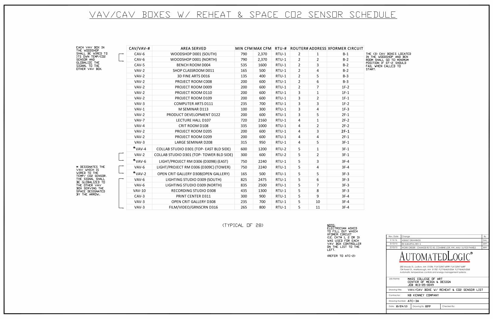
ATC-3A VAV/CAV BOXES WITH REHEAT & SPACE CO2 SCHEDULE
ATC-4 EXHIBIT HALL VAV BOXES WITH REHEAT & SPACE CO2
ATC-5 VAV BOXES WITH REHEAT, FTR & SPACE CO2
ATC-6 UNIT HEATERS & CABINET UNIT HEATER CONTROL
ATC-7 REMOVED
ATC-7A REMOVED
ATC-8 GENERAL EXHAUST FAN EF-1 & EF-2 CONTROL
ATC-8A ELECTRICAL ROOM EXHAUST FAN (EF-7) CONTROL
ATC-9 ELECT RM/ IT CLOSET EXHAUST FAN EF-3 & EF-4 CONTROL
ATC-10 ELEVATOR HOISTWAY VENT DAMPER CONTROL
ATC-11 AHU-1 & SPLIT AC-1 SYSTEM LAYOUT
ATC-12 PRINT SHOP MAU-1 & EXISTING EXHAUST FAN CONTROL
ATC-13 PRINT SHOP MAU-1 & EXISTING EXHAUST FAN CONTROL PANEL
ATC-14 PRINT SHOP MAU-1 SEQUENCE OF OPERATION
ATC-15 ROOFTOP UNIT RTU-1 CONTROL
ATC-16 ROOFTOP UNIT RTU-1 CONTROL PANEL
ATC-17 ROOFTOP UNIT RTU-2 CONTROL
ATC-18 ROOFTOP UNIT RTU-2 CONTROL PANEL
ATC-19 ROOFTOP UNITS RTU-1 & RTU-2 SEQUENCE OF OPERATION
ATC-20 REMOVED
ATC-21 REMOVED
ATC-22 REMOVED
ATC-23 REMOVED
ATC-24 REMOVED
ATC-25 HOT WATER SYSTEM CONTROL
ATC-26 HOT WATER SYSTEM CONTROL PANEL
ATC-27 HOT WATER SYSTEM SEQUENCE OF OPERATION
ATC-28 FUEL OIL SYSTEM LAYOUT
ATC-29 FUEL OIL SYSTEM CONTROL PANEL
ATC-30 WOODSHOP DUST COLLECTOR MONITORING
ATC-31 ELEVATOR MACHINE ROOM SPLIT AC-1 & CU-2 CONTROL
ATC-32 WIRING INSTRUCTION SHEET
DMP-1 DAMPER SCHEDULE (1-PAGE)
VLV-1 VALVE SCHEDULE (2-PAGES)

ROUTER# AREA SERVED # OF CONTROLLERS AAR ADDRESSROUTER # 2 BASEMENT VAV BOXES, UH'S, EF'S 17 2
BILL OF MATERIAL
SYMBOL QTY CATALOG NUMBER DESCRIPTION
C1 1 DELL LAPTOP INTEL CORETM 2 DUO, 2.6GHZ, DUAL CORE, 2.0 GB 667MHZ DRAM
512MB GRAPHICS CARD, 17" LCD DISPLAY, 80GB HARD DRIVE
24X CD‐RW/DVD,ETHERNET CARD
W1 1 DCP24-UL CONTROL PANEL ENCLOSURE
W2 1 PSH500A 120/24VAC XFORMER, (5) 100VA CIRCUITS
X1 1 LGR-250 ALC NETWORK CONTROLLER
X2 1 AAR ALC ARCNET ROUTER#3
3 BT485 ARCNET END‐OF‐LINE TERMINATORS
2 REP485 ALC ARCNET REPEATERS FOR MAIN ARCNET


BILL OF MATERIAL
SYMBOL QTY CATALOG NUMBER DESCRIPTION
W1 3 DCP16-UL CONTROL PANEL ENCLOSURE, 16" x 18"W2 3 PSC40AB10 120/24VAC XFORMER, 40VAX1 3 AAR ARCNET ROUTER
3 REP485 ARCNET REPEATERS7 BT485 ARCNET END-OF-LINE TERMINATORS
ROUTER# AREA SERVED # OF CONTROLLERS AAR ADDRESSROUTER # 3 1ST FLOOR (ALL ZN CARDS) 12 3
ROUTER # 4 2ND FLOOR (ALL ZN CARDS) 9 4
ROUTER # 5 3RD FLOOR/ ROOF 30 5

SEQUENCE OF OPERATION
FIRE ALARM INTERFACE MONITORING
The ALC system shall communicate to the fire alarm system (FAS) via a BACnet MSTP interface. Through this interface the ALC system shall be capable of monitoring the building fire/smoke alarms and damper fire/smoke damper positions. The ALC system shall monitor thefire/smoke damper positions and globalize them to the rooftop units (RTU-1 & RTU-2) controllers.

FLOOR XFORMER #CONTROLLERS
BSMT 300VA 19
1ST FLR 300VA 16
2ND FLR 300VA 12
3RD FLR 500VA 24
BILL OF MATERIAL
SYMBOL QTY CATALOG NUMBER DESCRIPTIONC1 17 ZN141V+ ALC ZN-LINE VAV SUPPLY BOX CONTROLLERP1 4 PSH300A 277/24VAC XFORMER, THREE 100VA CIRCUITST1 17 ZS PLUS SPACE TEMP SENSOR, SETPOINT ADJ & OCC OVRD SWT2 17 ALC/10K-2-D-8-NB-10' DUCT TEMP SENSOR. 8" PROBE 1000 OHM RTD @70DEGV1 17 SEE VALVE SCHEDULE 2 WAY HOT WATER VALVE, 2-10VDC MODULATING
VV/CV BOXES WITH HOT WATER REHEAT CONTROL
The VV/CV boxes shall be sequenced from the occupied to the unoccupied modeby a time of day program from the ALC system. An optimal start program shalldetermine the exact time, prior to the official start of the occupied mode, which each box will need to begin controlling so as to bring the space temperature to the occupied spacesetpoint by the start of the occupied mode. At this calculated time, the associated airhandling system shall start. If the boxes are calling for heat, the associated AHU shall runwith its outdoor air damper closed, recirculating air back to each VAV box, where it willbe heated by the box’s reheat coil. If the spaces are calling for cooling, the associatedAHU shall also start in a recirculation mode and the AHU DX cooling shall modulate to maintain a 55°F (adj.) discharge air setpoint. If the VAV box space temperature is belowthe space heating setpoint 73°F (adj.), the box damper shall position to its minimum CFMsetpoint and the box reheat coil valve shall open to maintain a maximum discharge air setpoint 14°F above the space temperature setpoint (adj.). If the space temperature isabove the space cooling setpoint 76°F (adj.), the box shall open so as to allow themaximum CFM setpoint. Once the space temperature has been driven to within the spaceheating and cooling setpoints, the occupied mode shall commence.
In the occupied mode, the box damper shall control based on the space setpoint.As the space temperature rises above the space cooling setpoint, the VAV box damper shall modulate open from the minimum CFM value up to the maximum CFM value toprovide space cooling. On a drop in space temperature below the space heating setpoint, the VAV box damper shall modulate closed to allow the minimum CFM value and the VAV box reheat valve shall modulate open, so as to maintain a discharge air setpoint which shall reset from 55°F to 90°F (max 14°F above the space setpoint) based on the offset of the space temperature from the space heating setpoint.
In the unoccupied mode, the VAV box damper shall close and box’s reheat coil valve shall close as well. If the space temperature should drop below the unoccupied space temperature setpoint 55°F (adj.), a signal shall be sent out to start the associaterooftop unit. The rooftop unit shall start as described above for the heating optimal startmode and all of the associated VV boxes served by the RTU shall open and shall control for their minimum CFM setpoints and the CV boxes shall open and shall control for theirfixed CFM setpoint. The box reheat coil valve shall open and shall remain open until thespace temperature has risen above the unoccupied space heating setpoint. Once the space temperature has risen above the unoccupied space setpoint, the VAV box reheat valve shall close. When all of the associated space temperatures have risen above theunoccupied setpoint, the RTU shall stop and the VV/CV box dampers shall close. An override button, located on each space sensor, shall place the room and the associated RTU into an occupied override mode for a 2-hour time period when the button is pressed.A night setback mode or cool-down mode shall operate in this fashion described above tocontrol for the night setback temperature setpoint.
If any space temperature should rise 5°F above the occupied cooling setpoint or5°F below the occupied heating setpoint for greater than 10-minutes, a temperature alarm shall be generated at the ALC system. If the CFM airflow rate should rise 10% above or10% below the calculated CFM setpoint for greater than 5-minutes, an airflow alarm shallbe generated by the ALC system.
CAV/VAV‐# AREA SERVED MIN CFMMAX CFM RTU‐# ROUTER# ADDRESSXFORMER CIRCUIT
CAV‐9 STORAGE D002C 135 400 RTU‐1 2 8 B‐1
CAV‐9 BUILDING STORAGE D010 135 400 RTU‐1 2 9 B‐2
CAV‐2 OFFICE D005 235 700 RTU‐1 2 10 B‐2
CAV‐9 HW PLANT D017 135 400 RTU‐1 2 11 B‐3
VAV‐9 CORRIDOR D007B 150 300 RTU‐1 2 12 B‐2
VAV‐2 CRIT GALLERY D106 165 500 RTU‐1 3 6 1E ‐1
VAV‐2 CD + M OFFICE D118 165 500 RTU‐1 3 7 1F‐1
VAV‐1 CONTROL ROOM D204 100 300 RTU‐1 4 6 2F‐1
VAV‐3 CRIT GALLERY D207 325 975 RTU‐1 4 7 2F‐2
VAV‐2 STORAGE D309B 35 100 RTU‐1 5 12 3F‐4
VAV‐1 CONTROL D310B 135 400 RTU‐1 5 13 3F‐3
CAV‐3 3D PRINTERS D311A 200 600 RTU‐1 5 14 3F‐4
VAV‐2 SIM INSTALLATION D317 100 300 RTU‐1 5 15 3F‐4
VAV‐5 COLLABRATIVE STUDIO 1 D123 500 1,500 RTU‐1 3 9 1F‐3
VAV‐5 MAIN LOBBY (MIDDLE‐TOWER BLD SIDE) 720 2160 RTU‐2 5 16 3F‐1
VAV‐5 MAIN LOBBY (BOTTOM‐TOWER BLD SIDE) 720 2160 RTU‐2 5 17 3F‐1
VAV‐5 MAIN LOBBY (BOTTOM‐EAST BLD SIDE) 720 2160 RTU‐2 5 19 3F‐1

FLOOR XFORMER #CONTROLLERS
BSMT 300VA 19
1ST FLR 300VA 16
2ND FLR 300VA 12
3RD FLR 500VA 24
VV/CV BOXES WITH HOT WATER REHEAT CONTROL
The VV/CV boxes shall be sequenced from the occupied to the unoccupied modeby a time of day program from the ALC system. An optimal start program shalldetermine the exact time, prior to the official start of the occupied mode, which each box will need to begin controlling so as to bring the space temperature to the occupied spacesetpoint by the start of the occupied mode. At this calculated time, the associated airhandling system shall start. If the boxes are calling for heat, the associated AHU shall runwith its outdoor air damper closed, recirculating air back to each VAV box, where it willbe heated by the box’s reheat coil. If the spaces are calling for cooling, the associatedAHU shall also start in a recirculation mode and the AHU DX cooling shall modulate to maintain a 55°F (adj.) discharge air setpoint. If the VAV box space temperature is belowthe space heating setpoint 73°F (adj.), the box damper shall position to its minimum CFMsetpoint and the box reheat coil valve shall open to maintain a 90°F discharge air temperature setpoint (adj.). If the space temperature is above the space cooling setpoint76°F (adj.), the box shall open so as to allow the maximum CFM setpoint. Once the space temperature has been driven to within the space heating and cooling setpoints, theoccupied mode shall commence.
In the occupied mode, the box damper shall control based on the space setpoint.As the space temperature rises above the space cooling setpoint, the VAV box damper shall modulate open from the minimum CFM value up to the maximum CFM value toprovide space cooling. On a drop in space temperature below the space heating setpoint, the VAV box damper shall modulate closed to allow the minimum CFM value and the VAV box reheat valve shall modulate open, so as to maintain a discharge air setpoint which shall reset from 55°F to 90°F adj. (max 14°F above the space setpoint) based on the offset of the space temperature from the space heating setpoint.
If the space CO2 level should rise above 1000 ppm (adj.), the VAV box controllershall gradually increase the VAV boxes’ minimum CFM setpoint, up as high as themaximum CFM setpoint for each box, until the CO2 level has dropped below setpoint.During the high CO2 mode, the reheat coil valve shall open, as required, so as to maintain the space temperature setpoint. Once the CO2 level has dropped below setpoint,the minimum CFM setpoint shall revert back to its original setting.
In the unoccupied mode, the VAV box damper shall close and box’s reheat coil valve shall close as well. If the space temperature should drop below the unoccupied space temperature setpoint 55°F (adj.), a signal shall be sent out to start the associaterooftop unit. The rooftop unit shall start as described above for the heating optimal start mode and all of the associated VV boxes served by the RTU shall open and shall control for their minimum CFM setpoints and the CV boxes shall open and shall control for theirfixed CFM setpoint. The box reheat coil valve shall open and shall remain open until the space temperature has risen above the unoccupied space heating setpoint. Once the space temperature has risen above the unoccupied space setpoint, the VAV box reheat valve shall close. When all of the associated space temperatures have risen above the unoccupied setpoint, the RTU shall stop and the VV/CV box dampers shall close. An override button, located on each space sensor, shall place the room and the associated RTU into an occupied override mode for a 2-hour time period when the button is pressed. A night setback or cool-down mode shall operate in this fashion described above tocontrol for the night setback temperature setpoint.
The Woodshop is served by two VAV boxes, (both VAV-6), that share (2) temperature/ CO2 sensors. The temperature/ CO2 sensor located by the (D004A Vest.)shall be wired to the VAV box beside it and globalize it’s signal to the other VAV-6 box. The temperature/ CO2 sensors located by the (Mech. Crawl space) shall be wired to thesecond VAV and globalize its signal to the first VAV.
If any space temperature should rise 5°F above the occupied cooling setpoint or5°F below the occupied heating setpoint for greater than 10-minutes, a temperature alarm shall be generated at the ALC system. If the CFM airflow rate should rise 10% above or 10% below the calculated CFM setpoint for greater than 5-minutes, an airflow alarm shallbe generated by the ALC system. The (3) CAV boxes located in the Woodshop andBench room should close if EF-2 should fail when called to start.
BILL OF MATERIAL
SYMBOL QTY CATALOG NUMBER DESCRIPTIONC1 28 ZN141V+ ALC ZN‐LINE VAV SUPPLY BOX CONTROLLER
CO2 25 TR9294‐A‐L SPACE CO2 SENSOR. 0‐5VDC = 0‐2000 PPM, AIRTEST
P1 1 PSH500A 120/24VAC XFORMER, FIVE 100VA CIRCUITS
T1 25 ZS PLUS SPACE TEMP SENSOR, SETPOINT ADJ & OCC OVRD SW
T2 28 ALC/10K‐2‐D‐8‐NB‐10' DUCT TEMP SENSOR, 8" PROBE 1000 OHM RTD @70DEG
V1 28 SEE VALVE SCHEDULE 2 WAY HOT WATER VALVE, 2‐10VDC MODULATING
CAV/VAV‐# AREA SERVED MIN CFMMAX CFM RTU‐# ROUTER# ADDRESS XFORMER CIRCUIT
CAV‐6 WOODSHOP D001 (SOUTH) 790 2,370 RTU‐1 2 1 B‐1
CAV‐6 WOODSHOP D001 (NORTH) 790 2,370 RTU‐1 2 2 B‐2
CAV‐5 BENCH ROOM D004 535 1600 RTU‐1 2 3 B‐2
VAV‐2 SHOP CLASSROOM D011 165 500 RTU‐1 2 4 B‐2
VAV‐2 3D FINE ARTS D016 135 400 RTU‐1 2 5 B‐3
VAV‐2 PROJECT ROOM C008 200 600 RTU‐1 2 6 B‐3
VAV‐2 PROJECT ROOM D009 200 600 RTU‐1 2 7 1F‐2
VAV‐2 PROJECT ROOM D110 200 600 RTU‐1 3 1 1F‐1
VAV‐2 PROJECT ROOM D109 200 600 RTU‐1 3 2 1F‐1
VAV‐3 COMPUTER ARTS D111 235 700 RTU‐1 3 3 1F‐2
VAV‐1 M SEMINAR D113 100 300 RTU‐1 3 4 1F‐3
VAV‐2 PRODUCT DEVELOPMENT D122 200 600 RTU‐1 3 5 2F‐1
VAV‐7 LECTURE HALL D107 720 2160 RTU‐1 4 1 2F‐2
VAV‐4 CRIT ROOM D108 335 1000 RTU‐1 4 2 2F‐2
VAV‐2 PROJECT ROOM D205 200 600 RTU‐1 4 3 2F‐1
VAV‐2 PROJECT ROOM D209 200 600 RTU‐1 4 4 2F‐1
VAV‐3 LARGE SEMINAR D208 315 950 RTU‐1 4 5 3F‐1
*VAV‐4 COLLAB STUDIO D301 (TOP‐ EAST BLD SIDE) 600 1200 RTU‐2 5 1 3F‐1
VAV‐2 COLLAB STUDIO D301 (TOP‐ TOWER BLD SIDE) 300 600 RTU‐2 5 2 3F‐1
*VAV‐6 LIGHT/PROJECT RM D306 (D309B) (EAST) 750 2240 RTU‐1 5 3 3F‐4
VAV‐6 LIGHT/PROJECT RM D306 (D309C) (TOWER) 750 2240 RTU‐1 5 4 3F‐4
*VAV‐2 OPEN CRIT GALLERY D308(OPEN GALLERY) 165 500 RTU‐1 5 5 3F‐3
VAV‐6 LIGHTING STUDIO D309 (SOUTH) 825 2475 RTU‐1 5 6 3F‐3
VAV‐6 LIGHTING STUDIO D309 (NORTH) 835 2500 RTU‐1 5 7 3F‐3
VAV‐10 RECORDING STUDIO D308 435 1300 RTU‐1 5 8 3F‐3
CAV‐3 PRINT CENTER D311 300 900 RTU‐1 5 9 3F‐4
VAV‐3 OPEN CRIT GALLERY D308 235 700 RTU‐1 5 10 3F‐4
VAV‐3 FILM/VIDEO/GRNSCRN D316 265 800 RTU‐1 5 11 3F‐4

BILL OF MATERIAL
SYMBOL QTY CATALOG NUMBER DESCRIPTIONC1 3 ZN141V+ ALC ZN‐LINE VAV SUPPLY BOX CONTROLLER
CO2 2 TR9294‐A‐L SPACE CO2 SENSOR, 0‐5VDC = 0‐2000 PPM, AIRTEST
P1 1 PSC100AB10 120/24VAC XFORMER, 100VA
T1 2 ZS PLUS SPACE TEMP SENSOR, SETPOINT ADJ & OCC OVRD SW
T2 3 ALC/10K‐2‐D‐8‐NB‐10' DUCT TEMP SENSOR. 8" PROBE 1000 OHM RTD @70DEG
V1 3 SEE VALVE SCHEDULE 2 WAY HOT WATER VALVE, 2‐10VDC MODULATING
VAV‐# AREA SERVED MIN CFM MAX CFM RTU‐# ROUTER# ADDRESS
*VAV‐5 *EXHIBIT HALL (SOUTH/ ENTRY SIDE) 720 2160 RTU‐2 5 20
VAV‐5 EXHIBIT HALL (MIDDLE) 720 2160 RTU‐2 5 21
*VAV‐5 *EXHIBIT HALL (NORTH BALCONY SIDE) 720 2160 RTU‐2 5 22
A night setback or cool-down mode shall operate in this fashion described above tocontrol for the night setback temperature setpoint.
If any space temperature should rise 5°F above the occupied cooling setpoint or5°F below the occupied heating setpoint for greater than 10-minutes, a temperature alarm shall be generated at the ALC system. If the CFM airflow rate should rise 10% above or10% below the calculated CFM setpoint for greater than 5-minutes, an airflow alarm shallbe generated by the ALC system.
VV/CV BOXES WITH HOT WATER REHEAT CONTROL
The VV/CV boxes shall be sequenced from the occupied to the unoccupied modeby a time of day program from the ALC system. An optimal start program shalldetermine the exact time, prior to the official start of the occupied mode, which each boxwill need to begin controlling so as to bring the space temperature to the occupied spacesetpoint by the start of the occupied mode. At this calculated time, the associated airhandling system shall start. If the boxes are calling for heat, the associated AHU shall runwith its outdoor air damper closed, recirculating air back to each VAV box, where it willbe heated by the box’s reheat coil. If the spaces are calling for cooling, the associatedAHU shall also start in a recirculation mode and the AHU DX cooling shall modulate tomaintain a 55°F (adj.) discharge air setpoint. If the VAV box space temperature is belowthe space heating setpoint 73°F (adj.), the box damper shall position to its minimum CFMsetpoint and the box reheat coil valve shall open to maintain a maximum discharge airsetpoint 14°F above the space temperature setpoint (adj.). If the space temperature isabove the space cooling setpoint 76°F (adj.), the box shall open so as to allow themaximum CFM setpoint. Once the space temperature has been driven to within the spaceheating and cooling setpoints, the occupied mode shall commence.
In the occupied mode, the box damper shall control based on the space setpoint.As the space temperature rises above the space cooling setpoint, the VAV box damper shall modulate open from the minimum CFM value up to the maximum CFM value toprovide space cooling. On a drop in space temperature below the space heating setpoint, the VAV box damper shall modulate closed to allow the minimum CFM value and the VAV box reheat valve shall modulate open, so as to maintain a discharge air setpoint which shall reset from 55°F to 90°F (max 14°F above the space setpoint) based on the offset of the space temperature from the space heating setpoint.
If the space CO2 level should rise above 1000 ppm (adj.), the VAV box controllershall gradually increase the VAV boxes’ minimum CFM setpoint, up as high as themaximum CFM setpoint for each box, until the CO2 level has dropped below setpoint.During the high CO2 mode, the reheat coil valve shall open, as required, so as tomaintain the space temperature setpoint. Once the CO2 level has dropped below setpoint,the minimum CFM setpoint shall revert back to its original setting.
In the unoccupied mode, the VAV box damper shall close and box’s reheat coil valve shall close as well. If the space temperature should drop below the unoccupied space temperature setpoint 55°F (adj.), a signal shall be sent out to start the associaterooftop unit. The rooftop unit shall start as described above for the heating optimal startmode and all of the associated VV boxes served by the RTU shall open and shall control for their minimum CFM setpoints and the CV boxes shall open and shall control for theirfixed CFM setpoint. The box reheat coil valve shall open and shall remain open until thespace temperature has risen above the unoccupied space heating setpoint. Once the space temperature has risen above the unoccupied space setpoint, the VAV box reheat valve shall close. When all of the associated space temperatures have risen above theunoccupied setpoint, the RTU shall stop and the VV/CV box dampers shall close. An override button, located on each space sensor, shall place the room and the associated RTU into an occupied override mode for a 2-hour time period when the button is pressed.

BILL OF MATERIAL
SYMBOL QTY CATALOG NUMBER DESCRIPTIONC1 2 ZN341V+ ALC ZN-LINE VAV SUPPLY BOX CONTROLLERCO2 2 TR9294-A-L SPACE CO2 SENSOR, 0-5VDC = 0-2000 PPM, AIRTESTT1 2 ZS PLUS SPACE TEMP SENSOR, SETPOINT ADJ & OCC OVRD SW T2 2 ALC/10K-2-D-8-NB-10' DUCT TEMP SENSOR. 8" PROBE, 1000 OHM RTD @70DEGV1 2 SEE VALVE SCHEDULE 2 WAY HOT WATER VALVE, 2-10VDC MODULATINGV2 3 SEE VALVE SCHEDULE 2 WAY FTR VALVE, FLOATING, N.O.
FLOOR XFORMER #CONTROLLERS
BSMT 300VA 19
1ST FLR 300VA 16
2ND FLR 300VA 12
3RD FLR 500VA 24
VAV BOXES WITH HW REHEAT, RADIATION & CO2 CONTROL
The VV/CV boxes shall be sequenced from the occupied to the unoccupied modeby a time of day program from the ALC system. An optimal start program shalldetermine the exact time, prior to the official start of the occupied mode, which each box will need to begin controlling so as to bring the space temperature to the occupied spacesetpoint by the start of the occupied mode. At this calculated time, the associated airhandling system shall start. If the boxes are calling for heat, the associated AHU shall runwith its outdoor air damper closed, recirculating air back to each VAV box, where it willbe heated by the box’s reheat coil. If the spaces are calling for cooling, the associatedAHU shall also start in a recirculation mode and the AHU DX cooling shall modulate to maintain a 55°F (adj.) discharge air setpoint. If the VAV box space temperature is belowthe space heating setpoint 73°F (adj.), the box damper shall position to its minimum CFMsetpoint and the box reheat coil valve shall open to maintain a maximum discharge air setpoint 14°F above the space temperature setpoint (adj.). If the space temperature is above the space cooling setpoint 76°F (adj.), the box shall open so as to allow themaximum CFM setpoint. Once the space temperature has been driven to within the spaceheating and cooling setpoints, the occupied mode shall commence.
In the occupied mode, the box damper shall control based on the space setpoint.As the space temperature rises above the space cooling setpoint, the VAV box damper shall modulate open from the minimum CFM value up to the maximum CFM value toprovide space cooling. On a drop in space temperature below the space heating setpoint,the VAV box damper shall modulate closed to allow the minimum CFM value and the space radiation valve(s) shall modulate to maintain the space heating setpoint. On acontinued drop below the space heating setpoint, the VAV box reheat valve shall modulate open, so as to maintain a discharge air setpoint which shall reset from 55°F to90°F (max 14°F above the space setpoint) based on the offset of the space temperaturefrom the space heating setpoint.
If the space CO2 level should rise above 1000 ppm (adj.), the VAV box controllershall gradually increase the VAV boxes minimum CFM setpoint, up as high as themaximum CFM setpoint for each box, until the CO2 level has dropped below setpoint.During the high CO2 mode, the reheat coil valve shall open, as required, so as tomaintain the space temperature setpoint. Once the CO2 level has dropped below setpoint,the minimum CFM setpoint shall revert back to its original setting.
In the unoccupied mode, the VAV box damper shall close and box’s reheat coil valve shall close as well. If the space temperature should drop below the unoccupied space temperature setpoint 58°F (adj.), the room radiation valve shall open. If the spacetemperature should continue to drop below 55°F, a signal shall be sent out to start theassociate rooftop unit. The rooftop unit shall start as described above for the heatingoptimal start mode and all of the associated VV boxes served by the RTU shall open and shall control for their minimum CFM setpoints. The box reheat coil valve shall open andshall remain open until the space temperature has risen above the unoccupied spaceheating setpoint. Once the space temperature has risen above the unoccupied space setpoint, the VAV box reheat valve shall close. When all of the associated spacetemperatures have risen above the unoccupied setpoint, the AHU shall stop and the VVbox dampers shall close. An override button, located on each space sensor, shall place theroom and the associated AHU into an occupied override mode for a 2-hour time period when the button is pressed. A night setback mode or cool-down mode shall operate in thisfashion as described above to control for the night setback temperature setpoint.
If any space temperature should rise 5°F above the occupied cooling setpoint or5°F below the occupied heating setpoint for greater than 10-minutes, a temperature alarm shall be generated at the ALC system. If the CFM airflow rate should rise 10% above or10% below the calculated CFM setpoint for greater than 5-minutes, an airflow alarm shall be generated by the ALC system.
The VAV boxes serving the Main Lobby consist of (2) vertical columns, each with (3) VAV’s stacked one on top of the other (see diagram). The (middle and bottom) VAV’s in each stack (4 total) serve the Main Lobby. The (top) VAV box serves the Collaborative studio II (not shown on this drawing). The Main Lobby is also served by (4) fin-tube radiations that are located along the perimeter of southern/ entry side of the Main Lobby and on the wall facing the Tower building. The middle VAV in the stack closest to the East Building shall be wired to the space temperature and CO2 sensor located in the Main Lobby which shall then globalize its signal to each of the other (3) VAV’s serving the Main Lobby.
VAV-# AREA SERVED MIN CFM MAX CFM RTU-# ROUTER# ADDRESS XFORMER CIRCUIT
VAV-5 *MAIN LOBBY(MIDDLE-EAST BLD SIDE) 865 2,160 RTU-2 5 18
VAV-5 *COLLABRATIVE STUDIO 1 D123(DOOR SIDE) 600 1,500 RTU-1 3 8

BILL OF MATERIAL
SYMBOL QTY CATALOG NUMBER DESCRIPTION
C1-C2 5 ZN220 ALC ZN-LINE CONTROLLER. 2AI, 2 DOR1-R2 5 RIB2401C 24VAC RELAY, SPDTT1-T2 3 ZS BASE SPACE TEMP SENSORT3 2 ALC/10K-2-D-8-NB-10 DUCT TEMP SENSOR, 8" PROBEV1-V2 5 SEE VALVE SCHEDULE UH/CUH VALVE, 24VAC FAIL OPEN
SEQUENCE OF OPERATION CABINET UNIT HEATER & UNIT HEATER CONTROL
The cabinet unit heaters (CUH’s) and unit heater (UH) shall be sequenced from the occupied to the unoccupied mode by a time of day schedule at the ALC system. In the occupied mode, the unit heater shall start so as to maintain the occupied space temperature setpoint 73°F (adj.). The space heating setpoint for the UH’s located in the air plenum D000A shall be 85°F (adj.). On a call for heating, the HW valve shall open and the heater fan shall start. The unit shall run in this fashion until the space temperature has risen above the space setpoint for 5-minutes (adj.).
In the unoccupied mode, the unit heaters and cabinet unit heaters shall operate in the fashion as described above so as to maintain the unoccupied space temperaturesetpoint (adj.). The ALC system shall transmit a signal to each unit heater and caninetunit heater controller, indicating whether hot water is available. If hot water is notavailable, the unit heater and cabinet unit heater fans shall not be allowed to run.
FLOOR XFORMER #CONTROLLERS
BSMT 300VA 19
1ST FLR 300VA 16
2ND FLR 300VA 12
3RD FLR 500VA 24
UH‐# AREA SERVED ROUTER #ADDRESS
CUH‐1 ENTRY D102 2 13
CUH‐2 EXISTING STAIR A DSA‐1 3 10
*CUH‐3 *LOBBY D121 3 11
UH‐# AREA SERVED ROUTER # ADDRESS
*UH‐1 *BSMNT AIR PLENUM D000A 2 14
*UH‐1 *BSMNT AIR PLENUM D000A 2 15

ROOFTOP EXHAUST FANS EF-1 & EF-2 CONTROL The exhaust fans EF-1 & EF-2 shall be sequenced from the occupied to unoccupied mode to run concurrently with the occupied and unoccupied mode of RTU-1. EF-1 & EF-2 shall be disabled whenever RTU-1 is not running.
In the occupied mode, when RTU-1 is running, the ALC system shall send a command to start EF-1 & EF-2. Both EF-1 and EF-2 shall be wired to open their respective damper when called to start. Once the damper positions has been proven open by the respective damper switch, EF-1 & EF-2 shall start. EF-1 shall run at a constant speed, as determined by the testing and Balancing Contractor. Exhaust fan EF-2 shallstart at its minimum VFD speed and ramp up, as required to maintain the minimumexhaust air CFM setpoint, as determined by the Testing and Balancing Contractor.
A CV box located in the woodshop (CAV-6 North) shall monitor the dust collector exhaust fan status. The status of the dust collector exhaust fan shall be globalized from CAV-6 North to the EF-2 controller. If the dust collection system is called to run, EF-2 shall be disabled until the dust collection system is de-energized. Upon de-energizing the dust collection system, EF-2 shall be started and run in the occupied mode. If EF-2 should fail when called to start, the (3) CAV boxes (CAV-9, CAV-9 & CAV-5) serving the woodshop and bench room shall go to their closedpositions.
In the unoccupied mode (when RTU-1 is off), both EF-1 and EF-2 shall be off and their dampers closed.
Duct smoke detectors located in the supply and return ducts of RTU-1 shall shutdown the unit if a fire/ smoke condition exists. Upon shutdown of RTU-1, a signal shall be globalized and sent to EF-1 & EF-2 to shutdown. If any fan fails to start when commanded on, a fail failure alarm shall be generated by the ALC system.
BILL OF MATERIAL
SYMBOL QTY CATALOG NUMBER DESCRIPTION
C1 1 ZN220 ALC ZN‐LINE CONTROLLER, 2 DO, 2 IN
C2 1 ZN551 ALC ZN‐LINE CONTROLLER, 5 IN, 5 DO, 1 AO
2 ENCLOSURE 12"X12" ENCLOSURE
D1 2 SEE DAMPER SCHEDULE EXHAUST AIR DAMPER
DA1 2 NFB24‐S EXHAUST AIR DAMPER ACTUATOR, 24VAC, SWITCH
P1 1 PSC100AB10 120/24VAC TRANSFORMER, 100VA
R1‐R2 2 RIB2401C 24VAC RELAY, SPDT
VF1 1 BY OTHERS EXHAUST AIR FAN VFD
EF-# AREA SERVED CFM'S ROUTER# ADDRESS
EF‐1 BATHROOM/ J.C (FLOORS 1‐3) 4000 5 23
EF-# AREA SERVED CFM'S ROUTER# ADDRESS
EF‐2 WOODSHOP D002 7000 5 24

EF-# AREA SERVED CFM'S ROUTER# ADDRESS
EF‐7 ELEC. D318 200 5 28
EF‐7 EOPM. D309D 200 5 29
ROOFTOP EXHAUST FANS EF-1 & EF-2 CONTROL The exhaust fans shall be started and stopped based on the space temperature. Ifthe space temperature rises above 85°F(adj.), the corresponding exhaust fan shall start. The fan shall run until the space temperature has dropped below 83°F(adj.).
The ALC system shall send a command to start the exhaust fan. EF-7 dampershall be wired to start their respective EF when called to open. Once both supply and exhaust damper positions have been proven open by their hard wire interlock, EF-7 shall start. EF-7 shall run at a constant speed, as determined by the testing and BalancingContractor.
If any fan fails to start when commanded on, a fail failure alarm shall begenerated by the ALC system. If the space temperature should rise above 90°F or drop below 60°F, a room temperature alarm shall be generated by the ALC system. If the either of the fans start without a command from the ALC system, an EF hand start alarm shall be generated by the ALC system.
BILL OF MATERIAL
SYMBOL QTY CATALOG NUMBER DESCRIPTION
C1 2 ZN220 ALC ZN‐LINE CONTROLLER, 2 DO, 2 IN
2 ENCLOSURE 12"X12" ENCLOSURE
CS1 2 H‐922 CURRENT SENSOR, 0‐5VDC, VERIS
D1 2 SEE DAMPER SCHEDULE EXHAUST AIR DAMPER (8" X 8")
D2 2 SEE DAMPER SCHEDULE SUPPLY AIR DAMPER (8" X 8")
DA1‐DA2 4 TFB24‐S EXHAUST AIR DAMPER ACTUATOR, 24VAC, SWITCH
P1 1 PSC100AB10 120/24VAC TRANSFORMER, 100VA
R1‐R2 4 RIB2401C 24VAC & 120VAC RELAY, SPDT
T1 2 ZS‐ALC SPACE TEMP SENSOR, BASE

ELECTRICAL ROOM/ IT CLOSET EXHAUST FANS EF-3 & EF-4 CONTROL
The electrical room and IT closet exhaust fans shall be started and stopped based on the space temperature. If the space temperature rises above 85°F (adj.), the room’s exhaust fan shall run until the space temperature drops below 80°F (adj.). If the spacetemperature rises 10°F above the space temperature setpoint (82°F (adj.) a high temperature alarm shall be generated by the ALC system.
EF-# AREA SERVED FLOOR CFM'S ROUTER# ADDRESSEF-4 IT CLOSET D012B BSMT 250 2 17EF-3 ELECT CLOSET D119 1ST GYM 200 3 14EF-3 ELECT CLOSET D214B 2ND GYM 200 4 9EF-3 ELCT CLOSET D318 3RD GYM 200 5 25EF-4 SECURITY D315A 3RD GYM 250 5 26
FLOOR XFORMER #CONTROLLERS
BSMT 300VA 19
1ST FLR 300VA 16
2ND FLR 300VA 12
3RD FLR 500VA 24
BILL OF MATERIAL
SYMBOL QTY CATALOG NUMBER DESCRIPTION
C1 5 ZN220 ALC ZN‐LINE CONTROLLER, 2 DO'S & 2 IN'S
5 ENCLOSURE 12" X 12" ENCLOSURE FOR ZN MODULE
CS1 5 RIBXGTA CURRENT SWITCH, ADJ SETPOINT
R1 5 RIB2401C 24VAC RELAY, SPDT
T1 5 ZS BASE SPACE TEMP SENSOR

BILL OF MATERIAL
SYMBOL QTY CATALOG NUMBER DESCRIPTION
C1 1 ZN220 ALC ZN‐LINE CONTROLLER, 2 BO'S, 2 IN'S
1 ENCLOSURE 12" X 12" ENLCOSURE
FA1 1 BY OTHERS FIRE ALARM SYSTEM RELAY MODULE N.C.
D1 1 SEE DAMPER SCHEDULE ELEVATOR SHAFT RELIEF DAMPER
DA1 1 LFB24‐S DAMPER ACTUATOR, 24VAC, N.O., SW
P1 1 PSC40AB10 120/24VAC XFORMER, 40VA
T1 1 ZS BASE SPACE TEMP SENSOR
AREA SERVED ROUTER ADDRESS
ELEVATOR HOISTWAY 5 27
SEQUENCE OF OPERATION ELEVATOR HOISTWAY RELIEF DAMPER CONTROL
The Elevator shaft relief damper shall be controlled by the Fire Alarm system. If a smoke or fire condition is detected in the building, or if the temperature at the top of the elevator shaft should rise above 85°F (adj.), the normally open elevator shaft relief damper shall spring return open. If normal building power is lost, the damper shall also spring return open. Once the smoke condition has been cleared and the space temperature has dropped below 75°F (adj.), the damper shall close.
The ALC system shall monitor the damper positions and shall alarm on an off-normal condition.

AIR HANDLING UNIT AHU-1 & CONDENSER UNIT CU-1 CONTROL
The air handling unit AHU-1 shall typically run 24/7 to provide space cooling to the Sub-Station room D018. If the space temperature rises above the space temperature setpoint 85°F(adj.), AHU-1 and the outdoor condenser (CU-1) shall be started to provide DX cooling. If the space temperature rises to 90°F, stage 2 and CU-2 shall become energized. Once the space temperature drops below 82°F (adj.), CU-1 and CU-2 shall be disabled. AHU-1 shall continue to run for a 2-minute time period before cycling off. A duct smoke detector located in the return duct of AHU-1 shall disable the supply fan and the condenser unit if a smoke condition exists. Upon a smoke condition a smoke alarm shall be generated by the ALC system. If the space temperature rises 5°F above or drops 5°F below (adj.) the space temperature setpoint, the ALC system shall generate a high or low temperature alarm. If AHU-1 fails to start when commanded on, a fan failure alarm shall be generated by theALC system.
BILL OF MATERIAL
SYMBOL QTY CATALOG NUMBER DESCRIPTION
CS1 1 RIBXGTA CURRENT SWITCH, ADJ
DP1 1 ZPS-05-SR72-ST-BB-D AHU-1 DP SENSORS, 0 to 5.0" W.C.= 0-5V
FA1 1 BY OTHERS FIRE ALARM SYSTEM SHUTDOWN RELAY N.C.
R1-R3 2 RIB2401C RELAY, 24VAC, SPDT
SD1 1 BY OTHERS DUCT SMOKE DETECTORS, N.C., SPST
T1 1 ZS PLUS SPACE TEMP SENSOR, SETPOINT ADJ & OCC OVERRIDE SW
T2 1 ALC/10K-2-D-8-NB-10' DUCT EMP SENSOR, 8" PROBE 1000 OHM RTD @ 70 DEG
X1 1 ZN551 ALC ZN-LINE CONTROLLER 5 DI, 5 DO, 1 AO
X2 1 RH2B-ULAC24V RELAY, 24VAC, 2PDT
SH2B-05 RELAY SUBBASE

BILL OF MATERIAL
SYMBOL QTY CATALOG NUMBER DESCRIPTION
AF1 1 ELECTRA-flo/FI THERMAL FAN INLET FLOW STATION, AIR MONITOR, 0-10VDC OUTCS1 1 RIBXGTA CURRENT SWITCH, ADJ. SETPOINTD1 1 BY OTHERS OA DAMPER, COMING WITH THE JCI UNITD2 1 BY OTHERS SUPPLY AIR ISO DAMPERD3 1 See Damper schedule EXHAUST FAN DAMPER, PARALLEL BLADESDA1 1 NFB24-S DAMPER ACTUATOR, 24VAC 2-POS, SPRING SWITCHDA2 1 BY OTHERS SMOKE DAMPER ACTUATOR, 120VAC, SPRING, SWITCHDA3 1 NFB24-S DAMPER ACTUATOR, 24VAC 2-POS, SPRING SWITCHDP1-DP2 2 ZPS-05-SR72-ST-BB-D DP SENSOR, 0 to 2.0" W.C., 0-5VDC, BAPI, LCDFA1 1 BY OTHERS FIRE ALARM SYSTEM SHUTDOWN RELAYP1 1 ZPS-ACC-01 STAINLESS STEEL WALL PLATE PRESSURE PORTR1-R4 4 RIB2401C RELAY, SPDT, 24VAC, RIBSD1 1 BY OTHERS DUCT SMOKE DETECTORS, BY DIV 2600SS1-SS2 2 AFS-460 DUCT HI PRESSURE SAFETY SWITCH, MAN RESET, CLEVELANDT1 1 ALC/10K-2-O-BB OUTDOOR AIR TEMP SENSORT2 2 ALC/10K-2-D-12-BB DUCT TEMP SENSOR,12" PROBET3 1 ZS PLUS SPACE TEMP SENSOR WITH OCC OVRD SW, SETPT AD. & LCDV1 1 EXISTING 2-WAY FTR CONTROL VALVE, 2-10VDC, N.O.VF1-VF2 1 BY OTHERS JCI FAN VFD FOR MAU-1

BILL OF MATERIAL
SYMBOL QTY CATALOG NUMBER DESCRIPTION
W1 1 DCP20-UL CUSTOM CONTROL PANEL, 20" W x 24" HX1 1 SE6166 ALC SE-LINE CONTROLLER, 6 BO'S, 16 IN'S & 6 AO'SX2-X5 4 RH2B-ULAC24V RELAY, 24VAC, DPDT
4 SH2B-05 RELAY SUBBASEX6 1 AMR BACNET COMMUNICATION CONTROLLER FOR MAU VFDX7 1 ZPS-05-L56-EZ-NT PRESSURE SENSOR, -.10" TO +.10" W.C. = 0-5VDC, BAPIW2 1 PSH300A (3) 100 VA 24VAC POWER SUPPLIES, 12" x 12" ENCLOSURE

MAU-1 & EXISTING EXHAUST FAN CONTROL
The make up air unit MAU-1 and the associated exhaust fan shall be sequencedfrom the occupied to the unoccupied mode based on a time of day schedule from theALC system. The system shall also be capable of starting manually from the MAU-1 VFD by placing it in the Hand position at the drive. When the unit is under control of anoccupancy schedule, an optimal start mode shall determine the exact time, prior to theofficial start of the occupied mode, which the MAU-1 unit and the room’s fintuberadiation heating valves, will need to come under control so as to raise the spacetemperature to the occupied space setpoint by the official start of the occupied mode. Atthis calculated time, if the space temperature is below the occupied space heatingsetpoint, the fintube radiation valve(s) shall open 100%. The ALC system shall send astart command to the MAU-1 supply fan VFD. Upon receipt of this start command, theVFD shall send a signal to open the MAU outdoor air damper and the discharge airsmoke damper. Once both dampers have been proven open by their position switches, theMAU-1 supply fan shall start at its minimum VFD speed. The speed of the MAU supplyfan shall then ramp-up so as to provide the rated CFM for the system, as determined bythe system Testing and Balancing contractor. The MAU gas heat shall come undercontrol from the ALC system so as to maintain an 85°F discharge air setpoint. Once thespace temperature has risen to the space heating setpoint, the optimal start mode shall endand the occupied mode shall begin.
Whenever MAU is started, either by the ALC system or manually from the MAU-1 VFD, the associate exhaust fan shall also start so as to exhaust the space. When theexhaust fan is needed to run, the fan’s exhaust air damper shall be powered open. Oncethe damper is proven open by the damper’s position switch, the exhaust fan shall start andshall run continuously for as long as the MAU-1 supply fan is in operation. If the exhaustfan is manually started from its motor starter HOA switch, the exhaust damper shallpower open once the motor starter coil is energized.
In the occupied mode, the ALC system shall monitor the space pressure andmodulate the supply fan speed so as to maintain a slightly negative space pressure of0.05” W.C. (adj.). The exhaust fan shall continue to operate at its preset speed. The MAU-1 gas heat shall be controlled so as to maintain a discharge air setpoint, which shallbe reset based on the offset of the space temperature from the space temperature setpoint.The intent for this area is for the fintube radiation to provide the 1st stage of heating forthe space and for the MAU-1 system to add any additional heating required to raise thespace temperature to setpoint during the colder periods. If the space temperature is beingmaintained within 2°F below the space heating setpoint, the MAU-1 system shallmaintain a fixed 60°F (adj.) discharge air setpoint. As the space temperature drops belowthe space temperature setpoint, the fintube radiation valve(s) shall modulate open. If thefintube radiation valve(s) are 100% open (at 2°F below setpoint) and the spacetemperature continues to remain below the space heating setpoint, the MAU-1 discharge air setpoint shall be reset from 70°F to 80°F (adj.) as the space temperature drops from2°F to 4°F below setpoint (adj.). On a rise in the space temperature, the opposite shalloccur.
MAU-1 & EXISTING EXHAUST FAN CONTROL (cont.)
In the unoccupied mode, the MAU-1 supply fan shall stop, the outdoor air and discharge air smoke dampers shall close and the gas heat shall be de-energized. The exhaust fan shall stop and the exhaust air damper shall close. The fintube radiation valve(s) shall close. If the space temperature should drop below the unoccupied space heating setpoint (60°F adj.), the fintube radiation valve(s) shall open. Once the space temperature has risen above 62°F, the radiation valves shall close.
A duct smoke detector, located in the discharge air duct, shall stop both fans, close the dampers and de-energize the MAU gas heating if a smoke condition is sensed. The smoke alarm will be reported at the ALC system. The smoke detector will have to be reset from the fire alarm system before the unit will be allowed to restart. Low and high pressure safety switches, piped before and after the MAU-1 supply fan, shall stop the fans, close the dampers and de-energize the gas heating if a high or low pressure condition should exist. An MAU-1 fan pressure alarm shall be generated at the ALC system. The tripped pressure switch will have to be manually reset at the switch before the fan systems will be allowed to restart. If the MAU discharge air temperature should drop below 45°F for greater than 2-minutes, or if the discharge air temperature should rise above 105°F for greater than 2-minutes (adj.), the fans shall stop, as previously described, and a MAU low or high temperature alarm shall be generated at the ALC system. A manual software point at the ALC system will need to be reset before the fan system will be allowed to restart. If either fan should fail to start when commanded, or if any dampers fail to open when commanded, a fan failure alarm shall be generated at the ALC system. If the space temperature should rise above 85°F or drop below 55°F, a space temperature alarm shall be generated at the ALC system. The ALC system shall monitor the differential pressure across each unit’s filter bank. If a pressure above 1.0” W.C. (adj.) is sensed for greater than 30-minutes continuously, a “Dirty Filter” alarm message shall be generated at the ALC system.
The ALC system shall communicate to the MAU-1 VFD via a Bacnet communication interface. Through this interface, the ALC system shall monitor the drive’s alarm conditions, the MAU damper positions, the position of the drive’s HOA switch and the drive’s bypass contactor position. If the drive should go into a fault condition, or if the drive should be started manually in the hand or bypass positions, the condition shall be alarmed at the ALC system. If the space pressure should rise 0.1” W.C. above or drop 0.1” W.C. below setpoint for greater than a 5-minute interval, the ALC system shall generate a space pressure alarm,

BILL OF MATERIAL
SYMBOL QTY CATALOG NUMBER DESCRIPTION
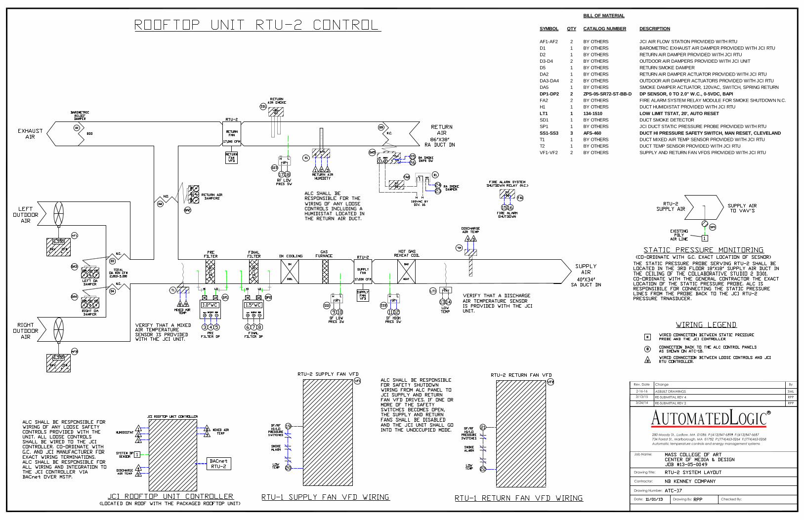
AF1-AF2 2 BY OTHERS JCI AIR FLOW STATION PROVIDED WITH RTU
D1 1 BY OTHERS BAROMETRIC EXHAUST AIR DAMPER PROVIDED WITH JCI RTU
D2 1 BY OTHERS RETURN AIR DAMPER PROVIDED WITH JCI RTU
D3-D4 2 BY OTHERS OUTDOOR AIR DAMPERS PROVIDED WITH JCI UNIT
DA2 1 BY OTHERS RETURN AIR DAMPER ACTUATOR PROVIDED WITH JCI RTU
DA3-DA4 2 BY OTHERS OUTDOOR AIR DAMPER ACTUATORS PROVIDED WITH JCI RTU
DP1-DP2 2 ZPS-05-SR72-ST-BB-D DP SENSOR, 0 TO 2.0" W.C., 0-5VDC, BAPI
FA1 1 BY OTHERS FIRE ALARM SYSTEM RELAY MODULE FOR SMOKE SHUTDOWN N.C.
H1 1 BY OTHERS DUCT HUMIDISTAT PROVIDED WITH JCI RTU
LT1 1 134-1510 LOW LIMIT TSTAT, 20', AUTO RESET
SD1 1 BY OTHERS DUCT SMOKE DETECTOR
SP1 1 BY OTHERS JCI DUCT STATIC PRESSURE PROBE PROVIDED WITH RTU
SS1-SS3 3 AFS-460 DUCT HI PRESSURE SAFETY SWITCH, MAN RESET, CLEVELAND
T1 1 BY OTHERS DUCT MIXED AIR TEMP SENSOR PROVIDED WITH JCI RTU
T2 1 BY OTHERS DUCT TEMP SENSOR PROVIDED WITH JCI RTU
VF1-VF2 2 BY OTHERS SUPPLY AND RETURN FAN VFDS PROVIDED WITH JCI RTU

BILL OF MATERIAL
SYMBOL QTY CATALOG NUMBER DESCRIPTION
W1 1 DCP20‐UL CUSTOM CONTROL PANEL
W2 1 PSC100AB10 120/24VAC XFORMER, 100VA
X1 1 ZN551 ALC ZN‐LINE CONTROLLER, 5 DI, 5 DO, 1 AO
X2 1 ZN220 ALC ZN‐LINE CONTROLLER, 2 DI, 2 DO
X3 1 AMR ALC BACNET INTERATION CONTROLLER
X4‐X9 6 RH2B‐ULAC24VAC RELAY, 24VAC, 2PDT
6 SH2B‐05 RELAY SUBBASE
BILL OF MATERIAL
SYMBOL QTY CATALOG NUMBER DESCRIPTION
AF1-AF2 2 BY OTHERS JCI AIR FLOW STATION PROVIDED WITH RTU
D1 1 BY OTHERS BAROMETRIC EXHAUST AIR DAMPER PROVIDED WITH JCI RTU
D2 1 BY OTHERS RETURN AIR DAMPER PROVIDED WITH JCI RTU
D3-D4 2 BY OTHERS OUTDOOR AIR DAMPERS PROVIDED WITH JCI UNIT
D5 1 BY OTHERS RETURN SMOKE DAMPER
DA2 1 BY OTHERS RETURN AIR DAMPER ACTUATOR PROVIDED WITH JCI RTU
DA3-DA4 2 BY OTHERS OUTDOOR AIR DAMPER ACTUATORS PROVIDED WITH JCI RTU
DA5 1 BY OTHERS SMOKE DAMPER ACTUATOR, 120VAC, SWITCH, SPRING RETURN
DP1-DP2 2 ZPS-05-SR72-ST-BB-D DP SENSOR, 0 TO 2.0" W.C., 0-5VDC, BAPIFA2 2 BY OTHERS FIRE ALARM SYSTEM RELAY MODULE FOR SMOKE SHUTDOWN N.C.
H1 1 BY OTHERS DUCT HUMIDISTAT PROVIDED WITH JCI RTU
LT1 1 134-1510 LOW LIMIT TSTAT, 20', AUTO RESETSD1 1 BY OTHERS DUCT SMOKE DETECTOR
SP1 1 BY OTHERS JCI DUCT STATIC PRESSURE PROBE PROVIDED WITH RTU
SS1-SS3 3 AFS-460 DUCT HI PRESSURE SAFETY SWITCH, MAN RESET, CLEVELANDT1 1 BY OTHERS DUCT MIXED AIR TEMP SENSOR PROVIDED WITH JCI RTU
T2 1 BY OTHERS DUCT TEMP SENSOR PROVIDED WITH JCI RTU
VF1-VF2 2 BY OTHERS SUPPLY AND RETURN FAN VFDS PROVIDED WITH JCI RTU

BILL OF MATERIAL
SYMBOL QTY CATALOG NUMBER DESCRIPTION
W1 1 DCP20‐UL CUSTOM CONTROL PANEL
W2 1 PSC100AB10 120/24VAC XFORMER, 100VA
X1 ‐X2 2 ZN551 ALC ZN‐LINE CONTROLLER, 5 DI, 5 DO, 1 AO
X3 1 AMR ALC BACNET INTERATION CONTROLLER
X4‐X10 7 RH2B‐ULAC24VAC RELAY, 24VAC, 2PDT
7 SH2B‐05 RELAY SUBBASE

ROOFTOP UNITS RTU-1 & RTU-2 CONTROL
The rooftop units RTU-1 & RTU-2 shall be controlled by the packaged Johnson ControlsInc. (JCI) controller, which shall receive a start stop command and a discharge air setpoint fromthe ALC system upon start-up. The JCI controller shall communicate all alarms and statuses to the ALC system through BACnet over MSTP. The RTU shall be sequenced from the occupied to unoccupied mode based on a time of day schedule as determined by the ALC system. An optimalstart program shall determine the exact time, prior to the official start of the occupied mode,which the unit will need to start so as to bring the area space temperature up to the heating and cooling setpoints by the scheduled start of the occupied mode. At this calculated time, the ALC system shall open the return air smoke damper (RTU-2 only) and open all of the associated VAV boxes to their minimum damper positions and communicate to the JCI controller to start in theoptimal start warm-up mode. In the optimal start mode, the JCI controller shall open the returnair mixing damper keeping the outdoor air dampers closed. The JCI controller shall then send a command to start the supply and return fans. Once started, the JCI controller shall ramp up theVFD speeds in unison, so as to maintain the maximum supply air static pressure setpoint, asdetermined by the Testing and Balancing Contractor.
At this time, if the associated space temperatures, as sensed by the ALC system are below the occupied space heating setpoint, initially set to 70°F (adj.), the ALC system shallcommunicate to the JCI controller to provide a discharge air temperature setpoint of 85°F (adj.).Once all of the space temperatures have risen to the space heating setpoint, the optimal startheating mode shall end and the ALC system shall communicate to the JCI controller to operate inthe occupied mode. If at this calculated time, the associated space temperatures are above the space cooling setpoint 74°F (adj.), the ALC system shall communicate to the JCI controller to provide a discharge air temperature setpoint of 55°F (adj.). Once all of the space temperatureshave dropped below their space cooling setpoint, the optimal start cooling mode shall end andthe occupied mode shall commence.
At the start of the occupied mode, the JCI controller shall modulate the outdoor airdampers in sequence with the return damper to maintain the minimum outdoor air CFM setpoint(adj.), initially set at (12,700 CFM for RTU-1) & (2000 CFM for RTU-2) and shall maintain a discharge air temperature setpoint of 55°F (adj.). If cooling is required, the JCI controller shall have the ability to determine if economizer free cooling is available. If economizer cooling isavailable, the JCI controller shall open the outdoor air dampers (RTU-1 max OA CFM = 15,000,RTU-2 max OA CFM = 7,550) to maintain the discharge air temperature setpoint. If economizer cooling is unavailable, the JCI controller shall stage on the DX cooling to maintain the dischargeair temperature setpoint. The JCI controller shall control the supply and return fan to provide a slightly positive pressure in the associated spaces while maintaining the static pressure setpoint,as determined by the Testing and Balancing Contractor. The outdoor air flow rate shall be determined by the JCI controller utilizing the JCI packaged outdoor air flow stations, AF1 and AF2. The barometric exhaust air damper shall remain closed unless the pressure in the returnduct exceeds the return duct pressure setpoint, as determined by the Testing and BalancingContractor.
The ALC system shall monitor the space CO2 levels in the locations served by RTU-2and communicate with the JCI controller to reset the minimum outdoor air CFM setpoint. If the space CO2 level rises above a high limit of 1000 ppm (adj.), the ALC system shall graduallyincrease the minimum outdoor air setpoint. The ALC system shall raise the minimum outdoor air setpoint up as high as the maximum outdoor air setpoint, 5000 CFM (adj.). The ALC systemshall raise the minimum outdoor air setpoint in this fashion upon any high CO2 condition. Oncethe CO2 level has decreased below the high CO2 limit, the ALC system shall gradually decreasethe minimum outdoor air setpoint down as low as the minimum outdoor air setpoint, 2000 CFM.
The ALC system shall monitor the associated space heating and cooling requests and the VAV box damper positions to determine the discharge air temperature setpoint. The ALC systemshall communicate with the JCI controller to maintain a discharge air temperature setpoint whichshall reset from 55°F to 60°F (adj.) based on the space heating and cooling requests. If all of theassociated VAV box dampers are operating below 85% (adj.), the ALC system shall raise thedischarge air temperature setpoint in 1°F increments for every 10-minute (adj.) interval wherethis condition exists. The discharge air temperature setpoint shall be increased in this fashion, upas high as a maximum of 60°F (adj.). During this time, the ALC system shall also communicateto the JCI controller to reset the static pressure setpoint. If all of the associated VAV box dampers are operating below 85% open (adj.) and are maintaining their CFM setpoints, the ALCsystem shall decrease the supply duct static pressure setpoint by .1” W.C. for every 10-minute (adj.) interval where this condition exists. The supply duct static pressure setpoint shall beallowed to be reduced in this fashion, down as low as the minimum duct static pressure setpoint(as set by the Balancing Contractor), for as long as all of the VAV box dampers are operatingbelow 85% open.
RTU-1 & RTU-2 CONTROL (continued) If any of the associated VAV box dampers begins to open above 85%, the ALC system shall increase the supply air static pressure setpoint by .1” W.C. at every 10-minute (adj.)interval where this situation exists. The supply static pressure setpoint shall be allowed to be incremented upward in this fashion, up as high as the maximum duct static pressure setpoint, until all of the associated supply box dampers are operating below 85% open.
The JCI controller shall monitor the humidity in the return air duct. If the space humidity level rises above a high limit, the JCI controller shall operate in the de-humidification mode. In the de-humidification mode, the JCI controller shall stage on the DX cooling in sequence with the hot gas reheat to maintain the discharge air temperature setpoint.
In the unoccupied mode, the JCI controller shall stop the supply and return fans, close the outdoor air dampers and open the return damper. If any space temperature drops below 60°F (adj.) or raises above 85°F (adj.) the ALC system shall open the VAV boxes to their minimum CFM positions and communicate with the JCI controller to start in the optimal start heating or cooling mode as described above.
Duct smoke detectors, located in the return air ducts, shall disable the fans and the ALC system shall command the JCI controller to close the return damper and go into the unoccupied mode. A smoke alarm shall be reported at the fire alarm panel and a smoke alarm shall also be generated by the ALC system. The smoke detector will have to be reset from the fire alarm system before the unit will be allowed to restart. Low limit thermostats, mounted on the leaving side of the steam heating coil, shall stop the fans and the ALC system shall place the RTU in the unoccupied mode if a temperature below 45°F is sensed. The low limit thermostat will have to be manually reset via a software point at the ALC system before the unit will be allowed to restart. Static pressure safety switches, located in the supply and discharge of the supply fan and discharge of the return fan, shall also stop the fans if a high supply or low return pressure condition should occur in either duct. If any of these scenarios should occur, or if any fan should fail to start when commanded, an alarm shall be generated at the ALC system. If the JCI controller senses a filter differential pressure above 1.0” W.C. (adj.) for greater than 30-minutes, a “Dirty Filter” alarm shall be communicated to the ALC system and an alarm shall be generated. If the unit’s discharge air temperature should remain 5°F above or 5°F below setpoint for greater than 5-minutes, a discharge air temperature alarm shall be generated at the ALC system. If the unit’s static pressure should rise more than .25” above or if it should drop.

BILL OF MATERIAL
SYMBOL QTY CATALOG NUMBER DESCRIPTION
BS1 1 WPS‐MP‐BS‐CLM EMERGENCY BOILER SHUTDOWN SWITCH
1 PILNCCB N.C. CONTACTS
CO1 1 GWVAS-GM0A SPACE CO SENSOR, 0-5VDC = 0-2000 PPM
CS1 1 RIBXGTA CURRENT SWITCH, ADJ
ES1‐ES3 4 S1A VALVE POSITION SWITCH, SPDT, BELIMO
P1‐P2 2 2091‐100P‐G2M‐11‐A1 PRESSURE SENSOR, 0‐100PSI = 4‐20mA, SETRA
R1-R4 4 RIB2401C RELAY, 24VAC, SPDT
SM1 1 BY OTHERS STEAM BTU METER
T1‐T2 2 ALC/10K‐2‐I‐4 IMMERSION TEMP SENSOR , 4"
2 BA/4 4" IMMERSION SENSOR WELL
T3 1 ALC/10K-2-H200-O-BB COMBO OUTDOOR AIR TEMP/ RH SENSOR BAPI
V1‐V2 2 See Valve Schedule STEAM SYSTEM SUPPLY VALVE, 2-10VDC, NC
V3‐V4 2 See Valve Schedule HX ISO VALVE, 24VAC FLOATING
V5 1 See Valve Schedule HX BYPASS VALVE, 24VAC FLOATING
V6 1 See Valve Schedule BOILER ISO VALVE, 24VAC FLOATING
V7 1 See Valve Schedule HW BYPASS VALVE, 2‐10VDC, POS FDBACK
VF1‐VF2 2 BY OTHERS PUMP VARIABLE FREQUENCY DRIVES

BILL OF MATERIAL
SYMBOL QTY CATALOG NUMBER DESCRIPTIONX1 1 ME812U ALC ME‐LINE CONTROLLER, 8 UNIV OUTPUTS, 12 INPUTS
X2 1 MEx88U ALC ME‐LINE EXPANDER#1, 8 UNIV OUTPUTS, 8 INPUTS
X3‐X6 4 RH1B‐ULDC24V RELAY, 24VDC, SPDT
4 SH1B‐05 RELAY SUBBASE
X7 1 RH2B‐ULDC24V RELAY, 24VDC, DPDT
1 SH2B‐05 RELAY SUBBASE

BOILER B-1, HX-1 & HX-2 AND HW SYSTEM CONTROL
The hot water system shall be started and stopped based on the outdoor air temperature and an occupancy schedule as set at the ALC system. The hot water system consists of (2) heat exchangers in parallel which shall be used in the winter heating season (if steam is available) and a summer boiler which shall be used in the cooling season or when steam is unavailable to the system. The ALC system shall monitor the steam BTU meter to determine if steam is available from the central steam plant to use for steam heating.
In the occupied mode, if steam is available and the outdoor air temperature drops below 60 F (adj.) or if there is a heating request from any of the building’s heating equipment, the lead heat exchanger, HX-1 or HX-2 as selected by the ALC system shall open its isolation valve, V3 or V4. The heat exchanger bypass valve, V5 shall also close to direct flow to the lead heat exchanger. Once the valve positions have been proven by their respective switches, the lead hot water pump, P-1 or P-2 as selected by the ALC system shall start at its minimum VFD speed and ramp up, as required to maintain the system differential pressure setpoint as determined by the Testing and Balancing contractor. If at any time the lead hot water pump is running at its minimum VFD speed and the system differential pressure remains above setpoint, the HW bypass valve, V7, shall modulate open so as to maintain the system DP setpoint. Once the lead hot water pump has been proven running, the ALC system shall modulate the lead steam supply valve, V1 or V2 to maintain a hot water supply setpoint which shall be reset from 140 F to
180 F (adj.) as the outdoor air temperature varies from 60 F to 0 F (adj.). The ALC system shall record the steam BTU usage and provide history and trending graphics to be viewed on the buildings’ WebCNTRL page. The ALC system shall automatically rotate the lead heat exchangeron a weekly basis so as to equalize the runtimes. Upon rotating the heat exchangers, the ALC system shall close the isolation valve of the lead heat exchanger and open the isolation valve of the lag heat exchanger. Once the outdoor air temperature rises above 60 F (adj.) and there are no longer any heating requests, the ALC system shall close the heat exchanger steam supply valve. The lead hot water pump shall continue to run for a 2-minute (adj.) period to dissipate the heat in the heat exchangers before shutting down.
In the unoccupied mode during the heating season, if the outdoor air temperate is above 45 F (adj.), the hot water system shall shutdown as previously described. If any space should call for unoccupied heating, the hot water system shall restart, as previously described in the occupied mode, and shall run until there is no longer a call for heating. If the outdoor air temperature drops below 45 F (adj.), the hot water system shall be enabled and shall remain
enabled until the outdoor air temperature rises about 47 F (adj.) and there is no longer a call for heating.
BOILER B-1, HX-1 & HX-2 AND HW SYSTEM CONTROL (CONTINUED)
In the cooling season when steam is unavailable; if the outdoor air temperature drops below 60 F (adj.) of if there is a heating request from any of the building’s heating equipment; the hot water system shall be placed in the occupied mode. In the occupied mode, the ALC system shall enable the boiler and send a start command to the rooftop unit (RTU-1). The CV box (CAV-9) serving the HW plant shall act as a combustion air damper for the HW Plant. The ALC system shall monitor CAV-9 and shall not allow B-1 to start until the flow has risen above a minimum combustion air setpoint of 300 CFM (adj.). Once the flow of CAV-9 has risen above the minimum CFM setpoint (adj.), the ALC system shall send a signal to the boiler’s combustion air damper proving contact to allow the boiler to run. If the boiler is manually started, the boiler shall send a signal to the ALC controller to start (RTU-1) for combustion air. Once the boiler has been enabled the ALC system shall close the heat exchanger isolation valves, V3 and V4 and open the heat exchanger bypass valve, V5 and open the boiler isolation valve, V6. Once the isolation valves have been proven closed and the HX bypass valve and boiler isolation valves proven open by their respective switches, the lead hot water pump, P-1 or P-2 as selected by the ALC system shall start and run as previously described. At the same time the boiler shall send a start command to the boiler pump, P-3 to draw the hot water into the boiler. Once flow through the boiler has been proven via the status of P-3, the boiler shall be called to start. Once the boiler has started, the ALC system shall send a 0-10VDC hot water supply command to maintain a hot water supply setpoint of 140 F (adj.). Once the outdoor temperature has risen above 60 F and there are no longer any heating requests, the ALC system shall disable the boiler. The lead hot water pump shall continue to run for a 2-minute (adj.) period to dissapate the heat in the boiler before shutting down. In the unoccupied mode, the boiler shall be disabled and the hot water pumps shall be off.
If the lead pump should fail to start when commanded, the lag pump shall automatically start and shall run in place of the failed pump. The lag Pump shall continue to operate until the lead pump is put back into service. If this should occur, a pump failure alarm shall be generated by the ALC system. If the boiler pump shall fail to start when commanded on, the boiler shall be disabled and a pump failure alarm shall be generated by the ALC system. An emergency boiler shutdown switch located outside the door of the HW Plant shall, when pressed, shutdown the boiler. A carbon monoxide sensor located in the HW Plant shall monitor the CO level. If the CO level rises above a high limit initially set at 25 ppm, the ALC system shall generate a high CO level alarm and shutdown the boiler. If an alarm condition is sensed by the boiler, a boiler alarm shall be generated by the ALC system.
DUPLEX CONDENSATE PUMP CONTROL
The duplex condensate pumps shall be provided with high and low condensate levelswitches, flow switched and have the ability to start the pumps. The condensate pump shall operate in a lead/ lag fashion and rotate on a bi-weekly basis so as to equalize runtime. If the first high level switch indicates an increase in condensate, the lead condensate pump shall start. If thelevel continues to rise above the second high level switch, the lag condensate pump shall start. If the lead pump fails to start, the lag pump shall start. When the condensate level drops below the low level switch, the pumps shall stop. The pumps shall automatically restart when standbypower is available after normal power is lost.

FUEL OIL PUMP SYSTEM ALARM MONITORING
The fuel oil pump system shall be monitored by the unit’s packaged control panel. The ALC system shall communicate to the fuel oil pump system control panel through the availabledry contacts. If a high or low oil level is sensed at the day tank the ALC system shall generate a day tank high/low level alarm. If there is a common, the ALC system shall generate a commonalarm. If there is a dirty strainer alarm, the ALC system shall generate an alarm. If a leak is detected in the containment piping, the ALC system shall generate a containment pipe leak alarm. If any pump should fail when called to start, the ALC system shall generate a pump failure alarm.
MAIN DAY TANK ALARM MONITORING
The Main day tank shall be monitored by a packaged control panel. The ALC systemshall communicate to the day tank control panel through a set of dry contacts. If a Low oil level is sensed, the ALC system shall generate a low level alarm. The ALC system shall generate a leak alarm if a leak is sensed in the main day tank. The ALC system shall also monitor the day tank oil volume from a 4-20mA output from the main day tank panel.
BILL OF MATERIAL
SYMBOL QTY CATALOG NUMBER DESCRIPTION
AL1 1 BY OTHERS MAIN TANK OVERFILL ALARM HORN
CP1 1 BY OTHERS MAIN TANK CONTROL PANEL, PNEUMERCATOR
CP2 1 BY OTHERS FUEL OIL CONTROL PANEL, HAYES
FS1 1 BY OTHERS PUMP FLOW SWITCH
HL1 1 BY OTHERS HIGH LEVEL SWITCH
LL1-LL2 2 BY OTHERS LOW LEVEL SWITCH
LD1-LD4 4 BY OTHERS LEAK DETECTION SENSOR
LS1 1 BY OTHERS LEVEL SENSOR

BILL OF MATERIAL
SYMBOL QTY CATALOG NUMBER DESCRIPTIONC1-C2 2 ZN551 ALC ZN-LINE CONTROLLER, 5UI, 5DO, 1AO

BILL OF MATERIAL
SYMBOL QTY CATALOG NUMBER DESCRIPTION
SW1 1 AL6M‐M14P‐R DUST COLLECTOR ON/OFF BUTTON, LED, 1 CONTACTS
DUST COLLECTION SYSTEM CONTROL
The dust collection system shall be controlled by the existing dust collector integrated control panel located in the woodshop (D002). When the dust collection system is energized via the remote ON/OFF push button located on the integrated control panel, a wired contact shall energize the dust collection system. The dust collector spark suppression panel shall monitor the status of the dust collector exhaust fan. The status of the dust collector exhaust fan shall be wiredfrom the dust collector fan VFD to (CAV-6 North) located in the woodshop (nearest the woodshop control panels). The status of the dust collector fan VFD shall be globalized to the exhaust fan, EF-2 controller. EF-2 shall remain disabled until the dust collection system has been proven off via the dust collector fan VFD status. If the dust collection system and exhaust fan EF-2 are running at the same time, the ALC system will shutdown EF-2 and an alarm shall be generated by the ALC system.

ELEVATOR MACHINE ROOM WITH SPLIT AC UNIT AC-1 & CU-2 CONTROL The split AC unit AC-1 and outdoor condensing unit CU-2 shall start and stop based on a packaged thermostat located in the Elevator Machine room D001A. If the thermostat senses a room temperature above setpoint 85°F (adj.), AC-1 and CU-2 shall be interlocked to start and shall run until the Elevator Machine room temperature has dropped below 82°F (adj.). If the space temperature should rise 10°F above setpoint for greater than a 10-minute interval, a space temperature alarm shall be generated by the ALC system.
SYMBOL QTY PART NUMBER DESCRIPTION
C1 1 ZN220 ALC ZN‐LINE CONTROLLER, 2IN, 2DO
1 ENCLOSURE 12"X12" ENCLOSURE
T1 1 ZS BASE SPACE TEMP SENSOR


MASS COLLEGE OF ARTCENTER FOR MEDIA DESIGN
VALVE SCHEDULE 2/14/14
13-05-0049 VLV-1
TAG-# UNIT# SERVICE VAV/CAV HW VALVE PART # QTY TYPE SIZE CONNECTION CV DP GPM CLOSEOFF ACTUATOR MANUFACTURER COMMENT
1 CAV-9 STORAGE D002C B208B+TFRB24-SR 1 2-WAY BALL 1/2" THREADED 0.46 3.8 0.9 200 PSI 2-10VDC, FAIL OPEN BELIMO2 CAV-6 WOOD SHOP D002 B211B+TFRB24-SR 1 2-WAY BALL 1/2" THREADED 1.9 2.2 2.8 200 PSI 2-10VDC, FAIL OPEN BELIMO3 CAV-6 WOOD SHOP D002 B211B+TFRB24-SR 1 2-WAY BALL 1/2" THREADED 1.9 2.2 2.8 200 PSI 2-10VDC, FAIL OPEN BELIMO4 CAV-9 BUILDING STORAGE D010 B208B+TFRB24-SR 1 2-WAY BALL 1/2" THREADED 0.46 3.8 0.9 200 PSI 2-10VDC, FAIL OPEN BELIMO5 CAV-5 BENCH ROOM D004 B210B+TFRB24-SR 1 2-WAY BALL 1/2" THREADED 1.2 3.7 2.3 200 PSI 2-10VDC, FAIL OPEN BELIMO6 CAV-2 OFFICE D005 B208B+TFRB24-SR 1 2-WAY BALL 1/2" THREADED 0.46 3.8 0.9 200 PSI 2-10VDC, FAIL OPEN BELIMO7 CAV-9 HW PLANT D017 B208B+TFRB24-SR 1 2-WAY BALL 1/2" THREADED 0.46 3.8 0.9 200 PSI 2-10VDC, FAIL OPEN BELIMO8 VAV-9 CORRIDOR D007A B208B+TFRB24-SR 1 2-WAY BALL 1/2" THREADED 0.46 3.8 0.9 200 PSI 2-10VDC, FAIL OPEN BELIMO9 VAV-2 SHOP CLASSROOM D011 B208B+TFRB24-SR 1 2-WAY BALL 1/2" THREADED 0.46 3.8 0.9 200 PSI 2-10VDC, FAIL OPEN BELIMO
10 VAV-2 3D FINE ARTS STUDIO D016 B208B+TFRB24-SR 1 2-WAY BALL 1/2" THREADED 0.46 3.8 0.9 200 PSI 2-10VDC, FAIL OPEN BELIMO11 VAV-2 PROJECT ROOM D008 B208B+TFRB24-SR 1 2-WAY BALL 1/2" THREADED 0.46 3.8 0.9 200 PSI 2-10VDC, FAIL OPEN BELIMO12 VAV-2 PROJECT ROOM D009 B208B+TFRB24-SR 1 2-WAY BALL 1/2" THREADED 0.46 3.8 0.9 200 PSI 2-10VDC, FAIL OPEN BELIMO13 VAV-2 PROJECT ROOM D110 B208B+TFRB24-SR 1 2-WAY BALL 1/2" THREADED 0.46 3.8 0.9 200 PSI 2-10VDC, FAIL OPEN BELIMO14 VAV-2 PROJECT ROOM D109 B208B+TFRB24-SR 1 2-WAY BALL 1/2" THREADED 0.46 3.8 0.9 200 PSI 2-10VDC, FAIL OPEN BELIMO15 VAV-3 COMPUTER ARTS D111 B209B+TFRB24-SR 1 2-WAY BALL 1/2" THREADED 0.8 2.6 1.3 200 PSI 2-10VDC, FAIL OPEN BELIMO16 VAV-2 CRIT GALLERY D106 B208B+TFRB24-SR 1 2-WAY BALL 1/2" THREADED 0.46 3.8 0.9 200 PSI 2-10VDC, FAIL OPEN BELIMO17 VAV-2 CD + M OFFICE D118 B208B+TFRB24-SR 1 2-WAY BALL 1/2" THREADED 0.46 3.8 0.9 200 PSI 2-10VDC, FAIL OPEN BELIMO18 VAV-1 M SEMINAR D113 B207B+TFRB24-SR 1 2-WAY BALL 1/2" THREADED 0.3 2.8 0.5 200 PSI 2-10VDC, FAIL OPEN BELIMO19 VAV-2 PROJECT DEVELOPMENT D122 B208B+TFRB24-SR 1 2-WAY BALL 1/2" THREADED 0.46 3.8 0.9 200 PSI 2-10VDC, FAIL OPEN BELIMO20 VAV-5 COLLABRATIVE STUDIO D123 B210B+TFRB24-SR 1 2-WAY BALL 1/2" THREADED 1.2 3.7 2.3 200 PSI 2-10VDC, FAIL OPEN BELIMO21 VAV-5 COLLABRATIVE STUDIO D123 B210B+TFRB24-SR 1 2-WAY BALL 1/2" THREADED 1.2 3.7 2.3 200 PSI 2-10VDC, FAIL OPEN BELIMO22 VAV-1 CONTROL ROOM D204 B207B+TFRB24-SR 1 2-WAY BALL 1/2" THREADED 0.3 2.8 0.5 200 PSI 2-10VDC, FAIL OPEN BELIMO23 VAV-7 LECTURE HALL D107 B212B+TFRB24-SR 1 2-WAY BALL 1/2" THREADED 3 1.8 4 200 PSI 2-10VDC, FAIL OPEN BELIMO24 VAV-4 CRIT ROOM D108 B209B+TFRB24-SR 1 2-WAY BALL 1/2" THREADED 0.8 4.0 1.6 200 PSI 2-10VDC, FAIL OPEN BELIMO25 VAV-2 PROJECT ROOM D205 B208B+TFRB24-SR 1 2-WAY BALL 1/2" THREADED 0.46 3.8 0.9 200 PSI 2-10VDC, FAIL OPEN BELIMO26 VAV-3 CRIT GALLERY D207 B209B+TFRB24-SR 1 2-WAY BALL 1/2" THREADED 0.8 2.6 1.3 200 PSI 2-10VDC, FAIL OPEN BELIMO27 VAV-2 PROJECT ROOM D209 B208B+TFRB24-SR 1 2-WAY BALL 1/2" THREADED 0.46 3.8 0.9 200 PSI 2-10VDC, FAIL OPEN BELIMO28 VAV-3 ARGE SEMINAR D208 B209B+TFRB24-SR 1 2-WAY BALL 1/2" THREADED 0.8 2.6 1.3 200 PSI 2-10VDC, FAIL OPEN BELIMO29 VAV-4 (TOP) COLLABRATIVE STUDIO D301 B209B+TFRB24-SR 1 2-WAY BALL 1/2" THREADED 0.8 4.0 1.6 200 PSI 2-10VDC, FAIL OPEN BELIMO30 VAV-5 (MID) MAIN LOBBY B210B+TFRB24-SR 1 2-WAY BALL 1/2" THREADED 1.2 3.7 2.3 200 PSI 2-10VDC, FAIL OPEN BELIMO31 VAV-5 (BOT) COLLABRATIVE STUDIO D301 B210B+TFRB24-SR 1 2-WAY BALL 1/2" THREADED 1.2 3.7 2.3 200 PSI 2-10VDC, FAIL OPEN BELIMO32 VAV-2 (TOP) COLLABRATIVE STUDIO D301 B209B+TFRB24-SR 1 2-WAY BALL 1/2" THREADED 0.46 3.8 0.9 200 PSI 2-10VDC, FAIL OPEN BELIMO33 VAV-5 (MID) MAIN LOBBY B210B+TFRB24-SR 1 2-WAY BALL 1/2" THREADED 1.2 3.7 2.3 200 PSI 2-10VDC, FAIL OPEN BELIMO34 VAV-5 (BOT) COLLABRATIVE STUDIO D301 B210B+TFRB24-SR 1 2-WAY BALL 1/2" THREADED 1.2 3.7 2.3 200 PSI 2-10VDC, FAIL OPEN BELIMO35 VAV-5 EXIBIT HALL B210B+TFRB24-SR 1 2-WAY BALL 1/2" THREADED 1.2 3.7 2.3 200 PSI 2-10VDC, FAIL OPEN BELIMO36 VAV-5 EXIBIT HALL B210B+TFRB24-SR 1 2-WAY BALL 1/2" THREADED 1.2 3.7 2.3 200 PSI 2-10VDC, FAIL OPEN BELIMO37 VAV-5 EXIBIT HALL B210B+TFRB24-SR 1 2-WAY BALL 1/2" THREADED 1.2 3.7 2.3 200 PSI 2-10VDC, FAIL OPEN BELIMO38 VAV-6 LIGHTING/PROJECT ROOM D306 B211B+TFRB24-SR 1 2-WAY BALL 1/2" THREADED 1.9 2.2 2.8 200 PSI 2-10VDC, FAIL OPEN BELIMO39 VAV-6 LIGHTING/PROJECT ROOM D306 B211B+TFRB24-SR 1 2-WAY BALL 1/2" THREADED 1.9 2.2 2.8 200 PSI 2-10VDC, FAIL OPEN BELIMO40 VAV-2 OPEN CRIT GALLERY D308 B209B+TFRB24-SR 1 2-WAY BALL 1/2" THREADED 0.46 3.8 0.9 200 PSI 2-10VDC, FAIL OPEN BELIMO41 VAV-6 LIGHTING STUDIO D309 B211B+TFRB24-SR 1 2-WAY BALL 1/2" THREADED 1.9 2.2 2.8 200 PSI 2-10VDC, FAIL OPEN BELIMO42 VAV-6 LIGHTING STUDIO D309 B211B+TFRB24-SR 1 2-WAY BALL 1/2" THREADED 1.9 2.2 2.8 200 PSI 2-10VDC, FAIL OPEN BELIMO43 VAV-2 STORAGE D309B B209B+TFRB24-SR 1 2-WAY BALL 1/2" THREADED 0.46 3.8 0.9 200 PSI 2-10VDC, FAIL OPEN BELIMO44 VAV-1 CONTROL D310B B207B+TFRB24-SR 1 2-WAY BALL 1/2" THREADED 0.3 2.8 0.5 200 PSI 2-10VDC, FAIL OPEN BELIMO

MASS COLLEGE OF ARTCENTER FOR MEDIA DESIGN
VALVE SCHEDULE 2/14/14
13-05-0049 VLV-1
45 VAV-10 OPEN CRIT GALLERY D308 B209B+TFRB24-SR 1 2-WAY BALL 1/2" THREADED 0.8 4.0 1.6 200 PSI 2-10VDC, FAIL OPEN BELIMO46 CAV-3 PRINT CENTER D311 B209B+TFRB24-SR 1 2-WAY BALL 1/2" THREADED 0.8 2.6 1.3 200 PSI 2-10VDC, FAIL OPEN BELIMO47 CAV-3 3D PRINTERS D311A B209B+TFRB24-SR 1 2-WAY BALL 1/2" THREADED 0.8 2.6 1.3 200 PSI 2-10VDC, FAIL OPEN BELIMO48 VAV-3 OPEN CRIT GALLERY D308 B209B+TFRB24-SR 1 2-WAY BALL 1/2" THREADED 0.8 2.6 1.3 200 PSI 2-10VDC, FAIL OPEN BELIMO49 VAV-3 FILM/VID ANIMTN/GRNSCRN D316 B209B+TFRB24-SR 1 2-WAY BALL 1/2" THREADED 0.8 2.6 1.3 200 PSI 2-10VDC, FAIL OPEN BELIMO50 VAV-2 SIM INSTALLING D317 B208B+TFRB24-SR 1 2-WAY BALL 1/2" THREADED 0.46 3.8 0.9 200 PSI 2-10VDC, FAIL OPEN BELIMO
TAG-# UNIT# SERVICE UH/CUH HW VALVE PART # QTY TYPE SIZE CONNECTION CV DP GPM CLOSEOFF ACTUATOR MANUFACTURER COMMENT
51 CUH-1 STORAGE D002D ZONE215N-10+ZONE24NO 1 2-WAY ZONE 1/2" THREADED 1 4.0 2 75 PSI 24VAC, ON/OFF, N.O. BELIMO52 UH-1 AIR PLENUM D0002 ZONE215N-35+ZONE24NO 1 2-WAY ZONE 3/4" THREADED 3.5 3.4 6.5 30 PSI 24VAC, ON/OFF, N.O. BELIMO53 UH-1 AIR PLENUM D0002 ZONE215N-35+ZONE24NO 1 2-WAY ZONE 3/4" THREADED 3.5 3.4 6.5 30 PSI 24VAC, ON/OFF, N.O. BELIMO54 CUH-2 EXISTING STAIR A DSA-1 ZONE215N-10+ZONE24NO 1 2-WAY ZONE 1/2" THREADED 1 2.3 1.5 75 PSI 24VAC, ON/OFF, N.O. BELIMO55 CUH-3 LOBBY D121 ZONE215N-10+ZONE24NO 1 2-WAY ZONE 1/2" THREADED 1 4.0 2 75 PSI 24VAC, ON/OFF, N.O. BELIMO56 CUH-2 EXISTING STAIR A DSA-2 ZONE215N-10+ZONE24NO 1 2-WAY ZONE 1/2" THREADED 1 2.3 1.5 75 PSI 24VAC, ON/OFF, N.O. BELIMO
TAG-# UNIT# SERVICE FTR HW VALVE PART # QTY TYPE SIZE CONNECTION CV DP GPM CLOSEOFF ACTUATOR MANUFACTURER COMMENT
57 FTR-1 MAIN LOBBY D100 (x3) B210B + TFRB24-3 1 2-WAY BALL 1/2" THREADED 1.2 3.4 2.2 200 PSI 24VAC, FLOATING, N.O. BELIMO585960 FTR-2 MAIN LOBBY D100 (X1) B211B + TFRB24-3 1 2-WAY BALL 1/2" THREADED 1.9 1.9 2.6 200 PSI 24VAC, FLOATING, N.O. BELIMO61 RP-1 COLLAB STUDIO 1 D123 (X2) B209B + TFRB24-3 1 2-WAY BALL 1/2" THREADED 0.8 1.6 1 75 PSI 24VAC, FAIL OPEN BELIMO62
TAG-# UNIT-# SERVICE STEAM SUPPLY VALVE PART# QTY TYPE SIZE CONNECTION CV DP lbs/hr INLET PSI ACTUATOR MANUFACTURER COMMENT
63 HX-1 HX-1 SUPPLY VALVE G665C+AFX24-MFT-X1 1 2-WAY GLOBE 2-1/2" FLANGED 65 2.1 1215 2 2-10VDC, FAIL CLOSE BELIMO SHELL SIDE = INLET PRES = 2 PSI64 HX-2 HX-2 SUPPLY VALVE G665C+AFX24-MFT-X1 1 2-WAY GLOBE 2-1/2" FLANGED 65 2.1 1215 2 2-10VDC, FAIL CLOSE BELIMO
TAG-# UNIT-# SERVICE HX ISO VALVE PART# QTY TYPE SIZE CONNECTION CV DP GPM CLOSEOFF ACTUATOR MANUFACTURER COMMENT
65 HX-1 HX-1 ISOLATION VALVE B239+ARB24-3 1 2-WAY BALL 1-1/2" THREADED 29 4.3 60 200 PSI 24VAC, FLOATING,FLP BELIMO66 HX-2 HX-2 ISOLATION VALVE B239+ARB24-3 1 2-WAY BALL 1-1/2" THREADED 29 4.3 60 200 PSI 24VAC,FLOATING, FLP BELIMO
TAG-# UNIT# SERVICE HX BYPASS VALVE PART # QTY TYPE SIZE CONNECTION CV DP GPM CLOSEOFF ACTUATOR MANUFACTURER COMMENT
67 HX HX BYPASS VALVE F665HD+ARB24-3-5 1 2-W BUTTERFLY 2-1/2" FLANGED 196 0.1 60 200 PSI 24VAC, FLOATING, FLP BELIMO
TAG-# UNIT# SERVICE HW DP BYPASS VALVE PART # QTY TYPE SIZE CONNECTION CV DP GPM CLOSEOFF ACTUATOR MANUFACTURER COMMENT
68 HW HW BYPASS B229+LRB24-SR-T 1 2-WAY BALL 1-1/4" THREADED 10 4.4 21 200 PSI 2-10VDC MODULATING BELIMO 35% FLOW, 2-10VDC POS
TAG-# UNIT# SERVICE BOILER ISO VALVE PART # QTY TYPE SIZE CONNECTION CV DP GPM CLOSEOFF ACTUATOR MANUFACTURER COMMENT
69 B-1 BOILER ISOLATION VALVE F665HD+ARB24-3-5 1 2-W BUTTERFLY 2-1/2" FLANGED 196 0.0 40 200 PSI 24VAC, FLOATING, FLP BELIMO
REMOVED
REMOVED

MASS COLLEGE OF ARTCENTER FOR DESIGN MEDIA
DAMPER SCHEDULE 2/14/14
JOB #13-05-0049DMP-1
ITEM# UNIT SERVICE DAMPER PART # QTY WIDTH" HEIGHT" AREA (SQ. FT.) APPLICATION TYPE MANUFACTURER COMMENTS1 PRINT SHOP EXHAUST FAN EXHAUST AIR VCDR-53 1 22" ROUND 2.64 CONTROL OPPOSED GREENHECK AIRFOIL BLADES2 ELEVATOR SHAFT RELIEF VDC-23 1 12 36 3.00 CONTROL OPPOSED GREENHECK3 SMOKE EXHAUST FANS EXHAUST AIR VCDR-53 4 36" ROUND 7.10 CONTROL OPPOSED GREENHECK AIRFOIL BLADES4 SUPPLY FAN (SF-2 & SF-3) SUPPLY AIR VCD-23 1 48" 36" 12 CONTROL OPPOSED GREENHECK5 SUPPLY FAN SF-1 SUPPLY AIR VCD-23 1 32" 42" 9.3 CONTROL OPPOSED GREENHECK6 EXHAUST FAN EF-1 EXHAUST AIR VCD-23 1 32 22 4.9 CONTROL OPPOSED GREENHECK7 EXHAUST FAN EF-2 EXHAUST AIR VCD-23 1 40 18 5 CONTROL OPPOSED GREENHECK