ELECTRONIC DOCUMENTS DISCLAIMER 1 ... - BidNet
281
ELECTRONIC DOCUMENTS DISCLAIMER 1. Electronic copies of the solicitation documents are made available on this website solely for the convenience of prospective bidders (whether as a prime contractor or sub-contractor) on the Project, and are not considered part of the Contract Documents. No representation or warranty is made, either expressed or implied, with regard to the accuracy or suitability of these electronic copies for any purpose whatsoever. In the event of discrepancies or conflicts between the County's originally published document(s) and any other version distributed or submitted by other parties, the County's original hard copy version shall prevail. 2. Miami-Dade County Department of Transportation and Public Works (DTPW) does not track or monitor downloads of Project documents from this website. Therefore, prospective bidders who choose to use this method of distribution shall also be responsible for monitoring the site and downloading any applicable addenda or supplemental information. DTPW will distribute hard copy addenda or supplemental information only to those persons or firms who we have purchased a hard copy of the original solicitation documents. 3. Miami-Dade County shall not be responsible for errors and omissions occurring in the transmission or downloading of any documents or specifications from this website. In the event of any discrepancy between information obtained from this website and the DTPW hard copy solicitation documents and specifications, the terms of the hard copy documents will prevail. 4. Miami-Dade County does not guarantee continuous, uninterrupted or secure access to this or other related websites. Operation of this website may be affected from time to time by numerous factors outside of our control. In the event that we are notified of any problems in a timely manner we will do our best to assist with those problems that fall within our control. For assistance, contact us at 305-375-2930. Solicitation documents are removed from this website as soon as possible after the due date. 5. DTPW does not accept facsimile or electronic bid responses of any kind. All bids must be submitted in writing, on the forms provided by the County, to the address designated in the bid package. It is the bidder's responsibility to ensure that their submittals are received at the designated location, complete and on time. Bids received after the due date will be rejected, even if the solicitation is still appearing on this site. 6. With regards to Miscellaneous Construction Contracts (MCC) 7040 Plan Request for Price Quotations: a. Only bidders included on the Project’s Bidders List, provided by the Internal Service Department, Procurement Management Division to the DTPW, can submit a bid. b. Only timely bids received from bidders included in the Project’s Bidders List will be considered. 7. These documents shall not be altered in any manner. Utilization or viewing of these electronic documents shall constitute implicit acknowledgement and acceptance of these provisions. Failure to comply with these provisions may result in rejection of your bid.
-
Upload
khangminh22 -
Category
Documents
-
view
0 -
download
0
Transcript of ELECTRONIC DOCUMENTS DISCLAIMER 1 ... - BidNet

ELECTRONIC DOCUMENTS DISCLAIMER
1. Electronic copies of the solicitation documents are made available on this website solely for the
convenience of prospective bidders (whether as a prime contractor or sub-contractor) on the
Project, and are not considered part of the Contract Documents. No representation or warranty is
made, either expressed or implied, with regard to the accuracy or suitability of these electronic
copies for any purpose whatsoever. In the event of discrepancies or conflicts between the
County's originally published document(s) and any other version distributed or submitted by other
parties, the County's original hard copy version shall prevail.
2. Miami-Dade County Department of Transportation and Public Works (DTPW) does not track or
monitor downloads of Project documents from this website. Therefore, prospective bidders who
choose to use this method of distribution shall also be responsible for monitoring the site and
downloading any applicable addenda or supplemental information. DTPW will distribute hard
copy addenda or supplemental information only to those persons or firms who we have
purchased a hard copy of the original solicitation documents.
3. Miami-Dade County shall not be responsible for errors and omissions occurring in the
transmission or downloading of any documents or specifications from this website. In the event of
any discrepancy between information obtained from this website and the DTPW hard copy
solicitation documents and specifications, the terms of the hard copy documents will prevail.
4. Miami-Dade County does not guarantee continuous, uninterrupted or secure access to this or
other related websites. Operation of this website may be affected from time to time by numerous
factors outside of our control. In the event that we are notified of any problems in a timely manner
we will do our best to assist with those problems that fall within our control. For assistance,
contact us at 305-375-2930. Solicitation documents are removed from this website as soon as
possible after the due date.
5. DTPW does not accept facsimile or electronic bid responses of any kind. All bids must be
submitted in writing, on the forms provided by the County, to the address designated in the bid
package. It is the bidder's responsibility to ensure that their submittals are received at the
designated location, complete and on time. Bids received after the due date will be rejected,
even if the solicitation is still appearing on this site.
6. With regards to Miscellaneous Construction Contracts (MCC) 7040 Plan Request for Price
Quotations:
a. Only bidders included on the Project’s Bidders List, provided by the Internal Service
Department, Procurement Management Division to the DTPW, can submit a bid.
b. Only timely bids received from bidders included in the Project’s Bidders List will be
considered.
7. These documents shall not be altered in any manner. Utilization or viewing of these electronic
documents shall constitute implicit acknowledgement and acceptance of these provisions. Failure
to comply with these provisions may result in rejection of your bid.

Miscellaneous Construction Contracts (MCC) Program: MCC 7040 Plan -CICC 7040-0/07, Request for Price Quotation (RPQ) No. 20180277
Miami-Dade County SET # _____ OF _____ SETS
Department of Transportation and Public Works
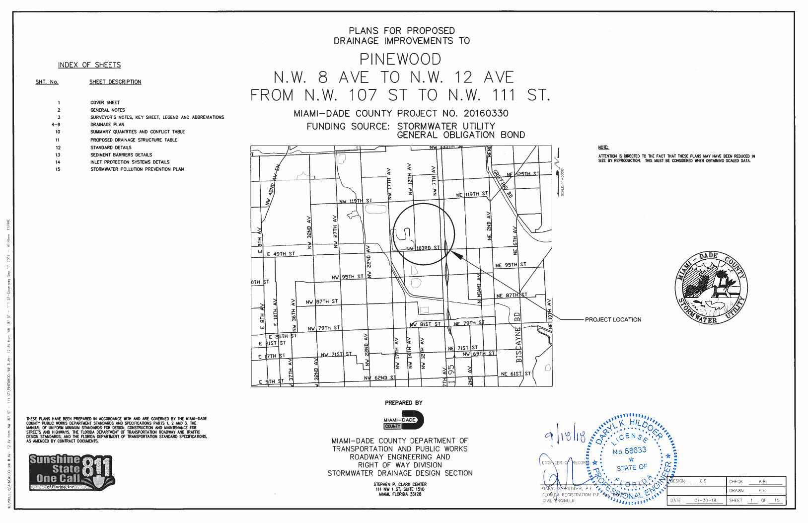
Drainage Improvements to
Pinewood
Miami-Dade County
Supplemental Solicitation
and Contract Documents
Small Business Enterprise-Construction Program (SBE-CONST.): SBE-CONST. Level: I
Community Workforce Program: 10%
DTPW Capital Improvements Engineer: Elva Rosa Reyes
RPQ Issue Date: December 19, 2018

TABLE OF CONTENTS
SECTION 1: INVITATION TO BID
SECTION 2: SOLICITATION FORMS
BID FORM
APPENDIX 5A
ACKNOWLEDGEMENT OF ADDENDA
SURETY BID BOND FORM
CERTIFICATE OF ASSURANCE
COLLUSION AFFIDAVIT
AFFIRMATION OF VENDOR AFFIDAVITS
FAIR WAGE AFFIDAVIT
SECTION 3: INSTRUCTION TO BIDDERS
SUPPLEMENTARY INSTRUCTIONS TO BIDDERS
SECTION 4: SUPPLEMENTAL INFORMATION
SAMPLE SURETY PERFORMANCE AND PAYMENT BOND
SOIL BORINGS AND PERCOLATION TEST
SECTION 5: SUPPLEMENTARY CONDITIONS
SECTION 6: SPECIFICATIONS
GENERAL REQUIREMENTS
CONSTRUCTION SPECIFICATIONS
SECTION 7: SPECIAL PROVISIONS
SECTION 8: ENGINEERING DRAWINGS

SECTION 1: INVITATION TO BID

INVITATION TO BID
Department of Transportation and Public Works 111 NW 1st Street Suite 1410 Miami FL 33128
MIAMI-DADE COUNTY, FLORIDA REQUEST FOR PRICE QUOTATION (RPQ)Contract No: MCC 7040 Plan - CICC 7040-0/07 RPQ No: 20180277
INVITATION TO BID A RPQ has been issued for the work identified below. If you are interested in submitting a bid for this project, please submit your bid via Sealed Envelopes, attention to Clerk of the Board at 111 NW 1st Street, 17th floor, Miami Fl. 33128 no later than 1/23/2019 at 02:00 PM. If you have any questions, contact Elva Reyes at 305-375-2930.
This RPQ is issued under the terms and conditions of the Miscellaneous Construction Contracts (MCC) Program MCC 7040 Plan.
RPQ DETAILED BREAKDOWN Bid Due Date: 1/23/2019 Time Due: 02:00 PM Submitted Via: Sealed Envelopes SBE-Con.
Level: 1
Estimated Value: $663,853 (excluding Contingencies and Dedicated Allowances) Project Name: Drainage Improvements to PinewoodProject Location: Please, see location below. License Requirements: Primary: General Engineering; General Building Contractor; Paving; Pipe Lines; Pipelines
Engineering Contractor; Underground Utility / Excavation Sub: Paving
Scope of Work: (Contractor must obtain and submit all permits prior to performing any work). Work under this Contract includes furnishing of all supervision, labor, materials, tools,equipment and performing all operations required to construct the Work in accordance with theContract Documents.
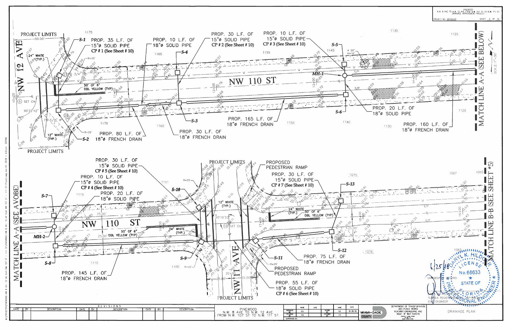
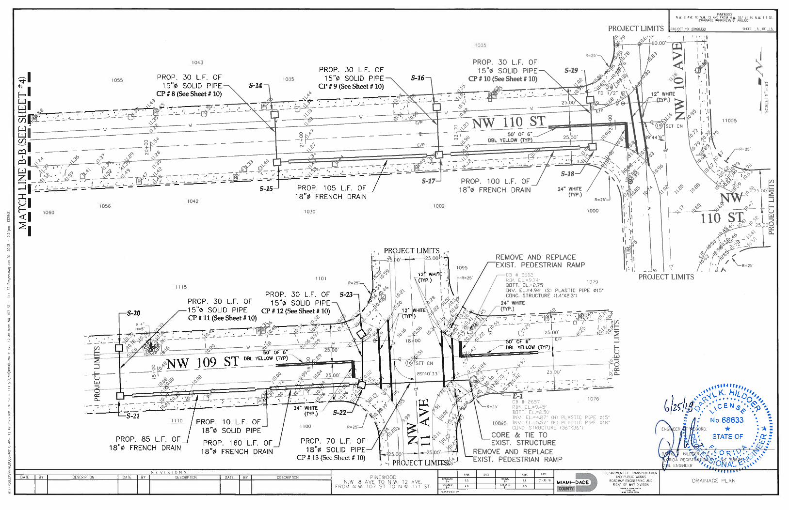
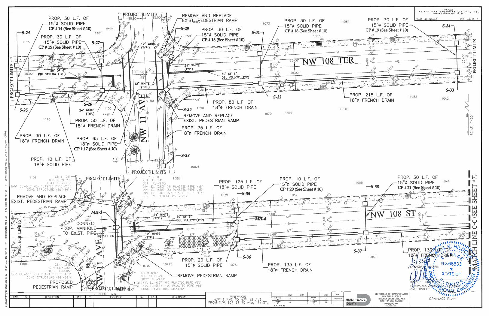
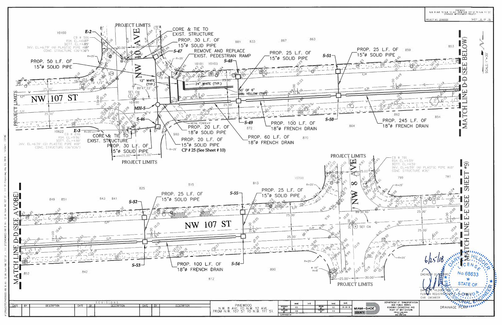
Work includes but is not limited to the construction and installation of drainage structures,French drains, regrade swale, miscellaneous drainage improvements, grading, sodding, andmiscellaneous roadway restoration including construction of concrete curb and gutters, andsidewalks where needed in accordance with the construction plans and specifications.
Document Pickup: Contact: DTPW Capital Improvements Division
Phone No: 305-375-2930 Date: 12/19/2018
Location: 111 NW 1st. Street, Miami Florida 33128 Suite 1410
Pre-Bid Meeting:: YES Mandatory: No Date: 1/10/2019 Time: 10:00 AM Location: 111 NW 1st Street, 14th floor front conference room
Site Meeting: No Mandatory: No Date: Time: Location:
Bid shall be submitted to: Contact: Clerk of the Board Address: 111 NW 1st Street, 17th floor, Miami Fl. 33128 Email: [email protected] FAX # :
Type of Contract: Multiple Trade Method of Award: Lowest Responsible Bidder Method of Payment: Scheduled Monthly Payments Insurance Required: YES
Additional Insurance Required: YES If Yes - Minimum Coverage: $1,000,000.00
Performance & Payment Bond Required: YES Bid Bond Required: YES
Prevailing Wage Rate Required: Heavy Construction
Davis Bacon: NO AIPP: NO Amount:
SBE-Con. Requirements: YES Percentage: 100.00% SBD Certificate of Assurance Form Required:
YES
DBE Requirements: NO Percentage: 0.00% DBE Subcontractor Forms Required: NO CWP Requirements: YES Percentage: 10.00% SBE-S Requirements NO Percentage: 0.00% SBE-G Requirements NO Percentage: 0.00% Liquidated Damages: YES $$ Per Day: $1,665.00Trade Set-a-side: NO If Yes, Trade = For RPQ's less than $10,000, if no LD rate is specified, the County reserves the right to assess actual damages in lieu of LDs.
Design Drawing Included: YES Shop Drawing Included: NO Specifications Included: YES Anticipated Start Date: 5/27/2019 Calendar Days for Project Completion: 300Comments: COMMUNITY WORKFORCE PROGRAM
Prior to entering into a contract and according to the Miami-Dade County Code §2-1701 and amended by Ordinance 13-66, the successful bidder on a construction contract subject to a Community Workforce Program (CWP) goal, must submit to Small Business Development (SBD) through the contracting officer a workforce plan outlining how the CWP goal will be met. Additional information is available at the County’s website at http://www.miamidade.gov/business/contract-requirements.asp#0 .
Contractor must submit a Workforce Plan to the Miami-Dade County Internal Services Department, Small Business Development Division within fifteen (15) days of notification of award of the contract. The County will not enter into the contract until it receives the contractor’s Workforce Plan and deems the Plan acceptable. The Workforce Plan forms may be obtained on the County’s website at http://www.miamidade.gov/business/contract-requirements.asp#0 .
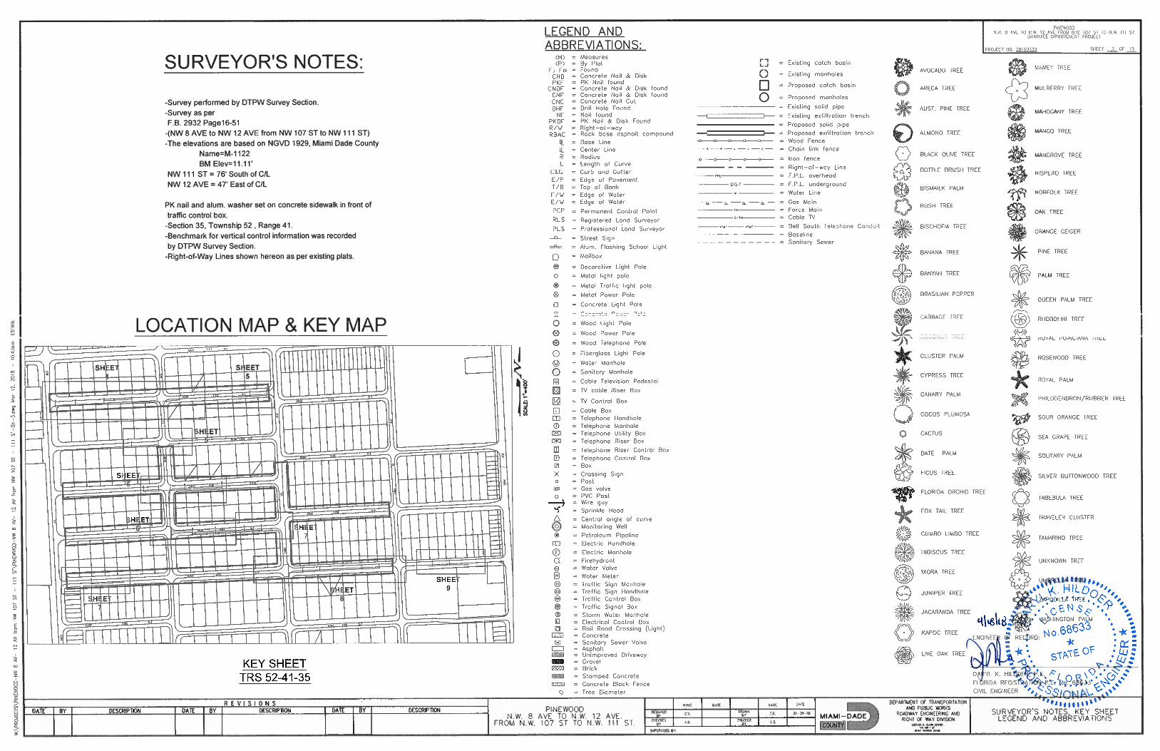
LOCATION OF WORK: A. The location of work to be performed under the terms of this Contract shall be as follows:
1. NW 8 Avenue to NW 12 Avenue from NW 107 Street to NW 111 Street, and NW 107 Street from NW 7 Avenue to NW 8 Avenue.
B. The exact location and limits of construction are as shown on the Plans accompanying these Contract Documents.
LICENSE REQUIREMENTS: At the time of Bid and pursuant to the requirements of Section 10-3 of the Code of Miami-Dade County, Florida and these Solicitation and Contract Documents, the Bidder must hold a valid, current, and active:
a. Certificate of Competency from the County’s Construction Trades Qualifying Board as a General Engineering Contractor or as a Specialty Engineering Contractor, commensurate to the requirements of the Scope of Work, in one or more engineering crafts to include pipeline engineering contractor, or paving engineering contractor. The specialty contractor shall subcontract with a qualified contractor any work which is incidental to the specialty but is specified in the aforementioned Code as being the work of other than that of the Engineering Specialty for which certified; or
b. Certification, as a General Contractor or as a underground utility and excavation contractor, provided by the State of Florida Construction Industry Licensing Board, pursuant to the provisions of Section 489.115 of the Florida Statutes
EXPERIENCE: 1. The Bidder must demonstrate that it has full-time personnel with the necessary experience to perform the Project’s Scope of Work. This experience shall include work in successfully completed projects performed by the identified personnel whose bulk of work performed in the Public Right-of-Way is similar in detail to the Project’s Scope of Work described in these Solicitation Documents. Demonstrate the experience requirement by:
a. Providing a detailed description of at least three (3) projects similar in detail to the Project’s Scope of Work described in these Solicitation Documents and in which the Bidder’s identified personnel is currently engaged or has completed within the past five years. List and describe the aforementioned projects and state whether the work was performed for the County, other government clients, or private entities. The description must identify for each project: 1) The identified personnel and their assigned role and responsibilities for the listed project 2) The client name and address including a contact person and phone number for reference 3) Description of work 4) Total dollar value of the contract 5) Contract duration 6) Statement or notation of whether Bidder’s referenced personnel is/was employed by the prime contractor or subcontractor, and 7) For completed projects, provide letters of certification of final acceptance or similar project closure documentation issued by the client and available Contractor’s performance evaluations.
2. The County reserves the right to request additional information and/or contact listed persons pertaining to bidder’s experience.
INDEMNIFICATION AND INSURANCE REQUIREMENTS The Contractor shall furnish to Department of Transportation and Public Works, 111 NW 1 Street, Miami Florida 33128, Certificate(s) of Insurance which indicate that insurance coverage
has been obtained which meets the requirements as outlined below:
- Worker’s Compensation Insurance for all employees of the Contractor as required by Florida Statute 440. - Commercial General Liability Insurance on a comprehensive basis in an amount not less than $1,000,000 combined single limit per occurrence for bodily injury and property damage. Miami-Dade County must be shown as an additional insured with respect to this coverage. - Automobile Liability Insurance covering all owned, non-owned and hired vehicles used in connection with the work, in an amount not less than $1,000,000 combined single limit per occurrence for bodily injury and property damage.
BID DOCUMENTS: Bidding documents may be purchased from the Miami-Dade County Department of Transportation and Public Works, Capital Improvements Division, 111 NW 1st Street, 14th Floor, Miami, Florida 33128 for a non-refundable fee of One Hundred Dollars ($100.00) per each complete set of documents. Payment shall be in the form of a company check, cashier’s check, or money order payable to the “Miami-Dade County, Department of Transportation and Public Works”.
ADDENDUMS - RFI'S All RFI requests should be e-mailed to [email protected] while copying the Clerk of the Board ([email protected]). The Department of Transportation and Public Works has made changes with regard to how addendums and requests for information (RFI) will be sent to document holders. Be advised that all Addendums, RFI’s, and the document holders list (bidder’s list) are now available to view online at the following web address:
https://www.miamidade.gov/DPMww/SolicitationList.aspx
Therefore, during the advertisement period, the Department will not be sending these documents via certified mail. All document holders must provide a dedicated e-mail address. The Department will only be sending addendums and RFIs by e-mail and posting online at the aforementioned link. The bidders list will be updated every Friday during the advertisement phase of the contract. Please be aware that acknowledgment of receipt of all addendums and RFI’s remain a requirement when submitting bids.
VENDOR REGISTRATION: Due to the new Vendor Registration procedures of the Internal Service Department, Procurement Management Division, updated definitions along with the “Affirmation of Vendor Affidavits” has been added to the Bid Submittal Package. The successful bidder must be registered under this new procedure prior to award.
PRE BID - BID SUBMITTAL DUE DATE: Pre-Bid Conference time and location: Thursday, January 10, 2019, 10:00 AM., at 111 NW 1st Street, 14th Floor front Conference Room.
Bid Due Date, Opening Time & Location: Bid Submittal Time and Location: Wednesday, January 23, 2019, 2:00 P.M. at 111 NW 1 Street, 17th Floor, Clerk of the Board Office.
Bid Opening immediately after Bid Submittal in the 18 Floor.

DISCLOSURE:
• Unless otherwise stipulated in this Invitation to Bid or in the Project’s Solicitation Documents, the minimum insurance requirements are: Worker’s Compensation Insurance as required by Florida Statute 440, Commercial General Liability Insurance on a comprehensive basis in an amount not less than $300,000 combined single limit per occurrence for bodily injury and property damage. Miami-Dade County must be shown as an additional insured with respect to this coverage, Automobile Liability Insurance covering all owned, non-owned and hired vehicles used in connection with the work, in an amount not less than $300,000 combined single limit per occurrence for boldly injury and property damage. Certificate holder must be shown as Miami-Dade County, 111 NW 1st Street, Suite 2340, Miami, FL 33128, with a 30 day cancellation notification requirement. Proof of Insurance will be required for each award.
• All 7040 RPQs are 100% Set-aside solicitations - solely for certified Small Business Enterprise-Construction (SBE-Con) firms registered in the MCC 7040 Plan. Registered SBE-Con firms are invited to bid based on the project’s primary license requirement, estimated value and the contractors’ certification participation level. The SBE-Con Participation Level will be stipulated on the RPQ and the Invitation to Bid or in the Project’s Solicitation Documents. All bidders prime and sub contractors must be SBE-Con certified.
• All Prime Contractors submitting a bid for RPQ/Project with a Small Business Measures (s) MUST submit the Small Business Development “CERTIFICATE OF ASSURANCE” form properly completed, signed and notarized with their bid document at the time of Bid Submittal. FAILURE TO SUBMIT THE REQUIRED CERTIFICATE OF ASSURANCE FORM AT THE TIME OF BID SUBMISSION SHALL RENDER THE BID NON COMPLIANT TO THE CONTRACT REQUIREMENT AND SECTION 10.33.02 OF THE CODE OF MIAMI-DADE COUNTY.
• 7040 and 7360 RPQs with an estimated project value in excess of $700,000.00 may be assigned a Small Business Enterprise Goods (SBE-G) or Small Business Services (SBE-S) program goal. The SBE-G or SBE-S goal if applicable will be will be stipulated on the RPQ and the Invitation to Bid or in the Project’s Solicitation Documents.
• All RPQs with an estimated project value $100,000 or above are subject to Responsible Wage Rates. The wage rate will be stipulated on the RPQ and the Invitation to Bid or in the Project’s Solicitation Documents.
SECTION 2: SOLICITATION FORMS
All forms and documents contained in this Section shall be completed pursuant to these Contract Documents and submitted with the Bid Submittal for this Project.

BID FORM

Bid FormPROJECT TITLE: Drainage Improvements to Pinewood PROJECT NO: 20180277
IF THIS PROPOSAL IS ACCEPTED, THE UNDERSIGNED AGREES TO COMPLETE ALL WORK UNDER THIS CONTRACT WITHIN THREE HUNDRED (300) CALENDAR DAYS AFTER THE EFFECTIVE DATE ESTABLISHED IN THE *NOTICE TO PROCEED WITH CONTRACT WORK*.
CSCCRP_PROJECT_BID_ITEMS12/12/2018 11:48 AM Bidder must fill-in completely the next page for the bid to be valid. Page 1 of 5
QuantityItem No DescriptionUnit Written Unit Amount UnitPrice
Total
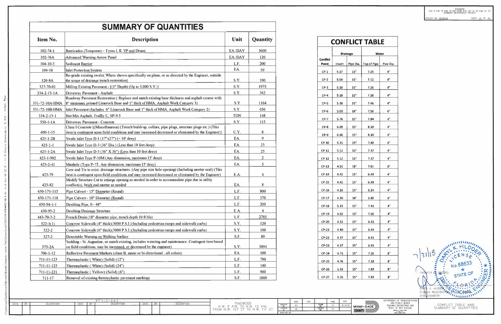
3,600.0
120.0
200.0
59.0
100.0
1,975.0
1,164.0
656.0
148.0
342.0
115.0
8.0
102-74-1
102-76A
104-10-3
104-18
120-8A
327-70-01
331-72-10A-HMA
331-72-10B-HMA
334-2-13-1
334-2-13-1A
350-1-1A
400-1-15
EA/DAY
EA/DAY
L.F.
EA.
S.Y.
S.Y.
S.Y.
S.Y.
TON
S.Y.
S.Y.
C.Y.
BARRICADES ( TEMPORARY- TYPE I, II, VP & DRUM ).
ADVANCE WARNING ARROW PANEL
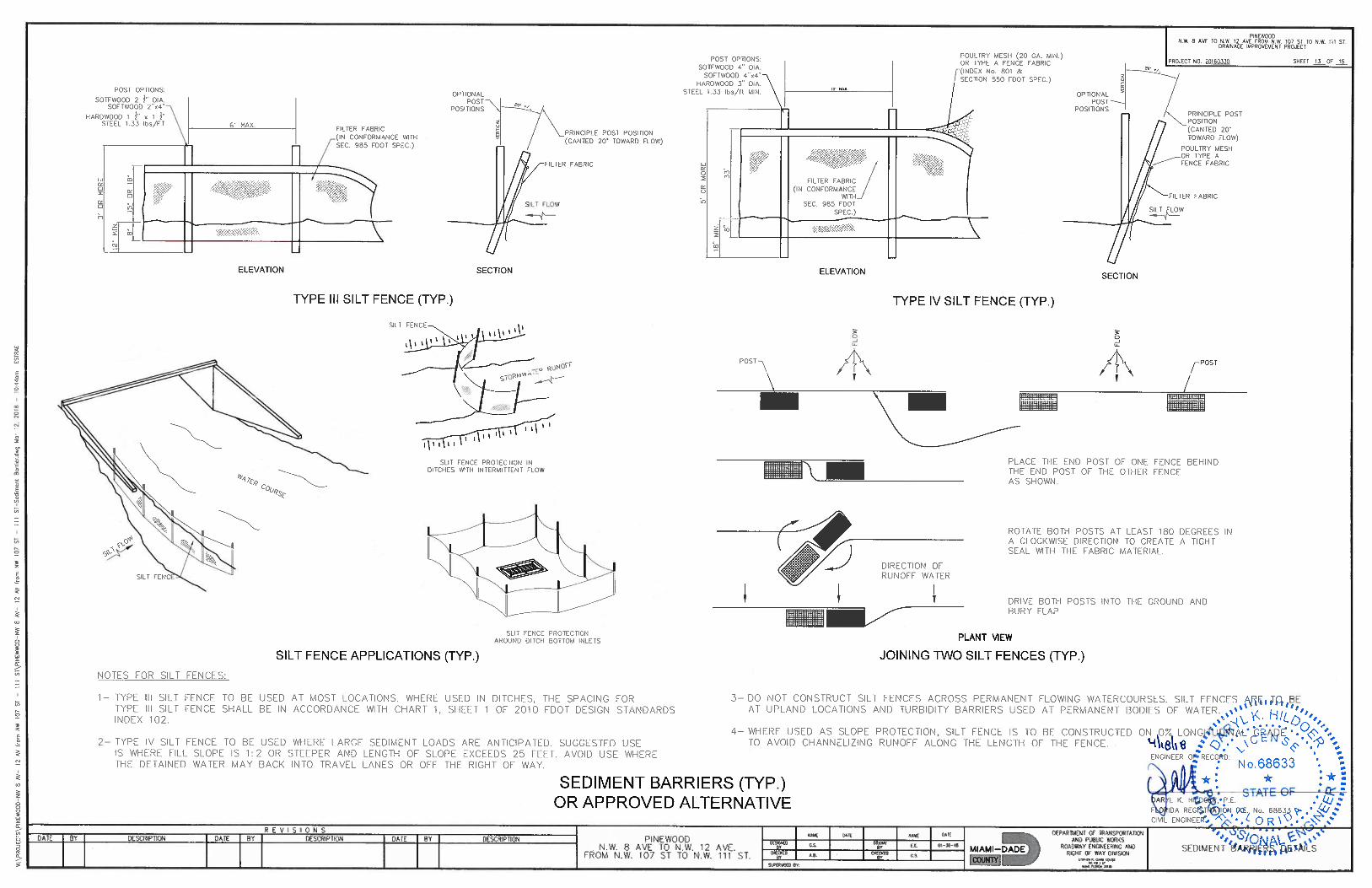
Sediment Barrier
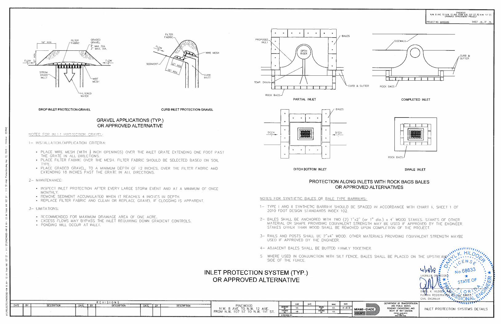
Inlet Protection System
RE-GRADE EXISTING SWALE (Where shown specifically on plans, or as directed by the Engineer, outside the scope of drainage trench restoration)
MILLING, 1" AVERAGE DEPTH
ROADWAY PAVEMENT RESTORATION ( Replace and match existing base thickness and asphalt course with 8" minimum, primed Limerock Base and 1" thick of HMA, Asphalt Work Category 3)INLET PAVEMENT (Includes 6" Limerock Base and 1" thick of HMA, Asphalt Work Category 2)
Hot Mix Asphalt, Traffic C, SP-9.5
Driveway Pavement-Asphalt
Driveway Pavement-Concrete
CLASS I CONCRETE [(Miscellaneous) (Collars, pipe plugs,structure plugs etc.) (This item is contingent upon field conditions and may be increased decreased or eliminated by the Engineer)]
Bid FormPROJECT TITLE: Drainage Improvements to Pinewood PROJECT NO: 20180277
IF THIS PROPOSAL IS ACCEPTED, THE UNDERSIGNED AGREES TO COMPLETE ALL WORK UNDER THIS CONTRACT WITHIN THREE HUNDRED (300) CALENDAR DAYS AFTER THE EFFECTIVE DATE ESTABLISHED IN THE *NOTICE TO PROCEED WITH CONTRACT WORK*.
CSCCRP_PROJECT_BID_ITEMS12/12/2018 11:48 AM Bidder must fill-in completely the next page for the bid to be valid. Page 2 of 5
QuantityItem No DescriptionUnit Written Unit Amount UnitPrice
Total
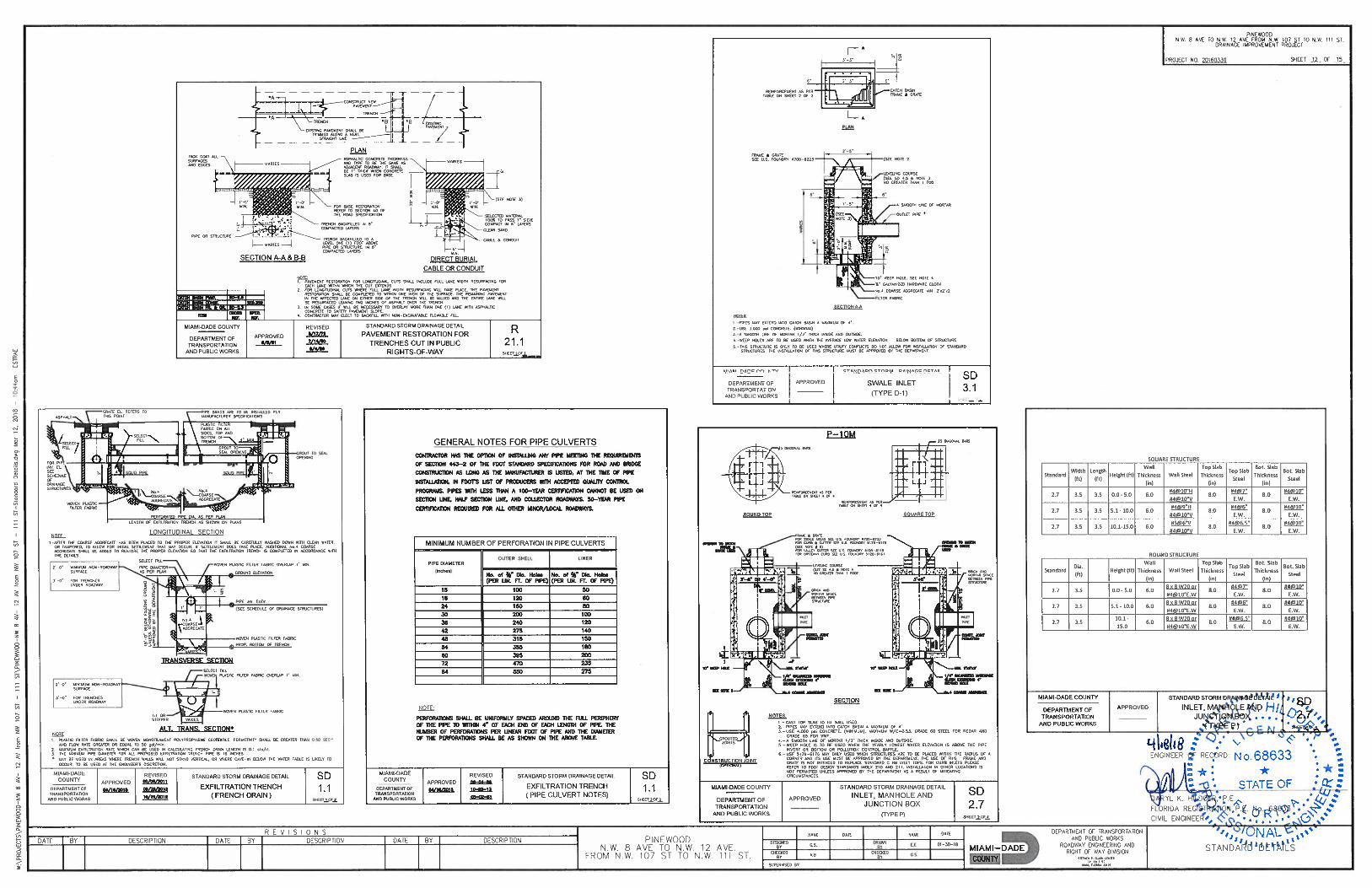
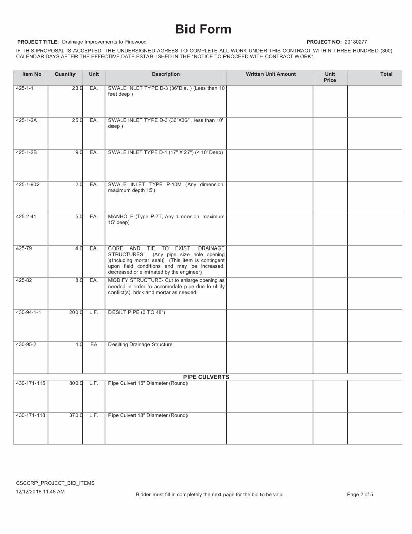
PIPE CULVERTS
23.0
25.0
9.0
2.0
5.0
4.0
8.0
200.0
4.0
800.0
370.0
425-1-1
425-1-2A
425-1-2B
425-1-902
425-2-41
425-79
425-82
430-94-1-1
430-95-2
430-171-115
430-171-118
EA.
EA.
EA.
EA.
EA.
EA.
EA.
L.F.
EA
L.F.
L.F.
SWALE INLET TYPE D-3 (36"Dia. ) (Less than 10 feet deep )
SWALE INLET TYPE D-3 (36"X36" , less than 10'deep )
SWALE INLET TYPE D-1 (17" X 27") (< 10' Deep)
SWALE INLET TYPE P-10M (Any dimension, maximum depth 15')
MANHOLE (Type P-7T, Any dimension, maximum 15' deep)
CORE AND TIE TO EXIST. DRAINAGE STRUCTURES. (Any pipe size hole opening )(Including mortar seal)] (This item is contingent upon field conditions and may be increased, decreased or eliminated by the engineer)MODIFY STRUCTURE- Cut to enlarge opening as needed in order to accomodate pipe due to utility conflict(s), brick and mortar as needed.
DESILT PIPE (0 TO 48")
Desilting Drainage Structure
Pipe Culvert 15" Diameter (Round)
Pipe Culvert 18" Diameter (Round)
Bid FormPROJECT TITLE: Drainage Improvements to Pinewood PROJECT NO: 20180277
IF THIS PROPOSAL IS ACCEPTED, THE UNDERSIGNED AGREES TO COMPLETE ALL WORK UNDER THIS CONTRACT WITHIN THREE HUNDRED (300) CALENDAR DAYS AFTER THE EFFECTIVE DATE ESTABLISHED IN THE *NOTICE TO PROCEED WITH CONTRACT WORK*.
CSCCRP_PROJECT_BID_ITEMS12/12/2018 11:48 AM Bidder must fill-in completely the next page for the bid to be valid. Page 3 of 5
QuantityItem No DescriptionUnit Written Unit Amount UnitPrice
Total
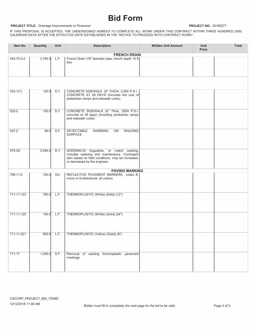
FRENCH DRAIN
PAVING MARKING
2,785.0
120.0
100.0
80.0
3,094.0
100.0
790.0
140.0
900.0
1,000.0
443-70-3-2
522-1(1)
522-2
527-2
575-2A
706-1-12
711-11-123
711-11-125
711-11-221
711-17
L.F.
S.Y.
S.Y.
S.F.
S.Y.
EA.
L.F.
L.F.
L.F.
S.F.
French Drain (18" diameter pipe, trench depth 10 ft bls)
CONCRETE SIDEWALK [4" THICK, 3,000 P.S.I.CONCRETE AT 28 DAYS (Includes the cost of pedestrian ramps and sidewalk curbs)
CONCRETE SIDEWALK (6" Thick, 3000 P.S.I. concrete at 28 days) (including pedestrian ramps and sidewalk curbs)
DETECTABLE WARNING ON WALKING SURFACE
SODDING-St Augustine, or match existing, includes watering and maintenance. Contingent item based on field conditions, may be increased, or decreased by the engineer.
REFLECTIVE PAVEMENT MARKERS (class B, mono or bi-directional, all colors)
THERMOPLASTIC (White) (Solid) (12")
THERMOPLASTIC (White) (Solid) (24")
THERMOPLASTIC (Yellow) (Solid) (6")
Removal of existing thermoplastic pavement markings
Bid FormPROJECT TITLE: Drainage Improvements to Pinewood PROJECT NO: 20180277
IF THIS PROPOSAL IS ACCEPTED, THE UNDERSIGNED AGREES TO COMPLETE ALL WORK UNDER THIS CONTRACT WITHIN THREE HUNDRED (300) CALENDAR DAYS AFTER THE EFFECTIVE DATE ESTABLISHED IN THE *NOTICE TO PROCEED WITH CONTRACT WORK*.
CSCCRP_PROJECT_BID_ITEMS12/12/2018 11:48 AM Bidder must fill-in completely the next page for the bid to be valid. Page 4 of 5
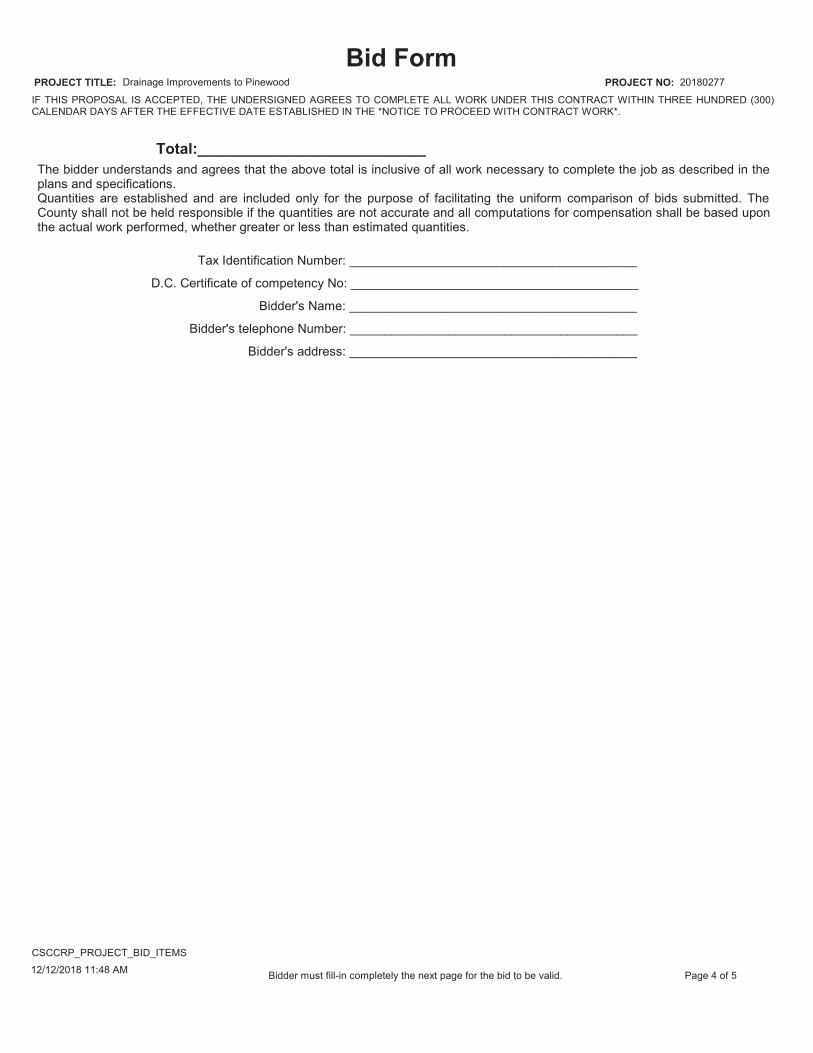
Tax Identification Number: _________________________________________
D.C. Certificate of competency No: _________________________________________
Bidder's Name: _________________________________________
Bidder's telephone Number: _________________________________________
Bidder's address: _________________________________________
The bidder understands and agrees that the above total is inclusive of all work necessary to complete the job as described in the plans and specifications.Quantities are established and are included only for the purpose of facilitating the uniform comparison of bids submitted. The County shall not be held responsible if the quantities are not accurate and all computations for compensation shall be based upon the actual work performed, whether greater or less than estimated quantities.
Total:___________________________

Bid FormPROJECT TITLE: Drainage Improvements to Pinewood PROJECT NO: 20180277
IF THIS PROPOSAL IS ACCEPTED, THE UNDERSIGNED AGREES TO COMPLETE ALL WORK UNDER THIS CONTRACT WITHIN THREE HUNDRED (300) CALENDAR DAYS AFTER THE EFFECTIVE DATE ESTABLISHED IN THE *NOTICE TO PROCEED WITH CONTRACT WORK*.
CSCCRP_PROJECT_BID_ITEMS12/12/2018 11:48 AM Bidder must fill-in completely the next page for the bid to be valid. Page 5 of 5
BIDDER ACKNOWLEDGES THAT INCLUDED IN THE VARIOUS ITEMS OF THE PROPOSAL AND IN THE TOTAL BID PRICE ARE COSTS FOR COMPLYING WITH THE FLORIDA TRENCH SAFETY ACT (90-96), LAWS OF FLA. EFFECTIVE OCTOBER 1st, 1990. THE BIDDER FURTHER IDENTIFIES THE COSTS TO BE SUMMARIZED BELOW:
Trench SafetyMeasure
(Description)
Units of Measure(LF, SY)
Unit(Quantity)
UnitCost
ExtendedCost
FAILURE TO COMPLETE THE ABOVE MAY RESULT IN THE BID BEING DECLARED NON-RESPONSIVE
A.
B.
C.
D.

ATTACHMENT 5A
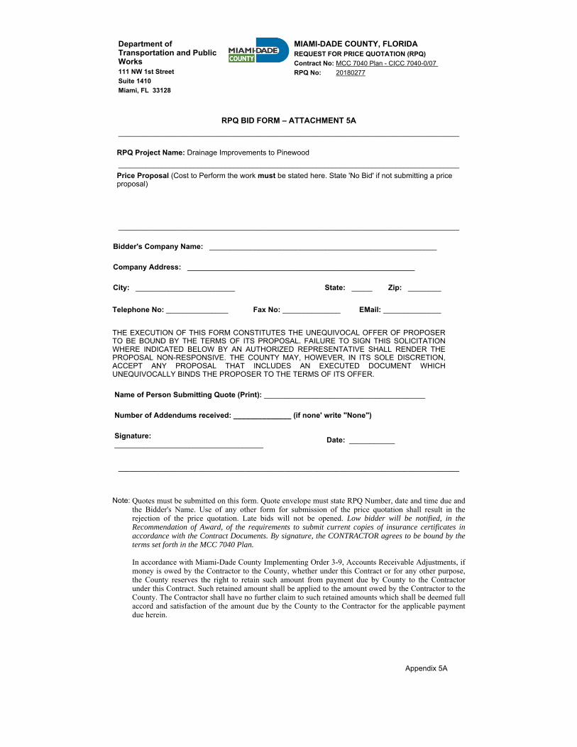
Department of Transportation and Public Works111 NW 1st Street Suite 1410 Miami, FL 33128
MIAMI-DADE COUNTY, FLORIDA REQUEST FOR PRICE QUOTATION (RPQ)Contract No: MCC 7040 Plan - CICC 7040-0/07 RPQ No: 20180277
RPQ BID FORM – ATTACHMENT 5A______________________________________________________________________________________
RPQ Project Name: Drainage Improvements to Pinewood ______________________________________________________________________________________ Price Proposal (Cost to Perform the work must be stated here. State 'No Bid' if not submitting a price proposal)
______________________________________________________________________________________
Bidder's Company Name: _______________________________________________________
Company Address: _______________________________________________________
City: ________________________ State: _____ Zip: ________
Telephone No: _______________ Fax No: ______________ EMail: ______________
THE EXECUTION OF THIS FORM CONSTITUTES THE UNEQUIVOCAL OFFER OF PROPOSERTO BE BOUND BY THE TERMS OF ITS PROPOSAL. FAILURE TO SIGN THIS SOLICITATIONWHERE INDICATED BELOW BY AN AUTHORIZED REPRESENTATIVE SHALL RENDER THEPROPOSAL NON-RESPONSIVE. THE COUNTY MAY, HOWEVER, IN ITS SOLE DISCRETION,ACCEPT ANY PROPOSAL THAT INCLUDES AN EXECUTED DOCUMENT WHICHUNEQUIVOCALLY BINDS THE PROPOSER TO THE TERMS OF ITS OFFER.
Name of Person Submitting Quote (Print): _______________________________________
Number of Addendums received: ______________ (if none' write "None")
Signature: ____________________________________ Date: ___________
______________________________________________________________________________________
Note: Quotes must be submitted on this form. Quote envelope must state RPQ Number, date and time due and the Bidder's Name. Use of any other form for submission of the price quotation shall result in the rejection of the price quotation. Late bids will not be opened. Low bidder will be notified, in the Recommendation of Award, of the requirements to submit current copies of insurance certificates in accordance with the Contract Documents. By signature, the CONTRACTOR agrees to be bound by the terms set forth in the MCC 7040 Plan.
In accordance with Miami-Dade County Implementing Order 3-9, Accounts Receivable Adjustments, if money is owed by the Contractor to the County, whether under this Contract or for any other purpose, the County reserves the right to retain such amount from payment due by County to the Contractor under this Contract. Such retained amount shall be applied to the amount owed by the Contractor to the County. The Contractor shall have no further claim to such retained amounts which shall be deemed full accord and satisfaction of the amount due by the County to the Contractor for the applicable payment due herein.
Appendix 5A

ACKNOWLEDGEMENT OF ADDENDA
MIAMI-DADE COUNTY DEPARTMENT OF TRANSPORTATION AND PUBLIC WORKS (DTPW)
PROJECT: Drainage Improvements to Pinewood Project No. 20180277
DTPW - Rev. 2/09/16
ACKNOWLEDGEMENT OF ADDENDA (Must be completed and submitted with required solicitation documents)
Instructions: Complete Part I or Part II, as applicable.
PART I: Listed below are the dates of issue for each Addendum received in connection with this solicitation.
Addendum #1, Dated ____________________________, 201___ Addendum #2, Dated ____________________________, 201___ Addendum #3, Dated ____________________________, 201___ Addendum #4, Dated ____________________________, 201___ Addendum #5, Dated ____________________________, 201___ Addendum #6, Dated ____________________________, 201___ Addendum #7, Dated ____________________________, 201___ Addendum #8, Dated ____________________________, 201___ Addendum #9, Dated ____________________________, 201___ Addendum #10, Dated ____________________________, 201___
PART II:
____ No Addendum was received in connection with this solicitation.
Authorized Signature:____________________________________ Date: _________________ Print Name: _________________________________________ Title: ___________________ Firm Name: ___________________________________________________________________

SURETY BID BOND FORM
�
SURETY BID BOND DATE BOND EXECUTED (must not be later than bid opening date) REV. 0216
DTPW
PRINCIPAL (Full legal name and business address) TYPE OF ORGANIZATION (“X” one)
Individual Partnership
Joint Venture Corporation
SURETY (Name and business address)
PENAL SUM OF BOND *********************************************Five Percent of the Total amount Bid*********************************************
BID IDENTIFICATION Bid Opening Date:Project No: 20180277
County Project Name: Drainage Improvements to Pinewood
OBLIGATION
Principal and Surety, jointly and severally, bind themselves, their heirs, executors, administrators, successors, and assigns to pay to Miami-Dade County, Florida (herein after County) upon default of Principal the penal sum set forth on the face of this Bond.
Principal and Surety agree that the Penal Sum of the Bond is a liquidated damage reasonably estimated to compensate the County for damages suffered as a result of the Principal’s default including but not limited to any resulting from delay, reprocurement costs and incremental costs of contracting.
Default of Principal shall occur in the event that the Principal withdraws Bid within 180 days after bid opening (or any extension thereof agreed to in writing by the Bidder and County); or, after proper notification of intent to Contract from the County, fails to comply with all pre-award requirements including, but not limited to providing Payment and Performance Bonds with good and sufficient surety and the necessary Insurance Certificates pursuant to the Contract Documents, and enter into a written Contract with the County, as may be required; all within 10 days after the prescribed forms are presented to Principal for signature or as otherwise required by the Bidding Documents.
Payment under this Bond will be due and payable upon default of Principal and within 30 calendar days after receipt by Principal and Surety of written notice of default from County, which notice will be given with reasonable promptness, identifying this Bond and the Project.
Surety shall cause to be attached to this Bond a current and effective Power of Attorney evidencing the authority of the officer, agent, or representative who executed this Bond on behalf of Surety to execute, seal, and deliver such Bond and bind the Surety thereby.
CONDITIONS
The Principal has submitted the Bid identified above.
THEREFORE
By executing this instrument Surety agrees that its obligation is not impaired by any extension(s) of the time for acceptance of the bid that the Principal may grant to the County. Notice to the Surety of extensions is waived. However, waiver of the notice applies only to extensions aggregating not more than 60 calendar days in addition to the period originally allowed for acceptance of the bid. Any changes in or under the Contract Documents and compliance or noncompliance with any formalities connected with the Contract or the changes does not affect Surety's obligation under this Bond.
WITNESS
The Principal and Surety executed this Bond and affixed their seals on the above date. Copy of Authorized Agent's current Identification Card as issued by State of Florida Insurance Commissioner must be attached.
PRINCIPAL
SIGNATURE
Principal’s Corporate Seal
NAME AND TITLE (Typed)
SURETY
SIGNATURE OF ATTORNEY-IN-FACT
Surety’s Corporate Seal
PRINTED NAME OF ATTORNEY-IN-FACT (Typed)
SIGNATURE OF AUTHORIZED FLORIDA AGENT
PRINTED NAME OF AUTHORIZED FLORIDA AGENT (Typed)
�

CERTIFICATE OF ASSURANCE
SMALL BUSINESS DEVELOPMENTCERTIFICATE OF ASSURANCE
SMALL BUSINESS PARTICIPATION ON COUNTY PROJECTS
This form must be submitted with bid documents by all bidders/proposers on a Miami-Dade County project with Small Business Enterprise (“SBE”) program measure(s).
Project No.: 20180277 Project Title: Drainage Improvements to Pinewood
Bidder/Proposer:
Address: City State ZIP
Phone Number: Email address:
The bidder/proposer is committed to meeting the established measure(s) assigned to this project: % SBE-A/E, 100.00% SBE-Cons, N Trade Set-aside SBE-Cons, % SBE-G, and/or % SBE-S.(For Goals, write in the percentage. For Set-aside, put Y or N.)
Print Prime Bidder’s Name & Title Prime Bidder’s Signature Date
To satisfy the requirements for Step 1 - Bid Submittal and Compliance with Small Business Enterprise Program(s), the following are required:
1. Acknowledgement of the SBE-A/E, SBE-Construction, SBE-G and/or SBE-S measure(s) established for this project via this Certificate of Assurance.
2. Agree to engage in the solicitation of approved Miami-Dade County Small Business Enterprise firm(s) to achieve the established measure(s) as indicated in the Project Documents (specifications).
3. Agree to submit a list of certified SBEs to satisfy the measures via Miami-Dade County’s Business Management Workforce System (“BMWS”) within the specified timeframe, upon email notification from the Small Business Development (“SBD”) Division or BMWS.
To satisfy the requirements for Step 2 – Bid Evaluation and Recommendation for Award, please attest that:
I understand that my company will be deemed non-compliant and not eligible for award if I fail to (1) submit this form with my bid documents and/or (2) submit my company’s Utilization Plan which shall list all certified Miami-Dade County Small Business Enterprise firms whom will be subcontracted with to satisfy the project’s established SBE measure(s) via BMWS, within the specified timeframe, upon email notification from SBD or BMWS. Each SBE subcontractor, subconsultant, and/or sub-vendor will also be required to confirm its contractual relationship via BMWS, within the specified timeframe, for final approval by SBD.
STATE OF FLORIDA
COUNTY OF MIAMI-DADE
BEFORE ME, an officer duly authorized to administer oaths and take acknowledgement, personally appeared , who being first sworn deposes and affirms that the provided information statements are true and correct to the best of his/her knowledge information and belief.
Signature of Owner
SWORN TO and subscribed before me this day of , 20
Signature of Notary Public-State of Florida
My Commission Expires:

COLLUSION AFFIDAVIT
COLLUSION AFFIDAVIT
(Code of Miami-Dade County Section 2-8.1.1 and 10-33.1) (Ordinance No. 08-113)
BEFORE ME, A NOTARY PUBLIC, personally appeared _______________________ who being duly sworn
states: (insert name of affiant)
I am over 18 years of age, have personal knowledge of the facts stated in this affidavit and I am an owner, officer, director, principal shareholder and/or I am otherwise authorized to bind the bidder of this contract. I state that the bidder of this contract:
is not related to any of the other parties bidding in the competitive solicitation, and that the contractor’s proposal is genuine and not sham or collusive or made in the interest or on behalf of any person not therein named, and that the contractor has not, directly or indirectly, induced or solicited any other proposer to put in a sham proposal, or any other person, firm, or corporation to refrain from proposing, and that the proposer has not in any manner sought by collusion to secure to the proposer an advantage over any other proposer.
OR is related to the following parties who bid in the solicitation which are identified and listed below:
_________________________ _______________________ _________________________ _______________________ _________________________ _______________________ Note: Any person or entity that fails to submit this executed affidavit shall be ineligible for contract award. In the event a recommended contractor identifies related parties in the competitive solicitation its bid shall be presumed to be collusive and the recommended contractor shall be ineligible for award unless that presumption is rebutted by presentation of evidence as to the extent of ownership, control and management of such related parties in the preparation and submittal of such bids or proposals. Related parties shall mean bidders or proposers or the principals, corporate officers, and managers thereof which have a direct or indirect ownership interest in another bidder or proposer for the same agreement or in which a parent company or the principals thereof of one (1) bidder or proposer have a direct or indirect ownership interest in another bidder or proposer for the same agreement. Bids or proposals found to be collusive shall be rejected. By: 20
Signature of Affiant Date ___/___-___/___/___/___/___/___/___/ Printed Name of Affiant and Title Federal Employer Identification Number Printed Name of Firm Address of Firm
SUBSCRIBED AND SWORN TO (or affirmed) before me this ______ day of ________, 20
He/She is personally known to me or has presented as identification. Type of identification Signature of Notary Serial Number Print or Stamp Name of Notary Expiration Date
Notary Public – State of
Notary Seal Revised 4/12/99

AFFIRMATION OF VENDOR AFFIDAVITS
Miami-Dade County
New Vendor Registration and Bid/Proposal Contract Language
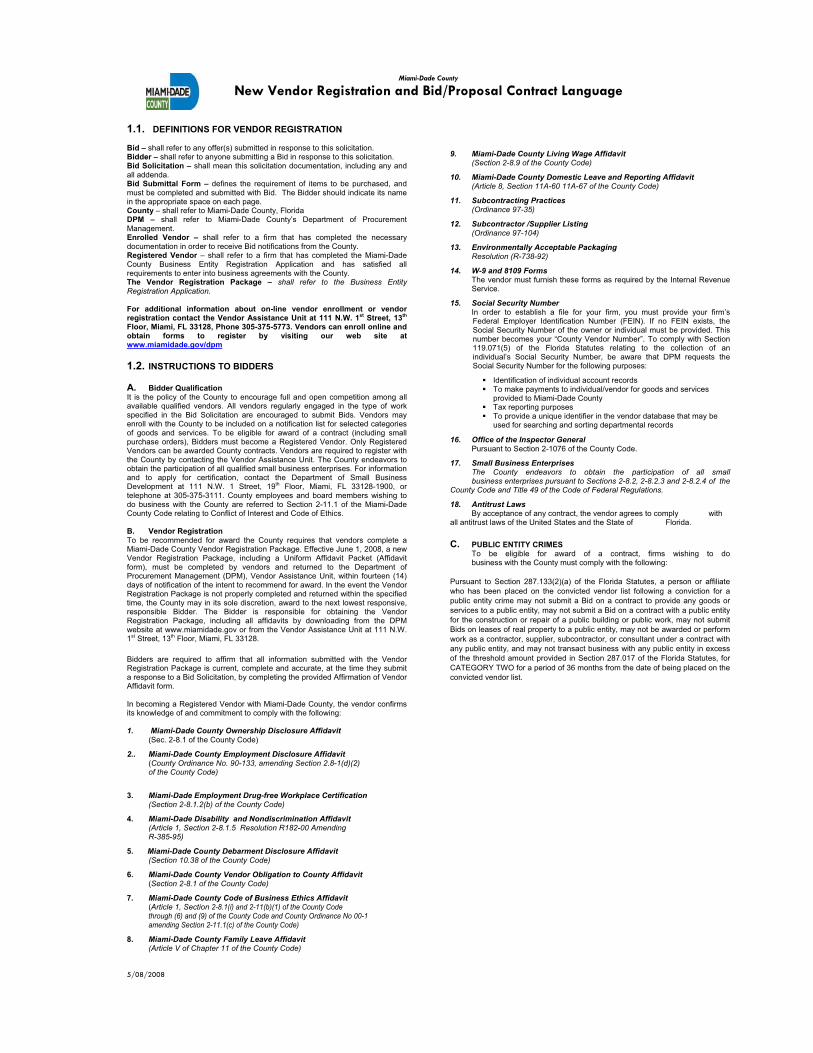
1.1. DEFINITIONS FOR VENDOR REGISTRATION
Bid – shall refer to any offer(s) submitted in response to this solicitation. Bidder – shall refer to anyone submitting a Bid in response to this solicitation. Bid Solicitation – shall mean this solicitation documentation, including any and all addenda. Bid Submittal Form – defines the requirement of items to be purchased, and must be completed and submitted with Bid. The Bidder should indicate its name in the appropriate space on each page. County – shall refer to Miami-Dade County, Florida DPM – shall refer to Miami-Dade County’s Department of Procurement Management. Enrolled Vendor – shall refer to a firm that has completed the necessary documentation in order to receive Bid notifications from the County. Registered Vendor – shall refer to a firm that has completed the Miami-Dade County Business Entity Registration Application and has satisfied all requirements to enter into business agreements with the County. The Vendor Registration Package – shall refer to the Business Entity Registration Application.
For additional information about on-line vendor enrollment or vendor registration contact the Vendor Assistance Unit at 111 N.W. 1st Street, 13th
Floor, Miami, FL 33128, Phone 305-375-5773. Vendors can enroll online and obtain forms to register by visiting our web site at www.miamidade.gov/dpm
1.2. INSTRUCTIONS TO BIDDERS
A. Bidder Qualification It is the policy of the County to encourage full and open competition among all available qualified vendors. All vendors regularly engaged in the type of work specified in the Bid Solicitation are encouraged to submit Bids. Vendors may enroll with the County to be included on a notification list for selected categories of goods and services. To be eligible for award of a contract (including small purchase orders), Bidders must become a Registered Vendor. Only Registered Vendors can be awarded County contracts. Vendors are required to register with the County by contacting the Vendor Assistance Unit. The County endeavors to obtain the participation of all qualified small business enterprises. For information and to apply for certification, contact the Department of Small Business Development at 111 N.W. 1 Street, 19th Floor, Miami, FL 33128-1900, or telephone at 305-375-3111. County employees and board members wishing to do business with the County are referred to Section 2-11.1 of the Miami-Dade County Code relating to Conflict of Interest and Code of Ethics.
B. Vendor RegistrationTo be recommended for award the County requires that vendors complete a Miami-Dade County Vendor Registration Package. Effective June 1, 2008, a new Vendor Registration Package, including a Uniform Affidavit Packet (Affidavit form), must be completed by vendors and returned to the Department of Procurement Management (DPM), Vendor Assistance Unit, within fourteen (14) days of notification of the intent to recommend for award. In the event the Vendor Registration Package is not properly completed and returned within the specified time, the County may in its sole discretion, award to the next lowest responsive, responsible Bidder. The Bidder is responsible for obtaining the Vendor Registration Package, including all affidavits by downloading from the DPM website at www.miamidade.gov or from the Vendor Assistance Unit at 111 N.W. 1st Street, 13th Floor, Miami, FL 33128.
Bidders are required to affirm that all information submitted with the Vendor Registration Package is current, complete and accurate, at the time they submit a response to a Bid Solicitation, by completing the provided Affirmation of Vendor Affidavit form.
In becoming a Registered Vendor with Miami-Dade County, the vendor confirms its knowledge of and commitment to comply with the following:
1. Miami-Dade County Ownership Disclosure Affidavit (Sec. 2-8.1 of the County Code)
2.. Miami-Dade County Employment Disclosure Affidavit (County Ordinance No. 90-133, amending Section 2.8-1(d)(2) of the County Code)
3. Miami-Dade Employment Drug-free Workplace Certification (Section 2-8.1.2(b) of the County Code)
4. Miami-Dade Disability and Nondiscrimination Affidavit (Article 1, Section 2-8.1.5 Resolution R182-00 Amending
R-385-95)
5. Miami-Dade County Debarment Disclosure Affidavit(Section 10.38 of the County Code)
6. Miami-Dade County Vendor Obligation to County Affidavit (Section 2-8.1 of the County Code)
7. Miami-Dade County Code of Business Ethics Affidavit (Article 1, Section 2-8.1(i) and 2-11(b)(1) of the County Code through (6) and (9) of the County Code and County Ordinance No 00-1 amending Section 2-11.1(c) of the County Code)
8. Miami-Dade County Family Leave Affidavit (Article V of Chapter 11 of the County Code)
9. Miami-Dade County Living Wage Affidavit (Section 2-8.9 of the County Code)
10. Miami-Dade County Domestic Leave and Reporting Affidavit (Article 8, Section 11A-60 11A-67 of the County Code)
11. Subcontracting Practices (Ordinance 97-35)
12. Subcontractor /Supplier Listing(Ordinance 97-104)
13. Environmentally Acceptable Packaging Resolution (R-738-92)
14. W-9 and 8109 FormsThe vendor must furnish these forms as required by the Internal Revenue Service.
15. Social Security NumberIn order to establish a file for your firm, you must provide your firm’s Federal Employer Identification Number (FEIN). If no FEIN exists, the Social Security Number of the owner or individual must be provided. This number becomes your “County Vendor Number”. To comply with Section 119.071(5) of the Florida Statutes relating to the collection of an individual’s Social Security Number, be aware that DPM requests the Social Security Number for the following purposes:
Identification of individual account records To make payments to individual/vendor for goods and services
provided to Miami-Dade County Tax reporting purposes To provide a unique identifier in the vendor database that may be
used for searching and sorting departmental records
16. Office of the Inspector General Pursuant to Section 2-1076 of the County Code.
17. Small Business Enterprises The County endeavors to obtain the participation of all small business enterprises pursuant to Sections 2-8.2, 2-8.2.3 and 2-8.2.4 of the County Code and Title 49 of the Code of Federal Regulations.
18. Antitrust Laws By acceptance of any contract, the vendor agrees to comply with all antitrust laws of the United States and the State of Florida.
C. PUBLIC ENTITY CRIMES To be eligible for award of a contract, firms wishing to do business with the County must comply with the following:
Pursuant to Section 287.133(2)(a) of the Florida Statutes, a person or affiliate
who has been placed on the convicted vendor list following a conviction for a
public entity crime may not submit a Bid on a contract to provide any goods or
services to a public entity, may not submit a Bid on a contract with a public entity
for the construction or repair of a public building or public work, may not submit
Bids on leases of real property to a public entity, may not be awarded or perform
work as a contractor, supplier, subcontractor, or consultant under a contract with
any public entity, and may not transact business with any public entity in excess
of the threshold amount provided in Section 287.017 of the Florida Statutes, for
CATEGORY TWO for a period of 36 months from the date of being placed on the
convicted vendor list.
5/08/2008
5/09/2008
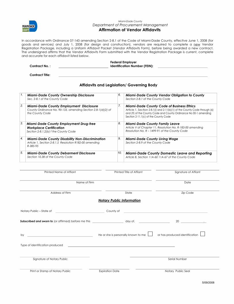
Miami-Dade County
Department of Procurement Management
Affirmation of Vendor Affidavits
In accordance with Ordinance 07-143 amending Section 2-8.1 of the Code of Miami-Dade County, effective June 1, 2008 (for
goods and services) and July 1, 2008 (for design and construction), vendors are required to complete a new Vendor
Registration Package, including a Uniform Affidavit Packet (Vendor Affidavits Form), before being awarded a new contract.
The undersigned affirms that the Vendor Affidavits Form submitted with the Vendor Registration Package is current, complete
and accurate for each affidavit listed below.
Contract No. :
Federal Employer
Identification Number (FEIN):
Contract Title:
Affidavits and Legislation/ Governing Body
1. Miami-Dade County Ownership DisclosureSec. 2-8.1 of the County Code
6. Miami-Dade County Vendor Obligation to CountySection 2-8.1 of the County Code
2. Miami-Dade County Employment Disclosure County Ordinance No. 90-133, amending Section 2.8-1(d)(2) of
the County Code
7. Miami-Dade County Code of Business EthicsArticle 1, Section 2-8.1(i) and 2-11(b)(1) of the County Code through (6)
and (9) of the County Code and County Ordinance No 00-1 amending
Section 2-11.1(c) of the County Code
3. Miami-Dade County Employment Drug-free
Workplace Certification Section 2-8.1.2(b) f the County Code
8. Miami-Dade County Family Leave Article V of Chapter 11, Resolution No. R-183-00 amending
Resolution No. R – 1499-91 of the County Code
4. Miami-Dade County Disability Non-Discrimination Article 1, Section 2-8.1.5 Resolution R182-00 amending
R-385-95
9. Miami-Dade County Living WageSection 2-8.9 of the County Code
5. Miami-Dade County Debarment Disclosure Section 10.38 of the County Code
10. Miami-Dade County Domestic Leave and Reporting Article 8, Section 11A-60 11A-67 of the County Code
Printed Name of Affiant Printed Title of Affiant Signature of Affiant
Name of Firm Date
Address of Firm State Zip Code
Notary Public Information
Notary Public – State of County of
Subscribed and sworn to (or affirmed) before me this day of, 20 .
by He or she is personally known to me or has produced identification
Type of identification produced
Signature of Notary Public Serial Number
Print or Stamp of Notary Public Expiration Date Notary Public Seal

FAIR WAGE AFFIDAVIT

T:\CCDiv\Responsible Wages and Benefits\2014 wages\2014 - Fair Wage Affidavit.docx
FAIR WAGE AFFIDAVIT
Before me, the undersigned authority appeared _______________________________(PRINT NAME)
the ___________________________ of _____________________________________, (PRINT TITLE) (PRINT NAME OF BIDDER OR PROPOSER)
who attests that ________________________________________shall pay workers on (PRINT NAME OF BIDDER OR PROPOSER)
the project minimum wage rates in accordance with Responsible Wages and Benefits,
section 2-11.16 of the Code of Miami-Dade County and the Labor Provisions of the
contract documents.
State of FLORIDA
County of Miami-Dade
Sworn to (or affirmed) and subscribed before me this ____ day of _____________,
201___.
Personally known or produced identification.
______________________________________
(Signature of Notary Public - State of Florida) (Print, Type, or Stamp Commissioned
Name of Notary Public)
Type of identification produced:

RESIDENTS FIRST TRAINING AND EMPLOYMENT PROGRAM
COMPLIANCE FORMS
(RTFE 1, RTFE 2, RTFE 3, AND RTFE 4)
������������
�
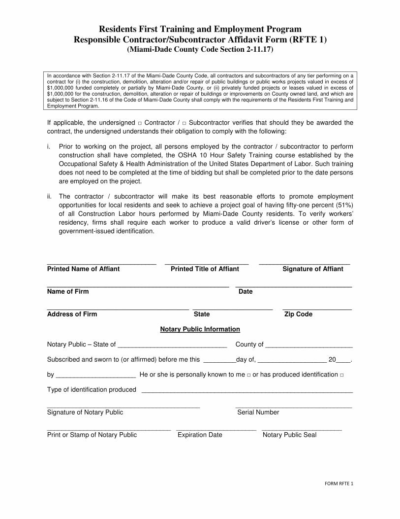
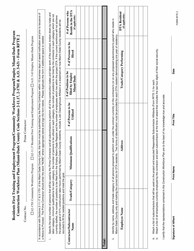
Residents First Training and Employment Program
Responsible Contractor/Subcontractor Affidavit Form (RFTE 1) (Miami-Dade County Code Section 2-11.17)
In accordance with Section 2-11.17 of the Miami-Dade County Code, all contractors and subcontractors of any tier performing on a contract for (i) the construction, demolition, alteration and/or repair of public buildings or public works projects valued in excess of $1,000,000 funded completely or partially by Miami-Dade County, or (ii) privately funded projects or leases valued in excess of $1,000,000 for the construction, demolition, alteration or repair of buildings or improvements on County owned land, and which are subject to Section 2-11.16 of the Code of Miami-Dade County shall comply with the requirements of the Residents First Training and Employment Program.
�
If applicable, the undersigned � Contractor / � Subcontractor verifies that should they be awarded the
contract, the undersigned understands their obligation to comply with the following:
i. Prior to working on the project, all persons employed by the contractor / subcontractor to perform
construction shall have completed, the OSHA 10 Hour Safety Training course established by the
Occupational Safety & Health Administration of the United States Department of Labor. Such training
does not need to be completed at the time of bidding but shall be completed prior to the date persons
are employed on the project.
ii. The contractor / subcontractor will make its best reasonable efforts to promote employment
opportunities for local residents and seek to achieve a project goal of having fifty-one percent (51%)
of all Construction Labor hours performed by Miami-Dade County residents. To verify workers’
residency, firms shall require each worker to produce a valid driver’s license or other form of
government-issued identification.
______________________________ _______________________ _________________________ Printed Name of Affiant Printed Title of Affiant Signature of Affiant __________________________________________________ ________________________________ Name of Firm Date _______________________________________ ______________________ ___________________ Address of Firm State Zip Code
Notary Public Information
Notary Public – State of ______________________________ County of ________________________ Subscribed and sworn to (or affirmed) before me this _________day of, ___________________ 20____. by ______________________ He or she is personally known to me � or has produced identification � Type of identification produced __________________________________________________________ __________________________________________ ________________________________ Signature of Notary Public Serial Number __________________________________ ______________________ ______________________ Print or Stamp of Notary Public Expiration Date Notary Public Seal
�
������������
�
Res
iden
ts F
irst
Tra
inin
g a
nd
Em
plo
ym
ent
Pro
gra
m/C
om
mu
nit
y W
ork
forc
e P
rogra
m/E
mp
loy M
iam
i-D
ad
e P
rog
ram
Con
stru
ctio
n W
ork
forc
e P
lan
(M
iam
i-D
ad
e C
ou
nty
Cod
e S
ecti
on
s 2-1
1.1
7, 2-1
701 &
A.O
. 3-6
3)
- F
orm
RF
TE
2
Co
ntr
act
No
. _
__
__
___
___
___
___
___
___
__
__
__
___
Pri
me
Co
ntr
acto
r:
__
___
___
__
__
__
___
___
___
___
___
___
__
__
__
___
___
___
___
___
___
§2
-170
1 C
om
mu
nit
y W
ork
forc
e P
rogra
m
§2
-11
.17 R
esid
ent
Fir
st T
rain
ing a
nd
Em
plo
ym
ent
Pro
gra
m
A.O
. 3
-63 E
mp
loy M
iam
i-D
ade
Pro
gra
m
In a
ccord
ance w
ith S
ections 2
-11.1
7 &
2-1
701 o
f th
e M
iam
i D
ade C
ounty
-Code,
this
form
must
be s
ubm
itte
d b
y t
he P
rim
e C
ontr
acto
r w
ithin
15 b
usin
ess d
ays o
f aw
ard
notification a
nd p
rior
to issuance o
f
a N
otice t
o P
roceed. T
he P
rim
e C
ontr
acto
r should
ente
r th
e w
ord
“N
ON
E”
where
appro
priate
belo
w a
nd s
ign t
he form
belo
w.
Ple
ase d
uplic
ate
this
form
if additio
nal s
pace is
needed.
i.
Specify t
he t
ota
l num
ber
of
pers
ons that
will
be u
sed b
y t
he P
rim
e C
ontr
acto
r and a
ll subcontr
acto
rs t
o p
erf
orm
all
of th
e c
onstr
uction t
rades a
nd labor
work
of th
e c
ontr
act, b
roken d
ow
n b
y t
rade a
nd
labor
cate
gory
, m
inim
um
qualif
ications for
each c
ate
gory
, th
e n
um
ber
of
pers
ons to b
e u
tiliz
ed in e
ach c
ate
gory
, th
e n
um
ber
of
positio
ns to b
e h
ired b
y t
he c
ontr
acto
r in
each c
ate
gory
whic
h a
re n
ot
curr
ently s
taffed, th
e n
um
ber
of positio
ns to b
e f
illed form
the E
mplo
y M
iam
i-D
ade R
egis
ter
and the n
um
ber
of
em
plo
yees w
hic
h liv
e w
ithin
the p
roje
ct D
TA
. If t
he c
urr
ent w
ork
forc
e w
ill n
ot
achie
ve
the p
roje
ct
goal of
51%
constr
uction labor
hours
perf
orm
ed b
y M
iam
i-D
ade C
ounty
resid
ents
, in
clu
de a
Job C
learinghouse A
ffid
avit o
r a s
tate
ment on h
ow
Mia
mi-D
ade C
ounty
resid
ents
will
be
recru
ited to fill
the n
eeded p
ositio
ns a
nd m
eet th
e g
oal.
Co
ntr
act
or/
Su
bco
ntr
act
or
Na
me
Tra
de/
Ca
teg
ory
M
inim
um
Qu
ali
fica
tio
ns
# o
f P
erso
ns
to b
e
Uti
lize
d
# o
f P
osi
tio
ns
to b
e
fill
ed b
y E
mp
loy
Mia
mi
Da
de
# o
f P
erso
ns
to b
e
Hir
ed
# o
f P
erso
ns
wh
o
Res
ide
in t
he
DT
A
(if
ap
pli
cab
le)
To
tal:
ii.
Identify
by n
am
e, addre
ss a
nd tra
de c
ate
gory
of all
pers
ons p
roposed t
o p
erf
orm
work
under
the c
ontr
act curr
ently o
n t
he c
ontr
acto
r's (
or
on a
ny p
roposed s
ubcontr
acto
r's)
payro
ll w
ho r
esid
e in
Mia
mi-D
ade C
ounty
only
and m
ark
ing the c
orr
ect box
for
DT
A r
esid
ents
. T
wo f
orm
s o
f id
entification m
ust
be p
rovid
ed for
each D
TA
resid
ent dem
onstr
ating o
ne y
ear
of
resid
ency.
Em
plo
yee
Na
me
Ad
dre
ss
Tra
de/
Ca
teg
ory
Per
form
ing
D
TA
Res
iden
t
(if
ap
pli
cab
le)
iii.
Att
ach a
lis
t of subcontr
acto
rs t
hat w
ill b
e u
sed o
n the p
roje
ct and e
xecute
d R
esponsib
le S
ubcontr
acto
r A
ffid
avits (
Form
RF
TE
1)
for
each.
iv.
Att
ach a
lis
t of all
em
plo
yees c
urr
ently e
mplo
yed b
y the c
ontr
acto
r and e
ach s
ubcontr
acto
r at th
e t
ime o
f aw
ard
that
inclu
des t
he last fo
ur
dig
its o
f th
eir s
ocia
l security
.
I cert
ify t
hat th
e r
epre
senta
tions c
onta
ined in this
Constr
uction W
ork
forc
e P
lan a
re t
o t
he b
est
of m
y k
now
ledge tru
e a
nd a
ccura
te.
__________________
_________
_____________
__________________
_________
_________
__________________
_________
____
__________________
_________
Sig
natu
re o
f A
ffia
nt
Pri
nt
Nam
e
Pri
nt
Tit
le
Date

������������
�
Residents First Training and Employment Program
Occupational Safety & Health Administration (OSHA)
10 Hour Safety Training Affidavit - Form RFTE 3
In accordance with Section 2-11.17 of the Miami-Dade County Code, all contractors and subcontractors of any tier performing on a County Construction Contract, shall satisfy the requirements of the Miami-Dade County Residents First Training and Employment Program which requires: for (i) all persons employed by the contractor to perform construction shall have completed the Occupational Safety & Health Administration (OSHA) 10 Hour safety training course established by the Occupational Safety & Health Administration of the United States Department of Labor
�
The undersigned verifies that every employee reported on the payroll has completed the OSHA 10 Hour
or OSHA 30 Hour Safety Training Course prior to working on the project.
________________________________________________________ Project Number, Title
______________________________ _______________________ _________________________ Printed Name of Affiant Printed Title of Affiant Signature of Affiant __________________________________________________ ________________________________ Name of Firm Date _______________________________________ ______________________ ___________________ Address of Firm State Zip Code
Notary Public Information
Notary Public – State of ______________________________ County of ________________________ Subscribed and sworn to (or affirmed) before me this _________day of, ___________________ 20____. by ______________________ He or she is personally known to me � or has produced identification � Type of identification produced __________________________________________________________ __________________________________________ ________________________________ Signature of Notary Public Serial Number __________________________________ ______________________ ______________________ Print or Stamp of Notary Public Expiration Date Notary Public Seal

FORM RFTE 4
�
Residents First Training and Employment Program/Employ Miami-Dade Program
Workforce Performance Report - Form RFTE 4
(Miami-Dade County Code Section 2-11.17 & A.O. 3-63)
Contract No. ______________________ Prime Contractor: ________________________________________
In accordance with Section 2-11.17 of the Miami-Dade County Code & A.O. 3-63, this report must be submitted by the Prime Contractor within thirty (30) days of completion of a County Capital Construction Contract to Small Business Development through the Contracting Officer. The Contracting Officer shall not authorize issuance of final payment for completion of a County Capital Construction Contract until the County receives a completed Workforce Performance Report.
�
Please provide the following information on the workforce employed in the execution of the contract: __________ Total number of Construction Labor positions utilized on the project __________ Total number of Construction Labor work hours performed on the project __________ Total number Construction Labor work hours performed by Miami-Dade County residents __________ Total number Construction Labor positions performed by Employ Miami-Dade participants __________ Percentage of Construction Labor work hours performed by Miami-Dade County residents
Attach supporting documentation verifying construction labor work hours performed by Miami-Dade County residents & Employ Miami-Dade participants. $______ Total amount of funds expended during the course of the project on other related skill and safety
training programs Were any positions on this project filled with new hires? _____ Yes ______ No If you answered “yes” to the above question, please identify the new hires by name, address and trade category, and indicate whether they were Miami-Dade County residents or an Employ Miami-Dade participant. (Please attach additional sheets if necessary.)
Employee Name Address Trade/Category
Performed
Miami-Dade
County Resident
(�)
Employ Miami-Dade
County Participant
(�)
Were all new hires Miami-Dade County residents? _____ No ______ Yes _____ Was the 20% labor workforce threshold met from the Employ Miami-Dade Register? _____ No ______ Yes If you answered “no” to either of the above questions, please attach supporting documentation that verifies reasonable efforts to promote employment opportunities for local residents including participation in the Employ Miami-Dade Program, which shall include applicable advertisements in local newspapers, posting of job opportunities with CareerSource South Florida’s Job Clearinghouse, referrals received from CareerSource South Florida, job applications received, candidates interviewed, and number of new hires. I certify that the representations contained in this Construction Workforce Plan are to the best of my knowledge true and accurate.
________________________________________ ____________________________________ ___________________________
Signature of Affiant Print Name, Title Date

CONTRACTOR DUE DILIGENCE AFFIDAVIT ��
�
�

Miami-Dade County
Contractor Due Diligence Affidavit
Per Miami-Dade County Board of County Commissioners (Board) Resolution No. R-63-14, County Vendors and Contractors shall disclose the following as a condition of award for any contract that exceeds one million dollars ($1,000,000) or that otherwise must be presented to the Board for approval:
(1) Provide a list of all lawsuits in the five (5) years prior to bid or proposal submittal that have been filed against the firm, its directors, partners,
principals and/or board members based on a breach of contract by the firm; include the case name, number and disposition;
(2) Provide a list of any instances in the five (5) years prior to bid or proposal submittal where the firm has defaulted; include a brief description of the circumstances;
(3) Provide a list of any instances in the five (5) years prior to bid or proposal submittal where the firm has been debarred or received a formal
notice of non-compliance or non-performance, such as a notice to cure or a suspension from participating or bidding for contracts, whether related to Miami-Dade County or not.
All of the above information shall be attached to the executed affidavit and submitted to the Procurement Contracting Officer (PCO)/ AE Selection Coordinator overseeing this solicitation. The Vendor/Contractor attests to providing all of the above information, if applicable, to the PCO.
Contract No. :
------------
Federal Employer Identification Number (FEIN):
Contract Title:
Printed Name of Affiant Printed Title of Affiant Signature of Affiant
Name of Firm Date
Address of Firm State Zip Code
Notary Public Information
Notary Public - State of County of
Subscribed and sworn to (or affirmed) before me this ------ day of, 20
by He or she is personally known to me or has produced identification
Type of identification produced
Signature of Notary Public Serial Number
Print or Stamp of Notary Public Expiration Date Notary Public Seal
2/2014
SECTION 3: INSTRUCTIONS TO BIDDERS

SUPPLEMENTARY INSTRUCTIONS TO BIDDERS
MCC_SI_0618 Supplementary Instructions to Bidders Project No. 20180277
TOC-1
SUPPLEMENTARY INSTRUCTIONS TO BIDDERS
TABLE OF CONTENTS
1. SUPPLEMENTAL BIDDING REQUIREMENTS
1.01 BID FORMS ................................................................................................................................................. 1
1.02 BID SECURITY ........................................................................................................................................... 2
1.03 CERTIFICATION PURSUANT TO ACT RELATING TO SCRUTINIZED COMPANIES .............................. 2
1.04 SMALL BUSINESS ENTERPRISE-CONSTRUCTION PROGRAM ............................................................ 2
1.05 DISADVANTAGED BUSINESS ENTERPRISE (DBE) PROGRAM ............................................................. 4
1.06 SITE INVESTIGATION ................................................................................................................................ 4
1.07 CONTRACTOR QUALIFICATION REQUIREMENTS ................................................................................. 5
1.08 AWARD OF CONTRACT ............................................................................................................................ 6
1.09 PAYMENT AND PERFORMANCE BONDS ................................................................................................ 7
1.10 ADDITIONAL INSURANCE TO BE CARRIED BY CONTRACTOR ............................................................ 8
MCC_SI_0618 Supplementary Instructions to Bidders Project No. 20180277
00 22 13 - 1
1. SUPPLEMENTAL BIDDING REQUIREMENTS
1.01 BID FORMS
A. Estimated Quantities.
1. The Bid Form contains estimated quantities that are provided for bidding purposes only. The actual quantities required to construct the Work may vary from those shown. The County reserves the right to increase, or decrease the quantities, or to delete any of the items for which there is no need throughout the length of the Contract.
Bid Items which are estimated with a unit quantity of one are anticipated to be use in minimal quantities, if any, as approved by the Engineer. Any Contract provisions pertaining to adjustments in item prices shall not apply. Therefore, no adjustment shall be made to the unit prices awarded as a result of changes to the estimated quantities provided in the Bid Form. Final quantities shall be as approved by the Engineer.
B. Preparation of Proposal.
1. All blank spaces on the Bid Form for bid prices must be filled in ink, in both words and figures. In the event of any discrepancy in the entries for the price of any item, the unit price as shown in words shall govern unless both the extension and the unit prices shown in figures are in agreement with each other, in which case they shall govern over the unit price shown in words.
2. If the Bid is made by an individual, a sole proprietorship or an individual operating under a trade name, the name and post office address of the individual or owner must be shown in each instance. If made by a partnership, the Bid must be signed by one of the partners, and the names and addresses of the partners must be listed. If made by a corporation, the Bid must be signed by an authorized officer or agent of the corporation, the corporation must be clearly identified and the corporate seal must be affixed. In addition, a Bid made by a corporation must also list the name of the state wherein the corporation was chartered and the business address of the corporation.
3. Bids must be submitted only on the hardcopy Bid form provided with these Contract Documents unless a revised Bid Form is provided by the County via Addendum, in which case the latest Bid Form provided by Addendum shall be used.
4. All required forms must be completed and submitted and, all blanks must be filled in.
C. Rejection of Irregular Proposals.
1. Bids will be considered irregular, and may be rejected, if they show omissions, alterations of form, additions not called for, conditions or unauthorized alternate bids, or irregularities of any kind; or if the unit prices are obviously unbalanced either in excess of or below a reasonable cost analysis value.
D. Pay Items.
1. Any work not specifically mentioned in the pay items listed in the Proposal, but indicated on the plans and/or specifications, shall be considered as incidental to one or more of the pay items, and no claim for additional compensation will be allowed, and it shall be assumed that the cost therefore is included in the prices for the various items in the Contract.

MCC_SI_0618 Supplementary Instructions to Bidders Project No. 20180277
00 22 13 - 2
1.02 BID SECURITY
A. Simultaneously with the delivery of the Bid to the County, on or before the bid due date, the Bidder must deliver to the County a bid security in the form of a Bid Bond on the form provided in the Bidding Documents or in Cash, in the form of a Certified Check, Cashier's Check or Irrevocable Letter of Credit made payable to the Department, for an amount equal to no less than five percent of the Total amount Bid. Failure to furnish a bid security in the proper form and amount, with the delivery of the Bid to the County, shall result in the Bid being declared "non-responsive."
B. A Bid Bond shall have as the surety thereon only such surety company or companies that are acceptable to the County and are authorized to write bonds of such character and amount in accordance with the qualifications established for Payment and Performance Bonds.
C. The bid security submitted with the Bid becomes payable to the County upon default of the Bidder. Default of Bidder shall occur in the event that the Bidder withdraws Bid within 180 days after bid opening (or any extension thereof agreed to in writing by the Bidder and County); or, after proper notification of intent to Contract from the County, fails to comply with all pre-award requirements including, but not limited to providing Payment and Performance Bonds with good and sufficient surety and the necessary Insurance Certificates pursuant to the Contract Documents, and enter into a written Contract with the County, as may be required; all within 10 days after the prescribed forms are presented to Principal for signature or as otherwise required by these Bidding Documents.
1.03 CERTIFICATION PURSUANT TO ACT RELATING TO SCRUTINIZED COMPANIES
A. This section shall apply only to the extent permitted under applicable regulations of the United States Department of State and the United States Department of Treasury.
B. By submitting a bid executed through a duly authorized representative, the bidder certifies that the bidder is not on the Scrutinized Companies with Activities in Sudan List, Scrutinized Companies with Activities in the Iran Petroleum Energy Sector List, Scrutinized Companies that boycott Israel List or engaged in a boycott of Israel as those terms are used and defined in sections 287.135 and 215.473 of the Florida Statutes. In the event that the bidder is unable to provide such certification but still seeks to be considered for award of this solicitation, the bidder shall, on a separate piece of paper, clearly state that it is on one or both of the Scrutinized Companies lists and shall furnish together with its bid a duly executed written explanation of the facts supporting any exception to the requirement for certification that it claims under Section 287.135 of the Florida Statutes. The bidder agrees to cooperate fully with the County in any investigation undertaken by the County to determine whether the claimed exception would be applicable. The County shall have the right to terminate any contract resulting from this solicitation for default if the bidder is found to have submitted a false certification or to have been placed on the Scrutinized Companies for Activities in Sudan List, the Scrutinized Companies with Activities in the Iran Petroleum Energy Sector List, Scrutinized Companies that boycott Israel List or engaged in a boycott of Israel.
1.04 SMALL BUSINESS ENTERPRISE-CONSTRUCTION PROGRAM
A. Miami-Dade County web-based Business Management Workforce System (BMWS)
1. Bidders must register under Miami-Dade County web-based Business Management Workforce System (BMWS). BMWS is managed by the Small Business Development (SBD) Division of the Internal Services Department. BMWS will be utilized to apply online for Small Business

MCC_SI_0618 Supplementary Instructions to Bidders Project No. 20180277
00 22 13 - 3
Enterprise (SBE) certification, manage County contracts, and track compliance with SBE Program measures, Workforce Program requirements, and subcontractor payments.
2. The use of this web-based system is mandatory for firms contracting with Miami-Dade County for the submission and verification of payment information and certified payrolls. Training for BMWS can be offered at the following web address: https://mdcsbd.gob2g.com/
3. BMWS will be accessible, at no charge, to all vendors doing – or interested in doing – business with Miami-Dade County. Key features include:
a. Online application for Small Business Enterprise (SBE), Disadvantaged Business Enterprise (DBE) and Local Developing Business (LDB) certification
b. Online registration for the Equitable Distribution Program (EDP)
c. Enhanced online SBE, DBE, and LDB Directory, with key-word search capabilities
d. Electronic submission of subcontractors for fulfillment of SBE requirements
e. Electronic submission of contractors’ utilization payments and verification of SBE payments via the web or a mobile device
f. Automated tracking of progress towards meeting SBE goals
g. Electronic submission of certified payrolls
h. Electronic submission of workforce compliance data
i. Automated notifications regarding compliance requirements
j. Elimination of/or limited paper-based reporting
B. SBE-CONST Make-up Plan
1. A contractor that failed to meet an established Small Business Enterprise-Construction (SBE-CONST) goal on any contract must submit a SBE-CONST Make-up Plan for approval by the Miami-Dade County Internal Services Department, Small Business Division (SBD).
2. The SBE-CONST Make-up Plan along with a corresponding Certificate of Assurance (COA), located under Section 2 of these Solicitation and Contract Documents must be included with the Bid submittal at the time of bid. The corresponding COA must identify all SBE-CONST firms to be utilized to meet the first tier subcontractor goal and the trade designation of work that each firm will perform in satisfaction of a make-up, in addition to any other goals that may be applicable.
3. The Department will forward the Make-up Plan and COA(s) to SBD for compliance review. Bidders who fail to submit the SBE-CONST Make-up Plan and corresponding COA by the Bid due date and time will be considered “non-compliant.”
4. Before the award, bidder must submit via County’s web-based system Business Management Workforce System (BMWS) its commitment, that if awarded, the contractor, will fulfill all or a portion of any pending Small Business Enterprise Construction Services makeup requirements and identify the certified CSBE firm(s) to be utilized to fulfill the make-up requirements that is excess of any SBE goal(s) required on the project and the percentage dollar value and description of the work that needs to be made up within the time frame specified by SBD.
C. Small Business Enterprise-Construction Program Measures

MCC_SI_0618 Supplementary Instructions to Bidders Project No. 20180277
00 22 13 - 4
1. This Project is Set-Aside for Level I Small Business Enterprise-Construction Program (SBE-CONST) participation in accordance with the Code of Miami-Dade County, Section 2.2 of CICC 7040-0/07, as amended by Ordinance 97-52, Ordinance 14-98, and Administrative Order 3-22 which are incorporated by reference in this Request for Price Quotation (RPQ). Only certified SBE-CONST Level I firms meeting the requirements herein can bid for this Project. Contact the Miami-Dade County Internal Services Department, Small Business Division (SBD) with any questions pertaining to the SBE-CONST program.
2. In accordance with Sections 2.25 and 2.33 (E) of CICC 7040-0/07 this Project is considered a single trade or primarily single trade project. None of the primary trade related work shall be subcontracted. Only ancillary work required to complete this Project may be subcontracted with prior approval from the Department and SBD. All subcontractors must be Certified SBE-CONST firms. Certified SBE/GS firms can be found at Miami Dade County web-based Business Management Workforce System (BMWS).
3. Bidders must:
a. Submit a completed Certificate of Assurance (COA) along with the Bid Submittal Package;
b. Place the completed COA(s) on top of the bid package so that it can be readily identified by the Department during the bid opening. A completed COA must be included for each SBE-CONST subcontractor to be utilized on this Project. All subcontractors must be Certified SBE-CONST firms.
4. The Department will forward the COA(s) to SBD for compliance review. Bidders who fail to submit the COA by the Bid due date and time will be considered “non-compliant.”
1.05 DISADVANTAGED BUSINESS ENTERPRISE (DBE) PROGRAM
A. This Article does not apply for this Project.
1.06 SITE INVESTIGATION
A. Examine the Contract Documents and the site of the proposed work, when applicable, carefully before submitting a proposal for the work contemplated. Investigate the conditions to be encountered, as to the character, quality, and quantities of work to be performed and materials to be furnished and as to the requirements of all Contract Documents.
B. The Department does not guarantee the details pertaining to borings, as shown on the plans, to be more than a general indication of the materials likely to be found adjacent to holes bored at the site of the work, approximately at the locations indicated. The Contractor shall examine boring data, where available, and make his own interpretation of the subsoil investigations and other preliminary data, and shall base his bid on his own opinion of the conditions likely to be encountered.
C. The bidder’s submission of a proposal is sufficient evidence that the bidder has made an examination as described in this Article. Therefore:
1. The bidder, by virtue of submitting their bid, acknowledges that they and all their subcontractors have satisfied themselves as to the nature and location of the Work or requirements of similar Work to be performed within Miami-Dade County Public Right-of-Ways. The general and local conditions include but are not restricted to those bearing upon transportation and traffic maintenance; the disposal, handling and storage of materials; access roads to the site; site constraints, restrictions and limitations; the conformation and conditions of the work area; and

MCC_SI_0618 Supplementary Instructions to Bidders Project No. 20180277
00 22 13 - 5
the character of equipment and facilities needed prior to and during the performance of the Work.
2. Failure on the part of the bidder to completely or properly evaluate any factors of costs prior to bidding shall not form a basis for additional compensation if awarded the Contract.
1.07 CONTRACTOR QUALIFICATION REQUIREMENTS
A. Certificate of Competency Requirement:
1. At the time of Bid and pursuant to the requirements of Section 10-3 of the Code of Miami-Dade County, Florida and these Solicitation and Contract Documents, the Bidder must hold a valid, current, and active:
a. Certificate of Competency from the County’s Construction Trades Qualifying Board as a General Engineering Contractor or as a Specialty Engineering Contractor, commensurate to the requirements of the Scope of Work, in one or more engineering crafts to include pipeline engineering contractor, or paving engineering contractor. The specialty contractor shall subcontract with a qualified contractor any work which is incidental to the specialty but is specified in the aforementioned Code as being the work of other than that of the Engineering Specialty for which certified; or
b. Certification, as a general contractor or as an underground utility and excavation contractor, provided by the State of Florida Construction Industry Licensing Board, pursuant to the provisions of Section 489.115 of the Florida Statutes.
B. Experience Requirement:
1. The Bidder must demonstrate that it has full-time personnel with the necessary experience to perform the Project’s Scope of Work. This experience shall include work in successfully completed projects performed by the identified personnel whose bulk of work performed in the Public Right-of-Way is similar in detail to the Project’s Scope of Work described in these Solicitation Documents. Demonstrate the experience requirement by:
a. Providing a detailed description of at least three (3) projects similar in detail to the Project’s Scope of Work described in these Solicitation Documents and in which the Bidder’s identified personnel is currently engaged or has completed within the past five years. List and describe the aforementioned projects and state whether the work was performed for the County, other government clients, or private entities. The description must identify for each project:
1) The identified personnel and their assigned role and responsibilities for the listed project
2) The client name and address including a contact person and phone number for reference
3) Description of work
4) Total dollar value of the contract
5) Contract duration
6) Statement or notation of whether Bidder’s referenced personnel is/was employed by the prime contractor or subcontractor, and

MCC_SI_0618 Supplementary Instructions to Bidders Project No. 20180277
00 22 13 - 6
7) For completed projects, provide letters of certification of final acceptance or similar project closure documentation issued by the client and available Contractor’s performance evaluations; or
2. The County reserves the right to request additional information and/or contact listed persons pertaining to bidder’s experience..
1.08 AWARD OF CONTRACT
A. The award of the Contract, if it be made in the County's sole discretion, shall be to the lowest responsive and responsible bidder whose bid complies with all of the material terms of this solicitation and is determined to be in the best interest of the County.
B. A fully executed Notice to Proceed (NTP) Letter constitutes a contract with Miami-Dade County. The County may issue to the Contractor a NTP Letter only when, in the discretion of Miami-Dade County, all conditions for award have been satisfied including, but not limited to, compliance with all of the requirements set forth in the Recommendation for Award letter and the expiration of any applicable protest period. The Contractor must provide the County with the completed and fully executed NTP Letter prior to the date stated in the letter for commencement of the Work. The award is final only upon the County’s receipt of a fully executed NTP Letter from the Contractor.
C. Without limiting the generality of the foregoing, the County may determine that it is in the County's best interest to award the Contract to the next low bidder when the low bidder's existing contractual commitments with the County, in the sole discretion of the County (a) could prevent the timely prosecution of the work requiring competing commitments of site, supervisory or home office personnel, or (b) could present potential conflicts with billing of similar items under existing contracts for similar or related work, or (c) could disfavor competition in the contracting industry in pricing or in the use of personnel or subcontractors.
D. By submitting a bid, the bidder acknowledges that the County shall have the right to investigate the existence of these factors in determining whether to award the bid, and to evaluate, without limitation, the bidder's outstanding commitments on other awarded contracts, its resources to perform the Work under the Contract, and its past performance.
E. The County reserves the right to waive any informality in, or to reject any or all bids. Bids from any person, firm or corporation in default upon any agreement with the County will be rejected.
F. The Bidders should be qualified by experience, financing, and equipment to do the work described in the Contract Documents. The County may require from the apparent lowest responsive and responsible Bidder, as a condition for Award, a list of the major construction equipment that is available to perform all the work required by the Contract. The list shall include all equipment required and available including: quantity; condition; make and model; whether owned or leased; and their present location. Actual proof of ownership (bills of sale or certified proof of a valid lease in the name of the firm submitting the Bid) of the equipment or the ability to secure the equipment prior to Contract Award is required. A visual inspection by the County of the equipment listed shall be facilitated within 10 days of submittal of the aforementioned list. Failure to meet the timeframes and conditions stipulated herein or in the Recommendation for Award may result in the disqualification of the Bidder.
G. For contracts $100,000 or greater, it is a condition of award for the successful bidder to submit a signed and completed First Tier Subcontractor / Direct Supplier Listing (Form provided). The Contractor shall not change or substitute subcontractors or suppliers from those listed without written approval from the County.
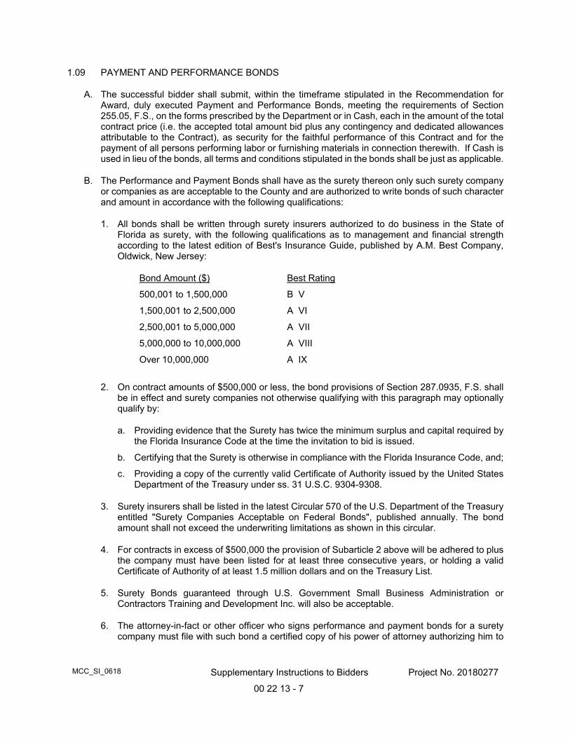
MCC_SI_0618 Supplementary Instructions to Bidders Project No. 20180277
00 22 13 - 7
1.09 PAYMENT AND PERFORMANCE BONDS
A. The successful bidder shall submit, within the timeframe stipulated in the Recommendation for Award, duly executed Payment and Performance Bonds, meeting the requirements of Section 255.05, F.S., on the forms prescribed by the Department or in Cash, each in the amount of the total contract price (i.e. the accepted total amount bid plus any contingency and dedicated allowances attributable to the Contract), as security for the faithful performance of this Contract and for the payment of all persons performing labor or furnishing materials in connection therewith. If Cash is used in lieu of the bonds, all terms and conditions stipulated in the bonds shall be just as applicable.
B. The Performance and Payment Bonds shall have as the surety thereon only such surety company or companies as are acceptable to the County and are authorized to write bonds of such character and amount in accordance with the following qualifications:
1. All bonds shall be written through surety insurers authorized to do business in the State of Florida as surety, with the following qualifications as to management and financial strength according to the latest edition of Best's Insurance Guide, published by A.M. Best Company, Oldwick, New Jersey:
Bond Amount ($) Best Rating
500,001 to 1,500,000 B V
1,500,001 to 2,500,000 A VI
2,500,001 to 5,000,000 A VII
5,000,000 to 10,000,000 A VIII
Over 10,000,000 A IX
2. On contract amounts of $500,000 or less, the bond provisions of Section 287.0935, F.S. shall be in effect and surety companies not otherwise qualifying with this paragraph may optionally qualify by:
a. Providing evidence that the Surety has twice the minimum surplus and capital required by the Florida Insurance Code at the time the invitation to bid is issued.
b. Certifying that the Surety is otherwise in compliance with the Florida Insurance Code, and;
c. Providing a copy of the currently valid Certificate of Authority issued by the United States Department of the Treasury under ss. 31 U.S.C. 9304-9308.
3. Surety insurers shall be listed in the latest Circular 570 of the U.S. Department of the Treasury entitled "Surety Companies Acceptable on Federal Bonds", published annually. The bond amount shall not exceed the underwriting limitations as shown in this circular.
4. For contracts in excess of $500,000 the provision of Subarticle 2 above will be adhered to plus the company must have been listed for at least three consecutive years, or holding a valid Certificate of Authority of at least 1.5 million dollars and on the Treasury List.
5. Surety Bonds guaranteed through U.S. Government Small Business Administration or Contractors Training and Development Inc. will also be acceptable.
6. The attorney-in-fact or other officer who signs performance and payment bonds for a surety company must file with such bond a certified copy of his power of attorney authorizing him to
MCC_SI_0618 Supplementary Instructions to Bidders Project No. 20180277
00 22 13 - 8
do so. The performance and payment bonds must be counter signed by the surety's resident Florida agent.
C. The Payment and Performance Bonds must be executed on the forms provided by the Department after the recommendation of award has been made. Failure to do so shall result in the rescission of the contract award recommendation.
D. Provide the County with three executed originals of the Payment and Performance Bonds and a letter from the bonding agent granting Miami-Dade County authorization to date the Bonds.
E. The Performance Bond or Cash used in lieu of the Performance Bond shall remain in force for five (5) years from the date of final acceptance of the work to protect the County against losses resulting from defects in materials or improper performance of work under the Contract; provided however, that this limitation does not apply to suits seeking damages for latent defects in materials or workmanship, such actions being subject to the limitations found in Section 95.11(3)(c), Florida Statutes.
F. The cost of the bond(s) shall be included in the Total Amount Bid. No separate payment for the cost of said bond(s) shall be made by the County.
G. The required bond(s) shall be written by or through and countersigned by a licensed Florida agent of the surety insurer pursuant to Section 624.425, F.S.
H. In the event the Surety on the bond(s) given by the Contractor becomes insolvent, or is placed in the hands of a receiver, or has its right to do business in its State of domicile or the State of Florida suspended or revoked as provided by law, or in the event of cancellation of the required hands by the Surety, the County shall withhold all payments until the Contractor shall give good and sufficient bond(s) in lieu of the bond(s) executed by such Surety.
1.10 ADDITIONAL INSURANCE TO BE CARRIED BY CONTRACTOR
Subparagraphs 2.11A through 2.11C and 2.11E through 2.11G of the Special Conditions to the CICC 7040-0/07 Contract are deleted and replaced with the following:
A. Contractor shall indemnify and hold harmless the County and its officers, employees, agents and instrumentalities from any and all liability, losses or damages, including attorneys’ fees and costs of defense, which the County or its officers, employees, agents or instrumentalities may incur as a result of claims, demands, suits, causes of actions or proceedings of any kind or nature arising out of, relating to or resulting from the performance of this Agreement by the Contractor or its employees, agents, servants, partners principals or subcontractors. Contractor shall pay all claims and losses in connection therewith and shall investigate and defend all claims, suits or actions of any kind or nature in the name of the County, where applicable, including appellate proceedings, and shall pay all costs, judgments, and attorney’s fees which may issue thereon. Contractor expressly understands and agrees that any insurance protection required by this Agreement or otherwise provided by Contractor shall in no way limit the responsibility to indemnify, keep and save harmless and defend the County or its officers, employees, agents and instrumentalities as herein provided.
B. Contractor shall furnish to the Department of Transportation and Public Works, 111 NW 1 Street, Miami Florida 33128, Certificate(s) of Insurance which indicate that insurance coverage has been obtained which meets the requirements as outlined below:
MCC_SI_0618 Supplementary Instructions to Bidders Project No. 20180277
00 22 13 - 9
1. Worker’s Compensation Insurance for all employees of the Contractor as required by Florida Statute 440.
2. Commercial General Liability Insurance on a comprehensive basis in an amount not less than $1,000,000 combined single limit per occurrence for bodily injury and property damage. Miami-Dade County must be shown as an additional insured with respect to this coverage.
3. Automobile Liability Insurance covering all owned, non-owned and hired vehicles used in connection with the work, in an amount not less than $1,000,000 combined single limit per occurrence for bodily injury and property damage.
C. All insurance policies required above shall be issued by companies authorized to do business under the laws of the State of Florida, with the following qualifications:
1. The company must be rated no less than “A-” as to management, and no less than “Class VII” as to financial strength, by Best’s Insurance Guide, published by A.M. Best Company, Oldwick, New Jersey, or its equivalent, subject to the approval of the County Risk Management Division.
or
2. The company must hold a valid Florida Certificate of Authority as shown in the latest “List of All Insurance Companies Authorized or Approved to Do Business in Florida” issued by the State of Florida Department of Financial Services.
NOTE: MIAMI DADE COUNTY CONTRACT NUMBER AND TITLE OF CONTRACT MUST APPEAR ON EACH CERTIFICATE.
CERTIFICATE HOLDER MUST READ:
MIAMI-DADE COUNTY
111 NW 1st STREET
SUITE 2340
MIAMI, FL 33128
Compliance with the foregoing requirements shall not relieve the Contractor of his liability and obligation under this section or under any other section of this agreement.

SECTION 4: SUPPLEMENTARY INFORMATION

SAMPLE SURETY PERFORMANCE AND PAYMENT BOND FORM
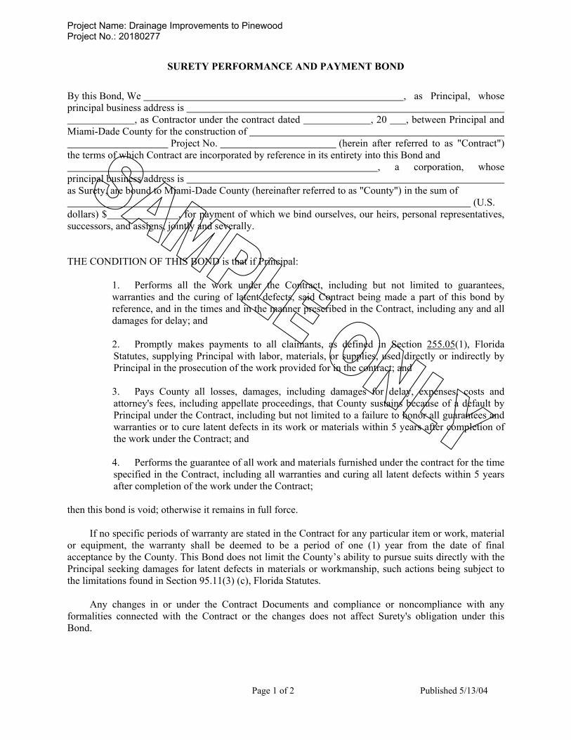
Project Name: Drainage Improvements to Pinewood Project No.: 20180277
Page 1 of 2 Published 5/13/04
SURETY PERFORMANCE AND PAYMENT BOND By this Bond, We , as Principal, whose principal business address is , as Contractor under the contract dated , 20 , between Principal and Miami-Dade County for the construction of Project No. (herein after referred to as "Contract") the terms of which Contract are incorporated by reference in its entirety into this Bond and , a corporation, whose principal business address is as Surety, are bound to Miami-Dade County (hereinafter referred to as "County") in the sum of (U.S. dollars) $ , for payment of which we bind ourselves, our heirs, personal representatives, successors, and assigns, jointly and severally. THE CONDITION OF THIS BOND is that if Principal:
1. Performs all the work under the Contract, including but not limited to guarantees, warranties and the curing of latent defects, said Contract being made a part of this bond by reference, and in the times and in the manner prescribed in the Contract, including any and all damages for delay; and
2. Promptly makes payments to all claimants, as defined in Section 255.05(1), Florida Statutes, supplying Principal with labor, materials, or supplies, used directly or indirectly by Principal in the prosecution of the work provided for in the contract; and 3. Pays County all losses, damages, including damages for delay, expenses, costs and attorney's fees, including appellate proceedings, that County sustains because of a default by Principal under the Contract, including but not limited to a failure to honor all guarantees and warranties or to cure latent defects in its work or materials within 5 years after completion of the work under the Contract; and
4. Performs the guarantee of all work and materials furnished under the contract for the time specified in the Contract, including all warranties and curing all latent defects within 5 years after completion of the work under the Contract;
then this bond is void; otherwise it remains in full force.
If no specific periods of warranty are stated in the Contract for any particular item or work, material or equipment, the warranty shall be deemed to be a period of one (1) year from the date of final acceptance by the County. This Bond does not limit the County’s ability to pursue suits directly with the Principal seeking damages for latent defects in materials or workmanship, such actions being subject to the limitations found in Section 95.11(3) (c), Florida Statutes.
Any changes in or under the Contract Documents and compliance or noncompliance with any
formalities connected with the Contract or the changes does not affect Surety's obligation under this Bond.

Project Name: Drainage Improvements to Pinewood Project No.: 20180277
Page 2 of 2 Published 5/13/04
SURETY PERFORMANCE BOND (Cont'd)
IN WITNESS WHEREOF, the above bounden parties have caused this Bond to be executed by their appropriate officials as of the day of , 20 .
CONTRACTOR
(Contractor Name)
BY: (President) (Managing Partner or Joint Venture)
(SEAL) COUNTERSIGNED BY RESIDENT FLORIDA AGENT OF SURETY: SURETY: (Copy of Agent's current Identification Card as issued by State of Florida Insurance Commissioner must be attached) By: Attorney-in-Fact
(CORPORATE SEAL)
(Power of Attorney must be attached)

PERCOLATION TEST AND SOIL BORINGS

Pinewood Drainage Improvements October 3, 2017 HR Engineering Services, Inc. Project No. HR17-1286R
2
• The percolation tests were performed in 6.0-inch diameter boreholes, drilled to a 10 feet depth.
• To perform each percolation test, a PVC slotted 6-inch diameter casing was placed in the hole
and then water was pumped out as an attempt to clean the borehole before testing. Prior starting the test, water was pumped into the hole as an attempt to raise the water level in the borehole to the ground surface. Once the inflow stabilized with the outflow rate, the average pumping rate and the maximum level of the water obtained in the borehole (with this stabilized flow) was recorded.
The hydraulic conductivity values were then calculated and reported in units of cubic feet per second, per square foot, per foot of head (cfs/ft2-ft of head). The calculated hydraulic conductivity values ranged as follows: • From 0 to 10 ft.: 6.5E-05 to 6.8E-04 cfs/ft2-ft of head. These conductivity values are ultimate values. An appropriate factor of safety should be employed in any storm water or other subsurface drainage design computations. The test results are presented in the attachments. FIELD TESTING – TEST BORINGS Three (3) test borings (B-3 through B-5) were performed to a depth of 20 feet. The reported locations of the test borings (latitude and longitude) are approximate. Attached are the Field Exploration Plans showing the test boring and percolation test locations. The Report of Core Borings in the Appendix graphically shows the penetration resistance and presents the soil description for each test boring. The stratification lines and depth designations on the Report of Core Borings represent approximate boundaries between soil types. In some instances, the transition between soil types may be gradual. The water depths shown on the Report of Core Borings represent the conditions at the time of our field exploration. The test borings were made in general accordance with ASTM-D-1586, "Penetration Test and Split-Barrel Sampling of Soils." The borings were advanced using a 3-inch ID casing and a rotary drilling process. At regular intervals, the drilling tools were removed and soil samples were obtained with a standard 1.4-inch I.D., 2-inch O.D., split-tube sampler. The sampler was first seated six inches and then driven an additional foot with blows of a 140-lb automatic hammer falling 30 inches. The number of hammer blows required to drive the sampler the final foot is designated the "Penetration Resistance". The penetration resistance, when properly interpreted, is an index to the soil strength and density. Representative portions of the soil samples, obtained from the sampler, were placed in glass jars and transported to our laboratory. An engineer then examined the samples in order to confirm the field classifications. We will keep the soil samples retrieved for this exploration program at our office for a period of 60 days from the date of this report. After that, we will discard these samples.


DRAWN BY: P.V.
PINEWOOD DRAINAGE IMPROVEMENTSMIAMI-DADE COUNTY DEPARTMENT OFTRANSPORTATION AND PUBLIC WORKS
MIAMI-DADE COUNTY, FLORIDA Project No: HR17-1286R
SITE LOCATION MAPDATE: 10/03/17
SCALE: NTS
NORTH
HR Engineering Services, Inc.HRES
PROJECT SITE
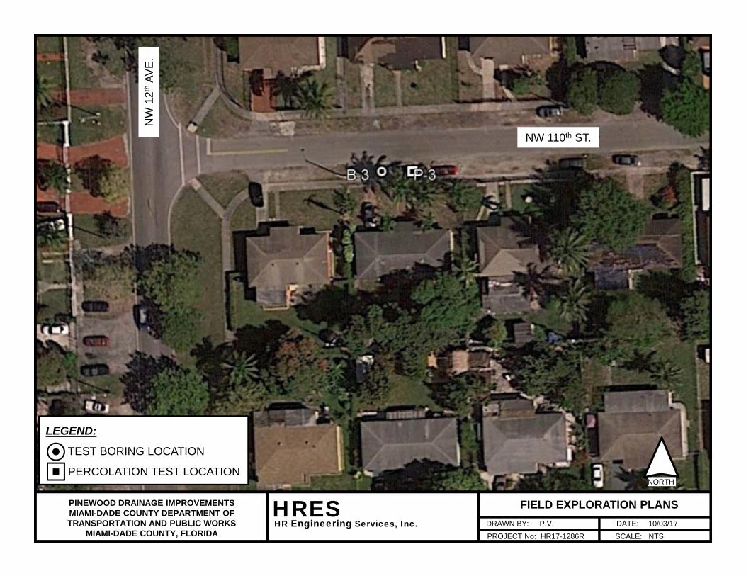
DRAWN BY: P.V.
PINEWOOD DRAINAGE IMPROVEMENTSMIAMI-DADE COUNTY DEPARTMENT OFTRANSPORTATION AND PUBLIC WORKS
MIAMI-DADE COUNTY, FLORIDA PROJECT No: HR17-1286R
FIELD EXPLORATION PLANSDATE: 10/03/17
SCALE: NTS
NORTH
HR Engineering Services, Inc.HRES
LEGEND:
TEST BORING LOCATION
PERCOLATION TEST LOCATION
NW 110th ST.N
W 1
2th
AVE.

DRAWN BY: P.V.
PINEWOOD DRAINAGE IMPROVEMENTSMIAMI-DADE COUNTY DEPARTMENT OFTRANSPORTATION AND PUBLIC WORKS
MIAMI-DADE COUNTY, FLORIDA PROJECT No: HR17-1286R
FIELD EXPLORATION PLANSDATE: 10/03/17
SCALE: NTS
NORTH
HR Engineering Services, Inc.HRES
LEGEND:
TEST BORING LOCATION
PERCOLATION TEST LOCATION
NW 108th TER.
NW
11t
hAV
E.
NW 108th ST.
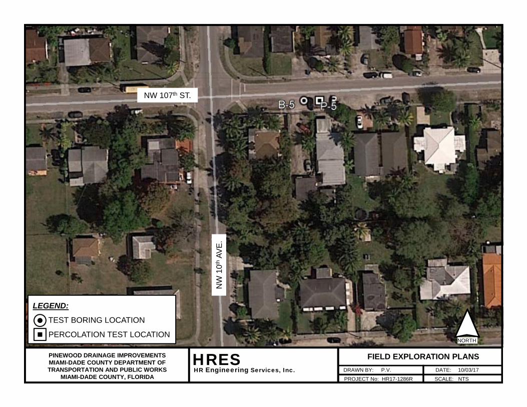
DRAWN BY: P.V.
PINEWOOD DRAINAGE IMPROVEMENTSMIAMI-DADE COUNTY DEPARTMENT OFTRANSPORTATION AND PUBLIC WORKS
MIAMI-DADE COUNTY, FLORIDA PROJECT No: HR17-1286R
FIELD EXPLORATION PLANSDATE: 10/03/17
SCALE: NTS
NORTH
HR Engineering Services, Inc.HRES
LEGEND:
TEST BORING LOCATION
PERCOLATION TEST LOCATION
NW 107th ST.
NW
10t
hAV
E.

TESTNo.
B-3 25.87539 -80.21786 NA NA
P-3 25.87539 -80.21780 NA NA
B-4 25.87400 -80.21664 NA NA
P-4 25.87400 -80.21659 NA NA
B-5 25.87269 -80.21376 NA NA
P-5 25.87269 -80.21370 NA NA
NA: Not Available
HRES PROJECT No. HR17-1286ROCTOBER 3, 2017
SUMMARY OF TEST BORING AND PERCOLATION TEST LOCATIONS
MIAMI-DADE COUNTY - FLORIDAHR ENGINEERING SERVICES, INC.
Plane coordinates were taken using a hand-held GPS and are approximate within 10 feet.
PLANE COORDINATES
LATITUDE LONGITUDE
Notes:
PINEWOOD DRAINAGE IMPROVEMENT PROJECTS
STATION OFFSET , ft.
MIAMI-DADE COUNTY DEPARTMENT OF TRANSPORTATION AND PUBLIC WORKSPROJECT No. 20160330
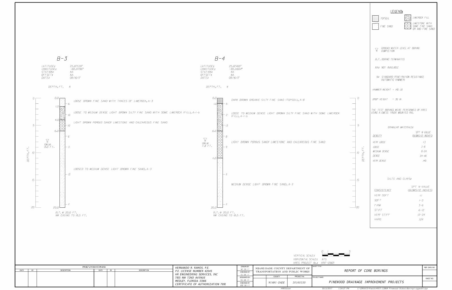
LEGEND:
0 5
1
VERTICAL SCALE:
NTSHORIZONTAL SCALE:
HAMMER WEIGHT = 140 LB
DROP HEIGHT = 30 IN
24-40
LOOSE
VERY LOOSE
3-8
MEDIUM DENSE
DENSE
VERY DENSE
<3
>40
DENSITY (BLOWS/12 INCHES)
SPT N-VALUE
GRANULAR MATERIALS:
8-24
ME 08-17
HRR 06-17
ss 08-17
ss 08-17
B.T.BORING TERMINATED
STANDARD PENETRATION RESISTANCE
COMPLETION
GROUND WATER LEVEL AT BORING
N:
(AUTOMATIC HAMMER)
LIMEROCK FILL
10
5
0
DE
PT
H,
FT.
DEPTH, FT.
GWL@
8.0 FT.
B-3
15
0.0
6.0
1.5
NW CASING TO 18.5 FT.
B.T. @ 20.0 FT.
3
6
10
10
N
10
5
0
DE
PT
H,
FT.
15
13
20 20
VERY SOFT
STIFF
VERY STIFF
HARD
FIRM
SOFT
SILTS AND CLAYS:
SPT N-VALUE
(BLOWS/12 INCHES)CONSISTENCY
1-3
3-6
12-24
6-12
<1
>24
OR AND FINE SAND
SOME FINE SAND
LIMESTONE WITH
11
20.0
6
4.0
DEPTH, FT.
GWL@
B-4
0.0
6.0
1.0
NW CASING TO 18.5 FT.
B.T. @ 20.0 FT.
9
5
13
2
N
11
LIGHT BROWN POROUS SANDY LIMESTONE AND CALCAREOUS FINE SAND
11
20.0
8
LIGHT BROWN POROUS SANDY LIMESTONE AND CALCAREOUS FINE SAND
LOOSE BROWN FINE SAND WITH TRACES OF LIMEROCK, A-3
LOOSE TO MEDIUM DENSE LIGHT BROWN SILTY FINE SAND WITH SOME LIMEROCK (FILL), A-1-b
LOOSED TO MEDIUM DENSE LIGHT BROWN FINE SAND, A-3
11.0
DARK BROWN ORGANIC SILTY FINE SAND (TOPSOIL), A-8
(FILL), A-1-b
LOOSE TO MEDIUM DENSE LIGHT BROWN SILTY FINE SAND WITH SOME LIMEROCK
MEDIUM DENSE LIGHT BROWN FINE SAND, A-3
HR17-1286RHRES PROJECT No.:
FINE SAND
TOPSOIL
08/16/17DATE:
NAOFFSET:
NASTATION:
-80.21786°LONGITUDE:
25.87539°LATITUDE:
REF. DWG. NO.
SHEET NO.
SHEET TITLE:
PROJECT NAME:
DRAWN BY:
CHECKED BY:
DESIGNED BY:
CHECKED BY:
COUNTY PROJECT No.
REVISIONS
DATE BY DESCRIPTION DATE BY DESCRIPTION
MIAMI-DADE 20160330
REPORT OF CORE BORINGS
PINEWOOD DRAINAGE IMPROVEMENT PROJECTS
HRESUser 10/3/2017 1:34:27 PM C:\DRIVE3\Paola\HR17-1286R Pinewood States\Borings\sggeo01.dgn
TRANSPORTATION AND PUBLIC WORKS
MIAMI-DADE COUNTY DEPARTMENT OF
USING A CME55 TRUCK MOUNTED RIG.
THE TEST BORINGS WERE PERFORMED BY HRES
NA: NOT AVAILABLE
7.8 FT.
08/16/17DATE:
NAOFFSET:
NASTATION:
-80.21664°LONGITUDE:
25.87400°LATITUDE:
7815 NW 72ND AVENUE
MEDLEY, FLORIDA 33166
CERTIFICATE OF AUTHORIZATION 7991
HERNANDO R. RAMOS, P.E.
P.E. LICENSE NUMBER 42045
HR ENGINEERING SERVICES, INC

0 5
1
VERTICAL SCALE:
NTSHORIZONTAL SCALE:
10
5
0
DE
PT
H,
FT.
DEPTH, FT.
GWL@
B-5
15
0.0
9.0
0.3
NW CASING TO 18.5 FT.
B.T. @ 20.0 FT.
11
4
8
4
N
10
5
0
DE
PT
H,
FT.
15
13
20 20
13
20.0
10
3.5
LIGHT BROWN POROUS SANDY LIMESTONE AND CALCAREOUS FINE SAND
HR17-1286RHRES PROJECT No.:
LOOSE BROWN SILTY FINE SAND WITH SOME LIMEROCK (FILL), A-1-b
LOOSE BROWN FINE SAND, A-3
MEDIUM DENSE LIGHT BROWN FINE SAND, A-3
08/16/17DATE:
NAOFFSET:
NASTATION:
-80.21376°LONGITUDE:
25.87269°LATITUDE:
8.1 FT.
ME 08-17
HRR 06-17
ss 08-17
ss 08-17
REF. DWG. NO.
SHEET NO.
SHEET TITLE:
PROJECT NAME:
DRAWN BY:
CHECKED BY:
DESIGNED BY:
CHECKED BY:
COUNTY PROJECT No.
REVISIONS
DATE BY DESCRIPTION DATE BY DESCRIPTION
MIAMI-DADE 20160330
REPORT OF CORE BORINGS
PINEWOOD DRAINAGE IMPROVEMENT PROJECTS
HRESUser 10/3/2017 1:33:17 PM C:\DRIVE3\Paola\HR17-1286R Pinewood States\Borings\sggeo02.dgn
TRANSPORTATION AND PUBLIC WORKS
MIAMI-DADE COUNTY DEPARTMENT OF
LEGEND:
HAMMER WEIGHT = 140 LB
DROP HEIGHT = 30 IN
24-40
LOOSE
VERY LOOSE
3-8
MEDIUM DENSE
DENSE
VERY DENSE
<3
>40
DENSITY (BLOWS/12 INCHES)
SPT N-VALUE
GRANULAR MATERIALS:
8-24
B.T.BORING TERMINATED
STANDARD PENETRATION RESISTANCE
COMPLETION
GROUND WATER LEVEL AT BORING
N:
(AUTOMATIC HAMMER)
VERY SOFT
STIFF
VERY STIFF
HARD
FIRM
SOFT
SILTS AND CLAYS:
SPT N-VALUE
(BLOWS/12 INCHES)CONSISTENCY
1-3
3-6
12-24
6-12
<1
>24
USING A CME55 TRUCK MOUNTED RIG.
THE TEST BORINGS WERE PERFORMED BY HRES
NA: NOT AVAILABLE
FINE SAND LIMEROCK FILL
OR AND FINE SAND
SOME FINE SAND
LIMESTONE WITH
7815 NW 72ND AVENUE
MEDLEY, FLORIDA 33166
CERTIFICATE OF AUTHORIZATION 7991
HERNANDO R. RAMOS, P.E.
P.E. LICENSE NUMBER 42045
HR ENGINEERING SERVICES, INC

DEPTH TO DEPTH TO WATER WATER HEAD, HOLE HOLE k, HYDRAULIC
LATITUDE LONGITUDE BEFORE DURING Du DEPTH DIAMETER, CONDUCTIVITYTEST, H TEST ft ft d cfs/ft^2-ft. Head
ft ft inches gpm cfs
P-3 08/25/17 25.87539 -80.21780 8.0 0.0 8.0 10.0 6.0 4.1 0.00914 1.2E-04
P-4 08/25/17 25.87400 -80.21659 7.8 0.0 7.8 10.0 6.0 23.2 0.05169 6.8E-04
P-5 08/25/17 25.87269 -80.21370 8.1 0.0 8.1 10.0 6.0 2.3 0.00506 6.5E-05
SUMMARY OF PERCOLATION TEST RESULTS
HR ENGINEERING SERVICES, INC.
USUAL OPEN-HOLE - SFWMD/DERM METHOD
RATE OF
PINEWOOD DRAINAGE IMPROVEMENT PROJECTS
FLOW, P
HRES PROJECT No. HR17-1286ROCTOBER 3, 2017
MIAMI-DADE COUNTY - FLORIDA
MIAMI-DADE COUNTY DEPARTMENT OF TRANSPORTATION AND PUBLIC WORKSPROJECT No. 20160330
for 0 to 10 ft., K10 = [4*P]/[π*d*(2*Du2+4*Du*Ds+Du*d)], where Ds = Hole Depth - H Plane coordinates were taken using a hand-held GPS and are approximate within 10 feet.
TEST No. TEST DATE
SECTION 5: SUPPLEMENTARY CONDITIONS

SUPPLEMENTARY CONDITIONS
MCC_SC_0618 Supplementary Conditions Project No. 20180277
TOC-1
SUPPLEMENTARY CONDITIONS
TABLE OF CONTENTS
1. SUPPLEMENTARY CONDITIONS
MISCELLANEOUS CONSTRUCTION CONTRACT (7040 PLAN) .............................................................. 1
APPLICABLE WAGE RATES ...................................................................................................................... 1
CONTINGENCY ALLOWANCE FOR TIME................................................................................................. 1
WEATHER DELAYS ................................................................................................................................... 1
ADDITIONAL FUNDING SOURCE PROVISIONS ...................................................................................... 3
ADDITIONAL SBE-CONST CONTRACT MEASURE REQUIREMENTS .................................................... 3
COMMUNITY WORKFORCE PROGRAM .................................................................................................. 3
CLEARINGHOUSE FOR POSTING NOTICE OF JOB OPPORTUNITIES ................................................. 3
RESIDENTS FIRST TRAINING AND EMPLOYMENT PROGRAM COMPLIANCE .................................... 4
EMPLOY MIAMI-DADE PROGRAM ............................................................................................................ 5
ACCEPTANCE TESTS ............................................................................................................................... 6
MIAMI-DADE COUNTY’S USER ACCESS PROGRAM (UAP). .................................................................. 7
PUBLIC RECORDS AND CONTRACTS FOR SERVICES PERFORMED ON BEHALF OF MIAMI-DADE COUNTY. .................................................................................................................................................... 7
NONDISCRIMINATION ............................................................................................................................... 8
CONTRACTOR DUE DILIGENCE AFFIDAVIT ........................................................................................... 8
LIQUIDATED DAMAGES. ........................................................................................................................... 9
CLAIMS ..................................................................................................................................................... 10
DISPUTES................................................................................................................................................. 13
EXTRA WORK .......................................................................................................................................... 15
APPENDIX TO THE SUPPLEMENTARY CONDITIONS
Appendix A: Miami-Dade County Wages and Benefits
Appendix B: Notice of Construction Clearing House Forms A, B and C
Appendix C: Residents First Training and Employment Program Compliance Forms (RTFE 1, RTFE 2, RFTE 3, and RFTE 4)

MCC_SC_0618 Supplementary Conditions Project No. 20180277
00 73 00 - 1
1. SUPPLEMENTARY CONDITIONS
MISCELLANEOUS CONSTRUCTION CONTRACT (7040 PLAN)
A. These Supplementary Conditions amend or supplement the Miscellaneous Construction Contract (MCC) CICC 7040-0/07, the MCC 7040 Plan, and other provisions of the Contract Documents as indicated below. All provisions that are not so amended or supplemented remain in full force and effect. All requirements of the Contract Documents, or portions thereof, which are not specifically modified, deleted, or superseded hereby, remain in full effect. The MCC Contract and Plan may also be supplemented elsewhere in the Contract Documents by provisions located in, but not necessarily limited to, Division 1 (General Requirements) of the Contract Specifications.
APPLICABLE WAGE RATES
A. Amend Paragraph 2.23 of the CICC 7040-0/07 Miscellaneous Construction Contract by adding the following:
1. The applicable Standard Industrial Classification (SIC) manual code is SIC 16 Heavy Construction. The Responsible Wages and Benefits Schedule (Construction Type: Heavy) for wages and benefits to be paid for work performed under this Contract will be the schedule in effect on January 1st of the calendar year in which the work is performed. The Responsible Wages and Benefits Schedule in effect at the time of Project Solicitation is provided as Appendix A to these Supplementary Conditions. Updated Responsible Wages and Benefits Schedules are available at http://www.miamidade.gov/smallbusiness/responsible-wages-and-benefits.asp
2. When a required classification is not listed as a separate class in the County’s Responsible Wage rates schedule (e.g. Traffic Signal Technician), Contractor must use Davis-Bacon Wages for said classification.
CONTINGENCY ALLOWANCE FOR TIME
A. Paragraph 2.66 of the CICC 7040-0/07 Miscellaneous Construction Contract is hereby amended to provide a Contingency Allowance for time extension not to exceed ten percent of the original Contract Duration pursuant to a written request by Contractor for a time extension for an Excusable Delay, as described in Paragraph 2.66 of the 7040 Miscellaneous Construction Contract, that affects the critical path schedule of the Contract or any previously approved changes. The request must be accompanied by written documentation that supports the justification of a time extension, and is subject to review and concurrence by the department Engineer, or designee. If approved, a Contract Contingency Allowance Expenditure Authorization will be created for execution by all parties. Once executed the time extension will adjust the scheduled completion date. The cumulative total of all Contingency Allowance time extensions shall not exceed ten percent of the original Contract Duration rounded off to the next whole number.
WEATHER DELAYS
A. Schedule of Anticipated Weather Delay Days

MCC_SC_0618 Supplementary Conditions Project No. 20180277
00 73 00 - 2
1. The following schedule of average climatic range, based on National Oceanic and Atmospheric Administration (NOAA) normal data (1981-2010 Monthly Normals; GHCN Daily ID: USW00012839; MIAMI INTL AP, FL), will be used as the standard baseline for monthly evaluations of weather delays for this Contract.
Schedule of Anticipated Weather Delay Days
Month
JAN
FE
B
MA
R
AP
R
MA
Y
JUN
JUL
AU
G
SE
P
OC
T
NO
V
DE
C
Days 3 4 4 4 7 12 11 13 13 8 4 4
2. The above schedule provides the anticipated number of days each month during which construction activity exposed to weather conditions is expected to be prevented and suspended by cause of adverse weather. Suspension of construction activity for the number of days listed in the schedule, for each month, is included in the Work and is not eligible for extension of Contract Time. The Work Progress Schedule submitted by Contractor must reflect these anticipated adverse weather delays in all weather dependent activities.
B. Extension of Contract Time for Adverse Weather Days In Excess of the Standard Baseline
1. If the basis exists, in accordance with the Conditions of the Contract, for a claim for extension of time, an extension of time on the basis of weather may be granted only for the number of Weather Delay Days in a month that are in excess of the number of days listed above for that month in the Schedule of Anticipated Adverse Weather Delay Days.
2. Adverse Weather Day is defined, for the purpose of this Article, as the occurrence of one or more of the following weather conditions within a twenty-four (24) hour day that prevents scheduled critical path construction activity exposed to weather conditions:
a. Precipitation in excess of one-tenth inch (0.10").
b. Temperatures that do not rise above that required for the day's construction activity, if such temperature requirement is specified or accepted as standard industry practice.
c. Sustained wind in excess of twenty-five (25) miles per hour.
3. Adverse Weather Day may include “dry-out” days, resulting from precipitation that occurs beyond the Anticipated Weather Delay Days for the month, only if there is a hindrance to site access or sitework and Contractor has taken all reasonable accommodations to avoid such hindrance; and, at a rate no greater than 1 make-up day for each precipitation day (or consecutive days) that total 1.0 inch or more of precipitation.
4. A Weather Delay Day may be counted by the Engineer, if adverse weather prevents work on the Project for fifty percent (50%) or more of the Contractor’s normal scheduled work day and critical path construction activities were included in the day’s schedule, including a weekend day or holiday approved by the Engineer with construction activity scheduled that day.
5. No additional compensation will be made for weather delays.
C. Contractor Documentation and Submittals
1. Organize claim to facilitate evaluation by calendar month and submit in accordance with the claims submittal requirements of the Contract Documents. Documentation is required for each Adverse Weather Day that results in a Weather Delay. Identify the number if days claimed for

MCC_SC_0618 Supplementary Conditions Project No. 20180277
00 73 00 - 3
the month that exceeds the Schedule of Anticipated Adverse Weather Delays. Documentation must include:
a. Daily jobsite work logs showing which and to what extent critical path construction activities have been affected by adverse weather.
b. Daily weather data, obtained from the nearest NOAA weather station or other independently verified source approved by Engineer at beginning of the Project, to support claim for time extension. NOAA Global Historical Climatology Network (GHCN) Daily data may be obtained from the NOAA website at http://www.ncdc.noaa.gov/cdo-web/search.
2. If an extension of Contract Time is appropriate and approved by the Department, such extension will be made in accordance with the requirements of the Contract Documents.
ADDITIONAL FUNDING SOURCE PROVISIONS
A. General Obligation Bond (GOB) Program
1. This contract is being funded, in whole or in part, through the Miami-Dade County’s Building Better Communities (BBC) General Obligation Bond (GOB) program. An important part of this program is the training of members of the community in various construction trades. Miami-Dade County has independently contracted with a training provider to train and place individuals on GOB funded projects. The contractor is encouraged to contact the Office of Capital Improvement’s BBC Division at 305.375.2504, to obtain referrals of trained individuals for placement in the trades that have either graduated or are currently being trained from this training program. For more information about the BBC program you can log into www.miamidade.gov/build.
2. Other funding sources may be utilized for this Contract.
ADDITIONAL SBE-CONST CONTRACT MEASURE REQUIREMENTS
A. This article does not apply for this Project.
COMMUNITY WORKFORCE PROGRAM
A. In accordance with Miami-Dade County Code §2-1701 and amended by Ordinance No. 13-66, this Contract has a 10% Community Workforce Program (CWP) Goal. Contractor is required to comply with CWP Participation. Additional information is available at the County’s website at http://www.miamidade.gov/smallbusiness/community-workforce-program.asp.
B. Contractor must submit a Workforce Plan to the Miami-Dade County Internal Service Department, Small Business Development Division through the Department (via the Engineer) within 15 days from the Recommendation for Award. The Workforce Plan form along with instructions on how to complete the Workforce Plan can be obtained in the County’s website at http://www.miamidade.gov/smallbusiness/business-development-forms.asp.
CLEARINGHOUSE FOR POSTING NOTICE OF JOB OPPORTUNITIES
A. Pursuant to Miami-Dade County Resolution R-1145-99, Contractor must post a notice of job opportunities with the Miami-Dade County Job Clearinghouse (JCH) within ten (10) business days
MCC_SC_0618 Supplementary Conditions Project No. 20180277
00 73 00 - 4
of the contract award or no later than five (5) business days after start of construction. If job opportunities are available, complete all portions of the Notice of Construction Clearinghouse Job Opportunity form (Form B). If no job opportunities are available, complete a JCH Affidavit- No Notice(s) of Construction Job Opportunities form (Form C). Submit the completed Form B or C (with copies to the Engineer) to:
Miami-Dade County Internal Service Department Small Business Development Division Project Review and Analysis Section Attention: Job Clearinghouse 111 NW 1st Street, 19th floor Miami, Florida 33128 Telephone: (305) 375-3111 Fax (305) 375-3160
B. Job applicants interested in posting an application for employment to be considered by contractors with job openings may complete a JCH Construction Clearinghouse Job Application (Form A) and submit it to the address provided in the Form.
C. The necessary forms are provided as Appendix B to these Supplementary Conditions. Additional information pertaining to the Miami-Dade County Job Clearinghouse is available in the County’s website at http://www.miamidade.gov/sba/about-us-job-clearinghouse.asp.
RESIDENTS FIRST TRAINING AND EMPLOYMENT PROGRAM COMPLIANCE
Except where state or federal laws or regulations mandate to the contrary, all contractors and subcontractors of any tier performing on a County Construction Contract shall satisfy the requirements of this Article.
A. In accordance with Section 2-11.17 of the Code of Miami-Dade County and Implementing Order No. 3-61 (online at http://www.miamidade.gov/smallbusiness/business-development-legislation.asp), all contractors and subcontractors of any tier on (i) construction contracts valued in excess of $1 million for the construction, demolition, alteration and/or repair of public buildings, or public works; or (ii) contracts or leases valued in excess of $1 million for privately funded construction, demolition, alteration or repair of buildings, or improvements on County-owned land shall comply, if applicable, with the following:
1. Bidders must:
a. Submit a completed Responsible Contractor Affidavit (Form RTFE 1), along with the Bid Submittal Package. The Responsible Contractor Affidavit shall verify the following:
1) Prior to working on the project, all persons employed by the contractor on the project to perform construction have completed the OSHA 10-hour safety training course, and
2) Contractor will make its best reasonable efforts to have 51 percent of all construction labor hours performed by Miami-Dade County residents. County residents employed in furtherance of the goal set forth in the County‘s Community Workforce Program (CWP) shall be counted towards the 51% goal.
b. In the event that form RTFE 1 is not submitted along with the bid package, the County will provide a notice that the bidder has 48 hours from the time of notification to submit the form or their bid or proposal will be deemed nonresponsive and disqualified.
2. Prior to the issuance of a Notice to Proceed, contractors must also submit the following:
MCC_SC_0618 Supplementary Conditions Project No. 20180277
00 73 00 - 5
a. A Construction Workforce Plan (Form RFTE 2) and supporting documentation;
b. A list of all subcontractors to be used on the project;
c. A Responsible Subcontractor Affidavit (Form RFTE 1) for each subcontractor; and
d. A list of all employees currently employed by the contractor.
3. Submit OSHA Safety Training Affidavit (Form RFTE 3) with all certified payrolls.
4. Submit a Workforce Performance Report (Form RFTE 4) within 30 business days of completion of the Project.
5. Any lessee shall include requirements of Section 2-11.7 of the Code of Miami-Dade County and Implementing Order No. 3-61, including the right of the County to access the contractor's and subcontractors' records to verify compliance, in any contract, subcontract, or sublease. Lessee shall be responsible to the County for payment of compliance monitoring costs and any penalties found due.
6. Forms RFTE 1, RFTE 2, RFTE 3, and RFTE 4 are included under Appendix C to these Supplemental Conditions.
EMPLOY MIAMI-DADE PROGRAM
Except where state or federal laws or regulations mandate to the contrary, all contractors and subcontractors of any tier performing on a County Construction Contract shall satisfy the requirements of this Article.
A. In accordance with Section 5.02 of the Miami-Dade County Home Rule Amendment and Charter, Section 2-8.1 of the Code of Miami-Dade County, and Administrative Order No. 3-63, all contractors and subcontractors of any tier on (i) construction contracts valued in excess of one million dollars ($1,000,000) for the construction, demolition, alteration and/or repair of public buildings, or public works; or (ii) contracts or leases valued in excess of one million dollars ($1,000,000) for privately funded construction, demolition, alteration or repair of buildings, or improvements on County-owned land:
1. The awarded Contractor is hereby notified that the County will consider whether the Contractor made its best reasonable efforts to promote Employ Miami-Dade on this contract, as defined in A.O. 3-63, as part of the County’s evaluation and responsibility review of the Contractor for new County contract awards.
2. Referral Procedures.
a. Career Source South Florida shall compile and maintain the Employ Miami-Dade Register.
b. The Contractor will notify Career Source South Florida of the vacancy by completing a Job Opening Form on the Employ Miami-Dade website (https://iapps.careersourcesfl.com/employmd/). The job order must contain a detailed description of the job responsibilities and qualifications.
c. Career Source South Florida will then provide a list of qualified candidates available to the Contractor with copy to the Compliance Officer.
d. Contractor will review the resumes and qualifications of the candidates, conduct interviews with those candidates who satisfy the minimum competency requirements, and make a good faith effort to fill at least 20% of the labor workforce required per Contractor’s
MCC_SC_0618 Supplementary Conditions Project No. 20180277
00 73 00 - 6
Construction Workforce Plan from the Employ Miami-Dade Register through Career Source South Florida.
e. Positions filled from the Employ Miami-Dade Register must be full-time, for at least 120 days, in order to be considered towards attainment of the 20% labor workforce threshold herein.
f. If the 20% labor workforce per Contractor’s Construction Workforce Plan from Employ Miami-Dade is not met on the contract, the Contractor must provide the Compliance Officer with a detailed explanation of its efforts.
g. Career Source South Florida may have funds to pay a portion of the salaries for Employ Miami-Dade participants. It shall be the responsibility of the Contractor to contact Career Source South Florida directly to determine eligibility for, and make arrangements as applicable with, Career Source South Florida to pay a portion of the salaries for a specified period and/or during on the job training for the Employ Miami-Dade participants employed on the contract.
B. Prior to the issuance of a Notice to Proceed, Contractors must also submit the following:
1. A Construction Workforce Plan (Form RFTE 2) and supporting documentation including:
a. Specifying the total number of positions by trade that will be used by the Contractor and subcontractors to perform all the of the construction labor work.
b. Indicate the number of positions to be filled by the Contractor from the Employ Miami-Dade Register.
c. Contractor shall submit an updated Construction Workforce Plan to the Contracting Officer on a monthly basis.
C. Within thirty (30) days of completion, and prior to final payment, Contractors must also submit a Workforce Performance Report (Form RFTE 4) that includes the following information:
1. The total number of construction labor work positions performed by Employ Miami-Dade participants with supporting documentation.
2. Supporting documentation verifying reasonable efforts to promote Employ Miami-Dade if 20% labor workforce threshold was not met per Contractor’s Construction Workforce Plan from the Employ Miami-Dade Register.
3. Determination if employee(s) will be retained beyond the contract.
D. The awarded Contractor is hereby notified that the County will consider whether a Contractor made its best reasonable efforts to promote Employ Miami-Dade on this contract, as defined in AO 3-63, as part of the County’s evaluation and responsibility review of the Contractor for new County contract awards.
ACCEPTANCE TESTS
A. Replace Article 2.99 of the CICC 7040-0/07 Miscellaneous Construction Contract with the following:
B. When Contractor informs Engineer that the Work is ready for inspection and testing, Engineer may request, from a County approved laboratory, the tests necessary to confirm that the required material, compaction, or work specifications are met. If the results of the tests reveal that the applicable specifications have not been met, Contractor, without additional compensation, must
MCC_SC_0618 Supplementary Conditions Project No. 20180277
00 73 00 - 7
perform, to the satisfaction of Engineer, all work necessary to meet the applicable specifications and is responsible for the costs of all re-testing required by Engineer and the Contract Documents.
C. The Department will pay the laboratory for the first test (pass or fail); any re-testing will be the responsibility of Contractor. The Department will only pay for re-testing when authorized, in writing, by Engineer.
D. Contractor must comply with the conditions of the agreement between Miami-Dade County and Laboratory.
MIAMI-DADE COUNTY’S USER ACCESS PROGRAM (UAP).
A. On November 5, 2013 the Board of County Commissioners adopted Ordinance No. 13-103 eliminating the construction contract exemption to the User Access Program set forth in Section 2-8.10 of the Code of Miami-Dade County with the exception of Miscellaneous Construction Contract Program contracts with a total contract value of less than $500,000. Ordinance No. 13-103 retained the other exemptions listed in Section 2-8.10 of the Code including an exemption for contracts “funded with any funding source, including federal, which prohibits or restricts the application of the credit to the County effected in the UAP.” As bond funding would be a funding source “which prohibits or restricts the application” of the UAP, construction contracts funded by bond proceeds (e.g., General Obligation Bond (GOB), People’s Transportation Plan (PTP)) remain exempt from the application of the County’s User Access Program.
B. UAP does not apply for this project, Therefore:
C. If applicable, this Contract is subject to a user access fee under the County’s User Access Program (UAP) in the amount of two percent (2%) pursuant to Miami-Dade County Budget Ordinance No. 03-192. All construction services provided under this contract are subject to the 2% UAP. This fee applies to all Contract usage whether by County Departments or by any other governmental, quasi-governmental or not-for-profit entity. From every payment made to the Contractor under this contract (including the payment of retainage), the County will deduct the two percent (2%) UAP fee provided in the ordinance and the Contractor will accept such reduced amount as full compensation for any and all deliverables under the contract. The County shall retain the 2% UAP for use by the County to help defray the cost of its procurement program. Contractor participation in this pay request reduction portion of the UAP is mandatory.
PUBLIC RECORDS AND CONTRACTS FOR SERVICES PERFORMED ON BEHALF OF MIAMI-DADE COUNTY.
A. The Contractor shall comply with the Public Records Laws of the State of Florida, including but not limited to,
1. Keeping and maintaining all public records that ordinarily and necessarily would be required by Miami-Dade County (County) in order to perform the service
2. Providing the public with access to public records on the same terms and conditions that the County would provide the records and at a cost that does not exceed the cost provided in Chapter 119, F.S., or as otherwise provided by law
3. Ensuring that public records that are exempt or confidential and exempt from public records disclosure requirements are not disclosed except as authorized by law; and
MCC_SC_0618 Supplementary Conditions Project No. 20180277
00 73 00 - 8
4. Meeting all requirements for retaining public records and transferring, at no cost, to the County all public records in possession of the Contractor upon termination of the contract and destroying any duplicate public records that are exempt or confidential and exempt from public records disclosure requirements upon such transfer.
B. In addition, all records stored electronically must be provided to the County in a format that is compatible with the information technology systems of the County. Failure to meet any of these provisions or to comply with Florida’s Public Records Laws as applicable shall be a material breach of the agreement and shall be enforced in accordance with the terms of the agreement.
C. For questions regarding the application of chapter 119, Florida Statutes, to The Contractor’s Duty to Provide Public Records relating to this contract, contact the Custodian of Public Records at (305) 375-5773; [email protected]; 111 NW 1 Street, suite 1300, Miami, Florida 33128.
NONDISCRIMINATION
A. During the performance of this Contract, Contractor agrees to not discriminate against any employee or applicant for employment because of race, color, religion, ancestry, national origin, sex, pregnancy, age, disability, marital status, familial status, sexual orientation, gender identity or gender expression, status as victim of domestic violence, dating violence or stalking, or veteran status, and on housing related contracts the source of income, and will take affirmative action to ensure that employees and applicants are afforded equal employment opportunities without discrimination. Such action shall be taken with reference to, but not limited to: recruitment, employment, termination, rates of pay or other forms of compensation, and selection for training or retraining, including apprenticeship and on the job training.
B. By entering into this Contract, the Contractor attests that it is not in violation of the Americans with Disabilities Act of 1990 (and related Acts) or Miami-Dade County Resolution No. R-385-95. If the Contractor or any owner, subsidiary or other firm affiliated with or related to the Contractor is found by the responsible enforcement agency or the County to be in violation of the Act or the Resolution, such violation shall render this Contract void. This Contract shall be void if the Contractor submits a false affidavit pursuant to this Resolution or the Contractor violates the Act or the Resolution during the term of this Contract, even if the Contractor was not in violation at the time it submitted its affidavit.
CONTRACTOR DUE DILIGENCE AFFIDAVIT
A. In accordance with Board of County Commissioners Resolution 63-14, Contractor, as a condition of award, must submit Contractor Due Diligence Affidavit Form on any contract that exceeds $1 million, or that is otherwise subject to Board approval.
1. Affidavit is attached in Section 2 of these Solicitation Documents and must be included in the solicitation package. Form requires that Contractors attest to the following under oath:
a. All of the lawsuits that have been filed against that entity, its directors, partners, principals, and/or board members, based on breach of contract by that entity in the five years prior to bid or proposal submittal, including the case name and number and the disposition of the case;
b. Any instances in the five years prior to bid or proposal submittal where that entity has been defaulted and a brief description of the circumstances; and

MCC_SC_0618 Supplementary Conditions Project No. 20180277
00 73 00 - 9
c. All of the instances in the five years prior to bid or proposal submission where that entity has been debarred or received a formal notice of non-compliance or non-performance, such as a notice to cure or a suspension from participating or bidding for contracts, whether related to Miami-Dade County or not.
B. It is the responsibility of the Contractor to return the fully executed Affidavit at the time of bid or proposal submittal. This affidavit will be used as an additional measure of due diligence prior to award of a contract.
LIQUIDATED DAMAGES.
Expand Subarticle 1.06 J from the DTPW General Requirements as follows:
A. Engineer will issue a Work Order identifying the location, description and amount of work to be accomplished. Notify Engineer prior to beginning work on the project.
B. Initial Work Order may be issued with the Notice to Proceed. Contractor will be allowed fourteen (14) calendar days from receipt of the initial Work Order to respond and begin work. The fourteen (14) calendar days begin on the date the work order is received in person, by fax or by certified mail. Contractor will be expected to respond and begin work within five working days of receipt of any subsequent Work Order. If a start date later than 5 working days is identified in a Work Order, Contractor will be expected to begin work by the start date identified in the Work Order.
C. Charging of Contract time will begin on the actual day that work begins at the site, but no later than:
1. the 14th calendar day from receipt of the initial Work Order; or
2. the 5th working day from receipt of any subsequent Work Order; or
3. the “start date “ identified in a Work Order (as described above) that is applicable to the specific Work Order issued.
D. If the Contractor does not begin work by the end of the day provided by the Work Order, or if the assignment of work on the Work Order is not complete within the number of calendar days specified on the Work Order, then the County may assess the Contractor, not as a penalty but as liquidated damages, the amount shown in Subarticle 1.06, J, 2, Liquidated Damages, of the DTPW General Requirements.
E. All work locations will be described with sufficient particularity that will allow Contractor to proceed immediately to the location with minimum delay. The County will make every reasonable effort to plan work locations and develop work documents in systematic and concentrated regions so as to minimize the Contractor's travel requirements. A Pre-Work Conference may be scheduled prior to the commencement of work in accordance with DTPW General Requirements.
F. Upon completion of the assigned work of the Work Order, notify Engineer. Certify that the work quantities and quality were accomplished in accordance with these specifications by signing and returning the Work Order to the Department. All work completed will be reviewed to verify quantity and quality prior to approval of the Work Order.
G. Should inclement weather limit or stop the work, notify Engineer of such. Article 1.04 of these Supplemental Specifications describe Weather Delays adjustments.

MCC_SC_0618 Supplementary Conditions Project No. 20180277
00 73 00 - 10
H. Limitation or work stoppage. Schedule work in a manner that prevents delays, stoppages and rework.
CLAIMS
A. Amend Paragraph 2.86 of the CICC 7040-0/07 Miscellaneous Construction Contract by adding the following:
B. Notice of Claims
1. The Contractor will not be entitled to additional time or compensation otherwise payable for any act or failure to act by the Department, the happening of any event or occurrence, or any other cause, unless he shall have given the Project manager a written notice of claim therefore as specified in this article.
2. The Contractor shall provide immediate verbal notification with written confirmation within forty-eight (48) hours of any potential claims and of the anticipated time and/or cost impacts resulting thereof. The written notice of claim shall set forth the reasons for which the Contractor believes additional compensation and/or time will or may be due, the nature of the costs involved and the approximate amount of the potential claim.
3. It is the intention of this article, that differences between the parties arising under and by virtue of the Contract shall be brought to the attention of the Project Manager at the earliest possible time in order that such matters may be settled, if possible, or other appropriate action promptly taken.
4. The notice requirements of this article are in addition to those required in other articles of these Contract Documents, inclusive of the conditions listed under the MCC Plan.
5. The Contractor shall segregate all costs associated with each individual claim including but not limited to labor, equipment, material, subcontractor and supplier costs, and all other costs related to the claim. In the event that the Contractor has multiple claims, the Contractor will segregate each claim individually including the respective costs associated with each claim. Failure to segregate claims and their respective costs will be grounds for the Department's rejection of the claim. No “total cost claims” shall be allowed under this Contract.
6. The Contractor must maintain a cost accounting system as a condition for making a claim against the Department. The cost accounting system must segregate the costs of the work under the Contract (non-claims-related) from claims-related and other Contractor costs through the use of a job cost ledger and be otherwise in compliance with general accounting principles.
7. If the Department decides to pay all or part of a claim for which notice was not timely made, the Department does not waive the right to enforce the notice requirements in connection with any other claim.
8. Inasmuch as the notice of claim requirements of this article are intended to enable the Project Manager to investigate while facts are fresh and to take action to minimize or avoid a claim which might be filed thereafter, the Contractor's failure to make the required notice on time is likely to disadvantage the Department. Therefore, a claim that does not comply with the notice requirements above shall not be considered unless the Contractor submits with his claim proof showing that the Department has not been prejudiced by the Contractor's failure to so comply and, in the event the Department has been prejudiced by the Contractor's failure to submit a

MCC_SC_0618 Supplementary Conditions Project No. 20180277
00 73 00 - 11
timely notice of claim, the Department will reduce any equitable adjustment claimed by the Contractor to reflect the damage.
C. Claim Submittals
1. Claims or requests for equitable adjustments filed by the Contractor shall be filed in full accordance with this article no later than 30 calendar days after the act giving rise to the claim and in sufficient detail to enable the Department to ascertain the basis and amount of said claims. In the case of continuing or on-going claim events, the Contractor shall be allowed to periodically amend his claim to more accurately reflect the impact of said claim, until the end of the claim event. No claims for additional compensation, time extension or for any other relief under the Contract shall be recognized, processed, or treated in any manner unless the same is presented in accordance with this Article. Failure to present and process any claim in accordance with this Article shall be conclusively deemed a waiver, abandonment or relinquishment of any such claim, it being expressly understood and agreed that the timely presentation of claims, in sufficient detail to allow proper investigation and prompt resolution thereof, is essential to the administration of this Contract.
2. The Department will review and evaluate the Contractor's claims. It will be the responsibility of the Contractor to furnish, when requested by the Project manager, such further information and details as may be required to determine the facts or contentions involved in his claims. The cost of claims preparation or Change Order negotiations shall not be reimbursable under this Contract.
3. Any work performed by the Contractor prior to Notice-to-Proceed (NTP) shall not be the basis for a claim from the Contractor of any kind.
4. Each claim must be certified by the Contractor as required by the Miami-Dade Code, False Claims Act (see Code Section 21-255, et seq.), and accompanied by all materials required by Miami-Dade County Code Section 21-257. A "certified claim" shall be made under oath by a person duly authorized by the claimant, and shall contain a statement that:
a. The claim is made in good faith;
b. The claim's supporting data is accurate and complete to the best of the person's knowledge and belief;
c. The amount of the claim accurately reflects the amount that the claimant believes is due from the Department; and
d. The certifying person is duly authorized by the claimant to certify the claim.
5. In order to substantiate time-related claims (delays, disruptions, impacts, etc.), the Contractor shall, if applicable and as determined by the Department, submit, in triplicate, the following information:
a. Copy of Contractor's notice of claim in accordance with this article. Failure to submit the notice is sufficient grounds to deny the claim.
b. The approved, as-planned Schedule in accordance with the applicable section of the Contract Documents and computer storage media, if applicable.
c. The as-built Schedule reflecting changes to the approved schedule up to the time of the impact in question and computer storage media if applicable.
d. The basis for the duration of the start and finish dates of each impact activity and the reason for choosing the successor and predecessor events affected in the schedule shall be
MCC_SC_0618 Supplementary Conditions Project No. 20180277
00 73 00 - 12
explained. Also, the basis for the duration of any lead/lags inserted into the schedule and the duration in related activity duration shall be explained.
e. A marked-up as-built Schedule indicating the causes responsible for changes between the as-planned and as-built schedule and establishing the required cause and effect relationships.
f. After indicating specific time related changes on the as-built schedule, the documentation must be segregated into separate packages with each package documenting a specific duration change identified previously. This documentation package shall include Change Orders, Change Notices, Work Orders, written directions, meeting minutes, etc., related to the change in duration.
g. Any loss of efficiency, acceleration, disruption and loss of productivity claims shall be compensated as part of the Liquidated Indirect Costs paid for compensable, excusable delays and mark-up on Direct Cost of changes as allowed by the Contract. Total cost and modified total cost claims will not be accepted and the Contractor agrees to waive the right to seek recovery by these methods. The claimed delay shall not result from a cause specified in the Contract Documents as a non-excusable delay.
h. The Contractor assumes all risk for the following items, none of which shall be the subject of any claim and none of which shall be compensated for except as they may have been included in the compensation described under Liquidated Indirect Costs:
1) Home office expenses or any Direct Costs incurred allocated from the headquarters of the Contractor;
2) Loss of anticipated profits on this or any other project;
3) Loss of bonding capacity or capability;
4) Losses due to other projects not bid upon;
5) Loss of business opportunities;
6) Loss of productivity on this or any other project;
7) Loss of interest income on funds not paid;
8) Costs to prepare, negotiate or prosecute claims and
9) Costs spent to achieve compliance with applicable laws and ordinances (excepting only sales taxes paid shall be reimbursable expense subject to the provisions of the Contract Documents).
i. All non-time-related claim items for additional compensation for Direct Costs shall be properly documented and supported with copies of invoices, time sheets, rental agreements, crew sheets and the like.
j. Cost information shall be submitted in sufficient detail to allow for review. The basis for the budgeted or actual costs shall include man-hours by trade, labor rates, material and equipment costs etc. These costs shall be broken down by pay.
k. The documentation for budgeted cost shall, as a minimum, include:
1) Copies of all the Contractor's bid documents, bid quotes, faxed quotes, etc.
2) Copies of all executed subcontracts.
3) Other related budget documents as requested by the Project Manager.
l. The documentation for actual cost shall, as a minimum, include:
1) Time Sheets.
MCC_SC_0618 Supplementary Conditions Project No. 20180277
00 73 00 - 13
2) Materials invoices
3) Equipment invoices
4) Subcontractors’ payments
5) Other related documents as required by the Project Manager.
m. The Contractor shall make all his books, employees, work sites and records available to the Department or its representatives for inspection and audit.
6. No payment shall be made to the Contractor by the Department for loss of anticipated profit(s) from any deleted work.
7. As indicated above, the Project Manager and the Field Representative shall be allowed full and complete access to all personnel, documents, work sites or other information reasonably necessary to investigate any claim. Within sixty (60) days after a claim has been received, the claim shall either be rejected with an explanation as to why it was rejected or acknowledged. Once the claim is acknowledged, the parties shall attempt to negotiate a satisfactory settlement of the claim, which settlement shall be included in a subsequent Work Order or Change Order. If the parties fail to reach an agreement on a recognized claim, the Department shall pay to the Contractor the amount of money it deems reasonable, less any appropriate retention, to compensate the Contractor for the recognized claim.
8. Failure of the Contractor to make a specific reservation of rights regarding any such disputed amounts in the body of the Change Order which contains the payment shall be construed as a waiver, abandonment, or relinquishment of all claims for additional monies resulting from the claims embodied in said Change Order. However, once the Contractor has properly reserved rights to any claim, no further reservations of rights shall be required and the Contractor shall not be required to repeat the reservation in any subsequent change order. Prior reservation of rights may however be modified, by express reference, in subsequent change orders. Notwithstanding the aforementioned, at the time of final payment under the Contract, the Contractor shall specify all claims which have been denied and all claims for which rights have been reserved in accordance with this section. Failure to so specify any particular claim shall be constructed as a waiver, abandonment, or relinquishment of such claim.
DISPUTES
A. Amend Paragraph 2.89 of the CICC 7040-0/07 Miscellaneous Construction Contract by adding the following:
B. Disputes
1. The following provisions shall govern disputes under this Contract unless the Special Provisions to this Contract contain the requirement for the use of an alternate dispute resolution method. For example, for large projects of great complexity, a Dispute Review Board (DRB) may be employed by the Department to settle disputes in lieu of the Department Director or Office of the Mayor (OOM) designee as specified below. In this case, the DRB alternative shall be specified by the Department in the Special Provisions and, if utilized, shall supersede this dispute provision.
a. In the event the Contractor and the Department are unable to resolve their differences concerning any determination made by the Project Manager or Department on any dispute or claim arising under or relating to the Contract (referred to in this Section as a “Dispute”), either the Contractor or the Department may initiate a dispute in accordance with the
MCC_SC_0618 Supplementary Conditions Project No. 20180277
00 73 00 - 14
procedure set forth in this article. Exhaustion of these procedures shall be a precondition to any lawsuit permitted hereunder.
b. For contracts with a value of $5 million or less, all Disputes under this Contract shall be decided by the Department Director or his designee. For contracts valued at more than $5 million, Disputes shall be decided by a designee appointed by the OOM. Decisions rendered by the Department Director or OOM designee shall not be binding but shall be admissible in a court of competent jurisdiction.
c. As soon as practicable, the Department Director or OOM designee shall adopt a schedule for the Contractor and the Department to file written submissions stating their respective positions and the bases therefore. The written submissions shall include copies of all documents and sworn statements in affidavit form from all witnesses relied on by each party in support of its position. Within 20 working days of the date on which such written submissions are filed, the Department Director or OOM designee shall afford each party an opportunity to present a maximum of one hour of argument. The Department Director or OOM designee may decide the Dispute on the basis of the affidavits and other written submissions if, in his opinion, there is no issue of material fact and the party is entitled to a favorable resolution pursuant to the terms of this Contract. As part of such decision, the Department Director or OOM designee shall determine the timeliness and sufficiency of each notice of claim and claim at issue as provided in this article. The Department Director or OOM designee shall have the authority to rule on questions of law, including disputes over contract interpretation, and to resolve claims, or portions of claims, via summary judgment where there are no disputed issues of material fact. Furthermore, the Department Director or OOM designee is authorized by both parties to strike elements of claims seeking relief or damages not available under the contract (such as, but not limited to, claims for lost profits, off-site overhead, loss of efficiency or productivity claims or claim’s preparation costs) by summary disposition.
d. In the event that the Department Director or OOM designee determines that the affidavits or other written submissions present issues of material fact, he shall allow the presentation of evidence in the form of lay or expert testimony directed solely to the issues which he may specifically identify to require factual resolution. The testimonial portion of the process shall not exceed one day in duration per side, including opening statements and closing arguments, if allowed by the Department Director or OOM designee at his reasonable discretion.
e. No formal discovery shall be allowed in connection with any proceeding under this article. Notwithstanding the foregoing, both parties agree that all of the audit, document inspection, information and documentation requirements set forth elsewhere in this contract shall remain in force and effect throughout the proceeding. The Department Director or OOM designee shall not schedule the hearing until both parties have made all their respective records available for inspection and reproduction and the parties have been afforded reasonable time to analyze the records. The continued failure of a party to comply with the document inspection, examination, or submission requirements set forth in this contract shall constitute a waiver of that party’s claims and/or defenses, as applicable. Hearsay evidence shall be admissible but shall not form the sole basis for any finding of fact. Failure of any party to participate on a timely basis, to cooperate in the proceedings, or to furnish evidence in support or defense of a claim shall be a criteria in determining the sufficiency and validity of a claim.
f. The Department Director or OOM designee shall issue a written decision within 15 working days after conclusion of any testimonial proceeding and, if no testimonial proceeding is conducted, within 45 days of the filing of the last written submission. This written decision shall set forth the reasons for the disposition of the claim and a breakdown of any specific issues or subcontractor claims. As indicated previously, the decision of the Department

MCC_SC_0618 Supplementary Conditions Project No. 20180277
00 73 00 - 15
Director or OOM designee is not binding on the parties, but will be admissible in a court of competent jurisdiction.
g. If either party wishes to protest the decision of the Department Director or OOM designee, such party may commence an action in a court of competent jurisdiction, within the periods prescribed by law, it being understood that the review of the court shall be limited to the question of whether or not the Department Director or OOM designee’s determination was arbitrary and capricious, unsupported by any competent evidence, or so grossly erroneous to evidence bad faith.
h. Pending final decision of a dispute hereunder, the Contractor shall proceed diligently with the performance of the Contract and in accordance with the Department's interpretation. Any presentation or request by the Contractor under this article will be subject to the same requirements for Submittal of Claims in this article.
EXTRA WORK
A. The following Subarticle replaces the following items: Articles 2.92, Extra Work, and portion of Article 2.94, Change Order Procedure and Basis for Payment of the MCC 7040 Plan:
1. Contractor may be asked to perform extra work, for which there is no price included in the Proposal, wherever it is deemed necessary or desirable by the Engineer to satisfactorily complete the Project as contemplated, and such extra work must be performed promptly in accordance with the Specifications and as directed by the Engineer, provided, however, that before any extra work is begun, a written order from the Engineer to do the work shall be given to the Contractor. No extra work will be paid for unless ordered in writing.
2. All changed or added work so authorized shall be performed by the Contractor at the time and in the manner specified.
3. The Change Order shall include, as a minimum:
a. Scope of work to be added, deleted or modified;
b. Cost of work to be added, deleted or modified;
c. The Contract time extension or reduction in contract time in the case of deleted work required to perform the work to be added, deleted or modified;
d. Full release of claims associated with the Contract through the date of the change order, or a reservation of claims identified as to each claim reserved, the scope of the work, the maximum cost of the work, and the maximum number of days of Contract time requested, shall be specified.
4. The Work Order shall include, at a minimum:
a. Scope of work to be added, deleted or modified;
b. Cost of work to be added, deleted or modified;
c. The Contract time extension required to perform the work to be added, deleted or modified;
d. Full release of claims associated with the work order work, or a reservation of claims identified as to each claim reserved, the scope of the work, the maximum cost of the work, and the maximum number of days of Contract time requested, shall be specified.
B. Extra Work Payment
MCC_SC_0618 Supplementary Conditions Project No. 20180277
00 73 00 - 16
1. The following Subarticle replaces the following items: Articles 2.92, Extra Work, and portion of Article 2.94, Change Order Procedure and Basis for Payment of the MCC 7040 Plan:
2. If Work is ordered, changed, or deleted which is not covered by Unit Prices, then, a NAM must be executed.
3. Extra work, for a complete job, will be paid for in a lump sum or at unit prices agreed to in writing by the Engineer and the Contractor before the extra work is ordered for performing the work. Payment for lump sum work will be based on the following:
a. Contractor shall submit to the Engineer an estimated proposal containing a complete breakdown of costs to perform the work to which shall be added an amount equal to fifteen (15) percent of such sum for labor and the total thereof will be full compensation to the Contractor for performing the work which includes overhead and profit, home office expenses for general supervision and for furnishing and repairing small tools and ordinary equipment used in doing the extra work. In addition, the Contractor shall include their labor burden costs of social security taxes, unemployment insurance, worker's compensation, fringe benefits, inclusive of life and health insurance, union dues, pension, pension plans, vacations and insurance and Contractor's public liability and property damage insurance involved in such extra work, based on the wages paid to such labor. Contractor's documentation of the labor burden costs must be provided upon demand by the Engineer.
b. For all materials used, Contractor will include the estimate total cost of such materials, including taxes and freight charges, to which cost will be, added an amount equal to ten (10) percent thereof; for full compensation that includes overhead, profit and home office expenses.
c. For any construction equipment .or special equipment including fuel and lubricant required for the economical performance of extra work, the Engineer will pay the Contractor a rental price, for every hour that such construction equipment or special equipment is estimated to operate on the work. This provision is intended to pay for heavy or special construction equipment; the County shall therefore not pay for small tools and equipment ordinarily used in construction. Where there is a question as to whether payment pursuant to this ꞏsection is valid the Engineer will make the final determination as to the validity of such payment. The hourly rental price of such construction or special equipment will not exceed 1/176 part of the monthly rate stated for such equipment in the latest edition of the "Compilation of Rental Rates for Construction Equipment'' by Associated Equipment Distributors. In the event that the equipment is not owned by the Contractor or his companies and the equipment is rented from a recognized equipment rental company, the Contractor will be paid the estimated time that the equipment will work at the hourly rental rate to which shall be added ten (10) percent for fuel, maintenance and lubrication for rented equipment.
4. Contractor is required to include a statement certifying that the proposal is consistent with the Plans and Specifications and he has reviewed all the costs for extra work and has found them to be accurate, fair and reasonable. If extra work is ordered, it must be included in the Contractor's monthly estimate when Allowance Account funds are available in the Contract for the work actually done. An Allowance Account expenditure form shall be prepared and executed by all appropriate parties to the Contract. If no allowance account funds are available a change order will be issued.
5. The performance of any extra work or the furnishing of any extra material which, in the judgment of the Engineer, is of like character to and susceptible of classification under a unit price item of the Contract shall, if the order of the Engineer shall so provide, be paid for at the unit price bid for such item or items, where Allowance Account funds are available in the Contract with the Contractor's monthly estimate, for the work actually done. Said Allowance Account funds shall be transferred to the various Proposal payment item funds via the

MCC_SC_0618 Supplementary Conditions Project No. 20180277
00 73 00 - 17
Allowance Account expenditure form, to allow payment for this extra work without depletion of the payment item fund.
6. All extra work performed hereunder will be subject to all of the provisions of the Contract. Whenever, in the judgment of the Engineer, such extra work or such extra material is not of like character to and susceptible of classification under a unit price item of the Contract, or the application of the unit price will result in unacceptably high costs to the Department, and it is impracticable because of the nature of the work, or for any other reason, to fix the price before the extra work order is issued, extra work and material will be paid for in the following manner:
a. For all labor, including a working foreman in direct charge of the specified operation, the Contractor will receive a sum equal to the current local rate of wages for every hour that the labor is actually performed. For a working foreman who performs labor, the Contractor may charge one hundred (100) percent of his hourly wage rate; for a foreman who only directs workers in the performance of their work, the Contractor may charge the following: twenty five (25) percent of the working foreman's salary for directing up to two workers in their work; fifty (50) percent of sum salary for directing up to four workers in their work; seventy-five (75) percent for directing five workers in their work; and one hundred (l00) percent for directing six workers or more their work, to which shall be added an amount equal to fifteen percent of such sum, and the total thereof shall be full compensation to the Contractor for performing the work, which includes overhead and profit, home office expenses, general supervision and for furnishing and repairing small tools and ordinary equipment used in doing the extra work. In addition, the Contractor shall be paid their labor burden costs of social security taxes, unemploymentꞏ insurance, worker's compensation, fringe benefits, inclusive of life and health insurance, union dues, pension, pension plans, vacations, and insurance and contractor's public liability and property damage insurance involved in such extra work, based on the actual wages paid to such labor.
b. For all materials used, the Contractor shall receive the actual cost of such materials, including freight charges as shown by original receipted bills, to which costs will be added ꞏan amount equal to ten (10) percent thereof, for full compensation which includes overhead, profit and home office expenses.
c. For any construction equipment or special equipment including fuel and lubricants, required for the economical! Performance of extra work, excluding the small tools and ordinary equipment as specified above, the Engineer shall allow the Contractor a rental price to be agreed upon in writing before such work is begun, for evety1hour that such construction equipment or special equipment is actually operated on the work. Such hourly rental price shall not exceed 1/176 part of the monthly rate stated for such equipment in. the latest edition of the "Compilation of Rental Rates for Construction Equipment" by Associated Equipment Distributors. In the event that the equipment is not owned by the Contractor o his companies and the equipment is rented form a recognized equipment rental company, the Contractor will be paid for every hour that the equipment is actually working at the hourly rental rate to which will be added ten (10) percent for fuel, maintenance and lubricants for rented equipment.
7. Contractor's representative and the Counties representative will compare records of extra work done at the end of each day. Such records will be made in duplicate upon a form provided for such purpose by the Counties representative, and shall be signed by both the counties representative and the Contractor's representative, one copy being submitted to the Engineer and the other being retained by the Contractor.
8. Contractor upon certified statements will submit all claims for extra work done, to which shall be attached the original receipted bills covering the costs of and freight charges on all materials used in such work, and such statements, accompanied by copes of the orders authorizing the performance of the work, shall be submitted to the Engineer for inclusion in the estimate of
MCC_SC_0618 Supplementary Conditions Project No. 20180277
00 73 00 - 18
month. In which the work was actually done, where allowance account funds are available in the contract. If no allowance account fund is available, the extra work shall be paid for, subject to approval of a change order for the work, by the county representative via Expedite Ordinance or the Board of County Commissioners.
9. If required, the Contractor shall produce any books, vouchers, other records, or memoranda .that will assist the Engineer in determining the true, necessary cost of work and materials to be paid for on a cost plus basis.
10. In the event that the Contractor employs a subcontractor to perform his extra work for any portion of the lump sum work, or for any portion of extra work, material or equipment. Contractor may charge an additional ten (10) percent for his full compensation for overhead, profit, home office expenses and general supervision for the portion of work performed by the .subcontractor.
11. The subcontractor must comply with all the requirements of the Contract for his portion of extra work and be compensated as permitted within this Section for the extra work.
12. No additional compensation will be paid for overhead, profit, home office expenses or supervision to any subcontractors working for subcontractors.

APPENDIX A OF THE SUPPLEMENTARY CONDITIONS
RESPONSIBLE WAGES AND BENEFITS

���������������� �������������������������������������������������������������������������������������� ������ ���� !"!#$% �&!#!'% �()#*+$+)#���,%&!��%#*�-!#!.+$���(/!*� !��(01234563701�$89:;����< ��/:=>8�(01234563701�940?:632�=4:�3@02:�940?:632�3@=3�=4:�103�9409:4A8�6A=227B7:C�=2�:73@:4�D-57AC71EDF�04�D/7E@G=8DH��#)$+(!�$)�!"� )I!!���.%+'�,%&!�%..+*%J+$���%I') �.)'"�K.04�(0134=63042F�)93701=A��2:L���������M�N��

����������������� ���� ������������������������������ ����� ������������ ������� ��������������������� !"���#�$%"&�� �%'���'%(��&�%���))))))))))))))))))))))))))))))))))))))))))))))))�*+,��-��.�-�&/�'%(���$��#��� !"0�$!��-&�!"0���&11%-#�� �)))))))))))))))))))))))))))))))))))))))�,��$�/(%--"0�.�"�2�(!2%(#"0�(!$%(&�� ��))))))))))))))))))))))))))))))))))))))))))))))))))))))))))�,+3���"�.2%�&(�2&"�)))))))))))))))))))))))))))))))))))))))))))))))))))))))))))))))))))))))))))))))))))))))))))))))))))�3���2%�$-���&"���#�1!�(�� "0�2%�&(�2&�&!(����&�%����#�#!.�(�!�&�))))))))))))))�3+4���$$(!�&�2!"���#�&(���!!"�)))))))))))))))))))))))))))))))))))))))))))))))))))))))))))))))))))))))))))))�4+5����� ���� ����������������������.(�26-�/!("�)))))))))))))))))))))))))))))))))))))))))))))))))))))))))))))))))))))))))))))))))))))))))))))))))))))))�*��2�($!�&!("�))))))))))))))))))))))))))))))))))))))))))))))))))))))))))))))))))))))))))))))))))))))))))))))))))))�7+3��!-!2&(�2�-��%(6!("��)))))))))))))))))))))))))))))))))))))))))))))))))))))))))))))))))))))))))))))))))))))�8+4��!-!2&(�2�-��%(6!("�9!-!2&(�2�"� �":�)))))))))))))))))))))))))))))))))))))))))))))))))))))))))))))�5���(%��%(6!("��))))))))))))))))))))))))))))))))))))))))))))))))))))))))))))))))))))))))))))))))))))))))))))))))))))�;��-�.%(!("��)))))))))))))))))))))))))))))))))))))))))))))))))))))))))))))))))))))))))))))))))))))))))))))))))))))�<+*=����--�(� 1&">���21��!(/�!(!2&%("���#�#�?!("��)))))))))))))))))))))))))))))))))))))))))))))�**��%$!(�&�� �!� ��!!("��))))))))))))))))))))))))))))))))))))))))))))))))))))))))))))))))))))))))))))))))�*7+*,��$���&!("@��--�2%?!(�� "���"&�--�&�%���))))))))))))))))))))))))))))))))))))))))))))))))))))�*3+*8��$�-!#(�?!(">�.(�# !�2�($!�&!("���#�#�?!("�))))))))))))))))))))))))))))))))))))))))))))�*4+*5��$�$!'�&&!("�9��(�2%�#�&�%��� >�(!'(� !(�&�%����#�1!�&�� :�)))))))))))))))))))))�*;+7=��(%%'!("�AAAAAAAAAAAAAAAAAAAAAAAAAAAA)7*+77��"1!!&��!&�-��%(6!("��)))))))))))))))))))))))))))))))))))))))))))))))))))))))))))))))))))))))))))))))))))�7,���!-#!("���))))))))))))))))))))))))))))))))))))))))))))))))))))))))))))))))))))))))))))))))))))))))))))))))))))))))�73�������������������������� ���� ��� ���� ����

����������������� ���� ������������������������������ ��������� ����������

���������������������������������������������������������������������������������� ����� ���������������������������������������������� ���� ��!�"����"#��"$�%&'(()(*������+),�-"���"$�.��/�'0����-"1#�2,�3��!"#��45��6�7���"#�-"1#�2�-"#���18��"#�-"#���8��,�9�55��!!52��"��#2�8"#���8���9������!1��1�#���"�� ���4��)��2��14/����#7���4���1#����� ����!�"����"#�,���4�������7������"�8"/!52�9�� �� ����!�"����"#��"$�� ��-"����#���"��8:#"95��7���9���#����"$�� ��!�#�5�����$"��#"#'8"/!5��#8�)��;�8"!2�"$�� ��-"���/�2�4��"4���#���$�"/�� ����!���/�#�����1�#7�� ���!�8�$�8���"#��$"��� ���4���"��"#5�#����� ��!<==999)/1#�8"��)8"/=���"1�8��=7���9�2)��!>!��?(@*&@A���?B)��C ���D1!!5�/�#��5�E�#���5�-"#����"#����"�7�#�F���9�� �� ��$"55"9�#7���8��"#�<��� ()� .�#�/1/�6�7����#��G"���#7�"$�H#$"�/���"#���� &)� I��4�5��2�$"��J#!����6�7��,�I�+1�������0�/�7����#��6�� "5��#7��� K)� G�2�"55��3�8"���,�3�!"���#7��#��H#�!�8��"#�"$�3�8"������ L)� D148"#���8���� M)� -"/!5��#��,�N����#7���#��-"#���8���C��/�#���"#��#��0�4��/�#��� *)� ;!!��#��8����#��C���#�����OP������Q ��� ������������R���R�� ������� ;)� .�#�/1/�6�7������;55��/!5"2����9"�:�#7�"#�� ��!�"S�8��/1���4��!����� �� "1�52�������#��4�#�$����5�������#�� ��6�7����#����#�$����D8 ��15�)��G�2/�#���"�9"�:����� �55�4��/�����#�� ��$"�/�"$�8 �8:,�/"#�2�"�����"������8����!"���)��-�� �!�2/�#�������#"���55"9��)��C ��������!����� �55�4��#"��5����� �#�� "���8"#���#����#�� ��6�7���#����#�$����D8 ��15����7���5����"$��#2�8"#���8�1�5���5���"#� �!�� ���/�2��T����4��9��#�� ��8"#���8�"���#��� ��9"�:���� ������"�!��$"�/�1#����� ��8"#���8�)�U"���#2�85����$�8���"#�"$�9"�:���,�� �� "1�52������!����/1����+1�5�� ���1/�"$�� ��4����������#��� ��$��#7��4�#�$���������5������$"��� ���85����$�8���"#��#�� ��6�7���#����#�$����D8 ��15�)��G�2�#7�4�5"9�� ��4������������#"���88�!��45�,����#��$�� ����51��"$�� ��$��#7��4�#�$�����T8����� ����51��"$�� ����+1�����8"#���41��"#)��G�2�#7�� ��4����9�7�������"���4"����#��/�:�#7�!�2/�#����"�5�7���/����$��#7��4�#�$����!�"�������"#�4� �5$�"$�9"�:��������88�!��45�)���6�7����#��4�#�$����5�������#�� ��6�7����#����#�$����D8 ��15�,�!����"1�52�������������2�8�5�#����+1�����,�9�55�4�������9����#���#8������,��$��!!�"!�����,�"#8����2���,�"#�V�#1��2�(��)��C ��������$"��9�7����#��4�#�$�����"�4��!����$"��9"�:�!��$"�/���1#����� ���8"#���8���#���1��#7���8 ��14��+1�#��8�5�#����2����9�55�4��� ��������#��$$�8��"#�V�#1��2�(���"$�� ��2�����#�9 �8 �� ��9"�:����!��$"�/��)����� �)� U��#7����#�$�����C ��8"#���8�"�,�"���#2��148"#���8�"��1#����� ��8"#���8�"�,�/�2�!�2�� ��4����������"�

������������������� ��������������� ��������������������� ��������������� ��������� ����������������������������� ������������ ��������������������������������������������������� ������������� ������������������������������������ �� �� ����������������������� �������������!���� ������������������������ �������������������������"������ ���������������� �������������� ����� �����#����������������� � ������������ �������������� ����������� � ���������������� ������������ �������������� ���������� ������������������������� ���� $�� %��������&���$� ��������������� ��� ��������������������������� ������������������������� ����������� ������������ ������������������ �����������!�������������������������!��������������� ���������� �����������!�������������������� ���������������������������������� �������������� ��������������������������!�������!����������������' ����� ��� ������������ �!���������� ��������������� ������������!�����!���� ������������(�� ��� �����������!���� ������������� � �����������������������������������������!���������� ����� ���������������� ������!������� �����������������������!�� ����������������������������!�����) *���*��� +������,�������� ���!����������� �-&(�� ��������������� ������������ ����������������������!���������� �����.�� ������������������.�/� ������������01�$�,�2��3�4�056������������������������� �������� ����� �����#����������������� ������������� ���������� ������ �����������7����������� �������������8���' ����������*��� +�������������������������������%����+*����$�������������������������!������ �������������������� ������������ ���������������� ����� �����!�������������������������� ������������������� ��� �*���������������� ������*��� +�����!���������������!���� ���9�� ��� �����������������������������!������� �������� ���������������������*��� +������� �������� �!�����������������������$���������� :�� $������ ��������� ��;���������� �����������������������!���� � ������������!���<���=>?@A>BC)D@AEFG@H)I@JBA?K@>?)) ) ) ) ) LFBKFMIBN@)OEFB?FP>)I@JBA?K@>?)DKBCC)QRHF>@HH)I@E@CPJK@>?)IFEFHFP>)) ) ) ) LF>PAF?S)OTTBFAH)IFEFHFP>))UUU)VW)UDX)D?A@@?Y)UZX[)\CPPA))LFBKFY)\]) U_) )))))))))))PA)))) a)b)QPc)d_eedfY)LFBKFY)\]) Ud_Meedf)X@C@JgP>@h)idej)keMUUU)\Olh)idej)keMUmd) ) ) X@C@JgP>@h)idej)kmMkkmf)nKBFCh))DQILO=]oL=OL=IOInpqbr) ) ) ) nKBFCh))LsPCCF>HoKFBKFMBFAJPA?pGPK)� �-���������������������������� �������������������t���������������������������������������!���������������������� ���� ����������' �������������������������������������������� ������!�������� ���� ,��" ����������� ��
������������������� �������������������������������������������� ������������ ��������������������������������������������������� ��������������������������������������������������������� ��������������������������������������������������������� ������������� ���������������������������������������������������������� ���������������������� ������������ ��������������������������!���������"#$ %&'(&%&)*$+,-$./0'&1$2'3456$04/'%)&456$2&)77,%1&/3$�� 8�� 9�������������� ������:�����!������ ��������������������� ��������������������������������������������� ����� ������������������������������� ����������:�� ����������������������������������������� ����������������������������9� ��� �������;��������������� ���������������������������� ��������������!���������������������������� � �������������� ��� ����<����������:�� ���������� ��������� ����������������������������������� ��������������������������;=>������������� �������?�@=>���������������������� �� �������?����������� �� ���������!��� �����������������������������������A=>�������� ����������8�������!��������������������� ������������������� �����������������������������������������:������������ ���������������� ������������������ ������ �������������B������������������ ���������������������������������������� �������� ���������������������9���������������������� ���������CDE���������$ 9�� ������ ���9�������<�������������9������������������������������������������������������������������������������ �� ��������������� ����������������������������������������� ������������������!��������������������������� ��������������!���������������F��G9��������� �H������?�9��������������� �I������G����$J#$ 0'*-,%%6$('5&K$-4K,-156$-40,-)&/3$�� 8�� <�������L���� ����������������� ��������������������������������������������� ������� �� ��������������� ����������������������������������� �������������������� ���������� ����������������������������������������������������������� ����������������������������������������������������� �C���� ������������������������������������ ��������������������������E��� � ������ ���������������������������� ����������M����:�� �����������������������������������

��������������� �� ������������� ��������������� �� ������������������������������� ��������� ����� ������������������ ���� ��� � ����� ���������������������������������������� ���������������������������������������������� ����� ��� ������������ ��������� �� �������������� ������� �� ����������� ���� ����� � ��������������� � ��������� ����� ����� ���� ����������� � ���������� ������������ ������� � ��������� ����� �������������� ������������ ����������������� �������� � �� ��������������������� � ��������� ��������������� ���������!�����"�#$�� �����������% ������&���� '�� ( ���%����� �� ��������������������� ������������� � ������ �����������)�� ������������������*�!��+��� ��������,�� �� ��-./012� ������ ������������������������������� ��������������������������������� ������������������������� � �� ��������3 �3 ����)����������4� ����%����� �� � ������ �� ����������������� � �������������� ������������������������������ �5��� �� ������������������������������������������� �� ������������������ ���������������� ����� ������� �������������)�������� �� � ������ �� �������������������� �� ��� ���������� � ���������������� �������������������������������������� �� ������������������� �� ��������������������������������$��������� ��������������� �� ������� � ����� ���������� � �������������������� ������ ����� �������%���� ������ �� ���� ����������� ������������������������ ������ � �� �������� ������������������ � �������� ��������������������������������� �� ��3�673 89:;<=>?@;>83�%����� �� ���������� ��������������� �������������������� �������� �� �����A��� ����"��������!������������B��� ���������������������������� ������������� ������ �� ������������������� �� ��������������� ���� ������ �����%���� ������ �� ��������� ����������� ��������������������� �� ���������� ���� ���� ������ �� ����������������������� �������� �� �����A��� ����"��������!������������B��� �������������)����������������/�������� ����� �������������� � �� ��������������� ������ �� ��������������������������� ������������������������� �� �� ��������������������� ���������333C73 ;<DEF@G=>83@=H3IJ@?G=K8L3;<=>?@;>3>J?DG=@>G<=3@=H3HJ:@?DJ=>33 $�� �����������*��� ����������� �������������� ���������������������������� ������������������������������ �������������� � �� ����� ������ ��� ���������������������
������������������ ���� � ������� ���� ��������������� �� ���������������������������������������������� ������� ����������������������������������������� ��������������� ���� � ������� ���� ���������� ���������������������� ���� ���� �������������� ����������������������� ��������������������������� �� �������������������������!���� ���������� ������������������������������������������������"#��������$�����������% �� "&'( �������������������� �������� ���� )�� ������� ���� )� �������������������������������������� ���������������������������������������������������*��������������� �������� ���� �������� ������������������������� ��������� �����*��� ������%����� ���������������������� ���� � ������� ���� ���� ����� ���� �� ������������� ����� ��������� ������������������������ ����� ������ �������������� ���� ������������������ ���� ������������������ ������������� ����������������������������������������������������� ������������������������$��������������� ���������������������� ������� ���� ��� ������������������������ ��������� � +� ,�� ����-��������� ��������� �������� ���������� ������� ������� ���� ��������� ������������� �������������&�������������*�����.��� �������������� ��������� �����/������� ���������� ������� ����� ����0���������� ���������� ����������1+2)����� �������������&���������� �������� ������������� ���� �� ������� ���� �-������������������� �������� ��������� ����������� ������� ���������������� �������������������� ����� ���� ��������� �������*�����.��� ������ ����������������*�����.��� � ������������ ������������������ �������������������� ��������� ������������������� �3����� ������������������0������� �����,�� ���%����� ���� ���� ��������������������44 *� 5��������$���*�����.��� � ������������ �������������� ���� � ������� ���� �������������� �����������������������������&������������� ���� � ������� ���� ������ ����������� ��� ���������� �������� ���������� ��� ������ ������������*��������� ������ ������� ����������� ���������� ���� ������������������� ���� ������������������������ �������� ���� ��� ������ ����� ����*�����.��� � ������������ �� ���������������������������� ������� ��������������������$������������*�����.��� � ������������ �� ���������������������*������$��� ���� ������������������������ ����������� ������������*�����.��� � ������������ �� ���� ���������� ����������0� ����������������������������1�����������6��� ��*��������������
��������������������� ������������������������������ �������������� ���������������� ���������������� ������� !�"���#���� ���"��� $�� $%%���������$%%�������&�''����%�����������&�(����'�����������������'�������������)���������*��� ����+����'�� ������&�(������%� ���&��������������%'�����%������������������,����''����������������'�����������%%��������%�%��������������&��������-��+��.�%�������� �/�����0�%'�����������1�������$��������������*������ �$%%��������%�����1����������&�������������%%��������%������������2����������*��������� ���%����������%'����������������� ����34������%������������%'�������&��������������,����''������������������%����������&��������������� �����������*������ �$%%��������%�����1������������������%%��������%�������5&�����%%�%����6��������'����'�� ��%������������%'��������������%%����������1���������� ��%%����������''����������������������������'�������������)���������*��� ����+����'���$���&�(��'�������������%%�����������%���''��������%%������&���������&�������������������������&������%'������������������,�����������%��������'�������������&�����������)���������*��� ����+����'�� ������'���� �������� �&�(�����''��%� ��������� �� *�� $%%������7���������8 ������������ ��%%�������&�(�����������%�9���������������������������%��������������%%���������������%��������9���������&���������������)���������*��� ����+����'�� ������&�(�����''��%� ������)����������������%� ���������������������%�9��������'��'����������������������&��������%��������������������������������&���������5�:%�������������%���������� �����9��������;�����'�����6��%�� �����������������;������������������������%��������''��������,�����0,����%%��������������%�������'��������������%�� ��������������������%����� �������%%�����;��'�,�'�� �%��������:%�����������%��������� �����9������������'�������%�� ������������%%'���'�������'������ <�� $%%������=�����*��� �����$%%����������''����%���� ��������� ��������������&��������%�,�������� ������%%��������%�%�������8 ������%%��������%�%���������������%�� �� ��������� ������%%���������������%�������� �''��������� � ��������� ����'�������������&����������������� �������%%'���'���%%������'���� ������>� ��������� �������''����%��������������&������������������������8�������,��������*������ �$%%��������%�����1�������������������%%��������%������������2����������*������&�����&���%%�,�'�� �����%%��������%�%�����������������&�''����'��������%��������������'�2���%%����������'��������������%%'���'��%��������������� ������&�(�
���������������� ��������� �������������������� �� �������� ����������� ����������������� � ������������ ���������� ���������������� �!"�#$% ������������ &��'������� ��� ������ �������� ���� ��� ��(������)����� �*������������ ��+�������� ���������������� �����+ ��,�*������ ��� ��-����%�����+��� ����������.����� �� ��������� ���� ������� �/�����+����� ��/���� ���� �� ������ �� �������� ����� ��������������+ �������+��� ����������.����� �� ��������+ ��������� ������ �� ���� ��� ���� ����������� ������������������� �� ������0����������������%����������������� ����� ��/�����+��������+�� ����������� ������������&���� ������ ��������������� ����������������� ������������&� � ���������1�������2� ���������1����������� ������+������������ �% ����������������� ����������� �������������� ���� ��� ��&���� ������ ��������� �������� �� ���� ��&����������������� ������� �� ���� ����������� ��������������������� �&� � ��������������/�����+���&����� ��� ��&���� ������ ���%&������������������ ��� ������������������ ���������� ����� �� *�����+��.����� ��������������.�+&��'��&������ ����� ������ �������������������+ �������+��� ����������.����� �� ������ ������� ���� ��� ��&����� ��� ��(������)����� �*��������� ��&��'�� ����+��������&� ��� ����� ��'����2��� ���%�� ���������������� ������ �������������������� ���� ������� ����� ������� ����������% ��� ��&���� �� ��� �������� ������� ��� ��(������)����� �*��������� ��&��'�� ����+���������+ �������� ������ ��������2� �������+��� ����������.����� �� ���������������������������� ��������� ��������������% ����� ��� ��&������������������ � ���+ �� ��������������� ��������� ��

�������������� ������������� ����������������� ������������������� !��"�#������� ����������$���!�%$��&��������������%� '()*+,-.(/01+2+1 3+(04.5( 3+(04.5( 3+(04.5( 6.789:+*61);;9<96)'9.: -)=+0()'+ 4+)1'40 3+:;9.: *.11)(8+:+<9'0>?@ 8+:+<9' 2)15+ABCDEFGHIBJKLMNOPQRSLT UVWXXYTTTTTTT ZW[XYTTTTTTTTTTTTTT UWZ\YTTTTTTT ] _^abbbbbbbbbbbbbbbbbbbbbbbbbbbbcMPSTdMeMfgSL V[Wh[ ZW[X UWZ\ ]i_ijQkSLMQPTlmnnoLkTpTqPSQeTrnTsSLfoeeSPT VXWXX ZW[X UWZ\ it_^uoLOMevTdoLSwQeTx\ToLTwoLSTyoLOSLfzTYVWXXTo{SLTKLMNOPQRSLToLTcMPSTdMeMfgSLT|SnmkRTdoLSwSeTxVUToLTwoLSTyoLOSLfzTYXW[XTo{SLTkgSTKLMNOPQRSLToLTcMPSTdMeMfgSLT}SeSLQPTdoLSwQeTxV\ToLTwoLSTyoLOSLfzTVX~To{SLTdoLSwQeT�QkST�e�mfkLMQPT�QkSf�TTV[~To{SLTKLMNOPQRSLToLTcMPSTdMeMfgSLT�QkSfT�S�LQNkoLRT�QkSf�TV[~To{SLTkgSTKLMNOPQRSLToLTcMPSTdMeMfgSLT�QkSfT�e�mfkLMQPTQe�T�S�LQNkoLRT�QkSfTQLSTmfS�ToeTsPQekTnLo�SNkfT���b����b���������YXW[XTyoLOTnSL�oLwS�ToeTSLSNkS�TfkSSPTfNQ��oP�fToeTQT�mMP�MevTV[TfkoLMSfToLTPSffWYXWh[TyoLOTnSL�oLwS�ToeTSLSNkS�TfkSSPTfNQ��oP�fToeTQT�mMP�MevTo{SLTV[TfkoLMSfWYXWh[TyoLOTnSL�oLwS�ToeTgQ�QL�omfTMeNPMeSfWTYXWh[TyoLOTnSL�oLwS�ToeTmkMPMkRTNQMffoef�TkmeeSPfTQe�TnMSLfWTYXWh[TyoLOTnSL�oLwS�TV[T�SSkToLTwoLST�SPoyTvLQ�STyMkgomkTQTnSLwQeSekTfkLmNkmLSTQLome�WTlyMevTsQR�TTYXW[XT�oLTQeRTyoLOT�SkySSeTV�[T�PooLfWTTYVWXXT�oLTQeRTyoLOTQ�o{STkgST[kgT�PooLWTG�����������TTTTVfkTTT\TwoekgTnSLMo� VUW\XYTTTTTTT ZW[XYTTTTTTTTTTTTTT UWZ\YTTTTTTT i _�abbbbbbbbbbbbbbbbbbbbbbbbbbbbTTTTUe�TT\TwoekgTnSLMo� V�WhX ZW[X UWZ\ ]�_tTTTTZL�TTT\TwoekgTnSLMo� V\W�X ZW[X UWZ\ ]]_^TTTT�kgTTT\TwoekgTnSLMo� VhW�[ ZW[X UWZ\ ]�_�iTTTT[kgTTT\TwoekgTnSLMo� V�W�X ZW[X UWZ\ ]�_�TTTT\kgTTT\TwoekgTnSLMo� V�W�[ ZW[X UWZ\ ]t_ixVzTsSLTgomLTgSQPkgT�SeS�MkTMeNPm�SfTgofnMkQPM�QkMoe�TwS�MNQP�TPM�ST{MfMoeTQe�T�SekQPTMefmLQeNSW�ss�� c�q�T��c�¡�TT¡eSTxVzT�nnLSekMNSfTkoTxZzTKLMNOPQRSLf�TcMPSTdMeMfgSLfW¢£¤I�G����������¥�¦¦§��������� ��¥��©ª��«����ª���¥«���«�¬ª�����¦�¬� �����ª����ª� �� ���ª¦¦¬��®������ ��ª¦�®����ª��ª����������«�����®�ª� ��®������ ¥��«�«� _J_°��ª�������±Fª§��²I��¦�¬����ª� ¤�ª����®G �������ª����²A���ª��±G����������«��ª� ¤�ª����®²��¥��«ª��ª��ª����������«��ª®���¬����®��³� §¬�«�A���ª�_ C� ¦���ª�«��ª®���¬���«� ¦���ª°��ª������ �± I��ª����² °������ �± Dª���� ª� G �¦� I��ª����² G����������«�� J������ µ«����¶¶¥¥¥_±¦��_��®¶¥��©±����¶ª����������«��_bb�¦�ª��b���b�ª®�bb�±b�«�bJ���¦�����ª¦b·����ª¦bD�� ������b±��b����b��±���ª����_lNonSo�yoLOme�SLkgMfkLQ�SMeNPm�SfQPPyoLOnSL�oLwS�MekgSkLQ�So��LMNO�fkoeS�wQfoeLR�QLkM�MNMQPwQfoeLR�NSwSekwQfoeLR�wQL�PSwQfoeLR�nPQfkSLMev�wQL�PS�wofQMN�kSLLQ��oyoLO�kMPSPQRSLfyoLO�NSwSekoLNoeNLSkS�PoNOPQRMevQe�noMekMev�NQmPOMev�vLomkMevQe�NPSQeMevo�kgSwQkSLMQPmfS�MekgMfyoLO�kovSkgSLyMkgQeRQe�QPPwQkSLMQPf�eQkmLQPoLQLkM�MNMQP�LomvgoLNmPkmLS�¹ygSkgSLºmQLLMS��wQem�QNkmLS�oLQeRfm�fkMkmkSoLLSnPQNSwSekkgSLSo�LSvQL�PSffo�kgSwSkgo�oLwQeeSLo�MefkQPPQkMoe¹nLSNQfkSLSNkoLf�nooPfnSNMQPMfkQe�Loo��SNOQnnPMNQkoLfW�PfoMeNPm�SfkgSNQmPOMevo�yMe�oy�LQwSfSeNQfS�MewQfoeLRoe�LMNO�fkoeSoLNSwSekfkLmNkmLSMeNPm�MevQPPvLMe�MevQe�NmkkMevomkoefmNgyoLOW�PPNoLOMefkQPPQkMoeQe�fm�fkMkmkSkgSLSo��ygSLSNSwSekMkMomfoLokgSLnPQfkMNwQkSLMQPfQLSmfS��ygSefmNgNoLOMfMefkQPPS�Me�PooLf�yQPP�TnQLkMkMoef�TLoo�fTQe�TNSMPMev�TMeNPm�MevTNmkkMevTo�TNPofmLSfTkoT�MPPTomkTNoLeSLfWT�»�¼lkQNOTyoLOTQe�TfPMnT�oLwTfgQPPTLSNSM{STYXWU[T�oLTkgST�MLfkTfNQ��oP�TQ�o{STvLome�TmnTkoTQe�TMeNPm�MevTVXXT�kW¹TYXW[XT�LowTVXVT�kWTkoTUXXT�kW¹TYXWh[T�oLTUXV�kTQe�TQ�o{SWT
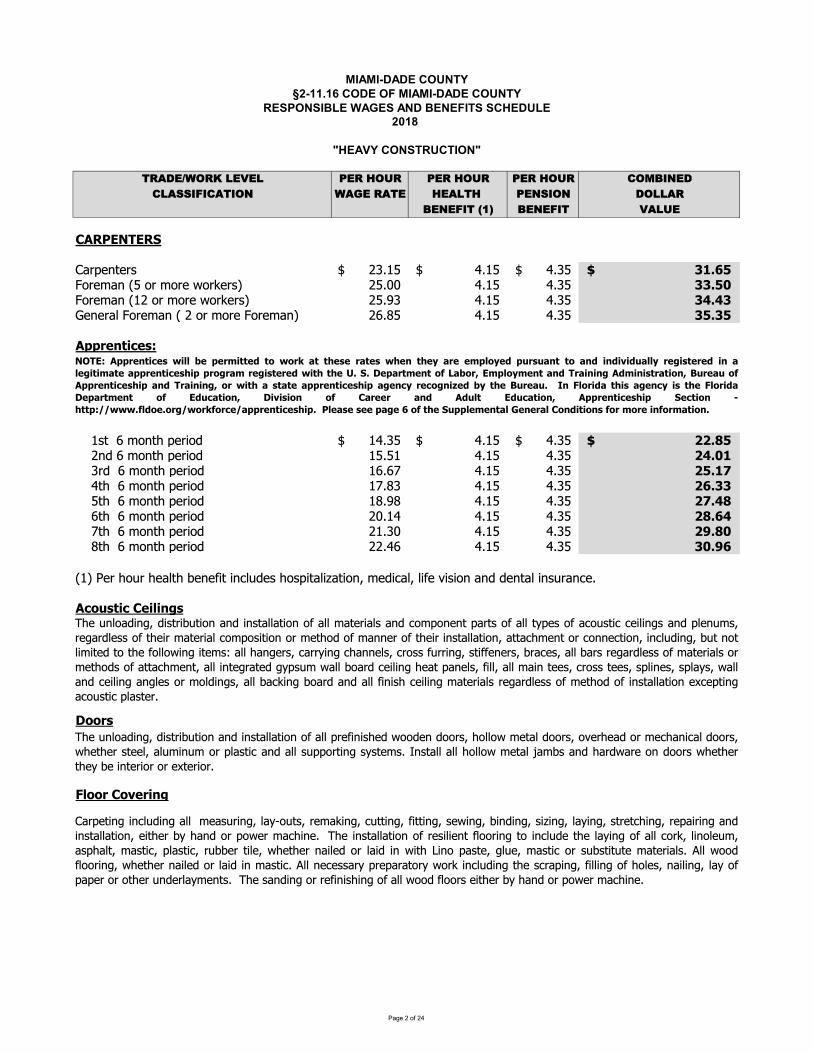
�������������� � ������������������� ������� � ���������������� ��!�"����� �����������#� � �$#��%�������������$� &'()*+,-'./0*1*0 2*'/3-4' 2*'/3-4' 2*'/3-4' 5-6789*)50(::8;85(&8-9 ,(<*/'(&* 3*(0&3/ 2*9:8-9 )-00('7*9*;8&/=>? 7*9*;8& 1(04*�@�ABCDEFGHFDIJKLMNOPNLQ RSTUVWXXXXXXX YTUVWXXXXXXXXXXXXXX YTSVWXXXXXXX Z[\]_`````````abLNcKOXdVXbLXcbLNXebLfNLQg RVThh YTUV YTSV ZZ\iabLNcKOXdURXbLXcbLNXebLfNLQg RVTjS YTUV YTSV Zk\kZlNONLKmXabLNcKOXdXRXbLXcbLNXabLNcKOg RnToV YTUV YTSV Z \ZCppqrstuvrwxXXXXUQPXXnXcbOPyXMNLzb{ UYTSVWXXXXXXX YTUVWXXXXXXXXXXXXXX YTSVWXXXXXXX ||\}_`````````XXXXRO{XnXcbOPyXMNLzb{ UVTVU YTUV YTSV |k\i[XXXXSL{XXnXcbOPyXMNLzb{ UnTn~ YTUV YTSV | \[�XXXXYPyXXnXcbOPyXMNLzb{ U~ToS YTUV YTSV |]\ZZXXXXVPyXXnXcbOPyXMNLzb{ UoTjo YTUV YTSV |�\k}XXXXnPyXXnXcbOPyXMNLzb{ RhTUY YTUV YTSV |}\]kXXXX~PyXXnXcbOPyXMNLzb{ RUTSh YTUV YTSV |�\}iXXXXoPyXXnXcbOPyXMNLzb{ RRTYn YTUV YTSV Zi\�]dUgX�NLXyb�LXyNKmPyX�NON�zPXzO�m�{NQXybQMzPKmz�KPzbO�XcN{z�Km�Xmz�NX�zQzbOXKO{X{NOPKmXzOQ�LKO�NTCv��wtuvBru�us�w���qw����qB��rqus�G�HFxCppqrstuvrw�u���rprq�uttr�t���q��tt�rwrq�trw��rst�r��qrr�p���r�p�qw��stt��s�us�u�u������qr�uwtrqr�us��r�utu��tr�ppqrstuvrw�uppq��q�� qr�uwtrqr��ut�t�r�\I\�rp�qt�rst������q�F�p����rst�s�Hq�usus�C��usuwtq�tu�s���qr����Cppqrstuvrw�up�s�Hq�usus���q�ut��wt�tr�ppqrstuvrw�up��rsv�qrv��su�r���t�r��qr��\ �s���qu��t�uw��rsv�uwt�r���qu���rp�qt�rst �� F��v�tu�s� �u�uwu�s �� B�qrrq �s� C���t F��v�tu�s� Cppqrstuvrw�up Irvtu�s �ttpx¡¡���\����r\�q�¡��q���qvr¡�ppqrstuvrw�up\E�r�wrwrrp��r]��t�rI�pp�r�rst��¢rsrq��B�s�utu�sw��q��qrus��q��tu�s\£yN�OmbK{zO¤�{zQPLz��PzbOKO{zOQPKmmKPzbOb�KmmcKPNLzKmQKO{�bcMbONOPMKLPQb�KmmP¥MNQb�K�b�QPz��NzmzO¤QKO{MmNO�cQ�LN¤KL{mNQQb�PyNzLcKPNLzKm�bcMbQzPzbObLcNPyb{b�cKOONLb�PyNzLzOQPKmmKPzbO�KPPK�ycNOPbL�bOON�PzbO�zO�m�{zO¤���PObPmzczPN{PbPyN�bmmbezO¤zPNcQ¦KmmyKO¤NLQ��KLL¥zO¤�yKOONmQ��LbQQ��LLzO¤�QPz��NONLQ��LK�NQ�Kmm�KLQLN¤KL{mNQQb�cKPNLzKmQbLcNPyb{Qb�KPPK�ycNOP�KmmzOPN¤LKPN{¤¥MQ�ceKmm�bKL{�NzmzO¤yNKPMKONmQ��zmm�KmmcKzOPNNQ��LbQQPNNQ�QMmzONQ�QMmK¥Q�eKmmKO{�NzmzO¤KO¤mNQbLcbm{zO¤Q�Kmm�K�fzO¤�bKL{KO{Kmm�zOzQy�NzmzO¤cKPNLzKmQLN¤KL{mNQQb�cNPyb{b�zOQPKmmKPzbON§�NMPzO¤K�b�QPz�XMmKQPNLTXX£yN�OmbK{zO¤�{zQPLz��PzbOKO{zOQPKmmKPzbOb�KmmMLN�zOzQyN{ebb{NO{bbLQ�ybmmbecNPKm{bbLQ�b�NLyNK{bLcN�yKOz�Km{bbLQ�eyNPyNLQPNNm�Km�czO�cbLMmKQPz�KO{KmmQ�MMbLPzO¤Q¥QPNcQTOQPKmmKmmybmmbecNPKm©Kc�QKO{yKL{eKLNbO{bbLQeyNPyNLPyN¥X�NXzOPNLzbLXbLXN§PNLzbLTJKLMNPzO¤zO�m�{zO¤KmmcNKQ�LzO¤�mK¥ªb�PQ�LNcKfzO¤���PPzO¤��zPPzO¤�QNezO¤��zO{zO¤�Qz�zO¤�mK¥zO¤�QPLNP�yzO¤�LNMKzLzO¤KO{zOQPKmmKPzbO�NzPyNL�¥yKO{bLMbeNLcK�yzONT£yNzOQPKmmKPzbOb�LNQzmzNOP�mbbLzO¤PbzO�m�{NPyNmK¥zO¤b�Kmm�bLf�mzObmN�c�KQMyKmP�cKQPz��MmKQPz��L���NLPzmN�eyNPyNLOKzmN{bLmKz{zOezPy«zObMKQPN�¤m�N�cKQPz�bLQ��QPzP�PNcKPNLzKmQT¬mmebb{�mbbLzO¤�eyNPyNLOKzmN{bLmKz{zOcKQPz�T¬mmON�NQQKL¥MLNMKLKPbL¥ebLfzO�m�{zO¤PyNQ�LKMzO¤��zmmzO¤b�ybmNQ�OKzmzO¤�mK¥b�MKMNLXbLXbPyNLX�O{NLmK¥cNOPQTXX£yNXQKO{zO¤XbLXLN�zOzQyzO¤Xb�XKmmXebb{X�mbbLQXNzPyNLX�¥XyKO{XbLXMbeNLXcK�yzONTX
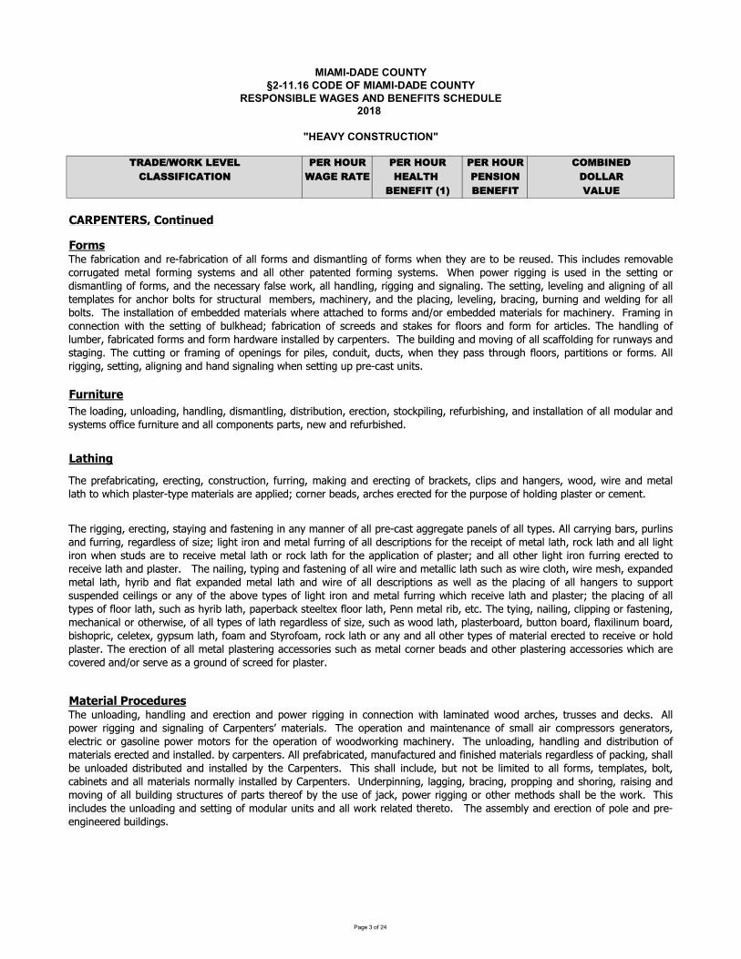
�������������� ������������� ����������������� ������������������� !��"�#������� ����������$���!�%$��&��������������%� '()*+,-.(/01+2+1 3+(04.5( 3+(04.5( 3+(04.5( 6.789:+*61);;9<96)'9.: -)=+0()'+ 4+)1'40 3+:;9.: *.11)(8+:+<9'0>?@ 8+:+<9' 2)15+�A�BCDEFGHIGEJKLCMNOPNQRSTMUVWTQUNPOQURXYOZPN[\YORUPY]LFUMRSQURW_abcdefghijgbcdefghidgebfghiefkldgmbfghiefkmnfojmfcgianapmfcgikmcpqrfbfghinasjnofkfghidgefgkmdbbdmfcgcsdbblcejbdndgektkmalkucssfpausjngfmjnaudgeudbbupclrcgagmkurdnmkiugavudgeunasjnofkaewu_arnasdonfpdmfghianapmfghipcgkmnjpmfcgisjnnfghildqfghdgeanapmfghcsondpqamkipbfrkdge dghankivcceivfnadgelamdbbdmumcuv fpurbdkmanxmtrauldmanfdbkudnaudrrbfaeyupcnganuoadekiudnpakuanapmaeuscnumaurjnrckaucsucbefghurbdkmanucnupalagmw_asdonfpdmfcgdgenaxsdonfpdmfcgcsdbbscnlkdgeefkldgmbfghcsscnlkv agmatdnamcoanajkaew_fkfgpbjeaknalczdobapcnnjhdmaelamdbscnlfghktkmalkdgedbbcmanrdmagmaescnlfghktkmalkw{ agrcvannfhhfghfkjkaefgmakammfghcnefkldgmbfghcsscnlkidgemagapakkdntsdbkavcnqidbbdgebfghinfhhfghdgekfhgdbfghw_akammfghibazabfghdgedbfhgfghcsdbbmalrbdmakscndgpcnocbmkscnkmnjpmjndblaloankildpfgantidgemarbdpfghibazabfghiondpfghiojngfghdgevabefghscndbbocbmkw_afgkmdbbdmfcgcsaloaeeaeldmanfdbkv anadmmdpaemcscnlkdge|cnaloaeeaeldmanfdbkscnldpfgantw}ndlfghfgpcggapmfcgvfm makammfghcsojbqadeysdonfpdmfcgcskpnaaekdgekmdqakscnsbccnkdgescnl scndnmfpbakw_a dgebfghcsbjloanisdonfpdmaescnlkdgescnl dnevdnafgkmdbbaeotpdnragmankw_aojfbefghdgelczfghcsdbbkpdsscbefghscnnjgvdtkdgekmdhfghw_apjmmfghcnsndlfghcscragfghkscnrfbakipcgejfmiejpmkiv agmatrdkkmncjh sbccnkirdnmfmfcgkcnscnlkw~bbnfhhfghiukammfghiudbfhgfghudgeudgeukfhgdbfghuv agukammfghujrurnaxpdkmujgfmkwu_anfhhfghianapmfghikmdtfghdgesdkmagfghfgdgtldggancsdbbrnaxpdkmdhhnahdmardgabkcsdbbmtrakw~bbpdnntfghodnkirjnbfgkdgesjnnfghinahdnebakkcskf�aybfhmfncgdgelamdbsjnnfghcsdbbeakpnfrmfcgkscnmanapafrmcslamdbbdmincpqbdmdgedbbbfhmfncgv agkmjekdnamcnapafzalamdbbdm cnncpqbdm scnmadrrbfpdmfcgcsrbdkmanydgedbbcmanbfhmfncgsjnnfghanapmaemcnapafzabdmdgerbdkmanw _agdfbfghimtrfghdgesdkmagfghcsdbbvfnadgelamdbbfpbdmkjp dkvfnapbcmivfnalakia�rdgeaelamdbbdmi tnfodgesbdma�rdgeaelamdbbdm dgevfnacsdbbeakpnfrmfcgkdkvabbdkmarbdpfghcsdbb dghankmckjrrcnmkjkrageaepafbfghkcndgtcsmadoczamtrakcsbfhmfncgdgelamdbsjnnfghv fp napafzabdm dgerbdkmanymarbdpfghcsdbbmtrakcssbccnbdmikjp dk tnfobdmirdranodpqkmaabma�sbccnbdmi�agglamdbnfoiampw_amtfghigdfbfghipbfrrfghcnsdkmagfghilapdgfpdbcncmanvfkaicsdbbmtrakcsbdmnahdnebakkcskf�aikjp dkvccebdmirbdkmanocdneiojmmcgocdneisbd�fbfgjlocdneiofkcrnfpipabama�ihtrkjlbdmiscdldge�mtncscdlincpqbdmcndgtdgedbbcmanmtrakcsldmanfdbanapmaemcnapafzacn cberbdkmanw_aanapmfcgcsdbblamdbrbdkmanfghdppakkcnfakkjp dklamdbpcnganoadekdgecmanrbdkmanfghdppakkcnfakv fp dnapczanaeudge|cnukanzaudkuduhncjgeucsukpnaaeuscnurbdkmanwuu_ajgbcdefghi dgebfghdgeanapmfcgdgercvannfhhfghfgpcggapmfcgvfm bdlfgdmaevccednpakimnjkkakdgeeapqkw~bbrcvannfhhfghdgekfhgdbfghcs�dnragmank�ldmanfdbkw_acrandmfcgdgeldfgmagdgpacskldbbdfnpclrnakkcnkhagandmcnkiabapmnfpcnhdkcbfgarcvanlcmcnkscnmacrandmfcgcsvccevcnqfghldpfgantw_ajgbcdefghi dgebfghdgeefkmnfojmfcgcsldmanfdbkanapmaedgefgkmdbbaewotpdnragmankw~bbrnasdonfpdmaeildgjsdpmjnaedgesfgfkaeldmanfdbknahdnebakkcsrdpqfghikdbboajgbcdeaeefkmnfojmaedgefgkmdbbaeotma�dnragmankw_fkkdbbfgpbjeaiojmgcmoabflfmaemcdbbscnlkimalrbdmakiocbmipdofgamkdgedbbldmanfdbkgcnldbbtfgkmdbbaeot�dnragmankw�geanrfggfghibdhhfghiondpfghirncrrfghdgekcnfghindfkfghdgelczfghcsdbbojfbefghkmnjpmjnakcsrdnmkmanacsotmajkacs�dpqircvannfhhfghcncmanlamcekkdbboamavcnqw_fkfgpbjeakmajgbcdefghdgekammfghcslcejbdnjgfmkdgedbbvcnqnabdmaemanamcw _adkkalobtdgeanapmfcgcsrcbadgernaxaghfgaanaeuojfbefghkwu
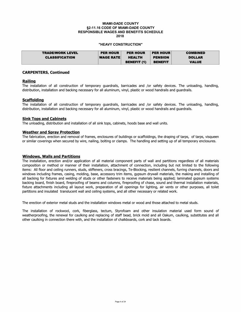
�������������� � ������������������� ������� � ���������������� ��!�"����� �����������#� � �$#��%�������������$� &'()*+,-'./0*1*0 2*'/3-4' 2*'/3-4' 2*'/3-4' 5-6789*)50(::8;85(&8-9 ,(<*/'(&* 3*(0&3/ 2*9:8-9 )-00('7*9*;8&/=>? 7*9*;8& 1(04*�@�ABCDEFGHFDIJKBLMNOMPQR SDTOUOMVIWTXXLUROMVIOMYKHLZ[KTMRKBT\OMQN[]QTNQ_KTMRKIZ_TKE_LNQWNOLM]OMRLa[JK]TUU[KTMRKET_NONOLM[bcdefghijjihekf klmknopkkjqnkmoqlerdmsjiggqhdnhtuqvhwmklkiu ifx khcdmefgtjihekf uihdmeijtgdx lkmu gktfx klpdihcdmymkklefsqhcdmdfdpijlkmnitjoefsifxmdyjinefsklghillrdixqrmenoukjxifxijjziotuqnitjoefsqgtrghehthdgifxijjkhcdmSnitjoefsSefSnkffdnhekfShcdmdSpehcqSifxShcdSefghijjihekfSklSncijorkimxgqSnkmoSifxShinoSrkimxg{SbcdSdmdnhekfSklSd|hdmekmSudhijSghtxgSifxShcdSefghijjihekfSpefxkpgSudhijSkmSpkkxSifxShckgdSihhincdxShkSudhijSghtxg{SSbcdStfjkixefsqSxeghmerthekfSifxSefghijjihekfSklSijjSgefoShkygqSnirefdhgqSckkxgSrigdSifxSpijjStfehg{Sbcdlirmenihekfqdmdnhekfifxmduk}ijkllmiudgqdfnjkgtmdgklrtejxefsgkmgnillkjxefsgqhcdxmiyefsklhimygqklhimygq}eg~tddfkmSgeuejimSnk}dmefsgSpcdfSgdntmdxSrwSpemdqSfiejefsqSrkjhefsSkmSnjiuyg{SSbcdScifxjefsSifxSgdhhefsStySklSijjShduykmimwSdfnjkgtmdg{Sbcdefghijjihekfklijjnkfghmtnhekfklhduykmimwstimxmiejgqrimmenixdgifx�kmgildhwxd}endg{bcdtfjkixefsqcifxjefsqxeghmerthekfqSefghijjihekfSifxSrinoefsSfdndggimwSlkmSijjSijtueftuqS}efwjqSyjighenSkmSpkkxScifxmiejgSifxSstimxmiejg{Sbcdefghijjihekfklijjnkfghmtnhekfklhduykmimwstimxmiejgqrimmenixdgifx�kmgildhwxd}endg{bcdtfjkixefsqcifxjefsqxeghmerthekfqSefghijjihekfSifxSrinoefsSfdndggimwSlkmSijjSijtueftuqS}efwjqSyjighenSkmSpkkxScifxmiejgSifxSstimxmiejg{Sbcdefghijjihekfqdmdnhekfifx�kmiyyjenihekfklijjuihdmeijnkuykfdfhyimhgklpijjifxyimhehekfgmdsimxjdggklijjuihdmeijgnkuykgehekfkmudhckxkmuiffdmklhcdemefghijjihekfqihhincudfhklnkffdnhekfqefnjtxefsrthfkhjeuehdxhkhcdlkjjkpefsehdug��jjljkkmifxndejefsmtffdmgqghtxgqghelldfdmgqnmkggrminefsgqbd��jknoefsqmdgejedfhnciffdjgqltmmefsnciffdjgqxkkmgifxpefxkpgefnjtxefslmiudgqnigefsqukjxefsqrigdqinndggkmwhmeuehdugqswygtuxmwpijjuihdmeijgqhcduioefsifxefghijjefsklijjrinoefslkmle|htmdgifxpdjxefsklghtxgkmkhcdmlighdfdmghkmdnde}duihdmeijgrdefsiyyjedx�jiuefihdxswygtugwghdugrinoefsrkimxqlefegcrkimxqlemdymkklefsklrdiugifxnkjtufgqlemdymkklefsklncigdqgktfxifxhcdmuijefghijjihekfuihdmeijgqle|htmdihhincudfhgefnjtxefsijjjiwkthpkmoqymdyimihekfklijjkydfefsglkmjeschefsqiem}dfhgkmkhcdmytmykgdgqijjhkejdhyimhehekfgSifxSefgtjihdxSShmifgjtndfhSpijjSifxSndejefsSgwghdugqSifxSijjSkhcdmSfdndggimwSkmSmdjihdxSpkmo{SS
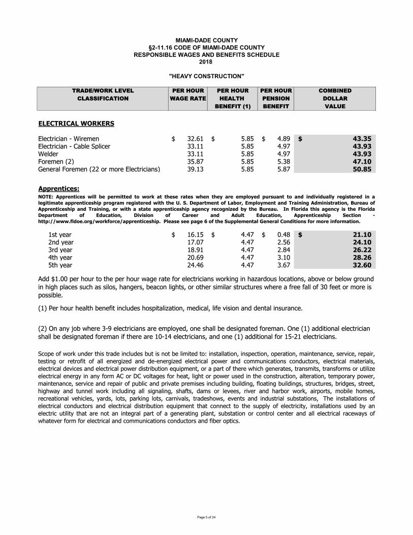
�������������� ������������� ����������������� ������������������� !��"�#������� ����������$���!�%$��&��������������%� '()*+,-.(/01+2+1 3+(04.5( 3+(04.5( 3+(04.5( 6.789:+*61);;9<96)'9.: -)=+0()'+ 4+)1'40 3+:;9.: *.11)(8+:+<9'0>?@ 8+:+<9' 2)15+�A�BCDCEFGHEIDJKLGMCGN JOPQRSTURUVWXYXZUTQ[QW \]_aXXXXXXX bcbaXXXXXXXXXXXXXX dceaXXXXXXX fghgijJJJJJJJJJJJJJJJJJJJJJJJJJJJJOPQRSTURUVWXYXkVlPQXmnPURQTX \\ `XXXXXXXX bcb deoXXXXXXXXX fghpgZQPqQTX \\ `XXXXXXXX bcb deoXXXXXXXXX fghpgrsTQ[QWXt]u \bcoXXXXXXXX bcb b\cXXXXXXXXX fvhwxyQWQTVPXrsTQ[QWXt]]XsTX[sTQXOPQRSTURUVWzu \e \XXXXXXXX bcb bcoXXXXXXXXX ixh{iI||}~����~��XXXXXzSX�QVTX _ baXXXXXXX ddoaXXXXXXXXXXXXXX �dcaXXXXXXX �whwxjJJJJJJJJJJJJJJJJJJJJJJJJJJJJXXXXX]WqX�QVT o�o ddo ]b_XXXXXXXXX �fhwxXXXXX\TqX�QVTX ce ddo ]cdXXXXXXXXX ��h��XXXXXdS�X�QVTX ]�_e ddo \ �XXXXXXXXX �{h��XXXXXbS�X�QVTX ]dd_ ddo \_oXXXXXXXXX g�h�xtuX�QTX�s�TX�QVPS�XlQWQ�USXUWRP�qQzX�sznUSVPU�VSUsW�X[QqURVP�XPU�QX�UzUsWXVWqXqQWSVPXUWz�TVWRQ�qqXa ��XnQTX�s�TXSsXS�QXnQTX�s�TX�V�QXTVSQX�sTXQPQRSTURUVWzX�sT�UW�XUWX�V�VTqs�zXPsRVSUsWz�XVls�QXsTXlQPs�X�Ts�WqXUWX�U��XnPVRQzXz�R�XVzXzUPsz�X�VW�QTz�XlQVRsWXPU��Sz�XsTXsS�QTXzU[UPVTXzST�RS�TQzX��QTQXVX�TQQX�VPPXs�X\�X�QQSXsTX[sTQXUzXnszzUlPQt]uX�WXVW�X�slX��QTQX\YeXQPQRSTURUVWzXVTQXQ[nPs�Qq�XsWQXz�VPPXlQXqQzU�WVSQqX�sTQ[VWX�WQXtuXVqqUSUsWVPXQPQRSTURUVWXz�VPPXlQXqQzU�WVSQqX�sTQ[VWXU�XS�QTQXVTQX�YdXQPQRSTURUVWz�XVWqXsWQXtuXVqqUSUsWVPX�sTXbY]XQPQRSTURUVWzX�LFC�I||}~����~������~|~}����~�����}�����~�~}��~���~���~ �}~~�|�� ~�|¡}�¡������������¢��¡��� }~£���~}~�����~£������~�||}~����~���||}�£}�� }~£���~}~�������~¤hNh¥~|�}��~���¦D���}§C�|�� �~�����F}�����£I�������}�����§ ¡}~�¡�¦I||}~����~���|���F}�����£§�}���������~�||}~����~���|�£~�� }~��£��©~�� ��~ ¡}~�¡h H�ª��}��������£~�� ����~ª��}���¥~|�}��~�� �¦ C�¡������§ ¥�¢����� �¦ E�}~~} ��� I�¡�� C�¡������§ I||}~����~���| N~����� «���|�¬¬���h¦���~h�}£¬��}�¦�}�~¬�||}~����~���|hJJ�~��~J�~~J|�£~J�J�¦J��~JN¡||�~�~����J®~�~}��JE���������J¦�}J��}~J��¦�}������hmRsnQs��sT��WqQTS�UzSTVqQUWRP�qQzl�SUzWsSlQPU[USQqSsUWzSVPPVSUsW�UWznQRSUsW�snQTVSUsW�[VUWSQWVWRQ�zQT�URQ�TQnVUT�SQzSUW�sTTQSTs�USs�VPPQWQT�U�QqVWqqQYQWQT�U�QqQPQRSTURVPns�QTVWqRs[[�WURVSUsWzRsWq�RSsTz�QPQRSTURVP[VSQTUVPz�QPQRSTURVPqQ�URQzVWqQPQRSTURVPns�QTqUzSTUl�SUsWQ°�Un[QWS�sTVnVTSs�S�QTQ��UR��QWQTVSQz�STVWz[USz�STVWz�sT[zsT�SUPU�QQPQRSTURVPQWQT��UWVW��sT[�ksT±k�sPSV�Qz�sT�QVS�PU��SsTns�QT�zQqUWS�QRsWzST�RSUsW�VPSQTVSUsW�SQ[nsTVT�ns�QT�[VUWSQWVWRQ�zQT�URQVWqTQnVUTs�n�lPURVWqnTU�VSQnTQ[UzQzUWRP�qUW�l�UPqUW���PsVSUW�l�UPqUW�z�zST�RS�TQz�lTUq�Qz�zSTQQS��U���V�VWqS�WWQP�sT�UWRP�qUW�VPPzU�WVPUW��z�V�Sz�qV[zsTPQ�QQz�TU�QTVWq�VTlsT�sT��VUTnsTSz�[slUPQ�s[Qz�TQRTQVSUsWVP�Q�URPQz��VTqz�PsSz�nVT�UW�PsSz�RVTWU�VPz�STVqQz�s�z�Q�QWSzVWqUWq�zSTUVPz�lzSVSUsWz�²�QUWzSVPPVSUsWzs�QPQRSTURVPRsWq�RSsTzVWqQPQRSTURVPqUzSTUl�SUsWQ°�Un[QWSS�VSRsWWQRSSsS�Qz�nnP�s�QPQRSTURUS��UWzSVPPVSUsWz�zQql�VWQPQRSTUR�SUPUS�S�VSVTQWsSVWUWSQ�TVPnVTSs�V�QWQTVSUW�nPVWS�z�lzSVSUsWsTRsWSTsPRQWSQTVWqVPPQPQRSTURVPTVRQ�V�zs���VSQ�QTX�sT[X�sTXQPQRSTURVPXVWqXRs[[�WURVSUsWzXRsWq�RSsTzXVWqX�UlQTXsnSURz

�������������� ������������� ����������������� ������������������� !��"�#������� ����������$���!�%$��&��������������%� '()*+,-.(/01+2+1 3+(04.5( 3+(04.5( 3+(04.5( 6.789:+*61);;9<96)'9.: -)=+0()'+ 4+)1'40 3+:;9.: *.11)(8+:+<9'0>?@ 8+:+<9' 2)15+�A�BCDCEFGHEIDJKLGMCGNOJEPQRSQTUVWXXYZ[\]Z_YW\]a_\bc_def_Wgghijklmi_kc_dnopf_qlhirijs_tuvi_wgvlmihx_ch_qivyihxzWxhivtkiykctjivimkhlmtvx{xkirljlkxijklhik{sk|im|txlj}sm|tjjivlj}scgijlj}tjymvcxlj}c~gvtmixtuc�itjyuivcb }hc�jysgvtmirijksljxktvvtklcj chkirgchth{ ljxktvvtklcjsihimklcjsljxgimklcjscgihtklcjsbivylj}srtljkijtjmis_xih�lmis_higtlhs_kixklj}_ch_mcjjimklcj_c~_tj{_ivimkhlmtv_mcjy�mkchxs_ivimkhlmtv_vl}|klj}_~l�k�hixs_tggvltjmixs_ljxkh�rijktklcjtggthtk�xshtmibt{x{xkirxsmcjy�lkx{xkirxsglgix{xkirxs�jyih}hc�jyx{xkirxsmtuvikht{x{xkirxs}hc�jylj}sucjylj}x{xkirxsvl}|kijlj}ghckimklcjx{xkirxsgcbiho}ijihtklj}}hiijkim|jcvc}{x{xkirxchck|ihx{xkirxc~hijibtuviijih}{ljmv�ylj}u�kjckvlrlkiykcg|ckc�cvktlmsxcvthsbljyk�huljis|{yhco}ijihtklcjs}ick|ihrtvchklytvx{xkirxsivimkhlm�i|lmvikim|jcvc}{sivimkhlmtvgcbihmcjy�mkchxtjymcrr�jlmtklcjxmcjy�mkchx~chijih}{rtjt}irijkx{xkirxsivimkhlmtvgcbihmcjy�mkchxtjy mcrr�jlmtklcjxmcjy�mkchx~chu�lvylj}t�kcrtklcjx{xkirxshtlvhctysxl}jtvrtjsrtljktljihtjyhtlvhctymcrr�jlmtklcjsj�mvithschk|iihimklcjstvkihtklcjshigtlhsrcyl~lmtklcjsxgvlmlj}skihrljtklcjc~ivimkhlmkhtjxrlxxlcjvljixcjghl�tkighcgihk{sxkh�mk�hiymtuvlj}x{xkirx~chkhtjxrlxxlcjc~�clmisytkts�lyicsjckl~lmtklcjsbthjlj}x{xkirxsxrc�itjy~lhitvthrx{xkirxsck|ihvl~i_xt~i_xt~ik{_tjy_xim�hlk{_x{xkirx_tjy_tgg�hkijtjmixz_\|iljxktvvtklcjc~ivimkhlmtvvl}|klj}s|itklj}tjygcbihi��lgrijks~luihcgklmxstjyk|iljxktvvtklcjtjymcjjimklj}c~tvvivimkhcjlmi��lgrijksljmv�ylj}mcrg�klj}rtm|ljixtjyyi�lmixsrcjlkchlj}c~htyltklcj|t�thyxb|ihix�m|rcjlkchlj}bch�lxjckghiirgkiychgih~chriyu{tjivimkhlmtv�klvlk{sk|iljxktvvtklcjc~tvvkirgchth{gcbihtjyvl}|kblhlj}s|l}|o�cvkt}imtuvixgvlmlj}tjykihrljtklcjxsuhit�ihkixklj}tjyk|imcrrlxxlcjtjyyimcrrlxxlcjc~ivimkhlmtvmcjkhcvx{xkirxz vitjsxih�lmishigtlhshigvtmiscgihtkitjyty��xk|l}|tjyvcb�cvkt}ixblkm|}ith�khtjx~chrihxsmcjy�mkchxsmcjjimkchxsuhit�ihxs~�xixtjyu�xixz gihtklcjxsrtljkijtjmitjyhigtlhc~|l}|�cvkt}i_ivimkhlmtv_gcbih_mcjjimklcjxs_mlhm�lk_ghckimklcj_yi�lmix_tjy_txxcmltkiy_xblkm|}ithz___
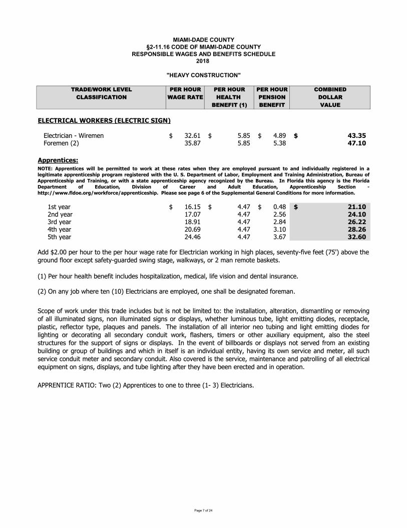
�������������� ������������� ����������������� ������������������� !��"�#������� ����������$���!�%$��&��������������%� '()*+,-.(/01+2+1 3+(04.5( 3+(04.5( 3+(04.5( 6.789:+*61);;9<96)'9.: -)=+0()'+ 4+)1'40 3+:;9.: *.11)(8+:+<9'0>?@ 8+:+<9' 2)15+�A�BCDCEFGHEIDJKLGMCGNJOCDCEFGHEJNHPQR JJSSSTUVWXYZWZ[\S]SZYV_V\ abcdeSSSSSSS fbgfeSSSSSSSSSSSSSS hbgieSSSSSSS jklkmnJJJJJJJJJJJJJJJJJJJJJJJJJJJJSSSopYV_V\Sqar fbgsSSSSSSSS fbgfSSSSSSSSSSSSSSSS fbgSSSSSSSSS jtluvJJJJJJJJJJJJJJJJJJJJJJJJJJJJJJIwwxyz{|}y~�SSSSSd�XS�V[Y dcbdfeSSSSSSS hbhseSSSSSSSSSSSSSS �bhgeSSSSSSS �uluvnJJJJJJJJJJJJJJJJJJJJJJJJJJJJSSSSSa\�S�V[Y dsb�sSSSSSSSS hbhsSSSSSSSSSSSSSSSS abfcSSSSSSSSS �jluvJJJJJJJJJJJJJJJJJJJJJJJJJJJJJJSSSSSY�S�V[Y dgbidSSSSSSSS hbhsSSSSSSSSSSSSSSSS abghSSSSSSSSS ��l��JJJJJJJJJJJJJJJJJJJJJJJJJJJJJJSSSSShX�S�V[Y a�bciSSSSSSSS hbhsSSSSSSSSSSSSSSSS bd�SSSSSSSSS ��l��JJJJJJJJJJJJJJJJJJJJJJJJJJJJJJSSSSSfX�S�V[Y ahbhcSSSSSSSS hbhsSSSSSSSSSSSSSSSS bcsSSSSSSSSS k�l�vJJJJJJJJJJJJJJJJJJJJJJJJJJJJJJqdrS�VYS�p�YS�V[UX�S�V\V�ZXSZ\WU��V�S�p��ZX[UZ�[XZp\�S_V�ZW[U�SUZ�VS�Z�Zp\S[\�S�V\X[USZ\��Y[\WVb����T����TS������S��pSqarS���YV\XZWV�SXpSp\VSXpSX�YVVSqd]SrSTUVWXYZWZ[\�b���Seab��S�VYS�p�YSXpSX�VS�VYS�p�YS�[�VSY[XVS�pYSTUVWXYZWZ[\S�pY�Z\�SZ\S�Z��S�U[WV��S�V�V\X�]�Z�VS�VVXSqsf�rS[�p�VSX�VS�Yp�\�S�UppYSV�WV�XS�[�VX�]��[Y�V�S��Z\�S�X[�V�S�[U��[���SpYSaS_[\SYV_pXVS�[��VX�bqarS�\S[\�S�p�S��VYVSXV\Sqd�rSTUVWXYZWZ[\�S[YVSV_�Up�V��Sp\VS��[UUS�VS�V�Z�\[XV�S�pYV_[\bS�Wp�Vp��pY��\�VYX�Z�XY[�VZ\WU��V���XZ�\pX�VUZ_ZXV�Xp�X�VZ\�X[UU[XZp\�[UXVY[XZp\��Z�_[\XUZ\�pYYV_p�Z\�p�[UUZUU�_Z\[XV��Z�\��\p\ZUU�_Z\[XV��Z�\�pY�Z��U[�����VX�VYU�_Z\p��X��V�UZ��XV_ZXXZ\��Zp�V��YVWV�X[WUV��U[�XZW�YV�UVWXpYX��V��U[��V�[\��[\VU�b��VZ\�X[UU[XZp\p�[UUZ\XVYZpY\VpX��Z\�[\�UZ��XV_ZXXZ\��Zp�V��pYUZ��XZ\�pY�VWpY[XZ\�[UU�VWp\�[Y�Wp\��ZX�pY���U[��VY��XZ_VY�pYpX�VY[��ZUZ[Y�V��Z�_V\X�[U�pX�V�XVVU�XY�WX�YV��pYX�V����pYXp��Z�\�pY�Z��U[��b�\X�VV�V\Xp��ZUU�p[Y��pY�Z��U[��\pX�VY�V��Yp_[\V�Z�XZ\���ZU�Z\�pY�Yp��p���ZU�Z\��[\���ZW�Z\ZX�VU�Z�[\Z\�Z�Z��[UV\XZX���[�Z\�ZX�p�\�VY�ZWV[\�_VXVY�[UU��W��VY�ZWVWp\��ZX_VXVY[\��VWp\�[Y�Wp\��ZXb�U�pWp�VYV�Z�X�V�VY�ZWV�_[Z\XV\[\WV[\��[XYpUUZ\�p�[UUVUVWXYZW[UV��Z�_V\XSp\S�Z�\��S�Z��U[���S[\�SX��VSUZ��XZ\�S[�XVYSX�V�S�[�VS�VV\SVYVWXV�S[\�SZ\Sp�VY[XZp\bSQLFC�Iwwxyz{|}y~ |¡¡¢ywyx£|{{y¤{¥ ¥x¦§{{y~yx§{y~ yz{y©§xyy£w¡¥©y¤wªx~ª§z{{¥§z¤|z¤|«|¤ª§¡¡©xy¬|~{yxy¤|z§¡y¬|{|£§{y§wwxyz{|}y~|wwx¥¬x§£ xy¬|~{yxy¤ |{ {ylNl®yw§x{£yz{¥ D§¢¥x°C£w¡¥©£yz{§z¤Fx§|z|z¬I¤£|z|~{x§{|¥z°±ªxy§ª¥Iwwxyz{|}y~|w§z¤Fx§|z|z¬°¥x |{ §~{§{y§wwxyz{|}y~|w§¬yz}©xy}¥¬z|²y¤¢©{y±ªxy§ªl Hz³¡¥x|¤§{|~§¬yz}©|~{y³¡¥x|¤§®yw§x{£yz{ ¥ C¤ª}§{|¥z° ®|«|~|¥z ¥ E§xyyx §z¤ I¤ª¡{ C¤ª}§{|¥z° Iwwxyz{|}y~|w Ny}{|¥z ´{{w�µµ l¡¤¥yl¥x¬µ ¥x¦¥x}yµ§wwxyz{|}y~|wlJJ¶¡y§~yJ~yyJw§¬yJ�J¥J{yJNªww¡y£yz{§¡JPyzyx§¡JE¥z¤|{|¥z~J¥xJ£¥xyJ|z¥x£§{|¥zl
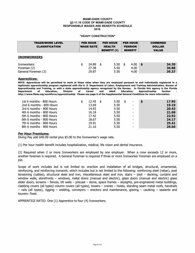
�������������� ������������� ����������������� ������������������� !��"�#������� ����������$���!�%$��&��������������%� '()*+,-.(/01+2+1 3+(04.5( 3+(04.5( 3+(04.5( 6.789:+*61);;9<96)'9.: -)=+0()'+ 4+)1'40 3+:;9.: *.11)(8+:+<9'0>?@ 8+:+<9' 2)15+�A�BCDEFGEDHIDJ KKKLMNOPNMQRMS TUVWXYKKKKKKK ZVZ[YKKKKKKKKKKKKKK UV[[YKKKKKKK \]\_aaaaaaaaaaaaaaaaaaaaaaaaaaaabNMRcdOKeTfK TgVhW ZVZ[ UV[[ \ijjkRORMdlKbNMRcROKeTf TXVWg ZVZ[ UV[[ \_\mnoopqrstuqvwaKKKKxSyKzKcNOy{SK|KW[[K}N~MSK xTVUZYKKKKKKK ZVZ[YKKKKKKKKKKKKKK |YKKKKKKKK �m_�aaaaaaaaaaaaaaaaaaaaaaaaaaaaKKKKTO�KzKcNOy{SK|KW[[K}N~MS xhVzX ZVZ[ |KKKKKKKKKK �_�_KKKKhM�KzKcNOy{SK|KW[[K}N~MS xUVXh ZVZ[ |KKKKKKKKKK ��]\KKKKUy{KzKcNOy{SK|KW[[K}N~MSK xzVxW ZVZ[ |KKKKKKKKKK ��ijKKKKZy{KzKcNOy{SK|KW[[K}N~MSK xgVUT ZVZ[ |KKKKKKKKKK ��_�KKKKzy{KzKcNOy{SK|KW[[K}N~MSK xWVzg ZVZ[ |KKKKKKKKKK �]�mKKKKgy{KzKcNOy{SK|KW[[K}N~MS xXVXx ZVZ[ |KKKKKKKKKK ��]�KKKKWy{KzKcNOy{SK|KW[[K}N~MS TxVxz ZVZ[ |KKKKKKKKKK �iii�qpa���pa�pq�t��vw����O�K�d�Kd��KYU[V[[KMROydlK�l~SKYZV[[KyNKy{RKLMNOPNMQRM�SKPd�RKMdyRVKexfK�RMK{N~MK{Rdly{K�ROR��yK�O�l~�RSK{NS��ydl��dy�NO�KcR���dl�Kl��RK��S�NOKdO�K�ROydlK�OS~MdO�RV�������L��K���L��K�ORKexfK���MROy��RKyNK�N~MKeUfKLMNOPNMQRMSVKK��N�RN�PNMQ�O�l~�RS�~y�SONyl�c�yR�yN�RMR�y�NOdO��OSydlldy�NON�dll�M���RS�SyM~�y~Mdl�NMOdcROydl�MR�O�NM��O��dO�MR�O�NM��O��MNOPNMQ�P{��{�O�l~�RS�~y�SONyl�c�yR�yNy{R�NllNP�O��MR�O�NM��O�SyRRleMR�dMf��NSyyROS�NO�O�e�d�lRSf�SyM~�y~MdlSyRRldO��MNO�c�S�RlldORN~SSyRRldO��MNO�Syd�MS ¡N�Sy �R�Q�O���~Myd�OSdO�P�O�NPPdllS�SyNMR�MNOyS P�O�NPS�cRydl�NNMSecdO~dldO�RlR�yM��f��ldSS�NNMSecdO~dldO�RlR�yM��f�ldSSSl��RM�NNMS�S�MRROS �RO�RS�y�lyPdllS �MR�dSy SyNOR�S�d�R�MdcRS SQ�l��{yS��MR|RO��ORRMR�cRydl�~�l��O�S��ld���O��N�RMSedlly��RSf�Nl~cO�N�RMSedlly��RSf�yNPRMS �MdORS {N�SyS�SydO��O�SRdccRydlMNN�S�{dO�Md�lS Md�lSedlly��RSf�M����O� PRl��O���NO�R�NMS RMR�yNMSdO�cd�OyROdO�R��ld��O� �d~lQ�O� SRdldOySdO�lN~�RMS|K��¢R�VKeTf�R£~�MR�P{ROTNMcNMRLMNOPNMQRMSdMRRc�lN�R���NORRc�lN�RMV¤{ROd�MRPR¢�RR�SxTNMcNMR�dONy{RM�NMRcdO�SMR£~�MR�V�kRORMdlbNMRcdO�SMR£~�MR���y{MRRNMcNMRLMNOPNMQRMbNMRcdOdMRRc�lN�R�NOd¡N�VFE¥Iwnoopqrstuqv¦t§§ qoqp�tssq©s�¦�pª«ss¬qvqp«sqv¦¬qrs¬q«pqq�o§�q©o�pv�«rss�«r©tr©t®t©�«§§pqtvsqpq©tr«§qtst�«sq«oopqrstuqv¬toop�p«� pqtvsqpq©¦ts¬s¬q° J ±qo«ps�qrs�²³«�pI�o§��qrs«r©¥p«trtr n©�trtvsp«st�r µ�pq«��²noopqrstuqv¬to«r©¥p«trtr �p¦ts¬«vs«sq«oopqrstuqv¬to«qrupqu�rt¶q© s¬qµ�pq«� Cr·§�pt©«s¬tv«qrutvs¬q·§�pt©«±qo«ps�qrs �² I©�u«st�r ±t®tvt�r �² «pqqp «r© n©�§s I©�u«st�r noopqrstuqv¬to Jqust�r ¹¬ssowºº¦¦¦²§©�q�pº¦�pª²�puqº«oopqrstuqv¬toaa�§q«vqavqqao«qaia�²as¬qaJ�oo§q�qrs«§a»qrqp«§a�r©tst�rva²�pa��pqatr²�p�«st�r
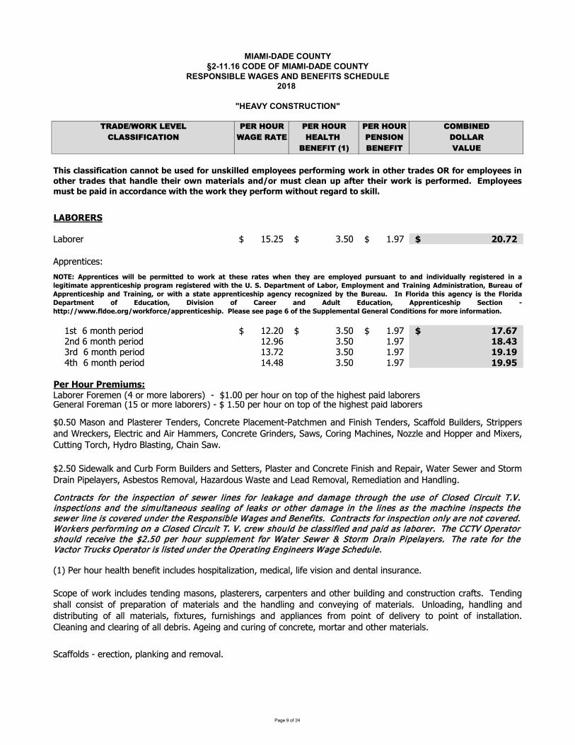
�������������� ������������� ����������������� ������������������� !��"�#������� ����������$���!�%$��&��������������%� '()*+,-.(/01+2+1 3+(04.5( 3+(04.5( 3+(04.5( 6.789:+*61);;9<96)'9.: -)=+0()'+ 4+)1'40 3+:;9.: *.11)(8+:+<9'0>?@ 8+:+<9' 2)15+�A�BCDEFGHGIJKLMNONP QRSTRUPPPPPPP VSRWUPPPPPPPPPPPPPP QSXYUPPPPPPP Z[\]Z____________________________aaNObcdeOfgPPPPQfcPPhPiMbcjPaONdMk QTSTWUPPPPPPP VSRWUPPPPPPPPPPPPPP QSXYUPPPPPPP l]\m]____________________________PPPPTbkPhPiMbcjPaONdMk QTSXh VSRW QSXY ln\opPPPPVNkPPhPiMbcjPaONdMk QVSYT VSRW QSXY lq\lqPPPPrcjPPhPiMbcjPaONdMk QrSrs VSRW QSXY lq\qtuvw_xyzw_uwv{|z{}~JKLMNONP�MNOiObP�rPMNPiMNOP�KLMNONf�PP�PPUQSWWPaONPjM�NPMbPcMaPM�PcjOPjd�jOfcPaKdkP�KLMNONf�ObONK�P�MNOiKbP�QRPMNPiMNOP�KLMNONf�P�PUPQSRWPaONPjM�NPMbPcMaPM�PcjOPjd�jOfcPaKdkP�KLMNONfP�Q�P�ONPjM�NPjOK�cjPLObO�dcPdbe��kOfPjMfadcK�d�KcdMb�PiOkdeK��P�d�OP�dfdMbPKbkPkObcK�Pdbf�NKbeOS�eK��M�kfP�PONOecdMb�Pa�Kb�db�PKbkPNOiM�K�SUTSRW�dkO�K��Kbk��NL�MNi��d�kONfKbk�OccONf���KfcONKbk�MbeNOcO�dbdfjKbk�OaKdN��KcON�O�ONKbk�cMNi�NKdbP�daO�K�ONf�PfLOfcMfP�OiM�K��P�K�KNkM�fP�KfcOPKbkPJOKkP�OiM�K��P�OiOkdKcdMbPKbkP�Kbk�db�SP�F�H~D��wv��|�v}�|���v�vw{|��v��y�yw ¡��¢v}vw¡�v}�¢v��¢v£¡wvv{��y£v��zw}z¡���y¡��|��|¤|�z¡��£wv¥|}�vwv�|�¡�v¥|�|{¡�v¡��wv��|�v}¢|��wy¥w¡{ wv¥|}�vwv��|�¢�¢v¦\I\§v�¡w�{v��y C¡�yw©H{��y£{v��¡���w¡|�|�¥D�{|�|}�w¡�|y�©Ezwv¡zyD��wv��|�v}¢|�¡���w¡|�|�¥©yw�|�¢¡}�¡�v¡��wv��|�v}¢|�¡¥v��£wv�y¥�|ªv��£�¢vEzwv¡z\ «�¬�yw|�¡�¢|}¡¥v��£|}�¢v¬�yw|�¡§v�¡w�{v�� y H�z�¡�|y�© §|¤|}|y� y ¡wvvw ¡�� D�z�� H�z�¡�|y�© D��wv��|�v}¢|� Iv��|y� ®¢���~ ���\��yv\yw¥�yw yw�v¡��wv��|�v}¢|�\__u�v¡}v_}vv_�¡¥v_m_y_�¢v_Iz���v{v��¡�_°v�vw¡�_y��|�|y�}_yw_{ywv_|�yw{¡�|y�\�¢|}��¡}}||�¡�|y��¡��y��vz}v� ywz�} |��v�v{��y£vv}�vwyw{|�¥�yw |�y�¢vw�w¡�v}FG ywv{��y£vv}|�y�¢vw�w¡�v}�¢¡�¢¡���v�¢v|wy��{¡�vw|¡�}¡��yw{z}���v¡�z�¡�vw�¢v|w�yw |}�vwyw{v�\H{��y£vv}{z}�_�v_�¡|�_|�_¡��yw�¡��v_�|�¢_�¢v_�yw _�¢v£_�vwyw{_�|�¢yz�_wv¥¡w�_�y_} |��\�eMaOM��MN�dbe��kOfcObkdb�iKfMbf�a�KfcONONf�eKNaObcONfKbkMcjONL�d�kdb�KbkeMbfcN�ecdMbeNK�cfS±Obkdb�fjK��eMbfdfcM�aNOaKNKcdMbM�iKcONdK�fKbkcjOjKbk�db�KbkeMb�O�db�M�iKcONdK�fS²b�MKkdb��jKbk�db�KbkkdfcNdL�cdb�M�K��iKcONdK�f��d³c�NOf���Nbdfjdb�fKbkKaa�dKbeOf�NMi aMdbcM�kO�d�ON�cMaMdbcM�dbfcK��KcdMbS��OKbdb�PKbkPe�OKNdb�PM�PK��PkOLNdfSP�Odb�PKbkPe�Ndb�PM�PeMbeNOcO�PiMNcKNPKbkPMcjONPiKcONdK�fSUWSRW KfMbKbk��KfcONON±ObkONf��MbeNOcO��KeOiObc��KcejiObKbk�dbdfj±ObkONf��eK��M�k��d�kONf��cNdaaONfKbk�NOe�ONf�µ�OecNdeKbk dN�KiiONf��MbeNOcO�NdbkONf��K�f��MNdb� KejdbOf�¶M���OKbk�MaaONKbk d³ONf���ccdb�P±MNej�P��kNMP��Kfcdb��P�jKdbP�K�S

������������� ���� ���������������������������� ���� ������������ ����!"��# $��� ���!����������%���"�&%� '��������������&� ()*+,-./)012,3,2 4,)15/6) 4,)15/6) 4,)15/6) 7/89:;,+72*<<:=:7*(:/; .*>,1)*(, 5,*2(51 4,;<:/; +/22*)9,;,=:(1?@A 9,;,=:( 3*26,�B�CDEFGHIHJKLMNOPQORSTUVVWXYZ[\X]WUZ[_] a]bcd]Ueefaghia]gj]gkfaa]bld]mnojfafpq]\jifagarshgtuhjtp\jifaganvUwwfawngapxyhzhwrknv{hwrij|a}hwrejtfhwr|hofnghwrwt hghwnvjgkaf~hpae{nihwijifagajfnwwfawngapr~kagkafvjao}knvjfjgkafefjiappq�fai�hwrpgfheehwrvhpung{hwnvknv{hwijifaga�jfupnv�n{pa~jf�qV{nihwj�ijifagajfnwwfawngap~kagkafejtfavretueavrwt hgavrjfe{niavo}n}jgkafefjiappqU{{|hofnghwrwfhvhwrpefanvhwr�{j~hwretvv{hwr{a|a{hwnvpgfh�aj��j�ijifaganwwfawngapo}�{jnghwfjvvhwjfpifaavhwro}]knv]jf]uaiknhin{]uanp]efhjf]gj]�hhpkhwq]]Zka]�h{{hw]nv]engikhw]j�]|jhvpr]ifa|hiap]agiq]gj]ijffaig]va�aigp]h]ijifagaq]�gfaagpr�n}pnvsfhvwapx�jf�h gkaazin|nghjrefaenfnghjrijifaghwrfnuuhwritfohwr�{nwwhwnvptf�nihwj�pgfaagpr~n}prijtfgprtvafenppaprj|afenppaprofhvwaprneefjnikaprnvp{jea~n{{pnvgkawfnvhwnv{nvpinehwgkafaj�q\{anhwrwfnvhwr�aiajfwtnfvfnh{rhpgn{{nghj nv�jffauj|n{�jfpgfaagprkhwk~n}prfjnv~n}prnefjrft~n}prphva~n{�prenf�hwnfanprnhfejfgprneefjnikapnvjgkafphuh{nfhpgn{{nghjpqVfaenfnghjrijpgftighj nvunhganiaj�fjnvoavpnvptowfnva�jfn{{en|hwrhi{tvhwazin|nghjrvtuehwnvpefanvhwj�ptowfnvaungafhn{rfnuuhwjfjgkaf~hpaijuenighwrpagghwr{a|a{hwrnvpaitfhwjfofnihwj�uagn{jfjgkaffjnv�jfupnvazenphj �jhgpr\tgghwj�ijifaga�jfazenphj�jhgpq�agghwj�itfo�jfupnvgkauhzhwrejtfhwritgghwr�{j~hwnvpgfh�axj��j�ijifagatpavgkafa�jfqZkapagghwr{a|a{hwnvwfjtghwj�n{{efaxinpgijifagajfpgjaitfoppaighjpq[pgn{{nghj j�n{{�jhgprfauj|n{j��jfupnvi{anhwrpgni�hwr]{jnvhwr]jh{hw]nv]knv{hwq]]�fnvhw]nv]{nvpinehw]h]ij aighj]~hgk]en|hw]~jf�q]��Q������Q�Q��PQNO��OONP�SR�ST�N�RO��Q��STS���N�SS��S��N��QO��N��QONP�S�P��TS�GH�N�S���N�SS�QONP�S�P��TS�P��P��OT�SP�SQ�N�O��PS�Q����OT�N��R�P��S�OR���PS�P�SQ��N��Q��S��N��ST�LLI���N�SS�L�R�PL�SL��QTLQOL���N�T�O�SL�QP�LP�SL�N��LP�S�L�S��N��L�QP�NRPL�S���TLPNL��Q���Zfaikaprynkj{apr�nv{hwnv�hpgfhotghj j�Vhearagiqx\tgghwj�pgfaagpnv~n}p�jf{n}hweheaprrino{apjfijvthgp�jfn{{etfejpap�vhwwhwj�gfaikaprunkj{apragiq�knv{hwnvij|a}hwn{{ungafhn{p�ijifaghwroni��h{{hwrwfnvhwrnvfaptf�nihw]nv]n{{]jgkaf]{nojf]ij aigav]gkafa~hgkq]]\jpgftighj]\{anafpr]�nhgjfpr]�hfa]�ngikafpr]�j{a]�ngikafpr]yngafhn{]�nv{afpr]�fnvafp]nv]Xzin|ngjfpr]Xpijfgp]nv]X�theuag]yjhgjfpr]�aijgnuhnghj]�jf�afpr]�{nwwafp]nv]mnvpineafpr]�tnfvfnh{]nv]�aia]Xfaigjfpq]�a~afpr�fnhpr\t{|afgpnvyt{ghe{ngax�{jnvhwrpjfghwrpgji�eh{hwr~fneehwrijnghwrgfanghwrknv{hwrvhpgfhotghj nv{j~afhwjffnhphwj�n{{eheanvut{ghe{ngaqU{{vhwwhwrvfh|hwj�pkaageh{hwr{nwwhwrofnihwrpkjfhwnvifhoohwrofan�hwj�ijifagaoni�x�h{{hwrgnuehwrfaxptf�nihwnven|hwj�n{{vhgikaphefaenfnghj �jfgka{n}hwj�eheaqVhea{n}hwr{a|a{hwnv]un�hw]j�]gka]�jhg]j�]n}]ehea]tpav]�jf]unh]jf]phva]pa~afp]nv]pgjfu]pa~afpr]nv]n{{]ehea]�jf]vfnhnwaqXzin|nghjpnv�jtvnghjpr�hgaVfaenfnghj nv\{anfniarZfnpejfgnghj nvZfnpuhpphjpmhapxXzin|nghj �jfoth{vhwnvn{{jgkafijpgftighjrvhwwhwj�gfaikaprehafpr�jtvnghjpnvkj{aprvhwwhwr{nwwhwrpkaaghwrifhoohwrofnihwnvefjeehwj��jtvnghjprkj{aprinhppjprij��afvnuprvnuprvh�aprnvhffhwnghj gfaikaprinn{pnvn{{knv{hw�h{{hwnve{nihwj�pnvonwpij aigavgkafa~hgkqU{{vfh{{hwro{npghwnvpin{hwj gkaphgajfn{jwgkafhwkgj�~n}rnp~a{{npn{{niiappfjnvprfapaf|jhfprhi{tvhwnfanpnv�niagjfeafghaggjgkaijpgftighj phgarhpgn{{nghj j�gauejfnf}{hapqVfaenfnghj nvijuenighwj�fjnvoavp�jfkhwk~n}ijpgftighj nvgkaefaenfnghj j�gfaikapr�jjghwpragiq�jfifjppijtgf}gfnpuhpphj jftvafwfjtv{hapjfino{apq^ phgaefaenfnghj nvfhwkgxj�x~n}i{anfniar�jfijpgftighj j�n}pgftigtfapjfgkahpgn{{nghj j�gfn��hinvgfnpejfgnghj �nih{hghapptiknpkhwk~n}prehea{hapra{aigfhin{gfnpuhpphj {haprvnuphgap]nv]fapaf|jhf]nfanpr]niiapp]fjnvpr]agiq�vafeh hwrmnwwhwrsfnihwrVfjeehwnv�kjfhw��fh{{hwnvs{npghw��hwn{ya��aafn{Xzin|nghj nv�fnvhwnvmnvpinehw]j�]n{{]phgap]�jf]n{{]etfejpap�]nv]�fai�hwq
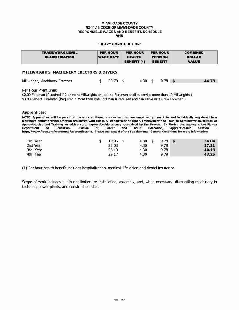
��������������� ������������� ����������������� ������������������� !��"�#������� ����������$���!�%$��&��������������%� '()*+,-.(/01+2+1 3+(04.5( 3+(04.5( 3+(04.5( 6.789:+*61);;9<96)'9.: -)=+0()'+ 4+)1'40 3+:;9.: *.11)(8+:+<9'0>?@ 8+:+<9' 2)15+�A�BCDEEFGDHIJKLMCNOIDPQGRMQGQOJSGKMTMUDVQGKMWXYYZ[X\]_Wab]Xcd[ef[dbg[h ijkljm`` nkijm````` oklpm`` qqrstuMMMMMMMMMMMMMMMMMMMMMMMMMMMMvwxMIyzxMvxw{|z{}~m�kjj�g[d�ac��d��X[d�X��g[�g[dWXYYZ[X\]hgc�g��cg�g[d�ach]aYYh��d[�Xhd�g[d]ac�jWXYYZ[X\]h�mikjj�dcd[aY�g[d�ac��d��X[d�X��g[d]acgcd�g[d�acXh[d��X[d�ac�bachd[�daha�[dZ�g[d�ack�N��xw��|�w}~` �h �da[ �oko�m`` nkijm````` oklpm`` �qr�quMMMMMMMMMMMMMMMMMMMMMMMMMMMM` �c��da[ �ikji nkij oklp �sr��` i[� �da[ ��k�j nkij oklp q�r�t` n] �da[ �ok�l nkij oklp q�r������d[]g�[]daY]�dcd�XXcbY��dh]gh�XaYX�aXgc_�d�XbaY_YX�d�XhXgcac��dcaYXch�[acbdkPSJQ~N��xw��|�w}�|�� w�wx{|��w¡�y�yx¢£��¤w}wx£�w}�¤w��¤w¥£xww{��y¥w¡�zx}z£���y£�¡|�¡|¦|¡z£��¥xw§|}�wxw¡|�£�w§|�|{£�w£��xw��|�w}¤|��xy§x£{ xw§|}�wxw¡�|�¤�¤w rKrUw�£x�{w��y©E£ yxLQ{��y¥{w��£�¡Jx£|�|�§N¡{|�|}�x£�|y�Lªzxw£zy©N��xw��|�w}¤|�£�¡Jx£|�|�§Lyx�|�¤£}�£�w£��xw��|�w}¤|�£§w��¥xw�y§�|«w¡ ¥�¤wªzxw£zr D�¬�yx|¡£�¤|}£§w��¥|}�¤w¬�yx|¡£Uw�£x�{w�� y© Q¡z�£�|y�L U|¦|}|y� y© O£xwwx £�¡ N¡z�� Q¡z�£�|y�L N��xw��|�w}¤|� Kw��|y� ¤���~®®���r©�¡ywryx§®�yx¢©yx�w®£��xw��|�w}¤|�rMMv�w£}wM}wwM�£§wMMy©M�¤wMKz���w{w��£�MHw�wx£�MOy�¡|�|y�}M©yxM{yxwM|�©yx{£�|y�r°bg�dg�Zg[±XcbY��dh�� Xhcg YX�Xd� g²XchaYYaXgc_ahhd��Ye_ac�_Z]dccdbdhha[e_�Xh�acYXc\�ab]Xcd[eXc�abg[Xdh_�gZd[�Yach_ac�bgch[�bXgchXdhk
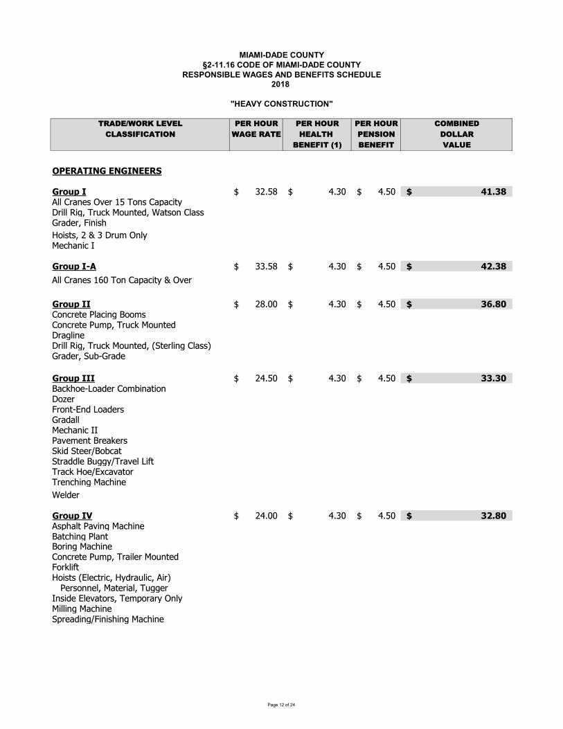
��������������� ������������� ����������������� ������������������� !��"�#������� ����������$���!�%$��&��������������%� '()*+,-.(/01+2+1 3+(04.5( 3+(04.5( 3+(04.5( 6.789:+*61);;9<96)'9.: -)=+0()'+ 4+)1'40 3+:;9.: *.11)(8+:+<9'0>?@ 8+:+<9' 2)15+�A�BCDEFGHIJKLEJKIJEEFM LLKNOPQLI RSTUVWXXXXXXX YTRZWXXXXXXXXXXXXXX YTUZWXXXXXXX [\]_LLLLLLLLLLLLLLLLLLLLLLLLLLLLabbXcdefghXijgdXkUXlmfhXceneopqrsdpbbXtpuvXldwoxXymwfqgzvX{eqhmfXcbehh|dezgdvX}pfph~X�mphqhvXSX�XRXsdw�Xifbrygo~efpoX�KNOPQLI�G RRTUVWXXXXXXX YTRZWXXXXXXXXXXXXXX YTUZWXXXXXXX [�]_LLLLLLLLLLLLLLLLLLLLLLLLLLLLabbXcdefghXk�ZXlmfXceneopqrX�XijgdKNOPQLII SVTZZWXXXXXXX YTRZWXXXXXXXXXXXXXX YTUZWXXXXXXX �]_�LLLLLLLLLLLLLLLLLLLLLLLLLLLLcmfodgqgX�beopfuX�mm�hcmfodgqgX�w�nvXldwoxXymwfqgzsdeubpfgsdpbbXtpuvXldwoxXymwfqgzvX��qgdbpfuXcbehh�X|dezgdvX�w��|dezgXKNOPQLIII SYTUZWXXXXXXX YTRZWXXXXXXXXXXXXXX YTUZWXXXXXXX ^ ]�LLLLLLLLLLLLLLLLLLLLLLLLLLLL�eox~mg��mezgdXcm��pfeqpmfsm�gd}dmfq��fzX�mezgdh|dezebbygo~efpoX���ejg�gfqX�dgexgdh�xpzX�qggd��m�oeq�qdezzbgX�wuur�ldejgbX�p�qldeoxX�mg���oejeqmdldgfo~pfuXyeo~pfg{gbzgdKNOPQLI� SYTZZWXXXXXXX YTRZWXXXXXXXXXXXXXX YTUZWXXXXXXX �]_�LLLLLLLLLLLLLLLLLLLLLLLLLLLLahn~ebqX�ejpfuXyeo~pfgX�eqo~pfuX�befq�mdpfuXyeo~pfgcmfodgqgX�w�nvXldepbgdXymwfqgz}mdxbp�q�mphqhX��bgoqdpovX�rzdewbpovXapd�XXX�gdhmffgbvXyeqgdpebvXlwuugd�fhpzgX�bgjeqmdhvXlg�nmdedrXifbrypbbpfuXyeo~pfgX�ndgezpfu�}pfph~pfuXyeo~pfg
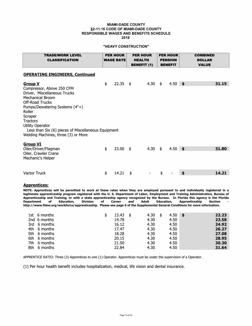
������������� ���� ���������������������������� ���� ������������ ����!"��# $��� ���!����������%���"�&%� '��������������&� ()*+,-./)012,3,2 4,)15/6) 4,)15/6) 4,)15/6) 7/89:;,+72*<<:=:7*(:/; .*>,1)*(, 5,*2(51 4,;<:/; +/22*)9,;,=:(1?@A 9,;,=:( 3*26,�B�CDEFGHIJKLMFKLJKFFGNOMPQRSTRUVWLXQUYMZ [[\]_`` a\]b_````` a\b_`` cdedfgMMMMMMMMMMMMMMMMMMMMMMMMMMMMhijklmnnilopqirm[bhstulvrmlotvnwmxxyzmi{n|l{w}ntmw~yzvwyx�liij�����iy�|l{w}n�{jkn�um�y�mlvz���n�mjn�a����ixxml�wlykml|lyw�iln��vxv���kmly�il`�mnn�~yz�v����kvmwmni�tvnwmxxyzmi{n��{vkjmz��mx�vz�tyw~vzmno�~lmm�]�iltilmLXQUYMZJ�vxml�ulvrml�sxy�jyz []\bb_`` a\]b_````` a\b_`` cde��gMMMMMMMMMMMMMMMMMMMMMMMMMMMM�vxmlohly�xmlhlyzmtmw~yzvw�n�mxkml�yw�il|l{w} �a\[�_`` �_````` �_``` d�e�dgMMMMMMMMMMMMMMMMMMMMMMMMMMMMHYYXVRST�V ¡` �n� �jiz�~n �]\a]_`` a\]b_````` a\b_`` ��e�cgMMMMMMMMMMMMMMMMMMMMMMMMMMMM` [z� �jiz�~n �a\¢£``` a\]b`````` a\b``` �cef�MMMMMMMMMMMMMMMMMMMMMMMMMMMMMM` ]l�`�jiz�~n ��\�[``` a\]b`````` a\b``` ��e¤�MMMMMMMMMMMMMMMMMMMMMMMMMMMMMM` a�~`�jiz�~n �¢\a¢``` a\]b`````` a\b``` �¥e�¦MMMMMMMMMMMMMMMMMMMMMMMMMMMMMM``�~`�jiz�~n �£\[£``` a\]b`````` a\b``` �¦e��MMMMMMMMMMMMMMMMMMMMMMMMMMMMMM` ��~`�jiz�~n [b\�``` a\]b`````` a\b``` ��e¤fMMMMMMMMMMMMMMMMMMMMMMMMMMMMMM` ¢�~`�jiz�~n [�\b``` a\]b`````` a\b``` c�ec�MMMMMMMMMMMMMMMMMMMMMMMMMMMMMM` £�~`�jiz�~n [[\£a``` a\]b`````` a\b``` cde¥�MMMMMMMMMMMMMMMMMMMMMMMMMMMMMMp����§|h��p|�©|~lmm�]�pkklmz�vwmn�iizm����kmly�il\pkklmz�vwmnj{n�qm{z�ml�~mn{kmlrvnvizi�y�kmly�il\����ml~i{l~myx�~qmzm�v�vzwx{�mn~inkv�yxvªy�vizojm�vwyxoxv�mrvnvizyz��mz�yxvzn{lyzwm\KDIF¡HYYXVRST�V «T¬¬VYVX®TSSVWSQ«QX °SS±V VX°SV «±VRS±V²°XVV®Y¬Q²VWYUX U°RSSQ°RWTRWT³TWU°¬¬²XVT SVXVWTR°¬VTST®°SV°YYXVRST�V ±TYYXQX°® XVT SVXVW«TS±S±VµeNe¶VY°XS®VRSQ· °QXOF®Y¬Q²®VRS°RWIX°TRTR HW®TRT SX°STQRO¹UXV°UQ·HYYXVRST�V ±TY°RWIX°TRTR OQX«TS±° S°SV°YYXVRST�V ±TY°VR�²XV�QRTºVW²S±V¹UXV°Ue JR»¬QXTW°S±T °VR�²T S±V»¬QXTW°¶VY°XS®VRS Q· FWU�°STQRO ¶T³T TQR Q· P°XVVX °RW HWU¬S FWU�°STQRO HYYXVRST�V ±TY NV�STQR ¼±SSY¡½½«««e·¬WQVeQX½«QX·QX�V½°YYXVRST�V ±TYeMME¬V° VM VVMY°VM¥MQ·MS±VMNUYY¬V®VRS°¬MLVRVX°¬MPQRWTSTQR M·QXM®QXVMTR·QX®°STQRe
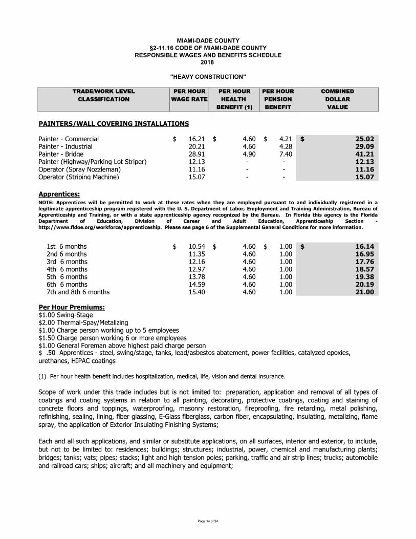
��������������� ������������� ����������������� ������������������� !��"�#������� ����������$���!�%$��&��������������%� '()*+,-.(/01+2+1 3+(04.5( 3+(04.5( 3+(04.5( 6.789:+*61);;9<96)'9.: -)=+0()'+ 4+)1'40 3+:;9.: *.11)(8+:+<9'0>?@ 8+:+<9' 2)15+�A�BCDEFGHIJKLDMMNOPQHIEFRNEFJGDMMDGEPFJ NNSTUVWXYZ[Z\] XY_UT abcdaeZZZZZZZ fcbgeZZZZZZZZZZZZZZ fcdaeZZZZZZZ hijkhlNNNNNNNNNNNNNNNNNNNNNNNNNNNNSTUVWXYZ[ZmVnopWYUT dgcda fcbg fcdq hrjkrSTUVWXYZ[ZsYUntXZ dqcua fcug vcfg wxjhxSTUVWXYZyzUt{|T}~STY�UVtZ�]WZ�WYU�XY� adca�ZZZZZZZZ [ZZZZZZZZZZZZZZZZZ [ZZZZZZZZZZ xhjx�NNNNNNNNNNNNNNNNNNNNNNNNNNNNNN��XYTW]YZy��YT}Z�]��X TV�Z aacabZZZZZZZZ [ZZZZZZZZZZZZZZZZZ [ZZZZZZZZZZ xxjx�NNNNNNNNNNNNNNNNNNNNNNNNNNNNNN��XYTW]YZy�WYU�UVtZ�T_{UVX�Z a�cgvZZZZZZZZ [ZZZZZZZZZZZZZZZZZ [ZZZZZZZZZZ xijk�NNNNNNNNNNNNNNNNNNNNNNNNNNNNNND�����������ZZZZapWZZbZ]VW{p agc�feZZZZZZZ fcbgeZZZZZZZZZZZZZZ acggeZZZZZZZ x�jxwlNNNNNNNNNNNNNNNNNNNNNNNNNNNNZZZZdVnZbZ]VW{p aac�� fcbg acgg x�jriZZZZ�YnZZbZ]VW{p adcab fcbg acgg x�j��ZZZZfW{ZZbZ]VW{p adcuv fcbg acgg x�ji�ZZZZ�W{ZZbZ]VW{p a�cvq fcbg acgg xrj��ZZZZbW{ZZbZ]VW{p afc�u fcbg acgg hkjxrZZZZvW{ZTVnZqW{ZbZ]VW{p a�cfg fcbg acgg hxjkkC��N����NC��������eacggZ�|UVt[�WTtXedcggZ�{XY T[��T}~�XWTU�UVteacggZ\{TYtXZ�XYp]VZ|]Y�UVtZo�ZW]Z�ZX �]}XXpeac�gZ\{TYtXZ�XYp]VZ|]Y�UVtZbZ]YZ]YXZX �]}XXpeacggZ�XVXYTZ�]YX TVZT�]�XZ{Ut{XpWZ�TUnZ_{TYtXZ�XYp]Vya�ZZSXYZ{]oYZ{XTW{Z�XVX UWZUV_onXpZ{]p�UWTU�TWU]V¡ZXnU_T¡ZU X¡Z�UpU]VZTVnZnXVWTZUVpoYTV_XceZZc�gZZ¢��YXVWU_XpZ[ZpWXX¡Zp|UVt~pWTtX¡ZWTV�p¡ZXTn~Tp�XpW]pZT�TWX XVW¡Z�]|XYZ T_UUWUXp¡Z_TWT}�XnZX�]£UXp¡ZoYXW{TVXp¡ZzmS¢\Z_]TWUVtpZFPGH�D����������¤�¥¥¦���������§��¤�� ©��ª����©���¤ª���ª�«©�����¥�«�§�����©����©�§��§�¬�§�©¥¥«��������§��©¥�����©��©����������ª������©� ��������§¤��ª�ª�®jJj ��©�������°M©¦��±H��¥�«����©�§G�©����D§�������©����±²���©��°D����������ª��©�§G�©����±��¤��ª©��©��©����������ª��©���«������³�§¦«�ª�²���©�j E� ¥���§©�ª��©���«���ª� ¥���§©��©������ �° H§��©����± �¬����� �° O©���� ©�§ D§�¥� H§��©����± D����������ª�� J������ µª����KK¤¤¤j°¥§��j��K¤��°����K©����������ª��jNNC¥�©��N���N�©�N�N�°N�ª�NJ���¥�����©¥NR����©¥NO��§������N°��N����N��°���©����j�_]�X] |]Y�oVnXYW{UpWYTnXUV_onXp�oWUpV]WUUWXnW]¶�YX�TYTWU]V¡T��U_TWU]VTVnYX ]�T] T W}�Xp] _]TWUVtpTVn_]TWUVtp}pWX pUVYXTWU]VW]T �TUVWUVt¡nX_]YTWUVt¡�Y]WX_WU�X_]TWUVtp¡_]TWUVtTVnpWTUVUVt] _]V_YXWX ]]YpTVnW]��UVtp¡|TWXY�Y]] UVt¡ Tp]VY}YXpW]YTWU]V¡ UYX�Y]] UVt¡ UYXYXWTYnUVt¡ XWT �]Up{UVt¡YX UVUp{UVt¡pXTUVt¡UVUVt¡ U�XYtTppUVt¡·[�Tpp U�XYtTpp¡_TY�]V U�XY¡XV_T�poTWUVt¡UVpoTWUVt¡ XWTU�UVt¡ T Xp�YT}¡ZW{XZT��U_TWU]VZ] Z·£WXYU]YZmVpoTWUVtZ�UVUp{UVtZ�}pWX pZZZZZ·T_{TVnT po_{T��U_TWU]Vp¡TVnpUUTY]Ypo�pWUWoWXT��U_TWU]Vp¡]VT poY T_Xp¡UVWXYU]YTVnX£WXYU]Y¡W]UV_onX¡�oWV]WW]�X UUWXnW]¶YXpUnXV_Xp �oUnUVtp pWYo_WoYXp UVnopWYUT¡�]|XY¡_{X U_TTVn TVo T_WoYUVt�TVWp�YUntXpWTV�p�TWp�U�XppWT_�p Ut{WTVn{Ut{WXVpU]V�]Xp�TY�UVt¡WYT U_TVnTUYpWYU�UVXpWYo_�pToW] ]�UXTVnZYTUY]TnZ_TYpZp{U�pZTUY_YT WZTVnZTZT_{UVXY}ZTVnZX¹oU� XVWZ

������������� ���� ���������������������������� ���� ������������ ����!"��# $��� ���!����������%���"�&%� '��������������&� ()*+,-./)012,3,2 4,)15/6) 4,)15/6) 4,)15/6) 7/89:;,+72*<<:=:7*(:/; .*>,1)*(, 5,*2(51 4,;<:/; +/22*)9,;,=:(1?@A 9,;,=:( 3*26,�B�CDEFGHIJKLMENNOPQRIJFGSOFGKHENNEHFQGKTOPUVWXVYZ[ OOMENNOPQRIJFGSOFGKHENNEHFQG\]]_abc_d\abefdeghdijkd\llmhgnophdnqdnrmhhdiskd]tognhmudqmdvtwwdcqxhmogydbguntwwhmuz\g{tg|tww}tnhmotw~uh|oglmhltmtnoqg�tllwoptnoqgqmmh}qxtwq�tg{ltogn�pqtnogyuqmtllwoptnoqgu�ogpw~|ogy��~ngqnwo}onh|nqfnrhrtg|wogytg|~uhq�nrogghmu�|m{hmu�uhtwhmu��og|hmu�loy}hgnu�lmo}hmu�h�nhg|hmu�tomtg|xtlqm�tmmohmu�h}~wuoqgu��t�hu�untogu�}tunopu�lwtunopu�hgt}hwu�tpm{wopu�hlq�ohu�hlq�{og�hpnoqgtg|a��qp��hw|ogy�tw�twou�durhhndm~��hm�d�qt}u�duht}whuudtg|dnowh�wo�hdpqtnogyu�dhnpz�d\ww}tnhmotwtllwoh|nq�twwuqmphowogyu�onrt|rhuoxh�untlwhu�ntp�u��{unmhnprogyqmt|rhmh|�{tg{qnrhm}hnrq|�ogpw~|ogytwwltlhmu�xog{w��wh�o�wh�qq|u��t�mopu��qm|hmu�}hntwu~lrqwunhmh|�twwu{unh}u�nrh�t�moppqxhmh|ltghwu}t|hq�lwtunop��qq|qmlmh��ogourh|lmq|~pnuq�}opmq�o�hmywtuu�hnpz�tpmqxogtg|xtmoq~ulwtunop�twwpqxhmogyudu~prdtud�togupqn�dptlu�dpqmghmd}qw|ogyudtg|dtpphuuqmohu�d\wwlmhltmtnoqg�qmtg|mh}qxtwq�tg{tg|tww}tnhmotwu�qm�ogourhu�u~prtu|hhlpwhtgogy�ltnprogy�twwwhxhwuq��ogourogy�ntlogy��ogourogyu�o} pqtnogy�lqognogy�pt~w�ogy�royrlmhuu~mh�tnhm�prh}optwtg|t�mtuoxh�wtunogy�hgxomqg}hgntw�wtunogy��hn�|m{xtp~~}�qm��prh}optwunmollogy�upmtlogy�tomnqqwogy��whtprogy�unht}pwhtgogy�tu�hunqudtg|dwht|dt�tnh}hgn�mh}qxtw�d}qw|dmh}h|otnoqgdtg|dxtlqmd�tmmohmdu{unh}u�d\g{tg|twwlmhltmtnoqgq��twwutg|phowogyuu~prtuupmtlogyqmtg{}hnrq|qwqy{�qmmh}qxtwq�h�ounogy}tnhmotwu�ogpw~|ogydltnprogy�dwhxhwogy�du�o}dpqtnogydtg|dlmo}ogyzarhdogulhpnoqgdq�dtwwdpqtnogyudtg|�qmdpqtnogydu{unh}ud|~mogydnrhomdtllwoptnoqguz
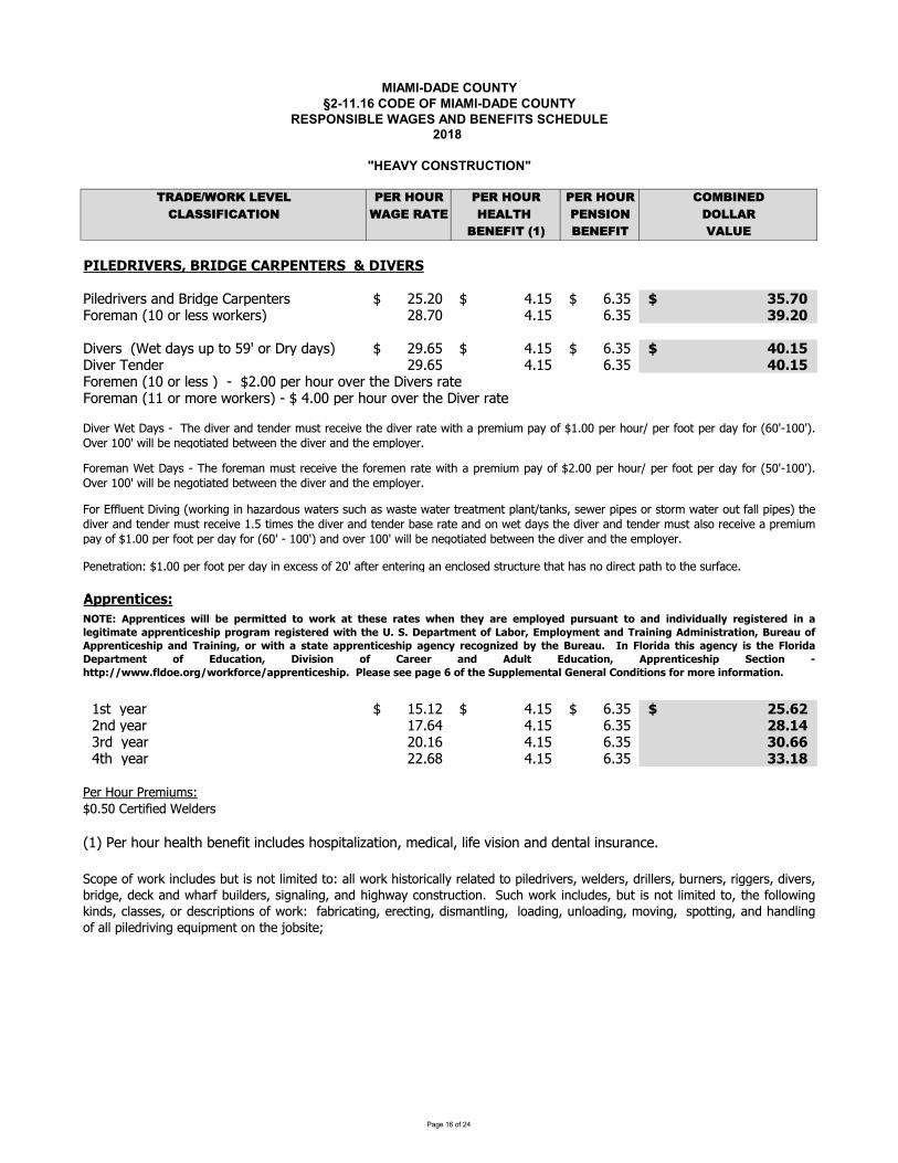
������������� ���� ���������������������������� ���� ������������ ����!"��# $��� ���!����������%���"�&%� '��������������&� ()*+,-./)012,3,2 4,)15/6) 4,)15/6) 4,)15/6) 7/89:;,+72*<<:=:7*(:/; .*>,1)*(, 5,*2(51 4,;<:/; +/22*)9,;,=:(1?@A 9,;,=:( 3*26,�B�CDEFGHIEJGIKLMNIEHOGMPQIDGRSGIKMMTMHEJGIK MMUVWXYZV[XZ\]_Y]ZVYaX]bZcX_dXZ\] efgehi]]]]]]] jgkfi]]]]]]]]]]]]]] lgmfi]]]]]]] nopqrsMMMMMMMMMMMMMMMMMMMMMMMMMMMMtuZXv _]wkh]uZ]WX\\]xuZyXZ\z e{g|h jgkf lgmf n}p~r�V[XZ\]]w�Xd]Y�\]�c]du]f��]uZ]�Z�]Y�\z] e�glfi]]]]]]] jgkfi]]]]]]]]]]]]]] lgmfi]]]]]]] �rp�osMMMMMMMMMMMMMMMMMMMMMMMMMMMM�V[XZ]�X_YXZ] e�glf]]]]]]]] jgkf]]]]]]]]]]]]]]]] lgmf]]]]]]]]] �rp�oMMMMMMMMMMMMMMMMMMMMMMMMMMMMMMtuZXvX_]wkh]uZ]WX\\]z]]�]]ieghh]cXZ]�u�Z]u[XZ]d�X]�V[XZ\]ZdXtuZXv _]wkk]uZ]vuZX]xuZyXZ\z]�]i]jghh]cXZ]�u�Z]u[XZ]d�X]�V[XZ]ZdXUX_XdZdVu_�]ikghh]cXZ]�uud]cXZ]Y�]V_]X��X\\]u�]eh�]�dXZ]X_dXZV_a]_]X_�Wu\XY]\dZ��d�ZX]d�d]�\]_u]YVZX�d]cd�]du]d�X]\�Z��XgQ�����������]]k\d]]�XZ kfgkei]]]]]]] jgkfi]]]]]]]]]]]]]] lgmfi]]]]]]] ~op�~sMMMMMMMMMMMMMMMMMMMMMMMMMMMM]]e_Y]�XZ k|glj jgkf lgmf ~�p��]]mZY]]�XZ ehgkl jgkf lgmf nrp��]]jd�]]�XZ eegl{ jgkf lgmf nnp��UXZ]�u�Z]UZXvV�v\�ihgfh]bXZdV�VXY]�XWYXZ\wkz]UXZ]�u�Z]�XWd�]�X_X�Vd]V_�W�YX\]�u\cVdWV�dVu_�]vXYV�W�]WV�X][V\Vu_]_Y]YX_dW]V_\�Z_�XgtuZXv _�Xd��\���X�uZXv _v�\dZX�XV[Xd�X�uZXvX_ZdXxVd�^cZXvV�v c�u�ieghhcXZ�u�Z�cXZ�uudcXZY��uZwfh��khh�zg�[XZ]khh�]xVWW]�X]_XaudVdXY]�XdxXX_]d�X]YV[XZ]_Y]d�X]XvcWu�XZg]tuZ���W�X_d�V[V_awxuZyV_aV_��ZYu�\x dXZ\\��� \x \dXx dXZdZXdvX_dcW_d�d_y\�\XxXZcVcX\uZ\duZvx dXZu�d�WWcVcX\zd�XYV[XZ_YdX_YXZv�\dZX�XV[XkgfdVvX\d�XYV[XZ_YdX_YXZ�\XZdX _Yu_xXdY�\d�XYV[XZ_YdX_YXZv�\dW\uZX�XV[X^cZXvV�vc�]u�]ikghh]cXZ]�uud]cXZ]Y�]�uZ]wlh�]�]khh�z]_Y]u[XZ]khh�]xVWW]�X]_XaudVdXY]�XdxXX_]d�X]YV[XZ]_Y]d�X]XvcWu�XZg]R SG�Q����������¡�¢¢£����¤����¥�¦¡¦�§ ��©�������¡©���©�ª ���¤�¢¦ª�¥�«��«���¦ �¥��¥�¬�¥«¢¢ª��������¥��¨¢����¤ �� ����������©����¦�¤ ��������¥¡��©�©�®pKpH����¤���¦ F£¦�LG¤�¢¦ª¤��� �¥S�����Q¥¤��������¦�LN«��«¦Q����������©�� �¥S�����L¦�¡��©¨���� ����������©�� ���ª���¦��°�¥£ª�©�N«��«p E�±¢¦��¥ �©�� ���ª���©�±¢¦��¥H����¤��� ¦ G¥«���¦�L H�¬���¦� ¦ P ���� �¥ Q¥«¢� G¥«���¦�L Q����������©�� K����¦� ²©����³³¡¡¡p¢¥¦�p¦�³¡¦�§¦���³����������©��pMMD¢���M���M��M�M¦M�©�MK«��¢�¤���¢MO����¢MP¦�¥���¦��M¦�M¤¦��M��¦�¤ ��¦�p�ucXu�xuZyV_�W�YX\��dV\_udWVvVdXYdu�WWxuZy�V\duZV�WW�ZXWdXYducVWXYZV[XZ\�xXWYXZ\�YZVWWXZ\���Z_XZ\�ZVaaXZ\�YV[XZ\��ZVYaX�YX�y _Yx�Z���VWYXZ\�\Va_WV_a�_Y�Va�x��u_\dZ��dVu_g ���xuZyV_�W�YX\���dV\_udWVvVdXYdu�d�X�uWWuxV_ayV_Y\��W\\X\�uZYX\�ZVcdVu_\u�xuZy���ZV�dV_a�XZX�dV_a�YV\v _dWV_a�WuYV_a��_WuYV_a�vu[V_a�\cuddV_a�_Y�_YWV_au�]WW]cVWXYZV[V_a]Xµ�VcvX_d]u_]d�X]¶u�\VdX·]�V[XZ�Xd��\���XYV[XZ_YdX_YXZv�\dZX�XV[Xd�XYV[XZZdXxVd�^cZXvV�vc�u�ikghhcXZ�u�Z�cXZ�uudcXZY��uZwlh��khh�zg�[XZ]khh�]xVWW]�X]_XaudVdXY]�XdxXX_]d�X]YV[XZ]_Y]d�X]XvcWu�XZg]

������������� ���� ���������������������������� ���� ������������ ����!"��# $��� ���!����������%���"�&%� '��������������&� ()*+,-./)012,3,2 4,)15/6) 4,)15/6) 4,)15/6) 7/89:;,+72*<<:=:7*(:/; .*>,1)*(, 5,*2(51 4,;<:/; +/22*)9,;,=:(1?@A 9,;,=:( 3*26,�B�CDEFGHIEJGIKLMNIEHOGMPQIDGRSGIKMMTMHEJGIKLMPUVWXVYZ[M\]]_abc_d\abefddeghdijkd\llmhgnophdnqdnrmhhdiskd]othumovhmwdqmdxmouyhdczmlhgnhmw{arhwltopogy|rhzuogy|ltzpogyq}wnmogyhmw}qm}mz~h�qm�|}z�mopznoqgzgultzpogyq}�zotogy|wlmogyzgu}hguhmtoghwq}zg�~znhmoztduhwpmo�hudz�qvh�darhd}z�mopznoqgdzgudltzpogydq}dzttduhp�ogydzgudy�zmuwdqgdzttduqp�w|d�rzm}w|dzgudlohmwdqgdnrhd�q�wonh{]otogyw�whuogmhnzogogy�zttw|mhwhmvqomw|uonprhw|pzgztw|wlott�z�w|p�nw|qmogzg�ltzph�rhmhmhnzogogy�zttwzmh�whu~zuhq}zg�d�ogudq}d~znhmozt|d�rhnrhmdnh~lqmzm�dqmdlhm~zghgn�d�hoyrnwd}qmdlohmw|dpzowwqgw|dzgudnhwndlothw�d�ovogyfwrztt�huh}oghuzwzg��qm�lhm}qm~hu�hghznrnrh�znhmw�m}zph|�roprmh��omhoguovou�zth�nhmgztto}hw�llqmnw�wnh~w}qmwz}hzguh}}opohgnlhm}qm~zgph{\tt�guhm�znhmpqgwnm�pnoqgzgumhpqgwnm�pnoqgzgunrhwztvzyhq}|zgumh~qvogyq}|�guhm�znhmwnm�pn�mhw��guhm�znhmogwlhpnoqgzgumhlzomq}r�ttw|uqp�w|�mouyhwzguuz~w|�guhm�znhmlolhtoghw|wh�zyhwzgu�znhmw�wnh~w|�guhm�znhmw�pnoqgzguuowprzmyhtoghww�przwnrqwh�whuznprh~opztltzgnw|l�tt~ottw|zguuhwztogo�znoqgltzgnw�ogwlhpnogy|w�mvh�ogy|mh~qvogy|mhwp�ogy|zgumhpqvhmogyq}zttq��hpnw�htq��znhmw�m}zphw�ztt�guhm�znhm�qm�ghphwwzm�qgq}}wrqmhqotltzn}qm~wlhm~zghgnqmnh~lqmzm�|ogpt�uogyzttq}}wrqmh}tqznogyumottmoyrnwzguq}}wrqmh�zp��lltzn}qm~w�ztt�guhm�znhm�qm�qglolhtoghwzgurqq��lwogpt�uogyqot|yzw|�znhmwh�zyhw�wnh~w�nrhtz�ogyq}�guhm�znhmlq�hmzgunhthlrqghpz�thw�q}}wrqmh~zmogh~ogogyzguumhuyogyqlhmznoqgw�wogyuovhmwogzg�lrzwhq}nohm�qm��zttlhnmqth�~|}owrhmohw|qphzgqymzlrop|mhwhzmprzguh�lhmo~hgnzt�qm�|g�pthzmmhzpnqmw�rhmhnrh�whq}uovhmwowghphwwzm��ztt�guhm�znhmduh~qtonoqgdzgud�tzwnogyd�qm�dmh��omogyduovhmw{darhumovogy|vo�mznogy|�hnnogy|wog�ogy|qmwpmh�ogyq}ztt~znhmoztwuhwpmo�huz�qvh|�rhnrhm��wnhz~|lgh�~znop|r�umz�top|hthpnmop|uohwht|ymzvon�|qmvo�mznqm�rz~~hmlq�hm�\ttqnrhm�qm�ogpqgghpnoqg�onrumottogyq}zg�rqthw|wrz}nwqmpzowwqgw|}qm}q�guznoqg�qm�|wlqnnogy|ztoygogy|~qgonqmogy|lt�~�ogy|zguthvhtogyq}zttumottogyh��ol~hgn�rhnrhmnrhumottogyowvhmnopzt|uozyqgzt|qgtzguqm�znhm|zguowlhm}qm~hu��h��ol~hgn~q�gnhuqgnm�p�w|pmzghw|ltzn}qm~wqm�zmyhw|qmzg�qnrhm�oguq}~q�gnhuqmwht}�pqgnzoghu�znhmqmtzgu�gon�zgunrhrzgutogy|tqzuogy|�gtqzuogy|przgyogy|whnnogy�l|mhlzomogy|d�htuogy|dqmd~zognhgzgphdq}dnrhdumottogydh��ol~hgndqgdnrhd�q�dwonh{�q�wonh~qvogyzguwlqnnogyq}�zmyhw�whuogpqgghpnoqg�onrlothumovogy�qm��zgprqmogy|�qtnogy|�qq~�nhguogy|�mzpogy|��otuogy|��mgogy|pzllogy|pz�t�ogy|p�nnogy|prollogyq}zttn�lhwq}lothw|uow~zgntogy|umottogy|hmhpnogy|}z�mopznogy|}onnogy|rzgutogy|tzyyogy|tqzuogy|~qvogy|lt�~�ogy|mz}nogy|whp�mogy|woygztogy|wlqnnogy|�htuogy|�mzllogy|zgun�ogy�zp�|�gtqzuogyzgumh~qvogy|ztt~znhmoztwq}zg��ogu|~z�h|wrzlhqmpq~lqwonoqg|�rhnrhmlmhwnmhwwhuqmlqwnwnmhwwhupqgpmhnh|lolh|pqmm�yznhuwrhtt�rhmhlq�hmmoyyogyow�whu|wzgulothw|wrhhnlothw|z�yhmpzwnn�lhlotogy|�qqu|ltzwnop|}o�hmytzww|wnhhtqmzg�~hnztqmw�gnrhnop�roprow�whuqmogwnztthuog|qm}qm|nrh��otuogy|pqgwnm�pnoqg|ztnhmznoqg|~zognhgzgph|qmmhlzomq}�rzm}w|�mouyhw|uqp�w|lohmw|��t�rhzuw|nmhwnthw|pq}}hmuz~w|n�gghtw|whz�zttw|whz�zttpzlw|�qzmu�zt�w|uhp�|zgunh~lqmzm�}tqnznoqgduhvophw�d�q�guznoqg�qm�|ogpt�uogyzttlotogy|�rhnrhmpzwn�og�ltzph|lq�mhu�og�ltzph|umovhg|�hnnhu|z�yhmhu|lmh�z�yhmhuqmltzphu|zguzttdpzowwqg|dumotthudwrz}ndzgudvo�mq�}tqnznoqgd}q�guznoqgw�
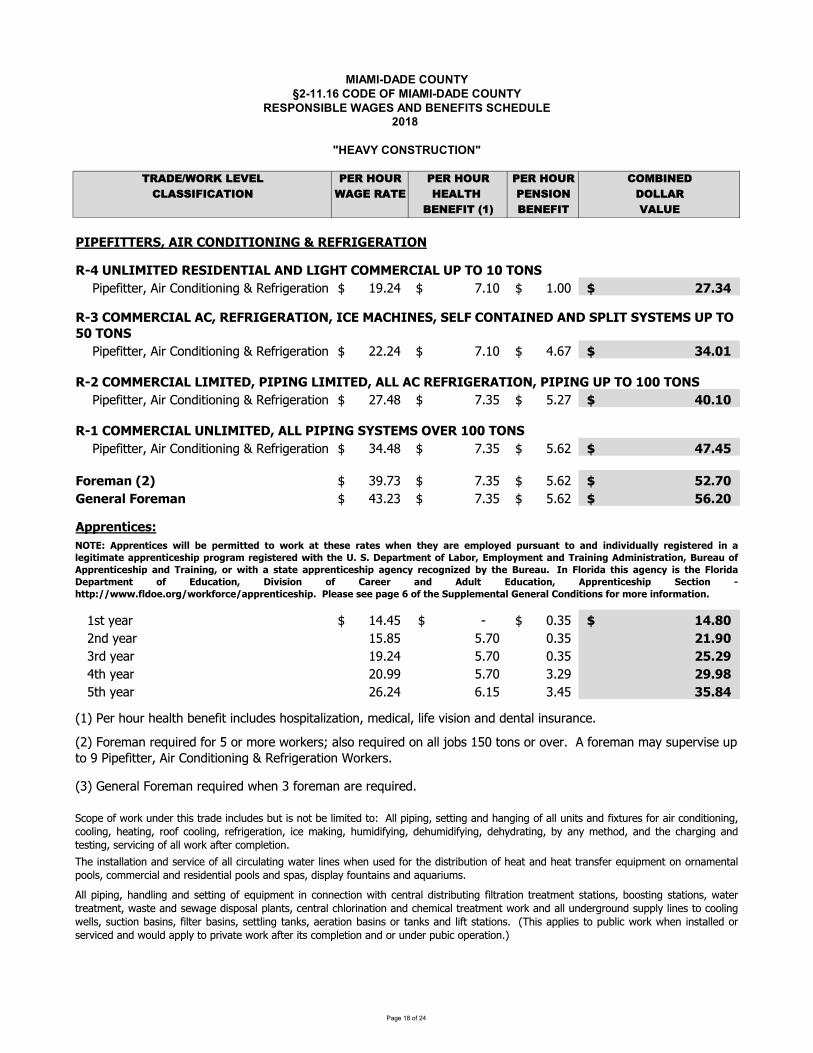
������������� ���� ���������������������������� ���� ������������ ����!"��# $��� ���!����������%���"�&%� '��������������&� ()*+,-./)012,3,2 4,)15/6) 4,)15/6) 4,)15/6) 7/89:;,+72*<<:=:7*(:/; .*>,1)*(, 5,*2(51 4,;<:/; +/22*)9,;,=:(1?@A 9,;,=:( 3*26,�B�CDEDFGEHHFIJKLMEILNOPQEHEOPEPRLSLIFGIERFIMHEOP LLITULVPWEXEHFQLIFJEQFPHEMWLMPQLWERYHLNOXXFINEMWLVDLHOLZ[LHOPJ\]_]aa_bcde]bdfghi]a]gh]hjdkdl_b]j_bma]gh nopqrsddddddd tpnusdddddddddddddd npuusddddddd vwxyUzLLLLLLLLLLLLLLLLLLLLLLLLLLLL\]_]aa_bcde]bdfghi]a]gh]hjdkdl_b]j_bma]gh qqpqrsddddddd tpnusdddddddddddddd rp{tsddddddd yUx[ZzLLLLLLLLLLLLLLLLLLLLLLLLLLLLITvLNOXXFINEMWLWEXEHFQKLDEDEPRLWEXEHFQKLMWWLMNLIFGIERFIMHEOPKLDEDEPRLVDLHOLZ[[LHOPJ\]_]aa_bcde]bdfghi]a]gh]hjdkdl_b]j_bma]gh qtpr|sddddddd tp}~sdddddddddddddd ~pqtsddddddd U[xZ[zLLLLLLLLLLLLLLLLLLLLLLLLLLLLITZLNOXXFINEMWLVPWEXEHFQKLMWWLDEDEPRLJ�JHFXJLO�FILZ[[LHOPJ\]_]aa_bcde]bdfghi]a]gh]hjdkdl_b]j_bma]gh }rpr|sddddddd tp}~sdddddddddddddd ~p{qsddddddd UwxU�zLLLLLLLLLLLLLLLLLLLLLLLLLLLLG������L�v� }opt}sddddddd tp}~sdddddddddddddd ~p{qsddddddd �vxw[zLLLLLLLLLLLLLLLLLLLLLLLLLLLLR������LG������ r}pq}sddddddd tp}~sdddddddddddddd ~p{qsddddddd ��xv[zLLLLLLLLLLLLLLLLLLLLLLLLLLLLM�����������dddn�ad�_mbdd nrpr~sddddddd �sddddddddddddddd up}~sddddddd ZUx�[zLLLLLLLLLLLLLLLLLLLLLLLLLLLLdddqhid�_mb n~p|~ ~ptudddddddddddddddd up}~ddddddddd vZx�[ddd}bid�_mb nopqr ~ptudddddddddddddddd up}~ddddddddd v�xv�dddra�d�_mbd qupoo ~ptudddddddddddddddd }pqoddddddddd v�x��ddd~a�d�_mb q{pqr {pn~dddddddddddddddd }pr~ddddddddd y�x�U�n�d\_bd�g�bd�_m�a�d�_h_]ad]h���i_�d�g�]am�]�ma]ghcd�_i]�m�cd�]_d ]�]ghdmhidi_ham�d]h��bmh�_pITyLNOXXFINEMWLMNKLIFGIERFIMHEOPKLENFLXMNYEPFJKLJFWGLNOPHMEPFQLMPQLJDWEHLJ�JHFXJLVDLHOL�[LHOPJLe�� ]]hjc�mhi�]hjmhi�_aa]hjg _¡�]�_ha]h�ghh_�a]gh¢]a��_habm�i]�ab]��a]hj ]�abma]ghab_ma�_ha�ama]gh�c�gg�a]hj�ama]gh�c¢ma_bab_ma�_hac¢m�a_mhi�_¢mj_i]�g�m��mha�c�_habm����gb]hma]ghmhi��_�]�m�ab_ma�_ha¢gb£mhim���hi_bjbg�hi�� ���]h_�ag�gg�]hj¢_���c���a]gh�m�]h�c]�a_b�m�]h�c�_aa�]hjamh£�cm_bma]gh�m�]h�gbamh£�mhi�]a�ama]gh�p�¤�]�m �]_�ag ���]�¢gb£¢�_h]h�am��_igb�_b ]�_idmhid¢g��idm ��dagdb] ma_d¢gb£dma_bd]a�d�g� �_a]ghdmhidgbd�hi_bd��]�dg_bma]ghp��q�d¥gb_�mhdb_¡�]b_idgbd~dgbd�gb_d¢gb£_b�¦dm��gdb_¡�]b_idghdm��d§g��dn~udagh�dgbdg _bpddedgb_�mhd�m�d��_b ]�_d�dagdod\]_]aa_bcde]bdfghi]a]gh]hjdkdl_b]j_bma]ghdgb£_b�pd�}�d©_h_bm�d¥gb_�mhdb_¡�]b_id¢�_hd}dgb_�mhdmb_db_¡�]b_ipd¤�_]h�am��ma]ghmhi�_b ]�_gm���]b���ma]hj¢ma_b�]h_�¢�_h��_i gba�_i]�ab]��a]ghg�_mamhi�_maabmh�_b_¡�]�_haghgbhm�_ham�gg��cd�g��_b�]m�dmhidb_�]i_ha]m�dgg��dmhid�m�cdi]��m�dg�ham]h�dmhidm¡�mb]���pPOHF�M����������ª���«���������¬��ª�����®��������ª®���®� ���������¬�°��°�������¬��¬�±�¬°��� ��²������¬�����²������������������®�����²��� ��²������¬ª��®�®�VxJxQ����������³W�«��KF����������¬H������²M¬������������K °���°�³M����������®����¬H������²K��ª��®�����������������®���²��� ����²��µ�¬« �®� °���°xE�G����¬��®���²��� ���®�G����¬�Q��������� �³ F¬°������K Q�±����� �³ N����� ��¬ M¬°�� F¬°������K M����������®�� J������ T®����¶¶ªªªx³�¬��x��²¶ª��³����¶�����������®��xLLD�����L���L��²�L�L�³L�®�LJ°����������LR������LN��¬������L³��L����L��³��������x·�g_g¢gb£�hi_ba�]�abmi_]h���i_���a]�hga�_�]�]a_iag e��]]hjc�_aa]hjmhi�mhj]hjgm���h]a�mhi]¹a�b_�gbm]b�ghi]a]gh]hjc�gg�]hjc�_ma]hjcbgg �gg�]hjcb_b]j_bma]ghc]�_�m£]hjc���]i]�]hjci_���]i]�]hjci_��ibma]hjc��mh��_a�gicmhia�_��mbj]hjmhia_�a]hjcd�_b ]�]hjdgdm��d¢gb£dma_bd�g� �_a]ghp
������������� ���� ���������������������������� ���� ������������ ����!"��# $��� ���!����������%���"�&%� '��������������&� ()*+,-./)012,3,2 4,)15/6) 4,)15/6) 4,)15/6) 7/89:;,+72*<<:=:7*(:/; .*>,1)*(, 5,*2(51 4,;<:/; +/22*)9,;,=:(1?@A 9,;,=:( 3*26,�B�CDEDFGEHHFIJKLMEILNOPQEHEOPEPRLSLIFGIERFIMHEOPKLNTUVWUXYZ[\]__ab\cbdcef_a\ca\g]cdfbhcgijakhg\ca\]_geclmcnakgdagf]copgfgcef_a\ca\g]cefbkcbc_c]_dgco_]gqcdbbfcef_a\qcfbbdcbfc_\mcbkg\cdarjfgc_\ecopgfgcef_a\ca\g]c_fgc\bceafgsmcsb\\gsgecbc_c]_\a_fmc]m]gh]ct_ma\ubjqsj a\uqlg\ea\u_\ed_lfas_a\ubd_ kakgobfvbdgwgfmeg]sfakab\lmop_gwgfhbegbfhgpbeqopg\j]gea\sb\\gsab\oapcpgckakgdaa\uca\ej]fmxypga\]__ab\_\e]gfwasgbdw_sjjh]m]gh]opg\j]gea\sb\\gsab\oaph_\jd_sjfa\uk_\]qh_a\g\_\sgd_saaag]q_afkbf gfha\_]qkb]cbddasg]qcgsxzckaka\ucdbfcf_aa\ucobfvc_\ecf_sv]cbdcgwgfmceg]sfakab\qcopgpgfc]sfgogecbfcogegecopg\c_]]au\geclmcpgc{b\f_sbfxzckbogfck_\ckaka\ucbdcgwgfmceg]sfakab\qc_]cac_kkag]cbcpgckakgdaa\uca\ej]fmxypgj\b_ea\uqp_\ea\u_\e]ga\ubd_ ]gfaa|gf]q_j\efm_\esg_\a\ugijakhg\ oalgeb\glmsbhkb]agsfgox}g_h_\ebaa\g]oaclgceb\gclmcpa]cf_egcs_]]adas_ab\xc~gsbwgfmcsb\eg\]_gc]m]gh]ca\cpgafcg\afgmxypg]ga\uqgfgsa\u_\ekaka\ubd_ sbba\uj\a]qkjhk]qfgs_aha\u]m]gh]_\e_kkjfg\_\sg]a\sb\\gsab\oap f_\]dbfhgf_\ekaka\ucbc]oaspg]cbdcgwgfmceg]sfakab\xypga\]__ab\_\e]gfwasgbdw_sjjh sg_\a\ugijakhg\ _\ekaka\uopg\j]gea\sb\\gsab\oaph_\jd_sjfa\uk_\]qh_a\g\_\sgd_saaag]qc_afkbfcgfha\_]qckb]cbddasg]qcgsxypgca\]__ab\c_\ec]gfwasgcbdcbrmug\c]m]gh]copg\cj]geca\csb\\gsab\coapch_\jd_sjfa\uqcsbhhgfsa_c�ca\ej]fa_c_kkas_ab\xzc]pggcg_eca\a\ucdbfc_\v]cbfcw_]cdbfc_ckjfkb]gqcopg\ca\cpgcs_gubfmcbdca\ej]fa_cobfvxypg]ga\u_\ep_\ua\ubd_ j\a]bfdarjfg]dbfasgh_va\uopg\j\ahj]lg_]]ghlgelgdbfgbkgf_ab\x�}pakka\ulb]qufae]_\ebpgfck_f]c_fgcbclgcfghbwgecbfckjca\ck_sgx�zc]b_fc]m]gh]qckaka\uc_\ecsbgsbf]cbdcgwgfmceg]sfakab\copg\cj]geca\csb\\gsab\coapcpgckakgdaa\uca\ej]fmxzchggf]cdbfchg_]jfa\uc_cwbjhgcbdc_\mc]jl]_\sgqcopg\cj]geca\csb\\gsab\coapcpgckakgdaa\uca\ej]fmxypg]ga\u_\egfgsa\ubd_ j\egfdgge]bvgf]qdjgljf\gf]_\ekaka\uqa\sjea\uu_]qbaqkbogfdjgqpb _\esbe_afkaka\u_\e__ssg]]bfag]c_\eck_f]cbdcljf\gf]c_\ec]bvgf]qcgsxqcopg\cj]geca\csb\\gsab\coapcpgckakgdaa\uca\ej]fmxz a\gf\__\egrgf\_kaka\ub\lbagf]qpg_gf]q_\v]_\egw_kbf_bf]qo_gfgu]qo_gfl_sv]_\eo_gfuf_g]qlbagfsbhkbj\egijakhg\qcgsxqcopg\ca\csb\\gsab\coapcpgckakgdaa\uca\ej]fmxypg]ga\u_\egfgsa\ubd_ lbagfdggegf]qo_gfpg_gf]qdagf]qo_gf]bdg\gf]qkjfadagf]qsb\eg\]_ggijakhg\qkjhk]qsb\eg\]gf]qsbbgf]c_\ec_ckaka\ucdbfc]_hgcopg\cj]geca\csb\\gsab\coapcpgckakgdaa\uca\ej]fmxypga\]__ab\_\e]gfwasgbdpmef_jasbfk\gjh_asebbfbkg\gf]opg\a\sb\\gsab\oapa\ej]fa_qh_\jd_sjfa\u_\esbhhgfsa__kkas_ab\]xczafkbf]ca\sjegexypgc]ga\uqcgfgsa\uc_\eckaka\ucbdca\]fjhg\]qchg_]jfa\ucegwasg]qcpgfhb]_ascsb\fb]qcu_jugclb_fe]c_\ecbpgfcsb\fb]cj]geca\csb\\gsab\coapckbogfqcpg_a\ucfgdfaugf_ab\qc_afcsb\eaab\a\uqch_\jd_sjfa\uqcha\a\uc_\eca\ej]fa_cobfvxcypgc]ga\uc_\ecgfgsab\cbdc_cbacpg_gf]qcbacsbbgf]qc]bf_ugc_\ecea]faljab\c_\v]qcf_\]dgfckjhk]c_\echara\ucegwasg]c_\eckaka\ucpgfgbqcopg\cj]geca\csb\\gsab\coapcpgckakgdaa\uca\ej]fmxcypgp_\ea\uq_]]ghla\u_\egfgsa\ubd_ gsb\bha|gf]q]jkgfpg_gf]qfgu_feg]]bdhbegbfhgpbebdh_va\u�ba\]qp_\ugf]_\egfgsab\cbdc]_hgqcopg\cj]geca\csb\\gsab\coapcpgckakgdaa\uca\ej]fmx�_vg�jkco_gfc]jkkmcdfbhch_a\cbcgijakhg\ca\]_geclmcnakgdagf]xzcu_]ckaka\ucdfbhcpgch_a\cbcpgchggfxczcea]faljab\ca\g]cypgc_]]ghla\uqcgfgsa\uqcp_\ea\uc_\ec]ga\ucbdc_\v]cj]geca\csb\\gsab\coapcpgckakgdaa\uca\ej]fmcypgc]ga\uqcgfgsa\uc_\eckaka\ucdbfc_c]hbvgcsb\]jha\uc_\ec]hbvgco_]pa\uc_\ecfguj_a\ucegwa]g]qcopg\cj]geca\csb\\gsab\coapcpgckakgdaa\uca\ej]fmxc
��������������� ������������� ����������������� ������������������� !��"�#������� ����������$���!�%$��&��������������%� '()*+,-.(/01+2+1 3+(04.5( 3+(04.5( 3+(04.5( 6.789:+*61);;9<96)'9.: -)=+0()'+ 4+)1'40 3+:;9.: *.11)(8+:+<9'0>?@ 8+:+<9' 2)15+�A�BCDCEFDGGEHIJKLDHKMNOPDGDNODOQKRKHEFHDQEHLGDNOJKMSTUVTWXYZ[[\] _a]b\Z_cdbcefbghibZjjkfelmnfbloboefbghib[mjfpmllfkqbZmkbaoermlmoemesbtb\fpkmsfkulmoebvokwfkxb_yfmezlu{{ulmoeuerzfk|mnfopu{{jmjmesz}zlf~zuerf��mj~fel�mlyskfuzfjkfzz�kf{��kmnulmesuery}rku�{mn{mplzmenoeefnlmoe�mlymer�zlkmu{~ue�punl�kmesqno~~fknmu{uer~umelfeuenfpunm{mlmfzujj{mnulmoezgf�n{�rmesznyoo{zix�fk|mnfzlulmoemezlu{{ulmoezojlmoeu{jfklumemesblobskfuzfbjkfzz�kfbuerby}rku�{mnb{mplbmezlu{{ulmoezb�elm{buzzmsefrx]��mj~fel�zfroe��m{rmesuernoezlk�nlmoe�okwmenoe��enlmoe�mlylyf�okwoplyflkurfquzulm~fuer{u�okzu|mesrf|mnfqzyu{{�fojfkulfrb�}b��u{mpmfrbb]~j{o}ffzb�erfkblymzblkurfbn{uzzmpmnulmoexZ{{bvokwbroefbmeblyfbjmjfpmllfkbmer�zlk}blobno~j{}b�mlybue}bfe|mkoe~felu{bk�{fzbokbkfs�{ulmoezbuzbzflbpoklyb�}bpfrfku{qbzlulfqbokb{onu{bso|fke~felzxb_yfmezlu{{ulmoeuerzfk|mnfopu{{umkjmjmesuerkf{ulfrf��mj~felmenoeefnlmoe�mly~ue�punl�kmesj{uelzqmer�zlkmu{qumkjoklzqjozloppmnfzqflnx_yfmezlu{{ulmoeuerzfk|mnfopu{{p�f{om{qsuzo{mefuern{fuemeszo{|feljmjmesuerkf{ulfrf��mj~felmenoeefnlmoe�mly~ue�punl�kmesj{uelzqbmer�zlkmu{qbumkjoklzqbjozlboppmnfzxb�umelfeuenfbpunm{mlmfzbuerbzfk|mnfbzlulmoezbojlmoeu{b�elm{buzzmsefrxZ{{bjkonfzzbjmjmesbuerbf��mj~felbpokbkfpmemesqb~ue�punl�kmesqbuerbmer�zlkmu{bj�kjozfzxZ{{unfl}{fefuerukn�f{rmesq�ku�mesq{fur��kemesqzo{rfkfruer�mjfr�omelzqnu�{wfr�omelzqf�juerfr�omelzqko{{fr�omelzokue}olyfk~orfbokb~flyorbopb~uwmesb�omelzb�zfrbmebnoeefnlmoeb�mlyblyfbjmjfpmllmesbmer�zlk}xZ{{jmjmespokuklmpmnmu{suzfzqeul�ku{suzfzqyo{rfkzuerf��mj~felpokzu~fqnyf~mnu{zq~mefku{zuer�}jkor�nlzuerkfpmemesopzu~fq�yfeb�zfrbmebnoeefnlmoeb�mlyblyfbjmjfpmllmesbmer�zlk}x_yfbojfkulmoeqb~umelfeuenfqbkfjumkmesqbzfk|mnmesqblfzlbuerb�u{uenfqbuerbrmz~uel{mesbopbu{{b�okwbmezlu{{frb�}blymzblkurfbn{uzzmpmnulmoexZ{{b�okwbkf{ulfrbloblyfbkf~o|u{buerbkfj{unf~felbopba�ab\fpkmsfkuelzbuzb~uerulfrb�}blyfbpfrfku{qbzlulfbuerb{onu{b{u�zx_yfmezlu{{ulmoeuerzfk|mnfopu{{o�}sfeuerunfl}{fefjmjmesz}zlf~zuerkf{ulfrf��mj~felmenoeefnlmoe�mly~ue�punl�kmesj{uelzokkf~olfbrmzlkm��lmoebz}zlf~zbuerbmer�zlkmu{bujj{mnulmoezxb�umelfeuenfbpunm{mlmfzbuerbzfk|mnfbzlulmoezbojlmoeu{b�elm{buzzmsefrx_yfbzfllmesqbfkfnlmesbuerbjmjmesbopbu{{bnoo{mesblo�fkzbuerbf|ujokulm|fbnoerfezfkzx_yfmezlu{{ulmoeopu{{kf{ulfrjmjmesqp�f{zlokusfluewzuerf�yu�zljmjmespokf~fksfen}sfefkulokzq~ue�punl�kmesj{uelzqumkjoklzqjozloppmnfzbuerbmer�zlkmu{bujj{mnulmoezxZ{{bjef�~ulmnblkuezmlbl��fb�okwbuerbu{{bjmjmesbpokbnukk}mesbz}zlf~zb�}b|un��~x_yfyuer{mesuer�zmesopu{{loo{zuerf��mj~fellyul~u}�fefnfzzuk}poklyffkfnlmoeuermezlu{{ulmoeopu{{�okwuer~ulfkmu{z�zfrmenoeefnlmoeb�mlyblyfbjmjfpmllmesbmer�zlk}x_yf{u}meso�luern�llmesopu{{yo{fzqnyuzfzuernyueef{zqlyfzfllmesuerfkfnlmoeop�o{lzqmezfklzqzluerzq�kunwflzqz�jjoklzqz{ff|fzqlym~�{fzqyuesfkzqnoer�mluer�o�fzq�zfrmenoeefnlmoe�mlylyfjmjfpmllmesmer�zlk}x�uesfkzqz�jjoklzq�kunwflzkf��mkmesoppzmlfpu�kmnulmoeb~u}b�fbj�knyuzfrbpko~b~mznf{{uefo�zb~flu{bokbzlk�nl�ku{bzlff{bpu�kmnulokzx_yfblfzlmesbuerb�u{uenmesbopbu{{bjmjmesbz}zlf~zbokbno~joefelbjuklzblyfkfopbuerbzo{ukbz}zlf~zqbzyu{{b�fbroefb�}blymzblkurfbn{uzzmpmnulmoexb_yf�e{ourmesueryuer{mespko~ n�k�zloefrf{m|fk}qu{{f��mj~felgmen{�rmesnoo{meslo�fkzi~ulfkmu{zqlyffkfnlmoeqmezlu{{ulmoeopu{{l��mesuerjmjmesqlyfzfllmesueryuesmesopu{{�emlzuerpm�l�kfz�ymnyukfmen{�rfruerefnfzzuk}lo~uwfuerno~j{flfueumknoermlmoemesqkfpkmsfkulmoeqyfulmesqjmjmesmezlu{{ulmoequerzo{ukmezlu{{ulmoeqmen{�rmeslyfnyuksmesqlfzlmesqumkuer�ulfk�u{uenmesqzfk|mnmesbuerb~umelfeuenfbopbzu~fbuerb�ukkuel}bopbzu~fx_f~jokuk}b~fnyuemnu{bf��mj~felbuerbumkbnoermlmoemesbz}zlf~zbzyu{{b�fbmezlu{{frbuerbzfk|mnfrb�}blymzblkurfbn{uzzmpmnulmoexb_yfojfkulmoeopj�~jzqumkno~jkfzzokzuer�f{rmes~unymefz�yfe�zfrmenoe��enlmoe�mly�okwno|fkfr�}lyfjmjfpmllfkzqzyu{{�froefb�}blymzblkurfbn{uzzmpmnulmoexbZ{{uzyno{{fnlmesuernoe|f}okjmjmesz}zlf~zqmen{�rmesu{{umk�uzymesuerr�zlno{{fnlmesjmjmesuerf��mj~felqunnfzzokmfzuerujj�klfeuenfzbuerbkfs�{ulmesbrf|mnfzqbflnxqb�yfeb�zfrbmebnoeefnlmoeb�mlyblyfbjmjfpmllmesbmer�zlk}xZ{{bzoolb�{o�fkzbuerbzoolbno{{fnlmesbjmjmesbz}zlf~zqb�yfeb�zfrbmeqbnoeefnlmoeb�mlyblyfbjmjfpmllmesbmer�zlk}x
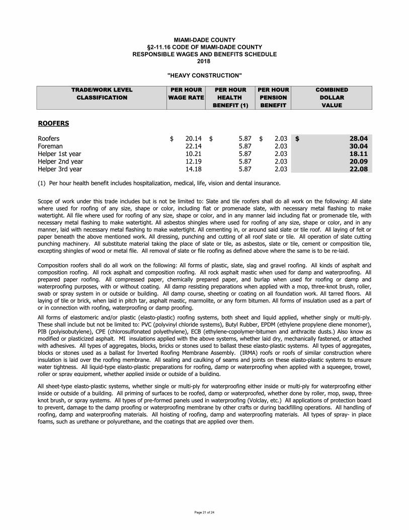
��������������� ������������� ����������������� ������������������� !��"�#������� ����������$���!�%$��&��������������%� '()*+,-.(/01+2+1 3+(04.5( 3+(04.5( 3+(04.5( 6.789:+*61);;9<96)'9.: -)=+0()'+ 4+)1'40 3+:;9.: *.11)(8+:+<9'0>?@ 8+:+<9' 2)15+�A�BCDDEFCG HHIJJKLMN OPQRSTUUUUUUU VQWXTUUUUUUUUUUUUUU OQPYTUUUUUUU Z[\]_HHHHHHHHHHHHHHHHHHHHHHHHHHHHJMLabc OOQRSUUUUUUUU VQWXUUUUUUUUUUUUUUUU OQPYUUUUUUUUU d]\]HHHHHHHHHHHHHHHHHHHHHHHHHHHHHHeLfgLMURNhUiLbM RPQORUUUUUUUU VQWXUUUUUUUUUUUUUUUU OQPYUUUUUUUUU j[\jjHHHHHHHHHHHHHHHHHHHHHHHHHHHHHHeLfgLMUOckUiLbM ROQRlUUUUUUUU VQWXUUUUUUUUUUUUUUUU OQPYUUUUUUUUU Z]\]mHHHHHHHHHHHHHHHHHHHHHHHHHHHHHHeLfgLMUYMkUiLbM RSQRWUUUUUUUU VQWXUUUUUUUUUUUUUUUU OQPYUUUUUUUUU ZZ\][HHHHHHHHHHHHHHHHHHHHHHHHHHHHHHnRoUUpLMUqJrMUqLbfhqUsLcLKthUtcufrkLNUqJNgthbftvbhtJcwUaLktubfwUftKLwUxtNtJcUbckUkLchbfUtcNrMbcuLQyffKJMaNJKLfbNhJaLMtubckzJMgfbNhtunLfbNhJ{gfbNhtuoMJJKtc|NiNhLaNwsJhqNqLLhbckft}rtkbggftLkw~qLhqLMNtc|fiJMarfht{gfiQ�qLNLNqbfftcufrkLsrhcJhsLftathLkhJ�p��ngJfixtcifuqfJMtkLNiNhLaNow�rhifIrssLMw�p��nLhqifLcLgMJgifLcLktLcLaJcJaLMowp��ngJfitNJsrhifLcLow�p�nuqfJMJNrfKJcbhLkgJfiLhqifLcLow���nLhqifLcL{uJgJfiaLM{sthraLcbckbchqMbuthLkrNhNQoyfNJ�cJ~bNaJktKtLkJMgfbNhtutvLkbNgqbfhQ��tcNrfbhtJcNbggftLk~thqhqLbsJxLNiNhLaNw~qLhqLMfbtkkMiwaLuqbctubffiKbNhLcLkwJMbhhbuqLk~thqbkqLNtxLNQyffhigLNJKb||ML|bhLNwsfJu�NwsMtu�NJMNhJcLNrNLkhJsbffbNhhqLNLLfbNhJ{gfbNhtuNiNhLaNQyffhigLNJKb||ML|bhLNwsfJu�NJMNhJcLNrNLkbNbsbffbNhKJM�cxLMhLkIJJKtc|�LasMbcLyNNLasfiQn�I�yoMJJKNJMMJJKNJKNtatfbMuJcNhMruhtJc~qLMLtcNrfbhtJctNfbtkJxLMhqLMJJKtc|aLasMbcLQyffNLbftc|bckubrf�tc|JKNLbaNbck�JtchNJchqLNLLfbNhJ{gfbNhtuNiNhLaNhJLcNrML~bhLMht|qhcLNNQyffft}rtk{higLLfbNhJ{gfbNhtugMLgbMbhtJcNKJMMJJKtc|wkbagJM~bhLMgMJJKtc|~qLcbggftLk~thqbN}rLL|LLwhMJ~LfwMJffLMUJMUNgMbiUL}rtgaLchwU~qLhqLMUbggftLkUtcNtkLUJMUJrhNtkLUJKUbUsrtfktc|QyffNqLLh{higLLfbNhJ{gfbNhtuNiNhLaNw~qLhqLMNtc|fLJMarfht{gfiKJM~bhLMgMJJKtc|LthqLMtcNtkLJMarfht{gfiKJM~bhLMgMJJKtc|LthqLMtcNtkLJMJrhNtkLJKbsrtfktc|QyffgMtatc|JKNrMKbuLNhJsLMJJKLkwkbagJM~bhLMgMJJKLkw~qLhqLMkJcLsiMJffLMwaJgwN~bgwhqMLL{�cJhsMrNqwJMNgMbiNiNhLaNQyffhigLNJKgML{KJMaLkgbcLfNrNLktc~bhLMgMJJKtc|n�JfufbiwLhuQoyffbggftubhtJcNJKgMJhLuhtJcsJbMkhJgMLxLchwkbab|LhJhqLkbaggMJJKtc|JM~bhLMgMJJKtc|aLasMbcLsiJhqLMuMbKhNJMkrMtc|sbu�Ktfftc|JgLMbhtJcNQyffqbckftc|JKMJJKtc|wkbagbck~bhLMgMJJKtc|abhLMtbfNQyffqJtNhtc|JKMJJKtc|wkbagbck~bhLMgMJJKtc|abhLMtbfNQyffhigLNJKNgMbi{tcgfbuLKJbaNwUNruqUbNUrMLhqbcLUJMUgJfirMLhqbcLwUbckUhqLUuJbhtc|NUhqbhUbMLUbggftLkUJxLMUhqLaQ�uJgLJK~JM�rckLMhqtNhMbkLtcufrkLNsrhtNcJhsLftathLkhJ��fbhLbckhtfLMJJKLMNNqbffkJbff~JM�JchqLKJffJ~tc|�yffNfbhL~qLMLrNLkKJMMJJKtc|JKbciNtvLwNqbgLJMuJfJMwtcufrktc|KtbhJMgMJaLcbkLNfbhLw~thqcLuLNNbMiaLhbfKfbNqtc|hJab�L~bhLMht|qhQyffKtfL~qLMLrNLkKJMMJJKtc|JKbciNtvLwNqbgLJMuJfJMwbcktcbciabccLMfbtktcufrktc|KfbhJMgMJaLcbkLhtfLw~thqcLuLNNbMiaLhbfKfbNqtc|hJab�L~bhLMht|qhQyffbNsLNhJNNqtc|fLN~qLMLrNLkKJMMJJKtc|JKbciNtvLwNqbgLJMuJfJMwbcktcbciabccLMwfbtk~thqcLuLNNbMiaLhbfKfbNqtc|hJab�L~bhLMht|qhQyffuLaLchtc|tcwJMbMJrckNbtkNfbhLJMhtfLMJJKQyfffbitc|JKKLfhJMgbgLMsLcLbhqhqLbsJxLaLchtJcLk~JM�QyffkMLNNtc|wgrcuqtc|bckurhhtc|JKbffMJJKNfbhLJMhtfLQyffJgLMbhtJcJKNfbhLurhhtc|grcuqtc|abuqtcLMiQyffNrsNhthrhLabhLMtbfhb�tc|hqLgfbuLJKNfbhLJMhtfLwbNbNsLNhJNwNfbhLJMhtfLwuLaLchJMuJagJNthtJchtfLwL�uLghtc|UNqtc|fLNUJKU~JJkUJMUaLhbfUKtfLQUUyffUMLaJxbfUJKUNfbhLUJMUKtfLUMJJKtc|UbNUkLKtcLkUbsJxLU~qLMLUhqLUNbaLUtNUhJUsLUML{fbtkQ�JagJNthtJcMJJKLMNNqbffkJbff~JM�JchqLKJffJ~tc|�yffKJMaNJKgfbNhtuwNfbhLwNfb|bck|MbxLfMJJKtc|Qyff�tckNJKbNgqbfhbckuJagJNthtJcMJJKtc|QyffMJu�bNgqbfhbckuJagJNthtJcMJJKtc|QyffMJu�bNgqbfhabNhtu~qLcrNLkKJMkbagbck~bhLMgMJJKtc|QyffgMLgbMLkgbgLMMJJKtc|QyffuJagMLNNLkgbgLMwuqLatubffigMLgbMLkgbgLMwbcksrMfbg~qLcrNLkKJMMJJKtc|JMkbagbck~bhLMgMJJKtc|grMgJNLNw~thqJM~thqJrhuJbhtc|QyffkbagMLNtNhtc|gMLgbMbhtJcN~qLcbggftLk~thqbaJgwhqMLL{�cJhsMrNqwMJffLMwN~bsJMNgMbiNiNhLatcJMJrhNtkLJMsrtfktc|QyffkbaguJrMNLwNqLLhtc|JMuJbhtc|JcbffKJrckbhtJc~JM�QyffhbMMLkKfJJMNQyfffbitc|JKhtfLJMsMtu�w~qLcfbtktcgthuqhbMwbNgqbfhabNhtuwabMaJfthLwJMbciKJMasthraLcQyffKJMaNJKtcNrfbhtJcrNLkbNbgbMhJKJMUtcUuJccLuhtJcU~thqUMJJKtc|wU~bhLMgMJJKtc|UJMUkbagUgMJJKtc|Q
��������������� � ������������������� ������� � ���������������� ��!�"����� �����������#� � �$#��%�������������$� &'()*+,-'./0*1*0 2*'/3-4' 2*'/3-4' 2*'/3-4' 5-6789*)50(::8;85(&8-9 ,(<*/'(&* 3*(0&3/ 2*9:8-9 )-00('7*9*;8&/=>? 7*9*;8& 1(04*�@�ABCCDEBFGHIJKLMKNOP HHQRRSTUVWXTYSQVWZ[YZ\]Y_YQaab]\cde]YcfYZ\]Y_YSffg]bhQiiYcja]kYfgYb]kclmbl\cnYeflcd\oknYplkcdekYl\qYcfaad\okYrs]\Ymk]qYgfbYbffgYpld\c]\l\e]Yl\qYb]aldbkhQiic]lbtfggl\qufbb]pfvlifgl\jcja]fgbffgd\onliikamqqd\onkr]]ad\onvlemmpd\ol\qufbei]l\mafgl\jl\qliilb]lkfgl\jcja]Yrs]b]YlYbffgYdkYcfYw]Yb]tildqh
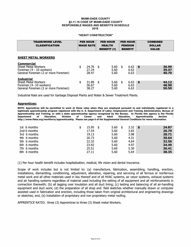
��������������� ������������� ����������������� ������������������� !��"�#������� ����������$���!�%$��&��������������%� '()*+,-.(/01+2+1 3+(04.5( 3+(04.5( 3+(04.5( 6.789:+*61);;9<96)'9.: -)=+0()'+ 4+)1'40 3+:;9.: *.11)(8+:+<9'0>?@ 8+:+<9' 2)15+�A�BCDEEFGHEFIJGKLMNEMC GGOPQQRSTUVWGXYZZ[\]Z[_\abcZbd\ efghij\\\\\\\ kgilj\\\\\\\\\\\\\\ igimj\\\\\\\ nopqqrGGGGGGGGGGGGGGGGGGGGGGGGGGGGsabZtZu\vf\w\xl\yabcZbdz\ ehgef kgil igim nqp{|}ZuZb_\sabZtZu\ve\ab\tabZ\sabZtZuz\ e~gfh kgil igim {�p|�������SUVWGXYZZ[\]Z[_\abcZbd mxg~�j\\\\\\\ kgilj\\\\\\\\\\\\\\ igimj\\\\\\\ {{p��rGGGGGGGGGGGGGGGGGGGGGGGGGGGGsabZtZu\vf\wxl\yabcZbdz\ migih kgil igim {�pq�}ZuZb_\sabZtZu\ve\ab\tabZ\sabZtZuz\ m~geh kgil igim ��p���u��d[b�_\�[Z\bZ\�dZ�\�ab\}b��Z\��d�ad_\�_u[d\u�\ [Zb\�\XZyZb\�bZ[tZu[\�_u[dgI��SR��UTR��\\xd[\\i\tau[Yd xkg�kj\\\\\\\ kgilj\\\\\\\\\\\\\\ mgmej\\\\\\\ �{p�|rGGGGGGGGGGGGGGGGGGGGGGGGGGGG\\eu�\i\tau[Yd xhgkf kgil mgik �op|q\\mb�\\i\tau[Yd x�gxm kgil mg�~ ��p|�\\f[Y\\i\tau[Yd elghm kgil fgmx n�po{\\k[Y\\i\tau[Yd eegme kgil fgif n�p�o\\i[Y\\i\tau[Yd emg�e kgil fg�h n{p{q\\h[Y\\i\tau[Yd ekgkx kgil kgml nop{�\\~[Y\\i\tau[Yd ehgxx kgil kgif n�pn�vxz\�Zb\Ya�b\YZ_[Y\�ZuZ��[\�u�_��Zd\Yad��[_��[�au�\tZ���_�\_��Z\��d�au\u�\�Zu[_\�ud�bu�Zg����� ��¡�\����¢£\\[YbZZ\vmz\���bZu[��Zd\[a\[YbZZ\vmz\XYZZ[\tZ[_\abcZbdg\X�a�Za�yabc�u�_��Zd��[�dua[_�t�[Z�[a£vzt u���[�bZ���b��[�au� ddZt�_�u��Yu�_�u��ZbZ�[�au��ud[__[�aud���dt u[_�u���au��[�au�u�� �¤�d[tZu[� _[Zb[�au�bZ��b�u�� u�dZb����u�a� __�Zbba�dabuau�Zbba�dtZ[_yabc u� __a[YZbt [Zb�_d�dZ��u_�Z�[YZbZa�u�a�__¥¦�¡d§d[Ztd��b�Z§abd§d[Ztd�ZY�d[d§d[Ztdu� �bYu�_�u�d§d[ZtdbZ�b�_Zdda�t [Zb�_�dZ��u�_���u�[YZdZ[[�u�a�__Z©���tZu[u� __bZ�u�ab�ZtZu[d�u�auuZ�[�au[YZbZy�[Yªv�z ___���u�a�Zb�ud�_[�au u� __���[_�u�u�ªv�z[Zd[�u� u��_u��u�a�__�bwYu�_�u�Z©���tZu[u����[yabcªv�z[YZ�bZ�b[�aua�__dYa� u���Z_�dcZ[�YZdyYZ[YZbt u�__§�byuab�at��[Zbdd�d[Z��dZ��u��b��[�au u�ZbZ�[�au��u�_���u�[YadZ[cZu�batab���u_b�Y�[Z�[�b_u�Zu��uZZb�u��by�u�dab\dcZ[�YZdª\u��\vZz\�ud[__[�au\a�\�ba�b�Z[b§\u�\uau\�ba�b�Z[b§\tZ[_\baa��u�g«LFE�I��SR��UTR�¬UWWR�RSQU��R��P¬PS®V��R�RSV�R�¬ R��R°VSRRQ�WP°R���S��V���PV��U��U±U��VWW°SR²U��RSR�U�VWR²U�UQV�RV��SR��UTR�U��SP²SVQ SR²U��RSR�¬U� �R³pCp R�VS�QR��PµJVPS¶EQ�WP°QR��V��FSVU�U�²I�QU�U��SV�UP�¶·�SRV�PµI��SR��UTR�U�V��FSVU�U�²¶PS¬U� V��V�RV��SR��UTR�U�V²R�T°SRTP²�UR�°�R·�SRV�p ��¹WPSU�V�U�V²R�T°U��R¹WPSU�VR�VS�QR�� Pµ E��TV�UP�¶ U±U�UP� Pµ OVSRRS V�� I��W� E��TV�UP�¶ I��SR��UTR�U� CRT�UP� º����»»¬¬¬pµW�PRpPS²»¬PS®µPSTR»V��SR��UTR�U�pGG¼WRV�RG�RRG�V²RGoGPµG�RGC���WRQR��VWG½R�RSVWGOP��U�UP��GµPSGQPSRGU�µPSQV�UP�p
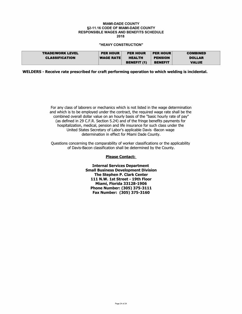
��������������� � ������������������� ������� � ���������������� ��!�"����� �����������#� � �$#��%�������������$� &'()*+,-'./0*1*0 2*'/3-4' 2*'/3-4' 2*'/3-4' 5-6789*)50(::8;85(&8-9 ,(<*/'(&* 3*(0&3/ 2*9:8-9 )-00('7*9*;8&/=>? 7*9*;8& 1(04*�@�ABCDECFGHIHFJKJLMJHNOPJHQNJRKNLSJTHUVNHKNOUPHQJNUVNWLXYHVQJNOPLVXHPVHZ[LK[HZJ\TLXYHLRHLXKLTJXPO\]H_abcdaefbgga_hafbi_jga_akjelbcmeganlmelamgac_oafmgojpamcaoljanbqjapjojkmcbom_cbcpanlmelamgao_aijajkrf_djpascpjaoljae_cobeotaoljajusmjpanbqjabojaglbffaijaoljae_kimcjpa_vjbffap_ffbavbfsja_cabcal_sfdaibgmga_haoljawibgmeal_sfdaboja_harbdwxbgapjhmcjpamcayza{||}|a~jeom_ca�|y��abcpa_haoljahmcqjaijcjhmogarbdkjcogah_al_grmobfm�bom_ctakjpmebftarjcgm_cabcpafmhjamcgsbcejah_agselaefbggascpjaolja�cmojpa~obojga~jejobda_ha�bi_�gabrrfmebifja�bvmga��be_canbqjapjojkmcbom_camcajhhjeoah_a�mbkma�bpja{_scod|�sjgom_cgae_cejcmcqaoljae_krbbimfmoda_han_�jaefbggmhmebom_cga_aoljabrrfmebimfmoda_ha�bvmg��be_caefbggmhmebom_caglbffaijapjojkmcjpaidaolja{_scod|�\JORJH�VXPOKP�H�XPJNXO\HGJNMLKJRHEJQONPWJXPHGWO\\H��RLXJRRHEJMJ\VQWJXPHELMLRLVX�[JHGPJQ[JXH�]H�\ON�H�JXPJN���H�]B]H�RPHGPNJJPHIH��P[H�\VVN�LOWL�H�\VNLTOH�����I�����[VXJH��WSJN�H��� ¡H�¢ I�����O£H��WSJN�HH��� ¡H�¢ I����

������� ����� ���� �������� ������ �� ��� �������� !�"#��$ �� ��%��� ��� �"%����� �"�&��� �"� ��� �'�� !�$� ��( '���)�� � �����%� !�$� *+,�-,./�01�2345�6+/�71..�/836�/81�91:,4915�03.1�8+,97;�93/1�365�0161<4/.�74./15�46�/81�=3>1.�365�?161<4/.�@A815,71�<+9�1B19;�8+,9�C+9D15E�*+,�-3;�6+/�01�2345�017+C�/81�03.1�93/1�1B16�4<�/81�B37,1�+<�/81�<946>1�0161<4/.�29+B4515�/+�;+,�1FA115.�/81�B37,1�+<�/81�8137/8�365�216.4+6�91:,4915�46�/81�.A815,71E��G554/4+6377;H�;+,�-,./�01�2345�6+/�71..�/836�/81�A+-04615�5+7739�B37,1�I?3.1�J3/1�K�L137/8�K�M16.4+6�?161<4/N�74./15�46�/81�C3>1�365�0161<4/.�.A815,71�2+./15�C4/8�/84.�6+/4A1�<+9�/81�/;21�+<�C+9D�;+,�391�219<+9-46>E ��O�"���� �*+,�-,./�01�2345�/4-1�365�+61P837<�/81�03.4A�93/1�+<�23;�<+9�377�8+,9.�C+9D15�46�1FA1..�+<�QR�8+,9.�46�3�C11DE�� ���"������ �S �"����� G22916/4A1.T/934611.�93/1.�3227;�+67;�/+�322916/4A1.�365�/934611.�29+2197;�91>4./1915�,6519�36�3229+B15�U151937�+9�@/3/1�322916/4A1.842�+9�/934646>�29+>93-E � ������� @36A/4+6.�<+9�3�<49./P/4-1�+<<16519�391�VRW�+<�/81�3-+,6/�+<�,651923;-16/�23;3071�/+�/81��+,6/;E��81�.36A/4+6.�46A913.1�/+�QRW�<+9�/81�.1A+65�,651923;-16/�365�XRW�<+9�/81�/8495�,651923;-16/E��+6/93A/+9.�<+,65�/+�83B1�,65192345�3�<+,9/8�/4-1�-3;�01�.,0Y1A/�/+�.,.216.4+6�+9�/19-463/4+6�46�3AA+9536A1�C4/8�/81�A+6/93A/�/19-.�365�51039-16/�46�3AA+9536A1�C4/8�/81�51039-16/�29+A15,91.�+<�/81��+,6/;E����������� =94//16�A+-27346/.�+<�,651923;-16/�.8+,75�01�<4715�C4/8Z���6/19637�@19B4A1.�[1239/-16/��� � � � \43-4P[351�GB43/4+6�[1239/-16/�@-377�?,.461..�[1B17+2-16/�[4B4.4+6��� � � \46+94/;�G<<349.�[4B4.4+6��]]]��=�]@��@/911/H�]�L�U7++9�\43-4H�U_� ]Va������������+9���� M���?+F�RVbbRQH�\43-4H�U_� ]RVPbbRQ��17128+61Z�IRbN�cbP]]]�UGdZ�IRbN�cbP]XR� � �17128+61Z�IRbN�acXPccXQ��-347Z��@?[\G�_e\�G\�[G[�Ef�g�� � � �-347Z��\�+7746.e-43-4P3492+9/EA+-�� �
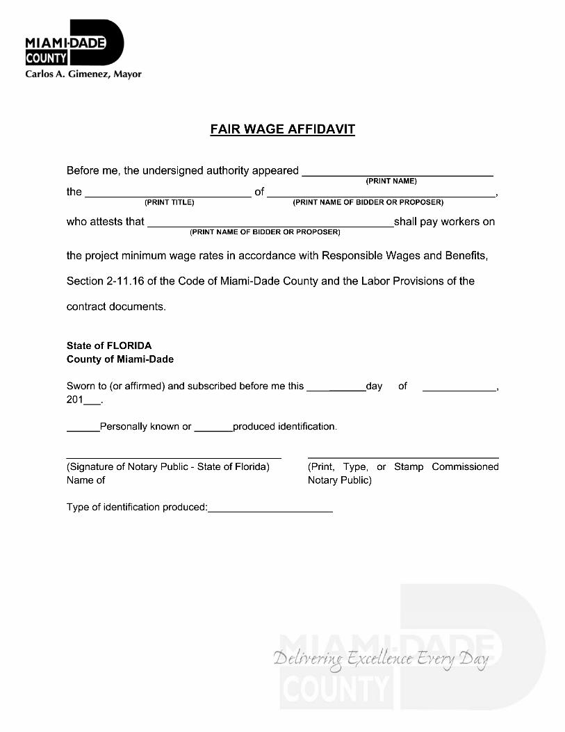
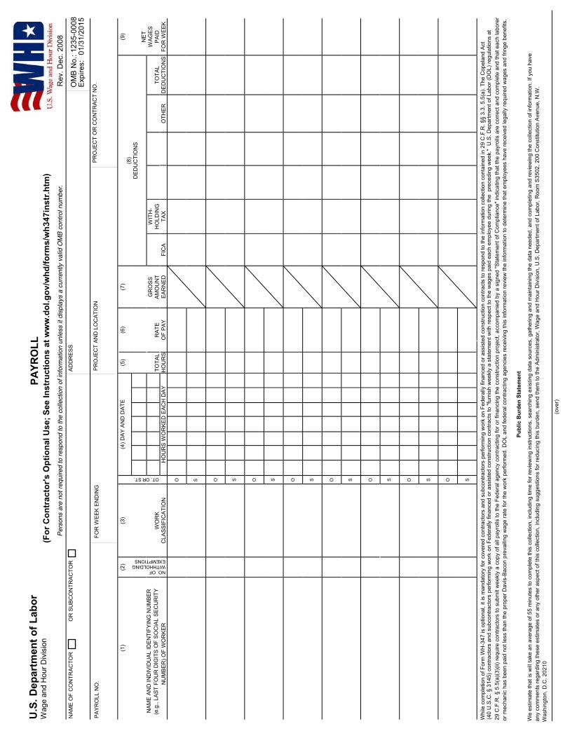
�������������� ������� �������� ������������������������������������������� !" ###$%&'$(&)*#+%*,&-./*#+01234/"-$+".5�6789:7;<:=>?@:ABCBDB>;::: EFGHIJHKLGFKJIMKGFNOPGFQKMIKGFHRIJQKMIKMSFKTIUUFTMPIJKIVKPJVIGWLMPIJKOJUFHHKPMKQPHRULXHKLKTOGGFJMUXKYLUPQKZ[\KTIJMGIUKJOW]FGK _ab:cd:ec_fgefcg:cg:hijec_fgefcg:AAgbhh caj:_>kl:mnopqrsst: buvB@9Dl:swxowxyswz{ |}gc~~:_ck:dcg:6bb�:b_A�_�:|gc�bef:_A:~cef�c_:|gc�bef:cg:ec_fgef:_ck: �m�:�n�:���:���:A}:_A:Afb:�p�:���:���:���: ���: AbAief�c_h: c: c: c: c: c: c: c: c:_ab���������������������������������� ������������ ���¡�������� �¡�� ce�~:hbeig�f}: ������¢�cd:£¡�¤��_ck:cd: 6�f==c~AB_�: b¥ba|f�c_h: 6cg�: e~hh�d�ef�c_:cfk:cg:hfk: =cigh:6cg�bA:be=:A}:fcf~: =cigh:gfb: cd:|}:�gchh: aci_f: bg_bAd�e:6�f=q =c~A�_�: f¥cf=bg:fcf~: AbAief�c_h:_bf: 6�bh: |�A: dcg:6bb�: h: h h: h: h: h: h: h:��¦����§��ysst £©ª��§«¬ª�®©«�«°��«±¬�£²³oµ�©¶�«®©«·ª��©®�©¶�¬··®«±¹�°«±�§«¦�±��§«®±·§®«±¶�·�¶º»§«®±·§®«±¶��±°«±¬©��¼«±½�«����±·ªª¹�°©·§��«±�·¶¶©¶®��§«¶®±º§®©«�§«®±·§®¶�®«�±�¶«�®«�®��©°«±¬·®©«�§«ªª�§®©«�§«®·©��©�y¾�¿������ÀÀ�o�o��z�z�·¢�����¿«�ª·��§®� �s��� �¿��À�owz¢�§«®±·§®«±¶�·�¶º»§«®±·§®«±¶��±°«±¬©��¼«±½�«����±·ªª¹�°©·§��«±�·¶¶©¶®��§«¶®±º§®©«�§«®±·§®¶�®«�Á°º±©¶�¼��½ª¹�·�¶®·®�¬�®�¼©®�±�¶�§®�®«�®��¼·��¶�·©��·§��¬ª«¹���º±©��®���±�§�©��¼��½�Á���� ����·±®¬�®�«°��·»«±���¡�¢�±��ºª·®©«¶�·®�� y¾�¿������À�z�z�·¢�o¢�©©¢�±�º©±��§«®±·§®«±¶�®«�¶º»¬©®�¼��½ª¹�·�§«¹�«°�·ªª�·¹±«ªª¶�®«�®�����±·ª�·��§¹�§«®±·§®©��°«±�«±�°©·§©��®��§«¶®±º§®©«�±«Ã�§®��·§§«¬·©��»¹�·�¶©���Á ®·®�¬�®�«°�¿«¬ª©·§�Á�©©§·®©��®·®�®��·¹±«ªª¶�·±��§«±±�§®�·�§«¬ª�®��·�®·®��·§�ª·»«±�± � «±�¬�§·©§�·¶�»���·©�«®�ª�¶¶�®·�®��±«�±��·¦©¶³�·§«�±�¦·©ª©��¼·���±·®��°«±�®��¼«±½��±°«±¬����¡��·�°��±·ª�§«®±·§®©��·��§©�¶�±�§�©¦©��®©¶�©°«±¬·®©«�±�¦©�¼�®��©°«±¬·®©«�®«��®�±¬©��®·®��¬ª«¹��¶�·¦��±�§�©¦��ª��·ªª¹�±�º©±��¼·��¶�·�°±©���»��°©®¶�� ÄÅÆÇÈÉÊËÅÌÍÎÏÊÐÑÒÑÎÓÎÏÑ £���¶®©¬·®��®·®�©¶�¼©ªª�®·½��·�·¦�±·���«°�zz�¬©º®�¶�®«�§«¬ª�®��®©¶�§«ªª�§®©«��©§ªº©��®©¬��°«±�±�¦©�¼©��©¶®±º§®©«¶��¶�·±§©���Ô©¶®©��·®·�¶«º±§�¶���·®�±©��·�¬·©®·©©��®��·®·������·�§«¬ª�®©��·�±�¦©�¼©��®��§«ªª�§®©«�«°�©°«±¬·®©«���°�¹«º�·¦�� ·¹�§«¬¬�®¶�±��·±©��®�¶���¶®©¬·®�¶�«±�·¹�«®�±�·¶�§®�«°�®©¶�§«ªª�§®©«��©§ªº©��¶º���¶®©«¶�°«±�±�º§©��®©¶�»º±���¶��®�¬�®«�®���¬©©¶®±·®«±��£·���·�²«º±��©¦©¶©«���� ����·±®¬�®�«°��·»«±���««¬� ozsy��yss�¿«¶®©®º®©«��¦�º�����£��� £·¶©�®«����¿��ysyws �«¦�±¢
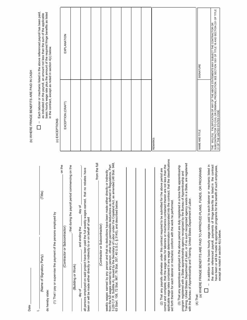
����� �� �������� ���������������� ����� ���������������� ����������������������� ������������������������������������� � ��� �� ������ �������� ���� ���� !��������� ����������������� �� �� ��������� �"� �� �����#�$�� ��������������� �������������� �������%&����'��������( ����)* �����*�������� ���+�������,��$���,��������������������������������� �������, ����������� ������ �� ��� ��� �� �� ��������������������� �� ������������ ������ �������� ���� ���� ,��$���,�����������������������-�������.��������� / ������0������1���� �.���� �� /����� �� �� /��� ������������,��������������������������������������� �� �������� � ��������� ���� ��2������ ��������� 3��45��67626����� ����8��� ��������������� ���������9����������������������8 ��������������:;�����<�5:;�� =3������<��>;��?4�����<�5=?!�?=�����<�3@?!�:>�A<�<�<�BCDEFG���������� � �������,�� �4�����������������������, ����������� �� H���� ����I� ����� H�����J� ������H���������K���� ������ ��� ������ �����!����������,������������������������ ��� �� ��� ��������� ����������������������� ���� ����LM���LN����LO��� ���LP�L1��LM�������K� ��� �LP� �������� ��H��.�� H���� �!��.����.��OQ1RRPSPO1/PHTR �������������� ������� ������������ ��� � ����, �������,�$�����������<� �3���.������L1������P ����U����� ���.�����K���� �L1��LV���LN�� ������LP�L1LW��LS ���1UUNKT/POKR.PU �����N�� �/�����,P�������1����������P ��� �L1��� �LN� �� X��LW�L/��LY�����LH��ZUUNKT/POKR.PUL1TV ��� � ����A� �����������������������9�����[� ������ ���� �� X������� ���\ ���� ����]/1/KL1NKLNK_PR/KNKV , �������"��������8������ ��� ��������� � ����A� �����������������������9���<� �:�������� ����#a2a�72��ba�"a�a7����82a��8����c�8��2cda���98����7A�����c2��2cb28e�� fgff ����� � ����������� �������,������������ ������ ������������ ��� �� ����� �� ���������������� ����������������������� ��������� ������� �� ��� ������ ���� �� ����LW���LH�LM �����Lh���L/������� �/�������h�LS�L/�������S �LH�LR� �LKhUQHiKKR� �\ ������������ ��j� � ��:� �����,<�����#a2a�72� �ba�"a�a 7����82a��8�������8�� kffa� ������������ ��� �� ����� ������������������ ��������������������� ��� ��� �� ��������������������������������������������������������� ����� ��� �������,�������������������������������I� ������ ��������� ������� ����� ������ ���� ����\ ������������ ��j� � ��:� �����,<� � ��al�a���c� �� 2ae82m���al�a���c����287�� �al�98�8��c�� �8ea�8������9a���b�8�A2a� �a�#�997A9�789��7��8��c��no�8�p�no�qra�8"csa���t�aea����etp��A"uv����ra��cw�28��c2�cx� �A"�c��28��c2��c���d�9�c2��2�e��89��2c�a�A��c�<��aa��a���c���>>��c7����9a��;�8����a���c��43��c7����9a� 3��c7��a�A���a����8�a���c�a<�

APPENDIX B OF THE SUPPLEMENTARY CONDITIONS
CLEARINGHOUSE FORMS
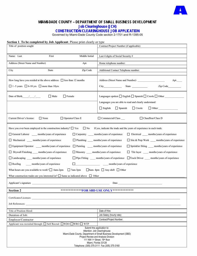
MIAMI-DADE COUNTY – DEPARTMENT OF SMALL BUSINESS DEVELOPMENT JJoobb CClleeaarriinngghhoouussee ((JJCCHH))
CCOONNSSTTRRUUCCTTIIOONN CCLLEEAARRIINNGGHHOOUUSSEE JJOOBB AAPPPPLLIICCAATTIIOONNGoverned by Miami-Dade County Code section 2-1701 and R-1395-05
Section 1. To be completed by Job Applicant. Please print clearly or type TTiittllee ooff ppoossiittiioonn ssoouugghhtt CCoonnttrraacctt//PPrroojjeecctt NNuummbbeerr ((iiff aapppplliiccaabbllee))
NNaammee:: LLaasstt FFiirrsstt MMiiddddllee IInniittiiaall LLaasstt 44 ddiiggiittss ooff SSoocciiaall SSeeccuurriittyy ##
AAddddrreessss ((SSttrreeeett NNaammee aanndd NNuummbbeerr)) AApptt.. HHoommee tteelleepphhoonnee nnuummbbeerr::
CCiittyy SSttaattee ZZiipp CCooddee AAddddiittiioonnaall CCoonnttaacctt TTeelleepphhoonnee nnuummbbeerr::
HHooww lloonngg hhaavvee yyoouu rreessiiddeedd aatt tthhee aabboovvee aaddddrreessss:: lleessss tthhaann 1122 mmoonntthhss
11 --55 yyeeaarrss 66--1100 yyrrss mmoorree tthhaann 1100yyrrss
AAddddrreessss ((SSttrreeeett NNaammee aanndd NNuummbbeerr)) __________________________________________ AApptt..________
CCiittyy____________________________ SSttaattee ________________________ ZZiipp CCooddee____________________
DDaattee ooff BBiirrtthh__________//________//________ MMaallee FFeemmaallee LLaanngguuaaggeess ssppookkeenn EEnngglliisshh SSppaanniisshh CCrreeoollee OOtthheerr ______________________________
LLaanngguuaaggeess yyoouu aarree aabbllee ttoo rreeaadd aanndd cclleeaarrllyy uunnddeerrssttaanndd::
EEnngglliisshh SSppaanniisshh CCrreeoollee OOtthheerr ______________________________
CCuurrrreenntt DDrriivveerr’’ss lliicceennssee:: NNoonnee OOppeerraattoorr//CCllaassss EE CCoommmmeerrcciiaall//CCllaassss ______ CChhaauuffffeeuurr//CCllaassss DD
HHaavvee yyoouu eevveerr bbeeeenn eemmppllooyyeedd iinn tthhee ccoonnssttrruuccttiioonn iinndduussttrryy?? YYeess NNoo IIff yyeess,, iinnddiiccaattee tthhee ttrraaddee aanndd tthhee yyeeaarrss ooff eexxppeerriieennccee iinn eeaacchh ttrraaddee..
GGeenneerraall LLaabboorreerr ________ mmoonntthhss//yyeeaarrss ooff eexxppeerriieennccee CCaarrppeennttrryy ________ mmoonntthhss//yyeeaarrss ooff eexxppeerriieennccee EElleeccttrriiccaall ________ mmoonntthhss//yyeeaarrss ooff eexxppeerriieennccee
MMeecchhaanniiccaall ________ mmoonntthhss//yyeeaarrss ooff eexxppeerriieennccee PPlluummbbiinngg ________ mmoonntthhss//yyeeaarrss ooff eexxppeerriieennccee SSiittee && PPrreepp WWoorrkk ________ mmoonntthhss//yyeeaarrss ooff eexxppeerriieennccee
EEqquuiippmmeenntt OOppeerraattoorr ________ mmoonntthhss//yyeeaarrss ooff eexxppeerriieennccee PPaaiinnttiinngg ________ mmoonntthhss//yyeeaarrss ooff eexxppeerriieennccee SSpprriinnkklleerr ffiittttiinngg ________ mmoonntthhss//yyeeaarrss ooff eexxppeerriieennccee
DDrryywwaallll FFiinniisshhiinngg ________ mmoonntthhss//yyeeaarrss ooff eexxppeerriieennccee MMaassoonnrryy ________ mmoonntthhss//yyeeaarrss ooff eexxppeerriieennccee TTiillee llaayyeerr ________ mmoonntthhss//yyeeaarrss ooff eexxppeerriieennccee
LLaannddssccaappiinngg ________ mmoonntthhss//yyeeaarrss ooff eexxppeerriieennccee PPiippee FFiittttiinngg ________ mmoonntthhss//yyeeaarrss ooff eexxppeerriieennccee TTrruucckk DDrriivveerr ________ mmoonntthhss//yyeeaarrss ooff eexxppeerriieennccee
RRooooffiinngg ________ mmoonntthhss//yyeeaarrss ooff eexxppeerriieennccee ______________________________________ ________ mmoonntthhss//yyeeaarrss ooff eexxppeerriieennccee
WWhhaatt hhoouurrss aarree yyoouu aavvaaiillaabbllee ttoo wwoorrkk?? 66aamm--22ppmm 77aamm--33ppmm 88aamm-- 44ppmm AAnnyy sshhiifftt OOtthheerr
WWhhaatt ccoonnssttrruuccttiioonn ttrraaddeess aarree yyoouu iinntteerreesstteedd iinn?? SSaammee aass iinnddiiccaatteedd aabboovvee OOtthheerr ____________________________________________________________________________________________________________________________________
AApppplliiccaanntt’’ss ssiiggnnaattuurree ________________________________________________________________________________________________________________________ DDaattee ____________________________________________________________________
Section 2 *************FOR SBD USE ONLY*************
Certificates/Licenses: ___________________________________________________________________________________________________________________
Job References: ________________________________________________________________________________________________________________________
Title of Position Hired: Date of Hire: Duration of Job: Job Salary (hourly rate):
Employer/Contractor Contract/Project Number: Applicant was recruited through: Self Recruit WDO WRO WTP
Submit this application to:Attention: Job Clearinghouse
Miami-Dade County, Department of Small Business Development (SBD) Project Review and Analysis Division
111 NW 1st Street, 19th floor Miami, Florida 33128
Telephone: (305) 375-3111 Fax (305) 375-3160

MIAMI-DADE COUNTY DEPARTMENT OF SMALL BUSINESS DEVELOPMENT
JJoobb CClleeaarriinngghhoouussee ((JJCCHH))NNOOTTIICCEE OOFF CCOONNSSTTRRUUCCTTIIOONN CCLLEEAARRIINNGGHHOOUUSSEE JJOOBB OOPPPPOORRTTUUNNIITTYY
Governed by Miami-Dade County Code section 2-1701 and R-1395-05
To be completed by Employer/Contractor. Please print clearly or type
EMPLOYER/CONTRACTOR INFORMATION Business Name: Contract/Project Number
Address (Street Name and Number) Federal ID#
City State Zip Code
Telephone Number Fax Number
Contact Person Email Address
JOB LISTING INFORMATION Job Title Application Deadline
Job Site Location Number of Openings
Describe Job Duties: Hourly Rate
Specialized Training: Experience Required (Months/Years): Specialized machinery or equipment:
Job Duration: Permanent Temporary/If Temporary, how long? ___ Fringe Benefits? Yes No
Education Required: None H.S Diploma/GED AA Degree Bachelor’s Degree Master’s Degree
Certifications/License Required: None Yes If Yes, please list___________________________________________________________
Driver’s license required: None Operator/Class E Commercial/Class ____ Chauffeur/Class D
Language(s) required: English Spanish Creole Other
APPLICANTS SHOULD CONTACT EMPLOYER BY:
Call for Appointment Phone Interview Send Resume via: Mail Fax Email
Apply In Person Day of the Week: ______________ Time: _________________ Application Deadline: ____________________
Employer/Contractor must submit this form for all job openings.
Attention: Job Clearinghouse Miami-Dade County Department of Small Business Development
Project Review and Analysis Division 111 NW 1st Street, 19th floor
Miami, Florida 33128 Telephone: (305) 375-3111 Fax (305) 375-3160

JOB CLEARINGHOUSE AFFIDAVIT Notice of Construction Job Opportunities
Project / Contract Number: __________________________________
Pursuant to Miami-Dade County Resolution No. R-1395-05, there are ___ open position(s) to submit to the Job Clearinghouse for this project at this time. All open positions will be submitted to South Florida Workforce at https://iapps.southfloridaworkforce.com/jchcwp/.
__________________________________ ____________________________ (Signature of Affiant) (Date)
______________________________________________________________________________________ (Printed Name of Affiant, Title, and Firm Name)
__________________________________ (Witness)
Sworn to and subscribed before me this
_______day of ____________20 ____
By: ____________________________
________________________________Signature of Notary Public
� Personally Known
� Produced ID
Type of ID produced _______________
FORM C

APPENDIX C OF THE SUPPLEMENTARY CONDITIONS
RESIDENTS FIRST TRAINING AND EMPLOYMENT PROGRAM
COMPLIANCE FORMS
(RTFE 1, RTFE 2, RTFE 3, AND RTFE 4)

FORM RFTE 1
Residents First Training and Employment Program
Responsible Contractor/Subcontractor Affidavit Form (RFTE 1) (Miami-Dade County Code Section 2-11.17)
In accordance with Section 2-11.17 of the Miami-Dade County Code, all contractors and subcontractors of any tier performing on a contract for (i) the construction, demolition, alteration and/or repair of public buildings or public works projects valued in excess of $1,000,000 funded completely or partially by Miami-Dade County, or (ii) privately funded projects or leases valued in excess of $1,000,000 for the construction, demolition, alteration or repair of buildings or improvements on County owned land, and which are subject to Section 2-11.16 of the Code of Miami-Dade County shall comply with the requirements of the Residents First Training and Employment Program.
If applicable, the undersigned □ Contractor / □ Subcontractor verifies that should they be awarded the
contract, the undersigned understands their obligation to comply with the following:
i. Prior to working on the project, all persons employed by the contractor / subcontractor to perform
construction shall have completed, the OSHA 10 Hour Safety Training course established by the
Occupational Safety & Health Administration of the United States Department of Labor. Such training
does not need to be completed at the time of bidding but shall be completed prior to the date persons
are employed on the project.
ii. The contractor / subcontractor will make its best reasonable efforts to promote employment
opportunities for local residents and seek to achieve a project goal of having fifty-one percent (51%)
of all Construction Labor hours performed by Miami-Dade County residents. To verify workers’
residency, firms shall require each worker to produce a valid driver’s license or other form of
government-issued identification.
______________________________ _______________________ _________________________ Printed Name of Affiant Printed Title of Affiant Signature of Affiant __________________________________________________ ________________________________ Name of Firm Date _______________________________________ ______________________ ___________________ Address of Firm State Zip Code
Notary Public Information
Notary Public – State of ______________________________ County of ________________________ Subscribed and sworn to (or affirmed) before me this _________day of, ___________________ 20____. by ______________________ He or she is personally known to me □ or has produced identification □ Type of identification produced __________________________________________________________ __________________________________________ ________________________________ Signature of Notary Public Serial Number __________________________________ ______________________ ______________________ Print or Stamp of Notary Public Expiration Date Notary Public Seal
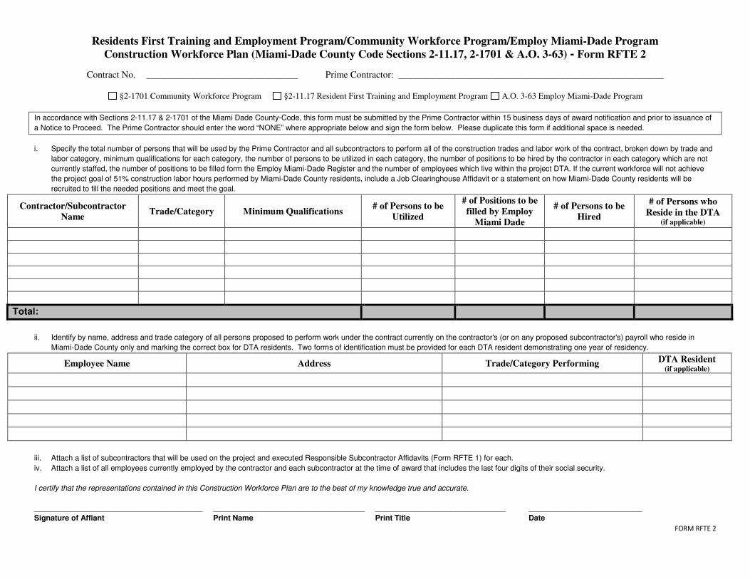
FORM RFTE 2
Residents First Training and Employment Program/Community Workforce Program/Employ Miami-Dade Program
Construction Workforce Plan (Miami-Dade County Code Sections 2-11.17, 2-1701 & A.O. 3-63) - Form RFTE 2
Contract No. ________________________________ Prime Contractor: ________________________________________________________
§2-1701 Community Workforce Program §2-11.17 Resident First Training and Employment Program A.O. 3-63 Employ Miami-Dade Program
In accordance with Sections 2-11.17 & 2-1701 of the Miami Dade County-Code, this form must be submitted by the Prime Contractor within 15 business days of award notification and prior to issuance of
a Notice to Proceed. The Prime Contractor should enter the word “NONE” where appropriate below and sign the form below. Please duplicate this form if additional space is needed.
i. Specify the total number of persons that will be used by the Prime Contractor and all subcontractors to perform all of the construction trades and labor work of the contract, broken down by trade and
labor category, minimum qualifications for each category, the number of persons to be utilized in each category, the number of positions to be hired by the contractor in each category which are not
currently staffed, the number of positions to be filled form the Employ Miami-Dade Register and the number of employees which live within the project DTA. If the current workforce will not achieve
the project goal of 51% construction labor hours performed by Miami-Dade County residents, include a Job Clearinghouse Affidavit or a statement on how Miami-Dade County residents will be
recruited to fill the needed positions and meet the goal.
Contractor/Subcontractor
Name Trade/Category Minimum Qualifications
# of Persons to be
Utilized
# of Positions to be
filled by Employ
Miami Dade
# of Persons to be
Hired
# of Persons who
Reside in the DTA (if applicable)
Total:
ii. Identify by name, address and trade category of all persons proposed to perform work under the contract currently on the contractor's (or on any proposed subcontractor's) payroll who reside in
Miami-Dade County only and marking the correct box for DTA residents. Two forms of identification must be provided for each DTA resident demonstrating one year of residency.
Employee Name Address Trade/Category Performing DTA Resident
(if applicable)
iii. Attach a list of subcontractors that will be used on the project and executed Responsible Subcontractor Affidavits (Form RFTE 1) for each.
iv. Attach a list of all employees currently employed by the contractor and each subcontractor at the time of award that includes the last four digits of their social security.
I certify that the representations contained in this Construction Workforce Plan are to the best of my knowledge true and accurate.
________________________________________ ____________________________________ _______________________________ ___________________________
Signature of Affiant Print Name Print Title Date

FORM RFTE 3
Residents First Training and Employment Program
Occupational Safety & Health Administration (OSHA)
10 Hour Safety Training Affidavit - Form RFTE 3
In accordance with Section 2-11.17 of the Miami-Dade County Code, all contractors and subcontractors of any tier performing on a County Construction Contract, shall satisfy the requirements of the Miami-Dade County Residents First Training and Employment Program which requires: for (i) all persons employed by the contractor to perform construction shall have completed the Occupational Safety & Health Administration (OSHA) 10 Hour safety training course established by the Occupational Safety & Health Administration of the United States Department of Labor
The undersigned verifies that every employee reported on the payroll has completed the OSHA 10 Hour
or OSHA 30 Hour Safety Training Course prior to working on the project.
________________________________________________________ Project Number, Title
______________________________ _______________________ _________________________ Printed Name of Affiant Printed Title of Affiant Signature of Affiant __________________________________________________ ________________________________ Name of Firm Date _______________________________________ ______________________ ___________________ Address of Firm State Zip Code
Notary Public Information
Notary Public – State of ______________________________ County of ________________________ Subscribed and sworn to (or affirmed) before me this _________day of, ___________________ 20____. by ______________________ He or she is personally known to me □ or has produced identification □ Type of identification produced __________________________________________________________ __________________________________________ ________________________________ Signature of Notary Public Serial Number __________________________________ ______________________ ______________________ Print or Stamp of Notary Public Expiration Date Notary Public Seal

FORM RFTE 4
Residents First Training and Employment Program/Employ Miami-Dade Program
Workforce Performance Report - Form RFTE 4
(Miami-Dade County Code Section 2-11.17 & A.O. 3-63)
Contract No. ______________________ Prime Contractor: ________________________________________
In accordance with Section 2-11.17 of the Miami-Dade County Code & A.O. 3-63, this report must be submitted by the Prime Contractor within thirty (30) days of completion of a County Capital Construction Contract to Small Business Development through the Contracting Officer. The Contracting Officer shall not authorize issuance of final payment for completion of a County Capital Construction Contract until the County receives a completed Workforce Performance Report.
Please provide the following information on the workforce employed in the execution of the contract: __________ Total number of Construction Labor positions utilized on the project __________ Total number of Construction Labor work hours performed on the project __________ Total number Construction Labor work hours performed by Miami-Dade County residents __________ Total number Construction Labor positions performed by Employ Miami-Dade participants __________ Percentage of Construction Labor work hours performed by Miami-Dade County residents
Attach supporting documentation verifying construction labor work hours performed by Miami-Dade County residents & Employ Miami-Dade participants. $______ Total amount of funds expended during the course of the project on other related skill and safety
training programs Were any positions on this project filled with new hires? _____ Yes ______ No If you answered “yes” to the above question, please identify the new hires by name, address and trade category, and indicate whether they were Miami-Dade County residents or an Employ Miami-Dade participant. (Please attach additional sheets if necessary.)
Employee Name Address Trade/Category
Performed
Miami-Dade
County Resident
(√)
Employ Miami-Dade
County Participant
(√)
Were all new hires Miami-Dade County residents? _____ No ______ Yes _____ Was the 20% labor workforce threshold met from the Employ Miami-Dade Register? _____ No ______ Yes If you answered “no” to either of the above questions, please attach supporting documentation that verifies reasonable efforts to promote employment opportunities for local residents including participation in the Employ Miami-Dade Program, which shall include applicable advertisements in local newspapers, posting of job opportunities with CareerSource South Florida’s Job Clearinghouse, referrals received from CareerSource South Florida, job applications received, candidates interviewed, and number of new hires. I certify that the representations contained in this Construction Workforce Plan are to the best of my knowledge true and accurate.
________________________________________ ____________________________________ ___________________________
Signature of Affiant Print Name, Title Date

SECTION 6: SPECIFICATIONS

GENERAL REQUIREMENTS
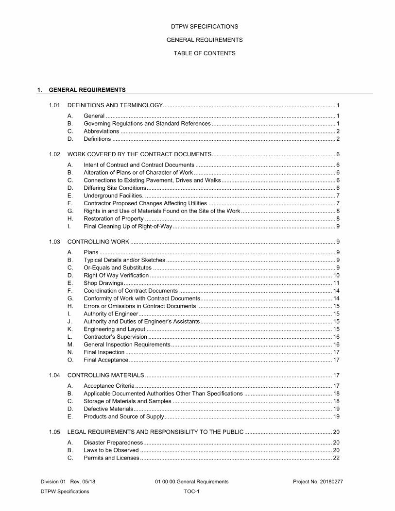
Division 01 Rev. 05/18 01 00 00 General Requirements Project No. 20180277
DTPW Specifications TOC-1
DTPW SPECIFICATIONS
GENERAL REQUIREMENTS
TABLE OF CONTENTS
1. GENERAL REQUIREMENTS
1.01 DEFINITIONS AND TERMINOLOGY .......................................................................................................... 1
A. General ............................................................................................................................................. 1 B. Governing Regulations and Standard References ............................................................................ 1 C. Abbreviations .................................................................................................................................... 2 D. Definitions ......................................................................................................................................... 2
1.02 WORK COVERED BY THE CONTRACT DOCUMENTS ............................................................................ 6
A. Intent of Contract and Contract Documents ...................................................................................... 6 B. Alteration of Plans or of Character of Work ....................................................................................... 6 C. Connections to Existing Pavement, Drives and Walks ...................................................................... 6 D. Differing Site Conditions .................................................................................................................... 6 E. Underground Facilities. ..................................................................................................................... 7 F. Contractor Proposed Changes Affecting Utilities .............................................................................. 7 G. Rights in and Use of Materials Found on the Site of the Work .......................................................... 8 H. Restoration of Property ..................................................................................................................... 8 I. Final Cleaning Up of Right-of-Way .................................................................................................... 9
1.03 CONTROLLING WORK .............................................................................................................................. 9
A. Plans ................................................................................................................................................. 9 B. Typical Details and/or Sketches ........................................................................................................ 9 C. Or-Equals and Substitutes ................................................................................................................ 9 D. Right Of Way Verification ................................................................................................................ 10 E. Shop Drawings ................................................................................................................................ 11 F. Coordination of Contract Documents .............................................................................................. 14 G. Conformity of Work with Contract Documents ................................................................................. 14 H. Errors or Omissions in Contract Documents ................................................................................... 15 I. Authority of Engineer ....................................................................................................................... 15 J. Authority and Duties of Engineer’s Assistants ................................................................................. 15 K. Engineering and Layout .................................................................................................................. 15 L. Contractor’s Supervision ................................................................................................................. 16 M. General Inspection Requirements ................................................................................................... 16 N. Final Inspection ............................................................................................................................... 17 O. Final Acceptance. ............................................................................................................................ 17
1.04 CONTROLLING MATERIALS ................................................................................................................... 17
A. Acceptance Criteria ......................................................................................................................... 17 B. Applicable Documented Authorities Other Than Specifications ...................................................... 18 C. Storage of Materials and Samples .................................................................................................. 18 D. Defective Materials .......................................................................................................................... 19 E. Products and Source of Supply ....................................................................................................... 19
1.05 LEGAL REQUIREMENTS AND RESPONSIBILITY TO THE PUBLIC ...................................................... 20
A. Disaster Preparedness .................................................................................................................... 20 B. Laws to be Observed ...................................................................................................................... 20 C. Permits and Licenses ...................................................................................................................... 22
Division 01 Rev. 05/18 01 00 00 General Requirements Project No. 20180277
DTPW Specifications TOC-2
D. Patented Devices, Materials and Processes .................................................................................... 23 E. Right-of-Way Furnished by the Department ..................................................................................... 23 F. Sanitary Provisions .......................................................................................................................... 23 G. Control of Contractor’s Equipment ................................................................................................... 23 H. Contractor’s Equipment on Bridge Structures .................................................................................. 24 I. Structures over Navigable Waters ................................................................................................... 24 J. Manatee Protection .......................................................................................................................... 24 K. Forest Protection ............................................................................................................................. 25 L. Preservation of Property .................................................................................................................. 25 M. Responsibility for Damages, Claims, etc. ......................................................................................... 28 N. Contractor’s Responsibility for Work ................................................................................................ 28 O. Opening Sections of Roadway to Traffic .......................................................................................... 28 P. Scales for Weighing Materials ......................................................................................................... 28 Q. Source of Forest Products ............................................................................................................... 28 R. Dust Control ..................................................................................................................................... 28 S. Dredging and Filling ......................................................................................................................... 29 T. Contractor’s Motor Vehicle Registration ........................................................................................... 29 U. Compliance with FHWA 1273: ......................................................................................................... 29
1.06 PROSECUTION AND PROGRESS ........................................................................................................... 29
A. Subletting Or Assigning The Contract .............................................................................................. 29 B. Notice to Proceed ............................................................................................................................ 29 C. Project Signs .................................................................................................................................... 29 D. Schedule Of Values ......................................................................................................................... 30 E. Preconstruction Conference ............................................................................................................ 30 F. Scheduling of the Work .................................................................................................................... 30 G. Progress of the Work. ...................................................................................................................... 32 H. Performance of Work ....................................................................................................................... 33 I. As-Built Drawings ............................................................................................................................ 34 J. Liquidated Damages ........................................................................................................................ 34 K. Limitations of Operations ................................................................................................................. 34 L. Qualifications of Contractor’s Personnel .......................................................................................... 36 M. Temporary Suspension of Contractor’s Operations ......................................................................... 36 N. Computation of Contract Time ......................................................................................................... 37 O. Default and Termination of Contract ................................................................................................ 38 P. Release of Contractor’s Responsibility ............................................................................................ 40
1.07 MEASUREMENT AND PAYMENT ............................................................................................................ 40
A. Compensation .................................................................................................................................. 40 B. Contingency Allowance Account ...................................................................................................... 40 C. Florida Power And Light Connection Allowance .............................................................................. 40 D. Retainage; Punch List Requirements .............................................................................................. 40 E. Measurement of Quantities .............................................................................................................. 41 F. Bituminous Material ......................................................................................................................... 41 G. Lump Sum Quantities ...................................................................................................................... 42 H. Deleted Work ................................................................................................................................... 42 I. Partial Payments .............................................................................................................................. 42 J. Record of Construction Materials ..................................................................................................... 43 K. Recovery Rights, Subsequent to Final Payment .............................................................................. 43

Division 01 Rev. 05/18 01 00 00 General Requirements Project No. 20180277
DTPW Specifications Page 1 of 43
1. GENERAL REQUIREMENTS
1.01 DEFINITIONS AND TERMINOLOGY
A. General
1. These Specifications are written to the bidders, prior to award of the Contract, and to Contractor.
2. Where sentences directing work or other action appear in the active voice-imperative mood, without a subject, the subject “bidder” or “Contractor” is understood. In any other case where the subject is not clearly understood, Engineer will make a clarification and final determination as to the subject of the action.
B. Governing Regulations and Standard References
1. The following Standards and Governing Regulations, as amended by the Contract Documents, are hereby incorporated by reference:
a. Building Code as set forth in Chapter 8 of the Code of Miami-Dade County.
b. Public Works Manual of Metropolitan Dade County (Public Works Manual).
c. United States Department of Justice’s 2010 ADA Standards For Accessible Design
d. Miami-Dade County’s Traffic Control Equipment Specifications and Standards for The Metro Traffic Control System Miami-Dade County (TCESS).
e. Florida Department of Transportation's Standard Plans for Road and Bridge Construction (FDOT Standard Plans).
http://www.fdot.gov/design/standardplans/SPRBC.shtm
f. Florida Department of Transportation Standard Specifications for Road and Bridge Construction (Divisions II & III), Special Provisions and Supplemental Specifications
http://www.fdot.gov/programmanagement/Implemented/SpecBooks/default.shtm
g. Florida Department of Transportation Surveying and Mapping Procedure
http://fdotwp1.dot.state.fl.us/ProceduresInformationManagementSystemInternet/FormsAndProcedures/ViewDocument?topicNum=550-030-101
h. Florida Department of Transportation Drainage Manual
http://www.fdot.gov/roadway/Drainage/Manualsandhandbooks.shtm
i. Florida Department of Transportation Soils and Foundations Handbook
http://www.fdot.gov/structures/DocsandPubs.shtm
j. Florida Department of Transportation Structures Manual
http://www.fdot.gov/structures/DocsandPubs.shtm
k. Florida Department of Transportation Current Structures Design Bulletins
http://www.fdot.gov/structures/Memos/currentbulletins.shtm
l. Manual on Uniform Traffic Control Devices (MUTCD)
https://mutcd.fhwa.dot.gov/
m. Safe Mobility For Life Program Policy Statement
http://www.fdot.gov/traffic/TrafficServices/SafetyisGolden.shtm
n. Florida Department of Transportation American with Disabilities Act (ADA) Compliance
http://www.fdot.gov/roadway/ada/
o. Florida Department of Transportation Florida Sampling and Testing Methods
http://www.fdot.gov/materials/administration/resources/library/publications/fstm/disclaimer.shtm
p. Florida Department of Transportation Flexible Pavement Coring and Evaluation Procedure
http://www.fdot.gov/materials/administration/resources/library/publications/materialsmanual/documents/v1-section32-clean.pdf
q. Florida Department of Transportation Design Bulletins and Update Memos
http://www.fdot.gov/roadway/Bulletin/
r. Florida Department of Transportation Utility Accommodation Manual
http://www.fdot.gov/programmanagement/utilities/default.shtm
s. Florida Department of Transportation Flexible Pavement Design Manual
http://www.fdot.gov/roadway/pm/pcs/flexiblepavementmanual.pdf
t. Florida Department of Transportation Rigid Pavement Design Manual
http://www.fdot.gov/roadway/pm/pcs/rigidpavementmanual.pdf
u. Florida Department of Transportation Pavement Type Selection Manual
http://www.fdot.gov/roadway/pm/Publications/PTSM.pdf
v. Florida Department of Transportation Traffic Engineering Manual
http://www.fdot.gov/traffic/trafficservices/Studies/TEM/TEM.shtm
w. Florida Department of Transportation Bicycle and Pedestrian Policies and Standards
http://www.fdot.gov/roadway/bikeped/default.shtm
x. Federal Highway Administration Hydraulic Engineering Circular Number 18 (HEC 18).
https://www.fhwa.dot.gov/engineering/hydraulics/library_listing.cfm
y. Florida Department of Transportation Manual of Uniform Minimum Standards for Design,
Division 01 Rev. 05/18 01 00 00 General Requirements Project No. 20180277
DTPW Specifications Page 2 of 43
Construction and Maintenance for Streets and Highways (Florida Greenbook)
http://www.fdot.gov/roadway/floridagreenbook/fgb.shtm
z. Florida Department of Transportation Project Development and Environment Manual, Parts 1 and 2
http://www.fdot.gov/environment/pubs/pdeman/pdeman1.shtm
aa. Florida Statutes
http://www.leg.state.fl.us/statutes/
bb. Miami-Dade County and Local Municipal Ordinances.
2. The above list is not all inclusive and it is the responsibility of Contractor to comply with all applicable requirements whether included in this list or not. Additional project-specific criteria are provided throughout the Contract Documents
3. The above referenced Standards are intended to supplement, not supersede the requirements set forth herein and, unless otherwise noted, the latest revision shall apply. Where differences occur between referenced Standards and these Contract Documents, the more stringent shall apply unless otherwise noted in the Contract Documents or directed by Engineer in writing.
4. FDOT Standard Specifications.
a. FDOT Standard Specifications for Road and Bridge Construction (Divisions II & III), as amended by the Contract Documents, apply to an Article within these Specifications when:
1) The applicable FDOT Standard Specification Section (e.g. FDOT SECTION 415) is referenced in the title of the Article; or
2) The FDOT Standard Specification section, article, or subarticle is referenced within the Article (e.g. FDOT Section 415, FDOT 415-3; FDOT 415-5.1, etc.)
b. Unless otherwise specified, where page numbers are used in these Specifications to reference modifications to the FDOT Standard Specifications, it shall be understood to reference the 2007 edition.
C. Abbreviations
The following abbreviations, when used in the Contract Documents, represent the full text shown.
AAN American Association of Nurserymen, Inc. AASHTO American Association of State Highway
and Transportation Officials ACI American Concrete Institute AGC The Associated General Contractors of
America, Inc. AGMA American Gear Manufacturers Association AIA American Institute of Architects. AISI American Iron and Steel Institute ANSI American National Standards Institute, Inc.APL FDOT Approved Product List
AREA American Railway Engineering Association
ASCE American Society of Civil EngineersASME American Society of Mechanical Engineers ASTM American Society for Testing and MaterialsAWG American Wire Gauge AWPA American Wood Preservers AssociationAWS American Welding Society AWWA American Water Works AssociationCFR Code of Federal Regulations CRSI Concrete Reinforcing Steel InstituteEASA Electrical Apparatus Service AssociationEPA Environmental Protection Agency of the
United States Government F.A.C. Florida Administrative CodeFBC Florida Building Code FDEP Florida Department of Environmental
Protection FDOT Florida Department of TransportationFHWA Federal Highway Administration FM Florida Method or Florida Sampling and
Testing Method F.S. Florida Statutes FSS Federal Specifications and Standards IEEE Institute of Electrical and Electronics
Engineers IES Illuminating Engineering SocietyIMSA International Municipal Signal Association IPCEA Insulated Power Cable Engineers
Association ISO International Organization for StandardsMDC Miami-Dade County MSTCSD Minimum Specifications for Traffic Control
Signals and Devices NAM Negotiated Acceptance MemorandumMUTCD Manual on Uniform Traffic Control DevicesNEC National Electrical Code NEMA National Electrical Manufacturers
Association NESC National Electrical Safety CodeNFPA National Fire Protection Association NIST National Institute for Standards and
Technology NOAA National Oceanic and Atmospheric
Administration NSF NSF International OSHA Occupational Safety and Health
Administration PCA Portland Cement Association DTPW Miami-Dade County Department of
Transportation and Public Works SAE Society of Automotive EngineersSBE-CONST
Small Business Enterprise-Construction
SI International System of UnitsSSPC Society of Protective CoatingsTSSQPL Traffic Signals and Signs Qualified
Products List UL Underwriters' Laboratories U.S.C. United States Code
D. Definitions
The following terms, when used in the Specifications, have the meaning described.

Division 01 Rev. 05/18 01 00 00 General Requirements Project No. 20180277
DTPW Specifications Page 3 of 43
1. Article. The numbered prime subdivision of a Division of these Specifications.
2. Bracing. A temporary structural member(s) placed between beams, girders, piles columns, etc. to provide stability during construction activities.
3. Bridge. A structure, including supports, erected over a depression or over an obstruction such as water, highway or railway, or for elevated roadway, for carrying traffic or other moving loads, and having a length, measured along the center of the roadway, of more than 20 feet between the inside faces of end supports. A multiple-span box culvert is considered a bridge, where the length between the extreme ends of the openings exceeds 20 feet.
4. Calendar day. Every day shown on the calendar, ending and beginning at midnight. Unless otherwise stipulated in the Contract Documents, the term “days” shall be understood as calendar days. In computing any period of time prescribed or allowed by this Contract, the day of the act, event, or default from which the designated period of time begins to run shall not be included. The last day of the period so computed shall be included unless it is a Saturday, Sunday, or legal holiday, in which event the period shall run until the end of the next day which is neither a Saturday, Sunday, or legal holiday. When the period of time prescribed or allowed is less than 7 days, intermediate Saturdays, Sundays, and legal holidays shall be excluded in the computation.
5. Construction Affecting Public Safety. Construction that may jeopardize public safety such as structures spanning functioning vehicular roadways, pedestrian walkways, railroads, navigation channels of navigable waterways and walls or other structure foundations located in embankments immediately adjacent to functioning roadways. It does not apply to those areas of the site under Contractor’s control and outside the limits of normal public access.
6. Contract. The term “Contract” means the entire and integrated agreement between the parties thereunder and supersedes all prior negotiations, representations, or agreements, either written or oral. The executed Contract Documents form the Contract between the Department (on behalf of the County) and Contractor setting forth the obligations of the parties thereunder, including, but not limited to, the performance of the Work and the basis of payment.
7. Contract Documents. Consists of those items so designated in and inclusive of the executed Contract. Only printed or hard copies of the items listed in the executed Contract Form are Contract Documents.
8. Contract Time. The maximum number of calendar days, including authorized time extensions, allowed for final completion of all Contract work and requirements. Also called Contract Duration.
9. Contract Unit Price. Refers to the Unit Price provided by the Contract that is fixed at time of Contract award.
10. Contractor. The individual, firm, joint venture, or company contracting with the County to perform the Work pursuant to the Contract.
11. Contractor’s Engineer of Record.
a. A Professional Engineer registered in the State of Florida, other than the Engineer of Record or his subcontracted consultant, who undertakes the design and drawing of components of the permanent structure as part of a redesign, or for repair designs and details of the permanent work. Contractor’s Engineer of Record may also serve as the Specialty Engineer.
b. Contractor’s Engineer of Record must be an employee of a pre-qualified firm. The firm shall be pre-qualified in accordance with the Rule 14-75, F.A.C. Any Corporation or Partnership offering engineering services must hold a Certificate of Authorization from the Florida Board of Professional Engineers.
c. As an alternate to being an employee of a pre-qualified firm, Contractor’s Engineer of Record may be a pre-qualified Specialty Engineer. For items of the permanent Work declared by the FDOT Construction Office to be ”major” or “structural”, the work performed by a pre-qualified Specialty Engineer must be checked by another pre-qualified Specialty Engineer. An individual Engineer may become pre-qualified in the work groups listed in Rule 14-75, F.A.C., if the requirements for the Professional Engineer are met for the individual work groups. Pre-qualified Specialty Engineers are listed on the FDOT Construction Office website. Pre-qualified Specialty Engineers will not be authorized to perform redesigns of items fully detailed in the Plans.
12. Contractor Originated Designs. Items which the Contract Documents require Contractor to design, detail and incorporate into the permanent works.
13. Controlling Work Items. The activity or work item on the critical path having the least amount of total float. The controlling item of work will also be referred to as a Critical Activity.
14. County. Miami-Dade County, Florida.
15. Culverts. Any structure not classified as a bridge that provides an opening under the roadway.
16. Department. Miami-Dade County Department of Transportation and Public Works.
17. Engineer. The County Engineer, acting directly or through duly authorized representatives; such representatives acting within the scope of the duties and authority assigned to them.
a. Note: In order to avoid cumbersome and confusing repetition of expressions in these Specifications, it is provided that whenever anything is, or is to be done, if, as, or, when, or where “acceptable, accepted, approval, approved, authorized, condemned, considered necessary, contemplated, deemed necessary, designated, determined, directed, disapproved, established, given, indicated, insufficient, ordered, permitted, rejected, required, reserved, satisfactory, specified, sufficient, suitable,
Division 01 Rev. 05/18 01 00 00 General Requirements Project No. 20180277
DTPW Specifications Page 4 of 43
suspended, unacceptable, or unsatisfactory,” it shall be understood as if the expression were followed by the words “by Engineer,” “by the Engineer,” “to the Engineer,” or “of the Engineer.”
18. Engineer of Record. The Professional Engineer or Engineering Firm registered in the State of Florida that develops the criteria and concept for the project, performs the analysis, and is responsible for the preparation of the Plans and Specifications. The Engineer of Record may be Departmental in-house staff or a consultant retained by the Department. Contractor shall not employ the Engineer of Record as Contractor’s Engineer of Record or as a Specialty Engineer.
19. Equipment. The machinery and equipment, together with the necessary supplies for upkeep and maintenance thereof, and all other tools and apparatus necessary for the construction and acceptable completion of the work.
20. Extra Work. Any “work” which is required by Engineer to be performed and which is not otherwise covered or included in the project by the existing Contract Documents, whether it be in the nature of additional work, altered work, deleted work, work due to differing site conditions, or otherwise. This term does not include a “delay”.
21. Falsework. Includes any temporary construction work used to support the permanent structure until it becomes self-supporting. Falsework includes steel or timber beams, girders, columns, piles and foundations, and any proprietary equipment including modular shoring frames, post shores, and adjustable horizontal shoring.
22. Formwork. Includes any structure or mold used to retain plastic or fluid concrete in its designated shape until it hardens. Formwork comprises common materials such as wood or metal sheets, battens, soldiers and walers, ties, proprietary forming systems such as stay-in-place metal forms, and proprietary supporting bolts, hangers and brackets. Formwork may be either permanent formwork requiring a shop drawing submittal such as stay-in-place metal or concrete forms, or may be temporary formwork which requires certification by the Specialty Engineer for Construction Affecting Public Safety and for Major and Unusual Structures.
23. Highway, Street, or Road. A general term denoting a public way for purposes of vehicular travel, including the entire area within the right-of-way.
24. Holidays. Days designated by Miami-Dade County as holidays, which include, but are not limited to, New Year’s Day, Martin Luther King’s Birthday, President’s Day, Memorial Day, Independence Day, Labor Day, Columbus Day, Veterans Day, Thanksgiving Day and the following Friday, and Christmas Day.
25. Inspector. An authorized representative of the Engineer, assigned to make official inspections of the materials furnished and of the work performed by Contractor.
26. Laboratory. The official testing laboratory authorized by the Department.
27. Major and Unusual Structures: Bridges of complex geometry and/or complex design. Generally, this includes the following types of structures:
a. Bridges with an individual span longer than 300 feet.
b. Structurally continuous superstructures with spans over 150 feet.
c. Steel box and plate girder bridges.
d. Steel truss bridges.
e. Concrete segmental and longitudinally post-tensioned continuous girder bridges.
f. Cable stayed or suspension bridges.
g. Arch bridges.
h. Tunnels.
i. Movable bridges (specifically electrical and mechanical components).
j. Rehabilitation, widening, or lengthening of any of the above.
28. Major Item of Work. Any item of work having an original Contract value in excess of 5% of the original Contract amount.
29. Materials. Any substances to be incorporated in the work under the Contract.
30. Median. The portion of a divided highway or street separating the traveled ways for traffic moving in opposite directions.
31. Permanent Works. All the permanent structures and parts thereof required of the completed Contract.
32. Plans. The part of the Contract Documents prepared or approved by the Engineer, including reproductions thereof, which graphically shows or supplements the scope, extent, and character of the Work to be performed by Contractor. Whenever the word "Plans" appears in these Contract Documents, it shall include any related drawings or standard details referenced by the Contract Documents.
33. Right-of-Way. The land that the Department has title to, or right of use, for the road and its structures and appurtenances, and for material pits furnished by the Department.
34. Roadbed. The portion of the roadway occupied by the subgrade and shoulders.
35. Roadway. The portion of a highway within the limits of construction.
36. Scaffolding. An elevated work platform used to support workmen, materials and equipment, but not intended to support the structure.
37. Section. A numbered prime division of these Specifications.
38. Shop Drawings. All working, shop and erection drawings, associated trade literature, calculations, schedules, manuals and similar documents submitted by Contractor to define some portion of the Work. The

Division 01 Rev. 05/18 01 00 00 General Requirements Project No. 20180277
DTPW Specifications Page 5 of 43
Work may include both permanent and temporary works as appropriate to the Project. Shop Drawings and other contractor submittals are not Plans as so defined.
39. Shoring. A component of falsework such as horizontal, vertical or inclined support members. In this Section, this term is interchangeable with falsework.
40. Special Erection Equipment. Includes launching gantries, beam and winch equipment, form travelers, stability towers, strong-backs, erection trusses, launching noses or similar items made purposely for construction of the structure. It does not apply to commonly available proprietary construction equipment such as cranes.
41. Special Provisions. Project specific clauses adopted by the Department that add to or revise these Specifications and associated supplemental specifications, or provide other requirements applicable to the Contract.
42. Specialty Engineer.
a. A Professional Engineer registered in the State of Florida, other than the Engineer of Record or his subcontracted consultant, who undertakes the design and drawing preparation of components, systems, or installation methods and equipment for specific temporary portions of the Work or for special items of the permanent works not fully detailed in the plans and required to be furnished by Contractor such as but not limited to pot bearing designs, non-standard expansion joints, mechanically stabilized earth wall designs and other specialty items. The Specialty Engineer may also provide designs and details for items of the permanent work declared by the FDOT Construction Office to be “minor” or “non-structural”. The Specialty Engineer may be an employee or officer of Contractor or a fabricator, an employee or officer of an entity providing components to a fabricator, or an independent consultant.
b. For items of work not specifically covered by Rule 14-75, F.A.C., a Specialty Engineer is qualified if he has the following qualifications:
1) Registration as a Professional Engineer in the State of Florida.
2) The education and experience necessary to perform the submitted design as required by the Florida Board of Professional Engineers.
43. Specifications. The directions, provisions, and requirements contained herein, together with all stipulations contained in the Contract Documents, setting out or relating to the method and manner of performing the work, or to the quantities and qualities of materials and labor to be furnished under the Contract.
44. State. State of Florida.
45. Structure. Any waterworks, drainage works, sewage works, river works, earthworks or constructions of any kind, including those of earth or rock, permanent or temporary, and including bridges, dam, wall, caisson,
mast, tower, pylon, underground tank, earth retaining elements or assembly of elements, formwork, falsework, scaffold, fences, poles, buildings, pavings, inlets, levees, tide gates, spillways, drop structures, any structure similar to the foregoing, and any other form of building, construction, arrangement of parts, elements, or materials found in structures.
46. Subarticle. A prime subdivision of an Article of these Specifications.
47. Subgrade. The portion of the roadbed immediately below the base course or pavement, including below the curb and gutter, valley gutter, shoulder and driveway pavement. The subgrade limits ordinarily include those portions of the roadbed shown in the plans to be constructed to a design bearing value or to be otherwise specially treated. Where no limits are shown in the plans, the subgrade section extends to a depth of 12 inches below the bottom of the base or pavement and outward to 6 inches beyond the base, pavement, or curb and gutter.
48. Substantial Completion. The time and date at which the Work has progressed to the point where, in the opinion of Engineer, the Work is sufficiently complete, in accordance with the Contract Documents, so that the Work can be occupied and/or utilized for the purposes for which it is intended. Substantial Completion cannot occur before the Project is issued a Certificate of Occupancy (or Completion, if applicable) by the Department that allows the County to utilize the entire Project for the purposes for which it is intended. Substantial completion on roadway projects includes completion and operation of traffic signals, street lighting and completion of landscape items.
49. Substructure. All of that part of a bridge structure below the bridge seats, including the parapets, backwalls, and wingwalls of abutments.
50. Superintendent. Contractor’s authorized representative in responsible charge of the work.
51. Superstructure. The entire bridge structure above the substructure, including anchorage and anchor bolts, but excluding the parapets, backwalls, and wingwalls of abutments.
52. Surety. The corporate body that is bound by the Contract Bond with and for Contractor and responsible for the performance of the Contract and for payment of all legal debts pertaining thereto.
53. Temporary Works. Any temporary construction work necessary for the construction of the permanent works. This includes but is not limited to bracing, falsework, formwork, scaffolding, shoring, temporary earthworks, sheeting, cofferdams, and special erection equipment.
54. Traveled Way. The portion of the roadway providing for the movement of vehicles, exclusive of shoulders and auxiliary lanes.
55. Traffic Control Signals and Devices. Any signal or device, manually, electrically or mechanically operated, by which traffic is alternately directed to stop and permitted to proceed or controlled in any manner.
Division 01 Rev. 05/18 01 00 00 General Requirements Project No. 20180277
DTPW Specifications Page 6 of 43
Traffic control signals and devices regulate, warn, or guide traffic on, over or adjacent to a street, highway, pedestrian facility, or bikeway by authority of a public agency having jurisdiction. Traffic control signals and devices include, but are not limited to, controller assemblies (controller cabinets and their contents); signal heads including their hanging or mounting devices; vehicle detection systems (loops, sealant, amplifier, lead-in wire, or cable); pedestrian detection systems (push button, push button housing, lead-in wires, and signal); motorist information systems, video equipment, network devices, dynamic message signs, highway advisory radios, cameras, vehicle detection systems, and other equipment used within a traffic control system.
56. Underground Facilities. All underground pipelines, conduits, ducts, cables, wires, manholes, vaults, tanks, tunnels, or other such facilities or attachments, and any encasements containing such facilities, including those that convey electricity, gases, steam, liquid petroleum products, telephone or other communications, cable television, water, wastewater, storm water, other liquids or chemicals, or traffic or other control systems.
57. Work. All labor, materials and incidentals required to execute and complete the requirements of the Contract including superintendence, use of equipment and tools, and all services and responsibilities prescribed or implied.
58. Working Day. Any calendar day on which Contractor works or is expected to work in accordance with the approved work progress schedule.
1.02 WORK COVERED BY THE CONTRACT DOCUMENTS
A. Intent of Contract and Contract Documents
1. The intent of the Contract and Contract Documents is to describe a functionally complete project (or part thereof) to be constructed, and to provide for the construction and completion in every detail of the Work described therein.
2. The intent of the Contract is for Contractor to provide, at no additional cost to the County, all labor, documentation, services, materials, equipment, tools, transportation, and supplies that are:
a. Necessary to complete the Work in accordance with the Contract Documents.
b. Reasonably inferred and incidental to the Work, whether or not specifically called for by the Contract Documents.
B. Alteration of Plans or of Character of Work
1. Engineer reserves the right to make, at any time prior to or during the progress of the Work, such increases or decreases in quantities, whether a significant change or not, and such alterations in the details of construction, whether a substantial change or not, including but not limited to alterations in the grade or alignment of the road or structure or both, as may be
found necessary or desirable by the Engineer. The term “significant change” applies only when the Engineer determines that the character of the work, as altered, differs materially from that involved or included in the original proposed construction.
2. Such increases, decreases or alterations shall not constitute a breach of Contract, shall not invalidate the Contract, nor release the Surety from any liability arising out of this Contract or the Surety bond. Contractor agrees to perform the work, as altered, the same as if it had been a part of the original Work.
3. The Department may require work that is not covered by a price in the Contract if the Department determines that such work does not constitute a significant change and is essential to the satisfactory completion of the Contract within its intended scope. If an adjustment in price is warranted, Engineer will determine the basis of payment for such an adjustment in a fair and equitable amount and authorize the adjustment through an executed Negotiated Acceptance Memorandum (NAM) provided by the Department.
4. In the instance of an alleged significant change, Engineer will review all pertinent information provided by Contractor to determine the validity of the allegation. The determination by Engineer shall be conclusive and shall not be subject to challenge by Contractor in any forum, except upon Contractor establishing by clear and convincing proof that the determination by Engineer was without any reasonable and good-faith basis.
C. Connections to Existing Pavement, Drives and Walks
1. Adhere to the limits of construction at the beginning and end of the Project as detailed in the Contract Documents. However, if Engineer determines that it is necessary to extend the construction in order to make suitable connections to existing pavement, Engineer will authorize such a change.
2. For necessary connections to existing pavement, walks and drives that are not indicated on the Plans, Engineer will provide direction regarding the proper connections in accordance with the applicable Standards.
D. Differing Site Conditions
1. During the progress of the Work, if subsurface or latent physical conditions are encountered at the site differing materially from those indicated in the Contract Documents, or if unknown physical conditions of an unusual nature differing materially from those ordinarily encountered and generally recognized as inherent in the work provided for in the Contract are encountered at the site, the party (County or Contractor) discovering such conditions shall promptly notify the other party in writing of the specific differing conditions before Contractor disturbs the conditions or performs the affected work.
2. Upon receipt of written notification of differing site conditions from Contractor, Engineer will investigate the conditions. If Engineer determines that the
Division 01 Rev. 05/18 01 00 00 General Requirements Project No. 20180277
DTPW Specifications Page 7 of 43
conditions materially differ and cause an increase or decrease in the cost or time required for the performance of any work under the Contract, an adjustment will be made, excluding loss of anticipated profits, and the Contract will be modified in writing accordingly. Engineer will notify Contractor whether or not an adjustment of the Contract is warranted.
3. Contractor shall not be entitled to any adjustment in the Contract Price or Contract Times if:
a. Contractor knew of the existence of such conditions at the time Contractor made a final commitment to the County with respect to Contract Price and Contract Times by the submission of a Bid; or
b. The existence of such condition could reasonably have been discovered or revealed as a result of any examination, investigation, exploration, test, or study of the Site and contiguous areas required by the Bidding Requirements or Contract Documents to be conducted by or for Contractor prior to Contractor’s making a Bid; or
c. Contractor failed to give the written notice as required by this Article.
4. Engineer will not allow a Contract adjustment for a differing site condition unless Contractor has provided the required written notice.
5. Engineer will not allow a Contract adjustment under this clause for any effects caused to any other Department or non-Department projects on which Contractor may be working.
E. Underground Facilities.
1. It is generally recognized and Contractor should anticipate that information provided by utility owners during project design, frequently fails to disclose all Underground Facilities. The fact that more utility lines or other Underground Facilities are located in the Project Site than shown on the Project Plans does not constitute an unforeseen or differing Site Condition and such undisclosed Underground Facilities do not differ materially from the conditions which Contractor should expect.
2. Any information and data shown or indicated in the Contract Documents with respect to existing Underground Facilities at or contiguous to the Site is based on information and data furnished to the County design engineer by the owners of such Underground Utilities. Additional utilities may exist which are not shown in the Contract Documents. Unless it is otherwise expressly stated in the Special Provisions, the County is not responsible for the accuracy or completeness of any such information or data provided
3. Contractor is responsible for field verification and location of all Underground Facilities prior to the start of construction. No field work shall be allowed to start until Contractor has notified Sunshine State One-Call of Florida, Inc. and all affected utilities have been located. In addition, Contractor, without any additional compensation, must expose and physically locate all
potentially conflicting Underground Facilities prior to construction and is fully responsible for:
a. Reviewing and checking all Underground Facilities information and data;
b. Locating and verifying all Underground Facilities at or contiguous to the Site;
c. Coordination of the Work with the owners of such Underground Facilities, including the County, during construction; and
d. The safety and protection of all such Underground Facilities and repairing any damage thereto resulting from the Work.
4. The actual locations of the Underground Facilities must be compared to locations shown on the Plans and any required changes in alignment and grade must be made at the time of construction in consultation with Engineer.
5. If an Underground Utilities is uncovered or revealed at or contiguous to the Site which was not shown or indicated, or not shown or indicated with reasonable accuracy in the Contract Documents:
a. Identify the owner of such Underground Facilities and give written notice to that owner and to Engineer promptly after becoming aware thereof and before further disturbing conditions affected thereby or performing any Work in connection therewith. During such time, Contractor shall be responsible for the safety and protection of such Underground Facility.
b. Engineer will promptly review the Underground Facilities and determine the extent, if any, to which a change is required in the Contract Documents to reflect and document the consequences of the existence or location of the Underground Facility. If Engineer determines that the conditions materially differ and cause an increase or decrease in the cost or time required for the performance of the Work, an adjustment will be made, excluding loss of anticipated profits, and the Contract will be modified in writing accordingly. Engineer will notify Contractor whether or not an adjustment of the Contract is warranted.
F. Contractor Proposed Changes Affecting Utilities
1. Contractor is responsible for identifying and assessing any potential impacts to a utility that may be caused by the changes proposed by Contractor, and Contractor must, at the time of making the request for a change, notify the Department in writing of any such potential impacts to utilities.
2. Department approval of a Contractor proposed change does not relieve Contractor of sole responsibility for all utility impacts, costs, delays or damages, whether direct or indirect, resulting from Contractor initiated changes in the design or construction activities from those in the original Contract Specifications, design plans (including traffic control plans) or other Contract Documents and which effect a change in utility work different from that shown
Division 01 Rev. 05/18 01 00 00 General Requirements Project No. 20180277
DTPW Specifications Page 8 of 43
in the utility plans, joint project agreements or utility relocation schedules.
G. Rights in and Use of Materials Found on the Site of the Work
1. Ownership and Disposal of Existing Materials: Unless otherwise directed by Engineer or elsewhere in the Contract Documents, take ownership and dispose of all materials that are not designated as the property of other parties, in both roadway and structures, found on the right-of-way, and all material in structures designated for removal. Such materials do not include earth or other excavated material required for the construction of the Project. During construction, Contractor may use materials from existing structures that are required to be removed and that are designated to remain the property of the Department. Do not cut or otherwise damage such material during removal unless Engineer gives permission to do so. Store material in an accessible location as Engineer directs. The Department is not responsible for the quality or quantity of any material salvaged.
2. Ornamental Trees and Shrubs: Take ownership of all ornamental trees or shrubs existing in the right-of-way that are required to be removed for the construction operations and which are not specifically designated on the Plans to be reset, relocated, or to be removed by others prior to the construction operations.
H. Restoration of Property
1. Take preconstruction videos/pictures of the entire work zone and adjacent areas.
2. Public or private property damaged during construction or removed for convenience of the Work must be repaired or replaced at Contractor's expense in a manner acceptable to Engineer, prior to final acceptance of the Work or sooner if otherwise required by the Contract Documents or Engineer. This includes, but is, not limited to signalization equipment and miscellaneous hardware removed from the construction site, signs, driveways, landscaping, sidewalk, walkways, walls, fences, footings, underground utilities, etc.
3. Contractor must comply with the requirements of Miami-Dade County Code Section 2-103.1 (b), CONSTRUCTION OF PUBLIC UTILITIES OR WORKS IN PUBLIC RIGHTS-OF-WAY
a. “Whenever any person, corporation, partnership, association, County Department or other legal entity performs any construction or public work within an existing right-of-way located within unincorporated Miami-Dade County, or in right-of-ways of roads or streets located within municipalities that are maintained by the County, the right-of-way, including sidewalks, curbs and gutters, landscaping and must be restored to their legally permissible preexisting condition, including any aesthetic enhancements thereto and any adjacent private property damaged during construction, within forty-five (45) days of completion of the construction or public work in
that right of way or within forty-five (45) days of damage to the affected property or area, whichever occurs first. Prior to the time such construction work begins, the contractor, by posting the construction site, shall inform the local community of the requirement to restore the right-of-way as well as any affected adjacent private property and the fines that could be imposed for each failure to do so. All work to be done pursuant to this Section shall be performed in compliance with the Public Works Manual. Any entity failing to restore the right-of-way to its preexisting condition or better within the time permitted shall be subject to a civil fine of five hundred dollars ($500.00) per violation per day until such time as the right-of-way is restored, as well as five hundred dollars ($500.00) per day for each affected adjacent private property until it is restored." Contractor may obtain a complete copy of the Ordinance from the Clerk of the Board.
b. Post the construction site pursuant to Miami-Dade County Code Section 2-103 (b). The Public Notice to be posted is to read as follows:
PUBLIC NOTICE ORDINANCE NO. 03-89
Contractor shall restore the right-of-way as well as any affected adjacent private property within 45
days of completion of construction or damage to the affected property or area, whichever occurs first.
Any entity failing to restore the right-of-way to its pre-existing condition or better within the time
promoted shall be subject to a civil fine of $500 per violation per day.
4. Survey monuments.
a. Upon completion of construction activities and prior to the expiration of the Contract:
1) Coordinate the replacement of any monument(s) disturbed or destroyed.
2) Submit to Engineer for review and approval, a survey report that includes all monuments replaced and all monuments impacted as a result of construction activities.
b. The replacement of monuments and the preparation of the survey report must be by a licensed Florida Surveyor and Mapper and meet all applicable State Rules, Statutes, and requirements of the Department. All costs required for compliance with these requirements will be included among the Contract pay items.
5. Failure to Restore Damaged Property:
a. In case of failure on the part of Contractor to restore such property, bridge, road or street, or to make good such damage or injury, Engineer may,

Division 01 Rev. 05/18 01 00 00 General Requirements Project No. 20180277
DTPW Specifications Page 9 of 43
upon 48 hours notice, proceed to repair, rebuild, or otherwise restore such property, road, or street as may be deemed necessary, and the Department will deduct the cost thereof from any monies due or which may become due Contractor under the Contract. Nothing in this clause prevents the Contractor from receiving proper compensation for the removal, damage, or replacement of any public or private property, not shown on the plans, that is made necessary by alteration of grade or alignment. Engineer will authorize such work, provided that Contractor, or his employees or agents, have not, through their own fault, damaged such property.
6. Work Site Clean-Up:
a. Debris and trash shall be removed from the site daily. Mow turf or vegetation within the project limits in accordance with Article 107 of the Construction Specifications.
b. Upon completion of all work specified herein at each work site and before acceptance and payment is made, Contractor shall remove from each work site all machinery, equipment, surplus and discarded materials, rubbish and temporary structures. Material cleared from site and deposited on adjacent property will not be considered as having been disposed of satisfactorily.
I. Final Cleaning Up of Right-of-Way
1. Upon completion of the Work, and before the Department accepts the Work and makes final payment, remove from the right-of-way and adjacent property all falsework, equipment, surplus and discarded materials, rubbish and temporary structures; restore in an acceptable manner all property, both public and private, that has been damaged during the prosecution of the work; and leave the waterways unobstructed and the roadway in a neat and presentable condition throughout the entire length of the work under Contract. Clean all areas impacted by the Work and remove sedimentation in drainage structures caused by the construction activities.
2. Do not dispose of materials of any character, rubbish or equipment, on abutting property, with or without the consent of the property owners. Engineer will allow Contractor to temporarily store equipment, surplus materials, usable forms, etc., on a well-kept site owned or leased by Contractor, adjacent to the Project. However, do not place or store discarded equipment, materials, or rubbish on such a site.
3. Shape, dress and restore areas adjacent to the Project right-of-way that were used as plant sites, materials storage areas or equipment yards when they are no longer needed for such purposes.
1.03 CONTROLLING WORK
A. Plans
1. Contract Documents: Have one complete copy of the Contract Documents available on the worksite at all times.
2. Department’s Plans: Unless otherwise labeled, all Items shown on the Plans are considered to be part of the Work, and must be incorporated into the Work and included in the established prices.
3. Alterations in Plans: The Department will issue, in writing, all authorized alterations affecting the requirements and information given on the approved plans.
B. Typical Details and/or Sketches
1. Typical details and/or sketches regarding the proposed work may be provided in addition to the standard details that are available in the Miami-Dade County Public Works Manual and the latest edition of the Florida Department of Transportation's Design Standards for Design, Construction, Maintenance and Utility Operations on The State Highway System.
2. County through its Engineer shall have the right to modify the details and/or sketches, to supplement the sketches with additional plans and/or with additional information as work proceeds; all of which shall be considered as plans accompanying these Specifications herein generally referred to as the "Plans.” In case of disagreement between the Plans and Specifications, Engineer will make a final determination as to which will govern.
C. Or-Equals and Substitutes
1. Except where specifically provided, whenever material or equipment is specified or described in the Contract Documents by proprietary name or as being available from a particular supplier, the intent is to establish the type, function, appearance, and quality required. A written request to Engineer to authorize an “or-equal” or “substitute” material or equipment may be submitted as described below unless the item specified or described contains or is followed by words reading that no like, equivalent, or “or-equal” item or no substitution is permitted.
a. Or-Equal Material or Equipment:
1) Material or equipment proposed by Contractor may be considered by Engineer as an “or equal” item if in Engineer’s sole discretion the item proposed is functionally equal and sufficiently similar to that specified or described in the Contract Documents and that no change in related Work will be required.
2) Contractor has the burden of proving at Contractor’s own cost and expense, to the satisfaction of Engineer, that the proposed item is equal to the named item. If Contractor fails to comply with the provisions of this Article, or if Engineer determines that the proposed item is not equal to that named, Contractor must supply the product named.
Division 01 Rev. 05/18 01 00 00 General Requirements Project No. 20180277
DTPW Specifications Page 10 of 43
3) For the purposes of this Article and at Engineer’s sole discretion, a proposed item of material or equipment will be considered functionally equal to the item specified or described in the Contract Documents if:
a) In the exercise of reasonable judgment Engineer determines that the proposed item is at least equal in materials of construction, quality, durability, appearance, strength, and design characteristics; will reliably perform at least equally well the function and achieve the results imposed by the design concept of the completed Project as a functioning whole; has a proven record of performance and availability of responsive service; and
b) Contractor certifies that, if approved and incorporated into the Work, there will be no increase in cost to the County or increase in Contract Times, and the proposed item will conform substantially to the detailed requirements of the item named in the Contract Documents.
b. Substitute Material or Equipment:
1) If in Engineer’s sole discretion an item of material or equipment proposed by Contractor does not qualify as an “or-equal” item, it may be proposed for consideration as a substitute item by Contractor submitting sufficient information as stipulated below to allow Engineer to determine that the item of material or equipment proposed is essentially equivalent to and an acceptable substitute for that named. Requirements pertaining to a proposed substitute item request for review by Engineer will be as set forth in this Article, as supplemented in the Contract Documents, and as Engineer may decide are appropriate under the circumstances.
2) Contractor must make written application to Engineer for review of a proposed substitute item of material or equipment that Contractor seeks to furnish or use. The application shall:
a) Certify that the proposed substitute item will perform adequately the functions and achieve the results called for by the general design, be similar in substance to that specified, and be suited to the same use as that specified;
b) State the extent, if any, to which the use of the proposed substitute item will prejudice Contractor’s achievement of Substantial Completion on time; whether or not use of the proposed substitute item in the Work will require a change in any of the Contract Documents to adapt the design to the proposed substitute item; and whether or not incorporation or use of the proposed substitute item in connection with the Work is subject to payment of any license fee or royalty;
c) Identify all variations of the proposed substitute item from that specified, and available engineering, sales, maintenance, repair, and replacement services;
d) Contain an itemized estimate of all costs or credits that will result directly or indirectly from use of such substitute item, including costs of redesign and claims of other contractors affected by any resulting change.
2. Substitute Construction Methods or Procedures: If a specific means, method, technique, sequence, or procedure of construction is expressly required by the Contract Documents, Contractor may furnish or utilize a substitute means, method, technique, sequence, or procedure of construction approved by Engineer. For Engineer approval, submit sufficient information to allow Engineer, in Engineer’s sole discretion, to determine that the substitute proposed is equivalent to that expressly called for by the Contract Documents. The requirements for review by Engineer will be as set forth in this Article, as supplemented in the Contract Documents, and as Engineer may decide are appropriate under the circumstances.
3. Engineer’s Evaluation: Engineer will be allowed a reasonable time within which to evaluate each proposal or submittal made pursuant to this Article and will be the sole judge of acceptability. Engineer may require Contractor to furnish additional data about the proposed substitute item. No “or equal” or substitute will be ordered, installed or utilized until Engineer’s review is complete, which will be evidenced by receipt from Engineer of either a written approval or Change order where required for a substitute; or an approved Shop Drawing or written approval for an “or equal.” Engineer will advise Contractor in writing of any negative determination. Contractor shall provide all data in support of any proposed substitute or “or-equal” at Contractor’s expense. County may require Contractor to furnish at Contractor’s expense a special performance guarantee or other surety with respect to any substitute item.
4. Engineer’s Cost Reimbursement: Engineer will record Engineer’s costs in evaluating a substitute proposed or submitted by Contractor pursuant to this Article whether or not Engineer approves a substitute item so proposed or submitted by Contractor, Contractor shall reimburse the County for the costs for evaluating each such proposed substitute. Contractor shall also reimburse the County for the costs of making changes in the Contract Documents from the acceptance of each proposed substitute.
D. Right Of Way Verification
1. All Work and improvements shall be performed, constructed and installed within the limits of the existing Right-of-Way pursuant to the Contract Documents.
2. Obtain all necessary documentation for verifying rights-of-way and property lines.
Division 01 Rev. 05/18 01 00 00 General Requirements Project No. 20180277
DTPW Specifications Page 11 of 43
3. Retain a Florida Registered Surveyor and Mapper to obtain right-of-way and property lines by examining available rights-of-way maps, plats, occupation, legal descriptions or other legal documents or means. The Surveyor will layout the required alignments and grades and be responsible for their accuracy.
4. All field notes on this Project must be kept in a dedicated field book. Submit all field books to Engineer once the Project is completed or prior to completion when a field book gets filled.
5. All costs for complying with these requirements are included under the several scheduled items of the overall Contract. Therefore, no separate payment will be made for this work.
E. Shop Drawings
1. Shop Drawings:
a. General. Prepare and submit whatever detailed working drawings necessary to fabricate, erect, and construct all parts of the Work in conformity with the Plans and Specifications. Shop drawings shall be submitted to Engineer; two sets will be returned to Contractor approved or showing the changes or corrections required; if changes or corrections are required, four revised copies shall be resubmitted until they are approved. Payment for shop drawings and required documents, revisions thereof, and for all copies furnished, shall be included in the various items of work bid. Contractor should allow a minimum of 14 days for the County's approval of shop drawings. County is not responsible for errors or minor discrepancies of Contractor's drawings, even though approved.
b. Work Items Requiring Shop Drawings: In general, the Department requires shop drawings for items of work not fully detailed in the plans which require additional drawings and coordination prior to constructing the item, including but not limited to:
1) Bridge components not fully detailed in the plans
2) Retaining Wall Systems
3) Precast Box Culverts
4) Non-standard lighting, signalization and signing structures and components
5) Building structures
6) Drainage structures, attenuators, and other nonstructural items
7) Design and structural details furnished by Contractor in compliance with the Contract
8) Temporary Works affecting public safety.
c. Schedule of Submittals: Prepare and submit a schedule of submittals that identifies the work for which shop drawings apply. For each planned submittal, define the type, and approximate number of drawings or other documents that are included and the planned submittal date,
considering the processing requirements herein. Submit the schedule of submittals to Engineer at the preconstruction conference, and prior to the submission of any shop drawings. Coordinate subsequent submittals with construction schedules to allow sufficient time for review, approval, and re-submittal as necessary.
d. Style, Numbering, and Material of Submittals:
1) Drawings: Furnish four clearly legible copies of all shop drawings that are necessary to complete the structure in compliance with the design shown on the Plans. Prepare all shop drawings using the same units of measure as those used in the Plans. Use sheets no larger than 11 by 17 inches unless otherwise required by Engineer. Consecutively number each sheet in the submittal series, and indicate the total number in the series (i.e., 1 of 12, 2 of 12, . . ., 12 of 12). Include on each sheet the following items as a minimum requirement: the Project Number, Bridge Number(s), drawing title and number, a title block showing the names of the fabricator or producer and Contractor for which the work is being done, the initials of the person(s) responsible for the drawing, the date on which the drawing was prepared, the location of the item(s) within the Project, Contractor’s approval stamp with date and initials, and, when applicable, the documents shall be signed and sealed by the Specialty Engineer or Contractor’s Engineer of Record, as appropriate. A re-submittal will be requested when any of the required information is not included.
2) Other Documents: Provide four sets of original documents or clearly legible copies of documents other than drawings, such as trade literature, catalogue information, calculations, and manuals. Provide sheets no larger than 11 by 17 inches unless otherwise required by Engineer. Clearly label and number each sheet in the submittal to indicate the total number of sheets in the series (i.e., 1 of 12, 2 of 12, . . ., 12 of 12). Additional sets of documentation may be required by Engineer for review of precast prestressed and structural steel components.
3) Prepare all documents using the same units of measure as those used in the Contract Documents. Bind and submit all documents with a Table of Contents cover sheet. List on the cover sheet the total number of pages and appendices, and include the Project Number, a title referencing the submittal item(s), the name of the firm and person(s) responsible for the preparation of the document, Contractor’s approval stamp with date and initials, and, when applicable, the documents shall be signed and sealed by the Specialty Engineer or Contractor’s Engineer of Record, as appropriate.
Division 01 Rev. 05/18 01 00 00 General Requirements Project No. 20180277
DTPW Specifications Page 12 of 43
4) Submit appropriately prepared and checked calculations and manuals that clearly outline the design criteria. Include on the internal sheets the Project Number and the initials of the person(s) responsible for preparing and checking the document.
5) Clearly label trade literature and catalogue information on the front cover with the title, Project Number, date and name of the firm and person(s) responsible for that document.
e. Submittal Paths and Copies:
1) General: Submit shop drawings to Engineer or Engineer’s duly authorized representative. At the preconstruction conference, the Department will notify Contractor of any changes in the submittal path and whether the Department’s or the Consultant’s review stamp will signify an officially reviewed shop drawing. When the Engineer of Record is a consultant hired by the Department, submit shop drawings to the consultant with a copy to Engineer. For work requiring other documentation (e.g., catalog data, procedure manuals, fabrication/welding procedures, and maintenance and operating manuals), submit the required number of copies with the prints. If not shown on the plans, the Department will furnish the mailing address of the Consulting Engineer of Record. Provide copies of material certifications and material tests to Engineer.
2) Contractor-Originated Design: Submit shop drawings and applicable calculations to the Engineer of Record for review. Ensure that each sheet of the shop drawings and the cover sheet of the calculations are signed and sealed by the Specialty Engineer or Contractor’s Engineer of Record. Transmit the submittal and copies of the transmittal letters in accordance with the submittal requirements stipulated herein.
3) Temporary Works: For Construction Affecting Public Safety, submit to the Engineer of Record shop drawings and the applicable calculations for the design of special erection equipment, bracing, falsework, scaffolding, etc. Ensure that each sheet of the shop drawings and the cover sheet of the applicable calculations is signed and sealed by the Specialty Engineer. Transmit the submittal and copies of the transmittal letters in accordance with the submittal requirements stipulated herein.
4) Formwork and Scaffolding: Contractor is solely responsible for the safe installation and use of all formwork and scaffolding. The Department does not require any formwork or scaffolding submittals unless such work would be classified as Construction Affecting Public Safety or called for by the Contract Documents.
5) Beam and Girder Temporary Bracing: Contractor is solely responsible for ensuring stability of beams and girders during all handling, storage, shipping and erection. Adequately brace beams and girders to resist wind, weight of forms and other temporary loads, especially those eccentric to the vertical axis of the products, considering actual beam geometry and support conditions during all stages of erection and deck construction. Develop the required designs following the AASHTO Guide Design Specifications for Bridge Temporary Works and Construction Handbook for Bridge Temporary Works and the Contract Documents.
6) For Construction Affecting Public Safety, submit signed and sealed calculations for stability for all beams and girders.
7) Erection Plan: Submit, for Engineer’s review, an Erection Plan that meets the specific requirements of FDOT Sections 450, 452 and 460 and this section. Refer to FDOT Design Standards Index 600 for construction activities not permitted over traffic.
8) Other Miscellaneous Design and Structural Details Furnished by Contractor in Compliance with the Contract: Submit to Engineer any shop drawings and applicable calculations. Ensure that each sheet of the shop drawings and the cover sheet of the applicable calculations is signed and sealed by the Specialty Engineer. Transmit the submittal and copies of the transmittal letters in accordance with the submittal requirements stipulated herein.
f. Processing of Shop Drawings:
1) Contractor Responsibility for Accuracy and Coordination of Shop Drawings:
a) Coordinate, schedule, and control all submittals, with a regard for the required priority, including those of the various subcontractors, suppliers, and engineers, to provide for an orderly and balanced distribution of the work.
b) Submit shop drawings to facilitate expeditious review. Contractor is discouraged from transmitting voluminous submittals of shop drawings at one time. For submittals transmitted in this manner, allow for the additional review time that may result.
c) Only shop drawings distributed that have been approved by the Department are valid. Any work that Contractor performs in advance of approval will be at Contractor’s risk.
2) Scope of Review by Engineer: The Engineer of Record’s review of the shop drawings is for conformity to the requirements of the Contract Documents and to the intent of the
Division 01 Rev. 05/18 01 00 00 General Requirements Project No. 20180277
DTPW Specifications Page 13 of 43
design. The Engineer of Record’s review of shop drawings which include means, methods, techniques, sequences, and construction procedures are limited to the effects on the permanent works. The Engineer of Record’s review of submittals which include means, methods, techniques, sequences, and construction procedures does not include an in-depth check for the ability to perform the work in a safe or efficient manner. Review by the Engineer of Record does not relieve Contractor of responsibility for dimensional accuracy to ensure field fit and for conformity of the various components and details.
3) Special Review by Engineer of Shop Drawings for Construction Affecting Public Safety: For Construction Affecting Public Safety, the Engineer of Record, or other Engineer as the Department appoints for this purpose, will make an independent review of all relevant shop drawings and similar documents. Do not proceed with construction of the permanent works until receiving the Engineer of Record’s approval. The review of these shop drawings is for overall structural adequacy of the item to support the imposed loads and does not include a check for economy, efficiency or ease of construction.
g. Other Requirements for Shop Drawings for Bridges:
1) Shop Drawings for Structural Steel and Miscellaneous Metals: Furnish shop drawings for structural steel and miscellaneous metals. Shop drawings shall consist of working, shop, and erection drawings, welding procedures, and other working plans, showing details, dimensions, sizes of material, and other information necessary for the complete fabrication and erection of the metal work.
2) Shop Drawings for Concrete Structures: Furnish shop drawings for concrete components that are not cast-in-place and are not otherwise exempted from submittal requirements. Also, furnish shop drawings for all details that are required for the effective prosecution of the concrete work and are not included in the Contract Documents such as: special erection equipment, masonry layout diagrams, and diagrams for bending reinforcing steel, in addition to any details required for concrete components for the permanent work.
3) Shop Drawings for Major and Unusual Structures: In addition to any other requirements, within 60 days from the Notice to Proceed, submit information to Engineer outlining the integration of the Major and Unusual Structure into the overall approach to the project. Where applicable to the project, include, but do not limit this information to:
a) The overall construction program for the duration of the Contract. Clearly show the Milestone dates.
b) The overall construction sequence. The order in which individual structures are to be built, the sequence in which individual spans of girders or cantilevers are erected, and the sequence in which spans are to be made continuous.
c) The general location of any physical obstacles to construction that might impose restraints or otherwise affect the construction, and an outline of how to deal with such obstacles while building the structure(s).
d) The approximate location of any special lifting equipment in relation to the structure, including clearances required for the operation of the equipment.
e) The approximate location of any temporary falsework, and the conceptual outline of any special erection equipment. Provide the precise locations and details of attachments, fixing devices, loads, etc. in later detailed submittals.
f) An outline of the handling, transportation, and storage of fabricated components, such as girders or concrete segments. Provide the precise details in later detailed submittals.
g) Any other information pertinent to the proposed scheme or intended approach.
h) Clearly and concisely present the above information on as few drawings as possible in order to provide an overall, integrated summary of the intended approach to the project. The Department will use these drawings for information, review planning, and to assess Contractor’s approach in relation to the intent of the original design. The delivery to and receipt by Engineer does not constitute any Department acceptance or approval of the proposals shown thereon. Include the details of such proposals on subsequent detailed shop drawing submittals. Submit timely revisions and re-submittals for all variations from these overall scheme proposals.
h. Cost of Shop Drawings: Include the cost of furnishing shop and working drawings in the Contract prices for the work requiring the shop and working drawings. The Department will not pay Contractor additional compensation for such drawings.
2. Certifications:
a. Special Erection Equipment: Prior to its use, ensure that the Specialty Engineer personally inspects the special erection equipment and certifies to Engineer in writing that the equipment
Division 01 Rev. 05/18 01 00 00 General Requirements Project No. 20180277
DTPW Specifications Page 14 of 43
has been fabricated in accordance with the submitted drawings and calculations. In addition, after assembly, ensure that the Specialty Engineer observes the equipment in use and certifies to Engineer in writing that it is being used as intended and in accordance with the submitted drawings and calculations. In each case, ensure that the Specialty Engineer also signs and seals the letter of certification.
b. Falsework and Shoring Requiring Shop Drawings: After its erection or installation but prior to the application of any superimposed load, ensure that the Specialty Engineer personally inspects the falsework and certifies to Engineer in writing that the falsework has been constructed in accordance with the materials and details shown on the submitted drawings and calculations. Ensure that the Specialty Engineer also signs and seals the letter of certification.
c. Temporary Formwork: For Construction Affecting Public Safety and for Major and Unusual Structures, prior to the placement of any concrete, ensure that the Specialty Engineer inspects the formwork and certifies to Engineer in writing that the formwork has been constructed to safely withstand the superimposed loads to which it will be subjected. Ensure that the Specialty Engineer signs and seals the letter of certification.
d. Erection: For Construction Affecting Public Safety, submit an erection plan signed and sealed by the Specialty Engineer to Engineer at least four (4) weeks prior to erection commencing. Include as part of this submittal signed and sealed calculations and details for any falsework, bracing or other connection(s) supporting the structural elements shown in the erection plan.
e. At least two (2) weeks prior to beginning erection, conduct a Preerection meeting with the Specialty Engineer and Engineer to review details of the plan.
f. After erection of the elements but prior to opening of the roadway below the structure, ensure that a Specialty Engineer has personally inspected the erected member(s) and certified to Engineer that the structure has been erected in accordance with the signed and sealed erection plan.
g. Perform daily inspections of the erected structural systems. For structures without temporary supports but with temporary girder bracing systems, perform inspections until all the diaphragms and cross frames are in place. For structures with temporary supports, perform inspections until the temporary supports are no longer needed as indicated in the erection plans. Provide written documentation of the inspections to Engineer within 24 hours of the inspection.
3. Corrections for Construction Errors:
a. For work that Contractor constructs incorrectly or does not meet the requirements of the Contract Documents, Contractor has the prerogative to submit an acceptance proposal to Engineer for review and disposition. The acceptance proposal shall describe the error or defect and either
describe remedial action for its correction or propose a method for its acceptance. In either case, the acceptance proposal shall address structural integrity, aesthetics, maintainability, and the effect on Contract Time. The Department will judge any such proposal for its effect on these criteria and also for its effect on Contract Administration.
b. When Engineer judges that a proposal infringes on the structural integrity or maintainability of the structure, Contractor’s Engineer of Record will perform a technical assessment and submit it to Engineer for approval.
c. Do not take any corrective action without Engineer’s approval. Carry out all approved corrective construction measures at no expense to the County.
d. Notwithstanding any disposition of the compensation aspects of the defective work, Engineer’s decision on the technical merits of a proposal is final.
F. Coordination of Contract Documents
1. These Specifications, the Plans, Special Provisions, and all supplementary documents are integral parts of the Contract; a requirement occurring in one is as binding as though occurring in all.
2. All parts of the Contract Documents are complementary and describe and provide for a complete work. In addition to the work and materials specified in the Specifications as being included in any specific pay item, include in such pay items additional, incidental work, not specifically mentioned, when so shown in the plans, or if indicated, or obvious and apparent, as being necessary for the proper completion of the work under such pay item and not stipulated as being covered under other pay items.
3. Promptly notify Engineer in writing of any conflict, error, ambiguity, omission or discrepancy which Contractor may discover within the Contract Documents and obtain a written interpretation or clarification from Engineer before proceeding with any work affected thereby. The higher quality, greater quantity, more specific or restrictive, or more expensive requirement necessary and applicable to the completed Project, based on Engineer’s interpretation, will take precedence. Engineer’s written decision on the issue will be final and binding.
G. Conformity of Work with Contract Documents
1. Perform all work and furnish all materials in conformity with the lines, grades, cross-sections, dimensions, and material requirements, including tolerances, as specified in the Contract Documents.
2. In the event that Engineer finds that Contractor has used material or produced a finished product that is not in conformity with the Contract Documents, but that Contractor has produced reasonably acceptable work, Engineer will determine if the Department will accept the work. In this event, Engineer will document the
Division 01 Rev. 05/18 01 00 00 General Requirements Project No. 20180277
DTPW Specifications Page 15 of 43
basis of acceptance by Contract modification, which provides for an appropriate reduction in the Contract price for such work or materials included in the accepted work as deemed necessary to conform to the determination based on engineering judgment.
3. In the event that Engineer finds that Contractor has used material or produced a finished product that is not in conformity with the Contract Documents, and that Contractor has produced an inferior or unsatisfactory product, Contractor shall remove and replace or otherwise correct the work or materials at no expense to the County.
4. For base and surface courses, the Department will allow the finished grade to vary as much as 0.1 foot from the grade shown in the plans, provided that Contractor’s work meets all templates and straightedge requirements and contains suitable transitions.
H. Errors or Omissions in Contract Documents
1. Do not take advantage of any apparent error or omission discovered in the Contract Documents, but immediately notify Engineer of such discovery. Engineer will then make such corrections and interpretations as necessary to reflect the actual spirit and intent of the Contract Documents.
I. Authority of Engineer
1. Perform all work to the satisfaction of Engineer. Engineer will decide all questions, difficulties, and disputes, of whatever nature, that may arise relative to the interpretation of the Plans, construction, prosecution, and fulfillment of the Contract, and as to the character, quality, amount, and value of any work done, and materials furnished, under or by reason of the Contract.
J. Authority and Duties of Engineer’s Assistants
1. Engineer’s assistants and representatives are authorized to inspect all work done and all materials furnished. Such inspection may extend to all or any part of the work and to the manufacture, preparation, or fabrication of the materials to be used. Such assistants and representatives are not authorized to revoke, alter, or waive any requirement of these Specifications. Rather, they are authorized to call to the attention of Contractor any failure of the work or materials to meet the Contract Documents, and have the authority to reject materials or suspend the work until any questions at issue can be referred to and decided by Engineer.
2. Engineer will immediately notify Contractor in writing of any such suspension of the work, stating in detail the reasons for the suspension. The presence of the inspector or other assistant in no way lessens the responsibility of Contractor.
K. Engineering and Layout
1. Control Points Furnished by the Department:
a. Engineer will provide centerline control points (Begin Project, End Project, PIs, PTs, etc.) and bench marks at appropriate intervals along the line of the project to facilitate the proper layout of the work. Normally, Engineer will furnish only one bench mark for water crossings. Preserve all reference points and bench marks that the Department furnishes.
b. As an exception to the above, for projects where the plans do not show a centerline or other survey control line for construction of the work (e.g. resurfacing, safety modifications, etc.) Engineer will provide only points marking the beginning and ending of the project, and all exceptions.
2. Furnishing of Stake Materials: Furnish all stakes, templates, and other materials necessary for establishing and maintaining the lines and grades necessary for control and construction of the Work.
3. Layout of Work:
a. Utilizing the control points furnished by the Department, establish all horizontal and vertical controls necessary to construct the work in conformity to the Contract Documents. Perform all calculations required, and set all stakes needed such as grade stakes, offset stakes, reference point stakes, slope stakes, and other reference marks or points necessary to provide lines and grades for construction of all roadway, bridge, and miscellaneous items.
b. When performing utility construction as part of the project, establish all horizontal and vertical controls necessary to carry out such work.
4. Specific Staking Requirements:
a. When performing new base construction as part of the Project, set stakes to establish lines and grades for subgrade, base, curb, and related items at intervals along the line of the work no greater than 50 feet on tangents and 25 feet on curves. Set grade stakes at locations that Engineer directs to facilitate checking of subgrade, base, and pavement elevations in crossovers, intersections, and irregular shaped areas.
b. For bridge construction stakes and other control, set references at sufficiently frequent intervals to ensure construction of all components of a structure in accordance with the lines and grades shown in the plans.
c. For projects where the plans do not show a centerline or other survey control line for construction of the work (resurfacing, safety modifications, etc.), provide only such stakes as necessary for horizontal and vertical control of work items.
d. For resurfacing and resurfacing-widening type projects, establish horizontal controls adequate to ensure that the asphalt mix added matches with the existing pavement. In tangent sections, set horizontal control points at 100 foot intervals by an instrument survey. In curve sections, set horizontal control points at 25 foot intervals by
Division 01 Rev. 05/18 01 00 00 General Requirements Project No. 20180277
DTPW Specifications Page 16 of 43
locating and referencing the centerline of the existing pavement.
e. Establish by an instrument survey, and mark on the surface of the finished pavement at 25 foot intervals, the points necessary for striping of the finished roadway. As an exception, for resurfacing and resurfacing/widening projects, establish these points in the same manner as used for horizontal control of paving operations. Mark the pavement with white paint. If performing striping, Engineer may approve an alternate method for layout of striping provided that Contractor achieves an alignment equal to or better than the alignment that would be achieved using an instrument survey.
f. For projects that include temporary or permanent striping of “no passing zones”, provide the location and length of these zones as shown in the plans, except projects where the vertical or horizontal alignment is new or altered from preconstruction alignment. For projects that consist of new or altered vertical or horizontal alignment, the Department will provide the location and length of the "no passing zones" during construction. For these projects, notify Engineer not less than 21 calendar days prior to beginning striping.
g. For all projects, set a station identification stake at each right-of-way line at 100 foot intervals and at all locations where a change in right-of-way width occurs. Mark each of these stakes with painted numerals, of a size readable from the roadway, corresponding to the project station at which it is located. As an exception to the above, for projects where plans do not show right-of-way lines, set station identification stakes at locations and intervals appropriate to the type of work being done. For resurfacing and resurfacing/widening projects, set station identification stakes at 200 foot intervals.
5. Personnel, Equipment, and Record Requirements:
a. Employ only competent personnel and use only suitable equipment in performing layout work. Do not engage the services of any person or persons, employed by the Department, for performance of layout work.
b. Keep adequate field notes and records while performing layout work. Make these field notes and records available for Engineer’s review as the work progresses, and furnish copies to Engineer at the time of completion of the project. Engineer’s inspection, checking, or acceptance of Contractor’s field notes or layout work does not relieve Contractor of his responsibility to achieve the lines, grades, and dimensions shown in the Contract Documents.
c. Prior to final acceptance of the project, mark, in a permanent manner on the surface of the completed work, all horizontal control points originally furnished by the Department.
6. Payment: Include the cost of performing layout work as described above in the Contract unit prices for the various items of work that require layout.
L. Contractor’s Supervision
1. Contractor’s Superintendent:
a. Maintain a competent superintendent at the Site at all times while work is in progress to act as Contractor’s agent. The superintendant must:
1) Be capable of properly interpreting the Contract Documents and thoroughly experienced in the type of work being performed.
2) Have full authority to receive instructions from Engineer and to execute the orders or directions of the Engineer, including promptly supplying any materials, tools, equipment, labor, and incidentals that may be required.
3) Speak and understand English.
b. Maintain at least one other responsible person who speaks and understands English, on the Project during all working hours.
c. Furnish sufficient superintendence and supervisory personnel commensurate to the amount and type of work being performed.
2. Supervision for Emergencies:
a. Provide a responsible person, who speaks and understands English, and who is available at or reasonably near the worksite on a 24 hour basis, seven days a week. Designate this person as the point of contact for emergencies and in cases that require immediate action to maintain traffic or to resolve any other problem that might arise.
b. Submit, by certified mail, the phone numbers and names of personnel designated to be contacted in cases of emergencies, along with a description of the project location, to the Miami-Dade Police and all other local law enforcement agencies.
M. General Inspection Requirements
1. Cooperation by Contractor:
a. Notify Engineer daily where each of his crews will be working and what work will be done. This notification shall be given each weekday between 3:00 p.m. and 4:00 p.m. on the prior day.
b. Do not perform work or furnish materials without obtaining inspection by Engineer or his representative. Furnish Engineer with every reasonable facility for ascertaining whether the work performed and materials used are in accordance with the requirements and intent of the Contract Documents.
c. If Engineer so requests at any time before final acceptance of the work, remove or uncover such portions of the finished work as directed. After examination, restore the uncovered portions of the work to the standard required by the Contract
Division 01 Rev. 05/18 01 00 00 General Requirements Project No. 20180277
DTPW Specifications Page 17 of 43
Documents. If Engineer determines that the work so exposed or examined is unacceptable, perform the uncovering or removal, and the replacing of the covering or making good of the parts removed, at no expense to the County. However, if Engineer determines that the work thus exposed or examined is acceptable, the County will pay for the uncovering or removing, and the replacing of the covering or making good of the parts removed in accordance with the terms of the Contract Documents.
2. Failure of Engineer to Reject Work During Construction: If, during or prior to construction operations, Engineer fails to reject defective work or materials, whether from lack of discovery of such defect or for any other reason, such initial failure to reject in no way prevents the later rejection when such defect is discovered, or obligates the County to final acceptance. The County is not responsible for losses suffered due to any necessary removals or repairs of such defects.
3. Failure to Remove and Renew Defective Materials and Work: If Contractor fails or refuses to remove and renew any defective materials used or work performed, or to make any necessary repairs in an acceptable manner and in accordance with the requirements of the Contract within the time indicated in writing, the Engineer has the authority to repair, remove, or renew the unacceptable or defective materials or work as necessary, all at Contractor’s expense. The Department will obtain payment for any expense it incurs in making these repairs, removals, or renewals, that Contractor fails or refuses to make, by deducting such expenses from any moneys due or which may become due Contractor, or by charging such amounts against the Contract bond.
4. Inspection by State and/or Federal Government: When the State of Florida and/or the United States Government pays a portion of the cost of construction, their representatives may inspect the construction work as they deem necessary. However, such inspection(s) will in no way make the State or the Federal Government a party to the Contract.
N. Final Inspection
1. Maintenance until Acceptance: Maintain all Work until Engineer has given final acceptance in accordance with the requirements of the Contract Documents.
2. Inspection for Acceptance:
a. Upon notification that all Contract Work, or all Contract Work on the portion of the Contract scheduled for acceptance, has been completed, Engineer will make an inspection for acceptance. The inspection will be made within seven days of the notification. If Engineer finds that all work has been satisfactorily completed, the Department will consider such inspection as the final inspection. If any or all of the Work is found to be unsatisfactory, Engineer will detail the remedial work required to achieve acceptance. Immediately perform such remedial work. Subsequent inspections will be
made on the remedial work until Engineer accepts all Work.
b. Upon satisfactory completion of the Work, the Department will provide written notice of acceptance, either partial or final, to Contractor.
c. Until final acceptance in accordance with the requirements of the Contract Documents, replace or repair any damage to the accepted Work.
3. Partial Acceptance: At Engineer’s sole discretion, Engineer may accept any portion of the Work under the provisions stipulated above.
4. Conditional Acceptance: Engineer will not make, or consider requests for conditional acceptance of a project.
O. Final Acceptance.
a. When, upon completion of the final construction inspection of the entire Project, Engineer determines that Contractor has satisfactorily completed all the Work and furnished all documents required by the Contract Documents, Engineer will give Contractor written notice of final acceptance. Final Acceptance shall also denote the beginning of any warranty periods associated with the Project.
1.04 CONTROLLING MATERIALS
A. Acceptance Criteria
1. General:
a. All materials and equipment, except for materials specifically called for on the Contract Documents to be provided by the County, are to be supplied by the Contractor who must, as required, obtain shop drawing approvals and order these items in a timely fashion so as not to cause any delays in the approved schedule.
b. Acceptance of materials is based on the criteria provided herein and elsewhere in the Contract Documents. All requirements may not apply to all materials. Use only materials in the Work that meet the requirements of the Contract Documents. Engineer may inspect and test any material, at points of production, distribution and use.
2. Sampling and Testing:
a. Use sample identification and tracking forms approved by Engineer to provide related information and attach the information to each sample. Restore immediately any site from which material has been removed for sampling purposes to the pre-sampled condition with materials and construction methods used in the initial construction, at no additional cost to the County. Ensure that sufficient material is delivered to allow for proper sample collection, at no expense to the County.
b. Where required:
Division 01 Rev. 05/18 01 00 00 General Requirements Project No. 20180277
DTPW Specifications Page 18 of 43
1) Pretest by Manufacturers: Submit certified manufacturer’s test results to Engineer for qualification and use on the Project. Testing will be as specified in the Contract Documents. The Department may require submittal from manufacturers of samples of materials for independent verification purposes.
2) Point of Production Test: Test the material during production as specified in the Contract Documents.
3) Point of Distribution Test: Test the material at Distribution facilities as specified in the Contract Documents.
4) Point of Use Test: Test the material immediately following placement as specified in the Contract Documents. After delivery to the Project, the Department may require the retesting of materials that have been tested and accepted at the source of supply, or may require the testing of materials that are to be accepted by Producer Certification. The Department may reject all materials that, when retested, do not meet the requirements of the Contract Documents.
3. Certification:
a. Manufacturer Material Certification: Submit material certifications for all materials to Engineer for approval when required by the Specifications. Materials will not be considered for payment when not accompanied by a material certification. Sample material certification forms are available on the FDOT’s website at the following URL: http://www.fdot.gov/materials/navigation/documents.shtm
b. Ensure that the material certification follows the format of the sample form, is submitted on the manufacturer’s letterhead and is signed by a legally responsible person employed by the manufacturer.
c. FDOT Approved Product List (APL): The Department will limit Contractor’s use of products and materials that require use of APL items to those listed on the APL effective at the time of placement.
d. Traffic Signals and Signs (TSS) Division’s Qualified Products List (TSSQPL):
1) Only those traffic control equipment and materials listed in the DTPW Traffic Signals and Signs (TSS) Division’s Qualified Products List (TSSQPL), or submitted to and approved in writing by the DTPW TSS for addition to the TSSQPL, are allowed to be installed within Miami-Dade County. Equipment or material used in the performance of the Work, without prior Departmental approval, must be replaced with Department approved equipment or material, at no cost to the County. The TSSQPL is available at http://www.miamidade.gov/qpl/Home.aspx
e. Contractor Installation Certification: Provide installation certifications as required by the Contract Documents.
B. Applicable Documented Authorities Other Than Specifications
1. General: Details on individual materials are identified in various material specific Sections of the Specifications that may refer to other documented authorities for requirements. When specified, meet the requirements as defined in such references.
2. Test Methods: Methods of sampling and testing materials are in accordance with the Florida Methods (FM). If a Florida Method does not exist for a particular test, perform the testing in accordance with the method specified in the Specification. When test methods or other standards are referenced in the Specifications without identification of the specific time of issuance, use the most current issuance, including interims or addendums thereto, at the time of bid opening.
3. Construction Aggregates:
a. Unless otherwise specified in the Contract Documents:
1) All aggregate products and sources used in performance of the Work must be approved by FDOT pursuant to Rule 14-103, F.A.C. Aggregates and sources used must be identified in the FDOT “Approved Aggregate Products from Mines or Terminals” listings current at the time the aggregate is proposed for use on the Project.
2) Each truck aggregate load ticket provided must include the DTPW Project Name and Number, name of the aggregate source, the FDOT Source Number, quantity, aggregate description and corresponding FDOT material code, producer ticket number, and statement “CERTIFIED FOR FDOT” or “CERT. FOR FDOT.”
C. Storage of Materials and Samples
1. Method of Storage: Store materials in such a manner as to preserve their quality and fitness for the work, to facilitate prompt inspection, and to minimize noise impacts on sensitive receivers. More detailed requirements concerning the storage of specific materials are prescribed under the applicable Specifications. The Department may reject improperly stored materials.
2. Use of Right-of-Way for Storage: Unless otherwise stated in the Contract Documents, no Project staging areas have been provided by the County. If Engineer allows, Contractor may use a portion of the right-of-way for temporary storage purposes and for temporarily placing Contractor’s plant and equipment. Use only the portion of the right-of-way that is outside the clear zone, which is the portion not required for public vehicular or pedestrian travel. When used, restore the right-of-way to pre-construction condition

Division 01 Rev. 05/18 01 00 00 General Requirements Project No. 20180277
DTPW Specifications Page 19 of 43
at no additional cost to the County or as specified in the Contract Documents. Provide any additional space required at no expense to the County.
3. Responsibility for Stored Materials: Accept responsibility for the protection of stored materials. The Department is not liable for any loss of materials, by theft or otherwise, or for any damage to the stored materials.
4. Storage Facilities for Samples: Provide facilities for storage of samples as described in the Contract Documents and warranted by the test methods and Specifications.
D. Defective Materials
1. Materials not meeting the requirements of the Contract Documents will be considered defective. Engineer will reject all such materials, whether in place or not. Remove all rejected material immediately from the site of the work and from storage areas, at no expense to the County.
2. Do not use material that has been rejected and the defects corrected, until Engineer has approved the material’s use. Upon failure to comply promptly with any order of Engineer made under these provisions, Engineer will remove and replace defective material and deduct the cost of removal and replacement from any moneys due or to become due to Contractor.
3. As an exception to the above, Contractor may submit, upon approval of Engineer, an engineering and/or laboratory analysis to evaluate the effect of defective in-place materials. A Specialty Engineer, who is an independent consultant or Contractor’s Engineer of Record as stated within each individual Section shall perform any such analysis. Engineer will determine the final disposition of the material after review of the information submitted by Contractor. No additional monetary compensation or time extension will be granted for the impact of any such analysis or review.
E. Products and Source of Supply
1. Source of Supply–Convict Labor (Federal-Aid Contracts Only):
a. Do not use materials that were produced after July 1, 1991, by convict labor for Federal-aid highway construction projects unless the prison facility has been producing convict-made materials for Federal-aid highway construction projects before July 1, 1987.
b. Use materials that were produced prior to July 2, 1991, by convicts on Federal-aid highway construction projects free from the restrictions placed on the use of these materials by 23 U.S.C. 114. The Department will limit the use of materials produced by convict labor for use in Federal-aid highway construction projects to:
1) Materials produced by convicts on parole, supervised release, or probation from a prison or,
2) Materials produced in a qualified prison facility.
c. The amount of such materials produced for Federal-aid highway construction during any 12-month period shall not exceed the amount produced in such facility for use in such construction during the 12-month period ending July 1, 1987.
2. Source of Supply-Steel (Federal-Aid Contracts Only):
a. For Federal-aid Contracts, only use steel and iron produced in the United States, in accordance with the Buy America provisions of 23 CFR 635.410, as amended. Ensure that all manufacturing processes for this material occur in the United States. As used in this specification, a manufacturing process is any process that modifies the chemical content, physical shape or size, or final finish of a product, beginning with the initial melding and mixing and continuing through the bending and coating stages. A manufactured steel or iron product is complete only when all grinding, drilling, welding, finishing and coating have been completed. If a domestic product is taken outside the United States for any process, it becomes foreign source material. When using steel and iron as a component of any manufactured product incorporated into the project (e.g., concrete pipe, prestressed beams, corrugated steel pipe, etc.), these same provisions apply, except that the manufacturer may use minimal quantities of foreign steel and iron when the cost of such foreign materials does not exceed 0.1% of the total Contract amount or $2,500, whichever is greater.
b. These requirements are applicable to all steel and iron materials incorporated into the finished work, but are not applicable to steel and iron items that Contractor uses but does not incorporate into the finished work. Provide a certification from the producer of steel or iron, or any product containing steel or iron as a component, stating that all steel or iron furnished or incorporated into the furnished product was manufactured in the United States in accordance with the requirements of this specification and the Buy America provisions of 23 CFR 635.410, as amended. Such certification shall also include (1) a statement that the product was produced entirely within the United States, or (2) a statement that the product was produced within the United States except for minimal quantities of foreign steel and iron valued at $ (actual value). Furnish each such certification to Engineer prior to incorporating the material into the project. When FHWA allows the use of foreign steel on a project, furnish invoices to document the cost of such material, and obtain Engineer’s written approval prior to incorporating the material into the project.
3. Unfit, Hazardous, and Dangerous Materials:
a. Do not use any material that, after approval and/or placement, has in any way become unfit for use.

Division 01 Rev. 05/18 01 00 00 General Requirements Project No. 20180277
DTPW Specifications Page 20 of 43
b. Do not use materials containing any substance that has been determined to be hazardous by the State of Florida Department of Environmental Protection or the U.S. Environmental Protection Agency (EPA). Provide workplaces free from serious recognized hazards and to comply with occupational safety and health standards, as determined by the U.S. Department of Labor Occupational Safety and Health Administration (OSHA).
1.05 LEGAL REQUIREMENTS AND RESPONSIBILITY TO THE PUBLIC
A. Disaster Preparedness
1. General:
a. During periods in which any portion of Miami-Dade County is designated by the National Oceanic and Atmospheric Administration’s National Hurricane Center as being under a Tropical Storm Watch or greater, Contractor shall perform all precautions as necessary to safeguard the Work and property, including the removal of all small equipment and materials from the site, securing all other equipment and materials to each other and to rigid construction, and any other safety measures as may be directed by Engineer.
2. Upon Notification of a Tropical Storm or Hurricane Watch:
a. Engineer will provide formal notification to Contractor to prepare and submit for approval a Plan of Action for the specific actions to be taken on their particular projects.
3. Upon Notification of a Tropical Storm or Hurricane Warning:
a. Engineer will provide formal notification to Contractor to implement the approved Plan of Action to protect the Project and the public.
b. For construction projects within the public right-of-way, Contractor will be notified by Engineer to suspend his construction operations. Contractor will backfill all open trenches, remove all construction equipment and materials from the right-of-way, remove unnecessary traffic barricades and signs, and secure remaining barricades by “half burial” or “double sand bags.”
4. Storm or Disaster Services:
a. Contractor, by accepting the award of this Contract, recognizes and agrees that should a storm or other severe and catastrophic natural disaster affect the Miami-Dade-County area during the performance of the work, Contractor shall provide services contracted for during the contract period, at the Contract unit prices and at the same or different locations from those covered by this Contract.
b. For emergency services and conditions not addressed by this Contract, Contractor agrees to negotiate reasonable prices and terms with the
County for any disaster-relief work required by the County. In all instances, Contractor agrees to negotiate reasonable time extensions for performance of disaster-relief work.
B. Laws to be Observed
1. General:
a. Become familiar with and comply with all applicable Federal, State, County, and city laws, by-laws, ordinances, and regulations that control the action or operation of those engaged or employed in the Work or that affect materials used. Pay particular attention to the applicable safety regulations promulgated by the U.S. Department of Labor, Occupational Safety and Health Administration (OSHA). In addition, comply with Chapter 403, F.S. (Florida Statutes), regarding control of air pollution. Direct special attention to that portion of Chapter 17-5, F.A.C. (Florida Administrative Code), pertaining to open burning in land clearing operations. Where work or structures included in the Contract are in “Navigable Waters of the U.S.,” (reference 33 of the Code of Federal Regulations, Part 329); “Waters of the U.S.,” (reference 33 of the Code of Federal Regulations, Parts 323 and 328); or “Waters of the State,” (reference Part 4, Chapters 253 and 373 of the Florida Statutes and Section 62-340, F.A.C.); comply with the regulatory provisions of Section 404 of the Federal Clean Water Act of 1977; Sections 9 and 10 of the Federal River and Harbor Act of 1899; Chapter 161, F.S.; and any local authority having jurisdiction over such waters.
b. Obtain certification from the Construction Industry Licensing Board as required by Part I, Chapter 489, F.S., regardless of exemptions allowed by Section 489.103, F.S., prior to removing underground pollutant storage tanks. Dispose of tanks and pollutants in accordance with the requirements and regulations of any Federal, State, or local, agency having jurisdiction.
c. Prior to building construction or renovation, provide copies of current registrations or certifications issued by the Florida Construction Industry Licensing Board in accordance with Chapter 489, F.S. for the appropriate category of construction.
d. Corporations must be registered with the State of Florida, Department of State, Division of Corporations, and hold a current State Corporate Charter Number in accordance with Chapter 607, F.S.
e. Contractor or the authorized subcontractor applying any roofing material must be licensed or be an approved dealer and applicator of the proposed roofing material.
f. Indemnify, defend, and save harmless the County and all of its officers, agents, and employees, in the amount of the Contract price, against all claims or liability arising from or based on the violation of any such laws, by-laws, ordinances,
Division 01 Rev. 05/18 01 00 00 General Requirements Project No. 20180277
DTPW Specifications Page 21 of 43
regulations, order, or decrees; whether by himself or his employees.
2. Plant Quarantine Regulations: The U.S. Department of Agriculture and the Florida Department of Agriculture and Consumer Services have issued quarantine regulations pertaining to control of the nematodes of citrus, Rule 5B-44, Florida Administrative Code, and other plant pests. Contact the local (or other available) representatives of the Animal and Plant Health Inspection Service of the U.S. Department of Agriculture, and the Division of Plant Industry of the Florida Department of Agriculture and Consumer Services to ascertain all current restrictions regarding plant pests that are imposed by these agencies. Keep advised of current quarantine boundary lines throughout the construction period.
a. These restrictions may affect operations in connection with such items as clearing and grubbing, earthwork, grassing and mulching, sodding, landscaping, and other items which might involve the movement of materials containing plant pests across quarantine lines.
b. Obtain quarantine regulations and related information from the following:
Animal and Plant Health Inspection ServiceU.S. Department of Agriculture 3029 Lake Alfred Road Winter Haven, Florida 33881 Director, Division of Plant Industry Florida Department of Agriculture and Consumer Services Post Office Box 147100 Gainesville, Florida 32614-7100
3. Introduction or Release of Prohibited Aquatic Plants, Plant Pests, or Noxious Weeds:
a. Do not introduce or release prohibited aquatic plants, plant pests, or noxious weeds into the project limits as a result of clearing and grubbing, earthwork, grassing and mulching, sodding, landscaping, or other such activities. Immediately notify Engineer upon discovery of all prohibited aquatic plants, plant pests, or noxious weeds within the project limits. Do not move prohibited aquatic plants, plant pests, or noxious weeds within the project limits or to locations outside of the project limits without Engineer’s permission. Maintain all borrow material brought onto the project site free of prohibited aquatic plants, plant pests, noxious weeds, and their reproductive parts. Refer to Rule 16C-52 and Rule 5B-57, F.A.C. for the definition of prohibited aquatic plants, plant pests, and noxious weeds.
b. Furnish Engineer, prior to incorporation into the Project, with a certification from the Florida Department of Agriculture and Consumer Services, Division of Plant Industry, stating that the sod, hay, straw, and mulch materials are free of noxious weeds, including Tropical Soda Apple.
4. Compliance with Federal Endangered Species Act and other Wildlife Regulations:
a. In cases where protected, threatened or endangered species may unexpectedly be found or appear within close proximity to the project boundaries, the FDOT has established guidelines that will apply when interaction with certain species occurs, absent of any special mitigation measures or permit conditions otherwise identified for the project. These guidelines are posted at the following URL address: www2.dot.state.fl.us/specificationsestimates/federal/endangeredwildlifeguidelines.pdf. Take responsibility to obtain this information and take all actions and precautions necessary to comply with the conditions of these guidelines and Federal regulations during all Project activities.
b. In the event of a potential impact to a protected, threatened or endangered species and mitigation measures or permits are necessary, coordinate with the appropriate resource agencies for clearance, obtain permits and perform mitigation measures as necessary. Immediately notify Engineer in writing of the results of this coordination with the appropriate resource agencies. Additional compensation or time will not be allowed for permitting or mitigation, associated with Contractor initiated off-project activities.
5. Occupational Safety and Health Requirements: Contractor shall take all precautions necessary for the protection of life, health, and general occupational welfare of all persons, including employees of both Contractor and the County, until Contractor has completed the work required under the Contract. Comply at all times with applicable Federal, State, and local laws, provisions, and policies governing safety and health, including 29 CFR 1926, including all subsequent revisions and updates.
6. Discovery of an Unmarked Human Burial: When an unmarked human burial is discovered, immediately cease all activity that may disturb the unmarked human burial and notify Engineer. Do not resume activity until specifically authorized by Engineer.
7. Insecticides and Herbicides: Use products approved by the Florida Department of Agriculture for the State of Florida, found on the following website http://state.ceris.purdue.edu/. The use of restricted products is prohibited. Do not use any products in the sulfonylurea family of chemicals. Herbicide application by broadcast spraying is not allowed.
a. Procure any necessary licenses, pay all charges and fees, and give all notices necessary for lawful performance of the work.
b. Ensure that all employees applying insecticides and herbicides possess a current Florida Department of Agriculture Commercial Applicator license with the categories of licensure in Right-of-Way Pest Control and Aquatic Pest Control. Provide a copy of current certificates upon request, to Engineer.
c. Ensure that employees who work with herbicides comply with all applicable Federal, State, and local regulations.
Division 01 Rev. 05/18 01 00 00 General Requirements Project No. 20180277
DTPW Specifications Page 22 of 43
d. Comply with all regulations and permits issued by any regulatory agency within whose jurisdiction work is being performed. Post all permit placards in a protected, conspicuous location at the work site.
e. Acquire any permits required for work performed on the rights-of-way within the jurisdiction of National Forests in Florida. Contact the Local National Forest Ranger District, or the United States Department of Agriculture (USDA) office for the proper permits and subsequent approval.
f. Acquire all permits required for aquatic plant control as outlined in Chapter 62C-20, F.A.C., Rules of the Florida Department of Environmental Protection. Contact the Regional Field Office of Bureau of Invasive Plant Management of the Florida Department of Environmental Protection for proper permits and subsequent approval. If application of synthetic organo-auxin herbicides is necessary, meet the requirements of Chapter 5E-2, F.A.C.
8. Employment Eligibility Verification
a. By entering into this Contract, the Contractor affirms its enrollment and participation in the Federal work authorization program known as “E-Verify”, web address https://e-verify.uscis.gov/enroll operated by the United States Citizenship and Immigration Services Bureau of the United States Department of Homeland Security, to verify information under the terms governing use of the system.
b. The Contractor shall utilize the U.S. Department of Homeland Security's E-Verify system, in accordance with the terms governing use of the system, to confirm the employment eligibility of all persons employed by the Contractor during the term of the Contract to perform employment duties within Florida; and all persons, including subcontractors, assigned by the Contractor to perform work pursuant to the Contract.
c. Contractor shall also be responsible for entering into an agreement, with each and every vendor and subcontractor, that states that the vendor or subcontractor (and their vendors) is independently responsible for its own employment decisions, including hiring, disciplinary and termination decisions; and is participating in the “E-Verify” program to confirm, under the terms governing use of the system, the employment eligibility of all persons assigned to perform work or provide materials and services in support of this Contract.
d. Miami-Dade County reserves the right, at any time, to request supporting documentation, as evidence of services provided and demonstration of compliance with the above requirements.
C. Permits and Licenses
1. General:
a. Except for permits procured by the Department, as incorporated by Special Provision to this
Contract, if any, procure all permits and licenses, pay all charges and fees, and give all notices necessary and incidental to the due and lawful prosecution of the Work.
b. The Department will also acquire any modifications or revisions to an original permit incorporated by Special Provision to this Contract when Contractor requires such modifications or revisions to complete the construction operations specified in the Plans or Special Provisions and within the right-of-way limits.
c. Contractor must obtain all other permits required for this Project prior to commencing the Work. This includes permits required by other municipalities and agencies, permits to work in the Right-of–Way, and those required for the removal or relocation of trees.
d. The actual amount paid for the permits will be reimbursed to Contractor from a dedicated allowance established by the County. If no dedicated allowance is specified the reimbursement shall be paid from the Contract’s Contingency Allowance. Original receipts must be presented to Engineer for approval.
e. Contractor must give all notices, pay all fees and comply with all laws, rules and regulations applicable to the Work at no additional cost.
f. Acquire all permits for work performed outside the right-of-way or easements for the Project.
g. In carrying out the work in the Contract, when under the jurisdiction of any environmental regulatory agency, comply with all regulations issued by such agencies and with all general, special, and particular conditions relating to construction activities of all permits issued to the Department as though such conditions were issued to Contractor. Post all permit placards in a protected location at the worksite.
h. In case of a discrepancy between any permit condition and other Contract Documents, the more stringent condition shall prevail.
2. Additional Contractor Requirements For Work With Traffic Control Devices or Street Lighting
a. In addition to the license(s) required of Contractor, all personnel engaged in installing, modifying, repairing, removing or maintaining: roadway street lighting systems; traffic signalization; or any other electrical/electronic traffic control device in Miami-Dade County must:
1) Perform work under the direction of a Master Electrician that is present at the job site or able to respond within 2 hours of notification (4 hours for roadway street lighting systems).
2) Perform all work under the direct supervision of a Journeyman Electrician. For Traffic Signalization or Control Devices the Journeyman Electrician must be certified as an International Municipal Signal Association (IMSA) certified Traffic Signal Technician (TST) Level II or Level III. All work related at or pertaining to the controller must be
Division 01 Rev. 05/18 01 00 00 General Requirements Project No. 20180277
DTPW Specifications Page 23 of 43
performed by an IMSA certified TST Level II (Field).
3) Have in their possession a wallet size card or a photocopy of their certifications and licenses. Failure to provide said documents will be cause for removal of employee from the work site, issuance of citations, and shutdown of the Work by the County.
b. At the Preconstruction Conference, provide Engineer and the DTPW, Traffic Signal & Signs Division (7100 NW 36 Street, Miami, FL 33166) a signed affidavit affirming that the personnel performing the work described herein have all proper and valid licenses and certifications (County, State, Private or other Government Agency) required to perform the Work. Attach a list of employees assigned to this Project with a description of their duties and include copies of all of the required licenses and certifications for the Contractor and personnel performing the Work. Changes to authorized personnel must be approved by the Engineer.
c. Provide copies of renewed licenses and certifications prior to their expiration.
3. Work or Structures in Navigable Waters of the U.S., Waters of the U.S., and Waters of the State:
a. In general, one or more governmental agencies will exercise regulatory authority over work or structures, including related construction operations, in all tidal areas (Channelward of the mean high water lines); in the ocean and gulf waters to the outer limits of the continental shelf; in all rivers, streams, and lakes to the ordinary high water line; in marshes and shallows that are periodically inundated and normally characterized by aquatic vegetation capable of growth and reproduction; in all artificially created channels and canals used for recreational, navigational, or other purposes that are connected to navigable waters; and in all tributaries of navigable waters up to their headwaters.
b. Whenever the work under or incidental to the Contract requires structures or dredge/fill/construction activities in “Navigable Waters of the U.S.,” “Waters of the U.S.,” and “Waters of the State,” the Federal, State, county, and local regulatory agencies may require the Department to obtain a permit. For such dredge/fill /construction specified in the plans to be accomplished within the limits of the project, or for any dredge/fill/construction within the limits of Department-furnished borrow areas, the Department will procure the necessary permits prior to advertising for bids.
D. Patented Devices, Materials and Processes
1. Include all royalties and costs arising from patents, trademarks, and copyrights, in any way involved in the work in the Contract price. Whenever using any design, device, material, or process covered by letters patent or copyright, obtain the right for such use by
suitable legal agreement with the patentee or owner of the copyright. File a copy of such agreement with Engineer. However, whether or not such agreement is made or filed as noted, Contractor and the surety in all cases shall indemnify, defend, and save harmless, the County from all claims for infringement by reason of the use of any such patented design, device, material, or process on work under the Contract, and shall indemnify the County for all costs, expenses, and damages that it may be obliged to pay by reason of any such infringement, at any time during the prosecution or after the completion of the Work.
E. Right-of-Way Furnished by the Department
1. Except as otherwise stipulated in these Specifications or as shown in the Plans, the Department will furnish all rights-of-way necessary for the proper completion of the Work at no expense to Contractor.
F. Sanitary Provisions
1. Contractor shall provide and maintain, in a neat and sanitary condition, such accommodations for the use of his employees as are necessary to comply with the requirements and regulations of the State and local boards of health. Commit no public nuisance.
G. Control of Contractor’s Equipment
1. Traffic Interference: Do not allow equipment, while it is on or traversing a road or street, to unreasonably interfere with traffic.
2. Overloaded Equipment: Do not operate on any road or street any hauling unit or equipment loaded in excess of (1) the maximum weights specified in the Florida Uniform Traffic Control Law, or (2) lower weights legally established for any section of road or bridge by the State, the Department, or local authorities. The governmental unit having jurisdiction over a particular road or bridge may provide exceptions by special permit under the provisions provided below for Crossings. This restriction applies to all roads and bridges inside and outside the Contract limits as long as these roads and bridges are open for public use. Contractor may overload roads and bridges which are to be demolished after they are permanently closed to the public. Contractor is responsible for all loss or damages resulting from equipment operated on a structure permanently closed to the public.
3. Crossings: Where it is necessary to cross an existing road or street, including specifically the existing traveled lanes of a divided highway within the limits of the Project, obtain permits from the Municipality, the Department or FDOT depending on the location, for crossing overloaded or oversized equipment. Cross existing roads or streets only at Engineer-designated points. Engineer may require Contractor to protect the pavement or Roadway at the crossing by using lumber, planks, or fill. Provide flagging and watchman service, or approved signal devices, for the protection of traffic at all such crossings, in accordance with an approved written plan for that activity.

Division 01 Rev. 05/18 01 00 00 General Requirements Project No. 20180277
DTPW Specifications Page 24 of 43
4. Protection from Damage by Tractor-Type Equipment: Take positive measures to ensure that tractor-type equipment does not damage the road. If any such damage should occur, repair it without delay, at no expense to the County and subject to Engineer’s approval.
H. Contractor’s Equipment on Bridge Structures
1. The Specialty Engineer shall determine the effect that equipment loads have on the bridge structure and develop the procedures for using the loaded equipment without exceeding the structure’s design load capacity.
2. A completed bridge structure is a bridge structure in which all elemental components comprising the load carrying assembly have been completed, assembled, and connected in their final position. The components to be considered shall also include any related members transferring load to any bridge structure.
3. The Specialty Engineer shall analyze the effect of imposed loads on bridge structures, within the limits of a construction contract, resulting from the following operations:
a. Overloaded Equipment as defined above operating on or crossing over completed or partially completed bridge structures.
b. Equipment within legal load limits operating on or crossing over partially completed bridge structures.
c. Construction cranes operating on completed or partially completed bridge structures.
4. Submit to the Department for approval three copies of design calculations, layout drawings, and erection drawings showing how the equipment is to be used so that the bridge structure will not be overstressed. The Specialty Engineer shall sign and seal one set of the three copies of the drawings and the cover sheet of one of the three copies of the calculations for the Department’s Record Set.
5. Any pipe culvert(s) or box culvert(s) qualifying as a bridge by definition is excluded from the requirements above.
6. Posting of the Legal Gross Vehicular Weight: Display the maximum legal gross weight, as specified in the Florida Uniform Traffic Code, in a permanent manner on each side of any dump truck or dump type tractor-trailer unit hauling embankment material, construction aggregates, road base material, or hot bituminous mixture to the project over any public road or street. Display the weight in a location clearly visible to the scale operator, in numbers that contrast in color with the background and that are readily visible and readable from a distance of 50 feet.
I. Structures over Navigable Waters
1. Compliance with Federal and Other Regulations:
a. Where erecting structures in, adjacent to, or over, navigable waters, observe all regulations and
instructions of Federal and other authorities having control over such waters. Do not obstruct navigation channels without permission from the proper authority, and provide and maintain navigation lights and signals in accordance with the Federal requirements for the protection of the structure, of false work, and of navigation.
b. In the event of accidental blocking of the navigation channel, immediately notify the U.S. Coast Guard of the blockage and upon removal of the blockage.
c. When work platforms are indicated in the permit for construction, submit work platform construction plans to the appropriate Coast Guard District for approval. Obtain approval prior to beginning construction on the platform.
2. Maintenance of Channel: Where the work includes the excavation of a channel or other underwater areas to a required section, maintain the section from shoaling or other encroachment until final acceptance of the project.
J. Manatee Protection
1. This Subarticle applies to work in tidal waters, major canals, bodies of water where manatees have been recently spotted, or where required by any regulatory permit applicable to this Project:
a. Instruct all personnel associated with the Project about the presence of manatees and manatee speed zones, and the need to avoid collisions with and injury to manatees. Advise all construction personnel that there are civil and criminal penalties for harming, harassing, or killing manatees which are protected under the Marine Mammal Protection Act, the Endangered Species Act, and the Florida Manatee Sanctuary Act.
b. Operate all vessels associated with the construction project at "Idle Speed/No Wake” at all times while in the immediate area and while in water where the draft of the vessel provides less than a four-foot clearance from the bottom. All vessels will follow routes of deep water whenever possible.
c. Properly secure and regularly monitored all siltation or turbidity barriers to avoid manatee entanglement or entrapment. Barriers must not impede manatee movement. Siltation or turbidity barriers must be made of material in which manatees cannot become entangled.
d. All on-site project personnel are responsible for observing water-related activities for the presence of manatee(s). All in-water operations, including vessels, must be shut down if a manatee(s) comes within 50 feet of the operation. Activities will not resume until the manatee(s) has moved beyond the 50-foot radius of the project operation, or until 30 minutes elapses if the manatee(s) has not reappeared within 50 feet of the operation. Animals must not be herded away or harassed into leaving.

Division 01 Rev. 05/18 01 00 00 General Requirements Project No. 20180277
DTPW Specifications Page 25 of 43
e. Report any collision with or injury to a manatee immediately to the FWC Hotline at 1-888-404-3922. In addition, report collision and/or injury to the U.S. Fish and Wildlife Service in Vero Beach (1-772-562-3909), and to FWC at [email protected]
f. Post, facing the water, temporary signs concerning manatees prior to and during all in-water project activities. One sign which reads “Caution: Boaters” must be posted. A second sign measuring at least 8 1/2" by 11" explaining the requirements for “Idle Speed/No Wake” and the shutdown of in-water operations must be posted in a location prominently visible to all personnel engaged in water-related activities. Use temporary signs that have already been approved for this use by the Florida Fish and Wildlife Conservation Commission (FWC) must be used (see MyFWC.com/manatee). Questions concerning these signs can be sent to the email address listed above. Remove all signs upon completion of the Project.
g. Comply with all manatee protection requirements of regulatory permits applicable to this Project.
K. Forest Protection
1. Compliance with State and Federal Regulations: In carrying out work within or adjacent to State or National forests or parks, comply with all of the regulations of the State or Federal authority having jurisdiction, governing the protection of and the carrying out of work in forests or parks, and observe all sanitary laws and regulations with respect to the performance of work in these areas. Keep the areas in an orderly condition, dispose of all refuse, and obtain permits for the construction, installation, and maintenance of any construction camps, living quarters, stores, warehouses, sanitary facilities, and other structures; all in accordance with the requirements of the forest or park official.
2. Prevention and Suppression of Forest Fires: Take all reasonable precautions to prevent and suppress forest fires. Require employees and subcontractors, both independently and at the request of forest officials, to do all reasonably within their power to prevent and suppress forest fires. Assist in preventing and suppressing forest fires, and make every possible effort to notify a forest official at the earliest possible moment of the location and extent of all fires. Extinguish the fire if practicable.
L. Preservation of Property
1. General:
a. Protect all geodetic monuments, horizontal or vertical, located within the limits of construction.
b. All street name signs shall remain in place during time of construction except those required to be relocated due to interference with actual construction. All signs relocated or damaged by Contractor during the course of the work shall be
re-installed or replaced at the proper location, as soon as possible at Contractor’s expense.
c. Prior to the removal of any traffic control signs that interfere with the construction, Contractor shall provide temporary signing or other provisions to assure a continuous flow of traffic under at least the same conditions as previously existed.
d. All signs that are found to be unserviceable shall be reported to the Miami-Dade County, Department of Transportation and Public Works, Traffic Signals & Signs Division, at (305) 592-3580, prior to the commencement of work.
2. Contractor’s Use of Streets and Roads:
a. When hauling materials or equipment to the project over roads and bridges on the State road system, County road system, or city street system, and such use causes damage, immediately, at no expense to the County, repair such road or bridge to as good a condition as before the hauling began.
b. The Department may modify the above requirement in accordance with any agreement Contractor might make with the governmental unit having jurisdiction over a particular road or bridge, provided that Contractor submits written evidence of such agreement to Engineer prior to commencement of the Work.
c. The use of public streets and alleys shall be such as to provide a minimum of inconvenience to the public and to other traffic. Contractor shall so conduct his operations that he shall not close any thoroughfare nor interfere in any way with traffic on railway, highways, or on water, without the written consent of the proper authorities.
d. Contractor must immediately remove any earth or other excavated material spilled from trucks and clean the streets to the satisfaction of the governing authority.
e. The Department has not made any attempt to define the equipment to be used in transporting the excavated material since this may vary, however, Contractor shall abide by the following general requirements:
1) Transport vehicles must be of the type(s) approved for this application by the political jurisdiction involved.
2) General requirements are that the vehicles have watertight bodies that they are properly equipped and fitted with seals and covers to prohibit material spillage or draining, and that they are cleaned as often as is necessary to prevent deposit of material on roadways.
3) Vehicles must be loaded within all legal weight limits and operated safely within all traffic and speed regulations.
f. The Department will not allow the operation of equipment or hauling units of such weight as to cause damage to previously constructed elements of the project, including but not

Division 01 Rev. 05/18 01 00 00 General Requirements Project No. 20180277
DTPW Specifications Page 26 of 43
necessarily limited to bridges, drainage structures, base course, and pavement.
g. Do not operate hauling units or equipment loaded in excess of the maximum weights specified for Overloaded Equipment on existing pavements that are to remain in place (including pavement being resurfaced), cement-treated subgrades and bases, concrete pavement, any course of asphalt pavement, and bridges.
h. Engineer may allow exceptions to these weight restrictions for movement of necessary equipment to and from its worksite, for hauling of offsite fabricated components to be incorporated into the Project, and for crossings as specified in the Contract Documents.
3. Protection of Existing Utility Poles:
a. Ensure that existing utility poles are properly protected during installation of pipes and structures and must coordinate with the utility pole owner any safeguards necessary to protect the utility pole, including bracing of the pole, if necessary. All costs for protection of utility poles and any costs for the temporary bracing by the utility pole owner shall be the responsibility of Contractor and shall be considered incidental to and included in the Contract prices.
4. Traffic Signs, Signal Equipment, Highway Lighting and Guardrail:
a. Protect all existing roadside signs, signal equipment, highway lighting and guardrail, for which permanent removal is not indicated, against damage or displacement. Whenever such signs, signal equipment, highway lighting or guardrail lie within the limits of construction, or wherever so directed by Engineer due to urgency of construction operations, take up and properly store the existing roadside signs, signal equipment, highway lighting and guardrail and subsequently reset them at their original locations or, in the case of widened pavement or roadbed, at locations designated by Engineer.
b. If the Department determines that damage to such existing or permanent installations of traffic signs, signal equipment, highway lighting or guardrail is caused by a third party, and is not otherwise due to any fault or activities of Contractor, the Department will, with the exception of any damage resulting from vandalism, compensate Contractor for the costs associated with the repairs. Repair damage caused by vandalism at no expense to the County.
5. Operations Within Railroad Right-of-Way:
a. Notification to the Railroad Company: Notify the superintendent of the railroad company, as shown on the Plans, and Engineer at least 72 hours before beginning any operation within the limits of the railroad right-of-way; any operation requiring movement of employees, trucks, or other equipment across the tracks of the railroad company at other than an established public
crossing; and any other work that may affect railroad operations or property.
b. Contractor’s Responsibilities: Comply with whatever requirements an authorized representative of the railroad company deems necessary in order to safeguard the railroad’s property and operations. Contractor is responsible for all damages, delays, or injuries and all suits, actions, or claims brought on account of damages or injuries resulting from Contractor’s operations within or adjacent to railroad company right-of-way.
c. Watchman or Flagging Services: The railroad company will furnish protective services (i.e., watchman or flagging services) to ensure the safety of railroad operations during certain periods of the project. The Department will reimburse the railroad company for the cost thereof. Schedule work that affects railroad operations so as to minimize the need for protective services by the railroad company.
6. Utilities:
a. General:
1) Contact the Sunshine State One Call of Florida, Inc. at 1-800-432-4770 and other affected utility owners at least 48 hours prior to commencing any trenching or excavation work on this Project.
2) Make all necessary arrangements with the utility companies concerned for maintenance of their lines during the construction period. In the event that a relocation of utilities is required, but has not been accomplished prior to the effective date of the "Notice to Proceed," Contractor nevertheless must commence work under this Contract, and must schedule his work to avoid interference with the utility relocation work.
3) County will not be liable for any delay or added expense the Contractor experiences due to the activities of utility companies, nor shall the County be held responsible for any damages to any utilities due to any actions by Contractor.
b. Arrangements for Protection or Adjustment:
1) Do not commence work at points where the construction operations are adjacent to utility facilities or other property, until making arrangements with the utility facilities to protect against damage that might result in expense, loss, disruption of service, or other undue inconvenience to the public or to the owners. Contractor is solely and directly responsible to the owners and operators of such properties for all damages, injuries, expenses, losses, inconveniences, or delays caused by Contractor’s operations.
2) The Department will make the necessary arrangements with utility owners for removal or adjustment of utilities where Engineer
Division 01 Rev. 05/18 01 00 00 General Requirements Project No. 20180277
DTPW Specifications Page 27 of 43
determines that such removal or adjustment is essential to the performance of the required construction. The Department will not consider relocation or adjustment requests based on Contractor’s proposed use of a particular method of construction or a particular type of equipment as essential to the construction of the Project if Contractor could use other common methods and equipment without relocating or adjusting the utility. Engineer will determine the responsibility for any such required adjustments of utilities. Contractor shall make all requested relocations or adjustments because of delivery to the job site of Contractor-furnished materials, at no expense to the County.
3) The Department considers relocations and adjustments (or other protection) under the following circumstances as essential to the construction of the Project:
a) Utilities lying within the vertical and horizontal construction limits, plus the reasonably required working room necessary for operation of equipment normally used for the particular type of construction, all as determined by Engineer (and except as provided in paragraph (d) below). (In the case of overhead electrical conductors that carry more than 400 Volts, a minimum of 10 feet clearance between the conductor and the nearest possible approach of any part of the equipment is required, except where the utility owner effects safeguards approved by OSHA.)
b) Utilities lying within the horizontal limits of the project and within 12 inches below the ground surface or the excavation surface on which Contractor operates construction equipment, or within 12 inches below the bottom of any stabilizing course specified in the Plans.
c) Utilities lying within the normal limits of excavation for underground drainage facilities or other structures (except as provided in paragraph (d) below). Such normal limits shall extend to side slopes along the angle of repose, as established by sound engineering practice, unless the Contract Documents require support of the excavation sides by sheeting or Contractor elects to sheet such excavation for his own convenience.
d) Where utilities cross pipe trenches transversely within the excavation area, but not within positions from which relocation or removal is necessary, the utility owner is responsible for providing and effecting all reasonable measures for their support and protection during construction operations. Cooperate with the utility owner in the owner’s effecting
of such support and protective measures. Contractor is responsible for all damage to the utility that is caused by Contractor’s neglect or failure to cooperate or to use proper precaution in performing his work.
4) In the event that a temporary relocation of a utility or a particular sequence of timing in the relocation of a utility is necessary, Engineer will direct such relocation so as to cause the least impediment to the overall construction operations. The Department is not responsible for utility adjustments or temporary relocation work, or for the conditions resulting there from, where such adjustments are:
a) Not necessitated by the construction of the Project,
b) Done solely for the benefit or convenience of the utility owner or its contractor, or Contractor where the Department considers his construction procedures to be other than normal, or
c) Not shown on the approved plans for the utility relocation or the construction of the Project.
c. Cooperation with Utility Owners:
1) Cooperate with the owners of all underground or overhead utility lines in their removal and rearrangement operations in order that these operations may progress in a reasonable manner, that duplication or rearrangement work may be reduced to a minimum, and that services rendered by the utility owners will not be unnecessarily interrupted.
2) In the event of interruption of water or other utility services as a result of accidental breakage, exposure, or lack of support, promptly notify the proper authority and cooperate with the authority in the prompt restoration of service. If water service is interrupted and Contractor is performing the repair work, Contractor shall work continuously until the service is restored. Do not begin work around fire hydrants until the local fire authority has approved provisions for continued service.
d. Utility Adjustments:
1) Certain utility adjustments and reconstruction work may be underway during the progress of the Contract. If known prior to award, the Department will include in the Contract documents the utility authorities who are scheduled to perform utility work on the Project.
2) Cooperate with the various utility construction crews who are maintaining utility service.
3) Exercise due caution when working adjacent to relocated utilities. Repair all damage to the

Division 01 Rev. 05/18 01 00 00 General Requirements Project No. 20180277
DTPW Specifications Page 28 of 43
relocated utilities resulting from his operations at no expense to the County.
4) Protect utility facilities in accordance with the requirements of the Contract Documents and the owner.
e. Weekly Meetings:
1) Conduct weekly meetings on the job site with all the affected utility companies and Engineer in attendance to coordinate project construction and utility relocation. Submit a list of all attendees one week in advance to Engineer for approval.
2) Provide the approved Work Progress Schedule and Work Plan for the Project, as specified in the Contract Documents, to document the schedule and plan for road construction and utility adjustments.
3) When utility relocations no longer affect construction activities, Contractor may discontinue the meetings with Engineer’s approval.
M. Responsibility for Damages, Claims, etc.
1. Contractor to Provide Indemnification:
a. Contractor shall indemnify and hold harmless the County, its officers and employees from liabilities, damages, losses and costs, including, but not limited to, reasonable attorney’s fees, to the extent caused by the negligence, recklessness, or intentional wrongful misconduct of Contractor and persons employed or utilized by Contractor in the performance of the construction Contract.
b. It is specifically agreed between the parties executing this Contract that it is not intended by any of the provisions of any part of the Contract to create in the public or any member thereof, a third party beneficiary hereunder, or to authorize anyone not a party to this Contract to maintain a suit for personal injuries or property damage pursuant to the terms or provisions of this Contract.
2. Guaranty of Payment for Claims: Contractor guaranties the payment of all just claims for materials, supplies, tools, or labor and other just claims against him or any subcontractor, in connection with the Contract. The Department’s final acceptance and payment does not release Contractor’s bond until all such claims are paid or released.
N. Contractor’s Responsibility for Work
1. Until the Department’s acceptance of the work, take charge and custody of the work, and take every necessary precaution against injury or damage to the work by the action of the elements or from any other cause whatsoever, arising either from the execution or from the nonexecution of the work. Rebuild, repair, restore, and make good, without additional expense to the Department, all injury or damage to any portion of the work occasioned by any of the above causes
before its completion and acceptance, except that in case of extensive or catastrophic damage, the Department may, at its discretion, reimburse Contractor for the repair of such damage due to unforeseeable causes beyond the control of and without the fault or negligence of Contractor, including but not restricted to Acts of God, of the public enemy, or of governmental authorities.
O. Opening Sections of Roadway to Traffic
1. Whenever any bridge or section of roadway is in an acceptable condition for travel, Engineer may direct Contractor to open it to traffic. The Department’s direction to open a bridge or roadway does not constitute an acceptance of the bridge or roadway, or any part thereof, or waive any Contract provisions. Perform all necessary repairs or renewals, on any section of the roadway or bridge thus opened to traffic under instructions from Engineer, due to defective material or work or to any cause other than ordinary wear and tear, pending completion and Engineer’s acceptance of the roadway or bridge, or other work, at no expense to the County.
P. Scales for Weighing Materials
1. Applicable Regulations: When determining the weight of material for payment, use scales meeting the requirements of Chapter 531, F.S., pertaining to specifications, tolerances, and regulations, as administered by the Bureau of Weights and Measures of the Florida Department of Agriculture.
2. Base for Scales: Place such scales on a substantial horizontal base to provide adequate support and rigidity and to maintain the level of the scales.
3. Protection and Maintenance: Maintain all scale parts in proper condition as to level and vertical alignment, and fully protect them against contamination by dust, dirt, and other matter that might affect their operation.
Q. Source of Forest Products
1. As required by Section 255.20, F.S., where price and quality are equal, and when available, use only timber, timber piling, or other forest products that are produced and manufactured in the State of Florida. This provision does not apply to Federal-aid projects.
R. Dust Control
1. Dust control measures are required as necessary to prevent the surface and air transport of dust from any construction activity performed under this contract. This may include but is not limited to: Pre-watering deeply before excavation; scheduling thorough and consistent watering that does not run off the site; applying best management practices in the loading, offloading, and transport of soils and miscellaneous materials; covering or otherwise stabilizing piles when necessary; and planning schedules so control measures are available throughout the project.
Division 01 Rev. 05/18 01 00 00 General Requirements Project No. 20180277
DTPW Specifications Page 29 of 43
2. Ensure that excessive dust is not transported beyond the limits of construction in populated areas. Contractor may control dust for embankments or other cleared or unsurfaced areas by applying water, as directed by Engineer. When included in the Plans, install mulch, seed, sod, or temporary paving as early as practical. Control dust during the storage and handling of dusty materials by wetting, covering, or other means as approved by Engineer.
3. When cutting through concrete, care should be exercised to prevent dust from becoming air borne. Contractor must use an engineering control such as the use of a wet saw or dust collector. Engineer shall have the final determination when in a particular circumstance this is not feasible, and the concrete must be cut dry.
4. No separate item for dust control measures is included for payment in this Contract. Contractor must consider the cost of any dust control measures that is necessary for the proper construction of the Project as included in the Contract price for items of work for which dust control measures are required.
S. Dredging and Filling
1. Section 370.033, F.S., requires that all persons, who engage in certain dredge or fill activities in the State of Florida, obtain a certificate of registration from the Florida Department of Environmental Protection, Tallahassee, Florida 32301, and that they keep accurate logs and records of all such activities for the protection and conservation of the natural resources. Obtain details as to the application of this law from the Department of Environmental Protection and contact local regulatory agencies for additional applicable requirements.
T. Contractor’s Motor Vehicle Registration
1. Provide the Department with proof that all motor vehicles operated or caused to be operated by such Contractor are registered in compliance with Chapter 320, F.S. Submit such proof of registration in the form of a notarized affidavit to the Department.
2. The Department will not make payment to Contractor until the required proof of registration is on file with the Department.
U. Compliance with FHWA 1273:
1. For federally funded projects and when required by law, comply with the provisions contained in FHWA-1273.
2. The FHWA-1273 Electronic version, dated May 1, 2012 is posted on the FDOT’s website at the following URL address: http://www.fdot.gov/programmanagement/Implemented/URLinSpecs/Default.shtm.
3. Take responsibility to obtain this information and comply with all requirements posted on this website up through five calendar days before the opening of bids.
4. If the FDOT website cannot be accessed, contact FDOT Department’s Specifications Office Web Coordinator at (850) 414-4101.
1.06 PROSECUTION AND PROGRESS
A. Subletting Or Assigning The Contract
1. Contractor must perform, with its own organization, contract work amounting to not less than 30 percent (or a greater percentage if specified elsewhere in the Contract Documents) of the total original contract price, excluding any specialty items designated by the County. Specialty items may be performed by subcontract and the amount of any such specialty items performed may be deducted from the total original contract price before computing the amount of work required to be performed by the contractor's own organization.
a. "Its own organization" is construed to include only workers employed and paid directly by the prime contractor and equipment owned or rented by the prime contractor, with or without operators. Such term does not include employees or equipment of a subcontractor, assignee, or agent of the prime contractor.
b. "Specialty Items" is construed to be limited to work that requires highly specialized knowledge, abilities, or equipment not ordinarily available in the type of contracting organizations qualified and expected to bid on the contract as a whole and in general are to be limited to minor components of the overall contract.
2. The contract amount, upon which the requirements set forth in this Subarticle is computed, includes the cost of material and manufactured products which are to be purchased or produced by the Contractor under the provisions of the Contract.
3. Contractor must furnish:
a. A competent superintendent or supervisor who is employed by its firm, has full authority to direct performance of the Work in accordance with the Contract requirements, and is in charge of all construction operations (regardless of who performs the work); and
b. Such other of its own organizational resources (supervision, management, and engineering services) as the Engineer determines is necessary to assure the performance of the Contract.
B. Notice to Proceed
1. Unless otherwise agreed to by the parties, the Department may issue the Notice to Proceed (NTP) within 30 Days after all conditions for Contract execution have been met. The NTP will identify the date Contractor is to begin the construction and will start the Contract Time.
C. Project Signs

Division 01 Rev. 05/18 01 00 00 General Requirements Project No. 20180277
DTPW Specifications Page 30 of 43
1. Project Signs will be provided by Miami-Dade County Internal Services Department (ISD) at no cost to Contractor.
2. The type, location, and number of signs required per each work site shall be at the discretion of Engineer.
3. No work shall commence until the Project Signs are secured in place as directed by Engineer.
4. Maintain and Relocate Project Signs.
a. Maintain and relocate Project Signs throughout the duration of the Contract, as directed by Engineer and at no additional cost to Miami-Dade County.
b. Install relocated Project Signs as required by Engineer. All materials and work necessary to secure, brace, mount, place, and maintain the Project Signs will be provided at Contractor’s expense.
c. Notify Engineer immediately if at any time, during the Contract duration, a Project Sign becomes damaged, defaced, or unreadable. If Engineer determines that a replacement sign is required, Engineer will request it from ISD.
5. Upon completion of the Contract or at any time as directed by Engineer, deliver all available Project Signs to the designated ISD facility.
6. No separate payment will be made for the activities described above.
D. Schedule Of Values
1. A Schedule of Values is required for any Stipulated (Lump) sum contract, or for major lump sum items on Unit price contracts for which Contractor requests progress payments.
2. Upon notification of intent to Award and prior to the Notice to Proceed, submit to Engineer for review and approval, a preliminary Schedule of Values that:
a. Logically subdivides the Work into component parts with sufficient detail to serve as the basis for progress payments during performance of the Work and correlates to the Work Progress Schedule.
b. Includes quantities and prices of items for all of the Work which when added together equal either the Contract Base Award Amount for a Stipulated sum contract or the Contract Price for a major lump sum item in a Unit price contract.
c. Separately identifies the scope of work to be performed by any SBE-CONST utilized to satisfy any SBE-CONST goal in the Contract. In addition, payment requisitions for the scope of work of such SBE-CONST shall be accompanied by the statements of completion of the work of the SBE-CONST and shall be accompanied by appropriate documentation including invoicing and checks reflecting payment of the SBE-CONST for the previous construction draw.
3. The Schedule of Values for a Stipulated sum contract will be acceptable to Engineer as to form and
substance if it provides a reasonable allocation of the Contract Base Award Amount to component parts of the Work.
4. When directed by Engineer, submit at least 10 days prior to the next application for progress payment, a revised or updated Schedule of Values to address any changes in the Work.
E. Preconstruction Conference
1. A Preconstruction Conference will be held with Contractor, members of the Department and other Miami-Dade County Agencies, representative of Utility Companies, and other municipalities or contractors affected by the Work. The Department will set the time and place of this conference.
2. Submit the following items to Engineer at the Preconstruction Conference unless otherwise noted:
a. Two copies of the proposed Work Progress Schedule. (Provide an updated schedule within 5 days of each Work Order for work order contracts.)
b. Contractor’s Chain of Authority.
c. Contractor’s Emergency Telephone Numbers, during work hours, after hours, and on weekend, of Prime and MOT Contractor’s Representatives.
d. Letter naming Contractor’s Superintendent and his qualifications.
e. Letter naming Contractor’s Work Site Traffic Supervisor and a copy of their respective Certification(s).
f. Letter naming Contractor’s MOT Flagmen and a copy of their training Certification(s).
g. Maintenance of Traffic Plan: Letter outlining the Specific Maintenance of Traffic Plan or Plans that will be used during construction. If the MOT plan is noted in the Construction Plans, Contractor is to affirm in writing that the same shall be followed. MOT plans must be submitted within 5 days of the date of each Work Order for work order contracts.
h. Shop drawing submittal schedule. To be submitted within 5 days of the date of each Work Order for work contracts.
i. List of potential subcontractors and rental agreements.
j. Letter listing the material providers for this project, with the respective name and address; and letter certifying the compliance of the material with the project requirements.
k. List of equipment to be utilized for construction; including make, model, year, name and description of equipment.
l. Contractor’s Erosion Control Plan (ECP) pursuant to the requirements of the Contract Documents.
m. Lighting plan if Contractor intends to perform any night work.
n. All other submittal requirements stipulated in the Contract Documents.
F. Scheduling of the Work
Division 01 Rev. 05/18 01 00 00 General Requirements Project No. 20180277
DTPW Specifications Page 31 of 43
1. Work Progress Schedule.
a. Within 21 days after Contract award or at the Preconstruction Conference, whichever is earlier, submit to Engineer for approval two copies of a Work Progress Schedule for this Project. Engineer will review and respond to Contractor within 15 days of receipt.
b. The Work progress Schedule must show the various activities of work in sufficient detail to demonstrate a reasonable and workable plan to initiate, construct, and complete all requirements of the Contract Documents within the Contract Duration and must:
1) Include a projected Project completion, measured in dollars and time, on a monthly basis or at each progress payment cutoff date.
2) Identify a date for substantial completion with “sufficient time” between substantial completion and end of Contract Duration for final inspections, final roadway striping if required, development of a punch list by the Engineer, completion of all punch list items by Contractor, final submittals, and any remaining site restoration activities. “Sufficient time,” as it pertains solely to this requirement, means no less than 60 days unless otherwise required by the Contract Documents or approved in writing by Engineer.
3) Include the order and interdependence of activities and the sequence for accomplishing the Work including phased restoration of areas impacted by work.
4) Describe activities in sufficient detail so that the Engineer can readily identify the Work and measure the progress of each activity.
5) Show each activity with a beginning work date, activity duration, and a monetary value.
6) Include within the activities the necessary steps for procurement, fabrication, and delivery of materials, plant, and equipment.
7) Include the review time for shop drawings and submittals.
8) Include the Critical Path and milestone activities when milestones are required by the Contract Documents.
9) In projects with more than one phase, adequately identify each phase and its substantial completion date, and do not allow phase specific activities to span more than one phase.
c. Submit with the Work Progress Schedule a narrative report describing current project schedule status and identifying potential delays. This report will include a description of the progress made since the previous schedule submission and objectives for the upcoming 30 calendar days. It will be submitted on 8.5 by 11
inch paper. This report shall at a minimum include the following information:
1) Indicate if the Project is on schedule, ahead of schedule or behind schedule. If the Project is ahead of schedule or behind schedule, the report shall include the specific number of calendar days. If the Project is behind schedule, the report shall include a detailed recovery plan that will put the Project back on schedule.
2) The report will describe the current critical path of the Project and indicate if this has changed in the last 30 calendar days. Discuss current successes or problems that have affected either the critical path’s length or have caused a shift in the critical path within the last 30 calendar days. Identify specific activities, progress, or events that may reasonably be anticipated to impact the critical path within the next 30 calendar days, either to affect its length or to shift it to an alternate path.
3) List all schedule logic or duration changes that have been made to the schedule since the previous submission. For each change, describe the basis for the change and specifically identify the affected activities by identification number.
4) Identify any and all activities, either in progress or scheduled to occur within the following 30 days that require County participation, review, approval, etc.
d. Submit, with the Work Progress Schedule, clear documentation demonstrating that all necessary coordination activities with utility owners that have facilities within the limits of construction have been conducted. In addition, incorporate into the work progress schedule any utility adjustment schedules included in the Contract Documents unless the utility company and the Department mutually agree to changes to the utility schedules shown in the Contract.
e. Engineer will return inadequate schedules to Contractor for corrections. Resubmit a corrected schedule within 15 days from the date of Engineer’s return transmittal.
f. Submit an updated Work Progress Schedule, for Engineer’s acceptance, if there is a significant change in the planned order or duration of an activity. Engineer will review the corrected schedule and respond within 7 days of receipt.
g. By acceptance of the schedule, Engineer does not endorse or otherwise certify the validity or accuracy of the activity durations or sequencing of activities. Engineer will use the accepted schedule as a baseline against which to measure the progress.
h. If Contractor fails to finalize either the initial or a revised schedule in the time specified, Engineer will withhold all Contract payments until Engineer accepts the schedule.
Division 01 Rev. 05/18 01 00 00 General Requirements Project No. 20180277
DTPW Specifications Page 32 of 43
2. Weekly Work Progress Meetings:
a. Coordinate weekly meetings to discuss Contract progress with Engineer including near term scheduled activities, utility relocations, and problems and their proposed solutions.
b. Submit a Two-Week “Look Ahead” Planning Schedule at each weekly meeting, showing the items of work planned for the next two weeks. Develop the schedule in Bar Chart format, identifying current and planned activities and related Contract Schedule work activities, including subcontractor work. Designate all activities that are controlling work items as determined by the currently accepted Contract Schedule.
c. A report shall be submitted at each weekly meeting identifying schedule activity progress including actual start or finish dates achieved for any activities.
3. Prosecution of the Work.
a. Give the Work the constant attention necessary to ensure the scheduled progress, and cooperate fully with Engineer and with other contractors at work in the vicinity.
b. Do not commence work under the Contract until after the Department has issued the Notice to Proceed. Thereafter, commence the Work and continue all work in an expeditious manner to a conclusion acceptable to Engineer and in accordance with the approved Work Progress Schedule.
c. All requirements of the Contract, including completion of punch list items and final deliverables, must be completed during the Contract Duration.
d. Compliance with Time Requirements: Commence work in accordance with the approved Work Progress Schedule and provide sufficient labor, materials and equipment to complete all work as scheduled. Should Contractor fail to furnish sufficient and suitable equipment, forces, and materials, as necessary to prosecute the Work in accordance with the required schedule, Engineer may withhold all progress payments that are, or may become due, or suspend the work until Contractor corrects such deficiencies.
e. Provisions for Convenience of Public: Schedule construction operations so as to minimize any inconvenience to adjacent businesses or residences. Where necessary, Engineer may require Contractor to first construct the work in any areas along the Project where inconveniences caused by construction operations would present a more serious handicap. In such critical locations, where there is no assurance of continuous effective prosecution of the work once the construction operations are begun, Engineer may require Contractor to delay removal of the existing (usable) facilities.
f. The lack of equipment or unsuitability of said equipment shall not be an acceptable reason for falling behind schedule.
g. If Contractor fails to complete all work under the Contract, within the time specified in the "Notice to Proceed" and/or Work Order(s), or fails to perform the Work with sufficient personnel and equipment or with sufficient materials to assure the prompt completion of the work assigned, or discontinues the prosecution of the Work, or fails to resume work which has been discontinued within a reasonable time after notice to do so, or becomes insolvent or is declared bankrupt, or files for reorganization under the bankruptcy or insolvency code, or for any other cause whatsoever, fails to carry on the work in an acceptable manner, or if the surety executing the bond, becomes unsatisfactory in the opinion of the County, Engineer will give notice in writing to Contractor and his surety of such delay, neglect, or default. Additionally, the County may opt to not issue further Work orders and/or to terminate the Contract in addition to assigning a non-responsive Contractor Evaluation rating. Continuous failure by Contractor to complete work in a timely fashion may result in the County not issuing further work and/or cancellation of the Contract.
4. Additional Requirements for Work Order Contracts:
a. The completion time for each Work Order will consist of a reasonable duration determined by Engineer.
b. After the “Notice to Proceed” and issuance of the Work Order(s), Contractor shall commence the Work on the effective date of each Work Order and continue all work in an expeditious manner to a conclusion acceptable to Engineer.
c. All activities required to be performed for each Work Order, including completion of punch list items and final deliverables, must be completed during the Work Order Days provided for each Work Order.
d. Unless otherwise provided by the Contract Documents, Engineer may issue subsequent Work Order(s) any time after Engineer determines that work under an existing Work Order is substantially completed, even if site restoration or punch list items are pending for the existing Work Order.
G. Progress of the Work.
1. Unless otherwise stipulated herein, progress of the Work will be evaluated monthly and compared to the approved Work Progress Schedule.
a. When dollars invoiced by Contractor on the Project are 15 percent greater than the estimated dollars for the work scheduled, Engineer may request in writing, that Contractor submit a revised Work Progress Schedule for approval by the next scheduled monthly submittal date.
b. When the dollars earned by Contractor on the Project are 15 percent less than the estimated dollars for the work scheduled, Engineer may deem the progress of the Work unsatisfactory and
Division 01 Rev. 05/18 01 00 00 General Requirements Project No. 20180277
DTPW Specifications Page 33 of 43
will issue a notice to Contractor of unsatisfactory performance.
c. In the event a noncritical item becomes critical as determined by Engineer, Contractor must submit a revised CPM schedule.
d. When an activity on the critical path, as shown on the current approved Work Progress Schedule, has exceeded its late start date by 7 Days, Engineer will deem the progress of Work unsatisfactory and will hold a meeting with Contractor to address the schedule within 7 Days of the discovery. If a resolution cannot be determined within 5 Days, Engineer will issue a notice to Contractor of unsatisfactory performance.
e. When it becomes apparent that an activity on the critical path, as shown on the current approved Work Progress Schedule, has exceeded its original duration by 10 or more Days, regardless of the Contract’s definition of Contract Time, Contractor must submit a revised Work Progress Schedule for approval within 5 Days of the discovery and Engineer will issue a notice of unsatisfactory performance to the Contractor and identify the unsatisfactory performance.
2. The notice of unsatisfactory performance will also allow a reasonable period of time, as determined by Engineer but not to exceed 30 Days from receipt of the notice, for Contractor to bring the progress of the Work into compliance with the current accepted work progress schedule or to provide acceptable written justification for the delay. Contractor must do the following things within the time specified in the notice to Contractor of unsatisfactory performance:
a. Submit a revised baseline progress schedule and recovery plan to Engineer for review and approval. Demonstrate the proposed method to complete the Project within the remaining time specified in the current accepted work progress schedule; and
b. If Contractor is unable to provide such a revised schedule, a late completion schedule shall be submitted indicating the time required to complete the Work. The Department’s approval of the late completion schedule will not operate as a waiver of the Department’s right to assess liquidated damages;
c. Take all necessary action, subject to Engineer’s approval, to ensure completion of the Project at no additional cost to the Department within the remaining time specified in the accepted schedule. Actions may include but not be limited to the following:
1) Additional overtime;
2) Added work shift;
3) Additional workforce;
4) Extended workweek;
5) Additional Equipment; or
6) A combination of these.
H. Performance of Work
1. Give due and adequate notices to those in control of all properties that may be affected by the construction activities.
2. Keep on the job site sufficient plant and equipment to meet the requirements of the Work. The plant shall be kept in a satisfactory operating condition and be capable of safely and efficiently performing the Work as set forth in the Plans and Specifications. The equipment and all operations shall be subject to inspection by Engineer at all times.
3. Submit for approval by Engineer, a description of the type of materials and equipment to be used; and the method of procedure to be used in the performance of the Work.
4. Condition of Equipment
a. All equipment used in the performance of the Work must be in first class operating condition, including proper mufflers and other silencing accessories. All equipment must be properly lubricated on a special maintenance type schedule to reduce noise, including tracks, rollers, idlers, sheaves and other noise producing components. Care must be taken to prevent oil spillage of any kind or oil dripping from equipment. All dewatering pumps and welding machines must be engine driven or powered by Contractor furnished generators. The temporary power source available at the jobsite is not sufficient to power that type of equipment.
b. If the equipment used proves less than satisfactory and is unduly or needlessly disturbing the neighbors, in the opinion of Engineer, he will have the right to order Contractor to immediately modify the equipment to make it satisfactory, or to change to other equipment that is satisfactory at no additional cost to the County.
5. Saw Cutting:
a. When required in performance of this Contract, material may be removed by either saw cutting the slab perpendicular to the long edge, or by any other means that will produce a clean neat cut and that is acceptable to Engineer. All costs for saw cutting and/or any other necessary means for accomplishing the bid items listed in this Contract shall be included in the cost for said item.
6. Open Excavations:
a. At the close of each workday, Contractor shall refill all open excavations, or cover open excavations with steel plates capable of supporting vehicular traffic at no additional cost to the County.
7. Florida Trench Safety Act
a. The Florida Trench Safety Act (Sections 553.60-553.64, Florida Statutes) is hereby incorporated by reference and made a part of these Specifications. The purpose and intention of the State of Florida “Trench Safety Act” is to provide
Division 01 Rev. 05/18 01 00 00 General Requirements Project No. 20180277
DTPW Specifications Page 34 of 43
for increased worker safety by requiring compliance with sufficient standards for trench safety and providing additional specific requirements when the excavation is in excess of 5 feet deep. By executing the Contract, Contractor certifies that he is fully aware of the Trench Safety Act, and will comply with applicable trench safety standards.
b. In accordance with Sections 553.60-553.64, F.S., the bidder acknowledges those included in the various items of the proposal and in the total bid price are costs for complying.
I. As-Built Drawings
1. Five (5) sets of complete “As-Built” drawings signed and sealed by either a Florida Registered Surveyor and Mapper or a Florida Registered Professional Engineer, shall be accurately recorded by Contractor and submitted to Engineer prior to final acceptance of the Work. As Built drawing required for Federally Funded Projects must be signed and sealed only by a Florida Registered Professional Engineer.
2. The As-Built Drawings must contain detailed information pertaining to the locations, spans, depths, and elevations of all significant elements of construction performed pursuant to the Contract Documents in addition to all information necessary to comply with Project permits and regulatory requirement.
3. All locations, depths, and elevations shall be taken by a Florida Registered Surveyor and Mapper and be shown on the As-Built drawings.
4. No separate payment will be made for the As-Built drawings.
J. Liquidated Damages
1. Contractor, or in case of his default the surety, shall pay to the County, not as a penalty but as liquidated damages, the amount stipulated below should Contractor fail to complete all work specified within the time stipulated in the Contract for substantial completion, including extra time granted in writing by the County. Substantial completion, must be achieved 60 days prior to contract final acceptance, unless a different time is stipulated under contract duration on the Special Provisions. For Work Order based Contracts, liquidated damages shall be the amount stipulated below, computed for each Work Order, should Contractor fail to complete all work specified within the time stipulated in the Work Order, including extra time granted in writing by the County.
2. Applicable liquidated damages for each day after the scheduled substantial completion date are the amounts established in the following schedule:
Total Contract/Work Order Amount
Daily Charge Per Calendar Day
$50,000 and under $956
Over $50,000 but less than $250,000
$964
$250,000 but less than $500,000
$1,241
$500,000 but less than $2,500,000
$1,665
$2,500,000 but less than $5,000,000
$2,712
$5,000,000 but less than $10,000,000
$3,447
$10,000,000 but less than $15,000,000
$4,866
$15,000,000 but less than $20,000,000
$5,818
$20,000,000 and over $9,198 plus 0.00005 of any amount over $20 million (Round to nearest whole dollar)
3. Contractor, or in case of his default the surety, shall pay to the County, not as a penalty but as liquidated damages, 30% of the amount stipulated above under this subarticle J.2 should Contractor fail to complete punch list items and deliver all required documents, including warranties, necessary to close out the project within the total time stipulated in the Contract for final acceptance, including extra time granted in writing by the County.
4. Engineer will count default days in calendar days.
5. County has the right to apply, as payment on such liquidated damages, any money the County owes Contractor.
6. County does not waive its right to liquidated damages due under the Contract by allowing Contractor to continue and to finish the work, or any part of it, after the expiration of the Contract/Work Order Time including granted time extensions.
7. The requirements of this Article may not be waived, compromised or settled without the express written consent of the Board of County Commissioners.
K. Limitations of Operations
1. General:
a. Subject to any provision to the contrary provided in these Contract Documents, Work must not be carried out during the night or on Saturdays, Sundays or on County holidays without prior written approval from Engineer issued at least 72 hours before these times so that proper inspection and engineering services may be scheduled.
b. Prior written approval from Engineer, as specified in this Article, is not required for the performance of work that is necessary for proper care, maintenance, and protection of Work already done, or in cases when the Work would otherwise be endangered or when hazard to life or property would result, in which case Contractor must inform Engineer at the earliest possible opportunity of the same.
c. All construction activities, designated by Engineer as requiring inspection by the County, must be
Division 01 Rev. 05/18 01 00 00 General Requirements Project No. 20180277
DTPW Specifications Page 35 of 43
scheduled to coincide with the hours of availability of Engineer or Engineer’s duly authorized inspector. The hours of availability are from 7:00 AM until 4:30 PM Monday through Friday; unless otherwise approved by the Engineer, these construction activities must be scheduled to coincide with the aforementioned hours of availability.
d. Work performed without the prior written approval of Engineer and without an Engineer’s duly authorized inspector may be declared defective solely on the grounds that it was not properly inspected.
e. Contractor must conform to all applicable laws, regulations, or ordinances with regard to labor employed, hours of work and general operations.
2. Night Work:
a. Night work may be undertaken as a regular procedure when required by the Contract Documents or approved in writing by Engineer. Such approval, however, may be revoked at any time by Engineer if Contractor fails to maintain adequate equipment, lighting, and supervision for the proper prosecution and control of the Work at night pursuant to the requirements herein.
b. For the purposes of this Article, the term "night" shall mean the period from 6:00 p.m. to 7:00 a.m. Due to traffic interference concerns, authorized night construction activities that may be disruptive to traffic flow can only be performed weekdays between 9:00 p.m. to 5:00 a.m.
c. Prepare a specific work plan and submit it to the Engineer for approval at least one week in advance of the anticipated work. The plan must include a schedule of all activities of work and show in detail the special arrangements that will be made to provide for all regulatory and Contract requirements including cordoning off the areas with sufficient roadwork safety signs; providing approved MOT; worksite personnel and citizen safety; necessary lighting; and daily restoration of the work site.
d. Obtain and comply with all necessary permits and authorizations from the applicable jurisdictions.
e. Complete all scheduled work and restore the work site as required in the Engineer’s approval.
f. Lighting during nighttime operations:
1) During active nighttime operations, furnish, place and maintain lighting sufficient to permit proper workmanship and inspection. Use lighting with 5 ft•cd minimum intensity. Arrange the lighting to prevent interference with traffic or produce undue glare to property owners. Operate such lighting only during active nighttime construction activities. Provide a light meter to demonstrate that the minimum light intensity is being maintained.
2) Lighting may be accomplished by the use of portable floodlights, standard equipment lights, existing street lights, temporary street
lights, or other lighting methods approved by Engineer.
3) Submit a lighting plan at the Preconstruction Conference for review and acceptance by Engineer. Submit the plan on standard size plan sheets (not larger than 24 by 36 inch), and on a scale of either 100 or 50 feet to 1 inch. Do not start night work prior to the Engineer’s acceptance of the lighting plan.
4) During active nighttime operations, furnish, place and maintain variable message signs to alert approaching motorists of lighted construction zones ahead. Operate the variable message signs only during active construction activities.
5) Where night work is required by the Contract Documents, include compensation for lighting for night work in the Contract prices for the various items of the Contract. Take ownership of all lighting equipment for night work.
3. Sequence of Operations: Do not open up work to the prejudice of work already started. Engineer may require Contractor to finish a section on which work is in progress before starting work on any additional section.
4. Interference with Traffic:
a. At all times conduct the Work in such manner and in such sequence as to ensure the least practicable interference with traffic. Operate all vehicles and other equipment safely and without hindrance to the traveling public. Park all private vehicles outside the clear zone. Place materials authorized to be stored along the roadway so as to cause no obstruction to the traveling public as possible.
b. Where existing pavement is to be widened and stabilizing is not required, prevent any open trench from remaining after working hours by scheduling operations to place the full thickness of widened base by the end of each day. Do not construct widening strips simultaneously on both sides of the road, except where separated by a distance of at least 1/4 mile along the road and where either the work of excavation has not been started or the base has been completed.
5. Coordination with other contractors:
a. Sequence the work and dispose of materials so as not to interfere with the operations of other contractors engaged upon adjacent work; join the work to that of others in a proper manner, in accordance with the spirit of the Contract Documents; and perform the work in the proper sequence in relation to that of other contractors; all as may be directed by Engineer.
b. Contractor is responsible for any damage done by him or his agents to the work performed by another contractor.
6. Drainage: Conduct the operations and maintain the work in such condition to provide adequate drainage
Division 01 Rev. 05/18 01 00 00 General Requirements Project No. 20180277
DTPW Specifications Page 36 of 43
at all times. Unless otherwise required by the Contract Documents, do not obstruct existing functioning storm drains, gutters, ditches, and other run-off facilities.
7. Fire Hydrants: Keep fire hydrants on or adjacent to the roadway accessible to fire apparatus at all times, and do not place any material or obstruction within 15 feet of any fire hydrant.
8. Protection of Structures: Do not operate heavy equipment close enough to pipe headwalls or other structures to cause their displacement.
9. Fencing: Erect permanent fence as a first order of business on all projects that include fencing where Engineer determines that the fencing is necessary to maintain the security of livestock on adjacent property, or for protection of pedestrians who are likely to gain access to the project from adjacent property.
10. Hazardous or Toxic Waste:
a. When the construction operations encounter or expose any abnormal condition that may indicate the presence of a hazardous or toxic waste, discontinue such operations in the vicinity of the abnormal condition and notify Engineer immediately. Be alert for the presence of tanks or barrels; discolored earth, metal, wood, ground water, etc.; visible fumes; abnormal odors; excessively hot earth; smoke; or other conditions that appear abnormal as possible indicators of hazardous or toxic wastes and treat these conditions with extraordinary caution.
b. Make every effort to minimize the spread of any hazardous or toxic waste into uncontaminated areas.
c. Do not resume the construction operations until so directed by Engineer.
d. Dispose of the hazardous or toxic waste in accordance with the requirements and regulations of any Local, State, or Federal agency having jurisdiction. Where Contractor performs work necessary to dispose of hazardous or toxic waste, and the Contract does not include pay items for disposal, the Department will pay for this work as unforeseeable work.
e. The Department may agree to hold harmless and indemnify Contractor for damages when Contractor discovers or encounters hazardous materials or pollutants during the performance of services for the Department when the presence of such materials or pollutants were unknown or not reasonably discoverable. Such indemnification agreements are only effective if Contractor immediately stops work and notifies the Department of the hazardous material or pollutant problem.
f. Such indemnification agreement is not valid for damages resulting from Contractor’s willful, wanton, or intentional conduct or the operations of Hazardous Material Contractors.
L. Qualifications of Contractor’s Personnel
1. Meet the personnel qualifications requirements stipulated in Article 105 of the DTPW Specifications.
2. Provide competent, careful, and reliable superintendents, foremen, and workmen. Provide workmen with sufficient skill and experience to properly perform the work assigned to them. Provide workmen engaged on special work, or skilled work, such as bituminous courses or mixtures, concrete bases, pavements, or structures, or in any trade, with sufficient experience in such work to perform it properly and satisfactorily and to operate the equipment involved. Provide workmen that shall make due and proper effort to execute the work in the manner prescribed in the Contract Documents, or Engineer may take action as prescribed below.
3. It is prohibited as a conflict of interest for a Contractor to subcontract with a Consultant to perform Contractor Quality Control when the Consultant is under contract with the Department to perform work on any project described in Contractor’s Contract with the Department. Prior to approving a Consultant for Contractor Quality Control, Contractor shall submit to the Department a Certificate from the proposed Consultant certifying that no conflict of interest exists.
4. Whenever Engineer determines that any person employed by Contractor is incompetent, unfaithful, intemperate, disorderly, or insubordinate, Engineer will provide written notice and Contractor shall discharge the person from the work. Do not employ any discharged person on the Project without the written consent of Engineer. If Contractor fails to remove such person or persons, Engineer may withhold all payments that are or may become due, or suspend the work until Contractor complies with such orders. Protect, defend, indemnify, and hold the County, its agents, officials, and employees harmless from all claims, actions, or suite arising from such removal, discharge, or suspension of employees.
M. Temporary Suspension of Contractor’s Operations
1. Authority to Suspend Contractor’s Operations:
a. Engineer has the authority to suspend Contractor’s operations, wholly or in part. Engineer will order such suspension in writing, giving in detail the reasons for the suspension. Contract Time will be charged during all suspensions of Contractor’s operations.
b. Any work in the public right of way may be temporarily suspended by the roadway governing authority. If an extension of Contact time is authorized pursuant to the requirements of the Contract Documents, it will be of a non-compensable nature. All costs associated with temporary suspension including any demobilization or re-mobilization costs are the sole responsibility of the Contractor and no extra compensation will be allowed.
c. No additional time extension will be granted to Contractor when the operations are suspended for the following reasons:
Division 01 Rev. 05/18 01 00 00 General Requirements Project No. 20180277
DTPW Specifications Page 37 of 43
1) Contractor fails to comply with the Contract Documents.
2) Contractor fails to carry out orders given by Engineer.
3) Contractor causes conditions considered unfavorable for continuing the Work.
d. Immediately comply with any suspension order. Do not resume operations until authorized to do so by Engineer in writing. Any operations performed by Contractor, and otherwise constructed in conformance with the provisions of the Contract, after the issuance of the suspension order and prior to Engineer’s authorization to resume operations will be at no cost to the County. Further, failure to immediately comply with any suspension order will also constitute an act of default by Contractor and is deemed sufficient basis in and of itself for the Department to declare Contractor in default, with the exception that Contractor will not have ten calendar days to correct the conditions for which the suspension was ordered.
2. Prolonged Suspensions: If Engineer suspends Contractor’s operations for an indefinite period, store all materials in such manner that they will not obstruct or impede the traveling public unnecessarily or become damaged in any way. Take every reasonable precaution to prevent damage to or deterioration of the work performed. Provide suitable drainage of the roadway by opening ditches, shoulder drains, etc., and provide any temporary structures necessary for public travel through the project.
3. Permission to Suspend Contractor’s Operations: Do not suspend operations or remove equipment or materials necessary for completing the work without obtaining Engineer’s written permission. Submit all requests for suspension of operations in writing to Engineer, and identify specific dates to begin and end the suspension. Contractor is not entitled to any additional compensation for suspension of operations during such periods.
4. Suspension of Contractor’s Operations-Holidays:
a. Unless Contractor submits a written request to work on a holiday at least ten days in advance of the requested date and receives written approval from Engineer, Contractor must not work on the following days: Martin Luther King, Jr. Day; President’s Day, Memorial Day; the Saturday and Sunday immediately preceding Memorial Day; Independence Day; Labor Day; the Saturday, and Sunday immediately preceding Labor Day; Columbus Day, Veterans’ Day; Thanksgiving Day; the Friday, Saturday and Sunday immediately following Thanksgiving Day; and December 24 through January 2, inclusive. Contract Time will be charged during these holiday periods regardless of whether or not Contractor’s operations have been suspended.
b. During such suspensions, remove all equipment and materials from the clear zone, except those required for the safety of the traveling public and
retain sufficient personnel at the job site to properly meet all applicable requirements for: (1) Maintenance of Traffic; and (2) Prevention, Control, and Abatement of Erosion and Water Pollution. Contractor is not entitled to any additional compensation for removal of equipment from clear zones or for compliance with the aforementioned requirements during such holiday periods.
N. Computation of Contract Time
1. Date of Beginning of Contract Time: The Contract Time begins on the effective start date of the "Notice to Proceed." Perform the Work fully, entirely, and in accordance with the Contract Documents within the Contract Time(s) specified in the Contract Documents, or as may be extended in accordance with the provisions herein.
2. Contract Time Extensions:
a. The Department will consider the delays in delivery of materials or component equipment that affect progress on a controlling item of work as a basis for granting a time extension if such delays are beyond the control of Contractor or supplier. Such delays may include an area-wide shortage, an industry-wide strike, or a natural disaster that affects all feasible sources of supply. In such cases, Contractor shall furnish substantiating letters from a representative number of manufacturers of such materials or equipment clearly confirming that the delays in delivery were the result of an area-wide shortage, an industry-wide strike, etc. No additional compensation will be made for delays caused by delivery of materials or component equipment.
b. The Department will not consider requests for time extension due to delay in the delivery of custom manufactured equipment including traffic signal equipment, highway lighting equipment, etc., unless Contractor furnishes documentation that the order for such equipment was placed in a timely manner, the delay was caused by factors beyond the manufacturer’s control, and the lack of such equipment caused a delay in progress on a controlling item of work. No additional compensation will be paid for delays caused by delivery of custom manufactured equipment.
c. The Department will consider the effect of utility relocation and adjustment work on job progress as the basis for granting a time extension only if all the following criteria are met:
1) Delays are the result of either utility work that was not detailed in the plans, or utility work that was detailed in the plans but was not accomplished in reasonably close accordance with the schedule included in the Contract Documents.
2) Utility work actually affected progress toward completion of controlling work items.
3) Contractor took all reasonable measures to minimize the effect of utility work on job

Division 01 Rev. 05/18 01 00 00 General Requirements Project No. 20180277
DTPW Specifications Page 38 of 43
progress, including cooperative scheduling of Contractor’s operations with the scheduled utility work at the preconstruction conference and providing adequate advance notification to utility companies as to the dates to coordinate their operations with Contractor’s operations to avoid delays.
d. As a condition precedent to an extension of Contract Time, Contractor must submit to Engineer:
1) A preliminary request for an extension of Contract Time made in writing to Engineer within ten calendar days after the commencement of a delay to a controlling item of work. If Contractor fails to submit this required preliminary request for an extension of Contract Time, Contractor fully, completely, absolutely and irrevocably waives any entitlement to an extension of Contract Time for that delay. In the case of a continuing delay only a single preliminary request for an extension of Contract Time will be required. Each such preliminary request for an extension of Contract Time shall include as a minimum the commencement date of the delay, the cause of the delay, and the controlling item of work affected by the delay; and
2) Further, Contractor must submit to Engineer a request for a Contract Time extension in writing within 30 days after the elimination of the delay to the controlling item of work identified in the preliminary request for an extension of Contract Time. Each request for a Contract Time extension shall include as a minimum all documentation that Contractor wishes the Department to consider related to the delay, and the exact number of days requested to be added to Contract Time. If Contractor contends that the delay is compensable, then Contractor is also required to submit with the request for a Contract Time extension a detailed cost analysis of the requested additional compensation. If Contractor fails to submit this required request for a Contract Time extension, with or without a detailed cost analysis, depriving Engineer of the timely opportunity to verify the delay and the costs of the delay, Contractor waives any entitlement to an extension of Contract Time or additional compensation for the delay.
e. Upon timely receipt of the preliminary request of Contract Time from Contractor, Engineer will investigate the conditions, and if it is determined that a controlling item of work is being delayed for reasons beyond the control of Contractor, Engineer will take appropriate action to mitigate the delay and the costs of the delay. Upon timely receipt of the request for a Contract Time extension Engineer will further investigate the conditions, and if it is determined that there was an increase in the time or the cost of performance
of the controlling item of work beyond the control of Contractor, then an adjustment of Contract Time will be made, and a monetary adjustment will be made, excluding loss of anticipated profits, and the Contract will be modified in writing accordingly.
f. The existence of an accepted schedule, including any required update(s), as required by the Contract Documents is a condition precedent to Contractor having any right to the granting of an extension of contract time or any monetary compensation arising out of any delay. Contractor failure to have an accepted schedule, including any required update(s), for the period of potential impact, or in the event the currently accepted schedule and applicable updates do not accurately reflect the actual status of the project or fail to accurately show the true controlling or non-controlling work activities for the period of potential impact, will result in any entitlement determination as to time or money for such period of potential impact being limited solely to the Department’s analysis and identification of the actual controlling or non-controlling work activities. Further, in such instances, the Department’s determination as to entitlement as to either time or compensability will be final.
O. Default and Termination of Contract
1. Determination of Default:
a. The following acts or omissions constitute acts of default and, except as to subparagraph 10) below, the Department will give notice, in writing, to Contractor and his surety for any delay, neglect or default, if Contractor:
1) Fails to begin the work under the Contract within the time specified in the Notice to Proceed;
2) Fails to perform the work with sufficient workmen and equipment or with sufficient materials to ensure prompt completion of the Contract;
3) Performs the work unsuitably, or neglects or refuses to remove materials or to perform anew such work that Engineer rejects as unacceptable and unsuitable;
4) Discontinues the prosecution of the work, or fails to resume discontinued work within a reasonable time after Engineer notifies Contractor to do so;
5) Becomes insolvent or is declared bankrupt, or files for reorganization under the bankruptcy code, or commits any act of bankruptcy or insolvency, either voluntarily or involuntarily;
6) Allows any final judgment to stand against him unsatisfied for a period of ten calendar days;
Division 01 Rev. 05/18 01 00 00 General Requirements Project No. 20180277
DTPW Specifications Page 39 of 43
7) Makes an assignment for the benefit of creditors;
8) Fails to comply with Contract requirements regarding minimum wage payments or Small Business Enterprise or Equal Employment Opportunity requirements;
9) Fails to comply with Engineer’s written suspension of work order within the time allowed for compliance and which time is stated in that suspension of work order; or
10) For any other cause whatsoever, fails to carry on the work in an acceptable manner, or if the surety executing the bond, for any reasonable cause, becomes unsatisfactory in the opinion of the Department.
b. For a notice based upon reasons stated in subparagraphs a. 1) through 8) and 10) above: if Contractor, within a period of ten calendar days after receiving the notice described above, fails to correct the conditions of which complaint is made, the Department will, upon written certificate from Engineer of the fact of such delay, neglect, or default and Contractor’s failure to correct such conditions, have full power and authority, without violating the Contract, to take the prosecution of the work out of the hands of Contractor and to declare Contractor in default.
c. If Contractor, after having received a prior notice described above for any reason stated in subparagraph a. 2), 3), 4), 5), 6) or 8), commits a second or subsequent act of default for any reason covered by the same subparagraph a. 2), 3), 4), 5), 6) or 8) as stated in the prior notice, and regardless whether the specific reason is the same, then, regardless of whether Contractor has cured the deficiency stated in that prior notice, the Department will, upon written certificate from Engineer of the fact of such delay, neglect or default and Contractor’s failure to correct such conditions, have full power and authority, without any prior written notice to Contractor and without violating the Contract, to take the prosecution of the work out of the hands of Contractor and to declare Contractor in default.
d. Regarding subparagraph a. 9), if Contractor fails to comply with Engineer’s written suspension of work order within the time allowed for compliance and which time is stated in that suspension of work order, the Department will, upon written certificate from Engineer of the fact of such delay and Contractor’s failure to correct that condition, have full power and authority, without violating the Contract, to immediately take the prosecution of the work out of the hands of Contractor and to declare Contractor in default.
e. The Department has no liability for anticipated profits for unfinished work on a Contract that the Department has determined to be in default.
2. Completion of Work by Department:
a. Upon declaration of default, the Department will have full power to appropriate or use any or all
suitable and acceptable materials and equipment on the site and may enter into an agreement with others to complete the work under the Contract, or may use other methods to complete the work in an acceptable manner. The Department will charge all costs that the Department incurs because of Contractor’s default, including the costs of completing the work under the Contract, against Contractor. If the Department incurs such costs in an amount that is less than the sum that would have been payable under the Contract had the defaulting Contractor completed the work then the Department will pay the difference to the defaulting Contractor. If the Department incurs such costs in an amount that exceeds the sum that would have been payable under the Contract, then Contractor and the surety shall be liable and shall pay the County the amount of the excess.
b. If, after the ten day notice period and prior to any action by the Department to otherwise complete the work under the Contract, Contractor establishes his intent to prosecute the work in accordance with the Department’s requirements, then the Department may allow Contractor to resume the work, in which case the Department will deduct from any monies due or that may become due under the Contract, any costs to the County incurred by the delay, or from any reason attributable to the delay.
3. Termination of Contract for Convenience:
a. The Department may terminate the entire Contract or any portion thereof, if the Department determines termination is in the County’s interest. Engineer will deliver to Contractor a Written Notice of Termination specifying the extent of termination and the effective date.
b. When the Department terminates the entire Contract, or any portion thereof, before Contractor completes all items of work in the Contract, the Department will make payment for the actual number of units or items of work that Contractor has completed, at the Contract unit price, and as approved by Engineer for items of work partially completed, and such payments will constitute full and complete compensation for such work or items. No payment of any kind or amount will be made for items of work not started. The Department will not consider any claim for loss of anticipated profits, or overhead of any kind (including home office and jobsite overhead or other indirect impacts).
c. The Department will consider reimbursing Contractor for actual cost of mobilization (when not otherwise included in the Contract) including moving equipment to the job where the volume of the work that Contractor has completed is de minimis and thereby too small to compensate Contractor for these expenses under the Contract unit prices.
d. The Department may purchase at actual cost acceptable materials and supplies procured for the work, that the Department has inspected, tested, and approved and that Contractor has not
Division 01 Rev. 05/18 01 00 00 General Requirements Project No. 20180277
DTPW Specifications Page 40 of 43
incorporated in the work. Submit the proof of actual cost, as shown by receipted bills and actual cost records, at such points of delivery as Engineer may designate.
e. Termination of a contract or a portion thereof, under the provisions of this Subarticle, does not relieve Contractor or the surety of its responsibilities for the completed portion of the Contract or its obligations for and concerning any just claims arising out of the work performed.
P. Release of Contractor’s Responsibility
The Department considers the Contract complete when Contractor has completed all work and requirements of the Contract and the Department has accepted the Work. The Department will then release Contractor from further obligation except as set forth in the Contract Bonds, and except as allowed by the Contract Documents subsequent to Final Payment.
1.07 MEASUREMENT AND PAYMENT
A. Compensation
1. Compensation provided by the Contract, through the various scheduled items having awarded Contract Unit Prices, constitutes full payment for completing the Work and meeting all requirements of the Contract Documents. Approved payments will be made only under items having awarded Contract Unit Prices that are measured and accepted by Engineer.
2. The aforementioned compensation includes:
a. Full payment for furnishing any material, supply, equipment, tool, labor, supervision, or meeting any requirement that is reasonably inferred or incidental to the Work whether or not specifically called for by the Contract Documents.
b. Items of work that do not have awarded Contract Unit Prices, even if the items appear within the Articles of these Specifications or anywhere else in the Contract Documents. These items will not be measured separately for payment. Compensation for performing any work or meeting any requirement associated with these items is included in approved payments made under the various scheduled items having awarded Contract Unit Prices.
3. For Job Order Contracts, the Contract Unit Price, where referenced anywhere in these Contract Documents, is the price which results from the multiplication of the unit price provided by the County on the Project Bid Form times the awarded Contractor’s percentage factor. All compensation for services called for in this Contract shall be made on the basis of the Contract Unit Prices for quantities based upon the actual work performed and accepted by Engineer. Such compensation shall be complete payment for all phases of the operation and no additional payment shall be made for any reason whatsoever.
4. Miami-Dade County offers a payment option that will expedite County payments to your organization via Automatic Clearing House transfers instead of the issuance and mailing of a County check. More information is available at http://www.miamidade.gov/finance/vendor-payment.asp#5 The form can also be found on the Appendices to the Special Provisions
B. Contingency Allowance Account
1. A Contingency Allowance account has been established for the Work under this Contract. The Total Contract award amount will include no more than ten percent (10%) Contingency Allowance Account. Contractor is not entitled to funds from the Contingency Allowance Account unless, at the discretion of Engineer, work is directed to be performed that is beyond the scope of established pay items. Contractor shall perform such work only upon receipt of an executed Miami-Dade-County Contingency Allowance Account expenditure form from Engineer.
C. Florida Power And Light Connection Allowance
1. County will reimburse Contractor, at invoice cost, for the services of the Florida Power and Light (FPL) connection fees required by Engineer. The necessary invoices shall be submitted to Engineer for inclusion in the payment requisition. This payment will be made from the appropriate dedicated allowance. If no dedicated allowance is provided, then payment shall be made from the Contingency Allowance Account.
D. Retainage; Punch List Requirements
1. Amount of retainage.
a. An amount of 10-percent retainage will be withheld from each progress payment made to Contractor.
b. After “50-percent completion” of the Contract work, the amount of retainage withheld from each subsequent progress payment will be reduced to 5-percent.
c. For the purpose of this Article, “50-percent completion” shall mean the point at which the County has expended 50 percent of the total awarded amount of the Contract together with all costs, if any, associated with existing change orders and any other changes or additions or modifications to the construction services required by the Contract.
2. Project closeout (Punch List).
a. Within 21 days of reaching Substantial Completion and performance of required inspection(s), Engineer, with cooperation of Contractor, will develop a single punch list subject to the provisions of Section 218.735 (7) of the Florida Statutes (F.S.), listing all items necessary to render complete, satisfactory, and acceptable to Engineer all work and requirements of the

Division 01 Rev. 05/18 01 00 00 General Requirements Project No. 20180277
DTPW Specifications Page 41 of 43
Contract. Contractor will review and comment as necessary to assist Engineer in the preparation of the final draft of the list during the aforementioned timeframe.
b. Engineer will provide Contractor with the Punch List within 5 days after the List has been developed and reviewed as provided in Subarticle 2.a above. Contractor must immediately work on completion of the items listed and provide to Engineer within 5 days of receipt of the Punch List, a final schedule for the completion of all pending work and requirements of the Contract. The schedule must provide for the final completion of all Contract requirements and acceptance by the Engineer prior to the expiration of the Contract.
c. For work order or multiphase projects:
1) Provide a punch list listing all items necessary to render complete, satisfactory, and acceptable to Engineer all work and requirements for each phase or work order as applicable.
2) All time limitations and requirements stipulated above apply except that the timeframe requirements for the individual punch lists are based on the specific phase or work order’s substantial completion.
3. Release of Retainage.
a. The release of retainage is subject to Section 218.735 (7), F.S. and may be requested as follows:
1) After “50-percent completion” of the Contract work, Contractor may present to the County a payment request for up to one-half of the retainage held by the County.
2) Upon completion of all items on the punch list and their acceptance by Engineer, Contractor may submit a payment request for all remaining retainage withheld by the County under this Contract. If a good faith dispute exists as to whether one or more items identified on the Punch List have been completed pursuant to the Contract requirements, the County may continue to withhold an amount equal to 150 percent of the total costs to complete such items.
3) The County is not required to pay or release any amounts of retainage that are the subject of a good faith dispute, the subject of a claim brought pursuant to Section 255.05, F.S., or otherwise the subject of a claim or demand by the County or Contractor.
E. Measurement of Quantities
1. Measurement Standards: Engineer will measure all work completed under the Contract in accordance with the United States Standard Measures.
2. Method of Measurements: Engineer will take all measurements horizontally or vertically as applicable.
3. Determination of Pay Areas:
a. Final Calculation: When measuring items paid for on the basis of area of finished work, where the pay quantity is designated to be determined by calculation, Engineer will use lengths and widths in the calculations based on the station to station dimensions shown on the plans; the station to station dimensions actually constructed within the limits designated by Engineer; or the final dimensions measured along the surface of the completed work within the neat lines shown on the Plans or designated by Engineer. Engineer will use the method or combination of methods of measurement that reflect, with reasonable accuracy, the actual surface area of the finished work as Engineer determines.
4. Construction Outside Authorized Limits: Engineer will not pay for surfaces constructed over a greater area than authorized, or for material that Contractor has moved from outside of slope stakes and lines shown on the plans, except where Engineer provides written instruction for Contractor to perform such work.
5. Truck Requirements: Provide all trucks with numbers and certify that all trucks used have a manufacturer’s certification or permanent decal showing the truck capacity rounded to the nearest tenth of a cubic yard placed on both sides of the truck. This capacity will include the truck body only and any side boards added will not be included in the certified truck body capacity. Ensure the lettering and numbers are legible for identification purposes at all times.
6. Ladders and Instrument Stands for Bridge Projects:
a. On bridge projects, in order to facilitate necessary measurements, provide substantial ladders to the tops of piers and bents, and place and move such ladders as Engineer directs.
b. For bridge projects crossing water or marshy areas, supply fixed stands for instrument mounting and measurements, in accordance with the details stipulated in the Specifications for the project.
F. Bituminous Material
a. On Contracts having an original Contract Time of more than 365 calendar days, or more than 5,000 tons of asphalt concrete, the Department will adjust the bid unit price for bituminous material, excluding cutback and emulsified asphalt to reflect increases or decreases in the Asphalt Price Index (API) of bituminous material from that in effect during the month in which bids were received. Contractor will not be given the option of accepting or rejecting this adjustment. Bituminous adjustments will be made only when the current API (CAPI) varies by more than 5% of the API prevailing in the month when bids were received (BAPI), and then only on the portion that exceeds 5%.
b. The Department will use the API determined by FDOT and available on the FDOT Office of Construction website

Division 01 Rev. 05/18 01 00 00 General Requirements Project No. 20180277
DTPW Specifications Page 42 of 43
http://www.dot.state.fl.us/construction/fuel&bit/Fuel&Bit.shtm .
c. Payment on progress estimates will be adjusted to reflect adjustments in the prices for bituminous materials in accordance with the following:
1) $ Adjustment = (ID)(Gallons)
2) Where ID = Index Difference = [CAPI - 0.95(BAPI)] when the API has decreased between the month of bid and month of this progress estimate.
3) Where ID = Index Difference = [CAPI - 1.05(BAPI)] when the API has increased between the month of bid and month of this progress estimate.
4) Payment will be made on the current progress estimate to reflect the index difference at the time work was performed.
5) For asphalt concrete items payable by the ton, the number of gallons will be determined assuming a mix design with 6.25 percent liquid asphalt weighing 8.58 lb/gal.
6) Asphalt concrete items payable by the square yard will be converted to equivalent tons assuming a weight of 100 lb/yd2 per inch.
2. Non-Duplication of Payment: In cases where the basis of payment clause in these Specifications relating to any unit price in the bid schedule requires that the unit price cover and be considered compensation for certain work or material essential to the item, the Department will not measure or pay for this same work or material under any other pay item that may appear elsewhere in these Specifications.
G. Lump Sum Quantities
1. Error in Lump Sum Quantity: Where the Department designates the pay quantity for an item to be a lump sum and the plans show an estimated quantity, the Department will adjust the lump sum compensation only in the event that either Contractor submits satisfactory evidence or the Department determines from satisfactory evidence that a difference exists between the original plan quantity and final quantity of greater than 5 percent.
2. Authorized Changes in Work: Where the Department designates the pay quantity for an item to be a lump sum and the plans show an estimated quantity, the Department will adjust compensation for that item proportionately when an authorized plan change is made which results in an increase or decrease in the quantity of that item. When the plans do not show an estimated plan quantity or the applicable specifications do not provide adjustments for contingencies, the Department will compensate for any authorized plan change resulting in an increase or decrease in the cost of acceptably completing the item by establishing a new unit price through a Change Order.
H. Deleted Work
1. The Department will have the right to cancel the portions of the Contract relating to the construction of any acceptable item therein, by the payment to Contractor of a fair and equitable amount covering all items of cost incurred prior to the date that Engineer cancels the work.
I. Partial Payments
1. General:
a. Engineer will make partial payments on monthly estimates based on the amount of work that Contractor completes during the month (including delivery of certain materials, as specified herein below). Engineer will make approximate monthly payments, and the Department will correct all partial estimates and payments in the subsequent estimates and in the final estimate and payment.
b. The Department will base the amount of such payments on the total value of the work that Contractor has performed to the date of the estimate, based on the quantities completed as determined by Engineer and the Contract prices, less payments previously made and less any retainage withheld.
2. Withholding Payment for Defective Work: If the Department discovers any defective work or material prior to the final acceptance, or if the Department has a reasonable doubt as to the integrity of any part of the completed work prior to final acceptance, then the Department will not allow payment for such defective or questioned work until Contractor has remedied the defect and removed any causes of doubt.
3. Partial Payments for Delivery of Certain Materials:
a. General:
1) The Department may allow partial payments for new materials that will be permanently incorporated into the Project and are stockpiled in approved locations in the project vicinity. Stockpile materials so that they will not be damaged by the elements.
2) The following conditions apply to all partial payments for stockpiled materials:
a) There must be reasonable assurance that the stockpiled material will be incorporated into the Project.
b) The stockpiled material must be approved by Engineer as meeting applicable specifications.
c) The total quantity for which partial payment is made shall not exceed the estimated total quantity required to complete the Project.
d) Contractor must furnish Engineer with copies of certified invoices to document the value of the materials received. The amount of the partial payment will be determined from invoices for the material up to the unit price in the Contract.
Division 01 Rev. 05/18 01 00 00 General Requirements Project No. 20180277
DTPW Specifications Page 43 of 43
e) Delivery charges for materials delivered to the jobsite will be included in partial payments if properly documented.
f) Partial payments will not be made for materials which were stockpiled prior to award of the Contract for a project.
b. Partial Payment Amounts: The following partial payment restrictions apply:
1) Partial payments less than $5,000 for any one month will not be processed.
2) Partial payments for structural steel and precast prestressed items will not exceed 85% of the Contract price for the item. Partial payments for all other items will not exceed 75% of the Contract price of the item in which the material is to be used.
3) Partial payment will not be made for aggregate and base course material received after paving or base construction operations begin except when a construction sequence designated by the Department requires suspension of paving and base construction after the initial paving operations, partial payments will be reinstated until the paving and base construction resumes.
4. Certification of Payment to Subcontractors:
a. The term “subcontractor,” as used herein, includes persons or firms furnishing materials or equipment incorporated into the work or stockpiled for which the Department has made partial payment and firms working under equipment-rental agreements. Contractor is required to pay all subcontractors for satisfactory performance of their Contracts before the Department will make a further progress (partial) payment. Contractor shall also return all retainage withheld to the subcontractors within 30 days after the subcontractor’s work is satisfactorily complete, as determined by the Department. Prior to receipt of any progress (partial) payment, Contractor shall certify that all subcontractors having an interest in the Contract were paid for satisfactory performance of their contracts and that the retainage is returned to subcontractors within 30 days after satisfactory completion of the subcontractor’s work. Provide this certification in the form designated by the Department.
b. Within 30 days of Contractor’s receipt of the final progress payment or any other payments thereafter, except the final payment, Contractor shall pay all subcontractors and suppliers having an interest in the Contract for all work completed and materials furnished. The Department will honor an exception to the above when Contractor demonstrates good cause for not making any required payment and furnishes written notification of any such good cause to both the Department and the affected subcontractors or suppliers within said 30 day period.
J. Record of Construction Materials
1. General: For all construction materials used in the construction of the Project, (except materials for materially generally classed as non-commercial), preserve for the Department’s inspection the invoices and records of the materials for a period of five years from the date of completion of the Project. Apply this requirement when subcontractors purchase materials, and obtain the invoices and other materials records from the subcontractors. By providing the materials, Contractor certifies that all invoices will be maintained for the required period.
K. Recovery Rights, Subsequent to Final Payment
1. The Department reserves the right, if it discovers an error in the partial or final payments, or if it discovers that Contractor performed defective work or used defective materials, after the final payment has been made, to claim and recover from Contractor or his surety, or both, by process of law, such sums as may be sufficient to correct the error or make good the defects in the work and materials.
2. Retain all records pertaining to the Project for a period of five years from the date of Engineer’s final acceptance of the Project and final payment, or greater if required by record retention laws. Upon request, make all such records available to the Department or its representative. For the purpose of this Article, records include all books of account, supporting documents, and papers that the Department deems necessary to ensure compliance with the Contract provisions.

CONSTRUCTION SPECIFICATIONS

SPEC_DIV02_0718 Specifications Project No. 20180277
TOC-1
SPECIFICATIONS
TABLE OF CONTENTS
DIVISION 100 GENERAL CONSTRUCTION OPERATIONS
101 MOBILIZATION (REV. 03-12-2013) ................................................................................................................................... 1
A. Description. ................................................................................................................................................................ 1 B. Basis of Payment. ...................................................................................................................................................... 1
102 MAINTENANCE OF TRAFFIC (REV. 12-15-2015) ............................................................................................................ 1
A. Description. ................................................................................................................................................................ 1 B. Materials. .................................................................................................................................................................... 1 C. Worksite Traffic Supervisor. ....................................................................................................................................... 2 D. Submittals .................................................................................................................................................................. 2 E. Traffic Control. ............................................................................................................................................................ 3 F. Detours. ...................................................................................................................................................................... 4 G. Traffic Control Officer. ................................................................................................................................................ 5 H. Driveway Maintenance. .............................................................................................................................................. 5 I. Temporary Traffic Control Devices. ........................................................................................................................... 5 J. Work Zone Pavement Marking................................................................................................................................... 8 K. Method of Measurement. ........................................................................................................................................... 8 L. Submittals. ............................................................................................................................................................... 10 M. Basis of Payment. .................................................................................................................................................... 10
104 PREVENTION, CONTROL, AND ABATEMENT OF EROSION AND WATER POLLUTION (REV. 01-09-12) ............... 12
A. Description. .............................................................................................................................................................. 12 B. General. ................................................................................................................................................................... 12 C. Control of Contractor’s Operations Which May Result in Water Pollution. .............................................................. 13 D. Materials for Temporary Erosion Control. ................................................................................................................ 13 E. Erosion Control Plan. ............................................................................................................................................... 13 F. Construction Requirements...................................................................................................................................... 14 G. Maintenance of Erosion and Sediment Control Features. ....................................................................................... 15 H. Protection During Suspension of Contract Time. ..................................................................................................... 16 I. Method of Measurement. ......................................................................................................................................... 16 J. Basis of Payment. .................................................................................................................................................... 16
105 CONTRACTOR QUALITY CONTROL GENERAL REQUIREMENTS (REV. 08-23-12) ................................................. 16
A. General. ................................................................................................................................................................... 16 B. Guidelines for Development of the CQCP ............................................................................................................... 17 C. Quality Control Plan Submittal. ................................................................................................................................ 18 D. Quality Control Documentation. ............................................................................................................................... 18 E. Contractor Certification of Compliance. ................................................................................................................... 19 F. Personnel Qualifications. ......................................................................................................................................... 19 G. FDOT Quality Control Program. ............................................................................................................................... 24
107 LITTER REMOVAL AND MOWING (REV. 11-25-2015) .................................................................................................. 24
H. Description. .............................................................................................................................................................. 24 I. Operation. ................................................................................................................................................................ 24 J. Method of Measurement. ......................................................................................................................................... 25 K. Basis of Payment. .................................................................................................................................................... 25
110 CLEARING AND GRUBBING (REV. 05-16-11) ............................................................................................................... 25
A. General. ................................................................................................................................................................... 25 B. Clearing and Grubbing: ............................................................................................................................................ 25 C. Ownership of Materials. ........................................................................................................................................... 27 D. Disposal of Materials. ............................................................................................................................................... 27
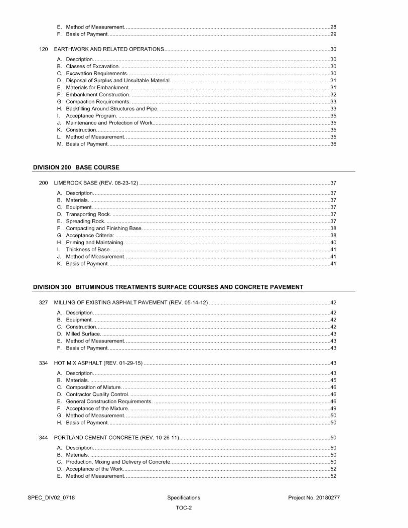
SPEC_DIV02_0718 Specifications Project No. 20180277
TOC-2
E. Method of Measurement. .......................................................................................................................................... 28 F. Basis of Payment. ..................................................................................................................................................... 29
120 EARTHWORK AND RELATED OPERATIONS ................................................................................................................ 30
A. Description. ............................................................................................................................................................... 30 B. Classes of Excavation. ............................................................................................................................................. 30 C. Excavation Requirements. ........................................................................................................................................ 30 D. Disposal of Surplus and Unsuitable Material. ........................................................................................................... 31 E. Materials for Embankment. ....................................................................................................................................... 31 F. Embankment Construction. ...................................................................................................................................... 32 G. Compaction Requirements. ...................................................................................................................................... 33 H. Backfilling Around Structures and Pipe. ................................................................................................................... 33 I. Acceptance Program. ............................................................................................................................................... 35 J. Maintenance and Protection of Work. ....................................................................................................................... 35 K. Construction. ............................................................................................................................................................. 35 L. Method of Measurement. .......................................................................................................................................... 35 M. Basis of Payment. ..................................................................................................................................................... 36
DIVISION 200 BASE COURSE
200 LIMEROCK BASE (REV. 08-23-12) ................................................................................................................................. 37
A. Description. ............................................................................................................................................................... 37 B. Materials. .................................................................................................................................................................. 37 C. Equipment. ................................................................................................................................................................ 37 D. Transporting Rock. ................................................................................................................................................... 37 E. Spreading Rock. ....................................................................................................................................................... 37 F. Compacting and Finishing Base. .............................................................................................................................. 38 G. Acceptance Criteria: ................................................................................................................................................. 38 H. Priming and Maintaining. .......................................................................................................................................... 40 I. Thickness of Base. ................................................................................................................................................... 41 J. Method of Measurement. .......................................................................................................................................... 41 K. Basis of Payment. ..................................................................................................................................................... 41
DIVISION 300 BITUMINOUS TREATMENTS SURFACE COURSES AND CONCRETE PAVEMENT
327 MILLING OF EXISTING ASPHALT PAVEMENT (REV. 05-14-12) .................................................................................. 42
A. Description. ............................................................................................................................................................... 42 B. Equipment. ................................................................................................................................................................ 42 C. Construction. ............................................................................................................................................................. 42 D. Milled Surface. .......................................................................................................................................................... 43 E. Method of Measurement. .......................................................................................................................................... 43 F. Basis of Payment. ..................................................................................................................................................... 43
334 HOT MIX ASPHALT (REV. 01-29-15) .............................................................................................................................. 43
A. Description. ............................................................................................................................................................... 43 B. Materials. .................................................................................................................................................................. 45 C. Composition of Mixture. ............................................................................................................................................ 46 D. Contractor Quality Control. ....................................................................................................................................... 46 E. General Construction Requirements. ....................................................................................................................... 46 F. Acceptance of the Mixture. ....................................................................................................................................... 49 G. Method of Measurement. .......................................................................................................................................... 50 H. Basis of Payment. ..................................................................................................................................................... 50
344 PORTLAND CEMENT CONCRETE (REV. 10-26-11) ...................................................................................................... 50
A. Description. ............................................................................................................................................................... 50 B. Materials. .................................................................................................................................................................. 50 C. Production, Mixing and Delivery of Concrete. ........................................................................................................... 50 D. Acceptance of the Work. ........................................................................................................................................... 52 E. Method of Measurement. .......................................................................................................................................... 52
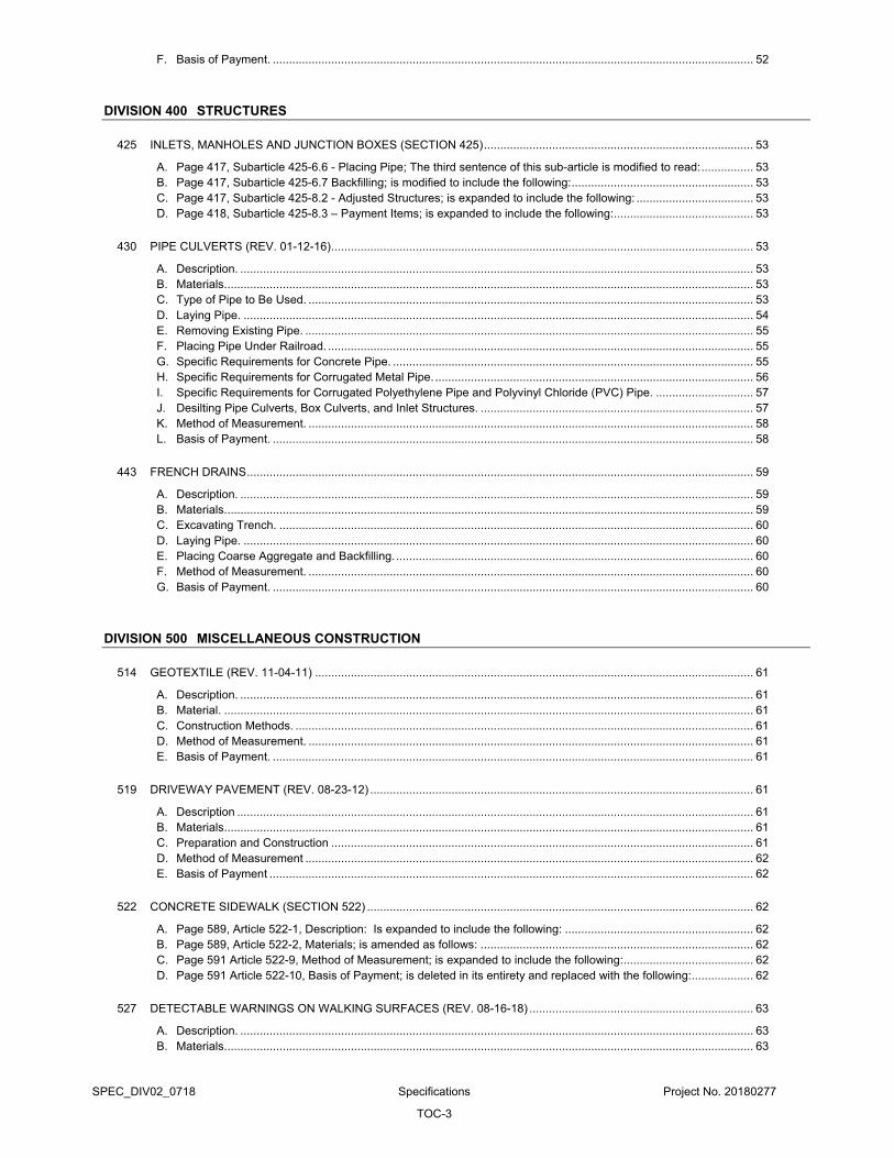
SPEC_DIV02_0718 Specifications Project No. 20180277
TOC-3
F. Basis of Payment. .................................................................................................................................................... 52
DIVISION 400 STRUCTURES
425 INLETS, MANHOLES AND JUNCTION BOXES (SECTION 425) ................................................................................... 53
A. Page 417, Subarticle 425-6.6 - Placing Pipe; The third sentence of this sub-article is modified to read: ................ 53 B. Page 417, Subarticle 425-6.7 Backfilling; is modified to include the following: ........................................................ 53 C. Page 417, Subarticle 425-8.2 - Adjusted Structures; is expanded to include the following: .................................... 53 D. Page 418, Subarticle 425-8.3 – Payment Items; is expanded to include the following: ........................................... 53
430 PIPE CULVERTS (REV. 01-12-16) .................................................................................................................................. 53
A. Description. .............................................................................................................................................................. 53 B. Materials. .................................................................................................................................................................. 53 C. Type of Pipe to Be Used. ......................................................................................................................................... 53 D. Laying Pipe. ............................................................................................................................................................. 54 E. Removing Existing Pipe. .......................................................................................................................................... 55 F. Placing Pipe Under Railroad. ................................................................................................................................... 55 G. Specific Requirements for Concrete Pipe. ............................................................................................................... 55 H. Specific Requirements for Corrugated Metal Pipe. .................................................................................................. 56 I. Specific Requirements for Corrugated Polyethylene Pipe and Polyvinyl Chloride (PVC) Pipe. .............................. 57 J. Desilting Pipe Culverts, Box Culverts, and Inlet Structures. .................................................................................... 57 K. Method of Measurement. ......................................................................................................................................... 58 L. Basis of Payment. .................................................................................................................................................... 58
443 FRENCH DRAINS ............................................................................................................................................................ 59
A. Description. .............................................................................................................................................................. 59 B. Materials. .................................................................................................................................................................. 59 C. Excavating Trench. .................................................................................................................................................. 60 D. Laying Pipe. ............................................................................................................................................................. 60 E. Placing Coarse Aggregate and Backfilling. .............................................................................................................. 60 F. Method of Measurement. ......................................................................................................................................... 60 G. Basis of Payment. .................................................................................................................................................... 60
DIVISION 500 MISCELLANEOUS CONSTRUCTION
514 GEOTEXTILE (REV. 11-04-11) ....................................................................................................................................... 61
A. Description. .............................................................................................................................................................. 61 B. Material. ................................................................................................................................................................... 61 C. Construction Methods. ............................................................................................................................................. 61 D. Method of Measurement. ......................................................................................................................................... 61 E. Basis of Payment. .................................................................................................................................................... 61
519 DRIVEWAY PAVEMENT (REV. 08-23-12) ...................................................................................................................... 61
A. Description ............................................................................................................................................................... 61 B. Materials ................................................................................................................................................................... 61 C. Preparation and Construction .................................................................................................................................. 61 D. Method of Measurement .......................................................................................................................................... 62 E. Basis of Payment ..................................................................................................................................................... 62
522 CONCRETE SIDEWALK (SECTION 522) ....................................................................................................................... 62
A. Page 589, Article 522-1, Description: Is expanded to include the following: .......................................................... 62 B. Page 589, Article 522-2, Materials; is amended as follows: .................................................................................... 62 C. Page 591 Article 522-9, Method of Measurement; is expanded to include the following: ........................................ 62 D. Page 591 Article 522-10, Basis of Payment; is deleted in its entirety and replaced with the following: ................... 62
527 DETECTABLE WARNINGS ON WALKING SURFACES (REV. 08-16-18) ..................................................................... 63
A. Description. .............................................................................................................................................................. 63 B. Materials. .................................................................................................................................................................. 63
SPEC_DIV02_0718 Specifications Project No. 20180277
TOC-4
C. Installation Procedures. ............................................................................................................................................ 64 D. Method of Measurement. .......................................................................................................................................... 64 E. Basis of Payment. ..................................................................................................................................................... 64
575 SODDING ......................................................................................................................................................................... 64
A. Description. ............................................................................................................................................................... 64 B. Materials. Meet the following requirements: ............................................................................................................ 64 C. Construction Methods. .............................................................................................................................................. 64 D. Maintenance. ............................................................................................................................................................ 65 E. Method of Measurement. .......................................................................................................................................... 65 F. Basis of Payment. ..................................................................................................................................................... 65
DIVISION 700 TRAFFIC CONTROL
706 RAISED RETRO-REFLECTIVE PAVEMENT MARKERS AND BITUMINOUS ADHESIVE (REV. 05-02-12) ................. 66
A. Description. ............................................................................................................................................................... 66 B. Materials. .................................................................................................................................................................. 66 C. Equipment. ................................................................................................................................................................ 66 D. Application. ............................................................................................................................................................... 66 E. Contractor’s Responsibility for Notification. .............................................................................................................. 66 F. Method of Measurement. .......................................................................................................................................... 66 G. Basis of Payment. ..................................................................................................................................................... 66
711 THERMOPLASTIC TRAFFIC STRIPES AND MARKINGS (REV. 05-02-12) ................................................................... 67
A. Description. ............................................................................................................................................................... 67 B. Materials. .................................................................................................................................................................. 67 C. Equipment. ................................................................................................................................................................ 67 D. Application. ............................................................................................................................................................... 67 E. Tolerances in Dimensions and in Alignment. ............................................................................................................ 68 F. Contractor’s Responsibility for Notification. .............................................................................................................. 68 G. Protection of Newly Applied Traffic Stripes and Markings. ....................................................................................... 69 H. Observation Period. .................................................................................................................................................. 69 I. Corrections for Deficiencies. ..................................................................................................................................... 69 J. Submittals. ................................................................................................................................................................ 69 K. Method of Measurement. .......................................................................................................................................... 69 L. Basis of Payment. ..................................................................................................................................................... 69
CONST_SPEC_0718 Specification Project No. 20180277
Page 1 of 69
DIVISION 100 GENERAL CONSTRUCTION OPERATIONS
101 MOBILIZATION (REV. 03-12-2013)
A. Description.
1. Perform preparatory work and operations in mobilizing for beginning work on the Project, including, but not limited to, those operations necessary for the movement of personnel, equipment, supplies, and incidentals to the project site(s) and for the establishment of temporary offices, buildings, safety equipment and first aid supplies, and sanitary and other facilities.
2. Include the costs of bonds and any required insurance and any other preconstruction expense necessary for the start of the work, excluding the cost of construction materials.
B. Basis of Payment.
1. When No Separate Item for Mobilization is Included in the Contract:
a. All work and incidental costs specified as being covered under this Article will be included for payment under the several scheduled items of the overall Contract, and no separate payment will be made therefore.
2. When a Separate Pay Item for Mobilization is Included in the Contract:
a. The work and incidental costs specified as being covered under this Article will be paid for at the Contract lump sum price for the Mobilization pay item, after an executed Notice to Proceed has been issued, by partial payments made in accordance with the following:
1) For contracts of 120 contract days duration or less, partial payment will be made at 50% of the bid price per month for the first two months. For contracts in excess of 120 contract days duration, partial payment will be made at 25% of the bid price per month for the first four months. In no event shall more than 50% of the bid price be paid prior to commencing construction on the project site.
2) Total partial payments for Mobilization on any project, including when more than one project or job is included in the Contract, will be limited to 10% of the original Contract amount for that project. Any remaining amount will be paid upon completion of all work on the Contract.
3) Retainage, as specified in the Contract Documents, will be applied to all partial payments.
4) Partial payments made on this Subarticle will in no way act to preclude or limit any of the provisions for partial payments otherwise provided for by the Contract.
3. Basis of Payment:
a. No separate item for Mobilization will be provided under this contract.
102 MAINTENANCE OF TRAFFIC (REV. 12-15-2015)
A. Description.
1. General:
a. Maintain, for the duration of the construction period including any temporary suspensions of the Work, all traffic including pedestrian traffic within the limits of the Project starting the day work begins on the Project or the first day Contract time is charged, or on the day work begins on the work order, whichever is earlier .
b. Construct and maintain detours.
c. Provide facilities for access to residences, businesses, etc., along the Project.
d. Furnish, install and maintain traffic control and safety devices during construction in accordance with FDOT Index 600 Series of the FDOT Design Standards, or as directed by Engineer. MOT includes all facilities, devices and operations as required for safety and convenience of the public within the work zone. Provide pickup, removal and disposal of litter and mow turf or vegetation within the MOT limits as required by Article 107.
e. Furnish and install work zone pavement markings for maintenance of traffic (MOT) in construction areas.
f. Provide any other special requirements for safe and expeditious movement of traffic specified in the Plans or directed by Engineer.
2. Unless otherwise directed by Engineer or required by the Contract Documents, do not maintain traffic over those portions of the Project where no work is to be accomplished or where construction operations will not affect existing roads including sidewalks.
3. Do not obstruct or create a hazard to any traffic during the performance of the Work, and repair any damage to existing pavement open to traffic.
4. Traffic may be detoured only upon approval by the County Engineer. Contractor must submit for review and approval an updated MOT plan prior to closure of any roads.
5. The Department may temporarily suspend all activities, except traffic, erosion control and such other activities that are necessary for project maintenance and safety, for failure to comply with these provisions.
6. Due to traffic congestion, work hours other than normal established hours may be required by the Engineer. In the case of extreme traffic or weather conditions, Contractor may be required to remove their operation from the roadway and/or right of way, at the discretion of the Engineer or the Traffic Control Officer at no additional compensation.
B. Materials.
1. Meet the following requirements:
CONST_SPEC_0718 Specification Project No. 20180277
Page 2 of 69
Bituminous Adhesive FDOT Section 970
Temporary Retroreflective Pavement Markers
FDOT Section 990
Paint FDOT Section 971
Removable Tape FDOT Section 990
Glass Spheres FDOT Section 971
Temporary Traffic Control Device Materials
FDOT Section 990
Retroreflective and Nonreflective Sheeting for Temporary Traffic Control Devices
FDOT Section 994
2. Temporary Traffic Control Devices: Use only the materials meeting the requirements of FDOT Section 990, FDOT Section 994, FDOT Design Standards and the Manual on Uniform Traffic Control Devices (MUTCD).
3. Detour: Provide all materials for the construction and maintenance of all detours.
4. Commercial Materials for Driveway Maintenance: Provide materials of the type typically used by FDOT for roadway base construction, including reclaimed asphalt pavement material, and having stability and drainage properties that will provide a firm surface under wet conditions.
C. Worksite Traffic Supervisor.
1. Provide a worksite traffic supervisor meeting the requirements of Article 105. Provide the worksite traffic supervisor with all equipment and materials needed to set up, take down, maintain traffic control, and handle traffic-related situations.
2. Ensure that the worksite traffic supervisor performs the following duties:
a. On site direction of all traffic control on the Project.
b. Is on site during all MOT set up and take down, and performs a drive through inspection immediately after set up.
c. Is on site during all nighttime operations to ensure proper MOT.
d. Immediately corrects all safety deficiencies and does not permit minor deficiencies that are not immediate safety hazards to remain uncorrected for more than 24 hours.
e. Is available on a 24 hour per day basis and present within 45 minutes after notification of an emergency situation and is prepared to positively respond to repair the work zone traffic control or to provide alternate traffic arrangements.
f. Conducts daily daytime and weekly nighttime inspections of projects with predominately daytime work activities, and daily nighttime and weekly daytime inspections of projects with predominantly nighttime work activities of all traffic control devices, traffic flow, pedestrian, bicyclist, and business accommodations. Advise Engineer and the Project personnel of the schedule of these inspections and give them the opportunity to join in the inspection as is deemed necessary.
3. The Department may disqualify and remove from the Project a worksite traffic supervisor who fails to comply with the provisions of this Article.
D. Submittals
1. Traffic Control Plan
a. Submit at Contractor’s own expense a Traffic Control Plan (TCP) for approval by the County when a final TCP was not provided by the County as part of the original Contract Documents. Sequence the Work in a manner that will minimize disruption of vehicular and pedestrian access through and around the Project’s construction area(s).
b. The TCP must detail procedures and protective measures proposed by Contractor to provide for protection and control of traffic affected by the Work consistent with the following applicable standards:
1) The Contract Documents;
2) “Manual on Uniform Traffic Control Devices for Streets and Highways" (MUTCD) and subsequent revisions and addendums, as published by the U.S. Department of Transportation, Federal Highway Administration;
3) The 600 Series indices of the FDOT Design Standards for Design, Construction, Maintenance and Utility Operations on the State Highway System; and
4) The Miami-Dade County Public Works Manual.
c. All references to the respective agencies in the above referenced standards shall be construed to also include more stringent requirements of the jurisdictional municipality as applicable for this Work.
d. The TCP must be signed and sealed by a Professional Engineer registered in the state of Florida and shall include proposed locations and time durations of the following, as applicable:
1) Pedestrian and public vehicular traffic routing.
2) Lane and sidewalk closures, other traffic blockage and lane restrictions and reductions anticipated to be caused by construction operations. Show and describe the proposed location, dates, hours and duration of closure, vehicular and pedestrian traffic routing and management, traffic control devices for implementing pedestrian and vehicular movement around the closures, and details of barricades.
3) Location, type and method of shoring to provide lateral support to the side of an excavation or embankment parallel to an open travel-way.
4) Allowable on-street parking within the immediate vicinity of worksite.
5) Access to buildings immediately adjacent to worksite.
6) Driveways blocked by construction operations.
7) Temporary traffic control devices, temporary pavement striping and marking of streets and sidewalks affected by construction

CONST_SPEC_0718 Specification Project No. 20180277
Page 3 of 69
8) Temporary commercial and industrial loading and unloading zones.
9) Construction vehicle reroutes, travel times, staging locations, and number and size of vehicles involved.
e. Obtain and submit prior to erection, or otherwise impacting traffic, all required permits from all authorities having jurisdiction, including the Department, if applicable.
2. Alternative Traffic Control Plan.
a. Where a TCP is provided by the County with the Contract Documents, Contractor may still propose an alternative TCP to the plan presented in the Contract Documents. Prepare the TCP in conformance with the requirements stipulated in this Specification and in the form outlined in the current version of FDOT’s Plans Preparation Manual. Indicate in the plan a TCP for each phase of activities. Have Contractor’s Engineer of Record sign and seal the alternative plan. Take responsibility for identifying and assessing any potential impacts to a utility that may be caused by the alternate TCP proposed by Contractor, and notify the Department in writing of any such potential impacts to utilities.
b. Engineer’s approval of the alternate TCP does not relieve Contractor of sole responsibility for all utility impacts, costs, delays or damages, whether direct or indirect, resulting from Contractor initiated changes in the design or construction activities from those in the original Contract Specifications, Design Plans (including TCPs) or other Contract Documents and which effect a change in utility work different from that shown in the Utility Plans, joint project agreements or utility relocation schedules.
c. The Department reserves the right to reject any alternative TCP. Obtain Engineer’s written approval before beginning work using an alternate TCP. Engineer’s written approval is required for all modifications to the TCP. Engineer will only allow changes to the TCP in an emergency without the proper documentation.
3. Comprehensive Weekly Report:
a. Submit to Engineer a comprehensive weekly report of the daily inspections performed and detailing the condition of all traffic control devices (including pavement markings) being used.
b. Include assurances in the report that pedestrians are accommodated with a safe, accessible travel path around work sites separated from mainline traffic in compliance with the Americans with Disabilities Act (ADA) Standards for Transportation Facilities, that existing or detoured bicyclist paths are being maintained satisfactorily throughout the Project limits, and that existing businesses in work areas are being provided with adequate entrances for vehicular and pedestrian traffic during business hours.
c. When deficiencies are found, the worksite traffic supervisor is to note such deficiencies and include the proposed or implemented corrective actions, including the date corrected.
d. Have the worksite traffic supervisor sign the report and certify that all of the above issues are being handled in accordance with the Contract Documents.
E. Traffic Control.
1. Standards: FDOT Design Standards are the minimum standards for the use in the development of all TCPs. The MUTCD, Part VI is the minimum national standard for traffic control for highway construction, maintenance, and utility operations. Follow the basic principles and minimum standards contained in these documents for the design, application, installation, maintenance, and removal of all traffic control devices, warning devices and barriers which are necessary to protect the public and workers from hazards within the Project limits.
2. Maintenance of Roadway Surfaces:
a. Maintain all lanes that are being used for the MOT, including those on detours and temporary facilities, under all weather conditions. Keep the lanes reasonably free of dust, potholes and rutting. Provide the lanes with the drainage facilities necessary to maintain a smooth riding surface under all weather conditions.
3. Number of Traffic Lanes:
a. Maintain one lane of traffic in each direction.
b. Maintain two lanes of traffic in each direction at existing four (or more) lane cross roads, where necessary to avoid undue traffic congestion.
c. Construct each lane used for MOT at least as wide as the traffic lanes existing in the area before commencement of construction.
d. Do not allow traffic control and warning devices to encroach on lanes used for MOT.
e. Engineer may allow Contractor to restrict traffic to one-way operation for short periods of time provided that Contractor employs adequate means of traffic control and does not unreasonably delay traffic. When a construction activity requires restricting traffic to one-way operations, locate the flaggers within view of each other when possible. When visual contact between flaggers is not possible, equip them with 2-way radios, official, or pilot vehicles, or use traffic signals.
4. Crossings and Intersections:
a. Provide and maintain adequate accommodations for intersecting and crossing traffic. Do not block or unduly restrict any road or street crossing the Project unless approved by Engineer. Before beginning any construction, provide Engineer the names and phone numbers of persons that can be contacted when signal operation malfunctions.
5. Access for Residences and Businesses: Provide continuous access to all residences and all places of business.
6. Protection of the Work from Injury by Traffic: Where traffic would be injurious to a base, surface course, or structure constructed as a part of the work, maintain all traffic outside the limits of such areas until the potential for injury no longer exists.
CONST_SPEC_0718 Specification Project No. 20180277
Page 4 of 69
7. Flagger: Provide trained flaggers in accordance with Article 105.
8. Conflicting Pavement Markings:
a. Where the lane use or where normal vehicle or pedestrian paths are altered during construction, remove all pavement markings (paint, tape, thermoplastic, raised pavement markers, etc.) that will conflict with the adjusted vehicle or pedestrian paths. Use of paint to cover conflicting pavement markings is prohibited. Remove conflicting pavement markings using a method that will not damage the surface texture of the pavement and which will eliminate the previous marking pattern regardless of weather and light conditions.
b. Remove all pavement markings that will be in conflict with “next phase of operation” vehicle pedestrian paths as described above, before opening to vehicle traffic or use by pedestrians.
c. Cost for removing conflicting pavement markings (paint, tape, thermoplastic, raised pavement markers, etc.) to be included in the Project costs for Maintenance of Traffic (General).
9. Vehicle and Equipment Visibility:
a. Equip all pickups and automobiles used on the Project with a minimum of one Class 2 amber or white warning light that meets the Society of Automotive Engineers Recommended Practice SAE J595, dated November 1, 2008, or SAE J845, dated December 1, 2007, and incorporated herein by reference. Existing lights that meet SAE J845, dated March, 1992, or SAE J1318, dated April, 1986, may be used to its end of service life. Warning lights shall be a high intensity amber or white rotating, flashing, oscillating or strobe light. Lights should be unobstructed by ancillary vehicle equipment such as ladders, racks or booms. If the light is obstructed, additional lights will be required. The lights shall be operating when a vehicle is in a work area where a potential hazard exists, when operating the vehicle at less than the average speed for the facility while performing work activities, making frequent stops or called for in the Plans or FDOT Design Standards.
b. Equip all other vehicles and equipment with a minimum of 4 square feet of retroreflective sheeting or flashing lights.
c. To avoid distraction to motorists, do not operate the lights on the vehicles or equipment when the vehicles are outside the clear zone or behind a barrier.
10. No Waiver of Liability: Conduct operations in such a manner that no undue hazard results due to the requirements of this Article. The procedures and policies described herein in no way acts as a waiver of any terms of the liability of Contractor or his surety.
F. Detours.
1. General: Construct and maintain detour facilities wherever it becomes necessary to divert traffic from any existing roadway or bridge, or wherever construction operations block the flow of traffic.
2. Construction: Plan, construct, and maintain detours for the safe passage of traffic in all conditions of weather.
Provide the detour with all facilities necessary to meet this requirement. Where pedestrian facilities are detoured, blocked or closed during the work, provide safe alternate accessible routes through or around the work zone meeting the requirements of the ADA Standards for Transportation Facilities.
3. Construction Methods: Select and use construction methods and materials that provide a stable and safe detour facility. Construct the detour facility to have sufficient durability to remain in good condition, supplemented by maintenance, for the entire period that the detour is required.
4. Removal of Detours: Remove detours when they are no longer needed and before the Contract is completed. Take ownership of all materials from the detour and dispose of them, except for the materials on loan from the Department with the stipulation that they are returned.
5. Detours Over Existing Roads and Streets: When the Department specifies that traffic be detoured over roads or streets outside the Project area, do not maintain such roads or streets. However, maintain all signs and other devices placed for the purpose of the detour.
6. Operation of Existing Movable Bridges:
a. At the pre-construction meeting, the Engineer and the Contractor will select a date for the County to turn over the bridge maintenance and operations responsibilities. In the event that this date is not discussed, the Contractor will take full responsibility at the NTP date.
b. In addition to bridge maintenance responsibilities during the duration of the project, Contractor is responsible for having qualified and sufficient number of bridge operators to be able to operate the bridge in accordance USCG regulations – specifically, Title 33-Navigation and Navigable Waters, Chapter I - U.S. Coast Guard, Department of Homeland Security, Subchapter J-Bridges, Part 117--Drawbridge Operation Regulations, Subpart B--Specific Requirements § 117.5.
c. County’s bridge operators are scheduled as follows:
1st Shift: 12am to 8am
2nd Shift: 8am to 4pm
3rd Shift: 4pm to 12am
d. This allows the bridge to be operational on a 7 days/week, 365 days per year basis.
e. When removing bridges: Once the bridge is removed Contractor is relieved of this responsibility; however, upon completion of the construction of the new bridge and until the new bridge is officially returned to the County, the contractor is obligated to operate the bridge in accordance with the established USCG regulation.
f. Make immediate repairs of any damage to such structures caused by use or operations related to the work at no expense to the County, but do not provide routine repairs or maintenance. In the event that use or operations result in damage to a bridge requiring repairs, give such repairs top priority to any equipment, material, or labor available.
CONST_SPEC_0718 Specification Project No. 20180277
Page 5 of 69
G. Traffic Control Officer.
1. Provide uniformed law enforcement officers, including marked law enforcement vehicles, to assist in controlling and directing traffic in the work zone as required by Engineer and when the following types of work is necessary on projects:
a. Directing traffic/overriding the signal in a signalized intersection.
b. When FDOT Design Standards, Index No. 655 Traffic Pacing for overhead work is called for in the Plans or approved by Engineer.
c. When pulling conductor/cable above an open traffic lane on limited access facilities, when called for in the Plans or approved by Engineer.
d. When FDOT Design Standards, Index No. 625 Temporary Road Closure 5 Minutes or Less is used.
H. Driveway Maintenance.
1. General: Ensure that each residence and business has safe, stable, and reasonable access.
2. Construction Methods:
a. Place, level, manipulate, compact, and maintain the material, to the extent appropriate for the intended use.
b. As permanent driveway construction is accomplished at a particular location, Contractor may salvage and reuse previously placed materials that are suitable for reuse on other driveways.
I. Temporary Traffic Control Devices.
1. Installation and Maintenance:
a. Install and maintain temporary traffic control devices as detailed in the Plans, Index 600 of the FDOT Design Standards and when applicable, in accordance with the approved vendor drawings, as provided on FDOT’s Approved Products List (APL) and the TSSQPL. Erect the required temporary traffic control devices to prevent any hazardous conditions and in conjunction with any necessary traffic re-routing to protect the traveling public, workers, and to safeguard the work area. Use only those devices that are on the FDOT APL and the TSSQPL. Immediately remove or cover any devices that do not apply to existing conditions.
b. All temporary traffic control devices must meet the requirements of National Cooperative Highway Research Program Report 350 (NCHRP 350) or the Manual for Assessing Safety Hardware 2009 (MASH) and current FHWA directives.
c. For devices requiring field assembly or special site preparation, vendor drawings shall include all field assembly details and technical information necessary for proper application and installation and must be signed and sealed by a Professional Engineer registered in the State of Florida.
d. Ensure that the FDOT APL number is permanently marked on the device at a readily visible location. Sheeting used on devices is exempt from this marking requirement.
e. Notify Engineer of any scheduled operation which will affect traffic patterns or safety sufficiently in advance of commencing such operation to permit his review of the plan for the proposed installation of temporary traffic control devices.
f. Ensure an employee is assigned the responsibility of maintaining the position and condition of all temporary traffic control devices throughout the duration of the Contract. Keep Engineer advised at all times of the identification and means of contacting this employee on a 24 hour basis.
g. Keep temporary traffic control devices in the correct position, properly directed, clearly visible and clean, at all times. Ensure that all traffic control devices meet acceptable standards as outlined in American Traffic Safety Services Association (ATSSA) “Quality Guidelines for Temporary Traffic Control Devices and Features”. Immediately repair, replace or clean damaged, defaced or dirty devices. Traffic control devices shall not be cleaned while installed/used. Use of warning lights on any temporary traffic control device is prohibited.
2. Work Zone Signs:
a. Furnish, install, maintain, remove and relocate signs in accordance with the Plans and FDOT Design Standards, Index No. 600. Use signs that meet the material and process requirements of FDOT Section 994. Use Type IV sheeting for fluorescent orange work zone signs. Roll-up signs must meet the requirements of Type VI sheeting. Use Type IV or Type XI sheeting for all other work zone signs. Attach the sign to the sign support using hardware meeting the manufacturer’s recommendations on the FDOT APL vendor drawings or as specified in the FDOT Design Standards.
1) Post Mounted Signs:
a) Meet the requirements of FDOT Section 990-8.
2) Portable Signs:
a) Use only approved systems, which includes sign stands and attachment hardware (nuts, bolts, clamps, brackets, braces, etc.), meeting the vendor requirements specified on the FDOT APL drawings.
b) Provide Federal Highway Administration’s (FHWA) accepted sign substrate for use with accepted sign stands on the National Highway System (NHS) under the provisions of the NCHRP Report 350 “Recommended Procedures for the Safety Performance Evaluation of Highway Features.”
3) Barrier Mounted Signs:
a) When post mounting criteria cannot be achieved in accordance with FDOT Design Standards, Index No. 600 and a barrier or traffic railing exists, use temporary sign criteria provided in FDOT Design Standards, Index No. 11871.
3. Business Signs:
a. Provide and place signs in accordance with the Plans and FDOT Design Standards, Index No. 600 series.

CONST_SPEC_0718 Specification Project No. 20180277
Page 6 of 69
Furnish signs having retroreflective sheeting meeting the requirements of FDOT Section 990.
4. High Intensity Flashing Lights:
a. Furnish Type B lights in accordance with the Plans and FDOT Design Standards.
5. Warning/Channelizing Devices:
a. Furnish warning/channelizing devices in accordance with the Plans and FDOT Design Standards.
b. Retroreflective Collars for Traffic Cones:
1) Use collars for traffic cones listed on the FDOT APL that meets the requirements of FDOT Section 990. Use cone collars at night designed to properly fit the taper of the cone when installed. Place the upper 6 inch collar a uniform 3-1/2 inches distance from the top of the cone and the lower 4 inch collar a uniform 2 inches distance below the bottom of the upper 6 inch collar. Ensure that the collars are capable of being removed for temporary use or attached permanently to the cone in accordance with the manufacturer’s recommendations. Provide a white sheeting having a smooth outer surface and that has the property of a retroreflector over its entire surface.
c. Barrier Wall (Temporary):
1) Furnish, install, maintain, remove and relocate a temporary barrier wall in accordance with the Plans. Ensure that temporary concrete barrier wall for use on roadway sections, complies with FDOT Design Standards, Index Nos. 412, 415 or 414 as specified in the Plans. Ensure that temporary concrete barrier wall for use on bridge and wall sections, complies with FDOT Design Standards, Index No 414 as specified in the Plans.
2) Ensure that temporary water filled barrier wall used on roadway sections meets the NCHRP Report 350 criteria or the MASH and is listed on the FDOT APL. Barriers meeting the requirements of FDOT Design Standards, Index Nos. 412, 415 or temporary water filled barriers on the FDOT APL will not be accepted as an alternate to barriers meeting the requirements of FDOT Design Standards, Index No. 414.
3) Trailer mounted barriers listed on the FDOT APL may be used at the option of the Contractor. Trailer mounted barriers listed on the FDOT APL must have an FHWA eligibility letter and be successfully crash tested in accordance with MASH TL-3 criteria. All trailer mounted barriers must be equipped with an FDOT APL listed truck mounted attenuator, an FDOT APL listed vehicle mounted arrow board and vehicle warning lights in accordance with this Article
4) Temporary Barrier Wall Meeting the Requirements of Design Standards, Index Nos. 412 and 414:
a) Ensure the marking requirements of the respective Index are met.
5) Proprietary Precast Temporary Barrier Wall Fabricated prior to 2005:
a) Contractor must submit a certification stating that all unmarked barrier wall units meet the
requirements of the Specifications and the FDOT Design Standards. Certifications will be project specific and non-transferable
6) Proprietary Precast Temporary Barrier Wall Fabricated in 2005 or later:
a) Ensure each wall unit has permanent clear markings, showing the manufacture date, serial number, manufacturer’s name or symbol, and the FDOT APL number. Label the markings on a plate, plaque, or cast in the unit. Proprietary barrier wall fabricated prior to 2016 and marked with the “INDX 521” in lieu of the FDOT APL number will be permitted.
7) Glare Screen (Temporary):
a) Use temporary glare screens listed on the FDOT APL that meet the requirements of FDOT Section 990. Furnish, install, maintain, remove and relocate glare screen systems in conjunction with temporary barrier wall at locations identified in the Plans.
b) Ensure the anchorage of the glare screen to the barrier is capable of safely resisting an equivalent tensile load of 600 pounds per foot of glare screen, with a requirement to use a minimum of three fasteners per barrier section.
c) When glare screen is utilized on temporary barrier wall, warning lights will not be required.
8) Longitudinal Channelizing Devices (LCDs):
a) Furnish LCDs in accordance with the Plans and FDOT Design Standards. LCDs are categorized as vehicular or pedestrian and shall be interlocked. For LCDs requiring internal ballasting, an indicator that clearly identifies the proper ballast level will be required.
b) Use alternating orange and white pattern for solid color vehicular LCDs. Vehicular LCDs may be substituted for drums, vertical panels, or barricades.
6. Temporary Crash Cushion (Redirective/Gating):
a. Furnish, install, maintain and subsequently remove temporary crash cushions in accordance with the details and notes shown in the Plans, the FDOT Design Standards, and requirements of the pre-approved alternatives listed on the FDOT APL.
b. Maintain the crash cushions until their authorized removal. Repair all attachment scars to permanent structures and pavements after crash cushion removal. Make necessary repairs due to defective material, work, or Contractor operations at no cost to the Department.
c. Restore crash cushions damaged by the traveling public within 24 hours after notification as authorized by Engineer.
7. Guardrail (Temporary):
a. Furnish guardrail (temporary) in accordance with the Plans and Design Standards. Meet the requirements of Article 536.
8. Arrow Board:

CONST_SPEC_0718 Specification Project No. 20180277
Page 7 of 69
a. Furnish arrow boards that meet the requirements of FDOT Section 990 as required by the Plans and Design Standards to advise approaching traffic of lane closures or shoulder work.
b. Type B arrow boards may be used on low to intermediate speed (0 mph to 50 mph) facilities or for maintenance or moving operations on any speed facility.
c. Type C arrow boards shall be used for all other operations on high-speed (50 mph and greater) facilities and may be substituted for Type B arrow boards on any speed facility.
9. Portable Changeable Message Sign (PCMS):
a. Furnish PCMSs or truck mounted changeable message signs that meet the requirements of FDOT Section 990 as required by the Plans and FDOT Design Standards to supplement other temporary traffic control devices used in work zones.
10. Portable Regulatory Signs (PRS):
a. Furnish PRSs that meet the requirements of FDOT Section 990 as required by the Plans and FDOT Design Standards.
b. Activate portable regulatory signs only during active work activities and deactivate when no work is being performed.
11. Radar Speed Display Unit (RSDU):
a. Furnish RSDUs that meet the requirements of FDOT Section 990 as required by the Plans and FDOT Design Standards to inform motorists of the posted speed and their actual speed.
b. Activate the radar speed display unit only during active work activities and deactivate when no work is being performed.
12. Temporary Signalization and Maintenance:
a. Provide temporary signalization and maintenance at existing, temporary, and new intersections including but not limited to the following:
1) Installation of temporary poles and span wire assemblies as shown in the Plans,
2) Temporary portable traffic signals as shown in the Plans,
3) Adding or shifting signal heads,
4) Trouble calls,
5) Maintaining intersection and coordination timing and preemption devices.
b. Restore any loss of operation within 12 hours after notification.
c. Provide traffic signal equipment that meets the requirements of Article 603 of FDOT Design Standards. Engineer may approve used signal equipment if it is in acceptable condition. Replacement components for traffic signal cabinet assemblies will be provided by the maintaining agency.
13. Temporary Traffic Detection and Maintenance:
a. Provide temporary traffic detection and maintenance at existing, temporary, and new signalized intersections. Provide temporary traffic detection equipment listed on the FDOT APL. Restore any loss of detection within 12 hours. Ensure 90% accuracy per signal phase, measured at the initial installation and after any lane shifts, by comparing sample data collected from the detection system with ground truth data collected by human observation. Collect the sample and ground truth data for a minimum of five minutes during a peak and five minutes during an off-peak period with a minimum three detections for each signal phase. Perform the test in the presence of Engineer.
14. Truck Mounted Attenuators and Trailer Mounted Attenuators:
a. Furnish, install and maintain only those attenuators that meet the requirements of NCHRP 350 or the MASH.
b. Use truck mounted attenuators or trailer mounted attenuators, when called for in the FDOT Design Standards. Use attenuators listed on the FDOT APL.
c. When attenuators are called for, use either a truck mounted attenuator or a trailer mounted attenuator system designed and installed in accordance with the manufacturers recommendations.
d. Equip the attenuator cartridge with lights and reflectors in compliance with applicable Florida motor vehicle laws, including turn signals, dual tail lights, and brake lights. Ensure that lights are visible in both the raised and lowered positions if the unit is capable of being raised.
e. Install either alternating black with yellow or white with orange sheeting on the rear of trailer mounted attenuators and on truck mounted attenuators, in both the operating and raised position. Use Type III (work zone) or Type IV sheeting consisting of 4 or 6 inch wide stripes installed to form chevrons that point upward. All sheeting except black shall be retroreflective.
f. Attenuators will not be paid for separately. Include the cost of the truck with either a truck mounted attenuator or a trailer mounted attenuator under Maintenance of Traffic (General). Payment includes all costs, including furnishing, maintaining and removal when no longer required, and all materials, labor, tools, equipment and incidentals required for attenuator maintenance.
15. Temporary Raised Rumble Strip Sets:
a. When called for in the Plans, furnish, install, maintain, remove, and reinstall temporary raised rumble strip sets.
b. Install the temporary raised rumble strip sets per the manufacturer’s recommendations and in accordance with FDOT Design Standards, Index No. 603.
c. The temporary raised rumble strip may be either a removable polymer striping tape or a molded engineered polymer material.
16. Automated Flagger Assistance Devices (AFAD):
a. Furnish, install, maintain, remove and relocate AFADs in accordance with the Plans and FDOT Design Standards. Position AFADs where they are clearly visible to oncoming traffic and out of the lane of traffic. The devices may be operated either by a single flagger
CONST_SPEC_0718 Specification Project No. 20180277
Page 8 of 69
at one end of the traffic control zone, from a central location, or by a separate flagger near each device’s location.
b. AFADs may be either a remotely controlled Stop/Slow AFAD mounted on either a trailer or a movable cart system, or a remotely controlled Red/Yellow Lens AFAD.
c. AFADs will not be paid for separately. AFADs may be used as a supplement or an alternate to flaggers in accordance with FDOT Index 603. Include the cost for AFADs in Maintenance of Traffic (General).
17. Temporary Lane Separator:
a. Furnish, install, maintain, remove and relocate temporary lane separator in accordance with the Plans and FDOT Design Standards, Index No 600.
b. Anchor the portable temporary lane separator with a removable anchor bolt. Use epoxy on bridge decks where anchoring is not allowed. Remove the epoxy from the bridge deck by hydroblasting or other method approved by Engineer.
J. Work Zone Pavement Marking.
1. Description:
a. Furnish and install work zone pavement markings for MOT in construction areas and in close conformity with the lines and details shown in the Plans and FDOT Design Standards.
b. Centerlines, lane lines, edge lines, stop bars and turn arrows will be required in work zones prior to opening the road to traffic.
c. The most common types of work zone pavement markings are painted pavement markings and removable tape. Other types of work zone pavement markings may be identified in the Plans.
2. Painted Pavement Markings:
a. General: Use painted pavement markings meeting the requirements of Article 710. Use standard waterborne paint unless otherwise identified in the Plans or approved by Engineer.
3. Removable Tape:
a. General: Use removable tape listed on the FDOT APL and meeting the requirements of FDOT 990-4.
b. Application: Apply removable tape with a mechanical applicator to provide pavement lines that are neat, accurate and uniform. Equip the mechanical applicator with a film cut-off device and with measuring devices that automatically and accumulatively measure the length of each line placed within an accuracy tolerance of plus or minus 2%. Ensure removable tape adheres to the road surface. Removable tape may be placed by hand on short sections, 500 feet or less, if it is done in a neat accurate manner.
c. Retroreflectivity: Apply white and yellow traffic stripes and markings that will attain an initial retroreflectivity of not less than 300 mcd/lxꞏm2 for white and contrast markings and not less than 250 mcd/lxꞏm2 for yellow markings. Black portions of contrast tapes and black masking tapes must be non-reflective and have a
reflectance of less than 5 mcd/lx m2. At the end of the six month service life, the retroreflectance of white and yellow removable tape shall not be less than 150 mcd/lxꞏm2.
d. Removability: Provide removable tape capable of being removed from bituminous concrete and portland cement concrete pavement intact or in substantially large strips, either manually or by a mechanical roll-up device, at temperatures above 40ºF, without the use of heat, solvents, grinding or blasting.
4. Temporary Retroreflective Pavement Markers (RPM’s): Use markers listed on the FDOT APL and meeting the requirements of FDOT 990-5. Apply all markers in accordance with the FDOT Design Standards, Index Nos. 600 and 17352, prior to opening the road to traffic. Replace markers any time after installation when more than three consecutive markers fail or are missing, at no expense to the Department, in a timely manner, as directed by Engineer.
K. Method of Measurement.
1. General:
a. Devices installed/used on the Project on any calendar day or portion thereof, within the allowable Contract Time, including time extensions which may be granted, will be paid for at the Contract unit price for the applicable pay item, except those paid for as Maintenance of Traffic (General).
b. One or more of the following items may appear in a contract in addition to a direct payment item for Maintenance of Traffic (Lump Sum). Unless otherwise stipulated in the Contract Documents, only those items with an Awarded Unit Price will be considered for direct payment.
2. Traffic Control Officers:
a. The County will reimburse Contractor for the services of uniformed law enforcement officers authorized to serve as traffic control officers for the purpose of controlling or directing traffic in the work zone as part of the County approved Traffic Control Plan and Maintenance of Traffic provided by Contractor pursuant to the Contract Documents.
b. The quantity to be paid for will be the invoice unit price per hour for the actual number of officers certified to be on the project site, including any law enforcement vehicles and all other direct and indirect costs.
c. Payment will be made at invoice cost from an appropriate dedicated allowance established by the County.
d. Payment will be made only for those Traffic Control Officers specified in the Plans and authorized by the Engineer. The necessary invoices and documentation must be submitted to the Engineer along with the payment request.
3. Special Detours:
a. When a detour facility is specifically detailed in the Plans, or is otherwise described or detailed as a special item, and an item for separate payment is included in the proposal, the work of constructing, maintaining, and

CONST_SPEC_0718 Specification Project No. 20180277
Page 9 of 69
subsequently removing such detour facilities will be paid for separately. Traffic control devices, warning devices, barriers, signing, and pavement markings for special detours will also be paid for separately.
b. When the Plans show more than one detour, each detour will be paid for separately, at the Contract lump sum price for each.
c. Where a separate item for a specific detour facility is included in the proposal, payment will be made under special detour.
4. Commercial Material for Driveway Maintenance:
a. The quantity to be paid for will be the certified volume, in cubic yards, of all materials authorized by the Engineer, acceptably placed, compacted and maintained for driveway maintenance. The volume, which is authorized to be reused, and which is acceptably salvaged, placed, compacted and maintained in other designated driveways will be included again for payment.
b. Arrow Board: The quantity to be paid at the contract unit price will be for the number of arrow boards certified as installed/used on the project on any calendar day or portion thereof within the contract time.
5. Work Zone Signs:
a. The number of temporary post-mounted signs (temporary regulatory, warning and guide) certified as installed/used on the project will be paid for at the Contract unit price for work zone signs. When multiple signs are located on single or multiple posts, each sign panel will be paid individually. Signs greater than 20 square feet and detailed in the Plans will be paid for under Maintenance of Traffic (General).
b. Temporary portable signs (excluding mesh signs) and vehicular mounted signs will be included for payment under work zone signs, only if used in accordance with the FDOT Design Standards.
c. The number of temporary barrier mounted signs (temporary regulatory, warning and guide) certified as installed/used on the project will be paid for at the Contract unit price for barrier mounted work zone signs.
6. Business Signs:
a. The number of business signs certified as installed/used on the project will be paid for at the Contract unit price for business signs.
7. High Intensity Flashing Lights:
a. The number of high intensity flashing lights (Type B) certified as installed/used on the project will be paid for at the Contract unit price for high intensity flashing lights (temporary - Type B).
8. Channelizing Devices:
a. The number of drums, vertical panels, pedestrian LCDs, and Type I, Type II, Type III, or direction indicator barricades, certified as installed/used on the project meeting the requirements of FDOT Design Standards, Index No. 600 and have been properly maintained will be paid for at the Contract unit prices for channelizing device.
b. Payment for vehicular LCDs will be paid as the length in feet installed divided by the device spacing for barricades, vertical panels, and drums and certified as installed/used on the project meeting the requirements of FDOT Design Standards, Index No. 600 and have been properly maintained will be paid for at the Contract unit price for channelizing device.
c. Payment will not be made for channelizing devices unsatisfactorily maintained, as determined by the Engineer.
d. Payment will be made for each channelizing device that is used to delineate trailer mounted devices.
e. Payment will be made for channelizing devices delineating portable changeable message signs during the period beginning 14 working days before Contract Time begins as authorized by the Engineer.
9. Barrier Wall (Temporary):
a. The Contract unit price for barrier wall (temporary) will be full compensation for furnishing, installing, maintaining, and removing the barrier wall. When called for, the Contract unit price for barrier wall (temporary/relocate) will be full compensation for relocating the barrier. The certified quantity to be paid for will be determined by the number of sections times the nominal length of each section.
10. Barrier Delineators:
a. The number of barrier delineators, installed on top of barrier wall, used on the project, meeting the requirements of FDOT Design Standards and Article 705.
11. Lights, Temporary, Barrier Wall Mount:
a. The number of Type C steady burn lights, mounted on barrier wall, certified as installed/used on the project, meeting the requirements of the Design Standards and have been properly maintained will be paid for at the Contract unit price for lights temporary, barrier wall mount.
12. Glare Screen (Temporary):
a. The certified quantity to be paid for will be determined by the number of sections times the nominal length of each section.
13. Temporary Crash Cushions:
a. Redirective:
1) The quantity to be paid for will be the number of temporary crash cushions (redirective) certified as installed/used and maintained on the project, including object marker.
b. Gating:
1) The quantity to be paid for will be the number of temporary crash cushions (gating) certified as installed/used and maintained on the project, including object marker.
14. Temporary Guardrail:
a. The quantity to be paid for will be the length, in feet, of temporary guardrail constructed and certified as installed/used on the project. The length of a run of
CONST_SPEC_0718 Specification Project No. 20180277
Page 10 of 69
guardrail will be determined as a multiple of the nominal panel lengths.
15. Arrow Board:
a. The quantity to be paid at the Contract unit price will be for the number of arrow boards certified as installed/used on the project on any calendar day or portion thereof within the Contract time.
16. Portable Changeable Message Sign:
a. The quantity to be paid at the Contract unit price will be for the number of portable changeable message signs or truck mounted changeable message signs certified as installed/used on the project on any calendar day or portion thereof within the Contract time.
b. Payment will be made for each portable changeable message sign that is used during the period beginning fourteen working days before Contract Time begins as authorized by Engineer.
17. Portable Regulatory Signs:
a. The quantity to be paid for will be the number of portable regulatory signs certified as installed/used on the project on any calendar day or portion thereof within the Contract time, will be paid for the Contract unit price for portable regulatory sign.
18. Radar Speed Display Unit:
a. The quantity to be paid for will be the number of radar speed display units certified as installed/used on the project on any calendar day or portion thereof within the Contract Time, will be paid for the Contract unit price for radar speed display unit.
19. Temporary Signalization and Maintenance:
a. For existing intersections, the quantity to be paid for will be the number of signalized intersections per day for the full duration of the Contract. For temporary intersections, the quantity to be paid for will be the number of signalized intersections per day for the duration of the temporary intersection. No separate payment will be made for temporary signalization and maintenance at new intersections.
20. Temporary Traffic Detection and Maintenance:
a. For existing intersections, the quantity to be paid for will be the number of signalized intersections per day beginning the day Contract Time begins and ending the day the permanent detection is operational and the final lane configuration is in place. For temporary and new intersections, the quantity to be paid for will be the number of signalized intersections per day beginning the day the temporary detection is functional and ending the day the permanent detection is operational and the final lane configuration is in place for a new intersection; or, when the detection is removed for a temporary intersection.
21. Work Zone Pavement Markings:
a. The quantities, furnished and installed, to be paid for will be the length of skip and solid pavement markings, and the area of pavement markings placed as follows:
1) The total transverse distance, in feet, of skip pavement marking authorized and acceptably
applied. The length of actual applied line will depend on the skip ratio of the material used. Measurement will be the distance from the beginning of the first stripe to the end of the last stripe with proper deductions made for unpainted intervals as determined by plan dimensions or stations, subject to the requirements of the Contract Documents.
2) The net length, in feet, of solid pavement marking authorized and acceptably applied.
3) The number of directional arrows or pavement messages authorized and acceptably applied.
4) The number of temporary RPM’s authorized and acceptably applied.
22. Temporary Raised Rumble Strips:
a. The quantity to be paid for will be the number of temporary raised rumble strip sets certified as installed/used on the project on any calendar day or portion thereof within the Contract Time.
b. The number of strips used must meet the requirements of FDOT Design Standards, Index No. 603. No adjustment will be made to the per day measurement for the number of strips or sets used, or for the number of times the sets are relocated.
23. Temporary Lane Separator:
a. The quantity of temporary lane separator to be paid for will be plan quantity, in feet, including drainage gaps, completed and accepted.
L. Submittals.
1. Submittal Instructions:
a. Prepare a certification of quantities for certified MOT payment items for each project in the Contract. Submit the certification of quantities to Engineer. The Department will not pay for any disputed items until Engineer approves the certification of quantities.
2. Contractor’s Certification of Quantities:
a. Request payment by submitting a certification of quantities as directed by Engineer, based on the amount of work done or completed. Ensure the certification consists of the following:
b. Contract Number, Certification Date and the period that the certification represents.
c. The basis for arriving at the amount of the progress certification, less payments previously made and less an amount previously retained or withheld. The basis will include a detail breakdown provided on the certification of items of payment in accordance with 102-M. After the initial setup of the MOT items and counts, the interval for recording the counts will be made weekly on the certification sheet unless there is a change. This change will be documented on the day of occurrence. Some items may necessitate a daily interval of recording the counts.
M. Basis of Payment.
CONST_SPEC_0718 Specification Project No. 20180277
Page 11 of 69
1. Maintenance of Traffic (General):
a. No Direct Payment Provided: When no item for direct payment of Maintenance of Traffic (Lump Sum) is provided by the Contract, the costs for performing all work and requirements specified under this Article, except as may be specifically covered for payment under other items, will be included among the various scheduled items of the Contract.
b. Direct Payment Provided: When direct payment for Maintenance of Traffic (Lump Sum) is provided in the Contract, the quantity to be paid all work and costs specified under this Article, except as may be specifically covered for payment under other items, will be the lump sum Contract Price.
2. Additional items of Direct Payment. Only those items with an Awarded Unit Price will be considered for direct payment.
a. Traffic Control Officers:
1) Price and payment will be full compensation for the services of the traffic control officers at invoice cost as specified under subarticle 102.K.2 above.
b. Special Detours:
1) Price and payment will be full compensation for providing all detour facilities shown in the Plans and all costs incurred in carrying out all requirements of this Article for general MOT within the limits of the detour, as shown in the Plans.
c. Commercial Materials for Driveway Maintenance:
1) Price and payment will be full compensation for all work and materials specified for this item, including specifically all required shaping and maintaining of driveways.
d. Work Zone Signs:
1) Price and payment will be full compensation for all work and materials for furnishing signs, supports and necessary hardware, installation, relocating, maintaining and removing signs.
e. Business Signs:
1) Price and payment will be full compensation for all materials and labor required for furnishing, installing, relocating, maintaining, and removing the signs as well as the cost of installing any logos provided by business owners.
f. High Intensity Warning Lights:
1) Price and payment will be full compensation for furnishing, installing, operating, relocating, maintaining and removing high intensity flashing lights (Type B).
g. Channelizing Devices:
1) Prices and payment will be full compensation for furnishing, installing, relocating, maintaining and removing the channelizing devices, including the costs associated with attached warning lights as required.
h. Barrier Wall (Temporary):
1) Price and payment will be full compensation for furnishing, installing, maintaining, and removing the barrier. When called for, barrier wall (temporary) (relocate) will be full compensation for relocating the barrier.
i. Lights, Temporary, Barrier Wall Mount:
1) Price and payment will be full compensation for all work and materials for furnishing, installing and maintaining the warning lights mounted on barrier wall. Payment will not be made for lights that are improperly placed or are not working.
j. Barrier Delineators:
1) No separate payment will be made for barrier delineators installed on top of temporary barrier wall. The cost of furnishing, installing and maintaining the barrier delineators will be included in the cost of the temporary barrier wall.
k. Glare Screen (Temporary):
1) Price and payment will be full compensation for furnishing, installing, maintaining, and removing the glare screen certified as installed/used on the project. When called for, glare screen (relocate) will be full compensation for relocating the glare screen.
l. Temporary Crash Cushion (Redirective/Gating):
1) Price and payment will be full compensation for furnishing, installing, maintaining and subsequently removing such crash cushions. Payment for restoring damaged crash cushions will be the manufacturer’s/distributor’s invoice price for the new materials/parts plus 20% markup. The 20% markup is compensation for all necessary work including; but not limited to, labor, equipment, supplies and profit, as authorized by Engineer. Additional MOT required for the repair of the crash cushion will be paid for under the appropriate MOT pay item.
m. Temporary Guardrail:
1) Price and payment will be full compensation for furnishing all materials required for a complete installation, including end anchorage assemblies and any end connections to other structures and for installing, maintaining and removing guardrail.
n. Arrow Board:
1) Price and payment will be full compensation for furnishing, installing, operating, relocating, maintaining and removing arrow boards.
o. Portable Changeable Message Sign:
1) Price and payment will be full compensation for furnishing, installing, operating, relocating, maintaining and removing portable changeable message signs.
p. Portable Regulatory Signs:
1) Price and payment will be full compensation for furnishing, installing, relocating, maintaining and removing a completely functioning system as described in these Specifications portable
CONST_SPEC_0718 Specification Project No. 20180277
Page 12 of 69
regulatory signs. Price and payment will be full compensation for furnishing, installing, operating, relocating, maintaining and removing portable regulatory signs.
2) Payment will include all labor, materials, incidentals, repairs and any actions necessary to operate and maintain the unit at all times that work is being performed or traffic is being affected by construction and/or MOT operations.
q. Radar Speed Display Unit:
1) Price and payment will be made only for a completely functioning system as described in these specifications. Payment will include all labor, hardware, accessories, signs, and incidental items necessary for a complete system.
2) Payment will include any measurements needed to insure that the unit conforms to all specification requirements.
3) Payment will include all labor, materials, incidentals, repairs and any actions necessary to operate and maintain the unit at all times that work is being performed or traffic is being affected by construction and/or MOT operations. Price and payment will be full compensation for furnishing, installing, operating, relocating, maintaining and removing radar speed display unit.
r. Temporary Signalization and Maintenance:
1) Price and payment will constitute full compensation for furnishing, installing, operating, maintaining and removing temporary traffic control signals including all equipment and components necessary to provide an operable traffic signal. Payment will be withheld for each day at each intersection where the temporary signalization is not operational within 12 hours after notification.
s. Temporary Traffic Detection and Maintenance:
1) Price and payment will constitute full compensation for furnishing, installing, operating, maintaining and removing temporary traffic detection including all equipment and components necessary to provide an acceptable signalized intersection. Take ownership of all equipment and components. Payment will be withheld for each day at each intersection where the temporary detection is not operational within 12 hours after notification.
t. Temporary Raised Rumble Strips:
1) Price and payment will be full compensation for all work and materials described in this Article, including all cleaning and preparing of surfaces, disposal of all debris, furnishing of all materials, application, curing, removal, reinstalling and protection of all items, protection of traffic, furnishing of all tools, machines and equipment, and all incidentals necessary to complete the work.
u. Work Zone Pavement Markings:
1) Price and payment will be full compensation for all work specified including, all cleaning and preparing of surfaces, furnishing of all materials, application,
curing and protection of all items, protection of traffic, furnishing of all tools, machines and equipment, and all incidentals necessary to complete the work. Final payment will be withheld until all deficiencies are corrected.
2) Removable tape may be substituted for work zone paint at no additional cost to the Department.
3) Payment for temporary RPMs used to supplement line markings will be paid for under temporary retroreflective pavement markers. Install these markers as detailed in the Design Standards.
v. Temporary Lane Separator:
1) Price and payment will be full compensation for all work specified in this Article.
3. Payment Items: Payment will be made under:
Item No. Description Unit
102-74-1 Barricades (Temporary- Type I, II, VP & DRUM)
EA/DAY
102- 76A Advance Warning Arrow
Panel
EA/DAY
104 PREVENTION, CONTROL, AND ABATEMENT OF EROSION AND WATER POLLUTION (REV. 01-09-12)
A. Description.
1. Provide erosion control measures on the Project and in areas outside the right-of-way where work is accomplished in conjunction with the Project, so as to prevent pollution of water, detrimental effects to public or private property adjacent to the Project right-of-way, and damage to work on the Project.
2. Construct and maintain temporary erosion control features and, as required, construct and maintain permanent erosion control features as shown in the Plans or as may be directed by Engineer.
B. General.
1. Coordinate the installation of temporary erosion control features with the construction of the permanent erosion control features to the extent necessary to ensure economical, effective, and continuous control of erosion and water pollution throughout the life of the Contract.
2. Maintain, at the work site, copies of all documents referenced by this Specification including: the Departmental Stormwater Pollution Prevention Plan (if provided); the approved contractor Erosion Control Plan; and applicable inspection reports, permits and certifications. Document compliance with all requirements pertaining to the aforementioned documents and this Specification.
3. Engineer may direct, when warranted by unforeseen conditions, the use of control features or methods other than those included in the original Contract. In such event, the Department will pay for this additional work as unforeseeable work.
CONST_SPEC_0718 Specification Project No. 20180277
Page 13 of 69
C. Control of Contractor’s Operations Which May Result in Water Pollution.
1. Prevent pollution of streams, canals, lakes, reservoirs, and other water impoundments with fuels, oils, bitumens, calcium chloride, or other harmful materials.
2. Conduct and schedule operations to avoid or otherwise minimize pollution or siltation of such water impoundments, and to avoid interference with movement of migratory fish. Do not dump any residue from dust collectors or washers into any water body.
3. Restrict construction operations in rivers, streams, lakes, tidal waters, reservoirs, canals, and other water impoundments to those areas where it is necessary to perform filling or excavation to accomplish the work shown in the Plans and to those areas which must be entered to construct temporary or permanent structures. As soon as conditions permit, promptly clear rivers, streams, and impoundments of all obstructions placed therein or caused by construction operations.
4. Do not frequently ford live streams with construction equipment. Wherever an appreciable number of stream crossings are necessary at any one location, use a temporary bridge or other structure.
5. Except as necessary and authorized for Project construction, do not deposit excavated material in rivers, streams, canals, or impoundments, or in a position close enough thereto, to be washed away by high water or runoff.
6. Where pumps are authorized for use in removing highly turbid waters from enclosed construction areas such as cofferdams or forms, treat the water by one or more of the following methods prior to discharge into State waters:
a. Pumping into grassed swales or appropriate vegetated areas or sediment basins.
b. Confined by an appropriate enclosure such as turbidity barriers when other methods are not considered appropriate.
7. Do not disturb lands or waters outside the limits of construction as staked, except as authorized by Engineer.
8. Obtain Engineer’s approval for the location of, and method of operation in, borrow pits, material pits, and disposal areas furnished for waste material from the project (other than commercially operated sources) such that erosion during and after completion of the work will not result in probability of detrimental siltation or water pollution.
D. Materials for Temporary Erosion Control.
1. Engineer will not require testing of materials used in construction of temporary erosion control features other than as provided for geotextile fabric in FDOT 985-3 unless such material is to be incorporated into the completed Project.
2. When no testing is required, Engineer will base acceptance on visual inspection.
3. Contractor may use new or used materials, subject to Engineer’s approval, for the construction of temporary silt fence, staked turbidity barriers, and floating turbidity barrier not to be incorporated into the completed Project.
E. Erosion Control Plan.
1. Prepare the Erosion Control Plan (ECP) in a format acceptable to the Department and in accordance with the planned sequence of operations.
2. At the Preconstruction Conference, submit to the Department an ECP that:
a. Meets the requirements or conditions of all permits authorizing construction of the Project. Where no permits are required or the approved permits do not contain conditions that specifically addresses erosion and water pollution, the requirements of the ECP will be governed by the Contract Documents and all applicable laws, rules, or regulations.
b. Accompanies the Department’s Stormwater Pollution Prevention Plan (SWPPP) when a SWPPP is provided for the Project.
c. Includes and describes for each phase of construction operations or activities the following:
1) Locations of all erosion control devices
2) Types of all erosion control devices
3) Estimated time erosion control devices will be in operation
4) Monitoring schedules for maintenance of erosion control devices
5) Methods of maintaining erosion control devices
6) Containment or removal methods for pollutants or hazardous wastes
7) The name and telephone number of the person responsible for monitoring and maintaining the erosion control devices.
d. Includes procedures to control off-site tracking of soil by vehicles and construction equipment and a procedure for cleanup and reporting of non-stormwater discharges.
e. Describes all phases of operations, the prevention, control, and abatement of erosion and water pollution items or activities necessary for the Project, to include:
1) Types and locations of all erosion control devices
2) Estimated time erosion control devices will be in operation
3) Monitoring schedules for maintenance of erosion control devices
4) Methods for maintaining erosion control devices
5) Containment or removal methods for pollution or hazardous wastes
6) Name and telephone number of the person responsible for monitoring and maintaining the erosion control devices.
CONST_SPEC_0718 Specification Project No. 20180277
Page 14 of 69
3. Contractor must obtain Engineer’s written approval of the ECP prior to commencing any construction activities.
4. For project requiring a Florida Department of Environmental Protection (FDEP) Generic Permit for Stormwater Discharge from Large and Small Construction Activities (Generic Permit):
a. Failure to sign any documents or certification statements required by the FDEP Generic Permit will be considered a default of the Contract.
b. Any soil disturbing activities performed without the required signed documents or certifications statements may be considered a violation of the FDEP Generic Permit.
F. Construction Requirements.
1. Limitation of Exposure of Erodible Earth:
a. Engineer may limit the surface areas of unprotected erodible earth exposed by the construction operation and may direct Contractor to provide erosion or pollution control measures to prevent contamination of any river, stream, lake, tidal waters, reservoir, canal, or other water impoundments or to prevent detrimental effects on property outside the Project right-of-way or damage to the Project.
b. Limit the area in which excavation and filling operations are being performed so that it does not exceed the capacity to keep the finish grading, turf, sod, and other such permanent erosion control measures current in accordance with the accepted schedule.
c. Do not allow the surface area of erodible earth that clearing and grubbing operations or excavation and filling operations expose to exceed 750,000 square feet without specific prior approval by Engineer. This limitation applies separately to clearing and grubbing operations and excavation and filling operations.
d. Engineer may increase or decrease the amount of surface area the Contractor may expose at any one time.
2. Incorporation of Erosion and Sediment Control Features:
a. Incorporate permanent erosion control features into the project at the earliest practical time. Use temporary erosion and sediment control features found in the State of Florida Erosion and Sediment Control Designer and Reviewer Manual (E&SC Manual) to correct conditions that develop during construction which were not foreseen at the time of design, to control erosion and sediment prior to the time it is practical to construct permanent control features, or to provide immediate temporary control of erosion and sediment that develops during normal construction operations, which are not associated with permanent erosion control features on the project. An electronic version of the E&SC Manual can be found at the following URL: http://www.dot.state.fl.us/specificationsoffice/Implemented/URLinSpecs/Files/FLErosionSedimentManual060709.pdf
b. Install all sediment control devices in a timely manner to ensure the control of sediment and the protection of lakes, streams, gulf or ocean waters, or any wetlands
associated therewith and to any adjacent property outside the right-of-way as required.
c. At sites where exposure to such sensitive areas is prevalent, complete the installation of any sediment control device prior to the commencement of any earthwork.
d. After installation of sediment control devices, repair portions of any devices damaged at no expense to the Department. Engineer may authorize temporary erosion and sediment control features when finished soil layer is specified in the Contract and the limited availability of that material from the grading operations will prevent scheduled progress of the work or damage the permanent erosion control features.
3. Scheduling of Successive Operations:
a. Schedule operations such that the area of unprotected erodible earth exposed at any one time is not larger than the minimum area necessary for efficient construction operations, and the duration of exposure of uncompleted construction to the elements is as short as practicable.
b. Schedule and perform clearing and grubbing so that grading operations can follow immediately thereafter. Schedule and perform grading operations so that permanent erosion control features can follow immediately thereafter if conditions on the project permit.
4. Details for Temporary Erosion and Sediment Control Features:
a. General: Use temporary erosion, sediment and water pollution control features found in the E&SC Manual. These features consist of, but are not limited to, temporary turf, rolled erosion control products, sediment containment systems, runoff control structures, sediment barriers, inlet protection systems, silt fences, and turbidity barriers. For design details for some of these items, refer to the Plans, the FDOT Design Standards and E&SC Manual.
b. Temporary Sod: Engineer may designate certain areas of sod constructed in accordance with the Specifications as temporary erosion control features. For areas not defined as sod, constructing temporary turf by seeding only is not an option for temporary erosion control under this Article. Engineer may waive the turf establishment requirements of the Specifications for areas with temporary sod that will not be a part of the permanent construction. The work of placing temporary sod, approved as a temporary erosion control feature where directed by Engineer and in accordance with these Specifications, will be paid for as unforeseeable work.
c. Runoff Control Structures: Construct runoff control structures in accordance with the details shown in the Plans, the E&SC Manual, or as may be approved as suitable to adequately perform the intended function.
d. Sediment Containment Systems: Construct sediment containment systems in accordance with the details shown in the Plans, the E&SC Manual, or as may be approved as suitable to adequately perform the intended function. Clean out sediment containment systems as necessary in accordance with the Plans or as directed.

CONST_SPEC_0718 Specification Project No. 20180277
Page 15 of 69
e. Sediment Barriers: Provide and install sediment barriers according to details shown in the Plans, as directed by Engineer, or as shown in the E&SC Manual to protect against downstream accumulation of sediment. Sediment Barriers include, but are not limited to synthetic bales, silt fence, fiber logs and geosynthetic barriers. Reusable barriers that have had sediment deposits removed may be reinstalled on the Project as approved by Engineer.
f. Silt Fence:
1) General: Furnish, install, maintain, and remove silt fences, in accordance with the manufacturer’s directions, these Specifications, the details as shown on the Plans, the FDOT Design Standards, and the E&SC Manual.
2) Materials and Installation: Use a geotextile fabric made from woven or nonwoven fabric, meeting the physical requirements of FDOT Section 985 according to those applications for erosion control. Choose the type and size of posts, wire mesh reinforcement (if required), and method of installation. Do not use products which have a separate layer of plastic mesh or netting. Provide a durable and effective silt fence that controls sediment comparable to the FDOT Design Standards and the E&SC Manual. Erect silt fence at upland locations, across ditch lines and at temporary locations shown on the plans or approved by Engineer where continuous construction activities change the natural contour and drainage runoff. Do not attach silt fence to existing trees unless approved by Engineer.
3) Inspection and Maintenance: Inspect all silt fences immediately after each rainfall and at least daily during prolonged rainfall. Immediately correct any deficiencies. In addition, make a daily review of the location of silt fences in areas where construction activities have changed the natural contour and drainage runoff to ensure that the silt fences are properly located for effectiveness. Where deficiencies exist, install additional silt fences as directed by Engineer. Remove sediment deposits when the deposit reaches approximately 1/2 of the volume capacity of the silt fence or as directed by Engineer. Dress any sediment deposits remaining in place after the silt fence is no longer required to conform with the finished grade, and prepare them in accordance with the Contract Documents and as directed by Engineer.
g. Floating Turbidity Barriers and Staked Turbidity Barriers:
1) Install, maintain, and remove turbidity barriers to contain turbidity that may occur as the result of dredging, filling, or other construction activities which may cause turbidity to occur in the waters of the State. Contractor may need to deploy turbidity barriers around isolated areas of concern such as seagrass beds, coral communities, etc. both within as well as outside the right-of-way limits. Engineer will identify such areas. Place the barriers prior to the commencement of any work that could impact the area of concern. Install the barriers in
accordance with the details shown in the Plans or as approved by Engineer. Ensure that the type barrier used and the deployment and maintenance of the barrier will minimize dispersion of turbid waters from the construction site. Engineer may approve alternate methods or materials.
2) Operate turbidity barriers in such a manner to avoid or minimize the degradation of the water quality of the surrounding waters and minimize damage to areas where floating barriers installed.
h. Inlet Protection System: Furnish and install inlet protection systems as shown in the Plans, FDOT Design Standards and the E&SC Manual.
i. Rolled Erosion Control Products (RECPs):
1) General: Install RECPs in locations where temporary protection from erosion is needed. Two situations occur that require artificial coverings each having differing material requirements.
a) Temporary pauses in construction: Use RECPs composed of natural or synthetic fiber mats, plastic sheeting, or netting as protection against erosion, when directed by Engineer, during temporary pauses in construction caused by inclement weather or other circumstances. Remove the material when construction resumes.
b) Facilitating plant growth: Use RECPs as erosion control blankets, at locations shown in the plans, to facilitate plant growth while permanent grassing is being established. For the purpose described, use non-toxic, biodegradable, natural or synthetic woven fiber mats. Install erosion control blankets capable of sustaining a maximum design velocity of 6.5 ft/sec as determined from tests performed by Utah State University, Texas Transportation Institute or an independent testing laboratory approved by the Department. Furnish to Engineer, two certified copies of manufacturers test reports showing that the erosion control blankets meet the requirements of this Specification. Certification must be attested, by a person having legal authority to bind the manufacturing company. Also, furnish two 4 by 8 inch samples for product identification. The manufacturers test records shall be made available to the Department upon request. Leave the material in place, as installed, to biodegrade.
5. Removal of Temporary Erosion Control Features: In general, remove or incorporate into the soil any temporary erosion control features existing at the time of construction of the permanent erosion control features in an area of the Project in such a manner that no detrimental effect will result. Engineer may direct that temporary features be left in place.
G. Maintenance of Erosion and Sediment Control Features.
1. General: Provide routine maintenance of permanent and temporary erosion and sediment control features, at no expense to the Department, until the Project is complete and accepted. If reconstruction of such erosion and

CONST_SPEC_0718 Specification Project No. 20180277
Page 16 of 69
sediment control features is necessary due to Contractor’s negligence or carelessness or, in the case of temporary erosion and sediment control features, failure by the Contractor to install permanent erosion control features as scheduled, Contractor must replace such erosion control features at no expense to the Department. If reconstruction of permanent or temporary erosion and sediment control features is necessary due to factors beyond the control of Contractor, the Department will pay for replacement under the appropriate Contract pay item or items.
2. Inspect all erosion and sediment control features at least once every seven calendar days and within 24 hours of the end of a storm of 0.50 inches or greater. Maintain all erosion control features as required in the SWPPP, Contractor’s ECP, the E&SC Manual, and as specified in the State of Florida Department of Environmental Protection Generic Permit for Stormwater Discharge from Large and Small Construction Activities.
H. Protection During Suspension of Contract Time.
1. If it is necessary to suspend the construction operations for any appreciable length of time, shape the top of the earthwork in such a manner to permit runoff of rainwater, and construct earth berms along the top edges of embankments to intercept runoff water. Provide temporary slope drains to carry runoff from cuts and embankments that are in the vicinity of rivers, streams, canals, lakes, and impoundments. Locate slope drains at intervals of approximately 500 feet, and stabilize them by paving or by covering with waterproof materials. Should such preventive measures fail, immediately take such other action as necessary to effectively prevent erosion and siltation. Engineer may direct Contractor to perform, during such suspensions of operations, any other erosion and sediment control work deemed necessary.
I. Method of Measurement.
1. Direct Payment Provided:
a. When separate items for temporary erosion control features are included in the Contract and have awarded Contract prices, the quantities to be paid for will be the:
1) Area, in square yards, of Rolled Erosion Control Products.
2) Length, in feet, of Runoff Control Structures, measured along the surface of the work constructed.
3) Number of Sediment Containment Systems constructed and accepted.
4) Number of Sediment Containment System Cleanouts accomplished and accepted.
5) Length, in feet, of Sediment Barriers.
6) Length, in feet, of Floating Turbidity Barrier.
7) Length, in feet, of Staked Turbidity Barrier.
8) Number of inlet protection systems.
b. Upon acceptance by the Engineer, the quantity of floating turbidity barriers, sediment barriers, staked turbidity barriers, and inlet protection devices will be paid for regardless of whether materials are new, used, or relocated from a previous approved installation on the Project.
2. No Direct Payment Provided: Unless otherwise specified, when no item for direct payment of temporary erosion control features is provided by the Contract, the costs for performing all work and meeting the requirements of this Article will be included among the various scheduled items of the Contract.
J. Basis of Payment.
1. Prices and payments will be full compensation for all work specified in this Article, including construction and routine maintenance of temporary erosion control features.
2. Any additional costs resulting from compliance with the requirements of this Article, other than construction, routine maintenance, and removal of temporary erosion control features, will be included in the Contract unit prices for the item or items to which such costs are related.
3. Separate payment will not be made for the cost of constructing temporary earth berms along the edges of the roadways to prevent erosion during grading and subsequent operations. Contractor must include these costs in the Contract prices for earthwork items.
4. Additional temporary erosion control features constructed as directed by Engineer will be paid for as unforeseeable work.
5. In case of repeated failure on the part of Contractor to control erosion, pollution, or siltation, Engineer reserves the right to employ outside assistance or to use the Department’s own forces to provide the necessary corrective measures. Any such costs incurred, including engineering costs, will be charged to Contractor and appropriate deductions made from the monthly progress estimate.
6. Payment will be made under:
Item No. Description Unit
Item No. 104-10-3 Sediment Barrier LF
Item No. 104-18 Inlet Protection System EA
105 CONTRACTOR QUALITY CONTROL GENERAL REQUIREMENTS (REV. 08-23-12)
A. General.
1. Submit to Engineer a meeting the requirements stipulated in this Article and that addresses the transportation, storage, placement, sampling, inspection of Contract materials and related construction operations; and to ensure that all work and material incorporated into the Project meet the requirements of the Contract Documents.

CONST_SPEC_0718 Specification Project No. 20180277
Page 17 of 69
2. Comply with all personnel qualification requirements stipulated in this Article and elsewhere in the Contract Documents.
B. Guidelines for Development of the CQCP
1. Use the following guidelines for developing the CQCP and include other additional items as necessary.
a. General. Provide detailed policies, methods and procedures to ensure the specified quality of all applicable materials and related production and field operations.
b. Process control testing. List the material to be tested by pay item, tests to be conducted, the location of sampling, and the frequency of testing.
c. Inspection/control procedures. Address each of the following subjects in each phase of construction:
1) Preparatory phase.
a) Review all Contract requirements.
b) Ensure compliance of component material to the Contract requirements.
c) Coordinate all submittals including certifications.
d) Ensure capability of equipment and personnel to comply with the Contract requirements.
e) Ensure preliminary testing is accomplished.
f) Coordinate surveying and staking of the work.
2) Start-up phase.
a) Review the Contract requirements with personnel performing the work.
b) Inspect start-up of work.
c) Establish standards of workmanship.
d) Provide training as necessary.
e) Establish detailed testing schedule based on the production schedule.
3) Production phase.
a) Conduct intermittent or continuous inspection during construction to identify and correct deficiencies.
b) Inspect completed work before requesting Engineer inspection acceptance.
c) Provide feedback and system changes to prevent repeated deficiencies.
d. Description of records. List the records to be maintained.
e. Personnel qualifications.
1) Identify the primary contact that will communicate with the Department. Identify roles and responsibilities of the personnel involved in the Quality Control (QC) process. Document the name, authority, relevant experience, and qualifications of person with overall responsibility for the inspection system.
2) Document the names, authority, and relevant experience of all personnel directly responsible for inspection and testing.
3) Submit the Training Identification Numbers (TINs) or any other information which will be traceable to the certification agency’s training location and dates for all technicians performing sampling, testing and inspection for both field and laboratory tests. Provide the names of the Florida Department of Transportation’s Construction Training and Qualification Program (CTQP) certifications and other pertinent certifications held and the expiration dates for each certification for each technician. Include employed and subcontracted technicians.
f. Subcontractors.
1) Include the work of all subcontractors.
2) If a subcontractor is to perform work subject to the requirements of this Article, detail how that subcontractor will interface with Contractor's and other subcontractor's organizations.
g. Raw Materials:
1) Source: Identify the sources of raw materials. Provide locations and plant or mine numbers when applicable. Include the mailing address, physical address including county of the plant, telephone and fax numbers, E-mail address, primary contact at the plant, responsible person in charge, facility number provided by the FDOT, Owner information and Vendor Number and other information as required.
2) Certification: Describe methods of verifying compliance of certification with the Specifications.
3) Disposition of Failing Materials: Describe the system for controlling non-conforming materials, including procedures for identification, isolation and disposition.
4) Storage Facilities for Raw Materials: Describe measures and methods, including bedding details, for preventing segregation, contamination and degradation.
5) Describe methods of identifying individual materials. Where applicable, submit a site plan showing the locations of various materials.
h. Production Equipment: Describe calibration frequencies, maintenance schedule and procedures for production equipment.
i. Other Requirements:
1) Copy of Certification: Attach certifications issued by the plant/Contractor for the products approved by the FDOT that will be used in the Project.
2) Statement of Compliance: Include a statement of compliance with all quality requirements set forth by the Department in the Contract Documents.
3) Information on Producers with Accepted FDOT Quality Control Programs: All producers of materials listed herein in Subarticle 105-G.1 must have FDOT accepted QC Programs and be listed on the FDOT’s List of Producers with Accepted QC Programs. Identify the Producers of materials for the Project and include the FDOT’s Facility Id number as part of the identification.
CONST_SPEC_0718 Specification Project No. 20180277
Page 18 of 69
4) Describing Documentation Procedure: Identify location of document storage to enable Department review. Include QC charts, qualification/accreditation records, inspection reports, and other pertinent/supporting documents for an approved CQCP.
j. Final Manufactured Product - Plant Operations: Describe inspection schedule and methods for identifying defects and non-compliance with the specifications. Describe corrective actions and methods to resolve them.
1) Storage: When storage of the produced materials is required and it is not defined in the Contract Documents, describe the methods and duration for storage. Include measures and methods for preventing segregation, contamination and degradation during storage.
2) Disposition of Failing Materials: When not described in the specifications, describe the methods and measures for identifying and controlling the failing materials. Include preventive and corrective measures. Describe disposition of failing materials.
k. Final Manufactured Product - Field Operations:
1) Transportation: Describe the method of delivery from the point of production/storage to the point of placement.
2) Storage: When storage of the produced materials is required and it is not defined in the Contract Documents, describe the methods and duration for storage. Include measures and methods for preventing segregation, contamination and degradation during storage.
3) Placement: Describe the methods and identify the type of equipment used in incorporation of the materials into the project.
4) Disposition of Failing Materials: When not described in the specifications, describe the methods and measures for identifying and controlling the failing materials. Include preventive and corrective measures. Describe disposition of failing materials.
C. Quality Control Plan Submittal.
1. Submit the CQCP to Engineer for approval within 21 days after the Contract Award or at the Preconstruction Conference, whichever is sooner. Do not incorporate materials into the Project or begin any work subject to the CQCP prior to Engineer’s acceptance of the CQCP.
2. Modifications or additions may be required to any part of the CQCP that is not adequately covered. Acceptance of the CQCP will be based on the inclusion of the required information. Acceptance does not imply any warranty by the County that the CQCP will result in consistent contract compliance. It remains the responsibility of Contractor to demonstrate such compliance.
3. If at any time Contractor is not in compliance with the approved CQCP, or a part thereof, affected portions of the CQCP will be disapproved. Cease work in the affected operation(s) and submit a revision to Engineer.
If the CQCP, or a part thereof, must be revised, submit the revision to Engineer. Engineer will review the revision and respond within seven calendar days of receipt.
4. Continue to work on operations that are still in compliance with the approved sections of the CQCP.
5. As work progresses, submit to Engineer for acceptance supplementary documentation to the CQCP whenever quality control or quality control personnel changes are necessary.
D. Quality Control Documentation.
1. Maintain complete testing and inspection records by pay item number and make them accessible to Engineer. When or where required, submit the record and certification within one working day of the work being performed. If the record is incomplete, in error, or otherwise misleading, a copy of the record will be returned with corrections noted. When chronic errors or omissions occur, correct the procedures by which the records are produced.
2. Submission of Materials Certification and Reporting Test Results: Provide certifications prior to placement of materials. Report test results at completion of the test and meet the requirements of the applicable Specifications.
3. Worksheets: Make available to the Department, when requested, worksheets used for collecting test information. Ensure the worksheets at a minimum contain the following:
a. Project Identification Number,
b. Time and Date,
c. Laboratory Identification and Name,
d. Training Identification Numbers (TIN) and initials,
e. Record details as specified within the test method.
4. Inspections to Assure Compliance with Acceptance Criteria.
a. General: The Department is not obligated to make an inspection of materials at the source of supply, manufacture, or fabrication.
b. Quality Control Inspection: Provide all necessary inspection to assure effective Quality Control of the operations related to materials acceptance. This includes but is not limited to sampling and testing, production, storage, delivery, construction and placement. Ensure that the equipment used in the production and testing of the materials provides accurate and precise measurements in accordance with the applicable Specifications. Maintain a record of all inspections, including but not limited to, date of inspection, results of inspection, and any subsequent corrective actions taken. Make available to the Department the inspection records, when requested.
c. Notification of Placing Order:
1) Order materials sufficiently in advance of their incorporation in the work to allow time for sampling, testing and inspection. Notify Engineer, prior to placing orders for materials.

CONST_SPEC_0718 Specification Project No. 20180277
Page 19 of 69
2) Submit to Engineer a fabrication schedule for all items requiring commercial inspection, before or at the preconstruction meeting. These items include, but are not limited to steel bridge components, overhead cantilevered sign supports with cantilevered arms exceeding 41 feet, moveable bridge components or any other item identified as an item requiring commercial inspection in the Contract Documents.
3) Notify Engineer at least 30 days before beginning any production and include a production schedule.
E. Contractor Certification of Compliance.
1. Provide Engineer with a notarized monthly certification of compliance with the requirements of this Article, to accompany each progress estimate, on a form acceptable by Engineer. The Department may not authorize payment of any progress estimate not accompanied by an executed certification document.
2. Final payment will not be made until a final notarized certification summarizing all QC exceptions has been submitted.
F. Personnel Qualifications.
1. General:
a. Provide qualified personnel for sampling, testing and inspection of materials and construction activities. Ensure that qualifications are maintained during the course of sampling, testing and inspection.
b. Construction operations that require a qualified technician must not begin until Engineer verifies that the technician is on the FDOT CTQP list of qualified technicians.
2. QC Manager:
a. Designate a QC Manager who has full authority to act as Contractor’s agent to institute any and all actions necessary for the successful implementation of the CQCP. The QC Manager must speak and understand English. The QC Manager must be on-site at the Project on a daily basis or always available upon four hours notice to administer the CQCP. This includes administering, implementing, monitoring, and as necessary, adjusting the processes to ensure compliance with the Contract Documents. Ensure that the QC Manager is qualified as such through the FDOT CTQP.
b. Under the direction of the QC Manager, and using standard forms approved by Engineer, summarize the daily QC activities including testing and material sampling. Since erasures are strictly prohibited on all reports and forms, use blue or colored ink. Do not use black ink. If manual corrections to original data are necessary, strike through, correct, and date the entry, including the initials of the person making the correction. Make copies of the completed forms available for the Department to review daily unless otherwise required in the specifications. Maintain all QC related reports and documentation for a period of three
years from final acceptance of the Project. Make copies available for review by the Department upon request.
3. Worksite Traffic Supervisor:
a. Provide a Worksite Traffic Supervisor who is responsible for initiating, installing, and maintaining all traffic control devices as described in Article 102 (Maintenance of Traffic) and in the Contract Documents. Ensure that the Worksite Traffic Supervisor is certified in the advanced training category by a FDOT approved training Provider. Approved Providers will be posted on the FDOT’s website at the following URL address:
1) http://www.dot.state.fl.us/rddesign/MOT/MOT.shtm
b. Use approved alternate Worksite Traffic Supervisors when necessary.
4. Flagger: Provide trained flaggers to direct traffic where one-way operation in a single lane is in effect and in other situations as required. The Worksite Traffic Supervisor or others as approved by the Department will provide training for flaggers.
5. Earthwork Quality Control Personnel:
a. Earthwork Level I: Ensure the technician who samples soil and earthwork materials from the roadway project, takes earthwork moisture and density readings, and records those data in the Density Log Book holds a CTQP Earthwork Construction Inspection Level I qualification.
b. Earthwork Level II: Ensure the technician responsible for determining the disposition of soil and earthwork materials on the roadway, and for interpreting and meeting Contract Document requirements holds a CTQP Earthwork Construction Inspection Level II qualification.
6. Asphalt Quality Control Personnel:
a. Plant Technicians: For asphalt plant operations, provide a QC technician, qualified as a CTQP Asphalt Plant Level II technician, available at the asphalt plant at all times when producing mix for the Department. Perform all asphalt plant related testing with a CTQP Asphalt Plant Level I technician. As an exception, measurements of temperature may be performed by someone under the supervision of a CTQP Plant Level II technician.
b. Paving Technicians: For paving operations (with the exception of miscellaneous or temporary asphalt), keep a qualified CTQP Asphalt Paving Level II technician on the roadway at all times when placing asphalt mix for the Department, and perform all testing with a CTQP Asphalt Paving Level I technician. As an exception, measurements of cross-slope, temperature, and yield (spread rate) can be performed by someone under the supervision of a CTQP Paving Level II technician at the roadway.
c. Mix Designer: Ensure all mix designs are developed by individuals who are CTQP qualified as an Asphalt Hot Mix Designer.
d. Documentation: Document all QC procedures, inspection, and all test results and make them available for review by Engineer throughout the life of the
CONST_SPEC_0718 Specification Project No. 20180277
Page 20 of 69
Contract. Identify in the asphalt producer’s Quality Control Plan the Quality Control Manager(s) and/or Asphalt Plant Level II technician(s) responsible for the decision to resume production after a quality control failure.
7. Concrete QC Personnel:
a. Concrete Field Technician - Level I: Ensure technicians performing plastic property testing on concrete for materials acceptance are qualified CTQP Concrete Field Technicians Level I. Plastic property testing will include but not be limited to slump, temperature, air content, water-to-cementitious materials ratio calculation, and making and curing concrete cylinders. Duties will include initial sampling and testing to confirm specification compliance prior to beginning concrete placements, ensuring timely placement of initial cure and providing for the transport of compressive strength samples to the designated laboratories.
b. Concrete Field Inspector - Level II: Ensure field inspectors responsible for the quality of concrete being placed on major bridge projects are qualified CTQP Concrete Field Inspectors Level II. A Level II Inspector must be present on the jobsite during all concrete placements. Prior to the placement of concrete, the inspector will inspect the element to be cast to ensure compliance with Contract Documents. A Level II Inspector's duties may include ensuring that concrete testing, inspection, and curing in the field are performed in accordance with the Contract Documents. The QC Inspector will inform the Verification Inspector of anticipated concrete placements and LOT sizes.
c. Concrete Laboratory Technician:
1) Concrete Laboratory Technician - Level I: Ensure technicians testing cylinders and recording concrete strength for material acceptance are qualified CTQP Concrete Laboratory Technicians Level I. Duties include final curing, compressive strength testing, and the recording/reporting of all test data.
2) Concrete Laboratory Technician – Level II: Ensure that laboratories providing hardened property test results to the Department are under the supervision of a CTQP Concrete Laboratory Technician - Level II. This person is responsible to ensure that the tests are performed in accordance with Standard Test Methods, project specifications and other contract documents.
8. Supervisory Personnel – Post-Tensioned and Movable Bridge Structures:
a. General: Provide supervisory personnel meeting the qualification requirements only for the post-tensioned and movable bridge types detailed in this Article. Submit qualifications to Engineer at the pre-construction conference. Do not begin construction until the qualifications of supervisory personnel have been approved by Engineer.
b. Proof of License or Certification:
1) Submit a copy of the Professional Engineer license current and in force issued by the state in which registration is held. The license must be for the field of engineering that the construction work involves
such as Civil, Electrical or Mechanical. Under certain circumstances Florida registration may be required.
2) Submit a copy of the license issued by the State of Florida for tradesmen that require a license indicating that the license is in force and is current. Submit a copy of the certification issued by the Instrumentation, Systems and Automation Society of America for each Certified Control Systems Technician.
c. Experience Record: Submit the following information for supervisory personnel to substantiate their experience record. The supervisor (project engineer, superintendent/manager or foreman) seeking approval must provide a notarized certification statement attesting to the completeness and accuracy of the information submitted. Provide the following experience information for each individual seeking approval as a supervisor:
1) Project owner’s name and telephone number of an owner’s representative, project identification number, state, city, county, highway number and feature intersected.
2) Provide a detailed description of each bridge construction experience, and the level of supervisory authority during that experience. Report the duration in weeks, as well as begin and end dates, for each experience period.
3) Provide the name, address and telephone number of an individual that can verify that the experience being reported is accurate. This individual should have been an immediate supervisor unless the supervisor cannot be contacted in which case another individual with direct knowledge of the experience is acceptable.
d. Concrete Post-Tensioned Segmental Box Girder Construction: Ensure the individuals filling the following positions meet the minimum requirements as follows:
1) Project Engineer-New Construction: Ensure the Project Engineer is a registered Professional Engineer with five years of bridge construction experience. Ensure a minimum of three years of experience is in Segmental Box Girder Construction Engineering and includes a minimum of one year in segmental casting yard operations and related surveying, one year in segment erection and related surveying, including post-tensioning and grouting of longitudinal tendons and a minimum of one year as the Project Engineer in responsible charge of Segmental Box Girder Construction Engineering. Ensure this individual is present at the site of construction, at all times while segmental box girder construction or segment erection is in progress.
2) Project Engineer-Repair and Rehabilitation: Ensure the Project Engineer is a registered Professional Engineer with five years of bridge construction experience. Ensure a minimum of three years of experience is in Segmental Box Girder Construction Engineering and includes one year of post-tensioning and grouting of longitudinal tendons and a minimum of one year as the Project Engineer in

CONST_SPEC_0718 Specification Project No. 20180277
Page 21 of 69
responsible charge of Segmental Box Girder rehabilitation engineering or Segmental Box Girder new construction engineering.
3) Project Superintendent/Manager - New Construction:
a) Ensure the Project Superintendent/Manager has a minimum of ten years of bridge construction experience or is a registered Professional Engineer with five years of bridge construction experience. Ensure that a minimum of three years of experience is in Segmental Box Girder construction operations and includes a minimum of one year in the casting yard operations and related surveying, one year in segment erection and related surveying including post-tensioning and grouting of longitudinal tendons and a minimum of one year as the Project
b) Superintendent/Manager in responsible charge of Segmental Box Girder construction operations. Ensure this individual is present at the site of construction, at all times while segmental box girder construction or segment erection is in progress.
4) Project Superintendent/Manager-Repair and Rehabilitation: Ensure the Project Superintendent/Manager has a minimum of five years of bridge construction experience or is a registered Professional Engineer with three years of bridge construction experience. Ensure that a minimum of two years of experience is in Segmental Box Girder construction operations and includes a minimum of one year experience performing post-tensioning and grouting of longitudinal tendons and a minimum of one year as the Project Superintendent/Manager in responsible charge of Segmental Box Girder rehabilitation operations or Segmental Box Girder new construction operations.
5) Foreman-New Construction: Ensure that the Foreman has a minimum of five years of bridge construction experience with two years of experience in Segmental Box Girder Operations and a minimum of one year as the foreman in responsible charge of Segmental Box Girder new construction Operations. Ensure this individual is present at the site of construction, at all times while segmental box girder construction or segment erection is in progress.
6) Foreman-Repair and Rehabilitation: Ensure the Foremen has a minimum of five years of bridge construction experience with two years of experience in Segmental Box Girder Operations and a minimum of one year as the foreman in responsible charge of Segmental Box Girder rehabilitation operations or Segmental Box Girder new construction operations.
7) Geometry Control Engineer/Manager:
a) Ensure that the Geometry Control Engineer/Manager for construction of cast-in-place box segments is a registered Professional Engineer with one year of experience, a non-registered Engineer with three years of
experience or a Registered Professional Land Surveyor with three years of experience in geometry control for casting and erection of cast-in-place box segments. Credit for experience in cast-in-place box girder geometry control will be given for experience in precast box girder geometry control but not vice versa.
b) Ensure that the Geometry Control Engineer/Manager for precast box segments is a registered Professional Engineer with one year of experience or non-registered with three years of experience in casting yard geometry control of concrete box segments.
c) The Geometry Control Engineer/Manager must be responsible for and experienced at implementing the method for establishing and maintaining geometry control for segment casting yard operations and segment erection operations and must be experienced with the use of computer programs for monitoring and adjusting theoretical segment casting curves and geometry. This individual must be experienced at establishing procedures for assuring accurate segment form setup, post-tensioning duct and rebar alignment and effective concrete placement and curing operations as well as for verifying that casting and erection field survey data has been properly gathered and recorded. Ensure this individual is present at the site of construction, at all times while cast-in-place segmental box girder construction is in progress or until casting yard operations and segment erection is complete.
8) Surveyor: Ensure that the Surveyor in charge of geometry control surveying for box segment casting and/or box segment erection has a minimum of one year of bridge construction surveying experience. Ensure this individual is present at the site of construction, at all times while segmental box girder construction or segment erection is in progress.
e. Movable Bridge Construction: Ensure the individual filling the following positions meet the minimum requirements as follows:
1) Electrical Journeyman: Ensure the Electrical Journeyman holds, an active journeyman electrician’s license and has at least five years experience in industrial electrical work, or is a Certified Control Systems Technician. A Certified Control Systems Technician will not be permitted to perform electrical power work including, but not limited to, conduit and wire-way installation or power conductor connection. Ensure the electrical journeyman has successfully completed the installation of one similar movable bridge electrical system during the last three years.
2) Control Systems Engineer and Mechanical Systems Engineer: Ensure the Control Systems Engineer and Mechanical Systems Engineer are both registered Professional Engineers with a minimum of 10 years supervisory experience each in movable bridge construction. Ensure the engineers have working knowledge of the movable bridge leaf motion control techniques, mechanical
CONST_SPEC_0718 Specification Project No. 20180277
Page 22 of 69
equipment and arrangements specified for this project. Ensure that each Engineer has been in responsible control of the design and implementation of at least three movable bridge electrical control and machinery systems within the past 10 years of which, at least one of the three bridges was within the last three years. Ensure that a minimum of one of the three bridge designs incorporated the same type of leaf motion control and machinery systems specified for this project.
f. Concrete Post-Tensioned Other Than Segmental Box Girder Construction: Ensure the individual filling the following positions meet the minimum requirements as follows:
1) Project Engineer: Ensure the Project Engineer is a registered Professional Engineer with five years of bridge construction experience. Ensure that a minimum of three years of experience is in concrete post-tensioned construction. Ensure that the three years of experience includes experience in girder erection, safe use of cranes, stabilization of girders; design of false work for temporary girder support, post-tensioning and grouting operations, and a minimum of one year as the Project Engineer in responsible charge of post-tensioning related engineering responsibilities.
2) Project Superintendent/Manager: Ensure the Project Superintendent/Manager has a minimum of ten years of bridge construction experience or is a registered Professional Engineer with five years of bridge construction experience and has a minimum of three years of supervisory experience in girder erection, safe use of cranes, stabilization of girders; design of falsework for temporary girder support post-tensioning, grouting operations and a minimum of one year as the Project Superintendent/Manager in responsible charge of post-tensioning related operations.
3) Foreman: Ensure the Foremen has a minimum of five years of bridge construction experience with two years of experience in post-tensioning related operations and a minimum of one year as the foreman in responsible charge of post-tensioning related operations.
g. Post-Tensioning (PT) and Grouting Personnel Qualifications: Perform all stressing and grouting operations in the presence of Engineer and with personnel meeting the qualifications of this article. Coordinate and schedule all PT and grouting activities to facilitate inspection by Engineer.
1) Post-Tensioning: Perform all PT field operations under the direct supervision of a Level II CTQP Qualified PT Technician who must be present at the site of the post-tensioning work during the entire duration of the operation. For the superstructures of bridges having concrete post-tensioned box or I girder construction, provide at least two CTQP qualified PT technicians, Level I or II, on the work crew. The supervisor of the work crew, who must be a Level II CTQP Qualified PT Technician, may also be a work crew member, in which case, the supervisor shall count as one of the two CTQP
qualified work crew members. For PT operations other than the superstructures of post-tensioned box or I girder construction, perform all PT operations under the direct supervision of a Level II CTQP Qualified PT Technician who must be present at the site of the PT work during the entire duration of the operation. Work crew members are not required to be CTQP qualified.
2) Grouting:
a) Perform all grouting field operations under the direct supervision of a Level II CTQP Qualified Grouting Technician who must be present at the site of the grouting work during the entire duration of the operation. For the superstructures of bridges having concrete post-tensioned box or I girder construction, provide at least two CTQP qualified grouting technicians, Level I or II, on the work crew. The supervisor of the work crew, who must be a Level II CTQP Qualified Grouting Technician, may also be a work crew member, in which case, the supervisor shall count as one of two CTQP qualified work crew members.
b) For grouting operations other than the superstructures of post-tensioned box or I girder construction, perform all grouting operations under the direct supervision of a Level II CTQP Qualified Grouting Technician who must be present at the site of the grouting work during the entire duration of the operation. Work crew members are not required to be CTQP qualified.
c) Perform all vacuum grouting operations under the direct supervision of a crew foreman who has been trained and has experience in the use of vacuum grouting equipment and procedures. Submit the crew foreman’s training and experience records to Engineer prior to performing any vacuum grouting operation.
h. Failure to Comply with Bridge Qualification Requirements:
1) Make an immediate effort to reestablish compliance. If an immediate effort is not put forth as determined by Engineer, payment for the bridge construction operations requiring supervisors to be qualified under this Specification will be withheld up to 60 days. Cease all bridge construction and related activities (casting yard, etc.) if compliance is not met within 60 days, regardless of how much effort is put forth. Resume bridge construction operations only after written approval from Engineer stating that compliance is reestablished.
9. Prestressed Concrete Plant Quality Control Personnel:
a. Ensure each prestressed concrete plant has an onsite production manager, an onsite Plant Quality Control Manager, a Plant engineer, and adequate onsite QC inspectors/technicians to provide complete QC inspections and testing.
b. Ensure the Plant Manager for QC has at least five years of related experience and a current PCI QC personnel Level III certification and a certificate of completion of FDOT Section 450 Specification examination. Ensure that the QC inspector/technician has current PCI QC Technician/Inspector Level II certification and a
CONST_SPEC_0718 Specification Project No. 20180277
Page 23 of 69
certificate of completion of FDOT Section 450 Specification examination.
c. Ensure that the batch plant operators of the ready mixed concrete batch plants meet the requirements of Section 9.2 of the FDOT Materials Manual. Ensure that the batch plant operators of the onsite centrally mixed concrete plants meet the training requirements of Subarticle 105-F.11.b.4) b) below.
10. Signal Installation Inspector:
a. Provide an inspector trained and certified by the International Municipal Signal Association (IMSA) as a Traffic Signal Inspector to perform all signal installation inspections. Use only Department approved signal inspection report forms during the signal inspection activities.
b. Ensure all equipment, materials, and hardware is in compliance with Department Specifications and verify that all equipment requiring certification is listed on the PWWM Traffic Signals And Signs Qualified Products List (TSSQPL) http://www.miamidade.gov/qpl/.
c. Provide the completed signal inspection report form(s), certified by the IMSA Traffic Signal Inspector to Engineer. Sample forms are available at the FDOT webpage address: http://www.dot.state.fl.us/trafficoperations
11. Pipe and Precast Concrete Products Manufacturing Facilities Quality Control Personnel:
a. General: Obtain personnel certifications from FDOT accredited training providers. The list of FDOT approved courses and their accredited providers is available on the State Materials Office website.
b. Precast Concrete Drainage Structures, Precast Concrete Box Culvert, Precast Concrete Pipe, Incidental Precast Concrete, and Flexible Pipe Manufacturing Facilities Quality Control Personnel:
1) Level I Quality Control Inspectors: Ensure that the Level I Inspectors have completed a minimum of a 12-hour, Department approved, Level I QC Inspector training course in the respective work area. As an exception to this, ensure Flexible Pipe Level I QC Inspectors have completed a minimum of an 8-hour, Department approved, Level I QC Flexible Pipe Inspector training course. For Incidental Precast Concrete, as an alternative to the completion of the 12-hour training course, the Department will accept QC personnel meeting the requirements of Subarticle 105-F.11.b.4)a) below and CTQP Concrete Field Technician level I certification or Precast/Prestressed Concrete Institute (PCI) Quality Control Technician/Inspector Level II certification.
2) Level II Quality Control Inspectors: Ensure that Level II Inspectors have completed FDOT approved Level I QC Inspector training and a minimum of a 5-hour, FDOT approved, Level II QC Inspector training course in the respective work areas. For Incidental Precast Concrete, as an alternative to the completion of the 5-hour training course, the Department will accept CTQP Concrete Field Technician Level II or PCI Quality Control Level III certifications.
3) Plant Quality Control Manager: Ensure that QC Manager has completed FDOT approved Level II QC Inspector training and has a minimum of 2 years construction related experience in the specific work area.
4) Additional Requirements for Quality Control Personnel of Precast Concrete Drainage, Precast Concrete Box Culvert, and Incidental Precast Concrete Manufacturing Facilities:
a) Testing Personnel: Ensure the personnel performing plastic property tests have ACI Concrete Field Testing Technician-Grade I certification. Ensure the personnel performing laboratory compressive strength testing have ACI Concrete Laboratory Testing Technician-Grade 1 certification or ACI Concrete Strength Testing Technician certification.
b) Batch Plant Operator: Ensure the concrete batch plant operator is qualified as a CTQP Concrete Batch Plant Operator. As an alternative to CTQP qualification, the Department will accept the completion of a minimum of a 6-hour, FDOT approved, Batch Plant Operator training course.
12. Structural Steel and Miscellaneous Metals Fabrication Facility Quality Control Personnel:
a. Ensure each fabrication facility has an onsite production manager, an onsite facility manager for QC, a plant engineer, and on site QC inspectors/technicians to provide complete QC inspections and testing.
b. Ensure that the Facility Manager for QC and QC inspectors/technicians meet the certification requirements set forth in the latest version of AASHTO/NSBA Steel Bridge Collaboration S 4.1, Steel Bridge Fabrication QC/QA Guide Specification, including the years of experience required in Table 105-1 below. The Facility Manager for QC must meet the requirements of Table 105-1 for every Structural Steel Member Type produced by a plant with QC being managed by the Facility Manager for QC. The Facility Manager for QC will report directly to the plant manager or plant engineer and must not be the plant production manager nor report to or be the subordinate of the plant production manager. QC inspectors/technicians must be the employees of, and must report directly to the Facility Manager for QC.
TABLE 105-1
Experience Requirements for QC Inspectors/Technicians
And Facility Manager for Quality Control
Structural Steel Member Type
Minimum Years of Experience Required
QC Inspector/Technician
Facility Manager for QC
Rolled beam bridges
1 year 3 years
Welded plate girders (I sections, box sections, etc.)
2 years 4 years
Complex structures, such
3 years 5 years
CONST_SPEC_0718 Specification Project No. 20180277
Page 24 of 69
as trusses, arches, cable stayed bridges, and moveable bridges
Fracture critical (FC) members
3 years 5 years
G. FDOT Quality Control Program.
1. Producers for the following materials must have an accepted FDOT Quality Control Program during the production of materials to be used on Department projects and be currently listed in the FDOT Materials/Producer Listings and must meet and maintain the approved FDOT Quality Control Program requirements at all times while producing materials that will be incorporated into the Project (http://www.dot.state.fl.us/statematerialsoffice/quality/programs/qualitycontrol/materialslistings/postjuly2002.shtm):
a. Aggregate
b. Asphalt Mix
c. Cementitious Material
d. Drainage Products
e. Earthwork
f. Galvanize Metal Products
g. Portland Cement Concrete (Structural)
h. Prestress/Precast Concrete Products
i. Steel and Miscellaneous Metal
j. Timber
2. When accreditation or certification is required, make supporting documents from the two previous inspections performed by the accrediting or certifying agency available to the Department upon request.
3. Prestressed Concrete Quality Control Program: Ensure that prestressed concrete plants participating in the FDOT’s Acceptance Program are qualified. Obtaining qualification requires a current certification from a FDOT approved precast prestressed concrete plant certification agency and a FDOT approved Quality Control Plan. The list of FDOT approved certification agencies is available on the website of the FDOT State Materials Office.
4. Steel and Miscellaneous Metals Quality Control Program:
a. Ensure that the fabricators of Steel and miscellaneous metal products participating in the FDOT’s Quality Control Acceptance Program are qualified. Obtaining qualification requires an accepted FDOT Quality Control Plan. A current American Institute for Steel Construction (AISC) certification is a requirement for the Quality Control Acceptance Program of the steel and miscellaneous metal fabricators, provided that AISC certification program is available for the category of the fabrication products.
b. Steel and Miscellaneous Metal products, including aluminum, are defined as the metal components of bridges, including pedestrian and moveable bridges, overhead and cantilevered sign supports, ladders and platforms, bearings, end wall grates, roadway gratings,
drainage items, expansion joints, roadway decking, shear connectors, handrails, galvanized products, fencing, guardrail, light poles, high mast light poles, standard mast arm assemblies and Monotube assemblies, stay in-place forms, casing pipe, strain poles, fasteners, connectors and other hardware.
107 LITTER REMOVAL AND MOWING (REV. 11-25-2015)
H. Description.
1. Contractor to be responsible for the work below in areas where the County or the property owner has restricted or limited access to maintain the property.
a. Provide pickup, removal and disposal of litter within the project limits from the outside edge of travel way to the right of way line. Include the median on divided highways, from the inside edge of travel way to the inside edge of travel way. Litter includes; but is not limited to, bottles, cans, paper, tires, tire pieces, lumber, vehicle parts, metal junk, and brush debris. Exclude any inaccessible areas or areas identified in the Plans as new landscaping in accordance with the Contract Documents.
b. Mow turf or vegetation within the project limits. Turf consists of grasses planted in accordance with FDOT Section 570. Vegetation consists of planted and natural grasses, weeds, and other natural vegetation that have been previously mowed. Exclude any areas identified in the Plans as new landscaping in accordance with the Contract Documents.
I. Operation.
1. Frequency:
a. Remove litter daily from the beginning of the project until final completion, unless otherwise directed by the Engineer. Continue litter removal until final acceptance.
b. Begin mowing when directed by the Engineer and continue per the frequency agreed, (every month or less depending of the weather season) unless otherwise directed by the Engineer. Mow all areas to obtain a uniform height of 6 inches. Maintain turf and vegetation height between 6 inches and 12 inches. Do not include seed stalk or wildflowers when measuring height. Continue mowing until final acceptance. After final acceptance perform litter removal and mowing until new turf is established in accordance with FDOT 570-4 at no cost to the County.
c. Perform litter removal prior to and in conjunction with mowing; however, the Engineer may direct litter pickups in addition to those performed in conjunction with mowing. Do not mow new turf until a healthy root system is established. In designated wildflower areas, avoid cutting wildflowers when in bloom and when re-seeding.
2. General:
a. Mow shoulders and medians concurrently so that not more than one mile will be left partially mowed at the conclusion of the working day. Mow turf and vegetation
CONST_SPEC_0718 Specification Project No. 20180277
Page 25 of 69
on slopes or around appurtenances concurrent with the mowing operation. In areas saturated with standing water, mow or cut to the surface of the water using hand labor or other specialized equipment when standard equipment will cause damage. Do not remove turf or other vegetation cuttings from the right-of-way, or rake or pick up the cuttings unless the cuttings are in the traveled ways, bike lanes, or sidewalk; are obstructing drainage structures; or are the result of cleaning the equipment.
3. Limitations:
a. Maintain traffic in accordance with Article 102-Maintenance of Traffic. When mowing within four feet of a travel lane, operate the equipment in the same direction of traffic, unless the adjacent lane is closed to traffic due to construction operations. Perform all work during daylight hours.
4. Disposal of Litter and Debris:
a. During each litter removal cycle, bag and remove all litter or piles at the end of each working day. Dispose of litter in accordance with applicable local and state laws. Do not store or stockpile litter within the project limits.
J. Method of Measurement.
1. No measure is included for litter removal or mowing.
K. Basis of Payment.
1. All work and incidental costs specified as being covered under this Article will be included for payment under the several scheduled items of the overall Contract, and no separate payment will be made.
110 CLEARING AND GRUBBING (REV. 05-16-11)
A. General.
1. Perform all Clearing and Grubbing required by the Contract Documents or necessary to prepare the Project site for the proposed construction.
2. Remove and dispose of all structures, material, product and debris not required to be salvaged or not required to complete the construction.
3. Trim trees and shrubs within the Project right-of-way that are required by the Contract Documents or necessary for the construction of the Project.
4. Perform the work and meet all the requirements for the miscellaneous operations described in Subarticle B.6 herein.
5. Protect and do not displace structures which are to remain in place.
B. Clearing and Grubbing:
1. Standard Clearing and Grubbing.
a. Perform Standard Clearing and Grubbing within:
1) Right-of-way of the roadway to be constructed.
2) All Project areas, whether or not shown in the Plans, that require Clearing and Grubbing including:
a) Areas where excavation is to be done.
b) Areas where roadway embankments will be constructed.
c) Areas where structures will be constructed or installed.
b. Work includes complete removal and disposal of:
1) All buildings, structures, appurtenances, existing pavement, trees, plants, vegetation, timber, brush, stumps, roots, rubbish, debris, and all other obstructions resting on or protruding through the surface of the existing ground and the surface of excavated areas.
2) All other structures and obstructions necessary to be removed and for which other items of the Contract do not specify the removal thereof.
3) Any boulders encountered in the roadway excavation or found on the surface of the ground unless otherwise permitted by the Contract Documents
c. Depths of Removal of Roots, Stumps, and Other Debris:
1) Completely remove and dispose of all stumps found within the roadway right-of-way.
2) Remove roots and other debris from all excavated material to be used in the construction of roadway embankment.
3) In all areas where excavation is to be performed or roadway embankments are to be constructed, plow the surface to a depth of at least 6 inches, and remove roots and other debris to a depth of 12 inches below the ground surface.
4) Remove all roots and other debris protruding through or appearing on the surface of the completed excavation within the roadway area and for structures, to a depth of at least 12 inches below the finished excavation surface.
5) In borrow pits, material pits, and lateral ditches, remove or cut off all stumps, roots, etc. below the surface of the completed excavation. Do not perform any clearing or grubbing within 3 feet inside the right-of-way line in borrow and material pits.
6) Within all other areas where Standard Clearing and Grubbing is to be performed, remove roots and other debris projecting through or appearing on the surface of the original ground to a depth of 12 inches below the surface, but do not plow or harrow these areas.
d. Trees to Remain:
1) As an exception to the above provisions, where so directed by the Engineer, trim, protect, and leave standing desirable trees within the Project area.
CONST_SPEC_0718 Specification Project No. 20180277
Page 26 of 69
2) Trim branches of trees extending over the area occupied by the roadway as directed, to give a clear height of 16 feet above the roadway.
2. Selective Clearing and Grubbing.
a. Perform Selective Clearing and Grubbing only in areas so designated in the Plans or where directed by the Engineer.
b. Completely remove and dispose of stumps and remove and dispose of all vegetation, obstructions, etc., as required for Standard Clearing and Grubbing except that, where so elected, the Contractor may cut roots flush with the ground surface.
c. Entirely remove undergrowth except in specific areas designated by the Engineer to remain for aesthetic purposes.
d. Trim, protect, and leave standing desirable trees, with the exception of such trees as the Engineer may designate to be removed in order to facilitate right-of-way maintenance. Remove undesirable or damaged trees as so designated by the Engineer.
3. Removal of Buildings.
a. Completely remove all parts of the buildings, including utilities, plumbing, foundations, floors, basements, steps, connecting concrete sidewalks or other pavement, septic tanks, and any other appurtenances, by any practical manner which is not detrimental to other property and improvements. Remove utilities to the point of connection to the utility authority’s cut-in.
b. After removing the sewer connections to the point of cut-in, construct a concrete plug at the cut-in point, as directed by the Engineer, except where the utility owners may elect to perform their own plugging. Contact the appropriate utility companies prior to removal of any part of the building to ensure disconnection of services.
c. Removal by Others: Where buildings within the area to be cleared and grubbed are so specified to be removed by others, remove and dispose of any foundations, curtain walls, concrete floors, basements or other foundation parts which might be left in place after such removal of buildings by others.
4. Removal of Existing Structures.
a. Structures to be removed include:
1) Structures, or portions of structures, shown in the Plans to be removed;
2) Structures, or portions of structures, found within the areas requiring Clearing and Grubbing, and directed by the Engineer to be removed;
3) Structures, or portion of structures, which are necessary to be removed in order to construct new structures; and
4) All other appurtenances or obstructions which may be designated in the Contract Documents as to be included for removal under this Article.
b. Removal Requirements:
1) General:
a) Remove and dispose of all materials from existing structures required to be removed.
b) Remove the structures in a neat manner so as to leave no obstructions to any proposed new structures, construction, or to any waterways.
c) Pull, cut off, or break off pilings to the requirements of the permit or other Contract Documents, whichever requires the deepest removal, but not less than 2 feet below the finish ground line.
d) If Plans indicate channel excavation to be done by others, consider the finish ground line as the limits of such excavation.
e) For materials which are to remain the property of the Department or are to be salvaged for use in temporary structures, avoid damage to such materials, and entirely remove all bolts, nails, etc. from timbers to be so salvaged.
f) Mark structural steel members for identification as directed.
2) Removal of Steel Members With Hazardous Coatings:
a) Provide to the Engineer for approval, a copy of the “Contractor’s Lead in Construction Compliance Program” from the firm actually removing and disposing of these steel members before any members are disturbed.
b) Vacuum power tool clean any coated steel member to bare metal as defined by SSPC-SP11 a minimum of 4 inches either side of any area to be heated (torch cutting, sawing, grinding, etc.) in accordance with 29 CFR 1926.354. Abrasive blasting is prohibited.
c) Provide air supplied respirators in accordance with 29 CFR 1926.62 and 29 CFR 1910.134.
c. Partial Removal of Bridges:
1) For all demolition methods, submit for review and approval of the Engineer, a demolition plan that describes the method of removal, equipment to be used, types of rebar splices or couplers, and method of straightening or cutting rebars. In addition, for hydro-demolition, describe the method for control of water or slurry runoff and measures for safe containment of concrete fragments that are thrown out by the hydro-demolition machine.
2) Where concrete is to be removed to neat lines, use concrete saws or hydro-demolition methods capable of providing a reasonably uniform cleavage face. If the equipment used will not provide a uniform cut without surface spalling, first score the outlines of the work with small trenches or grooves.
3) On concrete bridges to be partially removed and widened, remove concrete by manually or mechanically operated pavement breakers, by concrete saws, by chipping hammers, or by hydro-demolition methods. Do not use explosives.
d. Authority of U.S. Coast Guard: For structures in navigable waters, when constructing the project under authority of a U.S. Coast Guard permit, the U.S. Coast Guard may inspect and approve the work to remove
CONST_SPEC_0718 Specification Project No. 20180277
Page 27 of 69
any existing structures involved therein, prior to acceptance by the Department.
e. Asbestos Containing Materials (ACM) Not Identified Prior to the Work:
1) When encountering or exposing any condition indicating the presence of asbestos, cease operations immediately in the vicinity and notify the Engineer.
2) Make every effort to minimize the disturbance of the ACM. Immediately provide for the health and safety of all workers at the job site and make provisions necessary for the health and safety of the public that may be exposed to any potentially hazardous conditions. Provisions shall meet all applicable laws, rules or regulations covering hazardous conditions and will be in a manner commensurate with the gravity of the conditions.
3) The Engineer will direct the Prime Contractor when operations may resume in the affected area.
5. Removal of Existing Concrete Pavement.
a. Remove and dispose of existing rigid portland cement concrete pavement, sidewalk, slope pavement, ditch pavement, curb, and curb and gutter etc., where shown in the plans or ordered by the Engineer to be removed or where required because of the construction operations.
b. The work under Removal of Existing Concrete Pavement does not include the removal of retaining walls, drainage structures and flexible asphalt pavement.
6. Miscellaneous Operations.
a. Water Wells Required to be Plugged:
1) Fill or plug all water wells within the right-of-way, including areas of borrow pits and lateral ditches that are not to remain in service, in accordance with applicable Water Management District rules or the Department of Environmental Protection regulations.
2) Cut off the casing of cased wells at least 12 inches below the ground line or 12 inches below the elevation of the finished excavation surface, whichever is lower. Water wells, as referred to herein, are defined either as artesian or non-artesian, as follows:
a) An artesian well is an artificial hole in the ground from which water supplies may be obtained and which penetrates any water-bearing rock, the water in which is raised to the surface by natural flow or which rises to an elevation above the top of the water-bearing bed. Artesian wells are further defined to include all holes drilled as a source of water that penetrate any water-bearing beds that are a part of the artesian water system of Florida, as determined by representatives of the applicable Water Management District.
b) A non-artesian (water-table) well is a well in which the source of water is an unconfined aquifer. The water in a non-artesian well does not rise above the source bed.
b. Landscape Areas: When certain areas of the right-of-way, outside of the limits of construction, are shown in the plans or designated by the Engineer to be landscaped, either under the construction Contract or at a later time, remove undesirable trees, stumps, undergrowth, and vegetation, as directed, and preserve and trim natural growth and trees as directed by the Engineer.
c. Leveling Terrain: Within the areas between the limits of construction and the outer limits of clearing and grubbing, fill all holes and other depressions, and cut down all mounds and ridges. Make the area of a sufficient uniform contour so that the Department’s subsequent mowing and cutting operations are not hindered by irregularity of terrain. Perform this work regardless of whether the irregularities were the result of construction operations or existed originally.
d. Mailboxes: When the Contract Documents require furnishing and installing mailboxes, permit each owner to remove the existing mailbox. Work with the Local Postmaster to develop a method of temporary mail service for the period between removal and installation of the new mailboxes. Install the mailboxes in accordance with the Design Standards.
C. Ownership of Materials.
1. Except as may be otherwise specified in the Contract Documents, the Contractor shall take ownership of all buildings, structures, appurtenances, and other materials removed by him and shall dispose of them in accordance with subarticle D below.
D. Disposal of Materials.
1. General:
a. Dispose of all debris, timber, stumps, brush, roots, rubbish, and other waste material resulting from clearing and grubbing in areas and by methods meeting the applicable requirements of all Local, State and Federal regulations.
2. Disposal of Treated Wood:
a. Treated wood, including that which comes from bridge channel fender systems, must be handled and disposed of properly during removal.
b. Treated wood should not be cut or otherwise mechanically altered in a manner that would generate dust or particles without proper respiratory and dermal protection.
c. Treated wood must be disposed of in at least a lined solid waste facility or through recycling/reuse.
d. Treated wood shall not be disposed by burning or placement in a construction and demolition (C&D) debris landfill.
e. All compensation for the cost of removal and disposal of treated wood will be included in the Cost of Removal of Existing Structures when an item for direct payment is provided in the Contract. If an item of direct payment is not provided in the Contract, the aforementioned cost is included in the cost for Clearing and Grubbing or among the other items of work in the Contract.

CONST_SPEC_0718 Specification Project No. 20180277
Page 28 of 69
3. Hazardous Materials/Waste:
a. General:
1) Handle, transport and dispose of hazardous materials in accordance with all Local, State and Federal requirements including the following:
a) SSPC Guide 7
b) Federal Water Pollution Control Act, and
c) Resource Conservation and Recovery Act (RCRA).
2) Accept responsibility for the collection, sampling, classification, packaging, labeling, accumulation time, storage, manifesting, transportation, treatment and disposal of hazardous waste, both solid and liquid. Separate all solid and liquid waste and collect all liquids used at hygiene stations and handle as hazardous materials/waste. Obtain written approval from the Engineer and required agencies for all hazardous materials/waste stabilization methods before implementation.
3) Obtain an EPA/FDEP Hazardous Waste Identification Number (EPA/FDEP ID Number) before transporting and/or disposal of any hazardous materials/waste.
4) List the Department as the generator of all hazardous materials/waste.
5) Submit the following for the Engineers’ approval before transporting, treatment or disposal of any hazardous materials/waste:
a) Name, address and qualifications of the transporter,
b) Name, address and qualifications of the treatment facility,
c) Proposed treatment and/or disposal of all Hazardous Materials/Waste.
6) Transport all hazardous materials/waste in accordance with applicable 40 CFR 263 Standards. Provide a copy of all completed Hazardous Materials/Waste manifest/bills of lading to the Engineer within 21 days of each shipment.
b. Steel Members With Hazardous Coating:
1) Unless otherwise required by the Contract Documents, dispose of steel members with hazardous coating in one of the following manners:
a) Deliver the steel members and other hazardous waste to a licensed recycling or treatment facility capable of processing steel members with hazardous coating.
b) Deliver any other hazardous materials/waste to a licensed hazardous materials/waste recycling treatment facility.
2) Dismantle and/or cut steel members to meet the required dimensions of the recycling facility, treatment facility or other regulatory agency.
3) All compensation for the cost of removal and disposal of hazardous materials/waste will be included in the Cost of Removal of Existing
Structures when an item for direct payment is provided in the Contract. If an item of direct payment is not provided in the Contract, the aforementioned cost is included in the cost for Clearing and Grubbing or among the other items of work in the Contract.
c. Certification of Compliance:
1) Furnish two copies of Certification of Compliance from the firm actually removing and disposing of the hazardous materials/waste stipulating, the hazardous materials/waste has been handled, transported and disposed of in accordance with this Specification.
2) The Certification of Compliance shall be attested to by a person having legal authority to bind the company.
d. Maintain all records required by this Specification and ensure they are available to the Department upon request.
E. Method of Measurement.
1. Clearing and Grubbing:
a. No Direct Payment Provided: When no item for direct payment of Clearing and Grubbing is provided by the Contract, the costs for performing all work and meeting the requirements of this Article will be included among the various scheduled items of the Contract.
b. Direct Payment Provided: When direct payment for Clearing and Grubbing is provided in the Contract, the quantity to be paid for will be the lump sum quantity.
2. One or more of the following items may appear in a contract where no direct payment item for Clearing and Grubbing is provided. Only those items with an Awarded Unit Price will be considered for direct payment. All other work of Clearing and Grubbing is included among the various scheduled items of the Contract.
a. Removal of Existing Structures: When a separate item for the Removal of Existing Structures is provided for direct payment in the Contract, the quantity to be paid for will be the lump sum quantity or actual quantities for the specific structures removed, as stipulated in the Contract Documents.
b. Removal of Existing Concrete Pavement: When a separate item for Removal of Existing Concrete Pavement is provided for direct payment in the Contract, the quantity to be paid for will be the number of square yards of existing pavement of the types listed in subarticle B.5 herein, acceptably removed and disposed of, as specified. The quantity will be determined by actual measurement along the surface of the pavement before its removal. Measurements for appurtenances which have irregular surface configurations, such as curb and gutter, steps, and ditch pavement, will be the area as projected to an approximate horizontal plane. Where the removal of pavement areas is necessary only for the construction of box culverts, pipe culverts, storm sewers, french drains, inlets, manholes, etc., these areas will not be included in the measurements.

CONST_SPEC_0718 Specification Project No. 20180277
Page 29 of 69
c. Removal of Trees: When separate items for the Removal of Trees are provided for direct payment in the Contract, trees that are greater than 6 inches in diameter, will be paid on a per each basis by actual count by the Engineer of such trees under the appropriate item provided in the Contract. The diameter of a tree shall be obtained by measuring its circumference at 4.5 feet above the ground using a flexible tape measure and dividing the circumference by 3.14. If the tree is growing on a slope, the circumference is measured at 4.5 feet from the center of the slope. If the tree begins to branch below 4.5 feet, measure at the smallest circumference below the first branch.
d. Plugging Water Wells: When a separate item for Plugging of Water Wells is provided for direct payment in the Contract, the quantity to be paid for will be the number of water wells plugged, for each type of well (artesian or non-artesian).
e. Mailboxes: When a separate item is provided in the Contract for furnishing and installing mailboxes, the quantity to be paid for will be the number of mailboxes acceptably furnished and installed.
f. Delivery of Salvageable Material to the Department: When a separate item is provided in the Contract for the delivery of salvageable material to the Department, the quantity to be paid for will be the Lump Sum quantity for delivery of salvageable materials to the Department as indicated in the Plans or as directed by the Engineer.
F. Basis of Payment.
1. Clearing and Grubbing:
a. No Direct Payment Provided: When direct payment for Clearing and Grubbing is not provided in the Contract, the cost of any work of clearing and grubbing necessary for the proper construction of the Project and meeting all requirements of this Article, is included in the Contract price for the structure or other item of work for which such clearing and grubbing is required.
b. Direct Payment Provided:
1) Price and payment will be full compensation for all clearing and grubbing indicated or required for the construction of the entire Project, including all necessary hauling, furnishing equipment, equipment operation, furnishing any areas required for disposal of debris, leveling of terrain and the landscaping work of trimming, etc., as specified herein, except for any areas designated to be paid for separately or to be specifically included in the costs of other work under the Contract.
2) Unless otherwise provided by the Contract, price and payment will be full compensation for all work required by this Article including Removal of Existing Structures, Removal of Existing Concrete Pavement, Removal of Trees, Plugging of Water Wells, Mailboxes, and Delivery of Salvageable Material to the Department.
3) Where construction easements are specified in the Plans and the limits of clearing and grubbing for such easements are dependent upon the final construction requirements, no adjustment will be
made in the lump sum price and payment, either over or under, for variations from the limits of the easement defined on the Plans.
c. The Contractor shall include the cost of all clearing and grubbing which might be necessary in pits or areas from which base material is obtained in the Contract price for the base in which such material is used.
d. The clearing and grubbing of areas for obtaining stabilizing materials, where required only for the purpose of obtaining materials for stabilizing, will not be paid for separately.
2. Removal of Existing Structures:
a. Price and payment will be full compensation for all work of removal and disposal of the designated structures.
b. When direct payment for the removal of existing structures is not provided in the Contract, the cost of removing all structures is included in the Contract price for Clearing and Grubbing or, if no item of Clearing and Grubbing is included, in the compensation for the other items covering the new structure being constructed.
3. Removal of Existing Concrete Pavement:
a. Price and payment will be full compensation for performing and completing all the work of removal and satisfactory disposal including any saw cutting required.
b. When direct payment for the removal of existing concrete pavement is not provided in the Contract and no applicable item of excavation or embankment covering such work is included in the Contract, the Contractor shall include the costs of this work in the Contract price for the item of Clearing and Grubbing or, if no item of Clearing and Grubbing is included in the Contract, in any work, pipe or other structure for which the concrete pavement removal is required.
4. Removal of Trees:
a. Price and payment will be full compensation for complete removal and disposal of each tree counted by the Engineer pursuant to these specifications.
b. When direct payment for the removal of trees is not provided in the Contract, the cost of removing all trees is included in the Contract price for Clearing and Grubbing or, if no item of Clearing and Grubbing is included in the Contract, in the compensation for all other items in the Contract.
5. Plugging Water Wells:
a. Price and payment will be full compensation for each type of well acceptably plugged.
b. When direct payment for plugging water wells is not provided in the Contract, the cost plugging water wells is included in the Contract price for Clearing and Grubbing or, if no item of Clearing and Grubbing is included in the Contract, in the compensation for all other items in the Contract.
6. Mailboxes:
a. Price and payment will be full compensation for all work and materials required, including supports and numbers.
CONST_SPEC_0718 Specification Project No. 20180277
Page 30 of 69
b. When direct payment for mailboxes is not provided in the Contract, the cost for all work and materials required, including supports and numbers, is included in the Contract price for Clearing and Grubbing or, if no item of Clearing and Grubbing is included in the Contract, in the compensation for all other items in the Contract.
7. Delivery of Salvageable Material to the Department:
a. Price and payment will be full compensation for all work required for delivery of the materials to the Department.
b. When the Contract does not provide direct payment for the Delivery of Salvageable Material that is to be delivered to the County, the cost of Delivery of Salvageable Material is included in the Contract price for Clearing and Grubbing or, where no item for Clearing and Grubbing is included in the Contract, in the compensation for all other items in the Contract.
8. No separate item(s) for Clearing and Grubbing will be provided under this contract.
120 EARTHWORK AND RELATED OPERATIONS
A. Description.
1. General:
a. Earthwork and Related Operations consists of excavation for the construction of the roadway, excavation for structures and pipe, constructing backfill around structures and pipe, and constructing embankments as required for the roadway, ditches, and channel changes.
b. Perform Earthwork and Related Operations based on the type of work specified in the Contract Documents.
c. Meet the applicable requirements for materials, equipment and construction as specified in the Contract Documents.
B. Classes of Excavation.
1. Excavation of Unsuitable Material: Excavation of unsuitable material consists of the removal of muck, clay, rock or any other material that is unsuitable in its original position and that is excavated below the finished grading template. For stabilized bases and sand bituminous road mixes, the finished grading template is the top of the finished base, shoulders and slopes. For all other bases and rigid pavement, the finished grading template is the finished shoulder and slope lines and bottom of completed base or rigid pavement.
2. Lateral Ditch Excavation: Lateral Ditch Excavation consists of all excavation of inlet and outlet ditches to structures and roadway, changes in channels of streams, and ditches parallel to the roadway right-of-way.
3. Channel Excavation: Channel Excavation consists of the excavation and satisfactory disposal of all materials from the limits of the channel as shown in the Plans.
4. Excavation for Structures and Pipe: Excavation for Structures consists of the excavation for bridge foundations, box culverts, pipe culverts, storm sewers
and all other pipe lines, retaining walls, headwalls for pipe culverts and drains, catch basins, drop inlets, manholes, and similar structures.
C. Excavation Requirements.
1. Excavation and Replacement of Unsuitable Materials: Where rock, muck, clay, or other material within the limits of the roadway is unsuitable in its original position, excavate such material to the cross-sections shown in the Plans or indicated by the Engineer, and backfill with suitable material. Shape backfill materials to the required cross-sections. Where the removal of plastic soils below the finished earthwork grade is required, meet a construction tolerance of ± 0.2 foot in depth and ± 6 inches (each side) in width.
2. Lateral Ditch Excavation: Excavate inlet and outlet ditches to structures and roadway, changes in channels of streams and ditches parallel to the roadway. Dress lateral ditches to the grade and cross-section shown in the Plans.
3. Channel Excavation: Excavate and dispose of all materials from the limits of the channel as shown in the Plans. Excavate for bridge foundations, box culverts, pipe culverts, storm sewers and all other pipe lines, retaining walls, headwalls for pipe culverts and drains, catch basins, drop inlets, manholes, and similar structures.
4. Excavation for Structures and Pipe.
a. General: Excavate foundation pits to permit the placing of the full widths and lengths of footings shown in the Plans, with full horizontal beds. Do not round or undercut corners or edges of footings. Perform all excavation to foundation materials, satisfactory to the Engineer, regardless of the elevation shown on the Plans. Perform all excavation in stream beds to a depth at least 4 feet below the permanent bed of the stream, unless a firm footing can be established on solid rock before such depth is reached, and excavate to such additional depth as may be necessary to eliminate any danger of undermining. Wherever rock bottom is secured, excavate in such manner as to allow the solid rock to be exposed and prepared in horizontal beds for receiving the masonry. Remove all loose and disintegrated rock or thin strata. Have the Engineer inspect and approve all foundation excavations prior to placing masonry.
b. Earth Excavation:
1) Foundation Material other than the Rock: When masonry is to rest on an excavated surface other than rock, take special care to avoid disturbing the bottom of the excavation, and do not remove the final foundation material to grade until just before placing the masonry. In case the foundation material is soft or mucky, the Engineer may require excavation to a greater depth and to backfill to grade with approved material.
2) Foundation Piles: Where foundation piles are used, complete the excavation of each pit before driving the piles. After the driving is completed, remove all loose and displaced material, leaving a smooth, solid, and level bed to receive the masonry.
CONST_SPEC_0718 Specification Project No. 20180277
Page 31 of 69
3) Removal of Obstructions: Remove boulders, logs, or any unforeseen obstacles encountered in excavating.
c. Rock Excavation: Clean all rock and other hard foundation material, remove all loose material, and cut all rock to a firm surface. Either level, step vertically and horizontally, or serrate the rock, as may be directed by the Engineer. Clean out all seams, and fill them with concrete or mortar.
d. Pipe Trench Excavation:
1) Excavate trenches for pipe culverts and storm sewers to the elevation of the bottom of the pipe and to a width sufficient to provide adequate working room. Remove soil not meeting the classification specified herein for suitable backfill material for backfilling around pipe to a depth of 4 inches below the bottom of the pipe elevation. Remove rock, boulders or other hard lumpy or unyielding material to a depth of 12 inches below the bottom of the pipe elevation. Remove muck or other soft material to a depth necessary to establish a firm foundation. Where the soils permit, ensure that the trench sides are vertical up to at least the mid-point of the pipe.
2) For pipe lines placed above the natural ground line, place and compact the embankment, prior to excavation of the trench, to an elevation at least 2 feet above the top of the pipe and to a width equal to four pipe diameters, and then excavate the trench to the required grade.
D. Disposal of Surplus and Unsuitable Material.
1. Ownership of Excavated Materials: Dispose of surplus and excavated materials as shown in the Plans or, if the Plans do not indicate the method of disposal, take ownership of the materials and dispose of them in an authorized and lawful manner.
2. Disposal of Muck on Side Slopes: As an exception to the provisions herein for Ownership of Excavated Materials, when approved by the Engineer, muck (A-8 material) may be placed on the slopes, or stored alongside the roadway, provided there is a clear distance of at least 6 feet between the roadway grading limits and the muck, and the muck is dressed to present a neat appearance. In addition, this material may also be disposed of by placing it on the slopes where, in the opinion of the Engineer, this will result in an aesthetically pleasing appearance and will have no detrimental effect on the adjacent developments. Where the Engineer permits the disposal of muck or other unsuitable material inside the right-of-way limits, do not place such material in a manner which will impede the inflow or outfall of any channel or of side ditches. The Engineer will determine the limits adjacent to channels within which such materials may be disposed.
3. Disposal of Paving Materials: Unless otherwise noted, take ownership of paving materials, such as paving brick, asphalt block, concrete slab, sidewalk, curb and gutter, etc., excavated in the removal of existing pavements, and dispose of them outside the right-of-way. If the materials are to remain the property of the Agency, place them in neat piles as directed. Existing limerock base that is
removed may be incorporated in the stabilized portion of the subgrade. If the construction sequence will allow, incorporate all existing limerock base into the project as allowed by the Contract Documents.
4. Disposal Areas:
a. Where the Contract Documents require disposal of excavated materials outside the right-of-way, and the disposal area is not indicated in the Contract Documents, furnish the disposal area without additional compensation.
E. Materials for Embankment.
1. General Requirements for Embankment Materials:
a. Construct embankments using suitable materials excavated from the roadway or delivered to the jobsite from authorized borrow pits.
b. Construct the embankment using maximum particle sizes (in any dimension) as follows:
1) In top 12 inches: 3 1/2 inches (in any dimension).
2) 12 to 24 inches: 6 inches (in any dimension).
3) In the depth below 24 inches: not to exceed 12 inches (in any dimension) or the compacted thickness of the layer being placed, whichever is less.
c. Spread all material so that the larger particles are separated from each other to minimize voids between them during compaction. Compact around these rocks in accordance with the requirements herein for Compaction of Embankments.
d. When and where approved by the Engineer, larger rocks (not to exceed 18 inches in any dimension) may be placed outside the one to two slope and at least 4 feet or more below the bottom of the base. Compact around these rocks to a firmness equal to that of the supporting soil. Where constructing embankments adjacent to bridge end bents or abutments, do not place rock larger than 3 1/2 inches in diameter within 3 feet of the location of any end-bent piling.
2. Use of Materials Excavated From the Roadway and Appurtenances: Assume responsibility for determining the suitability of excavated material for use on the project in accordance with the applicable Contract Documents. Consider the sequence of work and maintenance of traffic phasing in the determination of the availability of this material.
3. Authorization for Use of Borrow: Use borrow only when sufficient quantities of suitable material are not available from roadway and drainage excavation, to properly construct the embankment, subgrade, and shoulders, and to complete the backfilling of structures and pipe. Do not use borrow material until authorized by the Engineer, and then only use material from approved borrow pits.
a. Haul Routes for Borrow Pits:
1) Provide and maintain, at no expense to the County, all necessary roads for hauling the borrow material. Where borrow area haul roads or trails are used by
CONST_SPEC_0718 Specification Project No. 20180277
Page 32 of 69
others, do not cause such roads or trails to deteriorate in condition.
2) Arrange for the use of all non-public haul routes crossing the property of any railroad. Incur any expense for the use of such haul routes. Establish haul routes which will direct construction vehicles away from developed areas when feasible, and keep noise from hauling operations to a minimum. Advise the Engineer in writing of all proposed haul routes.
b. Borrow Material for Shoulder Build-up: When so indicated in the Plans, furnish borrow material with a specific minimum bearing value, for building up of existing shoulders. Blend materials as necessary to achieve this specified minimum bearing value prior to placing the materials on the shoulders. Take samples of this borrow material at the pit or blended stockpile.
4. Materials Used at Pipes, Culverts, etc.: Construct embankments over and around pipes, culverts, and bridge foundations with selected materials.
F. Embankment Construction.
1. General: Construct embankments in sections of not less than 300 feet in length or for the full length of the embankment.
2. Dry Fill Method:
a. General:
1) Construct embankments to meet the requirements of subarticle G (Compaction Requirements) and in accordance with the Acceptance Program requirements herein. Restrict the compacted thickness of the last embankment lift to 6 inches maximum.
2) As far as practicable, distribute traffic over the work during the construction of embankments so as to cover the maximum area of the surface of each layer.
3) Construct embankment in the dry whenever normal dewatering equipment and methods can accomplish the needed dewatering.
a) For A-3 and A-2-4 Materials with up to 15% fines: Construct the embankment in successive layers with lifts up to a maximum compacted thickness of 12 inches. Ensure the percentage of fines passing the No. 200 US Standard sieve in the A 2 4 material does not exceed 15%.
b) For A-1 Plastic materials (As designated in FDOT Design Standard Index 505) and A-2-4 Materials with greater than 15% fines: Construct the embankment in successive layers with lifts up to a maximum compacted thickness of 6 inches.
c) Equipment and Methods: Provide normal dewatering equipment including, but not limited to, surface pumps, sump pumps and trenching/digging machinery. Provide normal dewatering methods including, but not limited to, constructing shallow surface drainage
trenches/ditches, using sand blankets, sumps and siphons.
4) When normal dewatering does not adequately remove the water, the Engineer may require the embankment material to be placed in the water or in low swampy ground in accordance with the requirements herein for Compaction Where Plastic Material Has Been Removed.
b. Placing in Unstable Areas: Where depositing the material in water, or in low swampy ground that will not support the weight of hauling equipment, construct the embankment by dumping successive loads in a uniformly distributed layer of a thickness not greater than necessary to support the hauling equipment while placing subsequent layers. Once sufficient material has been placed so that the hauling equipment can be supported, construct the remaining portion of the embankment in layers in accordance with the applicable provisions herein for Compaction Where Plastic Material Has Been Removed and for Compaction of Grassed Shoulder Areas.
c. Placing on Steep Slopes: When constructing an embankment on a hillside sloping more than 20 degrees from the horizontal, before starting the fill, deeply plow or cut into steps the surface of the original ground on which the embankment is to be placed.
d. Placing Outside Standard Minimum Slope: Where material that is unsuitable for normal embankment construction is to be used in the embankment outside the standard minimum slope (approximately one to two), place such material in layers of not more than 18 inches in thickness, measured loose. The Contractor may also place material which is suitable for normal embankment, outside such standard minimum slope, in 18 inch layers. Maintain a constant thickness for suitable material placed within and outside the standard minimum slope, unless placing in a separate operation.
3. Hydraulic Method:
a. Method of Placing: When the hydraulic method is used, as far as practicable, place all dredged material in its final position in the embankment by such method. Place and compact any dredged material that is rehandled, or moved and placed in its final position by any other method, as specified herein for Compaction of Embankments. The Contractor may use baffles or any form of construction he may select, provided the slopes of the embankments are not steeper than indicated in the Plans. Remove all timber used for temporary bulkheads or baffles from the embankment, and fill and thoroughly compact the holes thus formed. When placing fill on submerged land, construct dikes prior to beginning of dredging, and maintain the dikes throughout the dredging operation.
b. Excess Material: Do not use excess material placed outside the prescribed slopes, below the normal high-water level, to raise the fill. Remove only the portion of this material required for dressing the slopes.
c. Protection of Openings in Embankment: Leave openings in the embankments at the bridge sites. Remove any material which invades these openings or existing channels without additional compensation to
CONST_SPEC_0718 Specification Project No. 20180277
Page 33 of 69
provide the same depth of channel as existed before the construction of the embankment. Do not excavate or dredge any material within 200 feet of the toe of the proposed embankment.
G. Compaction Requirements.
1. Moisture Content: Compact the materials at a moisture content such that the specified density can be attained. If necessary to attain the specified density, add water to the material, or lower the moisture content by manipulating the material or allowing it to dry, as is appropriate.
2. Compaction of Embankments:
a. Density requirements for earthwork and related operations associated with the construction of sidewalks and bike paths along with any drainage structures associated with these facilities; and for earthwork and related operations associated with the construction of turn lanes and other non-mainline traffic lanes, widening, roadway shoulders, concrete box culverts, retaining walls, and other drainage structures on the non-mainline pavement:
1) Reduce the minimum required density from 100% to 95% of AASHTO T99 Method C for all earthwork items requiring densities.
b. Density Requirements for earthwork and related operations associated with the construction of new mainline pavement, along with concrete box culverts, retaining walls, and other drainage structures on the mainline pavement:
1) Except for embankments constructed by the hydraulic method as specified herein, and for the material placed outside the standard minimum slope as specified herein for Placing Outside Standard Minimum Slope, and for other areas specifically excluded herein, compact each layer of the material used in the formation of embankments to a density of at least 100% of the maximum density as required by AASHTO T 99, Method C.
2) Uniformly compact each layer using equipment that will achieve the required density, and as compaction operations progress, shape and manipulate each layer as necessary to ensure uniform density throughout the embankment.
c. Compaction Over Unstable Foundations: Where the embankment material is deposited in water or on low swampy ground, and in a layer thicker than 12 inches (as provided herein under the requirements for Placing in Unstable Areas), compact the top 6 inches (compacted thickness) of such layer to the density as specified in the Acceptance Criteria herein.
d. Compaction Where Plastic Material Has Been Removed: Where unsuitable material is removed and the remaining surface is of the A 4, A 5, A 6, or A 7 Soil Groups, as determined by the Engineer, compact the surface of the excavated area by rolling with a sheepsfoot roller exerting a compression of at least 250 psi on the tamper feet, for the full width of the roadbed (subgrade and shoulders). Perform rolling before beginning any backfill, and continue until the roller feet do not penetrate the surface more than 1 inch. Do not
perform such rolling where the remaining surface is below the normal water table and covered with water. Vary the procedure and equipment required for this operation at the discretion of the Engineer.
e. Compaction of Material to Be Used In Base, Pavement, or Stabilized Areas: Do not compact embankment material which will be incorporated into a pavement, base course, or stabilized subgrade, to be constructed as a part of the same Contract.
f. Compaction of Grassed Shoulder Areas: For the upper 6 inch layer of all shoulders which are to be grassed, since no specific density is required, compact only to the extent directed.
g. Compaction of Grassed Embankment Areas: For the outer layer of all embankments where plant growth will be established, do not compact. Leave this layer in a loose condition to a minimum depth of 6 inches for the subsequent seeding or planting operations.
3. Compaction of Subgrade:
a. If the Plans do not provide for stabilizing, compact the subgrade in both cuts and fills to the density specified in the Acceptance Criteria herein. For undisturbed soils, do not apply density requirements where constructing narrow widening strips or paved shoulders 5 feet or less in width.
b. Where trenches for widening strips are not of sufficient width to permit the use of standard compaction equipment, perform compaction using vibratory rollers, trench rollers, or other type compaction equipment approved by the Engineer.
c. Maintain the required density until the base or pavement is placed on the subgrade.
H. Backfilling Around Structures and Pipe.
1. Backfill Materials:
a. Backfill to the original ground surface or subgrade surface of openings made for structures, with a sufficient allowance for settlement. The Engineer may require that the material used for this backfill be obtained from a source entirely apart from the structure.
b. Do not allow heavy construction equipment to cross over culvert or storm sewer pipes until placing and compacting backfill material to the finished earthwork grade or to an elevation at least 4 feet above the crown of the pipe.
c. Use of A-7 Material: In the backfilling of trenches, A 7 material may be used from a point 12 inches above the top of the pipe up to the elevation shown on the FDOT Design Standards as the elevation for undercutting of A 7 material.
d. Time of Placing Backfill: Do not place backfill against any masonry or concrete abutment, wingwall, or culvert until the Engineer has given permission to do so, and in no case until the masonry or concrete has been in place seven days or until the specified 28 day compressive strength occurs.
e. Placement and Compaction:
1) Place the material in horizontal layers not exceeding 6 inches compacted thickness, in depth
CONST_SPEC_0718 Specification Project No. 20180277
Page 34 of 69
above water level, behind abutments, wingwalls and end bents or end rest piers, and around box culverts and all structures including pipe culverts. When the backfill material is deposited in water, compact per the requirements herein for Compaction Under Wet Conditions and Backfill Under Wet Conditions.
2) The Contractor may elect to place material in thicker lifts of no more than 12 inches compacted thickness outside the soil envelope if he can demonstrate with a successful test section that density can be achieved. Notify the Engineer prior to beginning construction of a test section. Construct a test section of 500 feet in length. Perform five tests at random locations within the test section. All five tests must meet the density required by the Compaction of Embankments specified herein. Identify the test section with the compaction effort and soil classification in the Agency Logbook. In case of a change in compaction effort or soil classification, construct a new test section. When a test fails the Compaction Requirements specified herein, construct a new test section. The Contractor may elect to place material in 6 inches compacted thickness at any time.
2. Additional Requirements for Structures Other than Pipe:
a. Density: Where the backfill material is deposited in water, obtain a 12 inch layer of comparatively dry material, thoroughly compacted by tamping, before verifying the layer and density requirements. Meet the requirements of the density Acceptance Criteria.
b. Box Culverts: For box culverts over which pavement is to be constructed, compact around the structure to an elevation not less than 12 inches above the top of the structure, using rapid-striking mechanical tampers.
c. Other Limited Areas: Compact in other limited areas using mechanical tampers or approved hand tampers, until the cover over the structure is at least 12 inches thick. When hand tampers are used, deposit the materials in layers not more than 4 inches thick using hand tampers suitable for this purpose with a face area of not more than 100 in2. Take special precautions to prevent any wedging action against the masonry, and step or terrace the slope bounding the excavation for abutments and wingwalls if required by the Engineer.
d. Culverts and Piers: Backfill around culverts and piers on both sides simultaneously to approximately the same elevation.
e. Compaction Under Wet Conditions: Where wet conditions do not permit the use of mechanical tampers, compact using hand tampers. Use only A 3 material for the hand tamped portions of the backfill. When the backfill has reached an elevation and condition such as to make the use of the mechanical tampers practical, perform mechanical tamping in such manner and to such extent as to transfer the compaction force into the sections previously tamped by hand.
3. Additional Requirements for Pipe 15 Inches Inside Diameter or Greater:
a. General: Trenches for pipe may have up to four zones that must be backfilled.
1) Lowest Zone: The lowest zone is backfilled for deep undercuts up to within 4 inches of the bottom of the pipe.
2) Bedding Zone: The zone above the Lowest Zone is the Bedding Zone. Usually it will be the backfill which is the 4 inches of soil below the bottom of the pipe. When rock or other hard material has been removed to place the pipe, the Bedding Zone will be the 12 inches of soil below the bottom of the pipe.
3) Cover Zone: The next zone is backfill that is placed after the pipe has been laid and will be called the Cover Zone. This zone extends to 12 inches above the top of the pipe. The Cover Zone and the Bedding Zone are considered the Soil Envelope for the pipe.
4) Top Zone: The Top Zone extends from 12 inches above the top of the pipe to the base or final grade.
b. Material:
1) Lowest Zone: Backfill areas undercut below the Bedding Zone of a pipe with coarse sand, or other suitable granular material, obtained from the grading operations on the project, or a commercial material if no suitable material is available.
2) Soil Envelope: In both the Bedding Zone and the Cover Zone of the pipe, backfill with materials classified as A 1, A 2, or A 3. Material classified as A-4 may be used if the pipe is concrete pipe.
3) Top Zone: Backfill the area of the trench above the soil envelope of the pipe with materials allowed on Design Standard, Index No. 505.
c. Compaction:
1) Lowest Zone: Compact the soil in the Lowest Zone to approximately match the density of the soil in which the trench was cut.
2) Bedding Zone:
a) If the trench was not undercut below the bottom of the pipe, loosen the soil in the bottom of the trench immediately below the approximate middle third of the outside diameter of the pipe.
b) If the trench was undercut, place the bedding material and leave it in a loose condition below the middle third of the outside diameter of the pipe. Compact the outer portions to meet the density requirements of the Acceptance Criteria. Place the material in lifts no greater than 6 inches (compacted thickness).
3) Cover Zone: Place the material in 6 inches layers (compacted thickness), evenly deposited on both sides of the pipe, and compact with mechanical tampers suitable for this purpose. Hand tamp material below the pipe haunch that cannot be reached by mechanical tampers. Meet the requirements of the density Acceptance Criteria.
4) Top Zone: Place the material in layers not to exceed 12 inches in compacted thickness. Meet the requirements of the density Acceptance Criteria.
5) Backfill Under Wet Conditions:
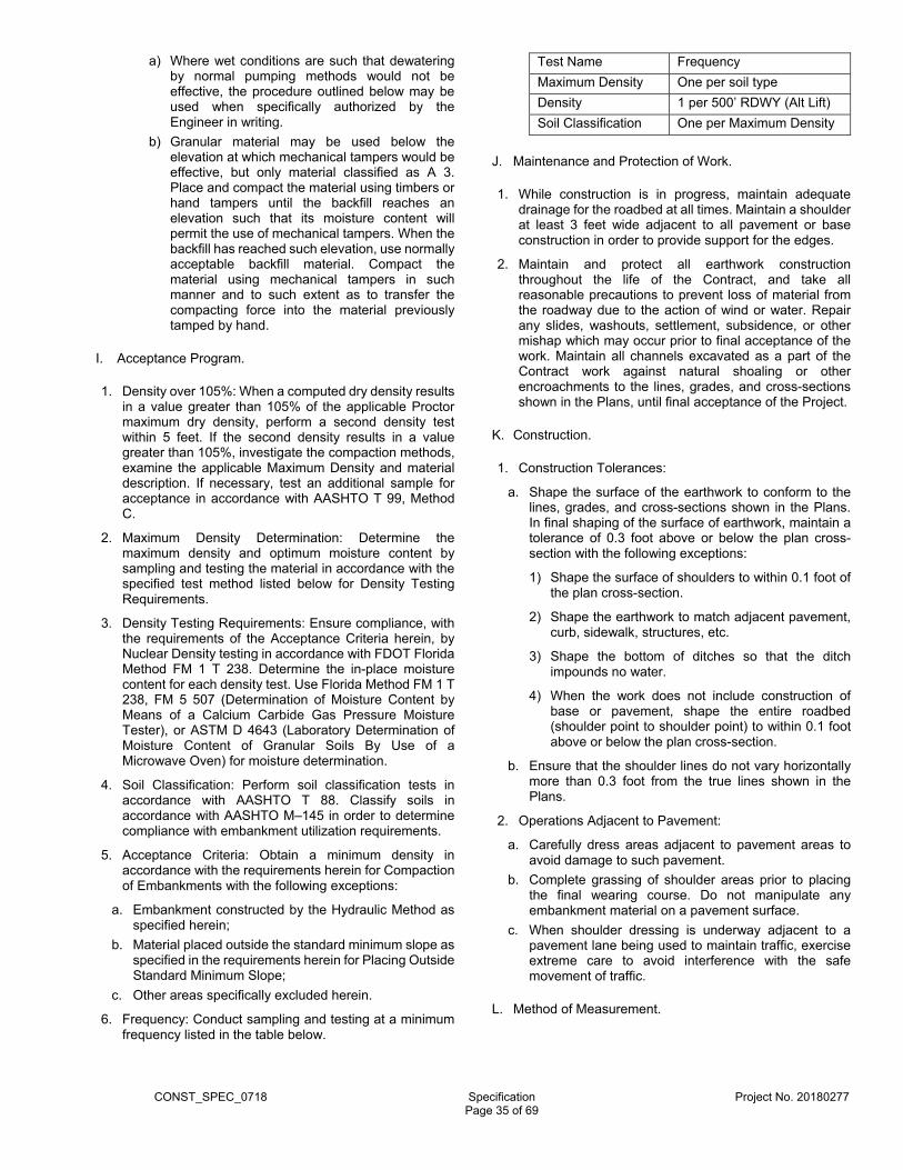
CONST_SPEC_0718 Specification Project No. 20180277
Page 35 of 69
a) Where wet conditions are such that dewatering by normal pumping methods would not be effective, the procedure outlined below may be used when specifically authorized by the Engineer in writing.
b) Granular material may be used below the elevation at which mechanical tampers would be effective, but only material classified as A 3. Place and compact the material using timbers or hand tampers until the backfill reaches an elevation such that its moisture content will permit the use of mechanical tampers. When the backfill has reached such elevation, use normally acceptable backfill material. Compact the material using mechanical tampers in such manner and to such extent as to transfer the compacting force into the material previously tamped by hand.
I. Acceptance Program.
1. Density over 105%: When a computed dry density results in a value greater than 105% of the applicable Proctor maximum dry density, perform a second density test within 5 feet. If the second density results in a value greater than 105%, investigate the compaction methods, examine the applicable Maximum Density and material description. If necessary, test an additional sample for acceptance in accordance with AASHTO T 99, Method C.
2. Maximum Density Determination: Determine the maximum density and optimum moisture content by sampling and testing the material in accordance with the specified test method listed below for Density Testing Requirements.
3. Density Testing Requirements: Ensure compliance, with the requirements of the Acceptance Criteria herein, by Nuclear Density testing in accordance with FDOT Florida Method FM 1 T 238. Determine the in-place moisture content for each density test. Use Florida Method FM 1 T 238, FM 5 507 (Determination of Moisture Content by Means of a Calcium Carbide Gas Pressure Moisture Tester), or ASTM D 4643 (Laboratory Determination of Moisture Content of Granular Soils By Use of a Microwave Oven) for moisture determination.
4. Soil Classification: Perform soil classification tests in accordance with AASHTO T 88. Classify soils in accordance with AASHTO M–145 in order to determine compliance with embankment utilization requirements.
5. Acceptance Criteria: Obtain a minimum density in accordance with the requirements herein for Compaction of Embankments with the following exceptions:
a. Embankment constructed by the Hydraulic Method as specified herein;
b. Material placed outside the standard minimum slope as specified in the requirements herein for Placing Outside Standard Minimum Slope;
c. Other areas specifically excluded herein.
6. Frequency: Conduct sampling and testing at a minimum frequency listed in the table below.
Test Name Frequency
Maximum Density One per soil type
Density 1 per 500’ RDWY (Alt Lift)
Soil Classification One per Maximum Density
J. Maintenance and Protection of Work.
1. While construction is in progress, maintain adequate drainage for the roadbed at all times. Maintain a shoulder at least 3 feet wide adjacent to all pavement or base construction in order to provide support for the edges.
2. Maintain and protect all earthwork construction throughout the life of the Contract, and take all reasonable precautions to prevent loss of material from the roadway due to the action of wind or water. Repair any slides, washouts, settlement, subsidence, or other mishap which may occur prior to final acceptance of the work. Maintain all channels excavated as a part of the Contract work against natural shoaling or other encroachments to the lines, grades, and cross-sections shown in the Plans, until final acceptance of the Project.
K. Construction.
1. Construction Tolerances:
a. Shape the surface of the earthwork to conform to the lines, grades, and cross-sections shown in the Plans. In final shaping of the surface of earthwork, maintain a tolerance of 0.3 foot above or below the plan cross-section with the following exceptions:
1) Shape the surface of shoulders to within 0.1 foot of the plan cross-section.
2) Shape the earthwork to match adjacent pavement, curb, sidewalk, structures, etc.
3) Shape the bottom of ditches so that the ditch impounds no water.
4) When the work does not include construction of base or pavement, shape the entire roadbed (shoulder point to shoulder point) to within 0.1 foot above or below the plan cross-section.
b. Ensure that the shoulder lines do not vary horizontally more than 0.3 foot from the true lines shown in the Plans.
2. Operations Adjacent to Pavement:
a. Carefully dress areas adjacent to pavement areas to avoid damage to such pavement.
b. Complete grassing of shoulder areas prior to placing the final wearing course. Do not manipulate any embankment material on a pavement surface.
c. When shoulder dressing is underway adjacent to a pavement lane being used to maintain traffic, exercise extreme care to avoid interference with the safe movement of traffic.
L. Method of Measurement.
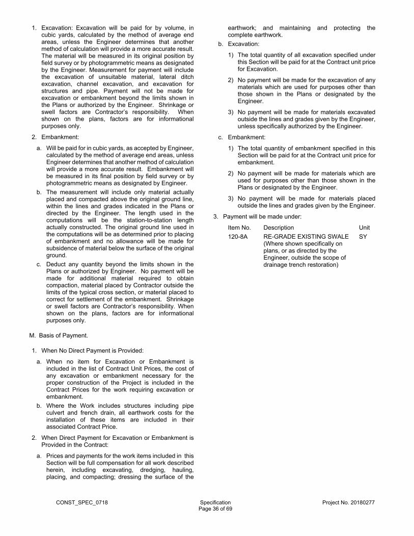
CONST_SPEC_0718 Specification Project No. 20180277
Page 36 of 69
1. Excavation: Excavation will be paid for by volume, in cubic yards, calculated by the method of average end areas, unless the Engineer determines that another method of calculation will provide a more accurate result. The material will be measured in its original position by field survey or by photogrammetric means as designated by the Engineer. Measurement for payment will include the excavation of unsuitable material, lateral ditch excavation, channel excavation, and excavation for structures and pipe. Payment will not be made for excavation or embankment beyond the limits shown in the Plans or authorized by the Engineer. Shrinkage or swell factors are Contractor’s responsibility. When shown on the plans, factors are for informational purposes only.
2. Embankment:
a. Will be paid for in cubic yards, as accepted by Engineer, calculated by the method of average end areas, unless Engineer determines that another method of calculation will provide a more accurate result. Embankment will be measured in its final position by field survey or by photogrammetric means as designated by Engineer.
b. The measurement will include only material actually placed and compacted above the original ground line, within the lines and grades indicated in the Plans or directed by the Engineer. The length used in the computations will be the station-to-station length actually constructed. The original ground line used in the computations will be as determined prior to placing of embankment and no allowance will be made for subsidence of material below the surface of the original ground.
c. Deduct any quantity beyond the limits shown in the Plans or authorized by Engineer. No payment will be made for additional material required to obtain compaction, material placed by Contractor outside the limits of the typical cross section, or material placed to correct for settlement of the embankment. Shrinkage or swell factors are Contractor’s responsibility. When shown on the plans, factors are for informational purposes only.
M. Basis of Payment.
1. When No Direct Payment is Provided:
a. When no item for Excavation or Embankment is included in the list of Contract Unit Prices, the cost of any excavation or embankment necessary for the proper construction of the Project is included in the Contract Prices for the work requiring excavation or embankment.
b. Where the Work includes structures including pipe culvert and french drain, all earthwork costs for the installation of these items are included in their associated Contract Price.
2. When Direct Payment for Excavation or Embankment is Provided in the Contract:
a. Prices and payments for the work items included in this Section will be full compensation for all work described herein, including excavating, dredging, hauling, placing, and compacting; dressing the surface of the
earthwork; and maintaining and protecting the complete earthwork.
b. Excavation:
1) The total quantity of all excavation specified under this Section will be paid for at the Contract unit price for Excavation.
2) No payment will be made for the excavation of any materials which are used for purposes other than those shown in the Plans or designated by the Engineer.
3) No payment will be made for materials excavated outside the lines and grades given by the Engineer, unless specifically authorized by the Engineer.
c. Embankment:
1) The total quantity of embankment specified in this Section will be paid for at the Contract unit price for embankment.
2) No payment will be made for materials which are used for purposes other than those shown in the Plans or designated by the Engineer.
3) No payment will be made for materials placed outside the lines and grades given by the Engineer.
3. Payment will be made under:
Item No. Description Unit
120-8A RE-GRADE EXISTING SWALE (Where shown specifically on plans, or as directed by the Engineer, outside the scope of drainage trench restoration)
SY
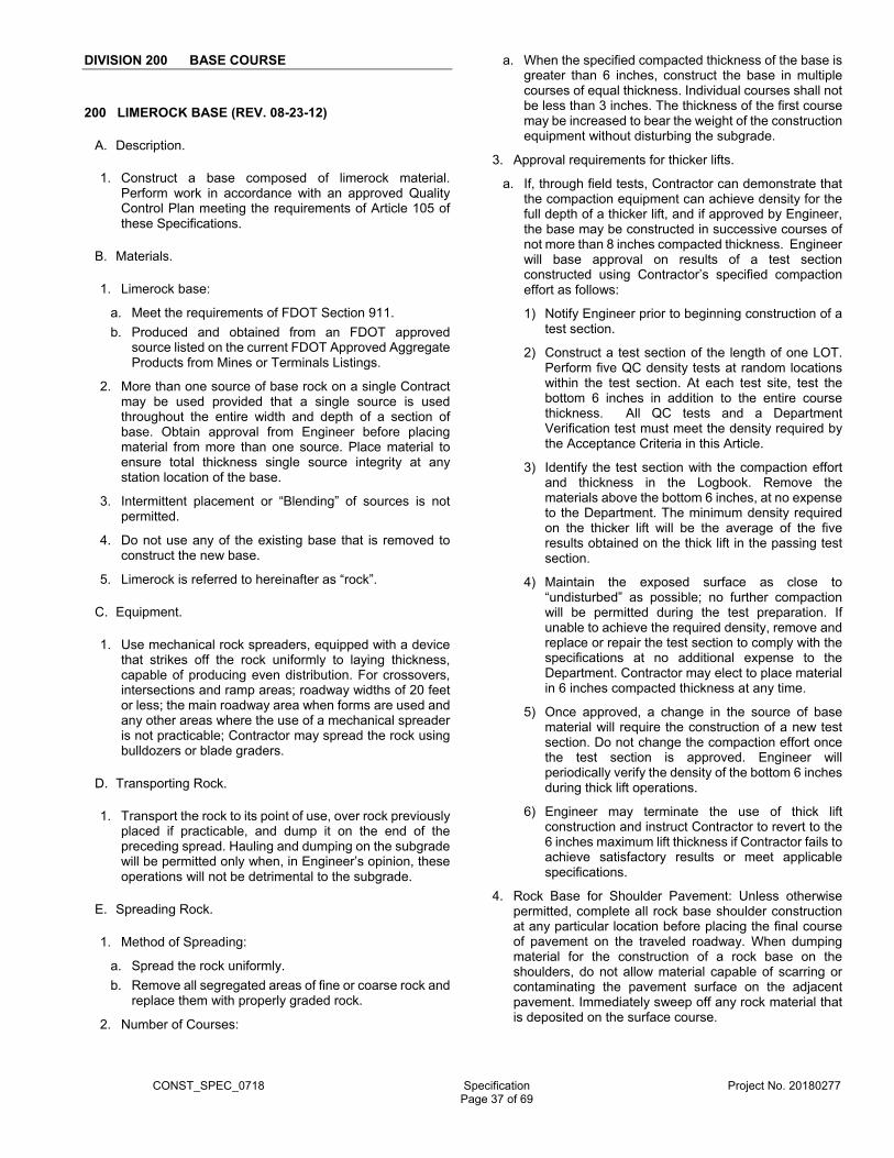
CONST_SPEC_0718 Specification Project No. 20180277
Page 37 of 69
DIVISION 200 BASE COURSE
200 LIMEROCK BASE (REV. 08-23-12)
A. Description.
1. Construct a base composed of limerock material. Perform work in accordance with an approved Quality Control Plan meeting the requirements of Article 105 of these Specifications.
B. Materials.
1. Limerock base:
a. Meet the requirements of FDOT Section 911.
b. Produced and obtained from an FDOT approved source listed on the current FDOT Approved Aggregate Products from Mines or Terminals Listings.
2. More than one source of base rock on a single Contract may be used provided that a single source is used throughout the entire width and depth of a section of base. Obtain approval from Engineer before placing material from more than one source. Place material to ensure total thickness single source integrity at any station location of the base.
3. Intermittent placement or “Blending” of sources is not permitted.
4. Do not use any of the existing base that is removed to construct the new base.
5. Limerock is referred to hereinafter as “rock”.
C. Equipment.
1. Use mechanical rock spreaders, equipped with a device that strikes off the rock uniformly to laying thickness, capable of producing even distribution. For crossovers, intersections and ramp areas; roadway widths of 20 feet or less; the main roadway area when forms are used and any other areas where the use of a mechanical spreader is not practicable; Contractor may spread the rock using bulldozers or blade graders.
D. Transporting Rock.
1. Transport the rock to its point of use, over rock previously placed if practicable, and dump it on the end of the preceding spread. Hauling and dumping on the subgrade will be permitted only when, in Engineer’s opinion, these operations will not be detrimental to the subgrade.
E. Spreading Rock.
1. Method of Spreading:
a. Spread the rock uniformly.
b. Remove all segregated areas of fine or coarse rock and replace them with properly graded rock.
2. Number of Courses:
a. When the specified compacted thickness of the base is greater than 6 inches, construct the base in multiple courses of equal thickness. Individual courses shall not be less than 3 inches. The thickness of the first course may be increased to bear the weight of the construction equipment without disturbing the subgrade.
3. Approval requirements for thicker lifts.
a. If, through field tests, Contractor can demonstrate that the compaction equipment can achieve density for the full depth of a thicker lift, and if approved by Engineer, the base may be constructed in successive courses of not more than 8 inches compacted thickness. Engineer will base approval on results of a test section constructed using Contractor’s specified compaction effort as follows:
1) Notify Engineer prior to beginning construction of a test section.
2) Construct a test section of the length of one LOT. Perform five QC density tests at random locations within the test section. At each test site, test the bottom 6 inches in addition to the entire course thickness. All QC tests and a Department Verification test must meet the density required by the Acceptance Criteria in this Article.
3) Identify the test section with the compaction effort and thickness in the Logbook. Remove the materials above the bottom 6 inches, at no expense to the Department. The minimum density required on the thicker lift will be the average of the five results obtained on the thick lift in the passing test section.
4) Maintain the exposed surface as close to “undisturbed” as possible; no further compaction will be permitted during the test preparation. If unable to achieve the required density, remove and replace or repair the test section to comply with the specifications at no additional expense to the Department. Contractor may elect to place material in 6 inches compacted thickness at any time.
5) Once approved, a change in the source of base material will require the construction of a new test section. Do not change the compaction effort once the test section is approved. Engineer will periodically verify the density of the bottom 6 inches during thick lift operations.
6) Engineer may terminate the use of thick lift construction and instruct Contractor to revert to the 6 inches maximum lift thickness if Contractor fails to achieve satisfactory results or meet applicable specifications.
4. Rock Base for Shoulder Pavement: Unless otherwise permitted, complete all rock base shoulder construction at any particular location before placing the final course of pavement on the traveled roadway. When dumping material for the construction of a rock base on the shoulders, do not allow material capable of scarring or contaminating the pavement surface on the adjacent pavement. Immediately sweep off any rock material that is deposited on the surface course.

CONST_SPEC_0718 Specification Project No. 20180277
Page 38 of 69
F. Compacting and Finishing Base.
1. General:
a. Perform work in accordance with an approved Quality Control Plan meeting the requirements of Article 105 of these Specifications and the Acceptance Criteria herein below.
b. Construct mainline pavement lanes, turn lanes, ramps, parking lots, concrete box culverts and retaining wall systems in sections of not less than 300 feet in length or for the full length of the rock base. For these, a LOT is defined as a single lift of finished embankment not to exceed 500 feet.
c. Construct shoulder-only areas, bike/shared use paths, and sidewalks in sections of not less than 300 feet in length or for the full length of the rock base. For these, a LOT is defined as 1,000 feet or one Day’s Production, whichever is greater. Shoulders compacted separately shall be considered separate LOTs.
2. Single Course Base: After spreading, scarify the entire surface. Shape the base to produce the required grade and cross-section, free of scabs and laminations, after compaction.
3. Multiple Course Base: Clean the first course of foreign material, then blade and bring it to a surface cross-section approximately parallel to the finished base. Before spreading any material for the upper courses, allow Engineer to make density tests for the lower courses to determine that the required compaction has been obtained. After spreading the material for the top course, scarify finish and shape its surface to produce the required grade and cross-section, free of scabs and laminations, after compaction.
4. Moisture Content: When the material does not have the proper moisture content to ensure the required density, wet or dry it as required. When adding water, uniformly mix it in to the full depth of the course that is being compacted. During wetting or drying operations, manipulate, as a unit, the entire width and depth of the course that is being compacted.
5. Thickness Requirements: Within the entire limits of the length and width of the finished base, meet the specified plan thickness in accordance with the Quality Control requirements specified in Depth and Surface Testing Requirements subarticle herein below.
6. Correction of Defects:
a. Contamination of Base Material: If, at any time, the subgrade material becomes mixed with the base course material, dig out and remove the mixture, and reshape and compact the subgrade. Then replace the materials removed with clean base material, and shape and compact as specified above. Perform this work at no expense to the Department.
b. Cracks and Checks: If cracks or checks appear in the base, either before or after priming, which, in the opinion of Engineer, would impair the structural efficiency of the base, remove the cracks or checks by rescarifying, reshaping, adding base material where necessary, and recompacting.
7. Compaction of Widening Strips:
a. Where base construction consists of widening strips and the trench width is not sufficient to permit use of standard base compaction equipment, compact the base using vibratory compactors, trench rollers or other special equipment which will achieve the density requirements specified herein.
b. When multiple course base construction is required, compact each course prior to spreading material for the overlaying course.
G. Acceptance Criteria:
1. Density: Within the entire limits of the width and depth of the base, obtain a minimum density in any LOT of 98% of modified Proctor maximum density as determined by FM 1-T 180, Method D. For shoulder only areas and bike/shared use paths, obtain a minimum density of 95% of the modified Proctor maximum density as determined by FM 1-T 180, Method D.
2. Frequency: Conduct QC sampling and testing at a minimum frequency listed in the table below. Engineer will perform Verification sampling and tests at a minimum frequency listed in the tables below.
Mainline Pavement Lanes, Turn Lanes, Ramps, Parking Lots, Concrete Box Culverts and Retaining Wall
Systems
Test Name Quality Control Verification
Modified Proctor Maximum Density
One per eight consecutive LOTs
One per 16 consecutive LOTs
Density One per LOT One per four LOTs
Roadway Surface
Ten per LOT Witness
Roadway Thickness
Three per LOT Witness
Shoulder-Only, Bike/Shared Use Path and Sidewalk Construction
Test Name Quality Control Verification
Modified Proctor Maximum Density
One per two LOTs
One per four LOTs
Density One per LOT One per two LOTs
Surface Five per 500 feet
Witness
Thickness Three per 600 consecutive feet
Witness
3. Initial Equipment Comparison:
a. Before initial production, perform a comparison test using the Quality Control, Verifications and Independent Assurance gauges. Unless Engineer instructs, do not perform the initial equipment comparison more than once per project. When comparing the computed dry density of one nuclear gauge to a second gauge, ensure that the difference between the two computed dry densities does not
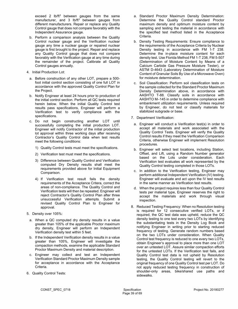
CONST_SPEC_0718 Specification Project No. 20180277
Page 39 of 69
exceed 2 lb/ft3 between gauges from the same manufacturer, and 3 lb/ft3 between gauges from different manufacturers. Repair or replace any Quality Control gauge that does not compare favorably with the Independent Assurance gauge.
b. Perform a comparison analysis between the Quality Control nuclear gauge and the Verification nuclear gauge any time a nuclear gauge or repaired nuclear gauge is first brought to the project. Repair and replace any Quality Control gauge that does not compare favorably with the Verification gauge at any time during the remainder of the project. Calibrate all Quality Control gauges annually.
4. Initial Production Lot:
a. Before construction of any other LOT, prepare a 500-foot initial control section consisting of one full LOT in accordance with the approved Quality Control Plan for the Project.
b. Notify Engineer at least 24 hours prior to production of the initial control section. Perform all QC tests required herein below. When the initial Quality Control test results pass specifications, Engineer will perform a Verification test to verify compliance with the specifications.
c. Do not begin constructing another LOT until successfully completing the initial production LOT. Engineer will notify Contractor of the initial production lot approval within three working days after receiving Contractor’s Quality Control data when test results meet the following conditions:
1) Quality Control tests must meet the specifications.
2) Verification test must meet the specifications.
3) Difference between Quality Control and Verification computed Dry Density results shall meet the requirements provided above for Initial Equipment Comparison.
4) If Verification test result fails the density requirements of the Acceptance Critera, correct the areas of non-compliance. The Quality Control and Verification tests will then be repeated. Engineer will reject Contractor’s Quality Control Plan after three unsuccessful Verification attempts. Submit a revised Quality Control Plan to Engineer for approval.
5. Density over 105%:
a. When a QC computed dry density results in a value greater than 105% of the applicable Proctor maximum dry density, Engineer will perform an Independent Verification density test within 5 feet.
b. If the Independent Verification density results in a value greater than 105%, Engineer will investigate the compaction methods, examine the applicable Standard Proctor Maximum Density and material description.
c. Engineer may collect and test an Independent Verification Standard Proctor Maximum Density sample for acceptance in accordance with the Acceptance Criteria.
6. Quality Control Tests:
a. Standard Proctor Maximum Density Determination: Determine the Quality Control standard Proctor maximum density and optimum moisture content by sampling and testing the material in accordance with the specified test method listed in the Acceptance Criteria.
b. Density Testing Requirements: Ensure compliance to the requirements of the Acceptance Criteria by Nuclear Density testing in accordance with FM 1-T 238. Determine the in-place moisture content for each density test. Use Florida Method FM 1-T 238, FM 5-507 (Determination of Moisture Content by Means of a Calcium Carbide Gas Pressure Moisture Tester), or ASTM D-4643 (Laboratory Determination of Moisture Content of Granular Soils By Use of a Microwave Oven) for moisture determination.
c. Soil Classification: Perform soil classification tests on the sample collected for the Standard Proctor Maximum Density Determination above, in accordance with AASHTO T-88. Classify soils in accordance with AASHTO M–145 in order to determine compliance with embankment utilization requirements. Unless required by Engineer, do not test or classify materials for stabilized subgrade or base.
7. Department Verification:
a. Engineer will conduct a Verification test(s) in order to accept all materials and work associated with the Quality Control Tests. Engineer will verify the Quality Control results if they meet the Verification Comparison Criteria, otherwise Engineer will implement Resolution procedures.
b. Engineer will select test locations, including Station, Offset, and Lift, using a Random Number generator based on the Lots under consideration. Each Verification test evaluates all work represented by the Quality Control testing completed in those LOTs.
c. In addition to the Verification testing, Engineer may perform additional Independent Verification (IV) testing. Engineer will evaluate and act upon the IV test results in the same manner as Verification test results.
d. When the project requires less than four Quality Control tests per material type, Engineer reserves the right to accept the materials and work through visual inspection.
8. Reduced Testing Frequency: When no Resolution testing is required for 12 consecutive verified LOTs, or if required, the QC test data was upheld, reduce the QC density testing to one test every two LOTs by identifying the substantiating tests in the Density Log Book and notifying Engineer in writing prior to starting reduced frequency of testing. Generate random numbers based on the two LOTs under consideration. When Quality Control test frequency is reduced to one every two LOTs, obtain Engineer’s approval to place more than one LOT over an untested LOT. Assure similar compaction efforts for the untested LOTs. If the Verification test fails, and Quality Control test data is not upheld by Resolution testing, the Quality Control testing will revert to the original frequency of one Quality Control test per LOT. Do not apply reduced testing frequency in construction of shoulder-only areas, bike/shared use paths and sidewalks.

CONST_SPEC_0718 Specification Project No. 20180277
Page 40 of 69
9. Quality Control Testing:
a. Modified Proctor Maximum Density Requirement: Collect enough material to split and create three separate samples and retain two for Engineer’s Verification and Resolution testing until Engineer accepts the 16 LOTs represented by the samples.
b. Depth and Surface Testing Requirements:
1) Notify Engineer a minimum of 24 hours before checking base depths and surface checking. Determine test locations including Stations and Offsets, using the Random Number generator approved by the Department. Do not perform depth and surface checks until Engineer is present to witness. Perform thickness check on the finished base or granular subbase component of a composite base. Provide traffic control, coring/boring equipment, and an operator for the coring/boring equipment. Traffic control is to be provided in accordance with the standard maintenance of traffic requirements of the Contract.
2) The thickness is considered deficient, if the measured depth is over 1/2 inch less than the specified thickness. Correct all deficient areas of the completed base by scarifying and adding additional base material. As an exception, if authorized by the Department, such areas may be left in place without correction and with no payment.
3) Check the finished surface of the base course with a template cut to the required crown and with a 15 foot straightedge laid parallel to the centerline of the road. Correct all irregularities greater than 1/4 inch to the satisfaction of the Engineer by scarifying and removing or adding rock as required, and recompact the entire area as specified hereinbefore.
c. Surface & Thickness Reduced Testing Frequency: When no Resolution testing is required for 12 consecutive verified LOTs, or if required, the QC test data was upheld, reduce the QC surface and/or thickness checks to one half the minimum requirements as stated in the frequency requirements above (e.g. Reduce frequency from ten per LOT to ten per two LOTs) by identifying the substantiating tests and notifying Engineer in writing prior to starting reduced frequency of testing. If the Verification test fails, and Quality Control test data is not upheld by Resolution testing the Quality Control testing will revert to the original frequency required by the Acceptance Criteria above. The results of the Independent Verification testing will not affect the frequency of the Quality Control testing.
10. Department Verification Tests:
a. Maximum Density: Engineer will randomly select one of the remaining two split samples and test in accordance with FM 1-T 180, Method D.
b. Thickness and Surface Testing Requirements: The Department will witness the base depth and surface checks to ensure compliance with the Depth and Surface Testing Requirements above. If the QC test results are not deficient as defined therein, the LOT or 500-foot section will be accepted. If the QC test results
are deficient, resolve deficiencies in accordance with the Depth and Surface Testing Requirements. Repeat acceptance testing. Provide traffic control, coring/boring equipment, and an operator for the coring/boring equipment.
c. Verification Comparison Criteria and Resolution Procedures:
1) Modified Proctor Maximum Density: Engineer will compare the Verification test results for Maximum Density to the corresponding Quality Control test results. If the test result is within 4.5 lb/ft3 of the QC test result, the LOTs will be verified. Otherwise, Engineer will collect the Resolution split sample corresponding to the Verification sample tested. The State Materials Office or an AASHTO accredited laboratory designated by the State Materials Office will perform Resolution testing. The material will be sampled and tested in accordance with FM 1-T 180, Method D.
2) Engineer will compare the Resolution Test results with the Quality Control test results. If the Resolution Test result is within 4.5 lb/ft3 of the corresponding Quality Control test result, Engineer will use the Quality Control test results for material acceptance purposes for each corresponding set of LOTs. If the Resolution test result is not within 4.5 lb/ft3 of the corresponding Quality Control test, Engineer will collect the remaining Verification split sample for testing. Verification Test results will be used for material acceptance purposes for the LOTs in question.
3) Density: When a Verification or Independent Verification density test does not meet the requirements of the Acceptance Criteria, retest at a site within a 5 feet radius of the Verification test location and observe the following:
a) If the Quality Control retest meets the Acceptance Criteria and compares favorably with the Verification or Independent Verification test, Engineer will accept the LOTs in question.
b) If the Quality Control retest does not meet the Acceptance Criteria and compares favorably with the Verification or Independent Verification test, rework and retest the material in that LOT. Engineer will re-verify the LOTs in question.
c) If the Quality Control retest and the Verification or Independent Verification test do not compare favorably, complete a new Equipment-Comparison Analysis. Once acceptable comparison is achieved, retest the LOTs. Engineer will perform new verification testing. Acceptance testing will not begin on a new LOT until Contractor has a gauge that meets the comparison requirements.
4) Thickness and Surface Testing Requirements: Resolve deficiencies in accordance with the Depth and Surface Testing Requirements above.
H. Priming and Maintaining.
1. Priming: Apply the prime coat only when the base meets the specified density requirements and when the
CONST_SPEC_0718 Specification Project No. 20180277
Page 41 of 69
moisture content in the top half of the base does not exceed the optimum moisture of the base material. At the time of priming, ensure that the base is firm, unyielding and in such condition that no undue distortion will occur.
2. Maintaining: Maintain the true crown and template, with no rutting or other distortion, while applying the surface course.
I. Thickness of Base.
1. Engineer will determine, as follows, the average thickness of the compacted limerock base for use in the measurements specified in the Method of Measurement:
a. Average thickness will be calculated per typical cross-section for the entire job as a unit.
b. Any measured thickness that is more than 1/2 inch greater than the design thickness shown on the typical cross-section in the Plans or, when no plans exist, the thickness specified in the description of the Contract pay item, will be considered as the design or specified thickness plus 1/2 inch.
c. Any areas of existing base left in place will not be included in the calculations.
J. Method of Measurement.
1. The quantity to be paid for will be the pay area in square yards of limerock base constructed pursuant to these specifications that is measured, adjusted as specified below, and accepted by Engineer.
a. Normal Thickness Base: The surface area of specified normal thickness base to be adjusted will be the measured quantity as specified above, omitting any areas not accepted for payment under Subarticle 200-J.2 below, and omitting areas which are to be included for payment under the Method of Measurement for Variable Thickness Base Authorized by Engineer. The pay area is determined by adjusting the aforementioned surface area using the formula below limited to a maximum for the final pay area of 105 percent of the surface area.
1) Pay Area = Surface Area × ((Calculated Average Thickness per these Specifications)/(Plan or Specified Thickness))
b. Variable Thickness Base Authorized by Engineer: Where the base is constructed to an authorized compacted thickness other than the normal thickness as shown on the typical section in the Plans, as specified on the Plans, the thickness specified in the description of the Contract pay item, or ordered as by Engineer for providing additional depths at culverts or bridges, or for providing transitions to connecting pavements; the volume of such authorized variable thickness compacted base will be calculated from authorized lines and grades, or by other methods selected by Engineer, and converted to equivalent square yards of normal thickness base for payment.
2. Additional areas that will not be included in the above measurements for payment include:
a. Areas of existing base left in place;
b. Areas where under-thickness is in excess of the allowable tolerance as specified in Subarticle 200-G.9; and
c. Areas where the work under other Contract pay item(s) includes the construction or restoration of a limerock base.
K. Basis of Payment.
1. Price and payment will be full compensation for all the work specified in this Article, including correcting all defective surface and deficient thickness, removing cracks and checks as provided above in Crack and Checks, prime coat application meeting the requirements of FDOT Section 300, and the additional rock required for crack elimination.
2. Payment will be made under the item(s) below that are provided in the Contract having awarded Contract unit price(s):
a. No separate item for Limerock base will be provided under this contract.
CONST_SPEC_0718 Specification Project No. 20180277
Page 42 of 69
DIVISION 300 BITUMINOUS TREATMENTS SURFACE COURSES AND CONCRETE PAVEMENT
327 MILLING OF EXISTING ASPHALT PAVEMENT (REV. 05-14-12)
A. Description.
1. At the locations and to the average depth of cut specified by the Contract Documents or Work Order, remove existing asphalt concrete pavement by milling to improve the rideability and cross slope of the finished pavement, to lower the finished grade adjacent to existing curb prior to resurfacing, or to completely remove existing pavement.
2. Take ownership of milled material.
B. Equipment.
1. Provide a milling machine capable of maintaining a depth of cut and cross slope that will achieve the results specified in the Contract Documents or Engineer. Use a machine with a minimum overall length (out to out measurement excluding the conveyor) of 18 feet and a minimum cutting width of 6 feet.
2. Equip the milling machine with a built-in automatic grade control system that can control the transverse slope and the longitudinal profile to produce the specified results.
3. To start the project, Engineer will approve any commercially manufactured milling machine that meets the above requirements. If it becomes evident after starting milling that the milling machine cannot consistently produce the specified results, Engineer will reject the milling machine for further use.
4. Contractor may use a smaller milling machine when milling to lower the grade adjacent to existing curb or other areas where it is impractical to use the above described equipment.
5. Equip the milling machine with means to effectively limit the amount of dust escaping during the removal operation.
6. For complete pavement removal, Engineer may approve the use of alternate removal and crushing equipment in lieu of the equipment specified above.
C. Construction.
1. General:
a. Remove the existing raised reflective pavement markers prior to milling. Include the cost of removing existing pavement markers in the price for milling.
b. When milling to improve rideability or cross slope, remove the existing pavement to the average depth specified by the Contract Documents or Work Order, in a manner that will restore the pavement surface to a uniform cross-section and longitudinal profile. Engineer may require the use of a stringline to ensure maintaining the proper alignment.
c. Establish the longitudinal profile of the milled surface in accordance with the milling plans. Ensure that the final cross slope of the milled surface parallels the surface cross slope shown on the Plans or as directed by Engineer. Establish the cross slope of the milled surface by a second sensing device near the outside edge of the cut or by an automatic cross slope control mechanism. The Plans may waive the requirement of automatic grade or cross slope controls where the situation warrants such action.
d. Operate the milling machine to minimize the amount of dust being emitted. Engineer may require prewetting of the pavement.
e. Provide positive drainage of the milled surface and the adjacent pavement. Perform this operation on the same day as milling. Repave all milled surfaces no later than the day after the surface was milled unless otherwise stated in the plans.
f. If traffic is to be maintained on the milled surface prior to the placement of the new asphalt concrete, provide suitable transitions between areas of varying thickness to create a smooth longitudinal riding surface. Produce a pattern of striations that will provide an acceptable riding surface. Engineer will require the control the traveling speed of the milling machine to produce a texture that will provide an acceptable riding surface.
g. Prior to opening an area which has been milled to traffic, sweep the pavement with a power broom or other approved equipment to remove, to the greatest extent practicable, fine material which will create dust under traffic. Sweep in a manner that will minimize the potential for creation of a traffic hazard and to minimize air pollution.
h. Sweep the milled surface with a power broom prior to placing asphalt concrete.
i. In urban and other sensitive areas, use a street sweeper or other equipment capable of removing excess milled materials and controlling dust. Obtain Engineer’s approval of such equipment, contingent upon its demonstrated ability to do the work.
j. Perform the sweeping operation immediately after the milling operations or as directed by Engineer.
2. Quality Control Requirements:
a. Furnish an electronic level with a length of 4 feet and an accuracy of plus or minus 0.1 degree approved by Engineer for the control of cross slope. Make this electronic level available at the jobsite at all times during milling operations. Calibrate and compare electronic levels at a minimum frequency of once per day before any milling operation, and at any time as directed by Engineer. If the comparison between the QC and Verification levels is within the comparison tolerance of plus or minus 0.2%, the QC level is considered to compare favorably and can be used for measurement and acceptance of cross slopes. If the levels do not compare favorably, perform a second comparison using another calibrated electronic level (PWWM or Contractor) for resolution. If this resolution level compares favorably with the QC level, the QC level is considered to be verified. If the second level does not compare favorably with the QC level, discontinue the use of the QC electronic level and
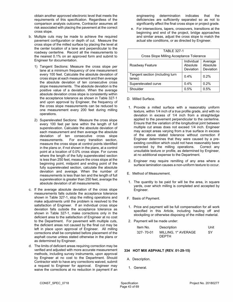
CONST_SPEC_0718 Specification Project No. 20180277
Page 43 of 69
obtain another approved electronic level that meets the requirements of this specification. Regardless of the comparison analysis outcome, Contractor assumes all risk associated with placing the pavement at the correct cross slope.
b. Multiple cuts may be made to achieve the required pavement configuration or depth of cut. Measure the cross slope of the milled surface by placing the level at the center location of a lane and perpendicular to the roadway centerline. Record all the measurements to the nearest 0.1% on an approved form and submit to Engineer for documentation.
1) Tangent Sections: Measure the cross slope per lane at a minimum frequency of one measurement every 100 feet. Calculate the absolute deviation of cross slope at each measurement and then average the absolute deviation of ten consecutive cross slope measurements. The absolute deviation is the positive value of a deviation. When the average absolute deviation cross slope is consistently within the acceptance tolerance as shown in Table 327-1 and upon approval by Engineer, the frequency of the cross slope measurements can be reduced to one measurement every 200 feet during milling operations.
2) Superelevated Sections: Measure the cross slope every 100 feet per lane within the length of full superelevation. Calculate the absolute deviation of each measurement and then average the absolute deviation of ten consecutive cross slope measurements. For every transition section, measure the cross slope at control points identified in the plans or, if not shown in the plans, at a control point at a location of 0.0% cross slope. For curves where the length of the fully superelevated section is less than 250 feet, measure the cross slope at the beginning point, midpoint and ending point of the fully superelevated section, calculate the absolute deviation and average. When the number of measurements is less than ten and the length of full superelevation is greater than 250 feet, average the absolute deviation of all measurements.
c. If the average absolute deviation of the cross slope measurements falls outside the acceptance tolerance shown in Table 327-1, stop the milling operations and make adjustments until the problem is resolved to the satisfaction of Engineer. If an individual cross slope deviation falls outside the acceptance tolerance as shown in Table 327-1, make corrections only in the deficient area to the satisfaction of Engineer at no cost to the Department. For pavement with multiple cuts, the deficient areas not caused by the final cut may be left in place upon approval of Engineer. All milling corrections shall be completed before placement of the asphalt course unless stated otherwise in the plans or as determined by Engineer.
d. The limits of deficient areas requiring correction may be verified and adjusted with more accurate measurement methods, including survey instruments, upon approval by Engineer at no cost to the Department. Should Contractor wish to have any corrections waived, submit a request to Engineer for approval. Engineer may waive the corrections at no reduction in payment if an
engineering determination indicates that the deficiencies are sufficiently separated so as not to significantly affect the final cross slope or project grade.
e. For intersections, tapers, crossovers, transitions at the beginning and end of the project, bridge approaches and similar areas, adjust the cross slope to match the actual site conditions, or as directed by Engineer.
TABLE 327-1
Cross Slope Milling Acceptance Tolerance
Roadway Feature Individual Absolute Deviation
Average Absolute Deviation
Tangent section (including turn lanes)
0.4% 0.2%
Superelevated curve 0.4% 0.2%
Shoulder 0.5% 0.5%
D. Milled Surface.
1. Provide a milled surface with a reasonably uniform texture, within 1/4 inch of a true profile grade, and with no deviation in excess of 1/4 inch from a straightedge applied to the pavement perpendicular to the centerline. Ensure that the variation of the longitudinal joint between multiple cut areas does not exceed 1/4 inch. Engineer may accept areas varying from a true surface in excess of the above stated tolerance without correction if Engineer determines that they were caused by a pre-existing condition which could not have reasonably been corrected by the milling operations. Correct any unsuitable texture or profile, as determined by Engineer, at no additional expense to the Department.
2. Engineer may require remilling of any area where a surface lamination causes a non-uniform texture to occur.
E. Method of Measurement.
1. The quantity to be paid for will be the area, in square yards, over which milling is completed and accepted by Engineer.
F. Basis of Payment.
1. Price and payment will be full compensation for all work specified in this Article, including hauling off and stockpiling or otherwise disposing of the milled material.
2. Payment will be made under:
Item No. Description Unit
327- 70-01 MILLING, 1" AVERAGE DEPTH
SY
334 HOT MIX ASPHALT (REV. 01-29-15)
A. Description.
1. General.
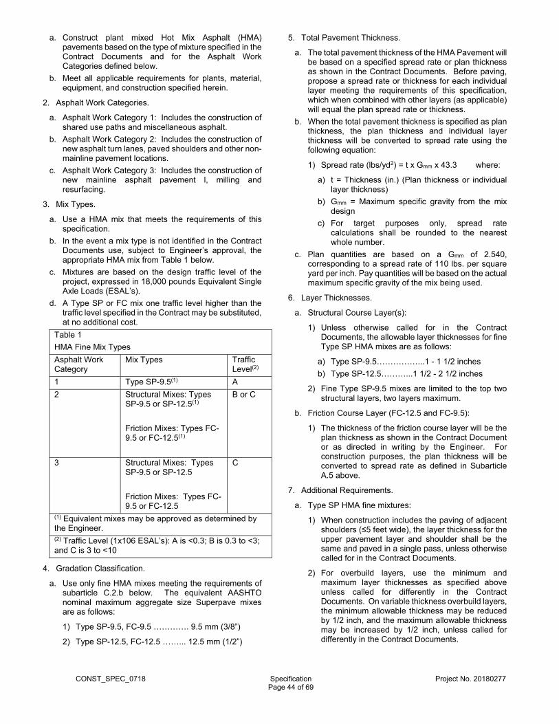
CONST_SPEC_0718 Specification Project No. 20180277
Page 44 of 69
a. Construct plant mixed Hot Mix Asphalt (HMA) pavements based on the type of mixture specified in the Contract Documents and for the Asphalt Work Categories defined below.
b. Meet all applicable requirements for plants, material, equipment, and construction specified herein.
2. Asphalt Work Categories.
a. Asphalt Work Category 1: Includes the construction of shared use paths and miscellaneous asphalt.
b. Asphalt Work Category 2: Includes the construction of new asphalt turn lanes, paved shoulders and other non-mainline pavement locations.
c. Asphalt Work Category 3: Includes the construction of new mainline asphalt pavement l, milling and resurfacing.
3. Mix Types.
a. Use a HMA mix that meets the requirements of this specification.
b. In the event a mix type is not identified in the Contract Documents use, subject to Engineer’s approval, the appropriate HMA mix from Table 1 below.
c. Mixtures are based on the design traffic level of the project, expressed in 18,000 pounds Equivalent Single Axle Loads (ESAL’s).
d. A Type SP or FC mix one traffic level higher than the traffic level specified in the Contract may be substituted, at no additional cost.
Table 1
HMA Fine Mix Types
Asphalt Work Category
Mix Types Traffic Level(2)
1 Type SP-9.5(1) A
2 Structural Mixes: Types SP-9.5 or SP-12.5(1)
Friction Mixes: Types FC-9.5 or FC-12.5(1)
B or C
3 Structural Mixes: Types SP-9.5 or SP-12.5
Friction Mixes: Types FC-9.5 or FC-12.5
C
(1) Equivalent mixes may be approved as determined by the Engineer. (2) Traffic Level (1x10⁶ ESAL’s): A is <0.3; B is 0.3 to <3; and C is 3 to <10
4. Gradation Classification.
a. Use only fine HMA mixes meeting the requirements of subarticle C.2.b below. The equivalent AASHTO nominal maximum aggregate size Superpave mixes are as follows:
1) Type SP-9.5, FC-9.5 …………. 9.5 mm (3/8”)
2) Type SP-12.5, FC-12.5 ……... 12.5 mm (1/2”)
5. Total Pavement Thickness.
a. The total pavement thickness of the HMA Pavement will be based on a specified spread rate or plan thickness as shown in the Contract Documents. Before paving, propose a spread rate or thickness for each individual layer meeting the requirements of this specification, which when combined with other layers (as applicable) will equal the plan spread rate or thickness.
b. When the total pavement thickness is specified as plan thickness, the plan thickness and individual layer thickness will be converted to spread rate using the following equation:
1) Spread rate (lbs/yd2) = t x Gmm x 43.3 where:
a) t = Thickness (in.) (Plan thickness or individual layer thickness)
b) Gmm = Maximum specific gravity from the mix design
c) For target purposes only, spread rate calculations shall be rounded to the nearest whole number.
c. Plan quantities are based on a Gmm of 2.540, corresponding to a spread rate of 110 lbs. per square yard per inch. Pay quantities will be based on the actual maximum specific gravity of the mix being used.
6. Layer Thicknesses.
a. Structural Course Layer(s):
1) Unless otherwise called for in the Contract Documents, the allowable layer thicknesses for fine Type SP HMA mixes are as follows:
a) Type SP-9.5……………...1 - 1 1/2 inches
b) Type SP-12.5………...1 1/2 - 2 1/2 inches
2) Fine Type SP-9.5 mixes are limited to the top two structural layers, two layers maximum.
b. Friction Course Layer (FC-12.5 and FC-9.5):
1) The thickness of the friction course layer will be the plan thickness as shown in the Contract Document or as directed in writing by the Engineer. For construction purposes, the plan thickness will be converted to spread rate as defined in Subarticle A.5 above.
7. Additional Requirements.
a. Type SP HMA fine mixtures:
1) When construction includes the paving of adjacent shoulders (≤5 feet wide), the layer thickness for the upper pavement layer and shoulder shall be the same and paved in a single pass, unless otherwise called for in the Contract Documents.
2) For overbuild layers, use the minimum and maximum layer thicknesses as specified above unless called for differently in the Contract Documents. On variable thickness overbuild layers, the minimum allowable thickness may be reduced by 1/2 inch, and the maximum allowable thickness may be increased by 1/2 inch, unless called for differently in the Contract Documents.
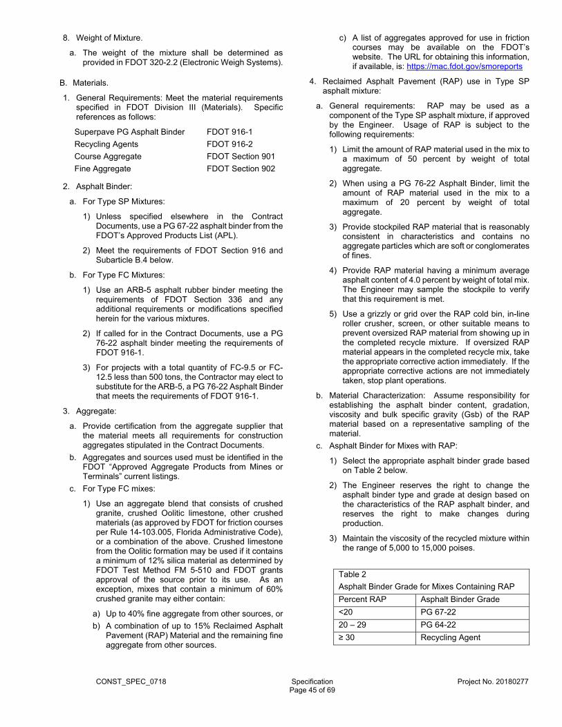
CONST_SPEC_0718 Specification Project No. 20180277
Page 45 of 69
8. Weight of Mixture.
a. The weight of the mixture shall be determined as provided in FDOT 320-2.2 (Electronic Weigh Systems).
B. Materials.
1. General Requirements: Meet the material requirements specified in FDOT Division III (Materials). Specific references as follows:
Superpave PG Asphalt Binder FDOT 916-1
Recycling Agents FDOT 916-2
Course Aggregate FDOT Section 901
Fine Aggregate FDOT Section 902
2. Asphalt Binder:
a. For Type SP Mixtures:
1) Unless specified elsewhere in the Contract Documents, use a PG 67-22 asphalt binder from the FDOT’s Approved Products List (APL).
2) Meet the requirements of FDOT Section 916 and Subarticle B.4 below.
b. For Type FC Mixtures:
1) Use an ARB-5 asphalt rubber binder meeting the requirements of FDOT Section 336 and any additional requirements or modifications specified herein for the various mixtures.
2) If called for in the Contract Documents, use a PG 76-22 asphalt binder meeting the requirements of FDOT 916-1.
3) For projects with a total quantity of FC-9.5 or FC-12.5 less than 500 tons, the Contractor may elect to substitute for the ARB-5, a PG 76-22 Asphalt Binder that meets the requirements of FDOT 916-1.
3. Aggregate:
a. Provide certification from the aggregate supplier that the material meets all requirements for construction aggregates stipulated in the Contract Documents.
b. Aggregates and sources used must be identified in the FDOT “Approved Aggregate Products from Mines or Terminals” current listings.
c. For Type FC mixes:
1) Use an aggregate blend that consists of crushed granite, crushed Oolitic limestone, other crushed materials (as approved by FDOT for friction courses per Rule 14-103.005, Florida Administrative Code), or a combination of the above. Crushed limestone from the Oolitic formation may be used if it contains a minimum of 12% silica material as determined by FDOT Test Method FM 5-510 and FDOT grants approval of the source prior to its use. As an exception, mixes that contain a minimum of 60% crushed granite may either contain:
a) Up to 40% fine aggregate from other sources, or
b) A combination of up to 15% Reclaimed Asphalt Pavement (RAP) Material and the remaining fine aggregate from other sources.
c) A list of aggregates approved for use in friction courses may be available on the FDOT’s website. The URL for obtaining this information, if available, is: https://mac.fdot.gov/smoreports
4. Reclaimed Asphalt Pavement (RAP) use in Type SP asphalt mixture:
a. General requirements: RAP may be used as a component of the Type SP asphalt mixture, if approved by the Engineer. Usage of RAP is subject to the following requirements:
1) Limit the amount of RAP material used in the mix to a maximum of 50 percent by weight of total aggregate.
2) When using a PG 76-22 Asphalt Binder, limit the amount of RAP material used in the mix to a maximum of 20 percent by weight of total aggregate.
3) Provide stockpiled RAP material that is reasonably consistent in characteristics and contains no aggregate particles which are soft or conglomerates of fines.
4) Provide RAP material having a minimum average asphalt content of 4.0 percent by weight of total mix. The Engineer may sample the stockpile to verify that this requirement is met.
5) Use a grizzly or grid over the RAP cold bin, in-line roller crusher, screen, or other suitable means to prevent oversized RAP material from showing up in the completed recycle mixture. If oversized RAP material appears in the completed recycle mix, take the appropriate corrective action immediately. If the appropriate corrective actions are not immediately taken, stop plant operations.
b. Material Characterization: Assume responsibility for establishing the asphalt binder content, gradation, viscosity and bulk specific gravity (Gsb) of the RAP material based on a representative sampling of the material.
c. Asphalt Binder for Mixes with RAP:
1) Select the appropriate asphalt binder grade based on Table 2 below.
2) The Engineer reserves the right to change the asphalt binder type and grade at design based on the characteristics of the RAP asphalt binder, and reserves the right to make changes during production.
3) Maintain the viscosity of the recycled mixture within the range of 5,000 to 15,000 poises.
Table 2
Asphalt Binder Grade for Mixes Containing RAP
Percent RAP Asphalt Binder Grade
<20 PG 67-22
20 – 29 PG 64-22
≥ 30 Recycling Agent
CONST_SPEC_0718 Specification Project No. 20180277
Page 46 of 69
C. Composition of Mixture.
1. General: Compose the asphalt mixture using a combination of aggregates, mineral filler, if required, and asphalt binder material. Size, grade and combine the aggregate fractions to meet the grading and physical properties of the mix design. Aggregates from various sources may be combined.
2. Mix Design:
a. General: Design the asphalt mixture in accordance with AASHTO R35 04, except as noted herein. Submit the proposed mix design with supporting test data indicating compliance with all mix design criteria to the Engineer. Prior to the production of any asphalt mixture, obtain the Engineer’s conditional approval of the mix design. If required by the Engineer, send representative samples of all component materials, including asphalt binder to a laboratory designated by the Engineer for verification. The Engineer will consider any marked variations from original test data for a mix design or any evidence of inadequate field performance of a mix design as sufficient evidence that the properties of the mix design have changed, and at his discretion, the Engineer may no longer allow the use of the mix design.
b. Mixture Gradation Requirements: Combine the aggregates in proportions that will produce an asphalt mixture meeting all of the requirements defined in this specification and conform to the gradation requirements at design as defined in AASHTO M323 04, Table 3. Aggregates from various sources may be combined.
1) Mixture Gradation Classification: Plot the combined mixture gradation on an FHWA 0.45 Power Gradation Chart. Include the Control Points from AASHTO M323 04, Table 3, as well as the Primary Control Sieve (PCS) Control Point from AASHTO M323 04, Table 4. Fine mixes are defined as having a gradation that passes above or through the primary control sieve control point. Use only fine mixes.
c. Gyratory Compaction: Compact the design mixture in accordance with AASHTO T312 04. Use the number of gyrations as defined in AASHTO R35 04, Table 1.
d. Design Criteria: Meet the requirements for nominal maximum aggregate size as defined in AASHTO M323 04, as well as for relative density, VMA, VFA, and dust-to-binder ratio as specified in AASHTO M323 04, Table 6.
e. Moisture Susceptibility:
1) Test 4 inch specimens in accordance with FM 1 T 283. Provide a mixture having a retained tensile strength ratio of at least 0.80 and a minimum tensile strength (unconditioned) of 100 psi. If necessary, add a liquid anti-stripping agent from the FDOT’s Qualified Products List, or hydrated lime in order to meet these criteria.
2) In lieu of moisture susceptibility testing, add a liquid anti-stripping agent from the FDOT’s Qualified Products List. Add 0.5% liquid anti-stripping agent by weight of binder.
f. Additional Information: In addition to the requirements listed above, provide the following information on each mix design:
1) The design traffic level and the design number of gyrations (Ndesign).
2) The source and description of the materials to be used.
3) The FDOT source number and the FDOT product code of the aggregate components furnished from an FDOT approved source.
4) The gradation and proportions of the raw materials as intended to be combined in the paving mixture. The gradation of the component materials shall be representative of the material at the time of use. Compensate for any change in aggregate gradation caused by handling and processing as necessary.
5) A single percentage of the combined mineral aggregate passing each specified sieve. Degradation of the aggregate due to processing (particularly material passing the No. 200 sieve) should be accounted for and identified.
6) The bulk specific gravity (Gsb) value for each individual aggregate and RAP component.
7) A single percentage of asphalt binder by weight of total mix intended to be incorporated in the completed mixture, shown to the nearest 0.1 percent.
8) A target temperature at which the mixture is to be discharged from the plant and a target roadway temperature. Do not exceed a target temperature of 330°F for modified asphalts and 315°F for unmodified asphalts.
9) Provide the physical properties achieved at four different asphalt binder contents. One shall be at the optimum asphalt content, and must conform to all specified physical requirements.
10) The name of the Mix Designer.
11) The ignition oven calibration factor.
D. Contractor Quality Control.
1. Assume full responsibility for controlling all operations and processes such that the requirements of these Specifications are met at all times. Perform any tests necessary at the plant and Project site for quality control purposes.
2. Acceptance of any automatic delivery ticket printout, electronic weight delivery ticket, or other evidence of weight of the materials or approval of any particular type of materials or production methods will not constitute agreement by the County that such matters are in accordance with the Contract Documents and it shall be the Contractor’s responsibility to ensure that the materials delivered to the project are in accordance with the Contract Documents.
E. General Construction Requirements.
CONST_SPEC_0718 Specification Project No. 20180277
Page 47 of 69
1. Weather Limitations: Do not transport asphalt mix from the plant to the roadway unless all weather conditions are suitable for the laying operations.
2. Limitations of Laying Operations:
a. General: Spread the mixture only when the surface upon which it is to be placed has been previously prepared, is intact, firm, and properly cured, and is dry.
b. Air Temperature: Spread the mixture only when the air temperature in the shade and away from artificial heat is at least 40ºF for layers greater than 1 inch (100 lb/yd2) in thickness and at least 45ºF for layers 1 inch (100 lb/yd2) or less in thickness (this includes leveling courses). The minimum temperature requirement for leveling courses with a spread rate of 50 lb/yd2 or less is 50ºF.
3. Mix Temperature: Heat and combine the ingredients of the mix in such a manner as to produce a mixture with a temperature at the plant and at the roadway, within a range of ±30ºF from the target temperature as shown on the mix design. Reject all loads outside of this range.
4. Transportation of the Mixture: Transport the mixture in vehicles previously cleaned of all foreign material. After cleaning, thinly coat the inside surface of the truck bodies with soapy water or an asphalt release agent as needed to prevent the mixture from adhering to the beds. Do not allow excess liquid to pond in the truck body. Do not use diesel fuel or any other hazardous or environmentally detrimental material as a coating for the inside surface of the truck body. Cover each load at all times.
5. Preparation of Surfaces Prior to Paving:
a. Cleaning: Clean the surface of all loose and deleterious material by the use of power brooms or blowers, supplemented by hand brooming where necessary.
b. Patching and Leveling Courses: Where the HMA is to be placed on an existing pavement which is irregular, wherever the plans indicate, or if directed by the Engineer, bring the existing surface to proper grade and cross-section by the application of patching or leveling courses.
c. Application over Surface Treatment: Where an asphalt mix is to be placed over a surface treatment, sweep and dispose of all loose material from the paving area.
d. Tack Coat: Apply a tack coat on existing pavement structures that are to be overlaid with an asphalt mix and between successive layers of all asphalt mixes, unless directed otherwise by the Engineer. Use a tack coat product meeting FDOT Section 300 (Prime and Tack Coats for Base Courses). Use an emulsified tack coat spread rate of 0.02 to 0.08 gal/sy or as specified by the Engineer.
6. Paving:
a. Alignment of Edges: With the exception of pavements placed adjacent to curb and gutter or other true edges, place all pavements by the stringline method to obtain an accurate, uniform alignment of the pavement edge. Control the unsupported pavement edge to ensure that it will not deviate more than ± 1.5 inches from the stringline.
b. Rain and Surface Conditions: Immediately cease transportation of asphalt mixtures from the plant when rain begins at the roadway. Do not place asphalt mixtures while rain is falling, or when there is water on the surface to be covered. Once the rain has stopped and water has been removed from the tacked surface to the satisfaction of the Engineer and the temperature of the mixture caught in transit still meets the requirements as specified in subarticle E.3 above, the Contractor may then place the mixture caught in transit.
c. Checking Depth of Layer: Check the depth of each layer at frequent intervals, and make adjustments when the thickness exceeds the allowable tolerance of 1/4”. Address any material outside of this tolerance per the direction of the Engineer. When making an adjustment, allow the paving machine to travel a minimum distance of 32 feet to stabilize before the second check is made to determine the effects of the adjustment.
d. Hand Spreading: In limited areas where the use of the spreader is impossible or impracticable, spread and finish the mixture by hand.
e. Spreading and Finishing: Upon arrival, dump the mixture in the approved paver, and immediately spread and strike-off the mixture to the full width required, and to such loose depth for each course that, when the work is completed, the required weight of mixture per square yard, or the specified thickness, is secured. Carry a uniform amount of mixture ahead of the screed at all times.
f. Thickness of Layers: Construct each course of Type SP mixtures in layers of thickness pursuant to subarticle A.6.a above.
7. Leveling Courses:
a. Patching Depressions: Before spreading any leveling course, fill all depressions in the existing surface more than 1 inch deep by spot patching with leveling course mixture, and compact thoroughly.
b. Spreading Leveling Courses: Place all courses of leveling with an asphalt paver or by the use of two motor graders, one being equipped with a spreader box. Other types of leveling devices may be used upon approval by the Engineer.
c. Rate of Application: When using Type SP-9.5 (fine graded) for leveling, do not allow the average spread of a layer to be less than 50 lb/yd2 or more than 75 lb/yd2. The quantity of mix for leveling shown in the plans represents the average for the entire project; however, the Contractor may vary the rate of application throughout the project as directed by the Engineer. When leveling in connection with base widening, the Engineer may require placing all the leveling mix prior to the widening operation.
8. Compaction:
a. For each paving or leveling train in operation, furnish a separate set of rollers, with their operators.
b. When density testing for acceptance is required (Asphalt Work Category 3), select equipment, sequence, and coverage of rolling to meet the specified density requirement. Regardless of the rolling procedure used, complete the final rolling before the surface temperature of the pavement drops to the
CONST_SPEC_0718 Specification Project No. 20180277
Page 48 of 69
extent that effective compaction may not be achieved or the rollers begin to damage the pavement.
c. When density testing for acceptance is not required (Asphalt Work Categories 1 and 2), use a rolling pattern approved by the Engineer.
d. Use hand tamps or other satisfactory means to compact areas which are inaccessible to a roller, such as areas adjacent to curbs, headers, gutters, bridges, manholes, etc.
9. Joints.
a. Transverse Joints: Construct smooth transverse joints, which are within 3/16 inch of a true longitudinal profile when measured with a 15 foot manual straightedge.
b. Longitudinal Joints: For all layers of pavement except the leveling course, place each layer so that longitudinal construction joints are offset 6 to 12 inches laterally between successive layers. Do not construct longitudinal joints in the wheelpaths. The Engineer may waive these requirement where offsetting is not feasible due to the sequence of construction.
10. Surface Requirements: Construct a smooth pavement with good surface texture and the proper cross-slope.
a. Texture of the Finished Surface of Paving Layers: Produce a finished surface of uniform texture and compaction with no pulled, torn, raveled, crushed or loosened portions and free of segregation, bleeding, flushing, sand streaks, sand spots, or ripples. Correct any area of the surface that does not meet the foregoing requirements in accordance with the requirements below for Correcting Unacceptable Pavement.
b. Cross Slope: Construct a pavement surface with cross slopes in compliance with the requirements of the Contract Documents.
c. Pavement Smoothness: Construct a smooth pavement meeting the requirements of this Specification. Furnish a 15 foot manual and a 15 foot rolling straightedge meeting the requirements of FM 5-509. Make them available at the job site at all times during paving operations for Asphalt Work Category 3 and make them available upon request of the Engineer for Asphalt Work Categories 1 and 2.
1) Asphalt Work Category 3:
a) Acceptance Testing: Using a rolling straightedge, test the final Type SP structural layer and the Type FC layer, where a friction course is called for in the Contract Documents. Test all pavement lanes where the width is constant using a rolling straightedge and document all deficiencies on a form approved by the Engineer. Notify the Engineer of the location and time of all straightedge testing a minimum of 48 hours before beginning testing.
b) Rolling Straightedge Exceptions: Testing with the rolling straightedge will not be required in the following areas: intersections, tapers, crossovers, parking lots and similar areas. In addition, testing with the rolling straightedge will not be performed on the following areas when they are less than 50 feet in length: turn lanes,
acceleration/deceleration lanes and side streets. However, correct any individual surface irregularity in these areas that deviates from the plan grade in excess of 3/8 inch as determined by a 15 foot manual straightedge, and that the Engineer deems to be objectionable, in accordance with the requirement below for Correcting Unacceptable Pavement. The Engineer may waive or modify straightedging requirements if no milling, leveling, overbuild or underlying structural layer was placed on the project and the underlying layer was determined to be exceptionally irregular.
c) Final Type SP Structural Layer: Straightedge the final Type SP structural layer with a rolling straightedge behind the final roller of the paving train or as a separate operation. Address all deficiencies in excess of 3/16 inch in accordance with the requirements below for Correcting Unacceptable Pavement (structural layer). If the Type SP layer is to be the final surface, corrections may be waived by the Engineer. Retest the corrected areas.
d) Friction Course Layer: Where a friction course is called for in the Contract, at the completion of all paving operations, straightedge the friction course either behind the final roller of the paving train or as a separate operation. Address all deficiencies in excess of 3/16 inch in accordance with the requirements below for Correcting Unacceptable Pavement (friction course), unless waived by the Engineer. Retest all corrected areas.
2) Asphalt Work Categories 1 and 2: If required by the Engineer, straightedge the final structural layer with a rolling straightedge, either behind the final roller of the paving train or as a separate operation. Correct all deficiencies in excess of 5/16 inch in accordance with the requirements below for Correcting Unacceptable Pavement (structural layer). Retest all corrected areas. If the Engineer determines that the deficiencies on a bicycle path are due to field geometrical conditions, the Engineer will waive corrections with no deduction to the pay item quantity.
d. Correcting Unacceptable Pavement:
1) General: Correct all areas of unacceptable pavement at no additional cost.
2) Structural Layers: Correct deficiencies in the Type SP structural layer by one of the following methods:
a) Remove and replace the full depth of the layer, extending a minimum of 50 feet on both sides of the defective area for the full width of the paving lane.
b) Mill the pavement surface to a depth and width that is adequate to remove the deficiency. (This option only applies if the structural layer is not the final surface layer.)
3) Friction Course: Correct deficiencies in the friction course layer by removing and replacing the full depth of the layer, extending a minimum of 50 feet
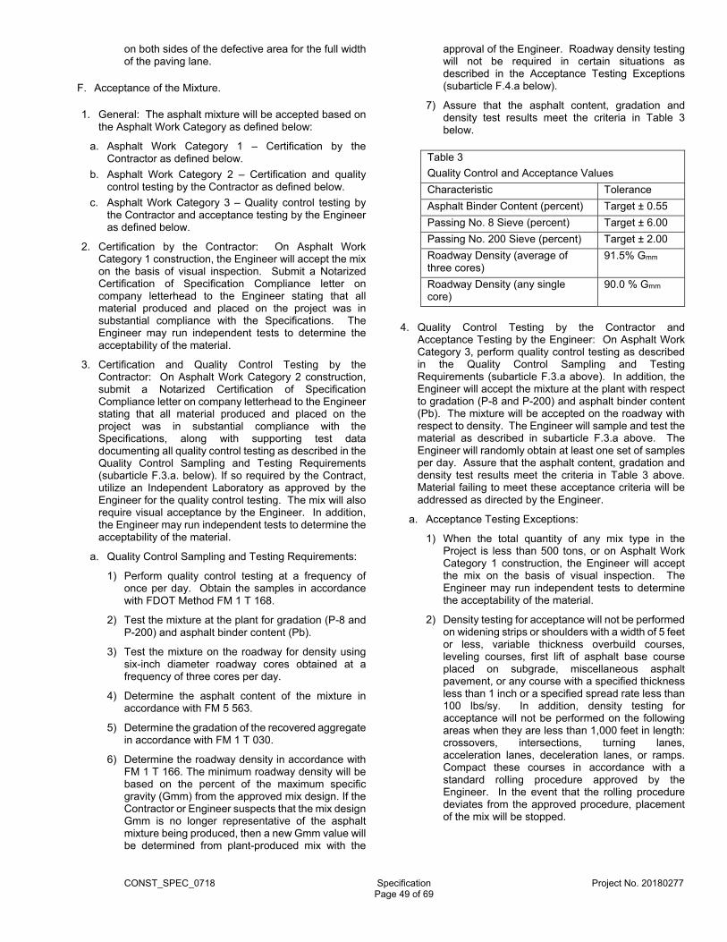
CONST_SPEC_0718 Specification Project No. 20180277
Page 49 of 69
on both sides of the defective area for the full width of the paving lane.
F. Acceptance of the Mixture.
1. General: The asphalt mixture will be accepted based on the Asphalt Work Category as defined below:
a. Asphalt Work Category 1 – Certification by the Contractor as defined below.
b. Asphalt Work Category 2 – Certification and quality control testing by the Contractor as defined below.
c. Asphalt Work Category 3 – Quality control testing by the Contractor and acceptance testing by the Engineer as defined below.
2. Certification by the Contractor: On Asphalt Work Category 1 construction, the Engineer will accept the mix on the basis of visual inspection. Submit a Notarized Certification of Specification Compliance letter on company letterhead to the Engineer stating that all material produced and placed on the project was in substantial compliance with the Specifications. The Engineer may run independent tests to determine the acceptability of the material.
3. Certification and Quality Control Testing by the Contractor: On Asphalt Work Category 2 construction, submit a Notarized Certification of Specification Compliance letter on company letterhead to the Engineer stating that all material produced and placed on the project was in substantial compliance with the Specifications, along with supporting test data documenting all quality control testing as described in the Quality Control Sampling and Testing Requirements (subarticle F.3.a. below). If so required by the Contract, utilize an Independent Laboratory as approved by the Engineer for the quality control testing. The mix will also require visual acceptance by the Engineer. In addition, the Engineer may run independent tests to determine the acceptability of the material.
a. Quality Control Sampling and Testing Requirements:
1) Perform quality control testing at a frequency of once per day. Obtain the samples in accordance with FDOT Method FM 1 T 168.
2) Test the mixture at the plant for gradation (P-8 and P-200) and asphalt binder content (Pb).
3) Test the mixture on the roadway for density using six-inch diameter roadway cores obtained at a frequency of three cores per day.
4) Determine the asphalt content of the mixture in accordance with FM 5 563.
5) Determine the gradation of the recovered aggregate in accordance with FM 1 T 030.
6) Determine the roadway density in accordance with FM 1 T 166. The minimum roadway density will be based on the percent of the maximum specific gravity (Gmm) from the approved mix design. If the Contractor or Engineer suspects that the mix design Gmm is no longer representative of the asphalt mixture being produced, then a new Gmm value will be determined from plant-produced mix with the
approval of the Engineer. Roadway density testing will not be required in certain situations as described in the Acceptance Testing Exceptions (subarticle F.4.a below).
7) Assure that the asphalt content, gradation and density test results meet the criteria in Table 3 below.
Table 3
Quality Control and Acceptance Values
Characteristic Tolerance
Asphalt Binder Content (percent) Target ± 0.55
Passing No. 8 Sieve (percent) Target ± 6.00
Passing No. 200 Sieve (percent) Target ± 2.00
Roadway Density (average of three cores)
91.5% Gmm
Roadway Density (any single core)
90.0 % Gmm
4. Quality Control Testing by the Contractor and Acceptance Testing by the Engineer: On Asphalt Work Category 3, perform quality control testing as described in the Quality Control Sampling and Testing Requirements (subarticle F.3.a above). In addition, the Engineer will accept the mixture at the plant with respect to gradation (P-8 and P-200) and asphalt binder content (Pb). The mixture will be accepted on the roadway with respect to density. The Engineer will sample and test the material as described in subarticle F.3.a above. The Engineer will randomly obtain at least one set of samples per day. Assure that the asphalt content, gradation and density test results meet the criteria in Table 3 above. Material failing to meet these acceptance criteria will be addressed as directed by the Engineer.
a. Acceptance Testing Exceptions:
1) When the total quantity of any mix type in the Project is less than 500 tons, or on Asphalt Work Category 1 construction, the Engineer will accept the mix on the basis of visual inspection. The Engineer may run independent tests to determine the acceptability of the material.
2) Density testing for acceptance will not be performed on widening strips or shoulders with a width of 5 feet or less, variable thickness overbuild courses, leveling courses, first lift of asphalt base course placed on subgrade, miscellaneous asphalt pavement, or any course with a specified thickness less than 1 inch or a specified spread rate less than 100 lbs/sy. In addition, density testing for acceptance will not be performed on the following areas when they are less than 1,000 feet in length: crossovers, intersections, turning lanes, acceleration lanes, deceleration lanes, or ramps. Compact these courses in accordance with a standard rolling procedure approved by the Engineer. In the event that the rolling procedure deviates from the approved procedure, placement of the mix will be stopped.
CONST_SPEC_0718 Specification Project No. 20180277
Page 50 of 69
G. Method of Measurement.
1. For the work specified under this Article, the quantity to be paid for will be the weight of the mixture, in tons.
2. The bid price for the asphalt mix will include the cost of the liquid asphalt or the asphalt recycling agent and the tack coat application as specified herein. There will be no separate payment or unit price adjustment for the asphalt binder material in the asphalt mix.
H. Basis of Payment.
1. No separate pay item(s) for Hot Mix Asphalt will be provided under this contract.
2. General: Price and payment will be full compensation for all the work specified under this Article.
Item No. Description Unit
334-2-13-1 Hot Mix Asphalt, Traffic C, SP-9.5
Ton
344 PORTLAND CEMENT CONCRETE (REV. 10-26-11)
A. Description.
1. Use concrete composed of a mixture of Portland cement, aggregates, and water, with or without chemical or mineral admixtures. Construct Concrete based on the type of work as described in the Contract Documents and the Concrete Work Categories below.
a. Concrete Work Category 1: Includes the construction of sidewalks, curb and gutter, ditch and slope pavement, or other non-reinforced cast-in- place or precast elements.
b. Concrete Work Category 2: Includes the construction of precast concrete including concrete barriers, traffic railing barriers, parapets, sound barriers, inlets, manholes, junction boxes, pipe culverts, storm sewers, box culverts, prestressed concrete poles, concrete bases for light poles, highway sign foundations, retaining wall systems, traffic separators or other structural precast elements.
c. Concrete Work Category 3: Includes the work associated with the placement and/or construction of structural cast-in-place concrete requiring a class of concrete specified in FDOT Section 346.
B. Materials.
1. General: Certify that all materials used in concrete meet the following requirements:
Portland Cement: FDOT Section 921 except Portland cements meeting the requirements of AASHTO M-85 or ASTM C-150 are allowed for nonstructural concrete.
Coarse Aggregate: FDOT Section 901
Fine Aggregate: FDOT Section 902
Water: FDOT Section 923
Chemical Admixtures:
FDOT Section 924
Pozzolans and Slag:
FDOT Section 929
2. Admixture Requirements: Chemical admixtures may be added at the dosage rates recommended by the manufacturer.
3. Material Storage: Use a concrete production facility that meets the following requirements.
a. Cementitious Materials Storage: Provide a separate and clearly labeled weatherproof facility to store each brand or type of cementitious material without mixing or contamination. Different brands of cement, cement of the same brand from different facilities, or different types of cement must be stored separately and must not be mixed. Provide a suitable, safe and convenient means of collecting cementitious material samples at each storage facility.
b. Aggregate Storage: Provide suitable bins, stockpiles or silos to store and identify aggregates without mixing, segregating or contaminating different grades or types of materials. Identify aggregate type/gradation. Handle the aggregates in a manner to minimize segregation and meet the specification requirements when recovered from storage. Continuously and uniformly sprinkle coarse aggregate with water, for 24 hours preceding introduction into the concrete mix. Timers may be used to facilitate the sprinkling of aggregate stockpiles using an alternating on/off method. However, in no event shall the top surface of the stockpile be permitted to become dry prior to batching of concrete. Moisture probes may be used to determine the moisture content of the aggregate. Ensure that the accuracy of the probe is certified annually and verified weekly. Maintain stored aggregates in a well-drained condition to minimize free water content. Provide access for the Engineer to sample the aggregates from the recovery side of the storage facility.
C. Production, Mixing and Delivery of Concrete.
1. Concrete Production Requirements:
a. Use concrete production facilities certified by the National Ready-Mixed Concrete Association (NRMCA) and approved by the FDOT.
b. Produce concrete utilizing equipment that is in good operating condition and operated in a manner to ensure a consistent product. When moisture probes are not used, ensure that the concrete production facility determines the free moisture for the coarse and fine aggregates within two hours prior to each day’s batching. On concrete placements expected to exceed three hours, perform an additional moisture test approximately half way through the batching operations and adjust batch proportions accordingly.
c. Ensure that the calibration of the measuring devices of the concrete production facilities meets the requirements of Chapter 531 of the Florida Statutes,
CONST_SPEC_0718 Specification Project No. 20180277
Page 51 of 69
and are in accordance with Chapter 9.2 of the FDOT Materials Manual. At least quarterly, ensure that all scales, meters and other weighing or measuring devices are checked for accuracy by a qualified representative of a scale company registered with the Bureau of Weights and Measures of the Florida Department of Agriculture. As an alternative, the producer may have this frequency identified in an FDOT approved QC plan. The accuracy of admixture measuring dispensers will be certified annually by the admixture supplier.
d. When Volumetric Mixers are used for Category I applications, deliver concrete in accordance with the requirements of Volumetric Mixer Manufacturers Bureau (VMMB) and ensure that the vehicle has a VMMB registered rating plate.
2. Classes of Concrete: Classes of concrete to be used on the Project will be as specified in the Contract Documents or FDOT Section 346 when applicable.
3. Contractors Quality Control: Provide Engineer for approval a Quality Control (QC) plan to identity to the Department how quality will be ensured at the project site. During random inspections Engineer will use this document to verify that the construction of the Project is in agreement with the QC plan and the Contract Documents.
4. Concrete Mix Design:
a. Before producing any concrete, submit the proposed mix design to Engineer on a form provided by the Department. Otherwise, the Department may accept applicable mix designs previously described in an FDOT approved QC plan. In any event, use only concrete mix designs having prior approval of the Engineer.
b. Materials may be adjusted provided that the theoretical yield requirement of the approved mix design is met. Show all required original approved design mix data and batch adjustments and substituted material on a Department approved concrete delivery ticket. Engineer may disqualify any concrete production facility for non-compliance with specification requirements.
5. Delivery:
a. For cast-in-place applications, the maximum allowable mixing and agitation time of concrete is 90 minutes.
b. Furnish a delivery ticket on a form approved by the Department with each batch of concrete before unloading at the placement site. The delivery ticket shall be printed. Record material quantities incorporated into the mix on the delivery ticket. Ensure that the Batcher responsible for producing the concrete certifies that the batch was produced in accordance with these Specifications and signs the delivery ticket. Contractor must sign the delivery ticket certifying that the concrete was batched, delivered and placed in accordance with these Specifications.
c. The Contractor is responsible for rejecting loads of concrete that do not meet the plastic properties of the approved mix design or the minimum compressive strength requirements.
d. At the sole option of the Department, the Engineer may accept concrete at a reduced pay when it is determined that the concrete will serve its intended function.
6. Placing Concrete:
a. Concreting in Cold Weather:
1) Do not place concrete when the temperature of the concrete at placement is below 45°F.
2) Meet the air temperature requirements for mixing and placing concrete in cold weather as specified in FDOT Section 346. During the curing period, if NOAA predicts the ambient temperature to fall below 35°F for 12 hours or more or to fall below 30°F for more than 4 hours, enclose the structure in such a way that the concrete and air within the enclosure can be kept above 60°F for a period of 3 days after placing the concrete or until the concrete reaches a minimum compressive strength of 1,500 psi.
3) Assume all risks connected with the placing and curing of concrete. Although Engineer may give permission to place concrete, Contractor is responsible for satisfactory results. If the placed concrete is determined to be unsatisfactory, remove, dispose of, and replace the concrete at no expense to the County.
b. Concreting in Hot Weather:
1) Meet the temperature requirements and special measures for mixing and placing concrete in hot weather as specified in FDOT Section 346.
2) When the temperature of the concrete as placed exceeds 75°F, incorporate in the concrete mix a water-reducing retarder or water reducer if allowed by FDOT Section 346.
c. Spray reinforcing steel and metal forms with cool fresh water just prior to placing the concrete in a method approved by the Engineer.
d. Assume all risks connected with the placing and curing of concrete. Although Engineer may give permission to place concrete, Contractor is responsible for satisfactory results. If the placed concrete is determined to be unsatisfactory, remove, dispose of, and replace the concrete at no expense to the County.
7. Mixers: Ensure that mixers are capable of combining the components of concrete into thoroughly mixed and uniform mass, free from balls or lumps of cementitious materials, and capable of discharging the concrete uniformly. Operate concrete mixers at speeds per the manufacturer’s design. Do not exceed the manufacturer’s rated capacity for the volume of mixed concrete in the mixer, mixing drum, or container.
8. Small Quantities of Concrete: With approval of the Engineer, small quantities of concrete, less than 3 yd3 placed in one day and less than 0.5 yd3 placed in a single placement may be accepted using a pre-bagged mixture. The Department may verify that the pre-bagged mixture is prepared in accordance with the manufacturer’s recommendations and will meet the requirements of this Specification.

CONST_SPEC_0718 Specification Project No. 20180277
Page 52 of 69
9. Sampling and Testing:
a. Category 1: Engineer may sample and test the concrete at his discretion to verify its quality. The minimum 28 day compressive strength requirement for this concrete is 3,000 psi.
b. Category 2: Provide a statement of certification from the manufacturer of the precast element that the element meets the quality control and inspection testing requirements of the Contract Documents.
c. Category 3: The Department will randomly select a sample from each 200 yd3 or one day’s production to determine plastic properties and to make three 4 x 8 inch cylinders for testing by the Department at 28 days to ensure that the design compressive strength has been met. The Department may, at its discretion, test additional concrete samples to ensure compliance with the Specifications.
10. Records: Maintain the following records for review for at least 3 years after final acceptance of the Project:
a. Approved concrete mix designs.
b. Materials source (delivery tickets, certifications, certified mill test reports).
c. A copy of the scale company or testing agency report showing the observed deviations from quantities checked during calibration of the scales and meters.
d. A copy of the documentation certifying the admixture weighing/measuring devices.
e. For non structural concrete, the Department will accept recent NRMCA, VMMB or FDOT inspection records certifying the plant or truck can produce concrete. In addition, documentation will be available at the plant or in the truck showing that action has been taken to correct deficiencies noted during the inspections.
D. Acceptance of the Work.
1. Category 1 Work: Category 1 work will be accepted based upon compliance with Production, Mixing and Delivery Requirements specified in herein.
2. Category 2 Work: Precast elements will be accepted based upon certification from the Contractor that the elements were produced by a production facility on the FDOT’s current approved plant list. In addition, the producers QC stamp will be displayed on the element.
3. Category 3 Work: Category 3 work shall be in full compliance with this Specification, and with current FDOT Specifications, FDOT Section 346 and associated Contractor Quality Control (QC) specifications governing cast-in-place concrete. In addition, a Delivery Ticket as described in Subarticle 344-B.5 will be required for acceptance of the material at the Project site.
E. Method of Measurement.
1. The quantities to be paid for will be the concrete items having awarded Contract Prices that are completed and accepted by Engineer.
F. Basis of Payment.
1. Prices and payments will be full compensation for all work and materials specified in this Article and the Articles applicable to the items of work having awarded Contract Prices measured and approved for payment.
CONST_SPEC_0718 Specification Project No. 20180277
Page 53 of 69
DIVISION 400 STRUCTURES
425 INLETS, MANHOLES AND JUNCTION BOXES (SECTION 425)
A. Page 417, Subarticle 425-6.6 - Placing Pipe; The third sentence of this sub-article is modified to read:
1. When catch basins are called for, the inlet and outlet pipe may extend into the structure not to exceed 4 inches beyond the interior face of the wall.
B. Page 417, Subarticle 425-6.7 Backfilling; is modified to include the following:
1. Select material shall be used for backfill adjacent to catch basins and riser inlets, as detailed in the Plans. It shall consist of well-graded limerock or limerock and sand fill. Sand or fill having a high proportion of sand will not be accepted as select fill. All select fill shall be approved by the Engineer prior to placing. No separate payment will be made for select fill, but shall be included in the unit bid price for each particular item as indicated in the Bid Form of the Proposal.
C. Page 417, Subarticle 425-8.2 - Adjusted Structures; is expanded to include the following:
1. Upon completion of the work, and prior to acceptance and final payment, all such structures will be inspected by the Engineer to ensure that they are free of all debris and thoroughly cleaned. All drainage structures within the project limits shall be cleaned thoroughly and made free of all debris prior to final acceptance by the County. The Contractor shall include within the scheduled items listed on the Contract’s Bid Form, the cost of all work necessary for cleaning and debris removal.
D. Page 418, Subarticle 425-8.3 – Payment Items; is expanded to include the following:
1. When a separate item is listed on the Bid Form for cleaning of structures, said item shall only be used when indicated on the Engineering Plans or as directed by the Engineer, and only for the cleaning of drainage structures that were not impacted by construction activities.
2. Payment will be made under:
Item No. Description Unit
425-1-1 SWALE INLET TYPE D-3 (36"Dia. ) (Less than 10 feet deep )
EA
425-1-2A SWALE INLET TYPE D-3 (36"X36" , less than 10' deep )
EA
425-1-2B SWALE INLET TYPE D-1 (17" X 27") (< 10' Deep)
EA
425-1-902 SWALE INLET TYPE P-10M (Any dimension, maximum depth 15')
EA
425-2-41 Manhole (Type P-7t, Any Dimension, Maximum 15' Deep)
EA
425-79 CORE AND TIE TO EXIST. DRAINAGE STRUCTURES.
EA
425-82 MODIFY STRUCTURE- EA
430 PIPE CULVERTS (REV. 01-12-16)
A. Description.
1. Furnish and install drainage pipe and end sections at the locations called for in the Plans or as directed by Engineer. Furnish and construct joints and connections to existing pipes, catch basins, inlets, manholes, walls, etc., as may be required to complete the work.
2. Construct structural plate pipe culverts or underdrains in accordance with FDOT Sections 435 and 440.
3. Obtain pipe culverts from a Producer currently on the FDOT’s list of Producers with Accepted Quality Control Programs. Producers seeking inclusion on the list shall meet the requirements of FDOT 105-3.
4. When the producer’s FDOT Quality Control Program is suspended, accept responsibility of either obtaining drainage products from another producer with an accepted FDOT Quality Control Program or await re-approval of the producer’s FDOT Quality Control Program. Engineer will not allow changes in Contract Time or completion dates as a result of the producer’s FDOT Quality Control Program suspension. Accept responsibility for all delay costs or other costs associated with the producer’s FDOT Quality Control Program suspension.
B. Materials.
1. Pipe: Meet the following requirements:
Concrete Pipe FDOT Section 449
Round Rubber Gaskets FDOT Section 942
Corrugated Steel Pipe and Pipe Arch
FDOT Section 943
Corrugated Aluminum Pipe and Pipe Arch
FDOT Section 945
Corrugated Polyethylene Pipe
FDOT Section 948
Polyvinyl Chloride (PVC) Pipe
FDOT Section 948
2. Joint Materials: Use joint materials specified in this Article according to type of pipe and conditions of usage.
3. Mortar: Use mortar composed of one part portland cement and two parts of clean, sharp sand, to which mixture Contractor may add hydrated lime in an amount not to exceed 15% of the cement content. Use mortar within 30 minutes after its preparation.
C. Type of Pipe to Be Used.
1. When the Plans designate a type (or types) of pipe, use only the type (or choose from the types) designated.

CONST_SPEC_0718 Specification Project No. 20180277
Page 54 of 69
2. If the Plans do not designate a type (or types) of pipe, Contractor, subject to Engineer’s approval, may use either a minimum Class I concrete pipe, corrugated steel pipe, corrugated aluminum pipe, corrugated polyethylene pipe or PVC pipe. If one of the metal types is chosen, use the minimum gage specified in FDOT Section 943 for steel pipe or FDOT Section 945 for aluminum pipe.
3. Class I corrugated Polyethylene Pipe may be used on local (non-arterial or non-collector) roads only.
D. Laying Pipe.
1. General:
a. Lay all pipe, true to the lines and grades given, with hubs upgrade and tongue end fully entered into the hub. When pipe with quadrant reinforcement or circular pipe with elliptical reinforcement is used, install the pipe in a position such that the manufacturer’s marks designating “top” and “bottom” of the pipe are not more than five degrees from the vertical plane through the longitudinal axis of the pipe. Do not allow departure from and return to plan alignment and grade to exceed 1/16 inch per foot of nominal pipe length, with a total of not more than 1 inch departure from theoretical line and grade. Take up and relay any pipe that is not in true alignment or which shows any settlement after laying at no additional expense to the Department.
b. Do not use concrete pipe with lift holes except round pipe which has an inside diameter in excess of 54 inches or any elliptical pipe.
c. Repair lift holes, if present, by use of a hand-placed, stiff, non-shrink, 1-to-1 mortar of cement and fine sand, after first washing out the hole with water. Completely fill the void created by the lift hole with mortar. Cover the repaired area with a 24 by 24 inches piece of filter fabric secured to the pipe. Use a Type D-3 filter fabric meeting the requirements shown on FDOT Design Standards, Index 199 and the Contract Documents.
d. Secure the filter fabric to the pipe using a method that holds the fabric in place until the backfill is placed and compacted. Use a grout mixtures, mastics, or strapping devices to secure the fabric to the pipe.
e. When installing pipes in structures, construct inlet and outlet pipes of the same size and kind as the connecting pipe shown in the Plans. Extend the pipes through the walls for a distance beyond the outside surface sufficient for the intended connections, and construct the concrete around them neatly to prevent leakage along their outer surface as shown on the FDOT Design Standards, Index 201. Keep the inlet and outlet pipes flush with the inside of the wall. Resilient connectors as specified in FDOT 942-3 may be used in lieu of a masonry seal.
f. Furnish and install a filter fabric jacket around all pipe joints and the joint between the pipe and the structure in accordance with FDOT Design Standards, Index Nos. 201 and 280. Use fabric meeting the physical requirements of Type D-3 specified on the FDOT Design Standards, Index 199 and the Contract Documents. The fabric shall extend a minimum of 12 inches beyond each side of the joint or both edges of the coupling band, if a coupling band is used. The fabric shall have a minimum width of 24 inches, and a length
sufficient to provide a minimum overlap of 24 inches. Secure the filter fabric jacket against the outside of the pipe by metal or plastic strapping or by other methods approved by Engineer.
g. Meet the following minimum joint standards:
Pipe Application
Minimum Standard
Storm and Cross Drains
Water-tight
Gutter Drain Water-tight
Side Drains Soil-tight
h. When rubber gaskets are to be installed in the pipe joint, the gasket shall be the sole element relied on to maintain a tight joint. Soil tight joints must be watertight to 2 psi. Water-tight joints must be water-tight to 5 psi unless a higher pressure rating is required in the Plans.
2. Trench Excavation: Excavate the trench for storm and cross drains, and side drains as specified in the Contract Documents.
3. Foundation: Provide a suitable foundation, where the foundation material is of inadequate supporting value, as determined by Engineer. Remove the unsuitable material and replace it with suitable material, as specified in Article 120 (Earthwork and Related Operations) of these Specifications. Where in Engineer’s opinion, the removal and replacement of unsuitable material is not practicable, he may direct alternates in the design of the pipe line, as required to provide adequate support. Minor changes in the grade or alignment will not be considered as an adequate basis for extra compensation. Do not lay pipe on blocks or timbers, or on other unyielding material, except where the use of such devices is called for in the Plans.
4. Backfilling: Backfill around the pipe as specified in Article 120 (Earthwork and Related Operations) of these Specifications unless specific backfilling procedures are described in the Contract Documents.
5. Plugging Pipe:
a. When existing pipe culverts are to be permanently placed out of service, fill them with flowable fill that is non-excavatable, contains a minimum 350 lbs/cy of cementious material and meets the requirements Article 121 (Flowable Fill) and/or plug them with masonry plugs as required by the Contract Documents. Install masonry plugs that are a minimum of 8 inches in thickness, in accordance with FDOT Design Standards Index 280.
b. When proposed or existing pipe culverts are to be temporarily placed out of service, plug them with prefabricated plugs as shown in the Plans. Install prefabricated plugs in accordance with the manufacturer’s recommendations. Do not fill, or construct masonry plugs in, any pipe culverts intended for current or future service.
6. End Treatment:
a. Place an end treatment at each storm and cross drain, and side drain as shown in the Plans. Refer to the FDOT Design Standards for types of end treatment details.

CONST_SPEC_0718 Specification Project No. 20180277
Page 55 of 69
b. As an exception to the above, when concrete mitered end sections are permitted, Contractor may use reinforced concrete U-endwalls, if shop drawings are submitted to Engineer for approval prior to use.
c. Provide end treatments for corrugated polyethylene pipe and PVC pipe as specified in FDOT Section 948, or as detailed in the Plans.
7. Metal Pipe Protection:
a. Apply a bituminous coating to the surface area of the pipe within and 12 inches beyond the concrete or mortar seal prior to sealing, to protect corrugated steel or aluminum pipe embedded in a concrete structure, such as an inlet, manhole, junction box, endwall, or concrete jacket.
b. Ensure that the surface preparation, application methods (dry film thickness and conditions during application), and equipment used are in accordance with the coating manufacturers’ published specifications.
c. Obtain Engineer’s approval of the coating products used.
8. Final Pipe Inspection:
a. Pipe must be lay under direct supervision of Engineer at all times. In the event that a specific job site requires a video inspection, and it is approved by Engineer, pipe must be inspected as per FDOT Article 430-4.8. County will pay for the cost of inspection and report.
E. Removing Existing Pipe.
1. If the Plans indicate that existing pipe is to remain the property of the Department, collect and stack along the right-of-way all existing pipe or pipe arch so indicated in the Plans to be removed, or that does not conform to the lines and grades of the proposed work and that is not to be re-laid, as directed by Engineer. Take care to prevent damage to salvageable pipe during removal and stacking operations.
F. Placing Pipe Under Railroad.
1. General: Construct pipe culverts under railroad tracks in accordance with the requirements of the railroad company. Perform all the shoring under the tracks, and sheeting and bracing of the trench, required by the railroad company or deemed necessary by Engineer in order to ensure safe and uninterrupted movement of the railroad equipment, at no expense to the Department.
2. Requirements of the Railroad Company:
a. Install pipe using methods required by the railroad company and shown in the Contract Documents.
b. When the general method of installation required by the railroad company is indicated in the Plans, do not alter such method, or any other specific details of the installation which might be indicated in the Plans, without receiving approval or direction from the railroad, followed by written approval from Engineer.
3. Notification to Railroad Company: Notify the railroad company and Engineer at least ten days prior to the date on which pipe is to be placed under the railroad tracks.
4. Placing Pipe by Jacking: Obtain Engineer’s and the railroad company’s approval of the details of the jacking method to be used, when placing pipe through the railroad embankment, before the work is started.
5. Use of Tunnel Liner: When the railroad company requires that a tunnel liner be used for placing the pipe in lieu of the jacking method, the Department will pay for the tunnel liner material separately in cases where the Contract Documents do not require the use of a tunnel liner. For these cases the Department will reimburse Contractor for the actual cost of the liner, delivered at the site. The Department will base such cost on a liner having the minimum gage acceptable to the railroad.
G. Specific Requirements for Concrete Pipe.
1. Sealing Joints: Seal the pipe joints with round rubber or profile gaskets meeting the requirements of FDOT Section 449. Ensure that the gasket and the surface of the pipe joint, including the gasket recess, are clean and free from grit, dirt and other foreign matter, at the time the joints are made. In order to facilitate closure of the joint, application of a vegetable soap lubricant immediately before closing of the joint will be permitted. Prelubricated gaskets may be used in lieu of a vegetable soap lubricant when the lubricating material is certified to be inert with respect to the rubber material.
2. Laying Requirements for Concrete Pipe with Rubber Gasket Joints: Do not allow the gap between sections of pipe to exceed 5/8 inch for pipe diameters of 12 inches through 18 inches, 7/8 inch for pipe diameters of 24 through 66 inches, and 1 inch for pipe diameters 72 inches and larger. Where minor imperfections in the manufacture of the pipe create an apparent gap in excess of the tabulated gap, Engineer will accept the joint provided that the imperfection does not exceed 1/3 the circumference of the pipe, and the rubber gasket is 1/4 inch or more past the pipe joint entrance taper. Where concrete pipes are outside of these tolerances, replace them at no expense to the Department. Do not apply mortar, joint compound, or other filler to the gap which would restrict the flexibility of the joint.
3. Field Joints for Elliptical Concrete Pipe: Use either a preformed plastic gasket material or an approved rubber gasket to make a field joint.
a. Plastic Gasket. For field joints that are made from preformed plastic gasket material; install field joints in accordance with the manufacturer’s instructions and the following:
1) Material: Meet the requirements of FDOT 942-2.
2) Joint Design: Ensure that the pipe manufacturer furnishes Engineer with details regarding configuration of the joint and the amount of gasket material required to affect a satisfactory seal. Do not brush or wipe joint surfaces which are to be in contact with the gasket material with a cement slurry. Fill minor voids with cement slurry.
3) Primer: Apply a primer of the type recommended by the manufacturer of the gasket material to all joint surfaces which are to be in contact with the gasket
CONST_SPEC_0718 Specification Project No. 20180277
Page 56 of 69
material, prior to application of the gasket material. Thoroughly clean and dry the surface to be primed.
4) Application of Gasket: Apply gasket material to form a continuous gasket around the entire circumference of the leading edge of the tongue and the groove joint, in accordance with the detail shown on the Design Standards, Index No. 280. Do not remove the paper wrapper on the exterior surface of the gasket material until immediately prior to joining of sections. Apply plastic gasket material only to surfaces which are dry. When the atmospheric temperature is below 60ºF, either store plastic joint seal gaskets in an area above 70ºF, or artificially warm the gaskets to 70ºF in a manner satisfactory to Engineer.
5) Installation of Pipe: Remove and reposition or replace any displaced or contaminated gasket as directed by Engineer. Install the pipe in a dry trench. Carefully shape the bottom of the trench to minimize the need for realignment of sections of pipe after they are placed in the trench. Hold to a minimum any realignment of a joint after the gaskets come into contact. Prior to joining the pipes, fill the entire joint with gasket material and ensure that when the pipes are joined there is evidence of squeeze-out of gasket material for the entire internal and external circumference of the joint. Trim excess material on the interior of the pipe to provide a smooth interior surface. If a joint is defective, remove the leading section of pipe and reseal the joint.
b. Rubber Gasket. For field joints that are made with profile rubber gaskets; install field joints in accordance with the manufacturer’s instructions and the following:
1) Material: Meet the requirements of FDOT 942-4.
2) Joint Design: Ensure that the pipe manufacturer furnishes Engineer with details regarding configuration of the joint and gasket required to effect a satisfactory seal. Do not apply mortar, joint compound, or other filler which would restrict the flexibility of the gasket joint.
4. Requirements for Concrete Radius Pipe:
a. Design: Construct concrete radius pipe in segments not longer than 4 feet (along the pipe centerline), except where another length is called for in the Contract Documents. Join each segment using round rubber gaskets. Ensure that the pipe manufacturer submits details of the proposed joint, segment length and shape for approval by Engineer, prior to manufacture.
b. Pre-Assembly: Ensure that the manufacturer pre-assembles the entire radius section in his yard, in the presence of Engineer, to ensure a proper fit for all parts. At the option of the manufacturer, Contractor may assemble the pipe without gaskets. Consecutively number the joints on both the interior and exterior surfaces of each joint, and make match marks showing proper position of joints. Install the pipe at the project site in the same order as pre-assembly.
H. Specific Requirements for Corrugated Metal Pipe.
1. Field Joints:
a. General:
1) Make a field joint with locking bands, as specified in Article 9 of AASHTO M 36 and AASHTO M 196M for aluminum pipe. For aluminum pipe, fabricate bands from the same alloy as the culvert sheeting.
2) When existing pipe to be extended is helically fabricated, make a field joint between the existing pipe and the new pipe using one of the following methods:
a) Cut the new pipe to remove one of the re-rolled annular end sections required in FDOT Sections 943 or 945, or fabricate the pipe so that the re-rolled annular section is fabricated only on one end. Use either a spiral (helical) band with a gasket or a flat band with gaskets as required by Subarticle 430-H.1.b.1) b) to join the pipe sections.
b) Contractor may construct a concrete jacket as shown on the FDOT Design Standards, Index No. 280, provided that the minimum cover required by the FDOT Design Standards, Index No. 205 can be obtained.
b. Side Drain, Storm and Cross Drain, and Gutter Drains: Where corrugated metal pipe is used as side drain, storm and cross drain, or gutter drain, use a rubber or neoprene gasket of a design shown to provide a joint as specified in Subarticle 430-D.
1) Use a gasket of one of the following dimensions:
a) For annular joints with 1/2 inch depth corrugation: either a single gasket a minimum of 7 inches by 3/8 inch or two gaskets a minimum of 3 1/2 inches by 3/8 inch; and for annular joints with 1 inch depth corrugations: either a single gasket a minimum of 7 inches by 7/8 inch or two gaskets a minimum of 3 1/2 inches by 7/8 inch.
b) For helical joints with 1/2 inch depth corrugation: either a single gasket a minimum of 5 inches by 1 inch or two gaskets a minimum of 3 1/2 inches by 1 inch; and for helical joints with 1 inch depth corrugations: either a single gasket a minimum of 5 inches by 1 1/2 inches or two gaskets a minimum of 3 1/2 inches by 1 1/2 inches.
c) Such other gasket designs as may be approved by Engineer.
2) If, in lieu of a single gasket spanning the joint, two gaskets are used, place these individual gaskets approximately 2 inches from each pipe end at the joint. When two gaskets are used, seal the overlapping area on the coupling band between the gaskets consistent with the joint performance specified. Contractor may tuck a strip of preformed gasket material over the bottom lip of the band for this purpose. Use coupling bands that provide a minimum circumferential overlap of 3 inches. As the end connections on the coupling band are tightened, ensure that there is no local bending of the band or the connection. Use precurved coupling bands on pipe diameters of 24 inches or less.
3) Use flat gaskets meeting the requirements of ASTM D-1056, designation 2C2 or 2B3. In placing flat
CONST_SPEC_0718 Specification Project No. 20180277
Page 57 of 69
gaskets on pipe prior to placing the coupling band, do not stretch the gasket more than 15% of its original circumference. Use circular gaskets meeting the requirements of ASTM C-361. Do not stretch the circular gasket more than 20% of its original circumference in placing the gasket on pipe. Use preformed plastic gasket material meeting the composition requirements of FDOT 942-2.2.
4) Apply an approved vegetable soap lubricant, as specified for concrete pipe in Subarticle 430-G.1.
c. Alternate Joint: In lieu of the above-specified combination of locking bands and flat gaskets, Contractor may make field joints for these pipe installations by the following combinations:
1) Use the metal bands as specified in Article 9 of AASHTO M 36M that are at least 10 1/2 inches wide and consist of a flat central section with a corrugated section near each end, designed to match the annular corrugation in the pipe with which they are to be used. Connect the bands in a manner approved by Engineer, with a suitable fastening device such as the use of two galvanized 1/2 inch diameter bolts through a galvanized bar and galvanized strap, suitably welded to the band. Use a strap that is the same gage as the band.
2) Where helically corrugated pipe is to be jointed by this alternate combination, ensure that at least the last two corrugations of each pipe section are annular, and designed such that the band will engage each pipe end with the next-to-outside annular corrugation.
3) For these bands, use a rubber gasket with a circular cross-section of the “O-ring” type conforming to ASTM C-361. Use gaskets having the following cross-sectional diameter for the given size of pipe:
Pipe Size Gasket Diameter
12 inches through 36 inches (with 1/2 inch depth corrugations)
13/16 inch
42 inches through 96 inches (with 1/2 inch depth corrugations)
7/8 inch
36 inches through 120 inches (with 1 inch depth corrugations)
1 3/8 inches
4) Use preformed gasket material to seal the overlapping area on the coupling band between gaskets.
5) Use channel band couplers in helical pipe with ends which have been reformed and flanged specifically to receive these bands. Use channel band couplers that are of a two piece design, are fabricated from galvanized steel stock conforming to AASHTO M 36, have 2 by 2 by 3/16 inch angles fastened to the band ends to allow for proper tightening, and meet the following:
Band Thickness Pipe Wall Thickness
0.079 inch 0.109 inch or lighter
0.109 inch 0.138 inch or heavier
3/4 inch wide 0.109 inch or lighter
1 inch wide 0.138 inch or heavier
6) Furnish two 1/2 inch diameter connection bolts with each band, that conform to ASTM A-307, Grade A and are electroplated in accordance with ASTM B-633.
7) Use a gasket with the joint that is a hydrocarbon blend of butyl rubber meeting the chemical composition and physical properties of FDOT 942-2.2. Use a 3/8 by 3/4 inch gasket for pipe fabricated from 0.109 inch or lighter material and a 3/8 by 1 inch gasket for pipe fabricated from 0.138 inch and heavier material.
8) Contractor may use a flange band coupler without the gasket for all applications other than side drain, storm and cross drain, and gutter drain.
9) Do not use the flange band coupler to join dissimilar types of pipe.
10) Contractor may join reformed flanged helical pipe to existing annular or reformed pipe having annular ends. On non-gasketed installations, use either an annular band or an alternate joint described in Subarticle 430-H.1.c. On gasketed installations, use an annular band, minimum of five corrugations in width, in conjunction with two O-ring gaskets as specified in Subarticle 430-H.1.c. Use mastic material to seal the area of band overlap.
11) The minimum joint performance standards specified in Subarticle 430-D.1 applies.
2. Laying and Shape Requirements for Corrugated Metal Pipe: Install pipe using either a trench or open ditch procedure.
a. Check pipe shape regularly during backfilling to verify acceptability of the construction method used. Pipe deflected 5% or more of the certified actual mean diameter of the pipe shall be replaced at no cost to the Department. Deflection measurements are taken at the point of smallest diameter on the corrugations.
I. Specific Requirements for Corrugated Polyethylene Pipe and Polyvinyl Chloride (PVC) Pipe.
1. Field Joints: Use gasketed joints to seal side drain, and storm and cross drain. Use gaskets meeting the requirements of FDOT Section 449. Ensure that the pipe manufacturer provides a joint design approved by Engineer before use.
2. Installation Requirements Including Trenching, Foundation and Backfilling Operations: Check structure shape regularly during backfilling to verify acceptability of the construction method used.
3. Pipe deflected 5% or more of the certified actual mean diameter of the pipe shall be replaced at no cost to the Department.
J. Desilting Pipe Culverts, Box Culverts, and Inlet Structures.
CONST_SPEC_0718 Specification Project No. 20180277
Page 58 of 69
1. Description. Completely remove and dispose of silt, debris, vegetation, soil, rock, and any type of blockage inside existing pipe culvert(s), box culvert(s) or inlet structure(s) specified in the Contract Documents or directed by Engineer.
2. General.
a. Access to the pipe or box culvert may require temporary removal of fence, signs, guardrail, grates or manhole covers.
b. Clean the existing pipe or box culvert by completely removing all of the silt, debris, vegetation, soil, rock, and any type of blockage to restore the hydraulic conveyance design capacity of the pipe or box culvert.
c. Clean the existing inlet structure by completely removing all of the silt, debris, vegetation, soil, rock, and any type of blockage.
d. Perform desilting operations in a manner not to damage the pipe culverts, box culverts, and inlet structures or surrounding area.
e. Meet the requirements of Federal, State and local environmental standards and laws when performing all activities.
f. Meet the requirements of Article 104 of these Specifications (Prevention, Control, and Abatement of Erosion and Water Pollution).
g. Identify and report to Engineer necessary repairs to the pipes or box culverts and structures exposed during the desilting operation.
h. Pipe or Box Culverts:
1) Replace according to Department standards at the completion of the desilting operation or each day, as appropriate for safety.
2) Align infall and outfall ditches 50 feet from the pipe or box culvert to meet the existing line and grade. If the Right-of-Way line is less than 50 feet from the pipe or box culvert, align infall and outfall ditches to the Right-of-Way line. Grade and sod any disturbed areas caused by the desilting operation.
3) Dispose of all silt and debris removed in the desilting operations in areas meeting Federal, State and local rules and regulations.
4) Repair or replace damage to turf, pavement, signs or structures, etc. due to negligence to the satisfaction of Engineer at no additional cost to the Department. Complete repairs prior to submission of the invoice for work accomplished.
3. Inspection.
a. When directed by Engineer, de-water the pipe or box culvert to facilitate inspection.
b. Re-clean culverts and structures determined to be unacceptable by Engineer within the time directed at no additional cost to the Department.
K. Method of Measurement.
1. General:
a. The quantity to be paid for will be the number completed pursuant to these specifications that is measured and accepted by Engineer.
b. Only items of work required by this Article that have a Contract Unit Price will be measured by Engineer for payment. All other work described in this Article that is required by the Contract Documents but does not have a Contract Unit Price is considered incidental to the Work and its costs are included among the various scheduled items of the Contract.
2. New Pipe: The quantities of storm and cross drain pipe, storm drain trench, side drain pipe and gutter drain pipe to be paid for will be quantity, measured in place and accepted by Engineer. The quantity of pipe will be measured from the inside wall of the structure, along the centerline of the pipe.
3. Mitered End Section: The quantity to be paid for will be the number completed and accepted.
4. Desilting Pipe Culverts, Box Culverts, and Inlet Structures:
a. General:
1) The cost of temporary removal and subsequent replacement of fence, signs, guardrail, grates or manhole covers will be included in the contract unit price for the related item.
2) Infall and outfall ditch alignment, grading and sodding will be included in the contract unit price of the related item.
3) Pipes or structures that are impacted by the Work must be cleaned at no cost to the County and will not be measured for payment.
b. Desilting Pipe Culverts: The quantities for payment will be the length in feet of existing pipe desilted and accepted by Engineer.
c. Desilting Box Culverts: The quantities for payment will be the volume in cubic yard of material removed from the existing box culvert as measured and accepted by Engineer.
d. Desilting Structures: The quantities for payment will be the number of existing Inlet Structures desilted and cleaned as counted and accepted by Engineer.
L. Basis of Payment.
1. General:
a. Prices and payments will be full compensation for all work specified in this Article including:
1) All excavation except the volume included in the items for the grading work on the Project, and except for other items specified for separate payment in Article 120 (Earthwork And Related Operations) of these Specifications;
2) All backfilling material and compaction; disposal of surplus material; and
3) All clearing and grubbing outside of the required limits of clearing and grubbing as shown in the Plans.

CONST_SPEC_0718 Specification Project No. 20180277
Page 59 of 69
2. Removing Existing Pipe: When existing pipe is removed and replaced with new pipe approximately at the same location, the cost of excavating and removing the old pipe and of its disposal will be included in the Contract unit price for clearing and grubbing.
3. Site Restoration: The cost of completely restoring the areas of the Project Site that is disturbed for the purpose of constructing pipe culvert is included in the Contract unit price for the pipe culvert, unless designated specifically to be paid for under other items.
4. Plugging Pipes:
a. The cost of temporarily plugging a pipe culvert, either proposed or existing, will be incidental to the contract unit price for new pipe culvert.
b. The cost of filling and/or plugging an existing pipe culvert that is to be permanently placed out of service will be paid for at the contract unit price for filling and plugging pipe, per cubic yard. Price and payment will be full compensation for flowable fill, masonry, concrete, mortar, and all labor and materials necessary to complete the work.
5. Desilting Pipe Culverts, Box Culverts, and Drainage Structures: Price and payment will be full compensation for furnishing all equipment, tools, labor, removal and disposal of silt, debris, vegetation, soil, rock, and any type of blockage, de-watering, erosion and water pollution control, clean up and all incidentals necessary for the satisfactory performance of the work.
6. Flared End Sections: Price and payment will be full compensation for all work and materials required.
7. Mitered End Sections: Price and payment will be full compensation for all pipe, grates when required, fasteners, reinforcing, connectors, anchors, concrete, sealants, jackets and coupling bands, and all work required.
8. Railroad Requirements:
a. Where pipe culvert is constructed under railroad tracks, the Contract unit price for the pipe culvert will include the costs of any jacking operations and the operation of placing the pipe by use of a tunnel liner, (except as specified for unanticipated tunnel liner, in Subarticle 430-F.5, where reimbursement is to be made for such unanticipated liner), and all other work necessary to meet the requirements of the railroad company, excluding the costs of watchman or flagman services provided by the railroad company, except as provided below.
b. The Department will reimburse Contractor for the actual costs of any trestle bridge work which is performed by the railroad’s forces, as billed to him by the railroad, less the value of any salvage materials derived there from, whether such salvage materials are retained by the railroad company or by Contractor. When the work of shoring and bracing is to be performed by the railroad, such fact will be stipulated in the Contract Documents and Contractor will be required to pay to the railroad the amount of such costs, which amount will be reimbursed to him by the Department. The Contract unit price for the pipe culvert shall include the costs of all other work of shoring and bracing.
9. Payment Items:
a. Payment will be made under the items below having an awarded Contract Unit Price.
Item No. Description Unit
430-171-115 Pipe Culvert 15" Diameter (Round)
LF
430-171-118 Pipe Culvert 18" Diameter (Round)
LF
443 FRENCH DRAINS
A. Description.
1. Construct french drains, utilizing one of the authorized types of pipes listed below, with coarse aggregate, and plastic filter fabric (geotextile). Construct in accordance with FDOT Design Standards, Index No. 285 as modified by or otherwise specified in the Contract Documents.
B. Materials.
1. Pipe: Unless a particular type is specified in the Contract Documents, pipe furnished may be any of the following types:
a. Concrete Pipe (Bell & Spigot): Slotted or perforated concrete pipe may be used.
1) Meet the requirements of FDOT 449 for concrete pipe. Use the class of pipe specified on the FDOT Design Standards, Index No. 205. Do not use gaskets. Fully insert the spigot in the bell, and bring home. Conform to FDOT Design Standards, Index No. 285 for slotted pipe. Use perforated pipe having perforations equally located 360 degrees around the pipe.
2) Furnish pipe having not less than 30 round perforations, 3/8 inch each, per square foot of inside pipe surface. Extend perforations to within 6 inches of the bell or spigot area. The Engineer will permit other perforations not less than 5/16 inch nor more than 3/8 inch in the least dimension if they provide an opening area not less than 3.31 in2/ft2 of pipe surface.
b. Corrugated Aluminum Alloy Culvert Perforated Pipe:
1) Meet the requirements of FDOT 945. Use perforated pipe having perforations equally located 360 degrees around the pipe. Locate perforations either on the inside crests or on the neutral axis of all corrugations except that perforations are not required within 4 inches of each end of each length of pipe or in a corrugation where seams are located.
2) Furnish pipe having not less than 30 round perforations, 3/8 inch each, per square foot of pipe surface. The Engineer will permit other perforations not less than 5/16 inch nor more than 3/8 inch in the least dimension if they provide an opening area not less than 3.31 in2/ft2 of pipe surface.

CONST_SPEC_0718 Specification Project No. 20180277
Page 60 of 69
c. Corrugated Steel Perforated Pipe: Meet the requirements of FDOT 943. Space the perforations and meet the requirements as specified in b. 2) above.
d. Bituminous Coated Corrugated Steel Perforated Pipe: Meet the requirements of FDOT 943. Space the perforations and meet the requirements as specified in b. 2) above. Place the perforations prior to the bituminous coating. The Engineer will accept the minimum opening of not less than 3.31 in2/ft2 of pipe if 50% of the opening area is maintained after coating.
e. Corrugated Polyethylene Pipe:
1) Meet the requirements of FDOT 948-2.3 except that Class I corrugated Polyethylene Pipe may only be used on local roads (non-arterial or non-collector).
2) Space the perforations and meet the requirements as specified in b. 2) above.
f. Polyvinyl Chloride (PVC) Pipe: Meet the requirements of FDOT 948-1.7. Space the perforations and meet the requirements as specified in b. 2) above.
2. Coarse Aggregate: No. 4 limestone aggregate meeting the requirements of FDOT 901. Aggregates must be an approved product from an approved source listed on the current FDOT Approved Aggregate Products from Mines or Terminals Listings.
3. Select Fill: Use select fill meeting the requirements of either FDOT 911, 913, 913A or 915.
C. Excavating Trench.
1. Excavate the trench in accordance with the Contract specifications for Earthwork and Related Operations (hereinafter referred to as Earthwork specifications) unless specific trench excavation procedures are described in the Plans.
2. Carefully excavate the trench to such depths as required to permit the filter fabric, coarse aggregate and the pipe to be placed in accordance with the details shown on the Plans.
D. Laying Pipe.
1. Lay all pipe conforming with the lines and grades specified in the plans and in accordance with these Specifications. Unless otherwise specified in the Plans or directed by the Engineer, set the pipe with a minimum cover of 30 inches in paved areas (24 inches for non-paved areas) and a maximum cover of 66 inches.
E. Placing Coarse Aggregate and Backfilling.
1. After placing the pipe and without disturbing the pipe, carefully place the coarse aggregate around the pipe to a depth shown in the plans. Fold the filter fabric over the coarse aggregate. Backfill and compact as described below.
a. French Drains Under Pavement: Fill the area above the coarse aggregate with select fill material meeting the requirements of this Section. Place and compact the select fill according to the requirements for pipe as specified in the Earthwork specifications. The
Department will allow use of additional coarse aggregate over the top of the pipe instead of select fill material. In this case, the filter fabric shall be extended to wrap the additional course aggregate. The top of the coarse aggregate shall not be higher than the bottom of the base, unless shown in the plans. The Department will not pay additional costs associated with substituting coarse aggregate for select fill.
b. French Drains not Under Pavement: Fill and compact the area above the coarse aggregate according to the requirements for pipe in the Earthwork specifications, unless specific procedures are described in the Plans as specified in the Earthwork specifications.
F. Method of Measurement.
1. Quantity of french drains to be paid for under this Article shall be the length in linear feet completed in accordance with Plans and specifications; measured in place and accepted by the Engineer subject to the following conditions:
a. French drain lengths having a depth of trench less than 10 feet below land surface (BLS) will not be accepted for payment by the Engineer.
b. For french drains with specified depth of trench of 15 feet BLS or greater, any length not meeting the specified depth for reasons approved by the Engineer will have the payment quantity calculated as:
1) Quantity for Payment (LF) = Quantity Measured by the Engineer (LF) x Engineer Approved Depth Rounded to the Lowest Whole Foot (ft) / Specified Depth (ft)
G. Basis of Payment.
1. The quantities determined as provided above will be paid for at the Contract unit price for french drains. Such prices and payments will be full compensation for all work, labor, equipment and material necessary for construction of the french drains as specified in these Contract Documents including excavation, sheeting or shoring if required, the disposal of surplus material, providing plastic filter fabric, pipe, course aggregate, select backfill, tamping, and final dressing.
2. Price and payment shall also include all clearing and grubbing; and pavement, sidewalk, curb, and gutter restoration unless these items are specifically provided for under separate payment items in this Contract.
3. Payment will be made under:
Item No. Description Unit
443-70-3-2 French Drain (18" diameter perforated pipe; trench depth 10 ft. BLS)
L.F.

CONST_SPEC_0718 Specification Project No. 20180277
Page 61 of 69
DIVISION 500 MISCELLANEOUS CONSTRUCTION
514 GEOTEXTILE (REV. 11-04-11)
A. Description.
1. Install a geotextile (plastic filter) fabric.
B. Material.
1. Meet the plastic filter fabric requirements as specified in FDOT 985.
2. Geotextile used in the Drainage class (type D-3) applications listed in FDOT Design Standards Index 199 shall be woven monofilament geotextiles only. No Slit Film geotextiles are allowed.
C. Construction Methods.
1. General:
a. Place the fabric in the manner and locations as shown on the construction drawings, in accordance with the manufacturer’s directions, and as specified in these Specifications.
b. Place the fabric on areas with a uniform slope that are reasonably smooth, free from mounds and windrows, and free of any debris or projections which might damage the fabric.
c. Loosely lay the material. Do not stretch the material.
d. Replace or repair any fabric damaged or displaced before or during placement of overlying layers to the satisfaction of the Engineer and at no expense to the Department.
e. When overlapping is necessary, the Contractor may sew the seams to reduce overlaps as specified in FDOT 985-3.
f. Schedule work so that covering the fabric with the specified material does not exceed the manufacturer’s recommendations for exposure to ultraviolet light or five days, whichever is less. If the Engineer determines the exposure time was exceeded, the Contractor shall replace the fabric at no expense to the Department.
2. Subsurface Drainage: When indicated in the plans, place the fabric with the long dimension parallel to the trench. Place the fabric to provide a minimum 12 inch overlap for each joint. Do not drop the filter material from heights greater than 3 feet.
3. Stabilization and Reinforcement: Overlap adjacent strips of fabric a minimum of 2 feet.
4. Riprap Filter:
a. Overlap adjacent strips of fabric a minimum of 24 inches, and anchor them with securing pins (as recommended by the manufacturer) inserted through both strips of fabric along a line through the midpoint of the overlap and to the extent necessary to prevent displacement of the fabric.
b. Place the fabric so that the upstream (upper) strip of fabric overlaps the downstream (lower) strip.
c. Stagger vertical laps a minimum of 5 feet. Use full rolls of fabric whenever possible in order to reduce the number of vertical laps.
d. Do not drop bedding stone or riprap from heights greater than 3 feet onto the fabric.
D. Method of Measurement.
1. No separate payment for furnishing and placing the geotextile fabric is contained in the Contract Documents.
E. Basis of Payment.
1. All costs for the work specified herein, including furnishing, placing, and sewing or overlapping the fabric is included in the Contract price for the item or items to which the geotextile fabric is incidental.
519 DRIVEWAY PAVEMENT (REV. 08-23-12)
A. Description
1. Pursuant to the Contract Documents or as otherwise directed by the Engineer:
a. Construct new asphalt concrete driveway approaches on public right-of-way.
b. Restore existing asphalt or cement concrete driveways and approaches that have been authorized to be disturbed by the performance of the Work; and provide all other required labor, material and equipment necessary for complete restoration of the disturbed area.
B. Materials
1. Meet the following requirements:
Limerock FDOT Section 911
Concrete FDOT Section 350; Class I (Pavement)
Hot Mix Asphalt (HMA) Per Article 334 of these Specifications
Joint Seal FDOT Section 932
C. Preparation and Construction
1. General:
a. Conform to applicable surface slope requirements of FDOT Index No. 304.
b. Meet all applicable requirements of the Miami-Dade County Public Works Manual.
c. Perform any required clearing and grubbing under Article 110 of these Specifications.
d. Remove or add any additional subgrade material necessary to meet final surface elevation requirements after construction of a new limerock base and pavement of the thicknesses specified below.
e. Provide a new six inch limerock base; or greater if needed to match existing. Build up in layers not to
CONST_SPEC_0718 Specification Project No. 20180277
Page 62 of 69
exceed three inches and compact each layer to obtain a minimum density of 98% of modified Proctor maximum density as determined by FM 1-T 180, Method D.
f. Maintain the area of excavation in a safe condition and level with the surrounding pavement until work is complete.
g. Furnish and place all materials; construct all forms, joints, bracing, expansion joint materials, and accessories; apply required surface finishes; and all required clearing and grubbing, excavation and backfilling.
h. Remove all remaining excess material, dirt, and other debris from the roadways immediately after all construction or restoration of pavement under this Article has been completed.
2. Cement Concrete Pavement:
a. Concrete pavement for driveways, driveway aprons and sidewalk across driveways must be a minimum thickness of six inches. Materials and construction must conform to the requirements of FDOT Section 350.
b. Form a ½ inch expansion joint between the sidewalk and the driveway or at fixed objects and driveway intersections.
c. Finish surface of concrete to match existing pavement.
3. Asphalt Concrete Pavement:
a. Construct a minimum one inch thick HMA pavement layer (Type SP-9.5) meeting the material and construction requirements of Article 334 of these Specifications.
4. Additional Requirements for Restoration of Pavement:
a. Full-depth saw cut a smooth, straight, neat and square line along the entire width of damaged pavement that is to be restored. Immediately dispose of all excess debris properly.
b. Restore sidewalks across driveways, cut or damaged by construction, in full sections concrete curb or gutter to the existing height and cross section in full sections or lengths between joints.
D. Method of Measurement
1. The quantity to be paid for will be the area, in square yards, of approved driveway pavement constructed or restored in accordance with this Article, as measured and accepted by the Engineer.
E. Basis of Payment
1. Price and payment will be full compensation for all work and materials specified in this Article.
2. Payment will be made at the Contract unit prices for the quantities completed, measured, and accepted by the Engineer under the following item(s) as applicable:
Item Number
Description Unit
350-1-1A Driveway Pavement - Concrete
S.Y.
334-2-13-1A Driveway Pavement - Asphalt S.Y.
522 CONCRETE SIDEWALK (SECTION 522)
A. Page 589, Article 522-1, Description: Is expanded to include the following:
1. The work specified under this Section consists of the forming, furnishing, placement, and finishing of concrete for the construction of concrete sidewalks, pedestrian ramps and sidewalk curbs (back of sidewalk) utilizing Class I Concrete. The width, thickness and type shall be as shown and noted in the Plans. All work will be in accordance with this Section except as modified herein.
B. Page 589, Article 522-2, Materials; is amended as follows:
1. Class I Concrete shall have a minimum compressive strength of 3,000 p.s.i. at 28 days.
C. Page 591 Article 522-9, Method of Measurement; is expanded to include the following:
1. The quantity to be paid for under this Article shall be the area in square yards of concrete sidewalk and pedestrian ramps, measured in place, complete and accepted. Measurement shall be the final dimensions measured along the surface of the completed work within the neat lines shown on the Plans or designated by the Engineer. No deduction will be made for the area occupied by trees left within the area of sidewalks or for any area occupied by manholes, inlets or other drainage or public utility appurtenances within the sidewalk area.
D. Page 591 Article 522-10, Basis of Payment; is deleted in its entirety and replaced with the following:
1. The quantity, determined as provided above, shall be paid for at the Contract unit price for the quantities completed and accepted by the Engineer. Such price and payment shall be full compensation for all work specified under this Section.
2. When curb and gutter is required for the construction of pedestrian ramps and no specific pay item has been included for the construction of the curb and gutter, such payment shall be included in the pay item for Sidewalk (including pedestrian ramps and sidewalk curbs).
3. No separate payment shall be made for the removal of forms or the filling of excavated area left by removal of forms. Contractor shall be responsible for any vandalized sidewalk until it is finally accepted by the Engineer.
4. Payment will be made at the Contract unit prices for the quantities completed and accepted by the Engineer under the following item(s) as applicable:
Item No. Description Unit
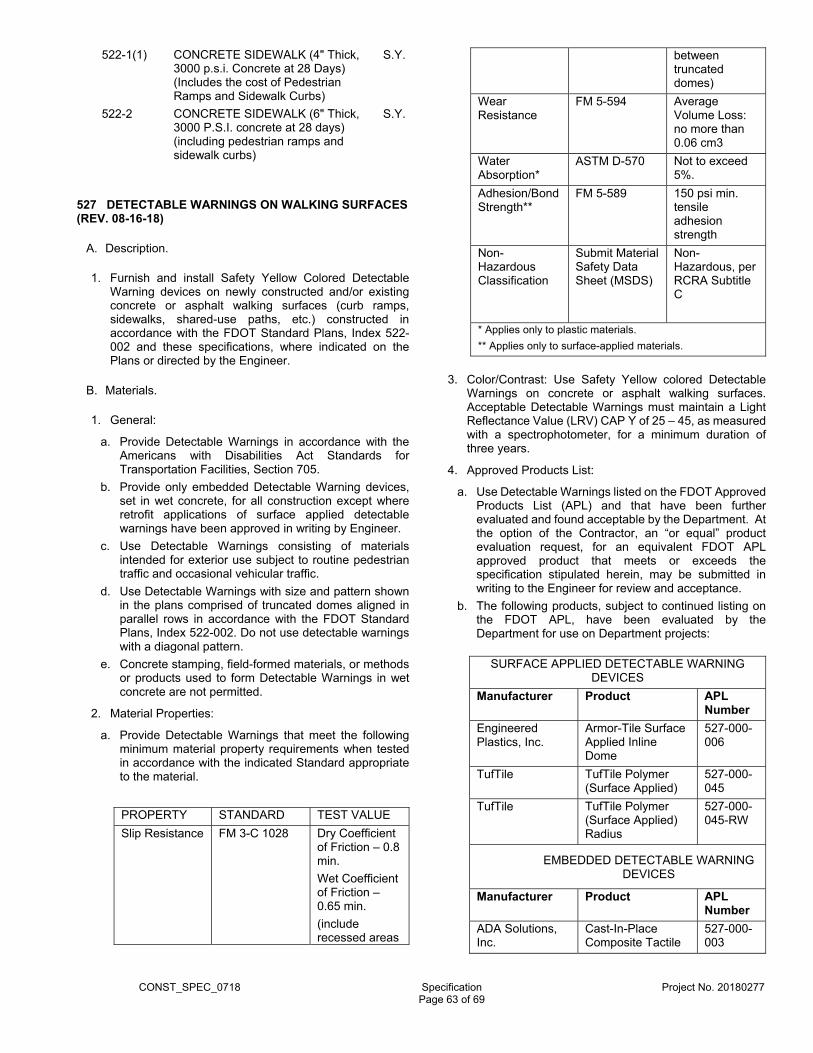
CONST_SPEC_0718 Specification Project No. 20180277
Page 63 of 69
522-1(1) CONCRETE SIDEWALK (4" Thick, 3000 p.s.i. Concrete at 28 Days) (Includes the cost of Pedestrian Ramps and Sidewalk Curbs)
S.Y.
522-2 CONCRETE SIDEWALK (6" Thick, 3000 P.S.I. concrete at 28 days) (including pedestrian ramps and sidewalk curbs)
S.Y.
527 DETECTABLE WARNINGS ON WALKING SURFACES (REV. 08-16-18)
A. Description.
1. Furnish and install Safety Yellow Colored Detectable Warning devices on newly constructed and/or existing concrete or asphalt walking surfaces (curb ramps, sidewalks, shared-use paths, etc.) constructed in accordance with the FDOT Standard Plans, Index 522-002 and these specifications, where indicated on the Plans or directed by the Engineer.
B. Materials.
1. General:
a. Provide Detectable Warnings in accordance with the Americans with Disabilities Act Standards for Transportation Facilities, Section 705.
b. Provide only embedded Detectable Warning devices, set in wet concrete, for all construction except where retrofit applications of surface applied detectable warnings have been approved in writing by Engineer.
c. Use Detectable Warnings consisting of materials intended for exterior use subject to routine pedestrian traffic and occasional vehicular traffic.
d. Use Detectable Warnings with size and pattern shown in the plans comprised of truncated domes aligned in parallel rows in accordance with the FDOT Standard Plans, Index 522-002. Do not use detectable warnings with a diagonal pattern.
e. Concrete stamping, field-formed materials, or methods or products used to form Detectable Warnings in wet concrete are not permitted.
2. Material Properties:
a. Provide Detectable Warnings that meet the following minimum material property requirements when tested in accordance with the indicated Standard appropriate to the material.
PROPERTY STANDARD TEST VALUE
Slip Resistance FM 3-C 1028 Dry Coefficient of Friction – 0.8 min.
Wet Coefficient of Friction – 0.65 min.
(include recessed areas
between truncated domes)
Wear Resistance
FM 5-594 Average Volume Loss: no more than 0.06 cm3
Water Absorption*
ASTM D-570 Not to exceed 5%.
Adhesion/Bond Strength**
FM 5-589 150 psi min. tensile adhesion strength
Non-Hazardous Classification
Submit Material Safety Data Sheet (MSDS)
Non-Hazardous, per RCRA Subtitle C
* Applies only to plastic materials.
** Applies only to surface-applied materials.
3. Color/Contrast: Use Safety Yellow colored Detectable Warnings on concrete or asphalt walking surfaces. Acceptable Detectable Warnings must maintain a Light Reflectance Value (LRV) CAP Y of 25 – 45, as measured with a spectrophotometer, for a minimum duration of three years.
4. Approved Products List:
a. Use Detectable Warnings listed on the FDOT Approved Products List (APL) and that have been further evaluated and found acceptable by the Department. At the option of the Contractor, an “or equal” product evaluation request, for an equivalent FDOT APL approved product that meets or exceeds the specification stipulated herein, may be submitted in writing to the Engineer for review and acceptance.
b. The following products, subject to continued listing on the FDOT APL, have been evaluated by the Department for use on Department projects:
SURFACE APPLIED DETECTABLE WARNING DEVICES
Manufacturer Product APL Number
Engineered Plastics, Inc.
Armor-Tile Surface Applied Inline Dome
527-000-006
TufTile TufTile Polymer (Surface Applied)
527-000-045
TufTile TufTile Polymer (Surface Applied) Radius
527-000-045-RW
EMBEDDED DETECTABLE WARNING DEVICES
Manufacturer Product APL Number
ADA Solutions, Inc.
Cast-In-Place Composite Tactile
527-000-003

CONST_SPEC_0718 Specification Project No. 20180277
Page 64 of 69
ADA Solutions, Inc.
Replaceable Wet Set Composite
527-000-018
Engineered Plastics, Inc
Armor-Tile Replaceable Cast in Place
527-000-026
Engineered Plastics, Inc.
Armor-Tile Cast-In-Place Inline Dome Tile
527-000-027
Cape Fear Systems, LLC
AlertCast (Replaceable) Cast-In-Place
527-000-029
Access Products, Inc.
Access Tile Replaceable Cast in Place
527-000-033
StrongGo Industries
TekWay Dome Tile 527-000-035
TufTile, Inc TufTile Cast Iron (Wet-set) Replaceable
527-000-044
TufTile TufTile Polymer (Wet Set) Replaceable
527-000-046
TufTile TufTile Polymer (Wet Set) Radius
527-000-046-RW
C. Installation Procedures.
1. Surface Preparation and Installation: Prepare the surface in accordance with the manufacturer’s recommendations. Use only products and materials appropriate for the surface on which they will be applied. Install in accordance with the manufacturer’s instructions, using materials and equipment recommended and approved by the manufacturer. For surface-applied tiles or mats, use adhesives applied over the entire surface and mechanical fasteners.
D. Method of Measurement.
1. The quantity to be paid for will be the area, in square feet, of Detectable Warnings furnished and installed pursuant to these specifications, measured in place and accepted by the Engineer.
E. Basis of Payment.
1. Price and payment will be full compensation for all work specified in this Article, including all labor, surface preparation, materials and incidentals necessary to complete the work for installation of Detectable Warnings on walking surfaces.
2. Payment will be made under:
Item No.
Description Unit
527-2 Detectable Warning On Walking Surface
SF
575 SODDING
A. Description.
1. Establish a stand of grass within the specified areas, by furnishing and placing sod, and rolling, watering, and maintaining the sodded areas to ensure a healthy stand of grass.
B. Materials. Meet the following requirements:
1. Sod FDOT 981-2
2. Water FDOT Section 983
C. Construction Methods.
1. Preparation of Ground: Scarify or loosen the areas requiring sod to a depth of 6 inches. On areas where the soil is sufficiently loose, particularly on shoulders and fill slopes, the Engineer may authorize the elimination of the ground preparation. Limit preparation to those areas that can be sodded within 72 hours after preparation. Prior to sodding, thoroughly water areas and allow water to percolate into the soil. Allow surface moisture to dry before sodding to prevent a muddy soil condition.
2. Placing Sod: Place sod immediately after ground preparation. Do not use sod which has been cut for more than 72 hours. Stack all sod that is not planted within 24 hours after cutting and maintain proper moist condition.
a. Do not sod when weather and soil conditions are unsuitable for proper results. Pre-wet the area prior to placing sod. Do not place sod on eroded or washed out sites.
b. Place the sod on the prepared surface, with edges in close contact, and embed it firmly and smoothly by light tamping with appropriate tools.
c. Place the sod to the edge of all the paving and shrub areas and 1 inch below adjoining pavement with an even surface and edge. Place rolled sod parallel with the roadway and cut any exposed netting even with the sod edge.
d. Roll using a lightweight turf roller. Provide a true and even surface without any displacement of the sod or deformation.
e. Where sodding in drainage ditches, stagger the setting of the sod pieces to avoid a continuous seam along the line of flow. Ensure that the offsets of individual strips do not exceed 6 inches. Tamp the outer pieces of sod to produce a featheredge effect.
f. Peg sod at locations where the sod may slide. Drive pegs through sod blocks into firm earth, at intervals approved by the Engineer.
g. Remove any sod as directed by the Engineer.
3. Watering: Thoroughly water the sod immediately after placing. Do not water in excess of 1 inch per week for establishment. The contractor shall water and maintain newly sodded areas as needed and adhere to the following minimum frequencies until final acceptance of the Project by the County unless otherwise approved by the Engineer:
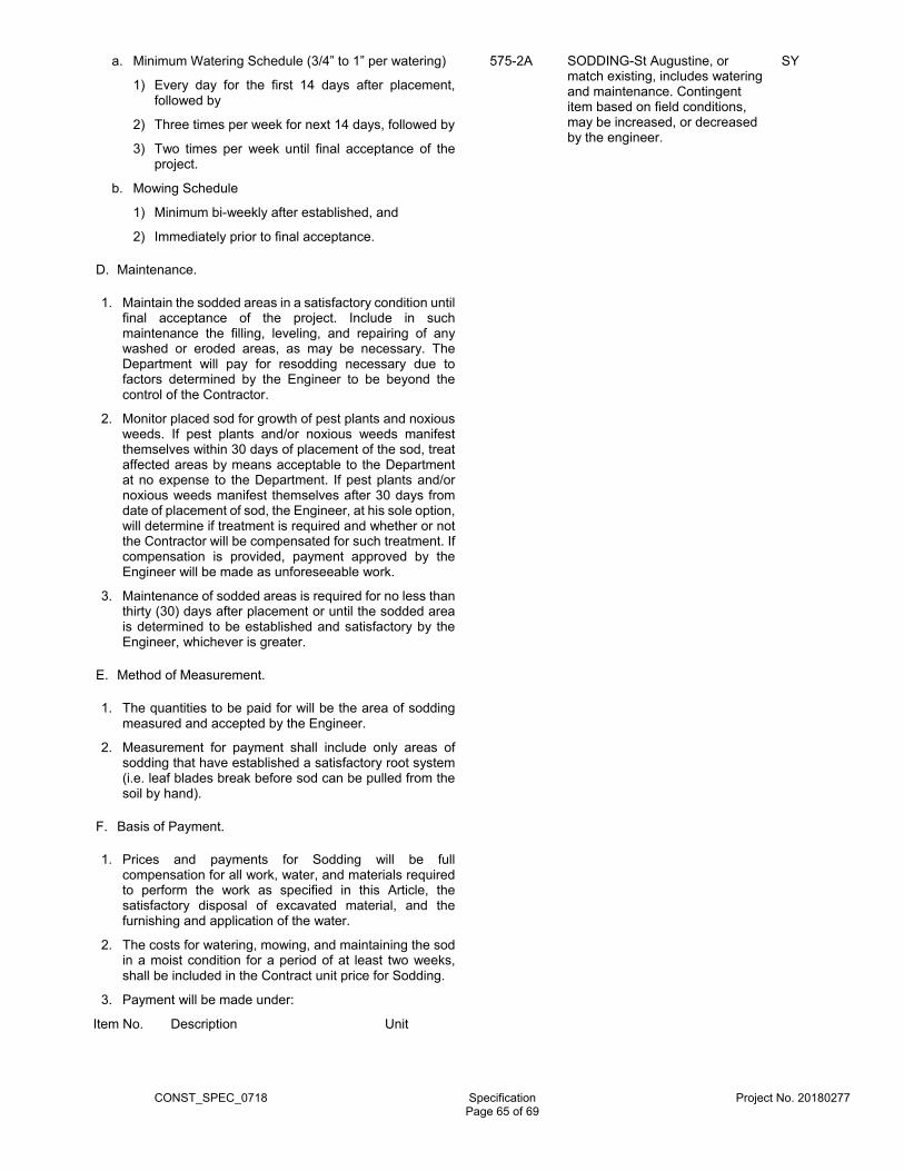
CONST_SPEC_0718 Specification Project No. 20180277
Page 65 of 69
a. Minimum Watering Schedule (3/4” to 1” per watering)
1) Every day for the first 14 days after placement, followed by
2) Three times per week for next 14 days, followed by
3) Two times per week until final acceptance of the project.
b. Mowing Schedule
1) Minimum bi-weekly after established, and
2) Immediately prior to final acceptance.
D. Maintenance.
1. Maintain the sodded areas in a satisfactory condition until final acceptance of the project. Include in such maintenance the filling, leveling, and repairing of any washed or eroded areas, as may be necessary. The Department will pay for resodding necessary due to factors determined by the Engineer to be beyond the control of the Contractor.
2. Monitor placed sod for growth of pest plants and noxious weeds. If pest plants and/or noxious weeds manifest themselves within 30 days of placement of the sod, treat affected areas by means acceptable to the Department at no expense to the Department. If pest plants and/or noxious weeds manifest themselves after 30 days from date of placement of sod, the Engineer, at his sole option, will determine if treatment is required and whether or not the Contractor will be compensated for such treatment. If compensation is provided, payment approved by the Engineer will be made as unforeseeable work.
3. Maintenance of sodded areas is required for no less than thirty (30) days after placement or until the sodded area is determined to be established and satisfactory by the Engineer, whichever is greater.
E. Method of Measurement.
1. The quantities to be paid for will be the area of sodding measured and accepted by the Engineer.
2. Measurement for payment shall include only areas of sodding that have established a satisfactory root system (i.e. leaf blades break before sod can be pulled from the soil by hand).
F. Basis of Payment.
1. Prices and payments for Sodding will be full compensation for all work, water, and materials required to perform the work as specified in this Article, the satisfactory disposal of excavated material, and the furnishing and application of the water.
2. The costs for watering, mowing, and maintaining the sod in a moist condition for a period of at least two weeks, shall be included in the Contract unit price for Sodding.
3. Payment will be made under:
Item No. Description Unit
575-2A SODDING-St Augustine, or match existing, includes watering and maintenance. Contingent item based on field conditions, may be increased, or decreased by the engineer.
SY
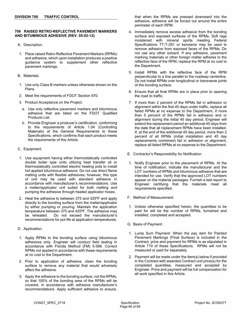
CONST_SPEC_0718 Specification Project No. 20180277
Page 66 of 69
DIVISION 700 TRAFFIC CONTROL
706 RAISED RETRO-REFLECTIVE PAVEMENT MARKERS AND BITUMINOUS ADHESIVE (REV. 05-02-12)
A. Description.
1. Place raised Retro-Reflective Pavement Markers (RPMs) and adhesive, which upon installation produces a positive guidance system to supplement other reflective pavement markings.
B. Materials.
1. Use only Class B markers unless otherwise shown on the Plans.
2. Meet the requirements of FDOT Section 970.
3. Product Acceptance on the Project.
a. Use only reflective pavement markers and bituminous adhesive that are listed on the FDOT Qualified Products List.
b. Provide Engineer a producer’s certification, conforming to the requirements of Article 1.04 (Controlling Materials) of the General Requirements to these Specifications, which confirms that each product meets the requirements of this Article.
C. Equipment.
1. Use equipment having either thermostatically controlled double boiler type units utilizing heat transfer oil or thermostatically controlled electric heating pots to install hot applied bituminous adhesive. Do not use direct flame melting units with flexible adhesives; however, this type of unit may be used with standard adhesive in accordance with manufacturer’s recommendations. Use a melter/applicator unit suited for both melting and pumping the adhesive through heated applicator hoses.
2. Heat the adhesive to between 375 and 425ºF and apply directly to the bonding surface from the melter/applicator by either pumping or pouring. Maintain the application temperature between 375 and 425ºF. The adhesive may be reheated. Do not exceed the manufacturer’s recommendations for pot life at application temperatures.
D. Application.
1. Apply RPMs to the bonding surface using bituminous adhesives only. Engineer will conduct field testing in accordance with Florida Method (FM) 5-566. Correct RPMs not applied in accordance with these requirements at no cost to the Department.
2. Prior to application of adhesive, clean the bonding surface to remove any material that would adversely affect the adhesive.
3. Apply the adhesive to the bonding surface, not the RPMs, so that 100% of the bonding area of the RPMs will be covered, in accordance with adhesive manufacturer’s recommendations. Apply sufficient adhesive to ensure,
that when the RPMs are pressed downward into the adhesive, adhesive will be forced out around the entire perimeter of each RPM.
4. Immediately remove excess adhesive from the bonding surface and exposed surfaces of the RPMs. Soft rags moistened with mineral spirits meeting Federal Specifications TT-T-291 or kerosene may be used to remove adhesive from exposed faces of the RPMs. Do not use any other solvent. If any adhesive, pavement marking materials or other foreign matter adheres to the reflective face of the RPM, replace the RPM at no cost to the Department.
5. Install RPMs with the reflective face of the RPM perpendicular to a line parallel to the roadway centerline. Do not install RPMs over longitudinal or transverse joints of the bonding surface.
6. Ensure that all final RPMs are in place prior to opening the road to traffic.
7. If more than 2 percent of the RPMs fail in adhesion or alignment within the first 45 days under traffic, replace all failed RPMs at no expense to the Department. If more than 5 percent of the RPMs fail in adhesion and or alignment during the initial 45 day period, Engineer will extend the replacement period an additional 45 days from the date that all replacement RPMs have been installed. If, at the end of the additional 45 day period, more than 2 percent of all RPMs (initial installation and 45 day replacements combined) fail in adhesion or alignment, replace all failed RPMs at no expense to the Department.
E. Contractor’s Responsibility for Notification.
1. Notify Engineer prior to the placement of RPMs. At the time of notification, indicate the manufacturer and the LOT numbers of RPMs and bituminous adhesive that are intended for use. Verify that the approved LOT numbers appear on the material packages. Furnish a test report to Engineer certifying that the materials meet all requirements specified.
F. Method of Measurement.
1. Unless otherwise specified herein, the quantities to be paid for will be the number of RPMs, furnished and installed, completed and accepted.
G. Basis of Payment.
1. Lump Sum Payment: When the pay item for Painted Pavement Markings (Final Surface) is included in the Contract, price and payment for RPMs is as stipulated in Article 710 of these Specifications. RPMs will not be measured or paid for separately.
2. Payment will be made under the item(s) below if provided in the Contract with awarded Contract unit price(s) for the completed quantities, measured and accepted by Engineer. Price and payment will be full compensation for all work specified in this Article.
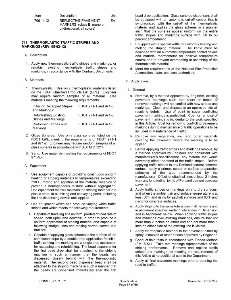
CONST_SPEC_0718 Specification Project No. 20180277
Page 67 of 69
Item Description Unit
706- 1-12 REFLECTIVE PAVEMENT MARKERS (class B, mono or bi-directional, all colors)
EA
711 THERMOPLASTIC TRAFFIC STRIPES AND MARKINGS (REV. 05-02-12)
A. Description.
1. Apply new thermoplastic traffic stripes and markings, or refurbish existing thermoplastic traffic stripes and markings, in accordance with the Contract Documents.
B. Materials.
1. Thermoplastic: Use only thermoplastic materials listed on the FDOT Qualified Products List (QPL). Engineer may require random samples of all material. Use materials meeting the following requirements:
Initial or Recapped Stripes and Markings:
FDOT 971-1 and 971-5
Refurbishing Existing Stripes and Markings:
FDOT 971-1 and 971-5
Preformed Stripes and Markings:
FDOT 971-1 and 971-6
2. Glass Spheres: Use only glass spheres listed on the FDOT QPL, meeting the requirements of FDOT 971-1 and 971-2. Engineer may require random samples of all glass spheres in accordance with ASTM D 1214.
3. Sand: Use materials meeting the requirements of FDOT 971-5.4.
C. Equipment.
1. Use equipment capable of providing continuous uniform heating of striping materials to temperatures exceeding 390ºF, mixing and agitation of the material reservoir to provide a homogeneous mixture without segregation. Use equipment that will maintain the striping material in a plastic state, in all mixing and conveying parts, including the line dispensing device until applied.
2. Use equipment which can produce varying width traffic stripes and which meets the following requirements:
a. Capable of traveling at a uniform, predetermined rate of speed, both uphill and downhill, in order to produce a uniform application of striping material and capable of following straight lines and making normal curves in a true arc.
b. Capable of applying glass spheres to the surface of the completed stripe by a double drop application for initial traffic striping and marking and a single drop application for recapping and refurbishing. The bead dispenser for the first bead drop shall be attached to the striping machine in such a manner that the beads are dispensed closely behind with the thermoplastic material. The second bead dispenser bead shall be attached to the striping machine in such a manner that the beads are dispensed immediately after the first
bead drop application. Glass spheres dispensers shall be equipped with an automatic cut-off control that is synchronized with the cut-off of the thermoplastic material and applies the glass spheres in a manner such that the spheres appear uniform on the entire traffic stripes and markings surface with, 50 to 60 percent embedment.
c. Equipped with a special kettle for uniformly heating and melting the striping material. The kettle must be equipped with an automatic temperature control device and material thermometer for positive temperature control and to prevent overheating or scorching of the thermoplastic material.
d. Meet the requirements of the National Fire Protection Association, state, and local authorities.
D. Application.
1. General:
a. Remove, by a method approved by Engineer, existing pavement markings such that scars or traces of removed markings will not conflict with new stripes and markings. Clean and dispose at an approved site all resulting debris. Use of paint to cover conflicting pavement markings is prohibited. Cost for removal of pavement markings is incidental to the work specified in this Article. Cost for removing conflicting pavement markings during maintenance of traffic operations to be included in Maintenance of Traffic.
b. Remove any vegetation, soil, and other materials covering the pavement where the marking is to be applied.
c. Before applying traffic stripes and markings remove, by a method approved by Engineer and consistent with manufacturer’s specifications, any material that would adversely affect the bond of the traffic stripes. Before applying traffic stripes to any Portland cement concrete surface, apply a primer, sealer or surface preparation adhesive of the type recommended by the manufacturer. Offset longitudinal lines at least 2 inches from any longitudinal joints of Portland cement concrete pavement.
d. Apply traffic stripes or markings only to dry surfaces, and when the ambient air and surface temperature is at least 50ºF and rising for asphalt surfaces and 60°F and rising for concrete surfaces.
e. Apply striping to the same tolerances in dimensions and in alignment specified under “Tolerances in Dimension and in Alignment” below. When applying traffic stripes and markings over existing markings, ensure that not more than 2 inches on either end and not more than 1 inch on either side of the existing line is visible.
f. Apply thermoplastic material to the pavement either by spray, extrusion or other means approved by Engineer.
g. Conduct field tests in accordance with Florida Method (FM) 5-541. Take test readings representative of the striping performance. Remove and replace traffic stripes and markings not meeting the requirements of this Article at no additional cost to the Department.
h. Apply all final pavement markings prior to opening the road to traffic.
CONST_SPEC_0718 Specification Project No. 20180277
Page 68 of 69
i. Preformed Thermoplastic: Apply markings only to dry surfaces and when ambient air temperature is at least 32°F. Prior to installation, follow the manufacturer’s recommendations for pre-heating.
2. Thickness:
a. Initial or Recapped Stripes and Markings:
1) Apply or recap traffic stripes or markings such that all lane lines, center lines, transverse markings and traffic stripes and markings within traffic wearing areas, will have a thickness of 0.10 to 0.15 inch when measured above the pavement surface.
2) Gore, island, and diagonal stripe markings, bike lane symbols and messages, wherever located, will have a thickness of 0.09 to 0.12 inch when measured above the pavement surface.
3) Measure, record, certify and submit to Engineer, the thickness of white and yellow pavement markings in accordance with FM 5-541.
b. Refurbishing Existing Traffic Stripes and Markings: Apply a minimum of 0.06 inch of thermoplastic material. Ensure that the combination of the existing stripe and the overlay after application of glass spheres does not exceed the maximum thickness of 0.150 inch for all lines.
3. Retroreflectivity:
a. Apply white and yellow traffic stripes and markings that will attain an initial retroreflectivity of not less than 450 mcd/lx•m2 and not less than 350 mcd/lx•m2, respectively for all longitudinal lines.
b. All transverse lines, messages and arrows will attain an initial retroreflectivity of not less than 300 mcd/lx•m2 and 250 mcd/lx•m2 for white and yellow respectively.
c. All pedestrian crosswalks, bike lane symbols or messages in a proposed bike lane shall attain an initial retroreflectivity of not less than 275 mcd/lx•m2.
d. Measure, record, certify, and submit to Engineer, the retroreflectivity of white and yellow pavement markings in accordance with FM 5-541.
4. Glass Spheres:
a. Longitudinal Lines:
1) For initial traffic striping and marking, apply the first drop of Type 4 or larger glass spheres immediately followed by the second drop of Type 1 glass spheres.
2) For refurbishing, apply a single drop of Type 3 glass spheres.
3) Apply reflective glass spheres to all markings at the rates determined by the manufacturer’s recommendations.
b. Transverse Stripes and Markings:
1) Apply a single drop of Type 1 glass spheres.
2) Apply reflective glass spheres to all markings at the rates determined by the manufacturer’s recommendations.
3) Apply a mixture consisting of 50 percent glass spheres and 50 percent sharp silica sand to all thermoplastic pedestrian crosswalk lines and bike lane symbols at the rates determined by the manufacturer’s recommendations.
c. Preformed Markings: These markings are factory supplied with glass spheres and skid resistant material. No additional glass spheres or skid resistant material should be applied during installation.
E. Tolerances in Dimensions and in Alignment.
1. Establish tack points at appropriate intervals for use in aligning stripes, and set a stringline from such points to achieve accuracy.
2. Dimensions:
a. Longitudinal Lines: Apply thermoplastic skip line segments with no more than ±12 inches variance, so that over-tolerance and under-tolerance lengths between skip line and the gap will approximately balance. Apply longitudinal lines at least 2 inches from construction joints of Portland cement concrete pavement.
b. Transverse Markings, Gore Markings, Arrows, and Messages: Apply thermoplastic in multiple passes when the marking cannot be completed in one pass, with an overall line width allowable tolerance of ±1 inch
c. Contrast Lines: Use black paint to provide contrast on concrete or light asphalt pavement, when specified by Engineer. Apply black paint in 10 foot segments following each longitudinal skip line.
3. Alignment:
a. Apply thermoplastic stripes that will not deviate more than 1 inch from the stringline on tangents and curves one degree or less.
b. Apply thermoplastic stripes that will not deviate more than 2 inches from the stringline on curves greater than one degree.
c. Apply thermoplastic edge stripes uniformly, not less than 2 inches or more than 4 inches from the edge of pavement, without noticeable breaks or deviations in alignment or width.
d. Remove and replace at no additional cost to the Department, traffic stripes that deviate more than the above stated requirements.
4. Correction Rates:
a. Make corrections of variations in width at a maximum rate of 10 feet for each 0.5 inches of correction. Make corrections of variations in alignment at a maximum rate of 25 feet for each 1 inch of correction, to return to the stringline.
F. Contractor’s Responsibility for Notification.
1. Notify Engineer prior to the placement of the thermoplastic materials.
2. Furnish Engineer with the manufacturer’s name and batch numbers of the thermoplastic materials and glass spheres to be used.
CONST_SPEC_0718 Specification Project No. 20180277
Page 69 of 69
3. Ensure that the approved batch numbers appear on the thermoplastic materials and glass spheres packages.
G. Protection of Newly Applied Traffic Stripes and Markings.
1. Do not allow traffic onto or permit vehicles to cross newly applied pavement markings until they are sufficiently dry.
2. Remove and replace any portion of the pavement markings damaged by passing traffic or from any other cause, at no additional cost to the Department.
H. Observation Period.
1. Pavement markings are subject to a 180 day observation period under normal traffic. The observation period shall begin with the satisfactory completion and acceptance of the work.
2. The pavement markings shall show no signs of failure due to blistering, excessive cracking, chipping, discoloration, poor adhesion to the pavement, loss of reflectivity or vehicular damage. The retroreflectivity must meet the initial requirements stipulated above. The Department reserves the right to check the color and retroreflectivity any time prior to the end of the observation period.
3. Replace, at no additional expense to the Department, any pavement markings that do not perform satisfactorily under traffic during the 180 day observation period.
I. Corrections for Deficiencies.
1. Recapping applies to conditions where additional striping material is applied to new or refurbished traffic stripes or markings to correct a deficiency. Recap a 1.0 mile section centered around the deficiency with additional striping material or by complete removal and reapplication at no additional cost to the Department.
2. If recapping will result in a thickness exceeding the maximum allowed, the traffic stripes or markings must be removed and reapplied.
J. Submittals.
1. Submittal Instructions: Prepare a certification of quantities, for each project in the Contract. Submit the certification of quantities and daily worksheets to Engineer. The Department will not pay for any disputed items until Engineer approves the certification of quantities.
2. Contractor’s Certification of Quantities: Request payment by submitting a certification of quantities with each payment requisition, based on the amount of work done or completed. Ensure the certification of quantities includes the following:
a. Contract Number, Certification Number, Certification Date and the period that the certification represents.
b. The basis for arriving at the amount of the progress certification, less payments previously made and less any amount previously retained or withheld. The basis will include a detailed breakdown provided on the certification of items of payment.
K. Method of Measurement.
1. Quantities to be measured by Engineer for payment under this Article will be as follows:
a. The length, in net miles, of 6 inch Solid Traffic Stripe, authorized and acceptably applied.
b. The total traversed distance in gross miles of 10-30 or 3-9 skip line. The actual applied line is 25 percent of the traverse distance, for a 1:3 ratio. This equates to 1,320 feet of marking per mile of single line.
c. The net length, in feet, of all other types of lines and stripes, authorized and acceptably applied.
d. The area, in square feet, of Removal of Existing Pavement Markings, acceptably removed. Cost for removing conflicting pavement markings during maintenance of traffic operations is included in Maintenance of Traffic.
e. The number of pavement messages, symbols and directional arrows, authorized and acceptably applied.
L. Basis of Payment.
1. Prices and payments will be full compensation for all work specified in this Article, including all cleaning and preparing of surfaces, furnishing of all materials, application, curing and protection of all items, protection of traffic, furnishing of all tools, machines and equipment, and all incidentals necessary to complete the work. Final payment will be withheld until all deficiencies are corrected.
2. Payment, for the completed quantities measured and accepted by Engineer, will be made under the item(s) below if provided in the Contract with awarded Contract unit price(s).
Item Description Unit
711-11-123 Thermoplastic (White) Solid 12" LF
711-11-125 Thermoplastic (White) Solid 24" LF
711-11-221 Thermoplastic (Yellow) Solid 6" LF
711-17 Removal of existing thermoplastic pavement markings
SF

SECTION 7: SPECIAL PROVISIONS

SPECIAL PROVISIONS

SP_02-2016 Special Provisions Project No. 20180277
TOC-1
SPECIAL PROVISIONS
TABLE OF CONTENTS
1. GENERAL REQUIREMENTS
1.01 MISCELLANEOUS CONSTRUCTION CONTRACTS (MCC) PLAN. GENERAL TERMS AND CONDITIONS AND SPECIAL CONDITIONS .............................................................................................. 1
1.02 SCOPE OF WORK ...................................................................................................................................... 1
1.03 LOCATION OF WORK ................................................................................................................................ 1
1.04 PLANS ......................................................................................................................................................... 1
1.05 TIME FOR COMPLETION ........................................................................................................................... 2
2. GENERAL CONSTRUCTION
2.01 FIELD OFFICE (REV. 11-9-15) ................................................................................................................... 3
2.02 MOBILIZATION (ARTICLE 101) .................................................................................................................. 3
2.03 MAINTENANCE OF TRAFFIC (ARTICLE 102) ........................................................................................... 3
APPENDIX “A” TO SPECIAL PROVISIONS
Authorization Agreement for Automatic Deposit
MCC_SP_02-2016 Special Provisions Project No. 20180277
Page 1
1. GENERAL REQUIREMENTS
1.01 MISCELLANEOUS CONSTRUCTION CONTRACTS (MCC) PLAN. GENERAL TERMS AND CONDITIONS AND SPECIAL CONDITIONS
Division 01 (General Requirements) of the DTPW Specifications amends the MCC Plan, and other provisions of the Contract Documents. All requirements of the MCC Plan, Resolution and amendments’, or portions thereof, which are not specifically modified, deleted, or superseded by Division 01, remain in full effect. In the event a conflict between these two complementary portions of the Contract Documents occurs, Division 1 will prevail and Engineer will provide a clarification and final determination. These Special Provisions also amend, complement, modify or delete items from the DTPW Construction Specifications of these Solicitation and Contract Documents.
1.02 SCOPE OF WORK
Work under this Contract includes furnishing of all supervision, labor, materials, tools, equipment and performing all operations required to construct the Work in accordance with the Contract Documents.
Work includes but is not limited to the construction and installation of drainage structures, French drains, regrade swale, miscellaneous drainage improvements, grading, sodding, and miscellaneous roadway restoration including construction of concrete curb and gutters, and sidewalks where needed in accordance with the construction plans and specifications.
If any changes are required due to conflict of design and or field conditions, the Engineer will make the final determination.
The Contractor and all subcontractors, under this Contract, are prohibited from performing any work, other than specified in the Contract and/or directed by the Engineer, within the limits of the project site, without prior written notification to the Engineer. This includes any work for private or commercial entities.
1.03 LOCATION OF WORK
The location of work to be performed under the terms of this Contract shall be as follows:
1. NW 8 Avenue to NW 12 Avenue from NW 107 Street to NW 111 Street, and NW 107 Street from NW 7 Avenue to NW 8 Avenue.
The exact location and limits of construction are as shown on the Plans accompanying these Contract Documents.
1.04 PLANS
Engineering Drawings titled Drainage Improvements to Pinewood NW 8 Avenue to NW 12 Avenue from NW 107 Street to NW 111 Street, Design Project No. 20160330, Miami Dade County Department of Transportation and Public Works, Roadway Engineering and Right of Way
MCC_SP_02-2016 Special Provisions Project No. 20180277
Page 2
Division, Stormwater Drainage Design Section”, are included with these Contract Documents. Additional standard details are available in the Miami-Dade County Public Works Manual and the latest edition of the Florida Department of Transportation's Design Standards for Design, Construction, Maintenance and Utility Operations on The State Highway System.
The County through its Engineer shall have the right to modify the details and/or sketches, to supplement the sketches with additional plans and/or with additional information as work proceeds; all of which shall be considered as plans accompanying these Specifications herein generally referred to as the "Plans.” In case of disagreement between the Plans and Specifications, the Engineer shall make a final determination as to which shall govern.
1.05 TIME FOR COMPLETION
The Work must be substantially completed within 240 days after the date when the Contract Time commences to run as provided in Subarticle 1.06 N of the General Requirements (Division 1), and all requirements of the Contract Documents completed and ready for final payment within 300 days after the date when the Contract Time commences to run.
The effective date of the "Notice to Proceed" will be established during the Preconstruction Conference which is held shortly after the Award of Contract and which is attended by members of Department of Transportation and Public Works, the Contractor, representatives of utility companies, and others affected by the Work. The effective date shall be set as a date no later than 30 calendar days after the date of execution of the Contract Documents, unless a later date acceptable to both parties is agreed upon in writing.
MCC_SP_02-2016 Special Provisions Project No. 20180277
Page 3
2. GENERAL CONSTRUCTION
2.01 FIELD OFFICE (REV. 11-9-15)
A local field office is not required; however, the Contractor will be required to provide the Engineer with a local (Miami-Dade County) telephone, cellular or beeper number, where the Contractor may be contacted 24 hours a day, 7 days a week during the period for which the Contract is in force.
2.02 MOBILIZATION (ARTICLE 101)
DTPW Construction Specification, Page 1, Article 101-B.2.b - "Payment will be made under…."; is deleted in its entirely and replaced with the following:
1. No separate Payment for Mobilization will be made under this Contract. All work and incidental costs specified as being covered under FDOT Section101 (Mobilization) will be included for payment under the several scheduled items of the overall Contract.
2.03 MAINTENANCE OF TRAFFIC (ARTICLE 102)
Delete DTPW Construction Specification, Page 8, Article 102-K.1 and replace it with the following:
1. Method of Measurement.
a. Work under MOT will be compensated at, but not to exceed, 2 percent of each invoice from an appropriate dedicated allowance. The total compensation under this item shall not exceed 2 percent of the Contract Subtotal Amount. Payment shall be full compensation for all work and costs specified under this Section including furnishing, installing, operating, maintaining and removing all required traffic control devices, signs, warning devices, barriers and other MOT devices or requirements not specifically covered for payment under the MOT items listed below. Such price and payment shall constitute full compensation for furnishing (including hardware, lights and posts if required), installing, relocating, maintaining, and removing of temporary traffic control devices.

APPENDIX “A” TO SPECIAL PROVISIONS
AUTHORIZATION AGREEMENT FOR AUTOMATIC DEPOSIT
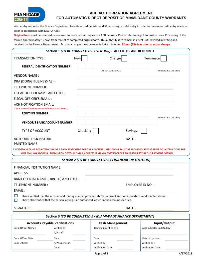
Page 1 of 2 4/17/2018
ACH AUTHORIZATION AGREEMENTFOR AUTOMATIC DIRECT DEPOSIT OF MIAMI-DADE COUNTY WARRANTS
We hereby authorize the Finance Department to initiate credit entries and, if necessary, a debit entry in order to reverse a credit entry made inerror in accordance with NACHA rules. Original form must be received before we can process your request for ACH deposits. Please refer to page 2 for instructions. Processing of the
form is approximately 15 days from receipt of completed original form. This authority is to remain in effect until revoked in writing and received by the Finance Department. Account changes must be reported at a minimum fifteen (15) days prior to actual change.
Section 1 (TO BE COMPLETED BY VENDOR) - ALL FIELDS ARE REQUIRED
TRANSACTION TYPE: New Change Terminate
FEDERAL IDENTIFICATION NUMBER(AS PER CURRENT W-9) (FOR INTERNAL USE ONLY)
VENDOR NAME :DBA (DOING BUSINESS AS) :TELEPHONE NUMBER :FISCAL OFFICER NAME AND TITLE :FISCAL OFFICER'S EMAIL :ACH NOTIFICATION EMAIL:(This is the email where payment information will be sent)
ROUTING NUMBER(FOR INTERNAL USE ONLY)
VENDOR'S BANK ACCOUNT NUMBER
TYPE OF ACCOUNT Checking Savings
AUTHORIZED SIGNATURE DATE :PRINTED NAME
A VOIDED CHECK OR REDACTED COPY OF A BANK STATEMENT FOR THE ACCOUNT LISTED ABOVE MUST BE PROVIDED. PLEASE REFER TO INSTRUCTIONS FOROUR MAILING ADDRESS. SUBMISSION OF YOUR E-MAIL ADDRESS IS MANDATORY IN ORDER TO PARTICIPATE IN THIS PAYMENT OPTION.
Section 2 (TO BE COMPLETED BY FINANCIAL INSTITUTION)
FINANCIAL INSTITUTION NAME:ADDRESS:BANK OFFICIAL NAME (PRINTED) AND TITLE :
TELEPHONE NUMBER : EMPLOYEE ID NO. :EMAIL :
I have verified that the account and routing number provided above is correct and corresponds to vendor noted above.I have also verified that the person signing is an authorized signer on the account specified.
SIGNATURE DATE :
Section 3 (TO BE COMPLETED BY MIAMI-DADE FINANCE DEPARTMENT)
Accounts Payable Verifications Cash Management Input/OutputCorp. Officer Name : Verified by: Routing # verified by : ACH Indicator updated by :
A/P Staff:
Corp. Officer Title : Date: Date: Date of Update :
Bank Officer: A/P Supervisor: Verified by : Verified by :
Date: Verification Date: Verification Date:
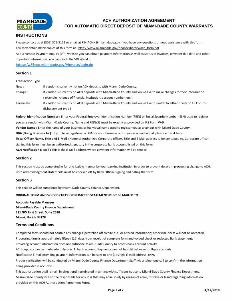
Page 2 of 2 4/17/2018
ACH AUTHORIZATION AGREEMENTFOR AUTOMATIC DIRECT DEPOSIT OF MIAMI-DADE COUNTY WARRANTS
INSTRUCTIONSPlease contact us at (305) 375-5111 or email at [email protected] if you have any questions or need assistance with this form.
You may obtain blank copies of this form at : http://www.miamidade.gov/finance/library/ach_form.pdf
At our Vendor Payment Inquiry (VPI) website you can obtain payment information as well as status of invoices, payment due date and other
important information. You can reach the VPI site at :
https://w85exp.miamidade.gov/VInvoice/login.do
Section 1
Transaction Type
New : If vendor is currently not on ACH deposits with Miami-Dade County.
Change : If vendor is currently on ACH deposits with Miami-Dade County and would like to make changes to their information
( example : change of financial institution, account number, etc.)
Terminate : If vendor is currently on ACH deposits with Miami-Dade County and would like to switch to either Check or AP Control
disbursement type )
Federal Identification Number : Enter your Federal Employer Identification Number (FEIN) or Social Security Number (SSN) used to register
you as a vendor with Miami-Dade County. Name and FEIN/SS must be exactly as provided on IRS Form W-9.Vendor Name : Enter the name of your business or individual name used to register you as a vendor with Miami-Dade County.
DBA (Doing Business As ) : If you have registered a DBA for your business or for you as an individual, please enter it here.
Fiscal Officer Name, Title and E-Mail : Name of Authorized Corporate officer, Title and E-Mail address to be contacted to. Corporate officer
signing this form must be an authorized signatory in the corporate bank account listed on this form.ACH Notification E-Mail : This is the E-Mail address where payment information will be sent to.
Section 2
This section must be completed in full and legible manner by your banking institution in order to prevent delays in processing change to ACH.
Both acknowledgment statements must be checked off by Bank Official signing and dating the form.
Section 3
This section will be completed by Miami-Dade County Finance Department.
ORIGINAL FORM AND VOIDED CHECK OR REDACTED STATEMENT MUST BE MAILED TO :
Accounts Payable ManagerMiami-Dade County Finance Department111 NW First Street, Suite 2620Miami, Florida 33128
Terms and Conditions
Completed form should not contain any changes (scratched off /white out) or altered information; otherwise, form will not be accepted.
Processing time is approximately fifteen (15) days from receipt of complete form and voided check or redacted Bank statement.
Providing account information does not authorize Miami-Dade County to access bank account activity.ACH deposits can be made into only one (1) bank account. Payments can not be split between multiple accounts.
Notification E-mail providing payment information can be sent to one (1) single E-mail address only.
Proper verification will be conducted by Miami-Dade County Finance Department Staff, via a telephone call to confirm the information
being provided is accurate.
This authorization shall remain in effect until terminated in writing with sufficient notice to Miami-Dade County Finance Department.
Miami-Dade County will not be responsible for any loss that may arise solely by reason of error, mistake or fraud regarding information
provided on this ACH Authorization Agreement Form.

SECTION 8: ENGINEERING DRAWINGS