SPECIAL PROVISIONS - BidNet
370
Bids open Thursday, April 7, 2022 Dated March 7, 2022 05 STATE OF CALIFORNIA DEPARTMENT OF TRANSPORTATION NOTICE TO BIDDERS AND SPECIAL PROVISIONS FOR CONSTRUCTION ON STATE HIGHWAY IN SAN LUIS OBISPO COUNTY ABOUT 8 MILES EAST OF SANTA MARIA FROM 0.5 MILE WEST OF HUASNA RIVER BRIDGE TO 1.9 MILES WEST OF CUYAMA RIVER BRIDGE In District 05 On Route 166 Under Bid book dated March 7, 2022 Standard Specifications dated 2018 Project plans approved February 7, 2022 Standard Plans dated 2018 Identified by Contract No. 05-1N7004 05-SLO-166-16.0/21.0 Project ID 0521000081
-
Upload
khangminh22 -
Category
Documents
-
view
0 -
download
0
Transcript of SPECIAL PROVISIONS - BidNet

Bids open Thursday, April 7, 2022
Dated March 7, 2022
05
STATE OF CALIFORNIA
DEPARTMENT OF TRANSPORTATION
NOTICE TO BIDDERS AND
SPECIAL PROVISIONS FOR CONSTRUCTION ON STATE HIGHWAY IN SAN LUIS OBISPO COUNTY
ABOUT 8 MILES EAST OF SANTA MARIA FROM 0.5 MILE WEST OF HUASNA RIVER BRIDGE TO 1.9 MILES WEST OF CUYAMA RIVER BRIDGE
In District 05 On Route 166
Under
Bid book dated March 7, 2022 Standard Specifications dated 2018
Project plans approved February 7, 2022 Standard Plans dated 2018
Identified by
Contract No. 05-1N7004
05-SLO-166-16.0/21.0
Project ID 0521000081


************************************************************************************************************************
SPECIAL NOTICES
************************************************************************************************************************
• See sections 2 and 3 for contractors' registration requirements. • The Department advises bidders that potential claim records must be submitted by the
contractor using the Department's Internet potential claim system. • See section 2 for submittal requirements for DBE quotes, DVBE quotes, and Non–Small
Business Subcontractor Preference. • See section 5-1.34 for safety survey questionnaire requirements. • For work plan for local material from (1) a noncommercial source or (2) a source not regulated
under California jurisdiction, see section 6-1.03B(1). • See section 7-1.02K(3) for the requirements for electronic submittal of certified payroll records
using LCPtracker Pro. • The flagging and temporary traffic control requirements have been revised. See sections 7-
1.03, 7-1.04, and 12. • See section 14-11.14 for changes to the management of treated wood waste.


Contract No. 05-1N7004 i
TABLE OF CONTENTS
NOTICE TO BIDDERS ..................................................................................................................................1
BID ITEM LIST ...............................................................................................................................................3
SPECIAL PROVISIONS ................................................................................................................................6
ORGANIZATION ...........................................................................................................................................6
DIVISION I GENERAL PROVISIONS ..........................................................................................................6
1 GENERAL ..................................................................................................................................................6
2 BIDDING ....................................................................................................................................................6
5 CONTROL OF WORK ...............................................................................................................................7
6 CONTROL OF MATERIALS ......................................................................................................................8
7 LEGAL RELATIONS AND RESPONSIBILITY TO THE PUBLIC ........................................................... 10
DIVISION II GENERAL CONSTRUCTION ............................................................................................... 12
12 TEMPORARY TRAFFIC CONTROL .................................................................................................... 12
14 ENVIRONMENTAL STEWARDSHIP ................................................................................................... 21
DIVISION IV SUBBASES AND BASES .................................................................................................... 24
30 RECLAIMED PAVEMENT .................................................................................................................... 24
DIVISION V SURFACINGS AND PAVEMENTS ....................................................................................... 45
36 GENERAL ............................................................................................................................................. 45
39 ASPHALT CONCRETE ........................................................................................................................ 53
DIVISION IX TRAFFIC CONTROL DEVICES ........................................................................................... 60
81 MISCELLANEOUS TRAFFIC CONTROL DEVICES ........................................................................... 60
83 RAILINGS AND BARRIERS ................................................................................................................. 60
84 MARKINGS........................................................................................................................................... 65
92 ASPHALT BINDERS ............................................................................................................................ 66
REVISED STANDARD SPECIFICATIONS APPLICABLE TO THE 2018 EDITION OF THE STANDARD SPECIFICATIONS ...................................................................................................................................... 67

Contract No. 05-1N7004 ii
STANDARD PLANS LIST The standard plan sheets applicable to this Contract include those listed below. The applicable revised standard plans (RSPs) listed below are included in the project plans.
A3A Abbreviations (Sheet 1 of 3)
A3B Abbreviations (Sheet 2 of 3)
A3C Abbreviations (Sheet 3 of 3)
A10A Legend - Lines and Symbols (Sheet 1 of 5)
A10B Legend - Lines and Symbols (Sheet 2 of 5)
A10C Legend - Lines and Symbols (Sheet 3 of 5)
A10D Legend - Lines and Symbols (Sheet 4 of 5)
A10E Legend - Lines and Symbols (Sheet 5 of 5)
A20A Pavement Markers and Traffic Lines - Typical Details
RSP A20B Pavement Markers and Traffic Lines - Typical Details
RSP A20E Pavement Markers and Traffic Lines - Typical Detail for Contrast Striping
A24D Pavement Markings - Words
A73C Delineators, Channelizers and Barricades
RSP A77L1 Midwest Guardrail System - Standard Railing Section (Wood Post with Wood Block)
RSP A77L2 Midwest Guardrail System - Standard Railing Section (Steel Post with Notched Wood or Notched Recycled Plastic Block)
RSP A77M1 Midwest Guardrail System - Standard Hardware
RSP A77N1 Midwest Guardrail System - Wood Post and Wood Block Details
A77N2 Midwest Guardrail System - Steel Post and Notched Wood Block Details
RSP A77N3 Midwest Guardrail System - Typical Line Post Embedment and Hinge Point Offset Details
RSP A77N4 Midwest Guardrail System - Typical Railing Delineation and Dike Positioning Details
A77N5 Minor Concrete Vegetation Control - Guardrail System
A77N5A Minor Concrete Vegetation Control - Guardrail System - Narrow Vegetation Control Installation
A77N6 Minor Concrete Vegetation Control - Guardrail System - For Terminal System End Treatments
A77N11 Minor Concrete Vegetation Control - Guardrail System - Miscellaneous Details
RSP A77P2 Midwest Guardrail System - Typical Layouts for Embankments
RSP A77P3 Midwest Guardrail System - Typical Layouts for Embankments
RSP A77P6 Midwest Guardrail System - Typical Layouts for Embankments
A77T2 Midwest Guardrail System - Buried Post End Anchor
A77U5 Midwest Guardrail System - Transition to Metal Beam Guardrail

Contract No. 05-1N7004 iii
A87B Hot Mix Asphalt Dikes
P74 Pavement Edge Treatments
P75 Pavement Edge Treatments - Overlays
D87A Corrugated Metal Pipe Downdrain Details
D87D Overside Drains
T1A Temporary Crash Cushion, Sand Filled (Unidirectional)
T1B Temporary Crash Cushion, Sand Filled (Bidirectional)
T2 Temporary Crash Cushion, Sand Filled (Shoulder Installations)
T3A Temporary Railing (Type K)
T3B Temporary Railing (Type K)
T9 Traffic Control System Tables for Lane and Ramp Closures
RSP T13 Traffic Control System with Reversible Control on Two Lane Conventional Highways
RSP T13A Traffic Control System - Two Lane Conventional Highways
RSP T13B Traffic Control System - Two Lane Conventional Highways
T17 Traffic Control System for Moving Lane Closure on Two Lane Highways
RSP T21 Traffic Control System Construction Work Zone Speed Limit Reduction Twenty-Four Hours a Day 7 Days a Week (24/7)
RSP T22 Traffic Control System For Construction Work Zone Speed Limit Reduction on Two Lane Conventional Highways
RSP T26 Temporary Automated End of Queue Warning System Type 1 (Queue <= 3.5 Miles)
RS1 Roadside Signs - Typical Installation Details No. 1
RS2 Roadside Signs - Wood Post - Typical Installation Details No. 2
RS4 Roadside Signs - Typical Installation Details No. 4
S89 Roadside Sign - Formed Single Sheet Aluminum Panel
S93 Framing Details for Framed Single Sheet Aluminum Signs, Rectangular Shape
S94 Roadside Framed Single Sheet Aluminum Signs, Rectangular Shape
S95 Roadside Single Sheet Aluminum Signs, Diamond Shape

Contract No. 05-1N7004 iv
CANCELED STANDARD PLANS LIST The standard plan sheets listed below are canceled and not applicable to this contract.
Plan No. Date
Canceled Plan No.
Date Canceled
Plan No. Date
Canceled
P31B 10-18-19
P32A 10-18-19
P32B 10-18-19
C7A 10-19-18
C7B 10-19-18
C7C 10-19-18
D89 10-18-19
B11-55 04-19-19
B11-56 10-19-18
B11-57 10-19-18
B11-60 04-16-21
RSP B11-61 04-16-21
S140 04-16-21
S141 04-16-21
S142 04-16-21
ES-2C 10-19-18
RSP ES-3A 04-16-21
RSP ES-3I 10-16-20
ES-3J 10-16-20
ES-3L 10-16-20
ES-7P 04-17-20

Contract No. 05-1N7004 1
NOTICE TO BIDDERS
Bids open Thursday, April 7, 2022
Dated March 7, 2022
General work description: Partial depth recycling and overlay with RHMA (Gap Graded).
The Department will receive sealed bids for CONSTRUCTION ON STATE HIGHWAY IN SAN LUIS OBISPO COUNTY ABOUT 8 MILES EAST OF SANTA MARIA FROM 0.5 MILE WEST OF HUASNA RIVER BRIDGE TO 1.9 MILES WEST OF CUYAMA RIVER BRIDGE.
District-County-Route-Post Mile: 05-SLO-166-16.0/21.0
Contract No. 05-1N7004
The Contractor must have either a Class A license or the following Class C license which constitutes a majority of the work: C-12.
The DVBE Contract goal is 3 percent.
Bids must be on a unit price basis.
Complete the work within 90 working days.
The estimated cost of the project is $4,450,000.
The Department will receive bids until 2:00 p.m. on the bid open date via Bid Express website. Bids received after this time will not be accepted. For more information refer to the Electronic Bidding Guide at the Office Engineer's website.
The Department will open and publicly read the bids through webcast/teleconference services immediately after the specified closing time.
For bid results go to:
http://ppmoe.dot.ca.gov/des/oe/contractor-info.html
Select Electronic Bidding under the Bidding tab.
District office addresses are provided in the Standard Specifications.
Present bidders' inquiries to the Department and view the Department's responses at:
http://ppmoe.dot.ca.gov/des/oe/bid-inquiries.php
Questions about alleged patent ambiguity of the plans, specifications, or estimate must be asked before bid opening. After bid opening, the Department does not consider these questions as bid protests.
Submit your bid with bidder's security equal to at least 10 percent of the bid.
Under Govt Code § 14835 et seq. and 2 CA Code of Regs § 1896 et seq., the Department gives preference to certified small businesses and non–small businesses who commit to 25 percent certified small business participation.
Under Pub Cont Code § 6107, the Department gives preference to a "California company," as defined, for bid comparison purposes over a nonresident contractor from any state that gives or requires a preference to be given to contractors from that state on its public entity construction contracts.

Contract No. 05-1N7004 2
Prevailing wages are required on this Contract. The Director of the California Department of Industrial Relations determines the general prevailing wage rates. Obtain the wage rates at the DIR website, http://www.dir.ca.gov, or from the Department's Labor Compliance Office of the district in which the work is located.
The Department has made available Notices of Suspension and Proposed Debarment from the Federal Highway Administration. For a copy of the notices, go to http://www.dot.ca.gov/hq/esc/oe/contractor_info. Additional information is provided in the Excluded Parties List System at https://www.epls.gov.
Caltrans and the Construction Industry are committed to making partnering the way we do business. For more information, go to http://www.dot.ca.gov/hq/construc/partnering.html.
Department of Transportation
D05IO
Contract No. 05-1N7004 3
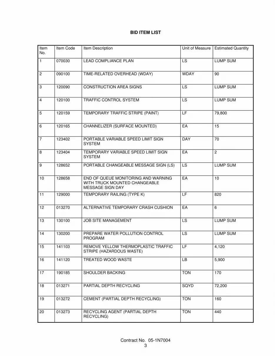
BID ITEM LIST
Item No.
Item Code Item Description Unit of Measure Estimated Quantity
1 070030 LEAD COMPLIANCE PLAN LS LUMP SUM
2 090100 TIME-RELATED OVERHEAD (WDAY) WDAY 90
3 120090 CONSTRUCTION AREA SIGNS LS LUMP SUM
4 120100 TRAFFIC CONTROL SYSTEM LS LUMP SUM
5 120159 TEMPORARY TRAFFIC STRIPE (PAINT) LF 79,800
6 120165 CHANNELIZER (SURFACE MOUNTED) EA 15
7 123402 PORTABLE VARIABLE SPEED LIMIT SIGN SYSTEM
DAY 70
8 123404 TEMPORARY VARIABLE SPEED LIMIT SIGN SYSTEM
EA 2
9 128652 PORTABLE CHANGEABLE MESSAGE SIGN (LS) LS LUMP SUM
10 128658 END OF QUEUE MONITORING AND WARNING WITH TRUCK MOUNTED CHANGEABLE MESSAGE SIGN DAY
EA 10
11 129000 TEMPORARY RAILING (TYPE K) LF 820
12 013270 ALTERNATIVE TEMPORARY CRASH CUSHION EA 6
13 130100 JOB SITE MANAGEMENT LS LUMP SUM
14 130200 PREPARE WATER POLLUTION CONTROL PROGRAM
LS LUMP SUM
15 141103 REMOVE YELLOW THERMOPLASTIC TRAFFIC STRIPE (HAZARDOUS WASTE)
LF 4,120
16 141120 TREATED WOOD WASTE LB 5,900
17 190185 SHOULDER BACKING TON 170
18 013271 PARTIAL DEPTH RECYCLING SQYD 72,200
19 013272 CEMENT (PARTIAL DEPTH RECYCLING) TON 160
20 013273 RECYCLING AGENT (PARTIAL DEPTH RECYCLING)
TON 440

Contract No. 05-1N7004 4
Item No.
Item Code Item Description Unit of Measure Estimated Quantity
21 013274 ASPHALTIC EMULSION (PARTIAL DEPTH RECYCLING)
TON 16
22 013275 SAND COVER (PARTIAL DEPTH RECYLCING) TON 190
23 390132 HOT MIX ASPHALT (TYPE A) TON 1,220
24 390137 RUBBERIZED HOT MIX ASPHALT (GAP GRADED) TON 11,600
25 394060 DATA CORE LS LUMP SUM
26 394073 PLACE HOT MIX ASPHALT DIKE (TYPE A) LF 20,000
27 394074 PLACE HOT MIX ASPHALT DIKE (TYPE C) LF 370
28 394075 PLACE HOT MIX ASPHALT DIKE (TYPE D) LF 5,500
29 394076 PLACE HOT MIX ASPHALT DIKE (TYPE E) LF 11,500
30 394090 PLACE HOT MIX ASPHALT (MISCELLANEOUS AREA)
SQYD 2,780
31 397005 TACK COAT TON 29
32 398100 REMOVE ASPHALT CONCRETE DIKE LF 37,200
33 398200 COLD PLANE ASPHALT CONCRETE PAVEMENT SQYD 5,380
34 013276 GROUT CF 4
35 690111 12" CORRUGATED STEEL PIPE DOWNDRAIN (.064" THICK)
LF 350
36 692005 12" ENTRANCE TAPER EA 11
37 692205 12" DOWNDRAIN SLIP JOINT EA 11
38 692305 12" ANCHOR ASSEMBLY EA 11
39 710138 REMOVE DOWNDRAIN (EA) EA 5
40 810190 GUARD RAILING DELINEATOR EA 93

Contract No. 05-1N7004 5
Item No.
Item Code Item Description Unit of Measure Estimated Quantity
41 810230 PAVEMENT MARKER (RETROREFLECTIVE) EA 2,090
42 820134 OBJECT MARKER (TYPE P) EA 6
43 832006 MIDWEST GUARDRAIL SYSTEM (STEEL POST) LF 5,200
44 013277 RUB RAIL LF 530
45 832017 MIDWEST GUARDRAIL SYSTEM (8' POST) LF 680
46 832070 VEGETATION CONTROL (MINOR CONCRETE) SQYD 2,130
47 839584 ALTERNATIVE IN-LINE TERMINAL SYSTEM EA 8
48 839752 REMOVE GUARDRAIL LF 5,920
49 840516 THERMOPLASTIC PAVEMENT MARKING (ENHANCED WET NIGHT VISIBILITY)
SQFT 50
50 840623 6" THERMOPLASTIC TRAFFIC STRIPE (ENHANCED WET NIGHT VISIBILITY) (BROKEN 36-12)
LF 3,540
51 846007 6" THERMOPLASTIC TRAFFIC STRIPE (ENHANCED WET NIGHT VISIBILITY)
LF 93,300
52 846030 REMOVE THERMOPLASTIC TRAFFIC STRIPE LF 4,120
53 847082 6" TRAFFIC STRIPE TAPE WITH CONTRAST LF 8,240
54 999990 MOBILIZATION LS LUMP SUM

Contract No. 05-1N7004 6
SPECIAL PROVISIONS
ORGANIZATION Special provisions are under headings that correspond with the main-section headings of the Standard Specifications. A main-section heading is a heading shown in the table of contents of the Standard Specifications.
Each special provision begins with a revision clause that describes or introduces a revision to the Standard Specifications as revised by any revised standard specification.
Any paragraph added or deleted by a revision clause does not change the paragraph numbering of the Standard Specifications for any other reference to a paragraph of the Standard Specifications.
^^^^^^^^^^^^^^^^^^^^^^^^^^^^^^^^^^^^^^^^
DIVISION I GENERAL PROVISIONS
1 GENERAL
Add to section 1-1.01:
Bid Items and Applicable Sections
Item code
Item description Applicable section
013270 ALTERNATIVE TEMPORARY CRASH CUSHION 12 013271 PARTIAL DEPTH RECYCLING 30 013272 CEMENT (PARTIAL DEPTH RECYCLING) 30 013273 RECYCLING AGENT (PARTIAL DEPTH RECYCLING) 30 013274 ASPHALTIC EMULSION (PARTIAL DEPTH RECYCLING) 30 013275 SAND COVER (PARTIAL DEPTH RECYCLING) 30 013276 GROUT 51 013277 RUB RAIL 83
^^^^^^^^^^^^^^^^^^^^^^^^^^^^^^^^^^^^^^^^
2 BIDDING
Add between the 1st and 2nd paragraphs of section 2-1.06B:
The Department makes the following supplemental project information available:
Supplemental Project Information
Means Description
Included in the Information Handout Summary of Existing Material Investigation Available as specified in the Standard Specifications
Existing Smoothness Profile Data Files in PPF format

Contract No. 05-1N7004 7
^^^^^^^^^^^^^^^^^^^^^^^^^^^^^^^^^^^^^^^^
5 CONTROL OF WORK
Add to the end of section 5-1.20A:
During the progress of the work under this Contract, work under the following contracts may be in progress at or near the job site of this Contract:
Coincident or Adjacent Contracts
Contract no. County–Route–Post Mile Location Type of work
05-1M7504 SLO-166-8.927 In San Luis Obispo County at the Route 101 and 166 interchange
Signalization at SLO-101/166 Interchange
Coordinate lane closures and traffic handling with the Engineer and with contractors of coincident or adjacent projects. Potential conflicts may not be limited to the contracts listed above.
Add between the 2nd and 3rd paragraphs of section 5-1.32:
Add to the end of section 5-1.32:
Personal vehicles of your employees must not be parked on the traveled way or shoulders, including sections closed to traffic.
Replace section 5-1.34 with:
5-1.34 SAFETY SURVEY QUESTIONNAIRES
Section 5-1.34 includes specifications for safety survey questionnaires.
Within 30 days of Contract approval, submit safety survey questionnaires for your company and each subcontractor listed on the Subcontractor List form. For a joint venture, each party must complete a separate survey questionnaire. Submit safety survey questionnaires through the electronic submittal system and provide copies to the Engineer.
Each company must provide the following items in the safety survey questionnaire:
1. Business name 2. Years in business under present business name and license number 3. Workers compensation experience modification rates for the previous 5 years 4. Lost workday incidence rates as days away, restricted, or transferred rates for the previous 3 years 5. Recordable injury incidence rates for the previous 3 years 6. Number of Cal/OSHA citations and assessed penalties for serious, other, willful or repeated violations
in the previous 5 years The safety survey questionnaire and electronic submittal system is available at:
https://app.smartsheet.com/b/form/dd65ce4997c8411ba10f55b324ac2925
Failure to provide a required safety survey questionnaire will result in a $1000 payment deduction for each missing questionnaire.

Contract No. 05-1N7004 8
^^^^^^^^^^^^^^^^^^^^^^^^^^^^^^^^^^^^^^^^
6 CONTROL OF MATERIALS
Add to section 6-1.03 of the RSS:
6-1.03B Submittals
6-1.03B(1) General
Not Used
6-1.03B(2) Work Plan
For local material, such as rock, gravel, earth, structure backfill, pervious backfill, imported borrow, and culvert bedding, obtained from a (1) noncommercial source, or (2) source not regulated under California jurisdiction, submit a local material plan for each material at least 60 days before placing the material. The local material plan must include:
1. Certification signed by you and an engineer who is registered as a civil engineer in the State or a professional geologist licensed as a professional geologist by the State stating:
I am aware local material from a noncommercial source or a source not regulated under CA
jurisdiction must be sampled and analyzed for pH and lead and may require sampling and analysis under section 6-1.03B(3) for other constituents of concern based on the land use history. I am aware that local material sources must not contain ADL at concentrations greater than 80 mg/kg total lead or equal to or greater than 5 mg/L soluble lead as determined by the Waste Extraction Test (WET) Procedures, 22 CA Code of Regs § 66261.24(a)(2) App II. I am aware that a maximum quantity of material may be excavated at the site based on the minimum number of samples taken before excavating at the site under section 6-1.03B(3).
2. Land use history of the local material location and surrounding property 3. Sampling protocol 4. Number of samples per volume of local material 5. QA and QC requirements and procedures 6. Qualifications of sampling personnel 7. Stockpile history 8. Name and address of the analytical laboratory that will perform the chemical analyses 9. Analyses that will be performed for lead and pH 10. Other analyses that will be performed for possible hazardous constituents based on:
10.1. Source property history 10.2. Land use adjacent to source property 10.3. Constituents of concern in the ground water basin where the job site is located
The plan must be sealed and signed by an engineer who is registered as a civil engineer in the State or a professional geologist licensed as a professional geologist by the State.
If the plan requires revisions, the Engineer provides comments. Submit a revised plan within 7 days of receiving comments. Allow 7 days for the review.

Contract No. 05-1N7004 9
6-1.03B(3) Analytical Test Results
At least 15 days before placing local material, submit analytical test results for each local material obtained from a noncommercial source or a source not regulated under CA jurisdiction. The analytical test results must include:
1. Certification signed by an engineer who is registered as a civil engineer in the State or a professional geologist licensed as a professional geologist by the State stating:
The analytical testing described in the local material plan has been performed. I performed a
statistical analysis of the test results using the US EPA's ProUCL software with the applicable 95 percent upper confidence limit. I certify that the material from the local material source is suitable for unrestricted use at the job site, it has a pH above 5.0, does not contain soluble lead in concentrations equal to or greater than 5mg/l as determined by the Waste Extraction Test (WET) Procedures, 22 CA Code of Regs § 66261.24(a)(2) App II, does not contain lead in concentrations above 80 mg/kg total lead, is free from all other contaminants identified in the local material plan, and will comply with the job site's basin plan and water quality objectives of the RWQCB.
2. Chain of custody of samples 3. Analytical results no older than 1 year 4. Statistical analysis of the data using US EPA’s ProUCL software with a 95 percent upper confidence
limit 5. Comparison of sample results to hazardous waste concentration thresholds and the RWQCB's basin
plan requirements and water quality objectives for the job site location 6-1.03B(4) Sample and Analysis
Sample and analyze local material from a (1) noncommercial source or (2) source not regulated under CA jurisdiction:
1. Before bringing the local material to the job site 2. As described in the local material plan 3. Under US EPA Test Methods for Evaluating Solid Waste, Physical/Chemical Methods (SW-846) The sample collection must be designed to generate a data set representative of the entire volume of proposed local material.
Before excavating at the (1) noncommercial material source or (2) a source not regulated under CA jurisdiction, collect the minimum number of samples and perform the minimum number of analytical tests for the corresponding maximum volume of local material as shown in the following table:
Minimum Number of Samples and Analytical Tests for Local Material
Maximum volume of imported borrow (cu yd)
Minimum number of samples and analytical tests
< 5,000 8
5,000–10,000 12 for the first 5,000 cu yd plus 1 for each additional 1,000 cu yd or portion thereof
10,000–20,000 17 for the first 10,000 cu yd plus 1 for each additional 2,500 cu yd or portion thereof
20,000-40,000 21 for the first 20,000 cu yd plus 1 for each additional 5,000 cu yd or portion thereof
40,000–80,000 25 for the first 40,000 cu yd plus 1 for each additional 10,000 cu yd or portion thereof
> 80,000 29 for the first 80,000 cu yd plus 1 for each additional 20,000 cu yd or portion thereof
Do not collect composite samples or mix individual samples to form a composite sample.

Contract No. 05-1N7004 10
Analyze the samples using the US EPA's ProUCL software with a 95 percent upper confidence limit. All chemical analysis must be performed by a laboratory certified by the SWRCB's Environmental Laboratory Accreditation Program (ELAP).
The analytical test results must demonstrate that the local material:
1. Is not a hazardous waste 2. Has a pH above 5.0 3. Has an average total lead concentration, based upon the 95 percent upper confidence limit, at or
below 80 mg/kg 4. Is free of possible contaminants identified in the local material plan 5. Complies with the RWQCB's basin plan for the job site location 6 Complies with the RWQCB's water quality objectives for the job site location 6-1.03C Local Material Management
Do not place local material until authorized.
If the Engineer determines the appearance, odor, or texture of any delivered local material suggests possible contamination, sample and analyze the material. The sampling and analysis is change order work unless (1) hazardous waste is discovered or (2) the analytical test results indicate the material does not comply with section 6-1.03B(3).
Dispose of noncompliant local material at an appropriately permitted CA Class I, CA Class II or CA Class III facility. You are the generator of noncompliant local material.
^^^^^^^^^^^^^^^^^^^^^^^^^^^^^^^^^^^^^^^^
7 LEGAL RELATIONS AND RESPONSIBILITY TO THE PUBLIC
Replace Section 7-1.02K(6)(j)(iii) of the RSS for Section 7-1.02K(6)(j)(iii) with:
7-1.02K(6)(j)(iii) Unregulated Earth Material Containing Lead
Section 7-1.02K(6)(j)(iii) includes specifications for handling, removing, and disposing of unregulated earth material containing lead. Management of this material exposes workers to health hazards that must be addressed in your lead compliance plan. This material contains average lead concentrations below 80 mg/kg total lead and below 5 mg/L soluble lead and is not regulated by DTSC as a hazardous substance or a hazardous waste. This material does not require disposal at a permitted landfill or solid waste disposal facility. The RWQCB has jurisdiction over reuse of this material at locations outside the job site limits.
Unregulated earth material exists throughout the job site.
Lead is typically found within the top 2 feet of material within the highway. Reuse all of the excavated material on the right-of-way.
Handle the material under all applicable laws, rules, and regulations, including those of the following agencies:
1. Cal/OSHA 2. CA RWQCB, Region 3-Central Coast

Contract No. 05-1N7004 11
Add to section 7-1.02M(2) of the RSS:
Obtain the emergency phone numbers of the California Department of Forestry and Fire Protection unit headquarters, United States Forest Service ranger district office, and U.S. Department of Interior Bureau of Land Management field offices. Submit these phone numbers to the Engineer before the start of job site activities. Post the agencies names and emergency phone numbers at a prominent place at the job site.
Hydrocarbon-fueled engines, both stationary and mobile, must be equipped with spark arresters pursuant to Pub Res Code § 4442 except for either of the following:
1. Motor trucks, truck tractors, buses, or passenger vehicles 2. Equipment powered by properly maintained exhaust-driven turbo-charged engines or equipped with
scrubbers with properly maintained water levels Each toilet must have a metal ashtray at least 6 inches in diameter by 8 inches deep, half-filled with sand, and within easy reach of anyone accessing the facility.
Locate flammable materials at least 50 feet away from equipment service, parking, and gas or oil storage areas. Each small mobile or stationary engine site must be cleared of flammable material for a radius of at least 15 feet from the engine.
Furnish the following fire tools:
1. 1 shovel and 1 fully charged fire extinguisher UL rated at 4B:C or more on each truck, personnel vehicle, tractor, grader, or other heavy equipment.
2. 1 shovel and one 5-gallon water-filled backpack fire pump for each welder. 3. 1 shovel or 1 chemical pressurized fire extinguisher, fully charged, for each gasoline-powered tool,
including chain saws, soil augers, and rock drills. The fire tools must always be within 25 feet from the point of operation of the power tool. Each fire extinguisher must be of the type and size required by the Pub Res Code § 4431 and 14 CA Code of Regs § 1234.
Each shovel must be size O or larger and at least 46 inches long.
Furnish a pickup truck and driver that will be available for fire control during working hours.
The pickup truck and operator must patrol the area of construction for at least 1/2 hour after job site activities have ended.
Cal Fire, USFS, and BLM have established the following adjective class ratings for 5 levels of fire danger for use in public information releases and fire protection signing: “low,” “moderate,” “high,” “very high,” “extreme.” Obtain the fire danger rating daily for the project area from the nearest Cal Fire unit headquarters, USFS ranger district office, or BLM field office. Monitor the National Weather Service daily forecasts for “fire weather watches” and “red flag warnings” covering the project’s locations.
If the fire danger rating is “very high” or a “fire weather watch” is issued, then:
1. Falling of dead trees or snags must be discontinued. 2. No open burning is permitted and fires must be extinguished. 3. Welding must be discontinued except in an enclosed building or within an area cleared of flammable
material for a radius of 25 feet. 4. Blasting must be discontinued. 5. Smoking is allowed only in automobiles and cabs of trucks equipped with an ashtray or in cleared
areas immediately surrounded by a fire break unless prohibited by other authority. 6. Vehicular travel is restricted to cleared areas except in case of emergency.

Contract No. 05-1N7004 12
If the fire danger rating is “extreme” or a “red flag warning” is issued, take the precautions specified for a “very high” fire danger rating or a “fire weather watch” issuance, except:
1. Smoking is only allowed in automobiles and cabs of trucks equipped with an ashtray. 2. Work of a nature that could start a fire requires that properly equipped fire guards be assigned to
such operation for the duration of the work. The Engineer may suspend work wholly or in part due to hazardous fire conditions. The days during this suspension are non–working days. If field and weather conditions become such that the work is suspended, section 7-1.02M(2) will not be enforced for the period of the suspension.
^^^^^^^^^^^^^^^^^^^^^^^^^^^^^^^^^^^^^^^^^^^^^^^^^^^^^^^^^^^^
DIVISION II GENERAL CONSTRUCTION
12 TEMPORARY TRAFFIC CONTROL
Replace Not Used in section 12-3.11B(5)(a) of the RSS for section 12 with:
Provide two C47B project funding identification signs.
Legend for the type of project must read as follows:
Highway repair
Legend for the types of funding on a construction project funding sign must read and be in the order as follows:
STATE HIGHWAY FUNDS
Legend for the year of completion on a construction project funding sign must read as follows:
YEAR OF COMPLETION 2022
Replace section 12-3.27 of the RSS for section 12 with:
12-3.27 ALTERNATIVE TEMPORARY CRASH CUSHION—TL-3
12-3.27(A) General
12-3.27A(1) Summary
Section 12-3.27 includes specifications for installing, repairing, replacing, maintaining, and removing alternative temporary crash cushion.
Alternative temporary crash cushion includes all components needed to attach it to temporary barrier or other temporary barrier system as shown and as approved by the manufacturer.
12-3.27A(2) Definitions
Not Used
12-3.27A(3) Submittals
At least 10 days before installation, submit a certificate of compliance and a minimum of two copies of the manufacturer’s drawings, installation instruction manual, and maintenance manual for each model of alternative temporary crash cushion to be used.

Contract No. 05-1N7004 13
12-3.27A(4) Quality Assurance
You must have a copy of the manufacturer’s drawings, installation instructions manual, and maintenance manual for each alternative temporary crash cushion to be used on the job site during installation.
Use personnel trained by the manufacturer to install alternative temporary crash cushion. A record of training provided by the manufacturer may be requested by the Engineer at any time.
12-3.27B Materials
The alternative temporary crash cushion must be one of the following or a Department-authorized equal and must meet Test Level 3 criteria:
1. Type ABSORB-M Crash cushion must be an ABSORB-M with three elements, gating, non-redirective system manufactured by Lindsay Transportation Solutions and can be obtained from the distributor:
Address Telephone no.
STATEWIDE SAFETY SYSTEMS 7920 CUCAMONGA AVENUE SACRAMENTO, CA 95826
(916) 452-4855
2. Type SLED - SENTRY LONGITUDINAL ENERGY DISSIPATOR END TREATMENT - Crash cushion
must be a SLED with four modules, gating, non-redirective system manufactured by TrafFix Devices, Inc., and can be obtained from the manufacturer:
Address Telephone no.
TRAFFIX DEVICES, INC 160 AVENIDA LA PATA SAN CLEMENTE, CA 92673
(949) 361-5663
12-3.27C Construction
Install alternative temporary crash cushion under the manufacturer's instructions and as shown.
The alternative temporary crash cushion must not be placed such that it impedes the through flow of traffic.
Attach a Type R or Type P marker panel to the front of the alternative temporary crash cushion if the closest point of the crash cushion array is within 12 feet of the traveled way. Firmly fasten the marker panel to the crash cushion with commercial-quality hardware or by other authorized methods.
Maintain alternative temporary crash cushion in place at each location, including times when work is not actively in progress.
Repair damaged alternative temporary crash cushion immediately. Remove and replace crash cushions damaged beyond repair.
Replacement and repair of crash cushions damaged by public traffic is change order work.
12-3.27D Payment
Not Used
Add to the beginning of section 12-3.32C of the RSS for section 12:
Place PCMSs at the locations shown and in advance of the 1st warning sign for each:
1. Stationary lane closure 2. Shoulder closure 3. Speed reduction zone

Contract No. 05-1N7004 14
Add between the 9th and 10th paragraphs of section 12-3.32C of the RSS for section 12:
Start displaying the message on the sign 15 minutes before closing the lane or shoulder or when directed by the Engineer.
Replace section 12-3.36 of the RSS for section 12 with:
12-3.36 PORTABLE TRANSVERSE RUMBLE STRIPS
12-3.36A General
12-3.36A(1) Summary
Section 12-3.36 includes specifications for placing portable transverse rumble strips.
12-3.36A(2) Definitions
Not Used
12-3.36A(3) Submittals
Submit a copy of the manufacturer's instructions.
12-3.36A(4) Quality Assurance
Not Used
12-3.36B Materials
The strip must be either the RoadQuake 2 or the RoadQuake 2F Folding Temporary Portable Rumble Strip manufactured by Plastic Safety Systems, Inc. For information on obtaining the rumble strips, contact:
CUSTOMER SERVICE PLASTIC SAFETY SYSTEMS, INC. 2444 BALDWIN RD CLEVELAND, OH 44104 Telephone no.: (800) 662-6338 or (216) 231-8590
12-3.36C Construction
Place portable transverse rumble strips before closing the lane to traffic.
The color of the portable transverse rumble strips must be black or orange. Use 2 arrays and, each array must consist of 3 rumble strips.
Portable transverse rumble strips must not be placed:
1. On sharp horizontal or vertical curves 2. Through pedestrian crossings If the portable transverse rumble strips become out of alignment or skewed by more than 6 inches, measured from one end to the other, readjust to bring the placement back to the original location.
Portable transverse rumble strips are not required if any of the following conditions is met:
1. Work duration occupies a location for 4 hours or less. 2. Posted speed limit is below 45 mph. 3. Work is of emergency nature. 4. Work zone is in snow or icy weather conditions.

Contract No. 05-1N7004 15
For a RoadQuake 2 rumble strip, securely connect the 3 sections under the manufacturer’s instructions before placing them in the traffic lane.
Remove all portable transverse rumble strips and warning signs before opening the lane to traffic.
If the Engineer determines that the portable transverse rumble strips no longer provide audible and vibratory alerts, replace them.
12-3.36D Payment
Not Used
Add between the 1st and 2nd paragraphs of section 12-4.02A(3)(c):
Submit a contingency plan for each of the following activities:
1. Cold planning asphalt concrete for depths of 2 inches or greater 2. HMA paving 3. Striping
Add to the end of section 12-4.02C(1):
Keep the full width of the traveled way open to traffic when no active construction activities are occurring in the traveled way or within 6 feet of the traveled way.
Add to the end of section 12-4.02C(3)(a) of the RSS for section 12:
If work vehicles or equipment is parked on the shoulder within 6 feet of a traffic , close the shoulder area with fluorescent-orange traffic cones or portable delineators. Place the cones or delineators on a taper in advance of the parked vehicles or equipment and along the edge of the traveled way at 25-foot intervals to a point not less than 25 feet past the last vehicle or piece of equipment. Use at least 9 cones or delineators for the taper. Place advance warning signs as specified in section 12-4.02C(8).

Contract No. 05-1N7004 16
Replace Reserved in section 12-4.02C(3)(f) with:
Closure restrictions for designated holidays and special days are shown in the following table:
Lane Closure Restrictions For Designated Holidays And Special Days
Thu Fri Sat Sun Mon Tues Wed Thu Fri Sat Sun Mon
x
H xx
xx
xx
xxx
SD xx
x
xx
H xx
xx
xxx
SD xx
xx
xx
H xx
xx
xxx
SD xx
x
xx
xx
xx
H xx
xxx
SD xx
xxx
xx
H xx
xxx
SD xx
xx
H xx
xxx
SD xx
x
H xx
xxx
x
xx
H* xx
xx
xx
xx
xxx
SD xx
Legend:
Refer to lane requirement charts. x The full width of the traveled way must be open for use by traffic after 1200. xx The full width of the traveled way must be open for use by traffic. xxx The full width of the traveled way must be open for use by traffic until 0800. H Designated holiday H* Thanksgiving Holiday-The full width of the traveled way must be open for use by traffic
between Tuesday at 1200 until the following Monday at 0800.
SD Special day

Contract No. 05-1N7004 17
Replace Reserved in section 12-4.02C(3)(k) with:
Comply with the requirements for the conventional highway lane closures shown in the following chart:
Chart No. K1__ Conventional Highway Lane Requirements
County: SLO Route/Direction:166 Eastbound & Westbound
Post Mile:16.0/21.0
Closure limits: Approximately 8 miles east of Santa Maria from 0.5 mile west of Huasna River Bridge to 1.9 miles west of Cuyama River Bridge Hour 00 01 02 03 04 05 06 07 08 09 10 11 12 13 14 15 16 17 18 19 20 21 22 23 24 Mon–Thu
R R R R R R R R R R
Fri R R R R R R R
Sat
Sun
Legend: R Provide at least 1 through traffic lane not less than 10 feet in width for use by both directions of
travel. (Reversing Control)
Work is allowed within the highway where a shoulder or lane closure is not required.
REMARKS: Maximum delay during daytime 10 minutes Maximum delay at nighttime is 20 minutes. Daytime hours: 0700 to 1659 Nighttime hours: 1900 to 0559
Replace the 1st paragraph of section 12-4.02C(7)(a) of the RSS for section 12 with:
Control traffic using stationary closures, except you may use a moving closure during traffic striping and pavement marker placement using a bituminous adhesive.
Add to the end of section 12-4.02C(7)(b) of the RSS for section 12:
For a stationary one-way-reversing traffic-control lane closure, you may stop traffic in 1 direction for periods not to exceed 10 minutes during daytime hours, and 20 minutes during night time hours. After each stoppage, all accumulated traffic for that direction must pass through the work zone before another stoppage is made.
The maximum length of a single stationary one-way-reversing traffic-control lane closure is 2 miles between flaggers.
Not more than 1 stationary one-way-reversing traffic-control lane closures will be allowed at one time. You may use a pilot car to control traffic. If a pilot car is used to control traffic, the cones shown along the centerline are not required. Pilot cars must have cellular or radio contact with other pilot cars and personnel in the work zone. The maximum speed of the pilot cars convoying or controlling traffic through the traffic control zone is 25 mph. Pilot cars must only use traffic lanes open to traffic.

Contract No. 05-1N7004 18
Add to the end of section 12-4.02C(8)(a):
For a complete freeway closure, install the closure signs at least 7 days before closing the freeway. Notify the Engineer at least 5 business days before installing the signs. If the freeway is not closed on the posted day, change the closure to allow for a 3-business-day advance notice before closure.
If shoulders are closed , use the following advance warning signs:
1. W21-5 (Shoulder Work) 2. W21-5b (Right/Left Shoulder Closed Ahead) 3. C30A(CA) (Shoulder Closed) 4. W11-1 (Bicycle Crossing) 5. W16-1P (Share the Road)
Replace section 12-4.02C(10) of the RSS for section 12 with:
12-4.02C(10) End of Queue Monitoring and Warning with Truck Mounted Changeable Message Sign
12-4.02C(10)(a) General
12-4.02C(10)(a)(i) Summary
Section 12-4.02C(10) includes specifications for placing, operating, maintaining, and removing portable changeable message sign truck (PCMST), monitoring the traffic end of queue, and warning approaching traffic.
12-4.02C(10)(a)(ii) Definitions
Not Used
12-4.02C(10)(a)(iii) Submittals
Submit a weekly report of PCMST operation by Tuesday of the following week. The report must indicate the date, time, message, county, route, direction, and post mile or station for each PCMST.
12-4.02C(10)(a)(iv) Quality Assurance
Not Used
12-4.02C(10)(b) Materials
Portable changeable message sign truck consists of a PCMS mounted on a supporting structure affixed to a pick-up truck under the PCMS manufacturer’s instructions.
PCMS must comply with section 12-3.32 and display characters at least 12 inches in height.
Each truck must be in good working order and have:
1. Gross vehicle weight rating of at least 5,000 pounds 2. Operable 2-way communication system to communicate with other PCMST operators and the
Engineer 3. Rotating or flashing amber light 4. Public address system with external speaker 5. 54-by-24-inch SC15 (CA) sign attached to the tailgate 12-4.02C(10)(c) Construction
Provide one operator per PCMST.
Provide 1 PCMST in the direction of travel for freeway, expressway, or multilane conventional highway lane closures. Provide 2 PCMSTs, one for each direction of travel, for two-lane conventional highway lane closures.
Provide end of queue monitoring and warning for the first 5 days of lane closures, for each direction, with a PCMST. During this time, along with the Engineer, determine, the most appropriate locations or upstream distances to place the PCMSs identified in Section 12-3.32c of these specifications.

Contract No. 05-1N7004 19
Initially, place PCMST from 1,000 to1,500 feet upstream of the W20-1 sign.
Monitor the traffic end of queue before the lane closure taper cones are placed and full time when the lane closure is in use.
Turn on the PCMS and display the alternating message:
1. SLOW TRAFFIC AHEAD and PREPARE TO STOP when traffic on the closure side is moving at 10 mph or more, below the posted speed limit
2. STOPPED TRAFFIC AHEAD and PREPARE TO STOP when traffic on the closure side stops within 200 feet downstream of the W20-1 signReposition PCMST as necessary to maintain a distance from
1,000 to 1,500 feet upstream from the end of queue until the traffic condition abates and traffic speed is within 10 mph of the posted speed limit. If the location of the PCMST falls outside the project limits, notify the Engineer and continue to monitor the end of queue and warn traffic.
If the traffic speed falls 10 mph or more below the posted speed limit after removing the lane closure, notify the Engineer and continue to warn traffic and monitor the end of queue for up to 2 hours. Monitoring the queue and warning traffic after the 2 hours is change order work.
If quick changing traffic conditions or road shoulder limitations do not allow for repositioning of PCMSTs, place additional PCMSTs to warn traffic. Additional PCMSTs are change order work.
12-4.02C(10)(d) Payment
Not Used
Replace section 12-4.02C(12) of the RSS for section 12 with:
12-4.02C(12) Construction Work Zone Speed Limit Reduction
12-4.02C(12)(a) General
Section 12-4.02C(12) includes specifications for providing, installing, maintaining, and removing traffic control devices for reducing the speed limit for the construction work zones.
Speed limit reduction is limited to 10 mph from the posted speed limit in construction work zones unless a greater speed limit reduction is specified. Construction work zone speed limit reduction can either be required when construction activities are active in a closure as a temporary condition or 24 hours a day, 7 days a week based on the roadway conditions when specified.
Temporary construction work zone speed limit reduction is required for lane closures when construction activities require workers to be present within the lane closures. Construction work zone speed limit reduction is not required for short duration closures of 1 hour or less or when the length of lane closure is 1/2 mile or less.
Construction work zone speed limit reduction is required 24 hours a day, 7 days a week when construction activities affect the roadway around the clock 24 hours a day, 7 days a week as shown on the traffic handling plans.
For divided highways, the construction speed limit reduction zone for 24 hours a day, 7 days a week applies only to the direction of travel where the roadway conditions require lower vehicle speeds.
12-4.02C(12)(b) Materials
For construction work zone speed limit reduction for 24 hours a day, 7 days a week, construction area signs must comply with the requirements for stationary-mounted signs in section 12-3.11. When the duration of construction work zone speed limit reduction for 24 hours a day, 7 days a week is 7 days or less, you may use portable signs that comply with the requirements for portable signs in section 12-3.11.
For temporary construction work zone speed limit reduction, signs must comply with the requirements for portable signs in section 12-3.11.
The PCMS must comply with section 12-3.32.

Contract No. 05-1N7004 20
Radar feedback sign LED displays must have LED:
1. Character of at least 18 inches in height for freeways and expressways 2. Character of at least 14 inches in height for conventional highways 3. Character's width-to-height ratio from 0.7 to 1.0 4. Character's stroke width-to-height ratio of 0.2 Portable radar speed feedback sign must comply with section 12-3.37.
Portable radar speed feedback sign trailers must have a minimum of 9 cones placed on a taper in advance of the device and along the edge of shoulder or edge of the traveled way at 25-foot intervals to a point not less than 25 feet past the device.
Temporary radar speed feedback sign system must comply with the specifications for:
1. Temporary electrical system in section 87-20 2. Radar speed feedback sign system in section 87-14 except the LED character display must remain
blank when no vehicles are detected or when the detected vehicle speed is 10 miles or less than the pre-set speed
12-4.02C(12)(c) Construction
Advise motorists of construction work zone speed limit reductions starting 14 days in advance of implementing the speed limit reduction using a PCMS displaying the alternating messages Reduced Speed and Starting XX/XX/XX (Date).
When construction work zone speed limit reduction is in effect, the PCMS message must be XX ZONE AHEAD and WILL BE ENFORCED. Mount a 48-by-48-inch W3-5 XX "SPEED LIMIT" ahead symbol sign on the PCMS trailer.
Cover all existing speed limit signs while the construction work zone speed limit reduction is in effect. Remove covers when construction work zone speed limit reduction is no longer in effect. For construction work zone speed limit reduction for 24 hours a day, 7 days a week, you may remove the existing speed limit signs and replace the signs when the construction activities that required the 24 hours a day, 7 days a week speed limit reduction are completed.
For construction work zone speed limit reduction for 24 hours a day, 7 days a week, install temporary radar speed feedback systems. In addition to the temporary radar speed feedback system shown, place a portable radar speed feedback system 400 feet upstream of active work areas. Portable radar speed feedback system must include a R2-1 sign with G20-5aP "WORK ZONE" plaque.
For temporary construction work zone speed limit reduction for lane closures, install portable radar speed feedback system as shown. In addition to the portable radar speed feedback system shown, place a portable radar speed feedback system 400 feet upstream of active work areas. The portable radar speed feedback system must include a R2-1 sign with G20-5aP "WORK ZONE" plaque.
For on-ramps within the limits of a construction work zone speed limit reduction, place R2-1 signs with G20-5aP "WORK ZONE" plaque within 500 feet of entrance ramps. You may use the strap and saddle method for mounting these sign panels on the entrance ramp lighting standard at the merge point.
For freeway to freeway connector ramps, install signs and devices as shown for construction work zone speed limit reduction.
For expressways, place a R2-1 sign with G20-5aP "WORK ZONE" plaque approximately 500 feet downstream from intersections within the limits of a construction work zone speed limit reduction.
For conventional highways, place a R2-1 sign with G20-5aP "WORK ZONE" plaque approximately 500 feet downstream from major intersections within the limits of a construction work zone speed limit reduction.
Within the limits of a construction work zone speed limit reduction, place intermediate R2-1 signs with G20-5aP "WORK ZONE" plaque at intervals not exceeding three miles.
You may use variable speed limit signs where R2-1 signs are described.

Contract No. 05-1N7004 21
For chip seal projects, place construction work zone speed limit reduction signs and devices as shown except place additional intermediate signs, W8-7 "LOOSE GRAVEL" sign, and a W13-1 (35) plaque every 2000 feet.
For construction work zone speed limit reduction for 24 hours a day, 7 days a week, install advisory warning signs 48-by-48-inch C46 (CA) UNEVEN PAVEMENT as shown.
12-4.02C(12)(d) Payment
For construction work zone speed limit reduction for 24 hours a day, 7 days a week, signs are paid for as construction area signs, PCMS is paid for as portable changeable message sign, temporary radar speed feedback sign is paid for as temporary radar speed feedback sign system, and portable radar speed feedback sign is paid for as portable radar speed feedback sign systems. Covering and removing covers of existing speed limit signs are included in the price paid for construction area signs.
For construction work zone speed limit reduction only during lane closures, signs are included in the bid item for traffic control system, PCMS is paid for as portable changeable message sign, and portable radar speed feedback sign is paid for as portable radar speed feedback sign systems. Covering and uncovering existing speed limit signs for each lane closure are included in the price paid for traffic control system.
Replace the first paragraph of Section 12-6.03A with:
If work activities obliterate pavement delineation, place temporary or permanent pavement delineation before opening the traveled way to traffic. The temporary pavement delineation must consist of limit line, lane line and centerline pavement delineation for traveled ways open to traffic. On multilane roadways, freeways, expressways, and 2-lane roadways with shoulders 4 feet or more in width, the temporary pavement delineation must also include edge line delineation for traveled ways open to traffic. The color, dimension, and location for temporary limit line must match existing pavement markings being replaced.
^^^^^^^^^^^^^^^^^^^^^^^^^^^^^^^^^^^^^^^^
14 ENVIRONMENTAL STEWARDSHIP
Add to the end of section 14-1.02:
More than one ESA exists on the job site. Use the management measures for the corresponding ESA shown in the following table:
ESA Management
Identification Location Management measures
Existing Vegetation Within project limits Store equipment and materials in areas that have been previously disturbed and are clear of vegetation.
Access to an ESA other than that described is prohibited.
Add after the 2nd paragraph of section 14-11.12A:
This project includes removal of yellow thermoplastic traffic stripe that will produce hazardous waste residue.

Contract No. 05-1N7004 22
Add after the 1st paragraph of 14-11.12E:
After the Engineer accepts the analytical test results, dispose of yellow thermoplastic and yellow paint hazardous waste residue at a Class 1 disposal facility located in California 60 days after accumulating 220 lb of residue.
If less than 220 lb of hazardous waste residue and dust is generated in total, dispose of it within 30 days after the start of accumulation of the residue.
Replace the RSS for section 14-11.14 with:
14-11.14 TREATED WOOD WASTE
14-11.14A General
Section 14-11.14 applies if treated wood waste is shown on the Bid Item List.
Section 14-11.14 includes specifications for handling, storing, transporting, and disposing of treated wood waste. Manage treated wood waste under Health & Safety Code §25230 et seq.
Wood removed from guardrail is treated wood waste.
14-11.14B Submittals
Within 5 business days of disposing of treated wood waste, submit as an informational submittal a copy of each completed shipping record and weight receipt.
14-11.14C Training
Provide training to personnel who handle or may come in contact with treated wood waste. Training must include:
1. Requirements of 8 CA Code of Regs 2. Procedures for identifying and segregating treated wood waste 3. Safe handling practices 4. Requirements of Health & Safety Code §25230 et seq 5. Proper disposal methods Maintain training records for 3 years after contract acceptance.
14-11.14D Storage of Treated Wood Waste
Store treated wood waste at the jobsite until transport to the CA permitted disposal site.
Until disposal, store treated wood waste using the following methods:
1. Raise the waste on blocks above a foreseeable run-on elevation and protect it from precipitation for no more than 90 days.
2. Place the waste on a containment surface or pad protected from run-on and precipitation for no more than 180 days.
3. Place the waste in water-resistant containers designed for shipping or solid waste collection for no more than 1 year.
4. Place the waste in a storage building as defined in Health & Safety Code §25230 et seq. Prevent unauthorized access to treated wood waste using a secure enclosure such as a locked chain-link-fenced area or a lockable shipping container located within the job site.
Resize and segregate treated wood waste at a location where debris including sawdust and chips can be contained. Collect and manage the debris as treated wood waste.

Contract No. 05-1N7004 23
Identify treated wood waste and accumulation areas using water-resistant labels that comply with Health & Safety Code §25230 et seq. Labels must include:
1. The words TREATED WOOD WASTE Do not burn or scavenge 2. The words Caltrans District and the district number 3. The words Construction Contract and the contract number 4. District office address 5. Engineer's name, address, and telephone number 6. Contractor's contact name, address, and telephone number 7. Date placed in storage 14-11.14E Transport and Disposal of Treated Wood Waste
Dispose of treated wood waste within:
1. 90 days of generation if stored on blocks 2. 180 days of generation if stored on a containment surface or pad 3. 1 year of generation if stored in a water-resistant container or within 90 days after the container is full,
whichever is shorter 4. 1 year of generation if stored in a storage building as defined in Health & Safety Code §25230 et seq Before transporting treated wood waste, obtain agreement from the receiving facility that it will accept the waste. Protect shipments of the waste from loss and exposure to precipitation. For projects generating 10,000 lbs or more of treated wood waste, request a generator's EPA Identification Number from the Engineer at least 5 business days before the 1st shipment. Each shipment must be accompanied by a shipping record such as a bill of lading or invoice that includes:
1. The words Caltrans District and the district number 2. The words Construction Contract and the contract number 3. District office address 4. Engineer's name, address, and telephone number 5. Contractor's name, contact person, and telephone number 6. Receiving facility's name and address 7. Description of the waste (e.g., treated wood waste with preservative type if known or
unknown/mixture) 8. Project location 9. Estimated weight or volume of the shipment 10. Date accumulation begins 11. Date of transport 12. Name of transporter 13. Date of receipt by the treated wood waste facility 14. Weight of shipment measured by the receiving facility 15. Generator's US EPA Identification Number for projects generating 10,000 lbs or more of treated wood
waste The shipping record must be 8-1/2 by 11 inches and a 4-part carbon or carbonless form to provide copies for the Engineer, transporter, and treated wood waste facility.
Transport treated wood waste directly to the CA permitted disposal site after leaving the jobsite. Do not mix treated wood waste from the job site with waste from any other generator.
Dispose of treated wood waste at one of the following:
1. An approved California disposal site operating under a RWQCB permit that includes acceptance of treated wood waste
2. California disposal site operating under a DTSC permit that includes acceptance of treated wood waste

Contract No. 05-1N7004 24
^^^^^^^^^^^^^^^^^^^^^^^^^^^^^^^^^^^^^^^^^^^^^^^^^^^^^^^^^^^^
DIVISION IV SUBBASES AND BASES
30 RECLAIMED PAVEMENT
Replace section 30-5 with:
30-5 PARTIAL DEPTH RECYCLING
30-5.01 GENERAL
30-5.01A Summary
Section 30-5 includes specifications for constructing the pavement using partial depth recycling (PDR).
PDR consists of:
1. Cold planing the existing asphalt concrete pavement to the depth shown 2. Mixing the cold-planed material with recycling agent, cement and water 3. Spreading and compacting the mixture 4. Applying asphaltic emulsion and sand cover 30-5.01B Definitions
action limit: Test results at which corrective actions must be made while production continues.
break-over point: Maximum density of the PDR section achieved when nuclear density tests do not show an increase in density after additional compaction passes.
CIR: cold in place recycling is a general term for in-place recycling of asphalt pavement without application of heat.
In-place recycled pavement material: the combination of processed in-place asphalt pavement material with recycling agent.
PDR: partial depth recycling is a type of CIR where only the HMA layers are recycled and no underlying layer material is incorporated.
PDR-EA: partial depth recycling using emulsified asphalt.
PDR-FA: partial depth recycling using foamed asphalt.
Recycling Agent: Cationic emulsified asphalt or foamed asphalt used in the recycling process.
lot: 2,640 feet or fraction thereof of PDR pavement constructed in the same day.
sub-lot: 528 feet or fraction thereof of PDR pavement constructed in the same day.
suspension limit: Test results at which production must be suspended while corrections are made.
30-5.01C Submittals
30-5.01C(1) General
Submit all the test results, including “report only”, to the Engineer and e-mail to:
[email protected] At least 20 days before starting PDR work, submit the following:
1. Quality Control (QC) Plan 2. Mix Design 3. Contingency Plan

Contract No. 05-1N7004 25
30-5.01C(2) Quality Control Plan
The Engineer reviews the QC plan within 5 business days from the submittal. Do not start PDR production until the Engineer authorizes the QC plan.
If QC procedures, personnel, tester qualifications, or lab accreditation status change, submit a QC plan supplement at least 3 business days before implementing proposed changes.
If a change is needed in your QC plan, do not implement the change without authorization.
30-5.01C(3) Mix Design
Submit separate mix designs based on in-place recycled pavement material qualities for each location shown on the following table:
Mix Design
Location No.
Post mile to post mile
1 16.0 to 21.0
For each PDR mix design, submit:
1. Mix design documentation on the Contractor PDR using recycling agent Mix Design form per CTM 315, including all raw test data and calculations. The mix design submittal must be signed and sealed by an engineer who is registered as a civil engineer in the State of California.
2. SDS for: 2.1. Recycling Agent 2.2. Cement 2.3 Other additives
3. Manufacture’s Certificate of Compliance (COC) for: 3.1. Recycling agent 3.2. Cement 3.3. Other additives 30-5.01C(4) Contingency Plan
Contingency plan must include actions you will take to ensure the roadway will be open to traffic at the end of each work shift. The contingency plan must include provisions for constructing a temporary structural section and reopening the roadway to traffic.
30-5.01C(5) Quality Control Reporting
For each lot, submit a report daily that includes the following items:
1. General Information: 1.1. Lot number 1.2. Location description 1.3. Beginning and ending station 1.4. Lane number and offset from centerline 1.5. Temperature:
1.5.1. Ambient air temperature before beginning daily PDR activities including time of temperature reading
1.5.2. Road surface temperatures before beginning daily PDR activities including time of temperature reading
2. For emulsified asphalt or foamed asphalt recycling agent: 2.1. Weight in tons 2.2. Percentage by weight of dry in-place recycled pavement material

Contract No. 05-1N7004 26
3. For cement: 3.1. Application rate by lb/sqyd, if you spread cement directly to the existing pavement, take surface
area measurements to calculate applied spread rate and submit with the quantity of cement used, area covered, and certified weight tickets.
3.2. Total weight in tons 3.3. Percentage by weight of dry in-place recycled pavement material
4. Water application rate: 4.1. Used for foaming asphalt by weight of asphalt for PDR-FA 4.2. Added during mixing for compaction by theoretical percent dry weight of PDR
5. For PDR processing: 5.1. Length, width, depth of cut at each end of the milling drum at least every 300 feet along the cut
length 5.2. Average forward speed 5.3. Calculated weight in tons of material processed 5.4. Break-over point used for relative compaction calculation
6. Straightedge measurement locations and the following: 6.1. Variance measured from the lower edge of a 12-foot straightedge placed parallel with the
centerline 6.2. Variance measured from the lower edge of a 12-foot straightedge placed transverse
7. PDR quality control test results for: 7.1. Wet field gradation for material passing the 1-inch, 3/4-inch, and No. 4 sieves under AASHTO
T 27 7.2. Relative compaction under California Test 231 for lifts greater than 4-inches and relative
compaction under California Test 375 for lifts less than or equal to 4-inches 7.3. For PDR-EA test for Marshall stability under California Test 315 and for PDR-FA test for ITS
under California Test 315. 7.4. Air voids under AASHTO T 269 7.5 Maximum theoretical specific gravity under AASHTO T 209
8. For asphaltic emulsion used on finished PDR surface: 8.1. Emulsion type 8.2. Emulsion application rate in gal/sqyd 8.3. Emulsion dilution as the weight ratio of added water to asphaltic emulsion
9. Rate of sand cover application 10. Note on the daily report postmile or station limits of any:
10.1. Changes to recycling agent application rate, including application rate change and reasons for change.
10.2. Changes to water application rate, including application rate change and reasons for change for: 10.2.1. Water for foaming (only for PDR-FA) 10.2.2. Water added for compaction
10.3. Unsuitable materials locations and when the Engineer was notified
Update each day's submitted report within 24 hours of obtaining test results. Consolidate all of the lots completed in a day into one report with each lot reported separately.
During PDR activities, submit the following items daily
1. Square yards recycled. 2. Tons recycling agent utilized. 3. Tons recycling agent to be carried over to next production day. 4. Tons cement utilized and spread rate. 5. Tons cement to be carried over to next production day. 30-5.01C(6) Certificates
Submit certificates of compliance for the cement, recycling agent and asphaltic emulsion with each delivery. Include the manufacturer’s test results for recycling agent and asphaltic emulsion with your certificate of compliance. The test results must be from material tested within 30 days prior to delivery.
Submit a certified copy of each delivery's weight for recycling agent, cement, asphaltic emulsion, and sand.

Contract No. 05-1N7004 27
30-5.01C(7) Recycling Agent
Submit samples of asphalt in 1-quart cans to the Engineer.
Within 10 business days after taking asphalt quality control samples, submit the test results for asphalt quality characteristics.
30-5.01C(8) Asphaltic Emulsion
Submit two samples of asphaltic emulsion in 1-quart plastic containers to the Engineer.
Within 10 business days after taking asphaltic emulsion quality control samples, submit the test results for asphaltic emulsion.
Each time you dilute the asphaltic emulsion, submit data according to Section 30-1.01C(2).

Contract No. 05-1N7004 28
30-5.01C(9) Partial Depth Recycling
Submit quality control test results for the quality characteristics within the reporting times allowance after sampling shown in the following tables:
30-5.01C(10) Partial Depth Recycling Surface Smoothness
Submit the PPF files for the initial PDR surface and the corrected PDR surface as shown in Section 36-3.01C. Use the required naming convention, except for where
X = PDRPAVE for the initial PDR surface, and PDRCORR for the corrected PDR surface.
Include both PDR profiles in the ProVAL project (PVP) file and payment adjustment spreadsheet required for the smoothness payment adjustment request for the hot mix asphalt pavement placed over the PDR surface.
PDR Quality Control Test Result Reporting Quality Characteristic Test Method Maximum reporting time
allowance
Water sulfates (max, ppm) California Test 417 Before work starts
Water chlorides (max, ppm) California Test 422 Asphalt expansion (for PDR-FA) (min, volume)
Visual Inspection 24 hours
Asphalt half-life (for PDR-FA) (min, seconds)
Visual Inspection
Maximum wet gradation (% passing) Sieve Size
1.25-inch AASHTO T 27 24 hours
Wet field gradation (% passing) Sieve size 1.25-inch 1-inch 3/4-inch No. 4
AASHTO T 27 24 hours
Dry gradation (% passing) Sieve size 1.25-inch
1-inch 3/4-inch No. 4 No. 30 No. 200
AASHTO T 27 10 business days
Bulk specific gravity of compacted samples AASHTO T 269 10 business days Maximum theoretical specific gravity AASHTO T 209 10 business days Air voids (%) AASHTO T 269 10 business days Relative compaction (min, %) California Test 231 24 hours In-place wet density (g/cc) California Test 375, Part 4
or California Test 231 24 hours
Relative compaction (%) California Test 375 or California Test 231
24 hours
Thickness (inch)
Each Core Average thickness of cores
Core measurements 24 hours
Marshall stability (min, lbs) AASHTO T 245 10 business days
Marshall retained stability (min, %) AASHTO T 245 10 business days Indirect dry tensile strength (psi) AASHTO T 283 10 business days Indirect wet tensile strength (min, psi) AASHTO T 283 10 business days Tensile strength ratio (%) AASHTO T 283 10 business days

Contract No. 05-1N7004 29
30-5.01D Quality Assurance
30-5.01D(1) General
Not used
30-5.01D(2) Quality Control
30-5.01D(2)(a) General
The laboratory used for preparing the mix design must be qualified under AASHTO re:source program and the Department's Independent Assurance Program.
Quality control laboratories and personnel performing sampling and testing must be in compliance with the Department Independent Assurance Program. For asphalt binder, cationic emulsified recycling agent and asphaltic emulsion, the quality control laboratory must be accredited under AASHTO re:source program.
If you adjust the application rate of PDR components, record the adjustments and document the reasons for the adjustments in your daily report submittal to the Engineer.
30-5.01D(2)(b) Quality Control Plan
The QC plan must describe the organization, responsible parties, and procedures you will use to perform the following:
1. Control the production process 2. Determine whether a change to the production process is needed 3. Obtain samples, including determining sampling locations 4. Control quality, including sampling, testing and reporting 5. Determine action limits when corrective actions are needed 6. Implement corrective actions 7. Ensure PDR cold planing, mixing, spreading, compacting and finishing activities are coordinated The QC plan must include action and suspension limits and the details of the corrective action to be taken if any process is outside of those limits. The suspension limits must not exceed the specified acceptance criteria.
The QC plan must address the elements affecting PDR quality including:
1. In-place recycled pavement material 2. Recycling Agent 3. Cement 4. Production 5. Paving 6. Compaction 7. Smoothness The QC plan must contain copies of the forms that will be used to provide the required inspection records and sampling and testing results.
The QC plan must include the name of your authorized laboratory.

Contract No. 05-1N7004 30
30-5.01D(2)(c) PDR Preconstruction Meeting
At least 10 days before starting PDR activities, meet with the Engineer for a PDR preconstruction meeting at a mutually agreed time and place. Discuss the QC plan and the methods of performing PDR production and placement. This meeting will also include just in time training provided by the contractor to Caltrans personnel working on the project.
The following personnel must attend the preconstruction meeting:
1. Project manager 2. Project superintendent 3. QC manager 4. Workers and your subcontractor's workers, including:
4.1. Foremen 4.2. Ground supervisors 4.3. Representative from quality control testing lab
30-5.01D(2)(d) Test Strip
On the 1st day of PDR activities and within the pavement area to receive PDR, construct a test strip. The test strip must be a single lane width and at least 1,056 feet (2 sub-lots) in length. The test strip must show:
1. How the equipment, materials, and processes proposed can produce and place the PDR mixture 2. How varying the forward speed and drum rotation rate of the cold planing machine affect the
consistency of the mixture 3. Application rates for asphalt, cement, and water 4. Rolling pattern needed to reach break-over point. 5. Application rates of asphaltic emulsion and sand cover Document the established rolling pattern and submit to the Engineer
The Engineer evaluates the test strip for authorization based on:
1. Visual inspection for the following: 1.1. Segregation, raveling, rutting, humps, depressions, roller marks, and loose material. 1.2. Uniform surface texture throughout the work limits.
2. Wet gradation
3. Smoothness
4. Relative compaction
For smoothness, only the straightedge requirements apply for test strip authorization.
Retest the test strip smoothness under section 30-5.01D(2)(d)(ii)(G). Rework and recompact or remove and replace test strip if it does not comply with the specifications. Do not proceed with PDR activities until the Engineer notifies you that the test strip is authorized.
30-5.01D(2)(d)(i) Quality Control Testing
30-5.01D(2)(d)(i)(A) General
Take samples under California Test 125.
For any lot including the test strip, stop PDR activities and immediately notify the Engineer whenever any test result does not comply with the quality characteristic requirements or your quality control plan suspension limits. If PDR activities are stopped for noncompliance, before resuming activities:
1. Notify the Engineer of the adjustments you will make 2. Reprocess, remedy, or replace the noncompliant lot

Contract No. 05-1N7004 31
30-5.01D(2)(d)(i)(B) Recycling Agent
During PDR activities, take four 1-quart samples of recycling agent from each load delivered to the job site in the presence of the Engineer. Use 2 samples for QC testing and submit 2 samples to the Engineer.
Perform sampling and testing of asphalt binder for compliance with the quality characteristics requirements in Section 92 table “PG Asphalt Binder” for the performance grade of asphalt used.
Test the first three asphalt samples and then every third sample taken.
Store recycling agent samples in clean, dry, and sealed 1-quart plastic containers at a temperature between 40 to 100 degrees F.
For emulsified asphalt, the authorized laboratory must perform sampling and testing every second tanker load according to Section 94-1.02E.
30-5.01D(2)(d)(i)(C) Asphaltic Emulsion
Circulate asphaltic emulsion in the distributor truck before sampling. Take samples from the distributor truck at mid-load or from a sampling tap or thief. Before taking samples, draw and dispose of 1 gal. In the presence of the Engineer take four 1-quart samples of asphalt emulsion in plastic containers with lined sealed lid for testing. Use 2-quart samples for QC testing and submit 2-quart samples to the Engineer for acceptance testing. Sample must be submitted in insulated shipping container.
For asphaltic emulsion, the Authorized Laboratory must perform quality control sampling and testing at each tanker load according to Section 94-1.02C or Section 94-1.02E.

Contract No. 05-1N7004 32
30-5.01D(2)(d)(i)(D) Partial Depth Recycling
Perform sampling and testing at the specified frequency and location for the following quality characteristics:
PDR Quality Testing Frequencies
Quality Characteristic Test method Minimum sampling
and testing frequency Location of sampling
Water sulfatesa (max, ppm)
California Test 417 1 per source Source
Water chlorides a (max, ppm)
California Test 422 1 per source Source
Asphalt expansion and half-life (for PDR-FA)
Visual Inspection Each Tanker Truck Recycling Equipment
Maximum wet gradation (% passing)
Sieve Size 1.25-inch
AASHTO T 27 Test strip and 2 per
lot
Recycled Mat
Wet gradation (% passing)
Sieve size 1.25-inch 1-inch 3/4-inch No. 4
AASHTO T 27 Test strip and every
3rd lot
Dry gradationb (% passing)
Sieve size 1.25-inch 1-inch 3/4-inch No. 4 No. 30 No. 200
AASHTO T 27 1 per day and prior to
the introduction of recycling agent
Marshall stability (min, lbs) California Test 315 Every other lot Marshall retained stability (min, %)c California Test 315 Every other lot
Indirect dry tensile strength (psi) California Test 315 Every other lot
Indirect wet tensile strength (min, psi)c California Test 315 Every other lot
Tensile strength ratio (%) California Test 315 Every other lot aOnly required for non-potable water sources. bSampling must be conducted prior to mixing the RAP with recycling agent and cement so as to obtain accurate gradations on dry gradations. cContractor shall fabricate companion samples for department testing.

Contract No. 05-1N7004 33
30-5.01D(2)(d)(i)(E) Density
Take and split a sample of the loose PDR mixture daily at a location determined by the Engineer. Split the PDR samples into 2 parts and label the containers with location and station. Submit 1 split part and use 1 part for your testing. For density, perform sampling and testing at the specified frequency and location for the following quality characteristics:
Density Quality Testing Frequencies
Quality Characteristic Test method Minimum sampling
and testing frequency
Location of sampling
Maximum theoretical specific gravitya, b, c
AASHTO T 209 Test strip and 2 per day
Recycled mat
Air voids of compacted and cured specimensa, b, c (%)
AASHTO T 269 Test strip and 2 per day
Recycled mat
In-place wet density (g/cc)d
California Test 375 Part 4, or California
Test 231
Test strip and 1 per day
Compacted mix
Relative compactiond, e (min, %) California Test 375 or California Test 231
Test strip and 2 test sites per
sublot
Compacted mix
aTake and split a sample of the loose PDR mixture daily at a location determined by the Engineer. Split the PDR samples into 2 parts and label the containers with location and station. Submit 1 split part and use 1 part for your testing. Determine maximum theoretical gravity of the PDR sample under AASHTO 209. Use the maximum theoretical gravity and calculate air voids under AASHTO T 269 for each compaction test site and the average of the lot. Report air voids ratio at end of project. The Department does not use your maximum theoretical specific gravity test results and air voids to determine specification compliance. bFabricate 3 4-inch diameter specimens compacted under AASHTO T 245 at 75 blows per side or under AASHTO T312 at 30 gyrations. Fabrication of specimens must be completed within 2 hours after materials have been mixed. cTest specimens after 104 degrees F curing to constant weight for 72 hours and allow the specimens to cool to room temperature. dUse California Test 375 for 4 inches or less and California Test 231 for greater than 4 inches. The relative compaction is based on the break-over point. Verify break-over point once per day of production and when significant changes in material are observed. eTesting frequency two test sites per sub-lot and no lot shall be represented by fewer than five test sites.
30-5.01D(2)(d)(i)(F) Smoothness
Straightedge and record surface smoothness at least once every 1,000 feet along the cut length.
Stop cold planing activities and immediately inform the Engineer whenever:
1. Variance of more than 0.02 foot measured from the lower edge of a 12-foot straightedge placed parallel with the centerline
2. Transverse slope variance of more than 0.03 foot measured from the lower edge of a 12-foot straightedge
3. Visual inspection shows evidence of 3.1. Raveling 3.2. Loose material 3.3. Non-uniform surface texture
After completing PDR activities, prior to HMA overlay, determine PDR surface smoothness under section 36-3. Smoothness is measured after supplemental compaction for PDR-EA. Smoothness is measured after final compaction for PDR-FA.

Contract No. 05-1N7004 34
Correct PDR surface with MRI greater than 90 in/mi for each 0.1-mile section and areas of localized roughness greater than 240 in/mi. Measure smoothness after corrections have been made under section 30-5.01C(10). For areas corrected by grinding or micro milling reapply asphaltic emulsion and sand.
Smoothness corrections must leave at least 90 percent of the specified PDR thickness. If ordered, core the pavement at the locations selected by the Engineer. Coring, including traffic control, is change order work. Remove and replace deficient pavement areas where the overlay thickness is less than 75 percent of the thickness specified.
30-5.01D(3) Department Acceptance
The Engineer samples materials for testing under California Test 125
PDR acceptance is based on:
1. Visual inspection for the following: 1.1. Segregation, raveling, rutting, humps, depressions, roller marks, and loose material. 1.2. Uniform surface texture throughout the work limits.
2. Compliance with smoothness requirements on the PDR surface of: 2.1 MRI of 90 in/mi or less for each 0.1-mile section 2.2 No areas of localized roughness greater than 240 in/mi. 2.3 For areas that require PDR surface smoothness determined using a 12-foot straightedge, the
PDR surface must not vary from the lower edge of the straightedge by more than: 2.3.1 0.02 foot when the straightedge is laid parallel with the centerline 2.3.2 0.03 foot when the straight edge is laid perpendicular to the centerline and extends
from edge to edge of a traffic lane 3. Asphalt acceptance is based on the Department’s sampling and testing for compliance with the
requirements for the quality characteristic requirements in Section 92 table “PG Asphalt Binder” for the performance grade of asphalt used.
4. Asphaltic emulsion acceptance is based on the Department’s sampling and testing for compliance with the requirements shown in the following table:
Asphaltic Emulsion Requirements
Quality characteristic Test method Requirements
Minimum Maximum
Test on emulsion: Sieve test (max, %) AASHTO T 59 -- 0.1 Residue by evaporation (min, %) AASHTO T 59 28.5a --
Test on residue by evaporation: Penetration, @ 25 °C (mm) AASHTO T 49 40 90
aResidue requirement is based on 1:1 dilution ratio of asphaltic emulsion and water.

Contract No. 05-1N7004 35
5. Compliance with quality characteristic requirements in the following table: PDR Quality
Quality Characteristic Test method Requirement
Maximum wet gradation (% passing)
Sieve Size 1.25-inch
AASHTO T 27 100
Wet gradation (% passing)
Sieve size 1.25-inch 1-inch 3/4-inch No. 4
AASHTO T 27
100 98
report only report only
Dry gradation (% passing) Sieve size
1.25-inch 1-inch 3/4-inch No. 4 No. 30 No. 200
AASHTO T 27 report only
Indirect wet tensile strength a,b (min, psi)
AASHTO T 283 report only
Relative compaction (min, %)c
California Test 231 or California Test 375
98-102
Thickness (inch)d
Each Core Average thickness of cores
Core measurements
±0.75 inch of the thickness shown
≥ thickness shown
aFabricate 3 indirect tensile strength specimens under AASHTO T 245 or AASHTO T 312. Fabrication of indirect tensile strength specimens must be completed within 2 hours after materials have been mixed. Indirect tensile strength testing is only required for acceptance of PDR-FA. No indirect tensile strength testing is required for PDR-EA. bCure the specimens at 100 degrees F for 72 hours and allow the specimens to cool to room temperature. Test 3 specimens for wet tensile strength under AASHTO T 283 after moisture conditioning. cAverage of lot test locations 98 to 102 percent with no individual test less than 95 to 105 percent. Use California Test 375 for 4 inches or less and California Test 231 for greater than 4 inches. dTake 4- or 6-inch core from two random location per lot as determined by the Engineer. Coring at more than 2 location per lot is change order work. Perform coring and measure core depth in the presence of the Engineer or submit depth measurements, taken in the presence of the engineer, if core retrieval is not achieved. This process will be done after supplemental compaction for PDR-EA. Coring must be done after any milling.
If the Engineer orders you to stop PDR activities for noncompliance, before resuming activities:
1. Notify the Engineer of the adjustments you will make 2. Reprocess, remedy, or replace the noncompliant lot 4. Obtain the Engineer's authorization 30-5.01D(4) Dispute Resolution
You and the Engineer must work together to avoid potential conflicts and to resolve disputes regarding test result and visual inspection discrepancies. Notify the Engineer within 5 business days of receiving a test result if you dispute the test result.

Contract No. 05-1N7004 36
If you or the Engineer dispute each other's test results, submit quality control test results and copies of paperwork including worksheets used to determine the disputed test results. An independent third party (ITP) performs referee testing. Before the ITP participates in a dispute resolution, the ITP must be qualified under AASHTO re:source program, and the Department's Independent Assurance Program. The ITP must be independent of the project. By mutual agreement, the ITP for referee testing is chosen from:
1. A Department laboratory in a district or region not in the district or region the project is located 2. The Department Transportation Laboratory 3. A laboratory not currently employed by you or your PDR producer If split QC or acceptance samples are not available, the ITP uses any available material representing the disputed PDR for evaluation.
If you or the Engineer dispute each other's visual inspection findings, submit copies of your visual inspection findings. An independent third party (ITP) consisting of a Department expert and a PDR industry or Academia expert will perform a joint visual inspection. The ITP must be independent of the project. The ITP is chosen by mutual agreement.
30-5.02 MATERIALS
30-5.02A General
A summary of existing material investigations is available in the Information Handout as supplemental project information.

Contract No. 05-1N7004 37
30-5.02B Material Quality Characteristics During Production
PDR Quality Characteristic Requirements
Quality characteristic Test method Requirement
Asphalt expansion and half-life (for PDR-FA)
Visual Inspection Foaming
Maximum wet gradation (% passing) Sieve size 1.25-inch
AASHTO T 27 100
Wet gradation (% passing) Sieve size 1.25-inch 1-inch 3/4-inch No. 4
AASHTO T 27
100 98
report only report only
Dry gradation (% passing) Sieve size
1.25-inch 1-inch 3/4-inch No. 4 No. 30 No. 200
AASHTO T 27 report only
Bulk specific gravity of compacted samples
AASHTO T 269 report only
Maximum theoretical specific gravity AASHTO T 209 report only Air voids (%) AASHTO T 269 report only Relative compaction (min, %)a California Test 231
or California Test 375
98-102
In-place wet density (g/cc) California Test 375, Part 4
report only
Thickness (inch)b
Each Core Average thickness of cores
Core measurements ±0.75 inch of the thickness shown
≥ thickness shown
Marshall stability (min, lbs)c AASHTO T 245 report only Marshall retained stability (min, %)c AASHTO T 245 report only Indirect dry tensile strength (psi)c AASHTO T 283 report only Indirect wet tensile strength (min, psi)c AASHTO T 283 report only
Tensile strength ratio (%)c AASHTO T 283 report only aAverage of lot test locations 98 to 102 percent with no individual test less than 95 to 105 percent. Use California Test 375 for 4 inches or less and California Test 231 for greater than 4 inches. bTake 4- or 6-inch core from two random location per lot as determined by the Engineer. Coring at more than 2 location per lot is change order work. Perform coring and measure core depth in the presence of the Engineer or submit depth measurements, taken in the presence of the engineer, if core retrieval is not achieved. This process will be done after supplemental compaction for PDR-EA. cTesting is report only during production, alternating between ITS and Marshall stability per lot.
30-5.02C Water
If a water source other than potable water is used, test water for sulfates and chlorides.
Water Requirements
Quality Characteristic Test method Requirement
Water sulfates (max, ppm) California Test 417 1,300 Water chlorides (max, ppm) California Test 422 650

Contract No. 05-1N7004 38
30-5.02D Cement
Cement must comply with section 90-1.02B(2).
30-5.02E Recycling Agent
Use PG 64-10 unmodified binder for PDR-FA or as approved by the Engineer.
Use PG 64-22 as the asphalt binder for PDR-EA.
Cationic emulsified recycling agent must comply with the requirements in Section 94-1.02E.
30-5.02F PDR Mix Design
The mix design must include RAP from the job site, asphalt, cement, and water.
The mix design must comply with California Test 315 and the requirements shown in the following table:
Mix Design Requirements
Quality Characteristic Test Method Requirement
RAP asphalt content (%) ASTM D 2172, Method B report only Bulk specific gravity of compacted samplesa, b
AASHTO T 269 report only
Maximum theoretical specific gravityb AASHTO T 209 report only Air voids of compacted and cured specimensb, (%)
AASHTO T 269 report only
Marshall Stability, cured specimenb, e at 104 °F with cement (min, lbs)
AASHTO T 245 1500
Marshall retained stabilityb, c, d, e based on moisture conditioning on cured specimen at 104 °F with cement (min, %)
AASHTO T 245 70
Indirect dry tensile strengthf
(psi) AASHTO T 283 report only
Indirect wet tensile strengthf
(min, psi) AASHTO T 283 35
Tensile strength ratiof
(min, %) AASHTO T 283 70
Maximum density (lb/cu ft)
California Test 216 report only
Ratio of asphalt binder to cement (min, %) -- 2.5:1 Raveling test at 50 °F (max, %)e ASTM D7196 7 RAP coating Test for PDR EA (%) AASHTO T 59 95 a4-inch diameter mold compaction based on gyratory compactor at 30 gyrations. bTest specimens after 140 degrees F curing to constant weight between 16 hours and 48 hours. cVacuum saturation from 55 percent to 75 percent. Water bath at 77 degrees F for 23 hours, with the last 30 minutes to 40 minutes in 104 degrees F water bath. dIf the saturated Marshall Stability is at least 1500 lbs, the Marshall Retained Stability ratio may be reduced to 60 percent eRequirements are only applicable to PDR-EA and for PDR-FA will be report only. fRequirements are only applicable to PDR-FA and for PDR-EA will be report only.
Cement must be at least 0.50 but not more than 1.0 percent of the dry weight of In-place recycled pavement material.
If additional mix designs are required, this work is change order work.

Contract No. 05-1N7004 39
30-5.02G Temporary Structural Section
Use minor HMA or commercial quality bituminous material to construct a temporary structural section.
The minor HMA for the temporary structural section must comply with Section 39-2.07.
30-5.02H Asphaltic Emulsion
Asphaltic emulsion must be Grade SS1h or Grade CSS1h or cationic emulsified recycling agent according to section 94-1.02.
Notify the Engineer if you dilute the asphaltic emulsion with water. The ratio by weight of added water to asphaltic emulsion must not exceed 1 to 1.
Measure added water weight.
30-5.02I Sand Cover
Sand used for sand cover must comply with the material specifications for fine aggregate in section 90-1.02C. Sand must not contain more than 2 percent moisture by dry weight of sand.
30-5.03 CONSTRUCTION
30-5.03A General
Do not disturb or damage the underlying materials during pavement cold planing activities. Do not use a heating device to soften the pavement.
Before starting PDR activities, provide 20 tons of commercial quality bituminous surfacing material onsite for maintenance and protection of the completed PDR surface.
Use the same equipment, materials, rolling pattern and construction methods that were used for the authorized test strip for the remainder of the PDR work. Any adjustments must be authorized.
If the equipment or process fail to meet the specifications, stop PDR activities and notify the Engineer.
30-5.03B Surface Preparation
Before starting PDR activities, prepare the existing roadway by:
1. Removing loose material from the roadway width including: 1.1. Dirt 1.2. Vegetation 1.3. Standing water 1.4. Combustible materials 1.5. Oils 1.6 Pavement markers and underlying adhesive
2. Accurately referencing the existing pavement's profile and cross slope. 3. Accurately marking the proposed longitudinal cut lines on the existing roadway surface. 30-5.03C Partial Depth Recycling Equipment
30-5.03C(1) General
The equipment for PDR must consist of:
1. Cold planing 2. Pulverizing, crushing, or sizing of in-place recycled pavement material 3. Recycling agent storage, supply and foaming for PDR-FA. 4. Mixing and proportioning 5. Water storage and supply 6 Cement storage, supply and spreading 7. PDR mixture spreading 8. Compacting 9. Applying asphaltic emulsion to the surface 10. Spreading sand cover

Contract No. 05-1N7004 40
Use equipment that:
1. Cold planes, pulverizes, crushes, and sizes the existing asphalt pavement 2. Mixes the in-place recycled pavement material with the recycling agent and cement into a
homogeneous mixture 3. Places the PDR mixture to the lines, grades, and specifications Pulverizing, crushing, or sizing equipment must produce uniform material to the specified size before mixing the in-place recycling pavement material with recycling agent.
30-5.03C(2) Cold-Planing Equipment
The cold-planing machine must:
1. Be self-propelled 2. Have a 12-foot minimum wide cutter that can recycle the existing pavement to the specified depths 3. Be equipped with automatic depth and cross slope controls capable of maintaining the cutting depth
to within 0.25 inch of the shown depth. The cold-planing machine may be equipped with ski devices for longitudinal profile. The ski devices may
be conventional contact ski or noncontact laser or sonar device. A cold-planing machine with a cutter narrower than 12 feet wide may be used for shoulders and miscellaneous areas.
30-5.03C(3) Mixing Chamber or Pugmill
Provide a continuous mixing chamber or pugmill mixing machine as part of the recycle train with either a belt scale or an integrated microprocessor control system to control:
1. In-place recycled pavement material delivered to the mixing chamber or pugmill
2. Amount of recycling agent being delivered The mixing chamber or pugmill must be arranged to mix the in-place recycled pavement material, recycling agent, and cement to produce the specified PDR mixture. The mixing chamber may be equipped with paddles or other suitable mixing devices. If paddles or other suitable mixing devices are used the in-place recycled pavement material must be fed from the pulverizing, crushing, or sizing equipment to the mixer at a uniform and controlled rate.
The PDR machine must rear load directly into the paver’s receiving hopper or the paver’s loading equipment must pick up the PDR mixture and deposit it in the paving machine without waste. If the paving screed is directly attached to the PDR equipment, feed the PDR mixture directly to the paving screed.
30-5.03C(4) Mixing and Proportioning Equipment
30-5.03C(4)(a) General
Use a mass flow, Coriolis Effect type meter with a visible readout display and printing capabilities.
The weighing and measuring devices for the recycling agent and cement must comply with the requirements of the MPQP. You may use equipment that has successfully passed the calibration requirements of MPQP within the past 6 months.
30-5.03C(5) Water Storage and Supply Equipment
As part of the recycle train, provide an independent supplemental water source separate from the water added to the mill to cool the teeth. Interlock the supplemental water with the in-place recycled pavement material weighing device or microprocessor to properly disperse the recycling agent.
30-5.03C(6) Cement Storage and Supply Equipment
Keep cement in dry cement spreader trucks, pneumatic trailers, or silos. Use an automated spreader capable of spreading the cement at the required weight per unit area. The spreader must have working scales and distance measuring devices to verify the spread rate.

Contract No. 05-1N7004 41
30-5. 03C(7) Spreading Equipment
Spreading equipment must comply with section 39-2.01C(2).
Spreading equipment must be equipped with ski devices for longitudinal profile. The ski devices maybe a conventional contact ski or noncontact laser or sonar device.
30-5.03C(8) Compacting Equipment
Compacting equipment must comply with sections 39-2.01C(2). Provide a minimum of 1 pneumatic-tired roller weighing at least 25 tons and 1 double drum vibratory steel-wheeled roller weighing at least 10 tons. Rollers must be at least 5.5 foot wide. Each roller must have a working water spray system.
30-5.03D Partial Depth Recycling
30-5.03D(1) General
Do not perform PDR activities under the following conditions:
1. Pavement surface is wet due to rain. 2. Rain is forecasted within 24 hours of the scheduled work. 3. Pavement temperature is less than 60 degrees F. 4. Ambient temperature is less than 50 degrees F. 5. Between 30 minutes before sunset and 30 minutes after sunrise for PDR-EA. 6. No freezing forecast temperatures in 48 hours. Use the existing pavement profile and cross slope to establish the PDR finished profile and cross slope. You may adjust the recycling depth by ± 0.75 inch from the depth shown to achieve uniform pavement profile, cross slope, and surface smoothness. The average recycled depth determined by cores must be equal to or greater than the depth shown.
To achieve PDR surface smoothness requirements, you may use a cold planer with automatic controls and sensors for profile control or perform smoothness correction on the existing pavement prior to preforming PDR, or use both methods, in addition to the spreading and compacting requirements required for PDR paving.
30-5.03D(2) Cold Planing
Do not leave gaps of unrecycled material between successive cuts along the same longitudinal cut line. Do not leave untreated wedges created by the entry of the milling drum into the existing pavement. Longitudinal joints between successive cuts must overlap by 4 inches minimum.
During cold planing of existing pavement use automatic controls for profile and cross slope
If cold planer automatic controls for profile and cross slope are used for achieving smoothness, use ski devices for longitudinal profile. The ski devices maybe conventional contact ski or noncontact laser or sonar device. The cutting head nearest the centerline must be controlled by a sensor activated by a ski device not less than 20 feet long. The end of the cutting head farthest from centerline must be controlled by:
1. A sensor activated by a similar ski device if adjacent to a lane or paved shoulder. 2. An automatic transverse slope device set to reproduce the existing pavement cross slope if adjacent
to an unpaved shoulder or no shoulder. When cold planing adjacent to previously completed PDR lanes use automatic controls for profile and cross slope. The end of the cutting head adjacent to the PDR lane must be controlled by a sensor that responds to the grade of the previously completed PDR surface and will reproduce the grade within a 0.01-foot tolerance. The end of the cutting head farthest from the previously completed PDR surface must be controlled in the same way it was controlled during initial cold planing.

Contract No. 05-1N7004 42
30-5.03D(3) Unsuitable Conditions
If you encounter unsuitable subgrade material:
1. Notify and meet with the Engineer immediately. 2. Clearly define the unsuitable material areas and depth. 3. Excavate and dispose of any unsuitable subgrade material encountered. 4. Unless otherwise ordered, backfill the excavated area with Class 2 AB as specified in section 26. 5. Submit within 24 hours of defining unsuitable material the following:
5.1. Unsuitable areas including station or postmile, length, width, depth and centerline offset. 5.2. Remediation taken, including quantities of materials used.
Place HMA Type A or a premixed bituminous material equivalent in thickness to the existing asphalt concrete layer adjacent to the excavation on top of class 2 AB. If premixed bituminous material is used, remove and replace it with HMA Type A prior to placing final surfacing. Place HMA in layers and compact until the level of the PDR surface is reached.
Excavating and disposing of unsuitable material and replacing with AB and surfacing material is change order work.
30-5.03D(4) Recycling Agent for PDR-FA
Inspect recycling agent foaming half-life and expansion ratio for each tanker load of asphalt. Verify the half-life and expansion ratio by visual inspection and confirm that the foaming action of the recycling agent is taking place through the test port.
30-5.03D(5) Cement
Add cement into the recycling process by one of the following methods:
1. Add directly in the pugmill 2. Spread on the existing pavement surface ahead of the recycling train in a dry form If you spread cement directly onto the existing pavement, do not spread more than 50 feet ahead of the recycling train. Do not spread under windy conditions and employ dust control measures to minimize fugitive dust.
Do not allow spread cement to remain exposed at the end of the work shift. Do not allow traffic other than the recycling equipment to pass over the spread cement.
30-5.03D(6) Water
Determine percentage of water for foaming based on expansion and half-life testing for each truck load of asphalt for PDR-FA.
For additional water added for compaction, water should be added by the recycling unit so that material being placed is consistent with the established break-over point.
30-5.03D(7) Proportioning
The amount of recycling agent must match the amount reported in the JMF or the amount as adjusted and authorized.
30-5.03D(8) Spreading and Compacting
Remove any visible oversized crack treatment material or paving fabric larger than 1 inch measured at any dimension in the in-place recycled pavement material or in the PDR mixture before placement and compaction.
When placing the initial mat of PDR, the end of the screed nearest the centerline must be controlled by a sensor activated by a ski device not less than 20 feet long. The end of the screed farthest from centerline must be controlled by: 1. A sensor activated by a similar ski device if adjacent to a lane or paved shoulder. 2. An automatic transverse slope device set to reproduce the existing pavement cross slope if adjacent
to an unpaved shoulder or no shoulder.

Contract No. 05-1N7004 43
When paving contiguously with previously placed PDR, the end of the screed adjacent to the previously placed PDR must be controlled by a sensor that responds to the grade of the previously placed PDR surface and will reproduce the grade in the new PDR within a 0.01-foot tolerance. The end of the screed farthest from centerline must be controlled by: 1. A sensor activated by a ski device if adjacent to a lane or paved shoulder. 2. An automatic transverse slope device set to reproduce the existing pavement cross slope if adjacent
to an unpaved shoulder or no shoulder You may vary the depth of the PDR to achieve uniform PDR pavement profile, cross slope, and surface smoothness.
Do not allow segregation of PDR mixture, or tearing, or scarring of the compacted surface.
For PDR-EA, determine the time interval between spreading and start of compacting PDR mixture. Establish the time interval based on ambient temperatures, weather, and type of emulsified asphalt. Record the time intervals in the daily quality control records. Avoid starting or stopping rolling on uncompacted material.
Compact the PDR mixture by implementing the same compaction rolling pattern established in the authorized test strip.
Establish a new rolling pattern if any of the following occur:
1. Relative compaction of any of the 10 individual locations is less than 95 percent or greater than 105 percent of the break-over point
2. Average relative compaction of the lot is less than 98 percent or greater than 102 percent of the break-over point
3. Changes in the in-place recycled pavement material or proportions 4. Changes in equipment or procedures 5. Change in temperature or weather conditions affecting mixing and compaction temperatures of the
placed mixture 6. Visible displacement or cracking occurs Perform final rolling with a double-drum vibratory steel-wheel roller operating in static or vibratory mode.
The compacted PDR surface must be free from raveling, segregation, rutting, humps, depressions, roller marks, or irregularities. Rework, recompact, or remove and replace PDR that shows raveling, segregation, rutting, humps, depressions, roller marks, or irregularities.
For PDR smoothness, the completed PDR surface must have an MRI of 90 in/mi or less for a 0.1-mile section and no areas of localized roughness greater than 240 in/mi.
For areas that require PDR surface smoothness determined using a 12-foot straightedge, the PDR surface must not vary from the lower edge of the straightedge by more than:
1. 0.02 foot when the straightedge is laid parallel with the centerline 2. 0.03 foot when the straightedge is laid perpendicular to the centerline and extends from edge to edge
of a traffic lane 30-5.03E Asphaltic Emulsion and Sand Cover
After final compaction and before opening the PDR surface to traffic, apply a coat of asphaltic emulsion followed by sand cover to the PDR surface and place temporary painted traffic stripes and painted pavement markings used for temporary delineation. Apply asphaltic emulsion and sand cover under section 37-4.03. Apply temporary pavement delineation under section 12-6 of the Standard Specifications.
Remove excess sand from the pavement surface by sweeping before opening to traffic.

Contract No. 05-1N7004 44
30-5.03F Temporary Structural Section
Place a temporary structural section to the level of the PDR surface if:
1. You are unable to complete the PDR before opening to roadway to traffic 2. PDR fails during the maintaining period by raveling or rutting For minor HMA or commercial quality bituminous material, place in layers and compact until the level of the PDR surface is reached. Compact the minor HMA or commercial quality bituminous material using method compaction process as specified in section 39-2.01C(15)(b).
If commercial quality bituminous material or minor HMA is used, remove and replace it with HMA Type A under an authorized JMF meeting the requirements for HMA Type A before placing overlay.
30-5.03G Maintain, Cure and Protect Surface
Do not recompact the PDR for PDR-FA.
Do not place the HMA layer over PDR surface until one of the following conditions is met:
1. 3 days and moisture measured at mid-depth of the PDR pavement is 2.0 percent or less 2. 10 days without rainfall 3. 4 days without rainfall and no change in measured moisture content of the PDR pavement within a 24
hour period. HMA layer must be placed within 15 days of completion of the PDR layer.
Immediately repair any damage or defects by:
1. Reworking and recompacting the PDR surface 2. Replacing any damaged area with the same depth of cold bituminous surfacing material or HMA 30-5.03H Supplemental Compaction for PDR-EA
Recompact the PDR surface:
1. After curing is completed per section 30-5.03G 2. When surface temperature is at least 80°F 3. Before smoothness testing 4. Before placing the HMA surfacing Use the same equipment to establish the rolling pattern and break over curve for recompacting the PDR surface. Adjustments must be authorized.
30-5.04 PAYMENT
Test strips are paid for as PDR.
The Department does not adjust the unit price for an increase or decrease in the quantity for:
1. Cement (Partial Depth recycling) 2. Recycling agent (Partial Depth recycling) 3. Asphaltic emulsion (Partial Depth recycling) 4. Sand cover (Partial Depth recycling)

Contract No. 05-1N7004 45
^^^^^^^^^^^^^^^^^^^^^^^^^^^^^^^^^^^^^^^^^^^^^^^^^^^^^^^^^^^^
DIVISION V SURFACINGS AND PAVEMENTS
36 GENERAL
Replace section 36-3 with:
36-3 PAVEMENT SMOOTHNESS
36-3.01 GENERAL
36-3.01A Summary
Section 36-3 includes specifications for measuring the smoothness of pavement surfaces.
36-3.01B Definitions
Area of Localized Roughness (ALR): Continuous moving average of the 25-foot International Roughness Index (IRI) values for each wheel path using a 250-mm filter.
Mean Roughness Index (MRI): Average of the 0.1-mile IRI values for the left and right wheel paths for the same traffic lane using a 250-mm filter.
Profile Viewer and Analyzer (ProVAL): An engineering software application that allows users to view and analyze pavement profiles.
wheel paths: Pair of parallel lines 3 feet left and right of the center of a traffic lane. Left and right wheel paths are based on the direction of travel.
36-3.01C Submittals
36-3.01C(1) General
Not used
36-3.01C(2) Inertial Profiler Data
At least 15 days before measuring pavement smoothness with an inertial profiler, register with the Department's secure file sharing system. To obtain information on the registration process, send an e-mail with your contact information to [email protected] for asphalt and [email protected] for concrete surfaces.
Within 12 hours or on the same day of completing smoothness measurement, submit electronic copy of the raw profile data as a pavement profile standard (PPF) file format on an authorized data storage device, along with a coordinated video or images taken at intervals no greater than 52.8 feet for the existing and baseline profiles. Also, submit a printout or a PDF file listing the following:
1. Profile data collection time and date 2. Data collection software version used 3. Sensor serial number 4. Low- and high-pass filter used 5. 0.1-MRI values Within 2 business days after each day of profiling, submit the profile information to the Engineer and to the Department's secure file sharing system. After submitting the profile information to the Department’s file sharing system, send a notification of your electronic submittal to the Engineer and to the above electronic mailbox address with the names of the files submitted.

Contract No. 05-1N7004 46
For each surface subject to inertial profile smoothness requirements, the profile data information must include:
1. Raw profile data for each lane 2. ProVAL ride quality analysis report for the MRI of each lane in a PDF file. Report the following:
2.1. Listing of MRI values for 0.1-mile segments or portions thereof 2.2. Input data including the specified MRI threshold and fixed segment length 2.3. Raw profile data name selections 2.4. Areas exempt from inertial profile smoothness requirements
3. ProVAL ride quality analysis report for the IRI of the left and right wheel paths of each lane in a PDF file. Report the following: 3.1. Listing of ALR 3.2. Input data including the specified area of the localized roughness threshold and continuous
segment length 3.3. Raw profile data name selections 3.4. Areas exempt from inertial profile smoothness
4. GPS data file for each lane. Submit the data file in GPS eXchange file format. 5. Manufacturer's recommended calibration and verification test results for the inertial profiler. 6. Inertial profiler's calibration and verification test results, including results for bounce, block, and the
distance measurement instrument. 7. Completed Pavement Smoothness Inertial Profiler Submittal Record form. Submit Asphalt Concrete Pavement Smoothness Corrections Information form or Concrete Pavement Smoothness Corrections Information form with your final profile data information submittal.
Submit the raw profile data in an unfiltered PPF file format. Use the following file naming convention:
YYYYMMDD_TTCCCRRR_EA_D_L_W_B_E_X_PT.EXT where: YYYY = year MM = month, leading zero DD = day of the month, leading zero TT = district, leading zero CCC = county, 2- or 3-letter abbreviation as shown in section 1-1.08 RRR = route number with no leading zeros EA = Contract number, excluding the district identification number, expressed as 6 characters D = traffic direction, NB, SB, WB, or EB L = lane number from left to right in the direction of travel W = wheel path, L for left, R for right, or B for both B = beginning station to the nearest foot, such as 10+20, or beginning postmile to the nearest
hundredth, such as 25.06 with no leading zero. E = ending station to the nearest foot, such as 14+20, or ending postmile to the nearest hundredth,
such as 28.06 with no leading zero. X = profile operation, EXIST for existing pavement, BASELINE for existing pavement after performing
repairs, PAVE for after paving, and FINAL for completed pavement documentation of compliance.
PT = type of pavement surface profiled, such as Type A HMA, RHMA-G, OGFC, JPCP, or CRCP EXT = "PPF" for raw profile data file extension.
If you are submitting multiple inertial profiler data files, compress the files into a .ZIP file format and submit them using the file-naming convention TT_EA_X_YYYYMMDD.zip.

Contract No. 05-1N7004 47
36-3.01C(3) Smoothness Corrective Grinding Plan
At least 2 business days before performing corrective grinding for areas that do not meet the smoothness requirements, submit a corrective grinding plan as an informational submittal.
The corrective grinding plan must include:
1. Grinder make and model 2. Grinder wheelbase in feet, measured from the front centerline to the back centerline of the single
wheel or tandem wheel spread 3. Grinder head position in feet, measured relative to the centerline of the front single wheel or the front
tandem wheel spread 4. Tandem wheel spreads in feet 5. Tabular listing of the planned corrective grinding, including:
5.1. Begin and End locations in stationing to the nearest foot 5.2. Width of grind, such as left half lane, right half lane, or full-width lane 5.3. Corresponding grinder head depths to the nearest 0.01 inch 5.4. Direction of grind such as forward, reverse, forward-forward, reverse-reverse, forward-reverse,
reverse-forward 6. Forecasted improvement in terms of the MRI and ALR values 36-3.01C(4) Straightedge Measurements
Within 2 business days of measuring smoothness with a straightedge, submit a list of the areas requiring smoothness correction or a report stating there are no areas requiring smoothness correction. Identify the areas requiring smoothness correction by:
1. Location number 2. District-County-Route 3. Beginning station or postmile to the nearest 0.01 mile 4. For correction areas within a traffic lane:
4.1. Lane direction, NB, SB, EB, or WB 4.2. Lane number from left to right in the direction of travel 4.3. Wheel path, L for left, R for right, or B for both
5. For correction areas not within a traffic lane: 5.1. Identify the pavement area, such as shoulder, weigh station, or turnout 5.2. Direction and distance from the centerline, L for left or R for right
6. Estimated size of correction area 36-3.01C(5) Smoothness Quality Control Plan
Submit a written smoothness quality control plan to the Engineer at or before preconstruction meeting, except the layout plan. Submit the layout plan as an addendum to the smoothness quality control plan no later than 3 days after the EXIST profile is collected. The plan must include:
1. Organization: Contact names, organizational chart, telephone numbers, current certifications and titles, and roles and responsibilities of personnel for monitoring smoothness, collecting profile data, submitting data, pay adjustment requests and reports, and implementing corrective actions.
2. Inertial profiler certification: 2.1. Inertial profiler certification issued by the Department 2.2. Operator certification for the inertial profiler issued by the Department 2.3. Manufacturer's instructions and test procedures for calibration and verification of the inertial
profiler 3. Schedule: The methods and timing used for monitoring or testing ride quality or both throughout the
placement operation process. Indicate the approximate timing of acceptance testing for the profile operations defined in section 36-3.01C(6)(b) in relation to placement operations.

Contract No. 05-1N7004 48
4. Layout plan: 4.1. Establish semipermanent reference points at the beginning and end of the project based on the
plans. For each profile run, define additional semipermanent reference points for the starting and end position of each run. Show the position and name of each semipermanent reference point. These reference points must be located outside of the traveled way perpendicular to the starting position of each lane. Where starting positions are adjacent to each other but staggered, use separate starting positions. Semipermanent reference points used to establish the beginning position of a profile run must be labeled in the field and in the pavement profiles using the following naming convention: XXX-D-L-STA-VAL where: XXX = "Beg" for the beginning of each profile run, "End" for the end of each profile run, "ExB"
for the beginning point of the areas excluded from inertial profiler testing and "ExE" for the end point of the areas excluded from inertial profiler testing.
D = traffic direction, NB, SB, WB, or EB. L = lane number from left to right in the direction of travel, such as "1", "2", or "3." STA = station to the nearest foot, such as 10+20. Do not use postmiles. VAL = use "INC" where the value of stationing in the pavement profile data file (PPF) will
increase in the direction of travel. Use "DEC" where the absolute value of the stationing in the pavement profile data file (PPF) will decrease in the direction of travel.
Use the same label name regardless of the stage of the profile.
4.2. For each semipermanent reference point, include a KMZ file with: 4.2.1. Color photographs clearly displaying the physical label used to define the
semipermanent reference points. 4.2.2. Listing of GPS coordinates.
Semipermanent reference points, wherever possible, must be recorded by inertial profilers using electronic eye readings of reflectors.
36-3.01C(6) Smoothness Payment Adjustment Request
36-3.01C(6)(a) General
Smoothness payment adjustment request must include a ProVAL project file and a payment adjustment spreadsheet for each lane.
36-3.01C(6)(b) ProVAL Project File
After completing final corrections, submit an electronic ProVAL project (PVP) file for each lane using the same naming convention listed in section 36-3.01C(2), except:
1. B = use the common beginning station found in all profiles included in the PVP file followed by the postmile to the nearest tenth of a mile, such as 675+84(12.83) for station 675+84 and post mile 12.83.
2. E = use the ending station found in the FINAL profile followed by the postmile to the nearest tenth of a mile.
3. X = PAYADJ. 4. EXT = "PVP" for ProVAL project file extension.

Contract No. 05-1N7004 49
Use a single PVP file for each lane. Each PVP file must contain the PPF files from the profile operation shown in the following table:
Profiles Needed by Smoothness Table
Profile HMA pavement constructed on
existing pavements
New HMA pavement alignment or new
realignments
Concrete pavement
target 60/67.5/75
Grind concrete pavement percent
improvement
EXIST X -- -- X
BASELINE X -- -- X
PAVE X X X --
FINAL X X X X
Establish and maintain stationing to allow for direct comparison of smoothness data between you and the Engineer in subsequent tests. The profiles must:
1. Align with each other in ProVAL. 2. Use the same beginning station position in all profile files and in a single PVP project file. 3. Use the same semipermanent reference points for the beginning and ending positions of each profile
and semipermanent reference points required by section 36-3.01C(2). 4. For alignment purposes, the end station determined from the profiles distance measuring
instrumentation of each sequentially numbered 0.1-mile segment or portion thereof in the BASELINE, PAVE and FINAL profiles must be no greater than 20 feet in the first mile when compared to the same sequentially numbered segment end station in the EXIST profile. For locations more than 1 mile but less than 2.5 miles, the difference must be prorated from 20 feet to 50 feet. For locations more than 2.5 miles from the beginning position of the profile, the difference must be no greater than 50 feet. Where these differences create an additional sequentially numbered segment and when needed to bring the sequentially numbered segments back into alignment, the event defining the ending position of the partial segment in the PPF file of the BASELINE, PAVE and FINAL profiles may be adjusted no more than 20 feet within the first 2.5 miles, and no more than 50 feet at all other locations. Include the same leave-out sections referenced to the same semipermanent reference points.
36-3.01C(6)(c) Payment Adjustment Spreadsheet
For each lane, submit payment adjustment spreadsheet using the Department-furnished worksheet. Data must be exported directly from the ProVAL project file Ride Quality module into the corresponding worksheet using the following settings:
1. Analysis Type set to "Fixed Interval" 2. Ride Quality Index set to "MRI" 3. Threshold (enter numeric value) 4. Segment Length (ft) set to "528.00" Obtain the worksheet from the following site:
https://dot.ca.gov/programs/construction/pavement-smoothness
When sequentially numbered segments are misaligned and adjustments are required as described in section 36-3.01C(6)(b), make the adjustments within the ProVAL project file before exporting data to a worksheet and notify the Engineer.
36-3.01C(7) Inertial Profiler Verification Test
Within 2 business days after the annual cross-correlation testing, submit a ProVAL profiler certification analysis report for the test results to the Engineer and to the electronic mailbox address:

Contract No. 05-1N7004 50
36-3.01D Quality Assurance
36-3.01D(1) General
Not Used
36-3.01D(2) Certifications
The inertial profiler must display a current certification decal showing the expiration date.
The operator must be certified for each model of inertial profiler operated.
The certifications issued by the Department for the inertial profiler and operator must be valid.
36-3.01D(3) Quality Control
36-3.01D(3)(a) General
Not Used
36-3.01D(3)(b) Smoothness Measurement
36-3.01D(3)(b)(i) General
Measure pavement smoothness using an inertial profiler.
The following areas are excluded from MRI smoothness requirements but are subject to ALR:
1. Continuous pavement less than 1000 feet in length 2. Ramps 3. Turn lanes 4. Acceleration and deceleration lanes The following areas are excluded from smoothness measurement with an inertial profiler but are subject to the 12-foot straightedge measurement:
1. Areas within 15 feet of manholes, weigh-in-motion, railroad crossing, cattle guards, bus pad, and transverse gutter pans
2. Sections of traffic lane immediately adjacent to ETW where the distance between ETW and the longitudinal gutter pan is less than or equal to 8 feet
3. Areas within 25 feet each side from the intersection radius 4. Areas within 25 feet each side from the roundabout radius 5. Shoulders 6. Miscellaneous areas such as medians, gore areas, turnouts, and maintenance pullouts 7. Areas within 15 feet of the beginning of an approach slab or bridge, and 40 feet beyond the end of a
departure slab or bridge 8. Horizontal curves with a centerline radius less than the following and within the superelevation
transition of such curves: 8.1. 150 feet for asphalt pavements 8.2. 300 feet for concrete pavements
9. Pavement length less than 25 feet 10. Areas of hot mix asphalt with a single opportunity within 20 feet of locations where localized
roughness exceeds 160 inches per mile on the BASELINE profile after filtering the profile with the ProVAL Moving Average Low Pass (MALP) filter with a 30-foot short cutoff wavelength
11. HMA placed under concrete pavement Where measurement with inertial profiler is required:
1. Determine the pavement smoothness by obtaining the IRI for the left and right wheel paths on each traffic lane.
2. Determine the MRI and ALR using ProVAL. Where OGFC is required, test the pavement smoothness of the final asphalt or concrete pavement surface before and after placing OGFC.

Contract No. 05-1N7004 51
36-3.01D(3)(b)(ii) Inertial Profiler Calibration and Verification Tests
Notify the Engineer at least 2 business days before performing calibration and verification testing of the inertial profiler.
Conduct the following calibration and verification tests in the Engineer's presence each day before profiling:
1. Block test to verify the accuracy of the height sensor under California Test 387 2. Bounce test to verify the combined accuracy of the height sensor and accelerometer under California
Test 387 3. Distance measurement instrument test to verify the accuracy of the distance measuring instrument
under California Test 387 4. Manufacturer's recommended tests Conduct a cross-correlation verification test of the inertial profiler in the Engineer's presence before performing the initial profiling. A verification test must be performed at least annually. Conduct 5 repeat runs of the inertial profiler on an authorized 0.1-mile test section. Calculate a cross-correlation to determine the repeatability of your device under California Test 387 using a ProVAL profiler certification analysis with a 3-foot maximum offset. The cross-correlation must be a minimum of 0.92.
36-3.01D(3)(b)(iii) Collecting and Analyzing Data
Operate the inertial profiler under the manufacturer's instructions. Collect profiling data under AASHTO R 57 at 1-inch recording intervals using a minimum 4-inch line laser sensor and analyze IRI using a 250- mm filter.
Establish semipermanent reference points for aligning inertial profiler runs and locating potential corrective grinding. Maintain semipermanent reference points until Department acceptance testing is completed.
While collecting the profile data to determine the IRI values, record semipermanent reference points at the beginning and end of the profile run and the beginning and end of the following locations in the raw profile data:
1. Bridge approach slabs 2. Bridges 3. Culverts visible on the roadway surface 4. Railroad crossings 5. At-grade intersections 6. Project limits 7. Change in pavement type Profile the left and right wheel paths of each lane. Determine the MRI for 0.1-mile fixed segments using the ProVAL ride quality analysis with a 250-mm filter. Calculate the MRI of each lane. Segments less than 0.05 mile will not be evaluated for MRI but must comply with ALR requirement. Segments greater than or equal to 0.05 mile and less than or equal to 0.10 mile must comply with the MRI specifications for a 0.1-mile segment. Pay adjustments for segments greater than or equal to 0.05 mile and less than or equal to 0.10 mile will be calculated based on a prorated length. Determine the ALR using ProVAL with the average IRI values for each wheel path using a 25-foot continuous interval and a 250-mm filter.
36-3.01D(4) Department Acceptance
36-3.01D(4)(a) General
The Department accepts pavement surfaces for smoothness based on compliance with the smoothness specifications for the type of pavement surface specified.
For areas that require pavement smoothness determined using a 12-foot straightedge, the pavement surface must not vary from the lower edge of the straightedge by more than:
1. 0.01 foot when the straightedge is laid parallel with the traffic lane centerline 2. 0.02 foot when the straightedge is laid perpendicular to the centerline and extends from edge to edge
of a traffic lane 3. 0.02 foot when the straightedge is laid within 24 feet of a pavement conform

Contract No. 05-1N7004 52
36-3.01D(4)(b) Profile Verification
The Engineer may perform verification testing using the Department’s inertial profiler. The Engineer notifies you of the Department’s intention to perform verification testing. Your acceptance test results are considered acceptable and will be used for incentive and disincentive payments if your mean MRI is within 10 percent of the Department’s mean MRI obtained over the same selected project length. When your test results are not considered acceptable, the Department’s MRI values will be used in the calculation for incentive and disincentive payments for that evaluated length and the Department will have 15 days to complete an evaluation of both profiler certifications.
You and the Engineer must work together to avoid potential conflicts and to resolve disputes regarding test result discrepancies. Notify the Engineer within 5 business days of receiving the verification test result if you will dispute it. An independent third party will perform referee testing over the same selected project length. Before the third party participates in a dispute resolution, their profiler and operator must be certified under the Department’s Profiler Certification Program. The independent third party must have no prior direct involvement with this Contract or no current direct involvement with you. The mean MRI value used in the calculation for incentive and disincentive payments will be from the party whose mean MRI value is closer to the independent third party and the other party pays for the independent third party's testing.
36-3.02 MATERIALS
Not Used
36-3.03 CONSTRUCTION
Notify the Engineer of the start location by station and start time at least 2 business days before each day of profiling.
Before profiling, remove foreign objects from the pavement surface and mark the beginning and ending station on the pavement shoulder. The stationing must be the same when profiling more than 1 surface.
36-3.04 PAYMENT
Not Used
Replace section 36-4 with:
36-4 RESIDUE CONTAINING LEAD FROM PAINT AND THERMOPLASTIC
36-4.01 GENERAL
Section 36-4 includes specifications for performing work involving residue from grinding and cold planing that contains lead from paint and thermoplastic.
36-4.02 MATERIALS
Not Used
36-4.03 CONSTRUCTION
The residue from grinding or cold planing contains lead from paint and thermoplastic. The average lead concentrations are less than 1,000 mg/kg total lead and 5 mg/L soluble lead. This residue:
1. Is a nonhazardous waste 2. Does not contain heavy metals in concentrations that exceed thresholds established by the Health
and Safety Code and 22 CA Code of Regs 3. Is not regulated by the Federal Resource Conservation and Recovery Act, 42 USC § 6901 et seq. Management of this material exposes workers to health hazards that must be addressed in your lead compliance plan.
36-4.04 PAYMENT
Not Used

Contract No. 05-1N7004 53
^^^^^^^^^^^^^^^^^^^^^^^^^^^^^^^^^^^^^^^^
39 ASPHALT CONCRETE
Replace section 39-2.01A(4)(i)(iii) with:
39-2.01A(4)(i)(iii) Pavement Smoothness
39-2.01A(4)(i)(iii)(A) General
Schedule smoothness testing with the Engineer. Unless otherwise authorized, all smoothness testing must be performed in the presence of the Engineer.
Measure smoothness of new pavement alignment or pavement realignment with an inertial profiler. The Department determines smoothness pay adjustments using the Pay Adjustment for New Pavement Alignment or Pavement Realignment table in section 39-2.01A(4)(i)(iii)(B).
Measure smoothness of pavement constructed on existing pavement surfaces with an inertial profiler. The Department determines pay adjustments as shown in the applicable Pay Adjustment for Pavement Constructed on Existing Pavement Surfaces table in section 39-2.01A(4)(i)(iii)(C).
Measure smoothness of:
1. Existing asphalt concrete surface before performing any work on the surface and submit the result labeled as the "EXIST" inertial profiler data file. Notify the Engineer if mean roughness index (MRI) results vary more than 10 percent from the MRI information provided by the Department at the time of advertisement. For projects suspended for more than 30 days, measure the smoothness of the existing surface that has not received an HMA overlay and submit the result labeled as "EXISTR" inertial profiler data file.
2. Existing pavement segments if structural repairs such as remove and replace asphalt concrete or leveling courses are made and submit the result labeled as "BASELINE" inertial profiler data file.
3. Pavement segments, exclusive of OGFC on new HMA, before performing any HMA smoothness corrections and submit the result labeled as "PAVE" inertial profiler data file.
4. Pavement segments, exclusive of OGFC on new HMA, after performing any HMA smoothness corrective work and submit the results labeled as "FINAL" inertial profiler data file. Use the "PAVE" inertial profiler data as the "FINAL" inertial profiler data if there is no corrective work in the segment.
5. Pavement segments of OGFC before performing any OGFC smoothness correction and submit the result labeled as "PAVEO" inertial profiler data file.
6. Pavement segments of OGFC after performing any OGFC smoothness corrective work and submit the result labeled as "FINALO" inertial profiler data file. Use the "PAVEO" inertial profiler data file as the "FINALO" inertial profiler data file when no corrective work in the segment is performed.
MRI0 is the lower MRI value from the "EXIST" and "BASELINE" profiles for the 0.1-mi segment.
Notify the Engineer 10 days before collecting inertial profiler data. Allow the Engineer 2 days after receipt of your data to complete inertial profiler verification of all data except the "FINAL" inertial profiler data. Allow the Engineer 10 days after receipt of your data to complete verification of "FINAL" inertial profiler data.
The Department uses the accepted inertial profiler data for acceptance and determination of the payment adjustment.
Segments may be correctively ground to improve pay adjustments to full pay. The Department does not allow corrective grinding into positive pay adjustments. The Department determines positive pay adjustment segments before any corrective grinding. Correction of areas of localized roughness in positive pay adjustment segments cannot improve pay.
Corrective actions may be diamond grinding or remove and replace at your option and must comply with section 39-2.01C(16).

Contract No. 05-1N7004 54
When OGFC is being placed over the surface of HMA, corrective actions apply to the HMA surface of which the OGFC is being placed on. Smoothness requirements for OGFC are specified in section 39-2.04A(4)(c)(iii).
When HMA is placed over PDR, use section 39-2.01A(4)(i)(iii)(C).
39-2.01A(4)(i)(iii)(B) Pay Adjustments for New Pavement Alignment or Pavement Realignment
The Department applies the following pavement smoothness pay adjustments to 0.1-mi segments based on your verified inertial profiler data:
Pay Adjustment for New Pavement Alignment or Pavement Realignment
MRISEG(in/mi) Pay adjustment per 0.1 mi ≥ 0.3’a
Pay adjustment per 0.1 mi <0.3’a
Corrective actionb
≤ 40.00 + $900.00 + $450.00 None
40.01 – 50.00 + (50.00 - MRISEG) x
$90.00 + (50.00 - MRISEG) x
$45.00 None
50.01 – 60.00 Full pay Full pay None
60.01 – 80.00 - (MRISEG - 60.00) x
$142.50 - (MRISEG - 60.00) x
$101.25 Optional
> 80.00 - - Mandatory aTotal HMA thickness exclusive of OGFC and HMA leveling courses and structural section repairs bSee 39-2.01A(4)(i)(iii) Pavement Smoothness
No areas of localized roughness over 160 IRI are allowed.
39-2.01A(4)(i)(iii)(C) Pay Adjustments for Pavement Constructed on Existing Pavement Surfaces
The Department determines payment adjustments using a pay range of target MRI. The target MRI (MRIT) is determined based on the "EXIST" or "BASELINE" MRI (MRI0) exclusive of the OGFC and the number of opportunities as shown in the following table:
Target MRI (MRIT)
Number of opportunities Target MRI (MRIT)a, b
1 = 0.2 x MRI0 + 45 2 = 0.1 x MRI0 + 50
3 or more = 55 aIf the calculated MRIT is less than 55, use MRIT = 55 bWhen HMA is placed over PDR, use MRIT = 55
Opportunities for improving smoothness include:
1. A single lift of asphalt. Where an HMA layer thickness allows the layer to be placed in more than 1 lift, the number of opportunities will be equal to the maximum number of lifts the layer can be broken into regardless of aggregate size chosen.
2. Micro milling or cold planing not in the same shift as the paving. When you choose to micro mill or cold plane and pave in the same shift but have the option to micro mill or cold plane and pave in different shifts, the micro milling or cold planning will still be considered a separate opportunity.
3. Segment correction.

Contract No. 05-1N7004 55
The Department applies pavement smoothness pay adjustments to 0.1-mi segments based on your verified inertial profiler data:
Pay Adjustment for Pavement Constructed on Existing Pavement Surfaces
Pay Ranges b
Payment adjustment per 0.1 mi per lane ≥ 0.30'a, c
Payment adjustment per 0.1 mi per lane
< 0.30'a
Corrective action in fixed increment
MRISEG ≤ MRIT - 20 + $900.00 + $450.00
May only grind areas to meet
localized roughness thresholds
MRIT - 20 < MRISEG ≤ MRIT - 5 + ((MRIT - 5) - MRISEG) x
$60.00 + ((MRIT - 5) -
MRISEG) x $30.00
May only grind areas to meet
localized roughness thresholds
MRIT - 5 < MRISEG ≤ MRIT + 5 Full pay Full pay
May only grind areas to meet
localized roughness thresholds
MRIT+5 < MRISEG ≤ greater of 90 or (MRIT+20)
- (MRISEG - (MRIT + 5)) x $190.00, deduction not to
exceed -$2,850
- (MRISEG - (MRIT + 5)) x $90.00,
deduction not to exceed -$1,350
Corrective actions permitted
MRISEG > greater of 90 or (MRIT+20)
- - Mandatory correction
aTotal HMA thickness exclusive of OGFC and HMA leveling courses and structural section repairs. bMRISEG = the MRI of each 0.1-mile section of completed lane after all corrections. cWhen HMA is placed over PDR, use payment adjustment per 0.1 mi per lane ≥ 0.30 feet regardless of HMA thickness.
No areas of localized roughness (ALR) greater than ALRMAX are allowed. ALRMAX is the greater value of 160 in/mi or calculated value using the following equation:
ALRMAX = 2.1 x MRIT
39-2.01A(4)(i)(iii)(D) Verification Testing
The Engineer verifies your inertial profiler data under section 36-3.01D(3)(b)(ii).
Replace section 39-2.01C(3)(d) with:
39-2.01C(3)(d) Reserved
Replace section 39-2.01C(3)(e) with:
39-2.01C(3)(e) Prepaving Corrections
39-2.01C(3)(e)(i) General
Section 39-2.01C(3)(e) applies to existing asphalt concrete surfaces if Segment Correction is shown in the Bid Item List.
When micro milling is used, the cold planing equipment and operation must comply with section 39-3.04C. The micro milling drum must have cutting teeth that are:
1. Tungsten-carbide or diamond tipped 2. Spaced no greater than 1/4-inch apart on center 3. Configured such that the deviation in elevation between any 2 teeth does not exceed 1/16 inch

Contract No. 05-1N7004 56
Dispose of grinding or micro milling residue.
Pave within 7 days of prepaving corrections.
The final pavement surface must comply with section 39-2.01A(4)(i)(iii).
39-2.01C(3)(e)(ii) Segment Correction
Section 39-2.01C(3)(e)(ii) applies to existing asphalt concrete segments if a bid item for segment correction number of 0.1-mi sections is shown on the Bid Items List.
Develop a correction plan and submit within 5 days before making segment corrections. Include the maximum removal depth according to the ProVAL smoothness assurance analysis grinding report or other 3D modeling software report. Do not remove more than 15 percent of the existing pavement thickness.
Correction includes one or a combination of the following:
1. Diamond grinding in the wheel paths, the entire surface, or cold planer or paver smoothness referencing locations
2. Micro milling in the wheel paths, the entire surface, or cold planer or paver smoothness referencing locations
3. 3D modeling of the existing roadway and subsequent automatic machine guidance of either cold planer, paver, or both
4. Alternative method of correction authorized by the Engineer that complies with final HMA pavement smoothness requirements
Upon authorization of your correction plan, correct the existing roadway.
Segment correction is considered an opportunity for improvement.
Notify the Engineer of those areas where existing pavement depth limits a 0.1-mi segment correction. The Engineer may order you to:
1. Not perform correction of the 0.1-mi segment. The "EXIST" profile MRI will be the MRI0. Final pavement surface must comply with section 39-2.01A(4)(i)(iii)(C).
2. Correct to a limited depth and measure smoothness of the corrected areas with an inertial profiler. The profile after making correction will be the "BASELINE" profile. Final pavement surface must comply with section 39-2.01A(4)(i)(iii)(C). Do not consider this correction as an opportunity for the percent improvement MRIT determination.
3. Correct by a different method and measure smoothness of the corrected 0.1-mi segment with an inertial profiler. Corrective work performed by a different method is change order work. The profile after making correction will be the "BASELINE" profile. Final pavement surface must comply with section 39-2.01A(4)(i)(iii)(C).
Replace section 39-2.04A(4)(c)(iii) with:
39-2.04A(4)(c)(iii) Pavement Smoothness of OGFC
39-2.04A(4)(c)(iii)(A) General
The pavement smoothness of a 0.1 mi segment of OGFC must comply with the requirements shown in the following table:
OGFC Pavement Smoothness Acceptance Criteria
OGFC placement on Applicable section
Existing pavement 39-2.04A(4)(c)(iii)(B) Existing pavement with cold plane 39-2.04A(4)(c)(iii)(C) HMA overlay or new construction 39-2.04A(4)(c)(iii)(D)
Corrective action is required only to reduce ALR below the maximum allowed. Corrective action must not reduce pavement thickness more than allowed in section 39-2.01C(16). Correction may be diamond grinding or remove and replace at your option. The maximum pay adjustment for remove and replace areas is full pay.

Contract No. 05-1N7004 57
39-2.04A(4)(c)(iii)(B) OGFC Paved on Existing Pavement
The target MRI for OGFC (MRITO) is determined using the following equation:
MRITO = (0.2 x MRI0 + 45) or 55, whichever is larger where: MRI0 = the lower of the “EXIST” MRI or "BASELINE" MRI MRISEGO = MRI of each 0.1-mi segment from PAVEO profile for OGFC paving
The Department applies pavement smoothness pay adjustments to 0.1-mi segments based on your verified profiler data:
Pay Adjustment for OGFC Paved on Existing
Pay Ranges Payment adjustment per 0.1 mi per
lane Corrective action in fixed
increment
MRISEGO ≤ MRITO - 20 + $450.00 May only grind to meet ALR thresholds
MRITO - 20 < MRISEGO ≤ MRITO - 5
+ ((MRITO - 5) - MRISEGO) x $30.00 May only grind to meet ALR thresholds
MRITO - 5 < MRISEGO ≤ MRITO + 5
Full pay May only grind to meet ALR thresholds
MRITO + 5 < MRISEGO ≤ MRITO + 20
- (MRISEGO - (MRITO + 5)) x $90.00 May only grind to meet ALR thresholds
MRISEGO > MRITO + 20 - (MRISEGO - (MRITO + 5)) x $90.00 May only grind to meet ALR thresholds
Corrective action required only to reduce ALR below the maximum allowed. Corrective action must not reduce pavement thickness more than allowed in section 39-2.01C(16). Correction may be diamond grinding or remove and replace at your option. The maximum pay adjustment for remove and replace areas is full pay.
No areas of localized roughness greater than ALRMAX is allowed. ALRMAX is the greater value of 160 in/mi or calculated value using the following equation:
ALRMAX = 2.1 x MRITO
39-2.04A(4)(c)(iii)(C) OGFC Paved on Existing Pavement with a Cold Planed Surface
The following pavement smoothness pay adjustments will be applied to segments where a bid item for cold plane asphalt concrete applies:
Pay Adjustment for OGFC Paved on Existing Pavement with a Cold Planed Surface
MRISEG(in/mi) Pay adjustment per 0.1 mi Corrective action
≤ 55.00 + $450.00 May only grind to meet ALR thresholds
55.01 – 70.00 + (70.00 - MRISEGO) x $30.00 May only grind to meet ALR thresholds
70.01 – 80.00 Full pay May only grind to meet ALR thresholds
> 80.00 - (MRISEGO - 80.00) x
$135.00 May only grind to meet ALR thresholds
MRISEGO = MRI of each 0.1-mi segment from PAVE profile for OGFC paving.

Contract No. 05-1N7004 58
Corrective action is required only to reduce ALR below the maximum allowed. Corrective action must not reduce pavement thickness more than allowed in section 39-2.01C(16). Correction may be diamond grinding or remove and replace at your option. The maximum pay adjustment for remove and replace areas is full pay.
No areas of localized roughness over 160 IRI are allowed.
39-2.04A(4)(c)(iii)(D) OGFC Paved on New Construction or HMA Overlay
The Department determines payment adjustments using a percent of targeted MRI (PoT) for the OGFC. The MRITO of the segment must be less than or equal to MRIFINALHMA.
Determine the Percent of Target MRI (PoT) of each completed 0.1-mi segment of lane using the following equations:
(%) PoT = (MRISEGO / MRITO) x 100 rounded to the nearest tenth of 1 percent where: MRISEGO = MRI of each 0.1-mi segment from PAVEO profile for OGFC paving. MRITO = Final MRI of HMA layer where OGFC is placed on (MRIFINALHMA) or 55, whichever is larger.
The Department applies pavement smoothness pay adjustments to 0.1-mi segments based on your verified inertial profiler data:
Pay Adjustment for OGFC on New Construction or HMA Overlay
PoT Payment adjustment per 0.1 mi per
lane Corrective grinding in fixed
increment
PoT ≤ 100% of MRITO Full pay May only grind to meet ALR thresholds
PoT > 100% of MRITO - (PoT - 100.00) x $100.00 May only grind to meet ALR thresholds
Corrective action is required only to reduce ALR below the maximum allowed. Corrective action must not reduce pavement thickness more than allowed in section 39-2.01C(16). Correction may be diamond grinding or remove and replace at your option. Remove and replace areas maximum pay adjustment is full pay.
No areas of localized roughness over 160 in/mi are allowed.
Replace section 39-2.01B(2)(b) with:
Determine the plasticity index of the aggregate blend under California Test 204. Use only the aggregate blend with plasticity index equal to or less than 10.
Treat aggregate with dry lime or lime slurry with marination.
Replace AASHTO T 308 at each occurrence in section 39 with:
AASHTO T 308 (Modified)
Add to the table in the 5th paragraph of section 39-2.01A(1):
AASHTO T 30 2019
Add between the 2nd and 3rd paragraphs of section 39-2.01A(4)(a):
AASHTO T 308 (Modified) is AASHTO T 308, except section A2.9.2 is modified as follows:

Contract No. 05-1N7004 59
Determine the average difference for the two values. The aggregate correction factors (equal to the resultant average differences) for all sieves shall be applied to all acceptance gradation test results determined by T 30, prior to final rounding and reporting.
Replace the 1st paragraph of section 39-2.01B(4)(b) with:
Test for aggregate gradation under AASHTO T 30.
Add to the table in the 1st paragraph of section 39-2.02A(4)(b)(ii):
Gradation AASHTO T 27 Once per day – Report only
Replace AASHTO T 27 in the row for Gradation in the table in the 1st paragraph of section 39-2.02A(4)(b)(ii) with:
AASHTO T 30
Delete footnote a in the table in the 1st paragraph of section 39-2.02A(4)(b)(ii).
Replace AASHTO T 27 in the row for Aggregate gradation in the table in item 1 in the paragraph of section 39-2.02A(4)(e) with:
AASHTO T 30
Delete footnote a for the table in item1 in the paragraph of section 39-2.02A(4)(e)
Replace AASHTO T 27 in the row for Gradation in the table in the 1st paragraph of section 39-2.03A(4)(c)(iii) with:
AASHTO T 30
Replace AASHTO T 27 in the row for Aggregate gradation the RSS for in the table in item 1 in the list in the paragraph of section 39-2.03A(4)(e)(i) with:
AASHTO T 30
Replace AASHTO T 27 in the row for Aggregate gradation in the table in item 1 in the list in the paragraph of section 39-2.04A(4)(c)(i) with:
AASHTO T 30
Replace Reserved in section 39-2.02B(3) with:
The grade of asphalt binder for Type A HMA must be PG 64-10.
For Type A HMA using RAP substitution of greater than 15 percent of the aggregate blend, the virgin binder grade must comply with the PG binder grade specified above with 6 degrees C reduction in the upper and lower temperature classification.
For Type A HMA using RAP substitution of 15 percent or less of the aggregate blend, the grade of the virgin binder must comply with the PG binder grade specified above.

Contract No. 05-1N7004 60
Add to section 39-2.03B(3)(a):
The grade of asphalt binder for RHMA-G must be PG 64-16.
Replace Reserved in section 39-3.03C with:
Remove the dike by cold planing.
Replace the 3rd paragraph of section 39-3.04A with:
At the locations listed below, schedule cold planing activities such that the pavement is cold planed, the HMA is placed, and the area is open to traffic during the same work shift:
1. Bridge Conforms 2. Mainline Conforms For locations not listed above, schedule cold planing activities such that not more than 2 days has elapsed between the time the pavement is cold planed and the time the HMA is placed. Items 2 and 3 of the last paragraph of section 39-3.04C(1) do not apply.
^^^^^^^^^^^^^^^^^^^^^^^^^^^^^^^^^^^^^^^^^^^^^^^^^^^^^^^^^^^^
DIVISION IX TRAFFIC CONTROL DEVICES
81 MISCELLANEOUS TRAFFIC CONTROL DEVICES
Replace the paragraph of section 81-8.04 with:
Full compensation for removing pavement markers and underlying adhesive is included in the payment for the bid items cold in-place recycling (emulsified asphalt), cement (cold in-place recycling), emulsified asphalt (cold in-place recycling), asphalt emulsion (cold in-place recycling), sand cover (cold in-place recycling), and intelligent compaction (cold in-place recycling).
^^^^^^^^^^^^^^^^^^^^^^^^^^^^^^^^^^^^^^^^
83 RAILINGS AND BARRIERS
Replace Reserved in section 83-2.01B with:
83-2.01B(1) General
83-2.01B(1)(a) Summary
Section 83-2.01B includes specifications for constructing vegetation control around railing and barrier posts.
Constructing minor concrete vegetation control includes clearing and excavation.
83-2.01B(1)(b) Definitions
Not Used

Contract No. 05-1N7004 61
83-2.01B(1)(c) Submittals
Submit a mix design for the minor concrete to be used for vegetation control. The mix design must show proportions of:
1. Coarse aggregate 2. Fine aggregate 3. Cementitious material 4. Reinforcing fiber 5. Water Include compressive strength test results with the mix design.
Submit a certificate of compliance for the crumb rubber aggregate, if used. Include the quantity in pounds of crumb rubber.
83-2.01B(1)(d) Quality Assurance
Not Used
83-2.01B(2) Materials
83-2.01B(2)(a) General
Not Used
83-2.01B(2)(b) Minor Concrete
83-2.01B(2)(b)(i) General
Concrete for vegetation control must comply with the specifications for minor concrete, except the concrete:
1. Must include reinforcing fibers 2. May include crumb rubber aggregate 3. Must contain:
3.1. At least 505 pounds of cementitious material per cubic yard, if crumb rubber aggregate is used 3.2. At least 400 pounds of cementitious material per cubic yard, if crumb rubber aggregate is not
used 4. Must have a maximum aggregate size of 3/8 inch All ingredients must be added at the concrete plant before delivery to the job site.
You may use volumetric proportioning complying with ASTM C685/C685M or as specified.
The minor concrete must have a 28-day compressive strength from 1,400 to 2,500 psi.
83-2.01B(2)(b)(ii) Crumb Rubber Aggregate
Crumb rubber aggregate must consist of ground or granulated scrap tire rubber from automobile and truck tires. Do not use tire buffings.
Crumb rubber aggregate must be ground and granulated at ambient temperature.
The crumb rubber aggregate gradation must comply with the requirements shown in the following table:
Gradation Requirements Sieve size Percentage passing
1/2" 100 3/8" 90–100 1/4" 35–45
No. 4 5–15 No. 8 0–5 No. 16 0
Crumb rubber aggregate must not contain more than 0.01 percent of wire by mass and must be free of oils and volatile organic compounds.

Contract No. 05-1N7004 62
Do not commingle crumb rubber from different sources.
The crumb rubber aggregate must be 3.5 ± 0.5 percent by weight of the concrete.
83-2.01B(2)(b)(iii) Reinforcing Fibers
Reinforcing fibers for minor concrete must be:
1. Manufactured specifically for use as concrete reinforcement from one of the following: 1.1. Polypropylene, polyethylene, or a combination of both. 1.2. Copolymer of polypropylene and polyethylene.
2. Blended ratio from 4 to 5.67 parts by weight of macro synthetic fibers to 1 part by weight of micro synthetic fibers. Synthetic fibers must be: 2.1. Nonfibrillated macro fibers with individual fiber lengths less than 2 ± 1/2 inches. 2.2. Fibrillated or monofilament micro fibers of various lengths and thicknesses.
3. Supplied in sealed, degradable bags of appropriate size for adding whole bags to concrete batches. 4. From a commercial source. The reinforcing fiber content of the minor concrete must be from 5 to 6 lb/cu yd.
83-2.01B(2)(b)(iv) Coloring Agent
Not Used
83-2.01B(2)(c) Block-Out Material
The block-out material must be a commercially available expanded polystyrene foam with a compressive strength of 13 ± 5 psi at 10 percent deformation when tested under ASTM D1621.
If authorized, you may substitute an alternative block-out material that complies with the compressive strength requirements of the expanded polystyrene foam.
83-2.01B(2)(d) Backfill Material
Backfill material must be Class 2 aggregate base complying with section 26.
83-2.01B(3) Construction
83-2.01B(3)(a) General
Not Used
83-2.01B(3)(b) Clearing
Clear areas to receive vegetation control of vegetation, trash, and debris. Dispose of the removed material.
83-2.01B(3)(c) Earthwork
Excavate or backfill areas to receive vegetation control.
If the vegetation control abuts the existing surfacing and the edge of the existing surfacing is not on a neat line, cut the surfacing on a neat line to a minimum depth of 2 inches before removing the surfacing.
Perform grading so that the finished elevation of the vegetation control maintains the existing or planned flow lines, slope gradients, contours, and existing surfacing.
Grade the areas to receive vegetation control to a smooth, uniform surface and compact to a relative compaction of at least 90 percent.
83-2.01B(3)(d) Block Outs
For block-out material supplied in more than 1 piece, tape the pieces together to make a smooth surface on the top and sides.
Ensure that the block-out material does not move during concrete placement.
83-2.01B(3)(e) Forming
Forming must comply with section 73-1.03C.
Leave forms in place for at least 12 hours after surface finishing.

Contract No. 05-1N7004 63
83-2.01B(3)(f) Minor Concrete
Strike off and compact the minor concrete until a layer of mortar is brought to the surface. Match the finished grade to the adjacent section of vegetation control, pavement, shoulder, or existing grade.
Construct contraction joints by scoring concrete with a grooving tool and rounding corners with an edger tool.
83-2.01B(3)(g) Backfill Material
Backfill material required for vegetation control under existing guardrail or barrier is change order work. Excavate or backfill areas to receive vegetation control.
83-2.01B(4) Payment
Not Used
Replace item 1 in the list in the 2nd paragraph of section 83-2.02C(1)(a) with:
1. Steel line posts.
Replace item 2 in the list in the 2nd paragraph of section 83-2.02C(1)(a) with:
2. Plastic blocks for line posts.
Add to section 83-2.02C(1)(a):
The exposed bolt threads on guardrail beyond the nut that are more than 0.5 inch must be cut off.
Replace section 83-2.04B with:
83-2.04B Alternative In-line Terminal Systems
83-2.04B(1) General
83-2.04B(1)(a) Summary
Section 83-2.04B includes specifications for constructing alternative in-line terminal systems.
83-2.04B(1)(b) Definitions
Not Used
83-2.04B(1)(c) Submittals
Submit a certificate of compliance for alternative in-line terminal systems.
83-2.04B(1)(d) Quality Assurance
For each model of alternative in-line terminal system being installed, obtain the manufacturer's check list for the assembly and installation of the alternative in-line terminal systems from the manufacturer's representative or distributor. Notify the Engineer of the alternative in-line terminal systems to be installed at each location before starting installation activities. Complete, sign, and date the check list for each installed in-line terminal system and submit a copy of the completed and signed check list for each installed location, and include the following:
1. Contract number 2. Name of installation Contractor 3. Flare offset used in layout 4. Date of installation 5. Location on the project by post mile, and by station if stationing shown on plans 6. Name and signature of individual completing the checklist. The Engineer signs and dates the completed check lists, verifying the in-line terminal system at each location was assembled and installed under the manufacturer's instructions and as described.
Use personnel trained by the manufacturer to install in-line terminal systems. A record of training provided by the manufacturer may be requested by the Engineer at any time.

Contract No. 05-1N7004 64
83-2.04B(2) Materials
Alternative in-line terminal systems must be one of the following or a Department-authorized equal:
1. Type SoftStop terminal systems must be SoftStop End Terminal System manufactured by Trinity Highway Products, LLC, and must include the connection components. Type SoftStop terminal system - Type SoftStop terminal system must be a SoftStop terminal with a System length of 50'-9 1/2" for test level 3, manufactured by Trinity Highway Products, LLC, and must include items detailed for SoftStop terminal system, as shown. The SoftStop terminal can be obtained from the manufacturer:
Address Telephone no.
TRINITY HIGHWAY PRODUCTS LLC PO BOX 99 CENTERVILLE UT 84012
(800) 772-7976
2. Type MSKT - Type MSKT terminal system must be a 31" MSKT Guard Rail End Terminal with a
system length of 50'-0" as manufactured by Road Systems, Inc., located in Big Spring, Texas, and must include items detailed for Type MSKT terminal system shown on the plans. The MSKT Guard Rail End Terminal can be obtained from the distributor:
Address Telephone no.
UNIVERSAL INDUSTRIAL SALES PO BOX 699 PLEASANT GROVE UT 84062
(801) 785-0505
GREGORY INDUSTRIES INC 4100 13TH ST SW CANTON OH 44708
(330) 477-4800
3. Type MAX-Tension Tangent Guardrail End Treatment by Barrier Systems, Inc. is a tangent, re-
directive gating guardrail terminal. The MAX-Tension has a length of 55'-1/2", and can be flared for an offset of 0 to 2 feet at the head. The MAX-Tension terminal can be obtained from the distributor:
Address Telephone no.
STATEWIDE SAFETY AND SIGNS INC 130 GROBRIC COURT FAIRFIELD CA 94533
(800) 770-2644
83-2.04B(3) Construction
Identify each terminal system by painting the type of terminal system in 2-inch-high, neat, black letters and figures on the backside of the rail element between system posts number 4 and 5. Paint must be metallic acrylic resin type spray paint. Before applying terminal system identification, the surface to receive terminal system identification must be free of all dirt, grease, oil, salt, or other contaminants by washing the surface with detergent or other suitable cleaner. Rinse thoroughly with fresh water and allow to fully dry.
Install Type SoftStop terminal system under the manufacturer's installation instructions. For Type SoftStop terminal system, use W6 x 8.5 steel yielding terminal posts for Posts 1 and 2 and standard W6 x 8.5 steel posts for the other posts. Drive all posts or place them in drilled holes. Backfill the space around the posts with selected earth that is free of rock. Moisten and thoroughly compact each layer. For the terminal with a system length of 50'-9 1/2" or system length of 38'-3 1/2", all blocks must be wood or plastic and must be 8 or 12 inches deep.

Contract No. 05-1N7004 65
For Type MSKT terminal system, install a W6x15 at lower section Post 1 with a soil plate attached and a 6 by 6 by 1/8 inches tube section at upper section Post 1. Install a W6x9 or W6x8.5 post assembly top and post assembly bottom at Post 2. Install W6x9 or W6x8.5 at Posts 3 through 8. Attach a 9'-4 1/2" W-beam MGS rail section to Post 3. Use 8-inch blocks. The posts must be, at your option, driven with or without pilot holes, or placed in drilled holes. Do not pound on the side plates when installing lower post #1 and lower post #2. Space around the posts must be backfilled with selected earth, free of rock, placed in layers approximately 4 inches thick and each layer must be moistened and thoroughly compacted.
Install Type MAX-Tension terminal system under the manufacturer's installation instructions. Use 8- or 12-inch wood or composite blocks. Install W6x8.5 or W6x9 at post positions after Post 1. Backfill the space around the posts with selected earth that is free of rock. The posts must be, at your option, driven with or without pilot holes, or placed in drilled holes. Space around the posts must be backfilled with selected earth, free of rock, placed in layers approximately 4 inches thick and each layer must be moistened and thoroughly compacted.
83-2.04B(4) Payment
Not Used
^^^^^^^^^^^^^^^^^^^^^^^^^^^^^^^^^^^^^^^^
84 MARKINGS
Replace the 3rd paragraph in section 84-9.03A of the RSS with:
Except for structures and approach slabs, remove contrast treatment, traffic stripes and pavement markings, including any paint in the gaps, by methods that do not remove pavement to a depth of more than 1/8 inch. For structures and approach slabs stripe removal methods must be by either shot blasting, high pressure water, mechanical wire brush, mechanical rotary eraser, or other authorized means.
Replace section 84-9.03B of the RSS for section 84-9 with:
84-9.03B Remove Traffic Stripes and Pavement Markings Containing Lead
Residue from the removal of painted or thermoplastic traffic stripes and pavement markings contains lead from the paint or thermoplastic. The average lead concentrations are less than 1,000 mg/kg total lead and 5 mg/L soluble lead. This residue:
1. Is a nonhazardous waste 2. Does not contain heavy metals in concentrations exceeding the thresholds established by the Health
and Safety Code and 22 CA Code of Regs 3. Is not regulated under the Federal Resource Conservation and Recovery Act (RCRA), 42 USC §
6901 et seq. Management of this material exposes workers to health hazards that must be addressed in your lead compliance plan.

Contract No. 05-1N7004 66
92 ASPHALT BINDERS
Add column PG 64-22 after PG 64-16 under the Requirement in the table in the 1st paragraph of section 92-1.02B:
PG Asphalt Binder
Quality characteristic Test method Requirement
PG 64-22
Original Binder Flash point (min, °C) AASHTO T 48 230 Solubilityb (min, %) AASHTO T 44 99 Viscosity at 135 °Cc
(max, Pa•s) AASHTO T 316
3.0 Dynamic shear
Test temperature at 10 rad/s (°C) G*/sin(delta) (min, kPa) G*/sin(delta) (max, kPa)
AASHTO T 315 64 1.00 2.00
RTFOf teste mass loss (max, %)
AASHTO T 240 1.00
RTFOf Test Aged Binder Dynamic shear
Test temperature at 10 rad/s (°C) G*/sin(delta) (min, kPa)
AASHTO T 315 64
2.20 Ductility at 25 °C (min, cm) AASHTO T 51 75 PAVg
Test temperature (°C) AASHTO R 28
100
RTFOf Test and PAVg Aged Binder Dynamic shear,
Test temperature at 10 rad/s (°C) G*sin(delta) (max, kPa)
AASHTO T 315 25d
5000 Creep stiffness,
Test temperature, °C S-value (max, MPa) M-value (min)
AASHTO T 313 -12 300
0.300

Contract No. 05-1N7004 67
REVISED STANDARD SPECIFICATIONS APPLICABLE TO THE 2018 EDITION
OF THE STANDARD SPECIFICATIONS


Contract No. 05-1N7004 1 of 294
REVISED STANDARD SPECIFICATIONS DATED
10-15-21
ORGANIZATION Revised standard specifications are under headings that correspond with the main-section headings of the Standard Specifications. A main-section heading is a heading shown in the table of contents of the Standard Specifications. A date under a main-section heading is the date of the latest revision to the section.
Each revision to the Standard Specifications begins with a revision clause that describes or introduces a revision to the Standard Specifications. For a revision clause that describes a revision, the date on the right above the clause is the publication date of the revision. For a revision clause that introduces a revision, the date on the right above a revised term, phrase, clause, paragraph, or section is the publication date of the revised term, phrase, clause, paragraph, or section. For a multiple-paragraph or multiple-section revision, the date on the right above a paragraph or section is the publication date of the paragraphs or sections that follow.
Any paragraph added or deleted by a revision clause does not change the paragraph numbering of the Standard Specifications for any other reference to a paragraph of the Standard Specifications.
^^^^^^^^^^^^^^^^^^^^^^^^^^^^^^^^^^^^^^^^^^^^^^^^^^^^^^^^^^^^
DIVISION I GENERAL PROVISIONS
1 GENERAL
10-15-21 Add between the 1st and 2nd paragraphs of section 1-1.01:
10-19-18
Global revisions are changes to contract documents not specific to a section of the Standard Specifications. In each contract document at each occurrence, interpret the following terms as shown:
Term Interpretation Conditions
Fed-Std-595 AMS Std 595 -- 04-17-20
Grade SS1 Grade SS-1 -- Grade SS1h Grade SS-1h -- Grade CSS1 Grade CSS-1 -- Grade CSS1h Grade CSS-1h -- Grade QS1h Grade QS-1h -- Grade CQS1h Grade CQS-1h --
10-15-21
Temporary railing Temporary barrier system Except Standard Plans T3A, T3B, T4
Temporary railing (Type K) Temporary barrier system Except section 12-3.20, Standard Plans T3A, T3B, T4
Transportation Laboratory METS -- Type K temporary railing Temporary barrier system Except section 12-3.20,
Standard Plans T3A, T3B, T4

Contract No. 05-1N7004 2 of 294
Add to the table in the 1st paragraph of section 1-1.06:
04-19-19
CSC conductor signal cable 04-17-20
NDS National Design Specification for Wood Construction BWC Bonded wearing course
Replace the row for FDR in the table in the 1st paragraph of section 1-1.06 with:
10-15-21
FDR full depth recycling
Replace the row for 12 in the table in the 1st paragraph of section 1-1.08 with:
04-17-20
12 Orange (Ora) 1750 E 4TH ST STE 100 SANTA ANA CA
1750 E 4TH ST STE 100 SANTA ANA CA 92705-3909
Replace the 9th row in the table of section 1-1.11 with:
04-19-19
Department of Conservation, Division of Mine Reclamation
http://www.conservation.ca.gov/dmr
-- --
Add to the table in section 1-1.11:
04-16-21
Authorized ADSC Standard Mitigation Plan
https://dot.ca.gov/-/media/dot-media/programs/engineering/documents/20201214-caltransapprovedadscstandardmitigationplan-a11y.pdf
-- --
Data Interchange for Materials Engineering
https://dime.dot.ca.gov MATERIALS ENGINEERING AND TESTING SERVICES DEPARTMENT OF TRANSPORTATION 5900 FOLSOM BLVD SACRAMENTO CA 95819-4612
(916) 227-5238
SWRCB, Land Disposal Program
https://www.waterboards.ca.gov/water_issues/programs/land_disposal/walist.html
-- --
^^^^^^^^^^^^^^^^^^^^^^^^^^^^^^^^^^^^^^^^

Contract No. 05-1N7004 3 of 294
2 BIDDING
04-16-21 Replace the 8th paragraph of section 2-1.06B with:
04-16-21
If bridge as-built drawings are available, submit a request to the Office of Structure Maintenance and Investigations electronic mailbox address [email protected]. Include in your request:
1. Business name and address 2. Contact information: name, email address, and telephone number 3. Contract number 4. District-County-Route 5. Bridge number
Replace the 5th paragraph of section 2-1.12B(1) with:
10-19-18
You are responsible to verify at bid opening the DBE firm is certified as a DBE by the California Unified Certification Program and possesses the most specific available NAICS codes or work codes applicable to the type of work the firm will perform on the Contract.
Replace section 2-1.12B(2) with:
10-19-18
2-1.12B(2) DBE Commitment Submittal
Submit DBE information under section 2-1.33.
Submit a copy of the quote from each DBE shown on the DBE Commitment form that describes the type and dollar amount of work shown on the form no later than 4 p.m. on the 5th day after bid opening. If the last day for submitting the quote falls on a Saturday or holiday, it may be submitted on the next business day with the same effect as if it had been submitted on the 5th day.
Submit a DBE Confirmation form for each DBE shown on the DBE Commitment form to establish that it will be participating in the Contract in the type and dollar amount of work shown on the form. If a DBE is participating as a joint venture partner, submit a copy of the joint venture agreement.
Failure to submit a completed DBE Confirmation form and a copy of the quote from each DBE will result in disallowance of the DBE's participation.
Add between the 4th and 5th paragraphs of section 2-1.15B:
10-19-18
Submit a copy of the quote from each DVBE listed on the Certified DVBE Summary form that describes the type and dollar amount of work shown on the form no later than 4 p.m. on the 4th business day after bid opening.
Add between the 3rd and 4th paragraphs of section 2-1.15C(1):
10-19-18
Submit a copy of the quote from each DVBE listed on the Certified DVBE Summary form that describes the type and dollar amount of work shown on the form no later than 4 p.m. on the 4th business day after bid opening.

Contract No. 05-1N7004 4 of 294
Add between the 1st and 2nd paragraphs of section 2-1.18C:
10-19-18
Failure to submit a completed Certified Small Business Listing for the Non–Small Business Preference form by 4 p.m. on the 2nd business day after bid opening will result in a nonresponsive bid.
Replace section 2-1.33B with:
10-19-18
2-1.33B Bid Form Submittal Schedules
2-1.33B(1) General
The Bid book includes forms specific to the Contract. The deadlines for the submittal of the forms vary depending on the requirements of each Contract. Determine the requirements of the Contract and submit the forms based on the applicable schedule specified in section 2-1.33B.
Bid forms and information on the form that are due after the time of bid may be submitted at the time of bid.
2-1.33B(2) Federal-Aid Contracts
2-1.33B(2)(a) General
Section 2-1.33B(2) applies to a federal-aid contract.
2-1.33B(2)(b) Contracts with a DBE Goal
2-1.33B(2)(b)(i) General
Section 2-1.33B(2)(b) applies if a DBE goal is shown on the Notice to Bidders.
2-1.33B(2)(b)(ii) Bid Form Submittal
Submit the bid forms according to the schedule shown in the following table:
Bid Form Submittal Schedule for a Federal-Aid Contract with a DBE Goal
Form Submittal deadline
Bid to the Department of Transportation Time of bid except for the public works contractor registration number
Copy of the Bid to the Department of Transportation as submitted at the time of bid with the public works contractor registration number
10 days after bid opening
Subcontractor List Time of bid except for the public works contractor registration number
Copy of the Subcontractor List as submitted at the time of bid with the public works contractor registration number
10 days after bid opening
Small Business Status Time of bid Opt Out of Payment Adjustments for Price Index Fluctuationsa
Time of bid
DBE Commitment No later than 4 p.m. on the 5th day after bid openingb
DBE Confirmation No later than 4 p.m. on the 5th day after bid openingb
DBE Good Faith Efforts Documentation No later than 4 p.m. on the 5th day after bid openingb
aSubmit only if you choose the option. bIf the last day for submitting the bid form falls on a Saturday or holiday, it may be submitted on the next business day with the same effect as if it had been submitted on the day specified.

Contract No. 05-1N7004 5 of 294
2-1.33B(2)(b)(iii) Reserved
2-1.33B(2)(c) Contracts without a DBE Goal
2-1.33B(2)(c)(i) General
Section 2-1.33B(2)(c) applies if a DBE goal is not shown on the Notice to Bidders.
2-1.33B(2)(c)(ii) Bid Form Schedule
Submit the bid forms according to the schedule shown in the following table:
Bid Form Submittal Schedule for a Federal-Aid Contract without a DBE Goal
Form Submittal deadline
Bid to the Department of Transportation Time of bid except for the public works contractor registration number
Copy of the Bid to the Department of Transportation as submitted at the time of bid with the public works contractor registration number
10 days after bid opening
Subcontractor List Time of bid except for the public works contractor registration number
Copy of the Subcontractor List as submitted at the time of bid with the public works contractor registration numbers
10 days after bid opening
Small Business Status Time of bid Opt Out of Payment Adjustments for Price Index Fluctuationsa
Time of bid
aSubmit only if you choose the option.
2-1.33B(2)(c)(iii) Reserved
2-1.33B(2)(d)–2-1.33B(2)(h) Reserved
2-1.33B(3) Non-Federal-Aid Contracts
2-1.33B(3)(a) General
Section 2-1.33B(3) applies to non-federal-aid contracts.
2-1.33B(3)(b) Contracts with a DVBE Goal
2-1.33B(3)(b)(i) General
Section 2-1.33B(3)(b) applies if a DVBE goal is shown on the Notice to Bidders.
2-1.33B(3)(b)(ii) Bid Form Submittal
Submit the bid forms according to the schedule shown in the following table:

Contract No. 05-1N7004 6 of 294
Bid Form Submittal Schedule for a Non-Federal-Aid Contract with a DVBE Goal
Form Submittal deadline
Bid to the Department of Transportation Time of bid except for the public works contractor registration number for a joint-venture contract
For a joint-venture contract, copy of the Bid to the Department of Transportation as submitted at the time of bid with the public works contractor registration number
10 days after bid opening
Subcontractor List Time of bid Opt Out of Payment Adjustments for Price Index Fluctuationsa
Time of bid
Certified DVBE Summary No later than 4 p.m. on the 4th business day after bid opening
California Company Preference Time of bid Request for Small Business Preference or Non–Small Business Preferencea
Time of bid
Certified Small Business Listing for the Non–Small Business Preferencea
No later than 4 p.m. on the 2nd business day after bid opening
aSubmit only if you choose the option or preference.
2-1.33B(3)(b)(iii) Reserved
2-1.33B(3)(c) Contracts without a DVBE Goal
2-1.33B(3)(c)(i) General
Section 2-1.33B(3)(c) applies if a DVBE goal is not shown on the Notice to Bidders.
2-1.33B(3)(c)(ii) Bid Form Submittal
Submit the bid forms according to the schedule shown in the following table:
Bid Form Submittal Schedule for a Non-Federal-Aid Contract without a DVBE Goal
Form Submittal deadline
Bid to the Department of Transportation Time of bid except for the public works contractor registration number for a joint-venture contract
For a joint-venture contract, copy of the Bid to the Department of Transportation as submitted at the time of bid with the public works contractor registration number
10 days after bid opening
Subcontractor List Time of bid Opt Out of Payment Adjustments for Price Index Fluctuationsa
Time of bid
California Company Preference Time of bid
Certified DVBE Summaryb No later than 4 p.m. on the 4th business day after bid opening
Request for Small Business Preference or Non–Small Business Preferencea
Time of bid
Certified Small Business Listing for the Non–Small Business Preferencea
No later than 4 p.m. on the 2nd business day after bid opening
aSubmit only if you choose the option or preference. bSubmit only if you obtain DVBE participation or you are the apparent low bidder, 2nd low bidder, or 3rd low bidder and you choose to receive the specified incentive.

Contract No. 05-1N7004 7 of 294
2-1.33B(3)(c)(iii) Reserved
2-1.33B(3)(d)–2-1.33B(3)(h) Reserved
2-1.33B(4)–2-1.33B(9) Reserved
^^^^^^^^^^^^^^^^^^^^^^^^^^^^^^^^^^^^^^^^
3 CONTRACT AWARD AND EXECUTION
04-17-20 Replace the 1st paragraph of Section 3-1.04 with:
04-17-20
Submit any bid protest to the Office Engineer before contract award.
^^^^^^^^^^^^^^^^^^^^^^^^^^^^^^^^^^^^^^^^
4 SCOPE OF WORK
04-16-21 Add to the end of the 2nd paragraph of section 4-1.05A:
04-16-21
If you disagree with the terms of a Change Order, submit an RFI within 10 days of receipt of the approved Change Order.
Add to the end of section 4-1.05B:
04-16-21
Submit an RFI for an ordered change that materially changes the character of work within 10 days of the change.
Replace section 4-1.07 with:
04-16-21
4-1.07 VALUE ENGINEERING
4-1.07A General
Reserved
4-1.07B Value Engineering Change Proposal
You may submit a VECP to reduce any of the following:
1. Total cost of construction 2. Construction activity duration 3. Traffic congestion 4. Right-of-way delay or third-party utility delay 5. Public impact Before preparing a VECP, meet with the Engineer to discuss:
1. Proposal concept 2. Permit issues 3. Impact on other projects 4. Project impacts, including traffic, schedule, and later stages 5. Peer reviews 6. Overall proposal merits 7. Review times required by the Department and other agencies

Contract No. 05-1N7004 8 of 294
The VECP must not impair the project's essential functions or characteristics, including:
1. Service life 2. Operation economy 3. Maintenance ease 4. Desired appearance 5. Design and safety The VECP must include:
1. Description of the Contract specifications and drawing details for performing the work and the proposed changes.
2. Itemization of Contract specifications and plan details that would be changed. 3. Detailed cost estimate for performing the work under the existing Contract and under the proposed
change. Determine the estimates under section 9-1.04. 4. Deadline for the Engineer to decide on the changes. 5. Bid items affected and resulting quantity changes. Submit a VECP using the Value Engineering Change Proposal Submittal form to the Engineer and the electronic mailbox on the form. The Engineer will acknowledge receipt of a VECP within 5 business days.
The Department makes every effort to consider a VECP. If a VECP is similar to a change in the plans or specifications being considered by the Department at the time the proposal is submitted or if the proposal is based on or similar to plans or specifications adopted by the Department before Contract award, the Department may make these changes without VECP payments. A VECP concept based on an alternative not chosen, but contemplated by the Department before bid, will be considered as a VECP.
If the Department does not approve a Change Order before the deadline stated in the VECP or other date you subsequently stated in writing, the VECP is rejected. The Department does not adjust time or payment for a rejected VECP.
The Department decides whether to accept a VECP and the estimated net construction-cost savings from adopting the VECP or parts of it. The Department may require you to accept a share of the investigation cost as a condition of reviewing a VECP. In determining the estimated net construction-cost savings, the Department excludes your VECP preparation cost and the Department’s VECP investigation costs, including parts paid by you. After written acceptance, the Department considers the VECP and deducts the agreed cost of the investigation.
If the Department accepts the VECP or parts of it, the Department issues a Change Order that:
1. Incorporates changes in the Contract necessary to implement the VECP or the parts adopted 2. Includes the Department's acceptance conditions 3. States the estimated net construction-cost savings resulting from the VECP 4. Adjusts the payment so that the Change Order results in a credit to the Department of 50 percent of
the estimated net construction-cost savings, except if the VECP provides a reduction in traffic congestion or avoids traffic congestion
If a VECP providing for a reduction in traffic congestion or avoiding traffic congestion is accepted by the Department, the Department adjusts the payment that results in a credit to the Department of 40 percent of the estimated net construction-cost savings attributable to the VECP. Submit detailed traffic handling comparisons between the existing Contract and the proposed change, including estimates of the traffic volumes and congestion.
If a VECP providing for a reduction in working days is accepted by the Department, 50 percent of the reduction is deducted from the Contract time.
The Department may apply an accepted VECP for general use on other contracts.
If an accepted VECP is adopted for general use, the Department pays only the contractor who first submitted the VECP and only for the contracts awarded to that contractor before the submission of the accepted VECP.

Contract No. 05-1N7004 9 of 294
If the Department does not adopt a general-use VECP, an identical or similar submitted proposal is eligible for acceptance.
4-1.07C Preconstruction Value Engineering Meeting
You may request a preconstruction value engineering meeting by submitting a request after Contract approval and before the start of Contract time.
The preconstruction value engineering meeting creates opportunity for the Contractor and Department personnel involved in daily construction of the project to examine the Contract prior to the start of Contract time to identify potential cost or time saving proposals.
The Department offers the preconstruction value engineering meeting to:
1. Allow real-time feedback on ideas from either the Contractor or Department construction personnel 2. Expedite the process of developing and approving a VECP The Department may postpone the start of Contract time based on the time required to develop and obtain approval of the VECP if:
1. Meeting results in a viable conceptual VECP 2. Project critical path method schedule is affected Postponement of the start of Contract time does not apply to a cost-plus-time Contract.
4-1.07D Value Analysis Workshop
Section 4-1.07D applies to a non-building-construction contract with a total bid of over $5 million.
You may request a value analysis workshop by submitting a request after Contract approval.
The Department offers a value analysis workshop to:
1. Identify value-enhancing opportunities 2. Consider changes to the Contract that will reduce the total cost of construction, construction activity
duration, or traffic congestion without impairing the essential functions specified for a VECP in section 4-1.07B
If the request is authorized, you and the Engineer:
1. Schedule a value analysis workshop 2. Select a facilitator and workshop site 3. Agree to other workshop administrative details The workshop must be conducted under the methods described in the Department's Value Analysis Team Guide. For the guide, go to the Department's Division of Design website.
The facilitator must be a certified value specialist as recognized by the Society of American Value Engineers.
The Department reimburses you for 1/2 of the workshop cost. The workshop cost is the sum of the workshop-facilitator cost and the workshop-site cost. The Engineer determines the workshop cost based on the facilitator and workshop-site invoice prices minus any available or offered discounts. The Department does not reimburse you for any other associated costs.
^^^^^^^^^^^^^^^^^^^^^^^^^^^^^^^^^^^^^^^^

Contract No. 05-1N7004 10 of 294
5 CONTROL OF WORK
10-15-21 Replace section 5-1.09B with:
10-16-20
5-1.09B Partnering Meetings
5-1.09B(1) General
Reserved
5-1.09B(2) Partnering Facilitator, Workshops, and Meetings
The Engineer sends you a written invitation to enter into a partnering relationship after Contract approval. Respond within 15 days to accept the invitation and request the initial partnering workshop. After the Engineer receives the request, you and the Engineer cooperatively:
1. Select a partnering facilitator that offers the service of a monthly partnering-evaluation survey with a 5-point rating and agrees to follow the Department’s Partnering Facilitator Standards and Expectations available at the Department’s Division of Construction website.
2. Determine the initial workshop date, duration, and site location. 3. Discuss when, where, and how the project close-out partnering workshop will be held. 4. Agree to other workshop administrative details. During the initial partnering workshop, determine the schedule for follow-up partnering team meetings. Monthly follow-up partnering team meetings are encouraged through Contract acceptance. Quarterly follow-up partnering team meetings are required if monthly team meetings are not held. Additional partnering workshops may be held outside the scheduled partnering team meetings as determined by you and the Engineer.
5-1.09B(3) Facilitated Dispute Resolution
The Department encourages the project team to exhaust the use of partnering meetings in dispute resolution before engaging an objective third party.
For certain disputes a facilitated dispute resolution session may be appropriate and effective in clarifying issues and resolving all or part of a dispute before referring the dispute to a DRA or DRB.
For projects with a DRB, an additional 20 days can be added before referring the dispute to a DRB traditional dispute meeting in accordance with section 5-1.43E(3)(d). This additional time affords the project team time to plan and hold the facilitated dispute resolution session. To allow this additional referral time, the project team must document its agreement and intention in the partnering charter as part of the dispute resolution plan.
Replace the 6th paragraph of section 5-1.13B(2) with:
10-19-18
If the Department authorizes the termination or substitution of a listed DBE, make good faith efforts to find another DBE. The substitute DBE must (1) perform at least the same dollar amount of work as the original DBE under the Contract to the extent needed to meet the DBE goal and (2) be certified as a DBE with the most specific available NAICS or work code applicable to the type of work the DBE will perform on the Contract at the time of your request for substitution. Submit your documentation of good faith efforts within 7 days of your request for authorization of the substitution. The Department may authorize a 7-day extension of this submittal period at your request. Refer to 49 CFR 26 app A for guidance regarding evaluation of good faith efforts to meet the DBE goal.
Replace the 2nd sentence in the 2nd paragraph of section 5-1.13C with:
10-19-18
The substitute must be another DVBE, unless DVBEs are not available. The substitute must perform the work originally stated.

Contract No. 05-1N7004 11 of 294
Replace the 6th paragraph of section 5-1.13C with:
10-19-18
If a DVBE substitute is not available, requests for substitutions of a listed DVBE must include:
1. Contact with the DVBE advocate from the Department and the Department of Veteran Affairs 2. Search results from the Department of General Services' website of available DVBEs 3. Communication with a DVBE community organization nearest the job site, if applicable 4. Documented communication with DVBEs describing the work to be performed, the percentage of the
total bid, the corresponding dollar amount, and the responses to the communication
Add to the list in the 1st paragraph of section 5-1.16:
10-16-20
5. Coordinate and manage project safety work
Replace section 5-1.24 with:
10-19-18
5-1.24 CONSTRUCTION SURVEYS
5-1.24A General
The Department places stakes and marks under chapter 12, "Construction Surveys," of the Department's Surveys Manual.
Submit your request for Department-furnished stakes:
1. Once staking area is ready for stakes 2. On a Request for Construction Staking form After your submittal, the Department starts staking within 2 business days.
Preserve stakes and marks placed by the Department. If the stakes or marks are destroyed, the Department replaces them at the Department's earliest convenience and deducts the cost.
Replace section 5-1.26 with:
10-19-18
5-1.26 RESERVED
Replace section 5-1.28 with:
04-16-21
5-1.28 PROJECT SAFETY REVIEWS
Your assigned project safety representative must perform and document project safety reviews with the Engineer:
1. At least 3 business days before the start of job site activities 2. Every other week after the start of job site activities and after any incident that results in serious
injury, illness, or fatality to your personnel, subcontractor’s and supplier’s personnel, and any other persons present at the job site at the request of you or your subcontractors
3. Submit project safety review documentation to the Engineer and correct deficiencies within 3 business days from the day the project safety review is completed or sooner as directed by the Engineer
Upon Contract acceptance, your project safety representative must participate in a safety meeting with the Engineer.

Contract No. 05-1N7004 12 of 294
Replace section 5-1.29 with:
04-16-21
5-1.29 JOB HAZARD ANALYSES
Prepare a job hazard analysis for each work activity to be performed on the job site as required by CA Code of Regs § 3203(a)(4) and 1511(b).
Submit each job hazard analysis as an informational submittal.
Each job hazard analysis must identify the following:
1. Work activity description 2. Existing and predictable hazards associated with the work activity 3. Hazard control measures, preventative, or corrective actions to be taken for the work activity Submit each job hazard analysis at least 5 working days before the start of a work activity. During the project safety reviews required under Section 5-1.28, discuss job hazard analyses for active work activities and work activities planned to start within 5 working days.
Submit a revised job hazard analysis when equipment or methods change results in a change to the hazards previously identified. Submit a revised job hazard analysis within one working day of the identified change.
Replace the 2nd paragraph of section 5-1.37B(3) with:
10-15-21
You may cross the bridge with pneumatic-tired material hauling equipment that exceeds the size and weight limits specified but that does not exceed the load limits shown on the "Material Hauling Equipment Loading" chart.
Replace items 3 and 4 in the 3rd paragraph of section 5-1.37B(3) with:
10-15-21
3. Confine equipment to the material hauling equipment lane using temporary barriers unless the plans show that the entire bridge may be used for hauling equipment and the permanent barriers are completed.
4. Allow at most 1 piece of equipment on the bridge at one time.
Replace the 2nd and 3rd paragraphs of section 5-1.43A with:
10-18-19
Submit potential claim records using the Department's Internet potential claim system. For information on submittal of potential claim records using the Internet potential claim system, go to the Department's Division of Construction website.
A potential claim record that you submit using the Internet potential claim system is the same as the originator of the claim and you signing the potential claim record.
For the Internet potential claim system, potential claim records are:
1. Initial Potential Claim Record form 2. Supplemental Potential Claim Record form 3. Full and Final Potential Claim Record form 4. Closed Potential Claim Record form Submit a Closed Potential Claim Record form if you choose not to pursue an Initial Potential Claim Record that has been submitted.

Contract No. 05-1N7004 13 of 294
Replace item 3.3.4 in the list in the 2nd paragraph of section 5-1.43D with:
04-17-20
3.3.4. Equipment rates at the rental rates listed in Labor Surcharge and Equipment Rental Rates in effect when the affected work related to the potential claim was performed
Add between the 2nd and 3rd paragraphs of section 5-1.43D:
04-17-20
If the total potential claim cost exceeds $500,000, include an independent CPA cost audit report. Submit the audit report within 70 days of the completion of the potentially claimed work. The CPA's cost audit must be performed as an examination-level engagement under the attestation engagements in the Government Auditing Standards published by the Comptroller General of the United States. The attest documentation prepared by the CPA in connection with the audit must be submitted for review with the audit report. Within 20 days of the Engineer's request, make your financial records available for an audit by the State for verifying the actual cost described in your audit. The Department does not participate in costs for the report where no entitlement is determined. If entitlement is determined, the Department pays for 1/2 the cost of the report; the Contractor pays for the other 1/2. The cost is determined under section 9-1.05 except no markup is allowed.
Replace section 5-1.43E with:
10-15-21
5-1.43E Alternative Dispute Resolution
5-1.43E(1) General
5-1.43E(1)(a) General
The ADR process must be used for the timely resolution of disputes that arise out of the work.
You must comply with section 5-1.43E to pursue a claim, file for arbitration, or file for litigation.
The ADR process is not a substitute for submitting an RFI or a potential claim record.
Do not use the ADR process for disputes between you and subcontractors or suppliers that have no grounds for a legal action against the Department. If you fail to comply with section 5-1.43 for a potential claim on behalf of a subcontractor or supplier, you release the Department of the subcontractor's or supplier's potential claim.
Do not use the ADR process for quantification of disputes for overhead expenses or costs. For a dispute for overhead expenses or costs, comply with section 9-1.17D.
Each party and the DRA or DRB must complete the Dispute Resolution Advisor Agreement form or Dispute Resolution Board Agreement form and comply with the provisions of the agreement. For these forms, go to the Department's Division of Construction website.
No DRA- or DRB-related meetings are allowed until each party and the DRA or DRB, execute the agreement. However, each party and the DRA or DRB, may agree to sign and execute the agreement at the initial project meeting.
DRA or DRB members must attend each meeting with the parties.
DRA or DRB members must submit an updated disclosure statement whenever there is change in status.
The Department furnishes the DRA or DRB with the Contract documents and provides meeting facilities at no cost to you.
Neither party may meet nor discuss Contract progress or issues with the DRA or DRB members outside of progress meetings, traditional dispute meetings, and informal dispute meetings unless the other party is present or included in the communication.
5-1.43E(1)(b) Definitions
dispute meeting: Traditional and informal dispute meeting.

Contract No. 05-1N7004 14 of 294
DRA: 1-member board established by the parties to assist in resolving disputes.
DRB: 3-member board established by the parties to assist in resolving disputes.
party: You or the Department.
1. the parties: You and the Department jointly. 2. each party: You and the Department severally. outside technical services: Consultants with no prior direct involvement in the Contract.
5-1.43E(1)(c) Establishment of Procedures
Upon selecting the DRA or DRB, the parties must have an initial project meeting at the start of job site activities with the DRA or DRB to establish and agree to procedures for:
1. Submitting documents 2. Conducting hearings 3. Providing recommendations 4. Performing associated tasks The established procedures must comply with the Contract and the Dispute Resolution Advisor Agreement or Dispute Resolution Board Agreement. The procedures need not comply with laws of evidence.
5-1.43E(1)(d) Progress Meetings
The parties must periodically meet with the DRA or DRB at the job site so the DRA or DRB members can keep abreast of construction activities and become familiar with the work in progress.
The meetings must be held at the start of job site activities and at least once every 3 months after that.
The parties may agree to waive the scheduled meetings when the only work remaining is plant establishment work or permanent erosion control establishment work.
5-1.43E(1)(e) Traditional Dispute Meetings
You must follow the traditional dispute meeting process to pursue a potential claim.
Either party may refer a dispute to the DRA or DRB. To request a dispute meeting, a party must submit a copy of the referral and supporting documentation to the DRA or DRB and the other party. The documentation must describe the dispute in individual discrete segments such that resolved and unresolved segments are differentiated. The party must include an estimate of the cost of the affected work and impacts to the work completion date.
If the dispute involves a subcontractor, the subcontractor's superintendent or project manager must attend the meeting otherwise your position paper is considered as your entire position.
Only the following persons are allowed to participate and present information at the meeting:
1. Engineer 2. Department's area construction engineer 3. Department's structure representative 4. Your superintendent 5. Your project manager 6. Either party's employees that have direct knowledge of the dispute and direct involvement in the
project 7. Consultants directly involved in the development of the estimate or construction 8. Subcontractor's superintendent or project manager if the dispute involves a subcontractor The person presenting information at the meeting must have been directly involved in the project at the time the dispute occurred.
The following persons are not allowed to attend the meeting:
1. Attorneys

Contract No. 05-1N7004 15 of 294
2. Claim consultants 3. Outside technical services not employed by either party unless requested by the DRA or DRB If the DRA or DRB needs outside technical services to help the DRA or DRB make a recommendation, the parties must agree to the services before they are provided. If the parties and the DRA or DRB agree, the technical services may be provided by technical staff who works for either party.
During a dispute meeting, each party presents its position, makes rebuttals, furnishes relevant documents, and responds to DRA or DRB questions and requests. The following is not allowed:
1. Testimony under oath 2. Cross-examination 3. Reporting of the procedures by a shorthand reporter or by electronic means If either party fails to attend a dispute meeting, all documents submitted by the nonattending party is considered as the nonattending party's entire position, and the DRA or DRB and the attending party may proceed with the dispute process.
5-1.43E(1)(f) Informal Dispute Meetings
The parties may resolve small and uncomplicated disputes using an informal process. The parties may use this process only if the parties and the DRA or DRB agree its use is appropriate for resolving the dispute.
The informal dispute meeting process is independent from the traditional process. The Department does not grant time extensions for the traditional dispute process if the informal dispute process is used.
Each party furnishes the DRA or DRB a 1-page brief description of the dispute with supporting documentation and any additional information requested by the DRA or DRB.
In an informal dispute meeting, each party presents its position and receives the DRA's or DRB's recommendation orally on the same day the dispute is heard. The DRA or DRB furnishes a 1-page report confirming the recommendation within 5 business days.
Either party may ask for clarification of the DRA's or DRB's recommendation at the dispute meeting.
If the dispute remains unresolved, the parties must notify the DRA or DRB within 5 business days after receipt of the DRA's or DRB's written confirmation of the recommendation.
The DRA or DRB will not be bound by its informal recommendation if a dispute is later heard in a traditional dispute meeting.
If the dispute is not resolved using the informal dispute meeting process, the parties must comply with the traditional dispute meeting specifications.
5-1.43E(1)(g) Recommendations
Recommendations must be based on the Contract and contract documents.
Recommendations resulting from the ADR process are nonbinding.
If the parties resolve the dispute with the aid of the DRA's or DRB's recommendation, the parties must implement the resolution.
5-1.43E(1)(h) Completion of Alternative Dispute Resolution
All ADR activities must be completed before Contract acceptance. Accelerated timeframes may be used if the parties and the DRA or DRB agree.
If a dispute becomes an unresolved claim after Contract acceptance, comply with section 9-1.17D(2).
Neither party may call the DRA or DRB members who served on the Contract as a witness in arbitration or other proceedings that may arise from the Contract.

Contract No. 05-1N7004 16 of 294
The parties must indemnify and hold harmless the DRA or DRB members from and against all claims, damages, losses, and expenses, including attorney's fees, arising out of and resulting from the findings and recommendations of the DRA or DRB.
5-1.43E(1)(i) Payment
Pay the DRA or each DRB member $2,000 per day for the DRA's or DRB member's participation at each on-site meeting.
On-site meetings include:
1. Initial project meeting 2. Progress meetings 3. Dispute meetings The payment includes full compensation for on-site time, travel time and expenses, transportation, lodging, and incidentals for each day or portion thereof.
Before a DRA or DRB member spends any time reviewing the plans or specifications, evaluating positions, preparing recommendations, completing forms, or performing any other off-site DRA- or DRB-related tasks, the parties must agree to pay for the tasks. Pay the DRA or DRB member $200 per hour for these off-site tasks. This payment includes full compensation for incidentals such as expenses for telephone, fax, and computer services.
The Department does not pay for (1) any DRA- or DRB-related work performed after Contract acceptance or (2) your cost of preparing for or attending ADR meetings.
The Department pays:
1. $2,000 for each DRA on-site meeting 2. $6,000 for each DRB on-site meeting 3. $200 per hour for agreed off-site DRA- or DRB-related tasks The Department does not adjust the unit price for an increase or decrease in the quantity of:
1. DRA on-site meeting 2. DRB on-site meeting 3. Hourly off-site DRA- or DRB-related tasks Within 60 days of receipt of Department's payment, submit copies of associated invoices and supporting documents in the form of a canceled check or bank statement for DRA- or DRB-payment verification.
5-1.43E(2) Dispute Resolution Advisor
5-1.43E(2)(a) General
Section 5-1.43E(2) applies if a bid item for dispute resolution advisor on-site meeting is shown on the Bid Item List.
Dispute Resolution Advisors must be on the Department's Dispute Resolution Advisor Candidates List at the Department's Division of Construction website.
To be listed on the Department's Dispute Resolution Candidates List, candidates must:
1. Submit a completed Candidate Application for Dispute Resolution Board (DRB) Member / Dispute Resolution Advisor (DRA) form
2. Meet the minimum qualifications for experience 3. Have completed training by the Department 4. Have served on at least 3 dispute resolution boards on a Department contract as a member or at
least 2 dispute resolution boards on a Department contract as the chairman Candidates must submit an updated resume on Dispute Resolution Board (DRB) Member / Dispute Resolution Advisor (DRA) Resume form annually or whenever there is a change in status of active DRAs or DRBs.

Contract No. 05-1N7004 17 of 294
5-1.43E(2)(b) DRA Selection
Within 30 days after Contract approval, the parties must select a DRA using the following procedure:
1. Each party nominates 3 DRA member candidates, each candidate must: 1.1. Be knowledgeable in the contract documents and the type of construction anticipated in the
Contract 1.2. Have no prior direct involvement on the Contract 1.3. Have no financial interest in the Contract or with the parties, subcontractors, suppliers,
consultants, or associated legal or business services within 6 months before award and during the Contract except for payments for Department DRA or DRB services or payments for retirement or pensions from either party not tied to, dependent on, or affected by the net worth of the party
2. The parties must request a disclosure statement from each nominated DRA candidate and must furnish them to the other party. Each statement must include: 2.1. Current resume of the candidate's experience 2.2. Declaration statement that describes past, present, anticipated, and planned professional or
personal relationships with each of the following: 2.2.1. Each party involved in the Contract 2.2.2. Each party's principals 2.2.3. Each party's counsel 2.2.4. Associated subcontractors and suppliers
3. The parties are allowed: 3.1. One-time objection to any of the three candidates without stating a reason 3.2. Objection to any of the other party's subsequent candidates based on a specific breach of the
candidate's responsibilities or qualifications under items 1 and 2 above 4. The parties must select 1 of the candidates to be the DRA. If the parties cannot agree on 1 candidate,
each party must select 1 of the candidates nominated by the other and the DRA is decided between the 2 candidates by a coin toss.
5-1.43E(2)(c) DRA Replacement
The services of the DRA may end at any time with a notice of at least 15 days if either of the following occurs:
1. DRA resigns. 2. Either party replaces the DRA for failing to comply with the required employment or financial
disclosure conditions of the DRA as described in the Contract and the Dispute Resolution Advisor Agreement.
A DRA replacement is selected the same way as the original DRA. The selection of a replacement DRA must start upon determination of the need for a replacement and must be completed within 15 days. The Dispute Resolution Advisor Agreement must be amended to reflect the change of the DRA.
5-1.43E(2)(d) DRA Traditional Dispute Meeting
If you choose to pursue a potential claim, refer the dispute to the DRA within 5 business days after receiving the Engineer's response to your Supplemental Potential Claim Record. The dispute meeting must be held no later than 25 days after the DRA receives the referral unless the parties agree otherwise.
At least 10 days before the scheduled dispute meeting, each party must furnish documentation to the DRA that supports its position and any additional information requested by the DRA. Upon receipt of both parties' position documentation, the DRA will provide each party the other party’s position documentation.
If the DRA requests additional information within 5 business days after the dispute meeting, the party receiving the request must provide this information to the DRA and the other party within 5 business days after receiving the request.
The DRA furnishes a written recommendation within 10 days after the dispute meeting unless the parties agree to allow more time.

Contract No. 05-1N7004 18 of 294
Within 5 business days after receiving the DRA's recommendation, either party may request clarification of any part of the recommendation. The DRA furnishes a written response within 2 business days of the request. Only 1 request for clarification from each party is allowed per dispute.
Within 10 days after receiving the DRA's recommendation, each party must furnish a written response to the DRA and the other party indicating acceptance or rejection of the recommendation. If a party rejects the recommendation and has new information that supports its position, the party may request reconsideration. The reconsideration request must be made within 10 days after receiving the DRA’s recommendation. Only 1 reconsideration request from each party is allowed per dispute.
If the parties accept the DRA's recommendation but cannot agree on the time or payment adjustment within 30 days after accepting the recommendation, either party may request that the DRA recommend an adjustment.
5-1.43E(3) Dispute Resolution Board
5-1.43E(3)(a) General
Section 5-1.43E(3) applies if a bid item for dispute resolution board on-site meeting is shown on the Bid Item List.
Dispute Resolution Board Members must be on the Department's Dispute Resolution Board Candidates List at the Department's Division of Construction website.
To be listed on the Department's Dispute Resolution Board Candidates List, candidates must:
1. Submit a completed Candidate Application for Dispute Resolution Board (DRB) Member / Dispute Resolution Advisor (DRA) form
2. Meet the minimum qualifications for experience 3. Have completed training by the Department Candidates must submit an updated resume on Dispute Resolution Board (DRB) Member / Dispute Resolution Advisor (DRA) Resume form annually or whenever there is a change in status of active DRAs or DRBs.
5-1.43E(3)(b) DRB Member Selection
Within 45 days after Contract approval, the parties must select DRB members and establish the DRB using the following procedure:
1. Each party nominates a DRB member candidate, each candidate must: 1.1. Be knowledgeable in the contract documents and the type of construction anticipated in the
Contract 1.2. Have no prior direct involvement on the Contract 1.3. Have no financial interest in the Contract or with the parties, subcontractors, suppliers,
consultants, or associated legal or business services within 6 months before award and during the Contract except for payments for Department DRA or DRB services or payments for retirement or pensions from either party not tied to, dependent on, or affected by the net worth of the party
2. The parties must request a disclosure statement from each nominated DRB member candidate and must each furnish it to the other party. Each statement must include: 2.1. Current resume of the candidate's experience 2.2. Declaration statement that describes past, present, anticipated, and planned professional or
personal relationships with each of the following: 2.2.1. Each party involved in the Contract 2.2.2. Each party’s principals 2.2.3. Each party’s counsel 2.2.4. Associated subcontractors and suppliers
3. The parties are allowed: 3.1. One-time objection to the other party's candidate without stating a reason 3.2. Objection to the other party's candidate based on a specific breach of the candidate's
responsibilities or qualifications under items 1 and 2 above 4. If either party objects to the other party's candidate, the party whose candidate was objected to must
nominate another DRB candidate within 5 business days.

Contract No. 05-1N7004 19 of 294
5. The 1st candidate from a party that receives no objection becomes that party's selected DRB member.
6. Each party furnishes written notification to its selected DRB member. 7. Within 15 days after their notifications, the selected DRB members recommend to the parties the 3rd
DRB member candidate and furnish that candidate’s disclosure statement. If the 2 DRB members cannot agree on the 3rd DRB candidate, they will submit a list of two candidates to the parties for the final selection and approval.
8. Within 10 days after the recommendation, each party must notify the first 2 DRB members whether the party approves of or objects to the recommended 3rd DRB member candidate. Objections may be allowed based on item 3 above.
9. The 3 selected DRB members then decide who will act as the DRB chairman. If the parties do not agree with the selected chairman, the 3rd member will act as the DRB chairman.
5-1.43E(3)(c) DRB Member Replacement
The services of a DRB member may end at any time with a notice of at least 15 days if any of the following occurs:
1. A member resigns. 2. The Department replaces its selected member. 3. You replace your selected member. 4. The Department's and your selected members replace the 3rd member. 5. Either party replaces any member for failing to comply with the required employment or financial
disclosure conditions of the DRB membership as described in the Contract and in the Dispute Resolution Board Agreement.
Replacing any DRB member must be accomplished by written notification to the DRB and the other party with substantiation for replacing the member.
A replacement DRB member is selected the same way as the original DRB member. The selection of a replacement DRB member must start upon determination of the need for a replacement and must be completed within 15 days. The Dispute Resolution Board Agreement must be amended to reflect the change to the DRB.
5-1.43E(3)(d) DRB Traditional Dispute Meeting
If you choose to pursue a potential claim, refer the dispute to the DRB within 21 days after receiving the Engineer's response to your Supplemental Potential Claim Record unless a facilitated dispute resolution is included in the signed original partnering charter, in which case, make the referral within 41 days after receiving the response. The dispute meeting must be held no sooner than 30 days and no later than 60 days after the DRB receives the referral unless the parties otherwise agree.
At least 15 days before the scheduled dispute meeting, each party must provide documentation to the DRB that supports its position and any additional information requested by the DRB. Upon receipt of both parties' position documentation, the DRB chairman will provide each party the other party’s position documentation.
If the DRB requests additional information at the dispute meeting, the party receiving the request must provide this information to the DRB and the other party within 10 days after receiving the request.
The DRB furnishes a written recommendation report within 30 days after the dispute meeting unless the parties agree to allow more time.
Within 10 days after receiving the DRB's recommendation report, either party may request clarification of any part of the recommendation. The DRB furnishes a written response within 7 days of the receipt of request. Only 1 request for clarification from each party is allowed per dispute.
Within 30 days after receiving the DRB's recommendation, each party must furnish a written response to the DRB and the other party indicating acceptance or rejection of the recommendation. If a party rejects the recommendation, the party must include a list of specific reasons for the rejection. If a party has new information that supports its position, the party may request a reconsideration. The reconsideration request must be made within 30 days after receiving the DRB's recommendation. Only 1 request for reconsideration from each party is allowed per dispute.

Contract No. 05-1N7004 20 of 294
If the parties accept the DRB's recommendation but cannot agree on the time or payment adjustment within 60 days after accepting the recommendation, either party may request that the DRB recommend an adjustment.
^^^^^^^^^^^^^^^^^^^^^^^^^^^^^^^^^^^^^^^^
6 CONTROL OF MATERIALS
10-16-20 Replace section 6-1.03 with:
04-19-19
6-1.03 LOCAL MATERIALS
6-1.03A General
Local material must be rock, sand, gravel, earth, or mineral material other than local borrow, or selected material obtained or produced from a source in the work vicinity, specifically for use on the project. Local borrow must not be a material from an established commercial source.
Upon your request, the Department tests material for quality characteristics from an untested local source. If satisfactory material from that source is used in the work, the Department does not charge you for the tests; otherwise, the Department deducts the test costs.
Add to section 6-1:
10-16-20
6-1.06 RESERVED
6-1.07 PROHIBITIONS ON MATERIALS, EQUIPMENT, AND SERVICES
6-1.07A General
Reserved
6-1.07B Telecommunications and Video Surveillance Equipment or Services
Do not enter into, extend, or renew a contract to procure or obtain telecommunications and video surveillance equipment or services as described in 2 CFR 200.216 and 2 CFR 200.471.
Furnish telecommunications and video surveillance equipment with a certificate of compliance. The certificate must state telecommunications and video surveillance equipment was not procured or obtained from manufacturers identified in section 889 of the National Defense Authorization Act for Fiscal Year 2019 (Pub. L. 115-232).
6-1.07C–6-1.07G Reserved
^^^^^^^^^^^^^^^^^^^^^^^^^^^^^^^^^^^^^^^^
7 LEGAL RELATIONS AND RESPONSIBILITY TO THE PUBLIC
04-16-21 Replace item 1.3 in the list in the 2nd paragraph of section 7-1.02K(3) with:
10-18-19
1.3. Last four digits of social security number pursuant to Labor Code § 226(a)
10-16-20
Delete the 4th paragraph of section 7-1.02K(3).

Contract No. 05-1N7004 21 of 294
Replace the 6th through 10th paragraphs of section 7-1.02K(3) with:
10-16-20
Submit certified payroll records electronically using the Department’s contracted certified payroll internet system LCPtracker Pro. For information on submittal of certified payroll records using LCPtracker Pro, go to the LCPtracker website:
https://www.lcptracker.com/solutions/lcptracker
Request user account for your designated representative by submitting LCPtracker Vendor Access Request form.
Replace the 12th paragraph of section 7-1.02K(3) with:
10-18-19
Make all payroll records, including employee's complete social security number, available for inspection and copying or furnish a copy upon request of a representative of the:
1. Department 2. Division of Labor Standards Enforcement of the Department of Industrial Relations 3. Division of Apprenticeship Standards of the Department of Industrial Relations
Replace the 1st sentence in the 5th paragraph of section 7-1.02K(6)(a) with:
10-19-18
Submit copies of your Injury and Illness Prevention Program, Code of Safe Practices, and permits required by Cal/OSHA as informational submittals.
Replace section 7-1.02K(6)(j)(iii) with:
10-18-19
7-1.02K(6)(j)(iii) Unregulated Earth Material Containing Lead
Reserved
Replace Reserved in section 7-1.02M(2) with:
10-18-19
Submit the names and emergency telephone numbers of the nearest fire suppression agencies before the start of job site activities as an informational submittal. Post the names and phone numbers at a prominent place at the job site.
Submit a copy of your fire prevention plan required by Cal/OSHA as an informational submittal before the start of job site activities.
04-19-19
Cooperate with fire prevention authorities in performance of the work.
Immediately report fires occurring within and near the project limits by dialing 911 and to the nearest fire suppression agency by using the emergency phone numbers retained at the job site.
Prevent project personnel from setting open fires that are not part of the work.
Prevent the escape of and extinguish fires caused directly or indirectly by job site activities.

Contract No. 05-1N7004 22 of 294
Replace the 2nd paragraph of section 7-1.02M(3) with:
04-19-19
For the list of permitted sites, go to the Department of Conservation, Division of Mine Reclamation website.
Replace the 13th paragraph of section 7-1.03 with:
10-18-19
For a taper on a bridge deck or approach slab, construct the taper with rapid setting concrete under section 60-3.02B(2) or polyester concrete under section 60-3.04B(2). Prepare the surface to receive the taper under section 60-3.02C(7). For tapers with aggregate fillers, rake conform edges to ensure smooth transitions. Cure the taper for at least 3 hours or the minimum time recommended by the manufacturer before opening to traffic.
Replace the 4th sentence in the 16th paragraph of section 7-1.03 with:
10-16-20
When not described and if ordered, providing flaggers is change order work.
Replace the 3rd sentence in the 7th paragraph of section 7-1.04 with:
10-16-20
When not described and if ordered, providing flaggers is change order work.
Replace the 13th paragraph of section 7-1.04 with:
10-18-19
Equipment must enter and leave the highway via existing ramps and crossovers and must move in the direction of traffic. All movements of workers and construction equipment on or across lanes open to traffic must be performed in a manner that do not endanger the public. Your vehicles or other mobile equipment leaving an open traffic lane to enter the construction area must slow down gradually in advance of the location of the turnoff to give the traffic following an opportunity to slow down. When leaving a work area and entering a roadway carrying traffic, your vehicles and equipment must yield to traffic. Compensation for flaggers, used for all movement of workers and construction vehicles and equipment on or across lanes open to traffic, is included in the bid items of work involved.
Replace section 7-1.06 with:
04-16-21
7-1.06 INSURANCE
7-1.06A General
Nothing in the Contract is intended to establish a standard of care owed to any member of the public or to extend to the public the status of a third-party beneficiary for any of these insurance specifications.
7-1.06B Casualty Insurance
Obtain and maintain insurance on all of your operations with companies acceptable to the State as follows:
1. Keep all insurance in full force and effect from the start of the work through Contract acceptance. 2. Maintain completed operations coverage with a carrier acceptable to the State through the expiration
of the patent deficiency in construction statute of repose set forth in Civ Pro Code § 337.1. 3. All insurance must be with an insurance company with a rating from A.M. Best Financial Strength
Rating of A- or better and a Financial Size Category of VII or better.

Contract No. 05-1N7004 23 of 294
7-1.06C Workers' Compensation and Employer's Liability Insurance
Under Labor Code § 1860, secure the payment of worker's compensation under Labor Code § 3700.
Submit to the Department the following certification before performing the work (Labor Code § 1861):
I am aware of the provisions of Section 3700 of the Labor Code which require every employer to be insured against liability for workers' compensation or to undertake self-insurance in accordance with the provisions of that code, and I will comply with such provisions before commencing the performance of the work of this contract.
Contract signing constitutes your submittal of this certification.
Provide Employer's Liability Insurance in amounts not less than:
1. $1,000,000 for each accident for bodily injury by accident 2. $1,000,000 policy limit for bodily injury by disease 3. $1,000,000 for each employee for bodily injury by disease Coverage shall contain a waiver of subrogation in favor of the State, including its officers, directors, agents, and employees.
If there is an exposure of injury to your employees under the US Longshoremen's and Harbor Workers' Compensation Act, the Jones Act, or under laws, regulations, or statutes applicable to maritime employees, coverage must be included for such injuries or claims.
7-1.06D Liability Insurance
7-1.06D(1) General
Evidence General Liability and Umbrella or Excess Liability Insurance covering all operations by or on behalf of you providing insurance for bodily injury liability, property damage liability, and personal and advertising injury for the limits outlined in 7-1.06D(2). Coverage must extend to premises, operations and mobile equipment, personal and advertising injury, products and completed operations, and contractual liability. Coverage shall not contain a cross-suits exclusion barring coverage for a suit brought by or between Caltrans and another Insured in the policy. Coverage shall also not contain an exclusion for explosion, collapse and underground hazards. Such policies must contain an annual reinstatement of limits during construction operations.
7-1.06D(2) Liability Limits/Additional Insureds
The limits of liability must be at least the values shown in the following table:
Liability Limits
Total bid For each occurrencea
Aggregate for products/completed operation
General aggregateb
Umbrella or excess liabilityc
≤ $1,000,000 $1,000,000 $2,000,000 $2,000,000 $5,000,000 > $1,000,000
$1,000,000 $2,000,000 $2,000,000 $10,000,000 ≤ $10,000,000 > $10,000,000
$2,000,000 $2,000,000 $4,000,000 $15,000,000 ≤ $25,000,000 > $25,000,000 $2,000,000 $2,000,000 $4,000,000 $25,000,000
aCombined single limit for bodily injury and property damage. bThis limit must apply separately to your work under this Contract. cThe umbrella or excess policy must contain a clause stating that it takes effect (drops down) in the event the primary limits are impaired or exhausted. The required umbrella liability limits are separate from and in addition to the required general liability limits. The umbrella or excess policies shall not contain exclusions barring follow-form coverage for required coverages in this specification.
Do not require a small business subcontractor to carry liability insurance that exceeds the limits shown in the preceding table. For a small business subcontractor, interpret Total Bid in the table as the dollar amount of subcontracted work.
As used in section 7-1.06D(2), a small business:

Contract No. 05-1N7004 24 of 294
1. For a non-federal-aid contract is defined in 2 CA Code of Regs § 1896 and is incorporated by this reference
2. For a federal-aid contract is defined in 13 CFR 121.201 and is incorporated by this reference The State, including its officers, directors, agents (excluding agents who are design professionals), and employees, must be named as additional insureds under the General Liability and Umbrella Liability Policies with respect to liability arising out of or connected with work or operations performed by or on behalf of you under this Contract. Coverage for such additional insureds does not extend to liability:
1. Arising from any defective or substandard condition of the roadway which existed at or before the time you started work, unless such condition has been changed by the work or the scope of the work requires you to maintain existing roadway facilities and the claim arises from your failure to maintain;
2. For claims occurring after the work is completed and accepted unless these claims are directly related to alleged acts or omissions of you that occurred during the course of the work; or
3. To the extent prohibited by Ins Code § 11580.04. Additional insured coverage must be provided by a policy provision or by an endorsement providing coverage at least as broad as Additional Insured endorsement form CG 2010 and CG 2037 (for completed operations), as published by the Insurance Services Office (ISO), or equivalent form as approved by the Department.
7-1.06D(3) Contractor's Insurance Policies are Primary
The policy must stipulate that the insurance afforded the additional insureds applies as primary insurance. Any other insurance or self-insurance maintained by the State is excess only and must not be called upon to contribute with this insurance.
7-1.06D(4) Contractor's Insurance - Waiver of Subrogation
The policy must stipulate that coverage contains a waiver of subrogation in favor of the State, including its officers, directors, agents (excluding agents who are design professionals), and employees.
7-1.06D(5) Contractor's Insurance - Separation of Insureds
The policy must stipulate that coverage shall apply separately to each insured against whom claim is made or suit is brought, except with respect to the limits of the insurer’s liability.
7-1.06E Automobile Liability Insurance
7-1.06E(1) General
Evidence automobile liability insurance, including coverage for all owned, hired, and non-owned automobiles. The primary limits of liability must be not less than $1,000,000 combined single limit for each accident for bodily injury and property damage liability.
7-1.06E(2) Automobile Liability Insurance Scheduled on Excess Liability Policies
The umbrella or excess liability coverage required under section 7-1.06D(2) also applies to automobile liability. The required limits of liability can be achieved by any combination of primary and excess policies. Automobile liability coverage must be scheduled on excess liability policies in order to meet the required automobile liability limits.
7-1.06F Policy Forms, Endorsements, and Certificates
Provide your General Liability Insurance under Commercial General Liability policy form no. CG0001 as published by the Insurance Services Office (ISO) or under a policy form at least as broad as policy form no. CG0001.
7-1.06G Deductibles
The State may expressly allow deductible clauses, which it does not consider excessive, overly broad, or harmful to the interests of the State. Regardless of the allowance of exclusions or deductions by the State, you are responsible for any deductible amount and must warrant that the coverage provided to the State complies with section 7-1.06.

Contract No. 05-1N7004 25 of 294
7-1.06H Enforcement
The Department may assure your compliance with your insurance obligations. Ten days before an insurance policy lapses, expires, or is canceled during the Contract period you must submit to the Department evidence of renewal through a binder or specimen copies of such policies or complete replacement of the policy.
If you fail to maintain any required insurance coverage, the Department may maintain this coverage and withhold or charge the expense to you or terminate your control of the work.
Any failure to comply with the reporting provisions of your policy shall not affect coverage provided to the State, including its officers, directors, agents (excluding agents who are design professionals), and employees.
You are not relieved of your duties and responsibilities to indemnify, defend, and hold harmless the State, its officers, agents, and employees by the Department's acceptance of insurance policies and certificates.
The minimum insurance coverage amounts do not relieve you for liability in excess of such coverage, nor do they preclude the State from taking other actions available to it, including the withholding of funds under this Contract.
7-1.06I Self-Insurance
Self-insurance programs and self-insured retentions in insurance policies are subject to separate annual review and approval by the State.
If you use a self-insurance program or self-insured retention, you must provide the State with the same protection from liability and defense of suits as would be afforded by first-dollar insurance. Execution of the Contract is your acknowledgment that you will be bound by all laws as if you were an insurer as defined under Ins Code § 23 and that the self-insurance program or self-insured retention shall operate as insurance as defined under Ins Code § 22.
Replace section 7-1.09 with:
10-16-20
7-1.09 UNSHELTERED INDIVIDUALS ENCAMPMENTS
Notify the Engineer at least 10 days prior to needing access to areas in the right of way with encampments that affect performance of the work. The Department will remove encampments including encampment debris.
^^^^^^^^^^^^^^^^^^^^^^^^^^^^^^^^^^^^^^^^
8 PROSECUTION AND PROGRESS
10-15-21 Replace the row for Safety in the table in the 2nd paragraph of section 8-1.03 with:
10-19-18
Safety Injury and Illness Prevention Program, Code of Safe Practices, and job site posters
Add to the end of the 4th paragraph of section 8-1.05:
04-16-21
If you disagree with a Weekly Statement of Working Days report, submit an RFI within 5 business days of receipt of the report.

Contract No. 05-1N7004 26 of 294
Replace the 2nd paragraph of section 8-1.07C with:
04-17-20
Losses for idle equipment, idle workers, and moving or transporting equipment are eligible for delay-related payment adjustments.
Replace item 3 in the list in the 3rd paragraph of section 8-1.07C with:
04-19-19
3. Delay days exclude Saturdays and holidays.
Add to section 8-1.07C:
04-17-20
If you claim additional costs due to impacts from an excusable delay, you must comply with section 5-1.42. Support your claim for additional costs based on the difference between the cost to perform the work as planned and the cost to perform the work as changed as determined under section 9-1.04. The Department adjusts payment for the work portion that was impacted.
Replace the 2nd paragraph of section 8-1.10A with:
10-15-21
The Department may withhold liquidated damages before the accrual date if the anticipated liquidated damages may exceed the value of the remaining work.
Replace the table in the 3rd paragraph of section 8-1.10A with:
10-15-21
Liquidated Damages
Total bid Liquidated damages per day From over To
$0 $200,000 $2,800 $200,000 $500,000 $3,600 $500,000 $1,000,000 $3,600
$1,000,000 $2,000,000 $4,200 $2,000,000 $5,000,000 $5,200 $5,000,000 $10,000,000 $6,700
$10,000,000 $20,000,000 $9,500 $20,000,000 $50,000,000 $13,200 $50,000,000 $100,000,000 $16,000
$100,000,000 $250,000,000 $19,300
Replace section 8-1.14E with:
10-18-19
8-1.14E Payment Adjustment for Termination
If the Department issues a termination notice, the Engineer determines the payment for termination during the performance period, from contract approval date to contract acceptance date, based on the following:
1. Direct cost for the work performed: 1.1. Including:
1.1.1. Mobilization 1.1.2. Demobilization 1.1.3. Securing the job site for termination 1.1.4. Losses from the sale of materials
1.2. Not including: 1.2.1. Cost of materials you keep

Contract No. 05-1N7004 27 of 294
1.2.2. Profit realized from the sale of materials 1.2.3. Cost of material damaged by:
1.2.3.1. Act of God 1.2.3.2. Act of a public enemy 1.2.3.3. Fire 1.2.3.4. Flood. 1.2.3.5. Governor-declared state of emergency 1.2.3.6. Landslide 1.2.3.7. Tsunami
1.2.4. Other credits 2. Cost of remedial work, as estimated by the Engineer, is not reimbursed. 3. Allowance for profit not to exceed 4 percent of the cost of the work performed where a likelihood of
having made a profit had the Contract not been terminated is shown. 4. Material handling costs for material returned to the vendor or disposed of as ordered. 5. Costs in determining the payment adjustment due to the termination, excluding attorney fees and
litigation costs. 6. Overhead costs. Termination of the Contract does not relieve the surety of its obligation for any just claims arising out of the work performed.
^^^^^^^^^^^^^^^^^^^^^^^^^^^^^^^^^^^^^^^^
9 PAYMENT
04-16-21 Add between the 1st and 2nd paragraphs of section 9-1.04A:
04-17-20
The Tentative Daily Extra Work Agreement form is used to identify the labor, materials, and equipment used on change order work paid at force account. Signatures on this form do not constitute final agreement regarding payment.
Replace the 2nd paragraph of section 9-1.06B with:
10-16-20
If the payment for the number of units of a bid item in excess of 125 percent of the Bid Item List is less than $15,000 at the unit price, the Engineer may not adjust the unit price unless you request it.
Replace section 9-1.07B(5) with:
10-19-18
9-1.07B(5) Hot Mix Asphalt Containing Reclaimed Asphalt Pavement
The Engineer calculates the quantity of asphalt in HMA containing RAP using the following formula:
Qrap = HMARTT x Xaa where: Xaa = Xta – [(Xrap x Xra x (Xta-100)) / (100 x (Xra – 100))] and: Qrap = quantity in tons of asphalt used in HMA containing RAP HMARTT = HMA containing RAP, total tons placed Xaa = asphalt content of HMA containing RAP adjusted to exclude the asphalt content in RAP,
expressed as a percentage of the total weight of HMA containing RAP Xta = total theoretical asphalt content in HMA containing RAP from the job mix formula, expressed as
a percentage of the total weight of HMA containing RAP

Contract No. 05-1N7004 28 of 294
Xrap = RAP percentage in HMA containing RAP from the job mix formula, expressed as a percentage of the total dry weight of aggregate in HMA containing RAP
Xra = average asphalt content of RAP from the job mix formula, expressed as percentage of total weight of RAP
Replace item 1.2 in the list in the 2nd paragraph of section 9-1.11C with:
04-16-21
1.2. Superintendents
Replace the 2nd sentence in the 7th paragraph of section 9-1.11E with:
04-19-19
The cost is determined under section 9-1.05 except no markup is allowed.
Replace section 9-1.16C with:
10-19-18
9-1.16C Materials On Hand
A material on hand but not incorporated into the work is eligible for a progress payment if:
1. Compliant with other Contract parts 2. Material cost exceeds either of the following:
2.1. $50,000 2.2. $25,000 if the requestor is certified as one or more of the following:
2.2.1. DVBE 2.2.2. DBE 2.2.3. Small business as certified by Department of General Services, Office of Small
Business and Disabled Veteran Business Enterprise Services 3. Purchased 4. Invoice is submitted 5. Stored within the State and you submit evidence that the stored material is subject to the
Department's control 6. Protected from weather and contamination 7. Water pollution control measures are established and maintained 8. Requested on the Department-furnished form
Replace the 1st paragraph of section 9-1.16E(3) with:
10-18-19
During each estimate period you fail to comply with a Contract part, including the submittal of a document as specified, such as QC plans, schedules, traffic control plans and water pollution control submittals, the Department withholds a part of the progress payment except as specified below for the failure to submit a document during the last estimate period.
Replace section 9-1.16F with:
04-16-21
9-1.16F Retentions
The Department does not retain moneys from progress payments due to the Contractor for work performed.

Contract No. 05-1N7004 29 of 294
Replace the 3rd paragraph of section 9-1.17C with:
10-18-19
If you claim that the total for work completed, excluding deductions, in the proposed final estimate is less than 90 percent of your total bid, the Department adjusts the final payment to cover your overhead. The adjustment in the final estimate is 10 percent of the difference between 90 percent of your total bid and the total for work completed, excluding deductions. The Department does not make this adjustment on a terminated contract.
Replace section 9-1.17D(2)(b) with:
04-17-20
9-1.17D(2)(b) Overhead Claims
9-1.17D(2)(b)(i) General
Section 9-1.17D(2)(b) includes specifications for overhead claims.
The Department deducts an amount for field and home office overhead paid on added work from any claim for overhead. The home office overhead deduction equals 5 percent of the added work. The field office overhead deduction equals 5-1/2 percent of the added work.
9-1.17D(2)(b)(ii) Definitions
actual daily overhead rates: The home office overhead and field office overhead rates expressed per business day for the contract performance period. The home office overhead rate is calculated using the Eichleay Formula and is based on overhead cost pools and all allocation bases from Contract and company revenues.
added work: Equals the value of the work completed minus the total bid.
contract performance period: The period from Contract approval to Contract acceptance.
9-1.17D(2)(b)(iii) Submittals
Submit the following for an overhead claim:
1. Final amount of additional payment requested. 2. Specific identification of each claim and dates associated with each claim for which you seek
reimbursement for specific overhead costs. 3. Audit report prepared by an independent CPA for the contract performance period identifying the
actual daily overhead rates, supporting calculations and documentation for both field and home office overhead excluding a profit markup.
Field office overhead costs from which the actual daily overhead rate is calculated must be:
1. Allowable under 48 CFR 31 2. Supported by reliable records 3. Related solely to the project 4. Incurred during the contract performance period 5. Comprised of only time-related field office overhead costs 6. Not a direct cost Home-office overhead costs from which the actual daily overhead rate is calculated must be:
1. Allowable under 48 CFR 31 2. Supported by reliable records 3. Incurred during the contract performance period 4. Comprised of only fixed home-office overhead costs 5. Not a direct cost Failure to submit the audit report for an overhead claim with the claim statement is a waiver of the overhead claim and operates as a bar to arbitration on the claim (Pub Cont Code § 10240.2).

Contract No. 05-1N7004 30 of 294
The CPA's audit must be performed as an examination-level engagement under the attestation engagements in the Government Auditing Standards published by the Comptroller General of the United States. The CPA's audit report must express an opinion of whether or not your calculations of your actual field and home office overhead daily rates comply with section 9-1.17D(2)(b). The attest documentation prepared by the CPA in connection with the audit must be submitted for review with the audit report.
Within 20 days of the Engineer's request, make your financial records available for an audit by the State for verifying the actual daily overhead rates in your audit report. The actual rate of time-related overhead is subject to authorization by the Engineer.
The Department pays for 1/2 the cost of the report unless otherwise specified. The cost is determined under section 9-1.05 except no markup is allowed.
Replace the 3rd and 4th paragraphs of section 9-1.17D(3) with:
04-16-21
If the Engineer determines that a claim requires additional analysis, the Engineer schedules a Department management meeting. Meet with Department management and make a presentation supporting the claim.
After the Engineer or Department management finishes reviewing the claim, the Department makes the final determination of claims and provides it to you. This final determination of claims is the final written decision by the Department on the claims under Pub Cont Code § 10240.1.
Add to the end of the 2nd paragraph of section 9-1.22:
04-16-21
The Department’s final written decision on a claim is the final determination of claims as specified in section 9-1.17D(3).
^^^^^^^^^^^^^^^^^^^^^^^^^^^^^^^^^^^^^^^^^^^^^^^^^^^^^^^^^^^^
DIVISION II GENERAL CONSTRUCTION
10 GENERAL
04-19-19 Replace the 1st sentence in the 4th paragraph of section 10-6 with:
04-19-19
The sources and discharge of recycled water must comply with the water-recycling criteria of the CDPH, SWRCB Order No. WQ 2016-0068-DDW, and the requirements of the appropriate RWQCB.
^^^^^^^^^^^^^^^^^^^^^^^^^^^^^^^^^^^^^^^^

Contract No. 05-1N7004 31 of 294
11 WELDING
04-16-21 Replace the table in the 3rd paragraph of section 11-1.01 with:
04-16-21
AWS code Year of adoption
D1.1 2020 D1.3 2018
D1.4 2018 D1.5 2020 D1.6 2017 D1.8 2016
Replace the introductory clause in the 1st paragraph of section 11-1.03 with:
04-16-21
Replace clause 8.1.3 of AWS D1.1, the 1st paragraph of clause 9.1.2 of AWS D1.4, and clause 8.1.2 of AWS D1.5 with:
Replace the introductory clause of the 2nd paragraph of section 11-1.04 with:
04-16-21
Replace clause 8.14.6.1 of AWS D1.1, clause 9.8.1 of AWS D1.4, and clause 8.1.3.4 of AWS D1.5 with:
Replace the 1st paragraph of section 11-1.05 with:
04-16-21
Replace the first sentence of clause 7.21.1.1 of AWS D1.1 with the following:
The separation between surfaces of plug and slot welds, and of joints landing on a backing, shall not exceed 1/16 in [2 mm].
Replace clause 5.3.1.1 of AWS D1.5 with the following:
The separation between surfaces of plug and slot welds, and of joints landing on a backing, shall not exceed 2 mm [1/16 in].
If weld joint details proposed for use in the work are not prequalified under clause 5 of AWS D1.1 or figure 4.4 or 4.5 of AWS D1.5, submit the proposed WPS and the intended weld joint locations.
Replace item 2 in the list in the 2nd paragraph of section 11-1.05 with:
04-19-19
2. Be mechanically and radiographically tested. Mechanical and radiographic testing and acceptance criteria must comply with the applicable AWS codes. The type of mechanical testing must be authorized.
Replace the 3rd paragraph of section 11-1.05 with:
10-16-20
If a nonprequalified weld joint configuration is proposed using a combination of WPSs for work welded under AWS D1.1, you may conduct a single test combining the WPSs to be used in production, if the essential variables, including weld bead placement, of each process are limited to those established in table 6.5 of AWS D1.

Contract No. 05-1N7004 32 of 294
Replace the 1st and 2nd paragraphs of section 11-1.06 with:
04-16-21
Replace item 3 of clause 8.26.3.2 of AWS D1.5 with:
3. If indications that exhibit these planar characteristics are present at scanning sensitivity, or other evidence exists to suggest the presence of transverse cracks, a more detailed evaluation of the discontinuity by other means must be performed (e.g., alternate UT techniques, RT, grinding, or gouging for visual inspection or MT of the excavated areas.)
Replace the scanning angle in clause 8.24.2.2 of AWS D1.5 with:
e = 45° max Clause 8.6.5 of AWS D1.1, clause 9.6.5 of AWS D1.4, and clause 8.6.5 of AWS D1.5 do not apply.
Replace the introductory clause of the 1st paragraph of section 11-2.04 with:
04-16-21
Clauses 8.1.4.2 and 8.1.4.4 of AWS D1.1, the 2nd paragraph of clause 9.1.2 of AWS D1.4, clauses 8.1.3.1 through 8.1.3.3 of AWS D1.5, and clause 7.2.3 of AWS D1.8 are replaced with:
Replace item 2 in the list in the 2nd paragraph of section 11-2.04 with:
04-16-21
2. Structural steel for building construction work is performed at a permanent fabrication or manufacturing plant that is certified under the AISC Quality Certification Program, Category BU, Fabricators of Steel Buildings.
Replace the introductory clause in the 1st paragraph of section 11-2.05 with:
04-16-21
Replace clause 8.5.4 of AWS D1.5 with:
Replace section 11-2.06 with:
04-19-19
11-2.06 WELDING PROCEDURES QUALIFICATION
04-16-21
Welding procedures qualification for work welded under AWS D1.5 must comply with clause 7.12 or 7.12.4 of AWS D1.5 and the following:
1. Macroetch tests are required for all WPS qualification tests, and acceptance must comply with clause 7.19.2 of AWS D1.5.
2. If a nonstandard weld joint is to be made using a combination of WPSs, you may conduct a test under figure 7.3, combining the qualified or prequalified WPSs to be used in production, if the essential variables, including weld bead placement, of each process are limited to those established in table 7.6 of AWS D1.5.
3. Before preparing mechanical test specimens, inspect the PQR welds by visual and radiographic tests. The backing bar must be 3 inches in width and must remain in place during NDT. Results of the visual and radiographic tests must comply with clause 8.26.2 of AWS D1.5 excluding clause 8.26.2.2. All other requirements for clause 7.17 are applicable.
10-16-20
When electric resistance welding is used for work welded under AWS D1.1, the welding procedure must be qualified under Clause 6 of AWS D1.1. Welding procedures must be qualified for the thickness and the

Contract No. 05-1N7004 33 of 294
pole diameter tested. Test samples for tapered poles must be obtained from three locations, each end and the middle of the tapered pole, to qualify for the diameter range tested.
Replace the 3rd paragraph of section 11-3.02 with:
04-19-19
The AISC Certification category for pole structures is Bridge and Highway Metal Component (CPT) or Standard for Steel Building Structures (BU).
^^^^^^^^^^^^^^^^^^^^^^^^^^^^^^^^^^^^^^^^
Replace section 12 with:
10-18-19
12 TEMPORARY TRAFFIC CONTROL
10-15-21 12-1 GENERAL
12-1.01 GENERAL
Section 12-1 includes general specifications for providing temporary traffic control.
Temporary traffic control, including flagging, apparel, temporary traffic control devices, and equipment for flaggers, must comply with the California MUTCD, Part 6, "Temporary Traffic Control."
12-1.02 MATERIALS
Not Used
12-1.03 CONSTRUCTION
Assign flaggers to:
1. Control traffic 2. Warn the public of any dangerous conditions resulting from the work activities 3. Provide for the passage of traffic through the work as specified for the passage of traffic for public
convenience and public safety Maintain flagging apparel, traffic control devices, and equipment for flaggers in good repair.
12-1.04 PAYMENT
Not Used
12-2 RESERVED
12-3 TEMPORARY TRAFFIC CONTROL DEVICES
12-3.01 GENERAL
12-3.01A General
12-3.01A(1) Summary
Section 12-3.01 includes general specifications for providing temporary traffic control devices.
10-15-21
Providing temporary traffic control devices includes installing, placing, maintaining, repairing, replacing, relocating, and removing temporary traffic control devices.
10-18-19
Do not use different types of channelizing devices on the same alignment. The types include plastic drums, portable delineators, channelizers, tubular markers, traffic cones, and Type I and Type II barricades.

Contract No. 05-1N7004 34 of 294
12-3.01A(2) Definitions
Category 1 temporary traffic control devices: Small devices weighing less than 100 lb certified as crashworthy by crash testing or crash testing of similar devices. Category 1 temporary traffic control devices include traffic cones, plastic traffic drums, portable delineators, and channelizers.
Category 2 temporary traffic control devices: Small devices weighing less than 100 lb that are not expected to produce significant changes in vehicular velocity but could cause harm to impacting vehicles. Category 2 temporary traffic control devices include barricades and portable sign supports.
10-15-21
Category 3 temporary traffic control devices: Devices weighing 100 lb or more that are expected to produce significant changes in the vehicular velocity of impacting vehicles. These devices include crash cushions, impact attenuator vehicles, temporary barriers, and end treatments for barriers.
10-18-19
orange: Orange, red-orange, fluorescent orange, or fluorescent red-orange.
useable shoulder area: Any longitudinal paved or unpaved contiguous surface adjacent to the traveled way with:
1. Enough weight-bearing capacity to support temporary traffic control devices, such as flashing arrow signs, PCMSs, and impact attenuator vehicles
2. Slope not greater than 6:1 (horizontal:vertical) 12-3.01A(3) Submittals
At least 5 business days before starting any work using the devices or within 2 business days after the request if the devices are already in use, submit as informational submittals:
1. Self-certification for crashworthiness of Category 1 temporary traffic control devices. Either you or the manufacturer must perform the self-certification. Include: 1.1. Date 1.2. Federal aid number for a federal-aid contract 1.3. Contract number, district, county, route, and post miles of the project limits 1.4. Company name, street address, city, state, and zip code of the certifying vendor 1.5. Printed name, signature, and title of the certifying person 1.6. Types of Category 1 temporary traffic control devices
2. List of proposed Category 2 temporary traffic control devices Obtain a standard form for self-certification from the Engineer.
Submit a sample of the type of portable delineator that you will be using before placing the delineators on the job site.
12-3.01A(4) Quality Assurance
Reserved
12-3.01B Materials
The condition of temporary traffic control devices must comply with the most current edition of the American Traffic Safety Services Association publication Quality Guidelines for Temporary Traffic Control Devices and Features.
Category 2 temporary traffic control devices must be on FHWA's list of acceptable crashworthy Category 2 hardware for work zones. For this list, go to FHWA's Safety Program website.
Category 2 temporary traffic control devices must be labeled with the FHWA acceptance letter code and the name of the manufacturer. The label must be legible and permanently affixed to the temporary traffic control device by the manufacturer.
Category 3 temporary traffic control devices must be on the Authorized Material List for highway safety features.

Contract No. 05-1N7004 35 of 294
Retroreflectivity for the following materials must comply with Table 2A-3, "Minimum Maintained Retroreflectivity Levels," of the California MUTCD and be on the Authorized Material List for signing and delineation materials:
1. Retroreflective sheeting for barricades 2. Retroreflective bands for portable delineators 3. Retroreflective sheeting for construction area signs 4. Retroreflective sheeting for channelizers 5. Reflectors for Type K temporary railing 6. Retroreflective cone sleeves 7. White and orange retroreflective stripes for plastic traffic drums The following temporary traffic control devices must be visible from 1,000 feet during the hours of darkness under an illumination of legal high-beam headlights by persons with 20/20 vision or vision corrected to 20/20:
1. Retroreflective bands on portable delineators 2. Retroreflective sheeting on channelizers 3. Retroreflective cone sleeves on traffic cones 12-3.01C Construction
Perform all layout work necessary to place channelizing devices:
1. On the proper alignment 2. Uniformly at the location and spacing described 3. Straight on a tangent alignment 4. On a true arc in a curved alignment If temporary traffic control devices are damaged, displaced, or stop operating or functioning as described from any cause during the progress of the work, immediately repair, repaint, or replace the components and restore them to their original locations and positions.
If ordered, furnish and place additional temporary traffic control devices. This work is change order work unless the temporary traffic control devices are being furnished and placed for public safety or public convenience.
Level and plumb a portable system.
Delineate the location of a trailer mounted system with a taper consisting of 9 traffic cones placed 25 feet apart, except where the system is placed within a lane closure or behind a barrier or guardrail.
When a portable system is not in use, remove it from the job site, place it behind a barrier or guardrail, or move it to an area at least 15 feet from the edge of the traveled way.
10-15-21
12-3.01D Payment
Payment for a system with a DAY unit of measure is based on a continuous 24-hour period. The 24-hour period will start when the system is placed in operation at the first location.
10-18-19
12-3.02 TRAFFIC CONES
12-3.02A General
Section 12-3.02 includes specifications for placing traffic cones.
12-3.02B Materials
A traffic cone must be flexible, orange, and manufactured from commercial-quality material designed for the intended purpose.
The outer section of the portion above the base of the traffic cone must be translucent and fabricated of a highly pigmented, orange, PV compound. The overall height of a traffic cone must be at least 28 inches and the bottom inside diameter of the traffic cone must be at least 10.5 inches.

Contract No. 05-1N7004 36 of 294
During the hours of darkness, a traffic cone must have a retroreflective cone sleeve.
Retroreflective cone sleeves must be permanently affixed, double-band, sleeves consisting of 2 white retroreflective bands. The top band must be 6 inches wide and placed a maximum of 4 inches from the top of the cone. The lower band must be 4 inches wide and placed 2 inches below the bottom of the top band. You may use traffic cones with double-band retroreflective cone sleeves during daylight hours.
12-3.02C Construction
Use the same type of retroreflective cone sleeve for all cones used on the project.
Anchor the base of a traffic cone if it does not have enough size and weight to keep the cone in an upright position.
12-3.02D Payment
Not Used
12-3.03 PLASTIC TRAFFIC DRUMS
12-3.03A General
12-3.03A(1) Summary
Section 12-3.03 includes specifications for placing plastic traffic drums.
12-3.03A(2) Definitions
Reserved
12-3.03A(3) Submittals
Submit a certificate of compliance for plastic traffic drums.
12-3.03A(4) Quality Assurance
Reserved
12-3.03B Materials
A plastic traffic drum must comply with the manufacturer's instructions for weight and ballast.
A plastic traffic drum must:
1. Be orange LDPE 2. Be flexible and collapsible upon vehicle impact 3. Have a weighted base to maintain an upright position and prevent displacement by passing traffic 4. Have a height such that the top of the drum is at least 36 inches above the traveled way The weighted base must:
1. Be detachable 2. Be shaped to prevent rolling upon impact 3. Have a 38-inch maximum outside diameter 4. Have a 4-inch maximum height above the ground surface 12-3.03C Construction
Use 1 type of plastic traffic drum on the project.
Use the same type and brand of retroreflective sheeting for all plastic traffic drums used on the project.
Do not use sandbags or comparable ballast.
Moving plastic traffic drums from location to location if ordered after initial placement is change order work.
12-3.03D Payment
Not Used

Contract No. 05-1N7004 37 of 294
12-3.04 PORTABLE DELINEATORS
12-3.04A General
Section 12-3.04 includes specifications for placing portable delineators.
12-3.04B Materials
A portable delineator, including its base, must be made of a material that has enough rigidity to remain upright when unattended and must be flexible or collapsible upon impact by a vehicle. The base must be (1) shaped to prevent rolling after impact and (2) anchored or weigh enough to keep the delineator in an upright position. Ballast for a portable delineator must comply with the manufacturer's instructions.
A portable delineator must be a minimum of 36 inches in height. The vertical portion of a portable delineator must be predominantly orange. The post must be not less than 3 inches in width or diameter. Retroreflectorization of a portable delineator that has a height of less than 42 inches must be provided by two 3-inch-wide white bands placed a maximum of 2 inches from the top with a maximum of 6 inches between the bands. Retroreflectorization of a portable delineator that has a height of 42 inches or more must be provided by four 4- to 6-inch-wide alternating orange and white stripes with the top stripe being orange.
12-3.04C Construction
Use only 1 type of portable delineator on the project.
12-3.04D Payment
Not Used
12-3.05 CHANNELIZERS
12-3.05A General
Section 12-3.05 includes specifications for placing channelizers.
12-3.05B Materials
A channelizer must be on the Authorized Material List for signing and delineation materials.
Its post must be orange.
A channelizer must be affixed with 3-by-12-inch, retroreflective, white sheeting.
12-3.05C Construction
Install channelizers on clean, dry surfaces.
Cement the channelizer bases to the pavement as specified for cementing pavement markers to the pavement in section 81-3.
When no longer required for the work, remove the channelizers and the underlying adhesive used to cement the channelizer bases to the pavement.
Do not remove channelizers that are shown to be left in place at the time of work completion.
12-3.05D Payment
Not Used
12-3.06–12-3.09 RESERVED
12-3.10 BARRICADES
12-3.10A General
Section 12-3.10 includes specifications for placing barricades.
12-3.10B Materials
Markings for barricade rails must be alternating orange and white retroreflective stripes.
Orange retroreflective sheeting must match color PR no. 6, Highway Orange, of the FHWA Color Tolerance Chart.

Contract No. 05-1N7004 38 of 294
The interface between the rail surface and the retroreflective sheeting must be free of air bubbles or voids.
The predominant color of barricade components other than the rails must be white or unpainted galvanized metal or aluminum.
You may use a Type III barricade as a sign support if the barricade has been successfully crash tested under NCHRP Report 350 criteria or the Manual for Assessing Safety Hardware (MASH) crash testing guidelines as a single unit with an attached sign panel of the size and type to be used.
A sign panel for a construction area sign or marker panel to be mounted on a barricade must comply with section 12-3.11B(2).
Do not imprint an owner identification on the retroreflective face of any rail.
12-3.10C Construction
Place each barricade such that the stripes slope downward in the direction road users are to pass.
Place each sand-filled bag near the ground level on the lower parts of the frame or stays to serve as ballast for the barricades. Do not place ballast on top of barricades or over any retroreflective barricade rail face that is facing traffic.
Do not remove barricades that are shown to be left in place at the time of work completion.
Moving a barricade from location to location is change order work if ordered after initial placement of the barricade.
12-3.10D Payment
Not Used
12-3.11 CONSTRUCTION AREA SIGNS
12-3.11A General
12-3.11A(1) Summary
Section 12-3.11 includes specifications for placing construction area signs.
04-17-20
Construction area signs include general information signs and all temporary signs and object markers required for the direction of traffic within the project limits.
10-18-19
12-3.11A(2) Definitions
background: Dominant sign color.
legend: Letters, numerals, tildes, bars, arrows, route shields, symbols, logos, borders, artwork, and miscellaneous characters that are intended to convey specific meanings on traffic signs.
12-3.11A(3) Submittals
Reserved
12-3.11A(4) Quality Assurance
Reserved
12-3.11B Materials
12-3.11B(1) General
04-17-20
Construction area sign must be the product of a commercial sign manufacturer.
10-18-19
The style, font, size, and spacing of the legend must comply with the Standard Alphabets published in the FHWA's Standard Highway Signs Book.

Contract No. 05-1N7004 39 of 294
The sign must be visible from 500 feet and legible from 300 feet at noon on a cloudless day and during the hours of darkness under an illumination of legal low-beam headlights by persons with 20/20 vision or vision corrected to 20/20. A fabric sign panel on a portable sign is not subject to the visibility and legibility requirements for headlight illumination during the hours of darkness.
04-16-21
Construction area warning and guide signs must have a black legend on a retroreflective, fluorescent orange background. W10-1 advance warning sign for highway-rail grade crossings must have a black legend on a retroreflective fluorescent yellow background.
10-18-19
12-3.11B(2) Stationary-Mounted Signs
04-16-21
Stationary-mounted sign must comply with section 82-2.
10-18-19
A temporary sign support of any type placed within 15 feet from the edge of the traveled way must comply with the specifications for a Category 2 temporary traffic control device.
The sign post must be good, sound wood posts with the breakaway feature as shown for a roadside sign.
Fastening hardware and back braces must be commercial-quality materials.
12-3.11B(3) Portable Signs
Each portable sign must consist of a base, standard or framework, and a sign panel. Units delivered to the job site must be capable of being placed into immediate operation.
A sign panel for a portable sign must comply with the specifications for a stationary-mounted sign panel or be fabricated from one of the following materials:
1. Type VI, retroreflective, elastomeric roll-up fabric 2. Nonretroreflective, cotton, drill fabric 3. Nonretroreflective, flexible, industrial, nylon fabric 4. Another type of fabric if authorized Do not use nonretroreflective portable signs during the hours of darkness.
The bottom of the portable sign panel must be at least 1 foot above the edge of the traveled way.
12-3.11B(4) Temporary Object Markers
A temporary object marker must be mounted on a stationary wood or metal post and must comply with section 82.
A marker panel for a Type N (CA), Type P (CA), or Type R (CA) object marker must comply with the specifications for a marker panel for a stationary sign panel in section 12-3.11B(2).
A target plate, post, and the hardware for a Type K (CA) and Type L (CA) temporary object marker must comply with the specifications for these items in section 82.
12-3.11B(5) General Information Signs
10-16-20
12-3.11B(5)(a) General
Not Used
04-16-21
12-3.11B(5)(b) Construction Project Funding Identification Signs
Construction project funding identification sign must:
1. Comply with: 1.1. Section 6F.109(CA) of the California MUTCD 1.2. Section 82-2.02E 1.3. Specifications on the Department’s Safety Programs website

Contract No. 05-1N7004 40 of 294
2. Be 48 by 30 inches for local roadways 3. Be 96 by 60 inches for conventional highways 4. Be 132 by 78 inches for freeways and expressways
10-18-19
12-3.11C Construction
12-3.11C(1) General
Place all construction area signs outside of the traveled way. Do not block a bicycle or pedestrian pathway with a construction area sign.
Place, install, maintain, and remove temporary object markers shown as construction area signs as specified for construction area signs.
Maintain accurate information on construction area signs. Immediately replace or correct signs that convey inaccurate information.
During the progress of work, immediately cover or remove unneeded signs.
Cover each unneeded sign such that the message cannot be seen. Securely fasten the cover to prevent movement from wind.
Check each covered sign daily for damage to the cover and immediately replace any cover if needed.
Clean each construction area sign panel at the time of installation and at least once every 4 months thereafter.
Be prepared to furnish additional construction area sign panels, posts, and mounting hardware or portable sign mounts on short notice due to changing traffic conditions or damage caused by traffic or other conditions. Maintain an inventory of commonly required items at the job site or make arrangements with a supplier who is able to furnish the items daily on short notice.
Replace any damaged construction area sign or repair the sign if authorized.
Remove any sign panel that exhibits irregular luminance, shadowing, or dark blotches at nighttime under vehicular headlight illumination.
12-3.11C(2) Stationary-Mounted Signs
Install stationary-mounted signs as described for the installation of roadside signs except:
1. Back braces and blocks for sign panels are not required for signs 48 inches or smaller in width and diamond-shaped signs 48 by 48 inches or smaller.
2. Bottom of the sign panel must be at least 7 feet above the edge of the traveled way. 3. You may install a construction area sign on an above-ground, temporary platform sign support or on
an existing lighting standard or other support if authorized. Do not make holes in a standard to support the sign if it is installed on an existing lighting standard.
4. Post embedment must be at least 2.5 feet if the post hole is backfilled around the post with commercial-quality concrete. The concrete must contain at least 295 pounds of cementitious material per cubic yard.
The Engineer determines the post size and number of posts if the type of sign installation is not shown.
Excavate each post hole by hand methods without the use of power equipment. You may use power equipment where you determine that subsurface utilities are not present in the area of the proposed post hole if authorized. The post-hole diameter must be at least 4 inches greater than the longest cross-sectional dimension of the post if it is backfilled with commercial-quality concrete.
Furnishing, installing, maintaining, moving, and removing any additional construction area signs if ordered is change order work.

Contract No. 05-1N7004 41 of 294
12-3.11C(3) General Information Signs
10-16-20
12-3.11C(3)(a) General
Not Used
04-16-21
12-3.11C(3)(b) Construction Project Funding Identification Signs
Do not add information to a construction project funding identification sign unless authorized.
Install construction project funding identification signs before starting major work activities visible to highway users.
Mount construction project funding identification signs on a wood posts under section 82-3.
10-18-19
12-3.11D Payment
Not Used
12-3.12 TELESCOPING FLAG TREES
12-3.12A General
Section 12-3.12 includes specifications for placing telescoping flag trees.
12-3.12B Materials
Telescoping flag trees must be manufactured from commercial-quality material designed for the intended purpose and capable of maintaining an upright position at all times while in use.
12-3.12C Construction
Not Used
12-3.12D Payment
Not Used
12-3.13–12-3.19 RESERVED
10-15-21
12-3.20 TEMPORARY BARRIER SYSTEMS
12-3.20A General
12-3.20A(1) Summary
Section 12-3.20 includes specifications for placing, maintaining, repairing, and removing temporary barrier systems.
Temporary barrier system consists of:
1. New or undamaged used interconnected barrier segments 2. Segment connection hardware 3. Stakes and anchor bolts 12-3.20A(2) Definitions
clear area width: Minimum width throughout the length of the barrier system that must be maintained clear of obstructions, objects, and work resources during non-working hours. The width is measured perpendicular from the non-traffic side toe.
set back distance: Space measured between the closest toe of temporary barrier and the edge of traveled way for both directions of traffic.
12-3.20A(3) Submittals
Submit as informational submittal for each type of temporary barrier system:
1. Certificate of compliance 2. Manufacturer's installation instructions except for Type K temporary railing

Contract No. 05-1N7004 42 of 294
Submit a signed manufacturer's replacement evaluation report within 10 days of damage to a temporary steel barrier system.
12-3.20A(4) Quality Assurance
12-3.20A(4)(a) General
Except for Type K temporary railing, temporary barrier systems must:
1. Be on the Authorized Materials List for highway safety features 2. Comply with MASH Test Level 3 requirements 3. Comply with the manufacturer's drawings shown on the Department’s Division of Safety Programs
website and the manufacturer’s installation instructions If a discrepancy exists, governing ranking in descending order is:
1. These specifications 2. Manufacturer’s drawings 3. Manufacturer’s installation instructions 12-3.20A(4)(b) Quality Control
Replace damaged temporary concrete barrier segments with exposed reinforcing steel or concrete spalls 1-1/2 inches in depth and 4 inches in width or greater.
Replace damaged temporary steel barrier segments with permanent bends, tearing, or buckling as described in the signed manufacturer's replacement evaluation report.
Realign temporary barrier system within 2 days of impact or displacement when displaced more than 3 inches.
12-3.20B Materials
12-3.20B(1) General
Temporary barrier segment must:
1. Be a minimum 31-1/2 inches in height 2. Have at least two lifting holes 3. Be designed to be used with temporary traffic screen when required Temporary barrier segment may have your name or logo on each barrier segment. The name or logo must be no more than 4 inches in height and must be located no more than 12 inches above the bottom of the barrier segment.
12-3.20B(2) Temporary Concrete Barriers
12-3.20B(2)(a) General
Temporary concrete barrier segment must:
1. Be precast concrete with a minimum 4,000-psi compressive strength. 2 Have reinforcement steel that complies with section 52. 3. Have a finished surface that complies with section 51-1.03F(2). 4. Comply with the requirements for precast concrete. 5. Include the manufacturer's name, lot number, and month and year of manufacture stamped on the
top of each barrier segment except for Type K temporary railing. The stamped information must be: 5.1. No more than 6 inches in height. 5.2. No more than 12 inches in length. 5.3. From 3/16 to 1/4 inch in depth. 5.4. Centered on the top width of the barrier segment.
Segment connection hardware must be one of the following:
1. Steel bar loops and connecting pins 2. "J" hook steel plates

Contract No. 05-1N7004 43 of 294
Steel bar loops must comply with ASTM A36/A36M.
Connecting pins must comply with ASTM A307. A round bar of the same diameter may be substituted for the connecting pins. The round bar must:
1. Comply with ASTM A36/A36M 2. Have a minimum length of 26 inches 3. Have a 3-inch-diameter, 3/8-inch-thick plate welded on the upper end using a 3/16-inch fillet weld "J" hook steel plates must be a minimum 18 inches in height.
12-3.20B(2)(b) Temporary Concrete Barrier with "J" Hooks
The steel stakes must be 1-1/2 inches in diameter and 48 inches long.
Anchor hardware must include:
1. 1-inch-diameter, 6-inch-long anchor bolt insert 2. 1-inch-diameter hex head bolt with a minimum length of 11 inches plus thickness of asphalt overlay 3. 3-by-3-by-3/8-inch plate washer 4. Retainer ring 12-3.20B(2)(c) Type K Temporary Railing
Reserved
12-3.20B(2)(d)–12-3.20B(2)(g)
Reserved
12-3.20B(3) Temporary Steel Barriers
Temporary steel barriers segment must:
1. Be galvanized steel. 2. Comply with ASTM A36. 3. Have a joint connection. 4. Include permanent identification information with no more than 6 inches in height and 12 inches in
length and centered on the top width of the segment. The identification information must include: 4.1. Manufacturer's name. 4.2. Serial number. 4.3. Lot number. 4.4. Month and year of manufacture.
12-3.20B(4)–12-3.20B(9)
Reserved
12-3.20B(10) Temporary Terminal Sections
Reserved
12-3.20C Construction
12-3.20C(1) General
Clean temporary barrier segments at time of installation and at least every 6 months thereafter.
Install the temporary barrier system based on the requirements shown in the following table:

Contract No. 05-1N7004 44 of 294
Minimum Clear Area Width
Barrier Configuration
Height differentials
3 feet or less (ft)
Height differentials
greater than 3 ft up to 8 feet
(ft)
Edge of deck or height
differentials greater than
8 feet (ft)
Fixed objects,
falsework members,
or temporary supportsa
(ft)
12'-6" temporary concrete barrier with "J" hooks
Freestanding 3 4 8 7 3 stakes
per segment traffic side
1 1 2 3
2 anchor bolts per segment traffic side
1 1 2 3
20-foot temporary concrete barrier with "J" hooks
Freestanding 3 4 8 7 4 stakes
per segment traffic side
1 1 2 3
3 anchor bolts per segment traffic side
1 1 2 3
50-foot temporary steel barrier
Staked or anchored at
both ends only
6 7 9 10
Staked or anchored every
250 feet
5 6 8 9
Staked or anchored every
33 feet
1 1 3 4
20-foot Type K temporary railing
Freestanding 2 3 8 7 2 stakes or 2 anchor bolts per segment traffic side
1 1 3 4
4 stakes or 4 anchor bolts per segment
N/A N/A 3 3
aThe minimum clear area width to a falsework or temporary support footing can be 2 feet less than the clear area width shown. Measure clear area width to the footing edge closest to traffic.
Stake down temporary barrier systems when placed on an asphalt concrete surface.
Anchor down temporary barrier systems when placed on a concrete surface. For bridge decks, confirm the anchor will not penetrate closer than 1-1/2 inches from the bottom of the deck before placement. When temporary barrier is not shown, request the Engineer to verify the bridge deck thickness.
For installations on concrete surfaces, drill holes and bond threaded rods or dowels under section 51-1. Do not drill the top of supporting beams or girders, bridge expansion joints, or drains.
Install stakes and anchor bolts so the heads do not project above the top of the temporary barrier pocket profile.
Install a reflector on the top or face of barrier segments placed within 10 feet of a traffic lane. Space reflectors at approximately 20-foot intervals. Apply adhesive for mounting the reflector under the reflector manufacturer's instructions.

Contract No. 05-1N7004 45 of 294
Install a Type P marker panel complying with section 82 at each end of temporary barrier system placed adjacent to a two-lane, two-way highway and at the end facing traffic for temporary barrier installed adjacent to a one-way roadbed. If the temporary barrier is placed on a skew, install the marker at the end of the skew nearest the traveled way.
Maintain a minimum height of 31-1/2 inches above surface for temporary barrier. For paving activities adjacent to temporary barrier, do not pave within 2 feet of the barrier segments unless authorized. For paving under the temporary barrier, remove and reset the barrier.
Remove stakes and anchor bolts so that minimal damage is done to surface.
After removing the temporary barrier systems:
1. Restore the area to its previous condition or construct it to its planned condition if temporary excavation or embankment was used to accommodate the temporary barrier.
2. Remove all threaded rods or dowels to a depth of at least 1 inch below the top of a concrete surface. Fill the resulting holes with mortar under section 51-1 except cure the mortar by the water method or by the curing compound method using curing compound no. 6.
3. Repair a damaged asphalt surface by providing a clean, smooth edge around the damaged area. Repair any heaving caused by stake removal to provide a uniform surface. Remove loose debris and use compressed air to clean out the stake hole. Comply with manufacturer’s requirements except fill the stake hole with grout to existing pavement elevation under section 51-1.
If the Engineer orders a lateral move of a temporary barrier system and repositioning is not shown, the lateral move is change order work except for work area access, clear area width compliance, or because of your means and methods to perform the work.
12-3.20C(2) Temporary Concrete Barriers
12-3.20C(2)(a) General
Before placing temporary concrete barrier on the job site and after each described relocation, paint the exposed surfaces of the segments with white paint complying with specifications for acrylic emulsion paint for exterior masonry.
Place and maintain the abutting ends of segments in alignment without substantial offset from each other.
Install temporary barrier systems with the last segment extending a minimum of 60 feet past the length of the protected area.
12-3.20C(2)(b) Temporary Concrete Barrier with "J" Hooks
Install a minimum 200 feet of temporary concrete barrier with "J" hooks.
Place the temporary barrier system on a concrete or asphalt concrete surface. The asphalt concrete surface must have a minimum 2 inches of asphalt concrete over 6 inches of compacted subbase.
Install two parallel temporary barrier systems, one for each direction of travel, when placed between two-way traffic. Maintain the minimum clear area as shown in the table titled "Minimum Clear Area Width" between the two systems. Maintain a minimum 1-foot set back distance.
12-3.20C(2)(c) Type K Temporary Railing
Do not install Type K temporary railing on projects advertised after December 31, 2026.
Install a minimum 160 feet of Type K temporary railing.
Excavate and backfill under section 19-3.
Do not compact earth fill placed behind Type K temporary railing in a curved layout.
Place temporary barrier system on a firm, stable surface. Grade the area to provide a uniform bearing surface throughout the entire length of the system.
Anchor or stake down each end segment and every other segment with four stakes as shown when placed between two-way traffic. Maintain a minimum 1-foot set back distance.

Contract No. 05-1N7004 46 of 294
12-3.20C(2)(d)–12-3.20C(2)(g)
Reserved
12-3.20C(3) Temporary Steel Barriers
12-3.20C(3)(a) General
Reserved
12-3.20C(3)(b) 50-Foot Temporary Steel Barriers
Use 50-foot temporary steel barriers with or without rubber pads.
Install a minimum 250 feet of 50-foot temporary steel barrier. The last segment must extend a minimum 25 feet past the length of the protected area.
Place the temporary barrier system on a concrete or asphalt concrete surface. Do not place the system on a dirt or earth surface.
Anchor or stake down the first and last segment of the temporary barrier system.
Maintain a minimum radius of 800 feet for segments placed on a curved layout. For tighter curves down to a 250-foot radius, contact the manufacturer before installation and provide manufacturer's written recommendation for the installation.
Maintain a minimum 2-foot set back distance on both sides of a temporary barrier system used with traffic on both sides of the barrier. Install the temporary barrier system under the manufacturer's instructions.
12-3.20C(3)(c)–12-3.20C(3)(h)
Reserved
12-3.20C(4)–12-3.20C(9)
Reserved
12-3.20C(10) Temporary Terminal Sections
Reserved
12-3.20D Payment
The payment quantity for types of temporary barrier systems is the length measured along the top of the barrier segments.
10-18-19
12-3.21 TEMPORARY TRAFFIC SCREENS
12-3.21A General
Section 12-3.21 includes specifications for installing temporary traffic screens.
12-3.21B Materials
Temporary traffic screen panels must be one of the following:
1. CDX grade or better plywood 2. Weather-resistant strand board 3. Plastic Plastic temporary traffic screen panels must be on the Authorized Material List for temporary traffic screen.
Wale boards for use with plywood or strand board must be Douglas fir, rough sawn, construction grade or better.
Pipe screen supports must be schedule 40, galvanized steel pipe.
Nuts, bolts, and washers must be cadmium plated.
Screws must be black or cadmium-plated flat head, cross-slotted, with full-thread length.

Contract No. 05-1N7004 47 of 294
Temporary traffic screen panels must be CDX grade or better, plywood or weather-resistant strand board.
Wale boards must be Douglas fir, rough sawn, construction grade or better.
Pipe screen supports must be schedule 40, galvanized steel pipe.
Nuts, bolts, and washers must be cadmium plated.
Screws must be black or cadmium-plated flat head, cross-slotted screws with full-thread length.
12-3.21C Construction
Install and anchor temporary traffic screens to the top of the Type K temporary railing. The temporary traffic screen must have 3-foot-long openings spaced at 200-foot intervals.
A lateral move of Type K temporary railing with attached temporary traffic screen is change order work if ordered and repositioning is not shown.
12-3.21D Payment
The payment quantity for temporary traffic screen is the length measured along the line of the screen with no deductions for openings in the temporary traffic screen.
12-3.22 TEMPORARY CRASH CUSHION MODULES
12-3.22A General
Section 12-3.22 includes specifications for placing sand-filled temporary crash cushion modules in groupings or arrays.
If activities expose traffic to a fixed obstacle, protect the traffic from the obstacle with a sand-filled temporary crash cushion. The crash cushion must be in place before opening traffic lanes adjacent to the obstacle.
12-3.22B Materials
Each sand-filled temporary crash cushion module must be manufactured after March 31, 1997 and be on the Authorized Material List for highway safety features.
The color of each module must be standard yellow with black lids as furnished by the manufacturer. Each module must be free from structural flaws and objectionable surface defects.
For a module requiring a seal, the top edge of the seal must be securely fastened to the wall of the module by a continuous strip of heavy-duty tape.
Fill each module with sand under the manufacturer's instructions and to the sand capacity in pounds for each module shown. Sand for filling the modules must be clean, commercial-quality, washed concrete sand. When sand is placed in a module, the sand must contain no more than 7 percent water when tested under California Test 226.
12-3.22C Construction
Use the same type of crash cushion module for a single grouping or array.
Temporary crash cushion arrays must not encroach on the traveled way.
Secure the sand-filled modules in place before starting an activity requiring a temporary crash cushion.
Maintain sand-filled temporary crash cushions in place at each location, including times when work is not actively in progress. You may remove the crash cushions during the work shift for access to the work if the exposed fixed obstacle is 15 feet or more from the nearest lane carrying traffic. Reset the crash cushion before the end of the work shift.
Immediately repair sand-filled temporary crash cushion modules damaged due to your activities. Remove and replace any module damaged beyond repair. Repair and replacement of temporary crash cushion modules damaged by traffic are change order work.
You may place sand-filled temporary crash cushion modules on movable pallets or frames complying with the dimensions shown. The pallets or frames must provide a full-bearing base beneath the modules. Do

Contract No. 05-1N7004 48 of 294
not move the modules and supporting pallets or frames by sliding or skidding along the pavement or bridge deck.
Attach a Type R or Type P marker panel to the front of the temporary crash cushion if the closest point of the crash cushion array is within 12 feet of the traveled way. Firmly fasten the marker panel to the crash cushion with commercial quality hardware or by other authorized methods. Attach the Type R marker panel such that the top of the panel is 1 inch below the module lid. Attach the Type P marker panel such that the bottom of the panel rests upon the pallet or roadway surface if pallets are not used.
A lateral move of a temporary crash cushion module is change order work if ordered and the repositioning is not shown.
Remove sand-filled temporary crash cushion modules, including sand, pallets or frames, and marker panels, at Contract acceptance. Do not install sand-filled temporary crash cushion modules in the permanent work.
12-3.22D Payment
The payment quantity for temporary crash cushion module does not include:
1. Modules placed for public safety 2. Modules placed in excess of the number described 3. Repositioned modules
04-16-21
12-3.23 IMPACT ATTENUATOR VEHICLES
12-3.23A General
12-3.23A(1) Summary
Section 12-3.23 includes specifications for using impact attenuator vehicles.
12-3.23A(2) Definitions
impact attenuator vehicle: Deployed impact attenuator mounted to a truck or deployed impact attenuator mounted to a trailer and towed by a truck.
12-3.23A(3) Submittals
Submit a certificate of compliance for each impact attenuator.
12-3.23A(4) Quality Assurance
Reserved
12-3.23B Materials
12-3.23B(1) General
Each impact attenuator vehicle includes:
1. Truck 2. Impact attenuator 3. Type II flashing arrow sign or PCMS 4. Flashing or rotating amber light 5. Two-way communication system 12-3.23B(2) Impact Attenuators
Each impact attenuator must:
1. Be on the Authorized Material List for highway safety features. 2. Comply with MASH test level 3 or NCHRP 350 test level 3 up to December 31, 2026, where the
posted speed limit is 50 mph or more. 3. Comply with MASH test level 2 or 3 or NCHRP 350 test level 2 or 3 up to December 31, 2026, where
the posted speed limit is 45 mph or less. 4. Be individually identified with the manufacturer's name, address, attenuator model number, and serial
number. The name and number must be a minimum 1/2-inch high, located on the street side on the lower left front corner.

Contract No. 05-1N7004 49 of 294
5. Have an inverted V-chevron pattern placed across the entire rear of the attenuator and composed of alternating 4-inch-wide, nonreflective black stripes and 4-inch-wide, yellow retroreflective stripes sloping at 45 degrees.
12-3.23B(3) Trucks
Each truck must comply with:
1. Veh Code Div 12 2. Vehicle weight limits as shown in the Authorized Materials List for highway safety features and the
impact attenuator manufacturer's instructions except the vehicle weight must be greater than 22,000 pounds when used with a stationary impact attenuator vehicle
3. Impact attenuator manufacturer’s mounting requirements A PCMS used as a flashing arrow sign must comply with the specifications for an arrow board in the California MUTCD.
12-3.23C Construction
12-3.23C(1) General
Secure objects, including equipment, tools, and ballast, on impact attenuator vehicles to prevent their loosening upon impact by an errant vehicle.
Do not use a damaged attenuator. Replace any damaged attenuator.
Do not place an impact attenuator vehicle within the buffer space.
Position the front of the impact attenuator vehicle at a distance upstream from the moving work vehicle as shown in the following table:
Impact Attenuator Vehicle Minimum Upstream Placement
Posted speed limit (mph) Distance (feet)
<45 100 45–55 150 >55 175
Monitor the placement and use of the impact attenuator vehicle on a regular basis and adjust the position to match changing field conditions as construction progresses.
12-3.23C(2) Stationary Impact Attenuator Vehicles
Section 12-3.23C(2) applies if a bid item for stationary impact attenuator vehicles is shown on the Bid Item List.
Use a stationary impact attenuator vehicle to protect workers on foot within the work area when the posted speed limit is 55 mph or greater and workers are not protected by a longitudinal barrier system.
Place the stationary impact attenuator vehicle between the longitudinal buffer space and the work area without intruding into the buffer space. Position the front of the stationary impact attenuator vehicle at a distance upstream of the work area as shown in the following table:
Impact Attenuator Vehicle Placement
Posted speed limit (mph) Distance (feet)
<45 75 45–55 100 >55 150
Place the transmission in park and set the parking brake or follow the impact attenuator manufacturer’s instructions.

Contract No. 05-1N7004 50 of 294
12-3.23D Payment
Stationary impact attenuator vehicle will be measured by 1-day of operation counting as 1 measure unit. A day is defined as 24 consecutive hours beginning at the start of the work shift and includes relocation of the stationary impact attenuator.
10-18-19
12-3.24–12-3.29 RESERVED
12-3.30 FLASHING ARROW SIGNS
12-3.30A General
Section 12-3.30 includes specifications for placing flashing arrow signs.
12-3.30B Materials
A flashing arrow sign must comply with the requirements shown in the following table:
Flashing Arrow Sign Requirements
Type
Panel size (min, inches)
Number of panel lights (min) Legibility distancea (min, miles)
I 48 x 96 15 1 II 36 x 72 13 3/4
aThe legibility distance is the distance that a flashing arrow sign must be legible at noon on a cloudless day and during the hours of darkness by persons with 20/20 vision or vision corrected to 20/20.
A flashing arrow sign must be finished with commercial-quality nonreflective black enamel and must be equipped with yellow or amber lamps that form arrows or arrowheads. Each lamp must be equipped with a visor and the lamps must be controlled by an electronic circuit that provides from 30 to 45 complete operating cycles per minute for each of the displays and modes specified. The control must be capable of dimming the lamps by reducing the voltage to 50 ± 5 percent for nighttime use. Type I signs must have both manual and automatic photoelectric-dimming controls. Dimming in both modes must be continuously variable over the entire dimming range.
A flashing arrow sign must be capable of operating in the following display modes:
1. Pass left display 2. Pass right display 3. Simultaneous display 4. Caution display or alternating diamond A flashing arrow sign must be capable of operating in the flashing arrow mode or the sequential mode.
In the flashing arrow mode, all lamps forming the arrowhead and shaft must flash on and off simultaneously.
In the sequential mode, either arrowheads or arrows must flash sequentially in the direction indicated.
In the simultaneous display mode, the lamps forming both the right and left arrowheads and the lamps forming the arrow shaft or center 3 lamps for Type I signs must flash simultaneously. For Type II signs, the lamps forming the right and left arrowhead, but not the center lamp, may be illuminated continuously; the lamps forming the shaft and the center lamp of the arrowheads must flash on and off simultaneously.
In the caution display mode, a combination of lamps not resembling any other display or mode must flash.
Each flashing arrow sign must be:
1. Mounted on a truck or trailer 2. Capable of operating when the vehicle is moving 3. Capable of being placed and maintained in operation at locations described A Type II flashing arrow sign must be controllable by the operator of the vehicle while the vehicle is in motion.

Contract No. 05-1N7004 51 of 294
The bottom of the flashing arrow sign must be a minimum of 7 feet above the roadway when mounted.
The trailer for a flashing arrow sign must be equipped with (1) devices to level and plumb the sign and (2) a supply of electrical energy capable of operating the sign.
12-3.30C Construction
Not Used
12-3.30D Payment
Not Used
12-3.31 PORTABLE FLASHING BEACONS
12-3.31A General
Section 12-3.31 includes specifications for placing, maintaining, and removing portable flashing beacons.
12-3.31B Materials
Each portable flashing beacon must have:
1. Standard and base 2. Signal section 3. Flasher unit 4. Battery power source The components must be assembled to form a complete, self-contained, portable flashing beacon that can be delivered to the job site and placed into immediate operation.
The portable flashing beacon must be weatherproof and operate a minimum of 150 hours between battery recharging and routine maintenance.
The signal section must be yellow and comply with section 86-1.02R(4)(a), except it must be rated for 25 W at 12 V.
The flash rate for the flashing unit must comply with chapter 4L, "Flashing Beacons," of the California MUTCD.
The standard must be adjustable to allow variable mounting of the signal section from 6 to 10 feet, from the bottom of the base to the center of the lens, and be capable of being secured at the desired height. The standard must be securely attached to the base and have a length of multiconductor, neoprene-jacketed cable long enough for the full vertical height.
The base must be (1) large enough to accommodate at least two 12 V automotive-type storage batteries and (2) a shape and weight such that the beacon will not roll if struck by a vehicle or pushed over.
12-3.31C Construction
Remove portable flashing beacons from the traveled way at the end of each night's work. You may store the flashing beacon at selected central locations within the highway where designated by the Engineer.
Moving portable flashing beacons from location to location if ordered after initial placement is change order work.
10-16-20
12-3.31D Payment
The payment quantity for portable flashing beacons (ea) is the number of portable flashing beacon locations with each location counting as 1 measurement unit.
10-18-19
12-3.32 PORTABLE CHANGEABLE MESSAGE SIGNS
12-3.32A General
12-3.32A(1) Summary
Section 12-3.32A includes specifications for placing, maintaining, and removing portable changeable message signs.

Contract No. 05-1N7004 52 of 294
12-3.32A(2) Definitions
Reserved
12-3.32A(3) Submittals
If requested, submit a certificate of compliance for each PCMS.
Submit your cell phone number before starting the first activity that requires a PCMS.
12-3.32A(4) Quality Assurance
Reserved
12-3.32B Materials
Each PCMS consists of a sign panel, a controller unit, a power supply, and a structural support system.
The PCMS must:
1. Be assembled to form a complete self-contained unit that can be delivered to the job site and placed into immediate operation.
2. Operate at an ambient air temperature from -4 to 158 degrees F. 3. Not be affected by mobile radio transmissions other than those required to control the PCMS. 4. Be capable of displaying a 3-line message with at least 7 characters per line. 5. Provide a complete alphanumeric selection. 6. Be internally or externally illuminated during the hours of darkness, when non-illuminated pixels are
used. 7. Have a dimming control that automatically adjusts the character light intensity to provide optimum
character visibility and legibility under all ambient lighting conditions. The dimming control must have a minimum 3 manual dimming modes of different intensities.
04-16-21
A message with 18-inch high characters or 12-inch high characters must be visible from a distance of 1,500 feet and legible from a distance of at least 750 feet at noon on a cloudless day and during the night by persons with 20/20 vision or vision corrected to 20/20.
10-18-19
A message with 10-inch high characters must be legible from a distance of at least 650 feet at noon on a cloudless day and during the night by persons with 20/20 vision or vision corrected to 20/20.
The controller must:
1. Be an all solid-state unit. 2. Include at least 5 preprogrammed messages. 3. Have a user adjustable display rate. 4. Have a user adjustable flashing-off time. 5. Include a screen to review the messages before being displayed on the sign. 6. Include a keyboard message entry system. The keyboard must be equipped with a security lockout
feature. 7. Have nonvolatile memory to store an infinite number of user created messages. 8. Be installed at a location that allows the user to perform all the functions from a single position. 12-3.32C Construction
Use a PCMS with characters:
1. At least 18 inches in height where the useable shoulder area is 15 feet wide or more 2. At least 12 inches in height where the useable shoulder area is less than 15 feet wide 3. At least 10 inches in height if the PCMS is:
3.1. Mounted on a service patrol truck or incident response vehicle 3.2. Used for traffic control where the posted speed limit is less than 40 mph
Place a PCMS as far from the traveled way as practicable where it is legible to approaching traffic without encroaching on the traveled way. Where the vertical roadway curvature restricts the sight distance of approaching traffic, place the sign on or before the crest of the curvature where it is most visible to the

Contract No. 05-1N7004 53 of 294
approaching traffic. Where the horizontal roadway curvature restricts the sight distance of approaching traffic, place the sign at or before the curve where it is most visible to approaching traffic. Where practicable, place the sign behind guardrail or Type K temporary railing.
If multiple signs are needed, place each sign on the same side of the road at least 1,000 feet apart on freeways and expressways and at least 500 feet apart on other types of highways.
04-16-21
Operate the PCMS under the manufacturer's instructions. Activate the security lockout feature at all times.
10-18-19
When in operation, place the bottom of a PCMS at least 7 feet above the roadway in areas where pedestrians are anticipated and 5 feet above the roadway elsewhere. Place the top of the PCMS no more than 14.5 feet above the roadway.
If more than one PCMS is simultaneously visible to traffic, only one sign may display a sequential message at any time. Do not use dynamic message displays, such as animation, rapid flashing, dissolving, exploding, scrolling, horizontal movement, or vertical movement of messages. The message must be centered within each line of the display.
You may use an additional PCMS if more than 2 phases are needed to display a message.
Display only messages shown or ordered.
Repeat the entire message continuously in not more than 2 phases of at least 3 seconds per phase. The sum of the display times for both of the phases must be a maximum of 8 seconds. If more than 2 phases are needed to display a message, use an additional PCMS.
You must be available by cell phone during activities that require a sign. Be prepared to immediately change the displayed message if ordered. You may operate the sign with a 24-hour timer control or remote control if authorized.
Keep the PCMS clean to provide maximum visibility.
After the initial placement, move a sign from location to location as ordered.
12-3.32D Payment
Not Used
10-15-21
12-3.33 PORTABLE SIGNAL SYSTEMS
12-3.33A General
12-3.33A(1) Summary
Section 12-3.33 includes specifications for installing, maintaining, and removing portable signal systems.
A portable signal system includes:
1. Two or more signal units 2. Portable lighting 3. Portable flashing beacons The components of a portable signal system are shown.
12-3.33A(2) Definitions
Not Used
12-3.33A(3) Submittals
Submit a certificate of compliance for each portable signal system.
Submit a 24-hour contact phone number before starting the activity that requires the portable signal system.

Contract No. 05-1N7004 54 of 294
If not shown, submit a traffic handling plan for the portable signal system.
12-3.33A(4) Quality Assurance
Assign an on-site portable signal system coordinator. The coordinator must be available to service, maintain, and relocate system components as necessary. The coordinator must be accessible 24 hours a day while the system is in operation.
Replace or repair damaged or malfunctioning portable signal system units within 12 hours of notification of a system failure.
12-3.33B Materials
The portable signal system must:
1. Comply with Part 4 of the California MUTCD 2. Be a complete system that can be delivered to the job site and placed into immediate operation 3. Withstand a 90-mph wind speed under AASHTO (2001) Standard Specification for Highway Signs,
Luminaries and Traffic Signals 4. Have a minimum one-mile communication range between signal units, not line of sight 5. Provide local and remote system control, monitoring, and diagnostics through a dedicated controller
or computer 6. Prevent unauthorized users or electronic devices from gaining access to the portable signal system
using an industry authentication and encryption standard level of security 7. Operate in either fixed time, traffic actuated, or manual mode 8. Operate at an ambient air temperature from -40 to 130 degrees F 9. Have secured wireless or wired communication between the signal units 10. Have a fail-safe device that monitors for malfunctions and prevents the system from displaying
conflicting indications 11. Display a red/stop indication in all signal heads when a conflict or communication failure is detected 12. Continuously monitor and automatically send email or text alerts to designated personnel for:
12.1. Signal malfunctions 12.2. Conflicting indications 12.3. Communication failures between signal units 12.4. Power, voltage, and battery low levels
13. Use radar or video detection A trailer must:
1. Be equipped with stabilizing and leveling devices 2. Be less than 7 feet wide A signal unit consist of:
1. Two or more signal heads 2. Adjustable overhead mast arm 3. Adjustable shaft 4. Controller unit 5. Communication device 6. Redundant conflict monitoring device 7. Primary and back-up power sources Signal units must:
1. Be self-contained and trailer mounted 2. Operate as a master or slave in a master-slave configuration 3. Automatically switch between the primary and the back-up power source in the event of a power
failure The signal heads must:
1. Comply with section 86-1.02R 2. Have 12-inch signal sections

Contract No. 05-1N7004 55 of 294
3. Be arranged vertically 4. Be mounted one on the shaft and one on the mast arm The adjustable mast arm must extend a minimum 8 feet separation between signal heads center to center.
The controller unit must:
1. Be an all solid-state unit 2. Have user adjustable timing parameters for each direction of travel, including bicycles and
pedestrians 3. Include a 7-inch LCD color graphic touch screen to review the timing parameters 4. Include a keyboard timing entry system. The keyboard must be equipped with a security lockout
feature 5. Have nonvolatile memory to store a library of user created traffic control scenarios Wireless communication devices must be FCC approved Part 15 certified.
The primary power source must be either a generator or a photovoltaic system.
The back-up power source must be either a generator, a photovoltaic system, or battery reserve. The battery reserve must operate the signal unit for at least 10 days continuously without external power or recharge.
Portable lighting must:
1. Comply with 8 CA Regs § 1523 2. Be provided at every signal unit location 3. Be controlled using a photoelectric unit 4. Be part of the signal unit or on a separate trailer 12-3.33C Construction
Provide a portable signal system for reversible traffic control systems as shown.
Notify the Engineer at least 7 days prior to the use of the portable signal system. The traffic operations office from the district in which the work is located will provide the timing parameters.
Place the signal unit trailer as far from the traveled way as practicable where it is visible to approaching traffic without encroaching onto the traveled way.
Position signal heads and any attachments mounted on the mast arm over the road surface from 17 to 19 feet from the bottom of the signal head to the top of the road surface.
Position signal heads mounted on the trailer at a minimum height of 10 feet but not more than 19 feet from the bottom of the signal head to the top of the ground surface.
Operate the portable signal system under the manufacturer's instructions. Have a qualified vendor representative on site to perform the initial set up and enter the timing parameters.
Activate the security lockout feature at all times.
Program all signal units to display a flashing red indication upon startup.
Keep the portable signal system clean to provide maximum visibility.
If the portable signal system operation fails, provide flaggers to control traffic until the system is back in operation.
12-3.33D Payment
The payment quantity is the number of complete portable signal systems in operation.

Contract No. 05-1N7004 56 of 294
10-18-19
12-3.34 TEMPORARY FLASHING BEACON SYSTEMS
12-3.34A General
Section 12-3.34 includes specifications for installing, maintaining, and removing temporary flashing beacon systems.
A temporary flashing beacon system must comply with section 87-20.
12-3.34B Materials
The sign panels installed on a temporary flashing beacon system must comply with section 12-3.11.
12-3.34C Construction
Not Used
12-3.34D Payment
Not Used
12-3.35 AUTOMATED WORK ZONE INFORMATION SYSTEMS
12-3.35A General
12-3.35A(1) Summary
Section 12-3.35 includes specifications for installing automated work zone information systems.
12-3.35A(2) Definitions
Reserved
12-3.35A(3) Submittals
Reserved
12-3.35A(4) Quality Assurance
Assign an on-site system coordinator. The coordinator must be available locally to service, maintain, and relocate system components as necessary. The coordinator must be accessible 24–7 while the system is deployed. If the system fails to perform as specified, perform any necessary remedial work and replace any failed components within 24 hours of notification of a system or component failure.
12-3.35B Materials
12-3.35B(1) General
The AWIS must be a proven system that has been successfully deployed and operated in actual work zones or congested areas.
The system must acquire traffic data throughout the work zone and automatically display predetermined information to motorists without operator intervention after system initialization.
Real-time information must be displayed to motorists using a PCMS. The sign must comply with section 12-3.32.
The system must be controlled either locally or remotely by a dedicated controller or computer.
Authorized users must be able to both locally and remotely override motorist information messages.
Traffic sensors must not require adjustments after the initial deployment.
12-3.35B(2) General System Function Requirements
The general system functions of the AWIS must be capable of:
1. Preventing any unauthorized users or systems from gaining access to the PCMSs through an industry authentication and encryption standard level of security.
2. Providing current operational status locally and remotely. Operational status must include current traffic data and messages, communications system, and power status.
3. Delivering notifications either by telephone, voice, or text messages to alert support staff of trouble conditions.

Contract No. 05-1N7004 57 of 294
4. Generating trouble alerts for conditions such as (1) low roadside equipment power or voltage, (2) system communications failure, (3) low speed traffic detected, and (4) excessive delay detected.
5. Adjusting the thresholds of reduced speed and congestion-induced delay at which the system initiates a trouble alert.
6. Allowing programming of the hours during which the trouble condition alerting subsystem initiates notification to authorized users.
7. Measuring periodically and automatically the power levels of all equipment. Alert support staff, locally and remotely via a telephone message, in time to provide supplemental power before the system ceases to operate.
8. Displaying preprogrammed messages based on the time of day and day of week. 12-3.35B(3) Motorist Information Message Requirements
The AWIS must be capable of:
1. Displaying predetermined speed, delay, diversion, and closure messages to motorists when user-adjustable thresholds are exceeded.
2. Updating its speed and delay advisory messages at least once per minute. The actual message updates must be consistent with traffic conditions.
3. Selecting messages for each PCMS independently, based on the traffic conditions downstream of the sign.
4. Recording motorist information messages in a comma-separated values file with time and date stamps, including message overrides with user ID.
5. Displaying default messages when traffic conditions, system algorithms, and user parameters do not dictate that an advisory message should be displayed.
6. Displaying separate, independent, default messages on each PCMS. 7. Analyzing traffic parameters in work zones in which there are multiple speed limits. The following parameters for the selection and presentation of information messages must be adjustable by the user:
1. Message update frequency 2. Minimum delay necessary to trigger a delay advisory message 3. Persistence of delay before a delay message is displayed 4. Level of delay required to trigger a diversion message 5. Change in delay needed to cause a delay advisory message update 6. Change in downstream speed at which a speed advisory message update occurs 12-3.35B(4) System Communication Requirements
The wireless communications subsystem of the AWIS must:
1. Operate independently of the public cellular phone system for receiving data to ensure reliable communications
2. Communicate independent of the line of sight or distance 3. Incorporate an error detection and correction mechanism to ensure the integrity of all traffic condition
data and motorist information messages 4. Configure automatically during system initialization 12-3.35B(5) Traffic Data Acquisition Requirements
The AWIS must collect accurate traffic data using a speed measurement technique with an accuracy of ±5 mph, allowing specific information messages. The system must collect data during reduced visibility conditions, including precipitation, fog, darkness, excessive dust, and road debris.
The system must (1) archive the data with time and date stamps and (2) aggregate the data in operator-definable time increments, accessible 24–7 to the Engineer in a comma-separated values file.
12-3.35B(6) User Interface
The system must have a user interface to control the AWIS PCMS communications. The interface must be (1) software compatible with a Windows environment or (2) a web service accessed by a web browser.

Contract No. 05-1N7004 58 of 294
Provide any software on a CD or other Engineer-authorized data-storage device for installation at the Department's Transportation Management Center.
The user interface must, at a minimum, provide the user with a list of AWIS PCMSs in the field, location information for each AWIS PCMS, and a real-time on-board display of the message in the field. Control options must, at a minimum, provide the user the ability to change the on-board messages and flash rate.
12-3.35C Construction
Obtain authorization for the message content and the threshold used for triggering the message before displaying any message on a PCMS.
Provide complete setup and support for the AWIS PCMS communications.
12-3.35D Payment
Not Used
12-3.36 PORTABLE TRANSVERSE RUMBLE STRIPS
Reserved
10-16-20
12-3.37 PORTABLE RADAR SPEED FEEDBACK SIGN SYSTEMS
12-3.37A General
Section 12-3.37 includes specifications for placing, maintaining, and removing portable radar speed feedback sign systems.
12-3.37B Materials
A portable radar speed feedback sign system must comply with the requirements for a temporary radar speed feedback sign system, except it must be trailer mounted.
12-3.37C Construction
Not Used
12-3.37D Payment
Not Used
10-18-19
12-3.38 AUTOMATED FLAGGER ASSISTANCE DEVICES
12-3.38A General
12-3.38A(1) Summary
Section 12-3.38 includes specifications for placing, maintaining, and removing automated flagger assistance devices (AFADs).
12-3.38A(2) Definitions
automated flagger assistance devices: Devices that enable a flagger to be positioned out of the lane of traffic and are used to control motorists through work zones. They are designed to be remotely operated either by a single flagger at one end of the work zone or at a central location, or by separate flaggers near the devices.
12-3.38A(3) Submittals
Submit a copy of the manufacturer's operating instructions for the automated flagger assistance devices.
12-3.38A(4) Quality Assurance
Reserved
12-3.38B Materials
04-17-20
The automated flagger assistance device must comply with the California MUTCD, Section 6E.04, and Section 6E.06, "Red/Yellow Lens Automated Flagger Assistance Devices."

Contract No. 05-1N7004 59 of 294
10-18-19
The device must:
1. Be equipped with a gate arm, which must not extend into the opposing lane 2. Alternately display a steadily illuminated circular red lens and a flashing circular yellow lens to control
traffic 3. Have a fail-safe device that prevents the operator from inadvertently actuating a simultaneous
flashing circular yellow lens at both ends of the work zone 4. Have a device that monitors for malfunctions and prevents the display of conflicting indication 5. Have a 24-by-30-inch R10-6 STOP HERE ON RED sign mounted on the trailer The device must continuously monitor the wireless communication links and verify transmission and reception of data between the devices. If communication is lost, the devices must immediately display the circular red/stop indication and lower the gate arms.
12-3.38C Construction
The devices must:
1. Be placed where a flagger station is shown with an unobstructed view from the operator 2. Be placed outside of the traveled lane 3. Be attended by the operator when in use 4. Have a minimum of 9 cones placed on a taper in advance of the device and along the edge of
shoulder or edge of the traveled way at 25-foot intervals to a point not less than 25 feet past the device
5. Be clearly visible to approaching traffic and illuminated during the hours of darkness If any device unit becomes inoperative, do one of the following:
1. Replace the unit with the same type and model. 2. Revert to human flagging operations. 3. Terminate all construction activities requiring the use of the devices. Incorporate the devices into the traffic control using one of the following methods:
1. Method 1: Place one device at each end of the closure. 2. Method 2: Place one device at one end of the closure and a flagger at the opposite end of the
closure.
Use two operators for both methods, except you may use a single operator if:
1. Operator has an unobstructed view of the devices 2. Operator has an unobstructed view of approaching traffic in both directions 3. Second flagger is on-site to assist with manual flagging should the device malfunction, or to direct
traffic when drivers fail to comply with the devices When AFADs are in operation:
1. Use portable transverse rumble strips at your discretion 2. Do not use the 48-inch-by-48-inch C9A (CA) sign 3. Do not use the gate cones 12-3.38D Payment
If automated flagger assistance devices bid item is not shown on the Bid Item List, providing AFADS is change order work.
10-16-20
12-3.39 TEMPORARY RADAR SPEED FEEDBACK SIGN SYSTEMS
12-3.39A General
Section 12-3.39 includes specifications for placing, maintaining, and removing temporary radar speed feedback sign systems.

Contract No. 05-1N7004 60 of 294
12-3.39B Materials
A temporary radar speed feedback sign system must comply with the requirements under section 87-20.
12-3.39C Construction
Place the system:
1. As far from the traveled way as practicable where it is visible and legible to approaching traffic. Where practicable, place the sign behind a barrier or guardrail.
2. At or before the crest of roadway vertical curvatures that restrict sight distance. 3. At or before the curve of horizontal roadway curvatures that restrict sight distance. Install a G20-5aP WORK ZONE plaque.
12-3.39D Payment
Not Used
04-16-21
12-3.40 VARIABLE SPEED LIMIT SIGN SYSTEM
12-3.40A General
12-3.40A(1) Summary
Section 12-3.40 includes specifications for placing, maintaining, and removing variable speed limit sign systems.
12-3.40A(2) Definitions
Not Used
12-3.40A(3) Submittals
Submit as an informational submittal a weekly variable speed limit sign system log report by Tuesday of the following week.
12-3.40A(4) Quality Assurance
Not Used
12-3.40B Materials
12-3.40B(1) General
A variable speed limit sign system consists of:
1. Signs 2. Two flashing beacons 3. Power source The variable speed limit sign system must:
1. Display the speed limit characters without animation. 2. Automatically adjust the digital display intensity to provide optimum character visibility and legibility
under all ambient lighting conditions using a photocell. 3. Create and maintain an electronic log report of the local and remote activities and system failures.
The report must include: 3.1. Date and time. 3.2. Location description, county, route, direction, post mile or station, and GPS position. 3.3. Speeds shown on the digital display. 3.4. ON or OFF status of flashing beacons. 3.5. System failure description including:
3.5.1. Cause of failure. 3.5.2. List of equipment that failed. 3.5.3. Work performed to correct the failure. 3.5.4. Duration of failure.
3.6. Name and unique user ID for user operating or repairing the system. 4. Include local and remote control of digital display legend and flashing beacons.

Contract No. 05-1N7004 61 of 294
5. Have a scheduling feature to allow for local or remote pre-programming of the digital display legend and flashing beacons at specific times and dates.
6. Send a real-time text or email message to the designated personnel for the following types of alerts: 6.1. Equipment alerts including low power, loss of power, and loss of communication. 6.2. Traffic alerts including flashing beacons ON or Off activations and digital display legend
changes.
Signs must comply with section 82-2.
The variable speed limit sign includes a digital display as part of the R2-1 sign. The R2-1 sign must be:
1. 48 by 60 inches for freeways and expressways 2. 36 by 48 inches for conventional highways The variable speed limit sign systems must include a G20-5aP sign above the R2-1 sign. The G20-5aP sign must have characters:
1. 8 inches in height for freeways and expressways 2. 6 inches in height for conventional highways The digital display must:
1. Be LED white legend on a black background. 2. Have two numerical characters. Each character must be:
2.1. Based on a minimum 5 x 7 character ratio. 2.2. At least 18 inches in height for freeways and expressways. 2.3. At least 14 inches in height for conventional highways.
3. Have a minimum 30 degrees cone of visibility, ±15 degrees from the centerline. The flashing beacons must:
1. Be yellow and comply with section 86-1.02R(4), except they may be rated for 12 V. 2. Operate in the alternating flashing mode. The flash rate for the flashing unit must comply with chapter
4L, "Flashing Beacons," of the California MUTCD. 3. Be securely mounted to assembly. 4. Be positioned vertically, one at a distance no more than 12 inches above the edge of the top sign and
one at a distance no more than 12 inches below the edge of the bottom sign. The power source must be either a generator or photovoltaic system and must include batteries to maintain the system’s communication and operation for 10 continuous days without external power or recharge.
12-3.40B(2) Portable Variable Speed Limit Sign Systems
A portable variable speed limit sign system must be trailer mounted.
12-3.40B(3) Temporary Variable Speed Limit Sign Systems
A temporary variable speed limit sign system must be post mounted under section 82-3.
12-3.40C Construction
Place the variable speed limit sign system: 1. As far from the traveled way as practicable where it is visible and legible to approaching traffic. Where
practicable, place the sign behind a barrier or guardrail. 2. At or before the crest of roadway vertical curvatures that restrict sight distance. 3. At or before the curve of horizontal roadway curvatures that restrict sight distance. 4. With the bottom of the R2-1 sign a minimum of 7 feet above the roadway. Delineate trailers with a taper consisting of 9 traffic cones placed 25 feet apart except when placed behind a barrier. Set up and level the portable system.

Contract No. 05-1N7004 62 of 294
Activate the flashing beacons and set the digital display to the reduced speed limit only when workers are present within the construction work zone and no more than 15 minutes before workers arrive in the work zone. Do not display unauthorized speed limits.
Deactivate the flashing beacons and change the digital display to the original posted speed limit no later than 15 minutes after workers depart the work zone.
12-3.40D Payment
Not Used
10-18-19
12-4 MAINTAINING TRAFFIC
12-4.01 GENERAL
12-4.01A General
Section 12-4.01 includes general specifications for maintaining traffic through construction work zones.
If local authorities regulate traffic, notify them at least 5 business days before the start of job site activities. Cooperate with the local authorities to handle traffic through the work zone and to make arrangements to keep the work zone clear of parked vehicles.
12-4.01B Materials
Not Used
12-4.01C Construction
Not Used
12-4.01D Payment
Not Used
12-4.02 TRAFFIC CONTROL SYSTEMS
12-4.02A General
12-4.02A(1) Summary
Section 12-4.02 includes specifications for providing a traffic control system to close traffic lanes, shoulders, ramps, and connectors.
A traffic control system for a closure includes flagging and the temporary traffic control devices described as part of the traffic control system. Temporary traffic control devices must comply with section 12-3.
12-4.02A(2) Definitions
Construction Zone Enhanced Enforcement Program (COZEEP): Program that provides California Highway Patrol officers to monitor the movement of traffic within the work zone.
10-16-20
Buffer lane: Closed lane that separates a lane carrying traffic from the work area to enhance safety of workers and allow errant vehicles to recover safely.
10-18-19
designated holidays: Designated holidays are shown in the following table:
Designated Holidays
Holiday Date observed
New Year's Day January 1st Washington's Birthday 3rd Monday in February Memorial Day Last Monday in May Independence Day July 4th Labor Day 1st Monday in September Veterans Day November 11th Thanksgiving Day 4th Thursday in November Christmas Day December 25th

Contract No. 05-1N7004 63 of 294
If a designated holiday falls on a Sunday, the following Monday is a designated holiday. If November 11th falls on a Saturday, the preceding Friday is a designated holiday.
12-4.02A(3) Submittals
12-4.02A(3)(a) General
Submit a request for a minor deviation from the specified work hours. For a project in District 7, submit the request at least 15 days before the proposed closure date. Your request may be authorized if (1) the Department does not accrue a significant cost increase and (2) the work can be expedited and better serve the traffic.
If a closure is not opened to traffic by the specified time, submit a work plan that ensures that future closures will be opened to traffic by the specified time. Allow 2 business days for review.
Submit closure schedule requests and closure schedule amendments using LCS to show the locations and times of the requested closures.
Submit a traffic break request using LCS to show the location and time of the requested traffic break.
12-4.02A(3)(b) Closure Schedules
Every Monday by noon, submit a closure schedule request for planned closures for the next week.
Except for a project in District 7, the next week is defined as Sunday at noon through the following Sunday at noon.
For a project in District 7, the next week is defined as Friday at noon through the following Friday at noon.
Submit a closure schedule request from 25 days to 125 days before the anticipated start of any job site activity that reduces:
1. Horizontal clearances of traveled ways, including shoulders, to 2 lanes or fewer due to activities such as temporary barrier placement and paving
2. Vertical clearances of traveled ways, including shoulders, due to activities such as pavement overlays, overhead sign installation, or falsework girder erection
Submit closure schedule changes, including additional closures, by noon at least 3 business days before a planned closure.
Cancel closure requests using LCS at least 48 hours before the start time of the closure.
The Department notifies you through LCS of authorized and unauthorized closures and closures that require coordination with other parties as a condition for authorization.
12-4.02A(3)(c) Contingency Plans for Closures
Submit a contingency plan for an activity that could affect a closure if a contingency plan is specified in the special provisions or if a contingency plan is requested.
If a contingency plan is requested, submit the contingency plan within 1 business day of the request.
The contingency plan must identify the activities, equipment, processes, and materials that may cause a delay in the opening of a closure to traffic. The plan must include:
1. List of additional or alternate equipment, materials, or workers necessary to ensure continuing activities and on-time opening of closures if a problem occurs. If the additional or alternate equipment, materials, or workers are not on the job site, specify their location, the method for mobilizing these items, and the required time to complete mobilization.
2. General time-scaled logic diagram displaying the major activities and sequence of the planned activities. For each activity, identify the critical event that will activate the contingency plan.
Submit revisions to a contingency plan at least 3 business days before starting the activity requiring the contingency plan. Allow 2 business days for review.

Contract No. 05-1N7004 64 of 294
12-4.02A(3)(d) Traffic Break Schedule
Every Monday by noon, submit a traffic break request for the next week. Support for a traffic break is based on local California Highway Patrol staffing levels and may not be available for the date or time requested.
Traffic break requests are limited to the hours when a shoulder or lane closure is allowed.
Cancel a traffic break request using LCS at least 48 hours before the start time of the traffic break.
The Department notifies you through LCS of authorized and unauthorized traffic breaks.
The Department does not adjust time or payment if (1) a California Highway Patrol officer is unavailable for the requested date or time or (2) your request is not authorized.
12-4.02A(4) Quality Assurance
Reserved
12-4.02B Materials
Not Used
12-4.02C Construction
12-4.02C(1) General
Work that interferes with traffic is limited to the hours when closures are allowed.
Do not reduce an open traffic lane width to less than 10 feet. If traffic cones or delineators are used for temporary edge delineation, the side of the base of the cones or delineators nearest to traffic is considered the edge of the traveled way.
Do not simultaneously close consecutive ramps in the same direction of travel servicing 2 consecutive local streets unless authorized.
Notify the Engineer of delays in your activities caused by the denial of either (1) an authorized closure or (2) a closure schedule request for the specified time frame allowed for closures.
Discuss the contingency plan for any activity that could affect the closure schedule with the Engineer at least 5 business days before starting the activity requiring the plan.
If you do not open a closure to traffic by the specified time, suspend work and submit a work plan. No further closures are allowed until your work plan has been authorized.
If the Engineer orders you to remove a closure before the time designated in the authorized closure schedule, any delay caused by this order is an excusable delay.
The Engineer may reschedule a closure that was canceled due to unsuitable weather.
You may use automated flagger assistance devices to enhance the traffic control system for a lane closure on a two-lane convention highway, except if a bid item for automated flagger assistance devices is shown in the Bid Item List, the use of AFADs is required.
Do not use automated flagger assistance devices:
1. On multi-lane highways 2. As a substitute or a replacement for a temporary traffic control signal 3. If the devices impair access for pedestrians and bicycles, unless alternate access is provided 4. If the usable shoulder area is not wide enough to place a trailer mounted device 5. If the distance between the devices is more than 800 feet, except when each device is controlled by a
separate operator and radio communication is available between the AFAD operators 12-4.02C(2) Lane Closure System
12-4.02C(2)(a) General
The Department provides LCS training. Request the LCS training at least 30 days before submitting the 1st closure request. The Department provides the training within 15 days after your request.

Contract No. 05-1N7004 65 of 294
LCS training is web-based or held at a time and location agreed upon by you and the Engineer. For web-based training, the Engineer provides you the website address to access the training.
Within 5 business days after completion of the training, the Department provides LCS accounts and user IDs to your assigned, trained representatives.
Each representative must maintain a unique password and current user information in the LCS.
The project is not accessible in LCS after Contract acceptance.
12-4.02C(2)(b) Status Updates for Authorized Closures
Update the status of authorized closures using the LCS Mobile web page.
For a stationary closure on a traffic lane, use code:
1. 10-97 immediately before you place the 1st cone on the traffic lane 2. 10-98 immediately after you remove all of the cones from the traffic lane For a stationary closure on the shoulder, use code:
1. 10-97 immediately before you place the 1st cone after the last advance warning sign 2. 10-98 immediately after you remove the last cone before the advance warning signs For a moving closure, use code:
1. 10-97 immediately before the actual start time of the closure 2. 10-98 immediately after the actual end time of the closure For closures not needed on the authorized date, use code 10-22 within 2 hours after the authorized start time.
If you are unable to access the LCS Mobile web page, immediately notify the Engineer of the closure's status.
12-4.02C(3) Closure Requirements and Charts
12-4.02C(3)(a) General
10-16-20
Where two or more lanes in the same direction of travel and on the same side are adjacent to the work area, closures must comply with the buffer lane requirements.
10-18-19
12-4.02C(3)(b) Complete Freeway or Expressway Closure Requirements
Reserved
12-4.02C(3)(c) HOV, Express, and Bus Lane Closure Requirements
Reserved
12-4.02C(3)(d) City Street Closure Requirements
Reserved
12-4.02C(3)(e) Closure Restrictions for Special Events and Venues
Reserved
12-4.02C(3)(f) Closure Restrictions for Designated Holidays and Special Days
Reserved
12-4.02C(3)(g) Freeway or Expressway Lane Requirement Charts
Reserved
12-4.02C(3)(h) Complete Freeway or Expressway Closure Hour Charts
Reserved

Contract No. 05-1N7004 66 of 294
12-4.02C(3)(i) Complete Connector Closure Hour Charts and Connector Lane Requirement Charts
Reserved
12-4.02C(3)(j) Complete Ramp Closure Hour Charts and Ramp Lane Requirement Charts
Reserved
12-4.02C(3)(k) Conventional Highway Lane Requirement Charts
Reserved
12-4.02C(3)(l) Complete Conventional Highway Closure Hour Charts
Reserved
12-4.02C(3)(m) City Street Closure Hour Charts and City Street Lane Requirement Charts
Reserved
12-4.02C(3)(n) Concrete Slab and Approach Slab Replacement Closure Hours Table
Reserved
12-4.02C(3)(o)–12-4.02C(3)(s) Reserved
10-16-20
12-4.02C(4) Buffer Lanes
Where two or more lanes are adjacent to a work area, including work on shoulders, you must close the lane adjacent to the work area in accordance with the lane requirement charts as follows:
1. Work is on the traveled way within 6 feet of the adjacent traffic lane. 2. Work is off the traveled way but within 6 feet of the edge of the traveled way, and the posted speed is
45 mph or greater. 3. Work is off the traveled way but within 3 feet of the edge of the traveled way, and the posted speed is
less than 45 mph. Closure of the adjacent traffic lane is not required for:
1. Workers protected by a permanent or temporary barrier 2. Installation, maintenance, or removal of traffic control devices except for temporary railing For time periods at the beginning or end of work when the lane requirement charts do not allow the closure of the adjacent traffic lane, the following construction activities are allowed without a buffer lane:
1. Paving. 2. Parking, positioning, loading, unloading vehicles, or storing equipment or materials necessary for the
work being performed. 3. Placing, removing or maintaining traffic stripes, pavement marking, or pavement markers. 4. Operations not performed by workers on foot such as grinding, grooving, planing, sweeping, applying
a tack coat, or operating a crane. 5. Operations where workers on foot are protected, at each work location, within the same closure by an
impact attenuator vehicle in the lane adjacent to live traffic. Do not perform work activities or store equipment, vehicles, or materials within the buffer lane.
10-18-19
12-4.02C(5)–12.4.02C(6) Reserved
12-4.02C(7) Traffic Control System Requirements
12-4.02C(7)(a) General
Control traffic using stationary closures.
If components of the traffic control system are displaced or cease to operate or function as specified, immediately repair them to their original condition or replace them and place them back in their original locations.

Contract No. 05-1N7004 67 of 294
04-16-21
Do not start activities that require an impact attenuator vehicle until the attenuator is in place.
10-18-19
Each vehicle used to place, maintain, and remove components of a traffic control system on a multilane highway must have a Type II flashing arrow sign that must operate whenever the vehicle is used for placing, maintaining, or removing the components. For a stationary closure, vehicles with a Type II flashing arrow sign not involved in placing, maintaining, or removing the components must display only the caution display mode. If a flashing arrow sign is required for a closure, activate the sign before the closure is in place.
12-4.02C(7)(b) Stationary Closures
Except for channelizing devices placed along open trenches or excavations adjacent to the traveled way, remove the components of the traffic control system for a stationary closure from the traveled way and shoulders at the end of each work period. You may store the components at authorized locations within the limits of the highway.
If a traffic lane is closed with channelizing devices for excavation work, move the devices to the adjacent edge of the traveled way when not excavating. Space the devices as shown for the lane closure.
04-16-21
Use an impact attenuator vehicle to place and remove components of a stationary traffic control system. Do not use an impact attenuator vehicle on two-lane conventional highways if the vehicle would have to stop within a lane open to traffic to place, maintain, or remove the traffic control system.
04-16-21
12-4.02C(7)(c) Moving Closures
For a moving closure, use a PCMS truck mounted on the upstream sign vehicle. The full operational height to the bottom of the sign may be less than 7 feet above the ground but must be as high as practicable.
If you use a flashing arrow sign in a moving closure, the sign must be truck mounted on the upstream sign vehicle. Operate the flashing arrow sign in the caution display mode if it is being used on a 2-lane highway.
Use an impact attenuator vehicle as a shadow vehicle.
10-18-19
12-4.02C(7)(d) Traffic Breaks
You may request a traffic break for special operations such as:
1. Installation, removal, or replacement of an overhead power line or other utility cable across the highway
2. Installation or removal of traffic control devices in areas without a standard-width shoulder 3. Transportation of large equipment across the highway 4. Access to median areas for workers or equipment If the Department authorizes the traffic break, the Engineer notifies you and arranges the traffic break with the California Highway Patrol through COZEEP. The duration of a traffic break must not exceed 5 minutes or as authorized.
Two California Highway Patrol officers per vehicle are required for traffic breaks occurring any time from 2200 to 0600 hours.
A minimum of 2 California Highway Patrol vehicles will be assigned to conduct a traffic break.
04-16-21
Place a truck mounted PCMS approximately 2,000 feet upstream of the work area or as agreed upon by the Engineer. Monitor the traffic during the traffic break. If a queue develops, reposition the PCMS truck far enough upstream of the traffic break to provide real-time notification to motorists before they approach the traffic queue.

Contract No. 05-1N7004 68 of 294
10-18-19
12-4.02C(8) Traffic Control System Signs
12-4.02C(8)(a) General
Traffic control system signs must comply with section 12-3.11.
12-4.02C(8)(b) Connector and Ramp Closure Signs
Inform motorists of a temporary closing of a (1) connector or a (2) freeway or expressway entrance or exit ramp using:
1. SC6-3(CA) (Ramp Closed) sign for closures of 1 day or less 2. SC6-4(CA) (Ramp Closed) sign for closures of more than 1 day SC6-3(CA) and SC6-4(CA) signs must be stationary mounted at the locations shown and must remain in place and visible to motorists during the connector or ramp closure.
Notify the Engineer at least 2 business days before installing the sign and install the sign from 7 to 15 days before the closure.
12-4.02C(9) Flagging
12-4.02C(9)(a) General
12-4.02C(9)(a)(i) Summary
Section 12-4.02C(9) includes specifications for flaggers, AFAD operators, additional flaggers, advance flaggers and flagger stations.
12-4.02C(9)(a)(ii) Definitions
04-17-20
AFAD operator: Flagger certified by the manufacturer to operate the specific automated flagger assistance device.
10-18-19
additional flagger: Flagger that controls the flow of traffic at intermediate locations within the limits of a closure with reversible control, at intersections, driveways and other traffic merging points.
advance flagger: Flagger positioned upstream of the traffic control system, who warns approaching traffic of road work ahead and potentially stopped traffic within the advance warning signs.
04-17-20
incidental flagger: Flagger that performs flagging that is not part of a traffic control system.
12-4.02C(9)(a)(iii) Submittals
Submit as informational submittals:
1. Flagger certification for each flagger including AFAD operators. The submittal must include: 1.1. Name of the individual receiving certification. 1.2. Name of entity providing certification. 1.3. Date of certification. 1.4. Certification expiration date.
2. AFAD manufacturer certification for each AFAD operator. The submittal must include: 2.1. Name of the manufacturer's authorized trainer. 2.2. Name of the trainee. 2.3. Description of device type and model for which training was provided. 2.4. Date when the training was provided.
3. Training qualifications for each incidental flagger. 12-4.02C(9)(a)(iv) Quality Assurance
Flaggers must be at least 18 years of age and maintain a valid government issued identification and must possess proof of certification during flagging operations.

Contract No. 05-1N7004 69 of 294
10-15-21
Flaggers that are part of a traffic control system must be certified by an authorized flagger training provider. The authorized flagger training provider list is available at the Department's Division of Construction website.
04-17-20
In addition, AFAD operators must be certified by the AFAD manufacturer on:
1. Device type and model to be used on the project 2. Installation procedures 3. Local and remote-controlled operation 4. Maintenance of the device Incidental flaggers must be trained under 8 CA Code of Regs § 1599.
10-18-19
12-4.02C(9)(b) Materials
Not Used
12-4.02C(9)(c) Construction
12-4.02C(9)(c)(i) General
Not Used
12-4.02C(9)(c)(ii) Flaggers
12-4.02C(9)(c)(ii)(A) General
Flaggers should stand in a conspicuous place and be visible to approaching vehicles.
10-16-20
Flaggers must wear a hard hat, safety glasses, and Class 3, high-visibility, safety apparel under ANSI/ISEA 107-2004, or equivalent subsequent revisions.
04-17-20
Flaggers must be equipped with a 24-by-24-inch "STOP/SLOW" paddle with a rigid staff tall enough to maintain the bottom of the paddle a minimum of 6 feet above the pavement.
10-18-19
12-4.02C(9)(c)(ii)(B) Automated Flagger Assistance Device Operators
When AFADs are in operation, the AFAD operators must:
1. Be positioned away from the traveled way 2. Be positioned where they have an unobstructed line of sight to approaching vehicles and to the
devices 3. Keep a backup hand held AFAD remote control readily available A pilot car driver must not operate a device and must not be considered as one of the flaggers present on-site available to operate a device.
10-16-20
12-4.02C(9)(c)(ii)(C) Additional Flaggers
Provide additional flaggers at any of the following locations:
1. At high-volume intersections and driveways between the two flagger stations as described 2. At Multi-lane and circular intersections
04-16-21
For other intersections and driveways, place a sign as described.
10-16-20
Additional flaggers use the STOP/SLOW sign paddle to control vehicles merging into the closure with reversible control.
If additional flaggers are not described, providing additional flaggers is change order work.

Contract No. 05-1N7004 70 of 294
10-18-19
12-4.02C(9)(c)(ii)(D) Advance Flaggers
Provide advance flaggers when any of the following conditions exist:
1. Queued traffic reaches the W20-4 (One Lane Road Ahead) sign. 2. When the horizontal roadway curvature restricts the sight distance of approaching traffic. 3. When the vertical roadway curvature restricts the sight distance of approaching traffic. Advance flaggers use the SLOW sign paddle to warn approaching vehicles of the flagging operation ahead and signals the drivers to slow down. If the STOP/SLOW paddle is used, the STOP side must be covered.
10-16-20
If advance flaggers are not described, providing advance flaggers is change order work.
10-18-19
12-4.02C(9)(c)(iii) Flagger Stations
Place flagger stations such that approaching vehicles have sufficient distance to react and follow the flagger's instructions.
Place a minimum of four cones at 50 feet intervals in advance of flagger stations.
During the hours of darkness, illuminate flagger stations under 8 CA Regs § 1523. Do not start flagging until flagger stations are illuminated.
Place advance warning signs W20-1, C9A(CA), and W3-4 upstream of the additional flagger station at intersections as shown.
Place advance warning signs W20-1, C9A(CA), and W3-4 upstream of the advance flagger station.
10-16-20
Remove the W20-1 sign from all flagger stations downstream from the advance flagger station furthest from the work area.
10-15-21
You may use a full-matrix PCMS in place of an advance flagger. The PCMS must alternately display the message "Prepare to Stop" and the C9A(CA) sign graphic. Place a portable W20-1 sign in advance of the PCMS.
04-16-21
If the distance E shown is 1,000 feet or more, place a SW60(CA) as shown. Place an additional SW60(CA) sign for every additional 1,000 feet of separation, space the signs at 1,000-foot intervals.
10-18-19
12-4.02C(9)(d) Payment
Not Used
10-16-20
12-4.02C(10) End of Queue Monitoring and Warning with Truck Mounted Changeable Message Sign
Reserved
12-4.02C(11) Traffic Control Technician
12-4.02C(11)(a) General
12-4.02C(11)(a)(i) Summary
Section 12-4.02C(11) includes specifications for training, certification, and responsibilities for traffic control technicians.
The traffic control technician:
1. Is responsible for the installation, maintenance, and removal of traffic control devices 2. Must have the authority to assign and direct flagging operations

Contract No. 05-1N7004 71 of 294
3. Must be knowledgeable about: 3.1. Section 7-1.03 “Public Convenience" 3.2. Section 7-1.04 “Public Safety” 3.3. Section 12 “Temporary Traffic Control” 3.4. Traffic control system Standard Plans 3.5. Traffic handling plans and detour plans
10-15-21
Assign a traffic control technician to each closure.
10-16-20
12-4.02C(11)(a)(ii) Definitions
Reserved
12-4.02C(11)(a)(iii) Submittals
12-4.02C(11)(a)(iii)(A) General
Every Monday by noon, submit traffic control daily reports for the previous week as an informational submittal.
12-4.02C(11)(a)(iii)(B) Quality Assurance Submittals
Submit the following as informational submittals:
1. Traffic control technician certification and flagger certification for each traffic control technician and each alternate traffic control technician. The certification must include: 1.1. Name of the individual receiving certification 1.2. Name of entity providing certification 1.3. Date of certification 1.4. Certification expiration date
2. Contact information for each traffic control technician and each alternate traffic control technician. The submittal must include the name, phone number and email address.
3. Traffic control daily reports for each closure. The traffic control daily report must include: 3.1. Date 3.2. Name of traffic control technician 3.3. Location of traffic control. Provide description, County, Route, Postmile or Station and Direction 3.4. Reference to traffic control standard plan or project plan sheet 3.5. For closure information include:
3.5.1. Lane requirement chart number, start time, and end time 3.5.2. Facility type: conventional highway, freeway, expressway, on ramp, off ramp, or
connector, street 3.5.3. Number of lanes closed, which lanes are closed, or shoulder closure 3.5.4. Names of flaggers, if applicable 3.5.5. Use of construction work zone speed limit reduction, buffer lanes, or COZEEP
support, if applicable 3.6. Documentation of:
3.6.1. LCS Mobile web page status confirmation for 1097 and 1098, or 1022 3.6.2. Verification that closure is in compliance with the contract requirements 3.6.3. Modifications to the traffic control including, a description of the change, the reason for
the change, time when the change is implemented 3.6.4. Traffic control system monitoring including, time of inspection and observations 3.6.5. Incidents that occur while the traffic control system is in place
12-4.02C(11)(a)(iv) Quality Assurance
12-4.02C(11)(a)(iv)(A) General
The traffic control technician must coordinate with the Engineer the implementation of traffic control systems and traffic handling plans prior to construction, and before major changes in traffic control.
12-4.02C(11)(a)(iv)(B) Training and Certifications
A traffic control technician must be certified as a flagger and as a traffic control technician. Department authorized traffic control technician and flaggers training providers list is available at:

Contract No. 05-1N7004 72 of 294
https://dot.ca.gov/programs/construction/safety-traffic/safety-training-courses
12-4.02C(11)(a)(iv)(C) Quality Control
The traffic control technician must:
1. Ensure safe, convenient, and effective passage of motorists, bicyclists, pedestrians, workers, and first responders, through or around the construction work zone
2. Inspect the condition of traffic control devices on a regular basis for compliance with the quality requirements in the American Traffic Safety Services Association publication Quality Guidelines for Temporary Traffic Control Devices and Features
3. Ensure the labor, equipment, and materials are available to immediately correct deficiencies in the traffic control system
4. Ensure workers performing flagging operations meet the flagger’s certificate requirements 5. Ensure the status of closures is reported using the LCS Mobile web page 6. Verify that all closures comply with the contract requirements and that traffic control devices, including
PCMS, arrow boards and radar speed feedback signs, are functioning after traffic control installation 12-4.02C(11)(b) Material
Not Used
12-4.02C(11)(c) Construction
10-15-21
For each closure, a traffic control technician must be present during the installation, operation, and removal of the traffic control system.
10-16-20
Notify the Engineer of the assigned traffic control technician for each closure 1 business day before the closure.
Notify the Engineer before an alternate traffic control technician assumes the duties of the assigned traffic control technician.
Traffic control technicians must be available by:
1. Cellular telephone 2. Two-way radio 3. Mobile internet access Traffic control technician must:
1. Mark the locations for traffic control devices before installation of closures 2. Monitor work zone traffic control activities and operations, including detours, to ensure the traffic
control is functioning properly When monitoring work zone traffic control, if an imminent danger is identified, take immediate corrective action and notify the Engineer. Notify the Engineer of modifications needed to the traffic control system plans or traffic handling plans if the traffic control is not functioning as required due to changes in traffic or site conditions. Do not implement any changes to the traffic control system plans or traffic handling plans until the proposed revisions are authorized.
12-4.02C(11)(d) Payment
Not Used
12-4.02C(12) Construction Work Zone Speed Limit Reduction
Reserved
12-4.02C(13) Traffic Control Supervision
Reserved

Contract No. 05-1N7004 73 of 294
12-4.02C(14)–12-4.02C(25) Reserved
10-18-19
12-4.02D Payment
The Department pays for change order work for a traffic control system by force account for increased traffic control and uses a force account analysis for decreased traffic control.
The Department does not pay for furnishing, placing, relocating, and removing PCMSs used for a traffic break.
The Department deducts the full cost of COZEEP support provided for the traffic break.
The hourly rate for each California Highway Patrol officer providing COZEEP support is $115. This rate includes full compensation for each hour or portion thereof that the officer provides the support. Markups are not added to any expenses associated with COZEEP support.
The minimum number of hours for an officer is 4 hours, except if a closure is already in place and the Engineer authorizes your request for an on-duty officer to conduct a traffic break, the minimum number of hours for an officer is 1 hour.
For a cancellation less than 48 hours before the scheduled start time of COZEEP support, except for a cancellation due to adverse weather or extenuating circumstances, the Department deducts:
1. Minimum of $50 per California Highway Patrol officer if the officer is notified before the start time 2. Maximum of 4 hours of pay per officer if the officer is not notified before the start time 12-4.03 FALSEWORK OPENINGS
04-17-20
12-4.03A General
Section 12-4.03 includes specifications for providing falsework openings.
12-4.03B Materials
Not Used
12-4.03C Construction
12-4.03C(1) General
Reserved
12-4.03C(2) Temporary Railing
Install Type K temporary railing on both sides of vehicular openings through falsework. If ordered, install temporary railing at other falsework less than 12 feet from the edge of a traffic lane. This is change order work.
Temporary railings for vehicular openings must start 150 feet in advance of the falsework and extend past the falsework in the direction of adjacent traffic flow. For 2-way traffic openings, temporary railing must extend at least 60 feet past the falsework in the direction of adjacent traffic flow.
Install temporary crash cushion modules as shown at the approach end of temporary railings located less than 15 feet from the edge of a traffic lane. For 2-way traffic openings install temporary crash cushion modules at the departing end of temporary railings located less than 6 feet from the edge of a traffic lane.
10-15-21
The Engineer determines the exact location and length of temporary barrier system and the type of flare to be used.
04-17-20
Install temporary railing for protecting the falsework before erecting it. Do not remove temporary railing until authorized.
12-4.03D Payment
Not Used

Contract No. 05-1N7004 74 of 294
10-18-19
12-4.04 TEMPORARY PEDESTRIAN ACCESS ROUTES
12-4.04A General
12-4.04A(1) Summary
Section 12-4.04 includes specifications for providing, maintaining, and removing temporary pedestrian access routes.
A temporary pedestrian access route includes temporary traffic control devices as shown except for Type K temporary railing and temporary crash cushions.
12-4.04A(2) Definitions
Reserved
12-4.04A(3) Submittals
If work activities require the closure of a pedestrian route and a temporary pedestrian access route is not shown, submit a work plan for a temporary pedestrian access route. The work plan must:
1. Describe the activities, processes, equipment, and materials that will be used to provide the temporary access route
2. Show the locations of the routes and the placement of traffic control devices for each stage of work 3. Include a time-scaled logic diagram displaying the sequence and duration of the planned activities for
each stage of work 4. Be sealed and signed by an engineer who is registered as a civil engineer in the State Submit "Temporary Pedestrian Access Route Contractor Compliance Report," within 2 business days after construction of a temporary pedestrian access route.
Submit "Temporary Pedestrian Access Route Contractor Weekly Report," within 2 business days of completing a weekly inspection.
12-4.04A(4) Quality Assurance
12-4.04A(4)(a) General
Reserved
12-4.04A(4)(b) Quality Control
Perform a review of the temporary pedestrian access route after it is constructed and document compliance on the "Temporary Pedestrian Access Route Contractor Compliance Report."
The Department will conduct a verification inspection after receiving the compliance report.
For a temporary pedestrian access route in use perform a weekly review and document compliance on the "Temporary Pedestrian Access Route Contractor Weekly Report."
12-4.04B Materials
The walkway surface must be slip resistant and surfaced with minor HMA or commercial-quality, bituminous material, commercial-quality concrete, or wood.
A handrail with a circular cross section must have an outer diameter from 1-1/4 to 2 inches. A handrail with a noncircular cross section must have a perimeter from 4 to 6-1/4 inches and a maximum cross-section dimension of 2-1/4 inches.
Fasteners must be rounded to prevent injury to a pedestrian's fingers, hands, and arms and to eliminate sharp edges that could catch on clothing.
A detectable warning surface must be on the Authorized Material List for detectable warning surfaces and match yellow color no. 33538 of AMS.Std.595.
Temporary traffic control devices used to channelize pedestrians must:
1. Be free of sharp or rough edges

Contract No. 05-1N7004 75 of 294
2. Have a continuous detectable edging at least 6 inches high and at no more than 2 inches above the walkway surface
3. Be at least 32 inches in height 4. Have smooth connection points between devices to allow for a handrail 5. Have a top and bottom surface in the same vertical plane 12-4.04C Construction
Notify the Engineer 5 business days before closing an existing pedestrian route. Do not close the route until authorized.
If work activities require the closure of a pedestrian route and a temporary pedestrian access route is not shown, provide a temporary pedestrian access route near the traveled way. You may route pedestrians using the existing sidewalk or by constructing a temporary access route.
If a bid item for a temporary pedestrian access route is not shown on the Bid Item List, then constructing a temporary pedestrian access route is change order work, except when the closure is a result of your means and methods.
Construct a temporary pedestrian access route such that:
1. Walkway surface is firm and stable and free of irregularities 2. Cross slope of the pedestrian route is at most 50:1 (horizontal:vertical) 3. Longitudinal slope of the pedestrian route is at most 20:1 (horizontal:vertical) 4. Walkway, landings, blended transitions, and curb ramps are at least 60 inches wide except where not
feasible, the width must be at least 48 inches wide with a 60-by-60-inch passing space at least every 200 feet
5. Lateral joints or gaps between surfaces are less than 1/2 inch wide 6. Discontinuities in surface heights are less than 1/2 inch and beveled if greater than 1/4 inch with a
slope no greater than 2:1 (horizontal:vertical) 7. Ramps have:
7.1. Longitudinal slope of at most 12:1 (horizontal:vertical) 7.2. Rise less than 30 inches 7.3. Protective edging at least 2 inches high on each side and handrails at a height from 34 to 38
inches above the walkway surface if the rise is greater than 6 inches 8. Curb ramps have:
8.1. Longitudinal slope of at most 12:1 (horizontal:vertical) 8.2. Protective edging at least 2 inches high on each side if the curb ramp does not have flares and
the rise is greater than 6 inches 9. Pedestrians are channelized when routed off existing pedestrian routes Construct handrails such that they are continuous, smooth and free of sharp or rough edges.
Provide an overhead covering to protect pedestrians from falling objects and drippings from overhead structures.
If the temporary access route is next to traffic or work activities, place a temporary barrier to separate the route from vehicles and equipment.
Install a detectable warning surface at locations where a curb ramp, landing, or blended transition connects to a street. Install the warning surface such that it extends a minimum of 36 inches in the direction of travel and for the full width of the landing, blended transition, or curb ramp, excluding the flares.
Maintain the temporary pedestrian access route clear of obstructions. Do not allow traffic control devices, equipment, or construction materials to protrude into the walkway. Maintain a continuous unobstructed path connecting all pedestrian routes, parking lots, and bus stops located within the project limits.
Remove the temporary pedestrian access route when the Engineer determines it is no longer needed.
Provide a temporary pedestrian access route through falsework under section 16-2.02.

Contract No. 05-1N7004 76 of 294
12-4.04D Payment
Not Used
12-4.05 BRIDGE CLEANING AND PAINTING ACTIVITIES
12-4.05A General
Section 12-4.05 includes specifications for maintaining traffic during bridge cleaning and painting activities.
Signs must comply with section 12-3.11.
12-4.05B Materials
Not Used
12-4.05C Construction
For bridge cleaning and painting activities, place the signs as shown in the following table in addition to those shown on the plans:
Sign no. Sign description Requirement
W20-1 Road Work Ahead
Place portable 30-by-30-inch signs at locations where traffic approaches a bridge with work underway. If the approach speed is greater than 50 mph, the sign must be 48 by 48 inches. The sign panel base material must not be plywood. Attach 2 orange, 16 sq in flags to each sign.
-- Cleaning and Painting Operations
Place a 48-by-48-inch sign near each W20-1 sign. Use 4-inch-high black lettering and include your name, address, and telephone number on an orange background.
The Engineer determines the exact locations of the signs. Do not use signs until needed. Maintain the signs in place during bridge cleaning and painting activities. Remove the signs at the end of each work shift.
After each day's bridge cleaning and painting activities, remove obstructions from the roadway to allow for free passage for traffic. Remove blast cleaning residue from the traveled way before opening the area to traffic.
You may lay supply lines along the top of curbs adjacent to railing posts if the lines do not interfere with traffic. Remove the lines when work is not in progress.
12-4.05D Payment
Not Used
12-4.06 TOLL BRIDGES
Reserved
12-4.07–12-4.10 RESERVED
12-5 RESERVED
12-6 TEMPORARY PAVEMENT DELINEATION
12-6.01 GENERAL
Section 12-6 includes specifications for placing temporary pavement delineation except for delineation on a seal coat project.
Temporary painted traffic stripes and painted pavement markings used for temporary delineation must comply with section 84-2.
Temporary signs for no-passing zones must comply with section 12-3.11.

Contract No. 05-1N7004 77 of 294
12-6.02 MATERIALS
12-6.02A General
The following types of temporary pavement delineation must be on the Authorized Material List for signing and delineation materials:
1. Temporary pavement markers for long term day/night use (180 days or less) 2. Temporary pavement markers for short term day/night use (14 days or less) 3. Temporary (removable) striping and pavement marking tape (180 days or less) 4. Permanent traffic striping and pavement marking tape 5. Channelizers 12-6.02B Temporary Pavement Markers
Temporary pavement markers must be the same color as the lane line or centerline markers being replaced.
Temporary pavement markers must be for long-term day or night use, 180 days or less, except you may use temporary pavement markers for short-term day or night use, 14 days or less, if you place the permanent pavement delineation before the end of the 14 days.
12-6.02C Channelizers
Channelizers used for temporary edge line delineation must be orange and surface mounted.
12-6.03 CONSTRUCTION
12-6.03A General
If work activities obliterate pavement delineation, place temporary or permanent pavement delineation before opening the traveled way to traffic. The temporary pavement delineation must consist of a lane line and centerline pavement delineation for traveled ways open to traffic. On multilane roadways, freeways, expressways, and 2-lane roadways with shoulders 4 feet or more in width, the temporary pavement delineation must also include edge line delineation for traveled ways open to traffic.
Establish the alignment for temporary pavement delineation, including the required lines or markers. Surfaces to receive an application of paint or removable traffic tape must be dry and free from dirt and loose material. Do not apply temporary pavement delineation over existing pavement delineation or any other temporary pavement delineation. Maintain temporary pavement delineation until no longer needed or replace it with a new striping detail of temporary or permanent pavement delineation.
When the Engineer determines the temporary pavement delineation is no longer required for the direction of traffic, remove the temporary pavement delineation, including any underlying adhesive for temporary pavement markers, from the final layer of surfacing and from the pavement to remain in place. Remove temporary pavement delineation that conflicts with any subsequent or new traffic pattern for the area.
12-6.03B Temporary Lane Line and Centerline Delineation
If lane lines or centerlines are obliterated and temporary pavement delineation to replace the lines is not shown, the minimum lane line and centerline delineation must consist of temporary pavement markers placed longitudinally at 24-foot maximum intervals.
For temporary lane line or centerline delineation consisting entirely of temporary pavement markers for short-term day or night use, 14 days or less, do not use the markers for more than 14 days on lanes opened to traffic. Place the permanent pavement delineation before the end of the 14 days. If the permanent pavement delineation is not placed within 14 days, replace the temporary pavement markers with additional temporary pavement delineation equivalent to the pattern described for the permanent pavement delineation for the area.
If no-passing centerline pavement delineation is obliterated, install the following temporary no-passing zone signs before opening lanes to traffic:
1. W20-1 (Road Work Ahead) sign from 1,000 to 2,000 feet in advance of the no-passing zone 2. R4-1 (Do Not Pass) sign at the beginning of the no-passing zone and at 2,000-foot maximum
intervals within the no-passing zone 3. W7-3a (Next ___ Miles) plaque beneath the W20-1 sign for continuous zones longer than 2 miles

Contract No. 05-1N7004 78 of 294
4. R4-2 (Pass With Care) sign at the end of the no-passing zone The Engineer determines the exact location of temporary no-passing zone signs. Maintain the temporary no-passing zone signs in place until you place the permanent no-passing centerline pavement delineation.
Remove the temporary no-passing zone signs when the Engineer determines they are no longer required for the direction of traffic.
12-6.03C Temporary Edge Line Delineation
On multilane roadways, freeways, expressways, and 2-lane roadways with shoulders 4 feet or more in width open to traffic where edge lines are obliterated and temporary pavement delineation to replace those edge lines is not shown, provide temporary pavement delineation for:
1. Right edge lines consisting of any of the following: 1.1. Solid 6-inch-wide traffic stripe tape of the same color as the stripe being replaced. 1.2. Traffic cones placed longitudinally at 100-foot maximum intervals. 1.3. Portable delineators or channelizers placed longitudinally at 100-foot maximum intervals.
2. Left edge lines consisting of any of the following: 2.1. Solid 6-inch-wide traffic stripe tape of the same color as the stripe being replaced. 2.2. Traffic cones placed longitudinally at 100-foot maximum intervals. 2.3. Portable delineators or channelizers placed longitudinally at 100-foot maximum intervals. 2.4. Temporary pavement markers placed longitudinally at 6-foot maximum intervals.
You may apply temporary traffic stripe paint of the same color as the stripe being replaced instead of solid 6-inch-wide temporary traffic stripe tape where the removal of the temporary traffic stripe is not required.
The Engineer determines the lateral offset for traffic cones, portable delineators, and channelizers used for temporary edge line delineation. If traffic cones or portable delineators are used for temporary edge line delineation, maintain the cones or delineators during the hours of the day when they are in use.
Cement the bases of channelizers used for temporary edge line delineation to the pavement with hot melt bituminous adhesive as specified in section 81-3 for cementing pavement markers to pavement.
12-6.03D Temporary Traffic Stripe, Pavement Marking, and Pavement Markers
12-6.03D(1) General
Reserved
12-6.03D(2) Temporary Traffic Stripe Tape
Except where the temporary traffic stripe is used for 14 days or less, apply temporary removable traffic stripe tape under the manufacturer's instructions and as follows:
1. Slowly roll the tape with a rubber-tired vehicle or roller to ensure complete contact with the pavement surface.
2. Apply the tape straight on a tangent alignment and on a true arc on a curved alignment. 3. Do not apply the tape when the ambient air or pavement temperature is less than 50 degrees F
unless otherwise authorized. For temporary traffic stripe tape used for 14 days or less, apply the temporary removable traffic stripe tape under the manufacturer's instructions.
12-6.03D(3) Temporary Traffic Stripe Paint
Apply temporary traffic stripe paint under section 84-2.03, except you may apply 1 or 2 coats of the temporary traffic stripe paint for new or existing pavement.
You are not required to remove painted temporary traffic stripe that will be covered by paving work.
12-6.03D(4) Temporary Pavement Marking Tape
Apply temporary removable pavement marking tape as specified for applying temporary removable traffic stripe tape in section 12-6.03D(2).

Contract No. 05-1N7004 79 of 294
12-6.03D(5) Temporary Pavement Marking Paint
Apply temporary pavement marking paint under section 84-2.03, except you may apply 1 or 2 coats of the temporary pavement marking paint.
You are not required to remove of painted temporary pavement markings that will be covered by paving work.
You may use permanent or temporary removable pavement marking tape instead of temporary pavement marking paint.
12-6.03D(6) Temporary Pavement Markers
Place temporary pavement markers under the manufacturer's instructions. Cement temporary markers to the surfacing with the manufacturer's recommended adhesive except do not use epoxy adhesive in areas where the removal of the pavement markers is required.
You may use retroreflective pavement markers instead of temporary pavement markers for long-term day or night use, 180 days or less, except to simulate patterns of broken traffic stripe. Retroreflective pavement markers used for temporary pavement markers must comply with section 81-3, except the waiting period before placing pavement markers on new asphalt concrete surfacing as specified in section 81-3.03 does not apply. Do not use epoxy adhesive to place pavement markers in areas where the removal of the pavement markers is required.
12-6.04 PAYMENT
The Department does not pay for additional temporary pavement delineation used to replace temporary pavement markers.
Temporary traffic stripe is measured as specified for traffic stripe in section 84.
Temporary pavement marking is measured as specified for pavement marking in section 84.
12-7 TEMPORARY PAVEMENT DELINEATION FOR SEAL COATS
12-7.01 GENERAL
Section 12-7 includes specifications for placing temporary pavement delineation for a seal coat project.
Temporary signs for no-passing zones must comply with section 12-3.11.
12-7.02 MATERIALS
Temporary raised pavement markers for seal coat applications must be temporary pavement markers for short-term day or night use, 14 days or less, on the Authorized Material List for signing and delineation materials.
12-7.03 CONSTRUCTION
Before applying binder that will obliterate existing traffic stripes, place temporary raised pavement markers on the existing traffic stripes except for right edge lines at 24-foot maximum intervals. Place 2 markers side by side on double traffic stripes with 1 marker placed on each stripe longitudinally at 24-foot maximum intervals. Place temporary raised pavement markers under the manufacturer's instructions. Before opening the lanes to uncontrolled traffic, remove the covers from the temporary raised pavement markers.
If you obliterate no-passing centerline pavement delineation, install the following temporary no-passing zone signs before opening lanes to traffic:
1. W20-1 (Road Work Ahead) sign from 1,000 to 2,000 feet in advance of the no-passing zone 2. R4-1 (Do Not Pass) sign at the beginning of the no-passing zone and at 2,000-foot maximum
intervals within the no-passing zone 3. W7-3a (Next ___ Miles) plaque beneath the W20-1 sign for continuous zones longer than 2 miles 4. R4-2 (Pass With Care) sign at the end of the no-passing zone

Contract No. 05-1N7004 80 of 294
The Engineer determines the exact location of the temporary no-passing zone signs. Maintain the temporary no-passing zone signs in place until you place the permanent no-passing centerline pavement delineation. Remove the temporary no-passing zone signs when the Engineer determines they are no longer required for the direction of traffic.
Maintain temporary pavement delineation until you replace it with the permanent pavement delineation.
12-7.04 PAYMENT
Not Used
12-8-12-10 RESERVED
^^^^^^^^^^^^^^^^^^^^^^^^^^^^^^^^^^^^^^^^
13 WATER POLLUTION CONTROL
10-16-20 Replace the 3rd paragraph of section 13-1.01A with:
10-16-20
You may view these manuals at the Stormwater and Water Pollution Control Information link at the Department's Division of Construction website.
Add to the end of section 13-1.01C(1):
04-17-20
Submittals for additional or new WPC practices to manage run-on, run-off, and stormwater conveyance must:
1. Describe the activities, processes, equipment, and materials that will be used to manage the run-on, run-off, and stormwater conveyance through the job site
2. Show the locations of the management practices 3. Include a time-scaled logic diagram displaying the sequence and duration of the management
practices for each stage of work 4. Be sealed and signed by an engineer who is registered as a civil engineer in the State
Add after the 2nd paragraph of section 13-1.01C(5):
04-19-19
For partial listing of disposal facilities and their waste acceptance list, go to SWRCB website.
Replace the 3rd paragraph of section 13-1.01D(3) with:
04-17-20
Training for assistant WPC managers who inspect, repair, and maintain WPC practices, collect water quality samples, and record water quality data must include:
1. Review of the sampling and analysis plan and the Construction Site Monitoring Program Guidance Manual
2. Health and safety review 3. Sampling simulations The training for assistant WPC managers must comply with the requirements described under "WPC Manager Training," and includes:
1. Obtaining a certificate by completing the 8-hour WPC manager training 2. Reviewing updates, revisions, and amendments to the training

Contract No. 05-1N7004 81 of 294
For training requirements, go to the Construction Storm Water and Water Pollution Control website.
Replace the 1st paragraph of section 13-1.01D(4)(a) with:
04-17-20
Assign a WPC manager to implement the WPCP or SWPPP. Assign an alternate WPC manager to perform the responsibilities of the WPC manager in the manager's absence. The alternate WPC manager must have the same qualifications as the WPC manager. You may assign an assistant WPC manager to act under the supervision of the WPC manager to inspect, repair, and maintain WPC practices, collect water quality samples, and record water quality data. You may have more than one assistant WPC manager.
Replace the 1st paragraph of section 13-1.01D(4)(b) with:
04-17-20
The WPC manager must:
1. Comply with the requirements provided in the Construction General Permit for QSP 2. Comply with the requirements described under "WPC Manager Training," including:
2.1. Obtaining a certificate by completing the 8-hour training 2.2 Reviewing updates, revisions, and amendments to the training
For the requirements, go to the Construction Storm Water and Water Pollution Control website.
04-19-19
Delete item 2.6.3 in the list of section 13-1.01D(4)(c).
Replace item 7 in the list in the 1st paragraph of section 13-1.01D(4)(c) with:
04-17-20
7. Revise the WPCP or recommend changes to the SWPPP
Replace the 3rd sentence in the 4th paragraph of section 13-1.03A with:
04-17-20
Additional WPC work is change order work except when the additional WPC practices are a result of your means and methods.
Replace the 1st paragraph of section 13-2.01C with:
04-19-19
Within 7 days after Contract approval, submit one printed copy and an electronic copy on a read-only CD, DVD, or other authorized data-storage device of your WPCP unless different quantities are ordered at the preconstruction conference. You may assign a QSP other than the WPC manager to develop the WPCP.
Replace item 4 in the list in the 2nd paragraph of section 13-2.01C with:
04-19-19
4. Show the locations and types of temporary WPC practices that will be used in the work for whichever has the longest duration in the first: 4.1. 60 days 4.2. Construction phase

Contract No. 05-1N7004 82 of 294
Replace item 7 in the list in the 2nd paragraph of section 13-2.01C with:
10-16-20
7. Include a copy of each permit obtained by the Department, such as the Department of Fish and Wildlife permits, US Army Corps of Engineers permits, RWQCB 401 certifications, Docket No. ESPO-SMA 15/16-001 Soil Management Agreement for Aerially Deposited Lead-Contaminated Soils with the DTSC (ADL Agreement), ADL Agreement notification, and RWQCB waste discharge requirements for reuse of aerially deposited lead
Replace the 4th paragraph of section 13-2.01C with:
04-19-19
After the Engineer authorizes the WPCP, submit one printed copy and an electronic copy on a read-only CD, DVD, or other Engineer-authorized data-storage device of the authorized WPCP.
04-19-19
Delete the row for Annual Certification in the table in section 13-3.01C(1).
Replace the 1st paragraph of section 13-3.01C(2)(a) with:
04-17-20
Within 15 days of Contract approval, submit 1 printed copy and an electronic copy on a read-only CD, DVD, or other authorized data-storage device of your SWPPP unless different quantities are ordered at the preconstruction conference.
You must assign a QSD to develop and revise the SWPPP.
Replace item 4 in the list in the 2nd paragraph of section 13-3.01C(2)(a) with:
04-19-19
4. Include a schedule showing when: 4.1. Work activities that could cause the discharge of pollutants into stormwater will be performed 4.2. WPC practices, including soil stabilization and sediment control, that will be used in the work
for whichever has the longest duration in the first: 4.2.1. 60 days 4.2.2. Construction phase
Replace item 5 in the list in the 2nd paragraph of section 13-3.01C(2)(a) with:
10-16-20
5. Include a copy of each permit obtained by the Department, such as the Department of Fish and Wildlife permits, US Army Corps of Engineers permits, RWQCB 401 certifications, Docket No. ESPO-SMA 15/16-001 Soil Management Agreement for Aerially Deposited Lead-Contaminated Soils with the DTSC (ADL Agreement), ADL Agreement notification, and RWQCB waste discharge requirements for aerially deposited lead reuse
Replace the 4th paragraph of section 13-3.01C(2)(a) with:
04-19-19
Submit an electronic copy on a read-only CD, DVD, or other Engineer-authorized data-storage device and 4 printed copies of the authorized SWPPP unless fewer quantities are authorized at the preconstruction conference.
Replace the introductory clause in the 7th paragraph of section 13-3.01C(2)(a) with:

Contract No. 05-1N7004 83 of 294
04-19-19
Submit a revised SWPPP annually before September 15th and any time:
Add after the 7th paragraph of section 13-3.01C(2)(a):
04-19-19
Revise the SWPPP through amendment. The annual SWPPP amendment must include an annual winterization plan.
The annual winterization plan must describe the preparation for the upcoming rainy season including:
1. Updated schedule 2. Materials and labor 3. Management of stormwater through the job site including:
3.1. Run-on 3.2. Run-off 3.3. Conveyance downslope
4. Management of areas within the job site including: 4.1. Areas where work is suspended 4.2. Areas of soil stabilization 4.3. New disturbed soil areas
5. Changes to monitoring locations 6. Slope stabilization
04-19-19
Delete section 13-3.01C(5).
Replace the 2nd paragraph of section 13-6.02A with:
10-16-20
Fiber rolls, compost socks, rope, stakes, gravel-filled bags, and foam barriers must comply with section 13-10.02.
Add to the list in the 1st paragraph of section 13-10.01C:
10-16-20
6. Compost socks
Replace section 13-10.03J with:
10-16-20
13-10.03J Temporary Compost Sock
Install temporary compost sock under section 21-2.03Q.
Temporary compost sock must not be installed upstream of a nutrient-impaired water body.
^^^^^^^^^^^^^^^^^^^^^^^^^^^^^^^^^^^^^^^^

Contract No. 05-1N7004 84 of 294
14 ENVIRONMENTAL STEWARDSHIP
10-15-21 Replace section 14-6.05 with:
10-15-21
14-6.05 INVASIVE SPECIES CONTROL
Reserved
Add between the 3rd and 4th paragraphs of section 14-10.01:
04-19-19
If ordered, remove solid waste from illegal dumping on the project site. This work is change order work. Illegal dumping is:
1. Third party nonhazardous residential or commercial waste 2. Greater than 1.0 cubic yard per event
Replace section 14-10.03 with:
04-16-21
14-10.03 RECYCLED MATERIALS REPORTING
Submit a Recycled Materials Report form within 5 business days after Contract acceptance. Show the types and amounts of recycled materials incorporated into the project.
If you fail to submit a completed report, the Department deducts $10,000.
Replace section 14-11.05A with:
10-18-19
14-11.05A General
Do not stockpile material containing hazardous waste or contamination unless authorized in your excavation and transportation plan. Stockpiles containing hazardous waste or contamination must not be placed where affected by surface run-on or run-off. Cover stockpiles with a minimum 12-mils-thick plastic sheeting. Do not place stockpiles in ESAs. Stockpiled material must not enter storm drains, inlets, or waters of the State.
Replace section 14-11.14 with:
11-19-20
14-11.14 TREATED WOOD WASTE
Reserved
Replace Reserved in section 14-11.15 with:
04-17-20
14-11.15A General
Section 14-11.15 includes specifications for disposing of electrical equipment containing hazardous materials.
14-11.15B Submittals
14-11.15B(1) General
Reserved

Contract No. 05-1N7004 85 of 294
14-11.15B(2) Identification of Disposal Facilities
Thirty days before starting work submit the name and address of the appropriately permitted facilities where electrical equipment containing hazardous materials will be taken to dispose or recycle them.
14-11.15C Waste Management
14-11.15C(1) General
When you mishandle and damage electrical equipment you are the generator of resulting hazardous waste and are responsible for cleanup, management, and disposal of this hazardous waste and the associated costs for the work under section 14-11.06.
14-11.15C(2) Universal Waste
14-11.15C(2)(a) General
Universal wastes include removed:
1. Light bulbs 2. E-waste including, electronic devices as described in 22 CA Code Regs § 66273.3(a), containing:
2.1. Circuit boards, including controller boxes and LED lights 2.2. Computer screens or video screens 2.3. Computer keyboards 2.4. Cathode ray tube devices
3. Batteries as described in 22 CA Code Regs § 66273.2 4. Mercury-containing equipment as described in section 22 CA Code Regs §66273.4(a); such as
lamps, timers, and switches 5. Fluorescent tubes, bulbs, and lamps Manage and dispose of universal waste under 22 CA Code Regs § 66261.9. Transport universal wastes to an appropriately permitted recycling or disposal facility.
14-11.15C(2)(b) Undamaged Lithium Thionyl Chloride batteries
Package removed equipment containing undamaged lithium thionyl chloride batteries and place the packages in US DOT approved sealed shipping containers. Transport the containers to a recycling or disposal facility. Notify the receiving facility 48 hours before delivery. Affix a label to containers of intact units identifying the contents as "Universal Waste: Lithium Thionyl Chloride Batteries."
Ship lithium thionyl chloride batteries that are separated from the electrical equipment units they powered to a recycling or disposal facility under 49 CFR 173.185. Package the batteries such that contact between them and resulting short circuits are avoided. Prevent accidental contact between batteries by:
1. Covering terminal ends to prevent them from touching each other 2. Placing batteries in a sealed plastic bag packed with loose fill, such as vermiculite The outer packaging must comply with 49 CFR 173.24 and 173.24a. Transport lithium thionyl chloride batteries to an approved hazardous waste recycling or disposal facility. For a partial list of facilities, go to:
http://www.calrecycle.ca.gov/Electronics/Recovery/Approved/Default.htm
14-11.15C(3) Damaged Lithium Thionyl Chloride batteries
Damaged Lithium thionyl chloride batteries are designated as an extremely hazardous waste under 22 CA Code of Regs, Div 4.5, Ch 11, Art 5, App 10.
When lithium thionyl chloride batteries are damaged by your mishandling you are the generator of the resulting hazardous waste and responsible for cleanup, management, and disposal of this hazardous waste and the associated costs for the work under section 14-11.06.
Lithium thionyl chloride batteries found damaged are Department-generated hazardous waste under section 14-11.07. Management of this Department-generated hazardous waste is change order work.
Use a hazardous waste manifest to transport this damaged equipment to an appropriately permitted disposal facility.

Contract No. 05-1N7004 86 of 294
14-11.15C(4) Electrical Equipment Containing PCBs
14-11.15C(4)(a) General
PCBs are found in electrical equipment produced before 1979 such as transformers, capacitors, and fluorescent light ballasts.
14-11.15C(4)(b) Transformers and Capacitors
Manage and dispose of transformers and capacitors containing PCBs under 40 CFR Part 761 and 22 CA Code of Regs Div 4.5.
14-11.15C(4)(c) Undamaged Fluorescent Light Ballasts
Manage and dispose of fluorescent light ballasts containing PCBs under 22 CA Code of Regs § 67426.1 et seq. Fluorescent light ballasts containing PCBs must be packaged and transported by a hauler with a current DTSC registration certificate and documentation of compliance with the CA Highway Patrol Basic Inspection of Terminals Program. The hauler must transport the fluorescent light ballasts containing PCBs to a facility permitted for hazardous waste disposal by DTSC.
14-11.15C(4)(d) Damaged Fluorescent Light Ballasts
Damaged fluorescent light ballasts containing PCBs are designated as extremely hazardous waste by DTSC.
When fluorescent light ballasts containing PCBs are damaged by your mishandling you are the generator of the resulting hazardous waste and responsible for cleanup, management, and disposal of this hazardous waste and the associated costs for the work under section 14-11.06.
Fluorescent light ballasts containing PCBs found damaged are Department-generated hazardous waste under section 14-11.07. Management of this Department-generated hazardous waste is change order work.
Use a hazardous waste manifest to transport damaged equipment to an appropriately permitted disposal facility.
14-11.15C(5) Lead Acid Batteries
Removed lead acid batteries are Department-generated hazardous waste. Manage hazardous waste lead acid batteries under 22 CA Code Regs § 66266.80 and 66266.81. Do not dispose of or attempt to dispose of, a lead-acid battery on or in any land, including dumpsters, landfills, lakes, streams, or the ocean.
Upon removal immediately place batteries upright in non-reactive, structurally-secure, closed containers such as polyethylene buckets or drums for transport. Package the batteries under 49 CFR 172.101 and 49 CFR 173.59. Prevent accidental contact between batteries by:
1. Covering terminal ends to prevent them from touching each other 2. Placing batteries in a sealed plastic bag packed with loose fill, such as vermiculite Label the container with the date the first battery is placed in it and identify the contents as "Lead-acid Batteries."
Use a:
1 Bill of lading under 13 CCR § 1161 for shipments of 9 or less batteries. 2. Hazardous waste manifest for shipments of 10 batteries or more. The Engineer provides the
Department's EPA Generator Identification Number for hazardous waste shipment. The Engineer signs the hazardous waste manifests. Notify the Engineer 5 business days before the manifests are to be signed.
Outer packaging must comply with 49 CFR 173.24. Transport batteries to a DTSC permitted recycling facility.
14-11.15C(6) Photovoltaic Panels
Removed photovoltaic panels are Department-generated hazardous waste due to heavy metals content. Manage and dispose of photovoltaic panels under section 14-11.07.

Contract No. 05-1N7004 87 of 294
^^^^^^^^^^^^^^^^^^^^^^^^^^^^^^^^^^^^^^^^
15 EXISTING FACILITIES
10-16-20 Replace item 1.3 in the list in the 7th paragraph of section 15-1.03B with:
10-16-20
1.3. Buried at least 10 feet from the dripline of trees or highway facilities
^^^^^^^^^^^^^^^^^^^^^^^^^^^^^^^^^^^^^^^^
16 TEMPORARY FACILITIES
10-15-21 Replace the 1st paragraph of section 16-2.02A(1) with:
10-15-21
Section 16-2.02 includes specifications for constructing temporary pedestrian facilities with a protective overhead covering.
Replace section 16-2.02C with:
10-15-21
16-2.02C Construction
If the temporary pedestrian facility is adjacent to traffic or work activities, place a temporary barrier to separate the facility from vehicles and equipment.
Construct handrails on each side of a temporary pedestrian facility as necessary to channelize and protect pedestrians. Handrails must be continuous smooth and free of sharp or rough edges.
Provide an overhead covering, to protect pedestrians. Extend overhead protection for pedestrians at least 4 feet beyond the edge of the work above. Illuminate pedestrian openings through falsework at all times.
The minimum width between the inside face of the handrails must be at least 60 inches. In areas where a width of 60 inches is not feasible, the width must be at least 48 inches wide with a 60 by 60 inch passing space at least every 200 feet. The clear height of the facility measured from the floor surface to the canopy overhead must be at least 8 feet but not greater than 10 feet.
Temporary pedestrian facilities must comply with section 12-4.04C.
^^^^^^^^^^^^^^^^^^^^^^^^^^^^^^^^^^^^^^^^^^^^^^^^^^^^^^^^^^^^
DIVISION III EARTHWORK AND LANDSCAPE
19 EARTHWORK
10-15-21 Replace item 1 in the list in the 1st paragraph of section 19-3.01A with:
10-15-21
1. Excavating foundations for structures, including trenches for culverts, slope protection, pipes, rods, deadmen, cutoff walls, and other facilities

Contract No. 05-1N7004 88 of 294
Replace section 19-3.01C(4) with:
04-17-20
19-3.01C(4) Ground Anchor and Soil Nail Walls
Submit shop drawings for earthwork for each ground anchor wall and soil nail wall under section 46-1.01C(2).
10-16-20
Delete the 5th paragraph of section 19-3.02C.
Replace section 19-3.02H with:
10-15-21
19-3.02H Concrete Backfill
19-3.02H(1) General
Reserved
19-3.02H(2) Steel Soldier Piles
Concrete backfill must:
1. Comply with section 90-1 2. Contain at least 505 pounds of cementitious material per cubic yard Concrete backfill placed under slurry must comply with the requirements above and:
1. Comply with the combined aggregate gradation requirements of 1/2-inch or 3/8-inch maximum gradation as specified in section 90-1.02C(4)(d).
2. Have a slump of 7 to 9 inches. The nominal and maximum slump and penetration in section 90-1.02G(6) do not apply.
Replace the 1st paragraph of section 19-3.03E(1) with:
10-19-18
Place structure backfill in uniform layers. Bring backfill up uniformly on all sides of structures or drainage facilities. Backfill layer thickness must not exceed 0.67 foot before compacting. If you perform compaction by ponding and jetting, the thickness of the backfill layer must not exceed 4 feet.
Replace the 1st sentence in the 3rd paragraph of section 19-3.03E(1) with:
10-19-18
Do not place structure backfill until footings or other parts of structures or drainage facilities are authorized.
Replace section 19-3.03E(2) with:
10-16-20
19-3.03E(2) Reserved
Replace the 2nd paragraph of section 19-3.03K with:
10-16-20
Clean the excavated face of loose materials, mud, rebound, and other materials that prevent or reduce the shotcrete from bonding to soil nails and the receiving surface.

Contract No. 05-1N7004 89 of 294
Replace the 3rd sentence in the 6th paragraph of section 19-3.03K with:
10-16-20
Take authorized remedial measures to stabilize the areas.
Add between the 6th and 7th paragraphs of section 19-3.03K:
10-16-20
Reset anchor if soil ravels, sloughs, or shows measurable displacement. Do not remove ground anchor excess tendon length until all lift-off tests for the ground anchor are complete.
Replace the list in the 9th paragraph of section 19-3.03K with:
10-16-20
1. Soil nails or ground anchors are installed and grouted. 2. Reinforced concrete facing if shown is constructed. 3. Grout and concrete facing if shown have cured for at least 72 hours. 4. Soil nail facing anchorages are attached or ground anchors are locked off.
^^^^^^^^^^^^^^^^^^^^^^^^^^^^^^^^^^^^^^^^
20 LANDSCAPE
10-15-21 Add to section 20-1.01D:
04-17-20
20-1.01D(3) Reserved
Replace item 2 in the list in the 1st paragraph of section 20-1.03C(1) with:
10-18-19
2. Controlling weeds and pests
Replace the 2nd paragraph of section 20-2.01A(4)(d) with:
10-19-18
In the presence of the Engineer, perform a functional test for each system that demonstrates:
1. Components of the system are functioning and integrated with one another. 10-18-19
2. Controller programming is complete including external weather, learned flow, and other system data inputs required to operate the system in the automatic mode.
10-19-18
3. Watering schedule is appropriate for the plants, current weather, season, and site conditions. 4. System has complete sprinkler coverage of the site. Perform the test for each system:
1. Before planting the plants 2. After irrigation system repair work 3. Annually during plant establishment work 4. Not more than 30 days prior to contract acceptance 5. When ordered

Contract No. 05-1N7004 90 of 294
10-19-18
Delete section 20-2.01A(4)(e).
Replace the 1st paragraph of section 20-2.01B(5) with:
10-19-18
Pull boxes must comply with section 86-1.02C and be no. 5 or larger. Pull boxes for low voltage conductors must not have side openings.
Replace the 2nd paragraph of section 20-2.01B(5) with:
04-19-19
Pull box covers used for control and neutral conductors for irrigation equipment operated by the irrigation controller must be marked SPRINKLER CONTROL.
Add to section 20-2.01B:
04-19-19
20-2.01B(9) Woven Wire Cloth and Gravel
Woven wire cloth must be galvanized and manufactured with a minimum diameter of 19-gauge wire and have square openings from 1/4 to 1/2 inches.
Gravel must be 3/4-inch gravel or crushed rock. Gravel or crushed rock must be clean, washed, dry, and free from clay or organic material.
Replace the 1st paragraph of section 20-2.01C(2) with:
10-19-18
Perform trenching and backfilling under section 87-1.03E(2).
Replace the introductory clause to the list in the 1st paragraph of section 20-2.01C(3) with:
10-19-18
Install pull boxes under section 87-1.03C at the following locations:
Add to section 20-2.01C(4):
04-19-19
Install valve boxes on woven wire cloth and gravel or crushed rock.
Add to the end of section 20-2.01C(4):
04-17-20
Space remote control valve boxes at least 2 feet from the edge of the adjacent valve box.
Replace items 1 and 2 in the list of section 20-2.02B(4) with:
10-15-21
1. Be made with a 10-gauge minimum-thickness Type 304 stainless steel sheet 2. Have expanded metal side, end, and top panels with openings of approximately 3/4 by 1-3/4 inches

Contract No. 05-1N7004 91 of 294
Replace the 1st paragraph of section 20-2.04A(4) with:
10-19-18
Perform field tests on control and neutral conductors. Field tests must comply with the specifications in section 87-1.01D(2)(a).
Replace the 1st and 2nd paragraphs of section 20-2.04B with:
10-19-18
Control and neutral conductors must comply with the provisions for conductors and cables in section 86-1.02F.
Electrical conduit and fittings must comply with section 86-1.02(B).
Replace the 1st paragraph of section 20-2.04C(4) with:
04-19-19
Splice conductors with a UL-listed connector manufactured for copper wire, direct burial irrigation systems. Connector must be prefilled with a moisture sealing compound that encapsulates and protects the splice in a waterproof housing. Connector must be sized for the number and gauge of the conductors at the splice.
Add to the end of the 4th paragraph of section 20-2.06B(2)(a):
10-18-19
Notify the Engineer at least 10 business days before accessing the network communications to integrate new irrigation controllers into the network.
Replace the introductory clause of the 1st paragraph of section 20-2.06B(3) with:
10-19-18
The irrigation controller enclosure cabinet must comply with section 86-1.02Q and must:
Add to the beginning of section 20-2.06C:
10-19-18
Install the irrigation controller enclosure cabinet under 87-1.03Q(1).
Replace the paragraph of section 20-2.07B(3) with:
10-18-19
Corrugated HDPE pipe must comply with ASTM F667 or be Type S complying with AASHTO M252 or AASHTO M294. Couplings and fitting must be as recommended by the pipe manufacturer.
Replace section 20-2.07B(5) with:
04-16-21
20-2.07B(5) PVC Pipe Conduit and PVC Pipe Conduit Sleeve
PVC pipe conduit and PVC pipe conduit sleeve must be schedule 40 complying with ASTM D1785.
Fittings must be schedule 80.

Contract No. 05-1N7004 92 of 294
Replace section 20-2.07C(3) with:
04-16-21
20-2.07C(3) PVC Pipe Conduit and PVC Pipe Conduit Sleeve
Where shown, install PVC pipe conduit and PVC pipe conduit sleeve under surfacing. PVC pipe conduit under surfacing must be installed using directional boring under section 20-2.07C(2)(b).
Cap ends of conduit until used.
Replace the 3rd paragraph of section 20-2.09B(1) with:
04-19-19
Threaded nipples for swing joints and risers must be schedule 80, PVC 1120 or PVC 1220 pipe, and comply with ASTM D1785.
Add to the end of section 20-2.10B(6):
10-18-19
Flanged adapters used to connect pipe to gate valves must be metal.
Replace section 20-2.10B(7) with:
04-17-20
Each pressure regulating valve used on the downstream side of the control valves must be:
1. Threaded type with outflow pressure clearly marked on the regulator 2. Plastic body with a working pressure of 125 psi or greater 3. Stainless-steel compression spring Each pressure regulating valve used on the upstream side of the control valves must be:
1. Flanged or threaded and manufactured of brass or bronze 2. Capable of withstanding a working pressure of 300 psi or greater 3. Adjustable with a stainless-steel spring and seat 4. Tapped and plugged for a pressure gauge and if shown with a gauge installed
Add to section 20-2.10B:
04-16-21
20-2.10B(11) Automatic Flush Valve
Automatic flush valve body must be one-piece thermoplastic threaded type. The body must be serviceable by unthreading the valve from the male adapter. The body must use a molded synthetic rubber seal. Valve must open automatically. The seat must be constructed of molded synthetic rubber that is held in the open position with a stainless steel spring. Flush rate must be at least 1.5 gpm at 60 psi.
20-2.10B(12) Air or Vacuum Relief Valve
Air relief valve body must be thermoplastic. Valve must be continuous acting air vent type. Valve must have a minimum release rate volume of 260 cfm at 5 psi.
Add to section 20-2.10C:
04-16-21
20-2.10C(8) Automatic Flush Valve
Install automatic flush valve under manufacturer's instructions. Valve box must contain a gravel bed that will absorb at least 1 gpm of water.

Contract No. 05-1N7004 93 of 294
20-2.10C(9) Air Relief Valve
Install air relief valve under the manufacturer's instructions.
Replace the 1st paragraph of section 20-2.11C with:
04-16-21
Install wye strainer assembly on the upstream side of the control valve.
Replace the table in the 3rd paragraph of section 20-3.01B(2)(a) with:
10-19-18
Plant group designation
Description Container size (cu in)
A No. 1 container 152–251 B No. 5 container 785–1242 C Balled and burlapped -- E Bulb -- F In flats -- H Cutting -- I Pot -- K 24-inch box 5775–6861 M Linera -- O Acorn -- P Plugsa, b -- S Seedlingc -- U No. 15 container 2768–3696 Z Palm Tree --
aDo not use containers made of biodegradable material. bGrown in individual container cells. cBare root.
Replace section 20-3.01B(2)(b) with:
10-15-21
20-3.01B(2)(b) Cuttings
20-3.01B(2)(b)(i) General
Cuttings must be taken from designated areas or you must make arrangements to supply cuttings. To obtain cuttings outside of project limits, but within the State right-of-way, contact the local district encroachment permit office.
Take cuttings randomly from healthy, vigorous plants free of pests and disease. Make cuts with sharp, clean tools. Clean and disinfect cutting tools before taking cuttings from a different cutting source and at the end of each day. Tree branch cuttings must be harvested from various trees within a stand.
Cuttings must not be harvested from more than 25 percent of an individual plant and not more than 50 percent from plants in the same area.
Cuttings must be covered and the ends kept wet until planted. Cuttings that have dried out or withered must be discarded.
20-3.01B(2)(b)(ii) Carpobrotus and Delosperma Cuttings
Carpobrotus cuttings must be a minimum of 10 inches in length and not have roots.
Delosperma cuttings must be a minimum of 6 inches in length and not have roots.
20-3.01B(2)(b)(iii) Willow and Cottonwood Cuttings
Willow and cottonwood cuttings must be:

Contract No. 05-1N7004 94 of 294
1. Reasonably straight 2. Cut square above a leaf bud to form the tip 3. Cut at an approximate 45-degree angle at the base below a leaf bud 4. Cut square at the top above a leaf bud 5. Trim off leaves and branches flush with the cutting stem 6. From 20 to 24 inches in length 7. From 3/4 to 1-1/2 inches in diameter at the base of the cutting Cuttings must be harvested from dormant plants after leaf drop and before buds open in early spring.
At least 50 percent of the base of the cuttings must be soaked for a minimum of 5 days, but not more than 30 days in fresh clean water to allow buds to swell prior to planting. Cuttings must be soaked in a shaded location until the time of planting. Cuttings that have been soaking for more than 30 days must be discarded.
20-3.01B(2)(b)(iv)–20-3.01B(2)(b)(viii) Reserved
Replace the introductory clause of the 1st paragraph of section 20-3.01B(4)(b) with:
10-19-18
Slow-release fertilizer must be a pelleted or granular form with a nutrient release over a 3 to 4 month period and be within the chemical analysis ranges shown in the following table:
Replace section 20-3.01C(3) with:
10-19-18
Water plants as needed to keep the plants in a healthy growing condition.
Add to section 20-3.02C(3)(a):
04-16-21
Where plants are shown to be planted in RECP areas, cut the RECP to provide a planting hole with minimal damage to the RECP. Secure cuts and loose edges of the RECP with fasteners after plants have been planted. Fasteners must be steel staples complying with section 21-2.02R. If you substitute steel staples with an alternative attachment device, submit a sample of the device at least 5 business days for approval before its installation.
Replace the 12th paragraph of section 20-3.02C(3)(b) with:
10-15-21
Install the foliage protector as follows:
1. Cut the bottom of the wire cylinder to match the slope of the ground and bottom of the plant basin. Remove sharp points of wire by bending or blunting.
2. Install support stakes for foliage protectors vertically into the soil. Space the support stakes equally around the plant and root ball.
3. Wrap wire mesh around the plant to form a cylinder. Secure the cylinder to support stakes with 16-gauge tie wire. Verify that the cylinder is snug against the support stakes but loose enough to be raised after untying for work within the plant basin.
4. Install jute mesh cover over the foliage protector and secure with twine.

Contract No. 05-1N7004 95 of 294
Replace section 20-3.02C(3)(d) with:
10-15-21
20-3.02C(3)(d) Cuttings, Liners, Pots, Plugs, and Seedling Plants
20-3.02C(3)(d)(i) General
Before planting, ensure the soil is moist to a minimum depth of:
1. 2 to 4 inches for Carpobrotus and Delosperma cuttings 2. 6 to 8 inches for liners, plugs, and seedling plants 3. 10 to 12 inches for willow and cottonwood cuttings and pots If shown, apply fertilizer to cuttings, liners, pots, plugs and seedling plants. Water immediately after planting.
If shown, apply root stimulant before planting under the manufacturer's instructions.
If shown, install foliage protectors under section 20-3.02C(3)(b).
Dispose of trimmings and unused cuttings, plugs, and seedling plants.
Plant cuttings during the period specified. If cuttings, liners, pots, plugs, and seedling plants cannot be planted prior to the start of plant establishment work, plant them during the plant establishment period.
20-3.02C(3)(d)(ii) Carpobrotus and Delosperma Cuttings
When planting Carpobrotus and Delosperma cuttings, make sure a minimum of 2 nodes are covered with soil. Gently compact the soil around each cutting without damaging the cutting. The basal end of:
1. Delosperma cuttings must be at least 2 inches below the surface of the soil 2. Carpobrotus cuttings must be at least 4 inches below the surface of the soil 20-3.02C(3)(d)(iii) Willow and Cottonwood Cuttings
Excavate planting holes for willow and cottonwood cuttings perpendicular to the ground line, or at the angle shown. Ensure planting hole excavation is large enough to receive the cuttings and fertilizer without damaging the bark. If you encounter solid rock or other unyielding material when excavating for planting holes, excavate new holes and backfill the unused holes.
Plant the base of the cutting at least 10 to 12 inches deep with 3 to 5 bud scars exposed above the ground. If more than 5 bud scars are exposed, trim off the excess cutting length.
If shown, place fertilizer in the backfill of each cutting, from 6 to 12 inches below grade and approximately 1 inch from the cutting.
Backfill the plant holes with excavated material after planting. Distribute the excavated material evenly within the hole without clods, lumps, or air pockets. Compact the backfill so the cutting cannot be easily removed from the soil. Do not damage the cutting's bark.
20-3.02C(3)(d)(iv) Reserved
Replace item 3 in the list in the 2nd paragraph of section 20-4.01A with:
10-18-19
3. Controlling weeds and pests
Replace the 1st paragraph of section 20-4.03G with:
10-18-19
Operate the electric irrigation systems utilizing external weather, learned flow, and other system data inputs required to operate the system in the automatic mode, unless otherwise authorized.

Contract No. 05-1N7004 96 of 294
10-19-18
Delete the 3rd paragraph of section 20-4.03G.
Replace the 1st paragraph of section 20-5.03A(2) with:
10-18-19
Preemergent must be granular oxadiazon.
Replace the paragraph of section 20-5.03A(3)(c) with:
10-18-19
After compaction, apply preemergent at the maximum label rate. Do not apply preemergent more than 12 inches beyond the inert ground cover limits. Complete the preemergent application and inert ground cover placement within the same day.
Replace section 20-5.03B(2)(b) with:
10-16-20
20-5.03B(2)(b) Concrete
Concrete must be minor concrete. Aggregate size must be from 3/8 to 3/4 inch.
Add to the end of section 20-5.03B(3):
10-19-18
If you are ordered to remove existing concrete below ground within the limits of the rock blanket, saw cut the concrete before removal. This work is change order work.
Replace the 1st paragraph of section 20-5.03C(3) with:
10-16-20
Place gravel and compact.
Replace section 20-5.04B(6) with:
10-16-20
20-5.04B(6) Pine Needle Mulch
Pine needle mulch must:
1. Be derived from pine needles 2. Be a blend of pine needles and not more than 25 percent by volume of bark, cones and small twigs 3. Contain at least 95 percent by volume pine needles from 4 to 12 inches in length 4. Not be crushed
Add between the 6th and 7th paragraphs of section 20-5.04C:
10-16-20
Place pine needle mulch uniformly without clumping.
Replace item 1 in the list in the 1st paragraph of section 20-10.03A(3) with:
10-19-18
1. Transplanting trees. The work plan must include methods of lifting, transporting, storing, planting, guying, watering and maintaining each tree to be transplanted. Include the root ball size, method of root ball containment, and a maintenance program for each tree.

Contract No. 05-1N7004 97 of 294
Replace item 2 in the list in the 1st paragraph of section 20-10.03A(3) with:
10-18-19
2. Maintain existing planted areas. The work plan must include controlling the weeds, fertilizing, mowing and trimming of turf areas, watering, and controlling pests.
Replace item 6 in the list in the 2nd paragraph of section 20-10.03A(4) with:
10-18-19
6. Pests
Add to the end of section 20-10.03C(3):
10-19-18
Water transplanted trees immediately after planting and as needed to keep it in a healthy growing condition until contract acceptance.
Add to the end of section 20-10.03C(4):
10-19-18
Water existing plants as needed to keep them in a healthy growing condition until contract acceptance.
^^^^^^^^^^^^^^^^^^^^^^^^^^^^^^^^^^^^^^^^
21 EROSION CONTROL
04-16-21 Add to section 21-2.01C(2):
04-16-21
Submit a 1 cu ft compost sample from the compost producer. Obtain authorization before delivering the compost to the job site.
Replace section 21-2.01C(3) with:
10-18-19
At least 60 days before seed application, submit proof that the purchase order for seed required for the Contract has been placed and accepted by the seed vendor. Include the seed's botanical names, quantity ordered, and the anticipated date of delivery on the purchase order.
Submit a copy of the supplier's seed analysis report and seed label for each seed species before application.
Seed analysis report must show:
1. Seed variety including botanical name and common name 2. Percent pure live seed 3. Percent by weight inert matter 4. Percent by weight other crop seed 5. Percent by weight weed seed 6. Name of restricted noxious weed seed by number per pound of seed 7. Germination test results 8. Name and address of the supplier or grower 9. Name and address of the seed laboratory

Contract No. 05-1N7004 98 of 294
10. Date of the analysis Seed labels must show:
1. Seed variety including botanical name and common name 2. Lot number or other lot identification 3. Origin 4. Net weight 5. Percent pure live seed 6. Percent total viability 7. Percent by weight inert matter 8. Percent by weight other crop seed 9. Percent by weight weed seed 10. Name of restricted noxious weed seed by number per pound of seed 11. Name and address of the supplier or grower 12. Date the seed was labeled
Replace section 21-2.01D(3) with:
10-18-19
Seed must be tested for purity and germination by a seed laboratory certified by the Association of Official Seed Analysts or by a seed technologist certified by the Society of Commercial Seed Technologists. Seed test must be performed for germination within 12 months before application.
Replace the 3rd paragraph of section 21-2.02B with:
04-16-21
Stockpile duff until work area to receive duff is complete. Duff stockpiles must not exceed 5 feet in height. Duff stockpiles must not be covered with a material that will stop air circulation, increase duff pile temperatures, or harm beneficial biological activity and resident seeds.
Replace item 1 in the list in the paragraph of section 21-2.02C with:
10-16-20
1. Consist of fertile, friable soil of loamy character with a pH range from 6 to 7 that contains organic matter in quantities natural to the region and capable of sustaining healthy plant life
Replace the 2nd paragraph of section 21-2.03J with:
04-19-19
Do not incorporate materials within 3 feet of the pavement edge.
04-19-19
Delete the 4th paragraph of section 21-2.03J
Replace item 2 in the list in the 2nd paragraph of section 21-2.03Q with:
10-18-19
2. Secure compost sock to soil surface with Type 1 installation. Do not construct a furrow.

Contract No. 05-1N7004 99 of 294
Replace the 1st paragraph of section 21-2.04 with:
04-17-20
The payment quantity for bid items paid for by area is the area measured parallel to the ground surface except overlaps and key trenches.
^^^^^^^^^^^^^^^^^^^^^^^^^^^^^^^^^^^^^^^^^^^^^^^^^^^^^^^^^^^^
DIVISION IV SUBBASES AND BASES
23 GENERAL 10-15-21
Replace the row for Reclaimed pavements (sq yd) in the table in the 1st paragraph of section 23-1.01D(2)(a) with:
10-15-21
Recycled pavements (sq yd) ≥ 10,000
^^^^^^^^^^^^^^^^^^^^^^^^^^^^^^^^^^^^^^^^
24 STABILIZED SOILS 10-15-21
Replace the 1st paragraph of section 24-3.02 with:
10-15-21
Cement must comply with section 90-1.02B(2).
^^^^^^^^^^^^^^^^^^^^^^^^^^^^^^^^^^^^^^^^
27 CEMENT TREATED BASES 10-15-21
Replace the 1st paragraph of section 27-1.02 with:
10-15-21
Cement must comply with section 90-1.02B(2).
^^^^^^^^^^^^^^^^^^^^^^^^^^^^^^^^^^^^^^^^
28 CONCRETE BASES
10-15-21 Replace the 1st paragraph of section 28-2.01D(1)(a) with:
04-19-19
The cylinders for compressive strength testing under ASTM C31 or ASTM C192 must be 6 by 12 inches.
Replace the 3rd paragraph of section 28-2.02A with:
10-15-21
Cement content in LCB must not exceed 300 lb/cu yd.
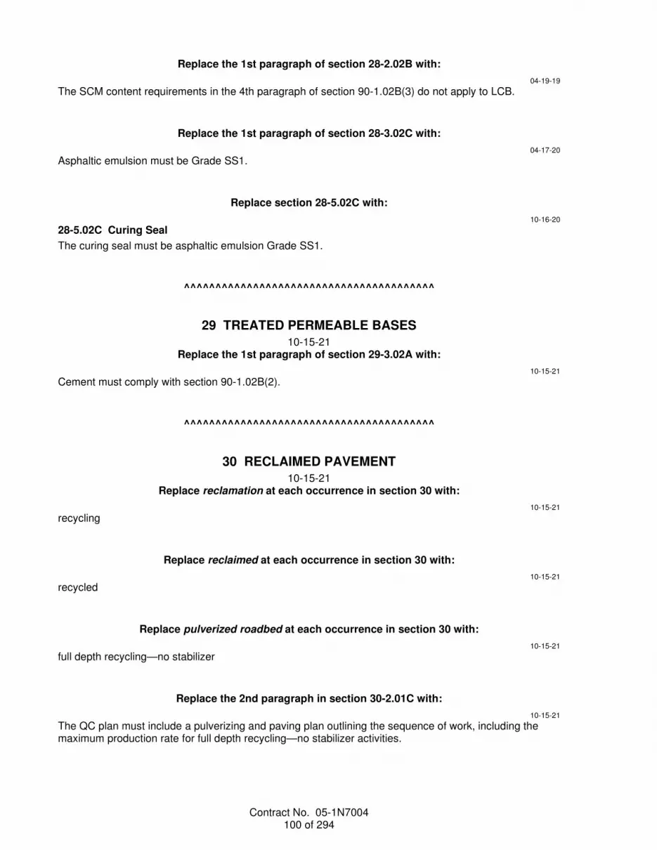
Contract No. 05-1N7004 100 of 294
Replace the 1st paragraph of section 28-2.02B with:
04-19-19
The SCM content requirements in the 4th paragraph of section 90-1.02B(3) do not apply to LCB.
Replace the 1st paragraph of section 28-3.02C with:
04-17-20
Asphaltic emulsion must be Grade SS1.
Replace section 28-5.02C with:
10-16-20
28-5.02C Curing Seal
The curing seal must be asphaltic emulsion Grade SS1.
^^^^^^^^^^^^^^^^^^^^^^^^^^^^^^^^^^^^^^^^
29 TREATED PERMEABLE BASES
10-15-21 Replace the 1st paragraph of section 29-3.02A with:
10-15-21
Cement must comply with section 90-1.02B(2).
^^^^^^^^^^^^^^^^^^^^^^^^^^^^^^^^^^^^^^^^
30 RECLAIMED PAVEMENT
10-15-21 Replace reclamation at each occurrence in section 30 with:
10-15-21
recycling
Replace reclaimed at each occurrence in section 30 with:
10-15-21
recycled
Replace pulverized roadbed at each occurrence in section 30 with:
10-15-21
full depth recycling—no stabilizer
Replace the 2nd paragraph in section 30-2.01C with:
10-15-21
The QC plan must include a pulverizing and paving plan outlining the sequence of work, including the maximum production rate for full depth recycling—no stabilizer activities.

Contract No. 05-1N7004 101 of 294
Replace section 30-4 with:
10-15-21
30-4 FULL DEPTH RECYCLING—CEMENT
30-4.01 GENERAL
30-4.01A Summary
Section 30-4 includes specifications for constructing a recycled pavement base using FDR—cement.
Constructing an FDR—cement base includes:
1. Pulverizing existing asphalt concrete pavement and underlying materials 2. Mixing with water, cement, and if specified, supplementary aggregate 3. Grading and compacting the mixture 4. Applying asphaltic emulsion and sand cover 30-4.01B Definitions
Lot: 1,000 sq yd of FDR—cement
30-4.01C Submittals
30-4.01C(1) General
With the QC plan, submit the mix design.
Submit quality control test results along with the daily reports.
Submit QC test results to [email protected].
30-4.01C(2) Quality Assurance Submittals
30-4.01C(2)(a) General
Reserved
30-4.01C(2)(b) Mix Design
Submit each FDR—cement mix design at least 2 weeks before starting FDR—cement operations. Each mix design submittal must be sealed and signed by an engineer who is registered as a civil engineer in the State.
You may submit multiple mix designs to optimize the cement content and adjust for varying underlying materials.
Each mix design submittal must include:
1. Area represented by the mix design by beginning and ending stations. 2. Gradation of the mixture before addition of cement. 3. Cement content in percent by weight of the dry mixture and in lb/sq yd surface application rate. 4. Supplementary aggregate in percent by weight of the dry mixture, if supplementary aggregate is
specified. 5. Moisture content of the material when mixing, relative to OMC. 6. Test results and any worksheets, photographs, and graphs. 7. Unconfined compressive strength test results. 8. Moisture-density curve of the material at the specified cement content. 9. Certificate of compliance for cement. 30-4.01C(2)(c) Quality Control Reporting
With the daily report, submit the following based on the testing frequencies specified:
1. General Information: 1.1. Weather:
1.1.1. Ambient air temperature before starting daily FDR—cement activities, including time of temperature reading.
1.1.2. Road surface temperature before starting daily FDR—cement activities, including time of temperature reading.

Contract No. 05-1N7004 102 of 294
2. Average forward speed of pulverizing equipment 3. FDR—cement quality control test results for unconfined compressive strength 4. Depth of pulverization With the daily report, submit the test results for the quality characteristics within the times after sampling shown in the following table:
FDR—Cement Quality Characteristic Test Result Reporting Time Allowances
Quality characteristic Maximum reporting time allowance
Water sulfates Before work starts
Water chlorides Aggregate gradation
24 hours Moisture content Laboratory maximum wet density Relative compaction Unconfined compressive strength 24 hours after testing specimens
30-4.01D Quality Assurance
30-4.01D(1) General
Relative compaction must be determined under California Test 231 and the following:
1. For a recycled layer 0.5-foot thick and less, perform 1 relative density test at mid layer. For thickness greater than 0.5-foot, test at every 0.5-foot intervals from 2 inches above the bottom of the FDR—cement layer.
2. A sample must contain no more than 5 percent retained on the 2-inch sieve and 15 percent retained on the 1-1/2-inch sieve.
3. Correction for oversize material does not apply. 4. Use the laboratory wet test maximum density closest in proximity to the lot to determine relative
compaction. If the relative compaction for a lot is less than 95 percent in accordance with ASTM D1557 requirements, perform California Test 216 and California Test 226 for each noncompliant lot and recalculate the relative compaction.
The Engineer tests each test strip under section 30-4.01D(4).
30-4.01D(2) Mix Design
Develop a mix design for each materials sampling location. The mix design must produce FDR—cement with an unconfined compressive strength from 300 to 600 psi, determined at 7 days under ASTM D1633, Method A, with the exceptions shown in FDR—Cement Quality Characteristic Requirements table under section 30-4.02A.
Notify the Engineer at least 2 business days before sampling.
Use materials from the specified FDR—cement mixing depth. If any portion of existing asphalt concrete pavement is to be removed before pulverizing, remove that portion of asphalt concrete pavement from the samples used in the mix design. If additional samples of subgrade material are needed, sampling locations can be excavated outside the edge of pavement to variable dimensions. Characterize and record sampling location features such as layer thicknesses and types, distresses, interlayers, thin or thick areas, digouts, and adhesion to the base. Use the sampled material to determine the mix design represented by the sampling location, according to the proportions of the pavement structure shown.
Before opening the mix design sampling locations to traffic, backfill sampling locations by replacing and compacting with an authorized material or minor HMA that complies with section 39-2.07. Backfill and compact to the existing grade and thickness of asphalt concrete pavement, in the Engineer's presence.
30-4.01D(3) Quality Control
30-4.01D(3)(a) General
Reserved
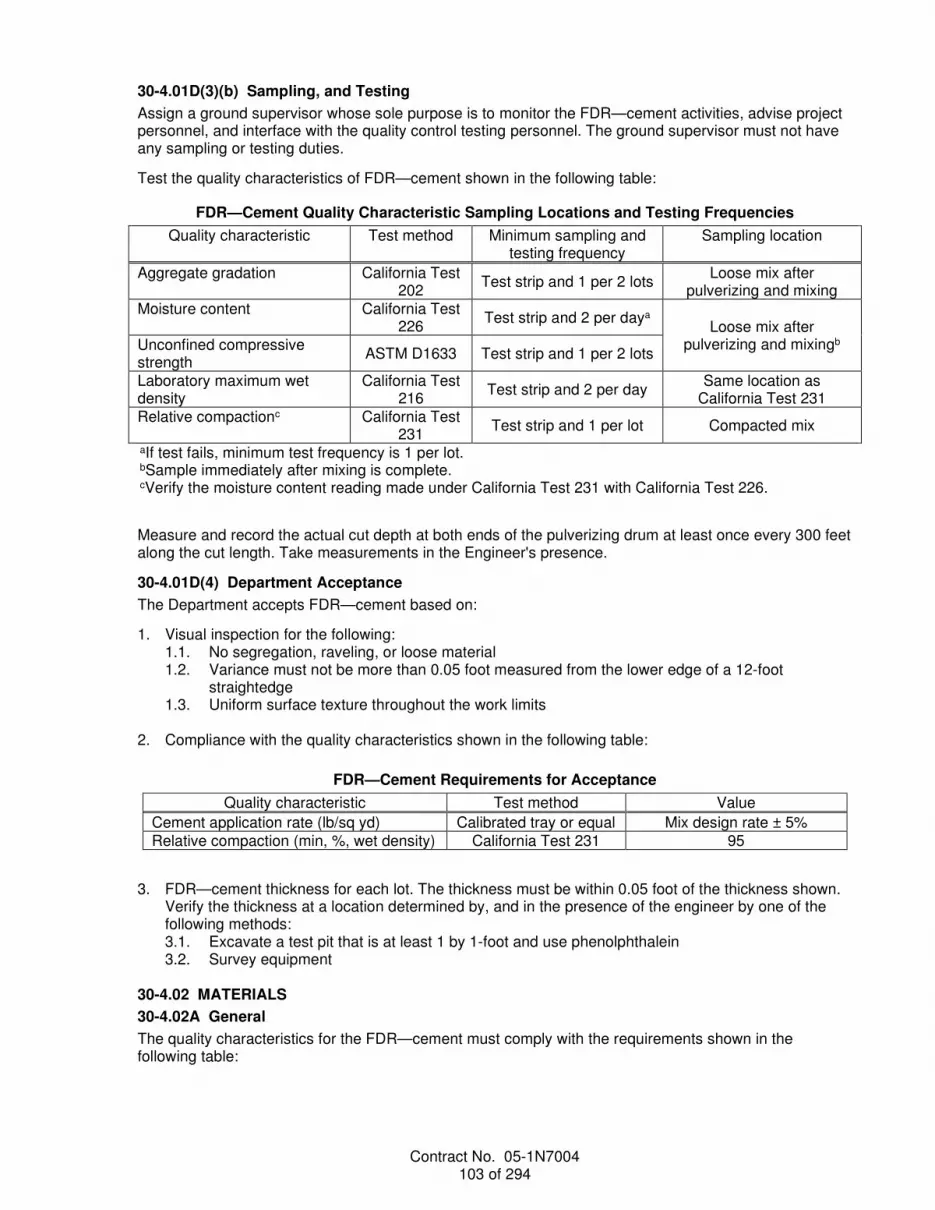
Contract No. 05-1N7004 103 of 294
30-4.01D(3)(b) Sampling, and Testing
Assign a ground supervisor whose sole purpose is to monitor the FDR—cement activities, advise project personnel, and interface with the quality control testing personnel. The ground supervisor must not have any sampling or testing duties.
Test the quality characteristics of FDR—cement shown in the following table:
FDR—Cement Quality Characteristic Sampling Locations and Testing Frequencies
Quality characteristic Test method Minimum sampling and testing frequency
Sampling location
Aggregate gradation California Test 202
Test strip and 1 per 2 lots Loose mix after
pulverizing and mixing Moisture content California Test
226 Test strip and 2 per daya
Loose mix after pulverizing and mixingb Unconfined compressive
strength ASTM D1633 Test strip and 1 per 2 lots
Laboratory maximum wet density
California Test 216
Test strip and 2 per day Same location as
California Test 231 Relative compactionc California Test
231 Test strip and 1 per lot Compacted mix
aIf test fails, minimum test frequency is 1 per lot. bSample immediately after mixing is complete. cVerify the moisture content reading made under California Test 231 with California Test 226.
Measure and record the actual cut depth at both ends of the pulverizing drum at least once every 300 feet along the cut length. Take measurements in the Engineer's presence.
30-4.01D(4) Department Acceptance
The Department accepts FDR—cement based on:
1. Visual inspection for the following: 1.1. No segregation, raveling, or loose material 1.2. Variance must not be more than 0.05 foot measured from the lower edge of a 12-foot
straightedge 1.3. Uniform surface texture throughout the work limits
2. Compliance with the quality characteristics shown in the following table:
FDR—Cement Requirements for Acceptance
Quality characteristic Test method Value
Cement application rate (lb/sq yd) Calibrated tray or equal Mix design rate ± 5% Relative compaction (min, %, wet density) California Test 231 95
3. FDR—cement thickness for each lot. The thickness must be within 0.05 foot of the thickness shown. Verify the thickness at a location determined by, and in the presence of the engineer by one of the following methods: 3.1. Excavate a test pit that is at least 1 by 1-foot and use phenolphthalein 3.2. Survey equipment
30-4.02 MATERIALS
30-4.02A General
The quality characteristics for the FDR—cement must comply with the requirements shown in the following table:

Contract No. 05-1N7004 104 of 294
FDR—Cement Quality Characteristic Requirements
Quality characteristic Test method Requirement
Aggregate gradation (%, passing)a Sieve Size: 3 inch 2 inch 1-1/2 inch
California Test 202
100 95–100 85–100
Moisture content (%) California Test 226 Mix design ± 2 percent Unconfined compressive strength (psi) ASTM D1633b Specified in section 30-4.01D(2)
Laboratory maximum wet density (lb/cu ft)
California Test 216 Use for relative compaction
calculation Relative compaction (min, %, wet density)c California Test 231 95
aPerform aggregate gradation on samples collected from full recycled depth. bMethod A, except:
1. Test specimens must be compacted under ASTM D1557, Method A or B. 2. Test specimens must be cured by sealing each specimen with 2 layers of plastic at least 4-mil thick. The plastic must be tight around the specimen. Seal all seams with duct tape to prevent moisture loss. Sealed specimens must be placed in an oven for 7 days at 100 ± 5 degrees F. At the end of the cure period, specimens must be removed from the oven and air-cooled. Duct tape and plastic wrap must be removed before capping. Specimens must not be soaked before testing.
cVerify the moisture content reading made under California Test 231 with California Test 226.
30-4.02B Cement
Reserved
30-4.02C Water
Reserved
30-4.02D Supplementary Aggregate
If supplementary aggregate is specified, supplementary aggregate must comply with the specifications for Class 2 aggregate base in section 26.
30-4.02E Asphaltic Emulsion
Asphaltic emulsion must be Grade SS-1h or CSS-1h.
Notify the Engineer if you dilute the asphaltic emulsion with water. The ratio by weight of added water to asphaltic emulsion must not exceed 1 to 1.
Measure added water weight.
30-4.02F Sand Cover
Sand used for sand cover must comply with the material specifications for fine aggregate under section 90-1.02C(3). Sand must not contain more than 2 percent moisture by dry weight of sand.
30-4.02G Test Pit Backfill Material
Backfill for test pits must be FDR—cement treated material.
30-4.03 CONSTRUCTION
30-4.03A General
Do not start FDR—cement activities if the ambient air temperature is below 40 degrees F or the road surface is below 40 degrees F. If the ambient air temperature falls below 40 degrees F during FDR—cement activities, you may only compact and finish FDR—cement.
Backfill test pits and compact to 95 percent under California Test 231. After compaction, the repair area must not vary more than 0.05 foot from the adjacent FDR—cement surface.

Contract No. 05-1N7004 105 of 294
30-4.03B Equipment
The FDR—cement mixing machine must have independent and interlocked systems for water and must include the following:
1. Digital electronic controller system 2. Pumping system 3. Spray bar system The cement distributor must have a vacuum or dust suppressant system to minimize airborne cement during spreading of the cement on the grade.
Storage equipment for water must not leak and must be attached to the FDR—cement mixing machine with a tow bar and hose. The hose must be attached to the bar and must not touch the ground at any time.
Grading and compacting equipment must be self-propelled and reversible. The frequency and amplitude of vibrating rollers must be adjustable and exceed a force of 15 tons in vibratory mode.
30-4.03C Pulverizing
Unless otherwise authorized, do not pulverize more material than can be mixed with cement and compacted in one day.
Do not leave a wedge where the pulverizing drum cuts into the existing material. The 1st cut width must use the full width of the pulverizing drum. Subsequent cuts must overlap at least 4 inches. Do not leave a gap of unpulverized material between cuts. If an overlap is less than 4 inches, immediately back up and pulverize the deviation along the correct cut line.
Mark the existing pavement where the center of the pulverizing drum stops. Start the following cut on this alignment at least 2 feet behind the mark.
30-4.03D Spreading Materials
Spread cement uniformly over the full roadway surface width. Do not spread cement more than 30 minutes before mixing. Do not apply dry cement in windy conditions that will result in dust outside the FDR—cement area. The spread rate must be the mix design rate or the ordered rate in lb/sq yd ± 5 percent.
Do not spread cement and supplementary aggregate before pulverizing.
30-4.03E Mixing
The overlap requirements in section 30-4.03C apply to mixing. With each cut, adjust the quantity of water proportionally to the actual cut width. If an overlap is less than 4 inches, immediately back up and pulverize the deviation along the correct line without adding water or cement.
Water must be injected through the mixing machine. The injection rate of mixing water must be sufficient to produce the FDR—cement material mixing moisture content described in the mix design.
Mark where the center of the pulverizing drum stops. Start the following cut on this alignment at least 2 feet behind the mark.
30-4.03F Compacting and Grading
Immediately after pulverizing and mixing, compact FDR—cement to the minimum relative compaction. Do not allow more than 2 hours between final mixing of the pulverized material with cement and completion of compaction. Check thickness of compacted FDR material in test pit with phenolphthalein prior to final compaction and grading.
During grading and final compaction with vibratory steel drum rollers, add water to maintain the mixing moisture content as described in the mix design. After final compaction, do not place cement treated soil to fill low areas in the grade.

Contract No. 05-1N7004 106 of 294
30-4.03G Finishing
Immediately after compaction, apply water and roll with pneumatic-tired rollers or steel drum roller with no vibration. The finished surface must be free of ruts, bumps, indentations, segregation, raveling, and any loose material.
Keep the compacted surface damp by lightly watering until asphaltic emulsion is applied.
Apply a diluted asphaltic emulsion to the finished surface when it is damp but free of standing water at the end of the day. The application rate of asphaltic emulsion must be from 0.13 to 0.25 gal/sq. yd. Do not water after applying asphaltic emulsion.
Spread sand cover after asphaltic emulsion is applied under section 37-4.03C. Remove excess sand from the surface by sweeping before opening to traffic.
During the period from 48 to 56 hours after compaction, microcrack the surface by applying 2 to 3 single passes using a 12-ton vibratory steel drum roller at maximum amplitude travelling from 2 to 3 mph.
Maintain the FDR—cement surface free of ruts, bumps, indentations, raveling, and segregation. Repair damaged FDR—cement material with minor HMA.
Determine the finished FDR—cement thickness before placing HMA. If FDR—cement thickness is less than the specified thickness by more than 0.05 foot, excavate a test pit at least 1 by 1-foot in the vicinity of the noncompliant test pit to determine the extent of the deficient thickness. Remove the FDR—cement material deficient in thickness by cold planing to a depth of 0.2 foot below the finished FDR—cement grade. Replace the planed FDR—cement with the HMA specified for the project and compact under section 39-2.01C.
For each lot of FDR—cement, the HMA layer must be placed within 7 days from final compaction of the FDR—cement base unless otherwise authorized.
Immediately before placing HMA, apply asphaltic emulsion at a rate from 0.03 to 0.05 percent residual binder content.
Do not place HMA until authorized.
30-4.04 PAYMENT
Not Used
^^^^^^^^^^^^^^^^^^^^^^^^^^^^^^^^^^^^^^^^^^^^^^^^^^^^^^^^^^^^
DIVISION V SURFACINGS AND PAVEMENTS
37 BITUMINOUS SEALS
10-16-20 Add to section 37-1.01D(1):
10-16-20
Take samples under California Test 125.
Replace item 1 in the list in the 1st paragraph of section 37-2.01A(3) with:
10-16-20
1. Samples for: 1.1. Asphaltic emulsion chip seal, two 1-quart samples of asphaltic emulsion 1.2. Polymer modified asphaltic emulsion chip seal, two 1-quart samples of polymer modified
asphaltic emulsion 1.3. Asphalt rubber binder chip seal, two 1-quart samples of base asphalt binder 1.4. Asphalt rubber binder chip seal, five 1-quart samples of asphalt rubber binder

Contract No. 05-1N7004 107 of 294
Replace section 37-2.02A(3) with:
10-16-20
37-2.02A(3) Submittals
Immediately after sampling, submit two 1-quart samples of asphaltic emulsion taken in the presence of the Engineer.
Replace the 1st paragraph of section 37-2.02A(4)(b)(ii) with:
10-16-20
Take two 1-quart samples for Department acceptance testing.
Replace section 37-2.03A(3) with:
10-16-20
37-2.03A(3) Submittals
Immediately after sampling, submit two 1-quart samples of polymer modified asphaltic emulsion taken in the presence of the Engineer.
Replace the 1st paragraph of section 37-2.03A(4)(b)(ii) with:
10-16-20
Take two 1-quart samples for Department acceptance testing.
Replace the 2nd paragraph of section 37-2.03B(2) with:
04-17-20
A polymer modified asphaltic emulsion must be either Grade PMCRS-2 or PMCRS-2h. Polymer content in percent by weight does not apply.
Replace the 1st paragraph of section 37-2.04A(4)(c)(iv) with:
10-16-20
For Department acceptance testing, take two 1-quart samples and one 1-gallon sample of asphalt rubber binder in the presence of the Engineer for every 5 lots or once a day, whichever is greater.
Replace item 1 in the list in the 1st paragraph of section 37-3.01A(3) with:
10-16-20
1. Samples for: 1.1. Asphaltic emulsion slurry seal, two 1-quart samples of asphaltic emulsion 1.2. Polymer modified asphaltic emulsion slurry seal, two 1-quart samples of polymer modified
asphaltic emulsion 1.3. Micro-surfacing, two 1-quart samples of micro-surfacing emulsion
Replace section 37-3.02A(3) with:
10-16-20
37-3.02A(3) Submittals
Immediately after sampling, submit two 1-quart samples of asphaltic emulsion or polymer modified asphaltic emulsion taken in the presence of the Engineer.

Contract No. 05-1N7004 108 of 294
Replace section 37-3.02A(4)(b)(i) with:
10-16-20
37-3.02A(4)(b)(i) General
Take two 1-quart samples of asphaltic emulsion and polymer modified asphaltic emulsion for Department acceptance testing.
Replace section 37-3.02B(3) with:
04-17-20
37-3.02B(3) Polymer Modified Asphaltic Emulsions
A polymer modified asphaltic emulsion must be grade PMCQS-1h.
A polymer modified asphaltic emulsion must consist of an elastomeric polymer mixed with an asphaltic material uniformly emulsified with water and an emulsifying or stabilization agent.
A polymer modified asphaltic emulsion must use either neoprene polymer or butadiene and styrene copolymer. The polymer must be homogeneous and milled into the asphaltic emulsion at the colloid mill.
Replace section 37-3.03A(3) with:
10-16-20
37-3.03A(3) Submittals
Immediately after sampling, submit two 1-quart samples of micro-surfacing emulsion taken in the presence of the Engineer.
Replace the 1st paragraph of section 37-3.03A(4)(b)(ii) with:
10-16-20
Take two 1-quart samples of micro-surfacing emulsion for Department acceptance testing.
Replace section 37-3.03B(2) with:
04-17-20
37-3.03B(2) Micro-surfacing Emulsions
A micro-surfacing emulsion must be grade MSE.
A micro-surfacing emulsion must be a homogeneous mixture of asphalt, an elastomeric polymer, and an emulsifier solution.
Add an elastomeric polymer modifier to asphalt or emulsifier solution before emulsification. An elastomeric polymer solid must be a minimum of 3 percent by weight of the residual asphalt in the micro-surfacing emulsion.
Replace item 1 in the paragraph of section 37-4.01A(3) with:
10-16-20
1. Two 1-quart samples of asphaltic emulsion
Add to section 37-4.01A:
10-16-20
37-4.01A(4) Quality Assurance
Reserved

Contract No. 05-1N7004 109 of 294
Replace section 37-4.02A(3) with:
10-16-20
37-4.02A(3) Submittals
Immediately after sampling, submit two 1-quart samples of asphaltic emulsion taken in the presence of the Engineer.
Replace the 1st paragraph of section 37-4.02A(4)(b)(ii) with:
10-16-20
Take two 1-quart samples for Department acceptance testing.
Replace the 6th paragraph of section 37-5.01C with:
10-16-20
Immediately after sampling, submit two 1-quart samples of parking area seal taken in the presence of the Engineer.
^^^^^^^^^^^^^^^^^^^^^^^^^^^^^^^^^^^^^^^^
39 ASPHALT CONCRETE
10-15-21 Replace 12 months at each occurrence in section 39 with:
10-15-21
24 months
Replace AASHTO T 324 (Modified) and AASHTO T 324 at each occurrence in section 39 with:
04-17-20
California Test 389
04-17-20
Delete the row for AASHTO T 324 in the table in the 5th paragraph of section 39-2.01A(1).
Add to the table in the 5th paragraph of section 39-2.01A(1):
10-16-20
ASTM D5095 2007
Replace the 1st and 2nd paragraphs of section 39-2.01A(3)(d) with:
04-19-19
If ordered, submit QC test results within 3 business days of a request.
04-17-20
Delete the 1st paragraph of section 39-2.01A(4)(a).

Contract No. 05-1N7004 110 of 294
Replace the 2nd paragraph of section 39-2.01A(4)(a) with:
10-16-20
Take samples under California Test 125. Reduce samples of HMA to testing size under California Test 306.
Replace item 2 in the list in the 2nd paragraph of section 39-2.01A(4)(b) with:
10-16-20
2. Asphalt binder. Take at least two 1-qt samples. If the asphalt binder is modified or rubberized, the asphalt binder must be sampled with the components blended in the proportions to be used.
Replace the 3rd, 4th, and 5th paragraphs of section 39-2.01A(4)(d) with:
10-15-21
The Engineer verifies the JMF for renewal under section 39-2.01A(4)(b) except:
1. Engineer keeps the samples until you provide test results for your part on a Contractor Job Mix Formula Renewal form.
2. Engineer may use the most recent aggregate quality test results within the past one year, or the Engineer may perform aggregate quality tests.
3. Engineer may use RAP and binder test results from the project where renewal samples are taken, or the Engineer may perform RAP and binder tests.
4. Department tests samples of materials obtained from the HMA production unit after you submit test results that comply with the mix design specifications.
5. After completion of the JMF verification renewal document review, the Engineer verifies each proposed JMF within 20 days of receiving the verification renewal samples and the complete Contractor Job Mix Formula Renewal form.
6. You may not adjust the JMF due to a failed verification. 7. For each HMA type and aggregate gradation specified, the Engineer verifies at no cost to you 1
proposed JMF renewal within a 24 month period.
Replace the 1st sentence in the 2nd paragraph of section 39-2.01A(4)(h)(i) with:
04-17-20
Condition each at-the-plant sample of HMA mixture for testing under AASHTO 283 in compliance with sections 7.1.2, 7.1.3, and 7.1.4 of AASHTO R 30.
Add to section 39-2.01A(4)(h)(v):
10-16-20
California Test 389 and AASHTO T 283 are not required if production start-up evaluation is within 45 days of the date the Hot Mix Asphalt Verification form is signed.
If production stops for more than 60 days, perform a production start-up evaluation. If production stops for more than 30 days but less 60 days, perform a reduced production start-up evaluation. Reduced production start-up evaluation is production start-up evaluation without California Test 389 and AASHTO T 283.
If production start-up evaluation fails, do not begin production.
Add between the 3rd and 4th paragraphs of section 39-2.01A(4)(i)(i):
04-19-19
You must assist in collecting Engineer acceptance samples. Sample in the presence of the Engineer. Split the Engineer acceptance samples into at least 4 parts. Engineer retains 3 parts and you keep 1 part.

Contract No. 05-1N7004 111 of 294
Replace the 1st sentence in the 5th paragraph of section 39-2.01A(4)(i)(i) with:
04-17-20
The Engineer conditions each at-the-plant sample of HMA mixture for testing under AASHTO 283 in compliance with sections 7.1.2, 7.1.3, and 7.1.4 of AASHTO R 30.
Replace the 1st through 3rd paragraphs of section 39-2.01A(4)(i)(iv) with:
04-19-19
You and the Engineer must work together to avoid potential conflicts and to resolve disputes regarding test result discrepancies. You and the Engineer may only dispute each other's test results if one party's test results pass and the other party's test results fail.
If there is a dispute, submit your test results and copies of paperwork including worksheets used to determine the disputed test results within 3 business day of receiving Engineer's test results. An independent third party performs referee testing. Before the third party participates in a dispute resolution, it must be qualified under AASHTO re:source program and the Department's Independent Assurance Program. The independent third party must have no prior direct involvement with this Contract. By mutual agreement, the independent third party is chosen from:
1. Department laboratory in a district or region not in the district or region the project is located 2. Transportation Laboratory 3. Laboratory not currently employed by you or your HMA producer If the Department's portion of the split acceptance samples are not available, the independent third party uses any available material agreed by you and the Engineer as representing the disputed HMA for evaluation.
Replace the 1st paragraph of section 39-2.01B(2)(b) with:
04-17-20
If the proposed JMF indicates that the aggregate is being treated with dry lime or lime slurry with marination, or the HMA with liquid antistrip, then testing the untreated aggregate under AASHTO T 283 and California Test 389 is not required.
Replace section 39-2.01B(5) with:
10-16-20
39-2.01B(5) Liquid Antistrip Treatment
Do not use liquid antistrip as a substitute for asphalt binder.
Total amine value for amine-based liquid antistrip must be a minimum of 325 when tested under ASTM D2074. Dosage for amine-based liquid antistrip must be from 0.25 to 1.00 percent by weight of asphalt.
Nonvolantile content of organosaline-based liquid antistrip must be 40 percent minimum when tested under ASTM D5095. Dosage for organosaline-based liquid antistrip must be from 0.05 to 0.15 percent by weight of asphalt.
Use only 1 liquid antistrip type or brand at a time. Do not mix liquid antistrip types or brands.
Store and mix liquid antistrip under the manufacturer's instructions.

Contract No. 05-1N7004 112 of 294
Replace the table in the 3rd paragraph of section 39-2.01C(3)(f) with:
Tack Coat Application Rates for HMA 04-17-20
HMA over:
Minimum residual rates (gal/sq yd) CSS-1/CSS-1h, SS-1/SS-1h, and QS-
1h/CQS-1h asphaltic emulsion
CRS-1/CRS-2 and QS-1/CQS-1
asphaltic emulsion
Asphalt binder and PMCRS-2/PMCRS-
2h asphaltic emulsion
New HMA (between layers) 0.02 0.03 0.02 Concrete pavement and existing asphalt concrete surfacing
0.03 0.04 0.03
Planed pavement 0.05 0.06 0.04
Replace the 9th paragraph of section 39-2.01C(3)(f) with:
04-16-21
If authorized, you may change the tack coat application rates.
Replace section 39-2.02A(4)(b)(iii) with:
04-16-21
39-2.02A(4)(b)(iii) Reclaimed Asphalt Pavement
Sample and test mix design RAP stockpile under California Test 384. Report the average AASHTO T 308 uncorrected binder content on page 4 of your Contractor Hot Mix Asphalt Design Data form. When the mix design RAP stockpile is augmented, sample RAP used to augment the stockpile at a minimum frequency of 1 sample per 1,000 tons under California Test 384 before augmenting the stockpile. Test each sample to determine the uncorrected binder content under AASHTO T 308. Average the results of the 3 tests. When tested under AASHTO T 308, the uncorrected binder content of each augmented RAP sample must be within ±2.00 percent of the average uncorrected asphalt binder content reported on page 4 of your Contractor Hot Mix Asphalt Design Data form. You must use the same ignition oven used to determine the uncorrected asphalt binder content reported on page 4 of your Contractor Hot Mix Asphalt Design Data form.
The augmented RAP sample when tested under AASHTO T 209 must be within ±0.06 of the average maximum specific gravity reported on page 4 of your Contractor Hot Mix Asphalt Design Data form.
During Type A HMA production, sample RAP twice daily and perform QC testing for:
1. Aggregate gradation at least once a day under California Test 384 2. Moisture content at least once a day
04-17-20
Replace footnote a in the table in item 1 in the list in the paragraph of section 39-2.02A(4)(e) with:
10-18-19 aThe Engineer determines combined aggregate gradations containing RAP under California Test 384. The Engineer uses the correlation factor from Contractor Hot Mix Asphalt Design Data form and mathematically combines the virgin and corrected RAP aggregate gradations at the correct proportions to obtain the combined gradation.

Contract No. 05-1N7004 113 of 294
Replace the table in item 2 in the list in the paragraph of section 39-2.02A(4)(e) with:
10-18-19
Reclaimed Asphalt Pavement Quality
Quality characteristic Test method Requirement
Uncorrected binder content (% within the average value reporteda)
AASHTO T 308 ±2.00
Specific gravity (within the average value reportedb) AASHTO T 209 ±0.06 aAverage uncorrected binder content of three ignition oven tests performed at JMF verification. Engineer must use the same ignition oven used to determine the average uncorrected binder content at JMF verification. bAverage maximum specific gravity reported on page 4 of Contractor Hot Mix Asphalt Design Data form.
Replace the row for Moisture susceptibility (min, psi, dry strength) in the table in item 3 in the list in the paragraph of section 39-2.02A(4)(e) with:
04-19-19
For RAP substitution equal to or less than 15% moisture susceptibility (min, psi, dry strength)
AASHTO T 283 100
For RAP substitution greater than 15% moisture susceptibility (psi, dry strength)
AASHTO T 283 100-300h
Replace the row for Hamburg wheel track (min number of passes at inflection point) in the table in item 3 in the paragraph of section 39-2.02A(4)(e) with:
04-17-20
Hamburg wheel track (number of passes at inflection point)
California Test 389
Report only
Replace the row for Moisture susceptibility (min, psi, wet strength) in the table in item 3 in the list in the paragraph of section 39-2.02A(4)(e) with:
10-16-20
Moisture susceptibility (min, psi, wet strength) AASHTO T 283i 70
Add a footnote to the table in item 3 in the list in the paragraph of section 39-2.02A(4)(e):
04-19-19 hNot required in the following areas:
1. Southern San Luis Obispo or Santa Barbara County in District 5. 2. Kern County in District 6. 3. Kings County in District 6: route 5, post mile 0 to 17; route 33, post mile 0 to 19; route 41, post mile 0 to 16. 4. Tulare County in District 6: route 65, post mile 0 to 10; route 99, post mile 0 to 10; route 43, post mile 0 to 15.
Add footnote i to the table in item 3 in the list in the paragraph of section 39-2.02A(4)(e):
10-16-20 iFreeze thaw required

Contract No. 05-1N7004 114 of 294
Replace the row for Hamburg wheel track (min number of passes at inflection point) in the 1st paragraph of section 39-2.02B(2) with:
04-17-20
Hamburg wheel track (number of passes at inflection point)
California Test 389c
Report only
Replace the row for Moisture susceptibility, dry strength in the table in the 1st paragraph of section 39-2.02B(2) with:
04-19-19
For RAP substitution equal to or less than 15% moisture susceptibility (min, psi, dry strength)
AASHTO T 283 100
For RAP substitution greater than 15% moisture susceptibility (psi, dry strength)
AASHTO T 283 100-300e
Add a footnote to the table in the 1st paragraph of section 39-2.02B(2):
04-19-19 eNot required in the following areas:
1. Southern San Luis Obispo or Santa Barbara County in District 5. 2. Kern County in District 6. 3. Kings County in District 6: route 5, post mile 0 to 17; route 33, post mile 0 to 19; route 41, post mile 0 to 16. 4. Tulare County in District 6: route 65, post mile 0 to 10; route 99, post mile 0 to 10; route 43, post mile 0 to 15.
Replace the 3rd and 4th paragraphs of section 39-2.02B(2) with:
04-19-19
For RAP substitution of 15 percent or less, the grade of the virgin binder must be the specified grade of asphalt binder for Type A HMA.
For RAP substitution greater than 15 percent and not exceeding 25 percent, the grade of the virgin binder must be the specified grade of asphalt binder for Type A HMA with the upper and lower temperature classification reduced by 6 degrees C. Hamburg wheel track requirements are based on the grade of asphalt binder specified for Type A HMA.
Replace the 2nd sentence in the 2nd paragraph of section 39-2.02B(11) with:
04-19-19
For RAP substitution of 15 percent or less, RAP must be within ±3 of RAP percentage shown in your Contractor Job Mix Formula Proposal form without exceeding 15 percent. For RAP substitution of greater than 15 percent, RAP must be within ±3 of RAP percentage shown in your Contractor Job Mix Formula Proposal form without exceeding 25 percent.

Contract No. 05-1N7004 115 of 294
Replace the row for Hamburg wheel track (min number of passes at 0.5-inch rut depth) in the table in item 2 in the paragraph of section 39-2.03A(4)(e)(i) with:
04-17-20
Hamburg wheel track (min number of passes at 0.5-inch rut depth) Base binder grade: PG 64 or lower PG 70
California Test 389
15,000 20,000
Replace the row for Hamburg wheel track (min number of passes at inflection point) in the table in item 2 in the paragraph of section 39-2.03A(4)(e)(i) with:
04-17-20
Hamburg wheel track (number of passes at inflection point)
California Test 389
Report only
Replace the row for Moisture susceptibility (min, psi, wet strength) in the table in item 2 in the list in the paragraph of section 39-2.03A(4)(e)(i) with:
10-16-20
Moisture susceptibility (min, psi, wet strength) AASHTO T 283g 70
Add footnote g to the table in item 2 in the list in the paragraph of section 39-2.03A(4)(e)(i):
10-16-20 gFreeze thaw required
Replace the row for Hamburg wheel track (min number of passes at 0.5-inch rut depth) in the table in 1st paragraph of section 39-2.03B(2) with:
04-17-20
Hamburg wheel track (min number of passes at 0.5-inch rut depth) Base binder grade: PG 64 or lower PG 70
California Test 389d
15,000 20,000
Replace the row for Hamburg wheel track (min number of passes at inflection point) in the table in 1st paragraph of section 39-2.03B(2) with:
04-17-20
Hamburg wheel track (number of passes at inflection point)
California Test 389d
Report only

Contract No. 05-1N7004 116 of 294
Replace the table in the 3rd paragraph of section 39-2.04C with:
Tack Coat Application Rates for OGFC 04-17-20
OGFC over:
Minimum residual rates (gal/sq yd) CSS-1/CSS-1h, SS-1/SS-1h, and QS-
1h/CQS-1h asphaltic emulsion
CRS-1/CRS-2 and QS-1/CQS-1
asphaltic emulsion
Asphalt binder and PMCRS-2/PMCRS-
2h asphaltic emulsion
New HMA 0.03 0.04 0.03 Concrete pavement and existing asphalt concrete surfacing
0.05 0.06 0.04
Planed pavement 0.06 0.07 0.05
Replace the 8th and 9th paragraphs of section 39-2.04C with:
04-19-19
For RHMA-O and RHMA-O produced with WMA water injection technology, and RHMA-O-HB and RHMA-O-HB produced with WMA water injection technology:
1. Spread and compact if the ambient air temperature is at least 55 degrees F and the surface temperature is at least 60 degrees F
2. Complete the 1st coverage using 2 rollers before the surface temperature drops below 280 degrees F 3. Complete compaction before the surface temperature drops below 250 degrees F For RHMA-O produced with WMA additive technology and RHMA-O-HB produced with WMA additives technology:
1. Spread and compact if the ambient air temperature is at least 45 degrees F and the surface temperature is at least 50 degrees F
2. Complete the 1st coverage using 2 rollers before the surface temperature drops below 270 degrees F 3. Complete compaction before the surface temperature drops below 240 degrees F Spread sand at a rate from 1 to 2 lb/sq yd on RHMA-O and RHMA-O-HB with or without WMA technology pavement after finish rolling activities are complete. Keep traffic off the pavement until spreading of the sand is complete.
Replace the 2nd paragraph of section 39-2.05A(1)(a) with:
04-17-20
Placing a BWC consists of applying a bonded wearing course asphaltic emulsion and placing the specified HMA in a single pass with an integrated paving machine.
Replace the 1st paragraph of section 39-2.05A(1)(d)(ii) with:
10-16-20
Take two 1-gallon samples of BWC.
Replace the 1st paragraph of section 39-2.05A(1)(d)(iii) with:
10-15-21
The Department accepts asphaltic emulsion based on compliance with the requirements for bonded wearing course asphaltic emulsion.

Contract No. 05-1N7004 117 of 294
Replace the paragraph of section 39-2.05A(2)(b) with:
10-15-21
Asphaltic emulsion must comply be bonded wearing course asphaltic emulsion
Replace the paragraph of section 39-2.07B(3) with:
10-15-21
Reserved
Add to section 39-2:
04-16-21
39-2.11–39-2.20 RESERVED
^^^^^^^^^^^^^^^^^^^^^^^^^^^^^^^^^^^^^^^^
40 CONCRETE PAVEMENT
10-15-21 10-16-20
Delete full-depth crack and its definition in section 40-1.01B.
Replace working crack and its definition in section 40-1.01B with:
10-16-20
working crack: Crack parallel to and within 4 inches of a planned JPCP contraction joint.
Add to section 40-1.01B:
10-16-20
uncontrolled crack: Any crack in JPCP that is not a working crack.
Replace the 2nd paragraph of section 40-1.01C(4) with:
10-15-21
At least 15 days before starting field qualification, submit the proposed concrete mix proportions, the corresponding mix identifications, and laboratory test reports, including measurements of 3 modulus of rupture and 3 compressive strength, for each trial mixture at 3, 7, 14, 21, 28, and 42 days.
Replace the 2nd paragraph of section 40-1.01C(9) with:
10-19-18
Submit your coefficient of thermal expansion test data at:
https://dime.dot.ca.gov/
Replace the 3rd paragraph of section 40-1.01D(1) with:
10-15-21
Provide material, labor and equipment that meets the initial curing requirement to assist the Engineer in fabricating, curing and handling specimens for the Department's modulus of rupture and compressive strength testing. Failure to maintain the proper curing environment during initial cure will not be basis for rejection of samples, dispute resolution, or claim against the Department. Secure the initial curing equipment at all times to protect against theft and damage.

Contract No. 05-1N7004 118 of 294
Add to the list in the 3rd paragraph of section 40-1.01D(3):
10-15-21
17. Compressive strength
Replace the 3rd paragraph of section 40-1.01D(5) with:
10-15-21
To determine the minimum content of cementitious materials or the maximum ratio of water to cementitious materials, use the compressive strength equivalent to modulus of rupture values of at least 570 psi for 28 days age and at least 650 psi for 42 days age. Compressive strength must be tested under CT 521.
Replace the row for Density in the table in the 1st paragraph of section 40-1.01D(7)(a) with:
04-17-20
Unit weight California Test 518 1 per 4 hours
Add to the list in the 4th paragraph of section 40-1.01D(7)(a):
04-17-20
6. Unit weight
Replace item 2 in the list in the 8th paragraph of section 40-1.01D(7)(a) with:
04-17-20
2. 1 point falls outside the suspension limit line for individual penetration, unit weight or air content measurements
Replace the 2nd paragraph of section 40-1.01D(7)(b) with:
10-15-21
For field qualification, the compressive strength must be equivalent to a modulus of rupture at an age of 42 days or earlier of at least:
1. 625 psi for each single beam 2. 650 psi for the average of 3 beams
Replace the row for modulus of rupture at 28 days in the table in the 1st paragraph of section 40-1.01D(8)(a) with:
10-15-21
Compressive strength at 42 days
California Test 521 1,000 cu yd
Replace nv in the 1st paragraph of section 40-1.01D(8)(b)(ii) with:
04-17-20
nv = number of Department's tests (minimum of 3 required)

Contract No. 05-1N7004 119 of 294
Replace the 4th paragraph of section 40-1.01D(8)(b)(ii) with:
04-17-20
If your QC test results are not verified, core at least 3 specimens from the concrete pavement under section 40-1.03M. For dispute resolution, the Engineer selects the core locations and the Department contracts with an independent testing laboratory or uses the Department's laboratory to test these specimens for air content under ASTM C457. The Engineer compares these test results with your QC test results using the t-test method. If your QC test results are verified based on this comparison, the Engineer uses your QC test results for acceptance of concrete pavement for air content, otherwise, the Engineer uses the test results from the dispute resolution process and you pay for the independent testing.
Replace the row for modulus of rupture at 28 days in the table in the 1st paragraph of section 40-1.01D(8)(c)(i) with:
10-15-21
Compressive strength at 42 days (min, psi)
California Test 521 650b equivalent modulus of
rupture to compressive strength
Replace the note b in the table in the 1st paragraph of section 40-1.01D(8)(c)(i) with:
10-15-21 bAverage of the individual test results of 3 cylinders
Replace the 1st sentence of section 40-1.01D(8)(c)(iii) with:
04-17-20
The Department verifies and accepts pavement smoothness based on the results of your inertial profiler testing under Section 36-3.
Replace section 40-1.01D(8)(c)(v) with:
04-17-20
40-1.01D(8)(c)(v) Determining Modulus of Rupture from Pavement Cores
For each approved mix design, a correlation between flexural beam strength and compressive core strength may be developed to evaluate low modulus of rupture results from projects. If the average 28-day modulus of rupture is below 570 psi, you may use compressive strength results from pavement cores to determine the equivalent 28-day modulus of rupture.
In the presence of engineer:
1. From the test strip, fabricate an additional 3 beams, and take a total of 15 cores under ASTM C42 to test 3 cores at each age of 28, 42, 56, 70, and 91 days.
2. If test strip is not constructed, fabricate additional 3 beams on the first day of production and placement of concrete pavement, and take total 15 cores under ASTM C42 to test 3 cores at each age of 28, 42, 56, 70, and 91 days.
3. Break 3 beams at 28 days and take the average. 4. Break 3 cores at each age of 28, 42, 56, 70, and 91 days under ASTM C 39 and take the average at
each age. Use the following formula to calculate the equivalent 28-day modulus of rupture:
MOR = MORs x [Cp(t)/Cs(t)]1/2
where: MOR = equivalent 28-day modulus of rupture in psi MORs = average modulus of rupture in psi of 3 beams taken from the test strip at 28 days

Contract No. 05-1N7004 120 of 294
Cs(t) = average compressive strength in psi of 3 cores taken from the test strip at (t): 28, 42, 56, 70, or 91 days under ASTM C39
Cp(t) = average compressive strength in psi of 3 cores taken from the pavement project at (t): 28, 42, 56, 70, or 91 days under ASTM C39
Submit all test results to engineer on the same date of completion of testing.
If the 28-day modulus of rupture is below 570 psi, select an age equal to one of the test ages from the test strip and drill 3 concrete cores under ASTM C42 of same diameter as the test strip from the area not complying to the acceptance strength requirement and test in presence of engineer for compressive strength under ASTM C39. The average compressive strength of 3 concrete cores will be used to determine the equivalent 28-day modulus of rupture.
Replace introductory clause in the 4th paragraph of section 40-1.03J with:
10-15-21
Do not allow traffic or use equipment on concrete pavement before the concrete has attained a modulus of rupture of 550 psi, or equivalent compressive strength if using maturity per section 40-1.03L, based on your testing unless:
Add to the list in the 4th paragraph of section 40-1.03J:
04-17-20
2.5 You must monitor for damage and immediately discontinue access and suspend operations if any damage becomes apparent
Replace section 40-1.03L with:
10-15-21
40-1.03L Use of the Maturity to Determine Opening to Traffic Concrete Strength
As an alternative to modulus of rupture testing, you can use the maturity method under ASTM C1074 to estimate the equivalent compressive strength for opening to traffic, use of equipment, and for early use of concrete pavement under section 40-1.03K.
Provide, install, and maintain all the maturity testing equipment.
Develop the strength-maturity relationship using:
1. Specimens prepared under ASTM C1074 2. Datum temperature of 14 degrees F 3. Nurse-Saul Method 4. Logarithmic best-fit curve with a R2 value of at least 0.90 Develop the strength-maturity relationship in the laboratory when you are designing your mix or in the field during the test strip or first day of production and submit the results to the Engineer. During test strip and production:
1. Place a sensor at mid-depth and at 1.5 ft from the edge of pavement at the beginning and at the end of the placement.
2. Estimate in-place strength of concrete based on your strength-maturity relationship per ASTM C1074. 3. Validate once for test strip and every 15,000 cubic yards or 30 days of concrete production,
whichever comes first The maturity method is not used to estimate compressive strength for acceptance of concrete pavements.

Contract No. 05-1N7004 121 of 294
Replace section 40-1.03N with:
10-16-20
40-1.03N Spall and Ravel Repair
Repair spalled or raveled areas that are any of the following:
1. Deeper than 0.05 foot 2. Wider than 0.10 foot 3. Longer than 0.30 foot Repair spalls or ravels under section 41-4 and complete the repairs before opening a lane or lanes to traffic. Remove and replace JPCP slabs that have combined raveled areas more than 5 percent of the total slab area or a single raveled area more than 4 sq ft.
Replace the 2nd paragraph of section 40-1.03O with:
10-15-21
Do not start corrective work until:
1. Pavement has at least a 550 psi modulus of rupture or equivalent compressive strength if using maturity under section 40-1.03L
2. Corrective method is authorized
Replace section 40-2 with:
10-18-19
40-2 CONTINUOUSLY REINFORCED CONCRETE PAVEMENT
40-2.01 GENERAL
40-2.01A Summary
Section 40-2 includes specifications for constructing continuously reinforced concrete pavement.
Constructing continuously reinforced concrete pavement includes terminal joints and expansion joints.
40-2.01B Definitions
Reserved
40-2.01C Submittals
For field qualification, submit the test data for the coefficient of thermal expansion of the concrete.
If you request to use plastic chairs to support the transverse bars, submit a sample of the plastic chair, including:
1. Manufacturer's instructions for the applicable use and load capacity 2. Chair spacing 3. Your calculation for the load on a chair for the area of bar reinforcement it supports During production, submit the test data for the coefficient of thermal expansion as an informational submittal.
40-2.01D Quality Assurance
For field qualification, test the coefficient of thermal expansion of the concrete under AASHTO T 336. The coefficient of thermal expansion must not exceed 6.0 microstrain/degree F.
During the evaluation of the test strip, the Engineer visually checks the reinforcement and dowel and tie bar placement.
During production, test the coefficient of thermal expansion of the concrete at a frequency of 1 test for each 5,000 cu yd of paving but not less than 1 test for a project with less than 5,000 cu yd of concrete.

Contract No. 05-1N7004 122 of 294
40-2.02 MATERIALS
40-2.02A General
Reserved
40-2.02B Transverse Bar Assembly
Transverse bar assemblies may be used to support longitudinal bars instead of transverse bars and other support devices.
40-2.02C Intermediate Transverse Bars
Intermediate transverse bars do not need to be epoxy-coated for a project not shown to be in a high desert or any mountain climate region.
40-2.02D Joints
Joint seals for transverse expansion joints must comply with section 51-2.02.
Geosynthetic bond breaker for expansion joint support slabs must comply with section 36-2.
40-2.03 CONSTRUCTION
40-2.03A General
Reserved
40-2.03B Bar Reinforcement
Place bar reinforcement under section 52-1.03D except you may request to use plastic chairs. Plastic chairs will be considered only for support directly under the transverse bars. You must demonstrate the vertical and lateral stability of the bar reinforcement and plastic chairs during the construction of the test strip.
For a transverse bar in a curve with a radius under 2,500 feet, place the reinforcement in a single continuous straight line across the lanes and aligned with the radius point as shown.
Lap splice bar reinforcement under section 52-6. For low carbon, chromium-steel bar reinforcement, the length of lap splice must be at least 30 inches.
40-2.03C Construction Joints
Transverse construction joints must be perpendicular to the lane line. Construct the joints so that the nearest longitudinal bar splice is at least 42 inches away from each side of the joint.
Clean joint surfaces before placing concrete against the surfaces. Remove laitance, curing compound, and other foreign materials.
40-2.03D Correcting Noncompliant Pavement Work
40-2.03D(1) General
The specifications for repairing cracks in section 40-1.03N do not apply to CRCP. Do not apply high-molecular-weight methacrylate to cracks in CRCP.
CRCP that develops raveling areas of 6 by 6 inches or greater requires partial depth repair.
40-2.03D(2) Partial Depth Repair
Partial depth repair must comply with section 41-4 except:
1. Determine a rectangular boundary which extends 6 inches beyond the damaged area. The depth of the saw cut must be between 2 inches from the surface to 1/2 inch above the longitudinal bars.
2. Provide additional reinforcement if each length of the repair boundaries is equal to or greater than 3 feet.
40-2.03D(3) Full-Depth Repair
40-2.03D(3)(a) General
Remove the full-depth of CRCP except for the portion of reinforcement to remain in place. Provide continuity of the reinforcement. For low carbon, chromium-steel bar reinforcement, the length of lap splice

Contract No. 05-1N7004 123 of 294
must be at least 30 inches. Splicing must comply with section 52-6. Do not damage the base, concrete, and reinforcement to remain in place. Place concrete in the area where you removed CRCP.
40-2.03D(3)(b) Transverse Cracks
Make initial full-depth transverse saw cuts normal to the lane line a distance of 3 feet on each side of the transverse crack.
40-2.03D(3)(c) Longitudinal Cracks
Remove the cracked area normal to the lane line for the full width of the lane a distance of 1 foot beyond each end of the crack. You may propose alternate limits with your repair plan.
40-2.03E Reserved
40-2.04 PAYMENT
Not Used
Add to the end of section 40-4.03B:
10-16-20
Replace JPCP for 4.5 feet on both sides of a joint with a rejected dowel bar.
Replace section 40-4.03C with:
10-16-20
40-4.03C Correcting Cracks
Correct JPCP cracks as follows:
1. Repair working cracks. 2. Remove and replace JPCP slabs that have uncontrolled cracks from joint to joint or edge to edge. 3. For other uncontrolled cracks, stop production, notify the Engineer, and submit a Corrective Action
Plan for approval. The Corrective Action Plan must include the following:
1. Root-cause analysis 2. Details for location, orientation, width, and depth of cracks 3. Proposed procedures for treatment or replacement 4. Details for demonstrating compliance with approved treatment procedures 5. Corrective steps to prevent reoccurrence If the joints are sealed, repair working cracks by routing and sealing. Use a router mounted on wheels with a vertical shaft and a routing spindle that moves along the crack on its caster wheels. Form a reservoir 3/4-inch deep by 3/8-inch wide in the crack and fill with sealant. The equipment must not cause raveling or spalling.
Treat the contraction joint adjacent to the working crack by either of the following methods:
1. Applying epoxy resin under ASTM C881/C881M, Type IV, Grade 2 2. Pressure injecting epoxy resin under ASTM C881/C881M, Type IV, Grade 1
^^^^^^^^^^^^^^^^^^^^^^^^^^^^^^^^^^^^^^^^

Contract No. 05-1N7004 124 of 294
41 EXISTING CONCRETE PAVEMENT
10-15-21 Replace the 4th paragraph of section 41-1.03D with:
10-15-21
Place portland cement concrete and modified high-alumina concrete on surfaces treated with a bonding agent recommended by the concrete manufacturer. If no bonding agent is recommended by the manufacturer, place concrete on damp surfaces that are not saturated.
Replace the 1st and 2nd paragraphs of section 41-2.02B with:
10-15-21
Grout must consist of Type II portland cement or Type IL cement, fly ash, and water. Use from 2.4 to 2.7 parts fly ash to 1 part portland cement or portland limestone cement by weight. Use enough water to produce the following grout efflux times determined under California Test 541, Part D:
1. From 10 to 16 seconds for subsealing 2. From 10 to 26 seconds for jacking Cement for grout must comply with the specifications for Type II portland cement or Type IL cement in section 90-1.02B(2).
Replace the 2nd paragraph of section 41-10.01C with:
04-17-20
At least 15 days before delivery of the chemical adhesive to the job site, submit the SDS and the manufacturer's instructions for:
1. Handling and storage 2. Installation procedures 3. Minimum cure time 4. Use of chemical adhesive
Replace the 3rd paragraph of section 41-10.02A with:
04-17-20
Each chemical adhesive system container must clearly and permanently show the:
1. Manufacturer's name 2. Material name 3. Lot or batch number 4. Expiration date 5. Evaluation report number 6. Directions for use 7. Storage requirement 8. Warnings or precautions required by State and federal laws and regulations
Replace section 41-10.03A with:
04-17-20
41-10.03A General
Drill holes for bars as shown without damaging the adjacent concrete. Clean drilled holes under the chemical adhesive manufacturer's installation instructions. Holes must be dry at the time of placing the chemical adhesive and bars. Immediately after inserting the bar into the chemical adhesive, support the bar to prevent movement until chemical adhesive has cured the minimum time recommended by the manufacturer.

Contract No. 05-1N7004 125 of 294
Use a grout retention ring when drilling and bonding dowel bars. Apply dowel bar lubricant to the entire exposed portion of the dowel bar.
If the Engineer rejects a bar installation: stop paving, drilling, and bonding activities. Adjust your procedures and obtain the verbal authorization before resuming paving, drilling, and bonding.
Cut the rejected bar flush with the pavement joint surface and coat the exposed end of the bar with chemical adhesive. Offset the new hole 3 inches horizontally from the rejected hole's center.
^^^^^^^^^^^^^^^^^^^^^^^^^^^^^^^^^^^^^^^^^^^^^^^^^^^^^^^^^^^^
DIVISION VI STRUCTURES
46 GROUND ANCHORS AND SOIL NAILS
10-15-21 Replace section 46-1.01C(2) with:
04-17-20
46-1.01C(2) Shop Drawings
46-1.01C(2)(a) General
Submit shop drawings and supporting calculations to OSD, Documents Unit for initial review. Notify the Engineer of the submittal. Include in the notification the date and contents of the submittal.
Submit 6 copies of the general project information, 5 copies of the fabricators plan, and 3 copies of the construction plan.
Shop drawings and calculations must be sealed and signed by an engineer who is registered as a civil engineer in the State.
Allow 30 days for the Department's review.
After review, submit from 6 to 12 copies of final shop drawings and supporting calculations, as requested, for authorization and use during construction.
46-1.01C(2)(b) General Project Information Plan
General project information plan must include:
1. Name, address, email address, and phone number of the contractor or subcontractor performing the work.
2. Wall construction schedule with construction sequence. 04-16-21
3. Wall construction staging schedule and layout of ground anchors and soil nails with identification numbers of ground anchors and soil nails based on the following labeling convention: 3.1. Identification number "r_ccc", where "r" represents row numbers starting with "1" or "A" from
top to bottom and "ccc" represents column numbers starting with "001" from down-station to up-station.
3.2. For structures that include both ground anchors and soil nails, use separate identification systems and add "GA" for ground anchors and "SN" for soil nails preceding the identification numbers.
3.3. Identify sacrificial test ground anchors and soil nails based on the nearest down-station production ground anchor and soil nail. Label the test type with "Proof Test", "Verification Test", or "Performance Test" preceding the identification numbers.
04-17-20
4. Table of lengths, tendon sizes, centralizers, and drilled-hole diameters. 5. For ground anchors, calculations for determining the bonded length and assumed bonded strength.
Do not rely on any capacity from the grout-to-ground bond within the unbonded length. 6. Procedures for installing verification and proof test nails. 7. Bench width requirements for installation equipment. 8. Excavation lift height and maximum duration of exposure for each wall zone, including:

Contract No. 05-1N7004 126 of 294
8.1. Methods to stabilize the exposed excavated face if face is not maintaining its integrity 8.2. Supporting calculations
46-1.01C(2)(c) Fabrication Plan
Fabrication plan must include:
1. Details and specifications for: 1.1. Ground anchors and anchorage system 1.2. Production and test soil nails
2. Corrosion protection details and repair procedure for: 2.1. Damaged sheathing 2.2. Couplers
04-16-21
3. Testing equipment, including: 3.1. Jacking frame and appurtenant bracing. 3.2. Method and equipment for measuring movement during testing.
10-15-21
3.3. Calculations that demonstrate the jacking frame and appurtenant bracing can support the test equipment at maximum test load on the (1) soils or (2) structural element with factor of safety for bearing capacity greater than 2.0.
04-17-20
4. For ground anchors, details for the transition between the corrugated plastic sheathing and the anchorage assembly. If shims are used during lock-off, include: 4.1. Shim thickness 4.2. Supporting calculations
You may start fabrication early by requesting an authorization of the fabrication plan portion before the complete shop drawings submittal is authorized. If the early fabrication plan is authorized, you are fully responsible for any changes that may occur after starting fabrication.
46-1.01C(2)(d) Construction Plan
Construction plan must include:
1. Methods of excavation for the staged lifts and types of excavation equipment. 2. Details for measuring the movement of the excavated face and the wall during stability testing and
construction. 3. Measures to ensure wall and slope stability during construction. 4. Details for providing the bonded and unbonded length. If packers or other similar devices are used,
include the type. 5. For soil nails, details for isolating installed proof test soil nails during shotcrete application. 6. Dewatering plan to divert, control, and dispose of surface and groundwater during construction 7. Drilling methods and equipment, including:
7.1. Size of drilled hole 7.2. Space requirements
8. Grout mix design and testing procedures. 9. Grout placement equipment and procedures, including minimum required cure time. 10. Testing equipment including method and equipment for measuring movement during testing. 11. For soil nails, include procedure for extracting grouted soil nails.
Replace section 46-1.01C(3) with:
04-16-21
46-1.01C(3) Test Data
Submit each ground anchor and soil nail test data in both electronic and hard copy format by noon the following working day after testing is complete.
For each test include:

Contract No. 05-1N7004 127 of 294
10-15-21
1. Supervisory personnel, subcontractors, and personnel performing the test 04-16-21
2. Test loading equipment 3. Ground anchor and soil nail identification number, location, and test type 4. Time and date of:
4.1. Drilling 4.2. Installation 4.3. Grouting 4.4. Testing
5. Hole diameter and depth 6. Drilling method 7. Soil or rock classification and description 8. Bonded and unbonded length 9. Quantity of groundwater encountered within the bonded length 10. Grout quantity and pressure used within the bonded length 11. Anchor end or nail head movement at each load increment or at each time increment during the load
hold period 12. Digital photo logs of extracted test ground anchors and soil nails For electronic format of test data, compile test data using the Quail software provided by the Department. For each wall, email the latest accumulated test data in XML format generated by Quail to [email protected] and the Engineer. Include the contract number and the Department’s structure number of the wall in the subject line of the email.
Replace Not Used in section 46-1.01D(1) with:
10-19-18
Welding must comply with AWS D1.1.
Replace the introductory clause in the 1st paragraph of section 46-1.03A with:
04-16-21
Water or grout from ground anchor and soil nail construction must not:
Add to the end of section 46-1.03A:
10-19-18
Shotcrete must comply with section 53-2.
10-19-18
Delete the 3rd paragraph of section 46-1.03B.
Replace the 1st paragraph of section 46-1.03C with:
04-16-21
Before you insert each ground anchor and soil nail into a drilled hole, clean the anchor or nail of oil, grease, dirt, and other extraneous substances and repair or replace any damaged sheathing.
Use centralizers to position the ground anchor and soil nail in the center of the drilled hole. The diameter of the centralizers must be no more than (1) 0.5-inch smaller than the diameter of the drilled hole, or (2) 0.25-inch smaller than the inside diameter of casing, if casing is used.

Contract No. 05-1N7004 128 of 294
Add to the end of section 46-2.01C:
04-16-21
If a pullout failure occurs, submit the pullout failure load as part of the test data.
Replace the 3rd paragraph of section 46-2.01D(2)(b)(i) with:
04-16-21
Do not stress against the concrete until it has attained a compressive strength of at least 2,880 psi and has cured for at least 7 days.
Replace the note for the table in the 1st paragraph of section 46-2.01D(2)(b)(ii) with:
10-15-21
NOTES: FTL = Factored test load shown AL = Alignment load = 0.10FTL aMaximum test load
Replace section 46-2.01D(3)(b)(i) with:
04-16-21
46-2.01D(3)(b)(i) General
Incrementally load the ground anchor until the maximum test load is held for the specified duration or a pullout failure occurs. If a pullout failure occurs, record the pullout failure load.
Add to the list in the 1st paragraph of section 46-2.01D(3)(b)(ii):
04-16-21
3. Pullout failure does not occur.
Replace the 1st paragraph of 46-2.02B with:
04-17-20
Strand tendons, bar tendons, and bar couplers must comply with section 50-1.02B and must be on the Authorized Material List for post-tensioning systems.
Replace the 1st sentence in the 2nd paragraph of section 46-2.02B with:
10-19-18
The anchorage enclosure and the steel tube and bearing plate of the anchorage assembly must be galvanized steel and comply with sections 55-1.02D(1) and 55-1.02E(1).
Replace item 9 in the list in the 3rd paragraph of section 46-2.02D with:
10-19-18
9. Have the physical properties shown in Table 4.1 of Recommendations for Prestressed Rock and Soil Anchors published by the Post-Tensioning Institute

Contract No. 05-1N7004 129 of 294
Replace the 11th paragraph of section 46-2.03A with:
04-16-21
Space centralizers at 5-foot maximum intervals for the full length of the tendon, with the uppermost centralizer located less than 2 feet from the end of the steel tube and the deepest centralizer located 2 feet from the end of the anchor.
Replace the 1st paragraph of section 46-2.03C with:
04-16-21
Use spacers to separate individual strands of strand tendons within both the bonded and unbonded lengths so that the entire surface of each strand is bonded in the grout in the bonded length and each sheathed strand is surrounded by grout in the unbonded length. The spacers must be:
1. Spaced at 5 feet maximum 2. Less than 2 feet from the ends of the strand tendon 3. Made of plastic 4. Strong enough to support the individual strands during construction
Replace the 4th paragraph of section 46-2.03D with:
10-19-18
Immediately after lock-off, perform a lift-off test to verify that the lock-off load has been attained. The lift-off load must be within 10 percent of the specified lock-off load. If necessary adjust the shim thickness to achieve the lock-off load. If the load is not within 10 percent of the specified lock-off load, the anchorage must be reset and another lift-off load reading must be made. Repeat the process until the specified lock-off load is obtained.
Replace the 2nd paragraph of section 46-3.01A with:
10-19-18
A soil nail consists of a solid steel bar with an anchorage assembly that is placed in a drilled hole and then grouted.
Replace the 2nd and 3rd paragraphs of section 46-3.01C(1) with:
10-15-21
If production soil nails are rejected under section 46-3.01D(2)(b)(ii)(C), submit revised shop drawings.
If additional verification soil nails are required under section 46-3.01D(2)(b)(ii)(B), submit revised shop drawings.
Replace the 1st paragraph of section 46-3.01C(2) with:
10-15-21
If additional verification soil nails are required under section 46-3.01D(2)(b)(ii)(B), submit a test boring report for the additional verification soil nails.
Replace section 46-3.01D(2)(b)(ii)(1) with:
04-16-21
46-3.01D(2)(b)(ii)(A) General
10-19-18
Determine the test load using the following equation:
T = Lb x Qb

Contract No. 05-1N7004 130 of 294
where: T = test load, pounds
04-16-21
Lb = soil nail bonded length, feet, 10 feet minimum for proof test; 8 feet minimum for verification test 10-19-18
Qb = test load per unit length of bond, pounds/foot
Replace the heading of section 46-3.01D(2)(b)(ii)(2) with:
04-16-21
46-3.01D(2)(b)(ii)(B) Verification Test
Replace the 1st through 3rd paragraphs of section 46-3.01D(2)(b)(ii)(2) with:
04-16-21
Perform verification testing in the Engineer's presence.
Install and test 2 verification test soil nails (1) for each wall zone, or (2) when you change equipment or method of drilling or grouting. You may install and test the nails during stability testing.
Conduct the verification test as follows:
1. Incrementally load the test soil nail as shown in the following table:
Verification Test Loading Schedule
Load increment Hold time (minutes)
AL Until stable 0.20T 1–2 0.40T 1–2 0.60T 1–2 0.80Ta 60 1.00Tb,c 10
AL Until stable
10-15-21
NOTES: T = Test load AL = Alignment load = 0.10T aCreep test bAcceptance test load for verification test cMaximum test load for verification test
04-16-21
2. Apply each load increment in less than 1 minute and hold it for the length of time shown in the table titled "Verification Test Loading Schedule."
3. Measure and record the applied test load and the nail head movement at each load increment. 4. During the creep test:
4.1. Hold the load constant for 60 minutes. 4.2. Start the observation period for the load hold when the pump starts to apply the load increment
from 0.60T to 0.80T. 4.3. Measure and record the nail head movement at 1, 2, 3, 4, 5, 6, 10, 20, 30, 40, 50, and 60
minutes. 4.4. Plot a creep curve as a function of the logarithm of time, showing the nail head movement from
6 to 60 minutes. 5. If the movement measured from 6 to 60 minutes is less than 0.08 inch:
5.1. Increase the load incrementally to 1.00T. 5.2. Hold the load constant for 10 minutes.

Contract No. 05-1N7004 131 of 294
5.3. Start the observation period for the load hold when the pump starts to apply the load increment from 0.80T to 1.00T.
5.4. Measure and record the nail head movement at 1, 2, 3, 4, 5, 6, and 10 minutes. 5.5. Reduce the load to the ending alignment load and record the residual movement.
6. If the movement measured from 6 to 60 minutes is 0.08 inch or greater, reduce the load to the ending alignment load.
Replace the 8th paragraph of section 46-3.01D(2)(b)(ii)(2) with:
04-19-19
If the Engineer revises soil nail lengths or test load per unit length of bond values, any additional verification test soil nails are change order work.
Replace section 46-3.01D(2)(b)(ii)(3) with:
04-16-21
46-3.01D(2)(b)(ii)(C) Proof Test
Perform proof testing in the Engineer's presence at the locations shown.
10-15-21
Production soil nails will be authorized when all the proof test soil nails within the same wall zone are authorized.
04-16-21
Test against a temporary yoke that bears directly on the shotcrete facing. Test loads transmitted through the temporary yoke must not fracture the shotcrete or cause displacement or sloughing of the soil surrounding the drilled hole.
Conduct the proof test as follows:
1. Incrementally load the test soil nail as shown in the following table:
Proof Test Loading Schedule
Load increment Hold time (minutes)
AL Until stable 0.20T 1–2 0.40T 1–2 0.60T 1–2 0.80Ta 10 or 60
1.00Tb,c 1–2 AL Until stable
10-15-21
NOTES: T = Test load AL = Alignment load = 0.10T aCreep test bAcceptance test load for proof test cMaximum test load for proof test
04-16-21
2. Apply each load increment in less than 1 minute and hold it for the length of time shown in the table titled "Proof Test Loading Schedule."
3. Measure and record the applied test load and the nail head movement at each load increment. 4. During the creep test:
4.1. Hold the load constant for 10 minutes. 4.2. Start the observation period for the load hold when the pump starts to apply the load increment
from 0.80T to 1.00T.

Contract No. 05-1N7004 132 of 294
4.3. Measure and record the nail head movement at 1, 2, 3, 4, 5, 6, and 10 minutes. 5. If the movement measured from 1 to 10 minutes is greater than 0.08 inch:
5.1. Hold the load constant for an additional 50 minutes. 5.2. Measure and record the nail head movement at 20, 30, 40, 50, and 60 minutes. 5.3. Plot a creep curve as a function of the logarithm of time, showing the nail head movement from
6 to 60 minutes. 6. Reduce the load to the ending alignment load and record the residual movement. Production soil nails represented by proof test soil nails that fail to comply with the acceptance criteria are rejected.
Submit revised shop drawings for replacement soil nails that show alternative installation methods, revised production soil nails, or a modified soil nail plan.
10-15-21
Delete section 46-3.01D(2)(b)(ii)(4).
Replace section 46-3.02A with:
04-19-19
46-3.02A General
Each production soil nail must be either a solid steel bar encapsulated full length in a grouted corrugated plastic sheathing or an epoxy-coated prefabricated solid steel bar partially encapsulated in a grouted corrugated plastic sheathing as shown.
Epoxy-coated prefabricated solid steel bars must comply with the specifications for epoxy-coated prefabricated reinforcement in section 52-2.03, except the average coating thickness after curing must be from 10 to 15 mils.
Solid steel bar for test soil nails is not required to be epoxy coated or encapsulated in grouted plastic sheathing.
Replace the heading of section 46-3.02B with:
10-19-18
46-3.02B Anchorage Assemblies
Replace the 2nd paragraph of section 46-3.02B with:
10-16-20
Concrete anchors on bearing plates must comply with the specifications for studs in clause 9 of AWS D1.1.
Replace section 46-3.02C with:
10-19-18
46-3.02C Solid Steel Bars
Solid steel bars must be either:
1. Threaded bars with spirally-deformed, ribbed threads continuous along the entire length of the bar. 2. Deformed reinforcing bars with at least a 6-inch length of thread cut into the bar on the anchorage
end. Use coarse threading and the next larger reinforcing bar size. Solid steel bars must comply with ASTM A615/A615M or A706/A706M, Grade 60 or ASTM A615/A615M, Grade 75.
Splicing must be authorized.

Contract No. 05-1N7004 133 of 294
Epoxy coating at the anchorage end of epoxy-coated bars may be omitted for a maximum of 6 inches. Metal surfaces of assembled splices of epoxy-coated bars must be epoxy coated.
Choose the solid steel bar size and grade for test soil nails. Test soil nail bars must not be smaller than the production soil nails they represent.
Replace the 1st paragraph of section 46-3.03A with:
10-19-18
Determine the drilled-hole diameter and installation method required to achieve the test load per unit length of bond values shown.
Replace section 46-3.03B with:
04-16-21
46-3.03B Test Soil Nails
Construct verification and proof test soil nails using the same equipment, methods, nail inclination, and drilled hole diameter as to be used for production soil nails.
Drill, install, and grout verification test soil nails in the Engineer's presence.
Install the verification test soil nails within the limits of each wall zone or within the limits of the excavated stability test face. Space the verification test soil nails at least 10 feet apart.
Grout only the bonded length of verification and proof test soil nails. Form the terminating grout surface perpendicular to the soil nail alignment using a forming device. The forming device must:
1. Have a diameter no more than 1 inch smaller than the drilled hole diameter 2. Be made of materials that can form a minimum 8-inch compressible zone measured along the test
soil nail alignment 3. Not deform during test soil nail installation Grout overflow above the forming device is allowed, but the forming device must not be submerged by overflowed grout.
Do not splice a test soil nail within the bonded length.
Remove each verification and proof test soil nail to 6 inches behind the front face of the shotcrete after testing is complete. Fill the voids with grout.
If ordered, extract verification and proof test soil nails selected by the Engineer. Fill the voids with grout. Photograph the extracted test nails in 5-foot section intervals.
Replace the 2nd paragraph of section 46-3.03C with:
04-16-21
Space the centralizers at 7.5 feet maximum intervals along the bar length and 1.5 feet from the bar ends. You may use plastic centralizers.
Replace the 3rd paragraph of section 46-3.03C with:
10-19-18
Splice the solid steel bar only where shown on the authorized shop drawings or at the end of a soil nail that is ordered to be lengthened.

Contract No. 05-1N7004 134 of 294
Replace the 1st sentence in the 7th paragraph of section 46-3.03C with:
10-19-18
Hand tighten the nut on the end of the production soil nail bar before shotcrete hardening begins. Ensure the bearing plate is fully seated on the shotcrete.
^^^^^^^^^^^^^^^^^^^^^^^^^^^^^^^^^^^^^^^^
47 EARTH RETAINING SYSTEMS
10-16-20 Replace section 47-3 with:
10-16-20
47-3 RESERVED
^^^^^^^^^^^^^^^^^^^^^^^^^^^^^^^^^^^^^^^^
48 TEMPORARY STRUCTURES
10-15-21 Replace section 48-1.01 with:
04-17-20
48-1.01 GENERAL
48-1.01A Summary
Section 48-1 includes general specifications for constructing temporary structures.
If a railroad company is involved, falsework, temporary supports, and jacking support systems must comply with any additional requirements of the railroad company.
04-16-21
Section 11 does not apply to temporary structures.
04-17-20
48-1.01B Definitions
frame: Portion of a bridge between expansion joints.
jacking: Positioning of new or existing structures or portions thereof, by jacks or other mechanical methods.
previously welded splice: Splice made in a temporary-structure member in compliance with AWS D1.1 or other recognized welding standard, before contract award.
temporary-structure adjustment: Grading or adjusting of temporary structures.
48-1.01C Submittals
48-1.01C(1) General
Submit 6 copies of shop drawings and 2 copies of calculations for:
1. Falsework 2. Temporary supports 3. Temporary decking 4. Jacking 5 Adjustment 48-1.01C(2) Temporary-Structure Inspection Report
Temporary-structure inspection reports must be:

Contract No. 05-1N7004 135 of 294
1. Prepared daily during jacking and temporary-structure adjustment activities. Reports must be submitted: 1.1. By close of business the following business day 1.2. Before opening the roadway on or under the temporary structure to traffic
2. Prepared before placing concrete The temporary-structure inspection report must be prepared, sealed, and signed by the temporary-structure engineer.
The temporary-structure inspection report must include:
1. Description of the progress of the jacking and adjustment activities 2. Description and evaluation of the condition of the temporary structure and supported structure 3. Inspection findings and the certifications listed in section 48-1.01D(2) that are completed by the
temporary-structure engineer 48-1.01C(3) Adjustment Plan Shop Drawings
Submit adjustment plan shop drawings if the falsework or temporary supports are to be adjusted more than 1/2 inch.
The adjustment plan shop drawings and calculations must be sealed and signed by the temporary-structure engineer.
Adjustment plan shop drawings and calculations must include:
1. Methods and sequencing for the adjustment. 2. Descriptions of equipment to be used. 3. Location of jacks or other adjustment equipment. 4. Detailed sequence for releasing of bracing. 5. Details and calculations for the stability and adjustment of the falsework or temporary supports during
all stages of the adjustment including any additional required temporary bracing. 6. Calculations that include stresses, deflections, and loads in all load carrying members, bracing, and
equipment as well as any redistributed loads resulting from the adjustment. Calculations must also include the effect of the adjustment sequence.
48-1.01D Quality Assurance
48-1.01D(1) General
Reserved
48-1.01D(2) Temporary-Structure Engineer
The temporary-structure engineer must:
1. Be registered as a civil engineer in the State. 2. Have experience in temporary structure design or temporary structure construction inspection. 3. Seal and sign the shop drawings. 4. Be present during all jacking and adjustment activities. 5. Prepare, seal, and sign a daily temporary-structure inspection report during jacking and temporary-
structure adjustment activities. 6. The temporary-structure engineer must inspect and certify that:
6.1. Temporary structure is stable before jacking activities or adjustments and before concrete is placed.
6.2. Temporary structure complies with the authorized shop drawings. 6.3. Materials and workmanship are satisfactory for the work.
7. Stop activity if any unanticipated issues occur. 8. Propose revisions to the authorized shop drawings to address any issues. Do not resume temporary
structure activities until the proposed revisions are authorized. The temporary-structure engineer may assign a representative to perform the temporary structure activities specified in section 48-1.01D. The temporary-structure engineer must submit a letter that is sealed and signed certifying that the representative:

Contract No. 05-1N7004 136 of 294
1. Is registered as a civil engineer in the State 2. Has experience in temporary structure design or temporary structure construction inspection 3. Is familiar with the authorized shop drawings and the stresses the members are required to sustain 4. Will attend at least 1 job site visit with the Engineer and your temporary-structure superintendent to
discuss the authorized shop drawings
Add to list in the 2nd paragraph of section 48-2.01A:
04-17-20
5. Includes illumination for vehicular and pedestrian traffic
Add to the end of section 48-2.01A:
04-17-20
Falsework used as temporary supports must comply with section 48-3.
Replace section 48-2.01B with:
04-17-20
48-2.01B Definitions
independent support system: Support system that is in addition to a falsework removal system that employs methods of holding falsework from above by winches, hydraulic jacks with prestressing steel, HS steel rods, or cranes.
falsework release: Lowering of falsework to the point that it no longer supports the loads imposed by the permanent structure, or any element, that the falsework was designed to support during construction. Falsework release includes blowing sand from sand jacks, turning screws on screw jacks, and removing wedges.
falsework removal: Releasing, lowering, and disposing of the falsework.
Add between the 1st and 2nd paragraphs of section 48-2.01C(1):
10-16-20
Submit a certificate of compliance for the timber used to construct falsework. The certificate of compliance must verify the grade and species of the timber.
Replace the last paragraph of section 48-2.01C(1) with:
04-17-20
Submit a falsework lighting plan at least 10 days before starting construction on falsework containing openings for vehicular traffic, pedestrians, or railroad.
The plan must include:
1. Location, spacing, and mounting heights of luminaires 2. Types of luminaires 3. Calculations of illumination levels used to determine placement of luminaries 4. Plot of illumination points used to demonstrate compliance with the illumination levels requirements 5. Lighting circuit diagrams

Contract No. 05-1N7004 137 of 294
Replace section 48-2.01C(2) with:
04-17-20
48-2.01C(2) Shop Drawings
Submit shop drawings and calculations for falsework.
The falsework shop drawings and calculations must be sealed and signed by the temporary-structure engineer for any of the following conditions:
1. Height of any portion of the falsework measured from the ground line to the soffit of the superstructure is more than 14 feet
2. Any individual falsework clear span is more than 16 feet 3. Falsework contains openings for vehicular, pedestrian, or railroad traffic 4. Falsework removal systems support falsework from above by winches, hydraulic jacks with
prestressing steel, HS rods or cranes
10-16-20
Shop drawings and calculations for falsework piles with a calculated nominal resistance greater than 100 tons must be sealed and signed by an engineer who is registered as a civil or geotechnical engineer in the State.
04-17-20
Falsework shop drawings and calculations must include:
1. Details of erection and removal activities. 2. Methods and sequences of erection and removal, including equipment. 3. Maximum falsework adjustment height. 4. Details for the stability of falsework during all stages of erection and removal activities. 5. Superstructure placing diagram showing concrete placing sequence and construction joint locations.
If a schedule for placing concrete is shown, no deviation is allowed. 6. Assumed soil bearing values for falsework footings. 7. Maximum horizontal distance falsework piles may be pulled for placement under caps. 8. Maximum deviation of falsework piles from vertical. 9. Anticipated total falsework and formwork settlements, including footing settlement and joint take-up. 10. Grade, species, and type of any timber or structural composite lumber. Include manufacturer's
tabulated working stress values for composite lumber. 11. Design calculations that include stresses and deflections in load carrying members. 12. Provisions for complying with temporary bracing requirements. 13. Welding standard used for welded members, including previously welded splices. 14. The following information for falsework removal systems employing methods of holding falsework
from above by winches, hydraulic jacks with prestressing steel, HS steel rods, or cranes: 14.1. Design code used for the analysis of the structural members of the independent support
system 14.2. Provisions for complying with current Cal/OSHA requirements 14.3. Load tests and ratings within 1 year of intended use of hydraulic jacks and winches 14.4. Location of the winches, hydraulic jacks with prestressing steel, HS steel rods, or cranes 14.5. Analysis showing that the bridge deck and overhang are capable of supporting all loads at all
time 14.6. Analysis showing that winches will not overturn or slide during all stages of loading 14.7. Location of deck and soffit openings if openings are needed 14.8. Details of repair for the deck and soffit openings after falsework removal
Submit separate falsework shop drawings and calculations for each:
1. Single bridge or portion of bridge 2. Frame for multi-frame bridges

Contract No. 05-1N7004 138 of 294
Add to section 48-2.01D:
04-17-20
48-2.01D(3) Falsework Lighting
After the installation of falsework lighting, measure the illumination levels in the presence of the Engineer, during the hours of darkness. For pavement and pedestrian walkway lighting, the measurements must be taken at ground level with the meter sensor pointing upward. For portal lighting, measurements must be taken at the face of the surface areas specified with the meter sensor perpendicular to the surface areas.
Falsework lighting must comply with the illumination levels shown in the following table:
Illumination Levels
Illumination Area Average Illuminance (fc) (Eavg) Uniformity (Eavg/Emin)
Pavement 0.6 4.0 Portal 1.0 4.0 Pedestrian Walkway 2.0 4.0
Replace the 1st paragraph of section 48-2.01D(2) with:
04-17-20
Except for previously welded splices, welding must comply with AWS D1.1. Welding of bar reinforcement must comply with AWS D1.4.
Replace the 2nd paragraph of section 48-2.01D(2) with:
10-16-20
Perform NDT on welded splices using UT or RT. Each weld and any repair made to a previously welded splice must be tested. You must select locations for testing. The length of a splice weld where NDT is to be performed must be a cumulative weld length equal to 25 percent of the original splice weld length. The cover pass must be ground smooth at test locations. Acceptance criteria must comply with the specifications for cyclically loaded nontubular connections subject to tensile stress in clause 8 of AWS D1.1. If repairs are required in a portion of the weld, perform additional NDT on the repaired sections. The NDT method chosen must be used for an entire splice evaluation, including any repairs.
Replace Reserved in section 48-2.02A with:
04-17-20
Wood must comply with the NDS. Timber used for falsework construction must be seasoned with moisture content not to exceed 19 percent.
Add to the end of section 48-2.02B(1):
04-17-20
Where falsework for multiple level bridges is supported on the deck of a structure:
1. Falsework must bear directly on either: 1.1. Girder stems, bent caps, or end diaphragms of the supporting structure. 1.2. Falsework sills that transmit the load to the girder stems, bent caps, or end diaphragms without
applying any stress to the deck slab. 2. Additional falsework must be in place beneath the supporting structure when construction loads are
imposed on the supporting structure. Design and construct additional falsework to support all construction loads imposed on the supporting structure from the upper structure.
Design the falsework lighting, for pavement, portals, and pedestrian walkways at or under falsework openings, to illuminate:
1. Falsework portals during the hours of darkness

Contract No. 05-1N7004 139 of 294
2. Pavement, with portals less than 150 feet apart, during the hours of darkness 3. Pavement, with portals 150 feet or more apart, 24 hours a day 4. Pedestrian walkways 24 hours a day Lighting branch circuits must not exceed 20 A.
Replace the 2nd sentence in the 1st paragraph of section 48-2.02B(2) with:
04-17-20
The minimum total design load for any falsework for combined live and dead load is 100 psf, including members that support walkways.
Replace the 4th paragraph of section 48-2.02B(2) with:
10-19-18
The assumed horizontal load the falsework bracing system must resist must be the sum of the actual horizontal loads due to equipment, construction sequence or other causes, and a wind loading. The assumed horizontal load in any direction must be at least 2 percent of the total dead load.
Replace the table in the 7th paragraph of section 48-2.02B(2) with:
04-17-20
Height zone, H (feet above ground)
Wind pressure value Shores or columns adjacent to traffic
(psf) At other locations
(psf)
H≤30 20 15 30<H≤50 25 20 50<H≤100 30 25
H>100 35 30
Replace the table in the 8th paragraph of section 48-2.02B(2) with:
04-17-20
Height zone, H
(feet above ground)
Wind pressure value For members over and bents adjacent to traffic opening
(psf) At other locations
(psf)
H≤30 2.0 Q 1.5 Q 30<H≤50 2.5 Q 2.0 Q 50<H≤100 3.0 Q 2.5 Q
H>100 3.5 Q 3.0 Q NOTE:
Q = 1 + 0.2W, but not more than 10 where: W = width of the falsework system in feet, measured in the direction of the wind force
Add to the end of section 48-2.02B(3)(a):
10-15-21
Deflection due to reinforced concrete loading only must not exceed 1/240 of the span length.
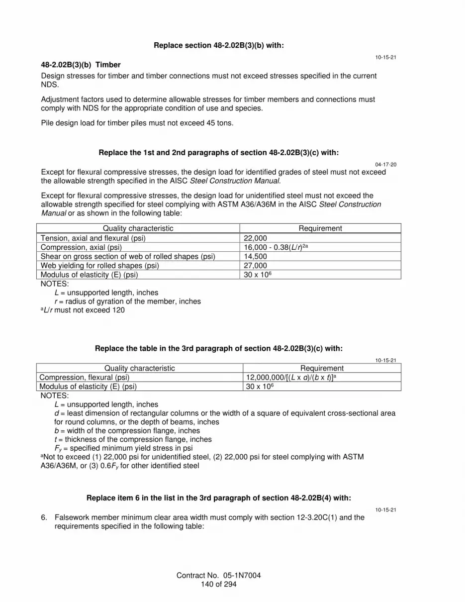
Contract No. 05-1N7004 140 of 294
Replace section 48-2.02B(3)(b) with:
10-15-21
48-2.02B(3)(b) Timber
Design stresses for timber and timber connections must not exceed stresses specified in the current NDS.
Adjustment factors used to determine allowable stresses for timber members and connections must comply with NDS for the appropriate condition of use and species.
Pile design load for timber piles must not exceed 45 tons.
Replace the 1st and 2nd paragraphs of section 48-2.02B(3)(c) with:
04-17-20
Except for flexural compressive stresses, the design load for identified grades of steel must not exceed the allowable strength specified in the AISC Steel Construction Manual.
Except for flexural compressive stresses, the design load for unidentified steel must not exceed the allowable strength specified for steel complying with ASTM A36/A36M in the AISC Steel Construction Manual or as shown in the following table:
Quality characteristic Requirement
Tension, axial and flexural (psi) 22,000 Compression, axial (psi) 16,000 - 0.38(L/r)2a Shear on gross section of web of rolled shapes (psi) 14,500 Web yielding for rolled shapes (psi) 27,000 Modulus of elasticity (E) (psi) 30 x 106 NOTES:
L = unsupported length, inches r = radius of gyration of the member, inches
aL/r must not exceed 120
Replace the table in the 3rd paragraph of section 48-2.02B(3)(c) with:
10-15-21
Quality characteristic Requirement Compression, flexural (psi) 12,000,000/[(L x d)/(b x t)]a Modulus of elasticity (E) (psi) 30 x 106 NOTES:
L = unsupported length, inches d = least dimension of rectangular columns or the width of a square of equivalent cross-sectional area for round columns, or the depth of beams, inches b = width of the compression flange, inches t = thickness of the compression flange, inches Fy = specified minimum yield stress in psi
aNot to exceed (1) 22,000 psi for unidentified steel, (2) 22,000 psi for steel complying with ASTM A36/A36M, or (3) 0.6Fy for other identified steel
Replace item 6 in the list in the 3rd paragraph of section 48-2.02B(4) with:
10-15-21
6. Falsework member minimum clear area width must comply with section 12-3.20C(1) and the requirements specified in the following table:

Contract No. 05-1N7004 141 of 294
Minimum Clear Area Width Falsework member
To permanent railing members and barriers
Footings 0'-3" Piles 2'-6" Other members 2'-6"
Add to section 48-2.02:
04-17-20
48-2.02C Falsework Lighting
48-2.02C(1) General
A falsework luminaire must:
1. Be commercially available 2. Include brackets and locking screws 48-2.02C(2) Pavement Illumination
Not Used
48-2.02C(3) Portal Illumination
Portal illumination includes plywood clearance guides 4 feet wide by 8 feet high and luminaires.
48-2.02C(4) Pedestrian Walkway Illumination
Not Used
04-17-20
Delete the 3rd paragraph of section 48-2.03A.
Add to section 48-2.03A:
04-17-20
During concrete placement, if (1) events occur that the Engineer determines will result in a structure that does not comply with the structure as described or (2) settlement variance is greater than 3/8-inch from the values shown on shop drawings, stop concrete placement and apply corrective measures. If the measures are not provided before initial concrete set occurs, stop concrete placement at the location ordered.
Detour traffic from the lanes over which falsework is being erected, released, adjusted, or removed.
Replace the 3rd paragraph of the section 48-2.03B with:
04-17-20
Falsework piles must be driven and assessed under section 49. The actual nominal driving resistance must be at least twice the falsework pile design load. For pile acceptance, the required number of hammer blows in the last foot of driving is determined using the formula in 49-2.01A(4)(c).
Add between the 2nd and 3rd paragraphs of section 48-2.03C:
10-19-18
Falsework erection includes adjustments or removal of components that contribute to the horizontal stability of the falsework system.

Contract No. 05-1N7004 142 of 294
04-17-20
Delete the 8th paragraph of section 48-2.03C.
Replace section 48-2.03D with:
04-17-20
48-2.03D Removal
Release and remove falsework such that portions of falsework to be removed remain stable.
Falsework release includes blowing sand from sand jacks, turning screws on screw jacks, and removing wedges.
Except for concrete above the deck, do not release falsework supporting any span of a:
1. Simple span bridge before 10 days after the last concrete has been placed 2. Continuous or rigid frame bridge before 10 days after the last concrete has been placed:
2.1. In that span 2.2. In adjacent portions of each adjoining span for a length equal to one-half of the span where
falsework is to be released 3. Simple span, continuous, or rigid frame bridge until the supported concrete has attained a
compressive strength of 2,880 psi or 80 percent of the specified strength, whichever is greater Do not release falsework for prestressed portions of structures until prestressing steel has been tensioned.
Do not release falsework supporting any span of a continuous or rigid frame bridge until all required prestressing is complete (1) in that span and (2) in adjacent portions of each adjoining span for a length equal to at least one half of the span where falsework is to be released.
Release falsework supporting spans of CIP girders, slab bridges, or culverts before constructing or installing railings or barriers on the spans, unless authorized.
Release falsework for arch bridges uniformly and gradually. Start at the crown and work toward the springing. Release falsework for adjacent arch spans concurrently.
Do not release falsework that supports overhangs, deck slabs between girders, or girder stems that slope 45 degrees or more from vertical before 7 days after deck concrete has been placed.
You may release falsework supporting the sides of girder stems that slope less than 45 degrees from vertical before placing deck concrete if you install lateral supports. Lateral supports must be:
1. Designed to resist rotational forces on the girder stem, including forces due to concrete deck placement
2. Installed immediately after each form panel is removed 3. Installed before releasing supports for the adjacent form panel Do not release falsework for bent caps supporting steel or PC concrete girders before 7 days after placing bent cap concrete.
Release falsework for structural members subject to bending as specified for simple span bridges.
Do not release falsework for box culverts and other structures with decks lower than the roadway pavement and span lengths of 14 feet or less until the last placed concrete has attained a compressive strength of 1,600 psi. Curing of the concrete must not be interrupted. Falsework release for other box culverts must comply with the specifications for the release of bridge falsework.
Do not release falsework for arch culverts sooner than 40 hours after concrete has been placed.
Remove falsework piling to at least 2 feet below the original ground or streambed. Remove falsework piling driven within ditch or channel excavation limits to at least 2 feet below the bottom and side slopes of the excavated areas.

Contract No. 05-1N7004 143 of 294
Falsework removal systems employing methods of holding falsework by winches, hydraulic jacks with prestressing steel, HS steel rods, or cranes must also be supported by an independent support system when the falsework is over vehicular, pedestrian, or railroad traffic openings open to traffic.
Bridge deck and soffit openings used to facilitate falsework removal activities must:
1. Have a 6-inch maximum diameter opening. 2. Be located away from the wheel paths for deck openings. 3. Be formed with corrugated HDPE pipe complying with section 20-2.07B(3). Before filling the bridge deck and soffit openings with concrete:
1. Trim HDPE pipes 1 inch from the exposed surface of the top of deck, bottom overhand, and soffit 2. Clean and roughen concrete surfaces of opening. Fill the opening with rapid setting concrete
complying with section 60-3.02B(2) or with a concrete mix of equal or higher strength than the deck. Finish surface must comply with section 51-10.3F(2).
Falsework removal over roadways with a vertical traffic opening of less than 20 feet must start within 14 days after the falsework is eligible to be released and must be completed within 45 days after it is eligible to be released.
Replace section 48-2.03E with:
04-17-20
48-2.03E Falsework Lighting
48-2.03E(1) General
Notify the Engineer at least 5 business days before the installation of the falsework lighting.
Fasten power cables to the supporting structure at a minimum 3-foot intervals and within 12 inches from every box. Encase cables within 8 feet of the ground in a minimum 1/2-inch Type 1 conduit.
Enclose splices in junction boxes.
Provide power for the falsework lighting under section 87-20.
Energize lighting circuits immediately after supporting structures have been erected.
48-2.03E(2) Pavement Illumination
Provide pavement illumination on roadways beneath falsework structures.
Install luminaires:
10-15-21
1. Along the sides of the opening not more than 4 feet behind or 2 feet in front of the roadway face of the temporary barrier system
04-17-20
2. 12 to 16 feet above the roadway surface without obstructing the light pattern on the pavement 3. Aimed to avoid glare to motorists 4. Spaced to comply with the illumination levels table 5. At the ends no more than 10 feet inside portal faces Measure the illumination levels at a minimum two points per lane, one on each side within one-quarter of the lane width from the lane stripe. Use this pattern to start the measurements at both ends of the falsework and then at 15-foot intervals through the length of the pavement under the falsework.
48-2.03E(3) Portal Illumination
Provide portal illumination on the sides facing traffic. Install luminaires and clearance guides immediately after falsework vertical members are erected.
Fasten clearance guides:

Contract No. 05-1N7004 144 of 294
1. To the vertical support adjacent to the traveled way, facing traffic 2. Vertically with the bottom of the clearance guide from 3 to 4 feet above the roadway
10-15-21
3. With the center located approximately 3 feet horizontally behind the face of the temporary barrier system on the roadway side
04-17-20
Paint clearance guides before each installation with not less than 2 applications of flat white paint.
If ordered, repainting is change order work.
Install luminaires on the structure directly over the vertical support, approximately 16 feet above the pavement and 6 feet in front of the guides. Aim the luminaires to illuminate the exterior falsework beam, the clearance guides, and the overhead clearance sign and comply with the illumination levels table.
Measure the illumination levels at the center and four corners of the clearance guides, at the exterior falsework beam, and at the overhead clearance sign.
48-2.03E(4) Pedestrian Walkway Illumination
Provide pedestrian walkway illumination immediately after the protective overhead covering is erected.
Install the luminaires a minimum 8 feet clearance in the protective overhead covering and center them over the pedestrian walkway. Space the luminaires through the pedestrian walkway as needed to comply with the illumination levels table. Install luminaires at the ends no more than 7 feet inside the pedestrian walkway openings.
Measure the illumination levels at a minimum two points, one on each side within one-quarter of the walkway width from the edge. Use this pattern to start the measurements at both ends of the falsework and then at 10-foot intervals through the length of the pedestrian walkway.
Replace section 48-3.01A with:
10-16-20
48-3.01A Summary
Section 48-3 includes specifications for providing temporary supports for structures during retrofit, reconstruction, erection, and removal activities.
Jacking assemblies, accessories, and activities required to jack and support structures must comply with section 48-5.
Falsework must comply with section 48-2.
Replace section 48-3.01B with:
10-16-20
48-3.01B Definitions
Reserved
Replace the 2nd paragraph of section 48-3.01C(1) with:
10-16-20
Submit a copy of the displacement monitoring record after completing the work.
Replace the 1st and 2nd paragraphs of section 48-3.01C(2) with:
10-16-20
Submit the following:
1. Descriptions and values of all loads, including construction equipment loads.

Contract No. 05-1N7004 145 of 294
2. Descriptions of equipment to be used. 3. Details and calculations for jacking and supporting the structure. 4. Stress sheets, anchor bolt layouts, shop details, erection plans, and removal plans for the temporary
supports. 5. Assumed soil bearing values and design stresses for temporary support footings, including
anticipated foundation settlement. 6. Maximum distance temporary-support piles may be pulled for placement under footing caps. 7. Maximum deviation of temporary-support piles from a vertical line through the point of fixity. 8. Details for use of permanent piles. Include any additional loads imposed on the piles. 9. Details for additional bracing required during erection and removal of temporary supports. 10. Details of the displacement monitoring system, including equipment, location of control points, and
methods and schedule for taking measurements. 11. Mitigation plan for jacking the structure if settlement occurs in the temporary supports. Calculations must show a summary of computed stresses in (1) temporary supports, (2) connections between temporary supports and the structure, and (3) load-supporting members. The computed stresses must include the effect of the jacking sequence. Calculations must include a lateral stiffness assessment of the temporary support system.
10-19-18
Delete the 4th paragraph of section 48-3.01C(2).
Replace section 48-3.01D with:
10-16-20
48-3.01D Quality Assurance
48-3.01D(1) General
Welding, welder qualification, and welding inspection for temporary supports must comply with AWS D1.1.
48-3.01D(2) Quality Control
Reserved
Replace section 48-3.02B with:
04-17-20
48-3.02B Design Criteria
The Engineer does not authorize temporary support designs based on allowable stresses or design load greater than those specified in section 48-2.02B(3).
If falsework loads are imposed on temporary supports, the temporary supports must also satisfy the deflection criteria in section 48-2.02B(3).
The temporary support system must support the initial jacking loads and the minimum temporary support design loads and forces shown. As a minimum, the horizontal load to be resisted in any direction by the temporary support system must be (1) the sum of actual horizontal loads due to equipment, construction sequence, or other causes plus an allowance for wind and (2) not less than 5 percent of the total supported dead load at the location being considered. Adjust vertical design loads for the weight of the temporary supports and jacking system, construction equipment loads, and additional loads imposed by jacking activities. Construction equipment loads must be at least 20 psf of deck surface area of the frame involved.
10-16-20
For column repair or removal, the temporary supports must resist the described lateral design forces applied at the point where the column to be removed meets the superstructure. Stiffness of temporary supports must match the described minimum stiffness. If the temporary support stiffness exceeds the

Contract No. 05-1N7004 146 of 294
described minimum stiffness, increase the lateral design forces to be compatible with the temporary support lateral stiffness.
04-17-20
Place temporary supports, that are resisting transverse lateral loads, within 1/2 of the span length from the existing bent. Place temporary supports, that are resisting longitudinal lateral loads, within the frame where columns are to be removed.
You may use the permanent piles as part of the temporary support foundation. Do not move or adjust permanent piles from the locations shown. If you install permanent piles longer than described to support the temporary supports above the top of the footing and later cut off the piles at their final elevation, you must use shear devices adequate to transfer all pile reactions into the footing.
Design temporary support footings to carry the loads imposed without exceeding the estimated soil bearing values or anticipated settlements. You must determine soil bearing values.
Where temporary supports are placed on the deck of an existing structure:
1. Temporary supports must bear either: 1.1. Directly on girder stems, bent caps, or end diaphragms of the supporting structure 1.2. On falsework sills that transmit the load to the stems, bent cap, or end diaphragms without
overstressing any member of the new or existing structure 2. Temporary supports must not induce permanent forces into the completed structure or produce
cracking. 3. Place additional temporary supports beneath the existing structure where temporary support loads
are imposed on the existing structure. Design and construct the additional temporary supports to support all loads from the upper structure and construction activities.
Provide additional bracing as required to withstand all imposed loads during each phase of temporary support erection and removal. Include wind loads complying with section 48-2.02B(2) in the design of additional bracing.
Mechanically connect (1) the structure to the temporary supports and (2) the temporary supports to their foundations. Mechanical connections must be capable of resisting the lateral design forces. Friction forces developed between the structure and temporary supports (1) are not considered an effective mechanical connection and (2) must not be used to reduce lateral forces.
Design mechanical connections to accommodate movement resulting from adjustments made to the temporary supports.
If the concrete is to be prestressed, design temporary supports to support changes to the loads caused by prestressing forces.
Temporary supports must comply with the specifications for falsework in section 48-2.02B(4).
Replace section 48-3.03 with:
10-16-20
48-3.03 CONSTRUCTION
Where described, install temporary crash cushion modules under section 12-3.22 before starting temporary support activities. Remove crash cushion modules when authorized.
Construct and remove temporary supports under the specifications for falsework in section 48-2.03.
If traffic is carried on the structure on temporary supports, do not release temporary supports until the supported concrete has attained 100 percent of the described strength.
Remove attachments from the existing structure. Restore concrete surfaces to original conditions except where permanent alterations are shown.

Contract No. 05-1N7004 147 of 294
Replace section 48-4.01 with:
04-17-20
48-4.01 GENERAL
48-4.01A Summary
Section 48-4 includes specifications for temporary decking for joint or deck reconstruction.
Temporary decking must consist of a steel plate system that spans the incomplete work.
Concrete anchorage devices and nonskid surface must comply with section 75-3.
48-4.01B Definitions
Reserved
48-4.01C Submittals
Submit shop drawings and calculations for temporary decking.
Shop drawings and calculations for temporary decking must be sealed and signed by an engineer who is registered as a civil engineer in the State.
Temporary decking shop drawings and calculations must include:
1. Storage location of equipment and materials that allows for 1 shift of work and placement of temporary decking within the time allowed
2. Construction sequence and schedule details 3. Cure time for concrete to be placed under temporary decking 4. Details for removing temporary decking and restoring the existing structure If temporary decking is not shown, shop drawings and calculations must also include:
1. Design calculations, including the description, location, and value, of all loads 2. Details of the connection between the temporary decking and the existing or new structure Submit a certificate of compliance for temporary decking materials.
Sections 48-1.01C(2), 48-1.01C(3), and 48-1.01D(2) do not apply for temporary decking.
48-4.01D Quality Assurance
Reserved
Replace Not Used in section 48-4.02 with:
04-17-20
48-4.02A General
Yield strength of steel plate must be greater than or equal to 36 ksi.
Bolts must comply with ASTM F3125, Grade A325.
Nuts must comply with ASTM A563/563M.
Material for temporary tapers must be rapid setting concrete or polyester concrete complying with section 60-3.02B(2) or 60-3.04B(2).
48-4.02B Design Criteria
If temporary decking is not shown, the temporary decking design must:
1. Comply with the unfactored permit loads, braking force, and HL93 loads except lane load from the current AASHTO LRFD Bridge Design Specifications with California Amendments.
2. Not exceed the allowable stresses or design loads specified in section 48-2.02B(3). 3. Have live load deflection not exceeding 1/300 of the temporary decking span for the design load. 4. Provide for temporary decking with a uniform surface with a coefficient of friction of at least 0.35 when
measured under California Test 342.

Contract No. 05-1N7004 148 of 294
5. Provide for temporary decking that is mechanically connected to the existing structure and adjacent approaches. If a steel plate spans a joint, the mechanical connection must accommodate at least 50 percent of the movement rating shown for that joint.
6. Not overstress, induce permanent forces into, or produce cracking in the existing structure.
Replace section 48-4.03 with:
04-17-20
48-4.03 CONSTRUCTION
For bolted connections, drill the holes without damaging the adjacent concrete. Do not damage existing reinforcement.
If the temporary decking does not extend the entire width of the roadway, taper the sides of the temporary decking at a 12:1 (horizontal: vertical) ratio.
Cure temporary tapers at least 3 hours before allowing traffic on the temporary decking.
If unanticipated displacements, cracking, or other damage occurs to the existing structure or to any new components installed in or adjacent to the deck, stop work on the deck and perform corrective measures.
Edges of steel plate systems must be in full contact with the existing deck and the adjacent approach slab. If used, shims must be securely attached to the plate.
Do not allow traffic on deck concrete until it has attained the compressive strength shown.
When temporary decking is no longer needed, immediately remove temporary decking materials and connections from the existing structure. Patch holes with rapid setting concrete complying with section 60-3.02. Remove modifications to the existing structure except where permanent alterations are shown.
Replace section 48-5 with:
10-16-20
48-5 JACKING
48-5.01 GENERAL
48-5.01A Summary
Section 48-5 includes specifications for jacking the bridge superstructure using a jacking support system.
48-5.01B Definitions
Reserved
48-5.01C Submittals
The submittal for shop drawings and calculations must include:
1. Descriptions, locations, and values of all loads, including construction equipment loads 2. Jacking construction sequence including staging areas for equipment and materials for jacking
support systems 3. Type, model number, and weight of equipment to be used including:
3.1. Jack capacity 3.2. Certified calibration chart for each jack 3.3. Certified indicator to determine jacking force
4. Details and calculations with the load paths for jacking and supporting the structure including a redundant system of supports to ensure stability of the jacking system during jacking activities
5. Stress sheets, anchor bolt layouts, shop drawing details, and erection and removal plans for the jacking support system
6. Assumed soil bearing values and design stresses for support footings, including anticipated foundation settlement
7. Details for bracing required during erection and removal 8. Details of the displacement monitoring system, including equipment, location of control points, and
methods and schedule of taking measurements

Contract No. 05-1N7004 149 of 294
9. Any additions or modifications to the structure in connection with the jacking support systems including: 9.1. Temporary strengthening and stiffening members 9.2. Permanent stiffening members
10. Mitigation plan for jacking the structure if settlement occurs Calculations must show a summary of computed stresses in the jacking support system and the connections between the jacking support system and the bridge superstructure. The computed stresses must include the effect of the jacking sequence.
Shop drawings and calculations must be sealed and signed by an engineer who is registered as a civil engineer in the State.
Submit the displacement monitoring records.
48-5.01D Quality Assurance
48-5.01D(1) General
Calibrate each jack within 6 months of use and after each repair. Each jack and its gauge must (1) be calibrated as a unit with the cylinder extension in the approximate position that it will be at the final jacking force and (2) accompanied by a certified calibration chart. Each load cell must be calibrated. Calibration must be performed by an authorized laboratory.
48-5.01D(2) Displacement Monitoring
04-16-21
Perform an initial survey to record the location of the structure before starting work. Monitor and record vertical and horizontal displacements of the jacking support system and the structure. Use vandal-resistant displacement monitoring equipment. Perform monitoring continuously during jacking activities. Make monitoring records available at the job site during normal work hours. Monitoring records must be sealed and signed by an engineer who is registered as a civil engineer in the State.
04-16-21
As a minimum, monitor the structure at the supported or jacking locations and at the midspan of both adjoining spans. Locate control points at each location near the center and at both edges of the superstructure. As a minimum, record elevations at the following times:
10-16-20
1. Before starting jacking activities 2. Immediately after completing jacking 3. After completing bridge removal 4. Before connecting the superstructure to the substructure 5. After removing the jacking support system 48-5.02 MATERIALS
48-5.02A General
Reserved
48-5.02B Design Criteria
The jacking support system must resist the structure dead load and lateral design forces shown, plus any additional loads from jacking equipment and activities. As a minimum, the horizontal load to be resisted in any direction for the jacking support system and temporary bracing must be (1) the sum of actual horizontal loads due to equipment, construction sequence, or other causes plus an allowance for wind as specified in section 48-2.02B(2) and (2) not less than 5 percent of the total dead load of the structure being jacked. If the jacking support system lateral stiffness exceeds the described minimum stiffness, increase the lateral design forces to be compatible with the jacking support system lateral stiffness.
Systems involving modifications to the bridge that impair the structural integrity, intended serviceability, or design capacity of the bridge are not allowed.
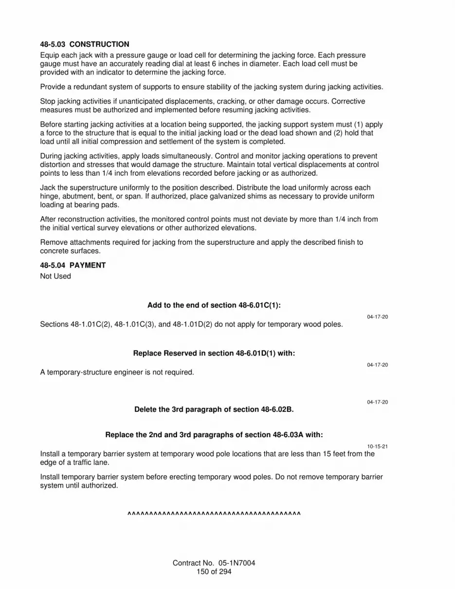
Contract No. 05-1N7004 150 of 294
48-5.03 CONSTRUCTION
Equip each jack with a pressure gauge or load cell for determining the jacking force. Each pressure gauge must have an accurately reading dial at least 6 inches in diameter. Each load cell must be provided with an indicator to determine the jacking force.
Provide a redundant system of supports to ensure stability of the jacking system during jacking activities.
Stop jacking activities if unanticipated displacements, cracking, or other damage occurs. Corrective measures must be authorized and implemented before resuming jacking activities.
Before starting jacking activities at a location being supported, the jacking support system must (1) apply a force to the structure that is equal to the initial jacking load or the dead load shown and (2) hold that load until all initial compression and settlement of the system is completed.
During jacking activities, apply loads simultaneously. Control and monitor jacking operations to prevent distortion and stresses that would damage the structure. Maintain total vertical displacements at control points to less than 1/4 inch from elevations recorded before jacking or as authorized.
Jack the superstructure uniformly to the position described. Distribute the load uniformly across each hinge, abutment, bent, or span. If authorized, place galvanized shims as necessary to provide uniform loading at bearing pads.
After reconstruction activities, the monitored control points must not deviate by more than 1/4 inch from the initial vertical survey elevations or other authorized elevations.
Remove attachments required for jacking from the superstructure and apply the described finish to concrete surfaces.
48-5.04 PAYMENT
Not Used
Add to the end of section 48-6.01C(1):
04-17-20
Sections 48-1.01C(2), 48-1.01C(3), and 48-1.01D(2) do not apply for temporary wood poles.
Replace Reserved in section 48-6.01D(1) with:
04-17-20
A temporary-structure engineer is not required.
04-17-20
Delete the 3rd paragraph of section 48-6.02B.
Replace the 2nd and 3rd paragraphs of section 48-6.03A with:
10-15-21
Install a temporary barrier system at temporary wood pole locations that are less than 15 feet from the edge of a traffic lane.
Install temporary barrier system before erecting temporary wood poles. Do not remove temporary barrier system until authorized.
^^^^^^^^^^^^^^^^^^^^^^^^^^^^^^^^^^^^^^^^

Contract No. 05-1N7004 151 of 294
49 PILING
10-15-21 Replace section 49-1.01B with:
04-16-21
49-1.01B Definitions
control zone: Zone where subsurface conditions are similar to the corresponding support location.
dry hole: Drilled hole that requires no work to keep it free of water.
dewatered hole: Drilled hole that:
1. Accumulates no more than 12 inches of water at the bottom during a 1-hour period without pumping from the hole
2. Has no more than 3 inches of water at the bottom immediately before placing concrete 3. Does not require temporary casing to control groundwater nominal driving resistance: Sum of (1) nominal resistance required to resist the factored axial loads and
(2) driving resistance from unsuitable, liquefiable, or scourable penetrated soil layers that do not contribute to the design resistance.
nominal resistance: Geotechnical resistance required to resist the factored axial loads.
Replace the 4th paragraph of section 49-1.01D(3) with:
04-16-21
Install load test piles with the same equipment to be used for installation of production piles.
Replace the 6th paragraph of section 49-1.01D(4) with:
10-19-18
Except for load test piles and anchor piles, drive the 1st production pile in the control zone. Do not install any additional production piles until dynamic monitoring has been performed, and the Engineer provides you with the bearing acceptance criteria curves for any piles represented by the dynamically monitored piles.
Add to the end of section 49-1.03:
04-16-21
For a mechanically stabilized embankment abutment, drive or install the piles before constructing the mechanically stabilized embankment around the piles. Mechanically stabilized embankment reinforcement must maintain a 6-inch clearance around the piles.
Replace the 3rd paragraph of section 49-2.01D with:
10-19-18
The payment quantity for furnish piling is the length measured along the longest side of the pile from the specified tip elevation shown to the plane of pile cutoff, except for dynamically monitored piles. For dynamically monitored piles, the payment quantity for furnish piling includes an additional length of 2 times the largest cross-sectional dimension of the pile plus 2 feet.
Add to the end of section 49-2.02A(2):
10-19-18
longitudinal weld length: The length of a continuous longitudinal weld.

Contract No. 05-1N7004 152 of 294
circumferential weld length: The length of a continuous weld around the circumference of the pipe pile.
spiral weld length: The length of one full 360-degree spiral weld revolution around the circumference of the pipe pile.
Replace the 3rd paragraph of section 49-2.02A(4)(b)(iii)(B) with:
10-19-18
For welding performed under AWS D1.1:
1. Perform NDT on 25 percent of each longitudinal, circumferential, or spiral weld length using RT or UT.
2. If repairs are required in a portion of the tested weld: 2.1. Perform additional NDT on untested areas on each end of the initial portion tested. The length
of additional NDT on each end must equal 10 percent of the weld length. If it is not possible to perform 10 percent of the weld length on one end, perform the remaining percentage on the other end.
2.2. After this additional 20 percent of NDT is performed, determine and record the total cumulative repair lengths from all NDT for each weld length. If the cumulative weld repair length is equal to or more than 10 percent of the weld length, then perform NDT on the entire weld length.
2.3. Perform NDT on the repaired portion plus 2 inches on each end of the repaired weld excavation.
Replace the 2nd paragraph of section 49-2.02A(4)(b)(iii)(C) with:
10-19-18
Perform NDT on 25 percent of the weld length performed by each welder, using RT or UT at locations selected by the Engineer. The Engineer may select several locations on a given splice. The cover pass must be ground smooth at locations to be tested.
Replace the 4th paragraph of section 49-2.02A(4)(b)(iii)(C) with:
10-19-18
If repairs are required in a portion of the tested weld:
1. Perform additional NDT on untested areas on each end of the initial portion tested. The length of additional NDT on each end must equal 10 percent of the pipe's outside circumference. If it is not possible to perform 10 percent of the weld length on one end, perform the remaining percentage on the other end.
2. After this additional 20 percent of NDT is performed, determine and record the total cumulative repair lengths from all NDT for each weld length. If the cumulative weld repair length is equal to or more than 10 percent of the pipe's outside circumference, then perform NDT on the entire weld length.
3. Perform NDT on the repaired portion plus 2 inches on each end of the repaired weld excavation.
Replace the 5th paragraph of section 49-2.02B(1)(a) with:
10-16-20
For welding and prequalifying base metal under Table 5.3 of AWS D1.1, treat steel pipe piles complying with ASTM A252 as either ASTM A572/572M, Grade 50, or ASTM A709/709M, Grade 50.
Replace the 7th paragraph of section 49-2.02B(1)(a) with:
10-16-20
For groove welds using submerged arc welding from both sides without backgouging, qualify the WPS under Table 6.5 of AWS D1.

Contract No. 05-1N7004 153 of 294
Replace the 5th paragraph of section 49-2.02B(1)(b) with:
10-16-20
If splicing steel pipe piles using a circumferential weld, the piles must comply with the fit-up requirements of clause 10.23.1 of AWS D1.1.
Replace clause 4.9.4 in item 2.3 in the list in the 2nd paragraph of section 49-2.02B(2) with:
10-16-20
Clause 6.10.4
Replace section 49-2.05A with:
10-15-21
49-2.05A General
Section 49-2.05 includes specifications for furnishing and installing permanent steel sheet piles.
Replace section 49-3.01B(2) with:
04-19-19
49-3.01B(2) Mass Concrete
Section 49-3.01B(2) applies to CIP concrete piles with a diameter greater than 8 feet.
For piles with a diameter greater than 8 feet and less than or equal to 14 feet:
1. The specifications for SCM content in the 4th paragraph of section 90-1.02B(3) do not apply. 10-15-21
2. The SCM content of the concrete must comply with the following: 2.1. Any combination of portland cement or portland limestone cement and fly ash satisfying:
Equation 1: (12 x FM)/MC ≥ X where: FM = fly ash complying with AASHTO M 295, Class F, with a CaO content of up to 10 percent,
including the quantity in blended cement, lb/cu yd MC = minimum quantity of cementitious material specified, lb/cu yd X = 3.0 for 8 < D ≤ 10, where D = pile diameter in feet X = 4.0 for 10 < D ≤ 14, where D = pile diameter in feet Equation 2: MC - MSCM - PC ≥ 0 where: MC = minimum quantity of cementitious material specified, lb/cu yd MSCM = minimum sum of SCMs that satisfies equation 1, lb/cu yd PC = quantity of Type IL cement or portland cement, including the quantity in blended cement,
lb/cu yd
2.2. You may replace any portion of the cement with any SCM complying with section 90-1.02B(3) if equations 1 and 2 are satisfied as specified above.
04-19-19
For piles with a diameter greater than 14 feet, the concrete must comply with the specifications for mass concrete in section 51-6.

Contract No. 05-1N7004 154 of 294
Replace section 49-3.02A(2) with:
10-15-21
49-3.02A(2) Definitions
Reserved
Replace the introductory clause in the 2nd paragraph of section 49-3.02A(3)(b) with:
04-16-21
For concrete placed under slurry, submit the additional information:
Replace item 3 in the list in the 2nd paragraph of section 49-3.02A(3)(g) with:
04-16-21
3. Step by step description of the mitigation work to be performed, including drawings if necessary. If the ADSC Standard Mitigation Plan is an acceptable mitigation method, include the most recent version. For the most recent Department-published version of ADSC Standard Mitigation Plan, go to the Authorized ADSC Standard Mitigation Plan website.
Replace the 3rd sentence in the 1st paragraph of section 49-3.02A(3)(h) with:
04-16-21
The mitigation report must be sealed and signed by an engineer who is registered as a civil engineer in the State, except for mitigation performed under the current Department-published version of ADSC Standard Mitigation Plan ‘A’ – Basic Repair.
Replace the 7th paragraph of section 49-3.02A(4)(d)(iii) with:
04-16-21
If a rejected pile requires mitigation, the Department withholds 30 percent of the contract item price of the rejected pile. The Department returns the withholding upon compliance with sections 49-3.02A(3)(h) and 49-3.02A(4)(d).
Replace the 1st paragraph of section 49-3.02B(2) with:
10-15-21
Concrete placed under slurry must:
1. Contain at least 675 pounds of cementitious material per cubic yard. 2. Have a slump of 7 to 9 inches. The nominal and maximum slump and penetration specifications in
section 90-1.02G(6) do not apply.
Replace the paragraph in section 49-3.02B(3) with:
10-15-21
For concrete placed under slurry, the combined aggregate gradation must comply with the 1/2-inch or 3/8-inch maximum gradation specified in section 90-1.02C(4)(d).
Add to the end of section 49-3.02C(1):
04-19-19
You may construct CIDH concrete piles 24 inches in diameter or larger by excavating and depositing concrete under slurry.

Contract No. 05-1N7004 155 of 294
Replace the 3rd paragraph of section 49-3.02C(7) with:
10-16-20
Section 49-2.01A(4)(c) and the 5th through 7th paragraphs of section 49-2.01C(5) do not apply to permanent casings specified in section 49-3.02C(7).
04-19-19
Delete the 2nd paragraph of section 49-3.02C(8).
Replace section 49-4 with:
10-15-21
49-4 STEEL SOLDIER PILING
49-4.01 GENERAL
49-4.01A Summary
Section 49-4 includes specifications for drilling holes, installing steel soldier piles, and placing concrete in the holes.
49-4.01B Definitions
dewatered hole: Drilled hole that:
1. Accumulates no more than 12 inches of water at the bottom during a 1-hour period without pumping from the hole
2. Has no more than 3 inches of water at the bottom immediately before placing concrete 49-4.01C Submittals
49-4.01C(1) General
Reserved
49-4.01C(2) Pile Installation Plan
Submit a pile installation plan. Include descriptions, details, and supporting calculations for:
1. Concrete mix designs for concrete backfill and lean concrete backfill 2. Methods, toolings, and equipment for drilling and cleaning hole 3. Number and sequence of piles you plan to install each day 4. Removing, handling, and disposing of drill cuttings 5. If temporary casing is used, proposed method of installing, drilling, placing concrete, and removing
temporary casing 6. Placing, aligning, plumbing, spacing and securing the position of the pile before concrete placement 7. Theoretical volume of concrete to be placed at each pile 8. Verifying the bottom of the drilled hole is clean before concrete placement 9. Determining top of concrete elevation during concrete placement 10. Method of concrete placement in a dry or dewatered hole For concrete placed under slurry, submit the additional information:
1. Method of placing concrete in a hole that is neither dry nor dewatered 2. Manufacturer’s recommendations on the use of and test reports on the physical and chemical
properties of the proposed slurry and any slurry chemical additives, including SDSs 3. Determining volume of slurry required for the work 4. Methods and equipment used for containment, mixing, agitating, placing, recirculating, and cleaning
of the slurry 5. Slurry testing equipment and testing procedures 6. Methods of removing, handling, and disposing of drilled cuttings, contaminated concrete, and slurry

Contract No. 05-1N7004 156 of 294
49-4.01C(3) Concrete Backfill Placement Report
Submit a concrete backfill placement report as an informational submittal within 2 business days of completion of concrete backfill placement in the hole.
The concrete backfill placement report must include:
1. Pile number, location, as-built tip elevation and concrete backfill cutoff elevation 2. Dates of drilling, concrete placement, and total quantity of concrete placed 3. Details of any hole stabilization methods and materials used 4. Drilling and tooling equipment used to complete the pile 49-4.01D Quality Assurance
Reserved
49-4.02 MATERIALS
49-4.02A General
Steel soldier piles must comply with section 49-2.03.
Concrete anchors must comply with the specifications for studs in clause 9 of AWS D1.1.
49-4.02B Slurry
Mineral slurry and synthetic slurry must comply with section 49-3.02B(6).
You may use water slurry. Water slurry must comply with the requirements shown in the following table:
Water Slurry Requirements
Quality characteristic Test method Requirement
Density Before final cleaning and immediately before placing concrete (pcf)
Mud weight (density), API RP 13B-1
Section 4 ≤64a
Sand content Before final cleaning and immediately before placing concrete (%)
Sand, API RP 13B-1, section 9 ≤1.0
aIf authorized, you may use salt water slurry. The allowable density of the slurry may be increased by 2 pcf.
49-4.03 CONSTRUCTION
49-4.03A General
Construct steel soldier piles in a dry or dewatered hole. If the hole is not dry or dewatered and if authorized, construct steel soldier piles under slurry.
Drilling the hole, installing the pile, and placing concrete backfill and lean concrete backfill must be performed in a continuous operation, unless otherwise authorized.
Place concrete evenly on all sides of the pile and continuously from the bottom of the hole to the cut-off elevation. Concrete placement must not disturb pile alignment.
49-4.03B Drilled Holes
The axis of the drilled hole must not deviate from plumb more than 1 inch per 10 feet of length.
During drilling, do not disturb the foundation material surrounding the pile. Equipment or methods used for drilling holes must not cause (1) quick soil conditions or (2) scouring or caving of the hole.
If the pile center-to-center spacing is less than four pile diameters, do not drill holes for the adjacent piles until 24 hours have elapsed after concrete placement in the preceding pile.
If slurry is used during drilling operations, maintain the slurry level at a height required to maintain a stable hole but not less than 10 feet above the piezometric head.

Contract No. 05-1N7004 157 of 294
After drilling begins, complete construction of the pile in one work shift to prevent deterioration of the surrounding foundation material. Remove and dispose of deteriorated foundation material, including material that has softened, swollen, or degraded, from the exposed surface.
Verify the bottom of the drilled hole is clean before placing the pile in the drilled hole.
If authorized, you may use temporary casing to control caving or ground water. Temporary casing must comply with section 49-3.02C(3).
If authorized to control caving or water seepage, you may enlarge portions of the hole, backfill the hole with slurry cement backfill or concrete, and redrill the hole to the diameter shown. The enlarged hole must allow for at least a 6-inch annulus of slurry cement or concrete surrounding the pile after the hole is redrilled.
49-4.03C Steel Soldier Piles
Plumb, align, and secure the pile before placing concrete. The hole must provide at least a 2-inch horizontal clearance around the pile for the full length of the hole. Provide vertical clearance at the tip of the pile as shown. Provide spacers if necessary. Ream or enlarge holes to provide the required clearance.
Before placing concrete, the pile must be secured in place and must not be suspended from a crane or other mobile equipment.
Maintain clearance and alignment of the pile in the hole while placing concrete.
49-4.03D Placing Concrete
Section 49-4.03D applies if placing concrete in a dry or dewatered hole.
Section 51-1.03D(3) does not apply to steel soldier piling.
Drilled holes must be clean and free of debris before concrete is placed.
Concrete must be directed to the bottom of the hole and not allowed to strike the sides of the hole. Placing concrete must not result in disturbance or caving of the hole. If necessary to prevent disturbance, use adjustable length pipes or tremie tubes to direct concrete to the bottom of the hole.
If temporary casing is used, remove temporary casing during concrete placement. Maintain the concrete within the casing at a level required to maintain a stable hole, but not less than 5 feet above the bottom of the casing, to prevent displacement of the concrete.
49-4.03E Placing Concrete Under Slurry
Section 49-4.03E applies if placing concrete under slurry.
Carefully place concrete in a compact, monolithic mass, using a method that prevents washing of the concrete. Do not vibrate the concrete.
The delivery system must consist of two tremie tubes, one on each side of the soldier pile, fed by one or more concrete pumps. The tremie tubes must be watertight steel tubes with sufficient rigidity to keep the tube ends in the mass of concrete placed for the full period of placement.
Do not allow concrete to fall into the groundwater or drilling slurry during concrete placement. Cap each delivery tube with a watertight cap or plug each tube above the slurry level with a tight-fitting moving plug that expels the slurry from the tubes as the tubes are charged with concrete. The caps or plugs must be designed to release as the tubes are charged.
Extend each tremie tube to the bottom of the hole before charging the tube with concrete. After charging the tube with concrete, induce the flow of concrete through the tube by slightly raising the discharge end.
During concrete placement:
1. Embed the tip of the delivery tube within 6 inches of the bottom of the hole until 10 feet of concrete has been placed. Maintain embedment of the tip at least 10 feet below the top surface of the concrete.
2. Do not rapidly raise or lower the delivery tube.

Contract No. 05-1N7004 158 of 294
If temporary casing is used, remove temporary casing from the hole during concrete placement. Maintain the concrete within the casing at the level required to prevent intrusion of groundwater, slurry, or soil, in the concrete but not less than 5 feet above the bottom of the casing until you reach the limits of concrete placement. Withdrawal of the casing must not cause contamination of the concrete with slurry.
Remove scum, laitance, and slurry-contaminated concrete from the top of the pile. Dispose of material resulting from placing concrete under slurry.
49-4.04 PAYMENT
Not Used
^^^^^^^^^^^^^^^^^^^^^^^^^^^^^^^^^^^^^^^^
51 CONCRETE STRUCTURES
10-15-21 Add to the beginning of section 51-1.01C(1):
04-19-19
If ordered, submit concrete form design and materials data for each forming system.
Replace section 51-1.01C(5) with:
04-17-20
51-1.01C(5) Drill and Bond Dowel—Chemical Adhesive
For each lot or batch of chemical adhesive used for drill and bond dowel chemical-adhesive systems, submit the following:
1. Certificate of compliance, including the material name and lot or batch number 2. Manufacturer's installation procedures, including the minimum cure time 3. SDS For each chemical adhesive, submit 1 test sample for every 100 cartridges or fraction thereof to be used. The test sample must consist of 1 cartridge of chemical adhesive, 1 mixing nozzle, and 1 retaining nut. Submit test samples to METS at least 25 days before use.
Each test sample must clearly and permanently show the following:
1. Manufacturer's name 2. Material name 3. Lot or batch number 4. Expiration date 5. Evaluation report number 6. Directions for use 7. Storage requirements 8. Warnings or precautions required by State and federal laws and regulations
Replace the 3rd paragraph of section 51-1.01D(3)(b)(ii) with:
04-16-21
Before the testing, clean the test area by sweeping and removing debris.

Contract No. 05-1N7004 159 of 294
Add between the 4th and 5th paragraphs of section 51-1.01D(3)(b)(ii):
04-16-21
Concrete roadway surfaces on the bridge deck and approach slabs must comply with the following smoothness requirements:
1. Profile trace having no high points over 0.02 foot 2. Profile count of 5 or less in any 100-foot section for portions within the traveled way 3. Surface not varying more than 0.02 foot from the lower edge of a 12-foot-long straightedge placed
transversely to traffic
04-16-21
Delete the 6th paragraph of section 51-1.01D(3)(b)(ii).
Replace the 1st paragraph of section 51-1.01D(3)(b)(iii) with:
10-15-21
After deck surfaces and approach slabs have been textured, the Engineer performs friction testing of the concrete surfaces under California Test 342. Allow 25 days for the Department to schedule for coefficient of friction testing.
Add to the end of section 51-1.01D(3):
04-17-20
51-1.01D(3)(c) Drill and Bond Dowel—Chemical Adhesive
The Department will verify the chemical adhesive used in the drill and bond dowel chemical adhesive system is chemically consistent with the chemical adhesive material on the Authorized Materials List.
Add to the end of section 51-1.02B:
10-18-19
Concrete for concrete bridge decks or PCC deck overlays must contain:
1. Polymer fibers. Each cubic yard of concrete must contain at least 1 pound of microfibers and at least 3 pounds of macrofibers.
2. Shrinkage reducing admixture. Each cubic yard of concrete must contain at least 3/4 gallon of a shrinkage reducing admixture. If you use the maximum dosage rate shown on the Authorized Material List for the shrinkage reducing admixture, your submitted shrinkage test data does not need to meet the shrinkage limitation specified in section 90-1.02A.
Replace section 51-1.02D with:
04-17-20
51-1.02D Rapid Strength Concrete
For bridge decks or PCC deck overlays:
1. RSC must have a minimum 28-day compressive strength of 4,500 psi 2. RSC must contain at least 675 pounds of cementitious material per cubic yard
10-16-20
3. If your RSC shrinkage test results are 0.024 percent or less without the use of a shrinkage reducing admixture:
04-17-20
3.1 Use of shrinkage reducing admixture is not required 3.2 Fibers are not required
4. If you use the maximum dosage rate shown on the Authorized Material List for shrinkage reducing admixture, your shrinkage test results must be 0.032 percent or less

Contract No. 05-1N7004 160 of 294
RSC must have a minimum 28-day compressive strength of 4,000 psi.
If you use chemical admixtures or SCMs, the same proportions must be used when testing.
If you use aggregate that is not on the Authorized Material List for innocuous aggregate, the cement in your proposed mix design must comply with one of the following:
1. Any hydraulic cement, with or without any proposed SCM, must have an expansion ratio of less than 0.10 percent when tested with glass aggregate under ASTM C1260. Test specimens must be prepared using proportions of ingredients under ASTM C441.
2. For Portland cement, the quantity of SCM in your proposed mix design must satisfy equation 1 of section 90-1.02B(3).
The specifications for a reduction in the operating range and contract compliance for cleanness value and sand equivalent specified in section 90-1.02C(2) and section 90-1.02C(3) for aggregate, do not apply to RSC used for a bridge element.
Replace the 1st paragraph of section 51-1.02G with:
10-15-21
Grout must consist of portland cement or portland limestone cement and water, with a water content of at most 4 gallons per 94 pounds of cement.
Replace the 1st paragraph of section 51-1.02H with:
04-17-20
Chemical adhesives for bonding dowels must be on the Authorized Material List for chemical adhesives and must be appropriate for the installation conditions of the project.
10-18-19
Delete the 5th paragraph of section 51-1.03C(2)(b).
Replace section 51-1.03D(2) with:
10-16-20
51-1.03D(2) Concrete Bridge Decks and Diaphragms
For decks on structural steel, install cross frames the entire width of the bridge before placing the deck concrete.
For concrete decks placed on bridges composed of continuous steel girders, place the portion of deck over the supports last.
For bridges composed of simple span PC concrete girders made continuous, place the deck (1) at least 5 days after placing the intermediate diaphragms or (2) after intermediate diaphragm concrete has attained a concrete compressive strength of at least 3,000 psi. Place end diaphragms with the portion of the deck over the supports last.
For bridges composed of simple span PC concrete girders not made continuous, place the deck (1) at least 5 days after placing the intermediate and end diaphragms or (2) after diaphragm concrete has attained a concrete compressive strength of at least 3,000 psi.
Deck closure pours must comply with the following:
1. During primary deck placement and for at least 24 hours after completing the deck placement, reinforcing steel protruding into the closure space must be free from any connection to reinforcing steel, concrete, forms, or other attachments of the adjacent structure.
2. Closure pour forms must be supported from the superstructure on both sides of the closure space.

Contract No. 05-1N7004 161 of 294
Replace the 1st paragraph of section 51-1.03E(1) with:
10-16-20
Where shown, paint the structure name, bridge number, year constructed, and other bridge identification information. Painting concrete must comply with section 78-4.03C(3).
Bridge identification on the bridge barrier must comply with section 83-1.03D.
Bridge identification on the bridge substructure must be (1) painted at each structure approach facing and (2) visible to approaching traffic. At bents or piers, paint identification 10 feet above roadway finish grade elevation or water surface elevation.
Add to the end of section 51-1.03E(1):
04-17-20
Repair rejected holes, that will not be encased in concrete, with bonding material complying with section 51-1.02C.
Replace the 2nd paragraph of section 51-1.03E(3) with:
04-17-20
If reinforcement is encountered during drilling before the specified depth is attained, notify the Engineer. Unless coring through the reinforcement is authorized. Drill a new hole adjacent to the rejected hole to the depth shown.
Replace section 51-1.03E(5) with:
04-17-20
51-1.03E(5) Drill and Bond Dowel—Chemical Adhesive
Install dowels for the drill and bond dowel chemical adhesive system under the manufacturer's instructions. When installing dowels in new concrete, install after the concrete has cured for at least 28 days.
Drill the holes without damaging the adjacent concrete. Remove all loose dust and concrete particles from the hole and protect the hole from deleterious materials until the anchor is installed.
If reinforcement is encountered during drilling before the specified depth is attained, notify the Engineer. Unless coring through the reinforcement is authorized. Drill a new hole adjacent to the rejected hole to the depth shown.
Immediately after inserting the dowel into the chemical adhesive, support the dowel as necessary to prevent movement until the chemical adhesive has cured the minimum time specified in the manufacturer's instructions. Dowels must not be adjusted by bending. The adhesive must be fully cured before the dowel is put into service.
Replace dowels that fail to bond or are damaged.
Replace section 51-1.03F(4) with:
10-15-21
51-1.03F(4) Class 2 Surface Finish
Where a Class 2 surface finish is described:
1. Apply an ordinary surface finish to the concrete surface. 2. Abrasive blast the surface to a rough texture and then thoroughly wash the surface with water.

Contract No. 05-1N7004 162 of 294
3. Pneumatically apply a mortar coat approximately 1/4 inch thick in at least 2 passes to the damp surface. The coating must firmly bond to the concrete surface.
The mortar coat must consist of either (1) sand, portland cement or portland limestone cement, and water, mechanically mixed before entering the nozzle or (2) premixed sand and cement, with water added before leaving the nozzle. The proportion of cement to sand must be at least 1 to 4. Use sand with a grading suitable for the work.
You may substitute cementitious material complying with section 90 for portland cement or portland limestone cement. You may use admixtures specified in section 90 if authorized.
Do not mortar coat areas where bridge name or other designations are to be painted.
The coating surface must be (1) uniform without unsightly bulges, depressions, or other imperfections and (2) as left by the nozzle. Protect the coating from damage and keep it damp for 3 days after placing. Remove and replace loose areas of coating.
Where a Class 2 surface finish is described for a pedestrian undercrossing, use silica sand and white portland cement or white portland limestone cement.
Replace the 2nd paragraph of section 51-1.03H with:
10-18-19
Cure the top surface of bridge decks by (1) misting and (2) the water method using a curing medium under section 90-1.03B(2). After strike-off, immediately and continuously mist the deck with an atomizing nozzle that forms a mist and not a spray. Continue misting until the curing medium has been placed and the application of water for the water method has started. At the end of the curing period, remove the curing medium and apply curing compound on the top surface of the bridge deck during the same work shift under section 90-1.03B(3). The curing compound must be curing compound no. 1.
10-18-19
Delete the 4th paragraph of section 51-1.03H.
Add to section 51-1.03:
10-19-18
51-1.03J Temporary Decking
If you are unable to complete bridge reconstruction activities before the bridge is to be opened to traffic, furnish and maintain temporary decking under section 48-4 until that portion of the work is complete.
Add to the end of section 51-2.01A(1):
10-18-19
The specifications for (1) shrinkage in section 90-1.02A, (2) shrinkage reducing chemical admixture in section 51-1.02B, and (3) polymer fibers in section 51-1.02B do not apply to concrete used to fill blocked-out recesses for joint seal assemblies.
Replace section 51-2.02B with:
04-16-21
51-2.02B Type A and AL Joint Seals
51-2.02B(1) General
51-2.02B(1)(a) Summary
Section 51-2.02B includes specifications for installing Type A and AL joint seals.
Type A and AL joint seals consist of field-mixed silicone sealant placed in grooves in the concrete.

Contract No. 05-1N7004 163 of 294
51-2.02B(1)(b) Definitions
Reserved
51-2.02B(1)(c) Submittals
At least 15 days before delivery to the job site, submit a certificate of compliance, SDS, and manufacturer’s instructions for:
1. Storing and installing: 1.1. Joint seals. 1.2. Backer rods. Include manufacturer data sheet verifying compatibility with the joint sealant.
2. Storing and applying primer, if required by the manufacturer. 51-2.02B(1)(d) Quality Assurance
Reserved
51-2.02B(2) Materials
Reserved
51-2.02B(2)(b) Type A and AL Joint Seal
Type A and AL joint seals must be on the Authorized Materials List for type A and AL joint seals.
Label sealant containers or provide identification tickets for tanks of 2-component material. Include the following:
1. Material designation 2. Lot number 3. Manufacturer's name 4. Date of manufacture and expiration 51-2.02B(2)(c) Backer Rods
Polyethylene foam or rod stock for retaining sealant must be commercial quality with a continuous, impervious glazed surface.
51-2.02B(3) Construction
51-2.02B(3)(a) General
Do not use sealant or adhesive that has skinned over or cannot be redispersed by hand stirring.
Do not use liquid components that have been exposed to air for more than 24 hours.
Abrasive blast clean joints and remove foreign material with high-pressure air immediately before installing seals. Protect waterstops during cleaning.
Joint surfaces must be surface dry when seals are installed.
Place the sealant using equipment that mixes and extrudes the sealant into the joint. The equipment and the sealant placement must be as recommended by the sealant manufacturer.
51-2.02B(3)(b) Type A Seal Preparation
For Type A joint seals, do not start cutting grooves until joint material is delivered to the job site.
Concrete saws for cutting grooves in the concrete must have diamond blades with a minimum thickness of 3/16 inch. Cut both sides of the groove simultaneously for a minimum 1st pass depth of 2 inches. The completed groove must have:
1. Top width within 1/8 inch of the width shown or ordered 2. Bottom width not varying from the top width by more than 1/16 inch for each 2 inches of depth 3. Uniform width and depth Cutting grooves in existing decks includes cutting any conflicting reinforcing steel.
Saw cutting grooves is not required at the following locations:

Contract No. 05-1N7004 164 of 294
1. Joints armored with metal 2. Joints in curbs, sidewalks, barriers, and railings, if grooves are formed to the required dimensions 3. Existing joints where Type A seals are to be installed Remove all material from the deck joint to the bottom of the saw cut. Remove foreign material from joints in curbs, sidewalks, barriers, railings, and deck slab overhangs.
Repair spalls, fractures, or voids in the grooved surface at least 64 hours before installing the joint seal. Bevel the lips of saw cuts by grinding.
The Engineer may order you to saw cut grooves at existing joints to be sealed with a Type A joint seal. This work is change order work.
51-2.02B(3)(c) Type AL Seal Preparation
For Type AL joint seals, remove expanded polystyrene and foreign material to the depth of the joint seal. Grind or edge the lip of the joint.
51-2.02B(4) Payment
Not Used
Replace the 2nd paragraph of section 51-4.01C(1) with:
04-19-19
For PC PS concrete girders and deck panels, submit an erection work plan. The work plan must be signed by an engineer who is registered as a civil engineer in the State and include procedures, details, and sequences for:
1. Unloading 2. Lifting 3. Erecting 4. Temporary bracing installation
Replace the 1st paragraph of section 51-4.01C(2)(a) with:
04-19-19
Submit shop drawings for PC concrete members to the OSD Documents Unit unless otherwise specified.
Replace Reserved in section 51-4.01C(2)(e) with:
04-19-19
For PC deck panels, shop drawings must include:
1. Panel materials, shapes, and dimensions. 2. Deck panel layout identifying the locations of each panel. 3. Reinforcing, joint, and connection details. 4. Complete details of the methods, materials, and equipment used in prestressing and precasting work. 5. Type of texture and method of forming the textured finish. 6. Methods and details for lifting, bracing, and erection. 7. Method of support and grade adjustment. 8. Methods of sealing against concrete leaks.
Replace the 2nd paragraph of section 51-4.02B with:
04-19-19
Handle, store, transport, and erect PC members in a position such that the points of support and directions of the reactions with respect to the member are approximately the same as when the member is in its final position.

Contract No. 05-1N7004 165 of 294
Replace Reserved in section 51-4.02D(7) with:
04-19-19
Clearly label the top surface of each panel with the word TOP as shown on the deck panel layout using waterproof paint or other authorized means.
Apply a coarse texture to at least 90 percent of the deck panel top surface area by brooming with a stiff bristled broom or by other suitable devices that results in uniform scoring parallel with the prestressing strands. The top surface texture must have a maximum 1/8-inch texture.
Each camber strip must:
1. Consist of high density expanded polystyrene with a minimum compressive strength of 55 psi. 2. Consist of a single layer and extend continuously under each deck panel. 3. Achieve a height that accounts for roadway profile, cross slope, and girder camber. 4. Have 1/4-inch v-notches or 1/2 by 1/2-inch slots cut into the top surface on 4-foot centers. Camber strip dimensions must comply with the following table:
Polystyrene Camber Strip Dimensions
Height (H) (inches)
Width (W) (inches)
1 to 2.5 1.5 Greater than 2.5 and less than or equal to 3.5 1.75 Greater than 3.5 and less than or equal to 4 2
Chemical adhesive must be suitable for use with concrete and polystyrene.
For the concrete deck pour, the aggregate must comply with the 1/2-inch maximum or the 3/8-inch maximum combined aggregate gradation specified in section 90-1.02C(4)(d).
Add between the 5th and 6th paragraphs of section 51-4.03B:
10-19-18
Erect steel or PC girders onto the supporting concrete, such as bent caps or abutments, after the concrete attains a compressive strength of 2,880 psi or 80 percent of the specified strength, whichever is greater.
Replace Reserved in section 51-4.03G with:
04-19-19
Construct the deck panel system in the following sequence:
1. After girders and diaphragms are in place, place each polystyrene camber strip along the top of each girder. Apply a continuous bead of chemical adhesive to the top and bottom of each camber strip to prevent gaps between the camber strip and concrete members.
2. Place each deck panel as shown on the deck panel layout such that each panel bears uniformly on the camber strips.
3. Abrasive blast clean deck panel and girder surfaces before placing deck reinforcement. Remove all surface laitance, curing compound, and other foreign materials. Thoroughly clean under the edges of each panel to ensure removal of construction debris before the stage 1 deck pour.
4. Place deck reinforcement. 5. Place deck concrete in a two-stage continuous pour:
5.1. Place and vibrate stage 1 concrete over the girders by completely filling the area between the camber strips in from 15 to 30 feet longitudinal sections ahead of the stage 2 concrete deck pour. Check slots or holes in camber strips to ensure removal of air voids and full consolidation during concrete placement.

Contract No. 05-1N7004 166 of 294
5.2. Place stage 2 concrete deck over stage 1 concrete and deck panels as to not result in a cold joint between the two stages.
If required, install temporary bracing between the ends of each deck panel to prevent transverse panel movement that could lead to loss of bearing on the camber strips.
Loads placed on deck panels during construction must not exceed 50 psf.
Replace the row for Apparent elongation in the table in the 2nd paragraph of section 51-5.02B with:
04-19-19
Apparent elongation (max, percent) ASTM D4632 35
Replace section 51-8 with:
10-15-21
51-8 HINGE TRANSVERSE SHEAR KEY
51-8.01 GENERAL
Section 51-8 includes specifications for fabricating hinge transverse shear keys.
51-8.02 MATERIALS
Hinge transverse shear keys must consist of HSS tubular section, HS threaded rods, nuts, washers, angles, mechanical expansion anchors, building paper, polyethylene, and thread-locking system.
HSS tubular section must comply with ASTM A500/A500M, Grade C.
HS threaded rods, nuts, and washers must comply with section 55-1.02D(1).
Angles must comply with section 55-1.02D(3).
Mechanical expansion anchors must comply with section 75-3.02C.
Building paper must be commercial-quality, 30-pound asphalt felt.
Polyethylene must have a compressive strength of at least 10 psi with a deflection between 5 percent and 15 percent when tested under ASTM D3575, Suffix B.
Thread-locking systems must comply with section 75-3.02B.
Galvanize under section 75-1.02B. After galvanizing, alterations resulting in new exposed surfaces, including holes or cut ends, must be coated as specified for repairing damaged galvanized surfaces under section 75-1.02B.
51-8.03 CONSTRUCTION
Not Used
51-8.04 PAYMENT
Not Used
^^^^^^^^^^^^^^^^^^^^^^^^^^^^^^^^^^^^^^^^

Contract No. 05-1N7004 167 of 294
52 REINFORCEMENT
10-15-21 Replace the definition for affected zone of section 52-1.01B with:
10-16-20
Any weld and the greater of 1 inch or 1 bar diameter adjacent to the weld, or portion of the reinforcing bar where any properties of the bar, including the physical, metallurgical, or material characteristics, have been changed by either:
1. Fabrication or installation of a splice 2. Manufacturing process for headed bar reinforcement
Add to section 52-1.01B:
10-16-20
group: Set of 5 or fewer consecutive lots after the 1st lot.
Replace the 2nd paragraph of section 52-1.01C(3) with:
10-16-20
Submit the following:
1. Copy of the certified mill test report for each heat and size of reinforcing steel showing: 1.1. Physical and chemical analysis 1.2. Manufacturing location
2. Two copies of a list of all reinforcement before starting reinforcement placement
Replace the 1st paragraph of section 52-1.02B with:
10-16-20
Reinforcing bars must be deformed bars complying with ASTM A706/A706M, Grade 60, except you may use:
1. Deformed bars complying with ASTM A615/A615M, Grade 60, in: 1.1. Junction structures 1.2. Sign and signal foundations 1.3. Minor structures 1.4. Mechanically-stabilized-embankment concrete panels
2. Deformed or plain bars complying with ASTM A615/A615M, Grade 40 or 60, in: 2.1. Slope and channel paving
10-15-21
2.2. Concrete barrier Type 60 10-16-20
3. Plain bars for spiral or hoop reinforcement in structures and concrete piles
Add to the list in the 2nd paragraph of section 52-1.02B:
10-16-20
10. Drainage inlets

Contract No. 05-1N7004 168 of 294
Replace section 52-1.02E with:
04-17-20
52-1.02E Dowels
52-1.02E(1) General
Reinforcing steel dowels must be deformed bars complying with section 52-1.02B.
Threaded rods used as dowels must comply with section 75-1.02A.
52-1.02E(2) Dowels for Drill and Bond Dowel—Chemical Adhesive
Dowels for drill and bond dowel chemical-adhesive systems must be one of the following:
1. Threaded rods complying with ASTM F1554, Grade 36 2. Deformed bar reinforcement complying with section 52-1.02B 3. Stainless steel reinforcement complying with ASTM A955/A955M, Grade 60, UNS Designation
S31653, S32304, S32205, or S31803
Replace the 2nd paragraph of section 52-2.02A(3)(c) with:
10-16-20
Submit a certificate of compliance for the patching material and one of the following:
1. Certification that the patching material is compatible with the epoxy powder to be used. 2. Copy of the patching material container label showing the patching material is compatible with the
epoxy powder to be used.
10-16-20
Delete the 3rd paragraph of section 52-2.02A(3)(c).
Replace the 1st paragraph of section 52-2.02A(4)(b) with:
10-16-20
Test samples must comply with the requirements for coating thickness specified in ASTM A775/A775M for bar reinforcement or ASTM A884/A884M Class A, Type 1 for wire reinforcement, as follows:
1. If both test samples comply with the requirements, the Department accepts all epoxy-coated reinforcement represented by the test.
2. If both test samples do not comply with the requirements, the Department performs 1 additional test on the reinforcement of the same size from the same shipment. This additional test consists of testing 2 test samples, randomly selected by the Engineer, for coating thickness. If both test samples do not comply with the specified requirements, the Department rejects all epoxy-coated reinforcement represented by the test.
Replace the 1st paragraph of section 52-2.03A(4)(b) with:
10-16-20
Test samples must comply with the requirements for coating thickness specified in ASTM A934/A934M for bar reinforcement or ASTM A884/A884M Class A, Type 2 for wire reinforcement, as follows:
1. If both test samples comply with the requirements, the Department accepts all epoxy-coated reinforcement represented by the test.
2. If both test samples do not comply with the requirements, the Department performs 1 additional test on the reinforcement of the same size from the same shipment. This additional test consists of testing 2 test samples, randomly selected by the Engineer, for coating thickness. If both test samples do not comply with the specified requirements, the Department rejects all epoxy-coated reinforcement represented by the test.

Contract No. 05-1N7004 169 of 294
Replace the 2nd paragraph of section 52-5.01D(3) with:
10-16-20
After receiving notification that lots are ready for QC testing, the Engineer randomly selects department acceptance test samples and places tamper-proof markings or seals on the test samples. Test samples must be removed from:
1. First QC lot 2. Each subsequent group of QC lots
Replace the introductory clause in the 2nd paragraph of section 52-5.01D(4)(b) with:
10-16-20
Headed bar reinforcement test samples are tested for necking under Necking Option I as specified in CT 670 and tensile tested:
Replace the 2nd paragraph of section 52-5.02 with:
10-16-20
At fracture, headed bar reinforcement must comply with:
1. Tensile requirements of ASTM A970/A970M, Class A. 2. Necking requirements under CT 670 by showing signs of visible necking in the reinforcing bar. The
visible necking must be located outside the affected zone.
Replace section 52-6.01B with:
10-16-20
52-6.01B Definitions
Reserved
Replace item 10.2. in the list in the 2nd paragraph of section 52-6.01C(4)(b) with:
10-16-20
10.2. Strain measured on the side without the fracture
Replace item 6 in the list in the 1st paragraph of section 52-6.01C(6)(c) with:
10-16-20
6. Manufacturer's QC Process Manual that details the production process and the frequency of QC measures
Replace the 2nd and 3rd paragraphs of section 52-6.01D(2)(b) with:
10-16-20
Each operator must prepare 4 prequalification splice test samples for each bar size of each splice coupler model type and position to be used.
Splice test samples for operator and procedure prequalification must have been prepared and tested no more than 2 years before the submittal of the splice prequalification report.

Contract No. 05-1N7004 170 of 294
Replace the 1st paragraph of section 52-6.01D(3)(b) with:
10-16-20
After completing the ultimate butt splices in a lot, including any required epoxy coating, notify the Engineer that the splices are ready for testing. The Engineer selects splice test samples at the job site or PC plant. For hoops, the Engineer selects splice test samples from the completed lot at the job site, PC plant, or fabrication plant.
Replace the 4th paragraph of section 52-6.01D(4)(b)(iv) with:
10-16-20
For splices made vertically at the jobsite in or above their final positions for bar reinforcement of columns or CIP concrete piles, you may prepare test samples as specified for service splice test samples in section 52-6.01D(4)(b)(iii) if authorized. Test the splice test samples as specified for ultimate butt splice test samples.
Replace the 1st paragraph of section 52-6.01D(5) with:
10-16-20
The Department tests and accepts service splices and ultimate butt splices as specified for QC testing in section 52-6.01D(4).
Replace the 3rd paragraph of section 52-6.02B(1) with:
10-16-20
Mechanical couplers must be on the Authorized Material List for steel reinforcing couplers. Resistance welding fabricators must be on the Authorized Material List for resistance welding fabricators.
Replace the introductory clause in the 3rd paragraph of section 52-6.03B with:
10-16-20
For uncoated and galvanized reinforcing bars complying with ASTM A615/A615M, Grade 60, ASTM A706/A706M, ASTM A1035/A1035M, or ASTM A767/A767M, Class 1, the length of lap splices must be at least:
Replace the introductory clause in the 4th paragraph of section 52-6.03B with:
10-16-20
For epoxy-coated reinforcing bars and alternatives to epoxy-coated reinforcing bars complying with ASTM A775/A775M, ASTM A934/A934M, or ASTM A1055/A1055M, the length of lap splices must be at least:
Replace the 3rd through 5th paragraphs of section 52-6.03C(4) with:
10-16-20
Make butt welds with multiple weld passes without an appreciable weaving motion using a stringer bead having a width at most 2.5 times the diameter of the electrode when using shielded metal arc welding. Remove slag between each weld pass. Weld reinforcement must not exceed 0.16 inch in convexity.
Electrodes for welding must have a minimum CVN impact value of 20 ft-lb at 0 degrees F.
For welding of bars complying with ASTM A 615/A 615M, Grade 40 or 60, the requirements of Table 7.2 of AWS D1.4 are superseded by the following: The minimum preheat and interpass temperatures must be 400 degrees F for Grade 40 bars and 600 degrees F for Grade 60 bars. Immediately after completing the welding, cover at least 6 inches of the bar on each side of the splice with insulated wrapping to control the rate of cooling. The insulated wrapping must remain in place until the bar has cooled below 200 degrees F.

Contract No. 05-1N7004 171 of 294
^^^^^^^^^^^^^^^^^^^^^^^^^^^^^^^^^^^^^^^^
53 SHOTCRETE
10-18-19 Replace the 1st paragraph of section 53-1.01A with:
10-18-19
Section 53-1 includes general specifications for applying shotcrete.
Replace section 53-1.01B with:
10-18-19
53-1.01B Definitions
shotcrete: Concrete pneumatically projected at high velocity onto a surface to achieve compaction.
dry-mix shotcrete: Dry aggregates and cementitious materials are mixed before entering the delivery hose. Mixing water is added at the nozzle.
wet-mix shotcrete: Dry aggregates, cementitious materials, and water are mixed before entering the delivery hose. If used, accelerator may be added at the nozzle.
rebound: Aggregate coated with cement paste that ricochets away from the surface against which the shotcrete is being applied.
Replace Reserved in section 53-1.01D with:
10-18-19
Air pressure and shotcrete supply at the nozzle must be uniform and provide a steady, continuous flow of shotcrete. Inspect nozzles and nozzle body components before each work shift. Replace nozzles and components under the manufacturer's instructions.
Replace the introductory clause to the list in the 2nd paragraph of section 53-1.02 with:
10-18-19
For dry-mix shotcrete:
Replace the introductory clause to the list in the 3rd paragraph of section 53-1.02 with:
10-18-19
For wet-mix shotcrete:
Replace the 1st sentence in item 2 in the list in the 3rd paragraph of section 53-1.02 with:
10-18-19
2. You may substitute a maximum of 40 percent coarse aggregate for the fine aggregate.
Replace section 53-1.03B with:
10-18-19
53-1.03B Preparing Receiving Surfaces
Evenly grade the receiving surface before applying shotcrete. No point on the graded slope may be above the slope plane shown.

Contract No. 05-1N7004 172 of 294
Thoroughly compact the receiving surface. The receiving surface must contain enough moisture to provide a firm foundation and prevent excess absorption of water from the shotcrete. The receiving surface must be free of surface water.
Forms must comply with section 51-1.03C(2). Reinforce, secure, and brace forms to maintain form alignment against distortion from shotcrete operations. Install and maintain alignment control means at corners or offsets not established by forms or shotcrete operations.
Use ground wires to establish thickness, surface planes, and finish lines. Use temporary coverings to protect adjacent surfaces from the nozzle stream.
Replace section 53-1.03C with:
10-18-19
53-1.03C Applying Shotcrete
Dry-mix or wet-mix shotcrete must be applied by the nozzle.
Apply shotcrete using small circular motions of the nozzle while building the required thickness. Direct the nozzle perpendicular to the receiving surface with the nozzle held at such a distance to produce maximum consolidation and full encapsulation of the reinforcement. Shotcrete must completely encase reinforcement and other obstructions.
Apply shotcrete first in corners, voids, and areas where rebound or overspray cannot easily escape. Do not incorporate rebound or overspray in the work.
Before applying subsequent layers of shotcrete:
1. Allow shotcrete to stiffen sufficiently. Remove hardened overspray and rebound from adjacent surfaces, including exposed reinforcement.
2. Use a cutting rod, compressed air blowpipe, or other authorized methods to remove all loose material, overspray, laitance, or other deleterious materials that may compromise the bond of the subsequent layers of shotcrete.
3. Bring the receiving surface to a saturated surface-dry condition immediately before applying subsequent layer.
For dry-mix shotcrete:
1. Adjust air volume, material feed volume, and distance of the nozzle from the work as necessary to encase reinforcement.
2. Maintain uniform water pressure at the nozzle of at least 15 psi greater than the air pressure at the machine.
3. Do not use aggregate and cementitious materials that have been mixed for more than 45 minutes. For wet-mix shotcrete:
1. Transport shotcrete under section 90-1.02G(3). 2. Apply ground wires at approximately 7-foot centers. 3. Select a slump range that will effectively encapsulate reinforcement within the work but not cause
shotcrete to sag or slough during application.
Replace section 53-1.03D with:
10-18-19
53-1.03D Finishing Shotcrete
Apply shotcrete to the line and grade shown. Leave finished shotcrete surface as gun finish unless otherwise described.
Do not initiate cutting or finishing until the shotcrete has set sufficiently to avoid sloughing or sagging. The finished surface must be smooth and uniform for the type of work involved.

Contract No. 05-1N7004 173 of 294
Remove and replace loose areas of shotcrete.
Cure shotcrete for at least 7 days by any of the methods specified in section 90-1.03B. If the curing compound method is used for a gun or roughened surface, apply the curing compound at twice the specified rate. If you add a coloring agent to the shotcrete and you use the curing compound method for curing the shotcrete, use curing compound no. 6.
Protect shotcrete under section 90-1.03C.
Replace the 2nd paragraph of section 53-1.04 with:
10-18-19
The Department does not pay for shotcrete applied outside the dimensions shown or to fill low areas of receiving surfaces.
Replace the paragraph of section 53-2.01A with:
10-18-19
Section 53-2 includes specifications for applying structural shotcrete. Structural shotcrete must be applied using wet-mix shotcrete.
Replace qualifications in item 1.1 in the list in the 1st paragraph of section 53-2.01C with:
10-18-19
certifications
Replace the paragraph of section 53-2.01D(2) with:
10-18-19
Nozzlemen performing the work must hold current ACI CPP 660.1-17 certification as a nozzleman for wet-mix shotcrete. Nozzlemen performing overhead shotcrete work must hold current qualifying ACI CPP 660.1-17 certification in the overhead shooting orientation for wet-mix shotcrete.
Replace the 2nd paragraph of section 53-2.01D(3) with:
10-18-19
Each nozzleman performing the work must construct 1 unreinforced test panel and 1 reinforced test panel for each proposed mix design. The test panel orientation must match the orientation of the work.
Replace the 1st sentence in the 1st paragraph of section 53-2.01D(4)(b) with:
10-18-19
Obtain at least four 3-inch-diameter test cores from each 50 cu yd, or portion thereof, of shotcrete applied.
Add between the 1st and 2nd paragraphs of section 53-2.01D(4)(b):
10-19-18
For soil nail walls, do not core through waler bars.
Replace section 53-2.02 with:
10-18-19
53-2.02 MATERIALS
Shotcrete must comply with the specifications for concrete in section 90-1.

Contract No. 05-1N7004 174 of 294
Shotcrete must have a minimum compressive strength of 3,600 psi, unless otherwise described.
Mortar and alternative filler material must comply with section 60-3.05B(2).
10-18-19
Delete the 2nd paragraph of section 53-2.03.
Add between the 3rd and 4th paragraphs of section 53-2.03:
10-18-19
Before applying shotcrete, reinforcement must be:
1. Free from loose rust, oil, curing compound, overspray, or other material deleterious to the bond between concrete and steel.
2. Lapped separated by one of the following: 2.1. Three times the diameter of the largest reinforcing bar. 2.2. Three times the maximum size aggregate. 2.3. Two inches, whichever is least, unless otherwise specified. Lapped bars must be in the same
plane and parallel to the shooting direction. 3. Securely tied to minimize movement or vibration. The temperature of reinforcement and receiving surfaces must be below 90 degrees F before applying shotcrete.
Apply the wet-mix shotcrete continuously removing accumulations of rebound and overspray using a compressed air blowpipe. Ensure the nozzleman and the blowpipe operator work together and the nozzleman does not get ahead of the blowpipe operator.
10-18-19
Delete the 4th paragraph of section 53-2.03.
Replace the 7th paragraph of section 53-2.03 with:
10-18-19
If a finish coat is used, clean the surface before applying the finish coat. Wash receiving surface with an air-water blast to remove all loose material, laitance, overspray, or other material that may compromise the bond of subsequent layers of shotcrete.
10-18-19
Delete the 8th paragraph of section 53-2.03.
Replace the 12th paragraph of section 53-2.03 with:
10-18-19
After removing field QC test cores, fill the holes with mortar or alternative filler material. If using mortar, apply mortar under section 51-1.03E(2). If using an alternative filler material, apply a bonding epoxy before placing the filler material. Apply the alternative filler material under the manufacturer's instructions.
^^^^^^^^^^^^^^^^^^^^^^^^^^^^^^^^^^^^^^^^

Contract No. 05-1N7004 175 of 294
55 STEEL STRUCTURES
04-16-21 Replace the introductory clause in the 2nd paragraph of section 55-1.02E(7)(a) with:
04-16-21
Replace Table 4.2 of AWS D1.5 with the following table:
Replace the 3rd paragraph of section 55-1.02E(7)(a) with:
10-16-20
Dimensional details and workmanship for welded joints in tubular and pipe connections must comply with clause 10 of AWS D1.1.
^^^^^^^^^^^^^^^^^^^^^^^^^^^^^^^^^^^^^^^^
56 OVERHEAD SIGN STRUCTURES, STANDARDS, AND POLES
10-15-21 Replace section 56-1.01D(2)(b)(i) with:
04-19-19
56-1.01D(2)(b)(i) General
Perform NDT of steel members under AWS D1.1 and the requirements shown in the following tables:
Nondestructive Testing for Steel Standards and Poles
Weld location Weld type Minimum required NDT
Circumferential splices around the perimeter of tubular sections, poles, and arms
CJP groove weld with backing ring
100% UT or RT
Longitudinal seam CJP or PJP groove weld
Random 25% MT
Longitudinal seam within 6 inches of a circumferential weld
CJP groove weld 100% UT or RT
Welds attaching base plates, flange plates, pole
CJP groove weld with backing ring and reinforcing fillet
t≥ 1/4 inch: 100% UT and 100% MT t< 1/4 inch: 100% MT after final weld
pass plates, or mast arm plates to poles or arm tubes
External (top) fillet weld for socket-type connections
100% MT
Hand holes and other appurtenances
Fillet and PJP welds MT full length on random 25% of all standards and poles
Longitudinal seam on the telescopic female end, designated slip-fit length plus 6 inches
CJP groove weld 100% UT or RT
NOTE: t = pole or arm thickness

Contract No. 05-1N7004 176 of 294
Nondestructive Testing for Overhead Sign Structures
Weld location Weld type Minimum required NDT
Base plate to post
CJP groove weld with backing ring and reinforcing fillet
100% UT and 100% MT
Base plate to gusset plate CJP groove weld 100% UT
Circumferential splices of pipe or tubular sections
CJP groove weld with backing ring
100% UT or RT
Split post filler plate welds CJP groove weld with backing bar
100% UT or RT
Longitudinal seam weld for pipe posts
CJP groove weld t < 1/4 inch: 25% MT t ≥ 1/4 inch: 25% UT or RT
PJP groove weld Random 25% MT
Chord angle splice weld CJP groove weld with backing bar
100% UT or RT
Truss vertical, diagonal, and wind angles to chord angles
Fillet weld Random 25% MT
Upper junction plate to chord (cantilever type truss)
Fillet weld Random 25% MT
Bolted field splice plates (tubular frame type)
CJP groove weld 100% UT and 100% MT
Cross beam connection plates (lightweight extinguishable message sign)
Fillet weld
Random 25% MT
Arm connection angles (lightweight extinguishable message sign)
Fillet weld
100% MT
Mast arm to arm plate (lightweight extinguishable message sign)
CJP groove weld with backing ring
t ≥ 1/4 inch: 100% UT and 100% MT t < 1/4 inch: 100% MT after final weld pass
Post angle to post (lightweight extinguishable message sign)
Fillet weld 100% MT
Hand holes and other appurtenances
Fillet and PJP welds
MT full length on random 25% of all sign structures
NOTE: t = pole or arm thickness
Replace section 56-1.01D(2)(b)(ii) with:
04-19-19
56-1.01D(2)(b)(ii) Ultrasonic Testing
10-16-20
For UT of welded joints with any members less than 5/16-inch thick or tubular sections less than 24 inches in diameter, the acceptance and repair criteria must comply with Clause 10.26.1.1 of AWS D1.1.
10-15-21
When performing UT, use an authorized procedure under AWS D1.1, Annex O.
10-16-20
For UT of other welded joints, the acceptance and repair criteria must comply with Table 8.3 of AWS D1.1 for cyclically loaded nontubular connections.
04-16-21
After galvanization, perform additional inspection for toe cracks along the full length of all CJP groove welds at multisided tube-to-transverse base plate connections using UT.

Contract No. 05-1N7004 177 of 294
Replace section 56-2 with:
04-16-21
56-2 OVERHEAD SIGN STRUCTURES
56-2.01 GENERAL
56-2.01A Summary
Section 56-2 includes specifications for constructing overhead sign structures.
Furnishing sign structures includes furnishing anchor bolt assemblies, removable sign panel frames, sign structure hardware, and fabricated sign structures at the job site, ready for installation, including welding and painting or galvanizing as required.
Installing sign structures includes installing anchor bolt assemblies, removable sign panel frames and sign panels, and performing any welding and painting or galvanizing required during installation.
Types of overhead sign structures include:
1. Truss 2. Versatile truss 3. Bridge mounted 4. Tubular 56-2.01B Definitions
Reserved
56-2.01C Submittals
56-2.01C(1) General
Allow 30 days for the Department's review.
56-2.01C(2) Shop Drawings
Submit 2 copies of shop drawings for sign structures. Include:
1. Sign panel dimensions 2. Span lengths 3. Post heights 4. Anchorage layouts 5. Proposed splice locations 6. Snugging and tensioning pattern for anchor bolts and HS bolted connections 7. Details for permanent steel anchor bolt templates 8. Details of clips, eyes, or removable devices for preventing damage to the finished galvanized or
painted surfaces used for: 8.1. Securing the sign during shipping 8.2. Lifting and moving during erection
56-2.01C(3) Quality Control Program
Submit a QC program for sign structures. Include methods, equipment, and personnel to be used during fabrication and installation.
Submit the QC program with the shop drawing submittal.
56-2.01D Quality Assurance
56-2.01D(1) General
Reserved
56-2.01D(2) Quality Control
56-2.01D(2)(a) General
Reserved
56-2.01D(2)(b) Nondestructive Testing
Reserved

Contract No. 05-1N7004 178 of 294
56-2.01D(2)(c) Walkway Safety Railing
The assembled and raised walkway safety railing must have less than 1 inch of wobble when a 50-lb horizontal load is applied alternating each way at the top center of each railing section.
56-2.01D(3) Department Acceptance
The Department inspects structural materials for sign structures at the fabrication site. You must:
1. Notify the Engineer when the materials are delivered to the fabrication site 2. Allow at least 10 days after delivery of the material for inspection before starting fabrication 56-2.02 MATERIALS
56-2.02A General
Materials must comply with section 55.
Do not use weathering steel.
56-2.02B Bars, Plates, Shapes, and Structural Tubing
56-2.02B(1) General
Materials must comply with the requirements shown in the following table:
Structural Steel
Material Specification
Bars and plates ASTM A36/A36M; ASTM A709/A709M, Grade 36 or 50; ASTM A572/A572M, Grade 42 or 50; or ASTM A1043/A1043M, Grade 36 or 50
Bars and plates for overhead versatile truss
ASTM A709/A709M, Grade 50; ASTM A1043/A1043M, Grade 50; ASTM A572/A572M, Grade 50; or ASTM A945/A945M, Grade 50
Other open shapes ASTM A36/A36M; ASTM A709/A709M, Grade 36 or 50; ASTM A992/A992M; ASTM A1043/A1043M, Grade 36 or 50; or ASTM A529/A529M, Grade 50
Other open shapes for overhead versatile truss
ASTM A709/A709M, Grade 50; ASTM A529/A529M, Grade 50; ASTM A572/A572M, Grade 50; ASTM A992/A992M; ASTM A1043/A1043M, Grade 50; or ASTM A913/A913M, Grade 50
Light fixture mounting channel must be continuous slot channel made from one of the following:
1. Steel complying with ASTM A1011/A1011M, Designation SS, Grade 33 2. Extruded aluminum of alloy 6063-T6 complying with ASTM B221 or B221M Structural tubing and hollow structural sections must be structural steel complying with ASTM A500/A500M, Grade B or ASTM A1085.
Surface flatness after galvanizing must comply with ASTM A6/A6M for the following:
1. Base plates that are to come in contact with concrete, mortar, or washers and leveling nuts 2. Plates in high-strength bolted connections 56-2.02B(2) Charpy V-notch Impact
10-15-21
Steel components over 1/2-inch thick must comply with the CVN testing requirements for ASTM A709/A709M Grade 50 steel in section 55-1.02D(2) if they are shown as main tension members or are welded to members shown as main tension members. For HSS shapes, the thickness is the nominal wall thickness. For other shapes, the thickness is the largest of the nominal thicknesses of the member. HSS members complying with ASTM A1085 are exempt from this requirement.

Contract No. 05-1N7004 179 of 294
04-16-21
56-2.02C Sheets
Sheets must be carbon steel complying with ASTM A1011/A1011M, Designation SS, Grade 33.
56-2.02D Bolted Connections
Bolts, nuts, and washers must comply with section 55-1.02D(1).
Components of HS bolts must comply with section 55 for high strength steel fastener assemblies unless the bolts are shown to be snug tight. Bolts, nuts, and washers for HS bolts shown to be snug tight must comply only with section 55-1.02D(1).
Anchor bolts must comply with ASTM F1554, Grade 55, weldable steel.
Use a permanent steel template to maintain the proper anchor bolt spacing.
Provide 1 top nut, 1 leveling nut, and 2 washers for the upper threaded portion of each anchor bolt.
56-2.02E Anchorages
Anchorages for bridge mounted sign structures must comply with the specifications for concrete anchorage devices in section 75-3.
56-2.02F Pipe Posts
Pipe posts must be welded or seamless steel pipes. Spiral seam welds are not allowed. The maximum ultimate tensile strength of pipe posts must not exceed 90 ksi. The maximum tensile yield strength of pipe posts must not exceed 70 ksi. Pipe posts having a yield strength of 50 ksi or more must comply with the Charpy V-Notch requirements in ASTM A1085/1085M.
Manufactured pipe posts must comply with one of the following:
1. API Specification 5L PSL2 Grades X52M or X52N, using nominal pipe sizes for threaded end pipe. 2. If the specified yield strength is 35 ksi or less:
2.1. ASTM A53/A53M, Grade B 2.2. ASTM A106/A106M, Grade B 2.3. ASTM A1085/A1085M, Grade A 2.4. API Specification 5L PSL1 or PSL2 Grades B, X42R or X42M, using nominal pipe sizes for
threaded end pipe
You may fabricate pipe posts from steel complying with one of the following:
1. ASTM A572/A572M, Grade 50 2. ASTM A709/A709M, Grade 50 3. ASTM A1043/A1043M, Grade 50 4. ASTM A945/A945M, Grade 50 5. If the specified yield strength is 35 ksi or less:
5.1. ASTM A36/A36M 5.2. ASTM A709/A709M, Grade 36 5.3. ASTM A572/A572M, Grade 42 5.4. ASTM A1043/A1043M, Grade 36
56-2.02G Walkway Gratings
56-2.02G(1) General
Gratings must be the standard product of an established grating manufacturer.
56-2.02G(2) Steel Walkway Gratings
Steel walkway gratings must comply with the following:
1. Material for gratings must be structural steel complying with ASTM A1011/A1011M as specified for Designation CS, Type B or Designation SS, Grade 36, Type 1
2. For welded type gratings, each joint must be full resistance welded under pressure to provide a sound, completely beaded joint
3. For mechanically locked gratings:

Contract No. 05-1N7004 180 of 294
3.1. Method of fabrication and interlocking of the members must be authorized 3.2. Fabricated grating must be equal in strength to the welded type
4. Gratings must be accurately fabricated and free from warps, twists, or defects affecting their appearance or serviceability including: 4.1. Ends of all rectangular panels must be square 4.2. Tops of the bearing bars and cross members must be in the same plane 4.3. Gratings distorted by the galvanizing process must be straightened
56-2.02G(3) Aluminum Walkway Gratings
Aluminum walkway gratings must comply with the following:
1. Standard Specifications for Metal Bar Gratings and treads as published in the NAAMM Metal Bar Grating Manual, latest edition
2. Minimum grating panel width is 2’ nominal 3. Either Type P-19-4 1-1/4 by 3/16 inch aluminum or Type P-19-4 1-1/2 inch I-Bar aluminum 4. Include toe boards that project vertically a nominal 4” above top of gratings and are securely attached
to grating 56-2.02H Elastomeric Bearing Pads
Elastomeric bearing pads must comply with section 51-3.02.
56-2.02I Safety Chain at Walkways
Safety chain at walkways must comply with ASTM A413/A413M, Grade 43. The nominal chain size must be 1/4 inch. Use the minimum length that allows lock-up of safety railing.
56-2.02J Safety Cable at Walkways
Safety cable at walkways must:
1. Be constructed of Type 302 or 304 stainless steel 7 by 19 wire strand core cable 2. Have a cable breaking strength of at least 10,000 lb 3. Not be prestretched 56-2.02K Fabrication
56-2.02K(1) General
Sign structures must be:
1. Free from kinks, twists, or bends 2. Uniform in appearance Fabricate sign structures into the largest practical sections before galvanizing.
Assemble the completed sections in the shop. Check sections for straightness, alignment, and dimension. Correct any variation.
Affix clips, eyes, and removable brackets to all signs and all posts for securing the sign during shipping, lifting, moving, and erection. Secure the sign as necessary to prevent damage to the finished galvanized or painted surfaces.
Do not make any holes in members unless the holes are shown or authorized.
Form the posts for tubular sign structures to the radii shown by heat treatment or by fabrication methods that will not:
1. Crimp or buckle the interior radius of the pipe bend 2. Change the physical characteristics of the material 56-2.02K(2) Welding
PJP longitudinal seam welds for tapered tubular members must have at least the minimum penetration shown but not less than 60 percent penetration. Within 6 inches of circumferential welds, longitudinal seam welds must be CJP groove welds.

Contract No. 05-1N7004 181 of 294
Except for welds at posts shown as PJP welds, longitudinal seam welds of fabricated pipe posts must be CJP groove welds.
Except for walkway safety railing, welding filler metal for versatile truss must be greater than or equal to 70 ksi.
10-15-21
Obtain authorization prior to repairs of cracks or more than 2 repairs to circumferential welds and to base plate-to-post welds.
04-16-21
56-2.02K(3) Bolted Connections
Except for HS bolts shown to be snug-tight, HS bolted connections must be HS assemblies complying with section 55-1.02E(6) except assemblies must consist of:
1. HS steel bolts 2. Nuts 3. Hardened washers 4. Direct tension indicators HS fastener assemblies and any other HS bolts, nuts, and washers attached to sign structures must be zinc-coated by the mechanical deposition process.
Nuts for HS bolts at joints designated as snug-tight must not be lubricated.
Use an alternating snugging and tensioning pattern for anchor bolts and HS bolted splices. Once tensioned, do not reuse HS fastener components.
For bolt diameters less than 3/8 inch, the diameter of the bolt hole must be not more than 1/32 inch larger than the nominal bolt diameter.
For bolt diameters greater than or equal to 3/8 inch, the diameter of the bolt hole must be not more than 1/16 inch larger than the nominal bolt diameter.
56-2.02K(4) Walkway
Safety cable at walkways must be continuous between lugs. Before tightening cable clips at the end anchorage, remove the slack in the cable.
Safety cable at walkways must not be kinked, knotted, deformed, frayed, or spliced.
Install clips at safety cables under the manufacturer's instructions.
56-2.02K(5) Handholes
The edges of handholes and other large post and arm openings must be ground smooth. The roughness of edges must be less than 0.001 inch.
56-2.02K(6) Identification Plate
Attach rectangular corrosion-resistant metal identification on all trusses and posts using stainless steel rivets or stainless steel screws as follows:
1. For posts, locate the plate on the traffic side near the base of all posts. 2. For trusses, locate the plate on an outward face of a bottom chord angle where it will be easily visible
from the shoulder or the median. The lettering on each identification plate must be:
1. Either depressed or raised 2. 1/4 inch tall 3. Legible 4. Readable after the support structure is coated and installed Include the following information on the plate.

Contract No. 05-1N7004 182 of 294
1. Name of the manufacturer 2. Date of manufacture 3. Contract number 4. Standard Plan year 5. Length, use one of the following:
5.1. For posts, “h=” and the dimension from bottom of base plate to bottom of truss 5.2. For single trusses, the length of each cantilever 5.3. For two post trusses, the length of the center span and the length of each cantilever
56-2.02L Surface Finish
56-2.02L(1) General
Galvanize all ferrous metal parts of the following sign structure types:
1. Truss 2. Bridge mounted 3. Tubular Except for tubular type sign structures, do not paint sign structures.
Clean and paint all ferrous metal parts of tubular sign structures after galvanizing, including the areas to be covered by sign panels.
Do not treat galvanized surfaces with chemicals before cleaning and painting.
Galvanize and do not paint walkway gratings, walkway brackets, gutters, safety railings, steel mountings for light fixtures, and all nuts, bolts, and washers for sign structures after fabrication.
56-2.02L(2) Galvanizing
Galvanizing must comply with section 75-1.02B except surfaces may be coated with zinc by the thermal spray coating process if authorized.
If authorized to use thermal spray coating, apply the coating under section 59-5. The thickness of the sprayed zinc coat must be at least 5 mils.
Do not use zinc solders or zinc alloys that contain tin to repair a damaged galvanized surface.
56-2.02L(3) Cleaning and Painting
Where specified, clean and paint sign structures under section 59-4.
56-2.03 CONSTRUCTION
56-2.03A General
Do not fasten any bridge-mounted sign to concrete elements of bridges or railings before the concrete attains a compressive strength of 2,500 psi.
After erection, remove the brackets used to secure tubular sign structures during shipping and lifting.
Install sign panels as shown. Install laminated and formed sign panels on sign structures using fastening hardware of the type and sizes shown.
Complete the CIDH concrete pile foundation at least 7 days before erecting the sign structure.
Plumb or rake posts as required by adjusting the leveling nuts before tightening nuts. Do not use shims or similar devices. After final adjustments of both top nuts and leveling nuts on anchorage assemblies have been made and the structure is properly positioned, tighten nuts as follows:
1. Tighten leveling nuts and top nuts, following a crisscross pattern, until bearing surfaces of all nuts, washers and base plates are in firm contact.
2. Use an indelible marker to mark the top nuts and base plate with lines showing relative alignment of the nut to the base plate.
3. Tighten top nuts following a crisscross pattern: 3.1. Additional 1/6 turn for anchor bolts greater than 1-1/2 inches in diameter. 3.2. Additional 1/3 turn for other anchor bolts.

Contract No. 05-1N7004 183 of 294
3.3. Tightening tolerance for all top nuts is ± 1/8 turn. 4. If anchor bolts project beyond the top face of the top nut by more than 1 inch or if requested,
mechanically cut off excess anchor bolt and paint over cured primer with paint to identify anchor bolt grade as follows: 4.1. Grade 36: blue 4.2. Grade 55: yellow 4.3. Grade 105: red
56-2.03B Existing Sign Structures
56-2.03B(1) General
Work involving existing sign structures must comply with section 15.
56-2.03B(2) Remove Sign Structure
Reserved
56-2.03B(3) Reconstruct Sign Structure
Reserved
56-2.03B(4) Modify Sign Structure
Reserved
56-2.03B(5) Relocate Sign Structure
Reserved
56-2.03B(6) Salvage Sign Structure
Reserved
56-2.04 PAYMENT
The payment quantity for install sign structure does not include the weight of sign panels.
For determining the payment quantity for furnish sign structure and install sign structure, the weight of extruded aluminum used for steel slot channel for the light fixture mounting channel is the computed weight of the steel channel.
Replace item 3 in the list in the 2nd paragraph of section 56-3.02B(2) with:
04-16-21
3. Galvanize under section 75-1.02B
Replace the 8th paragraph of section 56-3.02B(3)(c) with:
10-15-21
Obtain authorization prior to repairs of cracks or more than 2 repairs to circumferential welds and to base plate-to-pole welds.
^^^^^^^^^^^^^^^^^^^^^^^^^^^^^^^^^^^^^^^^
57 WOOD AND PLASTIC LUMBER STRUCTURES
10-16-20 10-16-20
Delete the 4th paragraph of section 57-2.01B(3).

Contract No. 05-1N7004 184 of 294
Replace the 5th paragraph of section 57-2.01B(3) with:
10-16-20
Timber and lumber treated with waterborne preservatives must be dried after treatment and have no visual evidence of preservative on the surface.
Replace the 7th paragraph of section 57-2.01B(3) with:
10-16-20
Manually applied wood preservative must comply with AWPA Standard M4.
10-16-20
Delete the 2nd paragraph of section 57-2.01C(3)(a).
Replace the 3rd paragraph of section 57-2.01C(3)(a) with:
10-16-20
Chromated copper arsenate must not be used for handrails or other applications with possible direct exposure to the public.
Replace the introductory clause of the 7th paragraph of section 57-2.01C(3)(a) with:
10-16-20
For lumber treated with ammoniacal copper zinc arsenate, alkaline copper quaternary ammonium compound, or copper azole:
Replace the 3rd paragraph of section 57-2.01C(3)(b) with:
10-16-20
If treated timber is framed, cut, or bored after treatment, thoroughly swab each cut, dap, or hole with 2 applications of a preservative as specified in AWPA Standard M4.
10-16-20
Delete the 2nd paragraph of section 57-2.02B.
Add to section 57-2.02B:
04-19-19
HDPE shims must be commercial quality.
Replace section 57-2.02C with:
10-18-19
57-2.02C Construction
Install lagging members 4 inches thick or less with a 3/8-inch gap between members. Install lagging members greater than 4 inches thick with a 1/2-inch gap between members.

Contract No. 05-1N7004 185 of 294
Replace the table in the 4th paragraph of section 57-3.02C with:
10-19-18
Quality characteristic Test method Requirement
Density of concrete core (kg/m3, min)
ASTM D792 1,762
28-day compressive strength of concrete core (psi, min)
ASTM C579 5,000
Structural strength of shell: Tensile strength, tensile modulus (percent loss) Flexural strength, flexural modulus (percent loss)
ASTM D638
ASTM D790
Less than 10 after UV
deterioration test specified for plastic lumber
Dry film thickness of coating (mils, min)
-- 15
Color change of coating ASTM D4587, Test Cycle 2
No visible color change when tested for 800 hours
Initial adhesion of coating (psi, min) ASTM D4541, Test Method D,
E, or F and Protocol 2
150
Decrease in initial adhesion of coating, decrease (percent)
ASTM D4541, Test Method D,
E, or F and Protocol 2
ASTM D1183, Test Condition Da
No more than 10 following 2 exposure cycles
aUse a low temperature phase at 4 ± 5 °F and high temperature phase at 140 ± 5 °F.
^^^^^^^^^^^^^^^^^^^^^^^^^^^^^^^^^^^^^^^^
59 STRUCTURAL STEEL COATINGS
10-19-18 Replace the 2nd paragraph in section 59-1.01D with:
10-19-18
Measure coating adhesion strength with a self-aligning adhesion tester under ASTM D4541, Test Method D, E, or F and Protocol 2.
Replace the 2nd paragraph of section 59-1.02C with:
10-19-18
Coatings selected for use must comply with the volatile organic compound concentration limits specified for the air quality district where the coating is applied. The undercoats and finish or final coats selected for use must be compatible with each other.
Add after the paragraph of section 59-2.01A(3)(a):
10-19-18
If requested by the Engineer, submit documentation from the coating manufacturer verifying the compatibility of the undercoats and finish or final coats selected for use.
^^^^^^^^^^^^^^^^^^^^^^^^^^^^^^^^^^^^^^^^
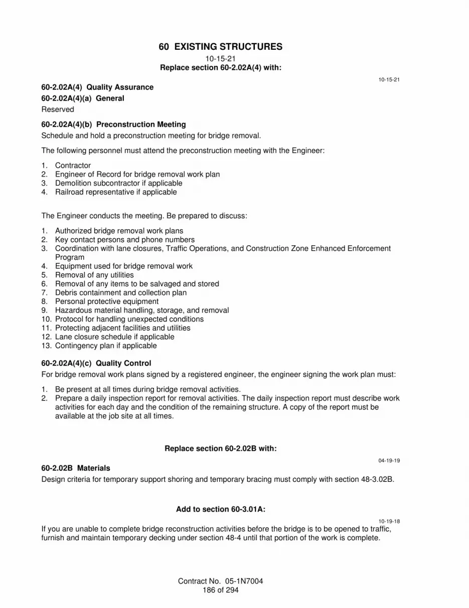
Contract No. 05-1N7004 186 of 294
60 EXISTING STRUCTURES
10-15-21 Replace section 60-2.02A(4) with:
10-15-21
60-2.02A(4) Quality Assurance
60-2.02A(4)(a) General
Reserved
60-2.02A(4)(b) Preconstruction Meeting
Schedule and hold a preconstruction meeting for bridge removal.
The following personnel must attend the preconstruction meeting with the Engineer:
1. Contractor 2. Engineer of Record for bridge removal work plan 3. Demolition subcontractor if applicable 4. Railroad representative if applicable
The Engineer conducts the meeting. Be prepared to discuss:
1. Authorized bridge removal work plans 2. Key contact persons and phone numbers 3. Coordination with lane closures, Traffic Operations, and Construction Zone Enhanced Enforcement
Program 4. Equipment used for bridge removal work 5. Removal of any utilities 6. Removal of any items to be salvaged and stored 7. Debris containment and collection plan 8. Personal protective equipment 9. Hazardous material handling, storage, and removal 10. Protocol for handling unexpected conditions 11. Protecting adjacent facilities and utilities 12. Lane closure schedule if applicable 13. Contingency plan if applicable 60-2.02A(4)(c) Quality Control
For bridge removal work plans signed by a registered engineer, the engineer signing the work plan must:
1. Be present at all times during bridge removal activities. 2. Prepare a daily inspection report for removal activities. The daily inspection report must describe work
activities for each day and the condition of the remaining structure. A copy of the report must be available at the job site at all times.
Replace section 60-2.02B with:
04-19-19
60-2.02B Materials
Design criteria for temporary support shoring and temporary bracing must comply with section 48-3.02B.
Add to section 60-3.01A:
10-19-18
If you are unable to complete bridge reconstruction activities before the bridge is to be opened to traffic, furnish and maintain temporary decking under section 48-4 until that portion of the work is complete.

Contract No. 05-1N7004 187 of 294
Replace the 3rd and 4th paragraphs of section 60-3.02C(3) with:
04-19-19
Remove asphalt concrete surfacing by cold milling under the following conditions:
1. If a membrane seal is shown: 1.1. Remove the seal by cold milling 1.2. Do not remove more than 1/2 inch of the existing concrete slab
2. If a membrane seal is not shown: 2.1. Remove asphalt concrete surfacing until a 1/2-inch minimum of surfacing remains on top of
existing concrete slab 2.2. Use other authorized means to remove the remaining asphalt concrete without damage to the
concrete slab
Add to section 60-3.02C(3):
04-19-19
Where a portion of the asphalt concrete surfacing is to remain, saw cut a 2-inch-deep true line along the edge to remain in place before removing asphalt concrete. Remove the asphalt concrete without damaging the surfacing to remain in place.
Replace item 3 in the list in the 9th paragraph of section 60-3.04B(1)(d) with:
10-15-21
3. RSC using hydraulic cement other than portland cement or portland limestone cement no sooner than 3 days after concrete placement and your test results for prequalification of RSC show that the concrete attained at least 3,500 psi compressive strength
04-19-19
Delete the 3rd paragraph of section 60-3.04B(3)(a).
Replace the 9th paragraph of section 60-3.04B(3)(c) with:
04-19-19
Protect the overlay from moisture and do not allow traffic or equipment on the overlay (1) for a minimum of 4 hours cure time after final finishing and (2) until each rebound test result for the final finish shows a reading of at least 28 when tested under ASTM C805. The cure time must be extended if ordered. The rebound test may not be used to reduce the 4-hour cure time of the overlay.
Replace section 60-3.05E with:
04-16-21
60-3.05E Galvanic Anodes
Reserved
Replace section 60-3.05F with:
10-15-21
60-3.05F Replace Bearings
60-3.05F(1) General
Section 60-3.05F includes specifications for replacing bearing pads or steel rocker bearings with elastomeric bearing pads.
Elastomeric bearing pads must comply with section 51-3.02.

Contract No. 05-1N7004 188 of 294
Temporary supports must comply with section 48-3.
Jacking must comply with section 48-5.
60-3.05F(2) Materials
Not Used
60-3.05F(3) Construction
Temporary supports must include jacking assemblies required to jack and support the imposed loads and structures. Temporary or permanent stiffening members are required at all girder locations, directly above the applied jacking forces, unless otherwise authorized.
When the bridge is in the raised position, do not allow traffic on the bridge until the structure is secured and fully supported by temporary supports.
Remove the existing bearing pads and steel rocker bearings under section 60-2.02, except a bridge removal work plan is not required.
For steel rocker bearings, remove the existing steel keeper plates, steel masonry plates, grout pads, anchor bolts and rocker bearings. Flame or air-arc type of cutting equipment is not allowed to remove existing keeper plates. Sharp, marred, or roughened corners and edges resulting from removal operations must be slightly rounded by grinding or other suitable means.
Steam clean existing bearing seats and bearing contact areas on the bottoms of concrete girders to remove waxy residue and other deleterious materials.
Use oil-free compressed air for final cleaning to remove all loose material from bearing contact areas before placing new elastomeric bearing pads.
Verify bearing surface of seats are level. Ensure equal bearing on the entire area of each pad.
60-3.05F(4) Payment
Not Used
Replace the 1st paragraph of section 60-4.06A(4) with:
04-16-21
For field welding of column casings:
1. Only visual inspection is required 2. 2nd sentence of clause 5.13.2 and the 1st sentence of clause 5.13.3 of AWS D1.5 do not apply
Replace the 10th paragraph of section 60-4.09B(2)(a) with:
10-19-18
Steel parts must comply with ASTM A36/A36M or A576, Grade 1030 and must not be rimmed or capped steel.
Replace section 60-4.10 with:
10-16-20
60-4.10 BRIDGE SEAT EXTENDERS FOR RETROFITS
60-4.10A General
60-4.10A(1) Summary
Section 60-4.10 includes specifications for fabricating and installing bridge seat extenders.
Bridge seat extenders must comply with the specifications for miscellaneous bridge metal in section 75-3.

Contract No. 05-1N7004 189 of 294
60-4.10A(2) Definitions
Reserved
60-4.10A(3) Submittals
Submit a work plan showing the method of grouting pipe seat extenders to prevent grout from entering the hinge area.
60-4.10A(4) Quality Assurance
Inspect bridge seat extender materials at the fabrication site.
Notify the Engineer:
1. When materials have been delivered to the fabrication site 2. At least 10 days before starting fabrication 60-4.10B Materials
60-4.10B(1) General
Reserved
60-4.10B(2) Pipe Seat Extenders
Pipe seat extenders must consist of double extra-strong steel pipes, HS threaded rods, nuts, and washers.
Double-extra strong steel pipe must comply with ASTM A53/A53M, Grade B. HS threaded rods, nuts, and washers must comply with section 55-1.02D(1).
Galvanize double-extra strong steel pipe under section 75-1.02B. After galvanizing, any alterations resulting in new exposed surfaces, including holes or cut ends, must be coated as specified for repairing damaged galvanized surfaces under section 75-1.02B.
Grout for bonding the pipe to the cored hole must comply with section 60-4.06B(2). Any filler materials or seals must not restrict joint movement.
60-4.10B(3) Slab Bridge Seat Extenders
Slab bridge seat extenders must consist of steel plates, support tubes, bolts, bars, nuts, washers, pins, and elastomeric bearing pads.
Slab bridge seat extender must comply with section 55. Elastomeric bearing pads must comply with section 51-3.02. The support tubes must comply with ASTM A500/A500M, Grade B.
Galvanize seat extender under section 75-1.02B. After galvanizing, any alterations resulting in new exposed surfaces, including holes or cut ends, must be coated as specified for repairing damaged galvanized surfaces under section 75-1.02B.
Epoxy mortar must consist of a mixture of epoxy binder and aggregate. The epoxy mortar must comply with section 95-1.02C. The mix proportions of epoxy mortar must be 1-part binder to 1-part aggregate by volume. Aggregate must consist of a combination of 1-part material passing the no. 30 sieve and 3-parts material passing the no. 20 sieve.
60-4.10C Construction
60-4.10C(1) General
Reserved.
60-4.10C(2) Pipe Seat Extenders
Reserved
60-4.10C(3) Slab Bridge Seat Extenders
Place epoxy mortar under section 95-1.03.
Place elastomeric bearing pads under section 51-3.02C. Bond elastomeric bearing pads to steel support tubes with adhesive complying with Federal Specification MMM-A-121.

Contract No. 05-1N7004 190 of 294
60-4.10D Payment
The payment quantity for seat extender does not include the weight of nonmetallic materials used in constructing the seat extenders.
Replace section 60-4.11 with:
10-15-21
60-4.11 REPLACE ACCESS DOORS
60-4.11A General
60-4.11A(1) Summary
Section 60-4.11 includes specifications for replacing access doors.
Replacing access doors includes (1) removing an existing recessed access door with hinges, and (2) installing a new access door with frame.
60-4.11A(2) Definitions
Reserved
60-4.11A(3) Submittals
Submit 3 copies of access door assembly shop drawings for each location requiring a new access door assembly. Shop drawings must include:
1. Name of fabricator 2. Field measurement of the height, width, and wall thickness 3. Details for temporary metal covers including connections or fasteners to be used 60-4.11A(4) Quality Assurance
Reserved
60-4.11B Materials
Materials for access door assemblies and associated hardware must comply with section 75-3.02.
Access door assemblies consist of:
1. Sheet steel door with stiffeners 2. Lock cover and hasp 3. Door frame Fabricate access door assemblies in a shop. Do not punch, cut, or weld assemblies in the field, except for tack welds of the expansion anchors.
Galvanize access door assemblies and hardware under section 75-1.02B.
After galvanizing, the access door assemblies and hardware must be free of fins, abrasions, and rough edges.
Repairs to galvanized surfaces must comply with section 75-1.02B.
60-4.11C Construction
Verify existing access opening sizes before fabricating access door assemblies. Where the existing door or cover is unusable after opening, furnish and install a temporary metal cover over the opening. This work is change order work.
If the existing access opening is smaller than the opening size shown on the plan, enlarge the opening by saw-cutting full-depth to the dimension shown. Cut existing reinforcement 1 inch below the surface. Clean and patch the holes under section 51-1.03F(2). This work is change order work.
Remove the existing steel cover.

Contract No. 05-1N7004 191 of 294
Clean and prepare the concrete surface surrounding the existing frame. Refinish concrete edging so the new frame is flush with the existing frame.
Furnish a padlock for the access door assembly until Contract acceptance.
Do not leave any access opening uncovered and unsecured at the end of a work shift.
60-4.11D Payment
Not Used
^^^^^^^^^^^^^^^^^^^^^^^^^^^^^^^^^^^^^^^^^^^^^^^^^^^^^^^^^^^^
DIVISION VII DRAINAGE FACILITIES Replace section 62 with:
04-17-20
62 STORMWATER TREATMENT
04-16-21 62-1 GENERAL
62-1.01 GENERAL
62-1.01A Summary
Section 62-1 includes general specifications for constructing permanent stormwater treatment best management practices.
Earthwork must comply with section 19.
Concrete and joint seals must comply with section 51.
Sealant must comply with section 41-5.
Reinforcement must comply with section 52.
Underdrain must comply with section 68-2.
Miscellaneous metal must comply with section 75.
Cable railing must comply with section 83-2.07.
62-1.01B Definitions
Reserved62-1.01C Submittals
At least 5 business days before placing permeable material, submit a certificate of compliance for the gradation of the material from the source.
No more than 5 business days after placing permeable material, submit:
1. At least one ASTM D6913 test on permeable material sampled at: 1.1. Job site 1.2. Authorized location
2. Verification that the permeable materials testing results meet the gradation requirements 62-1.01D Quality Assurance
Submit verification that the placed material complies with the gradation for the Class 4 and Class 5 permeable materials.
Submit verification of the uniformity coefficient for Class 5 permeable material.
For Department acceptance, the depth of the permeable material will be measured after the in-place washing is complete.

Contract No. 05-1N7004 192 of 294
62-1.02 MATERIALS
62-1.02A General
Not Used
62-1.02B Class 4 Permeable Material
Class 4 permeable material must consist of sand, gravel, or crushed stone that is hard, durable, and clean. The material must be free from organic material, clay balls, or other deleterious substances.
The percentage composition by weight of Class 4 permeable material in place must comply with the gradation requirements shown in the following table:
Class 4 Permeable Material Gradation Requirements
Sieve size Percentage passing
2" 100 1-1/2" 95–100 3/4" 50–100 3/8" 15–55 No. 4 0–25 No. 8 0–5 No. 100 0
Class 4 permeable material must have a durability index of not less than 40.
62-1.02C Class 5 Permeable Material
Reserved
62-1.02D Miscellaneous Metal
Fabricate the parts shown in the table below from the corresponding materials shown:
Miscellaneous Metal Parts Part Material
Ladders Steel Handrails Steel Trash screen Steel Components of riser support brackets
Stainless steel complying with ASTM A276, Grade 304 CIP inserts must be ferrule loop type
62-1.02E Filter Fabric
Class D filter fabric must comply with the requirements shown in the following table:
Class D Filter Fabric
Quality characteristic Test method Requirement
Permittivity (min and max, sec-1) ASTM D4491 1.6–1.8 Apparent opening size, average roll value (min and max, US standard sieve size)
ASTM D4751 60–80
Grab breaking load, 1-inch grip, in each direction (min, lb)
ASTM D4632 120
Apparent elongation, in each direction (min, %) ASTM D4632 50 UV resistance, retained grab breaking load, 500 hours (min, %)
ASTM D4355 70
62-1.02F–62-1.02I Reserved
62-1.03 CONSTRUCTION
62-1.03A General
Placing filter fabric must comply with section 68-1.03B.

Contract No. 05-1N7004 193 of 294
62-1.03B Permeable Material
62-1.03B(1) General
04-16-21
Before placement, wash Class 4 and Class 5 permeable materials:
1. To remove silt and clay particles 2. With potable water equal to at least 4 times the volume of the material being placed After placement, wash Class 4 and Class 5 permeable materials:
1. With potable water 2. Until the discharged water has a turbidity reading of:
2.1. 30 NTU or less for a project within the Tahoe Hydrologic Unit 2.2. 200 NTU or less for a project outside the Tahoe Hydrologic Unit
04-17-20
Capture the wash water. Handle the wash water by any of the following means:
1. Dispose of 2. Use as dust control 3. Disperse onsite in an authorized location other than the BMP 62-1.03B(2) Class 5 Permeable Material
Place Class 5 permeable material:
1. In a way that does not damage or displace the filter fabric 2. Using methods that produce a finished surface as shown 62-1.03C–62-1.03H Reserved
62-1.04 PAYMENT
Not Used
62-2 DESIGN POLLUTION PREVENTION INFILTRATION AREA
Reserved
62-3 INFILTRATION TRENCH
04-16-21
62-3.01 GENERAL
62-3.01A Summary
Section 62-3 includes specifications for constructing infiltration trenches.
Concrete curb must comply with section 73.
62-3.01B Definitions
Reserved
62-3.01C Submittals
At least 5 business days before placing permeable material, submit a certificate of compliance for the gradation of the material from the source.
62-3.01D Quality Assurance
Reserved
62-3.02 MATERIALS
62-3.02A General
Filter fabric must be Class D.

Contract No. 05-1N7004 194 of 294
62-3.02B Surface Gravel
Surface gravel must be Class 1, Type A permeable material under section 68-2.02F.
62-3.02C Trench Filler Material
Trench filler material must be Class 6 permeable material and must consist of rock or high porosity backfill material. Rock must be non-crushed, pre-washed, clean, hard, sound, durable, and uniform in quality. Rock must be free of detrimental quantity of soft, friable, thick elongated or laminated pieces, organic material, clay balls, oil, alkali, or other deleterious substances.
The percentage composition by weight of Class 6 permeable material in place must comply with the gradation requirements shown in the following table:
Class 6 Permeable Material Gradation Requirements
Sieve size Percentage passing
4" 100 3" 75 2" 8
1.5" 2
Class 6 permeable material must have a minimum durability index of not less than 40.
62-3.02D Observation Well
PVC pipe for the observation well must be perforated, have a smooth wall, and comply with AASHTO M278.
PVC matted end cap and vented well cap must comply with AASHTO M278.
Concrete must be minor concrete.
Pull box must comply with section 86-1.02C, except an electronic marker is not required. The cover marking must be OBSERVATION WELL.
62-3.02E Alternative Trench Filler Material
Reserved
62-3.03 CONSTRUCTION
62-3.03A General
Place filter fabric under section 68-1.03B.
62-3.03B Observation Well
The only joint allowed in the pipe in the observation well is between the perforated and solid wall pipe sections.
Place the observation well pipe vertically.
No permeable material, sand, or other material must be inside the well pipe.
62-3.04 PAYMENT
Not Used
04-17-20
62-4 INFILTRATION BASIN
Reserved
62-5 INFILTRATION GALLERY
Reserved
62-6 RESERVED

Contract No. 05-1N7004 195 of 294
62-7 BIORETENTION
Reserved
62-8 DETENTION BASIN
Reserved
62-9 AUSTIN EARTH BERM
Reserved
62-10 AUSTIN VAULT SAND FILTER
Reserved
62-11 DELAWARE SAND FILTER
Reserved
62-12 GROSS SOLIDS REMOVAL DEVICE
04-16-21
62-12.01 GENERAL
Section 62-12 includes specifications for constructing gross solids removal devices.
62-12.02 MATERIALS
62-12.02A General
Reserved
62-12.02B Miscellaneous Metal
Fasteners used to connect grates and screen to the frame must be vandal-resistant.
Stainless steel wedge-wire screens, plates, and bars must comply with ASTM A240/ A240M, Type 304, with a no. 2B finish.
Finished screens must be descaled by immersion in a nitric/hydrofluoric acid bath, rinsed, and air dried to achieve passivation.
Fasteners, anchorage devices, hardware for the inclined screen and screened pipe must be Type 304 stainless steel.
Welding of steel members must comply with AWS D1.1, D1.4, and D1.5. Welding of stainless steel members must comply with AWS D1.6.
Before welding, prepare and clean with stainless steel brushes and non-ferrous abrasives. Equipment used in the fabrication of carbon steel must not be used.
After welding, the stainless steel surface must be smooth and without waves.
Fabricate the parts shown in the table below from the corresponding materials shown:
Miscellaneous Metal Parts
Part Material
Jet plate Steel Deflector Steel Cleanout Steel or Type 304 stainless steel Chain Steel
62-12.02C Fiberglass Reinforced Plastic Components
Reserved
62-12.02D Inclined Screen
Inclined screen must be stainless steel wedge wire.
The screen slot width must be between 0.17 to 0.20 inch.

Contract No. 05-1N7004 196 of 294
Stainless steel wedge wire screen must have an open area from 60 to 70 percent of the total screen area.
62-12.02E Screened Pipe
Screened pipe, joints, supports, hatches, doors and ancillary hardware must be constructed of stainless steel. Screened pipe must comply with ASTM A778, and must be Type 316L.
Screened pipe must be 0.25-inch thick well screen with machine-made evenly spaced louvered openings perpendicular to the axis of the casing. Fabricate screened pipe with perforations and louvers as shown.
Fabrication tolerances on the screened pipe, joints, hatches, and doors must not exceed 0.20 inch.
Screened pipe sections must be joined after fabrication. Sections must be numbered using a metal tagging system after compatibility matching, with the tag indicating project location and section number. Section numbering must indicate the placement at each location, with the non-louvered section being labeled as the first section and continuing sequentially until the final section for each location. The metal tags must remain in place after installation.
62-12.02F Frame and Grates
Frames and grates for linear radial gross solids device must be steel.
Each grate section must be readily removable where shown. Frame and grate supports must be provided at openings and must clear ladders and other access points. Grate openings that fit around protrusions such as pipes and ladders must be discontinuous at approximately the centerline of opening so that each section of grate is easily removable.
62-12.03 CONSTRUCTION
Installation of inclined screens and supports, jet plates, and ancillary features must comply with sections 55-1.02E(6)(c) and 55-1.02E(7).
Install inclined screen, screened pipe, joints, hatches, doors, supports, and ancillary features such that gaps do not exceed 0.20 inch.
Install screened pipe with the aperture facing away from the discharge end of the pipe.
62-12.04 PAYMENT
Not Used
04-17-20
62-13 MULTI-CHAMBER TREATMENT TRAIN
Reserved
62-14 TRACTION SAND TRAP
Reserved
62-15–62-24 RESERVED
62-25 EXISTING STORMWATER TREATMENT
Reserved
^^^^^^^^^^^^^^^^^^^^^^^^^^^^^^^^^^^^^^^^
64 PLASTIC PIPE
10-15-21 Add to section 64-2.01C:
04-17-20
If recycled resin is used for corrugated polyethylene pipe, submit the percent of recycled resin.

Contract No. 05-1N7004 197 of 294
Replace the 1st and 2nd paragraphs of section 64-2.02A with:
10-15-21
Plastic pipe must be Type C or Type S corrugated polyethylene pipe, corrugated PVC pipe with smooth interior, or polypropylene dual wall pipe.
The residue from the ignition of polyethylene, PVC, and polypropylene compounds must not exceed 30 percent as determined under ASTM D2584 except the muffle furnace temperature must be 840 ± 45 degrees F.
Replace the 2nd and 3rd paragraphs of section 64-2.02C with:
04-17-20
Type C and Type S corrugated polyethylene pipe must comply with AASHTO M 294.
HDPE compounds used in the manufacture of corrugated polyethylene pipe and fittings must comply with AASHTO M 294 except the mix must contain from 2 to 4 percent well-dispersed carbon black and at least 49 percent virgin resin.
Replace section 64-2.02E with:
10-15-21
64-2.02E Polypropylene Dual Wall Pipe
Polypropylene dual wall pipe and fittings must have a smooth interior wall and annular exterior corrugations complying with ASTM F2881. Polypropylene dual wall pipe must not exceed 60 inches in nominal diameter.
Polypropylene compound for pipe and fitting production must be impact modified copolymer materials and meet the requirements of ASTM F2881.
Pipe and fittings must be manufactured from virgin compounds. Reworked plastic may be used if it meets the requirements for rework plastic conforming to ASTM F2881.
Pipe must be colored or black. Carbon black content must be from 2 to 3 percent by weight for black pipe. Add UV stabilizers for colored pipe under the manufacturer’s instructions.
Gaskets must be elastomeric and comply with ASTM F477. No reworked material will be allowed in the manufacture of the gasket. Gasket must be covered with a removable, protective wrap to ensure the gasket is free from debris.
All pipes and fittings must be clearly marked with:
1. Manufacturer’s name or trademark 2. Nominal size 3. Specification designation 4. Plant location or designation code 5. Date of manufacture Pipe must be marked at intervals of not more than 12 feet.
Store pipe and fittings above ground on adequate blocking. Pipe must be kept clean and fully drained during storage. Pipe, fittings, and gaskets must be covered or wrapped if exposed to sunlight during storage.

Contract No. 05-1N7004 198 of 294
Replace section 64-2.02F with:
10-15-21
64-2.02F Joints
Plastic pipe joints must comply with section 61-2.01D(2)(b) for standard or positive joints. Where sleeve joint connections are used, the sleeve width must be at least 7-3/4 inches and engage at least 2 corrugations of each pipe being joined.
Joints for pipes shown as watertight must be watertight under pressure and all conditions of expansion, contraction, and settlement, and must comply with section 61-2.01D(2)(a) for watertightness.
For corrugated polyethylene pipe:
1. If watertight joints are shown, use Type S corrugated polyethylene pipe with gaskets. If watertight joints are not shown, use gasketed joints when specified. Gaskets for Type C corrugated polyethylene pipe must be installed on each side of the joint. Gaskets must comply with ASTM F477 and be factory-installed.
2. Corrugated polyethylene pipe joints manufactured to comply with section 61-2.01D(2)(b) for integral joints must be laid to line and grade with sections closely jointed. Corrugated polyethylene pipe to be joined by sleeve joints must be laid to line and grade with the separate sections not more than 1-1/2 inches apart and then firmly joined together with at least 2 corrugations from each pipe section engaged in the coupler.
For corrugated PVC pipe with smooth interior:
1. Elastomeric gaskets must comply with ASTM F477 for low-head applications. Use extruded or molded gaskets cured in a way so that any cross section will be dense, homogeneous, and free of pores, blisters, pitting or other imperfections. Double gaskets must be single-piece gaskets that fit into the first 2 full corrugation valleys on the spigot end. Ship gaskets in containers that will prevent damage from UV exposure and handling.
2. Wyes, tees, reducers, elbows, couplings, laterals, and other fittings must be molded or fabricated under ASTM F949 for cell classification 12454 or 13343 as specified in ASTM D1784.
3. Lubricant must comply with the pipe manufacturer's instructions. The lubricant must not have a detrimental effect on gaskets or pipes.
4. Joints must comply with section 61-2.01D(2)(b) for integral joints except the joint overlap requirements are as shown. Pipe joints must be bell and spigot type with gaskets ready for field assembly. Install joints so that the elastomeric gasket will be compressed radially between the pipe bell and spigot to form a tight seal when assembled.
For polypropylene dual wall pipe:
1. All joints must be watertight unless otherwise described 2. Joints must comply with ASTM D3212 and be bell and spigot type unless alternative connections are
shown 3. Gaskets must be installed at all joints 4. Lubricant used for the assembly of the gasketed joint must be as recommended by the pipe
manufacturer with no detrimental effect on the gasket or pipe 5. Install joints so that the elastomeric gasket will be compressed radially between the pipe bell and
spigot to form a tight seal when assembled
Replace the 2nd paragraph of section 64-2.03A with:
10-15-21
Install Type S corrugated polyethylene pipe, corrugated PVC pipe, or polypropylene dual wall pipe wherever smooth interior wall type is shown.

Contract No. 05-1N7004 199 of 294
Replace item 2 in the list in 1st paragraph of section 64-2.03B with:
10-15-21
2. Backfill corrugated polyethylene pipe or polypropylene dual wall pipe greater than 48 inches in nominal diameter with either controlled low-strength material under section 19-3.02G or with slurry cement backfill under section 19-3.02E.
Replace item 3 in the list in the 1st paragraph of section 64-2.03B with:
04-16-21
3. Place controlled low-strength material used for structure backfill to a level at least 12 inches or 0.7 times the pipe diameter above the pipe crown, whichever is greater.
Add to the end of section 64-2.03C:
10-15-21
Place polypropylene dual wall pipe under the manufacturer's instructions except corrugated couplings must be split collar, engaging at least 2 full corrugations when non-watertight joints are allowed. Shortening pipe sections in the field must comply with the manufacturer's instructions.
^^^^^^^^^^^^^^^^^^^^^^^^^^^^^^^^^^^^^^^^
65 CONCRETE PIPE
10-15-21 Replace the 2nd paragraph of section 65-2.01D(3) with:
10-16-20
Pipes 24 inches in nominal diameter and smaller do not need to be tested to the load to produce a 0.01-inch-wide crack if the pipe is subjected to a load equivalent to the ultimate test load and complies with section 65-2.02. Instead of broken pipe pieces obtained as specified above, cores weighing at least 2.2 pounds from pipe sections selected by the Engineer may be used for the absorption test. Pipe sections that have been tested to the actual 0.01-inch-wide crack will not be load-tested further, and those sections that comply with or exceed the required strength and workmanship standards may be used in the work if authorized.
Replace the 2nd paragraph of section 65-2.01D(5) with:
10-16-20
Oval shaped reinforced concrete pipe 24 inches in nominal diameter and smaller does not need to be tested to the load to produce a 0.01-inch-wide crack if the pipe is subjected to a load equivalent to the ultimate test load and complies with section 65-2.02. Instead of broken pipe pieces obtained as specified above, cores weighing at least 2.2 pounds from pipe sections selected by the Engineer may be used for the absorption test. Pipe sections that have been tested to the actual 0.01-inch-wide crack will not be load-tested further, and those sections that comply with or exceed the required strength and workmanship standards may be used in the work if authorized.
Replace the 2nd paragraph of section 65-2.02A with:
10-16-20
The concrete for reinforced concrete pipe must contain at least 470 pounds of cementitious material per cubic yard and have a water to cementitious material ratio that does not exceed 0.40 by weight. You may use SCM. Circumferential reinforcement must have a minimum cover of 1 inch, except pipes with a nominal diameter of 18 inches or less must have a minimum cover of 3/4 inch.

Contract No. 05-1N7004 200 of 294
Replace item 1 in the list in the 3rd paragraph of section 65-2.02F with:
10-15-21
1. Cement mortar composed of 1 part portland cement or portland limestone cement and 2 parts sand by volume and the following: 1.1 Well graded sand passing a no. 8 sieve. 1.2 Mix materials to a consistency suitable for the purpose intended. Use the mortar within 30
minutes after you add the mixing water. 1.3 You may use admixtures of hydrated lime, fire clay, diatomaceous earth, or other authorized
inert material in the mortar to facilitate workability. Obtain authorization for the quantity of admixture.
Replace the 4th paragraph of section 65-2.03C with:
10-15-21
Do not allow free water to come in contact with the pipeline until portland cement or portland limestone cement sealing materials have set at least 24 hours.
^^^^^^^^^^^^^^^^^^^^^^^^^^^^^^^^^^^^^^^^
66 CORRUGATED METAL PIPE
10-19-18 Replace the 1st paragraph in section 66-1.02D with:
10-19-18
Coupling bands for corrugated metal pipe must comply with either section 66-1.02D or section 61-2.01D(2)(b).
Replace the 6th paragraph in section 66-1.02D with:
10-19-18
Joints for siphons and joints for pipes shown as watertight must be watertight under pressure and all conditions of expansion, contraction, and settlement, and must comply with section 61-2.01D(2)(a) for watertightness.
Replace the 4th paragraph of section 66-2.03 with:
10-19-18
Place cement treated structure backfill for slotted corrugated steel pipe as shown and under section 19-3.02F(3) for soil cement beddings. Cover the completed cement treated structure backfill with a curing seal of asphaltic emulsion, Grade SS1 or CSS1.
^^^^^^^^^^^^^^^^^^^^^^^^^^^^^^^^^^^^^^^^
68 SUBSURFACE DRAINS
04-16-21 Replace section 68-8 with:
04-16-21
68-8 PREFABRICATED VERTICAL DRAINS
68-8.01 GENERAL
68-8.01A Summary
This section includes specifications for installing prefabricated vertical drains.

Contract No. 05-1N7004 201 of 294
68-8.01B Definitions
refusal: Drive sleeve or mandrel advancing rate less than 3 inches per second with full applied force.
68-8.01C Submittals
68-8.01C(1) General
Submit:
1. Certificate of compliance 2. Test samples representing every 8,000 linear ft 3. Minimum average roll values as defined under ASTM D4759 Label submittals with the manufacturer's name and product information.
68-8.01C(2) Shop Drawings
Submit 5 copies of shop drawings. Upon review completion, submit from 6 to 12 copies, as requested, for authorization and use during construction.
Shop drawings and calculations must be stamped and signed by an engineer who is registered as a civil engineer in the State.
Shop drawings must include:
1. Your name, address, telephone number, and email address. 2. Plans showing the layout, identification, and working surface and bottom elevations of prefabricated
vertical drains. 3. Proposed installation sequence. 4. Proposed method to loosen and penetrate stiff upper soil layers before installing prefabricated vertical
drains and method to backfill the loosen holes, if needed. 5. Manufacturer, model number, description and specifications of installation equipment. 6. Manufacturer, model number, description and specifications of devices for measuring and recording
plumbness, installation length, and depth. 68-8.01C(3) Construction Record
Submit daily construction record within 24 hours. Include identification, location, and depth of installed prefabricated vertical drains.
68-8.01D Quality Assurance
68-8.01D(1) General
Reserved
68-8.01D(2) Quality Control
Reserved
68-8.01D(3) Department Acceptance
68-8.01D(3)(a) General
Reserved
68-8.01D(3)(b) Verification Testing
Do not start installation until the verification test is accepted.
Install 2 prefabricated vertical drains at locations determined by the Engineer. Use the same equipment and method to be used for installation. Perform verification tests in the Engineer's presence.
The verification test must demonstrate that the proposed equipment and method can install prefabricated vertical drains to the depth shown.
The Department rejects verification tests that fail to install prefabricated vertical drains to the depth shown. Submit revised shop drawings for additional verification tests. Repeat verification testing until the results demonstrate that the proposed equipment and method can install prefabricated vertical drains to the depths shown.

Contract No. 05-1N7004 202 of 294
68-8.01D(3)(c) Acceptance Testing
Reserved
68-8.02 MATERIALS
Prefabricated vertical drains must consist of a polymeric core with filter fabric integrally bonded to both sides of the core creating a stable drainage void. Prefabricated vertical drains must be free of defects, rips, or holes.
Identify prefabricated vertical drain rolls under ASTM D4873. Label or tag must include lot or control numbers, individual roll number, date of manufacture, manufacturer, and product identification.
Prefabricated vertical drains must comply with the requirements shown in the following table:
Prefabricated Vertical Drains
Quality characteristic Test method Requirement
Total discharge capacity @ 72 psi and unit hydraulic gradient (min, gallon per minute)
ASTM D4716 1.6
Tensile strength (min, lb) ASTM D4595 225 Nonwoven geotextile of prefabricated vertical drains
Apparent opening size, average roll value (max, µm(US Sieve))
ASTM D4751 212(70)
Permittivity (min, sec-1) ASTM D4491 0.3 Grab tensile strength (min, lb) ASTM D4632 112 Puncture strength (min, lb) ASTM D6241 125 Trapezoidal tear (min, lb) ASTM D4533 55
68-8.03 CONSTRUCTION
Handle and store prefabricated vertical drains under the manufacturer’s instructions and ASTM D4873. During shipment and storage, the prefabricated vertical drains must be wrapped in a heavy-duty protective covering. Store and protect prefabricated vertical drains from sunlight, mud, dirt, dust, debris, and detrimental substances.
Before installation, survey, mark, and label the prefabricated vertical drain locations as shown. Install prefabricated vertical drains within 6 inches from the locations shown.
Install prefabricated vertical drains from the working surface and to the tip elevation shown.
Equipment for installing prefabricated vertical drains must:
1. Be plumbed with deviation from vertical less than 1 in 50 during installation of the prefabricated vertical drains.
2. Be able to advance through the soil at the job site to the design tip elevation. 3. Have a cross-sectional area of the driving sleeve or mandrel combined with the anchor less than 10
square inches. 4. Have a driving sleeve or mandrel that can protect the prefabricated vertical drain material from tears,
cuts, and abrasions during installation. Advance the driving sleeve or mandrel at a constant force or constant rate.
Protect prefabricated vertical drains from tears, cuts, and abrasions during installation. Anchor the tip of each prefabricated vertical drains with a rod or anchor plate.
You may end the prefabricated vertical drain at an elevation within 8 feet of the design tip elevation.
Do not use jetting or impact method.
If authorized, you may use auger or vibrator to loosen and penetrate stiff upper soil layers before installing prefabricated vertical drains. Auger holes must be 6 inches or less in diameter and extend less than 12 inches past the obstruction. Backfill the auger hole with sands immediately after installation of each prefabricated vertical drain.

Contract No. 05-1N7004 203 of 294
Cut installed prefabricated vertical drains neatly with at least 12 inches protruding above the working surface.
Do not damage previously installed prefabricated vertical drains.
You may splice prefabricated vertical drains. Spliced section of prefabricated vertical drains must have the same or better structural and hydraulic properties than prefabricated vertical drains without splice. Place the end of the trailing roll of prefabricated vertical drains inside the geotextile covering of the existing roll. Overlap each end of prefabricated vertical drains with geotextile covering at least 8 inches.
Prefabricated vertical drains that are out of plumb, out of location, damaged, or improperly installed are rejected. Install 2 additional prefabricated vertical drains for each rejected prefabricated vertical drain 2 feet away from the rejected prefabricated vertical drain and at locations determined by the Engineer.
68-8.04 PAYMENT
Not Used
^^^^^^^^^^^^^^^^^^^^^^^^^^^^^^^^^^^^^^^^
70 MISCELLANEOUS DRAINAGE FACILITIES
10-15-21 Replace item 1 in the list in the 1st paragraph of section 70-5.02B(2) with:
10-15-21
1. Cement and aggregate must comply with section 90-1 except for the aggregate gradation requirements
^^^^^^^^^^^^^^^^^^^^^^^^^^^^^^^^^^^^^^^^
71 EXISTING DRAINAGE FACILITIES
04-17-20 Replace section 71-3.01A(4)(b) with:
04-17-20
71-3.01A(4)(b) Preconstruction Meetings
71-3.01A(4)(b)(i) General
Reserved
71-3.01A(4)(b)(ii) Prerehabilitation Meeting
Before starting cleaning and preparation work, you must schedule and attend a prerehabilitation meeting with the Engineer. Include any subcontractors, manufacturers and other parties involved in the culvert work. Provide a meeting facility that is within 5 miles of the job site or at another location accepted by the Engineer.
71-3.01A(4)(b)(iii) Pregrouting Meeting
Before starting grouting work, you must schedule and conduct a grouting meeting with the Engineer and your personnel involved in the grouting work, including your:
1. Project superintendent 2. Supervisory personnel 3. Grouting foreman 4. Grouting subcontractors Provide a meeting facility that is within 5 miles of the job site or at another location accepted by the Engineer.

Contract No. 05-1N7004 204 of 294
Replace section 71-3.01A(4)(c) with:
04-17-20
71-3.01A(4)(c) Quality Control
71-3.01A(4)(c)(i) General
Reserved
71-3.01A(4)(c)(ii) Annular Space Grouting
The grout cast density at the point of placement must be from 53 to 68 lb/cu ft and the minimum compressive strength must be 300 psi at 28 days.
Test the grout for compressive strength under ASTM C495 except that specimens must be moist cured before the 28-day compressive strength test and not be oven dried. If the grouting plan shows multiple stages, the grouting plan must include test results that verify that the grout stiffness is adequate for placement of multiple lifts.
For each batch of grout, perform density and viscosity tests under ASTM C138 and ASTM C939 in the presence of the Engineer. Grout density must be within 3 lb/cu ft of the density in the authorized grout plan with mix design. The time of efflux (outflow) must not exceed 20 seconds as specified in ASTM C939 unless otherwise authorized.
For pipeliners with a stiffness of less than 29 psi, the grout pump's pressure measured at the point of injection must not exceed either of the following:
1. 5 psi 2. Manufacturer's instruction For pipeliners with a stiffness of at least 29 psi, the grout pump's pressure measured at the point of injection must not exceed 7.25 psi.
The pipeliner must be able to withstand a static head of grout that is 6 inches above the highest crown elevation. The maximum grout pressure for a static grout head must not exceed the grout pump's maximum allowable pressure.
Install a grout pressure gauge and recorder immediately adjacent to each injection port. Continuously record on paper with ink the actual grouting pressure versus time. Record grout pressure to an accuracy of ±0.5 psi. Attach a gauge to a saddle-type diaphragm seal to prevent clogging with grout.
71-3.01A(4)(c)(iii) CCTV Recording
CCTV recordings must be made and submitted in high quality electronic media such as CD or DVD.
The CCTV equipment must include:
1. CCTV camera with articulating head 2. Transporter adapted for conditions of the culvert 3. Television monitor 4. Lighting 5. Cables and power sources CCTV equipment must:
1. Be specifically designed and constructed for pipe inspection 2. Have camera lighting for minimizing reflective glare 3. Have an adjustable focal-distance range from 6 inches to infinity 4. Produce a minimum resolution of 356 lines per inch for both the camera and monitor 5. Have a remote-reading meter counter accurate to 1 percent over the length of the particular section
being inspected Verify the accuracy of the distance meter in the CCTV with a walking meter, roll-a-tape, or other authorized device.

Contract No. 05-1N7004 205 of 294
Where human entry is possible for the entire length of the culvert, you may use a handheld video camera with lighting as an alternative to CCTV. Video and audio content must comply with the requirements for CCTV. Inspect at a rate that is not more than 30 feet per minute.
71-3.01A(4)(c)(iv) Photographs
Use a digital camera and lighting. Lighting and photo quality must be suitable to provide clear and focused photographs of the entire culvert surface under all conditions.
71-3.01A(4)(c)(v) Monitoring of Annular Space Grouting
Wherever a pipeliner with annular space grouting is described, monitor the grouting and record pressures throughout the grouting process. Verify compliance with the manufacturer's instructions for each phase of the grouting process. Gauges must comply with ANSI B40, Grade 2A. The pressure gauges, recorder, and field equipment must be calibrated by an independent testing agency.
71-3.01A(4)(c)(vi) Pipeliners
Pipeliners must be continuous over the entire length of the culvert and must have no visual defect such as foreign inclusions, concentrated ridges, discoloration, pitting, pin holes, cracking or other deformities. The pipeliner must not be over-deflected. There must not be segregation or voids in the grout.
71-3.01A(4)(c)(vii) Deflection Testing of Pipeliners
If a pipeliner with annular space grouting is described, test the pipeliner for deflection. Test after grouting and in the presence of the Engineer.
For pipeliners with a nominal inside diameter of 36 inches or less, either pull a mandrel through the pipeliner by hand or use another authorized method. The mandrel must be:
1. Rigid and nonadjustable 2. Comprised of at least 9 legs and have an odd number of total legs 3. Longer than it is wide 4. Made of steel 5. Fitted with pulling rings at each end 6. Stamped or engraved on some segment other than a runner indicating pipeliner material
specification, nominal size, and mandrel outside diameter (e.g., HDPE F 714-SDR 26- 36" – 31.569") 7. Furnished in a suitable carrying case labeled with the same data as stamped on the mandrel 8. Authorized before use For pipeliners with a nominal inside diameter greater than 36 inches, determine the deflection using a 1-inch diameter, rigid, nonadjustable metal bar; a minimum-radius rigid template; or other authorized method.
The pipeliner must not be over-deflected. For pipeliners 36 inches or less in nominal diameter, the mandrel must pass through the entire pipeliner. For pipeliners greater than 36 inches in nominal diameter, the deflection must be the lesser of either of the following:
1. 5 percent greater than the actual dimension of the pipeliner in place. This actual dimension includes the pipe joint system.
2. 6-1/2 percent of the nominal pipeliner dimension. If more than 8 percent of the nominal pipeliner dimension is over-deflected, the pipeliner is rejected. If 8 percent or less of the nominal pipeliner dimension is over-deflected, the pipeliner may remain in place and the Department deducts 20 percent of the bid amount for that pipeliner.
Replace item 2 in the list in the first paragraph of section 71-3.01B(2) with:
04-17-20
2. Not less than 590 lb of cementitious material per cubic yard

Contract No. 05-1N7004 206 of 294
Replace section 71-5.03B with:
04-17-20
71-5.03B Frames, Covers, and Grates
Adjust frames, covers, and grates must comply with section 78-23.03.
04-17-20
Delete the 2nd through 5th paragraphs of section 71-5.04.
^^^^^^^^^^^^^^^^^^^^^^^^^^^^^^^^^^^^^^^^^^^^^^^^^^^^^^^^^^^^
DIVISION VIII MISCELLANEOUS CONSTRUCTION
72 SLOPE PROTECTION 10-15-21
10-15-21
Delete the 1st paragraph of section 72-2.03A.
10-15-21
Delete the 1st paragraph of section 72-3.03A.
Replace the 7th paragraph of section 72-5.03 with:
10-15-21
Spread and tamp concrete until it is thoroughly compacted and mortar flushes to the surface. If the slope is too steep to allow the use of concrete wet enough to flush with tamping, tamp concrete until it is consolidated and immediately trowel on a mortar surface that is 1/4 inch thick. The mortar must consist of 1 part portland cement or portland limestone cement and 3 parts fine aggregate.
Replace the 2nd paragraph of section 72-11.01C(2) with:
10-15-21
Spread and tamp concrete until it is thoroughly compacted and mortar flushes to the surface. If the slope is too steep to allow the use of concrete wet enough to flush with tamping, tamp the concrete until it is consolidated and immediately trowel on a mortar surface that is 1/4 inch thick. The mortar must consist of 1 part portland cement or portland limestone cement and 3 parts fine aggregate.
^^^^^^^^^^^^^^^^^^^^^^^^^^^^^^^^^^^^^^^^
73 CONCRETE CURBS AND SIDEWALKS
10-15-21 Replace the 2nd paragraph of section 73-2.03A with:
10-15-21
Anchor steel dowels in drilled holes with mortar made from equal parts by volume of portland cement or portland limestone cement, sand, and water. You may use anchor bolts instead of anchored steel dowels if authorized.

Contract No. 05-1N7004 207 of 294
Replace the 3rd paragraph of section 73-1.02A with:
04-17-20
Preformed expansion joint filler must comply with ASTM D1751. As an alternative, a semi-rigid, closed-cell polypropylene foam, preformed joint filler that complies with ASTM D8139 may be used.
Replace the paragraph of section 73-1.02B with:
04-17-20
Detectable warning surface must be on the Authorized Material List for detectable warning surfaces and must match yellow color no. 33538 of AMS-STD-595.
^^^^^^^^^^^^^^^^^^^^^^^^^^^^^^^^^^^^^^^^
75 MISCELLANEOUS METAL
04-16-21 Replace the last paragraph in section 75-3.02B with:
10-18-19
Thread-locking systems must (1) consist of a cleaner, primer, and anaerobic thread-locking adhesive and (2) be on the Authorized Material List for anaerobic thread-locking systems. Apply all components of the system under the manufacturer's instructions.
Replace the 1st paragraph of section 75-3.02C(1) with:
04-16-21
Concrete anchorage devices must be on the Authorized Material List for stud mechanical expansion anchors, shell-type mechanical expansion anchors, resin capsule anchors, or cast-in-place inserts.
04-17-20
Delete the 3rd paragraph of section 75-3.02C(2).
Replace section 75-3.02C(3) with:
04-17-20
75-3.02C(3) Resin Capsule Anchors
Reserved
04-17-20
Delete the 3rd paragraph of section 75-3.02C(4).
^^^^^^^^^^^^^^^^^^^^^^^^^^^^^^^^^^^^^^^^

Contract No. 05-1N7004 208 of 294
78 INCIDENTAL CONSTRUCTION
10-16-20 Replace section 78-4.03 with:
04-19-19
78-4.03 PAINTING CONCRETE
78-4.03A General
78-4.03A(1) Summary
Section 78-4.03 includes specifications for preparing and painting concrete surfaces.
78-4.03A(2) Definitions
Reserved
78-4.03A(3) Submittals
Submit the coating manufacturer's application instructions at least 7 days before use.
78-4.03A(4) Quality Assurance
Reserved
78-4.03B Materials
Coatings for concrete must comply with the specifications for acrylic emulsion paint for exterior masonry in section 91-4.02B.
Coatings must be white.
78-4.03C Construction
78-4.03C(1) General
Reserved
78-4.03C(2) Surface Preparation
Before painting, surfaces must be:
1. At least 28 days old. 2. Prepared under SSPC-SP 13/NACE no. 6. Pressure rinse the prepared surfaces before applying the
paint. 3. Thoroughly dry. You may use artificial drying methods if authorized. 78-4.03C(3) Application
Apply at least 2 coats under the manufacturer's instructions and SSPC-PA 7. Protect adjacent surfaces during painting using an authorized method.
10-16-20
Paint text on structures and barriers in 2-1/2-inch high black letters. Black text must contrast with the background. If ordered, adjust text size and paint color to accommodate for paint location.
04-19-19
78-4.03D Payment
Not Used
Replace section 78-4.04 with:
04-19-19
78-4.04 STAINING CONCRETE AND SHOTCRETE
78-4.04A General
78-4.04A(1) Summary
Section 78-4.04 includes specifications for preparing and staining concrete and shotcrete surfaces.

Contract No. 05-1N7004 209 of 294
78-4.04A(2) Definitions
acid stain: non-tintable, transparent stain that contains dilute acid.
water-based stain: semi-transparent or solid water-based coating in an acrylic emulsion vehicle, that can be tinted to match an AMS-STD-595 color.
78-4.04A(3) Submittals
78-4.04A(3)(a) General
Submit the stain and sealer manufacturer's product data and application instructions at least 7 days before starting staining activities.
78-4.04A(3)(b) Contractor Qualifications
Submit the following documentation at least 10 days before the prestaining meeting:
1. Summary of the staining contractor's experience that demonstrates compliance with section 78-4.04A(4)(c).
2. List of at least 3 projects completed in the last 5 years that demonstrate the staining contractor's ability to stain surfaces similar to the surfaces for this project. For each project include: 2.1. Project description 2.2. Name and phone number of the owner 2.3. Staining completion date 2.4. Color photos of the completed stained surface
78-4.04A(3)(c) Staining Quality Work Plan
Submit a staining quality work plan at least 10 days before the prestaining meeting. The work plan must include details for preparing and staining the surfaces to achieve the required color, and for sealing the surfaces, including:
1. Number of applications that will be used to apply the stain 2. For each application of the stain, a description of:
2.1. Manufacturer, color, finish, and percentage strength mixture of the stain that will be applied 2.2. Proposed methods and tools for applying the stain
3. Proposed methods for protecting adjacent surfaces during staining 4. Proposed methods and tools for applying the sealer For acid stains, the work plan must also include a rinse water collection plan for containing all liquid, effluent, and residue resulting from preparing and staining the surfaces.
78-4.04A(4) Quality Assurance
78-4.04A(4)(a) General
Reserved
78-4.04A(4)(b) Test Panels
Stain the authorized test panel complying with section 51-1.01D(2)(c) or section 53-3.01D(3).
The test panel must be:
1. Stained using the same personnel, materials, equipment, and methods to be used in the work 2. Accessible for viewing 3. Displayed in an upright position near the work 4. Authorized for staining before starting the staining work If ordered, construct additional test panels until a satisfactory color is attained. The preparing and staining of additional test panels is change order work.
The Engineer uses the authorized stained test panel to determine the acceptability of the stained surface.
Dispose of the test panels after the staining work is complete and authorized. Notify the Engineer before disposing of the test panels.

Contract No. 05-1N7004 210 of 294
78-4.04A(4)(c) Contractor Qualifications
The staining contractor must have experience staining surfaces to simulate the appearance of natural rock formations or stone masonry, and must have completed at least 3 projects in the past 5 years involving staining of surfaces similar to the surfaces for this project.
78-4.04A(4)(d) Prestaining Meeting
Before starting staining activities, conduct a meeting to discuss the staining quality work plan. Meeting attendees must include the Engineer and all staining contractors.
78-4.04B Materials
78-4.04B(1) General
Reserved
78-4.04B(2) Stain
78-4.04B(2)(a) General
The stain must be:
1. Commercially available product designed specifically for exterior applications 2. Specifically manufactured for staining concrete surfaces 78-4.04B(2)(b) Acid Stain
Acid stain must:
1. Contain dilute acid that penetrates and etches the surfaces 2. Be a water-based solution of inorganic metallic salts 3. Produce abrasion-resistant color deposits 78-4.04B(2)(c) Water-based Stain
Water-based stain must be:
1. Acrylic emulsion 2. Non-fading and UV resistant 3. Capable of producing irregular, mottled tones 78-4.04B(3) Sealer
The sealer must be as recommended by the stain manufacturer, clear and colorless, and have a matte finish when dry.
78-4.04B(4) Joint Sealing Compound
Reserved
78-4.04C Construction
78-4.04C(1) General
At locations where there is exposed metal adjacent to the surfaces to be stained, seal the joint between the surfaces to be stained and the exposed metal with a joint sealing compound before applying the stain.
78-4.04C(2) Surface Preparation
Test surfaces for acceptance of the stain before applying the stain. Clean surfaces that resist accepting the stain and retest until passing.
Before staining, the surfaces must be:
1. At least 28 days old 2. Prepared under SSPC-SP 13/NACE no. 6 3. Thoroughly dry

Contract No. 05-1N7004 211 of 294
78-4.04C(3) Application
78-4.04C(3)(a) General
Apply the stain under the manufacturer's instructions. Protect adjacent surfaces during staining. Drips, puddles, or other irregularities must be worked into the surface.
Apply the sealer under the manufacturer's instructions.
78-4.04C(3)(b) Acid Stain
Work the acid stain into the concrete using a nylon bristle brush in a circular motion.
After the last coat of stain has dried, rinse the stained surfaces with water and wet scrub them with a stiff-bristle nylon brush until the rinse water runs clear. Collect all rinse water.
78-4.04D Payment
Not Used
Replace section 78-23 with:
04-17-20
78-23 ADJUST UTILITY FRAMES, COVERS, AND MANHOLES
78-23.01 GENERAL
Section 78-23 includes specifications for adjusting utility access box frames, covers, and manholes.
Work performed on existing utility frames, covers, grates and manholes must comply with section 15.
78-23.02 MATERIALS
Not Used
78-23.03 CONSTRUCTION
Lower and raise utility frames, covers, grates and manholes by lowering before cold planing and raising after paving or surfacing. Before opening the lane to traffic, either (1) complete permanent paving or surfacing or (2) temporarily fill any depressions with HMA.
Do not adjust to final grade until the adjacent pavement or surfacing is complete.
For a structure that is to be raised, remove the cover or frame and trim the top of the structure to provide a suitable foundation for the new material.
Instead of using new materials similar in character to those in the existing structure, you may use raising devices to adjust a manhole to grade. Before starting paving work, measure and fabricate raising devices. Raising devices must:
1. Comply with the specifications for section 75 except that galvanizing is not required 2 Have a shape and size that matches the existing frame 3. Be match marked by painting identification numbers on the device and corresponding structure 4. Result in an installation that is equal to or better than the existing one in stability, support, and
nonrocking characteristics 5. Be fastened securely to the existing frame without projections above the surface of the road or into
the clear opening Where manholes are to be lowered, remove the top portion to 3.5 feet below finished grade or to an authorized depth. Adjust the manhole using the taper needed to match the finished grade.
If a manhole cover is unstable or noisy under traffic, place a coil of asphalt-saturated rope, a plastic washer, or asphaltic compound on the cover seat. Before placement, obtain authorization for use of the material.
78-23.04 PAYMENT
Not Used

Contract No. 05-1N7004 212 of 294
^^^^^^^^^^^^^^^^^^^^^^^^^^^^^^^^^^^^^^^^
80 FENCES
10-18-19 Replace the 1st paragraph of section 80-2.02B with:
10-18-19
Line posts must comply with ASTM A702 except packaging of posts is not required. You may omit the anchor plate if the post is set in a concrete footing with a minimum cross-sectional dimension of 6 inches and a depth equal to the full penetration of the post.
Replace item 3 in the list in the 1st paragraph of section 80-2.02D with:
10-18-19
3. Be one of the following: 3.1. 12-1/2 gauge, Class 3 3.2. 13-1/2 gauge, Class 3 3.3. 14 gauge, Class 3 3.4. 15-1/2 gauge, Class 3
Replace the 2nd paragraph of section 80-3.02B with:
10-19-18
Posts and braces must comply with the strength requirements in ASTM F1043 for one of the following:
1. Group IA, regular grade, for round pipes 2. Group IC, 50,000 psi yield, for round pipes 3. Group II-L for roll-formed posts and braces
Replace the list in section 80-4.02B(1)(b) with:
10-19-18
1. Comply with ASTM A1064 and have a Class 1 zinc coating complying with ASTM A641 2. Be welded or woven galvanized steel wire fabric 3. Be made of at least 16-gauge wire 4. Be 36 inches wide
Replace the paragraph in section 80-4.02B(2) with:
10-19-18
The materials for a temporary desert tortoise fence must comply with section 80-4.02B(1).
Replace the 2nd sentence in the 1st paragraph of section 80-4.02C(2) with:
10-19-18
Embed the posts at maximum 10-foot intervals into the ground.
^^^^^^^^^^^^^^^^^^^^^^^^^^^^^^^^^^^^^^^^^^^^^^^^^^^^^^^^^^^^

Contract No. 05-1N7004 213 of 294
DIVISION IX TRAFFIC CONTROL DEVICES
82 SIGNS AND MARKERS
04-16-21 Replace the list in the 1st paragraph of section 82-2.01C with:
04-19-19
1. Aluminum sheeting 2. Retroreflective sheeting 3. Color imaging methods and film 4. Protective-overlay film
Replace section 82-2.02C with:
04-17-20
82-2.02C Retroreflective Sheeting
Retroreflective sheeting used for the background and legend must comply with ASTM D4956-13 and must be on the Authorized Material List for signing and delineation materials.
Retroreflective sheeting must be Type XI, except for white background signs, it must be Type VIII or IX.
Warning sign plaques and panels must be retroreflective fluorescent orange or fluorescent yellow background.
Type VIII, IX, and XI retroreflective sheeting must have Class 1, 3, or 4 adhesive backing. Adhesive backing must be pressure sensitive and fungus resistant.
Retroreflective sheeting must be applied to sign panels at the fabrication plant under the retroreflective sheeting manufacturer's instructions without appreciable stretching, tearing, or other damage.
Orientation of the legend must comply with the retroreflective sheeting manufacturer's instructions.
Retroreflective sheeting on a sign panel with a minor dimension of 48 inches or less must be a single, contiguous sheet without splices except for the splices produced during the manufacture of the retroreflective sheeting. Sign panel with a minor dimension greater than 48 inches may have 1 horizontal splice in the retroreflective sheeting other than the splices produced during the manufacture of the retroreflective sheeting.
Unless the retroreflective sheeting manufacturer's instructions require a different method, splices in the retroreflective sheeting must overlap by at least 1 inch. The retroreflective sheeting on either side of a splice must not exhibit a color difference under incident and reflected light.
Replace section 82-2.02D with:
04-19-19
82-2.02D Color Imaging Methods and Film
The material used for color imaging methods, film, and protective-overlay must be recommended by the retroreflective sheeting manufacturer.
Colored retroreflective sheeting must be used for the background.
Signs with green, red, blue, or brown backgrounds may use reverse-screened-process color on white retroreflective sheeting for the background color. The coefficient of retroreflection must be at least 70 percent of the coefficient of retroreflection specified in ASTM D4956 for the corresponding color of retroreflective sheeting.
The sign must have outdoor weatherability characteristics equivalent to those specified for the corresponding color of retroreflective sheeting in ASTM D4956.

Contract No. 05-1N7004 214 of 294
Replace the 2nd paragraph of section 82-3.01A with:
04-17-20
Roadside signs include ground-mounted signs and Type N (CA), Type P (CA), and Type R (CA) marker panels.
Add to section 82-3.01B:
04-17-20
ground-mounted sign: Roadside sign or signs with a wide-flange metal post.
Replace section 82-3.01D with:
10-16-20
82-3.01D Quality Assurance
When delivered to the job site, treated posts must:
1. Comply with the specified grading requirements 2. Be dry 3. Have no visual evidence of preservative on the surface
Add to section 82-3.02B:
04-16-21
Wide-flange metal posts must be fabricated from structural steel complying with ASTM A36/A36M. Nuts, bolts, and washers for the breakaway connections of a wide-flange steel post must comply with ASTM A325.
Perforated square steel tube posts and square steel anchor sleeves must:
1. Be fabricated from galvanized hot rolled steel complying with ASTM 1011 Grade 50 and galvanized under ASTM 653 G-90.
2. Have a minimum 60 ksi yield strength after cold forming. 3. Have zinc coated corner welds. Corner welds must be scarfed and then a conversion coating and
clear organic polymer topcoat must be applied. Perforated square steel tube post must have 7/16-inch diameter holes or punch-outs 1-inch on center on all four sides.
Gravel or stone for a steel tube post foundation must be natural rough surface gravel or broken stone.
Concrete for a steel tube post foundation must be minor concrete that contains at least 470 pounds of cementitious material per cubic yard.
10-16-20
Delete the 3rd paragraph of section 82-3.02C.
Replace the 4th paragraph of section 82-3.02C with:
10-16-20
Posts must be treated under section 57-2.01B(3) and under AWPA U1, Use Category UC4A, Commodity Specification A. Posts must be incised, and the minimum retention of preservative must comply with AWPA requirements.

Contract No. 05-1N7004 215 of 294
Add to section 82-3.02E:
04-16-21
Sign panel drive rivets must be galvanized steel or aluminum.
Square steel tube post drive rivets must be galvanized steel.
Replace the 9th paragraph of section 82-3.03A with:
04-16-21
Backfill the space around the wide-flange metal posts with minor concrete that contains at least 470 pounds of cementitious material per cubic yard.
Add to section 82-3.03A:
04-16-21
Fasten square steel tube posts to square steel anchor sleeves with square steel tube post drive rivets.
Add to section 82-3.03B:
04-16-21
Attach sign panel to square steel tube post with sign panel drive rivets. Place a fiber washer between the rivet head and the sign face.
Replace section 82-5.01A with:
10-19-18
Section 82-5 includes specifications for fabricating and installing markers, including milepost markers.
Replace the 2nd paragraph in section 82-5.02E with:
10-19-18
A target plate for milepost marker or Type L-1 (CA) or Type L-2 (CA) object marker installed on a metal post must be manufactured from an aluminum sheet or zinc-coated steel sheet.
Replace section 82-5.02H with:
10-19-18
82-5.02H Milepost Markers
Letters and numerals on a milepost marker must be made with opaque black paint or film. The paint and film must have an equivalent outdoor weatherability as the retroreflective sheeting specified in ASTM D4956. Nonreflective, opaque, black film must be vinyl or acrylic material.
Film for letters and numerals must be computer cut and have pressure-sensitive adhesive.
Replace the 5th paragraph of section 82-5.03 with:
10-19-18
Use stencils to paint letters and numerals on milepost markers.
Add to the end of section 82-9.03:
04-17-20
82-9.03F Installation of Sign Panels on Existing Posts
Install roadside sign panels on existing posts with fastening hardware under section 82-2.03A.

Contract No. 05-1N7004 216 of 294
Replace the 1st paragraph of section 82-9.04 with:
04-17-20
Payment for furnishing sign panels of any type is not included in the payment for install sign panel on existing frame and post.
Payment for removing existing sign panel is included in the payment for install roadside sign panel on existing post.
^^^^^^^^^^^^^^^^^^^^^^^^^^^^^^^^^^^^^^^^
83 RAILINGS AND BARRIERS
10-15-21 Add to the end of section 83-1.03:
10-16-20
83-1.03D Miscellaneous Construction
Where shown, paint the structure name, bridge number, year constructed, and other bridge identification information. Painting concrete must comply with section 78-4.03C(3).
Bridge identification on the bridge barrier must be (1) painted at each structure approach, (2) visible to approaching traffic, and (3) located near the paving notch, if applicable.
For open bridge barrier rails, paint bridge identification on the widest rail element.
For structures with adjacent retaining walls or approaches where metal beam bridge railings extend beyond the structure, paint bridge identification on the concrete end block of the barrier.
For bents and piers, paint bridge identification corresponding to the name and number shown, on the face of the bridge barrier directly above the centerline of each bent or pier.
Replace section 83-2.01A(3) with:
04-19-19
83-2.01A(3) Construction
For midwest guardrail systems and thrie beam barrier, install steel foundation tubes and soil plates in soil.
Add to section 83-2.01A(3):
04-16-21
Cut off any excess bolt that extends more than 0.5 inch beyond the nut.
Replace section 83-2.02C(1)(c) with:
10-16-20
83-2.02C(1)(c) Bolt Holes and Cuts in Wood Posts and Blocks
If copper naphthenate, Alkaline Copper Quaternary ammonium compound, or copper azole is used to treat wood posts and blocks, before inserting the bolts, fill the bolt holes with grease.
You may field bore the 2-3/8-inch-diameter holes shown for wood guardrail terminal posts and wood rail tensioning assembly posts.
If you perform field cutting or boring after treatment, manually treat with preservative under section 57-2.01C(3)(b).

Contract No. 05-1N7004 217 of 294
Replace the 4th paragraph of section 83-2.03C with:
04-19-19
If median barrier delineation is shown, match the barrier marker spacing to the raised pavement marker spacing on the adjacent median edge line pavement delineation.
Replace the 3rd paragraph of section 83-2.05B(3) with:
10-16-20
Stud bolts must comply with the specifications for studs in clause 9 of AWS D1.1.
Replace section 83-2.08 with:
04-16-21
83-2.08 TUBULAR RAILINGS
83-2.08A General
83-2.08A(1) Summary
Section 83-2.08 includes specifications for constructing tubular railings.
Tubular railing includes rail tubes, post tubes, plates, rail splice sleeves, and fasteners.
Paint for galvanized railing must comply with section 59-3.
83-2.08A(2) Definitions
Reserved
83-2.08A(3) Submittals
Submit a certificate of compliance verifying that all components of the tubular railing comply with section 83-2.08B.
Submit shop drawings for tubular railing. Shop drawings must include:
1. Details for venting holes in rails, posts, and sleeves 2. Railing layout 3. Complete details for the construction of the work including methods of construction, sequence of shop
and field assembly, galvanization, and installation procedures Submit 7 copies of the shop drawings. Allow 25 days for review. Upon authorization, the Engineer returns 2 copies to you for use during construction.
83-2.08A(4) Quality Assurance
Reserved
83-2.08B Materials
The materials for tubular railing components must comply with the specifications shown in the following table:
Material Specification
Rail and post tubes ASTM A500/A500M, Grade B Rolled bars and plates ASTM A36/A36M Rail splice sleeves ASTM A36/A36M Bolts ASTM F3125, Grade
A325/A325M, Type 1 Threaded rods ASTM A449, Type 1 Nuts for bolts and threaded rods ASTM A563/A563M Washers for bolts and threaded rods ASTM F436/F436M

Contract No. 05-1N7004 218 of 294
Bolts and threaded rods furnished under ASTM A449 must comply with the mechanical requirements specified in ASTM A449 after galvanizing.
Rail tubes must be shop bent or fabricated to fit the horizontal curve if the radius is less than 900 feet.
If the vertical radius of the tubular handrailing is 30 feet or less, that portion of the railing must be either shop bent or built up from 1/4-inch-thick structural steel plates. The built-up tubular rail elements must match the seamless tubing in appearance.
The difference between out-to-out rail splice sleeve dimensions and the clear inside dimensions of the tubular steel rail elements must not exceed 3/16 inch after galvanizing.
Carefully handle the materials such that no parts are bent, broken, abraded, or otherwise damaged. Do not use manufacturing, handling, or installation methods that damage or distort the members or damage the galvanizing.
83-2.08C Construction
83-2.08C(1) General
Before the tubular railing parts are assembled, clean the bearing surfaces and surfaces to be in permanent contact. If the railing is mounted on a concrete surface, the post bases must be true and flat to provide uniform bearing.
Tubular railings must present a smooth, uniform appearance in their final position and conform closely to the horizontal and vertical lines as shown.
83-2.08C(2) Tubular Handrailing
Adjust the vertical position of the tubular handrailing to compensate for the camber and dead load deflection of the superstructure. The Engineer determines the adjustment amount before the railing is installed.
The metal railing posts to which the chain link railing attaches must fit the mounting brackets, pipe sleeves, and other connection fittings.
Where necessary, install shims at posts and rail elements to provide uniform bearing and conformance with the horizontal lines and vertical grade lines. Shims at steel posts must be commercial-quality, galvanized sheet steel.
83-2.08C(3) Tubular Bicycle Railing
When mounted on concrete barriers, cast sleeves for threaded rods in concrete. If authorized, you may drill and bond the threaded rods using chemical adhesive systems under section 51-1.
Erect railing true to line and grade. Posts must be normal to the profile grade. Transverse to the profile grade, railings must be plumb within a tolerance not to exceed 0.02 foot in 10 feet. Adjacent rail elements must align with each other within 1/16 inch.
83-2.08D Payment
Not Used
10-15-21
Delete the 7th paragraph of section 83-3.01A.
Replace section 83-3.02F with:
10-15-21
83-3.02F Reserved

Contract No. 05-1N7004 219 of 294
Replace the paragraph of section 83-3.03A(11) with:
04-19-19
Where concrete barrier markers are shown, cement the markers to the barrier under the manufacturer's instructions. Match the barrier marker spacing to the raised pavement marker spacing on the adjacent median edge line pavement delineation.
Replace section 83-3.03A(12) with:
10-15-21
83-3.03A(12) Reserved
^^^^^^^^^^^^^^^^^^^^^^^^^^^^^^^^^^^^^^^^
84 MARKINGS
10-18-19 Replace section 84-2 with:
10-19-18
84-2 TRAFFIC STRIPES AND PAVEMENT MARKINGS
84-2.01 GENERAL
84-2.01A Summary
Section 84-2 includes specifications for applying traffic stripes and pavement markings.
Traffic stripes and pavement markings must comply with ASTM D6628 for daytime and nighttime color.
Retroreflectivity must be measured under ASTM E1710 and the sampling protocol specified in ASTM D7585.
84-2.01B Definitions
10-18-19
pavement marking: Transverse marking which includes shoulder or gore marking, traffic island marking, word or numeral or symbol marking, arrow, limit line, stop line, yield line, crosswalk marking, speed measurement marking, speed reduction marking, speed hump marking, parking space marking, and route shield marking.
10-19-18
traffic stripe: Longitudinal centerline or lane line used for separating traffic lanes in the same direction of travel or in the opposing direction of travel or a longitudinal edge line marking the edge of the traveled way or the edge of a lane at a gore area separating traffic at an exit or entrance ramp. A traffic stripe is shown as a traffic line.
84-2.01C Submittals
For each lot or batch of traffic stripe material, primer, and glass beads, submit:
1. Certificate of compliance, including the material name, lot or batch number, and manufacture date 2. METS notification letter stating that the material is authorized for use, except for thermoplastic and
primer 3. SDS 4. Manufacturer's Instructions For each lot or batch of thermoplastic, submit a manufacturer's certificate of compliance and the following test results from the California Test 423:
1. Brookfield Thermosel viscosity 2. Hardness 3. Yellowness index, white only 4. Daytime luminance factor

Contract No. 05-1N7004 220 of 294
5. Yellow color, yellow only 6. Glass bead content 7. Binder content The date of the test must be within 1 year of use.
Submit test results for each lot of beads specifying the EPA test methods used and tracing the lot to the specific test sample. The testing for lead and arsenic content must be performed by an independent testing laboratory.
Submit the thermoplastic test stripe to the Engineer.
Submit the retroreflectivity test result within 5 days of testing the traffic stripes and pavement markings. The data must include the retroreflectivity, time, date, and GPS coordinates for each measurement.
84-2.01D Quality Assurance
84-2.01D(1) General
Reserved
84-2.01D(2) Quality Control
Before starting permanent application of methyl methacrylate and two component paint traffic stripes and pavement markings, apply a test stripe on roofing felt or other suitable material in the presence of the Engineer. The test stripe section must be at least 50 feet in length.
Upon request, apply a thermoplastic test stripe on suitable material in the presence of the Engineer during the application of thermoplastic traffic stripes or markings. The test stripe must be at least 1 foot in length.
Remove loose glass beads before measuring the retroreflectivity. Obtain authorization to proceed with the application of traffic stripes and pavement markings.
Within 30 days of application, test the traffic stripes and pavement markings under the test methods and frequencies shown in the following table:
Traffic Stripe Testing Frequency
Quality characteristic Test method Minimum sampling and testing frequency Initial retroreflectivity (min, mcd·m-2·lx-1) White Yellow
ASTM E1710 ASTM D7585a
aUse the referee evaluation protocol for project length less than 10 miles. For project lengths greater than or equal to 10 miles, add one evaluation for every additional mile.
Verify the glass bead application rate by stabbing the glass bead tank with a calibrated rod.
84-2.01D(3) Department Acceptance
The Engineer will perform a nighttime, drive-through, visual inspection of the retroreflectivity of the traffic stripes and pavement markings and notify you of any locations with deficient retroreflectivity. Test the retroreflectivity of the deficient areas to confirm striping and pavement markings meets the requirements.
The thermoplastic test stripe will be tested for yellow color, daytime luminance factor, and yellowness index requirements by METS.
84-2.02 MATERIALS
84-2.02A General
Reserved
84-2.02B Glass Beads
Each lot of glass beads must comply with EPA Test Method 3052 and 6010B or 6010C. Glass beads must contain less than 200 ppm each of arsenic and lead.
Type 1 glass beads must comply with AASHTO M 247.

Contract No. 05-1N7004 221 of 294
Type 2 glass beads must comply with AASHTO M 247. At least 75 percent of the beads by count must be true spheres that are colorless and do not exhibit dark spots, air inclusions, or surface scratches when viewed under 20X magnification.
High-performance glass beads must be on the Authorized Material List for high-performance glass beads.
Large-gradation glass beads must be on the Authorized Material List for two component traffic paint.
Glass beads for methyl methacrylate must be on the Authorized Material List for methyl methacrylate traffic striping and pavement marking.
Glass beads for paint must comply with State Specification 8010-004.
Glass beads must be surface treated, according to the bead and the material manufacturer's instructions, to promote adhesion with the specified material.
84-2.02C Thermoplastic
Thermoplastic must comply with State Specification PTH-02HYDRO, or PTH-02ALKYD.
Sprayable thermoplastic must comply with State Specification PTH-02SPRAY.
Each lot or batch of thermoplastic must be tested under California Test 423.
84-2.02D Methyl Methacrylate
Methyl methacrylate traffic paint must:
1. Be on the Authorized Material List for methyl methacrylate traffic striping and pavement marking 2. Be Category 2 84-2.02E Traffic Striping and Pavement Marking Tape
Traffic striping and pavement marking tape must be on the Authorized Material List for signing and delineation materials.
04-19-19
White tape must have an initial retroreflectivity of a minimum 700 mcd/m2.
Yellow tape must have an initial retroreflectivity of a minimum 500 mcd/m2.
10-19-18
When contrast is required for traffic stripping and pavement marking tape, the tape must be pre-formed and retroreflective, consisting of a white film with retroreflective beads and a contrasting black film border. The contrasting black border must be a nonreflective film bonded on each side of the white film to form a continuous roll. Each black border must be a minimum of 2 inches wide. The width of the tape must be at least 4 inches wider than the stripe width.
84-2.02F Two-Component Paint
Two-component traffic paint must be on the Authorized Material List for two component traffic paint.
84-2.02G Paint
Paint must comply with the requirements shown in following table:
Paint Specifications
Paint type Color Specification
Waterborne traffic line White, yellow, and black State Specification PTWB-01R2 Waterborne traffic line for the international symbol of accessibility and other curb markings
Blue, red, and green Federal Specification TT-P-1952E

Contract No. 05-1N7004 222 of 294
84-2.02H–84-2.02L Reserved
84-2.03 CONSTRUCTION
84-2.03A General
Establish the alignment for traffic stripes and the layouts for pavement markings with a device or method that will not conflict with other traffic control devices.
Protect existing retroreflective pavement markers during work activities.
Remove existing pavement markers that are coated or damaged by work activities and replace with an equivalent marker on the Authorized Material List for signing and delineation materials.
A completed traffic stripe or pavement marking must:
1. Have well defined edges 2. Be uniform 3. Be free from runs, bubbles, craters, drag marks, stretch marks, and debris A completed traffic stripe must:
1. Be straight on a tangent alignment 2. Be a true arc on a curved alignment 3. Not deviate from the width shown by more than:
3.1. 1/4 inch on a tangent alignment 3.2. 1/2 inch on a curved alignment
The length of the gaps and individual stripes that form a broken traffic stripe must not deviate by more than 2 inches from the lengths shown. The gaps and stripes must be uniform throughout the entire length of the traffic stripe.
Protect newly placed traffic stripes and pavement markings from traffic and work activities until the traffic stripes and pavement markings are dry or hard enough to bear traffic.
Use mechanical methods to remove dirt, contaminants, and loose material from the pavement surface before applying the traffic stripe or pavement marking.
Use abrasive blast cleaning to remove laitance and curing compound from the surface of new concrete pavement before applying the traffic stripe or pavement marking.
Construct recesses as shown in the following table:
Recess Depth Requirements
Material Requirement
Depth (mils) Depth (in)
Thermoplastic 375 3/8 Two component traffic paint 250 1/4 Methyl methacrylate traffic paint 250 1/4
Construct recesses for double traffic stripes in a single pass.
Before applying the traffic stripes and pavement markings:
1. Allow wet ground recesses to dry a minimum of 24 hours 2. Remove all powdery residue from dry recess 3. Keep the recesses dry and free from debris Apply traffic stripes and pavement markings before the end of the same work shift.
84-2.03B Application of Traffic Stripes and Pavement Markings
84-2.03B(1) General
Apply material for a pavement marking with a stencil or a preformed marking.

Contract No. 05-1N7004 223 of 294
Immediately remove drips, overspray, improper markings, or material tracked by traffic, using an authorized method.
Apply a traffic stripe or a pavement marking only to a clean, dry surface during a period when the pavement surface temperature is above 50 degrees F.
Apply traffic stripe or pavement marking and glass beads in a single pass. You may apply the glass beads by hand on pavement markings.
Embed glass beads to a depth of 1/2 their diameters.
Distribute glass beads uniformly on traffic stripe and pavement markings.
Glass beads with integral color must match the color of the stripe or pavement marking.
Apply glass beads with two separate applicator guns when two gradations are specified.
Allow enough overlap distance between new and existing striping patterns to ensure continuity at the start and end of the transition.
The retroreflectivity of applied traffic stripes and pavement markings must comply with the requirements shown in the following table:
Retroreflectivity Requirements
Traffic stripe material White (min, mcd·m-2·lx-1) Yellow (min, mcd·m-2·lx-1)
Paint 250 125 Thermoplastic 250 125 Thermoplastic with wet night enhanced visibility
700 500
Two component 250 125 Methyl methacrylate 500 300 Tape 700 500
84-2.03B(2) Thermoplastic
84-2.03B(2)(a) General
Apply primer or surface preparation adhesive under the manufacturer's instructions:
1. To all roadway surfaces except for asphaltic surfaces less than 6 months old 2. At a minimum rate of 1 gallon per 300 square feet 3. To allow time for the thermoplastic primer to dry and become tacky before application of the
thermoplastic Do not thin the primer.
Preheat thermoplastic using preheaters with mixers having a 360-degree rotation.
Apply thermoplastic in a single uniform layer by spray or extrusion methods.
Completely coat and fill voids in the pavement surface with the thermoplastic.
Apply recessed thermoplastic at a thickness so that the top is 0 to 1/16 inch below the pavement surface.
84-2.03B(2)(b) Extruded Thermoplastic
Apply extruded thermoplastic at a temperature of 400 to 425 degrees F or as recommended by the manufacturer.
Apply extruded thermoplastic for a traffic stripe at a rate of at least 0.36 lb of thermoplastic per foot of 6-inch-wide solid stripe. The applied traffic stripe must be at least 0.060 inch thick.
Apply extruded thermoplastic pavement markings at a thickness from 0.100 to 0.150 inch.
Apply Type 2 glass beads to the surface of the molten thermoplastic at a rate of at least 8 lb of beads per 100 sq ft.

Contract No. 05-1N7004 224 of 294
84-2.03B(2)(c) Sprayable Thermoplastic
Apply sprayable thermoplastic at a temperature of 350 to 400 degrees F.
Apply sprayable thermoplastic for a traffic stripe at a rate of at least 0.24 lb of thermoplastic per foot of 6-inch-wide solid stripe. The applied stripe must be at least 0.040 inch thick.
84-2.03B(2)(d) Thermoplastic with Enhanced Wet-Night Visibility
Apply a thermoplastic traffic stripe or pavement marking with enhanced wet-night visibility in a single pass and in the following order:
1. Uniform layer of extruded thermoplastic 2. Layer of high-performance glass beads 3. Layer of Type 2 glass beads Apply thermoplastic with enhanced wet-night visibility at a maximum speed of 8 mph.
Apply thermoplastic with enhanced wet-night visibility for a traffic stripe at a rate of at least 0.47 lb of thermoplastic per foot of 6-inch-wide solid stripe. The applied stripe must be at least 0.090 inch thick.
Apply thermoplastic with enhanced wet-night visibility for a pavement marking at a rate of at least 1.06 lb of thermoplastic per square foot of marking. The applied pavement marking must be at least 0.100 inch thick.
Apply high-performance glass beads at a rate of at least 6 lb of glass beads per 100 sq ft of stripe or marking. Apply Type 2, glass beads at a rate of at least 8 lb of glass beads per 100 sq ft of stripe or marking.
84-2.03B(3) Methyl Methacrylate
Apply the methyl methacrylate when the pavement surface and atmospheric temperatures are from 40 to 104 degrees F.
Apply methyl methacrylate paint at a minimum thickness of 0.090 inch.
Apply recessed methyl methacrylate paint at a minimum thickness of 0.200 inch.
Apply the glass beads recommended by the methyl methacrylate manufacturer.
84-2.03B(4) Traffic Striping and Pavement Marking Tape
Do not use traffic stripe and pavement marking tape on existing open graded friction course or chip seal.
Prepare pavement surface and use primer under the traffic tape manufacturer's written instructions. Apply tape to clean and dry pavement surface. Roll or tamp the traffic tape in place.
84-2.03B(5) Two-Component Paint
Apply a two-component painted traffic stripe or pavement marking in a single pass and in the following order:
1. Coat of two-component paint 2. Application of large gradation glass beads recommended by the two-component paint manufacturer 3. Application of Type 1 glass beads Apply two-component paint when the pavement surface temperature is above 39 degrees F and the atmospheric temperature is above 36 degrees F. The temperature of the paint must comply with the paint manufacturer's instructions.
Apply two-component paint and glass beads at a maximum speed of 10 mph.
Apply large-gradation glass beads at a minimum rate of 11.7 lb of beads per gallon of paint.
Apply Type 1 glass beads at a minimum rate of 8.3 lb of beads per gallon of paint.
Apply two-component paint for the traffic stripes and pavement markings at the thickness and application rates shown in the following table:

Contract No. 05-1N7004 225 of 294
Type of pavement Stripe thickness (min, inch)
Application rate (min, sq ft/gal)
HMA open graded/chip seal 0.025 64 HMA dense graded 0.020 80 Concrete 0.020 80
Apply recessed two-component paint at a thickness between 0.020 and 0.025 inch.
84-2.03B(6) Paint
Do not apply paint if:
1. Fresh paint could become damaged by rain, fog, or condensation 2. Atmospheric temperature could drop below 50 degrees F during the drying period Do not thin paint.
Use mechanical means to paint traffic stripes and pavement markings and to apply glass beads for traffic stripes.
The striping machine must be capable of superimposing successive coats of paint on the 1st coat and on existing stripes at a minimum speed of 5 mph.
Where the configuration or location of a traffic stripe is such that the use of a striping machine is not practicable, you may apply the traffic paint and glass beads by other methods and equipment if authorized.
Apply traffic stripes and pavement markings in 1 coat on existing pavement surfaces, at an approximate rate of 107 sq ft/gal.
Apply traffic stripes and pavement markings in 2 coats on a new pavement surface. The 1st coat of paint must be dry before applying the 2nd coat.
Apply 2-coat paint at the approximate rate of 215 sq ft/gal for each coat.
Paint a 1-coat, 3-inch-wide black stripe between the two 6-inch-wide yellow stripes of a double traffic stripe. If the two 6-inch-wide yellow stripes are applied in 2 coats, apply the black stripe concurrently with the 2nd coat of the yellow stripes.
On 2-lane highways:
1. If the 1st coat of the centerline stripe is applied in the same direction as increasing post miles, use the right-hand spray gun of the 3 spray guns to apply a single yellow stripe
2. If the 1st coat of the centerline stripe is applied in the same direction as decreasing post miles, use the left-hand spray gun of the 3 spray guns to apply a single yellow stripe
3. Apply the 2nd coat of centerline striping in the opposite direction of the 1st coat Apply glass beads at an approximate rate of 5 lb of beads per gallon of paint.
Verify the application rate of paint by stabbing the paint tank with a calibrated rod. If the striping machine has paint gauges, the Engineer may measure the volume of paint using the gauges instead of stabbing the paint tank with a calibrated rod.
84-2.03B(7) Contrast Striping
04-19-19
Contrast striping consists of black striping placed on each side of a white stripe.
10-19-18
You may use permanent tape instead of paint or thermoplastic.
Apply contrast stripe paint in one coat.
Do not use glass beads or other reflective elements in contrast striping material.

Contract No. 05-1N7004 226 of 294
04-19-19
84-2.03B(8)–84-2.03B(10) Reserved
10-19-18
84-2.04 PAYMENT
The payment quantity for a traffic stripe is the length measured along the line of the traffic stripe without deductions for gaps in the broken traffic stripe.
The payment quantity for a pavement marking is the area covered.
A double traffic stripe consisting of two-6-inch-wide yellow stripes are measured as 2 traffic stripes except for painted traffic stripes and sprayable thermoplastic traffic stripes.A double sprayable thermoplastic traffic stripe consisting of two 6-inch-wide yellow stripes are measured as single traffic stripe.
A double painted traffic stripe consisting of two 6-inch-wide yellow stripes separated by a 3-inch-wide black stripe is measured as a single traffic stripe.
The payment quantity for contrast striping is the length measured along the line of the traffic stripe without deductions for gaps in the broken traffic stripe.
Replace section 84-9 with:
10-19-18
84-9 EXISTING MARKINGS
84-9.01 GENERAL
84-9.01A Summary
Section 84-9 includes specifications for removing existing markings.
Work performed on existing markings must comply with section 15.
84-9.01B Definitions
Reserved
04-19-19
84-9.01C Submittals
10-19-18
Submit your proposed method for removing traffic stripes and pavement markings at least 7 days before starting the removal work. Allow 2 business days for the review.
84-9.02 MATERIALS
Not Used
84-9.03 CONSTRUCTION
84-9.03A General
Remove existing traffic stripes before making any changes to the traffic pattern.
Remove existing traffic stripes and pavement markings before applying the following materials:
1. Traffic stripe and pavement marking tape 2. Two component traffic stripes and pavement markings 3. Methyl methacrylate traffic stripes and pavement markings
04-19-19
Remove contrast stripes, traffic stripes and pavement markings, including any paint in the gaps, by methods that do not remove pavement to a depth of more than 1/8 inch.
10-19-18
Remove pavement markings such that the old message cannot be identified. Make any area removed by grinding rectangular. Water must not puddle in the ground areas. Fog seal ground areas on asphalt concrete pavement.

Contract No. 05-1N7004 227 of 294
Sweep up or vacuum any residue before it can (1) be blown by traffic or wind, (2) migrate across lanes or shoulders, or (3) enter a drainage facility.
84-9.03B Remove Traffic Stripes and Pavement Markings Containing Lead
Reserved
84-9.03C–84-9.03J Reserved
84-9.04 PAYMENT
The payment quantity for remove traffic stripe is the measured length multiplied by:
1. 0.67 for a single 4-inch-wide traffic stripe 2 1.34 for a single 8-inch-wide traffic stripe 3. 2 for a double traffic stripe The payment quantity for remove traffic stripe does not include the gaps in broken traffic stripes. Payment for removal of paint evident in a gap is included in the payment for remove traffic stripe of the type involved.
10-18-19
If no bid item is shown on the Bid Item List for remove pavement marking, remove pavement marking is paid for as remove traffic stripe of the types shown in the Bid Item List and the payment quantity for 1 square foot of pavement marking is 2 linear feet.
^^^^^^^^^^^^^^^^^^^^^^^^^^^^^^^^^^^^^^^^^^^^^^^^^^^^^^^^^^^^
DIVISION X ELECTRICAL WORK
86 GENERAL
10-15-21 Replace section 86-1.01B with:
10-19-18
86-1.01B Definitions
accessible pedestrian signal: Accessible pedestrian signal as defined in the California MUTCD.
accessible walk indication: Activated audible and vibrotactile action during the walk interval.
actuation: Actuation as defined in the California MUTCD.
ambient sound level: Background sound level in dB at a given location.
ambient sound sensing microphone: Microphone that measures the ambient sound level in dB and automatically adjusts the accessible pedestrian signal speaker's volume.
audible speech walk message: Audible prerecorded message that communicates to pedestrians which street has the walk interval.
CALiPER: Commercially Available LED Product Evaluation and Reporting. A U.S. Department of Energy program that individually tests and provides unbiased information on the performance of commercially available LED luminaires and lights.
controller assembly: Assembly for controlling a system's operations, consisting of a controller unit and auxiliary equipment housed in a waterproof cabinet.
controller unit: Part of the controller assembly performing the basic timing and logic functions.
correlated color temperature: Absolute temperature in kelvin of a blackbody whose chromaticity most nearly resembles that of the light source.
detector: Detector as defined in the California MUTCD.

Contract No. 05-1N7004 228 of 294
electrolier: Assembly of a lighting standard and luminaire.
flasher: Device for opening and closing signal circuits at a repetitive rate.
illuminance gradient: Ratio of the minimum illuminance on a 1-foot square of sign panel to that on an adjacent 1-foot square of sign panel.
inductive loop detector: Detector capable of being actuated by an inductance change caused by a vehicle passing or standing over the loop. An inductive loop detector includes a loop or group of loops installed in the roadway and a lead-in cable installed and connected inside a controller cabinet.
junction temperature: Temperature of the electronic junction of the LED device. The junction temperature is critical in determining photometric performance, estimating operational life, and preventing catastrophic failure of the LED.
L70: Extrapolated life in hours of the luminaire when the luminous output depreciates 30 percent from the initial values.
lighting standard: Pole and mast arm supporting the luminaire.
link: Part of a system which provides a data connection between a transmitter and receiver.
LM-79: Test method from the Illumination Engineering Society of North America specifying the test conditions, measurements, and report format for testing solid state lighting devices, including LED luminaires.
LM-80: Test method from the Illumination Engineering Society of North America specifying the test conditions, measurements, and report format for testing and estimating the long-term performance of LEDs for general lighting purposes.
luminaire: Assembly that houses the light source and controls the light emitted from the light source.
mid-span access method: Procedure in which fibers from a single buffer tube are accessed and spliced to a multi buffer tube cable without cutting the unused fibers in the buffer tube, or disturbing the remaining buffer tubes in the cable.
National Voluntary Laboratory Accreditation Program: U.S. Department of Energy program that accredits independent testing laboratories.
optical time domain reflectometer: Fiber optic test equipment that is used to measure the total amount of power loss between two points and over the corresponding distance. It provides a visual and printed display of the relative location of system components such as fiber sections, splices and connectors as well as the losses that are attributed to each component and or defects in the fiber.
pedestrian change interval: Pedestrian change interval as defined in the California MUTCD.
powder coating: Coating applied electrostatically using exterior-grade, UV-stable, polymer powder.
power factor: Ratio of the real power component to the complex power component.
power meter: Portable fiber optic test equipment that, when coupled with a light source, is used to perform end-to-end attenuation testing. Its display indicates the amount of power injected by the light source at the designed wavelength of the system under testing that arrives at the receiving end of the link.
pretimed controller assembly: Assembly operating traffic signals under a predetermined cycle length.
programming mechanism: Device to program the accessible pedestrian signal operation.
pull box: Box with a cover that is installed in an accessible place in a conduit run to facilitate the pulling in of wires or cables.
push button information message: Push button information message as defined in the California MUTCD.
push button locator tone: Push button locator tone as defined in the California MUTCD.

Contract No. 05-1N7004 229 of 294
segment: Continuous cable terminated by 2 splices, 2 connectors or 1 splice and 1 connector.
signal face: Signal face as defined in the California MUTCD.
signal head: Signal head as defined in the California MUTCD.
signal indication: Signal indication as defined in the California MUTCD.
signal section: Signal section as defined in the California MUTCD.
signal standard: Pole with or without mast arms carrying 1 or more signal faces.
street side lumens: Lumens from a luminaire directed to light up areas between the fixture and the roadway, such as traveled ways and freeway lanes.
surge protection device: Subsystem or component that protects equipment against short-duration voltage transients in power line.
total harmonic distortion: Ratio of the rms value of the sum of the squared individual harmonic amplitudes to the rms value of the fundamental frequency of a complex waveform.
traffic-actuated controller assembly: Assembly for operating traffic signals under the varying demands of traffic as registered by detector actuation.
traffic phase: Traffic phase as defined in the California MUTCD.
vehicle: Vehicle as defined in the California Vehicle Code.
vibrotactile pedestrian device: Vibrotactile pedestrian device as defined in the California MUTCD.
10-19-18
Delete the 9th and 10th paragraphs of section 86-1.01C(1).
Replace section 86-1.01C(3) with:
10-19-18
86-1.01C(3) Luminaires
Submit for a luminaire:
1. Maximum power in watts 2. Maximum designed junction temperature 3. Heat sink area in square inches 4. Designed junction-to-ambient thermal resistance calculation with thermal resistance components
clearly defined 5. L70 in hours when extrapolated for the average nighttime operating temperature 6. Life expectancy based on the junction temperature 7. Manufacturer's data sheet for the power supply, including the rated life Submit the manufacturer's QC test data for luminaires as an informational submittal.
Replace section 86-1.01C(4) with:
10-19-18
86-1.01C(4) Reserved
Replace the 3rd paragraph of section 86-1.02B(1) with:
04-19-19
Conduit used for horizontal directional drilling must be high density polyethylene Type IPS, SDR 9 and comply with ASTM F2160.

Contract No. 05-1N7004 230 of 294
04-16-21
Replace the 4th paragraph of section 86-1.02B(1) with:
Conduit for fiber optic cable systems must be high density polyethylene schedule 40, complying with NEMA TC-7.
Replace the 8th paragraph of section 86-1.02B(1) with:
10-19-18
High density polyethylene for innerduct must:
1. Comply with ASTM D3485, D3035, D2239, and D2447, and NEMA TC7 and TC2 2. Have a minimum tensile yield strength of 3300 psi under ASTM D638
04-19-19
3. Have a density of 59.6187 lb/ft3 ± 0.3121 lb/ft3 under ASTM D1505
Replace the 9th paragraph of section 86-1.02B(1) with:
04-19-19
Tracer wire must be a minimum no. 12 solid copper conductor with orange insulation Type TW, THW, RHW, or USE. For direct burial, the tracer wire insulation must be Type UF.
Replace section 86-1.02C with:
10-18-19
86-1.02C Pull Boxes
86-1.02C(1) General
A pull box cover must have a marking on the top that is:
1. Clearly defined 2. Uniform in depth 3. Parallel to the longer side 4. From 1 to 3 inches in height The cover marking must include CALTRANS and one of the following:
1. SERVICE for service circuits from a service equipment enclosure to a subpanel 2. SERVICE IRRIGATION for circuits from a service equipment enclosure to an irrigation controller 3. SERVICE BOOSTER PUMP for circuits from a service equipment enclosure to the booster pump 4. TDC POWER for circuits from a service equipment enclosure to telephone demarcation cabinet 5. LIGHTING for a lighting system 6. SIGN ILLUMINATION for a sign illumination system 7. SIGNAL AND LIGHTING for a signal and lighting system 8. RAMP METER for a ramp metering system 9. TMS for a traffic monitoring station 10. FLASHING BEACON for a flashing beacon system 11. CMS for a changeable message sign system 12. INTERCONNECT for an interconnect conduit and cable system 13. FIBER OPTIC for fiber optic cable system 14. ELECTRICAL SYSTEMS if more than one system is shared in the same pull box The cover marking must not include CALTRANS, only the following:
1. ELECTRICAL SERVICE for circuits from an electrical utility to a service equipment enclosure 2. TELEPHONE SERVICE for circuits from a telephone utility to a telephone demarcation cabinet A metal pull box cover must include a fitting for a bonding conductor.

Contract No. 05-1N7004 231 of 294
The hardware must be stainless steel containing 18 percent chromium and 8 percent nickel.
86-1.02C(2) Roadway Pull Boxes
86-1.02C(2)(a) General
A pull box cover must have a nonskid surface.
The pull boxes and covers must not have exposed fibers or reinforcement on the finish surfaces that are exposed.
The load rating must be:
1. Stenciled or stamped on the inside and outside of the pull box 2. Stamped on the outside of the cover If a transformer or other device is to be placed in the pull box, include recesses for a hanger.
Hold-down bolts must:
1. Be a Penta Head 1/2-13UNC 2. Have a thread lock material 3. Withstand a torque from 55 to 60 ft-lb 4. Withstand a minimum pull-out strength of 750 lb The opening in which the cover sets must have length and width dimensions 1/8 inch greater than the cover.
86-1.02C(2)(b) Nontraffic Pull Boxes
A nontraffic pull box and cover must comply with ANSI/SCTE 77, "Specification for Underground Enclosure Integrity," for Tier 22 load rating and must be gray or brown.
An extended pull box must be a minimum 22 inches deep and may be a single box or a box with an extension made of the same material as the pull box. The extension may be another pull box if the bottom edge of the pull box fits into the opening for the cover.
The hold down bolts, nuts, and washers must be a captive design.
The pull box must have a 1/2-13 coarse-thread insert with drainage hole, to secure the hold down bolts.
The cover must have a 1/2 inches by 4 inches pull slot with a 3/16-inch center pin.
The cover markings must be cast in the mold of the cover or be engraved on a metal or UV resistant ABS plate secured to the cover with stainless steel screws.
86-1.02C(2)(c) Traffic Pull Boxes
A traffic pull box and cover must comply with AASHTO HS20-44 and load tested under AASHTO M 306.
A traffic pull box must be reinforced with a galvanized steel Z bar welded frame. The frame must be anchored to the box with 2-1/4-inch-long concrete anchors with a 1/4-inch diameter. The pull box must have 4 concrete anchors, one in each corner, and two near the middle one on each of the longer sides, except for a no. 3-1/2(T) pull box.
The frame must have nuts fabricated with the frame or spot welded to the underside of the frame, to secure the hold down bolts.
The nuts must be zinc-plated carbon steel, vibration-resistant, and have a wedge ramp at the root of the thread.
The cover must:
1. Be steel, reinforced and galvanized post fabrication. 2. Be countersunk approximately 1/4 inch to accommodate the bolt head. When tightened, the hold
down bolt head must be no more than 1/8 inch above the top of the cover.

Contract No. 05-1N7004 232 of 294
3. Have a 1/2-inch by 2-inch pull slot with a guard under the cover to prevent entry of more than 3 inches below the bottom surface of the cover without deflection.
Before galvanizing a steel cover, the manufacturer must apply the cover marking by one of the following methods:
1. Use a cast iron strip at least 1/4-inch thick with letters raised a minimum of 1/16 inch. Fasten the strip to the cover with 1/4-inch, flathead, stainless steel machine bolts and nuts. Peen the bolts after tightening.
2. Use a sheet steel strip at least 0.027-inch thick with letters raised a minimum of 1/16 inch. Fasten the strip to the cover by spot welding, tack welding, or brazing with 1/4-inch stainless steel rivets or 1/4-inch, roundhead, stainless steel machine bolts and nuts. Peen the bolts after tightening.
3. Bead weld the letters on the cover such that the letters are raised a minimum of 3/32 inch. 86-1.02C(2)(d) Tamper Resistant Pull Boxes
86-1.02C(2)(d)(i) General
Not Used
86-1.02C(2)(d)(ii) Tamper-Resistant Nontraffic Pull Box
86-1.02C(2)(d)(ii)(A) General
A tamper resistant nontraffic pull box must include a pull box with one of the following:
1. Anchored cover 2. Lockable cover 3. Pull box insert 86-1.02C(2)(d)(ii)(B) Anchored Cover
The anchored cover must:
1. Be of 1/2-inch-thick mild steel, hot dip galvanized, post fabrication. 2. Have spikes removed from the galvanized surfaces. 3. Have a center space for a top lock nut that must be torqued to 200 ft-lb. 4. Have a center opening for a stainless-steel threaded cap to cover the lock nut. 5. Weigh a minimum of 85 lb. 6. Include an all-around security skirt of 1/4-inch thick steel. The skirt must be sized to encase a
nontraffic pull box or sized to fit within a traffic pull box. 7. Be welded to the skirt. 86-1.02C(2)(d)(ii)(C) Lockable Cover
The lockable cover must:
1. Be manufactured from minimum 3/16-inch-thick galvanized steel or a polymer of minimum strength equal to 3/16-inch steel.
2. Be secured to the pull box with a locking mechanism of equal or greater strength than the manufactured material.
3. Have 1/2-by-2-inch slot holes for lifting. 4. Have dimensions complying with one of the following:
4.1. Department's standards for pull box covers as shown if the lockable cover is secured to the inside lip of the pull box.
4.2. Department's standards for the length and width as shown for pull box covers if the lockable cover is secured to the top of the pull box.
86-1.02C(2)(d)(ii)(D) Pull Box Insert
The pull box insert must:
1. Be made of minimum 3/16-inch-thick or 10 gauge mild hot-dipped galvanized steel 2. Have a minimum of 2 mounting brackets that rest under the side or end wall 3. Be lockable with a padlock having a minimum 3/8-inch shackle

Contract No. 05-1N7004 233 of 294
4. Have dimensions complying with the Department's standards for the length and width as shown for pull box covers
86-1.02C(2)(d)(iii) Tamper Resistant Traffic Pull Box
A tamper resistant traffic pull box must include a pull box with an anchored cover.
86-1.02C(3) Structure Pull Boxes
A no. 7 pull box must:
1 Be 12 by 12 by 12 inches. 2. Be manufactured with 0.075-inch sheet steel. 3, Have 3/4-inch flanges on the top and bottom. 4. Have one 1-inch and one 1-1/2-inch knockouts on each side, except for the covers
10-16-20
5. Have drilled and tapped holes on the top and the bottom flanges for the cover screws. The hole pattern and spacing must be the same at the top and bottom.
10-18-19
6. Have covers that secure to the box with eight 1/4-inch diameter, 20NC brass machine screws. A no. 8 pull box must:
1 Be 12 by 12 by 12 inches. 2. Be manufactured with 0.135-inch sheet steel. 3. Mount to the structure with three 3/8-inch diameter machine screws per side. 4. Have 1-1/2-inch knockouts on each side, except the cover.
10-16-20
5. Have drilled and tapped holes on the sides and the bottom for the cover screws. The holes must be reinforced with a 1-by-1-by-0.135-inch bar inside the box.
10-18-19
6. Have a cover with 3/4-inch flanges on the sides and bottom with the corners welded at the bottom. The cover must secure to the box with, three 1/4-inch diameter by 1/2-inch long cadmium plated brass or stainless steel, machine screws.
A no. 9 pull box must:
1 Be 24 by 9-1/2 by 6-1/4 inches. 2. Be manufactured with 0.075-inch sheet steel. 3. Have a rain tight hood. 4, Have a 1-1/2-by-4-1/2-by-0.135-inch strap welded to the back of the box at each corner, parallel to
the long side. The strap must have a 1/4-inch hole on the exposed end. 5. Have a 1-inch lip around the opening.
10-16-20
6. Have drilled and tapped holes with a minimum 1/4-inch thread length, at the ends of the bottom lip for the cover screws.
10-18-19
7. Have a 3-inch knockout on each side at the bottom and at the center of the bottom. 8. Have a 2-inch knockout on each side at the top and at both ends of the bottom. 9. Have an L 5/8-by-7/8-by-0.075-inch formed angle spot welded to the inside of the top on both sides
and on the bottom. 10. Have a cover manufactured with 0.125-inch steel, that secures to the box with two 3/8-inch diameter
by 3/4-inch long stainless-steel flathead screws with 11/16-inch diameter countersink holes. The cover must include a 1/16-inch neoprene gasket.
A no. 9A pull box must:
1 Be 20 by 8 by 8-1/2 inches. 2. Be manufactured with 0.075-inch sheet steel. 3. Have 3/4-inch flanges on the top. 4, Have drilled holes on the short sides for the cover screws. The holes must have a stainless-steel hex
nut or a 1/4-by-5/8-by-8-inch bar spot welded to the bottom of the flange.

Contract No. 05-1N7004 234 of 294
5. Have a 3-inch knockout on each side at the top and at the center of the bottom. 6. Have a 2-inch knockout on each side at the bottom and at both ends of the bottom. 7. Have a cover manufactured with 0.105-inch steel, that secures to the box with four 3/8-inch diameter
stainless steel hex head cap screws, two on each short side. The cover must have a rain tight hood and include a 1/16-inch neoprene gasket.
Pull box corner joints must be lapped and spot welded or riveted.
Concentric and eccentric multiple size knockouts are not be allowed.
Replace section 86-1.02D(3) with:
10-19-18
86-1.02D(3) Warning Tape
Warning tape must be orange color polyolefin film, minimum elongation of 500 percent before breakage, water and corrosion resistant, and comply with requirements shown in the following table:
Warning Tape Requirements
Quality characteristic Requirement
Thickness (min, mil) 4 Width (in) 4 Tensile strength of material (min, psi)
2800
Message spacing intervals (ft)
3
The warning tape must have a printed message that reads: CAUTION: CALTRANS FACILITIES BELOW.
The printed text height and color must be 1 inch, black color text over bright orange background.
Replace the 2nd paragraph of section 86-1.02E with:
10-19-18
Each sensor must:
1. Have a dissipation factor less than 0.04 nF when measured in the 20 nF range 2. Have resistance greater than 20 Megaohms 3. Be 1/4 inch wide by 6 feet long by 1/16 inch thick 4. Have a RG-58C/U coaxial screen transmission cable, jacketed with high-density polyethylene, rated
for direct burial and resistant to nicks and cuts 5. Operate over a temperature range from -40 to 160 degrees F 6. Have a signal to noise ratio equal to or greater than 10 to 1 7. Have an output signal of a minimum 250 mV ± 20 percent for a wheel load of 400 lb at 55 mph and
70 degrees F 8. Have an insulation resistance greater than 500 MΩ 9. Have a life cycle of a minimum 25 million equivalent single axle loadings
Replace section 86-1.02F(1) with:
10-19-18
86-1.02F(1) General
Conductors and cables must be clearly and permanently marked the entire length of their outer surface with:
1. Manufacturer's name or trademark 2. Insulation-type letter designation

Contract No. 05-1N7004 235 of 294
3. Conductor size 4. Voltage 5. Number of conductors for a cable The minimum insulation thickness and color code requirements must comply with NEC.
Replace the 2nd paragraph of section 86-1.02F(2)(a) with:
10-19-18
Conductors must be identified as shown in the following table:
Conductor Identification 04-17-20
Circuit Signal phase or
function
Identification
Copper size
Insulation color Band symbols Base Stripea

Contract No. 05-1N7004 236 of 294
Signals (vehicle)a,b
2, 6 Red, yellow, brown
Black 2, 6 14
4, 8 Red, yellow, brown
Orange 4, 8 14
1, 5 Red, yellow, brown
None 1, 5 14
3, 7 Red, yellow, brown
Purple 3, 7 14
Ramp meter 1 Red, yellow, brown
None No band required
14
Ramp meter 2 Red, yellow, brown
Black No band required
14
Pedestrian signals
2p, 6p Red, brown Black 2p, 6p 14 4p, 8p Red, brown Orange 4p, 8p 14 1p, 5p Red, brown None 1p, 5p 14 3p, 7p Red, brown Purple 3p, 7p 14
Push button assembly or accessible
pedestrian signal
2p, 6p Blue Black P-2, P-6 14 4p, 8p Blue Orange P-4, P-8 14 1p, 5p Blue None P-1, P-5 14 3p, 7p Blue Purple P-3, P-7 14
Traffic signal controller cabinet
Ungrounded circuit conductor
Black None CON-1 6
Grounded circuit conductor
White None CON-2 6
Highway lighting pull box to luminaire
Ungrounded - line 1 Black None No band required
14
Ungrounded - line 2 Red None No band required
14
Grounded White None No band required
14
Multiple highway lighting
Ungrounded - line 1 Black None ML1 10 Ungrounded - line 2 Red None ML2 10 Ungrounded - line 3 White None ML3 10
Lighting control
Ungrounded - Photoelectric unit
Black None C1 14
Switching leg from Photoelectric unit or
SM transformer
Red None C2 14
Service
Ungrounded - line 1 (signals)
Black None No band required
6
Ungrounded - line 2 (lighting)
Red None No band required
8
Sign lighting Ungrounded - line 1 Black None SL-1 10 Ungrounded - line 2 Red None SL-2 10
Flashing beacons Ungrounded between flasher and beacons
Red or yellow None FB-Location.c 14
Grounded circuit conductor
Push button assembly or
accessible pedestrian signal
White Black No band required
14
Signals and multiple lighting
White None No band required
10
Flashing beacons and sign lighting
White None No band required
12
Lighting control White None C-3 14 Service White None No band
required 14

Contract No. 05-1N7004 237 of 294
Spares Black None No band
required 14
Notes: aOn overlaps, the insulation is striped for the 1st phase in the designation, e.g., phase (2+3) conductor is striped as for phase 2. bBand for overlap and special phases as required cFlashing beacons having separate service do not require banding.
10-19-18
Delete the 4th paragraph of section 86-1.02F(2)(a).
Replace the 2nd paragraph of section 86-1.02F(2)(c)(ii) with:
10-19-18
An equipment grounding conductor must be insulated.
Replace the 3rd paragraph of section 86-1.02F(3)(d)(ii) with:
10-19-18
Cable must comply with the requirements shown in the following table:
Cable type
Conductor quantity and
type
Cable jacket thickness (mils)
Maximum nominal outside
diameter (inch)
Conductor color code
Average Minimum

Contract No. 05-1N7004 238 of 294
3CSC 3 no. 14 44 36 0.40 Blue/black stripe, blue/orange stripe, white/black stripe
5CSC 5 no. 14 44 36 0.50 Red, yellow, brown, black, white
9CSC 1 no. 12 8 no. 14
60 48 0.65 No. 12 - white, No. 14 - red,
yellow, brown, black,
red/black stripe, yellow/black stripe, brown/black stripe, white/black stripe
12CSC 1 no. 12 11 no. 14
60 48 0.80 No. 12 - white No. 14 - red,
yellow, brown, black,
red/black stripe, yellow/black stripe, brown/black stripe,
black/red stripe, black/white stripe, red/white stripe,
brown/white stripe 28CSC 1 no. 10
27 no. 14 80 64 0.90 No. 10 - white
No. 14 - red/black stripe, yellow/black stripe, brown/black stripe, red/orange stripe,
yellow/orange stripe, brown/orange stripe,
red/silver stripe, yellow/silver stripe, brown/silver stripe, red/purple stripe,
yellow/purple stripe, brown/purple stripe, red/2 black stripes,
brown/2 black stripes, red/2 orange stripes,
brown/2 orange stripes, red/2 silver stripes,
brown/2 silver stripes, red/2 purple stripes,
brown/2 purple stripes, blue/black stripe,
blue/orange stripe, blue/silver stripe, blue/purple stripe, white/black stripe, black/red stripe,
black

Contract No. 05-1N7004 239 of 294
Replace section 86-1.02F(3)(d)(iv) with:
10-15-21
86-1.02F(3)(d)(iv) Railroad Preemption Cables
A railroad preemption cable must be an 18-conductor cable having a polyvinyl chloride or polyethylene jacket. The cable jacket must be rated for 600 V(ac) and 75 degrees C.
The railroad preemption cable color code must be as shown in the following table:
Railroad Preemption Cable Color Code
Conductor no. Color Code
1 Black 2 White 3 Red 4 Green 5 Orange 6 Blue 7 White/black stripe 8 Red/black stripe 9 Green/black stripe 10 Orange/black stripe 11 Blue/black stripe 12 Black/white stripe 13 Red/white stripe 14 Green/white stripe 15 Blue/white stripe 16 Black/red stripe 17 White/red stripe 18 Orange/red stripe
The individual conductors in the cable must:
1. Be stranded and comply with ASTM B286 2. Have Type THW insulation 3. Be 14 AWG
Replace the 3rd paragraph of section 86-1.02G with:
10-19-18
The self-adhesive reflective labels must:
1. Be from 3 to 5 mils thick 2. Have all black capital characters on a white background 3. Extend beyond the character by a minimum of 1/4 inch
Replace the 4th paragraph of section 86-1.02H with:
10-19-18
PVC electrical tape must have a minimum thickness of 6 mils.

Contract No. 05-1N7004 240 of 294
Replace section 86-1.02K with:
04-17-20
86-1.02K Luminaires
86-1.02K(1) General
A luminaire must:
1. Be self-contained, not requiring assembly. 2. Comply with UL 1598 for luminaires in wet locations. 3. Have a power supply with ANSI/IEC 60529 rating of at least IP65. 4. Weigh less than 35 lb. 5. Have a minimum 60,000 hours L70 rating under LM-80 and TM-21 at an ambient temperature of 25
degrees C. 6. Operate over a temperature range from -40 to 130 degrees F. 7. Be operationally compatible with photoelectric controls. 8. Have a nominal correlated color temperature of 3000 K under ANSI C78.377 and a color rendering
index of 70 or greater. 9. Have a maximum effective projected area of 1.4 sq ft when viewed from either side or end. 10. Comply with ANSI C136.31. 11. Have a power factor of 0.90 or greater. The total harmonic distortion, current, and voltage induced
into a power line by a luminaire must not exceed 20 percent. Test voltage will be at 120 V(ac), 240 V(ac), or 480 V(ac).
12. Comply with the maximum power consumption and isofootcandle curves as shown. 13. Be on the Authorized Material List for LED luminaires or must be submitted and passed testing for
addition to the AML. A luminaire must include a surge protection device to withstand high-repetition noise transients caused by utility line switching, lightning strikes, and other interferences. The device must protect the luminaire from damage and failure due to transient voltages and currents as defined in Tables 1 and 4 of ANSI/IEEE C64.41.2 for location category C-High. The surge protection device must comply with UL 1449 and ANSI/IEEE C62.45 based on ANSI/IEEE C62.41.2 definitions for standard and optional waveforms for location category C-High.
The luminaire must operate over the voltage range:
1. From 95 to 277 V(ac) for luminaires rated 120, 240, or 277 V(ac) 2. From 347 to 480 V(ac) for luminaires rated 480 V(ac) The fluctuations of line voltage must have no visible effect on the luminous output.
The luminaire's housing, external bolts, screws, hinges, hinge pins, and door closure devices must withstand a 1008 hour cyclic salt fog spray/UV test under ASTM D5894 and an evaluation under ASTM D714 with a blister rating of 8 or greater and no more than medium density.
The luminaire's housing must be marine-grade alloy with less than 0.2 percent copper or die cast aluminum.
The housing must be designed to prevent the buildup of water on its top surface. Exposed heat sink fins must be oriented to allow water to run off the luminaire and carry dust and other accumulated debris away from the unit. The optical assembly of the luminaire must be protected against dust and moisture intrusion to at least an ANSI/IEC 60529 rating of IP66. The power supply enclosure must be protected to at least an ANSI/IEC 60529 rating of IP43.
If the components are mounted on a down-opening door, the door must be hinged and secured to the luminaire's housing separately from other components. The door must be secured to the housing to prevent accidental opening. A safety cable must mechanically connect the door to the housing.
A luminaire must have a barrier-type terminal block secured to the housing to connect field wires. The terminal screws must be captive and equipped with wire grips for conductors up to no. 6.
Terminals must be identified and marked.

Contract No. 05-1N7004 241 of 294
If needed, each refractor or lens must be made of UV-inhibiting high-impact plastic, such as acrylic or polycarbonate, or heat and impact-resistant glass. The refractor or lens must be resistant to scratching. Polymeric materials, except for the lenses of enclosures containing either the power supply or electronic components of the luminaire, must be made of UL94 V-0 flame-retardant materials.
The luminaire must be permanently marked inside the unit and outside of its packaging box. Marking consists of:
1. Manufacturer's name or trademark 2. Month and year of manufacture 3. Model, serial, and lot numbers 4. Rated voltage, wattage, and power in VA An LED luminaire must:
1. Comply with Class A emission limits under 47 CFR 15(B) for unintentional radiators. 2. Have a power supply with:
2.1. 2 leads to accept standard 0-10 V(dc) control. 2.2. Dimming control compatible with IEC 60929, Annex E. If the control leads are open or the
analog control signal is lost, the circuit must default to 100-percent power. 2.3. Case temperature self-rise of 77 degrees F or less above ambient temperature in free air with
no additional heat sinks. 3. Not be cooled by fans or other menchanical devices. 86-1.02K(2) Roadway Luminaires
A roadway luminaire must:
1. Have a housing color that matches a color no. 26152 to 26440, 36231 to 36375, or 36440 of AMS-STD-595
2. Have an ANSI C136.41-compliant, locking-type, photocontrol receptacle with dimming connections and a watertight shorting cap
3. Have an uplight rating of "U0" per IES TM-15-11 4. Have equipment identification character labels outside the unit on the side that will face the road.
Equipment identification characters consist of: 4.1. R1 for Roadway 1, R2 for Roadway 2, R3 for Roadway 3, and R4 for Roadway 4 4.2. Rated wattage
The luminaire's housing must have a slip fitter that must:
1. Fit on mast arms with outside diameters from 1-5/8 to 2-3/8 inches 2. Be adjustable to a minimum of ±5 degrees from the axis of the tenon in a minimum of 5 steps: +5,
+2.5, 0, -2.5, -5 3. Have clamping brackets that:
3.1. Are made of corrosion-resistant materials or treated to prevent galvanic reactions 3.2. Do not bottom out on the housing bosses when adjusted within the designed angular range 3.3. Do not permanently set more than 1/32 inch when tightened
86-1.02K(3) Overhead Sign Luminaires
An overhead sign luminaire must:
1. Have a uniformity average to minimum ratio of 10:1 for the distribution of light reflected on a 16' wide by 12' high sign panel
2. Not allow more than 2.5 percent of the rated lumens to project above 65 degrees measured up from the horizontal plane in the direction of the sign panel
3. Mount at a maximum height of 12 inches above the top of the mounting rails 4. Mount directly to the sign structure as shown or with a mounting adapter that meets the material
requirements of the luminaire's housing

Contract No. 05-1N7004 242 of 294
Replace section 86-1.02M with:
10-19-18
86-1.02M Photoelectric Controls
Photoelectric control types are as shown in the following table:
Photoelectric Control Types
Control type Description
I Pole-mounted photoelectric unit. Test switch and a 15-A circuit breaker per ungrounded conductor, housed in an enclosure.
II Pole-mounted photoelectric unit. Contactor, a 15-A circuit breaker per ungrounded conductor, and test switch located in a service equipment enclosure.
III Pole-mounted photoelectric unit. Contactor, a 15-A circuit breaker per ungrounded conductor, and a test switch housed in an enclosure.
IV A photoelectric unit that plugs into a NEMA twist-lock receptacle, integral with the luminaire.
V A photoelectric unit, contactor, a 15-A circuit breaker per ungrounded conductor, and test switch located in a service equipment enclosure.
The pole-mounted adaptor for Type I, II, and III photoelectric controls must include a terminal block and cable supports or clamps to support the wires.
Photoelectric unit must:
1. Have a screen to prevent artificial light from causing cycling. 2. Have a rating of 60 Hz, 105-130 V(ac), 210-240 V(ac), or 105-240 V(ac). 3. Operate at a temperature range from -20 to 55 degrees C. 4. Consume less than 10 W. 5. Be a 3-prong, twist-lock type with a NEMA IP 65 rating, ANSI C136.10-compliant. 6. Have a fail-on state. 7. Fit into a NEMA-type receptacle. 8. Turn on from 1 to 5 footcandles and turn off from 1.5 to 5 times the turn-on level. Measurements must
be made by procedures in EEI-NEMA Standards for Physical and Electrical Interchangeability of Light-Sensitive Control Devices Used in the Control of Roadway Lighting.
Type I, II, III, and V photoelectric controls must have a test switch to allow manual operation of the lighting circuit. Switch must be:
1. Single-hole mounting, toggle type 2. 15 A, single pole and single throw 3. Labeled Auto-Test on a nameplate Photoelectric control's contactor must be:
1. Normally open 2. Mechanical-armature type with contacts of fine silver, silver alloy, or equal or better material 3. Installed to provide a minimum space of 2-1/2 inches between the contactor terminals and the
enclosure's sides The terminal blocks must be rated at 25 A, 600 V(ac), molded from phenolic or nylon material, and be the barrier type with plated-brass screw terminals and integral marking strips.
Replace section 86-1.02N with:
10-19-18
86-1.02N Fused Splice Connectors
The fused splice connector for 240 and 480 V(ac) circuits must simultaneously disconnect both ungrounded conductors. The connector must not have exposed metal parts except for the head of the

Contract No. 05-1N7004 243 of 294
stainless steel assembly screw. The head of the assembly screw must be recessed a minimum of 1/32 inch below the top of the plastic boss that surrounds the head.
The connector must protect the fuse from water or weather damage. Contact between the fuse and fuse holder must be spring loaded.
Fuses must:
1. Be standard, midget, ferrule type 2. Have a nontime-delay feature 3. Be 13/32 by 1-1/2 inches Fuse ratings for luminaires are shown in the following table:
Fuse Current Rating Requirements
Circuit voltage
Fuse voltage rating
Soffit and roadway luminaires
120 V(ac) 250 V(ac) 5 A 240 V(ac) 250 V(ac) 5 A 480 V(ac) 500-600 V(ac) 5 A
Fuse ratings for transformers are shown in the following table:
Fuse Current Rating Requirements
Circuit voltage Fuse voltage rating
Fuse current rating for Single phase (two wires) Transformers (primary side)
1 kVA 2 kVA 3 kVA
120 V(ac) 250 V(ac) 10 A 20 A 30 A 240 V(ac) 250 V(ac) 6 A 10 A 20 A 480 V(ac) 500-600 V(ac) 3 A 6 A 10 A
Replace section 86-1.02P(1) with:
10-19-18
86-1.02P(1) General
The enclosures must be rated NEMA 3R and include a dead front panel and a hasp with a 7/16-inch-diameter hole for a padlock.
Except for a service equipment enclosure, an enclosure must:
1. Be manufactured from steel and either galvanized, cadmium plated, or powder coated 2. Mount to a standard, pole, post, or sign structural frame 3. Provide a minimum space of 2-1/2 inches between the internal components and the enclosure's sides The enclosure's machine screws and bolts must not protrude outside the cabinet wall.
The fasteners on the exterior of an enclosure must be vandal resistant and not be removable. The exterior screws, nuts, bolts, and washers must be stainless steel.
Replace the 1st paragraph of section 86-1.02P(2) with:
04-19-19
Service equipment enclosure must:
1. Comply with the Electric Utility Service Equipment Requirements Committee 2. Meet the requirements of the service utility 3. Be watertight

Contract No. 05-1N7004 244 of 294
4. Be factory wired and manufactured from steel and galvanized or have factory-applied, rust-resistant prime and finish coats, except Types II and III
5. Be marked as specified in NEC to warn of potential electric-arc flash hazards
04-19-19
Delete the 5th paragraph of 86-1.02P(2).
Add between 6th and 7th paragraphs of section 86-1.02P(2):
10-19-18
Service equipment enclosure must have the meter view windows located on the front side of the enclosure for Types III-AF, BF, CF and DF.
Service equipment enclosure must have the meter view windows located on the back side of the enclosure for Types III-AR, BR, CR and DR.
Replace the 7th paragraph of section 86-1.02P(2) with:
04-19-19
The meter area must have a sealable, lockable, weather-tight cover that can be removed without the use of tools.
04-19-19
Delete the 2nd sentence of the 9th paragraph of section 86-1.02P(2).
10-19-18
Delete section 86-1.02P(3).
Replace section 86-1.02Q with:
10-15-21
86-1.02Q Cabinets
86-1.02Q(1) General
Cabinets must be factory wired except for battery backup system cabinets.
The fasteners on the exterior of a cabinet, except for battery backup system cabinets, must be removable and vandal resistant. The exterior screws, nuts, bolts, and washers must be stainless steel.
Terminal blocks, circuit breakers, and a power supply must be UL approved.
86-1.02Q(2) Controller Cabinets
86-1.02Q(2)(a) General
The controller cabinet must comply with TEES and include anchor bolts.
86-1.02Q(2)(b) Department-Furnished Controller Cabinets
The Department furnishes the controller unit, controller cabinet, and all auxiliary equipment required to operate the system. The Department does not furnish anchor bolts.
86-1.02Q(3) Telephone Demarcation Cabinets
86-1.02Q(3)(a) General
The doors of a telephone demarcation cabinet must be attached using continuous aluminum steel piano hinges.

Contract No. 05-1N7004 245 of 294
86-1.02Q(3)(b) Type A Telephone Demarcation Cabinets
Reserved
86-1.02Q(3)(c) Type B Telephone Demarcation Cabinets
A Type B telephone demarcation cabinet consists of a mounting panel, outlets, circuit breaker, fan, dead front plates, and fuse.
The mounting panel must be made of 3/4-inch-thick ACX-grade plywood.
The mounting panel must be fastened to the cabinet with nuts, lock washers, and flat washers to 10 welded studs.
The cabinet must be made of 0.125-inch-thick anodized aluminum.
The cabinet door must be hung and secured with drawn latches, lockable with a padlock. The padlock latches must each have a minimum 7/16-inch-diameter hole.
Ventilation louvers must be located on the door.
The fan must be located in a ventilator housing and be controlled thermostatically. The thermostat control must have a range from 80 to 130 degrees F.
The thermostat and fan circuit must be protected with a fuse rated for 175 percent of the motor capacity. The fan capacity must be a minimum 25 cfm.
86-1.02Q(3)(d) Type C Telephone Demarcation Cabinets
Reserved
86-1.02Q(4) Battery Backup System Cabinets
A battery backup system includes the cabinet, batteries, and the Department-furnished electronics assembly.
The electronics assembly includes the inverter/charger unit, manual bypass, and the battery harness.
The cabinet for a battery backup system must:
1. Comply with TEES 2. Be submitted and pass testing for addition to the Authorized Material List
Add between the 2nd and 3rd paragraphs of section 86-1.02R(2):
10-19-18
Bracket arms must be long enough to allow proper alignment of signals and backplate installation.
Replace the 2nd paragraph for section 86-1.02R(3) with:
04-16-21
A metal backplate must be made of a minimum 1/16-inch-thick aluminum alloy 3003-H14.
Add to the end of section 86-1.02R(3):
04-17-20
Backplates for signal and lighting systems must have a 2-inch retroreflective strip on the face around the perimeter. The strip must be Type XI fluorescent yellow retroreflective sheeting on the Authorized Material List for signing and delineation materials.

Contract No. 05-1N7004 246 of 294
Replace item 2 in the list in the 5th paragraph of section 86-1.02R(4)(a)(iii) with:
10-19-18
2. Be a black color throughout, including the door, matching color no. 17038, 27038, or 37038 of AMS-STD-595
Replace section 86-1.02S(3)(c) with:
04-17-20
86-1.02S(3)(c) LED Countdown Pedestrian Signal Face Modules
10-15-21
An LED countdown pedestrian signal face module must be on the Authorized Material List for LED countdown pedestrian signal face modules.
04-17-20
An LED countdown PSF module must:
1. Comply with ITE publication ST-055-E, Pedestrian Traffic Control Signal Indicators: Light Emitting Diode (LED) Signal Modules.
2. Be manufactured with materials that comply with ASTM D3935. 3. Have circuit boards that comply with TEES, chapter 1, section 6. 4. Have symbols that are at least 9 inches high and 5-1/4 inches wide each. The 2-digit countdown
display, Upraised Hand, and Walking Person indications must be electronically isolated from each other. The 3 indications must not share a power supply or interconnect circuitry.
5. Use ultra-bright-type LED rated for 60,000 hours of continuous operation. Individual LEDs must be wired such that a loss or failure of 1 LED will not result in a loss of more than 5 percent of the module's light output. Failure of an individual LED in a string must not result in a loss of an entire string or other indication.
6. Have a manual control to turn on and off the 2-digit countdown display. 7. Have the lot number, month, and year of manufacture permanently marked on the back. 8. Have prominent and permanent vertical markings for accurate indexing and orientation within the
pedestrian signal housing. Markings must be a minimum of 1 inch in height and include an up arrow and the word up or top.
Upon initial testing at 25 degrees C, the module must have at least the luminance values shown in the following table:
Luminance Values
PSF module symbol Luminance (fL)
Upraised hand and 2-digit countdown timer
1,094
Walking person 1,547
The module must not exceed the power consumption requirements shown in the following table:
Maximum Power Consumption Requirements
PSF module display At 24 ºC At 74 ºC
Upraised Hand 10.0 W 12.0 W Walking Person 9.0 W 12.0 W
2-digit countdown timer 6.0 W 8.0 W
If the pedestrian change interval is interrupted, then the 2-digit countdown timer and display must reset to the full pedestrian change interval before being initiated the next time. The 2-digit countdown display on the PSF module must go dark within a second after displaying "0".

Contract No. 05-1N7004 247 of 294
Replace section 86-1.02T with:
10-15-21
86-1.02T Accessible Pedestrian Signals
Accessible pedestrian signal (APS) must be on the Authorized Material List for Accessible Pedestrian Signals.
An APS must comply with the California MUTCD, chapter 4E, and must:
1. Have an audible speech message that plays when the push button is actuated. The accessible pedestrian signal must have at least 5 audible message options.
2. Have a push button locator tone that clicks or beeps. 3. Allow the pushbutton to activate the pedestrian phase during any failure of the APS features. 4. Have a controllable and programmable volume level and messaging. 5. Be weatherproof and shockproof. 6. Weigh 7 lb maximum. 7. Measure 16 by 6 by 5 inches, maximum. 8. Have a switch for a push button. 9. Have a vibrotactile device on the push button or on the arrow. 10. Have an internal weatherproof speaker. 11. Have a microphone that senses the ambient sound level. 12. Include touch-free technology. Theft-proof bolts used for mounting the enclosure to the standard must be stainless steel with a content of 17 percent chromium and 8 percent nickel. The enclosure must be shaped to fit the pole's curvature.
The color of a metallic enclosure must match color no. 33538 of AMS-STD-595.
The color of a plastic enclosure must match color no. 17038, 27038, or 37038 of AMS-STD-595.
The separation between adjacent holes used for conductors and mounting must be at least twice the diameter of the larger hole.
The speaker grills must be located on the surface of the enclosure. The speakers must not interfere with the enclosure or its mounting hardware.
The signal interface cable between the APS and the pedestrian signal head must be rated for outdoor use and have:
1. Four no. 18 stranded tinned copper conductors with a minimum insulation thickness of 15 mils 2. Cable jacket with a minimum thickness of 20 mils and rated for a minimum:
2.1. 300 V(ac) 2.2. 176 degrees F
3. Nominal outside diameter less than 350 mils 4. Conductor color code of black, white, red, and green Touch-free technology must:
1. Activate a pedestrian phase when a pedestrian hand motion is detected during a set time interval 2. Have user adjustable detection area and time interval parameters 3. Detect the pedestrian hand motion up to a 6-inch range from the face of the sensor within a minimum
± 45-degree cone zone from the center of the sensor.
Replace the 1st paragraph of section 86-1.02U with:
10-19-18
The housing for a push button assembly must be made of die-cast aluminum, permanent mold-cast aluminum, or UV-stabilized self-extinguishing structural plastic.
The housing must have a uniform color that matches color no. 17038, 27038, or 37038 of AMS-STD-595.

Contract No. 05-1N7004 248 of 294
Replace the 2nd paragraph of section 86-1.02W(4) with:
10-19-18
The cured hot-melt rubberized asphalt sealant must comply with the requirements shown in the following table:
Cured Hot-Melt Rubberized Asphalt Sealant Requirements
Quality characteristic Test method Requirement
Cone penetration, 25 °C, 150 g, 5 s (max, 1/10 mm) ASTM D5329
35 Flow, 60 °C, 5 hr (max, mm) 5 Resilience, 25 °C (min, %) 25 Softening point (min, °C) ASTM D36 82 Ductility, 25 °C, 5 cm/min (min, cm) ASTM D113 30 Flash point, Cleveland Open Cup (min, °C) ASTM D92 288 Viscosity, no. 27 spindle, 20 rpm, 190 °C (Pa•s) ASTM D4402 2.5–3.5
Replace the 2nd paragraph of section 86-1.02Y with:
10-19-18
A transformer must be a dry type designed for operation on a 60 Hz supply. The transformer must have a decal showing a connection diagram. The diagram must show either color coding or wire tagging with primary (H1, H2) or secondary (X1, X2) markers and the primary and secondary voltage and volt-ampere rating. A transformer must comply with the electrical requirements shown in the following table:
Transformer Electrical Requirements
Quality characteristic Requirement
Rating (V(ac)) 120/240, 120/480, 240/120,
240/480, 480/120, or 480/240 Efficiency (%) > 95 Secondary voltage regulation and tolerance from half load to full load (%)
±3
^^^^^^^^^^^^^^^^^^^^^^^^^^^^^^^^^^^^^^^^
87 ELECTRICAL SYSTEMS
10-15-21 Replace Reserved in section 87-1.01C with:
10-19-18
Submit a digital file for geographic information system mapping for:
1. Conduit 2. Pull boxes 3. Cabinets 4. Service equipment enclosures 5. Standards The digital file must consist of:
1. Longitudinal and latitude coordinates, under the WGS84 reference coordinate system. The coordinates must be in decimal format having 6 significant figures after the decimal point. Coordinates must be read at the center of pull boxes, cabinet, standards, and service equipment enclosures; and on top of conduit at 20-foot intervals before backfill.
2. Type, depth and size for conduits. 3. Type for pull boxes, standards, cabinets, and service equipment enclosures.

Contract No. 05-1N7004 249 of 294
Replace item 4 in the list in the 1st paragraph of section 87-1.01D(2)(a) with:
10-19-18
4. Luminaires
Replace the 2nd paragraph of section 87-1.01D(2)(a) with:
10-18-19
Submit a sample size as shown in the following table:
Electrical Material Sampling
Contract quantity Test sample size
1–8 1 9–15 2
16–25 3 26–90 5 91–150 8 151–280 13 281–500 20 501–1200 32
Replace the 2nd paragraph of section 87-1.01D(2)(c) with:
10-16-20
Test the battery backup system in the presence of the Engineer by turning off the service power to the electrical system to be powered by the battery backup system. The electrical system must remain in full continuous operation for 30 minutes. If the test fails, correct the problem and retest the system. After successful completion of the test, turn on the service power for the electrical system.
Replace section 87-1.01D(2)(d) with:
10-19-18
87-1.01D(2)(d) Piezoelectric Axle Sensors
Piezoelectric axle sensors test consists of:
1. Demonstrating for each sensor: 1.1. Capacitance is within 20 percent of the value shown on the sensor's data sheet 1.2. Dissipation factor is less than 0.04 nF when measured in the 20 nF range 1.3. Resistance is greater than 20 Megaohms
2. Collecting a minimum of 100 vehicle records for each lane and demonstrating: 2.1. Volume is within ±3 percent accuracy 2.2. Vehicle classification is within 95 percent accuracy by type
Replace the 7th paragraph of section 87-1.03A with:
10-19-18
Notify the Engineer immediately if an existing facility is damaged by your activities:
1. Damaged existing traffic signal systems must be repaired or replaced within 24 hours. If the system cannot be fixed within 24 hours or it is located on a structure, provide a temporary system until the system can be fixed.
2. Damaged existing lighting systems must be repaired or replaced by nightfall. If the system cannot be fixed by nightfall, provide a temporary system until the system can be fixed.

Contract No. 05-1N7004 250 of 294
Add to the end of section 87-1.03A:
10-19-18
Collect the geographic information system mapping data.
Replace the 12th paragraph of section 87-1.03B(1) with:
10-19-18
For Type 1, 2, and 5 conduits, use threaded bushings and bond them using a jumper. For other types of conduit, use nonmetallic bushings or end bell.
Replace the 3rd paragraph of section 87-1.03B(3)(a) with:
10-19-18
Place a minimum of 2 inches of sand bedding in a trench before installing the conduit and 18 inches of slurry cement over the conduit before placing additional backfill material.
10-18-19
The slurry must be pigmented to match color no. 21105 of AMS-STD-595.
Replace the 1st sentence in the 6th paragraph of section 87-1.03B(3)(c) with:
10-19-18
Backfill trench with slurry concrete under section 19-3.02E.
Replace the 9th paragraph of section 87-1.03B(3)(c) with:
10-19-18
Install innerducts as one continuous unit between vaults. Innerducts may be interrupted inside pull boxes located between vaults and cabinets.
Replace section 87-1.03C with:
10-18-19
87-1.03C Installation of Pull Boxes
87-1.03C(1) General
Install pull boxes no more than 200 feet apart.
Place the cover on the box when not working in it.
87-1.03C(2) Roadway Pull Boxes
87-1.03C(2)(a) General
You may install larger pull boxes than specified or shown and additional pull boxes to facilitate the work except in structures.
10-16-20
Where a roadway pull box is adjacent to a post or standard, place the pull box within 5 feet from the post or standard on the downstream side of traffic when practical.
10-18-19
Install a pull box on a minimum 6-inch deep bed of crushed rock and grout it before installing conductors. The grout must be from 0.5 to 1 inch thick and sloped toward the drain hole. Place a layer of roofing paper between the grout and the crushed rock sump. Make a 1-inch drain hole through the grout at the center of the pull box.

Contract No. 05-1N7004 251 of 294
Set the pull box such that the top is 1-1/4 inches above the surrounding grade in unpaved areas and leveled with the finished grade in sidewalks and other paved areas.
Grout around conduits that are installed through the sides of the pull box.
Bond and ground the metallic conduit before installing conductors and cables in the conduit.
Bond metallic conduits in a nonmetallic pull box using bonding bushings and bonding jumpers.
Do not install pull boxes in concrete pads, curb ramps, or driveways.
Reconstruct the sump of a pull box if disturbed by your activities. If the sump was grouted, remove and replace the grout.
87-1.03C(2)(b) Nontraffic Pull Boxes
For a buried nontraffic pull box, install the electronic marker and set the box such that the top is from 6 to 8 inches below the surrounding grade. Place a 20-mil-thick plastic sheet made of HDPE or PVC virgin compounds to prevent water from entering the box.
When a pull box is in a structure, modify the base as required.
Place mortar between a nontraffic pull box and a pull box extension.
Where a nontraffic pull box is in the vicinity of a curb in an unpaved area, place the box adjacent to the back of the curb if practical.
If you replace the cover on a nontraffic pull box, anchor it to the box.
Perform the electronic marker test.
87-1.03C(2)(c) Traffic Pull Boxes
Place minor concrete around and under a traffic pull box as shown.
Bolt the steel cover to the box when not working in it.
Bond the steel cover to the conduit with a minimum 3-foot-long jumper and bolt it down after installing the conductors and cables.
87-1.03C(2)(d) Tamper-Resistant Pull Boxes
Install the tamper-resistant pull boxes under the manufacturer's instructions.
87-1.03C(3) Structure Pull Boxes
Install structure pull boxes parallel to the structure.
After removing the knockouts, flatten the surrounding area.
Bond conduit to a structure pull box using locknuts on the inside and outside of the box.
Cover pull boxes with a 1/4-inch plywood during pouring of PCC. For a no. 9 pull box, the upper edge of the plywood must fit against the lower edge of the rain tight hood.
Install no. 7 pull box with bottom flanges flush with the bottom of the box girder. Place top and bottom covers and seal the pull box during PCC pouring.
For no. 9 and 9A pull boxes:
1. Form a 1:1 chamfer around the cover 2. Use the drain hole in the center if the box is horizontal and the low end drain hole if the box is inclined 3. Mounted in a sloping parapet, drill a 1/2-inch elongated drain hole in the center if the box is horizontal
or the low end if the box is inclined

Contract No. 05-1N7004 252 of 294
Replace section 87-1.03D with:
10-16-20
87-1.03D Battery Backup System Cabinets
Install the battery backup system cabinet to the right side of the controller cabinet. If installation on the right side is not possible, obtain authorization for installation on the left side.
Construct access opening between controller cabinet and battery backup cabinet using:
1. 2-inch nylon-insulated, steel chase nipple 2. 2-inch steel sealing locknut 3. 2-inch nylon-insulated, steel bushing Remove the jumper between the terminals labeled BBS-1 and UBS-1 and the jumper between the terminals labeled BBS-2 and UBS-2 in the 7-position terminal block in the controller cabinet before connecting the Department-furnished electronics assembly.
Install the electronics assembly and batteries in the battery backup system cabinet. Obtain authorization for installation of the electronics assembly in the controller cabinet.
Replace section 87-1.03E(2) with:
04-16-21
Do not dig a trench until conduits or direct burial cables are to be installed.
04-19-19
Place excavated material in a location that will not interfere with traffic or surface drainage.
After placing the conduit or direct burial cable, backfill the trench.
Compact the backfill to a minimum relative compaction of:
1. 95 percent when placed within the hinge points and in areas where pavement is to be constructed 2. 90 percent when placed outside the hinge points and not under pavement
Restore the sidewalks, pavement, and landscaping at a location before starting excavation at another location.
Replace section 87-1.03E(3) with:
10-15-21
87-1.03E(3) Concrete Pads, Foundations, and Pedestals
Construct concrete pads, foundations, and pedestals under section 56-3.
Construct a pad in front of a Type III service equipment enclosure. The pad must be 24 inches in length, 4 inches in thickness, and must match the width of the foundation.
In unpaved areas, place the top of the foundation 6 inches above the surrounding grade, except place the top:
1. 1 foot 6 inches above the grade for 336LS cabinets 2. 1 foot 8 inches above the grade for Type C telephone demarcation cabinets 3. 2 inches above the grade for Type III service equipment enclosures The pad must be 2 inches above the surrounding grade in unpaved areas.
In and adjacent to the sidewalk and other paved areas, place the top of the foundation 4 inches above the surrounding grade, except place the top:
1. 1 foot 6 inches above the grade for 336LS cabinets

Contract No. 05-1N7004 253 of 294
2. 1 foot 8 inches above the grade for Type C telephone demarcation cabinets 3. Level with the finished grade for Type III service equipment enclosures The concrete pad must be level with the finished grade in paved areas.
Add between the 3rd and 4th paragraphs of section 87-1.03F(1):
04-17-20
Provide conductor and cable slack to comply with the requirements shown in the following table:
Conductor and Cable Slack Requirements
Location Slack (feet)
Signal standard 1 Lighting standard 1 Signal and lighting standard 1 Pull box 3 Splice 3 Controller cabinet 6 Standards with slip base 0
Replace the last paragraph of section 87-1.03F(1) with:
04-19-19
Install a tracer wire.
Replace section 87-1.03F(2) with:
04-17-20
87-1.03F(2) Cables
87-1.03F(2)(a) General
Reserved
87-1.03F(2)(b) Communication Cables
87-1.03F(2)(b)(i) General
Terminate the ends of the communication cables as shown.
87-1.03F(2)(b)(ii) Category 5E and 6 Cables
Do not splice category 5E and 6 cables.
87-1.03F(2)(b)(iii) Telephone Cables
Do not splice telephone cables between the telephone demarcation point and the controller cabinet.
87-1.03F(2)(c) Copper Cables
87-1.03F(2)(c)(i) General
Reserved
87-1.03F(2)(c)(ii) Detector Lead-in Cables
Install a Type B or C detector lead-in cable in conduit.
Seal the ends of the lead-in cable before installing it in the conduit to prevent moisture from entering the cable.
Splice loop conductors for each direction of travel for the same phase, terminating in the same pull box, to a separate lead-in cable running from the pull box adjacent to the loop detector to a sensor unit mounted in the controller cabinet. Install the lead-in cable without splices except at the pull box when connecting to loop wire.

Contract No. 05-1N7004 254 of 294
Verify in the presence of the Engineer that the loops are operational before making the final splices between loop conductors and the lead-in cable.
Identify and tag each lead-in cable with the detector designation at the cabinet and pull box adjacent to the loops.
87-1.03F(2)(c)(iii) Conductors Signal Cables
Do not splice signal cables except for a 28-conductor cable.
Provide identification at the ends of terminated conductors in a cable as shown.
Provide identification for each cable in each pull box showing the signal standard to which it is connected except for the 28-conductor cable.
Connect conductors in a 12-conductor cable as shown in the following table:
12CSC Color Code and Functional Connection Color code Termination Phase
Red Red signal 2, 4, 6, or 8 Yellow Yellow signal 2, 4, 6, or 8 Brown Green signal 2, 4, 6, or 8 Red/black stripe Red signal 1, 3, 5, or 7 Yellow/black stripe Yellow signal 1, 3, 5, or 7 Brown/black stripe Green signal 1, 3, 5, or 7 Black/red stripe Spare or as required for red or DONT
WALK --
Black/white stripe Spare or as required for yellow -- Black Spare or as required for green or WALK -- Red/white stripe Pedestrian signal DONT WALK -- Brown/white stripe Pedestrian signal WALK -- White Terminal block Neutral
Provide identification for each 28-conductor cable C1 or C2 in each pull box. The cable labeled C1 must be used for signal phases 1, 2, 3, and 4. The cable labeled C2 must be used for signal phases 5, 6, 7, and 8.
Connect conductors in a 28-conductor cable as shown in the following table:

Contract No. 05-1N7004 255 of 294
28CSC Color Code and Functional Connection Color code Termination Phase
Red/black stripe Red signal 2 or 6 Yellow/black stripe Yellow signal 2 or 6 Brown/black stripe Green signal 2 or 6 Red/orange stripe Red signal 4 or 8 Yellow/orange stripe Yellow signal 4 or 8 Brown/orange stripe Green signal 4 or 8 Red/silver stripe Red signal 1 or 5 Yellow/silver stripe Yellow signal 1 or 5 Brown/silver stripe Green signal 1 or 5 Red/purple stripe Red signal 3 or 7 Yellow/purple stripe Yellow signal 3 or 7 Brown/purple stripe Green signal 3 or 7 Red/2 black stripes Pedestrian signal DONT WALK 2 or 6 Brown/2 black stripes Pedestrian signal WALK 2 or 6 Red/2 orange stripes Pedestrian signal DONT WALK 4 or 8 Brown/2 orange stripes Pedestrian signal WALK 4 or 8 Red/2 silver stripes Overlap A, C OLAa, OLCa Brown/2 silver stripes Overlap A, C OLAc, OLCc Red/2 purple stripes Overlap B, D OLBa, OLDa Brown/2 purple stripes Overlap B, D OLBc, OLDc Blue/black stripe Pedestrian push button 2 or 6 Blue/orange stripe Pedestrian push button 4 or 8 Blue/silver stripe Overlap A, C OLAb, OLCb Blue/purple stripe Overlap B, D OLBb, OLDb White/black stripe Pedestrian push button common -- Black/red stripe Spare -- Black Spare -- White Terminal block Neutral OL = Overlap; A, B, C, and D = Overlapping phase designation aFor red phase designation bFor yellow phase designation cFor green phase designation
Use the neutral conductor only with the phases associated with that cable. Do not intermix neutral conductors from different cables except at the signal controller.
87-1.03F(2)(c)(iv) Signal Interconnect Cable
Do not splice the cable unless authorized.
If splices are authorized, insulate the conductor splices with heat-shrink tubing and overlap the insulation at least 0.6 inch. Cover the splice area of the cable with heat-shrink tubing and overlap the cable jacket at least 1-1/2 inches. Provide a minimum of 3 feet of slack at each splice.
87-1.03F(2)(c)(v) Railroad Preemption Cables
Do not splice railroad preemption cable from controller cabinet to railroad cabinet.
Terminate individual conductors with ferrule connectors in the controller cabinet.
Provide identification on both ends of the cable and connect the cable end in the controller cabinet as shown in the following table:

Contract No. 05-1N7004 256 of 294
10-15-21
Color Code and Functional Connection
Conductor no. Color Code Controller Cabinet Field Terminal Connections
Conductor Identification
1 Black Not Used Spare 2 White Not Used Spare 3 Red FT8-A145 Health Status DC+ 4 Green Not Used Spare 5 Orange FT7-A134 Simultaneous DC- 6 Blue FT7-A131 Advance DC- 7 White/black stripe Not Used Spare 8 Red/black stripe FT8-A144 Gate Down/Island 9 Green/black stripe Feld Terminal FT8-A142 Advance Pedestrian
Preemption 10 Orange/black stripe FT7-A135 Simultaneous Primary 11 Blue/black stripe FT7-A132 Advance Primary 12 Black/white stripe Not Used Spare 13 Red/white stripe FT8-A143 Gate Down/Island DC- 14 Green/white stripe FT8-A141 Advance Pedestrian
Preemption DC- 15 Blue/white stripe FT7-A133 Advance Secondary 16 Black/red stripe Not Used Spare 17 White/red stripe FT8-A146 Health Status DC- 18 Orange/red stripe FT7-A136 Simultaneous
Secondary
04-17-20
Keep all exposed conductors the same length and individually insulate spare conductors against each other.
Provide a minimum 6 feet of slack in the pull box adjacent to the railroad cabinet.
Connect the cable end in the railroad cabinet as directed by the railroad agency representative.
04-17-20
Delete the 4th paragraph of 87-1.03F(3)(a).
Replace the 1st paragraph of section 87-1.03F(3)(c)(ii) with:
10-19-18
Install a Type 1 or 2 inductive loop conductor except use Type 2 for Type E and F loop detectors.
10-19-18
Delete the last paragraph of section 87-1.03G.
Replace the 4th paragraph of section 87-1.03H(2) with:
10-19-18
Use Method B as follows:
1. Cover the splice area completely with an electrical insulating coating and allow it to dry. 2. Apply 3 layers of half-lapped, PVC electrical tape. 3. Apply 2 layers of butyl-rubber, stretchable tape with liner. 4. Apply 3 layers of half-lapped, PVC, pressure-sensitive, adhesive tape. 5. Cover the entire splice with an electrical insulating coating and allow it to dry.

Contract No. 05-1N7004 257 of 294
Replace section 87-1.03N with:
10-19-18
87-1.03N Fused Splice Connectors
Install a fuse splice connector with a fuse in each ungrounded conductor for luminaires, except for overhead sign luminaires. The connector must be located in the pull box adjacent to the luminaires.
If the pull box for the roadway luminaire is tamper resistant, install a fuse splice connector with 10 A fuse in the pull box and an additional fuse splice connector with a 5 A fuse in the handhole.
Install a fuse splice connector with a fuse on primary side of transformer.
Crimp the connector terminals onto the ungrounded conductors using a tool under the manufacturer's instructions. Insulate the terminals and make them watertight.
Add between the 2nd and 3rd paragraphs of section 87-1.03P:
04-16-21
Apply a sealing compound between the foundation and the enclosure before installing the enclosure.
Replace section 87-1.03T with:
10-15-21
87-1.03T Accessible Pedestrian Signals
Install accessible pedestrian signals of the same manufacturer at each location.
Do not install APS components inside the controller cabinet.
Identify conductors on both ends of the signal interface cable. Label each conductor according to their function under the manufacturer's instructions.
Attach the accessible pedestrian signal to the standard with self-tapping screws. Drill a 1-inch diameter hole on the standard for the signal interface cable.
Install the 9 by 12 inches R10-3j (CA) sign using the adapter plate provided by the APS manufacturer.
Point the arrow on the accessible pedestrian signal in the crossing direction.
When using a push button assembly post, cut the post to 2 inches above the R10-3j (CA) sign.
Furnish the equipment and hardware to set up and calibrate the accessible pedestrian signal.
Arrange to have a manufacturer's representative at the job site to program the accessible pedestrian signal with an audible message or tone.
When replacing an existing accessible pedestrian signal, the enclosure color must match the color of the existing enclosure.
Add to the end of section 87-1.03U:
10-19-18
When replacing an existing push button assembly, the housing color must match the color of the existing housing.
04-17-20
Delete the 9th paragraph for section 87-1.03V(2).

Contract No. 05-1N7004 258 of 294
Add between the 1st and 2nd paragraphs of section 87-1.03Y:
04-19-19
Use a submersible type transformer inside pull boxes.
Replace the 2nd paragraph of section 87-2.03A with:
10-19-18
Tighten the cap screws of the luminaire's clamping bracket to 10 ft-lb for roadway luminaires.
Replace section 87-3 with:
10-19-18
87-3 SIGN ILLUMINATION SYSTEMS
87-3.01 GENERAL
Section 87-3 includes specifications for constructing sign illumination systems.
Sign illumination system includes:
1. Foundations 2. Pull boxes 3. Conduit 4. Conductors 5. Overhead sign luminaires 6. Service equipment enclosure 7. Photoelectric control The components of a sign illumination system are shown on the project plans.
87-3.02 MATERIALS
Reserved
87-3.03 CONSTRUCTION
Perform the conductor test.
Install overhead sign luminaires under the manufacturer's instructions.
Do not modify the sign structure or mounting channels.
Perform the operational tests for the system.
87-3.04 PAYMENT
Not Used
Replace section 87-4 with:
04-17-20
87-4 SIGNAL AND LIGHTING SYSTEMS
87-4.01 GENERAL
Section 87-4 includes specifications for constructing signal and lighting systems.
Signal and lighting system includes:
1. Foundations 2. Pull boxes 3. Conduit 4. Conductors and cables 5. Standards 6. Signal heads

Contract No. 05-1N7004 259 of 294
7. Service equipment enclosure 8. Department-furnished controller assembly 9. Detectors 10. Telephone demarcation cabinet 11. Accessible pedestrian signals 12. Push button assemblies 13. Pedestrian signal heads 14. Luminaires 15. Photoelectric control 16. Fuse splice connectors 17. Battery backup system 18. Flashing beacons 19. Flashing beacon control assembly The components of a signal and lighting system are shown on the project plans.
87-4.02 MATERIALS
87-4.02A General
Not used
87-4.02B Railroad Preemption
A wire jumper for railroad preemption must be:
1. Stranded 2. 14 AWG 3. White with red stripes 87-4.03 CONSTRUCTION
87-4.03A General
Set the foundation for a standard such that the mast arm is perpendicular to the centerline of the roadway.
Tighten the cap screws of the roadway luminaire's clamping bracket to 10 ft-lb.
Label the month and year of the installation inside the luminaire housing's door.
Perform the conductor and operational tests for the system.
87-4.03B Railroad Preemption
Connect the C16 harness plug to the C16 socket on the Output File no. 2LX in the controller cabinet.
Connect the terminated conductors of the C16 harness to terminal block TB9 on input panel no.1 in the controller cabinet as shown in the following table:
Input Panel No. 1 Connections
Pin Label TB9
1 J-12D 4 2 J-12J 5 3 J-13D 7 4 J-13J 8 5 J-14D 10 6 J-14J 11
Terminate wire jumpers with spade connectors on both ends.
Connect three wire jumpers approximately 4 feet in length as show in the following table:

Contract No. 05-1N7004 260 of 294
Jumper Connections
Jumper Bus TB9
1 DC- 6 2 DC- 9 3 DC- 12
Connect three wire jumpers approximately 2 inches in length as show in the following table:
Jumper Connections
Jumper Terminal Block Pin Pin
1 TB-12 5 7 2 TB-13 5 7 3 TB-14 5 7
87-4.04 PAYMENT
Not Used
Replace section 87-7.02 with:
10-19-18
87-7.02 MATERIALS
Flashing beacon control assembly includes:
1. Enclosure. 2. Barrier-type terminal blocks rated for 25 A, 600 V(ac), made of molded phenolic or nylon material and
have plated-brass screw terminals and integral marking strips. 3. Solid state flasher complying with section 8 of NEMA standards publication no. TS 1 for 10 A, dual
circuits. 4. 15-A, circuit breaker per ungrounded conductor. 5. Single-hole-mounting toggle type, single-pole, single-throw switches rated at 12-A, 120 V(ac).
Switches must be furnished with an indicating nameplate reading Auto - Test. A 15-A circuit breaker may be used in place of the toggle switch.
Replace section 87-8 with:
10-16-20
87-8 PEDESTRIAN HYBRID BEACON SYSTEMS
87-8.01 GENERAL
87-8.01A Summary
Section 87-8 includes specifications for constructing pedestrian hybrid beacon system.
A pedestrian hybrid beacon system includes:
1. Foundations 2. Pull boxes 3. Conduit 4. Conductors and cables 5. Standards 6. Pedestrian hybrid beacon face 7. Pedestrian signal heads 8. Service equipment enclosure 9. Department-furnished controller assembly 10. Accessible pedestrian signals 11. Push button assemblies 12. Luminaires

Contract No. 05-1N7004 261 of 294
13. Fuse splice connectors 14. Battery backup system The components of a pedestrian hybrid beacon system are shown on the project plans.
87-8.01B Definitions
Reserved
87-8.01C Submittals
Reserved
87-8.01D Quality Assurance
87-8.01D(1) General
Reserved
87-8.01D(2) Quality Control
Verify the sequence for the pedestrian hybrid beacon system per California MUTCD, Chapter 4F, Figure 4F-3 "Sequence for a Pedestrian Hybrid Beacon" during the operational test.
Test the battery backup system.
87-8.02 MATERIALS
87-8.02A General
The pedestrian hybrid beacon system must comply with California MUTCD, Chapter 4F.
87-8.02B Pedestrian Hybrid Beacon Face
A pedestrian hybrid beacon face consists of two red indications on the top and one yellow indication on the bottom.
87-8.03 CONSTRUCTION
Install pedestrian hybrid beacon system under sections 87-4.03A.
Install battery backup system.
87-8.04 PAYMENT
Not Used
Replace the 1st paragraph of section 87-12.03 with:
10-19-18
Install changeable message sign on sign structure under section 56-2.
Add to the list in the 2nd paragraph of section 87-14.01A:
10-16-20
8. Signs
Replace section 87-14.02 with:
10-19-18
87-14.02 MATERIALS
87-14.02A General
Vehicle speed feedback sign consists of a housing, display window, and radar unit.
Sign must:
1. Comply with the California MUTCD, Chapter 2B

Contract No. 05-1N7004 262 of 294
2. Have an operating voltage of 120 V(ac) for permanent installations 3. Have a maximum weight of 45 lb 4. Have a wind load rating of 90 mph 5. Have an operating temperature range from -34 to 165 degrees F 6. Have a retroreflective white sheeting background 87-14.02B Housings
Housing must:
1. Be weatherproof (NEMA 3R or better) and vandal resistant 2. Be made of 0.09-inch-gauge welded aluminum with the outer surfaces being UV resistant 3. Have the manufacturer's name, model number, serial number, date of manufacture, rated voltage and
rated current marked inside 4. Have the internal components easily accessible for field repair without removal of the sign 87-14.02C Display Windows
Display window consists of a cover, LED character display, and dimming control. Character display and cover must deflect together without damage to the internal electronics and speed detection components.
Cover must be:
1. Vandal resistant and shock absorbent 2. Field replaceable with the removal of external stainless-steel, tamper proof fasteners Cover must be made of a minimum 0.25-inch-thick, shatter-resistant polycarbonate.
LED character display must:
10-16-20
1. Consist of two 7-segment, solid-state, numeric characters, which must: 1.1. Be a minimum:
1.1.1. 18 inches in height for freeways and expressways 1.1.2. 14 inches in height for conventional highways
1.2. Have a width-to-height ratio between 0.7 and 1.0 1.3. Have a stroke width-to-height ratio of 0.2 1.4. Be visible from a minimum distance of 1500 feet and legible from a minimum distance of 750
feet 1.5. Consist of a minimum 16 LEDs, which must:
1.5.1. Be amber and have a wavelength from 590 to 600 nm and rated for minimum 60,000 hours
1.5.2. Maintain a minimum 85 percent of the initial light output after 48 months of continuous use over the temperature range
10-19-18
2. Be capable of displaying the detected vehicle speed within 1 second 3. Remain blank when no vehicles are detected within the radar detection zone 4. Have the option to flash the pre-set speed limit when the detected vehicle speed is 5 miles higher
than the pre-set speed 5. Be viewable only by the approaching traffic Dimming control must:
1. Automatically adjust the character light intensity to provide optimum character visibility and legibility under all ambient lighting conditions
2. Have minimum 3 manual dimming modes of different intensities 87-14.02D Radar Units
Radar unit must:
1. Be able to detect up to 3 lanes of approaching traffic 2. Operate with an internal, low power, 24.159 GHz (K-band)

Contract No. 05-1N7004 263 of 294
3. Be FCC approved Part 15 certified 4. Have a speed accuracy of ±1 mph 5 Have a maximum 15 W power consumption
Add between the 1st and 2nd paragraphs of section 87-14.03:
10-16-20
Install R2-1 SPEED LIMIT sign.
Add to the list in the 2nd paragraph of section 87-18.01:
10-18-19
4. 12 position terminal block
Replace section 87-18.02 with:
10-18-19
87-18.02 MATERIALS
Terminal block must comply with TEES, chapter 1, section 3.
Replace the 2nd paragraph of section 87-18.03 with:
10-18-19
Install the terminal block on the input panel in the controller cabinet.
Connect the signal interconnect cable to the terminal block as shown on the following table:
Signal Interconnect Termination
Terminal Block Color
1 BLUE 2 BLACK 3 RED 4 BLACK 5 BROWN 6 BLACK 7 GREEN 8 BLACK 9 YELLOW 10 BLACK 11 WHITE 12 BLACK
Replace 87-19 with:
10-19-18
87-19 FIBER OPTIC CABLE SYSTEMS
87-19.01 GENERAL
87-19.01A Summary
Section 87-19 includes specifications for constructing fiber optic cable systems.
A fiber optic cable system includes:
1. Conduit and accessories

Contract No. 05-1N7004 264 of 294
2. Vaults 3. Warning tape 4. Fiber optic cables 5. Fiber optic splice enclosures 6. Fiber distribution units 7. Fiber optic markers 8. Fiber optic connectors and couplers The components of a fiber optic system are shown on the project plans.
87-19.01B Definitions
Reserved
87-19.01C Submittals
At least 15 days before cable installation, submit:
1. Manufacturer's procedures for pulling fiber optic cable 2. Test reports from a laboratory accredited to International Standards Organization/International
Electrotechnical Commission 17025 by the American Association for Laboratory Accreditation (A2LA) or the ANSI-ASQ National Accreditation Board (ANAB) for: 2.1. Water penetration 2.2. Cable temperature cycling 2.3. Cable impact 2.4. Cable tensile loading and fiber strain 2.5. Cable compressive loading 2.6. Compound flow 2.7. Cyclic flexing
3. Proof of calibration for the test equipment including: 3.1. Name of calibration facility 3.2. Date of calibration 3.3. Type of equipment, model number and serial number 3.4. Calibration result
Submit optical time-domain reflectometer data files for each test in a Microsoft Excel format.
After performing the optical time-domain reflectometer test and the power meter and light source test, submit within 4 business days a hard copy and electronic format:
1. Cable Verification Worksheet 2. Segment Verification Worksheet 3. Link Loss Budget Worksheet The worksheets are available at the Division of Construction website.
87-19.01D Quality Assurance
87-19.01D(1) General
Reserved
87-19.01D(2) Quality Control
Notify the Engineer 4 business days before performing field tests. Include exact location of the system or components to be tested. Do not proceed with the testing until authorized. Perform each test in the presence of the Engineer.
The optical time-domain reflectometer test consists of:
1. Inspecting the cable segment for physical damage. 2. Measuring the attenuation levels for wavelengths of 1310 and 1550 nm in both directions for each
fiber using the optical time-domain reflectometer. 3. Comparing the test results with the data sheet provided with the shipment. If there are attenuation
deviations greater than 5 percent, the test will be considered unsatisfactory and the cable segment

Contract No. 05-1N7004 265 of 294
will be rejected. The failure of any single fiber is a cause for rejection of the entire segment. Replace any rejected cable segments and repeat the test.
The power meter and light source test consists of:
1. Testing each fiber in a link using a light source at one end of the link and a power meter at the other end
2. Measuring and recording the power loss for wavelengths of 1310 and 1550 nm in both directions Index matching gel is not allowed.
Installation and splicing of the fiber optic cable system must be performed by a certified fiber optic installer.
The optical time-domain reflectometer test and the power meter and light source test must be performed by a certified fiber optic technician.
The certification for the fiber optic installer and fiber optic technician must be from an organization recognized by the International Certification Accreditations Council and must be current throughout the duration of the project.
87-19.02 MATERIALS
87-19.02A General
All metal components of the fiber optic cable system must be corrosion resistant.
All connectors must be factory-installed and tested.
Patch cords, pigtails, and connectors must comply with ANSI/TIA-568.
Pigtails must have a minimum 80 N pull out strength.
A splice cassette may be used in place of a pigtail and a splice tray.
Each cable reel must have a weatherproof label or tag with information specified in ANSI/ICEA S-87-640 including:
1. Contractor's name 2. Contract number 3. Number of fibers 4. Cable attenuation loss per fiber at 1310 and 1550 nm The labeled or tagged information must also be in a shipping record in a weatherproof envelope. The envelope must be removed only by the Engineer.
87-19.02B Vaults
A vault must:
1. Comply with section 86-1.02C and AASHTO HS 20-44, and load tested under AASHTO M 306. 2. Be a minimum:
2.1. 4 feet wide by 4 feet high by 4 feet long nominal inside dimensions for box type. 2.2. 4 feet high by 4 feet outside diameter for round type.
3. Have a minimum access of: 3.1. 30 inches diameter for round type. 3.2. 3 feet wide by 3 feet long for box type.
4. Be precast either modular or monolithic. 5. Have cable racks installed on the interior sides. A rack must:
5.1. Be fabricated from ASTM A36 steel plate. 5.2. Support a minimum of 100 pounds per rack arm. 5.3. Support a minimum of 4 splice enclosures and a minimum of 4 cables with a minimum slack of
50 feet each. 5.4. Be hot-dip galvanized after manufacturing. 5.5. Be bonded and grounded.

Contract No. 05-1N7004 266 of 294
6. Have a minimum: 6.1. Two 4-inch diameter knockouts on each side for box type. 6.2. Two 4-inch diameter knockouts placed every 90 degrees for round type.
7. Have a minimum 2-inch-diameter drain hole at the center of base. Entry points for knockouts must not cause the cable to exceed its maximum bend radius.
The access cover must:
1. Be a two-piece torsion-assisted sections or a minimum 30-inch-diameter cast iron. 2. Have inset lifting pull slots. 3. Have markings CALTRANS and FIBER OPTIC. 87-19.02C Fiber Optic Cable
The fiber optic cable must:
1. Comply with 7 CFR parts 1755.900, 1755.901, and 1755.902, and ANSI/ICEA S-87-640 2. Be a singlemode, zero-dispersion, and have non-gel loose type buffer tubes 3. Have no splices 4. Have a Type H or Type M outer jacket 5. Be shipped on a reel 6. Have 10 feet of length on each end of the cable accessible for testing 87-19.02D Fiber Optic Splice Enclosures
A fiber optic splice enclosure must:
1. Not exceed 36 inches in length, 8 inches in width, and 8 inches in height 2. Be made of thermoplastic material, weather proof, chemical and UV resistant, and re-sealable 3. Accommodate a minimum of 8 internal splice trays 4. Have from 1/4 to 1 inch in diameter cable entry ports 5. Have brackets, clips and cable ties 6. Have means to anchor the dielectric member of the fiber optic cable 7. Include grounding hardware 87-19.02E Fiber Distribution Units
The fiber distribution unit consists of a housing, a patch panel, a 12-multicolor pigtail, and a splice tray.
The fiber distribution unit must be self-contained and pre-assembled.
The housing must:
1. Be a 19-inch rack-mountable modular-metal enclosure 2. Be a one rack unit 3. Have cable clamps to secure buffer tube to the chassis 4. Have cable accesses with rubber grommets or similar material to prevent the cable from coming in
contact with the bare metal 5. Be weatherproof 6. Have a hinged top door with a latch or thumbscrew to hold it in the closed position A patch panel must have a minimum of 12-singlefiber type connector sleeves.
A pigtail must:
1. Be a simplex single mode fiber in a 900 µm tight buffer with a 12-inch-outer-diameter PVC jacket 2. Have a fiber optic connector attached on one end and bare fiber on the other end 3. Be at least 3 feet in length 4. Have the manufacturer's part number on the jacket Pigtails must be single-fiber or ribbon type.

Contract No. 05-1N7004 267 of 294
87-19.02F Patch Cords
Patch cords must:
1. Be a singlemode fiber in a 900 µm tight buffer with a 0.12-inch-outer-diameter PVC jacket 2. Have fiber optic connectors attached on both ends 3. Be at least 6 feet in length 4. Have manufacturer's part number on the jacket Duplex patch cords must be of round cable structure, and not have zip-cord structure.
87-19.02G Splice Trays
Splice trays must:
1. Have brackets to spool incoming fibers a minimum of 2 turns. 2. Have means to secure and protect incoming buffer tubes, pigtails, and a minimum of 12 heat shrink
fusion splices. 3. Be stackable. 4. Have a snap-on or hinged cover. The cover may be transparent.
87-19.02H Fiber Optic Markers
Fiber optic markers must be:
1. Type K-2 (CA) object markers for vaults or pull boxes. 2. Disk markers for paved areas and transition points from unpaved to paved areas. The disk marker
must be metallic, lead free and 4 inches in diameter, and must have a mounting stem at the center of the disk. The mounting stem must be a minimum 3 inches long and a minimum 0.70 inch in diameter.
3. Non-reflective Class 1, Type F, flexible post delineators for unpaved areas. 87-19.02I Fiber Optic Connectors and Couplers
Connectors must be:
1. 0.1-inch ceramic ferrule pre-radiused type 2. Capped when not used Couplers must be made of the same material as the connector's housing and have ceramic sleeves.
Singlemode fiber optic connectors must have a yellow strain relief boot or a yellow base.
87-19.03 CONSTRUCTION
87-19.03A General
Perform the optical time-domain reflectometer test:
1. On the fiber optic cable upon its arrival to the job site and before its installation. Complete the Cable Verification Worksheet. Do not install the fiber optic cable until the Engineer's written approval is received.
2. After the fiber optic cable segments have been pulled, but before breakout and termination. Complete the Segment Verification Worksheet.
3. Once the passive cabling system has been installed and is ready for activation. If the measured individual fusion splice losses exceed -0.30 dB, re-splice and retest. At the conclusion of the optical time-domain reflectometer test, perform the power meter and light source test. If the measured link loss exceeds the calculated link loss, replace the unsatisfactory cable segments or splices and retest. Complete the Link Loss Budget Worksheet.
87-19.03B Vaults Installation
Install a vault as shown and with the side facing the roadway a minimum of 2 feet from the edge of pavement or back of dike, away from traffic.
Install the top of the vault flush with surrounding grade in paved areas and 2 inches above the surrounding grade in unpaved areas.

Contract No. 05-1N7004 268 of 294
Place 6 inches of minor concrete around vaults. In unpaved areas, finish top of concrete at a 2 percent slope away from cover. In paved areas, finish top of concrete to match existing slope.
Bolt the steel cover to the vault when not working in it.
87-19.03C Fiber Optic Cable Installation
Install fiber optic cable by a certified installer or a representative from the fiber optic cable manufacturer during installation.
When using mechanical aids to install fiber optic cable:
1. Maintain a cable bend radius at least twenty times the outside diameter of the cable 2. Use cable grips having a ball bearing swivel 3. Use a pulling force on a cable not to exceed 500 pound-foot or manufacturer's recommended pulling
tension, whichever is less When installing the cable using the air blown method, the cable must withstand a static air pressure of 110 psi.
Lubricate the cable using a lubricant recommended by the cable manufacturer.
Install fiber optic cable without splices except where shown.
Provide a minimum of 65 feet of slack for each fiber optic cable at each vault. Divide the slack equally on each side of the splice enclosure.
04-17-20
Install tracer wires in the fiber optic conduits and innerducts as shown. Provide a minimum 3 feet of slack tracer wire in each pull box and splice vault from each direction. You may splice tracer wire at intervals of not less than 500 feet and only inside splice vaults or pull boxes.
10-19-18
If a fiber optic cable and tracer wire is installed in an innerduct, pulling a separate fiber optic cable into a spare duct to replace damaged fiber will not be allowed.
Apply a non-hygroscopic filling compound to fiber optic cable openings.
Seal the ends of conduit and innerducts after cables are installed.
Install strain relief for fiber optic cable entering a fiber optic enclosure.
Identify fibers and cables by direct labeling, metal tags, or bands fastened in such a way that they will not move. Use mechanical methods for labeling.
Provide identification on each fiber optic cable or each group of fiber optic cables in each vault and at the end of terminated fibers. Fiber optic cable must be identified as shown in the following table:

Contract No. 05-1N7004 269 of 294
Cable Identificationa
Sequence order
Description Code Numbers of
characters
1 Fiber type S: Singlemode 1 2 Fiber count ###: Example 048 3 3 Begin point T: TMC
H: Hub V: Video Node D: Data Node C: Cable Node TV: Camera CM: CMS E: Traffic Signal RM: Ramp Meter TM: Traffic Monitoring/ Count Station/Vehicle Count Station (VDS, TMS) HA: Highway Advisory Radio EM: Extinguishable Message Sign RW: Roadway Weather Information System WM: Weigh In Motion WS: Weigh-Station Bypass System SV: Vault SC: Splice Cabinet
1 or 2
4 Begin point county abbreviation
AA or AAA: Examples: Orange (ORA), San Mateo (SM) 2 or 3
5 Begin point route number
###: Examples: 005, 082, 114 3
6 Begin point post mile
#####: 02470 (example 024.70): Actual PM value to the 1/100 value
5
7 End Point In the same way as for Begin Point 1 or 2
8 End point county abbreviation
In the same way as for Begin Point County Abbreviation 2 or 3
9 End point route number
In the same way as Begin Point Route Number 3
10 End point post mile
In the same way as Begin Point Post Mile 5
aCable identification example: The cable code S 048 SV SM 084 02470 SV SC 082 02510 describes a singlemode, 48 strand, cable starting at a fiber optic vault in San Mateo County on Route 84 at post mile 24.70, and ending at another fiber optic vault in Santa Clara County on Route 82 at post mile 25.10.
Place labels on the cables at the following points:
1. Fiber optic vault and pull box entrances and exits 2. Splice enclosures entrance and exit 3. Fiber distribution unit entrance Lace fiber optic cable inside controller cabinets and secure to the cage.
Support the fiber optic cable within 6 inches from a termination and every 2 feet.
Secure fiber optic cables to the cable racks. Store excess cable in a figure 8 fashion.

Contract No. 05-1N7004 270 of 294
87-19.03D Fiber Optic Cable Splices
Use fusion splicing for fiber optic cables.
Splice single-buffer tube cable to multi-buffer tube cable using the mid-span access method under manufacturer's instructions. Any mid-span access splice or fiber distribution unit termination must involve only those fibers being spliced as shown.
Place fiber splices in the splice enclosures installed in the vaults.
87-19.03E Splice Enclosures Installation
Maintain an equal amount of slack on each side of the splice enclosure.
Secure the fiber optic splices in splice tray.
Secure the splice trays to the inner enclosure.
Label cables and buffer tubes.
Do not seal fiber splice enclosure until authorized and the power meter and light source test is performed. Seal the enclosure under manufacturer's instructions.
Flash test the outer enclosure under manufacturer's instructions in the presence of the Engineer. Visually inspect the enclosure. If bubbles are present, identify the locations where the bubbles are present, take corrective actions and repeat the flash test until no bubbles are present.
Attach the splice enclosure to the side wall of a vault or hub with a minimum 2 feet distance between the ground and the bottom of the enclosure.
Secure fiber optic cables to the chassis using cable clamps for fiber optic units.
Connect a minimum of one bonding conductor to a grounding electrode after mounting the fiber optic enclosure to the wall. If there are multiple bonding conductors, organize the conductors in a neat way.
87-19.03F Fiber Optic Distribution Unit Installation
Spool incoming buffer tubes 2 feet in the splice tray and expose 1 foot of individual fibers.
Maintain a minimum 2-inch-bend radius during and after installation in the splice tray.
Splice incoming fibers in the splice tray.
Restrain each fiber in the splice tray. Do not apply stress on the fiber when located in its final position.
Secure buffer tubes near the entrance of the splice tray.
Secure splice trays under manufacturer's instructions.
Label splice tray after splicing is completed.
Install patch cords in fiber distribution units and patch panels. Permanently label each cord and each connector in the panel with the system as shown.
87-19.03G Fiber Optic Markers Installation
Install fiber optic markers at 12-inch offset on the side furthest away from the edge of travel way:
1. For fiber optic cable at 500 feet apart in areas where the distance between vaults or pull boxes is greater than 500 feet
2. Adjacent to vaults and pull boxes 3. For fiber optic cable turns at:
3.1. Beginning of the turn 3.2. Middle of the arc 3.3. End of the turn
When a fiber optic cable crosses a roadway or ramp, install a disk marker over the conduit trench on:
1. Every shoulder within 6 inches from the edge of pavement

Contract No. 05-1N7004 271 of 294
2. Delineated median 3. Each side of a barrier Install markers under section 81 except each retroreflective face must be parallel to the road centerline and facing away from traffic.
87-19.04 PAYMENT
Not Used
Replace section 87-20 with:
04-17-20
87-20 TEMPORARY ELECTRICAL SYSTEMS
87-20.01 GENERAL
Section 87-20 includes specifications for providing, maintaining, and removing temporary electrical systems.
Temporary systems may be mounted on wood posts or trailers.
Obtain the Department's authorization for the type of temporary electrical system and its installation method.
A temporary system must operate on a continuous, 24-hour basis.
A temporary electrical system must have a primary power source and a back-up power source from:
1. Commercial utility company 2. Generator system 3. Photovoltaic system 87-20.02 MATERIALS
87-20.02A General
Temporary wood poles must comply with section 48-6.
The components of a temporary system are shown on the project plans.
If you use Type UF-B cable, the minimum conductor size must be no. 12.
A back-up power source must:
1. Have an automatic transfer switch 2. Start automatically and transfer the system load upon reaching the operating voltage in the event of a
power source failure A trailer must be equipped with devices to level and plumb the temporary system.
87-20.02B Generators
A generator must:
1. Be 120 V(ac) or 120/240 V(ac), 60 Hz, 2.5 kW minimum, continuous-duty type 2. Be powered by a gasoline, LPG, or diesel engine operating at approximately 1,800 rpm with an
automatic oil feed 3. Be equipped to provide automatic start-stop operation with a 12 V starting system 4. Have generator output circuits that have overcurrent protection with a maximum setting of 15 A 5. Have a spark arrester complying with Pub Cont Code § 4442 87-20.02C Automatic Transfer Switches
An automatic transfer switch must provide:
1. Line voltage monitoring in the event of a power outage that signals the back-up power source to start

Contract No. 05-1N7004 272 of 294
2. Start delay, adjustable from 0 to 6 seconds, to prevent starting if the power outage is only momentary and a stop delay, adjustable from 0 to 8 minutes, to allow the back-up power source to unload
3. Transfer delay from 0 to 120 seconds to allow the back-up power source to stabilize before connecting to the load and retransfer delay from 0 to 32 minutes to allow the line voltage to stabilize
4. Mechanical interlock to prevent an application of power to the load from both sources and to prevent backfeeding from the back-up power source to the primary power source
87-20.02D–87-20.02G Reserved
87-20.02H Temporary Flashing Beacon Systems
A temporary flashing beacon system consists of a flashing beacon system, wood pole, and a power source.
The system must comply with the specifications for flashing beacon systems in section 87-7.
87-20.02I Temporary Lighting Systems
A temporary lighting system consists of a lighting system, a power source, and wood poles.
The system must comply with the specifications for lighting systems in section 87-2.
87-20.02J Temporary Signal Systems
A temporary signal system consists of a signal and lighting system, wood poles and posts, and a power source.
The system must comply with the specifications for signal and lighting systems in section 87-4, except signal heads may be mounted on a wood pole, mast arm, tether wire, or a trailer.
87-20.02K Temporary Radar Speed Feedback Sign Systems
A temporary radar speed feedback sign system must comply with the specifications for a radar speed feedback sign system in section 87-14, except, the LED character display must remain blank when no vehicles are detected or when the detected vehicle speed is 10 miles less than the preset speed.
87-20.03 CONSTRUCTION
10-15-21
87-20.03A General
Provide power and telecommunication services for temporary systems. Do not use existing services unless authorized.
Commercial power must be 120 V(ac) or 120/240 V(ac) single phase. Make arrangements with the utility company for providing service. Protect the power source in a locked enclosure. Provide keys for all locks to the Engineer.
You may install conductors and cables:
1. In a conduit 2. Suspended form wood poles at least 25 feet above the roadway 3. Suitable for direct burial Install conduit outside the paved area at a minimum of 12 inches below grade for Type 1 and 2 conduit and at a minimum of 18 inches below grade for Type 3 conduit.
Install direct burial conductors and cables outside the paved area at a minimum depth of 24 inches below grade.
Install conductors and cables in Type 1, 2, or 3 conduit when mounted on wood poles to a height of 10 feet above the grade.
Place conductors across structures in a Type 1, 2, or 3 conduit. Attach the conduit to the outside face of the structure.
Mount the photoelectric unit at the top of the standard or wood post.
You may abandon:

Contract No. 05-1N7004 273 of 294
1. Conductors and cables in sawed slots 2. Underground conduit after removing conductors
04-17-20
87-20.03B–87-20.03G Reserved
87-20.03H Temporary Flashing Beacon Systems
Protect each flashing beacon with a fused splice connector on the line side. Wherever conductors are run overhead, install the fused splice connector in the line side outside of the control assembly.
87-20.03I Temporary Lighting Systems
Protect each luminaire with a fused splice connector on the line side. Wherever conductors are run overhead, install the fused splice connectors in the line side before entering the mast arm.
87-20.03J Temporary Signal Systems
You may splice conductors that run to a terminal compartment or a signal head on a pole to the through conductors of the same phase in a pull box adjacent to the pole. Do not splice conductors or cables except in a pull box or in a NEMA 3R enclosure.
The Department provides the timing for the temporary signal.
Maintain the temporary signal except for the Department-furnished controller assembly.
87-20.03K Reserved
87-20.04 PAYMENT
Not Used
Add between the 1st and 2nd paragraphs of section 87-21.03A:
04-17-20
Remove foundation under section 56-3.01C(2)(a).
Add to section 87-21.03A:
04-17-20
Remove electrical equipment, designated as a hazardous waste.
Replace the introductory clause of the 2nd paragraph of section 87-21.03B(2) with:
04-16-21
Maintain the following systems:
Replace item 7 in the list in the 2nd paragraph of section 87-21.03B(2) with:
10-19-18
7. Camera system
^^^^^^^^^^^^^^^^^^^^^^^^^^^^^^^^^^^^^^^^^^^^^^^^^^^^^^^^^^^^

Contract No. 05-1N7004 274 of 294
DIVISION XI MATERIALS
90 CONCRETE
10-15-21 Add to section 90-1.01B:
10-18-19
CIP structural concrete members: CIP components of bridge structures, piling, retaining walls, sound walls, box culverts, drainage inlets, approach slabs, bridge railing, and bridge barriers.
Replace section 90-1.01C(6) with:
10-18-19
90-1.01C(6) Mix Design
90-1.01C(6)(a) General
Submit the concrete mix design before using the concrete in the work and before changing the mix proportions or an aggregate source.
90-1.01C(6)(b) Cast-In-Place Structural Concrete Members
10-16-20
For CIP structural concrete members, submit with your mix design results from the tests specified in 90-1.01D(10)(b)(iv) and the results from the tests shown in the following table:
10-18-19
Quality characteristic Test method
Specific gravity and absorption of coarse aggregate ASTM C127 Specific gravity and absorption of fine aggregate ASTM C128 Durability index for fine aggregate California Test 229 Soundness California Test 214 Resistance to degradation ASTM C131 Organic impurities California Test 213 Chloride concentration of water for washing aggregates and mixing concrete
California Test 422
Sulfate concentration of water for washing aggregates and mixing concrete
California Test 417
Impurities in water for washing aggregates and mixing concrete
ASTM C191 or ASTM C266 and ASTM C109
Replace section 90-1.01C(8) with:
10-18-19
90-1.01C(8) Testing
90-1.01C(8)(a) General
If the concrete is tested for shrinkage, submit the test data with the mix design.
If prequalification is specified, submit certified test data or trial batch test reports under section 90-1.01D(5)(b).
If 56 days are allowed for the concrete to attain the compressive strength described, submit test results under section 90-1.01D(5)(a).
90-1.01C(8)(b) Cast-In-Place Structural Concrete Members
For CIP structural concrete members, submit test results within 3 business days after completing each QC test. For submittal of test results, go to:
http://dime.dot.ca.gov/

Contract No. 05-1N7004 275 of 294
For CIP structural concrete members, include the following with the test results:
1. Contract number 2. Mix design number 3. Test sample identification number 4. Date and time of test 5. Batch plant 6. Batch number 7. Bridge number and description of element 8. Supporting data and calculations 9. Name, certification number, and signature of the QC tester If additional compressive strength test results are needed for CIP structural concrete members to facilitate your schedule, submit a plot of the strength projection curve.
Add to the end of section 90-1.01C:
10-18-19
90-1.01C(11) Quality Control Plan for Cast-In-Place Structural Concrete Members
Section 90-1.01C(11) applies to CIP structural concrete members.
Submit 3 copies of the QC plan for review.
Submit an amended QC plan or an addendum to the QC plan when there are any changes to:
1. Concrete plants 2. Testing laboratories 3. Plant certification or laboratory accreditation status 4. Tester or inspector qualification status 5. QC personnel 6. Procedures and equipment 7. Material sources 8. Material testing Allow the Department 5 business days to review an amended QC plan or an addendum to the QC plan.
90-1.01C(12) Concrete Materials Quality Control Summary Report for Cast-In-Place Structural Concrete Members
Section 90-1.01C(12) applies to CIP structural concrete members.
During concrete production for CIP structural concrete members, submit a concrete materials QC summary report at least once a month. The report must include:
1. Inspection reports. 2. Test results. 3. Documentation of:
3.1. Test result evaluation by the QC manager 3.2. Any discovered problems or deficiencies and the corrective actions taken 3.3. Any testing of repair work performed 3.4. Any deviations from the specifications or regular practices with explanation
10-16-20
4. Certificate of compliance for the structural concrete material signed by the QC manager. The certificate must state that the information contained in the report is accurate, the minimum testing frequencies specified in section 90-1.01D(10)(b)(iv) are met, and the materials comply with the Contract.
10-18-19
90-1.01C(13) Polymer Fibers
For concrete used in concrete bridge decks or PCC deck overlays, submit:

Contract No. 05-1N7004 276 of 294
1. Fiber manufacturer's product data and application instructions 2. Certificate of compliance for each shipment and type of fiber
Replace the 3rd paragraph of section 90-1.01D(5)(a) with:
10-18-19
If the concrete is designated by compressive strength, the strength of concrete that is not steam cured is determined from cylinders cured under Method 1 of California Test 540.
Replace the 9th paragraph of section 90-1.01D(5)(a) with:
04-16-21
A compressive strength test represents no more than 300 cu yd of concrete and consists of the average compressive strength of two 6-by-12-inch cylinders or three 4-by-8-inch cylinders made from material taken from a single load of concrete. If a cylinder shows evidence of improper sampling, molding, handling, or testing, the cylinder is discarded and the test consists of the compressive strength of the remaining cylinders.
Replace the 1st paragraph of section 90-1.01D(5)(b) with:
04-16-21
If the concrete has a described 28-day compressive strength greater than or equal to 3,600 psi, or if prequalification is specified, prequalify the materials, mix proportions, mixing equipment, and procedures proposed for use in the work before placing the concrete.
Add to the end of section 90-1.01D:
10-18-19
90-1.01D(7) Qualifications for Cast-In-Place Structural Concrete Members
Section 90-1.01D(7) applies to CIP structural concrete members.
QC laboratory testing personnel must have an ACI Concrete Laboratory Testing Technician, Level 1 certification or an ACI Aggregate Testing Technician, Level 2 certification, whichever certification includes the test being performed.
QC field testing personnel and field and plant inspection personnel must have an ACI Concrete Field Testing Technician, Grade I certification.
90-1.01D(8) Certifications for Cast-In-Place Structural Concrete Members
04-16-21
Each concrete plant used for CIP structural concrete members must have a current authorization under the Department's MPQP.
10-18-19
Each QC testing laboratory must be an authorized laboratory with current accreditation from the AASHTO Accreditation Program for the tests performed.
90-1.01D(9) Preconstruction Meeting for Cast-In-Place Structural Concrete Members
Section 90-1.01D(9) applies to CIP structural concrete members.
Before concrete placement, hold a meeting to discuss the requirements for structural concrete QC. The meeting attendees must include the Engineer, the QC manager, and at least 1 representative from each concrete plant performing CIP structural concrete activities for the Contract.
90-1.01D(10) Quality Control
90-1.01D(10)(a) General
Reserved

Contract No. 05-1N7004 277 of 294
90-1.01D(10)(b) Cast-In-Place Structural Concrete Members
90-1.01D(10)(b)(i) General
Section 90-1.01D(10)(b) applies to CIP structural concrete members.
Develop, implement, and maintain a QC program that includes inspection, sampling, and testing of structural concrete materials for CIP structural concrete members.
Perform all sampling, testing, and inspecting required to control the process and to demonstrate compliance with the Contract and the authorized QC plan.
Provide a QC field inspector at the concrete delivery point while placement activities are in progress.
Provide a testing laboratory and the testing personnel for QC testing.
The QC inspector and the QC manager must be fully authorized by the Contractor to reject material.
QC testers and inspectors must be your employees or must be hired by a subcontractor providing only QC services. QC testers and inspectors must not be employed or compensated by a subcontractor or by other persons or entities hired by subcontractors who will provide other services or materials for the project.
If lightweight concrete, RSC, or SCC is used as structural concrete, you must also comply with the sampling and testing specifications of that section.
90-1.01D(10)(b)(ii) Quality Control Plan
The QC plan must detail the methods used to ensure the quality of the work and provide the controls to produce concrete. The QC plan must include:
1. Names and documentation of certification or accreditation of the concrete plants and testing laboratories to be used
2. Names, qualifications, and copies of certifications for the QC manager and all QC testing and inspection personnel to be used
3. Organization chart showing QC personnel and their assigned QC responsibilities 4. Example forms, including forms for certificates of compliance, hard copy test result submittals, and
inspection reports 5. Methods and frequencies for performing QC procedures, including inspections and material testing 6. Procedures to control quality characteristics, including standard procedures to address properties
outside of the specified operating range or limits, and example reports to document nonconformances and corrective actions taken
7. Procedures for verifying: 7.1. Materials are properly stored during concrete batching operations 7.2. Batch plants have the ability to maintain the concrete consistency during periods of extreme
heat and cold 7.3. Admixture dispensers deliver the correct dosage within the accuracy requirements specified 7.4. Delivery trucks have a valid National Ready Mixed Concrete Association certification card
8. Procedures for verifying that the weighmaster certificate for each load of concrete shows: 8.1. Concrete as batched complies with the authorized concrete mix design weights 8.2. Moisture corrections are being accurately applied to the aggregates 8.3. Cementitious materials are from authorized sources 8.4. Any water that is added after batching at the plant
9. Procedures for visually inspecting the concrete during discharge operations Allow the Department 5 business days to review an amended QC plan or an addendum to the QC plan.
90-1.01D(10)(b)(iii) Quality Control Manager
Assign a QC manager. The QC manager must have one of the following qualifications:
1. Civil engineering license in the State 2. ACI Concrete Laboratory Testing Technician, Level 1 certification 3. NICET Level II concrete certification 4. ICC Reinforced Concrete Special Inspector certification

Contract No. 05-1N7004 278 of 294
5. ASQ Certified Manager of Quality/Organizational Excellence with the qualifying 10 years of experience and body of knowledge in the field of concrete
During concrete placement, the QC manager must be at the plant or job site within 3 hours of receiving notification from the Engineer.
90-1.01D(10)(b)(iv) Quality Control Testing Frequencies
For each mix design used to produce CIP structural concrete, perform sampling and testing in compliance with the following tables:
Aggregate QC Tests
Quality characteristic Test method Minimum testing frequency
Aggregate gradation California Test 202 Once per each day of pour
Sand equivalent California Test 217
Cleanness value California Test 227 Moisture content of fine aggregate
California Test 226 1–2 times per each day of pour, depending on conditions
Concrete QC Tests
Quality characteristic Test method Minimum testing frequency
Slump ASTM C143/C143M Once per 100 cu yd or each day of pour, whichever is more frequent, and when requested by the Engineer
Uniformitya ASTM C143/C143M, California Test 533, and California Test 529
When ordered by the Engineer
Air content, (freeze-thaw area)
California Test 504b If concrete is air entrained, once per 30 cu yd or each day of pour, whichever is more frequent
Air content, (non-freeze-thaw area)
California Test 504b If concrete is air entrained, once per 100 cu yd or each day of pour, whichever is more frequent
Temperature California Test 557 Once per 100 cu yd or each day of pour, whichever is more frequent Density California Test 518
Compressive strengthc,d California Test 521 aAs specified in section 90-1.01D(4). bUse ASTM C173/C173M for lightweight concrete. cMark each cylinder with the Contract number, the date and time of sampling, and the weighmaster certificate number. dYou may need additional test samples to facilitate your schedule.
90-1.01D(10)(b)(v) Inspection Reports
Document each inspection performed by a QC inspector in an inspection report that includes:
1. Contract number 2. Mix design number 3. Date and time of inspection 4. Plant location 5. Concrete placement location 6. Batch number 7. Reviewed copies of weighmaster certificates 8. Description of the inspection performed 9. Name, certification number, and signature of the QC inspector

Contract No. 05-1N7004 279 of 294
90-1.01D(10)(b)(vi) Rejection of Material
If any of the QC concrete test results fail to comply with the specified requirements, the batch of concrete must not be incorporated in the work. Notify the Engineer. Repeat the QC concrete tests on each subsequent batch until the test results comply with the specified requirements.
If 3 consecutive batches fail to comply with the specified requirements, (1) revise concrete operations as necessary to bring the concrete into compliance and (2) increase the frequency of QC testing. The revisions must be authorized before resuming production. After production resumes, you must receive authorization before returning to the QC testing frequency authorized in the QC plan.
90-1.01D(11) Department Acceptance
90-1.01D(11)(a) General
Reserved
90-1.01D(11)(b) Cast-In-Place Structural Concrete Members
The Department accepts concrete incorporated into CIP structural concrete members based on only the Department's test results. QC test results will not be used for Department acceptance.
Replace the table in the 1st paragraph of section 90-1.02A with:
10-18-19
Type of work
Maximum length change of laboratory cast specimens at 28 days drying (average of 3)
(percent)
Paving and approach slab concrete 0.050 Bridge deck concrete 0.032
Add to the end of section 90-1.02A:
10-18-19
For new bridge decks or PCC deck overlays, fibers must comply with ASTM D7508. Microfibers must be from 1/2 to 2 inches long. Macrofibers must be from 1 to 2-1/2 inches long.
Replace the 2nd paragraph of section 90-1.02B(1) with:
10-15-21
Unless otherwise specified, the cementitious material must be one of the following:
1. Combination of Type II or V portland cement and SCM 2. Combination of blended cements and SCM 3. Blended cement
Replace section 90-1.02B(2) with:
10-15-21
90-1.02B(2) Cement
Portland cement must comply with ASTM C150/C150M Type II, III or V, except:
1. Alkali content must not exceed 0.60 percent by mass of alkalies as Na2O + 0.658 K2O when determined under AASHTO T 105
2. Autoclave expansion must not exceed 0.50 percent 3. C3S content of Type II cement must not exceed 65 percent 4. Type III cement may be used only if specified or authorized Blended cement, including portland limestone cement, Type IL must comply with AASHTO M 240, except:

Contract No. 05-1N7004 280 of 294
1. Maximum limits on pozzolan content do not apply 2. Sulfate resistance must be moderate (MS) or high (HS) 3. Alkali content in cement portion of blended cements must not exceed 0.60 percent by mass of
alkalies as Na2O + 0.658 K2O when determined under AASHTO T 105
Replace item 3 in the list in the 1st paragraph of section 90-1.02B(3) with:
04-16-21
3. Raw or calcined natural pozzolans complying with AASHTO M 295, Class N, except the maximum allowable loss on ignition is 10 percent, and either of the following: 3.1. Available alkali as Na2O + 0.658 K2O must not exceed 1.5 percent when tested under ASTM
C311. 3.2. Total alkali as Na2O + 0.658 K2O must not exceed 5.0 percent when tested under AASHTO T
105.
Replace the 3rd paragraph of section 90-1.02B(3) with:
10-15-21
The quantity of cement and SCM in concrete must comply with the minimum cementitious material content specified.
Replace the 4th paragraph of section 90-1.02B(3) with:
10-15-21
The SCM content in concrete must comply with one of the following:
1. Any combination of cement and SCMs, satisfying equations 1 and 2: Equation 1: [(25 x UF) + (12 x FA) + (10 x FB) + (6 x SL)]/MC ≥ X where: UF = silica fume, metakaolin, or UFFA, including the quantity in blended cement, lb/cu yd FA = natural pozzolan or fly ash complying with AASHTO M 295, Class F or N, with a CaO content of
up to 10 percent, including the quantity in blended cement, lb/cu yd FB = natural pozzolan or fly ash complying with AASHTO M 295, Class F or N, with a CaO content of
greater than 10 percent and up to 15 percent, including the quantity in blended cement, lb/cu yd
SL = GGBFS, including the quantity in blended cement, lb/cu yd MC = minimum quantity of cementitious material specified, lb/cu yd X = 1.8 for innocuous aggregate, 3.0 for all other aggregate Equation 2: MC - MSCM - PC ≥ 0 where: MC = minimum quantity of cementitious material specified, lb/cu yd MSCM = minimum sum of SCMs that satisfies equation 1, lb/cu yd PC = quantity of Type IL cement or portland cement, including the quantity in blended cement, lb/cu
yd
2. 15 percent Class F fly ash with at least 48 oz of LiNO3 solution added per 100 lb of portland cement or portland limestone cement. The CaO content of the fly ash must not exceed 15 percent.

Contract No. 05-1N7004 281 of 294
Replace the 5th paragraph of section 90-1.02C(2) with:
10-15-21
For cleanness value, an operating range limit of 71 minimum and a contract compliance limit of 68 minimum apply if you submit a certificate of compliance certifying that:
1. Coarse aggregate sampled at the completion of processing at the aggregate production plant had a cleanness value of at least 82 when tested under California Test 227
2. Tests performed under: 2.1. ASTM C39 showed that the aggregate would develop a relative compressive strength of at
least 95 percent 2.2. AASHTO T 160 showed that the aggregate has a relative drying shrinkage of no more than
105 percent based on concrete
Relative compressive strength and relative drying shrinkage are the ratios of the measured property for the concrete mixture prepared with the aggregate from the batch plant to the results of the concrete mixture prepared with the aggregate sampled at the processing plant.
Compressive strength of the concrete mixture is determined at 28 days.
Drying shrinkage of the concrete mixture is determined after drying for:
1. 14 days for prism samples of 3-inch square cross sections 2. 21 days for prism samples of 4-inch square cross sections
Replace the 3rd paragraph of section 90-1.02C(3) with:
10-15-21
For sand equivalent, an operating range limit of 71 minimum and a contract compliance limit of 68 minimum apply if you submit a certificate of compliance certifying that:
1 Fine aggregate sampled at the completion of processing at the aggregate production plant had a sand equivalent value of at least 82 when tested under California Test 217
2. Tests performed under: 2.1. ASTM C39 showed that the aggregate would develop a relative compressive strength of at
least 95 percent 2.2. AASHTO T 160 showed that the aggregate has a relative drying shrinkage of no more than
105 percent based on concrete
Relative compressive strength and relative drying shrinkage are the ratios of the measured property for the concrete mixture prepared with the aggregate from the batch plant to the results of the concrete mixture prepared with the aggregate sampled at the processing plant.
Compressive strength of the concrete mixture is determined at 28 days.
Drying shrinkage of the concrete mixture is determined after drying for:
1. 14 days for prism samples of 3-inch square cross sections 2. 21 days for prism samples of 4-inch square cross sections
Replace the 5th and 6th paragraphs of section 90-1.02F(4)(a) with:
10-15-21
Except for Type IL cement, weigh bulk blended cement in an individual hopper and keep it separate from the aggregates until the ingredients are released for discharge into the mixer.
Bulk portland cement, Type IL cement and SCM may be weighed in separate weigh hoppers or in the same weigh hopper. Keep the cement and SCM separate from the aggregates until the ingredients are released for discharge into the mixer.

Contract No. 05-1N7004 282 of 294
Replace items 1 and 2 in the list in the 5th paragraph of section 90-1.02F(4)(c) with:
04-16-21
1. Test results for 1 compressive strength test consisting of the average strength of cylinders made from material taken within the first 1/3, and 1 compressive strength test consisting of the average strength of cylinders made from material taken within the last 1/3, of a single batch of concrete discharged from the stationary mixer. Strength tests and cylinder preparation must comply with section 90-1.01D(5).
2. Calculations demonstrating that the average of the compressive strengths taken within the first 1/3 of the batch do not differ by more than 7.5 percent from the average of the compressive strengths taken within the last 1/3 of the batch.
Replace the table in section 90-1.02G(6) with:
04-19-19
Type of work
Nominal Maximum Penetration Slump Penetration Slump
(in) (in) (in) (in)
Concrete pavement 0–1 -- 1.5 -- Nonreinforced concrete members 0–1.5 -- 2 -- Reinforced concrete structures with:
Sections over 12 inches thick 0–1.5 1–3 2.5 5 Sections 12 inches thick or less 0–2 1–4 3 6
Concrete placed under water -- 6–8 -- 9 CIP concrete piles 2.5–3.5 5–7 4 8
Replace the 2nd paragraph of section 90-1.02H with:
10-15-21
The cementitious material to be used in the concrete must be a combination of Type II or V portland cement or Type IL (MS or HS) cement and SCM.
Replace the 6th paragraph of section 90-1.02H with:
10-15-21
For pavement, the total cementitious material must be composed of one of the following options, by weight:
1. 25 percent natural pozzolan or fly ash with a CaO content of up to 10 percent and 75 percent portland cement or Type IL cement
2. 20 percent natural pozzolan or fly ash with a CaO content of up to 10 percent, 5 percent silica fume, and 75 percent portland cement or Type IL cement
3. 12 percent silica fume, metakaolin, or UFFA, and 88 percent portland cement or Type IL cement 4. 50 percent GGBFS and 50 percent portland cement or Type IL cement For structures, the total cementitious material must be composed of one of the following options, by weight:
1. 25 percent natural pozzolan or fly ash with a CaO content of up to 10 percent and 75 percent portland cement or Type IL cement.
2. 20 percent natural pozzolan or fly ash with a CaO content of up to 10 percent, 5 percent silica fume, and 75 percent portland cement or Type IL cement.
3. 12 percent silica fume, metakaolin, or UFFA, and 88 percent portland cement or Type IL cement. 4. 50 percent GGBFS and 50 percent portland cement or Type IL cement. 5. 25 to 50 percent fly ash with a CaO content of up to 10 percent, and no natural pozzolan. The
remaining portion of the cementitious material must be (1) portland cement, (2) Type IL cement, or (3) a combination of portland cement or Type IL cement and UFFA, metakaolin, GGBFS, or silica fume.

Contract No. 05-1N7004 283 of 294
Replace the 3rd paragraph of section 90-1.02I(2)(b) with:
10-15-21
The cementitious material must be composed of any combination of (1) either portland cement or Type IL cement and (2) at least 1 SCM satisfying the following equation:
Equation 1: [(25 x UF) + (12 x FA) + (10 x FB) + (6 x SL)]/TC ≥ X
Replace section 90-1.03B(2) with:
04-19-19
90-1.03B(2) Water Method
The water method must consist of keeping the concrete continuously wet by applying water for a curing period of at least 7 days after the concrete is placed.
Keep the concrete surface wet by applying water with an atomizing nozzle that forms a mist until the surface is covered with curing media. Do not allow the water to flow over or wash the concrete surface. At the end of the curing period, remove curing media.
Use any of the following curing media to retain moisture:
1. Mats, rugs, or carpets 2. Earth or sand blankets 3. Sheeting materials complying with the durability and water vapor transmission rate specified in
section 5 of ASTM C171 To ensure proper coverage during curing:
1. Cover the entire concrete surface with the curing media 2. Secure the curing media joints to retain moisture 3. Keep the curing media within 3 inches of the concrete at all points along the surface being cured Monitor concrete surface temperature during curing. Ensure that surface temperature is maintained at 140 degrees F or below. If the surface temperature exceeds 140 degrees F, determine cause and provide alternative curing methods to the Engineer for authorization.
Add to section 90-3.01D:
10-16-20
90-3.01D(5) Shrinkage
Items 2 and 3 in the 1st paragraph of section 90-1.01D(3) do not apply.
Test the RSC for shrinkage as specified in section 90-1.01D(3) except:
1. Remove each specimen from the mold at the time of 1 hour +/- 15 min before the initial comparator reading and place the specimen in lime-saturated water at 73 ± 3 degrees F until the initial comparator reading
2. Take a comparator reading at an age of 10 times the final set time or 24 hours, whichever is earlier, and record it as the initial reading
Replace footnote b for the table in item 2.1 in the 1st paragraph of section 90-3.02A with:
04-16-21 bIf you use accelerating chemical admixtures, include them when testing

Contract No. 05-1N7004 284 of 294
10-19-18
Delete the 2nd paragraph of section 90-3.02A.
Replace the 7th paragraph of section 90-3.02B(4) with:
10-16-20
The volumetric mixer must be equipped such that accuracy checks can be made. Recalibrate the proportioning devices at a minimum of every 90 days or when you change the source or type of any ingredient.
Replace the 2nd paragraph of section 90-4.01A with:
10-18-19
The specifications for (1) shrinkage in section 90-1.02A, (2) shrinkage reducing chemical admixture in section 51-1.02B, and (3) polymer fibers in section 51-1.02B do not apply to PC concrete members.
Add to section 90-4.01C(1):
04-19-19
Submit your QC test results for the tests performed under section 90-4.01D as an informational submittal. The QC test results must be submitted electronically through the Data Interchange for Materials Engineering website within 3 business days of completion of each QC test and must include the concrete mix design number.
Replace the table titled "Concrete QC Tests" in the 5th paragraph of section 90-4.01D(2)(c) with:
04-16-21
Concrete QC Tests
Quality characteristic Test method Minimum testing frequency
Compressive strength ASTM C172/C172M, ASTM C31/C31M, and ASTM C39/C39M
Once per 100 cu yd of concrete cast, or every day of casting, whichever is more frequent
Slump ASTM C143/C143M Temperature at time of mixing ASTM C1064/C1064M Density ASTM C138 Once per 600 cu yd of concrete
cast or every 7 days of batching, whichever is more frequent
Air content ASTM C231/C231M or ASTM C173/C173Ma
If concrete is air entrained, once for each set of cylinders, and when conditions warrant
aASTM C173/C173M must be used for lightweight concrete.
^^^^^^^^^^^^^^^^^^^^^^^^^^^^^^^^^^^^^^^^
91 PAINT
10-15-21 Replace section 91-1.01 with:
10-15-21
91-1.01 GENERAL
Section 91-1 includes general specifications for furnishing paint used for highway construction.
^^^^^^^^^^^^^^^^^^^^^^^^^^^^^^^^^^^^^^^^

Contract No. 05-1N7004 285 of 294
92 ASPHALT BINDERS
10-16-20 Add to the beginning of section 92-1.01D(3):
10-16-20
Take samples of asphalt binder under California Test 125.
10-16-20
Delete the 2nd sentence in the 3rd paragraph of section 92-1.01D(3).
^^^^^^^^^^^^^^^^^^^^^^^^^^^^^^^^^^^^^^^^
94 ASPHALTIC EMULSIONS
10-16-20 Replace section 94 with:
04-17-20
94-1.01 GENERAL
94-1.01A Summary
Section 94 includes specifications for furnishing asphaltic emulsions.
94-1.01B Definitions
Reserved
94-1.01C Submittals
Submit an SDS for each shipment of asphaltic emulsion to the job site.
If you use the asphaltic emulsion before the Department's sampling and testing is complete, submit a certificate of compliance for each shipment to the job site. The certificate of compliance must include:
1. Shipment number and date 2. Source asphalt emulsion plant, consignee, and destination 3. Type and description of material with specific gravity and quantity 4. Contract or purchase order number 5. Signature by the manufacturer of the material 6. Certified test results If no certificate of compliance is submitted, do not use asphaltic emulsion until authorized.
94-1.01D Quality Assurance
10-16-20
Take samples of asphaltic emulsion under California Test 125.
04-17-20
Store samples in clean and airtight sealed containers. Samples taken must be placed in wide mouth plastic containers and taken in the presence of the Engineer. Samples must be stored at temperatures from 40 to 120 degrees F until submitted for testing.
94-1.02 MATERIALS
94-1.02A General
Asphaltic emulsions must be composed of a bituminous material uniformly emulsified with water and an emulsifying or a stabilizing agent. Polymer-modified asphaltic emulsion must contain a polymer.
Rapid-setting asphaltic emulsions must be tested within 7 days after delivery to job site. All other asphaltic emulsions must be tested within 14 days of delivery to job site. The asphaltic emulsion must be homogeneous after thorough mixing and not separated by freezing. Asphaltic emulsion separated by freezing will not be tested.

Contract No. 05-1N7004 286 of 294
94-1.02B Slow-Setting Anionic Asphaltic Emulsions
Slow-setting anionic asphaltic emulsion must comply with the requirements shown in the following table:
Slow-Setting Anionic Asphaltic Emulsion Requirements
Quality characteristic Test method Requirement Grade SS-1
Grade SS-1h
Saybolt Furol viscosity, at 25 °C (Saybolt Furol seconds)
AASHTO T 59
20–100
Storage stability test, 1 day (max, %) 1 Cement mixing test (max, %) 2.0 Sieve test (max, %) 0.10 Residue from distillation or evaporation test (min, %)a 57 Tests on residue:
Penetration, 25 °C (dmm) Ductility, 25 °C (min, mm) Solubility in trichloroethylene (min, %)
AASHTO T 49 AASHTO T 51 AASHTO T 44
100–200
400 97.5
40–90 400 97.5
aDistillation is the defining test if there is a conflict with evaporation.
94-1.02C Slow-Setting Cationic Asphaltic Emulsions
Slow-setting cationic asphaltic emulsion must comply with the requirements shown in the following table:
Slow-Setting Cationic Asphaltic Emulsion Requirements
Quality characteristic Test method Requirement Grade CSS-1
Grade CSS-1h
Saybolt Furol viscosity, at 25 °C (Saybolt Furol seconds)
AASHTO T 59
20–100
Storage stability test, 1 day (max, %) 1 Particle chargea Positive Cement mixing test (max, %) 2.0 Sieve test (max, %) 0.10 Residue from distillation or evaporation test (min, %)b 57 Tests on residue:
Penetration, 25 °C (dmm) Ductility, 25 °C (min, mm) Solubility in trichloroethylene (min, %)
AASHTO T 49 AASHTO T 51 AASHTO T 44
100–250
400 97.5
40–90
400 97.5
aMust comply with a pH requirement of 6.7 maximum under ASTM E70 if the particle charge test result is inconclusive. bDistillation is the defining test if there is a conflict with evaporation.
94-1.02D Rapid-Setting Cationic Asphaltic Emulsions
Rapid-setting cationic asphaltic emulsion must comply with the requirements shown in the following table:

Contract No. 05-1N7004 287 of 294
Rapid-Setting Cationic Asphaltic Emulsion Requirements
Quality characteristic Test method Requirement Grade CRS-1
Grade CRS-2
Grade CRS-1h
Grade CRS-2h
Saybolt Furol viscosity, at 50 °C (Saybolt Furol seconds)
AASHTO T 59
20–100 100–400 20–100 100–400
Storage stability test, 1 day (max, %) 1 Demulsibility (min, %)a 40 Particle chargeb Positive Sieve test (max, %) 0.10 Residue from distillation or evaporation test (min, %)c
60 65 60 65
Tests on residue: Penetration, 25 °C (dmm) Ductility, 25 °C, 50 mm/minute (min, mm) Solubility in trichloroethylene (min, %)
AASHTO T 49 AASHTO T 51
AASHTO T 44
100–250
400
97.5
40–90
400
97.5
aUse 35 ml of 0.8% sodium dioctyl sulfosuccinate solution. bMust comply with a pH requirement of 6.7 maximum under ASTM E70 if the particle charge test result is inconclusive. cDistillation is the defining test if there is a conflict with evaporation.
94-1.02E Cationic Emulsified Recycling Agent
Cationic emulsified recycling agent for cold-in-place recycling must comply with the requirements shown in the following table:
Cationic Emulsified Asphalt Requirements
Quality characteristic Test method Requirement Emulsified recycling agent
Sieve test (max, %) AASHTO T 59
0.10 Residue from distillation or evaporation test (min, %)a 63 Sieve test (max, %) Positive Tests on residue:
Penetration, 25 °C (dmm) Ductility, 25 °C (min, mm) Creep stiffness: Test temperature (°C) S-value (max, MPa) M-value (min)
AASHTO T 49 AASHTO T 51
AASHTO T 313
40–120
400
-12 300
0.300 aDistillation is the defining test if there is a conflict with evaporation. bMust comply with a pH requirement of 6.7 maximum under ASTM E70 if the particle charge test result is inconclusive.
94-1.02F Rapid-Setting Polymer-Modified Asphaltic Emulsions
Rapid-setting polymer-modified asphaltic emulsion must comply with the requirements shown in the following table:

Contract No. 05-1N7004 288 of 294
Rapid-Setting Polymer-Modified Asphaltic Emulsion Requirements
Quality characteristic Test method Requirement Grade
PMCRS-2 Grade
PMCRS-2h
Saybolt Furol viscosity, at 50 °C (Saybolt Furol seconds)
AASHTO T 59e
100–400
Storage stability test, 1 day (max, %) 1 Sieve test (max, %) 0.30 Demulsibility (min, %)a 40b Particle chargeb Positive Residue from distillation or evaporation test (min, %)c 65 Tests on residue:
Penetration, 25 °C (dmm) AASHTO T 49 100–200 40–90
Ductility, 25 °C (min, mm) AASHTO T 51 400 400 Torsional recovery (min, %)d or Elastic recovery, 25 °C (min, %)d
California Test 332
AASHTO T 301
20
65
20
65
Penetration, 4 °C, 200 g for 60 seconds (min, dmm)
AASHTO T 49 6 6
Ring and Ball Softening Point (min,°C) AASHTO T 53 57 57 aUse 35 ml of 0.8% sodium dioctyl sulfosuccinate solution. bMust comply with a pH requirement of 6.7 maximum under ASTM E70 if the particle charge test result is inconclusive. cDistillation is the defining test if there is a conflict with evaporation. dElastic recovery is the defining test if there is a conflict with torsional recovery. eDistillation temperature of 350 °F.
94-1.02G Bonded Wearing Course Asphaltic Emulsions
Bonded wearing course asphaltic emulsion must comply with the requirements shown in the following table:
Bonded Wearing Course Asphaltic Emulsion Requirements
Quality characteristic Test method Requirement
Saybolt Furol viscosity, at 25 °C (Saybolt Furol seconds)
AASHTO T 59c
20–100
Storage stability test, 1 day (max, %) 1 Sieve test (max, %) 0.05 Particle chargea Positive Residue from distillation or evaporation test (min, %)b 63 Tests on residue:
Penetration, 25 °C (dmm) Torsional recovery (min, %)d
AASHTO T 49
California Test 332
70–150
40 aMust comply with a pH requirement of 6.7 maximum under ASTM E70 if the particle charge test result is inconclusive. bDistillation is the defining test if there is a conflict with evaporation. cDistillation temperature of 350 °F. dMeasure the entire arc of recovery at 25 °C.
94-1.02H Rapid-Setting Polymer-Modified Rejuvenating Asphaltic Emulsions
Rapid-setting polymer-modified rejuvenating asphaltic emulsion must comply with the requirements shown in the following table:

Contract No. 05-1N7004 289 of 294
Rapid-Setting Polymer-Modified Rejuvenating Asphaltic Emulsion Requirements
Quality characteristic Test method Requirement Grade PMRE
Saybolt Furol viscosity, at 50 °C (Saybolt Furol seconds)
AASHTO T 59d
50–350
Storage stability test, 1 day (max, %) 1 Sieve (max, %) 0.30 Oil distillate (max, %) 0.5 Particle chargea Positive Demulsibility (min, %)b 40 Residue from distillation or evaporation test (min, %)c 65 pH ASTM E70 2.0–5.0 Tests on residue:
Viscosity, at 60 °C (max, Pa-s) Penetration, 4 °C (dmm) Elastic recovery, 25 °C (min, %)
AASHTO T 202e, f
AASHTO T 49 AASHTO T 301g
5000
40–70 60
aMust comply with a pH requirement of 6.7 maximum under ASTM E70 if the particle charge test result is inconclusive. bIf the product is to be diluted, demulsibility is waived. cDistillation is the defining test if there is a conflict with evaporation. dDistillation temperature of 350 °F. eIf it is suspected that a sample may contain solid material, strain the melted sample into the container through a No. 50 (300-µm) sieve conforming to Specification E 11. fUse an AI- 200 glass capillary tube to run the test. If the viscosity is 4000 or above, use an AI 400 instead. gElastic recovery, hour glass sides, pull to 20 cm, hold 5 minutes then cut, let sit 1 hour.
Rejuvenating agent for rapid-setting polymer-modified rejuvenating asphaltic emulsion must comply with the requirements shown in the following table:
Rejuvenating Agent Requirements
Quality characteristic Test method Requirement
Tests on rejuvenating agent: Viscosity, at 60 °C (cSt) Flash point (min, °C) Saturate (max, % by weight) Asphaltenes (max)
AASHTO T 201 AASHTO T 48 ASTM D2007 ASTM D2007
50–175
193 30 1.0
Tests on rejuvenating agent Rolling Thin-Film Oven Test residue: Weight change (max, %) Viscosity ratio (max)a
AASHTO T 240
6.5 3
aRolling Thin-Film Oven Test (RTFOT) viscosity divided by the original viscosity.
94-1.02I Quick-Setting Asphaltic Emulsions
Quick-setting asphaltic emulsion must comply with the requirements shown in the following table:

Contract No. 05-1N7004 290 of 294
Quick-Setting Asphaltic Emulsion Requirements
Quality characteristic Test method Requirement Anionic Cationic
Grade QS-1
Grade QS-1h
Grade CQS-1
Grade CQS-1h
Saybolt Furol viscosity, at 25 °C (Saybolt Furol seconds)
AASHTO T 59
15–90
Storage stability test, 1 day (max, %) 1 Particle chargea -- Positive Sieve test (max, %) 0.30 Residue from distillation or evaporation test (min, %)b
57
Tests on residue: Penetration, 25 °C (dmm) Ductility, 25 °C (min, mm) Solubility in trichloroethylene (min, %)
AASHTO T 49 AASHTO T 51 AASHTO T 44
100–200
400 97.5
40–90 400 97.5
100–200
400 97.5
40–90
400 97.5
aIf the result of the particle charge test is inconclusive; the asphaltic emulsion must be tested for pH under ASTM E70. Grade QS-1h asphaltic emulsion must have a minimum pH of 7.3. Grade CQS-1h asphaltic emulsion must have a maximum pH of 6.7. bDistillation is the defining test if there is a conflict with evaporation.
94-1.02J Quick-Setting Polymer-Modified Cationic Asphaltic Emulsions
Quick-setting polymer-modified cationic asphaltic emulsion must comply with the requirements shown in the following table:
Quick-Setting Polymer-Modified Cationic Asphaltic Emulsions
Quality characteristic Test method Requirement Grade PMCQS-1h
Saybolt Furol viscosity, at 25 °C (Saybolt Furol seconds)
AASHTO T 59d
15–90
Storage stability test, 1 day (max, %) 1 Sieve test (max, %) 0.30 Particle chargea Positive Residue from distillation or evaporation test (min, %)b 60 Tests on residue:
Penetration, 25 °C (dmm) Ductility, 25 °C (min, mm) Torsional recovery (min, %)c or Elastic recovery, 25 °C (min, %)c
AASHTO T 49 AASHTO T 51
California Test 332
AASHTO T 301
40–90
400 18
60 aIf the result of the particle charge test is inconclusive; the asphaltic emulsion must be tested for pH under ASTM E70. bDistillation is the defining test if there is a conflict with evaporation. cElastic recovery is the defining test if there is a conflict with torsional recovery. dDistillation temperature of 350 °F.
94-1.02K Micro Surfacing Emulsions
Micro surfacing emulsion must comply with the requirements shown in the following table:

Contract No. 05-1N7004 291 of 294
Micro Surfacing Emulsion Requirements
Quality characteristic Test method Requirement Grade MSE
Saybolt Furol viscosity, at 25 °C (Saybolt Furol seconds)
AASHTO T 59c
15–90
Storage stability test, 1 day (max, %) 1 Sieve test (max, %) 0.30 Particle chargea Positive Residue from distillation or evaporation test (min, %)b 62 Tests on residue:
Penetration, 25 °C (dmm) Softening point (min, °C) Torsional recovery (min, %)d or Elastic recovery, 25 °C (min, %)d
AASHTO T 49 AASHTO T 53
California Test 332
AASHTO T 301
40–90
57 20
65 aIf the result of the particle charge test is inconclusive; the asphaltic emulsion must be tested for pH under ASTM E70. bDistillation is the defining test if there is a conflict with evaporation. cDistillation temperature of 350 °F. dElastic recovery is the defining test if there is a conflict with torsional recovery.
94-1.03 CONSTRUCTION
Not Used
94-1.04 PAYMENT
The quantity of asphaltic emulsion is the weight determined before the addition of any water.
The weight of asphaltic emulsion is determined from volumetric measurements if:
1. Partial loads are used 2. Scale is not available within 20 miles 3. Asphaltic emulsion is delivered in:
3.1. Trucks with each tank calibrated and accompanied by its measuring stick and calibration card 3.2. Trucks equipped with a vehicle tank meter and a calibrated thermometer that determines the
asphalt temperature at delivery
For volumetric measurements, the measured volume of asphaltic emulsion is reduced to the volume the material would occupy at 60 degrees F. One ton of asphaltic emulsion at 60 degrees F equals 240 gal. One gallon of asphaltic emulsion at 60 degrees F equals 8.33 lb.
Convert volume to weight using the factors shown in the following table:

Contract No. 05-1N7004 292 of 294
Conversion Table
t M t M t M t M 60 1.00000 83 0.99425 106 0.98850 129 0.98275
61 0.99975 84 0.99400 107 0.98825 130 0.98250
62 0.99950 85 0.99375 108 0.98800 131 0.98225
63 0.99925 86 0.99350 109 0.98775 132 0.98200
64 0.99900 87 0.99325 110 0.98750 133 0.98175
65 0.99875 88 0.99300 111 0.98725 134 0.98150
66 0.99850 89 0.99275 112 0.98700 135 0.98125
67 0.99825 90 0.99250 113 0.98675 136 0.98100
68 0.99800 91 0.99225 114 0.98650 137 0.98075
69 0.99775 92 0.99200 115 0.98625 138 0.98050
70 0.99750 93 0.99175 116 0.98600 139 0.98025
71 0.99725 94 0.99150 117 0.98575 140 0.98000
72 0.99700 95 0.99125 118 0.98550 141 0.97975
73 0.99675 96 0.99100 119 0.98525 142 0.97950
74 0.99650 97 0.99075 120 0.98500 143 0.97925
75 0.99625 98 0.99050 121 0.98475 144 0.97900
76 0.99600 99 0.99025 122 0.98450 145 0.97875
77 0.99575 100 0.99000 123 0.98425 146 0.97850
78 0.99550 101 0.98975 124 0.98400 147 0.97825
79 0.99525 102 0.98950 125 0.98375 148 0.97800
80 0.99500 103 0.98925 126 0.98350 149 0.97775
81 0.99475 104 0.98900 127 0.98325 150 0.97750
82 0.99450 105 0.98875 128 0.98300 151 0.97725
t = observed temperature in degrees F M = multiplier for reducing volumes to the basis of 60 °F
^^^^^^^^^^^^^^^^^^^^^^^^^^^^^^^^^^^^^^^^
95 EPOXY
04-17-20 Replace section 95-1.02E with:
04-17-20
95-1.02E Epoxy Adhesive for Pavement Markers
Epoxy adhesive for bonding pavement markers to concrete and HMA must comply with ASTM C881/C881M, Type IV, Grade 3, Class B or C except the gel time for epoxy adhesive may be less than 30 minutes.
Use Class B whenever the surface temperature is from 40 to 60 degrees F. Use Class C whenever the surface temperature is above 60 degrees F.
Replace section 95-1.02F with:
04-17-20
95-1.02F Reserved
04-17-20
Delete the 2nd paragraph of section 95-1.02G.

Contract No. 05-1N7004 293 of 294
Replace section 95-1.02H with:
04-17-20
95-1.02H Epoxy Resin Adhesive for Pressure Injection Grouting of Concrete Pavement
Epoxy resin pressure injected into concrete must comply with ASTM C881/C881M, Type IV, Grade 1 except the epoxy must have a minimum bond strength of 3000 psi at 14 days.
^^^^^^^^^^^^^^^^^^^^^^^^^^^^^^^^^^^^^^^^
96 GEOSYNTHETICS
04-17-20 Replace the row for Apparent opening size in the table in the 2nd paragraph of section 96-1.02B
with:
04-17-20
Apparent opening size, average roll value (max, µm(US Sieve))
ASTM D4751 425(40) 250(60) 212(70)
Replace the row for Apparent opening size in the table in the 1st paragraph of section 96-1.02E with:
04-17-20
Apparent opening size, average roll value (max, µm(US Sieve))
ASTM D4751 600(30) 300(50)
Replace the row for Apparent opening size in the table in the 1st paragraph of section 96-1.02F with:
04-17-20
Apparent opening size, average roll value (max, µm(US Sieve)) ASTM D4751 425(40)
Replace the row for Apparent opening size in the table in the 1st paragraph of section 96-1.02G with:
04-17-20
Apparent opening size, average roll value (max, µm(US Sieve))
ASTM D4751 600(30) 300(50)
Replace the row for Apparent opening size in the table in the 1st paragraph of section 96-1.02H with:
04-17-20
Apparent opening size, average roll value (max, µm(US Sieve))
ASTM D4751 600(30) 300(50)

Contract No. 05-1N7004 294 of 294
Replace the row for Apparent opening size in the table in the 3rd paragraph of section 96-1.02I with:
04-17-20
Apparent opening size (min and max, µm(US Sieve))
ASTM D4751 150(100)–212(70) 150(100)–212(70)
Replace the row for Apparent opening size in the table in the 2nd paragraph of section 96-1.02O with:
04-17-20
Apparent opening size (max, µm(US Sieve))
ASTM D4751 300(50) 300(50) 600(30) 300(50) 300(50)
Replace the 3rd table in the 3rd paragraph of section 96-1.02R with:
10-19-18
Cushion Fabric
Quality characteristic Test method Requirement
Class 10 Class 12 Class 16 Class 24 Class 32 Class 60
Mass per unit area (oz/sq yd) ASTM D5261 10 12 16 24 32 60 Grab tensile break strength (min, lb) ASTM D4632 230 300 370 450 500 630 Grab tensile break elongation (min, %)
ASTM D4632 50
Puncture strength (min, lb) ASTM D6241 700 800 900 1100 1700 2400 Trapezoidal tear strength (min, lb) ASTM D4533 95 115 145 200 215 290 UV resistance (min, %) ASTM D7238 70