sample marital settlement agreement provisions - Mediate.com
Upload
khangminh22Category
view
3download
0
BDE SPECIAL PROVISIONS For the August 5, 2022 and September 23, 2022 Lettings
The following special provisions indicated by a “check mark” are applicable to this contract and will be included by the Project Coordination and Implementation Section of the BD&E. An * indicates a new or revised special provision for the letting.
File Name # Special Provision Title Effective Revised 80099 1 Accessible Pedestrian Signals (APS) April 1, 2003 Jan. 1, 2022 80274 2 Aggregate Subgrade Improvement April 1, 2012 April 1, 2022 80192 3 Automated Flagger Assistance Device Jan. 1, 2008 80173 4 Bituminous Materials Cost Adjustments Nov. 2, 2006 Aug. 1, 2017 80426 5 Bituminous Surface Treatment with Fog Seal Jan. 1, 2020 Jan. 1, 2022 80436 6 Blended Finely Divided Minerals April 1, 2021 80241 7 Bridge Demolition Debris July 1, 2009 * 5053I 8 Building Removal Sept. 1, 1990 Aug. 1, 2022 * 5026I 9 Building Removal with Asbestos Abatement Sept. 1, 1990 Aug. 1, 2022
80384 10 Compensable Delay Costs June 2, 2017 April 1, 2019 80198 11 Completion Date (via calendar days) April 1, 2008 80199 12 Completion Date (via calendar days) Plus Working Days April 1, 2008 80293 13 Concrete Box Culverts with Skews > 30 Degrees and April 1, 2012 July 1, 2016
Design Fills ≤ 5 Feet 80311 14 Concrete End Sections for Pipe Culverts Jan. 1, 2013 April 1, 2016 80261 15 Construction Air Quality – Diesel Retrofit June 1, 2010 Nov. 1, 2014 80434 16 Corrugated Plastic Pipe (Culvert and Storm Sewer) Jan. 1, 2021 80029 17 Disadvantaged Business Enterprise Participation Sept. 1, 2000 March 2, 2019 80229 18 Fuel Cost Adjustment April 1, 2009 Aug. 1, 2017 80433 19 Green Preformed Thermoplastic Pavement Markings Jan. 1, 2021 Jan. 1, 2022 80422 20 High Tension Cable Median Barrier Jan. 1, 2020 Jan. 1, 2022 80443 21 High Tension Cable Median Barrier Removal April 1, 2022
* 80442 22 Hot-Mix Asphalt Jan. 1, 2022 Aug. 1, 2022 80444 23 Hot-Mix Asphalt - Patching April 1, 2022 80438 24 Illinois Works Apprenticeship Initiative – State Funded Contracts June 2, 2021 Sept. 2, 2021 80411 25 Luminaires, LED April 1, 2019 Jan. 1, 2022 80045 26 Material Transfer Device June 15, 1999 Jan. 1, 2022 80418 27 Mechanically Stabilized Earth Retaining Walls Nov. 1, 2019 Nov. 1, 2020 80430 28 Portland Cement Concrete – Haul Time July 1, 2020 3426I 29 Railroad Protective Liability Insurance Dec. 1, 1986 Jan. 1, 2022 80395 30 Sloped Metal End Section for Pipe Culverts Jan. 1, 2018 80340 31 Speed Display Trailer April 2, 2014 Jan. 1, 2022 80127 32 Steel Cost Adjustment April 2, 2004 Jan. 1, 2022 80397 33 Subcontractor and DBE Payment Reporting April 2, 2018 80391 34 Subcontractor Mobilization Payments Nov. 2, 2017 April 1, 2019 80437 35 Submission of Payroll Records April 1, 2021 80435 36 Surface Testing of Pavements – IRI Jan. 1, 2021 Jan. 1, 2022 80410 37 Traffic Spotters Jan. 1, 2019 20338 38 Training Special Provisions Oct. 15, 1975 Sept. 2, 2021 80318 39 Traversable Pipe Grate for Concrete End Sections Jan. 1, 2013 Jan. 1, 2018 80429 40 Ultra-Thin Bonded Wearing Course April 1, 2020 Jan. 1, 2022 80440 41 Waterproofing Membrane System Nov. 1, 2021 80302 42 Weekly DBE Trucking Reports June 2, 2012 Nov. 1, 2021 80427 43 Work Zone Traffic Control Devices Mar. 2, 2020 80071 44 Working Days Jan. 1, 2002
The following special provisions have been deleted from use.
File Name Special Provision Title Effective Revised 5048I Building Removal-Case II (Non-Friable Asbestos) Sept. 1, 1990 April 1, 2010 5049I Building Removal-Case III (Friable Asbestos) Sept. 1, 1990 April 1, 2010 80439 Vehicle and Equipment Warning Lights Nov. 1, 2021

The following special provisions are in the 2022 Standard Specifications and Recurring Special Provisions. File Name Special Provision Title New Location(s) Effective Revised
80425 Cape Seal Sections 405, 1003 Jan. 1, 2020 Jan. 1, 2021 80387 Contrast Preformed Plastic Pavement Marking Articles 780.08, 1095.03 Nov. 1, 2017 80402 Disposal Fees Article 109.04(b) Nov. 1, 2018 80378 Dowel Bar Inserter Articles 420.03, 420.05, 1103.20 Jan. 1, 2017 Jan. 1, 2018 80421 Electric Service Installation Articles 804.04, 804.05 Jan. 1, 2020 80415 Emulsified Asphalts Article 1032.06 Aug. 1, 2019 80423 Engineer’s Field Office and Laboratory Section 670 Jan. 1, 2020 80417 Geotechnical Fabric for Pipe Underdrains and
French Drains Articles 1080.01(a), 1080.05 Nov. 1, 2019
80420 Geotextile Retaining Walls Article 1080.06(d) Nov. 1, 2019 80304 Grooving for Recessed Pavement Markings Articles 780.05, 780.14, 780.15 Nov. 1, 2012 Nov. 1, 2020 80416 Hot-Mix Asphalt – Binder and Surface Course Sections 406, 1003, 1004, 1030,
1101 July 2, 2019 Nov. 1, 2019
80398 Hot-Mix Asphalt – Longitudinal Joint Sealant Sections 406, 1032 Aug. 1, 2018 Nov. 1, 2019 80406 Hot-Mix Asphalt – Mixture Design Verification
and Production (Modified for I-FIT) Sections 406, 1030 Jan. 1, 2019 Jan. 2, 2021
80347 Hot-Mix Asphalt – Pay for Performance Using Percent Within Limits – Jobsite Sampling
Sections 406, 1030 Nov. 1, 2014 July 2, 2019
80383 Hot-Mix Asphalt – Quality Control for Performance
Sections 406, 1030 April 1, 2017 July 2, 2019
80393 Manholes, Valve Vaults, and Flat Slab Tops Articles 602.02, 1042.10 Jan. 1, 2018 Mar. 1, 2019 80424 Micro-Surfacing and Slurry Sealing Sections 404, 1003 Jan. 1, 2020 Jan. 1, 2021 80428 Mobilization Article 671.02 April 1, 2020 80412 Obstruction Warning Luminaires, LED Sections 801, 822, 1067 Aug. 1, 2019 80359 Portland Cement Concrete Bridge Deck Curing Articles 1020.13, 1022.03 April 1, 2015 Nov. 1, 2019 80431 Portland Cement Concrete Pavement Patching Articles 701.17(e)(3)b, 1001.01(d),
1020.05(b)(5) July 1, 2020
80432 Portland Cement Concrete Pavement Placement
Article 420.07 July 1, 2020
80300 Preformed Plastic Pavement Marking Type D - Inlaid
Articles 780.08, 1095.03 April 1, 2012 April 1, 2016
80157 Railroad Protective Liability Insurance (5 and 10)
Article 107.11 Jan. 1, 2006
80306 Reclaimed Asphalt Pavement (RAP) and Reclaimed Asphalt Shingles (RAS)
Section 1031 Nov. 1, 2012 Jan. 2, 2021
80407 Removal and Disposal of Regulated Substances
Section 669 Jan. 1 2019 Jan. 1, 2020
80419 Silt Fence, Inlet Filters, Ground Stabilization and Riprap Filter Fabric
Articles 280.02, 280.04, 1080.02, 1080.03, 1081.15
Nov. 1, 2019 July 1, 2021
80408 Steel Plate Beam Guardrail Manufacturing Article 1006.25 Jan. 1, 2019 80413 Structural Timber Article 1007.03 Aug. 1, 2019 80298 Temporary Pavement Marking Section 703, Article 1095.06 April 1, 2012 April 1, 2017 80409 Traffic Control Devices – Cones Article 701.15(a), 1106.02(b) Jan. 1, 2019 80288 Warm Mix Asphalt Sections 406, 1030, 1102 Jan. 1, 2012 April 1, 2016 80414 Wood Fence Sight Screen Article 641.02 Aug. 1, 2019 April 1, 2020
The following special provisions require additional information from the designer. The additional information needs to be submitted as a separate document. The Project Coordination and Implementation section will then include the information in the applicable special provision.
• Bridge Demolition Debris • Completion Date • Railroad Protective Liability Insurance • Building Removal • Completion Date Plus Working Days • Training Special Provisions • Building Removal with
Asbestos Abatement • DBE Participation • Working Days

To: Regional Engineers
From: Jack A. Elston
Subject: Special Provision for Training Special Provisions
Date: October 1, 2021
This special provision was created for the IDOT Training Program in accordance with 23 U.S.C. 140(a). It has been revised to base the applicability of the Illinois Works Apprenticeship Initiative (30 ILCS 559/20-20 to 20-25) on the awarded contract value.
This special provision should be inserted into federal-aid contracts with at least one trainee identified by the Office of Business and Workforce Diversity (OBWD).
The districts should include the BDE Check Sheet marked with the applicable special provisions for the January 21, 2022 and subsequent lettings. The Project Coordination and Implementation Section will include a copy in the contract.
20338m

TRAINING SPECIAL PROVISIONS (BDE) Effective: October 15, 1975 Revised: September 2, 2021 This Training Special Provision supersedes Section 7b of the Special Provision entitled “Specific Equal Employment Opportunity Responsibilities,” and is in implementation of 23 U.S.C. 140(a). As part of the Contractor’s equal employment opportunity affirmative action program, training shall be provided as follows: The Contractor shall provide on-the-job training aimed at developing full journeyman in the type of trade or job classification involved. The number of trainees to be trained under this contract will be . In the event the Contractor subcontracts a portion of the contract work, it shall determine how many, if any, of the trainees are to be trained by the subcontractor, provided however, that the Contractor shall retain the primary responsibility for meeting the training requirements imposed by this special provision. The Contractor shall also ensure that this Training Special Provision is made applicable to such subcontract. Where feasible, 25 percent of apprentices or trainees in each occupation shall be in their first year of apprenticeship or training. The number of trainees shall be distributed among the work classifications on the basis of the Contractor’s needs and the availability of journeymen in the various classifications within the reasonable area of recruitment. Prior to commencing construction, the Contractor shall submit to the Illinois Department of Transportation for approval the number of trainees to be trained in each selected classification and training program to be used. Furthermore, the Contractor shall specify the starting time for training in each of the classifications. The Contractor will be credited for each trainee it employs on the contract work who is currently enrolled or becomes enrolled in an approved program and will be reimbursed for such trainees as provided hereinafter. Training and upgrading of minorities and women toward journeyman status is a primary objective of this Training Special Provision. Accordingly, the Contractor shall make every effort to enroll minority trainees and women (e.g. by conducting systematic and direct recruitment through public and private sources likely to yield minority and women trainees) to the extent such persons are available within a reasonable area of recruitment. The Contractor will be responsible for demonstrating the steps it has taken in pursuance thereof, prior to a determination as to whether the Contractor is in compliance with this Training Special Provision. This training commitment is not intended, and shall not be used, to discriminate against any applicant for training, whether a member of a minority group or not. No employee shall be employed as a trainee in any classification in which he or she has successfully completed a training course leading to journeyman status or in which he or she has been employed as a journeyman. The Contractor should satisfy this requirement by including appropriate questions in the employee application or by other suitable means. Regardless of the method used, the Contractor’s records should document the findings in each case.

The minimum length and type of training for each classification will be as established in the training program selected by the Contractor and approved by the Illinois Department of Transportation and the Federal Highway Administration. The Illinois Department of Transportation and the Federal Highway Administration shall approve a program, if it is reasonably calculated to meet the equal employment opportunity obligations of the Contractor and to qualify the average trainee for journeyman status in the classification concerned by the end of the training period. Furthermore, apprenticeship programs registered with the U.S. Department of Labor, Bureau of Apprenticeship and Training, or with a State apprenticeship agency recognized by the Bureau and training programs approved by not necessarily sponsored by the U.S. Department of Labor Employment Training Administration shall also be considered acceptable provided it is being administered in a manner consistent with the equal employment obligations of Federal-aid highway construction contracts. Approval or acceptance of a training program shall be obtained from the State prior to commencing work on the classification covered by the program. It is the intention of these provisions that training is to be provided in the construction crafts rather than clerk-typists or secretarial-type positions. Training is permissible in lower level management positions such as office engineers, estimators, timekeepers, etc., where the training is oriented toward construction applications. Training in the laborer classification may be permitted provided that significant and meaningful training is provided and approved by the Illinois Department of Transportation and the Federal Highway Administration. Some offsite training is permissible as long as the training is an integral part of an approved training program and does not comprise a significant part of the overall training. Except as otherwise noted below, the Contractor will be reimbursed 80 cents per hour of training given an employee on this contract in accordance with an approved training program. As approved by the Engineer, reimbursement will be made for training of persons in excess of the number specified herein. This reimbursement will be made even though the Contractor receives additional training program funds from other sources, provided such other source does not specifically prohibit the Contractor from receiving other reimbursement. Reimbursement for offsite training indicated above may only be made to the Contractor where he does one or more of the following and the trainees are concurrently employed on a Federal-aid project; contributes to the cost of the training, provides the instruction to the trainee or pays the trainee’s wages during the offsite training period. No payment shall be made to the Contractor if either the failure to provide the required training, or the failure to hire the trainee as a journeyman, is caused by the Contractor and evidences a lack of good faith on the part of the Contractor in meeting the requirement of this Training Special Provision. It is normally expected that a trainee will begin his training on the project as soon as feasible after start of work utilizing the skill involved and remain on the project as long as training opportunities exist in his work classification or until he has completed his training program. It is not required that all trainees be on board for the entire length of the contract. A Contractor will have fulfilled his responsibilities under this Training Special Provision if he has provided acceptable training to the number of trainees specified. The number trained shall be determined on the basis of the total number enrolled on the contract for a significant period.

Trainees will be paid at least 60 percent of the appropriate minimum journeyman’s rate specified in the contract for the first half of the training period, 75 percent for the third quarter of the training period, and 90 percent for the last quarter of the training period, unless apprentices or trainees in an approved existing program are enrolled as trainees on this project. In that case, the appropriate rates approved by the Departments of Labor or Transportation in connection with the existing program shall apply to all trainees being trained for the same classification who are covered by this Training Special Provision. The Contractor shall furnish the trainee a copy of the program he will follow in providing the training. The Contractor shall provide each trainee with a certification showing the type and length of training satisfactorily complete. The Contractor shall provide for the maintenance of records and furnish periodic reports documenting its performance under this Training Special Provision. For contracts with an awarded contract value of $500,000 or more, the Contractor is required to comply with the Illinois Works Apprenticeship Initiative (30 ILCS 559/20-20 to 20-25) and all applicable administrative rules to the extent permitted by Section 20-20(g). For federally funded projects, the number of trainees to be trained under this contract, as stated in the Training Special Provisions, will be the established goal for the Illinois Works Apprenticeship Initiative 30 ILCS 559/20-20(g). The Contractor shall make a good faith effort to meet this goal. For federally funded projects, the Illinois Works Apprenticeship Initiative will be implemented using the FHWA approved OJT procedures. The Contractor must comply with the recordkeeping and reporting obligations of the Illinois Works Apprenticeship Initiative for the life of the project, including the certification as to whether the trainee/apprentice labor hour goals were met. Method of Measurement. The unit of measurement is in hours. Basis of Payment. This work will be paid for at the contract unit price of 80 cents per hour for TRAINEES. The estimated total number of hours, unit price, and total price have been included in the schedule of prices. 20338

To: Regional Engineers
From: Jack A. Elston
Subject: Special Provision for Railroad Protective Liability Insurance
Date: October 1, 2021
This special provision has been revised to incorporate the BDE Special Provision, “Railroad Protective Liability Insurance (5 and 10)” by adding a field to indicate when the railroad is a Class 1. It has also been revised to update the list of Class 1 railroads and remove redundancy with Article 107.11 as revised in the 2022 Standard Specifications.
This special provision should be used for all railroads. The following is a list of Class 1 railroads:
The Belt Railway Company of Chicago BNSF Railway Company Chicago, Central & Pacific Railroad Company and its Parents Canadian Pacific Railway/Soo Line Railroad CSX Transportation, Inc. Dakota, Minnesota, and Eastern Railroad Company Grand Trunk Western Railroad Company and its Parents Illinois Central Railroad Company and its Parents Indiana Harbor Belt Railroad Company The Kansas City Southern Railway Company and its Affiliates / Gateway Western Railway Metra * Norfolk Southern Corporation and its subsidiaries Union Pacific Railroad Company Wisconsin Central, Ltd. Company and its Parents
* When Metra is the Class 1 railroad, they shall be listed in the specialprovision as follows:
“The Commuter Rail Division of the Regional Transportation Authority, a division of an Illinois municipal corporation, and its affiliated separate public corporation known as the Northeast Illinois Regional Commuter Railroad Corporation, both operating under the service mark Metra, as now exists or may hereafter be constituted or acquired, and the Regional Transportation Authority, an Illinois municipal corporation.”

The districts should include the BDE Check Sheet marked with the applicable special provisions for the January 21, 2022 and subsequent lettings. The Project Coordination and Implementation Section will include a copy in the contract. 3426Im

RAILROAD PROTECTIVE LIABILITY INSURANCE (BDE) Effective: December 1, 1986 Revised: January 1, 2022 Description. Railroad Protective Liability and Property Damage Liability Insurance shall be carried according to Article 107.11 of the Standard Specifications. A separate policy is required for each railroad unless otherwise noted. NUMBER & SPEED OF NUMBER & SPEED OF NAMED INSURED & ADDRESS PASSENGER TRAINS FREIGHT TRAINS Class 1 RR (Y or N): DOT/AAR No.: RR Mile Post: RR Division: RR Sub-Division: For Freight/Passenger Information Contact: Phone: For Insurance Information Contact: Phone: Class 1 RR (Y or N): DOT/AAR No.: RR Mile Post: RR Division: RR Sub-Division: For Freight/Passenger Information Contact: Phone: For Insurance Information Contact: Phone: Basis of Payment. Providing Railroad Protective Liability and Property Damage Liability Insurance will be paid for at the contract unit price per Lump Sum for RAILROAD PROTECTIVE LIABILITY INSURANCE. 3426I

To: Regional Engineers
From: Jack A. Elston
Subject: Special Provision for Building Removal with Asbestos Abatement
Date: April 22, 2022
This special provision was developed by the Bureau of Design and Environment to replace three BDE Special Provisions: Building Removal – Case I (Non-Friable and Friable Asbestos), Building Removal – Case II (Non-Friable Asbestos), and Building Removal – Case III (Friable Asbestos). This special provision combines the three into one, provides clarification on when non-friable asbestos cannot remain in the building during demolition, removes redundant statements, and updates to current practice. It should be included on contracts involving building removal with friable and/or non-friable asbestos. This special should be used when you have multiple buildings to be removed and at least one has asbestos. Designer Note. Include the following from the asbestos containing building material (ACBM) building inspection report: (1) Sketches indicating the location of ACBMs, (2) Materials Description Table for a brief description and location of the various materials, and (3) Materials Quantities Table listing the approximate quantity of each friable and/or non-friable ACBM. In identifying the buildings (on page 1 of this BDE Special Provision), include if asbestos has been found within the description. The pay item BUILDING REMOVAL NO. ___ should be inserted for each building on the contract, regardless of asbestos type. The districts should include the BDE Check Sheet marked with the applicable special provisions for the August 5, 2022 and subsequent lettings. The Project Coordination and Implementation Section will include a copy in the contract. 5026im

BUILDING REMOVAL WITH ASBESTOS ABATEMENT (BDE) Effective: September 1, 1990 Revised: August 1, 2022 Description. This work shall consist of the removal and disposal of building(s), including all foundations, retaining walls, and piers, down to a plane 1 ft (300 mm) below the ultimate bottom of building elevation or proposed bottom of construction elevation. The building(s) are identified as follows: Parcel Bldg. No. No. Location Description
CONSTRUCTION REQUIREMENTS
General. The IEPA’s "State of Illinois Demolition/Renovation/Asbestos Project Notification Form” shall be submitted and a copy sent to the Engineer. It shall be updated if there is a change in the start and/or finish date or if the quantity of asbestos changes by more than 20 percent. Asbestos abatement work shall be performed by an IDPH licensed Contractor prequalified with the Illinois Capital Development Board who has an on-site supervisor licensed by IDPH and employs workers licensed by IDPH. This work shall be completed according to the requirements of the U.S. Environmental Protection Agency (USEPA), IEPA, OSHA, and local regulatory agencies. Discontinuance of Utilities. The Contractor shall arrange for the discontinuance of all utility services and the removal of the metering devices that serve the building(s) according to the respective requirements and regulations of the city, county, or utility companies involved. The Contractor shall disconnect and seal the service outlets. Posting. Upon execution of the contract and prior to the removal of any buildings, the Contractor shall paint or stencil, in contrasting colors of an oil base paint, on all sides of each building or structure, the following posting:
NO TRESPASSING VIOLATORS WILL BE PROSECUTED
The postings shall be positioned prominently on the structure(s) so they can be easily read and at a sufficient height to prevent defacing.

Asbestos Abatement. Friable asbestos containing building materials (ACBMs) and Category II non-friable ACBMs shall be removed from the building(s) prior to demolition. Category II non-friable ACBMs include asbestos containing transite boards, siding, and other cementitious materials (cement pipe or highly weathered roofing shingles/materials) which have a likelihood of becoming friable during typical demolition activities (by crumbling, pulverizing, or otherwise reducing to powder) making them regulated asbestos containing materials (RACM). Removed ACBM shall be kept separate from non-ACBM demolition debris for purposes of transport and disposal. Category I non-friable ACBM may be kept in place for demolition or removal of the building unless it has become friable as determined by the ACBM inspector. If the Contractor demolishes the building(s) with the non-friable asbestos in place, the following shall apply.
(a) The Contractor shall continuously wet the non-friable ACBM and other building debris with water during demolition and loading for disposal.
(b) The Contractor shall dispose of all demolition debris as ACBM.
The Contractor shall perform air monitoring during asbestos abatement activities. Air sampling shall be conducted by a qualified air sampling professional. Air sampling shall be conducted according to NIOSH Method 7400. Air monitoring equipment shall be calibrated and maintained in proper operating condition. The Contractor shall submit a copy of the air sampling professional’s certificate to the Engineer. The results of the tests, and daily calibration and maintenance records shall be kept on site and be available to the Engineer upon request. Personal monitoring shall be conducted per applicable OSHA regulations. Excursion limits shall be monitored daily, and corrective actions taken immediately to bring excursions within OSHA permissible exposure limits. When asbestos is removed prior to demolition, clearance testing per IDPH shall be conducted upon the removal of ACBM. Submittals. The following submittals shall be made to the Engineer prior to the start of the asbestos abatement:
(a) Manufacturer's certification stating that vacuums, ventilation equipment, and other
equipment required to contain airborne fibers conform to ANSI 29.2. (b) A listing of the brand name, manufacturer, and specification of all sealants or surfactants
to be used. (c) Proof that arrangements for transport and disposal of ACBMs have been obtained (i.e., a
letter of authorization to utilize designated landfill). (d) A detailed work plan of the Contractor’s anticipated procedures including the location and
layout of decontamination units, the sequencing of work, the respiratory protection plan, a

site safety plan, a disposal plan, and a detailed description of the methods to be used to control pollution.
(e) Proof of the Contractor’s prequalification with Capital Development Board and employee
certifications with IDPH. Submittals that shall be made upon completion of abatement work:
(f) Copies of waste chain-of-custodies, trip tickets, shipping manifests, or disposal receipts for asbestos waste materials removed from the work area.
(g) Copies of each day’s work site entry logbook with information on worker and visitor access. (h) Logs documenting filter changes on respirators, HEPA vacuums, negative pressure
ventilation units, and other engineering controls. (i) Test results of any bulk material analysis and air sampling data collected during the
abatement including results of any on-site testing by any federal, state, or local agency. Any holes, such as basements, shall be backfilled according to Article 502.10. Basis of Payment. This work will be paid for at the contract lump sum unit price for BUILDING REMOVAL NO. ___. Removal and disposal of friable ACBM will be paid for at the contract lump sum unit price for REMOVAL AND DISPOSAL OF FRIABLE ASBESTOS, BUILDING NO. ____. Removal and disposal of non-friable ACBM will be paid for at the contract lump sum unit price for REMOVAL AND DISPOSAL OF NON-FRIABLE ASBESTOS, BUILDING NO. ____. 5026I

To: Regional Engineers
From: Jack A. Elston
Subject: Special Provision for Building Removal
Date: April 22, 2022
This special provision was developed by the Bureau of Design and Environment to replace BDE Special Provision, “Building Removal – Case IV (No Asbestos)”. It has been revised to remove redundant statements and update to current practice. It should be included on contracts involving building removal with no asbestos present in any of the buildings. If even one building to be removed contains asbestos, BDE Special Provision, “Building Removal with Asbestos Abatement” should be included instead. The districts should include the BDE Check Sheet marked with the applicable special provisions for the August 5, 2022 and subsequent lettings. The Project Coordination and Implementation Section will include a copy in the contract. 5053im

BUILDING REMOVAL (BDE) Effective: September 1, 1990 Revised: August 1, 2022 Description. This work shall consist of the removal and disposal of building(s), including all foundations, retaining walls, and piers, down to a plane 1 ft (300 mm) below the ultimate bottom of building elevation or proposed bottom of construction elevation. The building(s) are identified as follows: Parcel Bldg. No. No. Location Description
CONSTRUCTION REQUIREMENTS
General. The IEPA’s "State of Illinois Demolition/Renovation/Asbestos Project Notification Form” shall be submitted and a copy sent to the Engineer. It shall be updated if there is a change in the start and/or finish date or if asbestos is found to be present in the building(s) to be removed. Discontinuance of Utilities. The Contractor shall arrange for the discontinuance of all utility services and the removal of the metering devices that serve the building(s) according to the respective requirements and regulations of the city, county, and utility companies involved. The Contractor shall disconnect and seal the service outlets. Posting. Upon execution of the contract and prior to the removal of any buildings, the Contractor shall paint or stencil, in contrasting colors of an oil base paint, on all sides of each building or structure, the following posting:
NO TRESPASSING VIOLATORS WILL BE PROSECUTED
The postings shall be positioned prominently on the structure so they can be easily read and at a sufficient height to prevent defacing. Any holes, such as basements, shall be backfilled according to Article 502.10. Basis of Payment. This work will be paid for at the contract lump sum unit price for BUILDING REMOVAL NO. ____. 5053I

To: Regional Engineers
From: Jack A. Elston
Subject: Special Provision for Disadvantaged Business Enterprise
Participation
Date: January 11, 2019
This special provision was developed by the Bureau of Small Business Enterprises. It has been revised to require all bidders to submit a DBE utilization plan; to require the utilization plan be submitted electronically using the “Integrated Contractor Exchange (iCX)” application within the Department’s “EBids System”; and to correct grammatical/typographical errors.
This special provision should be inserted in contracts with DBE goals.
The districts should include the BDE Check Sheet marked with the applicable special provisions for the March 8, 2019 and subsequent lettings. The Project Coordination and Implementation Section will include a copy in the contract.
This special provision will be available on the transfer directory January 11, 2019.
80029m

DISADVANTAGED BUSINESS ENTERPRISE PARTICIPATION (BDE) Effective: September 1, 2000 Revised: March 2, 2019 FEDERAL OBLIGATION. The Department of Transportation, as a recipient of federal financial assistance, is required to take all necessary and reasonable steps to ensure nondiscrimination in the award and administration of contracts. Consequently, the federal regulatory provisions of 49 CFR Part 26 apply to this contract concerning the utilization of disadvantaged business enterprises. For the purposes of this Special Provision, a disadvantaged business enterprise (DBE) means a business certified by the Department in accordance with the requirements of 49 CFR Part 26 and listed in the Illinois Unified Certification Program (IL UCP) DBE Directory. STATE OBLIGATION. This Special Provision will also be used by the Department to satisfy the requirements of the Business Enterprise for Minorities, Females, and Persons with Disabilities Act, 30 ILCS 575. When this Special Provision is used to satisfy state law requirements on 100 percent state-funded contracts, the federal government has no involvement in such contracts (not a federal-aid contract) and no responsibility to oversee the implementation of this Special Provision by the Department on those contracts. DBE participation on 100 percent state-funded contracts will not be credited toward fulfilling the Department’s annual overall DBE goal required by the US Department of Transportation to comply with the federal DBE program requirements. CONTRACTOR ASSURANCE. The Contractor makes the following assurance and agrees to include the assurance in each subcontract the Contractor signs with a subcontractor.
The Contractor, subrecipient, or subcontractor shall not discriminate on the basis of race, color, national origin, or sex in the performance of this contract. The Contractor shall carry out applicable requirements of 49 CFR Part 26 in the award and administration of contracts funded in whole or in part with federal or state funds. Failure by the Contractor to carry out these requirements is a material breach of this contract, which may result in the termination of this contract or such other remedy as the recipient deems appropriate, which may include, but is not limited to: (a) Withholding progress payments;
(b) Assessing sanctions;
(c) Liquidated damages; and/or
(d) Disqualifying the Contractor from future bidding as non-responsible.
OVERALL GOAL SET FOR THE DEPARTMENT. As a requirement of compliance with 49 CFR Part 26, the Department has set an overall goal for DBE participation in its federally assisted contracts. That goal applies to all federal-aid funds the Department will expend in its federally assisted contracts for the subject reporting fiscal year. The Department is required to make a

good faith effort to achieve the overall goal. The dollar amount paid to all approved DBE companies performing work called for in this contract is eligible to be credited toward fulfillment of the Department’s overall goal. CONTRACT GOAL TO BE ACHIEVED BY THE CONTRACTOR. This contract includes a specific DBE utilization goal established by the Department. The goal has been included because the Department has determined the work of this contract has subcontracting opportunities that may be suitable for performance by DBE companies. The determination is based on an assessment of the type of work, the location of the work, and the availability of DBE companies to do a part of the work. The assessment indicates, in the absence of unlawful discrimination and in an arena of fair and open competition, DBE companies can be expected to perform _______% of the work. This percentage is set as the DBE participation goal for this contract. Consequently, in addition to the other award criteria established for this contract, the Department will only award this contract to a bidder who makes a good faith effort to meet this goal of DBE participation in the performance of the work. A bidder makes a good faith effort for award consideration if either of the following is done in accordance with the procedures set for in this Special Provision:
(a) The bidder documents enough DBE participation has been obtained to meet the goal or,
(b) The bidder documents a good faith effort has been made to meet the goal, even though the effort did not succeed in obtaining enough DBE participation to meet the goal.
DBE LOCATOR REFERENCES. Bidders shall consult the IL UCP DBE Directory as a reference source for DBE-certified companies. In addition, the Department maintains a letting and item specific DBE locator information system whereby DBE companies can register their interest in providing quotes on particular bid items advertised for letting. Information concerning DBE companies willing to quote work for particular contracts may be obtained by contacting the Department’s Bureau of Small Business Enterprises at telephone number (217) 785-4611, or by visiting the Department’s website at: http://www.idot.illinois.gov/doing-business/certifications/disadvantaged-business-enterprise-certification/il-ucp-directory/index. BIDDING PROCEDURES. Compliance with this Special Provision is a material bidding requirement and failure of the bidder to comply will render the bid not responsive. The bidder shall submit a DBE Utilization Plan (form SBE 2026), and a DBE Participation Statement (form SBE 2025) for each DBE company proposed for the performance of work to achieve the contract goal, with the bid. If the Utilization Plan indicates the contract goal will not be met, documentation of good faith efforts shall also be submitted. The documentation of good faith efforts must include copies of each DBE and non-DBE subcontractor quote submitted to the bidder when a non-DBE subcontractor is selected over a DBE for work on the contract. The required forms and documentation must be submitted as a single .pdf file using the “Integrated Contractor Exchange (iCX)” application within the Department’s “EBids System”.

The Department will not accept a Utilization Plan if it does not meet the bidding procedures set forth herein and the bid will be declared not responsive. In the event the bid is declared not responsive, the Department may elect to cause the forfeiture of the penal sum of the bidder’s proposal guaranty and may deny authorization to bid the project if re-advertised for bids. GOOD FAITH EFFORT PROCEDURES. The contract will not be awarded until the Utilization Plan is approved. All information submitted by the bidder must be complete, accurate and adequately document enough DBE participation has been obtained or document the good faith efforts of the bidder, in the event enough DBE participation has not been obtained, before the Department will commit to the performance of the contract by the bidder. The Utilization Plan will be approved by the Department if the Utilization Plan documents sufficient commercially useful DBE work to meet the contract goal or the bidder submits sufficient documentation of a good faith effort to meet the contract goal pursuant to 49 CFR Part 26, Appendix A. This means the bidder must show that all necessary and reasonable steps were taken to achieve the contract goal. Necessary and reasonable steps are those which, by their scope, intensity and appropriateness to the objective, could reasonably be expected to obtain sufficient DBE participation, even if they were not successful. The Department will consider the quality, quantity, and intensity of the kinds of efforts the bidder has made. Mere pro forma efforts, in other words efforts done as a matter of form, are not good faith efforts; rather, the bidder is expected to have taken genuine efforts that would be reasonably expected of a bidder actively and aggressively trying to obtain DBE participation sufficient to meet the contract goal.
(a) The following is a list of types of action that the Department will consider as part of the evaluation of the bidder’s good faith efforts to obtain participation. These listed factors are not intended to be a mandatory checklist and are not intended to be exhaustive. Other factors or efforts brought to the attention of the Department may be relevant in appropriate cases and will be considered by the Department. (1) Soliciting through all reasonable and available means (e.g. attendance at pre-bid
meetings, advertising and/or written notices) the interest of all certified DBE companies that have the capability to perform the work of the contract. The bidder must solicit this interest within sufficient time to allow the DBE companies to respond to the solicitation. The bidder must determine with certainty if the DBE companies are interested by taking appropriate steps to follow up initial solicitations.
(2) Selecting portions of the work to be performed by DBE companies in order to increase the likelihood that the DBE goals will be achieved. This includes, where appropriate, breaking out contract work items into economically feasible units to facilitate DBE participation, even when the Contractor might otherwise prefer to perform these work items with its own forces.
(3) Providing interested DBE companies with adequate information about the plans, specifications, and requirements of the contract in a timely manner to assist them in responding to a solicitation.

(4) a. Negotiating in good faith with interested DBE companies. It is the bidder’s responsibility to make a portion of the work available to DBE subcontractors and suppliers and to select those portions of the work or material needs consistent with the available DBE subcontractors and suppliers, so as to facilitate DBE participation. Evidence of such negotiation includes the names, addresses, and telephone numbers of DBE companies that were considered; a description of the information provided regarding the plans and specifications for the work selected for subcontracting; and evidence as to why additional agreements could not be reached for DBE companies to perform the work.
b. A bidder using good business judgment would consider a number of factors in negotiating with subcontractors, including DBE subcontractors, and would take a firm’s price and capabilities as well as contract goals into consideration. However, the fact that there may be some additional costs involved in finding and using DBE companies is not in itself sufficient reason for a bidder’s failure to meet the contract DBE goal, as long as such costs are reasonable. Also the ability or desire of a bidder to perform the work of a contract with its own organization does not relieve the bidder of the responsibility to make good faith efforts. Bidders are not, however, required to accept higher quotes from DBE companies if the price difference is excessive or unreasonable. In accordance with the above Bidding Procedures, the documentation of good faith efforts must include copies of each DBE and non-DBE subcontractor quote submitted to the bidder when a non-DBE subcontractor was selected over a DBE for work on the contract.
(5) Not rejecting DBE companies as being unqualified without sound reasons based on a thorough investigation of their capabilities. The bidder’s standing within its industry, membership in specific groups, organizations, or associations and political or social affiliations (for example union vs. non-union employee status) are not legitimate causes for the rejection or non-solicitation of bids in the bidder’s efforts to meet the project goal.
(6) Making efforts to assist interested DBE companies in obtaining bonding, lines of credit, or insurance as required by the recipient or Contractor.
(7) Making efforts to assist interested DBE companies in obtaining necessary equipment, supplies, materials, or related assistance or services.
(8) Effectively using the services of available minority/women community organizations; minority/women contractors’ groups; local, state, and federal minority/women business assistance offices; and other organizations as allowed on a case-by-case basis to provide assistance in the recruitment and placement of DBE companies.
(b) If the Department determines the bidder has made a good faith effort to secure the work commitment of DBE companies to meet the contract goal, the Department will award the contract provided it is otherwise eligible for award. If the Department determines the

bidder has failed to meet the requirements of this Special Provision or that a good faith effort has not been made, the Department will notify the responsible company official designated in the Utilization Plan that the bid is not responsive. The notification will also include a statement of reasons for the adverse determination. If the Utilization Plan is not approved because it is deficient as a technical matter, unless waived by the Department, the bidder will be notified and will be allowed no more than a five calendar day period to cure the deficiency.
(c) The bidder may request administrative reconsideration of an adverse determination by emailing the Department at “[email protected]” within the five calendar days after the receipt of the notification of the determination. The determination shall become final if a request is not made on or before the fifth calendar day. A request may provide additional written documentation or argument concerning the issues raised in the determination statement of reasons, provided the documentation and arguments address efforts made prior to submitting the bid. The request will be reviewed by the Department’s Reconsideration Officer. The Reconsideration Officer will extend an opportunity to the bidder to meet in person to consider all issues of documentation and whether the bidder made a good faith effort to meet the goal. After the review by the Reconsideration Officer, the bidder will be sent a written decision within ten working days after receipt of the request for reconsideration, explaining the basis for finding that the bidder did or did not meet the goal or make adequate good faith efforts to do so. A final decision by the Reconsideration Officer that a good faith effort was made shall approve the Utilization Plan submitted by the bidder and shall clear the contract for award. A final decision that a good faith effort was not made shall render the bid not responsive.
CALCULATING DBE PARTICIPATION. The Utilization Plan values represent work anticipated to be performed and paid for upon satisfactory completion. The Department is only able to count toward the achievement of the overall goal and the contract goal the value of payments made for the work actually performed by DBE companies. In addition, a DBE must perform a commercially useful function on the contract to be counted. A commercially useful function is generally performed when the DBE is responsible for the work and is carrying out its responsibilities by actually performing, managing, and supervising the work involved. The Department and Contractor are governed by the provisions of 49 CFR Part 26.55(c) on questions of commercially useful functions as it affects the work. Specific counting guidelines are provided in 49 CFR Part 26.55, the provisions of which govern over the summary contained herein.
(a) DBE as the Contractor: 100 percent goal credit for that portion of the work performed by the DBE’s own forces, including the cost of materials and supplies. Work that a DBE subcontracts to a non-DBE does not count toward the DBE goals.
(b) DBE as a joint venture Contractor: 100 percent goal credit for that portion of the total dollar value of the contract equal to the distinct, clearly defined portion of the work performed by the DBE’s own forces.

(c) DBE as a subcontractor: 100 percent goal credit for the work of the subcontract performed by the DBE’s own forces, including the cost of materials and supplies, excluding the purchase of materials and supplies or the lease of equipment by the DBE subcontractor from the Contractor or its affiliates. Work that a DBE subcontractor in turn subcontracts to a non-DBE does not count toward the DBE goal.
(d) DBE as a trucker: 100 percent goal credit for trucking participation provided the DBE is responsible for the management and supervision of the entire trucking operation for which it is responsible. At least one truck owned, operated, licensed, and insured by the DBE must be used on the contract. Credit will be given for the following: (1) The DBE may lease trucks from another DBE firm, including an owner-operator who
is certified as a DBE. The DBE who leases trucks from another DBE receives credit for the total value of the transportation services the lessee DBE provides on the contract.
(2) The DBE may also lease trucks from a non-DBE firm, including from an owner-operator. The DBE who leases trucks from a non-DBE is entitled to credit only for the fee or commission is receives as a result of the lease arrangement.
(e) DBE as a material supplier: (1) 60 percent goal credit for the cost of the materials or supplies purchased from a DBE
regular dealer.
(2) 100 percent goal credit for the cost of materials of supplies obtained from a DBE manufacturer.
(3) 100 percent credit for the value of reasonable fees and commissions for the procurement of materials and supplies if not a DBE regular dealer or DBE manufacturer.
CONTRACT COMPLIANCE. Compliance with this Special Provision is an essential part of the contract. The Department is prohibited by federal regulations from crediting the participation of a DBE included in the Utilization Plan toward either the contract goal or the Department’s overall goal until the amount to be applied toward the goals has been paid to the DBE. The following administrative procedures and remedies govern the compliance by the Contractor with the contractual obligations established by the Utilization Plan. After approval of the Utilization Plan and award of the contract, the Utilization Plan and individual DBE Participation Statements become part of the contract. If the Contractor did not succeed in obtaining enough DBE participation to achieve the advertised contract goal, and the Utilization Plan was approved and contract awarded based upon a determination of good faith, the total dollar value of DBE work calculated in the approved Utilization Plan as a percentage of the awarded contract value shall become the amended contract goal. All work indicated for performance by an approved DBE shall be performed, managed, and supervised by the DBE executing the DBE Participation Commitment Statement.

(a) NO AMENDMENT. No amendment to the Utilization Plan may be made without prior
written approval from the Department’s Bureau of Small Business Enterprises. All requests for amendment to the Utilization Plan shall be emailed to the Department at [email protected].
(b) CHANGES TO WORK. Any deviation from the DBE condition-of-award or contract plans, specifications, or special provisions must be approved, in writing, by the Department as provided elsewhere in the Contract. The Contractor shall notify affected DBEs in writing of any changes in the scope of work which result in a reduction in the dollar amount condition-of-award to the contract. Where the revision includes work committed to a new DBE subcontractor, not previously involved in the project, then a Request for Approval of Subcontractor, Department form BC 260A or AER 260A, must be signed and submitted. If the commitment of work is in the form of additional tasks assigned to an existing subcontract, a new Request for Approval of Subcontractor will not be required. However, the Contractor must document efforts to assure the existing DBE subcontractor is capable of performing the additional work and has agreed in writing to the change.
(c) SUBCONTRACT. The Contractor must provide copies of DBE subcontracts to the Department upon request. Subcontractors shall ensure that all lower tier subcontracts or agreements with DBEs to supply labor or materials be performed in accordance with this Special Provision.
(d) ALTERNATIVE WORK METHODS. In addition to the above requirements for reductions in the condition of award, additional requirements apply to the two cases of Contractor-initiated work substitution proposals. Where the contract allows alternate work methods which serve to delete or create underruns in condition of award DBE work, and the Contractor selects that alternate method or, where the Contractor proposes a substitute work method or material that serves to diminish or delete work committed to a DBE and replace it with other work, then the Contractor must demonstrate one of the following: (1) The replacement work will be performed by the same DBE (as long as the DBE is
certified in the respective item of work) in a modification of the condition of award; or
(2) The DBE is aware its work will be deleted or will experience underruns and has agreed in writing to the change. If this occurs, the Contractor shall substitute other work of equivalent value to a certified DBE or provide documentation of good faith efforts to do so; or
(3) The DBE is not capable of performing the replacement work or has declined to perform the work at a reasonable competitive price. If this occurs, the Contractor shall substitute other work of equivalent value to a certified DBE or provide documentation of good faith efforts to do so.

(e) TERMINATION AND REPLACEMENT PROCEDURES. The Contractor shall not terminate or replace a DBE listed on the approved Utilization Plan, or perform with other forces work designated for a listed DBE except as provided in this Special Provision. The Contractor shall utilize the specific DBEs listed to perform the work and supply the materials for which each is listed unless the Contractor obtains the Department’s written consent as provided in subsection (a) of this part. Unless Department consent is provided for termination of a DBE subcontractor, the Contractor shall not be entitled to any payment for work or material unless it is performed or supplied by the DBE in the Utilization Plan. As stated above, the Contractor shall not terminate or replace a DBE subcontractor listed in the approved Utilization Plan without prior written consent. This includes, but is not limited to, instances in which the Contractor seeks to perform work originally designated for a DBE subcontractor with its own forces or those of an affiliate, a non-DBE firm, or with another DBE firm. Written consent will be granted only if the Bureau of Small Business Enterprises agrees, for reasons stated in its concurrence document, that the Contractor has good cause to terminate or replace the DBE firm. Before transmitting to the Bureau of Small Business Enterprises any request to terminate and/or substitute a DBE subcontractor, the Contractor shall give notice in writing to the DBE subcontractor, with a copy to the Bureau, of its intent to request to terminate and/or substitute, and the reason for the request. The Contractor shall give the DBE five days to respond to the Contractor’s notice. The DBE so notified shall advise the Bureau and the Contractor of the reasons, if any, why it objects to the proposed termination of its subcontract and why the Bureau should not approve the Contractor’s action. If required in a particular case as a matter of public necessity, the Bureau may provide a response period shorter than five days. For purposes of this paragraph, good cause includes the following circumstances: (1) The listed DBE subcontractor fails or refuses to execute a written contract;
(2) The listed DBE subcontractor fails or refuses to perform the work of its subcontract in
a way consistent with normal industry standards. Provided, however, that good cause does not exist if the failure or refusal of the DBE subcontractor to perform its work on the subcontract results from the bad faith or discriminatory action of the Contractor;
(3) The listed DBE subcontractor fails or refuses to meet the Contractor’s reasonable, nondiscriminatory bond requirements;
(4) The listed DBE subcontractor becomes bankrupt, insolvent, or exhibits credit unworthiness;
(5) The listed DBE subcontractor is ineligible to work on public works projects because of suspension and debarment proceedings pursuant 2 CFR Parts 180, 215 and 1200 or applicable state law.

(6) The Contractor has determined the listed DBE subcontractor is not a responsible
contractor;
(7) The listed DBE subcontractor voluntarily withdraws from the projects and provides written notice to the Contractor of its withdrawal;
(8) The listed DBE is ineligible to receive DBE credit for the type of work required;
(9) A DBE owner dies or becomes disabled with the result that the listed DBE subcontractor is unable to complete its work on the contract;
(10) Other documented good cause that compels the termination of the DBE subcontractor. Provided, that good cause does not exist if the Contractor seeks to terminate a DBE it relied upon to obtain the contract so that the Contractor can self-perform the work for which the DBE contractor was engaged or so that the Contractor can substitute another DBE or non-DBE contractor after contract award. When a DBE is terminated or fails to complete its work on the Contract for any reason, the Contractor shall make a good faith effort to find another DBE to substitute for the original DBE to perform at least the same amount of work under the contract as the terminated DBE to the extent needed to meet the established Contract goal. The good faith efforts shall be documented by the Contractor. If the Department requests documentation under this provision, the Contractor shall submit the documentation within seven days, which may be extended for an additional seven days if necessary at the request of the Contractor. The Department will provide a written determination to the Contractor stating whether or not good faith efforts have been demonstrated.
(f) FINAL PAYMENT. After the performance of the final item of work or delivery of material
by a DBE and final payment therefore to the DBE by the Contractor, but not later than 30 calendar days after payment has been made by the Department to the Contractor for such work or material, the Contractor shall submit a DBE Payment Agreement on Department form SBE 2115 to the Resident Engineer. If full and final payment has not been made to the DBE, the DBE Payment Agreement shall indicate whether a disagreement as to the payment required exists between the Contractor and the DBE or if the Contractor believes the work has not been satisfactorily completed. If the Contractor does not have the full amount of work indicated in the Utilization Plan performed by the DBE companies indicated in the Utilization Plan and after good faith efforts are reviewed, the Department may deduct from contract payments to the Contractor the amount of the goal not achieved as liquidated and ascertained damages. The Contractor may request an administrative reconsideration of any amount deducted as damages pursuant to subsection (h) of this part.
(g) ENFORCEMENT. The Department reserves the right to withhold payment to the Contractor to enforce the provisions of this Special Provision. Final payment shall not be

made on the contract until such time as the Contractor submits sufficient documentation demonstrating achievement of the goal in accordance with this Special Provision or after liquidated damages have been determined and collected.
(h) RECONSIDERATION. Notwithstanding any other provision of the contract, including but not limited to Article 109.09 of the Standard Specifications, the Contractor may request administrative reconsideration of a decision to deduct the amount of the goal not achieved as liquidated damages. A request to reconsider shall be delivered to the Contract Compliance Section and shall be handled and considered in the same manner as set forth in paragraph (c) of “Good Faith Effort Procedures” of this Special Provision, except a final decision that a good faith effort was not made during contract performance to achieve the goal agreed to in the Utilization Plan shall be the final administrative decision of the Department. The result of the reconsideration process is not administratively appealable to the U.S. Department of Transportation.
80029

To: Regional Engineers
From: Jack A. Elston, P.E.
Subject: Special Provision for Material Transfer Device
Date: October 1, 2021
This special provision was developed by the Bureau of Materials. It has been revised to reference a new material transfer device (MTD) qualified product list (QPL) and limit the use of a Category II MTD’s to lower lifts of a full-depth hot-mix asphalt (HMA) pavement where there is less than 10 in. (250 mm) of HMA binder thickness in place. It has also been revised to work with the 2022 Standard Specifications and remove the “fill in the blanks” as the required use of an MTD will now be shown in the HMA Mixture Requirements Table of the plans (see Figure 53-4.K in the BDE Manual).
This special provision shall be inserted into interstate HMA resurfacing and full-depth HMA contracts. For full-depth HMA contracts, an MTD shall be used for constructing all lifts of the pavement. It may be inserted in other HMA paving contracts at the district’s discretion.
The operation or transportation of heavy equipment on pavement or structures within contract limits is governed by Article 107.16 of the Standard Specifications and implemented through Construction Memorandum No. 39. Additionally, this special provision contains specific restrictions regarding travel on structures. The designer shall submit information to the Bureau of Bridges and Structures identifying the structures that will be crossed by a Category I MTD. The Bureau of Bridges and Structures will analyze the structures to verify that they have the capacity to safely carry an emptied Category I MTD and will provide the designer with recommendations. The recommendations provided by the Bureau of Bridges and Structures will identify any structure, which due to general deterioration or insufficient load carrying capacity, cannot be crossed by an emptied Category I MTD. The plans shall include notice to the contractor of special requirements and restrictions for structures that cannot be crossed by an emptied Category I MTD. The notice shall indicate to the contractor that the emptied Category I MTD must be transported over the identified structures on a transport vehicle and that information describing axle loads and axle spacing of the transport vehicle must be provided to the Engineer for review by the Bureau of Bridges and Structures.
The districts should include the BDE Check Sheet marked with the applicable special provisions for the January 21, 2022 and subsequent lettings. The

Project Coordination and Implementation Section will include a copy in the contract. 80045m

MATERIAL TRANSFER DEVICE (BDE) Effective: June 15, 1999 Revised: January 1, 2022 Add the following to Article 406.03 of the Standard Specifications:
“ (n) Material Transfer Device ..................................................................................... 1102.02” Add the following to the end of Article 406.06(f) of the Standard Specifications:
“ When required, a material transfer device (MTD) shall be used to transfer the HMA from the haul trucks to the spreading and finishing machine. The particular HMA mixtures for which an MTD is required will be specified in the plans. When not required, an MTD may still be used at the Contractor’s option, subject to the requirements and restrictions herein. Use of MTDs shall be according to the following.
MTD Category Usage Category I Any resurfacing application
Full-Depth HMA where the in-place binder thickness is ≥ 10 in. (250 mm)
Category II Full-Depth HMA where the in-place binder thickness is < 10 in. (250 mm)
Category I MTD’s will only be allowed to travel over structures under the following conditions:
(1) Approval will be given by the Engineer. (2) The MTD shall be emptied of HMA material prior to crossing the structure and shall
travel at crawl speed across the structure. (3) The tires of the MTD shall travel on or in close proximity and parallel to the beam
and/or girder lines of the structure.” Add the following to the end of Article 406.13(b) of the Standard Specifications:
“ The required use of an MTD will be measured for payment in tons (metric tons) of the HMA mixtures placed with the MTD. The use of an MTD at the Contractor’s option will not be measured for payment.”
Add the following between the second and third paragraphs of Article 406.14 of the Standard Specifications:

“ The required use of an MTD will be paid for at the contract unit price per ton (metric ton) for MATERIAL TRANSFER DEVICE. The HMA mixtures placed with the MTD will be paid for separately according to their respective specifications.” Revise Article 1102.02 of the Standard Specifications to read:
“ 1102.02 Material Transfer Device (MTD). The MTD shall be according to the following.
(a) Requirements. The MTD shall have a minimum surge capacity of 15 tons (13.5 metric tons), shall be self-propelled and capable of moving independent of the paver, and shall be equipped with the following.
(1) Front-Dump Hopper and Conveyor. The conveyor shall provide a positive restraint
along the sides of the conveyor to prevent material spillage. MTDs having paver style hoppers shall have a horizontal bar restraint placed across the foldable wings which prevents the wings from being folded.
(2) Paver Hopper Insert. The paver hopper insert shall have a minimum capacity of
14 tons (12.7 metric tons). (3) Mixer/Agitator Mechanism. This re-mixing mechanism shall consist of a segmented,
anti-segregation, re-mixing auger.
(b) Qualification and Designation. The MTD shall be on the Department’s qualified product list with one of the following designations. (1) Category I. The MTD has a documented maximum HMA carrying capacity contact
pressure greater than 25 psi and has a central surge hopper of sufficient capacity to mix upstream HMA with downstream HMA.
(2) Category II. The MTD has a documented maximum HMA carrying capacity contact pressure less than or equal to 25 psi.”
80045

All District Engineers, Walter S. Kos & Miguel d'Escoto
Michael L. Hine
Special Provision for Working Days
January 11, 2002
This special provision was developed by the Bureau of Design & Environmentas a result of changes to the letting proposal.
It should be inserted into all working day contracts.
The districts should include the BDE Check Sheet marked with the applicablespecial provisions for the April 26, 2002 and subsequent lettings. The ProjectDevelopment and Implementation Section will include the paper copy in thecontract.
This special provision will be transferred through the E-mail System to thedistrict offices on January 11, 2002.
80071m

WORKING DAYS (BDE)
Effective: January 1, 2002
The Contractor shall complete the work within working days.
80071

To: Regional Engineers
From: Jack A. Elston, P.E.
Subject: Special Provision for Accessible Pedestrian Signals (APS)
Date: October 1, 2021
This special provision was developed by the Bureau of Operations and the Bureau of Design and Environment to provide statewide requirements for accessible pedestrian signals (APS). It has been revised to meet the requirements of the new Policy on Accessible Pedestrian Signals and Pushbuttons for Traffic Signals and Pedestrian Hybrid Beacons and to incorporate the latest national standards.
This special provision should be inserted into contracts using APS.
The installation of APS at signalized intersections should be based on the Bureau of Operations Policy on Accessible Pedestrian Signals and Pushbuttons for Traffic Signals and Pedestrian Hybrid Beacons.
Designer Notes:
• Pedestrian pushbutton posts and pedestrian signal heads are not part ofthis work. If they are needed, use the appropriate pay items as perSections 876 and 881 of the Standard Specifications.
• Signs R10-3 and R10-3a may be used at any location with pedestriansignals to direct the pedestrian to the pushbutton.
• Signs R10-3e and R10-3i may be used as an educational sign wherecountdown pedestrian signals are provided. In order to assist thepedestrian in understanding which button to push, Sign R10-3i adds thename of the street to be crossed.
• The name of the street to be crossed may be substituted for the wordSTREET in the legend of signs R10-3a and R10-4a.
• Signs R10-4 and R10-4a shall be used at locations where pedestriansignals are not used and pedestrians proceed on a green signalindication.
• Specify the sign type in the plans. This may be accomplished with aschedule of quantities.
The districts should include the BDE Check Sheet marked with the applicable special provisions for the January 21, 2022 and subsequent lettings. The Project Coordination and Implementation Section will include a copy in the contract.

80099m

ACCESSIBLE PEDESTRIAN SIGNALS (APS) (BDE) Effective: April 1, 2003 Revised: January 1, 2022 Description. This work shall consist of furnishing and installing accessible pedestrian signals (APS). Each APS shall consist of an interactive vibrotactile pedestrian pushbutton with speaker, an informational sign, a light emitting diode (LED) indicator light, a solid-state electronic control board, a power supply, wiring, and mounting hardware. The APS shall meet the requirements of the MUTCD and Sections 801 and 888 of the Standard Specifications, except as modified herein. Electrical Requirements. The APS shall operate with systems providing 95 to 130 VAC, 60 Hz and throughout an ambient air temperature range of -29 to +160 °F (-34 to +70 °C). The APS shall contain a power protection circuit consisting of both fuse and transient protection. Audible Indications. A pushbutton locator tone shall sound at each pushbutton and shall be deactivated during the associated walk indication and when associated traffic signals are in flashing mode. Pushbutton locator tones shall have a duration of 0.15 seconds or less and shall repeat at 1-second intervals. Each actuation of the pushbutton shall be accompanied by the speech message “Wait”. If two accessible pedestrian pushbuttons are placed less than 10 ft (3 m) apart or placed on the same pole, the audible walk indication shall be a speech walk message. This message shall sound throughout the WALK interval only. The verbal message shall be modeled after: “’Street Name.’ Walk Sign is on to cross “Street Name’.” For signalized intersections utilizing exclusive pedestrian phasing, the verbal message shall be “Walk sign is on for all crossings”. In addition, a speech pushbutton information message shall be provided by actuating the APS pushbutton when the WALK interval is not timing. This verbal message shall be modeled after: “Wait. Wait to cross ‘Street Name’ at ‘Street Name’”. Where two accessible pedestrian pushbuttons are separated by at least 10 ft (3 m), the walk indication shall be an audible percussive tone. It shall repeat at 8 to 10 ticks per second with a dominant frequency of 880 Hz. Automatic volume adjustments in response to ambient traffic sound level shall be provided up to a maximum volume of 100 dBA. Locator tone and verbal messages shall be no more than 5 dB louder than ambient sound. At locations with railroad interconnection, an additional speech message stating “Walk time shortened when train approaches” shall be used after the speech walk message. At locations with emergency vehicle preemption, an additional speech message “Walk time shortened when emergency vehicle approaches” shall be used after the speech walk message. Pedestrian Pushbutton. Pedestrian pushbuttons shall be at least 2 in. (50 mm) in diameter or width. The force required to activate the pushbutton shall be no greater than 3.5 lb (15.5 N).

A red LED shall be located on or near the pushbutton which, when activated, acknowledges the pedestrians request to cross the street. Signage. A sign shall be located immediately above the pedestrian pushbutton and parallel to the crosswalk controlled by the pushbutton. The sign shall conform to one of the following standard MUTCD designs: R10-3, R10-3a, R10-3e, R10-3i, R10-4, and R10-4a. Tactile Arrow. A tactile arrow, pointing in the direction of travel controlled by a pushbutton, shall be provided on the pushbutton. Vibrotactile Feature. The pushbutton shall pulse when depressed and shall vibrate continuously throughout the WALK interval. Method of Measurement. This work will be measured for payment as each, per pushbutton. Basis of Payment. This work will be paid for at the contract unit price per each for ACCESSIBLE PEDESTRIAN SIGNALS. 80099

To: Regional Engineers
From: Jack A. Elston, P.E.
Subject: Special Provision for Steel Cost Adjustment
Date: October 1, 2021
This special provision was developed by the Bureau of Design and Environment to account for the industry wide escalation in the cost of steel. It has been revised to change the term “mesh reinforcement” to “welded reinforcement” (i.e. welded wire or bar mat).
It should be included in all projects involving steel metal piling (excluding temporary sheet piling), structural steel, and reinforcing steel. It should also be included for other materials such as dowel bars, tie bars, welded reinforcement, guardrail, steel traffic signal and light poles, towers and mast arms, metal railings (excluding wire fence), and frames and grates that may be subject to a steel cost adjustment when the pay item they are used in has a contract value of $10,000 or greater.
The districts should include the BDE Check Sheet marked with the applicable special provisions for the January 21, 2022 and subsequent lettings. The Project Coordination and Implementation Section will include a copy in the contract.
80127m

STEEL COST ADJUSTMENT (BDE) Effective: April 2, 2004 Revised: January 1, 2022 Description. Steel cost adjustments will be made to provide additional compensation to the Contractor, or a credit to the Department, for fluctuations in steel prices when optioned by the Contractor. The bidder shall indicate with their bid whether or not this special provision will be part of the contract. Failure to indicate “Yes” for any item of work will make that item of steel exempt from steel cost adjustment. Types of Steel Products. An adjustment will be made for fluctuations in the cost of steel used in the manufacture of the following items:
Metal Piling (excluding temporary sheet piling) Structural Steel Reinforcing Steel
Other steel materials such as dowel bars, tie bars, welded reinforcement, guardrail, steel traffic signal and light poles, towers and mast arms, metal railings (excluding wire fence), and frames and grates will be subject to a steel cost adjustment when the pay items they are used in have a contract value of $10,000 or greater. The adjustments shall apply to the above items when they are part of the original proposed construction, or added as extra work and paid for by agreed unit prices. The adjustments shall not apply when the item is added as extra work and paid for at a lump sum price or by force account. Documentation. Sufficient documentation shall be furnished to the Engineer to verify the following:
(a) The dates and quantity of steel, in lb (kg), shipped from the mill to the fabricator. (b) The quantity of steel, in lb (kg), incorporated into the various items of work covered by
this special provision. The Department reserves the right to verify submitted quantities. Method of Adjustment. Steel cost adjustments will be computed as follows: SCA = Q X D Where: SCA = steel cost adjustment, in dollars
Q = quantity of steel incorporated into the work, in lb (kg) D = price factor, in dollars per lb (kg)
D = MPIM – MPIL

Where: MPIM = The Materials Cost Index for steel as published by the Engineering News-Record for the month the steel is shipped from the mill. The indices will be converted from dollars per 100 lb to dollars per lb (kg).
MPIL = The Materials Cost Index for steel as published by the Engineering News-
Record for the month prior to the letting for work paid for at the contract price; or for the month the agreed unit price letter is submitted by the Contractor for extra work paid for by agreed unit price,. The indices will be converted from dollars per 100 lb to dollars per lb (kg).
The unit weights (masses) of steel that will be used to calculate the steel cost adjustment for the various items are shown in the attached table. No steel cost adjustment will be made for any products manufactured from steel having a mill shipping date prior to the letting date. If the Contractor fails to provide the required documentation, the method of adjustment will be calculated as described above; however, the MPIM will be based on the date the steel arrives at the job site. In this case, an adjustment will only be made when there is a decrease in steel costs. Basis of Payment. Steel cost adjustments may be positive or negative but will only be made when there is a difference between the MPIL and MPIM in excess of five percent, as calculated by: Percent Difference = {(MPIL – MPIM) MPIL} 100 Steel cost adjustments will be calculated by the Engineer and will be paid or deducted when all other contract requirements for the items of work are satisfied. Adjustments will only be made for fluctuations in the cost of the steel as described herein. No adjustment will be made for changes in the cost of manufacturing, fabrication, shipping, storage, etc. The adjustments shall not apply during contract time subject to liquidated damages for completion of the entire contract.

Attachment Item Unit Mass (Weight)
Metal Piling (excluding temporary sheet piling) Furnishing Metal Pile Shells 12 in. (305 mm), 0.179 in. (3.80 mm) wall thickness) Furnishing Metal Pile Shells 12 in. (305 mm), 0.250 in. (6.35 mm) wall thickness) Furnishing Metal Pile Shells 14 in. (356 mm), 0.250 in. (6.35 mm) wall thickness) Other piling
23 lb/ft (34 kg/m) 32 lb/ft (48 kg/m) 37 lb/ft (55 kg/m)
See plans Structural Steel See plans for weights
(masses) Reinforcing Steel See plans for weights
(masses) Dowel Bars and Tie Bars 6 lb (3 kg) each Welded Reinforcement 63 lb/100 sq ft (310 kg/sq m) Guardrail
Steel Plate Beam Guardrail, Type A w/steel posts Steel Plate Beam Guardrail, Type B w/steel posts Steel Plate Beam Guardrail, Types A and B w/wood posts Steel Plate Beam Guardrail, Type 2 Steel Plate Beam Guardrail, Type 6 Traffic Barrier Terminal, Type 1 Special (Tangent) Traffic Barrier Terminal, Type 1 Special (Flared)
20 lb/ft (30 kg/m) 30 lb/ft (45 kg/m) 8 lb/ft (12 kg/m)
305 lb (140 kg) each 1260 lb (570 kg) each 730 lb (330 kg) each 410 lb (185 kg) each
Steel Traffic Signal and Light Poles, Towers and Mast Arms Traffic Signal Post Light Pole, Tenon Mount and Twin Mount, 30 - 40 ft (9 – 12 m) Light Pole, Tenon Mount and Twin Mount, 45 - 55 ft (13.5 – 16.5 m) Light Pole w/Mast Arm, 30 - 50 ft (9 – 15.2 m ) Light Pole w/Mast Arm, 55 - 60 ft (16.5 – 18 m) Light Tower w/Luminaire Mount, 80 - 110 ft (24 – 33.5 m) Light Tower w/Luminaire Mount, 120 - 140 ft (36.5 – 42.5 m) Light Tower w/Luminaire Mount, 150 - 160 ft (45.5 – 48.5 m)
11 lb/ft (16 kg/m) 14 lb/ft (21 kg/m) 21 lb/ft (31 kg/m) 13 lb/ft (19 kg/m) 19 lb/ft (28 kg/m) 31 lb/ft (46 kg/m) 65 lb/ft (97 kg/m) 80 lb/ft (119 kg/m)
Metal Railings (excluding wire fence) Steel Railing, Type SM Steel Railing, Type S-1 Steel Railing, Type T-1 Steel Bridge Rail
64 lb/ft (95 kg/m) 39 lb/ft (58 kg/m) 53 lb/ft (79 kg/m) 52 lb/ft (77 kg/m)
Frames and Grates Frame Lids and Grates
250 lb (115 kg) 150 lb (70 kg)
80127


All Regional Engineers
Eric E. Harm
Special Provision for Automated Flagger Assistance Devices
September 28, 2007 This special provision was developed by the Bureau of Safety Engineering to provide safer working conditions for flaggers. This Special Provision allows the use of Automated Flagger Assistance Devices (AFADs) on two-lane, two-way highways, at the option of the contractor. The use of this device is allowed by the FHWA memorandum, “MUTCD - Revised Interim Approval for the use of Automated Flagger Assistance Devices in Temporary Traffic Control Zones (IA-4R)”, dated January 28, 2005. This special provision should be used on two-lane highways where two-way traffic will be maintained over one lane of pavement. For example: rural milling and/or resurfacing projects, bridge maintenance projects, haul road crossings, pavement patching, or other similar projects with slow moving or stationary operations where the use of a flagger is required. AFADs should not be used on urban projects with numerous intersections where additional flaggers are required to control traffic. Any questions regarding the use of AFADs should be directed to the Bureau of Safety Engineering. The districts should include the BDE Check Sheet marked with the applicable special provisions for the January 18, 2008, and subsequent lettings. The Project Development and Implementation Section will include a copy in the contract. This special provision will be available on the transfer directory September 28, 2007. 80192m

AUTOMATED FLAGGER ASSISTANCE DEVICES (BDE) Effective: January 1, 2008 Description. This work shall consist of furnishing and operating automated flagger assistance devices (AFADs) as part of the work zone traffic control and protection for two-lane highways where two-way traffic is maintained over one lane of pavement. Use of these devices shall be at the option of the Contractor. Equipment. AFADs shall be according to the FHWA memorandum, “MUTCD - Revised Interim Approval for the use of Automated Flagger Assistance Devices in Temporary Traffic Control Zones (IA-4R)”, dated January 28, 2005. The devices shall be mounted on a trailer or a moveable cart and shall meet the requirements of NCHRP 350, Category 4. The AFAD shall be the Stop/Slow type. This device uses remotely controlled “STOP” and “SLOW” signs to alternately control right-of-way. Signs for the AFAD shall be according to Article 701.03 of the Standard Specifications and the MUTCD. The signs shall be 24 x 24 in. (600 x 600 mm) having an octagon shaped “STOP” sign on one side and a diamond shaped “SLOW” sign on the opposite side. The letters on the signs shall be 8 in. (200 mm) high. If the “STOP” sign has louvers, the full sign face shall be visible at a distance of 50 ft (15 m) and greater. The signs shall be supplemented with one of the following types of lights.
(a) Flashing Lights. When flashing lights are used, white or red flashing lights shall be mounted within the “STOP” sign face and white or yellow flashing lights within the “SLOW” sign face.
(b) Stop and Warning Beacons. When beacons are used, a stop beacon shall be mounted 24 in. (600 mm) or less above the “STOP” sign face and a warning beacon mounted 24 in. (600 mm) or less above, below, or to the side of the “SLOW” sign face. As an option, a Type B warning light may be used in lieu of the warning beacon.
A “WAIT ON STOP” sign shall be placed on the right hand side of the roadway at a point where drivers are expected to stop. The sign shall be 24 x 30 in. (600 x 750 mm) with a black legend and border on a white background. The letters shall be at least 6 in. (150 mm) high.
This device may include a gate arm or mast arm that descends to a horizontal position when the “STOP” sign is displayed and rises to a vertical position when the “SLOW” sign is displayed. When included, the end of the arm shall reach at least to the center of the lane being controlled. The arm shall have alternating red and white retroreflective stripes, on both sides, sloping downward at 45 degrees toward the side on which traffic will pass. The stripes shall be 6 in. (150 mm) in width and at least 2 in. (50 mm) in height.

Flagging Requirements. Flaggers and flagging requirements shall be according to Article 701.13 of the Standard Specifications and the following. AFADs shall be placed at each end of the traffic control, where a flagger is shown on the plans. The flaggers shall be able to view the face of the AFAD and approaching traffic during operation. To stop traffic, the “STOP” sign shall be displayed, the corresponding lights/beacon shall flash, and when included, the gate arm shall descend to a horizontal position. To permit traffic to move, the “SLOW” sign shall be displayed, the corresponding lights/beacon shall flash, and when included, the gate arm shall rise to a vertical position. If used at night, the AFAD location shall be illuminated according to Section 701 of the Standard Specifications. When not in use, AFADs will be considered nonoperating equipment and shall be stored according to Article 701.11 of the Standard Specifications. Basis of Payment. This work will not be paid for separately but shall be considered as included in the cost of the various traffic control items included in the contract. 80192

All Regional Engineers
Scott E. Stitt
Special Provision for Completion Date (via calendar days)
January 14, 2011 This special provision was developed per the recommendations of an FHWA/IDOT Joint Process Review to establish a form of contract time which is based upon a set number of calendar days. This special provision should be used at the district’s discretion and per the guidance in Chapter 66 of the Bureau of Design and Environment Manual. The districts should include the BDE Check Sheet marked with the applicable special provisions for the April 29, 2011, and subsequent lettings. The Project Development and Implementation Section will include a copy in the contract. This special provision will be available on the transfer directory January 14, 2011. 80198m

COMPLETION DATE (VIA CALENDAR DAYS) (BDE) Effective: April 1, 2008 The Contractor shall complete all work on or before the completion date of this contract which will be based upon calendar days. The completion date will be determined by adding the specified number of calendar days to the date the Contractor begins work, or to the date ten days after execution of the contract, whichever is the earlier, unless a delayed start is granted by the Engineer. 80198

All Regional Engineers
Scott E. Stitt
Special Provision for Completion Date (via calendar days) Plus Working Days
January 14, 2011 This special provision was developed per the recommendations of an FHWA/IDOT Joint Process Review to establish a form of contract time which is based upon a set number of calendar days. This special provision should be used at the district’s discretion and per the guidance in Chapter 66 of the Bureau of Design and Environment Manual. The districts should include the BDE Check Sheet marked with the applicable special provisions for the April 29, 2011, and subsequent lettings. The Project Development and Implementation Section will include a copy in the contract. This special provision will be available on the transfer directory January 14, 2011. 80199m

COMPLETION DATE (VIA CALENDAR DAYS) PLUS WORKING DAYS (BDE) Effective: April 1, 2008 The Contractor shall complete work on or before the completion date of this contract which will be based upon calendar days. After the completion date, an additional working days will be allowed to complete . The completion date will be determined by adding the specified number of calendar days to the date the Contractor begins work, or to the date ten days after execution of the contract, whichever is the earlier, unless a delayed start is granted by the Engineer. 80199


All Regional Engineers
Charles J. Ingersoll
Special Provision for Bridge Demolition Debris
April 17, 2009 This special provision was developed by the Bureau of Design to comply with Federal Public Law 109-59, Section 1805 which requires the department to first make the debris from the demolition of bridges available for beneficial use by Federal, State, or local government, unless such use obstructs navigation. It should be inserted in contracts in which a unit of local government has expressed interest in the debris and has coordinated with the District Bureau of Local Roads and Streets. The districts should include the BDE Check Sheet marked with the applicable special provisions for the July 31, 2009 and subsequent lettings. The Project Development and Implementation Section will include a copy in the contract. This special provision will be available on the transfer directory April 17, 2009. 80241m

BRIDGE DEMOLITION DEBRIS (BDE) Effective: July 1, 2009 The debris from removing structure number shall be delivered to (agency name), located at (address), miles from the jobsite. For description of debris to be salvaged, the Contractor shall contact (agency contact person and phone number). The Contractor shall coordinate delivery of the debris to the designated location, at no additional cost to the Department. Upon receipt of the debris, the receiving agency shall be responsible for additional costs of processing, delivery placement and use of the material and shall assume legal and permitting responsibility for the placement of the debris. Payment for delivery of the debris to the designated location shall be included in the cost for removal of existing structures. 80241


CONSTRUCTION AIR QUALITY – DIESEL RETROFIT (BDE) Effective: June 1, 2010 Revised: November 1, 2014 The reduction of emissions of particulate matter (PM) for off-road equipment shall be accomplished by installing retrofit emission control devices. The term “equipment” refers to diesel fuel powered devices rated at 50 hp and above, to be used on the jobsite in excess of seven calendar days over the course of the construction period on the jobsite (including rental equipment). Contractor and subcontractor diesel powered off-road equipment assigned to the contract shall be retrofitted using the phased in approach shown below. Equipment that is of a model year older than the year given for that equipment’s respective horsepower range shall be retrofitted:
Effective Dates Horsepower Range Model Year
June 1, 2010 1/ 600-749 2002 750 and up 2006
June 1, 2011 2/ 100-299 2003 300-599 2001 600-749 2002 750 and up 2006
June 1, 2012 2/ 50-99 2004 100-299 2003 300-599 2001 600-749 2002 750 and up 2006
1/ Effective dates apply to Contractor diesel powered off-road equipment assigned to the contract.
2/ Effective dates apply to Contractor and subcontractor diesel powered off-road equipment assigned to the contract.
The retrofit emission control devices shall achieve a minimum PM emission reduction of 50 percent and shall be:
a) Included on the U.S. Environmental Protection Agency (USEPA) Verified Retrofit Technology List (http://www.epa.gov/cleandiesel/verification/verif-list.htm), or verified by the California Air Resources Board (CARB) (http://www.arb.ca.gov/diesel/verdev/vt/cvt.htm); or
b) Retrofitted with a non-verified diesel retrofit emission control device if verified retrofit
emission control devices are not available for equipment proposed to be used on the project, and if the Contractor has obtained a performance certification from the retrofit

device manufacturer that the emission control device provides a minimum PM emission reduction of 50 percent.
Note: Large cranes (Crawler mounted cranes) which are responsible for critical lift operations are exempt from installing retrofit emission control devices if such devices adversely affect equipment operation. Diesel powered off-road equipment with engine ratings of 50 hp and above, which are unable to be retrofitted with verified emission control devices or if performance certifications are not available which will achieve a minimum 50 percent PM reduction, may be granted a waiver by the Department if documentation is provided showing good faith efforts were made by the Contractor to retrofit the equipment. Construction shall not proceed until the Contractor submits a certified list of the diesel powered off-road equipment that will be used, and as necessary, retrofitted with emission control devices. The list(s) shall include (1) the equipment number, type, make, Contractor/rental company name; and (2) the emission control devices make, model, USEPA or CARB verification number, or performance certification from the retrofit device manufacturer. Equipment reported as fitted with emissions control devices shall be made available to the Engineer for visual inspection of the device installation, prior to being used on the jobsite. The Contractor shall submit an updated list of retrofitted off-road construction equipment as retrofitted equipment changes or comes on to the jobsite. The addition or deletion of any diesel powered equipment shall be included on the updated list. If any diesel powered off-road equipment is found to be in non-compliance with any portion of this special provision, the Engineer will issue the Contractor a diesel retrofit deficiency deduction. Any costs associated with retrofitting any diesel powered off-road equipment with emission control devices shall be considered as included in the contract unit prices bid for the various items of work involved and no additional compensation will be allowed. The Contractor's compliance with this notice and any associated regulations shall not be grounds for a claim. Diesel Retrofit Deficiency Deduction When the Engineer determines that a diesel retrofit deficiency exists, a daily monetary deduction will be imposed for each calendar day or fraction thereof the deficiency continues to exist. The calendar day(s) will begin when the time period for correction is exceeded and end with the Engineer's written acceptance of the correction. The daily monetary deduction will be $1,000.00 for each deficiency identified. The deficiency will be based on lack of diesel retrofit emissions control. If a Contractor accumulates three diesel retrofit deficiency deductions for the same piece of equipment in a contract period, the Contractor will be shutdown until the deficiency is corrected.

Such a shutdown will not be grounds for any extension of the contract time, waiver of penalties, or be grounds for any claim. 80261
To: Regional Engineers
From: Jack A. Elston
Subject: Special Provision for Aggregate Subgrade Improvement
Date: January 14, 2022
This special provision was developed by the Central Bureau of Materials to allow the use of coarse aggregate in fills ranging from 12 in. to over 24 in. in thickness. It has been revised to reduce the CA 2, CA 6, and CA 10 maximum lift thickness from 12 inches to 9 inches. In addition, it has been revised to fit with the 2022 Standard Specifications. It should be included in contracts utilizing aggregate subgrade improvement. The designer should check with the District Geotechnical Engineer to determine the appropriate thickness of the aggregate subgrade material. The districts should include the BDE Check Sheet marked with the applicable special provisions for the April 29, 2022 and subsequent lettings. The Project Coordination and Implementation Section will include a copy in the contract. 80274m

AGGREGATE SUBGRADE IMPROVEMENT (BDE) Effective: April 1, 2012 Revised: April 1, 2022 Add the following Section to the Standard Specifications:
“SECTION 303. AGGREGATE SUBGRADE IMPROVEMENT
303.01 Description. This work shall consist of constructing an aggregate subgrade improvement (ASI).
303.02 Materials. Materials shall be according to the following. Item Article/Section
(a) Coarse Aggregate ............................................................................................... 1004.07 (b) Reclaimed Asphalt Pavement (RAP) ................................................................... 1031.09
303.03 Equipment. The vibratory roller shall be according to Article 1101.01, or as approved
by the Engineer. Vibratory machines, such as tampers, shall be used in areas where rollers do not fit.
303.04 Soil Preparation. The minimum immediate bearing value (IBV) of the soil below the improved subgrade shall be according to the Department’s “Subgrade Stability Manual” for the aggregate thickness specified.
303.05 Placing and Compacting. The maximum nominal lift thickness of aggregate gradations CA 2, CA 6, and CA 10 when compacted shall be 9 in. (225 mm). The maximum nominal lift thickness of aggregate gradations CS 1, CS 2, and RR 1 when compacted shall be 24 in. (600 mm).
The top surface of the aggregate subgrade improvement shall consist of a layer of capping aggregate gradations CA 6 or CA 10 that is 3 in. (75 mm) thick after compaction. Capping aggregate will not be required when aggregate subgrade improvement is used as a cubic yard pay item for undercut applications.
Each lift of aggregate shall be compacted to the satisfaction of the Engineer. If the moisture
content of the material is such that compaction cannot be obtained, sufficient water shall be added so that satisfactory compaction can be obtained.
303.06 Finishing and Maintenance. The aggregate subgrade improvement shall be
finished to the lines, grades, and cross sections shown on the plans, or as directed by the Engineer. The aggregate subgrade improvement shall be maintained in a smooth and compacted condition.

303.07 Method of Measurement. This work will be measured for payment according to Article 311.08.
303.08 Basis of Payment. This work will be paid for at the contract unit price per cubic yard
(cubic meter) or ton (metric ton) for AGGREGATE SUBGRADE IMPROVEMENT or at the contract unit price per square yard (square meter) for AGGREGATE SUBGRADE IMPROVEMENT, of the thickness specified.” Add the following to Section 1004 of the Standard Specifications:
“ 1004.07 Coarse Aggregate for Aggregate Subgrade Improvement (ASI). The aggregate shall be according to Article 1004.01 and the following.
(a) Description. The coarse aggregate shall be crushed gravel, crushed stone, or crushed
concrete. In applications where greater than 24 in. (600 mm) of ASI material is required, gravel may be used below the top 12 in (300 mm) of ASI.
(b) Quality. The coarse aggregate shall consist of sound durable particles reasonably free of
deleterious materials. (c) Gradation.
(1) The coarse aggregate gradation for total ASI thickness less than or equal to 12 in. (300 mm) shall be CA 2, CA 6, CA 10, or CS 1.
The coarse aggregate gradation for total ASI thickness greater than 12 in. (300 mm) shall be CS 1 or CS 2 as shown below or RR 1 according to Article 1005.01(c).
COARSE AGGREGATE SUBGRADE GRADATIONS
Grad No. Sieve Size and Percent Passing 8” 6” 4” 2” #4
CS 1 100 97 ± 3 90 ± 10 45 ± 25 20 ± 20 CS 2 100 80 ± 10 25 ± 15
COARSE AGGREGATE SUBGRADE GRADATIONS (Metric)
Grad No. Sieve Size and Percent Passing 200 mm 150 mm 100 mm 50 mm 4.75 mm
CS 1 100 97 ± 3 90 ± 10 45 ± 25 20 ± 20 CS 2 100 80 ± 10 25 ± 15
(2) Capping aggregate shall be gradation CA 6 or CA 10.”
Add the following to Article 1031.09 of the Standard Specifications:
“ (b) RAP in Aggregate Subgrade Improvement (ASI). RAP in ASI shall be according to Articles 1031.01(a), 1031.02(a), 1031.06(a)(1), and 1031.06(a)(2), and the following.

(1) The testing requirements of Article 1031.03 shall not apply.
(2) Crushed RAP used for the lower lift may be mechanically blended with aggregate
gradations CS 1, CS 2, and RR 1 but it shall be no greater than 40 percent of the total product volume. RAP agglomerations shall be no greater than 4 in. (100 mm).
(3) For capping aggregate, well graded RAP having 100 percent passing the 1 1/2 in.
(38 mm) sieve may be used when aggregate gradations CS 1, CS 2, CA 2, or RR 1 are used in the lower lift. FRAP will not be permitted as capping material.
Blending shall be through calibrated interlocked feeders or a calibrated blending plant such that the prescribed blending percentage is maintained throughout the blending process. The calibration shall have an accuracy of ± 2.0 percent of the actual quantity of material delivered.”
80274


CONCRETE BOX CULVERTS WITH SKEWS > 30 DEGREES AND DESIGN FILLS ≤ 5 FEET (BDE) Effective: April 1, 2012 Revised: July 1, 2016 Revise the second paragraph of Article 540.04 of the Standard Specifications to read:
“ Unless otherwise noted on the plans, the Contractor shall have the option, when a cast-in-place concrete box culvert is specified, of constructing the box culvert using precast box culvert sections when the design cover is 6 in. (150 mm) minimum. The precast box culvert sections shall be designed for the same design cover shown on the plans for cast-in-place box culvert; shall be of equal or larger size opening, and shall satisfy the design requirements of ASTM C 1577.”
Add the following after the seventh paragraph of Article 540.06 of the Standard Specifications:
“ Precast concrete box culverts with skews greater than 30 degrees and having design covers less than or equal to 5 ft are not covered by the standard design table shown in ASTM C 1577. The design table provided herein is provided to address this design range. The same notes, reinforcement configurations, clearances, and requirements of ASTM C 1577 apply to this special design table. A box designated 7 x 6 x 8 indicates a span of 7 ft, a rise of 6 ft, and top slab, bottom slab, walls and haunches of 8 in. unless otherwise noted on the tables.

3 ft x 2 ft x 4 in.
Design Earth
Cover, ft
Circumferential Reinforcement Areas, sq in./ ft
As1 As2 As3 As4 As5 As6 As7 As8 “M”, in.
0<2* 0.17 1.10 0.30 0.10 0.28 0.17 0.92 0.14
2<3 0.14 0.18 0.19 0.10 31
3-5 0.10 0.12 0.12 0.10 29 *top slab 7.0 in., bottom slab 6.0 in.
3 ft x 3 ft x 4 in.
Design Earth
Cover, ft
Circumferential Reinforcement Areas, sq in./ ft
As1 As2 As3 As4 As5 As6 As7 As8 “M”, in.
0<2* 0.17 1.17 0.33 0.10 0.31 0.17 0.92 0.14
2<3 0.10 0.22 0.22 0.10 31
3-5 0.10 0.14 0.14 0.10 31 *top slab 7.0 in., bottom slab 6.0 in.
4 ft x 2 ft x 5 in.
Design Earth
Cover, ft
Circumferential Reinforcement Areas, sq in./ ft
As1 As2 As3 As4 As5 As6 As7 As8 “M”, in.
0<2* 0.21 0.88 0.26 0.12 0.28 0.18 0.89 0.14
2<3 0.20 0.21 0.20 0.12 33
3-5 0.13 0.13 0.14 0.12 32 *top slab 7.5 in., bottom slab 6.0 in.

4 ft x 3 ft x 5 in.
Design Earth
Cover, ft
Circumferential Reinforcement Areas, sq in./ ft
As1 As2 As3 As4 As5 As6 As7 As8 “M”, in.
0<2* 0.18 1.02 0.31 0.12 0.32 0.18 0.87 0.14
2<3 0.16 0.25 0.24 0.12 38
3-5 0.12 0.16 0.17 0.12 34 *top slab 7.5 in., bottom slab 6.0 in.
4 ft x 4 ft x 5 in.
Design Earth
Cover, ft
Circumferential Reinforcement Areas, sq in./ ft
As1 As2 As3 As4 As5 As6 As7 As8 “M”, in.
0<2* 0.18 1.08 0.34 0.12 0.34 0.18 0.86 0.14
2<3 0.13 0.28 0.27 0.12 38
3-5 0.12 0.18 0.19 0.12 38 *top slab 7.5 in., bottom slab 6.0 in.
5 ft x 2 ft x 6 in.
Design Earth
Cover, ft
Circumferential Reinforcement Areas, sq in./ ft
As1 As2 As3 As4 As5 As6 As7 As8 “M”, in.
0<2* 0.27 0.63 0.23 0.14 0.24 0.19 0.19 0.17
2<3 0.25 0.22 0.20 0.14 37
3-5 0.17 0.15 0.15 0.14 35 *top slab 8.0 in., bottom slab 7.0 in.

5 ft x 3 ft x 6 in.
Design Earth
Cover, ft
Circumferential Reinforcement Areas, sq in./ ft
As1 As2 As3 As4 As5 As6 As7 As8 “M”, in.
0<2* 0.20 0.72 0.27 0.14 0.29 0.19 .0.71 0.17
2<3 0.21 0.26 0.25 0.14 37
3-5 0.14 0.18 0.18 0.14 35 *top slab 8.0 in., bottom slab 7.0 in.
5 ft x 4 ft x 6 in.
Design Earth
Cover, ft
Circumferential Reinforcement Areas, sq in./ ft
As1 As2 As3 As4 As5 As6 As7 As8 “M”, in.
0<2* 0.19 0.78 0.30 0.14 0.31 0.19 0.70 0.17
2<3 0.18 0.30 0.28 0.14 45
3-5 0.14 0.20 0.21 0.14 40 *top slab 8.0 in., bottom slab 7.0 in.
5 ft x 5 ft x 6 in.
Design Earth
Cover, ft
Circumferential Reinforcement Areas, sq in./ ft
As1 As2 As3 As4 As5 As6 As7 As8 “M”, in.
0<2* 0.19 0.82 0.33 0.14 0.34 0.19 0.69 0.17
2<3 0.16 0.33 0.32 0.14 45
3-5 0.14 0.22 0.23 0.14 45 *top slab 8.0 in., bottom slab 7.0 in.

6 ft x 2 ft x 7 in.
Design Earth
Cover, ft
Circumferential Reinforcement Areas, sq in./ ft
As1 As2 As3 As4 As5 As6 As7 As8 “M”, in.
0<2* 0.33 0.51 0.21 0.17 0.23 0.19 0.61 0.17
2<3 0.31 0.22 0.22 0.17 42
3-5 0.22 0.17 0.17 0.17 41 *top slab 8.0 in.
6 ft x 3 ft x 7 in.
Design Earth
Cover, ft
Circumferential Reinforcement Areas, sq in./ ft
As1 As2 As3 As4 As5 As6 As7 As8 “M”, in.
0<2* 0.27 0.58 0.26 0.17 0.27 0.19 0.58 0.17
2<3 0.26 0.27 0.27 0.17 41
3-5 0.18 0.19 0.20 0.17 39 *top slab 8.0 in.
6 ft x 4 ft x 7 in.
Design Earth
Cover, ft
Circumferential Reinforcement Areas, sq in./ ft
As1 As2 As3 As4 As5 As6 As7 As8 “M”, in.
0<2* 0.25 0.64 0.30 0.17 0.30 0.19 0.57 0.17
2<3 0.23 0.31 0.31 0.17 42
3-5 0.17 0.22 0.23 0.17 41 *top slab 8.0 in.

6 ft x 5 ft x 7 in.
Design Earth
Cover, ft
Circumferential Reinforcement Areas, sq in. / ft
As1 As2 As3 As4 As5 As6 As7 As8 “M”, in.
0<2* 0.23 0.68 0.33 0.17 0.32 0.19 0.56 0.17
2<3 0.20 0.34 0.35 0.17 52
3-5 0.17 0.24 0.25 0.17 48 *top slab 8.0 in.
6 ft x 6 ft x 7 in.
Design Earth
Cover, ft
Circumferential Reinforcement Areas, sq in./ ft
As1 As2 As3 As4 As5 As6 As7 As8 “M”, in.
0<2* 0.21 0.72 0.37 0.17 0.34 0.19 0.55 0.17
2<3 0.18 0.37 0.38 0.17 52
3-5 0.17 0.26 0.28 0.17 52 *top slab 8.0 in.
7 ft x 2 ft x 8 in.
Design Earth
Cover, ft
Circumferential Reinforcement Areas, sq in./ ft
As1 As2 As3 As4 As5 As6 As7 As8 “M”, in.
0<2 0.38 0.60 0.26 0.19 0.22 0.19 0.75 0.19
2<3 0.38 0.24 0.24 0.19 46
3-5 0.27 0.19 0.19 0.19 44

7 ft x 3 ft x 8 in.
Design Earth
Cover, ft
Circumferential Reinforcement Areas, sq in./ ft
As1 As2 As3 As4 As5 As6 As7 As8 “M”, in.
0<2 0.36 0.57 0.32 0.19 0.25 0.19 0.71 0.19
2<3 0.33 0.29 0.30 0.19 44
3-5 0.23 0.21 0.21 0.19 42
7 ft x 4 ft x 8 in.
Design Earth
Cover, ft
Circumferential Reinforcement Areas, sq in./ ft
As1 As2 As3 As4 As5 As6 As7 As8 “M”, in.
0<2 0.34 0.61 0.37 0.19 0.27 0.19 0.70 0.19
2<3 0.29 0.34 0.34 0.19 44
3-5 0.21 0.24 0.25 0.19 42
7 ft x 5 ft x 8 in.
Design Earth
Cover, ft
Circumferential Reinforcement Areas, sq in./ ft
As1 As2 As3 As4 As5 As6 As7 As8 “M”, in.
0<2 0.32 0.65 0.42 0.19 0.30 0.19 0.69 0.19
2<3 0.26 0.37 0.38 0.19 49
3-5 0.19 0.27 0.28 0.19 46

7 ft x 6 ft x 8 in.
Design Earth
Cover, ft
Circumferential Reinforcement Areas, sq in./ ft
As1 As2 As3 As4 As5 As6 As7 As8 “M”, in.
0<2 0.29 0.69 0.46 0.19 0.32 0.19 0.67 0.19
2<3 0.23 0.40 0.42 0.19 59
3-5 0.19 0.29 0.30 0.19 55
7 ft x 7 ft x 8 in.
Design Earth
Cover, ft
Circumferential Reinforcement Areas, sq in./ ft
As1 As2 As3 As4 As5 As6 As7 As8 “M”, in.
0<2 0.27 0.73 0.50 0.19 0.34 0.19 0.65 0.19
2<3 0.21 0.43 0.45 0.19 59
3-5 0.19 0.31 0.33 0.19 59
8 ft x 2 ft x 8 in.
Design Earth
Cover, ft
Circumferential Reinforcement Areas, sq in./ ft
As1 As2 As3 As4 As5 As6 As7 As8 “M”, in.
0<2 0.47 0.50 0.29 0.19 0.23 0.19 0.61 0.19
2<3 0.51 0.30 0.31 0.19 50
3-5 0.36 0.22 0.22 0.19 48

8 ft x 3 ft x 8 in.
Design Earth
Cover, ft
Circumferential Reinforcement Areas, sq in./ ft
As1 As2 As3 As4 As5 As6 As7 As8 “M”, in.
0<2 0.43 0.49 0.35 0.19 0.26 0.19 0.58 0.19
2<3 0.45 0.36 0.37 0.19 48
3-5 0.32 0.26 0.27 0.19 45
8 ft x 4 ft x 8 in.
Design Earth
Cover, ft
Circumferential Reinforcement Areas, sq in./ ft
As1 As2 As3 As4 As5 As6 As7 As8 “M”, in.
0<2 0.40 0.52 0.40 0.19 0.29 0.19 0.57 0.19
2<3 0.40 0.42 0.43 0.19 45
3-5 0.28 0.30 0.31 0.19 45
8 ft x 5 ft x 8 in.
Design Earth
Cover, ft
Circumferential Reinforcement Areas, sq in./ ft
As1 As2 As3 As4 As5 As6 As7 As8 “M”, in.
0<2 0.37 0.56 0.45 0.19 0.31 0.19 0.56 0.19
2<3 0.36 0.46 0.47 0.19 48
3-5 0.26 0.33 0.34 0.19 45

8 ft x 6 ft x 8 in.
Design Earth
Cover, ft
Circumferential Reinforcement Areas, sq in./ ft
As1 As2 As3 As4 As5 As6 As7 As8 “M”, in.
0<2 0.34 0.61 0.49 0.19 0.33 0.19 0.56 0.19
2<3 0.33 0.50 0.52 0.19 56
3-5 0.24 0.36 0.37 0.19 50
8 ft x 7 ft x 8 in.
Design Earth
Cover, ft
Circumferential Reinforcement Areas, sq in./ ft
As1 As2 As3 As4 As5 As6 As7 As8 “M”, in.
0<2 0.32 0.65 0.53 0.19 0.35 0.19 0.56 0.19
2<3 0.30 0.53 0.56 0.19 65
3-5 0.22 0.38 0.40 0.19 61
8 ft x 8 ft x 8 in.
Design Earth
Cover, ft
Circumferential Reinforcement Areas, sq in./ ft
As1 As2 As3 As4 As5 As6 As7 As8 “M”, in.
0<2 0.30 0.69 0.57 0.19 0.36 0.19 0.55 0.19
2<3 0.28 0.56 0.59 0.19 65
3-5 0.20 0.40 0.43 0.19 65

9 ft x 2 ft x 9 in.
Design Earth
Cover, ft
Circumferential Reinforcement Areas, sq in./ ft
As1 As2 As3 As4 As5 As6 As7 As8 “M”, in.
0<2 0.46 0.35 0.26 0.22 0.22 0.22 0.47 0.22
2<3 0.58 0.32 0.32 0.22 55
3-5 0.41 0.23 0.23 0.22 52
9 ft x 3 ft x 9 in.
Design Earth
Cover, ft
Circumferential Reinforcement Areas, sq in./ ft
As1 As2 As3 As4 As5 As6 As7 As8 “M”, in.
0<2 0.42 0.35 0.32 0.22 0.23 0.22 0.47 0.22
2<3 0.52 0.38 0.39 0.22 52
3-5 0.37 0.27 0.28 0.22 49
9 ft x 4 ft x 9 in.
Design Earth
Cover, ft
Circumferential Reinforcement Areas, sq in./ ft
As1 As2 As3 As4 As5 As6 As7 As8 “M”, in.
0<2 0.38 0.38 0.36 0.22 0.25 0.22 0.47 0.22
2<3 0.47 0.44 0.45 0.22 52
3-5 0.33 0.31 0.32 0.22 49

9 ft x 5 ft x 9 in.
Design Earth
Cover, ft
Circumferential Reinforcement Areas, sq in./ ft
As1 As2 As3 As4 As5 As6 As7 As8 “M”, in.
0<2 0.35 0.41 0.41 0.22 0.28 0.22 0.47 0.22
2<3 0.43 0.49 0.50 0.22 49
3-5 0.30 0.35 0.36 0.22 49
9 ft x 6 ft x 9 in.
Design Earth
Cover, ft
Circumferential Reinforcement Areas, sq in. / ft
As1 As2 As3 As4 As5 As6 As7 As8 “M”, in.
0<2 0.32 0.44 0.44 0.22 0.29 0.22 0.47 0.22
2<3 0.39 0.53 0.54 0.22 55
3-5 0.28 0.38 0.39 0.22 52
9 ft x 7 ft x 9 in.
Design Earth
Cover, ft
Circumferential Reinforcement Areas, sq in. / ft
As1 As2 As3 As4 As5 As6 As7 As8 “M”, in.
0<2 0.30 0.46 0.48 0.22 0.31 0.22 0.45 0.22
2<3 0.36 0.56 0.59 0.22 64
3-5 0.26 0.40 0.42 0.22 58

9 ft x 8 ft x 9 in.
Design Earth
Cover, ft
Circumferential Reinforcement Areas, sq in./ ft
As1 As2 As3 As4 As5 As6 As7 As8 “M”, in.
0<2 0.28 0.49 0.52 0.22 0.33 0.22 0.45 0.22
2<3 0.33 0.60 0.63 0.22 72
3-5 0.24 0.43 0.45 0.22 72
9 ft x 9 ft x 9 in.
Design Earth
Cover, ft
Circumferential Reinforcement Areas, sq in./ ft
As1 As2 As3 As4 As5 As6 As7 As8 “M”, in.
0<2 0.27 0.51 0.55 0.22 0.34 0.22 0.45 0.22
2<3 0.31 0.63 0.66 0.22 72
3-5 0.23 0.45 0.48 0.22 72
10 ft x 2 ft x 10 in.
Design Earth
Cover, ft
Circumferential Reinforcement Areas, sq in./ ft
As1 As2 As3 As4 As5 As6 As7 As8 “M”, in.
0<2 0.46 0.29 0.24 0.24 0.24 0.24 0.34 0.24
2<3 0.66 0.33 0.34 0.24 59
3-5 0.46 0.24 0.24 0.24 59

10 ft x 3 ft x 10 in.
Design Earth
Cover, ft
Circumferential Reinforcement Areas, sq in./ ft
As1 As2 As3 As4 As5 As6 As7 As8 “M”, in.
0<2 0.44 0.33 0.30 0.24 0.24 0.24 0.24 0.24
2<3 0.59 0.40 0.41 0.24 59
3-5 0.42 0.29 0.29 0.24 56
10 ft x 4 ft x 10 in.
Design Earth
Cover, ft
Circumferential Reinforcement Areas, sq in./ ft
As1 As2 As3 As4 As5 As6 As7 As8 “M”, in.
0<2 0.40 0.36 0.35 0.24 0.24 0.24 0.24 0.24
2<3 0.54 0.46 0.47 0.24 56
3-5 0.38 0.33 0.34 0.24 52
10 ft x 5 ft x 10 in.
Design Earth
Cover, ft
Circumferential Reinforcement Areas, sq in./ ft
As1 As2 As3 As4 As5 As6 As7 As8 “M”, in.
0<2 0.37 0.39 0.39 0.24 0.26 0.24 0.24 0.24
2<3 0.49 0.51 0.52 0.24 52
3-5 0.35 0.36 0.38 0.24 52

10 ft x 6 ft x 10 in.
Design Earth
Cover, ft
Circumferential Reinforcement Areas, sq in./ ft
As1 As2 As3 As4 As5 As6 As7 As8 “M”, in.
0<2 0.34 0.42 0.43 0.24 0.28 0.24 0.42 0.24
2<3 0.45 0.55 0.57 0.24 56
3-5 0.33 0.40 0.41 0.24 52
10 ft x 7 ft x 10 in.
Design Earth
Cover, ft
Circumferential Reinforcement Areas, sq in./ ft
As1 As2 As3 As4 As5 As6 As7 As8 “M”, in.
0<2 0.32 0.44 0.46 0.24 0.30 0.24 0.24 0.24
2<3 0.42 0.59 0.62 0.24 59
3-5 0.31 0.42 0.45 0.24 56
10 ft x 8 ft x 10 in.
Design Earth
Cover, ft
Circumferential Reinforcement Areas, sq in. / ft
As1 As2 As3 As4 As5 As6 As7 As8 “M”, in.
0<2 0.30 0.47 0.50 0.24 0.31 0.24 0.24 0.24
2<3 0.39 0.63 0.66 0.24 75
3-5 0.29 0.45 0.48 0.24 66

10 ft x 9 ft x 10 in.
Design Earth
Cover, ft
Circumferential Reinforcement Areas, sq in./ ft
As1 As2 As3 As4 As5 As6 As7 As8 “M”, in.
0<2 0.28 0.49 0.53 0.24 0.33 0.24 0.24 0.24
2<3 0.37 0.66 0.70 0.24 79
3-5 0.27 0.47 0.51 0.24 79
10 ft x 10 ft x 10 in.
Design Earth
Cover, ft
Circumferential Reinforcement Areas, sq in./ ft
As1 As2 As3 As4 As5 As6 As7 As8 “M”, in.
0<2 0.27 0.51 0.56 0.24 0.34 0.24 0.24 0.24
2<3 0.35 0.69 0.74 0.24 79
3-5 0.26 0.50 0.54 0.24 79
11 ft x 2 ft x 11 in.
Design Earth
Cover, ft
Circumferential Reinforcement Areas, sq in./ ft
As1 As2 As3 As4 As5 As6 As7 As8 “M”, in.
0<2 0.50 0.27 0.26 0.26 0.26 0.26 0.26 0.26
2<3 0.73 0.35 0.35 0.26 67
3-5 0.52 0.26 0.26 0.26 63

11 ft x 3 ft x 11 in.
Design Earth
Cover, ft
Circumferential Reinforcement Areas, sq in./ ft
As1 As2 As3 As4 As5 As6 As7 As8 “M”, in.
0<2 0.45 0.31 0.29 0.26 0.26 0.26 0.26 0.26
2<3 0.67 0.42 0.43 0.26 63
3-5 0.47 0.30 0.31 0.26 60
11 ft x 4 ft x 11 in.
Design Earth
Cover, ft
Circumferential Reinforcement Areas, sq in./ ft
As1 As2 As3 As4 As5 As6 As7 As8 “M”, in.
0<2 0.41 0.34 0.33 0.26 0.26 0.26 0.26 0.26
2<3 0.61 0.48 0.49 0.26 60
3-5 0.43 0.35 0.35 0.26 56
11 ft x 5 ft x 11 in.
Design Earth
Cover, ft
Circumferential Reinforcement Areas, sq in./ ft
As1 As2 As3 As4 As5 As6 As7 As8 “M”, in.
0<2 0.38 0.37 0.37 0.26 0.26 0.26 0.26 0.26
2<3 0.56 0.53 0.54 0.26 56
3-5 0.40 0.38 0.39 0.26 56

11 ft x 6 ft x 11 in.
Design Earth
Cover, ft
Circumferential Reinforcement Areas, sq in./ ft
As1 As2 As3 As4 As5 As6 As7 As8 “M”, in.
0<2 0.35 0.40 0.40 0.26 0.26 0.26 0.26 0.26
2<3 0.52 0.58 0.60 0.26 56
3-5 0.37 0.42 0.43 0.26 56
11 ft x 7 ft x 11 in.
Design Earth
Cover, ft
Circumferential Reinforcement Areas, sq in./ ft
As1 As2 As3 As4 As5 As6 As7 As8 “M”, in.
0<2 0.33 0.42 0.43 0.26 0.28 0.26 0.26 0.26
2<3 0.48 0.62 0.64 0.26 60
3-5 0.35 0.44 0.47 0.26 56
11 ft x 8 ft x 11 in.
Design Earth
Cover, ft
Circumferential Reinforcement Areas, sq in./ ft
As1 As2 As3 As4 As5 As6 As7 As8 “M”, in.
0<2 0.31 0.45 0.47 0.26 0.30 0.26 0.26 0.26
2<3 0.45 0.66 0.69 0.26 67
3-5 0.33 0.47 0.50 0.26 63

11 ft x 9 ft x 11 in.
Design Earth
Cover, ft
Circumferential Reinforcement Areas, sq in./ ft
As1 As2 As3 As4 As5 As6 As7 As8 “M”, in.
0<2 0.30 0.47 0.50 0.26 0.31 0.26 0.26 0.26
2<3 0.43 0.69 0.73 0.26 85
3-5 0.31 0.49 0.53 0.26 70
11 ft x 10 ft x 11 in.
Design Earth
Cover, ft
Circumferential Reinforcement Areas, sq in./ ft
As1 As2 As3 As4 As5 As6 As7 As8 “M”, in.
0<2 0.28 0.49 0.53 0.26 0.33 0.26 0.26 0.26
2<3 0.41 0.73 0.77 0.26 86
3-5 0.30 0.52 0.56 0.26 86
11 ft x 11 ft x 11 in.
Design Earth
Cover, ft
Circumferential Reinforcement Areas, sq in./ ft
As1 As2 As3 As4 As5 As6 As7 As8 “M”, in.
0<2 0.27 0.51 0.56 0.26 0.34 0.26 0.26 0.26
2<3 0.39 0.76 0.81 0.26 86
3-5 0.29 0.55 0.59 0.26 86

12 ft x 2 ft x 12 in.
Design Earth
Cover, ft
Circumferential Reinforcement Areas, sq in./ ft
As1 As2 As3 As4 As5 As6 As7 As8 “M”, in.
0<2 0.51 0.29 0.29 0.29 0.29 0.29 0.29 0.29
2<3 0.81 0.37 0.37 0.29 71
3-5 0.57 0.29 0.29 0.29 68
12 ft x 3 ft x 12 in.
Design Earth
Cover, ft
Circumferential Reinforcement Areas, sq in./ ft
As1 As2 As3 As4 As5 As6 As7 As8 “M”, in.
0<2 0.46 0.29 0.29 0.29 0.29 0.29 0.29 0.29
2<3 0.74 0.44 0.44 0.29 68
3-5 0.53 0.32 0.32 0.29 64
12 ft x 4 ft x 12 in.
Design Earth
Cover, ft
Circumferential Reinforcement Areas, sq in./ ft
As1 As2 As3 As4 As5 As6 As7 As8 “M”, in.
0<2 0.42 0.33 0.31 0.29 0.29 0.29 0.29 0.29
2<3 0.68 0.50 0.51 0.29 64
3-5 0.49 0.36 0.37 0.29 60

12 ft x 5 ft x 12 in.
Design Earth
Cover, ft
Circumferential Reinforcement Areas, sq in./ ft
As1 As2 As3 As4 As5 As6 As7 As8 “M”, in.
0<2 0.39 0.35 0.34 0.29 0.29 0.29 0.29 0.29
2<3 0.63 0.55 0.56 0.29 64
3-5 0.45 0.40 0.41 0.29 60
12 ft x 6 ft x 12 in.
Design Earth
Cover, ft
Circumferential Reinforcement Areas, sq in./ ft
As1 As2 As3 As4 As5 As6 As7 As8 “M”, in.
0<2 0.36 0.38 0.38 0.29 0.29 0.29 0.29 0.29
2<3 0.59 0.60 0.62 0.29 60
3-5 0.42 0.44 0.45 0.29 56
12 ft x 7 ft x 11 in.
Design Earth
Cover, ft
Circumferential Reinforcement Areas, sq in./ ft
As1 As2 As3 As4 As5 As6 As7 As8 “M”, in.
0<2 0.34 0.41 0.42 0.29 0.29 0.29 0.29 0.29
2<3 0.55 0.65 0.67 0.29 60
3-5 0.40 0.47 0.49 0.29 60

12 ft x 8 ft x 12 in.
Design Earth
Cover, ft
Circumferential Reinforcement Areas, sq in./ ft
As1 As2 As3 As4 As5 As6 As7 As8 “M”, in.
0<2 0.32 0.43 0.45 0.29 0.29 0.29 0.29 0.29
2<3 0.52 0.69 0.72 0.29 67
3-5 0.38 0.50 0.52 0.29 64
12 ft x 9 ft x 12 in.
Design Earth
Cover, ft
Circumferential Reinforcement Areas, sq in./ ft
As1 As2 As3 As4 As5 As6 As7 As8 “M”, in.
0<2 0.30 0.45 0.47 0.29 0.29 0.29 0.29 0.29
2<3 0.49 0.73 0.76 0.29 75
3-5 0.36 0.52 0.56 0.29 68
12 ft x 10 ft x 12 in.
Design Earth
Cover, ft
Circumferential Reinforcement Areas, sq in./ ft
As1 As2 As3 As4 As5 As6 As7 As8 “M”, in.
0<2 0.29 0.48 0.50 0.29 0.30 0.29 0.29 0.29
2<3 0.46 0.76 0.80 0.29 93
3-5 0.34 0.55 0.59 0.29 79

12 ft x 11 ft x 12 in.
Design Earth
Cover, ft
Circumferential Reinforcement Areas, sq in./ ft
As1 As2 As3 As4 As5 As6 As7 As8 “M”, in.
0<2 0.29 0.50 0.53 0.29 0.32 0.29 0.29 0.29
2<3 0.44 0.79 0.85 0.29 91
3-5 0.33 0.57 0.62 0.29 79
12 ft x 12 ft x 12 in.
Design Earth
Cover, ft
Circumferential Reinforcement Areas, sq in./ ft
As1 As2 As3 As4 As5 As6 As7 As8 “M”, in.
0<2 0.29 0.52 0.56 0.29 0.33 0.29 0.29 0.29
2<3 0.43 0.83 0.89 0.29 93
3-5 0.32 0.60 0.65 0.29 93” 80293

To: Regional Engineers
From: Jack A. Elston
Subject: Special Provision for Weekly DBE Trucking Reports
Date: July 23, 2021
This special provision was developed by the Office of Business and Workforce Diversity and the Bureau of Construction as a result of revised DBE monitoring requirements set forth in 49 CFR 26.37. It has been revised to make the reporting period Sunday through Saturday as shown on SBE 723.
This special provision should be inserted into all contracts.
The districts should include the BDE Check Sheet marked with the applicable special provisions for the November 5, 2021 and subsequent lettings. The Project Coordination and Implementation Section will include a copy in the contract.
80302m

WEEKLY DBE TRUCKING REPORTS (BDE) Effective: June 2, 2012 Revised: November 1, 2021 The Contractor shall submit a weekly report of Disadvantaged Business Enterprise (DBE) trucks hired by the Contractor or subcontractors (i.e. not owned by the Contractor or subcontractors) that are used for DBE goal credit. The report shall be submitted to the Engineer on Department form “SBE 723” within ten business days following the reporting period. The reporting period shall be Sunday through Saturday for each week reportable trucking activities occur. Any costs associated with providing weekly DBE trucking reports shall be considered as included in the contract unit prices bid for the various items of work involved and no additional compensation will be allowed. 80302


CONCRETE END SECTIONS FOR PIPE CULVERTS (BDE) Effective: January 1, 2013 Revised: April 1, 2016 Description. This work shall consist of constructing cast-in-place concrete and precast concrete end sections for pipe culverts. These end sections are shown on the plans as Highway Standard 542001 or 542011. This work shall be according to Section 542 of the Standard Specifications except as modified herein. Materials. Materials shall be according to the following Articles of Division 1000 – Materials of the Standard Specifications.
Item Article/Section (a) Portland Cement Concrete (Note 1) ........................................................................... 1020 (b) Precast Concrete End Sections (Note 2) (c) Coarse Aggregate (Note 3) ................................................................................... 1004.05 (d) Structural Steel (Note 4) ........................................................................................ 1006.04 (e) Anchor Bolts and Rods (Note 5) ........................................................................... 1006.09 (f) Reinforcement Bars .......................................................................................... 1006.10(a) (g) Nonshrink Grout .................................................................................................... 1024.02 (h) Chemical Adhesive Resin System ............................................................................. 1027 (i) Mastic Joint Sealer for Pipe ....................................................................................... 1055 (j) Hand Hole Plugs ................................................................................................... 1042.16
Note 1. Cast-in-place concrete end sections shall be Class SI, except the 14 day mix design shall have a compressive strength of 5000 psi (34,500 kPa) or a flexural strength of (800 psi) 5500 kPa and a minimum cement factor of 6.65 cwt/cu yd (395 kg/cu m). Note 2. Precast concrete end sections shall be according to Articles 1042.02 and 1042.03(b)(c)(d)(e) of the Standard Specifications. The concrete shall be Class PC according to Section 1020, and shall have a minimum compressive strength of 5000 psi (34,000 kPa) at 28 days. Joints between precast sections shall be produced with reinforced tongue and groove ends according to the requirements of ASTM C 1577. Note 3. The granular bedding placed below a precast concrete end section shall be gradation CA 6, CA 9, CA 10, CA 12, CA 17, CA 18, or CA 19. Note 4. All components of the culvert tie detail shall be galvanized according to the requirements of AASHTO M 111 or M 232 as applicable. Note 5. The anchor rods for the culvert ties shall be according to the requirements of ASTM F 1554, Grade 105 (Grade 725).

CONSTRUCTION REQUIREMENTS
The concrete end sections may be precast or cast-in-place construction. Toe walls shall be either precast or cast-in-place, and shall be in proper position and backfilled according to the applicable paragraphs of Article 502.10 of the Standard Specifications prior to the installation of the concrete end sections. If soil conditions permit, cast-in-place toe walls may be poured directly against the soil. When poured directly against the soil, the clear cover of the sides and bottom of the toe wall shall be increased to 3 in. (75 mm) by increasing the thickness of the toe wall.
(a) Cast-In-Place Concrete End Sections. Cast-in-place concrete end sections shall be constructed according to the requirements of Section 503 of the Standard Specifications and as shown on the plans.
(b) Precast Concrete End Sections. When the concrete end sections will be precast, shop drawings detailing the slab thickness and reinforcement layout shall be submitted to the Engineer for review and approval. The excavation and backfilling for precast concrete end sections shall be according to the requirements of Section 502 of the Standard Specifications, except a layer of granular bedding at least 6 in. (150 mm) in thickness shall be placed below the elevation of the bottom of the end section. The granular bedding shall extend a minimum of 2 ft (600 mm) beyond each side of the end section. Anchor rods connecting precast sections shall be brought to a snug tight condition followed by an additional 2/3 turn on one of the nuts. Match marks shall be provided on the bolt and nut to verify relative rotation between the bolt and the nut. When individual, precast end sections are placed side-by-side for a multi-pipe culvert installation, a 3 in. (75 mm) space shall be left between adjacent end section walls and the space(s) filled with Class SI concrete.
Method of Measurement. This work will be measured for payment as each, with each end of each culvert being one each. Basis of Payment. This work will be paid for at the contract unit price per each for CONCRETE END SECTION, STANDARD 542001 or CONCRETE END SECTION, 542011, of the pipe diameter and slope specified. 80311


TRAVERSABLE PIPE GRATE FOR CONCRETE END SECTIONS (BDE) Effective: January 1, 2013 Revised: January 1, 2018 Description. This work shall consist of constructing a traversable pipe grate on a concrete end section. Materials. Materials shall be according to the following Articles of Division 1000 – Materials of the Standard Specifications.
Item Article/Section (a) Traversable Pipe Grate Components (Note 1) (b) Chemical Adhesive Resin System ............................................................................ 1027 (c) High Strength Steel Bolts, Nuts, and Washers (Note 2) ........................................ 1006.08
Note 1. All steel pipe shall be according to ASTM A 53 (Type E or S), Grade B, or ASTM A 500 Grade B, standard weight (SCH. 40). Structural steel shapes and plates shall be according to AASHTO M270 Grade 50 (M 270M Grade 345) and the requirements of Article 1006.04 of the Standard Specifications. All steel components of the grating system shall be galvanized according to AASHTO M 111 or ASTM F 2329 as applicable. Anchor rods shall be according to ASTM F 1554, Grade 36 (Grade 250). Note 2. Threaded rods conforming to the requirements of ASTM F 1554, Grade 105 (Grade 725) may be used for the thru bolts.
CONSTRUCTION REQUIREMENTS
Fabrication of the traversable pipe grate shall be according to the requirements of Section 505 of the Standard Specifications and as shown on the plans. Anchor rods shall be set according to Article 509.06 of the Standard Specifications. Bolts and anchor rods shall be snug tightened by a few impacts of an impact wrench or the full force of a worker using an ordinary spud wrench. Thru bolts shall be snug tightened and shall be brought to a snug tight condition followed by an additional 2/3 turn on one of the nuts. Match marks shall be provided on the bolt and nut to verify relative rotation between the bolt and the nut. Splicing of pipes shall be made by utilizing full penetration butt welds according to Article 505.04(q) of the Standard Specifications. In lieu of welding, bolted or sleeve type splices may be utilized, provided the splices are located over intermediate supports with no more than one splice per pipe run with the exception that no splice may occur in pipe runs under 30 ft (9 m) in length.

Method of Measurement. This work will be measured for payment in place in feet (meters). The length measured shall be along the pipe grate elements from end to end for both longitudinal and intermediate support pipes. Basis of Payment. This work will be paid for at the contract unit price per foot (meter) for TRAVERSABLE PIPE GRATE FOR CONCRETE END SECTION. 80318

To: Regional Engineers
From: Jack A. Elston, P.E.
Subject: Special Provision for Speed Display Trailer
Date: October 1, 2021
This special provision was developed by the Bureau of of Safety Programs and Engineering to enhance safety of the traveling public and workers in work zones by alerting drivers of their speed, thus deterring them from driving above the posted work zone speed limit. This special provision has been revised to work with the 2022 Standard Specifications.
This special provision should be inserted into all freeway and expressway projects involving Highway Standard 701400 and other contracts at the district’s discretion requiring speed display trailers.
The districts should include the BDE Check Sheet marked with the applicable special provisions for the January 21, 2022 and subsequent lettings. The Project Coordination and Implementation Section will include a copy in the contract.
80340m

SPEED DISPLAY TRAILER (BDE) Effective: April 2, 2014 Revised: January 1, 2022 Revise the last paragraph of Article 701.11 of the Standard Specifications to read:
“ When not being utilized to inform and direct traffic, sign trailers, speed display trailers, arrow boards, and portable changeable message boards shall be treated as nonoperating equipment.” Add the following to Article 701.15 of the Standard Specifications:
“ (m) Speed Display Trailer. A speed display trailer is used to enhance safety of the traveling public and workers in work zones by alerting drivers of their speed, thus deterring them from driving above the posted work zone speed limit.”
Add the following to Article 701.20 of the Standard Specifications:
“ (k) When speed display trailers are shown on the Standard, this work will not be paid for separately but shall be considered as included in the cost of the Standard.
For all other speed display trailers, this work will be paid for at the contract unit price per calendar month or fraction thereof for each trailer as SPEED DISPLAY TRAILER.”
Add the following to Article 1106.02 of the Standard Specifications:
“ (o) Speed Display Trailer. The speed display trailer shall consist of a LED speed indicator display with self-contained, one-direction radar mounted on an orange see-through trailer. The height of the display and radar shall be such that it will function and be visible when located behind concrete barrier. The speed measurement shall be by radar and provide a minimum detection distance of 1000 ft (300 m). The radar shall have an accuracy of ±1 mile per hour. The speed indicator display shall face approaching traffic and shall have a sign legend of “YOUR SPEED” immediately above or below the speed display. The sign letters shall be between 5 and 8 in. (125 and 200 mm) in height. The digital speed display shall show two digits (00 to 99) in mph. The color of the changeable message legend shall be a yellow legend on a black background. The minimum height of the numerals shall be 18 in. (450 mm), and the nominal legibility distance shall be at least 750 ft (250 m). The speed indicator display shall be equipped with a violation alert that flashes the displayed detected speed when the work zone posted speed limit is exceeded. The speed indicator shall have a maximum speed cutoff. On roadway facilities with a normal posted speed limit greater than or equal to 45 mph, the detected speeds of vehicles traveling more than 25 mph over the work zone speed limit shall not be displayed. On facilities with normal posted speed limit of less than 45 mph, the detected speeds of vehicles traveling more than 15 mph over the work zone speeds limit shall not be

displayed. On any roadway facility if detected speeds are less than 25 mph, they shall not be displayed. The display shall include automatic dimming for nighttime operation. The speed indicator measurement and display functions shall be equipped with the power supply capable of providing 24 hours of uninterrupted service.”
80340

To: Regional Engineers
From: Jack A. Elston
Subject: Special Provision for Compensable Delay Costs
Date: January 11, 2019
This special provision was developed to allow the department to pay for escalated material costs, escalated labor costs, extended project overhead, and extended traffic control when a contract delay meets certain criteria. It has been revised to remove the extended traffic control adjustment equations for completion date contracts and simply refer to Article 109.04
This special provision should be inserted into all contracts.
The districts should include the BDE Check Sheet marked with the applicable special provisions for the April 26, 2019 and subsequent lettings. The Project Coordination and Implementation Section will include a copy in the contract.
This special provision will be available on the transfer directory January 11, 2019.
80384m

COMPENSABLE DELAY COSTS (BDE) Effective: June 2, 2017 Revised: April 1, 2019 Revise Article 107.40(b) of the Standard Specifications to read:
“ (b) Compensation. Compensation will not be allowed for delays, inconveniences, or damages sustained by the Contractor from conflicts with facilities not meeting the above definition; or if a conflict with a utility in an unanticipated location does not cause a shutdown of the work or a documentable reduction in the rate of progress exceeding the limits set herein. The provisions of Article 104.03 notwithstanding, compensation for delays caused by a utility in an unanticipated location will be paid according to the provisions of this Article governing minor and major delays or reduced rate of production which are defined as follows. (1) Minor Delay. A minor delay occurs when the work in conflict with the utility in an
unanticipated location is completely stopped for more than two hours, but not to exceed two weeks.
(2) Major Delay. A major delay occurs when the work in conflict with the utility in an unanticipated location is completely stopped for more than two weeks.
(3) Reduced Rate of Production Delay. A reduced rate of production delay occurs when the rate of production on the work in conflict with the utility in an unanticipated location decreases by more than 25 percent and lasts longer than seven calendar days.”
Revise Article 107.40(c) of the Standard Specifications to read:
“ (c) Payment. Payment for Minor, Major, and Reduced Rate of Production Delays will be made as follows. (1) Minor Delay. Labor idled which cannot be used on other work will be paid for
according to Article 109.04(b)(1) and (2) for the time between start of the delay and the minimum remaining hours in the work shift required by the prevailing practice in the area. Equipment idled which cannot be used on other work, and which is authorized to standby on the project site by the Engineer, will be paid for according to Article 109.04(b)(4).
(2) Major Delay. Labor will be the same as for a minor delay. Equipment will be the same as for a minor delay, except Contractor-owned equipment will be limited to two weeks plus the cost of move-out to either the

Contractor’s yard or another job and the cost to re-mobilize, whichever is less. Rental equipment may be paid for longer than two weeks provided the Contractor presents adequate support to the Department (including lease agreement) to show retaining equipment on the job is the most economical course to follow and in the public interest.
(3) Reduced Rate of Production Delay. The Contractor will be compensated for the reduced productivity for labor and equipment time in excess of the 25 percent threshold for that portion of the delay in excess of seven calendar days. Determination of compensation will be in accordance with Article 104.02, except labor and material additives will not be permitted.
Payment for escalated material costs, escalated labor costs, extended project overhead, and extended traffic control will be determined according to Article 109.13.”
Revise Article 108.04(b) of the Standard Specifications to read:
“ (b) No working day will be charged under the following conditions. (1) When adverse weather prevents work on the controlling item.
(2) When job conditions due to recent weather prevent work on the controlling item.
(3) When conduct or lack of conduct by the Department or its consultants,
representatives, officers, agents, or employees; delay by the Department in making the site available; or delay in furnishing any items required to be furnished to the Contractor by the Department prevents work on the controlling item.
(4) When delays caused by utility or railroad adjustments prevent work on the controlling
item.
(5) When strikes, lock-outs, extraordinary delays in transportation, or inability to procure critical materials prevent work on the controlling item, as long as these delays are not due to any fault of the Contractor.
(6) When any condition over which the Contractor has no control prevents work on the
controlling item.” Revise Article 109.09(f) of the Standard Specifications to read:
“ (f) Basis of Payment. After resolution of a claim in favor of the Contractor, any adjustment
in time required for the work will be made according to Section 108. Any adjustment in the costs to be paid will be made for direct labor, direct materials, direct equipment, direct jobsite overhead, direct offsite overhead, and other direct costs allowed by the resolution. Adjustments in costs will not be made for interest charges, loss of anticipated profit, undocumented loss of efficiency, home office overhead and unabsorbed overhead

other than as allowed by Article 109.13, lost opportunity, preparation of claim expenses and other consequential indirect costs regardless of method of calculation. The above Basis of Payment is an essential element of the contract and the claim cost recovery of the Contractor shall be so limited.”
Add the following to Section 109 of the Standard Specifications.
“ 109.13 Payment for Contract Delay. Compensation for escalated material costs, escalated labor costs, extended project overhead, and extended traffic control will be allowed when such costs result from a delay meeting the criteria in the following table.
Contract Type Cause of Delay Length of Delay
Working Days Article 108.04(b)(3) or Article 108.04(b)(4)
No working days have been charged for two consecutive weeks.
Completion Date
Article 108.08(b)(1) or Article 108.08(b)(7)
The Contractor has been granted a minimum two week extension of contract time, according to Article 108.08.
Payment for each of the various costs will be according to the following. (a) Escalated Material and/or Labor Costs. When the delay causes work, which would have
otherwise been completed, to be done after material and/or labor costs have increased, such increases will be paid. Payment for escalated material costs will be limited to the increased costs substantiated by documentation furnished by the Contractor. Payment for escalated labor costs will be limited to those items in Article 109.04(b)(1) and (2), except the 35 percent and 10 percent additives will not be permitted.
(b) Extended Project Overhead. For the duration of the delay, payment for extended project
overhead will be paid as follows. (1) Direct Jobsite and Offsite Overhead. Payment for documented direct jobsite
overhead and documented direct offsite overhead, including onsite supervisory and administrative personnel, will be allowed according to the following table.
Original Contract Amount
Supervisory and Administrative Personnel
Up to $5,000,000 One Project Superintendent
Over $ 5,000,000 - up to $25,000,000
One Project Manager, One Project Superintendent or Engineer, and One Clerk
Over $25,000,000 - up to $50,000,000
One Project Manager, One Project Superintendent, One Engineer, and

One Clerk
Over $50,000,000
One Project Manager, Two Project Superintendents, One Engineer, and One Clerk
(2) Home Office and Unabsorbed Overhead. Payment for home office and unabsorbed
overhead will be calculated as 8 percent of the total delay cost.
(c) Extended Traffic Control. Traffic control required for an extended period of time due to the delay will be paid for according to Article 109.04. When an extended traffic control adjustment is paid under this provision, an adjusted unit price as provided for in Article 701.20(a) for increase or decrease in the value of work by more than ten percent will not be paid.
Upon payment for a contract delay under this provision, the Contractor shall assign subrogation rights to the Department for the Department’s efforts of recovery from any other party for monies paid by the Department as a result of any claim under this provision. The Contractor shall fully cooperate with the Department in its efforts to recover from another party any money paid to the Contractor for delay damages under this provision.” 80384

To: Regional Engineers
From: Jack A. Elston
Subject: Special Provision for Subcontractor Mobilization Payments
Date: January 11, 2019
This special provision was developed by the Bureau of Construction and Office of Chief Council to comply with Illinois Procurement Code 30 ILCS 500/30-50. It has been revised to shorten the timing of the mobilization payment from “at least 14 days” to “at least 7 days” prior to the subcontractor starting work
This special provision should be inserted into all contracts.
The districts should include the BDE Check Sheet marked with the applicable special provisions for the April 26, 2019 and subsequent lettings. The Project Coordination and Implementation Section will include a copy in the contract.
This special provision will be available on the transfer directory January 11, 2019.
80391m

SUBCONTRACTOR MOBILIZATION PAYMENTS (BDE) Effective: November 2, 2017 Revised: April 1, 2019 Replace the second paragraph of Article 109.12 of the Standard Specifications with the following:
“ This mobilization payment shall be made at least seven days prior to the subcontractor starting work. The amount paid shall be at the following percentage of the amount of the subcontract reported on form BC 260A submitted for the approval of the subcontractor’s work.
Value of Subcontract Reported on Form BC 260A Mobilization Percentage
Less than $10,000 25% $10,000 to less than $20,000 20% $20,000 to less than $40,000 18% $40,000 to less than $60,000 16% $60,000 to less than $80,000 14%
$80,000 to less than $100,000 12% $100,000 to less than $250,000 10% $250,000 to less than $500,000 9%
$500,000 to $750,000 8% Over $750,000 7%”
80391


SLOPED METAL END SECTION FOR PIPE CULVERTS (BDE) Effective: January 1, 2018 Description. This work shall consist of furnishing and installing sloped metal end sections and sloped metal end sections with traversable pipe grate for pipe culverts. Work shall be according to Section 505 and 542 of the Standard Specifications except as modified herein. Materials. Materials shall be according to the following:
(a) Sloped Metal End Section. The sloped metal end sections shall be fabricated of steel and all component parts shall be of the same material. The base metal, bolts, and spelter coating shall be according to AASHTO M 36 (M 36M). Toe plates shall be furnished and the metal thickness shall be the same as that used in the end section.
(b) Traversable Pipe Grate. Traversable pipe grate components shall be according
ASTM A 53, (Type E or S), Grade B, or ASTM A 500 Grade B, standard weight Schedule 40. All steel components of the grating system shall be galvanized according to AASHTO M 111 or M 232 as applicable.
Construction Requirements General. Fabrication shall be according to the dimensions and details shown on Highway Standard 542411 or 542416. Assembly, hardware, and rods for sloped metal end sections shall be according to the manufacturer’s specifications. Galvanizing, assembly, and hardware for traversable pipe grate shall be according to the manufacturer’s specifications. Method of Measurement. This work will be measured for payment as each, with each end of each culvert being one each. Basis of Payment. This work will be paid for at the contract unit price per each for SLOPED METAL END SECTION, STANDARD 542411, SLOPED METAL END SECTION WITH GRATE, STANDARD 542411, SLOPED METAL END SECTION, STANDARD 542416, or SLOPED METAL END SECTION WITH GRATE, STANDARD 542416, of the pipe diameter and slope specified. 80395


SUBCONTRACTOR AND DBE PAYMENT REPORTING (BDE) Effective: April 2, 2018 Add the following to Section 109 of the Standard Specifications.
“ 109.14 Subcontractor and Disadvantaged Business Enterprise Payment Reporting. The Contractor shall report all payments made to the following parties:
(a) first tier subcontractors;
(b) lower tier subcontractors affecting disadvantaged business enterprise (DBE) goal credit;
(c) material suppliers or trucking firms that are part of the Contractor’s submitted DBE
utilization plan. The report shall be made through the Department’s on-line subcontractor payment reporting
system within 21 days of making the payment.” 80397

To: Regional Engineers
From: Jack A. Elston
Subject: Special Provision for Traffic Spotters
Date: September 27, 2019
This special provision was developed to implement the recommendation of the IDOT/FHWA Work Zone Task Force to use spotters in lieu of flaggers to support workers on freeway/expressway lane closures, as shown on the revised Highway Standards 701401 and 701406. The goal of the recommendation is to reduce the potential for traffic queues, and the associated crashes, approaching interstate and freeway work zones. The cover memorandum of this special provision has been updated to include Highway Standard 701446 in the usage guidance.
This special provision should be inserted into all contracts utilizing traffic control and protection standards 701401, 701406, or 701446.
The districts should include the BDE Check Sheet marked with the applicable special provisions for the January 17, 2020 and subsequent lettings. The Project Coordination and Implementation Section will include a copy in the contract.
This special provision will be available on the transfer directory September 27, 2019.
80410m

TRAFFIC SPOTTERS (BDE) Effective: January 1, 2019 Revise Article 701.13 of the Standard Specifications to read:
“ 701.13 Flaggers and Spotters. Flaggers shall be certified by an agency approved by the Department. While on the job site, each flagger shall have in his/her possession a current driver’s license and a current flagger certification I.D. card. For non-drivers, the Illinois Identification Card issued by the Secretary of State will meet the requirement for a current driver’s license. This certification requirement may be waived by the Engineer for emergency situations that arise due to actions beyond the Contractor's control where flagging is needed to maintain safe traffic control on a temporary basis. Spotters are defined as certified flaggers that provide support to workers by monitoring traffic.
Flaggers and spotters shall be stationed to the satisfaction of the Engineer and be equipped
with a fluorescent orange, fluorescent yellow/green, or a combination of fluorescent orange and fluorescent yellow/green vest meeting the requirements of ANSI/ISEA 107-2004 or ANSI/ISEA 107-2010 for Conspicuity Class 2 garments. Flaggers shall be equipped with a stop/slow traffic control sign. Spotters shall be equipped with a loud warning device. The warning sound shall be identifiable by workers so they can take evasive action when necessary. Other types of garments may be substituted for the vest as long as the garments have a manufacturer’s tag identifying them as meeting the ANSI Class 2 requirement. The longitudinal placement of the flagger may be increased up to 100 ft (30 m) from that shown on the plans to improve the visibility of the flagger. Flaggers shall not encroach on the open lane of traffic unless traffic has been stopped. Spotters shall not encroach on the open lane of traffic, nor interact with or control the flow of traffic.
For nighttime flagging, flaggers shall be illuminated by an overhead light source providing a
minimum vertical illuminance of 10 fc (108 lux) measured 1 ft (300 mm) out from the flagger’s chest. The bottom of any luminaire shall be a minimum of 10 ft (3 m) above the pavement. Luminaire(s) shall be shielded to minimize glare to approaching traffic and trespass light to adjoining properties. Nighttime flaggers shall be equipped with fluorescent orange or fluorescent orange and fluorescent yellow/green apparel meeting the requirements of ANSI/ISEA 107-2004 or ANSI/ISEA 107-2010 for Conspicuity Class 3 garments.
Flaggers and spotters shall be provided per the traffic control plan and as follows. (a) Two-Lane Highways. Two flaggers will be required for each separate operation where
two-way traffic is maintained over one lane of pavement. Work operations controlled by flaggers shall be no more than 1 mile (1600 m) in length. Flaggers shall be in sight of each other or in direct communication at all times. Direct communication shall be obtained by using portable two-way radios or walkie-talkies. The Engineer will determine when a side road or entrance shall be closed to traffic. A flagger will be required at each side road or entrance remaining open to traffic within the

operation where two-way traffic is maintained on one lane of pavement. The flagger shall be positioned as shown on the plans or as directed by the Engineer.
(b) Multi-Lane Highways. At all times where traffic is restricted to less than the normal number of lanes on a multilane pavement with a posted speed limit greater than 40 mph and the workers are present, but not separated from the traffic by physical barriers, a flagger or spotter shall be furnished as shown on the plans. Flaggers shall warn and direct traffic. Spotters shall monitor traffic conditions and warn workers of errant approaching vehicles or other hazardous conditions as they occur. One flagger will be required for each separate activity of an operation that requires frequent encroachment in a lane open to traffic. One spotter will be required for each separate activity with workers near the edge of the open lane or with their backs facing traffic.
Flaggers will not be required when no work is being performed, unless there is a lane closure on two-lane, two-way pavement.” 80410

To: Regional Engineers
From: Jack A. Elston, P.E.
Subject: Special Provision for Luminaires, LED
Date: October 1, 2021
This special provision was developed to create a statewide specification for the various light emitting diode (LED) luminaires used for roadway lighting. This special provision has been revised to work with the 2022 Standard Specifications.
This special provision should be inserted into contracts requiring the furnishing or installation of LED roadway luminaires, LED highmast luminaires, LED underpass luminaires, or LED sign lighting luminaires.
The districts should include the BDE Check Sheet marked with the applicable special provisions for the January 21, 2022 and subsequent lettings. The Project Coordination and Implementation Section will include a copy in the contract.
80411m

LUMINAIRES, LED (BDE) Effective: April 1, 2019 Revised: January 1, 2022 Description. This work shall consist of furnishing and installing light emitting diode (LED) luminaires. Work shall be according to Sections 801, 821, and 1067 of the Standard Specifications, except as modified herein. Submittals. In addition to the requirements listed in Article 801.05(a), submittals for LED luminaires shall include the following.
• Completed manufacturer’s luminaire ordering form with the full catalog number provided.
• Descriptive literature and catalog cuts for the luminaire, driver, and surge protective device.
• Lighting calculations generated with AGi32 software demonstrating compliance with the Luminaire Performance Table(s) shown in the contract. These calculations shall be performed to the following criteria: photopic units shall be used; calculations shall be performed to an accuracy matching the number of significant digits given in the Luminaire Performance Table(s); point-by-point illuminance, luminance, and veiling luminance ratios demonstrating the submitted luminaire meets the lighting metrics specified in the Luminaire Performance Table(s) using IES RP-8 methods.
Upon request by the Engineer, submittals for LED Luminaires shall also include any or all the following.
• IES file associated with each submitted luminaire in IES LM-63 format.
• TM-21 calculator spreadsheet (XLSX or PDF format) and if available, TM-28 report for the specified luminaire or luminaire family. Both reports shall be for 50,000 hours at an ambient temperature of 77 °F (25 °C).
• LM-79 report with National Voluntary Laboratory Accreditation Program (NVLAP) current at the time of testing in PDF format inclusive of the following: isofootcandle diagram with half candela contour and maximum candela point; polar plots through maximum plane and maximum cone; coefficient of utilization graph; candela table; and spectral distribution graph and chromaticity diagram.
• LM-80 report for the specified LED package in PDF format and if available, LM-84 report for the specified luminaire or luminaire family in PDF format. Both reports shall be conducted by a laboratory with NVLAP certification current at the time of testing.
• In Situ Temperature Measurement Test (ISTMT) report for the specified luminaire or luminaire family in PDF format.

• Vibration test report in accordance with ANSI C136.31 in PDF format.
• ASTM B117/ASTM D1654 (neutral salt spray) test and sample evaluation report in PDF
format.
• ASTM G154 (ASTM D523) gloss test report in PDF format.
• LED drive current, total luminaire input wattage, and current over the operating voltage range at an ambient temperature of 77 °F (25 °C).
• Power factor (pf) and total harmonic distortion (THD) at maximum and minimum supply and at nominal voltage for the dimmed states of 70%, 50%, and 30% full power.
• Ingress protection (IP) test reports, conducted according to ANSI C136.25 requirements, for the driver and optical assembly in PDF format.
• Installation, maintenance, and cleaning instructions in PDF format, including recommendations on periodic cleaning methods.
• Documentation in PDF format that the reporting laboratory is certified to perform the required tests.
Roadway Luminaires. Revise Article 821.02(d) to read.
“ (d) Light Source ....................................................................................................... 1067.06” Revise the third paragraph of Article 821.03 to read.
“ Each luminaire driver and/or driver arrangement shall be checked to ensure compatibility with the project power supply.” Replace the fifth paragraph of Article 821.03 with the following.
“ No luminaire shall be installed before it is approved. When independent luminaire testing is required, full approval will not be given until complete test results which demonstrate compliance with the contract documents have been reviewed and accepted by the Engineer. Independent luminaire testing will be required, and shall be conducted, according to Article 1067.01(k)”. Revise the last paragraph of Article 821.03 to read.
“ When installing or adjusting the luminaire, care shall be taken to avoid touching the lenses or allowing contaminants to be deposited on any part of the optical assembly. Each lens shall be free of all dirt, smudges, etc. Should the luminaire require cleaning, the luminaire manufacturer’s cleaning instructions shall be strictly followed.”

Revise Article 821.08 to read.
“ 821.08 Basis of Payment. This work will be paid for at the contract unit price per each for LUMINAIRE, LED, ROADWAY, of the output designation specified; LUMINAIRE, LED, HIGHMAST, of the output designation specified; LUMINAIRE, LED, UNDERPASS, WALLMOUNT, of the output designation specified; LUMINAIRE, LED, UNDERPASS, SUSPENDED, of the output designation specified; LUMINAIRE, LED, SIGN LIGHTING, of the output designation specified.
Luminaires. Revise Articles 1067.01 through 1067.06 to read.
“ 1067.01 General. The size, weight, and shape of the luminaire shall be designed so as not to incite detrimental vibrations in its respective pole and it shall be compatible with the pole and arm. All electrical and electronic components of the luminaire shall comply with the requirements of Restriction of Hazardous Materials (RoHS) regulations. The luminaire shall be listed for wet locations by an NRTL and shall meet the requirements of UL 1598 and UL 8750.
(a) Labels. An internal label shall be provided indicating the luminaire is suitable for wet
locations and indicating the luminaire is an NRTL listed product to UL1598 and UL8750. The internal label shall also comply with the requirements of ANSI C136.22. An external label consisting of two black characters on a white background with the dimensions of the label and the characters as specified in ANSI C136.15 for HPS luminaires. The first character shall be the alphabetical character representing the initial lumen output as specified in Table 1 of Article 1067.06(c). The second character shall be the numerical character representing the transverse light distribution type as specified in IES RP-8 (i.e. Types 1, 2, 3, 4, or 5).
(b) Surge Protection. The luminaire shall comply the requirements of ANSI C136.2 for electrical transient immunity at the “Extreme” level (20KV/10KA) and shall be equipped with a surge protective device (SPD) that is UL1449 compliant with indicator light. An SPD failure shall open the circuit to protect the driver.
(c) Optical Assembly. The optical assembly shall have an IP66 or higher rating in accordance with ANSI C136.25. The circuiting of the LED array shall be designed to minimize the effect of individual LED failures on the operation of other LEDs. All optical components shall be made of glass or a UV stabilized, non-yellowing material.
(d) Housing. All external surfaces shall be cleaned in accordance with the manufacturer’s recommendations and be constructed in such a way as to discourage the accumulation of water, ice, and debris.
(e) Driver. The driver shall be integral to the luminaire and shall be capable of receiving indefinite open and short circuit output conditions without damage.

The driver shall incorporate the use of thermal foldback circuitry to reduce output current under abnormal driver case temperature conditions and shall be rated for a lifetime of 100,000 hours at an ambient temperature exposure of 77 °F (25 °C) to the luminaire. If the driver has a thermal shut down feature, it shall not turn off the LEDs when operated at 104 °F (40 °C) or less. The driver shall have an input voltage range of 120 to 277 volts (± 10%) or 347 to 480 volts (± 10%) according to the contract documents. When the driver is operating within the rated input voltage range and in an un-dimmed state, the power factor measurement shall be not less than 0.9 and the THD measurement shall be no greater than 20%. The driver shall meet the requirements of the FCC Rules and Regulations, Title 47, Part 15 for Class A devices with regard to electromagnetic compatibility. This shall be confirmed through the testing methods in accordance with ANSI C63.4 for electromagnetic interference. The driver shall be dimmable using the protocol listed in the Luminaire Performance Table shown in the contract.
(f) Photometric Performance. The luminaire shall be IES LM-79 tested by a laboratory holding accreditation from the NVLAP for IES LM-79 testing procedures. At a minimum the LM-79 report shall include a backlight/uplight/glare (BUG) rating and a luminaire classification system (LCS) graph showing lumen values and percent lumens by zone as described in IES RP-8. The uplight of the BUG rating shall be U=0. The luminaire shall also meet the requirements of the Luminaire Performance Table shown in the contract.
(g) Finish. The luminaire shall have a baked acrylic enamel finish. The color of the finish shall be gray, bronze, or black to match the pole or tower on which the luminaire is mounted. The finish shall have a rating of six or greater according to ASTM D1654, Section 8.0 Procedure A – Evaluation of Rust Creepage for Scribed Samples after exposure to 1000 hours of testing according to ASTM B117 for painted or finished surfaces under environmental exposure. The luminaire finish shall have less than or equal to 30% reduction of gloss according to ASTM D523 after exposure of 500 hours to ASTM G154 Cycle 6 QUV® accelerated weathering testing.
(h) Hardware. All hardware shall be stainless steel or of other corrosion resistant material approved by the Engineer.
(i) Vibration Testing. All luminaires, with the exception of underpass and sign lighting luminaires, shall be subjected to and pass vibration testing requirements at “3G” minimum

zero to peak acceleration in accordance with ANSI C136.31 requirements using the same luminaire. To be accepted, the luminaire housing, hardware, and each individual component shall pass this test with no noticeable damage and the luminaire must remain fully operational after testing.
(j) Wiring. All wiring in the luminaire shall be rated for operation at 600V, 221 °F (105 °C). (k) Independent Luminaire Testing. When a contract has 30 or more luminaires of the same
manufacturer’s catalog number, that luminaire shall be independently tested to verify it will meet the contract requirements. The quantity of luminaires requiring testing shall be one luminaire for the first 30 plus one additional luminaire for each additional 50 luminaires of that catalog number. Testing is not required for temporary lighting luminaires. Prior to testing the Contractor shall propose a properly accredited laboratory and a qualified independent witness, submitting their qualifications to the Engineer for approval. After approval, the Contractor shall coordinate the testing and pay all associated costs, including travel expenses, for the independent witness. (1) Independent Witness. The independent witness shall select from the project
luminaires at the manufacturer’s facility the luminaires for testing. In all cases, the selection of luminaires shall be a random selection from the entire completed lot of luminaires required for the contract. Selections from partial lots will not be allowed. The independent witness shall mark each sample luminaire’s shipping carton with the IDOT contract number and a unique sample identifier. At the time of random selection, the independent witness shall inspect the luminaire(s) for compliance with all physical, mechanical, and labeling requirements for luminaires according to Sections 821 and 1067. If deficiencies are found during the physical inspection, the Contractor shall have all luminaires of that manufacturer’s catalog number inspected for the identified deficiencies and shall correct the problem(s) where found. Random luminaire selection and physical inspection must then be repeated. When the physical inspection is successfully completed, the independent witness shall mark the project number and sample identifier on the interior housing and driver of the luminaires and have them shipped to the laboratory. The independent witness shall be present when testing is approved to be performed by the luminaire manufacturer. If the tests are performed by a laboratory independent of the luminaire manufacturer, distributor, and Contractor, the independent witness need not be present during the testing.
(2) Laboratory Testing. Luminaires shall be tested at an NVLAP accredited laboratory approved for each of the required tests. The testing shall include photometric, colorimetric, and electrical testing according to IES LM-79. Colorimetric values shall be determined from total spectral radiant flux measurements using a spectroradiometer. Photometric testing shall be according to IES recommendations and as a minimum, shall yield an isofootcandle chart, with max candela point and half

candela trace indicated, an isocandela diagram, maximum plane and maximum cone plots of candela, a candlepower table (house and street side), a coefficient of utilization chart, a luminous flux distribution table, BUG rating report, and complete calculations based on specified requirements and test results. All testing shall cover the full spherical light output at a maximum of 5 degree intervals at the vertical angles. The vertical angles shall run from 0 to 180 degrees. There shall be a minimum of 40 lateral test planes listed in Fig. 1 of IES LM-31 plus the two planes containing the maximum candela on the left and right sides of the luminaire axis. Before testing, the luminaire when mounted on the goniometer shall be scanned for vertical and horizontal angles of maximum candela and these planes included in the test. The luminaire shall be checked for a bi-symmetric light distribution. Individual tests must be conducted for each hemisphere, quadrant, and left/right sides. The results for each photometric and colorimetric test performed shall be presented in a standard IES LM-79 report that includes the contract number, sample identifier, and the outputs listed above. The calculated results for each sample luminaire shall meet or exceed the contract specified levels in the luminaire performance table(s). The laboratory shall mark its test identification number on the interior of each sample luminaire. Electrical testing shall be in according to IES LM-79 as well as NEMA and ANSI standards. The report shall list luminaire characteristics including input amperes, watts, power factor, total harmonic distortion, and LED driver current for full and partial power.
(3) Summary Test Report. The summary test report shall consist of a narrative documenting the test process, highlight any deficiencies and corrective actions, and clearly state which luminaires have met or exceeded the test requirements and may be released for delivery to the jobsite. Photographs shall also be used as applicable to document luminaire deficiencies and shall be included in the test report. The summary test report shall include the Luminaire Physical Inspection Checklist (form BDE 5650), photometric and electrical test reports, and point-by-point photometric calculations performed in AGi32 sorted by luminaire manufacturers catalog number. All test reports shall be certified by the independent test laboratory’s authorized representative or the independent witness, as applicable, by a dated signature on the first page of each report. The summary test reports shall be delivered to the Engineer and the Contractor as an electronic submittal. Hard copy reports shall be delivered to the Engineer for record retention.
(4) Approval of Independent Testing Results. Should any of the tested luminaires fail to satisfy the specifications and perform according to approved submittal information, all luminaires of that manufacturers catalog number shall be deemed unacceptable and shall be replaced by alternate equipment meeting the specifications. The submittal and testing process shall then be repeated in its entirety. The Contractor may request in writing that unacceptable luminaires be corrected in lieu of replacement. The

request shall identify the corrections to be made and upon approval of the request, the Contractor shall apply the corrections to the entire lot of unacceptable luminaires. Once the corrections are completed, the testing process shall be repeated, including selection of a new set of sample luminaires. The number of luminaires to be tested shall be the same quantity as originally tested. The process of retesting, correcting, or replacing luminaires shall be repeated until luminaires for each manufacturers catalog number are approved for the project. Corrections and re-testing shall not be grounds for additional compensation or extension of time. No luminaires shall be shipped from the manufacturer to the jobsite until all luminaire testing is completed and approved in writing. Submittal information shall include a statement of intent to provide the testing as well as a request for approval of the chosen independent witness and laboratory. All summary test reports, written reports, and the qualifications of the independent witness and laboratory shall be submitted for approval to the Engineer with a copy to the Bureau of Design and Environment, 2300 S Dirksen Parkway, Room 330 Springfield, IL 62764.
1067.02 Roadway Luminaires. Roadway luminaires shall be according to Article 1067.01
and the following. The luminaire shall be horizontally mounted and shall be designed to slip-fit on a 2-3/8 in.
(60 mm) outside diameter pipe arm with a stop to limit the amount of insertion to 7 in. (180 mm). It shall not be necessary to remove or open more than the access door to mount the luminaire.
The effective projected area (EPA) of the luminaire shall not exceed 1.6 sq ft (0.149 sq m)
and the weight, including accessories, shall not exceed 40 lb (18.14 kg). If the weight of the luminaire is less than 20 lb (9.07 kg), weight shall be added to the mounting arm or a supplemental vibration damper installed as approved by the Engineer.
The luminaire shall be equipped with both internal and external leveling indicators. The
external leveling indicator shall be clearly visible in daylight to an observer directly under the luminaire at a mounting height of 50 ft (15.2 m).
The luminaire shall be fully prewired to accept a seven-pin, twist-lock receptacle that is
compliant with ANSI C136.41. All receptacle pins shall be connected according to TALQ Consortium protocol.
The luminaire shall be provided with an installed shorting cap that is compliant with
ANSI C136.10. 1067.03 Highmast Luminaires. Highmast luminaires shall be according to Article 1067.01
and the following.

The luminaire shall be horizontally mounted and shall be designed and manufactured for highmast tower use. The EPA of the luminaire shall not exceed 3.0 sq ft (0.279 sq m) and the weight, including accessories, shall not exceed 85 lb (38.6 kg).
The optical assembly shall be capable of being rotated 360 degrees. A vernier scale shall be
furnished on the axis of rotation for aiming the luminaire in relation to its mounting tenon arm. The scale shall be graduated in 5 degree increments or less. The luminaire shall be clearly marked at the vernier as to ‘house-side’ and ‘street-side’ to allow proper luminaire orientation.
1067.04 Underpass Luminaires. Underpass luminaries shall be according to
Article 1067.01 and the following. The underpass luminaire shall be complete with all supports, hardware, and appurtenant
mounting accessories. The underpass luminaire shall be suitable for lighting a roadway underpass at an approximate mounting height of 15 ft (4.5 m) from a position suspended directly above the roadway edge of pavement or attached to a wall or pier. The underpass luminaire shall meet the requirements of ANSI C136.27.
It shall not be necessary to remove more than the cover, reflector and lens to mount the
luminaire. The unit shall be suitable for highway use and shall have no indentations or crevices in which dirt, salt, or other corrosives may collect.
(a) Housing. The housing and lens frame shall be made of die cast aluminum or 16 gauge
(1.5 mm) minimum thickness Type 304 stainless steel. All seams in the housing enclosure shall be welded by continuous welds. The housing shall have an opening for installation of a 3/4 in. (19 mm) diameter conduit.
(b) Lens and Lens Frame. The frame shall not overlap the housing when closed. The luminaire shall have a flat glass lens to protect the LEDs from dirt accumulation or be designed to prevent dirt accumulation. The optic assembly shall be rated IP 66 or higher.
1067.05 Sign Lighting Luminaires. Sign lighting luminaries shall be suitable for lighting overhead freeway and expressway guide signs; and shall be according to Article 1067.01.
1067.06 Light Sources. The light sources in all luminaires shall be LED according to
Article 1067.01 and the following. (a) The light source shall be according to ANSI C136.37 for solid state light sources used in
roadway and area lighting. (b) The light source shall have a minimum color rendering index (CRI) of 70 and a nominal
correlated color temperature (CCT) of 4000 K. (c) The rated initial luminous flux (lumen output) of the light source, as installed in the
luminaire, shall be according to the following table for each specified output designation.

Output Designations and Initial Luminous Flux (for information only)
Output Designation
Initial Luminous Flux
(lm)
Approximate High Pressure Sodium (HPS)
Equivalent Wattage A 2,200 35 (Low Output) B 3,150 50 (Low Output) C 4,400 70 (Low Output) D 6,300 100 (Low Output) E 9,450 150 (Low Output) F 12,500 200 (Med Output) G 15,500 250 (Med Output) H 25,200 400 (Med Output) I 47,250 750 (High Output) J 63,300 1,000 (High Output) K 80,000+ 1,000+ (High Output)
Luminaires with an initial luminous flux less than or greater than the values listed in the above table may be acceptable if they meet the requirements given in the Luminaire Performance Table shown in the contract and approved by the Engineer.”
80411

To: Regional Engineers
From: Jack A. Elston
Subject: Special Provision for Mechanically Stabilized Earth Retaining
Walls
Date: July 24, 2020
This special provision was developed by the Central Bureau of Materials to update the Department’s specifications for fine and coarse aggregate for select fill used in permanent retaining wall applications utilizing steel soil reinforcement. This is a response to inconsistent test results obtained by independent laboratories supplying material certifications to the Department. The intent is to clarify the test methods employed so the results obtained will be consistent and reproducible. It has been revised to update the material acceptance procedures.
This special provision should be inserted into contracts requiring mechanically stabilized earth (MSE) retaining walls.
The districts should include the BDE Check Sheet marked with the applicable special provisions for the November 6, 2020 and subsequent lettings. The Project Coordination and Implementation Section will include a copy in the contract.
This special provision will be available on the transfer directory July 24, 2020.
80418m

MECHANICALLY STABILIZED EARTH RETAINING WALLS (BDE) Effective: November 1, 2019 Revised: November 1, 2020 Revise Articles 1003.07(f)(2) and 1004.06(f)(2) of the Standard Specifications to read:
“(2) The chlorides shall be a maximum of 100 parts per million according to Illinois Modified AASHTO T 291.”
Revise Articles 1003.07(f)(3) and 1004.06(f)(3) of the Standard Specifications to read:
“ (3) The sulfates shall be a maximum of 200 parts per million according to Illinois Modified AASHTO T 290.”
Revise Articles 1003.07(g) and 1004.06(g) of the Standard Specifications to read:
“ (g) Testing Protocol. Prior to the start of and during construction, the internal friction angle and pH shall be determined in order to demonstrate the select fill material meets the specification requirements. Resistivity, chlorides, sulfates, and organic content test results shall also be determined if steel reinforcement is used. Testing shall be according to the current Bureau of Materials Policy Memorandum “Fine and Coarse Aggregates Used as Select Fill in MSE Walls Acceptance Procedures for Approved/Qualified Aggregate Sources”.”
80418

To: Regional Engineers
From: Jack A. Elston, P.E.
Subject: Special Provision for High Tension Cable Median Barrier
Date: October 1, 2021
This special provision was developed by the Bureau of Operations to create a statewide specification for the reflectors used on high tension cable median barrier. It has been revised to update the reflector installation.
This special provision should be inserted into contracts utilizing high tension cable median barrier.
The districts should include the BDE Check Sheet marked with the applicable special provisions for the January 21, 2022 and subsequent lettings. The Project Coordination and Implementation Section will include a copy in the contract.
80422m

HIGH TENSION CABLE MEDIAN BARRIER (BDE) Effective: January 1, 2020 Revised: January 1, 2022 Revise Note 2 in Article 644.02 of the Standard Specifications to read:
“ Note 2. The wire rope (cable) shall be according to AASHTO M 30, Type 1 with Class A coating, of the diameter shown in the manufacturer’s specifications. Additionally, the wire rope shall be prestretched and shall have a minimum breaking strength of 39,900 lbs (177 kN) for 3/4 in. (19 mm) wire rope (individual wire strength equivalent to 174,000 psi (1200 N/sq mm)) and the prestretched wire rope shall have a minimum modulus of elasticity of 11,805,000 psi (8300 kg/sq mm).”
Revise the first paragraph of Article 644.05 of the Standard Specifications to read:
“ 644.05 Line Posts. Line posts for the HTC median barrier shall consist of driving posts directly into the soil or setting posts in driven sockets or concrete socket foundations. Posts shall be placed at the spacing and depth recommended by the manufacturer.” Revise Article 782.01 of the Standard Specifications to read:
“ 782.01 Description. This work shall consist of furnishing and installing reflectors on guardrail, barrier wall, high tension cable (HTC) median barrier, and curbs.”
Revise the first paragraph of Article 782.04 of the Standard Specifications to read:
“ 782.04 Guardrail, Barrier Wall, and High Tension Cable Median Barrier Reflectors. Guardrail, barrier wall, and HTC median barrier reflectors shall be vertical and perpendicular to the surface on which they are installed.” Add the following to the end of Article 782.04 of the Standard Specifications:
“ (d) High Tension Cable Median Barrier Reflectors. HTC median barrier reflectors shall be
monodirectional, and attached to each anchorage post and first line post. Beyond the first line post, the reflectors shall be spaced according to the following table.
Reflector Spacing Table
Distance from HTC to Outside Edge of Shoulder Nominal Spacing ≤ 8 ft (2.4 m) 80 ft (24 m)
> 8 ft (2.4 m) but ≤ 30 ft (9.1 m) 400 ft (122 m) > 30 ft (9.1 m) Omit Reflectors

HTC median barrier reflectors shall be attached at a minimum height of 24 in. (600 mm) above ground level at the base of the post. The method of attaching HTC median barrier reflectors shall be as specified by the manufacturer.”
Revise Article 782.07 of the Standard Specifications to read:
“ 782.07 Basis of Payment. This work will be paid for at the contract unit price per each for GUARDRAIL REFLECTORS, of the type specified, BARRIER WALL REFLECTORS, of the type specified, HIGH TENSION CABLE MEDIAN BARRIER REFLECTORS, or CURB REFLECTORS.” Revise the first paragraph of Article 1097.02 of the Standard Specifications to read:
“ 1097.02 Guardrail, Barrier Wall, and High Tension Cable Median Barrier Reflectors. Guardrail, barrier wall, and HTC median barrier reflectors shall be according to the following.” Add the following subparagraph to Article 1097.02 of the Standard Specifications:
“ (d) High Tension Cable Median Barrier Reflectors. HTC median barrier reflectors shall be monodirectional, amber colored, and provide a minimum reflective area of 7 sq in. (4520 sq mm). The reflective sheeting shall meet Type AZ according to Article 1091.03, and meet the minimum coefficient of retroreflection for “white” and “yellow” as specified therein. The reflector shall be approved by the HTC system manufacturer as compatible with the system.”
80422

To: Regional Engineers
From: Jack A. Elston, P.E.
Subject: Special Provision for Bituminous Surface Treatment with Fog Seal
Date: October 1, 2021
This special provision was developed by the Bureau of Research and Central Bureau of Materials to replace the Recurring Special Provision, “Preventative Maintenance - Bituminous Surface Treatment (A-1)” and to include A-2 and A-3 treatments, as well as add a fog seal. This special provision has been revised to include pay items for A-2 and A-3 treatments, update the nomenclature “bituminous material” to the more specific term “emulsified asphalt”, and to work with the 2022 Standard Specifications.
This special provision should be inserted into contracts involving bituminous surface treatment (aka chip seal) with fog seal.
Designer Note: The aggregate gradation must be specified in the plans as CA 14, CA 15, CA 16, CA 20, FA 1 (Special), FA 4 (Special), or FA 22. Districts are encouraged to use CA 20.
The districts should include the BDE Check Sheet marked with the applicable special provisions for the January 21, 2022 and subsequent lettings. The Project Coordination and Implementation Section will include a copy in the contract.
80426m

BITUMINOUS SURFACE TREATMENT WITH FOG SEAL (BDE) Effective: January 1, 2020 Revised: January 1, 2022 Replace Section 403 of the Standard Specifications with the following:
“SECTION 403. BITUMINOUS SURFACE TREATMENT WITH FOG SEAL 403.01 Description. This work shall consist of constructing a single or multiple course
bituminous surface treatment with fog seal.
(a) A-1. A-1 shall consist of an emulsified asphalt and a seal coat aggregate with an emulsified asphalt fog seal.
(b) A-2. A-2 shall consist of an emulsified asphalt and a cover coat aggregate, and an emulsified asphalt and seal coat aggregate with an emulsified asphalt fog seal.
(c) A-3. A-3 shall consist of two separate applications of an emulsified asphalt and cover coat aggregate, and an emulsified asphalt and seal coat aggregate with an emulsified asphalt fog seal.
403.02 Materials. Materials shall be according to the following.
Item Article/Section
(a) Cover Coat Aggregate ................................................................................ 1003, 1004.03 (b) Seal Coat Aggregate (Note 1) ................................................................... 1003, 1004.03 (c) Emulsified Asphalts (Note 2) (Note 3) ....................................................................... 1032
Note 1. The seal coat aggregate shall be either fine or coarse aggregate. When fine aggregate is used, it shall be stone sand, wet bottom boiler slag, slag sand, or steel slag sand. The aggregate gradation shall be FA 1 (Special), FA 4 (Special), or FA 22 as specified on the plans and shall meet the following.
FINE AGGREGATE GRADATIONS
Grad. No.
Sieve Size and Percent Passing 3/8 in.
(9.5 mm) No. 4
(4.75 mm) No. 8
(2.36 mm) No. 16
(1.18 mm) No. 40
(425 µm) No. 200 (75 µm)
FA 1 (Special) 100 90 ± 10 62.5 ± 17.5 32.5 ± 7.5 7.5 ± 7.5 1.5 ± 1
FA 4 (Special) 100 -- -- 2 ± 2 -- 1.5 ± 1
FA 22 100 1/ 1/ 8 ± 8 -- 2 ± 2

1/ For the fine aggregate gradation FA 22, the aggregate producer shall set the midpoint percent passing, and the Department will apply a range of ± 10 percent. The midpoint shall not be changed without Department approval.
When coarse aggregate is used, it shall be crushed gravel, crushed stone, wet bottom boiler slag, crushed slag, crushed sandstone, or crushed steel slag. The coarse aggregate material shall be selected from the table in Article 1004.03(a) based upon the friction aggregate mixture specified. The aggregate quality shall be Class B and the total chert count shall be no more than 25.0 percent by weight (mass) as determined by the ITP 203. The aggregate gradation shall be CA 14, CA 15, CA 16, or CA 20 as specified on the plans. Note 2. The emulsified asphalt used to construct the bituminous surface treatment shall be either CRS-2P or HFRS-2P. Note 3. The emulsified asphalt used to construct the fog seal shall be either SS-1h or CSS-1h.
403.03 Equipment. Equipment shall be according to the following.
Item Article/Section (a) Self-Propelled Pneumatic-Tired Roller (Note 1) ................................................... 1101.01 (b) Mechanical Sweeper (Note 2) ............................................................................. 1101.03 (c) Aggregate Spreaders (Note 3) ............................................................................. 1102.04 (d) General Use Pressure Distributor (Note 4) ...................................................... 1102.05(a) (e) Heating Equipment .............................................................................................. 1102.07
Note 1. There shall be a minimum of two rollers, with the final number of rollers determined by the rollers’ abilities to maintain proper spacing with the aggregate spreader as directed by the Engineer. Note 2. The mechanical sweeper shall be power driven and self-propelled with the broom located between the axles. The mechanical sweeper shall not use a cantilever-mounted broom and the broom rotation shall not be operated by forward movement. Note 3. The aggregate spreader shall be a self-propelled mechanical type with the receiving hopper in the rear and shall pull the aggregate truck. The spreader shall be fitted with an automated system which provides positive interconnected control of the aggregate flow with the forward speed of the spreader. The automated system shall provide uniform and consistent aggregate application at the rate specified. The Engineer will check the spread roll of the aggregate spreader for straightness each day before operations begin. Should the surface of the spread roll vary off a straight line along its longitudinal dimension by more than 1/16 in. (1.5 mm), the Engineer will inspect the application of aggregate for corrugations and, should these occur, the machine shall be repaired or replaced. The forward speed of the spreader during calibration shall be the

same as is to be used during construction. The equipment required for aggregate spreader calibration may consist of several sheets of canvas, each being exactly 1 sq yd (0.8 sq m), and a weight scale. By making several runs at different gate openings over the sheets of canvas, placed to cover the full width applied by the spreader, and carefully measuring the aggregate on each canvas sheet, the gate opening at the pre-established speed required to apply aggregate at the specified rate may be determined. Note 4. The general use pressure distributor shall have a minimum capacity of 3000 gal (11,500 L). The application rate control shall be automated and shall control the application rate regardless of ground speed or spray bar width. The computer shall have the capability of recording the application rate, gallons sprayed, square yards, and feet traveled. The general use pressure distributor shall be capable of maintaining the asphalt emulsion at the specified temperature. The spray bar nozzles shall produce a uniform triple lap application fan spray, and the shutoff shall be instantaneous, with no dripping. The general use pressure distributor shall be capable of maintaining the specified application rate within 0.015 gal/sq yd ( 0.070 L/sq m) for each load. The spray-bar nozzles shall be turned to make the same angle with the longitudinal axis of the spray bar as recommended by the manufacturer. Application rates shall be determined by the procedures listed in ASTM D 2995, except the sample may be taken on three 8 x 12 in. (200 x 300 mm) metal plates. The three plates shall be positioned as directed by the Engineer.
CONSTRUCTION REQUIREMENTS
403.04 Weather Limitations. This work shall be done between May 1 and August 31. Emulsified asphalt shall be applied only when the temperature of the air in the shade is above 55 °F (13 °C). No work shall be started if local conditions indicate that rain is imminent.
Fog seal operations shall be performed during daylight hours and not during foggy weather. The road surface may be damp but shall be free of standing water.
This work may be done between September 1 and September 15 provided both of the following conditions are met:
(a) The temperature of the air in the shade is above 70 °F (20 °C) and the temperature of the surface to which the asphalt will be applied is 70 °F (20 °C) or above, and
(b) The National Weather Service forecast for the area does not show any rain or any temperatures below 55 °F (13 °C) for the day the work is to be done or for the following five days.
403.05 Repair and Preparation of Base or Existing Surface. The base or existing surface shall be prepared according to Section 358.

403.06 Calibration. At least three days prior to starting the work, the Contractor shall provide the Engineer with a copy of the manufacturer's recommendations for the equipment to be used. The working day prior to starting construction, the general use pressure distributor and aggregate spreader shall be calibrated and adjusted according to the manufacturer's recommendations. Calibrations and adjustments shall be made in the presence of the Engineer on a level surface at a location approved by the Engineer. The Contractor shall maintain proper calibration and adjustment of the equipment and the Engineer reserves the right to check application rates as the work progresses. Should the equipment fail to consistently apply the specified rates, the work shall be stopped, and the Contractor shall recalibrate and readjust the equipment.
403.07 Application Rates. Based upon the aggregate gradation to be used, the Contractor shall determine the application rates of emulsified asphalt and cover or seal coat aggregate. The application rates along with the gradations shall be submitted to the Engineer for approval prior to the start of work. Application rates shall be according to the following table for the aggregate type shown on the plans and shall result in aggregate embedment between 50 and 70 percent behind the roller. Changes in the application rate of greater than 15 percent shall be resubmitted to the Engineer for approval.
Aggregate Type Emulsified Asphalt Rate Aggregate Rate
CA 14 0.38 – 0.46 gal/sq yd
(1.7 – 2.1 L/sq m) 24 – 32 lb/sq yd
(13 – 17 kg/sq m)
CA 15 0.38 – 0.46 gal/sq yd (1.7 – 2.1 L/sq m)
22 – 30 lb/sq yd (12 – 16 kg/sq m)
CA 16 0.38 – 0.45 gal/sq yd (1.7 – 2.0 L/sq m)
18 – 26 lb/sq yd (10 – 14 kg/sq m)
CA 20 0.36 – 0.45 gal/sq yd (1.6 – 2.0 L/sq m)
18 – 26 lb/sq yd (10 – 14 kg/sq m)
FA 1 (Special) 0.26 – 0.30 gal/sq yd (1.2 – 1.4 L/sq m)
16 – 20 lb/sq yd (9 – 11 kg/sq m)
FA 4 (Special) 0.28 – 0.36 gal/sq yd (1.3 – 1.6 L/sq m)
18 – 24 lb/sq yd (10 – 13 kg/sq m)
FA 22 0.32 – 0.40 gal/sq yd (1.5 – 1.8 L/sq m)
15 – 22 lb/sq yd (8 – 12 kg/sq m)
403.08 Preparation of Emulsified Asphalt. The temperature of the emulsified asphalt at
the time of application shall be such that it sprays uniformly without clogging the spraying nozzles and is applied within the temperature range of 150 – 190 °F (65 – 90 °C).
403.09 Preparation of Aggregate. The aggregate shall be stockpiled near the jobsite according to Article 1003.01(e) or 1004.01(e). The aggregate used shall contain no free moisture but the aggregate shall be slightly damp (saturated surface-dry or drier).
403.10 Application of Emulsified Asphalt. The emulsified asphalt shall be applied with a general use pressure distributor. The entire length of the spray bar shall be set at the height

above the surface recommended by the manufacturer for even distribution of the emulsified asphalt. A hand spray bar shall be used at locations not covered by the distributor.
The distributor shall be operated in a manner such that missing or overlapping of transverse joints shall be avoided. To prevent overlapping of successive applications of emulsified asphalt at transverse joints, heavy paper shall be spread over the previously applied emulsified asphalt and aggregates. In order to obtain a uniform application of the emulsified asphalt, the distributor shall be traveling at the speed required for the specified rate of application when the spray bar crosses the paper.
Adjacent construction, such as concrete pavement, curb and gutter, bridge floors, raised reflective pavement markers, and bridge handrails, shall be protected by shields, covers or other means. If emulsified asphalt is applied to adjacent construction, the Contractor shall remove such material to the satisfaction of the Engineer.
The emulsified asphalt shall not be applied when the wind conditions will inhibit uniform coverage from the fans of asphalt being applied.
403.11 Application of Aggregates. The cover and seal coat aggregates shall be spread evenly with an aggregate spreader over the entire surface being treated. When treating one-half of the pavement width at a time, an inside strip of uncovered emulsified asphalt 3 in. (75 mm) wide shall be left during construction of the first half to provide center joint overlap when the second half of the treatment is placed. In all cases, the aggregate shall be applied ahead of the truck or spreader wheels. Hand spreading will be permitted only when approved by the Engineer and, when so permitted, the aggregate shall be spread uniformly and at the approximate rate specified. Any ridges of aggregate left by the aggregate spreader shall be smoothed out with hand brooms immediately behind the aggregate spreader.
Equipment involved in the work shall operate as close to each other as practical. The aggregate spreader shall be within 150 ft (45 m) of the pressure distributor and the aggregate shall cover the asphalt emulsion within 30 seconds of application to ensure proper asphalt/aggregate adhesion.
Each aggregate truck shall be equipped with a suitable hitch for connection to the aggregate spreader while unloading. The trucks shall avoid contact between the truck body or bed and the aggregate spreader. The body or bed of the truck shall be modified, if necessary, to empty cleanly and completely into the receiving hopper of the aggregate spreader. No aggregate shall be allowed to spill onto the road surface when the truck is emptying into this hopper.
403.12 Cover Coat. Emulsified asphalt for the cover coat shall not be applied until the previous application is acceptable to the Engineer.
At the beginning of each day’s work, no emulsified asphalt shall be applied until there is sufficient cover coat aggregate in the trucks at the work site to completely cover the first application of asphalt emulsion. The amount of surface area covered by each successive application of emulsified asphalt shall be determined by the Engineer. In no case shall this area

be greater than can be covered with cover coat aggregate and given the initial rolling while the emulsified asphalt is still in condition to hold aggregate.
The emulsified asphalt shall be applied uniformly over the surface at the rate specified in the table above. Immediately following the application of the asphalt emulsion, the cover coat aggregate shall be spread over the treated surface at the rate specified in the table above.
The aggregate shall be rolled following spreading. A maximum time of five minutes will be allowed between the spreading of aggregate and completion of the initial rolling of the aggregate. The rollers shall proceed in a longitudinal direction at a speed less than or equal to 5 mph (8 km/h). Each roller will travel over the aggregate a minimum of two times. The entire surface shall be rolled immediately with a self-propelled pneumatic-tired roller. Rolling shall proceed in a longitudinal direction beginning at the edges and progressing toward the center, overlapping on successive trips by at least 1/2 the width of the roller. The aggregate shall then be rolled with a separate pneumatic-tired roller until the aggregate is properly seated in the asphalt emulsion.
403.13 Seal Coat. When constructing A-2 or A-3, the seal coat shall not be started until the cover coat immediately preceding the seal coat is completed.
Application of the emulsified asphalt and aggregate and rolling of the seal coat shall be the same as specified above for the cover coat.
During the construction period, the Contractor shall maintain the completed work. If necessary, the Contractor shall apply additional seal coat aggregate to absorb excess bitumen appearing on the surface and shall repair any areas where pickup has occurred.
The Contractor shall use the appropriate sweeping equipment to perform an initial sweeping after a minimum of two hours curing and not less than one hour before sunset on the day the bituminous surface treatment is placed. The initial sweeping shall remove excess aggregate by lightly sweeping each pavement lane. The sweeping shall be sufficient to prevent migration of loose aggregate back onto any part of the pavement.
The Contractor shall sweep the pavement surface as needed to remove excess aggregate.
403.14 Application of Fog Seal. The emulsified asphalt for the fog seal shall not be applied to the treated surface until the seal coat has cured for at least 24 hours.
The emulsified asphalt shall be applied uniformly and at a rate that will provide a residual asphalt rate on the prepared surface of 0.03 to 0.08 lb/sq ft (0.146 to 0.391 kg/sq m). An application rate greater than 0.05 lb/sq ft (0.244 kg/sq m) shall be applied in two passes, one from each direction. The Contractor shall demonstrate the application will produce 100 percent coverage of the surface after curing. If the application demonstration does not meet the coverage requirements, the spray pattern shall be adjusted until approved by the Engineer. The emulsified asphalt shall be applied in a manner to minimize the amount of overspray.

A check shall be performed in the first 1,000 ft (300 m) to verify the application rate according to the test procedure for “Determination of Residual Asphalt in Prime and Tack Coat Materials”.
403.15 Opening to Traffic. The road shall be opened to traffic according to Article 701.17(c)(4).
403.16 Method of Measurement. The bituminous surface treatment (A-1, A-2, or A-3) will be measured for payment in place and the area computed in square yards (square meters). The width for measurement will be the top width of the bituminous surface treatment as shown on the plans or as directed by the Engineer.
Emulsified asphalt for fog seal will be measured for payment as specified in Section 1032.
403.17 Basis of Payment. This work will be paid for at the contract unit price per square yard (square meter) for BITUMINOUS SURFACE TREATMENT, of the type specified.
Emulsified asphalt for fog seal will be paid for at the contract unit price per pound (kilogram) of residual asphalt for BITUMINOUS MATERIALS (FOG SEAL).
When provided as a payment item, the preparation of the existing surface will be measured and paid for as specified in Section 358. If not provided as a payment item, preparation of existing surface will be paid for according to Article 109.04.” 80426

To: Regional Engineers
From: Jack A. Elston
Subject: Special Provision for Work Zone Traffic Control Devices
Date: January 10, 2020
This special provision was developed by the Bureau of Safety Programs and Engineering to update temporary traffic control devices to MASH-16 requirements in accordance with AASHTO and FHWA guidelines.
This special provision should be inserted into all contracts.
The districts should include the BDE Check Sheet marked with the applicable special provisions for the April 24, 2020 and subsequent lettings. The Project Coordination and Implementation Section will include a copy in the contract.
This special provision will be available on the transfer directory January 10, 2020.
80427m

WORK ZONE TRAFFIC CONTROL DEVICES (BDE) Effective: March 2, 2020 Add the following to Article 701.03 of the Standard Specifications:
“ (q) Temporary Sign Supports ................................................................................... 1106.02” Revise the third paragraph of Article 701.14 of the Standard Specifications to read:
“ For temporary sign supports, the Contractor shall provide a FHWA eligibility letter for each device used on the contract. The letter shall provide information for the set-up and use of the device as well as a detailed drawing of the device. The signs shall be supported within 20 degrees of vertical. Weights used to stabilize signs shall be attached to the sign support per the manufacturer’s specifications.” Revise the first paragraph of Article 701.15 of the Standard Specifications to read:
“ 701.15 Traffic Control Devices. For devices that must meet crashworthiness standards, the Contractor shall provide a manufacturer’s self-certification or a FHWA eligibility letter for each Category 1 device and a FHWA eligibility letter for each Category 2 and Category 3 device used on the contract. The self-certification or letter shall provide information for the set-up and use of the device as well as a detailed drawing of the device.” Revise the first six paragraphs of Article 1106.02 of the Standard Specifications to read:
“ 1106.02 Devices. Work zone traffic control devices and combinations of devices shall meet crashworthiness standards for their respective categories. The categories are as follows.
Category 1 includes small, lightweight, channelizing and delineating devices that have been
in common use for many years and are known to be crashworthy by crash testing of similar devices or years of demonstrable safe performance. These include cones, tubular markers, plastic drums, and delineators, with no attachments (e.g. lights). Category 1 devices manufactured after December 31, 2019 shall be MASH-16 compliant. Category 1 devices manufactured on or before December 31, 2019, and compliant with NCHRP 350 or MASH 2009, may be used on contracts let before December 31, 2024.
Category 2 includes devices that are not expected to produce significant vehicular velocity
change but may otherwise be hazardous. These include vertical panels with lights, barricades, temporary sign supports, and Category 1 devices with attachments (e.g. drums with lights). Category 2 devices manufactured after December 31, 2019 shall be MASH-16 compliant. Category 2 devices manufactured on or before December 31, 2019, and compliant with NCHRP 350 or MASH 2009, may be used on contracts let before December 31, 2024.
Category 3 includes devices that are expected to cause significant velocity changes or other
potentially harmful reactions to impacting vehicles. These include crash cushions (impact

attenuators), truck mounted attenuators, and other devices not meeting the definitions of Category 1 or 2. Category 3 devices manufactured after December 31, 2019 shall be MASH-16 compliant. Category 3 devices manufactured on or before December 31, 2019, and compliant with NCHRP 350 or MASH 2009, may be used on contracts let before December 31, 2029. Category 3 devices shall be crash tested for Test Level 3 or the test level specified.
Category 4 includes portable or trailer-mounted devices such as arrow boards, changeable
message signs, temporary traffic signals, and area lighting supports. It is preferable for Category 4 devices manufactured after December 31, 2019 to be MASH-16 compliant; however, there are currently no crash tested devices in this category, so it remains exempt from the NCHRP 350 or MASH compliance requirement.
For each type of device, when no more than one MASH-16 compliant is available, an
NCHRP 350 or MASH-2009 compliant device may be used, even if manufactured after December 31, 2019.” Revise Articles 1106.02(g), 1106.02(k), and 1106.02(l) to read:
“ (g) Truck Mounted/Trailer Mounted Attenuators. The attenuator shall be approved for use at
Test Level 3. Test Level 2 may be used for normal posted speeds less than or equal to 45 mph.
(k) Temporary Water Filled Barrier. The water filled barrier shall be a lightweight plastic shell designed to accept water ballast and be on the Department’s qualified product list. Shop drawings shall be furnished by the manufacturer and shall indicate the deflection of the barrier as determined by acceptance testing; the configuration of the barrier in that test; and the vehicle weight, velocity, and angle of impact of the deflection test. The Engineer shall be provided one copy of the shop drawings.
(l) Movable Traffic Barrier. The movable traffic barrier shall be on the Department’s qualified product list. Shop drawings shall be furnished by the manufacturer and shall indicate the deflection of the barrier as determined by acceptance testing; the configuration of the barrier in that test; and the vehicle weight, velocity, and angle of impact of the deflection test. The Engineer shall be provided one copy of the shop drawings. The barrier shall be capable of being moved on and off the roadway on a daily basis.”
80427

To: Regional Engineers
From: Jack A. Elston, P.E.
Subject: Special Provision for Ultra-Thin Bonded Wearing Course
Date: October 1, 2021
This special provision was developed by the Bureau of Research to provide a pavement preservation treatment that is thinner than a conventional hot-mix asphalt surface course and has enhanced bonding characteristics which allows it to be placed directly on portland cement concrete surfaces. It has been revised to work with the 2022 Standard Specifications.
Designer Note: Select the mixture composition based upon the roadway type and calculate the quantity of the rapid setting polymer modified emulsion (RSPME), i.e. tack coat, based upon the planned residual asphalt rate shown below. Theplanned thickness of each mixture is shown for the designers use in determiningfinal elevations and is not something that can be altered.
Roadway Type Mixture Composition
Planned Thickness
Planned Residual Asphalt Rate of
RSPME
Interstate IL-12.5 UTB 0.9 in. 0.19 lb/sq ft Non-Interstate IL-9.5 UTB 0.75 in. 0.14 lb/sq ft
The districts should include the BDE Check Sheet marked with the applicable special provisions for the January 21, 2022 and subsequent lettings. The Project Coordination and Implementation Section will include a copy in the contract.
80429m

ULTRA-THIN BONDED WEARING COURSE (BDE) Effective: April 1, 2020 Revised: January 1, 2022 Description. This work shall consist of constructing an ultra-thin bonded (UTB) wearing course on a prepared pavement. Materials. Materials shall be according to the following.
Item Article/Section (a) Fine Aggregate .................................................................................................... 1003.03 (b) Coarse Aggregate (Note 1) ................................................................................... 1004.03 (c) Mineral Filler ............................................................................................................. 1011 (d) Performance Graded Asphalt Binder (Note 2) ..................................................... 1032.05 (e) Bituminous Materials (Note 3) .................................................................................. 1032
Note 1. The blending, alternate use, and/or substitutions of aggregates from different sources for use in this work will not be permitted without the approval of the Engineer. Any blending shall be by interlocked mechanical feeders. The blending shall be uniform, compatible with the other components of the mix, and the equipment shall be approved by the Engineer. If blending aggregates, the blend shall have a washed gradation performed every other day or a minimum of three tests per week. Testing shall be completed before the aggregate receives final acceptance for use in the mix. Note 2. The asphalt binder shall be either SBR or SBS PG 70-22. Note 3. The bituminous material used for tack coat shall be a rapid setting anionic polymer modified emulsion or a rapid setting cationic polymer modified emulsion. When using a cationic material, the supplier shall certify prior to the start of mix production, the material has a positive particle charge when tested according to AASHTO T 59. When using either a cationic or anionic material, the supplier shall certify prior to the start of mix production, the material meets the following requirements.
Tests on Emulsions (AASHTO T 59) Result Viscosity, Saybolt Furol, 77 F (25 C), s 20 - 100 Viscosity, Rotational Paddle, 77 F (25 C), mPa-s (AASHTO T 382) 40 - 200 Storage Stability Test, 24 hours, % 1/ 1 max. Sieve Test, % retained on #20 (850 μm) sieve 0.05 max. Residue from Distillation, % 63 min. Demulsibility:
35 ml, 0.02N CaCl2, %, or 35 ml, 0.8% dioctyl sodium sulfosuccinate, %
40 min. 40 min.

Tests on Residue from Evaporation Result Penetration, 77 °F (25 °C), 100 g, 5 s, 0.1 mm, (AASHTO T 49) 90 - 150 Elastic Recovery, 50 °F (10 °C), straight sided, 5 cm/min, 20 cm elongation, 5 min hold, % (AASHTO T 301) 50 min.
Ash Content, % (AASHTO T 59) 1 max. 1/ Upon examination of the storage stability test cylinder after standing undisturbed for
24 hours, the surface shall show minimal to no white, milky colored substance and shall be a homogenous brown color throughout. The material may be released prior to completion of the test based on approval of the Department.
Equipment. Equipment shall be according to the following.
Item Article/Section (a) Tandem Rollers (Note 1) ..................................................................................... 1101.01 (b) Hot-Mix Asphalt Plant .......................................................................................... 1102.01 (c) Spreading and Finishing Machine (Note 2) .......................................................... 1102.03 (d) Heating Equipment .............................................................................................. 1102.07
Note 1. A minimum of two tandem rollers (TB), operating in the static mode, sufficient to match paving production will be required. Note 2. The spreading and finishing machine shall be a “spray-paver” capable of spraying the tack coat, applying the wearing course, and providing a smooth surface to the mat in one pass at the rate of 30 ft/min (9 m/min) or greater. The wearing course shall be spread over the tack coat within five seconds of applying the tack coat during normal paving speeds. No wheel or other part of the spray-paver shall come in contact with the tack coat before the wearing course is applied. The spray-paver shall also have the following: (1) a receiving hopper with a minimum of two heated twin screw feed augers,
(2) an integral storage tank for tack coat material,
(3) integral twin expandable emulsion spray bars located immediately in front of the
asphalt spread augers and an activated screed,
(4) variable width vibratory heated activated screed. The screed shall have the ability to be crowned at the center both positively and negatively and have vertically adjustable extensions to accommodate the desired pavement profile.
CONSTRUCTION REQUIREMENTS
Mixture Design. The target values for the Job Mix Formula (JMF) shall fall within the following limits.

ULTRA-THIN BONDED, MIXTURE COMPOSITION (% PASSING)
Sieve Size IL-12.5 UTB IL-9.5 UTB 3/4 in. (19 mm) 100 -- 1/2 in. (12.5 mm) 85 - 100 100 3/8 in. (9.5 mm) 55 - 80 85 - 100 No. 4 (4.75 mm) 22 - 38 22 - 38 No. 8 (2.36 mm) 19 - 32 19 - 32 No. 16 (1.18 mm) 15 - 24 15 - 24 No. 30 (600 μm) 11 - 18 11 - 18 No. 50 (300 μm) 8 - 14 8 - 14 No. 100 (150 μm) 5 - 10 5 - 10 No. 200 (75 μm) 4 - 5.5 4 - 5.5 Asphalt Binder, % 4.6 - 6.1 4.8 - 6.1
The need for an anti-stripping additive shall be determined according to Article 1030.05(c). The effective binder film thickness shall be a minimum of 0.3 ± 0.03 mils (10 ± 1 μm). The percent asphalt binder of the mix shall be determined by calculating the binder film thickness in accordance with Illinois Test Procedure (ITP) 406. Draindown from the loose mixture shall not exceed 0.10 percent when tested according to Illinois Modified AASHTO T 305. The draindown shall be tested at the job mix formula asphalt content plus 0.5 percent. The temperature shall be the mixing temperature plus 59 ºF (15 ºC). The temperature shall not exceed 350 ºF (175 ºC). The mixture shall not contain reclaimed materials. The mixing temperature shall be according to Illinois Modified AASHTO T 312. Preparation of Mineral Aggregates. The aggregates shall be heated in such a manner as to assure the mixing temperature is uniformly maintained. The aggregates shall be dried to less than 0.3 percent residual moisture by weight. This may require the aggregate to be processed twice through the drier. Mix Production. After target values have been determined for the JMF, an adjustment/plant change may be made according to the following limitations.
Parameter Adjustment
3/8 in. (9.5 mm) 5 % No. 4 (4.75 mm) 5 % No. 8 (2.36 mm) 5 % No. 200 (75 μm) 1.5 % Asphalt Binder Content 1/ 0.3 %

1/ The quantity of anti-stripping additive will not be included in this percentage.
Adjustments outside the above limitations will require a new mix design. Placing. The placement conditions of Article 406.06(c) shall apply, except the surface of the existing pavement shall be cleaned using a mechanical or vacuum sweeper; and the mixture shall only be placed when the pavement and ambient air temperatures are at least 50 ºF (10 ºC) at the time of placement and the forecast is for rising temperatures. The IL-12.5 UTB mixture shall be placed at a rate of 90 lb/sq yd (50 kg/sq m). The IL-9.5 UTB mixture shall be placed at a rate of 75 lb/sq yd (40 kg/sq m). These placement rates are based on a mixture with a unit weight of 100 lb/sq yd/in. (2.1 kg/sq m/mm) and a specific gravity of 2.5. Mixtures with a different specific gravity will require an adjusted placement rate to maintain the planned thickness. The tack coat shall be uniformly spray applied with the spreading and finishing machine at a temperature of 120 - 180 ºF (50 - 80 ºC). The rate of application shall be accurately and continuously monitored to ensure a uniform application over the entire width to be overlaid. The rate of application shall be determined as follows.
(a) Determination of In-Place Air Voids. Two 6 in. (150 mm) specimens shall be prepared
according to AASHTO T 312 to 80 gyrations. The percent air voids shall be determined according to AASHTO T 269. The air void determination shall be the average of the two specimens. 2.5 percent air voids shall be added to the lab determined air voids to approximate in-place air voids.
(b) Calculated Application Rate. Calculate the volume of 1 sq yd (1 sq m) of mix at a depth of 70 percent of the nominal maximum aggregate size. Multiply that volume by the percent of in-place air voids. Convert the volume to gal (L). Express the result in lb/sq ft (kg/sq m).
The Engineer will make field adjustments to the calculated application rate no greater than ± 0.05 lb/sq ft (± 0.25 kb/sq m) based on the existing surface condition. Once the target application rate is established, the tolerance shall be ± 0.01 lb/sq ft ( 0.05 kg/sq m). Compaction. Compaction shall consist of each area of the mat receiving a minimum of two passes with a tandem roller, before the material temperature has fallen below 180 F (80 C). Opening to Traffic. The wearing course may be opened to traffic when it has hardened to the satisfaction of the Engineer. Quality Control/Quality Assurance. Material testing shall be according to Articles 1030.06 and 1030.09, except the following tests will not be required.
(a) Bituminous Core Density (b) Nuclear Density

(c) Gmm and Gmb testing Additionally, the Contractor shall have a representative present during construction that is familiar with the lay down of the product and its design methods. Method of Measurement. The bituminous material for tack coat will be measured for payment as specified in Section 1032. The wearing course will be measured for payment in place and the quantity computed in square yards (square meters). Basis of Payment. The tack coat will be paid for at the contract unit price per pound (kilogram) of residual asphalt for RAPID SETTING POLYMER MODIFIED EMULSION. The wearing course will be paid for at the contract unit price per square yard (square meter) for ULTRA-THIN BONDED WEARING COURSE, of the mixture composition and friction aggregate specified. 80429

To: Regional Engineers
From: Jack A. Elston
Subject: Special Provision for Portland Cement Concrete – Haul Time
Date: April 17, 2020
This special provision was developed by the Central Bureau of Materials to increase the maximum haul time of concrete transported in nonagitator trucks.
This special provision should be inserted into contracts requiring cast-in-place concrete.
The districts should include the BDE Check Sheet marked with the applicable special provisions for the July 31, 2020 and subsequent lettings. The Project Coordination and Implementation Section will include a copy in the contract.
This special provision will be available on the transfer directory April 17, 2020.
80430m

PORTLAND CEMENT CONCRETE – HAUL TIME (BDE) Effective: July 1, 2020 Revise Article 1020.11(a)(7) of the Standard Specifications to read:
“ (7) Haul Time. Haul time shall begin when the delivery ticket is stamped. The delivery ticket shall be stamped no later than five minutes after the addition of the mixing water to the cement, or after the addition of the cement to the aggregate when the combined aggregates contain free moisture in excess of two percent by weight (mass). If more than one batch is required for charging a truck using a stationary mixer, the time of haul shall start with mixing of the first batch. Haul time shall end when the truck is emptied for incorporation of the concrete into the work. The maximum haul time shall be as follows.
Concrete Temperature at Point of Discharge,
°F (°C)
Maximum Haul Time 1/ (minutes)
Truck Mixer or Truck Agitator
Nonagitator Truck
50 - 64 (10 - 17.5) 90 45 > 64 (> 17.5) - without retarder 60 30 > 64 (> 17.5) - with retarder 90 45
1/ To encourage start-up testing for mix adjustments at the plant, the first two trucks
will be allowed an additional 15 minutes haul time whenever such testing is performed.
For a mixture which is not mixed on the jobsite, a delivery ticket shall be required for each load. The following information shall be recorded on each delivery ticket: (1) ticket number; (2) name of producer and plant location; (3) contract number; (4) name of Contractor; (5) stamped date and time batched; (6) truck number; (7) quantity batched; (8) amount of admixture(s) in the batch; (9) amount of water in the batch; and (10) Department mix design number. For concrete mixed in jobsite stationary mixers, the above delivery ticket may be waived, but a method of verifying the haul time shall be established to the satisfaction of the Engineer.”
80430

To: Regional Engineers
From: Jack A. Elston, P.E.
Subject: Special Provision for Green Preformed Thermoplastic Pavement Markings
Date: October 1, 2021
This special provision was developed by the Bureau of Operations and the Bureau of Design and Environment to create a statewide specification for green preformed thermoplastic pavement markings used to delineate a path for bicyclists through a right turn lane conflict and to mark the location of bicycle boxes at an intersection. It has been revised to work with the 2022 Standard Specifications.
This special provision should be inserted in contracts using green thermoplastic pavement markings as part of an intersection with specific bicycle accommodation design.
Designer Note: Green pavement markings for right turn lane conflicts and bicycle boxes shall be detailed in the plans and paid for per square foot as PREFORMED THERMOPLASTIC PAVEMENT MARKINGS – LETTERS AND SYMBOLS. See BDE Manual 17-2.02(e) for more guidance.
The districts should include the BDE Check Sheet marked with the applicable special provisions for the January 21, 2022 and subsequent lettings. The Project Coordination and Implementation Section will include a copy in the contract.
80433

GREEN PREFORMED THERMOPLASTIC PAVEMENT MARKINGS (BDE) Effective: January 1, 2021 Revised: January 1, 2022 Revise the following in Table 1 of Article 780.15 of the Standard Specifications to read:
“SYMBOLS 1/
Symbol Large Size sq ft (sq m)
Small Size sq ft (sq m)
Through Arrow 11.5 (1.07) 6.5 (0.60) Left or Right Arrow 15.6 (1.47) 8.8 (0.82) 2 Arrow Combination Left (or Right) and Through 26.0 (2.42) 14.7 (1.37)
3 Arrow Combination Left, Right, and Through 38.4 (3.56) 20.9 (1.94)
Lane Drop Arrow 41.5 (3.86) -- Wrong Way Arrow 24.3 (2.26) -- Railroad "R" 6 ft (1.8 m) 3.6 (0.33) -- Railroad "X" 20 ft (6.1 m) 54.0 (5.02) -- International Symbol of Accessibility 3.1 (0.29) --
Bike Symbol 4.7 (0.44) -- Shared Lane Symbol 8.0 (0.74) Intersection Bicycle Box 2/ variable sizes Two-Stage Bicycle Turn Box 2/ variable sizes
1/ Table applies to all types of pavement marking materials, except intersection bicycle box
and two-stage bicycle turn box which are limited to preformed thermoplastic. 2/ The cost of symbols appearing in the box are included in the overall square area of the
box.” Add the following paragraph to the end of Article 1095.01(a)(2) of the Standard Specifications:
“ The pigments used for the green thermoplastic compound shall not contain any hazardous materials listed in the Environmental Protection Agency Code of Federal Regulations (CFR) 40, Section 261.24, Table 1. The combined total of RCRA listed heavy metals shall not exceed 100 ppm when tested by X-ray fluorescence spectroscopy. The pigments shall also be heat resistant, UV stable, and color-fast greens. The pigment shall be uniformly distributed throughout the thermoplastic compound.”

Add the following to Article 1095.01(b)(1)e. of the Standard Specifications:
“Green ** Daylight Reflectance 15 % min.
** Shall meet the coordinates of the following color tolerance chart.
x 0.230 0.266 0.367 0.444 y 0.754 0.460 0.480 0.583”
80433

To: Regional Engineers
From: Jack A. Elston
Subject: Special Provision for Corrugated Plastic Pipe (Culvert and Storm Sewer)
Date: September 25, 2020
This special provision was developed to implement a qualified product list (QPL) for corrugated plastic polyvinyl chloride, polyethylene, and polypropylene pipes with a smooth interior when used for culvert or storm sewer applications. The QPL shows the pre-qualified corrugated plastic pipe producers with the pipe diameters and permissible fill types for each product name. This special provision replaces the applicable pipe tables in Sections 542 and 550 of the Standard Specifications which now refer to the QPL.
This special provision should be inserted in contracts using Class C or Class D pipe culverts, or Class B storm sewers.
The districts should include the BDE Check Sheet marked with the applicable special provisions for the January 15, 2021 and subsequent lettings. The Project Coordination and Implementation Section will include a copy in the contract.
This special provision will be available on the transfer directory September 25, 2020.
80434m

CORRUGATED PLASTIC PIPE (CULVERT AND STORM SEWER) (BDE) Effective: January 1, 2021 Revise Tables IIIA and IIIB of Article 542.03 and the storm sewers tables of Article 550.03 of the Standard Specifications to read:
(SEE TABLES ON NEXT 10 PAGES)

“PIPE CULVERTS TABLE IIIA: PLASTIC PIPE PERMITTED
FOR A GIVEN PIPE DIAMETER AND FILL HEIGHT OVER THE TOP OF THE PIPE
Nominal Diameter
(in.)
Type 1 Type 2 Type 3 Type 4 Fill Height: 3' and less,
with 1' min Fill Height: Greater than 3',
not exceeding 10' Fill Height: Greater than 10',
not exceeding 15' Fill Height: Greater than 15',
not exceeding 20'
PVC CPVC PE CPE CPP PVC CPVC PE CPE CPP PVC CPVC PE CPE CPP PVC CPVC PE CPE CPP
10 X QPL X QPL NA X QPL X QPL NA X QPL X QPL NA X QPL X QPL NA 12 X QPL X QPL QPL X QPL X QPL QPL X QPL X QPL QPL X QPL X QPL QPL 15 X QPL NA QPL QPL X QPL NA QPL QPL X QPL NA QPL QPL X QPL NA QPL QPL 18 X QPL X QPL QPL X QPL X QPL QPL X QPL X QPL QPL X QPL X QPL QPL 21 X QPL NA QPL NA X QPL NA QPL NA X QPL NA QPL NA X QPL NA NA NA 24 X QPL X QPL QPL X QPL X QPL QPL X QPL X QPL QPL X QPL X NA QPL 27 X NA NA NA NA X NA NA NA NA X NA NA NA NA X NA NA NA NA 30 X QPL X QPL QPL X QPL X QPL QPL X QPL X QPL QPL X QPL X NA QPL 36 X QPL X QPL QPL X QPL X QPL QPL X QPL X QPL QPL X QPL X NA QPL 42 X NA X QPL QPL X NA X QPL QPL X NA X NA QPL X NA X NA NA 48 X NA X QPL QPL X NA X QPL QPL X NA X NA QPL X NA X NA NA 54 NA NA NA NA NA NA NA NA NA NA NA NA NA NA NA NA NA NA NA NA 60 NA NA NA QPL QPL NA NA NA QPL QPL NA NA NA NA QPL NA NA NA NA NA
Notes: PVC Polyvinyl Chloride Pipe CPVC Corrugated Polyvinyl Chloride Pipe with a Smooth Interior PE Polyethylene Pipe CPE Corrugated Polyethylene Pipe with a Smooth Interior CPP Corrugated Polypropylene Pipe with a Smooth Interior X Permitted QPL Permitted for the producers approved for that diameter in the Department’s qualified product list NA Not Acceptable

PIPE CULVERTS (metric) TABLE IIIA: PLASTIC PIPE PERMITTED
FOR A GIVEN PIPE DIAMETER AND FILL HEIGHT OVER THE TOP OF THE PIPE
Nominal Diameter
(mm)
Type 1 Type 2 Type 3 Type 4 Fill Height: 1 m and less,
with 0.3 m min. cover Fill Height: Greater than 1 m,
not exceeding 3 m Fill Height: Greater than 3 m,
not exceeding 4.5 m Fill Height: Greater than 4.5 m, not
exceeding 6 m
PVC CPVC PE CPE CPP PVC CPVC PE CPE CPP PVC CPVC PE CPE CPP PVC CPVC PE CPE CPP
250 X QPL X QPL NA X QPL X QPL NA X QPL X QPL NA X QPL X QPL NA 300 X QPL X QPL QPL X QPL X QPL QPL X QPL X QPL QPL X QPL X QPL QPL 375 X QPL NA QPL QPL X QPL NA QPL QPL X QPL NA QPL QPL X QPL NA QPL QPL 450 X QPL X QPL QPL X QPL X QPL QPL X QPL X QPL QPL X QPL X QPL QPL 525 X QPL NA QPL NA X QPL NA QPL NA X QPL NA QPL NA X QPL NA NA NA 600 X QPL X QPL QPL X QPL X QPL QPL X QPL X QPL QPL X QPL X NA QPL 675 X NA NA NA NA X NA NA NA NA X NA NA NA NA X NA NA NA NA 750 X QPL X QPL QPL X QPL X QPL QPL X QPL X QPL QPL X QPL X NA QPL 900 X QPL X QPL QPL X QPL X QPL QPL X QPL X QPL QPL X QPL X NA QPL 1050 X NA X QPL QPL X NA X QPL QPL X NA X NA QPL X NA X NA NA 1200 X NA X QPL QPL X NA X QPL QPL X NA X NA QPL X NA X NA NA 1350 NA NA NA NA NA NA NA NA NA NA NA NA NA NA NA NA NA NA NA NA 1500 NA NA NA QPL QPL NA NA NA QPL QPL NA NA NA NA QPL NA NA NA NA NA
Notes: PVC Polyvinyl Chloride Pipe CPVC Corrugated Polyvinyl Chloride Pipe with a Smooth Interior PE Polyethylene Pipe CPE Corrugated Polyethylene Pipe with a Smooth Interior CPP Corrugated Polypropylene Pipe with a Smooth Interior X Permitted QPL Permitted for the producers approved for that diameter in the Department’s qualified product list NA Not Acceptable

PIPE CULVERTS TABLE IIIB: PLASTIC PIPE PERMITTED
FOR A GIVEN PIPE DIAMETER AND FILL HEIGHT OVER THE TOP OF THE PIPE
Nominal Diameter
(in.)
Type 5 Type 6 Type 7 Fill Height: Greater than 20',
not exceeding 25' Fill Height: Greater than 25',
not exceeding 30' Fill Height: Greater than 30',
not exceeding 35'
PVC CPVC PE CPE CPP PVC CPVC PE PVC CPVC PE
10 X QPL X QPL NA X QPL X X QPL X 12 X QPL X QPL QPL X QPL X X QPL X 15 X QPL NA NA QPL X QPL NA X QPL NA 18 X QPL X NA NA X QPL X X QPL X 21 X QPL NA NA NA X QPL NA X QPL NA 24 X QPL X NA NA X QPL X X QPL X 27 X NA NA NA NA X NA NA X NA NA 30 X QPL X NA QPL X QPL X X QPL X 36 X QPL X NA NA X QPL X X QPL X 42 X NA X NA NA X NA X X NA X 48 X NA X NA NA X NA X X NA X 54 NA NA NA NA NA NA NA NA NA NA NA 60 NA NA NA NA NA NA NA NA NA NA NA Notes: PVC Polyvinyl Chloride Pipe
CPVC Corrugated Polyvinyl Chloride Pipe with a Smooth Interior CPP Corrugated Polypropylene Pipe with a Smooth Interior X Permitted QPL Permitted for the producers approved for that diameter in the Department’s qualified product list NA Not Acceptable

PIPE CULVERTS (metric) TABLE IIIB: PLASTIC PIPE PERMITTED
FOR A GIVEN PIPE DIAMETER AND FILL HEIGHT OVER THE TOP OF THE PIPE
Nominal Diameter
(mm)
Type 5 Type 6 Type 7 Fill Height: Greater than 6 m,
not exceeding 7.5 m Fill Height: Greater than 7.5 m,
not exceeding 9 m Fill Height: Greater than 9 m,
not exceeding 10.5 m
PVC CPVC PE CPE CPP PVC CPVC PE PVC CPVC PE
250 X QPL X QPL NA X QPL X X QPL X 300 X QPL X QPL QPL X QPL X X QPL X 375 X QPL NA NA QPL X QPL NA X QPL NA 450 X QPL X NA NA X QPL X X QPL X 525 X QPL NA NA NA X QPL NA X QPL NA 600 X QPL X NA NA X QPL X X QPL X 675 X NA NA NA NA X NA NA X NA NA 750 X QPL X NA QPL X QPL X X QPL X 900 X QPL X NA NA X QPL X X QPL X
1000 X NA X NA NA X NA X X NA X 1200 X NA X NA NA X NA X X NA X 1350 NA NA NA NA NA NA NA NA NA NA NA 1500 NA NA NA NA NA NA NA NA NA NA NA
Notes: PVC Polyvinyl Chloride Pipe CPVC Corrugated Polyvinyl Chloride Pipe with a Smooth Interior CPP Corrugated Polypropylene Pipe with a Smooth Interior X Permitted QPL Permitted for the producers approved for that diameter in the Department’s qualified product list NA Not Acceptable

STORM SEWERS KIND OF MATERIAL PERMITTED AND STRENGTH REQUIRED
FOR A GIVEN PIPE DIAMETERS AND FILL HEIGHTS OVER THE TOP OF THE PIPE
Nominal Diameter
in.
Type 1 Type 2
Fill Height: 3' and less, with 1' min.
Fill Height: Greater than 3', not exceeding 10'
RCCP CSP ESCP PVC CPVC PE CPE CPP RCCP CSP ESCP PVC CPVC PE CPE CPP 10 NA 3 X X QPL X QPL NA NA 1 *X X QPL X QPL NA 12 IV NA X X QPL X QPL QPL II 1 *X X QPL X QPL QPL 15 IV NA NA X QPL NA QPL QPL II 1 *X X QPL NA QPL QPL 18 IV NA NA X QPL X QPL QPL II 2 X X QPL X QPL QPL 21 III NA NA X QPL NA QPL NA II 2 X X QPL NA QPL NA 24 III NA NA X QPL X QPL QPL II 2 X X QPL X QPL QPL 27 III NA NA X NA NA NA NA II 3 X X NA NA NA NA 30 IV NA NA X QPL X QPL QPL II 3 X X QPL X QPL QPL 33 III NA NA NA NA NA NA NA II NA X NA NA NA NA NA 36 III NA NA X QPL X QPL QPL II NA X X QPL X QPL QPL 42 II NA X X NA X QPL QPL II NA X X NA X QPL QPL 48 II NA X X NA X QPL QPL II NA X X NA X QPL QPL 54 II NA NA NA NA NA NA NA II NA NA NA NA NA NA NA 60 II NA NA NA NA NA QPL QPL II NA NA NA NA NA QPL QPL 66 II NA NA NA NA NA NA NA II NA NA NA NA NA NA NA 72 II NA NA NA NA NA NA NA II NA NA NA NA NA NA NA 78 II NA NA NA NA NA NA NA II NA NA NA NA NA NA NA 84 II NA NA NA NA NA NA NA II NA NA NA NA NA NA NA 90 II NA NA NA NA NA NA NA II NA NA NA NA NA NA NA 96 II NA NA NA NA NA NA NA III NA NA NA NA NA NA NA 102 II NA NA NA NA NA NA NA III NA NA NA NA NA NA NA 108 II NA NA NA NA NA NA NA III NA NA NA NA NA NA NA
RCCP Reinforced Concrete Culvert, Storm Drain, and Sewer Pipe CSP Concrete Sewer, Storm drain, and Culvert Pipe (number in column indicates strength class) ESCP Extra Strength Clay Pipe PVC Polyvinyl Chloride Pipe CPVC Corrugated Polyvinyl Chloride Pipe with a Smooth Interior PE Polyethylene Pipe CPE Corrugated Polyethylene Pipe with a Smooth Interior CPP Corrugated Polypropylene Pipe with a Smooth Interior X Permitted QPL Permitted for the producers approved for that diameter in the Department’s qualified product list NA Not Acceptable * May also use Standard Strength Clay Pipe

STORM SEWERS (metric) KIND OF MATERIAL PERMITTED AND STRENGTH REQUIRED
FOR A GIVEN PIPE DIAMETERS AND FILL HEIGHTS OVER THE TOP OF THE PIPE
Nominal Diameter
mm
Type 1 Type 2
Fill Height: 1 m and less, with 300 mm min,
Fill Height: Greater than 1 m, not exceeding 3 m
RCCP CSP ESCP PVC CPVC PE CPE CPP RCCP CSP ESCP PVC CPVC PE CPE CPP 250 NA 3 X X QPL X QPL NA NA 1 *X X QPL X QPL NA 300 IV NA X X QPL X QPL QPL II 1 *X X QPL X QPL QPL 375 IV NA NA X QPL NA QPL QPL II 1 *X X QPL NA QPL QPL 450 IV NA NA X QPL X QPL QPL II 2 X X QPL X QPL QPL 525 III NA NA X QPL NA QPL NA II 2 X X QPL NA QPL NA 600 III NA NA X QPL X QPL QPL II 2 X X QPL X QPL QPL 675 III NA NA X NA NA NA NA II 3 X X NA NA NA NA 750 IV NA NA X QPL X QPL QPL II 3 X X QPL X QPL QPL 825 III NA NA NA NA NA NA NA II NA X NA NA NA NA NA 900 III NA NA X QPL X QPL QPL II NA X X QPL X QPL QPL
1050 II NA X X NA X QPL QPL II NA X X NA X QPL QPL 1200 II NA X X NA X QPL QPL II NA X X NA X QPL QPL 1350 II NA NA NA NA NA NA NA II NA NA NA NA NA NA NA 1500 II NA NA NA NA NA QPL QPL II NA NA NA NA NA QPL QPL 1650 II NA NA NA NA NA NA NA II NA NA NA NA NA NA NA 1800 II NA NA NA NA NA NA NA II NA NA NA NA NA NA NA 1950 II NA NA NA NA NA NA NA II NA NA NA NA NA NA NA 2100 II NA NA NA NA NA NA NA II NA NA NA NA NA NA NA 2250 II NA NA NA NA NA NA NA II NA NA NA NA NA NA NA 2400 II NA NA NA NA NA NA NA III NA NA NA NA NA NA NA 2550 II NA NA NA NA NA NA NA III NA NA NA NA NA NA NA 2700 II NA NA NA NA NA NA NA III NA NA NA NA NA NA NA
RCCP Reinforced Concrete Culvert, Storm Drain, and Sewer Pipe CSP Concrete Sewer, Storm drain, and Culvert Pipe (number in column indicates strength class) ESCP Extra Strength Clay Pipe PVC Polyvinyl Chloride Pipe CPVC Corrugated Polyvinyl Chloride Pipe with a Smooth Interior PE Polyethylene Pipe CPE Corrugated Polyethylene Pipe with a Smooth Interior CPP Corrugated Polypropylene Pipe with a Smooth Interior X Permitted QPL Permitted for the producers approved for that diameter in the Department’s qualified product list NA Not Acceptable * May also use Standard Strength Clay Pipe

STORM SEWERS KIND OF MATERIAL PERMITTED AND STRENGTH REQUIRED
FOR A GIVEN PIPE DIAMETERS AND FILL HEIGHTS OVER THE TOP OF THE PIPE
Nominal Diameter
in.
Type 3 Type 4
Fill Height: Greater than 10' not exceeding 15'
Fill Height: Greater than 15' not exceeding 20'
RCCP CSP ESCP PVC CPVC PE CPE CPP RCCP CSP ESCP PVC CPVC PE CPE CPP 10 NA 2 X X QPL X QPL NA NA 3 X X QPL X QPL NA 12 III 2 X X QPL X QPL QPL IV NA NA X QPL X QPL QPL 15 III 3 X X QPL NA QPL QPL IV NA NA X QPL NA QPL QPL 18 III NA X X QPL X QPL QPL IV NA NA X QPL X QPL QPL 21 III NA NA X QPL NA QPL NA IV NA NA X QPL NA NA NA 24 III NA NA X QPL X QPL QPL IV NA NA X QPL X NA QPL 27 III NA NA X NA NA NA NA IV NA NA X NA NA NA NA 30 III NA NA X QPL X QPL QPL IV NA NA X QPL X NA QPL 33 III NA NA NA NA NA NA NA IV NA NA NA NA NA NA NA 36 III NA NA X QPL X QPL QPL IV NA NA X QPL X NA QPL 42 III NA NA X NA X NA QPL IV NA NA X NA X NA NA 48 III NA NA X NA X NA QPL IV NA NA X NA X NA NA 54 III NA NA NA NA NA NA NA IV NA NA NA NA NA NA NA 60 III NA NA NA NA NA NA QPL IV NA NA NA NA NA NA NA 66 III NA NA NA NA NA NA NA IV NA NA NA NA NA NA NA 72 III NA NA NA NA NA NA NA IV NA NA NA NA NA NA NA 78 III NA NA NA NA NA NA NA IV NA NA NA NA NA NA NA 84 III NA NA NA NA NA NA NA IV NA NA NA NA NA NA NA 90 III NA NA NA NA NA NA NA 1680 NA NA NA NA NA NA NA 96 III NA NA NA NA NA NA NA 1690 NA NA NA NA NA NA NA 102 III NA NA NA NA NA NA NA 1700 NA NA NA NA NA NA NA 108 1360 NA NA NA NA NA NA NA 1710 NA NA NA NA NA NA NA
RCCP Reinforced Concrete Culvert, Storm Drain, and Sewer Pipe (RCCP with a number instead of a Roman numeral shall be furnished according to AASHTO M170 Section 6. This number represents the D-load to produce a 0.01 in crack.)
CSP Concrete Sewer, Storm drain, and Culvert Pipe (number in column indicates strength class) ESCP Extra Strength Clay Pipe PVC Polyvinyl Chloride Pipe CPVC Corrugated Polyvinyl Chloride Pipe with a Smooth Interior PE Polyethylene Pipe CPE Corrugated Polyethylene Pipe with a Smooth Interior CPP Corrugated Polypropylene Pipe with a Smooth Interior X Permitted QPL Permitted for the producers approved for that diameter in the Department’s qualified product list NA Not Acceptable
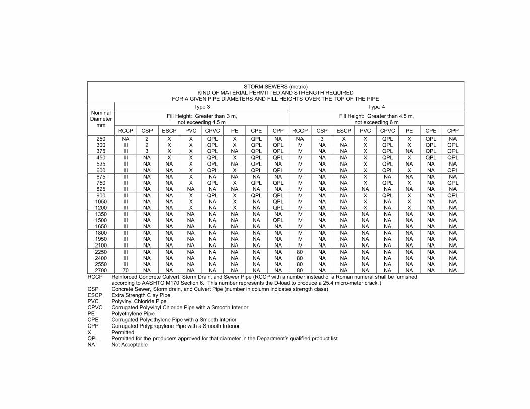
STORM SEWERS (metric) KIND OF MATERIAL PERMITTED AND STRENGTH REQUIRED
FOR A GIVEN PIPE DIAMETERS AND FILL HEIGHTS OVER THE TOP OF THE PIPE
Nominal Diameter
mm
Type 3 Type 4
Fill Height: Greater than 3 m, not exceeding 4.5 m
Fill Height: Greater than 4.5 m, not exceeding 6 m
RCCP CSP ESCP PVC CPVC PE CPE CPP RCCP CSP ESCP PVC CPVC PE CPE CPP 250 NA 2 X X QPL X QPL NA NA 3 X X QPL X QPL NA 300 III 2 X X QPL X QPL QPL IV NA NA X QPL X QPL QPL 375 III 3 X X QPL NA QPL QPL IV NA NA X QPL NA QPL QPL 450 III NA X X QPL X QPL QPL IV NA NA X QPL X QPL QPL 525 III NA NA X QPL NA QPL NA IV NA NA X QPL NA NA NA 600 III NA NA X QPL X QPL QPL IV NA NA X QPL X NA QPL 675 III NA NA X NA NA NA NA IV NA NA X NA NA NA NA 750 III NA NA X QPL X QPL QPL IV NA NA X QPL X NA QPL 825 III NA NA NA NA NA NA NA IV NA NA NA NA NA NA NA 900 III NA NA X QPL X QPL QPL IV NA NA X QPL X NA QPL
1050 III NA NA X NA X NA QPL IV NA NA X NA X NA NA 1200 III NA NA X NA X NA QPL IV NA NA X NA X NA NA 1350 III NA NA NA NA NA NA NA IV NA NA NA NA NA NA NA 1500 III NA NA NA NA NA NA QPL IV NA NA NA NA NA NA NA 1650 III NA NA NA NA NA NA NA IV NA NA NA NA NA NA NA 1800 III NA NA NA NA NA NA NA IV NA NA NA NA NA NA NA 1950 III NA NA NA NA NA NA NA IV NA NA NA NA NA NA NA 2100 III NA NA NA NA NA NA NA IV NA NA NA NA NA NA NA 2250 III NA NA NA NA NA NA NA 80 NA NA NA NA NA NA NA 2400 III NA NA NA NA NA NA NA 80 NA NA NA NA NA NA NA 2550 III NA NA NA NA NA NA NA 80 NA NA NA NA NA NA NA 2700 70 NA NA NA NA NA NA NA 80 NA NA NA NA NA NA NA
RCCP Reinforced Concrete Culvert, Storm Drain, and Sewer Pipe (RCCP with a number instead of a Roman numeral shall be furnished according to AASHTO M170 Section 6. This number represents the D-load to produce a 25.4 micro-meter crack.)
CSP Concrete Sewer, Storm drain, and Culvert Pipe (number in column indicates strength class) ESCP Extra Strength Clay Pipe PVC Polyvinyl Chloride Pipe CPVC Corrugated Polyvinyl Chloride Pipe with a Smooth Interior PE Polyethylene Pipe CPE Corrugated Polyethylene Pipe with a Smooth Interior CPP Corrugated Polypropylene Pipe with a Smooth Interior X Permitted QPL Permitted for the producers approved for that diameter in the Department’s qualified product list NA Not Acceptable

STORM SEWERS KIND OF MATERIAL PERMITTED AND STRENGTH REQUIRED
FOR A GIVEN PIPE DIAMETERS AND FILL HEIGHTS OVER THE TOP OF THE PIPE
Nominal Diameter
in.
Type 5 Type 6 Type 7 Fill Height: Greater than 20',
not exceeding 25' Fill Height: Greater than 25',
not exceeding 30' Fill Height: Greater than 30',
not exceeding 35' RCCP PVC CPVC PE CPE CPP RCCP PVC CPVC PE RCCP PVC CPVC PE
10 NA X QPL X QPL NA NA X QPL X NA X QPL X 12 IV X QPL X QPL QPL V X QPL X V X QPL X 15 IV X QPL NA NA QPL V X QPL NA V X QPL NA 18 IV X QPL X NA NA V X QPL X V X QPL X 21 IV X QPL NA NA NA V X QPL NA V X QPL NA 24 IV X QPL X NA NA V X QPL X V X QPL X 27 IV X NA NA NA NA V X NA NA V X NA NA 30 IV X QPL X NA QPL V X QPL X V X QPL X 33 IV NA NA NA NA NA V NA NA NA V NA NA NA 36 IV X QPL X NA NA V X QPL X V X QPL X 42 IV X NA X NA NA V X NA X V X NA X 48 IV X NA X NA NA V X NA X V X NA X 54 IV NA NA NA NA NA V NA NA NA V NA NA NA 60 IV NA NA NA NA NA V NA NA NA V NA NA NA 66 IV NA NA NA NA NA V NA NA NA V NA NA NA 72 V NA NA NA NA NA V NA NA NA V NA NA NA 78 2020 NA NA NA NA NA 2370 NA NA NA 2730 NA NA NA 84 2020 NA NA NA NA NA 2380 NA NA NA 2740 NA NA NA 90 2030 NA NA NA NA NA 2390 NA NA NA 2750 NA NA NA 96 2040 NA NA NA NA NA 2400 NA NA NA 2750 NA NA NA
102 2050 NA NA NA NA NA 2410 NA NA NA 2760 NA NA NA 108 2060 NA NA NA NA NA 2410 NA NA NA 2770 NA NA NA
RCCP Reinforced Concrete Culvert, Storm Drain, and Sewer Pipe (RCCP with a number instead of a Roman numeral shall be furnished according to AASHTO M170 Section 6. This number represents the D-load to produce a 0.01 in crack.)
PVC Polyvinyl Chloride Pipe CPVC Corrugated Polyvinyl Chloride Pipe with a Smooth Interior PE Polyethylene Pipe CPE Corrugated Polyethylene Pipe with a Smooth Interior CPP Corrugated Polypropylene Pipe with a Smooth Interior X Permitted QPL Permitted for the producers approved for that diameter in the Department’s qualified product list NA Not Acceptable

STORM SEWERS (metric) KIND OF MATERIAL PERMITTED AND STRENGTH REQUIRED
FOR A GIVEN PIPE DIAMETERS AND FILL HEIGHTS OVER THE TOP OF THE PIPE
Nominal Diameter
mm
Type 5 Type 6 Type 7 Fill Height: Greater than 6 m,
not exceeding 7.5 m Fill Height: Greater than 7.5 m,
not exceeding 9 m Fill Height: Greater than 9 m,
not exceeding 10.5 m RCCP PVC CPVC PE CPE CPP RCCP PVC CPVC PE RCCP PVC CPVC PE
250 NA X QPL X QPL NA NA X QPL X NA X QPL X 300 IV X QPL X QPL QPL V X QPL X V X QPL X 375 IV X QPL NA NA QPL V X QPL NA V X QPL NA 450 IV X QPL X NA NA V X QPL X V X QPL X 525 IV X QPL NA NA NA V X QPL NA V X QPL NA 600 IV X QPL X NA NA V X QPL X V X QPL X 675 IV X NA NA NA NA V X NA NA V X NA NA 750 IV X QPL X NA QPL V X QPL X V X QPL X 825 IV NA NA NA NA NA V NA NA NA V NA NA NA 900 IV X QPL X NA NA V X QPL X V X QPL X
1050 IV X NA X NA NA V X NA X V X NA X 1200 IV X NA X NA NA V X NA X V X NA X 1350 IV NA NA NA NA NA V NA NA NA V NA NA NA 1500 IV NA NA NA NA NA V NA NA NA V NA NA NA 1650 IV NA NA NA NA NA V NA NA NA V NA NA NA 1800 V NA NA NA NA NA V NA NA NA V NA NA NA 1950 100 NA NA NA NA NA 110 NA NA NA 130 NA NA NA 2100 100 NA NA NA NA NA 110 NA NA NA 130 NA NA NA 2250 100 NA NA NA NA NA 110 NA NA NA 130 NA NA NA 2400 100 NA NA NA NA NA 120 NA NA NA 130 NA NA NA 2550 100 NA NA NA NA NA 120 NA NA NA 130 NA NA NA 2700 100 NA NA NA NA NA 120 NA NA NA 130 NA NA NA
RCCP Reinforced Concrete Culvert, Storm Drain, and Sewer Pipe (RCCP with a number instead of a Roman numeral shall be furnished according to AASHTO M170 Section 6. This number represents the D-load to produce a 25.4 micro-meter crack.)
PVC Polyvinyl Chloride Pipe CPVC Corrugated Polyvinyl Chloride Pipe with a Smooth Interior PE Polyethylene Pipe CPE Corrugated Polyethylene Pipe with a Smooth Interior CPP Corrugated Polypropylene Pipe with a Smooth Interior X Permitted QPL Permitted for the producers approved for that diameter in the Department’s qualified product list NA Not Acceptable”

Revise the first paragraph of Article 1040.03 of the Standard Specifications to read:
“ 1040.03 Polyvinyl Chloride (PVC) Pipe. Acceptance testing of PVC pipe and fittings shall be accomplished during the same construction season in which they are installed. The pipe shall meet the following additional requirements.” Revise Article 1040.04(b) of the Standard Specifications to read:
“ (b) Corrugated PE Pipe with a Smooth Interior. The manufacturer shall be listed as compliant through the NTPEP program and the pipe shall be according to AASHTO M 294 (nominal size – 12 to 60 in. (300 to 1500 mm)). The pipe shall be Type S or D.”
Revise the first paragraph of Article 1040.04(d) of the Standard Specifications to read:
“ (d) PE Pipe with a Smooth Interior. The pipe shall be according to ASTM F 714 (DR 32.5) with a minimum cell classification of PE 335434 as defined in ASTM D 3350.”
Revise the first paragraph of Article 1040.08 of the Standard Specifications to read:
“ 1040.08 Polypropylene (PP) Pipe. Storage and handling shall be according to the manufacturer's recommendations, except in no case shall the pipe be exposed to direct sunlight for more than six months. Acceptance testing of the pipe shall be accomplished during the same construction season in which it is installed. The pipe shall meet the following additional requirements.” 80434

To: Regional Engineers
From: Jack A. Elston, P.E.
Subject: Special Provision for Surface Testing of Pavements – IRI
Date: October 1, 2021
This special provision was developed by the Bureau of Research to change surface testing requirements to the International Roughness Index (IRI), add a new Illinois Test Procedure and improve quality assurance (QA) testing methods. It has been revised to increase the number of days the Contractor has to measure the smoothness of the pavement, to add jobsite volumetric sampling locations to the list of miscellaneous pavements, to clarify when corrective work is required, to allow HMA removal depth to be varied slightly in order to satisfy smoothness requirements, to bring straightedge equipment specs back in from the test procedure, and to work with the 2022 Standard Specifications.
This special provision should be inserted with contracts involving portland cement concrete pavement, hot-mix asphalt pavement (full-depth), or HMA overlays with a minimum of 2.00 inches total thickness of new HMA material and at least two activities. An activity is defined as either milling or a lift of HMA (binder or surface).
The districts should include the BDE Check Sheet marked with the applicable special provisions for the January 21, 2022 and subsequent lettings. The Project Coordination and Implementation Section will include a copy in the contract.
80435m

SURFACE TESTING OF PAVEMENTS – IRI (BDE) Effective: January 1, 2021 Revised: January 1, 2022 Description. This work shall consist of testing the ride quality of the finished surface of pavements, according to Illinois Test Procedure 701, “Ride Quality Testing Using the International Roughness Index (IRI)”. Work shall be according to Sections 406, 407, or 420 of the Standard Specifications, except as modified herein. Hot-Mix Asphalt (HMA) Overlays Add Article 406.03(n) to the Standard Specifications:
“ (n) Pavement Surface Grinding Equipment ............................................................... 1101.04” Revise Article 406.11 of the Standard Specifications to read:
“406.11 Surface Tests. Prior to pavement improvements, the Engineer will measure the smoothness of the existing high-speed mainline pavement. The Contractor shall measure the smoothness of the finished high-speed mainline, low-speed mainline, and miscellaneous pavements within seven days of paving. Testing shall be performed in the presence of the Engineer and according to Illinois Test Procedure 701. The pavement will be identified as high-speed mainline, low-speed mainline, or miscellaneous as follows.
(a) Test Sections
(1) High-Speed Mainline Pavement. High-speed mainline pavement shall consist of pavements, ramps, and loops with a posted speed limit greater than 45 mph. These sections shall be tested with an inertial profiling system (IPS).
(2) Low-Speed Mainline Pavement. Low-speed mainline pavement shall consist of
pavements, ramps, and loops with a posted speed limit of 45 mph or less. These sections shall be tested with an IPS and will be analyzed using the rolling 16 ft (5 m) straightedge simulation in ProVAL.
(3) Miscellaneous Pavement. Miscellaneous pavement includes segments that either
cannot readily be tested by an IPS or conditions beyond the control of the contractor preclude the achievement of smoothness levels typically achievable with mainline pavement construction. This may include the following examples or as determined by the Engineer.
(a) Pavement on horizontal curves with a centerline radius of curvature of less than or
equal to 1,000 ft (300 m) and the pavement within the superelevation transition of such curves;

(b) Pavement on vertical curves having a length less than or equal to 200 ft (60 m) in
combination with an algebraic change in tangent grade greater than or equal to 3 percent as may occur on urban ramps or other constricted-space facilities;
(c) The first and last 50 ft (15 m) of a pavement section where the Contractor is not
responsible for the adjoining surface;
(d) Intersections and the 25 ft (7.6 m) before and after an intersection or end of radius return;
(e) Variable width pavements;
(f) Side street returns, to the end of radius return;
(g) Crossovers;
(h) Connector pavement from the mainline pavement expansion joint to the bridge
approach slab;
(i) Bridge approach slab;
(j) Pavement that must be constructed in multiple short segments, typically defined as 600 ft (180 m) or less;
(k) Pavement within 25 ft (7.6 m) of manholes, utility structures, or other
appurtenances;
(l) Turn lanes; and (m) Pavement within 5 ft (1.5 m) of jobsite sampling locations for HMA volumetric
testing that fall within the wheel path.
Miscellaneous pavement shall be tested using a 16 ft (5 m) straightedge.
(4) International Roughness Index (IRI). An index computed from a longitudinal profile measurement using a quarter-car simulation at a simulation speed of 50 mph (80 km/h).
(5) Mean Roughness Index (MRI). The average of the IRI values for the right and left
wheel tracks. (6) Areas of Localized Roughness (ALR). Isolated areas of roughness, which can cause
significant increase in the calculated MRI for a given sublot.

(7) Lot. A lot will be defined as a continuous strip of pavement 1 mile (1,600 m) long and one lane wide. When the length of a continuous strip of pavement is less than 1 mile (1,600 m), that pavement will be included in an adjacent lot. Structures will be omitted when measuring pavement length, but will not be considered as a discontinuity and the numbering of sublots will not restart. The limits of the structure shall include the entire length between the outside ends of both connector pavements.
(8) Sublot. Lots will be divided into 0.1 mile (160 m) sublots. A partial sublot greater than
or equal to 264 ft (80 m) resulting from an interruption in the pavement will be subject to the same evaluation as a whole sublot. Partial sublots less than 264 ft (80 m) shall be included with the previous sublot for evaluation purposes.
(b) Corrective Work. Corrective work shall be completed according to the following.
(1) High-Speed Mainline Pavement. For high-speed mainline pavement, any 25 ft (7.6 m)
interval with an ALR in excess of 150 in./mile (2,400 mm/km) will be identified by the Engineer and shall be corrected by the Contractor. Any sublot having a MRI greater than MRID, including ALR, shall be corrected to reduce the MRI to the MRIF, or replaced at the Contractor’s option.
(2) Low-Speed Mainline Pavement. Bumps in low-speed mainline pavement which exceed the 5/16 in. (8 mm) tolerance using a simulated 16 ft (5 m) straightedge will be identified by the Engineer and shall be corrected by the Contractor.
(3) Miscellaneous Pavements. Bumps in miscellaneous pavement which exceed the 5/16 in. (8 mm) tolerance on a 16 ft (5 m) straightedge will be identified by the Engineer and shall be corrected by the Contractor.
Corrective work shall be completed with pavement surface grinding equipment or by removing and replacing the pavement. Corrective work shall be applied to the full lane width. When completed, the corrected area shall have uniform texture and appearance, with the beginning and ending of the corrected area normal to the centerline of the paved surface. Upon completion of the corrective work, the surface of the sublot(s) shall be retested. The Contractor shall furnish the data and reports to the Engineer within 2 working days after corrections are made. If the MRI and/or ALR still do not meet the requirements, additional corrective work shall be performed. Corrective work shall be at no additional cost to the Department.
(c) Smoothness Assessments. Assessments will be paid to or deducted from the Contractor
for each sublot of high-speed mainline pavement per the Smoothness Assessment Schedule. Assessments will be based on the MRI of each sublot prior to performing any corrective work unless the Contractor has chosen to remove and replace the sublot. For

sublots that are replaced, assessments will be based on the MRI determined after replacement. The upper MRI thresholds for high-speed mainline pavement are dependent on the MRI of the existing pavement before construction (MRI0) and shall be determined as follows.
Upper MRI Thresholds 1/ MRI Thresholds (High-Speed, HMA Overlay)
MRI0 ≤ 125.0 in./mile (≤ 1,975 mm/km)
MRI0 > 125.0 in./mile 1/ (> 1,975 mm/km)
Incentive (MRII) 45.0 in./mile (710 mm/km) 0.2 × MRI0 + 20 Full Pay (MRIF) 75.0 in./mile (1,190 mm/km) 0.2 × MRI0 + 50 Disincentive (MRID) 100.0 in./mile (1,975 mm/km) 0.2 × MRI0 + 75
1/ MRI0, MRII, MRIF, and MRID shall be in in./mile for calculation.
Smoothness assessments for high-speed mainline pavement shall be determined as follows.
SMOOTHNESS ASSESSMENT SCHEDULE (High-Speed, HMA Overlay)
Mainline Pavement MRI Range Assessment Per Sublot 1/
MRI ≤ MRII + (MRII – MRI) × $33.00 2/ MRII < MRI ≤ MRIF + $0.00 MRIF < MRI ≤ MRID – (MRI – MRIF) × $20.00
MRI > MRID – $500.00
1/ MRI, MRII, MRIF, and MRID shall be in in./mile for calculation. 2/ The maximum incentive amount shall not exceed $500.00.
Smoothness assessments will not be paid or deducted until all other contract requirements for the pavement are satisfied. Pavement that is corrected or replaced for reasons other than smoothness, shall be retested as stated herein.”
Hot-Mix Asphalt (HMA) Pavement (Full-Depth) Revise the first paragraph of Article 407.03 of the Standard Specifications to read:
“407.03 Equipment. Equipment shall be according to Article 406.03.” Revise Article 407.09 of the Standard Specifications to read:
“407.09 Surface Tests. The finished surface of the pavement shall be tested for smoothness

according to Article 406.11, except as follows: The testing of the existing pavement prior to improvements shall not apply and the
smoothness assessment for high-speed mainline pavement shall be determined according to the following table.
SMOOTHNESS ASSESSMENT SCHEDULE (High-Speed, Full-Depth HMA)
Mainline Pavement MRI, in./mile (mm/km) Assessment Per Sublot 1/
≤ 45.0 (710) + (45 – MRI) × $80.00 2/ > 45.0 (710) to 75.0 (1,190) + $0.00
> 75.0 (1,190) to 100.0 (1,580) – (MRI – 75) × $30.00 > 100.0 (1,580) – $750.00
1/ MRI shall be in in./mile for calculation. 2/ The maximum incentive amount shall not exceed $1,200.00.”
Portland Cement Concrete Pavement Delete Article 420.03(i) of the Standard Specifications. Revise Article 420.03(j) of the Standard Specifications to read:
“ (i) Coring Machine (Note 1)” Revise Article 420.10 of the Standard Specifications to read:
“ 420.10 Surface Tests. The finished surface of the pavement shall be tested for smoothness according to Article 406.11, except as follows.
The testing of the existing pavement prior to improvements shall not apply. The Contractor
shall measure the smoothness of the finished surface of the pavement after the pavement has attained a flexural strength of 250 psi (3,800 kPa) or a compressive strength of 1,600 psi (20,700 kPa).
Membrane curing damaged during testing shall be repaired as directed by the Engineer at no
additional cost to the Department. (a) Corrective Work. No further texturing for skid resistance will be required for areas
corrected by grinding. Protective coat shall be reapplied to ground areas according to Article 420.18 at no additional cost to the Department. Pavement corrected by removal and replacement, shall be corrected in full panel sizes.

(b) Smoothness Assessments. Smoothness assessment for high-speed mainline pavement shall be determined as follows.
SMOOTHNESS ASSESSMENT SCHEDULE (High-Speed, PCC)
Mainline Pavement MRI, in./mile (mm/km) 3/ Assessment Per Sublot 1/
≤ 45.0 (710) + (45 – MRI) × $120.00 2/ > 45.0 (710) to 75.0 (1,190) + $0.00
> 75.0 (1,190) to 100.0 (1,580) – (MRI – 75) × $45.00 > 100.0 (1,580) – $1,125.00
1/ MRI shall be in in./mile for calculation. 2/ The maximum incentive amount shall not exceed $1,800.00. 3/ If pavement is constructed with traffic in the lane next to it, then an additional
10 in./mile will be added to the upper thresholds.” Removal of Existing Pavement and Appurtenances Revise the first paragraph of Article 440.04 of the Standard Specifications to read:
“ 440.04 HMA Surface Removal for Subsequent Resurfacing. The existing HMA surface shall be removed to the depth specified on the plans with a self-propelled milling machine. The removal depth may be varied slightly at the discretion of the Engineer to satisfy the smoothness requirements of the finished pavement. The temperature at which the work is performed, the nature and condition of the equipment, and the manner of performing the work shall be such that the milled surface is not torn, gouged, shoved or otherwise damaged by the milling operation. Sufficient cutting passes shall be made so that all irregularities or high spots are eliminated to the satisfaction of the Engineer. When tested with a 16 ft (5 m) straightedge, the milled surface shall have no surface variations in excess of 3/16 in. (5 mm).” 80435

To: Regional Engineers
From: Jack A. Elston
Subject: Special Provision for Blended Finely Divided Minerals
Date: January 8, 2021
This special provision was developed by the Central Bureau of Materials to allow blended finely divided minerals in concrete mixes according to ASTM C 1697 in an effort to expand options for procuring finely divided minerals.
This special provision should be inserted into contracts involving any type of concrete work. This includes, but is not limited to, cast-in-place, precast, soil modification, cement aggregate mixture (CAM) II, controlled low-strength material (CLSM), and cellular concrete.
The districts should include the BDE Check Sheet marked with the applicable special provisions for the April 23, 2021 and subsequent lettings. The Project Coordination and Implementation Section will include a copy in the contract.
This special provision will be available on the transfer directory January 8, 2021.
80436m

BLENDED FINELY DIVIDED MINERALS (BDE) Effective: April 1, 2021 Revise the second paragraph of Article 1010.01 of the Standard Specifications to read:
“ Different sources or types of finely divided minerals shall not be mixed or used alternately in the same item of construction, except as a blended finely divided mineral product according to Article 1010.06.” Add the following article to Section 1010 of the Standard Specifications:
“ 1010.06 Blended Finely Divided Minerals. Blended finely divided minerals shall be the product resulting from the blending or intergrinding of two or three finely divided minerals. Blended finely divided minerals shall be according to ASTM C 1697, except as follows.
(a) Blending shall be accomplished by mechanically or pneumatically intermixing the constituent finely divided minerals into a uniform mixture that is then discharged into a silo for storage or tanker for transportation.
(b) The blended finely divided mineral product will be classified according to its predominant constituent or the manufacturer’s designation and shall meet the chemical requirements of its classification. The other finely divided mineral constituent(s) will not be required to conform to their individual standards.”
80436
To: Regional Engineers
From: Jack A. Elston
Subject: Special Provision for Submission of Payroll Records
Date: January 8, 2021
This special provision was developed by the Central Bureau of Construction to update the process for submitting payroll records to the Illinois Department of Labor in accordance with the State Prevailing Wage Act (820 ILCS 130).
This special provision should be inserted into state funded contracts, i.e. contracts with Check Sheet #5 of the Recurring Special Provisions.
The districts should include the BDE Check Sheet marked with the applicable special provisions for the April 23, 2021 and subsequent lettings. The Project Coordination and Implementation Section will include a copy in the contract.
This special provision will be available on the transfer directory January 8, 2021.
80437m

SUBMISSION OF PAYROLL RECORDS (BDE) Effective: April 1, 2021 Revise Item 3 of Section IV of Check Sheet #5 of the Recurring Special Provisions to read:
“ 3. Submission of Payroll Records. The Contractor and each subcontractor shall, no later than the 15th day of each calendar month, file a certified payroll for the immediately preceding month to the Illinois Department of Labor (IDOL) through the Illinois Prevailing Wage Portal in compliance with the State Prevailing Wage Act (820 ILCS 130). The portal can be found on the IDOL website at https://www2.illinois.gov/idol/Laws-Rules/CONMED/Pages/Prevailing-Wage-Portal.aspx. Payrolls shall be submitted in the format prescribed by the IDOL.”
80437

To: Regional Engineers
From: Jack A. Elston
Subject: Special Provision for Illinois Works Apprenticeship Initiative - State Funded Contracts
Date: October 1, 2021
This special provision was created for the Illinois Works Jobs Program Act (30 ILCS 559/20-1 et seq.). It has been revised to base the applicability of the program on the awarded contract value. It has also been revised to give general guidance on the requirements/forms of this initiative, as more detailed information is in Construction Memorandum No. 92.
This special provision should be inserted into all nonfederal-aid contracts.
The districts should include the BDE Check Sheet marked with the applicable special provisions for the January 21, 2022 and subsequent lettings. The Project Coordination and Implementation Section will include a copy in the contract.
80438m

ILLINOIS WORKS APPRENTICESHIP INITIATIVE – STATE FUNDED CONTRACTS (BDE) Effective: June 2, 2021 Revised: September 2, 2021 Illinois Works Jobs Program Act (30 ILCS 559/20-1 et seq.). For contracts having an awarded contract value of $500,000 or more, the Contractor shall comply with the Illinois Works Apprenticeship Initiative (30 ILCS 559/20-20 to 20-25) and all applicable administrative rules. The goal of the Illinois Apprenticeship Works Initiative is that apprentices will perform either 10% of the total labor hours actually worked in each prevailing wage classification or 10% of the estimated labor hours in each prevailing wage classification, whichever is less. The Contractor may seek from the Department of Commerce and Economic Opportunity (DCEO) a waiver or reduction of this goal in certain circumstances pursuant to 30 ILCS 559/20-20(b). The Contractor shall ensure compliance during the term of the contract and will be required to report on and certify its compliance. An apprentice use plan, apprentice hours, and a compliance certification shall be submitted to the Engineer on forms provided by the Department and/or DCEO. 80438

To: Regional Engineers
From: Jack A. Elston
Subject: Special Provision for Waterproofing Membrane System
Date: July 23, 2021
This special provision was developed by the Central Bureau of Materials to update the fine aggregate requirements for waterproofing membrane system. The aggregate no longer has to be dry, and the No. 10 and 16 sieves have been eliminated.
This special provision should be inserted into contracts utilizing the pay item, WATERPROOFING MEMBRANE SYSTEM.
The districts should include the BDE Check Sheet marked with the applicable special provisions for the November 5, 2021 and subsequent lettings. The Project Coordination and Implementation Section will include a copy in the contract.
80440m

WATERPROOFING MEMBRANE SYSTEM (BDE) Effective: November 1, 2021 Revise Article 1061.05 of the Standard Specifications to read:
“ 1061.05 Aggregate for Slurry Seal Top Coat. The aggregate shall meet the requirements of Article 1003.01, be clean, hard, and shall contain a minimum of dust. It shall be graded as follows.
Sieve Size Passing Percent No. 8 (2.36 mm) No. 30 (600 µm)
100 0 – 10”
80440

To: Regional Engineers
From: Jack A. Elston
Subject: Special Provision for Hot-Mix Asphalt
Date: April 22, 2022
This special provision was developed by the Central Bureau of Materials to correct omissions from the 2022 Standard Specifications. This special provision requires Hamburg wheel test (High ESAL mixtures only) and I-FIT samples to be collected at the start of production when 3,000 tons or more of a mixture is to be placed. It was revised to address Quality Control/Quality Assurance Quality Management Program mix quantity overages, small tonnage, and Department density verification test maximum theoretical specific gravity determination. This special provision title was changed from Hot-Mix Asphalt – Start of Production. This special provision should be inserted into all HMA contracts. The districts should include the BDE Check Sheet marked with the applicable special provisions for the August 5, 2022 and subsequent lettings. The Project Coordination and Implementation Section will include a copy in the contract. 80442m

HOT-MIX ASPHALT (BDE) Effective: January 1, 2022 Revised: August 1, 2022 Replace Article 1030.09(g)(1) of the Standard Specifications with the following:
“ (1) The Contractor shall sample approximately 150 lb (70 kg) of mix as required for the Department’s random mixture verification tests according to Article 1030.09(h)(1).”
Replace the second sentence of Article 1030.09(h)(1) of the Standard Specifications with the following:
“ The Engineer will randomly identify one sample for each 3,000 tons (2,720 metric tons) of mix, with a minimum of one sample per mix. If the remaining mix quantity is 600 tons (544 metric tons) or less, the quantity will be combined with the previous 3,000 tons (2,720 metric tons) in the Engineer’s random sample identification. If the required tonnage of a mixture for a single pay item is less than 250 tons (225 metric tons) in total, the Engineer will waive mixture verification tests.”
Add the following to the end of the third paragraph of Article 1030.09(h)(2) of the Standard Specifications:
“ The HMA maximum theoretical specific gravity (Gmm) will be based on the Department mixture verification test. If there is more than one Department mixture verification Gmm test, the Gmm will be based on the average of the Department test results.”
Add the following paragraph between the third and four paragraphs of Article 1030.10 of the Standard Specifications:
“ When a test strip is not required, each HMA mixture with a quantity of 3,000 tons (2,750 metric tons) or more shall still be sampled on the first day of production: I-FIT and Hamburg wheel testing for High ESAL; I-FIT testing for Low ESAL. Within two working days after sampling the mixture, the Contractor shall deliver gyratory cylinders to the District laboratory for Department verification testing. The High ESAL mixture test results shall meet the requirements of Articles 1030.05(d)(3) and 1030.05(d)(4). The Low ESAL mixture test results shall meet the requirements of Article 1030.05(d)(4).” 80442

To: Regional Engineers
From: Jack A. Elston
Subject: Special Provision for High Tension Cable Median Barrier Removal
Date: January 14, 2022
This special provision was developed by the Central Bureau of Operations to address removal and disposal of high tension cable median barrier. This special provision should be inserted into contracts utilizing HIGH TENSION CABLE MEDIAN BARRIER REMOVAL. The districts should include the BDE Check Sheet marked with the applicable special provisions for the April 29, 2022 and subsequent lettings. The Project Coordination and Implementation Section will include a copy in the contract. 80443m

HIGH TENSION CABLE MEDIAN BARRIER REMOVAL (BDE) Effective: April 1, 2022 Replace Section 632 of the Standard Specifications with the following:
“SECTION 632. GUARDRAIL, CABLE ROAD GUARD, AND HIGH TENSION CABLE MEDIAN BARRIER REMOVAL
632.01 Description. This work shall consist of the removal and disposal of existing
guardrail (including traffic barrier terminals), cable road guard, and high tension cable (HTC) median barrier.
CONSTRUCTION REQUIREMENTS
632.02 General. Posts and terminals shall be removed completely or cut off at least 6 in. (150 mm) below the ground surface. Socket foundations shall be removed at least 1 ft (300 mm) below the ground surface. All holes shall be filled and tamped. Pavement or paved mow strip shall be level and free of protrusions or loose pieces greater than 1 in. (25 mm).
HTC median barrier shall be disconnected at the nearest turnbuckle past the removal limits.
Mow strip, anchorage system, and other appurtenances within the removal limits shall be removed.
Materials that are to be salvaged under the contract or which the Engineer deems fit for
reuse shall be removed and stored at locations and in a manner approved by the Engineer. Materials that are not to be salvaged or materials unfit for reuse through no fault of the Contractor shall be removed and disposed of according to Article 202.03.
632.03 Method of Measurement. This work will be measured for payment in feet
(meters), measured from the limits of removal as directed by the Engineer. 632.04 Basis of Payment. This work will be paid for at the contract unit price per foot
(meter) for GUARDRAIL REMOVAL, CABLE ROAD GUARD REMOVAL, or HIGH TENSION CABLE MEDIAN BARRIER REMOVAL.” 80443

To: Regional Engineers
From: Jack A. Elston
Subject: Special Provision for Hot-Mix Asphalt – Patching
Date: January 14, 2022
This special provision was developed by the Central Bureau of Materials to correct density testing references for HMA patching in the 2022 Standard Specifications. This special provision should be inserted into contracts with CLASS D PATCHES or PAVEMENT PATCHING. The districts should include the BDE Check Sheet marked with the applicable special provisions for the April 29, 2022 and subsequent lettings. The Project Coordination and Implementation Section will include a copy in the contract. 80444m

HOT-MIX ASPHALT – PATCHING (BDE) Effective: April 1, 2022 Replace Article 442.08(b) of the Standard Specifications with the following:
“ (b) Density. The density of the compacted HMA shall be according to Articles 1030.06, 1030.09(b), 1030.09(c), and 1030.09(f).”
80444
Copyright © 2022 FDOKUMEN