SPECIAL PROVISIONS | NJ.gov
317
ROUTE 1&9T(25) Page 1 CONTRACT NO. 003970114 HUDSON COUNTY SPECIAL PROVISIONS ROUTE 1&9T(25) ST. PAUL’S AVE. BRIDGE GRADING, PAVING AND STRUCTURES CITY OF JERSEY CITY, HUDSON COUNTY FEDERAL PROJECT NUMBER BR-0046(116) AUTHORIZATION OF CONTRACT The Contract for this Project is authorized by the provisions of Title 27 of the Revised Statutes of New Jersey and supplements thereto, and Title 23 of the United States Code - Highways. SPECIFICATIONS TO BE USED The 2001 Metric Standard Specifications for Road and Bridge Construction, of the New Jersey Department of Transportation as amended herein will govern the construction of this Project and the execution of the Contract. These Special Provisions consist of the following: Pages 1 to 317 inclusive for General, Road, and Bridge Provisions. Required Contract Provisions, Federal-Aid Construction Contracts (Form FHWA-1273) pages 1 to 10 inclusive, dated January 2007. Standard Federal Equal Employment Opportunity Construction Contract Specifications (Executive Order 11246), pages 1 to 5 inclusive, dated January 2007. Notice of Requirement for Affirmative Action to Ensure Equal Employment Opportunity (Executive Order 11246), pages 1 and 2, dated January 2007. State of New Jersey Equal Employment Opportunity for Contracts Funded by FHWA, page 1, dated January 2007. Emerging Small Business Enterprise Utilization Attachment, FHWA Funded Contracts, pages 1 to 7 inclusive, dated January 2007. Equal Employment Opportunity Special Provisions, pages 1 to 11 inclusive, dated January 2007. Special Contract Provisions for Investigating, Reporting, and Resolving Employment Discrimination and Sexual Harassment Complaints, pages 1 and 2 inclusive, dated January 2007. Specifications for Pipeline Occupancy on New Jersey Transit Property, EP-2 (including General Requirements for Working Within the Right-of-Way) – dated June 18, 2001 – 42 pages Requirements for Temporary Sheeting and Shoring to Support New Jersey Transit Rail Operations, Inc. Tracks - not dated - 4 pages Specifications for Wire, Conduit and Cable Occupations of Consolidated Rail Corporation Property, CE-4 - dated November 12, 1990 - 12 pages Specific Requirements of Consolidated Rail Corporation for Work on Its Right of Way, CE-6– dated February 1, 1997 -15 pages Specifications for Pipeline Occupancy of Consolidated Rail Corporation Property, CE-8 - dated May 1, 1995 - 39 pages Route 1&9T(25) – ITS Specifications – dated March 2008 – 144 pages General wage determinations issued under Davis-Bacon and related acts, published by US Department of Labor, may be obtained from the Davis-Bacon web site at http://www.access.gpo.gov/davisbacon/nj.html under the appropriate county, select the construction type heading: HIGHWAY. The Contractor shall pay the minimum wage rates determined by the United States Secretary of Labor and the New Jersey Department of Labor. If the minimum wage rate prescribed for any craft by the United States Secretary of Labor is not the same as the minimum wage rate prescribed for that craft by the New Jersey Department of Labor, the higher rate shall be the rate paid. State wage rates may be obtained from the New Jersey Department of Labor (Telephone: 609-292-2259) or by accessing the Department of Labor’s web site at http://www.nj.gov/labor/lsse/lspubcon.html The State wage rates in effect at the time of award will be made a part of this Contract, pursuant to Chapter 150, Laws of 1963 (NJSA 34:11- 56.25, et seq.). In the event it is found that any employee of the Contractor or any subcontractor covered by the Contract, has been paid a rate of wages less than the minimum wage required to be paid by the Contract, the State may terminate the Contractor’s or subcontractor’s right to proceed with the Work, or such part of the Work, as to which there has been a
-
Upload
khangminh22 -
Category
Documents
-
view
4 -
download
0
Transcript of SPECIAL PROVISIONS | NJ.gov

ROUTE 1&9T(25) Page 1 CONTRACT NO. 003970114 HUDSON COUNTY
SPECIAL PROVISIONS
ROUTE 1&9T(25) ST. PAUL’S AVE. BRIDGE GRADING, PAVING AND STRUCTURES
CITY OF JERSEY CITY, HUDSON COUNTY FEDERAL PROJECT NUMBER BR-0046(116)
AUTHORIZATION OF CONTRACT The Contract for this Project is authorized by the provisions of Title 27 of the Revised Statutes of New Jersey and
supplements thereto, and Title 23 of the United States Code - Highways.
SPECIFICATIONS TO BE USED The 2001 Metric Standard Specifications for Road and Bridge Construction, of the New Jersey Department of
Transportation as amended herein will govern the construction of this Project and the execution of the Contract. These Special Provisions consist of the following:
Pages 1 to 317 inclusive for General, Road, and Bridge Provisions.
Required Contract Provisions, Federal-Aid Construction Contracts (Form FHWA-1273) pages 1 to 10 inclusive,
dated January 2007. Standard Federal Equal Employment Opportunity Construction Contract Specifications (Executive Order 11246),
pages 1 to 5 inclusive, dated January 2007. Notice of Requirement for Affirmative Action to Ensure Equal Employment Opportunity (Executive Order 11246),
pages 1 and 2, dated January 2007. State of New Jersey Equal Employment Opportunity for Contracts Funded by FHWA, page 1, dated January 2007. Emerging Small Business Enterprise Utilization Attachment, FHWA Funded Contracts, pages 1 to 7 inclusive,
dated January 2007. Equal Employment Opportunity Special Provisions, pages 1 to 11 inclusive, dated January 2007. Special Contract Provisions for Investigating, Reporting, and Resolving Employment Discrimination and Sexual
Harassment Complaints, pages 1 and 2 inclusive, dated January 2007. Specifications for Pipeline Occupancy on New Jersey Transit Property, EP-2 (including General Requirements for
Working Within the Right-of-Way) – dated June 18, 2001 – 42 pages Requirements for Temporary Sheeting and Shoring to Support New Jersey Transit Rail Operations, Inc. Tracks -
not dated - 4 pages Specifications for Wire, Conduit and Cable Occupations of Consolidated Rail Corporation Property, CE-4 - dated
November 12, 1990 - 12 pages Specific Requirements of Consolidated Rail Corporation for Work on Its Right of Way, CE-6– dated February 1,
1997 -15 pages Specifications for Pipeline Occupancy of Consolidated Rail Corporation Property, CE-8 - dated May 1, 1995 - 39
pages Route 1&9T(25) – ITS Specifications – dated March 2008 – 144 pages General wage determinations issued under Davis-Bacon and related acts, published by US Department of Labor,
may be obtained from the Davis-Bacon web site at http://www.access.gpo.gov/davisbacon/nj.html under the appropriate county, select the construction type heading: HIGHWAY.
The Contractor shall pay the minimum wage rates determined by the United States Secretary of Labor and the New Jersey Department of Labor. If the minimum wage rate prescribed for any craft by the United States Secretary of Labor is not the same as the minimum wage rate prescribed for that craft by the New Jersey Department of Labor, the higher rate shall be the rate paid.
State wage rates may be obtained from the New Jersey Department of Labor (Telephone: 609-292-2259) or by accessing the Department of Labor’s web site at http://www.nj.gov/labor/lsse/lspubcon.html The State wage rates in effect at the time of award will be made a part of this Contract, pursuant to Chapter 150, Laws of 1963 (NJSA 34:11-56.25, et seq.).
In the event it is found that any employee of the Contractor or any subcontractor covered by the Contract, has been paid a rate of wages less than the minimum wage required to be paid by the Contract, the State may terminate the Contractor’s or subcontractor’s right to proceed with the Work, or such part of the Work, as to which there has been a

ROUTE 1&9T(25) Page 2 CONTRACT NO. 003970114 HUDSON COUNTY
failure to pay required wages and to prosecute the Work to completion or otherwise. The Contractor and its sureties shall be liable to the State for any excess costs occasioned thereby.
ROUTE 1&9T(25) Page 3 CONTRACT NO. 003970114 HUDSON COUNTY
DIVISION 100 - GENERAL PROVISIONS
SECTION 101 - GENERAL INFORMATION
101.01 General. THE FOLLOWING IS ADDED:
Pursuant to NJSA 27:1B-21.6 and USC (United States Code) Section 115, the Commissioner intends to enter into an advanced construction contract for the advancement of the Project. Although the advanced construction contract will pledge funds anticipated to be appropriated for the Project by the Legislature, payment of the moneys pledged is subject to the availability of funds in the fiscal year (FY) in which the funds are to be appropriated. Only amounts appropriated by law may be expended.
The Commissioner intends to proceed expeditiously with the Project. However, there is no assurance that the Annual Appropriations Act will contain an appropriation or that the Federal Government will approve or provide federal funding for the Project. The Legislature has no legal obligation to make such an appropriation. Failure by the Legislature to appropriate funds or failure by the Federal Government to approve or provide federal funding sufficient to advance the Project will not constitute a default under, or breach of, any contract entered into by the State for the construction of the Project. However, if the State terminates the Contract or suspends work under the Contract because the Legislature has failed to appropriate or the Federal Government has failed to provide or approve sufficient funding to advance the Project, the parties to the Contract will retain their rights pursuant to the suspension of work and termination of Contract Provisions of the Project specifications; except as indicated below.
The Contractor shall not expend or cause to be expended any sum in excess of the amount allocated in the current fiscal year's Capital Program (as specified below). The Department will notify the Contractor when each level of additional funding has been appropriated by the Legislature or approved or provided by the Federal Government. Any expenditure by the contractor which exceeds the amount actually appropriated or exceeds the amount of approved federal funding is at the Contractor's risk and the Contractor waives any right to recover any sum in excess of that appropriated amount or the amount approved or provided by the Federal Government even if the State terminates or suspends work under the Contract because the Legislature has failed to appropriate or the Federal Government has not provided or approved sufficient funds to advance the Project.
The approved 2008 Capital Program has an item with $ 21 million for the construction of the Project. It is anticipated that 65.5million dollars in additional funds will be provided during Federal FY 2009. It is further anticipated that the balance of the funds necessary to complete the Project will be provided during
Federal Fiscal Years 2010 and 2011. It should be noted that the Federal FY begins October 1 of the previous calendar year and that the State FY begins
July 1 of the previous calendar each year. 101.03 Terms. THE FIRST SENTENCE IS CHANGED TO:
When the following terms are used in the Contract Documents, the intent and meaning shall be strictly construed as follows: THE FOLLOWING TERMS ARE ADDED: ADDITIONAL COMPENSATION. A monetary payment(s), sought by the Contractor, premised upon (1.) an
adjustment or modification to the Contract pay item(s) for particular work or (2.) any or all forms of compensation over and above that which is specifically provided under the various individual Contract Pay Items or Contract payment provisions.
COMPLETION OF THE CONTRACT. The event termed “Completion of the Contract”, under the Specifications and
the Contractual Liability Act NJSA 59:13-1 et seq., shall be deemed to have occurred as of the date the Contractor accepts or accepts with reservation of specific claims, in writing in accord with forms supplied by the Department, the Final Certificate issued by the Department or the 31st day after issuance of said Final Certificate by the Department, whichever event may be the first to occur.

ROUTE 1&9T(25) Page 4 CONTRACT NO. 003970114 HUDSON COUNTY
CLAIM. The Contractor has reason to believe it is entitled to additional compensation and/or an extension of contract
time, in accordance with and subject to the Contract Documents and the provisions of the Contractual Liability Act, N.J.S.A. 59:13-1 et seq., arising out of or relating to the happening of an event, thing or occurrence or an act or failure to act by the Engineer. A claim accrues when it arises, meaning when a situation or occurrence takes place or comes about which has or possesses the potential to support or become the basis for additional compensation and/or an extension of time.
DISPUTE (AS TO A CLAIM). A disagreement between the Department and the Contractor with regard to the Work or
Contract Documents arising out of a claim by the Contractor for additional compensation or an extension of time. FINAL CERTIFICATE. It is the final payment document that sets forth the total amount payable to the Contractor,
including therein an itemization of said amount segregated as to Pay Item quantities, Extra Work, and any other basis for payment; it also includes therein any retainage to be released and all deductions made or to be made from prior payments as required pursuant to the provisions of the Contract Documents, which may result in either a Final Payment to the Contractor or a Credit (payment) due the Department.
NON-BINDING MEDIATION. The fourth and final step in the Department’s Contractual Claim Resolution Process for
claims arising under the Contract utilizing a non-binding mediation forum wherein an independent mediator is engaged in an attempt to resolve a claim presented by a Contractor.
PARCEL. Property to be acquired for transportation purposes, described by metes and bounds. SECRETARY, DEPARTMENT CLAIMS COMMITTEE. The individual employed by the Department who gathers
information and provides administrative assistance to the members of the Department Claims Committee. This individual is the conduit between the Department Claims Committee members and the Contractor. Contact by the Contractor regarding any issue involving the Claims Committee or Mediation shall be through the Secretary.
THE FOLLOWING TERMS ARE CHANGED: THE THIRD ITEM LISTED UNDER THE TERM “COMPLETION” IS CHANGED TO:
3. the Contractor has satisfactorily executed and delivered to the Engineer all documents, which is to include the federal form FHWA-47 “Contractor’s Statement of Materials and Labor” according to 23CFR 635, for Federal Funded Projects, certifications, and proofs of compliance required by the Contract Documents, it being understood that the satisfactory execution and delivery of said documents, certificates, and proofs of compliance is a requirement of the Contract.
DEPARTMENT CLAIMS COMMITTEE. A contractual body available to review and resolve claims that arise under
the Contract. The Committee consists of three voting members with the Director of Design Services as the chairperson, one member is the Department’s Chief Financial Office, and one member is selected from the other directors within Capital Program Management. Additional non-voting members are a Deputy Attorney General, the Secretary of the Department Claims Committee, and a member of the Federal Highway Administration (for federally funded projects).
DESIGN UNIT. The term “Design Unit” means the Department’s consultant engineering firm, the in-house design
unit(s), or both that prepared the Contract Documents for a project. The design unit(s) for any particular project shall be as designated by letter to the awarded Contractor.
EXTREME WEATHER CONDITIONS. When, solely as a result of adverse weather, the Contractor is not able to work,
the Contractor is entitled to claim that progress of the Work has been affected by extreme weather conditions and may seek an extension of Contract Time consistent with the provisions of Subsection 108.11.

ROUTE 1&9T(25) Page 5 CONTRACT NO. 003970114 HUDSON COUNTY
HOT MIX ASPHALT (HMA) PAVEMENT. The combination of base course, intermediate course, and surface course of hot mix asphalt.
ON-DUTY POLICE. The term “on-duty” with regard to municipal police shall mean that the work of providing traffic
safety services shall be an extension of regular employment for, and sanctioned by, the municipality, even if it is on an overtime pay rate basis. The municipal police, while so working, shall be covered by the municipality’s liability insurance coverage; and must have successfully completed a traffic safety program approved by the Department.
PAVEMENT STRUCTURE. The combination of surface, intermediate and base courses, and when specified, a subbase
course, placed on a subgrade to support the traffic load and distribute it to the roadbed (see Figure 101-1). These various courses are defined as follows:
1. Surface Course. One or more layers of specified material of designed thickness at the top of the pavement structure.
2. Intermediate Course. One or more layers of specified material of designed thickness placed on the base course.
3. Base Course. One or more layers of specified material of designed thickness placed on the subgrade or subbase.
4. Subbase. One or more layers of specified material of designed thickness placed on the subgrade. PLANS. The approved plans, profiles, typical sections, cross-sections, approved working drawings, and supplemental
drawings, or exact reproductions thereof, which show the location, character, dimensions, quantities, and details of the Work to be done. This includes the latest version of all Standard Construction Details in effect at the time of Advertisement. Certified working drawings are not plans and not part of the Contract Documents.
PROPOSAL: The term “Proposal” means the offer of a Bidder, properly signed and guaranteed, to perform the Work for
the prices quoted therein. PROPOSAL FORM: The term “Proposal form” means the Department approved proposal form produced from the
Expedite software downloaded from the Department’s Bid Express web site at http://www.bidx.com, prepared and submitted for the Work.
REGIONAL DISPUTE BOARD. A three-member Board, comprised of one member from the Division of Project
Management, one member from the Bureau of Construction Engineering, and the Regional Construction Engineer (Chairperson), that is available under the terms of the Contract to review Disputes which have not been resolved by the Resident Engineer.
REMEDIATE. The term “remediate” means the process that is approved by the New Jersey Department of
Environmental Protection to address all regulated discharges. SPECIFICATIONS. The compilation of provisions and requirements for the performance of prescribed work contained
in the Standard Specifications, as supplemented by the Supplemental Specifications and Special Provisions, and modified by Addenda which, before the receipt of bids, are transmitted to prospective Bidders.
1. Standard Specifications. The term “Standard Specifications” means the 2001 Standard Specifications for Road and Bridge Construction of the New Jersey Department of Transportation, which has been approved for general application and repetitive use.
2. Supplemental Specifications. Approved additions and revisions to the Standard Specifications. 3. Special Provisions. Revisions to the Standard and Supplemental Specifications applicable to an
individual project. 4. Electrical Materials Specifications. Approved standards for electrical materials, equipment, and
installations that are in addition to the above specifications. SUBSTANTIAL COMPLETION. The term “Substantial Completion” means the point at which the performance of all
Work on the Project has been completed except landscaping items (including the planting of trees, shrubs, vines, ground covers, and seedlings), final cleanup, and repair of unacceptable work, and provided the Engineer has solely determined that:
1. the Project is safe and convenient for use by the public, and

ROUTE 1&9T(25) Page 6 CONTRACT NO. 003970114 HUDSON COUNTY
2. failure to complete the Work and repairs excepted above does not result in the deterioration of other completed Work; and provided further, that the value of landscaping work remaining to be performed, repairs, and cleanup is less than two percent of the Total Adjusted Contract Price.
THE FOLLOWING TERMS ARE DELETED: ADDENDA COMPUTER DISK CLAIMS REVIEW BOARD DISPUTE 101.04 Inquiries Regarding the Project. THE FOLLOWING IS ADDED:
Inquiries regarding the various types of work of this Contract shall be directed to the following representatives of the Department having offices at P.O. Box 600, Trenton, New Jersey 08625, or such other individuals as may hereafter be designated:
1 Before Award of the Contract. All inquiries shall be e-mailed directly to the Bureau of Quality Assurance at [email protected]
All inquiries shall include the following:
a. Name of the company; b. Contract number and project description c. Specifics of the inquiry, including anticipated impacts.
The deadline for submitting inquiries will be 12:00 noon on the 3rd STATE BUSINESS DAY prior to the bid date.
The Department will investigate the information provided in the inquiry and then respond through an addendum only.
Requests for postponement of bids will not receive a response. The Department will issue an addendum postponing bids if warranted.
2. After Award of the Contract. All inquiries shall be directed to the Resident Engineer through the following
Regional Construction Office:
North Mr. Carl F. Kneidinger, Regional Construction Engineer 200 Stierli Court Mt. Arlington, NJ 07856-1322 Telephone: 973-770-5025
SECTION 102 - BIDDING REQUIREMENTS AND CONDITIONS
THE ENTIRE SECTION IS CHANGED TO: 102.01 Qualifications to Bid.
The Department will not accept bids from Bidders who fail to meet all of the following criteria:

ROUTE 1&9T(25) Page 7 CONTRACT NO. 003970114 HUDSON COUNTY
1. The Bidder has been prequalified according to Regulations Covering the Classification of Prospective Bidders as required by N.J.S.A. 27:7-35.1 et seq.
2. Before delivery of the bid the Bidder has disclosed ownership as required by N.J.S.A. 52:25-24.2. 3. At the time the bid is delivered, the Bidder has an effective maximum and project ratings of not less than the
amount of its bid. 4. If the Bidder is a corporation not incorporated in the State, the Bidder has been authorized to do business in
the State as required by N.J.S.A. 14A:15-2 et seq. 5. For wholly State funded projects, the Bidder is in compliance with N.J.S.A. 19:44A-20.13 et seq. (P.L. 2005,
c.51). 6. For wholly State funded projects, the Bidder has a valid business registration with the Division of Revenue in
the New Jersey Department of Treasury as required by N.J.S.A. 52:32-44. 7. For wholly State funded projects, the Bidder has a valid, current registration with the New Jersey Department
of Labor, Division of Wage and Hour Compliance as required by “Public Works Contractor Registration Act,” N.J.S.A. 34:11-56.48 et seq.
102.02 Bidder Registration and Downloading of the Bid Documents.
This project is being bid by use of an electronic bidding process. Electronic bidding information is available on the Department’s website. Registration and a subscription fee are required to access the bid documents. The Bidder shall download the bidding software. When installing the bid program the Bidder enters its Vendor code assigned by the Department.
The Bidder shall download all Bid Documents from the Department’s website. The bid shall consist of the completed Bid Documents that are submitted by the Bidder to the Department at the time for the opening of bids. The Department assumes no responsibility for errors or omissions in the downloaded documents except as specifically provided for in the Contract. The Bidder shall address questions or problems with downloading or using the electronic files, not the requirements of the Contract, to the contacts on the website.
The Proposal Form states the location and description of the Project, and shows the estimate of the various quantities and kinds of Work to be performed. The Proposal includes a schedule of Pay Items for which bid prices are invited, and the date and time of the opening of bids. The Special Provisions state the number of days or date in which the Project shall be completed. Other documents of the Contract are considered part of the bid whether attached or not.
The Bidder is required to submit the bid via the Internet using the appropriate software. No alteration to that software is permitted. 102.03 Examination of Contract and Site of Project.
The Bidder shall carefully examine the site of the proposed Project, the Contract, and all other information before submitting a bid. If site conditions are inconsistent with the Contract or there are discrepancies, errors, omissions or patent ambiguities within the Contract, the bidder shall immediately notify the Department as specified in 101.04. The Bidder shall evaluate subsurface conditions as necessary to determine how these conditions may affect the methods and cost of construction. The Bidder shall evaluate, with respect to possible material sources, the quality and quantity of material available, applicable regulatory requirements, and the type and extent of processing that may be required to produce material conforming to the requirements of the Contract. It is understood and agreed that the Bidder has considered in its Proposal all of the permanent and temporary utility facilities in their present, new, or relocated positions to the extent required by the Contract and as revealed by its own investigations; and is aware that utility service demands, adverse field conditions and emergencies may affect the Utility’s ability to comply with the proposed schedules for utility work. Submission of a bid is confirmation that the Bidder has made such independent evaluation and examination, including the information specified below, and is fully aware of the requirements of the Contract, including all restrictions. Further, the Bidder warrants that the proposed contract prices in the bid include all costs to complete the Work.
The Bidder shall provide written notice to the Regional Construction Engineer as specified in the Special Provisions, at least 24 hours in advance of any visits to the site. The Bidder shall ensure staff at the site has proper identification.
Items 1 through 3 below are not a part of the Contract and are made available for information only. The boring logs and pavement cores are part of the Contract, but any reports or interpretations of them are considered information. The Department makes no representation, warranty, or guarantee, expressed or implied, by making available such information. It is the Bidder’s responsibility to obtain such information.

ROUTE 1&9T(25) Page 8 CONTRACT NO. 003970114 HUDSON COUNTY
1. Evaluation of Subsurface and Surface Conditions. The Bidder may inspect the records of the Department’s subsurface investigation through the Department’s Engineering Documents Unit, 1035 Parkway Avenue, P.O. Box 600, Trenton, New Jersey 08625. This investigation is not a substitute for the Bidder’s own evaluation or judgment in preparing a bid. The Bidder should not rely on any estimates and quantities included in these investigations. The conditions indicated by such investigations or records thereof, and as shown by the cross-sections in the Plans, may not be representative of those existing throughout such areas, and materials other than, or in proportions different from those indicated, may be encountered.
The soil and rock descriptions shown on the boring logs are determined by a visual inspection of samples from the various explorations, unless otherwise noted. The Department may make these samples available for nondestructive examination. The observed water levels and other water conditions indicated on the boring logs are as recorded at the time of the exploration. These levels and other conditions may vary considerably, with time, according to the prevailing climate, rainfall, and other factors. If a generalized soil profile is described in the text, it is intended to convey trends in subsurface conditions. The boundaries between strata are approximate and idealized and have been developed by interpretations of widely spaced explorations and samples.
The Bidder is charged with knowledge of the State’s physical geography, and in performing its site evaluation shall be fully aware of the available publications on that subject matter.
Pavement core record will be provided in the Special Provision for the Contractor’s information only.

ROUTE 1&9T(25) Page 9 CONTRACT NO. 003970114 HUDSON COUNTY
NEW JERSEY DEPARTMENT OF TRANSPORTATION
PAVEMENT CORE RECORD
PROJECT/ROUTE & SECTION: Route 1 & 9 T Section (25)
DRILLER: Jersey Boring and Drilling Co., Inc.)
COUNTY/TOWNSHIP: Jersey City, NJ
DATE STARTED: 1/11/2005 DATE COMPLETED: 1/14/2005
CORE NUMBER C-1 C-2 C-3 C-4 C-5
ROUTE St. Pauls Ave St. Pauls Ave St. Pauls Ave St. Pauls Ave St. Pauls Ave
DIRECTION (N, E, S, W) WB EB WB EB WB
MILE POST (MP or Station)
Sta. 1+224.1 Prop. St. Pauls
Ave
Sta. 1+326.1 Prop. St. Pauls
Ave
Sta. 1+445.0 Prop. St. Pauls
Ave
Sta. 1+543.9 Prop. St. Pauls
Ave
Sta. 1+665.8 Prop. St. Pauls
Ave LANE NO. (Left to Right) 1 1 1 1 1
SHOULDER (Inside or Outside) ----- ---- ------ ------ -----
CORE DIAMETER (Inches) 4” 4” 4” 4” 4”
TOTAL CORE DEPTH (Inches) 11.5” 14” 9.5” 10-11” 10.5”
CORE DRILLED TO Full Depth Full Depth Full Depth Full Depth Full Depth
SURFACE TYPE (AC/PC) AC AC AC AC AC
AC THICKNESS (Inches) 5.5” 6” 4” 5”-5.5” 5”
PC THICKNESS (Inches) 6” N.A 5.5” 5”-5.5” 5.5”
* Lane 1 is the left lane in the direction of travel.
The pavement information shown herein was obtained for State design and estimate purposes. It is made available to the authorized users only that they may have access to the same information available to the State. It is presented in
good faith, but is not intended as a substitute for investigations, interpretation or judgment of such authorized users.

ROUTE 1&9T(25) Page 10 CONTRACT NO. 003970114 HUDSON COUNTY
NEW JERSEY DEPARTMENT OF TRANSPORTATION PAVEMENT CORE RECORD
PROJECT/ROUTE & SECTION: Route 1 & 9 T Section (25)
DRILLER: Jersey Boring and Drilling Co., Inc.)
COUNTY/TOWNSHIP: Jersey City, NJ
DATE STARTED: 1/11/2005 DATE COMPLETED: 1/14/2005
CORE NUMBER C-6 C-7 C-8 C-9 C-10
ROUTE Charlotte Ave Ramp 1 Ramp 1 Ramp B Ramp B
DIRECTION (N, E, S, W) SB ----- ----- ----- -----
MILE POST (MP or Station)
Sta. 20+557.3 Charlotte Ave.
Sta. 1+180 Ramp 1
Sta. 1+103.7 Ramp 1
Sta. 87+820.4 Rt. 1&9
Sta. 87+853.3 Rt. 1&9
LANE NO. (Left to Right) 1 1 1 1 1
SHOULDER (Inside or Outside) --- ---- ---- ---- ---
CORE DIAMETER (Inches) 4” 4” 4” 4” 4”
TOTAL CORE DEPTH (Inches) 10.25” 11.75” 10.5” 16” 11”
CORE DRILLED TO Full Depth Full Depth Full Depth Full Depth Full Depth
SURFACE TYPE (AC/PC) AC AC AC AC AC
AC THICKNESS (Inches) 2” 1.75” 2.5” 6” 5”
PC THICKNESS (Inches) 7.25” 10” 8” 10” 6”
* Lane 1 is the left lane in the direction of travel.
The pavement information shown herein was obtained for State design and estimate purposes. It is made available to the authorized users only that they may have access to the same information available to the State. It is presented in
good faith, but is not intended as a substitute for investigations, interpretation or judgment of such authorized users.
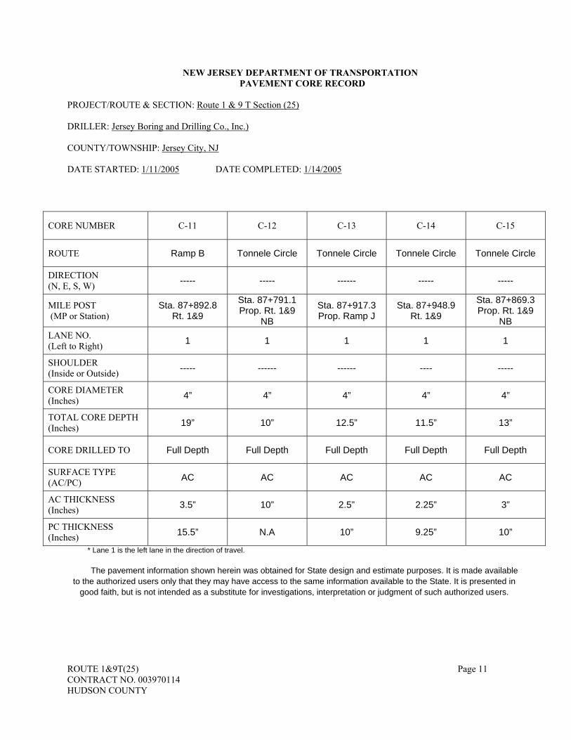
ROUTE 1&9T(25) Page 11 CONTRACT NO. 003970114 HUDSON COUNTY
NEW JERSEY DEPARTMENT OF TRANSPORTATION PAVEMENT CORE RECORD
PROJECT/ROUTE & SECTION: Route 1 & 9 T Section (25)
DRILLER: Jersey Boring and Drilling Co., Inc.)
COUNTY/TOWNSHIP: Jersey City, NJ
DATE STARTED: 1/11/2005 DATE COMPLETED: 1/14/2005
CORE NUMBER C-11 C-12 C-13 C-14 C-15
ROUTE Ramp B Tonnele Circle Tonnele Circle Tonnele Circle Tonnele Circle
DIRECTION (N, E, S, W) ----- ----- ------ ----- -----
MILE POST (MP or Station)
Sta. 87+892.8 Rt. 1&9
Sta. 87+791.1 Prop. Rt. 1&9
NB
Sta. 87+917.3 Prop. Ramp J
Sta. 87+948.9 Rt. 1&9
Sta. 87+869.3 Prop. Rt. 1&9
NB LANE NO. (Left to Right) 1 1 1 1 1
SHOULDER (Inside or Outside) ----- ------ ------ ---- -----
CORE DIAMETER (Inches) 4” 4” 4” 4” 4”
TOTAL CORE DEPTH (Inches) 19” 10” 12.5” 11.5” 13”
CORE DRILLED TO Full Depth Full Depth Full Depth Full Depth Full Depth
SURFACE TYPE (AC/PC) AC AC AC AC AC
AC THICKNESS (Inches) 3.5” 10” 2.5” 2.25” 3”
PC THICKNESS (Inches) 15.5” N.A 10” 9.25” 10”
* Lane 1 is the left lane in the direction of travel.
The pavement information shown herein was obtained for State design and estimate purposes. It is made available to the authorized users only that they may have access to the same information available to the State. It is presented in
good faith, but is not intended as a substitute for investigations, interpretation or judgment of such authorized users.

ROUTE 1&9T(25) Page 12 CONTRACT NO. 003970114 HUDSON COUNTY
NEW JERSEY DEPARTMENT OF TRANSPORTATION PAVEMENT CORE RECORD
PROJECT/ROUTE & SECTION: Route 1 & 9 T Section (25)
DRILLER: Jersey Boring and Drilling Co., Inc.)
COUNTY/TOWNSHIP: Jersey City, NJ
DATE STARTED: 1/11/2005 DATE COMPLETED: 1/14/2005
CORE NUMBER C-16 C-17 C-18 C-19 C-20
ROUTE Tonnele Circle Rt. 139 Rt. 1 &9 Rt. 1 &9 Rt. 1 &9
DIRECTION (N, E, S, W) ------ ----- SB SB SB
MILE POST (MP or Station)
Sta. 87+918.7 Prop.Rt. 1&9 NB
Sta. 0+209.2 Ramp M
Sta. 1+069.7 Ramp 1
Sta. 88+123 Ramp J
Sta. 88+256.1 Prop.Rt. 1&9
LANE NO. (Left to Right) 1 2 2 1 2
SHOULDER (Inside or Outside) ----- ---- ----- ----- ------
CORE DIAMETER (Inches) 4” 4” 4” 4” 4”
TOTAL CORE DEPTH (Inches) 12.5” 15.25” 12.5” 13.5” 14-15”
CORE DRILLED TO Full Depth Full Depth Full Depth Full Depth Full Depth
SURFACE TYPE (AC/PC) AC AC AC AC AC
AC THICKNESS (Inches) 2.5” 4” 12.5” 4” 4.25”
PC THICKNESS (Inches) 10” 11.25” N.A 9.5” 9.75-10.75”
* Lane 1 is the left lane in the direction of travel.
The pavement information shown herein was obtained for State design and estimate purposes. It is made available to the authorized users only that they may have access to the same information available to the State. It is presented in
good faith, but is not intended as a substitute for investigations, interpretation or judgment of such authorized users.

ROUTE 1&9T(25) Page 13 CONTRACT NO. 003970114 HUDSON COUNTY
NEW JERSEY DEPARTMENT OF TRANSPORTATION PAVEMENT CORE RECORD
PROJECT/ROUTE & SECTION: Route 1 & 9 T Section (25)
DRILLER: Jersey Boring and Drilling Co., Inc.)
COUNTY/TOWNSHIP: Jersey City, NJ
DATE STARTED: 1/11/2005 DATE COMPLETED: 1/14/2005
CORE NUMBER C-21 C-22 C-23
ROUTE Rt. 1 & 9 T Rt. 1 & 9 T Rt. 1 & 9 T
DIRECTION (N, E, S, W) SB NB NB
MILE POST (MP or Station)
Sta. 88+317.1 Prop.Rt.1&9
Sta. 88+377.9 Prop.Rt.1&9
Sta. 88+444.2 Prop.Rt.1&9
LANE NO. (Left to Right) 1 1 2
SHOULDER (Inside or Outside) ----- ----- -----
CORE DIAMETER (Inches) 4” 4” 4”
TOTAL CORE DEPTH (Inches) 14” 5.5”-6” 12.25”
CORE DRILLED TO Full Depth Full Depth Full Depth
SURFACE TYPE (AC/PC) AC AC AC
AC THICKNESS (Inches) 4.5” 5.5”-6” 3.5”
PC THICKNESS (Inches) 9.5” N.A 8.75”
* Lane 1 is the left lane in the direction of travel.
The pavement information shown herein was obtained for State design and estimate purposes. It is made available to the authorized users only that they may have access to the same information available to the State. It is presented in
good faith, but is not intended as a substitute for investigations, interpretation or judgment of such authorized users.

ROUTE 1&9T(25) Page 14 CONTRACT NO. 003970114 HUDSON COUNTY
The Department evaluated the existing HMA surface course using the International Roughness Index (IRI) according to ASTM E 1926 for information only. The IRI information shown herein was obtained for State design and estimate purposes. It is made available to the authorized users only that they may have access to the same information available to the State. It is presented in good faith, but is not intended as a substitute for investigations, interpretation or judgment of such authorized users.
NEW JERSEY DEPARTMENT OF TRANSPORTATION INTERNATIONAL ROUGHNESS INDEX TESTING RESULT
PROJECT/ROUTE & SECTION: Route 1 & 9 T Section (25)
COUNTY/TOWNSHIP: Jersey City, NJ
DATE STARTED: 06/14/06 DATE COMPLETED: 12/12/2006
Route Dir MP From MP To date tested IRI 001T E 0.1 0.2 12-Dec-06 212 001T E 0.2 0.3 12-Dec-06 212 001T E 0.3 0.4 12-Dec-06 253 001T E 0.4 0.5 12-Dec-06 135 001T E 0.5 0.6 12-Dec-06 195 001T E 0.6 0.7 12-Dec-06 208 001T E 0.7 0.8 12-Dec-06 310 001T E 0.8 0.9 12-Dec-06 153 001T E 0.9 1 12-Dec-06 141 001T E 1 1.1 12-Dec-06 262 001T E 1.1 1.2 12-Dec-06 131 001T E 1.2 1.3 12-Dec-06 112 001T E 1.3 1.4 12-Dec-06 144 001T E 1.4 1.5 12-Dec-06 103 001T E 1.5 1.6 12-Dec-06 153 001T E 1.6 1.7 12-Dec-06 168 001T E 1.7 1.8 12-Dec-06 305 001T E 1.8 1.9 12-Dec-06 333 001T E 1.9 2 12-Dec-06 203 001T E 2 2.1 12-Dec-06 114 001T E 2.1 2.2 12-Dec-06 145 001T E 2.2 2.3 12-Dec-06 506 001T E 2.3 2.4 12-Dec-06 270 001T E 2.4 2.5 12-Dec-06 289 001T E 2.5 2.6 12-Dec-06 244 001T E 2.6 2.7 12-Dec-06 195 001T E 2.7 2.8 12-Dec-06 213 001T E 2.8 2.9 12-Dec-06 391 001T E 2.9 3 12-Dec-06 205 001T E 3 3.1 12-Dec-06 175 001T E 3.1 3.2 12-Dec-06 272

ROUTE 1&9T(25) Page 15 CONTRACT NO. 003970114 HUDSON COUNTY
001T E 3.2 3.3 12-Dec-06 237 001T E 3.3 3.4 12-Dec-06 199 001T E 3.4 3.5 12-Dec-06 305 001T E 3.5 3.6 12-Dec-06 218
001T W 0.1 0.2 18-Nov-06 90 001T W 0.2 0.3 18-Nov-06 240 001T W 0.3 0.4 18-Nov-06 226 001T W 0.4 0.5 18-Nov-06 244 001T W 0.5 0.6 18-Nov-06 176 001T W 0.6 0.7 18-Nov-06 197 001T W 0.7 0.8 18-Nov-06 329 001T W 0.8 0.9 18-Nov-06 146 001T W 0.9 1 18-Nov-06 225 001T W 1 1.1 18-Nov-06 159 001T W 1.1 1.2 18-Nov-06 200 001T W 1.2 1.3 18-Nov-06 149 001T W 1.3 1.4 18-Nov-06 106 001T W 1.4 1.5 18-Nov-06 114 001T W 1.5 1.6 18-Nov-06 203 001T W 1.6 1.7 18-Nov-06 245 001T W 1.7 1.8 18-Nov-06 339 001T W 1.8 1.9 18-Nov-06 301 001T W 1.9 2 18-Nov-06 217 001T W 2 2.1 18-Nov-06 98 001T W 2.1 2.2 18-Nov-06 135 001T W 2.2 2.3 18-Nov-06 174 001T W 2.3 2.4 18-Nov-06 192 001T W 2.4 2.5 18-Nov-06 276 001T W 2.5 2.6 18-Nov-06 242 001T W 2.6 2.7 18-Nov-06 194 001T W 2.7 2.8 18-Nov-06 293 001T W 2.8 2.9 18-Nov-06 217 001T W 2.9 3 18-Nov-06 165 001T W 3 3.1 18-Nov-06 197 001T W 3.1 3.2 18-Nov-06 326 001T W 3.2 3.3 18-Nov-06 241 001T W 3.3 3.4 18-Nov-06 222 001T W 3.4 3.5 18-Nov-06 232 001T W 3.5 3.6 18-Nov-06 185
007 N 0.50 0.60 16-Oct-06 445 007 N 0.60 0.70 16-Oct-06 193 007 N 0.70 0.80 16-Oct-06 161 007 N 0.80 0.90 16-Oct-06 149 007 N 0.90 1.00 16-Oct-06 177 007 N 1.00 1.10 16-Oct-06 306 007 N 1.10 1.20 16-Oct-06 351

ROUTE 1&9T(25) Page 16 CONTRACT NO. 003970114 HUDSON COUNTY
007 N 1.20 1.30 16-Oct-06 361 007 N 1.30 1.40 16-Oct-06 216 007 N 1.40 1.50 16-Oct-06 105 007 N 1.50 1.60 16-Oct-06 100 007 N 1.60 1.70 16-Oct-06 247 007 N 1.70 1.80 16-Oct-06 164 007 N 1.80 1.90 16-Oct-06 178 007 N 1.90 2.00 16-Oct-06 175 007 N 2.00 2.10 16-Oct-06 132 007 N 2.10 2.20 16-Oct-06 145 007 N 2.20 2.30 16-Oct-06 158 007 N 2.30 2.40 16-Oct-06 149 007 N 2.40 2.50 16-Oct-06 497 007 N 2.50 2.60 16-Oct-06 518 007 N 2.60 2.70 16-Oct-06 325 007 N 2.70 2.80 16-Oct-06 117 007 N 2.80 2.90 16-Oct-06 336 007 N 2.90 3.00 16-Oct-06 349 007 N 3.00 3.10 16-Oct-06 397 007 N 3.10 3.20 16-Oct-06 230 007 N 3.20 3.30 16-Oct-06 71 007 N 3.30 3.40 16-Oct-06 110 007 N 3.40 3.50 16-Oct-06 79 007 N 3.50 3.60 16-Oct-06 80 007 N 3.60 3.70 16-Oct-06 104 007 N 3.70 3.80 16-Oct-06 184 007 N 3.80 3.90 16-Oct-06 104 007 N 3.90 4.00 16-Oct-06 110 007 N 4.00 4.10 16-Oct-06 136 007 N 4.10 4.20 16-Oct-06 197
007 S 0.50 0.60 16-Oct-06 343 007 S 0.60 0.70 16-Oct-06 197 007 S 0.70 0.80 16-Oct-06 147 007 S 0.80 0.90 16-Oct-06 126 007 S 0.90 1.00 16-Oct-06 140 007 S 1.00 1.10 16-Oct-06 248 007 S 1.10 1.20 16-Oct-06 367 007 S 1.20 1.30 16-Oct-06 320 007 S 1.30 1.40 16-Oct-06 262 007 S 1.40 1.50 16-Oct-06 157 007 S 1.50 1.60 16-Oct-06 216 007 S 1.60 1.70 16-Oct-06 219 007 S 1.70 1.80 16-Oct-06 254 007 S 1.80 1.90 16-Oct-06 179 007 S 1.90 2.00 16-Oct-06 127 007 S 2.00 2.10 16-Oct-06 122 007 S 2.10 2.20 16-Oct-06 161

ROUTE 1&9T(25) Page 17 CONTRACT NO. 003970114 HUDSON COUNTY
007 S 2.20 2.30 16-Oct-06 190 007 S 2.30 2.40 16-Oct-06 162 007 S 2.40 2.50 16-Oct-06 412 007 S 2.50 2.60 16-Oct-06 469 007 S 2.60 2.70 16-Oct-06 376 007 S 2.70 2.80 16-Oct-06 90 007 S 2.80 2.90 16-Oct-06 342 007 S 2.90 3.00 16-Oct-06 359 007 S 3.00 3.10 16-Oct-06 337 007 S 3.10 3.20 16-Oct-06 253 007 S 3.20 3.30 16-Oct-06 89 007 S 3.30 3.40 16-Oct-06 107 007 S 3.40 3.50 16-Oct-06 95 007 S 3.50 3.60 16-Oct-06 131 007 S 3.60 3.70 16-Oct-06 188 007 S 3.70 3.80 16-Oct-06 189 007 S 3.80 3.90 16-Oct-06 175 007 S 3.90 4.00 16-Oct-06 166 007 S 4.00 4.10 16-Oct-06 185 007 S 4.10 4.20 16-Oct-06 253
009W N 5.4 5.5 14-Jun-06 200 009W N 5.5 5.6 14-Jun-06 231 009W N 5.6 5.7 14-Jun-06 233 009W N 5.7 5.8 14-Jun-06 203 009W N 5.8 5.9 14-Jun-06 165 009W N 6.3 6.4 14-Jun-06 232 009W N 6.4 6.5 14-Jun-06 247 009W N 6.5 6.6 14-Jun-06 211 009W N 6.6 6.7 14-Jun-06 217 009W N 7.30 7.40 14-Jun-06 270 009W N 7.40 7.50 14-Jun-06 357 009W N 7.50 7.60 14-Jun-06 276 009W N 7.60 7.70 14-Jun-06 148 009W N 7.70 7.80 14-Jun-06 154 009W N 7.80 7.90 14-Jun-06 360 009W N 7.90 8.00 14-Jun-06 257 009W N 8.00 8.10 14-Jun-06 308 009W N 8.10 8.20 14-Jun-06 175 009W N 8.20 8.30 14-Jun-06 228 009W N 8.30 8.40 14-Jun-06 226 009W N 8.40 8.50 14-Jun-06 240 009W N 8.50 8.60 14-Jun-06 235 009W N 8.60 8.70 14-Jun-06 211 009W N 8.70 8.80 14-Jun-06 342 009W N 8.80 8.90 14-Jun-06 207 009W N 8.90 9.00 14-Jun-06 178

ROUTE 1&9T(25) Page 18 CONTRACT NO. 003970114 HUDSON COUNTY
009W S 5.4 5.5 14-Jun-06 161 009W S 5.5 5.6 14-Jun-06 164 009W S 5.6 5.7 14-Jun-06 159 009W S 5.7 5.8 14-Jun-06 136 009W S 5.8 5.9 14-Jun-06 230 009W S 5.9 6 14-Jun-06 133 009W S 6.3 6.4 14-Jun-06 167 009W S 6.4 6.5 14-Jun-06 248 009W S 6.5 6.6 14-Jun-06 153 009W S 6.6 6.7 14-Jun-06 177 009W S 7.30 7.40 14-Jun-06 278 009W S 7.40 7.50 14-Jun-06 184 009W S 7.50 7.60 14-Jun-06 198 009W S 7.60 7.70 14-Jun-06 116 009W S 7.70 7.80 14-Jun-06 238 009W S 7.80 7.90 14-Jun-06 314 009W S 7.90 8.00 14-Jun-06 241 009W S 8.00 8.10 14-Jun-06 206 009W S 8.10 8.20 14-Jun-06 151 009W S 8.20 8.30 14-Jun-06 141 009W S 8.30 8.40 14-Jun-06 183 009W S 8.40 8.50 14-Jun-06 185 009W S 8.50 8.60 14-Jun-06 148 009W S 8.60 8.70 14-Jun-06 194 009W S 8.70 8.80 14-Jun-06 148 009W S 8.80 8.90 14-Jun-06 137 009W S 8.90 9.00 14-Jun-06 148

ROUTE 1&9T(25) Page 19 CONTRACT NO. 003970114 HUDSON COUNTY
2. Utility Agreements. In addition to what is specified in 105.09, the Bidder may inspect or order the Utility
agreements, modifications and orders relating to the Project through the Department’s Division of Project Management, 1035 Parkway Avenue, P.O. Box 600, Trenton, NJ 08625-0600. The Bidder shall obtain existing information and proposed construction documents through the Utility for its respective work.
3. Existing Plans and As-Builts. The Bidder may inspect as-built plans of Department-owned facilities or order copies upon written request through the Engineering Documents Unit. Contour maps may be available for some Projects and the Bidders may inspect such maps or the Bidder may obtain copies for their use upon written request to the Engineering Documents Unit. The Bidder shall obtain plans of municipal-owned or County-owned facilities through the municipality or county. The Bidder shall verify any information obtained from the existing documents with regard to its application for bidding and completing the Project. The Department will provide a list of existing structures within the Project on the Plans. The Department will list the existing plans and as-builts used in the development of Contract in the Special Provisions. Existing Plans and As-builts used are as follows: a. Route 1&9T over St Paul’s Avenue (Structure No. 0906-156) b. Pulaksi Skyway – Ramp I (Structure No. 0901-150) c. Ramp D over Tonnele Circle (Structure No. 0906-158) d. Tonnele Avenue (Rte. 1&9) over NJ Transit (Structure No. 0902-150) e. Tonnele Avenue (Rte 1&9) over Conrail (Structure No. 0902-151) f. Route 1&9T over Jersey City Water Mains (Structure No. 0906-155) g. Route 1&9 Ramp 1B over Jersey City Water Mains (Structure No. 0906-157) h. Route 1&9T(26) – Operational Improvements – Parts A & B. i. Utility Test Pits Data
102.04 Interpretation of Quantities in the Proposal Form.
The quantities appearing in the Proposal Form are estimates and are used for the comparison of bids. The Department may increase or decrease the scheduled quantities of Work, or may eliminate Pay Items in their entirety, in its sole discretion.
The Department will pay only for the quantities of Work completed as specified in the Contract. The Department will make payment at the original unit prices for the quantities of Work accepted by the RE. 102.05 “If and Where Directed” Items.
The Proposal Form may include Pay Items that may be incorporated into the Project “if and where directed” by the RE. Such items may or may not be shown on the Plans. The estimated quantities set out in the Proposal Form for “if and where directed” items are presented for the purpose of obtaining a representative bid price, but are not indicative of the Department’s intent regarding incorporation into the Project. The Department may or may not incorporate “if and where directed” items into the Project, in its sole discretion. If the Department incorporates such “if and where directed” items, the actual quantity may be many times the estimated quantity or only a fraction thereof. 102.06 Preparation of the Proposal Form.
The Bidder shall submit a Proposal Form produced from the software that was downloaded from the Department’s electronic bidding website. The Bidder shall include all addenda on the Proposal Form. The Bidder shall specify a price in figures for each Pay Item. The Bidder shall insert the price solely in the box provided for the lump sum item under the column designated as “Amounts.” For unit price items, the Bidder shall insert the per unit price under the column designated “Unit Price” in the appropriate box at the location provided therefore. When the Bidder intends to bid zero ($0.00) for a Pay Item, the Bidder shall insert a “0” in the “Unit Price” and “Amounts” columns for unit price items or in the “Amounts” column for lump sum items. When the Proposal Form contains alternate items, the Bidder shall insert only the unit price and amount for the lowest priced alternate item. When alternate items in the proposal have a lump sum pay quantity, the Bidder shall insert only the amount for the lowest priced alternate item. The Bidder shall construct the alternate item for which a price has been provided. When the proposal contains alternate groups of items, the Bidder shall insert only the unit price and amount for each item within the lowest priced alternate group. The Bidder shall construct the alternate group of items for which a price has been provided.
The only entries permitted in the proposal form will be the unit or lump sum prices for items that shall be bid. The software will perform all extensions of the unit or lump sum prices and calculate the total bid amounts.

ROUTE 1&9T(25) Page 20 CONTRACT NO. 003970114 HUDSON COUNTY
The Bidder shall check the bid before submission using the software. The Bidder shall select “tools” and then select “check bid” and ensure there are no errors prior to submitting the electronic bid. For bids submitted by Joint Ventures select “tools” from the software menu and mark the electronic bid as “Joint Bid.” The Bidder may print a completed Proposal Form for their records after completing the bid.
Where no figure is provided by the Bidder in either the “Unit Price” or the “Amount” columns for one or more Pay Items, or where no figure is provided in the “Amount” column for one or more lump sum Pay Items, the Department will consider the amount bid to be zero ($0.00) for that item. 102.07 Balanced Bids.
The Bidder shall reflect in each Pay Item the actual cost the Bidder anticipates incurring for the performance of that particular item, together with a proportional share of the Bidder’s anticipated profit, overhead, and costs to perform work for which no Pay Item is provided. 102.08 Proposal Bond.
The Proposal Bond guarantees execution of the Contract by the Bidder receiving the award. With the bid submission, the Bidder shall complete the included electronic bond form. The Bond must be
satisfactory to the Department and for a sum of 50 percent of the total bid amount. The Bidder shall ensure that the Proposal Bond is properly completed and furnished by a surety company or
companies authorized to do business in this State as are listed and authorized to issue bonds in at least the amount of the Proposal bond as established by the current US Treasury Department Circular 570 as of the date for receipt of bids for the particular Project.
The Bidder shall ensure that the Proposal Bond has a power of attorney executed by the surety company or companies. The power of attorney shall set forth the limits of authority of the attorney-in-fact who has signed the bond on behalf of the surety company to bind the company and shall further certify that such power is in full force and effect as of the date of the bond.
Proposal Bonds that do not comply in all respects with the provisions of N.J.A.C. 16:44-5.1(d) and that are not substantiated by a valid power of attorney executed by the surety company will not be accepted. 102.09 Revisions Before Submitting a Bid.
Any written, graphic, or electronic information to clarify, correct, or change the Bid Documents, Contract, or bidding notices will be issued only as addenda (or “addendum” can be used interchangeably) posted on the website before the opening of bids. The Department will post no addenda less than 24 hours before the time set for the receipt of bids, with the exception of addenda postponing the bid opening date and time.
Acknowledgment thereof shall be made by the Bidder for all addenda posted through the Department’s website. All addenda shall be acknowledged or the Department will not accept the bid. It is the obligation of the bidder to check the Department’s website for addenda. 102.10 Submission of Bids.
Once the Bidder has completed its bid and made all desired changes, the Bidder shall submit the electronically signed bid via the Internet. The Bidder shall ensure delivery of its bid with all required components and attachments, including, but not limited to the following:
1. Schedule of items 2. Updated Financial Statement form DC-74B 3. Addenda acknowledgement 4. For wholly State funded contracts, acknowledgement of compliance with the two registrations as specified in
102.01 5. For wholly State funded contracts, acknowledgement of compliance with N.J.S.A. 19:44A-20.13 et seq. 6. Proposal Bond form 7. Other related documents as specified in the Contract When the Bidder submits bids for two or more Projects on which bids will be accepted on the same day, a single
Updated Financial Statement is acceptable instead of a separate statement for each Project. The Bidder is solely responsible for any and all errors and for timely submission of the bid, all components thereof,
and all attachments thereto, through the electronic bidding system; the Department assumes no responsibility for any claim arising from the failure of any Bidder or of the electronic delivery system to cause any bid, bid component, or attachment to not be delivered to the Department on or before the time set for bid opening.

ROUTE 1&9T(25) Page 21 CONTRACT NO. 003970114 HUDSON COUNTY
102.11 Withdrawal of Bids.
A Bidder may withdraw a bid after it has been submitted to the Department, provided the request for such withdrawal is received by the Department, in writing or fax, before the time set for opening bids.
The Bidder may not withdraw a bid after the time designated for the public opening of such bid, except that when bids for more than one project are to be opened at the same time, a Bidder, at its option, may submit a written request to withdraw its bid for the second or succeeding project before the time set for opening of those bids. 102.12 Public Opening of Bids
The Department will open and read bids publicly at the time and place indicated in the Advertisement or such other time and place as may be established by addenda. The Department invites Bidders, their authorized agents, and other interested parties to be present. 102.13 Consideration of Proposals.
The Department reviews proposals for conformity with the Contract and compares proposals on the basis of the correctly determined summation of the correctly determined products of all the quantities for Pay Items shown in the Proposal multiplied by the unit prices bid together with the sums bid for lump sum Pay Items. The Department will make the total bid amount for all bids available. 102.14 Irregular Bids.
The Department will consider bids irregular and will reject bids if the Department determines that the bid contains a material defect. 102.15 Disqualification of Bidders.
The Department will disqualify a Bidder and reject a bid submitted by that Bidder if the Bidder is determined by the Department to lack responsibility. Factors demonstrating a lack of responsibility include but are not be limited to:
1. Evidence of collusion among Bidders. 2. Uncompleted work, which in the opinion of the Department, might hinder or prevent completion of additional
work if awarded. 3. Failure to satisfy the pre-award requirements for Disadvantaged Business Enterprise (DBE) or Emerging
Small Business Enterprise (ESBE) as specified in the Special Provisions for federally funded contracts. 4. Failure to satisfy the pre-award requirements for Small Business Enterprise (SBE) as specified in the Special
Provisions for wholly State funded contracts. 5. Materially unbalanced bid. 6. Lack of competency or lack of adequate machinery, plant, or other equipment. 7. Unsatisfactory performance on previous or current contracts. 8. Questionable moral integrity as determined by the Attorney General of New Jersey or the Department. 9. Any other outward actions or lack of action that demonstrates the Bidder is not responsible. 10. Disqualification, suspension, or debarment of an individual, firm, partnership, corporation, or any
combination as required by N.J.S.A. 16:44-8.1. 102.16 Rejection of All Bids.
The Department may reject all bids when the Department deems it advisable to do so in the best interest of the State or public.
SECTION 103 - AWARD AND EXECUTION OF CONTRACT THE TEXT OF THE ENTIRE SECTION IS CHANGED TO: 103.01 Consideration of Proposals. THE CONTENT OF THIS SUBSECTION HAS BEEN DELETED AND IT IS INTENTIONALLY LEFT BLANK 103.02 Award of Contract.
The Department will award the Contract to the lowest responsible Bidder whose bid conforms in all respects to the requirements set forth in the Contract. The Department will make Award on the basis of the Total Contract Price. The Department will award the Contract or reject all bids within 30 State Business Days after the bids are received. The

ROUTE 1&9T(25) Page 22 CONTRACT NO. 003970114 HUDSON COUNTY
Department may make a Conditional Award pending the approval of the Federal Government, another State governmental body, or private party. If the Department does not award the Contract or conditionally award the Contract within 30 State Business Days, all Bidders have the right to withdraw their bids. However, the Department and the lowest responsible Bidder, the second lowest responsible Bidder, or both can agree to extend the time within which the Department may make an award or conditional award by mutual consent.
At the time of Award or Conditional Award to a Bidder not a resident of the State, such Bidder shall appoint, on the form furnished by the Department, a proper agent in the State on whom service can be made in event of litigation of any type arising under the Contractor or as a result of performance of the Contract. Said agency shall remain in effect during the performance of the Contract and for 6 years following Acceptance.
The Award or Conditional Award is not binding upon the Department until the Department has executed the Contract. No person shall perform any Work in furtherance of the Contract until notified that the Contract has been executed, and then only as specified in 108.03.
The term “State Business Day” as used in this Subsection is synonymous with the term “Working Day” as used in N.J.S.A. 27:7-31 and N.J.S.A. 27:7-33 and is any day exclusive of Saturdays, Sundays, State recognized legal holidays, and such other holidays or State office closings as declared by the State. 103.03 Cancellation of Award.
The Department reserves the right to cancel an Award or Conditional Award at any time before the execution of said Contract by all parties without incurring any liability of any kind. 103.04 Release of Proposal Bond.
The Department will release all Proposal Bonds except those of the 2 lowest Bidders within 5 days after receipt of bids.
The Department will release the Proposal Bond of the lowest and next lowest Bidders when the Contract and Performance Bond and Payment Bond have been executed and delivered as specified in 103.06, or, if not executed, when other disposition of the matter has been made by the Department. 103.05 Performance Bond and Payment Bond.
Within ten State business days of the date of Award or Conditional Award, the Bidder to whom the Contract has been awarded shall complete and deliver a Performance Bond and a Payment Bond on forms furnished by the Department.
Each bond shall be the sum of not less than the Total Contract Price less the lump sum bid for the Pay Item “Performance Bond and Payment Bond” and shall be maintained by the Contractor until Acceptance. In the event of the insolvency of the surety or if the Performance Bond and Payment Bond have not been properly authorized or issued by the Surety company, the Contractor shall furnish and maintain, as above provided, other surety satisfactory to the Commissioner.
All alterations, extensions of Contract Time, extra and additional work, and other changes authorized by the Contract Documents may be made without securing the consent of the surety or sureties of the bonds. The surety corporation bonds shall be furnished by only those sureties listed in the US Treasury Department Circular 570 and authorized to do business in the State. The bonds shall be accompanied by a certification as to authorization of the attorney-in-fact to commit the surety company and a true and correct statement of the financial condition of said surety company. Reinsurance is prohibited pursuant to NJAC 16:44-6.1(b)6.
Payment for the Performance Bond and the Payment Bond will be made upon commencement of work on the basis of the lump sum bid or the actual cost (gross premium), whichever is less, upon submission of a paid bill and the report of execution issued by the Surety showing the gross premium of the bonds and the broker’s fee. Upon Completion, the Department’s payment for the Performance and Payment Bond will be adjusted to reflect any increase or decrease in the actual cost of the bonds. Any increase will be based upon the rate schedule certified by the Surety and submitted by the Contractor at the beginning of the Project. If the certified schedule and the paid bill are not submitted at the beginning of the Project, no adjustment will be made. Any increase or decrease in the actual cost of the bonds otherwise known as the adjustment of less than one hundred dollars will be disregarded. The adjustment will be calculated on whichever of the following methods results in the lowest adjustment:
1. The difference between the actual cost paid by the Contractor before the commencement of work and the paid final bill submitted by the surety company or agent.
2. The difference between the actual cost paid by the Contractor before the commencement of work and the final amount as calculated by using the certified schedule submitted at the beginning of the Project.

ROUTE 1&9T(25) Page 23 CONTRACT NO. 003970114 HUDSON COUNTY
If the amount of this final bill reflects an increase in the cost of the Performance and Payment Bonds, the Department will pay the Contractor the amount as determined above in the final payment to be made to the Contractor after Acceptance. If the amount of the final bill reflects a decrease in the cost of the Payment and Performance Bonds, the Department will deduct that amount from the final payment made to the Contractor after Acceptance.
Any increase in the construction layout ratio will not be included in the Surety adjustment. Payment will be made under:
Pay Item Pay Unit PERFORMANCE BOND AND PAYMENT BOND LUMP SUM
103.06 Execution of the Contract.
Within 14 days of the date of Award or Conditional Award, the Bidder shall properly and duly execute the Contract and deliver to the Department with the following:
1. Performance Bond and Payment Bond as specified in 103.05. 2 Request for Authorization Form (RFA) for the New Jersey Pollutant Discharge Elimination System
(NJPDES) Stormwater General Permit for Construction and Mining Activity when specified for the Contract. 3 Proof of the two registrations as specified in 102.01 for the Department of Treasury and the Department of
Labor. 4. For wholly State funded projects, all completed Certification/Disclosure Forms for compliance with N.J.S.A.
19:44A-20.13 et seq. (P.L. 2005, c.51). 5 If the case of non-resident Bidders, the completed form regarding “Appointment of Agent” for compliance
with N.J.S.A. 14A:15-2 et seq. If said Contract is not executed by the Department within 60 days following receipt from the successful Bidder of
the executed Contract and Performance Bond and Payment Bond, the successful Bidder may, at its discretion, withdraw its bid without penalty. Where the Bidder chooses not to withdraw before the Department executing said Contract, the Bidder shall be deemed to have waived any claim for additional payment or for an extension of time. The Contract does not become effective until it has been fully executed by all parties. 103.07 Failure to Execute Contract.
Failure on the part of the Bidder, whom the Contract has been awarded, to execute and deliver the Contract, Performance Bond and Payment Bonds, and other documents as specified in 103.06, in the manner and within the time specified, is just cause for annulment of the Award or Conditional Award and for the exclusion of the Bidder from bidding on subsequent projects for such period as the Department may deem appropriate. If the Award is annulled for the above reasons, the Proposal Bond, as specified in 102.08, shall become forfeited and the Department may proceed to recover under the terms and provisions of the Proposal Bond. The Department may award to the next lowest responsible Bidder, or may readvertise and construct the Work under contract, or otherwise, as the Department may decide in its sole discretion. The successful Bidder may file with the Department a written notice, signed by the Bidder or the Bidder’s authorized representative, stating that the Bidder refuses to execute the Contract. The filing of such notice has the same force and effect as the failure of the Bidder to execute the Contract and furnish a Performance Bond and Payment Bond within the time specified in 103.06. 103.08 Acquisition of Documents.
After the Award, additional sets of the Plans or additional copies of the Special Provisions are available to subscribers through the Department’s website or upon request to the Department’s Engineering Documents Unit, at a charge according to the Department rate.
SECTION 104 - SCOPE OF WORK 104.01 Intent. THE FIRST PARAGRAPH IS CHANGED TO:
The intent of the Contract Documents is to describe a functionally complete and aesthetically acceptable Project to be constructed and completed by the Contractor in every detail according to the Contract Documents. Any work that may be reasonably inferred from the Contract Documents as being required to produce the intended result shall be supplied whether or not specifically called for. The Contractor is responsible to provide such elements to complete the Work under the pay items of the Contract for no Additional Compensation as provided under Subsection 109.02.

ROUTE 1&9T(25) Page 24 CONTRACT NO. 003970114 HUDSON COUNTY
However, as specified in the respective Subsections, adjustments may be allowed when the Department determines there is a discrepancy, error, omission, or latent ambiguity. It is understood that only the best construction practice is to prevail and only materials and workmanship of the first quality are to be used. THE FOLLOWING IS ADDED:
In addition to the roadway related work, the bridge and structure work in this contract will consist of but is not limited to, the following:
BRIDGES:
Structure No. 1 - Ramp A over Charlotte Avenue Ramp A over Charlotte Avenue provides access from Charlotte Avenue to Route 7 Westbound (Wittpenn Bridge). The proposed structure will range from a 34.0-m to 37.5-m-long (111.5-ft to 123.0–ft-long) simple-span, curved composite steel plate girder with wraparound MSE abutments. The cross-section of the bridge provides for an 8.40-m (27.6-ft) roadway with a 2.1-m (6.9-ft) left shoulder and a 0.6-m (2.0-ft) right shoulder.
Structure No. 2 - Mainline over Charlotte Avenue
The Mainline structure over Charlotte Avenue is a 37.75-m-long (124-ft-long) composite steel plate girder integral with wraparound MSE abutments. Particular attention was given to eliminating a pier in the median of Charlotte Avenue. The cross-section is similar to the mainline structure, consisting of three 3.6-m (12-ft) lanes, 2.45-m (8-ft) median, one 4.2-m (13.8-ft) shoulder for the westbound traffic and a 3.6-m (12-ft) shoulder for the eastbound traffic.
Structure No. 3 - Ramp B over Charlotte Avenue and Ramp C
Ramp B over Charlotte Avenue and Ramp C provides access from Route 7 Eastbound to Ramp B over St. Pauls Avenue, and is part of the Route 1&9T and Charlotte Avenue interchange. The proposed structure is a 76.6-m-long (251-ft-long) two-span continuous composite steel plate girder structure integral with wraparound MSE abutments. The cross-section of the bridge provides for a 4.5-m (14.8-ft) travel lane and a 2.7-m (8.85-ft) left shoulder. A hammerhead pier is proposed.
Structure No. 4 - Ramp B over St. Pauls Avenue
Ramp B connects Route 7 Eastbound to the Tonnele Circle. The proposed structure is a 158.1-m-long (519 ft-long), five-span composite steel plate girder structure. Spans 1 through 3 are continuous and spans 4 and 5 are continuous. Pier 1 is a hammerhead pier, while Pier 2 is monolithic with the Mainline Pier 2. Piers 3 and 4 are multi-column bents supporting both Ramp B and Ramp C. The pier caps for Piers 2 and 3 are steel boxes. Full height abutments have been used. The western abutment supports Ramp B, Ramp C and the Mainline Viaduct. The cross-section consists of a 4.5-m (14.8-ft) travel lane, a 2.70-m (8.85-ft) left shoulder and a 0.6-m (2-ft) right shoulder. Traffic from this ramp will merge with traffic from Ramp C just before passing under Ramp I.
Structure No. 5 - Ramp C over St. Pauls Avenue
Ramp C connects Route 1&9T to the Tonnele Circle. A section of the structure is monolithic with the Mainline Viaduct and an off-ramp section of the structure merges with Ramp B to connect to Tonnele Circle. The proposed structure is a 160.9-m-long (528-ft-long), five-span composite steel plate girder structure. Spans 1 through 3 are continuous and spans 4 and 5 are continuous. Pier 1 is a multi-column bent that supports the Mainline Viaduct and Ramp C. Pier 2 is a multi-column bent that supports the Mainline Viaduct, Ramp B, and Ramp C. Piers 3 and 4 are multi-column bents supporting both Ramp B and Ramp C. The pier caps for Piers 1, 2 and 3 are steel boxes and for Pier 4 the pier cap is reinforced concrete. Full-height abutments will be used. The western abutment will support Ramp B, Ramp C and the Mainline Viaduct. The eastern abutment will support Ramp B and Ramp C. The cross-section consists of a 4.2-m (13.8-ft) travel lane, adjacent to the Northbound Mainline traffic, and a varying-width shoulder as Ramp C merges with Ramp B approaching the Tonnele Circle.

ROUTE 1&9T(25) Page 25 CONTRACT NO. 003970114 HUDSON COUNTY
Structure No. 6 - Mainline Viaduct The Mainline Viaduct connects Route 1&9 north of Tonnele Circle with Route 7 at the Wittpenn Bridge. This structure will pass over the congested area occupied by St. Paul's Avenue, Conrail railroad tracks, several utilities and various city streets and ramps. The intricate network of underground utilities, the Conrail railroad tracks, and the existing St. Paul’s Avenue has significantly influenced substructure locations. Through discussions with Conrail, an allowance was made for a future second track, to the west of the existing Conrail track, through Marion Junction. The proposed structure is a 245.4-m-long (805-ft-long), seven-span composite steel plate girder structure. Spans 1 through 3 are continuous and spans 4 through 7 are continuous. Pier 1 is a multi-column bent that supports the Mainline Viaduct and Ramp C. Pier 2 is a multi-column bent that supports the Mainline Viaduct, Ramp B, and Ramp C. Piers 3 through 6 are multi-column bents supporting only the Mainline Viaduct. The pier caps for Piers 1 and 2 are steel boxes and those for Pier 3 through 6 are reinforced concrete. Full-height abutments are proposed. The western abutment supports Ramp B, Ramp C and the Mainline Viaduct. The Mainline Viaduct cross-section varies to accommodate acceleration and deceleration lanes for the various ramps. It maintains two, 3.6-m (11.8-ft) travel lanes and a 4.2-m (13.8 ft) right shoulder for southbound traffic. The northbound traffic is accommodated by two variable-width lanes with a 3.6-m minimum width in addition to variable-width gore areas at the split with Ramp C. A 0.82-m-wide (2.7-ft-wide) concrete median barrier divides the two directions of traffic with 0.9-m (3-ft) shoulders on either side of the barrier. An open longitudinal joint, located in the concrete median barrier, runs the entire length of the bridge.
Structure No. 7 - Ramp I over Ramps B, C and D
Ramp I provides access from Tonnele Avenue (SB) to the Pulaski Skyway (SB). The existing Ramp I is a two-span simply supported steel structure. The second span is framed directly into the north fascia of the Pulaski Skyway. This ramp meets the Pulaski Skyway at a "stop" condition, with little sight distance for the driver on the ramp. There is no auxiliary merging lane, which leads to a continuous safety concern when motorists have to extend the vehicle into the right lane of high-speed traffic on the Pulaski Skyway in order to find a safe gap in which to enter. The stop condition at the entrance is not desirable, and is substandard for a major arterial roadway such as Route 1&9. The proposed structure would improve the safety of the motorists by providing a yield-controlled entrance to the Pulaski Skyway.
The proposed structure consists of a two-span continuous steel superstructure with the remaining spans framing directly into the Pulaski Skyway. Several structural modifications will also have to be made to the fascia of the Pulaski Skyway. The existing ramp will be replaced with a two-span continuous composite steel plate girder superstructure. The existing north fascia girder of the Pulaski Skyway will be removed and replaced with a new fascia girder to accommodate the deck widening of the Pulaski Skyway. Six additional stingers will be added along the north fascia of the Pulaski Skyway to provide for a tapered structure. The typical cross-section of the first two spans consists of a 5.4-m (17.7-ft) travel lane and a 1.2-m (4-ft) shoulder on each side of traffic. The lane will then merge into the Pulaski Skyway. The proposed reinforced concrete deck will be doweled into the existing reinforced concrete deck on the Pulaski Skyway. The piers will be hammerheads and the abutment will be full height.
Structure No. 8 - Ramp D over Tonnele Circle
The existing Ramp D crosses over Tonnele Circle and serves traffic traveling toward Route 7 and Route 1&9T via the existing viaduct. This traffic would be rerouted onto the proposed loop Ramp D, allowing access to Route 1&9T SB and Route 7 WB. The proposed bridge is a 105-m-long (344-ft-long) four-span structure with span 1 as a simple span and spans 2 through 4 as continuous spans. To accommodate required vertical clearances, Pier 2 is integral, in that the steel girder superstructure frames directly into the steel pier cap supported by concrete columns. Piers 1 and 3 are reinforced concrete. The west abutment is a Stub abutment sitting on a MSE wall and the east abutment is full height. The bridge will be built in two main stages.

ROUTE 1&9T(25) Page 26 CONTRACT NO. 003970114 HUDSON COUNTY
The proposed roadway cross-section consists of a 4.5-m (14.8-ft) travel lane, a 2.4-m (7.9-ft) left shoulder and a 0.9-m (3-ft) right shoulder. The proposed bridge will be constructed slightly to the south of the existing structure. This alignment will facilitate a viable construction-staging plan, thus allowing a continuous flow of traffic during construction. The proposed pier locations were chosen so as to maximize the capacity of the superstructure within the allowable structure depth (provided by proposed vertical profiles) in order to maintain or improve the existing vertical clearances. Continuity was utilized in order to reduce stresses and eliminate deck joints.
Structure No. 9 - Route 1&9T Northbound Mainline Flyover
The Route 1&9T Northbound Mainline Flyover connects the Mainline Viaduct with Tonnele Avenue. This structure passes over the NJ Transit and Conrail railroad tracks and Tonnele Avenue. The proposed bridge is a 268-m-long (879-ft-long), eight-span composite and curved steel plate girder structure. Spans 1 through 5 are continuous and spans 6 through 8 are continuous. The pier cap for Pier 1 spans Tonnele Avenue and is a steel box. The pier cap for Pier 2 is a steel box. The pier caps for Piers 3 and 4 are steel boxes and are integral with the superstructure. Piers 5, 6 and 7 are concrete hammerheads. The south abutment is full height. The cross-section consists of two, 4.2-m (13.8-ft) travel lanes with a maximum 3.0-m (10-ft) left shoulder and a 0.6-m (2-ft) right shoulder. Substructure locations are determined by lateral clearances established by the existing structures on Tonnele Avenue and lateral clearances required by both NJ Transit and Conrail. Design and construction staging of this structure will accommodate construction over electrified NJ Transit railroad lines as well as underground, active, high powered electric lines located adjacent to the Conrail tracks.
Structure No. 10 – Tonnele Avenue over New Jersey Transit
The proposed structure, which will replace the existing Tonnele Avenue over the NJ Transit structure, has several complicating factors associated with its construction. The NJ Transit tracks are powered by overhead catenary lines, supported on catenary structures located in the immediate vicinity of the bridge and on both fascias of the existing bridge. These tracks are also extremely active. In addition, several utility lines, currently supported above the deck of the existing bridge, will be relocated on the new structures between the new stringers. The construction-staging schedule for this structure includes maintaining four lanes of traffic on Tonnele Avenue, while strategically erecting the structure over the catenary lines in three main stages. The proposed structure will be wider to accommodate the staged construction and required work areas between the existing bridges and the new portion of the structure under construction. The proposed structure will accommodate a new electrical duct bank, relocated gas mains, and a relocated water main. The installation/relocation of these utilities will be coordinated with the respective utility companies. The proposed superstructure consists of a single-span 36.6-m-long (120-ft-long) composite steel girder bridge with integral abutments built in three main stages. The north abutment will be built behind the existing abutment that will remain and act as a retaining wall. The cross-section will provide a 3.6-m (12-ft) shoulder, a 3.3-m (11-ft) travel lane, a 3.6-m (12-ft) travel lane and a 3.3-m (11-ft) travel lane to accommodate the southbound traffic. Northbound motorists will be accommodated with a travel lane that varies from a minimum of a 3.3-m (11-ft) travel lane and a shoulder that varies from 2.4 m (8 ft) to 3.6 m (12 ft). The opposing traffic is separated by a variable width median and barrier. A variable width sidewalk will be provided on the east fascia of the bridge to facilitate pedestrian traffic.
Structure No. 11 – Tonnele Avenue over Conrail

ROUTE 1&9T(25) Page 27 CONTRACT NO. 003970114 HUDSON COUNTY
The proposed structure, which will replace the existing structure on Tonnele Avenue over the Conrail railroad tracks, also has several complicating factors associated with its construction. There are currently high-powered electrical utility lines that run parallel and adjacent to the Conrail tracks. In addition, the construction-staging scheme for this structure will maintain four lanes of traffic on Tonnele Avenue, while erecting the structure over an active train line. The underground utilities that are located in the vicinity of this proposed structure cannot be relocated. Therefore, careful attention was paid to the location and form of the proposed footings. Test pits were dug to locate the utilities in the Conrail ROW. The proposed bridge is a 54.9-m-long (180–ft-long), single-span composite steel girder structure with full-height abutments to be built in three main stages. The south abutment will be built behind the existing abutment that will remain and act as a retaining wall. To reduce the complexity of the construction, the bottom of the footing of the south abutment will be raised to an elevation of +9.5 m and will be supported on piles. A sheetpile wall has also been proposed to eliminate high pressure on the existing retaining wall and to facilitate construction. The cross-section will provide a 3.6-m (12-ft) shoulder, a 3.3-m (11-ft) lane, a 3.6-m (12-ft) lane, and a 3.3-m (11-ft) lane to accommodate southbound traffic. The northbound traffic is accommodated by a 3.3-m (11-ft) travel lane and a 3.6-m (12-ft) shoulder. The opposing traffic is separated by a 0.65-m (2.1-ft) concrete barrier in a 2.45-m-wide (8-ft-wide) median. A variable-width sidewalk on the east and west fascias will facilitate pedestrian traffic.
Retaining Walls Structures 12 through 56
Prefabricated retaining wall structures are proposed for a total of approximately 2900 LM (9500 ft) of the project. Generally, exposed wall heights will range from 1 to 7.6 m (3 to 25 ft) and footings will be stepped in order to limit concrete, excavation and fill quantities. A maximum exposed wall height of 11.2 m (37 ft) is required for the Mainline Viaduct Walls Nos. 4 and 5 to accommodate the diverging northbound and southbound roadways. As shown on the plans, some areas require MSE walls, others require modular walls. The remainder of the areas can use either MSE or modular walls at the option of the contractor. In addition, there are two cast-in-place reinforced concrete walls as shown on the plans, one is at Ramp A and one is at Tonnele Avenue.
Sign Structures Structures 57 through 73 Additional sign and ITS structures are required as detailed on the plans.
104.02 Changes THE SECOND SENTENCE OF THE NINTH PARAGRAPH IS CHANGED TO:
Attention is directed to Subsections 102.07 and 107.27. 104.05 Increased or Decreased Quantities. THE FOLLOWING IS ADDED:
Those Pay Items listed below shall be considered as major Pay Items even though their Contract value may not be more than ten percent of the Total Contract Price:
ROADWAY EXCAVATION, REGULATED WASTE ROADWAY EXCAVATION, REGULATED WASTE, HAZARDOUS ROADWAY EXCAVATION, REGULATED WASTE, CHROMIUM OFF-SITE MANAGEMENT OF REGULATED WASTE OFF-SITE MANAGEMENT OF REGULATED WASTE, HAZARDOUS OFF-SITE MANAGEMENT OF REGULATED WASTE, CHROMIUM FOUNDATION EXCAVATION, REGULATED WASTE

ROUTE 1&9T(25) Page 28 CONTRACT NO. 003970114 HUDSON COUNTY
FOUNDATION EXCAVATION, REGULATED WASTE (MSE WALL ALTERNATIVE) FOUNDATION EXCAVATION, REGULATED WASTE (MODULAR WALL ALTERNATIVE)
104.07 Changes in Character of Work. THE FIRST PARAGRAPH UP TO AND INCLUDING THE FIRST SENTENCE OF ITEM 1 IS CHANGED TO:
If an ordered alteration in the Work pursuant to Subsection 104.02 materially changes the character of the work of a Pay Item, and if the change substantially increases or decreases the actual unit cost of such changed item as compared to the actual or estimated actual cost of performing the work of said item according to the Contract Documents originally applicable thereto, in the absence of a supplementary agreement or unprotested Change Order specifying the compensation payable, an adjustment in compensation therefore will be made according to the following:
1. The basis of such adjustment in compensation will be the difference between the actual unit cost to perform the work of said item or portion thereof involved in the alteration as originally planned and the actual unit cost of performing the work of said item or portion thereof involved in the alteration, as changed.
104.11 Value Engineering
4. Conditions. THE LAST TWO PARAGRAPHS ARE CHANGED TO:
The proposal shall not change the Contract’s original design criteria, merely eliminate work, be based on an unknown factor, or delay the Project.
All proposals for changes to bridges and structures shall conform to the current AASHTO Standard
Specifications for Highway Bridges as modified by the NJDOT Design Manual for Bridges and Structures.
SECTION 105 - CONTROL OF WORK 105.03 Plans and Specifications. THE ENTIRE TEXT IS CHANGED TO:
The Contract Documents are essential parts of the Contract, and a requirement occurring in one is as binding as though occurring in all. All components are complementary and describe and provide for the general completion of the Project. The Contractor shall keep one set of Plans, Special Provisions, Addenda, Standard Specifications, Supplemental Specifications, and Standard Details available on the Project site at all times.
In case of discrepancy, calculated dimensions will govern over scaled dimensions; Plans will govern over Specifications; Contract Documents will govern over Working Drawings, Right-of-Way Plans will govern over Plans when setting monuments; Special Provisions will govern over Supplemental Specifications; and Supplemental Specifications will govern over Standard Specifications.
The Contractor shall not take advantage of any apparent discrepancy, error, omission, or patent ambiguity in the Contract Documents. In the event the Contractor discovers any discrepancy, error, omission; or patent ambiguity in the Contract Documents, or if there is any doubt or question as to the intent or meaning of the Contract Documents, the Contractor shall immediately notify the Resident Engineer in writing with sufficient detail. The Department will promptly make, in writing, such corrections and interpretations as deemed necessary. The Contractor shall not be relieved of the obligation of completing an item of Work because of any discrepancy, error, omission, or patent ambiguity, and shall complete the Work as directed with adjustments as specified in Section 104. The Contractor shall not commence with any changes to the Work as provided under the Contract Documents without written authorization from the Department. 105.04 Working Drawings. THE SECOND SENTENCE OF THE THIRD PARAGRAPH IS CHANGED TO:
Those provisions shall not apply to the review and approval of the design for proprietary walls, noise barriers, temporary sheeting, sheeting left in place, temporary structures, cofferdams, erection plans, demolition plans, traffic control/staging plans and precast concrete culverts or any other items where conceptual plans were included in the Contract Documents and the Contractor is required to complete the final design plans.

ROUTE 1&9T(25) Page 29 CONTRACT NO. 003970114 HUDSON COUNTY
THE FOLLOWING IS ADDED TO THE ELEVENTH PARAGRAPH:
The design unit(s) shall be as designated for each Contract by letter from the Department. THE FOLLOWING IS ADDED TO THE END OF THE SEVENTEENTH PARAGRAPH:
22. Precast Concrete Arch Structures THE FOLLOWING IS ADDED TO THE FIRST LIST OF WORKING DRAWINGS APPEARING ON PAGE 100-31 OF THE STANDARD SPECIFICATIONS: 23. Geotechnical Instrumentation and Monitoring 24. Drilled Shafts for Sign Structure Foundation 25. Monitoring and Control of Vibration and Displacement 26. High Strength Geosynthetic Reinforcement 27. Geofoam 28. Expansion Joint, Modular 29. Repointing Existing Masonry 30. Parapet Architectural Details 31. Historic Light Standard Assemblies 32. Post Tensioning System 33. JCMUA Gate Valves THE FOLLOWING IS ADDED TO THE END OF SUBSECTION 105.04: The Contractor shall submit a list and anticipated submission schedule of submittals required under the contract, including but not limited to shop drawings, vendor catalog data, calculations and erection/demolition plans to the Engineer for review and approval within sixty calendar days of Contract award. In the development of the list and anticipated submission schedule, The Contractor shall identify the long lead-time fabrication items and other critical path items. 105.07 Coordination of Contract Documents. THE SUBSECTION HEADING AND TEXT ARE CHANGED TO: 105.07 Purchase of Contract Documents. THE CONTENT OF THIS SUBSECTION HAS BEEN DELETED AND IT IS INTENTIONALLY LEFT BLANK TO MAINTAIN SUBSEQUENT NUMBERING. 105.09 Cooperation with Utilities. THE ENTIRE TEXT IS CHANGED TO:
A. General. It is understood and agreed that the Contractor has considered in its Proposal all of the permanent and temporary utility facilities in their present, new, or relocated positions to the extent required by the Contract Documents and as revealed by its own investigations; is aware that utility service demands, adverse field conditions and emergencies may affect the Utility’s ability to comply with the proposed schedules for utility work; is cognizant of the limited ability of the Department to control the actions of the Utility(s), and has made allowances in its Proposal that it is not entitled to any Additional Compensation by reasons of delays, inconvenience or damage sustained by the Contractor due to any interference from utility facilities or the operation of moving or installing them. Similarly, the Contractor is deemed to understand that only limited extensions of time may be granted as specified in Subsection 108.11.
The Contractor shall notify, in writing, the Utility(s) involved of the nature and scope of the Project, and of its operations that may affect their facilities or property. The notice shall include an inquiry for all information required to determine the location of the existing utility facilities and the Contractor shall also

ROUTE 1&9T(25) Page 30 CONTRACT NO. 003970114 HUDSON COUNTY
provide the portion of the approved Preliminary Schedule relative to that respective Utility. Two copies of such notices and the Utility’s responses shall be sent to the Resident Engineer prior to the start of Construction Operations. The Contractor shall also attend a Utility preconstruction conference prior to the start of Construction Operations.
The Contractor shall provide each Utility the portion of the approved Baseline CPM Schedule related to the respective Utility and any approved updates or revisions that affect that Utility.
Information on the Utility(s), including the work to be performed by the Utility(s) on the Project, will be provided in the Special Provisions.
The corporations, companies, agencies, or municipalities owning or controlling the utilities, and the
name, title, address, and telephone number of their local representative are as listed below:
Electric (Overhead and Underground) Public Service Electric & Gas Company Palisades Division 325 County Avenue Secaucus, New Jersey 07094 Mr. James E. Lizer - Engineering Technician Telephone: (201) 330-6582 Telephone Verizon 1500 Teaneck Road, 2nd Floor Teaneck, NJ 07666 Ms. Sandra Cruger Telephone: (201) 541-9969 Telephone Teleport Communications New York 175 West Main Street Freehold, NJ 07728 Mr. Scott Jordan Telephone (732) 620-1267 Mr. Carlo Verdi Telephone: (732) 577-8062 Mr. Bill Sohl Telephone: (732) 577-8084 Telephone Sprint Nextel 480 Williamsport Pike, Suite 3 Martinsburg, WV 25401 Mr. Michael Brown – Project Manager Telephone: (304) 283 -5668 Cable-TV Comcast Cablevision of Jersey City, Inc 2121 Kennedy Blvd. Jersey City, N.J. 07305 Mr. Angel Cortez - MDU/Construction Supervisor Telephone: O (201) 526-9965
C (201) 206-7872 Email: [email protected] Gas

ROUTE 1&9T(25) Page 31 CONTRACT NO. 003970114 HUDSON COUNTY
Public Service Electric & Gas Company 80 Park Plaza Newark, NJ 07102 - 4194 Mr. Steve Peterson Telephone: (973) 430-8807 Water
Jersey City Municipal Utilities Authority 550 Route 440 Jersey City, NJ 07305 Mr. Keh Jong Liu Telephone: (201) 369-0413 Sanitary Sewer
Jersey City Municipal Utilities Authority 550 Route 440 Jersey City, NJ 07305 Mr. Chris Piersa, P.E. Telephone: (201) 432-0974 Rail Road Consolidated Rail Corporation 1000 Howard Boulevard 4th Floor Mt. Laurel, NJ 08054 Mr. J.L. McGlynn, P.E. – Director of Engineering and Construction Telephone: (856) 231-2450 Rail Road New Jersey Transit Headquarters 1 Penn Plaza, 8th Floor Newark, New Jersey 07105 Mr. Anthony Tanchak – Principal Civil Engineer Telephone: (973) 491-7673 The Port Authority of New York & New Jersey Project Management Department Two Gateway Center, 15th Floor Newark, NJ 07120 Mr. Gary Mason – Project Manager Telephone: (973) 792-4747 Cablevision 19 South Street Warwick, NY 10990 Mr. Dennis Haney – Project Coordinator Telephone: (845) 986-0221 x 248 Email: [email protected]
Bidders are advised to verify the above information as its accuracy and completeness is not guaranteed
by the Department.
Utility Work and Time Frames
General Notes

ROUTE 1&9T(25) Page 32 CONTRACT NO. 003970114 HUDSON COUNTY
1. State's resident engineer shall provide the utility with the notices called for in the schedules. 2. State will provide the utility with survey control the state and the utility shall jointly verify the
location of the facilities prior to installation. 3. Poles shall be placed as close to the right-of-way as practical. A minimum of 0.5m (18") from face
of curb to face of pole. 4. Utility schedules are estimated time frames for this utility owner only and do not include work
performed by other utility owners sharing joint facilities. 5. Utility schedules are based on the project traffic control and staging plan for each utility
mobilization utility service demands, field and weather conditions may alter these schedules. State (contractor) changes to the traffic control and staging plan require reestablishing utility schedules.
6. Where joint facilities are proposed, the utility shall coordinate its work with the joint owners. 7. Existing facilities can only be removed after the relocated facilities have been installed and are in operation. 8. Distances, stations, offsets, lengths or units on the utility plan are approximate (plus or minus). 9. The utility shall obtain all guying and anchor rights from private property owners necessary to accomplish this work. 10. Proposed utility poles placed in the vicinity of either existing or proposed guide rail shall be in accordance with the latest NJDOT roadway design standards.
Utility Work to be Performed
Public Service Electric & Gas Company (Electric Facilities)
Existing Facilities Underground Primary and Secondary Electric Facilities
Work to be Performed by the State (Contractor) 1. Duffield Avenue between St. Paul’s Avenue and Howell Street. Remove / abandon underground
900mm (36”) concrete duct bank.
1a. Intersection of Duffield and St. Paul’s Avenue. Reset 5 manholes and reset 1 electric vault
2. Howell Street between Duffield Avenue and Charlotte Avenue. Remove / abandon underground concrete electric duct bank. Remove 14-125mm (5”) PVC underground electric line and 6 manholes.
3. Charlotte Avenue between Newark Avenue and Dey Street. Reset 6 manholes. Manhole
identification to be determined by PSE&G.
3a. Charlotte Avenue between St. Paul’s Avenue and Howell Street. Remove / abandon 4 underground electric lines.

ROUTE 1&9T(25) Page 33 CONTRACT NO. 003970114 HUDSON COUNTY
4. East of Charlotte Avenue parallel with Howell Street. Remove / abandon 2.4m (8 L.F.) concrete
duct bank.
5. Dey Street between Charlotte Avenue and Conrail Tracks. Remove / abandon underground concrete duct bank, 1-100mm (4”) underground gray PVC conduit, 2-100mm (4”) metal conduits, 2 vaults, and 1 manhole.
6. James Avenue between St. Paul’s Avenue and Dey Street. Remove / abandon underground electric
lines.
7. St. Paul’s Avenue and West Side Avenue. Install 2m (6’5”) PVC Button Board on north wall of existing MH #77 at the intersection of St. Paul’s Avenue and West Side Avenue. Install 76.2m (250 L.F.) of 14-125mm (5”) PVC Duct and all necessary cable from Existing Manhole #77 to Existing MH #80 under the Pulaski Skyway as shown on the plans. Rebuild Existing MH #80 to a Modified 4-way MH.
8. St. Paul’s Avenue (south curbline) between West Side Avenue and Covert Street. Remove /
abandon underground electric lines.
9. St. Paul’s Avenue between Westside Avenue and Conrail Tracks. Abandon existing MH #78.
10. Intersection of Tonnele Avenue with Tonnele Circle. Construct approx. 15.3m (50 L.F.) of 4-125mm (5”) PVC duct and cable from existing manhole “G” to interior of Tonnele Circle and stub (for NJDOT traffic signals and highway lighting). Construct approx. 15m (50 L.F.) of 2-100mm (4”) schedule 40 PVC. Locations to be determined in field.
11. Tonnele Avenue – East side. Construct approx. 100m (325 L.F.) of 18-125mm (5”) PVC type DB
conduit concrete encased and install all necessary cable from MH “G” to MH “J” as shown on the project plans. Construct approx. Construct MH “J” 2.1m x 4.3m x 3.1m (7’x14’x10’) PIP HR MH. Construct approx. 40m (130 L.F.) of 4-125mm (5”) PVC duct and cable from proposed manhole “J” to Route 139. Construct approx. 8m (25 L.F.) of 2-125mm (5”) PVC, type DB conduit encased-locations to be determined in field. Construct 153m (500 L.F.) of 18-125mm (5”) PVC type DB conduit concrete encased and install all necessary cable from MH “J” to MH “K” as shown on the project plans. Construct duct bank/conduit riser under Route 1&9 Bridge over N.J. Transit 38m ± (125 L.F. ±) w/ hangers as shown on the project plans. Construct MH “K” 2.1m x 4.3m x 3.1m (7’x14’x10’) PIP HR MH. Construct approx. 122m (400 L.F.) of 18-125mm (5”) PVC type DB conduit concrete encased and install all necessary cable from MH “K” to MH “L” as shown on the project plans. Construct duct bank/conduit under Route 1&9 Bridge over Conrail 60m± (195 L.F. ±) w/ hangers as shown on the project plans. Construct MH “L” ” 2.1m x 4.3m x 3.1m (7’x14’x10’) PIP HR MH.
12. Tonnele Avenue – East Side Spruce Street. Construct approx. 69m (225 L.F.) of 18-125mm (5”)
PVC type DB conduit concrete encased and install all necessary cable from MH ‘L’ to MH ‘M’ as shown on the project plans. Install duct in 31m (100 L.F.) of 1.2m (48”) steel casing pipe under NJDOT flyover Ramp as shown on the project plans. Construct MH ‘M’ 2.6m x 2.6m x 4m x 3.1m (8.5’ x 8.5’ x 13’x 10’) PIP 3-Way HR MH.
13. Spruce Street. Construct two (2) 2-125mm (5”) PVC Duct Risers and cable (13 kV) from MH ‘M’
to existing U/P #65688JC and new pole w/anchor as shown on the project plans. Install steel plates separating proposed gas and electric facilities at crossover locations. Construct approx. 57m (185 L.F.) of 12-125mm (5”) PVC Type DB conduit concrete encased and install all necessary cable from MH ‘M’ to existing MH #1412 as shown on the project plans. Rebuild Existing Manhole #1412 at Spruce Street and Liberty Avenue to 2m x 4.3m x 2.7m (7’ x 14’ x 9’). Construct approx. 43m (140 L.F.) of 16-125mm (5”) PVC Type DB conduit concrete encased and install all necessary cable from

ROUTE 1&9T(25) Page 34 CONTRACT NO. 003970114 HUDSON COUNTY
MH ‘M’ (Spruce Street) to MH ‘P’ (west side of Spruce/Tonnele intersection) as shown on the project plans. Install steel plates separating proposed gas and electric facilities at two (2) crossover locations.
14. Spruce Street. Remove existing electric duct bank.
15. Utica Street. Rebuild existing MH #1410 to 3.7m x 3.7m x 2.7m (12’ x 12’ x 9’). Construct approx.
72m (235 L.F.) of 12-125mm (5”) PVC Type DB conduit concrete encased and install all necessary cable from MH #1410 to MH ‘N’ as shown on the project plans. Construct MH ‘N’ 2m x 4.3m x 3.2m (7’ x 14’ x 10’) PIP HR MH.
16. Utica Street. Remove existing electric duct bank.
17. Tonnele Avenue – West Side. Construct approx. 93m (305 L.F.) of 12-150mm (6”) PVC Type DB
conduit concrete encased and install all necessary cable from MH ‘N’ to MH ‘O’ as shown on the project plans. Construct duct bank/conduit under Route 1&9 Bridge over Conrail 38m± (125 L.F. ±) w/hangers as shown on the project plans. Construct MH ‘O’ 2m x 4.3m x 3.1m (7’ x 14’ x 10’) PIP HR MH. Construct approx. 55m (180 L.F.) of 16-125mm (5”) PVC Type DB conduit concrete encased and install all necessary cable from MH ‘O’ to MH ‘P’ as shown on the project plans. Construct 3-Way MH ‘P’ 6m x 2.6m x 4m x 3.1m (8.5’ x 8.5’ x 13’ x 10’) PIP HR MH. Construct approx. 84m (275 L.F.) of 16-125mm (5”) PVC Type DB conduit concrete encased and install all necessary cable from MH ‘P’ to MH ‘Q’ as shown on the project plans. Construct MH ‘Q’ 2m x 4.3m x 3.1m (7’ x 14’ x 10’) PIP HR MH. Construct approx. 84m (275 L.F.) of 16-125mm (5”) PVC Type DB conduit concrete encased and install all necessary cable from MH ‘Q’ to Existing MH #1094 as shown on the project plans. Rebuild Existing MH #1094 to 3.7m x 3.7m x 2.7m (12’ x 12’ x 9’) HR MH. Install 31m (100 L.F.) of 9-125mm (5”) PVC Duct and cable from Existing Manhole ‘Q’ to interior of Gas Station site on northbound Tonnele Avenue north of Spruce Street. Stub & cap conduit for pad mounted switch and services for adjoining properties. Construct three (3) 2-125mm (5”) PVC Duct Risers and cable (13 kV) from MH #1094 to three (3) new poles as shown on the project plans.
18. Tonnele Avenue – West Side. Remove existing electric duct bank.
Notes: a. Utility will supply manholes and conduit, state contractor shall supply concrete encasement.
b. The state's construction plans, specifications and special provisions section 622 for the project indicated in this work
Schedule: To take place within State Contractor's overall construction schedule.
Work to be Performed by the Company
1. Utility will pull conductors upon completion of manholes and conduits by State Contractor. 2. Inspection of facilities constructed by the State (Contractor)
Schedule: Company requires two (2) weeks notice and six (6) weeks to complete the work.
Public Service Electric & Gas Company (Electric Facilities)
Existing Facilities Overhead Primary and Secondary Electric Facilities
Work to be Performed by the Company

ROUTE 1&9T(25) Page 35 CONTRACT NO. 003970114 HUDSON COUNTY
1. Intersection of Duffield Avenue and St. Paul's Avenue. Remove 13 utility poles: ULP #63490, ULP #64391, ULP #A67153JC, UP # 64392, UP #64393, UP # 66413JC, UP # 64394, UP #13073, UP #12986JC, ULP #13072JC, ULP #13071JC, ULP #13070JC, ULP #13069JC with guy, and UP #65562JC. Remove overhead electric lines on west side of Duffield Avenue.
2. Intersection of Duffield Avenue and St. Paul’s Avenue. Install guy anchor for ULP#64395.
3. Howell Street between Duffield Avenue and Charlotte Avenue: Remove 5 poles: ULP #66374JC,
ULP #66375JC, ULP #66376JC, ULP #66377JC, and ULP #66378JC. Remove overhead electric line. Remove 1 guy wire & anchor.
4. Howell Street between Duffield Avenue and Charlotte Avenue: Relocate 1 pole: ULP #64389JC &
guy, location to be determined by actual field conditions.
5. South of Howell Street between Duffield Avenue and Charlotte Avenue. Remove 7 utility poles: ULP #18407, ULP #8172, ULP #19228, ULP #abandoned, ULP #18354, ULP #13859, & ULP #BT693/68508. Remove overhead electric lines.
6. Charlotte Avenue between Newark Avenue and St. Paul's Avenue. Remove 10 utility Poles: ULP
#PS19701JC, ULP #PS19697JC, UP #PS19699JC, ULP #P S19698JC, ULP #19700JC, ULP #24728, ULP #19225, ULP #19226, ULP #19227, & ULP#19224. Remove 1 guy anchor. Remove overhead electric lines.
7. Charlotte Avenue between Dey Street and St. Paul's Avenue. Install 1 new inter-built pole (riser)
and anchor. Install new anchor south of ULP #8143 (+/- 18'). Relocate feeder recloser.
8. Dey Street between Charlotte Avenue and Lewis Avenue. Remove 8 poles: ULP #A66228JC, ULP #A65643JC, ULP #A65644JC, ULP #60081, service mast, ULP #68051JC, ULP #PS12826JC & guy, ULP #6013JCY. Remove 1 guy. Remove overhead electric line between the 8 poles.
9. St. Paul's Avenue between James Avenue and Covert Avenue. Remove 7 Utility Poles: Up #13373,
ULP #64684, UP #64458, ULP #60210JC, ULP #No stencil, service mast, ULP #E67627JC. Remove overhead electric line between the 7 poles.
10. St. Paul's Avenue between James Avenue and Covert Avenue. Install 1 new interbuilt pole (Riser)
w/ #60211JC.
11. St. Paul's Avenue between Covert Avenue and Seaman Avenue. Remove 3 utility poles: ULP #13927, UP #19775JC & UP #PS6860 (2 floodlights).
12. St. Paul's Avenue between Covert Avenue and Seaman Avenue. Relocate ULP #A67628JC.
13. Covert Street, north of St. Paul's Avenue. Remove 10 poles: UP #24973, UP #10129JC, ULP
#B65967JC, UP #A65966JC, ULP #65965, ULP #A67300, ULP #24988, ULP #24989, ULP # 24990, and ULP #24972. Remove 3 guy wires and overhead electric line between the 10 poles.
14. Larch Avenue, north of St. Paul's Avenue and area of retention basin. Remove 6 poles: ULP
#E64698JC, ULP #65396JC, ULP #A65397JC, ULP #A65398JC, ULP #19139, and UP #A65968JC. Remove 1 guy wire and overhead electric line between the 7 poles.
15. Tonnele Avenue between St. Paul's Avenue and Tonnele Circle. Install 2 riser poles and relocate
transformer at ULP #B61322JC to ULP # 61321.
16. Tonnele Avenue between Tonnele Circle and Spruce Street. Charlotte Circle: Remove 5 poles (UP #A66179JC, ULP #PS9420JC/ guy UP #PS19691JC, ULP #66180JC, ULP #66181). Remove

ROUTE 1&9T(25) Page 36 CONTRACT NO. 003970114 HUDSON COUNTY
overhead electric line. Along Tonnele Avenue (east curb line): Remove 7 poles (ULP #66181, ULP #9420, ULP #A68659JC, ULP #A66219, ULP #A67484JC, ULP #E65001JC, and ULP #12886JC). Remove 4 guy wires and anchors and overhead electric lines. Along Tonnele Avenue (west curb line): Remove 4 poles (ULP# 65312JC, ULP #3968 ULP # PS7269 and UP #9619) Remove 5 guy wires and anchors and overhead electric line between 4 poles.
17. Spruce Street. Remove 1 pole (ULP #69171JC). Remove 1 guy wire and anchor and overhead electric line.
18. Spruce Street. Install 1 new anchor w/ UP#65888.
19. Tonnele Avenue between Spruce Street and Allen Street. Remove 5 poles: (ULP #68309JC, ULP
#A60308JC, ULP #3965, ULP #3963, & #19158). Remove 4 guy wire and anchor and overhead electric line.
20. Tonnele Avenue between Spruce Street and Allen Street. Relocate pole ULP #9424 behind the new
curb with guy wire and anchor. Install 2 risers.
21. Route 1 & 9T, west of Mead Avenue. Remove overhead electric wires.
22. Route 1 & 9T, west of Mead Avenue. Install overhead electric lines (possibly replace 3 poles for height?) Need exact ht of sign.
23. Along Route 1&9 (Tonnele Avenue) between Route 3 and Secaucus Road. Remove 2 poles (ULP
#PS2640 and ULP #P2641 NB) and overhead electric wires.
24. Along Route 1&9 (Tonnele Avenue) between Route 3 and Secaucus road. Install 2 new poles and overhead electric wires.
Schedule: Company requires 2 weeks notice, and 6 months to complete the work.
Public Service Electric & Gas Company (Gas Facilities)
Existing Facilities Gas Facilities
Work to be Performed by the State (Contractor)
1. Charlotte Avenue between Howell Street and Dey Street. Reset one (1) gas valve. 2. Dey Street between Charlotte Avenue and Conrail Tracks. Remove / abandon 30” gas main and
eleven (11) gas valves.
3. Apollo Plastics Corporation, 44 Howell Street, East of Conrail between St. Paul’s Avenue and Howell Street. Abandon in place 30” cast iron gas main, use as casing for new service.
4. Larch Avenue between St. Paul’s Avenue and Private Road. Remove / abandon 17 gas valves.
5. Covert Street to Tonnele Circle. Remove / abandon 36” gas main.
6. Covert Street to Tonnele Circle along Private Road. Remove / abandon 24” gas main.

ROUTE 1&9T(25) Page 37 CONTRACT NO. 003970114 HUDSON COUNTY
7. Tonnele Avenue Sta. 1+45± (south of circle) to Sta. 87+970± (Ramp 139 Off Ramp) as shown on plans. Remove existing 24” cast iron gas main.
8. Tonnele Avenue Sta. 87+970 RT. to Sta. 88+034 RT. Remove / abandon 24” steel and cast iron gas
main.
9. Tonnele Avenue Pipe Jacking (Sta. 88+034 ±). Remove / abandon 24” cast iron gas main.
10. Tonnele Avenue Sta. 88+035 ± to Sta. 88+060. Install 80 L.F. 30” steel gas main between Tonnele Avenue pipe crossing and N.J. Transit Bridge.
11. Tonnele Avenue Sta. 88+035 ± to Sta. 88+060. Remove / abandon 24” cast iron gas main.
12. Tonnele Avenue Sta. 88+050 ±. Disconnect 2” cast iron service during construction.
13. Tonnele Avenue Sta. 88+050 ±. Provide rack of 3-250lb bottles of gas as temporary supply to track
heater shed during construction. Two inch (2”) plastic service to be reestablished after new gas main is activated.
14. Route 1&9 Bridge over N.J. Transit (Sta. 88+060 RT. to Sta. 88+095 RT ±). Install 120 L.F. 30”
steel gas main inside 36” steel casing pipe across N.J. Transit Bridge, and one (1) expansion chamber and all the necessary gas main fittings along the back wall of NJ Transit Bridge.
15. Route 1&9 Bridge over N.J. Transit (Sta. 88+060 RT. to Sta. 88+095 RT ±). Remove 24” cast iron
gas main.
16. Tonnele Avenue Sta. 88+100 RT. to Sta. 88+140 RT ±. Install 145 L.F. ± steel gas main (various cover).
17. Tonnele Avenue Sta. 88+100 RT. to Sta. 88+140 RT ±. Remove / abandon 24” cast iron gas main.
18. Tonnele Avenue Bridge over Conrail Bridge (Sta. 88+140 RT. to Sta. 88+200 RT ±). Install 200
L.F. 30” steel gas main inside 36” steel casing pipe across bridge, and one (1) expansion chamber and all necessary gas main fittings along back wall of Conrail Bridge.
19. Tonnele Avenue Bridge over Conrail Bridge Sta. 88+140 RT. to Sta. 88+200 RT ±). Remove 24”
cast iron gas main.
20. Tonnele Avenue Sta. 88+200 RT to Sta. 88+330 RT ±. Install 415 L.F. ± 30” steel gas main (various cover) including one (1) 30” ball valve and various miter welds.
21. Tonnele Avenue Sta. 88+200 RT to Sta. 88+330 RT ±. Remove 24” cast iron gas main.
22. Tonnele Avenue Sta. 88+330 RT to Sta. 88+450 RT ±. Install 410 L.F. ± 30” steel gas main (various
cover) from north of Spruce Street to Sta. 88+425±. Install 80 L.F. ± 24” steel gas main (various cover) from 88+425± to 88+500±. 24” steel gas main to be split to meet two (2) existing 24” gas mains. Items of work to be installed include two (2) 30” tees steel to steel, two (2) 30” x 24” reducers, two (2) 24” ball valves and four (4) 24” 45-degree elbows. Encapsulate and thrust restrain six (6) 24” cast iron joints as needed adjacent to tie-in location.
23. Tonnele Avenue Sta. 88+330 RT to Sta. 88+450 RT ±. Remove two (2) 24” cast iron gas main.
24. Spruce Street. Install 180 L.F. ± of 24” Steel Gas Main from Sta. 88+ 330 RT ± to the existing main
on Spruce Street as shown on the plans. Included in this work are one (1) 30” x 24” reducer, one (1)

ROUTE 1&9T(25) Page 38 CONTRACT NO. 003970114 HUDSON COUNTY
24” ball valve, and two (2) 24” 45-degree elbows. Encapsulate and thrust restrain three (3) 24” cast iron joints on the main immediately adjacent to the tie-in location.
30. Spruce Street. Remove two (2) 24” cast iron gas main.
Schedule: To take place within State Contractor's overall construction schedule.
Work Performed by the Company
1. Inspection of facilities constructed by the state. Schedule: Company requires two (2) weeks notice.
Teleport Communication New York
Existing Facilities Overhead facilities within the project
Work Performed by the Company
1. Intersection of Howell Street and Duffield Avenue. Relocate existing aerial 432-fiber optic cable
carried between two (2) utility poles (UP #A64388JC and ULP #64389JC). 2. Duffield Avenue between St. Paul's Avenue and Howell Street. Remove existing aerial 432-fiber
optic cable carried between nine (9) poles (ULP #A64389JC, ULP #64390JC, ULP #64391JC, ULP #A67153JC, ULP #64392, ULP #64393, UP #66413JC, ULP #64394JC and ULP #64395JC).
3. Duffield Avenue between St. Paul's Avenue and Howell Street. Install aerial 432-fiber optic cable
on existing utility poles along west curbline of Duffield Avenue.
4. St. Paul's Avenue between Lewis Avenue and Covert Street. Remove existing aerial 432-fiber optic cable carried between five (5) utility poles (ULP #60212JC, ULP #60211JC, UP #64458, ULP #60210JC and ULP #E67627JC).
5. Intersection of St. Paul's Avenue and Covert Street to Larch Avenue and Private Road. Remove
existing aerial 432-fiber optic cable carried between eight (8) poles (ULP #E67627JC, ULP #A67300, ULP #65965JC, UP #A65966JC, ULP #B65967JC, UP #A65968JC, ULP #19139 and ULP #A65398JC).
6. Intersection of Larch Avenue and Private Road to St. Paul's Avenue Sta. 1+780 LT. Remove
existing aerial 432-fiber optic cable carried between seven (7) utility poles (ULP #A65398JC, ULP #A65397JC, ULP #65396JC, ULP #E64698JC, UP #BT7502JC, ULP #A67628JC, and ULP #60205JC / SPT8001JC).
7. St. Paul's Avenue between Lewis Avenue and Larch Avenue. Relocate existing aerial 432-fiber
optic cable in item NOs 4, 5 and 6 into existing Verizon conduit between James Avenue and Larch Avenue.
Schedule: Company requires nine (9) weeks notice and two (2) weeks to complete the work.
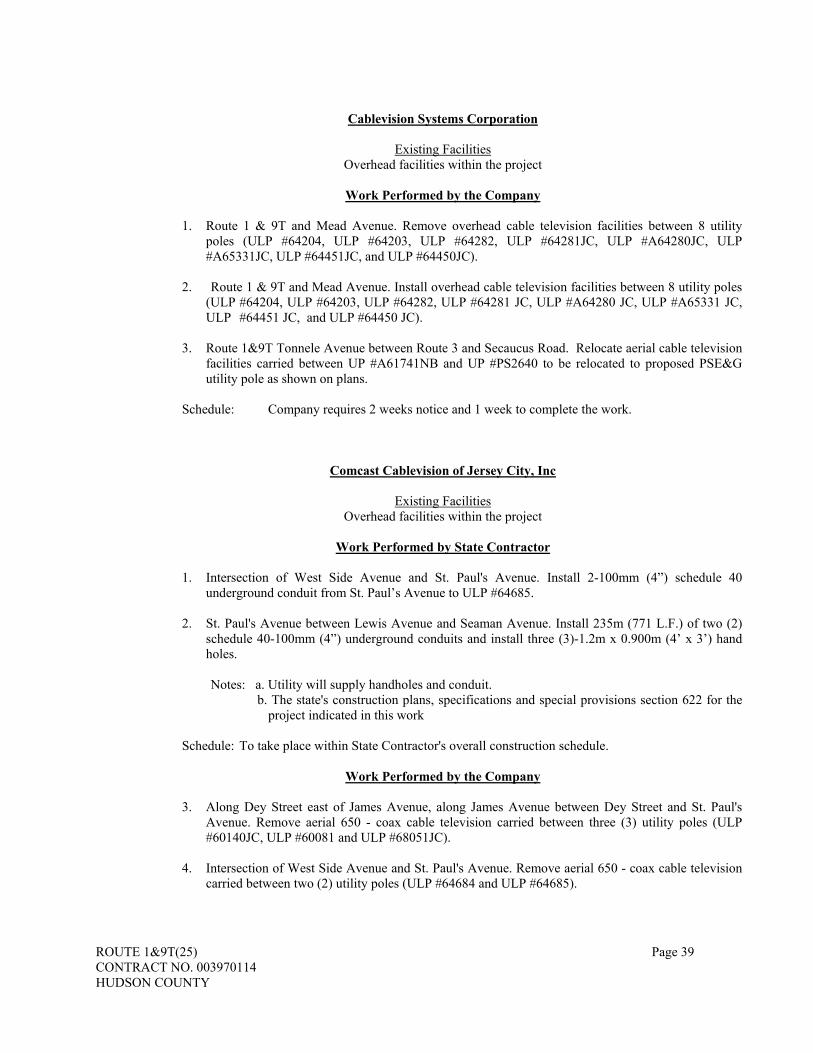
ROUTE 1&9T(25) Page 39 CONTRACT NO. 003970114 HUDSON COUNTY
Cablevision Systems Corporation
Existing Facilities
Overhead facilities within the project
Work Performed by the Company
1. Route 1 & 9T and Mead Avenue. Remove overhead cable television facilities between 8 utility poles (ULP #64204, ULP #64203, ULP #64282, ULP #64281JC, ULP #A64280JC, ULP #A65331JC, ULP #64451JC, and ULP #64450JC).
2. Route 1 & 9T and Mead Avenue. Install overhead cable television facilities between 8 utility poles
(ULP #64204, ULP #64203, ULP #64282, ULP #64281 JC, ULP #A64280 JC, ULP #A65331 JC, ULP #64451 JC, and ULP #64450 JC).
3. Route 1&9T Tonnele Avenue between Route 3 and Secaucus Road. Relocate aerial cable television
facilities carried between UP #A61741NB and UP #PS2640 to be relocated to proposed PSE&G utility pole as shown on plans.
Schedule: Company requires 2 weeks notice and 1 week to complete the work.
Comcast Cablevision of Jersey City, Inc
Existing Facilities Overhead facilities within the project
Work Performed by State Contractor
1. Intersection of West Side Avenue and St. Paul's Avenue. Install 2-100mm (4”) schedule 40
underground conduit from St. Paul’s Avenue to ULP #64685. 2. St. Paul's Avenue between Lewis Avenue and Seaman Avenue. Install 235m (771 L.F.) of two (2)
schedule 40-100mm (4”) underground conduits and install three (3)-1.2m x 0.900m (4’ x 3’) hand holes.
Notes: a. Utility will supply handholes and conduit. b. The state's construction plans, specifications and special provisions section 622 for the
project indicated in this work
Schedule: To take place within State Contractor's overall construction schedule.
Work Performed by the Company
3. Along Dey Street east of James Avenue, along James Avenue between Dey Street and St. Paul's Avenue. Remove aerial 650 - coax cable television carried between three (3) utility poles (ULP #60140JC, ULP #60081 and ULP #68051JC).
4. Intersection of West Side Avenue and St. Paul's Avenue. Remove aerial 650 - coax cable television
carried between two (2) utility poles (ULP #64684 and ULP #64685).

ROUTE 1&9T(25) Page 40 CONTRACT NO. 003970114 HUDSON COUNTY
5. St. Paul's Avenue between Lewis Avenue and Seaman Avenue. Remove aerial 650 - coax cable television carried between eight (8) utility poles (ULP #60212JC, ULP #60211JC, UP #64458, ULP #60210JC, ULP #E67627JC, BT 6860, BT 6861 and ULP #A67628JC).
6. St. Paul's Avenue between Lewis Avenue and Seaman Avenue. Install 235m (771 L.F.) of 650-coax
cable television.
7. Intersection of Covert Street and St. Paul's Avenue north along Covert Street. Remove aerial 650 - coax cable television carried between eight (8) utility poles (BT 6860, ULP #A67300, ULP #65965JC, UP #A65966JC, ULP #B65967JC, UP #A65968JC, ULP #19139 and ULP #A65398JC).
8. Intersection of Larch Avenue and St. Paul's Avenue north along Larch Avenue. Remove aerial 650 -
coax cable television carried between five (5) utility poles (UP #BT7502JC, ULP #E64698JC, ULP #65396JC, ULP #A65397JC and ULP #A65398JC).
9. From Spruce Street between Liberty Avenue and Route 1 &9T (Tonnele Avenue) and Route 1&9T
(Tonnele Avenue) between Spruce Street and Allen Street. Remove aerial 650-coax cable television carried between eight (8) utility poles (ULP#65888JC, ULP#69171JC, UP#969, ULP#68309JC, ULP#A60308JC, ULP No #, ULP No# and ULP#3663).
10. Along the east curbline of Tonnele Avenue between south of Allen Street and Carlton Avenue. Install
aerial 650-coax cable television carried between 6 utility poles (ULP #No Stencil, ULP# 68323JC, ULP# JC68217, ULP# 66182JC, ULP# BT7323JC and ULP #68807JC).
Note: Utility to provide inspection of facilities constructed by the State’s contractor. Schedule: Company requires 30 days notice and 45 working days to complete the work.
Jersey City Municipal Utilities Authority
Existing Facilities Combined Sanitary Sewer Pipes and Manholes
Work Performed by the State (Contractor)
1. Intersection of Duffield Avenue and St. Paul's Avenue. Reset 1 existing sewer manhole. 2. Along Charlotte Avenue between Dey Street and Newark Avenue.
Reset 5 existing sewer manholes.
3. A distance of 101m± (332 L.F.±) south of Charlotte Avenue baseline sta. 20+500 to the intersection of James Avenue and Dey Street. Abandon / remove existing 1350mm (53”) combined sanitary sewer pipe and 2 sewer manholes.
4. A distance of 101m± (332 L.F.±) south of Charlotte Avenue baseline sta. 20+500 to the
intersection of James Avenue and Dey Street. Install new 1350mm (53”) sanitary sewer pipe, construct 4 new sewer manholes and Reset / reconstruct 1 existing sewer chamber.
5. Between Charlotte Avenue and James Avenue along Dey Street. Reset 6 existing sewer
manholes.
6. Between Dey Street and St. Paul's Avenue along James Avenue. Reset 6 existing sewer manholes.

ROUTE 1&9T(25) Page 41 CONTRACT NO. 003970114 HUDSON COUNTY
7. Between St. Paul's Avenue and north of Private Road along Larch Avenue. Abandon / remove existing 375mm (15”) arch combined sanitary sewer pipe and 7 sewer manholes.
8. Along Seaman Avenue between St. Paul's Avenue and Private Road. Abandon / remove existing
combined sanitary sewer pipe and 2 sewer manholes.
9. Along Seaman Avenue. Reset 2 existing sewer manholes.
11. Tonnele Ccircle along Tonnele Avenue. Abandon / remove existing sewer pipe and 3 sewer manholes.
12. Tonnele Circle reset 1 existing sewer manhole. 13. Along Rte 1&9 (Tonnele Avenue) between Spruce Street and Allen Street (sta. 88+316 to sta.
88+442). Abandon / remove existing sewer pipe and 4 sewer manholes. 14. Along Rte 1&9 (Tonnele Avenue) between Spruce Street and Allen Street (sta. 88+309 to sta.
88+442). Install 750mm (30”) sewer pipe, construct 3 manholes and reset / reconstruct 1 manhole.
Schedule: To take place within the State Contractor's overall construction schedule.
Work to be Performed by the Company
1. Inspection of facilities constructed by the State. Schedule: Company requires two (2) weeks notice.
Verizon
Existing Facilities Aerial Cables and Underground Conduits
Work Performed by the State (Contractor)
1. Tonnele Circle. Install 2-100mm (4”) underground conduits from ULP #A61323JC to new pole installed by Verizon at U-Haul driveway entrance.
Notes: a. The state's construction plans, specifications and special provisions section 622 for the
project indicated in this work
Schedule: To take place within the State Contractor's overall construction schedule.
Work to be Performed by the Company
1. Route 1 & 9T and Mead Avenue. Remove overhead telephone carrier between 8 utility poles (ULP #64204, ULP #64203, ULP #64282, ULP #64281JC, ULP #A64280JC, ULP #A65331JC, ULP #64451JC, and ULP #64450JC).

ROUTE 1&9T(25) Page 42 CONTRACT NO. 003970114 HUDSON COUNTY
2. Route 1 & 9T and Mead Avenue. Install overhead telephone carrier between 8 utility poles (ULP
#64204, ULP #64203, ULP #64282, ULP #64281 JC, ULP #A64280 JC, ULP #A65331 JC, ULP #64451 JC, and ULP #64450 JC).
3. Route 1 & 9T and Mead Avenue. Remove overhead telephone carrier between 8 utility poles (ULP
#64204, ULP #64203, ULP #64282, ULP #64281JC, ULP #A64280JC, ULP #A65331JC, ULP #64451JC, and ULP #64450JC).
4. Route 1 & 9T and Mead Avenue. Install overhead telephone carrier between 8 utility poles (ULP
#64204, ULP #64203, ULP #64282, ULP #64281 JC, ULP #A64280 JC, ULP #A65331 JC, ULP #64451 JC, and ULP #64450 JC).
5. Duffield Avenue between Howell Street and St. Paul's Avenue. Remove 4 overhead cables (1 –
400AE, 2 – 300X and 1 – 50X) carried between 6 utility poles (ULP #64395JC, ULP #64394JC, UP #66413JC, ULP #64393, ULP #64392, ULP #A67153JC, ULP #64391JC, ULP #64390JC and ULP #A64389JC).
6. Duffield Avenue between Howell Street and St. Paul's Avenue. Install overhead telephone cables on
existing PSE&G utility poles (ULP #64395, ULP #25009, ULP #25010, ULP #25011, ULP #16272, ULP #69248JC) along the west curbline of Duffield Avenue and ULP #A64389JC.
4a. Duffield Avenue between Howell Street and St. Paul's Avenue. Install 30-100mm (4”) underground
telephone conduit and 1 manhole on east side of Duffield Avenue. 7. St. Paul's Avenue between Duffield Avenue and Larch Avenue. Install 30-100mm (4”) underground
telephone conduits and 2 manholes between Duffield Avenue and James Avenue. Install 28-100mm (4”) underground telephone conduits and 1 manhole between James Avenue and Westside Avenue.
8. St. Paul's Avenue between Lewis Avenue and Larch Avenue. Remove aerial telephone carried
between 9 utility poles (ULP#60212JC, ULP#60211JC, ULP#64685, UP#64458, ULP #60210JC, ULP#E67627JC, BT #6860, BT #6861 and ULP#A67628JC). Remove portion of 2-100mm PVC underground telephone conduits & 7-100mm PVC underground telephone conduits.
9. Howell Street between Duffield Avenue and Charlotte Avenue. Remove 3 overhead cables (1 - 300x
AE, 1 – 50X AE and 1 – 25X ISO) carried between 5 utility poles (ULP #A64389JC, ULP #66374JC, ULP #66375JC, ULP #66376JC and UP #No stencil).
10. Along Charlotte Avenue, Dey Street and James Avenue. Remove 6 overhead cables (1 - 100X, 1 -
50X, 1 - 200X AE, 1 - 200X and 2 - 200X) carried on 4 utility poles (ULP #A65643JC, ULP #A65644JC, ULP #60081 and ULP #60140JC), and remove overhead drop wire between 5 utility poles (ULP #8143, ULP #19700JC, ULP #PS19698JC, ULP #A66228JC and ULP #A65643JC).
11. Along Charlotte Avenue, Dey Street and James Avenue. Install 2 new poles and aerial telephone
cables along west sidewalk of the proposed Charlotte Avenue.
12. Larch Avenue between St. Paul's Avenue and Private Road. Remove 2 aerial cables (1 – 200X, 1 – 50X) carried between 5 utility poles (UP #BT7502JC, ULP #E64698 JC, ULP #65396 JC, ULP #A65397 JC and ULP #A65398 JC). Remove UP #BT7502JC.
13. Tonnele Circle. Remove aerial telephone carried between 3 utility poles (UP #A66179 JC, UPL
#A66180JC and UPL #66181).
14. Tonnele Circle. Install new riser pole at U-Haul driveway entrance. Install cable inside new conduit from pole ULP #A61323JC to new pole at U-Haul driveway entrance.

ROUTE 1&9T(25) Page 43 CONTRACT NO. 003970114 HUDSON COUNTY
15. Tonnele Avenue between Conrail and Spruce Street. Remove overhead drop wire between 8 utility
poles (ULP #PS2886JC, ULP #NO stencil, ULP #PS7269JC, UP #919, ULP #68309JC, ULP #A60308JC, ULP #NO stencil and UP #71155JC).
16. Tonnele Avenue between Spruce Street and Allen Street. Remove overhead telephone carried
between 4 utility poles (ULP #19158, UP #71155JC, UP #BT6009JC and ULP #No stencil).
17. Tonnele Avenue between Route 3 and Secaucus Road. Remove aerial telephone carried between 2 utility poles (UP #PS2640 and UP #No stencil).
18. Tonnele Avenue between Route 3 and Secaucus Road. Install aerial telephone between 2 utility
poles (UP #PS2640 and UP #No stencil). Note: Utility to provide inspection of facilities constructed by the State’s contractor. Schedule: Company requires 2 weeks notice, and 6 months to complete the work.
Jersey City Municipal Utilities Authority
Existing Facilities 150mm (6”) to 900mm (36”) Water Mains, Valves and Fire Hydrants
Work to be Performed by the State (Contractor)
1. Intersection of Duffield Avenue and St. Paul's Avenue. Reset 11 water valve boxes. 2. Duffield Avenue between St. Paul's Avenue and south of Howell Street. Install 500mm (20")
ductile iron water pipe, 2 fire hydrants, 4-150 mm (6") gate valves and boxes, 150 mm (6") ductile iron water pipe, 2-500 mm x 150 mm (20" x 5") tees, 1-500 mm x 200 mm (20" x 8") tee and 1-500 mm (20") gate valve with bypass and boxes.
3. Duffield Avenue between St. Paul's Avenue and south of Howell Street. Remove / abandon 200
mm (8") water pipe and 7 gate valves and boxes. 4. Howell Street between Duffield Avenue and Charlotte Avenue. Remove / abandon 200mm (8")
water main, 8 gate valves and boxes. Remove 3 fire hydrants. 5. Between Duffield Avenue and Charlotte Avenue on the south side of Howell Street.
Remove/abandon 500mm (20") and 900mm (36") ductile iron water pipe. 6. Between Duffield Avenue and Charlotte Avenue on the south side of Howell Street. Install 500 mm
(20") and 900 mm (36") ductile iron water pipe, 900 mm (36") and 1050 mm (42") steel casings with stainless steel band spacers and end seals, 2 - 500 mm (20") and 2 - 900 mm gate valves with bypass and boxes, 2-900 mm x 500 mm (36" x 20") tees, and 1-900 mm (36") inserting valve and boxes.
7. South of Dey Street and Charlotte Avenue intersection. Install 1 fire hydrant, 150 mm (6") ductile
iron water pipe, and one (1) 150 mm (6") gate valve and boxes. 7a. South of Dey Street and Charlotte Avenue intersection. Remove 1 fire hydrant and 1 gate valve and
boxes.

ROUTE 1&9T(25) Page 44 CONTRACT NO. 003970114 HUDSON COUNTY
8. Dey Street between Charlotte Avenue and Conrail tracks. Connect proposed 200 mm (8") ductile iron water pipe and new fire hydrant to existing 600 mm (24") water pipe. Install 600 mm (24") and 200 mm (8") ductile iron water pipes, 1-600 mm x 200 mm (24" x 8") tee, 2-200 mm (8") gate valves with bypass and boxes, 2 fire hydrants, 150 mm (6") ductile iron water pipe and 2-150 mm (6") gate valve and boxes.
9. Dey Street between Charlotte Avenue and Conrail tracks. Remove/abandon 200mm (8") and
150mm (6") water mains.
10. James Avenue between St. Paul's Avenue and Dey Street install 1 fire hydrant, 150 mm (6") and 200 mm (8") ductile iron water pipe, 2-150 mm (6") gate valve and boxes, 1-200 mm x 150 mm (8" x 6") tee. Reset 2 gate valve boxes.
11. Intersection of James Avenue and St. Paul's Avenue. Remove 1 fire hydrant and 1 gate valve and
boxes. 12. Intersection of James Avenue and Dey Street south along James Avenue. Remove / abandon 150
mm (6") water pipe and 2 gate valves and boxes. 13. Along existing Route 1 & 9t between Charlotte Avenue and Covert Street install 900 mm (36") and
500mm (20") ductile iron water pipe, 4 fire hydrants, 150 mm (6") ductile iron water pipe, 8-150 mm gate valves and boxes 2-500 mm (20") and 2-900mm (36") gate valves and boxes with bypass, 500 mm x 200 mm (20" x 8") tees and 900 mm x 150 mm (36" x 6") tapping sleeves.
14. Along existing route 1 & 9T between Charlotte Avenue and Covert Street remove / abandon 900
mm (36") and 500 mm (20") water pipes and water pipe tunnel.
25. At the intersection of Charlotte Avenue and route 7 westbound. Reset 7 gate valve boxes. 26. North curbline of St. Paul's Avenue between Covert Street and larch Avenue. Connect new fire
hydrant to existing 150 mm (6") water pipe. Install 1 fire hydrant, 1- 150 mm x 150 mm (6" x 6") tee, 150 mm (6") ductile iron water pipe, and 1 gate valve and boxes.
27. North curbline of St. Paul's Avenue between Covert Street and larch Avenue. Remove 1 fire
hydrant. 28. Covert Street to Tonnele Circle. Install 900 mm (36") and 500 mm (20") ductile iron water pipes
and 4 fire hydrants, 150 mm (6") ductile iron water pipes, 4-150 mm (6") gate valves and boxes, 2 - 500 mm (20") and 2 - 900 mm (36") gate valves and boxes with bypass, 2-900 mm x 150 mm (36" x 6") tapping sleeve and 2-500 mm x 150 mm (20" x 6") tees.
29. Covert Street to Tonnele Circle. Remove / abandon 900mm (36") and 500 mm (20") ductile iron
water pipe and demolish water pipe tunnel.
30. Seaman Avenue north of St. Paul's Avenue. Remove / abandon 150 mm (6") ductile iron water pipe. 31. Larch Avenue north of St. Paul's Avenue. Remove / abandon 150 mm (6") and 200 mm (8") water
mains, 10 gate valves and 2 fire hydrants.
32. Tonnele Avenue between Tonnele Circle and N.J. Transit structure. Remove / abandon 150 mm (6") and 300 mm (12") water pipes and gate valve with bypass, 10 gate valves and 1 fire hydrant.
33. South side of Tonnele Circle along Tonnele Avenue to Spruce Street. Install 500 mm (20") ductile
iron water pipe and 200 mm (8") ductile iron water pipe bypass, 1 water vault, 11 gate valves, 1 blow-off valve, 2 fire hydrants, 150 mm (6") ductile iron water pipe, 1-200 mm x 500 mm (8" x

ROUTE 1&9T(25) Page 45 CONTRACT NO. 003970114 HUDSON COUNTY
20") reducer, 1-200 mm x 500 mm (8" x 20") tee, 1-200mm x 900mm (8" x 36") tee, 1-200 mm (8") and 1-500 mm (20") gate valves and boxes with bypass, & reset 1 gate valve boxes.
34. South of N.J. Transit structure along Tonnele Avenue to spruce Street. Remove / abandon 300 mm
(10") and 500 mm (20") water pipe, 5 gate valves and boxes.
35. Along route 1&9 (Tonnele Avenue) to proposed detention basin. Install 1- 200 mm x 150 mm (8" x 6") tee, 150 mm (6") ductile iron water pipe, 1-150 mm (6") blow off valve and boxes.
36. Spruce Street between Tonnele Avenue and Liberty Avenue. Install 200 mm (8") ductile iron water
pipe, 2 gate valves and reset 1 water valve boxes.
37. Spruce Street and Tonnele Avenue intersection. Install 3 fire hydrants, 150 mm (6") ductile iron water pipe, and 4 gate valves. Reset 1 water valve boxes.
38. Spruce Street and Tonnele Avenue intersection. Remove 3 fire hydrants and 2 gate valves and
boxes.
Schedule: To take place within State Contractor's overall construction schedule.
Work to be Performed by the Company
1. Inspection of facilities constructed by the State. Schedule: Company requires two (2) weeks notice.
B. Existing Facilities. The Contractor shall not proceed with any excavation operations until it has determined
the exact location of the existing utility facilities within the Project from examination of the Contract Documents and information provided in Subsection 102.03, through inquiries to the respective Utility(s), and through its own subsurface site investigations, including test pits. Test Pits shall be as specified in Subsection 207.04. The Contractor shall notify the Resident Engineer as specified in Subsection 105.03 if their examinations determine any conflicts to completing the Work.
The Contractor shall notify the Resident Engineer at least 10 State Business Days in advance of the excavation of any test pits, or other subsurface investigations. Bidders shall notify the Department in advance as specified in Subsection 102.03.
Electrical installations, including Intelligent Transportation Systems (ITS) facilities as specified in Section 706, of the Department constructed either before or as part of the Contract shall be considered a Utility, and all provisions of this Subsection and Division 700 shall be applicable.
Examinations of Department documents available on existing electrical installations shall be as specified in Subsection 102.03. For any work in the vicinity of the Department’s fiber optic network, the Contractor shall submit a Traffic Operations Markout Form to the Traffic Operations location specified in the Special Provisions. The Contractor shall obtain and complete the form as specified on the Department’s web site, and provide the RE a copy of the form. The Department will complete the markout within 10 State Business days after Traffic Operations receives the form. The Contractor shall maintain the markout until construction operations in the vicinity of the Department’s fiber optic network are completed.
C. Regulations. The Contractor shall also comply with all other State and Federal rules, and regulations
applicable to work on or in the proximity of utilities. Specific attention is made to: 1. The State’s Underground Facility Protection Act. The Contractor shall notify the State’s One Call
System (1-800-272-1000) and identify itself as the State’s Contractor and specify the route and contract number of the Project before performing Work on the Project.
2. High voltage line requirements according to NJSA 34:6-47.1 to 47.9, 29 CFR 1926.550, and the Utility Accommodation Policy, NJSA 16:25. The Contractor shall obtain written approval from

ROUTE 1&9T(25) Page 46 CONTRACT NO. 003970114 HUDSON COUNTY
the Department of Labor, Office of Safety Compliance, and the respective Utility(s) if required, for any operations that do not provide the minimum clearances under these regulations. The Contractor shall be responsible for any proposed power outage or de-energization associated with their operations. A copy of the approvals shall be submitted to the Resident Engineer at least 5 State Business Days in advance of starting those operations.
D. Notices. The Contractor shall make a written request to the Resident Engineer at least 10 State Business Days
in advance of the notice requirements provided in the Special Provisions for the Department to notify Utility(s) to proceed with the Utility(s) utility work. The Contractor shall be cognizant that where joint use poles or duct banks are used, the time frames for work performed by each user are cumulative. The Contractor shall guarantee the site availability for utility operations. The Department will notify the Utility(s) to proceed if in the Department’s opinion the site will be available for a particular item of utility work. The Contractor shall permit the Utility(s) or their agents access to their facilities at all times and shall cooperate with them in performing their work.
The Contractor shall cooperate with the Utility(s) concerned and shall notify them, through the Resident Engineer, not less than 10 State Business Days in advance of the time it proposes to construct any utility item or perform any work that may endanger or affect their facilities. The Contractor shall have the contractual obligation of coordinating its activities with those of the Utility(s). The Utility(s) shall be given the opportunity to inspect the actual material to be installed as well as the installation.
The Contractor shall provide 72 hour advance notice to the Resident Engineer of any meetings scheduled with Utility(s) and provide the Resident Engineer with a copy of any correspondence with the Utility(s).
The Contractor shall make separate written notifications, with a copy to the Resident Engineer, a minimum of 4 State Business Days prior to when work may impact or be adjacent to Department electrical installations. For ITS facilities, notification shall be to the Bureau of Traffic Operations at the location and telephone number provided in the Special Provisions. For all other electrical installations, notification shall be made to the Regional Bureau of Electrical Maintenance at the location and telephone number provided in the Special Provisions. No Department-owned installation shall be accessed, modified, removed, or disturbed in any manner, without first making such notifications and attending a meeting with the Department if requested.
Bureau of Electrical Maintenance, North Region 200 Stierli Court Mt. Arlington, NJ 07856-1322 Telephone: 973-770-5065 Bureau of Traffic Operations, North Region (TOCN) 670 River Drive Elmwood Park, NJ 07407 Telephone: 201-797-3575
E. Damages. The Contractor shall protect, support, and secure all in-place utility facilities so as to avoid damage
to them and any interruption of service. The Contractor shall not temporarily move existing or completed utility facilities without the Utility(s) written consent, and the facilities shall be as safe and permanent at completion as they were before the Contractor’s involvement. In the event the Contractor damages a utility facility, including property service connections, the Contractor shall notify the Utility(s) immediately. The Utility(s) may complete the repairs or allow the Contractor to complete the repairs, with the Contractor responsible for any applicable time and expense. Repairs to Department electrical installations shall be as specified in Subsection 105.19 and the additional requirements for the fiber optic network of the Department ITS facilities as specified in this Subsection. The fiber optic network includes the conduit/cable, junction boxes/cabinets, and hubs.
Within two hours of any damage by the Contractor to the fiber optic network, the Contractor shall notify the Resident Engineer, in writing with a copy to the Traffic Operations contact specified in the Special Provisions, that the Contractor shall complete the repairs within 48 hours and have the repairs underway within 12 hours after the damage has occurred. If the written notice has not been received from the Contractor within two hours and/or the commencement of the repairs has not started within 12 hours, the Department may undertake and complete the repairs. The cost of repairs made by the Department for damages that are

ROUTE 1&9T(25) Page 47 CONTRACT NO. 003970114 HUDSON COUNTY
determined by the Resident Engineer to be the Contractor’s responsibility shall be deducted from subsequent estimates. If the Contractor does not complete the repairs within 48 hrs, damages for lost services will be assessed to the Contractor at a minimum of $1000 per hour, or increased based on costs calculated by the Department, and deducted from subsequent estimates.
Should the Contractor, for its own convenience, cause the Utility(s) to incur costs not covered by the utility agreement, or delay the Utility(s), or incur costs without prior written approval of the Resident Engineer, the Contractor shall be responsible for these costs and delays. The Contractor shall pay the Utility(s) within 30 days of the Utility(s) request for cost reimbursement of any repairs and other incurred costs. If payment has not been made within 30 days, the Department may reimburse the Utility(s) for the Contractor generated costs and deduct these expenses from partial or final payment due the Contractor.
F. Railroads. In addition to the foregoing provisions and the attached railroad documents, the following specific
provisions relate to railroads only: 1. Railroad Traffic and Property. Where the Project includes work across, over, under, or adjacent to
railroad tracks or railroad ROW, the Contractor shall safeguard the traffic, tracks, and appurtenances, and other property of the railroad that may be affected by its Work. The Contractor shall comply with the regulations of the railroad relating to its Work, shall keep tracks clear of obstructions, and shall provide barricades, warning signs, lights, or other safety devices as required by the railroad. Payment for such safety devices will be made as specified in Section 617. Prior to the commencement of any work within the railroad ROW or on railroad facilities, the Contractor shall obtain the railroad’s written approval of access, the method of construction (including demolition), and the schedule of the Work. The Contractor shall provide a copy of the submittal and approval to the Resident Engineer.
Estimated railroad train schedules will be provided in the Special Provisions. The safety and continuity of railroad operations shall be the first priority when working in proximity
to the railroad. Railroad approval does not release the Contractor from responsibility or liability for any damage that the railroad may suffer, or for which the Contractor may be held liable, by the acts of the Contractor.
Fouling of railroad facilities’ track, power lines, and signal systems occurs when the railroad parameters for normal operations are jeopardized because obstructions are in close proximity to the facilities. The Contractor shall obtain from the railroad its fouling parameters for the work site and observe the railroad’s regulations concerning fouling. Construction equipment or material shall not be stored or operated within the fouling distance of the railroad facilities without written permission of the railroad, with a copy to the Resident Engineer.
The railroad may assign inspectors, engineers, or flagmen during the time the Contractor is engaged in work on railroad property for the general supervision of construction operations, to ensure adherence to the Contract Documents and applicable railroad requirements, and to ensure the use of approved construction methods.
If materials are to be hauled across the tracks of any railroad, the Contract Documents will provide for any new crossings required or for the use of any existing crossings. If the Contractor elects to use crossings other than those designated, it shall obtain written approval from the railroad with a copy of the approval to the Resident Engineer at least 10 State Business Days in advance.
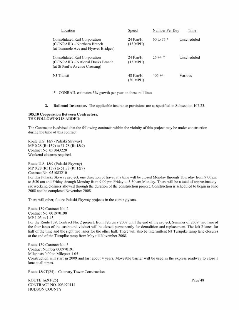
ROUTE 1&9T(25) Page 48 CONTRACT NO. 003970114 HUDSON COUNTY
Location Speed Number Per Day Time
Consolidated Rail Corporation (CONRAIL) – Northern Branch (at Tonnnele Ave and Flyover Bridges)
24 Km/H(15 MPH)
60 to 75 * Unscheduled
Consolidated Rail Corporation (CONRAIL) – National Docks Branch (at St Paul’s Avenue Crossing)
24 Km/H(15 MPH)
25 +/- * Unscheduled
NJ Transit
48 Km/H(30 MPH)
405 +/- Various
* - CONRAIL estimates 5% growth per year on these rail lines
2. Railroad Insurance. The applicable insurance provisions are as specified in Subsection 107.23.
105.10 Cooperation Between Contractors. THE FOLLOWING IS ADDED: The Contractor is advised that the following contracts within the vicinity of this project may be under construction during the time of this contract: Route U.S. 1&9 (Pulaski Skyway) MP 0.28 (Rt 139) to 51.78 (Rt 1&9) Contract No. 051043220 Weekend closures required. Route U.S. 1&9 (Pulaski Skyway) MP 0.28 (Rt 139) to 51.78 (Rt 1&9) Contract No. 051083210 For this Pulaski Skyway project, one direction of travel at a time will be closed Monday through Thursday from 9:00 pm to 5:30 am and Friday through Monday from 9:00 pm Friday to 5:30 am Monday. There will be a total of approximately six weekend closures allowed through the duration of the construction project. Construction is scheduled to begin in June 2008 and be completed November 2008. There will other, future Pulaski Skyway projects in the coming years. Route 139 Contract No. 2 Contract No. 001970190 MP 1.03 to 1.45 For the Route 139, Contract No. 2 project: from February 2008 until the end of the project, Summer of 2009, two lane of the four lanes of the eastbound viaduct will be closed permanently for demolition and replacement. The left 2 lanes for half of the time and the right two lanes for the other half. There will also be intermittent NJ Turnpike ramp lane closures at the end of the Turnpike ramp from May till November 2008. Route 139 Contract No. 3 Contract Number 000970191 Mileposts 0.00 to Milepost 1.05 Construction will start in 2009 and last about 4 years. Moveable barrier will be used in the express roadway to close 1 lane at all times. Route 1&9T(25) – Catenary Tower Construction

ROUTE 1&9T(25) Page 49 CONTRACT NO. 003970114 HUDSON COUNTY
MP 54.74 to 54.76 (Rt 1&9) Contract No. HUD088010 The Wittpenn Bridge (Route 7) over the Hackensack River Future Projects In addition, utility work, by others, will be ongoing within the project limits and the PSE&G Plant on Duffield Avenue may begin a major rehabilitation project. The Contractor shall conduct its Work so as not to interfere with or hinder the progress or completion of the work being performed by other contractors. The Contractor's attention is directed to the need for close coordination and cooperation with the contractors on the above listed projects and any additional future projects that may impact the project that may occur during the work of this project. The Contractor shall be aware of the potential for schedule changes on the projects noted above. The Contractor shall contact the contractors of the above listed projects to coordinate maintenance and protection of traffic required within their respective jurisdictions for road and bridge work at least four weeks before commencement of work, changes of Traffic Patterns and start of lane closures in the areas of project overlap. 105.11 Construction Stakes, Lines, and Grades.
A. For Projects with Construction Layout as a Pay Item. THE FIFTH PARAGRAPH IS CHANGED TO:
The Contractor shall complete all utility work layouts required after approval of the insurance certificates as specified in Subsection 107.23 and the Safety and Health Program as specified in Subsection 107.10. The Contractor shall notify the Utility(s) as specified in Subsection 105.09.
105.15 Field Office.
1. Construction Field Offices. a Type A.
THE FIRST PARAGRAPH IS CHANGED TO:
Type A field office shall be of weatherproof construction located adjacent to the contractor’s field office having a floor area of not less than 56 square meters and a ceiling height of not less than 2.3 meters, and having partitions and doors providing three communicating rooms, one with a floor area of not less than 28 square meters and two with a floor area of not less than 14 square meters each.
PART (1) IS CHANGED TO:
(1) 7 multi-line touch-tone telephones and 2 telephone lines for use with the telephones installed as directed and operational in the Field Office and other facilities specified and multi-line telephone answering machine or voice mail.
(a) 2 dedicated, operational telephone line(s) for Fax machines (s) and/or microcomputer system(s) modem use installed as directed in the Field Offices specified.
(b) 6 portable hand held cellular phone(s) with two way capacity. The cellular telephone plan shall provide for unlimited mobile to mobile in-network usage, unlimited push-to-talk / walkie-talkie usage and an anticipated usage of approximately 900 anytime minutes per telephone per month. All cell phones must have the same phone plan. Each of the cellular phones shall have as a minimum the following features:
1) Home rate with no roaming charges within the entire state 2) 832 Channel Compatible 3) Mute Function 4) Back Light Display with Battery Saver 5) Signal Strength Indicator

ROUTE 1&9T(25) Page 50 CONTRACT NO. 003970114 HUDSON COUNTY
6) Individual Call Length Timer 7) Full Lock Function 8) 30 Memory Number Feature 9) Low Battery Warning 10) 70 Minute Continuous Use 11) 12 hour Standby Mode 12) Alphanumeric Display 13) Transmission Power 0.6 Watt 14) Passive Repeating Antenna for Vehicle 15) Spare high capacity Battery Pack 16) Home Charging Station 17) Cigarette lighter power adapter /charger 18) AC charging station 19) Hands-Free headset
PART (12) IS CHANGED TO:
(12) 1 copy machine with letter, legal and ledger size capabilities. Also to have automatic document feed, 15 ppm, tray size, and variable reduce/enlarge capability features.
PART (14) IS CHANGED TO:
(14) 4 digital cameras each with auto-focus, rechargeable batteries and charger, 4-256 MB memory cards, USB Memory Card Readers compatible with cameras and field office computers, 1.5 inch LCD monitors, 5 mega pixel resolution, 10X optical zoom lens, built in flash, image stabilization, computer connections, and carrying cases
PART (17) THE FIRST SENTENCE OF THE FIRST PARAGRAPH IS CHANGED TO:
(17) A microcomputer system compatible with the Department’s “ACES” system, whether purchased new or previously used.
THE FIFTH PARAGRAPH IS CHANGED TO:
The microcomputer system (after the project data has been erased from the hard drive by the Department), manuals, instructions, software, and literature shall be removed and retained by the Contractor when no longer required as determined by the Resident Engineer. The data cartridges and data diskettes will become the property of the State.
THE FOLLOWING ARE ADDED TO PART (17):
The microcomputer system shall include the following: (a) 4 base computer system(s) having at minimum:
1) Pentium IV Processor at 3.5 GHz or faster, Intel processor with Hyper Threading technology, with 1024 MB RAM, 512 MB Video RAM, mouse, mouse pad, 200 Gigabyte hard drive or larger (must be designated as drive C:), one DVD (+/-) Writer Drive, one CD-R Recordable Drive, and one 90-millimeter, 1.44 MB floppy diskette drive with multi-media card reader installed as the “A” drive. System must be USB 2.0 compactable.
2) 56K baud data/fax modem. (e.g., 3Com U.S. Robotics 56K Fax modem, 3Com U.S. Robotics Courier V.Everything/V.34 - 56K ITU / x2 Technology, or Hayes Accura 56K). Ensure that at least one computer is equipped with a dial-up modem and has a Microsoft Windows 32 Bit Operating System.
3) One wireless network card for each base computer system specified, when more than one base computer is specified.
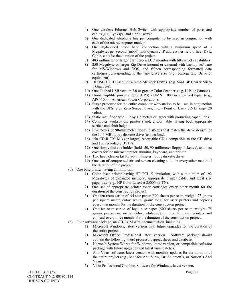
ROUTE 1&9T(25) Page 51 CONTRACT NO. 003970114 HUDSON COUNTY
4) One wireless Ethernet Hub Switch with appropriate number of ports and cables (e.g. Lynksys) and a print server.
5) One dedicated telephone line per computer to be used in conjunction with each of the microcomputer modem.
6) One high-speed broad band connection with a minimum speed of 3 Megabytes per second (mbps) with dynamic IP address per field office (DSL, Cable, etc.) for the duration of the project.
7) 483 millimeter or larger Flat Screen LCD monitor with tilt/swivel capabilities. 8) 250 Megabyte or larger Zip Drive internal or external with backup software
for MS-Windows and DOS, and fifteen corresponding formatted data cartridges corresponding to the tape drive size (e.g., Iomega Zip Drive or equivalent).
9) 10 USB 1 GB Flash/Stick/Jump Memory Drives. (e.g. SanDisk Cruzer Micro 1 Gigabyte).
10) One Flatbed USB version 2.0 or greater Color Scanner. (e.g. H.P. or Cannon) 11) Uninterruptible power supply (UPS) - OMNI 1000 or approved equal (e.g.,
APC-1000 - American Power Corporation). 12) Surge protector for the entire computer workstation to be used in conjunction
with the UPS (e.g., Zero Surge Power, Inc. - Point of Use - 2R-15 amp/120 volts).
13) Static mat, floor type, 1.2 by 1.5 meters or larger with grounding capabilities. 14) Computer workstation, printer stand, and/or table having both appropriate
surface and chair height. 15) Five boxes of 90-millimeter floppy diskettes that match the drive density of
the 1.44 MB floppy diskette drive (ten per box). 16) 150 CD-R 700 MB (or larger) recordable CD’s compatible to the CD drive
and 100 recordable DVD’s. 17) One floppy diskette holder (holds 50, 90-millimeter floppy diskettes), and dust
covers for the microcomputer, monitor, keyboard, and printer. 18) Two head cleaner kit for 90-millimeter floppy diskette drive. 19) One can of compressed air and screen cleaning solution every other month of
the duration of the project. (b) One base printer having at minimum:
1) Color laser printer having HP PCL 5 emulation, with a minimum of 192 Megabytes of expanded memory, appropriate printer cable, and legal size paper tray (e.g., HP Color LaserJet 2500N or TN).
2) One set of appropriate printer toner cartridges every other month for the duration of the construction project.
3) One ten-ream carton of A4 size paper (500 sheets per ream, weight: 75 grams per square meter, color: white, grain: long, for laser printers and copiers) every two months for the duration of the construction project.
4) One ten-ream carton of legal size paper (500 sheets per ream, weight: 75 grams per square meter, color: white, grain: long, for laser printers and copiers) every three months for the duration of the construction project.
(c) Four software package, on CD-ROM with documentation, including: 1) Microsoft Windows, latest version with future upgrades for the duration of
the entire project. 2) Microsoft Office Professional latest version. Software package should
contain the following: word processor, spreadsheet, and database. 3) Norton’s System Works for Windows, latest version, or compatible software
package with future upgrades and latest virus patches. 4) Anti-Virus software, latest version with monthly updates for the duration of
the entire project (e.g., McAfee Anti Virus, Dr. Solomon’s, or Norton’s Anti Virus).
5) Visio Professional Graphics Software for Windows, latest version.

ROUTE 1&9T(25) Page 52 CONTRACT NO. 003970114 HUDSON COUNTY
(d) 1 base printer(s) for Primavera having at minimum: 1) Color Inkjet printer of current technology, with appropriate printer cable. 2) Ink cartridge replacements, one of each color, every other month for the
duration of the construction project. 3) One 10-ream carton of 8½ X 11 inches size paper (500 sheets per ream,
weight: 75 grams per square meter, color: white, grain: long, for laser printers and copiers) every three months for the duration of the construction project.
(e) 4 Primavera Project Planner (P3) or equivalent software, latest version. To be approved as a Substitute or "Or Equal", the software must be completely compatible with the
Department database that contains the Capital Program Management's design process schedule and budget, as well as the construction scheduling from design through construction. The software shall be compatible with the hierarchy of the coding and able to import and export data within the Department’s Capital Program Management's database without distortion of any coding or relationships contained in the database.
The Contractor shall only utilize equivalent or compatible software for a project, which has received written approval from the Department in accordance with the most current NJDOT Capital Program Management Construction Scheduling Standard Coding and Procedures for Designers and Contractors Manual. The approved equivalent/compatible software utilized shall not vary throughout the construction phase. The following additional equipment shall be furnished by the Contractor for the exclusive use of the Resident
Engineer. This equipment shall conform to the applicable ASTM designation, when appropriate, and be in good working condition. The Contractor shall repair or replace damaged equipment throughout the duration of the Contract. The equipment shall become the property of the Contractor after Acceptance: • 1 laptop micro-computer with:
Latitude D630: Intel® Core™ 2 Duo T7300 (2.00GHz) 4M L2 Cache, 800MHz Dual Core Operating System: Genuine Windows® XP Professional, SP2, with media LCDs: 14.1 inch Wide Screen WXGA LCD Panel Graphics: 128MB NVIDIA® Quadro NVS 135M™ Memory: 2.0GB, DDR2-667 SDRAM, 2 DIMMS Batteries: 9 Cell Primary Battery Additional AC Adapter: Dell Slim 65W Auto/Air/AC Adapter Media Bay Devices: 8X DVD+/-RW w/Roxio and Cyberlink Power DVD™ Carrying Cases: Large Nylon Carrying Case Wireless LAN (802.11): Intel® 3945 802.11a/g Dual-Band Mini Card Mobile Broadband: Verizon Wireless built-in mobile broadband (EV-DO Rev A) Productivity Software: Microsoft® Office 2007 Professional and Adobe Acrobat 8 STD Security Software: Norton Internet Security™ 2006 54 Month Subscription System Documentation: Resource CD - Contains Diagnostics and Drivers Docking Solutions: D/Port Advanced Port Replicator External Monitors: Dell 19 inch UltraSharp™ 1908FP Flat Panel, adjustable stand, VGA/DVI External Keyboard: Dell USB Enhanced Multimedia Black Keyboard with built-in 2-port USB Hub Mouse: Dell USB 2-Button Black Optical Mouse Speakers: Dell AS501 Sound Bar for all UltraSharp Flat Panel Displays Hard Drives: 120GB Hard Drive, 9.5MM, 7200RPM File System: NTFS File System for all Operating Systems Floppy Drive: Floppy Drive 1 Air Card/WiFi
• 1 wireless router and 6 USB drives with a 1 GB storage • 1 Date / Received Stamp and ink pad • 1 Flatbed USB version 2.0 or greater Color Scanner with automatic document feeder and latest version of
PaperPort software. • 3 additional electronic calculators

ROUTE 1&9T(25) Page 53 CONTRACT NO. 003970114 HUDSON COUNTY
• 4 illuminated measuring wheels • 3 Smart Levels • 4 digital infrared remote read thermometers • 4 asphalt thermometers • 4 surface thermometers • 6 concrete thermometers • 4 six foot Carpenter rulers • 1 Sledge hammer, 8lb • 3 -100’ steel measuring tape • 4 -100’ cloth measuring tape • 12 lanterns with monthly battery replacements • 12 sets of safety equipment consisting of:
Safety vests-orange, reflectorized, 360º high visibility safety vests according to ANSI/ISEA Class 3, Level 2 standards. To be replaced yearly for the duration of the contract. Hard hats, eye and ear protection, which meets all OSHA requirements.
• 12 sets of rain gear with reflective sheeting • Concrete Testing equipment to include (one of each): Wheelbarrow, square tipped shovel, concrete scoop,
slump cone and base set (rod, slump cone, base and funnel) tamping rod (12 inches long, 3/8-inch diameter with hemispherical ends), tamping rod (24 inches long, 5/8-inch diameter with hemispherical ends), 12” ruler, Forney air meter (complete set) or equivalent, sponge and long handled scrub brush, rubber or rawhide mallet (2.25 lb. ± -0.50 lb.), pointed trowel and five-gallon bucket, concrete cylinder curing items in accordance with the governing specifications
105.19 Maintenance During Construction. THE THIRD PARAGRAPH IS CHANGED TO:
Any damage to the Roadway due to the Contractor’s operations shall be repaired at no Additional Compensation, except as specified in Subsection 107.22. The Contractor shall complete within 24 hours specific repairs directed by the Department, except where the requirements are specified by a Subsection. Nothing in this Subsection shall be construed to limit or change the risks assumed by the Contractor as specified in Subsection 107.22. THE SIXTH PARAGRAPH IS CHANGED TO:
The Department may direct the Contractor to construct Bituminous Concrete Patch as specified in Section 402 to maintain sections of traveled way and shoulders in a smooth riding condition at all times including seasonal shutdowns. Payment for Bituminous Concrete Patch will be made as specified in Section 402 except for those areas that are damaged or created by the Contractor’s operations. THE FOLLOWING IS ADDED:
The existing bridges shall not be used for construction and/or demolition activities without signed and sealed calculations from a Professional Engineer licensed in New Jersey. These bridges have low sufficiency ratings and their ability to support construction / demolition loads has not been established. 105.22 Substantial Completion. THE THIRD SENTENCE OF THE FIRST PARAGRAPH IS CHANGED TO: If the Engineer determines that the Work is substantially complete, the Engineer will then prepare a letter which states the date of Substantial Completion and establishes a reasonable time within which the Contractor shall perform the final cleanup, and repair unacceptable Work, which time may be prior to Contract Time as modified.

ROUTE 1&9T(25) Page 54 CONTRACT NO. 003970114 HUDSON COUNTY
SECTION 106 – CONTROL OF MATERIAL 106.03 Materials, Inspections, Tests, and Samples. THE SUBSECTION HEADING IS CHANGED TO: 106.03 Materials, Inspections, Tests, Samples and Certified Training.
B. Sampling and Field Testing of Soil Aggregates. THIS SIXTH PARAGRAPH IS CHANGED TO:
Sampling and testing of aggregates by the Department that meet the Specifications and are used in the Work will be performed without cost to the Contractor.
THE FOLLOWING SUBPART IS ADDED:
D. Sharing of Pay-Adjustments for Portland Cement Concrete. Positive and negative pay-adjustments, as defined in Subsection 914.02, Subpart E, are awarded to encourage high quality construction and, when necessary, to recoup the anticipated extra costs to the Department resulting from poor quality construction. The manner in which positive and negative pay-adjustments are to be shared by the prime Contractor and Subcontractors or Producers is to be negotiated by the affected parties. A letter signed by both parties, stating that an agreement has been reached between the parties shall be provided to the Engineer before commencement of Work. Nothing contained herein shall create right of action either in law or equity against the Department.
106.06 Materials Field Laboratory THE FOLLOWING IS ADDED AFTER THE FIRST PARAGRAPH:
The Contractor shall annually pay all fees necessary to procure and maintain a Uniform Code Type Four Fire Permit according to regulations of the New Jersey Department of Community Affairs. Additional information concerning the permit fees and processing of the application may be obtained by contacting the Bureau of Materials.
1. Laboratory. b.
THE FOLLOWING IS ADDED:
(19) Hands-Free headset
z. THE FIRST SENTENCE OF SUBPART Z. IS CHANGED TO:
Equipment and test apparatus conforming to that listed in AASHTO T 310 when the Pay Item “Nuclear Density Gauge” appears in the Proposal.
SUBPART (1) IS CHANGED TO:
(1) Conformance to AASHTO T 310,
aa THE ENTIRE PART aa TEXT IS CHANGED TO:
aa Microcomputer workstation hardware and software requirements as indicated. The microcomputer system shall include the following:
(1) One base computer system(s) having at minimum: a) Pentium IV Processor at 3.5 GHz or faster, Intel processor with Hyper
Threading technology, with 1024 MB RAM, 512 MB Video RAM, mouse, mouse pad, 200 Gigabyte hard drive or larger (must be designated as drive C:), one DVD (+/-) Writer Drive, one CD-R Recordable Drive, and one 90-
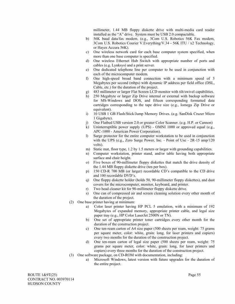
ROUTE 1&9T(25) Page 55 CONTRACT NO. 003970114 HUDSON COUNTY
millimeter, 1.44 MB floppy diskette drive with multi-media card reader installed as the “A” drive. System must be USB 2.0 compactable.
b) 56K baud data/fax modem. (e.g., 3Com U.S. Robotics 56K Fax modem, 3Com U.S. Robotics Courier V.Everything/V.34 - 56K ITU / x2 Technology, or Hayes Accura 56K).
c) One wireless network card for each base computer system specified, when more than one base computer is specified.
d) One wireless Ethernet Hub Switch with appropriate number of ports and cables (e.g. Lynksys) and a print server.
e) One dedicated telephone line per computer to be used in conjunction with each of the microcomputer modem.
f) One high-speed broad band connection with a minimum speed of 3 Megabytes per second (mbps) with dynamic IP address per field office (DSL, Cable, etc.) for the duration of the project.
g) 483 millimeter or larger Flat Screen LCD monitor with tilt/swivel capabilities. h) 250 Megabyte or larger Zip Drive internal or external with backup software
for MS-Windows and DOS, and fifteen corresponding formatted data cartridges corresponding to the tape drive size (e.g., Iomega Zip Drive or equivalent).
i) 10 USB 1 GB Flash/Stick/Jump Memory Drives. (e.g. SanDisk Cruzer Micro 1 Gigabyte).
j) One Flatbed USB version 2.0 or greater Color Scanner. (e.g. H.P. or Cannon) k) Uninterruptible power supply (UPS) - OMNI 1000 or approved equal (e.g.,
APC-1000 - American Power Corporation). l) Surge protector for the entire computer workstation to be used in conjunction
with the UPS (e.g., Zero Surge Power, Inc. - Point of Use - 2R-15 amp/120 volts).
m) Static mat, floor type, 1.2 by 1.5 meters or larger with grounding capabilities. n) Computer workstation, printer stand, and/or table having both appropriate
surface and chair height. o) Five boxes of 90-millimeter floppy diskettes that match the drive density of
the 1.44 MB floppy diskette drive (ten per box). p) 150 CD-R 700 MB (or larger) recordable CD’s compatible to the CD drive
and 100 recordable DVD’s. q) One floppy diskette holder (holds 50, 90-millimeter floppy diskettes), and dust
covers for the microcomputer, monitor, keyboard, and printer. r) Two head cleaner kit for 90-millimeter floppy diskette drive. s) One can of compressed air and screen cleaning solution every other month of
the duration of the project. (2) One base printer having at minimum:
a) Color laser printer having HP PCL 5 emulation, with a minimum of 192 Megabytes of expanded memory, appropriate printer cable, and legal size paper tray (e.g., HP Color LaserJet 2500N or TN).
b) One set of appropriate printer toner cartridges every other month for the duration of the construction project.
c) One ten-ream carton of A4 size paper (500 sheets per ream, weight: 75 grams per square meter, color: white, grain: long, for laser printers and copiers) every two months for the duration of the construction project.
d) One ten-ream carton of legal size paper (500 sheets per ream, weight: 75 grams per square meter, color: white, grain: long, for laser printers and copiers) every three months for the duration of the construction project.
(3) One software package, on CD-ROM with documentation, including: a) Microsoft Windows, latest version with future upgrades for the duration of
the entire project.

ROUTE 1&9T(25) Page 56 CONTRACT NO. 003970114 HUDSON COUNTY
b) Microsoft Office Professional latest version. Software package should contain the following: word processor, spreadsheet, and database.
c) Norton’s System Works for Windows, latest version, or compatible software package with future upgrades and latest virus patches.
d) Anti-Virus software, latest version with monthly updates for the duration of the entire project (e.g., McAfee Anti Virus, Dr. Solomon’s, or Norton’s Anti Virus).
e) Visio Professional Graphics Software for Windows, latest version.
Hardware and software shall be acceptable to the Regional Construction and Resident Engineers before purchase/installation. All software shall be compatible with the computer’s operating system.
The microcomputer system, whether purchased new or previously used, shall be installed in the materials field laboratory.
At the time of installation, the Contractor shall ensure that the system is fully operational and meets all Department requirements. All software listed above shall be installed by the Contractor and maintained in the materials field laboratory. The Contractor shall configure the software to operate with the hardware provided. Any accessories for the microcomputer shall be compatible with the microcomputer.
The Contractor will not be permitted to use this microcomputer system at any time. It is being supplied solely for the Department’s use.
The Contractor shall forward all manuals, instructions, software, and literature received with the microcomputer system to the Resident Engineer. The Contractor is responsible for maintaining the microcomputer system in good working condition. Any part of the microcomputer system that becomes inoperable or defective, during the duration of the construction project, shall be replaced by the Contractor within 48 hours.
The microcomputer system (after the project data has been erased from the hard drive by the Department), manuals, instructions, software, and literature shall be removed and retained by the Contractor when no longer required as determined by the Resident Engineer. The data cartridges and data diskettes will become the property of the State.
THE LAST SEVEN PARAGRAPHS ARE CHANGED TO:
Setting up the materials field laboratory shall consist of furnishing the laboratory and enclosure complete with furniture, equipment, electricity, water, heating, air-conditioning, installation and activation of telephone lines, telephone sets (touch tone and cellular), pager units, sanitary facilities, and lavatory supplies.
Maintenance of the materials field laboratory, for the time required, shall consist of maintaining the furniture, equipment, and utilities which includes the cost of telephone fixed monthly service charges, cellular phone fixed monthly service charges for the plan specified and pager services, providing lavatory supplies, janitorial and waste disposal services weekly, restocking of the first aid box, and snow removal services. Maintenance of the materials field laboratory shall also include monthly rent.
Payment for nuclear density gauge will be made by the number of units supplied. Payment for setting up the materials field laboratory will be made by the number of units. Payment for the maintenance of the materials field laboratory will be made for each month or fraction thereof that
the materials field laboratory is required, except that payment will not be made for any month or fraction thereof in which the Contractor is assessed liquidated damages according to Subsection 108.16.
Payment will be made under: Pay Item Pay Unit NUCLEAR DENSITY GAUGE UNIT MATERIALS FIELD LABORATORY SET-UP UNIT MATERIALS FIELD LABORATORY MAINTENANCE MONTH
Payment for telephone service will be made according to Subsection 105.15. 106.09 Storage and Handling of Materials. THE ENTIRE TEXT IS CHANGED TO:

ROUTE 1&9T(25) Page 57 CONTRACT NO. 003970114 HUDSON COUNTY
Materials shall be stored to ensure the preservation of their quality and fitness. Stored materials, even though
approved before storage, may again be inspected before their use on the Project. Stored materials shall be located so as to facilitate their prompt inspection. With the approval of the Department, portions of the ROW may be used for storage purposes and for the placing of the Contractor’s plant and equipment, but any additional space must be provided by the Contractor at the Contractor’s expense. Equipment and materials shall be placed behind barriers or crash cushions, or stored more than 10 meters from the traveled way. The barriers and crash cushions must be approved before installation. Furnishing, placing, and removing the barriers and crash cushions shall be at no Additional Compensation. No materials shall be stored within restricted areas noted on the plans. No materials shall be stored within 3 meters, plus the extended boom length of the largest crane on site, of overhead high voltage power lines. The high voltage power line is defined as an aerial power line having a voltage differential in excess of 750 volts between any pairs of conductors or between any conductor and ground. The Contractor shall be responsible for any power outage or de-energization associated with the Contractor’s activity in the vicinity of the power lines. Private property shall not be used for storage purposes without written permission of the owner or lessee, and any other approvals, including those as specified in Subsection 107.05. Copies of such written permission shall be furnished to the Resident Engineer before storage. Storage sites shall be restored to their original condition at no Additional Compensation. 106.13 Fuel Price Adjustment. THE 26 TH, 27 TH, & 28 TH ELIGIBLE PAY ITEMS AFTER THE THIRD PARAGRAPH ARE CHANGED TO:
Eligible Pay Items Fuel Usage Factor SUPERPAVE HOT MIX ASPHALT ___ ___ ___ SURFACE COURSE
10.4 Liters per Megagram
SUPERPAVE HOT MIX ASPHALT ___ ___ ___ INTERMEDIATE COURSE
10.4 Liters per Megagram
SUPERPAVE HOT MIX ASPHALT ___ ___ ___ BASE COURSE 10.4 Liters per Megagram THE FIFTH PARAGRAPH IS CHANGED TO:
The monthly fuel price index will be posted every month on the Department’s web site: www.state.nj.us/transportation/eng/CCEPM/PriceIndex.shtm. THE FIRST SENTENCE OF THE SIXTH PARAGRAPH IS CHANGED TO:
The basic fuel price index will be the previous month’s fuel price index before receipt of bids. THE EIGHTH PARAGRAPH IS DELETED.
SECTION 107 - LEGAL RELATIONS AND RESPONSIBILITY TO PUBLIC 107.01 Legal Jurisdiction. THE ENTIRE SUBSECTION IS CHANGED TO:
1. Applicable Law. This Contract shall be construed and shall be governed according to the Constitution and laws of this State.
2. Sovereign Immunity. The State by entering into this Contract does not waive its Sovereign Immunity, except as provided by the New Jersey Contractual Liability Act, NJSA 59:13-1 et seq. The rights or benefits provided the Contractor in this Contract which exceed those provided under the Act are contractual in nature and shall not be deemed to expand the waiver of Sovereign Immunity as set forth in that Act.
3. Litigation of Claims by Contractor. The Contractual Claims Resolution Process is not an administrative procedure but is contractual in nature, intended to review properly filed and documented claims. Pursuant to N.J.C.A. 16:45-1.3, exhaustion of the Claims Resolution Process as set forth under the Specifications is not a prerequisite to the filing of a legal action against the Department or State. The Contractor, however, must fully comply with all of the terms and conditions of the Contractual Liability Act, N.J.S.A. 59:13-1 et seq. prior to commencing a legal action. Therefore, where a Contractor brings a legal action, arising out of a

ROUTE 1&9T(25) Page 58 CONTRACT NO. 003970114 HUDSON COUNTY
Contract, against the Department or State or any officials or employees, thereof, arising out of or related, directly or indirectly, to a claim pending against the Department; the Contractual Claims Resolution Process, at any step, shall terminate as to that claim(s) or related claims being litigated, no matter which level of review the claim may be at when the legal action is filed. Furthermore, once the Contractor files a legal action any claim(s), related to that legal action will no longer qualify to be reviewed by the Claims Committee or to have the same claim(s) resolved under the Non-Binding Mediation Procedure or at any other Level of review. Such claim(s) will, thereafter, be resolved under the legal action subject to the provisions of the Contractual Liability Act, N.J.S.A. 59:13-1 et seq. unless and until the legal action is dismissed with or without prejudice. The Contractor may submit to the Department for processing through the various steps of the Contractual Claims Resolution Process any claims that are unrelated to the pending litigation subject to the terms of the Specifications and the Contractual Liability Act N.J.S.A. 59:13-1 et seq.
4. Completion of the Contract. The Completion of the Contract shall control as to any issue that may arise regarding the particular point in time when a Contractor may be barred from recovering against the State as provided under N.J.S.A. 59:13-5 et seq. The Contractual Claims Resolution Process and the various steps thereof may continue beyond the Completion of the Contract; however, the Contractual Claims Resolution Process will not in any manner, expressed or implied, extend any statute of limitation that may apply as to a claim. The Contractor by entering into the Contract with the Department agrees no further notice to the Contractor regarding the provisions stated in this Section are required. The Contractor also agrees to be responsible for compliance with all statutes of limitation and compliance with the various provisions of the Contractual Liability Act, N.J.S.A. 59:13-1 et seq.
5. Subcontractor(s). Pursuant to Subsection 108.02, the Department will not process or review any claims submitted by a subcontractor(s) or supplier(s) at any tier. All claims submitted by the Contractor must be an obligation or liability of the Contractor and cannot be merely a pass through of a claim by a subcontractor or by a supplier.
107.02 Notice of Potential Claim and the Administrative Process for the Resolution of Contract Disputes. THE HEADING AND THE ENTIRE SUBSECTION IS CHANGED TO: 107.02 Notice of Claim and the Contractual Claim Resolution Process.
1. Notice. a. Obligations. The various notice provisions set forth in this Contract are contractual obligations assumed
by the Contractor by the act of executing the Contract. The Contractor shall be responsible to notify the Department in writing within the time frame as may be mandated in an applicable Subsection of the Specifications as well as within 90 days of any situation or occurrence which may potentially result in or be the basis of a belief that additional compensation or an extension of time is due from the State, except where permission to file a “late notice of claim” has been obtained by the Contractor from the Superior Court in accordance with N.J.S.A. 59:13-6. The Department is not authorized to expand, reduce or waive either the contractual or statutory time limitations within which a notice of claim is to be filed with the Department. Any required notice shall be given only on the Contractual Notice Form provided by the Department. Submission of a Contractual Notice Form is required in order to comply with the notice requirements of the New Jersey Contractual Liability Act, N.J.S.A. 59:13-5 et seq., provided such notices are given within the time limits established by that Act. The Contractor, by executing the Contract, agrees that the only evidence of compliance with the notice provisions of the Contractual Liability Act, N.J.S.A. 59:13-5 et seq., and the Specifications shall be the filing of a fully completed (except that the amount of the claim need not be stated when unknown) Contractual Notice Form with the Department, and that no other documents sent or delivered to the Department or any of its officers or employees shall satisfy the statutory and/or contractual notice requirements.
b. Time. The Contractor, by the act of executing the Contract, acknowledges that it will be forever barred from recovering against the State if it fails to give timely notice in accordance with N.J.S.A. 59:13-5 et seq., on the Contractual Notice Form required under this Subsection of any happening of an event, thing, or occurrence or of an act or failure to act, by the Department and that the Contractor is solely responsible for complying with the various notice requirements and the timeliness of a claim as set forth under the Contractual Liability Act, N.J.S.A. 59:13-5 et seq. and the Specifications.
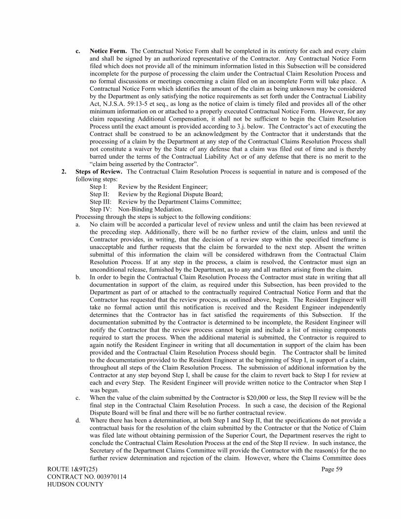
ROUTE 1&9T(25) Page 59 CONTRACT NO. 003970114 HUDSON COUNTY
c. Notice Form. The Contractual Notice Form shall be completed in its entirety for each and every claim and shall be signed by an authorized representative of the Contractor. Any Contractual Notice Form filed which does not provide all of the minimum information listed in this Subsection will be considered incomplete for the purpose of processing the claim under the Contractual Claim Resolution Process and no formal discussions or meetings concerning a claim filed on an incomplete Form will take place. A Contractual Notice Form which identifies the amount of the claim as being unknown may be considered by the Department as only satisfying the notice requirements as set forth under the Contractual Liability Act, N.J.S.A. 59:13-5 et seq., as long as the notice of claim is timely filed and provides all of the other minimum information on or attached to a properly executed Contractual Notice Form. However, for any claim requesting Additional Compensation, it shall not be sufficient to begin the Claim Resolution Process until the exact amount is provided according to 3.j. below. The Contractor’s act of executing the Contract shall be construed to be an acknowledgment by the Contractor that it understands that the processing of a claim by the Department at any step of the Contractual Claims Resolution Process shall not constitute a waiver by the State of any defense that a claim was filed out of time and is thereby barred under the terms of the Contractual Liability Act or of any defense that there is no merit to the “claim being asserted by the Contractor”.
2. Steps of Review. The Contractual Claim Resolution Process is sequential in nature and is composed of the following steps:
Step I: Review by the Resident Engineer; Step II: Review by the Regional Dispute Board; Step III: Review by the Department Claims Committee; Step IV: Non-Binding Mediation.
Processing through the steps is subject to the following conditions: a. No claim will be accorded a particular level of review unless and until the claim has been reviewed at
the preceding step. Additionally, there will be no further review of the claim, unless and until the Contractor provides, in writing, that the decision of a review step within the specified timeframe is unacceptable and further requests that the claim be forwarded to the next step. Absent the written submittal of this information the claim will be considered withdrawn from the Contractual Claim Resolution Process. If at any step in the process, a claim is resolved, the Contractor must sign an unconditional release, furnished by the Department, as to any and all matters arising from the claim.
b. In order to begin the Contractual Claim Resolution Process the Contractor must state in writing that all documentation in support of the claim, as required under this Subsection, has been provided to the Department as part of or attached to the contractually required Contractual Notice Form and that the Contractor has requested that the review process, as outlined above, begin. The Resident Engineer will take no formal action until this notification is received and the Resident Engineer independently determines that the Contractor has in fact satisfied the requirements of this Subsection. If the documentation submitted by the Contractor is determined to be incomplete, the Resident Engineer will notify the Contractor that the review process cannot begin and include a list of missing components required to start the process. When the additional material is submitted, the Contractor is required to again notify the Resident Engineer in writing that all documentation in support of the claim has been provided and the Contractual Claim Resolution Process should begin. The Contractor shall be limited to the documentation provided to the Resident Engineer at the beginning of Step I, in support of a claim, throughout all steps of the Claim Resolution Process. The submission of additional information by the Contractor at any step beyond Step I, shall be cause for the claim to revert back to Step I for review at each and every Step. The Resident Engineer will provide written notice to the Contractor when Step I was begun.
c. When the value of the claim submitted by the Contractor is $20,000 or less, the Step II review will be the final step in the Contractual Claim Resolution Process. In such a case, the decision of the Regional Dispute Board will be final and there will be no further contractual review.
d. Where there has been a determination, at both Step I and Step II, that the specifications do not provide a contractual basis for the resolution of the claim submitted by the Contractor or that the Notice of Claim was filed late without obtaining permission of the Superior Court, the Department reserves the right to conclude the Contractual Claim Resolution Process at the end of the Step II review. In such instance, the Secretary of the Department Claims Committee will provide the Contractor with the reason(s) for the no further review determination and rejection of the claim. However, where the Claims Committee does
ROUTE 1&9T(25) Page 60 CONTRACT NO. 003970114 HUDSON COUNTY
review a claim, there shall not be deemed a waiver by the Department of any defense that the Notice was filed late or that there does not exists a contractual basis for resolution.
3. Information Required. As a minimum, all of the following information must accompany each claim and be incorporated into or attached to the contractually required Contractual Notice Form: a. A detailed factual statement of the claim providing all necessary dates, locations, and items of work
affected by the claim. b. The date on which facts arose that gave rise to the claim. c. A copy of any notice given to the Department pursuant to any other Subsection of the Contract which
relates to the matter giving rise to the claim. d. The name, function, and activity of each State individual, official, or employee involved in or
knowledgeable about the claim. e. The specific provisions of the Contract which support or mitigate against the claim and a statement of
the reasons why such provisions support or mitigate against the claim. f. If the claim relates to a decision of the Department which the Contract leaves to the Department's
discretion or as to which the Contract provides that the Department's decision is final, the Contractor shall set out in detail all facts supporting its contention that the decision of the Department was fraudulent, arbitrary or capricious.
g. The identification of any documents and the substance of any oral communications relating to such claim attaching same to the Form.
h. A statement as to whether the additional compensation or extension of contract time sought is based on the operation of the provisions of the Contract or an alleged breach of contract.
i. If an extension of contract time is sought, the specific days sought and the basis for such claim, supported by the Contractor’s approved baseline progress schedule and updates, as well as a fragment, which will include a time impact evaluation, depicting the delay according to Subsection 108.04.
j. If additional compensation is sought, the exact amount sought and a breakdown of that amount into the following categories: (1) Direct Labor (2) Direct Materials (3) Direct Overhead as specified in Subsections 109.03 and 109.04. (4) Subcontractor's Work (5) Other categories as specified by the Contractor. (6) The basis and manner of the Contractor’s calculations of the additional compensation claimed. The Department will not determine liability separate and apart from damages. The Contractual Claims
Resolution Process shall not be bifurcated. The Department shall review liability and damage valuation issues at the same time.
4. The Procedures for the Process. a. Step I, Resident Engineer Review. The Resident Engineer will render a written decision regarding the
claim presented within 30 State Business Days of the Resident Engineer’s determination that the information provided by the Contractor on the Contractual Notice Form in support of the claim satisfied the requirements to begin Step I. This time limit may be extended by mutual agreement of the parties. Within 15 State Business Days of the receipt of the decision by the Resident Engineer, the Contractor shall either accept or reject the decision in writing; or upon failure to complete this, the claim will be considered withdrawn from the Contractual Claim Resolution Process and there will be no further review of the claim. If the Contractor accepts the decision, such acceptance shall include execution of an unconditional release furnished by the Department effective upon payment.
b. Step II, Regional Dispute Board Review. If the Contractor provides a written rejection of the Resident Engineer’s decision and a request to forward the claim to Step II, the Resident Engineer will forward the claim and supporting information previously submitted by the Contractor to the Regional Dispute Board within five State Business Days. The Regional Dispute Board will schedule and hold a meeting to review the claim with the Contractor within 30 State Business Days of receipt of the said claim information from the Resident Engineer. This time limit may be extended by mutual agreement of the parties. The Regional Dispute Board will issue a written decision regarding the claim within 20 State Business Days of the meeting.
Within 15 State Business Days of receipt of the Regional Dispute Board decision, the Contractor shall either accept or reject it in writing; or upon failure to complete this, the claim will be considered

ROUTE 1&9T(25) Page 61 CONTRACT NO. 003970114 HUDSON COUNTY
withdrawn and the Contractual Claim Resolution Process shall be considered to be concluded for that particular claim. If the Contractor accepts the decision, such acceptance shall include execution of an unconditional release furnished by the Department effective upon payment.
The Director, Construction Services and Materials, may request an informal meeting with the Contractor to discuss the then pending claim(s) after the Step II decision has been issued and sent to the Contractor, but prior to the matter being reviewed at the next step, subject to the mutual consent of the Contractor and the Department.
c. Step III, Claims Committee Review. A written request for a Step III review of the claim is to be made to the Secretary of the Department Claims Committee, P.O. Box 600, Trenton, New Jersey 08625-0600 with a copy to the Director, Construction Services & Materials. The Contractor may request that the Department Claims Committee immediately review claims, which are unresolved after review by the Regional Dispute Board,, when the following conditions are met: 1. A claim or the combination of claims exceed $250,000; or 2. It is mutually agreed to by the Contractor and the Department.
However, when a project becomes 75 percent complete by contract time or dollar amount, which ever first occurs, claims that are unresolved at Step II will be reviewed at a single session of the Department Claims Committee after the Completion of the Work.
Additionally, the Contractor may request at the time of issuance of the Final Certificate that all unresolved claims, with the exception of the exclusionary cases as provided for in this Subsection, that have gone through the Steps I and II of the Contractual Claim Resolution Process, and which have not been presented at Step III of the Contractual Claim Resolution Process, be reviewed by the Department Claims Committee as provided for in this Subsection. The Contractor's written request must accompany its exceptions to the Final Certificate, with a copy sent to the Secretary of the Department Claims Committee and shall be made no later than 30 State Business Days after the issuance of the Final Certificate.
The Secretary of the Department Claims Committee will schedule a Claims Committee meeting with representatives of the Contractor and the Region, to be held within 45 State Business Days of the receipt of the claim information. This time limit may be extended by mutual agreement of the parties. The Department Claims Committee will notify the Contractor in writing of its decision on the claim(s) within 45 State Business Days of the meeting, stipulating the terms of any resolution of the claims. If the Department Claims Committee determines after review of the claims that no resolution and no further payment is warranted, it shall notify the Contractor in writing of its decision. Within 15 State Business Days of the receipt of the Department Claims Committee decision, the Contractor shall either accept or reject it in writing, or upon failure to complete this, the claim will be considered withdrawn and the Contractual Claim Resolution Process shall be considered to be concluded for that particular claim. If the Contractor accepts the decision, such acceptance shall include execution of an unconditional release furnished by the Department effective upon payment. If the Contractor rejects the decision, there will be no further review of the claim unless the Contractor submits a written request for the utilization of Non-Binding Mediation.
d. Step IV, Non-Binding Mediation. (1) Conditions. The Contractor may request at any time during the Project, but no later than 30 State
Business Days after issuance of the Final Certificate, that any claim unresolved by the Department Claims Committee be elevated to Step IV. The request must be in writing to the Secretary, Department Claims Committee, P.O. Box 600, Trenton, New Jersey 08625-0600. No claim will be elevated to Step IV unless all of the following conditions are satisfied:
(a.) The claim has been reviewed by the Department Claims Committee. (b.) The Contractor has escrowed its bid preparation documents as required under Subsection 103.06
and the documents are still being held in escrow. (c.) The Contractor has entered into a Non-Evidential agreement to the effect that any statement or
information provided during the Non-Binding Mediation proceedings shall not be evidential in any legal proceeding unless obtained by other discoverable means.
(d.) The Contractor has entered into a cost sharing agreement to equally share the cost of using Non-Binding Mediation in accord with Department issued forms.
(e.) The utilization of Non-Binding Mediation has been mutually agreed to by the Department and the Contractor; and

ROUTE 1&9T(25) Page 62 CONTRACT NO. 003970114 HUDSON COUNTY
(f.) Prior to the commencement of the Non-Binding Mediation the parties shall confer with one another for the purpose of resolving the format of presenting the claim summary, supporting information, opening statements, and responses. Failure by the Contractor to request Non-Binding Mediation within the required time period
shall constitute a waiver by the Contractor of any utilization of the Non-Binding Mediation Step. (2) Forms. Where the Contractor requests that Non-Binding Mediation be conducted, the Department
will forward to the Contractor the required Non–Evidential and cost sharing agreement forms which shall be executed by the Contractor and returned to the Department within ten State Business Days. The failure by the Contractor to return the fully executed Non-Evidential and cost sharing agreements to the Department within the ten-day period shall constitute a waiver by the Contractor of the availability of Step IV.
(3) Mediator. The Department will select the Mediator to be utilized for the Non-Binding Mediation from a list of candidates submitted by the Contractor. The Contractor shall submit the names of six proposed Mediators, along with a biographical background listing the experience and qualifications of each candidate. Candidates may be from the same employment category or disciplines, such as construction, mediation, partnering facilitation, consulting engineer, attorney, judiciary (retired), accountant, architect, etc.
A candidate may have been used for mediation purposes for this Project or another project but shall not have any other relationships with either the Department or the Contractor for a period of two years preceding the request for Step IV. If the Department determines that none of the candidates submitted are acceptable, the Department will request and the Contractor shall submit four additional Mediator candidates. The Contractor shall submit this additional list within five State Business Days of the receipt of the written request. Upon mutual agreement, the Mediator can be an individual proposed by the Department.
(4) Escrow Documents. Once the Contractor has fully executed the required Non-Evidential and cost sharing agreements, its escrowed bid documents will be released upon request of the Department Claims Committee Chairperson solely for the exclusive use of the Mediator, the Department’s selected Negotiator(s), the Department Regional Representative(s) and the Contractor Representative(s) participating in the Mediation session. These documents will be used by the Department as part of the Contractual Claims Resolution Process only to resolve the pending claims except it may seek such documents through the discovery process in the event mediation is not successful and litigation ensues.
(5) Meeting. The Secretary of the Department Claims Committee will schedule a meeting for the Non-Binding Mediation of the submitted claims to be held within 30 State Business Days of the return of the executed Non-Evidential and cost sharing agreements. The meeting time limit may be extended by mutual agreement of the parties. The Secretary of the Department Claims Committee will issue the recommendations of the Department’s Negotiator to the Commissioner for action within 15 State Business Days of the Non Binding Mediation session. The Commissioner, or their designee, will accept, reject, or modify the recommendation of the Department Negotiator and notify the Contractor of the decision within 15 State Business Days.
(6) Decision. The Contractor shall accept or reject the decision within 15 State Business Days of notification of the Commissioner's decision. If the Contractor accepts the decision of the Commissioner, or their designee, such acceptance shall be in writing and include execution of an unconditional release furnished by the Department effective upon payment. If the Contractor fails to accept or reject the Commissioner’s decision within 15 State Business Days, the decision of the Commissioner will be withdrawn and the Contractual Claims Resolution Process shall be deemed concluded as to that particular claim under review.
After submission of the recommendation to the Commissioner, the bid documents released from escrow will be returned to the escrow agent for continued escrow in the designated repository.
107.22 Risks Assumed by the Contractor THE FIRST PARAGRAPH UNDER SUBPART 1 IS CHANGED TO:
1. Risks of Loss or Damage to the Permanent Construction. Until Acceptance, and within the limits of the Project’s work, the Contractor shall bear the risk of all loss or damage to all permanent construction

ROUTE 1&9T(25) Page 63 CONTRACT NO. 003970114 HUDSON COUNTY
and temporary construction performed under this Contract and to materials, whether or not it has received payment for such construction or materials under Subsection 109.05, 109.06, or 109.07, except payment will be made to the Contractor for the repair or replacement of any permanent element of the construction which has not been accepted by the Department, if the element of the work damaged is completed to the stage of serving its intended function and is subsequently damaged by accident by public traffic. In order to receive payment, the Contractor must supply satisfactory evidence that such damage was caused by a public traffic accident which was not caused by vandalism or by the equipment of the Contractor or any of its subcontractors or suppliers. Satisfactory evidence shall generally be limited to: accident reports filed with the Division of Motor Vehicles, police agencies or insurance companies; statements by reliable, unbiased eye witnesses; identification of the vehicle involved in the accident. Physical evidence that the damage was caused by a motor vehicle (such as tire marks or broken headlight glass) will not be sufficient unless it can be clearly shown that the damage was not caused by the Contractor’s vehicles or by vandalism. The Contractor shall take every precaution, as allowed by the Contract against injury or damage to any part of the construction or to materials by the action of the elements, the traveling public, vandalism, or from any other cause, whether arising from the execution or the non-execution of the work. The Contractor shall promptly repair, replace, and make good any such damage or loss without cost to the Department. The Contractor shall not bear such risk of loss or damage, which arises from acts of war or floods, tidal waves, earthquakes, cyclones, tornadoes, hurricanes, or other cataclysmic natural phenomenon unless such loss or damage is covered by insurance.
107.23 Insurance.
6. Railroad Insurance. Insurance coverage shall be procured and maintained for the following railroad(s):
Consolidated Rail Corporation (CONRAIL) New Jersey Transit Rail Operations
It is estimated that 20 percent of the Project cost is located within or adjacent to the railroad right-of-
way.
SECTION 108 - PROSECUTION AND PROGRESS 108.02 Subcontracting.
. Specialty Items are as listed below:
Dynamic Pile Load Tests Above ground highway lighting items. Above ground sign lighting items. Above and below bridge deck lighting items. Electrical wire items. ITS Items Post Tensioning at Northbound Flyover Piers 2 and 4 Drilled Shafts Vibration and Displacement Monitoring Gas and Electric Utility Work and Appurtenances
THE FOLLOWING IS ADDED TO THE END OF THE FIFTH PARAGRAPH: The Contractor shall also attach to that form (application for subcontracting form) proof of the Subcontractor’s valid, current registration with the New Jersey Department of Labor, Division of Wage and Hour Compliance as required by “Public Works Contractor Registration Act,” N.J.S.A. 34:11-56.48 et seq. (P.L. 2003, c. 91). Pursuant to P.L. 2003, c.

ROUTE 1&9T(25) Page 64 CONTRACT NO. 003970114 HUDSON COUNTY
91, the Department will not consent to the proposed subcontracting, and the Subcontractor shall not perform any work under the Contract, unless the Contractor first provides the required proof of the Subcontractor’s valid, current registration with the New Jersey Department of Labor, Division of Wage and Hour Compliance as required by “Public Works Contractor Registration Act.” The Contractor shall ensure full compliance with the Public Works Contractor Registration requirements by their Subcontractors. THE FOLLOWING IS ADDED AFTER THE SIXTH PARAGRAPH ON PAGE 100-77 OF THE STANDARD SPECIFICATION:
Subcontracting of those gas and electric items that require utilizing a Public Service Electric and Gas Company (PSE&G) qualified subcontractor will be permitted only to those subcontractors who are registered to do business in the State, are not on the State's debarred list, and are listed as being qualified by PSE&G, as shown on the list of those subcontractors contained in Section 622, regardless of the value of the subcontract THE EIGHTH AND NINTH PARAGRAPHS ARE DELETED 108.03 Commencement of Work. THE THIRD SENTENCE OF THE FIRST PARAGRAPH IS CHANGED TO: Construction operations shall not begin until the Contractor has supplied, and the Engineer has accepted, the preliminary schedule and other certifications, forms, schedules, and any other information required by the Contract Documents, and until the Contractor has established a field office as required by Subsection 105.15. THE FOLLOWING IS ADDED TO THE END OF THE FIRST PARAGRAPH: The Contractor shall notify the Resident Engineer in writing at least twenty-one calendar days in advance of the date of the start of Work at the Project site. No work at the Project Site will be permitted prior to the date given in the notice. Notices submitted prior to the Pre-Construction meeting shall be addressed to the contacts specified in Subsection 101.04. THE LAST PARAGRAPH IS CHANGED TO:
The Contractor shall give the Resident Engineer in writing a notice 72 hours in advance of starting Construction Operations. 108.04 Progress Schedule and Prosecution of the Work. THIS SUBSECTION IS CHANGED TO:
In scheduling and executing the Work, the following shall be complied with: 1. Progress Schedules. The progress schedule shall conform to and incorporate the following requirements:
a. General. (1) The work shall be monitored by a detailed CPM schedule. The CPM schedule shall be developed
utilizing the most current NJDOT Capital Program Management Construction Scheduling Standard Coding and Procedures for Designers and Contractors Manual and the NJDOT Primavera template project containing the latest standard coding. The manual and template are available from the Bureau of Quality Management Services.
The CPM schedule shall consist of diagrams and accompanying mathematical analyses. The scheduling of submittals, procurement, construction, and all else necessary to complete the Work as described in the Contract Documents, is the responsibility of the Contractor. The requirement for the CPM schedule is included to ensure adequate planning and execution of the Work and to assist the Department in appraising the reasonableness of the proposed schedule, as well as its compliance with Contract requirements.
The CPM schedule is the Contractor’s committed plan to complete all work within the allotted time. The Contractor assumes full responsibility for the prosecution of the Work as shown. The CPM schedule shall be based on and derived from detailed schedules used to complete all Contract activities.
ROUTE 1&9T(25) Page 65 CONTRACT NO. 003970114 HUDSON COUNTY
(2) No claim for extension of time due to extra work or any other type of delay will be considered unless the baseline schedule has been approved and monthly updates are current and submitted within the time limits stated.
(3) No claim for additional compensation as specified in Subsection 109.04 will be considered unless the baseline schedule has been approved and monthly updates are current and submitted within the time limits stated.
(4) The CPM preliminary, baseline, and updated schedules shall be submitted in electronic format on a floppy diskette or compact disk, in addition to the required number of copies specified in b. (1) and b. (2) below.
(5) Once the CPM baseline schedule has been approved, the Contractor shall not deviate therefrom without first notifying the Engineer in writing and schedule is updated in accordance with 1.h. and 1.i. below.
b. Submittals. The CPM schedule shall consist of the following two distinct initial submittals: (1) Preliminary Schedule. No later than 10 State Business Days after execution of the Contract, the
Contractor shall submit to the Engineer for review and approval or rejection and return a preliminary schedule. The contractor shall submit six copies of:
(a) A CPM time-scaled diagram defining the Contractor’s planned activities during the first 90 Calendar Days. For projects with a construction cost over $ 40 million, a CPM time-scaled diagram defining the Contractor’s planned activities during the first 120 Calendar Days.
(b) A summary network for the remainder of the Contract time. The preliminary schedule shall indicate all milestone activities expected to be completed or partially completed before submission and approval of the CPM baseline schedule as specified in b. (2) below.
(c) All multiple shifts per day and anticipated production rates shall be detailed in the Contractor’s narrative accompanying the preliminary schedule.
(d) The Work shall not begin until the preliminary schedule has been approved. Five State Business Days will be required for review and approval or rejection and return of the preliminary schedule.
(2) Baseline CPM Schedule. In accordance with the time frames listed below, the Contractor shall submit six copies of the Baseline CPM Schedule documents depicting the Contractor’s work plan for the entire Contract.
Project Construction Cost ($ million)
Time Frame After Approval of Preliminary Schedule for Submission
of the Baseline CPM Schedule (State Business Days)
< 5 10 5 - 15 15 15 - 40 20 > 40 30
The Contractor shall submit to the Engineer for review and approval or rejection and return:
(a) Computer generated tabular schedule and logic reports in accordance with 1.e. below. (b) Time-scaled computer generated Layout Output in conformance with 1.f. below. (c) A written narrative explaining the schedule and the Contractor’s general approach for achieving
Substantial Completion and the date of Completion as specified in Subsection 108.10 of these Special Provisions. Multiple shifts per day and anticipated production rates shall be detailed in the Contractor’s narrative accompanying the Baseline CPM Schedule.
(d) Electronic version as specified in 1.a. (4) above. c. CPM Schedule Requirements for the Baseline and Updates.
(1) The CPM schedule and updates shall contain the following: (a) The order in which the Contractor proposes to prosecute the Work; the starting dates of the various
work stages, operations, and principal items of work including procurement of materials and plant, and the contemplated dates for completing the same.
(b) List dates for all required submissions. (c) A clear outline of the intended maintenance of traffic.

ROUTE 1&9T(25) Page 66 CONTRACT NO. 003970114 HUDSON COUNTY
(d) The locations and timeframes for the installation of temporary and permanent soil erosion and sediment control measures to be installed.
(e) All unusual requirements specific to the project included in the Contract Documents or as deemed appropriate for the project.
(f) Special consideration to sensitive areas such as wetlands, floodplains, waterways, and parklands to ensure that appropriate staging and seasonal constraints are considered in order to maximize the effectiveness of the soil erosion and sediment controls.
(g) The time frames when work is restricted in sensitive areas as reflected in present and future permits as anticipated or known.
(h) Updates to reflect permit conditions if changed. (i) Include a detailed, step-by-step outline of any clean-up operations regarding contaminated material. (j) The work of the Contractor, subcontractors, suppliers, the Department, permitting agencies, utility
companies, and all others that affect progress shall be shown and identified on the schedule by responsibility codes.
(k) Procurement activities shall be shown, including plans, permits, materials, individual working drawings, fabrication, and delivery of the material. 20 State Business Days will be required for review and certification or rejection and return of fabrication working drawings. 30 State Business Days will be required for review and approval or rejection and return of working drawings for items that were included as conceptual and the Contractor is required to complete final design plans. The time frames set forth in this paragraph are provided for scheduling purposes only. The Department reserves the right to enlarge such time periods for review by a reasonable amount of time where circumstances necessitate, within the sole discretion of the Engineer. 30 State Business Days will be required for review and approval or rejection and return of working drawings for work affecting NJ Transit and Conrail.
See Subsection 105.04 of these Special Provisions for shop drawing schedule requirements. (l) Traffic staging, delivery of Department - furnished labor/equipment, project phasing, right-of-way
availability dates, and any other requirements specified in Divisions 200 through 900 shall be shown.
(m) The CPM schedule shall contain sufficient activities to adequately depict the Work, and will be subject to the review and approval of the Engineer.
(n) The logic and activity time durations established by the Contractor shall be consistent with the Contract Documents and be reflective of proper coordination between trades.
(o) The CPM schedule shall contain sufficient activities for notification of the Department by the Contractor for changes to the traffic patterns and staging, including the following:
1) An activity with a duration of at least twenty-eight calendar days, but not more than sixty calendar days, shall be shown in advance of the date of establishing a new permanent traffic pattern.
2) An activity with a duration of at least fourteen calendar days shall be shown in advance of the date of starting establishing a new permanent traffic pattern.
(2) The CPM schedule shall operate as follows: (a) The CPM schedule shall be of the precedence type. (b) One activity for each discrete component part of each Pay Item scheduled in the Proposal. The
Engineer may allow grouping of similar Pay Items into one activity. No work activity shall have a duration greater than 30 Calendar Days, except as approved by the Engineer. The activities shall be consistent with the Work Breakdown Structure (WBS), and shall also include discrete component parts of the Contractor’s submittal preparation, Department approval, procurement, and construction work activities with sufficient detail such that all the relationships with all direct and non-direct parties to the Work are shown.
(c) The system shall be based upon network diagrams and accompanying mathematical tabulations as described hereinafter. Diagrams shall show the order and interdependence of activities and the sequence and quantities in which work is to be accomplished. The basic concept of network scheduling shall be followed to show how the start of a given activity is dependent on the

ROUTE 1&9T(25) Page 67 CONTRACT NO. 003970114 HUDSON COUNTY
completion of preceding activities and how its completion may affect the start of subsequent activities. The critical path shall be distinguished from other paths on the network.
(d) The completion date of the CPM schedule shall be the date of Completion specified in Subsection 108.10 of these Special Provisions, except as specified in Subsection 108.04 subpart 5, which shall be input as a Finish Milestone with a Late Finish Constraint. All Intermediate Milestones required in the Contract shall be shown in proper logical sequence and input as a “Start-no-Earlier-Than” constraint for entrance into an area or start activity or a “Finish-no-Later-Than” constraint date for completions.
(e) Activities shall be described such that the Work is readily identifiable for assessment of start and completion, as well as intermediate status. Descriptions shall utilize activity codes for physical locations at each stage such as distance-markers, structures, and elevations where possible to define the Work. Activity descriptions of “Start,” “Continue,” “Completion,” “X percent,” “Y percent,” “Z percent” or similar nonspecific descriptions will not be allowed.
(f) The CPM schedule shall be calculated in Working Days. The Working Day to calendar date correlation shall be based upon the Contractor’s proposed work week with adequate allowance for weekends, legal holidays and any special requirements of the Contract. Activities shall indicate the calendar being used. Durations for activities shall not be less than one workday. Multiple shifts per day and anticipated production rates shall be detailed in the Contractor’s narrative accompanying the baseline schedule and subsequent updates.
(g) Constraint dates are permitted only on milestone activities, unless otherwise approved by the Engineer.
(h) All activities with the exception of the Project Start Milestone and Project Completion Milestone shall have predecessors and successors. The start of an activity shall have a Start-to-Start or Finish-to-Start relationship with preceding activities. The completion of an activity shall have a Finish-to-Start or Finish-to-Finish relationship with a succeeding activity. Start-to-Finish relationships are not acceptable.
(i) CPM schedules, which have been resource leveled, are permissible, provided the effects of leveling are incorporated in the schedule using “Start-no-Earlier-Than” date constraints.
d. Computer Program Requirements. The computer program requirements shall be the same as that specified in Subsection 105.15 subpart 1.e. of these Special Provisions.
e. Tabular Reports. (1) CPM schedule reports shall be provided for the following sort orders: (a) Total float, then early start for activities with float less than 20 days. (b) Grouped by responsibility, then by early start. (c) Grouped by WBS, area, then sorted by early start. (2) The minimum activity information required for each of the above reports in (1), shall include the
following: (a) A unique activity ID for each activity. (b) A description of the Work represented by the activity. (c) Location code identification. (d) Work responsibility code identification. (e) Original activity duration and remaining activity duration in Working Days. (f) Early and late, start and finish dates calculated according to CPM principles. (g) Total float. (h) Historical (actual) dates for activities completed or underway shall replace the appropriate
calculated dates. (i) Stages. (j) Calendar used for each activity.
f. CPM Time-Scaled Layout Output. (1) The network displayed on the schedule diagram shall depict the exact detail of the CPM schedule
reports. (2) The network diagram shall be of the precedence type and drawn by using early dates. (3) The layout output shall be time-scaled. The length of the activity representation shall be
proportional to the activity duration. (4) The activity display shall include the:

ROUTE 1&9T(25) Page 68 CONTRACT NO. 003970114 HUDSON COUNTY
(a) Activity description. (b) Activity identification. (c) Activity original duration and remaining duration. (d) Activities coded by area, responsibility, and WBS. (e) Activity total float. (f) Activities early start dates. (g) Activities finish dates. (5) The activities, which are displayed on the network diagram, shall be grouped by WBS and sorted
by area. The title of these components shall appear on the left-hand side of the plot. (6) The critical path shall be identified on the plot. (7) Vertical lines indicating the start and the end of each month shall be shown. (8) The data date shall be indicated on the plot in the activity display and in the title at the top or
bottom of the plot. (9) Completed activities shall be indicated on the plot. (10) The Contract title shall be displayed on the plot. (11) A legend shall be provided which indicates the various symbols used and their meanings. (12) Milestone Activity shall be indicated by a prominent symbol. (13) Different line types shall indicate the critical path and completed Milestone and activities.
g. Review and Approval. The Engineer will review a submitted preliminary schedule for approval or rejection within five State Business Days of receipt and will thereafter return same to the party having submitted it. There will, in turn, be allotted ten State Business Days for review and approval or rejection by the Engineer of the submitted baseline schedule, which will thereafter be returned to the party having submitted it. The Engineer will review revised preliminary or revised baseline submittals within five State Business Days of receipt. The time periods set forth in this paragraph are provided for scheduling purposes only. The Department reserves the right to enlarge such time periods for review by a reasonable amount of time where circumstances necessitate, within the sole discretion of the Engineer.
h. Updating and Revisions. (1) Within ten State Business Days after review by the Engineer, all preliminary and baseline
schedules that are not approved shall be revised and resubmitted by the Contractor until the Engineer’s approval is received.
(2) The Contractor shall update the CPM schedule monthly whether or not the Engineer has accepted the schedule, to reflect actual activity progress. The update shall include the historical record of actual start and actual finish dates for activities in progress, or completed, and the remaining duration based on the amount of workdays required to complete the activity.
(3) Monthly progress meetings shall be held. The updated CPM schedule shall be the basis for the monthly progress review meetings. Activity progress shall be prepared in advance of the meeting. At this meeting, attended by the Engineer, all progress during the calendar month shall be presented and reviewed for incorporation into the schedule by the Contractor. Within a period of ten State Business Days from the date of this progress meeting, the Contractor shall submit the schedule update to the Engineer with the agreed upon changes.
(4) The monthly schedule update submission shall consist of three copies of electronic format on floppy diskettes or compact disks and three copies of the following:
(a) Updated CPM schedule reports (see Item e. above). (b) Layout output. (See item f. above) (c) CPM progress narrative.
The CPM progress narrative report submitted as part of the update analysis shall include, but not be limited to, the:
1. Description of schedule status. 2. Discussion of current and anticipated delaying problem areas and their estimated impact. 3. Schedule slippage, pay revisions, and/or progress along the critical path in terms of days ahead or
behind the allowable dates, and if the Work is behind schedule, progress along other paths with negative float. This shall be in addition to and not a substitute for requirements in Subsection 108.11.
4. Logic changes and an explanation of the revisions. Revisions to activities not worked on during the period, including changes in duration, or revisions to activity relationships are to be considered

ROUTE 1&9T(25) Page 69 CONTRACT NO. 003970114 HUDSON COUNTY
logic revisions. Out-of-sequence activities are not acceptable and shall be corrected in logic revisions prior to submission to the Department.
(5) When, in the Engineer’s opinion, the CPM schedule fails to reflect the Contractor’s actual plan and method of operation, or the Contractor’s completion date as indicated by the CPM is more than one month behind the Contract completion date, the Engineer may require the Contractor to submit for review within ten State Business Days, a recovery plan for completion of the remaining work within the Contract completion date. A recovery plan shall include, but not be limited to, a revised CPM schedule and additional manpower and equipment that shall be utilized to complete the project by the date of Completion.
(6) When the Contractor adds activities that are not Extra Work Items to the CPM schedule, they shall be added in a method that completion dates of any succeeding baseline activities are not affected. All revisions shall be submitted to the Engineer for approval before incorporation into the CPM schedule.
(7) The Engineer shall have the right, within its sole discretion, to prepare its own update(s) or revision(s) to the baseline schedule in the event of a dispute between the parties regarding the appropriateness of the submitted revision(s) or updates to the baseline schedule or by reason of a failure on the part of the contractor to prepare same, which update(s) or revision(s) may reflect what the Engineer has determined to be the actual status of the project progress, actual sequencing of the Work and appropriate scheduling logic required under this Subsection. The Engineer may thereupon rely on its own revision(s) or update(s) of the baseline schedule in the administration of the project, review of claims and/or the imposition of liquidated damages.
i. Changes and Delays. To ensure that the CPM schedule continues to accurately reflect the Contractor’s plan for the Work and that it incorporates the impact of all changes and delays as soon as the Work scope can be defined, the Contractor shall use the following procedure to incorporate changes and delays.
When Extra Work or a change is proposed or claimed, the Contractor shall submit a Time Impact Evaluation form. Each Time Impact Evaluation must identify in a CPM fragnet sketch, additional work required as a result of the proposal and its interrelationship to the CPM schedule. Each change or delay shall be represented by adding a new activity or activities. These activities shall be clearly identified. This sketch shall show all activities, logic revisions, duration changes, and new activities with all the predecessors and successors. The Time Impact Evaluation form shall also include any associated cost changes for performing the Work in question. Upon the Engineer’s approval of the Time Impact Evaluation, the Contractor shall incorporate the fragnet’s illustrating the influence of changes and delays into the baseline schedule and the working schedule in the next schedule update. An extension of time may only be considered when the Time Impacted scheduled completion date exceeds the date of Completion. For cases where the Contractor is behind schedule, an extension will be granted for only the amount of time that the Department is responsible as supported by a Time Impact Evaluation. In the event of a dispute, the Engineer may prepare an update, which is believed to be the true impact on the project. No additional compensation will be paid to the Contractor for preparing these revisions. Any request for extension of time shall be verified by CPM analysis and shall be in accordance with Subsection 108.11. Compensation for additional expense to the Contractor and allowance of additional time for completion of the Work shall be as set forth in a Construction Order in accordance with Subsections 108.11 and 109.03.
2. Staging. The Contractor shall schedule the Work using such procedures and staging as may be specified in the Contract Documents. Work designated as part of separate stages may be performed simultaneously where provided by the Contract Documents or where approved.
When the Contract Documents provide for staging or specific procedures, the Contractor may present, for written approval of the Engineer, a detailed, written alternate staging plan or procedure which incorporates the requirements of the Department. If the Contractor proposes an alternate-staging plan, two CPM schedules shall be submitted. One based on the original staging and one based on the Contractor’s alternate staging. As a condition of the Engineer’s reviewing of the alternate staging plan or procedure, the Contractor agrees that it is not entitled to additional Contract Time or compensation arising from possible delays to construction due to the time spent in reviewing the Contractor’s staging plan or procedure, regardless of whether the Department accepts or rejects it. The Engineer will review and approve or reject and or return, with comments, the staging

ROUTE 1&9T(25) Page 70 CONTRACT NO. 003970114 HUDSON COUNTY
plan within ten State Business Days. If such staging plan or alternate procedure is approved in writing, the Contractor shall then finalize the progress schedule consistent with the alternate approved staging.
3. Prosecution of the Work. a. At or prior to the preconstruction conference, the Contractor shall furnish the name and location of the
solid waste facilities to be utilized as well as the fee structure of each of the facilities. Failure to provide such information shall make the Contractor ineligible for adjusted compensation as provided for in Subsection 104.07.
b. The Contractor shall provide sufficient materials, equipment, and labor to guarantee the Completion of the Project in accordance with the Contract Documents and within the time set forth under Subsection 108.10.
c. The Contractor shall supply the Engineer with a weekly work schedule indicating the Contractor’s planned work, the subcontractor’s planned work, the dates when materials and submissions are to be delivered, and a forecast of lane closings.
d. The Contractor shall notify the Engineer, in writing, prior to discontinuing work for any reason and at least 24 hours in advance of resuming operations.
e. The Contractor shall arrange and prosecute the Work so that each successive construction operation at each location shall follow the preceding operation as closely as the requirements of the various types of construction permit.
f. Underground structures for traffic signals, except for pressure detector installations shall be constructed prior to completion of the intersecting road.
g. Work, which closes or alters the use of existing roadways shall not be undertaken until adequate provisions, conforming to the requirements of Section 617, have been made by the Contractor and approved.
h. The Engineer may revise stage construction and maintenance of traffic, if deemed necessary, by the Engineer due to unforeseen circumstances that may arise during construction.
i. When possible, the construction of subsurface structures adjacent to traffic shall be performed while traffic is being diverted from such areas. If traffic must be maintained in such areas, the Work shall be done expeditiously in stages, as approved, and with minimum interference with traffic.
j. Subsurface structure excavation adjacent to traffic shall not remain open overnight unless adequately protected by approved safety devices.
k. The Contractor shall proceed with the Work of demolition of the various buildings that are identified with a demolition number as and when they become available for demolition. If any of the buildings to be demolished is not available for demolition at the time the Contractor begins work on the Project, the Contractor shall temporarily defer its work in the vicinity of the building and complete the Work when the building is made available for demolition.
l. Operations adjacent to traffic shall be confined to only one side of the traffic at any one time unless otherwise specified in the Contract Documents.
m. Concrete curbs constructed adjacent to flexible base and surface courses shall be completed, cured, and backfilled before the flexible base and surface courses are constructed.
n. Bituminous paving operations shall be staged to progress up to the bottom of the surface course. The top layer of the bituminous concrete surface course for the full width of the traveled way, shoulder, and auxiliary lanes shall be paved as a single stage of construction and as the final paving operation.
4. Acceleration and Default. If, in the opinion of the Engineer, the Contractor falls behind its baseline schedule, and cannot complete the Work within the time prescribed under Subsection 108.10, as modified pursuant to Subsection 108.11, the Contractor shall take such steps as may be necessary to improve its progress. The Engineer may require the Contractor to increase the number of shifts, begin overtime operations, work extra days including weekends and holidays, or supplement its construction plant and to submit for approval such supplementary schedule or schedules, as may be deemed necessary to demonstrate the manner in which the agreed rate of progress shall be regained, all at no cost to the State.
Failure of the Contractor to comply with the requirements of the Engineer under this Subheading is grounds for the determination that the Contractor is not prosecuting the Work with such diligence as to ensure Completion within the time specified. Upon such determination, the Engineer may terminate the Contractor’s right to proceed with the Work or any separate part thereof in accordance with Subsection 108.17.
5. Intent, Responsibility, and Time. Scheduling of construction shall be the responsibility of the Contractor. The Contractor’s shall determine the most feasible order of work commensurate with the Contractor’s abilities
ROUTE 1&9T(25) Page 71 CONTRACT NO. 003970114 HUDSON COUNTY
and the Contract Documents. The CPM schedule will be used for determining extensions or reductions of Contract Time pursuant to Subsection 108.11.
It is not intended that the Engineer, by approving the CPM schedule, agrees that it is reasonable in any or all respects or that following the CPM schedule can result in timely completion of the Project. The progress schedule is not a part of the Contract.
If, in the preparation of the CPM schedule, the Contractor reflects a completion date different than that specified under Subsection 108.10, this in no way voids the date set therein. The date as specified in that Subsection governs. Where the CPM schedule reflects a completion date earlier than that specified as the Contract Time, the Engineer may approve such schedule with the Contractor specifically understanding that no claim for additional Contract Time or compensation shall be brought against the State as the result of failure to complete the Work by the earlier date shown on the CPM schedule.
6. Payment. Payment for the accepted progress schedule will be made on a lump sum basis for the costs for schedule preparation, maintenance, updating, facilities, personnel, computer hardware and software requirements, schedule submittals and reproduction as specified. Twenty-five percent of the lump sum bid will be paid upon approval of the baseline submission, and the balance paid on approval of updates at a prorated sum based upon the number of anticipated updates to be submitted during the Contract Time.
Payment will be made under: Pay Item Pay Unit PROGRESS SCHEDULE LUMP SUM
108.05 Mobilization. THIS SUBSECTION IS CHANGED TO:
Mobilization shall consist of the preparatory work and operations necessary for the movement of personnel, equipment, supplies, and incidentals to the Project site, and other work performed or costs incurred prior to beginning Work.
Payment for mobilization will be made on a lump sum basis regardless of the fact that the Contractor may have, for any reason, shut down its work on the Project or moved equipment away from the Project and back again.
Payment will be made in accordance with the following schedule: 1. When five percent of the Work is completed and the Baseline Progress Schedule is approved by the Engineer,
25 percent of the lump sum bid for mobilization or 2.5 percent of the Total Contract Price, whichever is less, will be paid.
2. When ten percent of the Work is completed and all required CPM Progress Schedule Updates are approved by the Engineer, 50 percent of the lump sum bid for mobilization or five percent of the Total Contract Price, whichever is less, will be paid.
3. When 15 percent of the Work is completed and all required CPM Progress Schedule Updates are approved by the Engineer, 75 percent of the lump sum bid for mobilization or 7.5 percent of the Total Contract Price, whichever is less, will be paid.
4. When 20 percent of the Work is completed and all required CPM Progress Schedule Updates are approved by the Engineer, 100 percent of the lump sum bid for mobilization or ten percent of the Total Contract Price, whichever is less, will be paid.
5. When all Work on the Project is complete, payment for the lump sum bid for mobilization in excess of ten percent of the Total Contract Price will be made.
6. The percentage of Work completed shall be the total of payments earned compared to the Total Contract Price. The total of payments earned excludes the amount paid for this item and the amount paid for materials furnished but not incorporated into the Work in accordance with Subsection 109.06, as shown on the monthly estimates of the approximate quantities of Work performed, prepared in accordance with Subsection 109.05.
7. No payment will be made for mobilization until a Baseline Schedule is approved, except when all Work on the Project is complete, then 50 percent of the lump sum bid for mobilization will be paid and no further payment(s) will be made for the lump sum bid for mobilization.
Payment will be made under: Pay Item Pay Unit MOBILIZATION LUMP SUM
When mobilization is not a Pay Item, all costs for the Work shall be included in the prices bid for various Pay Items scheduled in the Proposal.

ROUTE 1&9T(25) Page 72 CONTRACT NO. 003970114 HUDSON COUNTY
108.09 Unusual Site Conditions. THE FIRST SENTENCE OF THE SECOND PARAGRAPH IS CHANGED TO:
Upon written notification, the Engineer will investigate the conditions, and if the Engineer determines that the conditions materially differ and could not have been discovered by the Contractor pursuant to Subsection 102.03 and if they cause an increase or decrease in the cost or time required for the performance of any work under the Contract, an adjustment, excluding loss of anticipated profits, will be made and the Contract modified in writing accordingly. 108.10 Time of Completion.
A. Stage III (Ramp “I” Closure and Detour) shall not be in place more than 365 calendar days.
B. Stage IIIB-3 (Ramp “D” Closure and Detour) shall not be in place more than 7 calendar days.
C. Stage IIIB-1 (Pulaski Skyway Lane Closure) shall not be in place more than 14 calendar days.
D. Stage IIIB-3 (Pulaski Skyway Lane Closure) shall not be in place more than 7 calendar days.
E. Stage IIIC-2 (Pulaski Skyway Lane Closure) shall not be in place more than 7 calendar days.
F. All work required for Substantial Completion of the Project shall be completed on or before July 31, 2012.
G. The entire Work of the Project shall be completed on or before September 4, 2012. 108.11 Extensions and Reductions of Contract Time. THE ENTIRE TEXT IS CHANGED TO:
A. Basis for Adjustment. Extensions or reductions to the Contract Time may be provided by Construction Order, however, such extensions or reductions will be allowed only to the extent that the increase or decrease in the Work or delays of the types indicated below affect the Critical Path of the current approved Progress Schedule update and the Completion of the Work and/or Substantial Completion Dates provided in Subsection 108.10. However, when the Finish Milestone(s) for the Substantial Completion Date or Completion of the Work Date identified on the current approved schedule is a date or dates prior in time to the dates specified in the Contract, the Department will consider the time between the dates projected in the schedule and that in the Contract as constituting float in the schedule which shall offset the amount of allowable delay contributable to the actions of the Department, third parties, or the Contractor, or caused by a combination of those factors, and other factors beyond the control of the Contractor as determined by the Department which ever first occurs.
An extension will also provide only for those Working Days adversely impacted where operations were on an approved schedule, including all shifts of Work. No extension can be requested unless all submittals and approvals have been completed as specified in Subsection 108.04.
The Contractor may be granted an extension of Contract Time and not be assessed liquidated damages for any portion of the delay beyond the Completion of the Work and/or Substantial Completion Dates as specified in Subsection 108.10 caused by reasons beyond the control and without the fault or negligence of the Contractor, and subject to all due diligence by the Contractor to avoid and mitigate the delay. Reasons may include, but are not restricted to, those provided for in the Specifications and the following:
1. acts of civil or military authorities, terrorism, war, or riot; 2. fire; 3. floods, tidal waves, earthquakes, cyclones, tornadoes, hurricanes, sustained severe winds exceeding
121 kph, or other cataclysmic natural phenomenon (except on working day contracts); 4. Extreme Weather Conditions (subject to Item 1 of subpart B) (except on working day contracts); 5. epidemics or quarantine restrictions; 6. strikes or labor disputes beyond the control of the Contractor that prevent work on the construction
operations that are critical to the completion of the Project; 7. shortages of materials (subject to Item 2 of subpart B) or freight embargoes;

ROUTE 1&9T(25) Page 73 CONTRACT NO. 003970114 HUDSON COUNTY
8. acts of the State in its sovereign capacity; 9. court orders or injunctions; 10. discovery of Regulated Hazardous Waste; 11. acts by others consistent with Subsections 105.10 and 107.09; 12. failure of the Engineer to furnish interpretations of the Contract Documents (subject to Item 3 of
subpart B). Unless specifically provided for in the Specifications or where the delay is caused by the negligence, bad
faith, active interference, or other tortuous conduct of the Department or its employees, the Contractor shall not make any claim for damages or Additional Compensation for any delay, and agrees that any such delay shall be fully compensated for by an extension of Contract Time if granted. In such a case where the delay is shown by the Contractor to have been caused by such tortuous conduct of the Department or its employees, the Contractor's remedy for Additional Compensation shall be as specified in Subsection 109.04. Negligence of consultants, other contractors, Utility(s), other public entities or any other person or entity, shall not be imputed to the Department. The Contractor shall not be entitled to Additional Compensation or an extension of Contract Time for any delay contemplated or that which should have been contemplated by the Contractor at the time the Contract was awarded.
Extensions of Contract Time will not be granted due to delays caused by, or in any way related to, the financial condition of the Contractor, subcontractors, sub-subcontractors, material, personnel, fabricators, or suppliers. The Contractor and its surety assume full responsibility for ensuring that the financial condition of any of the above does not delay completion of the Contract.
If the Work required is reduced or altered so that the time required for Completion is reduced, the Department may reduce the Contract Time as specified in Subsection 108.10. The Engineer will evaluate the facts and the extent of the reduction. The Department’s findings thereon will be final and conclusive.
The Contractor or surety is not relieved of liability for liquidated damages for any period of delay in completion in excess of that expressly provided for in this Subsection.
B. Requests for Extensions. Request for extension of Contract Time will not be evaluated or granted unless
they meet the provisions of A. above and the Contractor has notified the Resident Engineer in writing of the causes of delay within 15 State Business Days from the beginning of any such delay on forms provided by the Department. The effect of the delay on the Progress Schedule shall be documented by the Contractor as specified in Subsection 108.04. The Department will evaluate the facts and the extent of the delay, and the Department’s findings will be final and conclusive. Request for extensions shall also be based on the following:
1. If the Contractor submits daily documentation of such conditions, Extensions of Contract Time for Extreme Weather Conditions may be granted according to the following: a. The specified completion dates anticipate that the number of total Working Days available
for Construction Operations, subject to the requirements of the Contract Documents, during the period of April through November each year inclusive is at least 145 for road and bridge work.
b. The specified completion dates anticipate that the number of total Working Days available for Construction Operations, subject to the requirements of the Contract Documents, during the four month winter period of December through March each year inclusive is 35 for road work and 50 for bridge work.
c. When the actual number of Working Days available for Construction Operations is less than the anticipated number provided for in the Special Provisions, an extension of one day for each day less may be allowed.
2. Extensions of Contract Time will not be granted for a delay caused by a shortage of materials unless the Contractor furnishes the following: a. Documentary proof that it has diligently made every effort to obtain such materials from all
known sources within reasonable distance from the Work. b. Proof that the inability to obtain such materials when originally planned, could not be
compensated for by revising the sequence of the Contractor's operations. The term "shortage of materials" applies only to raw and fabricated materials, articles, parts, or equipment which are standard items and does not apply to materials, parts, articles, or equipment which are processed, made, constructed, fabricated, or manufactured to meet the specific requirements
ROUTE 1&9T(25) Page 74 CONTRACT NO. 003970114 HUDSON COUNTY
of the Contract. Only the physical shortage of materials and not the cost of materials will be considered.
3. Extensions of Contract Time will not be granted for failure of the Engineer to furnish interpretations of the Contract Documents unless such request for an interpretation of the Contract Documents is reasonable and made in good faith, and the failure to respond was palpably unwarranted and was furnished more than 20 State Business Days after the written request was received by the Resident Engineer.
4. Extension of Contract Time for utility work delays will only be granted when the Utility does not complete their work within an additional 30% of the estimated durations for the Utility as specified in Subsection 105.09. A day for day extension will be allowed for each day extended beyond the 30% time that the Critical Path is affected.
108.12 Right-Of-Way Delays. THE TITLE OF THIS SUBSECTION IS CHANGED TO: 108.12 Right-Of-Way Information and Delays. THE FOLLOWING IS ADDED:
The Contractor shall obtain from the Engineer all information regarding ROW Parcels and Easements acquired for the Project as well as the nature and type of title acquired. The Contractor shall make periodic requests for updates to this information during the course of the Contract.
The Contractor shall not enter an Easement until the Resident Engineer provides written notice to the property owner. The Contractor shall provide written notice to the Resident Engineer, 30 calendar days prior to entering a particular Easement or right, which is lesser than a fee interest. The Contractor shall make no claim for delays by reason that entry upon an Easement or right which is lesser than a fee interest is conditioned upon notice or is limited in duration; the Contractor is required to schedule accordingly and take such limitations into account when planning performance of the Work.
Temporary Easements and/or temporary construction rights will in most cases contain a limitation as to the length of time that they are extant. The Contractor shall schedule the Work pursuant to Subsection 108.04 so as to accommodate the particular time limitations of an Easement or right which is lesser than a fee interest as reflected on the R.O.W. plans. The Contractor shall provide a written request to the Engineer that the Department procure an extension from the owner of a particular temporary easement or right, which is lesser than a fee simple interest, so as to enable the Contractor to continue occupancy of or re-enter same in the future, beyond the initial time period set forth in the respective property description prior to the expiration thereof.
Where the Contractor fails to complete the work within an area of a temporary easement or right lesser than a fee interest during the time allowed under the property description, by reason of the Contractor’s own fault; the Contractor shall reimburse the State for the sum payable to the owner of the underlying fee interest for the extended period of occupancy use. The Resident Engineer may deduct an amount equal to such payments from the monthly estimate of the Work performed after providing 30 day written notice to the Contractor of such action, including a breakdown of the costs sought or to be sought by reason of the delay in timely vacating a temporary easement or right lesser than a fee interest. 108.13 Archeological Findings. THE FOLLOWING IS ADDED:
PROCEDURES FOR ARCHAEOLOGICAL MONITORING DURING CONSTRUCTION
Purpose
Archaeological monitoring of the U.S. Route 1&9T construction on Tonnele Avenue is intended to fulfill the requirements of the Memorandum of Agreement between the Federal Highway Administration (FHWA), the New Jersey Department of Transportation (NJDOT), and the New Jersey State Historic Preservation Office (SHPO), signed January 2002. Monitoring by archaeologists will enable the identification and recordation of archaeological resources that may

ROUTE 1&9T(25) Page 75 CONTRACT NO. 003970114 HUDSON COUNTY
be eligible for the National Register of Historic Places, while working within the framework of the construction schedule. The following has been adapted from a protocol obtained from SHPO, which was originally developed by Hunter Research, Inc. Definitions “Observational Monitoring” means the rapid recordation of archaeological discoveries made during the contractor’s operations, through visual observation, photographic recordation, and written notes; the inspection of backdirt piles; and the mapping of discoveries in plan and profile. Short-term cessation of construction work (as defined below) may be required in order to complete some recordation actions. “Documentary Monitoring” means the detailed archaeological investigations of discoveries while contractor operations are suspended at a particular location during an agreed period. Such stoppages will be of a duration of up to 2 days. Stoppages of longer than 2 days may be authorized only if deemed necessary by NJDOT’s Project Manager in consultation with the State Historic Preservation Office. “Short Term Cessation of Work” means a period of not more than 2 hours during observational monitoring. “Contractor” means the firm that will actually be constructing the project or any of their subcontractors who may be undertaking work that requires archaeological monitoring. “Archaeologist” means the Principal Investigator or a designated Senior Archaeologist of the RBA Group, Inc (sub-contractor to Hardesty and Hanover). Field technicians may also be present during monitoring, but work stoppages may be directed only by the above personnel. Contractor Responsibilities The contractor will:
1. Ensure that the archaeologist has access to the work site and is provided with assistance in removal of soils and mechanical exposure of archaeological remains. Coordinate with the NJDOT Resident Engineer to ensure that the archaeological Monitors are aware of the project schedule and have adequate notification of construction activities that require monitoring.
2. Communicate the requirements and procedures for archaeological monitoring to any subconsultants. NJDOT Resident Engineer Responsibilities The Resident Engineer or designate will:
1. Be familiar with the requirements of the archaeological monitoring program. 2. Act as a prime point of contact between the contractor, the NJDOT Project Manager, and the archaeological
monitors. 3. Ensure that the archaeological monitors are informed of the Contractor’s schedule. 4. Convene meetings as necessary in consultation with the NJDOT Project Manager in order to determine specific
courses of action when potentially significant discoveries may be made. Archaeologist Responsibilities The Archaeologist will:
1. Maintain regular contact with the Resident Engineer. 2. Conform to the Contractor’s procedures and schedules on the work site. 3. Seek to work with the NJDOT and Contractor to perform the required archaeological monitoring so as to limit,
as far as may be possible, disruption of the overall project schedule. 4. Provide adequate staff to complete the appropriate recording for short-term cessation of work and for the
Documentary Monitoring Procedures. ACTIONS THAT REQUIRE MONITORING Construction activities that require the presence of the archaeologist will be any removal of soils below the existing grade in areas marked on the contract plans in the following locations:

ROUTE 1&9T(25) Page 76 CONTRACT NO. 003970114 HUDSON COUNTY
• Larch Avenue area for monitoring of the existing 900mm and 500mm Jersey City Water Works Pipeline prior to it’s removal.
• Van Winkle House Site at 296-8 Tonnele Avenue (Block 690, Lot 15) to determine the presence or absence of significant archaeological deposits.
PROCEDURES 1. Flow of Information The NJDOT Resident Engineer, in consultation with the NJDOT Project Manager, will facilitate a regular exchange of information on the Contractor’s work schedule and the requirements for archaeological monitoring. Detailed arrangements will be made to ensure that the archaeological monitors will be on site during periods of excavation or soil removal. Appropriate periods of advanced notice will be observed, typically 24 hours during the week, 48 hours during the weekends. 2. General Considerations Safety: Archaeological monitoring will conform to Site Safety and Health Procedures defined for this project. Archaeological monitors will report to the Site Safety and Health Officer prior to the start of monitoring activities. Training and Briefings: At times to be agreed, the archaeological monitors will brief the equipment operators performing the excavation on the purpose of the monitoring and the methods to be employed. 3. Observational Monitoring Observational monitoring will involve one or more of the following: A. Non-intrusive Observations Archaeological monitors will observe the contractor’s grading operations and excavations within the limits of the areas marked on the contract plans, inspect backdirt piles, and examine trench profiles. The archaeological monitors will take notes, photograph, obtain soil samples, and collect artifacts. Recordation of profile information is the paramount goal. Excavation trenches may be entered for short-term inspection of exposed soils, features, or collection of artifacts without undue interruption of the contractor’s work by taking advantage of work halts or breaks. B. Short Duration Work Stoppage On the basis of observations, the archaeological monitor may request a short-term halt to excavation work at a specific location in order to record or observe in greater detail. The archaeological monitor may also direct the contractor’s use of machinery on a limited basis in order to expose more detail, or to assist in the exposure of particular material. This assistance will be comprised of excavation work that would ordinarily be done without archaeological involvement, and where such archaeological direction could help to ensure that significant types of materials will not be disturbed. “Short-term cessation of work is defined as a period of not more than 2 hours. If a longer period of time is necessary, it will be considered as Documentary Monitoring, and require the authorization as set out below. Day-to-day decision making during the observational monitoring will be made by the Resident Engineer, the Contractor, and the Archaeological Monitor, with all final decisions residing in the Project Manager, in case of a difference of opinion. More extensive consultation will be discussed below, in the section entitled Documentary Monitoring. 4. Documentary Monitoring A. Decision Making Process

ROUTE 1&9T(25) Page 77 CONTRACT NO. 003970114 HUDSON COUNTY
If the senior archaeological monitor on site judges that there are significant archaeological resources present at the work location, and that these resources cannot be adequately evaluated or recorded through the steps outlined under the Section on Observational Monitoring (up to and including work stoppages of 2 hours), he/she will inform the Contractor and the Resident Engineer immediately, and in any case, within the 2 hour cessation period if the cessation period is in effect. The Resident Engineer or other specified NJDOT point of contact will confer with the Project Manager and convene a site meeting or arrange a conference call in order to determine whether Documentary Monitoring is appropriate. The final decision will rest with the NJDOT Project Manager after consultation with the NJDOT staff archaeologist assigned to that project. The NJSHPOI will be informed of any decision reached. B. Procedures For the duration of the Documentary Monitoring, the defined portion of the site will be under the control of the archaeological monitor, who will be free to operate (within the terms of this agreement), at that location. The archaeological monitor will conform to the terms of the Health and Safety Plan provisions, which apply to the specific location, and will in addition consult with the Contractor’s Site Safety and Health Officer prior to the start of each day’s work. The archaeological monitor will inform the Contractor and the Resident Engineer as soon as the documentary monitoring is completed. 5. Analysis and Reporting Data collected via monitoring and from artifacts recovered during monitoring will be analyzed and reported by the Archaeologist in accord with the Secretary of the Interior’s Standards and Guideline for Archaeology and Historic Preservation, as updated and revised by the National Park Service, and NJHPO archaeological reporting guidelines. One section each of the 900mm and 500mm pipelines will be removed and set aside by the Contractor for salvage as directed by the Archaeological Monitor. 108.16 Failure to Complete on Time. THE SUBSECTION HEADING AND TEXT ARE CHANGED TO: 108.16 Liquidated Damages and Incentive Payments For Early Completion.
A. Liquidated Damages. The Contractor and the Department recognize that delay in Completion results in damages to the State in terms of the effect of the delay on the use of the Project, upon the public convenience and economic development of the State, and also results in additional costs to the State for engineering, inspection, and administration of the Contract. Because it is difficult or impossible to accurately estimate the damages incurred; therefore, the parties agree that if the Contractor fails to complete the Contract within the time stated in these Special Provisions, or within such further time as may have been granted in according to the provisions of the Contract, the Contractor shall pay the State liquidated damages according to those provided in the Special Provisions. Such liquidated damages shall be paid for each and every day, as hereinafter defined, that the Contractor is in default to complete the Contract.
Liquidated damages shall be as follows: 1. For each Calendar Day that the Contractor fails to complete the Work as specified in Subpart A of
Subsection 108.10 of these Special Provisions, the Contractor shall pay liquidated damages to the State in the amount of $5,000.
2. For each Calendar Day that the Contractor fails to complete the Work as specified in Subpart B of
Subsection 108.10 of these Special Provisions, the Contractor shall pay liquidated damages to the State in the amount of $10,000.

ROUTE 1&9T(25) Page 78 CONTRACT NO. 003970114 HUDSON COUNTY
3. For each Calendar Day that the Contractor fails to complete the Work as specified in Subpart C of Subsection 108.10 of these Special Provisions, the Contractor shall pay liquidated damages to the State in the amount of $15,000.
4. For each Calendar Day that the Contractor fails to complete the Work as specified in Subpart D of
Subsection 108.10 of these Special Provisions, the Contractor shall pay liquidated damages to the State in the amount of $15,000.
5. For each Calendar Day that the Contractor fails to complete the Work as specified in Subpart E of
Subsection 108.10 of these Special Provisions, the Contractor shall pay liquidated damages to the State in the amount of $15,000.
6. For each Calendar Day that the Contractor fails to complete the Work as specified in Subpart F of
Subsection 108.10 of these Special Provisions, for Substantial Completion, the Contractor shall pay liquidated damages consisting of Road User Costs and Construction Engineering Costs to the State in the amount of $16,400.
7. For each Calendar Day that the Contractor fails to complete the entire Work of the Project as
specified in Subpart G of Subsection 108.10 of these Special Provisions, for Completion of the Work, the Contractor shall pay liquidated damages consisting of Construction Engineering Costs to the State in the amount of $3,200, provided that the Work as specified for Substantial completion is actually completed.
The Department will recover all liquidated damages specified above by deducting the amount thereof from any monies due or that may become due the Contractor, or from the Contractor or from its surety on this or any other contract being performed for the Department.
B. Incentive Payment for Early Completion. As provided for in the Special Provisions.
No Incentive Payment for Early Completion is specified for this project.
108.19 Lane Occupancy Charges. THE SECOND PARAGRAPH IS CHANGED TO:
Except as specifically excluded in the Special Provisions, a Lane Occupancy Charge will be collected by deducting the appropriate charge, calculated according to this Subsection, from the monthly estimate, whenever a lane or lanes are not promptly made available to the traveling public during the lane closure limits for the following reasons: equipment breakdowns; non-extreme weather related causes; late start of work; shortage of labor, materials, fuel, machinery or equipment or by reason of the Contractor’s negligence or fault or that of its workers, employees, subcontractors or suppliers. This charge will be collected for that period of time each lane is unavailable to the traveling public beyond the lane closure limits. This charge will be calculated by multiplying the length of time of the delayed opening, in minutes, by the rate of $10 per minute per lane, unless otherwise set forth in the Special Provisions. THE THIRD PARAGRAPH IS CHANGED TO:
The total amount of the Lane Occupancy Charge collected from a Contractor shall not exceed $10,000.00 per day. THE FOURTH PARAGRAPH IS CHANGED TO:
The Resident Engineer will keep record of each occurrence as well as the cumulative amount of time that a lane is kept closed beyond the lane closure limits. After each occurrence the Contractor will be notified. For every three such occurrences, one day will be deducted from the Substantial Completion date or days. For every 60 minutes of lane closures recorded beyond the lane closure limits, one additional day will be deducted from the Substantial Completion
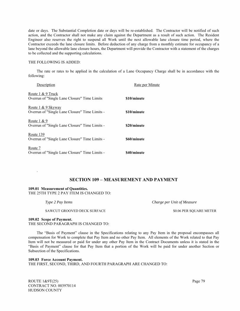
ROUTE 1&9T(25) Page 79 CONTRACT NO. 003970114 HUDSON COUNTY
date or days. The Substantial Completion date or days will be re-established. The Contractor will be notified of such action, and the Contractor shall not make any claim against the Department as a result of such action. The Resident Engineer also reserves the right to suspend all Work until the next allowable lane closure time period, where the Contractor exceeds the lane closure limits. Before deduction of any charge from a monthly estimate for occupancy of a lane beyond the allowable lane closure hours, the Department will provide the Contractor with a statement of the charges to be collected and the supporting calculations. THE FOLLOWING IS ADDED:
The rate or rates to be applied in the calculation of a Lane Occupancy Charge shall be in accordance with the following:
Description
Route 1 & 9 Truck Overrun of "Single Lane Closure" Time Limits Route 1 & 9 Skyway Overrun of "Single Lane Closure" Time Limits - Route 1 & 9 Overrun of "Single Lane Closure" Time Limits - Route 139 Overrun of "Single Lane Closure" Time Limits - Route 7 Overrun of "Single Lane Closure" Time Limits -
Rate per Minute
$10/minute
$10/minute
$20/minute $60/minute $40/minute
.
SECTION 109 – MEASUREMENT AND PAYMENT 109.01 Measurement of Quantities. THE 25TH TYPE 2 PAY ITEM IS CHANGED TO:
Type 2 Pay Items Charge per Unit of Measure
SAWCUT GROOVED DECK SURFACE $0.06 PER SQUARE METER 109.02 Scope of Payment. THE SECOND PARAGRAPH IS CHANGED TO:
The “Basis of Payment” clause in the Specifications relating to any Pay Item in the proposal encompasses all compensation for Work to complete that Pay Item and no other Pay Item. All elements of the Work related to that Pay Item will not be measured or paid for under any other Pay Item in the Contract Documents unless it is stated in the “Basis of Payment” clause for that Pay Item that a portion of the Work will be paid for under another Section or Subsection of the Specifications. 109.03 Force Account Payment. THE FIRST, SECOND, THIRD, AND FOURTH PARAGRAPH ARE CHANGED TO:

ROUTE 1&9T(25) Page 80 CONTRACT NO. 003970114 HUDSON COUNTY
When the Department has directed the Contractor to do Work on a Force Account basis it will be compensated as specified in this Subsection.
The total direct costs for labor, materials, equipment, bonds, insurance, and tax as provided below, together with applicable markups constitute full compensation for all direct and indirect costs (including overhead and profit), and are deemed to include all items of expense not specifically designated. Any adjustments to Performance Bond and Payment Bond will be made as specified in Subsection 103.05. Force Account payments will be adjusted for those costs incurred determined to be the fault of the Contractor. The Force Account payment will be further adjusted where the Contractor’s prices in its Proposal for any affected original items of work did not properly include all the costs to complete the affected work as originally provided in the Contract Documents.
When Work that is paid on a Force Account basis is performed by forces other than the Contractor's organization, the Contractor shall reach an agreement with such other forces as to the distribution of payments made by the State for such Work, with a copy of all such completely executed agreements to the Resident Engineer. Additional payment will not be made for any reason due to the performance of the Work by a subcontractor or other forces, or for costs outside that covered by the agreement.
It is understood that a Contractor’s remedy for Additional Compensation for Extra Work or for any other reason as specified in these Specifications, when an action is brought before the Superior Court as specified in the Contractual Liability Act, NJSA 59:12-1 et seq., shall not exceed the amount that would be specified in these provisions had a Force Account been carried out. However, damages sought by the Contractor in a court proceeding shall be limited to actual additional costs incurred by the Contractor resulting directly from the Extra Work or by other reason specifically permitted under the terms of the Specifications as specified in the Contractual Liability Act. As a condition predicate to seeking Additional Compensation under the claims process or in the Superior Court, the Contractor shall have the burden of proof to demonstrate compliance with the requirements of this Subsection and other applicable Subsections, and shall have kept all records required under this Subsection even if the Department has not directed that the Contractor do such Work on a Force Account basis.
Force Account payment will be limited to the following: 1. Labor.
THE FIRST PARAGRAPH IS CHANGED TO:
For all necessary direct labor and foremen in direct charge of the specific operations, whether the employer is the Contractor, subcontractor, or another, the Contractor shall receive the rate of wage (or scale) actually paid as shown in its certified payrolls for each and every hour that said labor and foremen are actually engaged in such Work.
For specific extraordinary operations the Department may allow supervising or other special type employees to be considered direct labor, but only that time in direct labor or direct charge to complete the specific construction operations.
2. Bond, Insurance, and Tax.
THE ENTIRE TEXT IS CHANGED TO:
For bond premiums; property damage, liability, and workers compensation insurance premiums; unemployment insurance contributions; and social security taxes on the Force Account work, the Contractor shall receive the actual incremental cost thereof, necessarily and directly resulting from the Force Account work. For payment, the Contractor shall furnish satisfactory evidence of the rate or rates paid for such bond, insurance, and tax.
Payment for Performance Bond and Payment Bond adjustments will be as specified in Subsection 103.05.
4. Equipment and Plant.
a. Contractor Owned Equipment and Plant. THE SECOND AND THIRD PARAGRAPHS ARE CHANGED TO:
The Blue Book will be used in the following manner:
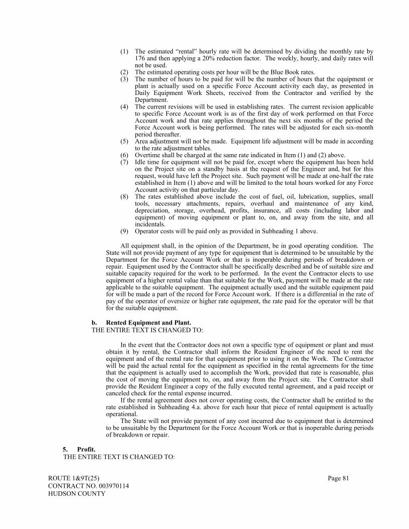
ROUTE 1&9T(25) Page 81 CONTRACT NO. 003970114 HUDSON COUNTY
(1) The estimated “rental” hourly rate will be determined by dividing the monthly rate by 176 and then applying a 20% reduction factor. The weekly, hourly, and daily rates will not be used.
(2) The estimated operating costs per hour will be the Blue Book rates. (3) The number of hours to be paid for will be the number of hours that the equipment or
plant is actually used on a specific Force Account activity each day, as presented in Daily Equipment Work Sheets, received from the Contractor and verified by the Department.
(4) The current revisions will be used in establishing rates. The current revision applicable to specific Force Account work is as of the first day of work performed on that Force Account work and that rate applies throughout the next six months of the period the Force Account work is being performed. The rates will be adjusted for each six-month period thereafter.
(5) Area adjustment will not be made. Equipment life adjustment will be made in according to the rate adjustment tables.
(6) Overtime shall be charged at the same rate indicated in Item (1) and (2) above. (7) Idle time for equipment will not be paid for, except where the equipment has been held
on the Project site on a standby basis at the request of the Engineer and, but for this request, would have left the Project site. Such payment will be made at one-half the rate established in Item (1) above and will be limited to the total hours worked for any Force Account activity on that particular day.
(8) The rates established above include the cost of fuel, oil, lubrication, supplies, small tools, necessary attachments, repairs, overhaul and maintenance of any kind, depreciation, storage, overhead, profits, insurance, all costs (including labor and equipment) of moving equipment or plant to, on, and away from the site, and all incidentals.
(9) Operator costs will be paid only as provided in Subheading 1 above.
All equipment shall, in the opinion of the Department, be in good operating condition. The State will not provide payment of any type for equipment that is determined to be unsuitable by the Department for the Force Account Work or that is inoperable during periods of breakdown or repair. Equipment used by the Contractor shall be specifically described and be of suitable size and suitable capacity required for the work to be performed. In the event the Contractor elects to use equipment of a higher rental value than that suitable for the Work, payment will be made at the rate applicable to the suitable equipment. The equipment actually used and the suitable equipment paid for will be made a part of the record for Force Account work. If there is a differential in the rate of pay of the operator of oversize or higher rate equipment, the rate paid for the operator will be that for the suitable equipment.
b. Rented Equipment and Plant.
THE ENTIRE TEXT IS CHANGED TO:
In the event that the Contractor does not own a specific type of equipment or plant and must obtain it by rental, the Contractor shall inform the Resident Engineer of the need to rent the equipment and of the rental rate for that equipment prior to using it on the Work. The Contractor will be paid the actual rental for the equipment as specified in the rental agreements for the time that the equipment is actually used to accomplish the Work, provided that rate is reasonable, plus the cost of moving the equipment to, on, and away from the Project site. The Contractor shall provide the Resident Engineer a copy of the fully executed rental agreement, and a paid receipt or canceled check for the rental expense incurred.
If the rental agreement does not cover operating costs, the Contractor shall be entitled to the rate established in Subheading 4.a. above for each hour that piece of rental equipment is actually operational.
The State will not provide payment of any cost incurred due to equipment that is determined to be unsuitable by the Department for the Force Account Work or that is inoperable during periods of breakdown or repair.
5. Profit.
THE ENTIRE TEXT IS CHANGED TO:
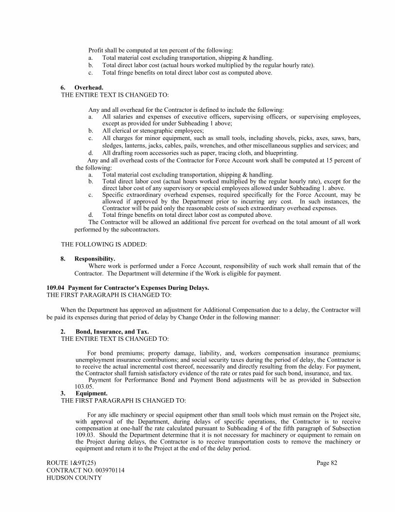
ROUTE 1&9T(25) Page 82 CONTRACT NO. 003970114 HUDSON COUNTY
Profit shall be computed at ten percent of the following: a. Total material cost excluding transportation, shipping & handling. b. Total direct labor cost (actual hours worked multiplied by the regular hourly rate). c. Total fringe benefits on total direct labor cost as computed above.
6. Overhead.
THE ENTIRE TEXT IS CHANGED TO:
Any and all overhead for the Contractor is defined to include the following: a. All salaries and expenses of executive officers, supervising officers, or supervising employees,
except as provided for under Subheading 1 above; b. All clerical or stenographic employees; c. All charges for minor equipment, such as small tools, including shovels, picks, axes, saws, bars,
sledges, lanterns, jacks, cables, pails, wrenches, and other miscellaneous supplies and services; and d. All drafting room accessories such as paper, tracing cloth, and blueprinting. Any and all overhead costs of the Contractor for Force Account work shall be computed at 15 percent of
the following: a. Total material cost excluding transportation, shipping & handling. b. Total direct labor cost (actual hours worked multiplied by the regular hourly rate), except for the
direct labor cost of any supervisory or special employees allowed under Subheading 1. above. c. Specific extraordinary overhead expenses, required specifically for the Force Account, may be
allowed if approved by the Department prior to incurring any cost. In such instances, the Contractor will be paid only the reasonable costs of such extraordinary overhead expenses.
d. Total fringe benefits on total direct labor cost as computed above. The Contractor will be allowed an additional five percent for overhead on the total amount of all work
performed by the subcontractors.
THE FOLLOWING IS ADDED:
8. Responsibility. Where work is performed under a Force Account, responsibility of such work shall remain that of the
Contractor. The Department will determine if the Work is eligible for payment. 109.04 Payment for Contractor's Expenses During Delays. THE FIRST PARAGRAPH IS CHANGED TO:
When the Department has approved an adjustment for Additional Compensation due to a delay, the Contractor will be paid its expenses during that period of delay by Change Order in the following manner:
2. Bond, Insurance, and Tax. THE ENTIRE TEXT IS CHANGED TO:
For bond premiums; property damage, liability, and, workers compensation insurance premiums; unemployment insurance contributions; and social security taxes during the period of delay, the Contractor is to receive the actual incremental cost thereof, necessarily and directly resulting from the delay. For payment, the Contractor shall furnish satisfactory evidence of the rate or rates paid for such bond, insurance, and tax.
Payment for Performance Bond and Payment Bond adjustments will be as provided in Subsection 103.05.
3. Equipment. THE FIRST PARAGRAPH IS CHANGED TO:
For any idle machinery or special equipment other than small tools which must remain on the Project site, with approval of the Department, during delays of specific operations, the Contractor is to receive compensation at one-half the rate calculated pursuant to Subheading 4 of the fifth paragraph of Subsection 109.03. Should the Department determine that it is not necessary for machinery or equipment to remain on the Project during delays, the Contractor is to receive transportation costs to remove the machinery or equipment and return it to the Project at the end of the delay period.

ROUTE 1&9T(25) Page 83 CONTRACT NO. 003970114 HUDSON COUNTY
4. Miscellaneous.
THE SUBPART HEADING IS CHANGED TO: 4. Overhead.
6. Records.
THE SECOND AND THIRD PARAGRAPHS ARE CHANGED TO:
The Department's records will be compared with completed daily reports furnished by the Contractor and any necessary adjustments will be made. When these daily reports are agreed upon and signed by both parties, said reports become the basis of payment for the expenses incurred, but do not preclude subsequent adjustment based on a later audit by the Department.
The Contractor's cost records pertaining to expenses under this Subsection shall be open to inspection or audit by the Department during the life of the Contract and for a period of not less than three years after Acceptance thereof, and the Contractor shall retain such records for that period. Where payment for equipment or labor is based on the cost thereof to forces other than the Contractor, the Contractor shall make every reasonable effort to ensure that the cost records of such other forces are open to inspection and audit by the Department on the same terms and conditions as the cost records of the Contractor. Payment for such cost may be deleted if the records of such third parties are not made available to the Department. If an audit is to be commenced more than 60 days after Acceptance, the Contractor is to be provided with a reasonable notice of the time when such audit is to begin. In case all or a part of such records are not made so available, the Contractor understands and agrees that any items not supported by reason of such unavailability of the records will not be allowed, or if payment therefore has already been made, the Contractor shall refund to the Department the amount so disallowed.
109.05 Partial Payments. SUBPART 1 OF THE SECOND PARAGRAPH IS CHANGED TO:
1. Each subcontractor or supplier has been paid any amount due from any previous progress payment and shall be paid any amount due from the current progress payment and no retainage is being withheld from any subcontractor on federally funded projects; or
THE SEVENTH PARAGRAPH IS CHANGED TO:
From the total amounts ascertained as payable, excluding subcontracted work on federally funded projects, an amount equivalent to two percent of the amount due on the total adjusted Contract price will be deducted and retained pending Substantial Completion. Any amounts paid to the Contractor in the form of incentive payments for early Completion and positive pay adjustments will not be included in the adjusted Contract price when calculating retainage. 109.06 Materials Payments. THE SUBSECTION HEADING IS CHANGED TO: 109.06 Materials Payments and Storage. THE FIRST PARAGRAPH IS CHANGED TO:
The monthly estimates and payments made on account thereof may also include, when authorized by the Department, an amount equal to the actual cost of materials furnished but not incorporated into the Work, provided, however, that such amount does not exceed 85 percent of the Contract price for the Pay Item into which the material is to be incorporated, and the quantity allowed does not exceed the corresponding quantity estimated in the Contract Documents. Advance payment will only be for that portion of the price in the Proposal related to the materials and any costs for storage at the facility of manufacture. Any taxes levied by any government against the materials shall be borne by the Contractor. Before including payments for such materials in an estimate, the Department must be satisfied that:
1. The materials have been properly stored and protected along or upon the Project site or have been stored and protected at locations owned or leased by the Contractor or the Department within the State, except that structural steel, prestressed concrete beams, and other large items not suitable for storage on or near the site, may be stored outside the State with the approval of the Department; and
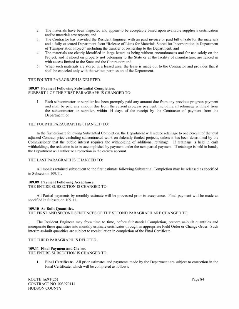
ROUTE 1&9T(25) Page 84 CONTRACT NO. 003970114 HUDSON COUNTY
2. The materials have been inspected and appear to be acceptable based upon available supplier’s certification and/or materials test reports; and
3. The Contractor has provided the Resident Engineer with an paid invoice or paid bill of sale for the materials and a fully executed Department form “Release of Liens for Materials Stored for Incorporation in Department of Transportation Project” including the transfer of ownership to the Department; and
4. The materials are clearly identified in large letters as being without encumbrances and for use solely on the Project, and if stored on property not belonging to the State or at the facility of manufacture, are fenced in with access limited to the State and the Contractor; and
5. When such materials are stored in a leased area, the lease is made out to the Contractor and provides that it shall be canceled only with the written permission of the Department.
THE FOURTH PARAGRAPH IS DELETED. 109.07 Payment Following Substantial Completion. SUBPART 1 OF THE FIRST PARAGRAPH IS CHANGED TO:
1. Each subcontractor or supplier has been promptly paid any amount due from any previous progress payment and shall be paid any amount due from the current progress payment, including all retainage withheld from the subcontractor or supplier, within 14 days of the receipt by the Contractor of payment from the Department; or
THE FOURTH PARAGRAPH IS CHANGED TO:
In the first estimate following Substantial Completion, the Department will reduce retainage to one percent of the total adjusted Contract price excluding subcontracted work on federally funded projects, unless it has been determined by the Commissioner that the public interest requires the withholding of additional retainage. If retainage is held in cash withholdings, the reduction is to be accomplished by payment under the next partial payment. If retainage is held in bonds, the Department will authorize a reduction in the escrow account. THE LAST PARAGRAPH IS CHANGED TO:
All monies retained subsequent to the first estimate following Substantial Completion may be released as specified in Subsection 109.11. 109.09 Payment Following Acceptance. THE ENTIRE SUBSECTION IS CHANGED TO:
All Partial payments by monthly estimate will be processed prior to acceptance. Final payment will be made as specified in Subsection 109.11. 109.10 As-Built Quantities. THE FIRST AND SECOND SENTENCES OF THE SECOND PARAGRAPH ARE CHANGED TO:
The Resident Engineer may from time to time, before Substantial Completion, prepare as-built quantities and incorporate these quantities into monthly estimate certificates through an appropriate Field Order or Change Order. Such interim as-built quantities are subject to recalculation in completion of the Final Certificate. THE THIRD PARAGRAPH IS DELETED. 109.11 Final Payment and Claims. THE ENTIRE SUBSECTION IS CHANGED TO:
1. Final Certificate. All prior estimates and payments made by the Department are subject to correction in the Final Certificate, which will be completed as follows:

ROUTE 1&9T(25) Page 85 CONTRACT NO. 003970114 HUDSON COUNTY
a. After Acceptance is completed as specified in Subsection 105.23 and the As-Built quantities finalized, the Department will make an estimate of the total amount of Work done under the Contract, and prepare and issue the Final Certificate to the Contractor.
b. Within 30 State Business Days after said Final Certificate has been issued to the Contractor, the Contractor shall submit to the Department either a written acceptance of the Final Certificate without exception together with an executed release in the form provided with the Final Certificate or a written acceptance of the Final Certificate with a reservation of specific claims, but otherwise releasing all claims not specifically reserved, by executing a conditional release in the form provided with the Final Certificate. The Contractor's failure to submit any written acceptance or acceptance with reservation within said 30 days will be construed by the Department as an acceptance by the Contractor of the Final Certificate without exception or reservation of Claims.
c. Upon receipt of the Contractor’s written acceptance of the Final Certificate with unconditional or conditional release, or when the Contractor fails to provide any written acceptance of the Final Certificate within 30 State Business Days of issuance, the Department will pay the entire sum due thereunder as provided by the New Jersey Prompt Payment Act NJSA 52:32-32 et seq., provided the Final Certificate indicates a payment is due the Contractor. However, where the Final Certificate indicates a Credit (payment) is due the Department, the Contractor shall remit said Credit (payment) to the Department in the amount set forth in the Final Certificate.
d. If the Contractor fails to remit the Credit (payment) due the Department, as indicated on the Final Certificate, within 30 State Business Days of issuance of the Final Certificate, the Department may pursue all legal means available to recover the amount due the State, including but not limited to, deducting the amount from payment due the Contractor on this or other Department Contracts or from retainage and/or the sale of bonds held in lieu of retainage for the Contract or for other Contracts, even where the credit is being contested by the Contractor.
Neither the failure of the Contractor to accept the tendered Final Payment nor the failure of the Contractor to remit the credit (payment) due the Department shall affect when the “Completion of the Contract” shall be deemed to have occurred for any reason. Where there is a remaining monetary balance due to the Contractor by the Department, Final Payment will be made after the “Completion of the Contract”. Retainage shall be released to the Contractor upon completion of the contract unless a credit (payment) is due to the Department, which shall be deducted or adjusted in accord with the Specifications.
2. Conditions for Claims. Conditional acceptance of the Final Certificate will be permitted only where all of the following are met:
a. When the Contractor submits a Release conditioned with exception or reservation, the release shall state the specific monetary amounts and category of the claims being reserved. The Contractor acknowledges, by the act of executing the contract, that the failure to state specific monetary amounts and specific categories shall result in a waiver of such claims lacking as to amounts or specific categories thereof. The Contractor may reserve only those claims properly filed with the Department pursuant to Subsection 107.02 and not previously resolved. The Contractor waives all claims for which the required notice has not been filed with the Department.
b. The Contractor further understands and agrees, by the act of executing the Contract that neither the procedures established under this Subsection nor the review of claims by the Department pursuant hereto shall in any way modify the requirements applicable to the filing of a Contractual Notice Form or the filing of a suit pursuant to the provisions of N.J.S.A. 59:13-1 et seq. .
c. If the Contractor conditions its acceptance of the Final Certificate by reserving particular claims, the Contractor shall at the same time state in writing whether it would like to submit its reserved claims for review by the Department Claims Committee. Only those claims properly reserved, as provided for in Subsection 107.02, and which are unresolved after completing Steps I and II of the Contractual Claim Resolution Process for the resolution of contract claims, are eligible for review by the Department Claims Committee to the extent provided in that Subsection. If the Contractor states that it does not want Department Claims Committee review of the reserved claims or if it fails to request Department Claims Committee review of reserved claims when it conditions its acceptance of the Final Certificate or if it files suit in a court of law regarding those claims, the Contractor shall be deemed to have waived any ability to have its reserved claims reviewed by the Department Claims Committee.

ROUTE 1&9T(25) Page 86 CONTRACT NO. 003970114 HUDSON COUNTY
d. If the Contractor requests review of its reserved claims when it conditions its acceptance of the Final Certificate, it shall send at the same time a copy of its request for review to the Secretary of the Department Claims Committee, PO Box 600, Trenton, NJ 08625-0600. Department Claims Committee review will then take place according to Subsection 107.02.
e. At the election of the Contractor upon completion of the Contract, claims that are unresolved after review by the Department Claims Committee may be submitted to Non-Binding Mediation according to Subsection 107.02.
f. Interest shall neither be paid nor shall it accrue upon the amount of any additional compensation paid in resolution or settlement of a claim resolved through the various steps of the Contractual Claims Resolution Process.
109.13 Contractor’s Compliance with NJSA 34:11-56.25 et seq. THE ENTIRE SUBSECTION TEXT IS CHANGED TO:
The Contractor shall furnish the Engineer with written statements on a form provided by the Department certifying that all employees employed by the Contractor or by any subcontractor have been paid wages not less than those required by the Contract provisions. 109.15 Affidavit Concerning Gifts to Department of Transportation Employees, etc. THE ENTIRE SUBSECTION TEXT IS CHANGED TO:
The Contractor shall not give any gifts of any nature, nor any gratuity in any form whatsoever, nor loan any money or anything of value to any Department employee, or relative or agent of any Department employee. The Contractor shall not rent or purchase any equipment or supplies of any nature whatsoever from any Department employee, or relative or agent of any Department employee. Similarly, such gifts, gratuities, loans, rentals, or purchases shall not be given to or made from any agent of the Department during the period of time that such agent is performing any function related in any way to the Project. The Contractor shall execute, under oath, an affidavit, on forms provided by the Department, swearing that the Contractor has given no such prohibited gift, gratuities, or loans nor made any such prohibited rentals or purchases, and acknowledges that the Contractor has a continuing obligation to abide by the restrictions set forth in this Subsection.

ROUTE 1&9T(25) Page 87 CONTRACT NO. 003970114 HUDSON COUNTY
DIVISION 200 - EARTHWORK
SECTION 201 - CLEARING SITE
201.03 Clearing Site. THE FOLLOWING IS ADDED:
The Contractor shall conduct all clearing and removal activities in areas identified on the Environmental Plan Sheets as containing Regulated Waste in accordance with Subsection 202.04, Management of Regulated Waste. The Contractor shall institute controls to minimize contact with materials containing regulated waste during clearing and removal activities as defined elsewhere in the Special Provisions and Specifications. Site clearing shall not be initiated until the Contractor’s Environmental Plans (Site Specific Health and Safety Plan, Materials Handling Plan, and Pollution Prevention Control Plan) have been reviewed and accepted by the Engineer. 201.04 Removal of Bridges, Culverts, and Other Structures. THE FOLLOWING IS ADDED:
The bridge work to be performed under this Contract includes removal and disposal of reinforced concrete bridge decks, sidewalks, curbs, parapets, deck joints, railings, and conduit as shown on the Plans and as directed by the Engineer.
The equipment listed below is permitted subject to the following applicable restrictions: 1. Pneumatic or Electric Equivalent Hand Operated Hammers.
a. Up to 41-kilogram (90-pound) hammers exclusive of the bit may be used for deck removal not closer than 150 millimeters to structural members. This hammer may also be used for removal of barriers, sidewalks, curbs, and parapets not closer than 150 millimeters from structural members. Only chisel point bits will be permitted. Structural members are defined as girders, floorbeams, stringers, diaphragms, or cross frames.
b. Up to 14-kilogram (30-pound) hammers exclusive of bit may be used for removal of concrete within 150 millimeters of structural members.
2. Saw Cutters. a. Vermeer concrete cutters or cutting saws may be used to cut within 150 millimeters adjacent to structural
members. b. If water is used in conjunction with cutting operations, shielding beneath the operation shall prevent
water leakage. Water shall be disposed by an approved method. The disposal method shall be submitted by the Contractor for approval by the Engineer.
3. Hydraulic Breakers. Hydraulic breakers, such as, but not limited to, Tramac or other ram-hoe type breakers, are permitted for removal of substructure concrete. For deck concrete removal, such equipment is permitted subject to the following restrictions: a. The girders shall be analyzed to determine if induced stresses may be harmful. b. The centerline and limits of the top flange of girders shall be delineated before starting the equipment
operation. c. The equipment shall not be used directly over the top of girders nor in overhang areas. Concrete
removal in these areas shall be performed by jackhammers. d. Pulling and twisting of the reinforcement steel is prohibited. e. Any damage to existing reinforcement, shear studs, structural steel, or any other structural components
that are to remain shall be repaired at no cost to the State. 4. Hydraulic Splitters. Hydraulic splitters such as Darda hydraulic splitters are permitted subject to approval. 5. Other Equipment. Equipment not specifically approved in this Section may be used only with written
approval.

ROUTE 1&9T(25) Page 88 CONTRACT NO. 003970114 HUDSON COUNTY
The sequence of removal shall be coordinated with the operations of the utility company to protect and maintain its facilities.
During removal operations, the Contractor shall take all necessary precautions so as not to damage the structural members scheduled to remain. All damage done to the existing structural members scheduled to remain shall be repaired. The repair procedure shall be as follows:
1. Prestressed Concrete Stringers and Concrete Diaphragms. Damage done to existing prestressed concrete stringers and concrete diaphragms scheduled to remain shall be repaired with nonshrink grout conforming to Subsection 914.03 before deck placement. The repair procedure shall be approved.
2. Steel Stringers, Floorbeams, Cross Frames, and Diaphragms. a. Repair procedures to tensile components shall conform to ASTM A 6/A 6M and the following:
(1) Gouges up to 3 millimeters shall be removed by grinding flush in the direction of principal stress. (2) Gouges deeper than 3 millimeters shall be removed first by grinding; then, weld metal shall be
deposited and ground flush with the surface of the metal in the direction of principal stress. Welding shall be done using low hydrogen electrodes conforming to current AWS Specifications A5.1 and A5.5. The electrodes shall be protected from moisture during storage.
(3) Kinks and deformations shall be repaired by flame straightening or a combination of flame straightening and jacking. Flame straightening shall be done by personnel approved by the Department with a minimum of three years of prior documented experience.
b. Repair procedures to compression components shall conform to the following: (1) Where more than five percent of the cross-sectional area of the member is damaged due to removal
operations, the Contractor shall submit a repair procedure for approval. (2) Kinks and deformations shall be repaired as outlined in 2.a (3) above.
Existing top flanges of beams exposed by removal operations shall be cleaned and painted with a prime coat of paint according to Subsection 514.07, Subpart B. THE FOLLOWING IS ADDED:
Special protective systems for the removal of bridges, culverts, and other structures shall be as follows: 1. Temporary Shielding. Temporary shielding for demolition and new construction shall include furnishing,
installing, and removing a structural framing and barrier system. The system shall be supported from girders to provide an adequate and substantial temporary shielding system to protect vehicular, pedestrian, and railroad traffic from falling construction materials or other objects. The barrier system shall remain in place during the time that construction work is performed and until the work is completed and accepted.
For deck replacement or new deck work, the temporary shielding shall seal the underside of deck and extend outside of the fascia stringers to enclose the soffits and parapets.
For parapet removal and replacement or new parapet construction, an outrigging type of temporary shielding, which encloses the soffit and parapet, shall be used.
The Contractor shall submit for approval detailed working drawings showing all elements of the temporary shielding system, including bonding and grounding over electrified rail lines, design calculations, and the sequence of operations thereof, signed and sealed by a Professional Engineer licensed in the State. Should the Contractor’s operation or construction staging require it to install and remove the shielding more than once, no additional payment will be made.
The traffic lanes and pedestrian areas below the areas where temporary shielding is being installed shall be closed, in accordance with the requirements of Section 617.
The temporary shielding shall be designed to withstand a load of at least 5.75 kilopascals or greater if heavier loads are anticipated and shall prevent small particles and dust from falling through. Stay-in-place forms shall not be used as shielding.
Bolted connections or welding between temporary shielding and bottom flanges of the beams shall not be permitted. Any materials dropped on the temporary shielding shall not be allowed to accumulate and shall be removed promptly.
The selection of sizes, materials, their arrangements, and details shall be the Contractor’s option and responsibility, but subject to approval by the Engineer.
In no case shall the temporary shielding reduce the existing underclearances of the bridges to less than 4.5 meters over roadways and 6.75 meters over railroads. If any existing underclearance is less than these values, it shall be maintained without any further reduction.

ROUTE 1&9T(25) Page 89 CONTRACT NO. 003970114 HUDSON COUNTY
The Contractor shall obtain the Engineer’s approval of the method, design, and details of the temporary shielding system that the Contractor intends to use for the protection of traffic. No construction work shall be performed above traffic before such approval.
It is the Contractor’s responsibility to ensure the structural integrity and continuous operation of the railroad’s electrified lines, their supports, and appurtenances.
The Contractor shall comply with the railroad’s maintenance of traffic requirements, rules, and regulations.
A 150 millimeter minimum clearance to a catenary wire shall be maintained. An electrification shutdown by the railroad on a track-by-track basis shall allow for construction of the special protection systems.
2. Bonding and Grounding. Bonding and grounding shall consist of the furnishing of cables, connectors, terminals, and all hardware required for grounding and bonding the solid overhead barrier to the main girders. .
The work shall also include furnishing cable and hardware for the grounding and bonding of the temporary protective barrier and of the new Route 1&9 Bridge over NJ Transit.
The Contractor shall submit a list for review by the Engineer identifying the items being furnished with a complete description of the items including manufacturer and catalog number. The list shall be submitted to the railroad for approval before ordering the materials.
The solid overhead barrier shall be grounded to the main girders at two locations on each side of the bridge with 336400 bare aluminum cable. Terminals, connectors, and hardware shall be compatible for cable to steel connections.
The top rail of the solid overhead barrier shall be bonded at all splices with insulated aluminum cable having a diameter of 107.2 square millimeters, seven-strand polyethylene weatherproof insulation. Terminals and hardware shall be compatible for the cable to steel connections.
The temporary protective shield shall be bonded with copper cable having a diameter of 107.2 square millimeters. Terminals and hardware shall be compatible for the cable and connected material. One cable having a diameter of 107.2 square millimeters shall be placed on top of the shield and run the full length of the shield. The barrier shall be grounded to the girders at each end.
The Contractor shall remove concrete from existing fascia girders and drill holes for the necessary connection to the grounding system as shown on the Plans.
THE FOLLOWING IS ADDED:
In span 2 of the existing Route 1&9 Bridge over NJ Transit (Structure No. 0902-150), the original plans indicate that the elliptical and trapezoidal deck forms are composed of 9.5 mm (3/8”) thick transite, a material containing a minimum of 15% asbestos. Also, the plans indicate that the heads of the anchor bolts used to secure the formwork are painted with asbestos cement. Removal and disposal of the transite shall be performed in accordance with the rules and regulations of NJAC 5:23-8.1. 201.07 Removal of Underground Storage Tanks. THE FIRST PARAGRAPH IS CHANGED TO:
The general locations and types of underground storage tanks to be removed are provided in Environmental Plan Sheets and as noted below. The information given below was developed from secondary sources and must be verified by the Contractor. The Contractor shall excavate test pits as necessary to confirm locations, types, and sizes of underground storage tanks in accordance with Subsection 207.04. The Contractor shall use the information concerning underground storage tanks to complete and submit the NJDEP's Underground Storage Tank Facility Questionnaire(s) for unregistered Underground Storage Tanks, apply and secure permits for the removal of all underground storage tanks, 30 day Notices of Intent to Close an Underground Storage Tank System, Site Investigation Reports, and Storage Tank Closure Plans. All reports, as well as notice of receipt and approval by the NJDEP, must be received by the NJDOT and their environmental consultant prior to payment.

ROUTE 1&9T(25) Page 90 CONTRACT NO. 003970114 HUDSON COUNTY
PARCEL ID NO.
UST REGISTRATION
NO.
SIZE (GALLONS)1 CONTENTS DATE
INSTALLED STATUS
61B unknown 5,000 unknown unknown unknown 69 unknown 3,000 unknown unknown unknown 69 unknown 5,000 unknown unknown unknown
1. The tank sizes were estimated from geophysical surveys conducted on the parcels.
201.08 Sealing of Abandoned Wells. THE FOLLOWING IS ADDED:
A copy of well abandonment records shall be submitted to the Engineer at the same time as and in addition to submitting the original record to the NJDEP.
201.09 Demolition of Buildings. THE FOLLOWING IS ADDED BEFORE THE FIRST PARAGRAPH:
4. Demolition Operations. Prior to start of demolition operations, the Contractor shall remove and properly dispose of all chemicals, miscellaneous cylinders, drums and garbage from the buildings.
5. Backfilling.
THE FIRST ITEM OF THE FIRST PARAGRAPH IS DELETED. 201.10 Disposal of Material and Debris. THE FOLLOWING IS ADDED:
The Contractor shall handle all material and debris known to have contacted Roadway Excavation Regulated Waste or defined elsewhere in the specification in accordance with Subsections 202.04 Site Specific HASP. Excess contaminated earth and unusable contaminated soil and/or debris generated during clearing site shall be disposed of at off-site recycling, treatment or disposal facilities in accordance with NJAC 7:26 et seq. and USEPA 40CFR 260-266 et seq. No separate payment will be made for managing and disposing of contaminated material and debris generated in clearing site. 201.11 Method of Measurement. THE FIRST PARAGRAPH IS CHANGED TO:
Clearing Site, including bridges and other structures, will not be measured, and payment will be made on a lump sum basis.
THE FOLLOWING IS ADDED:
Clearing Site, Tank Removal will be measured by the unit. A unit shall be comprised of each tank and associated piping and contents removed.
THE FOLLOWING IS ADDED:
Excavation or the use of any type of sheeting that is required for the removal of the structure, or when such sheeting is to remain for planned new construction that is at the same location of the removal, will not be measured. Payment shall be included in the bid price for “Clearing Site, _______”.

ROUTE 1&9T(25) Page 91 CONTRACT NO. 003970114 HUDSON COUNTY
201.12 Basis of Payment. THE FOLLOWING PAY ITEMS ARE ADDED TO THE FIRST PARAGRAPH: Pay Item Pay Unit CLEARING SITE, TANK REMOVAL UNIT
THE SECOND PARAGRAPH IS CHANGED TO:
Payment for the Pay Item “Clearing Site” in excess of $541,300 will not be made until Completion. THE FOLLOWING IS ADDED AFTER THE THIRD PARAGRAPH:
Payment for the Pay Item “Clearing Site, Bridge (Structure No.0906-156)” in excess of $4,048,600 will not be made until Substantial Completion.
Payment for the Pay Item “Clearing Site, Bridge (Ramp I-Structure No.0901-150)” in excess of $918,000 will not be made until Substantial Completion.
Payment for the Pay Item “Clearing Site, Bridge (Structure No.0906-155)” in excess of $515,300 will not be made until Substantial Completion.
Payment for the Pay Item “Clearing Site, Bridge (Structure No.0906-157)” in excess of $342,100 will not be made until Substantial Completion.
The payment schedule for “Clearing Site, Bridge (Structure No.0906-158)” will be as follows: Payment for the Pay Item “Clearing Site, Bridge (Structure No.0906-158)” in excess of $2,408,600 will not be
made until Substantial Completion. Fifty percent of the price bid (or $1,204,300, whichever is less) upon acceptance of Stage IIIA demolition. Fifty percent of the price bid (or $1,204,300, whichever is less) upon acceptance of Stage IIIC demolition. The payment schedule for “Clearing Site, Bridge (Structure No.0902-150)” will be as follows: Payment for the Pay Item “Clearing Site, Bridge (Structure No.0902-150)” in excess of $2,479,000 will not be
made until Substantial Completion. Twenty percent of the price bid (or $495,800, whichever is less) upon acceptance of Stage IA demolition. Forty percent of the price bid (or $991,600, whichever is less) upon acceptance of Stage IB demolition. Forty percent of the price bid (or $991,600, whichever is less) upon acceptance of Stage IC demolition. The payment schedule for “Clearing Site, Bridge (Structure No.0902-151)” will be as follows: Payment for the Pay Item “Clearing Site, Bridge (Structure No.0902-151)” in excess of $4,476,200 will not be
made until Substantial Completion. Twenty percent of the price bid (or $895,300, whichever is less) upon acceptance of Stage IA demolition. Forty percent of the price bid (or $1,790,450, whichever is less) upon acceptance of Stage IB demolition. Forty percent of the price bid (or $1,790,450, whichever is less) upon acceptance of Stage IC demolition. Payment for the Pay Item “Clearing Site, Structure (Overhead Sign Support Structure No. 0909-206)” in excess of
$16,300 will not be made until Substantial Completion. Payment for the Pay Item “Clearing Site, Structure (Overhead Sign Support Structure No. 0902-210)” in excess of
$16,300 will not be made until Substantial Completion. Payment for the Pay Item “Clearing Site, Structure (Overhead Sign Support Structure No. 0909-211)” in excess of
$16,300 will not be made until Substantial Completion. Payment for the Pay Item “Clearing Site, Structure (Overhead Sign Support Structure No. 0902-218)” in excess of
$16,300 will not be made until Substantial Completion. Payment for the Pay Item “Clearing Site, Structure (Overhead Sign Support Structure at Tonnele Circle)” in excess
of $16,300 will not be made until Substantial Completion. THE FOLLOWING IS ADDED TO THIS SUBSECTION:
Separate payment will not be made for the transite removal and disposal for the Route 1&9 over NJ Transit Bridge
(Structure 0902-150) but shall be included in the lump sum pay item, “Clearing Site, Bridge (Structure No.0902-150)”.

ROUTE 1&9T(25) Page 92 CONTRACT NO. 003970114 HUDSON COUNTY
SECTION 202 - ROADWAY EXCAVATION
202.01 Description. THE FOLLOWING IS ADDED:
This work shall also include the excavation, handling, reuse at locations identified on the environmental plans, and disposal and/or recycling of Regulated Waste generated in excavation for roadway, utilities, and subsurface structures. 202.02 Classification.
THE FIRST AND SECOND PARAGRAPHS ARE CHANGED TO:
Roadway Excavation, Regulated Waste consists of the excavation of all materials of whatever character is encountered in areas exhibiting restricted use criteria in accordance with N.J.A.C. 7:26E et seq. Requirements and methods for excavation and management of Regulated Waste are provided in Subsection 202.04.
202.04 Excavation. THE LAST PARAGRAPH IS CHANGED TO:
All unstable material shall be disposed of in accordance with Subsections 202.12 or 202.13, as appropriate. THE FOLLOWING IS ADDED TO THIS SECTION:
MANAGEMENT OF REGULATED WASTE Preliminary analysis has identified areas of contaminated soil within and adjacent to planned excavation areas. An area has been identified to contain chromium contaminated material, and one area has been identified to contain levels of lead that characterize the material as hazardous waste. Excavation in areas containing one or more contaminants exceeding New Jersey Department of Environmental Protection (NJDEP) soil cleanup criteria, as identified in the construction documents, as directed by the Engineer, or as determined by the Contractor and approved by the Engineer, shall be performed in accordance with applicable Federal, State and local laws, rules and regulations; the Contractor's Site Specific Health and Safety Plan (HASP); the specifications and the direction of the Engineer. A. REQUIREMENTS AND METHODS FOR EXCAVATION AND MANAGEMENT OF REGULATED
WASTE Description.
The work shall include the excavation, handling, sampling and analysis for disposal and/or recycling, reuse at locations identified on the environmental plans, and disposal and/or recycling of regulated waste except as provided for in Subsection 202.13. The disposal of regulated waste shall comply with the construction plans, specifications, Federal, State and local laws, rules, and regulations, the waste management plan of the district of origin, and Subsection 202.13. The term “Regulated Waste” as used shall mean Regulated Waste, Regulated Waste, Hazardous, and Regulated Waste, Chromium, as appropriate. Construction Requirements.
The Contractor shall provide all personnel, materials, and equipment needed to undertake excavation as required to complete the work in a safe manner that is protective of human health and the environment. Excavation of regulated waste shall be performed with equipment of suitable size and compatible with site conditions. All equipment shall comply with and shall be operated in accordance with all applicable regulations. Excavation of Regulated Waste shall be to the limits shown on the plans and no further, unless directed by the Engineer.
The Contractor shall handle all excavated material in a manner that protects site personnel, the public, and the environment in accordance with all applicable Federal, State, and local laws and regulations. Prior to any excavation of

ROUTE 1&9T(25) Page 93 CONTRACT NO. 003970114 HUDSON COUNTY
regulated waste the Contractor shall develop a Site-Specific Health and Safety Plan (HASP) in accordance with 29 CFR 1910, 29 CFR 1926 and the Site Specific Health and Safety Requirements specified herein. Environmental Sampling and Testing.
The Contractor shall provide all personnel, materials, and equipment needed to properly characterize excavated Regulated Waste material as required for disposal/recycling facility approval. Stockpiling material at a location outside the project corridor will not be allowed. The Contractor shall submit as part of the Material Handling Plan described herein, a sampling analysis section for characterizing the Regulated Waste for off-site disposal in accordance with applicable Federal, State and local laws, rules and regulations or according to the disposal facility accepting the waste.
The Contractor shall submit as part of the sampling and analysis section, the name, address, and telephone number of the contact for the Contractor’s proposed environmental laboratory and the name and experience of the proposed environmental sampling technician. The use of a proposed environmental laboratory and proposed environmental sampling technician are subject to review and acceptance by the Engineer.
The Contractor shall provide all personnel, equipment, and ancillary services required to collect, transport, and analyze environmental samples required for proper characterization of the material. All sampling, testing, and inspections conducted in areas containing potential regulated waste shall be performed in accordance with the site-specific HASP in Subsection 202.04.
All sampling, testing, and data management procedures shall comply with current versions of the NJDEP Field
Sampling Procedures Manual, NJDEP Technical Requirements for Site Remediation, NJDEP Management of Excavated Soils Guidelines, and Appendix 1, and the NJDEP Waste Classification Form.
Where required by the Contractor’s disposal facility, the Contractor shall collect and analyze for additional parameters necessary for off-site disposal. The Contractor shall not sample, test or analyze for the purpose of redefining the limits or designation of the Regulated Excavation. Stockpiling Regulated Waste. The Contractor shall provide all personnel, materials and equipment needed to properly store (and dewater, if necessary) Regulated Waste in temporary stockpiles. If needed, any temporary stockpile(s) shall be located at area(s) within the project limits selected by the Contractor and approved by the Resident Engineer. Regulated waste, unsuitable for construction activities and/or reuse, shall not be stockpiled for more than 180 days. Regulated Waste subsequently classified as hazardous waste shall be properly staged and removed within 90 days of excavation.
The location(s) of any stockpile(s) shall be approved by the Resident Engineer. Stockpiles shall only be placed on
dry areas on PVC sheeting, or similar material, a minimum of 10 mils thick. All joints in the underlying PVC sheeting shall overlap a minimum of 300 millimeters at the ends. Each stockpile shall include a sediment barrier comprised of hay bales or silt fence placed continuously at the perimeter of the stockpile(s). Stockpile shall be constructed so that heights shall not exceed 4.5 meters, nor with side slopes steeper than one vertical and two horizontal. The Contractor shall segregate material of differing types and degrees of contamination so as to prevent cross-contamination of uncontaminated material.
The Contractor shall provide protection for the regulated waste stockpile to prevent the run-on of stormwater,
migration of contaminants, dusting, erosion and unauthorized contact. Stockpiles shall be covered with PVC sheeting or similar material, a minimum of 10 mils thick. The sheeting shall be secured in place with tie downs and/or heavy objects such as concrete blocks at the end of each workday and during adverse weather conditions. All joints in the cover shall overlap a minimum 300 millimeters and securing materials shall be placed along the joints such that the cover will not be opened by wind action.
The Contractor shall be responsible for the proper protection and maintenance for the regulated waste stockpile and
embankment until completion of the work and acceptance by the Engineer. The Contractor shall maintain the sheeting and, as needed, repair or replace damaged cover sheeting, and replace displaced cover sheeting. At the direction of the Engineer, the Contractor shall remedy any observed deficiencies in the cover and sediment barrier surrounding the temporary stockpile or embankment as soon as practicable, including but not limited to the removal and disposal of

ROUTE 1&9T(25) Page 94 CONTRACT NO. 003970114 HUDSON COUNTY
accumulated sediments behind the sediment barrier, to maintain satisfactory protection, and as otherwise needed to prevent contamination migration or exposure.
Drainage shall be controlled with hay bales, placed continuously at the perimeter of the stockpile(s), PVC cover
and silt fence such that run-on and run-off from the regulated waste stockpile(s) is mitigated. Decant from the dewatering of sediments shall be in accordance with the Pollution Prevention and Control Plan (described herein Subsection 212.06). Soil/Sediment Usage Tracking Log.
The Contractor shall monitor and record on Daily Soil/Sediment Tracking Logs the source location, type, quantity, and characteristics of Regulated Waste excavated. The Contractor shall submit a Daily Soil/Sediment Tracking Log to the Engineer for each workday involving excavation, transport, and off-site management of Regulated Waste. The Daily Soil Tracking Log shall contain, at a minimum, the following information: A) Date, B) Location(s) of excavation and placement of material, C) Volume of regulated waste removed, and
D) Name(s) and signature(s) of the Contractor representative(s) responsible for preparing and executing the Usage Tracking Log.
Two copies of Daily Soil/Sediment Tracking Logs shall be submitted to the Engineer on a weekly basis. The Engineer will not approve any progress payment invoice if the required Daily Soil/Sediment Tracking logs have not been submitted.
A record of the updates shall accompany every application for progress payment. The Engineer will not approve any progress payment invoice if the specified does not accompany the invoice. B. SITE-SPECIFIC HEALTH AND SAFETY REQUIREMENTS Background Environmental Information.
The documentation and environmental information provided by the NJDOT is for information purposes only. The Contractor is responsible for appropriate interpretation of the information. The Contractor shall perform a hazard assessment of each proposed work task and make an independent evaluation regarding the appropriate level of health and safety requirements. Description.
This work shall consist of the Contractor preparing, submitting, and implementing a Site-Specific Health and Safety Plan (HASP) in accordance with all applicable health and safety requirements for work in and with contaminated soil, sediment, and water. The Engineer shall review all submittals for compliance with the health and safety requirements. Excavation shall not commence until the Engineer's review has been completed as evidenced by written comment and acceptance as to completeness and compliance with these specifications. The Engineer will not approve the plan. However, acceptance of the plan by the Engineer implies only that at the time of review, the Engineer was not aware of any reasons to object to the plan. Acceptance of the plan, by the Engineer, does not relieve the Contractor of any responsibilities under the contract. Construction Requirements.
The Contractor shall employ a Certified Industrial Hygienist (CIH) or Certified Safety Professional (CSP) to develop and oversee implementation of the Contractor's HASP. The CIH/CSP shall prepare the HASP to protect the Contractor's employees, the subcontractor’s employees, NJDOT employees and consultants, and the public from contamination present in the areas requiring excavation as designated on the construction plans. The HASP shall be prepared in accordance with all applicable Federal, State and local laws, rules and regulations, including the health and safety requirements of OSHA 29 CFR parts 1910 and 1926.
The CIH/CSP shall review the site specific data and address the proposed activities to the level of detail as needed to ensure that site specific data, appropriate regulations, and a description of the site conditions are incorporated into the
ROUTE 1&9T(25) Page 95 CONTRACT NO. 003970114 HUDSON COUNTY
HASP. The Contractor shall comply with all the requirements of the accepted HASP during the excavation, handling, disposal, or recycling of regulated wastes.
The HASP as needed shall describe workplace and emergency procedures to be followed so that this project may be constructed in a safe manner. The HASP shall govern all facets of the project constructed and encompass the activities of all persons who enter and/or work on the site. The HASP shall incorporate procedures that conform to all Federal, State, and local regulations pertaining to employee working conditions where appropriate, National Institute for Occupational Safety and Health (NIOSH), Occupational Safety and Health Administration (OSHA), US Coast Guard, US Environmental Protection Agency (USEPA), and New Jersey Department of Environmental Protection (NJDEP).
The HASP shall require that a health and safety designate monitor the working conditions during all excavation procedures and during the handling of regulated wastes to ensure conformance with the accepted HASP. The CIH/CSP shall evaluate the need for air monitoring during excavation and loading operations in areas designated as containing Regulated Waste. The air monitoring program shall, if deemed necessary by the CIH/CSP, be implemented by the CIH/CSP or an assigned designate suitably trained and approved by the CIH/CSP for the work required. The CIH/CSP shall include in the HASP applicable training and qualifications documentation for him/her self and each health and safety designate.
The Contractor shall deliver four (4) copies of the HASP and a listing of the health and safety personnel to the Engineer for review and acceptance at least one month prior to clearing site. No work on the site shall be permitted until the HASP has been submitted, reviewed and accepted by the Engineer. The Contractor shall be responsible for implementing the HASP submitted to and accepted by the Engineer. The Contractor shall deliver original logs and reports related to the HASP to the Engineer on a weekly basis. C. MATERIAL HANDLING PLAN
This work shall consist of developing and implementing a Materials Handling Plan (MHP) for Regulated Waste encountered, moved, and disposed and/or recycled during construction. The MHP shall explain the Contractor's planned techniques to be used in managing Regulated Waste so as to protect workers, the Resident Engineer and his representatives, visitors, the public and adjoining property owners against uncontrolled exposure to Regulated Waste, plus to prevent uncontrolled release of Regulated Waste to the environment.
The Contractor shall prepare and submit for Engineer’s approval a MHP prior to any excavation. The MHP shall detail standard operating procedures for excavation, sampling and analysis, measurement, transportation, and disposal of regulated waste. The Contractor shall make all necessary modifications to the MHP that result from comments given by the Engineer and the Department. The Contractor shall perform planning, administrative, and control functions required in implementing the MHP. The MHP shall be in full compliance with the Specification. The Contractor shall implement the MHP in accordance with the contract documents.
The Contractor shall not commence work activities governed by the MHP until the Engineer has given written acceptance of the MHP. The Contractor shall submit the MHP to the Engineer for review and acceptance at least one month prior to commencing excavation.
The Contractor’s MHP shall include at a minimum: details of current certification, permits, insurance types and levels of coverage; qualifications of the transportation and receiving facilities; the types of equipment to be used in transporting regulated waste; proposed route(s) to disposal facilities and weighing facilities; waste characterization forms, daily soil/sediment tracking logs, sampling logs, analytical reports; transport manifests; and waste disposal documentation forms from the receiving facility.
The Contractor’s MHP shall include specific details for the proper excavation, stockpiling, sampling, and off-site management of material excavated for the removal of a 1350mm sanitary sewer from Charlotte Circle to St. Paul’s Avenue. Pipe bedding and back fill used for the construction of this sanitary sewer pipe contained chromate ore processing residue (COPR) or chromate waste. A portion of the pipeline has been investigated by NJDEP to identify the location and concentration of chromium in the pipe bedding and backfill. The work associated with removal of the sanitary sewer, including excavation of the pipe backfill and bedding, requires health and safety measures to protect the
ROUTE 1&9T(25) Page 96 CONTRACT NO. 003970114 HUDSON COUNTY
following, contractor workers, NJDOT workers, subcontractor workers, visitors, the public and adjoining property owners. The Contractor’s Certified Industrial Hygienist (CIH) or Certified Safety Professional (CSP) shall include requirements in the Site Specific Health and Safety Plan for the operations necessary for proper removal and disposal of the chromium-contaminated material. The Contractor is also required to separately track the work associated with the removal of the chromium- contaminated material. This request was made by the NJDEP for future cost recovery action against responsible parties. The contractor shall separately track the costs associated with excavation, stockpiling, characterization and disposal of chromium-contaminated material from the removal of the identified sanitary sewer. 202.09 Milling of HMA.
2. Construction Requirements. THE FOLLOWING IS ADDED AFTER THE NINTH PARAGRAPH:
Milled areas shall not be left unpaved for longer than 72 hours, unless approved by the Engineer. Subsection 202.13 Disposal of Regulated Waste. THE TITLE AND CONTENT OF THIS SUBSECTION IS CHANGED TO: 202.13. Off-Site Management of Regulated Waste
Off-Site Management of Regulated Waste, Hazardous Off-Site Management of Regulated Waste, Chromium
Description. This work shall include the loading and off-site transport, and disposal of Regulated Waste, Regulated Waste, Hazardous, and Regulated Waste, Chromium designated by the Engineer as excess, unusable or unsuitable material to the project. The disposal, recycling or treatment of Regulated Waste, Regulated Waste, Hazardous, and Regulated Waste, Chromium shall be in accordance with these specifications, the Material Handling Plan, Federal, State and local laws, rules, and regulations, and the waste management plan of the district of origin. The references to Regulated Waste hereinafter shall mean Regulated Waste, Regulated Waste, Hazardous, and Regulated Waste, Chromium as appropriate. Construction Requirements. The Contractor shall provide all labor, equipment and materials needed to load, transport and dispose or recycle Regulated Waste in a manner protective of human health and the environment. All work in and with Regulated Waste shall be performed in accordance with the Site Specific Health and Safety Plan and Federal, State and local regulations. Pipe bedding material around the 1350 mm diameter sanitary sewer pipe that is to be removed has been identified as chromium contaminated soil. The New Jersey Department of Environmental Protection (NJDEP) has requested work associated with removal of the chromium contaminated soil be tracked separately for future cost recovery purposes. Transport and Disposal of Regulated Waste. The Contractor shall provide all personnel, material and equipment needed to transport and dispose or recycle all Regulated Waste generated on the project in accordance with Federal, State and local laws, rules, and regulations and the waste management plan of the district of origin and Subsection 201.10.
The Contractor shall be solely responsible for locating and contracting with appropriate hauler(s) and disposal facility(ies) for the Regulated Waste directed to be removed in accordance with Federal, State and local laws, rules and regulations. The Contractor shall prepare and submit all documentation to obtain all Federal, State or local approvals and fees necessary for disposing of regulated waste. The Contractor shall ensure that the waste disposal facility(ies) proposed for receipt of the material is (are) properly permitted to accept the classification of Regulated Waste.
The Contractor shall submit to the Engineer, results of waste sampling and analysis, waste facility application and acceptance documentation, and fee payment requirements at least two weeks prior to planned removal of Regulated Waste. The Contractor shall submit to the Engineer a bill of lading (for ID-27 waste) or a hazardous waste manifest

ROUTE 1&9T(25) Page 97 CONTRACT NO. 003970114 HUDSON COUNTY
(for hazardous waste) for each truckload of Regulated Waste removed from the site. The bill of landing and/or waste manifest form shall present the following information:
A. Transport subcontractor name, address, permit number and phone number. B. Type and quantity of waste removed. C. Weight of vehicle and weight of load with associated weigh ticket. D. Recycling or disposal facility name, address, permit number and telephone number. E. Date removed from site. F. Signature of transport vehicle operator. G. Waste manifest number.
A representative of the Engineer will sign all waste manifests as the generator of the waste. The Contractor shall submit to the Engineer a copy of all waste manifests of Regulated Waste by the end of the day that the truck leaves the site.
All vehicles leaving the site with Regulated Waste shall be inspected by the Contractor to ensure that no excess soil
adheres to the wheels or under carriage of the vehicles, and securely covered and equipped to prevent leakage of water. In the event of leakage of soil or water to the public roads, the Contractor shall immediately clean the road to restore it to the original condition and immediately notify the Engineer.
The licensed hauler shall transport the Regulated Waste to the disposal/recycling facility with no unauthorized
stops in between, except as required by regulatory authority. The hauler shall use appropriate vehicles and operating practices to prevent spillage from occurring during transport. Regulated Waste shall not be transported over public roads if they contain free liquid or are sufficiently wet to be potentially flowable during transport.
The Contractor shall obtain appropriate documentation of disposal facility acceptance of the Regulated Waste and
provide a copy of the documentation, including the weight ticket slips, to the Engineer and the County of origin within ten working days of waste acceptance at the disposal facility.
Should any problems arise regarding the facility chosen to accept the Regulated Waste for off-site management that
would require the return of waste, or should such facility have violated any environmental regulation which may result in any regulatory enforcement action, the Contractor shall immediately notify the Engineer in writing of such a situation. The Contractor shall propose an alternate disposal facility, and obtain the written approval of the Engineer for off-site management at such facility.
The disposal of all Regulated Waste shall be in accordance with the Material Handling Plan, Federal, State and
local laws, rules and regulations and the waste management plan of the district of origin. The NJDOT will provide the Contractor with a USEPA Hazardous Waste Identification Number for the project
containing Hazardous Waste.
202.14 Method of Measurement. THE FOLLOWING IS ADDED:
Off-site Management of Regulated Waste , Off-site Management of Regulated Waste, Hazardous, and Regulated Waste, Chromium which includes the administration, off-site transport and the disposal and/or recycling of Regulated Waste classified as hazardous waste per N.J.A.C. 7:26, shall be measured by the megagram. This will be verified by using certified weigh tickets and waste manifest forms. Sampling and Analysis for Disposal and/or Recycling for regulated waste will be measured by the unit. Each unit will include all costs associated with planning, collecting, analyzing, and processing individual waste characterization samples as needed by regulatory authority and/or disposal/recycling facility to classify regulated waste and obtain regulatory and/or facility approval for acceptance.

ROUTE 1&9T(25) Page 98 CONTRACT NO. 003970114 HUDSON COUNTY
Sampling and Analysis for Disposal and/or Recycling for regulated waste, chromium, will be measured by the unit. Each unit will include all costs associated with planning, collecting, analyzing, and processing individual waste characterization samples as needed by regulatory authority and/or disposal/recycling facility to classify regulated waste, chromium and obtain regulatory and/or facility approval for acceptance. 202.15 Basis of Payment. THE FOLLOWING PAY ITEM IS ADDED:
Pay Item Pay Unit ROADWAY EXCAVATION, REGULATED WASTE, HAZARDOUS CUBIC METER ROADWAY EXCAVATION, REGULATED WASTE, CHROMIUM CUBIC METER OFF-SITE MANAGEMENT OF REGULATED WASTE MEGAGRAM OFF-SITE MANAGEMENT OF REGULATED WASTE, HAZARDOUS MEGAGRAM OFF-SITE MANAGEMENT OF REGULATED WASTE, CHROMIUM MEGAGRAM SAMPLING AND ANALYSIS FOR DISPOSAL AND/OR RECYCLING UNIT
Separate payment will not be made for Management of Regulated Waste, but all costs thereof shall be included in
applicable excavation pay items. Separate payment will not be made for mobilizing, preparing periodic reports, or planning special handling and
placement of regulated waste in a manner protective of human health and the environment. All costs associated with labor, equipment, and materials needed for special handling and placement of regulated waste shall be included in the applicable excavation pay items.
Separate payment will not be made for the development and implementation of the Site Specific HASP, including
supply and operation of air quality monitoring equipment performed during execution of excavation, handling, and transport of regulated wastes, but, all costs thereof shall be included in applicable excavation and disposal pay items.
Separate payment will not be made for the developing and implementation of the Material Handling Plan (MHP).
Payment for preparation, implementation, monitoring and administration of the MHP, including supervision, documentation, and monitoring performing during execution of excavation, handling, and transport of Regulated Waste, shall be included in applicable excavation and disposal pay items.
Payment for dewatering of Regulated Waste will be made under the item “Dewatering Basins”. THE FOLLOWING IS ADDED AFTER THE FOURTH PARAGRAPH.
Separate payment will not be made for Sawcutting when used with the Pay Items "Joint Removal" or "Removal of Concrete Base Course and Concrete Surface Courses".
SECTION 203 - EMBANKMENT 203.08 Control Fill Method.
A. Control Strips. 4. Procedure.
THE LAST SENTENCE OF THE FOURTH PARAGRAPH IS CHANGED TO:
Density of the control strip will be determined according to AASHTO T 191 or AASHTO T 310 (Direct Transmission Method) except that only one method will be used throughout the Project.
B. Embankment Compaction.
THE THIRD PARAGRAPH IS CHANGED TO:

ROUTE 1&9T(25) Page 99 CONTRACT NO. 003970114 HUDSON COUNTY
The density of such inaccessible areas will be determined from the average of five randomly located measurements according to AASHTO T 191 or AASHTO T 310 (Direct Transmission Method) except that only one method will be used throughout the Project.
203.10 Density Control Method. THE LAST SENTENCE OF THE FIRST PARAGRAPH IS CHANGED TO: The compacted density of embankments will be determined by taking the average of a minimum of five randomly located measurements for each 765 cubic meters placed according to AASHTO T 191 or AASHTO T 310 (Direct Transmission Method) except that only one method will be used throughout the Project.
THE FOLLOWING IS ADDED TO THIS SECTION:
GEOTECHNICAL INSTRUMENTATION AND MONITORING Description.
This work shall include furnishing labor, transportation, equipment, materials, and incidentals necessary for installing, and maintaining instrumentation required to observe ground movements and pore pressure levels during preloading and overload operations.
Protect and maintain instrumentation throughout the Contract, or until directed otherwise by the Engineer. No instrumentation installation shall take place before review and approval by the Engineer of instrumentation
submittals. Instrumentation shall be installed after placement of the drainage blanket, and the high strength geosynthetic
reinforcement and sufficient soil thickness to allow for the movement of the drilling equipment. The minimum thickness of the soil above the high strength geosynthetic reinforcement shall be determined according to the Special Provisions Section 204 but shall not exceed 0.6 meter. Circular cuts of 250 millimeter diameter shall be made in the High Strength Geosynthetic Reinforcement at the locations of the inclinometers and probe extensometers to avoid drilling through the High Strength Geosynthetic Reinforcement and damaging it. A casing of 250 millimeter diameter shall be placed at the holes locations to ensure that the drilling for the instrument installation is carried out through the holes made in the high strength geosynthetic layers.
Responsibilities of Contractor shall include, but not be limited to, the following:
1 Furnish components of instrumentation that are to be installed during construction. 2 Furnish portable readout units for the Engineer’s use. 3 Install instruments. 4 Perform and report the results of pre-installation and post installation acceptance tests. 5 Taking initial readings of all installed instrumentation. All initial readings shall be taken jointly with the
Engineer. 6 Protect instruments from damage and maintain instruments installed, both by Contractor and existing
instruments installed by others. Repair or replace damaged or inoperative instruments at no cost to the Authority.
7 Maintain and calibrate probes and portable readout units for Engineer’s use. 8 Provide access to the Engineer for data collection. 9 Coordinate with the Engineer to verify consistency of collected data.
Description of Instruments: 1. Settlement platforms are surface displacement reference platforms placed on the prepared ground surface
as shown on the Plans and after placement of the drainage blanket and high strength geosynthetic reinforcement and before placement of the embankment fill. A settlement platform consists of a square steel plate to which risers are attached. The risers are extended as the embankment and overload is placed. Settlement platforms are monitored by optical survey methods to determine vertical displacements occurring during and after preload fill placement.
ROUTE 1&9T(25) Page 100 CONTRACT NO. 003970114 HUDSON COUNTY
2. Inclinometers consist of an inclinometer casing installed and grouted within vertical boreholes in the in-situ soil materials. A probe lowered within the casing is used to monitor horizontal soil displacements occurring during and after construction. The inclinometer casings are extended as the fill is placed if necessary.
3. Probe Extensometer Settlement Indicators consist of magnetic extensometer systems installed and grouted within vertical boreholes in the in-situ soil materials. Probe extensometers are extended as the fill is placed. Sensor magnets are located at designated intervals along the length of the extensometer. A probe lowered within the extensometer is used to monitor vertical soil displacements occurring during and after construction.
4 Groundwater observation wells consist of PVC riser pipes with perforated bottom sections embedded in a zone of granular filter medium. The groundwater observation wells are installed within a vertical borehole to measure groundwater levels. The groundwater observation well riser pipe is extended as the fill is placed if necessary.
5 Deep benchmarks consist of an outer casing and an inner steel benchmark pipe installed and grouted into dense soil or rock to provide a stable benchmark for survey operations.
Purpose of Instrument Monitoring: 1. To provide reliable information for the Engineer to assess the overload and embankment stability,
ground movements, and pore pressures resulting from overload and embankment fill placement. 2. To permit timely implementation of proper remedial measures when and as required to prevent slope
stability failures, and damage to existing structures, roadways, equipment and utilities. Remedial measures may include modification of construction procedures or suspension of filling operation.
3. To provide reliable information for the Engineer to determine the rate of settlements and pore pressure dissipation after surcharge placement in order to evaluate the performance of the preload.
4. To permit the Engineer to evaluate the actual time period for which the surcharge is required to achieve the desired degree of consolidation of the underlying compressible soil.
5. To document ground movements and preload performance. Definitions:
1. Instrumentation monitoring is the reading of installed instruments at defined time intervals and calculating elevations, changes from initial elevations, lateral displacements, vertical displacements, pore pressure increases or decreases; recording and plotting all instrument readings.
2. Survey control consists of precise field measurements as specified herein, taken by qualified personnel using approved methods and equipment for accurately determining elevations, coordinates, and distances essential for the prosecution of this Section's work.
Quality Assurance. A. Reference Standards:
American Society for Testing Materials (ASTM) ASTM A36 Carbon Structural Steel. ASTM A53 Pipe, Steel, Black and Hot-Dipped, Zinc-Coated Welded and Seamless. ASTM C109 Compressive Strength of Hydraulic Cement Mortars Using 2 inch Cube Specimens. ASTM C827 Early Volume Change of Cementitious Mixtures. ASTM C1557 Moisture-Density Relations of Soils and Soil-Aggregate Mixtures using a 10 pound Rammer and an 18 inch Drop. ASTM D1556 Density and Unit Weight of Soil in Place by the Sand Cone Method. ASTM D1586 Penetration Test and Split-Barrel Sampling of Soils. ASTM D1785 Polyvinyl Chloride (PVC) Plastic Pipe, Schedules 40, 80, and 120. ASTM D2487 Classification of Soils for Engineering Purposes (Unified Soil Classification System).
B. Control of Materials: 1. The Engineer reserves the right to approve each of the materials to be used in fulfilling the requirements of
instrumentation work. Approval of the materials to be used for instrumentation shall not relieve Contractor of the responsibility to provide instrumentation in accordance with these Special Provisions.
2. The Engineer reserves the right to inspect, test, and approve the workmanship of the instrumentation equipment and materials.

ROUTE 1&9T(25) Page 101 CONTRACT NO. 003970114 HUDSON COUNTY
3. A final quality assurance inspection shall be made by the manufacturer before shipment. During the inspection a checklist shall be completed to indicate each inspection and test detail. A completed copy of the checklist shall be supplied with each instrument.
4. Contractor shall provide the manufacturer’s warranty for each portable readout unit furnished. C. Field Monitoring:
1 The Engineer reserves the right to approve the method of installation and maintenance of monitoring devices. Approval of the method of installation and maintenance of monitoring devices shall not relieve Contractor of the responsibility to install and maintain the instruments in conformance with the Specifications.
2 The Engineer shall be notified of monitoring devices that become damaged or inoperable within 12 hours of the time Contractor becomes aware of such conditions.
3 Contractor shall engage qualified technicians with at least four years of previous experience in the installation of the instruments specified herein. Contractor’s instrumentation personnel shall include a qualified geotechnical engineer, registered in the State of New Jersey, with at least four years of direct field experience in the installation and monitoring of the types of instruments specified herein to supervise and be responsible for instrumentation installation. Contractor shall provide the Engineer, for his approval, a description of the applicable experience of such personnel. Approval of the personnel shall be received before commencing with the installation. Responsibilities of Contractor’s geotechnical engineer shall include, but not be limited to, the following: a. Prepare detailed step-by-step procedures and installation schedule for all instruments specified herein. b. Review and sign all data submittals. c. Be on-site and supervise at least the first two installations of each type of instrument. d. Conduct at least the first two activities of each of the following tasks for each instrument specified
herein: pre-installation acceptance tests, post-installation acceptance tests, field calibration, initial reading and data collection, reduction, processing, plotting, and reporting.
4 Contractor’s instrumentation personnel shall include a superintendent who will be in responsible charge full-time on-site during the installation and initial readings of geotechnical instrumentation program. The superintendent shall have at least four years of direct field experience in installation and monitoring of the types of instrumentation specified herein and shall have supervised instrumentation programs of similar magnitude in similar subsurface conditions. The superintendent shall be on-site and supervise all instrument installations, pre-installation acceptance tests, post-installation acceptance tests, field calibrations, initial readings and data collection, reduction, processing, plotting, and reporting after the geotechnical instrumentation engineer has performed the first two of these tasks as specified herein above.
5 The person in responsible charge of the surveyors shall be a qualified land surveyor registered in the State of New Jersey with a minimum of four years of experience in deformation measurements of the types and accuracies specified herein. The field survey party chief shall have a minimum of one year of experience in deformation survey measurements of the types and accuracies specified herein.
6 The driller responsible for drilling instrumentation boreholes shall be on-site full-time during the drilling program and shall have at least four years of direct field experience in drilling boreholes for the types of instruments specified herein.
7 Contractor’s instrumentation personnel and surveyors, including the geotechnical instrumentation engineer, the superintendent, the driller, the field survey party chief, and all other field and office personnel shall be subject to the approval of the Engineer.
D A factory calibration shall be conducted on all instruments at the manufacturer's facility before shipment. Each factory calibration shall include a calibration curve with data points clearly indicated, and a tabulation of the data. Each instrument shall be marked with a unique identification number. 1. Factory calibrations of probe extensometers shall be made by verifying that an audible signal is emitted as the
probes pass through each magnet. Each magnet shall be supplied with a label or sticker confirming that it has been checked as specified. The tape attached to the probe shall be checked against a standard traceable to the National Institute of Standards and Technology, to an accuracy of plus or minus 0.05 inch.
2. Factory calibrations of inclinometers shall include comprehensive calibrations of the force balance accelerometers before assembly in the probe. A final calibration shall include measurements made at 18 degree intervals from minus 22 degrees to plus 86 degrees with respect to vertical, and a comprehensive repeatability check over a smaller zone near vertical.

ROUTE 1&9T(25) Page 102 CONTRACT NO. 003970114 HUDSON COUNTY
Submittals. A. No instrumentation shall be delivered or installed on the site before review by the Engineer of the materials,
products, and installation procedures. At least 30 calendar days before proceeding with the work, Contractor shall submit to the Engineer for review the following: 1. Schedule and Procedures: Proposed schedule and procedures for instrumentation installation and performance
of initial reading monitoring for the instruments. Detailed step-by-step procedure for installation, together with a sample installation record sheet. The procedures shall be bound and indexed. The installation procedures shall include, but not be limited to: a. The method to be used for cleaning the inside of casing. b. Drill casing type and size. c. Depth increments for backfilling boreholes with sand and bentonite pellets. d. For probe extensometer spider magnets, method for actuating leaf springs, method for creating a
reproducible signature to verify that leaf springs have been actuated, method for holding leaf springs in their retracted position, including routing of any nylon lines, method for ensuring that magnets remain at the specified locations during installation and spring actuation, and method for ensuring that all leaf spring actuation devices can be retrieved.
e. Method for overcoming buoyancy of instrumentation components during grouting. f. Method for sealing of joints in pipes and inclinometer casing to prevent ingress of grout. g. Detailed step-by-step procedures for conducting all optical survey measurements to obtain initial
readings to the specified accuracy’s, including types of surveying equipment as specified herein. h. Method and equipment for mixing and placing the grout.
2. Product Data: Manufacturer's catalog cuts, shop drawings, material specifications, installation and maintenance instructions, and other data pertinent to the work of this Section.
3. Within two workdays of receipt of each instrument at the site, Contractor shall submit to the Engineer, copy of factory calibration, manufacturer's test equipment certification, completed copy of quality assurance checklist, and warranty for each portable readout unit furnished for the Engineer's monitoring program.
4. Grout Mix: Material specifications and mix design for grout required for deep benchmarks, inclinometer, piezometer, and probe extensometer settlement indicator installations along with verification from a certified testing laboratory that this mix is in accordance with the requirements specified. The information shall include specifications for proposed grout mixes, including commercial names, proportions of admixtures and water, mixing sequence, mixing methods and duration, pumping methods and tremie pipe type, size and quantity.
5. Certifications: Manufacturer's certifications in accordance with Article 100 of the General Conditions that products, materials, and equipment furnished meet the specified requirements.
6. Qualifications: Documentation that supervisory personnel and technicians performing the instrumentation work are qualified.
B. Working Drawings: 1. Survey Control Layout: Show survey bench marks and baselines. Show proposed location of benchmarks to
permit surveying with sight distances less than 60 meters. 2. Instrumentation Layout and Installation Details: Within two days of installing each instrument, Contractor
shall submit an installation record sheet including appropriate items from the following list. a. Project name. b. Contract name and number. c. Instrument type and number including readout unit. d. Planned location in horizontal position and elevation. e. Planned orientation. f. Planned lengths and volumes of backfill. g. Personnel responsible for installation. h. Plant and equipment used including diameter and depth of any drill casing or augers used. i. Date and time of start and completion. j. Spaces on record sheet for necessary measurements or readings required at hold-points during
installation to ensure that all previous steps have been followed correctly including instrument readings made during installation.
k. A log of subsurface data indicating the elevations of strata changes encountered in the borehole. Soil strata nomenclature shall conform to ASTM D 2487.
ROUTE 1&9T(25) Page 103 CONTRACT NO. 003970114 HUDSON COUNTY
l. Type of backfill used to fill instrumentation boreholes. m. As-built location in horizontal position, top elevation, and bottom elevation. n. As-built orientation. o. As-built lengths and volumes of various backfill materials placed in the instrumentation borehole. p. Result of post-installation acceptance test. q. Weather conditions at the time of installation. r. Notes of importance on the installation including problems encountered, delays, unusual features of the
installation, and details of any events that may have a bearing on instrument behavior. Job Conditions.
A. Protection: Protect from damage due to construction operations, weather, traffic, and vandalism, survey reference and control points, instruments and appurtenant fixtures, instrument leads, connections, and other components of the instrumentation systems. Replace any monitoring probes, cables, or readout units that may be damaged or, in the opinion of the Engineer, are not functioning properly or consistently. Such equipment shall be replaced at no additional cost to the Authority.
B. Scheduling: Except where otherwise specified, maintain access to instruments. Temporary stoppage or interruption of certain portions of the work may be required to enable the Engineer to monitor and take readings. The Engineer will perform such monitoring and measurement in a manner not to delay the work unnecessarily. Contractor's schedule shall include time for such monitoring and measuring.
C. Contractor shall provide 2 meter by 2 meter minimum level area around the instrument for the Department’s personnel to operate from while monitoring instruments. Easy access to each instrument shall be provided by the Contractor throughout the construction period and until removal of the overload.
D. When in the Engineer's judgment, the instrumentation data indicate potentially damaging ground displacements, Contractor shall modify the construction rate and sequence as directed by the Engineer, at no additional cost to the Authority, and take other action as approved by the Engineer to reduce further ground displacements to a rate acceptable to the Engineer.
Materials.
General. A. Contractor shall provide products, materials, and equipment in conformance with the Plans and Special
Provisions so as to fulfill the requirements of the instrumentation work. B. Whenever any product is specified by brand name and model number, such specifications shall be
deemed to be used for the purpose of establishing a standard of quality and facilitating the description of the product desired. The term “or approved equal” shall be understood to indicate that the “approved equal” product is the same or better than the product named in the Specifications in function, performance, reliability, quality, and general configuration. This procedure is not to be construed as eliminating from competition other suitable products of equal quality by other manufacturers. In such cases Contractor may submit complete comparative data to the Engineer for consideration of another product. Substitute products shall not be ordered, delivered to the site, or used in the work unless accepted in writing by the Engineer. The Engineer will be the sole judge of the suitability and equivalency of the substituted product.
C. Any request from Contractor for consideration of a substitution shall clearly state the nature of the deviation from the product specified.
D. For each instrument type, provide an instruction manual which shall include the following: 1. A description of the purpose of the instrument. 2. Theory of operation. 3. Step-by-step procedures for:
a. Pre-installation acceptance test when instruments are received on site, to ensure the instruments are functioning correctly before installation.
b. Calibration of readout units. 4. A list of calibration equipment required, and recommended frequency of calibration. 5. Step-by-step instrument installation procedure including materials, tools, spare parts and any
borehole requirements, and post-installation acceptance tests. 6. Maintenance procedure. 7. Step-by-step data collection procedure.

ROUTE 1&9T(25) Page 104 CONTRACT NO. 003970114 HUDSON COUNTY
8. Data reduction, processing, and plotting procedures. E. All graduations shall be in English Units
1. Settlement Platforms A. Casing and inner pipe shall be steel pipe conforming to the requirements of ASTM A53, welded,
standard weight. B. Base plate shall be steel conforming to the requirements of ASTM A 36. C. Sand base and sand fill shall be NJDOT Designation I-9 material conforming to the provisions of
Subsection 203.03. 2. Inclinometer
A. Provide inclinometer casing, probe, cable, readout unit, and accessories as manufactured by Slope Indicator Company, or approved equal.
B. Inclinometer Probe: Probe shall be Slope Indicator Company Model No. 50302500 or approved equal. Probe shall be supplied in a carrying case. Probe shall be biaxial consisting of two force balance accelerometers mounted at 90 degrees, with a 600 millimeter wheelbase.
C. Inclinometer Readout Unit: Readout unit shall be Slope Indicator Company “Digitilt DataMate”, or approved equal. The time interval between recordings 600 millimeter apart in the casing shall be such that the reading stabilizes to within plus or minus one unit of display within eight seconds. The readout unit shall be compatible with inclinometer probe.
D. Inclinometer Casing: ABS plastic with a minimum outside diameter of 85 millimeters in 3.05 meter lengths and with adequate wall thickness to withstand external ground pressures but with flexibility enough to reflect horizontal ground movement. Casing segments 5 feet long shall also be needed to avoid cutting 10 feet segments when small extensions are needed through the embankment fill. At least three 5 feet casing segments shall be provided by the Contractor for each inclinometer located inside the embankment fill. The casings shall have four broached internal keyways equally spaced 90 degrees apart, with twist-tolerance better than one degree per 3.05 meters of length, and shall be compatible with other components of the inclinometer.
E. Telescoping Couplings: ABS plastic standard telescoping couplings with self aligning grooves or keys. Couplings shall be compatible with the casing sections.
F. Bottom Caps: ABS semi-rigid plastic to form a watertight seal using commercial grade ABS Solvent Cement.
G. Top Caps: ABS semi-rigid plastic to prevent dirt from entering the casing. H. Special Grout: Portland cement, bentonite, and water as specified in Part 8 below. I. Dummy Probe: The dummy probe shall be equal in dimension to the inclinometer sensor but shall not
include internal electronics and shall be compatible with the casing and couplings. J. Control Cable: The control cable shall be compatible with sensor and readout unit, 60 meters long,
sheathed with neoprene or polyurethane, with vulcanized rubber markers, and an internal wire rope. Minimum cable outside diameter shall be 10 millimeters.
K. Pulley Assembly: The pulley assembly shall be compatible with casing and control cable with cable hold.
L. Software: Provide one set of inclinometer software, Gtilt Plus, Version 1.46 or later, as supplied by Mitre Software Corporation, or approved equal and should be compatible with the readout unit.
M. Miscellaneous: Carrying case and pulley assembly for each probe and a dummy probe shall be provided.
3. Probe Extensometer Deep Settlement Indicators A. Magnetic Probe Extensometer Settlement Indicators: The magnetic extensometer system shall be as
supplied by Slope Indicator Company, Inc. or approved equal. B. Access Tubes: Access tube shall be threaded schedule 80 PVC pipe, 25 millimeter nominal diameter.
Access tubes shall be threaded for assembly with the end cap. C. Couplings and End Cap: Telescoping compression/extension tube joints shall be provided at all
connections in the access tube to allow for vertical compression. Telescoping casing shall be capable of accommodating at least one meter of compression. Telescoping couplings and end caps shall be model No. 50711458 and 50711428, respectively, as manufactured by Slope Indicator Company, Inc. or approved equal.
D. Magnetic Targets: Magnetic settlement targets shall be pneumatically or mechanically actuated spider magnets, with six leaf springs, suitable for installation in a 115 to 140 millimeter diameter borehole and

ROUTE 1&9T(25) Page 105 CONTRACT NO. 003970114 HUDSON COUNTY
shall be spaced at intervals as shown on the Plans or as directed by the Engineer. No targets shall be placed nearer than 450 millimeters above or below telescoping joints in the access tubes. The stiffness of the leaf springs shall be such that a force of at least five pounds is required to move a 200 millimeter long leaf spring from its extended position to the longitudinal axis of the target. The extended diameter of the leaf springs shall be at least 225 millimeters. Two datum ring magnets shall be provided for each installation. The profiles of the spider magnet bodies and actuation devices shall be tapered such that there is no possibility of actuation devices hanging up on magnet bodies during retrieval. The actuation devices shall be designed such that there is a clear and reproducible signature to verify that the leaf springs have been released. If pneumatically actuated cutters are used, the connection between the cutter and pneumatic tubing shall sustain a tensile force of not less than 200-Newtons. The spider magnets shall be model No. 51817503 manufactured by Slope Indicator Company, Inc. or approved equal. Datum ring magnets shall be model No. 51817303 as manufactured by Slope Indicator Company, Inc. or approved equal. Plate magnets shall be model No. 51817703, as manufactured by Slope Indicator Company, Inc. or approved equal.
E. Settlement Probe, Cable Reel and Tape: Reed switch probe and reel shall have 30 meters of nylon-coated tape with integral conductors. Tape shall be graduated in 3 millimeter (0.01 ft). A minimum of one probe, reel, and tape shall be provided for the monitoring program. The magnet/reed switch probe with readout reel shall be model No. 51817310 as manufactured by Slope Indicator Company, Inc. or approved equal.
F. Cement grout shall be Type III Portland cement and water. G. Special grout shall be cement bentonite grout as specified in Part 8 below.
4. Groundwater Observation Wells A. Riser Pipe: Riser pipe shall consist of 32 millimeter Schedule 40 rigid PVC pipe conforming to ASTM D
1785. Riser pipe shall be clean, straight, and free of obstructions. Pipe sections shall be joined with PVC glue solvent and PVC couplings in accordance with manufacturer’s specifications.
B. Slotted PVC Well Screen Pipe: Slotted PVC well screens shall consist of 32 millimeter Schedule 40 PVC pipe conforming to ASTM D 1785 fitted with machine cut slot openings of 0.25 millimeter. The slots shall be arranged in three rows and the spacing between the individual slots measured along the pipe shall not exceed 6 millimeter. The screen shall be 1525 millimeter long and shall be capped at the bottom. The well screen shall be joined to the riser pipe with PVC glue solvent and PVC couplings.
C. Filter Sand: Filter sand shall be clean, unweathered, durable, natural (non-crushed), uniform sand. The sand shall be graded such that 90 percent or more will be retained by the slotted well screen. Filter sand that is contaminated with soil, organic debris, or other deleterious materials shall not be used. Contractor shall provide the Engineer with a grain size analysis of the proposed material for approval before use.
D. Bentonite Pellet Seal: Use pelletized bentonite with an approved water soluble coating for forming a seal above the well screen. Size pellets to permit placing without difficulty at the required elevation before hydration.
E. Special Grout: Portland cement, bentonite, and water as specified in Part 8 below. F. Water Level Meter: Water level meter shall be model No. 101 as manufactured by Solinst Canada Ltd.
or approved equal. 5. Deep Benchmarks.
A. Provide outer casing pipe consisting of 76 millimeter minimum inside diameter, Schedule 40 steel casing, ASTM A53.
B. Provide inner benchmark pipe consisting of 38 millimeter diameter Schedule 80 steel pipe, ASTM A53. C. Cement grout shall be as specified in Part 8 below. D. Bentonite slurry shall consist of a mixture of powdered bentonite and water in proportions to yield a
thick slurry that can be placed by tremie methods. E. Provide PVC centralizers which shall consist of Schedule 40 PVC pipe, ASTM D1785, sized to provide
a tight fit on the inner benchmark pipe and spring formed to a larger diameter to provide a loose fit in the outer casing pipe.
6. Terminal Boxes and Covers A. For all instruments except inclinometers and probe extensometers, surface protection shall consist of a
Tyler Pipe Model 26T-6855 LF top-only roadway box with a plain 5.3 lock lid, or a Bresnahan Foundry

ROUTE 1&9T(25) Page 106 CONTRACT NO. 003970114 HUDSON COUNTY
Model 00068 roadway box with matching lock-lid cover, or approved equal. Roadway boxes for inclinometers shall either have a diameter adequate to allow attachment of cable support assembly or shall allow for attachment of an inclinometer casing extension while readings are being taken. Roadway boxes for probe extensometers shall have a diameter adequate to allow reading and maintenance.
7. Cementitious Materials A. Special Grout Mix: The special grout required for installation of instrumentation shall be a cement-
bentonite material that is non-shrink and non-metallic. The special grout shall not contain calcium chloride or other salts, or aluminum or other harmful metals. When tested in accordance with ASTM C827, the material shall show no shrinkage in the plastic state, and in accordance with ASTM C109 shall show a seven-day strength of no less than 24 kPa and a 28 day strength of between 33 and 45 kPa as measured on 50 millimeter cubes.
B. Cement Grout: The cement grout required for the installation of the deep benchmarks probe extensometers shall be Type III Portland cement and water.
C. Water: Water shall conform to ACI 301, Chapter 2, Paragraph 2.3. D. Lean Concrete: The concrete required for installation of protective terminal boxes shall have a minimum
compressive strength of 21 MPa.
Construction Requirements. 1. Pre-Installation Acceptance Tests
A. When instruments are received at the site, Contractor’s instrumentation personnel shall perform pre-installation acceptance tests to ensure that the instruments and readout units are functioning correctly before installation. Pre-installation acceptance tests shall include relevant items from the following list. 1. Examine factory calibration curve and tabulated data to verify completeness. 2. Examine manufacturer’s final quality assurance inspection checklist to verify completeness. 3. Check cable length. 4. Check tag numbers on instrument and cable. 5. By comparing with procurement document, check that the model, dimensions, materials, etc. are
correct. 6. At point of connection to instrument bend cable back and forth while reading the instrument to
verify connection integrity. 7. Perform resistance and insulation testing in accordance with criteria provided by the instrument
manufacturer using a gauge insulation or circuit tester that applies two volts or less for resistance testing and two volts or less for insulation testing.
8. Verify that all components fit together in the correct configuration. 9. Check all components for signs of damage in transit. 10. Check that quantities received correspond to quantities ordered.
B. During pre-installation acceptance testing of each instrument Contractor’s instrumentation personnel shall complete a pre-installation acceptance test record form.
C. An instrument that fails the specified pre-installation acceptance test shall be repaired such that it passes a subsequent pre-installation acceptance test or shall be replaced by an identical instrument at no additional cost to the State.
2. General A. All instrumentation shall be installed and furnished in accordance with the details shown on the Plans
and requirements of the Specifications at the locations shown on the drawings or as directed by the Engineer.
B. Instrumentation shall include maintaining instrumentation throughout the Contract. This shall include, but shall not be limited to the raising and lowering of settlement platform risers, inclinometers, probe extensometers access tube riser pipes, and observation well risers, as required to enable access to and measurement of monitoring instruments from the top of the fill. Locations where instrumentation and settlement plate risers and coiled tubes protrude through the fill or extend out beyond the toe of the fill shall be barricaded and clearly flagged with a color flag. Barricading shall consist of 50 millimeter by 100 millimeter wood risers and horizontals, or other methods approved by the Engineer. The barricades shall be placed at least 0.6 meter from the risers and tubes.

ROUTE 1&9T(25) Page 107 CONTRACT NO. 003970114 HUDSON COUNTY
C. Damaged instrumentation shall be repaired or replaced at the expense of Contractor. The repair or replacement shall occur within one week of notification of damage by the Engineer, unless otherwise specified.
D. Specimens of grout shall be obtained from each batch of grout mix prepared for instrument installation for testing by a certified laboratory to verify that the 28 day compressive strength of the batch is as specified. Specimens shall either be 50 millimeter cubes or cylindrical specimens with a diameter of 75 millimeter and a length of 150 millimeter, or as approved by the Engineer. One specimen shall be taken immediately before initial placement of each batch of grout in the ground (the "initial" specimen) and another specimen (the "final" specimen) shall be recovered after at least two-thirds of the batch has been placed or at the completion of grouting if less than two-thirds of the batch has been used. The Engineer may order additional ("intermediate") specimens be prepared following delays or stoppage of the work or at other times as deemed necessary. Each specimen shall be labeled with the time and date at which it was prepared and whether it is an initial, final, or intermediate specimen.
E. Installation procedures for instruments in boreholes shall be such that all steps in the procedure can be quality assured. Volumes of each increment of backfilling with sand and bentonite shall be small enough such that no bridging occurs, and the depth to the top of each increment shall be checked after placement.
F. Specifications and Plans refer to depth of boreholes into dense sand or bedrock for inclinometers, probe extensometers, and deep benchmarks. Minimum depths are specified and estimated bottom elevations are shown on the Plans. Boreholes shall be drilled to the specified minimum depths into dense sand or bedrock, or to the specified bottom elevations, whichever are deeper.
G. The Contractor shall notify the Engineer at least 24 hours prior to installing each instrument. H. An instrument that fails the specified post-installation acceptance test shall be replaced by an identical
instrument at no additional cost to the State. I. Whenever withdrawing drill casing during instrument installation in a borehole, care should be taken to
minimize the length of unsupported borehole and the rate of drill casing withdrawal. Collapse of the borehole shall not be allowed to occur. Backfill material shall not be allowed to build up inside the drill casing such that the instrument is lifted as the casing is withdrawn. The drill casing shall be withdrawn without rotation.
3. Settlement Platforms A. Settlement platforms shall be constructed and installed as shown on the Plans after placement of Zone 1
blanket and high strength geosynthetic reinforcement and before placement of embankment fill. Settlement platforms shall consist of square platforms installed on a sand base with a vertical pipe marked to indicated distances above the plate, extending up through the preload fill. They shall be fabricated according to the details shown on the Plans.
B. The settlement plate shall be placed on sand base. The sand base shall be tamped to provide a firm, unyielding and level bearing surface for the base plate. The original ground surface must be stripped of all vegetation to provide a level base of sand for the settlement plate. The vertical pipes shall have a maximum length of 1.2 meter for each section. Spacers shall be provided between the riser pipe and casing pipes at intervals of 1.2 meter maximum to ensure concentricity. A container or protective casing with both ends open shall be placed around the initial length of casing pipe. This container shall be backfilled with tamped clean sand or gravel to support the pipe in a vertical position during fill placement until the fill is carried above the platform.
C. As the height of fill above the settlement plate changes, the casing and settlement measuring pipes shall be increased or decreased in a maximum of 1.2 meter increments to maintain the top of the pipe and casing above the embankment. As each additional length of pipe is added or removed, the pipe cap on the casing shall be immediately transferred to the top section on the settlement plate to prevent fill material from entering the casing.
D. The casing pipe shall be marked by flags to clearly show its location and to warn equipment operators and others of its location. Contractor shall maintain the flags during the Contract, and replace those that are missing.
E. Contractor is responsible for maintaining the settlement platforms in working order during the Contract. Settlement platforms damaged by Contractor's construction operation shall be repaired or replaced by Contractor, at Contractor's expense, within three calendar days after being damaged.

ROUTE 1&9T(25) Page 108 CONTRACT NO. 003970114 HUDSON COUNTY
F. Contractor shall request a joint initial survey from the Engineer upon the completion of the installation of the settlement platforms. The Engineer shall be given a minimum of two working days notice before survey services are required.
G. The Engineer will survey the position and elevation of the settlement plate risers at least twice per week until one month after completion of placement of the embankment fill and overload and then at least once every week until the overload fill is removed. Contractor shall cooperate as necessary in order that the subject operations can be performed.
H. The settlement plate risers shall at no time rise above 1.2 meter over the surrounding ground surface elevation. Sections shall be added or removed as necessary during filling or removal of fill to maintain the tops of the pipes at least 0.3 meter above the surface of the fill.
I. The settlement plate risers shall be surveyed by the Engineer immediately before and after additional extensions are added or removed. Contractor shall notify the Engineer at least two working days before extension or removal of the settlement plate risers.
4. Inclinometers A. Install inclinometer casing as shown on the Plans, as approved by the Engineer, and according to the
manufacturer's recommendations. Inclinometers shall be installed before any embankment fill is installed. Inclinometers located inside the embankment fill shall be installed after placement of high strength geosynthetic reinforcement as specified in Subsection “Description”. The Engineer reserves the right to modify the locations, number, and depth of the instrument based on the materials encountered in the boreholes during installation. After installation, the bottom 3 meter of the inclinometer shall be installed within a stratum that will provide fixity, such as dense sand.
B. Install inclinometer casing to the depths specified or as directed by the Engineer in a minimum 150 millimeter diameter borehole. The boring shall be advanced and cleaned by rotary wash boring methods. Stabilize the borehole with temporary drilling casing as the borehole is advanced. The inclinometer casing shall be installed within one degree of vertical for the entire length. After installation, the casing groove spiral shall not exceed one degree per 3 meter of length and the orientation of the grooves at the top of the casing shall be within ten degrees of the planned orientation.
C. Three split spoon samples shall be taken of the material assumed to provide base fixity, one at the bottom of the borehole, others at 1.5 meter and 3 meter above the bottom of the borehole and submitted to the Engineer before installation of the instrument.
D. Place protective cap on the bottom of the inclinometer casing and seal with ABS solvent cement to provide a waterproof seal.
E. Assemble additional sections of inclinometer casing using appropriate couplings and lower them into the hole. Fully extend telescoping casing sections and ensure that seals are watertight.
F. Add clean water to inside of inclinometer casing to facilitate lowering inclinometer through water or drilling mud in the borehole.
G. Position inclinometer casing so that the orthogonal grooves are parallel and perpendicular to the centerline of the embankment.
H. Grout annulus between inclinometer casing and borehole with special grout mix as specified and as approved by the Engineer. Place grout with a detachable, flexible tremie pipe or grout pipe attached to the bottom of the inclinometer casing. Ensure an intimate soil/grout contact. Recover grout specimens for testing as required.
I. Immediately after grouting, jet and flush inclinometer casing with clean water. J. Casing groove orientation shall be maintained throughout installation. K. After completion of installation but before the grout has set, a post-installation acceptance test shall be
performed to verify that there is no grout in the inclinometer casing, that groove orientation is correct, and that the inclinometer probe tracks correctly in all four orientations. After the grout has set, a check shall again be made to verify that the inclinometer probe tracks correctly in all four orientations.
L. Install protective terminal box with locking cover over the top end of the inclinometer casing. Lock cover.
M. Each inclinometer installation shall be marked with a survey stake one meter long and tied with flags to clearly show its location and to warn equipment operators and others of its location. Contractor shall maintain the stakes and flags during the entire period of this Contract, and replace those that are missing.
N. Contractor is responsible for maintaining the inclinometers in working order during the period of this Contract. This includes raising and lowering inclinometer casing with preload fill. Sections shall be

ROUTE 1&9T(25) Page 109 CONTRACT NO. 003970114 HUDSON COUNTY
added and removed as necessary to maintain the top of the inclinometer casing at least 0.3 meter but no more than 1.2 meter above the surface of the fill. As each additional inclinometer casing is added, Contractor shall immediately lower the "dummy" probe into the inclinometer casing up to the bottom in two directions to ensure that the four grooves are free of obstructions over their entire length. Instruments damaged by Contractor's construction operation shall be repaired or replaced by Contractor at Contractor's expense, to the satisfaction of the Engineer.
O. The Engineer and Contractor shall take the initial joint inclinometer readings immediately after the inclinometer is installed and before any fill is placed. The Engineer will take readings at least once a week thereafter for the duration of the Contract. Contractor shall cooperate as necessary in order that the subject operations can be performed.
5. Probe Extensometer Settlement Indicators A. Furnish and install probe extensometer settlement indicators as shown on the Plans, as approved by the
Engineer, and according to the manufacturers' recommendations. Probe extensometers shall be installed after placement of high strength geosynthetic reinforcement as specified in Subsection “Description”. After installation, the bottom 3 meter of access tube shall be within a stratum suitable for providing base fixity, such as dense sand or bedrock.
B. Probe extensometers shall be installed at the locations and depths shown on the Plans. The magnetic settlement targets shall be spaced at intervals shown on the Plans and shall extend from the original ground surface to the elevation shown on the Plans. The first magnetic settlement target shall be located 1 foot below the existing ground surface. The Engineer reserves the right to revise the number, depth, and location based on the materials encountered in the boreholes during installation.
C. Before drilling the borehole, the drill rig shall be plumbed to within one degree of vertical. Using wash boring or rotary drilling method, install flush-joint casing to the specified depth of the bottom cap, plus any additional depth needed to accommodate any required bottom weight. All materials adhering to the inside of the casing and all cuttings shall be removed thoroughly from the borehole. Borehole shall be washed until the water runs clear.
D. Three split spoon samples shall be taken of the material assumed to provide base fixity, one at the bottom of the borehole, others at 1.5 meter and 3 meter above the bottom of the borehole and submitted to the Engineer before installation of the instrument.
E. Before completion of the boring, prefix spider magnets and datum magnets to the access tube. During installation, spider magnets shall be held adequately on the access tube so that they do not slide during installation, but are free to slide subsequently. The access tube shall be coated with heavy grease to fill the annular space between each spider magnet and the access tube, and for a distance of 50 millimeter above and below each magnet location. For a further distance of 300 millimeter above and below each magnet location, the access tube shall be coated with silicon grease. Fit the actuation devices to each spider magnet. Install the bottom cap on the access tube.
F. During installation, the access tube shall not be rotated, and connections to actuation devices shall not become intertwined. All actuation devices shall be retrieved, to demonstrate that spider magnets have been actuated.
G. Add sufficient weight to the bottom of the access tube to overcome buoyancy, and lower coupled access tube throughout the borehole, filling the access tube with water, and sealing joints in the access tube to prevent grout ingress. Ensure that telescoping couplings are in the fully extended position.
H. Verify that the drill casing is free to move. Using a tremie method, fill the bottom of the boring with a measured volume of cement grout sufficient to fill the annulus between the bottom 3 meter of access tube and the ground. Fill the remainder of the boring with special grout. Grout shall be placed using tremie method with side discharge ports on tremie pipe.
I. When all access tube and magnets are installed, withdraw drill casing without rotation to 0.6 meter above the lowest spider magnet, release the magnet legs, and retrieve the actuation device.
J. Repeat for each spider magnet in turn topping up with special grout as the installation proceeds, and withdrawing all drill casing.
K. Collapse of the borehole shall not be allowed to occur. Grout shall be placed and casing withdrawn such that the probe extensometer is not lifted or disturbed as the casing is withdrawn.
L. After completion of installation, but before the grout has set, a post-installation acceptance test shall be performed to verify that there is no grout in the access tube, that telescoping couplings are in the fully extended position, that no spider magnet varies from its specified position by more than 150 millimeter

ROUTE 1&9T(25) Page 110 CONTRACT NO. 003970114 HUDSON COUNTY
and that no spider magnet is nearer than 450 millimeter above or below the end of a telescoping joint in the access tube. The reed switch probe shall be used to check the depth of each magnet.
M. The access tube shall be flushed with clean water and top cap to the access tube fitted in place. N. After grout has set the access tube shall be flushed and post-installation acceptance test repeated. O. A protective terminal box with locking cap shall be placed over the installation as shown on the Plans
and marked by flags to show it's location. The cap shall be locked. P. Sections of access tubes and protective casing shall be added or removed as the height of fill changed to
maintain the top of the access tube not less than 0.3 meter and not more than 1.2 meter above the surface of the fill.
Q. Contractor is responsible for maintaining the probe extensometers in working order during the period of the Contract. This includes raising and lowering the access tube and protective casing with the surrounding fill. Instruments damaged by Contractor's construction operation shall be repaired or replaced by Contractor within five days at his own expense, to the satisfaction of the Engineer.
R. The Engineer and Contractor shall take the initial joint probe extensometer settlement indicators readings immediately after the probe extensometer settlement indicators is installed and before any fill is placed. The Engineer will take readings at least once a week thereafter for the duration of the Contract. Contractor shall cooperate as necessary in order that the subject operations can be performed.
6. Groundwater Observation Wells A. Groundwater observation well installations shall be installed in a drill hole using water as a drilling fluid
and using temporary casing to maintain the hole. The minimum diameter of the borehole shall be as shown on the Plans. Contractor shall keep a log of soils encountered during drilling and submit it to the Engineer.
B. When drilling is completed, flush the hole with clean water to remove drilling fluid and suspended soil particles.
C. Place 2 feet minimum of filter sand in the bottom of the hole. Then insert the well screen with the riser pipe and bottom cap into the hole such that they are centered in the hole.
D. Fill the annulus between the well assembly and the wall of the hole with filter sand to 0.6 meter above the top of the well screen. Using the cylindrical sounding hammer, check that the required level of filter sand to be placed in the hole has been achieved. The temporary casing should be carefully withdrawn as the filter sand is being placed to prevent caving of the borehole around the filter sand or riser pipe.
E. Place bentonite in the annulus and tamp in place to produce a bentonite seal a minimum of 0.6 meter thick above the top of the filter sand. Check the depth of the bentonite with the cylindrical sounding hammer to verify that the required seal thickness has been achieved.
F. Fill the remaining annulus to the ground surface with special grout and set the terminal box and lockable cover in place.
G. When installation is completed, develop the well by flushing out the riser pipe with clean water. H. Survey the well to establish its exact location and collar elevation. Prepare a well log for the observation
well. I. Before construction operations, demonstrate in the Engineer’s presence that each observation well is
functioning properly by adding or removing water, measuring rates at which water levels fall and rise in standpipes; and comparing the final water levels with pre-test levels.
J. During construction operations, periodically demonstrate continued proper functioning of each observation well by performing rising and falling head tests on a schedule as directed by the Engineer.
K. Protect and maintain observation wells in satisfactory working condition until Contract completion. Clean out all clogged water level observation wells by flushing with water or other suitable means.
L. The observation well shall be adequately marked by flags to clearly show its location. M. Contractor shall be responsible for maintaining the observation wells in working order during the period
of construction operations. All observation wells damaged by Contractor’s construction operation shall be repaired or replaced by Contractor at its own expense to the satisfaction of the Engineer.
N. The Engineer and Contractor shall take the initial joint observation well readings immediately after the observation well is installed and before any fill is placed. The Engineer will take readings at least once a week thereafter for the duration of the Contract. Contractor shall cooperate as necessary in order that the subject operations can be performed.
7. Deep Benchmarks.

ROUTE 1&9T(25) Page 111 CONTRACT NO. 003970114 HUDSON COUNTY
A. Install deep benchmarks as shown on the Plans. The exact locations of the deep benchmarks shall be determined by the Resident Engineer in conjunction with the Contractor to accommodate survey operations.
B. Drill and permanently case with 75 millimeter I.D. casing, a hole from the ground surface to a minimum depth shown on the Plans.
C. Drill a minimum of 3 meter into the firm stratum below the bottom of the permanent casing. Three samples shall be taken of the material assumed to provide base fixity, one at the bottom of the borehole, others at 1.5 meter and 3 meter above the bottom of the borehole, and submitted to the Engineer.
D. Clean the bottom of the hole of all loose soil and rock fragments by flushing the hole until the return water runs clear.
E. Tremie cement grout into the bottom 3 meter of the borehole. F. Lower coupled 38 millimeter diameter steel pipe into the casing down to the bottom of the cored hole. G. The length of the 38 millimeter diameter pipe shall be adjusted as required so that the final location of
the round head reference screw fitted to the steel cap shall be approximately 100 millimeter below ground surface. A metal collar, sleeve, or other acceptable centralizer device shall be provided to prevent lateral movement at the top of the 38 millimeter pipe as indicated on the Plans.
H. A steel pipe cap fitted with a stainless steel round head reference screw shall be attached to the 38 millimeter diameter pipe by welding, as indicated on the Plans.
I. Install the terminal box at the ground surface, as shown on the Plans. J. The annulus between the permanent casing and the surface protection device shall be filled with
bentonite slurry. 8. Instrumentation Monitoring
A. Contractor is responsible for initial readings of all installed instrumentation. All initial readings shall be taken jointly with the Engineer. The Engineer’s representative will take the second and all subsequent readings. Contractor shall be available for additional readings if the Engineer feels the instrumentation is not working correctly.
B. Initial Readings: 1. Obtain initial readings for all instruments before the fill placement. 2. Prove initial readings by conducting at least three separate and complete sets of readings on each
instrument and yielding consistent results. 9. Tolerances
A. Establish the elevation of benchmarks to 1.0 millimeter. B. Establish the initial elevation of settlement platforms, probe extensometer settlement indicators,
groundwater observation wells, and inclinometers to 3 millimeter. C. Establish the initial coordinates of each instrument installation to 30 millimeter. D. Install inclinometer casing within one degree of vertical for the entire length.
10 Survey Control A. Before start of construction, establish bench marks for use by monitoring instruments using bench
marks, supplied by the Authority and deep benchmarks installed as part of this Contract, to the tolerances specified herein.
B. Establish the elevation of bench marks by running level circuits started and closed at the specified existing benchmarks. 1. Establish turning points during leveling so that foresight and back-sight distances are
approximately equal. 2. Use well-defined surface points of solid objects or masonry nails driven into pavement for turning
points. 3. Do not exceed sight distances of 60 meters. 4. Establish an error of closure less than 3 millimeter for level circuit closures. If an error of closure
greater than 3 millimeter is achieved for any level circuit, resurvey the circuit. 5. Prove the established elevations of benchmarks by obtaining consistent results on at least three
separate and complete level circuits. If an inconsistent elevation for any bench mark results, resurvey the level circuit until correct and repeatable elevations are obtained.
C. Check elevation of bench marks every month or when directed by the Engineer. 11 Protection and Maintenance

ROUTE 1&9T(25) Page 112 CONTRACT NO. 003970114 HUDSON COUNTY
A. Protect and maintain instrument systems throughout the entire Contract. Maintenance shall include draining or flushing protective terminal boxes, repairs to damaged or missing components of systems, and raising and lowering instrumentation, as required, during general excavation and fill placement and removal. Damaged or missing instrumentation shall be repaired or replaced by Contractor within seven days, unless otherwise specified at no expense to the Authority.
B. Contractor shall furnish and install protective terminal boxes as specified and as shown on the Plans. The terminal boxes shall be installed at the locations indicated on the Plans. The terminal boxes shall be installed outside and concentrically with the instrument casings and as approved by the Engineer. The terminal boxes shall extend to a maximum of 1.2 meter above the final grade and shall penetrate at least 0.6 meter below the final grade and as approved by the Engineer. Ensure an intimate soil/terminal box and terminal box/instrument casing contact using lean concrete as specified.
12 Disposition of Instruments. A. All readout units, sensors, accessories, and instruments shall become the property of the Contractor after
the project is completed. B. All instruments shall remain in place except those that may be removed or abandoned, as directed by the
Engineer because of interference with the roadway construction. When directed by the Engineer, remove and dispose of those portions of all instruments, including terminal boxes and covers that are readily accessible. Grout all remaining open portions of the boreholes, probe extensometers, groundwater observation wells, and inclinometer casings, backfill the area, patch pavement of surface, and restore to the Engineer’s satisfaction. Grout shall be cement grout consisting of Type III Portland cement and water. No instrumentation shall be demolished, abandoned, removed, or disposed of without prior approval of the Engineer.
C. All surfaces affected by installation of instruments shall be restored to the original condition prior to completion of the work.
Method of Measurement.
A. The following items of work will be measured by the actual number of linear meters measured from the existing ground surface at the time of installation to the bottom of the hole complete in place installed in compliance with the Plans and Specifications. No separate measurement will be made for the extensions of the instruments above the existing ground surface. 1. Inclinometers. 2. Probe extensometer settlement indicators. 3. Deep Benchmarks. 4. Groundwater observation wells.
B. The following items of work will be measured as a unit complete in place or as furnished in compliance with the Plans and Specifications. 1. Settlement Platforms. 2. Inclinometer Sensors with cable and inclinometer software. 3. Inclinometer Readout Units. 4. Probe Extensometer Reed Switch Probes, Cable Reels, and Tapes. 5. Groundwater Observation Well Water Level Indicator.
C. Drilling of holes, temporary casing, dummy inclinometer probe, terminal boxes and covers, and incidental items necessary for installation of the instruments and removal of instruments no longer required including filling of holes with grout, will not be measured separately for payment, but all costs therefore, will be considered incidental to these items of work.
Basis of Payment.
Payment for the items specified above will be made at the Contract prices for the quantities as determined above, which prices shall include the cost of furnishing all labor, materials, equipment, and incidentals necessary to satisfactorily fabricate, calibrate, test, furnish, install, protect, and maintain, and monitor the instrumentation and to remove instruments no longer required as shown on the Plans and specified herein, including labor for assistance to the Engineer in monitoring instruments.
Payment will be made under:
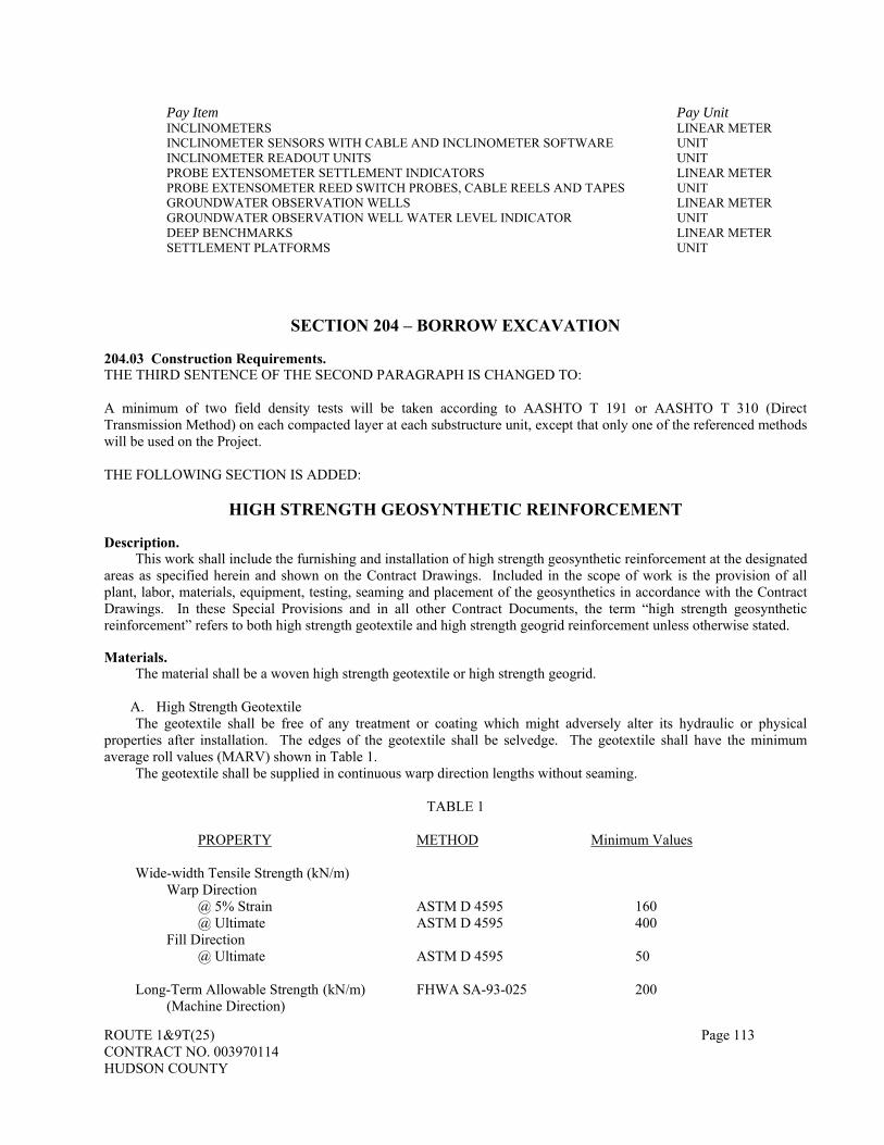
ROUTE 1&9T(25) Page 113 CONTRACT NO. 003970114 HUDSON COUNTY
Pay Item Pay Unit INCLINOMETERS LINEAR METER INCLINOMETER SENSORS WITH CABLE AND INCLINOMETER SOFTWARE UNIT INCLINOMETER READOUT UNITS UNIT PROBE EXTENSOMETER SETTLEMENT INDICATORS LINEAR METER PROBE EXTENSOMETER REED SWITCH PROBES, CABLE REELS AND TAPES UNIT GROUNDWATER OBSERVATION WELLS LINEAR METER GROUNDWATER OBSERVATION WELL WATER LEVEL INDICATOR UNIT DEEP BENCHMARKS LINEAR METER SETTLEMENT PLATFORMS UNIT
SECTION 204 – BORROW EXCAVATION
204.03 Construction Requirements. THE THIRD SENTENCE OF THE SECOND PARAGRAPH IS CHANGED TO: A minimum of two field density tests will be taken according to AASHTO T 191 or AASHTO T 310 (Direct Transmission Method) on each compacted layer at each substructure unit, except that only one of the referenced methods will be used on the Project. THE FOLLOWING SECTION IS ADDED:
HIGH STRENGTH GEOSYNTHETIC REINFORCEMENT
Description.
This work shall include the furnishing and installation of high strength geosynthetic reinforcement at the designated areas as specified herein and shown on the Contract Drawings. Included in the scope of work is the provision of all plant, labor, materials, equipment, testing, seaming and placement of the geosynthetics in accordance with the Contract Drawings. In these Special Provisions and in all other Contract Documents, the term “high strength geosynthetic reinforcement” refers to both high strength geotextile and high strength geogrid reinforcement unless otherwise stated. Materials.
The material shall be a woven high strength geotextile or high strength geogrid.
A. High Strength Geotextile The geotextile shall be free of any treatment or coating which might adversely alter its hydraulic or physical properties after installation. The edges of the geotextile shall be selvedge. The geotextile shall have the minimum average roll values (MARV) shown in Table 1.
The geotextile shall be supplied in continuous warp direction lengths without seaming.
TABLE 1
PROPERTY METHOD Minimum Values
Wide-width Tensile Strength (kN/m) Warp Direction
@ 5% Strain ASTM D 4595 160 @ Ultimate ASTM D 4595 400
Fill Direction @ Ultimate ASTM D 4595 50
Long-Term Allowable Strength (kN/m) FHWA SA-93-025 200
(Machine Direction)

ROUTE 1&9T(25) Page 114 CONTRACT NO. 003970114 HUDSON COUNTY
Permittivity (sec-1) ASTM D 4491 0.02 Geotextile / Soil Friction (degrees) ASTM D 5321 24
The long-term allowable strength shall be determined as outlined in “Guidelines for Design Specification, and
Contracting of Geosynthetic Mechanically Stabilized Earth Slopes on Firm Foundations”, FHWA-SA-93-025, Section 3.5. The long-term allowable strength shall reflect the effect of creep, installation damage and chemical and biological degradation.
B. High Strength Geogrid Reinforcement The geogrid shall have the minimum average roll values (MARV) shown in Table 2.
TABLE 2
PROPERTY METHOD Minimum Values
Wide-width Tensile Strength (kN/m) Machine Direction
@ 5% Strain ASTM D 6637 160 @ Ultimate ASTM D 6637 400
Cross-Machine Direction @ Ultimate ASTM D 6637 50
Long-Term Allowable Strength (kN/m) FHWA SA-93-025 200
(Warp Direction)
Open Area (%) 40 Geogrid / Soil Friction (degrees) ASTM D 5321 28
High Strength Geosynthetic Reinforcement Approval.
The Contractor shall submit six sets of manufacturer’s certification for approval at least thirty days prior to the start of the high strength geosynthetic reinforcement placement. The manufacturer’s certification shall indicate that the material has been evaluated in full compliance with this specification and that the geotextile meets the full requirements given in Table 1 and the geogrid meets the full requirements given in Table 2. The Contractor’s submittal package shall include; but not be limited to, actual tests results for tension/creep, durability/aging, and construction damage. The manufacturer shall also provide written certification that all resins used to produce the geotextile or geogrid are virgin and capable of withstanding direct exposure to sunlight for 120 days with no measurable deterioration as measured per ASTM D4355.
The manufacturers of the high strength geosynthetic reinforcement (geotextile or geogrid whichever is used) shall supply written certification that the resins and additives used in manufacture of the geosynthetic are specifically formulated to provide long-term tensile strength and that the manufactured geosynthetic are durable in a soil environment for applications up to 75 years and is fit-for-use in long-term, critical soil reinforcement applications and with the frequent or permanent submergence of the material under water. Certification shall be notarized and signed by an officer of the manufacturing company.
The high strength geosynthetic reinforcement shall be manufactured with a high degree of quality control. The purpose of QC testing program is to verify that the geotextile or geogrid being supplied to the project is representative of the geotextile or geogrid used for performance testing. In most cases, however, sampling can be performed on sacrificial portions of the supplied material.
Conformance testing shall be performed as part of the manufacturing process. If the manufacturer has an established quality control program, then documentation describing the program shall be submitted to the Engineer for review. As a minimum, the manufacturer shall conduct quality control testing as outlined below:
TEST TEST PROCEDURE TESTING FREQUENCY (SM)

ROUTE 1&9T(25) Page 115 CONTRACT NO. 003970114 HUDSON COUNTY
Wide Width Tensile Strength
Machine Direction ASTM D 4595 (for Geotextile) 3000 ASTM D 6637 (for Geogrid) Cross-Machine Direction ASTM D 4595 (for Geotextile) 3000
ASTM D 6637 (for Geogrid)
Roller grips may be used in conducting wide width tension tests if other types of grips are not suitable for the high
strength geotextile. Soil / High Strength Geosynthetic direct shear tests shall be conducted according to ASTM D 5321 using the same
soil that will be in contact with the geosynthetic and at the relative density in the actual construction. The tests shall be conducted in both machine and cross-machine directions of the geosynthetic under normal pressures of 60, 120 and 180 kN/m2. Soil and geosynthetic specimen shall not be used for more than one data point. Two sets of tests shall be conducted for each geosynthetic direction on selected samples to establish the soil / geosynthetic interface friction angle.
Strength and shear tests shall be performed by an independent third-party laboratory to perform all geosynthetic testing specified. The laboratory shall be certified by the Geosynthetic Accreditation Institute. Samples not satisfying the specifications shall result in the rejection of the applicable rolls at no cost to the State. At the manufacturer’s discretion and expense, additional testing of individual rolls may be performed to more closely identify the non-complying rolls and/or to qualify individual rolls.
The manufacturer shall certify the quality of the rolls of geosynthetic. As a minimum, the manufacturer shall provide quality control certificates for each batch of resin and each shift’s production. These quality control certificates shall be signed by an officer of the manufacturer (such as the production manager), and supplied to the Engineer at least two (2) weeks prior to installation of the geosynthetic.
The quality control certificate shall include: 1. Roll numbers and identification 2. Sampling procedures 3. Result of quality control tests, including a description of test methods used
A quality assurance program shall be conducted by the Contractor verifying that the product supplied to the job site meets the design requirements. Independent testing of field samples shall be conducted at the frequencies outlined below:
TENSILE STRENGTH (kN/m) METHOD FREQUENCY (SM)
@ 2% Strain ASTM D 4595 (for Geotextile) 6000 ASTM D 6637 (for Geogrid)
@ 5% Strain ASTM D 4595 (for Geotextile) 6000 ASTM D 6637 (for Geogrid)
Ultimate ASTM D 4595 (for Geotextile) 6000 ASTM D 6637 (for Geogrid)
The laboratory shall be certified by the Geosynthetic Accreditation Institute.
Construction Requirements.
The Contractor shall check the high strength geosynthetic material upon delivery to ensure that the proper material has been received. During all periods of shipment and storage, the material shall be protected from temperatures greater than 140 ºF or less than 32 ºF, mud, dirt, dust and debris, or materials, which may permanently damage the geosynthetic. The manufacturer’s instructions regarding protection from direct sunlight shall be followed. At the time of installation, the Engineer will reject the geosynthetic if it has defects, tears, punctures, flaws, deterioration, or damage incurred during manufacture, transportation or storage.
The Contractor at no cost to the Authority shall replace geosynthetic material damaged during storage or installation.

ROUTE 1&9T(25) Page 116 CONTRACT NO. 003970114 HUDSON COUNTY
The geosynthetic material supplier shall provide a qualified and experienced representative on site at the initiation of geosynthetic installation and placement of fill for a minimum of three days to assist the Contractor and Engineer. Placement of High Strength Geosynthetic Reinforcement.
The geosynthetic shall be placed in accordance with the manufacturer’s recommendations. The geosynthetic shall be placed at the proper elevation and location as shown on the plans or as directed by the Engineer. The geosynthetics shall be laid such that their machine direction is perpendicular to the longitudinal direction of the roadway. These geosynthetics shall be referred to as transverse geosynthetics. At certain abutments and other locations specified in the Contract Drawings, additional geosynthetics, which shall be referred to as longitudinal geosynthetics, shall be placed such that their machine direction is parallel to the longitudinal direction of the roadway for a minimum distance of 30 meters behind the abutment.
The Contractor shall take all necessary measures to avoid damaging the high strength geosynthetic during placement. Geosynthetics damaged during installation or placement of the fill shall be repaired and replaced as directed by the Engineer at the Contractor’s expense. Mechanical equipment will not be permitted on the geosynthetic surface. Low-pressure construction equipment (28 kN/m2) is allowed to operate after placement of a minimum of 0.15 meter thick granular layer over the geosynthetic. On-road dump trucks shall not be permitted unless the geosynthetic is covered with a minimum of 0.45 meter of granular material. The speed shall not exceed 16 kilometer per hour and sudden braking and turning shall be avoided. Other restrictions recommended by the manufacturer shall be adhered to. Porous fill compaction above the geosynthetics shall be according to manufacturer’s recommendations in conjunction with the control fill method. Documentation including restrictions recommended by the geosynthetic manufacturer shall be submitted to the Engineer prior to placement of the high strength geosynthetic reinforcement. Seaming of Geosynthetic Panels.
Transverse geosynthetics shall be placed continuous in the machine direction without seaming or overlapping in the direction perpendicular to the centerline of the roadway. No seaming or overlapping shall be allowed in the machine direction of the longitudinal geosynthetics at abutments.
Seaming in the cross-machine direction shall be made by overlapping. A minimum overlap length of 0.6 meter shall be used.
All overlaps of geosynthetics panels shall be shingled in the direction of fill placement in order to avoid altering the overlap alignment during pushing of the fill. The overlap distance may be changed as directed by the Engineer depending on the location of the overlap.
The Contractor shall provide shop drawings showing the geosynthetic panel arrangement and overlapping. Method of Measurement.
High strength geosynthetic reinforcement will be measured by the square meter for each layer of the total of the plan areas covered by the transverse geosynthetics as well as the areas covered by the longitudinal geosynthetics. No separate measurement will be made for overlapping. Basis of Payment.
Payment will be made under: Pay Item Pay Unit HIGH STRENGTH GEOSYNTHETIC REINFORCEMENT SQUARE METER
Separate payment will not be made for supply, testing, installation and overlapping of the high strength
geosynthetic reinforcement, the cost thereof shall be included in the item “High Strength Geosynthetic Reinforcement”.
EPS-BLOCK GEOFOAM Description.
This work shall consist of providing all necessary plant, labor, equipment and materials, and performing all operations for the installation of block-molded expanded polystyrene (EPS) and its protective gasoline resistant geomembrane for use as a geofoam fill material in the construction of the segment of Ramp A overlying existing utilities in accordance with the details shown on the Construction Drawings and with the requirements of these specifications. The subcontractor for this work will be termed the Geofoam Contractor (GFC). The manufacturer of Geofoam blocks

ROUTE 1&9T(25) Page 117 CONTRACT NO. 003970114 HUDSON COUNTY
will be termed the Geofoam Molder (GFM). The geofoam protective gasoline resistant geomembrane is covered in a separate section entitled “GEOMEMBRANE (GASOLINE RESISTANT)”. Qualifications.
The GFM shall be a specialist in the manufacturing of EPS-block Geofoam and shall have supplied a minimum of 50,000 cubic meters of EPS-block Geofoam in the last five years. The GFM shall have an in-place Quality Control system with a third-party certification. The GFC shall have installed at least 10,000 cubic meters of EPS-block Geofoam in roadway embankments over the last five years and shall be an approved installer of geofoam.
The GFC and GFM shall submit their qualifications and experience for the proposed EPS-block Geofoam installation to the Engineer for review and approval at least 3 weeks prior to the commencement of Geofoam shipping activities. Materials.
(a) General: The EPS-block Geofoam shall consist entirely of expanded polystyrene. The EPS-block Geofoam shall consist of virgin raw material. A mixture of virgin raw material and recycled EPS material may be used if approved by the Engineer.
(b) Seasoning: All Geofoam blocks are to be adequately seasoned prior to shipment to the project site. Seasoning is defined as storage in a suitable area for the intended purpose as subsequently defined herein for a minimum of 72 hours at normal ambient room temperature after an EPS Geofoam block is released from the mold. Adequate seasoning in a suitable area shall consist of the following:
(1) Geofoam blocks seasoned for a minimum of 72 hours at normal ambient room temperature. (2) Seasoning performed within a building or other structure that shall ably protect the Geofoam blocks
from moisture and ultraviolet (UV) radiation. (3) Seasoning performed in an area with adequate space allowed between the blocks. (4) Seasoning performed in an area with positive air circulation and venting in order to allow the out-
gassing of blowing agent and trapped condensate from the Geofoam blocks.
The Engineer shall be allowed to inspect the structures to be used for seasoning upon request during normal business days and hours. The GFM may request a shortened seasoning period if the Geofoam blocks are seasoned within an appropriately heated storage space and if the GFM demonstrates to the satisfaction of the Engineer that the alternative seasoning method produces blocks of equal or better quality than those subjected to the normal aforementioned 72-hour seasoning.
(c) Flammability: All EPS Geofoam blocks shall satisfy the product flammability requirements specified in
ASTM C 578. Geofoam shall be considered combustible and shall not be exposed to open flame or any source of ignition. If blocks are to be stockpiled and/or stored on site, the storage area shall be away from any heat source or construction activity that may produce heat or flame. Furthermore, smoking shall not be allowed in the storage area.
(d) Properties: The dry density/unit weight of each EPS block (as measured for the entire block as a whole)
after the period of seasoning, as previously defined, shall equal or exceed that shown in Table 1.
TABLE 1 - Material type designations for EPS-Block Geofoam
Material Designation Minimum Allowable Density/Unit Weight kg/m3 (lb/ft3)
AASHTO (proposed)
ASTM D 6817 ASTM C 578 Each Block as a Whole
Any Test QA/QC Specimen
EPS 100 EPS 29 IX 32 (2.0) 29 (1.8)
The dry density/unit weight shall be determined by measuring the mass/weight of the entire block by weighing the block on a scale and dividing the mass by the volume of the block. The volume shall be determined by obtaining dimensional measurements of the block in accordance with ASTM C 303.
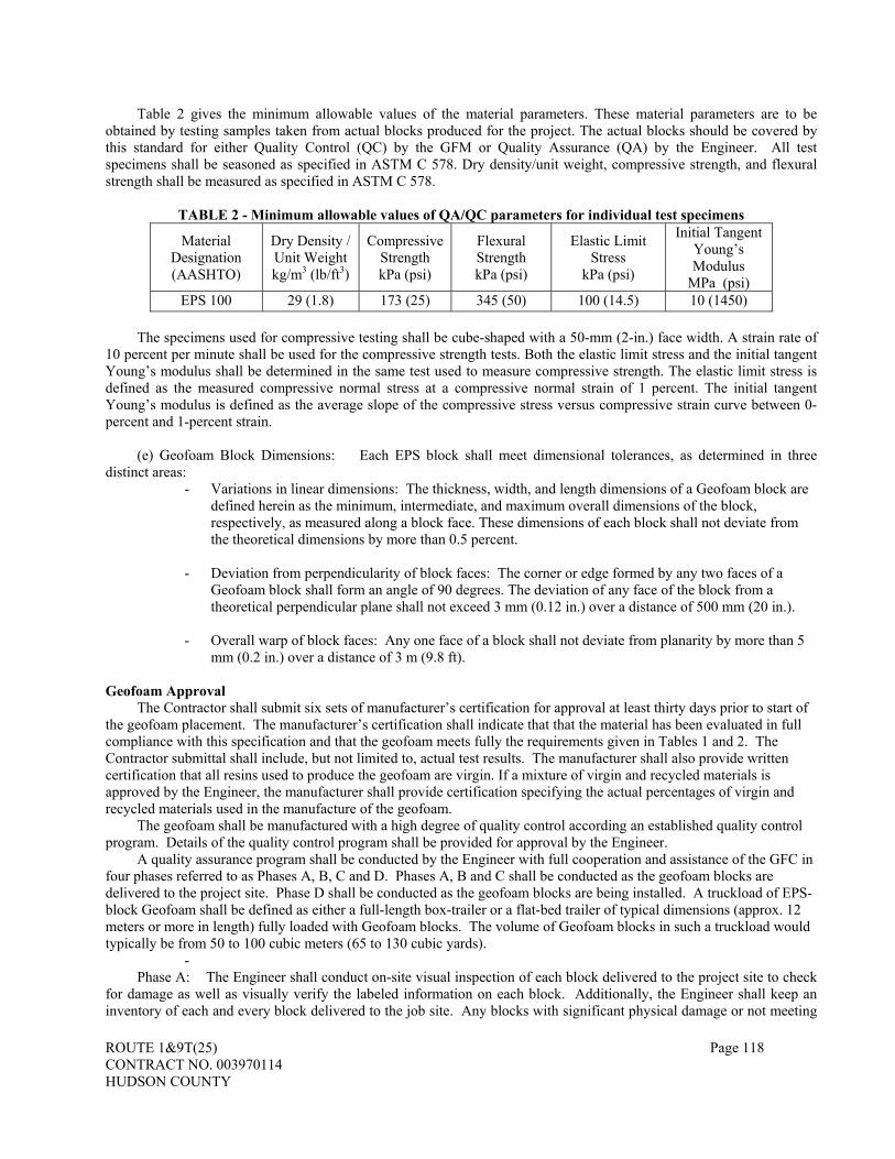
ROUTE 1&9T(25) Page 118 CONTRACT NO. 003970114 HUDSON COUNTY
Table 2 gives the minimum allowable values of the material parameters. These material parameters are to be obtained by testing samples taken from actual blocks produced for the project. The actual blocks should be covered by this standard for either Quality Control (QC) by the GFM or Quality Assurance (QA) by the Engineer. All test specimens shall be seasoned as specified in ASTM C 578. Dry density/unit weight, compressive strength, and flexural strength shall be measured as specified in ASTM C 578.
TABLE 2 - Minimum allowable values of QA/QC parameters for individual test specimens
Material Designation (AASHTO)
Dry Density / Unit Weight kg/m3 (lb/ft3)
Compressive Strength kPa (psi)
Flexural Strength kPa (psi)
Elastic Limit Stress
kPa (psi)
Initial Tangent Young’s Modulus
MPa (psi) EPS 100 29 (1.8) 173 (25) 345 (50) 100 (14.5) 10 (1450)
The specimens used for compressive testing shall be cube-shaped with a 50-mm (2-in.) face width. A strain rate of
10 percent per minute shall be used for the compressive strength tests. Both the elastic limit stress and the initial tangent Young’s modulus shall be determined in the same test used to measure compressive strength. The elastic limit stress is defined as the measured compressive normal stress at a compressive normal strain of 1 percent. The initial tangent Young’s modulus is defined as the average slope of the compressive stress versus compressive strain curve between 0-percent and 1-percent strain.
(e) Geofoam Block Dimensions: Each EPS block shall meet dimensional tolerances, as determined in three
distinct areas: - Variations in linear dimensions: The thickness, width, and length dimensions of a Geofoam block are
defined herein as the minimum, intermediate, and maximum overall dimensions of the block, respectively, as measured along a block face. These dimensions of each block shall not deviate from the theoretical dimensions by more than 0.5 percent.
- Deviation from perpendicularity of block faces: The corner or edge formed by any two faces of a
Geofoam block shall form an angle of 90 degrees. The deviation of any face of the block from a theoretical perpendicular plane shall not exceed 3 mm (0.12 in.) over a distance of 500 mm (20 in.).
- Overall warp of block faces: Any one face of a block shall not deviate from planarity by more than 5
mm (0.2 in.) over a distance of 3 m (9.8 ft).
Geofoam Approval The Contractor shall submit six sets of manufacturer’s certification for approval at least thirty days prior to start of
the geofoam placement. The manufacturer’s certification shall indicate that that the material has been evaluated in full compliance with this specification and that the geofoam meets fully the requirements given in Tables 1 and 2. The Contractor submittal shall include, but not limited to, actual test results. The manufacturer shall also provide written certification that all resins used to produce the geofoam are virgin. If a mixture of virgin and recycled materials is approved by the Engineer, the manufacturer shall provide certification specifying the actual percentages of virgin and recycled materials used in the manufacture of the geofoam.
The geofoam shall be manufactured with a high degree of quality control according an established quality control program. Details of the quality control program shall be provided for approval by the Engineer.
A quality assurance program shall be conducted by the Engineer with full cooperation and assistance of the GFC in four phases referred to as Phases A, B, C and D. Phases A, B and C shall be conducted as the geofoam blocks are delivered to the project site. Phase D shall be conducted as the geofoam blocks are being installed. A truckload of EPS-block Geofoam shall be defined as either a full-length box-trailer or a flat-bed trailer of typical dimensions (approx. 12 meters or more in length) fully loaded with Geofoam blocks. The volume of Geofoam blocks in such a truckload would typically be from 50 to 100 cubic meters (65 to 130 cubic yards).
- Phase A: The Engineer shall conduct on-site visual inspection of each block delivered to the project site to check
for damage as well as visually verify the labeled information on each block. Additionally, the Engineer shall keep an inventory of each and every block delivered to the job site. Any blocks with significant physical damage or not meeting

ROUTE 1&9T(25) Page 119 CONTRACT NO. 003970114 HUDSON COUNTY
these specifications shall be either rejected on the spot or placed in an area separate from those blocks that are accepted or marked as unacceptable and returned to the supplier.
Phase B: For each truckload, one block per load should be tested to ensure that the minimum block dry density /
unit weight, as well as the physical tolerances, meet the specifications set forth in Tables 1 and 2. If the selected block does not meet specifications, then other blocks in the truckload shall be checked and none used until the additional checking has determined which blocks are unsatisfactory.
Phase C: At least one block will be selected by the Engineer for sampling from the first truckload. Laboratory
testing shall be conducted to check compliance of the Geofoam with the parameters shown in Table 2. The Contractor shall select a certified testing laboratory approved by the Engineer to perform the tests. Portions of sampled blocks that are not damaged or otherwise compromised by the sampling can be used as desired by the Contractor. If unsatisfactory test results are obtained, the GFC may be directed to remove potentially defective Geofoam blocks and replace them with blocks of acceptable quality at no additional expense to the State. Once satisfactory test results have been obtained, the GFC may begin installation of the EPS-block Geofoam.
Phase D: As the Geofoam blocks are placed, the GFC under supervision by the Engineer, shall prepare as-built
drawings as well as perform additional record keeping documenting the location of all Geofoam blocks placed for the project. Shop Drawings.
The GFC shall submit shop drawings indicating the proposed location and layout of all Geofoam blocks to be placed during the project. These drawings shall be reviewed and approved by the Engineer. The block layout shall be designed in order to meet the following general design details:
- There must be a minimum of two layers of blocks at all locations. - Within a given layer of blocks, the longitudinal axes of all blocks must be parallel to each other. - The longitudinal axes of blocks for layers above and/or below a given layer must be perpendicular to the
longitudinal axes of blocks within that given layer. - The longitudinal axes of the uppermost layer of blocks must be perpendicular to the longitudinal axis of the
road alignment. - Within a given layer of blocks, the joints between the adjacent ends of blocks within a given row of blocks
must be offset to the greatest extent practicable relative to blocks in adjacent rows and layers. Details showing arrangement of EPS-Blocks at locations of drainage pipes penetrating the geofoam and sequence
of installation of the blocks, drainage pipe and the aggregate material around the pipe shall be included in the shop drawings and shall be according to GFM recommendations.
Pre-Construction Meeting. Prior to delivery of any EPS-block Geofoam to the project site, a meeting shall be held between the Engineer, the GFC and a representative of the GFM. The purpose of this meeting is to review the quality control and quality assurance programs and discuss other aspects of construction to ensure that all parties are familiar with the requirements of this specification. Upon satisfactory conclusion of this meeting, the contractor shall be allowed to begin on-site receipt, storage, and placement of the EPS-block Geofoam. Construction.
(a) General: Once Phase C of the quality assurance program has been completed, the GFC may begin installing the EPS-block Geofoam. The General Contractor and the GFC shall be directly responsible for all construction quality control. Items covered by construction quality control shall include all earthwork and related activities other than manufacturing and shipment of the EPS-block Geofoam.
(b) Site Preparation: The natural soil subgrade shall be cleared of vegetation and any large or sharp-edged soil
particles and be reasonably level prior to placing the sand bedding layer. The surface of the sand layer shall be sufficiently smooth prior to placement of the first block layer. The required smoothness is defined as a vertical deviation of no more than 5 millimeters (0.4 inches) over any 3-meter (9.8-foot) distance.

ROUTE 1&9T(25) Page 120 CONTRACT NO. 003970114 HUDSON COUNTY
At the time of placement, there shall be no standing water or accumulated snow or ice on the subgrade within the
area of Geofoam block placement. (c) Shipment and Storage: Each Geofoam block shall be labeled by the GFM to indicate the name of the GFM;
the date the block was molded; the mass/weight of the entire block (in kilograms or pounds) as measured after seasoning; the dimensions of the block in millimeters or inches; and the actual dry density / unit weight in kilograms per cubic meter or pounds per cubic foot. Additional markings using alphanumeric characters, colors, and/or symbols shall be applied as necessary by the GFM to indicate the placement location of each block relative to the shop drawings, as well as the density of the block if multiple block densities are to be supplied for the given project.
Geofoam blocks in temporary on-site storage shall be secured with sandbags to prevent their being dislodged by
wind. The blocks shall not be covered in any manner that might allow the buildup of heat beneath the cover. Furthermore, the blocks shall not be trafficked by any vehicle or equipment.
In addition, Geofoam blocks shall be handled in a manner which minimizes potential damage to the blocks. No
blocks shall be lifted, transported, or otherwise moved or disturbed in any way that would create dents or holes in the block or cause losses of portions of the block.
(d) Installation: EPS blocks shall be placed at the locations shown on the contract drawings and the approved
shop drawings submitted by the contractor. All Geofoam blocks shall be placed so that all joints between blocks are tight in all directions. Blocks shall not be
placed above blocks on which there exists standing water, snow, or ice on the surface. Blocks shall be placed with a minimum of two multi-barbed connector plates (gripper plates) per block. These
gripper plates shall be located on the top of the block and shall connect the Geofoam block to the bottom of the blocks in the above layer. If multiple Geofoam blocks overlay the block in question, a minimum of one gripper plate per each of the overlaying blocks. For roadway applications, a minimum of four gripper plates is recommended per block.
With the exception of sand bags or other weights used to temporarily restrain the object, no construction material
shall be placed or stockpiled on the Geofoam blocks other than that shown on the contract drawings. No vehicles or construction equipment shall travel on top of the Geofoam blocks during or after placement of the blocks until 300 mm (12 in) of cover soil or aggregate exists atop the blocks.
Soil for the surcharge system shall be placed using bulldozers and/or a front-end loader or other appropriate
equipment. The final surface of the Geofoam blocks shall be covered as indicated on the contract drawings. Care shall be exercised during placement of the geomembrane (gasoline resistant) and the cover material to prevent damage to the Geofoam blocks.
The pavement system shall be constructed above the Geofoam as shown on the contract drawings and shall be
installed after removal of surcharge from the project site. The pavement system is defined as all material placed above the Geofoam blocks within the limits of the proposed roadway, including shoulders. Method of Measurement.
EPS-Block Geofoam will be measured by the cubic meter that is placed in accordance with the Plans. No measurement shall be made for the gasoline resistant geomembrane. Method of Payment.
Payment will be made under: Pay Item Pay Unit GEOFOAM CUBIC METER
Payment for EPS-Block Geofoam shall include all material, labor, equipment, fasteners, and other necessary items
required for completing the work including storage costs, disposal of unused materials, and transportation costs.

ROUTE 1&9T(25) Page 121 CONTRACT NO. 003970114 HUDSON COUNTY
No separate payment will be made for plates, bolts, screws or other hardware that is needed for attaching or for
assembly and or installation of Geofoam, all costs thereof will be included in the pay item “GEOFOAM”. No separate payment will be made for all material, labor, equipment and other necessary items and accessories for installation of the gasoline resistant geomembrane, the cost thereof will be included in the pay item “GEOFOAM”.
GEOMEMBRANE (GASOLINE RESISTANT)
Description.
This work shall consist of providing all necessary plant, labor, equipment and materials, and performing all operations for the installation of gasoline resistant geomembrane for protection of the EPS-Block Geofoam in the construction of the segment of Ramp A overlying existing utilities in accordance with the details shown on the Construction Drawings and with the requirements of these specifications. The geofoam is covered in the previous section entitled “EPS-BLOCK GEOFOAM”. Material.
Geomembrane (gasoline resistant) shall consist of reinforced or unreinforced tri-polymer membrane consisting of polyvinyl chloride (PVC), ethylene interpolymer allow, and polyurethane or a comparable polymer combination. The geomembrane shall be suitable for the containment of spilled liquid hydrocarbons, including gasoline, diesel fuel, kerosene, hydraulic fluid, methanol, ethanol, mineral spirits, and naptha. The geomembrane shall be sufficiently flexible to cover and closely conform to 90 degrees edges and corners of EPS-Block Geofoam at ambient pressures as low as 7oC without application of heat.
Gasoline resistant geomembrane shall have the following properties, specified as minimum or maximum, not average roll properties:
Physical Property ASTM Designation
Acceptance Value
Unleaded Gasoline
Permeability
D 814 122 g/m2 Maximum per 24 hours
Thickness D 751 * 0.71 mm Minimum Grab Tensile
Strength (25 mm grip, 100 mm x 200 mm sample
D 751 * 2.67 kN Minimum in each direction
Tensile Strength D 1623 130 kPa Minimum Elongation at
break D 4632 * 20 Percent Minimum
Toughness (Percent
elongation times Grab Tensile Strength **)
N/A 62 kN Minimum
Puncture Resistance (ball
tip)
D 751 3.56 kN Minimum
Cold Crack Resistance (25 mm mandrel, 4
hours)
D 2138 * Pass at -17°C
* or ASTM test method appropriate for specific polymer ** for example, 3 kN x 30% = 90 kN
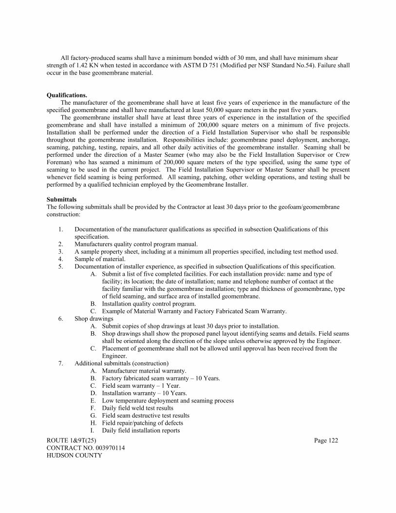
ROUTE 1&9T(25) Page 122 CONTRACT NO. 003970114 HUDSON COUNTY
All factory-produced seams shall have a minimum bonded width of 30 mm, and shall have minimum shear strength of 1.42 KN when tested in accordance with ASTM D 751 (Modified per NSF Standard No.54). Failure shall occur in the base geomembrane material. Qualifications.
The manufacturer of the geomembrane shall have at least five years of experience in the manufacture of the specified geomembrane and shall have manufactured at least 50,000 square meters in the past five years.
The geomembrane installer shall have at least three years of experience in the installation of the specified geomembrane and shall have installed a minimum of 200,000 square meters on a minimum of five projects. Installation shall be performed under the direction of a Field Installation Supervisor who shall be responsible throughout the geomembrane installation. Responsibilities include: geomembrane panel deployment, anchorage, seaming, patching, testing, repairs, and all other daily activities of the geomembrane installer. Seaming shall be performed under the direction of a Master Seamer (who may also be the Field Installation Supervisor or Crew Foreman) who has seamed a minimum of 200,000 square meters of the type specified, using the same type of seaming to be used in the current project. The Field Installation Supervisor or Master Seamer shall be present whenever field seaming is being performed. All seaming, patching, other welding operations, and testing shall be performed by a qualified technician employed by the Geomembrane Installer. Submittals The following submittals shall be provided by the Contractor at least 30 days prior to the geofoam/geomembrane construction:
1. Documentation of the manufacturer qualifications as specified in subsection Qualifications of this specification.
2. Manufacturers quality control program manual. 3. A sample property sheet, including at a minimum all properties specified, including test method used. 4. Sample of material. 5. Documentation of installer experience, as specified in subsection Qualifications of this specification.
A. Submit a list of five completed facilities. For each installation provide: name and type of facility; its location; the date of installation; name and telephone number of contact at the facility familiar with the geomembrane installation; type and thickness of geomembrane, type of field seaming, and surface area of installed geomembrane.
B. Installation quality control program. C. Example of Material Warranty and Factory Fabricated Seam Warranty.
6. Shop drawings A. Submit copies of shop drawings at least 30 days prior to installation. B. Shop drawings shall show the proposed panel layout identifying seams and details. Field seams
shall be oriented along the direction of the slope unless otherwise approved by the Engineer. C. Placement of geomembrane shall not be allowed until approval has been received from the
Engineer. 7. Additional submittals (construction)
A. Manufacturer material warranty. B. Factory fabricated seam warranty – 10 Years. C. Field seam warranty – 1 Year. D. Installation warranty – 10 Years. E. Low temperature deployment and seaming process F. Daily field weld test results G. Field seam destructive test results H. Field repair/patching of defects I. Daily field installation reports

ROUTE 1&9T(25) Page 123 CONTRACT NO. 003970114 HUDSON COUNTY
J. As-built drawings Installation
Gasoline Resistant Geomembrane shall be placed directly on the surface of the lightweight fill (EPS block) fill, which shall be clean and free of sharp objects. Field seams shall be bonded with an electrically-heated hot-wedge device as recommended by the manufacturer. Hot air extrusion welding devices or solvent bonding chemicals shall not be used. The temperature of the bonded geomembrane shall not exceed 74°C immediately before contacting the lightweight fill (EPS block) fill. Before installation of geomembrane, the Contractor shall demonstrate to the Engineer that the equipment, techniques, and personnel proposed for the bonding of field seams can produce vapor-tight seams under similar weather and work conditions near the job site. Field seams shall be inspected and, when ordered by the Engineer, shall be tested and pass the Vacuum Box Test. Construction equipment shall not be operated directly on the geomembrane. Any material damaged by the Contractor’s equipment or operations shall be replaced or repaired to the satisfaction of the Engineer by the Contractor at his expense.
Geomembrane penetration boots shall be installed according to the following requirements:
A. The Contractor shall furnish all geomembrane penetration boots and other materials required for completion of the geomembrane installation. All geomembrane boots required for the project shall be factory prefabricated boots. The geomembrane shall be of the same thickness as the geomembrane panels.
B. Geomembrane penetrations are to be constructed only at the locations shown on the Plans. The Contractor is cautioned that no deviation in the quantity or configuration of geomembrane penetrations will be accepted without the advance written approval of the Engineer.
C. All penetrations through the geomembrane shall be thoroughly and securely sealed. The seal between the geomembrane and the pipe shall be without any detectable leakage.
D. In attaching the geomembrane penetration boot in the field, no field seams will be allowed in locations or configurations that do not allow for Construction Quality Control testing. Visual observation is not considered a sole acceptable method for in-field quality control.
E. Where clamps, fasteners, gasket seals or sealants are used, the Contractor shall use only materials that are compatible with the geomembrane.
Method of Measurement.
No measurement shall be made for the gasoline resistant geomembrane. Method of Payment.
No separate payment will be made for all material, labor, equipment and other necessary items and accessories for installation of the gasoline resistant geomembrane, the cost thereof will be included in the pay item “GEOFOAM”.
SECTION 206 – FOUNDATION AND BRIDGE EXCAVATION
206.01 Description. THE FOLLOWING IS ADDED:
This work shall also include the excavation of Regulated Waste as noted in the rules of the Solid Waste
Administration, NJDEP, in accordance with the rules and regulations of N.J.A.C. 7:26 and as noted on the Environmental Plan Sheets.

ROUTE 1&9T(25) Page 124 CONTRACT NO. 003970114 HUDSON COUNTY
206.02 Classification of Excavation. THE FOLLOWING IS ADDED:
Foundation Excavation, Regulated Waste consists of the excavation and on-site management of all materials of whatever character encountered that exhibits the characteristics of ID-27 non-hazardous contaminated soil, sediment, and debris. 206.07 Excavation. THE FOLLOWING IS ADDED:
Excavation in areas of Regulated Waste, as depicted on Environmental Plans or as directed by the Engineer, shall be performed in accordance with Subsections 202.04, Management of Regulated Waste, Subsection 202.13, Off-Site Management of Regulated Waste, and Subsection 212.06, Soil Erosion and Sediment Control Measures. THE FOLLOWING IS ADDED: See Subsection 108.13 for procedures for archaeological monitoring during construction. 206.11 Excess or Unusable Material. REPLACE THE FIRST AND SECOND PARAGRAPHS WITH THE FOLLOWING:
Excavated material from areas identified as Hazardous Waste shall be managed in accordance with Subsection 202.04, Management of Regulated Waste and 202.13, Off-Site Management of Regulated Waste, hazardous. Excess material excavated from areas identified on Environmental Plans as containing Regulated Waste shall be used in accordance with Subsection 202.04, Management of Regulated Waste and Section 203, Embankments, or, if not required for embankments, the material shall be disposed of in accordance with Subsection 202.13, Off-Site Management of Regulated Waste.
Unusable material excavated from areas identified on Environmental Plans as containing Regulated Waste shall be disposed of in accordance with Subsection 202.13, Off-Site Management of Regulated Waste.
206.12 Method of Measurement. THE FOLLOWING IS ADDED:
Foundation Excavation, Regulated Waste, which includes the handling, stockpiling, and on-site transport of Regulated Waste, will be measured by the cubic meter. Off-site Management of Regulated Waste shall be in accordance with 202.13. Sampling and Analysis for Disposal and/or Recycling will be measured in accordance with 202.14. 206.13 Basis of Payment. THE FOLLOWING PAY ITEMS ARE ADDED:
Pay Item Pay Unit FOUNDATION EXCAVATION, REGULATED WASTE CUBIC METER FOUNDATION EXCAVATION, REGULATED WASTE (MSE WALL ALTERNATIVE) CUBIC METER FOUNDATION EXCAVATION, REGULATED WASTE (MODULAR WALL ALTERNATIVE) CUBIC METER
THE FOLLOWING IS ADDED:

ROUTE 1&9T(25) Page 125 CONTRACT NO. 003970114 HUDSON COUNTY
Separate payment will not be made for work conducted in Regulated Waste in accordance with Subsection 202.04, but all costs thereof shall be included under the Pay Items Foundation Excavation, Regulated Waste ____. Payment for Sampling and Analysis for Disposal and/or Recycling of Regulated Waste will be made in accordance with Subsection 202.15.
Payment for Off-Site Transport and Disposal and/or Recycling of Regulated Waste will be made in accordance with Subsection 202.15.
Separate payment will not be made for implementing Site-Specific Health and Safety Plan requirements for
work conducted in Regulated Waste in accordance with Subsection 202.04, Management of Regulated Waste. All costs thereof shall be included in the applicable excavation pay item.
.
SECTION 207 – SUBSURFACE STRUCTURE EXCAVATION
207.01 Description. THE FOLLOWING IS ADDED:
Subsurface Structures excavation shall also include the excavation of Regulated Waste as noted in the Rules of the Solid Waste Administration, NJDEP, in accordance with the rules and regulations of N.J.A.C. 7:26 and as noted on the Environmental Plans 207.02 Classification of Excavation. THE FOLLOWING IS ADDED TO THIS SECTION:
Subsurface Structure Excavation, Regulated Waste consists of the excavation and on-site management of all materials of whatever character encountered that exhibits the characteristics of ID-27 non-hazardous contaminated soil, sediment, and debris.
Subsurface structure excavation shall also include the excavation of Regulated Waste as noted in the Rules of
the Solid Waste Administration, NJDEP, in accordance with the rules and regulations of NJAC 7:26 and as noted on the Environmental Plans. 207.03 Bedding Materials. SUBSECTION HEADING IS CHANGED TO: 207.03 Bedding and Backfill Materials. 207.03 Bedding and Backfill Materials. THE FOLLOWING IS ADDED:
Controlled Low Strength Material (CLSM) shall conform to Subsection 919.22 207.04 Construction Requirements. THE FOLLOWING IS ADDED TO THIS SECTION:

ROUTE 1&9T(25) Page 126 CONTRACT NO. 003970114 HUDSON COUNTY
Excavation in areas of Regulated Waste, as depicted on Environmental Plans or as directed by the Engineer, shall be performed in accordance with Subsections 202.04, Management of Regulated Waste, Subsection 202.13, Off-Site Management of Regulated Waste, and Subsection 212.06, Soil Erosion and Sediment Control Measures. THE FIRST PARAGRAPH IS CHANGED TO:
Before excavating, existing subsurface structures which may be affected by or interfere with the proposed construction shall be located. If directed, test pits shall be excavated to obtain the required information. Test pits or portions of a test pit shall be dug by hand when in close proximity to utilities or when directed. Excavation beyond that which is necessary to obtain the required information will not be measured for payment. Test pits shall be backfilled according to Subsection 203.06.
1. Pipes and Culverts. THE FIRST PARAGRAPH IS CHANGED TO:
The width of trench shall be at least 450 millimeters greater than the outside diameter of the pipe or culvert. When the material at the bottom of the excavation is rock or other hard material, it shall be removed within 150 millimeters for reinforced concrete culvert pipe and high density polyethylene (HDPE) pipe, 300 millimeters for corrugated metal, steel, or aluminum alloy culvert pipe outside the bottom of the pipe or culvert and the space backfilled with suitable material.
207.05 Bedding for Pipes and Culverts. THE FIFTH PARAGRAPH IS CHANGED TO:
Bedding for corrugated aluminum alloy culvert pipe and HDPE pipe shall be placed as specified for Class B bedding. 207.06 Backfilling.
A. Pipes and Culverts. THE ENTIRE SUBPART A. IS CHANGED TO:
Backfill to a height of 600 millimeters above the top of pipes and culverts, except underdrains, corrugated aluminum alloy culvert pipe and HDPE pipe, shall be made with excavated material free from stones or rock fragments larger than 50 millimeters in any dimension. Below this level, the backfill shall be placed in layers not more than 150 millimeters thick, and each layer shall be compacted with flat-face mechanical tampers. Backfill shall be worked into the haunch area and compacted for all pipe.
For HDPE pipe, backfill to a height of 600 millimeters above the top of the pipe shall be made with excavated material free from class IV or class V materials according to ASTM D2321, with stones or rock fragments no larger than 37.5 millimeters in any direction. Below this level, the backfill shall be placed symmetrically on each side of the pipe in layers not more than 150 millimeters thick with each layer compacted with flat-faced mechanical tampers for all pipe.
Backfill to a height of 600 millimeters above the top of corrugated aluminum alloy culvert pipe shall be made with a granular soil with the gradation as specified in Subsection 207.03. Below this level, the backfill shall be placed symmetrically on each side of the pipe in layers not more than 150 millimeters thick, and each layer shall be compacted with flat-faced mechanical tampers.
All backfill more than 600 millimeters above the top of pipes and culverts, except underdrains, shall be made with excavated material and compacted in 150 millimeter layers as follows:
1. By vibratory soil compactors, if the backfill material is predominately sand or sand and gravel. 2. By flat-faced mechanical tampers, if the backfill material is not predominantly sand or sand and
gravel.

ROUTE 1&9T(25) Page 127 CONTRACT NO. 003970114 HUDSON COUNTY
3. Flat-faced mechanical tampers may be substituted for the vibratory soil compactors where the shoring and bracing of trenches or other special conditions make the use of vibratory compactors impractical.
4. Care shall be taken to avoid contact between the pipe and compaction equipment at all times. All damaged pipes shall be removed and replaced at no additional cost to the State. The Engineer may direct compaction to be according to Subsection 203.10 except that the frequency
of measurements may increase. If a hydrohammer or hoe-pak is used for compacting the backfill over the pipe, a minimum of 1200 MM of cover over the pipe shall be provided.
CLSM may be used as alternate backfill material when backfilling trenches for drainage pipe and utility conduit. Combining other backfill materials in the same trench as CLSM shall not be permitted. Mixing and placement of CLSM shall begin only when the ambient temperature is at least –1 °C. During placement, the CLSM mixture shall have a temperature of at least 5 °C and shall not be placed on frozen ground. The CLSM mixture shall be discharged directly from the truck into the trench to be filled with care taken to prevent the pipe from becoming displaced. After placement, the CLSM mixture shall be cured and protected to prevent damage from cold weather according to Subsection 405.14. CLSM shall not be used to replace pavement, base courses or drainage layers that form the structure of the roadway.
The special backfill in trenches for the underdrains shall be compacted by vibratory compactors. Earth backfill above the special backfill material shall be compacted as specified in Subsection 203.07.
Shoring, bracing, and sheathing shall be withdrawn as the backfilling proceeds. Compaction requirements shall not be compromised due to the removal of sheathing, shoring, trench boxes or other type of excavation support systems.
In rock cuts, the backfill shall be either broken stone or washed gravel. 207.07 Excess or Unusable Material. REPLACE THE FIRST AND SECOND PARAGRAPHS WITH THE FOLLOWING:
Excess material excavated from areas identified on Environmental Plans as containing Regulated Waste shall be used in accordance with Subsection 202.04, Management of Regulated Waste and Section 203, Embankments, or, if not required for embankments, the material shall be disposed of in accordance with Subsection 202.13, Off-Site Management of Regulated Waste.
Unusable material excavated from areas identified on Environmental Plans as containing Regulated Waste shall be disposed of in accordance with Subsection 202.13, Off-Site Management of Regulated Waste.
207.08 Method of Measurement. THE FOLLOWING IS ADDED: Off-Site Management of Regulated Waste shall be in accordance with 202.13. Sampling and Analysis for Disposal and/or Recycling shall be measured in accordance with 202.14. Controlled low strength material shall be measured by the cubic meter. 207.09 Basis of Payment. THE THIRD AND FOURTH PAY ITEMS ARE CHANGED TO:
Pay Item Pay Unit ROCK EXCAVATION, SUBSURFACE STRUCTURES CUBIC METER PIPE BEDDING, CLASS ___ CUBIC METER
THE FOLLOWING PAY ITEM IS ADDED:

ROUTE 1&9T(25) Page 128 CONTRACT NO. 003970114 HUDSON COUNTY
Pay Item Pay Unit CONTROLLED LOW STRENGTH MATERIAL CUBIC METER
THE FOLLOWING IS ADDED AT THE END OF THE SUBSECTION:
Payment for Sampling and Analysis for Disposal and/or Recycling of Regulated Waste will be made in accordance with Subsection 202.15.
Payment for Off-Site Transport and Disposal and/or Recycling of Regulated Waste will be made in accordance with Subsection 202.15.
Separate payment will not be made for implementing Site-Specific Health and Safety Plan requirements for work conducted in Regulated Waste in accordance with Subsection 202.04, Management of Regulated Waste. All costs thereof shall be included in the applicable excavation pay item.
SECTION 212 - SOIL EROSION AND SEDIMENT CONTROL
212.06 Soil Erosion and Sediment Control Measures.
J. Dewatering Basin. THE FOLLOWING IS ADDED TO THIS SUBPART:
The Contractor shall comply with Subsection 107.28. The Contractor shall control and treat all
storm and ground waters removed from excavations in areas of Regulated Waste so as to capture all free product and meet discharge requirements for permitted discharge to dewatering basins, surface water body or storm sewer system as selected by the Contractor. Following use, the discharge basin shall be backfilled using soils excavated during construction of the basin.
THE FOLLOWING IS ADDED:
K. Concrete Washout Facility. Design concrete washout facility to fully contain all concrete washout needs of the Work. Concrete washout facility may be portable or a bermed basin that is lined with a single sheet of a minimum of 0.25-millimeter polyethylene sheeting that extends over the entire basin and berm to prevent escape of discharge. Place a secure, non-collapsing, non-water collecting cover over the concrete washout facility prior to inclement weather to prevent accumulation and overflow of precipitation. Submit a plan for concrete washout facility for approval to the Resident Engineer 10 days before first concrete pour. Provide concrete washout facility to prevent discharge from concrete trucks or equipment cleaning to inlets, surface or groundwater. Designate an area for the concrete washout facility that is no closer than 15 meters from environmentally sensitive areas such as waterbodies, wetlands, or other areas indicated on the plans. Use signs to designate concrete washout facilities. Ensure that the concrete washout facility complies with all Federal, State, and local laws, rules, and regulations. Ensure that the concrete washout facility is in place before delivery of concrete to the site.
Ensure that concrete washout is limited to the designated areas. Contents of the concrete washout facility shall not exceed 50 % capacity of the facility. At or before the 50 % capacity is reached, discontinue pouring concrete until the facility is cleaned out. Remove hardened concrete and properly dispose or reuse it as specified in Subsection 202.12. Allow slurry to evaporate or remove from site and dispose of it as specified in Subsection 201.10.
If a lined basin is used, immediately replace the liner if it gets damaged. Remove concrete washout facility when it is no longer needed. Restore the disturbed area to its original condition.

ROUTE 1&9T(25) Page 129 CONTRACT NO. 003970114 HUDSON COUNTY
L. Oil-Only Emergency Spill Kit. Before start of construction operations of the Work, place on site at least 2 oil-only emergency spill kits with each kit capable of cleaning up at least 50 gallons of spill. Ensure that each kit contains the items as provided in the Special Provisions: 1. 10 oil-only absorbent booms (125-millimeters by 250-millimeters) 2. 10 oil-only absorbent booms (75-millimeters by 250-millimeters) 3. 60 absorbent mat-type pads (500-millimeters by 400-millimeters) 4. 20 temporary disposal bags and ties 5. 1 emergency response guide book 6. 1 instruction manual 7. 1 wheeled container for the above 8. One 18 kilograms bag loose absorbent pellets
If a spill occurs, immediately contain and clean up the spill. Notify the Resident Engineer as soon
as circumstances permit. Stockpile the excavated contaminated soil separately. Dispose of cleaned up material and used kit material as specified in Subsection 201.10. Replenish kits as necessary to keep at least 2 complete kits on site at all times during construction operations.
M. Pollution Prevention and Control Plan.
This work consists of developing and implementing a Pollution Prevention and Control Plan (hereinafter referred to as PPC Plan) to prevent unpermitted discharge of contaminated storm water, ground water, sediments and/or free product during stormwater control, excavation and dewatering operations.
The Contractor shall prepare a PPC Plan detailing methods, personnel, equipment, and reporting
requirements in preventing unpermitted discharge of contaminated sediment and water generated during stormwater control, excavation, and dewatering operations. The PPC Plan shall comply with all Federal, state, and local laws, rules, and regulations relative to contaminated discharges. The Contractor shall submit the PPC plan to the Engineer for review and approval at least one month prior to beginning excavation.
The PPC Plan shall provide methods and equipment for collecting, pumping, treating, monitoring,
and disposing liquids generated during storm water control, measures to prevent storm water run-on and runoff, dewatering of excavations, dewatering of sediments, decontaminating personnel and equipment, and storing fuels and chemicals. The PPC Plan shall detail water collection, treatment, monitoring, discharge activities, and reporting requirements. The PPC plan shall require that water collection, treatment, monitoring, and discharge activities, personnel and equipment, and relevant quantities shall be included in daily construction reports.
Water removed from excavations and decant water derived from contaminated soil/sediment shall
be handled and treated such that when the water is discharged to a dewatering basin, it is done in accordance with all Federal, State and local regulations governing such discharges.
The Contractor shall maintain a PPC log of incidents and water collection, monitoring, and handling activities, and shall make the log available to the Engineer upon request. The PPC log shall note daily water removal, treatment and discharge volumes, effluent sampling activities and results, discharge or spill incidents, and sampling and reporting activities.
N. Oil-Water Separator. The Contractor shall provide all personnel, materials, and equipment to mobilize, operate and
maintain an oil-water separator for removal of free product and contaminated sediments generated in dewatering excavations in areas of petroleum contaminated groundwater. If the Contractor chooses to

ROUTE 1&9T(25) Page 130 CONTRACT NO. 003970114 HUDSON COUNTY
conduct multiple dewatering operations in such areas, then multiple oil-water separators shall be required to properly treat all flows.
The oil-water separator shall be a self-contained factory assembled unit capable of removing free petroleum product and contaminated sediments to achieve a discharge quality of less than 30 parts per million as total petroleum hydrocarbon or as required by discharge permits obtained by the Contractor. The separator shall be designed in accordance with Chapters 3 and 5 of the American Petroleum Institute (API) manual on disposal of refiner wastes (volume on liquid wastes, latest edition) and with API bulletin #1630, First Edition, May 1989. Each separator shall be designed for intermittent, varied or continuous flows of water, oil and/or combinations of non-emulsified oil-water mixtures, and in a manner to minimize solids buildup in the separators oil-water collection chamber that would reduce the efficiency of the unit.
Construction and thickness of each separator shall be in strict accordance with the Underwriters
Laboratories UL-58 standard for steel tanks for flammable and combustible liquids. Each separator shall bear the Underwriters label. Each separator shall be mounted so that the unit may be moved about the project as needed.
The Contractor shall dispose all oils and sediments collected in the oil-water separator(s) in
accordance with Subsection 201.10 and the Solid Waste Management Act (N.J.S.A. B:1 E-1). No separate payment will be made for the disposal of oils and sediment collected in the oil-water separator.
212.09 Method of Measurement. THE FOLLOWING IS ADDED:
Concrete washout Facility will not be measured, and payment will be made on a lump sum basis. Oil only emergency spill kit will be measured by the unit. Oil-water separator will be measured by the unit to include all costs associated with purchase, permitting, operation, maintenance, demobilization of equipment; monitoring and reporting; and disposal of wastes. Development, preparation, and acceptance of the Contractor’s PPC Plan will not be measured. Implementation of the Contractor’s PPC Plan will not be measured.
212.10 Basis of Payment. THE FOLLOWING PAY ITEMS ARE ADDED:
Pay Item Pay Unit CONCRETE WASHOUT FACILITY LUMP SUM OIL ONLY EMERGENCY SPILL KIT UNIT
HEAVY DUTY SLIT FENCE, ORANGE LINEAR METER HEAVY DUTY SILT FENCE, BLACK LINEAR METER OIL-WATER SEPARATOR UNIT
THE FOLLOWING IS ADDED:

ROUTE 1&9T(25) Page 131 CONTRACT NO. 003970114 HUDSON COUNTY
The oil-water separator shall include all costs associated with purchase, permitting, operation, maintenance, demobilization of equipment; monitoring and reporting; and disposal of wastes. No separate payment will be made for the disposal of oil and sediment collected in the oil-water separator.
Payment for dewatering will be made under the pay item “Dewatering Basin”.
Separate payment will not be made for any work involved in developing, preparing, or adhering to the PPC plan, nor in implementing the various provisions thereof. All such costs shall be included in the cost of the applicable excavation pay items.
DIVISION 300 - BASE COURSES
SECTION 301 - SOIL AGGREGATE BASE COURSE AND DENSE-GRADED
AGGREGATE BASE COURSE 301.05 Compaction. THE LAST SENTENCE OF THE FIRST PARAGRAPH IS CHANGED TO: The in-place dry density of each compacted layer will be determined according to AASHTO T 191 or T 310 (Direct Transmission Method) except that only one method will be used throughout the Project.
2. Compaction Acceptance Testing. THE THIRD SENTENCE OF THE LAST PARAGRAPH IS CHANGED TO:
One density determination will be made at each of the selected locations using AASHTO T 191 or T 310 (Direct Transmission Method) except that only one method will be used throughout the Project.
SECTION 302 – ROAD-MIXED STABILIZATION 302.09 Compaction, Shaping, and Finishing.
A. Compaction. THE LAST SENTENCE OF THE SECOND PARAGRAPH IS CHANGED TO:
The in-place dry density of each compacted course will be determined according to AASHTO T 191 or T 310 (Direct Transmission Method) except that only one method will be used throughout the Project.
SECTION 305 – CONCRETE BASE COURSE
305.05 Opening to Traffic. THIS SUBSECTION IS CHANGED TO:
The opening to traffic shall be as specified in Subsection 405.20.
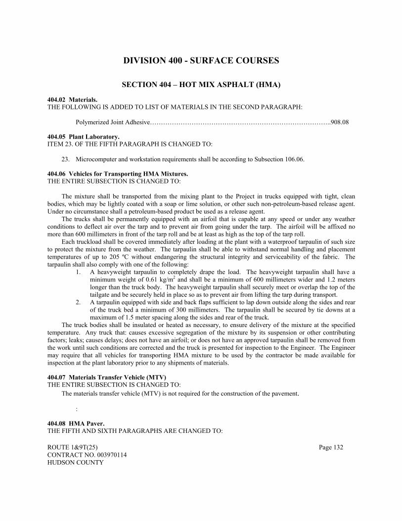
ROUTE 1&9T(25) Page 132 CONTRACT NO. 003970114 HUDSON COUNTY
DIVISION 400 - SURFACE COURSES
SECTION 404 – HOT MIX ASPHALT (HMA) 404.02 Materials. THE FOLLOWING IS ADDED TO LIST OF MATERIALS IN THE SECOND PARAGRAPH:
Polymerized Joint Adhesive………………………………………………………………………..908.08 404.05 Plant Laboratory. ITEM 23. OF THE FIFTH PARAGRAPH IS CHANGED TO:
23. Microcomputer and workstation requirements shall be according to Subsection 106.06. 404.06 Vehicles for Transporting HMA Mixtures. THE ENTIRE SUBSECTION IS CHANGED TO:
The mixture shall be transported from the mixing plant to the Project in trucks equipped with tight, clean bodies, which may be lightly coated with a soap or lime solution, or other such non-petroleum-based release agent. Under no circumstance shall a petroleum-based product be used as a release agent.
The trucks shall be permanently equipped with an airfoil that is capable at any speed or under any weather conditions to deflect air over the tarp and to prevent air from going under the tarp. The airfoil will be affixed no more than 600 millimeters in front of the tarp roll and be at least as high as the top of the tarp roll.
Each truckload shall be covered immediately after loading at the plant with a waterproof tarpaulin of such size to protect the mixture from the weather. The tarpaulin shall be able to withstand normal handling and placement temperatures of up to 205 ºC without endangering the structural integrity and serviceability of the fabric. The tarpaulin shall also comply with one of the following:
1. A heavyweight tarpaulin to completely drape the load. The heavyweight tarpaulin shall have a minimum weight of 0.61 kg/m2 and shall be a minimum of 600 millimeters wider and 1.2 meters longer than the truck body. The heavyweight tarpaulin shall securely meet or overlap the top of the tailgate and be securely held in place so as to prevent air from lifting the tarp during transport.
2. A tarpaulin equipped with side and back flaps sufficient to lap down outside along the sides and rear of the truck bed a minimum of 300 millimeters. The tarpaulin shall be secured by tie downs at a maximum of 1.5 meter spacing along the sides and rear of the truck.
The truck bodies shall be insulated or heated as necessary, to ensure delivery of the mixture at the specified temperature. Any truck that: causes excessive segregation of the mixture by its suspension or other contributing factors; leaks; causes delays; does not have an airfoil; or does not have an approved tarpaulin shall be removed from the work until such conditions are corrected and the truck is presented for inspection to the Engineer. The Engineer may require that all vehicles for transporting HMA mixture to be used by the contractor be made available for inspection at the plant laboratory prior to any shipments of materials. 404.07 Materials Transfer Vehicle (MTV) THE ENTIRE SUBSECTION IS CHANGED TO:
The materials transfer vehicle (MTV) is not required for the construction of the pavement.
: 404.08 HMA Paver. THE FIFTH AND SIXTH PARAGRAPHS ARE CHANGED TO:

ROUTE 1&9T(25) Page 133 CONTRACT NO. 003970114 HUDSON COUNTY
When wedge joint construction is required, HMA pavers shall be equipped with a sloped plate to produce a wedge edge at longitudinal joints. The sloped plate shall meet the requirements of Subsection 404.17.1.B and shall be attached to the paver screed extension. THE SEVENTH PARAGRAPH IS DELETED. 404.13 Weather Limitations. THE LAST PARAGRAPH IS DELETED. 404.17 Spreading and Finishing. SUBPART 1. “LONGITUDINAL JOINTS” IS CHANGED TO:
1. Longitudinal Joints. All longitudinal joints shall be cleaned free from dust and coated before placing the HMA with a uniform application of a polymerized joint adhesive selected from the Department’s approved products list. The polymerized joint adhesive material shall be applied at a slow rate to ensure an even coating thickness of 3 millimeters over the entire joint face. For echelon paving the longitudinal joints need not be treated with the polymerized joint adhesive.
The paving shall be done with the spring loaded end plates of the paver in the “down” position. When constructing the first lane, care shall be exercised in rolling so as not to displace the line and grade of the edges of the HMA. The longitudinal joint in one layer shall offset that in the layer immediately below by approximately 150 millimeters. The joint in the surface course shall be offset from the lane lines by 150 millimeters except for the centerline of a roadway in which the joint shall fall between the double yellow traffic stripe.
Paving, compaction and the supply of material shall proceed at a uniform rate with minimal or no stopping.
If a single paver does not spread the HMA material the entire width of the roadway, two pavers shall be used provided that the rate of production of HMA material can be maintained. The second unit shall follow within 90 meters of the first unit in echelon, so as not to permit cooling of the longitudinal joint between the two lanes. If echelon paving is to be utilized, the distance that the screed and end gate of the trailing paver shall extend over the uncompacted HMA layer behind the first paver shall be 25 millimeters or less. The inside end gate of the second paver must be set at the same level as the bottom of the screed plate of the first paver. Raking of the joint is not needed.
A wedge joint shall be constructed when traffic is to be maintained and lift thickness is greater than 57 millimeters. A vertical edge joint will be permitted for lift thickness 57 millimeters or less when traffic has to be maintained. For lift thickness greater than 57 millimeters and traffic is not required to be maintained, a vertical edge shall be utilized.
Longitudinal joints shall be constructed utilizing one of the following methods: A. Vertical Edge Joint. The paver shall be positioned so that in spreading, the HMA material
uniformly overlaps the edge of the lane previously placed by 25 to 50 millimeters and shall be left sufficiently high to allow for compaction. In general, the height of the uncompacted HMA above the compacted HMA shall be 6 millimeters for every 25 millimeters of compacted mix. The overlapped HMA material being placed in the abutting lane shall be tightly crowded (bumped) over the joint. Any material in excess of the 25 to 50 millimeters overlap shall be pulled away from the joint and removed instead of broadcasting onto the new mat. When compacted, the new mat at the joint shall be even or slightly higher (Maximum 3 millimeters) than the previously placed adjoining mat. If the newly compacted mat results in a depression at the joint of 3 millimeters or more lower than the previously placed adjacent HMA layer, all paving operations shall cease until corrective action is taken by the Contractor to prevent reoccurrence. For all longitudinal joints that do not meet this requirement, the Contractor shall saw joints according to dimension guidelines of Subsection 404.19 and seal with an approved sealer.

ROUTE 1&9T(25) Page 134 CONTRACT NO. 003970114 HUDSON COUNTY
B. Wedge Joint. The sloped plate of the paver shall produce a wedge edge having a face slope of 3H:1V. The plate shall be so constructed as to accommodate compacted layer thickness of 50 to 100 millimeters. The bottom of the sloped plate shall be mounted 25 millimeters above the existing surface. The plate shall be interchangeable on either side of the screed. The Contractor shall maintain the wedge configuration under traffic conditions.
All loose material shall be removed from the traveled way before opening to traffic. The rolling operation of the adjoining lane shall proceed as indicated in subpart A above, except that care shall be taken to keep coarse aggregate away from the point where the wedge meets the surface of the previously placed lane.
To assure a true line, the paver shall closely follow lines or markings placed along the joint for alignment purposes. All longitudinal joints shall be constructed parallel to the centerlines within a tolerance of plus or minus 75 millimeters for every 30 linear meters. If this tolerance is not met, the mat shall be cut back to conform. The width and depth of overlapped material shall be kept uniform at all times. Overlapped material shall be luted back, pushing the material off of the cold HMA and onto the hot HMA mat directly over the joint. In no case shall excess material be broadcast across the new layer. All excess material shall be removed.
404.18 Compaction. THE FOURTH PARAGRAPH IS CHANGED TO:
When compacting the longitudinal edge of the first lanes placed using the wedge joint, the breakdown roller shall not extend more than 50 millimeters over the top of the sloped face of the wedge joint. The Contractor shall submit a plan, to ensure material at the wedge edge is properly seated and loose material is removed, for the Resident Engineer’s approval prior to the commencement of paving operations. THE FOLLOWING IS ADDED AFTER THE FOURTH PARAGRAPH:
Care shall be taken to prevent lateral displacement of the unconfined edge during the compaction operation. The edge of the drums of vibratory or static wheel rollers shall extend over the free edge of the mat by at least 150 millimeters. When compacting the joint, while paving the adjacent lane, the roller shall be placed on the newly placed HMA and overlap the joint by a distance of approximately 150 millimeters. THE FIFTH PARAGRAPH IS CHANGED TO:
Alternate trips of the roller shall be terminated in stops approximately 600 millimeters from the preceding stop. When paving in echelon, rollers compacting the mat behind the lead paver shall maintain approximately 150 millimeters of uncompacted material adjacent to the second paver. After mix from the second paver is placed against the uncompacted edge of the mat from the first paver, the rollers shall compact the HMA on both sides of the joint. THE FOLLOWING IS ADDED AFTER THE ELEVENTH PARAGRAPH:
After compaction has been completed, the pavement shall be free of all visible defects such as segregation, bleeding, ruts, ridges, roller marks, cracking, tearing, raveling, open or segregated transverse or longitudinal joints, depressed or raised areas around manholes or raised areas around inlets in the Traveled Way or any other defects, as determined by the Resident Engineer. All visible defects shall be repaired to the satisfaction of the Resident Engineer at no additional cost to the State.
At the discretion of the Resident Engineer where it is deemed to be impractical to repair such visible defects, a payment reduction due to nonconformance will be applied according to Subsection 404.26.

ROUTE 1&9T(25) Page 135 CONTRACT NO. 003970114 HUDSON COUNTY
.
404.25 Method of Measurement. THE FOLLOWING IS ADDED AFTER THE SEVENTH PARAGRAPH:
Polymerized joint adhesive will be measured by the linear meter. THE EIGHTH AND NINTH PARAGRAPHS ARE CHANGED TO:
Sealing of Cracks in HMA surface course will be measured by the linear meter. Sawing and sealing joints in HMA overlays will be measured by the linear meter. Sawing joints in base or
intermediate course will be measured by the linear meter. THE THIRTEENTH PARAGRAPH IS CHANGED TO:
The monthly asphalt price index will be the average of quotations from suppliers serving the area in which the Project is located. The asphalt price index for North and South of Route I-195 will be posted every month on the Department’s web site: www.state.nj.us/transportation/eng/CCEPM/PriceIndex.shtm. THE FOURTEENTH PARAGRAPH IS CHANGED TO:
The basic asphalt price index will be the previous month’s asphalt price index before receipt of bids. THE LAST PARAGRAPH IS DELETED. 404.26 Basis of Payment. THE NINTH AND THIRTEENTH PAY ITEMS IN THE FIRST PARAGRAPH ARE CHANGED TO:
Pay Item Pay Unit SAWING JOINTS IN INTERMEDIATE OR BASE COURSE LINEAR METER CORE SAMPLES, HOT MIX ASPHALT UNIT
THE FOLLOWING NEW PAY ITEM IS ADDED:
Pay Item Pay Unit POLYMERIZED JOINT ADHESIVE LINEAR METER
THE FOLLOWING PAY ITEM IS DELETED:
SEALING OF CRACKS AND JOINTS IN HOT MIX ASPHALT SURFACE COURSE LINEAR METER THE LAST PARAGRAPH IS CHANGED TO:
Separate payment will not be made for MTV, test strips, and quality control for compaction, including comparison cores, and nuclear density testing. All costs thereof shall be included in the prices bid for Hot Mix Asphalt Surface Course Mix I-5, and Hot Mix Asphalt Base Course Mix I-2.
SECTION 405 – CONCRETE SURFACE COURSE 405.02 Materials.

ROUTE 1&9T(25) Page 136 CONTRACT NO. 003970114 HUDSON COUNTY
THE FOURTH AND FIFTH PARAGRAPHS ARE CHANGED TO:
Epoxy grout shall meet the requirements of ASTM C 881, Type I, Grade 3, Class B or C. Certifications of compliance shall be furnished according to Subsection 106.04. 405.08 Mixing Concrete.
1. Mixing on the Project in Truck Mixers. THIS FIRST SENTENCE IN THE FIFTEENTH PARAGRAPH IS CHANGED TO:
Each batch shall be mixed not less than 50 revolutions at the rate of rotation designated as mixing speed.
3. Transit Mixing.
THE NINTH PARAGRAPH IS CHANGED TO:
Mixing shall begin immediately following the complete charging of the drum and continue for not less than 50 revolutions of the drum at the mixing speed recommended by the manufacturer of the truck mixer. Upon completion of at least the minimum number of mixing revolutions at the plant, the speed of the drum shall be reduced to the agitation speed recommended by the manufacturer.
THE LAST PARAGRAPH IS CHANGED TO:
Transit mix concrete will be rejected for any of the following reasons: a. If the concrete is not discharged within the specified time limit after loading all ingredients
into the drum; b. If the indicator on the counter shows that the instrument has been turned off or tampered with; c. If the non-resettable total revolution counter shows more than 300 revolutions; d. If water has been added while the truck mixer is en route to the Project. Two-way telephone or
radio communication between the site of the placement of concrete and the batching plant shall be provided.
405.22 Bridge Approach and Transition Slabs. THE ENTIRE SUBSECTION TEXT IS DELETED. 405.24 Method of Measurement. THE FIRST PARAGRAPH IS CHANGED TO:
Concrete surface courses, with or without reinforcement, of the various thicknesses, will not be measured and payment will be made for the quantity in the Proposal adjusted for Change Orders except as provided for in Subsection 109.01. THE SEVENTH PARAGRAPH IS DELETED. 405.25 Basis of Payment. THE THIRD, FOURTH AND ELEVENTH PAY ITEMS ARE DELETED.
SECTION 406 – SUPERPAVE HOT MIX ASPHALT COURSES 406.12 Air Voids Acceptance Plan. THE FIRST SENTENCE OF THE FOURTH PARAGRAPH IS CHANGED TO:
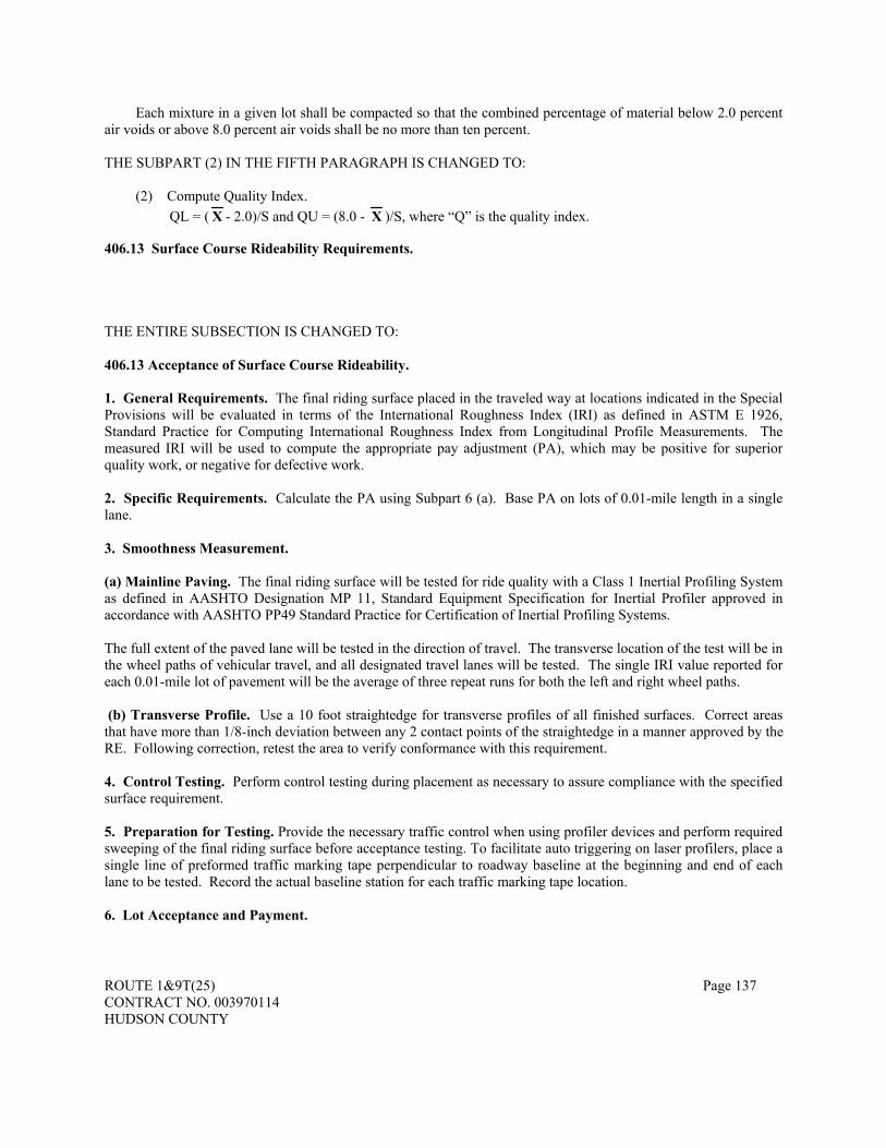
ROUTE 1&9T(25) Page 137 CONTRACT NO. 003970114 HUDSON COUNTY
Each mixture in a given lot shall be compacted so that the combined percentage of material below 2.0 percent air voids or above 8.0 percent air voids shall be no more than ten percent. THE SUBPART (2) IN THE FIFTH PARAGRAPH IS CHANGED TO:
(2) Compute Quality Index. QL = ( X - 2.0)/S and QU = (8.0 - X )/S, where “Q” is the quality index.
406.13 Surface Course Rideability Requirements.
THE ENTIRE SUBSECTION IS CHANGED TO:
406.13 Acceptance of Surface Course Rideability. 1. General Requirements. The final riding surface placed in the traveled way at locations indicated in the Special Provisions will be evaluated in terms of the International Roughness Index (IRI) as defined in ASTM E 1926, Standard Practice for Computing International Roughness Index from Longitudinal Profile Measurements. The measured IRI will be used to compute the appropriate pay adjustment (PA), which may be positive for superior quality work, or negative for defective work. 2. Specific Requirements. Calculate the PA using Subpart 6 (a). Base PA on lots of 0.01-mile length in a single lane. 3. Smoothness Measurement. (a) Mainline Paving. The final riding surface will be tested for ride quality with a Class 1 Inertial Profiling System as defined in AASHTO Designation MP 11, Standard Equipment Specification for Inertial Profiler approved in accordance with AASHTO PP49 Standard Practice for Certification of Inertial Profiling Systems.
The full extent of the paved lane will be tested in the direction of travel. The transverse location of the test will be in the wheel paths of vehicular travel, and all designated travel lanes will be tested. The single IRI value reported for each 0.01-mile lot of pavement will be the average of three repeat runs for both the left and right wheel paths. (b) Transverse Profile. Use a 10 foot straightedge for transverse profiles of all finished surfaces. Correct areas that have more than 1/8-inch deviation between any 2 contact points of the straightedge in a manner approved by the RE. Following correction, retest the area to verify conformance with this requirement. 4. Control Testing. Perform control testing during placement as necessary to assure compliance with the specified surface requirement. 5. Preparation for Testing. Provide the necessary traffic control when using profiler devices and perform required sweeping of the final riding surface before acceptance testing. To facilitate auto triggering on laser profilers, place a single line of preformed traffic marking tape perpendicular to roadway baseline at the beginning and end of each lane to be tested. Record the actual baseline station for each traffic marking tape location. 6. Lot Acceptance and Payment.

ROUTE 1&9T(25) Page 138 CONTRACT NO. 003970114 HUDSON COUNTY
(a) Compute pay adjustment. Pay equations below express the PA in dollars per lane per 0.01 mile for the road sections described. For lots of any other length, the pay adjustment is scaled up or down in proportion to the actual length of the lot. IRI numbers are in inches per mile. Freeways / Limited Access Highways Paving more than one lift IRI < 45: PA = $100 (Eq. 1) 45 ≤ IRI < 63: PA = $350 - ($5.5556 x IRI) (Eq. 2) IRI = 63: PA = $0 (Eq. 3) 63 < IRI ≤ 125: PA = (IRI - 63) x (- $16.1290) (Eq. 4) IRI > 125: Remove & Replace / Retest Value (RV) Paving one lift IRI < 60: PA = $50 (Eq. 5) 60 ≤ IRI < 75: PA = $250 - ($3.3333 x IRI) (Eq. 6) IRI = 75: PA = $0 (Eq. 7) 75 < IRI ≤ 145: PA = (IRI - 75) x (- $7.1429) (Eq. 8) IRI > 145: Remove and Replace / Retest Value Highways Other Than Freeways / Limited Access Paving more than one lift IRI < 60: PA = $50 (Eq. 9) 60 ≤ IRI < 80: PA = $200 - ($2.50 x IRI) (Eq. 10) IRI = 80: PA = $0 (Eq. 11) 80 < IRI ≤ 140: PA = (IRI - 80) x (- $8.3333) (Eq. 12) IRI > 140: Remove and Replace / Retest Value Paving one lift IRI < 70: PA = $50 (Eq. 13) 70 ≤ IRI < 85: PA = $283.33 - ($3.333 x IRI) (Eq. 14) IRI = 85: PA = $0 (Eq. 15) 85 < IRI ≤ 160: PA = (IRI -85) x (- $6.6667) (Eq. 16) IRI > 160: Remove and Replace / Retest Value Other Roadways IRI < 80: PA = $50 (Eq. 17) 80 ≤ IRI < 100: PA = $250 - ($2.50 x IRI) (Eq. 18) IRI = 100: PA = $0 (Eq. 19) 100 < IRI ≤ 170: PA = (IRI - 100) x (- $7.1429) (Eq. 20) IRI > 170: Remove and Replace / Retest Value

ROUTE 1&9T(25) Page 139 CONTRACT NO. 003970114 HUDSON COUNTY
Paving Ramps and Shoulders IRI = 120: PA = $0 (Eq. 21) 120 < IRI ≤ 170: PA = (IRI - 120) x (- $10.00) (Eq. 22) IRI > 170: Remove and Replace / Retest Value (b) Retest provision. After testing, if IRI equals or exceeds the Remove and Replace / Retest Value (RV) in Subpart (a), The Department will retest the lot. If the average of the two tests exceeds the RV, remove and replace the lot. The Department has the option of performing a retest of any lot in question. If there is definite evidence that the initial test is invalid, the initial test will be disregarded and a retest will be performed. The retest will assume the status of an initial test. If there is no evidence that the original test was invalid, and the Department elects to perform the retest, the IRI values from the initial test and the retest will be averaged to determine the final result. The Department will be reimbursed for any retests performed due to IRI at the RV. On projects where only a small percentage (<8 %) of paving lots falls under Remove and Replace, the Department may allow the Contractor to submit a plan for corrective action. If the plan for corrective action is deemed unsatisfactory, the Department may require removal and replacement, or may allow the lot(s) to remain in place and the lot(s) will be subject to the pay adjustment as computed in the final equation in the applicable set of equations (Eq. 4, 8, 12, 16, 20, 22). If the plan for corrective action is accepted and the lot is reworked, it will be tested and evaluated as a new lot which must meet all the same requirements as the initial work. Corrective action locations are not eligible for bonus payments. (c) Removal and Replacement. If IRI is greater than the Remove and Replace / Retest Value, remove and replace at no additional compensation. Any replacement work is subject to the same requirements as the initial work. For this Project, the no payment reduction provisions shall govern. 406.14 Thickness Requirements. THE FIRST SENTENCE OF THE SECOND PARAGRAPH IS CHANGED TO:
Conformance to thickness requirements will be judged from the full depth cores taken for surface course air voids determinations evaluated according to Section 990, NJDOT B-4. THE THIRD PARAGRAPH IS CHANGED TO:
Acceptance will be based on total thickness and thickness of the surface course. THE FOLLOWING IS ADDED TO THE END OF THIS SUBSECTION:
Evaluation of the surface course will be performed solely to determine whether a remove-and-replace or an overlay condition exists, not for pay adjustment. To be judged acceptable, no more than 10.0 percent of the surface course shall be of deficient thickness as calculated by the procedure below.
Acceptance for surface course thickness will be based on the percentage of the lot estimated to fall below the specified thickness as follows:
(1) Compute the sample mean ( X ) and the standard deviation (S) of the N Test Results (X1, X2,..., XN): X = X1 + X2 + ... + XN
N
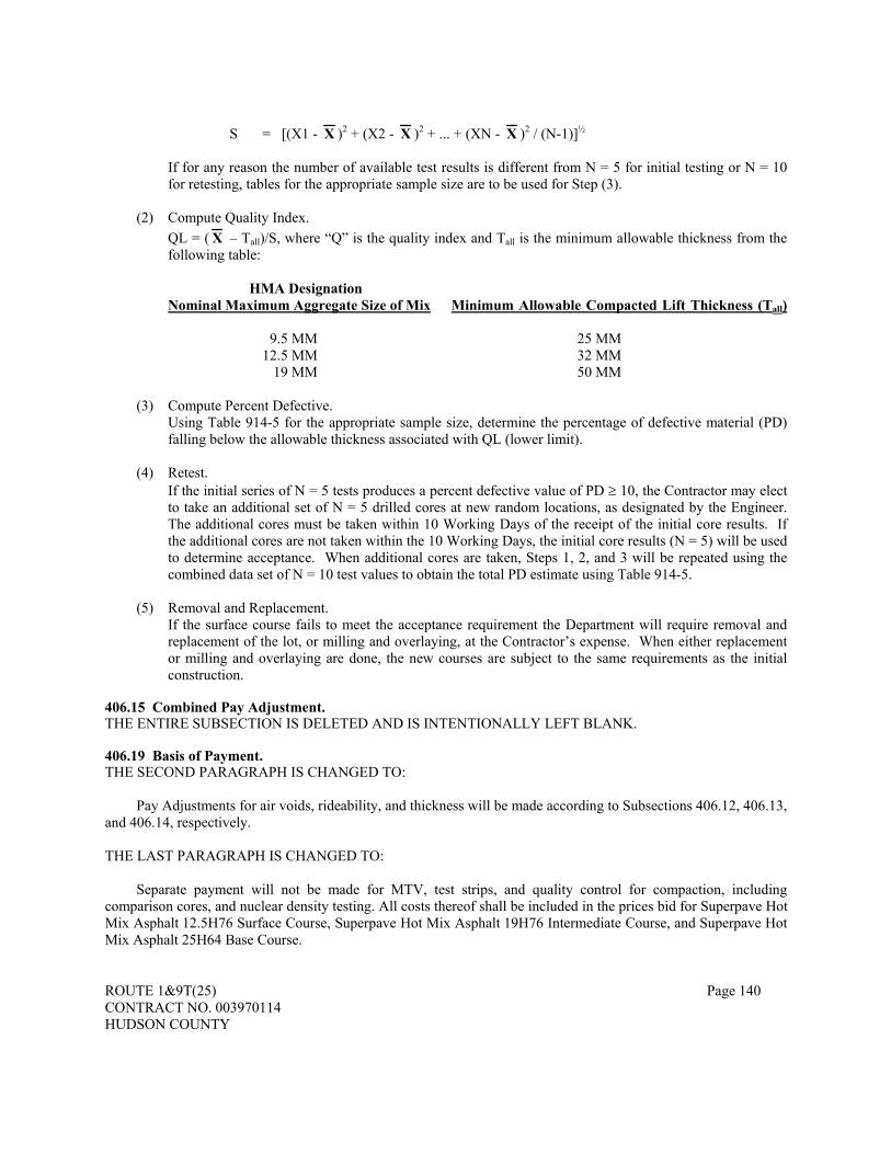
ROUTE 1&9T(25) Page 140 CONTRACT NO. 003970114 HUDSON COUNTY
S = [(X1 - X )2 + (X2 - X )2 + ... + (XN - X )2 / (N-1)]½
If for any reason the number of available test results is different from N = 5 for initial testing or N = 10
for retesting, tables for the appropriate sample size are to be used for Step (3).
(2) Compute Quality Index. QL = ( X – Tall)/S, where “Q” is the quality index and Tall is the minimum allowable thickness from the
following table:
HMA Designation Nominal Maximum Aggregate Size of Mix Minimum Allowable Compacted Lift Thickness (Tall)
9.5 MM 25 MM 12.5 MM 32 MM 19 MM 50 MM
(3) Compute Percent Defective.
Using Table 914-5 for the appropriate sample size, determine the percentage of defective material (PD) falling below the allowable thickness associated with QL (lower limit).
(4) Retest. If the initial series of N = 5 tests produces a percent defective value of PD ≥ 10, the Contractor may elect
to take an additional set of N = 5 drilled cores at new random locations, as designated by the Engineer. The additional cores must be taken within 10 Working Days of the receipt of the initial core results. If the additional cores are not taken within the 10 Working Days, the initial core results (N = 5) will be used to determine acceptance. When additional cores are taken, Steps 1, 2, and 3 will be repeated using the combined data set of N = 10 test values to obtain the total PD estimate using Table 914-5.
(5) Removal and Replacement. If the surface course fails to meet the acceptance requirement the Department will require removal and
replacement of the lot, or milling and overlaying, at the Contractor’s expense. When either replacement or milling and overlaying are done, the new courses are subject to the same requirements as the initial construction.
406.15 Combined Pay Adjustment. THE ENTIRE SUBSECTION IS DELETED AND IS INTENTIONALLY LEFT BLANK. 406.19 Basis of Payment. THE SECOND PARAGRAPH IS CHANGED TO:
Pay Adjustments for air voids, rideability, and thickness will be made according to Subsections 406.12, 406.13, and 406.14, respectively. THE LAST PARAGRAPH IS CHANGED TO:
Separate payment will not be made for MTV, test strips, and quality control for compaction, including comparison cores, and nuclear density testing. All costs thereof shall be included in the prices bid for Superpave Hot Mix Asphalt 12.5H76 Surface Course, Superpave Hot Mix Asphalt 19H76 Intermediate Course, and Superpave Hot Mix Asphalt 25H64 Base Course.

ROUTE 1&9T(25) Page 141 CONTRACT NO. 003970114 HUDSON COUNTY
THE FOLLOWING IS ADDED TO THIS SECTION:
STEEL REINFORCEMENT MESH WITH SLURRY SEAL
Description. This work shall consist of furnishing and placing a woven steel mesh on the existing pavement, embedded in a
slurry seal intermediate course, prior to placing asphalt overlay at the locations specified in the Contract Drawings.
Materials. Steel Mesh Reinforcement The steel mesh reinforcement shall be PaveTrac® MeshTrack 1 (MT-1) as manufactured by Bekaert
Corporation, 1395 S. Marietta Parkway, Marietta, GA 30067, or approved equal. The steel mesh reinforcement shall be a double twist woven hexagonal wire mesh manufactured of eutectic 95% Zinc, 5% Aluminum alloy (Bezinal®) coated steel, transversely reinforced at regular intervals by alternately torsioned flat bars interwoven in the mesh. Steel reinforcement mesh shall be protected with a Bezinal® coating. Bezinal® coating shall be in accordance with ASTM B750. The steel mesh shall have the following physical and mechanical properties:
Physical and Mechanical Properties of Steel Mesh Reinforcement Mesh aperture width 80 mm +/- 8mm (3.15 in +/- 0.32 in) Mesh aperture length 118 mm +/- 14 mm (4.65 in +/- 0.55 in) Torsional flat bar spacing 245 mm +/- 20 mm (9.65 in +/- 0.79 in) Round wire diameter 2.45 mm +/- 0.09 mm (0.096 in +/- 0.004 in) Flat bar thickness 3.00 mm +/- 0.05 mm (0.118 in +/- 0.002 in) Flat bar width 7.00 mm +/- 0.2 mm (0.276 in +/- 0.008 in) Bezinal® coating thickness(1) Round wire class 40 - min. 125 g/m2 Flat bar class 20 - min. 80 g/m2 Tensile strength Round wire min. 1800 N (404.5 lbs) Flat bar min. 12000 N (2697 lbs) Modulus of Elasticity (E) 200 kN/mm2 (129 x 106 psi) Axial stiffness (EA)(2) Mesh-longitudinal 23600 N/mm (134,703 lbs/in) Mesh-transverse 29300 N/mm (167,237 lbs/in) (1) In accordance with EN 10244-2 - class B (2) Calculated value Clip Anchors Clip anchors shall be A-Clip 50 millimeter anchors as manufactured by Hilti, Inc., 5400 South 122nd East
Avenue, Tulsa, OK 74146, or approved equal. Slurry Seal The slurry seal shall be a polymer modified slurry seal consisting of a mixture of latex modified asphalt
emulsion and aggregate. Polymer emulsified asphalt shall be a quick traffic, quick cure (RS) type; shall be homogeneous; and shall show no separation after thorough mixing. The Contractor may add cement to the mixture in order to accelerate the breaking up of the emulsion after spreading. Aggregate material shall consist of sound, durable sand and approved mineral filler. The material shall be free from vegetation and other deleterious substances. Aggregates shall be 100% crushed with no rounded particles. The percentage composition by weight of the aggregate shall conform to the following gradation:
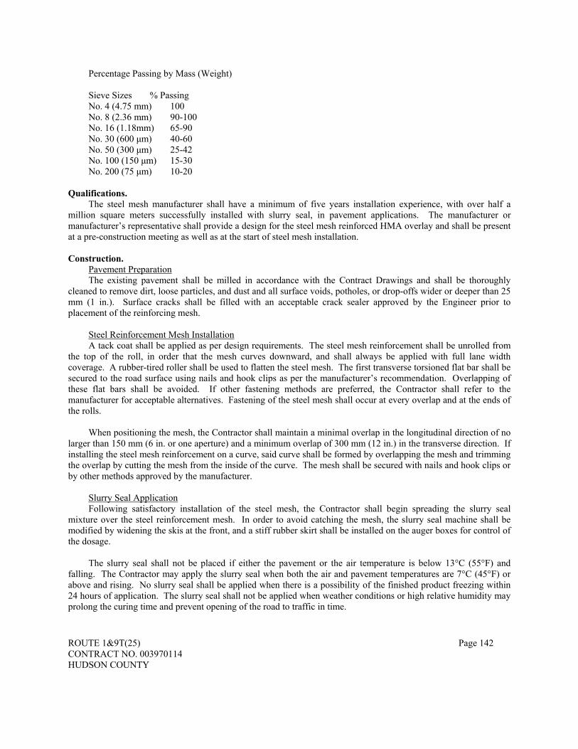
ROUTE 1&9T(25) Page 142 CONTRACT NO. 003970114 HUDSON COUNTY
Percentage Passing by Mass (Weight) Sieve Sizes % Passing No. 4 (4.75 mm) 100 No. 8 (2.36 mm) 90-100 No. 16 (1.18mm) 65-90 No. 30 (600 μm) 40-60 No. 50 (300 μm) 25-42 No. 100 (150 μm) 15-30 No. 200 (75 μm) 10-20
Qualifications. The steel mesh manufacturer shall have a minimum of five years installation experience, with over half a
million square meters successfully installed with slurry seal, in pavement applications. The manufacturer or manufacturer’s representative shall provide a design for the steel mesh reinforced HMA overlay and shall be present at a pre-construction meeting as well as at the start of steel mesh installation.
Construction.
Pavement Preparation The existing pavement shall be milled in accordance with the Contract Drawings and shall be thoroughly
cleaned to remove dirt, loose particles, and dust and all surface voids, potholes, or drop-offs wider or deeper than 25 mm (1 in.). Surface cracks shall be filled with an acceptable crack sealer approved by the Engineer prior to placement of the reinforcing mesh.
Steel Reinforcement Mesh Installation A tack coat shall be applied as per design requirements. The steel mesh reinforcement shall be unrolled from
the top of the roll, in order that the mesh curves downward, and shall always be applied with full lane width coverage. A rubber-tired roller shall be used to flatten the steel mesh. The first transverse torsioned flat bar shall be secured to the road surface using nails and hook clips as per the manufacturer’s recommendation. Overlapping of these flat bars shall be avoided. If other fastening methods are preferred, the Contractor shall refer to the manufacturer for acceptable alternatives. Fastening of the steel mesh shall occur at every overlap and at the ends of the rolls.
When positioning the mesh, the Contractor shall maintain a minimal overlap in the longitudinal direction of no
larger than 150 mm (6 in. or one aperture) and a minimum overlap of 300 mm (12 in.) in the transverse direction. If installing the steel mesh reinforcement on a curve, said curve shall be formed by overlapping the mesh and trimming the overlap by cutting the mesh from the inside of the curve. The mesh shall be secured with nails and hook clips or by other methods approved by the manufacturer.
Slurry Seal Application Following satisfactory installation of the steel mesh, the Contractor shall begin spreading the slurry seal
mixture over the steel reinforcement mesh. In order to avoid catching the mesh, the slurry seal machine shall be modified by widening the skis at the front, and a stiff rubber skirt shall be installed on the auger boxes for control of the dosage.
The slurry seal shall not be placed if either the pavement or the air temperature is below 13°C (55°F) and
falling. The Contractor may apply the slurry seal when both the air and pavement temperatures are 7°C (45°F) or above and rising. No slurry seal shall be applied when there is a possibility of the finished product freezing within 24 hours of application. The slurry seal shall not be applied when weather conditions or high relative humidity may prolong the curing time and prevent opening of the road to traffic in time.
ROUTE 1&9T(25) Page 143 CONTRACT NO. 003970114 HUDSON COUNTY
When installing the steel mesh directly over the old pavement, the reinforcing mesh shall be fixed to the existing pavement with a slurry seal layer at a rate of approximately 17 kg/m2 (31 lbs/yd2). In the case of installing the steel mesh over milled pavement, a rate of approximately 20-22 kg/m2 (36-40 lbs/yd2) shall be required. The Contractor should note that the pattern of the steel mesh reinforcement should be visible after curing of the emulsions and hardening of the slurry seal. The complete curing of the slurry seal should take approximately 3-6 hours, depending on the type of emulsion and weather conditions.
The manufacturer’s recommendations shall be followed as to when to open the road to traffic after placement
of the slurry seal. After the complete curing of the slurry seal, the asphalt overlay may be applied. Longitudinal and construction
joints in the overlay shall not coincide with the overlaps in the steel mesh.
Measurement. Steel mesh reinforcement will be measured by the square meter. No separate measurement will be made for
overlapping, clips, slurry seal and preparation of the pavement surface.
Basis of Payment. Payment will be made under: Pay Item Pay Unit PAVETRAC SQUARE METER The unit price bid per square meter shall include the cost of furnishing all labor, equipment, and materials
necessary to complete the work. No separate payment shall be made for preparation of the pavement surface, overlaps, clips and slurry seal, the cost thereof shall be included in the item “PAVETRAC”.
ROUTE 1&9T(25) Page 144 CONTRACT NO. 003970114 HUDSON COUNTY
DIVISION 500 - BRIDGES AND STRUCTURES
SECTION 501 - CONCRETE STRUCTURES
501.01 Description. THE FOLLOWING IS ADDED AFTER THE FIRST PARAGRAPH:
This work shall also consist of the construction of portland cement concrete deck slabs, parapets, sidewalks, curbs, barriers, pier columns, and pier caps with the use of High Performance Concrete (HPC). THE SECOND THROUGH SIXTH PARAGRAPHS ARE DELETED. 501.02 Materials. THE FOLLOWING IS ADDED TO THE FIRST PARAGRAPHS MATERIAL LIST
High Performance Concrete ................................................................................................................914.02 THE SECOND THROUGH SIXTH PARAGRAPHS ARE CHANGED TO:
The pressure injected epoxy shall meet the requirements of ASTM C 881, Type I or IV, Grade 1, Class B or C. The epoxy crack sealant shall be recommended by the pressure injected epoxy manufacturer. Certifications of compliance shall be furnished according to Subsection 106.04.
The pressure injected epoxy shall be capable of penetrating the cracks to their full depth and capable of bonding to the surfaces of cracked concrete.
In the production of HPC, in order to achieve the desired resistance to chloride penetration, an appropriate pozzalonic or other cementitious material; such as, silica fume, fly ash or ground granulated blast furnace slag shall be provided in the mix design.
Silica fume shall not be used as a sole material to achieve the desired resistance to chlorides. When used, silica fume’s content shall be limited to a maximum of 5 percent of the total cement content and a proportion of fly ash or ground granulated blast furnace slag shall be included to obtain the resistance specified in 914.02 to chloride penetration. The fly ash and ground granulated blast furnace slag limitations specified in 914.02 may be increased in the fabrication of HPC.
The maximum water cement ratio shall be maintained at 0.40. In the fabrication of HPC, the cement content should not be increased for the purpose of achieving high early strength. THE FOLLOWING IS ADDED:
Stainless Steel Machine Screws – Stainless Steel Flat Head Machine Screws used for attachment of galvanized steel bent plates as parapet joint covers shall be ASTM F593 Alloy 304 Condition A Stainless Steel 19mm diameter x 40mm long flat head machine screws. Contractor may substitute ASTM A193 Alloy 304 countersunk bolts.
Threaded Concrete Inserts – Threaded Concrete Inserts used for attachment of galvanized steel bent plates as parapet joint covers shall be ASTM F593 Alloy 304 Condition A. 501.05 Working Drawings. THE SECOND, THIRD AND FOURTH PARAGRAPHS ARE DELETED. 501.07 Forms. 2. Metal Ties THE FOLLOWING IS ADDED:

ROUTE 1&9T(25) Page 145 CONTRACT NO. 003970114 HUDSON COUNTY
All metal ties shall be epoxy coated per Subsection 915.01.
7. Permanent Steel Bridge Deck Forms. THE FIRST SENTENCE OF THE SECOND PARAGRAPH IS CHANGED TO:
The use of permanent steel bridge deck forms shall conform to the following:
a. Design. THE SEVENTH PARAGRAPH IS CHANGED TO:
The spacing (pitch) of the ribs (flutes) shall match the spacing of the bottom main reinforcement steel, except on curved girder structures and in the areas of bridge decks with a flared rebar pattern. In these locations, the pitch of the flutes may be independent of the bottom main reinforcement spacing, and the forms may be dropped as necessary to achieve the minimum 25 millimeters concrete cover between the main reinforcement steel and the form. When the forms are dropped, additional dead load shall be accounted for in the design. Approval from the Engineer to drop the forms shall be obtained before construction of the deck begins.
b. Construction.
THE FOLLOWING IS ADDED AT THE END OF THE SECOND PARAGRAPH:
Joints between the forms should be lapped in the direction of concrete placement. 501.11 Limitations of Placing. THE SECOND SENTENCE OF THE FIRST PARAGRAPH IS CHANGED TO: In no case, during mixing and placement, shall the temperature of the concrete be less than 16 or more than 32 degrees C. 501.12 Placing Concrete.
5. Deck Slabs. THE FOLLOWING IS ADDED AFTER THE FIRST PARAGRAPH:
a. General Provisions. The following provisions shall be adhered to in all concrete deck slab construction.
THE 21 ST PARAGRAPH IS CHANGED TO:
When the concrete placing within any complete unit (i.e., for trusses, arches, continuous or cantilevered unit) is to be divided, the placing shall be made and finished in the numbered sequence shown, beginning with the lowest number. All sections having the same number shall be placed before sections of higher number. The sequence of placing for sections having the same number shall be optional. No deck section shall be placed until all previously placed concrete within the complete unit has cured for 72 hours. This requirement may be waived if the succeeding section(s) can be completed within four hours after the start of the initial placement of section(s) of any given unit for that day. A written request to waive this requirement shall be submitted to the Engineer for approval. This requirement may not be waived for deck slabs on prestressed concrete beams that are continuous for live load. The numbered sequence shown on the Plans shall be adhered to
THE FOLLOWING IS ADDED:

ROUTE 1&9T(25) Page 146 CONTRACT NO. 003970114 HUDSON COUNTY
b. High Performance Concrete (HPC) for Deck Slabs, Sidewalks, Concrete Railings and substructure Protection. HPC is defined as concrete that meets special performance and uniformity requirements that cannot always be obtained by using conventional ingredients, normal mixing procedures and typical curing practices. The furnishing of HPC shall conform to the requirements of 914.02. (1) The Contractor is advised that curing of the HPC deck slab shall be performed in
accordance with the provisions of Subsection 501.17. Upon completion of the 7 day wet curing period, the HPC deck slab shall be further cured according to the provisions of Subsection 405.14, Subpart 1.
(2) The finishing machine equipment shall be set up so that the HPC is placed only 2 to 2.4 meters ahead of the machine.
15. Pumped Concrete.
THE FOLLOWING IS ADDED:
As per the provisions of 914.04, fresh mixed concrete shall be sampled according to the requirements of AASHTO T 141. Samples shall be taken at the discharge of the concrete pump. If the Engineer believes that this is not a feasible, the pump shall be calibrated to calculate slump and air entrainment losses. These losses shall be deducted from the values as sampled from the concrete truck.
17. Reinforced Concrete Box Culvert, Precast.
THIS SUBPART IS DELETED.
18. Slip-form Method of Parapet Construction. THIS SUBPART NUMBER IS CHANGED TO:
17. Slip-form Method of Parapet Construction.
19. Corrosion Inhibitor Admixture. THIS SUBPART NUMBER IS CHANGED TO:
18. Corrosion Inhibitor Admixture. PARAGRAPH C IS DELETED.
20. Pressure Injection. THIS SUBPART NUMBER IS CHANGED TO:
19. Pressure Injection. THE FOLLOWING SUBPART IS ADDED:
20. Mass Concrete. Mass concrete is the placement of any large volume of cast in place concrete or precast concrete with dimensions large enough to require that measures be taken to cope with the generation of heat and attendant volume change, so as to minimize cracking.
A Mass Concrete member is defined as any concrete placement where each measured dimension of a
concrete component exceeds 1 meter and the ratio of its volume to surface area is greater than 300 millimeters. The surface area will include all of the cumulative area of all surfaces of the concrete component being considered including the full underside (bottom) surface of footings, caps, etc. Volume and surface area calculations shall be in units of meters. Therefore, the volume shall be measured in units of cubic meters and the area in units of square meters.
Mass concrete members will be as designated on the plans. Deck slab placements will not be
considered as mass concrete.

ROUTE 1&9T(25) Page 147 CONTRACT NO. 003970114 HUDSON COUNTY
a. Thermal Curing Plan. At least 20 days prior to the Mass Concrete pour; the Contractor shall submit to the Engineer a Thermal Curing Plan Report. The Report shall address the following issues:
(1) An analysis of the anticipated thermal developments within the mass pour placements
using proposed materials and casting methods.
(2) A plan outlining specific measures to be taken to control the temperature differential within the limits stated below.
(3) The proposed monitoring system.
(4) Outline of corrective actions to maintain the temperature differential.
(5) Proposed methods of repairs or corrective actions if the mass concrete member is not
accepted.
b. Curing and Monitoring. The Contractor shall thermally cure the concrete so as to maintain a temperature differential between the internal (hottest – located as close as possible to the center of the pour but not less than 300 millimeters from the surface and external (coolest) temperature of the concrete to a 1.7 degrees C. maximum. In addition, the internal temperature of the concrete (measured at the hottest point located at the center of the pour) shall at no time exceed 71 degrees C.
The Contractor shall provide temperature-monitoring devices to record temperature
development between the interior and exterior of the element at points approved by the Engineer and shall monitor the mass pours to measure temperature differentials. Temperature monitoring shall continue until the interior temperature is within 1.7 degrees C. of the lowest ambient temperature or a maximum of two weeks. The Resident Engineer shall be provided with a copy of each set of readings as they are taken and a temperature chart for each mass pour element showing temperature readings vs. time.
If monitoring indicates that the proposed measures are not controlling the concrete
temperature differential within the 1.7 degrees C. specified, the Contractor shall implement corrective actions as presented in the Thermal Curing Plan to maintain the temperature differential.
c. Concrete Mix Requirement. In order to better control the heat of hydration of the mass
concrete, the concrete mix design shall contain a pozzolanic material; such as, fly ash, silica fume or ground granulated blast furnace slag.
d. Approval and Acceptance. Should any mass concrete placed under this specification prove
unsatisfactory, the Contractor will be required to make the necessary repairs or remove and replace the material at the Contractor’s expense.
The Engineer will be the sole judge in determining acceptance of the Mass Concrete
member. Corrective actions, as approved in the Thermal Curing Plan Report, shall be made to those areas directed by the Engineer before the Mass Concrete member will be considered for acceptance.
THE FOLLOWING SUBPART IS ADDED:
ROUTE 1&9T(25) Page 148 CONTRACT NO. 003970114 HUDSON COUNTY
21. Concrete Bridge Approach Slabs.
Provide and install subbase material as specified in Section 208. At least 1 day before placing concrete, set forms as specified in 501.07 and place reinforcement steel as specified in 501.08 for the area that is to be paved. Forms shall be set at grade and in full contact with the under laying surface. Install dowel bars, as detailed on the Plans, through the forms and secure in place. Ensure that concrete does not seep through the dowel bar locations.
Check the alignment and grade elevations of the forms and make corrections before placing the
concrete. Ensure that the forms do not deviate from the required alignment by more than 6 millimeters. Reset, or remove and replace, forms that settle or deflect under the spreading and finishing equipment. Clean the top and face of forms and oil the face before placing the concrete.
Comply with the requirements of placing deck slab concrete that are specified in 501.12. Subpart 5.
Apply the surface texturing as specified in 501.15. Cure the concrete as specified in 501.17. Saw cut groove the surface as specified in 501.15.
Adhere to the loading and vehicular traffic restrictions as specified in 501.24.
THE FOLLOWING SUBPART IS ADDED: 22. Sleeper and Relief Slabs.
At least 20 calendar days before placing deck concrete with sleeper and relief slabs, a plan of operation shall be submitted for review. Methods, procedures and equipment shall be used which produce a riding surface according to the texture and surface tolerance requirements specified in Subsections 501.15 and 501.16 “Concrete in Superstructure Deck Slabs and Integral Abutments, HPC”.
501.15 Deck Slab Surface Texture Finish. THE FIRST PARAGRAPH AND SUBPART 1 ARE CHANGED TO:
The surface of the deck slab shall be finished according to Subsection 405.13 except that Subpart G shall not apply. The time between strike-off and application of deck slab surface texture finish in any location shall not exceed one hour. All concrete bridge deck slabs shall be textured with a stiff, coarse broom and shall be saw cut groove finished as follows:
1. Broom Finish. Immediately after finishing has been completed, the surface shall be given a texture with an approved stiff, coarse broom.
The broom shall be operated in a longitudinal or transverse direction. Once begun, the direction of texturing shall not be changed. Transverse texturing shall be done from a work bridge.
The broom finish shall be applied so as to prevent ridges or gouges from forming in the concrete surface. The broom shall be weighted and the contact area changed as required to produce a uniform texture. The broom shall be cleaned periodically to remove all hardened concrete particles. Texture resulting from the broom shall stop within 300 millimeters of curbs.
3. Saw Cut Grooved Surface.
THE SECOND PARAGRAPH IS DELETED. 501.16 Concrete Deck Surface Requirements.
B. Control Testing. THIS SUBPART IS CHANGED TO:
ROUTE 1&9T(25) Page 149 CONTRACT NO. 003970114 HUDSON COUNTY
Deck slab surfaces shall be checked during placement to correct surface irregularities while the concrete is in workable condition.
Such control testing shall be performed as follows: 1. After strike-off, the deck surface shall be checked with an aluminum straightedge having a minimum
length of 3 meters, as provided by the contractor. The Resident Engineer shall determine the specific conduct of the control testing, including the number and location of Straightedge checks. Surface variations shall be corrected before the concrete sets. Major deviations shall be corrected by the finishing machine or other strike-off, while minor deviations may be corrected by a straightedge or float. The addition of water to the surface of the concrete to assist in finishing operations will not be permitted.
THE FIRST PARAGRAPH IN SUBPART C IS CHANGED TO:
C. Acceptance Testing. Conformance to the surface tolerance for concrete deck slabs will be determined in lots, each being equal to the length of deck in one span or continuous span. The longitudinal limits of the lot will be bounded by the expansion joints or fixed structural deck joints. The full length of the lot will be tested through any construction joints within the deck, whether these joints are required for the placement sequence or caused by the Contractor’s operations. Such lot quantity will be calculated using the specified nominal deck thickness and excludes the quantity of concrete placed in haunches, end dams, and diaphragms. For the second course of the two-course deck slab construction, such lot quantity will be calculated using the specified nominal thickness of the concrete overlay protective system.
501.17 Curing and Protecting Concrete
A. Curing Concrete Under Normal Conditions. THIS SUBPART IS CHANGED TO:
Concrete decks, curbs, and tops of sidewalks for one-course deck slab construction shall be cured according to Subheading 4 of Subsection 405.14 with the exception that the minimum wet cure period shall not be less than seven calendar days. The burlap shall be kept continuously wet throughout this curing period. According to the provisions of Subheading 3 of Subsection 405.14, the wet burlap shall be covered with white polyethylene sheeting for the seven-day duration. The polyethylene sheeting shall be lapped at the joints and secured to the deck as tightly as possible. In two-course deck slab construction, the Contractor shall prepare the entire deck surface area according to Subheading 6 of Subpart C of Subsection 518.06 before placing the second course. The second course shall be cured according to Subsection 518.06 C.12.
The time between final finishing and application of the wet burlap shall not exceed 20 minutes in
any location within the placement area.
Other concrete structures and concrete surfaces to receive an epoxy coating, rubbed finish or to be covered with another material shall be cured according to Subheadings 2, 3, 4, and 5 of the sixth paragraph of Subsection 405.14.
501.25 Method of Measurement. THE 8TH PARAGRAPH IS DELETED. 501.26 Basis of Payment. THE 18TH PAY ITEM IS CHANGED TO:
Pay Item Pay Unit SAWCUT GROOVED DECK SURFACE SQUARE METER

ROUTE 1&9T(25) Page 150 CONTRACT NO. 003970114 HUDSON COUNTY
THE FOLLOWING PAY ITEMS ARE ADDED:
CONCRETE IN SUPERSTRUCTURE, DECK SLABS HPC CUBIC METER CONCRETE IN SUPERSTRUCTURE, SIDEWALKS HPC CUBIC METER CONCRETE IN SUPERSTRUCTURE, PARAPETS HPC LINEAR METER CONCRETE IN SUBSTRUCTURES, HPC CUBIC METER CONCRETE BRIDGE APPROACH SLAB CUBIC METER SAW CUT GROOVED SURFACE, APPROACH SLAB SQUARE METER 400 MM X 1070 MM SPLIT MEDIAN CONCRETE BARRIER, BRIDGE, HPC LINEAR METER 650 MM X 1070 MM MEDIAN CONCRETE BARRIER, BRIDGE, HPC LINEAR METER CONCRETE IN SUPERSTRUCTURE, 500 MM X 1070 MM PARAPET, HPC LINEAR METER CONCRETE IN SUPERSTRUCTURE, 600 MM X 2000 MM PARAPET, HPC LINEAR METER CONCRETE IN SUPERSTRUCTURE, 300 MM X 2000 MM PARAPET, HPC LINEAR METER CONCRETE IN SUPERSTRUCTURE, 400 MM X 1070 MM PARAPET, HPC LINEAR METER CONCRETE IN SUPERSTRUCTURE, 400 MM X 1170 MM PARAPET, HPC LINEAR METER CONCRETE IN SUPERSTRUCTURE, 375 MM X 815 MM PARAPET, HPC LINEAR METER CONCRETE IN SUPERSTRUCTURE, 200 MM THICK REINFORCED ISLAND, HPC LINEAR METER CONCRETE IN SUPERSTRUCTURE,
DECK SLABS AND INTEGRAL ABUTMENTS, HPC CUBIC METER CONCRETE IN SUBSTRUCTURES, PIER COLUMNS AND CAPS, HPC CUBIC METER CONCRETE IN SUPERSTRUCTURE, CLOSURE POUR AND SIDEWALK, HPC CUBIC METER CONCRETE IN SUBSTRUCTURES, CRASH WALLS CUBIC METER CONCRETE IN SUBSTRUCTURES, CONCRETE PIPE SUPPORTS CUBIC METER
THE 19TH PAY ITEM IS DELETED. THE FOLLOWING IS ADDED:
No separate payment will be made for work described under 501.12, Subpart 20. Mass Concrete. Such cost shall be included in the bid price for the applicable Pay Item.
In the construction of deck joint systems, no separate payment will be made for supplying and installation of steel armoring that is to be placed on the roadway side of the header. Such cost shall be included in the bid price for the Pay Item “Concrete in Substructures, Abutment Walls”.
Payment for the furnishing of the F–Shape and Texas Type HT barriers shall be made under the Item “Concrete in Superstructure, Parapets”. Steel railing that is to be provided with the Texas Type HT barrier shall be included in the Item.
No Separate payment will be made for deck, relief and sleeper slabs for bridges with integral abutments type bridges. The cost of these shall be included in the price bid for the Pay Item “Concrete in Superstructure, Deck Slabs and Integral Abutments, HPC.”
The pay item “Concrete in Substructures, HPC” will include payment for use of HPC for substructure member protection concrete.
As detailed on the plans, the cost for providing the subbase outlet drain shall be included in the price bid for the Approach Slab item. Cost for providing the subbase material shall be according to Section 208. The Contractor may construct the approach slabs with the use of High Performance Concrete (HPC). No additional payment will be made for the use of HPC. THE FOLLOWING IS ADDED TO THIS SECTION:
DRILLING AND GROUTING Description

ROUTE 1&9T(25) Page 151 CONTRACT NO. 003970114 HUDSON COUNTY
The work shall consist of drilling holes into existing concrete, at locations and depths shown on the plans, and grouting reinforcing bars into them. Henceforth in this specification the term “anchor” shall mean reinforcing bar. Drilling shall be done using a rotary- impact drill. If reinforcing steel is encountered it shall be cut with a core drill. The work shall also include providing load test equipment and load testing of anchors. The reinforcing bars will be paid for under another item. Materials The Contractor shall use a grout which meets NJDOT Standard Specifications, Sub Section 914.03. The Contractor is hereby notified that not all approved grouts have the same bond strength nor are they compatible with all concretes. Therefore, it is Contractor’s responsibility to assure the concrete-grout compatibility by pre-testing a number of anchors to be re tested to assure concrete-grout compatibility. Construction Details Only a rotary impact drill is to be used to drill holes in concrete. If a rebar is encountered, it shall be cut with a core drill. After the rebar is cut, the remainder of the hole shall be drilled with a rotary impact drill Drilling shall not cause spalling, cracking, or other damage to the concrete. Concrete spalled or otherwise damaged by the Contractor’s operations shall be repaired in a manner satisfactory to the Engineer. Such repair shall be done at no additional cost to the State. Drilling with a lubricant, including detergents, other than water shall not be permitted. If approved by the Engineer, hole locations may be moved to avoid encountering reinforcing steel. The Contractor may increase the embedment length beyond that required by the Contract Documents if approved by the Engineer. The increase shall be done at no additional cost to the State. The bottom of the hole shall be at least 40mm from the nearest free surface of a structural element, unless otherwise shown in the contract documents. Grout storage and handling, hole diameter, cleaning of the hole, and installation shall be in accordance with the grout manufacturer’s instruction. The anchor shall be inserted in the hole, at least, to the depth shown on the plans. After insertion of the anchor, all excess grout shall be struck-off flush with the concrete surface. Acceptance of Anchor Installations A number of anchors in each lot shall be randomly chosen by the Engineer for load testing. The number to be loaded tested in each lot shall be in accordance with Table 1. A lot size is determined by the Contractor, but must meet the following criteria:
1. A lot size shall not exceed 600 anchors. 2. All anchors in a lot must be installed within a two-month period. 3. Any anchors installed beyond the two-month period set forth in 2. above shall be part of another lot. 4. A lot shall only include anchors grouted with a single product. 5. A lot shall only include anchors of the same type, diameter and embedment depth.
Testing of anchors in a lot shall not begin until all the anchors required for testing (N1) and the number of anchors required for additional testing (N2). Table1

ROUTE 1&9T(25) Page 152 CONTRACT NO. 003970114 HUDSON COUNTY
LOT SIZE N1 N2 1-30 All the Anchors in the lot -- 31-50 30 -- 51-75 38 -- 76-100 44 21 101-200 49 26 201-300 50 30 301-600 55 30 If all of the N1 anchors selected for testing pass the load test, the lot shall be accepted. If the lot size is 75 or less and one of the N1 anchors fails the load test, all the remaining anchors in the lot shall be tested. If the lot size is 76 or greater and an N1 anchor fails the load test, the Engineer shall immediately add the appropriate N2 number of anchors to the N1 anchors being tested. If not additional N1 and none of the N2 anchors fail the load test, the lot shall be accepted. If any additional N1 or any of the N2 anchors fails a load test, all of the remiaing anchors in the lot shall be tested. Testing Equipment The equipment shall consist of a load cell, jacking system, a frame to distribute the jack load, couplers to connect the jack to the anchors, and appropriate safety devices. Prior to starting the testing, the Contractor shall supply the Engineer with a certificate of calibration for the load cell performed within the previous six months by an independent testing agency. Supports for the frame used to distribute the jack load shall be located outside a circle centered at the anchor. The circle shall have a diameter equal to 50 millimeters plus twice the anchor embedment length, but need not exceed 600 millimeters. The frame and jack shall be positioned so that the load is applied along the axis of the anchor. Chains or cables shall be used to connect the various pieces of the tensioning system so that free flying projectiles will not be created by the failure of an anchor coupling or other portion of the testing system. The test load for anchors shall be 90% of the ASTM proof load, unless otherwise specified in the contract documents. When no proof load is given in the ASTM specifications for an anchor, use the yield strength. The test load for rebars shall be 90% of the yield strength unless otherwise specified in the contract documents. Listed below are the test loads for the most commonly used anchor bolts and rebar steels and anchor types. TEST LOADS ASTM A615M GR420 REBARS Size Test Load (kN) #13 48.04 #16 74.29 #19 105.87 #22 144.12 #25 189.94 #29 240.20 #32 305.15

ROUTE 1&9T(25) Page 153 CONTRACT NO. 003970114 HUDSON COUNTY
#36 374.54 Anchors shall be deemed to pass if the specified test load is attained without permanently displacing the anchors. NOTE: THIS LOAD TESTING IS DESIGNED TO BE NON-DESTRUCTIVE. LOADING SHALL BE STOPPED AS SOON AS THE TEST LOAD IS REACHED. Repairs Concrete spalled or otherwise damaged by the load testing shall be repaired in a manner satisfactory to the Engineer. Such repair shall be done at the Contractor’s expense. All anchors which fail a load test, or are otherwise damaged, shall be replaced at the Contractor’s expense. All such replaced anchors shall be load tested. Method of Measurement Drilling and grouting will be measured by the linear meter shown on the plans. Basis of Payment
Payment will be made under: Pay Item Pay Unit DRILLING AND GROUTING LINEAR METER
THE FOLLOWING IS ADDED TO THIS SECTION:
ANTI-GRAFFITI TREATMENT Description. This work shall consist of the application of an anti-graffiti coating system on exposed concrete surfaces as shown on the plans. The System shall consist of a single prime coat and two coats of finish. The area of work shall include all exposed concrete surfaces. The coating shall extend to 300 millimeter below finished grade in addition other areas where directed by the Engineer shall be included in this work. Whenever there is a discrepancy between these specifications and the manufacturer’s recommendations, with the approval of the Engineer, the manufacturer’s recommendations shall govern. Materials. Primer shall be a tdi free methane coating, single component moisture curing type containing aluminum pigment. Primer shall be supplied at 50% volume solids. Anti-graffiti coating shall be an aliphatic urethane coating consisting of two components. Part A: containing the polyester resins. The polyester resins consist of a combination, containing in a major portion, a polyester resin with an average equivalent weight of 325 and corrected hydroxyl number of 155-190 and compatible with modifying resins such as cellulose acetate butyrate and related additives. The minor portion is based on a polyester of average equivalent weight of 522 and corrected hydroxyl number of 90-125. Part B: contains the clear aliphatic, biuret isocyanate resin, the curing agent for part A. Provide parts A and B in separate packages and use the original containers supplied by the coating manufacturer when making the components. Ensure that the free isocyanate monomer, when calculated on the buiret compound as 100 percent solids, does not exceed 0.7 percent.

ROUTE 1&9T(25) Page 154 CONTRACT NO. 003970114 HUDSON COUNTY
Combined vehicle properties, aliphatic polyester urethane-ensure that the coating meets the flowing requirements when Part A and Part B are mixed in accordance with the manufacturer’s recommendation. Part A combined with Part B specification limits Solids Pigment Clear Weight, ASTM D1644 60% Minimum 45%Minimum Volume, ASTM D2697 50% Minimum 40% Minimum Pot Live 6 Hour Minimum Dry Time Touch, Fed. Std. 141, Method 4061.1 2 Hour Maximum Hard, Fed. Std. 141, Method 406.1 7 Days Maximum Hardness, Pencil, ASTM D3363 2 Hour Minimum Gloss, 60 Degress Glossmeter (Lenara Form Wk) Gloss Finish 90+ Matte Finish 35 Maximum Flexibility, 1/8” Mandrel test Pass Salt Spray Resistance, ASTM B-117-73 (Evaluate The Surface According to ASTM D-1654-61 With No More Than 1/16” Rust Crepage From Each Side Of Scribe. There Is To Be No Surface Blistering.) 3,000 Hours Minimum Tabor Abrasion, Cs-17 Wheel, 30Mg. Maximum 100 Cycles (Loss) Mix Ratio, By Volume 2.2-2.6 Parts A to Part B Chemical resistance, hours to Failure (minimum) 100% Acetic Acid 40 37% Hydrochloric 150 20% Nitric Acid 40 50% Sulfuric Acid 250 Methyl Ethyl Ketone 30 Cellosolve Acetate 720 Solvent Resistance No Downgloss, 43 Hours After Topcoat Applied; No Softening 100 Double Rubs With Methyl Ethyl Ketone Accelerated Weathering

ROUTE 1&9T(25) Page 155 CONTRACT NO. 003970114 HUDSON COUNTY
Florida Exposure At 45 Degree Angle From Vertical Facing Due South. Gloss on 60 Degree Glossmeter. Minimum Retention of Original Gloss At 24 Months 50% The anti-graffiti coating prime coat and finish shall be clear. Construction Requirements. All work is to be done in accordance with current local, State, and Federal environmental regulations. The contractor shall submit catalog cuts, material specifications and samples of the installed product to the Engineer for Approval in accordance with section 106. The contractor shall first apply the anti-graffiti coating to a test area, size and location to be selected by the Engineer. The test area be prepared and coated following the same procedures to be utilized in the work upon approval of the test coating, the contractor may begin full scale operations. Concrete surfaces shall be thoroughly cleaned of all residual dirt, contaminates and efflorescence. Cleaning shall follow applicable procedures as defined by ASTM standard practice designation D-4258 “surface cleaning concrete for coating.” efflorescence shall be removed by abrading as defined by ASTM Standard practice designation D-4759 “standard practice for abrading concrete”. The concrete surface shall be prepared in accordance with the primer manufacturer’s recommendations to achieve maximum adhesion of the primer. Concrete surfaces must be thoroughly dry prior to application of coatings. The contractor shall mask or otherwise protect all areas and property that are not to be coated, to ensure that they remain free of coating overspray. The contractor shall follow the manufacturer’s requirements for mixing components, thinning allow-ability, minimum dry film thickness, and temperature, humidity and precipitation. The coating shall be applied using brushes, rollers, spray equipment, or any combination of equipment that will attain satisfactory results and the required film thickness. Method of Measurement. Anti-graffiti treatment will be measured on a square meter basis. Basis of Payment: Payment will be made under:
Pay Item Pay Unit ANTI- GRAFFITI TREATMENT SQUARE METER
Separate payment will not be made for the cleaning and surface preparation required to the concrete surface prior to application of the coating. All cost thereof shall be included in the pay item “Anti-Graffiti Treatment”
SECTION 503 - STEEL STRUCTURES 503.01 Description.

ROUTE 1&9T(25) Page 156 CONTRACT NO. 003970114 HUDSON COUNTY
THE FIRST PARAGRAPH IS CHANGED TO:
This work shall consist of the furnishing, fabrication, erection and painting of bridges, structures, furnishing of Structural Bearings and Reinforced Elastomeric Bearings and associated elements that include use of structural steel and miscellaneous metals. 503.02 Materials
A. Materials. THE FOLLOWING IS ADDED:
Surface-Mount Hinges - Surface-Mount Hinges for attachment of doors to end plates of cross girder box beams shall be Alloy 316L Stainless Steel 127mm x 152mm diameter bolt or screw size, and each hinge shall be made of triple-weight steel capable of carrying a minimum of 907 Kilograms.
Padlock Hasps – Padlock Hasps for locking the doors at the end plates of the cross girder box beams shall be
heavy duty Alloy 316L Stainless Steel, with a 103mm mounting arm, a 79mm slotted flap, and be 5mm thick. They shall be attached to the door and the end plate with #12 Type 18-8 Stainless Steel screws.
Padlocks – Padlocks or locking the doors at the end plates of the cross girder box beams shall be heavy duty
extreme-weather padlocks with stainless-steel padlocks and stainless steel bearings. The padlock shackle diameter shall be 11mm.
C. 1. Steel. THE FIRST SENTENCE IS CHANGED TO:
Steel that is to be used in the bearing assemblies shall conform to AASHTO M 270M, Grades 250 or 345, except for steel that is used for guide bars and shear restriction pins and sleeves.
D. 1. b. (7)
THE 2ND SENTENCE IS DELETED.
E. 1. Elastomer Material. THE LAST SENTENCE IN THE FIRST PARAGRAPH IS DELETED.
E. 3. Bond Strength. THIS SUBPART IS CHANGED TO:
The vulcanized bond between fabric and reinforcement shall have a minimum peel strength of 5250 newtons/meter. Steel laminated bearings shall develop a minimum peel strength of 7000 newtons/meter. Peel strength tests shall be performed by ASTM D 429 Method B.
503.03 Inspection and Testing. THE SUBPART 1 IS CHANGED TO:
1. Steel bridge bearings and HLMR bearing assemblies are considered to be main load carrying members. THE SUBPART 2 a IS CHANGED TO:
2. a. Simple Steel Bridge Structures (SBr): Includes highway sign support structures, parts for bridges (such as cross frames), unspliced rolled steel bridges, steel bridge bearings and HLMR bearing assemblies.

ROUTE 1&9T(25) Page 157 CONTRACT NO. 003970114 HUDSON COUNTY
THE SUBPART 4 c IS CHANGED TO:
4. c. Fracture Control Plan. Steel bridge members or member components designated as Fracture Critical Members (FCM’s) shall conform to the provisions of the most current edition of the AASHTO/AWS D1.5 Bridge Welding Code, Section 12 “AASHTO/AWS Fracture Control Plan (FCP) for Non-Redundant Members”.
503.07 Shipping, Handling and Erection.
B. Erection. THE FOLLOWING IS ADDED TO THE FIRST LISTED ITEM 2.:
The written plan shall be signed by a Professional Engineer licensed in the State of New Jersey. The Contractor’s Professional Engineer and the State’s Design Engineer shall attend the meeting.
THE FOLLOWING IS ADDED TO THE FIRST LIST:
4. The Contractor’s Professional Engineer shall inspect each phase of girder installation prior to permitting vehicular or pedestrian traffic on or below the bridge.
503.08 Setting Shoes and Bearings.
D. Structural Bearings. THE FIRST SENTENCE IS CHANGED TO:
This work shall consist of furnishing and installing structural bearing assemblies that are one or more of the following types: High Load Multi-Rotational (HLMR) bearings as defined in 503.02 or Seismic Isolation Bearings. As per the requirements of 105.04, Working Drawings, for the complete design of such structural bearing assemblies, shall be submitted. The designs shall conform to the provisions of the AASHTO LRFD Bridge Design Specifications and/or the AASHTO LRFD Bridge Construction Specifications and these Specifications.
503.15 Cleaning and Painting of Structural Steel.
A. 4. f THE FOLLOWING IS ADDED AFTER THE FIRST SENTENCE:
Surfaces of steel that will be embedded in concrete shall be given a prime coat of paint only.
F. 3. b SUBPART b IS CHANGED TO:
With the exception of steel designated to be galvanized, all structural steel for a distance away from the ends of the girders of 1.5 times the depth of the girder or a maximum of 2 meters shall be cleaned and painted.
503.17 Method of Measurement. THE FOLLOWING IS ADDED:
Reinforced Elastomeric Bearing assemblies shall be measured on a Unit basis. 503.18 Basis of Payment. THE FOLLOWING PAY ITEM IS DELETED:
Pay Item Pay Unit
ROUTE 1&9T(25) Page 158 CONTRACT NO. 003970114 HUDSON COUNTY
STEEL BEARINGS FOR PRESTRESSED CONCRETE BEAMS LUMP SUM
THE FOLLOWING PAY ITEMS ARE ADDED:
Pay Item Pay Unit
REINFORCED ELASTOMERIC BEARING ASSEMBLY UNIT STRUCTURAL BEARING ASSEMBLY (VERTICAL LOAD LESS THAN 1500 KN) UNIT STRUCTURAL BEARING ASSEMBLY (VERTICAL LOAD 1500 KN TO 3000 KN) UNIT STRUCTURAL BEARING ASSEMBLY (VERTICAL LOAD 3000 KN TO 6000 KN) UNIT STRUCTURAL BEARING ASSEMBLY (VERTICAL LOAD 6000 KN TO 9000 KN) UNIT STRUCTURAL BEARING ASSEMBLY (VERTICAL LOAD MORE THAN 9000 KN UNIT
THE SECOND PARAGRAPH IS CHANGED TO:
Structural bearing assemblies shall include payment for furnishing all labor, materials, tools, equipment and incidentals, and all work involving furnishing, testing, and installing said bearing assemblies, complete and in place, as shown on the Working Drawings. THE FOLLOWING IS ADDED TO THIS SECTION:
EXPANSION JOINT, MODULAR Description This work shall consist of furnishing and installing shop-fabricated modular expansion joint systems, of the general size, configuration, and joint movement specified, in accordance with this specification and in conformity to the lines, elevations, locations, details, and notes shown on the Plans or established by the Engineer. Qualification Each lot of seals and adhesives furnished under this specification shall be identified by product name and manufacturer, shall be products that have been tested by the manufacturer or a commercial laboratory and shall comply with these specifications. Certification Certified copies of the qualification test results for the continuous seals, indicating that the tested materials comply with this specification, shall be submitted to the Engineer for approval. Sampling, if directed, shall be submitted to the Engineer. From each lot, seal samples shall be one piece 610 millimeters ( 2 feet) long. Acceptance Material acceptance will be based upon evaluation of certified test results submitted, upon laboratory test of sampled material, or upon evaluation of both certificates and tested samples. Requirements The expansion joints shall be as manufactured by: Watson-Bowman & Acme Corp., 95 Pineview Drive, Amherst, New York 14120; Telephone (716) 691-7566; www.wbacorp.com D.S. Brown Company, 300 East Cherry Street, P.O. Box 158, North Baltimore, Ohio 45872-0158
Telephone (419) 257-3561; www.dsbrown.com

ROUTE 1&9T(25) Page 159 CONTRACT NO. 003970114 HUDSON COUNTY
D.S. TechStar, Inc., 1219 West Main Cross Street, Findlay, OH 45840 Telephone: (419) 424 0888; www.techstar-inc.com;
or an approved equal.
The fabricator shall be certified AISC Category III or AISC-major steel bridges. The expansion joint manufacturer shall have at least five (5) years recent experience in manufacturing modular expansion joints for bridges similar to those furnished under this contract. All modular expansion joints under this contract shall be furnished by the same manufacturer. The expansion joint assembly consists of a modular, multiple seal joint system that will allow movements as shown and noted in the Plans. The configuration of the expansion joint system shall consist of preformed neoprene strip seals mechanically held in place by steel edge and separation beams. Each separation beam shall be supported by an independent support bar which is welded to the separation beam. The support bars shall be suspended over the joint opening by sliding elastomeric bearings. An equidistant control system shall be incorporated which develops its maximum compressive force when the joint is at its maximum opening. The expansion joint system shall not incorporate any bolted connections between the separator beams and support bars. The expansion joint shall seal the deck surface to prevent water from passing through to below the deck. The expansion joint system shall be continuous across the full width of the roadway and turned up into the traffic barriers and/or sidewalk/curbs. Transverse joints in the seals and/or seal retaining elements will not be permitted. The neoprene seal elements shall be recessed and designed to be self-cleaning. They shall be positively gripped by the transverse support beams throughout the range of anticipated movement and provided with end plugs. Each elastomeric sealing element shall be limited to a maximum 75 millimeters (3 inches) of movement per seal. The transverse center beams, support bars, bearings, and other structural elements of the expansion joint shall be designed to support an HL-93 Live Load Vehicle per Chapter 14 of the AASHTO LRFD Bridge Design Specifications, 3rd Ed., and for fatigue criteria based on ADTTSL = 10,000. Detailed design calculations showing that the modular expansion joint device can meet impact and fatigue requirements shall be prepared and stamped by a Professional Engineer licensed in the state of New Jersey. Three (3) copies of the calculations shall be submitted to the Engineer for review and shall be approved prior to fabrication. The expansion joint seals shall accommodate movements as shown in the Plan design notes, without binding or debonding. All steel surfaces, except the surfaces under stainless steel or those to be bonded to TFE or those in direct contact with the seal, shall be protected against corrosion by painting. All structural steel members, connections both welded and bolted and other components shall be fatigue tested per the requirements described below and the documentation of such testing submitted to the Engineer for review and approval prior to fabrication.
1. Materials. Manufactured components, including the edge beams, center beams, strip seals, support bars, bearings, springs, and support bar boxes shall be furnished by one (1) manufacturer. All steel members or components shall be ASTM A709M Grade 345 structural steel. Stainless steel shall be ASTM A167M or A240M Type 304 and shall be used for contact areas of steel on sliding surfaces; Connection bolts, nuts and washers shall be ASTM A307M or A325M, galvanized in accordance with ASTM B695M; Fasteners securing removable and replaceable items shall be Type 316 stainless steel; and stud anchors shall be ASTM A108M.

ROUTE 1&9T(25) Page 160 CONTRACT NO. 003970114 HUDSON COUNTY
Concrete for the blockouts shall meet the requirements of the item CONCRETE IN SUPERSTRUCTURE, DECK SLABS HPC. The elastomeric sealing element shall be a vulcanized elastomeric virgin polychloroprene (neoprene) locking strip seal. The seal shall be one (1) piece full length of the expansion joint. The sealing elements shall conform to ASTM designation D2628M, modified to omit the recovery test and as noted herein. Property Requirements ASTM Method Hardness Type A D2240M Durometer 60 ± 5 Modified Tensile Strength 13,800 kPa (2000 psi) (Min.) D412M Elongation at Break 250% (Min.) D412M Compression Set @72 hours 100°C (212° F) 40% (Max.) D395M The seals shall be resilient and shall not soften excessively or become brittle between -34°C to 71°C (-30°F to 160°F). The neoprene seals shall be installed with a lubricant/adhesive recommended by the seal manufacturer. Adhesives shall meet the requirements of ASTM D4070M. Certifications shall be supplied in accordance with ASTM D4070M Part 5.1.1. Adhesives shall be stored at temperatures between 10°C and 27°C (50°F and 80°F) and shall be used within 270 days after the date of manufacture. Support bar bearings shall be fabricated from solid urethane bonded to a steel substrate to which is bonded a polytetrafluoroethylene (PTFE) self-lubricating surface. Urethane and PTFE materials shall conform to manufacturer’s specifications and AASHTO LRFD Bridge Construction Specifications. Equalization springs, which work counter to the compression forces of the sealing elements, shall be used to maintain equalized expansion properties for each element across the joint. The springs shall be a dense polyurethane foam elastomeric. The support bars shall incorporate stainless steel sliding surfaces to minimize resistance to joint movements, be supported above, below and laterally as required to prevent lifting, transmit bearing loads, and maintain positioning of bar, and shall not be less than 50 millimeters (2 inches) in width and 75 millimeters (3 inches) in height. Each separator bar shall be welded to its own dedicated support bar. The neoprene seals, support bar bearings, and equalization springs shall be removable and replaceable.
2. Fabrication. The expansion joints shall be fabricated according to the requirements herein. Shop welds
splicing main beams, or connections to the main beams shall be full penetration welded and 100 percent non-destructively tested in accordance with AWS D1.5 Bridge Welding Code.
The joints shall be shop assembled with all components, including neoprene seals, in one continuous unit (no field splices). The shop-assembled unit(s) shall include the roadway channels and all anchor plates for both sides of the joint. The shop-assembled unit(s) shall be adjusted to proper alignment and secured for shipping, ready to be set in place in the new construction. The expansion joint shall be fabricated and shipped with the joint setting dimension as shown on the plans or the approved shop drawings. Once in place, the setting dimensions shall be adjusted to proper ambient temperature dimension by means of prestressing devices furnished by the manufacturer which shall accompany the expansion joint assembly to the job site.

ROUTE 1&9T(25) Page 161 CONTRACT NO. 003970114 HUDSON COUNTY
All steel components, except stainless steel, shall be metalized. The same coating system should be used for all steel components. The thickness of the coating shall be 152-203 micrometers (6-8 mils). The wire used for the metalizing shall consist of 100% zinc. Surface preparation and application shall conform to SSPC-CS 23.00, Guide for Thermal Spray Metallic Coating Systems. Metalizing of the surfaces of the retainers to which the glands will be bonded is not required. These surfaces may be masked to prevent the buildup of overspray within the retainer groove. All metalized surface that will be in contact with freshly poured concrete shall be shop-coated with an epoxy barrier coat that conforms to the epoxy coat of SS 910. The barrier coat shall be 51 to 76 micrometers (2 to 3) mils dry film thickness. Metalized surfaces damaged during shipment or installation and field welded areas shall be field repaired. These areas shall be cleaned in accordance with SSPC-SP11 A Power Tool Cleaning to Bare Metal @ and subsequently coated with the epoxy intermediate coat in accordance with SS 910. The Contractor may employ alternate coatings for touch-up purposes subject to the approval of the Engineer.
3. Fatigue Testing. Constant amplitude fatigue testing shall be performed to determine FSR for all structural
members, connections both welded and bolted, and components.
The allowable limit state fatigue stress range of 100 million cycles shall be based on a survival probability of 95 percent. The test loading shall be applied so that the vertical and horizontal loading are applied simultaneously. Testing shall be performed so that the horizontal load is 20 percent of the vertical load. Fatigue testing shall be done by a nationally recognized independent testing laboratory paid for by the manufacturer. Results of previous fatigue test may be used. The transverse center beams, support bars, bearings, and other structural elements shall be fatigue tested following the provisions in Chapter 14 of AASHTO LRFD Bridge Design Specifications, 3rd Ed.
Preparations for Installation.
The Contractor shall submit an installation procedure for the specific expansion joints that he plans on utilizing. This plan will be in accordance with the recommendations from the joint manufacturer. This plan will include at a minimum:
• Step-by-step installation procedures • Method for securing the joint • Method for adjusting the joint for temperature considerations • Method for insuring rideability • Method for placing surrounding concrete and steel reinforcing • Method for attaching the parapet joint cover plates, where they are specified
The Contractor shall also have a representative from the joint manufacturer on site during the installation of at least the first joint of each type and provide written certification that the joint was installed properly. This written certification shall be submitted to the Engineer.
After deck concrete has been milled in adjacent spans and up to the deck joint blockouts for the full width of the bridge, final adjustment of the modular joints shall be made with respect to the roadway surface prior to placing blockout concrete.

ROUTE 1&9T(25) Page 162 CONTRACT NO. 003970114 HUDSON COUNTY
Temporary supports shall be provided as required to maintain proper alignments. After the joint has been adjusted for the correct temperature setting, all existing concrete bonding surfaces shall be primed with epoxy polysulfide grout no sooner than two (2) hours prior to adhesive bonding. The cleaned groove shall be solvent cleaned as described above.
Installation.
Immediately prior to adhesive application, bonding surfaces shall be clean, dry and warmer than 10°C (50°F), and they shall be maintained at or above this temperature until the adhesive has cured. Adhesive shall be applied liberally to both steel and elastomeric bonding surfaces using a stiff brush if necessary to achieve a complete and relatively uniform coat. Then the bulbed edges of the elastomeric seal shall be inserted into the anchor grooves. After installation, excess adhesive shall be removed from the exposed seal surfaces.
The joint seal shall be installed with equipment specifically for the installation of elastomeric strip seals. This equipment shall not elongate the seal longitudinally, cause structural damage to the seal, nor twist, distort, or cause other malformations in the completed seal. Equipment that does not provide a properly installed seal shall not be used.
The complete, installed expansion devices shall be tested for water tightness, by filling the joint opening, or portions thereof as designated by the Engineer, with a 75 millimeter (3 inch) minimum depth of water for a period of not less than six (6) hours. Leaking seals shall be removed, the bonding surfaces cleaned of all adhesive, and the seals replaced and retested. This water tightness test shall be performed again after joint installation in the field.
The joint assembly manufacturer shall furnish technical assistance to the Contractor and Engineer, through the services of a technical representative, during installation of all expansion joint systems. The manufacturer’s technical representative shall be present during the installation of at least one assembly to verify the proper joint installation procedure including anchoring the joint support elements to the bridge’s structure elements. Where special instructions are not contained herein or elsewhere in the Specifications, direction for the installation shall be according to the recommendations of the technical representative.
The Contractor shall be responsible for informing the manufacturer of the date of installation, and advance notice shall be given with sufficient time for proper coordination and scheduling of operations.
Shop Drawings.
All work shall conform to approved shop drawings, prepared in accordance with the requirements herein. Shop drawings shall include procedures for installation of neoprene seal, replacement of neoprene seal, and replacement of springs and sliding bearings.
The contractor shall submit details of the expansion joint system to be used together with installation and
waterproofing plans to the engineer for approval prior to fabrication of the joint assembly. These drawings shall include but not be limited to the following: a. Plans, elevation and section of the joint system for each movement rating and roadway width
showing dimensions and tolerances. b. All ASTM, AASHTO, or other material designations. c. Method of installation including but not limited to sequence, setting relative to temperature,
anchorage during setting, and installation at curbs. d. Corrosion protection system. e. Details of temporary supports for shipping and handling. f. Design calculations for all structural elements. The design calculations shall include a fatigue
design and a strength design (when appropriate) for all structural elements, connections, and splices. All welded center beam splices shall be shown on the shop plans.

ROUTE 1&9T(25) Page 163 CONTRACT NO. 003970114 HUDSON COUNTY
g. Welding procedures shall be in accordance with AASHTO/AWS D1.5-95 Bridge Welding Code.
Shop drawings shall also include details of additional reinforcing steel in deck slab required around joint blockouts, as shown in the Plans or as required by the joint manufacturer. The deck stab at the joint location shall be formed with a void of sufficient size for the placement of the expansion joint device. The length, width and depth of this blockout shall be verified by the Contractor and coordinated with the manufacturer and shall be as shown on the plans or the approved shop drawings. The Contractor shall be responsible for coordinating the proper fit of reinforcing steel and post-tensioning steel as applicable with the expansion joint. Shop drawings covering all details, for Modular Expansion Joints are required. One (1) sepia and four (4) prints shall be submitted to the Engineer for review and approval.
Method of Measurement.
Payment for accepted quantities of the installed joint shall be based on the sealed length of the joint measured horizontally along the centerline of the modular expansion joint seal complete in place and accepted. This payment shall include the cost of furnishing, testing, cleaning and placing the modular expansion seals, primers and adhesives; furnishing and installing structural steel angles or extrusions an anchor plates welded thereto, steel plates, additional deck slab reinforcing steel at blockouts, angles, bolts, shims, and all other miscellaneous metal work required for the bonding surfaces, steel parapet/median cover plates, technical support, and all other incidentals necessary to complete this work according to Plans and Special Provisions. The dimension noted in the payment item is the required movement rating for the expansion joint.
Basis of Payment. Payment shall be made under: Pay Item Pay Unit
MODULAR JOINT, 2 CELL LINEAR METER No additional payment shall be made for all miscellaneous steel cover plates and connectors at sidewalk, barriers, and curbs. Payment for miscellaneous steel cover plates and connectors shall be included in the modular expansion joint pay items.
SECTION 505 - LOAD BEARING PILES 505.03 Equipment.
B. Impact Pile Drivers. SUBPART 3. IS CHANGED TO:
3. For steam or air hammers, the weight of the ram shall be no less than 1/3 the weight of the pile. For diesel hammers, the weight of the ram shall be no less than ¼ the weight of the pile.
E. Leads and Followers.
THE FOLLOWING IS ADDED AFTER THE SECOND SENTENCE:
Leads may be either of the fixed or swinging type. Fixed leads, when used, shall be held in position by guys or braces to ensure support to the pile during driving. Swinging leads, when used, shall be fitted with a pile gate at the bottom of the leads and, in the case of battered piles, a horizontal brace may be required. Swinging leads shall be adequately embedded in the ground or the pile constrained in a structural frame such as a template to maintain alignment.

ROUTE 1&9T(25) Page 164 CONTRACT NO. 003970114 HUDSON COUNTY
G. Hammer Cushion (Cap Block) and Pile Cushion. 1. Hammer Cushion.
THE SECOND AND THIRD SENTENCES ARE CHANGED TO:
Hammer cushions (cap block) shall be made of manufactured materials according to the hammer manufacturers guidelines. Wood, rope, wire rope, hose, tires and asbestos cushions are specifically disallowed and shall not be used.
505.04 Preparation for Driving. THE FOLLOWING IS ADDED:
4. Installation Sequence. The order of placing individual piles in pile groups shall be either starting from the center of the group and proceeding outwards in both directions or, starting at an outside row and proceeding progressively across the group.
505.06 Methods of Driving.
1. Accuracy of Driving. THE FIRST SENTENCE IS CHANGED TO:
Foundation and fender piles shall be driven with a variation of not more than 6 millimeters per 300 millimeters from the vertical or from the batter. Foundation piles shall not be out of the required position by more than 150 millimeters after driving, or ¼ of their diameter, whichever is greater.
THE FIRST PARAGRAPH OF SUBPART 4. IS CHANGED TO:
4. Test Piles. Test piles of the specified materials, dimensions, and at the designated locations shall be furnished and driven with an impact hammer unless specifically stated otherwise in the Special Provisions or on the Plans. In general, lengths of test piles will be greater than the estimated length of production piles to provide for variation in soil conditions. The driving equipment and procedure (criteria) used for driving test piles shall be identical to that which the Contractor proposes to use on the production piles. The Contractor shall excavate the ground at each footing location to the elevation of the bottom of the footing before the pile is driven.
505.07 Determination of Bearing Values. THE FIRST PARAGRAPH IS CHANGED TO:
Test piles of the materials and dimensions specified and lengths directed shall be furnished. Test piles shall be driven with the same type of equipment that is used for driving production piles. Test piles shall be driven at the designated locations to the bearing capacity and tip elevation that is shown on the Plans. The Engineer shall be the sole judge in determining bearing capacity and the length of pile to be driven.
4. Dynamic Pile Load Tests. THE THIRD SENTENCE OF THE FIFTH PARAGRAPH IS CHANGED TO:

ROUTE 1&9T(25) Page 165 CONTRACT NO. 003970114 HUDSON COUNTY
The restrike should be terminated when the ultimate capacity of the pile is reached or the penetration reaches 150 millimeterses or the total number of hammer blows reaches 50, whichever occurs first.
505.12 Extensions and Splices.
B. Precast and Prestressed Concrete Piles. THE FIRST SENTENCE OF THE SECOND PARAGRAPH IS CHANGED TO:
After the driving is completed, the concrete at the end of the pile shall be cut away leaving the reinforcing steel exposed for a length of 40 diameters.
505.13 Cut-Offs and Cappings. THE SECOND PARAGRAPH IS DELETED. THE THIRD PARAGRAPH IS CHANGED TO:
As shown on the Plans, all piles shall be anchored to the structure. 505.15 Method of Measurement. THE 10TH PARAGRAPH IS CHANGED TO:
Splices for all type piles will be measured per each individual splice. However, splices within the pile length ordered by the Engineer will not be measured unless the ordered length is in excess of 24.4 meters.
Conical tips for pipe piles will be measured by the unit.
505.15 Basis of Payment THE FOLLOWING IS ADDED: Pay Item Pay Unit
TEST PILES DRIVEN, CONCRETE - FILLED PIPE PILES, 610 MM DIAMETER LINEAR METER
TEST PILES FURNISHED, CONCRETE - FILLED PIPE PILES, 610 MM DIAMETER LINEAR METER
PRODUCTION PILES DRIVEN, CONCRETE - FILLED PIPE PILES, 610 MM DIAMETER LINEAR METER
PRODUCTION PILES FURNISHED, CONCRETE - FILLED PIPE PILES, 610 MM DIAMETER LINEAR METER
SPLICES FOR 610 MM CONCRETE - FILLED PIPE PILES UNIT CONICAL TIPS FOR 610 MM CONCRETE - FILLED PIPE PILES UNIT
TEST PILES DRIVEN,
CONCRETE - FILLED PIPE PILES, 450 MM DIAMETER LINEAR METER TEST PILES FURNISHED,
CONCRETE - FILLED PIPE PILES, 450 MM DIAMETER LINEAR METER PRODUCTION PILES DRIVEN,
CONCRETE - FILLED PIPE PILES, 450 MM DIAMETER LINEAR METER PRODUCTION PILES FURNISHED,
CONCRETE - FILLED PIPE PILES, 450 MM DIAMETER LINEAR METER CONICAL TIPS FOR 450 MM CONCRETE - FILLED PIPE PILES UNIT
TEST PILES, HP 310MM X 125KG/M, DRIVEN LINEAR METER TEST PILES, HP 310MM X 125KG/M, FURNISHED LINEAR METER STEEL H-PILES, 310MM X 125KG/M, DRIVEN LINEAR METER
ROUTE 1&9T(25) Page 166 CONTRACT NO. 003970114 HUDSON COUNTY
STEEL H-PILES, 310MM X 125KG/M, FURNISHED LINEAR METER
SECTION 507 - PNEUMATICALLY APPLIED MORTAR 507.04 Applying Mortar. THE FOLLOWING IS ADDED:
Anchors for attaching steel reinforcement shall be power driven fasteners as manufactured by one of the following suppliers:
Hilti, Inc. Tulsa, Oklahoma
Ramset Fastening Systems Route 139 Bradford, Connecticut
Remington 25000 S. Western Avenue Park Forest, Illinois
SECTION 509 – SIGN SUPPORT STRUCTURES
509.01 Description. THE FOLLOWING IS ADDED: This work will also include the erection of new sign panels on existing sign structures. 509.02 Materials. THE SEVENTH PARAGRAPH IS CHANGED TO:
Caps for the ends of chords and tops of posts shall be steel conforming to AASHTO M 270M Grade 250 and shall be hot dip galvanized according to ASTM A 123. 509.10 Basis of Payment THE FOLLOWING IS ADDED:
For the sign panel replacement on existing sign structures the unit of measure shall be each.
509.11 Basis of Payment THE FOLLOWING IS ADDED: Pay Item Pay Unit
CANTILEVER DMS SIGN SUPPORT, STRUCTURE NO.___ UNIT SIGN PANEL REPLACEMENT INSTALLATION _____ UNIT

ROUTE 1&9T(25) Page 167 CONTRACT NO. 003970114 HUDSON COUNTY
SECTION 510 - PUBLIC UTILITIES IN STRUCTURES 510.02 Materials.
1. Gas Mains. THIS SUBSECTION IS CHANGED TO THE FOLLOWING:
Gas main material and appurtenances shall be in accordance with Section 622 of these Special Provisions. 2. Water Mains.
THIS SUBSECTION IS CHANGED TO THE FOLLOWING: Water main material and appurtenances shall be in accordance with Section 602 of these Special Provisions.
THIS SUBSECTION IS ADDED: 3. Electric. Electric duct bank material and appurtenances shall be in accordance with Section 622 of these Special Provisions.
510.03 Construction Requirements.
A. Electric and Telephone Conduits THE FOLLOWING IS ADDED:
Electric duct bank construction shall be in accordance with the plans and Section 622 of these Special Provisions.
B. Gas Mains.
THE FOLLOWING IS ADDED: Gas main construction shall be in accordance with the plans and Section 622 of these Special Provisions.
C. Water Mains.
THE FOLLOWING IS ADDED: Water main construction shall be in accordance with the plans and Section 602 of these Special Provisions.
510.05 Basis of Payment THE FOLLOWING IS ADDED:
Pay Item Pay Unit GAS 900MM STEEL CASING & 750MM STEEL GAS MAIN (NJ TRANSIT BRIDGE) LINEAR METER GAS 900MM STEEL CASING & 750MM STEEL GAS MAIN (CONRAIL BRIDGE) LINEAR METER CONDUIT INST ENCASED 18-125MM PVC (NJ TRANSIT BRIDGE) LINEAR METER

ROUTE 1&9T(25) Page 168 CONTRACT NO. 003970114 HUDSON COUNTY
CONDUIT INST. ENCASED 12-150MM PVC (CONRAIL BRIDGE) LINEAR METER CONDUIT INST ENCASED 18-125MM PVC (CONRAIL BRIDGE) LINEAR METER
SECTION 513 – SHEETING, TEMPORARY AND LEFT IN PLACE 513.05 Method of Measurement. THE FIRST PARAGRAPH IS REMOVED AND THE FOLLOWING IS ADDED:
Temporary sheeting will be measured by the square meters basis. The area measured will be the product of the average height and the length of sheeting that is driven. The average height will be determined by extending a line from the bottom of excavation to a vertical plane of the top of sheeting at the existing ground line. THE FOLLOWING IS ADDED: Removal of existing sheeting will be measured by the square meter. Temporary sheeting (left in place) will be measured by the square meter. 513.05 Basis of Payment. THE FOLLOWING IS ADDED:
Pay Item Pay Unit REMOVAL OF EXISTING SHEETING SQUARE METER TEMPORARY SHEETING (LEFT IN PLACE) SQUARE METER
SECTION 514 - PAINTING EXISTING BRIDGES
514.04 Limits of Cleaning and Painting.
A. General. THE FOLLOWING IS ADDED AFTER THE FIRST PARAGRAPH:
Concrete encasement removal and painting is defined as the removal of concrete encasement, commercial blast cleaning of the exposed structural steel and painting with an organic zinc coating system. The blast cleaning should follow the requirements of Surface Preparation Standards Guides and Specifications Guide SSPC-SP 6. All costs associated with this work shall be included in the pay items “Structural Steel Modifications,_______” in Section 524 of these Special Provisions.
It is mandatory that the prospective bidders examine the structure. If any discrepancies are found with the Contract documents, the bidder shall contact the Department immediately as described in Subsection 101.04 of these Special Provisions.
The submission of a bid is conclusive evidence that the bidder has made such an examination, is fully aware of the conditions and the quantities to be encountered in performing the work as described in the requirements of the contract documents.
514.07 Conditions for Painting.
A. General. THE FOLLOWING IS ADDED:

ROUTE 1&9T(25) Page 169 CONTRACT NO. 003970114 HUDSON COUNTY
6. Drying times between subsequent coats and recoating of existing coats shall be as per the manufacturer’s recommendations. However, no painting of subsequent coats shall be permitted within twenty-four (24) hours of the application of a previous coat.
514.13 Protection of Environment, Structure, Persons, and Property. THE SIXTH PARAGRAGH IS CHANGED TO:
Projects that involve lead paint abatement shall require that the Contractor’s personnel, who supervise and/or perform the lead paint abatement work, be trained in the applicable programs that concern health and safety compliance and environmental regulations regarding lead abatement. The training shall be certified by the Department of Health, in accordance with N.J.S.A.26:2q.1 et seq. and N.J.A.C. 8:62-1.1 et seq. Each supervisor and worker shall possess an individual lead permit as issued by the Department of Health. Also, the Contractor’s firm shall be certified by the Department of Community Affairs, Division of Codes and Standard, in accordance with N.J.S.A. 52:27d-427 et seq. and N.J.A.C.5:17-1.1 et seq. The Contractor shall submit a copy of the Department of community Affairs certification to the Bureau of Construction Services, Division of Procurement (609-530-2103), prior to the award of this Contract. The Contractor shall maintain the appropriate lead abatement certification throughout the duration of this Contract. The applicable regulating State agencies will monitor projects for compliance with the training and certification requirements through random inspections.
1. Blast Cleaning Requirements.
a. Pollution Control System. (1) Containment Plan.
(a) Description. THE FOLLOWING IS ADDED AFTER THE SECOND PARAGRAPH:
A “Level-1 Class-A Containment System”, as specified in accordance with SSPC Guide 6i (con), shall be utilized on this project for all surface preparation for all structural steel, bearings and appurtenances. Visible emissions for this project shall meet or exceed section 5.51.1, Level 1 Emissions. Compliance with all Federal, State and Local Regulations shall be verified in accordance with Section 5.5.4 Method D, Ambient Air Monitoring for Toxic Metals.
The Contractor shall consider the following time frames when submitting all plans required under the pollution control system for this project. The Department will require up to two (2) weeks in order to complete the review process for all containment plans, waste disposal plans and lead health and safety plans. An additional two (2) weeks may be required each time plans are re-submitted, if revisions are necessary.
(c) Construction.
THE FOLLOWING IS ADDED:
Reference information can be obtained from the following sources: SSPC guide 6i (con), latest version.
For all work over the traveled lanes and adjacent shoulders, only containment system designs that employ either “rapid deployment type containment trailers” or “suspended work platforms” shall be permitted. Simple bridge to grade containment systems shall not be permitted at these locations.
A “suspended work platform” shall only be permitted provided that all of the below listed criteria can be met:
1. The platform shall have a minimum live load design of twenty-five (25) pounds per square foot, excluding all OSHA safety factors.
ROUTE 1&9T(25) Page 170 CONTRACT NO. 003970114 HUDSON COUNTY
2. The minimum clearance shall be greater than sixteen (16) feet after installation and during operation.
3. The Contractor shall specify and employ continuous vacuuming of all spent blast material, during all blast cleaning operations. This shall be noted in the Containment Plans.
4. The Contractor shall have an independent qualified individual certify in writing that each “suspended work platform” has been constructed in accordance with the Containment Plans accepted by the Department. The qualified individual shall not be an employee of the Contractor or have any affiliation with the individual or firm that prepared the Contractor’s Containment Plans. The credentials of the qualified individual who certifies the construction of the suspended work platform shall be subject to the approval of the Resident Engineer. No blast cleaning operations shall be permitted until this written certification has been received by the Resident Engineer.
For all other locations over traveled and adjacent shoulders, “rapid deployment type containment trailers” shall be utilized. The Resident Engineer shall be responsible for approving the type and design prior to implementation for use at each specific location.
For all work over water, suspended work platforms can be utilized, provided all of the above listed criteria can be met for suspended work platforms for use over roadways with the following exception: The minimum clearance shall be determined on a case-by-case basis, depending on the use of the waterway.
No specific payment shall be made for providing the above noted independent written certifications. All costs shall be deemed included in the various unit prices bid in the Proposal.
The Engineer may request the Contractor to conduct or request others to conduct air quality, water quality or such other testing that will determine the quality of any materials escaping from the containment system(s) employed on the Project. If it is determined that pollution of the environment adjacent to the site has occurred, the Contractor shall be responsible for all corrective action and cleanup.
Any additional testing directed by the Engineer and not included in any other Pay Items of the Contract will be paid under the Pay Items “Structural Steel Modifications,_______” in Section 524 of these Special Provisions.
(2) Waste Disposal Plan.
THE FOLLOWING IS ADDED AFTER THE THIRD PARAGRAPH:
The hazardous waste generator identification number(s) for use on the manifest is (are) as follows:
Structure No. EPA ID No. 0901-150 NJR000070789
The Hazardous Waste Manifests should be sent to the following address:
Department of Transportation Bureau of Project Support 951 Parkway Avenue P.O. Box 600 Trenton, NJ 08625
THE FIRST SENTENCE OF THE TWENTY-THIRD PARAGRAPH IS CHANGED TO:
Prior to any reclaiming/disposal activities the Contractor shall also specify the proposed transportation/storage/disposal (TSD) facility, including a commitment letter from the TSD facility

ROUTE 1&9T(25) Page 171 CONTRACT NO. 003970114 HUDSON COUNTY
indicating that it has the capacity to accept the estimated volume of waste material and stating that it will be open for business during the Contract duration to accept the estimated volume of waste materials specified herein.
THE FOLLOWING IS ADDED TO THIS SUBSECTION:
The Contractor is advised that it is the Department’s intent to dispose of the waste generated on this project at an approved USEPA lead reclaiming facility. The Department is aware of the following two possible lead reclaiming facilities which it believes are currently approved by USEPAL:
1.` Exide Corporation 645 Penn Street Reading, PA 19612 1-800-437-8495 Contact: Mr. Robert F. Jordan
2. Encycle Texas 5500 Upriver Road Corpus Christi, TX 78407 512-289-0300 Contact: Mr. Richard Gilbert
The Contractor is specifically warned to verify that the lead reclaiming facility it intends to use is
currently approved by USEPA for lead reclaiming. Lead reclaiming facilities that are not listed above may be used, but only if such facilities are
approved by the United States Environmental Protection Agency (USEPA) for lead reclaiming. The Contractor is advised to contact USEPA to determine whether a particular lead reclaiming facility is approved by USEPA. Proof of approval by USEPA of the reclaiming facility shall be submitted to the Engineer prior to any cleaning or blasting.
In the event that the Contractor is unable to legally dispose of the waste at a lead reclaiming facility, an alternate transportation/storage/ disposal (TSD) facility may be selected. The alternate TSD shall meet all the requirements of this subsection, with the exception of the lead reclaiming requirements. However, in order to use the alternate TSD, the contractor shall provide sufficient documentation to the Resident Engineer indicating that the waste was unable to be disposed of at a lead reclaiming facility.
1. Blast Cleaning Requirements.
b. Lead Health and Safety. 1) Lead Health and Safety Requirements.
(h) Medical Surveillance Program. THE FOLLOWING IS ADDED AFTER THE END OF SUBPARAGRAPH 7):
The Resident Engineer shall verify that all blood monitoring is conducted at a New Jersey clinical laboratory approved by OSHA, and has demonstrated proficiency in blood lead analysis. A list of all currently approved laboratories for the State of New Jersey can be obtained from the following website:
http://osha.gov/SLT/bloodlead/state/_list.html#states
(k) Reference Documents.
THE FOLLOWING IS ADDED TO EACH SUBPARAGRAPH:

ROUTE 1&9T(25) Page 172 CONTRACT NO. 003970114 HUDSON COUNTY
1) Additional information is also available from the home page of the following website under laws and regulations – standards:
http://www.osha.gov/
2) Additional information is also available from the home page of the following
website under laws and regulations – standards:
http://www.osha.gov/
3) This publication is available from the following website address:
http://www.osha.gov/Publications/osha3142.pdf
4) Additional information is also available from the home page of the following website:
http://www.state.nj.us/health/eoh/survweb/
5) This publication is available from the following website address:
http://www.cdc.gov/niosh/91-116.html
THE FIRST PARAGRAPH OF SUBPART (2) IS CHANGED TO: 514.14 Provisions for Inspection. THE EQUIPMENT LIST AT THE END OF THE FOURTH PARAGRAPH IS CHANGED TO READ AS FOLLOWS:
Equipment Quantity
1. SSPC Publications Volume 1 and 2 1 set 2. “Positector 6000” 2 each 3. NIST calibration standards 2 sets 4. Plastic shims 2 sets 5. “Dew Check” conditions meter (fully electronic) 2 each 6. Testex “Press-O-Film” test kits (appropriate size) 2 each 7. Digital thermometer, 1% accuracy 2 each 8. Disposal latex gloves (sizes as needed) 200 pairs 9. “tyvek” suits (sizes as needed) 100 each 10. Portable flashlight 14,000 candle power 2 each 11. Coating inspection mirrors 6 each 12. SSPC Visual Standard Vis 1 2 each 13. SSPC Visual Standard Vis 2 2 each 14. Respirators (self contained breathing apparatus) As required shall be properly fitted for each person designated by the Engineer complete with appropriate chemical cartridges as specified by the Engineer
THE FOLLOWING IS ADDED:

ROUTE 1&9T(25) Page 173 CONTRACT NO. 003970114 HUDSON COUNTY
The Contractor shall have available for use by the Project Manager one (01) dry film thickness – Tooke Gauge.
This will only need to be provided if requested by the Project Manager. No separate payment will be made for providing the above listed equipment. All associated costs for providing
this equipment shall be included in the unit prices bid in the proposal for the “Structural Steel Modifications, _______” items in Section 524 of these Special Provisions.
SECTION 515 – GRANITE MASONRY 515.07 Pointing. THE FIRST SENTENCE OF THE SECOND PARAGRAPH IS CHANGED TO:
Pointing shall be done with epoxy mortar. THE FOLLOWING IS ADDED TO THIS SECTION:
REPOINTING EXISTING MASONRY
Description
Under this work the Contractor shall furnish all labor, material and equipment to repoint existing stone masonry where indicated on the Contract plans or where directed by the Engineer. Materials
Components of pointing mortar shall conform to the requirements of the following subsections of the Standard Specifications:
Portland Cement – Masonry Cement 919.11 Hydrated Lime 919.09 Mortar Sand 901.12 Water 919.15
Mortar shall conform to Subsection 914.03 with the following amendments:
1. The color of the pointing mortar shall match the existing clean mortar. Pointing mortar shall consist
of 1 part Portland Cement, 1 part Hydrated Lime, and 3 parts Mortar Sand. It is anticipated that this mix will achieve a color which is fairly close to that of the existing mortar. However, the addition of mortar coloring admixtures, may be required for final color matching. Mortar coloring agents shall be manufactured form minerals and be light-fast, durable and resistant to alkali. The quantity of admixture shall not exceed that recommended by the manufacturer. The use of coloring admixtures shall result in no additional cost to the State.
2. All cementitious materials and aggregates shall be mixed in a mechanical batch mixer for at least 3
minutes after sufficient water has been added to obtain a workable consistency. Hand mixing of mortar may be permitted only for small quantities as permitted by the Engineer. Retempering shall not be permitted. Mortars shall be used and placed in their final positions within 2 ½ hours after mixing.
3. Color matching of pointing mortar shall be approved in the following manner. The Contractor shall
point approximately 3 linear meters of joint, adjacent to existing intact pointing, with his proposed mortar mix. The existing adjacent pointing mortar shall have been steam cleaned or otherwise cleaned as approved by the Engineer. After a minimum curing period of 24 hours, the Engineer will view the pointing for color match. Upon approval by the Engineer, the Contractor shall duplicate the trial mortar mix for all subsequent pointing.

ROUTE 1&9T(25) Page 174 CONTRACT NO. 003970114 HUDSON COUNTY
If the Engineer disapproves the color match, the Contractor shall rake out the new pointing and shall repeat the process with a fresh trial mix. This shall result in no additional cost to the State.
4. Mortar shall not contain more than 0.01% chlorides by weight.
CONSTRUCTION DETAILS Surface Preparation
Surface must be structurally sound, clean and free of loose or deteriorated concrete, rust, marine growth, oily materials, and other contaminants. Undercut edges of the area to be patched to a minimum depth of 19mm. When substrate is bit absorptive, abrade as necessary to ensure proper bonding. Tuck Pointing (raking out and repointing).
Repoint the joints in masonry where indicated on the Contract plans or directed by the Engineer. Use masonry or mortar cement as specified above.
Remove soft, loose, cracked and deteriorated mortar to a minimum depth (measured from the wall face) of twice the average joint width, and remove all deteriorated mortar beyond the minimum depth, as ordered by the Engineer. Do not damage the masonry during the removal process. Clean all contamination from the prepared joints.
Prior to repointing, flush with water and leave all surfaces to be re-mortared in a dampened, surface dry state. Pack the prepared joints in layers with mortar that closely matches the original color and texture, allowing each layer to become thumb-print hard before the next. Use at least two layers when the joint depth is twice the joint width. Apply a final layer thickness that does not exceed the joint width. When the final layer is thumb-print hard, finish with a pointing tool that recreates the original joint shape, or as approved by the Engineer.
Perform pointing when the ambient temperature is 5 degree C or above, and the masonry is frost free. Avoid recessed joints that hold water.
After the mortar sets, clean all mortar and cement stains from other surfaces. In direct sunlight, keep the newly pointed masonry moist for at least 3 days. In shade, moisten 2 to 3 times a day for at least 3 days. Drawings
The contract plans show the general character of the masonry. Prior to the beginning of any work, the Contractor shall prepare and submit for the approval of the Engineer, three sets of detail plans for all dimension masonry shown on the plans. The Contractor shall carefully check and assume full responsibility for the accuracy of this work. These detail plans will be examined and either approved or returned without approval to the Contractor, who shall check the indicated corrections and resubmit two sets of prints of revised details. When the detail plans have been approved, the Contractor shall furnish the Engineer with three sets, one of which shall be reproducible. The drawings shall conform to the size and type of requirements for Shop Drawings set forth in the Special Provisions. Method of Measurement.
Repointing existing masonry will be measured by the linear meter. Basis of Payment. Pay Item Pay Unit
REPOINTING EXISTING MASONRY LINEAR METER

ROUTE 1&9T(25) Page 175 CONTRACT NO. 003970114 HUDSON COUNTY
THE FOLLOWING IS ADDED TO THIS SECTION:
REBUILDING EXISTING RUBBLE STONE WALL Description Under this work the Contractor shall furnish and place Rubble Stone Masonry of the type, shape, size and location indicated on the plans or directed by the Engineer. Materials Contractor is expected to use existing stones that have been removed from the wall. If new stones are necessary, all new stones shall be clean, free from structural defects and acceptable to the Engineer. Selected stones, roughly squared and pitched to line, shall be used at all angles and ends of walls. Construction Details Rubble Stone Masonry shall not be constructed when the ambient temperature is 0° C or below, or when the stone masonry units contain frost, except by written permission of the Engineer and subject to any conditions the Engineer may require. Stone, masonry units or coping units shall not be dropped upon or slid over existing masonry, nor shall hammering or turning of stones, masonry units or coping on the masonry be allowed. Stones, masonry unit or coping units shall be carefully set without jarring masonry already laid, and they shall be handled in a manner so as not to cause disfigurement. Existing stones shall be carefully removed from the wall to the limits shown on the Contract Plans, stored on a pallet and covered with a tarpaulin, and reused to rebuild the wall wherever possible. The Engineer shall have the final decision over which stones can be reused for the wall. Laid Dry The stone shall be laid to form substantial masonry presenting a neat, finished appearance. The minimum size of new stone (if necessary) to be used shall be 100 mm in depth or rise, 230 mm in width, and 300 mm long. Spalls and pinners will not be allowed to show on the face of the work and shall be used otherwise only where necessary. The length of stretchers shall not exceed three times their rise, and the width of stretchers shall in no case be less than one and one-half times their rise. At lease one-fourth of the stones in the face shall be headers and shall be evenly distributed. The length of headers shall be not less than 810 mm nor more than the thickness of the wall, where the work is 1.2 m or less in thickness. Where the work is more than 1.2 m thick, the length of headers shall be not less than 810 mm. The width of headers shall be not less than their rise. All stones shall be laid to break joints 150 mm or more and to thoroughly bond the work. No joint in the face shall be over 25 mm in width. Backing shall be good-sized, well-shaped stones so laid as to break joints. Spaces between stones shall be filled with spalls. The degree of roughness of exposed faces shall be measured with a two meter straight edge supported between adjacent projections on the stone face. Variations in the stone face, in excess of 100 mm, measured from the straight edge to the extreme depression in stone will not be permitted. Rear faces shall present approximately plane surfaces. Method of Measurement Payment for rubble stone masonry will be made for the number of square meters within the payment lines shown on the plans and placed in accordance with the specifications. Basis of Payment Payment will be made under: Pay Item Pay Unit REBUILDING EXISTING RUBBLE STONE WALL SQUARE METER

ROUTE 1&9T(25) Page 176 CONTRACT NO. 003970114 HUDSON COUNTY
The unit price bid per square meter for Rubble Stone Masonry with joints or laid dry, shall include the cost of furnishing all labor, materials and equipment necessary to complete the work except excavation and backfill will be paid for under the appropriate excavation and backfill item.
SECTION 517 – STORM DRAINS, BRIDGE 517.06 Basis of Payment. THE FOLLOWING IS ADDED:
Pay Item Pay Unit 200 MM FIBERGLASS DRAIN PIPE LINEAR METER
SECTION 518 - BRIDGE DECK REHABILITATION 518.01 Description. 518.02 Materials.
A. Repair of Concrete Deck. THE SECOND “OTHER MATERIALS” REFERENCE IS CHANGED TO:
Epoxy Bonding Coat ……………………………………………………………………………912.06 THE FIRST SENTENCE OF THE SECOND PARAGRAPH IS CHANGED TO:
To verify the approved product listing of quick-setting patching materials that may be used, the Contractor is advised to study the “Bureau of Material’s Approved List” on the following NJDOT website: http://www.state.nj.us/transportation/eng/technology/materials
B. Membrane Waterproofing.
THE FIRST SENTENCE OF THE FIRST PARAGRAPH IS CHANGED TO:
To verify approved membrane waterproofing products, the Contractor is advised to study the “Bureau of Material’s Approved List” on the following NJDOT website: http://www.state.nj.us/transportation/eng/technology/materials
C. Concrete Deck Overlay Protective System.
THE SECOND SENTENCE OF SUBPART 6 IS CHANGED TO:
To verify approved listing of Concrete Deck Overlay Protective Systems that may be used, the Contractor is advised to study the “Bureau of Material’s Approved List” on the following NJDOT website: http://www.state.nj.us/transportation/eng/technology/materials
518.06 Concrete Deck Overlay Protective System.
C. Furnishing and Installation. 13. Saw Cut Grooving.
THE FIRST SENTENCE IS CHANGED TO:

ROUTE 1&9T(25) Page 177 CONTRACT NO. 003970114 HUDSON COUNTY
After the completion of the curing time specified in C.12. the overlay shall be sawcut grooved according to Subsection 501.15, Item 3., provided that the concrete has attained a strength of at least 28 megapascals as determined from cylinders that are cast during the placement.
SECTION 519 - PREFABRICATED MODULAR WALLS
519.01 Description. THE SECOND SENTENCE OF THE SECOND PARAGRAPH IS CHANGED TO:
To verify the approved listing of Prefabricated Modular Wall systems that may be used, the Contractor is advised to study the “Bureau of Material’s Approved List” on the following NJDOT website: http://www.state.nj.us/transportation/eng/technology/materials
519.02 Materials.
2. Joint Filler Material. THE SECOND SENTENCE IS CHANGED TO:
Filler for front face horizontal joints between units shall be closed-cell polyethylene foam backer rod conforming to AASHTO M 153, Type 1, fiber expansion joint material and shall be in conformance with 908.01.
519.03 Construction.
A. Fabrication and Curing. THE FOLLOWING IS ADDED:
The front face of the walls shall have a bush hammer finish, as shown on the plans. Prior to beginning wall fabrication, the Contractor shall submit to the Engineer for approval, a 300mm by 300mm panel with the bush hammer finish.
The pattern of the horizontal and vertical joints shall be as shown on the plans. Prior to beginning wall fabrication, the Contractor shall submit to the Engineer for approval, a shop drawing showing the joint pattern.
. D. Installation.
3. Compaction of Backfill Material. f.
THE SECOND SENTENCE IS CHANGED TO:
AASHTO T 310 (Direct Transmission Method) shall be used to determine the achieved density.
SECTION 520 - MECHANICALLY STABILIZED EARTH (MSE) WALLS
520.01 Description. THE FIRST PARAGRAPH IS CHANGED TO:
This work shall consist of the complete construction of one and two-stage Mechanically Stabilized Earth (MSE) wall structures that are composed of precast concrete facing panels, concrete leveling pads, steel reinforcement strips, joint materials, fasteners, select granular or broken stone backfill materials and all other appurtenant items of construction within the common structure volume as shown on the Plans or specified herein.

ROUTE 1&9T(25) Page 178 CONTRACT NO. 003970114 HUDSON COUNTY
Wire mesh walls shall be used for Stage 1 portions of two-stage wall systems and for temporary conditions such as for retained surcharge.
The two-stage MSE walls consist of constructing the embankment fill with a welded wire and fabric facing and
reinforcing strips. If overload (surcharge) is required, it may be constructed using geosynthetic or metallic reinforcing elements in combination with a welded wire mesh and fabric facing. The overload shall be left in place until the settlement is completed. Monitoring of the settlement will be done based on the instrumentation program as shown on the construction plans. The Engineer will be sole judge to determine that the settlement has been completed, and at that time he will authorize removal of the overload. After removal of the overload, placing of the concrete facing panels and connecting them to the reinforcing strips shall be carried out.
THE SECOND SENTENCE OF THE SEVENTH PARAGRAPH IS CHANGED TO:
To verify approved listing of MSE Wall systems that may be used, the Contractor is advised to study the “Bureau of Material’s Approved List” on the following NJDOT website: http://www.state.nj.us/transportation/eng/technology/materials 520.02 Materials.
6. Backfill Material. a. Select Granular Borrow Excavation Material.
THE FOURTH ITEM UNDER SIEVE SIZE IS CHANGED TO:
Sieve Size ..................................................................................................Percent Passing 300 µm...........................................................................................................................0-20
THE THIRD PARAGRAPH IS CHANGED TO:
Select granular backfill shall meet the following recommended electrochemical limit requirements: THE FIRST ITEM IN FOURTH PARAGRAPH IS CHANGED TO:
Property Standard Test Procedure Resistivity, ohm-cm Greater than 3,000 ASTM G57
THE SIXTH PARAGRAPH IS CHANGED TO:
The frequency of sampling of select granular backfill necessary to ensure electrochemical limits shall be performed at least once for every 4580 cubic meters of material that is placed. A minimum of one sample per structure shall be taken. Whenever the appearance or behavior of the material changes and as directed, additional samples shall be taken.
THE SEVENTH PARAGRAPH IS CHANGED TO:
The materials shall be substantially free of shale or other soft, poor durability particles. The material shall have a sodium sulfate soundless loss of less than 15 percent after five cycles determined according to AASHTO T 104.
THE LAST PARAGRAPH IS CHANGED TO:
The Contractor shall determine, by means of proper sampling and laboratory tests that the Select Granular Material from proposed sources conform to the requirements of the Specifications. A copy of all test results performed by the Contractor shall be furnished to the Engineer prior to delivery of the material.
ROUTE 1&9T(25) Page 179 CONTRACT NO. 003970114 HUDSON COUNTY
520.03 Methods of Construction.
A. Panel Fabrication.
THE FOLLWING IS ADDED:
6. The front face of the walls shall have a bush hammer finish, as shown on the plans. Prior to beginning wall fabrication, the Contractor shall submit to the Engineer for approval, a 300mm by 300mm panel with the bush hammer finish.
The pattern of the horizontal and vertical joints shall be as shown on the plans. Prior to beginning wall fabrication, the Contractor shall submit to the Engineer for approval, a shop drawing showing the joint pattern.
H. Back of Wall Drainage. THE FOLLOWING SENTENCE IS ADDED:
For two-staged walls, the buffer zone between the precast wall panels and the wire mesh will serve as the drainage pocket. The buffer zone shall be backfilled with Coarse No. 57 aggregate to the level of the geotextile layer in accordance with Q below.
K. Precast Concrete Panels Placement.
THE FOLLOWING IS ADDED:
5. In a two-stage MSE wall, the first stage shall consist of construction of a permanent wire-face
MSE wall, with soil reinforcements attached to the wire facings, and the second stage shall consist of construction of the MSE precast concrete facing panels in front of the wire-faced wall. The precast concrete facing panels shall be connected structurally to the wire facings and the soil reinforcements.
O. Compaction of Backfill Material.
6. THE SECOND SENTENCE IS CHANGED TO:
AASHTO T 310 (Direct Transmission Method) shall be used to determine the achieved density. THE FOLLOWING IS ADDED AFTER SUBSECTION P
Q. Second Stage Backfill Placement. In a two-stage MSE wall, backfill placement between the wire facing and the precast panels shall follow
erection of each course of panels. Backfill shall be placed in such a manner as to avoid any damage or disturbance to the wall materials or misalignment of the face panels. Any wall materials that become damaged or disturbed during backfill placement shall be either removed and replaced at the Contractor’s expense or corrected as directed. If there is any excessive bulging or horizontal misalignments of the wire facing that creates problems with attachment to the second stage precast concrete panels, the Contractor shall make all corrective adjustment, repairs or replacements as approved by the Engineer at no cost to the State. Such corrective action shall not impair the structural integrity and performance of the finished MSE wall.

ROUTE 1&9T(25) Page 180 CONTRACT NO. 003970114 HUDSON COUNTY
520.04 Working Drawings. THE FOLLOWING IS ADDED:
The working drawings submission shall include, but not limited to, the descriptive plan
presentations that are listed in Subsection 521.03. Details of the overload (surcharge) shall be shown on the working drawings, where applicable.
SECTION 521 - ALTERNATE RETAINING WALL DESIGNS 521.01 Description. THE FOLLOWING IS ADDED TO THE THIRD PARAGRAPH:
Also, as required, provision for furnishing cofferdam work shall be included. 521.04 Method of Measurement. THE FOLLOWING IS ADDED: No measurement shall be made for transverse MSE walls specified in the Plans and constructed on both sides of drainage pipes crossing the walls, the cost thereof shall be included in the longitudinal wall pay item. 521.05 Basis of Payment. THE FOLLOWING IS ADDED: Pay Item Pay Unit RETAINING WALL, _________ SQUARE METER No separate payment shall be made for transverse MSE walls specified in the Plans and constructed on both sides of drainage pipes crossing the walls, the cost thereof shall be included in the longitudinal wall pay item.
THE FOLLOWING SECTION IS ADDED:
SECTION 523 - DRILLED SHAFTS FOR SIGN STRUCTURE FOUNDATION 523.01 Description.
This work shall consist of the construction of drilled cast-in-place concrete shafts for Sign Structure and DMS Sign Structure foundation where indicated on plans. The work shall include furnishing all equipment, materials and labor necessary for constructing drilled shafts in accordance with these specifications and as directed by the Engineer. The work shall include excavation, installing and removing temporary casing, permanent casing, drilling slurry, soil drilling to penetrate whatever the materials and obstructions encountered, installing reinforcement, concrete, finished shaft top preparation and disposal of excavated soils.
MATERIALS

ROUTE 1&9T(25) Page 181 CONTRACT NO. 003970114 HUDSON COUNTY
523.02 Materials. Portland cement concrete shall conform to Class A concrete strength requirements. The design, control and
acceptance testing of the concrete mix design shall confirm to the requirements of Section 914.02. The permitted range of consistency slump during concrete placement shall be 178 mm to 230 mm (7 inches to 9 inches) under a drilling fluid and shall be 152 mm to 200 mm (6 inches to 8 inches) when placed in the dry.
Casing shall be smooth, non-corrugated, clean, be of watertight steel, and of ample strength to withstand both handling and driving stresses, pressures of concrete, of fluids and of the surrounding earth materials. Casings shall have inside diameters not less than indicated shaft sizes.
Reinforcing steel shall meet the requirements of Section 915.01.
EQUIPMENT 523.03 Equipment.
Drilled shafts shall be installed with approved drilling equipment. The proposed drilled shaft installation equipment and methods shall be subject to the approval of the Engineer and approval shall be secured before mobilization. Approval by the Engineer shall not relieve the Contractor or drilled shaft subcontractor of his responsibility to provide equipment with sufficient power, downward thrust and torque, materials, and methods to adequately perform the work in a safe, timely, workmanlike manner. Approval shall not be reason to hold the State and/or the Engineer responsible for the Contractor’s or drilled shaft subcontractor's failure to perform the work.
Drilled shaft installation equipment shall be capable of installing drilled shafts with the use of temporary or permanent steel casing. Wet rotary drilling using the slurry displacement method shall employ sufficient fluid pressure to provide complete removal of the cuttings from the hole. The Contractor shall provide a weighted bar with slender tip and attached to a thin cable with calibrated depth marker, metal tape, or other approved equipment suitable for confirming the completeness of the final cleaning operations.
The Contractor or his specialized subcontractor shall provide all equipment, including concrete pumps or tremie pipes required for the placement of concrete into the drilled shafts in accordance with the plans and specifications. The minimum inside diameter of concrete pump lines or the tremie pipe shall be greater than six times the maximum aggregate size.
CONSTRUCTION 523.04 Working Drawings and Calculations.
Six copies of the following items shall be submitted to the Engineer for approval: 1. A summary of the Contractor’s or his specialized drilled shaft subcontractor's experience on projects of
a similar nature and scope. The specialty subcontractor shall be selected by the Contractor and be approved by the Engineer. Approval will be based on qualifications and previous experience on similar projects.
2. List and size of proposed equipment including cranes, drills, augers, bailing buckets, final cleaning equipment, desanding equipment, slurry pumps, concrete pumps, temporary steel casing, slurry sampling and testing equipment.
3. Details of equipment and procedures for drilled shaft installation, including drawings showing consecutive steps of drilled shaft installation and drawings with measurements showing that the proposed equipment can perform the specified work. Included in the drawings shall be shown the areas that are planned to be used for staging, layout drawings showing the proposed sequence of drilled shaft installation, details of placement, splicing, and centering devices for steel reinforcing.
4. Mix design for the concrete and documentation from an independent laboratory certified by the State of New Jersey and approved by NJDOT showing that the mix design conforms to the submitted mix and meets the strength requirements set by the Engineer. The mix design and documentation should be submitted for approval at least 30 calendar days prior to use.
5. Details of slurry including proposed methods of mixing, placing and circulating. 6. Details of shaft excavation methods. 7. Details of proposed methods to clean shaft after initial excavation. 8. Procedures for control and removal of spoils. 9. Details of shaft reinforcement, including methods to ensure centering/required cover, cage integrity
ROUTE 1&9T(25) Page 182 CONTRACT NO. 003970114 HUDSON COUNTY
during placement, placement procedures, and cage support. 10. Details of concrete placement including proposed operational procedures for concrete pump or tremie
including initial placement, raising during placement, and overfilling of the shaft concrete, and provisions to prepare the completed shaft top at its final shaft top elevation.
The Engineer will evaluate the drilled shaft installation plan for conformance with the plans and these specifications. Within 20 working days after receipt of the plan, the Engineer will notify the Contractor of any additional information required and/or changes that may be necessary in the opinion of the Engineer to satisfy the plans and these specifications. Any part of the plan that is unacceptable will be rejected and the Contractor shall submit changes agreed upon for reevaluation. The Engineer will notify the Contractor within seven working days after receipt of proposed changes of their acceptance or rejection. All approvals given by the Engineer shall be subject to trial and satisfactory performance in the field.
Actual drilled shaft location data shall be submitted to the Engineer within one working day after a drilled shaft is installed. Drilled shaft subcontractor shall provide the Engineer's on-site representative with written tabulations of the following information:
1. Drilled shaft location. 2. Elevation of top of drilled shaft measured to the nearest Centimeters. 3. Deviation from design plan location measured to the nearest Centimeters. 4. Plumbness (deviation from vertical).
Within seven working days after the completion of installation of all the drilled shafts, and before removing the drilled shaft installation equipment from the site, the Contractor shall provide the Engineer with a plan certified by a land surveyor registered in the State of New Jersey showing the as-installed location of all drilled shafts installed to the tolerances indicated in these specifications and as shown on the plans. 523.05 Shaft Drilling.
The Contractor shall perform the excavations required for the shafts through whatever materials are encountered, to the dimensions and elevations shown in the plans or otherwise required by these specifications. The Contractor's methods and equipment shall be suitable for the intended purpose and whatever the materials encountered. The Contractor shall provide equipment capable of constructing shafts to a depth equal to the deepest shaft shown in the plans plus 4.5 Meters or plus three times the shaft diameter, whichever is greater, except when the plans instruct the Contractor to provide equipment capable of constructing shafts to a greater depth.
An approved fixed template, adequate to maintain shaft position and alignment during all excavation and concreting operations, shall be provided for all drilled shafts.
The Contractor shall install a suitable temporary casing for the full depth of the drilled shaft. All drilled shafts shall meet construction tolerance criteria and be installed in accordance with the dimensions as shown on the plans, or as directed by the Engineer.
The top center of each drilled shaft shall not vary from the plan location by more than 75 Millimeters. At the top of the drilled shaft, reinforcing bars shall not vary in plan distance from the plan shaft by more than 1 inch. The drilled shaft shall not vary from the vertical by more than one percent of its length, as measured above ground and shall not be out of the required position at the top by more than 75 Millimeters. The plumbness shall be checked by plumbing the Contractor's extended Kelly bar with a full size drill bucket when it is down to the bottom of the drilled shaft with an accurate carpenter's level placed against the exposed part of the Kelly bar, followed by measurements of offset from the Kelly bar to the permanent casing in four compass directions.
The Contractor or his specialized subcontractor shall protect existing utilities to remain within the drilled shaft installation work zone in accordance with the requirements of authorities having jurisdiction over same. The Contractor shall repair or replace any construction-induced damage to the satisfaction of the governing authority at the Contractor's expense.
The Contractor or his specialized subcontractor shall employ within his contract bid price, a licensed registered Land Surveyor, experienced in this type of work, who shall establish lines and grades. The Contractor shall be responsible for the correct location of drilled shafts and keeping a record of drilled shafts installed.
Drilled shafts shall be located and staked by the Contractor and prior to the start of installation work. The Contractor shall maintain all location stakes and shall establish all elevations required.
Unless the accuracy and precision of other methods are demonstrated to the satisfaction of the Engineer, the

ROUTE 1&9T(25) Page 183 CONTRACT NO. 003970114 HUDSON COUNTY
plan position of the center of each shaft shall be determined by optical survey measurements to a minimum of four points arranged around the shaft casing perimeter at the four compass directions. These measurements are to be geometrically averaged to calculate the best-fit mathematical center of the shaft at the measurement elevation. Then the calculated center of the shaft at the measurement level shall be reduced to calculate the mathematical center of the shaft at the proposed final shaft top elevation by adjustment using the shaft plumbness measurement information. 523.06 Shaft Concrete.
The handling, measuring, proportioning, mixing, and placing of concrete shall conform to Section 501 and this section. Concrete shall be placed only in the presence of the Engineer.
Concrete shall be placed using concrete pump or a tremie pipe from the bottom of the excavation upward so as to avoid segregation. Concrete shall not be allowed to fall freely. Neither air, water, nor slurry shall be injected into the shaft concrete during placement. A disposable foam or rubber plug shall be used in the concrete pump line or tremie pipe to separate the fresh concrete from the slurry at the start of concrete placement. The plug shall be inserted so that the first flow of concrete pushes the plug out of the pipe and prevents slurry mixing and contamination as the concrete placement commences. The concrete pump line or tremie shall consist of a tube constructed in section having flanged couplings fitted with gaskets. The means of supporting the concrete pump line or tremie shall be such as to permit free movement of the discharge end over the entire top of the concrete and to permit its being lowered rapidly when necessary to choke off or retard the flow. The tremie, if used, shall be filled by a method that prevents washing of the concrete. The discharge end shall be completely submerged in concrete at all times after initiation of concrete placement flow and the concrete line shall contain sufficient concrete to prevent any water entry. Maintain the concrete level at the top of the drilled shaft until the concrete has set.
If concrete flow is halted and the concrete line’s discharge end is for any reason raised out of the shaft concrete, flow shall be reinitiated only after fully recharging the concrete line with fresh concrete by 1) inserting a foam or rubber plug or pig into the concrete line at the concrete hopper end, 2) placing the discharge end approximately 150 Millimeters above the top of the shaft concrete, 3) resuming concrete flow, recharging the pump or tremie line and depositing what will be classified as waste concrete on the top of the previously placed shaft concrete, 4) discharging waste concrete until the line is fully recharged with fresh concrete and the pig is pushed completely through the line, 5) without halting the flow of fresh concrete plunging the discharge end of the concrete line into the shaft concrete to within 1.8 Meters or less of the shaft bottom or to a level as directed by the Engineer, 6) continuing concrete placement without further interruption, and 7) placing a final volume of additional concrete in the shaft no less than the volume of waste concrete placed to recharge the line in the process of resuming concrete flow. This procedure shall be applied without exception as necessary to avoid injecting any air, any water, any slurry, or any concrete that has flowed through a line filled with air, water, or slurry into the shaft concrete.
Final concrete placement elevation details shall be as specified herein for shaft top preparation. A hole shall not be progressed within five drilled shaft diameters of a previously installed drilled shaft until the
concrete has been in place for a minimum of 2 days. 523.07 Shaft Construction Timing.
Every effort shall be made by the Contractor in planning, coordinating, and carrying out the work to minimize the time between the start of excavation and completion of shaft concrete placement. Each step in the process of initially drilling, satisfactorily cleaning the shaft bottom, placing reinforcing steel, and completing concrete placement shall be coordinated to avoid delays during or between each work step. In general, the time between shaft excavation and completion of concrete placement is expected to be eight (8) continuous hours or less.
For cases where two (2) or more continuous hours elapse between completion of excavation and commencement of concrete placement, any reinforcing steel already placed in the shaft shall be removed, the shaft bottom shall be satisfactorily cleaned, reinforcing steel immediately placed in the shaft, and concrete placement immediately commenced. 523.08 Shaft Reinforcing Steel.
Where shafts are extended at the direction of the Engineer to final authorized tip elevations lower than the estimated minimum tip elevations, no fewer than one-half of the vertical reinforcing steel bars (every other bar around the circumference) shall be extended to the authorized tip elevation by lap splicing or mechanical splicing.

ROUTE 1&9T(25) Page 184 CONTRACT NO. 003970114 HUDSON COUNTY
Lap splices shall be tied firmly enough to support the full weight of the reinforcing cage above the lap zone. Horizontal reinforcing bands shall be added in the bottom extension zone at a vertical spacing no more than 150 Millimeters center to center. 523.09 Shaft Top Preparation.
If tremie concrete is used, the top-most concrete placed in the shaft shall be considered waste concrete and shall be either: (A) pushed upward and ejected completely out of the top of the casing and wasted as final concrete is placed or, alternatively, or (B) pumped upward to a level at least 600 Millimeters clear distance above the plan shaft top level and allowed to cure in place for removal later. Waste concrete shall be considered to be the top 600 mm of initial concrete placed, plus the height of any additional volume of waste concrete deposited in the shaft where concrete placement was halted and restarted, plus any additional amount necessary to produce full strength concrete, non-segregated concrete at the plan shaft top level.
Where waste concrete alternative (A) is selected, waste concrete must be allowed to evenly overflow the full top circumference of the casing, and may not be channeled or bleed off by notches or holes cut in the casing top. Any fresh concrete in the casing at a level above the plan shaft top level after ejecting all waste concrete may be dipped or pumped out to the plan top elevation while still plastic by methods and equipment approved by the Engineer, or allowed to cure in place for removal later.
Final shaft top preparation may commence only once the drilled shaft concrete obtains an average unconfined compression strength of at least 17 MPa, or, in lieu of concrete strength testing, beginning seven (7) full days after completion of concrete placement. Final top preparation steps shall consist of (A) cutting off any extra casing above the top of casing elevation, (B) cutting off any cured overpour concrete to the plan shaft top elevation by approved methods, (C) dressing the final shaft top surface, (D) verification by the Engineer that the exposed concrete consists of full strength concrete with a typical, non-segregated mortar and aggregate distribution, (E) approved non-destructive strength testing by the Contractor where required by the Engineer to verify that concrete has full design strength, (F) removal of additional concrete below the plan shaft top level as necessary to reach full-strength, non-segregated concrete, and (G) preparation of the shaft top key recess.
523.10 Shaft Acceptance.
A comparison of the computed volume of the excavation (theoretical) with the volume of concrete placed (actual) shall be made. A plot of depth versus volume shall be computed. The contractor shall provide cooperation and whatever assistance necessary to accurately monitor the volume of concrete placed at all times during the pour.
Unaccepted drilled shafts are drilled shafts that are rejected by the Engineer because of damage, failure to advance through obstructions, mislocation, misalignment, or failure to install the drilled shaft to the proper bearing stratum. The Contractor shall submit a written plan of action to the Engineer for approval, showing how to correct the problem and prevent its reoccurrence. The drilled shaft shall be repaired, augmented or replaced to the satisfaction of the Engineer. To mitigate and/or to remedy unaccepted drilled shafts, the Contractor may be required to provide additional drilled shafts or supplement drilled shafts to meet specified requirements at no cost to the State.
When otherwise acceptably installed drilled shafts exceed the specified tolerances, the drilled shaft subcontractor shall provide an accurate as-built survey to the Design Engineer. The Design Engineer will then analyze the total loads on individual drilled shaft based on the survey data. If the load on any drilled shaft exceeds 10 percent of the specified load capacity, corrections shall be made in accordance with a design provided by the Design Engineer.
COMPENSATION
523.11 Method of Measurement. Drilled shafts will be measured by the linear meter. The limits for payment for drilled shafts will be as shown
on the plans. Furnishing equipment, mobilization for drilled shaft installation will not be measured, and all costs shall be
included in drilled shaft.
ROUTE 1&9T(25) Page 185 CONTRACT NO. 003970114 HUDSON COUNTY
523.12 Basis of Payment.
Payment will be made under: Pay Item Pay Unit DRILLED SHAFT, IN SOIL, 1370 MM DIAMETER LINEAR METER DRILLED SHAFT, IN SOIL, 1070 MM DIAMETER LINEAR METER
No separate payment will be made for temporary and permanent casing, reinforcement steel and concrete
within the drilled shaft limits shown on plans. The costs thereof shall be included in the appropriate drilled shaft pay item.
No separate payment will be made for obstructions or rock material. Whatever the material is encountered, the payment will be made for one item as soil.
The contract items and unit price bids set forth in the bid schedules shall include all services, permits, labor,
equipment, transportation, materials, testing, and supplies for the complete work, including, without limitation, mobilization and demobilization for completion of the work. No payment will be made for drilled shafts abandoned because of defects in the work or other fault of the Contractor or his drilled shaft subcontractor. THE FOLLOWING SECTION IS ADDED:
SECTION 524- STRUCTURAL STEEL MODIFICATIONS 524.01 Description
Modification items to include demolition of existing fascia girder, parapets, sidewalk and deck between stated bents (not applicable to Bents 8-9 where demolition is included in clearing site, bridge); concrete encasement removal; removal of plates, angles and rivets as specified; new steel plates, angles, bolts and other shapes as specified; field measurements; field drilling; cleaning and painting of steel; lead health and safety plan; containment plan; and waste disposal plan.
524.02 Materials
A. Structural Steel shall conform to Subsection 917.10
B. Bolts and Bolting materials shall conform to Subsection 917.01 524.03 Construction Requirements
A. Concrete encasement removal shall be performed on the various members to the limits shown on the plans or as directed by the Engineer. In the performance of this work, the equipment listed below is permitted subject to the following restrictions:
1. Pneumatic or Electric Equivalent Hand Operated Hammers. Up to 14-kilogram hammers exclusive of bit may be used for removal of concrete within 150 millimeters of structural members. 2. Saw Cutters.

ROUTE 1&9T(25) Page 186 CONTRACT NO. 003970114 HUDSON COUNTY
a. Vermeer concrete cutters or cutting saws may be used to cut within 150 millimeters adjacent to structural members.
b. If water is used in conjunction with cutting operations, shielding beneath the operation shall prevent water leakage. Water shall be disposed by an approved method. Disposal method shall be submitted by the Contractor for approval by the Engineer.
3. Hydraulic Breakers. Hydraulic breakers such as, but not limited to, Tramac or other ram-hoe type breakers are not permitted. 4. Hydraulic Splitters. Hydraulic splitters such as the Darda hydraulic splitters are permitted subject to approval. 5. Hydrodemolition. Hydrodemolition is permitted subject to approval by the Engineer and provided that the Contractor can demonstrate experience with the technique in similar conditions. All equipment operated by internal combustion engines shall have additional sound muffling equipment installed to reduce sound levels to acceptable decibels as prescribed by the local township ordinances and Subsection 107.28, Part 2 of the Standard Specifications. 6. Other Equipment. Equipment not specifically approved in this Specification may be used
only with written approval.
During removal operations, the Contractor shall take all necessary precautions so as not to damage the structural members scheduled to remain. All damage done to the existing structural members scheduled to remain shall be repaired. The repair procedure shall be as follows: Steel Stringers, Floorbeams, Girders Cross Frames, and Diaphragms. a. Repair procedures to tensile components shall conform to ASTM A 6/A 6M and the
following:
(1) Gouges up to 3 millimeters shall be removed by grinding flush in the direction of principal stress.
(2) Gouges deeper than 3 millimeters shall be removed first by grinding; then, weld
metal shall be deposited and ground flush with the surface of the metal in the direction of principal stress. Welding shall be done using low hydrogen electrodes conforming to current AWS Specifications A5.1 and A5.5. The electrodes shall be protected from moisture during storage.
(3) Kinks and deformations shall be repaired by flame straightening or a
combination of flame straightening and jacking. Flame straightening shall be done by personnel approved by the Department with a minimum of three years of prior documented experience.
b. Repair procedures to columns, truss compression members and other compression
components shall conform to the following:

ROUTE 1&9T(25) Page 187 CONTRACT NO. 003970114 HUDSON COUNTY
(1) Where more than five percent of the cross-sectional area of the member is damaged due to removal operations, the Contractor shall submit a repair procedure for approval.
(2) Kinks and deformations shall be repaired as outlined in Subpart 6a-3.
c. Repair procedures to truss tensile components.
(1) Where more than five percent of the cross-sectional area of the member is
damaged due to removal operations, the Contractor shall submit a repair procedure for approval.
B. Concrete encasement shall be completely removed so as to fully expose the underlying steel members.
Wire mesh or reinforcing steel used to anchor the encasement to the steel members shall also be removed including any clips or other devices to secure the mesh or reinforcing steel to the steel members. Holes in the steel members through which the wire mesh, reinforcing steel or clips pass shall be completely cleaned of all concrete.
Removed encasement and wire mesh, reinforcement steel, clips and other materials generated by the
removal process shall be disposed of in a manner that is consistent with any applicable laws and regulations.
C. Except in those areas where temporary shielding is scheduled to be installed and except over public
streets and sidewalks, the Contractor may allow the removed encasement to drop to the ground except as stipulated below. Where encasement is dropped to the ground, the Contractor will be required to restore the areas to the pre-construction condition. If the Contractor proposes to drop removed encasement to the ground, extreme caution shall be exercised when working adjacent to the steel bents or other substructure units so as to not cause damage to these units from falling encasement. Any damage to these units shall be repaired by the Contractor to the satisfaction of the engineer at no cost to the State.
D. Upon removal of the concrete encasement, the underlying structural steel members will be inspected by the Engineer to determine the presence and extent of structural steel deterioration. In this matter, the Contractor is to provide to the Engineer, at the Pre-Construction meeting, a schedule indicating the location, time and duration of each removal operation to assist the Engineer in scheduling of manpower. This schedule shall be updated as necessary.
The Contractor shall provide access to the work area for the Engineer’s inspection. The Contractor
shall contact the Engineer when the encasement in a given location has been removed and before the means of access has been removed for the Engineer’s inspection. Three (3) days minimum notice is required.
E. Demolition of existing fascia girder, and parapets as shown on the Contract Plans shall be in accordance with Section 201.
F. Deck shall be saw cut to a 50-millimeter depth before removal. Concrete deck shall be removed to the
limits shown on the plans. Removal of concrete may be performed by power chipping or hand tools, except that pneumatic hammers heavier than nominal 14-kilogram class (15 kilograms maximum) will not be permitted. Pneumatic hammers heavier than nominal 7-kilogram class (9 kilograms maximum) will not be permitted for chipping areas directly below the top longitudinal reinforcing. Technical data sheets for pneumatic hammers intended for use shall be submitted at the preconstruction meeting for approval. Care shall be taken so as not to damage or debond the reinforcement steel, or to shatter the
ROUTE 1&9T(25) Page 188 CONTRACT NO. 003970114 HUDSON COUNTY
concrete beyond the area to be removed. Final surface to be vertical, as shown on the plans, with a rough finish.
All existing sidewalk and parapet reinforcement in areas to be demolished shall be removed. All existing deck reinforcement located in the portion of the Pulaski Skyway deck to be removed shall remain, unless otherwise directed by the Engineer. All existing reinforcement in this area shall be cleaned by sandblasting, water blasting or wire brushing. Those bars that have less than 25% section loss of their original cross-sectional area shall remain, unless otherwise directed by the Engineer. Those bars with 25% or greater section loss shall be sawcut or burned off from flush with the demolition line to 50mm from the demolition line.
G. New structural steel construction as shown on the Contract Plans shall be in accordance with Section 503.
H. Cleaning and painting of existing structural steel shall be in accordance with Section 514.
I. Lead health and safety plan; containment plan; and waste disposal plan shall be in accordance with
Section 514. 524.05 Method of Measurement Structural Steel modifications will not be measured but payment will be made on a lump sum basis. 524.06 Basis of Payment Payment will be made under: Pay Item Pay Unit
STRUCTURAL STEEL MODIFICATIONS, BENTS A1-A2 LUMP SUM STRUCTURAL STEEL MODIFICATIONS, BENTS A2-A3A LUMP SUM STRUCTURAL STEEL MODIFICATIONS, BENTS 8 – 9 LUMP SUM STRUCTURAL STEEL MODIFICATIONS, BENTS 9 – 11 LUMP SUM STRUCTURAL STEEL MODIFICATIONS, BENTS 11 – 14 LUMP SUM STRUCTURAL STEEL MODIFICATIONS, BENTS 14 – 17 LUMP SUM STRUCTURAL STEEL MODIFICATIONS, BENTS 17 – 18 LUMP SUM
THE FOLLOWING SECTION IS ADDED:
SECTION 525 – MONITORING AND CONTROL OF VIBRATION AND DISPLACEMENT
525.01 Description.
Vibration monitoring consists of repeated measurement, recording, and reporting of actual ground-borne vibration amplitudes generated by project construction activities. Displacement monitoring consists of repeated measurement, recording, and reporting of actual displacement of nearby facilities during construction activities. Vibration and displacement control consists of (a) comparison of reported vibration amplitudes and displacements to maximum allowable values established herein, and (b) adjustment of construction procedures by the Contractor, whenever and wherever necessary, in order to maintain actual vibration amplitudes and displacements within maximum allowable limits, to comply with applicable regulations, standards, and project agreements, and to prevent adverse effects upon nearby facilities and (c) repeated inspection of existing nearby facilities to document actual conditions of those facilities prior to, during, and after construction.

ROUTE 1&9T(25) Page 189 CONTRACT NO. 003970114 HUDSON COUNTY
525.02 Definitions. 1. Construction Site: For purposes of monitoring and control of vibration and displacement, the Contract
limits of construction. This includes territory between Right-of-Way lines, property lines, and construction Easement Boundary or property lines, plus Contractor staging areas located outside the defined boundary lines used expressly for project construction.
2. Nearby Facility: Any existing building structure, sign structure, roadway or railroad structure, railroad rails, roadway pavement, sidewalk, or utility, whether physically located within the construction site or not, located close enough to project construction activities to receive measurable vibration amplitude increase over and above preconstruction background vibration amplitudes, or located within 100 feet of foundation pile driving or excavation support system installation work.
3. Vibration-Sensitive Facility: Any historic facilities; any masonry structure or building structure with unreinforced load bearing walls, any medical offices, hospital or clinic, school; any business with precision control machinery or machinery with specific vibration limit criteria; roadway bridges; railroad bridges; and other locations so named herein and elsewhere in the Contract Documents, whether physically located within the construction site or not.
4. Vibration or Vibration Amplitude: Maximum peak particle velocity (PPV) levels in inches/second (in/sec), consisting of the maximum of the peak particle velocities measured separately in the vertical, longitudinal, and transverse directions. PPV is not the vector sum of the three components of motion, but greatest among the three components.
5. Measurable Vibration Amplitude Increase: Any increase in peak particle velocity vibration amplitude equaling or exceeding 0.05 inches per second above and beyond preconstruction background vibration amplitudes.
6. Preconstruction Background Vibration Amplitude: Maximum peak particle velocity measured by the Resident Engineer during normal workday conditions prior to the start of project construction at selected locations around the construction site. Preconstruction background vibration amplitude at any particular given nearby facility will be considered the value recorded by the Resident Engineer at the nearest location for which the Resident Engineer has obtained specific preconstruction background vibration amplitude measurements.
7. Vibration Monitoring Gage: Approved instrument incorporating electronic vibration sensing transducers, amplifiers, peak detectors, and frequency band filters complying with ANSI S2.4.
8. Vibration-Generating Activity: Project construction work including any of the following: pile driving or pile drilling, sheet pile installation, vibratory extraction, excavation, fill compaction, dumping, loading, heavy material handling, heavy machinery operations, plus any other project activities conducted anywhere on the construction site that can at any time reasonably be expected to generate vibration amplitudes equaling or exceeding 0.25 inches per second at the source of vibration.
9. Adverse Effect: Any of the following conditions, whether consisting of an increase in a documented preconstruction condition, or as a new condition that did not exist before construction: structural damage; any new visible structural or cosmetic cracking; any measurable settlement, heave, or lateral displacement; any increase in vibrations reaching or exceeding Alert Response Levels as defined herein; permanent or temporary loss or restriction of use or impairment of function.
10. Daytime: The period from 6:00 AM to 6:00 PM local time daily, except Sundays and legal holidays as defined in local ordinances.
11. Evening: The period from 6:00 PM to 10:00 PM local time daily, except Sundays and legal holidays as defined in local ordinances.
12. Off-Hours: Other than daytime and evening, and includes Sunday and legal holidays as defined in local ordinances.
13. Response Action Plan: The Response Action Plan refers to a project-specific document to be prepared by the Contractor to specify actions to be taken when measured vibration amplitudes exceed specified Response Action Levels.
14. Vibration Monitoring and Control Plan: The Vibration Monitoring and Control Plan refers to a project-specific document to be prepared by the Contractor to specify monitoring details and vibration control

ROUTE 1&9T(25) Page 190 CONTRACT NO. 003970114 HUDSON COUNTY
details intended to prevent Response Action Levels from being reached and thereby prevent the Response Action Plan from being triggered.
15. Displacement: Any permanent measurable vertical or horizontal movement. Total displacement shall refer to the vertical or horizontal displacement measured since the start of construction for the project.
16. Displacement Monitoring Point: A stable, fixed, accessible mark or attachment on nearby facilities, marked or attached by approved methods suitable to that facility, and suitable for high precision measurement of elevation and horizontal position for precise detection of vertical and/or horizontal movements.
17. Displacement monitoring: Repeated, high precision measurement of elevation and horizontal position for precise detection of vertical and/or horizontal movement by approved optical survey methods or by other approved displacement monitoring devices, including recording and reporting of actual displacement of nearby facilities during construction activities to the Resident Engineer.
525.03 Referenced Sections.
NONE
525.04 Cited Standards. 1. American National Standards Institute (ANSI):
A. S2.4 - Method for Specifying the Characteristics of Auxiliary Analog Equipment for Shock and Vibration Measurements
2. “Geotechnical Instrumentation for Monitoring Field Performance”, 1993, Dunnicliff, J. and Green, G. E., John Wiley & Sons, Inc., ISBN 0-471-09614-8.
525.05 Quality Control.
1. Regulatory Requirements: Verify compliance with the following codes and regulations: a. Code of Federal Regulations (CFR):
(1) 29 CFR 1926 - Safety and Health Regulations for Construction (OSHA) (2) New Jersey Building Code (3) Pre-Construction, Construction Phase, and Post-Construction Condition Surveys shall be
carried out by a Professional Engineer registered in the State of New Jersey. (4) Displacement Monitoring shall be carried out by a Professional Engineer or Professional Land
Surveyor registered in the State of New Jersey. (5) Displacement monitoring measurements shall be made with instruments by methods capable of
producing accurate, repeatable measurements with direct reading precision of 0.002 feet or finer in the vertical direction and 0.005 feet or finer in the horizontal direction.
2. Responsibilities of Contractor:
a. Identify all vibration-sensitive facilities within the zone of measurable vibration amplitude increase surrounding the project construction site. Identify all nearby facilities located within 100 feet of proposed foundation pile driving or temporary excavation support installation work.
b. Perform project Work in such a way as to maintain vibration and displacement effects upon nearby facilities within the maximum allowable vibration amplitude criteria and allowable displacement, and in compliance with procedures provided for in this Section and applicable Federal, State, and local laws, regulations, and project agreements.
c. Other than those provided herein, obtain at no additional cost to the State all permits, variances, equipment certifications, and other documents required by this Section and by applicable Federal, State, and local laws, regulations, and project agreements.
d. Plan monitoring, perform monitoring, and report monitored vibration levels and displacements as specified herein during construction.

ROUTE 1&9T(25) Page 191 CONTRACT NO. 003970114 HUDSON COUNTY
e. Provide access to the Resident Engineer to independently collect vibration monitoring data and displacement monitoring data, or to observe the Contractor’s vibration monitoring and displacement monitoring data collection work.
f. Perform pre-construction, construction phase, and post construction facility inspections as specified herein.
g. Implement vibration control responses as required by this Section, based on vibration monitoring data and adverse effect conditions discovered by Contractor, Resident Engineer, or facility owners. Remediate adverse effects.
h. Designate a single staff member or subcontractor staff member as Vibration Monitoring Engineer as specified in herein.
i. Designate staff members or subcontractor staff members as Vibration and Displacement Control Representative to be trained by and work with the Vibration Monitoring Engineer specified herein.
j. Designate staff members or subcontractor staff members as Displacement Monitoring Engineer, who at the Contractor’s election may be if so qualified, but need not also be, the Vibration Monitoring Engineer.
3. Responsibilities of the Resident Engineer:
a. The Resident Engineer will measure preconstruction background vibration amplitudes to determine ambient baseline conditions before the start of project construction and provide this information to the Contractor before project construction operations commence.
b. The Resident Engineer will review vibration monitoring data and displacement monitoring data provided by the Contractor during construction.
c. The Resident Engineer will monitor Contractor's vibration and displacement monitoring and control compliance performance, inspect as necessary the Contractor’s records, reports and procedures, and will review the specific vibration and displacement monitoring and control measures proposed by the Contractor.
4. Vibration Monitoring Engineer
a. Vibration Monitoring Engineer shall be responsible for preparing and overseeing the implementation of the Response Action Plan and the Vibration Monitoring and Control Plan, and for training and supervision of qualified technicians carrying out actual on-site monitoring work when the Vibration Monitoring Engineer is not present on the site.
b. The minimum requirements for the Vibration Monitoring Engineer shall be a Bachelor of Science Degree or higher degree, from a qualified program in engineering, physics, geophysics, or architecture offered by an accredited university or college, and ten years experience (or as approved by the Resident Engineer) in vibration control engineering and vibration analysis. In addition to the basic requirements shown above, the vibration monitoring engineer must demonstrate substantial and responsible experience in preparing and implementing construction response action plans and vibration monitoring plans and control plans on similar construction projects conducted in an urban setting, and designing and overseeing the implementation of construction vibration control measures.
5. Vibration and Displacement Control Representatives
a. Vibration and Displacement Control Representatives shall be responsible for overseeing implementation in the actual construction work of all actual vibration control measures called for by the Vibration Monitoring and Control Plan and all displacement control measures necessary to comply with specifications, and for documenting in daily construction work reports all actual vibration control measures and displacement control measures that have been implemented as called for by the Vibration Monitoring and Control Plan and the specifications.
b. Vibration and Displacement Control Representatives may be superintendents, forepersons, construction engineers, or other approved personnel employed by the Contractor or subcontractors in carrying out specific, separate portions of the project construction work.

ROUTE 1&9T(25) Page 192 CONTRACT NO. 003970114 HUDSON COUNTY
c. Vibration and Displacement Control Representatives shall have authority and responsibility to direct that any and all vibration control measures called for by the Vibration Monitoring and Control Plan and all displacement control measures called for in the specifications are in fact implemented in the work.
d. Vibration and Displacement Control Representatives shall have the responsibility to immediately inform the Vibration Monitoring Engineer and document any occasions when vibration control measures called for by the Vibration Monitoring and Control Plan are for any reason not implemented as required, and to inform the Resident Engineer when displacement control measures called for in the specifications are for any reason not implemented as required.
6. Displacement Monitoring Engineer a. Displacement Monitoring Engineer shall be responsible for preparing and overseeing the
implementation of displacement monitoring for the project, and for training and supervision of qualified personnel carrying out actual on-site monitoring work when the Displacement Monitoring Engineer is not present on the site.
b. The minimum requirements for the Displacement Monitoring Engineer shall be a registration in the State of New Jersey as either a Professional Engineer or a Professional Land Surveyor, and ten years experience (or as approved by the Resident Engineer) in construction displacement monitoring and reporting.
525.06 Submittals.
1. No vibration-generating activities shall commence until the Response Action Plan and separate Vibration Monitoring and Control Plan has been submitted, reviewed and approved by the Resident Engineer.
2. Prior to commencing with any foundation pile driving or excavation support system installation, submit
for review and approval by the Resident Engineer working drawings showing the locations of nearby facilities, and the locations proposed for displacement monitoring points on those facilities. Working drawings shall also include details of the proposed displacement monitoring points and proposed methods of attachment.
3. Submit to the Resident Engineer for review and approval within 15 days after NTP the name, address,
company affiliation, qualifications and work experience of the Vibration Monitoring Engineer and the Displacement Monitoring Engineer as specified herein. Review and approval of this submittal is required before submittal of the Response Action Plan and before submittal of the Vibration Monitoring and Control Plan.
4. Submit to the Resident Engineer for review and approval within 30 days after NTP the name, address,
company affiliation, qualifications and work experience of the Vibration and Displacement Control Representatives as specified herein.
5. Submit to the Resident Engineer for review and approval within 30 days after NTP a Response Action
Plan, with details as specified herein. The plan is to be prepared by the Vibration Monitoring Engineer only after approval of the proposed Vibration Monitoring Engineer by the Resident Engineer.
6. Submit to the Resident Engineer for review and approval within 30 days after NTP a Vibration
Monitoring and Control Plan as specified in this Section. The plan is to be prepared by the Vibration Monitoring Engineer only after approval of the proposed Vibration Monitoring Engineer by the Resident Engineer.
7. Shop and Working Drawings, computations, material data and other criteria, for vibration monitoring
and/or vibration control measures identified in the Vibration Monitoring and Control Plan. Drawings and computations shall be stamped by a Professional Engineer registered in the State of Jersey.
ROUTE 1&9T(25) Page 193 CONTRACT NO. 003970114 HUDSON COUNTY
8. Materials Data for all materials necessary in the vibration monitoring and/or vibration control, and for all displacement monitoring and displacement control work.
525.07 Pre-Construction Meeting.
A pre-construction meeting will be scheduled by the Resident Engineer and held prior to the start of project construction activities. The Resident Engineer, General Contractor, the Contractor’s Vibration Monitoring Engineer, Contractor’s Displacement Monitoring Engineer, and the Contractor’s Vibration and Displacement Control Representative shall attend the meeting. Attendance is mandatory. The pre-construction meeting will be conducted to clarify the construction requirements for the work, to coordinate the construction schedule and activities, and to identify contractual relationships and delineation of responsibilities amongst the general Contractor, subcontractors, nearby facility owners, and the various parties. 525.08 Pre-Construction Facility Inspection and Monitoring Point Installation
1. Prior to start of work, the Contractor shall perform a pre-construction facility inspection survey to record and document all pre-existing cracks, locations of pre-existing settlement, displacement, spalling, deterioration, damage or other pre-existing adverse effects for each project vibration-generating activity work area. Inspect all nearby vibration-sensitive facilities located within the zone of measurable vibration amplitude increase for each such area. The documentation shall include photographs, measurements and descriptions. Prior to construction within a given vibration-generating activity work area, said documentation for that work area will be submitted to the Resident Engineer.
2. Prior to commencing pile driving operations within 100 feet of nearby facilities, the Contractor shall
establish displacement monitoring points along the nearest side of each nearby facility at convenient, approved points on stable substructure units of the facilities. These displacement monitoring points shall be monitored vertically and horizontally on a daily basis for a period of at least 5 days prior to commencing pile installation operations to establish ambient pre-construction baseline data.
525.09 Construction-Phase Facility Re-Inspections
1. Perform periodic construction-phase re-inspection for nearby vibration sensitive facilities located within each vibration-generating activity work area defined above. Perform these re-inspections for the single nearest vibration-sensitive facilities regardless of distance, plus any and all other vibration sensitive facilities locations with any portion located within 100 feet of the vibration-generating activities. Perform re-inspections at the end of day for each day of the first two weeks of nearby vibration generating activities that monitoring shows to produce measurable vibration amplitude increase. Subject to approval by the Resident Engineer, the level of documentation detail may be reduced for these daily re-inspections based on the nature of or the lack of any visually determined changes in facility condition, except that fully detailed re-inspections with full documentation in notes and photographs shall be required for at least one day per week in the first two weeks .
2. If the foregoing inspections show that the facilities have experienced no adverse effects, then for a period
of two months thereafter, perform construction-phase re-inspection of vibration-sensitive facility conditions at least once per week during each week in which any vibration-generating activities are performed in each respective vibration-generating activity work area. These re-inspections shall be performed for any and all vibration-sensitive facilities with any portion located within 100 feet of vibration-generating activities conducted since the previous re-inspection day for that work area. Subject to approval by the Resident Engineer, the level of documentation detail can be reduced for these daily re-inspections based on the nature of or the lack of any visually determined changes in facility conditions, except that for any portion of any vibration-sensitive building located within 50 feet of vibration-generating activities since the project’s previous re-inspection day, fully detailed re-inspections with full documentation in notes and photographs shall be required for the entirety of those facilities.

ROUTE 1&9T(25) Page 194 CONTRACT NO. 003970114 HUDSON COUNTY
3. If the foregoing inspections show that the facilities have experienced no adverse effects, then for the remainder of construction, perform construction-phase re-inspection of vibration-sensitive facilities at least once per month during each month in which any vibration-generating activities are performed in each respective vibration-generating activity work area. These re-inspections shall be performed for any and all vibration-sensitive facilities with any portion located within 100 feet of such activities since the previous re-inspection day. Subject to approval by the Resident Engineer, the level of documentation detail can be reduced for these daily re-inspections based on the nature of or the lack of any visually determined changes in facility conditions, except that for any portion of any vibration-sensitive facilities located within 50 feet of vibration-generating activities, since the project’s previous re-inspection day, fully detailed re-inspections with full documentation in notes and photographs shall be required for the entirety of those facilities.
4. The Contractor shall immediately conduct a complete re-inspection of all vibration-sensitive structures
with any vibration-generating activity work area where it becomes necessary for the Contractor to undertake Response Actions as specified in this Section.
5. The Contractor shall reduce maximum allowable vibration amplitude criteria for the project based on
findings of any adverse effect in the construction-phase re-inspections, and shall report these reduced maximum allowable vibration amplitude criteria in updates to the Vibration Monitoring and Control Plan as specified in this Section.
6. If at any time any displacement monitoring point is observed to reach a total displacement of more than
1/8 inch vertically or 1/8 inch horizontally, the Contractor shall immediately inform the Resident Engineer, immediately perform a re-inspection of the portion of the involved structure adjacent to the Contractor’s operations, and immediately thereafter report to the Resident Engineer the results of the re-inspection. Movement of any displacement monitoring point to a total displacement of more than 1/8 inches shall immediate trigger a mandatory evaluation by the Contractor and the Resident Engineer of current construction methodology and, if judged by the Resident Engineer to be necessary, implementation of mitigation actions to manage vibrations and avoid adverse effect on the surrounding nearby facilities. Continuation of the Work in the area of concern shall be allowed only at the sole discretion of the Resident Engineer. Any adverse effects created by continuation of the Work in the area of concern while and after displacement monitoring points have moved more than 1/8 inch shall be the sole responsibility of the Contractor.
7. If at any time any displacement monitoring point is observed to reach a total displacement of more than
1/4 inch vertically or 1/4 inch horizontally, the Contractor shall immediately inform the Resident Engineer and immediately cease all Work that can reasonably be assumed to be contributing to the excessive displacements in the area of concern. An immediate evaluation and shall be made by the Contractor and the Resident Engineer of all necessary mitigation action to investigate for and correct any damage that may have been caused to surrounding nearby facilities, plus any other additional mitigation actions deemed by the Resident Engineer to be necessary based on the specifics of the case involved, followed by immediate implementation by the Contractor. As a general requirement, resumption of Work in the area of concern shall be allowed only upon approval of the Resident Engineer and only upon satisfactory submission of the following by the Contractor: a. Satisfactory identification by the Contractor of the particular operations that created the conditions
that substantially contributed to the excessive displacement values, or that were the primary contributor to the Upset Limiting values being exceeded.
b. Presentation of a construction management plan indicating how such operations will be revised or managed upon resumption of work to avoid increasing measured displacements further.
8. If at any time after resumption of the Work following a Work cessation (see item above), additional total
displacement of 1/8 inch or more is measured, the Resident Engineer shall again be immediately notified
ROUTE 1&9T(25) Page 195 CONTRACT NO. 003970114 HUDSON COUNTY
and work shall again immediately be ceased and the above stated requirements for resumption of work shall be repeated.
525.10 Post-Construction Phase Building Inspection
Upon conclusion of all construction operations for the project involving any vibration-generating activities, perform a full final post-construction inspection of general building conditions for each of the project’s vibration-sensitive facilities with any portion located within 100 feet of the construction site limits, and for any other additional facilities for which adverse effects from vibration-generating activities were noted during construction, with full documentation in notes and photographs.
525.11 Construction Requirements.
1. Maximum Allowable Vibration Amplitude: The maximum allowable vibration amplitude criteria for preventing adverse effects upon nearby facilities and avoiding necessity for implementation of response action shall be defined by Contractor based on the Contractor’s construction specific proposed means and methodology. However, under no circumstances shall those maximum allowable vibration amplitude criteria exceed the following limiting criteria:
Maximum Allowable Vibration Amplitude
Type of Facility Alert Threshold Values
(Peak Particle Velocity)
Upset Limiting Values
(Peak Particle Velocity)
Historic Structures, Masonry Structures, and Unreinforced Load Bearing Walls
Including But Not Limited to These Known Vibration Sensitive Facilities:
U-Haul Building: 278 Tonnele Ave. Melendez Residence: 416 St. Paul’s Ave. Alejandro Residence: 418 St. Paul’s Ave. Linder Graphics: 1183 West Side Ave.
0.25 inches per second
0.50 inches per second
Modern Frame Structures, Reinforced Load Bearing Walls, and NJDOT Bridge Structures, Railroad Bridge Structures, Retaining Walls.
Including But Not Limited to These Known Vibration Sensitive Facilities:
St. Anne’s Condominium, 203 Tonnele Ave. Brunswick Towers, 75 Liberty Ave., and NJ Transit Substation, Foot of Covert Street
0.50 inches per second
0.75 inches per second
Roadways, Railroad Rails, Sidewalks, Utilities
Including But Not Limited to These Known Vibration Sensitive Facilities:
PSE&G 138kV Transmission Line, Charlotte Avenue
0.50 inches per second
1.0 inches per second
ROUTE 1&9T(25) Page 196 CONTRACT NO. 003970114 HUDSON COUNTY
2. Definition of Exceedance of Maximum Allowable Vibration Amplitudes: Maximum Allowable vibration amplitudes shall be considered to have been exceeded if they are exceeded at any monitored floor, column, component, or position within any given facility.
3. Response Upon Exceedance of Maximum Allowable Vibration Amplitudes: Measurement of vibrations
amplitudes exceeding any one of the above maximum allowable vibration amplitude values shall immediately trigger the Response Action Plan described below for the involved facility.
4. The Response Action Plan
a. The Response Action Plan shall identify prior to construction the specific anticipated actions or example actions to be implemented at each Response Action Level defined herein for each element of the Work that may reasonably be expected to cause measurable vibration amplitude increase.
b. The Response Action Plan shall at a minimum also identify all vibration-sensitive facilities with any portion located within the predicted zone of measurable vibration amplitude increase surrounding the project construction site, together with identification their owners, tenants, and responsible local contact persons, and shall assign a specific Contractor team field construction supervisor responsible for protection of each such facility.
c. The Response Action Plan shall at a minimum include the general requirements described below under the respective Response Action Levels defined herein, plus all other more specific response measures proposed in advance by the Contractor as being the most effective for reducing vibrations and/or mitigating their effects. The Response Action Plan shall also identify the resources required for each response action included in the Plan, and shall list notifications required at each level of response.
f. The Response Action Plan shall State any additional limitations to Alert Threshold levels and Upset Limiting levels of maximum allowable peak particle velocities specified herein as necessary for the Contractor’s specific proposed means and methods of construction to prevent adverse effects upon specific nearby facilities.
d. The Response Action Plan shall be updated by the Contractor from time to time as required by the Resident Engineer based upon performance in field and changes in responsible persons as the project proceeds.
5. Response Action Levels
a. Responses under the Response Action Plan shall be divided into two category levels of response based on the maximum value of the measured vibration amplitude:
b. Alert Threshold Response Action Level: Upon measurement of vibration amplitudes reaching or exceeding the Alert Threshold values but less than the Upset Limiting values, Contractor will immediately undertake the corresponding Alert Threshold measures defined in the Response Action Plan and shall implement all necessary steps so that the Upset Limiting values are not reached. As a general requirement, measurement of vibration amplitudes reaching or exceeding maximum allowable Alert Threshold values shall trigger the immediate mandatory evaluation by the Contractor and the Resident Engineer of current construction methodology and, if judged by the Resident Engineer to be necessary, implementation of mitigation actions to manage vibrations and avoid adverse effect on the surrounding nearby facilities. Continuation of the Work in the area of concern shall be allowed only at the sole discretion of the Resident Engineer. Any adverse effects created by continuation of the Work in the area of concern while creating vibrations of amplitude between the Alert Threshold value and the Upset Limiting value shall be the sole responsibility of the Contractor.
c. Upset Limiting Response Action Level: Measurement of vibration amplitudes equaling or exceeding allowable Upset Limiting values shall trigger the mandatory cessation of all Work that can reasonably be assumed to be contributing to the excessive vibration amplitudes in the area of concern and will immediately require implementation of all necessary mitigation action to

ROUTE 1&9T(25) Page 197 CONTRACT NO. 003970114 HUDSON COUNTY
investigate for and correct any damage that may have been caused to surrounding nearby facilities as defined in the Contractor’s Response Action Plan, plus any other additional mitigation actions, whether already included in the Response Action Plan or not, if deemed by the Resident Engineer to be necessary based on the specifics of the case involved. As a general requirement, resumption of vibration generating Work in the area of concern shall be allowed only upon approval of the Resident Engineer and only upon satisfactory submission of the following by the Contractor: (1) Satisfactory identification by the Contractor of the particular operations that created the
vibrations that substantially contributed to the vibrations exceeded the Upset Limiting values, or that were the primary contributor to the Upset Limiting values being exceeded.
(2) Presentation of a revised and updated Vibration Monitoring and Control Plan indicating how such operations will be revised or managed upon resumption of work to avoid exceeding Upset Limiting values.
(3) Presentation of a revised and updated Response Action Plan based on new additional mitigation actions deemed found to be necessary based on the specifics of the case involved.
525.12 Vibration Monitoring and Control Plan.
1. One overall Vibration Monitoring and Control Plan for the entire project shall be developed, updated, maintained, and incrementally updated as the work proceeds. The overall Vibration Monitoring and Control Plan shall include separate document divisions for separate work areas within the overall project construction site where vibration-generating construction activities will be concentrated, and shall present specific separate vibration monitoring and control plan measures for each such separate work area.
2. In general, all vibration-sensitive facilities for which any portion of the facility is located within a
distance of 100 feet of vibration-generating activities shall be specifically monitored, plus all other facilities at greater distances that are particularly vibration-sensitive and that have the potential to be adversely affected.
3. For each separate division of the Plan and for each corresponding vibration-generating construction
activity work area, the Vibration Monitoring and Control Plan shall separately provide the following: a. Site Drawings: Scaled drawings of the vibration-generating activity work area indicating the
following:
(1) Vibration-generating activity work area name and a unique designation number. (2) Names of any involved Subcontractors. (3) Scale or scales. (4) Direction of North. (5) Separate expected start and end dates of all vibration generating construction activities. (6) Limits of the specific work area with the construction site limits where vibration-generating
activities will be concentrated. (7) Limits of the predicted zone of potential adverse effects on existing nearby facilities for each
expected vibration-generating activity. (8) Limits of the predicted zone of measurable vibration amplitude increase for each such vibration-
generating activity work area, all based on the Contractor’s specific proposed construction means and methodology.

ROUTE 1&9T(25) Page 198 CONTRACT NO. 003970114 HUDSON COUNTY
(9) Provide calculations to demonstrate how the zones of potential adverse effects and potential
measurable vibration amplitude increase of the Works were defined.
(10) Vibration-sensitive buildings located within zones of predicted potential adverse effects and predicted measurable vibration amplitude increase as determined by Contractor for each respective work area.
(11) Vibration-sensitive buildings that the Contractor proposes to provide specific monitoring for.
b. Other Documents: Plus all other documents necessary to specify the following:
(1) List and identification of all nearby facilities within the zone of predicted potential adverse
effects and the zone of predicted measurable vibration amplitude increase as determined by Contractor for each respective work area.
(2) List and identification of all vibration-sensitive facilities within the zones of predicted potential
adverse effects and potential measurable vibration amplitude increase as determined by Contractor for each respective work area.
(3) List and identification of specific potential adverse effects upon all nearby facilities located
within the zone of potential adverse effects. (4) Equipment Inventory: Prepare an inventory of equipment used to perform the construction. (5) Proposed work schedule, including identification of any evening or off-hours work hours for any
vibration-generating activities to be conducted within the work area. (6) Vibration Calculations: Prepare calculations of the predicted maximum peak particle velocity
vibration level and its variation with distance from the construction site limits considering all phases of construction, all directions of displacement, and all modes of vibration at all nearby vibration-sensitive facilities.
(7) Proposed vibration monitoring gages and methods, any proposed recording threshold trigger
amplitudes, and proposed positions of all monitoring locations. (8) Proposed vibration monitoring schedule during vibration-generating activities, including but not
limited to identification of any evening or off-hours for vibration monitoring activities to be conducted; identification of the frequency, shift hours, and duration of periods that the Vibration Monitoring Engineer will be present in the field for oversight of actual vibration monitoring; identification of the number of staff, frequency, shift hours, and duration of periods that qualified technicians will be present in the field for actual vibration monitoring; identification of frequency that automated electronic recordings of monitoring measurements will be made during periods when vibration monitoring technicians are not present within the work area.
(9) Vibration Control Methods: To the extent required to reduce vibrations and to avoid exceeding
vibration Response Action Levels specified by this Section, identify any specific modified construction operations, and timing of operations, or other means as necessary and approved to reduce vibration.
4. Plan Updates: Update and re-submit the overall Vibration Monitoring and Control Plan prior to the start
of work in each new vibration-generating activity work area, and upon any major change in work

ROUTE 1&9T(25) Page 199 CONTRACT NO. 003970114 HUDSON COUNTY
schedule, construction methods, or equipment operations not included in the most recent Plan update, or upon determination that addition of or adjustments to any vibration reduction methods are needed. Whenever and wherever the Contractor is obligated to undertake response actions as specified in this Section, and/or where adjustments in vibration reduction methods are required, immediately provide an additional Vibration Monitoring and Control Plan update explaining the response actions undertaken, and/or explaining the why the adjustments are required, making reference in the explanation to previously obtained vibration monitoring results and facility inspection results. Additionally update the Vibration Monitoring and Control Plan at three month intervals from the initial acceptance date and re-submit the Plan within 10 days of the start of each three month period.
525.13 Method of Measurement.
Monitoring and Control of Vibration and Displacement will not be measured, and payment will be made on a lump sum basis. 525.14 Basis of Payment.
Payment will be full compensation for all labor, supervision, equipment, materials, material tests, field tests, engineering, reports, drawings, and all other incidentals necessary to acceptably monitor and control vibrations and displacements as specified herein, including but not limited to performing inspections of the nearby facilities, establishing monitoring points on nearby facilities, providing vibration monitoring and displacement monitoring of said monitoring points, providing the services of a vibration monitoring specialist and displacement monitoring specialist, analysis of adverse effects on existing structures, development of proposed repair procedures, and conducting repair procedures, all in accordance with these special provisions for the project as specified herein. Fifty percent payment will be made after satisfactory submission and acceptance by the Engineer of all pre-construction phase submittals, all pre-construction facility inspections, and all pre-construction monitoring point installations and baseline surveys. The remaining fifty percent payment will be made after pile driving, excavation support system installation or other vibration generating operations have been completed and after remediation of any adverse effects from vibration or displacement on existing nearby facilities has been completed.
Payment will be made for the following bid item included in the bid form:
Pay Item Pay Unit MONITORING AND CONTROL OF VIBRATION AND DISPLACEMENT LUMP SUM
THE FOLLOWING SECTION IS ADDED:
SECTION 526- PRECAST PANEL 526.01 Description
New panel between Bents 8-9 includes 2 new steel girders, shear studs, deck concrete and rebar. Work items to appear on Precast Panel Drawings. 526.02 Materials
A. Structural Steel shall conform to Subsection 917.10
B. Portland Cement Concrete shall conform to Section 914.
C. Reinforcing Steel shall conform to Subsection 915.01 526.03 Construction Requirements
A. Concrete shall conform to Section 501

ROUTE 1&9T(25) Page 200 CONTRACT NO. 003970114 HUDSON COUNTY
B. Structural steel shall conform to Section 503
526.04 Method of Measurement
Precast Panel will not be measured but payment will be made on a lump sum basis. 526.05 Basis of Payment
Payment will be made under: Pay Item Pay Unit
PRECAST PANEL LUMP SUM
THE FOLLOWING SECTION IS ADDED:
SECTION 527 - POST-TENSIONING SYSTEM 527.01 General 1.1 Description
The work specified in this Section shall consist of furnishing, installing, stressing and grouting prestressing steel at Piers 2 and 4 of the Northbound Flyover in accordance with the details shown on the plans and the requirements of these Specifications.
It shall also include the furnishing and installing of any appurtenant items necessary for the particular prestressing system used, including but not limited to anchorage assemblies, additional reinforcing bars required to resist stresses caused by anchorage assemblies, ducts, vents, inlets, outlets and grout used for pressure grouting ducts.
527.02 Materials 2.1 General
The materials to be incorporated into work covered by this Section shall conform to the requirements set out herein. Use of a post-tensioning system is subject to the approval of the Engineer. Only post-tensioning systems of proper type and size for the tendons shown on the plans shall be used. Substitution of components from different post-tensioning systems shall not be allowed. Post-tensioning systems shall utilize tendons fully encapsulated in anchorages and ducts. Systems that transfer prestress force by bonding the prestress steel directly to concrete shall not be used. For permanent applications, the use and location of bar couplers is subject to approval by the Engineer. All post-tensioning material shall be stored in a weatherproof building, shed or container until the time of use.
2.2 Prestressing Steel Thread-Bar: Unless otherwise noted on the plans, prestress bars shall be uncoated, Grade 150, high strength deformed thread bars, Type II, conforming to the requirements of ASTM A-722, “Standard Specification for Uncoated High Strength Steel Bar for Prestressing Concrete”.

ROUTE 1&9T(25) Page 201 CONTRACT NO. 003970114 HUDSON COUNTY
2.3 Thread-Bar Couplers
Thread-bar couplers shall meet the requirements of ASTM A-722. Bar couplers shall be used only at locations specifically shown on the plans or approved by the Engineer. A bar coupler shall develop at least 95 percent of the required ultimate strength of the bar with a minimum elongation of two percent when tested in the unbonded condition measured in 10 foot gauge lengths, without failure of the coupler or the thread-bar.
Testing of couplers shall be performed using samples of the prestressing bar to be used on the project. The test specimen shall be assembled in an unbonded state and during testing the anticipated set shall not be exceeded.
Only threaded type couplers shall be used with post-tensioning thread bars. Post-tensioning thread-bars shall be threaded into 1/2 the length of the coupler + 1/4 inch so that when two bars are mated in a coupler, the length of each bar positively engaged in the coupler shall be half the coupler's length within the acceptable tolerances. No coupling or splicing will be permitted with strands.
2.4 Post-Tensioning Anchorages
All prestressing steel shall be secured at the ends by means of permanent type anchoring devices. Prestress anchorages shall develop at least 95 percent of the actual ultimate tensile strength of the prestressing steel, when tested in an unbonded state, without exceeding the anticipated set. Anchorages shall be tested to meet or exceed the testing requirements of the AASHTO LRFD Bridge Construction Specifications. Written certification shall be provided to the Engineer.
The anchorage system shall be so arranged that the prestressing force in the tendon may be verified prior to the removal of the stressing equipment.
2.5 Permanent Grout Caps
Anchorages shall be fitted with a permanent grout cap made from fiber reinforced polymer or ASTM A-240 Type 316L stainless steel. The resins used in the fiber reinforced polymer shall be either nylon Acrylonitrite-Butadiene-Styrene or polyester. For products made from nylon, the cell class of the nylon according to ASTM D-5989 shall be S-PA0141 (weather resistant), S-PA0231 or S-PA0401 (ultimate strength no less than 10,000 psi with UV stabilizer added). The cap shall have an “O” ring or precision fitted flat gasket seal against the bearing plate. The grout cap shall have a grout vent oriented to the top of the cap. Grout caps shall be rated for a minimum pressure of 150 psi. Use ASTM A-240 Type 316L stainless steel bolts to attach the grout cap to the anchorage. Certified test reports of the chemical analysis of stainless steel caps is required for verification.
2.6 Grout Vents (Inlets and Outlets), Valves and Plugs
All inlets and outlets shall be equipped with pressure rated mechanical shut-off valves or plugs. Grout vents at inlets and outlets, valves, vent plugs or caps shall be rated for a minimum pressure rating of 150 psi. Grout vents (inlets and outlets) shall have a minimum inside diameter of ¾ inch for strand and 3/8 inch for single bar tendons and four-strand duct. Dual mechanical shut-off valves shall be provided when performing vertical grouting.
All permanent attachments to anchorages and ducts for grout vents (inlets and outlets) and threaded vent plugs or caps shall be made of ASTM A-240 Type 316 stainless steel, nylon or polyolefin materials. For

ROUTE 1&9T(25) Page 202 CONTRACT NO. 003970114 HUDSON COUNTY
products made from nylon, the cell class of the nylon according to ASTM D0=-5989 shall be S-PA0141 (weather resistant), S-PA0231 or S-PA0401 (ultimate strength no less than 10,000 psi with UV stabilizer added). Products made from polyolefin shall contain antioxidant(s) with a minimum Oxidation Induction Time (OIT) according to ASTM D-3895 of not less than 20 minutes. The finished polyolefin material shall be tested to satisfy stress crack resistance using STM F-2136 at an applied stress of 348 psi with a minimum failure time of 3 hours. Temporary items, not part of the permanent structure, may be made of any suitable material. Grout vents (inlets and outlets) shall be provided at locations designated on the Shop Drawings, in accordance with the requirements in this Specification for construction and installation (below).
2.7 Ducts 2.7.1 General
Only steel pipe shall be used for ducts. All connectors, connections and components of post-tensioning system hardware shall be sufficiently air and water tight to pass the pressure test requirements herein. All duct material shall be sufficiently rigid to withstand loads imposed during placing of concrete and internal pressure during grouting while maintaining its shape, remaining in proper alignment and remaining watertight. The duct system, including splices and joints shall effectively prevent entrance of cement paste or water into the system and shall effectively contain pressurized grout during grouting of the tendon. The interior diameter of ducts for single bars shall be at least 1/2 inch greater than the nominal diameter of the bar measured across the upstanding deformations. For prestressing bars with couplers, the entire length of duct shall be 1/2 inch larger than the diameter of the coupler.
2.8 Specific Material Properties of Ducts and Attachments
2.8.1 Galvanized Rigid Steel Pipe
Steel pipe duct shall be galvanized steel pipe conforming to the requirements of ASTM A-53, Type 3, Grade B. The nominal wall thickness of the pipe shall not be less than that of Schedule 40. The pipe shall be bent so as to accurately conform to the alignment of the tendon taking into consideration the minimum bending radius shown in the contract plans or shop drawings.
2.9 Shipping and Storage of Ducts
Duct shall be furnished with end caps to seal the duct interior from contamination. Ducts shall be shipped in bundles which are capped and covered during shipping and storage. Ducts shall be protected against ultraviolet degradation, crushing, excessive bending, dirt contamination and corrosive elements during transportation, storage and handling. End caps supplied with the duct shall not be removed until the duct is incorporated into the bridge component. Duct shall be stored in a location that is dry and protected from the sun. Storage must be on a raised platform and completely covered to prevent contamination: in if necessary, duct shall be washed before use to remove any contamination.
2.10 Duct System Test Requirements

ROUTE 1&9T(25) Page 203 CONTRACT NO. 003970114 HUDSON COUNTY
2.10.1 General
For each family of post-tensioning systems, a pressure test shall be performed on an assembled system as defined herein. For each family of post-tensioning systems two assemblies shall be tested (largest and smallest) from the family. The post-tensioning assembly shall include at least one of each component required to make a tendon from grout cap to grout cap.
2.10.2 Grouting Component Assembly Pressure Test
The anchorage and grout cap shall be assembled with all required grouting attachments (grout tube, valves, plugs, etc.). The opening in the anchorage where the duct connects shall be sealed. Condition the assembly by maintaining a pressure of 150 psi in the system for 3 hours. After conditioning, the assembly must sustain a 150 psi internal pressure for 5 minutes with no more than 15 psi reduction in pressure. For systems using the same anchorages, grout caps and grouting attachments as a previously approved system, the Grouting Component Assembly Pressure Test may include documentation from a previous submittal with written certification that the same components are being utilized in both anchorages.
2.11 Sampling and Testing of Prestressing Elements
All testing shall be done in accordance with ASTM Specifications.
The following samples of materials, devices and test certifications as designated by the Engineer shall be furnished by the Contractor at his expense. 1. one randomly selected sample, five feet long, of post-tensioning bar, per manufacturer, per size of
bar, per heat of steel, with a minimum of one sample per shipment. 2. If bar couplers are to be used, three samples with two specimens each consisting of four foot
lengths of the specific prestressing bar coupled with a bar coupler from the materials to be used on the project.
3. One unit of each prestress anchorage to be used on the project. 4. For each type of duct material intended for the project, one sample, four feet long, from each
production lot or per 10,000 linear feet, whichever is greater. With each sample of prestressing steel bar furnished for testing, a certification shall be submitted to the Engineer stating the manufacturer’s minimum guaranteed ultimate tensile strength for that sample. Samples shall be furnished at least 90 days in advance of the time they are to be incorporated into the work.
The Engineer reserves the right to reject any material or device which is determined to be defective or was damaged subsequent to testing.
2.12 Grout Materials and Properties
2.12.1 General
Grout for bar tendons shall consist of Portland cement and mineral admixtures for partial cement replacement, other specified or approved admixtures which impart low water content, flow, fluidity, minimum bleeding, non-shrink and, when necessary, set retarding properties to the grout. Any admixture containing chlorides, sulphites, fluorides or nitrates shall not be used in the grout. Gas evolving expansion agents and/or additives containing free aluminum or other components which produce hydrogen, carbon dioxide or oxygen gas shall not be used. Grout shall be mixed using potable water.

ROUTE 1&9T(25) Page 204 CONTRACT NO. 003970114 HUDSON COUNTY
Only commercial, pre-packaged, cement-based, enhanced, grout mixtures, meeting the Requirements of this Specification, shall be used for this project subject to approval by the Engineer. Grout shall be stored in a location that is both dry and convenient to the work. Storage in the open must be on a raised platform and with adequate waterproof covering to protect the material. On site storage of grout is limited to a maximum period of one month. Post-tensioning grout shall be formulated for proper use in either horizontal, vertical or repair applications. Grout fluidity shall be strictly maintained by production grouting flow-cone testing.
2.12.2 Classification of Grouts
“Normal Grout” is to be used only in non-aggressive exposure conditions. The primary constituents of Normal Grout are cement and water. Chemical admixtures may be required, but mineral admixtures such as silica fume and fly ash would not normally be compulsory to meet the performance criteria for Normal Grout. In general, Normal Grout will not have thixotropic properties. Normal grout shall be used on this project.
2.12.3 Water for Grout Water shall be potable, clean and free of injurious quantities or substances (chlorides, sulfides, sulfates and nitrates) known to be harmful to Portland cement or prestressing steel. Water shall have chloride, sulfide, sulfate, and nitrate contents not greater than 500, 100, 650 and 13 ppm respectively.
Water used for grouting tendons shall be tested for the chemicals noted above at regular intervals not to exceed 120 days. Water shall be tested at the location where the water is placed into containers for the project. If the water is stored in containers, which might contaminate it (e.g. unlined metal tanks) then the Engineer can request that tests be performed on water coming from the storage tanks. The Contractor shall provide the Engineer with copies of test reports for the stored water.
2.12.4 Required Physical Properties of Grout
The following physical properties of grout are required to be satisfied. Laboratory trial batches of the proposed grout mix shall be prepared using the same materials to be used on the job site. Trial batches shall be subjected to the tests described in this Section at a Laboratory approved by the Engineer to demonstrate that the proposed grout mix meets the requirements of this Specification. Testing shall be performed by personnel experienced in testing of grouts, and under temperature and humidity conditions expected at the site.
Grout material qualification laboratory testing requirements may be waived at the discretion of the Engineer provided the Contractor proposes to use a commercial pre-packaged grout that has previously met the requirements of this Specification as independently certified by a Laboratory approved by the Engineer. Prior to beginning grouting operations, the Contractor shall furnish the Engineer with a report detailing the results of all laboratory testing, including the types and number of tests performed, test procedures, results and comparison of results with specified values.
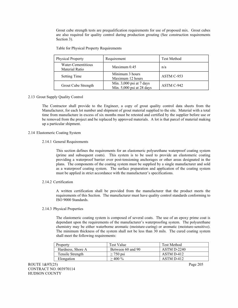
ROUTE 1&9T(25) Page 205 CONTRACT NO. 003970114 HUDSON COUNTY
Grout cube strength tests are prequalification requirements for use of proposed mix. Grout cubes are also required for quality control during production grouting (See construction requirements Section 3). Table for Physical Property Requirements
Physical Property Requirement Test Method
Water-Cementitious Material Ratio Maximum 0.45 n/a
Setting Time Minimum 3 hours Maximum 12 hours ASTM C-953
Grout Cube Strength Min. 3,000 psi at 7 days Min. 5,000 psi at 28 days ASTM C-942
2.13 Grout Supply Quality Control
The Contractor shall provide to the Engineer, a copy of grout quality control data sheets from the Manufacturer, for each lot number and shipment of grout material supplied to the site. Material with a total time from manufacture in excess of six months must be retested and certified by the supplier before use or be removed from the project and be replaced by approved materials. A lot is that parcel of material making up a particular shipment.
2.14 Elastomeric Coating System
2.14.1 General Requirements This section defines the requirements for an elastomeric polyurethane waterproof coating system (prime and subsequent coats). This system is to be used to provide an elastomeric coating providing a waterproof barrier over post-tensioning anchorages or other areas designated in the plans. The components of the coating system must be supplied by a single manufacturer and sold as a waterproof coating system. The surface preparation and application of the coating system must be applied in strict accordance with the manufacturer’s specifications.
2.14.2 Certification
A written certification shall be provided from the manufacturer that the product meets the requirements of this Section. The manufacturer must have quality control standards conforming to ISO 9000 Standards.
2.14.3 Physical Properties
The elastomeric coating system is composed of several coats. The use of an epoxy prime coat is dependant upon the requirements of the manufacturer’s waterproofing system. The polyurethane chemistry may be either waterborne aromatic (moisture-curing) or aromatic (moisture-sensitive). The minimum thickness of the system shall not be less than 30 mils. The cured coating system shall meet the following requirements:
Property Test Value Test Method Hardness, Shore A Between 60 and 90 ASTM D-2240 Tensile Strength > 750 psi ASTM D-412 Elongation > 400 % ASTM D-412

ROUTE 1&9T(25) Page 206 CONTRACT NO. 003970114 HUDSON COUNTY
Tear Strength > 70 psi ASTM C-957 Abrasion Resistance H-18 wheels 1000 gm/wheel < 350 mg loss / 1000 revs. ASTM C-957
Crack Bridging 1000 Cycles System Passes ASTM C-957 Elongation Recovery > 94% ASTM C-957
2.14.4 System Modifications for Use on Bridge Substructure
Supply the elastomeric coating system with an aliphatic polyurethane top coating. When applied to bridge substructures, match the color to the color scheme shown in the plans. If no color scheme is shown on the plans utilize a color similar to Federal Color Standard No. 595B, Table VIII, and Shade No. 36622.
2.15 Payment for Testing
All testing of components, materials and all laboratory and field tests required for this project shall be incidental to the price paid for post-tensioning.
527.03 Construction Requirements 3.1 Protection of Prestressing Steel 3.1.1 Before Installation of Tendons in Ducts
All prestressing steel shall be protected against physical damage at all times from manufacture to grouting or encasing in concrete. Prestressing steel that has sustained physical damage at any time shall be rejected. Any reel that is found to contain broken wires shall be rejected and the reel replaced. The wire must be bright and uniformly colored, having no foreign matter or pitting on its surface. Prestressing steel shall be packaged in containers for protection of the steel against physical damage and corrosion during shipping and storage. A corrosion inhibitor, which prevents rust or other results of corrosion, shall be placed in the package or form, or shall be incorporated in a corrosion inhibitor carrier type packaging material. The corrosion inhibitor shall have no deleterious effect on the steel or concrete or bond strength of steel to concrete. Inhibitor carrier type packaging material shall conform to the provisions of Federal Specifications MIL-P-3420. Packaging or forms damaged from any cause shall be immediately replaced or restored to original condition. The prestressing steel shall be stored in a manner which will at all times prevent the packing material from becoming saturated with water and allow a free flow of air around the packages. If the useful life of the corrosion inhibitor in the package expires, it shall immediately be rejuvenated or replaced. At the time the prestressing steel is installed in the work, it shall be free from loose rust, loose mill scale, dirt, paint, oil, grease or other deleterious material. Removal of tightly adhering rust or mill scale will not be required. Prestressing steel that has experienced rusting to the extent it exhibits pits visible to the naked eye shall not be used in the work.
The shipping package shall be clearly marked with the heat number and with a statement that the package contains high-strength prestressing steel and care is to be used in handling, and the type, kind and amount of corrosion inhibitor used, including the date when placed, safety orders and

ROUTE 1&9T(25) Page 207 CONTRACT NO. 003970114 HUDSON COUNTY
instructions for use shall also be marked on the package or form. Specifically designate low relaxation (stabilized) strands per requirements of ASTM A-416. Strands not so designated will be rejected.
3.1.2 After Installation of Tendons in Ducts
After installation in the ducts, prestressing steel shall be protected from corrosion and the duct system shall be sealed to prevent moisture intrusion from the time of tendon installation to the time of grouting. In addition, all grout vents shall be closed or plugged at all times during the period prior to grouting except that low-point drainage vents shall remain open and point downward. (See Section 3.2.5 for protection of ducts prior to installing tendons.) Grouting shall proceed as soon as possible after installation and stressing of the tendons. The time from installing the tendons in an unstressed condition to grouting after stressing shall not exceed the following without approval of the Engineer:
Very damp atmosphere (RH > 70%) or over salt water - 7 calendar days Moderate to dry atmosphere (RH < 70%) - 10 calendar days
In this context, the “RH” is the average annual relative humidity for the site. For this project, the maximum time shall be 7 calendar days. Any light surface discoloration or corrosion forming during this period shall not be cause for rejection of the prestressing steel. Flushing of grout is not permitted and vacuum grouting is required to repair all voids and blockages. Flushing of ducts is only permitted if a lubricant is required to reduce the friction or if a corrosion inhibitor is used due to temperatures below the minimum specified. When flushing is permitted by the Engineer, use flush water containing slack lime (calcium hydroxide) or quicklime (calcium oxide) in the amount of 0.17 lb/gal. Except when waived by the Engineer in writing, failure to grout tendons within the time limit specified above will result in stoppage of the affected work in accordance with direction provided by the Engineer.
3.1.3 Tendon Protection between Installation and Stressing
Measures shall be taken to protect the prestressing steel when there is a period of more than 24 hours between installation of the tendons in ducts and stressing. Bare strand projecting out of an anchorage shall be wrapped in continuous plastic sheeting and sealed using waterproof tape extending from the tendon anchorage, and the anchorage opening shall be sealed with plastic and waterproof tape in a sufficient manner to prevent moisture intrusion. All grout vents shall be closed or plugged, all duct connections shall be sealed and drainage vents shall be open, pointing downward.
3.1.4 Use of Temporary Corrosion Inhibitors
It is the intent of the Specifications that the tendons be grouted within the time limit specified above. Corrosion inhibitors shall be considered when grouting cannot be accomplished due to temperatures below the specified minimum. Corrosion inhibitors shall be VPCI or NJDOT approved alternatives. The prestressing steel shall be so protected until grouted.

ROUTE 1&9T(25) Page 208 CONTRACT NO. 003970114 HUDSON COUNTY
3.1.5 Extended Periods for Ungrouted Tendons Ungrouted tendons for extended periods will be permitted given strict compliance with the following specifications.
Allowance for increase in time between stressing and grouting of tendons will only be allowed for post-tensioning which cannot be grouted within the lower temperature limits set forth in this specification, and with the approval of the Engineer. The Contractor shall take every effort to minimize the length of time and number of ungrouted post-tensioning tendons or bars during winter months. Grouting of ungrouted post-tensioning shall take top priority when temperature limits allow grouting operations to continue.
For anchorages where a permanent grout cap is not specified, a rigid temporary cap capable of
providing a seal against moisture intrusion for the duration of time the post-tensioning is ungrouted shall be used. This cap shall be placed within 48 hours of stressing. Permanent caps shall be used where applicable. All grout ports and vents shall remain plugged, sealed or otherwise capped, and all duct connections shall be sealed, except minimum number of low vent ports allowing full drainage from any condensation shall be left open. All open vent ports shall not be exposed to the weather for the full length of time the post-tensioning remains ungrouted.
Upon inspection, if ungrouted post-tensioning shows signs of corrosion (other than light surface rust with no pitting) the Contractor shall immediately take corrective measures. Corrective measures may include, but are not necessarily limited to, re-establishing moisture tight seals, alternate corrosion protection, external heating and grouting, tendon replacement and restressing.
Details for protecting ungrouted post-tensioning through extended periods and the procedures for
expedient grouting of the ungrouted post-tensioning shall be submitted as a part of the Grouting Operation Plan submittal outlined below.
3.2 Installation of Ducts, Grout Injection Ports and Outlet Vents
3.2.1 General
All post-tensioning anchorages, ducts, inlet and outlet pipes, miscellaneous hardware, reinforcing bars, and other embedded items shall be accurately and securely fastened at locations shown on the plans or on the approved Shop Drawings or as otherwise approved by the Engineer. Ducts for tendons shall be made using the minimum number of duct splices possible.
3.2.2 Tolerances
In their final position post-tensioning ducts shall be within the following tolerances:
Table of Duct Position Tolerances
Tolerances Vertical position Inches
Lateral position Inches
Vertical tendons in pier shafts ±1/2 ±1/4

ROUTE 1&9T(25) Page 209 CONTRACT NO. 003970114 HUDSON COUNTY
If conflicts exist between the reinforcement and post-tensioning duct, the position of the post-tensioning duct shall prevail and the reinforcement shall be adjusted locally with the Engineer’s approval.
3.2.3 Ducts
Ducts shall be accurately aligned and located as shown on the plans or according to the approved Shop Drawings and as required herein. All internal ducts shall be secured in position at regular intervals not exceeding 30 inches for steel pipes, 24 inches for round plastic duct and 12 inches for flat ducts to prevent movement, displacement or damage from concrete placement and consolidation operations. The method and spacing of duct supports shall be shown on appropriate Shop Drawings. Any additional mild reinforcing or other devices required to support post-tensioning ducts shall be supplied by the Contractor at no additional expense to the Owner. All duct alignments, including curves and straight portions, shall be smooth and continuous with no lips, kinks or dents. This also applies to curves in pre-bent steel pipe. All ducts shall be carefully checked and repaired as necessary before placing any concrete. After installation of ducts, until grouting is complete, all ends of ducts, connections to anchorages, splices, vents (inlets and outlets) shall remain sealed at all times. An absolute seal shall be provided of anchorage and duct termination locations by using plumber’s plugs or equal. Grout vents (inlets and outlets) shall be installed with plugs or valves in the closed position. Low point drainage outlets shall be left open. The use of duct tape shall not be permitted. Ducts shall be carefully inspected and repaired before placing of the concrete is started. Care shall be exercised during placement of the concrete to avoid displacing or damaging the ducts. All splices, joints, couplings, vent connections (inlets and outlets) and valves shall be part of the approved post-tensioning system. Approved shrink-sleeve material may be used to repair duct. The use of duct tape to repair or seal duct shall not be permitted.
3.2.4 Grout Vents (Inlets and Outlets) and Drains
Grout pipes shall be installed on each duct to serve as injection or evacuation vents during grouting and to allow the escape of air, water, grout and bleed water. Drainage vents, point downward, shall be provided at low points of tendon profile to allow any accumulated moisture to be drained prior to installing tendons.
The length of an inlet or outlet shall be sufficient to extend out of the concrete to allow for proper closing. At all high points the outlet shall connect at the uppermost part of the duct profile.
Inlets and Outlets shall be placed at locations shown on the Contract Plans, on the Approved Shop Drawings, and/or the approved Grouting Operation Plan (below). Locations shall be as follows: 1. At the top of each tendon anchorage 2. At top of each grout cap. 3. At each high point of the duct profile when the vertical distance between the highest and
lowest point is more than 20 inches. 4. At a location between 3 feet and 6 feet past high points of the duct on the down stream
side opposite the direction of grouting. 5. At all low points. The vent (outlet) shall be free draining. 6. At major changes in the cross section of the duct. 7. At each side of PT bar-couplers.
ROUTE 1&9T(25) Page 210 CONTRACT NO. 003970114 HUDSON COUNTY
8. At a distance between 3 feet and 6 feet from each high point in the direction of grout flow.
9. At other locations required by the Engineer.
Grout pipes shall extend a sufficient distance out of the concrete member to allow for proper closing of valves.
Vents shall be mortar tight and shall provide means for injection of grout through the vents and for sealing the vents.
All inlet and outlets shall be permanently sealed to prevent water infiltration to the grouted tendon. Sealing details are to be submitted for approval to the Engineer.
All grout injection and vent pipes shall be fitted with positive mechanical shut-off valves. Vents and injection pipes shall be fitted with valves, caps or other devices capable of withstanding the pumping pressures.
3.2.5 Care and Protection of Ducts, Vents, Anchorages and Block outs
Care shall be taken to ensure that all ducts, anchorages, block outs, openings and vents are kept clean and free of debris, fuel, oils, other contaminants and site trash at all times prior to and after installing the tendons. Temporary plugs, seals and covers shall be used. Minor damage to ducts may be repaired by removing the local damage and splicing duct or couplers onto the intact section (prior to the placing of concrete). Repair of major duct damage requires the removal and replacement of the entire duct section.
Connections from grout hose to inlet and ejection ports and to vents shall be kept free from dirt and are airtight.
3.2.6 Placing Concrete
Methods used to place and consolidate concrete shall not displace or damage any of the post-tensioning ducts, anchorage assemblies, splices and connections, reinforcement or other embedded items. Duct splices shall be made so as to prevent duct kinks during concrete placement. Suitable mandrels shall be used as needed to maintain duct alignment and shape.
3.2.7 Problems and Remedies:
The Engineer will reject ducts or any part of the work found to be deficient. No remedial or repair work shall be performed without the Engineer’s approval.
3.2.8 Installing Tendons
If a tendon duct has been contaminated with chlorides, it shall be thoroughly flushed before placing the prestressing strands using lime treated potable water. The last two gallons of flushing water shall be tested for presence of chlorides and oils. Chlorides in the water must be less than 600 ppm. If chloride levels exceed 600 ppm, flushing shall continue until the chloride level is below 250 ppm. Oil-free compressed air shall then be blown through the duct to remove any excess water.
3.3 Post-Tensioning Operations

ROUTE 1&9T(25) Page 211 CONTRACT NO. 003970114 HUDSON COUNTY
3.3.1. General
3.3.1.1 Concrete Strength
Post-tensioning shall only be applied when the concrete has attained the required compressive strength as determined from test cylinders cured under the same conditions as the structural concrete.
3.3.1.2 Stressing Tendons
All post-tensioning steel shall be tensioned with hydraulic jacks so that the post-tensioning force is not less than that required by the plans or approved shop drawings, or as otherwise approved by the Engineer.
3.3.1.3 Maximum Stress at Jacking
The maximum temporary stress (jacking stress) in post-tensioning steel shall not exceed 80% of the specific minimum ultimate tensile strength. Tendons shall not be overstressed to achieve elongation.
3.3.1.4 Initial and Permanent Stress
The post-tensioning steel must be anchored at initial stresses that will result in the long term retention of permanent stresses or forces of no less than those shown on the plans or the approved shop drawings. Unless otherwise approved by the Engineer, the initial stress after anchor set must not exceed 70% of the specified ultimate tensile strength of the post-tensioning steel.
Permanent stress and permanent force are the stress and force remaining in the post-tensioning steel after all losses, including long term creep and shrinkage of concrete, elastic shortening of concrete, relaxation of steel, losses in the post-tensioning steel from the sequence of stressing, friction and unintentional wobble of the ducts, anchor set, friction in the anchorages and all other losses peculiar to the post-tensioning system
3.3.1.5 Stressing Sequence
Stressing sequence in accordance with the plans or approved shop drawings or as otherwise approved by the Engineer.
3.3.2 Stressing Jacks
3.3.2.1 Stressing Equipment
Each jack shall be equipped with a pressure gauge having an accurate reading dial at least six inches in diameter for determining the jack pressure.
3.3.2.2 Calibration
Prior to use for stressing on the project, each jack and its gauge shall be calibrated as a unit. Initial jack calibration shall be done, using a proven load cell, by the post-tensioning supplier or by an independent testing laboratory, approved by the Engineer.
ROUTE 1&9T(25) Page 212 CONTRACT NO. 003970114 HUDSON COUNTY
The calibration shall consist of three test cycles with the cylinder extension of the jack in various positions (i.e. 2 inch, 4 inch, 8 inch stroke). At each pressure increment, the forces from each test cycle shall be averaged to obtain an average force. Calibration shall be done with the cylinder extension approximately in the position that it will be when applying the final jacking force and with the jacking assembly in an identical configuration to that which will be used at the job site (i.e. same length hydraulic lines). Load cells used for calibration shall have been calibrated within the last 12 months. Certified calibration calculations and a calibration chart, both in English units of measure, shall be furnished to the Engineer for each jack and gauge unit. Documentation denoting the load cell(s) calibration date and tractability to NIST (National Institute of Standards and Technology) along with the jack/gauge calibration shall be provided.
Recalibration of each jack shall be done at six month intervals and at other times when requested by the Engineer. At the option of the Contractor, calibrations subsequent to the initial laboratory calibration may be accomplished by the use of a master gauge. The master gauge shall be calibrated at the same time as the initial calibration of the jacks, and shall be part of the unit for each jack. The data recorded during the initial calibrations shall be furnished to the Engineer for use in the field. The master gauge shall be supplied by the Contractor in a protective waterproof container capable of protecting the calibration of the master gauge during shipment. The contractor shall provide a quick-attach coupler next to the permanent gauge in the hydraulic lines which enables the quick and easy installation of the master gauge to verify the permanent gauge readings. The master gauge shall remain in the possession of the Engineer for the duration of the project. If a jack is repaired or modified, including replacing the seals or changing the length of the hydraulic lines, the jack shall be recalibrated by the approved testing laboratory. No extra compensation will be allowed for the initial or subsequent jack calibrations or for the use and required calibration of a master gauge.
3.3.3 Stressing of Tendons
The tensioning process shall be so conducted that tension being applied and the elongation of the post-tensioning steel may be measured at all times. A permanent record shall be kept of gauge pressures and elongations at all times and shall be submitted to the Engineer. The post-tensioning force may be verified as deemed necessary by the Engineer.
The anchor force for all permanent post-tensioning bars with lengths less than 20 feet shall be verified with a lift-off after initial stressing operations. The resulting lift-off shall be within ±7% of the expected final anchor force as specified in the plans.
3.3.4 Friction
The Contract Plans were prepared based on the assumed friction and wobble coefficients and anchor set noted on the plans. Calculations shall be submitted to show a typical tendon force diagram, after friction, wobble and anchor set losses, on the shop drawings based upon the expected actual coefficients and values for the post-tensioning system used. These coefficients and values shall be shown on the shop drawings.
If, in the opinion of the Engineer, the actual friction significantly varies from the expected friction, revise post-tensioning operations so the final tendon force is in agreement with the plans.

ROUTE 1&9T(25) Page 213 CONTRACT NO. 003970114 HUDSON COUNTY
When friction must be reduced, graphite with no corrosive agents may be used as a lubricant subject to the approval of the Engineer. Lubricants shall be flushed from the duct as soon as possible after stressing is completed by use of lime treated potable water. After ducts have been flushed, they shall be immediately and thoroughly blown dry with oil-free air.
3.3.5 Cutting of Post-Tensioning Steel
Post-tensioning steel shall be cut by an abrasive saw or an approved plasma-cutter within 3/4 to 1-1/2 inches away from the anchoring device. Flame cutting of prestressing steel is not allowed.
3.3.6 Record of Stressing Operations
The Contractor shall keep a record of the following post-tensioning operations for each tendon installed:
1. Project name, Financial Project ID. 2. Contractor and/or subcontractor. 3. Tendon location, size and type. 4. Date tendon was first installed in ducts. 5. Reel number for strands and heat number for bars. 6. Tendon cross-sectional area. 7. Modulus of elasticity. 8. Date stressed. 9. Jack and Gauge numbers per end of tendon. 10. Required jacking force. 11. Gauge pressures. 12. Elongations (theoretical and actual). 13. Anchor sets (anticipated and actual); 14. Stressing sequence (i.e. tendons to be stressed before and after). 15. Stressing mode (one end/ two ends/ simultaneous). 16. Witnesses to stressing operation (Contractor and inspector).
17. Date grouted.
Any other relevant information shall be recorded. A complete copy of all stressing and grouting operations shall be provided to the Engineer.
3.3.7 Duct Pressure Field Test
After stressing and before grouting tendons, all grout caps, inlets and outlets shall be installed and the tendon tested with compressed air to determine if duct connections require repair. In the presence of the Engineer, pressurize the tendon to 50 psi and lock-off the outside air source. Record the pressure loss for one minute. A pressure loss of 25 psi will be acceptable. If the pressure loss exceeds 25 psi, leaking connections shall be corrected using methods approved by the Engineer and retested.
3.3.8. Cleaning and Flushing Tendons Tendons shall not be flushed with water except as directed by the Engineer. If flushing is to be performed as directed by the Engineer, the inside of the duct system shall be flushed with water (under pressure) meeting the requirements of Section 3.2.10 to remove all traces of the contaminants. Following the flushing operation, water shall be totally drained from within the duct system and it shall be blown out with compressed oil-free air to the extent

ROUTE 1&9T(25) Page 214 CONTRACT NO. 003970114 HUDSON COUNTY
necessary to dry the prestressing steel and inside surfaces of the ducts. The waste fluid flushed from the duct system shall be captured and disposed of properly.
3.3.9 Tendon Protection
Within four hours after stressing, install grout caps and seal all other tendon openings. If acceptance of the tendon is delayed, all tendon openings and open ends of the anchorages shall be temporarily sealed. If tendon contamination occurs, the tendon shall be removed and replaced.
3.4 Grouting
3.4.1 General
After post-tensioning and anchoring of a tendon has been completed and accepted, the annular space between the prestressing steel and the duct shall be grouted in accordance with this Specification. Also grout all empty ducts. The interval between post-tensioning and grouting shall be limited as specified above. Immediately after post-tensioning, all grout vents, anchorages, and duct connections of each tendon shall be temporarily sealed to prevent entrance of air and water until just prior to tendon grouting. At least six weeks before grouting commences, the Contractor shall submit to the Engineer for review and approval a "Grouting Operation Plan". Written approval of the plan by the Engineer is required before grouting proceeds. Any adjustments to the plan as a result of trials or mock-ups shall be incorporated. Grouting operations shall be under the supervision of a qualified and experienced person, acceptable to the Engineer.
At a minimum the Grouting Operation Plan shall address the following: 1. Names and proof of training for the grouting crew and the crew supervisor in
conformance with this specification. 2. Type, quantity, and brand of materials used in grouting including all certifications
required. 3. Type of equipment furnished, including capacity in relation to demand and working
condition, as well as back-up equipment and spare parts. 4. General grouting procedure. 5. Duct pressure test and repair procedures. 6. Method to be used to control the rate of flow within ducts. 7. Theoretical grout volume calculations. 8. Mixing and pumping procedures. 9. Direction of grouting. 10. Sequence of use of the inlets and outlet pipes. 11. Procedures for handling blockages. 12. Procedures for possible post grouting repair. 13. Contractor's QC forms that are to be signed daily by Grout Supervisor.
Before grouting operations commence, a joint meeting shall be held with the Contractor, Grouting Crew, Owner, and Engineering Inspection Team to discuss and understand the grouting operation plan, required testing and corrective procedures.
3.4.2 Grouting Personnel Qualifications
All grouting operations shall be carried out by workers trained for the tasks required. Grouting shall be performed under the immediate control of a person skilled in the various aspects of

ROUTE 1&9T(25) Page 215 CONTRACT NO. 003970114 HUDSON COUNTY
grouting, and having experience on at least four previous and satisfactorily completed projects of a similar size and scope. This person shall be named and shall furnish proof of experience as required by the Engineer. Grouting Supervisors must have ASBI Grouting Certification and/or previous experience on satisfactorily completed projects of a similar size and scope.
3.4.3 Supplies
Before grouting operations start, an adequate supply of water and compressed air for clearing and testing the ducts, mixing and pumping the grout shall be provided. Where water is not supplied through the public water supply system, a water storage tank of sufficient capacity must be provided. A sufficient supply of grout material shall be available to complete the planned grouting operation.
3.4.4 Equipment
3.4.4.1 General
Grouting equipment shall consist of measuring devices for water, a high-speed shear colloidal mixer, a storage hopper (holding reservoir) and a pump with all the necessary connecting hoses, valves, and pressure gauge. Pumping equipment shall have sufficient capacity to ensure that the post-tensioning ducts to be grouted can be filled and vented without interruption at the required rate of injection in not more than 30 minutes.
An air compressor and hoses with sufficient output to perform the required functions shall be provided. Vacuum grouting equipment (volumetric measuring type) shall be provided prior to the start of grouting operations and retained on the job during the duration of tendon grouting operations.
3.4.4.2 Mixer, Storage Hopper
A high speed shear colloidal mixer shall be provided capable of continuous mechanical mixing to produce a homogeneous and stable grout free of lumps and undispersed cement. The colloidal grout machinery will have a charging tank for blending and a holding tank. The blending tank must be equipped with a high shear colloidal mixer. The holding tank must be kept agitated and at least partially full at all times during the pumping operation to prevent air from being drawn into the post-tensioning duct.
Water shall be added during the initial mixing by use of a flow meter or calibrated water reservoir with a measuring accuracy equal to one percent of the total water volume.
3.4.4.3 Grout Pumping Equipment
Grout pumping equipment capable of continuous operation shall be provided which will include a system for circulating the grout when actual grouting is not in progress.
The equipment will be capable of maintaining pressure on completely grouted ducts and will be fitted with a valve that can be closed off without loss of pressure in the duct.

ROUTE 1&9T(25) Page 216 CONTRACT NO. 003970114 HUDSON COUNTY
Grout pumps will be positive displacement type and will provide a continuous flow of grout and will be able to maintain a discharge pressure of at least 145 psi. Pumps will have seals adequate to prevent oil, air or other foreign substances entering the grout and to prevent loss of grout or water. The capacity will be such that an optimal rate of grouting can be achieved. A pressure gauge having a full scale reading of no more than 300 psi will be placed at the duct inlet. If long hoses (in excess of 100 feet) are used, two gauges shall be provided, one at the pump and one at the inlet. The diameter and rated pressure capacity of the grout hoses must be compatible with the pump output.
3.4.4.4 Vacuum Grouting Equipment
Vacuum grouting equipment shall be provided at the job site concurrently with all pressure grouting operations, consisting of the following: 1. Volumeter for the measurement of void volume. 2. Vacuum pump with a minimum capacity of 10 cfm and equipped with a flow-
meter capable of measuring amount of grout being injected. 3. Manual colloidal mixers and/or dissolvers (manual high speed shear mixers), for
voids less than 20 liters in volume. 4. Standard colloidal mixers, for voids 20 liters and greater in volume.
3.4.4.5 Availability of Testing Equipment
Equipment for field-testing shall be available at the job site. 3.4.4.6 Stand-by Equipment
During grouting operations, a stand-by grout mixer and pump shall be provided.
3.4.5 Grouting Operations
3.4.5.1 General
Tendons shall be grouted in accordance with the procedures set forth in the approved grouting operation plan. All empty ducts shall also be grouted.
3.4.5.2 Temperature Considerations
The maximum grout temperature must not exceed 90°F at the grout inlet. Chilled water and/or pre-cooling of the bagged material to maintain mixed grout temperature below the maximum allowed temperature shall be used. Grouting operations shall be prohibited when the temperature of the grout is below 45°F. Grouting operations shall be prohibited when the ambient temperature is below 40°F or is 40°F and falling. When it is anticipated that the ambient temperature will fall below 32°F, ducts shall be kept free of water so as to avoid freeze damage to ducts.
3.4.5.3 Mixing and Pumping
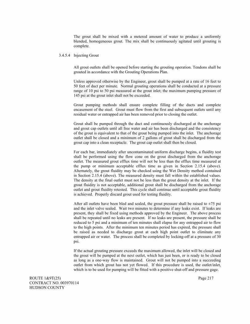
ROUTE 1&9T(25) Page 217 CONTRACT NO. 003970114 HUDSON COUNTY
The grout shall be mixed with a metered amount of water to produce a uniformly blended, homogeneous grout. The mix shall be continuously agitated until grouting is complete.
3.4.5.4 Injecting Grout
All grout outlets shall be opened before starting the grouting operation. Tendons shall be grouted in accordance with the Grouting Operations Plan. Unless approved otherwise by the Engineer, grout shall be pumped at a rate of 16 feet to 50 feet of duct per minute. Normal grouting operations shall be conducted at a pressure range of 10 psi to 50 psi measured at the grout inlet; the maximum pumping pressure of 145 psi at the grout inlet shall not be exceeded.
Grout pumping methods shall ensure complete filling of the ducts and complete encasement of the steel. Grout must flow from the first and subsequent outlets until any residual water or entrapped air has been removed prior to closing the outlet. Grout shall be pumped through the duct and continuously discharged at the anchorage and grout cap outlets until all free water and air has been discharged and the consistency of the grout is equivalent to that of the grout being pumped into the inlet. The anchorage outlet shall be closed and a minimum of 2 gallons of grout shall be discharged from the grout cap into a clean receptacle. The grout cap outlet shall then be closed. For each bar, immediately after uncontaminated uniform discharge begins, a fluidity test shall be performed using the flow cone on the grout discharged from the anchorage outlet. The measured grout efflux time will not be less than the efflux time measured at the pump or minimum acceptable efflux time as given in Section 2.15.4 (above). Alternately, the grout fluidity may be checked using the Wet Density method contained in Section 2.15.4 (above). The measured density must fall within the established values. The density at the final outlet must not be less than the grout density at the inlet. If the grout fluidity is not acceptable, additional grout shall be discharged from the anchorage outlet and grout fluidity retested. This cycle shall continue until acceptable grout fluidity is achieved. Properly discard grout used for testing fluidity. After all outlets have been bled and sealed, the grout pressure shall be raised to ±75 psi and the inlet valve sealed. Wait two minutes to determine if any leaks exist. If leaks are present, they shall be fixed using methods approved by the Engineer. The above process shall be repeated until no leaks are present. If no leaks are present, the pressure shall be reduced to 5 psi and a minimum of ten minutes shall elapse for any entrapped air to flow to the high points. After the minimum ten minutes period has expired, the pressure shall be raised as needed to discharge grout at each high point outlet to eliminate any entrapped air or water. The process shall be completed by locking-off at a pressure of 30 psi. If the actual grouting pressure exceeds the maximum allowed, the inlet will be closed and the grout will be pumped at the next outlet, which has just been, or is ready to be closed as long as a one-way flow is maintained. Grout will not be pumped into a succeeding outlet from which grout has not yet flowed. If this procedure is used, the outlet/inlet, which is to be used for pumping will be fitted with a positive shut-off and pressure gage.

ROUTE 1&9T(25) Page 218 CONTRACT NO. 003970114 HUDSON COUNTY
When complete grouting of the tendon cannot be achieved by the steps stated herein, the grouting operation shall stop. After waiting 48 hours, the tendon shall be filled with grout in accordance with the procedure outlined in Section 3.4.9.
All waste grout and liquids shall be captured and disposed of properly.
3.4.6 Vertical Grouting
All vertical bars as the prestressing steel shall be fitted with a standpipe at the upper end of the tendon to store bleed water and grout and maintain the grout level above the level of the post-tensioning plate and anchorage. The standpipe will be designed and sized to maintain the level of the grout at an elevation which will assure that bleeding will at no time cause the level of the grout to drop below the highest point of the upper anchorage device. The standpipe shall be designed to allow all bleed water to rise into the standpipe, not into the uppermost part of the tendon and anchorage device.
After the grout is discharged, check the grout fluidity as described in Section 3.4.6. As
grouting is completed, the standpipe shall be filled with grout to a level, which will assure that, as settlement of grout occurs, the level of grout will not drop below the highest point in the upper anchorage device. If the level of grout drops below the level of the highest point in the anchorage device, additional grout shall immediately be added to the standpipe. After the bleed water is absorbed and the grout has hardened, the standpipe shall be removed. In the presence of the Engineer, visually inspect for voids using an endoscope or probe. All voids found in the duct shall be filled using volumetric measuring vacuum grouting processes.
3.4.7 Construction Traffic and Operations Causing Vibrations
During grouting and for a period of 4 hours upon completion of grouting, eliminate vibrations from all sources such as moving vehicles, jackhammers, compressors, generators, pile driving operations, soil compaction, etc., that are operating within 300 feet down-station and 300 feet up-station of the ends of the span in which grouting is taking place.
3.4.8 Post-Grouting Inspection
Grout vents (inlets and outlets) shall not be opened or removed until the grout has cured for 24 to 48 hours. Inspections shall be performed within one hour after the removal of the inlet/outlet. After the grout has cured, all outlets located at anchorages and high points along the tendon shall be opened to facilitate inspection. All high points along the tendon as well as inlets or outlets located at the anchorages shall be drilled and inspected. Depending on the geometry of the grout inlets, drilling may be required to penetrate to the inner surface of the trumpet or duct. Drilling equipment shall automatically shut-off when steel is encountered. Unless grout caps are determined to have voids by sounding, caps shall not be drilled. Inspection of grout shall be

ROUTE 1&9T(25) Page 219 CONTRACT NO. 003970114 HUDSON COUNTY
performed in the presence of the Engineer using endoscopes or probes. Within four hours of completion of the inspections, all voids shall be filled using the vacuum injection grouting process. All anchorage and inlet/outlet voids that are produced by drilling for inspection purposes shall be sealed and repaired as specified in Section 3.4.10. The inlet/outlet shall be removed to a minimum depth of 2 inches. An injection tube extending to the bottom of the drilled holes shall be used for backfilling with epoxy. Post grouting inspection of tendons having a length of less than 150 feet shall be based on the following statistical frequency for inspection: 1. For one bar per pier, outlet located at anchors and tendon high points shall be inspected
by drilling and probing with an endoscope or probe. 2. When no defects are detected as defined in No. 1 above, no further inspection is
required. If tendon grouting operations were prematurely terminated prior to completely filling the tendon, then the duct shall be drilled into and voided areas explored with an endoscope. Probing shall not be allowed. The location and extent of all voided areas shall be determined. Grout inlets shall be installed as needed and the voids filled using volumetric measuring vacuum grouting equipment.
3.4.9 Post-Grouting Sealing of Grout Vents
Shut off valves shall not be opened at injection or evacuation vent pipes, nor shall pipes or caps be removed until the grout has set and inspection of vents has been accepted.
Intermediate grout vent pipes (inlets and outlets) along an internal tendon (including rigid steel pipes in diaphragms) shall be installed straight to facilitate possible drilling and inspection for complete grout filling using, if necessary, an endoscope. Place threaded plastic caps in all inlet/outlet locations required in the plans. The inlet/outlet locations shall be repaired as shown on the plans using an approved Type F-1 epoxy compound meeting the requirements of Material Section above. The surface to receive the epoxy material shall be prepared in strict compliance with the manufacturer’s recommendations.
3.4.10 Record of Grouting Operations
The Contractor shall keep a record of all grouting operations for each tendon installed, stressed and grouted. This shall include, but shall not necessarily be limited to the following: 1. Tendon or group of tendons grouted in one continuous operation. 2. Date grouted. 3. Number of days from stressing to grouting, per tendon. 4. Type of grout mix and additives. 5. Fluidity of grout (flow-cone) per batch for both newly mixed and 30 minute, rested grout. 6. Density of grout per batch of fresh mix. 7. Location of injection vent and direction of grout flow (note; injection vent may not
necessarily be at an end anchorage). 8. Applied grouting pressure during normal pumping and maximum pressure sustained for
two minutes after closing all vents grouting.

ROUTE 1&9T(25) Page 220 CONTRACT NO. 003970114 HUDSON COUNTY
9. Theoretical volume of grout anticipated in order to fill the duct or ducts. 10. Actual quantity of grout in place in the duct(s) after grouting (for one grout mixing and
injection operation, this is the quantity mixed less the quantity wasted at the vents, less the quantity remaining in the mixer and injection equipment).
11. Summarize any difficulties encountered and corrective action taken. 12. Witnesses to grouting operation (Contractor and Inspector). Within 72 hours, the Contractor shall provide the Engineer with a complete copy of all tendon stressing and grouting operations.
3.5. Protection of Post-Tensioning Anchorages
After acceptance of grouting, all miscellaneous material (tie wire, tape, plastic, etc.) used for temporary protection or sealing shall be removed prior to carrying out further work to protect anchorages. Details for anchor protection shall be shown on the Shop Drawings in accordance with the plans and the following requirements.
3.5.1 Installation of Anchor Protection
Anchorage protection shall be installed within seven days from the satisfactory completion of the grouting. The application of the elastomeric coating may be delayed for up to 90 days after grouting. Use plastic or stainless steel threaded caps to plug all grout inlets/outlets.
3.5.1.1 Elastomeric Coating
Exposed grout caps shall be coated with an approved elastomeric coating system meeting the requirements of the Material Section above. The coating thickness shall be 30 to 45 mils. The application of the elastomeric coating may be delayed up to 90 days after grouting; however, surface cleaning shall be performed immediately prior to application with sufficient time to allow for drying. Elastomeric coating shall have a final, cured color to the approval of the Engineer. Grout caps or other substrates shall be structurally sound, clean and dry. Concrete must be a minimum of 28 days old. All laitance, grease, curing compounds, surface treatments, coatings and oils shall be removed by grit blasting or water blasting using a minimum 10,000 psi nozzle pressure to establish the anchor pattern. Blow the surface with compressed air to remove the dust or water. For elastomeric coated pour-backs which are to receive an approved cosmetic or aesthetic coating, apply a manufacture’s approve primer over the elastomeric coating before applying the approved cosmetic or aesthetic coating. A concrete test block 2 x 4 feet with a similar surface texture to the surfaces to be coated shall be constructed. A vertical face shall be coated with the elastomeric coating system chosen. The number of coats required for a finished coating thickness of 30 to 45 mils without runs and drips shall be determined. The elastomeric coating shall be mixed and applied per manufacturer’s current standard technical specifications. Spray or roller application is permitted (spray application preferred). Have the coating manufacturer representative on site to supervise and comment on the application of the elastomeric coating onto the test block. Coatings shall be applied by personnel with a minimum of
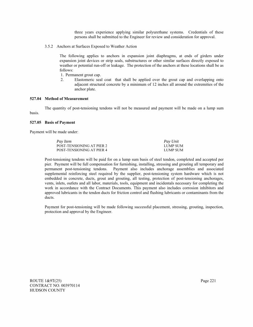
ROUTE 1&9T(25) Page 221 CONTRACT NO. 003970114 HUDSON COUNTY
three years experience applying similar polyurethane systems. Credentials of these persons shall be submitted to the Engineer for review and consideration for approval.
3.5.2 Anchors at Surfaces Exposed to Weather Action
The following applies to anchors in expansion joint diaphragms, at ends of girders under expansion joint devices or strip seals, substructures or other similar surfaces directly exposed to weather or potential run-off or leakage. The protection of the anchors at these locations shall be as follows: 1. Permanent grout cap. 2. Elastomeric seal coat that shall be applied over the grout cap and overlapping onto
adjacent structural concrete by a minimum of 12 inches all around the extremities of the anchor plate.
527.04 Method of Measurement The quantity of post-tensioning tendons will not be measured and payment will be made on a lump sum basis. 527.05 Basis of Payment Payment will be made under: Pay Item Pay Unit
POST-TENSIONING AT PIER 2 LUMP SUM POST-TENSIONING AT PIER 4 LUMP SUM
Post-tensioning tendons will be paid for on a lump sum basis of steel tendon, completed and accepted per pier. Payment will be full compensation for furnishing, installing, stressing and grouting all temporary and permanent post-tensioning tendons. Payment also includes anchorage assemblies and associated supplemental reinforcing steel required by the supplier, post-tensioning system hardware which is not embedded in concrete, ducts, grout and grouting, all testing, protection of post-tensioning anchorages, vents, inlets, outlets and all labor, materials, tools, equipment and incidentals necessary for completing the work in accordance with the Contract Documents. This payment also includes corrosion inhibitors and approved lubricants in the tendon ducts for friction control and flushing lubricants or contaminants from the ducts. Payment for post-tensioning will be made following successful placement, stressing, grouting, inspection, protection and approval by the Engineer.

ROUTE 1&9T(25) Page 222 CONTRACT NO. 003970114 HUDSON COUNTY
DIVISION 600 - INCIDENTAL CONSTRUCTION
SECTION 602 - PIPES
602.01 Description. THE FOLLOWING IS ADDED: This work shall also consist of the installation of Ductile Iron Water Pipe, valves, appurtenances, construction of thrust blocking and/or saddles at bends, tees and any other fittings and disinfection of all newly installed water mains as shown on the Contract Drawings or as directed by the Engineer. This work shall also include installation of a steel casing at locations shown on the plans and as directed by the Engineer. 602.02 Materials.
THE ENTIRE SUBSECTION IS CHANGED TO:
Materials shall conform to the following Subsections: Ductile Iron Culvert Pipe.....................................................................................................................913.02 Concrete Pipe ......................................................................................................................................913.04 Corrugated Aluminum Alloy Culvert Pipe and Pipe Arches...............................................................913.05 Corrugated Steel Culvert Pipe and Pipe Arches ..................................................................................913.07 Corrugated Steel Sewer Pipe and Pipe Arches ....................................................................................913.08 High Density Polyethylene (HDPE) pipe ............................................................................................913.11 Mortar and Grout.................................................................................................................................914.03 Gaskets ................................................................................................................................................919.08
Portland cement concrete for pipe plugs, encasements, or saddles shall conform to Section 914. Where corrugated metal culvert pipe is designated, corrugated aluminum alloy culvert pipe or corrugated steel
culvert pipe may be used. Where corrugated metal culvert pipe arch is designated, corrugated aluminum alloy culvert pipe arch or
corrugated steel culvert pipe arch may be used. End sections shall be of the same material as the pipe or pipe arch to which the end sections are attached,
except that end sections for HDPE pipe for outfall systems shall be concrete. For jacked pipe, reinforced concrete culvert pipe shall conform to Subsection 913.04 except that the pipe shall
be Class V, Wall B, tongue and groove type. The tube material shall conform to the requirements of ASTM F 1216. The tube shall be fabricated to a size
that, when installed, conforms to the internal circumference and length of the original pipe. The wall color of the interior tube surface after installation shall not be of a dark or non-reflective nature that
could inhibit proper closed-circuit television inspection. All HDPE pipe shall be type S (smooth interior with annular corrugations), with gasketed silt-tight joints
according to AASHTO M294 All HDPE pipes shall be in compliance with the requirements of the National Transportation Product
Evaluation Program’s (NTPEP) evaluation of HDPE and thermoplastic pipe. NTPEP test results shall be furnished to the Resident Engineer and to the Bureau of Materials Engineering and Testing before construction operation. THE FOLLOWING IS ADDED AFTER THE LAST PARAGRAPH: Ductile iron water pipe shall be thickness Class 52 for pipes sizes up to 500mm (20”) in conformance with ANSI 21.51. All D.I.P. shall be furnished for 1700kPa (250psi). The pipe shall be cast utilizing iron conforming to Grade 60-42-10 as required in the above noted ANSI Specification D.I.P. shall be Class 56 for 600mm (24”) and 900mm (36”) sizes. Pipe shall be furnished in nominal 5m (16’) to 6m (20’) laying lengths.

ROUTE 1&9T(25) Page 223 CONTRACT NO. 003970114 HUDSON COUNTY
The lining of the ductile iron water pipe shall consist of cement-mortar of full thickness to the ends of the individual lengths of pipe and shall be in accordance with ANSI A21.4. A bituminous interior seal coat shall be applied to the cement-mortar lining. The exterior of the pipe shall receive standard coal-tar or asphalt foundry dip unless otherwise directed. The weight, class, and pipe material shall be conspicuously indicated by the manufacturer on the outside of the pipe. All ductile iron water pipes shall be wrapped in polyethylene and have joints that are push on type restrained joints. The polyethylene encasement must meet the material specifications of AWWA Standard ANSI/AWWA C105/A21.5.
Joints for ductile iron water pipe shall be push on joint restrained joint, except for hydrant laterals, which shall be mechanical joint.
Joint for ductile iron water pipe shall be Dressler Coupling as specified where the new ductile iron water pipe is connected to existing water main and flanged-ended fitting connected to valve. Wye, ell, or tee fittings, as required for the ductile iron water pipe, shall be cast-iron standard mechanical joint fittings, conforming to the requirements of ANSI A21.10 and with joints as per ANSI A21.11. Standard mechanical joint accessories shall be furnished for each bell opening on fittings and shall consist of high strength cast-iron tee head bolts, cast-iron glands and rubber gaskets. Assembly shall be in accordance with the manufacturer’s recommendations. Fittings shall be cement lined and bituminous coated inside and outside as specified hereinbefore for ductile-iron pipe. In all cases, the fittings and appurtenances shall at least meet the strength and pressure requirements shown or listed in ANSI A21.10.
Tie rods and couplings shall be given one coat of bitumastic paint immediately after assembly. Joint restraint for mechanical joint pipe and fittings shall be the MJ FIELD LOK Gasket. Joint restraint for 500
MM (20”) water pipes and fittings located within a steel casing shall be the FIELD LOK Gasket. The restraint system shall be completely integral to the gasket, requiring only standard mechanical joint assembly techniques. The restraining system for ductile iron shall be pressure rated to 2400kPa 350 psi in sizes up to and including 16” and pressure rated to 1700kPa 250 psi for sizes 450 mm to 600 mm (18”–24”). The restraining system shall be rated in accordance with the performance requirements of ANSI/AWWA C111/A21.11 Rubber Gasket Joints for Ductile-Iron Pressure Pipe and Fittings.
Joint restraint for 900 MM (36”) water pipes and fittings located within a steel casing shall be the FIELD LOK Gasket. The restraint system shall be completely integral to the gasket, requiring only standard mechanical joint assembly techniques. The restraining system for ductile iron shall be pressure rated to 1700kPa 250 psi. The restraining system shall be rated in accordance with the performance requirements of ANSI/AWWA C111/A21.11 Rubber Gasket Joints for Ductile-Iron Pressure Pipe and Fittings. Ductile iron water pipe installation on the NJ Transit and Conrail bridges shall be connected with Field Lok 350 and encased in a 900 (36") steel sleeve. The water pipe shall be covered with a minimum of 50 mm (2") foam insulation. The steel casing for the water mains shall be 13.51 millimeters thick. Steel casing shall be ASTM A53M-996 Type E or Type S and shall be hot-dipped zinc coated (galvanized), according to A53M-996 specification. Steel casing pipe shall have a specified minimum yield strength of at least 240 MPa (35,000 psi) .
The concrete for thrust blocking shall be Ready-Mixed Concrete supplied by a manufacturer approved by the Engineer. Concrete shall be Class B as specified in the Standard Specifications and shall be 5% + 1% air entrainment. The compressive strength of the concrete shall be 24,000kPa (3500psi) after twenty-eight (28) days during time in accordance with ASTM C9. The concrete shall be of a consistency to produce a slump of 50mm (2”) to 100mm (4”) in accordance with ASTM C143.
All ductile iron water pipe work shall be in accordance with the latest editions of the standards of the American Water Works Association and the American National Standards Institute.
Referenced Standards: • ANSI/AWWA C110/A21.10-87; Ductile-Iron and Gray-Iron Fittings, 75mm (3”) through 1200mm (48-
in)., for Water and Other Liquids. • ANSI/AWWA C111/A21.11-85; Rubber-Gasket Joints/push-on joints for Ductile-Iron and Gray-Iron
Pressure Pipe and Fittings. • ANSI/AWWA C104/A21.4-85; Cement-Mortar Lining for Ductile-Iron Pipe and Fittings for Water. • ANSI/AWWA C151/A21.51-86; Ductile-Iron Pipe Centrifugal Cast in Metal Molds or Sand-Lined
Molds, for

ROUTE 1&9T(25) Page 224 CONTRACT NO. 003970114 HUDSON COUNTY
• Water or Other Liquids. • ANSI/AWWA C600-87; Installation of Ductile-Iron Water Mains and their Appurtenances. • ANSI/AWWA C651-86; Disinfecting Water Mains • AWWA Standard C150/A21.5-81 for Ductile-Iron Pipe and AWWA Standard C104-21.4-85 latest
edition for cement-mortar lining. • AWWA C 500, Gate Valves for Water and Sewerage Systems. • AWWA C 550, Protective Epoxy Interior Coatings for Vales and Hydrants.
Test of ductile iron water pipe and fittings shall be made by the pipe manufacturer in accordance with ASTM Standards. Certified copies of the test made by the Manufacturer or by a competent commercial laboratory shall be submitted to the Engineer prior to the first shipment of pipe.
The Contractor shall be responsible for all material necessary for work related to the ductile iron water pipe, and shall replace at his own expense all such materials found defective in manufacture or damages in handling. All material shall be carefully examined for defects, and no material shall be installed which is known to be defective. Any defective, damaged, or unsound material, as determined by the Engineer, shall be removed and replaced with sound material at the Contractor’s expense. Any materials found defective shall be promptly removed from the site.
All material furnished by the Contractor shall be delivered and distributed at the site by the Contractor. All ductile iron water pipe, fittings, valves, and accessories shall be loaded and unloaded by lifting with hoists or skidding, so as to avoid shock or damage. Under no circumstances shall such materials be dropped. Pipe handled on skidways shall not be skidded or rolled against pipe already on the ground.
The ductile iron water pipe and fittings shall be so handled that the coating and lining will not be damaged. If however, any part of the coating or lining is damaged, the repair shall be made by the Contractor at his expense in a manner satisfactory to the Engineer. Gate valves shall consist of the furnishing and installation of new gate valves and valve boxes, corporation stops, excavation, demolition of existing valve vaults and valve chambers, access opening for entrance and dewatering, installation of permanent access opening, backfill, removal and transportation of existing gate valves and valve boxes, concrete, sheeting, shoring and bracing, all necessary fitting and adapters as shown on the contract drawings or as specified by the Engineer. Contractor shall furnish and install all additional fittings as required or as directed by the Engineer but not be limited to all 150 mm (6"), 200 mm (8"), & 250 (10") bends, tees, four-way cross, etc. Ductile Iron Fittings shall conform to AWWA C110/A21.10-82 and shall be furnished for 1700kPa 250 psi. DIP fittings shall be cement-lined. All work shall be in-accordance with the latest editions of the standards of the American Water Works Association and the American National Standards Institute. Pipe, fittings, gaskets and appurtenances shall be made by single manufacturer with a minimum of five years experience in accordance with ASTM Standard. All gate valves shall be as manufactured by U.S. Pipe and Foundry Co., Chattanooga Tenn., as described below, or approved equal.
“Metropolitan” DMJ Horizontal gate valve, enclosed cut bevel gears, SBCD with-bypass and cleanouts, non-rising stems, mechanical joint ends, 1700kPa 250psi working pressure. Furnished with 2” square operating nut. All valves shall be suitable for buried service. All valves shall open by turning to the right (open by turning clockwise).
All valves shall be loaded and unloaded by lifting with hoists or skidding. Valves shall be so handled that coating will not be damaged. Valves shall be kept drained, and stored before installation in a manner protecting them from damage due to freezing of trapped water. Valves shall have mechanical joint ends conforming to ANSI A21.11 and joint shall be restrained. Valve boxes shall consist shall consist of three parts-upper and lower sections and cover. Intermediate sections shall be provided if necessary to provide the desired length. The upper section shall have a projecting flange to hold it in position and the lower section shall have a projecting flange to keep the box from resting on the dome or cover of the valve. The valve body shall be manufactured with mounting flanges for 6" bypass piping.

ROUTE 1&9T(25) Page 225 CONTRACT NO. 003970114 HUDSON COUNTY
All bolts, nuts and studs on or required to connect buried or submerged valves shall be Type 304 Stainless Steel. Bolts and nuts shall have hexagon heads and nuts unless otherwise specified or approved. Shop painting: Interior and exterior surfaces of the valves shall be shop painted as follows:
Primer: Koppers 294 Epoxy or equal 2 coats @ 1.5 - 2.0 dry mils per coat
Color approved by Engineer.
Corporation Stops shall be a minimum 2 inch ground key design furnished with bronze stem, washer, nut, body and key with a 20,680kPa 3000 psi maximum working pressure as manufactured by Mueller or approved equal. Valve boxes shall be 7" diameter, two piece screw type, the cover shall have the word “WATER” cast into the cover.
The Engineer reserves the right to reject all defective ductile iron water pipe and fittings shipped to the job site or stored at the site. The Engineer shall examine the pipe and fittings and determine if the pipe is damaged prior to the installation of the pipe in the trench. All defective pipe and fittings shall be laid aside for final inspection by the Engineer to determine if corrective repairs may be made, or the piece is to be rejected. The Engineer shall determine the extent of repairs, and the Contractor shall comply in all respects. Defective pipe shall be classified as follows:
• Damage to interior and/or exterior paint seal coats. • Damage to interior cement-mortar lining. • Insufficient cement-mortar lining thickness. • Poor quality interior paint seal coat to the extent that it causes a partial obstruction in the pipe round. • Pipe out of round. • Damaged pipe barrel area to a point where pipe class thickness is reduced.
Submittals: Shop drawings at a scale sufficiently large enough to show pertinent aspects of the gate valves and valve boxes
along with appropriate manufacturer’s literature shall be submitted to the Engineer for forwarding and approval by Jersey City Municipal Utilities Authority before ordering any gate valves. 602.03 Construction Requirements. THE SUBSECTION HEADING AND ENTIRE TEXT ARE CHANGED TO: 602.03 Construction and Inspection Requirements.
A. Construction. Excavation, bedding, backfilling, and disposal of excess material shall conform to Section 207 and the following: 1. Trench openings shall not remain open overnight, unless adequately protected, within or adjacent to
roadways on which traffic is being maintained or within the normal limits of pedestrian access. 2. When installing storm drains across private property, the topsoil and sod disturbed by excavation
operations shall be salvaged for use in restoring the area to its original condition. 3. Except where necessary to maintain flow, drains shall not be placed in embankment until it has been
constructed to a height of at least 1 meter above the top of the pipe or to the top of the embankment, whichever is lower, and then a trench shall be excavated for placing of the pipe.
4. Before the installation of HDPE pipe, and at the discretion of the Resident Engineer, a technical representative from the pipe manufacturer shall be on site for the first day of pipe installation to validate proper installation procedures.
5. Existing drainage flow during construction shall be maintained until proposed drainage facilities are completed and put into service.
6. Pipe shall be handled and stored carefully in order to prevent damage such as cracking, denting and breaking. Pipe shall be lifted off of the delivery vehicle in order to avoid damage while unloading. Pipe shall not be dragged off the vehicle. Pipe shall be stored in an area where it will not be damaged during construction operations. When pipe is stacked, it shall be properly blocked or strapped, and the bell and spigots shall alternate to reduce the load on the bells. Pipe that is damaged, bowed or considered unacceptable for other reasons will be rejected by the Engineer and shall not be used on the Project.
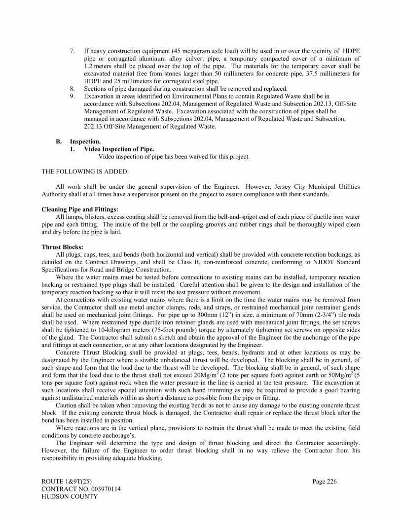
ROUTE 1&9T(25) Page 226 CONTRACT NO. 003970114 HUDSON COUNTY
7. If heavy construction equipment (45 megagram axle load) will be used in or over the vicinity of HDPE pipe or corrugated aluminum alloy culvert pipe, a temporary compacted cover of a minimum of 1.2 meters shall be placed over the top of the pipe. The materials for the temporary cover shall be excavated material free from stones larger than 50 millimeters for concrete pipe, 37.5 millimeters for HDPE and 25 millimeters for corrugated steel pipe.
8. Sections of pipe damaged during construction shall be removed and replaced. 9. Excavation in areas identified on Environmental Plans to contain Regulated Waste shall be in
accordance with Subsections 202.04, Management of Regulated Waste and Subsection 202.13, Off-Site Management of Regulated Waste. Excavation associated with the construction of pipes shall be managed in accordance with Subsections 202.04, Management of Regulated Waste and Subsection, 202.13 Off-Site Management of Regulated Waste.
B. Inspection.
1. Video Inspection of Pipe. Video inspection of pipe has been waived for this project.
THE FOLLOWING IS ADDED:
All work shall be under the general supervision of the Engineer. However, Jersey City Municipal Utilities Authority shall at all times have a supervisor present on the project to assure compliance with their standards.
Cleaning Pipe and Fittings:
All lumps, blisters, excess coating shall be removed from the bell-and-spigot end of each piece of ductile iron water pipe and each fitting. The inside of the bell or the coupling grooves and rubber rings shall be thoroughly wiped clean and dry before the pipe is laid. Thrust Blocks:
All plugs, caps, tees, and bends (both horizontal and vertical) shall be provided with concrete reaction backings, as detailed on the Contract Drawings, and shall be Class B, non-reinforced concrete, conforming to NJDOT Standard Specifications for Road and Bridge Construction.
Where the water mains must be tested before connections to existing mains can be installed, temporary reaction backing or restrained type plugs shall be installed. Careful attention shall be given to the design and installation of the temporary reaction backing so that it will resist the test pressure without movement.
At connections with existing water mains where there is a limit on the time the water mains may be removed from service, the Contractor shall use metal anchor clamps, rods, and straps, or restrained mechanical joint restrainer glands shall be used on mechanical joint fittings. For pipe up to 300mm (12”) in size, a minimum of 70mm (2-3/4”) tile rods shall be used. Where restrained type ductile iron retainer glands are used with mechanical joint fittings, the set screws shall be tightened to 10-kilogram meters (75-foot pounds) torque by alternately tightening set screws on opposite sides of the gland. The Contractor shall submit a sketch and obtain the approval of the Engineer for the anchorage of the pipe and fittings at each connection, or at any other locations designated by the Engineer.
Concrete Thrust Blocking shall be provided at plugs, tees, bends, hydrants and at other locations as may be designated by the Engineer where a sizable unbalanced thrust will be developed. The blocking shall be in general, of such shape and form that the load due to the thrust will be developed. The blocking shall be in general, of such shape and form that the load due to the thrust shall not exceed 20Mg/m2 (2 tons per square foot) against earth or 50Mg/m2 (5 tons per square foot) against rock when the water pressure in the line is carried at the test pressure. The excavation at such locations shall receive special attention with such hand trimming as may be required to provide a good bearing against undisturbed materials within as short a distance as possible from the pipe or fitting.
Caution shall be taken when removing the existing bends as not to cause any damage to the existing concrete thrust block. If the existing concrete thrust block is damaged, the Contractor shall repair or replace the thrust block after the bend has been installed in position.
Where reactions are in the vertical plane, provisions to restrain the thrust shall be made to meet the existing field conditions by concrete anchorage’s.
The Engineer will determine the type and design of thrust blocking and direct the Contractor accordingly. However, the failure of the Engineer to order thrust blocking shall in no way relieve the Contractor from his responsibility in providing adequate blocking.

ROUTE 1&9T(25) Page 227 CONTRACT NO. 003970114 HUDSON COUNTY
Ductile Iron Water Pipe Bedding and Backfill: Immediately after the pipe is brought to final position, it shall be thoroughly secured and properly bedded, and
ample support shall be provided to prevent settlement or disturbances. As soon as practicable, after the pipe or masonry has been placed and the masonry has acquired a suitable degree of
hardness, the backfilling shall begin and shall thereafter be prosecuted expeditiously. Compaction and tamping shall be as directed to the end that the pipe shall be securely bedded and protected at the
end of each day’s operation. Unless otherwise specified, all trenches or excavations shall then be backfilled up to the original surface of the ground or up to such grades as shall be directed. The backfilling shall be done as completely as possible in such a manner as to prevent after-settlement around all structures and pipelines. No heavy stones or boulders shall be allowed to drop into the trench. The trenches and excavation shall be made wet as required to obtain optimum density while the backfilling is being carried out.
When backfilling is commenced, approved backfill material shall be placed by hand and compacted around and above the pipe to a depth of 0.6m (2’) over the top of the pipe. Care shall be taken to prevent any disturbance of the pipe or damage to newly made joints. If the remainder of the approved backfill materials is dumped from buckets, the contents of the buckets shall be deposited and allowed to slide into the trench. Bracing and sheeting shall not be removed until the trench below it has been filled and every precaution shall be taken to prevent any slips of earth from the side of the trench.
All backfilling shall be properly consolidated by tamping in 200mm (8”) loose layers with a mechanical tamper. Each layer shall be compacted to the satisfaction of the Engineer before the next layer is placed.
The Engineer shall have the right to make such selection of material for various portions of the backfill as may be required for the satisfactory execution of the work. Only such material as is specified for backfilling shall be used. All boulders, rock or other unsuitable material shall be deposited of at approved locations.
At the end of each day’s operation, the Contractor shall properly cover all openings of installed mains, valves and fittings to prevent entry of foreign matter, animals or debris.
Valves Installation of gate valves and gate valve boxes shall be as indicated on the contract drawings, in accordance with the manufacturer’s recommendations and as directed by the Engineer. Existing gate valves and gate valve boxes shall be carefully removed and properly disposed of or delivered to the JCMUA upon direction from the Engineer. Suggested Sequence of Work:
1. Perform excavation to uncover valves to be replaced and sufficient pipe upstream and downstream of the
valves to facilitate replacement. 2. Close valves up and downstream to depressurize system about valve to be replaced. 3. Maintain dry conditions in trench. 4. Remove valve and adjacent pipe. 5. Clean and install new valve and piping. 6. Pressurize system. Equalize pressure using 6 inch bypass. 7. Disinfect and blow out new valve and piping through corporation stop. 8. Operate valve and perform leak test observation. 9. Backfill and restore site.
Install valves plumb and level. Install valves free of distortion and strain caused by misaligned piping, equipment or other causes. Set valve boxes plumb, and centered with the bodies directly over the valves. Carefully tamp earth fill around each valve box to a distance of 4 feet on all sides of the box, or the undisturbed trench face, if less than 4 feet. Crossing Utility Lines:
When crossing over an existing pipe, conduit, etc., the new ductile iron water pipe shall be encased in concrete or supported by other means as required or as directed by the Engineer or as shown on the Contract Drawings. In this case, the cover on the ductile iron water pipe may be decreased as required and if approved by the Engineer.
When crossing under an existing pipe, conduit, structure, etc., the existing pipe shall be cradled or supported by other means without transmitting the load to the new ductile iron water pipe and the method of construction shall be as required or as directed by the Engineer or as shown on the Contract Drawings.

ROUTE 1&9T(25) Page 228 CONTRACT NO. 003970114 HUDSON COUNTY
In all cases, the ductile iron water pipe shall be brought back to original grade properly and with a smooth transition as directed by the Engineer.
In all cases of crossing an existing utility, pipe, conduit, or structure, approval of the construction method and the crossing design shall be obtained from the Owner of the utility, pipe, conduit, or structure, if such approval is required. Separation between Water Lines and Sewers: Horizontal Separation:
When possible, water mains shall be laid 3m (10’) horizontally, from any existing of proposed sewer. Should local conditions prevent a lateral separation of 3m (10’), a water main may be laid closer than 3m (10’) to a sewer pipe if:
• It is laid in a separate trench. • The elevation of the top (crown) of the sewer is at least 450mm (18”) below the bottom (invert) of the water
main. Vertical Separation:
Whenever water mains must cross over sewer, the water main at such an elevation that the top of the sewer is at least 450mm (18”) below the bottom of the water main. When the above requirements cannot be met, the water main shall be relocated to provide this separation, for a distance of 3m (10‘) extending on each side of the sewer. One full length of water main should be centered over the sewer so that both joints will be as far from the sewer as possible. Unusual Conditions:
Where conditions prevent the minimum vertical separation above from being maintained, or when it is necessary for the water main to pass under the sewer or drain, the water main shall be laid with mechanical joint pipe, and the pipe should extend on each side of the crossing until the normal distance from the water main sewer or drain line at least 3m (10’). In making such a crossing, it is preferable to center a length of water main pipe over the sewer to be crossed, so that the joints will be equi-distant from the sewer and as remote wherefrom as possible. Where a water main must cross under a sewer, a vertical separation of 450mm (18”) between the bottom of the sewer and the top of the water main should be maintained, with adequate support for the larger-sized sewer lines to prevent them from settling on and breaking the water main. Sewer Manholes:
Water pipe shall not pass through or come into contact with any part of a sewer manhole. Reconnection of Water Service Lines:
Contractor shall reconnect all existing water service lines to the newly installed water mains. Contractor shall be responsible for all tapping connections to the new mains. For services 50mm (2”) and less, Contractor shall connect existing lead or copper services to new type “K” copper tubing, which is to be connected to the new main. For services greater than 50mm (2”), Contractor shall connect existing services to new D.I.P., which is to be connected to the new main. All connections between existing service lines and new materials shall be done using suitable unions and fittings. All reconnections and all other plumbing work shall be done by a New Jersey licensed plumber. Hydrostatic and Leakage Tests:
The entire installed water system and appurtenances shall be disinfected and tested for complete sterilization by the Contractor. The Contractor shall be responsible for each portion before the work will be approved, accepted, and placed in operation. The disinfection method shall be in accordance with the applicable portions of the AWWA Standards and approved by the Engineer. The bacteriological examination shall be conducted at the expense of the Contractor by a licensed bioanalytical laboratory.
The Contractor will be expected to begin testing and disinfection of the various sections of water mains promptly upon the completion of a section of work. The delay of the testing and disinfection, in order to consolidate such work, will not be permitted, unless the Engineer specifically approves such consolidation of specific parts of this work in writing. the Engineer also reserves the right to require the testing and disinfection of intermediate sections of long water mains or otherwise limit the amount of water main to be tested. The Contractor shall close the section of water main to be tested by valves or temporary plugs, and shall install temporary reaction backing, as required, at no additional expense.
Where any sections of water main are protected by concrete reaction backings, the hydrostatic pressure test shall not be made until at least 7 days have elapsed after the concrete reaction backing was installed. If high early strength

ROUTE 1&9T(25) Page 229 CONTRACT NO. 003970114 HUDSON COUNTY
cement concrete is used for reaction backing, the hydrostatic pressure test shall not be made until at least 2 days have elapsed.
The Contractor may, at his option, completely backfill the trench or partially backfill the trench over the center section of each pipe prior to carrying out the pressure teSt. The Engineer reserves the right, however, to direct that the entire trench be backfilled, if traffic or other local conditions require such action.
The section of water main being tested shall be filled with water a minimum of 24 hours before the main is tested. During the filling of the pipe, extreme care must be exercised to insure that all air is expelled from the pipeline. If necessary, the Contractor shall install taps on the main points of highest elevation. After completion of the test, the taps shall be tightly plugged, unless otherwise used. Any taps necessary to release air or water from the main shall be made at the Contractor’s expense. Pressure Tests:
After the pipeline has been filled with water for 24 hours, the Contractor shall conduct a hydrostatic or pressure test. The duration of the pressure test shall be at least 1 hour. The water mains shall be tested at static head of 1034kPa (150 psi) measured at the low point in the system.
The section of pipeline being tested shall have the specified test pressure applied by means of a pump connected to the pipe in a manner satisfactory to the Engineer. The pump, pipe connection, tap on the main, and all necessary apparatus shall be furnished and installed by the Contractor. The Contractor shall have backup equipment for testing to prevent delays if the original equipment breaks down.
All exposed pipes, joints, fittings, and valves shall be carefully examined during the test, and all joints showing visible leakage shall be made tight. All defective pipes, fittings, and valves shall be removed from the line and replaced by the Contractor.
Where the trench has been completely backfilled, whether at the option of the Contractor or required by the Engineering, and the pressure gauge fails to hold the required specified pressure, the Contractor shall open up the trench at his own expense to repair any leaks. Leakage:
The leakage test shall have a minimum duration of 2 hours, and shall be at the same pressure as specified for the hydrostatic test. The leakage test shall be conducted in the same manner as the pressure test, except that the Contractor shall provide means of measuring the leakage, satisfactory to the Engineer.
For sections of main being tested for leakage which are constructed of ductile iron pipe with push on joints, the particular section of main will not be accepted if the leakage is greater than that determined by the formula.
L = ND P 3700 in which L is the allowable leakage in gallons per hour; N is the number of joints in the length of pipeline tested; D is the nominal diameter of the pipe in inches; and P is the average test pressure in pounds per square inch.
The leakage test may be conducted at the same time as the pressure test, provided suitable means are provided to measure the leakage during the pressure test, and a record of water added to the pipeline is kept for a period of at least 2 hours.
The allowable leakage at average test pressure in liters per hour per 3281 meters (gallons per hour per 1,000 feet) for specific pipe sizes is shown in the following table:
Pressure Size in mm (Inches)
Avg. Test Pressure
KPa (psi) 50mm
(2”) 150mm
(6”) 200mm
(8”) 300mm (12”)
400mm (16”)
500mm (20”)
600mm (24”)
750mm (30”)
690 kPa (100)
1.14 (0.30)
3.41 (0.90)
4.55 (1.20)
6.82 (1.80)
9.09 (2.40)
11.36 (3.00)
13.63 (3.60)
17.04 (4.50)
759 kPa (110)
1.17 (0.31)
3.56 (0.94)
4.77 (1.26)
7.16 (1.89)
9.54 (2.52)
11.93 (3.15)
14.31 (3.78)
17.87 (4.72)
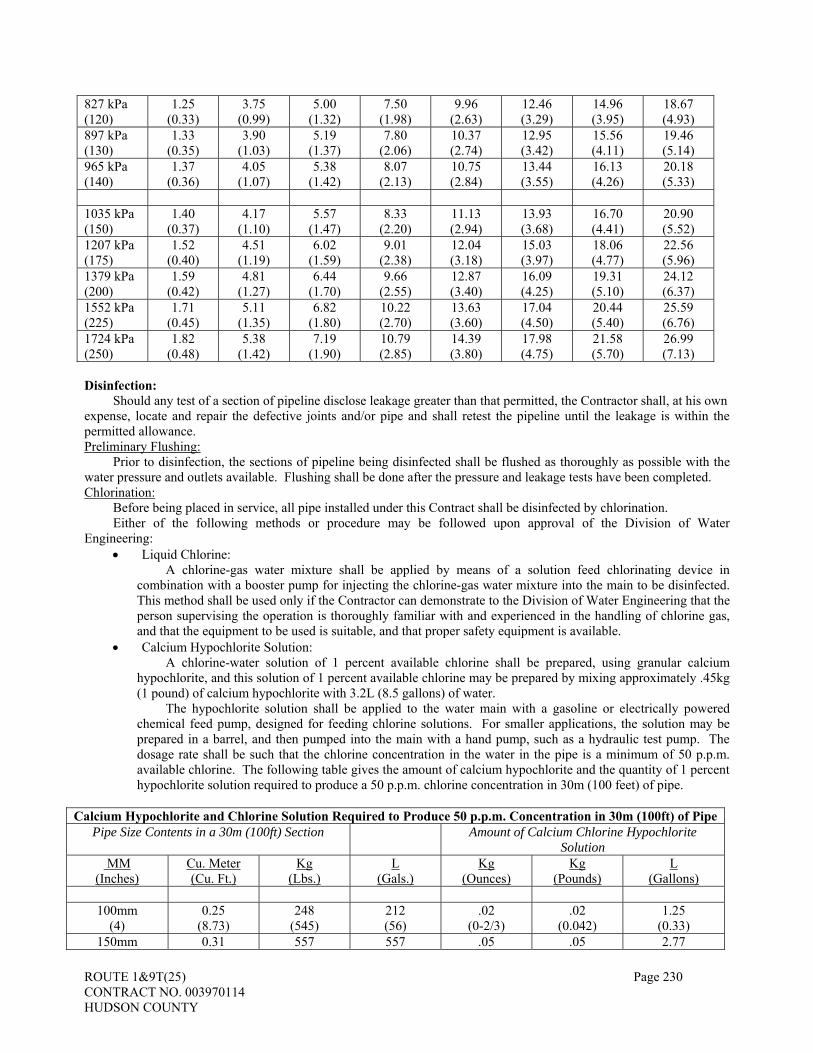
ROUTE 1&9T(25) Page 230 CONTRACT NO. 003970114 HUDSON COUNTY
827 kPa (120)
1.25 (0.33)
3.75 (0.99)
5.00 (1.32)
7.50 (1.98)
9.96 (2.63)
12.46 (3.29)
14.96 (3.95)
18.67 (4.93)
897 kPa (130)
1.33 (0.35)
3.90 (1.03)
5.19 (1.37)
7.80 (2.06)
10.37 (2.74)
12.95 (3.42)
15.56 (4.11)
19.46 (5.14)
965 kPa (140)
1.37 (0.36)
4.05 (1.07)
5.38 (1.42)
8.07 (2.13)
10.75 (2.84)
13.44 (3.55)
16.13 (4.26)
20.18 (5.33)
1035 kPa (150)
1.40 (0.37)
4.17 (1.10)
5.57 (1.47)
8.33 (2.20)
11.13 (2.94)
13.93 (3.68)
16.70 (4.41)
20.90 (5.52)
1207 kPa (175)
1.52 (0.40)
4.51 (1.19)
6.02 (1.59)
9.01 (2.38)
12.04 (3.18)
15.03 (3.97)
18.06 (4.77)
22.56 (5.96)
1379 kPa (200)
1.59 (0.42)
4.81 (1.27)
6.44 (1.70)
9.66 (2.55)
12.87 (3.40)
16.09 (4.25)
19.31 (5.10)
24.12 (6.37)
1552 kPa (225)
1.71 (0.45)
5.11 (1.35)
6.82 (1.80)
10.22 (2.70)
13.63 (3.60)
17.04 (4.50)
20.44 (5.40)
25.59 (6.76)
1724 kPa (250)
1.82 (0.48)
5.38 (1.42)
7.19 (1.90)
10.79 (2.85)
14.39 (3.80)
17.98 (4.75)
21.58 (5.70)
26.99 (7.13)
Disinfection:
Should any test of a section of pipeline disclose leakage greater than that permitted, the Contractor shall, at his own expense, locate and repair the defective joints and/or pipe and shall retest the pipeline until the leakage is within the permitted allowance. Preliminary Flushing:
Prior to disinfection, the sections of pipeline being disinfected shall be flushed as thoroughly as possible with the water pressure and outlets available. Flushing shall be done after the pressure and leakage tests have been completed. Chlorination:
Before being placed in service, all pipe installed under this Contract shall be disinfected by chlorination. Either of the following methods or procedure may be followed upon approval of the Division of Water
Engineering: • Liquid Chlorine:
A chlorine-gas water mixture shall be applied by means of a solution feed chlorinating device in combination with a booster pump for injecting the chlorine-gas water mixture into the main to be disinfected. This method shall be used only if the Contractor can demonstrate to the Division of Water Engineering that the person supervising the operation is thoroughly familiar with and experienced in the handling of chlorine gas, and that the equipment to be used is suitable, and that proper safety equipment is available.
• Calcium Hypochlorite Solution: A chlorine-water solution of 1 percent available chlorine shall be prepared, using granular calcium
hypochlorite, and this solution of 1 percent available chlorine may be prepared by mixing approximately .45kg (1 pound) of calcium hypochlorite with 3.2L (8.5 gallons) of water.
The hypochlorite solution shall be applied to the water main with a gasoline or electrically powered chemical feed pump, designed for feeding chlorine solutions. For smaller applications, the solution may be prepared in a barrel, and then pumped into the main with a hand pump, such as a hydraulic test pump. The dosage rate shall be such that the chlorine concentration in the water in the pipe is a minimum of 50 p.p.m. available chlorine. The following table gives the amount of calcium hypochlorite and the quantity of 1 percent hypochlorite solution required to produce a 50 p.p.m. chlorine concentration in 30m (100 feet) of pipe.
Calcium Hypochlorite and Chlorine Solution Required to Produce 50 p.p.m. Concentration in 30m (100ft) of Pipe
Pipe Size Contents in a 30m (100ft) Section Amount of Calcium Chlorine Hypochlorite Solution
MM (Inches)
Cu. Meter (Cu. Ft.)
Kg (Lbs.)
L (Gals.)
Kg (Ounces)
Kg (Pounds)
L (Gallons)
100mm
(4) 0.25
(8.73) 248
(545) 212 (56)
.02 (0-2/3)
.02 (0.042)
1.25 (0.33)
150mm 0.31 557 557 .05 .05 2.77

ROUTE 1&9T(25) Page 231 CONTRACT NO. 003970114 HUDSON COUNTY
(6) (10.65) (1227) (147) (1-1/2) (0.093) (0.73) 200mm
(8) 0.99
(34.90) 989
(2180) 988
(261) .07
(2-1/2) .07
(0.159) 4.92
(1.30) 250mm
(10) 1.55
(54.55) 1545
(3405) 1545 (408)
.11 (3-7/8)
.11 (0.244)
7.73 (2.04)
300mm (12)
2.23 (78.48)
2223 (4899)
2223 (587)
.17 (5-3/4)
.17 (0.358)
10.60 (2.80)
The point of application of the chlorinating agent shall be at the high end of the pipeline section, and through a corporation stop inserted in the top of the new pipe. If the water for the preparation of the chlorine solution is supplied from a tap on the existing pipeline, there shall be a physical break between the injector or pump.
The chlorine solution shall be pumped slowly into the new pipeline. Chlorine application shall not cease until the entire main is filled with chlorine solution. If required by the Engineer, the chlorine residual shall be measured at several points along the section of main being tested to insure that the proper dosage and distribution of the chlorine solution is obtained.
If the above forms of applied chlorine cannot be used, the line may be sterilized by the use of hypochlorite tablets. The number of tablets in each length of pipe shall be as recommended by the tablet manufacturer. Fasten the required number of tablets to the top of the inside of each length of pipe, using a non-toxic water resistant adhesive which shall not cover the sides or face of the tablet. Water from an approved source of supply shall be controlled to flow slowly into the pipe to be sterilized.
Great care shall be exercised in manipulating valves, so that the strong chlorine solution in the line being treated will not flow back into the adjoining water distribution system.
The chlorinated water shall be retained in the main for at least 24 hours, during which time, all valves and hydrants in the section treated shall be operated, in order to disinfect the appurtenances. At the end of this 24-hour period, the treated water shall contain no less than 25 p.p.m. chlorine throughout the length of the main. Should the initial procedure fail to result in the conditions specified, the chlorination procedure shall be repeated until such results are obtained, at the Contractor’s expense.
The Contractor shall discharge the sterilizing solution from the mains through available outlets, or through taps in the main. The Contractor shall exercise all due precautions in discharging the chlorine bearing water, since it is extremely toxic and, if allowed to flow into streams, can readily destroy aquatic life. If any damage to property or fish life occurs due to the disposal of the sterilizing solution, the cost of the damage shall be paid by the Contractor.
If the possibility of damage to aquatic life is such, in the opinion of the Engineer, that special precautions are required, the Contractor shall de-chlorinate the disinfecting solution before it goes to waste. The chlorine solution may be neutralized by applying sodium thiosulfate in the ratio of 2 parts thiosulfate to 1 part chlorine at the point of discharge. Final Flushing:
Following chlorination, the heavily chlorinated water shall be thoroughly flushed from the line at its extremities until the replacement water throughout its length, upon test, be proved comparable to the quality of water in the existing distribution system. Water for Testing:
Water shall be furnished by the Contractor for the hydrostatic tests and disinfection procedures. If pipelines must be re-tested and disinfected, the cost of additional water shall be borne by the Contractor. Disinfection of Water Main Connections:
Since it may not be possible to disinfect the pipe, valves, and fittings installed at certain connections in the manner specified above, the Contractor shall proceed as follows:
• Every precaution shall be observed during the installation of the connection to prevent foreign material and trench water from entering the pipe, fittings, and valves during their installation.
• The interior of all pipe, fittings, and valves shall be swabbed with a 5 percent hypochlorite solution. A 5 percent hypochlorite solution can be obtained by mixing approximately 1.4kg (3 pounds) of granulated calcium hypochlorite with 19L (5 gallons) of water.
• After the pipe, fittings, and valves have been swabbed, they shall be thoroughly flushed with water. 602.04 Laying of Pipe. THE LAST PARAGRAPH IS CHANGED TO:

ROUTE 1&9T(25) Page 232 CONTRACT NO. 003970114 HUDSON COUNTY
Pipe will be inspected before and during backfilling operations. Any pipe found to be out of alignment, excessively settled, lifted, or damaged shall be removed and relaid or replaced. THE FOLLOWING IS ADDED AFTER THE LAST PARAGRAPH:
No ductile iron water pipe shall be laid in wet trench conditions or on a frozen trench bottom or when, in the
opinion of the Engineer, trench or weather conditions are unsuitable. Every precaution shall be taken to prevent foreign material from entering the ductile iron water pipe while it is
being placed. During laying operation, no debris, tools, clothing, or other materials shall be placed in the ductile iron water pipe.
The ductile iron water pipe shall be supported in its full length on the proper line and uniform grade of the trench. A bell-hole shall be dug at each joint, said hole being of sufficient size to insure the proper making up of each joint. After placing a length of ductile iron water pipe in the trench, the spigot end shall be centered in the bell and the pipe forced home.
Care shall be experienced when making each joint, and all joints shall be made in accordance with the ductile iron water pipe supplier’s specifications and in accordance with the following instruction.
The cutting of the ductile iron water pipe shall be carried out only with the equipment specifically designed for that purpose. The use of chisels, hand saws, or handheld power saws will not be permitted.
Ductile iron water pipe shall be laid with the ball ends facing in the direction of laying, unless otherwise shown on the Contract Drawings, or as directed by the Engineer.
All ductile iron water pipe shall be laid and maintained at the required lines and grades as shown on the Contract Drawings, with joints centered, spigots forced home, and all valve and hydrant stems plumb. No deviation shall be made from the required line and grade, except with the approval of the Engineer.
Where the proposed route of the ductile iron water pipe is on a curve, the Contractor may, after receiving approval from the Engineer, deflect the pipe at the joints. In no case shall the pipe be deflected more than the maximum permissible deflection recommended by the pipe manufacturer and, in case the curve is too sharp for the allowable deflections, short lengths of pipe may be used upon approval of the Engineer.
Except at points indicated on the Contract Drawings by the profile, particular care shall be exercised so that no high points are established where air can accumulate. All water mains shall have a minimum burial depth of 1.2m (4’-0”), and a maximum burial depth of 1.8m (6’-0”) unless replacement of existing pipe section.
All ductile iron water pipe, fittings and appurtenances shall be carefully lowered into the trench piece by piece by means of derrick, ropes, or other suitable tools or equipment, in such a manner as to prevent damage to water main materials and protective coatings and linings. Under no circumstances shall water main materials be dropped or dumped into the trench. 602.05 Joining Pipe. THE FIRST PARAGRAPH IS CHANGED TO:
Joints for rigid pipe shall be made with mortar, grout, or gaskets. Other types of joints recommended by the pipe manufacturer may be permitted as approved by the Resident Engineer. Corrugated metal pipe shall be joined by coupling bands. THE FOLLOWING IS ADDED AFTER THE LAST PARAGRAPH: Push-On Type Joints:
All mud, stones and debris shall be removed from the inside of the ball, from the gasket, and from the inserting spigot end. These parts shall be kept clean throughout assembly of the joint.
The entire gasket shall be properly seated and checked by lightly pulling the gasket forward with the fingertips. A minimum amount of lubricant shall be evenly applied to the spigot end with a brush. The spigot end shall be
kept cleaned and lubricated throughout assembly. The spigot end shall be properly centered, force applied using a crowbar or a ratchet jack until the white stripe on
the spigot end is just visible at the face of the bell. Any required deflection shall be made only after joint assembly has been made.
If the joint is extremely difficult to assemble, a check shall be made for proper positioning, adequate lubrication, and presence of foreign matter in the joint.

ROUTE 1&9T(25) Page 233 CONTRACT NO. 003970114 HUDSON COUNTY
The edges of “field cut” ductile iron water pipe shall be touched up with a file or grinder so as to remove rough edges and facilitate assembly. Mechanical Joints:
Thoroughly clean the bell and the spigot end of the pipe of all foreign matter, and wash them with soapy water. Slip the gland and gasket over the plain end and seat the spigot end in the bell (the small end of the gasket and the
lip on the gland shall face the bell). Push gasket into position with fingers, making sure it is evenly seated. Move gland into position for bolting and make all nuts fingertight, keeping the spigot centrally located within the
bell. The following table is used in determining the wrench to be used by the average man in tightening the bolts:
Bolt Size, mm (″ ) Length of Wrench, mm (″ ) 15.9 (5/8) 200 (8) 19 (3/4) 250 (10) 25 (1) 300 (12) 31.8 (1 –1/4) 350 (14)
When tightening bolts, it is essential that the gland be brought up toward the ductile iron water pipe flange evenly, maintaining approximately the same distance between the gland and the face of the flange at all points around the socket. This is to be done by partially tightening the bottom bolt first, then the top bolt, next the bolts at either side and last, the remaining bolts. Repeat this cycle until all bolts are within range of the torques listed below:
Bolt Size, mm (″) Range of Torque, N-m (ft. – lbs.) 15.9 (5/8) 10-80 (40-60) 19 (3/4) 80-120 (60-90)
25 (1) 90-135 (70-100) 31.8 (1 –1/4) 120-160 (90-120)
If effective sealing is not obtained at the maximum torque indicated above, the joint must be disassembled after through cleaning. Under no circumstances are bolts to be overstressed. 602.06 Reinforced Concrete Culvert Pipe, Jacking and Tunneling Methods.
1. Jacking Method. THE THIRD PARAGRAPH IS CHANGED TO:
Project site conditions which may be present, and the extent to which such conditions may affect methods of operations, shall be determined according to Subsections 102.03 and 108.09.
602.10 Method of Measurement. THE FOLLOWING IS ADDED:
__ MM Metal Pipe, Casing will be measured by the linear meter. __ MM Ductile Iron Water Pipe, Class __ will be measured by the linear meter. __ by __ MM Reinforced Concrete Elliptical Pipe, Class V will be measured by the linear meter. __ by __ MM Reinforced Concrete End Sections will be measured by the unit.
602.11 Basis of Payment. THE FOLLOWING PAY ITEMS ARE ADDED:
Pay Item Pay Unit 600 MM METAL PIPE , CASING LINEAR METER 900 MM METAL PIPE , CASING LINEAR METER 500 MM DUCTILE IRON WATER PIPE, CLASS 52 LINEAR METER 600 MM DUCTILE IRON WATER PIPE, CLASS 56 LINEAR METER 900 MM DUCTILE IRON WATER PIPE, CLASS 56 LINEAR METER 360 BY 580 MM REINFORCED CONCRETE ELLIPTICAL CULVERT PIPE LINEAR METER 550 BY 860 MM REINFORCED CONCRETE ELLIPTICAL CULVERT PIPE LINEAR METER 800 BY 1 260 MM REINFORCED CONCRETE ELLIPTICAL CULVERT PIPE LINEAR METER 860 BY 1 350 MM REINFORCED CONCRETE ELLIPTICAL CULVERT PIPE LINEAR METER 360 BY 580 MM REINFORCED CONCRETE ELLIPTICAL CULVERT PIPE, CLASS V LINEAR METER

ROUTE 1&9T(25) Page 234 CONTRACT NO. 003970114 HUDSON COUNTY
550 BY 860 MM REINFORCED CONCRETE ELLIPTICAL CULVERT PIPE, CLASS V LINEAR METER 800 BY 1 260 MM REINFORCED CONCRETE ELLIPTICAL CULVERT PIPE, CLASS V LINEAR METER 860 BY 1 350 MM REINFORCED CONCRETE ELLIPTICAL CULVERT PIPE, CLASS V LINEAR METER 860 BY 1 350 MM REINFORCED CONCRETE END SECTIONS UNIT
THE FOLLOWING PAY ITEMS ARE DELETED:
___ X ___ MM REINFORCED CONCRETE CULVERT PIPE ARCH, CLASS ___ LINEAR METER ___ X ___ MM REINFORCED CONCRETE SEWER PIPE ARCH, CLASS ___ LINEAR METER
THE FOLLOWING IS ADDED AFTER THE LAST PARAGRAPH:
Separate payment will not be made for thrust blocks, couplings, casing spacers, end seals, joints, welding of steel casing, water service reconnections, cleaning water pipes and fittings, water pressure tests and disinfection, but all costs shall be included in the unit bid price for __mm ductile iron water pipe, class __.
Separate payment will be made for backfilling (soil aggregate, type I-6). All work shall be done in conformance with Section 300.
Separate payment will be made for pipe bedding (broken stone or washed gravel). All work shall be done in conformance with Section 207.
The cost of pipe roll stand supports of the water and storm sewer pipe attached to the bridges shall be included in the unit price for that pipe.
SECTION 603 – INLETS AND MANHOLES THE FOLLOWING IS ADDED TO THIS SECTION: Flap Valves:
The flap valve shall be of the size indicated on the drawings and will be flange framed with resilient to bronze seating. The cover shall be bronze ASTM B584 C885. The body shall be cast iron ASTM A126 Class B. The resilient elastomer seat will be mounted in the body of the valve. Pivot hardware shall be Type 304 stainless steel. Attaching hardware shall be Type 304 stainless steel. 603.12 Method of Measurement. THE FOLLOWING IS ADDED:
Inlets, Type ___________ will be measured by the unit. Manholes, Type _____________ will be measured by the unit. Outlet Control Structure, Type _______will be measured by the unit. Flap valve will be measured by the unit. 603.13 Basis of Payment. THE FOLLOWING PAY ITEMS ARE ADDED:
Pay Item Pay Unit INLETS, TYPE B DOUBLE UNIT INLETS, TYPE B-1 DOUBLE UNIT INLETS, TYPE D-1 DOUBLE UNIT INLETS, TYPE E-Y UNIT INLETS, TYPE B-Y DOUBLE UNIT INLETS, TYPE A-Y UNIT MANHOLES, TYPE MH-Y UNIT OUTLET CONTROL STRUCTURE, TYPE OS-1 UNIT OUTLET CONTROL STRUCTURE, TYPE OS-2 UNIT FLAP VALVE UNIT BOX CHAMBER, SANITARY SEWER UNIT

ROUTE 1&9T(25) Page 235 CONTRACT NO. 003970114 HUDSON COUNTY
SECTION 605 - CURBS 605.07 Concrete Curbs.
A. Limitations. THE SECOND ITEM OF THIS SUBPART IS CHANGED TO:
2. Concrete curb shall not be constructed from November 1 to March 15 except at the following locations:
SECTION 607 – SIDEWALKS AND DRIVEWAYS
607.02 Materials. THE ENTIRE TEXT IS CHANGED TO:
HMA shall conform to Section 903 except that the composition of the mixture for the top layer may also include up to 20 percent of RAP. Portland cement concrete shall conform to Section 914 except that driveways shall attain a strength of not less than 21 megapascals in three days. Other materials shall conform to the following Subsections:
Soil Aggregate .................................................................................................................................... 901.09 Prime Coat: Cut-back Asphalt, Grade MC-30 or MC-70 ..................................................................................... 904.02 Tack Coat: Cut-back Asphalt, Grade RC-70 or RC-T......................................................................................... 904.02 Emulsified Asphalt, Grade RS-1, SS-1, or SS-1h ............................................................................. 904.03 Cationic Emulsified Asphalt, Grade CSS-1 or CSS-1h .................................................................... 904.03 Curing Materials ................................................................................................................................. 905.03 Preformed Expansion Joint Filler ....................................................................................................... 908.01 Reinforcement Steel............................................................................................................................ 915.03 Detectable Warning Surfaces.............................................................................................................. 905.06
Dense-graded aggregate for base course used with HMA sidewalk shall conform to Subsection 901.08. 607.06 Concrete Sidewalks, Driveways, and Public Sidewalk Curb Ramp Delineation. THE SUBSECTION HEADING IS CHANGED TO: 607.06 Concrete Sidewalks, Driveways, and Detectable Warning Surfaces. SUBPART 5 HEADING AND ENTIRE TEXT ARE CHANGED TO:
5. Detectable Warning Surfaces. Immediately before installing safety red color and Detectable Warning Surfaces, the designated area shall be thoroughly cleaned and dried according to the manufacturer’s recommendation. The installation of Detectable Warning Surfaces shall be according to the corresponding construction details and the manufacturer’s recommendation. The background surface upon which the detectable warning surface is installed, silicon carbide 60 grit shall be evenly broadcast at a rate of 38 grams per square meter for skid resistance.
A list of approved manufacturers will be provided in the Special Provisions. Product Name Manufacturer Address / Phone No. Strongwarn SWADA2000 Strongwall Industries, Inc. PO Box 201
Ridgewood, NJ 07541 Phone: (800) 535-0666 Fax: (201) 447-2317 www.strongwall.com
SAFETI-TRAX COTE-L Industries, Inc. 1542 Jefferson Street
Teaneck, NJ 07666 Phone: (201) 836-0733 Fax: (201) 836-5220
ROUTE 1&9T(25) Page 236 CONTRACT NO. 003970114 HUDSON COUNTY
www.cotelind.com
Vanguard Truncated Dome Vanguard ADA Systems of America 20628 Broadway Avenue
Snohomish, WA 98296 Phone: (360) 668-5700 Fax: (425) 212-2555
www.vanguardonlin.com
All areas determined to have been damaged or not to be in conformance with the Specifications or the Plans shall be removed and replaced at no additional compensation to the State.
607.07 Method of Measurement. THE THIRD PARAGRAPH IS CHANGED TO:
Detectable Warning Surfaces will be measured by the square meter. THE FOLLOWING IS ADDED:
Curbs of the various sizes and kinds will be measured by the linear meter. 607.08 Basis of Payment. THE FOLLOWING PAY ITEM IS DELETED:
Pay Item Pay Unit PUBLIC SIDEWALK CURB RAMP DELINEATION SQUARE METER
THE FOLLOWING PAY ITEMS ARE ADDED:
Pay Item Pay Unit DETECTABLE WARNING SURFACES SQUARE METER VARIABLE WIDTH BY 1445 MM CONCRETE BARRIER CURB LINEAR METER VARIABLE WIDTH BY VARIABLE HEIGHT CONCRETE BARRIER CURB LINEAR METER 400 BY 1445 MM CONCRETE BARRIER CURB LINEAR METER 650 BY 1445MM CONCRETE BARRIER CURB LINEAR METER 225 BY 475 MM CONCRETE VERTICAL CURB LINEAR METER 225 BY 525 MM CONCTRET VERTICAL CURB LINEAR METER 650 MM BY VARIABLE HEIGHT CONCRETE BARRIEAR CURB LINEAR METER
SECTION 612 – BEAM GUIDE RAIL 612.04 Beam Guide Rail End Treatment. THE SECOND, THIRD AND FOURTH PARAGRAPHS ARE CHANGED TO:
Slotted guide rail (flared) terminals shall be FLEAT 350 (Flared Energy Absorbing Terminal) as manufactured by Road Systems, Inc.
Extruder (tangent) terminals shall be either ET-2000 PLUS (Guardrail End Treatment) by Trinity Highway Safety Products, Inc. or SKT 350 (Sequential Kinking Terminal) by Road Systems, Inc. For the ET-2000 PLUS, the 15 meters configuration shall be used with 450 millimeters panels. Seven “SYT” and one “HBA” posts shall be used.
Telescoping guide rail end terminals shall be either CAT 350 (Crash Cushion Attenuating Terminal) by Trinity Highway Safety Products, Inc. or Brakemaster 350 by Energy Absorption Systems. 612.08 Beam Guide Rail on Bridges.
ROUTE 1&9T(25) Page 237 CONTRACT NO. 003970114 HUDSON COUNTY
THE FOURTH PARAGRAPH IS DELETED.
SECTION 613 – MISCELLANEOUS CONCRETE 613.06 Method of Measurement. THE FOLLOWING IS ADDED:
Concrete pylon will be measured by the linear meter. 613.07 Basis of Payment. THE FOLLOWING PAY ITEM IS ADDED:
Pay Item Pay Unit CONCRETE PYLON LINEAR METER
SECTION 617 - TRAFFIC CONTROL 617.02 Materials. THE ENTIRE SUBSECTION IS CHANGED TO:
Materials shall conform to the following Subsections: Removable Wet Weather Pavement Marking Tape and Removable Black Line Masking Tape........ 912.12 Temporary Pavement Markers............................................................................................................ 912.16
Materials for all construction signs mounted on light poles shall be light-weight aluminum, 0.060 gauge plastic or fiberglass composite and shall be fade resistant.
617.03 Traffic Control Devices. THE FOLLOWING IS ADDED TO THE FIRST PARAGRAPH:
Traffic Control devices shall be NCHRP-350 crash test compliant by the NJDOT implementation dates stated in the table below and shall be duly certified, if necessary.
Traffic Control Device
Category
Commonly used NJDOT
Traffic Control Devices
AASHTO/FHWA implementation date for newly
purchased Devices
NJDOT
implementation date for newly
purchased Devices
NJDOT deadline By which devices
must be NCHRP-350
compliant
1
Traffic cones, drums and
delineator guide posts
10/1/1998
1/1/2003
8/15/2003
2
Vertical panel, portable sign
supports, and type III barricades
10/1/2000
1/1/2003
8/15/2003

ROUTE 1&9T(25) Page 238 CONTRACT NO. 003970114 HUDSON COUNTY
3
Truck mounted attenuators and traffic barriers-impact
attenuators (crash cushions), barrier terminals, and longitudinal barriers
10/01/1998 attenuators 10/01/2002
temporary barriers
10/01/1998
3/15/2005
4
Portable, usually trailer-mounted, devices such as lighting supports, flashing arrows panels, temporary
traffic signals, and changeable message signs used in or adjacent to the
traveled way
to be announced
6/15/2005
6/15/2007
Note: Resident Engineer’s approval shall be obtained to use traffic control devices that are certified
NCHRP 350 compliant, but not listed in the table.
Newly purchased devices shall be NCHRP-350 compliant. A list of NCHRP 350 compliant and FHWA approved devices can be found at: http://www.fhwa.dot.gov/safety/fourthlevel/pro_res_road_nchrp350.htm
NCHRP-350 non-compliant, yet adequately serviceable category 3 traffic control devices, such as truck-mounted attenuators (TMA) purchased prior to 10/01/1998, will be allowed to be used until 03/15/2005 upon submitting new purchase documentation to the Resident Engineer.
2. Construction Barriers. THE FIRST PARAGRAPH IS CHANGED TO:
Precast concrete curb used for construction barriers shall be concrete or white concrete conforming to Subsection 605.09. Construction barrier curb delivered to the job site shall be maintained throughout the duration of the Project. At least 30 days prior to delivery of construction barrier curb to the Project, a notice shall be provided to the Resident Engineer to inspect the barrier curb to be used. The Resident Engineer will inspect the barrier curb and approve individual pieces for delivery to the Project. Precast concrete curb deemed unsatisfactory by the Engineer shall be replaced at no cost to the State. The Construction barrier curbs shall not have any of the following deficiencies:
a. exposed steel at the connector flangeway; b. exposed reinforcement steel; c. cracking through the cross section; d. an area of concrete missing larger than a 75 mm by 75 mm right triangle; e. debris in the keyway; f. non-functioning anchor bolt holes; g. non-functioning anchor rod hole; h. paint applied to the surface; i objects protruding from the surface; or j. previous repairs.
The Engineer shall be the sole judge of the acceptability of the precast concrete curb. Precast concrete curb deemed unsatisfactory by the Engineer shall be replaced at no cost to the State.

ROUTE 1&9T(25) Page 239 CONTRACT NO. 003970114 HUDSON COUNTY
Construction barrier curb Type 4, Alternate Design A or B may be used interchangeably in any location where Type 4 has been specified, except that Alternate Design B, Joint Class D, shall be used as bridge parapets. Construction barrier curb Type 4, Alternate B, may be used in any location where Type 1 has been specified. There shall be no intermixing of construction barrier curb Types 1 and 4 in any one continuous run. Beam guide rail used for construction barrier shall be constructed according to Section 612 and shall be set at locations, and removed and reset at new locations as directed. Components that do not remain serviceable shall be replaced at no cost to the State. Beam guide rail scheduled for permanent installation shall not be used for construction barriers. All construction barriers shall be provided with retroreflective sheeting covered reflectors on the top and sides. The reflectors on the top of the construction barriers shall have a surface area of 6 inches wide by 1 foot high mounted on a plastic or 0.080 inch aluminum support. The top reflectors shall be located at 100-foot intervals on tangent sections, curves of radii greater than 1,910 feet, and at 50-foot intervals on curves of 1,910 feet or less. The reflectors on the sides of the construction barriers shall have a surface area of 3 by 3 inches and shall be mounted perpendicular to the upper face, 3 inches from the top. A side reflector shall be attached at the lead end of each barrier segment. The side reflectors shall be flexible or hinge-mounted so as to return to their original position after being struck. Any side reflectors that fail to return to original perpendicular position shall be replaced. The retroreflective sheeting shall be Type II or Type III-A as specified in Subsection 916.04 and cover the surface areas indicated for top and side reflectors. The retroreflective sheeting shall be yellow when the construction barrier is to the left of traffic and silver (white) when the construction barrier is to the right of traffic. Reflectors that are lost or damaged shall be replaced at no cost to the State. At least 30 days prior to delivery of construction barrier curb to the Project, the Contractor shall provide the RE notice that the barrier curb is available for inspection. The RE will inspect the barrier curb and approve individual pieces for delivery to the Project.
3. Illuminated Flashing Arrows. The solar powered arrow boards approved for use on projects are: a. Work Area Protection – Arrowmaster Model WAAW–15-SB b. Solar Technology Inc. – Silent Sentinel c. Trafcon Industries Inc. – Model TC1-15S d. Protect-O-Flash Inc. – Model No. M-90 (LED bulbs only) e. TRACOM (Trailer Component Mfg., Inc.)
6. Traffic Control Trucks with Mounted Crash Cushions. THE FOLLOWING IS ADDED AFTER THE SECOND PARAGRAPH:
The Resident Engineer shall be provided with a copy of the crash cushion manufacturer’s recommendations. The traffic control truck shall be positioned to ensure that adequate stopping distance is available after impact and to prevent errant vehicles from endangering workers. The trucks equipped with manual transmission shall be placed in second gear and trucks equipped with automatic transmission shall be placed in “park” gear while in fixed position. The parking brake shall be set and the wheels shall be turned to avoid rolling into live traffic. Traffic control trucks shall not be used in place of other temporary impact attenuators for more than 24 hours. The traffic control truck shall be relocated as specified by the Traffic Control Plan, or as directed by the Resident Engineer. The trucks shall not be used to carry additional equipment, materials, or debris. If ballast is to be used, the Resident Engineer shall be provided with Working drawings for certification detailing the method of securing ballast to the truck. The Working Drawings shall be signed and sealed by a Professional Engineer verifying that it is capable of withstanding the impact forces for which the impact attenuator is rated.
THE FOLLOWING IS ADDED:
7. Temporary Overhead Guide Signs. Temporary overhead guide signs are mounted to existing and/or proposed overhead sign structures and are used to provide guidance to traffic through temporary traffic patterns during construction where space or pattern does

ROUTE 1&9T(25) Page 240 CONTRACT NO. 003970114 HUDSON COUNTY
not permit ground-mounted guide signs to adequately convey the same message. Temporary guide sign panels are to be fabricated and installed as described in Subsection 619.04. Use of the temporary guide sign panels during construction shall be consistent with Item 1 in this Subsection.
617.10 Traffic Directors. THE FOLLOWING NEW SUBPART IS ADDED:
C. Emergency Towing Service. Thirty days before the start of Construction Operations, the Contractor shall provide an Emergency Towing Service Plan for approval by the Resident Engineer, which shall indicate the type, quantity, and location of towing equipment to be used.
Emergency towing service shall be provided during those periods of time when construction operations require closure of a lane or lanes of traffic or as directed by the Resident Engineer. Emergency towing service shall consist of having personnel and equipment at the designated locations on the project site capable of removing disabled vehicles, without damage to the vehicle, from the construction zone to the nearest location that will permit the disabled vehicle to be legally parked without interfering with traffic. Emergency towing service shall respond immediately upon notice of a disabled vehicle by the Resident Engineer or Contractor personnel.
617.15 Removable Pavement Marking Tape. THE SUBSECTION HEADING AND ENTIRE TEXT ARE CHANGED TO: 617.15 Removable Wet Weather Pavement Marking Tape.
Removable wet weather pavement marking tape shall be installed at designated locations and according to the Manufacturer’s recommendations. The tape shall be white or yellow and shall be installed in single or double lines, as designated.
The surface upon which the tape is to be installed shall be prepared according to Subsection 618.05. Removable wet weather marking tape shall be installed on dry surfaces, when the surface temperature is between 10 ºC and 65 ºC and when the ambient temperature is 10 ºC and rising, and when the weather is otherwise favorable as determined by the Engineer. The tape shall not be overlapped, and only butt splices shall be used.
To ensure maximum adhesion, the tape shall be tamped and a truck shall be driven slowly over the tape several times. The tape shall be removed when no longer required for traffic control.
Removable tape that has become damaged and is no longer serviceable shall be replaced immediately and will not be measured for payment. Tape that is damaged by construction operations shall also be replaced without additional compensation. 617.16 Method of Measurement. THE SIXTEENTH PARAGRAPH IS CHANGED TO:
Removable wet weather pavement marking tape will be measured by the linear foot of 100-MM wide strips, deducting the gaps. THE FOLLOWING IS ADDED
Emergency Towing Service will be measured by the number of hours at the project site.
THE FOLLOWING IS ADDED:
Temporary guide sign panels of the various types shall be measured by square meter. 617.17 Basis of Payment. DELETE THE FOLLOWING PAY ITEM:
Pay Item Pay Unit REMOVABLE PAVEMENT MARKING TAPE LINEAR METER

ROUTE 1&9T(25) Page 241 CONTRACT NO. 003970114 HUDSON COUNTY
ADD THE FOLLOWING PAY ITEMS:
Pay Item Pay Unit REMOVABLE WET WEATHER PAVEMENT MARKING TAPE LINEAR METER TEMPORARY GUIDE SIGN PANELS, TYPE __ SQUARE METER EMERGENCY TOWING SERVICE HOURS
SECTION 618 - TRAFFIC STRIPES AND MARKINGS
618.01 Description. THE FOLLOWING IS ADDED TO THIS SUBSECTION:
Removal of pavement reflectors and castings consists of the removal and disposal of existing raised pavement markers, including the lense when still intact.
Removal and replacement of pavement reflector lenses consists of the removal of existing pavement reflector lenses and installing new mono−directional or bi−directional pavement reflector lenses. 618.03 Equipment. THE ENTIRE SUBSECTION TEXT IS CHANGED TO:
The epoxy resin striping and liquid system striping equipment shall be so designed, equipped, maintained, and operated that the material is properly applied in variable widths at a consistent temperature. The striping equipment shall include a tachometer and a pressure gauge and a calibrated holding vessel for each component. The holding vessels for all pigments and hardeners shall have thermometers for measuring the temperature of the vessel contents. The striping equipment shall be equipped with a separate power unit for the pumps used in the mixing and distribution of the components. The following shall be furnished with each striping equipment:
1. A calibration sheet that shows the number of the truck body, the capacity thereof, and an outage table in increments of not over 15 millimeters. This calibration sheet must be certified by the manufacturer or testing agency.
2. A metal rod for each holding vessel, with accurate divisions marked and consecutively numbered starting at the bottom. The rod shall be not less than 300 millimeters longer than the depth of the vessel.
3. Slip-proof steps with handrail to reach ground level. 4. Slip-proof catwalk with handrail, running along the top of the vessel. 5. Fire extinguisher in working order. The equipment for applying thermoplastic material shall be capable of providing continuous mixing and agitation
of the material. The parts of the equipment conveying the material between the main reservoir and the shaping die shall be so constructed to prevent accumulation and clogging. The mixing and conveying parts and the shaping dies or spray gun shall be capable of maintaining the material at optimum plastic temperature. The equipment shall be so constructed to ensure continuous uniformity in the dimensions of the entire stripe or marking. The kettle provided for the melting and heating of the thermoplastic material shall be equipped with an automatic thermostat control device and heated by a controlled heat-transfer liquid rather than by a direct flame. The heating kettle and applicator shall be equipped and arranged to meet the National Board of Fire Underwriters and State and Federal regulations. The parts of the equipment that come in contact with the material shall be easily accessible for cleaning and maintenance.
All equipment for applying traffic stripes or traffic markings shall be equipped with glass bead dispensers of a type that will mechanically and automatically dispense beads uniformly on wet stripes or markings at the rates specified.
Equipment for removing the various types of traffic stripes or traffic markings shall be designed with a vacuum system to remove all millings from the pavement surface and prevent airborne residue from escaping into the atmosphere.
All equipment including traffic marking tape applicator and retrometer shall be duly calibrated and shall conform manufacturer’s requirements. 618.04 Determination of Acceptability. THE ENTIRE SUBSECTION TEXT IS CHANGED TO:
The Contractor shall furnish for approval, 20 calendar days before placement, a complete schedule of operations for applying pavement markings, including the number and types of equipment, and procedures for the Project.

ROUTE 1&9T(25) Page 242 CONTRACT NO. 003970114 HUDSON COUNTY
When long-life traffic stripes are required on the Project, the Contractor shall furnish the manufacturer’s written instructions for proper use of the materials, including but not limited to, mixing ratios and application temperatures.
The Contractor shall arrange for and have each long-life material manufacturer’s representative on the site for the first full day of applying either long-life traffic stripes or traffic markings to provide technical assistance.
The Contractor shall furnish a LTL-2000 Retrometer for the Engineer’s use in determining the retroreflectance values of the various traffic stripes or traffic markings. This equipment is for the sole use of the Engineer and will become the property of the Contractor after Acceptance.
Before starting long-life traffic striping operations, the Contractor shall construct one or more test strips. Each test strip shall consist of approximately 150 meters of pavement with white and yellow striping (lane and edge lines) or markings similar to that required for the Project. The test strips shall demonstrate the capability of the proposed materials, equipment, and procedures to produce long-life traffic stripes that comply with the Specifications, including dimensions, appearance (stripes with uniform color and crisp, well defined edges), wet film thickness, drying time, adhesion, and glass beads application and retention. A test strip will be required for each applicator equipment used. Additional test strips may be required when major equipment repairs or adjustments are made or when the traffic stripes fail to comply with the Specifications. Permission to proceed with the striping operations will be given when the test strips are in compliance. Each test strip may remain in place and become part of the finished stripes subject to the requirements of Subsection 618.10. 618.05 Surface Preparation. THE SECOND PARAGRAPH IS CHANGED TO:
The Contractor shall apply a primer-sealer conforming to NJDEP volatile organic content (VOC) requirements to the areas of HMA and portland cement concrete surfaces as required, in accordance with the striping manufacturer’s recommendations. 618.07 Long-Life Epoxy Resin Traffic Stripes. THE SUBSECTION HEADING AND TEXT ARE CHANGED TO: 618.07 Long-Life Traffic Stripes.
The Contractor shall mix epoxy resin material with an automatic proportioning and mixing machine and hot-spray the compound at a temperature between 38 and 55 ºC onto thoroughly dry surfaces. The material shall only be placed during anticipated dry weather when the ambient temperature is a minimum of 7 ºC and the surface temperature is a minimum of 10 ºC. The temperature of the sprayed mixture shall be adjusted as required for prevailing conditions, including the air and pavement surface temperatures, to achieve a no-track drying time of 30 minutes or less. The epoxy resin mixture shall be applied in a wet film thickness of 500 ± 25 micrometers.
Immediately after, or in conjunction with the epoxy resin application, the Contractor shall apply large glass beads and small glass beads to the wet compound. Each type of bead shall be applied in a uniform pattern and each at a rate of 1.4 kilograms per liter of epoxy resin material.
The Contractor shall remove all epoxy resin material that has been tracked or spilled in areas outside of the intended placement areas.
Alternate liquid striping materials shall be selected from the approved product list maintained by the Bureau of Materials. 618.08 Long-Life Thermoplastic Traffic Markings. THE SUBSECTION HEADING AND ENTIRE TEXT ARE CHANGED TO: 618.08 Long-Life Thermoplastic and Preformed Tape Traffic Markings.
The Contractor shall apply preformed thermoplastic or hot extruded thermoplastic or preformed tape traffic markings, using equipment and procedures that produce markings that are straight and have sharp edges; that are the specified color, width, and thickness; that have uniform retroreflectivity; and that are properly bonded to the pavement. The thermoplastic material shall be applied as follows:
1. Preformed Thermoplastic. The Contractor shall place preformed thermoplastic traffic marking tape on thoroughly dry surfaces and during anticipated dry weather. The preformed thermoplastic tape shall be melted using the flame from a propane-type torch, according to the manufacturer’s recommendations, to bond the traffic markings permanently in position.
ROUTE 1&9T(25) Page 243 CONTRACT NO. 003970114 HUDSON COUNTY
If required, the Contractor shall apply additional glass beads to the hot-wet material in a uniform pattern, to attain the minimum initial retroreflectance value specified in Subsection 618.10 for thermoplastic tape.
2. Hot Extruded Thermoplastic. The Contractor shall heat the thermoplastic material uniformly and apply the melted material at a temperature between 205 and 220 ºC, to thoroughly dry surfaces and during anticipated dry weather, when the ambient and surface temperatures are a minimum of 10 ºC. The thermoplastic traffic markings shall be extruded on the HMA or portland cement concrete pavement in a thickness of 2.3± 0.1 millimeters.
Immediately after, or in conjunction with the thermoplastic application, the Contractor shall apply, by mechanical means, glass beads to the wet material in a uniform pattern and at a minimum rate of 0.5 kilogram per square meter of markings. Hand throwing of the beads will not be allowed.
3. Preformed tape. Preformed traffic tape shall be applied according to the tape manufacturer’s installation instructions. The use of primers or other adhesion promoting agents shall be used according to the recommendations of the tape and primer/agent manufacturers. Applied stripes and markings shall be free from snaking, air bubbles, loose edges or any other condition that may cause early failure as determined by the engineer.
Tape shall be applied at least 75 millimeter away from longitudinal joints. In areas where it is not possible to avoid a joint beneath the tape, such as transverse construction joints, short lengths of longitudinal joints or other pavement depressions and irregularities directly beneath the tape, the tape shall be cut or treated according to the tape or marking manufacturer’s recommendations. In no case shall more than two continuous feet of striping tape be placed over a longitudinal joint.
618.10 Defective Stripes or Markings. THE ENTIRE SUBSECTION TEXT IS CHANGED TO:
The Contractor shall replace long-life traffic stripes or traffic markings determined to be in nonconformance with the Specifications, or not placed at the locations or in the dimensions specified. The defective stripes or markings shall be removed according to Subsection 618.12.
The Contractor shall replace defective long-life traffic stripes based on the following: 1. The entire 3 meter broken line if the line to be replaced is determined to have a deficiency. 2. The entire length of epoxy resin striping determined to have a wet film thickness of less than 480 micrometers
shall be restriped with 500 micrometers of new epoxy resin, based upon the calculated and measured yields. 3. The entire length of striping shall be replaced where improper curing or discoloration has occurred.
Discoloration is defined as localized areas or patches of brown or grayish colored epoxy resin material. When improper curing or discoloration occurs intermittently in intervals of 30 meters or less throughout the striping, the entire length of striping shall be replaced from where it first occurs until where it no longer exists plus 1.5 meters on each end.
4. The entire length of striping that has failed to bond or adhere to the pavement, or has chipped or cracked, shall be replaced from where it first occurs to where it no longer exists. When more than 25 spots (combined or individual) of chipping, cracking or poor bonding/adhesion has occurred within a 300-meter distance, the entire 300 meters shall be replaced.
5. The entire length of 1 kilometer of striping shall be replaced where the initial retroreflectance value of two of four readings for that 1 kilometer of 100-millimeter wide striping is not in compliance with the following: As measured with a LTL-2000 Retrometer
Type White
(Millicandelas per square meter per lux) Yellow
(Millicandelas per square meter per lux)
Epoxy Resin 375 250 Permanent Tape 500 300
6. The entire area of striping shall be replaced where the glass bead coverage or retention is deficient, based on
yield determinations made during application and on visual comparisons of the production traffic stripes with those of the test strips.
The Contractor shall replace defective long-life thermoplastic traffic markings based on the following:

ROUTE 1&9T(25) Page 244 CONTRACT NO. 003970114 HUDSON COUNTY
1. The entire area of marking determined to be less than the required thickness, to have an incorrect color or width, to have failed to bond to the pavement, or to have chipped or cracked shall be replaced. The minimum replacement area is an individual word or symbol, or entire length of longitudinal line from where the deficiency first occurs to where it no longer exists.
2 The entire area of marking shall be replaced where the initial retroreflectance value is less than 375 millicandelas per square meter per lux for white or 250 millicandelas per square meter per lux for yellow. Initial retroreflectance will be determined as follows:
Step 1: Visual night inspections will be made to identify traffic markings that appear to be below the specified minimum value.
Step 2: All retroreflectance measurements taken with an LTL-2000 retrometer will be made on a clean, dry surface.
Step 3: a. For word markings, three random retroreflectance measurements will be made on each letter. b. For symbols, nine random retroreflectance measurements will be made over the symbol. Step 4: All retroreflectance measurements within an area will be averaged to determine if the minimum
retroreflectance requirements are met. At no Additional Compensation to the State, the Contractor shall remove all traffic paint where the striping or
markings will not be directly under long-life material, replace long-life traffic stripes or traffic markings damaged due to any sawing or sealing of joints in the HMA overlay, and replace all existing pavement reflectors that have been marred by striping or marking material as a result of improperly located traffic stripes or traffic markings. 618.12 Removal of Traffic Stripes or Traffic Markings. SUBSECTION IS RENAMED AND CHANGED TO: 618.12 Removal and Replacement of Traffic Delineation Devices.
A. Removal of Traffic Stripes, Markings, or Reflectors and Castings. The Contractor shall remove all types of traffic stripes or traffic markings by methods that do not damage the integrity of the underlying pavement or adjacent pavement areas, and that do not cause gouging, or create ridges or grooves in the pavement that may result in compromising vehicular control. Obliterating stripes or markings by painting over them shall not be permitted.
Before starting removal operations, the Contractor shall demonstrate the proposed method to accomplish the complete removal of the reflectors and castings and the removal of approximately 95 percent of the stripe or marking without the removal of more than 2 millimeters of pavement thickness. Area of removal includes the area of the stripe or marking plus 25 millimeters on all sides. Removal operations shall not be permitted until the method of removal has been approved.
Debris from the removal of traffic stripes and markings shall be disposed of according to Subsection 201.10.
Disposal of pavement reflectors and castings shall be in conformance with Subsection 201.10. B. Removal and Replacement of Pavement Reflector Lenses. The Contractor shall remove existing pavement
reflector lenses and install new mono−directional or bi−directional pavement reflector lenses within the limits of construction or as directed by the Engineer. The reflector adhesive used in the bonding of the reflector lenses to the casting shall be in conformance with Subsection 912.17.
The Contractor shall remove and replace pavement reflector lenses by methods that do not damage the underlying castings.
Disposal of pavement reflectors lenses shall be in conformance with Subsection 201.10. 618.14 Method of Measurement. THE FOLLOWING IS ADDED TO THIS SUBSECTION:
Removal of pavement reflectors and castings will be measured by the number of units. Removal and replacement of pavement reflector lenses will be measured by the number of units.
618.15 Basis of Payment. THE FOLLOWING PAY ITEMS ARE ADDED:
Pay Item Pay Unit REMOVAL OF PAVEMENT REFLECTORS AND CASTINGS UNIT

ROUTE 1&9T(25) Page 245 CONTRACT NO. 003970114 HUDSON COUNTY
REMOVAL AND REPLACEMENT OF PAVEMENT REFLECTOR LENSES UNIT TRAFFIC STRIPES, LIQUID SYSTEM LINEAR METER TRAFFIC STRIPES, LONG LIFE, PREFORMED TAPE LINEAR METER TRAFFIC MARKINGS, LINES, PREFORMED TAPE LINEAR METER TRAFFIC MARKINGS, SYMBOLS, PREFORMED TAPE SQUARE METER
SECTION 619 - SIGNS
619.03 Regulatory and Warning Signs. THE FIRST PARAGRAPH IS CHANGED TO:
Regulatory and warning signs shall be fabricated of flat aluminum sheets and shall be covered with ASTM D 4956 Type III retroreflective sheeting. Legends, borders, and accessories shall be Type B unless otherwise designated. Signs shall be fabricated according to Subsection 916.08.
2. Mounting Signs. THE FOLLOWING IS ADDED UNDER THE FIRST PARAGRAPH:
Signs mounted to the mast arms of traffic signal assemblies shall be mounted as shown on the applicable New Jersey Department of Transportation Standard Electrical Details.
619.04 Guide Signs. THE FIRST PARAGRAPH IS CHANGED TO:
Guide signs fabricated of extruded aluminum sheets shall be covered with ASTM D 4956, TYPE III, Type VIII or Type IX retroreflective sheeting depending on the following:
1. Guide signs on steel “U” posts shall be fabricated of flat aluminum sheets and shall be covered with ASTM D 4956 Type III retroreflective sheeting. Legends, borders, and accessories shall be Type B unless otherwise designated.
2. Guide signs on overheads and breakaway or non-breakaway posts shall be fabricated of extruded aluminum panels covered with ASTM D 4956 Types VIII or IX retroreflective sheeting. Legends, borders, and accessories shall be Type A.
619.04 Guide Signs.
THE FOLLOWING IS ADDED: Relocate Existing Guide Sign Panels, Type GA. This item shall consist of the removal of existing ground-mounted guide sign panels and steel u-post support systems, storage of said guide sign panels, and reinstallation of guide sign panels on new steel u-post support system, including all hardware, fasteners and protection materials required to perform the work. Specific locations of these existing guide signs to be relocated are as noted on the Traffic Striping and Signing Plans, and details of the new u-post support systems are found in the Sign Text Data sheets.
The Contractor shall exercise care in removing the existing guide sign panel(s) and steel u-post support system. Upon removal, the sign panel(s) shall be stored such that the panel(s) and reflective sheeting are not damaged during storage. When directed by the Plans or by the Engineer, the Contractor shall reinstall the existing guide sign panel(s) and other new panels as directed in the Plans. Sign panels damaged during removal, storage or reinstallation, as deemed by the Engineer, shall be refabricated and installed at no additional cost to the State. Relocate Existing Guide Sign Panels, Type GO. This item shall consist of the removal of existing overhead guide sign panels and connecting hardware from an existing overhead sign structure, storage of said guide sign panels, and reinstallation of guide sign panels on a new overhead sign structure, including all hardware, fasteners and protection materials required to perform the work. Specific locations of these existing overhead guide signs to be relocated are as noted on the Traffic Striping and Signing Plans, and details of their position on the new overhead sign structure and required mounting hardware are found in the Overhead Sign Structure sheets.
The Contractor shall exercise care in removing the existing guide sign panel(s) and connecting hardware from the structure. Upon removal, the sign panel(s) shall be stored such that the panel(s) and reflective sheeting are not damaged during storage. When directed by the Plans or by the Engineer, the Contractor shall reinstall the existing guide sign panel(s) and other new panels on the proposed overhead sign structure where shown on the Plans. Sign panels damaged during removal, storage or reinstallation, as deemed by the Engineer, shall be refabricated and installed at no additional cost to the State.
ROUTE 1&9T(25) Page 246 CONTRACT NO. 003970114 HUDSON COUNTY
619.06 Method of Measurement. THE FOLLOWING IS ADDED:
Relocation of existing Guide sign panels or various types will be measured by the square meter. 619.07 Basis of Payment. THE FOLLOWING PAY ITEM IS ADDED:
Pay Item Pay Unit RELOCATE EXISTING GUIDE SIGN PANELS, TYPE __ SQUARE METER
SECTION 620 - DELINEATORS
620.03 Ground Mounted Flexible Delineators. THE SECOND PARAGRAPH IS CHANGED TO:
Retroreflective sheeting, ASTM D 4956 Types VII or VIII shall be pre-applied to the front (surface facing traffic) of the unit by the manufacturer. The retroreflective sheeting shall cover a minimum area of 75 by 300 millimeters, beginning a maximum of 50 millimeters from the top of the post. The color shall be white when the delineator is located on the right side to the direction of traffic and shall be yellow when the delineator is located on the left side to the direction of traffic. 620.04 Guide Rail Mounted Flexible Delineators. THE SECOND PARAGRAPH IS CHANGED TO:
Retroreflective sheeting, ASTM D 4956 Types VII or VIII shall be applied to the upper portion of the flexible delineator panel. The retroreflective sheeting shall cover a minimum area of 115 by 115 millimeters (115 by 230 millimeters for deceleration and acceleration lanes). The color shall be white when the delineator is located on the right side to the direction of traffic and shall be yellow when the delineator is located on the left side to the direction of traffic. 620.05 Barrier Curb Mounted Flexible Delineators. THE THIRD PARAGRAPH IS CHANGED TO:
Retroreflective sheeting, ASTM D 4956 Types VII or VIII shall be applied to the upper portion of the flexible delineator panel facing traffic and perpendicular to the top of the concrete barrier curb. The retroreflective sheeting shall cover an area of 90 by 90 millimeters. The color shall be white when the delineator is located on the right side to the direction of traffic and shall be yellow when the delineator is located on the left side to the direction of traffic.
SECTION 621 – CRASH CUSHIONS 621.04 Method of Measurement. THE FOLLOWING IS ADDED: Resetting of quadguards shall be measured by the unit. 621.05 Basis of Payment. THE FOLLOWING PAY ITEM IS ADDED: Payment will be made under: Pay Item Pay Unit RESET QUADGUARD UNIT .
ROUTE 1&9T(25) Page 247 CONTRACT NO. 003970114 HUDSON COUNTY
SECTION 622 - WATER, GAS, AND SANITARY SEWER LINES
622.02 Materials. THE FOLLOWING IS ADDED: Materials for reducers, tapping sleeves, inserting valve and boxes, double disk gate valve and boxes, double butterfly valves and boxes, blow-off valve and boxes, will also be provided in Section 602. 622.04 Method of Measurement. THE FOLLOWING IS ADDED: Reducers, tapping sleeves, tees, double disk gate valves and boxes, double butterfly valve and boxes and blow-off valve and boxes of the various sizes will be measured by the number of units. 622.05 Basis of Payment. THE FOLLOWING IS ADDED: Payment will be made under:
Pay Item Pay Unit __ MM X __ MM REDUCER UNIT __ MM DOUBLE DISK GATE VALVE AND BOXES UNIT __ MM DOUBLE BUTTERFLY VALVE UNIT __ MM BLOW-OFF VALVE UNIT __ MM X __ MM TAPPING SLEEVE UNIT __ MM GATE VALVE AND BOX WITH BYPASS UNIT __ MM X __ MM TEES UNIT __ MM STEEL CASING LINEAR METER THE FOLLOWING IS ADDED TO THIS SECTION:
TEMPORARY BYPASS PIPE AND SERVICE CONNECTION Description.
This work shall include all work required to provide temporary water service to customers and temporary fire hydrants when the mains are out of service for cleaning and lining. Included in this item is the installation of temporary bypass piping above ground and all the connections between the bypass piping and the customers’ services. Also included is the reconnection of the customers’ service lines to the permanent water main. Materials.
Bypass Pipe And Fittings. The Contractor shall select the size bypass required to serve the customers on each section of the main which
is out of service. The size selected shall be subject to the approval of the Engineer. The pipe fittings which are to be furnished for use with the temporary bypass shall be approved by the
Engineer and shall be fully adequate to withstand the pressures indicated and all conditions of use. The pipe and fittings shall provide adequate watertightness and shall be disinfected by the Contractor before being put in service. The bypass pipe shall include all necessary outlets for the required service connections.
Construction Requirements.
Bypass Pipe Installation.
ROUTE 1&9T(25) Page 248 CONTRACT NO. 003970114 HUDSON COUNTY
The Contractor, with the approval of the Engineer, may use hydrants for the source of water for this bypass system. In the event a hydrant in unavailable for its use not permitted, the Contractor shall make a tap on the main for his source of water.
Temporary bypass pipe shall be steel pipe with victualic joints and shall be installed flush with curbing in street. Bypass pipe shall be secured in place with asphalt mounds over pavement abutting curbing.
Individual connections may be flexible hose type and connected to outside hose bibs or installed by removing meter. Affected customers are to receive unmetered water while rehabilitation work is being performed and temporary service piping is utilized.
The temporary bypass lines shall be maintained in safe and operative conditions at all times. The Contractor shall mound over the bypass wherever it crosses a street, driveway, or interferes with vehicular and pedestrian traffic. When directed by the Engineer, the Contractor shall bury the bypass piping. Lights and barricades as required to protect the work and public shall be furnished and maintained by the Contractor. After restoration of service to a section of cleared and lined water main, the Contractor shall remove temporary bypass and all related facilities, and shall leave street, sidewalks and adjacent property in a neat, satisfactory condition.
Booster Pumping To Maintain Service.
The Contractor shall furnish and operate booster pumps in conjunction with the bypass pipeline whenever their need for such pumping becomes necessary to maintain adequate service to customers.
Burial Of Bypass Piping.
The Contractor shall bury the bypass piping whenever, in the judgement of the Engineer, it becomes necessary inn order to ensure the smooth flow of traffic. The Contractor shall perform all related pavement removal, excavation, backfill and upon removal of the pipe, all pavement and curb restoration.
Temporary Service Connections.
The Contractor shall notify Jersey City far enough in advance of any work that will affect services prior to notifying the customers accordingly. It is the Contractor’s responsibility to notify all customers. The Contractor shall locate customer services. The Contractor shall disinfect all temporary service connections. The Contractor shall take all measures to assure that the service connection do no create a hazardous condition for pedestrian traffic.
The temporary hydrants shall have the same 114mm (4-1/2’’) streamer nozzle as per Jersey City standards, and shall be installed as close to the existing fire hydrant as possible or as directed by the Engineer.
After the mains have been cleaned and lined, the Contractor shall clear the service lines by back flushing with air or potable water. After the pipeline has been returned to service and Contractor has restored all service pipe to normal disconnect the hose from the customer’s connection. The Contractor shall restore all landscaped areas, sidewalks, driveways, etc. to the satisfaction of the Engineer.
Method of Measurement.
In arriving at his bid price for this item, the Contractor shall be responsible for the accuracy of his count of the number of sizes of the customers’ services which must be maintained. He shall obtain this information in the course of his pre-bid inspection of the site. The Contractor may also make use of the records of service connections on the file in the Jersey City Division of Engineering. The Contractor is cautioned that the Contract Drawings indicate only service connections 50mm (2”) and larger and that it is likely that not all these are shown. Therefore, his bid must be based on his own examination of the site and the official connection records in the Jersey City Division of Engineering. Any failure on the part of the Contractor to determine the number and size of connections required will not be cause for additional payment. Basis of Payment.
Payment will be made under:
Pay Item Pay Unit TEMPORARY BYPASS PIPE AND SERVICE CONNECTION LUMP SUM
THE FOLLOWING IS ADDED TO THIS SECTION:

ROUTE 1&9T(25) Page 249 CONTRACT NO. 003970114 HUDSON COUNTY
INSTALLATION OF GAS MAINS AND APPURTENANCES Description.
The work for these items shall consist of the Contractor hiring a prequalified gas Subcontractor to perform the work as specified within. For these items of work Subcontractor shall mean any of the qualified gas contractors listed under the construction requirements noted below and hired by the Contractor to perform the installation of gas mains and appurtenances for the gas utility company.
However, the Contractor shall perform construction layout, traffic control, sawcutting, pavement removal, removal of excess gas, excavation unclassified, temporary pavement, final pavement restoration, sidewalk or landscape restoration as necessary for this project.
This actual work shall consist of the construction of new gas lines, valves, vents, and appurtenances. The Subcontractor shall furnish all supervision, labor, tools and equipment to pick up and/or unload pipe, fittings and miscellaneous materials supplied by Public Service Electric and Gas Company (PSE&G). The Subcontractor shall excavate, sheet and dewater excavations, place and tamp backfill. The Subcontractor shall place backfill up to the bottom of the proposed pavement, sidewalk or in a landscape area the bottom of topsoil. The Subcontractor shall fabricate, weld, lay, pig pipe and internally clean pipe. The Subcontractor shall also clean, sandblast, coat and wrap all buried pipe and joints, perform an air test, pour concrete pads for valves and line stops.
This work shall also include the Subcontractor assisting PSE&G crews to perform cutout, hot taps, line stops and make gas main tie-ins. Any material, equipment, or related work required for the completion of the pipe installation which is not indicated or specified herein, shall be provided at no additional cost. This shall also include the placement and removal of any temporary fencing or steel plates used to keep any gas excavation open overnight.
This work may also consist of the excavation and placement of gas, pipe bedding and the placement of a permanent gas, protective steel plate to protect an existing gas main that will remain in place.
This also does not preclude the Contractor from hiring the gas or some other Subcontractor to perform the work of construction layout, traffic control, sawcutting, pavement removal, removal of excess gas, excavation unclassified, temporary pavement, final pavement restoration, sidewalk or landscape restoration at no additional cost to the State. Materials.
All material for gas work will be supplied by PSE&G except for the necessary gas, backfill, aggregates, minor accessories and concrete. Pipe and large fittings will be delivered directly to the job site by PSE&G. These materials shall also include the gas protective steel plate if required to protect an existing or proposed gas main. The Contractor shall be responsible for the delivery of the pipe within the jobsite unless, where possible, other delivery arrangements can be made in which the Subcontractor must then supply unloading equipment and personnel. Other material required to complete the work on this project may have to be picked up by the Subcontractor at PSE&G’s Central Stockage Facility in Sayerville. Miscellaneous materials shall be picked up at PSE&G’s Store Rooms located at pertinent District Headquarters and/or other PSE&G designation for delivery to the job site. The Subcontractor shall be responsible for the adequate storage and protection of the pipe after acceptance by a representative of the Subcontractor.
All nonstandard pipe elbows will be supplied by PSE&G as standard elbows. The Subcontractor shall cut the standard elbows, 45 or 90 degrees, to match the required elbow as shown on the Construction Drawings or as field conditions may warrant.
PSE&G shall make every reasonable effort to make available materials to be furnished by PSE&G to avoid delays in the Contractor's work. However, should PSE&G for any reason, fail to make available any such item, and delay shall result, the Contractor shall not be entitled to additional compensation on account of such delay.
The Contractor shall be held responsible for removing all surplus pipeline materials from the job site. All excess pipe, fittings and other miscellaneous materials furnished by PSE&G shall be returned to the pertinent District Headquarters and/or other PSE&G designation.
The concrete support pad for line stops and valves shall be Class B concrete as specified in Section 914. Gas, earth excavation for tests pits shall be backfilled in accordance with Subsection 203.06. Materials for gas, pipe bedding shall conform to Subsection 207.03 for class B pipe bedding. Materials for broken stone or washed gravel shall conform to Subsection 901.04 for broken stone and Subsection
901.05 for washed gravel. Materials for gas, coarse aggregate, size no. 57 shall conform to Subsection 901.03 and Table 901 – 1. Materials for gas, backfill shall conform to Subsection 203.03 for borrow excavation, selected material with a soil
designation I – 13. Construction Requirements.
1. Qualified Gas Contractors. State’s Contractor shall subcontract this gas work to one of PSE&G’s qualified
gas contractors. The following contractors are qualified by PSE&G to perform all work called for in this project:

ROUTE 1&9T(25) Page 250 CONTRACT NO. 003970114 HUDSON COUNTY
Henkels & McCoy, Inc. Al Luciatti Elbow Lane Tel: 609-387-9000 P.O. Box 218 Fax: 609-387-9682 Burlington, NJ 08016 Harry Tucker Tel: 908-474-0500 J. F. Creamer & Son, Inc. Ted Paliwoda 1701 East Linden Ave. Tel: 908-925-3200 Linden, NJ 07036 Fax: 908-925-3350 DiClemente Contractors Andy DiClemente 3100 Dell Avenue Tel: 201-319-0900 No. Bergen, N.J. 07047 Fax: 201-319-9312 Kemsco Construction, Inc. Ralph Serpe P.O. Box 10019 Tel: 973-733-2255 Newark, NJ Fax: 973-642-2928 Napp Grecco Company Tel: 973-482-3500 1500 McCarter Highway Fax: 973-268-3639 Newark, NJ 07104 Gary Pilik Tel: 973-268-3639 Mario Maraschi Tel: 973-268-3617 Roman E&G Corp. Michael Lamorgese 14 Ogden Street. Tel: 973-482-1113 Newark, NJ 07104 Fax: 973-482-2501
It is the responsibility of the Contractor to obtain any one or all of the qualified contractors listed when preparing their Proposal for the Project.
2. Compliance with PSE&G Specifications and Standards. All gas work on this contract shall be performed in accordance with PSE&G General Specifications 94-5000 and 2000-D-100 and Gas Distribution Standards Manual. Only the PSE&G qualified gas contractors may obtain a copy of these PSE&G documents for security reasons. Upon completion of the work, the Subcontractor shall submit to PSE&G as-built drawings as per PSE&G’s criteria that include plans and profiles in MicroStation format. As-built drawings shall be completed by the Subcontractor and accepted by PSE&G before the Engineer will issue a Certificate of Completion in accordance with Subsection 105.23 to the Contractor.
3. Scheduling of Work and Interruption to Utilities and PSE&G Operations.
A. Contractor shall provide the Engineer and PSE&G with a detailed schedule of the work to be performed in accordance with Subsection 108.04 to include the work being performed by the Subcontractor. This schedule shall include the number of crews to be working, work locations, and time of day work shall be performed (night shift, day shift, weekends, etc.). The Subcontractor shall coordinate closely with PSE&G once construction begins. The Contractor shall notify PSE&G, through the Engineer, at least two weeks prior to construction of any gas activities. The Subcontractor shall be required to supply the labor and other resources necessary to meet the projected work schedule of the Contractor.
B. The work to be performed under this contract requires special attention to the scheduling and conduct of work in connection with the existing PSE&G (gas) utilities and the NJDOT’s operations. No work is to be performed on gas facilities from October 1 through April 31. This period can be extended based on weather conditions and system demand requirements as determined by PSE&G.
C. The Subcontractor shall perform the work as specified herein in a diligent and timely fashion so as to minimize any adverse impact with PSE&G’s activities and inconvenience to their operations and personnel. Hence, the Contractor shall coordinate all his operations, but most importantly gas construction activities with PSE&G, affording all reasonable cooperation and taking all prudent precautions in order to prevent excess hardship, noise or other nuisance.
ROUTE 1&9T(25) Page 251 CONTRACT NO. 003970114 HUDSON COUNTY
D. Insofar as practicable, the Subcontractor’s operations shall be confined to the immediate area. The Subcontractor shall not use any more space than reasonably required for gas work and shall perform the complete work returning each area to normal usage as soon as practicable.
Safety. All excavation work shall be performed in accordance with 29 CFR Part 1926, Occupational Safety and
Health Standards – Excavation. The Subcontractor is required to work in compliance with the Minimum Federal Safety Standards for Gas Lines (Part 192, TITLE 49, Code of Federal Regulations). Work shall be in compliance with all State, County or Municipal Ordinances.
Environmental. Work shall conform to all Federal, State and Local environmental requirements, as well as to
PSE&G Specifications and the Contract Special Provisions. All applicable permit requirements for physical site protection measures must be adhered to throughout construction. During the construction period, the Contractor shall assume full responsibility for site dust control measures and for any and all pollutants caused by this work that may be detrimental to the environment.
Gas, Excavation in General. The Contractor shall provide traffic control, construction layout, sawcutting the
existing pavement or sidewalk where gas lines are to be installed and remove these materials. The Contractor is also required to remove and or use on the project any excess gas, excavation unclassified excavated by the Subcontractor and not used as backfill. The Contractor shall also remove any unsuitable excavation and miscellaneous debris that is determined to be unsatisfactory for the project. However, when the Contractor has the Subcontractor performing this work the Subcontractor shall follow the plan established by the Contractor for such removal. If no plan has been established by the Contractor then the Contractor shall develop the plan, have it approved by the Engineer and require the Subcontractor to follow it. If the soil is determined to be contaminated the Contractor shall remove and dispose of the soil in accordance with Section 202 of the Specifications as approved by the Engineer. Any acceptable excess excavated materials may be used on the project as approved by the Engineer.
Verification of Contract Documents. The Contractor and his Subcontractor shall examine the Drawings and
Specifications before submitting a proposal, and shall identify the conditions under which the Subcontractor shall be obliged to operate. Any items of work not listed below shall be at no additional cost to the State. If the Subcontractor finds any errors or omissions during their evaluation of the plans for this project that are normally included as part of a gas contract they shall be brought to the attention of the State during the advertising period for this project.
Roadway Lane Closings. Roadway lane closings shall be required when work is being performed in the roadway.
The Contractor shall coordinate and schedule the lane closures with the NJDOT, as appropriate, in accordance with the Traffic Control Plans, NJDOT Standard Traffic Control Plans and Section 617 of the Specifications. Before performing any work the Subcontractor shall insure the Contractor has all the necessary traffic control devices in place.
Staging Areas. Certain areas shall be designated as construction lay down/staging areas. The Subcontractor in
coordination with the Contractor is required to provide whatever physical security is necessary to secure the material storage areas utilized for which additional payment will not be made.
Temporary Fencing and Plates. Temporary fencing and/or plates shall be required to secure excavations that are
to remain open overnight. The Subcontractor shall supply and install temporary fencing and plates, as necessary. Plates shall be utilized when and where necessary or as directed by PSE&G to secure excavations required to remain open over night. The Subcontractor shall install and maintain these plates in accordance with local Municipal, State and/or County specifications at no additional cost to the State.
Site Supervision. It is the responsibility of the Subcontractor to have a competent person at the job site to
determine the need for sheeting and shoring of the trench excavation. Additional payment will not be made for any sheeting or shoring required to perform the work.
Quality Control. PSE&G shall furnish an inspector on site to inspect the construction of the work by the
Contractor’s Subcontractor. All work shall be done in a workmanship like manner and shall be subject to the requirements, inspections, and approval of the PSE&G inspector in coordination with the State’s inspector and the Engineer. PSE&G’s inspector shall also track materials taken from PSE&G storerooms. PSE&G’s inspector shall immediately notify the State’s Engineer of any work being performed by the Subcontractor that does not meet the requirements of the Contract Agreement between the State and PSE&G including but not limited to the Drawings, Permits and Specifications. The State’s Engineer will be responsible for

ROUTE 1&9T(25) Page 252 CONTRACT NO. 003970114 HUDSON COUNTY
directing the Contractor to have the Subcontractor correct defective work to meet the requirements herein. The PSE&G inspector shall immediately notify the PSE&G Engineer if the requirements of the Contract Agreement between the State and PSE&G remain unresolved or the correction of the defective work does not meet the requirements herein. If the PSE&G Engineer is not satisfied that the work meets the requirements of the Contract Agreement between the State and PSE&G, the PSE&G Engineer shall notify the Department’s Project Field Manager and the Department’s Utility Engineer in the Utility and Railroad Engineering Unit immediately. If the PSE&G Engineer is still not satisfied that the work meets the requirements of the Contract Agreement between the State and PSE&G, the PSE&G Engineer shall notify the Regional Construction Engineer and the Manager of the Utility and Railroad Engineering Unit immediately to resolve the problems.
Damage. All work shall be performed without damage to adjacent structures, property, and/or equipment. This
includes, but is not limited to buildings, fences, roads, parking lots, bridges, culverts, drainage ditches, waterways, and wetlands. However, should damage occur, the Subcontractor shall repair and restore the damaged item to its original condition at no additional cost to the State or PSE&G.
Clean-Up. The clean-up procedure of the job site is subject to the approval of the Engineer. The Subcontractor
shall, at all times, keep the site free from accumulations of waste materials and rubbish. A waste receptacle and recyclable receptacle shall be provided and maintained on the job site. There shall not be any disposal of waste in the trench excavation for any gas work.
Existing Utilities and Structures.
A. The Subcontractor shall be responsible for determining the location, protection and permanent support of
all surface and subsurface structures encountered in the work area, including but not limited to underground electric, water, sewer or storm drains.
B. The Subcontractor shall notify the Engineer and the PSE&G Inspector when excavation is required within three feet of any gas, oil, water lines, telephone, electrical, or fiber optic cables. The notice shall be provided whether such lines belong to PSE&G, or are foreign; in order that PSE&G and Subcontractor may agree upon and approve an excavation method for their protection.
C. The Contractor shall coordinate with the Subcontractor to provide prior notice to the PSE&G Inspector, through the Engineer, when crossing foreign lines. This allows the PSE&G Inspector time to notify the owner of any possible pipeline or other facility crossing and provide that owner the option to have a representative present at the time of excavation or other construction.
D. In work areas that are adjacent to or under overhead power line rights of way, the Contractor and Subcontractor shall be aware of the hazards of operating their equipment and take precautions to insure the safety of personnel and the integrity of the existing power line facilities.
E. All work shall be performed in accordance with NJSA 34:6-47 “High Voltage Proximity Act”. F. All street signs, mailboxes and similar items shall be appropriately removed and reinstalled by the
Subcontractor in accordance with Section 201 as required.
Restoration and Landscaping in General. The Contractor shall be responsible for all temporary and final restoration or landscaping within the right-of-way. The Subcontractor shall be responsible for all temporary and final restoration or landscaping outside the right-of-way. However, the placement of steel plates over gas excavations to remain open overnight shall also be the responsibility of the Subcontractor. When the work is inside the right-of-way the Subcontractor shall backfill up the bottom of a temporary pavement box, permanent pavement box, sidewalk box or the bottom of topsoil. The Contractor shall be required to place all materials in the temporary pavement box, its removal, the final pavement box, sidewalk box or topsoil and fertilizing and seeding. When the restoration area is outside the right-of-way the Subcontractor shall be responsible for construction layout, excavation and all other operations necessary up to a complete restoration of the areas impacted by their work to the satisfaction of the Resident Engineer. Landscaping shall conform to the requirements under Division 800 of the Specifications. The Subcontractor shall also provide fencing and/or steel plates for any gas excavations left open overnight. Final restoration by the Contractor, inside the right-of-way, shall conform to the Construction Drawings and Specifications for the project . The Subcontractor shall restore all areas impacted by their work, outside the right-of-way, to its original condition and satisfaction of the Resident Engineer. Separate payment will not be made to the Subcontractor for this excavation, restoration or landscaping work that may also include replacement of sidewalks and driveways.
Tie-in and Gas Out. Subcontractor shall make and have available all equipment and personnel needed to make
simultaneous cutout and tie-in of both ends of the new pipe. PSE&G shall be responsible for purging and

ROUTE 1&9T(25) Page 253 CONTRACT NO. 003970114 HUDSON COUNTY
cutting the pipeline. Once started, the work shall continue until completed. Tie-in excavations shall be left open and/or plated as required, or until PSE&G has completed all its work.
Sheeting and Dewatering. The Subcontractor shall be responsible for the design and installation of all solid tight
sheeting. The Subcontractor shall provide all dewatering required to affect the work to be performed as part of this contract in conformance with Subsection 212.06, Subparagraph J.]
Pressure (Air) Test. The Subcontractor shall perform an air pressure test on all new piping in the field including the tie-in pieces. The proper time, method, and sequence of operation for the testing of the line shall be in coordination with the Engineer at PSE&G’s direction and under direct PSE&G supervision. The minimum test duration times are noted in the table below. The cost of this test, including but not limited to appropriate excavations, and the passing of a scraper barrel pig (steel mains) or poly pig (plastic mains), shall be included in the overall cost of the proposed items, noted below, for this work scheduled in the Proposal.
Pressure (Air) Test
Size Material Test Pressure Duration (Hours)
750mm (30”) Steel Based on field conditions
Based on length tested
610mm (24”) Steel Based on field Conditions
Based on length tested
50mm (2”) Plastic Based on field conditions
Based on length tested
A. The Subcontractor shall supply all required small fittings, valves, hoses, pipe, etc. to connect the test
equipment. The Subcontractor shall also supply two (2) compressors to attain the required test pressures, canvas or burlap to cover the exposed piping, qualified personnel and equipment required to install, operate, and remove equipment and temporary piping at no additional cost to the State.
B. A PSE&G representative shall supervise the test after the piping is pressurized. The section under test should be allowed to reach equilibrium before the test is started. If pressure loss is observed, the Contractor shall be responsible for locating and repairing any and all leaks at no additional cost to the State.
C. All steel mains shall be pigged using a scraper barrel (pig) driven by compressed air to remove internal pipe debris prior to placing the main in service. The Subcontractor shall is also required to furnish the pig in a new or near-new condition and all other necessary equipment for its operation. All these costs shall be included in the cost of the pipe installation.
D. If deficiencies are found, they shall be corrected and re-tested as soon as possible. All work and material required to rectify the deficiencies shall be performed at no additional cost to the State.
Installation of Gas Mains. This work shall consist of all work required for the installation of gas mains. This
work includes breaking out the pavement, excavating, laying the pipe, welding or fusing the pipe, installing elbows and associated fittings and appurtenances, cathodic protection, testing, and backfilling. When sufficient excavated material is not available the Subcontractor shall provide and install gas, backfill. The Contractor shall construct a temporary riding pavement final pavement or a landscaped surface as required. This work may also include any sheeting and dewatering associated with laying the pipe to be provided by the Subcontractor. PSE&G shall install the tie-in pieces as called for in the plans. A. Installation of the pipe shall conform to Section 602 where applicable, the contract documents and with
the following construction sequencing as shown on the project plans. B. All pipe shall be installed at the nominal cover of 0.91 meters (36”), except when crossing drains,
culverts, etc. as shown on the Contract Drawings or as field conditions permit. Except for the placement of sand 152mm (6”) below and 305mm (12”) above the main, the trench shall be backfilled with excavated material. The use of quarry process stone or additional sand may be approved at the direction of the PSE&G Inspector. Backfill shall be well compacted under and around the sides of the pipe, and thereafter in 152mm (6”) lifts. Excess soil must be removed and disposed of at the Contractor’s expense.
C. It shall be the responsibility of the Subcontractor to ensure the gas mains are installed within the established boundaries as shown on the Construction Plans. However, the Contractor is responsible for construction layout.
D. Insulating joints, valves, valve risers, miscellaneous fittings, locating wire, pipeline markers, test stations, and/or any other necessary appurtenances shall be installed as directed by PSE&G in

ROUTE 1&9T(25) Page 254 CONTRACT NO. 003970114 HUDSON COUNTY
coordination with the Engineer and shall be incorporated into the price bid for the various items for gas pipe installation noted below. There shall be no additional compensation for this work.
E. Cathodic protection on steel pipes shall be installed as shown on the Contract Plans. This includes pipe coating, anodes or rectifiers, insulating joints, and test stations. The Subcontractor shall install the anodes at a lower elevation than the pipe (in or below the water table where possible) and shall be offset as far as practical from the pipe. The anode shall not be placed so that some other metallic structure, such as conduit, cable, pipe, etc., is between the main and the anode. Backfill shall be the existing soil tamped into position around the anode. The Subcontractor shall not backfill around the anodes installed with sand padding that may be used in the main trench.
F. The open cut method for installing gas pipe within a casing shall consist of all work required for the installation of a steel gas casing and the steel gas main through the means of open cut trenching. This work includes excavation of the trench, installation of a steel casing, welding the steel casing, inserting a steel carrier pipe, and welding the steel carrier pipe. This work also includes sheeting and dewatering the trench, and sealing and venting the casing, and installation of spacers within the casing.
G. Jacking method for installing pipe shall consist of all work required for the installation of a steel gas main within a steel casing through the means of jacking and boring. This work includes excavating both a jacking and a receiving pit, jacking a steel casing, welding the steel casing, inserting a steel pipe, and welding the steel pipe. This also includes sheeting and dewatering the pits, sealing, and venting the casing. Jacking shall conform to Subsection 602.06.
H. All gas pipes passing over the Conrail or New Jersey Transit tracks, shall be encased in a steel casing pipe supplied by PSE&G. The gas pipe shall be installed on centering cradles and insulating spacers. The casing shall also be sealed on both ends and vented. The installation of an expansion joint and expansion joint pit are required. The pipeline in the bridge (both temporary and permanent) shall be installed within a casing. The casing on the temporary bridge shall be "bare" pipe and painted in accordance with PSE&G Gas Distribution Standards, Section 2.12, page 1. The casing in the permanent bridge shall be epoxy coated. All joints shall be coated with a two-part epoxy in accordance with the pipe manufacturer's recommendations. The casing shall be supported and installed as shown on the structural plans and detail drawings. The installation of both the temporary and permanent casings shall be in compliance with the Conrail and New Jersey bonding and grounding requirements.
Service Installations. The work associated with installing a gas service shall consist of all work required for the
transfer/installation of a gas service, permanent or temporary. This work includes breaking out the existing pavement and its removal by the Contractor. The Subcontractor shall excavate the trench, lay the bedding, lay the pipe, fusing the pipe, assisting PSE&G tie into the main and backfilling, including final restoration and landscaping outside the right-of-way. The Contractor shall provide a temporary riding pavement, final pavement, sidewalk or a landscaped surface as required inside the right-of-way. The Subcontractor shall also be required to perform all associated work with the transfer service. This work includes the excavation of one (1) tie-in hole for direct burial and transfer installations and two (2) tie-in holes for insert installations. Any additional excavation pits required for service installation work will be paid for on a cubic yard basis under the pay item gas, excavation unclassified. A. Only the Subcontractor’s personnel trained by PSE&G and carrying an up-to-date qualification card
shall make fused or mechanical connections on plastic service pipe. B. All service installations shall be 12.7mm through 31.8mm plastic tubing and 51mm, 76mm, 102mm, and
152mm plastic pipe. The services shall be installed by either inserting plastic in the existing service or by directly burying plastic tubing/pipe. PSE&G shall witness and record the pressure testing of the services. Pressure test the service as required and soap test all fuses and mechanical connections.
C. The Subcontractor shall be responsible to perform all work associated with the service installation by using direct burial plastic pipe. This shall include, but is not limited to, the following steps:
1. Use pressure control equipment to shut the gas off at the service tee on the existing main prior to cutting the existing service pipe. 2. Disconnect the service pipe inside the building before the meter. Support the meter set to avoid stress on the house piping. 3. Excavate and install the replacement/new direct burial plastic service, including location wire, from the main to the building. This shall include a curb shut off behind the curb and a meter shut off at the head of the meter. Seal the hole in the foundation wall surrounding the service pipe with cement and/or water plug grout. 4. Electrofuse/weld the self-tapping tee to the new main and connect it to the new plastic service using Electrofuse/mechanical fittings.

ROUTE 1&9T(25) Page 255 CONTRACT NO. 003970114 HUDSON COUNTY
5. Pressure test the service as required soap test all fuses and mechanical connections. When the air test is satisfactory, release pressure, tap self-tapping tee and gas out service through the hose from the meter shut off to the outside of the building until a 95% to 100% gas reading is obtained on a combustible gas indicator. Install tee cap and soap test.
D. The Subcontractor shall be responsible to perform all work associated with service installation by plastic insertion. Trenching or direct burial from the existing gas main to the point of insertion shall be paid for under the work performed for gas service insertion. This work shall include, but is not limited to, the following steps:
1. Use pressure control equipment to shut the gas off at the service tee on the existing main prior to cutting the existing service pipe. 2. Excavate and remove any curb shut off, offset, swing or service drip that may impede the insertion of the plastic pipe. 3. Disconnect the service pipe inside the building before the meter. Support the meter set to avoid stress on the house piping. 4. Ream the existing service, from the building to the main, with the appropriate sized reamer. Once the service is reamed, air blow the service from the house to the main. 5. Insert the plastic tubing from main to the house or building receiving the service. This shall include the installation of a curb shut off and a meter shut off valve at the head of the service. The meter shut off valve shall be left in the open position with the plug installed. 6. Electrofuse/weld the self-tapping tee to the new main and connect it to the new plastic service using Electrofuse/mechanical fittings. 7. Pressure test the service as required and soap test all fuses and mechanical connections. When the air test is satisfactory, release pressure, tap self-tapping tee and gas out service through the hose from the meter shut off to the outside of the building until a 95% to 100% gas reading is obtained on a combustible gas indicator. Install tee cap and soap test.
E. The Subcontractor shall also be responsible to perform all work associated with the service transfer. This shall include, but is not limited to, the following steps: 1. Use pressure control equipment to shut the gas off at the service tee on the existing main prior to
cutting existing service pipe. 2. Disconnect the service pipe inside the building before the meter. Support the meter set to avoid
stress on the house piping. Install plug in meter shut off valve and leave valve open. 3. Electrofuse/weld the self-tapping tee to the new main and connect it to the existing service using
Electrofuse/mechanical fittings. 4. Pressure test the service as required and soap test all fuses and mechanical connections. When the
air test is satisfactory, release pressure, tap self-tapping tee and gas out service through the hose from the meter shut off to the outside of the building until a 95% to 100% gas reading is obtained on a combustible gas indicator. Install tee cap and soap test.
Steel Gas Pipe.
A. The steel pipe used for the installation shall be single and/or double random lengths. The Subcontractor is responsible for the adequate storage and protection of the pipe during construction.
B. All welding shall be performed in accordance with the latest edition of API Standard 1104, "Standard for Field Welding of Pipelines".
C. Before any pipe welding is performed, the Subcontractor shall submit a copy of the welders’ Performance Qualification Record in accordance with API 1104 showing that the welders have been tested and approved by an authorized PSE&G representative. Welders previously qualified by test may be accepted without requalification subject to approval of the PSE&G Inspector.
D. The Subcontractor shall utilize existing PSE&G Welding Procedures as detailed in the Gas Distribution Standards Manual.
E. PSE&G may require preheat of welding at any time because of atmospheric conditions, pipe chemistry, and/or sections of heavy wall thickness.
F. Tacking of ground clamps and other devices to the pipe is not permissible. G. Arc burn damage to pipe parent material shall be ground smooth when the depth of the physical defect is
no greater than 8% of the nominal wall thickness of the pipe. H. When the depth of an arc burn physical defect is greater than 8% of the nominal wall thickness, the
combination of physical and metallurgical defect shall be considered excessive and the defect and adjacent girth weld shall be removed from the pipeline at no cost to the State or PSE&G.
I. Welding repairs shall not be made on gouges, scratches, arc burns or other defects in the parent metal of the pipe. Field repair for gouges and grooves in the parent metal of the pipe may be made by grinding.

ROUTE 1&9T(25) Page 256 CONTRACT NO. 003970114 HUDSON COUNTY
The grinding shall not reduce the wall thickness at any point to less than 92% of the nominal wall thickness of the pipe.
J. A dent which contains a stress concentration, such as a scratch, gouge, groove or arc burn shall be removed by cutting out the damaged portion of the pipe.
K. A minimum of five percent (5%) of the joints will be x-rayed by PSE&G and one hundred percent (100%) of all joints of the carrier pipe will be x-rayed on all bridge crossings. Unacceptable welds shall be removed or repaired at the Contractor's expense. PSE&G will make the necessary arrangements with the Contractor to x-ray the joints. The Contractor shall provide adequate space to perform the testing at the site of all welding operations.
L. The Contractor's bid prices, provided by the Subcontractor, to install pipe shall also include costs to apply and/or repair pipe coating where necessary so that all pipe coatings pass the holiday detector test. The Subcontractor shall make provisions so the coating can be checked prior to lowering the new pipe section into the trench. Any damage to the pipe coating incurred during lowering shall be repaired by the Subcontractor at no additional cost to the State.
M. All field welds and fittings shall be sealed with Raychem Unisleeve or with a double layer of cold applied, 102mm wide, corrosion protective tape in coordination with the Resident Engineer at the direction of PSE&G Raychem sleeves, primer and tape will be supplied by PSE&G.
N. The Subcontractor shall be paid for each additional weld that is required due to unanticipated alignment changes not identified on the Contract Plans as approved by the PSE&G inspector in coordination with the Engineer or his inspector.
Plastic Gas Pipe.
A. The Subcontractor shall have two qualified fusers (laborer, foreman, etc.) on the job site when installing plastic mains and/or plastic services. All fuses must be inspected by another qualified fuser who is not performing the fusing operation.
B. The plastic pipe supplied by PSE&G will be heat fusible, medium density, polyethylene PE-2406 Driscopipe or Plexcopipe. The Subcontractor’s personnel fusing and inspecting butt fusion joints must be certified by PSE&G in accordance with the “Minimum Federal Safety Standards for Gas Lines”, Part 192, TITLE 49, and must carry a fusion qualification card with them at all times. It shall be the Subcontractor’s responsibility to supply the heat fusion equipment that has been inspected and certified by PSE&G before use.
C. Lengths of Polyethylene pipe shall be adequately supported every 3.05 meters. during storage and while being transported to and from the jobsite.
D. The Subcontractor shall prefab Steel by Plastic Transition Fittings with an electric arc welder. Care must be taken to prevent excessive heat from being transmitted to the plastic portion of the fitting.
Gas, Excavation Unclassified.
A. Prior to the Subcontractor beginning their excavation the Contractor shall have completed the pavement sawcutting and pavement or sidewalk removal. The Subcontractor shall then perform their gas pipe excavation, excavation for pits required for line stop, flow stop, bagging and venting, hot taps, purging and the tie-in. The Subcontractor shall excavate for the pits and backfill to the bottom of the pavement box, sidewalk box or bottom of topsoil for work inside the right-of-way. The Contractor shall provide a temporary riding pavement, final pavement, sidewalk or a landscaped surface when gas main is complete and or the pit is no longer required. The Subcontractor shall also provide sheeting and dewatering of the pits as required. PSE&G will perform line stop, flow stop, bagging and venting, hot taps, purging of the gas, and tie-in. The Subcontractor shall perform the thrust restraint and bell joint encapsulation work as required.
B. The excavation pits may be left open and/or plated as required, or until PSE&G has completed its work. A temporary skid resistant structural steel plate shall be used as required. This structural plate shall conform to the requirements of Subsection 917.10 of the Standard Specifications.
C. Line stop, bag and vent, and tie-in pits shall be made accessible for a period of several weeks for PSE&G or as directed based on field conditions.
Thrust Restraints and Bell Joint Encapsulations. Whenever excavation on a Cast Iron main system occurs, the
use of Thrust Restraint devices and encapsulation devices is usually necessary. Thrust restraint and bell joint encapsulation pits shall be performed prior to excavating other pits. The number of devices is dependent upon field conditions and the location of the tie-in and live gas excavations. The final number and location of Thrust Restraint devices and encapsulation devices will be determined in the field by the Engineer as directed by PSE&G. The installation of a Thrust Restraint device and/or a Bell Joint Encapsulation device shall include all work necessary to complete the installation including but not limited to the excavating and stockpiling of the soil, hand locating all underground facilities, installing the thrust restraint device and/or the
ROUTE 1&9T(25) Page 257 CONTRACT NO. 003970114 HUDSON COUNTY
encapsulation device, backfill the trench with the stockpiled material (dispose of any excess material) and tamping in 150 mm lifts. The Contractor shall be required to break and remove any existing pavement and restore the pavement with a temporary riding pavement or a landscaped surface as required. The Subcontractor shall be paid for as one unit no matter the amount of devices that are installed in each excavated pit.
Line Stop and Tie-in Assistance. Line Stop assistance shall consist of the Subcontractor supplying labor and
equipment necessary to perform the work and handle the pipe, in coordination with the Engineer, as specified by the PSE&G line stop specialists in performing the line stop and also by PSE&G for the tie-in. A. Manpower required for 50mm (2”) thru 406mm (16”) pipe one (1) Forman two (2) Labors one (1)
Machine Operator. B. Equipment rubber tire backhoe C. Manpower required for 508mm (20”) thru 1066mm (42”) pipe one (1) Forman three (3) Labors one (1)
Machine Operator\Crane Operator. D. Equipment required track hoe Komatzo 230 or greater\4 ton Crane or greater.
Hot Tap Preparation. Hot Tap Preparation shall consist of the Subcontractor supplying labor and equipment to prepare the existing main for a hot tap that will be performed by PSE&G. This includes but is not limited to welding the spherical tee, three way tee, line stop fitting or other fitting on the existing steel main, installing the split sleeve collar, line stop fitting, or other fitting on the existing cast iron main. The Subcontractor shall have the Contractor notify the Engineer two weeks prior to welding the fitting so that PSE&G can supply an inspector and a qualified welder to oversee the welds. If PSE&G staff are not on site the work will not be approved.
Concrete Support Pad. The Subcontractor shall construct a Class B concrete pad under the pipe being worked on
for the line stop in advance to the Line Stop crew’s arrival. The concrete pad shall be constructed to the specifications of the specialized line stop crew. The Subcontractor shall also construct a concrete pad under valves as required to support the valve.
Fabrication of Tie-in Pieces. The Subcontractor shall be required to fabricate all tie-in pieces. This work includes
measuring the existing pipe at the tie-in location and modifying a standard tie-in piece to fit connection requirements.
Gas, Protective Steel Plate. In areas where the existing gas main will remain in place or where adequate cover
cannot be maintained over the proposed main as shown on the Construction Drawings or as determined by the Engineer and PSE&G Inspector the Subcontractor shall excavate to the top of the main and center such excavation based on the width of the proposed steel plate. The Subcontractor shall place 75mm (3”) of gas, pipe bedding to the width and length called for on the plans. The Subcontractor shall place the steel plates in 12M (4’) lengths and backfill with approved excavated materials from the excavation up to the bottom of the proposed pavement, sidewalk or in a landscape area the bottom of topsoil. The Contractor shall be responsible to Restore the pavement, construct the sidewalk or place topsoil and fertilize and seed the area excavated.
Method of Measurement.
Gas, excavation unclassified will be measured by the cubic yard in accordance with Subsection 202.14. Gas main pipe of various sizes, installed depths, and type of material will be measured by the linear meter. Casing and gas main, jack and bore casing and gas mains of the various sizes will be measured by the linear foot. Plastic gas service insertion of the various sizes will be measured by the number of each. Plastic gas service direct burial of the various sizes that are 33 meters or under will be measured by the number of each. Plastic gas service direct burial of the various sizes that are over 33 meters will be measured by the linear foot. Plastic gas service transfer of the various sizes will be measured by the unit Additional welds of the various sizes will be measured by the unit Line stop and tie-in excavation will be measured by the cubic meter Line stop and tie-in assistance of the various sizes will be measured by the crew-hour. (Time will be measured by the NJDOT inspector.)

ROUTE 1&9T(25) Page 258 CONTRACT NO. 003970114 HUDSON COUNTY
Hot tap preparation will be measured by the unit Line stop and valve concrete support pad will be measured by the cubic meter Fabricate tie-in piece of the various sizes will be measured by the unit. Plastic gas service pipe of the various sizes will be measured by the unit Thrust restraint and bell joint encapsulation of the various sizes will be measured by the unit Gas, excavation for test pits will be measured by the cubic meter Gas, pipe bedding will be measured by the cubic meter Gas, excavation, Rock will be measured by the cubic meter Gas, broken stone or washed gravel will be measured by the cubic meter Gas, coarse aggregate, size no. 57 will be measured by the cubic meter Gas, backfill will be measured by the cubic meter Gas, protective steel plate of the various sizes and thickness will be measured by the square meter Expansion chamber will be measured by the unit Removal of existing/abandoned existing gas main will be measured by the crew-hour
Basis of Payment.
Payment will be made under:
Pay Item Pay Unit __ MM STEEL GAS MAIN LINEAR METER __ INCH PLASTIC GAS MAIN LINEAR METER GAS __ MM STEEL CASING & __ MM STEEL GAS MAIN LINEAR METER __ INCH CASING AND __ INCH GAS MAIN LINEAR METER GAS __ MM STEEL CASING & __ MM STEEL GAS MAIN (NEW JERSEY TRANSIT BRIDGE) LINEAR METER GAS __ MM STEEL CASING & __ MM STEEL GAS MAIN (CONRAIL BRIDGE) LINEAR METER __ INCH JACK AND BORE CASING AND __ INCH GAS MAIN LINEAR METER __ INCH PLASTIC GAS SERVICE INSERTION UNIT __ INCH PLASTIC GAS SERVICE DIRECT BURIAL UNDER 100 FEET UNIT __ INCH PLASTIC GAS SERVICE DIRECT BURIAL OVER 100 FEET LINEAR METER __ INCH PLASTIC GAS SERVICE TRANSFER UNIT __ MM PIPE ADDITIONAL WELDS UNIT __ MM PIPE LINE STOP AND TIE-IN ASSISTANCE CREW-HOUR GAS, LINE STOP AND TIE-IN EXCAVATION CUBIC METER HOT TAP PREPARATION UNIT LINE STOP AND VALVE CONCRETE SUPPORT PAD CUBIC METER __ INCH FABRICATE TIE-IN PIECE UNIT __ INCH PLASTIC GAS SERVICE UNIT __ INCH THRUST RESTRAINT AND BELL JOINT ENCAPSULATION, ALL INCLUSIVE UNIT GAS, ROADWAY EXCAVATION, UNCLASSIFIED CUBIC METER GAS, EXCAVATION FOR TEST PITS CUBIC METER GAS, PIPE BEDING CUBIC METER GAS, BROKEN STONE OR WASHED GRAVEL CUBIC METER GAS, COARSE AGGREGATE, SIZE NO. 57 CUBIC METER GAS, BACKFILL CUBIC METER GAS, PROTECTIVE STEEL PLATE SQUARE METER GAS, EXCAVATION, ROCK CUBIC METER GAS, DIRECTIONAL DRILLING LINEAR METER RACK OF 3-250 LB BOTTLE GAS UNIT EXPANSION CHAMBER UNIT REMOVAL OF EXISTING / ABANDONED EXISTING GAS MAIN CREW HOURS GAS, EXCAVATION AND BACKFILL FOR MAIN TIE-INS OR ABANDONMENT CUBIC YARD
Separate payment will be made to the Contractor for final pavement, sidewalk or landscape restoration under the items for that work contained in the Proposal.

ROUTE 1&9T(25) Page 259 CONTRACT NO. 003970114 HUDSON COUNTY
Separate payment will not be made to the Contractor for construction layout, traffic control, sawcutting, pavement removal and disposal, the removal of excess gas, excavation unclassified or, temporary pavement and its removal and all such costs for this work shall be included in the various gas bid items contained in the Proposal.
Separate payment will not be made to the Subcontractor for backfilling with the materials removed by gas, excavation unclassified and for excavation for the gas pipe installation. Payment will be made to the Subcontractor for gas, backfill as provided in the Proposal. All work shall be done in conformance with Section 207.
Separate payment will not be made to the Subcontractor for supplying the necessary small fittings, valves, hoses, pipe, etc. to connect the test equipment for Pressure (Air) Test and to perform the test itself.
Separate payment will not be made to the Subcontractor for temporary sheeting and dewatering excavation trenches or tie-in pits and all costs shall be included in the various gas items contained in the Proposal.
Separate payment will not be made to the Subcontractor for temporary fencing or temporary steel plates to keep trenches open overnight and all costs shall be included in various gas items contained in the Proposal.
Separate payment will not be made to the Subcontractor for restoring areas outside the right-of-way line that are impacted by their operations.
THE FOLLOWING IS ADDED TO THIS SECTION:
PUBLIC SERVICE UNDERGROUND ELECTRIC CONDUIT REQUIREMENTS
Description.
The work for these items shall consist of the Contractor hiring a prequalified Subcontractor to perform the work as specified within. For these items of work Subcontractor shall mean any of the qualified electric contractors listed under the construction requirements noted below and hired by the Contractor to perform the installation of electric conduit and manholes and appurtenances for the electric utility company.
However, the Contractor shall perform construction layout, traffic control, sawcutting, pavement removal,
excavation unclassified, temporary pavement, final pavement restoration, sidewalk or landscape restoration as necessary for this project.
This actual work shall consist of the construction of new electric conduit, manholes, risers, and appurtenances. The
Subcontractor shall furnish all supervision, labor, tools and equipment to pick up and/or unload conduit, castings and miscellaneous materials supplied by Public Service Electric and Gas Company (PSE&G). The Subcontractor shall excavate, sheet and dewater excavations, place and tamp backfill. The Subcontractor shall place backfill up to the bottom of the proposed pavement, sidewalk or in a landscape area the bottom of topsoil. The Subcontractor shall construct manholes, conduit, and concrete encasements in accordance with PSE&G requirements.
This work shall also include the Subcontractor assisting PSE&G crews to perform work related to cutovers as
needed. Any material, equipment, or related work required for the completion of the manhole and conduit construction which is not indicated or specified herein, shall be provided at no additional cost. This shall also include the placement and removal of any temporary fencing or steel plates used to keep any excavation open overnight.
This also does not preclude the Contractor from hiring the gas or some other Subcontractor to perform the work of
construction layout, traffic control, sawcutting, pavement removal, removal of excess gas, excavation unclassified, temporary pavement, final pavement restoration, sidewalk or landscape restoration at no additional cost to the State.
This Specification covers technical items relative to Conduit and Manhole Construction. This Specification is part of the contract documents for the project, New Jersey Department of Transportation Route 1&9T Section (25). This specification is included in the contractual l relationship between the State’s contractor and their subcontractor with PSE&G and PSE&G forces. A preconstruction meeting is required between PSE&G, NJDOT, the state’s contractor, and their subcontractor prior to work being performed.
It is to be considered additional requirements to those stated in, General Specification 94-5000, “General Terms and Conditions for Furnishing Labor and Material on a Lump Sum, Unit Price or Cost Plus Basis”, Detail Specifications or other Instructions to Contractors issued by PSE&G. Standard PSE&G Details for underground electric work can be
ROUTE 1&9T(25) Page 260 CONTRACT NO. 003970114 HUDSON COUNTY
obtained from Public Service Electric & Gas, Palisades Electric Division, 325 County Avenue, Secaucus, New Jersey 07094 Attention: Jim Lizer (201) 330-6582. The project limts are from the Tonnelle Avenue circle (Sta. 87+860) to Tonnelle Avenue (Sta. 88+480) north of Spruce Street. The scope of work includes the following:
• Concrete Encased Conduit, 2-5”, PVC • Concrete Encased Conduit, 4-5”, PVC • Concrete Encased Conduit, 6-5”, PVC • Concrete Encased Conduit, 12-5”, PVC • Concrete Encased Conduit, 12-6”, PVC • Concrete Encased Conduit, 14-5”, PVC • Concrete Encased Conduit, 18-5”, PVC • Install eight (8) manholes of varying size • Rebuild two (2) manholes • Incidental Work
MATERIALS Materials
Unless otherwise specified material and equipment shall be manufactured and installed in part and in whole in accordance with the latest applicable tested and installed ANSI, IEEE, ASME, NBFU, ASHRAE, ASTM, NEMA or other recognized Standards and Specifications.
The Company reserves the right to furnish any part of the Material, Labor or Services required in connection with the Contract and also such Tools and Construction Equipment as it may desire.
Concrete for all work shall be a Portland cement concrete in accordance with the following:
Concrete for conduit encasement shall develop a minimum compressive strength of 1500 psi at 28 days unless
otherwise specified in the detail specifications.
Concrete for manhole, sidewalks and curbs shall develop a minimum compressive strength of 4000 psi unless
otherwise specified in the detail specifications. Pavement base and pavement topping shall conform to the requirements of the latest edition of NJDOT
Standard Specifications for Road and Bridge Construction. The Portland cement shall be a standard brand, conforming to the Building Code of the American Concrete
Institute, and shall meet the requirements and tests for Portland Cement of the American Society for Testing Materials, latest revision.
Aggregate shall consist of inert materials that are clean, hard and durable, free from organic matter and
uncoated with clay or dirt. They shall meet the requirement of the Specifications and Tests for Concrete Aggregates of the American Society for Testing Materials, latest revision. Both large and small aggregates shall be well graded.
Reinforcing bars for concrete reinforcement shall be new billet steel, deformed bars, Grade 60 conforming to
the requirements of the Standard Specifications of the American Society for Testing Materials, ASTM A615. The bars shall be free from rust, scale or other coatings which would reduce bond.
Ready mixed concrete shall meet the requirements for measuring materials and for mixing and delivering of
concrete specified in the ASTM, Ready-Mixed Concrete.

ROUTE 1&9T(25) Page 261 CONTRACT NO. 003970114 HUDSON COUNTY
An acceptable bonding compound shall be used when pouring new concrete to aged concrete. No concrete shall be poured in subfreezing weather unless authorized by the Company and any concrete so
poured shall be protected from freezing until cured. Steel reinforcement shall be accurately placed and adequately secured in position with 16-gage tie wire, metal
chairs and spacers. There shall be a minimum of two inches between the outside of the concrete and the surface of reinforcing steel.
The Company will make slump tests of the concrete poured and samples will be taken for 7 and 28-day
compression tests. If such tests show that the concrete is below the specified strength, the Contractor shall pay for having core cylinders taken. If the cylinders indicate that the strength is below that specified the structure will be removed and replaced at the Contractor's cost.
CONSTRUCTION Construction Requirements.
1. Qualified Electric Contractors. State’s Contractor shall subcontract this gas work to one of PSE&G’s qualified electric contractors. The following contractors are qualified by PSE&G to perform the work called for in this project:
Henkels & McCoy, Inc. Al Luciatti Elbow Lane Tel: 609-387-9000 P.O. Box 218 Fax: 609-387-9682 Burlington, NJ 08016 Harry Tucker Tel: 908-474-0500 J. F. Creamer & Son, Inc. Ted Paliwoda 1701 East Linden Ave. Tel: 908-925-3200 Linden, NJ 07036 Fax: 908-925-3350 DiClemente Contractors Andy DiClemente 3100 Dell Avenue Tel: 201-319-0900 No. Bergen, N.J. 07047 Fax: 201-319-9312 Kemsco Construction, Inc. Ralph Serpe P.O. Box 10019 Tel: 973-733-2255 Newark, NJ Fax: 973-642-2928 Napp Grecco Company Tel: 973-482-3500 1500 McCarter Highway Fax: 973-268-3639 Newark, NJ 07104 Gary Pilik Tel: 973-268-3639 Mario Maraschi Tel: 973-268-3617 Roman E&G Corp. Michael Lamorgese 14 Ogden Street. Tel: 973-482-1113 Newark, NJ 07104 Fax: 973-482-2501
It is the responsibility of the Contractor to obtain any one or all of the qualified contractors listed when
preparing their Proposal for the Project. Contractors can contact PSE&G Electric – Palisades Division, 325 County Avenue, Secaucus, New Jersey 07094, to obtain the most current list of contractors prior to bidding.

ROUTE 1&9T(25) Page 262 CONTRACT NO. 003970114 HUDSON COUNTY
2. Safety. Contractor shall assume the risk of damage to all Underground Utilities and Structures encountered during construction operations, and shall be responsible for all damages due to his negligence sustained by the Company, or other Utilities, which may be encountered in the course of construction. Locations of existing Underground Utilities shown on Drawings are approximate and must be verified by the Contractor. The Contractor is advised to verify this information as it is not guaranteed by the Company. It shall be the Contractor's responsibility to contact SUPERSNOOPER (1-800-272-1000) and request field markouts of all existing Underground Facilities a minimum of 72 hours prior to starting.
Contractor shall take all necessary steps to protect the work site until the work is completed and accepted by the
Company. Reasonable precautions shall be taken to protect from personal injury all Workmen and other persons who may be on or about the portion of the work to be constructed.
Contractor shall be responsible for the Safety and Convenience of the Public until the work is completed and
shall maintain all Lights and temporary passages where necessary or where legally required. This shall include the rapid backfilling of excavations, placing of adequate Steel Plates, the installation of Temporary Paving, and all other precautions to insure safety at the job site.
Contractor shall be responsible for any damages to buildings or its contents and the conduct of his Employees
while working in or about the properties in the area quoted in this order. The Contractor shall provide Non-conducting Hard Hats and require all Personnel, including Visitors, to wear
them at the Job Site. Newly opened Manholes shall not be entered until satisfactory Gas and Oxygen Deficiency testing has been
done to prove the adequacy of the Oxygen supply and absence of Gas. The Contractor shall have Gas Detecting and Oxygen Analyzing Equipment on the Job Site at all times when entering Manholes is required. Testing shall be in accordance with OSHA Regulations and the procedures detailed in the Company's Outside Plant Construction Handbook.
All work done and all equipment used on the site shall be in compliance with Company Safety Standards and
the Occupational Health and Safety and Health Act (OSHA), and all other applicable Federal, State, County and Municipal regulations and standards.
The Contractor shall comply with all OSHA, State, Federal, and PSE&G Safety Measures which shall be
strictly enforced and adhered to. All trenching within twenty feet (20') from the manhole entrances, which exceeds five feet in depth, shall be braced in accordance with OSHA regulations for type "C" soil, or for more unsuitable soils if encountered. All other trenching and excavations shall be constructed in accordance with OSHA regulations dependent upon the soil classification determined by the Contractors assigned Competent Person. The cost shall be included in your bid price.
When handling Energized Cables, Workmen are to wear High Voltage Rubber Gloves with Leather Protectors,
Protective Flash Glasses, Hard Hats, Dielectric Footwear, Flame Retardant Pants and Flame Retardant Shirt with sleeves rolled down.
When removing concrete encasement, Workmen shall wear Protective Flash Glasses, Hard Hats, Dielectric
Footwear, Flame Retardant Pants and Flame Retardant Shirt with the sleeves rolled down. When removing concrete encasement from conduits containing Operating Cables a Foreman with a minimum
of two years experience on this type of work shall supervise EACH breakout location. When removing concrete encasement from conduits containing Operating Cables, Pneumatic Tools SHALL
NOT be used until an exploratory hole is made in each conduit to determine the presence of cables. Upon verifying the presence of cables, a non-metallic protective shield shall be provided and installed in the conduit around the cable to protect the cable during the removal of the encasement. Small pneumatic chipping guns may be used for the removal of concrete after the above precautions have been taken.
ROUTE 1&9T(25) Page 263 CONTRACT NO. 003970114 HUDSON COUNTY
When rebuilding existing manholes with by-pass conduits, the Contractor shall excavate around the manholes and follow the above procedures to determine if by-pass conduits are encased in the manhole walls.
3. Construction Layout.
The Company will furnish the Contractor with such information as it has, relative to subsurface conduits, culverts, pipes or other appurtenances, but shall not be liable or responsible for the completeness or accuracy of this information.
The Contractor shall check all quantities and dimensions given on the plans and shall be responsible for any
errors which can be discovered by a check of the plans, and shall be responsible for the final installation. Any inspection by the Company does not relieve the Contractor of any responsibility for correctness of the work.
The Contractor may be required to furnish design, shop or detail drawings, if requested in the detail specifications.
The approval of such drawings by the Company is not to be construed as a complete check of the drawings or the sufficiency of the design, and shall not lesson the responsibility of the Contractor.
The Contractor shall furnish the Company with an "AS-CONSTRUCTED" Drawing as portions of the work are
completed. This information shall be provided to the Field Supervisor prior to the submitting of invoicing for payment. The AS-BUILT information may be submitted on a marked up print of the proposal and shall include any changes. As-built information shall include horizontal and vertical changes and the relationship to other foreign utilities. This is in accordance with the "Procedures for Conduit and Manhole As-Built Requirements" issued by the Manager-Construction.
4. Excavation Requirements. In developed areas (city streets, paved areas and areas where no change in final grades are anticipated), the Company will assist the Contractor in marking out the centerline of the proposed trench and manhole locations in advance of construction. The Contractor is responsible for the final horizontal and vertical location of the facility.
In undeveloped areas (New Highway Construction, unpaved areas and areas where new final grades are to be
established), the Company will provide for stakeout of the proposed centerline of trench and will furnish necessary information relating to final grades. At least 24 hours notice shall be given to the Company when requesting control lines. The Contractor shall preserve all stakes, benchmarks and other control points and cooperate with the Engineer's men. The Contractor shall make final checks on all lines and grades prior to installation and shall be responsible for detail measurements and the accuracy of the final installation.
Excavation of test holes shall be made as required at the Contractor's expense, to locate and expose all
subsurface structures in advance of construction to permit the conduit to pass without abrupt changes in either horizontal or vertical contour.
Where the trench is located in a paved street or sidewalk area, the lines defining the edges of the trench are to
be marked on the pavement with chalk, keel, mason line or other suitable means and the pavement cut or neatly broken along these lines with pavement breaker or saw. All pavement, including base or sub-base material, is to be stripped from the trench, hauled from the job site to an authorized reuse or recycling facility. Under no condition is excavated pavement to be used for backfilling the trench.
All trenches shall be excavated true to the centerline and grade shown on the drawings so as to give, unless
otherwise specified, a minimum of 30 inches of cover. In general covers from 30" to 42" shall be considered as normal for payment. When subsurface structures are encountered, the conduit shall be installed to provide a minimum clearance of 12 inches. Trenches shall grade toward the manholes. Where curves are necessary they shall be minimal. Trenches shall conform as close as possible to typical trench sections shown on the Company's General Construction Standards.
If the removal of all excavated materials from the job site is required to permit adequate flow of traffic or if the
Contractor is so directed by municipal authorities, the Contractor shall comply with such conditions at no cost to the Company.

ROUTE 1&9T(25) Page 264 CONTRACT NO. 003970114 HUDSON COUNTY
Wherever ashes, cinders, rubble or other material characterized by relatively large voids are encountered in the trench, the trench proportions will be determined by the Field Supervisor.
The trench shall be free of water immediately prior to conduit laying and the Contractor shall maintain the
trench free of water until conduit laying, compaction and other related operations are completed. When in the opinion of the Field Supervisor it is impossible to maintain the trench free of water, the water level shall be lowered as much as he considers practicable. When the excavation is wet, a 6" crushed stone bed shall be placed before installing the conduit and shall be paid at the unit price submitted in the proposal.
Tunnels if required shall be installed and backfilled, as directed by the Field Supervisor and as stipulated by the
authority having jurisdiction over the work. All excavations shall be backfilled the same day when possible. Excavations and trenches shall be protected by
the use of signs, barricades, lights, etc., such that the public is aware of the construction and is protected from injury. Excavations left overnight or on non-working days shall be completely covered by the use of steel plates or other devices which completely prohibit entry into the excavation.
In general, the trench shall be excavated to a depth sufficient to provide a minimum of thirty (30”) inches of cover
over the conduit or concrete encasement. When less than thirty (30”) inches of cover is authorized by the Field Supervisor because of special conditions, ¼” steel plate protection shall be placed over the pipe prior to backfilling, and shall be reimbursed at the submitted unit price.
5. Protection of Existing Facilities. Work shall consist of protecting from damage all cables, transformers, or
equipment, as well as other existing utilities and structures encountered during the execution of the work. Work shall also include the repair or restoration of any and all utilities, pavements, curbing, structures, etc. disturbed or damaged as a result of the work.
Materials for use in the support and protection of existing utilities and structures shall be appropriate for the use
intended and materials used in repairing disturbed and damaged utilities, pavements, curbing, structures, etc. shall match that of the existing.
Where an existing Company structure containing operating cables interferes with construction, the Company
shall be notified. If shifting or relocating of equipment or cables is required, 48 HOUR ADVANCE NOTIFICATION SHALL BE MADE TO THE LOCAL DIVISION.
When, during the course of construction, the Contractor determines that a saving may result from the relocation
of a Company structure or the structure of another utility, and permission for such relocation is obtained from the Field Supervisor and the utility concerned, the expense of such relocation shall be paid by the Company.
If conditions are encountered that are not covered in the contract (i.e., obstructions, underground storage tanks,
rock or boulders, the work for that section may be done under cost plus or for a negotiated lump sum, in accordance with the terms in General Specification 94-5000.
6. Rock Excavation. Sandstone, its equivalent, or harder materials, including boulders, requiring special equipment (blasting, jack hammer, drills, rock splitters, etc.) that cannot be removed by a large backhoe such as a 215 trackhoe, shall be classified as rock. Payment shall be made on cubic yards excavated at pay lines indicated below, and is in addition to the payment for normal conduit trench and manhole excavation.
The pay line of blasting excavated rock shall include an excess of six (6") inches in the trench wall and twelve
(12") inches in the trench floor beyond the specified structure and for manholes, six (6") inches outside the sheeting line and twelve (12") inches below the floor grade.
When rock is removed by other than blasting the payline will be on neat line basis. The Contractor may use
specialized equipment in lieu of, or in conjunction with pneumatic tools and shall be reimbursed at the unit prices submitted in the proposal.

ROUTE 1&9T(25) Page 265 CONTRACT NO. 003970114 HUDSON COUNTY
The Contractor shall notify the Field Supervisor and obtain approval before removal of any classification of
rock noted above, and the method of removal for which he intends to request payment. 7. Tunneling Requirements. When open trenching is not permitted the conduit is to be installed in either a
steel casing or liner plate tunnel, between points established by the Engineer. The type of installation shall be shown on the construction drawings and included in the Detail Specification.
Joints between sections of steel casing shall be welded for the entire circumference of each joint. This weld
shall consist of a minimum of two passes. Welding joints shall be beveled prior to welding.
If liner plate is used, the casing shall be grouted upon completion but no less than each 24-hour period. The Contractor shall maintain close observation to detect settlement or displacement of facilities. The Contractor will be responsible for submitting working drawings and written procedures describing in detail the
proposed method of casing or liner plate installation to be used. This shall include but not be limited to jacking and receiving shaft details; method of dewatering and soil removal; installation of casing pipe and conduit; type of equipment; method of monitoring and controlling line and grade; method of detecting surface movement; and procedures to be used to grout casing and conduits.
All sheeting and bracing systems for jacking and receiving pits shall be designed in accordance with OSHA
requirements, and if required shall be signed and sealed by a Licensed Professional Engineer. 8. Conduit in Casings and Tunnels. Conduit Installed in a casing or liner plate tunnel shall be schedule 40
conduit and shall be installed in accordance with details shown on construction drawings and as stated in the detail specifications. All skids and other necessary equipment for installing the conduit within the casing shall be provided by the Contractor. The conduit shall be installed in a manner that will not damage the conduit, and the casing shall be grouted as specified in the detail specifications.
The following procedures are recommended to prevent damage to the PVC conduit during grouting operations.
Pumping pressures must be kept low to avoid collapsing or deforming of conduit. During pumping the exhaust nozzle shall be withdrawn properly so that back pressures will not exceed 50 psi. Additives such as Elastisell, Mearlcrete or an equivalent may be added to reduce the required pumping pressure, and increase the fluidity similar to an 11 inch slump. The outlet hose or pipe shall extend through the tunnel to the opposite end or to mid-point if the casing is extremely long. The nozzle shall be withdrawn slowly as grout builds up over the conduit.
A sequential pour technique is recommended, with filling done in layers allowing the grout to set up between
layers. The sealed far end of the pipe shall have an opening in the top of the pipe to allow for release of pressure build up.
9. Backfilling. Excavated materials (except excavated pavement materials) shall be reused as backfill to the extent practical, provided it is not frozen, does not include stones larger than 6 inches in any dimension, or other objects that may damage conduits, and is acceptable to the municipal authorities having jurisdiction over the work. Ashes, cinders and other injurious materials shall not be used under any circumstances, and shall be disposed of at approved disposal sites. All excavated materials that cannot be used as backfill shall be recycled. The Contractor shall transport all non-contaminated materials to an authorized reuse or recycling facility and the cost shall be included in the unit prices.
If excavated materials cannot be used as backfill the Contractors shall supply suitable backfill material at the
unit prices submitted in the proposal, or as agreed to in the contract proposal. The Contractor shall include the cost of trucking backfill materials and disposing of unacceptable materials in his trenching units.
Where the Company, Municipal or County permits specify special select backfill such as sand, stone dust, or
quarry blend, the Contractor shall comply with the requirements. Payment, chargeable to the Company shall be made on
ROUTE 1&9T(25) Page 266 CONTRACT NO. 003970114 HUDSON COUNTY
cubic yards of fill measured in place. The payline shall include an excess of 2 inches in the trench wall beyond the limits of the concrete conduit envelope in multiple duct installations and measured neat trench width plus 4 inches for single conduit installations, not to exceed a maximum payline width of 18 inches for normal cover installations. Limits governing multiple conduit installation shall apply to manhole installations. The cost of trucking and disposing of unacceptable material shall be included in his trenching units.
All earth backfill, including mechanically dumped earth backfill, shall be hand graded in 6 inch layers and each
layer thoroughly tampered with either pneumatic or mechanical tamper properly tamped to 95% compaction. Unless otherwise specified earth backfill shall be brought to within 8" of the street surface and filled with the specified materials for final grading.
The street shall be cleared of all debris resulting from the construction immediately after the conduit is laid in
that particular area. Trench opening will not be continued unless these backfilling procedures have been complied with. Excavated non-contaminated soils shall be used as backfill or recycled. The cost of transporting all non-
contaminated materials shall be included in the manhole and conduit pricing. Questionable excavated soils shall be transported to a separate temporary stockpile. The Company's local Division Environmental Coordinator shall be contacted, and will determine and provide the required testing and method of disposal. Contaminated and hazardous materials shall be handled in compliance with all applicable regulations.
The Company's preference for managing excavated soils that cannot be used as backfill is: • Reuse as landfill cover • Recycling as asphalt batching feed stock • Dispose of as ID-27 at an approved transfer station • Dispose of at an approved Hazardous waste facility 10. Pavement Restoration. All pavements, gutters, sidewalks, crosswalks, curbing and surface of any and
every description including grass plots, shrubbery, trees, fences and signs which have been disturbed in the progress of the work, shall be replaced or restored by the Contractor in proper condition and location to the satisfaction of the Field Supervisor and the proper civil authorities or owners.
Sidewalks and curbing at intersections shall be replaced with handicapped ramps in accordance with N.J.S.A.
52:32-14 & 15 and shall be guaranteed by the Contractor for TWO YEARS. Any repairs required during this period due to settlement of ground or any other cause due to work done under this Contract shall be made at the expense of the Contractor.
Unless otherwise specified Concrete sidewalks and curbs shall be Portland cement Class B, air entrained 4% to
7% and shall test at 4000-psi minimum at 28 days. All work shall be in accordance with NJDOT Standard Specification for Highway and Bridge Construction.
Unless otherwise specified Roadway restoration surface course material shall be Bituminous Concrete Type I-4
in accordance with the requirements of Section 404 of the NJDOT Standard Specifications for Highway and Bridge Construction.
A minimum of eight inches (8") of stabilized base material shall be installed to existing grade. The Contractor shall
mill two inches (2") of this pavement a minimum of 12" each side of the trench or as specified on the plans, and shall place FABC final pavement. The Contractor may be required to supply, place and maintain temporary paving at the unit price submitted in the proposal.
Equipment and construction requirements for milling shall conform to Section 202.09 of the NJDOT Standard
Specifications for Highway and Bridge Construction. 11. Manholes and Handholes. Test holes for manholes shall be excavated in advance of manhole installation.
The cost of one (1) test hole necessary to satisfactorily locate each manhole shall be included in the bid price of the manholes. The location, size and details of manholes are shown on the detailed construction drawings. In the event the

ROUTE 1&9T(25) Page 267 CONTRACT NO. 003970114 HUDSON COUNTY
manhole cannot be built or installed at the proposed location, additional test holes shall be performed on a unit price or cost plus basis.
The quotation shall cover the excavation, sheeting, dewatering, concrete according to the detail specification,
the installation of material supplied by the Company, (manhole frames, covers and pulling irons), and other incidental costs.
The normal basis for manhole construction depth shall be with a 24" neck from grade to the underside of the
roof and with a headroom as specified on the plans. After pouring the floor, setting the forms for walls and roof, and attaching the conduit entrance forms, the
manhole shall be poured monolithically. Concrete shall be vibrated during and after pouring to prevent voids. Immediately after forms are removed, any honeycomb or voids which appear shall be filled with grout.
Concrete shall conform to the Building Code of the American Concrete Institute, latest edition and shall
develop a minimum compressive strength of 4000 psi in 28 days. All reinforcing bars shall be deformed bars conforming to ASTM A615 Grade 60.
The manhole excavation shall be kept dry and free from refuse during the placing of concrete. If during
excavation the earth has been disturbed below the predetermined depth required for the manhole, the Contractor shall compact the loose and soft material at no cost to the Company. When excavation is wet, a crushed stone bed shall be placed before pouring floor, the cost of additional stone, exceeding 6" in depth shall be paid at submitted unit prices.
When the neck ring and/or hatch has been set, the frames shall be set to grade with steel wedges and grouted in
place. Steel frames and roof beam assemblies shall accurately set and firmly supported in position. Slab covers to be filled with concrete shall be poured in place to prevent warping and all covers inspected to insure proper fit to prevent rattle. Gratings when in place shall be checked for stability. When gratings are unstable or rattle they shall be shimmed or returned to vendor for straightening.
Handholes shall be poured in place unless otherwise specified by the Company to use precast. The quotation shall cover all costs of excavation, installing concrete, and the concreting of frames and covers
(furnished by Company) necessary to complete the handhole. Where handholes are to be built over existing service conduit, quotations shall cover all costs of excavation,
concrete, cutting existing conduit at each wall or center of handhole, installing and concreting the frame and cover (furnished by Company) necessary to complete the handhole.
12. Pre-Cast Manholes and Handholes. Precast manholes, if specified by the Company, will be furnished by
the Company and delivered by the supplier. Details of the manholes are included as part of the construction drawing or as an attachment. If in the opinion of the Field Supervisor a precast manhole can not be used, he may direct the Contractor to form and pour the manhole and payment shall be in accordance with unit price submitted in bid proposal.
a. Excavation. The manhole shall be located as shown on the construction drawings or as designated by the
Field Supervisor. Excavation should be of a sufficient size to allow a minimum of 6 inches between manhole wall or manhole appurtenances to face of walers, plus allowance for sheeting and walers. The depth of the excavation shall be determined by the size of the manhole, plus 6 inches of compacted stone, gravel or sand (for leveling), plus an allowance to provide a normal 24 inch neck. (Manholes shall not be installed with less than 12 inches between grade and top of the roof). Excavations shall be in accordance with the latest issue of OSHA Requirements 1926.650, 1926.651 and 1926.652.
b. Placing. Precast manholes up to 6'x17'-6" I.D., and 3 way manholes will be set by the supplier, Manholes
larger than 6'x17'-6", including precast 4-way manholes and 7' X 19' transformer manholes, will require a separate crane and shall be set in place by the Contractor. Contractor will provide a crane adequate to set the precast unit, and shall notify Company's Supervisor of the date and time of delivery forty-eight hours in advance of placing. The Contractor

ROUTE 1&9T(25) Page 268 CONTRACT NO. 003970114 HUDSON COUNTY
shall insure access to the site, including traffic control, consideration of overhead utilities, maintenance, and protection of the excavation until delivery is completed.
Manholes will be furnished in two or three sections with the walls keyed between sections. After placing the
lower section, the Contractor shall check to insure that the manhole is level. If the Field Supervisor does not approve, the manhole section shall be removed and the base material leveled correctly. The Contractor may supply and use precast concrete collars at no cost to the Company.
c. Backfilling. After upper manhole section has been lowered and placed all entrances should be plugged,
sheathing pulled and backfill placed between manhole walls and sides of the excavation. Backfilling shall be in accordance with paragraph 13.
d. Termination of Ducts at Manhole. Precast manholes are furnished with End Bell Duct Terminators as an
integral part of the manhole and/or with knockout windows to allow for installation of duct entrances by the Contractor as shown on construction drawings. Apply PVC cement to the spigot end of a length of conduit and insert into the duct terminator snugly against the shoulder.
When terminating conduits in manholes provided with knockout windows, follow details shown on attachment
DU-12-S-7913-2 and DU-12-S-8653-1, and as shown on the construction drawings. The entire knockout panel must be removed and completely filled with concrete when installing conduits. An acceptable bonding compound shall be used to insure adhesion of newly poured concrete to existing concrete.
Note: All operations performed during the foregoing installation shall be in accordance with applicable safety
provisions including but not limited to; the Occupational Safety and Health Act and the State of New Jersey, Department of Labor and Industry, Bureau of Engineering and Safety Construction Code (N.J.A.C. 12.180).
13. Conduit Installation. Conduit and associated materials will be supplied by the Company. Conduit to be
used to house electric cable shall be light grey in color. Only clean bore, round and undamaged conduit and couplings shall be used. Conduit shall be Polyvinyl Chloride labeled NEMA Specification TC-6, Type DB, non-metallic utility duct for concrete encased multiple conduit installations, and TC-2 Schedule 40 for direct buried and casing installations.
All completed conduit runs shall be rodded to check corresponding entrances in manholes. They shall be
cleaned with a wire brush slightly larger than the duct and a flexible mandrel at least 12 inches long and 1/4" less in diameter than the inside diameter of the duct. When manholes are enlarged or new manholes are installed in an existing conduit run, all vacant ducts shall be rodded for cleanliness and to check corresponding entrances in adjacent manholes. Polypropylene rope (3/16”) shall be supplied by the Contractor and installed in all ducts. A measuring tape shall be installed in lieu of the rope in single duct installations and in one duct of a multiple conduit line.
On all through conduit lines, the transfiguration of conduits shall be in accordance with the Company's
construction drawings and attachments. Any deviation to these standards must be approved by the Field Supervisor and must be noted on the as built notes.
Where the line of a conduit changes direction horizontally, only conduit segments with a minimum of 12'-6"
radius shall be used. The conduit bank shall be encased in concrete with a three-inch (3") envelope on all sides, and one and one half
inches (1 ½”) of concrete separation between conduits. The concrete shall be poured to give monolithic construction and be well spaded to prevent voids between the individual conduits. No outside forms other than sheeting are required during conduit construction. Sheeting and/or stone used shall be part of conduit construction, and included in the unit price.
Plastic duct must be tied in place with polypropylene banding. Weights shall be used to prevent the conduit
structure from floating while pouring concrete. All couplings and joints are to be cemented properly to prevent separation.

ROUTE 1&9T(25) Page 269 CONTRACT NO. 003970114 HUDSON COUNTY
Backfilling of trenches may start immediately after pouring concrete, provided the concrete is covered with heavy paper. A twelve inch (12") layer of clean earth, free of stones, shall be used directly over the line before tampering is started. All subsequent backfill shall be thoroughly tamped in six-inch layers with pneumatic tools.
The concrete and conduit in an existing conduit structure containing any operating cable must be removed in
accordance with the requirements specified in the Safety Section of this Specification, Section 4. Riser pipes shall be installed to poles as shown on the plan. They shall enter the manholes at locations shown in
the details and shall be placed on the side of the pole indicated. The material for riser pipes shall normally be schedule 40 P.V.C. conduit, type TC-2, supplied by the Company. Horizontal sweeps shall have a radius no less then 12'-6". Vertical 90 degree bends of 48" radius, supplied by the Company, shall be installed at the base of pole. Payment for installation of P.V.C. conduit for riser installations shall be based on duct feet measured from outside wall of manhole or pick up point of existing conduit, to the beginning of the bend at the pole base.
14. Street Light Foundations and Conduit. Street light foundations shall be poured in place unless otherwise
specified by the Company. Unit prices shall include: excavation, placement of material furnished by the Company, (bends, ground rod and
bolts) and concrete furnished in place as shown on attachment DU-12-S-8253. Conduit shall be mandrelled and roped from new foundations to the manhole. Protective barricades with flashers shall be furnished and placed until poles are erected by Division forces. If a standard foundation cannot be installed due to obstructions, a special design will be issued, and billing will be negotiated in accordance with General Specification 94-5000.
COMPENSATION
Method of Measurement.
Payment for installation of P.V.C. conduit of various sizes shall be based on duct feet measured from outside wall of manhole or pick up point of existing conduit to the beginning of the bend installed in the pole base. The price shall include excavation, duct installation, backfill and tamping. All new conduit must be cleaned and have 3/16" polypropylene rope supplied and installed by the Contractor from manhole to pole base.
Conduit of the various types will be measured by the linear meter.
Poured in Place Manholes of the various types will be measured by the unit.
Rebuild Manholes of the various types will be measured by the unit.
Steel Casing Pipe will be measured by the linear meter.
Steel Plate will be measured by the square meter.
Service Riser will be measured by the unit.
Rock Excavation will be measured by the cubic meter.
Basis of Payment.
Payment will be made under:
Pay Item Pay Unit
Buried, __”, SCH 40 PVC-____ Linear Meter
Conduit Inst, Encased, _ -__MM, PVC - Cover to __MM Linear Meter
ROUTE 1&9T(25) Page 270 CONTRACT NO. 003970114 HUDSON COUNTY
Conduit Inst, Encased, __”, PVC-Cov. to __” Linear Meter
Conduit Inst, Bridge Hanger, _”, PVC (NJ Transit Bridge) Linear Meter
Conduit Inst, Bridge Hanger, _”, PVC ( Conrail Bridge) Linear Meter
__MM Steel Casing Linear Meter
Poured Manhole, Exc. & Pour, __M x __M x __M HR Unit
Rebuild Manhole, Exc. & Pour, __M x __M x __M HR Unit
Poured 3-Way Manhole, Exc. & Pour, __M x __M x __M HR Unit
Rebuild Existing Manhole, (Modified 4-way) Unit
Protective Steel Plate Square Meter
Service Riser Unit
Electric, Rock Excavation Cubic Meter
Recessed Bays Unit
THE FOLLOWING IS ADDED TO THIS SECTION:
INSTALLATION OF TELEPHONE CONDUITS (VERIZON)
1. MATERIALS CONDUIT
VERIZON conduit shown on the prints as CPD is 4” diameter Telephone Duct, Type C as specified in NEMA Standard TC-10 and Bellcore specification CA08546. ASTM D1785-05 is the Standard Specification for Poly Vinyl Chloride (PVC) Schedule 40 and can be used instead of CPD. All segments and fittings to be Telephone Duct, Type C or Schedule 40, however, all vertical bends must be Schedule 40. These are shown as EPB in the conduit summary.11 ¼, 22 ½, 45 and 90-degree bends should be used when offsets or turns are required in the conduit system. The minimum radius of all bends is 3 feet. The color of all telephone conduits is to be white.
2. METHOD OF CONSTRUCTION CONDUIT RUNS
The sum of all segments and bends cannot exceed 270 degrees manhole to manhole, manhole to building, manhole to pole or pole to pole. All segments and bends must be encased in concrete. All conduits must be glued on the male end of each joint. Each conduit in the formation must be encased with sand or stone dust. A minimum of 12” of sand/stone dust is required over the top row of ducts. There should be a minimum of 3’ of cover over the top ducts in the formation. The minimum spacing between VERIZON and other Utilities is one (1) foot. Utilities cannot be built over other Utilities, except where they cross.
3. BASIS OF PAYMENT
Payment will be made under:
Pay Item Pay Unit
__ MM Rigid Metallic Conduit, Type CUG Linear Meter

ROUTE 1&9T(25) Page 271 CONTRACT NO. 003970114 HUDSON COUNTY
DIVISION 700 – ELECTRICAL
SECTION 701 – COMMON PROVISIONS 701.01 Description THE FIRST SENTENCE IS CHANGED TO:
These provisions are common to all work specified in Division 700. 701.02 Materials and Equipment. THE WEBSITE IN THE LAST PARAGRAPH IS CHANGED TO: http://www.state.nj.us/transportation/eng/ 701.03 Existing Systems. THE LAST PARAGRAPH IS CHANGED TO:
Before starting work on existing electrical facilities, the Contractor shall provide notification as specified in Subsection 105.09 and arrange a meeting with the Department if requested to verify the proper operation of the existing facilities. The Contractor shall document the resolutions of any meetings and forward a written summary to the Resident Engineer and all attendees. 701.04 Working Drawings. THE ENTIRE SUBSECTION TEXT IS CHANGED TO:
Furnish, as specified in Subsection 105.04, certified working drawings for all non pre-approved electrical materials and equipment, and approved working drawings as specified. The Department will allow the use of pre-approved materials provided the materials meet all requirements of the Contract. The current pre-approved materials list is available on the web site specified in Subsection 701.02. The Contractor shall submit a list of all pre-approved materials to be used for the duration of the Project with the initial Materials Questionnaire Forms as specified in Subsection 106.01.
As specified in Subsection 701.10, approval of the working drawings for the precast foundations or junction boxes shall only apply to the locations designated.
Other certified or approval working drawings shall be submitted as specified. 701.07 Conduits.
THE FOLLOWING IS ADDED TO THE FIRST PARAGRAPH: Rigid or flexible metal conduits designated as “Exposed” shall denote above-ground installations. Above-ground mountings of rigid metallic conduits to structural piers or substructural elements are additionally designated as “Hangar Mounted” or “Banded.” THE FOLLOWING IS ADDED: Exposed flexible metal conduits shall be supported by a span wire. Hangar-mounted conduits shall be mounted as shown in the Electrical Details of the Plans, and shall consist of a grid-type hangar assembly as manufactured by Condux International, Inc., or approved equal; WT5 x 24.5 member spanning the space between existing structural stringers; a 25mm steel plate and 10mm preformed expansion joint filler to be installed between the WT5 x 24.5 member and the existing stringer; and a bolt attachment system using the Hilti Kwik Bolt Stud Anchor System – KBII 12-512, or approved equal. Hangar-mounted conduit systems shall be placed at a maximum spacing of 2.13m along the length of the conduit run, as measured from the end of the horizontal tangent section, except as approved or directed by the Resident Engineer.
Banded conduits to sign structures, bridge understructures and piers shall be installed using a pipe-strap apparatus consisting of a pipe strap, unistrut and adhesive anchor with nut and washer (Hilti HVA, or approved equal). Details for

ROUTE 1&9T(25) Page 272 CONTRACT NO. 003970114 HUDSON COUNTY
the banding of single conduits are provided in the Electrical Details in the plans. Pipe straps shall be mounted at a maximum spacing of 3.0m along the length of the conduit run, except as approved or directed by the Resident Engineer. 701.09 Junction Boxes. THE FOLLOWING IS ADDED: Stainless Steel junction boxes shall be constructed in accordance with the following:
1. The junction boxes, bodies and doors, shall be constructed of 14 gauge 316L type stainless steel. 2. The seams shall be continuously welded and ground smooth, with no holes or knockouts. 3. A seamless foam-in-place gasket shall assure watertight and dust-tight seal. 4. A rolled lip shall be provided around three sides of door and all sides of enclosure opening to exclude
liquids and contaminants. 5. A stainless steel door clamp assembly shall provide a watertight seal. 6. A hasp with staple shall be provided for padlocking. 7. The door shall have a stainless steel continuous hinge pin. 8. The door shall be capable of removal by pulling the stainless steel continuous hinge pin. 9. The boxes shall be provided with mounting lugs. All hardware used in conjunction with mounting of
these boxes shall be stainless steel. The stainless steel junction boxes shall be securely bolted in place where shown on the plans. Stainless steel junction boxes shall include the removal and disposal of the existing junction box as well as the installation of the new box. 701.20 Basis of Payment. THE FOLLOWING IS ADDED:
Pay Item Pay Unit __ MM RIGID METALLIC CONDUIT, EXPOSED, BANDED LINEAR METER
THE FOLLOWING IS ADDED: Separate payment will not be made for the pipe straps, plates, and unistruts used to band conduits to the structural piers, but all costs thereof shall be included in the unit price bid for “__ mm Rigid Metallic Conduit, Exposed, Banded.”
SECTION 702 - TRAFFIC SIGNALS 702.02 Materials and Equipment. The following is added to the list of materials and equipment in the second paragraph: LED Countdown Pedestrian Signal Heads ..................................................................EBM-LED-PEDCSM
1. Controller Assembly. THE FOLLOWING IS ADDED:
Each controller assembly shall be mounted on a 457mm aluminum skirt with adjustable shelves. The 457mm skirt shall be of the same manufacturer as the controller cabinet.
Controller Assemblies, 8 Phase shall also include an uninterruptible power source (UPS) unit in each controller cabinet installed. The UPS unit shall conform to the following criteria:
1. All interconnecting harnesses shall be heavy duty with military type connectors. 2. The UPS unit shall be capable of running the intersection on flash for a minimum of 2 hours at 600
watts.

ROUTE 1&9T(25) Page 273 CONTRACT NO. 003970114 HUDSON COUNTY
3. The UPS unit shall be warranted for a minimum of 2 years. 4. The UPS unit shall be Clary SP1000 Traffic UPS System or approved equal.
The UPS unit shall be shelf-mounted and the battery pack shall be shelf mounted on the sidewall of the controller cabinet skirt. The Contractor shall submit catalog cuts and provide a fully wired cabinet for review and acceptance depicting placement of a fully equipped controller cabinet with UPS equipment and battery pack before final approval is given to proceed with the installation. 3. Pedestal Assemblies
THE FOLLOWING IS ADDED TO THE TABLE ENTITLED “PEDESTAL ASSEMBLIES, (HEIGHT MORE THAN 2.5 METERS)”:
PEDESTAL ASSEMBLIES (HEIGHT MORE THAN 2.5 METERS)
Type No.of Std. Faces
No.of Ped. Faces No.of Prog. Faces
No.of Spider Assemblies
P-1-D-3.65 P-2-D-3.65
PW-1-CD PW-2-CD
1 2 0 0
0 0 1 2
0 0 0 0
0 1 0 1
THE FOLLOWING IS ADDED: Pedestal assemblies designated with the letters “CD” shall be equipped with the noted number of symbolic hand/walking person LED countdown pedestrian signal modules.
4. Pedestrian Signal Assemblies.
THE FOLLOWING IS CHANGED:
a. Type W-1-CD shall consist of furnishing and installing one symbolic hand/walking person LED countdown pedestrian signal module with pole clamp mounting, miscellaneous fittings, the drilling of the standard, installing the grommet and traffic cable from the terminal block of the face to the base of the standard.
8. Traffic Signal Assemblies. THE LAST SENTENCE OF THE FIRST PARAGRAPH IS CHANGED TO:
The red, amber (refer to Subsection 906.09), green, bi-modal turn arrow, and green, amber and red turn arrow LED modules shall be used for all related indications.
THE SECOND TO LAST PARAGRAPH IS CHANGED TO:
Traffic signal assemblies shall also consist of removing the lamp, lens and reflector and furnishing and completely installing a LED module in all traffic signal heads.
THE FOLLOWING IS ADDED TO THE TABLE ENTITLED
“TRAFFIC SIGNAL ASSEMBLIES”:
TRAFFIC SIGNAL ASSEMBLIES Type Nomin
al Arm Length
No.of Std. Faces
No.of Spider
Assemblies
No.of Prog Faces
15.2S-0 15.2 0 0 0

ROUTE 1&9T(25) Page 274 CONTRACT NO. 003970114 HUDSON COUNTY
19.8S-1-1-OP
19.8
1
0
1
THE FOLLOWING IS ADDED TO THE TABLE ENTITLED
“REPLACEMENT TRAFFIC SIGNAL ASSEMBLIES”:
REPLACEMENT TRAFFIC SIGNAL ASSEMBLIES Type Nomin
al Arm Length
No.of Std. Faces
No.of Spider
Assemblies
No.of Prog Faces
H-1-1-OP
NA
1
0
1
9. Traffic Signal Standards.
THE FOLLOWING IS ADDED: Traffic signal standards designated with the letters “SB” are units intended for mounting on structures. The
transformer base is omitted, and a reinforced handhold is provided in the shaft.
Traffic Signal Standards, Type T(MOD) shall consist of a modified aluminum traffic signal pole as shown in the electrical details in the plans marked “TRAFFIC SIGNAL STANDARD, TYPE T(MOD).” Traffic signal equipment to be mounted on this pole shall be mounted at a minimum height of 1.8m.
THE FOLLOWING IS ADDED AFTER ITEM 12 IN THIS SECTION: 13. Video Detection Systems.
Video detection systems shall include furnishing, installing and calibrating a fully operation video detection system consisting of cameras, video cable, an automatic control unit (ACU) a pointing device, all mounting hardware, misc. hardware and fittings and any equipment needed to provide accurate detection at the proposed locations indicated in the Electrical Signal Plans. Each system shall include all equipment needed to provide detection at the locations controlled by the traffic signal as indicated on the Electrical Signal Plans.
Video cable shall be as specified in Section 906.03(D). Video Detection System No. 1 refers to the video detection system at the Route 1&9T/Newark Avenue
intersection. Video Detection System No. 2 refers to the video detection system at the Route 1&9T/Route 7/Charlotte
Avenue intersection. Video Detection System No. 3 refers to the video detection system at the western end of the Tonnele
Circle, as controlled by Controller A. Video Detection System No. 4 refers to the video detection system at the eastern end of the Tonnele
Circle, as controlled by Controller B.
702.04 Temporary and Interim Traffic Signal Systems. 1. Temporary Traffic Signal System.
THE FOLLOWING IS ADDED: One (1) Temporary Traffic Signal System is to be provided for this project, specifically the span-wire signal system at the Route 1&9T/Route 7/Charlotte Avenue intersection. Portions of both the existing traffic signal system and permanent traffic signal system are to be used during operation of the temporary system, as indicated on the Temporary Traffic Signal Plans. 2. Interim Traffic Signal System.
THE FOLLOWING IS ADDED:
ROUTE 1&9T(25) Page 275 CONTRACT NO. 003970114 HUDSON COUNTY
Two (2) Interim Traffic Signal Systems are to be provided for this project: • Interim Traffic Signal System, Location Number 2 refers to the operation of the existing traffic signal at the
Route 1&9T/Newark Avenue intersection during the conversion of the existing signal system to the permanent layout shown on the Electrical Signal Plans. Permanent equipment installed for use during the operation of the Interim Traffic Signal System is to be paid for under the items specified for the permanent electrical equipment
• Interim Traffic Signal System, Location Number 1 refers to the operation of the Tonnele Circle traffic signal system during all traffic stages, during which the existing two-controller operation is converted to the proposed two-controller operation shown on the Electrical Signal Plans. This Interim Traffic Signal System includes a span-wire signal configuration for traffic control in the northwest quadrant of the circle during most of the Stage I substages.
702.05 Assumption of Maintenance.
THE FOLLOWING IS ADDED: It is Department policy that the completed traffic signal system shall be placed into flash mode (with signals unbagged) for a maximum of 5 days prior to full activation of the traffic signal system. During the flash mode, the contractor is still responsible for the traffic signal system until assumption of maintenance by the Department.
702.06 Method of Measurement. THE FOLLOWING IS ADDED:
Video detection systems shall not be measured, but shall be paid for on a lump sum basis for each intersection
or traffic signal controller that controls video detection. Separate payment will not be made for placing the traffic signal system into flash mode prior to full activation and assumption of maintenance by the Department, but shall be included in the price bid for the pay item Traffic Controller Assembly Turn-On. Separate payment will not be made for the UPS unit with battery pack. All cost thereof shall be included in the price bid for the pay item Controller Assemblies. Separate payment will not be made for the 457mm aluminum skirt. All cost thereof shall be included in the price bid for the pay item Controller Assemblies. Meter cabinet foundation of the various types will be measured by the unit. 702.07 Basis of Payment. THE FOLLOWING PAY ITEMS ARE ADDED:
Pay Item Pay Unit VIDEO DETECTION SYSTEM NO. _ LUMP SUM METER CABINET FOUNDATION, TYPE T UNIT
THE FOLLOWING IS ADDED:
Separate payment shall not be made for video detectors or video cable but the costs shall be included in the lump sum price bid for video detection systems.
SECTION 703 - HIGHWAY LIGHTING
703.02 Materials and Equipment.

ROUTE 1&9T(25) Page 276 CONTRACT NO. 003970114 HUDSON COUNTY
THE THIRD LINE OF THE FIRST PARAGRAPH IS CHANGED TO:
Lamps and Amber LED Signal Modules…………………………………………………..906.09 2. Lighting Standard Assemblies. THE FOLLOWING IS ADDED: Lighting standard assemblies, Type L-E-S-7.9-X shall consist of a lighting pole, transformer base, an offset type luminarie with 150 watts high pressure sodium lamp and ballast on an appropriate slip-fitter mounting adapter, cable connectors (fused and/or non-fused) and two color-coded No. 10 AWG wires extending from the ballast terminals of each fixture to the distribution wire in the adjacent junction box.
Lighting standard assemblies designated with the letters “RE” are units intended for the removal and relocation of a lighting standard. Lighting standard assemblies, Type L-E-S-7.9-RE-X shall consist of the removal and relocation of the lighting pole, transformer base, an offset type luminarie with 150 watts high pressure sodium lamp and ballast on an appropriate slip-fitter mounting adapter, cable connectors (fused and/or non-fused) and two color-coded No. 10 AWG wires extending from the ballast terminals of each fixture to the distribution wire in the adjacent junction box. Lighting standard assemblies, Type L-0.4-3.65-V-X shall consist of a 381 meter modified “T” Pole as shown on contract plans, 0.4 meter arm and a vertical type luminaire with 70 watts high pressure sodium lamp and ballast on an appropriate supporting adapter, cable connectors (fused and/or non fused) and two color coded No. 10 AWG wires extending from the ballast terminals of each fixture to the distribution wire in the adjacent junction box.
Lighting standard assemblies designated with the letters “HD” shall be of the type, HADCO TF6/7 type 3, short globe.
Lighting standard assemblies, Type L-2.4-HD-SB-X shall consist of a lighting pole, pole pedestal, 2.4m aluminum alloy arm, teardrop type luminarie with 150 watts high pressure sodium lamp and ballast on an appropriate slip-fitter mounting adapter, cable connectors (fused and/or non-fused) and two color-coded No. 10 AWG wires extending from the ballast terminals of each fixture to the distribution wire in the adjacent junction box.
Lighting standard assemblies, Type L-4.6-HD-SB-X shall consist of a lighting pole, pole pedestal, 2.4m aluminum alloy arm, teardrop type luminarie with 150 watts high pressure sodium lamp and ballast on an appropriate slip-fitter mounting adapter, cable connectors (fused and/or non-fused) and two color-coded No. 10 AWG wires extending from the ballast terminals of each fixture to the distribution wire in the adjacent junction box.
Lighting standard assemblies, Type L-2.4-T-HD-SB-X shall consist of a single lighting pole, pole pedestal, two (2) 2.4m aluminum alloy arms, two (2) teardrop type luminaires with 150 watt high pressure sodium lamps and ballast on an appropriate slip-fitter mounting adapter, cable connectors (fused and/or non-fused) and two color-coded No. 10 AWG wires extending from the ballast terminals of each fixture to the distribution wire in the adjacent junction box.
Lighting standard assemblies, Type L-2.4-HD-X shall consist of a lighting pole, transformer base, 2.4m aluminum alloy arm, teardrop type luminaire with 150 watts high pressure sodium lamp and ballast on an appropriate slip-fitter mounting adapter, cable connectors (fused and/or non-fused) and two color-coded No. 10 AWG wires extending from the ballast terminals of each fixture to the distribution wire in the adjacent junction box.
Lighting standard assemblies, Type L-4.6-HD-X shall consist of a lighting pole, transformer base, 4.6m aluminum alloy arm, teardrop type luminaire with 150 watts high pressure sodium lamp and ballast on an appropriate slip-fitter mounting adapter, cable connectors (fused and/or non-fused) and two color-coded No. 10

ROUTE 1&9T(25) Page 277 CONTRACT NO. 003970114 HUDSON COUNTY
AWG wires extending from the ballast terminals of each fixture to the distribution wire in the adjacent junction box.
THE FOLLOWING IS ADDED TO THE TABLE ENTITLED “LIGHTING STANDARD ASSEMBLIES”:
LIGHTING STANDARD ASSEMBLIES
Type
Nominal Arm Length
(meters)
Arms
Luminaires
Lamp Size L-2.4-T-SB-X
L-2.4-3.65-V-X L-2.4-HD-X
2.4 2.4 2.4
2 1 1
2 1 1
150W-HPS 70W-HPS
150W-HPS L-E-S-7.9-X 0 0 1 150 W-HPS
L-E-S-7.9-RE-X 0 0 1 150 W-HPS L-0.4-3.65-V-X 0.4 1 1 70 W-HPS L-2.4-HD-SB-X 2.4 1 1 150 W-HPS L-4.6-HD-SB-X 4.6 1 1 150 W-HPS
L-2.4-T-HD-SB-X 2.4 2 2 150 W-HPS L-2.4-HD-X 2.4 1 1 150 W-HPS L-4.6-HD-X 4.6 1 1 150 W-HPS
3. Lighting Arm Assemblies.
THE FOLLOWING IS ADDED TO THE TABLE ENTITLED “LIGHTING ARM ASSEMBLIES”:
LIGHTING ARM ASSEMBLY
Type
Nominal Arm Length (meters)
Luminaires
Lamp Size
L-0.4A-V L-2.4-SA-V
0.4 2.4
1 1
70W-HPS 150W-HPS
The second line in the table for Light Arm Assemblies is changed to “SA” or “A” shall consist of a bracket arm on a traffic signal standard or existing.
LIGHTING ARM ASSEMBLIES
Type
Nominal Arm Length (meters)
Arms
Luminaires
Lamp Size L-0.4A-V 0.4 1 1 70 W-HPS
6. Underdeck Lighting Assemblies
THE FOLLOWING TABLE IS ADDED:
UNDERDECK LIGHTING ASSEMBLIES
Type
Nominal Arm Length (meters)
Arms
Luminaires
Lamp Size L-R-U-W-X 0 0 1 150 W-HPS L-R-U-P-X 0 0 1 150 W-HPS
703.03 Temporary Highway Lighting System

ROUTE 1&9T(25) Page 278 CONTRACT NO. 003970114 HUDSON COUNTY
THE FOLLOWING IS ADDED:
Lighting contractor shall be responsible for furnishing, installing, maintaining and repairing the temporary
lighting system for the entire extents of the project, including Tonnele Avenue over NJ Transit, as well as any affected areas adjacent to the project site. Electrical service for the temporary lighting shall be obtained from the utility company. Upon completion of the installation of each stage of the lighting system, the contractor shall remove all temporary lighting equipment. Locations of temporary lighting shall be as shown in the Contract Plans or as approved by the Resident Engineer. Temporary lighting must meet the NJDOT current standard for illumination.
703.06 Method of Measurement. THE FOLLOWING IS ADDED:
Remove and Relocate Existing Lighting Standard will be measured by the number of units Junction boxes of the various sizes and types will be measured by the number of units Temporary Highway Lighting System will not be measured and payment will be made on a lump sum basis. 703.07 Basis of Payment THE FOLLOWING PAY ITEMS ARE ADDED:
Pay Item Pay Unit 305 X 305 X 203MM STAINLESS STEEL JUNCTION BOX UNIT REMOVE AND RELOCATE EXISTING LIGHTING STANDARD UNIT 19MM FLEXIBLE METALLIC CONDUIT LINEAR METER 250 X 760MM JUNCTION BOX FRAME AND COVER UNIT TEMPORARY HIGHWAY LIGHTING SYSTEM LUMP SUM
THE LAST PARAGRAPH IS DELETED THE FOLLOWING IS ADDED:
Payment for lighting equipment mounted on temporary traffic signals of span-wire configuration and adjustments required thereof due to the staged construction shall be made under the respective temporary traffic signal systems.
Payment for permanent lighting equipment mounted to traffic signal poles and operational during interim traffic signal operations shall be made as stated above.
SECTION 705 - SIGN LIGHTING 705.01 Description. THE LAST PARAGRAPH IS CHANGED TO: The above ground installation consists of sign luminaires with lamp, Lumi-Trak lighting maintenance system, meter cabinets, flexible and rigid conduit, fittings, wire, sign service cabinet with control equipment, conduit, and wire to nearest junction box.

ROUTE 1&9T(25) Page 279 CONTRACT NO. 003970114 HUDSON COUNTY
705.02 Material and Equipment.
1. Sign Lighting Assemblies. THE FIRST SENTENCE IS CHANGED TO:
Sign lighting assemblies shall consist of fixtures, conduit, fittings, wire and wiring, sign service cabinet, Lumi Trak, hardware, bonding and grounding, painting, testing, sign tag indicating sign structure number and, if required, a photoelectric control unit and wire and wiring, and all other equipment and material necessary for sign illumination.
THE FOLLOWING IS ADDED: Lumi-Trak lighting maintenance system is available from the manufacturers representative Mr. Ron Lesser of Metro Tech Sales at (201) 529-0909 or from the manufacturer at the following address: Lumi Trak, Inc. PO Box 158 Shrewsbury, PA 17362 (717) 235-2863 No substitution will be allowed.
SECTION 706 - INTELLIGENT TRANSPORTATION SERVICES FACILITIES
See Attached: Route 1&9T(25) – ITS Specifications.
DIVISION 800 – LANDSCAPING
SECTION 808 - FERTILIZING AND SEEDING
808.05 Basis of Payment. THE SECOND PARAGRAPH IS CHANGED TO:
Payment will not be made for areas of fertilizing and seeding disturbed by Construction Operations, beyond the prescribed grading limits in islands and medians, and between prescribed grading limits and the right-of-way line, except as follows:
all areas within the right-of-way limits approved for storage of topsoil. SECTION 814 – NONVEGETATIVE SURFACES
STAMPED CONCRETE PAVING, 100MM THICK Description.
This work shall consist of constructing colored and stamped concrete paving, 100 mm thick in areas as designated on the plans and details.

ROUTE 1&9T(25) Page 280 CONTRACT NO. 003970114 HUDSON COUNTY
Materials. Admixture for colored concrete shall be “Bomanite” as manufactured by Bomanite Corporation (800) 972-0668.
The color-conditioning admixture shall be a single-component, colored, water-reducing, set-controlling admixture, factory formulated and packaged in cubic meter dosage. It shall comply with ASTM C 494. No calcium chloride shall be used.
The color hardener shall be ”Bomanite Color Hardener” manufactured by Bomanite Corporation. The color shall match “Bomanite” color “Desert Tan” or approved equal.
The release agent shall be “Bomanite Release Agent” manufactured by Bomanite Corporation. The color shall match “Bomanite” color “Autumn Brown” or approved equal. The concrete sealer shall be “Bomaseal I-18” Sealer as manufactured by Bomanite Corporation or approved equal. The sealer shall comply with ASTM C 309.
All concrete coloring shall be in accordance with ASTM C 979 for color stability. The concrete for the stamped concrete paving shall be Class B in accordance with Section 607, and shall conform
to Section 914. Control joints shall be 13mm(½”) wide and 6mm(¼”) deep.
Preformed Expansion Joint Filler…………………………………………………………………..908.01 Joint Sealer…………………………………………………………………………………………908.02
Construction Requirements.
Stamped concrete paving shall be installed by a Contractor that is certified by an established stamping tool manufacturer, and has American Concrete Institute (ACI) concrete flat-work finisher certification.
Prior to beginning the Stamped Concrete Paving, the Contractor shall construct at an on-site construction yard, a 1.22m x 1.22m sample panel for review by the Resident Engineer and the Landscape & Urban Design Unit. The sample panel shall include all the components as described herein. Cement and aggregates from the same source shall be used throughout the job and periodically sampled for comparison or color and gradation with the material used in the approved sample.
Prior to beginning construction of the stamped concrete paving, surrounding areas and adjacent surfaces shall be protected with plastic sheeting.
Stamped concrete pavement shall be constructed according to the manfacturer’s recommendations and the following: After the concrete is poured, the surface shall be floated and trimmed. Immediately after the surface water has dissipated, and as determined by an experienced installer, the “Bomanite” color hardener shall be applied uniformly across the surface by the dry shake method using a minimum of 3 kilograms per square meters (3 kg/S.M.). The color hardener shall then be thoroughly and completely worked into the surface. A second coat shall then be applied, with the color hardener worked into the surface before the surface is hand or machine troweled. Immediately prior to stamping, the release agent, “Bomanite Release Agent” shall be applied. This release agent is a bond-breaker that prevents the stamp from sticking to the fresh concrete. A portion of the release agent becomes embedded in the surface where it is trapped by the hardening concrete. A full contact imprinting tool for the “Bomacron” Ashlar Slate pattern or approved equal shall be utilized to imprint the concrete as shown on the detail. After the initial curing period, the surface shall be washed, then sealed with two coats of the “Bomaseal I -18” containing a slip/skid-resistant additive.
Supplemental admixtures, such as additional water-reducing admixtures, water-proofing agents, and super plasticizers or cement substitute, such as fly-ash or slag, shall not be used unless the manufacturer is consulted for approval. If a supplemental admixture or cement substitute is used, it must be added to all mixes on the project having the same color.
The concrete shall never be covered with plastic sheeting, wet burlap, damp sand, curing paper, ponding or other liquid-membrane curing compounds.
All mix designs, batching, placing, finishing, curing, joint sealing, and patching shall be done according to the approved manufacturer’s recommendations. Method of Measurement.
Stamped Concrete Paving, 100 MM Thick will be measured by the square meter. Basis of Payment.
Payment will be made under: Pay Item Pay Unit STAMPED CONCRETE PAVING, 100 MM THICK SQUARE METER
ROUTE 1&9T(25) Page 281 CONTRACT NO. 003970114 HUDSON COUNTY
DIVISION 900 - MATERIALS
SECTION 901 - AGGREGATES
901.04 Broken Stone. THE FIFTH THROUGH SEVENTH LINES IN THE TABLE IN THE FIRST PARAGRAPH ARE CHANGED TO:
Absorption in cold water No. 8 and larger ............................................................................................................................. 1.8 No. 89 and 9 .................................................................................................................................. 1.8
901.05 Washed Gravel. THE THIRD THROUGH FIFTH LINES IN THE TABLE FOLLOWING THE FIRST PARAGRAPH ARE CHANGED TO:
Absorption in cold water No. 8 and larger ............................................................................................................ 1.8 maximum No. 89 and 9 ................................................................................................................. 1.8 maximum
901.08 Dense-Graded Aggregate.
C. Production from Mixture with RAP. 6.
THE SECOND SENTENCE IS CHANGED TO:
When AASHTO T 310 (Direct Transmission Method, nuclear gauge method for measuring density and moisture content) is used to perform Compaction Acceptance Testing (Subsection 301.05, Subpart 2), a representative sample of five tests for each 4,000 square meter lot will be taken.
901.12 Aggregates for Portland Cement Concrete, Mortar, and Grout
B. Fine Aggregate. THE SIXTH LINE IN THE TABLE FOLLOWING THE FIRST PARAGRAPH IS CHANGED TO:
No. 30 ................................................................................................................................ 25 - 65
SECTION 902 - BEAM GUIDE RAIL 902.02 Posts and Spacers. THE ENTIRE SUBSECTION TEXT IS CHANGED TO:
Suppliers for obtaining recycled/synthetic routed spacers will be identified in the Standard Input. According to the provisions of 105.04, the Working Drawing submission shall provide evidence that the spacers that are to be used do satisfy the above criteria. Steel spacers shall conform to AASHTO M 270M Grade 250 and shall be galvanized according to AASHTO M 111M. Steel pipe spacers shall be schedule 40 galvanized pipe.
Wood timber spacers and posts shall conform to Subsection 918.01.
Steel posts shall be structural steel that conforms to AASHTO M 270M Grade 250 and shall be galvanized according to AASHTO M 111M.
To verify suppliers for obtaining recycled/synthetic routed spacers (Polymer & Composite Blockouts), the Contractor is advised to study the “Bureau of Material’s Approved List” on the following NJDOT website:
http://www.state.nj.us/transportation/eng/technology/materials

ROUTE 1&9T(25) Page 282 CONTRACT NO. 003970114 HUDSON COUNTY
SECTION 903 – HOT MIX ASPHALT 903.01 Composition of Mixtures.
For this Project, the 25 percent or less RAP requirements shall govern.
SECTION 904 – BITUMINOUS MATERIALS 904.01 Asphalt Binder. THE FIRST SENTENCE OF THE FIRST PARAGRAPH IS CHANGED TO:
Asphalt binder shall conform to AASHTO M320, “Performance-Graded Asphalt Binder”. 904.06 Temperature-Volume Correction Factors. SUBSECTION IS CHANGED TO:
Temperature-volume correction factors that shall be used to convert the volume of bituminous materials, measured at the temperature at the point of use, to the volume at 15 ºC are found in the following tables:
Table 904-1 Temperature-Volume Correction Factors for Bituminous Materials
Asphalt Binder, All Grades. Cut-Back Asphalt, Grades RC-800, RC-3000, MC-800, and MC-3000. Inverted Emulsified Asphalt, Grade IEMC-800.
http://www.state.nj.us/transportation/cpm/BaselineDocuments/
Table 904-1 Temperature-Volume Correction Factors for Bituminous Materials
Asphalt Binder, All Grades. Cut-Back Asphalt, Grades RC-800, RC-3000, MC-800, and MC-3000. Inverted Emulsified Asphalt, Grade IEMC-800.
Temp (ºC) Factor Temp (ºC) Factor Temp (ºC) Factor Temp (ºC) Factor
5
1.006 3
30
0.990 6
55
0.975 1
80
0.959 7 6
1.005 7
31
0.990 0
56
0.974 5
81
0.959 1
7
1.005 0
32
0.989 3
57
0.973 8
82
0.958 5 8
1.004 4
33
0.988 7
58
0.973 2
83
0.957 9
9
1.003 8
34
0.988 1
59
0.972 6
84
0.957 3 10
1.003 1
35
0.987 5
60
0.972 0
85
0.956 7
11
1.002 5
36
0.986 9
61
0.971 4
86
0.956 1 12
1.001 9
37
0.986 2
62
0.970 8
87
0.955 5
13
1.001 3
38
0.985 6
63
0.970 1
88
0.954 9 14
1.000 6
39
0.985 0
64
0.969 5
89
0.954 2
15
1.000 0
40
0.984 4
65
0.968 9
90
0.953 6 16
0.999 4
41
0.983 7
66
0.968 3
91
0.953 0
17
0.998 7
42
0.983 1
67
0.967 7
92
0.952 4 18
0.998 1
43
0.982 5
68
0.967 1
93
0.951 8
19
0.997 5
44
0.981 9
69
0.966 5
94
0.951 2 20
0.996 9
45
0.981 3
70
0.965 8
95
0.950 6
21
0.996 2
46
0.980 6
71
0.965 2
96
0.950 0 22
0.995 6
47
0.980 0
72
0.964 6
97
0.949 4

ROUTE 1&9T(25) Page 283 CONTRACT NO. 003970114 HUDSON COUNTY
23 0.995 0 48 0.979 4 73 0.964 0 98 0.948 8 24
0.994 4
49
0.978 8
74
0.963 4
99
0.948 2
25
0.993 7
50
0.978 2
75
0.962 8
100
0.947 6 26
0.993 1
51
0.977 5
76
0.962 2
101
0.947 0
27
0.992 5
52
0.976 9
77
0.961 6
102
0.946 4 28
0.991 8
53
0.976 3
78
0.960 9
103
0.945 8
29
0.991 2
54
0.975 7
79
0.960 3
104
0.945 2

ROUTE 1&9T(25) Page 284 CONTRACT NO. 003970114 HUDSON COUNTY
Table 904-1 (Continued)
Temp (ºC) Factor Temp (ºC) Factor Temp (ºC) Factor Temp (ºC) Factor 105
0.944 6
130
0.929 6
155
0.914 5
180
0.900 2
106
0.944 0
131
0.929 0
156
0.914 2
181
0.899 6 107
0.943 4
132
0.928 4
157
0.913 6
182
0.899 0
108
0.942 8
133
0.927 8
158
0.913 0
183
0.898 4 109
0.942 2
134
0.927 2
159
0.912 4
184
0.897 9
110
0.941 6
135
0.926 6
160
0.911 9
185
0.897 3 111
0.941 0
136
0.926 0
161
0.911 3
186
0.896 7
112
0.940 4
137
0.925 4
162
0.910 7
187
0.896 1 113
0.939 8
138
0.924 8
163
0.910 1
188
0.895 5
114
0.939 2
139
0.924 2
164
0.909 5
189
0.895 0 115
0.938 6
140
0.923 6
165
0.908 9
190
0.894 4
116
0.938 0
141
0.923 1
166
0.908 3
191
0.893 8 117
0.937 4
142
0.922 5
167
0.907 8
192
0.893 2
118
0.936 8
143
0.921 9
168
0.907 2
193
0.892 6 119
0.936 2
144
0.921 3
169
0.906 6
194
0.892 1
120
0.935 6
145
0.920 7
170
0.906 0
195
0.891 5 121
0.935 0
146
0.920 1
171
0.905 4
196
0.890 9
122
0.934 4
147
0.919 5
172
0.904 8
197
0.890 3 123
0.933 8
148
0.918 9
173
0.904 2
198
0.889 8
124
0.933 2
149
0.918 3
174
0.903 7
199
0.889 2 125
0.932 6
150
0.917 7
175
0.903 1
200
0.888 6
126
0.932 0
151
0.917 1
176
0.902 5
201
0.888 0 127
0.931 4
152
0.916 6
177
0.901 9
202
0.887 5
128
0.930 8
153
0.916 0
178
0.901 3
203
0.886 9 129
0.930 2
154
0.915 4
179
0.900 8
204
0.886 3
ROUTE 1&9T(25) Page 285 CONTRACT NO. 003970114 HUDSON COUNTY
Table 904-2 Temperature-Volume Correction Factors for Bituminous Materials
Cut-Back Asphalt, Grades RC-T, RC-70, RC-250, MC-30, and MC-250. Inverted Emulsified Asphalt, Grade IEMC-250.
Temp (ºC) Factor Temp (ºC) Factor Temp (ºC) Factor Temp (ºC) Factor
5
1.007 2
30
0.989 3
55
0.971 7
80
0.954 3 6
1.006 5
31
0.988 6
56
0.971 0
81
0.953 6
7
1.005 7
32
0.987 9
57
0.970 3
82
0.953 0 8
1.005 0
33
0.987 2
58
0.969 6
83
0.952 3
9
1.004 3
34
0.986 5
59
0.968 9
84
0.951 6 10
1.003 6
35
0.985 8
60
0.968 2
85
0.950 9
11
1.002 9
36
0.985 0
61
0.967 5
86
0.950 2 12
1.002 2
37
0.984 3
62
0.966 8
87
0.949 5
13
1.001 4
38
0.983 6
63
0.966 1
88
0.948 8 14
1.000 7
39
0.982 9
64
0.965 4
89
0.948 2
15
1.000 0
40
0.982 2
65
0.964 7
90
0.947 5 16
0.999 3
41
0.981 5
66
0.964 0
91
0.946 8
17
0.998 6
42
0.980 8
67
0.963 3
92
0.946 1 18
0.997 9
43
0.980 1
68
0.962 6
93
0.945 4
19
0.997 1
44
0.979 4
69
0.961 9
94
0.944 7 20
0.996 4
45
0.978 7
70
0.961 2
95
0.944 1
21
0.995 7
46
0.978 0
71
0.960 5
96
0.943 4 22
0.995 0
47
0.977 3
72
0.959 9
97
0.942 7
23
0.994 3
48
0.976 6
73
0.959 2
98
0.942 0 24
0.993 6
49
0.975 9
74
0.958 5
99
0.941 3
25
0.992 9
50
0.975 2
75
0.957 8
100
0.940 7 26
0.992 1
51
0.974 5
76
0.957 1
101
0.940 0
27
0.991 4
52
0.973 8
77
0.956 4
102
0.939 3 28
0.990 7
53
0.973 1
78
0.955 7
103
0.938 6
29
0.990 0
54
0.972 4
79
0.955 0
104
0.937 9

ROUTE 1&9T(25) Page 286 CONTRACT NO. 003970114 HUDSON COUNTY
Table 904-2 (Continued)
Temp (ºC) Factor Temp (ºC) Factor Temp (ºC) Factor Temp (ºC) Factor 105
0.937 3
130
0.920 5
155
0.904 0
180
0.887 7
106
0.936 6
131
0.919 8
156
0.903 3
181
0.887 1 107
0.935 9
132
0.919 1
157
0.902 6
182
0.886 4
108
0.935 2
133
0.918 5
158
0.902 0
183
0.885 8 109
0.934 6
134
0.917 8
159
0.901 3
184
0.885 1
110
0.933 9
135
0.917 1
160
0.900 7
185
0.884 5 111
0.933 2
136
0.916 5
161
0.900 0
186
0.883 9
112
0.932 5
137
0.915 8
162
0.899 4
187
0.883 2 113
0.931 9
138
0.915 2
163
0.898 7
188
0.882 6
114
0.931 2
139
0.914 5
164
0.898 1
189
0.881 9 115
0.930 5
140
0.913 8
165
0.897 4
190
0.881 3
116
0.929 8
141
0.913 2
166
0.896 8
191
0.880 7 117
0.929 2
142
0.912 5
167
0.896 1
192
0.880 0
118
0.928 5
143
0.911 8
168
0.895 5
193
0.879 4 119
0.927 8
144
0.911 2
169
0.894 8
194
0.878 7
120
0.927 2
145
0.910 5
170
0.894 2
195
0.878 1 121
0.926 5
146
0.909 9
171
0.893 5
196
0.877 5
122
0.925 8
147
0.909 2
172
0.892 9
197
0.876 8 123
0.925 1
148
0.908 6
173
0.892 2
198
0.876 2
124
0.924 5
149
0.907 9
174
0.891 6
199
0.875 5 125
0.923 8
150
0.907 2
175
0.890 9
200
0.874 9
126
0.923 1
151
0.906 6
176
0.890 3
201
0.874 3 127
0.922 5
152
0.905 9
177
0.889 6
202
0.873 6
128
0.921 8
153
0.905 3
178
0.889 0
203
0.873 0 129
0.921 1
154
0.904 6
179
0.888 4
204
0.872 4

ROUTE 1&9T(25) Page 287 CONTRACT NO. 003970114 HUDSON COUNTY
Table 904-3 Temperature-Volume Correction Factors for Bituminous Materials
Emulsified Asphalt, All Grades.
Temp (ºC) Factor Temp (ºC) Factor Temp (ºC) Factor
5
1.004 5
31
0.992 8
57
0.981 4 6
1.004 0
32
0.992 3
58
0.981 0
7
1.003 6
33
0.991 9
59
0.980 5 8
1.003 1
34
0.991 4
60
0.980 1
9
1.002 7
35
0.991 0
61
0.979 7 10
1.002 2
36
0.990 5
62
0.979 2
11
1.001 8
37
0.990 1
63
0.978 8 12
1.001 3
38
0.989 7
64
0.978 4
13
1.000 9
39
0.989 1
65
0.977 9 14
1.000 4
40
0.988 8
66
0.977 5
15
1.000 0
41
0.988 4
67
0.977 1 16
0.999 5
42
0.987 9
68
0.976 6
17
0.999 1
43
0.987 5
69
0.976 2 18
0.998 6
44
0.987 1
70
0.975 8
19
0.998 2
45
0.986 6
71
0.975 3 20
0.997 7
46
0.986 2
72
0.974 9
21
0.997 3
47
0.985 8
73
0.974 5 22
0.996 8
48
0.985 3
74
0.974 1
23
0.996 4
49
0.984 9
75
0.973 6 24
0.995 9
50
0.984 4
76
0.973 2
25
0.995 5
51
0.984 0
77
0.972 8 26
0.995 0
52
0.983 6
78
0.972 4
27
0.994 6
53
0.983 1
79
0.972 0 28
0.994 1
54
0.982 7
80
0.971 5
29
0.993 7
55
0.982 3
81
0.971 1 30
0.993 2
56
0.981 8

ROUTE 1&9T(25) Page 288 CONTRACT NO. 003970114 HUDSON COUNTY
SECTION 905 - CONCRETE ADMIXTURES AND CURING MATERIALS 905.02 Chemical Admixtures. THE FOLLOWING IS ADDED:
Corrosion inhibitor products that are to be used in the fabrication of concrete items shall be as follows:
Calcium Nitrite Based as produced by W.R. Grace & Company 2133 85th Street North Bergen, NJ 07047 Telephone: 201-869-5220
Calcium Nitrite Based as produced by The Euclid Chemical Company 5 Joanna Court East Brunswick, NJ 08816 Telephone: 732-390-9770
Calcium Nitrite Based as produced by Master Builders Inc. 798 Welsh Road Huntingdon Valley, PA 19006 Telephone: 215-938-7501
Calcium Nitrite Based as produced by SIKA Corporation 201 Polito Avenue Lyndhurst, NJ 07071 Telephone: 800 - 933 - SIKA (7452)
Calcium Nitrite Based as produced by Great Eastern Technologies, LLC “Chem Strong CI” 515 Route 528 P. O. Box 3015 Lakewood, NJ 08701 Telephone: 888 - 452 – 9348
THE FOLLOWING SUBSECTION IS ADDED: 905.06 Detectable Warning Surfaces.
Materials for Detectable Warning Surfaces shall be safety red and appear uniform in color after curing. The surface coating material shall be an abrasion, UV and chemical resistant and shall be capable of adhering to existing or new portland cement concrete surfaces. The minimum final dry coat thickness shall be 1 millimeter.
The cured coating shall exhibit the following minimum coefficients of friction when tested according to ASTM D 1894.
Static coefficient of friction Dynamic coefficient of friction Dry 0.95 – 0.99 Dry 0.91 – 0.95 Wet 1.39 – 1.42 Wet 1.27 – 1.36 The Detectable Warning Surfaces shall be installed according to the manufacturer’s recommendations.
SECTION 906 - ELECTRICAL MATERIALS

ROUTE 1&9T(25) Page 289 CONTRACT NO. 003970114 HUDSON COUNTY
For ITS material see attached Route 1&9T(25) – ITS Specifications
906.03 Cable and Wire. THE FOLLOWING IS ADDED:
Video Camera Cable. Video camera cables shall be round, 11 conductor, 16 – 18 AWG protected by a polyethylene jacket. They shall consist of four twisted pairs – 18 AWG and one twisted pair – 16 AWG. The cable shall provide one conductor – 16 AWG. The cables shall be as specified for “branch cable,” as manufactured by Econolite Control Products, Inc., or approved equal. 906.09 Lamps. THE HEADING IS CHANGED TO: 906.09 Lamps and Amber LED Signal Modules. THE FOLLOWING IS ADDED:
D. Amber LED Traffic Signal Modules.
The amber LED traffic signal module shall conform to the following: 1. The amber LED module shall conform to the ITE standard for chromaticity and shall have a nominal
wattage of 30 watts for the 300mm amber LED module and 18 watts for the 200mm amber LED module with adjusted power factor and total harmonic distortion.
2. The intensity of the amber LED module shall be at least two (2) times the intensity of the red LED
module. Documentation and two (2) amber LED modules (a 200mm and a 300mm) shall be submitted for evaluation and approval.
3. No “screw-in” type modules will be approved.
THE FOLLOWING SUBSECTION IS ADDED:
906.21 Video Detection Systems. The Video detection system shall process video images for vehicle presence, motion, count, speed, and other typical
traffic parameters. The processor shall provide simulated contact closures that emulate a standard loop detector amplifier to a traffic signal controller and comply with the NEMA (National Electrical Manufacturers Association) type C or D detector rack outputs. The system shall operate without the need for any computer attached to it.
The system shall be fully operational and provide accurate, real-time detector measures. The overall performance of
the video detection system shall be comparable to that of inductive wire loop detectors. The system shall be able to detect vehicle presence with 98% accuracy under normal day and night conditions, and 96% accuracy under inclement weather (fog, rain, and snow) conditions.
The ACU shall retain detector data in non-volatile memory, which shall be available for data transfer to a computer.
The Supplier shall provide documentation detailing the protocol utilized to access this information. The protocol shall not be proprietary and can be utilized by any NJDOT system integrator to interface to the equipment.
The system shall meet the environmental requirements defined by the NEMA TS1 and TS2 specifications.
Operating temperatures shall be from -30 degrees C to +74 degrees C at 0% to 95% relative humidity, non-condensing. The ACU shall be powered by 95 - 135 volts AC, 60 hertz.

ROUTE 1&9T(25) Page 290 CONTRACT NO. 003970114 HUDSON COUNTY
The video imaging detection software (VID) shall support the placement of detectors at any location within the field of view of the camera. The VID software shall support the editing, revising, deleting, and adding new detectors, as well as saving the detector configuration file.
One set of complete schematics and maintenance manual of the equipment shall be supplied with each assembly
furnished. The complete control and auxiliary equipment shall carry a two-year guarantee from the date of acceptance against
any imperfections in workmanship or materials.

ROUTE 1&9T(25) Page 291 CONTRACT NO. 003970114 HUDSON COUNTY
SECTION 908 – JOINT MATERIALS
908.02 Joint Sealers. THE FIRST PARAGRAPH IS CHANGED TO:
Hot-poured joint sealer for joints and cracks in both HMA and portland cement concrete surface course shall be sealant conforming to Subsections 908.06, 908.07, and ASTM D 6690 as follows:
1. Type II Sealant shall be used when sealing cracks in HMA. 2. Type IV Sealant shall be used when sealing joints and cracks in Portland cement concrete pavements and
HMA saw and seal applications. 908.03 Preformed Elastomeric Joint Sealer (Compression Type)
A. Requirements. THE SECOND SENTENCE IS CHANGED TO:
The material shall conform to the physical properties specified in Table 1 of ASTM D 3542 and as modified herein. The Compression-Deflection properties specified in Table 1 of ASTM 3542 shall be replaced with NJDOT Test Method J-2 as provided within these Specifications. The requirement for Pressure Deflection shall be 24kelopascals.
THE FIRST SENTENCE OF THE FIFTH PARAGRAPH IS CHANGED TO:
The width to height ratio of the compression sealer shall never be less than 90%. 908.05 Strip Seal Expansion Dam.
B. Glandular Type Strip Seal. 1. Scope.
THE FIRST SENTENCE IS CHANGED TO:
This specification covers the material requirements for glandular type strip seal deck joint systems consisting of an extruded neoprene rubber gland seal mechanically locked in the cavities of two parallel steel rail sections.
3. Metal Components and Adhesive.
THE FIRST AND SECOND SENTENCES ARE CHANGED TO:
Steel rail sections shall conform to AASHTO M 270M Grade 250 or 345. Steel for plates, shapes and other structural steel used in the deck joint system shall conform to AASHTO M 270M Grade 250 or 345.
THE FOLLOWING NEW SUBSECTION IS ADDED: 908.08 Polymerized Joint Adhesive.
Polymerized joint adhesive shall be hot-applied asphaltic joint adhesive/sealer and shall conform to the physical properties in Table 908-6 below.
Table 908-6 Tests for Identification
Property ASTM Test Procedure
Physical Requirements
Cone Penetration, 25ºC Flow, 60ºC Resilience, 25ºC Ductility, 25ºC Ductility, 4ºC
D 5329 D 5329 D 5329 D 113 D 113
60-100 5 mm maximum
30% minimum 30 cm minimum 30 cm minimum

ROUTE 1&9T(25) Page 292 CONTRACT NO. 003970114 HUDSON COUNTY
Tensile Adhesion, 25ºC Softening Point Asphalt Compatibility
D 5329 D 36
D 5329
500% minimum 77ºC minimum
Pass
The polymerized joint adhesive shall have a viscosity at the recommended pour temperature to allow for proper application of the material. The manufacturer of the joint adhesive shall provide documentation of recommended pour temperature and safe heating temperature for the material and shall submit certifications of compliance according to Subsection 106.04. Test results shall be attached to the certification.
SECTION 909 – LANDSCAPING MATERIALS 909.10 Topsoil.
A. Unacceptable Topsoil Sources. ITEM 1. IS CHANGED TO:
1. Soils having less than 4.1 pH value, or greater than 8.0 pH value.
SECTION 910 - MASONRY UNITS 910.07 Granite Facing for Pier Shafts. THE LAST SENTENCE OF THE LAST PARAGRAPH IS CHANGED TO: The number of cores to be furnished for such tests shall be six.
SECTION 912 - PAINTS, COATINGS, AND MARKINGS 912.06 Epoxy Bonding Coat. THE ENTIRE SUBSECTION TEXT IS CHANGED TO:
Epoxy bonding coat shall be a two-component, epoxy resin, bonding system for application to concrete that meets the requirements of ASTM C 881, Type II, Grade 1 or 2, Class B or C. Certifications of compliance shall be furnished according to Subsection 106.04. 912.07 Epoxy Waterproofing Seal Coat. THE ENTIRE SUBSECTION TEXT IS CHANGED TO:
Epoxy waterproofing seal coat shall meet the requirements of ASTM C 881, Type VII; Grade 1, 2, or 3; Class D, E, or F. The seal coat shall be gray in color to match the adjacent concrete. Certifications of compliance shall be furnished according to Subsection 106.04. 912.10 Pavements Stripes or Markings.
C. Thermoplastic. THE SECOND AND THIRD SUBPARTS ARE CHANGED TO:
2. For white, the composition of the mixture shall be as follows: Component Percent by weight Resin/Binder.................................................................................................................... 22-26 percent Glass Beads (pre-mix) .......................................................................................... 30 percent minimum WhitePigment....................................................................................................... 10 percent minimum Calcium Carbonate and Inert Fillers (shall not contain silica other than as glass beads) ........................................................ 34-38 percent
3. Only yellow non-lead formulas shall be used, the composition of the mixture shall be as follows: Component Percent by weight Resin/Binder.................................................................................................................... 22-26 percent Glass Beads (pre-mix) .......................................................................................... 30 percent minimum Yellow Pigment...................................................................................................... 2 percent minimum

ROUTE 1&9T(25) Page 293 CONTRACT NO. 003970114 HUDSON COUNTY
Calcium Carbonate and Inert Fillers (shall not contain silica other than as glass beads) ........................................................ 42-46 percent
The yellow material’s combined totals of lead, cadmium, mercury, and hexavalent chromium shall not exceed 100 parts per million.
The thermoplastic manufacturer shall certify, according to Subsection 106.04, that the material will meet the requirements specified.
THE FOLLOWING IS ADDED TO THE END OF LIST:
D. Preformed Traffic Tape. Preformed traffic tape for permanent and temporary applications shall be from the NJDOT approved products list maintained by the Bureau of Materials Engineering and Testing.
912.12 Removable Pavement Marking Tape and Removable Black Line Masking Tape. THE SUBSECTION HEADING AND SUBPART A IS CHANGED TO: 912.12 Removable Wet Weather Pavement Marking Tape and Removable Black Line Masking Tape.
A. Removable Wet Weather Pavement Marking Tape. The removable wet weather pavement marking tape shall consist of polymeric, conformable backing materials with a retroreflective surface designed to provide retroreflectivity in wet conditions. The underside of the tape shall be precoated with a pressure sensitive adhesive which bonds the tape to the roadway surface so as to be able to withstand traffic immediately after installation. Primers shall be used to promote tape adhesion to the pavement only in accordance with the tape manufacturer’s recommendations.
Daylight color of the white tape shall be no darker than color No. 37778 of FED-STD-595B. Daylight color of the yellow tape shall conform to the FHWA color tolerance chart for highway yellow.
THE THIRD PARAGRAPH IS CHANGED TO:
When measured with a LTL-2000 Retrometer, the tape shall have initial, minimum retroflectance values conforming to:
Dry Condition – ASTM E 1710
Entrance Angle = 88.76°
Observation Angle Specific Luminance
(Degrees) White (Millicandelas per square meter per lux)
Yellow (Millicandelas per square meter per lux)
1.05 750 450
Note: The angular aperture of both the photoreceptor and the light projector shall be six minutes of arc. The reference axis shall be taken perpendicular to the test sample.
Continuous Wet Condition – ASTM E 2176
Entrance Angle = 88.76°
Observation Angle Specific Luminance
(Degrees) White (Millicandelas per square meter per lux)
Yellow (Millicandelas per square meter per lux)
1.05 750 350
The removable tape shall be capable of being removed manually, intact or in large pieces, at temperatures above 4 °C without the use of solvents, burning, grinding, or blasting. Only tape that has previously received the approval of the Department Bureau of Materials shall be used. Certification of Compliance shall be furnished according to Subsection 106.04.

ROUTE 1&9T(25) Page 294 CONTRACT NO. 003970114 HUDSON COUNTY
912.13 Inorganic Zinc Coating System. THE FOLLOWING IS ADDED:
A complete coating system of an inorganic zinc rich primer, a high build epoxy intermediate coat and a urethane finish coat shall be selected from one of the approved coating systems listed on the following website:
http://www.state.nj.us/transportation/eng/technology/materials
All products for the complete system, including thinners and solvents, shall be from the same manufacturer and shall be from the Qualified Paint List.
Drying time between coats shall be per the manufacturer’s recommendations. The following information shall be submitted for the system selected at least one month before painting is
anticipated: 1. A 1-liter sample for each coat of paint in the system. 2. Infrared curves (0.1 to 0.6 mils) for each coat. Curves for the dry film of the vehicle (binder) of each
component and for the mixed paint shall be included. 3. Weight per liter, at 25 °C, for each coat. Variance shall be within plus or minus 0.24 kilogram of the normal
weight per liter of the sample that was approved and placed on the QPL. 4. Viscosity in Krebs Units, at 25 °C, for each coat. Variance shall be within plus or minus 5 Krebs Units, or
equivalent units of another viscometer, of the viscosity of the sample that was approved and placed on the QPL.
5. Percent of solids by weight of each coat. 6. Percent of metallic zinc by weight in the dry film of the cured zinc primer coat. This percentage shall be
greater than or equal to that of the sample that was approved and placed on the QPL. 7. Percent of metallic zinc by weight in the zinc pigment component. 8. Finish coat color chips for selection of color by the Engineer. 9. The required curing time and dry film thickness for the qualification of the zinc primer for slip-critical
connections in conformance with the requirements of AASHTO, Division I, Table 10.32.3C for Class of Surface B. A certified test report with the slip coefficient tested according to AASHTO Division 1, Article 10.32.3.2.3.
10. Technical data sheets, MSDS, and specific application instructions for all coats. In the event of a conflict between the data/instruction sheets and these Specifications, with the approval of the Engineer, the manufacturer’s requirements shall govern. Work shall not be allowed to proceed until the information is received and approved.
11. Mixing and thinning directions. 12. Recommended spray nozzles and pressures. The Contractor shall submit the manufacturer’s recommended repair procedures to correct damage such as that
caused in handling and shipping, deficient or excessive coating thickness, removal of zinc salts and other contaminants that would be detrimental to succeeding coats, and procedures for surface preparation and painting of rust spots.
The Contractor shall provide the services of a paint or a painting technical representative from the paint manufacturer at the beginning of operations and whenever required during operations.
Each container of paint shall be labeled to show the name of the manufacturer, the trade name designation of the contents, the lot or batch number, the date of manufacture, and the volumetric contents in liters or the weight of zinc powder in pounds. Each container shall be labeled according to the Code of Federal Regulations for flammables and shall contain all information necessary to comply with NJSA 34:5A-1 New Jersey Worker and Community Right To Know Act. 912.15 Organic Zinc Coating System. THE FOLLOWING IS ADDED:
A complete coating system of an organic zinc rich primer, a high build epoxy intermediate coat and a urethane finish coat shall be selected from one of the approved coating systems listed on the following website:
http://www.state.nj.us/transportation/eng/technology/materials

ROUTE 1&9T(25) Page 295 CONTRACT NO. 003970114 HUDSON COUNTY
All products for the complete system, including thinners and solvents, shall be from the same manufacturer and
shall be from the Qualified Paint List (QPL).
Drying time between coats shall be per the manufacturer’s recommendations. The following information shall be submitted for the system selected at least one month before painting is
anticipated: 1. A 1-liter sample for each coat of paint in the system. 2. Infrared curves (0.1 to 0.6 mils) for the zinc primer, intermediate, and finish coats to include curves for the
dry film of the vehicle (binder) of each component and for the mixed paint. 3. Weight per liter, at 25 °C, for the zinc primer, intermediate, and finish coats. Variance shall be within plus or
minus 14 grams of the nominal weight per liter of the sample that was approved and placed on the QPL. 4. Viscosity in Krebs Units, at 25 °C, for the zinc primer vehicle and the intermediate and finish coat paints.
Variance shall be within plus or minus 5 Krebs Units, or equivalent units of another viscometer, of the viscosity of the sample that was approved and placed on the QPL.
5. Percent of solids by weight of the zinc primer vehicle and the intermediate and finish coat paints. 6. Percent of metallic zinc by weight in the dry film of the cured zinc primer coat. This percentage shall be
greater than or equal to that of the sample that was approved and placed on the QPL. 7. Percent of metallic zinc by weight in the zinc pigment component. 8. Finish coat color chips for selection of color by the Engineer. 9. The required curing time and dry film thickness for the qualification of the zinc primer for slip-critical
connections in conformance with the requirements of AASHTO, Division I, Table 10.32.3C for Class of Surface A. A certified test report with the slip coefficient tested according to AASHTO Division 1 Article 10.32.3.2.2.
10. Technical data sheets, MSDS, and specific application instructions for all coats. In the event of a conflict between the data/instruction sheets and these Specifications, with the approval of the Engineer, the manufacturer’s requirements shall govern. Work shall not be allowed to proceed until the information is received and approved.
11. Mixing and thinning directions. 12. Recommended spray nozzles and pressures. The Contractor shall submit the manufacturer’s recommended repair procedures to correct damage such as that
caused in handling and shipping, deficient or excessive coating thickness, removal of zinc salts and other contaminants that would be detrimental to succeeding coats, and procedures for surface preparation and painting of rust spots.
The Contractor shall provide the services of a paint or a painting technical representative from the paint manufacturer at the beginning of operations and whenever required during operations.
Each container of paint shall be labeled to show the name of the manufacturer, the trade name designation of the contents, the lot or batch number, the date of manufacture, and the volumetric contents in liters or the weight of zinc powder in pounds. Each container shall be labeled according to the Code of Federal Regulations for flammables and shall contain all information necessary to comply with NJSA 34:5A-1 New Jersey Worker and Community Right To Know Act. 912.17 Pavement Reflectors and Castings. THE FOLLOWING IS ADDED:
6. Alternate pavement reflectors and castings. Alternate pavement reflectors and castings shall be from the NJDOT approved products list maintained by the Bureau of Materials Engineering and Testing.
SECTION 913 - PIPE
913.03 Ductile Iron Water Pipe. THE FIRST SENTENCE OF THE FIRST PARAGRAPH IS CHANGED TO:
Ductile iron water pipe shall conform to ANSI/AWWA C151/A21.51. 913.04 Concrete Pipe THE ENTIRE SUBSECTION TEXT IS CHANGED TO:

ROUTE 1&9T(25) Page 296 CONTRACT NO. 003970114 HUDSON COUNTY
In the manufacture of concrete pipe, concrete shall be composed of cement, coarse aggregate, fine aggregate, and
water. Concrete may include admixtures, fly ash, or GGBFS. The materials shall conform to the following: Aggregates ..................................................................................................................................................901.12 Air-Entraining Admixture...........................................................................................................................905.01 Chemical Admixture...................................................................................................................................905.02 Fly Ash....................................................................................................................... ASTM C 618, Class C or F GGBFS .......................................................................................................................................................919.18 Portland Cement or Blended Hydraulic Cement.........................................................................................919.11 Water...........................................................................................................................................................919.15
If fly ash is used to control alkali-silica reactivity, Class F fly ash shall be used. Reinforced concrete culvert pipe, storm drain, and sewer pipe shall conform to AASHTO M 170, Class III, Wall B,
unless otherwise designated. For jacked pipe, reinforced concrete culvert pipe shall conform to AASHTO M 170, Class V, Wall B. Reinforced concrete elliptical culvert, storm drain, and sewer pipe shall conform to AASHTO M 207, Class HE-III, unless otherwise designated.
If required for watertight flexible joints, preformed flexible joint sealants conforming to AASHTO M 198 shall be used.
The manufacturer of the pipe shall notify the Bureau of Materials at least 2 days before shipping pipe to the Project. Pipe will be inspected and approved in the manufacturer’s yard. For approval of the concrete pipe, three-point loading shall be performed in the manufacturer’s yard at a frequency directed by the Engineer.
SECTION 914 – PORTLAND CEMENT CONCRETE, MORTAR, AND GROUT THE TITLE OF THIS SECTION IS CHANGED TO:
SECTION 914 – PORTLAND OR BLENDED HYDRAULIC CEMENT CONCRETE, MORTAR, AND GROUT
914.01 Composition of Portland Cement Concrete. THE TITLE AND SUBSECTION ARE CHANGED TO: 914.01 Composition of Portland or Blended Hydraulic Cement Concrete.
Portland cement concrete shall be composed of portland cement or blended hydraulic cement, coarse aggregate, fine aggregate, admixtures, and water. Portland cement concrete except white concrete may include fly ash, Ground Granulated Blast Furnace Slag or Silica Fume. Materials shall conform to the following Subsections:
Aggregates .......................................................................................................................................... 901.12 Admixtures: Air-Entraining................................................................................................................................. 905.01 Chemical ......................................................................................................................................... 905.02 Mineral: Fly Ash......................................................................................................................................... 919.07 Silica Fume .................................................................................................................................. 919.10(b) Ground Granulated Blast Furnace Slag........................................................................................ 919.18 Portland Cement ................................................................................................................................. 919.11 Water................................................................................................................................................... 919.15
Chemical admixtures conforming to the requirements of Subsection 905.02 may be used in the mix design of structural concrete items. 914.02 Portland Cement Concrete Design, Control, and Acceptance Testing Requirements. THE TITLE OF THIS SUBSECTION IS CHANGED TO: 914.02 Portland or Blended Hydraulic Cement Concrete Design, Control, and Acceptance Testing Requirements. THE LIST FOR THE SELECTED STRUCTURAL CONCRETE PAY ITEM ADJUSTMENT HAS BEEN CHANGED TO:

ROUTE 1&9T(25) Page 297 CONTRACT NO. 003970114 HUDSON COUNTY
E. Acceptance Testing for Strength for Pay Adjustment Items. Concrete Pay Items which are subject to pay adjustment and the base prices are as follows:
DESCRIPTION UNIT BASE PRICE
CONCRETE IN SUPERSTRUCTURE, DECK SLABS CM $600.00 CONCRETE IN SUPERSTRUCTURE, DECK SLABS,W/CORR. INHB.
ADMIXTURE CM $685.00
CONCRETE IN SUPERSTRUCTURE, PARAPETS LM $400.00
B. Proportioning and Verification. THE SECOND SENTENCE OF THE THIRD PARAGRAPH IS CHANGED TO:
At least six 100 by 200 millimeter test cylinders shall be prepared from each batch and cured according to AASHTO T 23 or AASHTO T 126.
THE FIRST SENTENCE OF THE TENTH PARAGRAPH IS CHANGED TO:
Classes A and B concrete may be designed to achieve early strength requirements by increasing the Cement content.
C. Acceptance Testing Procedures for Slump and Air Entrainment.
THE FIRST SENTENCE OF THE FOURTH PARAGRAPH IS CHANGED TO:
Following any permitted additions, the drum shall be rotated at the recommended mixing speed for a minimum of 30 revolutions without exceeding 300 total revolutions, the original test results shall be disregarded, and a single test for both slump and air entrainment performed.
D. General Acceptance Testing Requirements for Strength.
THE FOLLOWING IS ADDED AFTER THE SECOND PARAGRAPH:

ROUTE 1&9T(25) Page 298 CONTRACT NO. 003970114 HUDSON COUNTY
Concrete test specimens which are to be used for determination of early strengths for form removal, opening to traffic, or otherwise placing the concrete into service shall be cured according to the field curing provisions in AASHTO T-23.
E. Acceptance Testing for Strength for Pay-Adjustment Items.
THE ENTIRE TEXT OF THIS SUBPART AFTER THE FIRST PARAGRAPH IS CHANGED TO:
The amount of pay-adjustment in dollars is the product of the Pay Item base price times the lot quantity times the percent pay-adjustment (expressed as a decimal) given by Equation 1 or Equation 2.
Equation 1 and Equation 2:
Quality Pay-adjustment (Percent) PD < 50 PPA = 3.0 - 0.3 PD Equation 1 PD ≥ 50 PPA = 26.0 - 0.76 PD Equation 2
Where: PPA = Percent Pay-adjustment
PD = Percent Defective (Estimate of percent of lot below the class design strength by the use of Equation 3 and Subsection 914.05, Table 914-5)
Equation 3:
Q = (ALS - CDS) / S
Where: Q = Quality index for pay-adjustment computations
ALS = Average lot strength in psi CDS = Class design strength in psi S = Standard deviation of the strength test results in psi for the lot as computed by Equation 4
Equation 4:
S = Σ(Xi- ALS)
N-1
2
Where: ∑ = Summation
Xi = Individual test result (average strength of a test cylinder pair) N = Number of test results for the lot
Note: When only a single test result is available, the standard deviation "S" is assumed to equal 2
Mpa.
For lots having percent defective (PD) levels less than 10 percent, Equation 1 provides positive adjustments to the contract price. For lots having exactly 10 percent defective, there is no adjustment to the contract price. For lots having greater than 10 percent defective, Equations 1 or 2, as appropriate, subtract progressively larger amounts from the contract price.
If, based on the initial series of tests, the lot quality of a pay-adjustment item is estimated to be PD = 50 or greater, or if any individual test value (average of a cylinder pair) falls below the retest limit for non-pay-adjustment concrete in Subsection 914.05, Table 914-4, the Engineer has the option to reevaluate by coring or other suitable means. When this provision is applied to Class P concrete, each beam or pile in the steam bed will be evaluated separately.
If the Department elects not to core, the Contractor may accept the pay-adjustment of (PPA) calculated by Equation 2 or, when approved by the Engineer, may take cores according to Subsection 914.05, Table 914-4 at no cost to the Department. The Contractor must take the cores within 60 days from notification of the
ROUTE 1&9T(25) Page 299 CONTRACT NO. 003970114 HUDSON COUNTY
option to core. As an aid in making this decision, the Contractor will be permitted to perform nondestructive testing using a method or device approved by the Engineer.
When re-evaluation is accomplished by a method other than coring, the results will be used only to determine what further action is to be taken. If any of the non-core tests results are below the class design strength, the Engineer has the option to core. If this option is waived, the Contractor may elect to core, at no cost to the State and within 60 days after being presented with this option, or to accept the pay-adjustment computed from the initial test cylinder results. If the Contractor elects to core, the coring shall be performed as directed and the Department will test the cores. If none of the non-core test results is below the class design strength, the Engineer may elect either to core or to accept the lot at 100 percent payment.
If, based on the core results, the lot is determined to be at a quality level of PD < 75, the pay-adjustment shall be computed by Equation 1 or Equation 2, as appropriate. If the lot is confirmed to be at a quality level of PD = 75 or greater, the lot is considered to be rejectable and the Engineer may:
1. Require the Contractor to remove and replace the defective lot at no cost to the State, 2. Allow the Contractor to leave the defective lot in place and receive a percent pay-adjustment (PPA)
computed by Equation 2, or 3. Allow the Contractor to submit a plan, for approval, for corrective action to be performed at no
cost to the State. If the plan for corrective action is not approved, either option 1 or 2 above may be applied.
F. Acceptance Testing for Strength for Non-Pay-Adjustment Items.
THE ENTIRE TEXT OF THIS SUBPART IS CHANGED TO:
All concrete items not specifically designated as pay-adjustment items as described in Subsection 914.02, Subpart E are considered to be non-pay-adjustment items, but may be accepted by pay-adjustment under certain circumstances. Such an item is eligible for 100 percent payment (PA = 0) provided the retest limit of Subsection 914.05, Table 914-4 is met. If this requirement is not met, the item will be treated as a pay-adjustment item according to Subsection 914.02, Subpart E, and all pay-adjustment provisions shall apply except that the item bid price will be used instead of an item base price in the computation of the pay-adjustment.
When a pay-adjustment is computed for any of the following items, which are only partially composed of concrete, the amount of pay-adjustment, if any, will be multiplied by the Estimated Percentage of Concrete (expressed as a decimal) as indicated below:
Pay Item Estimated Percentage of Concrete INLETS, TYPE A 30 INLETS, TYPE B- 40 INLETS, TYPE E 40 INLETS, TYPE D-1 40 RECONSTRUCTED INLETS, TYPE E, USING NEW CASTING 40 INLETS, TYPE B DOUBLE 50 INLETS, TYPE B-1 DOUBLE 50 INLETS, TYPE OS-O 50 MANHOLES, 1.5M DIAMETER 30 MANHOLES, 1.8M DIAMETER 30 MANHOLES, SANITARY SEWER 30 RECONSTRUCTED MANHOLES, USING EXISTING CASTING 30 RECONSTRUCTED MANHOLES, SANITARY SEWER USING EXISTING CASTING 30 BEAM GUIDE RAIL ANCHORAGES 25 CHAIN-LINK FENCE, 1.8M HIGH 25 CHAIN-LINK FENCE, 2.4M HIGH 25 GATES, CHAIN-LINK FENCE, 6M WIDE 25 RESET FENCE 25 GUIDE SIGNS, TYPE GA, STEEL “U”POST SUPPORTS 20
The amount of pay-adjustment for pay items not listed above is the product of the unit bid price times the lot quantity times the percent pay-adjustment given by Equation 1.
THE FOLLOWING IS ADDED:

ROUTE 1&9T(25) Page 300 CONTRACT NO. 003970114 HUDSON COUNTY
G. Mix Design, Fabrication and Furnishing of High Performance Concrete (HPC) for Deck
Slabs, Sidewalks, Concrete Railings and Substructure Members.
1. Fabrication Requirements. For the construction of deck slabs, sidewalks, concrete railings and substructure concrete, the HPC shall be fabricated in accordance with the requirements of these specifications.
2. Mix Design Verification. In the development of the HPC mix design, the following performance requirements, in accordance with the indicated test method, shall be achieved. A report to document these results shall be provided to the NJDOT Regional Materials Office. The Contractor shall obtain the results of these standard tests from an AASHTO Accredited testing agency, that is approved for Portland Cement concrete testing, at no cost to the Department.
Performance Requirements for Deck Slabs, Sidewalks, Concrete Railings
Performance Characteristic Standard Test Method Performance Required
Scaling Resistance (x = visual rating of the surface after 50 cycles) ASTM C 672 x = 3 max
Freeze-Thaw Durability (x = relative dynamic modulus of elasticity
after 300 cycles)
AASHTO T 161 ASTM C 666
Proc. A x = 80% minimum
Chloride Permeability 56 days (coulombs)
AASHTO T 277 ASTM C1202
1000 maximum
56 Day Compressive Strength (Verification Strength)
AASHTO T 22 ASTM C 39 37 MPa minimum
Performance Requirements for Substructure Protection Concrete
Performance Characteristic Standard Test Method Performance Required
Abrasion Resistance (x = average depth of wear ) ASTM C 944 x = 1 millimeter
maximum Freeze-Thaw Durability
(x = relative dynamic modulus of elasticity after 300 cycles)
AASHTO T 161 ASTM C 666
Proc. A x = 80% minimum
Chloride Permeability 56 days (coulombs)
AASHTO T 277 ASTM C1202
1000 maximum
56 Day Compressive Strength (Verification Strength)
AASHTO T 22 ASTM C 39 37 MPa minimum
Note: For the Scaling Resistance performance testing, as prescribed in the Standard Test Method,
specimens shall be moist cured for 14 days and then air cured for 14 days.
a. If the compressive strength requirement has been achieved in 28 days, the strength requirement shall be considered acceptable. If the required compressive strength is not achieved in 28 days, the HPC sample shall be tested at 56 days.
b. If the chloride permeability requirement has been achieved in 28 days, the chloride permeability shall be considered acceptable. If the required chloride permeability is not achieved in 28 days, the HPC sample shall be tested at 56 days.
c. At least 90 calendar days prior to the planned start of the concrete placement, the mix design shall be submitted for approval and verification in accordance with Subsection 914.02. The submission shall include the results of the required Performance testing specified above.
d. In accordance with the above referenced AASHTO T 277 test, at 28 and 56 day intervals, the Department will perform chloride permeability testing to document the quality of the HPC mix design and to verify the results submitted in the above referenced Report.
e. The Contractor shall submit four (4) additional cylindrical samples to the Department Laboratory, for performance of this testing. These samples shall be 100 millimeters in

ROUTE 1&9T(25) Page 301 CONTRACT NO. 003970114 HUDSON COUNTY
diameter and at least 200 millimeters in length. The test value shall be the result of the average value of tests on two (2) specimens for each mix design.
3. Production HPC.
a. As per the provisions of 501.12, Subpart 5., a plan of operation for placement of the HPC
deck slab, shall be submitted for review and approval by the Engineer. Additionally, a pre-placement meeting shall be held at least seven days prior to the start of placement.
b. During production, the components of the mix design shall not be changed in any way from the approved mix design. If for some reason, the components must be changed, the mix design shall be re-verified according to the requirements stated herein.
4. HPC Acceptance Requirements.
a. With the exception that compression testing may be conducted at 56 days, the requirements
specified in Subsection 914.02 for control and acceptance testing of Class A concrete shall be adhered to in the fabrication of the HPC elements.
b. Testing for the Chloride Permeability requirements stated below will not be performed for the sidewalk and parapet HPC.
c. Acceptance testing performance measures shall consists of the following parameters:
Performance Characteristic Standard Test Method Performance Required
Percent Air Entrainment * AASHTO T 152 6.0 ± 1.5 (#57 Aggregate) 6.0 ± 1.5 (#67 Aggregate) 7.0 ± 1.5 (#8 Aggregate)
Slump (millimeters) * 3 ± 1 Chloride Permeability **
56 days (coulombs) AASHTO T 277 ASTM C1202
2000 maximum
56 Day Compressive Strength *** (Retest Limit)
AASHTO T 22 ASTM C 39
30 MPa minimum
Notes: * As per the guidance stated in Subsection 501.03, a Type F water-reducing, high range admixture will be permitted in accordance with Subsection 905.02 and Subsection 914.02, Subparts B and C. When a Type F admixture is used, the Slump and Air Content values for the HPC shall be as follows:
Slump: 150± 50 millimeters Air Content: increase both the target value and tolerance percentages by 0.5
** For chloride permeability testing, 4 additional cylinders shall be provided to the
Department Laboratory. Two cylinders each from two randomly selected delivery trucks shall be taken for testing at 28 day and 56 day intervals.
*** For compressive strength testing, the Initial Sampling Rate for the HPC shall be 6/Lot.
d. The HPC shall be a Non-Pay-Adjustment Item. In accordance with the provisions of Subsection 914.02 F., the HPC shall be accepted for strength according to the strength performance requirements stated herein.
e. A test for chloride permeability shall consist of two test specimens. The results of the two specimens shall be averaged to determine the test result. There will be two tests performed on each lot from samples taken from two randomly selected delivery trucks.
f. The lot is eligible for 100 percent payment provided that all test results are equal to or below 2000 coulombs.
g. Whenever one or more individual test results exceed 2000 coulombs at 28 days, the lot shall be re-evaluated at the same testing rate at 56 days. If, upon testing at 56 days, one or more individual test results exceed 2000 coulombs, the Engineer may:
(1) Require the Contractor to remove and replace the defective lot at no cost to the State,

ROUTE 1&9T(25) Page 302 CONTRACT NO. 003970114 HUDSON COUNTY
(2) Permit the Contractor to submit a plan, for approval, for corrective action that is to be performed at no cost to the State.
5. Surface cracks Surface cracks that may develop in deck slabs and do not exceed 9.5 millimeters in depth shall be sealed with a low viscosity epoxy sealer or a low viscosity methacrylate monomer penetrating sealer that is to be approved by the Engineer. Cracks exceeding 9.5 millimeters in depth shall be repaired by methods that are to be approved by the Engineer. All such corrective work shall be at the Contractor’s expense.
914.03 Mortar and Grout. THE LAST PARAGRAPH IS CHANGED TO:
Epoxy grout conforming to the requirements of ASTM C 881, Type I; Grade 3; Class B or C may be used as a non-shrink grout. 914.04 Sampling and Testing Methods. THE FOLLOWING AASHTO TEST METHOD IS ADDED:
T303 Standard Test Method for Accelerated Detection of Potentially Deleterious Expansion of Mortar Bars Due to Alkali-Silica Reaction.
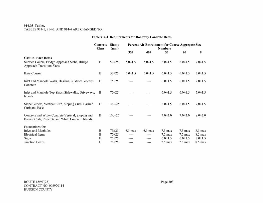
ROUTE 1&9T(25) Page 303 CONTRACT NO. 003970114 HUDSON COUNTY
914.05 Tables. TABLES 914-1, 914-3, AND 914-4 ARE CHANGED TO:
Table 914-1 Requirements for Roadway Concrete Items Concrete
Class Slump (mm)
Percent Air Entrainment for Coarse Aggregate Size Numbers
357 467 57 67 8
Cast-in-Place Items Surface Course, Bridge Approach Slabs, Bridge Approach Transition Slabs
B 50±25 5.0±1.5 5.0±1.5 6.0±1.5 6.0±1.5 7.0±1.5
Base Course B 50±25 5.0±1.5 5.0±1.5 6.0±1.5 6.0±1.5 7.0±1.5 Inlet and Manhole Walls, Headwalls, Miscellaneous Concrete
B 75±25 ---- ---- 6.0±1.5 6.0±1.5 7.0±1.5
Inlet and Manhole Top Slabs, Sidewalks, Driveways, Islands
B 75±25 ---- ---- 6.0±1.5 6.0±1.5 7.0±1.5
Slope Gutters, Vertical Curb, Sloping Curb, Barrier Curb and Base
B 100±25 ---- ---- 6.0±1.5 6.0±1.5 7.0±1.5
Concrete and White Concrete Vertical, Sloping and Barrier Curb, Concrete and White Concrete Islands
B 100±25 ---- ---- 7.0±2.0 7.0±2.0 8.0±2.0
Foundations for: Inlets and Manholes B 75±25 6.5 max 6.5 max 7.5 max 7.5 max 8.5 max Electrical Items B 75±25 ---- ---- 7.5 max 7.5 max 8.5 max Signs B 75±25 ---- ---- 6.0±1.5 6.0±1.5 7.0±1.5 Junction Boxes B 75±25 ---- ---- 7.5 max 7.5 max 8.5 max

ROUTE 1&9T(25) Page 304 CONTRACT NO. 003970114 HUDSON COUNTY
Table 914-1 (Continued)
Concrete
ClassSlump (mm)
Percent Air Entrainment for Coarse Aggregate Size Numbers
357 467 57 67 8 Cast-in-Place Items (continued) Footings for Fence Posts, Guide Rail End Treatment B 75±25 ---- ---- 7.5 max 7.5 max 8.5 max
Culverts A 75±25 ---- ---- 6.0±1.5 6.0±1.5 7.0±1.5
Monuments A 75±25 ---- ---- 7.5 max 7.5 max 8.5 max
Slope Protection B 50±25 ---- ---- 6.0±1.5 6.0±1.5 7.0±1.5
Precast Items Culverts A 75±25 ---- ---- 6.0±1.5 6.0±1.5 7.0±1.5 Inlets and Manholes, Junction Boxes, Headwalls, Reinforced Concrete End Sections (See note 2)
B 75±25 ---- ---- 6.0±1.5 6.0±1.5 7.0±1.5
Concrete and White Concrete Barrier Curb B 75±25 ---- ---- 7.0±2.0 7.0±2.0 8.0±2.0
Note 1: According to Subsection 501.03, a Type F water-reducing, high range admixture will be permitted according to Subsection 905.02 and Subsection 914.02, Subparts B and C. When a Type F admixture is used, the table Slump and Air Content values for the given concrete item shall be changed as follows:
Slump: 150 ± 50 millimeters Air Content: Increase both the target value and tolerance percentages by 0.5.
Note 2: For the items in this category, the slump may be reduced to zero (dry cast) provided that adequate consolidation,
acceptable to the Engineer, is achieved.

ROUTE 1&9T(25) Page 305 CONTRACT NO. 003970114 HUDSON COUNTY
Table 914-3 Mix Design Requirements
Class of Concrete
A
B
S
P
P-1
P-2 Class Design Strength (28 days, Mpa Note 3)
32
26
14
38
42
45
Verification Strength (28 days, Mpa Note 3)
37
31
--
42
45
48
Maximum Water/Cement Ratio (Note 2) kg/kg L/bag
0.443 19
0.488 21
0.577 25
Note 1 Note 1
Note 1 Note 1
Note 1 Note 1
Minimum Cement Content kg/m3 bags/m3
363 8.5
335 7.8
391 9.2
Note 1 Note 1
Note 1 Note 1
Note 1 Note 1
Note 1: According to PCI Manual, except as indicated in Note 2.
Note 2: The maximum water/cement ratio for all classes of concrete except for Classes P,
P-1 and P-2, when a Type F water-reducing, high range admixture is used according to Tables 914-1 and 914-2, shall be reduced by 0.40 kg/kg (17.0 L/bag).
Note 3: All concrete test results shall be recorded to the nearest 0.10 Mpa.
Note 4: To successfully meet the requirements of this specification, the target production
strength must be higher than the Class Design Strength by an amount proportional to the Producer’s within-lot standard deviation.
Table 914-4 Lot Sizes, Sampling Rates and Retest Limits
Class of Concrete A B S P P-1 P-2 Lot Size (maximum)
One Day's Production
One Day's Production of a
Single Steam Bed Pay-Adjustment Items Initial Sampling Rate 5/Lot 5/Lot -- 5/Lot 5/Lot 5/Lot Retest Sampling Rate (minimum) 5/Lot 5/Lot -- 5/Unit or Load Test
Non-Pay-Adjustment Items Initial Sampling Rate 3/Lot 2/Lot 1/Lot 3/Lot 3/Lot 3/Lot Retest Limit (Mpa) 30 25 14 37 41 44 Retest Sampling Rate 5/Lot 5/Lot 5/Lot 5/Lot 5/Lot 5/Lot
ROUTE 1&9T(25) Page 306 CONTRACT NO. 003970114 HUDSON COUNTY
Note 1: The lot sizes are maximums and, at the option of the Engineer, any lot may be subdivided into two or more smaller lots. When such a subdivision is made, the specified sampling rate applies to each of the smaller lots.
Note 2: An initial strength test result is defined as the average strength of two 100 by
200 millimeter compression test cylinders, cured for 28 days, and tested in the Department Laboratory except for Classes P, P-1, and P-2 cylinders which may be tested at the fabricator's plant under the supervision of the Engineer.
Note 3: A retest result is defined as the strength of an individual test result obtained by
coring or other suitable means. If retest is performed by coring, each retest result is defined as the corresponding nominal core strength divided by 0.85.
Note 4: The specified sampling rates shall apply except that no more than one test per
truckload or batch of concrete will be required (except for air and slump tests when retempering). It is expected that each structural component will have a representative sample taken. At the option of the Engineer, nonstructural concrete lots consisting of 15 cubic meters or less may be accepted without strength tests.
Note 5: No lot shall include more than one class of concrete nor include concrete of the
same class having different specified levels of slump or air entrainment.
Note 6: For prestressed concrete, if more than one bed is used or if more than 60 cubic meters of concrete are used, the production shall be subdivided as equally as possible into two or more lots.
Note 7: Retest limit for non-pay-adjustment roadway and structural items requiring the use
of Class B, white concrete, shall be 21 Mpa.
SECTION 915 – REINFORCEMENT STEEL 915.02 Prestressing Reinforcement.
C. Grit Impregnated Epoxy-Coated Prestressing Steel. THE FIRST SENTENCE IS CHANGED TO:
Grit impregnated epoxy-coated prestressing steel strands shall conform to the requirements of ASTM A 882 and to the criteria specified in 502.06.
915.03 Reinforcement Steel for Concrete Base and Concrete Surface Courses SUBPART 5 TEXT IS CHANGED TO:
5. Dowels. Dowel bars in transverse joints shall be epoxy-coated, Grade 60, plain reinforcement steel conforming to ASTM A 615. If specified, dowel bars shall be fitted with end caps. The end caps shall be non-metallic and designed to prevent the entrance of grout or mortar into the expansion void. End caps shall have a maximum length of 64 millimeters and shall allow a minimum of 19 millimeters of movement.
SECTION 916 - SIGN MATERIALS
916.04 Retroreflective Sheeting. THE ENTIRE SUBSECTION IS CHANGED TO:
As stated herein, the terms reflective sheeting and retroreflective sheeting are synonymous. Retroreflective sheeting shall conform to ASTM D 4956 based upon results obtained and reported through testing
performed by the National Transportation Product Evaluation Program (NTPEP).

ROUTE 1&9T(25) Page 307 CONTRACT NO. 003970114 HUDSON COUNTY
Fluorescent retroreflective sheeting shall be selected from the approved products list as provided in the Special Provisions.
1. General Requirements. a. Retroreflectance. All retroreflective sheeting shall have the minimum coefficient of retroreflection
(RA) in conformance with ASTM D 4956. b. Color. The colors of the retroreflective sheeting, except for fluorescent colors shall conform the color
requirements of ASTM D 4956. c. Fluorescent Colors. The daytime fluorescent color of retroreflective sheeting shall be determined
according to ASTM E 991. In addition, the color shall be equally distinguishable in daylight and at night under artificial
headlight illumination. The color shall have a consistent chromaticity across all signs of the same color. Noticeable deviation from the shades that would affect the required performance shall be a cause for rejection of any sheeting or completed sign at any time before acceptance. For sheeting that is directional, the datum mark (arrow) imprinted on the face of the sheeting shall be the datum mark for test purposes.
d. Product Performance Requirements. The retroreflective sheeting manufacturer shall meet the following requirements for their products. (1) Type III Sheeting – Sheeting shall be required to have a service life span of at least 12 years. (2) Types VI, VII, VIII AND IX Sheeting – Sheeting shall be required to have a service life span of at
least 10 years. (3) The performance requirements shall be such that there is: no loss of retroreflectivity; no loss of
colorfastness; no cracking; and no other conditions inherent to the sheeting including inks and overlay film that causes it to be incapable of performing as required.
2. Certification of Compliance. The manufacturer shall submit a certification of compliance according to Subsection 106.04 for each lot of sheeting supplied for use on the Project.
916.05 Legends, Borders, and Accessories. THE FOLLOWING IS ADDED AFTER THE SECOND PARAGRAPH:
All finished signs shall be clear and legible without smudging, blisters, delamination, loose edges or other blemishes.
1. Type A Demountable. THE FIRST AND SECOND PARAGRAPHS ARE CHANGED TO:
The demountable sign letters, digits, arrows, borders, and alphabet accessories shall be reflectorized and shall consist of ASTM D 4956 Type VIII OR IX wide angle prismatic retroreflective sheeting applied to 10-millimeter cutout aluminum plates conforming to ASTM B 209, Alloy 6061-T6 or 5052.
All shields and symbols to be mounted to sign types GO, GOX, and GA on breakaway tubular posts shall consist of ASTM D 4956 Type VIII OR IX wide angle prismatic retroreflective sheeting applied to 5-millimeter cutout aluminum plates conforming to ASTM B 209, Alloy 6061-T6.
2. Type B Direct and Permanently Applied Retroreflective Sheeting Copy.
SUBPART D, E, & F ARE DELETED AND C IS CHANGED TO:
c. When the background is ASTM D 4956 Type III sheeting, ASTM D 4956 Type III sheeting shall be used for copy.
916.08 Fabrication.
8. Shop Painting and Reflectorization. a. Application.
THE LAST SENTENCE IN THE THIRD PARAGRAPH IS CHANGED TO:
Sheeting applied to extruded sections shall extend over top edges and down side legs a minimum of 2 millimeters; except that where ASTM D 4956 Type VIII or IX sheeting is used, it shall be cut at the top edges according to the manufacturer’s recommendation.
ROUTE 1&9T(25) Page 308 CONTRACT NO. 003970114 HUDSON COUNTY
c. Screen Process Printing.
THE THIRD SENTENCE IN THE FIRST PARAGRAPH IS CHANGED TO:
Transparent screen process paint, after application to the retroreflective sheeting and thoroughly dry shall conform to the color requirements ASTM D 4956.
9. Packaging, Storage, and Shipping.
THE FIRST SENTENCE IN THE FIRST PARAGRAPH IS CHANGED TO:
Packaging, storage, and shipping of signs produced using retroreflective sheeting shall be according to the sheeting manufacturer’s recommendations.
916.10 Breakaway Steel “U” Post Sign Supports. THE HEADING AND ENTIRE SUBSECTION TEXT IS CHANGED TO: 916.10 Steel “U” Post Sign Supports.
The steel “U” post sign supports shall conform to ASTM A499. Signs shall be secured to the steel “U” post by means of 18-8 stainless steel M8 x 1.25 hexagonal headed bolts and nuts conforming to ASTM A 320M, Grade B8, Class 1. Sign mounting bolts shall extend beyond the end of each nut but not more than 20 millimeters when fully tightened.
The steel “U” posts shall be straight and have a smooth finish, free of burrs. The list of the approved products will be provided by the Bureau of Materials Engineering and Testing.
916.14 Flexible Delineators.
2. Composition. THE FIRST PARAGRAPH IS CHANGED TO:
For ground mounted flexible delineators, the portion of the delineator above ground shall be one component, or shall be bonded together if it consists of two or more components. The shape of the delineator post where the retroreflective sheeting is applied shall have a cross section that protects the sheeting from abrasion upon impact.
10. Mowability. THE ENTIRE SUBPART IS DELETED.
11. Sampling Rate THE SUBPART NUMBER IS CHANGED TO:
10. Sampling Rate. 916.17 Tables. THE ENTIRE SUBSECTION IS DELETED.
SECTION 917 – STRUCTURAL STEEL AND OTHER FERROUS METALS 917.01 Bolts and Bolting Material.
2. Specifications. THE FOLLOWING IS ADDED:
c. Direct Tension Indicators shall comply with ASTM F 959 and shall be accepted and installed according to Test Method S-3, “Procedure for Identification and Installation of High Strength Bolts with Direct Tension Indicators (DTI’s)”.
3. Manufacturing.
a. Bolts. THE FIRST SENTENCE IS CHANGED TO:

ROUTE 1&9T(25) Page 309 CONTRACT NO. 003970114 HUDSON COUNTY
Hardness for bolt diameters 6 millimeters to 13 millimeters, inclusive, shall be as noted: THE FOLLOWING IS ADDED:
When atmospheric corrosion resistant weathering steel is to be used, Type 3 bolts shall be used. THE FOLLOWING IS ADDED:
d. Direct Tension Indicators (DTI’s). When galvanizing of the bolt assembly is required, DTI’s shall be mechanically galvanized in accordance with AASHTO M 298, Class 50 (ASTM B 695, Class 50). DTI’s to be used for Type 3 bolts shall be epoxy coated with a black color.
4. Testing.
THE FOLLOWING IS ADDED:
g. Direct Tension Indicators (DTI’s). DTI’s shall be tested according to ASTM F 959.
7. Installation. THE SUBPART A. IS CHANGED TO:
a. Bolts shall be installed according to the appropriate AASHTO Specifications. Direct Tension Indicators (DTI’s) shall be used with high strength bolts to verify the required tension. The provisions of Article 11.5.6.4.7 of Division II of the AASHTO Standard Specifications or of Article 11.5.6.4.7 of the AASHTO LRFD Bridge Construction Specifications shall be followed. If warranted and as directed by the Engineer, the face of the nut shall be smeared with wax before it is installed. The Castral Stick Wax lubricant, beeswax or a water wax emulsion; such as, the MacDermid “Torque ’N Tension Control Fluid” may be used.
THE FOLLOWING IS ADDED AT THE END OF THE SUBSECTION:
Anchor bolts, rock anchors, and hardware shall conform to AASHTO M 270M Grade 250 and shall be galvanized after fabrication, including threading, according to ASTM A 153.
Dowels used to anchor prestressed concrete voided slabs and box beams to abutments and piers shall conform to AASHTO M 270M Grade 250 and shall be galvanized to ASTM A 153. Threading of dowels is not required.
Welded steel shear connectors shall conform to Division II, Section 11 of the AASHTO Standard Specifications for Highway Bridges or Section 11 of the AASHTO LRFD Bridge Construction Specifications.
Stainless steel bolts, nuts, and washers shall conform to ASTM A 320, Class 1, Grade B8 (AISI Type 304). For overhead and cantilever sign support structures, bolts, nuts and washers for steel to steel chord splices shall
conform to AASHTO M 164 and be hot-dip galvanized as per ASTM A 153. As an alternate, bolts, nuts and washers conforming to AASHTO M 164 may be substituted for bolts, nuts, and
washers of the same diameter, length, and thickness conforming to ASTM A 307. 917.03 Castings, Materials and Components for Drainage Structures. THE FIRST PARAGRAPH IS CHANGED TO:
All inlet and manhole castings, grates, extension rings, extension frames and covers shall be capable of withstanding the proof load testing requirements specified in AASHTO M 306 when they are tested as a complete assembled unit and shall conform to the following:
SECTION 919 - MISCELLANEOUS 919.02 Bearing Pads.
A. Elastomeric Bearing Pads. THE FIRST PARAGRAPH IS CHANGED TO:

ROUTE 1&9T(25) Page 310 CONTRACT NO. 003970114 HUDSON COUNTY
Elastomeric bearing pads for bridge beams shall conform to Division II, Section 18 of the AASHTO Standard Specifications for Highway Bridges or Section 18 of the AASHTO LRFD Bridge Construction Specifications.
919.07 Fly Ash. THE FIRST PARAGRAPH IS CHANGED TO:
Fly ash for portland cement concrete shall conform to ASTM C 618, Class C or Class F except that the loss on ignition shall not be more than three percent. Fly ash used to control alkali-silica reactivity shall be Class F. Before each source of fly ash is approved, certified results of tests conducted by a testing agency shall be submitted to and verified by the Department. Accompanying the certification shall be a statement from the supplier listing the source and type of coal, the methods used to burn, collect, and store the fly ash, and the quality control measures employed. 919.11 Portland Cement. THE TITLE AND SUBSECTION ARE CHANGED TO: 919.11 Portland or Blended Hydraulic Cement.
Portland cement shall conform to the following: Masonry Cement ................................................................................................................ASTM C 91 Portland Cement, Type I, II, and Type III (see Note 1)....................................................ASTM C 150 White Portland Cement, Type I and III (see Note 2)........................................................ASTM C 150 Blended Hydraulic Cement (see Note 3).........................................................................ASTM C 595
Note 1: Type III may be used only for prestressed or precast items. Note 2: Shall not contain more than 0.55 percent by weight of ferric oxide (Fe2O3). Note 3: Only types IS, I(PM), and I(SM) may be used. Portland cement, may be pre-blended with a
maximum of 15 percent fly ash, by weight, or a maximum of 10 % silica fume by weight, or with a maximum of 50% GGBFS by weight. If more than 30% GGBFS is used, a scaling test conforming to ASTM C 672 must be completed on the mix design and the concrete must have a visual rating less than 3 as based on ASTM C672 10.1.5 after 50 cycles.
When blended portland cement is used, no additional mineral admixtures shall be added. Different brands of cement, the same brand of cement from different mills or different types of cement shall not be
mixed. Suitable means shall be provided for storing and protecting the cement against dampness. Cement which for any
reason has become partially set or which contains lumps of caked cement will be rejected. The temperature of the cement at the time of delivery to the mixer shall not exceed 71 °C. 919.17 Epoxy Bedding and Bonding Compound. THE ENTIRE SUBSECTION TEXT IS CHANGED TO:
Epoxy bedding and bonding compound shall be a 2-part, non-sag gel, rapid-setting epoxy adhesive conforming to the requirements of ASTM C 881, Type IV, Grade 3, Class B or C. Certifications of compliance shall be furnished according to Subsection 106.04. 919.18 Ground, Granulated Blast Furnace Slag. THE SECOND PARAGRAPH IS CHANGED TO:
Ground, granulated blast furnace slag may be used as a replacement for portland cement as specified in Subsection 919.11 up to a maximum replacement level of 50 percent by weight. Replacement of portland cement greater than 30 percent will require a scaling test on the mix design conforming to ASTM C 672 with a visual rating less than 3. 919.19 Sampling and Testing Methods THE FOLLOWING ARE ADDED:
Mineral Admixtures ........................................................................................4-kilograms from each source Blended Hydraulic Cement.......................................................................................................ASTM C 595

ROUTE 1&9T(25) Page 311 CONTRACT NO. 003970114 HUDSON COUNTY
THE FOLLOWING NEW SUBSECTION IS ADDED: 919.22 Controlled Low Strength Material (CLSM).
CLSM shall conform to the following: Fine Aggregate.................................................................................................................................... 901.12 Chemical Admixtures ......................................................................................................................... 905.02 Portland Cement, Type I, II, III .......................................................................................................... 919.11 Water................................................................................................................................................... 919.15
CLSM shall consist of a mixture of portland cement, water, fine aggregate and chemical admixtures. Fly ash shall not be permitted in mixes intended for trench backfilling. The CLSM mixture shall be proportioned to provide a backfill material that is self-compacting and capable of being excavated with hand tools at a later date. CLSM shall be proportioned to produce a 28-day compressive strength of 345 to 1 035 kilopascals. An accelerating admixture shall be used to produce a fast setting flowable mixture as required. The CLSM shall have a permeability of 1.7 x 10⁻³ ± 0.2 x 10⁻³ centimeters per second according to ASTM D5084 for backfilling of conduits and piping.
At least 45 days prior to the start of any CLSM placement, trial batches of CLSM shall be prepared of the same materials and proportions proposed for use on the project. Each mix design shall be submitted on portland cement concrete mix design forms furnished by the Department, naming the sources of materials and test data.
Department personnel will be present at the time of verification batching to confirm that the proportions and materials batched are according to the proposed mix designs. At least six 150 X 300 millimeters compression test cylinders shall be prepared for each batch according to ASTM 5971-96 for 28-day strengths except for fast setting mixes, which shall be tested at the specified cure time. THE FOLLOWING SECTION IS ADDED:
SECTION 921 – FIBERGLASS REINFORCED PLASTIC LUMBER
The furnishing of Fiberglass Reinforced Plastic Lumber (FRPL) shall conform to the following material properties: 1. Plastic. The plastic for FRPL shall be a mixture of one or more of the following recycled post consumer or
post industrial thermoplastics: high-density polyethylene, medium-density polyethylene or, low-density polyethylene. The plastic shall be mixed with appropriate colorants, UV inhibitors and antioxidants so that the resulting product meets the material property requirements specified in Table I below.
FRPL shall not absorb moisture, corrode, rot, warp, splinter or crack. The outer skin shall be smooth and black in color unless otherwise specified in the contract plans. It shall contain hindered amine light stabilizers to provide sufficient resistance to ultraviolet light degradation so as to meet the requirements in Table I below.
2. Manufacturing. Manufacture FRPL as one continuous piece with no joints or splices to the dimensions and tolerances in accordance with Table 2 and consisting of a dense outer skin surrounding a less dense core. Interior voids shall not exceed 19 millimeters in diameter. FRPL shall be free of twist and curvature.
3. Reinforcement. FRPL shall be reinforced by fiberglass reinforcing rods spaced inside the four corners of the timber. Reinforce 254 MM x 254 MM FRPL with a minimum of four 38 millimeters diameter reinforcing rods placed in the corners of the section. Reinforce 305 MM x 305 MM FRPL with a minimum of four 38 millimeters diameter reinforcing rods placed in the corners of the section. Reinforcing rods must be continuous and offer a minimum flexural strength of 483 megapascals when tested in accordance with ASTM D 4476 and a minimum compressive strength of 276 megapascals when tested in accordance with ASTM D 695. Steel reinforcing rods shall not be permitted. All FRPL used for constructing platforms, blocking and wales shall have a minimum of 15% (by weight) chopped glass reinforcement added to the polyethylene. No fiberglass rebar will be required for the smaller dimensional FRPL.
4. Structural Properties. 254 MM x 254 MM and 305 MM x 305 MM FRPL shall meet the minimum structural properties (+/- 10%) listed in Tables 3A and 3B. Smaller, dimensional FRPL for platforms and blocking shall meet the minimum structural properties listed in Table 4.
TABLE 1: PLASTIC MATERIAL PROPERTIES
Density (ASTM D792) Skin 881-1009-kilograms/cubic meter Density (ASTM E1547) Core 54.4-769- kilograms/cubic meter Water Absorption (ASTM D570) Skin 2 hrs: <1.0% wt. increase

ROUTE 1&9T(25) Page 312 CONTRACT NO. 003970114 HUDSON COUNTY
24 hrs: <3.0% wt. increase Brittleness (ASTM D746) Skin No break at -4.4oC Impact Resistance (ASTM D746) Skin Greater than 0.22 N.m/millimeters Hardness (ASTM D2240) Skin 44-75 (Shore D) Abrasion (ASTM D4060) Cycles = 10,000 Wheel = CS17 Load – 1.0 kilograms
Skin Weight Loss: <0.03g Wear Index: 2.5 to 3.0
Chemical Resistance (ASTM D543)
Skin/Core Sea Water Gasoline No. 2 Diesel
<1.5% weight increase <7.5% weight increase <6.0% weight increase
Tensile Properties (ASTM D638) Skin/Core Minimum 3.4 MPa at break Compressive Modulus (ASTM D695) Skin/Core Minimum 276 MPa Coefficient of Friction (ASTM F489) Skin Maximum 0.25, wet or dry Nail Pull-Out (ASTM D1761) Skin/Core Minimum 27 kilograms
TABLE 2: DIMENSIONS AND TOLERANCES
Plastic Timber Dimension Tolerance Length Per order ± 150 millimeters Width See Contract Plans ± 6 millimeters Height See Contract Plans ± 6 millimeters Corner Radius 1.75 millimeters ± 6 millimeters Outer Skin Thickness 0.1875 millimeters ± 3 millimeters Distance from outer surface to rebar elements
1.5 millimeters ± 3 millimeters
Straightness (gap, bend or bulge inside while lying on a flat surface)
<38 millimeters per 1 meter length
TABLES 3-A AND 3-B: STRUCTURAL PROPERTIES
Table 3-A Member Size 254 millimeters x 254 millimeters Modulus of Elasticity as derived below 3592 MPa Stiffness, E.I. 1162 kN-m2 Yield Stress in Bending 40 MPa Weight 45-55 kg/m
Table 3-B Member Size 305 millimeters x 305 millimeters Modulus of Elasticity as derived below 2792 MPa Stiffness, E.I. 1888 kN-m2 Yield Stress in Bending 30 MPa Weight 63-76 kg/m
5. Modulus of Elasticity. Determine the Modulus of Elasticity of a full size specimen by conducting a three
point bend test with a load applied in the center of a simply supported 4267 millimeters span at a deflection rate of 6 millimeters per minute. The Modulus is to be taken at a strain of 0.25 millimeters per millimeters, where strain equals (6) x (depth of cross section) x (deflection) / (span length squared) and where Modulus of Elasticity equals (load) x (span length cubed) / [(48) x (deflection) x (moment of inertia)].
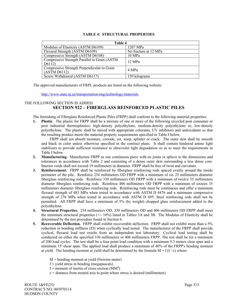
ROUTE 1&9T(25) Page 313 CONTRACT NO. 003970114 HUDSON COUNTY
TABLE 4: STRUCTURAL PROPERTIES
Table 4
Modulus of Elasticity (ASTM D6109) 1207 MPa Flexural Strength (ASTM D6109) No fracture at 12 MPa Compressive Strength (ASTM D6108) 10 MPa Compressive Strength Parallel to Grain (ASTM D6112) 12 MPa Compressive Strength Perpendicular to Grain (ASTM D6112) 4 MPa Screw Withdrawal (ASTM D6117) 159 kilograms
The approved manufacturers of FRPL products are listed on the following website:
http://www.state.nj.us/transportation/eng/technology/materials
THE FOLLOWING SECTION IS ADDED:
SECTION 922 – FIBERGLASS REINFORCED PLASTIC PILES
The furnishing of Fiberglass Reinforced Plastic Piles (FRPP) shall conform to the following material properties: 1. Plastic. The plastic for FRPP shall be a mixture of one or more of the following recycled post consumer or
post industrial thermoplastics: high-density polyethylene, medium-density polyethylene or, low-density polyethylene. The plastic shall be mixed with appropriate colorants, UV inhibitors and antioxidants so that the resulting product meets the material property requirements specified in Table I below.
FRPP shall not absorb moisture, corrode, rot, warp, splinter or crack. The outer skin shall be smooth and black in color unless otherwise specified in the contract plans. It shall contain hindered amine light stabilizers to provide sufficient resistance to ultraviolet light degradation so as to meet the requirements in Table I below.
2. Manufacturing. Manufacture FRPP as one continuous piece with no joints or splices to the dimensions and tolerances in accordance with Table 2 and consisting of a dense outer skin surrounding a less dense core. Interior voids shall not exceed 19 millimeters in diameter. FRPP shall be free of twist and curvature.
3. Reinforcement. FRPP shall be reinforced by fiberglass reinforcing rods spaced evenly around the inside perimeter of the pile. Reinforce 254 millimeters OD FRPP with a minimum of six 25 millimeters diameter fiberglass reinforcing rods. Reinforce 330 millimeters OD FRPP with a minimum of twelve 35 millimeters diameter fiberglass reinforcing rods. Reinforce 406 millimeters OD FRPP with a minimum of sixteen 35 millimeters diameter fiberglass reinforcing rods. Reinforcing rods must be continuous and offer a minimum flexural strength of 483 MPa when tested in accordance with ASTM D 4476 and a minimum compressive strength of 276 MPa when tested in accordance with ASTM D 695. Steel reinforcing rods shall not be permitted. All FRPP shall have a minimum of 5% (by weight) chopped glass reinforcement added to the polyethylene.
4. Structural Properties. 254 millimeters OD, 330 millimeters OD and 406 millimeters OD FRPP shall meet the minimum structural properties (+/- 10%) listed in Tables 3A and 3B. The Modulus of Elasticity shall be determined by the test procedure found in Section 6.
5. Recoverable Deflection. FRPP shall exhibit recoverable deflection. FRPP shall not exhibit more than a 5% reduction in bending stiffness (EI) when cyclically load tested. The manufacturer of the FRPP shall provide cyclical, flexural load test results from an independent test laboratory. Cyclical load testing shall be conducted on either the specified 330 millimeters or 406 millimeters FRPP. The test shall be for a minimum of 200 load cycles. The test shall be a four point load condition with a minimum 9.3 meters clear span and a minimum 15' shear span. The applied load shall produce a minimum of 40% of the FRPP's bending moment at yield. The bending moment at yield shall be determined by the formula M = f (I / c) where:
M = bending moment at yield (Newton meter) f = yield stress in bending (megapascals) I = moment of inertia of cross-section (MM4) c = distance from neutral axis to point where stress is desired (millimeters)

ROUTE 1&9T(25) Page 314 CONTRACT NO. 003970114 HUDSON COUNTY
TABLE 1: PLASTIC MATERIAL PROPERTIES
Density (ASTM D792) Skin 881-1009- kilograms/cubic meter Density (ASTM E1547) Core 544-769- kilograms/cubic meter
Water Absorption (ASTM D570) Skin
2 hrs: <1.0% wt. increase 24 hrs: <3.0% wt. increase
Brittleness (ASTM D746) Skin No break at -4oC Impact Resistance (ASTM D746) Skin Greater than 0.22 N.m/millimeters Hardness (ASTM D2240) Skin 44-75 (Shore D) Abrasion (ASTM D4060) Cycles = 10,000 Wheel = CS17 Load – 1 kg
Skin Weight Loss: <0.03g Wear Index: 2.5 to 3.0
Chemical Resistance (ASTM D543)
Skin/Core Sea Water Gasoline No. 2 Diesel
<1.5% weight increase <7.5% weight increase <6.0% weight increase
Tensile Properties (ASTM D638) Skin/Core Minimum 3.4 MPa at break Compressive Modulus (ASTM D695) Skin/Core Minimum 276 MPa Coefficient of Friction (ASTM F489) Skin Maximum 0.25, wet or dry Nail Pull-Out (ASTM D1761) Skin/Core Minimum 27 kgs
TABLE 2: DIMENSIONS AND TOLERANCES
FRPP Dimension Tolerance Length Per order (32 meters max) +150MM / -0.0 MM Outside Diameter 254 MM / 327 MM / 413 MM ± 10 MM Outer Skin Thickness 5 MM/ 5 MM / 5 MM ± 3 MM Distance from outer surface to rebar elements (SFRPP) 22 MM /19 MM / 32 MM ± 10 MM
Straightness (gap, bend or inside while lying on a flat surface) <38 millimeters per
3048 millimeters
TABLES 3-A and 3-B: STRUCTURAL PROPERTIES
Table 3-A Member Size 254 MM OD Modulus of Elasticity as derived below 3158 MPa Stiffness, E.I. 6457 kN-m2 Yield Stress in Bending 30 MPa Bending Moment at Yield 47644 N.M Weight 36-43 kg/m
Table 3-B Member Size 330 MM OD Modulus of Elasticity as derived below 7267 MPa Stiffness, E.I. 4247 kN-m2 Yield Stress in Bending 59 MPa Bending Moment at Yield 209994 N.m Weight 67-82 kg/m
Table 3-C
Member Size 406 MM OD Modulus of Elasticity as derived below 6874 MPa

ROUTE 1&9T(25) Page 315 CONTRACT NO. 003970114 HUDSON COUNTY
Table 3-C Stiffness, E.I. 9212 kN-m2 Yield Stress in Bending 54 MPa Bending Moment at Yield 357667 N.m Weight 98-121 kg/m
6. Modulus of Elasticity. The Modulus of Elasticity shall be determined by the following test procedure:
a. Place a 16.5 meters long standard commercial type FRPP in a clamping device so that 1.8 meters of
the piling will be firmly fixed and unable to move. b. The opposite end is to simply supported. c. Gradually apply a vertical (downward) load at a point that is 3.7 meters from the simply-supported
end. d. Measure the deflection along the length of the piling at the load point, and 3 equidistant locations. e. Use the load and deflection data to calculate the flexural modulus of elasticity, maximum outer fiber
stress, stiffness (EI), and the bending stress. f. The flexural modulus of elasticity is calculated by dividing EI by the moment of inertia of the cross
section of the product.
Calculate the properties in Table 3A and 3B utilizing standard elastic beam flexure formulas (as found in references such as Machinery’s Handbook; and Formulas for Stress and Strain, by Roark and Young). Report the Stiffness (EI) as the average of the stiffness at all measurement locations, between zero load and half the load corresponding to the specification yield stress. The specified minimum yield stress in bending shall be reached before failure of the product. Calculate the stress at the load point, on the tension side of the plastic composite marine piling.
As stated, conduct the tests on a full-scale product of the specified size. The results of these tests may be extended through engineering calculations, to a product of another size only if the other size has the same or smaller cross section than the tested product. Do not use smaller cross sections to predict the performance of larger cross sections.
7. Wrapping. Wrapping for the FRPP that are to be placed in clusters shall be 13 MM diameter steel cable (16
MM OD covering) polypropylene impregnated wire rope.
The approved manufacturers of FRPP products are listed on the following website:
http://www.state.nj.us/transportation/eng/technology/materials THE FOLLOWING SECTION IS ADDED:
SECTION 923 – FIBERGLASS-CONCRETE COMPOSITE PILES
The Fiberglass-Concrete Composite Piles (FCCP) shall consist of three components: a hollow composite tube, a concrete core and a durable coating. The furnishing of FCCP shall conform to the following material properties:
1. Composite Tubes. Composite tubes shall be produced of composite FRP (Fiber Reinforced Polymer) materials that have been formed by means of pultrusion, filament winding, scrimp, or by other methods of production. E-Glass or other continuous fiber reinforcement shall be incorporated in the shell and shall be impregnated with vinyl ester, polyester, or epoxy resin. The content of the structural wall shall be 50 to 70 percent glass with a minimum of 25 percent resin (by weight). The manufactured tubes shall be capable of withstanding normal handling, shipment, and installation procedures.
The Tubes shall exhibit superior corrosion and ultraviolet resistance as demonstrated when exposed to an accelerated environmental test chamber for not less than 3,600 hours. The tube shall show no structural failure (i.e. <10% loss of strength) as a result of exposure to moisture and lamps required in one of the following: ASTM G152, G155, G154 or B-117.
The Tubes to be used in the fabrication of FCCP shall provide sufficient cross section and strength to withstand stresses incurred by fabrication, handling and driving of the piles to the required resistance.
a. Tolerances. Acceptable tolerances for the fiberglass tubes shall be as follows:

ROUTE 1&9T(25) Page 316 CONTRACT NO. 003970114 HUDSON COUNTY
Minimum Length (millimeters) plus one meter; minus 0 millimeters Maximum Sweep (millimeters)* 0.08% of total length Ends out of Square (millimeters) 1.0% of diameter
* Sweep – deviation from straightness, measured at several points about the pile circumference
while the pile is not subjected to bending stresses. b. Physical Properties. As defined in ASTM D 2310 or D 2996, fiberglass products designated as
follows shall be used:
Class: RTRP (Reinforced Thermosetting Resin Pipe) Type: Type I (filament wound) Grade: Grade 1 (Glass fiber reinforced epoxy resin pipe),
Grade 2 (Glass fiber reinforced polyester resin pipe) or Vinylester resin.
In the manufacture of fiberglass tubes resins containing ultraviolet (UV) inhibitors shall be
used. A UV resistant film coating of a minimum 3 mils thickness to portions of piles remaining exposed after installation shall be applied. Fiberglass tubes that have the following minimum physical properties shall be used:
Nominal Tube Diameter (millimeters)
12 14 16 axial-tensile1 27580
MPa 23097mpa 2800 MPa
axial-compressive2 19305mpa 16203 MPa
1900 MPa Elastic Moduli (MPa) hoop-tensile3 31026
MPa 31026 MPa
31026 MPa
axial-tensile 483 MPa 400 MPa 338 MPa axial-compressive 269 MPa 241 MPa 200 MPa hoop-tensile 241 MPa 241 MPa 241 MPa Strength (MPa)
Wall thickness 4 MM 5 MM 6 MM 1 ASTM D 2105 2 ASTM D 695 (modified – see Allowable Degradation) 3 ASTM D 1599
c. Allowable Degradation. After exposure to light and water spray or salt spray for a duration of
3600 hours the total UV resistance of resin inhibitors and color film shall be sufficient to limit the loss of their properties to the limits specified below. Certification of exposure testing that has been conducted in accordance with at least one of the following ASTM methods: G 152, G 155, G 154 or B 117 shall be provided to the Engineer.
Property Allowable
loss/change Test Designation axial tensile strength loss ≤ 10% ASTM D 2105 axial compressive strength loss ≤ 10% ASTM D 695 (modified)* hoop tensile strength loss ≤ 10% ASTM D 1599 color film adhesion loss ≤ 10% ASTM D 4541 color change ΔΕ 25 ASTM E 308 and D 2244 * ASTM D 695 may be modified as follows: Test specimen dimensions: diameter: full diameter of tube being tested height: 25 millimeters Note. The compression tool described in ASTM D 695 is not to be used. Center the specimen in
the compression test machine and place a steel plate on top of the specimen to evenly distribute the load from the test machine.
ROUTE 1&9T(25) Page 317 CONTRACT NO. 003970114 HUDSON COUNTY
2. Dimensional and Physical Stability. Dimensional and physical stability of materials used in the manufacture of composite piles shall meet the evaluation criteria of ASTM D 696.
3. Color. Color shall be permanent. Color to be provided shall be black or gray. 4. Concrete. As a minimum, concrete infill for FCCP shall conform to Class A concrete strength requirements.
In addition, a positive connection such as either using a composite tube with a textured inside surface, or use of a chemical bonding agent, or by using shrinkage compensating concrete shall be established between the composite tube and concrete core to ensure composite action.
5. Ultimate Flexural Strength. Independent test lab results confirming that the FCCP meet or exceed a 158060 N.m ultimate flexural strength value for a 300 millimeters nominal dimension FCCP shall be submitted to the Engineer. In practice, FCCP should not be designed to their ultimate flexural strength capacity. Due to the strain limitations of concrete in tension, a factor of safety should be applied. For cyclically loaded bridge pier protection applications, FCCP should not be loaded beyond 50% of their ultimate flexural strength or 79030 N.m
6. Wrapping. Wrapping for the FCCP that are to be placed in clusters shall be 13 MM diameter steel cable (16 MM OD covering) polypropylene impregnated wire rope.
The approved manufacturers of FCCP products are listed on the following website:
http://www.state.nj.us/transportation/eng/technology/materials