notice to bidders - BidNet
322
Bids open Thursday, October 8, 2020 Dated August 17, 2020 OSD 08 STATE OF CALIFORNIA DEPARTMENT OF TRANSPORTATION NOTICE TO BIDDERS AND SPECIAL PROVISIONS FOR CONSTRUCTION ON STATE HIGHWAY IN RIVERSIDE COUNTY NEAR LAKE ELSINORE FROM ORANGE COUNTY LINE TO MONTE VISTA STREET In District 08 On Route 74 Under Bid book dated August 17, 2020 Standard Specifications dated 2018 Project plans approved May 4, 2020 Standard Plans dated 2018 Identified by Contract No. 08-1C8504 08-Riv-74-0.0/5.8 Project ID 0813000047 Federal-Aid Project ACHSST-S074(071)E
-
Upload
khangminh22 -
Category
Documents
-
view
1 -
download
0
Transcript of notice to bidders - BidNet

Bids open Thursday, October 8, 2020 Dated August 17, 2020 OSD
08
STATE OF CALIFORNIA DEPARTMENT OF TRANSPORTATION
NOTICE TO BIDDERS AND
SPECIAL PROVISIONS FOR CONSTRUCTION ON STATE HIGHWAY IN RIVERSIDE COUNTY NEAR
LAKE ELSINORE FROM ORANGE COUNTY LINE TO MONTE VISTA STREET In District 08 On Route 74
Under Bid book dated August 17, 2020 Standard Specifications dated 2018
Project plans approved May 4, 2020 Standard Plans dated 2018
Identified by Contract No. 08-1C8504
08-Riv-74-0.0/5.8 Project ID 0813000047
Federal-Aid Project ACHSST-S074(071)E

************************************************************************************************************************
SPECIAL NOTICES
************************************************************************************************************************ • See sections 2 and 3 for contractors' registration requirements. • The Department advises bidders that potential claim records must be submitted by the
contractor using the Department's Internet potential claim system. • See section 2 for submittal requirements for DBE quotes, DVBE quotes, and Non–Small
Business Subcontractor Preference. • See section 2-1.04 for mandatory prebid meeting requirements. • The schedules for the submittal of DBE forms have been revised. See section 2-1.33 for the
submittal schedules. • For work plan for local material from (1) a noncommercial source or (2) a source not regulated
under California jurisdiction, see section 6-1.03B(1). • See section 7-1.02K(3) for the requirements for electronic submittal of certified payroll records
using LCPtracker Pro. • The flagging and temporary traffic control requirements have been revised. See sections 7-
1.03, 7-1.04, and 12.

Contract No. 08-1C8504 i
TABLE OF CONTENTS
NOTICE TO BIDDERS ................................................................................................................................. 1
BID ITEM LIST .............................................................................................................................................. 3
SPECIAL PROVISIONS ............................................................................................................................. 11
ORGANIZATION ........................................................................................................................................ 11
DIVISION I GENERAL PROVISIONS ....................................................................................................... 11
1 GENERAL ............................................................................................................................................... 11
2 BIDDING ................................................................................................................................................. 12
3 CONTRACT AWARD AND EXECUTION .............................................................................................. 12
5 CONTROL OF WORK ............................................................................................................................ 13
6 CONTROL OF MATERIALS ................................................................................................................... 18
7 LEGAL RELATIONS AND RESPONSIBILITY TO THE PUBLIC ........................................................... 22
8 PROSECUTION AND PROGRESS ....................................................................................................... 25
DIVISION II GENERAL CONSTRUCTION ............................................................................................... 26
10 GENERAL ............................................................................................................................................. 26
12 TEMPORARY TRAFFIC CONTROL .................................................................................................... 26
13 WATER POLLUTION CONTROL......................................................................................................... 36
14 ENVIRONMENTAL STEWARDSHIP ................................................................................................... 36
15 EXISTING FACILITIES ......................................................................................................................... 44
DIVISION III EARTHWORK AND LANDSCAPE ....................................................................................... 44
17 GENERAL ............................................................................................................................................. 44
19 EARTHWORK ...................................................................................................................................... 45
20 LANDSCAPE ........................................................................................................................................ 47
DIVISION V SURFACINGS AND PAVEMENTS ....................................................................................... 50
36 GENERAL ............................................................................................................................................. 50
39 ASPHALT CONCRETE ........................................................................................................................ 58
DIVISION VI STRUCTURES ..................................................................................................................... 64
46 GROUND ANCHORS AND SOIL NAILS ............................................................................................. 64
48 TEMPORARY STRUCTURES ............................................................................................................. 73
49 PILING .................................................................................................................................................. 74
52 REINFORCEMENT .............................................................................................................................. 83
53 SHOTCRETE........................................................................................................................................ 87
DIVISION VII DRAINAGE FACILITIES ..................................................................................................... 89
Contract No. 08-1C8504 ii
71 EXISTING DRAINAGE FACILITIES ..................................................................................................... 89
DIVISION VIII MISCELLANEOUS CONSTRUCTION ............................................................................... 89
72 SLOPE PROTECTION ......................................................................................................................... 89
73 CONCRETE CURBS AND SIDEWALKS ............................................................................................. 99
78 INCIDENTAL CONSTRUCTION ........................................................................................................ 100
DIVISION IX TRAFFIC CONTROL DEVICES ......................................................................................... 102
83 RAILINGS AND BARRIERS ............................................................................................................... 102
84 MARKINGS ......................................................................................................................................... 109
DIVISION XI MATERIALS ....................................................................................................................... 109
90 CONCRETE ........................................................................................................................................ 109
REVISED STANDARD SPECIFICATIONS APPLICABLE TO THE 2018 EDITION OF THE STANDARD SPECIFICATIONS .................................................................................................................................... 111

Contract No. 08-1C8504 iii
STANDARD PLANS LIST The standard plan sheets applicable to this Contract include those listed below. The applicable revised standard plans (RSPs) listed below are included in the project plans.
A3A Abbreviations (Sheet 1 of 3)
A3B Abbreviations (Sheet 2 of 3)
A3C Abbreviations (Sheet 3 of 3)
A10A Legend - Lines and Symbols (Sheet 1 of 5)
A10B Legend - Lines and Symbols (Sheet 2 of 5)
A10C Legend - Lines and Symbols (Sheet 3 of 5)
A10D Legend - Lines and Symbols (Sheet 4 of 5)
A10E Legend - Lines and Symbols (Sheet 5 of 5)
A10F Legend - Soil (Sheet 1 of 2)
A10G Legend - Soil (Sheet 2 of 2)
A10H Legend - Rock
A20A Pavement Markers and Traffic Lines - Typical Details
RSP A20B Pavement Markers and Traffic Lines - Typical Details
RSP A20C Pavement Markers and Traffic Lines - Typical Details
RSP A20D Pavement Markers and Traffic Lines - Typical Details
RSP A20E Pavement Markers and Traffic Lines - Typical Detail for Contrast Striping
RSP A20F Pavement Markers and Traffic Lines - Typical Details
A24A Pavement Markings - Arrows
A24B Pavement Markings - Arrows and Symbols
A24C Pavement Markings - Symbols and Numerals
A24D Pavement Markings - Words
RSP A24E Pavement Markings - Words
A40B Shoulder Rumble Strip Details - Ground-In Indentations
A40D Centerline Rumble Strip Details - Ground-In Indentations
A40F Rumble Strip Placement at Intersections with Left Turn Pockets, Railroad Crossings, Private Roads, and Major Driveways
A62A Excavation and Backfill - Miscellaneous Details
A62B Limits of Payment for Excavation and Backfill - Bridge Surcharge and Wall
A62D Excavation and Backfill - Concrete Pipe Culverts
A62DA Excavation and Backfill - Concrete Pipe Culverts - Indirect Design Method
A62E Excavation and Backfill - Cast-In-Place Reinforced Concrete Box and Arch Culverts

Contract No. 08-1C8504 iv
A62F Excavation and Backfill - Metal and Plastic Culverts
RSP A62G Excavation and Backfill - Precast Reinforced Concrete Box Culvert
A73A Object Markers
RSP A73B Markers
A73C Delineators, Channelizers and Barricades
RSP A77L2 Midwest Guardrail System - Standard Railing Section (Steel Post with Notched Wood or Notched Recycled Plastic Block)
A77M1 Midwest Guardrail System - Standard Hardware
A77N2 Midwest Guardrail System - Steel Post and Notched Wood Block Details
RSP A77N3 Midwest Guardrail System - Typical Line Post Embedment and Hinge Point Offset Details
RSP A77N4 Midwest Guardrail System - Typical Railing Delineation and Dike Positioning Details
A77N5 Minor Concrete Vegetation Control - Guardrail System
A77N5A Minor Concrete Vegetation Control - Guardrail System - Narrow Vegetation Control Installation
A77N6 Minor Concrete Vegetation Control - Guardrail System - For Terminal System End Treatments
A77N7 Minor Concrete Vegetation Control - Guardrail System - At Structure Approach
A77N8 Minor Concrete Vegetation Control - Guardrail System - At Fixed Object
A77N9 Minor Concrete Vegetation Control - Guardrail System - At Fixed Object
A77N10 Minor Concrete Vegetation Control - Guardrail System - At Fixed Object
A77N11 Minor Concrete Vegetation Control - Guardrail System - Miscellaneous Details
RSP A77P1 Midwest Guardrail System - Typical Layouts for Embankments
RSP A77P2 Midwest Guardrail System - Typical Layouts for Embankments
RSP A77Q1 Midwest Guardrail System - Typical Layouts for Structure Approach
A77Q2 Midwest Guardrail System - Typical Layouts for Structure Approach and Between Structures
RSP A77Q3 Midwest Guardrail System - Typical Layouts for Structure Approach
RSP A77Q4 Midwest Guardrail System - Typical Layouts for Structure Departure
A77Q5 Midwest Guardrail System - Typical Layouts for Structure Departure
RSP A77R3 Midwest Guardrail System - Typical Layouts for Roadside Fixed Objects
RSP A77R4 Midwest Guardrail System - Typical Layouts for Roadside Fixed Objects
A77S1 Midwest Guardrail System - End Anchor Assembly (Type SFT)
A77S3 Metal Railing Anchor Cable and Anchor Plate Details
A77T2 Midwest Guardrail System - Buried Post End Anchor
A77U1 Midwest Guardrail System - Connections to Bridge Railings without Sidewalks Details No. 1
A77U2 Midwest Guardrail System - Connections to Bridge Railings without Sidewalks Details No. 2
RSP A77U4 Midwest Guardrail System - Transition Railing (Type WB-31)

Contract No. 08-1C8504 v
P74 Pavement Edge Treatments
P76 Pavement Edge Treatments - New Construction
D72B CIP Drainage Inlets - Types G1, G2, G3, G4, G5 and G6
D72C CIP Drainage Inlets - Types G1, G2, G3, G4, G5 and G6
D72F CIP Drainage Inlet Notes
D72G CIP Drainage Inlet Tables
D74 Drainage Inlet Details
D75A Steel Pipe Inlets
D75C Pipe Inlets - Ladder and Trash Rack Details
D77A Grate Details No. 1
D77B Grate Details No. 2
RSP D83A Precast Reinforced Concrete Box Culvert
RSP D83B Precast Reinforced Concrete Box Culvert - Miscellaneous Details
RSP D84 Box Culvert Wingwalls - Types A, B and C
D87D Overside Drains
D88 Construction Loads on Culverts
D88A Strut Details for Structural Steel Pipes, Arches and Vehicular Undercrossing
RSP D89A Pipe Culvert Headwalls - Straight and "L"
RSP D89B Pipe Culvert Headwalls - Straight and "L"
D90 Pipe Culvert Headwalls, Endwalls and Wingwalls - Types A, B and C
D93B Drainage Inlet Riser Connections
D94A Metal and Plastic Flared End Sections
D94B Concrete Flared End Sections
D97A Corrugated Metal Pipe Coupling Details No. 1 - Annular Coupling Band Bar and Strap and Angle Connections
D97C Corrugated Metal Pipe Coupling Details No. 3 - Helical and Universal Couplers
D97D Corrugated Metal Pipe Coupling Details No. 4 - Hugger Coupling Bands
D97E Corrugated Metal Pipe Coupling Details No. 5 - Standard Joint
D97F Corrugated Metal Pipe Coupling Details No. 6 - Positive Joint
D97G Corrugated Metal Pipe Coupling Details No. 7 - Downdrain
D97H Reinforced Concrete Pipe or Non-Reinforced Concrete Pipe - Standard and Positive Joints
D98G Grated Line Drain Details No. 1 - Polymer Concrete, 4" Nominal Width
D100A Gabion Basket Details No. 1
D100B Gabion Basket Details No. 2
T1A Temporary Crash Cushion, Sand Filled (Unidirectional)
Contract No. 08-1C8504 vi
T1B Temporary Crash Cushion, Sand Filled (Bidirectional)
T2 Temporary Crash Cushion, Sand Filled (Shoulder Installations)
T3A Temporary Railing (Type K)
T3B Temporary Railing (Type K)
T9 Traffic Control System Tables for Lane and Ramp Closures
RSP T13 Traffic Control System for Lane Closure on Two Lane Conventional Highways
RSP T21 Traffic Control System Construction Work Zone Speed Limit Reduction Twenty-Four Hours a Day 7 Days a Week (24/7)
T54 Temporary Water Pollution Control Details (Temporary Erosion Control Blanket)
T55 Temporary Water Pollution Control Details (Temporary Erosion Control Blanket)
T56 Temporary Water Pollution Control Details (Temporary Fiber Roll)
T58 Temporary Water Pollution Control Details (Temporary Construction Entrance)
T59 Temporary Water Pollution Control Details (Temporary Concrete Washout Facility)
T60 Temporary Water Pollution Control Details (Temporary Reinforced Silt Fence)
T61 Temporary Water Pollution Control Details (Temporary Drainage Inlet Protection)
T62 Temporary Water Pollution Control Details (Temporary Drainage Inlet Protection)
T63 Temporary Water Pollution Control Details (Temporary Drainage Inlet Protection)
T64 Temporary Water Pollution Control Details (Temporary Drainage Inlet Protection)
T65 Temporary Water Pollution Control Details (Temporary High-Visibility Fence)
B3-5 Retaining Wall Details No. 1
B3-6 Retaining Wall Details No. 2
RSP B11-81 Concrete Barrier Type 842 Details No. 1
RSP B11-82 Concrete Barrier Type 842 Details No. 2
RS1 Roadside Signs - Typical Installation Details No. 1
RS2 Roadside Signs - Wood Post - Typical Installation Details No. 2
RS4 Roadside Signs - Typical Installation Details No. 4
Contract No. 08-1C8504 vii
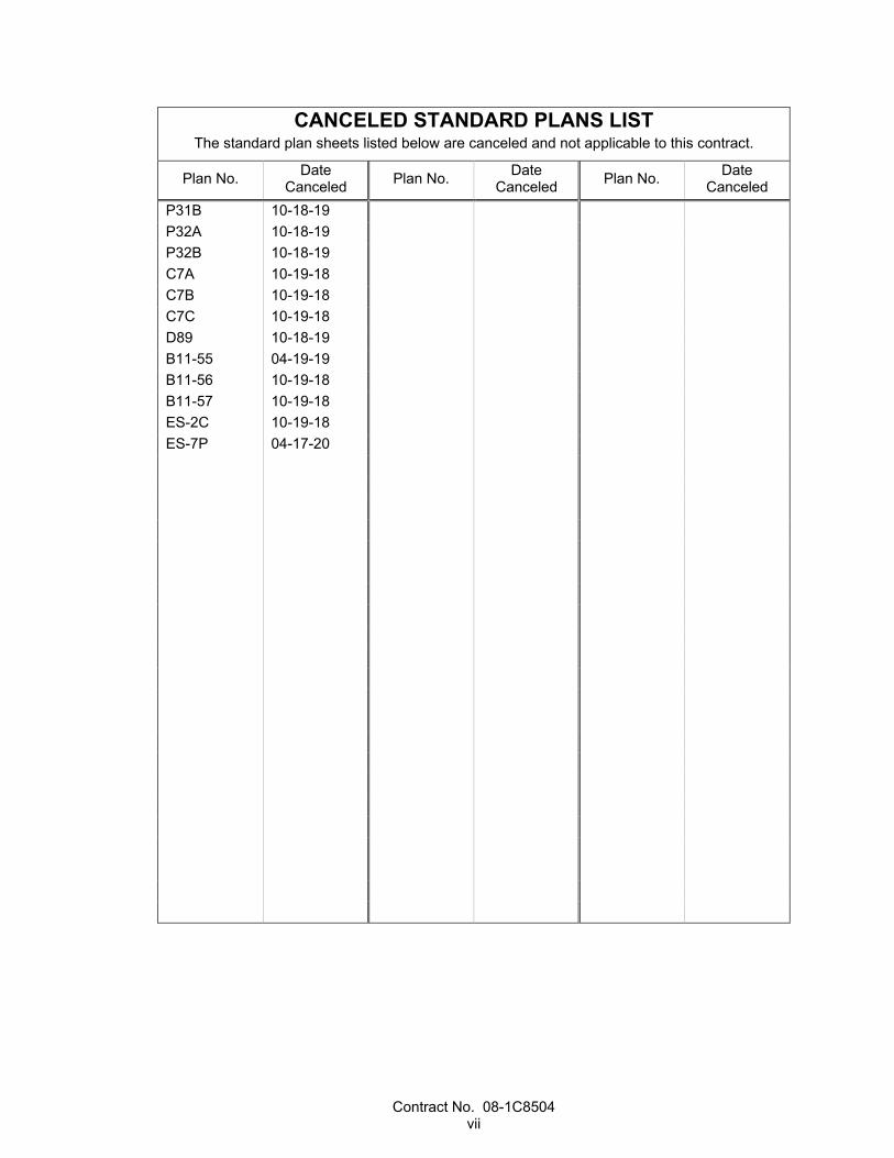
CANCELED STANDARD PLANS LIST The standard plan sheets listed below are canceled and not applicable to this contract.
Plan No. Date Canceled Plan No. Date
Canceled Plan No. Date Canceled
P31B 10-18-19 P32A 10-18-19 P32B 10-18-19 C7A 10-19-18 C7B 10-19-18 C7C 10-19-18 D89 10-18-19 B11-55 04-19-19 B11-56 10-19-18 B11-57 10-19-18 ES-2C 10-19-18 ES-7P 04-17-20


Contract No. 08-1C8504 1
NOTICE TO BIDDERS
Bids open Thursday, October 8, 2020
Dated August 17, 2020
General work description: Roadway excavation, hot mix asphalt, and structural shotcrete walls.
The Department will receive sealed bids for CONSTRUCTION ON STATE HIGHWAY IN RIVERSIDE COUNTY NEAR LAKE ELSINORE FROM ORANGE COUNTY LINE TO MONTE VISTA STREET.
District-County-Route-Post Mile: 08-Riv-74-0.0/5.8
Contract No. 08-1C8504
The Contractor must have either a Class A license or the following Class C license which constitutes a majority of the work: C-12.
The DBE Contract goal is 11 percent.
Federal-aid project no.:
ACHSST-S074(071)E
For the Federal training program, the number of trainees or apprentices is 25.
Bids must be on a unit price basis.
Complete the work, excluding plant establishment work, within 500 working days.
Complete the work, including plant establishment work, within 860 working days.
Complete the plant establishment work within 360 working days.
The estimated cost of the project is $49,000,000.
A mandatory prebid meeting is scheduled on August 27, 2020 at 10:00 a.m. at Webex meeting.
Virtual Mandatory Pre-Bid for 08-1C8504
Date: Thursday, August 27, 2020
Time: 10am to 11 am
Item Information
Early Registration Link To receive meeting password, please register early at the following link
- https://cadot.webex.com/cadot/j.php?RGID=ra8c2b2832e1e16bcbe5ee6c849bf5008
Registration is required to receive meeting password -
Registration Link Here
Contract No. 08-1C8504 2
Prime Bidders must attend the entire Virtual Mandatory Pre-Bid meeting for Bidder Eligibility.
The Department will receive bids until 2:00 p.m. on the bid open date via Bid Express website. Bids received after this time will not be accepted. For more information refer to the Electronic Bidding Guide at the Office Engineer's website.
The Department will open and publicly read the bids through webcast/teleconference services immediately after the specified closing time.
For bid results go to:
http://ppmoe.dot.ca.gov/des/oe/contractor-info.html
Select Electronic Bidding under the Bidding tab.
District office addresses are provided in the Standard Specifications.
Present bidders' inquiries to the Department and view the Department's responses at:
http://ppmoe.dot.ca.gov/des/oe/bid-inquiries.php
Questions about alleged patent ambiguity of the plans, specifications, or estimate must be asked before bid opening. After bid opening, the Department does not consider these questions as bid protests.
Submit your bid with bidder's security equal to at least 10 percent of the bid.
Prevailing wages are required on this Contract. The Director of the California Department of Industrial Relations determines the general prevailing wage rates. Obtain the wage rates at the DIR website, http://www.dir.ca.gov, or from the Department's Labor Compliance Office of the district in which the work is located.
The federal minimum wage rates for this Contract as determined by the United States Secretary of Labor are available at https://beta.sam.gov/.
If the minimum wage rates as determined by the United States Secretary of Labor differs from the general prevailing wage rates determined by the Director of the California Department of Industrial Relations for similar classifications of labor, the Contractor and subcontractors must not pay less than the higher wage rate. The Department does not accept lower State wage rates not specifically included in the federal minimum wage determinations. This includes helper, or other classifications based on hours of experience, or any other classification not appearing in the federal wage determinations. Where federal wage determinations do not contain the State wage rate determination otherwise available for use by the Contractor and subcontractors, the Contractor and subcontractors must not pay less than the federal minimum wage rate that most closely approximates the duties of the employees in question.
The Department has made available Notices of Suspension and Proposed Debarment from the Federal Highway Administration. For a copy of the notices, go to http://www.dot.ca.gov/hq/esc/oe/contractor_info. Additional information is provided in the Excluded Parties List System at https://www.epls.gov.
Caltrans and the Construction Industry are committed to making partnering the way we do business. For more information, go to http://www.dot.ca.gov/hq/construc/partnering.html.
Department of Transportation
D08/TTN
Contract No. 08-1C8504 3
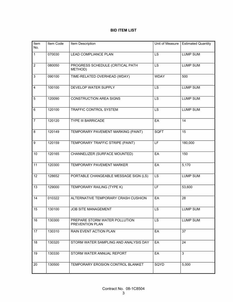
BID ITEM LIST
Item No.
Item Code Item Description Unit of Measure Estimated Quantity
1 070030 LEAD COMPLIANCE PLAN LS LUMP SUM
2 080050 PROGRESS SCHEDULE (CRITICAL PATH METHOD)
LS LUMP SUM
3 090100 TIME-RELATED OVERHEAD (WDAY) WDAY 500
4 100100 DEVELOP WATER SUPPLY LS LUMP SUM
5 120090 CONSTRUCTION AREA SIGNS LS LUMP SUM
6 120100 TRAFFIC CONTROL SYSTEM LS LUMP SUM
7 120120 TYPE III BARRICADE EA 14
8 120149 TEMPORARY PAVEMENT MARKING (PAINT) SQFT 15
9 120159 TEMPORARY TRAFFIC STRIPE (PAINT) LF 180,000
10 120165 CHANNELIZER (SURFACE MOUNTED) EA 150
11 120300 TEMPORARY PAVEMENT MARKER EA 5,170
12 128652 PORTABLE CHANGEABLE MESSAGE SIGN (LS) LS LUMP SUM
13 129000 TEMPORARY RAILING (TYPE K) LF 53,600
14 010322 ALTERNATIVE TEMPORARY CRASH CUSHION EA 28
15 130100 JOB SITE MANAGEMENT LS LUMP SUM
16 130300 PREPARE STORM WATER POLLUTION PREVENTION PLAN
LS LUMP SUM
17 130310 RAIN EVENT ACTION PLAN EA 37
18 130320 STORM WATER SAMPLING AND ANALYSIS DAY EA 24
19 130330 STORM WATER ANNUAL REPORT EA 3
20 130500 TEMPORARY EROSION CONTROL BLANKET SQYD 5,000
Contract No. 08-1C8504 4
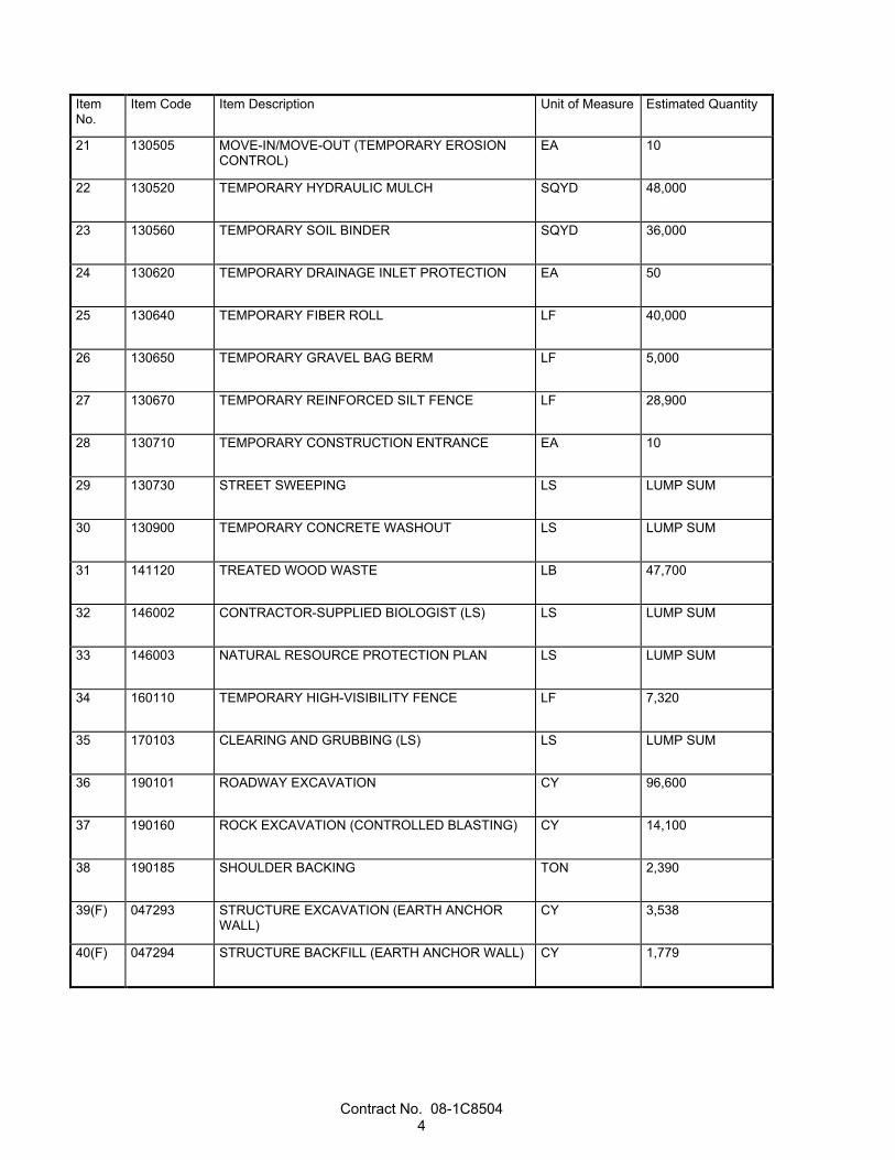
Item No.
Item Code Item Description Unit of Measure Estimated Quantity
21 130505 MOVE-IN/MOVE-OUT (TEMPORARY EROSION CONTROL)
EA 10
22 130520 TEMPORARY HYDRAULIC MULCH SQYD 48,000
23 130560 TEMPORARY SOIL BINDER SQYD 36,000
24 130620 TEMPORARY DRAINAGE INLET PROTECTION EA 50
25 130640 TEMPORARY FIBER ROLL LF 40,000
26 130650 TEMPORARY GRAVEL BAG BERM LF 5,000
27 130670 TEMPORARY REINFORCED SILT FENCE LF 28,900
28 130710 TEMPORARY CONSTRUCTION ENTRANCE EA 10
29 130730 STREET SWEEPING LS LUMP SUM
30 130900 TEMPORARY CONCRETE WASHOUT LS LUMP SUM
31 141120 TREATED WOOD WASTE LB 47,700
32 146002 CONTRACTOR-SUPPLIED BIOLOGIST (LS) LS LUMP SUM
33 146003 NATURAL RESOURCE PROTECTION PLAN LS LUMP SUM
34 160110 TEMPORARY HIGH-VISIBILITY FENCE LF 7,320
35 170103 CLEARING AND GRUBBING (LS) LS LUMP SUM
36 190101 ROADWAY EXCAVATION CY 96,600
37 190160 ROCK EXCAVATION (CONTROLLED BLASTING) CY 14,100
38 190185 SHOULDER BACKING TON 2,390
39(F) 047293 STRUCTURE EXCAVATION (EARTH ANCHOR WALL)
CY 3,538
40(F) 047294 STRUCTURE BACKFILL (EARTH ANCHOR WALL) CY 1,779
Contract No. 08-1C8504 5
Item No.
Item Code Item Description Unit of Measure Estimated Quantity
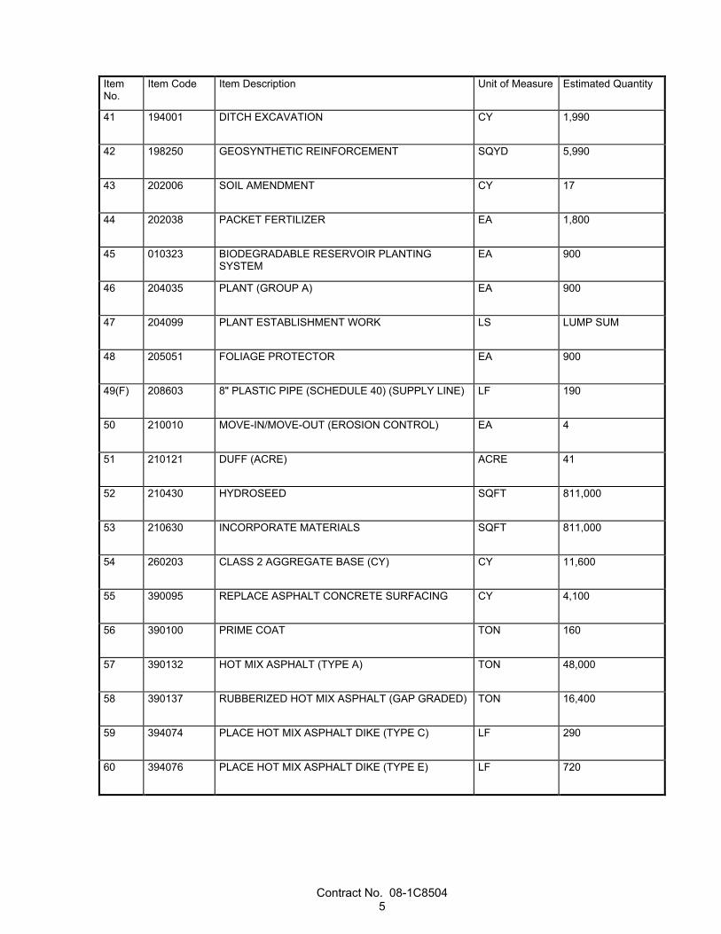
41 194001 DITCH EXCAVATION CY 1,990
42 198250 GEOSYNTHETIC REINFORCEMENT SQYD 5,990
43 202006 SOIL AMENDMENT CY 17
44 202038 PACKET FERTILIZER EA 1,800
45 010323 BIODEGRADABLE RESERVOIR PLANTING SYSTEM
EA 900
46 204035 PLANT (GROUP A) EA 900
47 204099 PLANT ESTABLISHMENT WORK LS LUMP SUM
48 205051 FOLIAGE PROTECTOR EA 900
49(F) 208603 8" PLASTIC PIPE (SCHEDULE 40) (SUPPLY LINE) LF 190
50 210010 MOVE-IN/MOVE-OUT (EROSION CONTROL) EA 4
51 210121 DUFF (ACRE) ACRE 41
52 210430 HYDROSEED SQFT 811,000
53 210630 INCORPORATE MATERIALS SQFT 811,000
54 260203 CLASS 2 AGGREGATE BASE (CY) CY 11,600
55 390095 REPLACE ASPHALT CONCRETE SURFACING CY 4,100
56 390100 PRIME COAT TON 160
57 390132 HOT MIX ASPHALT (TYPE A) TON 48,000
58 390137 RUBBERIZED HOT MIX ASPHALT (GAP GRADED) TON 16,400
59 394074 PLACE HOT MIX ASPHALT DIKE (TYPE C) LF 290
60 394076 PLACE HOT MIX ASPHALT DIKE (TYPE E) LF 720
Contract No. 08-1C8504 6
Item No.
Item Code Item Description Unit of Measure Estimated Quantity
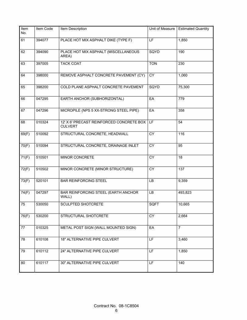
61 394077 PLACE HOT MIX ASPHALT DIKE (TYPE F) LF 1,850
62 394090 PLACE HOT MIX ASPHALT (MISCELLANEOUS AREA)
SQYD 190
63 397005 TACK COAT TON 230
64 398000 REMOVE ASPHALT CONCRETE PAVEMENT (CY) CY 1,060
65 398200 COLD PLANE ASPHALT CONCRETE PAVEMENT SQYD 75,300
66 047295 EARTH ANCHOR (SUBHORIZONTAL) EA 779
67 047296 MICROPILE (NPS 5 XX-STRONG STEEL PIPE) EA 358
68 010324 12' X 6' PRECAST REINFORCED CONCRETE BOX CULVERT
LF 54
69(F) 510092 STRUCTURAL CONCRETE, HEADWALL CY 116
70(F) 510094 STRUCTURAL CONCRETE, DRAINAGE INLET CY 95
71(F) 510501 MINOR CONCRETE CY 18
72(F) 510502 MINOR CONCRETE (MINOR STRUCTURE) CY 137
73(F) 520101 BAR REINFORCING STEEL LB 9,359
74(F) 047297 BAR REINFORCING STEEL (EARTH ANCHOR WALL)
LB 493,823
75 530050 SCULPTED SHOTCRETE SQFT 10,665
76(F) 530200 STRUCTURAL SHOTCRETE CY 2,664
77 010325 METAL POST SIGN (WALL MOUNTED SIGN) EA 7
78 610108 18" ALTERNATIVE PIPE CULVERT LF 3,460
79 610112 24" ALTERNATIVE PIPE CULVERT LF 1,850
80 610117 30" ALTERNATIVE PIPE CULVERT LF 140
Contract No. 08-1C8504 7
Item No.
Item Code Item Description Unit of Measure Estimated Quantity
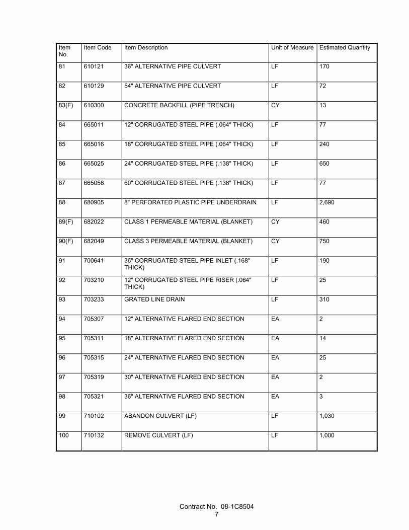
81 610121 36" ALTERNATIVE PIPE CULVERT LF 170
82 610129 54" ALTERNATIVE PIPE CULVERT LF 72
83(F) 610300 CONCRETE BACKFILL (PIPE TRENCH) CY 13
84 665011 12" CORRUGATED STEEL PIPE (.064" THICK) LF 77
85 665016 18" CORRUGATED STEEL PIPE (.064" THICK) LF 240
86 665025 24" CORRUGATED STEEL PIPE (.138" THICK) LF 650
87 665056 60" CORRUGATED STEEL PIPE (.138" THICK) LF 77
88 680905 8" PERFORATED PLASTIC PIPE UNDERDRAIN LF 2,690
89(F) 682022 CLASS 1 PERMEABLE MATERIAL (BLANKET) CY 460
90(F) 682049 CLASS 3 PERMEABLE MATERIAL (BLANKET) CY 750
91 700641 36" CORRUGATED STEEL PIPE INLET (.168" THICK)
LF 190
92 703210 12" CORRUGATED STEEL PIPE RISER (.064" THICK)
LF 25
93 703233 GRATED LINE DRAIN LF 310
94 705307 12" ALTERNATIVE FLARED END SECTION EA 2
95 705311 18" ALTERNATIVE FLARED END SECTION EA 14
96 705315 24" ALTERNATIVE FLARED END SECTION EA 25
97 705319 30" ALTERNATIVE FLARED END SECTION EA 2
98 705321 36" ALTERNATIVE FLARED END SECTION EA 3
99 710102 ABANDON CULVERT (LF) LF 1,030
100 710132 REMOVE CULVERT (LF) LF 1,000

Contract No. 08-1C8504 8
Item No.
Item Code Item Description Unit of Measure Estimated Quantity
101 710150 REMOVE INLET EA 17
102 710152 REMOVE HEADWALL EA 5
103 710370 SAND BACKFILL CY 69
104 010326 ROCK BOLTS (GROUTED) LF 220
105 010327 CABLE NET DRAPERY SQFT 86,300
106 721420 CONCRETE (DITCH LINING) CY 650
107(F) 722020 GABION CY 2,847
108 723015 ROCK SLOPE PROTECTION (2T, CLASS IX, METHOD A)
CY 95
109 723060 ROCK SLOPE PROTECTION (300 LB, CLASS IV, METHOD B) (CY)
CY 220
110 723070 ROCK SLOPE PROTECTION (150 LB, CLASS III, METHOD B) (CY)
CY 150
111 723090 ROCK SLOPE PROTECTION (1T, CLASS VIII, METHOD B)
CY 390
112 723095 ROCK SLOPE PROTECTION (20 LB, CLASS I, METHOD B) (CY)
CY 28
113 729011 ROCK SLOPE PROTECTION FABRIC (CLASS 8) SQYD 1,480
114 729012 ROCK SLOPE PROTECTION FABRIC (CLASS 10) SQYD 110
115(F) 750001 MISCELLANEOUS IRON AND STEEL LB 33,788
116 780440 PREPARE AND STAIN CONCRETE SQFT 121,519
117 780445 PREPARE AND STAIN SHOTCRETE SQFT 42,452
118 010328 STAIN GALVANIZED SURFACE (SQFT) SQFT 86,300
119 810120 REMOVE PAVEMENT MARKER EA 2,780
120 810170 DELINEATOR (CLASS 1) EA 480

Contract No. 08-1C8504 9
Item No.
Item Code Item Description Unit of Measure Estimated Quantity
121 810190 GUARD RAILING DELINEATOR EA 220
122 810250 PAVEMENT MARKER (RETROREFLECTIVE-RECESSED)
EA 2,670
123 820110 MILEPOST MARKER EA 15
124 820112 MARKER (CULVERT) EA 59
125 820130 OBJECT MARKER EA 50
126 010329 CONCRETE BARRIER MARKER EA 340
127 820220 REMOVE MARKER EA 74
128 820250 REMOVE ROADSIDE SIGN EA 72
129 820480 RESET OBJECT MARKER EA 34
130 820530 RESET ROADSIDE SIGN EA 11
131 820750 FURNISH SINGLE SHEET ALUMINUM SIGN (0.063"-UNFRAMED)
SQFT 310
132 820760 FURNISH SINGLE SHEET ALUMINUM SIGN (0.080"-UNFRAMED)
SQFT 200
133 820840 ROADSIDE SIGN - ONE POST EA 57
134 832005 MIDWEST GUARDRAIL SYSTEM LF 7,320
135 832070 VEGETATION CONTROL (MINOR CONCRETE) SQYD 6,410
136 010330 CRASH CUSHION (TYPE SCI-100GM) EA 7
137(F) 839521 CABLE RAILING LF 207
138 839543 TRANSITION RAILING (TYPE WB-31) EA 31
139 839581 END ANCHOR ASSEMBLY (TYPE SFT) EA 1
140 839584 ALTERNATIVE IN-LINE TERMINAL SYSTEM EA 28
Contract No. 08-1C8504 10
Item No.
Item Code Item Description Unit of Measure Estimated Quantity
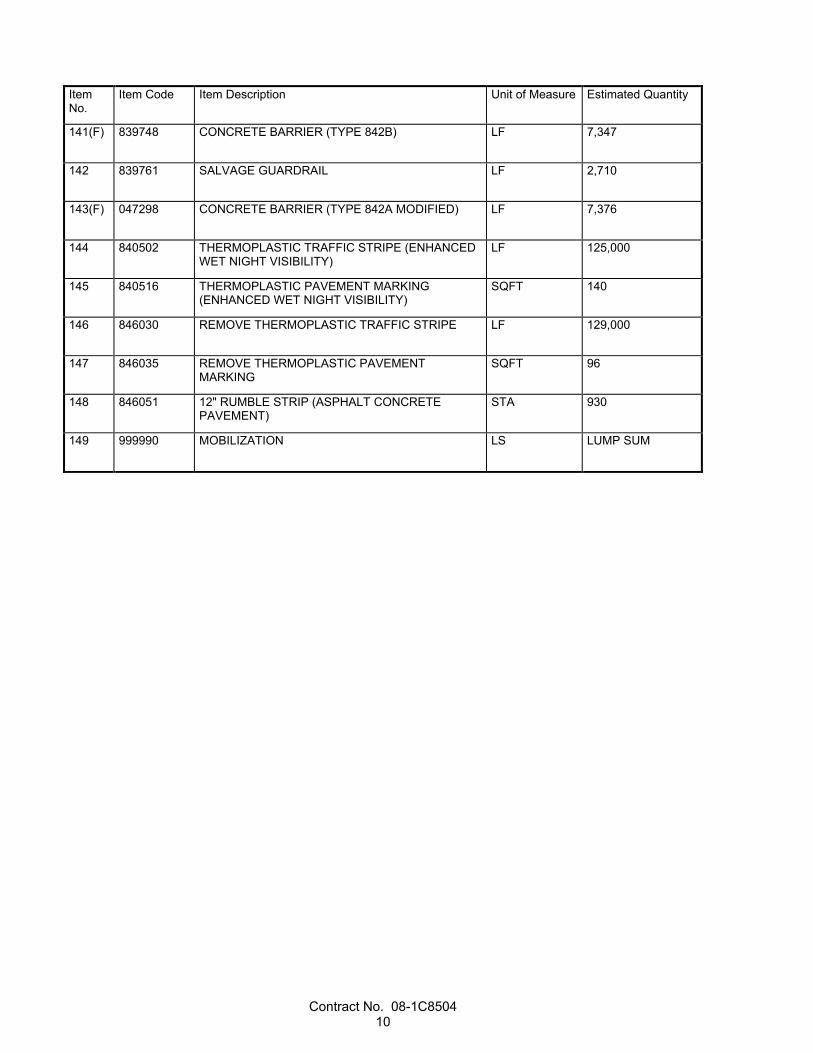
141(F) 839748 CONCRETE BARRIER (TYPE 842B) LF 7,347
142 839761 SALVAGE GUARDRAIL LF 2,710
143(F) 047298 CONCRETE BARRIER (TYPE 842A MODIFIED) LF 7,376
144 840502 THERMOPLASTIC TRAFFIC STRIPE (ENHANCED WET NIGHT VISIBILITY)
LF 125,000
145 840516 THERMOPLASTIC PAVEMENT MARKING (ENHANCED WET NIGHT VISIBILITY)
SQFT 140
146 846030 REMOVE THERMOPLASTIC TRAFFIC STRIPE LF 129,000
147 846035 REMOVE THERMOPLASTIC PAVEMENT MARKING
SQFT 96
148 846051 12" RUMBLE STRIP (ASPHALT CONCRETE PAVEMENT)
STA 930
149 999990 MOBILIZATION LS LUMP SUM
Contract No. 08-1C8504 11
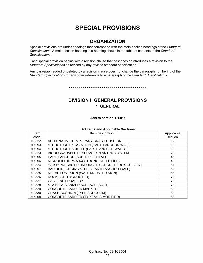
SPECIAL PROVISIONS
ORGANIZATION Special provisions are under headings that correspond with the main-section headings of the Standard Specifications. A main-section heading is a heading shown in the table of contents of the Standard Specifications.
Each special provision begins with a revision clause that describes or introduces a revision to the Standard Specifications as revised by any revised standard specification.
Any paragraph added or deleted by a revision clause does not change the paragraph numbering of the Standard Specifications for any other reference to a paragraph of the Standard Specifications.
^^^^^^^^^^^^^^^^^^^^^^^^^^^^^^^^^^^^^^^^
DIVISION I GENERAL PROVISIONS 1 GENERAL
Add to section 1-1.01:
Bid Items and Applicable Sections Item code
Item description Applicable section
010322 ALTERNATIVE TEMPORARY CRASH CUSHION 12 047293 STRUCTURE EXCAVATION (EARTH ANCHOR WALL) 19 047294 STRUCTURE BACKFILL (EARTH ANCHOR WALL) 19 010323 BIODEGRADABLE RESERVOIR PLANTING SYSTEM 20 047295 EARTH ANCHOR (SUBHORIZONTAL) 46 047296 MICROPILE (NPS 5 XX-STRONG STEEL PIPE) 49 010324 12' X 6' PRECAST REINFORCED CONCRETE BOX CULVERT 51 047297 BAR REINFORCING STEEL (EARTH ANCHOR WALL) 52 010325 METAL POST SIGN (WALL MOUNTED SIGN) 56 010326 ROCK BOLTS (GROUTED) 72 010327 CABLE NET DRAPERY 72 010328 STAIN GALVANIZED SURFACE (SQFT) 78 010329 CONCRETE BARRIER MARKER 82 010330 CRASH CUSHION (TYPE SCI-100GM) 83 047298 CONCRETE BARRIER (TYPE 842A MODIFIED) 83
Contract No. 08-1C8504 12
^^^^^^^^^^^^^^^^^^^^^^^^^^^^^^^^^^^^^^^^
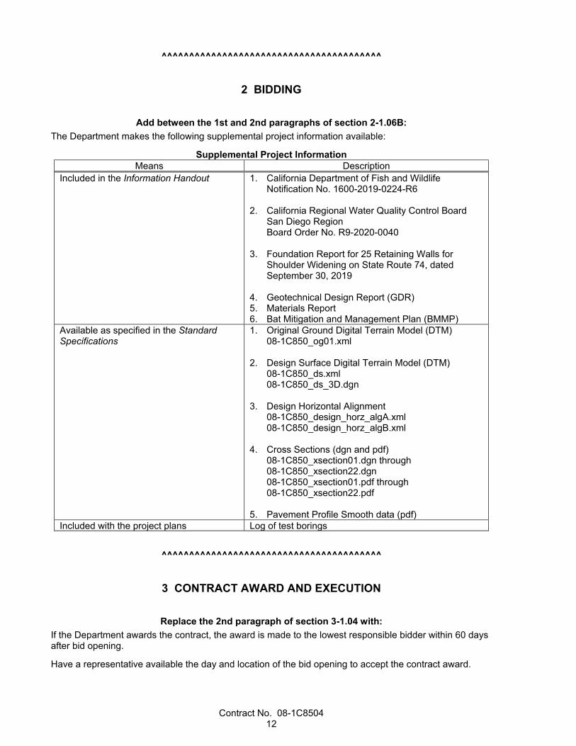
2 BIDDING
Add between the 1st and 2nd paragraphs of section 2-1.06B: The Department makes the following supplemental project information available:
Supplemental Project Information Means Description
Included in the Information Handout 1. California Department of Fish and Wildlife Notification No. 1600-2019-0224-R6
2. California Regional Water Quality Control Board San Diego Region Board Order No. R9-2020-0040
3. Foundation Report for 25 Retaining Walls for Shoulder Widening on State Route 74, dated September 30, 2019
4. Geotechnical Design Report (GDR) 5. Materials Report 6. Bat Mitigation and Management Plan (BMMP)
Available as specified in the Standard Specifications
1. Original Ground Digital Terrain Model (DTM) 08-1C850_og01.xml
2. Design Surface Digital Terrain Model (DTM)
08-1C850_ds.xml 08-1C850_ds_3D.dgn
3. Design Horizontal Alignment
08-1C850_design_horz_algA.xml 08-1C850_design_horz_algB.xml
4. Cross Sections (dgn and pdf)
08-1C850_xsection01.dgn through 08-1C850_xsection22.dgn 08-1C850_xsection01.pdf through 08-1C850_xsection22.pdf
5. Pavement Profile Smooth data (pdf)
Included with the project plans Log of test borings
^^^^^^^^^^^^^^^^^^^^^^^^^^^^^^^^^^^^^^^^
3 CONTRACT AWARD AND EXECUTION
Replace the 2nd paragraph of section 3-1.04 with: If the Department awards the contract, the award is made to the lowest responsible bidder within 60 days after bid opening.
Have a representative available the day and location of the bid opening to accept the contract award.

Contract No. 08-1C8504 13
If the lowest responsible bidder does not have a representative available to accept the contract award, the Department may award the contract to the next lowest responsible bidder who has a representative available to accept the contract award.
^^^^^^^^^^^^^^^^^^^^^^^^^^^^^^^^^^^^^^^^
5 CONTROL OF WORK
Add to the end of section 5-1.09A: The Department encourages the project team to exhaust the use of partnering in dispute resolution before engagement of an objective third party.
For certain disputes, a facilitated partnering session or facilitated dispute resolution session may be appropriate and effective in clarifying issues and resolving all or part of a dispute.
To afford the project team enough time to plan and hold the session, a maximum of 20 days may be added to the DRB referral time following the Engineer's response to a Supplemental Potential Claim Record.
To allow this additional referral time, the project team must document its agreement and intention in the dispute resolution plan of the partnering charter. The team may further document agreement of any associated criteria to be met for use of the additional referral time.
If the session is not held, the DRB referral time remains in effect as specified in section 5-1.43.
Add to the end of section 5-1.20A: During the progress of the work under this Contract, work under the following contracts may be in progress at or near the job site of this Contract:
Coincident or Adjacent Contracts Contract no. County–Route–Post Mile Location Type of work
120P0304 OC-74-PM 11.5/16.6 Ortiga Highway Rehab and Widenning
Add to the RSS for section 5-1.24: 5-1.24B Department Construction Surveys for Automated Machine Guidance The Department sets control points to a minimum of 0.07 foot local horizontal accuracy and 3rd order vertical accuracy standards.
For slope stakes and rough grade stakes, the Department sets 6 survey control points or 2 per mile, whichever is greater.
The Department sets slope stakes and rough grade stakes at:
1. Conform stations 2. Beginning and end of each alignment 3. Midpoint or every 200 feet, whichever results in a greater number of stakes, on a curve 4. Every 500 feet on tangents The Department sets final grade stakes under Chapter 12, "Construction Surveys," section 12.5-6 of the Department's Surveys Manual.
At your request, the Department sets survey control points under section 12.1-6, "Automated Machine Guidance." When control stakes are requested, final grade stakes are set at:
1. Conform stations

Contract No. 08-1C8504 14
2. Beginning and end of each alignment 3. Midpoint or every 100 feet, whichever results in the greater number of stakes, on a curve with a
radius of 1,200 feet or less 4. Midpoint or every 200 feet, whichever results in the greater number of stakes, on a curve with a
radius of more than 1,200 feet 5. Every 200 feet on a tangent At your request and under Chapter 12 of the Department's Surveys Manual, the Department provides (1) staking for intersections, clearing, fencing, drainage, curbs, structures, abutment fill, wall, and miscellaneous areas and (2) additional survey control or staking for earthwork in areas where global navigation satellite system coverage is inadequate for automated machine guidance.
Replace section 5-1.25 with: 5-1.25 AUTOMATED MACHINE GUIDANCE 5-1.25A General You may use automated machine guidance (AMG) if the AMG meets or exceeds the staking tolerances described in section 12.5, "Typical Department-Furnished Construction Stakes," of the Department's Surveys Manual.
You are responsible for determining whether the work and site conditions are practical for AMG use.
Furnish a GNSS rover compatible with your GNSS base station or the GNSS correction service you subscribe to. The Department returns the GNSS rover upon work completion. This is change order work.
At the preconstruction conference, be prepared to discuss survey control points, site and equipment calibration, inspection methods, conflict resolution, and staking.
5-1.25B Definitions automated machine guidance (AMG): Technology that uses positioning devices, singly or in
combination, such as global navigation satellite systems (GNSS), total stations, or rotating laser levels, to determine and control the real-time position of construction equipment using onboard computer equipment.
California Coordinate System of 1983 (CCS83): CCS83 as defined in Pub Res Code § 8801.
digital construction model (DCM): Three-dimensional model used by the Contractor's AMG equipment.
digital design model: Three-dimensional model consisting of roadway design alignments, profiles, and cross sections representing the finished grade.
digital terrain model: Three-dimensional model representing the original ground before job site activities start.
global navigation satellite system (GNSS): Satellite system used to pinpoint the geographic location of a user's receiver anywhere in the world. Two GNSS systems are in operation: the US GPS and the Russian Federation's GLONASS. Each of the GNSS systems uses a constellation of orbiting satellites working in conjunction with a network of ground stations.
GNSS base station: Single ground-based system consisting of a GNSS receiver, antenna, and telemetry equipment that provides differential GNSS correction signals to other GNSS receivers or rovers. Multiple base stations can be combined into a GNSS network.
GNSS correction service subscription: Subscription service to receive differential GNSS correction signals for higher accuracy GNSS positioning without the need of a GNSS base station. Signals are normally received via cellular wireless data services.
GNSS rover: Portable GNSS antenna, receiver, rod, and data collector with telemetry equipment for real-time point measurements.
grid: Cartesian coordinate system of Northing (y) and Easting (x) coordinates using CCS83.

Contract No. 08-1C8504 15
robotic total station: Survey instrument capable of tracking an optical target and providing real-time coordinates of the target to the equipment operator and AMG equipment. A robotic total station unit can provide AMG if site conditions do not allow GNSS receivers to be used and if a higher accuracy is required than the GNSS provides.
site calibration or localization: Process that establishes the relationship between the observed control point coordinates and the site coordinate system, which is usually grid. The term applies to both GNSS and robotic total station equipment.
5-1.25C Electronic Files Electronic design files include:
1. Digital terrain model in 3-D DGN or LandXML format 2. Roadway design alignments and profiles in LandXML format 3. Cross sections in 2-D DGN and PDF 4. Digital design model in LandXML format 5. 2-D layout lines and target geometry in DWG format The Department makes electronic design files available as supplemental project information.
You must create the digital construction models.
Convert the electronic design files to a format compatible with your AMG system. Manipulation of the electronic design files is at your own risk.
Submit copies of the digital construction model files and any updates to them in LandXML format.
Digital design model information may not exist for contour grading and some drainage areas. The Department places stakes for these areas.
The Department provides you with updated electronic data whenever the Engineer determines a plan change materially affects the finished grade. For minor grade changes, the Department places stakes and marks.
5-1.25D Quality Control Plan Submit an AMG QC plan at least 15 days before starting work requiring AMG. The plan must include the following information:
1. Contract number 2. Name and contact information of the AMG QC technician 3. Limits of the area for which the AMG will be used 4. Scope of work to be completed using AMG for the following work categories:
4.1. Clearing and grubbing 4.2. Earthwork 4.3. Trench excavation 4.4. Rough grading 4.5. Subgrade 4.6. Subbase 4.7 Base 4.8. Curb and gutter 4.9. Cold planning or milling existing pavement 4.10. Paving 4.11. Intelligent compaction 4.12. Concrete barrier 4.13. Finishing roadway
5. Project control plan sheet detailing control points covering the job site 6 List of GNSS equipment, including:
6.1. Type 6.2. Manufacturer 6.3. Model 6.4. Software version
7. Description of GNSS site calibration or localization checking, including:
Contract No. 08-1C8504 16
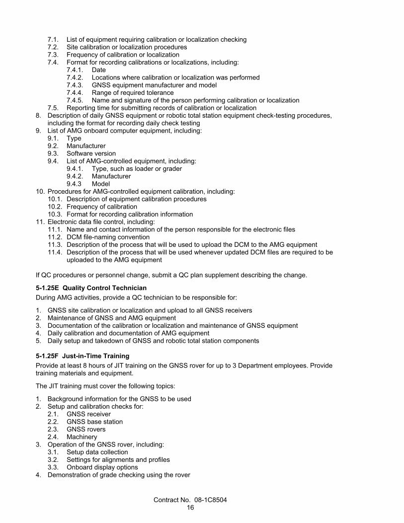
7.1. List of equipment requiring calibration or localization checking 7.2. Site calibration or localization procedures 7.3. Frequency of calibration or localization 7.4. Format for recording calibrations or localizations, including:
7.4.1. Date 7.4.2. Locations where calibration or localization was performed 7.4.3. GNSS equipment manufacturer and model 7.4.4. Range of required tolerance 7.4.5. Name and signature of the person performing calibration or localization
7.5. Reporting time for submitting records of calibration or localization 8. Description of daily GNSS equipment or robotic total station equipment check-testing procedures,
including the format for recording daily check testing 9. List of AMG onboard computer equipment, including:
9.1. Type 9.2. Manufacturer 9.3. Software version 9.4. List of AMG-controlled equipment, including:
9.4.1. Type, such as loader or grader 9.4.2. Manufacturer 9.4.3 Model
10. Procedures for AMG-controlled equipment calibration, including: 10.1. Description of equipment calibration procedures 10.2. Frequency of calibration 10.3. Format for recording calibration information
11. Electronic data file control, including: 11.1. Name and contact information of the person responsible for the electronic files 11.2. DCM file-naming convention 11.3. Description of the process that will be used to upload the DCM to the AMG equipment 11.4. Description of the process that will be used whenever updated DCM files are required to be
uploaded to the AMG equipment
If QC procedures or personnel change, submit a QC plan supplement describing the change.
5-1.25E Quality Control Technician During AMG activities, provide a QC technician to be responsible for:
1. GNSS site calibration or localization and upload to all GNSS receivers 2. Maintenance of GNSS and AMG equipment 3. Documentation of the calibration or localization and maintenance of GNSS equipment 4. Daily calibration and documentation of AMG equipment 5. Daily setup and takedown of GNSS and robotic total station components 5-1.25F Just-in-Time Training Provide at least 8 hours of JIT training on the GNSS rover for up to 3 Department employees. Provide training materials and equipment.
The JIT training must cover the following topics:
1. Background information for the GNSS to be used 2. Setup and calibration checks for:
2.1. GNSS receiver 2.2. GNSS base station 2.3. GNSS rovers 2.4. Machinery
3. Operation of the GNSS rover, including: 3.1. Setup data collection 3.2. Settings for alignments and profiles 3.3. Onboard display options
4. Demonstration of grade checking using the rover
Contract No. 08-1C8504 17
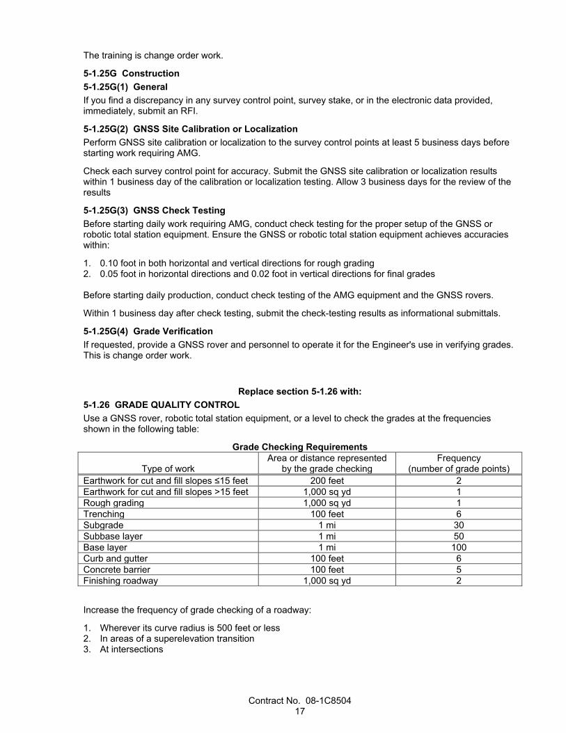
The training is change order work.
5-1.25G Construction 5-1.25G(1) General If you find a discrepancy in any survey control point, survey stake, or in the electronic data provided, immediately, submit an RFI.
5-1.25G(2) GNSS Site Calibration or Localization Perform GNSS site calibration or localization to the survey control points at least 5 business days before starting work requiring AMG.
Check each survey control point for accuracy. Submit the GNSS site calibration or localization results within 1 business day of the calibration or localization testing. Allow 3 business days for the review of the results
5-1.25G(3) GNSS Check Testing Before starting daily work requiring AMG, conduct check testing for the proper setup of the GNSS or robotic total station equipment. Ensure the GNSS or robotic total station equipment achieves accuracies within:
1. 0.10 foot in both horizontal and vertical directions for rough grading 2. 0.05 foot in horizontal directions and 0.02 foot in vertical directions for final grades Before starting daily production, conduct check testing of the AMG equipment and the GNSS rovers.
Within 1 business day after check testing, submit the check-testing results as informational submittals.
5-1.25G(4) Grade Verification If requested, provide a GNSS rover and personnel to operate it for the Engineer's use in verifying grades. This is change order work.
Replace section 5-1.26 with: 5-1.26 GRADE QUALITY CONTROL Use a GNSS rover, robotic total station equipment, or a level to check the grades at the frequencies shown in the following table:
Grade Checking Requirements
Type of work Area or distance represented
by the grade checking Frequency
(number of grade points) Earthwork for cut and fill slopes ≤15 feet 200 feet 2 Earthwork for cut and fill slopes ˃15 feet 1,000 sq yd 1 Rough grading 1,000 sq yd 1 Trenching 100 feet 6 Subgrade 1 mi 30 Subbase layer 1 mi 50 Base layer 1 mi 100 Curb and gutter 100 feet 6 Concrete barrier 100 feet 5 Finishing roadway 1,000 sq yd 2
Increase the frequency of grade checking of a roadway:
1. Wherever its curve radius is 500 feet or less 2. In areas of a superelevation transition 3. At intersections

Contract No. 08-1C8504 18
Notify the Engineer when an area is ready for line and grade inspection. Submit the grade checking results on a Grade Checking Report form as an informational submittal.
Add between the 2nd and 3rd paragraphs of section 5-1.36C(3): Installation of the utilities shown in the following table requires coordination with your activities. Make the necessary arrangements with the utility company through the Engineer and submit a schedule:
1. Verified by a representative of the utility company 2. Allowing at least the time shown for the utility owner to complete its work
Utility Relocation and Contractor-Arranged Time for the Relocation Utility Utility address Location Working days
Water Valve to be adjusted
Elsinore Valley Municipal Water District (EVMWD) Shawnele Morelos 31315 Chaney Street P.O. Box 3000 Lake Elsinore, CA 92530
27.6’ Lt “A1” Line, Sta 508+82.6 to 17.9’ Lt “A1” Line, Sta 536+05.70
2 days Advance Notice 2 Working days
Water Line EVMWD, same contact and address
33.2’ Lt “A1” Line, Sta 533+05.3 to 18.2’ Lt “A1” Line, Sta 542+67.8
2 days Advance Notice 65 Working days
^^^^^^^^^^^^^^^^^^^^^^^^^^^^^^^^^^^^^^^^
6 CONTROL OF MATERIALS
Add to section 6-1.03 of the RSS: 6-1.03B Submittals 6-1.03B(1) Work Plan For local material, such as rock, gravel, earth, structure backfill, pervious backfill, imported borrow, and culvert bedding, obtained from a (1) noncommercial source, or (2) source not regulated under California jurisdiction, submit a local material plan for each material at least 60 days before placing the material. The local material plan must include:
1. Certification signed by you and an engineer who is registered as a civil engineer in the State or a professional geologist licensed as a professional geologist by the State stating:
I am aware local material from a noncommercial source or a source not regulated under CA
jurisdiction must be sampled and analyzed for pH and lead and may require sampling and analysis under section 6-1.03B(3) for other constituents of concern based on the land use history. I am aware that local material sources must not contain ADL at concentrations greater than 80 mg/kg total lead or equal to or greater than 5 mg/L soluble lead as determined by the Waste Extraction Test (WET) Procedures, 22 CA Code of Regs § 66261.24(a)(2) App II. I am aware that a maximum quantity of material may be excavated at the site based on the minimum number of samples taken before excavating at the site under section 6-1.03B(3).
2. Land use history of the local material location and surrounding property 3. Sampling protocol 4. Number of samples per volume of local material 5. QA and QC requirements and procedures 6. Qualifications of sampling personnel 7. Stockpile history 8. Name and address of the analytical laboratory that will perform the chemical analyses
Contract No. 08-1C8504 19
9. Analyses that will be performed for lead and pH 10. Other analyses that will be performed for possible hazardous constituents based on:
10.1. Source property history 10.2. Land use adjacent to source property 10.3. Constituents of concern in the ground water basin where the job site is located
The plan must be sealed and signed by an engineer who is registered as a civil engineer in the State or a professional geologist licensed as a professional geologist by the State.
If the plan requires revisions, the Engineer provides comments. Submit a revised plan within 7 days of receiving comments. Allow 7 days for the review.
6-1.03B(2) Analytical Test Results At least 15 days before placing local material, submit analytical test results for each local material obtained from a noncommercial source or a source not regulated under CA jurisdiction. The analytical test results must include:
1. Certification signed by an engineer who is registered as a civil engineer in the State or a professional geologist licensed as a professional geologist by the State stating:
The analytical testing described in the local material plan has been performed. I performed a
statistical analysis of the test results using the US EPA's ProUCL software with the applicable 95 percent upper confidence limit. I certify that the material from the local material source is suitable for unrestricted use at the job site, it has a pH above 5.0, does not contain soluble lead in concentrations equal to or greater than 5mg/l as determined by the Waste Extraction Test (WET) Procedures, 22 CA Code of Regs § 66261.24(a)(2) App II, does not contain lead in concentrations above 80 mg/kg total lead, is free from all other contaminants identified in the local material plan, and will comply with the job site's basin plan and water quality objectives of the RWQCB.
2. Chain of custody of samples 3. Analytical results no older than 1 year 4. Statistical analysis of the data using US EPA’s ProUCL software with a 95 percent upper confidence
limit 5. Comparison of sample results to hazardous waste concentration thresholds and the RWQCB's basin
plan requirements and water quality objectives for the job site location 6-1.03B(3) Sample and Analysis Sample and analyze local material from a (1) noncommercial source or (2) source not regulated under CA jurisdiction:
1. Before bringing the local material to the job site 2. As described in the local material plan 3. Under US EPA Test Methods for Evaluating Solid Waste, Physical/Chemical Methods (SW-846) The sample collection must be designed to generate a data set representative of the entire volume of proposed local material.

Contract No. 08-1C8504 20
Before excavating at the (1) noncommercial material source or (2) a source not regulated under CA jurisdiction, collect the minimum number of samples and perform the minimum number of analytical tests for the corresponding maximum volume of local material as shown in the following table:
Minimum Number of Samples and Analytical Tests for Local Material Maximum volume of imported borrow
(cu yd) Minimum number of samples and analytical tests
< 5,000 8
5,000–10,000 12 for the first 5,000 cu yd plus 1 for each additional 1,000 cu yd or portion thereof
10,000–20,000 17 for the first 10,000 cu yd plus 1 for each additional 2,500 cu yd or portion thereof
20,000-40,000 21 for the first 20,000 cu yd plus 1 for each additional 5,000 cu yd or portion thereof
40,000–80,000 25 for the first 40,000 cu yd plus 1 for each additional 10,000 cu yd or portion thereof
> 80,000 29 for the first 80,000 cu yd plus 1 for each additional 20,000 cu yd or portion thereof
Do not collect composite samples or mix individual samples to form a composite sample.
Analyze the samples using the US EPA's ProUCL software with a 95 percent upper confidence limit. All chemical analysis must be performed by a laboratory certified by the SWRCB's Environmental Laboratory Accreditation Program (ELAP).
The analytical test results must demonstrate that the local material:
1. Is not a hazardous waste 2. Has a pH above 5.0 3. Has an average total lead concentration, based upon the 95 percent upper confidence limit, at or
below 80 mg/kg 4. Is free of possible contaminants identified in the local material plan 5. Complies with the RWQCB's basin plan for the job site location 6 Complies with the RWQCB's water quality objectives for the job site location 6-1.03C Local Material Management Do not place local material until authorized.
If the Engineer determines the appearance, odor, or texture of any delivered local material suggests possible contamination, sample and analyze the material. The sampling and analysis is change order work unless (1) hazardous waste is discovered or (2) the analytical test results indicate the material does not comply with section 6-1.03B(3).
Dispose of noncompliant local material at an appropriately permitted CA Class I, CA Class II or CA Class III facility. You are the generator of noncompliant local material.

Contract No. 08-1C8504 21
Add to section 6-1: 6-1.06 BUY CLEAN CALIFORNIA ACT 6-1.06A Summary The materials or products shown in the following table are subject to the Buy Clean California Act (Pub Cont Code § 3500 et seq.):
Material or product Material specifications Carbon steel rebara Section 52-1.02B, "Bar Reinforcement"
Excludes epoxy-coated or galvanized reinforcement uses. Structural steelb Section 55-1.02D(1), "General," – Structural Steel and Other
Materials tables and Section 99, "Building Construction" For hot-rolled, plate or hollow products.
Flat glassc Section 99, "Building Construction" Mineral wool board insulationd Section 99, "Building Construction" aFor each mill providing 20,000 pounds or more on the project bFor each mill providing 5,000 pounds or more on the project cFor each manufacturer providing 2,000 square feet or more on the project dFor each manufacturer providing 4,000 square feet or more on the project
For product category rules for applicable materials or products, go to the METS website. Use the product category rule in effect on the date of bid opening unless otherwise authorized. An environmental product declaration is not required for a material or product for either of the following conditions:
1. Applicable product category rule has expired without replacement as of the bid opening date. 2. Applicable product category rule was issued less than 100 days before the bid opening date. For projects with a bid opening date before December 1, 2019, the Department collects existing environmental product declarations for applicable materials or products.
For projects with a bid opening date from December 1, 2019, through May 31, 2021, with total bid over $1 million and 175 or more original working days, submit an environmental product declaration as an informational submittal for each applicable material or product. Submit each environmental product declaration within 15 days of initial installation of the material or product.
6-1.06B Definitions environmental product declaration: Independently verified document created and verified under
International Organization for Standardization (ISO) 14025 for Type III environmental declarations that identifies the global warming potential emissions of the facility-specific material or product through a product stage life cycle assessment.
product category rule: Program operator established rule based on the science of life cycle assessment that governs the development of the environmental product declaration for the material or product.
product stage: Boundary of the environmental product declaration that includes (1) raw material supply, (2) transportation processes, and (3) processing operations, including operations such as melting, mixing, fabrication, finishing, curing, cooling, trimming, packaging and loading for transport delivery. Commonly referred to as a "cradle-to-gate" life cycle assessment.
program operator: Independent agency that supervises and confirms the full environmental product declaration development process under ISO 14025.
raw material supply: Upstream processes which can include allocations, extraction, refinement, reclamation, handling and processing of the constituents used in producing the material or product.
transportation processes: Includes transportation of raw, reclaimed or recycled material constituents from the supplier to the gate of the manufacturer, producer or fabricator. Includes transport of related waste products.
Contract No. 08-1C8504 22
6-1.06C Submittals At least 15 days before submitting environmental product declarations, you must register on the Department’s Data Interchange for Materials Engineering. Follow the registration process at:
https://dime.dot.ca.gov/
Submit environmental product declarations for applicable materials or products to the Department’s Data Interchange for Materials Engineering and provide PDF copies to the Engineer. Carbon steel rebar or structural steel environmental product declarations must be mill produced.
Immediately notify the Engineer if a program operator has determined their product category rule does not allow for development of a facility-specific environmental product declaration for an applicable material or product. Include written correspondence from the program operator. If the Engineer determines the development of a facility-specific environmental product declaration for an applicable material or product cannot be achieved, no environmental product declaration will be required for that specific material or product.
6-1.06D Quality Assurance Not Used
^^^^^^^^^^^^^^^^^^^^^^^^^^^^^^^^^^^^^^^^
7 LEGAL RELATIONS AND RESPONSIBILITY TO THE PUBLIC
Delete paragraph 4 of section 7-1.02K(3):
Replace the 6th through 10th paragraphs of the RSS for section 7-1.02K(3) with: Starting on the date of contract approval or October 1, 2019, whichever date is later, and ending on October 1, 2021, you must submit certified payroll records electronically using the Department’s contracted certified payroll internet system LCPtracker Pro. For information on submittal of certified payroll records using LCPtracker Pro, go to LCPtracker’s website:
https://www.lcptracker.com/solutions/lcptracker
Request user account for your designated representative by submitting LCPtracker Vendor Access Request form.
Unless the Department notifies you to continue using LCPtracker Pro for submittal of certified payroll records, after October 1, 2021 you may submit certified payroll records electronically using the Department’s secure file transfer protocol site. For information on electronic submission of certified payroll records, go to the Department's Division of Construction website.
Submit payroll records electronically in a nonmodifiable PDF file, with the following file-naming convention:
TT-EA-WE-DOCTYPE.PDF where: TT = district, leading zero EA = Contract number, excluding the district identification number, expressed as 6 characters WE = week ending date entered as month, leading zero; day of month, leading zero; year, last 2
digits DOCTYPE = labor payroll document type, CP for Certified Payroll, FB for Fringe Benefit Statement,
or SC for Statement of Compliance

Contract No. 08-1C8504 23
Before submitting the payroll records electronically, you and your subcontractors must each complete and sign the Request for Electronic Submission of Certified Payroll Records and e-mail it in PDF format to the district Labor Compliance Office. The Department provides you and your subcontractors’ assigned representatives the accounts and user identifications by e-mail after each Request for Electronic Submission of Certified Payroll Records is received.
Each electronic submission must:
1. Include certified payroll records in a nonmodifiable PDF file 2. Include a signed Statement of Compliance form with each weekly record as a nonmodifiable PDF file 3. Be received by the Department by close of business on the 15th day of the month for the prior
month's work The Department allows the use of a Statement of Compliance form with identical wording as the Statement of Compliance form provided by the Department.
Replace Reserved in the RSS for section 7-1.02K(6)(j)(iii) with: Section 7-1.02K(6)(j)(iii) includes specifications for handling, removing, and disposing of unregulated earth material containing lead. Management of this material exposes workers to health hazards that must be addressed in your lead compliance plan. This material contains average lead concentrations below 80 mg/kg total lead and below 5 mg/L soluble lead and is not regulated by DTSC as a hazardous substance or a hazardous waste. This material does not require disposal at a permitted landfill or solid waste disposal facility. The RWQCB has jurisdiction over reuse of this material at locations outside the job site limits.
Unregulated earth material exists throughout the job site.
Lead is typically found within the top 2 feet of material within the highway. Reuse all of the excavated material on the right-of-way.
Unregulated earth material containing lead has been detected to a depth of 2 feet within the job site. Unregulated levels of lead found range from 0.64 to 370 mg/kg total lead with an average concentration of 41.90 mg/kg total lead as analyzed by EPA test method 6010 or EPA test method 7000 series and based upon a 95 percent upper confidence limit. Unregulated levels of lead on the job site have a predicted average soluble concentration of 0.10 mg/L as analyzed by the California Waste Extraction Test and based upon a 95 percent upper confidence limit.
Handle the material under all applicable laws, rules, and regulations, including those of the following agencies:
1. Cal/OSHA 2. CA RWQCB, Region 8 – Santa Ana 3. CA Department of Toxic Substances Control
If unregulated material is disposed of:
1. Submit as an informational submittal at least 15 days before disposal, the form titled "Agreement between a Contractor Working on State Facilities and a Real Property Owner for Disposing Construction-related Material Suitable for Use on Residential Zoned Property" which discloses the lead concentration of the material to the receiving property owner and obtains authorization for disposal on the property. Give a copy of the signed form to the property owner.
2. You are responsible for any additional sampling and analysis required by the receiving property owner.
If you choose to dispose of unregulated material at a commercial landfill:
1. Transport it to a Class III or Class II landfill appropriately permitted to receive the material

Contract No. 08-1C8504 24
2. You are responsible for identifying the appropriately permitted landfill to receive the material and for all associated trucking and disposal costs, including any additional sampling and analysis required by the receiving landfill
Add to section 7-1.02M(2) of the RSS: Obtain the emergency phone numbers of the California Department of Forestry and Fire Protection unit headquarters, United States Forest Service ranger district office, and U.S. Department of Interior Bureau of Land Management field offices. Submit these phone numbers to the Engineer before the start of job site activities. Post the agencies names and emergency phone numbers at a prominent place at the job site.
Hydrocarbon-fueled engines, both stationary and mobile, must be equipped with spark arresters pursuant to Pub Res Code § 4442 except for either of the following:
1. Motor trucks, truck tractors, buses, or passenger vehicles 2. Equipment powered by properly maintained exhaust-driven turbo-charged engines or equipped with
scrubbers with properly maintained water levels Each toilet must have a metal ashtray at least 6 inches in diameter by 8 inches deep, half-filled with sand, and within easy reach of anyone accessing the facility.
Locate flammable materials at least 50 feet away from equipment service, parking, and gas or oil storage areas. Each small mobile or stationary engine site must be cleared of flammable material for a radius of at least 15 feet from the engine.
Before clearing and grubbing, clear a fire break at the outer limits of the areas to be cleared and grubbed. Where clearing and grubbing limits allow, use a minimum fire break width of 20 feet. Each area to be cleared and grubbed must be cleared and kept clear of flammable material such as dry grass, weeds, brush, downed trees, oily rags and waste, paper, cartons, and plastic waste.
Furnish a pickup truck and driver for the sole purpose of fire control during working hours. The truck must be equipped with:
1. 10 shovels, 5 axes, two 5-gallon water-filled backpack fire pumps 2. 100-gallon tank of water with a gasoline motor powered pump and 100 feet of 3/4-inch hose on a reel In addition to being available at the site of the work, the truck and operator must patrol the area of construction from noon until at least 1/2 hour after job site activities have ended. If the fire danger rating is “very high” or “extreme” or “fire weather watches” or “red flag warning” is issued, the truck and operator must patrol the area of construction while work is being done and for at least 1/2 hour after job site activities have ended.
Cal Fire, USFS, and BLM have established the following adjective class ratings for 5 levels of fire danger for use in public information releases and fire protection signing: “low,” “moderate,” “high,” “very high,” “extreme.” Obtain the fire danger rating daily for the project area from the nearest Cal Fire unit headquarters, USFS ranger district office, or BLM field office. Monitor the National Weather Service daily forecasts for “fire weather watches” and “red flag warnings” covering the project’s locations.
Arrangements have been made with Cal Fire, and USFS to notify the Department when the fire danger rating is “very high” or “extreme.” This information will be furnished to the Engineer who will notify you for dissemination and action in the area affected. If a discrepancy between this notice and the fire danger rating obtained from the nearest office of either Cal Fire or USFS exists, you must conduct operations according to the higher of the two fire danger ratings.
If the fire danger rating is “very high” or a “fire weather watch” is issued, then:
1. Falling of dead trees or snags must be discontinued. 2. No open burning is permitted and fires must be extinguished. 3. Welding must be discontinued except in an enclosed building or within an area cleared of flammable
material for a radius of 25 feet. 4. Blasting must be discontinued.

Contract No. 08-1C8504 25
5. Smoking is allowed only in automobiles and cabs of trucks equipped with an ashtray or in cleared areas immediately surrounded by a fire break unless prohibited by other authority.
6. Vehicular travel is restricted to cleared areas except in case of emergency. If the fire danger rating is “extreme” or a “red flag warning” is issued, take the precautions specified for a “very high” fire danger rating or a “fire weather watch” issuance, except:
1. Smoking is only allowed in automobiles and cabs of trucks equipped with an ashtray. 2. Work of a nature that could start a fire requires that properly equipped fire guards be assigned to
such operation for the duration of the work. The Engineer may suspend work wholly or in part due to hazardous fire conditions. The days during this suspension are non–working days. If field and weather conditions become such that the work is suspended, section 7-1.02M(2) will not be enforced for the period of the suspension.
^^^^^^^^^^^^^^^^^^^^^^^^^^^^^^^^^^^^^^^^
8 PROSECUTION AND PROGRESS
Replace Reserved in section 8-1.04C with: Section 8-1.04B does not apply.
Start job site activities within 55 days after receiving notice that the Contract has been approved by the Attorney General or the attorney appointed and authorized to represent the Department.
Do not start job site activities until the Department authorizes or accepts your submittal for:
1. Contractor-supplied biologist 2. Biological resource information program 3. CPM baseline schedule 4. WPCP or SWPPP, whichever applies 5. Notification of DRA or DRB nominee and disclosure statement 6. Natural resource protection plan 7. Contingency plan for opening closures to traffic If the submittals for Contractor-supplied biologist and biological resource information program are authorized, you may enter the job site only to measure controlling field dimensions and locate utilities.
Do not start other job site activities until all the submittals from the above list are authorized or accepted and the following information is received by the Engineer:
1. Notice of Materials To Be Used form. 2. Written statement from the vendor that the order for the sign panels has been received and accepted
by the vendor. The statement must show the dates that the materials will be shipped. 3. Written statement from the vendor that the order for steel pipe pile has been received and accepted
by the vendor. The statement must show the dates that the materials will be shipped. You may start job site activities before the 55th day after Contract approval if you:
1. Obtain specified authorization or acceptance for each submittal before the 55th day 2. Receive authorization to start Submit a notice 72 hours before starting job site activities. If the project has more than 1 location of work, submit a separate notice for each location.

Contract No. 08-1C8504 26
^^^^^^^^^^^^^^^^^^^^^^^^^^^^^^^^^^^^^^^^^^^^^^^^^^^^^^^^^^^^
DIVISION II GENERAL CONSTRUCTION 10 GENERAL
Replace the 1st sentence in the 3rd paragraph of section 10-6 with: Water must be nonpotable.
^^^^^^^^^^^^^^^^^^^^^^^^^^^^^^^^^^^^^^^^
12 TEMPORARY TRAFFIC CONTROL
Replace Reserved in section 12-3.11B(5) of the RSS for section 12 with: 12-3.11B(5)(a) General Not Used
12-3.11B(5)(b) Construction Project Funding Identification Signs Construction project funding identification C47B(CA) sign must comply with the policy for construction funding identification signs in section 6F.109(CA) of the California MUTCD and specifications on the Department's Traffic Operations website.
Sign must be mounted on a wood post complying with section 82-3.
Sign panels must be framed, single-sheet, aluminum panels complying with section 82-2.
Background on the sign must be Type XI retroreflective sheeting. Type XI retroreflective sheeting must be on the Authorized Material List for signing and delineation materials.
Legend must be retroreflective except for nonreflective black letters and numerals.
Legend for the type of project must read as follows:
TYPE OF PROJECT HIGHWAY CONSTRUCTION
Legend for the types of funding on a construction project funding sign must read as follows and in the following order:
FEDERAL HIGHWAY TRUST FUNDS STATE HIGHWAY FUNDS
Engineer provides the year of completion for the legend on the sign. Install a sign overlay for the year of completion within 15 days of notification.
Replace Reserved in section 12-3.11C(3) of the RSS for section 12 with: 12-3.11C(3)(a) General Not Used
12-3.11C(3)(b) Construction Project Funding Identification Signs Install two 96 by 60-inch construction project funding identification signs at the location determined by the Engineer before starting major work activities visible to highway users.

Contract No. 08-1C8504 27
Replace section 12-3.24 with: 12-3.24 Alternative Temporary Crash Cushion 12-3.24(1) General 12-3.24(1)(a) Summary Section 12-3.24 includes specifications for constructing alternative temporary crash cushion.
12-3.24(1)(b) Definitions Not Used
12-3.24(1)(c) Submittals Submit a certificate of compliance for alternative temporary crash cushion.
12-3.24(1)(d) Quality Assurance At least 10 days before installation, submit a certificate of compliance and a minimum of two copies of the manufacturer’s drawings, installation instruction manual, and maintenance manual for each model of alternative temporary crash cushion to be used. You must have a copy of the manufacturer’s drawings, installation instructions manual, and maintenance manual for each alternative temporary crash cushion to be used on the job site during installation.
Use personnel trained by the manufacturer to install alternative temporary crash cushion. A record of training provided by the manufacturer may be requested by the Engineer at any time.
12-3.24(2) Materials The alternative temporary crash cushion must be one of the following or a Department-authorized equal:
1. Type ACZ-350 - alternative temporary crash cushion must be ACZ-350 Alternative Temporary Crash Cushion manufactured by Energy Absorption Inc. and must include the connection components. Type ACZ-350 alternative temporary crash cushion - Type ACZ-350 alternative temporary crash cushion must be test level 3, manufactured by Energy Absorption Inc. The ACZ-350 Alternative Temporary Crash Cushion can be obtained from the manufacturer:
Address Telephone no.
NATIONAL TRENCH SAFETY SAN FRANCISCO BAY AREA 45945 WARM SPRINGS BLVD
(510) 490-2140
2. Type ABSORB – 350(TL-3) - Type ABSORB-350 alternative temporary crash cushion must be Crash
Cushion test level 3 manufactured by Barrier Systems, Inc. Use the 9 element system to connect to temporary railing (Type K) and must include items detailed for Type ABSORB – 350 crash cushion shown on the plans. The ABSORB- 350 alternative temporary crash cushion can be obtained from the distributor:
Address Telephone no.
STATEWIDE TRAFFIC SAFETY & SIGNS, INC 522 LINDON LANE NIPOMO, CA 93444
(802) 929-3723
Contract No. 08-1C8504 28
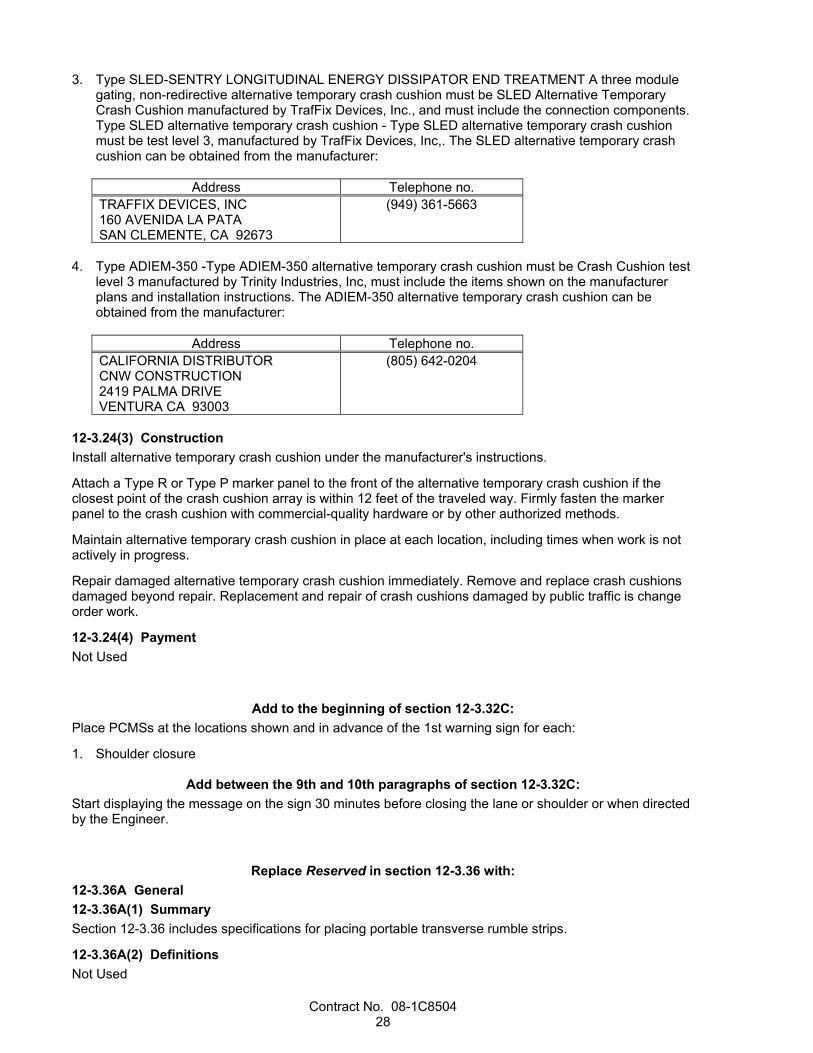
3. Type SLED-SENTRY LONGITUDINAL ENERGY DISSIPATOR END TREATMENT A three module gating, non-redirective alternative temporary crash cushion must be SLED Alternative Temporary Crash Cushion manufactured by TrafFix Devices, Inc., and must include the connection components. Type SLED alternative temporary crash cushion - Type SLED alternative temporary crash cushion must be test level 3, manufactured by TrafFix Devices, Inc,. The SLED alternative temporary crash cushion can be obtained from the manufacturer:
Address Telephone no.
TRAFFIX DEVICES, INC 160 AVENIDA LA PATA SAN CLEMENTE, CA 92673
(949) 361-5663
4. Type ADIEM-350 -Type ADIEM-350 alternative temporary crash cushion must be Crash Cushion test
level 3 manufactured by Trinity Industries, Inc, must include the items shown on the manufacturer plans and installation instructions. The ADIEM-350 alternative temporary crash cushion can be obtained from the manufacturer:
Address Telephone no.
CALIFORNIA DISTRIBUTOR CNW CONSTRUCTION 2419 PALMA DRIVE VENTURA CA 93003
(805) 642-0204
12-3.24(3) Construction Install alternative temporary crash cushion under the manufacturer's instructions.
Attach a Type R or Type P marker panel to the front of the alternative temporary crash cushion if the closest point of the crash cushion array is within 12 feet of the traveled way. Firmly fasten the marker panel to the crash cushion with commercial-quality hardware or by other authorized methods.
Maintain alternative temporary crash cushion in place at each location, including times when work is not actively in progress.
Repair damaged alternative temporary crash cushion immediately. Remove and replace crash cushions damaged beyond repair. Replacement and repair of crash cushions damaged by public traffic is change order work.
12-3.24(4) Payment Not Used
Add to the beginning of section 12-3.32C: Place PCMSs at the locations shown and in advance of the 1st warning sign for each:
1. Shoulder closure
Add between the 9th and 10th paragraphs of section 12-3.32C: Start displaying the message on the sign 30 minutes before closing the lane or shoulder or when directed by the Engineer.
Replace Reserved in section 12-3.36 with: 12-3.36A General 12-3.36A(1) Summary Section 12-3.36 includes specifications for placing portable transverse rumble strips.
12-3.36A(2) Definitions Not Used

Contract No. 08-1C8504 29
12-3.36A(3) Submittals Submit a copy of the manufacturer's instructions.
12-3.36A(4) Quality Assurance Not Used
12-3.36B Materials The strip must be either the RoadQuake 2 or the RoadQuake 2F Folding Temporary Portable Rumble Strip manufactured by Plastic Safety Systems, Inc. For information on obtaining the rumble strips, contact:
CUSTOMER SERVICE PLASTIC SAFETY SYSTEMS, INC. 2444 BALDWIN RD CLEVELAND, OH 44104 Telephone no.: (800) 662-6338 or (216) 231-8590
12-3.36C Construction Place portable transverse rumble strips before closing the lane to traffic.
The color of the portable transverse rumble strips must be black or orange. Use 2 arrays and, each array must consist of 3 rumble strips.
Portable transverse rumble strips must not be placed:
1. On sharp horizontal or vertical curves 2. Through pedestrian crossings If the portable transverse rumble strips become out of alignment or skewed by more than 6 inches, measured from one end to the other, readjust to bring the placement back to the original location.
Portable transverse rumble strips are not required if any of the following conditions is met:
1. Work duration occupies a location for 4 hours or less. 2. Posted speed limit is below 45 mph. 3. Work is of emergency nature. 4. Work zone is in snow or icy weather conditions. For a RoadQuake 2 rumble strip, securely connect the 3 sections under the manufacturer’s instructions before placing them in the traffic lane.
Remove all portable transverse rumble strips and warning signs before opening the lane to traffic.
If the Engineer determines that the portable transverse rumble strips no longer provide audible and vibratory alerts, replace them.
12-3.36D Payment Not Used
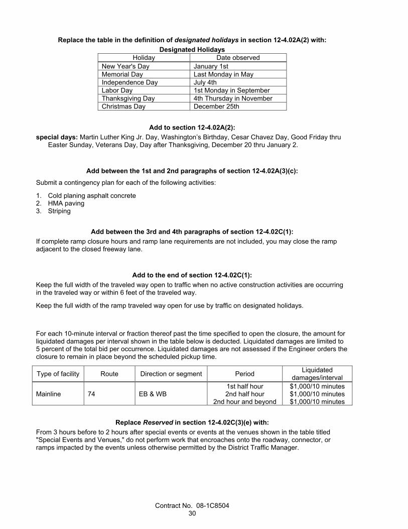
Contract No. 08-1C8504 30
Replace the table in the definition of designated holidays in section 12-4.02A(2) with: Designated Holidays
Holiday Date observed New Year's Day January 1st Memorial Day Last Monday in May Independence Day July 4th Labor Day 1st Monday in September Thanksgiving Day 4th Thursday in November Christmas Day December 25th
Add to section 12-4.02A(2): special days: Martin Luther King Jr. Day, Washington’s Birthday, Cesar Chavez Day, Good Friday thru
Easter Sunday, Veterans Day, Day after Thanksgiving, December 20 thru January 2.
Add between the 1st and 2nd paragraphs of section 12-4.02A(3)(c): Submit a contingency plan for each of the following activities:
1. Cold planing asphalt concrete 2. HMA paving 3. Striping
Add between the 3rd and 4th paragraphs of section 12-4.02C(1): If complete ramp closure hours and ramp lane requirements are not included, you may close the ramp adjacent to the closed freeway lane.
Add to the end of section 12-4.02C(1): Keep the full width of the traveled way open to traffic when no active construction activities are occurring in the traveled way or within 6 feet of the traveled way.
Keep the full width of the ramp traveled way open for use by traffic on designated holidays.
For each 10-minute interval or fraction thereof past the time specified to open the closure, the amount for liquidated damages per interval shown in the table below is deducted. Liquidated damages are limited to 5 percent of the total bid per occurrence. Liquidated damages are not assessed if the Engineer orders the closure to remain in place beyond the scheduled pickup time.
Type of facility Route Direction or segment Period Liquidated damages/interval
Mainline 74 EB & WB 1st half hour 2nd half hour
2nd hour and beyond
$1,000/10 minutes $1,000/10 minutes $1,000/10 minutes
Replace Reserved in section 12-4.02C(3)(e) with: From 3 hours before to 2 hours after special events or events at the venues shown in the table titled "Special Events and Venues," do not perform work that encroaches onto the roadway, connector, or ramps impacted by the events unless otherwise permitted by the District Traffic Manager.
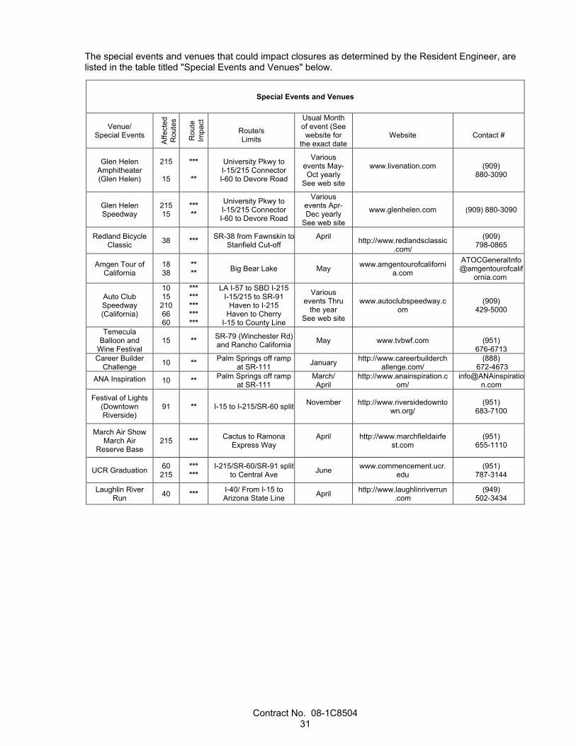
Contract No. 08-1C8504 31
The special events and venues that could impact closures as determined by the Resident Engineer, are listed in the table titled "Special Events and Venues" below.
Special Events and Venues
Venue/ Special Events
Affe
cted
R
oute
s
Rou
te
Impa
ct
Route/s Limits
Usual Month of event (See website for
the exact date
Website
Contact #
Glen Helen
Amphitheater (Glen Helen)
215
15
***
**
University Pkwy to I-15/215 Connector I-60 to Devore Road
Various events May-Oct yearly
See web site
www.livenation.com
(909) 880-3090
Glen Helen Speedway
215 15
*** **
University Pkwy to I-15/215 Connector I-60 to Devore Road
Various events Apr-Dec yearly
See web site
www.glenhelen.com (909) 880-3090
Redland Bicycle Classic 38 *** SR-38 from Fawnskin to
Stanfield Cut-off April
http://www.redlandsclassic
.com/
(909) 798-0865
Amgen Tour of California
18 38
** ** Big Bear Lake May www.amgentourofcaliforni
a.com
ATOCGeneralInfo@amgentourofcalif
ornia.com
Auto Club Speedway (California)
10 15
210 66 60
*** *** *** *** ***
LA I-57 to SBD I-215 I-15/215 to SR-91
Haven to I-215 Haven to Cherry
I-15 to County Line
Various events Thru
the year See web site
www.autoclubspeedway.com
(909) 429-5000
Temecula Balloon and
Wine Festival 15 ** SR-79 (Winchester Rd)
and Rancho California May www.tvbwf.com
(951) 676-6713
Career Builder Challenge 10 ** Palm Springs off ramp
at SR-111 January http://www.careerbuilderchallenge.com/
(888) 672-4673
ANA Inspiration 10 ** Palm Springs off ramp at SR-111
March/ April
http://www.anainspiration.com/
Festival of Lights (Downtown Riverside)
91 ** I-15 to I-215/SR-60 split November
http://www.riversidedowntown.org/
(951) 683-7100
March Air Show March Air
Reserve Base 215 *** Cactus to Ramona
Express Way April
http://www.marchfieldairfe
st.com (951)
655-1110
UCR Graduation 60 215
*** ***
I-215/SR-60/SR-91 split to Central Ave June www.commencement.ucr.
edu (951)
787-3144
Laughlin River Run 40 *** I-40/ From I-15 to
Arizona State Line April http://www.laughlinriverrun.com
(949) 502-3434

Contract No. 08-1C8504 32
Thunder & Lightning Powwow
10 *** I-10/ Morongo Valley September
http://www.morongocasinoresort.com/pow2.cfm
(800) 252-4499
ext.#: 23800
Coachella Valley Music and Arts
Festival
10 111
*** ***
I-10/Beaumont to Coachella
111/Whitewater to Coachella
April www.coachella.com
Stagecoach Music Festival
10 111
*** ***
I-10/Beaumont to Coachella
111/Whitewater to Coachella
April http://www.stagecoachfesti
val.com/
King of Hammers 247 *** sbd18 to 62
Around Feb. (for the date
go online/call)
http://www.griffinrad.com/kingofthehammers/
https://ultra4racing.com/ra
ce/17
1-800-722-3723 or Dave Cole
909 273 0216
Redlands University
Graduation 10 *** I-10 Redlands April http://www.redlands.edu/ (909) 793-2121
High School Graduation 10 *** I-10 Redlands June http://rhs.redlandsusd.net/ (909) 307-5300
** Designates Moderate Impact (20 minute delay or less) *** Designates High Impact (30 minute delay or less)
Note 1: The dates of events change yearly. Contact information and websites are provided to verify exact dates.
Note 2: Other special events do exist that impact our freeway and highway system. Close coordination with the local agencies and other impacted entities must be carried out before conducting work that requires full or partial closures.
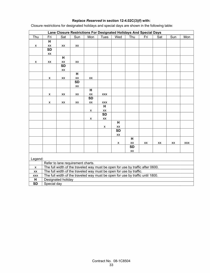
Contract No. 08-1C8504 33
Replace Reserved in section 12-4.02C(3)(f) with: Closure restrictions for designated holidays and special days are shown in the following table:
Lane Closure Restrictions For Designated Holidays And Special Days Thu Fri Sat Sun Mon Tues Wed Thu Fri Sat Sun Mon
x
H xx
xx
xx
SD xx
x
xx
H xx
xx
SD xx
x
xx
H xx
xx
SD xx
x
xx
xx
H xx
xxx
x
xx
xx
SD xx
xxx
x
H xx
x
SD xx
x
H xx
SD xx
x
H xx
xx
xx
xx
xxx
SD xx
Legend:
Refer to lane requirement charts. x The full width of the traveled way must be open for use by traffic after 0600. xx The full width of the traveled way must be open for use by traffic. xxx The full width of the traveled way must be open for use by traffic until 1800. H Designated holiday
SD Special day

Contract No. 08-1C8504 34
Replace Reserved in section 12-4.02C(3)(k) with: Comply with the requirements for the conventional highway lane closures shown in the following chart:
Chart No. K1 EA#: 1C850
ID#: 08 1300 0047 Conventional Highway Lane Requirements
County:Riv Route/Direction:74/EB & WB Post Mile:0-5.8
Closure limits:
Hour 00 01 02 03 04 05 06 07 08 09 10 11 12 13 14 15 16 17 18 19 20 21 22 23 24 Mon–Thu
R R R R R R R R R R R R R R R
Fri R R R R R R R R R R R R R R R
Sat R R R R R R R R R
Sun R R R R R R R R R
Legend: R Provide at least 1 through traffic lane not less than 10 feet in width for use by both directions of
travel. (Reversing Control) Work is allowed within the highway where a shoulder or lane closure is not required.
REMARKS: A maximum of ten (10) days of complete closure of both directions is allowed. Proper signing at freeways 15 and 5 shall be done. Refer to MI-1 for detour plan.
Replace Reserved in section 12-4.02C(3)(l) with: Comply with the requirements for the complete closure on a conventional highway shown in the following chart:
Chart No.: L1 EA#: 1C850
ID#: 0813000047 Complete Conventional Highway Closure Hours
County: Riv Route/Direction: 74/EB & WB Post Mile: 0-5.8
Closure limits:
Hour 00 01 02 03 04 05 06 07 08 09 10 11 12 13 14 15 16 17 18 19 20 21 22 23 24 Mon–Thu
C C C C C C C
Fri C C C C C C C
Sat C C C C C C C
Sun C C C C C C C
Legend: C Conventional highway may be closed completely. No complete conventional highway closure is allowed.
REMARKS: Proper singing on freeways 5 (In Orange county) and 15 needs to be done. The total number of closures shall not exceed 100.
Contract No. 08-1C8504 35
Add to the end of section 12-4.02C(7)(a): Except where prohibited, use an impact attenuator vehicle:
1. To follow behind equipment and workers who are placing and removing components of a closure. Operate the flashing arrow sign in the arrow or caution mode during this activity, whichever applies. Follow at a distance that prevents intrusion into the work space from passing traffic.
After placing components of a stationary traffic control system, you may place the impact attenuator vehicle in advance of the work area or at another authorized location to protect traffic and workers.
Add to the end of section 12-4.02C(7)(b): Additional advance flaggers are required.
Except for one-way-reversing traffic-control lane closures, the maximum length of the work area inside a closure is 2 miles.
Not more than 2 stationary closures are allowed in each direction of travel at one time.
Concurrent stationary closures in the same direction of travel must be spaced no closer than 2 miles apart. Closures in the same direction of travel on alternating inside lanes and outside lanes must be spaced by an additional 2 miles.
Closure spacing is the distance between the last cone of the upstream closure and the temporary sign W20-1 of the downstream closure. The number of lanes open in the upstream closures must be less than or equal to the number of lanes open in the downstream closures. For multiple closures in each direction of travel, pick up the downstream closures first.
For a stationary one-way-reversing traffic-control lane closure, you may stop traffic in 1 direction for periods not to exceed 15 minutes. After each stoppage, all accumulated traffic for that direction must pass through the work zone before another stoppage is made.
The maximum length of a single stationary one-way-reversing traffic-control lane closure is 2 miles between flaggers.
Not more than 2 stationary one-way-reversing traffic-control lane closures will be allowed at one time. Concurrent closures in the same direction of travel must be spaced no closer than 2 miles apart.
Transport bicyclists through the one-way-reversing traffic-control work zone.
You may use a pilot car to control traffic. If a pilot car is used to control traffic, the cones shown along the centerline are not required. Pilot cars must have cellular or radio contact with other pilot cars and personnel in the work zone. The maximum speed of the pilot cars convoying or controlling traffic through the traffic control zone is 25 mph. Pilot cars must only use traffic lanes open to traffic.
Add to the end of the 1st paragraph of section 12-6.01 with: Placing temporary painted traffic stripes and temporary painted pavement marking or pavement markers includes the removal of the stripes, marking or markers.
For seal coat and/or rehabilitation projects, placing and removal of temporary pavement delineation not shown on the plan is included under the item that obliterated the existing pavement delineation.

Contract No. 08-1C8504 36
^^^^^^^^^^^^^^^^^^^^^^^^^^^^^^^^^^^^^^^^
13 WATER POLLUTION CONTROL
Add to the end of section 13-3.01A: This project's risk level is 2.
Add between the 4th and 5th paragraphs of section 13-3.01C(2)(a): The following RWQCBs will review the authorized SWPPP:
1. Santa Ana
^^^^^^^^^^^^^^^^^^^^^^^^^^^^^^^^^^^^^^^^
14 ENVIRONMENTAL STEWARDSHIP
Add to the end of section 14-1.02: An ESA exists on this project.
Before starting job site activities, install Type 1 Temporary reinforced silt fence to protect the ESA and mark its boundaries.
Install signs 100 feet apart along the length and at the ends of the Temporary reinforced silt fence identifying the area as an ESA. Place the top of each sign flush with the top of the Temporary reinforced silt fence.
The signs must:
1. Be weatherproof and fade-proof 2. Be from 8-1/2 to 11 inches high and from 11 to 14 inches wide 3. Have the following message in black letters: Environmentally Sensitive Area The message must be legible from a distance of 20 feet by persons with 20/20 vision or vision corrected to 20/20.
The signs may be made of laminated printed paper attached to an inflexible weatherproof backer board.
Attach the signs to the Temporary reinforced silt fence with tie wire or locking plastic fasteners.
Maintain the signs until Contract acceptance.
Limited access to the ESA is allowed for monitoring. Notify the Engineer 5 business days or less before the planned entry date. Any other access to the ESA is prohibited.
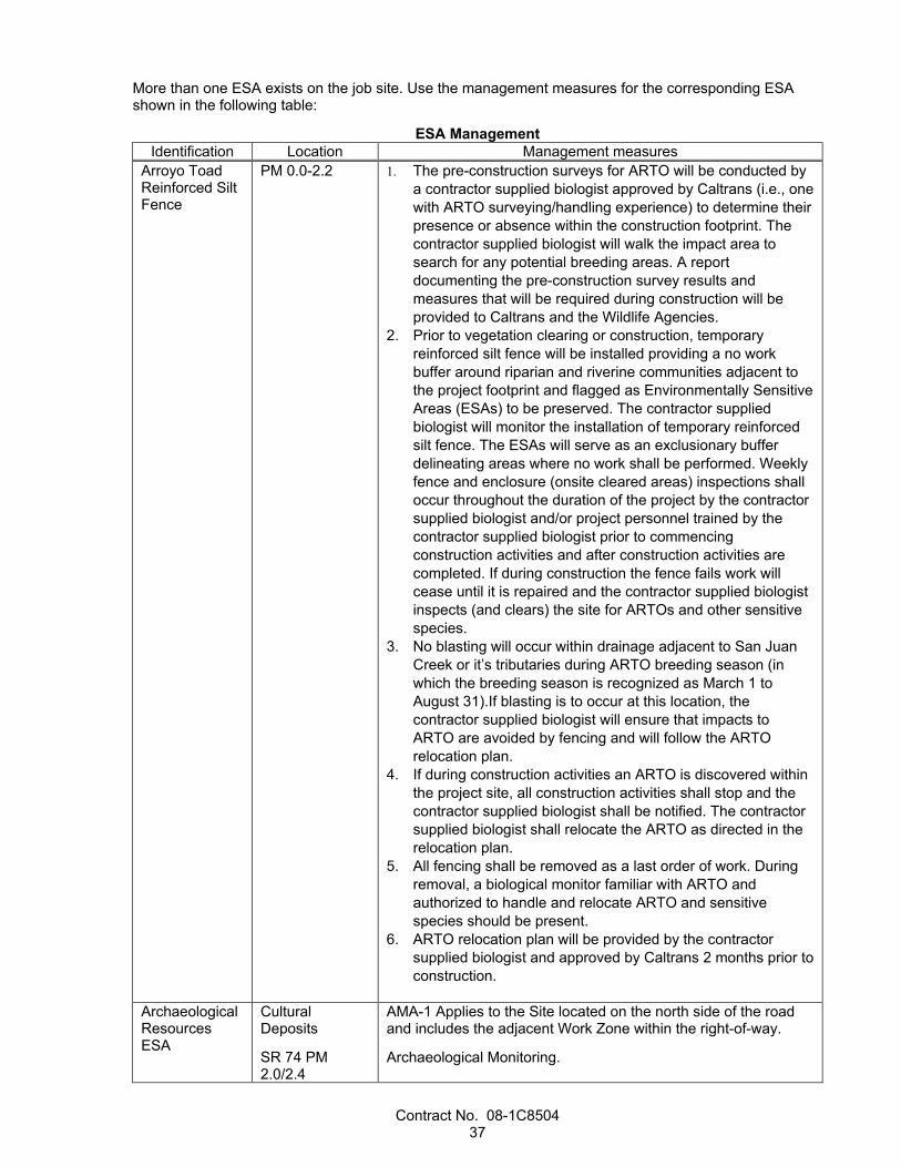
Contract No. 08-1C8504 37
More than one ESA exists on the job site. Use the management measures for the corresponding ESA shown in the following table:
ESA Management Identification Location Management measures
Arroyo Toad Reinforced Silt Fence
PM 0.0-2.2 1. The pre-construction surveys for ARTO will be conducted by a contractor supplied biologist approved by Caltrans (i.e., one with ARTO surveying/handling experience) to determine their presence or absence within the construction footprint. The contractor supplied biologist will walk the impact area to search for any potential breeding areas. A report documenting the pre-construction survey results and measures that will be required during construction will be provided to Caltrans and the Wildlife Agencies.
2. Prior to vegetation clearing or construction, temporary reinforced silt fence will be installed providing a no work buffer around riparian and riverine communities adjacent to the project footprint and flagged as Environmentally Sensitive Areas (ESAs) to be preserved. The contractor supplied biologist will monitor the installation of temporary reinforced silt fence. The ESAs will serve as an exclusionary buffer delineating areas where no work shall be performed. Weekly fence and enclosure (onsite cleared areas) inspections shall occur throughout the duration of the project by the contractor supplied biologist and/or project personnel trained by the contractor supplied biologist prior to commencing construction activities and after construction activities are completed. If during construction the fence fails work will cease until it is repaired and the contractor supplied biologist inspects (and clears) the site for ARTOs and other sensitive species.
3. No blasting will occur within drainage adjacent to San Juan Creek or it’s tributaries during ARTO breeding season (in which the breeding season is recognized as March 1 to August 31).If blasting is to occur at this location, the contractor supplied biologist will ensure that impacts to ARTO are avoided by fencing and will follow the ARTO relocation plan.
4. If during construction activities an ARTO is discovered within the project site, all construction activities shall stop and the contractor supplied biologist shall be notified. The contractor supplied biologist shall relocate the ARTO as directed in the relocation plan.
5. All fencing shall be removed as a last order of work. During removal, a biological monitor familiar with ARTO and authorized to handle and relocate ARTO and sensitive species should be present.
6. ARTO relocation plan will be provided by the contractor supplied biologist and approved by Caltrans 2 months prior to construction.
Archaeological Resources ESA
Cultural Deposits
SR 74 PM 2.0/2.4
AMA-1 Applies to the Site located on the north side of the road and includes the adjacent Work Zone within the right-of-way.
Archaeological Monitoring.
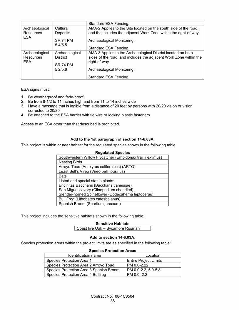
Contract No. 08-1C8504 38
Standard ESA Fencing. Archaeological Resources ESA
Cultural Deposits
SR 74 PM 5.4/5.5
AMA-2 Applies to the Site located on the south side of the road, and the includes the adjacent Work Zone within the right-of-way.
Archaeological Monitoring.
Standard ESA Fencing. Archaeological Resources ESA
Archaeological District
SR 74 PM 5.2/5.6
AMA-3 Applies to the Archaeological District located on both sides of the road, and includes the adjacent Work Zone within the right-of-way.
Archaeological Monitoring.
Standard ESA Fencing.
ESA signs must:
1. Be weatherproof and fade-proof 2. Be from 8-1/2 to 11 inches high and from 11 to 14 inches wide 3. Have a message that is legible from a distance of 20 feet by persons with 20/20 vision or vision
corrected to 20/20 4. Be attached to the ESA barrier with tie wire or locking plastic fasteners Access to an ESA other than that described is prohibited.
Add to the 1st paragraph of section 14-6.03A: This project is within or near habitat for the regulated species shown in the following table:
Regulated Species Southwestern Willow Flycatcher (Empidonax traillii extimus) Nesting Birds Arroyo Toad (Anaxyrus californicus) (ARTO) Least Bell’s Vireo (Vireo bellii pusillus) Bats Listed and special status plants: Encinitas Baccharis (Baccharis vanessae) San Miguel savory (Clinopodium chandleri) Slender-horned Spineflower (Dodecahema leptoceras) Bull Frog (Lithobates catesbeianus) Spanish Broom (Spartium junceum)
This project includes the sensitive habitats shown in the following table:
Sensitive Habitats Coast live Oak – Sycamore Riparian
Add to section 14-6.03A:
Species protection areas within the project limits are as specified in the following table:
Species Protection Areas Identification name Location
Species Protection Area 1 Entire Project Limits Species Protection Area 2 Arroyo Toad PM 0.0-2.22 Species Protection Area 3 Spanish Broom PM 0.0-2.2, 5.0-5.8 Species Protection Area 4 Bullfrog PM 0.0 -2.2
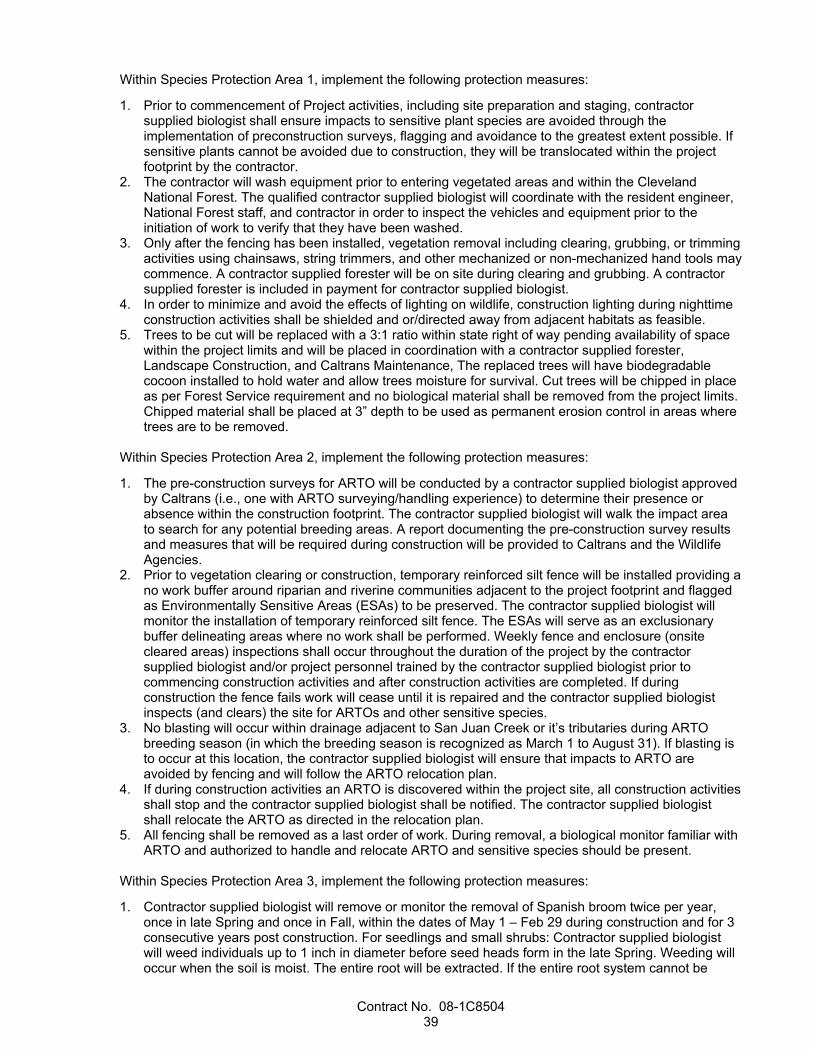
Contract No. 08-1C8504 39
Within Species Protection Area 1, implement the following protection measures:
1. Prior to commencement of Project activities, including site preparation and staging, contractor supplied biologist shall ensure impacts to sensitive plant species are avoided through the implementation of preconstruction surveys, flagging and avoidance to the greatest extent possible. If sensitive plants cannot be avoided due to construction, they will be translocated within the project footprint by the contractor.
2. The contractor will wash equipment prior to entering vegetated areas and within the Cleveland National Forest. The qualified contractor supplied biologist will coordinate with the resident engineer, National Forest staff, and contractor in order to inspect the vehicles and equipment prior to the initiation of work to verify that they have been washed.
3. Only after the fencing has been installed, vegetation removal including clearing, grubbing, or trimming activities using chainsaws, string trimmers, and other mechanized or non-mechanized hand tools may commence. A contractor supplied forester will be on site during clearing and grubbing. A contractor supplied forester is included in payment for contractor supplied biologist.
4. In order to minimize and avoid the effects of lighting on wildlife, construction lighting during nighttime construction activities shall be shielded and or/directed away from adjacent habitats as feasible.
5. Trees to be cut will be replaced with a 3:1 ratio within state right of way pending availability of space within the project limits and will be placed in coordination with a contractor supplied forester, Landscape Construction, and Caltrans Maintenance, The replaced trees will have biodegradable cocoon installed to hold water and allow trees moisture for survival. Cut trees will be chipped in place as per Forest Service requirement and no biological material shall be removed from the project limits. Chipped material shall be placed at 3” depth to be used as permanent erosion control in areas where trees are to be removed.
Within Species Protection Area 2, implement the following protection measures:
1. The pre-construction surveys for ARTO will be conducted by a contractor supplied biologist approved by Caltrans (i.e., one with ARTO surveying/handling experience) to determine their presence or absence within the construction footprint. The contractor supplied biologist will walk the impact area to search for any potential breeding areas. A report documenting the pre-construction survey results and measures that will be required during construction will be provided to Caltrans and the Wildlife Agencies.
2. Prior to vegetation clearing or construction, temporary reinforced silt fence will be installed providing a no work buffer around riparian and riverine communities adjacent to the project footprint and flagged as Environmentally Sensitive Areas (ESAs) to be preserved. The contractor supplied biologist will monitor the installation of temporary reinforced silt fence. The ESAs will serve as an exclusionary buffer delineating areas where no work shall be performed. Weekly fence and enclosure (onsite cleared areas) inspections shall occur throughout the duration of the project by the contractor supplied biologist and/or project personnel trained by the contractor supplied biologist prior to commencing construction activities and after construction activities are completed. If during construction the fence fails work will cease until it is repaired and the contractor supplied biologist inspects (and clears) the site for ARTOs and other sensitive species.
3. No blasting will occur within drainage adjacent to San Juan Creek or it’s tributaries during ARTO breeding season (in which the breeding season is recognized as March 1 to August 31). If blasting is to occur at this location, the contractor supplied biologist will ensure that impacts to ARTO are avoided by fencing and will follow the ARTO relocation plan.
4. If during construction activities an ARTO is discovered within the project site, all construction activities shall stop and the contractor supplied biologist shall be notified. The contractor supplied biologist shall relocate the ARTO as directed in the relocation plan.
5. All fencing shall be removed as a last order of work. During removal, a biological monitor familiar with ARTO and authorized to handle and relocate ARTO and sensitive species should be present.
Within Species Protection Area 3, implement the following protection measures:
1. Contractor supplied biologist will remove or monitor the removal of Spanish broom twice per year, once in late Spring and once in Fall, within the dates of May 1 – Feb 29 during construction and for 3 consecutive years post construction. For seedlings and small shrubs: Contractor supplied biologist will weed individuals up to 1 inch in diameter before seed heads form in the late Spring. Weeding will occur when the soil is moist. The entire root will be extracted. If the entire root system cannot be

Contract No. 08-1C8504 40
removed or breaks, herbicide (triclopyr or imazopyr) will be applied to the cut root. Soil disturbance will be minimized. Additional care will be used to ensure that seedlings downslope of shrubs are removed. Disposal of removed plants will occur within 24 hours or same day at commercial disposal facility. Contractor supplied biologist will use methylated seed oils (MSO) as a surfactant. Biologist will use a colored dye marker of different color to easily identify treated and untreated areas. Within 45 calendar days of completing construction the contractor shall submit to Caltrans a memo including the following: a. Color photographs taken at the project site before and after construction including a baseline
survey for Spanish Broom before and after construction; b. Date(s) work was initiated and completed; c. Summary of compliance status with each special condition of this habitat plan (including any
noncompliance that previously occurred or is currently occurring and corrective actions completed or being taken to achieve compliance);
d. Signed Certification of Compliance; e. Annual report submitted annually to include a description of the activities of work performed,
maps (PDF and GIS files) and quantitative data detailing the % cover of invasive species (Spanish broom) before and after each treatment, representative site photographs, and recommendations for further improvement. If Spanish broom reseeding annually at project site, additional measures may be suggested by Caltrans;
f. Final 3 years post construction plant surveys in the appropriate season.
Within Species Protection Area 4, implement the following protection measures:
1. Contractor supplied biologist will remove bullfrog once per year within July 1 and Feb 29 during construction and for 3 consecutive years post construction. Any additional equipment will be approved by Caltrans and prior to removal. Annual report for bullfrog removal will include a description of the activities of work performed, maps (including PDF and GIS files) and quantitative data detailing the number and location of exotic species (bullfrogs) removed, representative site photographs, and recommendations for further improvement.
2. Contractor supplied biologist will implement measures in Caltrans provided habitat mitigation and monitoring plan.
Replace the list in the 2nd paragraph of section 14-6.03D(1) with:
1. Prior to implementing any construction activities on the project site, the contractor supplied biologist shall implement a Biological Resources Information Program (BRIP) to educate on-site workers about sensitive environmental issues associated with the project. The program will be administered to all on-site personnel, including the contractor’s personnel, contractors, and all subcontractors, prior to the contractor’s commencing work on the site. Contractor shall provide interpretation for non-English speaking workers, and the same instruction shall be provided to any new workers before they are authorized to perform work within the project. The WEAP will include but not be limited to protected species that have potential to occur within the project, including nesting birds, plants, and other wildlife species.
2. The contractor supplied biologist will ensure that following documents are approved by Caltrans and will be implemented:
a. ARTO relocation plan i. ARTO relocation plan will be supplied by the contractor supplied biologist and sent to
Caltrans to be approved by CDFW and USFWS two months prior to the start of construction in Species Protection Area 2
b. Nesting bird plan i. Nesting bird plan will be supplied by Caltrans prior to clearing and grubbing.
c. Bat mitigation and management plan i. Bat mitigation and management plan will be supplied by Caltrans and be approved by CDFW
6 months prior to the start of construction. After approval, it will be sent to the contractor supplied biologist.
d. Habitat mitigation and monitoring program

Contract No. 08-1C8504 41
i. Habitat mitigation and monitoring program will be supplied by Caltrans and implemented by the contractor supplied biologist.
3. Prior to commencement of Project activities, including site preparation and staging, contractor supplied biologist shall ensure impacts to sensitive plant species are avoided through the implementation of preconstruction surveys, flagging and avoidance to the greatest extent possible. If sensitive plants cannot be avoided due to construction, they will be translocated within the project footprint by the contractor
4. The contractor will wash equipment prior to entering vegetated areas and within the Cleveland National Forest. The qualified contractor supplied biologist will coordinate with the resident engineer, National Forest staff, and contractor in order to inspect the vehicles and equipment prior to the initiation of work to verify that they have been washed.
5. Only after the fencing has been installed, vegetation removal including clearing, grubbing, or trimming activities using chainsaws, string trimmers, and other mechanized or non-mechanized hand tools may commence. A contractor supplied forester will be on site during clearing and grubbing.
6. In order to minimize and avoid the effects of lighting on wildlife, construction lighting during nighttime construction activities shall be shielded and or/directed away from adjacent habitats as feasible.
7. Trees to be cut will be replaced with a 3:1 ratio within state right of way pending availability of space within the project limits and will be placed in coordination with a contractor supplied forester, Landscape Construction, and Caltrans Maintenance. The replaced trees will have biodegradable cocoon installed to hold water and allow trees moisture for survival. Cut trees will be chipped in place as per Forest Service requirement and no biological material shall be removed from the project limits. Chipped material shall be placed in areas where the trees are to be removed at 3” thick and used as permanent erosion control.
8 The pre-construction surveys for ARTO will be conducted by a contractor supplied biologist approved by Caltrans (i.e., one with ARTO surveying/handling experience) to determine their presence or absence within the construction footprint. The contractor supplied biologist will walk the impact area to search for any potential breeding areas. A report documenting the pre-construction survey results and measures that will be required during construction will be provided to Caltrans and the Wildlife Agencies.
9 Prior to vegetation clearing or construction, temporary reinforced silt fence will be installed providing a no work buffer around riparian and riverine communities adjacent to the project footprint and flagged as Environmentally Sensitive Areas (ESAs) to be preserved. The contractor supplied biologist will monitor the installation of temporary reinforced silt fence. The ESAs will serve as an exclusionary buffer delineating areas where no work shall be performed. Weekly fence and enclosure (onsite cleared areas) inspections shall occur throughout the duration of the project by the contractor supplied biologist and/or project personnel trained by the contractor supplied biologist prior to commencing construction activities and after construction activities are completed. If during construction the fence fails work will cease until it is repaired and the contractor supplied biologist inspects (and clears) the site for ARTOs and other sensitive species.
10 No blasting will occur within drainage adjacent to San Juan Creek or it’s tributaries during ARTO breeding season (in which the breeding season is recognized as March 1 to August 31). If blasting is to occur at this location, the contractor supplied biologist will ensure that impacts to ARTO are avoided by fencing and will follow the ARTO relocation plan.
11 If during construction activities an ARTO is discovered within the project site, all construction activities shall stop and the contractor supplied biologist shall be notified. The contractor supplied biologist shall relocate the ARTO as directed in the relocation plan.
12 All fencing shall be removed as a last order of work. During removal, a biological monitor familiar with ARTO and authorized to handle and relocate ARTO and sensitive species should be present.
13 Contractor supplied biologist will remove or monitor the removal of Spanish broom twice per year, once in late Spring and once in Fall, within the dates of May 1 – Feb 29 during construction and for 3 consecutive years post construction. For seedlings and small shrubs: Contractor supplied biologist will weed individuals up to 1 inch in diameter before seed heads form in the late Spring. Weeding will occur when the soil is moist. The entire root will be extracted. If the entire root system cannot be removed or breaks, herbicide (triclopyr or imazopyr) will be applied to the cut root. Soil disturbance will be minimized. Additional care will be used to ensure that seedlings downslope of shrubs are removed. Disposal of removed plants will occur within 24 hours or same day at commercial disposal facility. Contractor supplied biologist will use methylated seed oils (MSO) as a surfactant. Biologist will use a colored dye marker of different color to easily identify treated and untreated areas.

Contract No. 08-1C8504 42
14 Contractor supplied biologist will remove bullfrog once per year within July 1 and Feb 29 during construction and for 3 consecutive years post construction. Any additional equipment will be approved by Caltrans and prior to removal. Annual report for bullfrog removal will include a description of the activities of work performed, maps (including PDF and GIS files) and quantitative data detailing the number and location of exotic species (bullfrogs) removed, representative site photographs, and recommendations for further improvement.
Replace the list in the 3rd paragraph of section 14-6.03D(1) with: 1. Within 45 calendar days of completing construction the contractor shall submit to Caltrans a memo
including the following: a. Color photographs taken at the project site before and after construction including a baseline
survey for Spanish Broom before and after construction; b. Date(s) work was initiated and completed; c. Summary of compliance status with each special condition of this habitat plan (including any
noncompliance that previously occurred or is currently occurring and corrective actions completed or being taken to achieve compliance);
d. Signed Certification of Compliance; e. Annual report submitted annually to include a description of the activities of work performed,
maps (PDF and GIS files) and quantitative data detailing the % cover of invasive species (Spanish broom) before and after each treatment, representative site photographs, and recommendations for further improvement. If Spanish broom reseeding annually at project site, additional measures may be suggested by Caltrans;
f. Final 3 years post construction plant surveys in the appropriate season.
Replace the 2nd and 3rd paragraphs of section 14-6.03D(1) with: The Contractor-supplied biologist must implement monitoring and reporting requirements described in the natural resources protection plan.
Add to section 14-6.03D(1): A Contractor-supplied biologist who performs specialized activities must have demonstrated field experience working with the regulated species or performing the specialized task. The biologist must have experience that complies with the requirements shown in the following table:
Specialized activity/species Requirements Avian species Caltrans approved Arroyo Toad Caltrans approved. Amphibian biologist Rare and sensitive plants Caltrans approved Forrester Caltrans approved Bats Caltrans approved. Must have at least 3 years
experience in conducting bat habitat assessments, night-time emergence surveys, and acoustic monitoring. Must have adequate experience identifying local bat species, type of habitat, and differences in roosting behavior and types. Must also have at least 2 years of experience in exclusionary techniques on transportation projects and 1 year experience in bat alternative housing.
Spanish Broom Caltrans approved Invasive Species/Restoration ecologist
Bull Frog Caltrans approved
Within 30 days before starting job site activities, submit protocols for species protection surveys. Use protocols required in the PLACs.
Survey the job site for regulated species and submit a preconstruction survey report within 14 days before starting work.

Contract No. 08-1C8504 43
The preconstruction survey report must include one of the following:
1. Detailed observations and locations where regulated species were observed 2. Statement that no regulated species were observed Submit an initial monitoring report as an informational submittal within 12 hours after starting ground-disturbing activities.
Submit a biological resource incident report within 24 hours of the incident.
The incident report must include:
1. Description of any take of regulated species or any violation of a biological resource PLAC 2. Species name and number taken 3. Details of required notifications with contact information 4. Corrective actions proposed or taken 5. Disposition of taken species Submit an annual monitoring report no later than January 15 during each year of construction.
The annual monitoring report must include:
1. Start and end dates of construction 2. Project impacts on the regulated species 3. Species protection measures and implementation details 4. Incidental take details, including species name, number taken, people contacted, contact information,
and disposition of taken species 5. Assessment of the effectiveness of the species protection measures in mitigating project impacts 6. Recommendations for improving species protection measures Submit a final monitoring report no later than 20 days after completion of the project. If the report requires revisions, the Department provides comments. Submit a revised report within 7 days of receiving comments. The final monitoring report must be a cumulative report including:
1. Start and end dates of construction 2. Project impacts on the regulated species 3. Species protection measures and implementation details 4. Incidental take details, including species name, number taken, people contacted, contact information,
and disposition of taken species 5. Assessment of the effectiveness of the species protection measures in mitigating project impacts 6. Recommendations for improving species protection measures
Add after the 2nd paragraph of section 14-11.12A: This project includes removal of yellow thermoplastic traffic strip that will produce hazardous waste residue.
Add after the 1st paragraph of 14-11.12E: After the Engineer accepts the analytical test results, dispose of yellow thermoplastic and yellow paint hazardous waste residue at a Class 1 disposal facility located in California 30 days after accumulating 220 lb of residue.
If less than 220 lb of hazardous waste residue and dust is generated in total, dispose of it within 30 days after the start of accumulation of the residue.
Add to the 1st paragraph of section 14-11.14A: Wood removed from guardrail and roadside sign is treated wood waste.
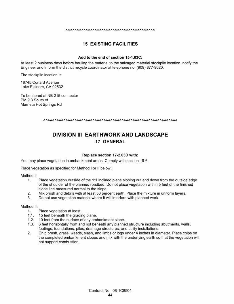
Contract No. 08-1C8504 44
^^^^^^^^^^^^^^^^^^^^^^^^^^^^^^^^^^^^^^^^
15 EXISTING FACILITIES
Add to the end of section 15-1.03C: At least 2 business days before hauling the material to the salvaged material stockpile location, notify the Engineer and inform the district recycle coordinator at telephone no. (909) 877-9020.
The stockpile location is:
18745 Conard Avenue Lake Elsinore, CA 92532 To be stored at NB 215 connector PM 9.3 South of Murrieta Hot Springs Rd
^^^^^^^^^^^^^^^^^^^^^^^^^^^^^^^^^^^^^^^^^^^^^^^^^^^^^^^^^^^^
DIVISION III EARTHWORK AND LANDSCAPE 17 GENERAL
Replace section 17-2.03D with: You may place vegetation in embankment areas. Comply with section 19-6.
Place vegetation as specified for Method I or II below:
Method I: 1. Place vegetation outside of the 1:1 inclined plane sloping out and down from the outside edge
of the shoulder of the planned roadbed. Do not place vegetation within 5 feet of the finished slope line measured normal to the slope.
2. Mix brush and debris with at least 50 percent earth. Place the mixture in uniform layers. 3. Do not use vegetation material where it will interfere with planned work.
Method II: 1. Place vegetation at least: 1.1. 15 feet beneath the grading plane. 1.2. 10 feet from the surface of any embankment slope. 1.3. 6 feet horizontally from and not beneath any planned structure including abutments, walls,
footings, foundations, piles, drainage structures, and utility installations. 2. Chip brush, grass, weeds, slash, and limbs or logs under 4 inches in diameter. Place chips on
the completed embankment slopes and mix with the underlying earth so that the vegetation will not support combustion.

Contract No. 08-1C8504 45
^^^^^^^^^^^^^^^^^^^^^^^^^^^^^^^^^^^^^^^^
19 EARTHWORK
Replace the 2nd, 3rd, and 4th paragraphs of section 19-2.03B with: Dispose of surplus material. Ensure enough material is available to complete the embankments before disposing of it.
Add to section 19-3.01A: If authorized, you may backfill the earth anchor excavation with slurry cement backfill.
Add to the end of section 19-3.01A: Structure backfill includes constructing the geocomposite drain system. The systems must comply with section 68-7.
Replace the paragraph in section 19-3.01C(5) with: Submit test results of any stability testing performed for ground anchor walls, soil nail walls, and earth anchor walls as an action submittal.
Add to section 19-3.01C: 19-3.01C(7) Earth Anchor Walls Submit shop drawings for earthwork for each earth anchor wall installation to OSD, Documents Unit. Notify the Engineer of the submittal. Include in the notification the date and a description of the contents of the submittal. The shop drawings must include:
1. All walls construction schedule 2. Wall construction schedule with construction sequence 3. Measures to ensure wall and slope stability during construction 4. Provisions for installing verification and proof test anchors 5. Methods of excavation and types of excavation equipment 6. Maximum duration of exposure for each wall zone, including supporting calculations and provisions to
stabilize the exposed excavated face 7. Details for measuring the movement of the excavated face during stability testing and construction 8. Space requirements for installation equipment 9. Dewatering plan to divert, control, and dispose of surface and groundwater during construction 10. Method of compaction and types of compaction equipment 11. Methods for protecting earth anchors during excavation and backfill Shop drawings and calculations must be sealed and signed by an engineer who is registered as a civil engineer in the State.
Submit 5 copies of shop drawings for initial review. Allow 30 days for review.
Submit from 6 to 12 copies of final shop drawings as requested by the Engineer for final authorization.

Contract No. 08-1C8504 46
Add to section 19-3.01D: 19-3.01D(3) Stability Test for Earth Anchor Walls A wall zone is the entire wall.
Perform the testing before roadway excavation.
Perform at least 1 stability test within the limits of each wall zone.
Excavate a neat face at least 3 feet in front of where the initial grouting would end. The excavated face must:
1. Have the height shown in the authorized shop drawings. 2. Be 20 feet long and parallel to the wall alignment with a constant height. You may excavate ramps
outside the 20-foot section for construction access. 3. Be left open for the proposed exposure time shown in the authorized shop drawings. 4. Maintain its integrity without raveling, sloughing, or measurable displacement throughout the
proposed exposure time. After authorization of the test results, you may use the proposed excavation height within the tested wall zone and the observed exposure time.
If the Engineer determines the exposed excavated face is not maintaining its integrity, you must immediately stabilize the excavated face and perform additional stability testing.
Add to the end of section 19-3.02E: Slurry cement backfill may contain returned plastic concrete.
Slurry cement backfill containing returned plastic concrete must comply with the specifications for concrete containing returned plastic concrete.
Replace Reserved in section 19-3.03A with: Protect earth anchors in place during excavation and backfill.
If ordered, remove and dispose loose or unsuitable material below the bottom of retaining wall trench footings and backfill with lean concrete backfill. This work is change order work.
Add to section 19-3.03B(1): Expect difficult earth anchor wall structure excavation due to the presence of the following conditions:
1. Bedrock profile irregularity 2. Shallow bedrock 3. Not rippable bedrock 4. Large cobbles and boulders in soil layer 5. Caving due to presence of cohesionless soils 6. Seasonal groundwater 7. Traffic control

Contract No. 08-1C8504 47
Add to section 19-3.03: 19-3.03L Earth Anchor Walls Do not use compaction equipment or methods that may cause displacement or damage to the earth anchors.
Notify the Engineer immediately if raveling or instability of the excavated face occurs.
Immediately stabilize unstable areas by buttressing the excavated face with an earth berm or other authorized methods. Stop construction in unstable areas. Take authorized remedial measures to stabilize the areas.
Replace any damaged earth anchors.
^^^^^^^^^^^^^^^^^^^^^^^^^^^^^^^^^^^^^^^^
20 LANDSCAPE
Replace the 1st through 5th paragraphs of section 20-1.02C with: Do not use pesticides.
Add to section 20-1.02C: Select herbicides from the following table:
Herbicides
Herbicide name
Herbicide type Preemergent
(granular) Preemergent (non granular)
Post- emergent
Selective Non- selective
Systemic
Imazapyr -- -- -- -- X -- Triclopyr -- -- -- -- -- X
Delete the 4th paragraph of section 20-1.03A.
Replace You may reduce in the 1st sentence of the 5th paragraph of section 20-1.03A with: Reduce
Replace the 1st paragraph of section 20-1.03C(2) with: When removing plants, trees stumps or root crowns that are greater than 8 inches in diameter at the lowest cut must remain. Lowest cut must be no more than 12 inches above finished grade.
Brush pesticide directly on the remaining stump or root crown immediately after the cut is made. After initial cutting, re-cut and re-brush pesticide if new plant growth appears.
Add to section 20-1.03C(3): Control weeds within the highway including medians and surfaced areas such as new and existing pavement, curbs, and sidewalks.
Control weeds within the highway. In the median and surfaced areas such as new and existing pavement, curbs, and sidewalks, weeds do not need to be controlled.
In mulched areas and within the area extending beyond the outer limits of the mulched areas to the adjacent edges of shoulders, dikes, curbs, sidewalks, walls, existing planting, and fences, control weeds

Contract No. 08-1C8504 48
with pesticides or by hand pulling. Where mulched areas are 12 feet or more from the adjacent edges of shoulders, dikes, curbs, sidewalks, walls, and fences, control weeds within the mulched areas and 6 feet beyond the outer limits of the mulched areas.
In areas where plants are to be planted in groups or rows 15 feet or less apart, control weeds within the planting area and the area extending 6 feet beyond the outer limits of the groups or rows of plants with pesticides or by hand pulling. Hand pull weeds within and on the plant basin walls, spot treat with pesticides outside of the plant basin.
Where the plants are to be planted more than 15 feet apart and are located outside of groundcover areas, control weeds with pesticides or by hand pulling within an area 6 feet in diameter centered at each plant location. Hand pull weeds within and on the plant basin walls, spot treat with pesticides outside of the plant basin.
Control weeds under guard rails by hand pulling.
Add to section 20-3.01A(3)(b): Some plants required may not be readily available and must be grown specifically for this project. Submit a statement within 30 days after Contract approval from the vendor that the order to grow the plants, including inspection plants and replacement plants, has been received and accepted by the vendor. The statement from the vendor must include the plant names, sizes, and quantities and the anticipated delivery date. Notify the Engineer when the vendor has started growing the plants.
Add to section 20-3.01B(3)(a): Soil amendment must be nitrolized fir bark.
Replace the 3rd paragraph of section 20-3.01B(9) with: Support stakes must be 2-inch nominal diameter or 2-by-2 inch nominal size wood stakes a minimum of 5 feet long. Wood stakes must be straight.
Add to section 20-4.01A: This project has a Type 2 plant establishment period.
Add before the 1st paragraph of section 20-4.03A: Maintain a neat and presentable job site during plant establishment including areas not visible to the public.
Add to section 20-4.03C: Apply slow-release fertilizer to the plants during the 1st week of April and October of each year.
Add to section 20-4.03D: Dispose of weeds under section 20-1.03C(4).
Add to section 20-4.03: 20-4.03H Pest Control Control pests under sections 20-1.03B and 20-1.03C(1).
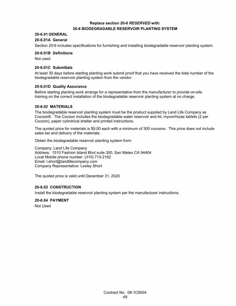
Contract No. 08-1C8504 49
Replace section 20-6 RESERVED with: 20-6 BIODEGRADABLE RESERVOIR PLANTING SYSTEM
20-6.01 GENERAL 20-6.01A General Section 20-6 includes specifications for furnishing and installing biodegradable reservoir planting system.
20-6.01B Definitions Not used. 20-6.01C Submittals At least 30 days before starting planting work submit proof that you have received the total number of the biodegradable reservoir planting system from the vendor. 20-6.01D Quality Assurance Before starting planting work arrange for a representative from the manufacturer to provide on-site training on the correct installation of the biodegradable reservoir planting system at no charge. 20-6.02 MATERIALS The biodegradable reservoir planting system must be the product supplied by Land Life Company as Cocoon®. The Cocoon includes the biodegradable water reservoir and lid, mycorrhizae tablets (2 per Cocoon), paper cylindrical shelter and printed instructions.
The quoted price for materials is $9.00 each with a minimum of 300 cocoons. This price does not include sales tax and delivery of the materials.
Obtain the biodegradable reservoir planting system from:
Company: Land Life Company Address: 1510 Fashion Island Blvd suite 300, San Mateo CA 94404 Local Mobile phone number: (310) 713-2162 Email: [email protected] Company Representative: Lesley Short The quoted price is valid until December 31, 2020 20-6.03 CONSTRUCTION Install the biodegradable reservoir planting system per the manufacturer instructions.
20-6.04 PAYMENT Not Used
Contract No. 08-1C8504 50
^^^^^^^^^^^^^^^^^^^^^^^^^^^^^^^^^^^^^^^^^^^^^^^^^^^^^^^^^^^^
DIVISION V SURFACINGS AND PAVEMENTS 36 GENERAL
Replace section 36-3 with:
36-3 PAVEMENT SMOOTHNESS 36-3.01 GENERAL 36-3.01A Summary Section 36-3 includes specifications for measuring the smoothness of pavement surfaces.
36-3.01B Definitions Area of Localized Roughness (ALR): Continuous moving average of the 25-foot International
Roughness Index (IRI) values for each wheel path using a 250-mm filter.
Mean Roughness Index (MRI): Average of the 0.1-mile IRI values for the left and right wheel paths for the same traffic lane using a 250-mm filter.
Wheel paths: Pair of parallel lines 3 feet left and right of the center of a traffic lane. Left and right wheel paths are based on the direction of travel.
36-3.01C Submittals 36-3.01C(1) General Not used
36-3.01C(2) Inertial Profiler Data At least 15 days before measuring pavement smoothness with an inertial profiler, you must register with the Department's secure file sharing system. To obtain information on the registration process, send an e-mail with your contact information to [email protected] for asphalt and [email protected] for concrete surfaces.
Submit electronic copy of the raw profile data as a PPF file on an authorized data storage device within 12 hours or on the same day of completing smoothness measurement, with a coordinated video or images taken at intervals no greater than 52.8 feet for the existing and baseline profiles. Also, submit a printout or a PDF file listing the following:
1. Profile data collection time and date 2. Data collection software version used 3. Sensor serial number 4. Low- and high-pass filter used 5. 0.1-MRI values Within 2 business days after each day of profiling, submit the profile information to the Engineer and to the Department's secure file sharing system. After submitting the profile information to the Department’s file sharing system, send a notification of your electronic submittal to the Engineer and to the above electronic mailbox address with the names of the files submitted.
For each surface subject to inertial profile smoothness requirements, the profile data information must include:
1. Raw profile data for each lane 2. ProVAL ride quality analysis report for the MRI of each lane in a PDF file. Report the following:
2.1. Listing of MRI values for 0.1-mile segments or portions thereof 2.2. Input data including the specified MRI threshold and fixed segment length 2.3. Raw profile data name selections 2.4. Areas exempt from inertial profile smoothness requirements
Contract No. 08-1C8504 51
3. ProVAL ride quality analysis report for the IRI of the left and right wheel paths of each lane in a PDF file. Report the following: 3.1. Listing of ALR 3.2. Input data including the specified area of the localized roughness threshold and continuous
segment length 3.3. Raw profile data name selections 3.4. Areas exempt from inertial profile smoothness
4. GPS data file for each lane. Submit the data file in GPS eXchange file format. 5. Manufacturer's recommended calibration and verification test results for the inertial profiler. 6. Inertial profiler's calibration and verification test results, including results for bounce, block, and the
distance measurement instrument. 7. Completed Pavement Smoothness Inertial Profiler Submittal Record. Submit Asphalt Concrete Pavement Smoothness Corrections Information or Concrete Pavement Smoothness Corrections Information with your final profile data information submittal.
Submit the raw profile data in an unfiltered pavement profile standard (PPF) file format. Use the following file naming convention:
YYYYMMDD_TTCCCRRR_EA_D_L_W_B_E_X_PT.EXT
where:
YYYY = year
MM = month, leading zero
DD = day of the month, leading zero
TT = district, leading zero
CCC = county, 2- or 3-letter abbreviation as shown in section 1-1.08
RRR = route number with no leading zeros
EA = Contract number, excluding the district identification number, expressed as 6 characters
D = traffic direction, NB, SB, WB, or EB
L = lane number from left to right in the direction of travel
W = wheel path, L for left, R for right, or B for both
B = beginning station to the nearest foot, such as 10+20, or beginning postmile to the nearest hundredth, such as 25.06 with no leading zero.
E = ending station to the nearest foot, such as 14+20, or ending postmile to the nearest hundredth, such as 28.06 with no leading zero.
X = profile operation, EXIST for existing pavement, BASELINE for existing pavement after performing repairs, PAVE for after paving, and FINAL for completed pavement documentation of compliance.
PT = type of pavement surface profiled, such as Type A HMA, RHMA-G, OGFC, JPCP, or CRCP
EXT = “PPF” for raw profile data file extension.
If you are submitting multiple inertial profiler data files, compress the files into a .ZIP file format and submit them using the file-naming convention TT_EA_X_YYYYMMDD.zip.

Contract No. 08-1C8504 52
36-3.01C(3) Smoothness Corrective Grinding Plan At least 2 business days before performing corrective grinding for areas that do not meet the smoothness requirements, submit a corrective grinding plan as an informational submittal.
The corrective grinding plan must include:
1. Grinder make and model 2. Grinder wheelbase in feet, measured from the front centerline to the back centerline of the single
wheel or tandem wheel spread 3. Grinder head position in feet, measured relative to the centerline of the front single wheel or the front
tandem wheel spread 4. Tandem wheel spreads in feet 5. Tabular listing of the planned corrective grinding, including:
5.1. Begin and End locations in stationing to the nearest foot 5.2. Width of grind, such as left half lane, right half lane, or full-width lane 5.3. Corresponding grinder head depths to the nearest 0.01 inch 5.4. Direction of grind such as forward, reverse, forward-forward, reverse-reverse, forward-reverse,
reverse-forward 6. Forecasted improvement in terms of the MRI and ALR values 36-3.01C(4) Straightedge Measurements Within 2 business days of measuring smoothness with a straightedge, submit a list of the areas requiring smoothness correction or a report stating there are no areas requiring smoothness correction. Identify the areas requiring smoothness correction by:
1. Location number 2. District-County-Route 3. Beginning station or postmile to the nearest 0.01 mile 4. For correction areas within a traffic lane:
4.1. Lane direction, NB, SB, EB, or WB 4.2. Lane number from left to right in the direction of travel 4.3. Wheel path, L for left, R for right, or B for both
5. For correction areas not within a traffic lane: 5.1. Identify the pavement area, such as shoulder, weigh station, or turnout 5.2. Direction and distance from the centerline, L for left or R for right
6. Estimated size of correction area 36-3.01C(5) Smoothness Quality Control Plan Submit a written Smoothness Quality Control Plan to the Engineer at or before Preconstruction Meeting. The plan must include:
1. Organization: Contact names, organizational chart, telephone numbers, current certifications and titles, and roles and responsibilities of personnel for monitoring smoothness, collecting profile data, submitting data, pay adjustment requests and reports, and implementing corrective actions.
2. Inertial profiler certification: 2.1. Inertial profiler certification issued by the Department 2.2. Operator certification for the inertial profiler issued by the Department 2.3. Manufacturer's instructions and test procedures for calibration and verification of the inertial
profiler 3. Schedule: The methods and timing used for monitoring and/or testing ride quality throughout the
placement operation process. Indicate the approximate timing of acceptance testing for the profile operations defined in Section 36-3.01C(6)(b) in relation to placement operations.
4. Layout plan: 4.1 Establish semipermanent reference points at the beginning and end of the project based on the
plans. For each profile run, define additional semipermanent reference points for the starting and end position of each run. Show the position and name of each semipermanent reference point. These reference points must be located outside of the traveled way perpendicular to the starting position of each lane. Where starting positions are adjacent to each other but staggered, use separate starting positions. Semipermanent reference points used to establish

Contract No. 08-1C8504 53
the beginning position of a profile run must be labeled in the field and in the pavement profiles using the following naming convention: XXX-D-L-STA-VAL
where:
XXX = “Beg” for the beginning of each profile run, “End” for the end of each profile run, “ExB” for the beginning point of the areas excluded from inertial profiler testing and “ExE” for the end point of the areas excluded from inertial profiler testing.
D = traffic direction, NB, SB, WB, or EB.
L = lane number from left to right in the direction of travel, such as “1”, “2”, or “3.”
STA= station to the nearest foot, such as 10+20. Do not use postmiles.
VAL= use “INC” where the value of stationing in the pavement profile data file (*.PPF) will increase in the direction of travel. Use “DEC” where the absolute value of the stationing in the pavement profile data file (*.PPF) will decrease in the direction of travel.
Use the same label name regardless of the stage of the profile.
4.2 For each semipermanent reference point, include a KMZ file with: 4.2.1 Color photographs clearly displaying the physical label used to define the
semipermanent reference points. 4.2.2 Listing of GPS coordinates.
Semipermanent reference points, wherever possible, must be recorded by inertial profilers using electronic eye readings of reflectors.
36-3.01C(6) Smoothness Payment Adjustment Request 36-3.01C(6)(a) General Smoothness payment adjustment data includes a ProVAL project file and a payment adjustment spreadsheet for each lane.
36-3.01C(6)(b) ProVAL Project File After completing final corrections, submit an electronic ProVAL project (PVP) file for each lane using the same naming convention listed in 36-3.01C(2), except:
B = use the common beginning station found in all profiles included in the PVP file followed by the postmile to the nearest tenth of a mile, such as 528 +00(10.0).
E = use the ending station found in the FINAL profile followed by the postmile to the nearest tenth of a mile such as 681+12(12.9).
X = PAYADJ.
EXT = “PVP” for ProVAL project file extension.

Contract No. 08-1C8504 54
Use a single PVP file for each lane. Each PVP file must contain the PPF files from the profile operation shown in the Profiles Needed by Smoothness Table.
Profiles Needed by Smoothness Table
Profile Asphalt
Target 60/75 Percent Improvement
Concrete Target 60/67.5/75
Grind Existing Concrete Percent Improvement
EXIST X X BASELINE X X
PAVE X X FINAL X X X
Establish and maintain stationing to allow for direct comparison of smoothness data between you and the Engineer in subsequent tests. The profiles must:
1. Align with each other in ProVAL. 2. Use the same beginning station position in all profiles files and in a single PVP project file. 3. Use the same semipermanent reference points for the beginning and ending positions of each profile
and semipermanent reference points required by Section 36-3.01C(3)(a). 4. For alignment purposes, the end station determined from the profiles distance measuring
instrumentation of each sequentially numbered 0.1-mile segment or portion thereof in the BASELINE, PAVE and FINAL profiles must be no greater than 20 feet in the first mile when compared to the same sequentially numbered segment end station in the EXIST profile. For locations more than 1 mile but less than 2.5 miles, the difference must be prorated from 20 feet to 50 feet. For locations more than 2.5 miles from the beginning position of the profile, the difference must be no greater than 50 feet. Where these differences create an additional sequentially numbered segment and when needed to bring the sequentially numbered segments back into alignment, the event defining the ending position of the partial segment in the PPF file of the BASELINE, PAVE and FINAL profiles may be adjusted no more than 20 feet within the first 2.5 miles, and no more than 50 feet at all other locations. Include the same leave-out sections referenced to the same semipermanent reference points.
36-3.01C(6)(c) Payment Adjustment Spreadsheet For each lane, submit payment adjustment spreadsheet using the Department-furnished worksheet. Data must be exported directly from the ProVAL project file Ride Quality module into the corresponding worksheet using the following settings:
1. Analysis Type set to “Fixed Interval” 2. Ride Quality Index set to “MRI” 3. Threshold (not applicable) 4. Segment Length (ft) set to “528.00” Obtain the worksheet from the following site:
https://dot.ca.gov/programs/construction/pavement-smoothness When sequentially numbered segments are misaligned and adjustments are required as described in Section 36-3.01C(6)(b), make the adjustments within the ProVAL project file before exporting data to a worksheet and notify the Engineer when this occurs.
36-3.01C(7) Inertial Profiler Verification Test Within 2 business days after the annual cross-correlation testing, submit a ProVAL profiler certification analysis report for the test results to the Engineer and to the electronic mailbox address [email protected].
36-3.01D Quality Assurance 36-3.01D(1) General Not Used
Contract No. 08-1C8504 55
36-3.01D(2) Certifications The inertial profiler must display a current certification decal showing the expiration date.
The operator must be certified for each model of inertial profiler operated.
The certifications issued by the Department for the inertial profiler and operator must not be expired.
36-3.01D(3) Quality Control 36-3.01D(3)(a) General Not Used
36-3.01D(3)(b) Smoothness Measurement 36-3.01D(3)(b)(i) General Measure pavement smoothness using an inertial profiler.
The following areas are excluded from the MRI smoothness requirements but are subject to ALR:
1. Traffic lanes less than 1,000 feet in length 2. Ramps 3. Turn lanes 4. Acceleration and deceleration lanes The following areas are excluded from smoothness measurement with an inertial profiler but are subject to the 12-foot straightedge measurement:
1. Areas within 15 feet of manholes, weigh-in-motion, railroad crossing, cattle guards, bus pad, and gutter pans
2. Areas within 25 feet each side from the intersection radius 3. Areas within 25 feet each side from the roundabout radius 4. Shoulders 5. Miscellaneous areas such as medians, gore areas, turnouts, and maintenance pullouts 6. Areas within 15 feet of the beginning of an approach slab or structure, and 40 feet beyond the end of
a departure slab or structure Where measurement with inertial profiler is required:
1. Determine the pavement smoothness by obtaining the IRI for the left and right wheel paths on each traffic lane.
2. Determine the MRI and ALR using FHWA’s engineering software ProVAL. Where OGFC is required, test the pavement smoothness of the final asphalt or concrete pavement surface before placing OGFC and after placing OGFC.
36-3.01D(3)(b)(ii) Inertial Profiler Calibration and Verification Tests Notify the Engineer at least 2 business days before performing calibration and verification testing of the inertial profiler.
Conduct the following calibration and verification tests in the Engineer's presence each day before profiling:
1. Block test to verify the accuracy of the height sensor under California Test 387 2. Bounce test to verify the combined accuracy of the height sensor and accelerometer under California
Test 387 3. Distance measurement instrument test to verify the accuracy of the distance measuring instrument
under California Test 387 4. Manufacturer's recommended tests Conduct a cross-correlation verification test of the inertial profiler in the Engineer's presence before performing the initial profiling. A verification test must be performed at least annually. Conduct 5 repeat runs of the inertial profiler on an authorized 0.1-mile test section. Calculate a cross-correlation to
Contract No. 08-1C8504 56
determine the repeatability of your device under California Test 387 using a ProVAL profiler certification analysis with a 3-foot maximum offset. The cross-correlation must be a minimum of 0.92.
36-3.01D(3)(b)(iii) Collecting and Analyzing Data Operate the inertial profiler under the manufacturer's instructions. Collect profiling data under AASHTO R 57 at 1-inch recording intervals using a minimum 4-inch line laser sensor and analyze IRI using a 250- mm filter.
Establish semipermanent reference points for aligning inertial profiler runs and locating potential corrective grinding. Maintain semipermanent reference points until Department acceptance testing is completed.
While collecting the profile data to determine the IRI values, record semipermanent reference points at the beginning and end of the profile run and the beginning and end of the following locations in the raw profile data:
1. Bridge approach slabs 2. Bridges 3. Culverts visible on the roadway surface 4. Railroad crossings 5. At-grade intersections 6. Project limits 7. Change in pavement type Profile the left and right wheel paths of each lane. Determine the MRI for 0.1-mile fixed segments using the ProVAL ride quality analysis with a 250-mm filter. Calculate the MRI of each lane. Segments less than 0.05 mile will not be evaluated for MRI but must comply with ALR requirement. Segments greater than or equal to 0.05 mile and less than or equal to 0.10 mile must comply with the MRI specifications for a 0.1-mile segment. Pay adjustments for segments greater than or equal to 0.05 mile and less than or equal to 0.10 mile will be calculated based on a prorated length. Determine the ALR using ProVAL with the average IRI values for each wheel path using a 25-foot continuous interval and a 250-mm filter.
36-3.01D(4) Department Acceptance 36-3.01D(4)(a) General The Department accepts pavement surfaces for smoothness based on compliance with the smoothness specifications for the type of pavement surface specified.
For areas that require pavement smoothness determined using a 12-foot straightedge, the pavement surface must not vary from the lower edge of the straightedge by more than:
1. 0.01 foot when the straightedge is laid parallel with the traffic lane centerline 2. 0.02 foot when the straightedge is laid perpendicular to the centerline and extends from edge to edge
of a traffic lane 3. 0.02 foot when the straightedge is laid within 24 feet of a pavement conform 36-3.01D(4)(b) Profile Verification The Engineer may perform verification testing using the Department’s inertial profiler. The Engineer notifies you of the Department’s intention to perform verification testing. Your acceptance test results are considered acceptable and will be used for incentive and disincentive payments if your mean MRI is within 10 percent of the Department’s mean MRI obtained over the same selected project length. When your test results are not considered acceptable, the Department’s MRI values will be used in the calculation for incentive and disincentive payments for that evaluated length and the Department will have 15 days to complete an evaluation of both profiler certifications.
You and the Engineer must work together to avoid potential conflicts and to resolve disputes regarding test result discrepancies. Notify the Engineer within 5 business days of receiving the verification test result if you will dispute it. An independent third party will perform referee testing over the same selected project length. Before the third party participates in a dispute resolution, their profiler and operator must be certified under the Department’s Profiler Certification Program. The independent third party must have no prior direct involvement with this Contract or no current direct involvement with you. The mean MRI
Contract No. 08-1C8504 57
value used in the calculation for incentive and disincentive payments will be from the party whose mean MRI value is closer to the independent third party and the other party pays for the independent third party's testing.
36-3.02 MATERIALS Not Used
36-3.03 CONSTRUCTION Notify the Engineer of the start location by station and start time at least 2 business days before each day of profiling.
Before profiling, remove foreign objects from the pavement surface and mark the beginning and ending station on the pavement shoulder. The stationing must be the same when profiling more than one surface.
36-3.04 PAYMENT Not Used
Replace Reserved in section 36-4 with: 36-4.01 GENERAL Section 36-4 includes specifications for performing work involving residue from grinding and cold planing that contains lead from paint and thermoplastic.
36-4.02 MATERIALS Not Used
36-4.03 CONSTRUCTION The residue from grinding or cold planing contains lead from paint and thermoplastic. The average lead concentrations are less than 1,000 mg/kg total lead and 5 mg/L soluble lead. This residue:
1. Is a nonhazardous waste 2. Does not contain heavy metals in concentrations that exceed thresholds established by the Health
and Safety Code and 22 CA Code of Regs 3. Is not regulated by the Federal Resource Conservation and Recovery Act, 42 USC § 6901 et seq. Management of this material exposes workers to health hazards that must be addressed in your lead compliance plan.
36-4.04 PAYMENT Not Used

Contract No. 08-1C8504 58
^^^^^^^^^^^^^^^^^^^^^^^^^^^^^^^^^^^^^^^^
39 ASPHALT CONCRETE
Replace section 39-2.01A(4)(i)(iii) with: 39-2.01A(4)(i)(iii) Pavement Smoothness Schedule smoothness testing with the Engineer. Unless otherwise authorized, all smoothness testing must be performed in the presence of the Engineer.
Measure smoothness of new pavement alignment or pavement realignment with an inertial profiler. The Department determines smoothness pay adjustments using the Target 60 Pay Adjustment table in Section 39-2.01A(4)(i)(iii)(A).
Measure smoothness of pavement constructed on existing pavement surfaces with an inertial profiler. The Department determines pay adjustments as shown in the applicable Pay Adjustment table.
Measure smoothness of:
1. Existing asphalt concrete surface before performing any work on the surface and provide the Engineer the result labeled as the "EXIST" inertial profiler data file. Notify the Engineer if mean roughness index (MRI) results vary more than 10 percent from the MRI information provided by the Department at the time of advertisement. For projects suspended for more than 30 days, measure the smoothness of the existing surface that has not received an HMA overlay and provide the Engineer the result labeled as "EXISTR" inertial profiler data file. Use the segment MRIs from this profile as the MRI0.
2. Existing pavement segments if structural repairs such as remove and replace asphalt concrete or leveling courses are made and provide the Engineer the result labeled as "BASELINE" inertial profiler data file.
3. Pavement segments, exclusive of OGFC on new HMA, before performing any HMA smoothness corrections and provide the Engineer the result labeled as "PAVE" inertial profiler data file.
4. Pavement segments, exclusive of OGFC on new HMA, after performing any HMA smoothness corrective work and provide the Engineer the results labeled as "FINAL" inertial profiler data file. Use the "PAVE" inertial profiler data as the "FINAL" inertial profiler data if there is no corrective work in the segment.
5. Pavement segments of OGFC before performing any OGFC smoothness correction. Profile the sections and provide the Engineer the result labeled as "PAVEO" inertial profiler data file.
6. Pavement segments of OGFC after performing any OGFC smoothness corrective work and provide the Engineer the result labeled as "FINALO" inertial profiler data file. Use the "PAVEO" inertial profiler data file as the "FINALO" inertial profiler data file when no corrective work in the segment is performed.
MRI0 is the lower MRI value from the "EXIST" and "BASELINE" profiles for the 0.1-mi segment and must be used to determine the applicable section:
HMA Pay Adjustment Total Asphalt Thickness (ft)a MRI0 (in/mi) HMA Final MRI (in/mi) Adjustment
Table Applicable Section
≥ 0.30 <165 Target 60 Pay Adjustment 39-2.01A(4)(i)(iii)(A)
≥165 Percent Improvement Pay Adjustment 39-2.01A(4)(i)(iii)(C)
< 0.30 <135 Target 75 Pay Adjustment 39-2.01A(4)(i)(iii)(B) ≥135 Percent Improvement Pay Adjustment 39-2.01A(4)(i)(iii)(C)
a Total HMA thickness exclusive of OGFC

Contract No. 08-1C8504 59
Notify the Engineer 10 days before collecting inertial profiler data. Allow the Engineer 2 days after receipt of your data to complete inertial profiler verification of all data except the "FINAL" inertial profiler data. Allow the Engineer 10 days after receipt of your data to complete verification of “FINAL” inertial profiler data.
If accepted by the Engineer, the Department uses your inertial profiler data for acceptance and determination of the payment adjustment.
Segments may be correctively ground to improve pay adjustments to full pay. The Department does not allow corrective grinding into positive pay adjustments. The Department determines positive pay adjustment segments before any corrective grinding. Correction of areas of localized roughness in positive pay adjustment segments cannot improve pay.
Corrective Actions:
1. Correction may be diamond grinding or remove and replace at your option.
2. Corrective grinding must comply with section 39-2.01C(16).
3. When OGFC is being placed over the surface of HMA, these requirements apply to the HMA surface of which the OGFC is being placed on. Smoothness requirements for OGFC are specified in Section 39-2.04A(4)(c)(iii).
39-2.01A(4)(i)(iii)(A) Pay Adjustments for Target MRI 60 The Department applies the following pavement smoothness pay adjustments to 0.1-mi segments based on your verified inertial profiler data:
Target 60 Pay Adjustment MRISEG(in/mi) Pay Adjustment per 0.1 mi Corrective Actiona
≤ 45.00 + $900.00 None 45.01 – 55.00 + ((55.00 – MRISEG) x $90.00) None 55.01 - 65.00 Full Pay None
65.01 – 80.00 - ((MRISEG – 65.00) x $190.00) Optional > 80.00 Not Applicable Mandatory
a See 39-2.01A(4)(i)(iii) Pavement Smoothness
No areas of localized roughness over 160 IRI are allowed.
39-2.01A(4)(i)(iii)(B) Pay Adjustments for Target MRI 75 The Department applies the following pavement smoothness pay adjustments to 0.1-mi segments based on your verified inertial profiler data:
Target 75 Pay Adjustment MRISEG(in/mi) Pay Adjustment per 0.1 mi Corrective Actiona
≤ 60.00 + $450.00 None
60.01 –70.00 + ((70.00 – MRISEG) x $45.00) None 70.01 - 80.00 Full Pay None 80.01 – 90.00 - ((MRISEG – 80.00) x $135.00) Optional
> 90.00 Not Applicable Mandatory a See 39-2.01A(4)(i)(iii) Pavement Smoothness
No areas of localized roughness over 160 IRI are allowed.

Contract No. 08-1C8504 60
39-2.01A(4)(i)(iii)(C) Acceptance Criteria using Percent Improvement The Department applies pavement smoothness pay adjustments to 0.1-mi segments based on your verified inertial profiler data. The Department determines payment adjustments using a percent of target MRI (PoT). The target MRI (MRIt) is determined based on the “EXIST” or "BASELINE" MRI (MRI0) exclusive of the OGFC and the number of opportunities as shown in the following table:
Target MRI (MRIt) Number of Opportunities Target MRI (MRIt)
1 = 0.3 x MRI0 + 35 2 = 0.09 x MRI0 + 45.5 3 = 0.027 x MRI0 + 48.7
Note: If the calculated MRIt is less than 60, use MRIt = 60 for HMA thickness ≥ 0.3'. If the calculated MRIt is less than 75, use MRIt = 75 for HMA thickness < 0.3'.
Opportunities for improving smoothness include:
1. A single lift of asphalt. Where an HMA layer thickness allows the layer to be placed in more than one lift, the number of opportunities will be equal to the maximum number of lifts the layer can be broken into regardless of aggregate size chosen by the contractor.
2. Micro milling or cold planing not in the same shift as the paving. When the contractor chooses to micro mill or cold plane and pave in the same shift, but has the option to micro mill or cold plane and pave in different shifts, the micro milling or cold planning will still be considered a separate opportunity.
Determine the Percent of Target MRI (PoT) of each completed 0.1-mi segment of lane using the following equation:
(%)PoT = (MRISEG / MRIt ) x 100 rounded to the nearest tenth of one percent where: MRISEG = the MRI of each 0.1-mi section of completed lane after all corrections.
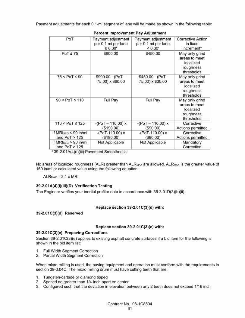
Contract No. 08-1C8504 61
Payment adjustments for each 0.1-mi segment of lane will be made as shown in the following table:
Percent Improvement Pay Adjustment PoT Payment adjustment
per 0.1 mi per lane ≥ 0.30'
Payment adjustment per 0.1 mi per lane
< 0.30'
Corrective Action in fixed
incrementa
PoT ≤ 75 $900.00 $450.00 May only grind areas to meet
localized roughness thresholds
75 < PoT ≤ 90 $900.00 - (PoT – 75.00) x $60.00
$450.00 - (PoT-75.00) x $30.00
May only grind areas to meet
localized roughness thresholds
90 < PoT ≤ 110 Full Pay Full Pay May only grind areas to meet
localized roughness thresholds
110 < PoT ≤ 125 -(PoT – 110.00) x ($190.00)
-(PoT – 110.00) x ($90.00)
Corrective Actions permitted
If MRISEG ≤ 90 in/mi and PoT > 125
-(PoT-110.00) x ($190.00)
-(PoT-110.00) x ($90.00)
Corrective Actions permitted
If MRISEG > 90 in/mi and PoT > 125
Not Applicable Not Applicable Mandatory Correction
a 39-2.01A(4)(i)(iii) Pavement Smoothness
No areas of localized roughness (ALR) greater than ALRMAX are allowed. ALRMAX is the greater value of 160 in/mi or calculated value using the following equation:
ALRMAX = 2.1 x MRIt
39-2.01A(4)(i)(iii)(D) Verification Testing The Engineer verifies your inertial profiler data in accordance with 36-3.01D(3)(b)(ii).
Replace section 39-2.01C(3)(d) with: 39-2.01C(3)(d) Reserved
Replace section 39-2.01C(3)(e) with: 39-2.01C(3)(e) Prepaving Corrections Section 39-2.01C(3)(e) applies to existing asphalt concrete surfaces if a bid item for the following is shown in the bid item list:
1. Full Width Segment Correction 2. Partial Width Segment Correction When micro milling is used, the paving equipment and operation must conform with the requirements in section 39-3.04C. The micro milling drum must have cutting teeth that are:
1. Tungsten-carbide or diamond tipped 2. Spaced no greater than 1/4-inch apart on center 3. Configured such that the deviation in elevation between any 2 teeth does not exceed 1/16 inch
Contract No. 08-1C8504 62
Dispose of grinding or micro milling residue.
Pave within 7 days of prepaving corrections.
The final pavement surface must comply with section 39-2.01A(4)(i)(iii).
39-2.01C(3)(e)(i) Full Width Segment Correction Full Width Segment Correction applies to the full width and length of a specified 0.1-mi segment where a bid item for Full Width Segment Correction is shown on the Bid Item List and locations shown on the plans. Full Width Segment Correction is:
1. Diamond grinding the entire segment surface or 2. Micro milling the entire segment surface not in the same shift as the paving When full width segment corrections are made to the existing pavement use the EXIST profile as the "BASELINE" profile. The Full Width Segment Correction is considered an opportunity for improvement.
39-2.01C(3)(e)(ii) Partial Width Segment Correction Partial Width Segment Corrections applies to existing asphalt concrete segments if a bid item for Partial Width Segment Corrections number of 0.1-mi sections is shown on the Bid Item List.
Develop a correction plan and provide to the Engineer 5 days before making segment corrections. Include the maximum removal depth according to the ProVAL smoothness assurance analysis grinding report or other 3D modeling software report. Do not remove more than 15% of the existing pavement thickness.
Correction includes:
1. Diamond grinding in the wheel paths or cold planer or paver smoothness referencing locations 2. Micro milling in the wheel paths or cold planer or paver smoothness referencing locations 3. 3D modeling of the existing roadway and subsequent automatic machine guidance of either cold
planer, paver, or both 4. Alternative method of correction approved by the Engineer that complies with final HMA pavement
smoothness requirements Upon approval of your correction plan, correct the existing roadway.
For HMA layer thickness, exclusive of the OGFC, greater than or equal to 0.30 ft including corrections, the final pavement surface must comply with 39-2.01A(4)(i)(iii)(A).
For HMA layer thickness, exclusive of the OGFC, less than 0.30 ft including corrections, the final pavement surface must comply with Section 39-2.01A(4)(i)(iii)(B).
Notify the Engineer of those areas where existing pavement depth limits a 0.1-mi segment correction. The Engineer may order you to:
1. Not perform correction of the 0.1-mi segment. The "EXIST" profile MRI will be the MRI0. Final pavement surface must comply with Section 39-2.01A(4)(i)(iii)(C)
2. Correct to a limited depth and measure smoothness of the corrected areas with an inertial profiler. The profile after making correction will be the "BASELINE" profile. Final pavement surface must comply with Section 39-2.01A(4)(i)(iii)(C). Do not consider this correction as an opportunity for the percent improvement MRIt determination
3. Correct by a different method and measure smoothness of the corrected 0.1-mi segment with an inertial profiler. Corrective work performed by a different method is change order work. The profile after making correction will be the "BASELINE" profile. Final pavement surface must comply with Section 39-2.01A(4)(i)(iii)(C)

Contract No. 08-1C8504 63
Replace section 39-2.01C(3)(c) with: 39-2.01C(3)(c) Prime Coat Apply a slow-setting asphaltic emulsion as a prime coat to AB areas designated by the Engineer and at a spread rate from 0.15 to 0.40 gal/sq yd. Do not apply more prime coat than can be absorbed completely by the AB in 24 hours.
You may modify the prime coat application rates if authorized.
Close areas receiving prime coat to traffic. Do not allow tracking the prime coat onto pavement surfaces beyond the job site.
Delete the row for For RAP Substitution equal to or less than 15% of the RSS for the table in item 3 in the list in the paragraph of section 39-2.02A(4)(e).
Replace the row for For RAP Substitution greater than 15% of the RSS for the table in item 3 in the list in the paragraph of section 39-2.02A(4)(e) with:
For RAP Substitution greater than 15% Moisture susceptibility (max, psi, dry strength)
AASHTO T 283 300
footnote h of the RSS for the table in item 3 in the list in the paragraph of section 39-2.02A(4)(e) with:
hNot required for the following areas in District 8: 1. Riverside County: Route 10, post mile 56.95 to 156.49; Route 111, post mile 0.00 to 28.53 2. San Bernardino County: Route 15, post mile 29.00 to 186.24; Route 40; Route 58; Route 138, post mile 0.00 to 15.20; Route 395
Replace the row for Moisture susceptibility (min, psi, wet strength) in the table in item 3 in the list in the paragraph of section 39-2.02A(4)(e) with:
Moisture susceptibility (min, tensile strength ratio) AASHTO T 283 70
Delete the row for For RAP substitution equal to or less than 15% of the RSS for the table in the 1st paragraph of section 39-2.02B(2).
Replace the row for For RAP substitution greater than 15% of the RSS for the table in the 1st paragraph of section 39-2.02B(2) with:
For RAP Substitution greater than 15% moisture susceptibility (max, psi, dry strength)
AASHTO T 283c 300e
Replace footnote e of the RSS for the table in the 1st paragraph of section 39-2.02B(2) with: eNot required for the following areas in District 8:
1. Riverside County: Route 10, post mile 56.95 to 156.49; Route 111, post mile 0.00 to 28.53 2. San Bernardino County: Route 15, post mile 29.00 to 186.24; Route 40; Route 58; Route 138, post mile 0.00 to 15.20; Route 395
Replace the row for Moisture susceptibility, wet strength in the table in the 1st paragraph of section 39-2.02B(2) with:
Moisture susceptibility (min, tensile strength ratio) AASHTO T 283c 70

Contract No. 08-1C8504 64
Replace Reserved in section 39-2.02B(3) with: The grade of asphalt binder for Type A HMA must be PG 64-28 M.
For Type A HMA using RAP substitution of greater than 15 percent of the aggregate blend, the virgin binder grade must comply with the PG binder grade specified above with 6 degrees C reduction in the upper and lower temperature classification.
For Type A HMA using RAP substitution of 15 percent or less of the aggregate blend, the grade of the virgin binder must comply with the PG binder grade specified above.
Delete the row for Moisture susceptibility (min, psi, dry strength) in the table in item 2 in the list in the paragraph of section 39-2.03A(4)(e)(i).
Replace the row for Moisture susceptibility (min, psi, wet strength) in the table in item 2 in the list in the paragraph of section 39-2.03A(4)(e)(i) with:
Moisture susceptibility (min, tensile strength ratio) AASHTO T 283 70
Delete the row for Moisture susceptibility, dry strength in the table in the 1st paragraph of section 39-2.03B(2).
Replace the row for Moisture susceptibility, wet strength in the table in the 1st paragraph of section 39-2.03B(2) with:
Moisture susceptibility (min, tensile strength ratio) AASHTO T 283 70
Add to section 39-2.03B(3)(a): The grade of asphalt binder for RHMA-G must be PG 64-16.
Replace the 3rd paragraph of section 39-3.04A with: At the locations listed below, schedule cold planing activities such that the pavement is cold planed, the HMA is placed, and the area is open to traffic during the same work shift:
1. PM 0.0 to PM 5.8
^^^^^^^^^^^^^^^^^^^^^^^^^^^^^^^^^^^^^^^^^^^^^^^^^^^^^^^^^^^^
DIVISION VI STRUCTURES 46 GROUND ANCHORS AND SOIL NAILS
Replace the paragraph in section 46-1.01A with: Section 46-1 includes general specifications for constructing ground anchors, soil nails, and earth anchors.
Replace section 46-1.01C with: 46-1.01C Submittals 46-1.01C(1) General Submit a certified calibration chart for each jack and its gauge as an informational submittal.
Contract No. 08-1C8504 65
46-1.01C(2) Shop Drawings and Calculations 46-1.01C(2)(a) General Submit 5 copies of shop drawings and calculations to OSD, Documents Unit. Notify the Engineer of the submittal and include the date and contents of the submittal in the notification.
Allow 30 days for the Department's review. After review, submit from 6 to 12 copies, as requested, for authorization and use during construction. Within 20 days after final authorization, submit 1 copy of final shop drawings and calculations.
Shop drawings and calculations must be sealed and signed by an engineer who is registered as a civil engineer in the State.
Ground anchor, soil nail, and earth anchor shop drawings must include:
1. Name, address, and phone number of the subcontractor performing the work. 2. Construction schedule and sequence of installing and grouting the ground anchor, soil nail, and earth
anchor. 3. Encapsulation details. 4. Drilled hole diameter. 5. Details for providing the bonded and unbonded length. If packers or other similar devices are to be
used, include the type. 46-1.01C(2)(b) Ground Anchor Shop Drawings and Calculations Ground anchor shop drawings and calculations must include the following additional information:
1. Details and specifications for the anchorage system and ground anchors. 2. Details for the transition between the corrugated plastic sheathing and the anchorage assembly. 3. If shims are used during lock-off, shim thickness and supporting calculations. 4. Calculations for determining the bonded length. Do not rely on any capacity from the grout-to-ground
bond within the unbonded length. 46-1.01C(2)(c) Soil Nail Shop Drawings and Calculations Soil nail shop drawings and calculations must include the following additional information:
1. Details and specifications for: 1.1. Anchorage system 1.2. Production soil nails 1.3. Test soil nails
2. Drilling methods and equipment, including: 2.1. Supporting calculations 2.2. Assumed bond strength
46-1.01C(2)(d) Earth Anchor Shop Drawings and Calculations Earth anchor shop drawings and calculations must include the following additional information:
1. Details and specifications for: 1.1. Sheathing and anchorage assembly 1.2. Test anchor 1.3. Production anchor 1.4. Couplers1.5. Centralizers
2. Calculations for determining the bonded length. Do not rely on any capacity from the unbonded length.
3. Details and specifications for splicing earth anchors, including corrosion protection. 4. Drilling methods and equipment, including supporting calculations.

Contract No. 08-1C8504 66
46-1.01C(3) Installation Plan 46-1.01C(3)(a) General Submit an installation plan for ground anchor, soil nail, and earth anchor. The installation plan must include:
1. Name, address, and telephone number of the subcontractor performing the work. 2. Construction schedule and sequence of installing and grouting. 3. Encapsulation details. 4. Repair procedure for damaged sheathing. 5. Drilling methods and equipment, including:
5.1. Drilled hole diameter. 5.2. Equipment space requirements.
6. Grout mix design and testing procedures. 7. Grout placement equipment and procedures, including minimum required cure time. 8. Details for providing the bonded and unbonded length. If packers or other similar devices are to be
used, include the type. 9. Testing equipment, including:
9.1. Jacking frame and appurtenant bracing. 9.2. Method and equipment for measuring movement during testing.
The installation plan must be sealed and signed by an engineer who is registered as a civil engineer in the State.
Allow 20 days for review.
46-1.01C(3)(b) Ground Anchor Installation Plan Ground anchor installation plan must include the following additional information:
1. Details and specifications for the anchorage system and ground anchors. 2. Details for the transition between the corrugated plastic sheathing and the anchorage assembly. 3. If shims are used during lock-off, shim thickness and supporting calculations. 46-1.01C(3)(c) Soil Nail Installation Plan Soil nail installation plan must include the following additional information:
1. Details and specifications for: 1.1. Anchorage system 1.2. Production soil nails 1.3. Test soil nails
2. Drilling methods and equipment, including: 2.1. Supporting calculations 2.2. Assumed bond strength
3. Details for isolating installed proof test soil nails during shotcrete application 4. Procedure for extracting grouted soil nails 46-1.01C(3)(d) Earth Anchor Installation Plan Earth anchor installation plan must include the following additional information:
1. Details and specifications for: 1.1. Sheathing and anchorage assembly. 1.2. Test anchor. 1.3. Production anchor.
2. Drilling methods and equipment, including: 2.1. Supporting calculations. 2.2. Assumed bond strength.
3. Details for protecting earth anchor during excavation, backfill, and other construction operations. 4. Methods to ensure that there are no kinks or bends at any location along the length of any earth
anchor. 5. Methods to prevent grout and water run-off from earth anchor construction. 6. Procedure for extracting verification earth anchors, if required.
Contract No. 08-1C8504 67
46-1.01C(4) Test Data Submit the following data for each ground anchor, soil nail, and earth anchor test:
1. Key personnel 2. Test loading equipment 3. Anchor or nail location 4. Time and date of:
4.1. Drilling 4.2. Installation 4.3. Grouting 4.4. Testing
5. Hole diameter and depth 6. Drilling method 7. Soil or rock classification and description 8. Bonded and unbonded length 9. Quantity of groundwater encountered within the bonded length 10. Grout quantity and pressure used within the bonded length 11. Anchor end or nail head movement at each load increment or at each time increment during the load
hold period 12. Digital photo logs of extracted test soil nails 13. Digital photo logs of extracted verification anchors, if requested Submit the test data in electronic and hard copy format within 2 business day after testing is complete. Upon completion of the wall, send an email of the soil nail or earth anchor test results as a tabulated spreadsheet to the Engineer and [email protected]. Include the contract number and Department's structure number of the wall in the subject line of the email.
Replace section 46-1.03 with: 46-1.03 CONSTRUCTION 46-1.03A General Earth anchors must be installed before placing backfill.
Water or grout from anchor or soil nail construction must not:
1. Fall on traffic 2. Flow across shoulders or lanes occupied by traffic 3. Flow into landscaping, gutters, or other drainage facilities Do not use an excessive quantity of water when drilling and installing anchors.
Shotcrete must comply with section 53-2.
46-1.03B Drilling Drilled holes must not extend beyond the right-of-way or easement limits.
Drilling equipment must produce straight, clean holes.
At locations where caving is anticipated, keep enough casing and auger lengths on the job site to maintain uninterrupted anchor or nail installation.
At locations where hard drilling conditions, such as rock, cobbles, boulders, or obstructions, are anticipated, keep a down-hole pneumatic hammer drill rig and drill bit available on the job site for drilling holes.
Clean the holes to remove material from drilling activities. Do not use water to clean soil nail or anchor holes unless authorized.
Dispose of drill cuttings under section 19-2.03B.
Contract No. 08-1C8504 68
46-1.03C Installation Before you insert each anchor, or soil nail into a drilled hole, clean the anchor or nail of oil, grease, dirt, and other extraneous substances and repair or replace any damaged sheathing.
There must be no evidence of distress in the plastic sheathing or crushing of the grout within the pregrouted sheathing.
Do not insert an anchor or nail into a hole until the hole has been inspected by the Engineer.
Install the anchor or nail in the drilled hole promptly so that caving or deterioration of the hole does not occur.
Install the earth anchor so that there are no kinks or bends at any location along the length of the anchor.
If you cannot insert an anchor or nail into a drilled hole to the required depth without difficulty, remove the anchor or nail and clean or redrill the hole. Do not force or drive a partially inserted anchor or nail into a drilled hole. Partially inserted anchors or nails are rejected.
For open-hole drilling methods, keep hole-cleaning tools on the job site. The tools must be suitable for cleaning drilled holes along their full length just before inserting the anchor or nail.
46-1.03D Grouting Mix the grout as follows:
1. Add water to the mixer followed by cement and any admixtures or fine aggregate. 2. Mix the grout with mechanical mixing equipment that produces a uniform and thoroughly mixed grout. 3. Agitate the grout continuously until the grout is pumped. 4. Do not add water after the initial mixing. Grouting equipment must be:
1. Capable of grouting at a pressure of at least 100 psi 2. Equipped with a pressure gauge having a full-scale reading of not more than 300 psi
Replace section 46-4 with: 46-4 EARTH ANCHORS
46-4.01 GENERAL 46-4.01A Summary Section 46-4 includes specifications for constructing earth anchors.
An earth anchor consists of a HS threaded steel bar with an anchorage assembly that is placed in a drilled hole and then grouted.
46-4.01B Definitions lock-off load: Load maintained on the jacks while the anchor head or anchor nuts on the earth anchor
are permanently set.
46-4.01C Submittals Submittals for HS threaded bars and associated couplers must comply with section 50-1.01C.
You may submit calculations and details for furnishing an alternative number of earth anchors that provide the same horizontal and vertical components and distribution of the design force as provided by the anchors shown. The maximum horizontal distance between these anchors must not be greater than 10 feet. Include alternative structure details. Alternative design calculations and details must be sealed and signed by an engineer who is registered as a civil engineer in the State.
46-4.01D Quality Assurance 46-4.01D(1) General Not Used

Contract No. 08-1C8504 69
46-4.01D(2) Quality Control 46-4.01D(2)(a) General HS threaded bar and associated couplers must comply with section 50-1.01D.
46-4.01D(2)(b) Load Testing 46-4.01D(2)(b)(i) General Perform load testing of verification and proof test earth anchors to verify the installation methods.
Perform testing in the Engineer's presence.
Install and test 1 verification test earth anchor for each wall as described. You may install and test the verification test earth anchor during the stability testing.
Proof test at least 25 percent of production earth anchors for each wall. Select a group of production earth anchors represented by the proof tests. A group of production earth anchors must:
1. Consist of either of the following: 1.1. At least 17 production earth anchors located consecutively. A minimum of 5 production earth
anchors from the group must be proof tested. 1.2. All production earth anchors of a wall.
2. Be initially grouted before proof testing. The Engineer selects the production earth anchors to be proof tested.
Perform load testing directly against the original soil or exposed excavation surface.
If an earth anchor fails to comply with the acceptance criteria, redesign or replace the earth anchor. Do not retest an earth anchor unless you post-grout the earth anchor bonded length after the unacceptable test.
Contract No. 08-1C8504 70
46-4.01D(2)(b)(ii) Test Procedure Conduct the verification and proof tests as follows:
1. Incrementally load and unload the anchor as shown in the following table: Loading Schedules
Verification test Proof test Load
increment Hold time (minutes)
Load increment
Hold time (minutes)
AL Until stable AL Until stable 0.20FTL 1–2 0.20FTL 1–2
AL Until stable 0.40FTL 1–2 0.20FTL 1–2 0.60FTL 1–2 0.40FTL 1–2 0.80FTL 1–2
AL Until stable 1.00FTLa 10 or 60 0.20FTL 1–2 AL Until stable 0.40FTL 1–2 -- -- 0.60FTL 1–2 -- --
AL Until stable -- -- 0.20FTL 1–2 -- -- 0.40FTL 1–2 -- -- 0.60FTL 1–2 -- -- 0.80FTL 1–2 -- --
AL Until stable -- -- 0.20FTL 1–2 -- -- 0.40FTL 1–2 -- -- 0.60FTL 1–2 -- -- 0.80FTL 1–2 -- -- 1.00FTLa 10 or 60 -- --
AL Until stable -- -- NOTES: FTL = factored test load shown. AL = alignment load = 0.10FTL. aMaximum test load
2. Apply each load increment in less than 1 minute and hold it for the length of time shown in the table
titled "Loading Schedules." 3. Measure and record the applied test load and the nail head movement at each load increment. 4. When applying the maximum test load:
4.1. Hold the load constant for 10 minutes. 4.2. Start the observation period for the load hold when the pump starts to apply the last load
increment. 4.3. Measure and record the anchor end movement at 1, 2, 3, 4, 5, 6, and 10 minutes.
5. If the movement measured from 1 to 10 minutes is greater than 0.04 inch: 5.1. Hold the load constant for an additional 50 minutes. 5.2. Measure and record the anchor end movement at 15, 20, 25, 30, 45, and 60 minutes. 5.3. Plot a creep curve as a function of the logarithm of time, showing the anchor end movement
from 6 to 60 minutes. 6. Reduce the load to the ending alignment load and record the residual movement. 46-4.01D(3) Department Acceptance 46-4.01D(3)(a) General The Department tests the efflux time of the grout under California Test 541.
46-4.01D(3)(b) Load Testing 46-4.01D(3)(b)(i) General Not Used
Contract No. 08-1C8504 71
46-4.01D(3)(b)(ii) Acceptance Criteria Earth anchors that are verification- or proof-tested must comply with the following:
1. Total measured movement at the maximum test load minus the measured residual movement at the ending alignment load exceeds 80 percent of the theoretical elastic elongation of the sum of the unbonded length and the jacking length.
2. Creep movement complies with one of the following: 2.1. For a 10-minute load hold, the creep movement measured from 1 to 10 minutes is less than
0.04 inch. 2.2. For a 60-minute load hold, the creep movement measured from 6 to 60 minutes is less than
0.08 inch and the creep rate is linear or decreasing in time logarithmic scale from the 6- to the 60-minute reading.
46-4.02 MATERIALS 46-4.02A General Not Used
46-4.02B Steel 46-4.02B(1) General HS threaded bars and associated couplers must comply with section 50-1.02B.
The anchorage assembly must be galvanized steel complying with section 55.
46-4.02B(2) Verification Test Earth Anchor Verification test earth anchor bar must be the same size and strength as the production earth anchors' they represent.
Steel bar for verification test earth anchors is not required to be epoxy coated or encapsulated in a grouted corrugated plastic sheathing.
46-4.02B(3) Production Earth Anchor Each production earth anchor must be an epoxy-coated prefabricated threaded bar encapsulated full length in a grouted corrugated plastic sheathing.
Epoxy-coated HS threaded bars and associated couplers must comply with the specifications for epoxy-coated prefabricated reinforcement in section 52-2.03, except the average coating thickness after curing must be from 10 to 15 mils.
Epoxy coating at the anchorage end of epoxy-coated bars may be omitted for a maximum of 6 inches.
46-4.02C Sheathing 46-4.02C(1) General Polypropylene sheathing must have a density of from 900 to 910 kg/m3 when measured under ASTM D792.
46-4.02C(2) Corrugated Plastic Sheathing Corrugated plastic sheathing must be PVC or HDPE.
PVC corrugated sheathing must have a nominal wall thickness of 40 mils.
HDPE corrugated sheathing with an outside diameter of 3 inches or greater must have a nominal wall thickness of 60 mils. HDPE corrugated sheathing with an outside diameter of less than 3 inches must have a nominal wall thickness of 40 mils.

Contract No. 08-1C8504 72
46-4.02E Grout The efflux time of the grout immediately after mixing must be at least 11 seconds.
For drilled holes 6 inches or larger in diameter, you may add fine aggregate to the grout used outside of the corrugated sheathing. The fine aggregate must comply with section 90-1.02C. Grout with fine aggregate must contain at least 845 pounds of cement per cubic yard.
46-4.03 CONSTRUCTION 46-4.03A General Expect difficult earth anchor installation due to the presence of the following conditions:
1. Existing alternative pipe culvert and corrugated metal pipe 2. Bedrock profile irregularity 3. Shallow bedrock 4. Not rippable bedrock 5. Large cobbles and boulders in soil layer 6. Caving due to presence of cohesionless soils 7. Seasonal ground water 8. Traffic control Earth anchor installation must comply with the manufacturer's instructions unless otherwise specified.
Determine the drilled hole diameter and the bonded length necessary to comply with the specified acceptance criteria.
Select an earth anchor installation method that achieves the acceptance criteria specified.
Do not drill for earth anchors in a wall zone until any required stability testing and verification testing are complete and the test results are authorized.
Drill the holes for earth anchors in the foundation material deep enough to provide the necessary bonded length beyond the minimum unbonded length shown.
Install and grout the earth anchors in the same work shift that the holes are drilled.
Use centralizers to support the earth anchor in the center of the drilled hole. The centralizers must ensure the center of the earth anchor does not deviate more than 0.5 inch from the center of the drilled hole. Place centralizers at 5-foot maximum intervals for the full length of the drilled hole, with the uppermost and deepest centralizers located 2 feet from the ends of the drilled hole. You may use plastic centralizers.
Verify and record the drilled hole length before grouting.
At each grouting stage, inject the grout at the low end of the void to be filled. Place the grout using grout tubes. Record the quantity of grout and the grout pressures.
If hot weather conditions will contribute to quick stiffening of the grout, cool the grout by authorized methods as necessary to prevent blockages during pumping activities.
After initial grouting, the anchor must remain undisturbed until the grout is strong enough to provide anchorage during load testing.
If ordered, lengthen the verification test earth anchors. The lengthening of test earth anchors is change order work.
If ordered, lengthen the production earth anchors or install additional production earth anchors. The lengthening or addition of production earth anchors is change order work.
46-4.03B Verification Test Earth Anchor Construct verification test earth anchors using the same equipment, methods, anchor inclination, and drilled hole diameter as to be used for production earth anchors.
You may install verification test earth anchors by any of the following means:

Contract No. 08-1C8504 73
1. Through the existing slope face. 2. Through the drill platform work bench. 3. Through the stabilization berm. 4. Through the stability test exposed face. 5. Into slot cuts made for the lift in which verification test earth anchors are located. A slot cut must be
no larger than is needed to accommodate the drill and test setup equipment. Grout only the bonded length of verification test earth anchors.
Do not splice a test earth anchor within the bonded length.
Splice the HS threaded bars only where shown on the authorized shop drawings or at the end of an earth anchor that is ordered to be lengthened.
If ordered, extract verification test anchors selected by the Engineer. Fill the voids with grout. Photograph the extracted test anchors in 5-foot section intervals. This work is change order work.
46-4.03C Production Earth Anchor Protect the anchorage assembly against rust, corrosion, and physical damage until the assembly is encased in shotcrete.
Repair or replace any damaged portions of the sheathing.
Repair any damage to the threaded bar epoxy coating under section 52-2.02B.
The diameter of the drilled hole must be large enough to provide a minimum grout cover of 1 inch over the corrugated sheathing for the drilled hole length of the HS threaded bar.
Sheathe the HS threaded barsfull length with corrugated plastic sheathing.
Center the HS threaded bar in the corrugated sheathing.
You may place the initial grout in the drilled hole before or after inserting the HS threaded bar. Hand tighten the nut on the end of the production earth anchor bar before shotcrete hardening begins. Ensure the bearing plate is fully seated on the shotcrete. Make the nut wrench tight after the shotcrete has set for 24 hours, unless a shorter time is authorized.
46-4.03D Lock-off Not Used
46-4.04 PAYMENT Verification test earth anchors are paid for as earth anchors (subhorizontal).
^^^^^^^^^^^^^^^^^^^^^^^^^^^^^^^^^^^^^^^^ 48 TEMPORARY STRUCTURES
Add a note to the table in item 6 in the list in the 3rd paragraph of section 48-2.02B(4):
Note: Anchored temporary railings require 4 capped stakes per panel

Contract No. 08-1C8504 74
^^^^^^^^^^^^^^^^^^^^^^^^^^^^^^^^^^^^^^^^
49 PILING
Add to section 49-1.03: Expect difficult micropile installation due to the following conditions:
1. Existing alternative pipe culvert and corrugated metal pipe 2. Bedrock profile irregularity 3. Shallow bedrock 4. Not rippable bedrock 5. Large cobbles and boulders in soil layer 6. Caving due to presence of cohesionless soils 7. Seasonal groundwater 8. Traffic control
Replace Reserved in section 49-5 with: 49-5.01 GENERAL 49-5.01A Summary Section 49-5 includes specifications for constructing micropiles.
49-5.01B Definitions micropile: Small-diameter, bored, CIP composite pile, in which the applied load is resisted by steel
reinforcing elements, grout, and frictional ground-grout bond.
steel reinforcing element: Steel element used to strengthen or stiffen a micropile, such as bar reinforcing steel, HS threaded bar, pipe, hollow structural section (HSS), or casing.
49-5.01C Submittals 49-5.01C(1) General For a wall, do not order materials nor install micropiles until the experience qualifications, shop drawings and calculations, installation plan, verification test, and verification test results for that wall are authorized.
49-5.01C(2) Experience Qualifications Submit the following experience qualification information:
1. Summary of the micropile subcontractor's experience that demonstrates compliance with section 49-5.01D(2).
2. Construction details, structural details, and load test results from at least 3 completed micropile installations performed by the micropile subcontractor in the last 5 years. The installations must be from 3 separate projects of similar scope to this Contract. Include a project description and the owner's name and current phone number.
3. List of on-site foremen and drill rig operators who will perform the micropile work and a summary of each individual's experience that demonstrates compliance with section 49-5.01D(2).
Allow 10 days for review.
49-5.01C(3) Shop Drawings and Calculations Submit 5 copies of micropile shop drawings and calculations to OSD, Documents Unit. Notify the Engineer of the submittal. Include in the notification the date and contents of the submittal.
Allow 30 days for review. After the review, submit 6 copies for final authorization and use during construction. Within 20 days after final authorization, submit 1 copy of final shop drawings and calculations.
The shop drawings and calculations must be sealed and signed by an engineer who is registered as a civil engineer in the State.
Contract No. 08-1C8504 75
The shop drawings and calculations must include:
1. Name, address, and phone number of the micropile subcontractor 2. Plan view, including:
2.1. Station and offset at the beginning and end of the micropile structure and at any change in the structure's horizontal alignment
2.2. Identification and location of each exploratory borehole 2.3. Location of any existing utilities, adjacent existing structures, and other potential interferences 2.4. Micropile layout and spacing 2.5. Unique identification number for each micropile
3. Typical sections, including: 3.1. Micropile inclination 3.2. Drilled hole diameter 3.3. Micropile tip elevation 3.4. Micropile cutoff elevation 3.5. Steel reinforcing element details, including sizes, and lengths 3.6. Centralizers and any spacers
4. Material properties 5. General notes for constructing the micropiles, including overall construction sequencing 49-5.01C(4) Installation Plan Submit a micropile installation plan, including:
1. Detailed construction procedures, including personnel, materials, testing, and equipment. 2. Layout drawing showing the micropile installation sequence. 3. Drilling or coring methods and equipment, including methods to:
3.1. Provide drilled hole support 3.2. Drill a straight hole 3.3. Advance through boulders and other obstructions 3.4. Prevent detrimental ground movements
4. Methods for placing, positioning, and supporting steel reinforcing elements. 5. Grouting plan, including:
5.1. Grout mix design. Include test results from an authorized laboratory for the compressive strength of the mix at 3, 7, 14, and 28 days and the density of the mix.
5.2. Procedures for monitoring grout quality. 5.3. Placement procedures and equipment. 5.4. Methods and equipment for monitoring and recording grout depth and volume as the grout is
placed. 5.5. Grouting rate calculations, upon request. Base the calculations on the static head on the grout
and losses throughout the placing system, including anticipated head of drilling fluid to be displaced, if applicable.
5.6. Minimum cure time and strength requirements for performing load testing. 6. Plan for the control and disposal of surface and groundwater, drill flush, and waste grout. 7. Load testing plan, including drawings and calculations that describe:
7.1. Testing procedures. 7.2. Reaction load system capacity and equipment setup. 7.3. Types and accuracy of the primary and secondary instrumentation equipment to be used for
applying and measuring the test loads and top of micropile movements. 7.4. Installation details for the instrumentation to be used for applying and measuring the test loads
and measuring the top of micropile movements. 8. Calibration reports and data for each test jack, pressure gauge, load cell, and electronic displacement
transducer to be used. The load cell calibration chart must show applied load versus millivolts per volt.
The installation plan must be sealed and signed by an engineer who is registered as a civil engineer in the State.
Allow 20 days for review.

Contract No. 08-1C8504 76
49-5.01C(5) Mill Test Reports Submit certified mill test reports for each heat number of each type of steel reinforcing element at least 7 days before using the materials in the work. The certified mill test reports must include ultimate strength, yield strength, elongation, and chemical composition.
49-5.01C(6) Installation Logs Submit each installation log as an informational submittal within 1 business day of the micropile installation. The installation log must include:
1. Micropile identification number and location 2. Names of superintendent, drill rig operator, grout plant operator, and any other personnel involved in
the micropile installation 3. Date, time, and duration of drilling, steel reinforcing element installation, and grout placement 4. Drilling or coring method and speed 5. Details of any hole stabilization method used 6. Description of soil or rock encountered 7. Quantity of groundwater encountered 8. Description of any unusual installation behaviors or conditions 9. Drilled hole diameter 10. Micropile tip elevation 11. Log of grout quantities, including the time and micropile depth 12. Lengths of steel reinforcing elements 49-5.01C(7) Grout Test Results Submit grout test results for density, efflux time, and compressive strength within 1 business day of testing.
49-5.01C(8) Load Test Data Submit load test data within 1 business day of the completion of a verification test. Load test data must include:
1. Micropile identification number and location 2. Installation date 3. Load test date 4. Testing personnel 5. Load testing equipment 6. Raw data from the electronic data acquisition system 7. Readings from the secondary load and displacement measurement systems recorded at each load
increment 8. Specified curves plotted using data from the electronic data acquisition system 9. Comparison of the load test results and the acceptance criteria Load test data must be sealed and signed by an engineer who is registered as a civil engineer in the State.
Allow 10 days for review.
49-5.01D Quality Assurance 49-5.01D(1) General Not Used
49-5.01D(2) Experience Qualifications The micropile subcontractor must:
1. Be experienced in micropile construction and load testing 2. Have successfully constructed at least 5 projects in the last 5 years involving a combined total of at
least 100 micropiles 3. Have previous micropile drilling and grouting experience in soil or rock similar to the soil or rock for
this Contract
Contract No. 08-1C8504 77
Each on-site foreman and drill rig operator must have experience installing micropiles on at least 3 projects completed in the last 5 years.
49-5.01D(3) Preconstruction Meeting Schedule and hold a micropile preconstruction meeting at least 5 business days after submitting the micropile shop drawings, calculations, and installation plan and at least 10 days before starting micropile construction. You must provide a meeting facility.
The meeting must include the Engineer, your representatives, representatives from the micropile subcontractor, and representatives from any other subcontractor to be involved in the micropile construction.
The Engineer conducts the meeting. Be prepared to discuss:
1. Contractual relationships and delineation of responsibilities among you and the subcontractors 2. Contacts and communication protocol between you and your representatives, the subcontractors, and
the Engineer 3. Coordination of the construction schedule and activities 4. Anticipated subsurface conditions 5. Structural, geotechnical, and construction requirements 6. Materials testing 7. Load testing 49-5.01D(4) Quality Control 49-5.01D(4)(a) General Not Used
49-5.01D(4)(b) Grout Testing Before placing grout into each micropile:
1. Test the grout density under API RP 13B-1 using the Baroid mud balance. Take the grout test samples directly from the grout plant.
2. Test the grout efflux time under California Test 541. Take the grout test samples at the point of placement.
Test the grout compressive strength under ASTM C109/C109M at an authorized laboratory. Test at least 1 set of three 2-inch grout cubes from each grout plant each day of operation or for every 10 micropiles installed, whichever occurs more frequently. Take the grout test samples directly from the grout plant.
49-5.01D(4)(c) Load Testing 49-5.01D(4)(c)(i) General Section 49-1.01D does not apply to micropile load testing.
The grout for each load test micropile must attain the compressive strength shown before you perform the load test.
Notify the Engineer at least 10 days before you perform each load test.
Perform each load test in the Engineer's presence.
Perform verification load testing in compression under ASTM D1143/D1143M.
Use the FTL and SL values shown for compression load testing.
Use a load cell as the primary load measurement system. The load cell must:
1. Be of the bonded electrical resistance strain gauge type. 2. Have a full scale range no greater than 150 percent of the maximum test load. 3. Be moisture resistant. 4. Be temperature compensated. The maximum temperature sensitivity at zero load must be ±0.05
percent of full scale per degree F. 5. Have a resolution within ±0.025 percent of full scale.

Contract No. 08-1C8504 78
6. Have an accuracy within ±0.25 percent of full scale. Use electronic displacement transducers as the primary movement measurement system. Displacement transducers must be capable of measuring to 0.001 inch and have enough travel to allow the load test to be performed without resetting.
Apply the test loads using a hydraulic jack. Use the gauge in the jack and pressure gauge assembly as the secondary load measurement system. Jack ram travel must be sufficient to allow the load test to be performed without resetting the equipment. The pressure gauge must be graduated in 100 psi increments or less.
The load cell, the electronic displacement transducers, and the jack and gauge assembly must be calibrated by an authorized laboratory accredited for calibration services using equipment traceable to NIST. The jack and gauge assembly must be calibrated as a unit.
Use an electronic data acquisition system to simultaneously monitor and record readings from the primary load and displacement measurement systems. The electronic data acquisition system must continuously take readings at regular intervals from the load cell and electronic displacement transducers.
The Department may verify the test loads using Department-furnished load cells. Upon request, furnish the resources necessary to install and support the Department's testing equipment at the load testing location and to remove the equipment after the testing is complete.
49-5.01D(4)(c)(ii) Verification Load Testing Perform verification load testing on each verification test micropile installed.
The verification test micropile described at each wall location represents the production micropiles in that wall.
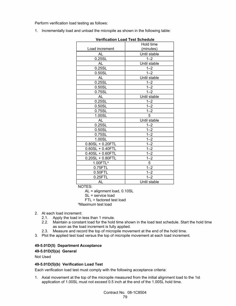
Contract No. 08-1C8504 79
Perform verification load testing as follows:
1. Incrementally load and unload the micropile as shown in the following table:
Verification Load Test Schedule
Load increment Hold time (minutes)
AL Until stable 0.25SL 1–2
AL Until stable 0.25SL 1–2 0.50SL 1–2
AL Until stable 0.25SL 1–2 0.50SL 1–2 0.75SL 1–2
AL Until stable 0.25SL 1–2 0.50SL 1–2 0.75SL 1–2 1.00SL 5
AL Until stable 0.25SL 1–2 0.50SL 1–2 0.75SL 1–2 1.00SL 1–2
0.80SL + 0.20FTL 1–2 0.60SL + 0.40FTL 1–2 0.40SL + 0.60FTL 1–2 0.20SL + 0.80FTL 1–2
1.00FTLa 5 0.75FTL 1–2 0.50FTL 1–2 0.25FTL 1–2
AL Until stable NOTES:
AL = alignment load, 0.10SL SL = service load FTL = factored test load
aMaximum test load 2. At each load increment:
2.1. Apply the load in less than 1 minute. 2.2. Maintain a constant load for the hold time shown in the load test schedule. Start the hold time
as soon as the load increment is fully applied. 2.3. Measure and record the top of micropile movement at the end of the hold time.
3. Plot the applied test load versus the top of micropile movement at each load increment. 49-5.01D(5) Department Acceptance 49-5.01D(5)(a) General Not Used
49-5.01D(5)(b) Verification Load Test Each verification load test must comply with the following acceptance criteria:
1. Axial movement at the top of the micropile measured from the initial alignment load to the 1st application of 1.00SL must not exceed 0.5 inch at the end of the 1.00SL hold time.
Contract No. 08-1C8504 80
2. Slope of the applied test load versus the top of micropile movement must not exceed 0.025 inch per kip at the maximum test load.
If a verification load test fails to comply with the acceptance criteria, the verification test micropile is rejected. The Department may lengthen the verification test micropile or production micropile, install and verification test additional micropiles, or install additional production micropiles.
If ordered, lengthen the verification test micropiles or production micropiles, install and verification test additional micropiles, or install additional production micropiles. The lengthening, testing, and addition is change order work.
49-5.02 MATERIALS 49-5.02A General Use identical materials and element sizes for a verification test micropile as to be used for the production micropiles it represents.
Welding must comply with AWS D1.1.
49-5.02B Steel Reinforcing Elements 49-5.02B(1) General Mill secondary steel reinforcing elements must not be used.
Steel reinforcing elements must not contain splices or joints.
49-5.02B(2) Pipe Pipe must comply with ASTM A53/A53M, Type E or S, Grade B.
Pipe to be welded for structural purposes must have a carbon equivalency as defined in AWS D1.1, Annex H5.1, not exceeding 0.47 percent and a sulfur content not exceeding 0.05 percent.
Welded seams must be CJP welds.
49-5.02B(3) Bar Reinforcing Steel Not Used
49-5.02C Anchorage Components Not Used
49-5.02D Grout Grout must be a stable, neat grout consisting of cement and water. Cement must comply with section 90-1.02B(2). Water must comply with section 90-1.02D.
If authorized, you may use an admixture in the grout. The admixture must comply with sections 90-1.01C(4) and 90-1.02E, except the admixture must not contain chloride ions in excess of 0.25 percent by weight nor be an accelerating admixture.
If authorized, you may add fine aggregate to the grout. Fine aggregate must comply with section 90-1.02C(3). Grout with fine aggregate must:
1. Have a slump of at least 7 inches when measured under ASTM C143/C143M 2. Have an air content of no more than 2 percent when measured under California Test 504 3. Not contain air-entraining admixtures Mix the grout as follows:
1. Add the water to the mixer followed by the cement and any admixtures or fine aggregate. 2. Mix the grout with mechanical mixing equipment that produces a uniform and thoroughly mixed grout. 3. Agitate the grout continuously until the grout is pumped. 4. Do not add water after the initial mixing.
Contract No. 08-1C8504 81
Grout must comply with the following requirements:
1. Density must be greater than or equal to the density submitted with the authorized mix design. 2. Efflux time must be at least 11 seconds. 3. Compressive strength must be at least that shown at 28 days. 49-5.02E Centralizers Centralizers must be fabricated from plastic, steel, or other material that is not detrimental to the steel reinforcing elements. Do not use wood centralizers or spacers.
Centralizers must be strong enough to support the steel reinforcing elements during construction activities.
49-5.02F Corrosion Protection Not Used
49-5.03 CONSTRUCTION 49-5.03A General Determine the installation methods necessary to comply with the micropile load test acceptance criteria.
You may perform additional geotechnical investigation for the purpose of determining the installation methods.
Do not construct any production micropiles until the test results are authorized for the verification test micropile that represents the production micropiles.
Do not drill a micropile that is within a center-to-center spacing of 5 feet from an open micropile hole or a micropile in which the initial grout has set for less than 12 hours.
49-5.03B Verification Test Micropiles Install a verification test micropile at each location shown. Notify the Engineer at least 7 days before installing a verification test micropile.
Excavate the verification load test site as necessary to provide a level work area. Keep the test site free of water throughout the testing.
Construct each verification test micropile in the Engineer's presence. Use identical drilling and grouting methods, inclination, tip elevation, and dimensions as to be used for the production micropiles it represents.
After the verification load test results are authorized, remove the verification test micropile and any anchor piles as specified for removing portions of bridges in section 60-2.02.
49-5.03C Proof Test Micropiles Not Used
49-5.03D Drilling Select drilling equipment and methods that are suitable for drilling through the conditions to be encountered without causing damage to any overlying or adjacent structure or service and without causing detrimental ground movements.
Use temporary casing or another authorized drilled hole support method in caving or unstable ground.
Each drilled hole must comply with the following tolerances:
1. Centerline of the drilled hole must not deviate from the micropile location shown by more than 3 inches.
2. Center-to-center spacing of the drilled holes must not deviate from the micropile spacing shown by more than 3 inches.
3. Axis of the drilled hole must not deviate from the alignment shown by more than 1 inch per 10 feet of length.

Contract No. 08-1C8504 82
Remove any material dislodged or drawn into the hole during micropile construction. The drilled hole must be open along its full length to the hole diameter shown before placing grout or any steel reinforcing elements not used to case the drilled hole.
Dispose of drill cuttings under section 19-2.03B.
49-5.03E Placing Steel Reinforcing Elements Place the steel reinforcing elements before withdrawing any temporary casing.
For steel reinforcing elements not used to case the drilled hole, use centralizers to support the element in the center of the hole and to provide at least the specified grout cover. Place the centralizers at 10-foot maximum intervals, with the uppermost centralizer a maximum of 4 feet from the top of the micropile and the lowermost centralizer from 2 to 4 feet from the bottom of the micropile.
Attach centralizers to the steel reinforcing elements such that the centralizers (1) are secure enough to withstand installation stresses and (2) allow the free flow of grout without misalignment of the steel reinforcing elements.
Before you insert each steel reinforcing element into a drilled hole, clean the surface of the element of deleterious substances, such as soil, mud, grease, and oil.
If you cannot insert a steel reinforcing element into the drilled hole to the required depth without difficulty, remove the reinforcing element, clean any grout from the surface of the reinforcing element, clean or redrill the hole, and reinsert the reinforcing element. Do not force or drive a reinforcing element into a drilled hole. Micropiles with partially inserted steel reinforcing elements are rejected.
49-5.03F Grouting Grout each micropile the same day the hole is drilled.
You may place the grout before or after placing the steel reinforcing elements.
Place the grout within 1 hour of mixing.
Inject the grout at the lowest point of the drilled hole. Continue the injection until uncontaminated grout flows from the top of the micropile.
Grout each micropile in 1 continuous operation. Use grouting procedures that ensure complete continuity of the grout column.
If temporary casing is used, extract the casing in stages. After you remove each length of casing, bring the grout level back up to ground level before removing the next length of casing. Maintain the grout at a level above the bottom of the temporary casing adequate to prevent displacement of the grout by material from outside the casing. The tremie pipe or casing must extend at least 10 feet below the grout level in the drilled hole at all times during grout placement.
Grout tubes may remain in the hole after the completion of grouting but must be filled with grout before pile acceptance.
Maintain the grout level at or above the micropile cutoff elevation until the grout has set.
Provide a positive means of support for maintaining the position of the steel reinforcing elements until the grout has set.
Load test micropiles must remain undisturbed until the grout is strong enough to provide anchorage during load testing.
Dispose of material resulting from grouting.
49-5.03G Ground Heave and Subsidence If you observe signs of ground heave or subsidence, immediately notify the Engineer and suspend the drilling and grouting operations. If the Engineer determines that the movements require corrective action, take the actions necessary to stop the movement and perform repairs.
Contract No. 08-1C8504 83
49-5.03H Installation Logs Prepare a separate installation log for each micropile.
49-5.04 PAYMENT Section 49-1.04 does not apply.
Verification test micropiles are paid for as micropiles.
^^^^^^^^^^^^^^^^^^^^^^^^^^^^^^^^^^^^^^^^
52 REINFORCEMENT
Replace section 52-4 with: 52-4 ELECTRIC-RESISTANCE WELDED STIRRUPS FOR CONCRETE BARRIER REINFORCEMENT
CAGES 52-4.01 GENERAL 52-4.01A Summary Section 52-4 includes specifications for welding longitudinal support wire to stirrups using electric-resistance welding (ERW) to partially fabricate reinforcing cages for concrete barriers.
Electric-resistance welded supports may be used only for concrete barrier stirrups on structures.
You may use ERW to weld support wire to no.5 reinforcing bars or smaller. The support wire must be W 6.5 or smaller.
52-4.01B Definitions partially fabricated reinforcing cage: Stirrups for concrete barrier reinforcing cages held in position by
welded longitudinal support wires.
lot: 150 count, or fraction thereof, of welds for each size of reinforcing bar and support wire and for each change to the welding equipment settings.
52-4.01C Submittals 52-4.01C(1) General Not Used
52-4.01C(2) Certificate of Compliance Submit a certificate of compliance for each shipment of partially fabricated cages. Include with the submittal:
1. Identification of each cage including lot numbers, welds traceable by welding clamp, and location tracking information.
2. Grade and size of welded reinforcement used for the stirrups and support wire. 3. For the reinforcing bar and support wire:
3.1. Heat number 3.2. Mill certificate
52-4.01C(3) Test Samples Submit QA test samples to METS.
Include copies of certificates of compliance with the test samples.
52-4.01C(4) Welding Quality Control Plan Submit 2 copies of a welding QC plan for each subcontractor or supplier performing ERW. The QC plan must include:

Contract No. 08-1C8504 84
1. WPSs 2. Names and certifications of welding personnel 3. Welding procedures including current setting, welding clamp force, weld time, and hold time for each
size of reinforcement to be welded 4. Welding equipment manufacturer's operating instructions including the recommended calibration
frequency of the welding equipment 5. Documentation of ERW equipment calibration 6. Fabricator's QC Process Control Manual 7. Method for identifying welds and tracking lots For the contents, format, and organization required for a welding QC plan, go to the METS website.
52-4.01C(5) Shop Drawings Submit shop drawings showing the stirrup positioning, welded connections of the support wire to the stirrups, and welding equipment layout. Allow 15 days for the Engineer's review.
52-4.01C(6) Prefabrication Test Results Submit the prefabrication test results within 3 days of prefabrication testing. The prefabrication test results must include:
1. Contract number 2. Bridge number 3. Welds identified by welding clamp 4. Reinforcement and support wire sizes 5. Test specimen length 6. Physical condition of test samples 7. Notable defects 8. Ultimate tensile strength of each sample 9. Location of necking area of each sample Allow 3 business days for the Engineer's review.
52-4.01C(7) Quality Control Test Reports Submit a QC test report within 7 days of testing for each lot. The report must be prepared by the authorized laboratory performing the testing. The report must be signed by the QC manager. For each lot, the report must include:
1. Contract number 2. Bridge number 3. Lot numbers with welds identified by welding clamp 4. Installed location of completed cages 5. Reinforcement and support wire sizes 6. Cage types 7. Cage lengths 8. Test specimen length 9. Physical condition of test samples 10. Notable defects 11. Ultimate tensile strength of each sample 12. Location of necking area of each test sample Allow 3 business days for the Engineer's review.
52-4.01D Quality Assurance 52-4.01D(1) General Provide a welding QC manager. The QC manager must be registered as a civil engineer in the State or currently certified as a CWI.
Contract No. 08-1C8504 85
52-4.01D(2) Prewelding Meeting Before submitting a welding QC plan, hold a prewelding meeting to discuss the work and the requirements for the welding QC plan. The meeting attendees must include the Engineer, your welding QC manager, and a representative from each entity performing welding or welding inspection.
52-4.01D(3) Test Samples Samples must be a minimum length of 4 feet of bar reinforcing steel with a support wire welded at midpoint. You may furnish shorter length samples if authorized.
Prepare the samples using the same materials, procedures, equipment, and equipment settings used in the work.
The welding clamps that produce the samples are determined by the Engineer.
Prepare QC test samples and the Department acceptance test samples concurrently:
1. During fabrication of samples representing the 1st lot 2. From 1 of every 5 subsequent lots, or fraction thereof, randomly selected by the Engineer After receiving notification that lots are ready for QC testing, the Engineer (1) randomly selects test samples to represent each lot and (2) places tamper-proof markings or seals on the test samples.
Before transporting test samples to an authorized laboratory and METS:
1. Securely bundle and package the test samples for each test in a way that preserves their condition during transportation
2. Identify each test sample by lot number and Contract number using weatherproof markings 3. Attach a completed Sample Identification Card to each bundle If a sample show signs of tampering before testing, the sample is rejected.
52-4.01D(4) Quality Control 52-4.01D(4)(a) General Test the samples for tensile strength under California Test 670, Section E, Part III, Tensile Test.
Tensile testing must be performed by an authorized laboratory. The laboratory must be on the Authorized Laboratories List for testing reinforcing steel splices.
52-4.01D(4)(b) Prefabrication Testing Before the start of fabrication of production cages, prepare 4 samples from each welding clamp.
Notify the Engineer at least 5 business days before fabricating the samples.
If 3 or more of the 4 samples from each welding clamp attain the specified minimum tensile strength, the Department accepts the prefabrication test results.
If 2 of the 4 samples attain the specified minimum tensile strength, determine the cause of the failure and take corrective action as specified in section 52-4.01D(4)(c). Fabricate 4 additional samples from the clamp that produced the noncompliant samples, and perform tensile tests until at least 3 of the 4 samples attain the specified minimum tensile strength.
Do not start fabrication of production cages until the Department accepts the test results.
52-4.01D(4)(c) Fabrication Testing During fabrication of production cages, for each lot prepare 8 test samples.
At least 5 business days before performing fabrication testing, notify the Engineer of:
1. Date of the testing 2. Location of the authorized laboratory where the tests will be conducted 3. Number of lots to be tested
Contract No. 08-1C8504 86
Do not perform tests on test samples from bundles containing fewer than 8 samples. Test 4 of the samples. The Engineer determines the samples to be tested.
If 3 or more of the 4 samples from a lot attain the specified minimum tensile strength, the Department accepts the lot.
If 2 of the 4 samples from a lot attain the specified minimum tensile strength, perform additional tests on the remaining samples. If any of the additional samples do not attain the specified minimum tensile strength, the Department rejects the lot.
If a lot is rejected, stop production until the following corrective actions have been performed:
1. QC manager reviews your QC process 2. You have prepared a welding rejection mitigation report describing:
2.1. Cause of the failure 2.2. Method used to identify the cause of failure 2.3. Identification of affected lots 2.4. Provisions for preventing similar failures in future lots 2.5. Procedure for repairing or replacing the welded connections in the rejected lot
3. Engineer has notified you that the welding rejection mitigation report is authorized 52-4.01D(5) Department Acceptance The Department accepts lots based on your QC tension test results specified in section 52-4.01D(4)(c).
The Department performs tensile test on samples from the 1st lot and from 1 of every 5 subsequent lots, or fraction thereof, randomly selected by the Engineer.
If 3 or more of the 4 samples attain the specified minimum tensile strength, the Department accepts the lot.
If 2 of the 4 samples attain the specified minimum tensile strength, fabricate 4 additional samples using the same materials and welding machine settings as the noncompliant lot. If any of the 4 additional samples do not attain the minimum specified tensile strength, the Department rejects the lot.
If QC and Department acceptance testing results have different compliance determinations, the Department will perform QA testing for all subsequent lots until QC testing and the Department testing are consistent for 2 consecutive lots before resuming testing for 1 of every 5 lots, or fraction thereof, as determined by the Engineer.
52-4.02 MATERIALS 52-4.02A General Reinforcing bars must comply with ASTM A706, Grade 60.
Support wire must comply with the specifications for plain wire in ASTM A1064.
The tensile strength of reinforcing bars with the support wire welded to the bar must be at least 80,000 psi.
52-4.02B Fabrication Perform ERW at a fabrication shop using computer-controlled equipment.
Weld the support wire to the stirrups. The stirrups must be positioned as shown. The support wire must be capable of maintaining the dimensions, position, and shape of the stirrups until the cage is complete.
52-4.03 CONSTRUCTION Provide bracing to avoid collapse of the cage during assembly, transportation, and placement as needed.
Field tack welding of support wire to reinforcement is not allowed.
Wiring longitudinal reinforcement at each stirrup intersection is not required.
52-4.04 PAYMENT Not Used
Contract No. 08-1C8504 87
^^^^^^^^^^^^^^^^^^^^^^^^^^^^^^^^^^^^^^^^
53 SHOTCRETE
Add to section 53-2.03: Construct a test panel for wall cap. You may use the authorized preconstruction test panels.
Replace Reserved in section 53-3 with: 53-3.01 GENERAL 53-3.01A Summary Section 53-3 includes specifications for applying sculpted shotcrete.
The sculpted shotcrete finish at retaining walls must match the texture, pattern, surface relief, and strata line detail of the existing wall on Route 74 in Orange County at post mile 13.34.
The sculpted shotcrete must not have repetitive patterns or contours, or secondary shadowing patterns.
53-3.01B Definitions Not Used
53-3.01C Submittals Submit a QC plan that includes:
1. Summary of your experience that demonstrates compliance with section 53-3.01D(2), including: 1.1. Name and qualifications of the lead sculptor 1.2. Names and qualifications of the nozzlemen who will place the sculpted shotcrete
2. List of at least 3 projects completed in the last 5 years that demonstrate the lead sculptor's ability to place sculpted shotcrete similar to the sculpted shotcrete for this project. For each project include: 2.1. Project description 2.2. Name and phone number of the owner 2.3. Sculpted shotcrete completion date 2.4. Color photos of the completed sculpted shotcrete
3. Installation plan that includes: 3.1. Proposed method of placing the sculpted shotcrete, including application rates, details and
locations of proposed construction joints, and methods for achieving the required thickness and surface finish
3.2. Procedures for curing sculpted shotcrete surfaces 3.3. Description of any required debris containment system
53-3.01D Quality Assurance 53-3.01D(1) General Assign a lead sculptor to supervise the placement of the sculpted shotcrete and the application of the final texture.
53-3.01D(2) Qualifications You must be experienced in the construction of textured artificial rockwork that simulates the appearance of natural rock formations.
The lead sculptor must have:
1. Successfully constructed at least 3 projects in the past 5 years involving placement of sculpted shotcrete similar to the sculpted shotcrete for this project
2. Experience in managing crews placing sculpted shotcrete similar to the sculpted shotcrete for this project

Contract No. 08-1C8504 88
The qualifications of the nozzlemen who will place sculpted shotcrete must comply with section 53-2.01D(2).
53-3.01D(3) Mock-ups The mock-up must be:
1. Constructed at an authorized location 2. The size shown and at least 6 inches deep 3. Constructed, finished, stained, and cured using the same personnel, materials, equipment and
methods to be used in the work 4. Accessible for viewing 5. Displayed in an upright position near the work 6. Authorized before starting work If ordered, construct additional mock-ups until a satisfactory finish, texture, color and pattern is attained.
The Engineer uses the authorized mock-up to determine the acceptability of the sculpted shotcrete work for all retaining walls.
Dispose of the mock-ups. Notify the Engineer before disposing of the mock-ups.
53-3.02 MATERIALS The mix design used for the sculpted shotcrete must be the same as that used for the structural shotcrete.
53-3.03 CONSTRUCTION Lay out the strata lines by applying high-visibility paint to the shotcrete wall face to illustrate the primary and secondary strata line patterns shown.
The personnel who lay out the strata lines must be the same as those who will place the sculpted shotcrete.
Before you lay out the strata lines:
1. The shotcrete wall face must be fully constructed 2. Abrasive blast clean the shotcrete wall face and remove surface laitance, curing compound, and
other foreign materials Notify the Engineer at least 3 days before laying out the strata lines.
The strata lines must be authorized before placing the reinforcing steel for the shotcrete wall and before placing the sculpted shotcrete.
Flush the shotcrete wall face with water and allow the surface to dry to a surface-dry condition immediately before placing the sculpted shotcrete.
Apply the sculpted shotcrete by the wet-mix process unless otherwise authorized. Do not use rebound in sculpted shotcrete.
Cure the sculpted shotcrete as specified for curing concrete in section 51-1.03H.
Replace any damaged sculpted shotcrete surfaces.
53-3.04 PAYMENT Not Used

Contract No. 08-1C8504 89
^^^^^^^^^^^^^^^^^^^^^^^^^^^^^^^^^^^^^^^^^^^^^^^^^^^^^^^^^^^^
DIVISION VII DRAINAGE FACILITIES 71 EXISTING DRAINAGE FACILITIES
Replace Reserved in section 71-6.03 with: 71-6.03A General Abandon culverts or pipelines by removing portions of the culverts or pipelines, filling the inside, and backfilling the depressions and trenches to grade. As an alternative to abandoning a culvert or pipeline, you may remove the culvert or pipeline, dispose of it, and backfill.
Notify the Engineer before abandoning a culvert or pipeline.
71-6.03B Materials Openings into existing structures that are to remain in place must be plugged with minor concrete under section 90.
71-6.03C Construction Wherever culverts or pipelines intersect side slopes, remove them to a depth of at least 3 feet. Measure the depth normal to the plane of the finished side slope. Abandon the remaining portion of the culvert or pipeline.
Culverts or pipelines that are 12 inches or more in diameter must be completely filled by authorized methods. Backfill with sand that is clean, free draining, and free from roots and other deleterious substances. As an alternative to sand, you may backfill with one of the following:
1. Controlled low-strength material under section 19-3.02G 2. Slurry cement backfill under section 19-3.02E Ends of culverts and pipelines must be securely closed by a 6-inch-thick, tight-fitting plug or wall of commercial-quality concrete.
71-6.03D Payment If backfilling inside the culvert or pipeline is required, payment for backfilling inside the culvert or pipeline is paid for as sand backfill. Payment for backfilling outside the culvert or pipeline is included in the payment for abandon culvert or abandon pipeline.
^^^^^^^^^^^^^^^^^^^^^^^^^^^^^^^^^^^^^^^^^^^^^^^^^^^^^^^^^^^^
DIVISION VIII MISCELLANEOUS CONSTRUCTION 72 SLOPE PROTECTION
Replace section 72-20 with:
72-20 ROCKFALL SYSTEMS 72-20.01 GENERAL 72-20.01A General Section 72-20 includes specifications for furnishing and installing rockfall systems.
72-20.01B Materials Not Used
Contract No. 08-1C8504 90
72-20.01C Construction Not Used
72-20.01D Payment Not Used
Add to section 72-20: 72-20.02 MESH DRAPERY 72-20.02A General 72-20.02A(1) Summary Section 72-20.02 includes specifications for furnishing and installing double twisted wire mesh (DTWM) and cable net drapery systems. Drapery systems include attenuators and elevated systems.
Cable net drapery (CND) systems include:
1. Double twisted wire mesh 2. Cable mesh 3. Drilled and grouted cable anchor assemblies 4. Cables 5. Hardware In areas to be covered with drapery, clear objectionable materials under section 17-2.03B prior to staking anchorage locations, except leave grass intact and prune brush to 2 inches above the ground.
72-20.02A(2) Definitions cable net: Uniform panel consisting of double twisted wire mesh (DTWM) woven into or fastened to cable
mesh with ring fasteners as shown.
DTWM: Double twisted wire mesh
pullout failure: Occurrence in which attempts to increase the test load result in cable anchor movement relative to a fixed reference point without an increase in load.
72-20.02A(3) Submittals 72-20.02A(3)(a) General Submit a certified calibration chart for each jack and its gage as an informational submittal.
Submit a copy of the manufacturer’s installation procedures and requirements for cable clips, including spacing, orientation of clip components, and required torque of nuts.
Submit a certificate of compliance for double twisted wire mesh.
Submit certificates of compliance for shackles, cables, and lacing cables.
Submit a copy of the manufacturer’s test data showing that the coupler used in two-component cable anchors can transfer the minimum tensile yield strength of the threaded hollow steel bar to the cable portion of the two-component cable anchor.
72-20.02A(3)(b) Work Plan Submit a draped mesh work plan to the Engineer. The work plan must include:
1. Identification of the manufacturer(s) of the cable mesh and DTWM products. Supply documentation from the manufacturer(s) that demonstrates the mesh products have been used as part of a draped mesh rockfall protection system where the site conditions were similar to the conditions on this project.

Contract No. 08-1C8504 91
2. Material information, as required by section 72-20.02B, including an inclusive list with the manufacturer's data sheets and catalog cut sheets for all system appurtenances to be used including, but not limited to, wire, wire rope clips, thimbles, ferrules, and other fastening hardware.
3. The methods, equipment, and materials for drilling and installing cable anchors. Include plan sheets for anchor layouts.
4. The methods, equipment, materials, and mix design for the grouting operations. 72-20.02A(3)(c) Test Data Submit the following data for each cable anchor test:
1. Key personnel 2. Test loading equipment 3. Cable anchor location 4. Time and date of:
4.1. Drilling 4.2. Installation 4.3. Grouting 4.4. Testing
5. Hole diameter and depth 6. Drilling method 7. Soil or rock classification and description 8. Volume of grout used in each hole Submit the test data when cable anchor testing is complete or when requested.
72-20.02A(4) Quality Assurance 72-20.02A(4)(a) General The Engineer shall be on-site to ensure that the project during construction is in conformance with the Construction Details and Special Provisions. 72-20.02A(4)(a)(i) Field Site Layout The CND system site layout shall be performed by the Engineer following the completion of slope excavation and clearing of objectionable materials in areas to be covered with drapery. Site layouts shall include staking locations for the CND system limits and anchorage locations. Approval from the Engineer is required prior to drilling.
The Engineer may stake locations for CND system limits and anchorage locations on cut slopes within the project limits but separate from the approximate CND system limits within the Construction Details.
72-20.02A(4)(a)(ii) Anchor Drilling Anchorage drilling and drill holes shall be observed and inspected by the Engineer in the field prior to installation of anchors and grout.
72-20.02A(4)(b) Quality Control 72-20.02A(4)(b)(i) General The Engineer shall inspect on-site the final installation of the CND systems. If approved, the Engineer shall provide an approval letter to the Contractor. Required changes shall be documented and submitted to the Contractor for compliance prior to approval.
72-20.02A(4)(b)(ii) Load Testing 72-20.02A(4)(b)(ii)(A) General Load test 10 percent of the cable anchors to the minimum allowable design load. If less than 20 cable anchors are shown, load test a minimum of 2 cable anchors. The Department does not pay for cable anchors not meeting acceptance criteria.
The Engineer selects which cable anchors to load test. Perform load testing in the presence of the Engineer.
Jacking equipment and the yoke or load frame must be stable during all phases of loading.

Contract No. 08-1C8504 92
No part of the yoke or load frame can bear within 1.5 foot of the cable anchor being tested.
Do not unload or reposition the test equipment during load testing.
Do not load test cable anchors until grout has cured for at least 72 hours.
Conduct load testing by measuring the load applied to the cable anchor and observing movement of the cable anchor using a dial gauge that is independent of the testing equipment.
The load test is accepted if pullout failure does not occur.
Record the maximum load for each load test and provide it to the Engineer. If a pullout failure occurs, record the failure load and item corresponding to the pullout failure as part of the test data.
72-20.02A(4)(b)(ii)(B) Load Testing Equipment and Calibration Calibrate each jack, load cell and pressure gauge as a unit, with the cylinder extension in the approximate position it will be at the final jacking force. Each jack, load cell and pressure gauge must be calibrated by an authorized laboratory within one year prior to its use on the project. Dial gauges shall permit the measurement of total anchor movement at every load increment to be read to the nearest 0.001-in.
Apply the test loads using a hydraulic jack supported by a reaction frame that can support the test equipment without deformation.
Use a calibrated pressure gauge and load cell to determine the magnitude of applied test loads.
The pressure gauge must have an accurately reading, clearly visible dial or display. Dial gages must be graduated in 100 psi increments or less.
The load cell must be calibrated and have an indicator capable of measuring the minimum allowable design load. The load cell range must be such that the lower 10 percent of the manufacturer's rated capacity is not used in determining the jacking force.
72-20.02B Materials 72-20.02B(1) General Galvanize all steel components and hardware. Where another method is not specified, galvanizing must comply with section 75-1.02B.
Steel fasteners must comply with section 55-1.02D(1).
Shackles must comply with the requirements of Federal Specification RR-C-271D Type IVA/IVB, Grade B, Class 2 and be permanently stamped with the rated working load.
Cable clips must be drop forged, correspond to the external diameter of the cable used, and comply with the requirements of Federal Specification FF-C-450 Type 1, Class 1.
Cables must comply with the requirements of ASTM A1023 and Federal Specification RR-W-410 Type I, Class 2, 6x19, independent wire rope core, corrosion-resistant steel. Galvanize cables under Federal Specification RR-W-410D.
Lacing cables must comply with the requirements of ASTM A641/A641M and Federal Specification RR-W-410 Type VI, Class 3, 7x19, corrosion-resistant steel. Galvanize cables under Federal Specification RR-W-410D. Lacing cables must be PVC coated and match the color of the DTWM.
Cable clips, thimbles, stop sleeves, and other cable fittings must correspond to the external diameter of the cable used and be installed per the manufacturer’s instructions.
Contract No. 08-1C8504 93
72-20.02B(2) Cable Anchors Cable anchors must consist of one of the following: 1. Continuous 3/4-inch diameter cable anchor as shown. 2. Two-component cable anchor as shown. Threaded hollow steel bar must comply with the following:
Property Test Method Specification Minimum Yield Strength (Kips)
ASTM A 1058 47.2
72-20.02B(3) Ring Fasteners Ring fasteners must be galvanized.
Wire for ring fasteners must have a minimum diameter of 0.118 inches, including galvanization, and must comply with ASTM A764 Class 1, Finish 2, with a Class 3 zinc finish coating.
72-20.02B(4) Double Twisted Wire Mesh Double twisted wire mesh must comply with the following:
Property Test Method Specification Wire tensile strength (psi)a
ASTM A 370 60,000 min
Weight per unit area (psf)b
N/A 0.3
a Tensile area includes galvanization. b Weight per unit area includes galvanization and PVC coating.
Galvanize wire in accordance with ASTM A641/A641M.
Stain galvanized surfaces of double twisted wire mesh under section 78-4.07.
DTWM must comply with the following:
1. Form a uniform hexagonal pattern using a non-raveling twist. 2. The major axis of any opening must not exceed 4.75 inches. 3. Openings must measure approximately 3.25 inches by 4.5 inches, ± 0.25”. 4. Splices in wire must be constructed at the manufacturing facility. 5. Partial openings at edges or joints must have a lesser area than hexagonal openings. 6. Openings must be oriented with the major axis parallel to the long direction of the panel. 7. Use selvedge wire on both edges of double twisted wire mesh panels Double twisted wire mesh drapery panels must be a minimum of 11 feet wide.
72-20.02B(5) Cable Mesh Cable mesh must be a uniform woven square or diamond pattern consisting of minimum 5/16” diameter type galvanized steel cable complying with The area of the square or diamond openings must not exceed 144 square inches.
Cable mesh panels must be continuous. If the cable mesh contains cut or unsecured cable ends, unsecured cable ends must be fastened to other cables with cable clips to form closed loops. Openings at panel edges must be equal to or smaller than the maximum specified opening area. Cable mesh with a diamond pattern must have a border cable at all edges.
Cable mesh panels must be a minimum of 11 feet wide.
Fasteners or woven connections where cables cross must resist slipping or breaking and maintain the specified opening size.
Stain galvanized surfaces of cable mesh under section 78-4.07.
Contract No. 08-1C8504 94
72-20.02B(6) Grout The grout must comply with section 50, except the grout is not required to pass through a screen with 1/16-inch maximum clear openings before being introduced into the grout pump.
72-20.02B(7) Posts Steel plates and shapes for posts must comply with section 75-1.02A.
Welding must comply with AWS D1.1. Grind welds flush with adjacent surfaces where cables will rub against the weld.
Galvanize posts after fabrication and before assembly under section 75-1.02B.
Concrete for post foundations must comply with the specifications for minor concrete.
Threaded rods and associated hardware for post foundations must comply with section 75-1.02A.
Stain galvanized surfaces of post assemblies under section 78-4.07.
72-20.02C Construction 72-20.02C(1) General Water or grout from cable anchor construction must not:
1. Fall on traffic 2. Flow across shoulders or lanes occupied by traffic 3. Flow into landscaping, gutters, or other drainage facilities 72-20.02C(2) Installation Install cable anchors in drilled holes and grout cable anchors in the same work shift. If the cable anchor cannot be installed in the hole due to caving, re-drill the hole. The Department does not pay for re-drilling holes.
Fill drilled holes with grout, free of voids and foreign material. Grout holes in a continuous operation.
For continuous cable anchors, remove all loose soil and rock from the drilled hole before placing the cable. Pump grout to the low end of the drilled hole through a tremie tube without air voids or inclusion of foreign material. Orient cable anchor in direction of loading while grout cures.
For two component cable anchors, pump grout through the threaded hollow steel bar until grout rises through the drilled hole and exits the surface of the hole to ensure a fully grouted bar. Install the coupler immediately after grouting and allow the grout to cure around the coupler. After the grout has cured for a minimum of 72 hours, excavate around the grouted bar and grout column to construct the concrete pad. Place the concrete pad in a continuous operation with no cold joints. Orient cable component of the anchor in direction of loading while the grout and concrete pad cure. Do not disturb or load cable anchors until grout and concrete pads have cured for 72 hours.
Install cable clips per the manufacturer’s installation instructions and requirements.
For cable net, if not woven into cable mesh, fasten DTWM to cable mesh on level ground with ring fasteners as shown.
For cable net draperies:
Install mesh panels on the slope working from the top down. Mold mesh to lie flush with the slope and maximize ground contact. Minimize voids between the mesh and the ground surface by manually pushing the mesh panels against the slope during installation. Install adjacent panels edge to edge as shown to minimize overlap. Furnish and install filler panels as required to provide a continuous drapery over local topography.
Lacing cable must alternately pass through every DTWM opening at seams and folds as shown.

Contract No. 08-1C8504 95
If you are ordered to install additional cable anchors, furnishing and installing additional cable anchors is change order work.
72-2.02D Payment The payment for cable net drapery is the area of cable net placed. The area of cable net placed includes the draped area, skirt panels, and the area required to conform to the terrain. Unless overlaps are shown, the Department does not pay for additional mesh used for overlaps.
Add to section 72-20: 72-20.04 ROCK ANCHOR 72-20.04A General 72-20.04A(1) Summary Section 72-20.04 includes specifications for furnishing, installing, and testing rock anchors as described. Rock anchors include rock dowels and rock bolts.
A rock dowel consists of a solid steel threaded rod with anchorage assembly that is placed in a drilled hole and then grouted.
A rock bolt consists of a solid steel threaded rod with an anchorage assembly that is placed in a drilled hole, and then grouted and stressed.
72-20.04A(2) Definitions pullout failure: Occurrence in which attempts to increase the test load result in anchor movement relative
to a fixed reference point without an increase in load.
72-20.04A(3) Submittals 72-20.04A(3)(a) General Submit a certified calibration chart for each jack and its gauge as an informational submittal.
72-20.04A(3)(b) Work Plan Submit work plan to the Engineer. Work plan must include:
1. Construction schedule and sequence of drilling, installing, and grouting. 2. Description of drilling methods and equipment including drilled hole diameter and length. 3. Description of grout placement equipment and procedures. 4. Details of the load testing equipment including the yoke or load frame and method of measuring
movement for verification tests. 5. Minimum bonded zone length(s), and supporting calculations. 6. Materials specifications for all materials used in rock bolt construction 7. Delivery, storage, and handling details, including:
7.1. Protective measures to be used when delivering, storing, and handling threaded rods 7.2. Storage locations 7.3. Methods of repairing damaged protective coating on materials
8. Method of splicing rock anchors, if allowed.
Allow 2 weeks for the Department's review of the rock bolt work plan.
If an unplanned event occurs or work activities deviate from the authorized work plan, immediately submit procedures proposed to correct or remedy this occurrence.

Contract No. 08-1C8504 96
72-20.04A(3)(c) Test Data Submit the following data for each rock anchor test:
1. Key personnel 2. Test loading equipment 3. Anchor location 4. Time and date of:
4.1. Drilling 4.2. Installation 4.3. Grouting 4.4. Testing
5. Hole diameter and depth 6. Drilling method 7. Soil or rock classification and description 8. Volume of grout used in each hole 9. Bonded and unbonded lengths 10. Quantity of groundwater encountered within the bonded length 11. Grout quantity and pressure used within the bonded length 12. Anchor end or anchor head movement at each load increment or at each time increment during the
load hold period
Submit the test data when anchor testing is complete or when requested.
72-20.04A(4) Quality Assurance 72-20.04A(4)(a) General Not Used
72-20.04A(4)(b) Quality Control 72-20.04A(4)(b)(i) General Not Used
72-20.04A(4)(b)(ii) Load Testing 72-20.04A(4)(b)(ii)(A) General The Engineer may select to a verification or proof load testing protocol.
Install and test 2 verification test anchors for each slope zone shown. All verification test anchors must be installed and tested prior to beginning construction of production anchors in that zone.
Proof load test 10 percent of the production anchors to the minimum allowable design load. The Engineer selects which anchors to proof load test.
Test against a temporary yoke or load frame. No part of the yoke or load frame can bear within 1 foot of the rock anchor being tested.
Jacking equipment and the yoke or load frame must be stable during all phases of loading.
Do not unload or reposition the test equipment during load testing.
Do not load test rock anchors until grout has cured for at least 72 hours.
Conduct verification load testing by measuring the load applied to the rock anchor and monitoring and recording displacement of the anchor relative to a stable reference point founded at least 3 feet from the anchor and test load reaction points.
Conduct proof load testing by measuring the load applied to the anchor and observing any movement of the anchor head relative to the load frame and ground.
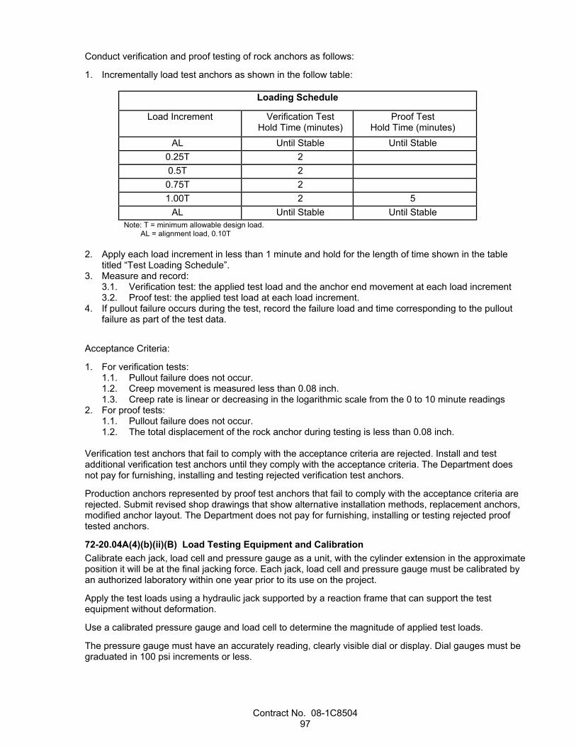
Contract No. 08-1C8504 97
Conduct verification and proof testing of rock anchors as follows:
1. Incrementally load test anchors as shown in the follow table:
Loading Schedule
Load Increment Verification Test Hold Time (minutes)
Proof Test Hold Time (minutes)
AL Until Stable Until Stable 0.25T 2 0.5T 2 0.75T 2 1.00T 2 5
AL Until Stable Until Stable Note: T = minimum allowable design load. AL = alignment load, 0.10T
2. Apply each load increment in less than 1 minute and hold for the length of time shown in the table
titled “Test Loading Schedule”. 3. Measure and record:
3.1. Verification test: the applied test load and the anchor end movement at each load increment 3.2. Proof test: the applied test load at each load increment.
4. If pullout failure occurs during the test, record the failure load and time corresponding to the pullout failure as part of the test data.
Acceptance Criteria:
1. For verification tests: 1.1. Pullout failure does not occur. 1.2. Creep movement is measured less than 0.08 inch. 1.3. Creep rate is linear or decreasing in the logarithmic scale from the 0 to 10 minute readings
2. For proof tests: 1.1. Pullout failure does not occur. 1.2. The total displacement of the rock anchor during testing is less than 0.08 inch.
Verification test anchors that fail to comply with the acceptance criteria are rejected. Install and test additional verification test anchors until they comply with the acceptance criteria. The Department does not pay for furnishing, installing and testing rejected verification test anchors.
Production anchors represented by proof test anchors that fail to comply with the acceptance criteria are rejected. Submit revised shop drawings that show alternative installation methods, replacement anchors, modified anchor layout. The Department does not pay for furnishing, installing or testing rejected proof tested anchors.
72-20.04A(4)(b)(ii)(B) Load Testing Equipment and Calibration Calibrate each jack, load cell and pressure gauge as a unit, with the cylinder extension in the approximate position it will be at the final jacking force. Each jack, load cell and pressure gauge must be calibrated by an authorized laboratory within one year prior to its use on the project.
Apply the test loads using a hydraulic jack supported by a reaction frame that can support the test equipment without deformation.
Use a calibrated pressure gauge and load cell to determine the magnitude of applied test loads.
The pressure gauge must have an accurately reading, clearly visible dial or display. Dial gauges must be graduated in 100 psi increments or less.
Contract No. 08-1C8504 98
The load cell must be calibrated and have an indicator capable of measuring the minimum allowable design load. The load cell range must be such that the lower 10 percent of the manufacturer's rated capacity is not used in determining the jacking force.
72-20.04B Materials 72-20.04B(1) General Washers and bearing plates must comply with section 75-1.02A.
Galvanize steel parts and hardware under section 75-1.02B, unless specified.
Couplers for rock anchor systems must be permitted or recommended by the Manufacturer.
Paint complies with section 59-3.
72-20.04B(2) Threaded rod Threaded rods must comply with the requirements for HS threaded rods in section 75-1.02A. (this includes galvanizing).
You may epoxy coat threaded bars, if authorized.
If authorized, you may use deformed reinforcing bars. Deformed reinforcing bars must have at least 6-inch length of thread cut into the bar on the anchorage end. Use coarse threading and the next larger reinforcing bar size.
Solid steel bars must comply with ASTM A615/A615M or A706/A706M, Grade 60 or ASTM A615/A615M, Grade 75.
Splicing must be authorized.
Epoxy coating at the anchorage end of epoxy-coated bars may be omitted for a maximum of 6 inches. Metal surfaces of assembled splices of epoxy-coated bars must be epoxy coated.
72-20.04B(6) Grout The grout must comply with section 50, except the grout is not required to pass through a screen with 1/16-inch maximum clear openings before being introduced into the grout pump. (verify the 1/16 inch dimension)
72-20.04C Construction 72-20.04C(1) General Water or grout from rock anchor construction must not:
1. Fall on traffic 2. Flow across shoulders or lanes occupied by traffic 3. Flow into landscaping, gutters, or other drainage facilities
72-20.04C(2) Installation Determine the drilled hole diameter, length, and installation methods required to meet rock anchor acceptance criteria.
Install threaded rods in drilled holes and grout threaded rods in the same work shift. If the threaded rod cannot be installed in the hole due to caving, re-drill the hole. The Department does not pay for re-drilling holes.
Remove all loose soil and rock fragments from the drilled hole before placing the threaded rod. Install the threaded rod in drilled holes with centralizers as shown. Securely fasten centralizers to the threaded rod. Fill drilled holes with a dense grout, free of voids and foreign material. Grout holes in a continuous operation. Pump grout to the low end of the drilled hole through a tremie tube without air voids or inclusion of foreign material.
For untensioned rock anchors, the entire length of the rock anchor shall be encapsulated in grout in a single operation. For tensioned rock anchors, the bonded zone will be grouted during the first stage grout.
Contract No. 08-1C8504 99
Do not disturb threaded rod until grout has cured. Once the grout has cured, apply the minimum design load to the bar and complete tensioned rock anchors with a second stage grout that encapsulates the entire length of the rock anchor
Construct production anchors using the same equipment, methods, and hole diameter used for accepted verification test.
Field mark the location of each production rock anchor on the slope for approval by the Engineer prior to beginning construction of production anchors. Adjust the layout and location of individual rock anchors to conform to local topography. Additional off-layout rock anchors must be approved by the Engineer.
Rock anchor installation must comply with the manufacturer's instructions unless otherwise specified.
Install the threaded rod within 5 degrees of the specified angle. Unless otherwise specified, install the threaded rod sloping downward a minimum of 15 degrees from horizontal to facilitate grouting. If the axis of the threaded rod is not close to perpendicular to the rock face, or within the angle provided by the beveled washer, or the rock below the bearing plate is not sound, install an authorized bearing pad.
Use centralizers to support the threaded rod in the center of the drilled hole. Space the centralizers at 3 feet maximum on center along the bar length and 0.5 feet from the bar ends. You may use plastic centralizers.
If you are ordered to install additional rock anchors, furnishing, and installing additional rock anchors is change order work.
Paint exposed portions of threaded rods, plates, nuts, and washers under section 59-3 after installation is complete for each anchor.
72-20.04D Payment The payment quantity for rock bolt is the length measured along the bar centerline from the back face of the anchor plate to the tip end shown or ordered.
Verification and proof test rock bolts are paid for as rock bolts.
The payment quantity for rock dowel is the length measured along the bar centerline from the back face of the anchor plate to the tip end shown or ordered.
Verification and proof test rock dowels are paid for as rock dowels.
^^^^^^^^^^^^^^^^^^^^^^^^^^^^^^^^^^^^^^^^
73 CONCRETE CURBS AND SIDEWALKS
Add to section 73-1.02A: Concrete must be minor concrete complying with section 90-2 and may contain returned plastic concrete complying with section 90-9.
Contract No. 08-1C8504 100
^^^^^^^^^^^^^^^^^^^^^^^^^^^^^^^^^^^^^^^^
78 INCIDENTAL CONSTRUCTION
Replace the paragraph of the RSS for section 78-4.04A(3)(b) with: Submit the following documentation at least 10 days before the prestaining meeting:
1. Summary of the staining contractor's experience that demonstrates compliance with section 78-4.04A(4)(c).
2. List of at least 6 projects completed in the last 5 years that demonstrate the staining contractor's ability to stain surfaces similar to the surfaces for this project. For each project include: 2.1. Project description 2.2. Name and phone number of the owner 2.3. Staining completion date 2.4. Color photos of the completed stained surface
Replace the 1st paragraph of the RSS for section 78-4.04A(4)(b) with: Stain the authorized test panel for concrete barrier surface finish complying with section 51-1.01D(2)(c).
Stain the authorized test panel for wall cap complying with section 53-2.01D(3).
Replace the paragraph of the RSS for section 78-4.04A(4)(c) with: The staining contractor must have experience staining surfaces to simulate the appearance of natural rock formations or stone masonry and must have completed at least 6 projects in the past 5 years involving staining of surfaces similar to the surfaces for this project.
Add to the RSS for section 78-4.04A(4): 78-4.04A(4)(e) Mock-ups Stain the authorized mock-up for the sculpted shotcrete complying with section section 53-3.01D(3).
The mock-up must be:
1. Stained using the same personnel, materials, equipment, and methods to be used in the work 2. Accessible for viewing 3. Displayed in an upright position near the work 4. Authorized for staining before starting the staining work The mock-up must closely resemble the existing wall on Route 74 in Orange County at post mile 13.34.
If ordered, construct additional mock-ups until a satisfactory color is attained.
After the stained mock-up is authorized, stain an 8 by 12 feet sculpted shotcrete test section on a production wall designated by the Engineer. Do not start the staining activities until the test section is authorized.
The Engineer uses the authorized stained mock-up and test section to determine the acceptability of the stained surface for walls.
Dispose of the mock-ups after the staining work is complete and authorized. Notify the Engineer before disposing of the mock-ups.
Add to the end of the RSS for section 78-4.04B(2)(a): The stain must be a water-based stain.

Contract No. 08-1C8504 101
The stain must consist of 1 base color and at least 3 accent colors. The base and accent colors must be from the same manufacturer.
Replace the paragraph of the RSS for section 78-4.04B(3) with: The sealer must:
1. Be from the same manufacturer as that of the stain 2. Be compatible with the concrete and shotcrete stain 3. Be clear and colorless 4. Have a matte finish when dry
Add to the beginning of the RSS for section 78-4.04C(3)(a): Stain the surfaces such that they closely resemble the colors, mottling, shades, flecking and veining of the wall at Route 74 in Orange County at post mile 13.34.
Replace Reserved in section 78-4.07 with: 78-4.07A GENERAL 78-4.07A(1) Summary Section 78-4.07 includes specifications for staining galvanized surfaces to achieve a rustic brown color with a matte finish.
Apply the stain to all visible galvanized surfaces of:1. Double Twist Wire Mesh Drapery 12' x 150' (57,600SQFT)
2. 5/8" Wire Rope 6 x 19 IWRC EIPS 3. Hardware
78-4.07A(2) Definitions Not Used
78-4.07A(3) Submittals Submit the following items for the stain:
1. Product data, including the manufacturer's product sheet, SDS, and application instructions 2. Certificate of compliance 3. Work plan showing methods to control overspray and spillage and protect adjacent surfaces during
staining 78-4.07A(4) Quality Assurance Apply the stain to a test section at least 2 feet long.
The test section may be a section of the surface to be stained if authorized.
The test section must be:
1. Prepared and stained using the same materials, equipment, and methods to be used in the staining work
2. Cured under the manufacturer's instructions 3. Authorized before starting the staining work Notify the Engineer at least 5 business days before staining the test section.
If ordered, prepare and stain additional test sections. Preparing and staining more than 1 additional test section is change order work.
The Engineer uses the authorized test section to determine the acceptability of the staining work.
Contract No. 08-1C8504 102
If the test section is not incorporated into the work, dispose of the test section after the staining work is complete and authorized.
78-4.07B MATERIALS The stain must be Natina Steel from Natina Products, LLC.
The quoted price for materials and application for the stain is $0.47 per square foot of galvanized surfaces to be stained. This price includes sales tax and delivery of the stained materials to the job site.
Obtain the stain from:
NATINA PRODUCTS, LLC 1555 NORTH VIP BLVD CASA GRANDE AZ 85122 (877) 762-8462
The quoted price is good until October 21, 2020.
78-4.07C CONSTRUCTION 78-4.07C(1) General Not Used
78-4.07C(2) Preparation Before applying the stain:
1. Identify and obtain authorization for the surfaces to be stained 2. Remove oils, dirt, and other contaminants from surfaces to be stained 3. Dry all surfaces to be stained 78-4.07C(3) Application Stain the galvanized surfaces under the manufacturer's instructions to achieve a color consistent with the color of the authorized test section. Apply stain only to thoroughly dry surfaces during periods of favorable weather.
Control overspray and protect adjacent surfaces during staining using an authorized method.
After application of the stain, keep stained galvanized surfaces dry as specified in the manufacturer's instructions.
Repair stained surfaces damaged during work activities with materials equal to that of the specified stain.
78-4.07D PAYMENT Not Used
^^^^^^^^^^^^^^^^^^^^^^^^^^^^^^^^^^^^^^^^^^^^^^^^^^^^^^^^^^^^
DIVISION IX TRAFFIC CONTROL DEVICES 83 RAILINGS AND BARRIERS
Replace Reserved in section 83-2.01B with: 83-2.01B(1) General 83-2.01B(1)(a) Summary Section 83-2.01B includes specifications for constructing vegetation control around railing and barrier posts.
Contract No. 08-1C8504 103
Constructing minor concrete vegetation control includes clearing and excavation.
83-2.01B(1)(b) Definitions Not Used
83-2.01B(1)(c) Submittals Submit a mix design for the minor concrete to be used for vegetation control. The mix design must show proportions of:
1. Coarse aggregate 2. Fine aggregate 3. Cementitious material 4. Reinforcing fiber 5. Water Include compressive strength test results with the mix design.
Submit a certificate of compliance for the crumb rubber aggregate, if used. Include the quantity in pounds of crumb rubber.
83-2.01B(1)(d) Quality Assurance Not Used
83-2.01B(2) Materials 83-2.01B(2)(a) General Not Used
83-2.01B(2)(b) Minor Concrete 83-2.01B(2)(b)(i) General Concrete for vegetation control must comply with the specifications for minor concrete, except the concrete:
1. Must include reinforcing fibers 2. May include crumb rubber aggregate 3. Must contain:
3.1. At least 505 pounds of cementitious material per cubic yard, if crumb rubber aggregate is used 3.2. At least 400 pounds of cementitious material per cubic yard, if crumb rubber aggregate is not
used 4. Must have a maximum aggregate size of 3/8 inch All ingredients must be added at the concrete plant before delivery to the job site.
You may use volumetric proportioning complying with ASTM C685/C685M or as specified.
The minor concrete must have a 28-day compressive strength from 1,400 to 2,500 psi.
Contract No. 08-1C8504 104
83-2.01B(2)(b)(ii) Crumb Rubber Aggregate Crumb rubber aggregate must consist of ground or granulated scrap tire rubber from automobile and truck tires. Do not use tire buffings.
Crumb rubber aggregate must be ground and granulated at ambient temperature.
The crumb rubber aggregate gradation must comply with the requirements shown in the following table:
Gradation Requirements Sieve size Percentage passing
1/2" 100 3/8" 90–100 1/4" 35–45
No. 4 5–15 No. 8 0–5 No. 16 0
Crumb rubber aggregate must not contain more than 0.01 percent of wire by mass and must be free of oils and volatile organic compounds.
Do not commingle crumb rubber from different sources.
The crumb rubber aggregate must be 3.5 ± 0.5 percent by weight of the concrete.
83-2.01B(2)(b)(iii) Reinforcing Fibers Reinforcing fibers for minor concrete must be:
1. Manufactured specifically for use as concrete reinforcement from one of the following: 1.1. Polypropylene, polyethylene, or a combination of both. 1.2. Copolymer of polypropylene and polyethylene.
2. Blended ratio from 4 to 5.67 parts by weight of macro synthetic fibers to 1 part by weight of micro synthetic fibers. Synthetic fibers must be: 2.1. Nonfibrillated macro fibers with individual fiber lengths less than 2 ± 1/2 inches. 2.2. Fibrillated or monofilament micro fibers of various lengths and thicknesses.
3. Supplied in sealed, degradable bags of appropriate size for adding whole bags to concrete batches. 4. From a commercial source. The reinforcing fiber content of the minor concrete must be from 5 to 6 lb/cu yd.
83-2.01B(2)(b)(iv) Coloring Agent Not Used
83-2.01B(2)(c) Block-Out Material The block-out material must be a commercially available expanded polystyrene foam with a compressive strength of 13 ± 5 psi at 10 percent deformation when tested under ASTM D1621.
If authorized, you may substitute an alternative block-out material that complies with the compressive strength requirements of the expanded polystyrene foam.
83-2.01B(2)(d) Backfill Material Backfill material must be Class 2 aggregate base complying with section 26.
83-2.01B(3) Construction 83-2.01B(3)(a) General Not Used
83-2.01B(3)(b) Clearing Clear areas to receive vegetation control of vegetation, trash, and debris. Dispose of the removed material.
Contract No. 08-1C8504 105
83-2.01B(3)(c) Earthwork Excavate or backfill areas to receive vegetation control.
If the vegetation control abuts the existing surfacing and the edge of the existing surfacing is not on a neat line, cut the surfacing on a neat line to a minimum depth of 2 inches before removing the surfacing.
Perform grading so that the finished elevation of the vegetation control maintains the existing or planned flow lines, slope gradients, contours, and existing surfacing.
Grade the areas to receive vegetation control to a smooth, uniform surface and compact to a relative compaction of at least 90 percent.
83-2.01B(3)(d) Block Outs For block-out material supplied in more than 1 piece, tape the pieces together to make a smooth surface on the top and sides.
Ensure that the block-out material does not move during concrete placement.
83-2.01B(3)(e) Forming Forming must comply with section 73-1.03C.
Leave forms in place for at least 12 hours after surface finishing.
83-2.01B(3)(f) Minor Concrete Strike off and compact the minor concrete until a layer of mortar is brought to the surface. Match the finished grade to the adjacent section of vegetation control, pavement, shoulder, or existing grade.
Construct contraction joints by scoring concrete with a grooving tool and rounding corners with an edger tool.
83-2.01B(3)(g) Backfill Material Backfill material required for vegetation control under existing guardrail or barrier is change order work. Excavate or backfill areas to receive vegetation control.
83-2.01B(4) Payment Not Used
Replace item 1 in the list in the 2nd paragraph of section 83-2.02C(1)(a) with: 1. Steel line posts.
Replace item 2 in the list in the 2nd paragraph of section 83-2.02C(1)(a) with: 2. Notched wood blocks for line posts.
Add to section 83-2.02C(1)(a): The exposed bolt threads on guardrail beyond the nut that are more than 0.5 inch must be cut off.
Replace Reserved in section 83-2.02C(3) with: The offset from the face of the Type WB-31 transition railing to the hinge point must be at least 3'-6".
The offset from the face of the adjacent midwest guardrail system to the hinge point must be transitioned from the offset at the Type WB-31 transition railing to 4'-0" using a ratio of 6:1.

Contract No. 08-1C8504 106
Replace section 83-2.04B with: 83-2.04B Alternative In-line Terminal Systems 83-2.04B(1) General 83-2.04B(1)(a) Summary Section 83-2.04B includes specifications for constructing alternative in-line terminal systems.
83-2.04B(1)(b) Definitions Not Used
83-2.04B(1)(c) Submittals Submit a certificate of compliance for alternative in-line terminal systems.
83-2.04B(1)(d) Quality Assurance For each model of alternative in-line terminal system being installed, obtain the manufacturer's check list for the assembly and installation of the alternative in-line terminal systems from the manufacturer's representative or distributor. Notify the Engineer of the alternative in-line terminal systems to be installed at each location before starting installation activities. Complete, sign, and date the check list for each installed in-line terminal system and submit a copy of the completed and signed check list for each installed location, and include the following:
1. Contract number 2. Name of installation Contractor 3. Flare offset used in layout 4. Date of installation 5. Location on the project by post mile, and by station if stationing shown on plans 6. Name and signature of individual completing the checklist. The Engineer signs and dates the completed check lists, verifying the in-line terminal system at each location was assembled and installed under the manufacturer's instructions and as described.
Use personnel trained by the manufacturer to install in-line terminal systems. A record of training provided by the manufacturer may be requested by the Engineer at any time.
83-2.04B(2) Materials Alternative in-line terminal systems must be one of the following or a Department-authorized equal: 1. Type SoftStop terminal systems must be SoftStop End Terminal System manufactured by Trinity
Highway Products, LLC, and must include the connection components. Type SoftStop terminal system - Type SoftStop terminal system must be a SoftStop terminal with a System length of 50'-9 1/2" for test level 3, manufactured by Trinity Highway Products, LLC, and must include items detailed for SoftStop terminal system, as shown. The SoftStop terminal can be obtained from the manufacturer:
Address Telephone no.
TRINITY HIGHWAY PRODUCTS LLC PO BOX 99 CENTERVILLE UT 84012
(800) 772-7976
Contract No. 08-1C8504 107
2. Type MSKT - Type MSKT terminal system must be a 31" MSKT Guard Rail End Terminal with a system length of 50'-0" as manufactured by Road Systems, Inc., located in Big Spring, Texas, and must include items detailed for Type MSKT terminal system shown on the plans. The MSKT Guard Rail End Terminal can be obtained from the distributor:
Address Telephone no.
UNIVERSAL INDUSTRIAL SALES PO BOX 699 PLEASANT GROVE UT 84062
(801) 785-0505
GREGORY INDUSTRIES INC 4100 13TH ST SW CANTON OH 44708
(330) 477-4800
3. Type MAX-Tension Tangent Guardrail End Treatment by Barrier Systems, Inc. is a tangent, re-
directive gating guardrail terminal. The MAX-Tension has a length of 55'-1/2", and can be flared for an offset of 0 to 2 feet at the head. The MAX-Tension terminal can be obtained from the distributor:
Address Telephone no.
STATEWIDE SAFETY AND SIGNS INC 130 GROBRIC COURT FAIRFIELD CA 94533
(800) 770-2644
83-2.04B(3) Construction Identify each terminal system by painting the type of terminal system in 2-inch-high, neat, black letters and figures on the backside of the rail element between system posts number 4 and 5. Paint must be metallic acrylic resin type spray paint. Before applying terminal system identification, the surface to receive terminal system identification must be free of all dirt, grease, oil, salt, or other contaminants by washing the surface with detergent or other suitable cleaner. Rinse thoroughly with fresh water and allow to fully dry.
Install Type SoftStop terminal system under the manufacturer's installation instructions. For Type SoftStop terminal system, use W6 x 8.5 steel yielding terminal posts for Posts 1 and 2 and standard W6 x 8.5 steel posts for the other posts. Drive all posts or place them in drilled holes. Backfill the space around the posts with selected earth that is free of rock. Moisten and thoroughly compact each layer. For the terminal with a system length of 50'-9 1/2" or system length of 38'-3 1/2", all blocks must be wood or plastic and must be 8 or 12 inches deep.
Install Type MSKT terminal system under the manufacturer's installation instructions. For Type MSKT terminal system, install a W6x15 at lower section Post 1 with a soil plate attached and a 6 by 6 by 1/8 inches tube section at upper section Post 1. Install a W6x9 or W6x8.5 post assembly top and post assembly bottom at Post 2. Install W6x9 or W6x8.5 at Posts 3 through 8. Attach a 9'-4 1/2" W-beam MGS rail section to Post 3. Use 8-inch blocks. The posts must be, at your option, driven with or without pilot holes, or placed in drilled holes. Do not pound on the side plates when installing lower post #1 and lower post #2. Space around the posts must be backfilled with selected earth, free of rock, placed in layers approximately 4 inches thick and each layer must be moistened and thoroughly compacted.
Install Type MAX-Tension terminal system under the manufacturer's installation instructions. Use 8- or 12-inch wood or composite blocks. Install W6x8.5 or W6x9 at post positions after Post 1. Backfill the space around the posts with selected earth that is free of rock. The posts must be, at your option, driven with or without pilot holes, or placed in drilled holes. Space around the posts must be backfilled with selected earth, free of rock, placed in layers approximately 4 inches thick and each layer must be moistened and thoroughly compacted.
83-2.04B(4) Payment Not Used
Contract No. 08-1C8504 108
Replace Reserved in section 83-3.03A(1) with: Construct a test panel for concrete barrier surface finish.
Add to section 83-3.04: Concrete barrier transition for concrete barrier (Type 842A Modified) is paid for as concrete barrier (Type 842A Modified).
Replace section 83-5.05 with: 83-5.05 SEVERE-DUTY CRASH CUSHION 83-5.05A General 83-5.05A(1) Summary Section 83-5.05 includes specifications for constructing a severe-duty crash cushion.
83-5.05A(2) Definitions Not Used
83-5.05A(3) Submittals Submit a copy of the manufacturer's plan and parts list for a model of the severe-duty crash cushion as an informational submittal.
Submit a certificate of compliance for the model of a severe-duty crash cushion.
83-5.05A(4) Quality Assurance Use personnel trained by the manufacturer to install crash cushions. A record of training provided by the manufacturer may be requested by the Engineer at any time.
83-5.05B Materials The severe-duty crash cushion must be the following:
1. CRASH CUSHION (TYPE SCI-100GM) - Crash cushion (Type SCI-100GM). The Type SCI-100GM is a fully re-directive, non-gating, bidirectional, impact crash cushion 21'-6'' in length. The Type SCI-100GM can be obtained from the following distributors:
Address Telephone and fax nos.
Work Area Protection Corporation 2500 Production Drive St. Charles IL 60174-9081
Telephone: (800) 327-4417 Fax: (630)377-9270
D&M Traffic Services Inc. 845 Reed Street Santa Clara CA 85050
Telephone: (408) 436-1127 Fax: (800) 953-2636
83-5.05C Construction Install Type SCI-100GM crash cushion under the manufacturer's installation instructions. Type SCI-100GM crash cushions must not be located over drainage basins, expansion joins, buried conduits, cables or utility lines. Attach a Type R (CA) or P (CA) marker panel to the front of the severe-duty crash cushion if the closest point of the crash cushion is within 12 feet of the traveled way. Firmly fasten the marker panel to the crash cushion with commercial quality hardware or by other authorized methods. Foundations must be a flat surface with longitudinal and cross slopes of 10:1 or less. Concrete foundations must reach full cure strength before use and the surface of the foundation must be cleaned of all debris, dirt, mud, etc. Before installing Type SCI-100GM on an existing foundation, the concrete must be thoroughly inspected for slope, signs of cracking, surface wear, settling, shifting from original position, and other signs of deterioration which may make the foundation unusable. If any of these signs are evident, the foundation must be removed and a new one must be installed.

Contract No. 08-1C8504 109
83-5.05D Payment The payment for Crash Cushion (Type SCI-100GM) includes the costs of all materials, equipment, labor, installation, anchorage devices, anchorage concrete slab, W beam connection devices required by the manufacturer.
^^^^^^^^^^^^^^^^^^^^^^^^^^^^^^^^^^^^^^^^
84 MARKINGS
Replace Reserved in section 84-9.03B of the RSS with: Residue from the removal of painted or thermoplastic traffic stripes and pavement markings contains lead from the paint or thermoplastic. The average lead concentrations are less than 1,000 mg/kg total lead and 5 mg/L soluble lead. This residue:
1. Is a nonhazardous waste 2. Does not contain heavy metals in concentrations exceeding the thresholds established by the Health
and Safety Code and 22 CA Code of Regs 3. Is not regulated under the Federal Resource Conservation and Recovery Act (RCRA), 42 USC §
6901 et seq. Management of this material exposes workers to health hazards that must be addressed in your lead compliance plan.
^^^^^^^^^^^^^^^^^^^^^^^^^^^^^^^^^^^^^^^^^^^^^^^^^^^^^^^^^^^^
DIVISION XI MATERIALS 90 CONCRETE
Replace the introductory clause of the RSS for section 90-1.01C(6)(b) with: For CIP structural concrete members, submit with your mix design results from the tests specified in 90-1.01D(10)(b)(iv) and the results from the tests shown in the following table:
Replace the 2nd paragraph of the RSS for section 90-1.01C(12) with: During concrete production for CIP structural concrete members, submit a concrete materials QC summary report at least once a month. The report must include:
1. Inspection reports. 2. Test results. 3. Documentation of:
3.1. Test result evaluation by the QC manager 3.2. Any discovered problems or deficiencies and the corrective actions taken 3.3. Any testing of repair work performed 3.4. Any deviations from the specifications or regular practices with explanation
4. Certificate of compliance for the structural concrete material signed by the QC manager. The certificate must state that the information contained in the report is accurate, the minimum testing frequencies specified in section 90-1.01D(10)(b)(iv) are met, and the materials comply with the Contract.
Add to section 90-1.02H: Shotcrete at retaining walls is in a corrosive environment.

Contract No. 08-1C8504 110
For shotcrete at retaining walls, the ratio of the quantity of free water to the quantity of cementitious material must not exceed 0.40.

Contract No. 08-1C8504 111
REVISED STANDARD SPECIFICATIONS APPLICABLE TO THE 2018 EDITION
OF THE STANDARD SPECIFICATIONS

Contract No. 08-1C8504 1 of 196
REVISED STANDARD SPECIFICATIONS DATED 04-17-20
ORGANIZATION
Revised standard specifications are under headings that correspond with the main-section headings of the Standard Specifications. A main-section heading is a heading shown in the table of contents of the Standard Specifications. A date under a main-section heading is the date of the latest revision to the section.
Each revision to the Standard Specifications begins with a revision clause that describes or introduces a revision to the Standard Specifications. For a revision clause that describes a revision, the date on the right above the clause is the publication date of the revision. For a revision clause that introduces a revision, the date on the right above a revised term, phrase, clause, paragraph, or section is the publication date of the revised term, phrase, clause, paragraph, or section. For a multiple-paragraph or multiple-section revision, the date on the right above a paragraph or section is the publication date of the paragraphs or sections that follow.
Any paragraph added or deleted by a revision clause does not change the paragraph numbering of the Standard Specifications for any other reference to a paragraph of the Standard Specifications.
^^^^^^^^^^^^^^^^^^^^^^^^^^^^^^^^^^^^^^^^^^^^^^^^^^^^^^^^^^^^
DIVISION I GENERAL PROVISIONS 1 GENERAL
04-17-20 Add between the 1st and 2nd paragraphs of section 1-1.01:
10-19-18 Global revisions are changes to contract documents not specific to a section of the Standard Specifications. In each contract document at each occurrence, interpret the following terms as shown:
Term Interpretation Conditions Fed-Std-595 AMS Std 595 --
04-17-20 Grade SS1 Grade SS-1 -- Grade SS1h Grade SS-1h -- Grade CSS1 Grade CSS-1 -- Grade CSS1h Grade CSS-1h -- Grade QS1h Grade QS-1h -- Grade CQS1h Grade CQS-1h --
Add to the table in the 1st paragraph of section 1-1.06: 04-19-19
CSC conductor signal cable 04-17-20
NDS National Design Specification for Wood Construction BWC Bonded wearing course
Contract No. 08-1C8504 2 of 196
Replace the row for 12 in the table in the 1st paragraph of section 1-1.08 with: 04-17-20
12 Orange (Ora) 1750 E 4TH ST STE 100 SANTA ANA CA
1750 E 4TH ST STE 100 SANTA ANA CA 92705-3909
Replace the 9th row in the table of section 1-1.11 with: 04-19-19
Department of Conservation, Division of Mine Reclamation
http://www.conservation.ca.gov/dmr
-- --
Add to the table in section 1-1.11: 04-19-19
Data Interchange for Materials Engineering
https://dime.dot.ca.gov MATERIALS ENGINEERING AND TESTING SERVICES DEPARTMENT OF TRANSPORTATION 5900 FOLSOM BLVD SACRAMENTO CA 95819-4612
(916) 227-5238
SWRCB, Land Disposal Program
https://www.waterboards.ca.gov/water_issues/programs/land_disposal/walist.html
-- --
^^^^^^^^^^^^^^^^^^^^^^^^^^^^^^^^^^^^^^^^
2 BIDDING 10-19-18
Replace the 5th paragraph of section 2-1.12B(1) with: 10-19-18
You are responsible to verify at bid opening the DBE firm is certified as a DBE by the California Unified Certification Program and possesses the most specific available NAICS codes or work codes applicable to the type of work the firm will perform on the Contract.
Replace section 2-1.12B(2) with: 10-19-18
2-1.12B(2) DBE Commitment Submittal Submit DBE information under section 2-1.33.
Submit a copy of the quote from each DBE shown on the DBE Commitment form that describes the type and dollar amount of work shown on the form no later than 4 p.m. on the 5th day after bid opening. If the last day for submitting the quote falls on a Saturday or holiday, it may be submitted on the next business day with the same effect as if it had been submitted on the 5th day.
Contract No. 08-1C8504 3 of 196
Submit a DBE Confirmation form for each DBE shown on the DBE Commitment form to establish that it will be participating in the Contract in the type and dollar amount of work shown on the form. If a DBE is participating as a joint venture partner, submit a copy of the joint venture agreement.
Failure to submit a completed DBE Confirmation form and a copy of the quote from each DBE will result in disallowance of the DBE's participation.
Add between the 4th and 5th paragraphs of section 2-1.15B: 10-19-18
Submit a copy of the quote from each DVBE listed on the Certified DVBE Summary form that describes the type and dollar amount of work shown on the form no later than 4 p.m. on the 4th business day after bid opening.
Add between the 3rd and 4th paragraphs of section 2-1.15C(1): 10-19-18
Submit a copy of the quote from each DVBE listed on the Certified DVBE Summary form that describes the type and dollar amount of work shown on the form no later than 4 p.m. on the 4th business day after bid opening.
Add between the 1st and 2nd paragraphs of section 2-1.18C: 10-19-18
Failure to submit a completed Certified Small Business Listing for the Non–Small Business Preference form by 4 p.m. on the 2nd business day after bid opening will result in a nonresponsive bid.
Replace section 2-1.33B with: 10-19-18
2-1.33B Bid Form Submittal Schedules 2-1.33B(1) General The Bid book includes forms specific to the Contract. The deadlines for the submittal of the forms vary depending on the requirements of each Contract. Determine the requirements of the Contract and submit the forms based on the applicable schedule specified in section 2-1.33B.
Bid forms and information on the form that are due after the time of bid may be submitted at the time of bid.
2-1.33B(2) Federal-Aid Contracts 2-1.33B(2)(a) General Section 2-1.33B(2) applies to a federal-aid contract.
2-1.33B(2)(b) Contracts with a DBE Goal 2-1.33B(2)(b)(i) General Section 2-1.33B(2)(b) applies if a DBE goal is shown on the Notice to Bidders.
2-1.33B(2)(b)(ii) Bid Form Submittal Submit the bid forms according to the schedule shown in the following table:

Contract No. 08-1C8504 4 of 196
Bid Form Submittal Schedule for a Federal-Aid Contract with a DBE Goal
Form Submittal deadline
Bid to the Department of Transportation Time of bid except for the public works contractor registration number
Copy of the Bid to the Department of Transportation as submitted at the time of bid with the public works contractor registration number
10 days after bid opening
Subcontractor List Time of bid except for the public works contractor registration number
Copy of the Subcontractor List as submitted at the time of bid with the public works contractor registration number
10 days after bid opening
Small Business Status Time of bid Opt Out of Payment Adjustments for Price Index Fluctuationsa Time of bid
DBE Commitment No later than 4 p.m. on the 5th day after bid openingb
DBE Confirmation No later than 4 p.m. on the 5th day after bid openingb
DBE Good Faith Efforts Documentation No later than 4 p.m. on the 5th day after bid openingb
aSubmit only if you choose the option. bIf the last day for submitting the bid form falls on a Saturday or holiday, it may be submitted on the next business day with the same effect as if it had been submitted on the day specified.
2-1.33B(2)(b)(iii) Reserved 2-1.33B(2)(c) Contracts without a DBE Goal 2-1.33B(2)(c)(i) General Section 2-1.33B(2)(c) applies if a DBE goal is not shown on the Notice to Bidders.
2-1.33B(2)(c)(ii) Bid Form Schedule Submit the bid forms according to the schedule shown in the following table:
Bid Form Submittal Schedule for a Federal-Aid Contract without a DBE Goal
Form Submittal deadline
Bid to the Department of Transportation Time of bid except for the public works contractor registration number
Copy of the Bid to the Department of Transportation as submitted at the time of bid with the public works contractor registration number
10 days after bid opening
Subcontractor List Time of bid except for the public works contractor registration number
Copy of the Subcontractor List as submitted at the time of bid with the public works contractor registration numbers
10 days after bid opening
Small Business Status Time of bid Opt Out of Payment Adjustments for Price Index Fluctuationsa Time of bid aSubmit only if you choose the option.
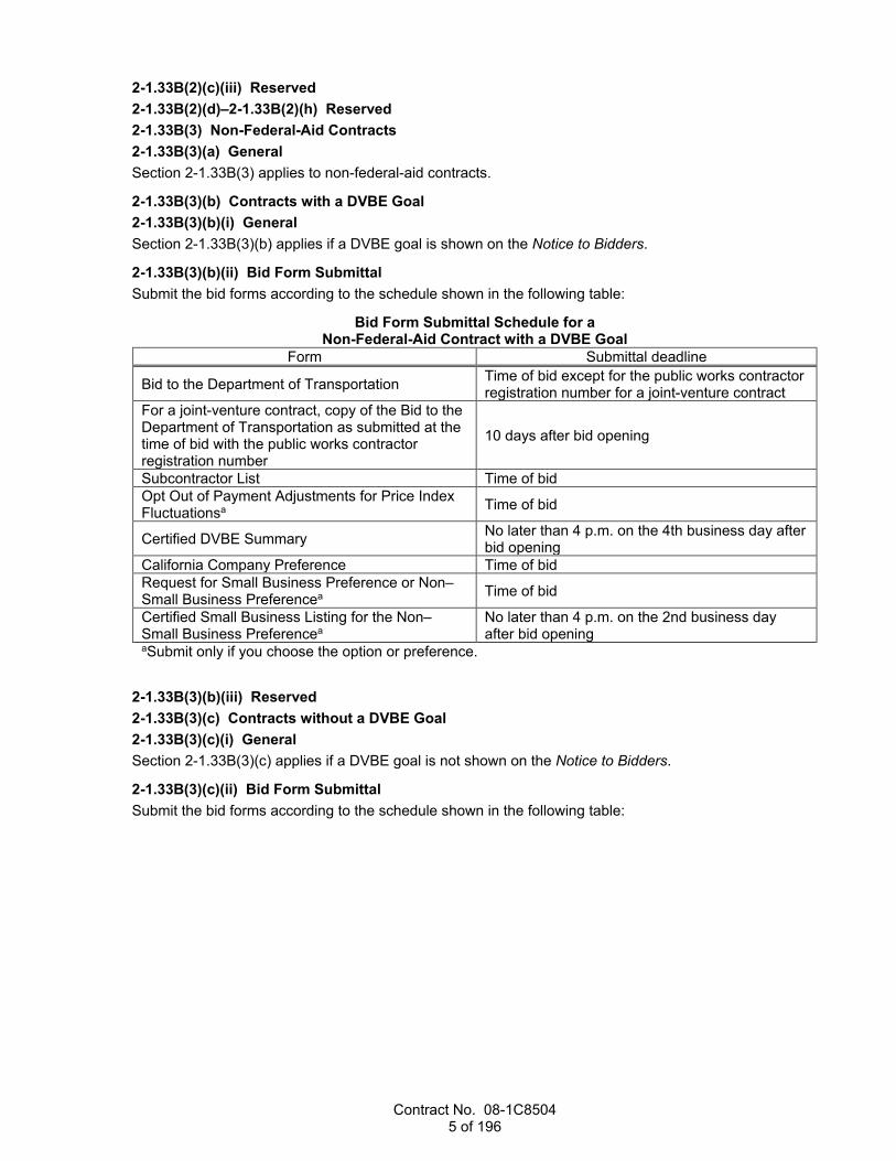
Contract No. 08-1C8504 5 of 196
2-1.33B(2)(c)(iii) Reserved 2-1.33B(2)(d)–2-1.33B(2)(h) Reserved 2-1.33B(3) Non-Federal-Aid Contracts 2-1.33B(3)(a) General Section 2-1.33B(3) applies to non-federal-aid contracts.
2-1.33B(3)(b) Contracts with a DVBE Goal 2-1.33B(3)(b)(i) General Section 2-1.33B(3)(b) applies if a DVBE goal is shown on the Notice to Bidders.
2-1.33B(3)(b)(ii) Bid Form Submittal Submit the bid forms according to the schedule shown in the following table:
Bid Form Submittal Schedule for a Non-Federal-Aid Contract with a DVBE Goal
Form Submittal deadline
Bid to the Department of Transportation Time of bid except for the public works contractor registration number for a joint-venture contract
For a joint-venture contract, copy of the Bid to the Department of Transportation as submitted at the time of bid with the public works contractor registration number
10 days after bid opening
Subcontractor List Time of bid Opt Out of Payment Adjustments for Price Index Fluctuationsa Time of bid
Certified DVBE Summary No later than 4 p.m. on the 4th business day after bid opening
California Company Preference Time of bid Request for Small Business Preference or Non–Small Business Preferencea Time of bid
Certified Small Business Listing for the Non–Small Business Preferencea
No later than 4 p.m. on the 2nd business day after bid opening
aSubmit only if you choose the option or preference.
2-1.33B(3)(b)(iii) Reserved 2-1.33B(3)(c) Contracts without a DVBE Goal 2-1.33B(3)(c)(i) General Section 2-1.33B(3)(c) applies if a DVBE goal is not shown on the Notice to Bidders.
2-1.33B(3)(c)(ii) Bid Form Submittal Submit the bid forms according to the schedule shown in the following table:

Contract No. 08-1C8504 6 of 196
Bid Form Submittal Schedule for a Non-Federal-Aid Contract without a DVBE Goal
Form Submittal deadline
Bid to the Department of Transportation Time of bid except for the public works contractor registration number for a joint-venture contract
For a joint-venture contract, copy of the Bid to the Department of Transportation as submitted at the time of bid with the public works contractor registration number
10 days after bid opening
Subcontractor List Time of bid Opt Out of Payment Adjustments for Price Index Fluctuationsa Time of bid
California Company Preference Time of bid
Certified DVBE Summaryb No later than 4 p.m. on the 4th business day after bid opening
Request for Small Business Preference or Non–Small Business Preferencea Time of bid
Certified Small Business Listing for the Non–Small Business Preferencea
No later than 4 p.m. on the 2nd business day after bid opening
aSubmit only if you choose the option or preference. bSubmit only if you obtain DVBE participation or you are the apparent low bidder, 2nd low bidder, or 3rd low bidder and you choose to receive the specified incentive.
2-1.33B(3)(c)(iii) Reserved 2-1.33B(3)(d)–2-1.33B(3)(h) Reserved 2-1.33B(4)–2-1.33B(9) Reserved
^^^^^^^^^^^^^^^^^^^^^^^^^^^^^^^^^^^^^^^^
3 CONTRACT AWARD AND EXECUTION 04-17-20
Replace the 1st paragraph of Section 3-1.04 with: 04-17-20
Submit any bid protest to the Office Engineer before contract award.
^^^^^^^^^^^^^^^^^^^^^^^^^^^^^^^^^^^^^^^^
4 SCOPE OF WORK 10-18-19
Replace the 7th and 8th paragraphs of section 4-1.07B with: 10-18-19
The Department decides whether to accept a VECP and the estimated net construction-cost savings from adopting the VECP or parts of it. The Department may require you to accept a share of the investigation cost as a condition of reviewing a VECP. In determining the estimated net construction-cost savings, the Department excludes your VECP preparation cost and the Department's VECP investigation costs, including parts paid by you. After written acceptance, the Department considers the VECP and deducts the agreed cost of the investigation.
Contract No. 08-1C8504 7 of 196
Replace item 4 in the list in the 9th paragraph of section 4-1.07B with: 10-18-19
4. Adjusts the payment so that the Change Order results in a credit to the Department of 50 percent of the estimated net construction-cost savings, except if the VECP provides a reduction in traffic congestion or avoids traffic congestion
Replace the 10th paragraph of section 4-1.07B with:
10-18-19 If a VECP providing for a reduction in traffic congestion or avoiding traffic congestion is accepted by the Department, the Department adjusts the payment that results in a credit to the Department of 40 percent of the estimated net construction-cost savings attributable to the VECP. Submit detailed traffic handling comparisons between the existing Contract and the proposed change, including estimates of the traffic volumes and congestion.
10-18-19 Delete the 12th paragraph of section 4-1.07B
^^^^^^^^^^^^^^^^^^^^^^^^^^^^^^^^^^^^^^^^
5 CONTROL OF WORK 04-17-20
Replace the 6th paragraph of section 5-1.13B(2) with: 10-19-18
If the Department authorizes the termination or substitution of a listed DBE, make good faith efforts to find another DBE. The substitute DBE must (1) perform at least the same dollar amount of work as the original DBE under the Contract to the extent needed to meet the DBE goal and (2) be certified as a DBE with the most specific available NAICS or work code applicable to the type of work the DBE will perform on the Contract at the time of your request for substitution. Submit your documentation of good faith efforts within 7 days of your request for authorization of the substitution. The Department may authorize a 7-day extension of this submittal period at your request. Refer to 49 CFR 26 app A for guidance regarding evaluation of good faith efforts to meet the DBE goal.
Replace the 2nd sentence in the 2nd paragraph of section 5-1.13C with: 10-19-18
The substitute must be another DVBE, unless DVBEs are not available. The substitute must perform the work originally stated.
Replace the 6th paragraph of section 5-1.13C with: 10-19-18
If a DVBE substitute is not available, requests for substitutions of a listed DVBE must include:
1. Contact with the DVBE advocate from the Department and the Department of Veteran Affairs 2. Search results from the Department of General Services' website of available DVBEs 3. Communication with a DVBE community organization nearest the job site, if applicable 4. Documented communication with DVBEs describing the work to be performed, the percentage of the
total bid, the corresponding dollar amount, and the responses to the communication
Contract No. 08-1C8504 8 of 196
Replace section 5-1.24 with: 10-19-18
5-1.24 CONSTRUCTION SURVEYS 5-1.24A General The Department places stakes and marks under chapter 12, "Construction Surveys," of the Department's Surveys Manual.
Submit your request for Department-furnished stakes:
1. Once staking area is ready for stakes 2. On a Request for Construction Staking form After your submittal, the Department starts staking within 2 business days.
Preserve stakes and marks placed by the Department. If the stakes or marks are destroyed, the Department replaces them at the Department's earliest convenience and deducts the cost.
Replace section 5-1.26 with: 10-19-18
5-1.26 RESERVED
Replace the 2nd and 3rd paragraphs of section 5-1.43A with: 10-18-19
Submit potential claim records using the Department's Internet potential claim system. For information on submittal of potential claim records using the Internet potential claim system, go to the Department's Division of Construction website.
A potential claim record that you submit using the Internet potential claim system is the same as the originator of the claim and you signing the potential claim record.
For the Internet potential claim system, potential claim records are:
1. Initial Potential Claim Record form 2. Supplemental Potential Claim Record form 3. Full and Final Potential Claim Record form 4. Closed Potential Claim Record form Submit a Closed Potential Claim Record form if you choose not to pursue an Initial Potential Claim Record that has been submitted.
Replace item 3.3.4 in the list in the 2nd paragraph of section 5-1.43D with: 04-17-20
3.3.4. Equipment rates at the rental rates listed in Labor Surcharge and Equipment Rental Rates in effect when the affected work related to the potential claim was performed
Add between the 2nd and 3rd paragraphs of section 5-1.43D: 04-17-20
If the total potential claim cost exceeds $500,000, include an independent CPA cost audit report. Submit the audit report within 70 days of the completion of the potentially claimed work. The CPA's cost audit must be performed as an examination-level engagement under the attestation engagements in the Government Auditing Standards published by the Comptroller General of the United States. The attest documentation prepared by the CPA in connection with the audit must be submitted for review with the

Contract No. 08-1C8504 9 of 196
audit report. Within 20 days of the Engineer's request, make your financial records available for an audit by the State for verifying the actual cost described in your audit. The Department does not participate in costs for the report where no entitlement is determined. If entitlement is determined, the Department pays for 1/2 the cost of the report; the Contractor pays for the other 1/2. The cost is determined under section 9-1.05 except no markup is allowed.
Replace section 5-1.43E(1)(i) with: 04-17-20
Pay the DRA or each DRB member $2,000 per day for the DRA's or DRB member's participation at each on-site meeting.
On-site meetings include:
1. Initial project meeting 2. Progress meetings 3. Dispute meetings The payment includes full compensation for on-site time, travel expenses, transportation, lodging, travel time, and incidentals for each day or portion thereof.
Before a DRA or DRB member spends any time reviewing the plans or specifications, evaluating positions, preparing recommendations, completing forms, or performing any other off-site DRA- or DRB-related tasks, the parties must agree to pay for the tasks. Pay the DRA or DRB member $200 per hour for these off-site tasks. This payment includes full compensation for incidentals such as expenses for telephone, fax, and computer services.
The Department does not pay for (1) any DRA- or DRB-related work performed after Contract acceptance or (2) your cost of preparing for or attending ADR resolution meetings.
The Department pays:
1. $2,000 for each DRA on-site meeting 2. $6,000 for each DRB on-site meeting 3. $200 per hour for agreed off-site DRA- or DRB-related tasks The Department does not adjust the unit price for an increase or decrease in the quantity of:
1. DRA on-site meeting 2. DRB on-site meeting 3. Hourly off-site DRA- or DRB-related tasks Within 60 days of receipt of Department payment, submit copies of associated invoices and supporting documents in the form of a canceled check or bank statement for DRA- or DRB- payment verification.
Replace section 5-1.43E(2)(a) with: 04-17-20
Section 5-1.43E(2) applies to a contract with an estimated cost from $3 million to $10 million.
Replace item 1.2 in the list in the 1st paragraph of section 5-1.43E(2)(b) with: 10-19-18
1.2. Have completed training by the Department
Replace section 5-1.43E(3)(a) with: 04-17-20
Section 5-1.43E(3) applies to a contract with an estimated cost of over $10 million.

Contract No. 08-1C8504 10 of 196
Replace item 1.2 in the list in the 1st paragraph of section 5-1.43E(3)(b) with: 10-19-18
1.2. Have completed training by the Department
^^^^^^^^^^^^^^^^^^^^^^^^^^^^^^^^^^^^^^^^
6 CONTROL OF MATERIALS 04-19-19
Replace section 6-1.03 with: 04-19-19
6-1.03 LOCAL MATERIALS 6-1.03A General Local material must be rock, sand, gravel, earth, or mineral material other than local borrow, or selected material obtained or produced from a source in the work vicinity, specifically for use on the project. Local borrow must not be a material from an established commercial source.
Upon your request, the Department tests material for quality characteristics from an untested local source. If satisfactory material from that source is used in the work, the Department does not charge you for the tests; otherwise, the Department deducts the test costs.
^^^^^^^^^^^^^^^^^^^^^^^^^^^^^^^^^^^^^^^^
7 LEGAL RELATIONS AND RESPONSIBILITY TO THE PUBLIC 10-18-19
Replace item 1.3 in the list in the 2nd paragraph of section 7-1.02K(3) with: 10-18-19
1.3. Last four digits of social security number pursuant to Labor Code § 226(a)
Replace the 6th through 10th paragraphs of section 7-1.02K(3) with: 04-19-19
You may submit certified payroll records electronically using the Department's secure file transfer protocol site. For information on electronic submission of certified payroll records, go to the Department's Division of Construction website.
Submit payroll records electronically in a nonmodifiable PDF file, using the following file-naming convention:
TT-EA-WE-DOCTYPE.PDF where: TT = district, leading zero EA = Contract number, excluding the district identification number, expressed as 6 characters WE = week ending date entered as month, leading zero; day of month, leading zero; year, last 2
digits DOCTYPE = labor payroll document type, CP for Certified Payroll, FB for Fringe Benefit Statement,
or SC for Statement of Compliance
Before submitting the payroll records electronically, you and your subcontractors must each complete and sign the Request for Electronic Submission of Certified Payroll Records and e-mail it in PDF format to the district Labor Compliance Office. The Department provides you and your subcontractors' assigned

Contract No. 08-1C8504 11 of 196
representatives the accounts and user identifications by e-mail after each Request for Electronic Submission of Certified Payroll Records is received.
Each electronic submission must:
1. Include certified payroll records in a nonmodifiable PDF file 2. Include a signed Statement of Compliance form with each weekly record as a nonmodifiable PDF file 3. Be received by the Department by close of business on the 15th day of the month for the prior
month's work
Replace the 12th paragraph of section 7-1.02K(3) with: 10-18-19
Make all payroll records, including employee's complete social security number, available for inspection and copying or furnish a copy upon request of a representative of the:
1. Department 2. Division of Labor Standards Enforcement of the Department of Industrial Relations 3. Division of Apprenticeship Standards of the Department of Industrial Relations
Replace the 1st sentence in the 5th paragraph of section 7-1.02K(6)(a) with: 10-19-18
Submit copies of your Injury and Illness Prevention Program, Code of Safe Practices, and permits required by Cal/OSHA as informational submittals.
Replace section 7-1.02K(6)(j)(iii) with: 10-18-19
7-1.02K(6)(j)(iii) Unregulated Earth Material Containing Lead Reserved
Replace Reserved in section 7-1.02M(2) with: 10-18-19
Submit the names and emergency telephone numbers of the nearest fire suppression agencies before the start of job site activities as an informational submittal. Post the names and phone numbers at a prominent place at the job site.
Submit a copy of your fire prevention plan required by Cal/OSHA as an informational submittal before the start of job site activities.
04-19-19 Cooperate with fire prevention authorities in performance of the work.
Immediately report fires occurring within and near the project limits by dialing 911 and to the nearest fire suppression agency by using the emergency phone numbers retained at the job site.
Prevent project personnel from setting open fires that are not part of the work.
Prevent the escape of and extinguish fires caused directly or indirectly by job site activities.
Replace the 2nd paragraph of section 7-1.02M(3) with: 04-19-19
For the list of permitted sites, go to the Department of Conservation, Division of Mine Reclamation website.

Contract No. 08-1C8504 12 of 196
Replace the 13th paragraph of section 7-1.03 with: 10-18-19
For a taper on a bridge deck or approach slab, construct the taper with rapid setting concrete under section 60-3.02B(2) or polyester concrete under section 60-3.04B(2). Prepare the surface to receive the taper under section 60-3.02C(7). For tapers with aggregate fillers, rake conform edges to ensure smooth transitions. Cure the taper for at least 3 hours or the minimum time recommended by the manufacturer before opening to traffic.
Replace the 4th sentence in the 16th paragraph of section 7-1.03 with: 10-18-19
When not shown and if ordered, providing flaggers is change order work.
Replace the 3rd sentence in the 7th paragraph of section 7-1.04 with: 10-18-19
When not shown and if ordered, providing flaggers is change order work.
Replace the 13th paragraph of section 7-1.04 with: 10-18-19
Equipment must enter and leave the highway via existing ramps and crossovers and must move in the direction of traffic. All movements of workers and construction equipment on or across lanes open to traffic must be performed in a manner that do not endanger the public. Your vehicles or other mobile equipment leaving an open traffic lane to enter the construction area must slow down gradually in advance of the location of the turnoff to give the traffic following an opportunity to slow down. When leaving a work area and entering a roadway carrying traffic, your vehicles and equipment must yield to traffic. Compensation for flaggers, used for all movement of workers and construction vehicles and equipment on or across lanes open to traffic, is included in the bid items of work involved.
^^^^^^^^^^^^^^^^^^^^^^^^^^^^^^^^^^^^^^^^
8 PROSECUTION AND PROGRESS 04-17-20
Replace the row for Safety in the table in the 2nd paragraph of section 8-1.03 with: 10-19-18
Safety Injury and Illness Prevention Program, Code of Safe Practices, and job site posters
Replace the 2nd paragraph of section 8-1.07C with: 04-17-20
Losses for idle equipment, idle workers, and moving or transporting equipment are eligible for delay-related payment adjustments.
Replace item 3 in the list in the 3rd paragraph of section 8-1.07C with: 04-19-19
3. Delay days exclude Saturdays and holidays.

Contract No. 08-1C8504 13 of 196
Add to section 8-1.07C: 04-17-20
If you claim additional costs due to impacts from an excusable delay, you must comply with section 5-1.42. Support your claim for additional costs based on the difference between the cost to perform the work as planned and the cost to perform the work as changed as determined under section 9-1.04. The Department adjusts payment for the work portion that was impacted.
Replace section 8-1.14E with: 10-18-19
8-1.14E Payment Adjustment for Termination If the Department issues a termination notice, the Engineer determines the payment for termination during the performance period, from contract approval date to contract acceptance date, based on the following:
1. Direct cost for the work performed: 1.1. Including:
1.1.1. Mobilization 1.1.2. Demobilization 1.1.3. Securing the job site for termination 1.1.4. Losses from the sale of materials
1.2. Not including: 1.2.1. Cost of materials you keep 1.2.2. Profit realized from the sale of materials 1.2.3. Cost of material damaged by:
1.2.3.1. Act of God 1.2.3.2. Act of a public enemy 1.2.3.3. Fire 1.2.3.4. Flood. 1.2.3.5. Governor-declared state of emergency 1.2.3.6. Landslide 1.2.3.7. Tsunami
1.2.4. Other credits 2. Cost of remedial work, as estimated by the Engineer, is not reimbursed. 3. Allowance for profit not to exceed 4 percent of the cost of the work performed where a likelihood of
having made a profit had the Contract not been terminated is shown. 4. Material handling costs for material returned to the vendor or disposed of as ordered. 5. Costs in determining the payment adjustment due to the termination, excluding attorney fees and
litigation costs. 6. Overhead costs. Termination of the Contract does not relieve the surety of its obligation for any just claims arising out of the work performed.
^^^^^^^^^^^^^^^^^^^^^^^^^^^^^^^^^^^^^^^^
9 PAYMENT 04-17-20
Add between the 1st and 2nd paragraphs of section 9-1.04A: 04-17-20
The Tentative Daily Extra Work Agreement form is used to identify the labor, materials, and equipment used on change order work paid at force account. Signatures on this form do not constitute final agreement regarding payment.
Contract No. 08-1C8504 14 of 196
Replace section 9-1.07B(5) with: 10-19-18
9-1.07B(5) Hot Mix Asphalt Containing Reclaimed Asphalt Pavement The Engineer calculates the quantity of asphalt in HMA containing RAP using the following formula:
Qrap = HMARTT x Xaa where: Xaa = Xta – [(Xrap x Xra x (Xta-100)) / (100 x (Xra – 100))] and: Qrap = quantity in tons of asphalt used in HMA containing RAP HMARTT = HMA containing RAP, total tons placed Xaa = asphalt content of HMA containing RAP adjusted to exclude the asphalt content in RAP,
expressed as a percentage of the total weight of HMA containing RAP Xta = total theoretical asphalt content in HMA containing RAP from the job mix formula, expressed as
a percentage of the total weight of HMA containing RAP Xrap = RAP percentage in HMA containing RAP from the job mix formula, expressed as a percentage
of the total dry weight of aggregate in HMA containing RAP Xra = average asphalt content of RAP from the job mix formula, expressed as percentage of total
weight of RAP
Replace the 2nd sentence in the 7th paragraph of section 9-1.11E with: 04-19-19
The cost is determined under section 9-1.05 except no markup is allowed.
Replace section 9-1.16C with: 10-19-18
9-1.16C Materials On Hand A material on hand but not incorporated into the work is eligible for a progress payment if:
1. Compliant with other Contract parts 2. Material cost exceeds either of the following:
2.1. $50,000 2.2. $25,000 if the requestor is certified as one or more of the following:
2.2.1. DVBE 2.2.2. DBE 2.2.3. Small business as certified by Department of General Services, Office of Small
Business and Disabled Veteran Business Enterprise Services 3. Purchased 4. Invoice is submitted 5. Stored within the State and you submit evidence that the stored material is subject to the
Department's control 6. Protected from weather and contamination 7. Water pollution control measures are established and maintained 8. Requested on the Department-furnished form
Replace the 1st paragraph of section 9-1.16E(3) with: 10-18-19
During each estimate period you fail to comply with a Contract part, including the submittal of a document as specified, such as QC plans, schedules, traffic control plans and water pollution control submittals, the Department withholds a part of the progress payment except as specified below for the failure to submit a document during the last estimate period.

Contract No. 08-1C8504 15 of 196
Replace the 3rd paragraph of section 9-1.17C with: 10-18-19
If you claim that the total for work completed, excluding deductions, in the proposed final estimate is less than 90 percent of your total bid, the Department adjusts the final payment to cover your overhead. The adjustment in the final estimate is 10 percent of the difference between 90 percent of your total bid and the total for work completed, excluding deductions. The Department does not make this adjustment on a terminated contract.
Replace section 9-1.17D(2)(b) with: 04-17-20
9-1.17D(2)(b) Overhead Claims 9-1.17D(2)(b)(i) General Section 9-1.17D(2)(b) includes specifications for overhead claims.
The Department deducts an amount for field and home office overhead paid on added work from any claim for overhead. The home office overhead deduction equals 5 percent of the added work. The field office overhead deduction equals 5-1/2 percent of the added work.
9-1.17D(2)(b)(ii) Definitions actual daily overhead rates: The home office overhead and field office overhead rates expressed per
business day for the contract performance period. The home office overhead rate is calculated using the Eichleay Formula and is based on overhead cost pools and all allocation bases from Contract and company revenues.
added work: Equals the value of the work completed minus the total bid.
contract performance period: The period from Contract approval to Contract acceptance.
9-1.17D(2)(b)(iii) Submittals Submit the following for an overhead claim:
1. Final amount of additional payment requested. 2. Specific identification of each claim and dates associated with each claim for which you seek
reimbursement for specific overhead costs. 3. Audit report prepared by an independent CPA for the contract performance period identifying the
actual daily overhead rates, supporting calculations and documentation for both field and home office overhead excluding a profit markup.
Field office overhead costs from which the actual daily overhead rate is calculated must be:
1. Allowable under 48 CFR 31 2. Supported by reliable records 3. Related solely to the project 4. Incurred during the contract performance period 5. Comprised of only time-related field office overhead costs 6. Not a direct cost Home-office overhead costs from which the actual daily overhead rate is calculated must be:
1. Allowable under 48 CFR 31 2. Supported by reliable records 3. Incurred during the contract performance period 4. Comprised of only fixed home-office overhead costs 5. Not a direct cost Failure to submit the audit report for an overhead claim with the claim statement is a waiver of the overhead claim and operates as a bar to arbitration on the claim (Pub Cont Code § 10240.2).

Contract No. 08-1C8504 16 of 196
The CPA's audit must be performed as an examination-level engagement under the attestation engagements in the Government Auditing Standards published by the Comptroller General of the United States. The CPA's audit report must express an opinion of whether or not your calculations of your actual field and home office overhead daily rates comply with section 9-1.17D(2)(b). The attest documentation prepared by the CPA in connection with the audit must be submitted for review with the audit report.
Within 20 days of the Engineer's request, make your financial records available for an audit by the State for verifying the actual daily overhead rates in your audit report. The actual rate of time-related overhead is subject to authorization by the Engineer.
The Department pays for 1/2 the cost of the report unless otherwise specified. The cost is determined under section 9-1.05 except no markup is allowed.
^^^^^^^^^^^^^^^^^^^^^^^^^^^^^^^^^^^^^^^^^^^^^^^^^^^^^^^^^^^^
DIVISION II GENERAL CONSTRUCTION 10 GENERAL
04-19-19 Replace the 1st sentence in the 4th paragraph of section 10-6 with:
04-19-19 The sources and discharge of recycled water must comply with the water-recycling criteria of the CDPH, SWRCB Order No. WQ 2016-0068-DDW, and the requirements of the appropriate RWQCB.
^^^^^^^^^^^^^^^^^^^^^^^^^^^^^^^^^^^^^^^^
11 WELDING 04-19-19
Replace the table in the 3rd paragraph of section 11-1.01 with: 04-19-19
AWS code Year of adoption D1.1 2015 D1.3 2018 D1.4 2018 D1.5 2015 D1.6 2017 D1.8 2016
Replace the introductory clause in the 1st paragraph of section 11-1.03 with: 04-19-19
Replace clause 6.1.3 of AWS D1.1, the 1st paragraph of clause 9.1.2 of AWS D1.4, and clause 6.1.2 of AWS D1.5 with:
Replace the introductory clause of the 2nd paragraph of section 11-1.04 with: 04-19-19
Replace clause 6.14.6.1 of AWS D1.1, clause 9.8.1 of AWS D1.4, and clause 6.1.3.4 of AWS D1.5 with:

Contract No. 08-1C8504 17 of 196
Add before the 1st paragraph of section 11-1.05: 04-19-19
Replace the first sentence of clause 5.21.1.1 of AWS D1.1 with the following:
5.21.1.1. The separation between surfaces of plug and slot welds, and of joints landing on a backing, shall not exceed 1/16 in [2 mm].
Replace clause 3.3.1.1 of AWS D1.5 with the following:
3.3.1.1. The separation between surfaces of plug and slot welds, and of joints landing on a backing, shall not exceed 2 mm [1/16 in].
Replace item 2 in the list in the 2nd paragraph of section 11-1.05 with: 04-19-19
2. Be mechanically and radiographically tested. Mechanical and radiographic testing and acceptance criteria must comply with the applicable AWS codes. The type of mechanical testing must be authorized.
Replace the 1st paragraph of 11-1.06 with: 04-19-19
Replace item 3 of clause 6.26.3.2 of AWS D1.5 with:
3. If indications that exhibit these planar characteristics are present at scanning sensitivity, or other evidence exists to suggest the presence of transverse cracks, a more detailed evaluation of the discontinuity by other means must be performed (e.g., alternate UT techniques, RT, grinding, or gouging for visual inspection or MT of the excavated areas.)
Replace the scanning angle in clause 6.24.2.2 of AWS D1.5 with:
Up to 45 degrees
Replace the 2nd paragraph of section 11-1.06 with: 04-19-19
Clause 6.6.5 of AWS D1.1, clause 9.6.5 of AWS D1.4, and clause 6.6.5 of AWS D1.5 do not apply.
Replace the introductory clause of the 1st paragraph of section 11-2.04 with: 04-19-19
Clauses 6.1.4.1 and 6.1.4.3 of AWS D1.1, the 2nd paragraph of clause 9.1.2 of AWS D1.4, clauses 6.1.3.1 through 6.1.3.3 of AWS D1.5, and clause 7.2.3 of AWS D1.8 are replaced with:
Replace item 2 in the list in the 2nd paragraph of section 11-2.04 with: 04-19-19
2. Structural steel for building construction work is performed at a permanent fabrication or manufacturing plant that is certified under the AISC Quality Certification Program, Category BU, Standard for Steel Building Structures.
Contract No. 08-1C8504 18 of 196
Replace section 11-2.06 with: 04-19-19
11-2.06 WELDING PROCEDURES QUALIFICATION Welding procedures qualification for work welded under AWS D1.5 must comply with clause 5.12 or 5.12.4 of AWS D1.5 and the following:
1. Macroetch tests are required for all WPS qualification tests, and acceptance must comply with clause 5.19.3 of AWS D1.5.
2. If a nonstandard weld joint is to be made using a combination of WPSs, you may conduct a test under figure 5.3, combining the qualified or prequalified WPSs to be used in production, if the essential variables, including weld bead placement, of each process are limited to those established in table 5.4 of AWS D1.5.
3. Before preparing mechanical test specimens, inspect the PQR welds by visual and radiographic tests. The backing bar must be 3 inches in width and must remain in place during NDT. Results of the visual and radiographic tests must comply with clause 6.26.2 of AWS D1.5 excluding clause 6.26.2.2. All other requirements for clause 5.17 are applicable.
When electric resistance welding is used for work welded under AWS D1.1, the welding procedure must be qualified under Clause 4 of AWS D1.1. Welding procedures must be qualified for the thickness and the pole diameter tested. Test samples for tapered poles must be obtained from three locations, each end and the middle of the tapered pole, to qualify for the diameter range tested.
Replace the 3rd paragraph of section 11-3.02 with: 04-19-19
The AISC Certification category for pole structures is Bridge and Highway Metal Component (CPT) or Standard for Steel Building Structures (BU).
^^^^^^^^^^^^^^^^^^^^^^^^^^^^^^^^^^^^^^^^
Replace section 12 with: 10-18-19
12 TEMPORARY TRAFFIC CONTROL 04-17-20
12-1 GENERAL 12-1.01 GENERAL Section 12-1 includes general specifications for providing temporary traffic control.
Temporary traffic control, including flagging, apparel, temporary traffic control devices, and equipment for flaggers, must comply with the California MUTCD, Part 6, "Temporary Traffic Control."
12-1.02 MATERIALS Not Used
12-1.03 CONSTRUCTION Assign flaggers to:
1. Control traffic 2. Warn the public of any dangerous conditions resulting from the work activities 3. Provide for the passage of traffic through the work as specified for the passage of traffic for public
convenience and public safety Maintain flagging apparel, traffic control devices, and equipment for flaggers in good repair.

Contract No. 08-1C8504 19 of 196
12-1.04 PAYMENT Not Used
12-2 RESERVED 12-3 TEMPORARY TRAFFIC CONTROL DEVICES
12-3.01 GENERAL 12-3.01A General 12-3.01A(1) Summary Section 12-3.01 includes general specifications for providing temporary traffic control devices.
Providing temporary traffic control devices includes installing, placing, maintaining, repairing, replacing, and removing temporary traffic control devices.
Do not use different types of channelizing devices on the same alignment. The types include plastic drums, portable delineators, channelizers, tubular markers, traffic cones, and Type I and Type II barricades.
12-3.01A(2) Definitions Category 1 temporary traffic control devices: Small devices weighing less than 100 lb certified as
crashworthy by crash testing or crash testing of similar devices. Category 1 temporary traffic control devices include traffic cones, plastic traffic drums, portable delineators, and channelizers.
Category 2 temporary traffic control devices: Small devices weighing less than 100 lb that are not expected to produce significant changes in vehicular velocity but could cause harm to impacting vehicles. Category 2 temporary traffic control devices include barricades and portable sign supports.
Category 3 temporary traffic control devices: Devices weighing 100 lb or more that are expected to produce significant changes in the vehicular velocity of impacting vehicles. Category 3 temporary traffic control devices include crash cushions, impact attenuator vehicles, temporary railing, temporary barrier, and end treatments for temporary railings and barriers.
orange: Orange, red-orange, fluorescent orange, or fluorescent red-orange.
useable shoulder area: Any longitudinal paved or unpaved contiguous surface adjacent to the traveled way with:
1. Enough weight-bearing capacity to support temporary traffic control devices, such as flashing arrow signs, PCMSs, and impact attenuator vehicles
2. Slope not greater than 6:1 (horizontal:vertical) 12-3.01A(3) Submittals At least 5 business days before starting any work using the devices or within 2 business days after the request if the devices are already in use, submit as informational submittals:
1. Self-certification for crashworthiness of Category 1 temporary traffic control devices. Either you or the manufacturer must perform the self-certification. Include: 1.1. Date 1.2. Federal aid number for a federal-aid contract 1.3. Contract number, district, county, route, and post miles of the project limits 1.4. Company name, street address, city, state, and zip code of the certifying vendor 1.5. Printed name, signature, and title of the certifying person 1.6. Types of Category 1 temporary traffic control devices
2. List of proposed Category 2 temporary traffic control devices Obtain a standard form for self-certification from the Engineer.
Submit a sample of the type of portable delineator that you will be using before placing the delineators on the job site.

Contract No. 08-1C8504 20 of 196
12-3.01A(4) Quality Assurance Reserved
12-3.01B Materials The condition of temporary traffic control devices must comply with the most current edition of the American Traffic Safety Services Association publication Quality Guidelines for Temporary Traffic Control Devices and Features.
Category 2 temporary traffic control devices must be on FHWA's list of acceptable crashworthy Category 2 hardware for work zones. For this list, go to FHWA's Safety Program website.
Category 2 temporary traffic control devices must be labeled with the FHWA acceptance letter code and the name of the manufacturer. The label must be legible and permanently affixed to the temporary traffic control device by the manufacturer.
Category 3 temporary traffic control devices must be on the Authorized Material List for highway safety features.
Retroreflectivity for the following materials must comply with Table 2A-3, "Minimum Maintained Retroreflectivity Levels," of the California MUTCD and be on the Authorized Material List for signing and delineation materials:
1. Retroreflective sheeting for barricades 2. Retroreflective bands for portable delineators 3. Retroreflective sheeting for construction area signs 4. Retroreflective sheeting for channelizers 5. Reflectors for Type K temporary railing 6. Retroreflective cone sleeves 7. White and orange retroreflective stripes for plastic traffic drums The following temporary traffic control devices must be visible from 1,000 feet during the hours of darkness under an illumination of legal high-beam headlights by persons with 20/20 vision or vision corrected to 20/20:
1. Retroreflective bands on portable delineators 2. Retroreflective sheeting on channelizers 3. Retroreflective cone sleeves on traffic cones 12-3.01C Construction Perform all layout work necessary to place channelizing devices:
1. On the proper alignment 2. Uniformly at the location and spacing described 3. Straight on a tangent alignment 4. On a true arc in a curved alignment If temporary traffic control devices are damaged, displaced, or stop operating or functioning as described from any cause during the progress of the work, immediately repair, repaint, or replace the components and restore them to their original locations and positions.
If ordered, furnish and place additional temporary traffic control devices. This work is change order work unless the temporary traffic control devices are being furnished and placed for public safety or public convenience.
Level and plumb a portable system.
Delineate the location of a trailer mounted system with a taper consisting of 9 traffic cones placed 25 feet apart, except where the system is placed within a lane closure or behind a barrier or guardrail.
When a portable system is not in use, remove it from the job site, place it behind a barrier or guardrail, or move it to an area at least 15 feet from the edge of the traveled way.

Contract No. 08-1C8504 21 of 196
12-3.01D Payment Not Used
12-3.02 TRAFFIC CONES 12-3.02A General Section 12-3.02 includes specifications for placing traffic cones.
12-3.02B Materials A traffic cone must be flexible, orange, and manufactured from commercial-quality material designed for the intended purpose.
The outer section of the portion above the base of the traffic cone must be translucent and fabricated of a highly pigmented, orange, PV compound. The overall height of a traffic cone must be at least 28 inches and the bottom inside diameter of the traffic cone must be at least 10.5 inches.
During the hours of darkness, a traffic cone must have a retroreflective cone sleeve.
Retroreflective cone sleeves must be permanently affixed, double-band, sleeves consisting of 2 white retroreflective bands. The top band must be 6 inches wide and placed a maximum of 4 inches from the top of the cone. The lower band must be 4 inches wide and placed 2 inches below the bottom of the top band. You may use traffic cones with double-band retroreflective cone sleeves during daylight hours.
12-3.02C Construction Use the same type of retroreflective cone sleeve for all cones used on the project.
Anchor the base of a traffic cone if it does not have enough size and weight to keep the cone in an upright position.
12-3.02D Payment Not Used
12-3.03 PLASTIC TRAFFIC DRUMS 12-3.03A General 12-3.03A(1) Summary Section 12-3.03 includes specifications for placing plastic traffic drums.
12-3.03A(2) Definitions Reserved
12-3.03A(3) Submittals Submit a certificate of compliance for plastic traffic drums.
12-3.03A(4) Quality Assurance Reserved
12-3.03B Materials A plastic traffic drum must comply with the manufacturer's instructions for weight and ballast.
A plastic traffic drum must:
1. Be orange LDPE 2. Be flexible and collapsible upon vehicle impact 3. Have a weighted base to maintain an upright position and prevent displacement by passing traffic 4. Have a height such that the top of the drum is at least 36 inches above the traveled way The weighted base must:
1. Be detachable 2. Be shaped to prevent rolling upon impact 3. Have a 38-inch maximum outside diameter

Contract No. 08-1C8504 22 of 196
4. Have a 4-inch maximum height above the ground surface 12-3.03C Construction Use 1 type of plastic traffic drum on the project.
Use the same type and brand of retroreflective sheeting for all plastic traffic drums used on the project.
Do not use sandbags or comparable ballast.
Moving plastic traffic drums from location to location if ordered after initial placement is change order work.
12-3.03D Payment Not Used
12-3.04 PORTABLE DELINEATORS 12-3.04A General Section 12-3.04 includes specifications for placing portable delineators.
12-3.04B Materials A portable delineator, including its base, must be made of a material that has enough rigidity to remain upright when unattended and must be flexible or collapsible upon impact by a vehicle. The base must be (1) shaped to prevent rolling after impact and (2) anchored or weigh enough to keep the delineator in an upright position. Ballast for a portable delineator must comply with the manufacturer's instructions.
A portable delineator must be a minimum of 36 inches in height. The vertical portion of a portable delineator must be predominantly orange. The post must be not less than 3 inches in width or diameter. Retroreflectorization of a portable delineator that has a height of less than 42 inches must be provided by two 3-inch-wide white bands placed a maximum of 2 inches from the top with a maximum of 6 inches between the bands. Retroreflectorization of a portable delineator that has a height of 42 inches or more must be provided by four 4- to 6-inch-wide alternating orange and white stripes with the top stripe being orange.
12-3.04C Construction Use only 1 type of portable delineator on the project.
12-3.04D Payment Not Used
12-3.05 CHANNELIZERS 12-3.05A General Section 12-3.05 includes specifications for placing channelizers.
12-3.05B Materials A channelizer must be on the Authorized Material List for signing and delineation materials.
Its post must be orange.
A channelizer must be affixed with 3-by-12-inch, retroreflective, white sheeting.
12-3.05C Construction Install channelizers on clean, dry surfaces.
Cement the channelizer bases to the pavement as specified for cementing pavement markers to the pavement in section 81-3.
When no longer required for the work, remove the channelizers and the underlying adhesive used to cement the channelizer bases to the pavement.
Do not remove channelizers that are shown to be left in place at the time of work completion.
Contract No. 08-1C8504 23 of 196
12-3.05D Payment Not Used
12-3.06–12-3.09 RESERVED 12-3.10 BARRICADES 12-3.10A General Section 12-3.10 includes specifications for placing barricades.
12-3.10B Materials Markings for barricade rails must be alternating orange and white retroreflective stripes.
Orange retroreflective sheeting must match color PR no. 6, Highway Orange, of the FHWA Color Tolerance Chart.
The interface between the rail surface and the retroreflective sheeting must be free of air bubbles or voids.
The predominant color of barricade components other than the rails must be white or unpainted galvanized metal or aluminum.
You may use a Type III barricade as a sign support if the barricade has been successfully crash tested under NCHRP Report 350 criteria or the Manual for Assessing Safety Hardware (MASH) crash testing guidelines as a single unit with an attached sign panel of the size and type to be used.
A sign panel for a construction area sign or marker panel to be mounted on a barricade must comply with section 12-3.11B(2).
Do not imprint an owner identification on the retroreflective face of any rail.
12-3.10C Construction Place each barricade such that the stripes slope downward in the direction road users are to pass.
Place each sand-filled bag near the ground level on the lower parts of the frame or stays to serve as ballast for the barricades. Do not place ballast on top of barricades or over any retroreflective barricade rail face that is facing traffic.
Do not remove barricades that are shown to be left in place at the time of work completion.
Moving a barricade from location to location is change order work if ordered after initial placement of the barricade.
12-3.10D Payment Not Used
12-3.11 CONSTRUCTION AREA SIGNS 12-3.11A General 12-3.11A(1) Summary Section 12-3.11 includes specifications for placing construction area signs.
04-17-20 Construction area signs include general information signs and all temporary signs and object markers required for the direction of traffic within the project limits.
10-18-19 12-3.11A(2) Definitions background: Dominant sign color.
legend: Letters, numerals, tildes, bars, arrows, route shields, symbols, logos, borders, artwork, and miscellaneous characters that are intended to convey specific meanings on traffic signs.

Contract No. 08-1C8504 24 of 196
12-3.11A(3) Submittals Reserved
12-3.11A(4) Quality Assurance Reserved
12-3.11B Materials 12-3.11B(1) General
04-17-20 Construction area sign must be the product of a commercial sign manufacturer.
10-18-19 The style, font, size, and spacing of the legend must comply with the Standard Alphabets published in the FHWA's Standard Highway Signs Book.
The sign must be visible from 500 feet and legible from 300 feet at noon on a cloudless day and during the hours of darkness under an illumination of legal low-beam headlights by persons with 20/20 vision or vision corrected to 20/20. A fabric sign panel on a portable sign is not subject to the visibility and legibility requirements for headlight illumination during the hours of darkness.
04-17-20 Construction area sign must have a black legend on a retroreflective, fluorescent orange background. W10-1 advance warning sign for highway-rail grade crossings must have a black legend on a retroreflective fluorescent yellow background.
10-18-19 12-3.11B(2) Stationary-Mounted Signs
04-17-20 Stationary-mounted sign must comply with section 82-2 and must have Type XI retroreflective sheeting.
10-18-19 A temporary sign support of any type placed within 15 feet from the edge of the traveled way must comply with the specifications for a Category 2 temporary traffic control device.
The sign post must be good, sound wood posts with the breakaway feature as shown for a roadside sign.
Fastening hardware and back braces must be commercial-quality materials.
12-3.11B(3) Portable Signs Each portable sign must consist of a base, standard or framework, and a sign panel. Units delivered to the job site must be capable of being placed into immediate operation.
A sign panel for a portable sign must comply with the specifications for a stationary-mounted sign panel or be fabricated from one of the following materials:
1. Type VI, retroreflective, elastomeric roll-up fabric 2. Nonretroreflective, cotton, drill fabric 3. Nonretroreflective, flexible, industrial, nylon fabric 4. Another type of fabric if authorized Do not use nonretroreflective portable signs during the hours of darkness.
The bottom of the portable sign panel must be at least 1 foot above the edge of the traveled way.
12-3.11B(4) Temporary Object Markers A temporary object marker must be mounted on a stationary wood or metal post and must comply with section 82.
A marker panel for a Type N (CA), Type P (CA), or Type R (CA) object marker must comply with the specifications for a marker panel for a stationary sign panel in section 12-3.11B(2).

Contract No. 08-1C8504 25 of 196
A target plate, post, and the hardware for a Type K (CA) and Type L (CA) temporary object marker must comply with the specifications for these items in section 82.
12-3.11B(5) General Information Signs Reserved
12-3.11C Construction 12-3.11C(1) General Place all construction area signs outside of the traveled way. Do not block a bicycle or pedestrian pathway with a construction area sign.
Place, install, maintain, and remove temporary object markers shown as construction area signs as specified for construction area signs.
Maintain accurate information on construction area signs. Immediately replace or correct signs that convey inaccurate information.
During the progress of work, immediately cover or remove unneeded signs.
Cover each unneeded sign such that the message cannot be seen. Securely fasten the cover to prevent movement from wind.
Check each covered sign daily for damage to the cover and immediately replace any cover if needed.
Clean each construction area sign panel at the time of installation and at least once every 4 months thereafter.
Be prepared to furnish additional construction area sign panels, posts, and mounting hardware or portable sign mounts on short notice due to changing traffic conditions or damage caused by traffic or other conditions. Maintain an inventory of commonly required items at the job site or make arrangements with a supplier who is able to furnish the items daily on short notice.
Replace any damaged construction area sign or repair the sign if authorized.
Remove any sign panel that exhibits irregular luminance, shadowing, or dark blotches at nighttime under vehicular headlight illumination.
12-3.11C(2) Stationary-Mounted Signs Install stationary-mounted signs as described for the installation of roadside signs except:
1. Back braces and blocks for sign panels are not required for signs 48 inches or smaller in width and diamond-shaped signs 48 by 48 inches or smaller.
2. Bottom of the sign panel must be at least 7 feet above the edge of the traveled way. 3. You may install a construction area sign on an above-ground, temporary platform sign support or on
an existing lighting standard or other support if authorized. Do not make holes in a standard to support the sign if it is installed on an existing lighting standard.
4. Post embedment must be at least 2.5 feet if the post hole is backfilled around the post with commercial-quality concrete. The concrete must contain at least 295 pounds of cementitious material per cubic yard.
The Engineer determines the post size and number of posts if the type of sign installation is not shown.
Excavate each post hole by hand methods without the use of power equipment. You may use power equipment where you determine that subsurface utilities are not present in the area of the proposed post hole if authorized. The post-hole diameter must be at least 4 inches greater than the longest cross-sectional dimension of the post if it is backfilled with commercial-quality concrete.
Furnishing, installing, maintaining, moving, and removing any additional construction area signs if ordered is change order work.
12-3.11C(3) General Information Signs Reserved
Contract No. 08-1C8504 26 of 196
12-3.11D Payment Not Used
12-3.12 TELESCOPING FLAG TREES 12-3.12A General Section 12-3.12 includes specifications for placing telescoping flag trees.
12-3.12B Materials Telescoping flag trees must be manufactured from commercial-quality material designed for the intended purpose and capable of maintaining an upright position at all times while in use.
12-3.12C Construction Not Used
12-3.12D Payment Not Used
12-3.13–12-3.19 RESERVED 12-3.20 TYPE K TEMPORARY RAILING 12-3.20A General 12-3.20A(1) Summary Section 12-3.20 includes specifications for placing Type K temporary railing and Type K temporary terminal sections.
Type K temporary railing must consist of interconnected PC concrete barrier panels.
You may have your name or logo on each panel of Type K temporary railing. The name or logo must not be more than 4 inches in height and must be located not more than 12 inches above the bottom of the rail panel.
Reinforcing steel must comply with section 52.
12-3.20A(2) Definitions Reserved
12-3.20A(3) Submittals Submit a certificate of compliance for Type K temporary railing not cast at the job site.
12-3.20A(4) Quality Assurance Reserved
12-3.20B Materials 12-3.20B(1) General Concrete must comply with the specifications for minor concrete except load tickets and a certificate of compliance are not required.
Steel bars to receive bolts at the ends of the concrete panels must comply with ASTM A36/A36M. The bolts must comply with ASTM A307.
You may substitute a round bar of the same diameter for the end-connecting bolt shown. If a round bar is used, the round bar must:
1. Comply with ASTM A36/A36M 2. Have a minimum length of 26 inches 3. Have a 3-inch-diameter, 3/8-inch-thick plate welded on the upper end using a 3/16-inch fillet weld The final surface finish of the railing must comply with section 51-1.03F(2).
Cure the exposed surfaces of the railing by the water method, the forms-in-place method, or the curing compound method using curing compound no. 1.
Contract No. 08-1C8504 27 of 196
12-3.20B(2) Type K Temporary Terminal Section The closure plate for a Type K temporary terminal section must be a white, commercial-quality steel plate shaped to conform to the cross section of the barrier. The mechanical expansion anchors for connecting the closure plate to the railings must comply with section 75-3 for concrete anchorage devices.
12-3.20C Construction 12-3.20C(1) General Before placing Type K temporary railing on the job site, paint the exposed surfaces of the railing with white paint complying with the specifications for acrylic emulsion paint for exterior masonry. The repainting of the units is change order work if it is ordered after the units are in place.
Place Type K temporary railing on a firm, stable foundation. Grade the foundation to provide a uniform bearing surface throughout the entire length of the railing.
Structure excavation and backfill must comply with section 19-3 except compaction of earth fill placed behind Type K temporary railing in a curved layout is not required.
Place and maintain the abutting ends of PC concrete units in alignment without substantial offset from each other.
The drilling of holes and bonding of threaded rods or dowels must comply with the specifications for drilling and bonding dowels in section 51-1.
Install a reflector on the top or face of the rail of each rail unit placed within 10 feet of a traffic lane. Apply adhesive for mounting the reflector under the reflector manufacturer's instructions.
Install a Type P marker panel at each end of railing placed adjacent to a 2-lane, two-way highway and at the end facing traffic for railing installed adjacent to a one-way roadbed. If the railing is placed on a skew, install the marker at the end of the skew nearest the traveled way. Type P marker panels must comply with section 82 except you must furnish the marker panels.
After removing Type K temporary railing:
1. Restore the area to its previous condition or construct it to its planned condition if temporary excavation or embankment was used to accommodate the railing.
2. Remove all threaded rods or dowels to a depth of at least 1 inch below the surface of the concrete. Fill the resulting holes with mortar under section 51-1 except cure the mortar by the water method or by the curing compound method using curing compound no. 6.
If the Engineer orders a lateral move of Type K temporary railing and repositioning is not shown, the lateral move is change order work and the railing is not measured in the new position.
12-3.20C(2) Type K Temporary Terminal Section When the Type K temporary terminal section is no longer required, remove the anchor bolts connecting the closure plate to the concrete barrier or cut the bolts flush with the face of the barrier. If the anchor bolts are removed, fill the holes with grout.
12-3.20D Payment The payment quantity for temporary railing (Type K) is the length measured along the top of the railing.
12-3.21 TEMPORARY TRAFFIC SCREENS 12-3.21A General Section 12-3.21 includes specifications for installing temporary traffic screens.
12-3.21B Materials Temporary traffic screen panels must be one of the following:
1. CDX grade or better plywood 2. Weather-resistant strand board 3. Plastic

Contract No. 08-1C8504 28 of 196
Plastic temporary traffic screen panels must be on the Authorized Material List for temporary traffic screen.
Wale boards for use with plywood or strand board must be Douglas fir, rough sawn, construction grade or better.
Pipe screen supports must be schedule 40, galvanized steel pipe.
Nuts, bolts, and washers must be cadmium plated.
Screws must be black or cadmium-plated flat head, cross-slotted, with full-thread length.
Temporary traffic screen panels must be CDX grade or better, plywood or weather-resistant strand board.
Wale boards must be Douglas fir, rough sawn, construction grade or better.
Pipe screen supports must be schedule 40, galvanized steel pipe.
Nuts, bolts, and washers must be cadmium plated.
Screws must be black or cadmium-plated flat head, cross-slotted screws with full-thread length.
12-3.21C Construction Install and anchor temporary traffic screens to the top of the Type K temporary railing. The temporary traffic screen must have 3-foot-long openings spaced at 200-foot intervals.
A lateral move of Type K temporary railing with attached temporary traffic screen is change order work if ordered and repositioning is not shown.
12-3.21D Payment The payment quantity for temporary traffic screen is the length measured along the line of the screen with no deductions for openings in the temporary traffic screen.
12-3.22 TEMPORARY CRASH CUSHION MODULES 12-3.22A General Section 12-3.22 includes specifications for placing sand-filled temporary crash cushion modules in groupings or arrays.
If activities expose traffic to a fixed obstacle, protect the traffic from the obstacle with a sand-filled temporary crash cushion. The crash cushion must be in place before opening traffic lanes adjacent to the obstacle.
12-3.22B Materials Each sand-filled temporary crash cushion module must be manufactured after March 31, 1997 and be on the Authorized Material List for highway safety features.
The color of each module must be standard yellow with black lids as furnished by the manufacturer. Each module must be free from structural flaws and objectionable surface defects.
For a module requiring a seal, the top edge of the seal must be securely fastened to the wall of the module by a continuous strip of heavy-duty tape.
Fill each module with sand under the manufacturer's instructions and to the sand capacity in pounds for each module shown. Sand for filling the modules must be clean, commercial-quality, washed concrete sand. When sand is placed in a module, the sand must contain no more than 7 percent water when tested under California Test 226.
12-3.22C Construction Use the same type of crash cushion module for a single grouping or array.
Temporary crash cushion arrays must not encroach on the traveled way.
Secure the sand-filled modules in place before starting an activity requiring a temporary crash cushion.
Contract No. 08-1C8504 29 of 196
Maintain sand-filled temporary crash cushions in place at each location, including times when work is not actively in progress. You may remove the crash cushions during the work shift for access to the work if the exposed fixed obstacle is 15 feet or more from the nearest lane carrying traffic. Reset the crash cushion before the end of the work shift.
Immediately repair sand-filled temporary crash cushion modules damaged due to your activities. Remove and replace any module damaged beyond repair. Repair and replacement of temporary crash cushion modules damaged by traffic are change order work.
You may place sand-filled temporary crash cushion modules on movable pallets or frames complying with the dimensions shown. The pallets or frames must provide a full-bearing base beneath the modules. Do not move the modules and supporting pallets or frames by sliding or skidding along the pavement or bridge deck.
Attach a Type R or Type P marker panel to the front of the temporary crash cushion if the closest point of the crash cushion array is within 12 feet of the traveled way. Firmly fasten the marker panel to the crash cushion with commercial quality hardware or by other authorized methods. Attach the Type R marker panel such that the top of the panel is 1 inch below the module lid. Attach the Type P marker panel such that the bottom of the panel rests upon the pallet or roadway surface if pallets are not used.
A lateral move of a temporary crash cushion module is change order work if ordered and the repositioning is not shown.
Remove sand-filled temporary crash cushion modules, including sand, pallets or frames, and marker panels, at Contract acceptance. Do not install sand-filled temporary crash cushion modules in the permanent work.
12-3.22D Payment The payment quantity for temporary crash cushion module does not include:
1. Modules placed for public safety 2. Modules placed in excess of the number described 3. Repositioned modules 12-3.23 IMPACT ATTENUATOR VEHICLES 12-3.23A General 12-3.23A(1) Summary Section 12-3.23 includes specifications for using impact attenuator vehicles.
12-3.23A(2) Definitions impact attenuator vehicle: Support truck towing a deployed attenuator mounted to a trailer or a support
truck with a deployed attenuator mounted to the support truck.
12-3.23A(3) Submittals Submit a certificate of compliance for each attenuator.
12-3.23A(4) Quality Assurance Before using an impact attenuator vehicle, conduct a meeting with the Engineer, subcontractors, and other parties involved with traffic control to discuss the operation of the impact attenuator vehicle during moving lane closures and when placing and removing components of a stationary traffic control system.
Schedule the location, time, and date for the meeting with all participants. Furnish a meeting facility located within 5 miles of the job site or at another location if authorized.
12-3.23B Materials An impact attenuator vehicle must be on the Authorized Material List for highway safety features. The vehicle must comply with Veh Code Div 12.
Each attenuator must be individually identified with the manufacturer's name, address, attenuator model number, and a specific serial number. The name and number must be a minimum 1/2 inch high and located on the left, street side, lower front corner.

Contract No. 08-1C8504 30 of 196
An impact attenuator vehicle must comply with the following test levels as specified in the National Cooperative Highway Research Program Report 350:
1. Test level 3 if the preconstruction posted speed limit is 50 mph or more 2. Test level 2 or 3 if the preconstruction posted speed limit is 45 mph or less The impact attenuator vehicle must comply with the attenuator manufacturer's instructions for:
1. Support truck except the weight of the support truck must be within the allowable vehicle weight limits shown on the Authorized Material List for highway safety features and the manufacturer's instructions
2. Trailer-mounted attenuator 3. Truck-mounted attenuator A flashing arrow sign must comply with section 12-3.30 except you may use a PCMS instead of a flashing arrow sign. A PCMS used as a flashing arrow sign must comply with the specifications for an arrow board in the California MUTCD.
Each impact attenuator vehicle must have:
1. Inverted V chevron pattern placed across the entire rear of the attenuator composed of alternating 4-inch-wide, nonreflective black stripes and 4-inch-wide, yellow retroreflective stripes sloping at 45 degrees
2. Type II flashing arrow sign 3. Flashing or rotating amber light 4. Operable 2-way communication system for maintaining contact with workers 12-3.23C Construction Do not use an impact attenuator vehicle until authorized.
Monitor the placement and use of the attenuator vehicle on a regular basis and adjust the use of the attenuator to match changing field conditions as construction progresses.
After placing the components of a stationary traffic control system, you may place the impact attenuator vehicle in advance of the work area or at another authorized location to protect traffic and workers.
Secure objects, including equipment, tools, and ballast, on impact attenuator vehicles to prevent their loosening upon impact by an errant vehicle.
Do not use a damaged attenuator in the work. Replace any attenuator damaged from an impact during work activities.
12-3.23D Payment Not Used
12-3.24–12-3.29 RESERVED 12-3.30 FLASHING ARROW SIGNS 12-3.30A General Section 12-3.30 includes specifications for placing flashing arrow signs.
12-3.30B Materials A flashing arrow sign must comply with the requirements shown in the following table:

Contract No. 08-1C8504 31 of 196
Flashing Arrow Sign Requirements
Type Panel size
(min, inches) Number of panel lights (min) Legibility
distancea (min, miles) I 48 x 96 15 1 II 36 x 72 13 3/4
aThe legibility distance is the distance that a flashing arrow sign must be legible at noon on a cloudless day and during the hours of darkness by persons with 20/20 vision or vision corrected to 20/20.
A flashing arrow sign must be finished with commercial-quality nonreflective black enamel and must be equipped with yellow or amber lamps that form arrows or arrowheads. Each lamp must be equipped with a visor and the lamps must be controlled by an electronic circuit that provides from 30 to 45 complete operating cycles per minute for each of the displays and modes specified. The control must be capable of dimming the lamps by reducing the voltage to 50 ± 5 percent for nighttime use. Type I signs must have both manual and automatic photoelectric-dimming controls. Dimming in both modes must be continuously variable over the entire dimming range.
A flashing arrow sign must be capable of operating in the following display modes:
1. Pass left display 2. Pass right display 3. Simultaneous display 4. Caution display or alternating diamond A flashing arrow sign must be capable of operating in the flashing arrow mode or the sequential mode.
In the flashing arrow mode, all lamps forming the arrowhead and shaft must flash on and off simultaneously.
In the sequential mode, either arrowheads or arrows must flash sequentially in the direction indicated.
In the simultaneous display mode, the lamps forming both the right and left arrowheads and the lamps forming the arrow shaft or center 3 lamps for Type I signs must flash simultaneously. For Type II signs, the lamps forming the right and left arrowhead, but not the center lamp, may be illuminated continuously; the lamps forming the shaft and the center lamp of the arrowheads must flash on and off simultaneously.
In the caution display mode, a combination of lamps not resembling any other display or mode must flash.
Each flashing arrow sign must be:
1. Mounted on a truck or trailer 2. Capable of operating when the vehicle is moving 3. Capable of being placed and maintained in operation at locations described A Type II flashing arrow sign must be controllable by the operator of the vehicle while the vehicle is in motion.
The bottom of the flashing arrow sign must be a minimum of 7 feet above the roadway when mounted.
The trailer for a flashing arrow sign must be equipped with (1) devices to level and plumb the sign and (2) a supply of electrical energy capable of operating the sign.
12-3.30C Construction Not Used
12-3.30D Payment Not Used
Contract No. 08-1C8504 32 of 196
12-3.31 PORTABLE FLASHING BEACONS 12-3.31A General Section 12-3.31 includes specifications for placing, maintaining, and removing portable flashing beacons.
12-3.31B Materials Each portable flashing beacon must have:
1. Standard and base 2. Signal section 3. Flasher unit 4. Battery power source The components must be assembled to form a complete, self-contained, portable flashing beacon that can be delivered to the job site and placed into immediate operation.
The portable flashing beacon must be weatherproof and operate a minimum of 150 hours between battery recharging and routine maintenance.
The signal section must be yellow and comply with section 86-1.02R(4)(a), except it must be rated for 25 W at 12 V.
The flash rate for the flashing unit must comply with chapter 4L, "Flashing Beacons," of the California MUTCD.
The standard must be adjustable to allow variable mounting of the signal section from 6 to 10 feet, from the bottom of the base to the center of the lens, and be capable of being secured at the desired height. The standard must be securely attached to the base and have a length of multiconductor, neoprene-jacketed cable long enough for the full vertical height.
The base must be (1) large enough to accommodate at least two 12 V automotive-type storage batteries and (2) a shape and weight such that the beacon will not roll if struck by a vehicle or pushed over.
12-3.31C Construction Remove portable flashing beacons from the traveled way at the end of each night's work. You may store the flashing beacon at selected central locations within the highway where designated by the Engineer.
Moving portable flashing beacons from location to location if ordered after initial placement is change order work.
12-3.31D Payment The payment quantity for flashing beacon (portable) is the number of portable flashing beacon locations with each location counting as 1 measurement unit.
12-3.32 PORTABLE CHANGEABLE MESSAGE SIGNS 12-3.32A General 12-3.32A(1) Summary Section 12-3.32A includes specifications for placing, maintaining, and removing portable changeable message signs.
12-3.32A(2) Definitions Reserved
12-3.32A(3) Submittals If requested, submit a certificate of compliance for each PCMS.
Submit your cell phone number before starting the first activity that requires a PCMS.
12-3.32A(4) Quality Assurance Reserved
Contract No. 08-1C8504 33 of 196
12-3.32B Materials Each PCMS consists of a sign panel, a controller unit, a power supply, and a structural support system.
The PCMS must:
1. Be assembled to form a complete self-contained unit that can be delivered to the job site and placed into immediate operation.
2. Operate at an ambient air temperature from -4 to 158 degrees F. 3. Not be affected by mobile radio transmissions other than those required to control the PCMS. 4. Be capable of displaying a 3-line message with at least 7 characters per line. 5. Provide a complete alphanumeric selection. 6. Be internally or externally illuminated during the hours of darkness, when non-illuminated pixels are
used. 7. Have a dimming control that automatically adjusts the character light intensity to provide optimum
character visibility and legibility under all ambient lighting conditions. The dimming control must have a minimum 3 manual dimming modes of different intensities.
A message with 18-inch high characters or 15-inch high characters must be visible from a distance of 1,500 feet and legible from a distance of at least 750 feet at noon on a cloudless day and during the night by persons with 20/20 vision or vision corrected to 20/20.
A message with 10-inch high characters must be legible from a distance of at least 650 feet at noon on a cloudless day and during the night by persons with 20/20 vision or vision corrected to 20/20.
The controller must:
1. Be an all solid-state unit. 2. Include at least 5 preprogrammed messages. 3. Have a user adjustable display rate. 4. Have a user adjustable flashing-off time. 5. Include a screen to review the messages before being displayed on the sign. 6. Include a keyboard message entry system. The keyboard must be equipped with a security lockout
feature. 7. Have nonvolatile memory to store an infinite number of user created messages. 8. Be installed at a location that allows the user to perform all the functions from a single position. 12-3.32C Construction Use a PCMS with characters:
1. At least 18 inches in height where the useable shoulder area is 15 feet wide or more 2. At least 12 inches in height where the useable shoulder area is less than 15 feet wide 3. At least 10 inches in height if the PCMS is:
3.1. Mounted on a service patrol truck or incident response vehicle 3.2. Used for traffic control where the posted speed limit is less than 40 mph
Place a PCMS as far from the traveled way as practicable where it is legible to approaching traffic without encroaching on the traveled way. Where the vertical roadway curvature restricts the sight distance of approaching traffic, place the sign on or before the crest of the curvature where it is most visible to the approaching traffic. Where the horizontal roadway curvature restricts the sight distance of approaching traffic, place the sign at or before the curve where it is most visible to approaching traffic. Where practicable, place the sign behind guardrail or Type K temporary railing.
If multiple signs are needed, place each sign on the same side of the road at least 1,000 feet apart on freeways and expressways and at least 500 feet apart on other types of highways.
Operate the PCMS under the manufacturer's instructions.
When in operation, place the bottom of a PCMS at least 7 feet above the roadway in areas where pedestrians are anticipated and 5 feet above the roadway elsewhere. Place the top of the PCMS no more than 14.5 feet above the roadway.
Contract No. 08-1C8504 34 of 196
If more than one PCMS is simultaneously visible to traffic, only one sign may display a sequential message at any time. Do not use dynamic message displays, such as animation, rapid flashing, dissolving, exploding, scrolling, horizontal movement, or vertical movement of messages. The message must be centered within each line of the display.
You may use an additional PCMS if more than 2 phases are needed to display a message.
Display only messages shown or ordered.
Repeat the entire message continuously in not more than 2 phases of at least 3 seconds per phase. The sum of the display times for both of the phases must be a maximum of 8 seconds. If more than 2 phases are needed to display a message, use an additional PCMS.
You must be available by cell phone during activities that require a sign. Be prepared to immediately change the displayed message if ordered. You may operate the sign with a 24-hour timer control or remote control if authorized.
Keep the PCMS clean to provide maximum visibility.
After the initial placement, move a sign from location to location as ordered.
12-3.32D Payment Not Used
12-3.33 PORTABLE SIGNAL SYSTEMS 12-3.33A General Section 12-3.33 includes specifications for installing, maintaining, and removing portable signal systems, including installing lighting and flashing beacons for traffic control.
A portable signal system must comply with section 87-20, except it must be trailer mounted.
12-3.33B Materials Not Used
12-3.33C Construction If the portable signal system is out of operation, provide flaggers to control the traffic until the traffic signals are in operation.
12-3.33D Payment Not Used
12-3.34 TEMPORARY FLASHING BEACON SYSTEMS 12-3.34A General Section 12-3.34 includes specifications for installing, maintaining, and removing temporary flashing beacon systems.
A temporary flashing beacon system must comply with section 87-20.
12-3.34B Materials The sign panels installed on a temporary flashing beacon system must comply with section 12-3.11.
12-3.34C Construction Not Used
12-3.34D Payment Not Used
12-3.35 AUTOMATED WORK ZONE INFORMATION SYSTEMS 12-3.35A General 12-3.35A(1) Summary Section 12-3.35 includes specifications for installing automated work zone information systems.

Contract No. 08-1C8504 35 of 196
12-3.35A(2) Definitions Reserved
12-3.35A(3) Submittals Reserved
12-3.35A(4) Quality Assurance Assign an on-site system coordinator. The coordinator must be available locally to service, maintain, and relocate system components as necessary. The coordinator must be accessible 24–7 while the system is deployed. If the system fails to perform as specified, perform any necessary remedial work and replace any failed components within 24 hours of notification of a system or component failure.
12-3.35B Materials 12-3.35B(1) General The AWIS must be a proven system that has been successfully deployed and operated in actual work zones or congested areas.
The system must acquire traffic data throughout the work zone and automatically display predetermined information to motorists without operator intervention after system initialization.
Real-time information must be displayed to motorists using a PCMS. The sign must comply with section 12-3.32.
The system must be controlled either locally or remotely by a dedicated controller or computer.
Authorized users must be able to both locally and remotely override motorist information messages.
Traffic sensors must not require adjustments after the initial deployment.
12-3.35B(2) General System Function Requirements The general system functions of the AWIS must be capable of:
1. Preventing any unauthorized users or systems from gaining access to the PCMSs through an industry authentication and encryption standard level of security.
2. Providing current operational status locally and remotely. Operational status must include current traffic data and messages, communications system, and power status.
3. Delivering notifications either by telephone, voice, or text messages to alert support staff of trouble conditions.
4. Generating trouble alerts for conditions such as (1) low roadside equipment power or voltage, (2) system communications failure, (3) low speed traffic detected, and (4) excessive delay detected.
5. Adjusting the thresholds of reduced speed and congestion-induced delay at which the system initiates a trouble alert.
6. Allowing programming of the hours during which the trouble condition alerting subsystem initiates notification to authorized users.
7. Measuring periodically and automatically the power levels of all equipment. Alert support staff, locally and remotely via a telephone message, in time to provide supplemental power before the system ceases to operate.
8. Displaying preprogrammed messages based on the time of day and day of week. 12-3.35B(3) Motorist Information Message Requirements The AWIS must be capable of:
1. Displaying predetermined speed, delay, diversion, and closure messages to motorists when user-adjustable thresholds are exceeded.
2. Updating its speed and delay advisory messages at least once per minute. The actual message updates must be consistent with traffic conditions.
3. Selecting messages for each PCMS independently, based on the traffic conditions downstream of the sign.
4. Recording motorist information messages in a comma-separated values file with time and date stamps, including message overrides with user ID.

Contract No. 08-1C8504 36 of 196
5. Displaying default messages when traffic conditions, system algorithms, and user parameters do not dictate that an advisory message should be displayed.
6. Displaying separate, independent, default messages on each PCMS. 7. Analyzing traffic parameters in work zones in which there are multiple speed limits. The following parameters for the selection and presentation of information messages must be adjustable by the user:
1. Message update frequency 2. Minimum delay necessary to trigger a delay advisory message 3. Persistence of delay before a delay message is displayed 4. Level of delay required to trigger a diversion message 5. Change in delay needed to cause a delay advisory message update 6. Change in downstream speed at which a speed advisory message update occurs 12-3.35B(4) System Communication Requirements The wireless communications subsystem of the AWIS must:
1. Operate independently of the public cellular phone system for receiving data to ensure reliable communications
2. Communicate independent of the line of sight or distance 3. Incorporate an error detection and correction mechanism to ensure the integrity of all traffic condition
data and motorist information messages 4. Configure automatically during system initialization 12-3.35B(5) Traffic Data Acquisition Requirements The AWIS must collect accurate traffic data using a speed measurement technique with an accuracy of ±5 mph, allowing specific information messages. The system must collect data during reduced visibility conditions, including precipitation, fog, darkness, excessive dust, and road debris.
The system must (1) archive the data with time and date stamps and (2) aggregate the data in operator-definable time increments, accessible 24–7 to the Engineer in a comma-separated values file.
12-3.35B(6) User Interface The system must have a user interface to control the AWIS PCMS communications. The interface must be (1) software compatible with a Windows environment or (2) a web service accessed by a web browser.
Provide any software on a CD or other Engineer-authorized data-storage device for installation at the Department's Transportation Management Center.
The user interface must, at a minimum, provide the user with a list of AWIS PCMSs in the field, location information for each AWIS PCMS, and a real-time on-board display of the message in the field. Control options must, at a minimum, provide the user the ability to change the on-board messages and flash rate.
12-3.35C Construction Obtain authorization for the message content and the threshold used for triggering the message before displaying any message on a PCMS.
Provide complete setup and support for the AWIS PCMS communications.
12-3.35D Payment Not Used
12-3.36 PORTABLE TRANSVERSE RUMBLE STRIPS Reserved
12-3.37 PORTABLE RADAR SPEED FEEDBACK SIGN SYSTEMS 12-3.37A General Section 12-3.37 includes specifications for placing, maintaining, and removing portable radar speed feedback sign systems.

Contract No. 08-1C8504 37 of 196
12-3.37B Materials A portable radar speed feedback sign system consists of a radar speed feedback sign system and a power source.
The system must comply with section 87-14, except:
1. System must be mounted on a trailer 2. LED character display must remain blank when no vehicles are detected or when the detected
vehicle speed is 10 miles less than the pre-set speed 12-3.37C Construction Place the portable radar speed feedback sign:
1. As far from the traveled way as practicable where it is visible and legible to approaching traffic. Where practicable, place the sign behind a barrier or guardrail.
2. At or before the crest of roadway vertical curvatures that restrict sight distance. 3. At or before the curve of horizontal roadway curvatures that restrict sight distance. 12-3.37D Payment Not Used
12-3.38 AUTOMATED FLAGGER ASSISTANCE DEVICES 12-3.38A General 12-3.38A(1) Summary Section 12-3.38 includes specifications for placing, maintaining, and removing automated flagger assistance devices (AFADs).
12-3.38A(2) Definitions automated flagger assistance devices: Devices that enable a flagger to be positioned out of the lane of
traffic and are used to control motorists through work zones. They are designed to be remotely operated either by a single flagger at one end of the work zone or at a central location, or by separate flaggers near the devices.
12-3.38A(3) Submittals Submit a copy of the manufacturer's operating instructions for the automated flagger assistance devices.
12-3.38A(4) Quality Assurance Reserved
12-3.38B Materials 04-17-20
The automated flagger assistance device must comply with the California MUTCD, Section 6E.04, and Section 6E.06, "Red/Yellow Lens Automated Flagger Assistance Devices."
10-18-19 The device must:
1. Be equipped with a gate arm, which must not extend into the opposing lane 2. Alternately display a steadily illuminated circular red lens and a flashing circular yellow lens to control
traffic 3. Have a fail-safe device that prevents the operator from inadvertently actuating a simultaneous
flashing circular yellow lens at both ends of the work zone 4. Have a device that monitors for malfunctions and prevents the display of conflicting indication 5. Have a 24-by-30-inch R10-6 STOP HERE ON RED sign mounted on the trailer The device must continuously monitor the wireless communication links and verify transmission and reception of data between the devices. If communication is lost, the devices must immediately display the circular red/stop indication and lower the gate arms.

Contract No. 08-1C8504 38 of 196
12-3.38C Construction The devices must:
1. Be placed where a flagger station is shown with an unobstructed view from the operator 2. Be placed outside of the traveled lane 3. Be attended by the operator when in use 4. Have a minimum of 9 cones placed on a taper in advance of the device and along the edge of
shoulder or edge of the traveled way at 25-foot intervals to a point not less than 25 feet past the device
5. Be clearly visible to approaching traffic and illuminated during the hours of darkness If any device unit becomes inoperative, do one of the following:
1. Replace the unit with the same type and model. 2. Revert to human flagging operations. 3. Terminate all construction activities requiring the use of the devices. Incorporate the devices into the traffic control using one of the following methods:
1. Method 1: Place one device at each end of the closure. 2. Method 2: Place one device at one end of the closure and a flagger at the opposite end of the
closure.
Use two operators for both methods, except you may use a single operator if:
1. Operator has an unobstructed view of the devices 2. Operator has an unobstructed view of approaching traffic in both directions 3. Second flagger is on-site to assist with manual flagging should the device malfunction, or to direct
traffic when drivers fail to comply with the devices When AFADs are in operation:
1. Use portable transverse rumble strips at your discretion 2. Do not use the 48-inch-by-48-inch C9A (CA) sign 3. Do not use the gate cones 12-3.38D Payment If automated flagger assistance devices bid item is not shown on the Bid Item List, providing AFADS is change order work.
12-3.39–12-3.40 RESERVED 12-4 MAINTAINING TRAFFIC
12-4.01 GENERAL 12-4.01A General Section 12-4.01 includes general specifications for maintaining traffic through construction work zones.
If local authorities regulate traffic, notify them at least 5 business days before the start of job site activities. Cooperate with the local authorities to handle traffic through the work zone and to make arrangements to keep the work zone clear of parked vehicles.
12-4.01B Materials Not Used
12-4.01C Construction Not Used
12-4.01D Payment Not Used
Contract No. 08-1C8504 39 of 196
12-4.02 TRAFFIC CONTROL SYSTEMS 12-4.02A General 12-4.02A(1) Summary Section 12-4.02 includes specifications for providing a traffic control system to close traffic lanes, shoulders, ramps, and connectors.
A traffic control system for a closure includes flagging and the temporary traffic control devices described as part of the traffic control system. Temporary traffic control devices must comply with section 12-3.
12-4.02A(2) Definitions Construction Zone Enhanced Enforcement Program (COZEEP): Program that provides California
Highway Patrol officers to monitor the movement of traffic within the work zone.
designated holidays: Designated holidays are shown in the following table:
Designated Holidays Holiday Date observed
New Year's Day January 1st Washington's Birthday 3rd Monday in February Memorial Day Last Monday in May Independence Day July 4th Labor Day 1st Monday in September Veterans Day November 11th Thanksgiving Day 4th Thursday in November Christmas Day December 25th
If a designated holiday falls on a Sunday, the following Monday is a designated holiday. If November 11th falls on a Saturday, the preceding Friday is a designated holiday.
12-4.02A(3) Submittals 12-4.02A(3)(a) General Submit a request for a minor deviation from the specified work hours. For a project in District 7, submit the request at least 15 days before the proposed closure date. Your request may be authorized if (1) the Department does not accrue a significant cost increase and (2) the work can be expedited and better serve the traffic.
If a closure is not opened to traffic by the specified time, submit a work plan that ensures that future closures will be opened to traffic by the specified time. Allow 2 business days for review.
Submit closure schedule requests and closure schedule amendments using LCS to show the locations and times of the requested closures.
Submit a traffic break request using LCS to show the location and time of the requested traffic break.
12-4.02A(3)(b) Closure Schedules Every Monday by noon, submit a closure schedule request for planned closures for the next week.
Except for a project in District 7, the next week is defined as Sunday at noon through the following Sunday at noon.
For a project in District 7, the next week is defined as Friday at noon through the following Friday at noon.
Submit a closure schedule request from 25 days to 125 days before the anticipated start of any job site activity that reduces:
1. Horizontal clearances of traveled ways, including shoulders, to 2 lanes or fewer due to activities such as temporary barrier placement and paving
2. Vertical clearances of traveled ways, including shoulders, due to activities such as pavement overlays, overhead sign installation, or falsework girder erection

Contract No. 08-1C8504 40 of 196
Submit closure schedule changes, including additional closures, by noon at least 3 business days before a planned closure.
Cancel closure requests using LCS at least 48 hours before the start time of the closure.
The Department notifies you through LCS of authorized and unauthorized closures and closures that require coordination with other parties as a condition for authorization.
12-4.02A(3)(c) Contingency Plans for Closures Submit a contingency plan for an activity that could affect a closure if a contingency plan is specified in the special provisions or if a contingency plan is requested.
If a contingency plan is requested, submit the contingency plan within 1 business day of the request.
The contingency plan must identify the activities, equipment, processes, and materials that may cause a delay in the opening of a closure to traffic. The plan must include:
1. List of additional or alternate equipment, materials, or workers necessary to ensure continuing activities and on-time opening of closures if a problem occurs. If the additional or alternate equipment, materials, or workers are not on the job site, specify their location, the method for mobilizing these items, and the required time to complete mobilization.
2. General time-scaled logic diagram displaying the major activities and sequence of the planned activities. For each activity, identify the critical event that will activate the contingency plan.
Submit revisions to a contingency plan at least 3 business days before starting the activity requiring the contingency plan. Allow 2 business days for review.
12-4.02A(3)(d) Traffic Break Schedule Every Monday by noon, submit a traffic break request for the next week. Support for a traffic break is based on local California Highway Patrol staffing levels and may not be available for the date or time requested.
Traffic break requests are limited to the hours when a shoulder or lane closure is allowed.
Cancel a traffic break request using LCS at least 48 hours before the start time of the traffic break.
The Department notifies you through LCS of authorized and unauthorized traffic breaks.
The Department does not adjust time or payment if (1) a California Highway Patrol officer is unavailable for the requested date or time or (2) your request is not authorized.
12-4.02A(4) Quality Assurance Reserved
12-4.02B Materials Not Used
12-4.02C Construction 12-4.02C(1) General Work that interferes with traffic is limited to the hours when closures are allowed.
Do not reduce an open traffic lane width to less than 10 feet. If traffic cones or delineators are used for temporary edge delineation, the side of the base of the cones or delineators nearest to traffic is considered the edge of the traveled way.
Do not simultaneously close consecutive ramps in the same direction of travel servicing 2 consecutive local streets unless authorized.
Notify the Engineer of delays in your activities caused by the denial of either (1) an authorized closure or (2) a closure schedule request for the specified time frame allowed for closures.
Discuss the contingency plan for any activity that could affect the closure schedule with the Engineer at least 5 business days before starting the activity requiring the plan.

Contract No. 08-1C8504 41 of 196
If you do not open a closure to traffic by the specified time, suspend work and submit a work plan. No further closures are allowed until your work plan has been authorized.
If the Engineer orders you to remove a closure before the time designated in the authorized closure schedule, any delay caused by this order is an excusable delay.
The Engineer may reschedule a closure that was canceled due to unsuitable weather.
You may use automated flagger assistance devices to enhance the traffic control system for a lane closure on a two-lane convention highway, except if a bid item for automated flagger assistance devices is shown in the Bid Item List, the use of AFADs is required.
Do not use automated flagger assistance devices:
1. On multi-lane highways 2. As a substitute or a replacement for a temporary traffic control signal 3. If the devices impair access for pedestrians and bicycles, unless alternate access is provided 4. If the usable shoulder area is not wide enough to place a trailer mounted device 5. If the distance between the devices is more than 800 feet, except when each device is controlled by a
separate operator and radio communication is available between the AFAD operators 12-4.02C(2) Lane Closure System 12-4.02C(2)(a) General The Department provides LCS training. Request the LCS training at least 30 days before submitting the 1st closure request. The Department provides the training within 15 days after your request.
LCS training is web-based or held at a time and location agreed upon by you and the Engineer. For web-based training, the Engineer provides you the website address to access the training.
Within 5 business days after completion of the training, the Department provides LCS accounts and user IDs to your assigned, trained representatives.
Each representative must maintain a unique password and current user information in the LCS.
The project is not accessible in LCS after Contract acceptance.
12-4.02C(2)(b) Status Updates for Authorized Closures Update the status of authorized closures using the LCS Mobile web page.
For a stationary closure on a traffic lane, use code:
1. 10-97 immediately before you place the 1st cone on the traffic lane 2. 10-98 immediately after you remove all of the cones from the traffic lane For a stationary closure on the shoulder, use code:
1. 10-97 immediately before you place the 1st cone after the last advance warning sign 2. 10-98 immediately after you remove the last cone before the advance warning signs For a moving closure, use code:
1. 10-97 immediately before the actual start time of the closure 2. 10-98 immediately after the actual end time of the closure For closures not needed on the authorized date, use code 10-22 within 2 hours after the authorized start time.
If you are unable to access the LCS Mobile web page, immediately notify the Engineer of the closure's status.
Contract No. 08-1C8504 42 of 196
12-4.02C(3) Closure Requirements and Charts 12-4.02C(3)(a) General Where 2 or more lanes in the same direction, including the shoulders, are adjacent to the area where the work is being performed, close the adjacent lane under any of the following conditions:
1. Work is off the traveled way but within 6 feet of the edge of the traveled way, and the approach speed is greater than 45 mph.
2. Work is off the traveled way but within 3 feet of the edge of the traveled way, and the approach speed is less than 45 mph.
Closure of the adjacent traffic lane is not required during any of the following activities:
1. Work behind a barrier 2. Paving, grinding, or grooving 3. Installation, maintenance, or removal of traffic control devices except for temporary railing 12-4.02C(3)(b) Complete Freeway or Expressway Closure Requirements Reserved
12-4.02C(3)(c) HOV, Express, and Bus Lane Closure Requirements Reserved
12-4.02C(3)(d) City Street Closure Requirements Reserved
12-4.02C(3)(e) Closure Restrictions for Special Events and Venues Reserved
12-4.02C(3)(f) Closure Restrictions for Designated Holidays and Special Days Reserved
12-4.02C(3)(g) Freeway or Expressway Lane Requirement Charts Reserved
12-4.02C(3)(h) Complete Freeway or Expressway Closure Hour Charts Reserved
12-4.02C(3)(i) Complete Connector Closure Hour Charts and Connector Lane Requirement Charts Reserved
12-4.02C(3)(j) Complete Ramp Closure Hour Charts and Ramp Lane Requirement Charts Reserved
12-4.02C(3)(k) Conventional Highway Lane Requirement Charts Reserved
12-4.02C(3)(l) Complete Conventional Highway Closure Hour Charts Reserved
12-4.02C(3)(m) City Street Closure Hour Charts and City Street Lane Requirement Charts Reserved
12-4.02C(3)(n) Concrete Slab and Approach Slab Replacement Closure Hours Table Reserved
Contract No. 08-1C8504 43 of 196
12-4.02C(3)(o)–12-4.02C(3)(s) Reserved 12-4.02C(4)–12.4.02C(6) Reserved 12-4.02C(7) Traffic Control System Requirements 12-4.02C(7)(a) General Control traffic using stationary closures.
If components of the traffic control system are displaced or cease to operate or function as specified, immediately repair them to their original condition or replace them and place them back in their original locations.
Vehicles equipped with attenuators must comply with section 12-3.23.
Each vehicle used to place, maintain, and remove components of a traffic control system on a multilane highway must have a Type II flashing arrow sign that must operate whenever the vehicle is used for placing, maintaining, or removing the components. For a stationary closure, vehicles with a Type II flashing arrow sign not involved in placing, maintaining, or removing the components must display only the caution display mode. If a flashing arrow sign is required for a closure, activate the sign before the closure is in place.
12-4.02C(7)(b) Stationary Closures Except for channelizing devices placed along open trenches or excavations adjacent to the traveled way, remove the components of the traffic control system for a stationary closure from the traveled way and shoulders at the end of each work period. You may store the components at authorized locations within the limits of the highway.
If a traffic lane is closed with channelizing devices for excavation work, move the devices to the adjacent edge of the traveled way when not excavating. Space the devices as shown for the lane closure.
12-4.02C(7)(c) Moving Closures For a moving closure, use a PCMS that complies with section 12-3.32 except the sign must be truck mounted. The full operational height to the bottom of the sign may be less than 7 feet above the ground but must be as high as practicable.
If you use a flashing arrow sign in a moving closure, the sign must be truck mounted. Operate the flashing arrow sign in the caution display mode if it is being used on a 2-lane, two-way highway.
12-4.02C(7)(d) Traffic Breaks You may request a traffic break for special operations such as:
1. Installation, removal, or replacement of an overhead power line or other utility cable across the highway
2. Installation or removal of traffic control devices in areas without a standard-width shoulder 3. Transportation of large equipment across the highway 4. Access to median areas for workers or equipment If the Department authorizes the traffic break, the Engineer notifies you and arranges the traffic break with the California Highway Patrol through COZEEP. The duration of a traffic break must not exceed 5 minutes or as authorized.
Two California Highway Patrol officers per vehicle are required for traffic breaks occurring any time from 2200 to 0600 hours.
A minimum of 2 California Highway Patrol vehicles will be assigned to conduct a traffic break.
Place a PCMS approximately 2,000 feet upstream of the work area or as agreed upon by the Engineer. The PCMS must comply with section 12-3.32 except the PCMS must not be trailer mounted. Monitor the traffic during the traffic break. If a queue develops, reposition the PCMS truck far enough upstream of the traffic break to provide real-time notification to motorists before they approach the traffic queue.
Contract No. 08-1C8504 44 of 196
12-4.02C(8) Traffic Control System Signs 12-4.02C(8)(a) General Traffic control system signs must comply with section 12-3.11.
12-4.02C(8)(b) Connector and Ramp Closure Signs Inform motorists of a temporary closing of a (1) connector or a (2) freeway or expressway entrance or exit ramp using:
1. SC6-3(CA) (Ramp Closed) sign for closures of 1 day or less 2. SC6-4(CA) (Ramp Closed) sign for closures of more than 1 day SC6-3(CA) and SC6-4(CA) signs must be stationary mounted at the locations shown and must remain in place and visible to motorists during the connector or ramp closure.
Notify the Engineer at least 2 business days before installing the sign and install the sign from 7 to 15 days before the closure.
12-4.02C(9) Flagging 12-4.02C(9)(a) General 12-4.02C(9)(a)(i) Summary Section 12-4.02C(9) includes specifications for flaggers, AFAD operators, additional flaggers, advance flaggers and flagger stations.
12-4.02C(9)(a)(ii) Definitions 04-17-20
AFAD operator: Flagger certified by the manufacturer to operate the specific automated flagger assistance device.
10-18-19 additional flagger: Flagger that controls the flow of traffic at intermediate locations within the limits of a
closure with reversible control, at intersections, driveways and other traffic merging points.
advance flagger: Flagger positioned upstream of the traffic control system, who warns approaching traffic of road work ahead and potentially stopped traffic within the advance warning signs.
04-17-20 incidental flagger: Flagger that performs flagging that is not part of a traffic control system.
12-4.02C(9)(a)(iii) Submittals Submit as informational submittals:
1. Flagger certification for each flagger including AFAD operators. The submittal must include: 1.1. Name of the individual receiving certification. 1.2. Name of entity providing certification. 1.3. Date of certification. 1.4. Certification expiration date.
2. AFAD manufacturer certification for each AFAD operator. The submittal must include: 2.1. Name of the manufacturer's authorized trainer. 2.2. Name of the trainee. 2.3. Description of device type and model for which training was provided. 2.4. Date when the training was provided.
3. Training qualifications for each incidental flagger. 12-4.02C(9)(a)(iv) Quality Assurance Flaggers must be at least 18 years of age and maintain a valid government issued identification and must possess proof of certification during flagging operations.
Effective July 1, 2020, flaggers that are part of a traffic control system must be certified by an authorized flagger training provider. The authorized flagger training provider list is available at the Department's Division of Construction website.

Contract No. 08-1C8504 45 of 196
In addition, AFAD operators must be certified by the AFAD manufacturer on:
1. Device type and model to be used on the project 2. Installation procedures 3. Local and remote-controlled operation 4. Maintenance of the device Incidental flaggers must be trained under 8 CA Code of Regs § 1599.
10-18-19 12-4.02C(9)(b) Materials Not Used
12-4.02C(9)(c) Construction 12-4.02C(9)(c)(i) General Not Used
12-4.02C(9)(c)(ii) Flaggers 12-4.02C(9)(c)(ii)(A) General Flaggers should stand in a conspicuous place and be visible to approaching vehicles.
04-17-20 Flaggers must wear a hard hat, safety glasses, and Class 3, high-visibility, safety apparel under ANSI/SEA 107-2004.
Flaggers must be equipped with a 24-by-24-inch "STOP/SLOW" paddle with a rigid staff tall enough to maintain the bottom of the paddle a minimum of 6 feet above the pavement.
10-18-19 12-4.02C(9)(c)(ii)(B) Automated Flagger Assistance Device Operators When AFADs are in operation, the AFAD operators must:
1. Be positioned away from the traveled way 2. Be positioned where they have an unobstructed line of sight to approaching vehicles and to the
devices 3. Keep a backup hand held AFAD remote control readily available A pilot car driver must not operate a device and must not be considered as one of the flaggers present on-site available to operate a device.
12-4.02C(9)(c)(ii)(C) Additional Flaggers Provide additional flaggers at any of the following locations:
1. At high-volume intersections and driveways between the two flagger stations as shown 2. At Multi-lane and circular intersections Additional flaggers use the STOP/SLOW sign paddle to control vehicles merging into the closure with reversible control.
If additional flaggers are not shown, providing additional flaggers is change order work.
12-4.02C(9)(c)(ii)(D) Advance Flaggers Provide advance flaggers when any of the following conditions exist:
1. Queued traffic reaches the W20-4 (One Lane Road Ahead) sign. 2. When the horizontal roadway curvature restricts the sight distance of approaching traffic. 3. When the vertical roadway curvature restricts the sight distance of approaching traffic. Advance flaggers use the SLOW sign paddle to warn approaching vehicles of the flagging operation ahead and signals the drivers to slow down. If the STOP/SLOW paddle is used, the STOP side must be covered.

Contract No. 08-1C8504 46 of 196
If advance flaggers are not shown, providing advance flaggers is change order work.
12-4.02C(9)(c)(iii) Flagger Stations Place flagger stations such that approaching vehicles have sufficient distance to react and follow the flagger's instructions.
Place a minimum of four cones at 50 feet intervals in advance of flagger stations.
During the hours of darkness, illuminate flagger stations under 8 CA Regs § 1523. Do not start flagging until flagger stations are illuminated.
Place advance warning signs W20-1, C9A(CA), and W3-4 upstream of the additional flagger station at intersections as shown.
Place advance warning signs W20-1, C9A(CA), and W3-4 upstream of the advance flagger station.
You may use a PCMS in place of an advance flagger. The PCMS must alternately display the messages "Prepare to Stop" and "Flagger Ahead". If the PCMS must be placed outside the project limits before the W20-1 construction area sign, place a portable W20-1 sign 500 feet in advance of the PCMS.
12-4.02C(9)(d) Payment Not Used
12-4.02C(10)–12-4.02C(12) Reserved 12-4.02D Payment The Department pays for change order work for a traffic control system by force account for increased traffic control and uses a force account analysis for decreased traffic control.
The Department does not pay for furnishing, placing, relocating, and removing PCMSs used for a traffic break.
The Department deducts the full cost of COZEEP support provided for the traffic break.
The hourly rate for each California Highway Patrol officer providing COZEEP support is $115. This rate includes full compensation for each hour or portion thereof that the officer provides the support. Markups are not added to any expenses associated with COZEEP support.
The minimum number of hours for an officer is 4 hours, except if a closure is already in place and the Engineer authorizes your request for an on-duty officer to conduct a traffic break, the minimum number of hours for an officer is 1 hour.
For a cancellation less than 48 hours before the scheduled start time of COZEEP support, except for a cancellation due to adverse weather or extenuating circumstances, the Department deducts:
1. Minimum of $50 per California Highway Patrol officer if the officer is notified before the start time 2. Maximum of 4 hours of pay per officer if the officer is not notified before the start time 12-4.03 FALSEWORK OPENINGS
04-17-20 12-4.03A General Section 12-4.03 includes specifications for providing falsework openings.
12-4.03B Materials Not Used
12-4.03C Construction 12-4.03C(1) General Reserved
Contract No. 08-1C8504 47 of 196
12-4.03C(2) Temporary Railing Install Type K temporary railing on both sides of vehicular openings through falsework. If ordered, install temporary railing at other falsework less than 12 feet from the edge of a traffic lane. This is change order work.
Temporary railings for vehicular openings must start 150 feet in advance of the falsework and extend past the falsework in the direction of adjacent traffic flow. For 2-way traffic openings, temporary railing must extend at least 60 feet past the falsework in the direction of adjacent traffic flow.
Install temporary crash cushion modules as shown at the approach end of temporary railings located less than 15 feet from the edge of a traffic lane. For 2-way traffic openings install temporary crash cushion modules at the departing end of temporary railings located less than 6 feet from the edge of a traffic lane.
The Engineer determines the exact location and length of railing and the type of flare to be used.
Install temporary railing for protecting the falsework before erecting it. Do not remove temporary railing until authorized.
12-4.03D Payment Not Used
10-18-19 12-4.04 TEMPORARY PEDESTRIAN ACCESS ROUTES 12-4.04A General 12-4.04A(1) Summary Section 12-4.04 includes specifications for providing, maintaining, and removing temporary pedestrian access routes.
A temporary pedestrian access route includes temporary traffic control devices as shown except for Type K temporary railing and temporary crash cushions.
12-4.04A(2) Definitions Reserved
12-4.04A(3) Submittals If work activities require the closure of a pedestrian route and a temporary pedestrian access route is not shown, submit a work plan for a temporary pedestrian access route. The work plan must:
1. Describe the activities, processes, equipment, and materials that will be used to provide the temporary access route
2. Show the locations of the routes and the placement of traffic control devices for each stage of work 3. Include a time-scaled logic diagram displaying the sequence and duration of the planned activities for
each stage of work 4. Be sealed and signed by an engineer who is registered as a civil engineer in the State Submit "Temporary Pedestrian Access Route Contractor Compliance Report," within 2 business days after construction of a temporary pedestrian access route.
Submit "Temporary Pedestrian Access Route Contractor Weekly Report," within 2 business days of completing a weekly inspection.
12-4.04A(4) Quality Assurance 12-4.04A(4)(a) General Reserved
12-4.04A(4)(b) Quality Control Perform a review of the temporary pedestrian access route after it is constructed and document compliance on the "Temporary Pedestrian Access Route Contractor Compliance Report."
The Department will conduct a verification inspection after receiving the compliance report.

Contract No. 08-1C8504 48 of 196
For a temporary pedestrian access route in use perform a weekly review and document compliance on the "Temporary Pedestrian Access Route Contractor Weekly Report."
12-4.04B Materials The walkway surface must be slip resistant and surfaced with minor HMA or commercial-quality, bituminous material, commercial-quality concrete, or wood.
A handrail with a circular cross section must have an outer diameter from 1-1/4 to 2 inches. A handrail with a noncircular cross section must have a perimeter from 4 to 6-1/4 inches and a maximum cross-section dimension of 2-1/4 inches.
Fasteners must be rounded to prevent injury to a pedestrian's fingers, hands, and arms and to eliminate sharp edges that could catch on clothing.
A detectable warning surface must be on the Authorized Material List for detectable warning surfaces and match yellow color no. 33538 of AMS.Std.595.
Temporary traffic control devices used to channelize pedestrians must:
1. Be free of sharp or rough edges 2. Have a continuous detectable edging at least 6 inches high and at no more than 2 inches above the
walkway surface 3. Be at least 32 inches in height 4. Have smooth connection points between devices to allow for a handrail 5. Have a top and bottom surface in the same vertical plane 12-4.04C Construction Notify the Engineer 5 business days before closing an existing pedestrian route. Do not close the route until authorized.
If work activities require the closure of a pedestrian route and a temporary pedestrian access route is not shown, provide a temporary pedestrian access route near the traveled way. You may route pedestrians using the existing sidewalk or by constructing a temporary access route.
If a bid item for a temporary pedestrian access route is not shown on the Bid Item List, then constructing a temporary pedestrian access route is change order work, except when the closure is a result of your means and methods.
Construct a temporary pedestrian access route such that:
1. Walkway surface is firm and stable and free of irregularities 2. Cross slope of the pedestrian route is at most 50:1 (horizontal:vertical) 3. Longitudinal slope of the pedestrian route is at most 20:1 (horizontal:vertical) 4. Walkway, landings, blended transitions, and curb ramps are at least 60 inches wide except where not
feasible, the width must be at least 48 inches wide with a 60-by-60-inch passing space at least every 200 feet
5. Lateral joints or gaps between surfaces are less than 1/2 inch wide 6. Discontinuities in surface heights are less than 1/2 inch and beveled if greater than 1/4 inch with a
slope no greater than 2:1 (horizontal:vertical) 7. Ramps have:
7.1. Longitudinal slope of at most 12:1 (horizontal:vertical) 7.2. Rise less than 30 inches 7.3. Protective edging at least 2 inches high on each side and handrails at a height from 34 to 38
inches above the walkway surface if the rise is greater than 6 inches 8. Curb ramps have:
8.1. Longitudinal slope of at most 12:1 (horizontal:vertical) 8.2. Protective edging at least 2 inches high on each side if the curb ramp does not have flares and
the rise is greater than 6 inches 9. Pedestrians are channelized when routed off existing pedestrian routes Construct handrails such that they are continuous, smooth and free of sharp or rough edges.

Contract No. 08-1C8504 49 of 196
Provide an overhead covering to protect pedestrians from falling objects and drippings from overhead structures.
If the temporary access route is next to traffic or work activities, place a temporary barrier to separate the route from vehicles and equipment.
Install a detectable warning surface at locations where a curb ramp, landing, or blended transition connects to a street. Install the warning surface such that it extends a minimum of 36 inches in the direction of travel and for the full width of the landing, blended transition, or curb ramp, excluding the flares.
Maintain the temporary pedestrian access route clear of obstructions. Do not allow traffic control devices, equipment, or construction materials to protrude into the walkway. Maintain a continuous unobstructed path connecting all pedestrian routes, parking lots, and bus stops located within the project limits.
Remove the temporary pedestrian access route when the Engineer determines it is no longer needed.
Provide a temporary pedestrian access route through falsework under section 16-2.02.
12-4.04D Payment Not Used
12-4.05 BRIDGE CLEANING AND PAINTING ACTIVITIES 12-4.05A General Section 12-4.05 includes specifications for maintaining traffic during bridge cleaning and painting activities.
Signs must comply with section 12-3.11.
12-4.05B Materials Not Used
12-4.05C Construction For bridge cleaning and painting activities, place the signs as shown in the following table in addition to those shown on the plans:
Sign no. Sign description Requirement
W20-1 Road Work Ahead
Place portable 30-by-30-inch signs at locations where traffic approaches a bridge with work underway. If the approach speed is greater than 50 mph, the sign must be 48 by 48 inches. The sign panel base material must not be plywood. Attach 2 orange, 16 sq in flags to each sign.
-- Cleaning and Painting Operations
Place a 48-by-48-inch sign near each W20-1 sign. Use 4-inch-high black lettering and include your name, address, and telephone number on an orange background.
The Engineer determines the exact locations of the signs. Do not use signs until needed. Maintain the signs in place during bridge cleaning and painting activities. Remove the signs at the end of each work shift.
After each day's bridge cleaning and painting activities, remove obstructions from the roadway to allow for free passage for traffic. Remove blast cleaning residue from the traveled way before opening the area to traffic.
You may lay supply lines along the top of curbs adjacent to railing posts if the lines do not interfere with traffic. Remove the lines when work is not in progress.
12-4.05D Payment Not Used

Contract No. 08-1C8504 50 of 196
12-4.06 TOLL BRIDGES Reserved
12-4.07–12-4.10 RESERVED 12-5 RESERVED
12-6 TEMPORARY PAVEMENT DELINEATION 12-6.01 GENERAL Section 12-6 includes specifications for placing temporary pavement delineation except for delineation on a seal coat project.
Temporary painted traffic stripes and painted pavement markings used for temporary delineation must comply with section 84-2.
Temporary signs for no-passing zones must comply with section 12-3.11.
12-6.02 MATERIALS 12-6.02A General The following types of temporary pavement delineation must be on the Authorized Material List for signing and delineation materials:
1. Temporary pavement markers for long term day/night use (180 days or less) 2. Temporary pavement markers for short term day/night use (14 days or less) 3. Temporary (removable) striping and pavement marking tape (180 days or less) 4. Permanent traffic striping and pavement marking tape 5. Channelizers 12-6.02B Temporary Pavement Markers Temporary pavement markers must be the same color as the lane line or centerline markers being replaced.
Temporary pavement markers must be for long-term day or night use, 180 days or less, except you may use temporary pavement markers for short-term day or night use, 14 days or less, if you place the permanent pavement delineation before the end of the 14 days.
12-6.02C Channelizers Channelizers used for temporary edge line delineation must be orange and surface mounted.
12-6.03 CONSTRUCTION 12-6.03A General If work activities obliterate pavement delineation, place temporary or permanent pavement delineation before opening the traveled way to traffic. The temporary pavement delineation must consist of a lane line and centerline pavement delineation for traveled ways open to traffic. On multilane roadways, freeways, expressways, and 2-lane roadways with shoulders 4 feet or more in width, the temporary pavement delineation must also include edge line delineation for traveled ways open to traffic.
Establish the alignment for temporary pavement delineation, including the required lines or markers. Surfaces to receive an application of paint or removable traffic tape must be dry and free from dirt and loose material. Do not apply temporary pavement delineation over existing pavement delineation or any other temporary pavement delineation. Maintain temporary pavement delineation until no longer needed or replace it with a new striping detail of temporary or permanent pavement delineation.
When the Engineer determines the temporary pavement delineation is no longer required for the direction of traffic, remove the temporary pavement delineation, including any underlying adhesive for temporary pavement markers, from the final layer of surfacing and from the pavement to remain in place. Remove temporary pavement delineation that conflicts with any subsequent or new traffic pattern for the area.
Contract No. 08-1C8504 51 of 196
12-6.03B Temporary Lane Line and Centerline Delineation If lane lines or centerlines are obliterated and temporary pavement delineation to replace the lines is not shown, the minimum lane line and centerline delineation must consist of temporary pavement markers placed longitudinally at 24-foot maximum intervals.
For temporary lane line or centerline delineation consisting entirely of temporary pavement markers for short-term day or night use, 14 days or less, do not use the markers for more than 14 days on lanes opened to traffic. Place the permanent pavement delineation before the end of the 14 days. If the permanent pavement delineation is not placed within 14 days, replace the temporary pavement markers with additional temporary pavement delineation equivalent to the pattern described for the permanent pavement delineation for the area.
If no-passing centerline pavement delineation is obliterated, install the following temporary no-passing zone signs before opening lanes to traffic:
1. W20-1 (Road Work Ahead) sign from 1,000 to 2,000 feet in advance of the no-passing zone 2. R4-1 (Do Not Pass) sign at the beginning of the no-passing zone and at 2,000-foot maximum
intervals within the no-passing zone 3. W7-3a (Next ___ Miles) plaque beneath the W20-1 sign for continuous zones longer than 2 miles 4. R4-2 (Pass With Care) sign at the end of the no-passing zone The Engineer determines the exact location of temporary no-passing zone signs. Maintain the temporary no-passing zone signs in place until you place the permanent no-passing centerline pavement delineation.
Remove the temporary no-passing zone signs when the Engineer determines they are no longer required for the direction of traffic.
12-6.03C Temporary Edge Line Delineation On multilane roadways, freeways, expressways, and 2-lane roadways with shoulders 4 feet or more in width open to traffic where edge lines are obliterated and temporary pavement delineation to replace those edge lines is not shown, provide temporary pavement delineation for:
1. Right edge lines consisting of any of the following: 1.1. Solid 6-inch-wide traffic stripe tape of the same color as the stripe being replaced. 1.2. Traffic cones placed longitudinally at 100-foot maximum intervals. 1.3. Portable delineators or channelizers placed longitudinally at 100-foot maximum intervals.
2. Left edge lines consisting of any of the following: 2.1. Solid 6-inch-wide traffic stripe tape of the same color as the stripe being replaced. 2.2. Traffic cones placed longitudinally at 100-foot maximum intervals. 2.3. Portable delineators or channelizers placed longitudinally at 100-foot maximum intervals. 2.4. Temporary pavement markers placed longitudinally at 6-foot maximum intervals.
You may apply temporary traffic stripe paint of the same color as the stripe being replaced instead of solid 6-inch-wide temporary traffic stripe tape where the removal of the temporary traffic stripe is not required.
The Engineer determines the lateral offset for traffic cones, portable delineators, and channelizers used for temporary edge line delineation. If traffic cones or portable delineators are used for temporary edge line delineation, maintain the cones or delineators during the hours of the day when they are in use.
Cement the bases of channelizers used for temporary edge line delineation to the pavement with hot melt bituminous adhesive as specified in section 81-3 for cementing pavement markers to pavement.
12-6.03D Temporary Traffic Stripe, Pavement Marking, and Pavement Markers 12-6.03D(1) General Reserved
12-6.03D(2) Temporary Traffic Stripe Tape Except where the temporary traffic stripe is used for 14 days or less, apply temporary removable traffic stripe tape under the manufacturer's instructions and as follows:
Contract No. 08-1C8504 52 of 196
1. Slowly roll the tape with a rubber-tired vehicle or roller to ensure complete contact with the pavement surface.
2. Apply the tape straight on a tangent alignment and on a true arc on a curved alignment. 3. Do not apply the tape when the ambient air or pavement temperature is less than 50 degrees F
unless otherwise authorized. For temporary traffic stripe tape used for 14 days or less, apply the temporary removable traffic stripe tape under the manufacturer's instructions.
12-6.03D(3) Temporary Traffic Stripe Paint Apply temporary traffic stripe paint under section 84-2.03, except you may apply 1 or 2 coats of the temporary traffic stripe paint for new or existing pavement.
You are not required to remove painted temporary traffic stripe that will be covered by paving work.
12-6.03D(4) Temporary Pavement Marking Tape Apply temporary removable pavement marking tape as specified for applying temporary removable traffic stripe tape in section 12-6.03D(2).
12-6.03D(5) Temporary Pavement Marking Paint Apply temporary pavement marking paint under section 84-2.03, except you may apply 1 or 2 coats of the temporary pavement marking paint.
You are not required to remove of painted temporary pavement markings that will be covered by paving work.
You may use permanent or temporary removable pavement marking tape instead of temporary pavement marking paint.
12-6.03D(6) Temporary Pavement Markers Place temporary pavement markers under the manufacturer's instructions. Cement temporary markers to the surfacing with the manufacturer's recommended adhesive except do not use epoxy adhesive in areas where the removal of the pavement markers is required.
You may use retroreflective pavement markers instead of temporary pavement markers for long-term day or night use, 180 days or less, except to simulate patterns of broken traffic stripe. Retroreflective pavement markers used for temporary pavement markers must comply with section 81-3, except the waiting period before placing pavement markers on new asphalt concrete surfacing as specified in section 81-3.03 does not apply. Do not use epoxy adhesive to place pavement markers in areas where the removal of the pavement markers is required.
12-6.04 PAYMENT The Department does not pay for additional temporary pavement delineation used to replace temporary pavement markers.
Temporary traffic stripe is measured as specified for traffic stripe in section 84.
Temporary pavement marking is measured as specified for pavement marking in section 84.
12-7 TEMPORARY PAVEMENT DELINEATION FOR SEAL COATS 12-7.01 GENERAL Section 12-7 includes specifications for placing temporary pavement delineation for a seal coat project.
Temporary signs for no-passing zones must comply with section 12-3.11.
12-7.02 MATERIALS Temporary raised pavement markers for seal coat applications must be temporary pavement markers for short-term day or night use, 14 days or less, on the Authorized Material List for signing and delineation materials.
Contract No. 08-1C8504 53 of 196
12-7.03 CONSTRUCTION Before applying binder that will obliterate existing traffic stripes, place temporary raised pavement markers on the existing traffic stripes except for right edge lines at 24-foot maximum intervals. Place 2 markers side by side on double traffic stripes with 1 marker placed on each stripe longitudinally at 24-foot maximum intervals. Place temporary raised pavement markers under the manufacturer's instructions. Before opening the lanes to uncontrolled traffic, remove the covers from the temporary raised pavement markers.
If you obliterate no-passing centerline pavement delineation, install the following temporary no-passing zone signs before opening lanes to traffic:
1. W20-1 (Road Work Ahead) sign from 1,000 to 2,000 feet in advance of the no-passing zone 2. R4-1 (Do Not Pass) sign at the beginning of the no-passing zone and at 2,000-foot maximum
intervals within the no-passing zone 3. W7-3a (Next ___ Miles) plaque beneath the W20-1 sign for continuous zones longer than 2 miles 4. R4-2 (Pass With Care) sign at the end of the no-passing zone The Engineer determines the exact location of the temporary no-passing zone signs. Maintain the temporary no-passing zone signs in place until you place the permanent no-passing centerline pavement delineation. Remove the temporary no-passing zone signs when the Engineer determines they are no longer required for the direction of traffic.
Maintain temporary pavement delineation until you replace it with the permanent pavement delineation.
12-7.04 PAYMENT Not Used
12-8-12-10 RESERVED
^^^^^^^^^^^^^^^^^^^^^^^^^^^^^^^^^^^^^^^^
13 WATER POLLUTION CONTROL 04-17-20
Add to the end of section 13-1.01C(1): 04-17-20
Submittals for additional or new WPC practices to manage run-on, run-off, and stormwater conveyance must:
1. Describe the activities, processes, equipment, and materials that will be used to manage the run-on, run-off, and stormwater conveyance through the job site
2. Show the locations of the management practices 3. Include a time-scaled logic diagram displaying the sequence and duration of the management
practices for each stage of work 4. Be sealed and signed by an engineer who is registered as a civil engineer in the State
Add after the 2nd paragraph of section 13-1.01C(5): 04-19-19
For partial listing of disposal facilities and their waste acceptance list, go to SWRCB website.
Replace the 3rd paragraph of section 13-1.01D(3) with: 04-17-20
Training for assistant WPC managers who inspect, repair, and maintain WPC practices, collect water quality samples, and record water quality data must include:
1. Review of the sampling and analysis plan and the Construction Site Monitoring Program Guidance Manual

Contract No. 08-1C8504 54 of 196
2. Health and safety review 3. Sampling simulations The training for assistant WPC managers must comply with the requirements described under "WPC Manager Training," and includes:
1. Obtaining a certificate by completing the 8-hour WPC manager training 2. Reviewing updates, revisions, and amendments to the training For training requirements, go to the Construction Storm Water and Water Pollution Control website.
Replace the 1st paragraph of section 13-1.01D(4)(a) with: 04-17-20
Assign a WPC manager to implement the WPCP or SWPPP. Assign an alternate WPC manager to perform the responsibilities of the WPC manager in the manager's absence. The alternate WPC manager must have the same qualifications as the WPC manager. You may assign an assistant WPC manager to act under the supervision of the WPC manager to inspect, repair, and maintain WPC practices, collect water quality samples, and record water quality data. You may have more than one assistant WPC manager.
Replace the 1st paragraph of section 13-1.01D(4)(b) with: 04-17-20
The WPC manager must:
1. Comply with the requirements provided in the Construction General Permit for QSP 2. Comply with the requirements described under "WPC Manager Training," including:
2.1. Obtaining a certificate by completing the 8-hour training 2.2 Reviewing updates, revisions, and amendments to the training
For the requirements, go to the Construction Storm Water and Water Pollution Control website.
04-19-19 Delete item 2.6.3 in the list of section 13-1.01D(4)(c).
Replace item 7 in the list in the 1st paragraph of section 13-1.01D(4)(c) with: 04-17-20
7. Revise the WPCP or recommend changes to the SWPPP
Replace the 3rd sentence in the 4th paragraph of section 13-1.03A with: 04-17-20
Additional WPC work is change order work except when the additional WPC practices are a result of your means and methods.
Replace the 1st paragraph of section 13-2.01C with: 04-19-19
Within 7 days after Contract approval, submit one printed copy and an electronic copy on a read-only CD, DVD, or other authorized data-storage device of your WPCP unless different quantities are ordered at the preconstruction conference. You may assign a QSP other than the WPC manager to develop the WPCP.

Contract No. 08-1C8504 55 of 196
Replace item 4 in the list in the 2nd paragraph of section 13-2.01C with: 04-19-19
4. Show the locations and types of temporary WPC practices that will be used in the work for whichever has the longest duration in the first: 4.1. 60 days 4.2. Construction phase
Replace the 4th paragraph of section 13-2.01C with: 04-19-19
After the Engineer authorizes the WPCP, submit one printed copy and an electronic copy on a read-only CD, DVD, or other Engineer-authorized data-storage device of the authorized WPCP.
04-19-19 Delete the row for Annual Certification in the table in section 13-3.01C(1).
Replace the 1st paragraph of section 13-3.01C(2)(a) with: 04-17-20
Within 15 days of Contract approval, submit 1 printed copy and an electronic copy on a read-only CD, DVD, or other authorized data-storage device of your SWPPP unless different quantities are ordered at the preconstruction conference.
You must assign a QSD to develop and revise the SWPPP.
Replace item 4 in the list in the 2nd paragraph of section 13-3.01C(2)(a) with: 04-19-19
4. Include a schedule showing when: 4.1. Work activities that could cause the discharge of pollutants into stormwater will be performed 4.2. WPC practices, including soil stabilization and sediment control, that will be used in the work
for whichever has the longest duration in the first: 4.2.1. 60 days 4.2.2. Construction phase
Replace the 4th paragraph of section 13-3.01C(2)(a) with: 04-19-19
Submit an electronic copy on a read-only CD, DVD, or other Engineer-authorized data-storage device and 4 printed copies of the authorized SWPPP unless fewer quantities are authorized at the preconstruction conference.
Replace the introductory clause in the 7th paragraph of section 13-3.01C(2)(a) with: 04-19-19
Submit a revised SWPPP annually before September 15th and any time:
Add after the 7th paragraph of section 13-3.01C(2)(a): 04-19-19
Revise the SWPPP through amendment. The annual SWPPP amendment must include an annual winterization plan.
The annual winterization plan must describe the preparation for the upcoming rainy season including:

Contract No. 08-1C8504 56 of 196
1. Updated schedule 2. Materials and labor 3. Management of stormwater through the job site including:
3.1. Run-on 3.2. Run-off 3.3. Conveyance downslope
4. Management of areas within the job site including: 4.1. Areas where work is suspended 4.2. Areas of soil stabilization 4.3. New disturbed soil areas
5. Changes to monitoring locations 6. Slope stabilization
04-19-19 Delete section 13-3.01C(5).
^^^^^^^^^^^^^^^^^^^^^^^^^^^^^^^^^^^^^^^^
14 ENVIRONMENTAL STEWARDSHIP 04-17-20
Add between the 3rd and 4th paragraphs of section 14-10.01: 04-19-19
If ordered, remove solid waste from illegal dumping on the project site. This work is change order work. Illegal dumping is:
1. Third party nonhazardous residential or commercial waste 2. Greater than 1.0 cubic yard per event
Replace section 14-11.05A with: 10-18-19
14-11.05A General Do not stockpile material containing hazardous waste or contamination unless authorized in your excavation and transportation plan. Stockpiles containing hazardous waste or contamination must not be placed where affected by surface run-on or run-off. Cover stockpiles with a minimum 12-mils-thick plastic sheeting. Do not place stockpiles in ESAs. Stockpiled material must not enter storm drains, inlets, or waters of the State.
Add to the beginning of section 14-11.14D: 04-19-19
Store treated wood waste at the jobsite until transport to the CA permitted disposal site.
Add to the beginning of section 14-11.14E: 04-19-19
Transport treated wood waste directly to the CA permitted disposal site after leaving the jobsite. Do not mix treated wood waste from the job site with waste from any other generator.
Contract No. 08-1C8504 57 of 196
Replace Reserved in section 14-11.15 with: 04-17-20
14-11.15A General Section 14-11.15 includes specifications for disposing of electrical equipment containing hazardous materials.
14-11.15B Submittals 14-11.15B(1) General Reserved
14-11.15B(2) Identification of Disposal Facilities Thirty days before starting work submit the name and address of the appropriately permitted facilities where electrical equipment containing hazardous materials will be taken to dispose or recycle them.
14-11.15C Waste Management 14-11.15C(1) General When you mishandle and damage electrical equipment you are the generator of resulting hazardous waste and are responsible for cleanup, management, and disposal of this hazardous waste and the associated costs for the work under section 14-11.06.
14-11.15C(2) Universal Waste 14-11.15C(2)(a) General Universal wastes include removed:
1. Light bulbs 2. E-waste including, electronic devices as described in 22 CA Code Regs § 66273.3(a), containing:
2.1. Circuit boards, including controller boxes and LED lights 2.2. Computer screens or video screens 2.3. Computer keyboards 2.4. Cathode ray tube devices
3. Batteries as described in 22 CA Code Regs § 66273.2 4. Mercury-containing equipment as described in section 22 CA Code Regs §66273.4(a); such as
lamps, timers, and switches 5. Fluorescent tubes, bulbs, and lamps Manage and dispose of universal waste under 22 CA Code Regs § 66261.9. Transport universal wastes to an appropriately permitted recycling or disposal facility.
14-11.15C(2)(b) Undamaged Lithium Thionyl Chloride batteries Package removed equipment containing undamaged lithium thionyl chloride batteries and place the packages in US DOT approved sealed shipping containers. Transport the containers to a recycling or disposal facility. Notify the receiving facility 48 hours before delivery. Affix a label to containers of intact units identifying the contents as "Universal Waste: Lithium Thionyl Chloride Batteries."
Ship lithium thionyl chloride batteries that are separated from the electrical equipment units they powered to a recycling or disposal facility under 49 CFR 173.185. Package the batteries such that contact between them and resulting short circuits are avoided. Prevent accidental contact between batteries by:
1. Covering terminal ends to prevent them from touching each other 2. Placing batteries in a sealed plastic bag packed with loose fill, such as vermiculite The outer packaging must comply with 49 CFR 173.24 and 173.24a. Transport lithium thionyl chloride batteries to an approved hazardous waste recycling or disposal facility. For a partial list of facilities, go to:
http://www.calrecycle.ca.gov/Electronics/Recovery/Approved/Default.htm
14-11.15C(3) Damaged Lithium Thionyl Chloride batteries Damaged Lithium thionyl chloride batteries are designated as an extremely hazardous waste under 22 CA Code of Regs, Div 4.5, Ch 11, Art 5, App 10.

Contract No. 08-1C8504 58 of 196
When lithium thionyl chloride batteries are damaged by your mishandling you are the generator of the resulting hazardous waste and responsible for cleanup, management, and disposal of this hazardous waste and the associated costs for the work under section 14-11.06.
Lithium thionyl chloride batteries found damaged are Department-generated hazardous waste under section 14-11.07. Management of this Department-generated hazardous waste is change order work.
Use a hazardous waste manifest to transport this damaged equipment to an appropriately permitted disposal facility.
14-11.15C(4) Electrical Equipment Containing PCBs 14-11.15C(4)(a) General PCBs are found in electrical equipment produced before 1979 such as transformers, capacitors, and fluorescent light ballasts.
14-11.15C(4)(b) Transformers and Capacitors Manage and dispose of transformers and capacitors containing PCBs under 40 CFR Part 761 and 22 CA Code of Regs Div 4.5.
14-11.15C(4)(c) Undamaged Fluorescent Light Ballasts Manage and dispose of fluorescent light ballasts containing PCBs under 22 CA Code of Regs § 67426.1 et seq. Fluorescent light ballasts containing PCBs must be packaged and transported by a hauler with a current DTSC registration certificate and documentation of compliance with the CA Highway Patrol Basic Inspection of Terminals Program. The hauler must transport the fluorescent light ballasts containing PCBs to a facility permitted for hazardous waste disposal by DTSC.
14-11.15C(4)(d) Damaged Fluorescent Light Ballasts Damaged fluorescent light ballasts containing PCBs are designated as extremely hazardous waste by DTSC.
When fluorescent light ballasts containing PCBs are damaged by your mishandling you are the generator of the resulting hazardous waste and responsible for cleanup, management, and disposal of this hazardous waste and the associated costs for the work under section 14-11.06.
Fluorescent light ballasts containing PCBs found damaged are Department-generated hazardous waste under section 14-11.07. Management of this Department-generated hazardous waste is change order work.
Use a hazardous waste manifest to transport damaged equipment to an appropriately permitted disposal facility.
14-11.15C(5) Lead Acid Batteries Removed lead acid batteries are Department-generated hazardous waste. Manage hazardous waste lead acid batteries under 22 CA Code Regs § 66266.80 and 66266.81. Do not dispose of or attempt to dispose of, a lead-acid battery on or in any land, including dumpsters, landfills, lakes, streams, or the ocean.
Upon removal immediately place batteries upright in non-reactive, structurally-secure, closed containers such as polyethylene buckets or drums for transport. Package the batteries under 49 CFR 172.101 and 49 CFR 173.59. Prevent accidental contact between batteries by:
1. Covering terminal ends to prevent them from touching each other 2. Placing batteries in a sealed plastic bag packed with loose fill, such as vermiculite Label the container with the date the first battery is placed in it and identify the contents as "Lead-acid Batteries."
Use a:
1 Bill of lading under 13 CCR § 1161 for shipments of 9 or less batteries. 2. Hazardous waste manifest for shipments of 10 batteries or more. The Engineer provides the
Department's EPA Generator Identification Number for hazardous waste shipment. The Engineer

Contract No. 08-1C8504 59 of 196
signs the hazardous waste manifests. Notify the Engineer 5 business days before the manifests are to be signed.
Outer packaging must comply with 49 CFR 173.24. Transport batteries to a DTSC permitted recycling facility.
14-11.15C(6) Photovoltaic Panels Removed photovoltaic panels are Department-generated hazardous waste due to heavy metals content. Manage and dispose of photovoltaic panels under section 14-11.07.
^^^^^^^^^^^^^^^^^^^^^^^^^^^^^^^^^^^^^^^^^^^^^^^^^^^^^^^^^^^^
DIVISION III EARTHWORK AND LANDSCAPE 19 EARTHWORK
04-17-20 Replace section 19-3.01C(4) with:
04-17-20 19-3.01C(4) Ground Anchor and Soil Nail Walls Submit shop drawings for earthwork for each ground anchor wall and soil nail wall under section 46-1.01C(2).
Replace the 1st paragraph of section 19-3.03E(1) with: 10-19-18
Place structure backfill in uniform layers. Bring backfill up uniformly on all sides of structures or drainage facilities. Backfill layer thickness must not exceed 0.67 foot before compacting. If you perform compaction by ponding and jetting, the thickness of the backfill layer must not exceed 4 feet.
Replace the 1st sentence in the 3rd paragraph of section 19-3.03E(1) with: 10-19-18
Do not place structure backfill until footings or other parts of structures or drainage facilities are authorized.
^^^^^^^^^^^^^^^^^^^^^^^^^^^^^^^^^^^^^^^^
20 LANDSCAPE 04-17-20
Add to section 20-1.01D: 04-17-20
20-1.01D(3) Reserved
Replace item 2 in the list in the 1st paragraph of section 20-1.03C(1) with: 10-18-19
2. Controlling weeds and pests

Contract No. 08-1C8504 60 of 196
Replace the 2nd paragraph of section 20-2.01A(4)(d) with: 10-19-18
In the presence of the Engineer, perform a functional test for each system that demonstrates:
1. Components of the system are functioning and integrated with one another. 10-18-19
2. Controller programming is complete including external weather, learned flow, and other system data inputs required to operate the system in the automatic mode.
10-19-18 3. Watering schedule is appropriate for the plants, current weather, season, and site conditions. 4. System has complete sprinkler coverage of the site. Perform the test for each system:
1. Before planting the plants 2. After irrigation system repair work 3. Annually during plant establishment work 4. Not more than 30 days prior to contract acceptance 5. When ordered
10-19-18 Delete section 20-2.01A(4)(e).
Replace the 1st paragraph of section 20-2.01B(5) with: 10-19-18
Pull boxes must comply with section 86-1.02C and be no. 5 or larger. Pull boxes for low voltage conductors must not have side openings.
Replace the 2nd paragraph of section 20-2.01B(5) with: 04-19-19
Pull box covers used for control and neutral conductors for irrigation equipment operated by the irrigation controller must be marked SPRINKLER CONTROL.
Add to section 20-2.01B: 04-19-19
20-2.01B(9) Woven Wire Cloth and Gravel Woven wire cloth must be galvanized and manufactured with a minimum diameter of 19-gauge wire and have square openings from 1/4 to 1/2 inches.
Gravel must be 3/4-inch gravel or crushed rock. Gravel or crushed rock must be clean, washed, dry, and free from clay or organic material.
Replace the 1st paragraph of section 20-2.01C(2) with: 10-19-18
Perform trenching and backfilling under section 87-1.03E(2).
Replace the introductory clause to the list in the 1st paragraph of section 20-2.01C(3) with: 10-19-18
Install pull boxes under section 87-1.03C at the following locations:
Contract No. 08-1C8504 61 of 196
Add to section 20-2.01C(4): 04-19-19
Install valve boxes on woven wire cloth and gravel or crushed rock.
Add to the end of section 20-2.01C(4): 04-17-20
Space remote control valve boxes at least 2 feet from the edge of the adjacent valve box.
Replace the 1st paragraph of section 20-2.04A(4) with: 10-19-18
Perform field tests on control and neutral conductors. Field tests must comply with the specifications in section 87-1.01D(2)(a).
Replace the 1st and 2nd paragraphs of section 20-2.04B with: 10-19-18
Control and neutral conductors must comply with the provisions for conductors and cables in section 86-1.02F.
Electrical conduit and fittings must comply with section 86-1.02(B).
Replace the 1st paragraph of section 20-2.04C(4) with: 04-19-19
Splice conductors with a UL-listed connector manufactured for copper wire, direct burial irrigation systems. Connector must be prefilled with a moisture sealing compound that encapsulates and protects the splice in a waterproof housing. Connector must be sized for the number and gauge of the conductors at the splice.
Add to the end of the 4th paragraph of section 20-2.06B(2)(a): 10-18-19
Notify the Engineer at least 10 business days before accessing the network communications to integrate new irrigation controllers into the network.
Replace the introductory clause of the 1st paragraph of section 20-2.06B(3) with: 10-19-18
The irrigation controller enclosure cabinet must comply with section 86-1.02Q and must:
Add to the beginning of section 20-2.06C: 10-19-18
Install the irrigation controller enclosure cabinet under 87-1.03Q(1).
Replace the paragraph of section 20-2.07B(3) with: 10-18-19
Corrugated HDPE pipe must comply with ASTM F667 or be Type S complying with AASHTO M252 or AASHTO M294. Couplings and fitting must be as recommended by the pipe manufacturer.
Contract No. 08-1C8504 62 of 196
Replace the 3rd paragraph of section 20-2.09B(1) with: 04-19-19
Threaded nipples for swing joints and risers must be schedule 80, PVC 1120 or PVC 1220 pipe, and comply with ASTM D1785.
Add to the end of section 20-2.10B(6): 10-18-19
Flanged adapters used to connect pipe to gate valves must be metal.
Replace section 20-2.10B(7) with: 04-17-20
Each pressure regulating valve used on the downstream side of the control valves must be:
1. Threaded type with outflow pressure clearly marked on the regulator 2. Plastic body with a working pressure of 125 psi or greater 3. Stainless-steel compression spring Each pressure regulating valve used on the upstream side of the control valves must be:
1. Flanged or threaded and manufactured of brass or bronze 2. Capable of withstanding a working pressure of 300 psi or greater 3. Adjustable with a stainless-steel spring and seat 4. Tapped and plugged for a pressure gauge and if shown with a gauge installed
Replace the table in the 3rd paragraph of section 20-3.01B(2)(a) with: 10-19-18
Plant group designation
Description Container size (cu in)
A No. 1 container 152–251 B No. 5 container 785–1242 C Balled and burlapped -- E Bulb -- F In flats -- H Cutting -- I Pot -- K 24-inch box 5775–6861 M Linera -- O Acorn -- P Plugsa, b -- S Seedlingc -- U No. 15 container 2768–3696 Z Palm Tree --
aDo not use containers made of biodegradable material. bGrown in individual container cells. cBare root.
Replace the introductory clause of the 1st paragraph of section 20-3.01B(4)(b) with: 10-19-18
Slow-release fertilizer must be a pelleted or granular form with a nutrient release over a 3 to 4 month period and be within the chemical analysis ranges shown in the following table:
Contract No. 08-1C8504 63 of 196
Replace section 20-3.01C(3) with: 10-19-18
Water plants as needed to keep the plants in a healthy growing condition.
Replace item 3 in the list in the 2nd paragraph of section 20-4.01A with: 10-18-19
3. Controlling weeds and pests
Replace the 1st paragraph of section 20-4.03G with: 10-18-19
Operate the electric irrigation systems utilizing external weather, learned flow, and other system data inputs required to operate the system in the automatic mode, unless otherwise authorized.
10-19-18 Delete the 3rd paragraph of section 20-4.03G.
Replace the 1st paragraph of section 20-5.03A(2) with: 10-18-19
Preemergent must be granular oxadiazon.
Replace the paragraph of section 20-5.03A(3)(c) with: 10-18-19
After compaction, apply preemergent at the maximum label rate. Do not apply preemergent more than 12 inches beyond the inert ground cover limits. Complete the preemergent application and inert ground cover placement within the same day.
Add to the end of section 20-5.03B(3): 10-19-18
If you are ordered to remove existing concrete below ground within the limits of the rock blanket, saw cut the concrete before removal. This work is change order work.
Replace item 1 in the list in the 1st paragraph of section 20-10.03A(3) with: 10-19-18
1. Transplanting trees. The work plan must include methods of lifting, transporting, storing, planting, guying, watering and maintaining each tree to be transplanted. Include the root ball size, method of root ball containment, and a maintenance program for each tree.
Replace item 2 in the list in the 1st paragraph of section 20-10.03A(3) with: 10-18-19
2. Maintain existing planted areas. The work plan must include controlling the weeds, fertilizing, mowing and trimming of turf areas, watering, and controlling pests.

Contract No. 08-1C8504 64 of 196
Replace item 6 in the list in the 2nd paragraph of section 20-10.03A(4) with: 10-18-19
6. Pests
Add to the end of section 20-10.03C(3): 10-19-18
Water transplanted trees immediately after planting and as needed to keep it in a healthy growing condition until contract acceptance.
Add to the end of section 20-10.03C(4): 10-19-18
Water existing plants as needed to keep them in a healthy growing condition until contract acceptance.
^^^^^^^^^^^^^^^^^^^^^^^^^^^^^^^^^^^^^^^^
21 EROSION CONTROL 04-17-20
Replace section 21-2.01C(3) with: 10-18-19
At least 60 days before seed application, submit proof that the purchase order for seed required for the Contract has been placed and accepted by the seed vendor. Include the seed's botanical names, quantity ordered, and the anticipated date of delivery on the purchase order.
Submit a copy of the supplier's seed analysis report and seed label for each seed species before application.
Seed analysis report must show:
1. Seed variety including botanical name and common name 2. Percent pure live seed 3. Percent by weight inert matter 4. Percent by weight other crop seed 5. Percent by weight weed seed 6. Name of restricted noxious weed seed by number per pound of seed 7. Germination test results 8. Name and address of the supplier or grower 9. Name and address of the seed laboratory 10. Date of the analysis Seed labels must show:
1. Seed variety including botanical name and common name 2. Lot number or other lot identification 3. Origin 4. Net weight 5. Percent pure live seed 6. Percent total viability 7. Percent by weight inert matter 8. Percent by weight other crop seed 9. Percent by weight weed seed 10. Name of restricted noxious weed seed by number per pound of seed 11. Name and address of the supplier or grower 12. Date the seed was labeled
Contract No. 08-1C8504 65 of 196
Replace section 21-2.01D(3) with: 10-18-19
Seed must be tested for purity and germination by a seed laboratory certified by the Association of Official Seed Analysts or by a seed technologist certified by the Society of Commercial Seed Technologists. Seed test must be performed for germination within 12 months before application.
Replace the 2nd paragraph of section 21-2.03J with: 04-19-19
Do not incorporate materials within 3 feet of the pavement edge.
04-19-19 Delete the 4th paragraph of section 21-2.03J
Replace item 2 in the list in the 2nd paragraph of section 21-2.03Q with: 10-18-19
2. Secure compost sock to soil surface with Type 1 installation. Do not construct a furrow.
Replace the 1st paragraph of section 21-2.04 with: 04-17-20
The payment quantity for bid items paid for by area is the area measured parallel to the ground surface except overlaps and key trenches.
^^^^^^^^^^^^^^^^^^^^^^^^^^^^^^^^^^^^^^^^^^^^^^^^^^^^^^^^^^^^
DIVISION IV SUBBASES AND BASES 28 CONCRETE BASES
04-17-20 Replace the 1st paragraph of section 28-2.01D(1)(a) with:
04-19-19 The cylinders for compressive strength testing under ASTM C31 or ASTM C192 must be 6 by 12 inches.
Replace the 1st paragraph of section 28-2.02B with: 04-19-19
The SCM content requirements in the 4th paragraph of section 90-1.02B(3) do not apply to LCB.
Replace the 1st paragraph of section 28-3.02C with: 04-17-20
Asphaltic emulsion must be Grade SS1.

Contract No. 08-1C8504 66 of 196
Replace the 1st paragraph of section 28-5.03A with: 04-17-20
The curing seal must be asphaltic emulsion Grade SS1.
^^^^^^^^^^^^^^^^^^^^^^^^^^^^^^^^^^^^^^^^^^^^^^^^^^^^^^^^^^^^
DIVISION V SURFACINGS AND PAVEMENTS 37 BITUMINOUS SEALS
04-17-20 Replace the 2nd paragraph of section 37-2.03B(2) with:
04-17-20 A polymer modified asphaltic emulsion must be either Grade PMCRS-2 or PMCRS-2h. Polymer content in percent by weight does not apply.
Replace section 37-3.02B(3) with: 04-17-20
37-3.02B(3) Polymer Modified Asphaltic Emulsions A polymer modified asphaltic emulsion must be grade PMCQS-1h.
A polymer modified asphaltic emulsion must consist of an elastomeric polymer mixed with an asphaltic material uniformly emulsified with water and an emulsifying or stabilization agent.
A polymer modified asphaltic emulsion must use either neoprene polymer or butadiene and styrene copolymer. The polymer must be homogeneous and milled into the asphaltic emulsion at the colloid mill.
Replace section 37-3.03B(2) with: 04-17-20
37-3.03B(2) Micro-surfacing Emulsions A micro-surfacing emulsion must be grade MSE.
A micro-surfacing emulsion must be a homogeneous mixture of asphalt, an elastomeric polymer, and an emulsifier solution.
Add an elastomeric polymer modifier to asphalt or emulsifier solution before emulsification. An elastomeric polymer solid must be a minimum of 3 percent by weight of the residual asphalt in the micro-surfacing emulsion.
^^^^^^^^^^^^^^^^^^^^^^^^^^^^^^^^^^^^^^^^
39 ASPHALT CONCRETE 04-17-20
Replace AASHTO T 324 (Modified) at each occurrence in section 39 with: 04-17-20
California Test 389
04-17-20 Delete the row for AASHTO T 324 in the table in the 5th paragraph of section 39-2.01A(1).

Contract No. 08-1C8504 67 of 196
Replace the 1st and 2nd paragraphs of section 39-2.01A(3)(d) with: 04-19-19
If ordered, submit QC test results within 3 business days of a request.
04-17-20 Delete the 1st paragraph of section 39-2.01A(4)(a).
Replace the 1st sentence in the 2nd paragraph of section 39-2.01A(4)(h)(i) with: 04-17-20
Condition each at-the-plant sample of HMA mixture for testing under AASHTO 283 in compliance with sections 7.1.2, 7.1.3, and 7.1.4 of AASHTO R 30.
Add to section 39-2.01A(4)(h)(v): 04-19-19
AASHTO T 324 (modified) and AASHTO T 283 are not required if production start-up evaluation is within 45 days of the date the Hot Mix Asphalt Verification form is signed.
If production stops for more than 60 days, perform a production start-up evaluation. If production stops for more than 30 days but less 60 days, perform a reduced production start-up evaluation. Reduced production start-up evaluation is production start-up evaluation without AASHTO T 324 and AASHTO T 283.
If production start-up evaluation fails, do not begin production.
Add between the 3rd and 4th paragraphs of section 39-2.01A(4)(i)(i): 04-19-19
You must assist in collecting Engineer acceptance samples. Sample in the presence of the Engineer. Split the Engineer acceptance samples into at least 4 parts. Engineer retains 3 parts and you keep 1 part.
Replace the 1st sentence in the 5th paragraph of section 39-2.01A(4)(i)(i) with: 04-17-20
The Engineer conditions each at-the-plant sample of HMA mixture for testing under AASHTO 283 in compliance with sections 7.1.2, 7.1.3, and 7.1.4 of AASHTO R 30.
Replace the 1st through 3rd paragraphs of section 39-2.01A(4)(i)(iv) with: 04-19-19
You and the Engineer must work together to avoid potential conflicts and to resolve disputes regarding test result discrepancies. You and the Engineer may only dispute each other's test results if one party's test results pass and the other party's test results fail.
If there is a dispute, submit your test results and copies of paperwork including worksheets used to determine the disputed test results within 3 business day of receiving Engineer's test results. An independent third party performs referee testing. Before the third party participates in a dispute resolution, it must be qualified under AASHTO re:source program and the Department's Independent Assurance Program. The independent third party must have no prior direct involvement with this Contract. By mutual agreement, the independent third party is chosen from:
1. Department laboratory in a district or region not in the district or region the project is located 2. Transportation Laboratory 3. Laboratory not currently employed by you or your HMA producer
Contract No. 08-1C8504 68 of 196
If the Department's portion of the split acceptance samples are not available, the independent third party uses any available material agreed by you and the Engineer as representing the disputed HMA for evaluation.
Replace the 1st paragraph of section 39-2.01B(2)(b) with: 04-17-20
If the proposed JMF indicates that the aggregate is being treated with dry lime or lime slurry with marination, or the HMA with liquid antistrip, then testing the untreated aggregate under AASHTO T 283 and California Test 389 is not required.
Replace the table in the 3rd paragraph of section 39-2.01C(3)(f) with: Tack Coat Application Rates for HMA
04-17-20
HMA over:
Minimum residual rates (gal/sq yd) CSS-1/CSS-1h, SS-1/SS-1h, and QS-
1h/CQS-1h asphaltic emulsion
CRS-1/CRS-2 and QS-1/CQS-1
asphaltic emulsion
Asphalt binder and PMCRS-2/PMCRS-
2h asphaltic emulsion
New HMA (between layers) 0.02 0.03 0.02 Concrete pavement and existing asphalt concrete surfacing
0.03 0.04 0.03
Planed pavement 0.05 0.06 0.04
Replace the 2nd paragraph of section 39-2.02A(4)(b)(iii) with: 10-18-19
When tested under AASHTO T 308, the uncorrected binder content of the combined RAP sample must be within ±2.00 percent of the average uncorrected asphalt binder content reported on page 4 of your Contractor Hot Mix Asphalt Design Data form. If a new processed RAP stockpile is required, the average uncorrected binder content of the new processed RAP stockpile tested under AASHTO T 308 must be within ±2.00 percent of the average uncorrected binder content reported on page 4 of your Contractor Hot Mix Asphalt Design Data form. You must use the same ignition oven used to determine the uncorrected asphalt binder content reported on page 4 of your Contractor Hot Mix Asphalt Design Data form.
Replace item 2 in the 4th paragraph of section 39-2.02A(4)(b)(iii) with: 10-18-19
2. Moisture content at least once a day
04-17-20 Replace footnote a in the table in item 1 in the list in the paragraph of section 39-2.02A(4)(e) with:
10-18-19 aThe Engineer determines combined aggregate gradations containing RAP under California Test 384. The Engineer uses the correlation factor from Contractor Hot Mix Asphalt Design Data form and mathematically combines the virgin and corrected RAP aggregate gradations at the correct proportions to obtain the combined gradation.
Contract No. 08-1C8504 69 of 196
Replace the table in item 2 in the list in the paragraph of section 39-2.02A(4)(e) with: 10-18-19
Reclaimed Asphalt Pavement Quality Quality characteristic Test method Requirement
Uncorrected binder content (% within the average value reporteda) AASHTO T 308 ±2.00
Specific gravity (within the average value reportedb) AASHTO T 209 ±0.06 aAverage uncorrected binder content of three ignition oven tests performed at JMF verification. Engineer must use the same ignition oven used to determine the average uncorrected binder content at JMF verification. bAverage maximum specific gravity reported on page 4 of Contractor Hot Mix Asphalt Design Data form.
Replace the row for Moisture susceptibility (min, psi, dry strength) in the table in item 3 in the list in the paragraph of section 39-2.02A(4)(e) with:
04-19-19 For RAP substitution equal to or less than 15%
moisture susceptibility (min, psi, dry strength) AASHTO T 283 100
For RAP substitution greater than 15% moisture susceptibility (psi, dry strength)
AASHTO T 283 100-300h
Replace the row for Hamburg wheel track (min number of passes at inflection point) in the table in item 3 in the paragraph of section 39-2.02A(4)(e) with:
04-17-20 Hamburg wheel track (number of passes at inflection point)
California Test 389 Report only
Add a footnote to the table in item 3 in the list in the paragraph of section 39-2.02A(4)(e): 04-19-19
hNot required in the following areas: 1. Southern San Luis Obispo or Santa Barbara County in District 5. 2. Kern County in District 6. 3. Kings County in District 6: route 5, post mile 0 to 17; route 33, post mile 0 to 19; route 41, post mile 0 to 16. 4. Tulare County in District 6: route 65, post mile 0 to 10; route 99, post mile 0 to 10; route 43, post mile 0 to 15.
Replace the row for Hamburg wheel track (min number of passes at inflection point) in the 1st paragraph of section 39-2.02B(2) with:
04-17-20 Hamburg wheel track (number of passes at inflection point)
California Test 389c Report only

Contract No. 08-1C8504 70 of 196
Replace the row for Moisture susceptibility, dry strength in the table in the 1st paragraph of section 39-2.02B(2) with:
04-19-19 For RAP substitution equal to or less than 15%
moisture susceptibility (min, psi, dry strength) AASHTO T 283 100
For RAP substitution greater than 15% moisture susceptibility (psi, dry strength)
AASHTO T 283 100-300e
Add a footnote to the table in the 1st paragraph of section 39-2.02B(2): 04-19-19
eNot required in the following areas: 1. Southern San Luis Obispo or Santa Barbara County in District 5. 2. Kern County in District 6. 3. Kings County in District 6: route 5, post mile 0 to 17; route 33, post mile 0 to 19; route 41, post mile 0 to 16. 4. Tulare County in District 6: route 65, post mile 0 to 10; route 99, post mile 0 to 10; route 43, post mile 0 to 15.
Replace the 3rd and 4th paragraphs of section 39-2.02B(2) with: 04-19-19
For RAP substitution of 15 percent or less, the grade of the virgin binder must be the specified grade of asphalt binder for Type A HMA.
For RAP substitution greater than 15 percent and not exceeding 25 percent, the grade of the virgin binder must be the specified grade of asphalt binder for Type A HMA with the upper and lower temperature classification reduced by 6 degrees C. Hamburg wheel track requirements are based on the grade of asphalt binder specified for Type A HMA.
Replace the 2nd sentence in the 2nd paragraph of section 39-2.02B(11) with: 04-19-19
For RAP substitution of 15 percent or less, RAP must be within ±3 of RAP percentage shown in your Contractor Job Mix Formula Proposal form without exceeding 15 percent. For RAP substitution of greater than 15 percent, RAP must be within ±3 of RAP percentage shown in your Contractor Job Mix Formula Proposal form without exceeding 25 percent.
Replace the row for Hamburg wheel track (min number of passes at 0.5-inch rut depth) in the table in item 2 in the paragraph of section 39-2.03A(4)(e)(i) with:
04-17-20 Hamburg wheel track (min number of passes at 0.5-inch rut depth) Base binder grade: PG 64 or lower PG 70
California Test 389
15,000 20,000

Contract No. 08-1C8504 71 of 196
Replace the row for Hamburg wheel track (min number of passes at inflection point) in the table in item 2 in the paragraph of section 39-2.03A(4)(e)(i) with:
04-17-20 Hamburg wheel track (number of passes at inflection point)
California Test 389 Report only
Replace the row for Hamburg wheel track (min number of passes at 0.5-inch rut depth) in the table in 1st paragraph of section 39-2.03B(2) with:
04-17-20 Hamburg wheel track (min number of passes at 0.5-inch rut depth) Base binder grade: PG 64 or lower PG 70
California Test 389d
15,000 20,000
Replace the row for Hamburg wheel track (min number of passes at inflection point) in the table in 1st paragraph of section 39-2.03B(2) with:
04-17-20 Hamburg wheel track (number of passes at inflection point)
California Test 389d Report only
Replace the table in the 3rd paragraph of section 39-2.04C with: Tack Coat Application Rates for OGFC
04-17-20
OGFC over:
Minimum residual rates (gal/sq yd) CSS-1/CSS-1h, SS-1/SS-1h, and QS-
1h/CQS-1h asphaltic emulsion
CRS-1/CRS-2 and QS-1/CQS-1
asphaltic emulsion
Asphalt binder and PMCRS-2/PMCRS-
2h asphaltic emulsion
New HMA 0.03 0.04 0.03 Concrete pavement and existing asphalt concrete surfacing
0.05 0.06 0.04
Planed pavement 0.06 0.07 0.05
Replace the 8th and 9th paragraphs of section 39-2.04C with: 04-19-19
For RHMA-O and RHMA-O produced with WMA water injection technology, and RHMA-O-HB and RHMA-O-HB produced with WMA water injection technology:
1. Spread and compact if the ambient air temperature is at least 55 degrees F and the surface temperature is at least 60 degrees F
2. Complete the 1st coverage using 2 rollers before the surface temperature drops below 280 degrees F 3. Complete compaction before the surface temperature drops below 250 degrees F For RHMA-O produced with WMA additive technology and RHMA-O-HB produced with WMA additives technology:
Contract No. 08-1C8504 72 of 196
1. Spread and compact if the ambient air temperature is at least 45 degrees F and the surface temperature is at least 50 degrees F
2. Complete the 1st coverage using 2 rollers before the surface temperature drops below 270 degrees F 3. Complete compaction before the surface temperature drops below 240 degrees F Spread sand at a rate from 1 to 2 lb/sq yd on RHMA-O and RHMA-O-HB with or without WMA technology pavement after finish rolling activities are complete. Keep traffic off the pavement until spreading of the sand is complete.
Replace the 2nd paragraph of section 39-2.05A(1)(a) with: 04-17-20
Placing a BWC consists of applying a bonded wearing course asphaltic emulsion and placing the specified HMA in a single pass with an integrated paving machine.
Replace the row for Penetration at 25 °C in the table in the 1st paragraph of section 39-2.05A(1)(d)(iii) with:
04-17-20
Penetration at 25 °C (dmm) AASHTO T 49 70–150
Replace the paragraph of section 39-2.05A(2)(b) with: 04-17-20
The asphaltic emulsion must be bonded wearing course asphaltic emulsion.
^^^^^^^^^^^^^^^^^^^^^^^^^^^^^^^^^^^^^^^^
40 CONCRETE PAVEMENT 04-17-20
Replace the 2nd paragraph of section 40-1.01C(4) with: 04-17-20
At least 15 days before starting field qualification, submit the proposed concrete mix proportions, the corresponding mix identifications, and laboratory test reports, including measurements of the modulus of rupture and compressive strength, for each trial mixture at 3, 7, 10, 21, 28, and 42 days.
Replace the 2nd paragraph of section 40-1.01C(9) with: 10-19-18
Submit your coefficient of thermal expansion test data at:
https://dime.dot.ca.gov/
Replace the 3rd paragraph of section 40-1.01D(1) with: 04-17-20
Provide material, labor and equipment that meets initial curing requirement to assist the Engineer in fabricating, curing and handling test beams for the Department's modulus of rupture testing. Failure to maintain the proper curing environment during initial cure will not be basis for rejection of samples, dispute resolution, or claim against the Department. The initial curing equipment must be capable of being locked, using a Department provided padlock. Ensure that the initial curing equipment is secured at all times and protected against theft and damage.

Contract No. 08-1C8504 73 of 196
Replace the row for Density in the table in the 1st paragraph of section 40-1.01D(7)(a) with: 04-17-20
Unit weight California Test 518 1 per 4 hours
Add to the list in the 4th paragraph of section 40-1.01D(7)(a): 04-17-20
6. Unit weight
Replace item 2 in the list in the 8th paragraph of section 40-1.01D(7)(a) with: 04-17-20
2. 1 point falls outside the suspension limit line for individual penetration, unit weight or air content measurements
Replace nv in the 1st paragraph of section 40-1.01D(8)(b)(ii) with: 04-17-20
nv = number of Department's tests (minimum of 3 required)
Replace the 4th paragraph of section 40-1.01D(8)(b)(ii) with: 04-17-20
If your QC test results are not verified, core at least 3 specimens from the concrete pavement under section 40-1.03M. For dispute resolution, the Engineer selects the core locations and the Department contracts with an independent testing laboratory or uses the Department's laboratory to test these specimens for air content under ASTM C457. The Engineer compares these test results with your QC test results using the t-test method. If your QC test results are verified based on this comparison, the Engineer uses your QC test results for acceptance of concrete pavement for air content, otherwise, the Engineer uses the test results from the dispute resolution process and you pay for the independent testing.
Replace the note b in the table in the 1st paragraph of section 40-1.01D(8)(c)(i) with:
04-17-20 bAverage of the individual test results of 3 test beams.
Replace the 1st sentence of section 40-1.01D(8)(c)(iii) with: 04-17-20
The Department verifies and accepts pavement smoothness based on the results of your inertial profiler testing under Section 36-3.
Replace section 40-1.01D(8)(c)(v) with: 04-17-20
40-1.01D(8)(c)(v) Determining Modulus of Rupture from Pavement Cores For each approved mix design, a correlation between flexural beam strength and compressive core strength may be developed to evaluate low modulus of rupture results from projects. If the average 28-day modulus of rupture is below 570 psi, you may use compressive strength results from pavement cores to determine the equivalent 28-day modulus of rupture.
In the presence of engineer:
Contract No. 08-1C8504 74 of 196
1. From the test strip, fabricate an additional 3 beams, and take a total of 15 cores under ASTM C42 to test 3 cores at each age of 28, 42, 56, 70, and 91 days.
2. If test strip is not constructed, fabricate additional 3 beams on the first day of production and placement of concrete pavement, and take total 15 cores under ASTM C42 to test 3 cores at each age of 28, 42, 56, 70, and 91 days.
3. Break 3 beams at 28 days and take the average. 4. Break 3 cores at each age of 28, 42, 56, 70, and 91 days under ASTM C 39 and take the average at
each age. Use the following formula to calculate the equivalent 28-day modulus of rupture:
MOR = MORs x [Cp(t)/Cs(t)]1/2
where: MOR = equivalent 28-day modulus of rupture in psi MORs = average modulus of rupture in psi of 3 beams taken from the test strip at 28 days Cs(t) = average compressive strength in psi of 3 cores taken from the test strip at (t): 28, 42, 56, 70,
or 91 days under ASTM C39 Cp(t) = average compressive strength in psi of 3 cores taken from the pavement project at (t): 28, 42,
56, 70, or 91 days under ASTM C39
Submit all test results to engineer on the same date of completion of testing.
If the 28-day modulus of rupture is below 570 psi, select an age equal to one of the test ages from the test strip and drill 3 concrete cores under ASTM C42 of same diameter as the test strip from the area not complying to the acceptance strength requirement and test in presence of engineer for compressive strength under ASTM C39. The average compressive strength of 3 concrete cores will be used to determine the equivalent 28-day modulus of rupture.
Replace introductory clause in the 4th paragraph of section 40-1.03J with: 04-17-20
Do not allow traffic or use equipment on concrete pavement before the concrete has attained a modulus of rupture of 550 psi based on the Department's testing unless:
Add to the list in the 4th paragraph of section 40-1.03J: 04-17-20
2.5 You must monitor for damage and immediately discontinue access and suspend operations if any damage becomes apparent
Replace section 40-2 with: 10-18-19
40-2 CONTINUOUSLY REINFORCED CONCRETE PAVEMENT 40-2.01 GENERAL 40-2.01A Summary Section 40-2 includes specifications for constructing continuously reinforced concrete pavement.
Constructing continuously reinforced concrete pavement includes terminal joints and expansion joints.
40-2.01B Definitions Reserved
40-2.01C Submittals For field qualification, submit the test data for the coefficient of thermal expansion of the concrete.
Contract No. 08-1C8504 75 of 196
If you request to use plastic chairs to support the transverse bars, submit a sample of the plastic chair, including:
1. Manufacturer's instructions for the applicable use and load capacity 2. Chair spacing 3. Your calculation for the load on a chair for the area of bar reinforcement it supports During production, submit the test data for the coefficient of thermal expansion as an informational submittal.
40-2.01D Quality Assurance For field qualification, test the coefficient of thermal expansion of the concrete under AASHTO T 336. The coefficient of thermal expansion must not exceed 6.0 microstrain/degree F.
During the evaluation of the test strip, the Engineer visually checks the reinforcement and dowel and tie bar placement.
During production, test the coefficient of thermal expansion of the concrete at a frequency of 1 test for each 5,000 cu yd of paving but not less than 1 test for a project with less than 5,000 cu yd of concrete.
40-2.02 MATERIALS 40-2.02A General Reserved
40-2.02B Transverse Bar Assembly Transverse bar assemblies may be used to support longitudinal bars instead of transverse bars and other support devices.
40-2.02C Intermediate Transverse Bars Intermediate transverse bars do not need to be epoxy-coated for a project not shown to be in a high desert or any mountain climate region.
40-2.02D Joints Joint seals for transverse expansion joints must comply with section 51-2.02.
Geosynthetic bond breaker for expansion joint support slabs must comply with section 36-2.
40-2.03 CONSTRUCTION 40-2.03A General Reserved
40-2.03B Bar Reinforcement Place bar reinforcement under section 52-1.03D except you may request to use plastic chairs. Plastic chairs will be considered only for support directly under the transverse bars. You must demonstrate the vertical and lateral stability of the bar reinforcement and plastic chairs during the construction of the test strip.
For a transverse bar in a curve with a radius under 2,500 feet, place the reinforcement in a single continuous straight line across the lanes and aligned with the radius point as shown.
Lap splice bar reinforcement under section 52-6. For low carbon, chromium-steel bar reinforcement, the length of lap splice must be at least 30 inches.
40-2.03C Construction Joints Transverse construction joints must be perpendicular to the lane line. Construct the joints so that the nearest longitudinal bar splice is at least 42 inches away from each side of the joint.
Clean joint surfaces before placing concrete against the surfaces. Remove laitance, curing compound, and other foreign materials.
Contract No. 08-1C8504 76 of 196
40-2.03D Correcting Noncompliant Pavement Work 40-2.03D(1) General The specifications for repairing cracks in section 40-1.03N do not apply to CRCP. Do not apply high-molecular-weight methacrylate to cracks in CRCP.
CRCP that develops raveling areas of 6 by 6 inches or greater requires partial depth repair.
40-2.03D(2) Partial Depth Repair Partial depth repair must comply with section 41-4 except:
1. Determine a rectangular boundary which extends 6 inches beyond the damaged area. The depth of the saw cut must be between 2 inches from the surface to 1/2 inch above the longitudinal bars.
2. Provide additional reinforcement if each length of the repair boundaries is equal to or greater than 3 feet.
40-2.03D(3) Full-Depth Repair 40-2.03D(3)(a) General Remove the full-depth of CRCP except for the portion of reinforcement to remain in place. Provide continuity of the reinforcement. For low carbon, chromium-steel bar reinforcement, the length of lap splice must be at least 30 inches. Splicing must comply with section 52-6. Do not damage the base, concrete, and reinforcement to remain in place. Place concrete in the area where you removed CRCP.
40-2.03D(3)(b) Transverse Cracks Make initial full-depth transverse saw cuts normal to the lane line a distance of 3 feet on each side of the transverse crack.
40-2.03D(3)(c) Longitudinal Cracks Remove the cracked area normal to the lane line for the full width of the lane a distance of 1 foot beyond each end of the crack. You may propose alternate limits with your repair plan.
40-2.03E Reserved 40-2.04 PAYMENT Not Used
^^^^^^^^^^^^^^^^^^^^^^^^^^^^^^^^^^^^^^^^
41 EXISTING CONCRETE PAVEMENT 04-17-20
Replace the 2nd paragraph of section 41-10.01C with: 04-17-20
At least 15 days before delivery of the chemical adhesive to the job site, submit the SDS and the manufacturer's instructions for:
1. Handling and storage 2. Installation procedures 3. Minimum cure time 4. Use of chemical adhesive
Replace the 3rd paragraph of section 41-10.02A with: 04-17-20
Each chemical adhesive system container must clearly and permanently show the:
1. Manufacturer's name 2. Material name
Contract No. 08-1C8504 77 of 196
3. Lot or batch number 4. Expiration date 5. Evaluation report number 6. Directions for use 7. Storage requirement 8. Warnings or precautions required by State and federal laws and regulations
Replace section 41-10.03A with: 04-17-20
41-10.03A General Drill holes for bars as shown without damaging the adjacent concrete. Clean drilled holes under the chemical adhesive manufacturer's installation instructions. Holes must be dry at the time of placing the chemical adhesive and bars. Immediately after inserting the bar into the chemical adhesive, support the bar to prevent movement until chemical adhesive has cured the minimum time recommended by the manufacturer.
Use a grout retention ring when drilling and bonding dowel bars. Apply dowel bar lubricant to the entire exposed portion of the dowel bar.
If the Engineer rejects a bar installation: stop paving, drilling, and bonding activities. Adjust your procedures and obtain the verbal authorization before resuming paving, drilling, and bonding.
Cut the rejected bar flush with the pavement joint surface and coat the exposed end of the bar with chemical adhesive. Offset the new hole 3 inches horizontally from the rejected hole's center.
^^^^^^^^^^^^^^^^^^^^^^^^^^^^^^^^^^^^^^^^^^^^^^^^^^^^^^^^^^^^
DIVISION VI STRUCTURES 46 GROUND ANCHORS AND SOIL NAILS
04-17-20 Replace section 46-1.01C(2) with:
04-17-20 46-1.01C(2) Shop Drawings 46-1.01C(2)(a) General Submit shop drawings and supporting calculations to OSD, Documents Unit for initial review. Notify the Engineer of the submittal. Include in the notification the date and contents of the submittal.
Submit 6 copies of the general project information, 5 copies of the fabricators plan, and 3 copies of the construction plan.
Shop drawings and calculations must be sealed and signed by an engineer who is registered as a civil engineer in the State.
Allow 30 days for the Department's review.
After review, submit from 6 to 12 copies of final shop drawings and supporting calculations, as requested, for authorization and use during construction.
46-1.01C(2)(b) General Project Information Plan General project information plan must include:
1. Name, address, email address, and phone number of the contractor or subcontractor performing the work.
2. Wall construction schedule with construction sequence. 3. Wall construction staging schedule.

Contract No. 08-1C8504 78 of 196
4. Table of lengths, tendon sizes, centralizers, and drilled-hole diameters. 5. For ground anchors, calculations for determining the bonded length and assumed bonded strength.
Do not rely on any capacity from the grout-to-ground bond within the unbonded length. 6. Procedures for installing verification and proof test nails. 7. Bench width requirements for installation equipment. 8. Excavation lift height and maximum duration of exposure for each wall zone, including:
8.1. Methods to stabilize the exposed excavated face if face is not maintaining its integrity 8.2. Supporting calculations
46-1.01C(2)(c) Fabrication Plan Fabrication plan must include:
1. Details and specifications for: 1.1. Ground anchors and anchorage system 1.2. Production and test soil nails
2. Corrosion protection details and repair procedure for: 2.1. Damaged sheathing 2.2. Couplers
3. Testing equipment including jacking frame and appurtenant bracing. 4. For ground anchors, details for the transition between the corrugated plastic sheathing and the
anchorage assembly. If shims are used during lock-off, include: 4.1. Shim thickness 4.2. Supporting calculations
You may start fabrication early by requesting an authorization of the fabrication plan portion before the complete shop drawings submittal is authorized. If the early fabrication plan is authorized, you are fully responsible for any changes that may occur after starting fabrication.
46-1.01C(2)(d) Construction Plan Construction plan must include:
1. Methods of excavation for the staged lifts and types of excavation equipment. 2. Details for measuring the movement of the excavated face and the wall during stability testing and
construction. 3. Measures to ensure wall and slope stability during construction. 4. Details for providing the bonded and unbonded length. If packers or other similar devices are used,
include the type. 5. For soil nails, details for isolating installed proof test soil nails during shotcrete application. 6. Dewatering plan to divert, control, and dispose of surface and groundwater during construction 7. Drilling methods and equipment, including:
7.1. Size of drilled hole 7.2. Space requirements
8. Grout mix design and testing procedures. 9. Grout placement equipment and procedures, including minimum required cure time. 10. Testing equipment including method and equipment for measuring movement during testing. 11. For soil nails, include procedure for extracting grouted soil nails.
Add to the list in the 1st paragraph of section 46-1.01C(3): 10-19-18
12. Digital photo logs of extracted test soil nails
Replace the 2nd paragraph of section 46-1.01C(3) with: 10-19-18
Submit the test data in electronic and hard copy format within 1 business day after testing is complete. Upon completion of the wall, send an email of the soil nail test results as a tabulated spreadsheet to the
Contract No. 08-1C8504 79 of 196
Engineer and [email protected]. Include the contract number and Department's structure number of the wall in the subject line of the email.
Replace Not Used in section 46-1.01D(1) with: 10-19-18
Welding must comply with AWS D1.1.
Add to the end of section 46-1.03A: 10-19-18
Shotcrete must comply with section 53-2.
10-19-18 Delete the 3rd paragraph of section 46-1.03B.
Replace the 1st paragraph of 46-2.02B with:
04-17-20 Strand tendons, bar tendons, and bar couplers must comply with section 50-1.02B and must be on the Authorized Material List for post-tensioning systems.
Replace the 1st sentence in the 2nd paragraph of section 46-2.02B with: 10-19-18
The anchorage enclosure and the steel tube and bearing plate of the anchorage assembly must be galvanized steel and comply with sections 55-1.02D(1) and 55-1.02E(1).
Replace item 9 in the list in the 3rd paragraph of section 46-2.02D with: 10-19-18
9. Have the physical properties shown in Table 4.1 of Recommendations for Prestressed Rock and Soil Anchors published by the Post-Tensioning Institute
Replace the 4th paragraph of section 46-2.03D with: 10-19-18
Immediately after lock-off, perform a lift-off test to verify that the lock-off load has been attained. The lift-off load must be within 10 percent of the specified lock-off load. If necessary adjust the shim thickness to achieve the lock-off load. If the load is not within 10 percent of the specified lock-off load, the anchorage must be reset and another lift-off load reading must be made. Repeat the process until the specified lock-off load is obtained.
Replace the 2nd paragraph of section 46-3.01A with: 10-19-18
A soil nail consists of a solid steel bar with an anchorage assembly that is placed in a drilled hole and then grouted.

Contract No. 08-1C8504 80 of 196
Replace section 46-3.01D(2)(b)(ii)(1) with: 10-19-18
46-3.01D(2)(b)(ii)(1) General Determine the test load using the following equation:
T = Lb x Qb where: T = test load, pounds Lb = soil nail bonded length, feet, 10 feet minimum Qb = test load per unit length of bond, pounds/foot
Replace the 8th paragraph of section 46-3.01D(2)(b)(ii)(2) with: 04-19-19
If the Engineer revises soil nail lengths or test load per unit length of bond values, any additional verification test soil nails are change order work.
Replace section 46-3.02A with: 04-19-19
46-3.02A General Each production soil nail must be either a solid steel bar encapsulated full length in a grouted corrugated plastic sheathing or an epoxy-coated prefabricated solid steel bar partially encapsulated in a grouted corrugated plastic sheathing as shown.
Epoxy-coated prefabricated solid steel bars must comply with the specifications for epoxy-coated prefabricated reinforcement in section 52-2.03, except the average coating thickness after curing must be from 10 to 15 mils.
Solid steel bar for test soil nails is not required to be epoxy coated or encapsulated in grouted plastic sheathing.
Replace the heading of section 46-3.02B with: 10-19-18
Anchorage Assemblies
Replace section 46-3.02C with: 10-19-18
46-3.02C Solid Steel Bars Solid steel bars must be either:
1. Threaded bars with spirally-deformed, ribbed threads continuous along the entire length of the bar. 2. Deformed reinforcing bars with at least a 6-inch length of thread cut into the bar on the anchorage
end. Use coarse threading and the next larger reinforcing bar size. Solid steel bars must comply with ASTM A615/A615M or A706/A706M, Grade 60 or ASTM A615/A615M, Grade 75.
Splicing must be authorized.
Epoxy coating at the anchorage end of epoxy-coated bars may be omitted for a maximum of 6 inches. Metal surfaces of assembled splices of epoxy-coated bars must be epoxy coated.
Choose the solid steel bar size and grade for test soil nails. Test soil nail bars must not be smaller than the production soil nails they represent.

Contract No. 08-1C8504 81 of 196
Replace the 1st paragraph of section 46-3.03A with: 10-19-18
Determine the drilled-hole diameter and installation method required to achieve the test load per unit length of bond values shown.
Replace the introductory clause to the list in the 3rd paragraph of section 46-3.03B with: 10-19-18
Install verification test soil nails by any of the following means:
Replace the 7th and 8th paragraphs of section 46-3.03B with: 10-19-18
Remove each verification and proof test soil nail to 6 inches behind the front face of the shotcrete after testing is complete. Fill the voids with grout.
If ordered, extract verification and proof test soil nails selected by the Engineer. Fill the voids with grout. Photograph the extracted test nails in 5-foot section intervals.
Replace the 3rd paragraph of section 46-3.03C with: 10-19-18
Splice the solid steel bar only where shown on the authorized shop drawings or at the end of a soil nail that is ordered to be lengthened.
Replace the 1st sentence in the 7th paragraph of section 46-3.03C with: 10-19-18
Hand tighten the nut on the end of the production soil nail bar before shotcrete hardening begins. Ensure the bearing plate is fully seated on the shotcrete.
^^^^^^^^^^^^^^^^^^^^^^^^^^^^^^^^^^^^^^^^
48 TEMPORARY STRUCTURES 04-17-20
Replace signed at each occurrence in section 48 with: 04-17-20
sealed and signed
Replace section 48-1.01 with: 04-17-20
48-1.01 GENERAL 48-1.01A Summary Section 48-1 includes general specifications for constructing temporary structures.
If a railroad company is involved, falsework, temporary supports, and jacking support systems must comply with any additional requirements of the railroad company.
48-1.01B Definitions frame: Portion of a bridge between expansion joints.

Contract No. 08-1C8504 82 of 196
jacking: Positioning of new or existing structures or portions thereof, by jacks or other mechanical methods.
previously welded splice: Splice made in a temporary-structure member in compliance with AWS D1.1 or other recognized welding standard, before contract award.
temporary-structure adjustment: Grading or adjusting of temporary structures.
48-1.01C Submittals 48-1.01C(1) General Submit 6 copies of shop drawings and 2 copies of calculations for:
1. Falsework 2. Temporary supports 3. Temporary decking 4. Jacking 5 Adjustment 48-1.01C(2) Temporary-Structure Inspection Report Temporary-structure inspection reports must be: 1. Prepared daily during jacking and temporary-structure adjustment activities. Reports must be
submitted: 1.1. By close of business the following business day 1.2. Before opening the roadway on or under the temporary structure to traffic
2. Prepared before placing concrete The temporary-structure inspection report must be prepared, sealed, and signed by the temporary-structure engineer.
The temporary-structure inspection report must include:
1. Description of the progress of the jacking and adjustment activities 2. Description and evaluation of the condition of the temporary structure and supported structure 3. Inspection findings and the certifications listed in section 48-1.01D(2) that are completed by the
temporary-structure engineer 48-1.01C(3) Adjustment Plan Shop Drawings Submit adjustment plan shop drawings if the falsework or temporary supports are to be adjusted more than 1/2 inch.
The adjustment plan shop drawings and calculations must be sealed and signed by the temporary-structure engineer.
Adjustment plan shop drawings and calculations must include:
1. Methods and sequencing for the adjustment. 2. Descriptions of equipment to be used. 3. Location of jacks or other adjustment equipment. 4. Detailed sequence for releasing of bracing. 5. Details and calculations for the stability and adjustment of the falsework or temporary supports during
all stages of the adjustment including any additional required temporary bracing. 6. Calculations that include stresses, deflections, and loads in all load carrying members, bracing, and
equipment as well as any redistributed loads resulting from the adjustment. Calculations must also include the effect of the adjustment sequence.
48-1.01D Quality Assurance 48-1.01D(1) General Reserved
Contract No. 08-1C8504 83 of 196
48-1.01D(2) Temporary-Structure Engineer The temporary-structure engineer must:
1. Be registered as a civil engineer in the State. 2. Have experience in temporary structure design or temporary structure construction inspection. 3. Seal and sign the shop drawings. 4. Be present during all jacking and adjustment activities. 5. Prepare, seal, and sign a daily temporary-structure inspection report during jacking and temporary-
structure adjustment activities. 6. The temporary-structure engineer must inspect and certify that:
6.1. Temporary structure is stable before jacking activities or adjustments and before concrete is placed.
6.2. Temporary structure complies with the authorized shop drawings. 6.3. Materials and workmanship are satisfactory for the work.
7. Stop activity if any unanticipated issues occur. 8. Propose revisions to the authorized shop drawings to address any issues. Do not resume temporary
structure activities until the proposed revisions are authorized. The temporary-structure engineer may assign a representative to perform the temporary structure activities specified in section 48-1.01D. The temporary-structure engineer must submit a letter that is sealed and signed certifying that the representative:
1. Is registered as a civil engineer in the State 2. Has experience in temporary structure design or temporary structure construction inspection 3. Is familiar with the authorized shop drawings and the stresses the members are required to sustain 4. Will attend at least 1 job site visit with the Engineer and your temporary-structure superintendent to
discuss the authorized shop drawings
Add to list in the 2nd paragraph of section 48-2.01A: 04-17-20
5. Includes illumination for vehicular and pedestrian traffic
Add to the end of section 48-2.01A: 04-17-20
Falsework used as temporary supports must comply with section 48-3.
Replace section 48-2.01B with: 04-17-20
48-2.01B Definitions independent support system: Support system that is in addition to a falsework removal system that
employs methods of holding falsework from above by winches, hydraulic jacks with prestressing steel, HS steel rods, or cranes.
falsework release: Lowering of falsework to the point that it no longer supports the loads imposed by the permanent structure, or any element, that the falsework was designed to support during construction. Falsework release includes blowing sand from sand jacks, turning screws on screw jacks, and removing wedges.
falsework removal: Releasing, lowering, and disposing of the falsework.

Contract No. 08-1C8504 84 of 196
Replace the last paragraph of section 48-2.01C(1) with: 04-17-20
Submit a falsework lighting plan at least 10 days before starting construction on falsework containing openings for vehicular traffic, pedestrians, or railroad.
The plan must include:
1. Location, spacing, and mounting heights of luminaires 2. Types of luminaires 3. Calculations of illumination levels used to determine placement of luminaries 4. Plot of illumination points used to demonstrate compliance with the illumination levels requirements 5. Lighting circuit diagrams
Replace section 48-2.01C(2) with: 04-17-20
48-2.01C(2) Shop Drawings Submit shop drawings and calculations for falsework.
The falsework shop drawings and calculations must be sealed and signed by the temporary-structure engineer for any of the following conditions:
1. Height of any portion of the falsework measured from the ground line to the soffit of the superstructure is more than 14 feet
2. Any individual falsework clear span is more than 16 feet 3. Falsework contains openings for vehicular, pedestrian, or railroad traffic 4. Falsework removal systems support falsework from above by winches, hydraulic jacks with
prestressing steel, HS rods or cranes Shop drawings and calculations for falsework piles with a calculated loading capacity greater than 100 tons must be sealed and signed by an engineer who is registered as a civil or geotechnical engineer in the State.
Falsework shop drawings and calculations must include:
1. Details of erection and removal activities. 2. Methods and sequences of erection and removal, including equipment. 3. Maximum falsework adjustment height. 4. Details for the stability of falsework during all stages of erection and removal activities. 5. Superstructure placing diagram showing concrete placing sequence and construction joint locations.
If a schedule for placing concrete is shown, no deviation is allowed. 6. Assumed soil bearing values for falsework footings. 7. Maximum horizontal distance falsework piles may be pulled for placement under caps. 8. Maximum deviation of falsework piles from vertical. 9. Anticipated total falsework and formwork settlements, including footing settlement and joint take-up. 10. Grade, species, and type of any timber or structural composite lumber. Include manufacturer's
tabulated working stress values for composite lumber. 11. Design calculations that include stresses and deflections in load carrying members. 12. Provisions for complying with temporary bracing requirements. 13. Welding standard used for welded members, including previously welded splices. 14. The following information for falsework removal systems employing methods of holding falsework
from above by winches, hydraulic jacks with prestressing steel, HS steel rods, or cranes: 14.1. Design code used for the analysis of the structural members of the independent support
system 14.2. Provisions for complying with current Cal/OSHA requirements 14.3. Load tests and ratings within 1 year of intended use of hydraulic jacks and winches 14.4. Location of the winches, hydraulic jacks with prestressing steel, HS steel rods, or cranes 14.5. Analysis showing that the bridge deck and overhang are capable of supporting all loads at all
time

Contract No. 08-1C8504 85 of 196
14.6. Analysis showing that winches will not overturn or slide during all stages of loading 14.7. Location of deck and soffit openings if openings are needed 14.8. Details of repair for the deck and soffit openings after falsework removal
Submit separate falsework shop drawings and calculations for each:
1. Single bridge or portion of bridge 2. Frame for multi-frame bridges
Add to section 48-2.01D: 04-17-20
48-2.01D(3) Falsework Lighting After the installation of falsework lighting, measure the illumination levels in the presence of the Engineer, during the hours of darkness. For pavement and pedestrian walkway lighting, the measurements must be taken at ground level with the meter sensor pointing upward. For portal lighting, measurements must be taken at the face of the surface areas specified with the meter sensor perpendicular to the surface areas.
Falsework lighting must comply with the illumination levels shown in the following table:
Illumination Levels Illumination Area Average Illuminance (fc) (Eavg) Uniformity (Eavg/Emin)
Pavement 0.6 4.0 Portal 1.0 4.0 Pedestrian Walkway 2.0 4.0
Replace the 1st paragraph of section 48-2.01D(2) with: 04-17-20
Except for previously welded splices, welding must comply with AWS D1.1. Welding of bar reinforcement must comply with AWS D1.4.
Replace Reserved in section 48-2.02A with: 04-17-20
Wood must comply with the NDS. Timber used for falsework construction must be seasoned with moisture content not to exceed 19 percent.
Add to the end of section 48-2.02B(1): 04-17-20
Where falsework for multiple level bridges is supported on the deck of a structure:
1. Falsework must bear directly on either: 1.1. Girder stems, bent caps, or end diaphragms of the supporting structure. 1.2. Falsework sills that transmit the load to the girder stems, bent caps, or end diaphragms without
applying any stress to the deck slab. 2. Additional falsework must be in place beneath the supporting structure when construction loads are
imposed on the supporting structure. Design and construct additional falsework to support all construction loads imposed on the supporting structure from the upper structure.
Design the falsework lighting, for pavement, portals, and pedestrian walkways at or under falsework openings, to illuminate:
1. Falsework portals during the hours of darkness 2. Pavement, with portals less than 150 feet apart, during the hours of darkness

Contract No. 08-1C8504 86 of 196
3. Pavement, with portals 150 feet or more apart, 24 hours a day 4. Pedestrian walkways 24 hours a day Lighting branch circuits must not exceed 20 A.
Replace the 2nd sentence in the 1st paragraph of section 48-2.02B(2) with: 04-17-20
The minimum total design load for any falsework for combined live and dead load is 100 psf, including members that support walkways.
Replace the 4th paragraph of section 48-2.02B(2) with: 10-19-18
The assumed horizontal load the falsework bracing system must resist must be the sum of the actual horizontal loads due to equipment, construction sequence or other causes, and a wind loading. The assumed horizontal load in any direction must be at least 2 percent of the total dead load.
Replace the table in the 7th paragraph of section 48-2.02B(2) with: 04-17-20
Height zone, H (feet above ground)
Wind pressure value Shores or columns adjacent to traffic
(psf) At other locations
(psf) H≤30 20 15
30<H≤50 25 20 50<H≤100 30 25
H>100 35 30
Replace the table in the 8th paragraph of section 48-2.02B(2) with: 04-17-20
Height zone, H
(feet above ground)
Wind pressure value For members over and bents adjacent to traffic opening
(psf) At other locations
(psf) H≤30 2.0 Q 1.5 Q
30<H≤50 2.5 Q 2.0 Q 50<H≤100 3.0 Q 2.5 Q
H>100 3.5 Q 3.0 Q NOTE:
Q = 1 + 0.2W, but not more than 10 where: W = width of the falsework system in feet, measured in the direction of the wind force
Replace section 48-2.02B(3)(b) with: 04-17-20
48-2.02B(3)(b) Timber Design stresses for timber and timber connections must not exceed stresses specified in the current NDS.
Contract No. 08-1C8504 87 of 196
Adjustment factors used to determine allowable stresses for timber members and connections must comply with NDS for the appropriate condition of use and species.
Deflection due to concrete loading only must not exceed 1/240 of the span length.
Pile design load for timber piles must not exceed 45 tons.
Replace the 1st and 2nd paragraphs of section 48-2.02B(3)(c) with: 04-17-20
Except for flexural compressive stresses, the design load for identified grades of steel must not exceed the allowable strength specified in the AISC Steel Construction Manual.
Except for flexural compressive stresses, the design load for unidentified steel must not exceed the allowable strength specified for steel complying with ASTM A36/A36M in the AISC Steel Construction Manual or as shown in the following table:
Quality characteristic Requirement Tension, axial and flexural (psi) 22,000 Compression, axial (psi) 16,000 - 0.38(L/r)2a Shear on gross section of web of rolled shapes (psi) 14,500 Web yielding for rolled shapes (psi) 27,000 Modulus of elasticity (E) (psi) 30 x 106 NOTES:
L = unsupported length, inches r = radius of gyration of the member, inches
aL/r must not exceed 120
Replace the table in the 3rd paragraph of section 48-2.02B(3)(c) with: 10-19-18
Quality characteristic Requirement Compression, flexural (psi) 12,000,000/[(L x d)/(b x t)]a Deflection due to concrete loading only 1/240 of the span Modulus of elasticity (E) (psi) 30 x 106 NOTES:
L = unsupported length, inches d = least dimension of rectangular columns or the width of a square of equivalent cross-sectional area for round columns, or the depth of beams, inches b = width of the compression flange, inches t = thickness of the compression flange, inches Fy = specified minimum yield stress in psi
aNot to exceed (1) 22,000 psi for unidentified steel, (2) 22,000 psi for steel complying with ASTM A36/A36M, or (3) 0.6Fy for other identified steel
Add to section 48-2.02: 04-17-20
48-2.02C Falsework Lighting 48-2.02C(1) General A falsework luminaire must:
1. Be commercially available 2. Include brackets and locking screws
Contract No. 08-1C8504 88 of 196
48-2.02C(2) Pavement Illumination Not Used
48-2.02C(3) Portal Illumination Portal illumination includes plywood clearance guides 4 feet wide by 8 feet high and luminaires.
48-2.02C(4) Pedestrian Walkway Illumination Not Used
04-17-20 Delete the 3rd paragraph of section 48-2.03A.
Add to section 48-2.03A: 04-17-20
During concrete placement, if (1) events occur that the Engineer determines will result in a structure that does not comply with the structure as described or (2) settlement variance is greater than 3/8-inch from the values shown on shop drawings, stop concrete placement and apply corrective measures. If the measures are not provided before initial concrete set occurs, stop concrete placement at the location ordered.
Detour traffic from the lanes over which falsework is being erected, released, adjusted, or removed.
Replace the 3rd paragraph of the section 48-2.03B with: 04-17-20
Falsework piles must be driven and assessed under section 49. The actual nominal driving resistance must be at least twice the falsework pile design load. For pile acceptance, the required number of hammer blows in the last foot of driving is determined using the formula in 49-2.01A(4)(c).
Add between the 2nd and 3rd paragraphs of section 48-2.03C: 10-19-18
Falsework erection includes adjustments or removal of components that contribute to the horizontal stability of the falsework system.
04-17-20 Delete the 8th paragraph of section 48-2.03C.
Replace section 48-2.03D with: 04-17-20
48-2.03D Removal Release and remove falsework such that portions of falsework to be removed remain stable.
Falsework release includes blowing sand from sand jacks, turning screws on screw jacks, and removing wedges.
Except for concrete above the deck, do not release falsework supporting any span of a:
1. Simple span bridge before 10 days after the last concrete has been placed 2. Continuous or rigid frame bridge before 10 days after the last concrete has been placed:
2.1. In that span 2.2. In adjacent portions of each adjoining span for a length equal to one-half of the span where
falsework is to be released

Contract No. 08-1C8504 89 of 196
3. Simple span, continuous, or rigid frame bridge until the supported concrete has attained a compressive strength of 2,880 psi or 80 percent of the specified strength, whichever is greater
Do not release falsework for prestressed portions of structures until prestressing steel has been tensioned.
Do not release falsework supporting any span of a continuous or rigid frame bridge until all required prestressing is complete (1) in that span and (2) in adjacent portions of each adjoining span for a length equal to at least one half of the span where falsework is to be released.
Release falsework supporting spans of CIP girders, slab bridges, or culverts before constructing or installing railings or barriers on the spans, unless authorized.
Release falsework for arch bridges uniformly and gradually. Start at the crown and work toward the springing. Release falsework for adjacent arch spans concurrently.
Do not release falsework that supports overhangs, deck slabs between girders, or girder stems that slope 45 degrees or more from vertical before 7 days after deck concrete has been placed.
You may release falsework supporting the sides of girder stems that slope less than 45 degrees from vertical before placing deck concrete if you install lateral supports. Lateral supports must be:
1. Designed to resist rotational forces on the girder stem, including forces due to concrete deck placement
2. Installed immediately after each form panel is removed 3. Installed before releasing supports for the adjacent form panel Do not release falsework for bent caps supporting steel or PC concrete girders before 7 days after placing bent cap concrete.
Release falsework for structural members subject to bending as specified for simple span bridges.
Do not release falsework for box culverts and other structures with decks lower than the roadway pavement and span lengths of 14 feet or less until the last placed concrete has attained a compressive strength of 1,600 psi. Curing of the concrete must not be interrupted. Falsework release for other box culverts must comply with the specifications for the release of bridge falsework.
Do not release falsework for arch culverts sooner than 40 hours after concrete has been placed.
Remove falsework piling to at least 2 feet below the original ground or streambed. Remove falsework piling driven within ditch or channel excavation limits to at least 2 feet below the bottom and side slopes of the excavated areas.
Falsework removal systems employing methods of holding falsework by winches, hydraulic jacks with prestressing steel, HS steel rods, or cranes must also be supported by an independent support system when the falsework is over vehicular, pedestrian, or railroad traffic openings open to traffic.
Bridge deck and soffit openings used to facilitate falsework removal activities must:
1. Have a 6-inch maximum diameter opening. 2. Be located away from the wheel paths for deck openings. 3. Be formed with corrugated HDPE pipe complying with section 20-2.07B(3). Before filling the bridge deck and soffit openings with concrete:
1. Trim HDPE pipes 1 inch from the exposed surface of the top of deck, bottom overhand, and soffit 2. Clean and roughen concrete surfaces of opening. Fill the opening with rapid setting concrete
complying with section 60-3.02B(2) or with a concrete mix of equal or higher strength than the deck. Finish surface must comply with section 51-10.3F(2).
Falsework removal over roadways with a vertical traffic opening of less than 20 feet must start within 14 days after the falsework is eligible to be released and must be completed within 45 days after it is eligible to be released.

Contract No. 08-1C8504 90 of 196
Replace section 48-2.03E with: 04-17-20
48-2.03E Falsework Lighting 48-2.03E(1) General Notify the Engineer at least 5 business days before the installation of the falsework lighting.
Fasten power cables to the supporting structure at a minimum 3-foot intervals and within 12 inches from every box. Encase cables within 8 feet of the ground in a minimum 1/2-inch Type 1 conduit.
Enclose splices in junction boxes.
Provide power for the falsework lighting under section 87-20.
Energize lighting circuits immediately after supporting structures have been erected.
48-2.03E(2) Pavement Illumination Provide pavement illumination on roadways beneath falsework structures.
Install luminaires:
1. Along the sides of the opening not more than 4 feet behind or 2 feet in front of the roadway face of the temporary railing
2. 12 to 16 feet above the roadway surface without obstructing the light pattern on the pavement 3. Aimed to avoid glare to motorists 4. Spaced to comply with the illumination levels table 5. At the ends no more than 10 feet inside portal faces Measure the illumination levels at a minimum two points per lane, one on each side within one-quarter of the lane width from the lane stripe. Use this pattern to start the measurements at both ends of the falsework and then at 15-foot intervals through the length of the pavement under the falsework.
48-2.03E(3) Portal Illumination Provide portal illumination on the sides facing traffic. Install luminaires and clearance guides immediately after falsework vertical members are erected.
Fasten clearance guides:
1. To the vertical support adjacent to the traveled way, facing traffic 2. Vertically with the bottom of the clearance guide from 3 to 4 feet above the roadway 3. With the center located approximately 3 feet horizontally behind the railing face on the roadway side Paint clearance guides before each installation with not less than 2 applications of flat white paint.
If ordered, repainting is change order work.
Install luminaires on the structure directly over the vertical support, approximately 16 feet above the pavement and 6 feet in front of the guides. Aim the luminaires to illuminate the exterior falsework beam, the clearance guides, and the overhead clearance sign and comply with the illumination levels table.
Measure the illumination levels at the center and four corners of the clearance guides, at the exterior falsework beam, and at the overhead clearance sign.
48-2.03E(4) Pedestrian Walkway Illumination Provide pedestrian walkway illumination immediately after the protective overhead covering is erected.
Install the luminaires a minimum 8 feet clearance in the protective overhead covering and center them over the pedestrian walkway. Space the luminaires through the pedestrian walkway as needed to comply with the illumination levels table. Install luminaires at the ends no more than 7 feet inside the pedestrian walkway openings.

Contract No. 08-1C8504 91 of 196
Measure the illumination levels at a minimum two points, one on each side within one-quarter of the walkway width from the edge. Use this pattern to start the measurements at both ends of the falsework and then at 10-foot intervals through the length of the pedestrian walkway.
Replace item 11 in the list in the 1st paragraph of section 48-3.01C(2) with: 04-17-20
11. Mitigation plan for jacking the structure if settlement occurs in the temporary supports.
10-19-18 Delete the 4th paragraph of section 48-3.01C(2).
Replace the 1st paragraph of section 48-3.01D(1) with: 04-17-20
Welding, welder qualification, and welding inspection for temporary supports must comply with AWS D1.1 and section 48-2.
Replace section 48-3.02B with: 04-17-20
48-3.02B Design Criteria The Engineer does not authorize temporary support designs based on allowable stresses or design load greater than those specified in section 48-2.02B(3).
If falsework loads are imposed on temporary supports, the temporary supports must also satisfy the deflection criteria in section 48-2.02B(3).
The temporary support system must support the initial jacking loads and the minimum temporary support design loads and forces shown. As a minimum, the horizontal load to be resisted in any direction by the temporary support system must be (1) the sum of actual horizontal loads due to equipment, construction sequence, or other causes plus an allowance for wind and (2) not less than 5 percent of the total supported dead load at the location being considered. Adjust vertical design loads for the weight of the temporary supports and jacking system, construction equipment loads, and additional loads imposed by jacking activities. Construction equipment loads must be at least 20 psf of deck surface area of the frame involved.
Temporary supports must resist the described lateral design forces applied at the point where the column to be removed meets the superstructure. If the temporary support lateral stiffness exceeds the described minimum stiffness, increase the lateral design forces to be compatible with the temporary support stiffness.
Place temporary supports, that are resisting transverse lateral loads, within 1/2 of the span length from the existing bent. Place temporary supports, that are resisting longitudinal lateral loads, within the frame where columns are to be removed.
You may use the permanent piles as part of the temporary support foundation. Do not move or adjust permanent piles from the locations shown. If you install permanent piles longer than described to support the temporary supports above the top of the footing and later cut off the piles at their final elevation, you must use shear devices adequate to transfer all pile reactions into the footing.
Design temporary support footings to carry the loads imposed without exceeding the estimated soil bearing values or anticipated settlements. You must determine soil bearing values.
Where temporary supports are placed on the deck of an existing structure:
1. Temporary supports must bear either: 1.1. Directly on girder stems, bent caps, or end diaphragms of the supporting structure

Contract No. 08-1C8504 92 of 196
1.2. On falsework sills that transmit the load to the stems, bent cap, or end diaphragms without overstressing any member of the new or existing structure
2. Temporary supports must not induce permanent forces into the completed structure or produce cracking.
3. Place additional temporary supports beneath the existing structure where temporary support loads are imposed on the existing structure. Design and construct the additional temporary supports to support all loads from the upper structure and construction activities.
Provide additional bracing as required to withstand all imposed loads during each phase of temporary support erection and removal. Include wind loads complying with section 48-2.02B(2) in the design of additional bracing.
Mechanically connect (1) the structure to the temporary supports and (2) the temporary supports to their foundations. Mechanical connections must be capable of resisting the lateral design forces. Friction forces developed between the structure and temporary supports (1) are not considered an effective mechanical connection and (2) must not be used to reduce lateral forces.
Design mechanical connections to accommodate movement resulting from adjustments made to the temporary supports.
If the concrete is to be prestressed, design temporary supports to support changes to the loads caused by prestressing forces.
Temporary supports must comply with the specifications for falsework in section 48-2.02B(4).
Replace section 48-4.01 with: 04-17-20
48-4.01 GENERAL 48-4.01A Summary Section 48-4 includes specifications for temporary decking for joint or deck reconstruction.
Temporary decking must consist of a steel plate system that spans the incomplete work.
Concrete anchorage devices and nonskid surface must comply with section 75-3.
48-4.01B Definitions Reserved
48-4.01C Submittals Submit shop drawings and calculations for temporary decking.
Shop drawings and calculations for temporary decking must be sealed and signed by an engineer who is registered as a civil engineer in the State.
Temporary decking shop drawings and calculations must include:
1. Storage location of equipment and materials that allows for 1 shift of work and placement of temporary decking within the time allowed
2. Construction sequence and schedule details 3. Cure time for concrete to be placed under temporary decking 4. Details for removing temporary decking and restoring the existing structure If temporary decking is not shown, shop drawings and calculations must also include:
1. Design calculations, including the description, location, and value, of all loads 2. Details of the connection between the temporary decking and the existing or new structure Submit a certificate of compliance for temporary decking materials.
Sections 48-1.01C(2), 48-1.01C(3), and 48-1.01D(2) do not apply for temporary decking.

Contract No. 08-1C8504 93 of 196
48-4.01D Quality Assurance Reserved
Replace Not Used in section 48-4.02 with: 04-17-20
48-4.02A General Yield strength of steel plate must be greater than or equal to 36 ksi.
Bolts must comply with ASTM F3125, Grade A325.
Nuts must comply with ASTM A563/563M.
Material for temporary tapers must be rapid setting concrete or polyester concrete complying with section 60-3.02B(2) or 60-3.04B(2).
48-4.02B Design Criteria If temporary decking is not shown, the temporary decking design must:
1. Comply with the unfactored permit loads, braking force, and HL93 loads except lane load from the current AASHTO LRFD Bridge Design Specifications with California Amendments.
2. Not exceed the allowable stresses or design loads specified in section 48-2.02B(3). 3. Have live load deflection not exceeding 1/300 of the temporary decking span for the design load. 4. Provide for temporary decking with a uniform surface with a coefficient of friction of at least 0.35 when
measured under California Test 342. 5. Provide for temporary decking that is mechanically connected to the existing structure and adjacent
approaches. If a steel plate spans a joint, the mechanical connection must accommodate at least 50 percent of the movement rating shown for that joint.
6. Not overstress, induce permanent forces into, or produce cracking in the existing structure.
Replace section 48-4.03 with: 04-17-20
48-4.03 CONSTRUCTION For bolted connections, drill the holes without damaging the adjacent concrete. Do not damage existing reinforcement.
If the temporary decking does not extend the entire width of the roadway, taper the sides of the temporary decking at a 12:1 (horizontal: vertical) ratio.
Cure temporary tapers at least 3 hours before allowing traffic on the temporary decking.
If unanticipated displacements, cracking, or other damage occurs to the existing structure or to any new components installed in or adjacent to the deck, stop work on the deck and perform corrective measures.
Edges of steel plate systems must be in full contact with the existing deck and the adjacent approach slab. If used, shims must be securely attached to the plate.
Do not allow traffic on deck concrete until it has attained the compressive strength shown.
When temporary decking is no longer needed, immediately remove temporary decking materials and connections from the existing structure. Patch holes with rapid setting concrete complying with section 60-3.02. Remove modifications to the existing structure except where permanent alterations are shown.
10-19-18 Delete the 4th paragraph of section 48-5.01C.

Contract No. 08-1C8504 94 of 196
Replace the 1st paragraph of section 48-5.02B with: 10-19-18
The jacking support system must resist the structure dead load and lateral design forces shown, plus any additional loads from jacking equipment and activities. As a minimum, the horizontal load to be resisted in any direction for the jacking support system and temporary bracing must be (1) the sum of actual horizontal loads due to equipment, construction sequence, or other causes plus an allowance for wind as specified in Section 48-2.02B(2) and (2) not less than 2 percent of the total dead load of the structure being jacked. You must determine soil bearing values for support footings. If the jacking support stiffness exceeds the described minimum stiffness, increase the lateral design forces to be compatible with the jacking support lateral stiffness.
Replace the 1st paragraph of section 48-5.03 with: 10-19-18
Construct the jacking support system under the specifications for falsework in section 48-2.03.
Add to the end of section 48-6.01C(1): 04-17-20
Sections 48-1.01C(2), 48-1.01C(3), and 48-1.01D(2) do not apply for temporary wood poles.
Replace Reserved in section 48-6.01D(1) with: 04-17-20
A temporary-structure engineer is not required.
04-17-20 Delete the 3rd paragraph of section 48-6.02B.
^^^^^^^^^^^^^^^^^^^^^^^^^^^^^^^^^^^^^^^^
49 PILING 04-19-19
Replace the 6th paragraph of section 49-1.01D(4) with: 10-19-18
Except for load test piles and anchor piles, drive the 1st production pile in the control zone. Do not install any additional production piles until dynamic monitoring has been performed, and the Engineer provides you with the bearing acceptance criteria curves for any piles represented by the dynamically monitored piles.
Replace the 3rd paragraph of section 49-2.01D with: 10-19-18
The payment quantity for furnish piling is the length measured along the longest side of the pile from the specified tip elevation shown to the plane of pile cutoff, except for dynamically monitored piles. For dynamically monitored piles, the payment quantity for furnish piling includes an additional length of 2 times the largest cross-sectional dimension of the pile plus 2 feet.
Add to the end of section 49-2.02A(2): 10-19-18
longitudinal weld length: The length of a continuous longitudinal weld.
Contract No. 08-1C8504 95 of 196
circumferential weld length: The length of a continuous weld around the circumference of the pipe pile.
spiral weld length: The length of one full 360-degree spiral weld revolution around the circumference of the pipe pile.
Replace the 3rd paragraph of section 49-2.02A(4)(b)(iii)(B) with: 10-19-18
For welding performed under AWS D1.1:
1. Perform NDT on 25 percent of each longitudinal, circumferential, or spiral weld length using RT or UT.
2. If repairs are required in a portion of the tested weld: 2.1. Perform additional NDT on untested areas on each end of the initial portion tested. The length
of additional NDT on each end must equal 10 percent of the weld length. If it is not possible to perform 10 percent of the weld length on one end, perform the remaining percentage on the other end.
2.2. After this additional 20 percent of NDT is performed, determine and record the total cumulative repair lengths from all NDT for each weld length. If the cumulative weld repair length is equal to or more than 10 percent of the weld length, then perform NDT on the entire weld length.
2.3. Perform NDT on the repaired portion plus 2 inches on each end of the repaired weld excavation.
Replace the 2nd paragraph of section 49-2.02A(4)(b)(iii)(C) with: 10-19-18
Perform NDT on 25 percent of the weld length performed by each welder, using RT or UT at locations selected by the Engineer. The Engineer may select several locations on a given splice. The cover pass must be ground smooth at locations to be tested.
Replace the 4th paragraph of section 49-2.02A(4)(b)(iii)(C) with: 10-19-18
If repairs are required in a portion of the tested weld:
1. Perform additional NDT on untested areas on each end of the initial portion tested. The length of additional NDT on each end must equal 10 percent of the pipe's outside circumference. If it is not possible to perform 10 percent of the weld length on one end, perform the remaining percentage on the other end.
2. After this additional 20 percent of NDT is performed, determine and record the total cumulative repair lengths from all NDT for each weld length. If the cumulative weld repair length is equal to or more than 10 percent of the pipe's outside circumference, then perform NDT on the entire weld length.
3. Perform NDT on the repaired portion plus 2 inches on each end of the repaired weld excavation.
Replace the 5th paragraph of section 49-2.02B(1)(b) with: 04-19-19
If splicing steel pipe piles using a circumferential weld, the piles must comply with the fit-up requirements of clause 9.24.1 of AWS D1.1.
Replace section 49-3.01B(2) with: 04-19-19
49-3.01B(2) Mass Concrete Section 49-3.01B(2) applies to CIP concrete piles with a diameter greater than 8 feet.
Contract No. 08-1C8504 96 of 196
For piles with a diameter greater than 8 feet and less than or equal to 14 feet:
1. The specifications for SCM content in the 4th paragraph of section 90-1.02B(3) do not apply. 2. The SCM content of the concrete must comply with the following:
2.1. Any combination of portland cement and fly ash satisfying:
Equation 1: (12 x FM)/MC ≥ X where: FM = fly ash complying with AASHTO M 295, Class F, with a CaO content of up to 10 percent,
including the quantity in blended cement, lb/cu yd MC = minimum quantity of cementitious material specified, lb/cu yd X = 3.0 for 8 < D ≤ 10, where D = pile diameter in feet X = 4.0 for 10 < D ≤ 14, where D = pile diameter in feet Equation 2: MC - MSCM - PC ≥ 0 where: MC = minimum quantity of cementitious material specified, lb/cu yd MSCM = minimum sum of SCMs that satisfies equation 1, lb/cu yd PC = quantity of portland cement, including the quantity in blended cement, lb/cu yd
2.2. You may replace any portion of the portland cement with any SCM complying with section 90-1.02B(3) if equations 1 and 2 are satisfied as specified above.
For piles with a diameter greater than 14 feet, the concrete must comply with the specifications for mass concrete in section 51-6.
Add to the end of section 49-3.02C(1): 04-19-19
You may construct CIDH concrete piles 24 inches in diameter or larger by excavating and depositing concrete under slurry.
04-19-19 Delete the 2nd paragraph of section 49-3.02C(8).
Replace section 49-4.01 with: 04-19-19
49-4.01 GENERAL 49-4.01A Summary Section 49-4 includes specifications for drilling holes and installing steel soldier piles in the holes.
Steel soldier piles must comply with section 49-2.03.
49-4.01B Definitions Reserved
49-4.01C Submittals Reserved

Contract No. 08-1C8504 97 of 196
49-4.01D Quality Assurance Reserved
^^^^^^^^^^^^^^^^^^^^^^^^^^^^^^^^^^^^^^^^
51 CONCRETE STRUCTURES 04-17-20
Add to the beginning of section 51-1.01C(1): 04-19-19
If ordered, submit concrete form design and materials data for each forming system.
Replace section 51-1.01C(5) with: 04-17-20
51-1.01C(5) Drill and Bond Dowel—Chemical Adhesive For each lot or batch of chemical adhesive used for drill and bond dowel chemical-adhesive systems, submit the following:
1. Certificate of compliance, including the material name and lot or batch number 2. Manufacturer's installation procedures, including the minimum cure time 3. SDS For each chemical adhesive, submit 1 test sample for every 100 cartridges or fraction thereof to be used. The test sample must consist of 1 cartridge of chemical adhesive, 1 mixing nozzle, and 1 retaining nut. Submit test samples to METS at least 25 days before use.
Each test sample must clearly and permanently show the following:
1. Manufacturer's name 2. Material name 3. Lot or batch number 4. Expiration date 5. Evaluation report number 6. Directions for use 7. Storage requirements 8. Warnings or precautions required by State and federal laws and regulations
Add to the end of section 51-1.01D(3): 04-17-20
51-1.01D(3)(c) Drill and Bond Dowel—Chemical Adhesive The Department will verify the chemical adhesive used in the drill and bond dowel chemical adhesive system is chemically consistent with the chemical adhesive material on the Authorized Materials List.
Add to the end of section 51-1.02B: 10-18-19
Concrete for concrete bridge decks or PCC deck overlays must contain:
1. Polymer fibers. Each cubic yard of concrete must contain at least 1 pound of microfibers and at least 3 pounds of macrofibers.
2. Shrinkage reducing admixture. Each cubic yard of concrete must contain at least 3/4 gallon of a shrinkage reducing admixture. If you use the maximum dosage rate shown on the Authorized Material

Contract No. 08-1C8504 98 of 196
List for the shrinkage reducing admixture, your submitted shrinkage test data does not need to meet the shrinkage limitation specified in section 90-1.02A.
Replace section 51-1.02D with: 04-17-20
51-1.02D Rapid Strength Concrete For bridge decks or PCC deck overlays:
1. RSC must have a minimum 28-day compressive strength of 4,500 psi 2. RSC must contain at least 675 pounds of cementitious material per cubic yard 3. If your RSC shrinkage test results are 0.24 percent or less without the use of a shrinkage reducing
admixture: 3.1 Use of shrinkage reducing admixture is not required 3.2 Fibers are not required
4. If you use the maximum dosage rate shown on the Authorized Material List for shrinkage reducing admixture, your shrinkage test results must be 0.032 percent or less
RSC must have a minimum 28-day compressive strength of 4,000 psi.
If you use chemical admixtures or SCMs, the same proportions must be used when testing.
If you use aggregate that is not on the Authorized Material List for innocuous aggregate, the cement in your proposed mix design must comply with one of the following:
1. Any hydraulic cement, with or without any proposed SCM, must have an expansion ratio of less than 0.10 percent when tested with glass aggregate under ASTM C1260. Test specimens must be prepared using proportions of ingredients under ASTM C441.
2. For Portland cement, the quantity of SCM in your proposed mix design must satisfy equation 1 of section 90-1.02B(3).
The specifications for a reduction in the operating range and contract compliance for cleanness value and sand equivalent specified in section 90-1.02C(2) and section 90-1.02C(3) for aggregate, do not apply to RSC used for a bridge element.
Replace the 1st paragraph of section 51-1.02H with: 04-17-20
Chemical adhesives for bonding dowels must be on the Authorized Material List for chemical adhesives and must be appropriate for the installation conditions of the project.
10-18-19 Delete the 5th paragraph of section 51-1.03C(2)(b).
Add to the end of section 51-1.03E(1): 04-17-20
Repair rejected holes, that will not be encased in concrete, with bonding material complying with section 51-1.02C.
Replace the 2nd paragraph of section 51-1.03E(3) with: 04-17-20
If reinforcement is encountered during drilling before the specified depth is attained, notify the Engineer. Unless coring through the reinforcement is authorized. Drill a new hole adjacent to the rejected hole to the depth shown.

Contract No. 08-1C8504 99 of 196
Replace section 51-1.03E(5) with: 04-17-20
51-1.03E(5) Drill and Bond Dowel—Chemical Adhesive Install dowels for the drill and bond dowel chemical adhesive system under the manufacturer's instructions. When installing dowels in new concrete, install after the concrete has cured for at least 28 days.
Drill the holes without damaging the adjacent concrete. Remove all loose dust and concrete particles from the hole and protect the hole from deleterious materials until the anchor is installed.
If reinforcement is encountered during drilling before the specified depth is attained, notify the Engineer. Unless coring through the reinforcement is authorized. Drill a new hole adjacent to the rejected hole to the depth shown.
Immediately after inserting the dowel into the chemical adhesive, support the dowel as necessary to prevent movement until the chemical adhesive has cured the minimum time specified in the manufacturer's instructions. Dowels must not be adjusted by bending. The adhesive must be fully cured before the dowel is put into service.
Replace dowels that fail to bond or are damaged.
Replace the 2nd paragraph of section 51-1.03H with: 10-18-19
Cure the top surface of bridge decks by (1) misting and (2) the water method using a curing medium under section 90-1.03B(2). After strike-off, immediately and continuously mist the deck with an atomizing nozzle that forms a mist and not a spray. Continue misting until the curing medium has been placed and the application of water for the water method has started. At the end of the curing period, remove the curing medium and apply curing compound on the top surface of the bridge deck during the same work shift under section 90-1.03B(3). The curing compound must be curing compound no. 1.
10-18-19 Delete the 4th paragraph of section 51-1.03H.
Add to section 51-1.03: 10-19-18
51-1.03J Temporary Decking If you are unable to complete bridge reconstruction activities before the bridge is to be opened to traffic, furnish and maintain temporary decking under section 48-4 until that portion of the work is complete.
Add to the end of section 51-2.01A(1): 10-18-19
The specifications for (1) shrinkage in section 90-1.02A, (2) shrinkage reducing chemical admixture in section 51-1.02B, and (3) polymer fibers in section 51-1.02B do not apply to concrete used to fill blocked-out recesses for joint seal assemblies.
Replace the 2nd paragraph of section 51-4.01C(1) with: 04-19-19
For PC PS concrete girders and deck panels, submit an erection work plan. The work plan must be signed by an engineer who is registered as a civil engineer in the State and include procedures, details, and sequences for:
Contract No. 08-1C8504 100 of 196
1. Unloading 2. Lifting 3. Erecting 4. Temporary bracing installation
Replace the 1st paragraph of section 51-4.01C(2)(a) with: 04-19-19
Submit shop drawings for PC concrete members to the OSD Documents Unit unless otherwise specified.
Replace Reserved in section 51-4.01C(2)(e) with: 04-19-19
For PC deck panels, shop drawings must include:
1. Panel materials, shapes, and dimensions. 2. Deck panel layout identifying the locations of each panel. 3. Reinforcing, joint, and connection details. 4. Complete details of the methods, materials, and equipment used in prestressing and precasting work. 5. Type of texture and method of forming the textured finish. 6. Methods and details for lifting, bracing, and erection. 7. Method of support and grade adjustment. 8. Methods of sealing against concrete leaks.
Replace the 2nd paragraph of section 51-4.02B with: 04-19-19
Handle, store, transport, and erect PC members in a position such that the points of support and directions of the reactions with respect to the member are approximately the same as when the member is in its final position.
Replace Reserved in section 51-4.02D(7) with: 04-19-19
Clearly label the top surface of each panel with the word TOP as shown on the deck panel layout using waterproof paint or other authorized means.
Apply a coarse texture to at least 90 percent of the deck panel top surface area by brooming with a stiff bristled broom or by other suitable devices that results in uniform scoring parallel with the prestressing strands. The top surface texture must have a maximum 1/8-inch texture.
Each camber strip must:
1. Consist of high density expanded polystyrene with a minimum compressive strength of 55 psi. 2. Consist of a single layer and extend continuously under each deck panel. 3. Achieve a height that accounts for roadway profile, cross slope, and girder camber. 4. Have 1/4-inch v-notches or 1/2 by 1/2-inch slots cut into the top surface on 4-foot centers. Camber strip dimensions must comply with the following table:
Polystyrene Camber Strip Dimensions Height (H) (inches)
Width (W) (inches)
1 to 2.5 1.5 Greater than 2.5 and less than or equal to 3.5 1.75 Greater than 3.5 and less than or equal to 4 2

Contract No. 08-1C8504 101 of 196
Chemical adhesive must be suitable for use with concrete and polystyrene.
For the concrete deck pour, the aggregate must comply with the 1/2-inch maximum or the 3/8-inch maximum combined aggregate gradation specified in section 90-1.02C(4)(d).
Add between the 5th and 6th paragraphs of section 51-4.03B: 10-19-18
Erect steel or PC girders onto the supporting concrete, such as bent caps or abutments, after the concrete attains a compressive strength of 2,880 psi or 80 percent of the specified strength, whichever is greater.
Replace Reserved in section 51-4.03G with: 04-19-19
Construct the deck panel system in the following sequence:
1. After girders and diaphragms are in place, place each polystyrene camber strip along the top of each girder. Apply a continuous bead of chemical adhesive to the top and bottom of each camber strip to prevent gaps between the camber strip and concrete members.
2. Place each deck panel as shown on the deck panel layout such that each panel bears uniformly on the camber strips.
3. Abrasive blast clean deck panel and girder surfaces before placing deck reinforcement. Remove all surface laitance, curing compound, and other foreign materials. Thoroughly clean under the edges of each panel to ensure removal of construction debris before the stage 1 deck pour.
4. Place deck reinforcement. 5. Place deck concrete in a two-stage continuous pour:
5.1. Place and vibrate stage 1 concrete over the girders by completely filling the area between the camber strips in from 15 to 30 feet longitudinal sections ahead of the stage 2 concrete deck pour. Check slots or holes in camber strips to ensure removal of air voids and full consolidation during concrete placement.
5.2. Place stage 2 concrete deck over stage 1 concrete and deck panels as to not result in a cold joint between the two stages.
If required, install temporary bracing between the ends of each deck panel to prevent transverse panel movement that could lead to loss of bearing on the camber strips.
Loads placed on deck panels during construction must not exceed 50 psf.
Replace the row for Apparent elongation in the table in the 2nd paragraph of section 51-5.02B with:
04-19-19 Apparent elongation (max, percent) ASTM D4632 35
^^^^^^^^^^^^^^^^^^^^^^^^^^^^^^^^^^^^^^^^
Contract No. 08-1C8504 102 of 196
52 REINFORCEMENT 04-17-20
Replace section 52-1.02E with: 04-17-20
52-1.02E Dowels 52-1.02E(1) General Reinforcing steel dowels must be deformed bars complying with section 52-1.02B.
Threaded rods used as dowels must comply with section 75-1.02A.
52-1.02E(2) Dowels for Drill and Bond Dowel—Chemical Adhesive Dowels for drill and bond dowel chemical-adhesive systems must be one of the following:
1. Threaded rods complying with ASTM F1554, Grade 36 2. Deformed bar reinforcement complying with section 52-1.02B 3. Stainless steel reinforcement complying with ASTM A955/A955M, Grade 60, UNS Designation
S31653, S32304, S32205, or S31803
^^^^^^^^^^^^^^^^^^^^^^^^^^^^^^^^^^^^^^^^
53 SHOTCRETE 10-18-19
Replace the 1st paragraph of section 53-1.01A with: 10-18-19
Section 53-1 includes general specifications for applying shotcrete.
Replace section 53-1.01B with: 10-18-19
53-1.01B Definitions shotcrete: Concrete pneumatically projected at high velocity onto a surface to achieve compaction.
dry-mix shotcrete: Dry aggregates and cementitious materials are mixed before entering the delivery hose. Mixing water is added at the nozzle.
wet-mix shotcrete: Dry aggregates, cementitious materials, and water are mixed before entering the delivery hose. If used, accelerator may be added at the nozzle.
rebound: Aggregate coated with cement paste that ricochets away from the surface against which the shotcrete is being applied.
Replace Reserved in section 53-1.01D with: 10-18-19
Air pressure and shotcrete supply at the nozzle must be uniform and provide a steady, continuous flow of shotcrete. Inspect nozzles and nozzle body components before each work shift. Replace nozzles and components under the manufacturer's instructions.
Replace the introductory clause to the list in the 2nd paragraph of section 53-1.02 with: 10-18-19
For dry-mix shotcrete:
Contract No. 08-1C8504 103 of 196
Replace the introductory clause to the list in the 3rd paragraph of section 53-1.02 with: 10-18-19
For wet-mix shotcrete:
Replace the 1st sentence in item 2 in the list in the 3rd paragraph of section 53-1.02 with: 10-18-19
2. You may substitute a maximum of 40 percent coarse aggregate for the fine aggregate.
Replace section 53-1.03B with: 10-18-19
53-1.03B Preparing Receiving Surfaces Evenly grade the receiving surface before applying shotcrete. No point on the graded slope may be above the slope plane shown.
Thoroughly compact the receiving surface. The receiving surface must contain enough moisture to provide a firm foundation and prevent excess absorption of water from the shotcrete. The receiving surface must be free of surface water.
Forms must comply with section 51-1.03C(2). Reinforce, secure, and brace forms to maintain form alignment against distortion from shotcrete operations. Install and maintain alignment control means at corners or offsets not established by forms or shotcrete operations.
Use ground wires to establish thickness, surface planes, and finish lines. Use temporary coverings to protect adjacent surfaces from the nozzle stream.
Replace section 53-1.03C with: 10-18-19
53-1.03C Applying Shotcrete Dry-mix or wet-mix shotcrete must be applied by the nozzle.
Apply shotcrete using small circular motions of the nozzle while building the required thickness. Direct the nozzle perpendicular to the receiving surface with the nozzle held at such a distance to produce maximum consolidation and full encapsulation of the reinforcement. Shotcrete must completely encase reinforcement and other obstructions.
Apply shotcrete first in corners, voids, and areas where rebound or overspray cannot easily escape. Do not incorporate rebound or overspray in the work.
Before applying subsequent layers of shotcrete:
1. Allow shotcrete to stiffen sufficiently. Remove hardened overspray and rebound from adjacent surfaces, including exposed reinforcement.
2. Use a cutting rod, compressed air blowpipe, or other authorized methods to remove all loose material, overspray, laitance, or other deleterious materials that may compromise the bond of the subsequent layers of shotcrete.
3. Bring the receiving surface to a saturated surface-dry condition immediately before applying subsequent layer.
For dry-mix shotcrete:
1. Adjust air volume, material feed volume, and distance of the nozzle from the work as necessary to encase reinforcement.
2. Maintain uniform water pressure at the nozzle of at least 15 psi greater than the air pressure at the machine.
3. Do not use aggregate and cementitious materials that have been mixed for more than 45 minutes.

Contract No. 08-1C8504 104 of 196
For wet-mix shotcrete:
1. Transport shotcrete under section 90-1.02G(3). 2. Apply ground wires at approximately 7-foot centers. 3. Select a slump range that will effectively encapsulate reinforcement within the work but not cause
shotcrete to sag or slough during application.
Replace section 53-1.03D with: 10-18-19
53-1.03D Finishing Shotcrete Apply shotcrete to the line and grade shown. Leave finished shotcrete surface as gun finish unless otherwise described.
Do not initiate cutting or finishing until the shotcrete has set sufficiently to avoid sloughing or sagging. The finished surface must be smooth and uniform for the type of work involved.
Remove and replace loose areas of shotcrete.
Cure shotcrete for at least 7 days by any of the methods specified in section 90-1.03B. If the curing compound method is used for a gun or roughened surface, apply the curing compound at twice the specified rate. If you add a coloring agent to the shotcrete and you use the curing compound method for curing the shotcrete, use curing compound no. 6.
Protect shotcrete under section 90-1.03C.
Replace the 2nd paragraph of section 53-1.04 with: 10-18-19
The Department does not pay for shotcrete applied outside the dimensions shown or to fill low areas of receiving surfaces.
Replace the paragraph of section 53-2.01A with: 10-18-19
Section 53-2 includes specifications for applying structural shotcrete. Structural shotcrete must be applied using wet-mix shotcrete.
Replace qualifications in item 1.1 in the list in the 1st paragraph of section 53-2.01C with: 10-18-19
certifications
Replace the paragraph of section 53-2.01D(2) with: 10-18-19
Nozzlemen performing the work must hold current ACI CPP 660.1-17 certification as a nozzleman for wet-mix shotcrete. Nozzlemen performing overhead shotcrete work must hold current qualifying ACI CPP 660.1-17 certification in the overhead shooting orientation for wet-mix shotcrete.
Replace the 2nd paragraph of section 53-2.01D(3) with: 10-18-19
Each nozzleman performing the work must construct 1 unreinforced test panel and 1 reinforced test panel for each proposed mix design. The test panel orientation must match the orientation of the work.

Contract No. 08-1C8504 105 of 196
Replace the 1st sentence in the 1st paragraph of section 53-2.01D(4)(b) with: 10-18-19
Obtain at least four 3-inch-diameter test cores from each 50 cu yd, or portion thereof, of shotcrete applied.
Add between the 1st and 2nd paragraphs of section 53-2.01D(4)(b): 10-19-18
For soil nail walls, do not core through waler bars.
Replace section 53-2.02 with: 10-18-19
53-2.02 MATERIALS Shotcrete must comply with the specifications for concrete in section 90-1.
Shotcrete must have a minimum compressive strength of 3,600 psi, unless otherwise described.
Mortar and alternative filler material must comply with section 60-3.05B(2).
10-18-19 Delete the 2nd paragraph of section 53-2.03.
Add between the 3rd and 4th paragraphs of section 53-2.03: 10-18-19
Before applying shotcrete, reinforcement must be:
1. Free from loose rust, oil, curing compound, overspray, or other material deleterious to the bond between concrete and steel.
2. Lapped separated by one of the following: 2.1. Three times the diameter of the largest reinforcing bar. 2.2. Three times the maximum size aggregate. 2.3. Two inches, whichever is least, unless otherwise specified. Lapped bars must be in the same
plane and parallel to the shooting direction. 3. Securely tied to minimize movement or vibration. The temperature of reinforcement and receiving surfaces must be below 90 degrees F before applying shotcrete.
Apply the wet-mix shotcrete continuously removing accumulations of rebound and overspray using a compressed air blowpipe. Ensure the nozzleman and the blowpipe operator work together and the nozzleman does not get ahead of the blowpipe operator.
10-18-19 Delete the 4th paragraph of section 53-2.03.
Replace the 7th paragraph of section 53-2.03 with: 10-18-19
If a finish coat is used, clean the surface before applying the finish coat. Wash receiving surface with an air-water blast to remove all loose material, laitance, overspray, or other material that may compromise the bond of subsequent layers of shotcrete.
Contract No. 08-1C8504 106 of 196
10-18-19 Delete the 8th paragraph of section 53-2.03.
Replace the 12th paragraph of section 53-2.03 with: 10-18-19
After removing field QC test cores, fill the holes with mortar or alternative filler material. If using mortar, apply mortar under section 51-1.03E(2). If using an alternative filler material, apply a bonding epoxy before placing the filler material. Apply the alternative filler material under the manufacturer's instructions.
^^^^^^^^^^^^^^^^^^^^^^^^^^^^^^^^^^^^^^^^
55 STEEL STRUCTURES 04-19-19
Replace the 3rd paragraph of section 55-1.02E(7)(a) with: 04-19-19
Dimensional details and workmanship for welded joints in tubular and pipe connections must comply with clause 9 of AWS D1.1.
^^^^^^^^^^^^^^^^^^^^^^^^^^^^^^^^^^^^^^^^
56 OVERHEAD SIGN STRUCTURES, STANDARDS, AND POLES 04-17-20
Replace section 56-1.01D(2)(b)(i) with: 04-19-19
56-1.01D(2)(b)(i) General Perform NDT of steel members under AWS D1.1 and the requirements shown in the following tables:
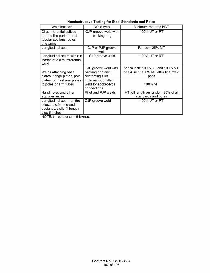
Contract No. 08-1C8504 107 of 196
Nondestructive Testing for Steel Standards and Poles Weld location Weld type Minimum required NDT
Circumferential splices around the perimeter of tubular sections, poles, and arms
CJP groove weld with backing ring
100% UT or RT
Longitudinal seam CJP or PJP groove weld
Random 25% MT
Longitudinal seam within 6 inches of a circumferential weld
CJP groove weld 100% UT or RT
Welds attaching base plates, flange plates, pole
CJP groove weld with backing ring and reinforcing fillet
t≥ 1/4 inch: 100% UT and 100% MT t< 1/4 inch: 100% MT after final weld
pass plates, or mast arm plates to poles or arm tubes
External (top) fillet weld for socket-type connections
100% MT
Hand holes and other appurtenances
Fillet and PJP welds MT full length on random 25% of all standards and poles
Longitudinal seam on the telescopic female end, designated slip-fit length plus 6 inches
CJP groove weld 100% UT or RT
NOTE: t = pole or arm thickness
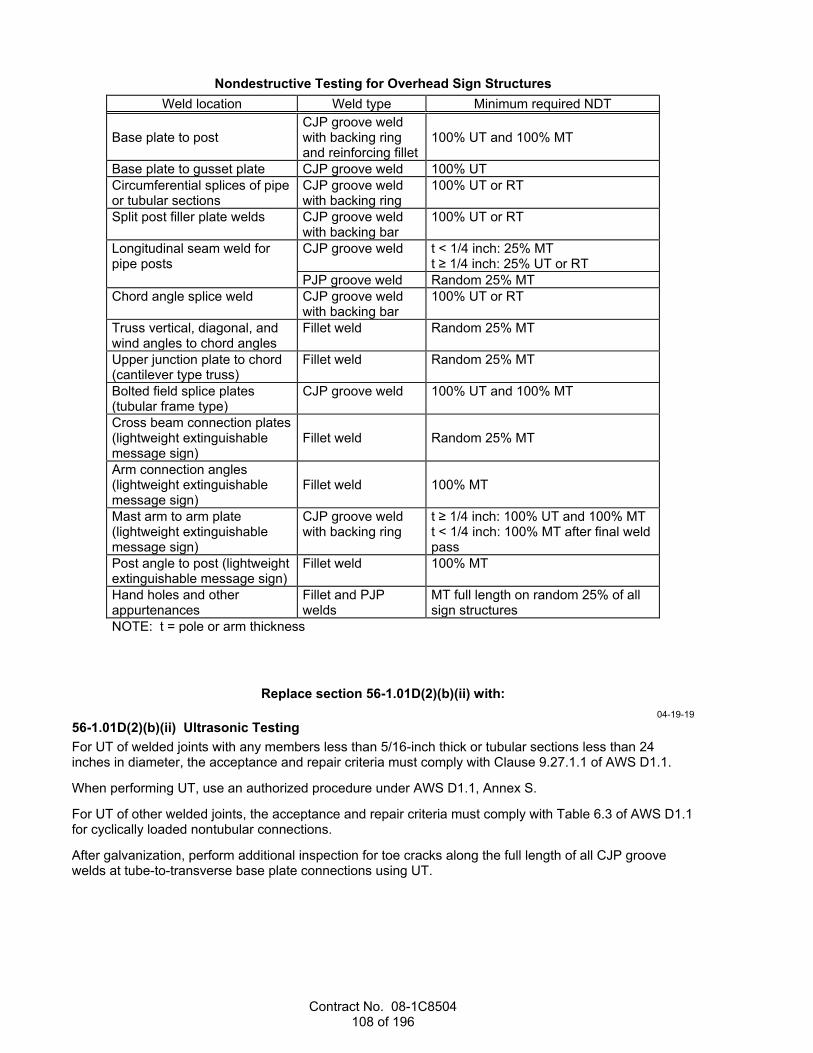
Contract No. 08-1C8504 108 of 196
Nondestructive Testing for Overhead Sign Structures Weld location Weld type Minimum required NDT
Base plate to post
CJP groove weld with backing ring and reinforcing fillet
100% UT and 100% MT
Base plate to gusset plate CJP groove weld 100% UT
Circumferential splices of pipe or tubular sections
CJP groove weld with backing ring
100% UT or RT
Split post filler plate welds CJP groove weld with backing bar
100% UT or RT
Longitudinal seam weld for pipe posts
CJP groove weld t < 1/4 inch: 25% MT t ≥ 1/4 inch: 25% UT or RT
PJP groove weld Random 25% MT
Chord angle splice weld CJP groove weld with backing bar
100% UT or RT
Truss vertical, diagonal, and wind angles to chord angles
Fillet weld Random 25% MT
Upper junction plate to chord (cantilever type truss)
Fillet weld Random 25% MT
Bolted field splice plates (tubular frame type)
CJP groove weld 100% UT and 100% MT
Cross beam connection plates (lightweight extinguishable message sign)
Fillet weld
Random 25% MT
Arm connection angles (lightweight extinguishable message sign)
Fillet weld
100% MT
Mast arm to arm plate (lightweight extinguishable message sign)
CJP groove weld with backing ring
t ≥ 1/4 inch: 100% UT and 100% MT t < 1/4 inch: 100% MT after final weld pass
Post angle to post (lightweight extinguishable message sign)
Fillet weld 100% MT
Hand holes and other appurtenances
Fillet and PJP welds
MT full length on random 25% of all sign structures
NOTE: t = pole or arm thickness
Replace section 56-1.01D(2)(b)(ii) with: 04-19-19
56-1.01D(2)(b)(ii) Ultrasonic Testing For UT of welded joints with any members less than 5/16-inch thick or tubular sections less than 24 inches in diameter, the acceptance and repair criteria must comply with Clause 9.27.1.1 of AWS D1.1.
When performing UT, use an authorized procedure under AWS D1.1, Annex S.
For UT of other welded joints, the acceptance and repair criteria must comply with Table 6.3 of AWS D1.1 for cyclically loaded nontubular connections.
After galvanization, perform additional inspection for toe cracks along the full length of all CJP groove welds at tube-to-transverse base plate connections using UT.
Contract No. 08-1C8504 109 of 196
Replace section 56-2.02F with: 04-17-20
56-2.02F Pipe Posts Pipe posts must be welded or seamless steel pipes. The maximum ultimate tensile strength of pipe posts must not exceed 90 ksi. Manufactured pipe posts must comply with one of the following:
1. ASTM A53/A53M, Grade B 2. ASTM A106/A106M, Grade B 3. ASTM A1085, Grade A 4. API Specification 5L PSL2 Grades B, X42R, X42M, X52M or Grade X52N, using nominal pipe sizes
for threaded end pipe You may fabricate pipe posts from structural steel complying with ASTM A36/A36M, ASTM A709/A709M, Grade 36, or ASTM A572/A572M, Grades 42 or 50.
Spiral seam welds are not allowed.
^^^^^^^^^^^^^^^^^^^^^^^^^^^^^^^^^^^^^^^^
57 WOOD AND PLASTIC LUMBER STRUCTURES 10-18-19
Add to section 57-2.02B: 04-19-19
HDPE shims must be commercial quality.
Replace section 57-2.02C with: 10-18-19
57-2.02C Construction Install lagging members 4 inches thick or less with a 3/8-inch gap between members. Install lagging members greater than 4 inches thick with a 1/2-inch gap between members.

Contract No. 08-1C8504 110 of 196
Replace the table in the 4th paragraph of section 57-3.02C with: 10-19-18
Quality characteristic Test method Requirement Density of concrete core (kg/m3, min)
ASTM D792 1,762
28-day compressive strength of concrete core (psi, min)
ASTM C579 5,000
Structural strength of shell: Tensile strength, tensile modulus (percent loss) Flexural strength, flexural modulus (percent loss)
ASTM D638
ASTM D790
Less than 10 after UV
deterioration test specified for plastic lumber
Dry film thickness of coating (mils, min)
-- 15
Color change of coating ASTM D4587, Test Cycle 2
No visible color change when tested for 800 hours
Initial adhesion of coating (psi, min) ASTM D4541, Test Method D,
E, or F and Protocol 2
150
Decrease in initial adhesion of coating, decrease (percent)
ASTM D4541, Test Method D,
E, or F and Protocol 2
ASTM D1183, Test Condition Da
No more than 10 following 2 exposure cycles
aUse a low temperature phase at 4 ± 5 °F and high temperature phase at 140 ± 5 °F.
^^^^^^^^^^^^^^^^^^^^^^^^^^^^^^^^^^^^^^^^
59 STRUCTURAL STEEL COATINGS 10-19-18
Replace the 2nd paragraph in section 59-1.01D with: 10-19-18
Measure coating adhesion strength with a self-aligning adhesion tester under ASTM D4541, Test Method D, E, or F and Protocol 2.
Replace the 2nd paragraph of section 59-1.02C with: 10-19-18
Coatings selected for use must comply with the volatile organic compound concentration limits specified for the air quality district where the coating is applied. The undercoats and finish or final coats selected for use must be compatible with each other.
Add after the paragraph of section 59-2.01A(3)(a): 10-19-18
If requested by the Engineer, submit documentation from the coating manufacturer verifying the compatibility of the undercoats and finish or final coats selected for use.
^^^^^^^^^^^^^^^^^^^^^^^^^^^^^^^^^^^^^^^^
Contract No. 08-1C8504 111 of 196
60 EXISTING STRUCTURES 10-18-19
Replace section 60-2.02B with: 04-19-19
60-2.02B Materials Design criteria for temporary support shoring and temporary bracing must comply with section 48-3.02B.
Add to section 60-3.01A: 10-19-18
If you are unable to complete bridge reconstruction activities before the bridge is to be opened to traffic, furnish and maintain temporary decking under section 48-4 until that portion of the work is complete.
Replace the 3rd and 4th paragraphs of section 60-3.02C(3) with: 04-19-19
Remove asphalt concrete surfacing by cold milling under the following conditions:
1. If a membrane seal is shown: 1.1. Remove the seal by cold milling 1.2. Do not remove more than 1/2 inch of the existing concrete slab
2. If a membrane seal is not shown: 2.1. Remove asphalt concrete surfacing until a 1/2-inch minimum of surfacing remains on top of
existing concrete slab 2.2. Use other authorized means to remove the remaining asphalt concrete without damage to the
concrete slab
Add to section 60-3.02C(3): 04-19-19
Where a portion of the asphalt concrete surfacing is to remain, saw cut a 2-inch-deep true line along the edge to remain in place before removing asphalt concrete. Remove the asphalt concrete without damaging the surfacing to remain in place.
04-19-19 Delete the 3rd paragraph of section 60-3.04B(3)(a).
Replace the 9th paragraph of section 60-3.04B(3)(c) with: 04-19-19
Protect the overlay from moisture and do not allow traffic or equipment on the overlay (1) for a minimum of 4 hours cure time after final finishing and (2) until each rebound test result for the final finish shows a reading of at least 28 when tested under ASTM C805. The cure time must be extended if ordered. The rebound test may not be used to reduce the 4-hour cure time of the overlay.
Replace the 10th paragraph of section 60-4.09B(2)(a) with: 10-19-18
Steel parts must comply with ASTM A36/A36M or A576, Grade 1030 and must not be rimmed or capped steel.

Contract No. 08-1C8504 112 of 196
Replace section 60-4.10 with: 10-18-19
60-4.10 BRIDGE SEAT EXTENDERS FOR RETROFITS 60-4.10A General 60-4.10A(1) Summary Section 60-4.10 includes specifications for fabricating and installing bridge seat extenders.
Bridge seat extenders must comply with the specifications for miscellaneous bridge metal in section 75-3.
60-4.10A(2) Definitions Reserved
60-4.10A(3) Submittals Submit a work plan showing the method of grouting pipe seat extenders to prevent grout from entering the hinge area.
60-4.10A(4) Quality Assurance Inspect bridge seat extender materials at the fabrication site.
Notify the Engineer:
1. When materials have been delivered to the fabrication site 2. At least 10 days before starting fabrication 60-4.10B Materials 60-4.10B(1) General Reserved
60-4.10B(2) Pipe Seat Extenders Pipe seat extenders must consist of double extra-strong steel pipes, HS threaded rods, nuts, and washers.
Double-extra strong steel pipe must comply with ASTM A53/A53M, Grade B. HS threaded rods, nuts, and washers must comply with section 55-1.02D(1).
Galvanize double-extra strong steel pipe under section 75-1.02B. After galvanizing, any alterations resulting in new exposed surfaces, including holes or cut ends, must be coated as specified for repairing damaged galvanized surfaces under section 75-1.02B.
Grout for bonding the pipe to the cored hole must comply with section 60-4.06B(2). Any filler materials or seals must not restrict joint movement.
60-4.09B(3) Slab Bridge Seat Extenders Slab bridge seat extenders must consist of steel plates, support tubes, bolts, bars, nuts, washers, pins, and elastomeric bearing pads.
Slab bridge seat extender must comply with section 55. Elastomeric bearing pads must comply with section 51-3.02. The support tubes must comply with ASTM A500/A500M, Grade B.
Galvanize seat extender under section 75-1.02B. After galvanizing, any alterations resulting in new exposed surfaces, including holes or cut ends, must be coated as specified for repairing damaged galvanized surfaces under section 75-1.02B.
Epoxy mortar must consist of a mixture of epoxy binder and aggregate. The epoxy mortar must comply with section 95-1.02C. The mix proportions of epoxy mortar must be 1-part binder to 1-part aggregate by volume. Aggregate must consist of a combination of 1-part material passing the no. 30 sieve and 3-parts material passing the no. 20 sieve.

Contract No. 08-1C8504 113 of 196
60-4.10C Construction 60-4.10C(1) General Reserved.
60-4.10C(2) Pipe Seat Extenders Reserved
60-4.10C(3) Slab Bridge Seat Extenders Place epoxy mortar under section 95-1.03.
Place elastomeric bearing pads under section 51-3.02C. Bond elastomeric bearing pads to steel support tubes with adhesive complying with Federal Specification MMM-A-121.
60-4.10D Payment The payment quantity for seat extender does not include the weight of nonmetallic materials used in constructing the seat extenders.
^^^^^^^^^^^^^^^^^^^^^^^^^^^^^^^^^^^^^^^^^^^^^^^^^^^^^^^^^^^^
DIVISION VII DRAINAGE FACILITIES Replace section 62 with:
04-17-20
62 STORMWATER TREATMENT 04-17-20
62-1 GENERAL 62-1.01 GENERAL 62-1.01A Summary Section 62-1 includes general specifications for constructing permanent stormwater treatment best management practices.
Earthwork must comply with section 19.
Concrete and joint seals must comply with section 51.
Sealant must comply with section 41-5.
Reinforcement must comply with section 52.
Underdrain must comply with section 68-2.
Miscellaneous metal must comply with section 75.
Cable railing must comply with section 83-2.07.
62-1.01B Definitions Reserved62-1.01C Submittals At least 5 business days before placing permeable material, submit a certificate of compliance for the gradation of the material from the source.
No more than 5 business days after placing permeable material, submit:
1. At least one ASTM D6913 test on permeable material sampled at: 1.1. Job site 1.2. Authorized location
2. Verification that the permeable materials testing results meet the gradation requirements
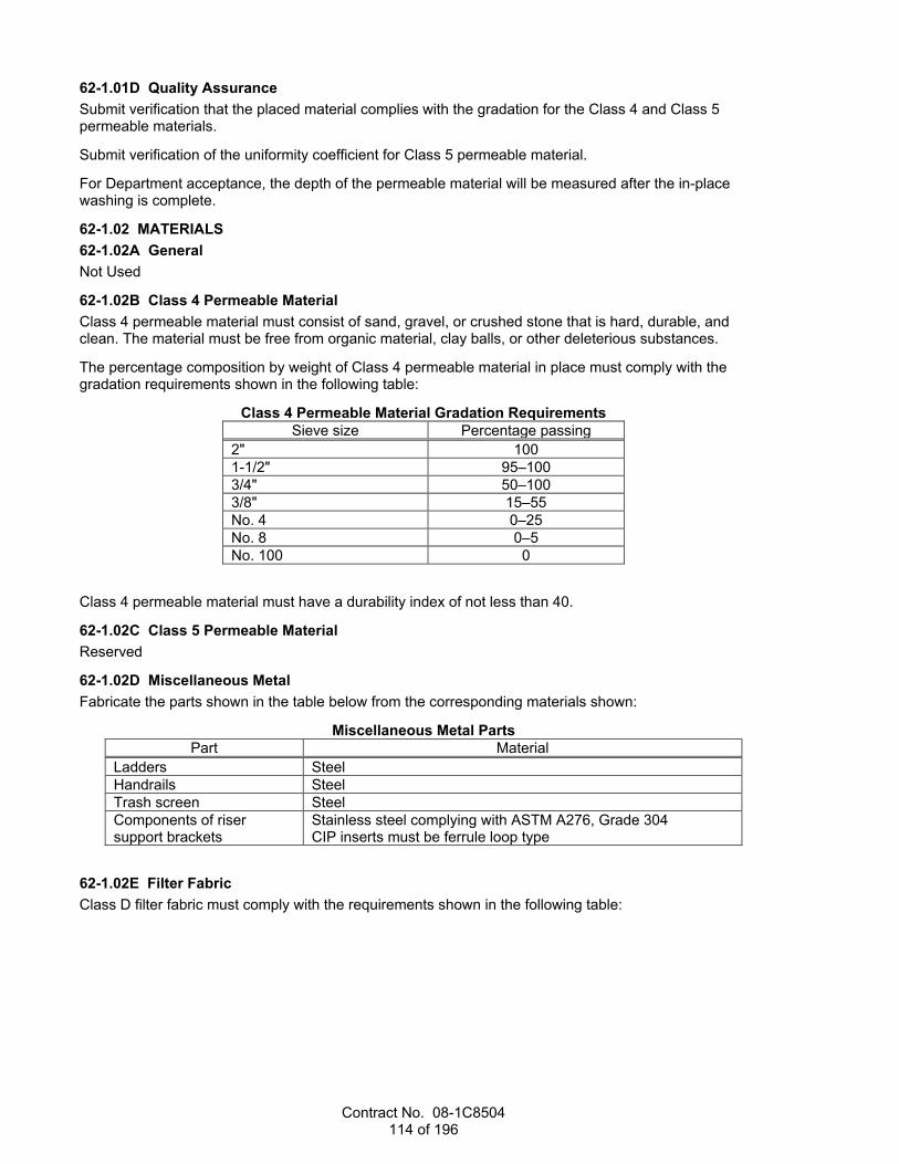
Contract No. 08-1C8504 114 of 196
62-1.01D Quality Assurance Submit verification that the placed material complies with the gradation for the Class 4 and Class 5 permeable materials.
Submit verification of the uniformity coefficient for Class 5 permeable material.
For Department acceptance, the depth of the permeable material will be measured after the in-place washing is complete.
62-1.02 MATERIALS 62-1.02A General Not Used
62-1.02B Class 4 Permeable Material Class 4 permeable material must consist of sand, gravel, or crushed stone that is hard, durable, and clean. The material must be free from organic material, clay balls, or other deleterious substances.
The percentage composition by weight of Class 4 permeable material in place must comply with the gradation requirements shown in the following table:
Class 4 Permeable Material Gradation Requirements Sieve size Percentage passing
2" 100 1-1/2" 95–100 3/4" 50–100 3/8" 15–55 No. 4 0–25 No. 8 0–5 No. 100 0
Class 4 permeable material must have a durability index of not less than 40.
62-1.02C Class 5 Permeable Material Reserved
62-1.02D Miscellaneous Metal Fabricate the parts shown in the table below from the corresponding materials shown:
Miscellaneous Metal Parts Part Material
Ladders Steel Handrails Steel Trash screen Steel Components of riser support brackets
Stainless steel complying with ASTM A276, Grade 304 CIP inserts must be ferrule loop type
62-1.02E Filter Fabric Class D filter fabric must comply with the requirements shown in the following table:
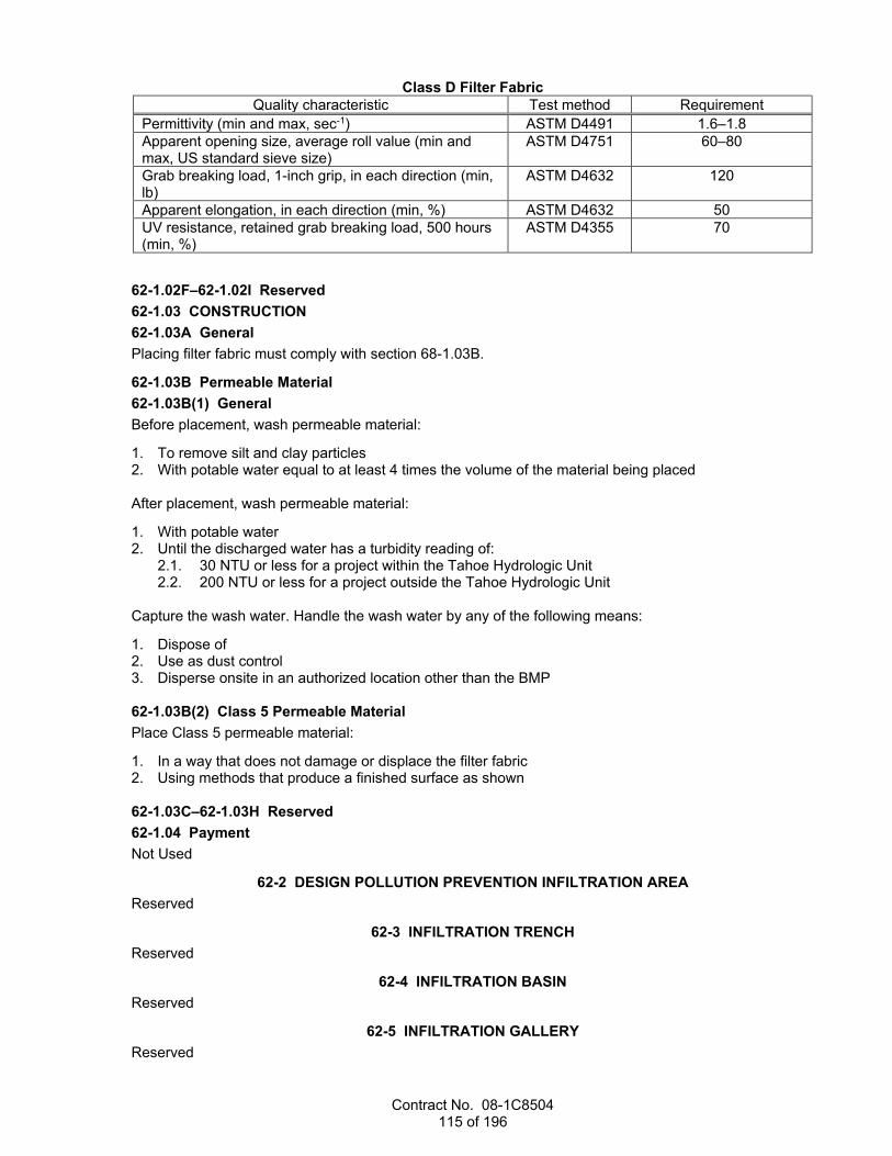
Contract No. 08-1C8504 115 of 196
Class D Filter Fabric Quality characteristic Test method Requirement
Permittivity (min and max, sec-1) ASTM D4491 1.6–1.8 Apparent opening size, average roll value (min and max, US standard sieve size)
ASTM D4751 60–80
Grab breaking load, 1-inch grip, in each direction (min, lb)
ASTM D4632 120
Apparent elongation, in each direction (min, %) ASTM D4632 50 UV resistance, retained grab breaking load, 500 hours (min, %)
ASTM D4355 70
62-1.02F–62-1.02I Reserved 62-1.03 CONSTRUCTION 62-1.03A General Placing filter fabric must comply with section 68-1.03B.
62-1.03B Permeable Material 62-1.03B(1) General Before placement, wash permeable material:
1. To remove silt and clay particles 2. With potable water equal to at least 4 times the volume of the material being placed After placement, wash permeable material:
1. With potable water 2. Until the discharged water has a turbidity reading of:
2.1. 30 NTU or less for a project within the Tahoe Hydrologic Unit 2.2. 200 NTU or less for a project outside the Tahoe Hydrologic Unit
Capture the wash water. Handle the wash water by any of the following means:
1. Dispose of 2. Use as dust control 3. Disperse onsite in an authorized location other than the BMP 62-1.03B(2) Class 5 Permeable Material Place Class 5 permeable material:
1. In a way that does not damage or displace the filter fabric 2. Using methods that produce a finished surface as shown 62-1.03C–62-1.03H Reserved 62-1.04 Payment Not Used
62-2 DESIGN POLLUTION PREVENTION INFILTRATION AREA Reserved
62-3 INFILTRATION TRENCH Reserved
62-4 INFILTRATION BASIN Reserved
62-5 INFILTRATION GALLERY Reserved

Contract No. 08-1C8504 116 of 196
62-6 RESERVED 62-7 BIORETENTION
Reserved
62-8 DETENTION BASIN Reserved
62-9 AUSTIN EARTH BERM Reserved
62-10 AUSTIN VAULT SAND FILTER Reserved
62-11 DELAWARE SAND FILTER Reserved
62-12 GROSS SOLIDS REMOVAL DEVICE Reserved
62-13 MULTI-CHAMBER TREATMENT TRAIN Reserved
62-14 TRACTION SAND TRAP Reserved
62-15–62-24 RESERVED 62-25 EXISTING STORMWATER TREATMENT
Reserved
^^^^^^^^^^^^^^^^^^^^^^^^^^^^^^^^^^^^^^^^ 64 PLASTIC PIPE
04-17-20 Add to section 64-2.01C:
04-17-20 If recycled resin is used for corrugated polyethylene pipe, submit the percent of recycled resin.
Replace the 2nd and 3rd paragraphs of section 64-2.02C with: 04-17-20
Type C and Type S corrugated polyethylene pipe must comply with AASHTO M 294.
HDPE compounds used in the manufacture of corrugated polyethylene pipe and fittings must comply with AASHTO M 294 except the mix must contain from 2 to 4 percent well-dispersed carbon black and at least 49 percent virgin resin.
^^^^^^^^^^^^^^^^^^^^^^^^^^^^^^^^^^^^^^^^
66 CORRUGATED METAL PIPE 10-19-18
Replace the 1st paragraph in section 66-1.02D with: 10-19-18
Coupling bands for corrugated metal pipe must comply with either section 66-1.02D or section 61-2.01D(2)(b).

Contract No. 08-1C8504 117 of 196
Replace the 6th paragraph in section 66-1.02D with: 10-19-18
Joints for siphons and joints for pipes shown as watertight must be watertight under pressure and all conditions of expansion, contraction, and settlement, and must comply with section 61-2.01D(2)(a) for watertightness.
Replace the 4th paragraph of section 66-2.03 with: 10-19-18
Place cement treated structure backfill for slotted corrugated steel pipe as shown and under section 19-3.02F(3) for soil cement beddings. Cover the completed cement treated structure backfill with a curing seal of asphaltic emulsion, Grade SS1 or CSS1.
^^^^^^^^^^^^^^^^^^^^^^^^^^^^^^^^^^^^^^^^
71 EXISTING DRAINAGE FACILITIES 04-17-20
Replace section 71-3.01A(4)(b) with: 04-17-20
71-3.01A(4)(b) Preconstruction Meetings 71-3.01A(4)(b)(i) General Reserved
71-3.01A(4)(b)(ii) Prerehabilitation Meeting Before starting cleaning and preparation work, you must schedule and attend a prerehabilitation meeting with the Engineer. Include any subcontractors, manufacturers and other parties involved in the culvert work. Provide a meeting facility that is within 5 miles of the job site or at another location accepted by the Engineer.
71-3.01A(4)(b)(iii) Pregrouting Meeting Before starting grouting work, you must schedule and conduct a grouting meeting with the Engineer and your personnel involved in the grouting work, including your:
1. Project superintendent 2. Supervisory personnel 3. Grouting foreman 4. Grouting subcontractors Provide a meeting facility that is within 5 miles of the job site or at another location accepted by the Engineer.
Replace section 71-3.01A(4)(c) with: 04-17-20
71-3.01A(4)(c) Quality Control 71-3.01A(4)(c)(i) General Reserved
71-3.01A(4)(c)(ii) Annular Space Grouting The grout cast density at the point of placement must be from 53 to 68 lb/cu ft and the minimum compressive strength must be 300 psi at 28 days.

Contract No. 08-1C8504 118 of 196
Test the grout for compressive strength under ASTM C495 except that specimens must be moist cured before the 28-day compressive strength test and not be oven dried. If the grouting plan shows multiple stages, the grouting plan must include test results that verify that the grout stiffness is adequate for placement of multiple lifts.
For each batch of grout, perform density and viscosity tests under ASTM C138 and ASTM C939 in the presence of the Engineer. Grout density must be within 3 lb/cu ft of the density in the authorized grout plan with mix design. The time of efflux (outflow) must not exceed 20 seconds as specified in ASTM C939 unless otherwise authorized.
For pipeliners with a stiffness of less than 29 psi, the grout pump's pressure measured at the point of injection must not exceed either of the following:
1. 5 psi 2. Manufacturer's instruction For pipeliners with a stiffness of at least 29 psi, the grout pump's pressure measured at the point of injection must not exceed 7.25 psi.
The pipeliner must be able to withstand a static head of grout that is 6 inches above the highest crown elevation. The maximum grout pressure for a static grout head must not exceed the grout pump's maximum allowable pressure.
Install a grout pressure gauge and recorder immediately adjacent to each injection port. Continuously record on paper with ink the actual grouting pressure versus time. Record grout pressure to an accuracy of ±0.5 psi. Attach a gauge to a saddle-type diaphragm seal to prevent clogging with grout.
71-3.01A(4)(c)(iii) CCTV Recording CCTV recordings must be made and submitted in high quality electronic media such as CD or DVD.
The CCTV equipment must include:
1. CCTV camera with articulating head 2. Transporter adapted for conditions of the culvert 3. Television monitor 4. Lighting 5. Cables and power sources CCTV equipment must:
1. Be specifically designed and constructed for pipe inspection 2. Have camera lighting for minimizing reflective glare 3. Have an adjustable focal-distance range from 6 inches to infinity 4. Produce a minimum resolution of 356 lines per inch for both the camera and monitor 5. Have a remote-reading meter counter accurate to 1 percent over the length of the particular section
being inspected Verify the accuracy of the distance meter in the CCTV with a walking meter, roll-a-tape, or other authorized device.
Where human entry is possible for the entire length of the culvert, you may use a handheld video camera with lighting as an alternative to CCTV. Video and audio content must comply with the requirements for CCTV. Inspect at a rate that is not more than 30 feet per minute.
71-3.01A(4)(c)(iv) Photographs Use a digital camera and lighting. Lighting and photo quality must be suitable to provide clear and focused photographs of the entire culvert surface under all conditions.
71-3.01A(4)(c)(v) Monitoring of Annular Space Grouting Wherever a pipeliner with annular space grouting is described, monitor the grouting and record pressures throughout the grouting process. Verify compliance with the manufacturer's instructions for each phase of

Contract No. 08-1C8504 119 of 196
the grouting process. Gauges must comply with ANSI B40, Grade 2A. The pressure gauges, recorder, and field equipment must be calibrated by an independent testing agency.
71-3.01A(4)(c)(vi) Pipeliners Pipeliners must be continuous over the entire length of the culvert and must have no visual defect such as foreign inclusions, concentrated ridges, discoloration, pitting, pin holes, cracking or other deformities. The pipeliner must not be over-deflected. There must not be segregation or voids in the grout.
71-3.01A(4)(c)(vii) Deflection Testing of Pipeliners If a pipeliner with annular space grouting is described, test the pipeliner for deflection. Test after grouting and in the presence of the Engineer.
For pipeliners with a nominal inside diameter of 36 inches or less, either pull a mandrel through the pipeliner by hand or use another authorized method. The mandrel must be:
1. Rigid and nonadjustable 2. Comprised of at least 9 legs and have an odd number of total legs 3. Longer than it is wide 4. Made of steel 5. Fitted with pulling rings at each end 6. Stamped or engraved on some segment other than a runner indicating pipeliner material
specification, nominal size, and mandrel outside diameter (e.g., HDPE F 714-SDR 26- 36" – 31.569") 7. Furnished in a suitable carrying case labeled with the same data as stamped on the mandrel 8. Authorized before use For pipeliners with a nominal inside diameter greater than 36 inches, determine the deflection using a 1-inch diameter, rigid, nonadjustable metal bar; a minimum-radius rigid template; or other authorized method.
The pipeliner must not be over-deflected. For pipeliners 36 inches or less in nominal diameter, the mandrel must pass through the entire pipeliner. For pipeliners greater than 36 inches in nominal diameter, the deflection must be the lesser of either of the following:
1. 5 percent greater than the actual dimension of the pipeliner in place. This actual dimension includes the pipe joint system.
2. 6-1/2 percent of the nominal pipeliner dimension. If more than 8 percent of the nominal pipeliner dimension is over-deflected, the pipeliner is rejected. If 8 percent or less of the nominal pipeliner dimension is over-deflected, the pipeliner may remain in place and the Department deducts 20 percent of the bid amount for that pipeliner.
Replace item 2 in the list in the first paragraph of section 71-3.01B(2) with: 04-17-20
2. Not less than 590 lb of cementitious material per cubic yard
Replace section 71-5.03B with: 04-17-20
71-5.03B Frames, Covers, and Grates Adjust frames, covers, and grates must comply with section 78-23.03.
04-17-20 Delete the 2nd through 5th paragraphs of section 71-5.04.

Contract No. 08-1C8504 120 of 196
^^^^^^^^^^^^^^^^^^^^^^^^^^^^^^^^^^^^^^^^^^^^^^^^^^^^^^^^^^^^
DIVISION VIII MISCELLANEOUS CONSTRUCTION 73 CONCRETE CURBS AND SIDEWALKS
04-17-20 Replace the 3rd paragraph of section 73-1.02A with:
04-17-20 Preformed expansion joint filler must comply with ASTM D1751. As an alternative, a semi-rigid, closed-cell polypropylene foam, preformed joint filler that complies with ASTM D8139 may be used.
Replace the paragraph of section 73-1.02B with: 04-17-20
Detectable warning surface must be on the Authorized Material List for detectable warning surfaces and must match yellow color no. 33538 of AMS-STD-595.
^^^^^^^^^^^^^^^^^^^^^^^^^^^^^^^^^^^^^^^^
75 MISCELLANEOUS METAL 04-17-20
Replace the last paragraph in section 75-3.02B with: 10-18-19
Thread-locking systems must (1) consist of a cleaner, primer, and anaerobic thread-locking adhesive and (2) be on the Authorized Material List for anaerobic thread-locking systems. Apply all components of the system under the manufacturer's instructions.
04-17-20 Delete the 3rd paragraph of section 75-3.02C(2).
Replace section 75-3.02C(3) with: 04-17-20
75-3.02C(3) Resin Capsule Anchors Reserved
04-17-20 Delete the 3rd paragraph of section 75-3.02C(4).
^^^^^^^^^^^^^^^^^^^^^^^^^^^^^^^^^^^^^^^^

Contract No. 08-1C8504 121 of 196
78 INCIDENTAL CONSTRUCTION 04-17-20
Replace section 78-4.03 with: 04-19-19
78-4.03 PAINTING CONCRETE 78-4.03A General 78-4.03A(1) Summary Section 78-4.03 includes specifications for preparing and painting concrete surfaces.
78-4.03A(2) Definitions Reserved
78-4.03A(3) Submittals Submit the coating manufacturer's application instructions at least 7 days before use.
78-4.03A(4) Quality Assurance Reserved
78-4.03B Materials Coatings for concrete must comply with the specifications for acrylic emulsion paint for exterior masonry in section 91-4.02B.
Coatings must be white.
78-4.03C Construction 78-4.03C(1) General Reserved
78-4.03C(2) Surface Preparation Before painting, surfaces must be:
1. At least 28 days old. 2. Prepared under SSPC-SP 13/NACE no. 6. Pressure rinse the prepared surfaces before applying the
paint. 3. Thoroughly dry. You may use artificial drying methods if authorized. 78-4.03C(3) Application Apply at least 2 coats under the manufacturer's instructions and SSPC-PA 7. Protect adjacent surfaces during painting using an authorized method.
78-4.03D Payment Not Used
Replace section 78-4.04 with: 04-19-19
78-4.04 STAINING CONCRETE AND SHOTCRETE 78-4.04A General 78-4.04A(1) Summary Section 78-4.04 includes specifications for preparing and staining concrete and shotcrete surfaces.
78-4.04A(2) Definitions acid stain: non-tintable, transparent stain that contains dilute acid.
water-based stain: semi-transparent or solid water-based coating in an acrylic emulsion vehicle, that can be tinted to match an AMS-STD-595 color.

Contract No. 08-1C8504 122 of 196
78-4.04A(3) Submittals 78-4.04A(3)(a) General Submit the stain and sealer manufacturer's product data and application instructions at least 7 days before starting staining activities.
78-4.04A(3)(b) Contractor Qualifications Submit the following documentation at least 10 days before the prestaining meeting:
1. Summary of the staining contractor's experience that demonstrates compliance with section 78-4.04A(4)(c).
2. List of at least 3 projects completed in the last 5 years that demonstrate the staining contractor's ability to stain surfaces similar to the surfaces for this project. For each project include: 2.1. Project description 2.2. Name and phone number of the owner 2.3. Staining completion date 2.4. Color photos of the completed stained surface
78-4.04A(3)(c) Staining Quality Work Plan Submit a staining quality work plan at least 10 days before the prestaining meeting. The work plan must include details for preparing and staining the surfaces to achieve the required color, and for sealing the surfaces, including:
1. Number of applications that will be used to apply the stain 2. For each application of the stain, a description of:
2.1. Manufacturer, color, finish, and percentage strength mixture of the stain that will be applied 2.2. Proposed methods and tools for applying the stain
3. Proposed methods for protecting adjacent surfaces during staining 4. Proposed methods and tools for applying the sealer For acid stains, the work plan must also include a rinse water collection plan for containing all liquid, effluent, and residue resulting from preparing and staining the surfaces.
78-4.04A(4) Quality Assurance 78-4.04A(4)(a) General Reserved
78-4.04A(4)(b) Test Panels Stain the authorized test panel complying with section 51-1.01D(2)(c) or section 53-3.01D(3).
The test panel must be:
1. Stained using the same personnel, materials, equipment, and methods to be used in the work 2. Accessible for viewing 3. Displayed in an upright position near the work 4. Authorized for staining before starting the staining work If ordered, construct additional test panels until a satisfactory color is attained. The preparing and staining of additional test panels is change order work.
The Engineer uses the authorized stained test panel to determine the acceptability of the stained surface.
Dispose of the test panels after the staining work is complete and authorized. Notify the Engineer before disposing of the test panels.
78-4.04A(4)(c) Contractor Qualifications The staining contractor must have experience staining surfaces to simulate the appearance of natural rock formations or stone masonry, and must have completed at least 3 projects in the past 5 years involving staining of surfaces similar to the surfaces for this project.

Contract No. 08-1C8504 123 of 196
78-4.04A(4)(d) Prestaining Meeting Before starting staining activities, conduct a meeting to discuss the staining quality work plan. Meeting attendees must include the Engineer and all staining contractors.
78-4.04B Materials 78-4.04B(1) General Reserved
78-4.04B(2) Stain 78-4.04B(2)(a) General The stain must be:
1. Commercially available product designed specifically for exterior applications 2. Specifically manufactured for staining concrete surfaces 78-4.04B(2)(b) Acid Stain Acid stain must:
1. Contain dilute acid that penetrates and etches the surfaces 2. Be a water-based solution of inorganic metallic salts 3. Produce abrasion-resistant color deposits 78-4.04B(2)(c) Water-based Stain Water-based stain must be:
1. Acrylic emulsion 2. Non-fading and UV resistant 3. Capable of producing irregular, mottled tones 78-4.04B(3) Sealer The sealer must be as recommended by the stain manufacturer, clear and colorless, and have a matte finish when dry.
78-4.04B(4) Joint Sealing Compound Reserved
78-4.04C Construction 78-4.04C(1) General At locations where there is exposed metal adjacent to the surfaces to be stained, seal the joint between the surfaces to be stained and the exposed metal with a joint sealing compound before applying the stain.
78-4.04C(2) Surface Preparation Test surfaces for acceptance of the stain before applying the stain. Clean surfaces that resist accepting the stain and retest until passing.
Before staining, the surfaces must be:
1. At least 28 days old 2. Prepared under SSPC-SP 13/NACE no. 6 3. Thoroughly dry 78-4.04C(3) Application 78-4.04C(3)(a) General Apply the stain under the manufacturer's instructions. Protect adjacent surfaces during staining. Drips, puddles, or other irregularities must be worked into the surface.
Apply the sealer under the manufacturer's instructions.
Contract No. 08-1C8504 124 of 196
78-4.04C(3)(b) Acid Stain Work the acid stain into the concrete using a nylon bristle brush in a circular motion.
After the last coat of stain has dried, rinse the stained surfaces with water and wet scrub them with a stiff-bristle nylon brush until the rinse water runs clear. Collect all rinse water.
78-4.04D Payment Not Used
Replace section 78-23 with: 04-17-20
78-23 ADJUST UTILITY FRAMES, COVERS, AND MANHOLES 78-23.01 GENERAL Section 78-23 includes specifications for adjusting utility access box frames, covers, and manholes.
Work performed on existing utility frames, covers, grates and manholes must comply with section 15.
78-23.02 MATERIALS Not Used
78-23.03 CONSTRUCTION Lower and raise utility frames, covers, grates and manholes by lowering before cold planing and raising after paving or surfacing. Before opening the lane to traffic, either (1) complete permanent paving or surfacing or (2) temporarily fill any depressions with HMA.
Do not adjust to final grade until the adjacent pavement or surfacing is complete.
For a structure that is to be raised, remove the cover or frame and trim the top of the structure to provide a suitable foundation for the new material.
Instead of using new materials similar in character to those in the existing structure, you may use raising devices to adjust a manhole to grade. Before starting paving work, measure and fabricate raising devices. Raising devices must:
1. Comply with the specifications for section 75 except that galvanizing is not required 2 Have a shape and size that matches the existing frame 3. Be match marked by painting identification numbers on the device and corresponding structure 4. Result in an installation that is equal to or better than the existing one in stability, support, and
nonrocking characteristics 5. Be fastened securely to the existing frame without projections above the surface of the road or into
the clear opening Where manholes are to be lowered, remove the top portion to 3.5 feet below finished grade or to an authorized depth. Adjust the manhole using the taper needed to match the finished grade.
If a manhole cover is unstable or noisy under traffic, place a coil of asphalt-saturated rope, a plastic washer, or asphaltic compound on the cover seat. Before placement, obtain authorization for use of the material.
78-23.04 PAYMENT Not Used
^^^^^^^^^^^^^^^^^^^^^^^^^^^^^^^^^^^^^^^^
Contract No. 08-1C8504 125 of 196
80 FENCES 10-18-19
Replace the 1st paragraph of section 80-2.02B with: 10-18-19
Line posts must comply with ASTM A702 except packaging of posts is not required. You may omit the anchor plate if the post is set in a concrete footing with a minimum cross-sectional dimension of 6 inches and a depth equal to the full penetration of the post.
Replace item 3 in the list in the 1st paragraph of section 80-2.02D with: 10-18-19
3. Be one of the following: 3.1. 12-1/2 gauge, Class 3 3.2. 13-1/2 gauge, Class 3 3.3. 14 gauge, Class 3 3.4. 15-1/2 gauge, Class 3
Replace the 2nd paragraph of section 80-3.02B with: 10-19-18
Posts and braces must comply with the strength requirements in ASTM F1043 for one of the following:
1. Group IA, regular grade, for round pipes 2. Group IC, 50,000 psi yield, for round pipes 3. Group II-L for roll-formed posts and braces
Replace the list in section 80-4.02B(1)(b) with: 10-19-18
1. Comply with ASTM A1064 and have a Class 1 zinc coating complying with ASTM A641 2. Be welded or woven galvanized steel wire fabric 3. Be made of at least 16-gauge wire 4. Be 36 inches wide
Replace the paragraph in section 80-4.02B(2) with: 10-19-18
The materials for a temporary desert tortoise fence must comply with section 80-4.02B(1).
Replace the 2nd sentence in the 1st paragraph of section 80-4.02C(2) with: 10-19-18
Embed the posts at maximum 10-foot intervals into the ground.
^^^^^^^^^^^^^^^^^^^^^^^^^^^^^^^^^^^^^^^^^^^^^^^^^^^^^^^^^^^^
Contract No. 08-1C8504 126 of 196
DIVISION IX TRAFFIC CONTROL DEVICES 82 SIGNS AND MARKERS
04-17-20 Replace the list in the 1st paragraph of section 82-2.01C with:
04-19-19 1. Aluminum sheeting 2. Retroreflective sheeting 3. Color imaging methods and film 4. Protective-overlay film
Replace section 82-2.02C with: 04-17-20
82-2.02C Retroreflective Sheeting Retroreflective sheeting used for the background and legend must comply with ASTM D4956-13 and must be on the Authorized Material List for signing and delineation materials.
Retroreflective sheeting must be Type XI, except for white background signs, it must be Type VIII or IX.
Warning sign plaques and panels must be retroreflective fluorescent orange or fluorescent yellow background.
Type VIII, IX, and XI retroreflective sheeting must have Class 1, 3, or 4 adhesive backing. Adhesive backing must be pressure sensitive and fungus resistant.
Retroreflective sheeting must be applied to sign panels at the fabrication plant under the retroreflective sheeting manufacturer's instructions without appreciable stretching, tearing, or other damage.
Orientation of the legend must comply with the retroreflective sheeting manufacturer's instructions.
Retroreflective sheeting on a sign panel with a minor dimension of 48 inches or less must be a single, contiguous sheet without splices except for the splices produced during the manufacture of the retroreflective sheeting. Sign panel with a minor dimension greater than 48 inches may have 1 horizontal splice in the retroreflective sheeting other than the splices produced during the manufacture of the retroreflective sheeting.
Unless the retroreflective sheeting manufacturer's instructions require a different method, splices in the retroreflective sheeting must overlap by at least 1 inch. The retroreflective sheeting on either side of a splice must not exhibit a color difference under incident and reflected light.
Replace section 82-2.02D with: 04-19-19
82-2.02D Color Imaging Methods and Film The material used for color imaging methods, film, and protective-overlay must be recommended by the retroreflective sheeting manufacturer.
Colored retroreflective sheeting must be used for the background.
Signs with green, red, blue, or brown backgrounds may use reverse-screened-process color on white retroreflective sheeting for the background color. The coefficient of retroreflection must be at least 70 percent of the coefficient of retroreflection specified in ASTM D4956 for the corresponding color of retroreflective sheeting.
The sign must have outdoor weatherability characteristics equivalent to those specified for the corresponding color of retroreflective sheeting in ASTM D4956.

Contract No. 08-1C8504 127 of 196
Replace the 2nd paragraph of section 82-3.01A with: 04-17-20
Roadside signs include ground-mounted signs and Type N (CA), Type P (CA), and Type R (CA) marker panels.
Add to section 82-3.01B: 04-17-20
ground-mounted sign: Roadside sign or signs with a wide-flange metal post.
Add to section 82-3.02B: 04-17-20
Mounting for a ground-mounted sign must be a wide-flange metal post fabricated from structural steel complying with ASTM A36/A36M. Nuts, bolts, and washers for the breakaway connections of a wide-flange steel post must comply with ASTM A325.
Replace section 82-5.01A with: 10-19-18
Section 82-5 includes specifications for fabricating and installing markers, including milepost markers.
Replace the 2nd paragraph in section 82-5.02E with: 10-19-18
A target plate for milepost marker or Type L-1 (CA) or Type L-2 (CA) object marker installed on a metal post must be manufactured from an aluminum sheet or zinc-coated steel sheet.
Replace section 82-5.02H with: 10-19-18
82-5.02H Milepost Markers Letters and numerals on a milepost marker must be made with opaque black paint or film. The paint and film must have an equivalent outdoor weatherability as the retroreflective sheeting specified in ASTM D4956. Nonreflective, opaque, black film must be vinyl or acrylic material.
Film for letters and numerals must be computer cut and have pressure-sensitive adhesive.
Replace the 5th paragraph of section 82-5.03 with: 10-19-18
Use stencils to paint letters and numerals on milepost markers.
Add to the end of section 82-9.03: 04-17-20
82-9.03F Installation of Sign Panels on Existing Posts Install roadside sign panels on existing posts with fastening hardware under section 82-2.03A.
Replace the 1st paragraph of section 82-9.04 with: 04-17-20
Payment for furnishing sign panels of any type is not included in the payment for install sign panel on existing frame and post.

Contract No. 08-1C8504 128 of 196
Payment for removing existing sign panel is included in the payment for install roadside sign panel on existing post.
^^^^^^^^^^^^^^^^^^^^^^^^^^^^^^^^^^^^^^^^
83 RAILINGS AND BARRIERS 04-19-19
Replace section 83-2.01A(3) with: 04-19-19
For midwest guardrail systems and thrie beam barrier, install steel foundation tubes and soil plates in soil.
Replace the 4th paragraph of section 83-2.03C with: 04-19-19
If median barrier delineation is shown, match the barrier marker spacing to the raised pavement marker spacing on the adjacent median edge line pavement delineation.
Replace the paragraph of section 83-3.03A(11) with: 04-19-19
Where concrete barrier markers are shown, cement the markers to the barrier under the manufacturer's instructions. Match the barrier marker spacing to the raised pavement marker spacing on the adjacent median edge line pavement delineation.
^^^^^^^^^^^^^^^^^^^^^^^^^^^^^^^^^^^^^^^^
84 MARKINGS 10-18-19
Replace section 84-2 with: 10-19-18
84-2 TRAFFIC STRIPES AND PAVEMENT MARKINGS 84-2.01 GENERAL 84-2.01A Summary Section 84-2 includes specifications for applying traffic stripes and pavement markings.
Traffic stripes and pavement markings must comply with ASTM D6628 for daytime and nighttime color.
Retroreflectivity must be measured under ASTM E1710 and the sampling protocol specified in ASTM D7585.
84-2.01B Definitions 10-18-19
pavement marking: Transverse marking which includes shoulder or gore marking, traffic island marking, word or numeral or symbol marking, arrow, limit line, stop line, yield line, crosswalk marking, speed measurement marking, speed reduction marking, speed hump marking, parking space marking, and route shield marking.
10-19-18 traffic stripe: Longitudinal centerline or lane line used for separating traffic lanes in the same direction of
travel or in the opposing direction of travel or a longitudinal edge line marking the edge of the traveled way or the edge of a lane at a gore area separating traffic at an exit or entrance ramp. A traffic stripe is shown as a traffic line.

Contract No. 08-1C8504 129 of 196
84-2.01C Submittals For each lot or batch of traffic stripe material, primer, and glass beads, submit:
1. Certificate of compliance, including the material name, lot or batch number, and manufacture date 2. METS notification letter stating that the material is authorized for use, except for thermoplastic and
primer 3. SDS 4. Manufacturer's Instructions For each lot or batch of thermoplastic, submit a manufacturer's certificate of compliance and the following test results from the California Test 423:
1. Brookfield Thermosel viscosity 2. Hardness 3. Yellowness index, white only 4. Daytime luminance factor 5. Yellow color, yellow only 6. Glass bead content 7. Binder content The date of the test must be within 1 year of use.
Submit test results for each lot of beads specifying the EPA test methods used and tracing the lot to the specific test sample. The testing for lead and arsenic content must be performed by an independent testing laboratory.
Submit the thermoplastic test stripe to the Engineer.
Submit the retroreflectivity test result within 5 days of testing the traffic stripes and pavement markings. The data must include the retroreflectivity, time, date, and GPS coordinates for each measurement.
84-2.01D Quality Assurance 84-2.01D(1) General Reserved
84-2.01D(2) Quality Control Before starting permanent application of methyl methacrylate and two component paint traffic stripes and pavement markings, apply a test stripe on roofing felt or other suitable material in the presence of the Engineer. The test stripe section must be at least 50 feet in length.
Upon request, apply a thermoplastic test stripe on suitable material in the presence of the Engineer during the application of thermoplastic traffic stripes or markings. The test stripe must be at least 1 foot in length.
Remove loose glass beads before measuring the retroreflectivity. Obtain authorization to proceed with the application of traffic stripes and pavement markings.
Within 30 days of application, test the traffic stripes and pavement markings under the test methods and frequencies shown in the following table:
Traffic Stripe Testing Frequency Quality characteristic Test method Minimum sampling and testing frequency
Initial retroreflectivity (min, mcd·m-2·lx-1) White Yellow
ASTM E1710 ASTM D7585a
aUse the referee evaluation protocol for project length less than 10 miles. For project lengths greater than or equal to 10 miles, add one evaluation for every additional mile.
Verify the glass bead application rate by stabbing the glass bead tank with a calibrated rod.
Contract No. 08-1C8504 130 of 196
84-2.01D(3) Department Acceptance The Engineer will perform a nighttime, drive-through, visual inspection of the retroreflectivity of the traffic stripes and pavement markings and notify you of any locations with deficient retroreflectivity. Test the retroreflectivity of the deficient areas to confirm striping and pavement markings meets the requirements.
The thermoplastic test stripe will be tested for yellow color, daytime luminance factor, and yellowness index requirements by METS.
84-2.02 MATERIALS 84-2.02A General Reserved
84-2.02B Glass Beads Each lot of glass beads must comply with EPA Test Method 3052 and 6010B or 6010C. Glass beads must contain less than 200 ppm each of arsenic and lead.
Type 1 glass beads must comply with AASHTO M 247.
Type 2 glass beads must comply with AASHTO M 247. At least 75 percent of the beads by count must be true spheres that are colorless and do not exhibit dark spots, air inclusions, or surface scratches when viewed under 20X magnification.
High-performance glass beads must be on the Authorized Material List for high-performance glass beads.
Large-gradation glass beads must be on the Authorized Material List for two component traffic paint.
Glass beads for methyl methacrylate must be on the Authorized Material List for methyl methacrylate traffic striping and pavement marking.
Glass beads for paint must comply with State Specification 8010-004.
Glass beads must be surface treated, according to the bead and the material manufacturer's instructions, to promote adhesion with the specified material.
84-2.02C Thermoplastic Thermoplastic must comply with State Specification PTH-02HYDRO, or PTH-02ALKYD.
Sprayable thermoplastic must comply with State Specification PTH-02SPRAY.
Each lot or batch of thermoplastic must be tested under California Test 423.
84-2.02D Methyl Methacrylate Methyl methacrylate traffic paint must:
1. Be on the Authorized Material List for methyl methacrylate traffic striping and pavement marking 2. Be Category 2 84-2.02E Traffic Striping and Pavement Marking Tape Traffic striping and pavement marking tape must be on the Authorized Material List for signing and delineation materials.
04-19-19 White tape must have an initial retroreflectivity of a minimum 700 mcd/m2.
Yellow tape must have an initial retroreflectivity of a minimum 500 mcd/m2.
10-19-18 When contrast is required for traffic stripping and pavement marking tape, the tape must be pre-formed and retroreflective, consisting of a white film with retroreflective beads and a contrasting black film border. The contrasting black border must be a nonreflective film bonded on each side of the white film to form a continuous roll. Each black border must be a minimum of 2 inches wide. The width of the tape must be at least 4 inches wider than the stripe width.

Contract No. 08-1C8504 131 of 196
84-2.02F Two-Component Paint Two-component traffic paint must be on the Authorized Material List for two component traffic paint.
84-2.02G Paint Paint must comply with the requirements shown in following table:
Paint Specifications Paint type Color Specification
Waterborne traffic line White, yellow, and black State Specification PTWB-01R2 Waterborne traffic line for the international symbol of accessibility and other curb markings
Blue, red, and green Federal Specification TT-P-1952E
84-2.02H–84-2.02L Reserved 84-2.03 CONSTRUCTION 84-2.03A General Establish the alignment for traffic stripes and the layouts for pavement markings with a device or method that will not conflict with other traffic control devices.
Protect existing retroreflective pavement markers during work activities.
Remove existing pavement markers that are coated or damaged by work activities and replace with an equivalent marker on the Authorized Material List for signing and delineation materials.
A completed traffic stripe or pavement marking must:
1. Have well defined edges 2. Be uniform 3. Be free from runs, bubbles, craters, drag marks, stretch marks, and debris A completed traffic stripe must:
1. Be straight on a tangent alignment 2. Be a true arc on a curved alignment 3. Not deviate from the width shown by more than:
3.1. 1/4 inch on a tangent alignment 3.2. 1/2 inch on a curved alignment
The length of the gaps and individual stripes that form a broken traffic stripe must not deviate by more than 2 inches from the lengths shown. The gaps and stripes must be uniform throughout the entire length of the traffic stripe.
Protect newly placed traffic stripes and pavement markings from traffic and work activities until the traffic stripes and pavement markings are dry or hard enough to bear traffic.
Use mechanical methods to remove dirt, contaminants, and loose material from the pavement surface before applying the traffic stripe or pavement marking.
Use abrasive blast cleaning to remove laitance and curing compound from the surface of new concrete pavement before applying the traffic stripe or pavement marking.
Construct recesses as shown in the following table:

Contract No. 08-1C8504 132 of 196
Recess Depth Requirements
Material Requirement Depth (mils) Depth (in)
Thermoplastic 375 3/8 Two component traffic paint 250 1/4 Methyl methacrylate traffic paint 250 1/4
Construct recesses for double traffic stripes in a single pass.
Before applying the traffic stripes and pavement markings:
1. Allow wet ground recesses to dry a minimum of 24 hours 2. Remove all powdery residue from dry recess 3. Keep the recesses dry and free from debris Apply traffic stripes and pavement markings before the end of the same work shift.
84-2.03B Application of Traffic Stripes and Pavement Markings 84-2.03B(1) General Apply material for a pavement marking with a stencil or a preformed marking.
Immediately remove drips, overspray, improper markings, or material tracked by traffic, using an authorized method.
Apply a traffic stripe or a pavement marking only to a clean, dry surface during a period when the pavement surface temperature is above 50 degrees F.
Apply traffic stripe or pavement marking and glass beads in a single pass. You may apply the glass beads by hand on pavement markings.
Embed glass beads to a depth of 1/2 their diameters.
Distribute glass beads uniformly on traffic stripe and pavement markings.
Glass beads with integral color must match the color of the stripe or pavement marking.
Apply glass beads with two separate applicator guns when two gradations are specified.
Allow enough overlap distance between new and existing striping patterns to ensure continuity at the start and end of the transition.
The retroreflectivity of applied traffic stripes and pavement markings must comply with the requirements shown in the following table:
Retroreflectivity Requirements Traffic stripe material White (min, mcd·m-2·lx-1) Yellow (min, mcd·m-2·lx-1)
Paint 250 125 Thermoplastic 250 125 Thermoplastic with wet night enhanced visibility
700 500
Two component 250 125 Methyl methacrylate 500 300 Tape 700 500
84-2.03B(2) Thermoplastic 84-2.03B(2)(a) General Apply primer or surface preparation adhesive under the manufacturer's instructions:
1. To all roadway surfaces except for asphaltic surfaces less than 6 months old 2. At a minimum rate of 1 gallon per 300 square feet
Contract No. 08-1C8504 133 of 196
3. To allow time for the thermoplastic primer to dry and become tacky before application of the thermoplastic
Do not thin the primer.
Preheat thermoplastic using preheaters with mixers having a 360-degree rotation.
Apply thermoplastic in a single uniform layer by spray or extrusion methods.
Completely coat and fill voids in the pavement surface with the thermoplastic.
Apply recessed thermoplastic at a thickness so that the top is 0 to 1/16 inch below the pavement surface.
84-2.03B(2)(b) Extruded Thermoplastic Apply extruded thermoplastic at a temperature of 400 to 425 degrees F or as recommended by the manufacturer.
Apply extruded thermoplastic for a traffic stripe at a rate of at least 0.36 lb of thermoplastic per foot of 6-inch-wide solid stripe. The applied traffic stripe must be at least 0.060 inch thick.
Apply extruded thermoplastic pavement markings at a thickness from 0.100 to 0.150 inch.
Apply Type 2 glass beads to the surface of the molten thermoplastic at a rate of at least 8 lb of beads per 100 sq ft.
84-2.03B(2)(c) Sprayable Thermoplastic Apply sprayable thermoplastic at a temperature of 350 to 400 degrees F.
Apply sprayable thermoplastic for a traffic stripe at a rate of at least 0.24 lb of thermoplastic per foot of 6-inch-wide solid stripe. The applied stripe must be at least 0.040 inch thick.
84-2.03B(2)(d) Thermoplastic with Enhanced Wet-Night Visibility Apply a thermoplastic traffic stripe or pavement marking with enhanced wet-night visibility in a single pass and in the following order:
1. Uniform layer of extruded thermoplastic 2. Layer of high-performance glass beads 3. Layer of Type 2 glass beads Apply thermoplastic with enhanced wet-night visibility at a maximum speed of 8 mph.
Apply thermoplastic with enhanced wet-night visibility for a traffic stripe at a rate of at least 0.47 lb of thermoplastic per foot of 6-inch-wide solid stripe. The applied stripe must be at least 0.090 inch thick.
Apply thermoplastic with enhanced wet-night visibility for a pavement marking at a rate of at least 1.06 lb of thermoplastic per square foot of marking. The applied pavement marking must be at least 0.100 inch thick.
Apply high-performance glass beads at a rate of at least 6 lb of glass beads per 100 sq ft of stripe or marking. Apply Type 2, glass beads at a rate of at least 8 lb of glass beads per 100 sq ft of stripe or marking.
84-2.03B(3) Methyl Methacrylate Apply the methyl methacrylate when the pavement surface and atmospheric temperatures are from 40 to 104 degrees F.
Apply methyl methacrylate paint at a minimum thickness of 0.090 inch.
Apply recessed methyl methacrylate paint at a minimum thickness of 0.200 inch.
Apply the glass beads recommended by the methyl methacrylate manufacturer.
84-2.03B(4) Traffic Striping and Pavement Marking Tape Do not use traffic stripe and pavement marking tape on existing open graded friction course or chip seal.

Contract No. 08-1C8504 134 of 196
Prepare pavement surface and use primer under the traffic tape manufacturer's written instructions. Apply tape to clean and dry pavement surface. Roll or tamp the traffic tape in place.
84-2.03B(5) Two-Component Paint Apply a two-component painted traffic stripe or pavement marking in a single pass and in the following order:
1. Coat of two-component paint 2. Application of large gradation glass beads recommended by the two-component paint manufacturer 3. Application of Type 1 glass beads Apply two-component paint when the pavement surface temperature is above 39 degrees F and the atmospheric temperature is above 36 degrees F. The temperature of the paint must comply with the paint manufacturer's instructions.
Apply two-component paint and glass beads at a maximum speed of 10 mph.
Apply large-gradation glass beads at a minimum rate of 11.7 lb of beads per gallon of paint.
Apply Type 1 glass beads at a minimum rate of 8.3 lb of beads per gallon of paint.
Apply two-component paint for the traffic stripes and pavement markings at the thickness and application rates shown in the following table:
Type of pavement Stripe thickness (min, inch)
Application rate (min, sq ft/gal)
HMA open graded/chip seal 0.025 64 HMA dense graded 0.020 80 Concrete 0.020 80
Apply recessed two-component paint at a thickness between 0.020 and 0.025 inch.
84-2.03B(6) Paint Do not apply paint if:
1. Fresh paint could become damaged by rain, fog, or condensation 2. Atmospheric temperature could drop below 50 degrees F during the drying period Do not thin paint.
Use mechanical means to paint traffic stripes and pavement markings and to apply glass beads for traffic stripes.
The striping machine must be capable of superimposing successive coats of paint on the 1st coat and on existing stripes at a minimum speed of 5 mph.
Where the configuration or location of a traffic stripe is such that the use of a striping machine is not practicable, you may apply the traffic paint and glass beads by other methods and equipment if authorized.
Apply traffic stripes and pavement markings in 1 coat on existing pavement surfaces, at an approximate rate of 107 sq ft/gal.
Apply traffic stripes and pavement markings in 2 coats on a new pavement surface. The 1st coat of paint must be dry before applying the 2nd coat.
Apply 2-coat paint at the approximate rate of 215 sq ft/gal for each coat.
Paint a 1-coat, 3-inch-wide black stripe between the two 6-inch-wide yellow stripes of a double traffic stripe. If the two 6-inch-wide yellow stripes are applied in 2 coats, apply the black stripe concurrently with the 2nd coat of the yellow stripes.
On 2-lane highways:
Contract No. 08-1C8504 135 of 196
1. If the 1st coat of the centerline stripe is applied in the same direction as increasing post miles, use the right-hand spray gun of the 3 spray guns to apply a single yellow stripe
2. If the 1st coat of the centerline stripe is applied in the same direction as decreasing post miles, use the left-hand spray gun of the 3 spray guns to apply a single yellow stripe
3. Apply the 2nd coat of centerline striping in the opposite direction of the 1st coat Apply glass beads at an approximate rate of 5 lb of beads per gallon of paint.
Verify the application rate of paint by stabbing the paint tank with a calibrated rod. If the striping machine has paint gauges, the Engineer may measure the volume of paint using the gauges instead of stabbing the paint tank with a calibrated rod.
84-2.03B(7) Contrast Striping 04-19-19
Contrast striping consists of black striping placed on each side of a white stripe.
10-19-18 You may use permanent tape instead of paint or thermoplastic.
Apply contrast stripe paint in one coat.
Do not use glass beads or other reflective elements in contrast striping material.
04-19-19 84-2.03B(8)–84-2.03B(10) Reserved
10-19-18 84-2.04 PAYMENT The payment quantity for a traffic stripe is the length measured along the line of the traffic stripe without deductions for gaps in the broken traffic stripe.
The payment quantity for a pavement marking is the area covered.
A double traffic stripe consisting of two-6-inch-wide yellow stripes are measured as 2 traffic stripes except for painted traffic stripes and sprayable thermoplastic traffic stripes.A double sprayable thermoplastic traffic stripe consisting of two 6-inch-wide yellow stripes are measured as single traffic stripe.
A double painted traffic stripe consisting of two 6-inch-wide yellow stripes separated by a 3-inch-wide black stripe is measured as a single traffic stripe.
The payment quantity for contrast striping is the length measured along the line of the traffic stripe without deductions for gaps in the broken traffic stripe.
Replace section 84-9 with: 10-19-18
84-9 EXISTING MARKINGS 84-9.01 GENERAL 84-9.01A Summary Section 84-9 includes specifications for removing existing markings.
Work performed on existing markings must comply with section 15.
84-9.01B Definitions Reserved
04-19-19 84-9.01C Submittals
10-19-18 Submit your proposed method for removing traffic stripes and pavement markings at least 7 days before starting the removal work. Allow 2 business days for the review.

Contract No. 08-1C8504 136 of 196
84-9.02 MATERIALS Not Used
84-9.03 CONSTRUCTION 84-9.03A General Remove existing traffic stripes before making any changes to the traffic pattern.
Remove existing traffic stripes and pavement markings before applying the following materials:
1. Traffic stripe and pavement marking tape 2. Two component traffic stripes and pavement markings 3. Methyl methacrylate traffic stripes and pavement markings
04-19-19 Remove contrast stripes, traffic stripes and pavement markings, including any paint in the gaps, by methods that do not remove pavement to a depth of more than 1/8 inch.
10-19-18 Remove pavement markings such that the old message cannot be identified. Make any area removed by grinding rectangular. Water must not puddle in the ground areas. Fog seal ground areas on asphalt concrete pavement.
Sweep up or vacuum any residue before it can (1) be blown by traffic or wind, (2) migrate across lanes or shoulders, or (3) enter a drainage facility.
84-9.03B Remove Traffic Stripes and Pavement Markings Containing Lead Reserved
84-9.03C–84-9.03J Reserved 84-9.04 PAYMENT The payment quantity for remove traffic stripe is the measured length multiplied by:
1. 0.67 for a single 4-inch-wide traffic stripe 2 1.34 for a single 8-inch-wide traffic stripe 3. 2 for a double traffic stripe The payment quantity for remove traffic stripe does not include the gaps in broken traffic stripes. Payment for removal of paint evident in a gap is included in the payment for remove traffic stripe of the type involved.
10-18-19 If no bid item is shown on the Bid Item List for remove pavement marking, remove pavement marking is paid for as remove traffic stripe of the types shown in the Bid Item List and the payment quantity for 1 square foot of pavement marking is 2 linear feet.
^^^^^^^^^^^^^^^^^^^^^^^^^^^^^^^^^^^^^^^^^^^^^^^^^^^^^^^^^^^^
DIVISION X ELECTRICAL WORK 86 GENERAL
04-17-20 Replace section 86-1.01B with:
10-19-18 86-1.01B Definitions accessible pedestrian signal: Accessible pedestrian signal as defined in the California MUTCD.
accessible walk indication: Activated audible and vibrotactile action during the walk interval.
Contract No. 08-1C8504 137 of 196
actuation: Actuation as defined in the California MUTCD.
ambient sound level: Background sound level in dB at a given location.
ambient sound sensing microphone: Microphone that measures the ambient sound level in dB and automatically adjusts the accessible pedestrian signal speaker's volume.
audible speech walk message: Audible prerecorded message that communicates to pedestrians which street has the walk interval.
CALiPER: Commercially Available LED Product Evaluation and Reporting. A U.S. Department of Energy program that individually tests and provides unbiased information on the performance of commercially available LED luminaires and lights.
controller assembly: Assembly for controlling a system's operations, consisting of a controller unit and auxiliary equipment housed in a waterproof cabinet.
controller unit: Part of the controller assembly performing the basic timing and logic functions.
correlated color temperature: Absolute temperature in kelvin of a blackbody whose chromaticity most nearly resembles that of the light source.
detector: Detector as defined in the California MUTCD.
electrolier: Assembly of a lighting standard and luminaire.
flasher: Device for opening and closing signal circuits at a repetitive rate.
illuminance gradient: Ratio of the minimum illuminance on a 1-foot square of sign panel to that on an adjacent 1-foot square of sign panel.
inductive loop detector: Detector capable of being actuated by an inductance change caused by a vehicle passing or standing over the loop. An inductive loop detector includes a loop or group of loops installed in the roadway and a lead-in cable installed and connected inside a controller cabinet.
junction temperature: Temperature of the electronic junction of the LED device. The junction temperature is critical in determining photometric performance, estimating operational life, and preventing catastrophic failure of the LED.
L70: Extrapolated life in hours of the luminaire when the luminous output depreciates 30 percent from the initial values.
lighting standard: Pole and mast arm supporting the luminaire.
link: Part of a system which provides a data connection between a transmitter and receiver.
LM-79: Test method from the Illumination Engineering Society of North America specifying the test conditions, measurements, and report format for testing solid state lighting devices, including LED luminaires.
LM-80: Test method from the Illumination Engineering Society of North America specifying the test conditions, measurements, and report format for testing and estimating the long-term performance of LEDs for general lighting purposes.
luminaire: Assembly that houses the light source and controls the light emitted from the light source.
mid-span access method: Procedure in which fibers from a single buffer tube are accessed and spliced to a multi buffer tube cable without cutting the unused fibers in the buffer tube, or disturbing the remaining buffer tubes in the cable.
National Voluntary Laboratory Accreditation Program: U.S. Department of Energy program that accredits independent testing laboratories.
optical time domain reflectometer: Fiber optic test equipment that is used to measure the total amount of power loss between two points and over the corresponding distance. It provides a visual and
Contract No. 08-1C8504 138 of 196
printed display of the relative location of system components such as fiber sections, splices and connectors as well as the losses that are attributed to each component and or defects in the fiber.
pedestrian change interval: Pedestrian change interval as defined in the California MUTCD.
powder coating: Coating applied electrostatically using exterior-grade, UV-stable, polymer powder.
power factor: Ratio of the real power component to the complex power component.
power meter: Portable fiber optic test equipment that, when coupled with a light source, is used to perform end-to-end attenuation testing. Its display indicates the amount of power injected by the light source at the designed wavelength of the system under testing that arrives at the receiving end of the link.
pretimed controller assembly: Assembly operating traffic signals under a predetermined cycle length.
programming mechanism: Device to program the accessible pedestrian signal operation.
pull box: Box with a cover that is installed in an accessible place in a conduit run to facilitate the pulling in of wires or cables.
push button information message: Push button information message as defined in the California MUTCD.
push button locator tone: Push button locator tone as defined in the California MUTCD.
segment: Continuous cable terminated by 2 splices, 2 connectors or 1 splice and 1 connector.
signal face: Signal face as defined in the California MUTCD.
signal head: Signal head as defined in the California MUTCD.
signal indication: Signal indication as defined in the California MUTCD.
signal section: Signal section as defined in the California MUTCD.
signal standard: Pole with or without mast arms carrying 1 or more signal faces.
street side lumens: Lumens from a luminaire directed to light up areas between the fixture and the roadway, such as traveled ways and freeway lanes.
surge protection device: Subsystem or component that protects equipment against short-duration voltage transients in power line.
total harmonic distortion: Ratio of the rms value of the sum of the squared individual harmonic amplitudes to the rms value of the fundamental frequency of a complex waveform.
traffic-actuated controller assembly: Assembly for operating traffic signals under the varying demands of traffic as registered by detector actuation.
traffic phase: Traffic phase as defined in the California MUTCD.
vehicle: Vehicle as defined in the California Vehicle Code.
vibrotactile pedestrian device: Vibrotactile pedestrian device as defined in the California MUTCD.
10-19-18 Delete the 9th and 10th paragraphs of section 86-1.01C(1).
Replace section 86-1.01C(3) with: 10-19-18
86-1.01C(3) Luminaires Submit for a luminaire:

Contract No. 08-1C8504 139 of 196
1. Maximum power in watts 2. Maximum designed junction temperature 3. Heat sink area in square inches 4. Designed junction-to-ambient thermal resistance calculation with thermal resistance components
clearly defined 5. L70 in hours when extrapolated for the average nighttime operating temperature 6. Life expectancy based on the junction temperature 7. Manufacturer's data sheet for the power supply, including the rated life Submit the manufacturer's QC test data for luminaires as an informational submittal.
Replace section 86-1.01C(4) with: 10-19-18
86-1.01C(4) Reserved
Replace the 3rd paragraph of section 86-1.02B(1) with: 04-19-19
Conduit used for horizontal directional drilling must be high density polyethylene Type IPS, SDR 9 and comply with ASTM F2160.
Replace the 8th paragraph of section 86-1.02B(1) with: 10-19-18
High density polyethylene for innerduct must:
1. Comply with ASTM D3485, D3035, D2239, and D2447, and NEMA TC7 and TC2 2. Have a minimum tensile yield strength of 3300 psi under ASTM D638
04-19-19 3. Have a density of 59.6187 lb/ft3 ± 0.3121 lb/ft3 under ASTM D1505
Replace the 9th paragraph of section 86-1.02B(1) with: 04-19-19
Tracer wire must be a minimum no. 12 solid copper conductor with orange insulation Type TW, THW, RHW, or USE. For direct burial, the tracer wire insulation must be Type UF.
Replace section 86-1.02C with: 10-18-19
86-1.02C Pull Boxes 86-1.02C(1) General A pull box cover must have a marking on the top that is:
1. Clearly defined 2. Uniform in depth 3. Parallel to the longer side 4. From 1 to 3 inches in height The cover marking must include CALTRANS and one of the following:
1. SERVICE for service circuits from a service equipment enclosure to a subpanel 2. SERVICE IRRIGATION for circuits from a service equipment enclosure to an irrigation controller 3. SERVICE BOOSTER PUMP for circuits from a service equipment enclosure to the booster pump 4. TDC POWER for circuits from a service equipment enclosure to telephone demarcation cabinet

Contract No. 08-1C8504 140 of 196
5. LIGHTING for a lighting system 6. SIGN ILLUMINATION for a sign illumination system 7. SIGNAL AND LIGHTING for a signal and lighting system 8. RAMP METER for a ramp metering system 9. TMS for a traffic monitoring station 10. FLASHING BEACON for a flashing beacon system 11. CMS for a changeable message sign system 12. INTERCONNECT for an interconnect conduit and cable system 13. FIBER OPTIC for fiber optic cable system 14. ELECTRICAL SYSTEMS if more than one system is shared in the same pull box The cover marking must not include CALTRANS, only the following:
1. ELECTRICAL SERVICE for circuits from an electrical utility to a service equipment enclosure 2. TELEPHONE SERVICE for circuits from a telephone utility to a telephone demarcation cabinet A metal pull box cover must include a fitting for a bonding conductor.
The hardware must be stainless steel containing 18 percent chromium and 8 percent nickel.
86-1.02C(2) Roadway Pull Boxes 86-1.02C(2)(a) General A pull box cover must have a nonskid surface.
The pull boxes and covers must not have exposed fibers or reinforcement on the finish surfaces that are exposed.
The load rating must be:
1. Stenciled or stamped on the inside and outside of the pull box 2. Stamped on the outside of the cover If a transformer or other device is to be placed in the pull box, include recesses for a hanger.
Hold-down bolts must:
1. Be a Penta Head 1/2-13UNC 2. Have a thread lock material 3. Withstand a torque from 55 to 60 ft-lb 4. Withstand a minimum pull-out strength of 750 lb The opening in which the cover sets must have length and width dimensions 1/8 inch greater than the cover.
86-1.02C(2)(b) Nontraffic Pull Boxes A nontraffic pull box and cover must comply with ANSI/SCTE 77, "Specification for Underground Enclosure Integrity," for Tier 22 load rating and must be gray or brown.
An extended pull box must be a minimum 22 inches deep and may be a single box or a box with an extension made of the same material as the pull box. The extension may be another pull box if the bottom edge of the pull box fits into the opening for the cover.
The hold down bolts, nuts, and washers must be a captive design.
The pull box must have a 1/2-13 coarse-thread insert with drainage hole, to secure the hold down bolts.
The cover must have a 1/2 inches by 4 inches pull slot with a 3/16-inch center pin.
The cover markings must be cast in the mold of the cover or be engraved on a metal or UV resistant ABS plate secured to the cover with stainless steel screws.
86-1.02C(2)(c) Traffic Pull Boxes A traffic pull box and cover must comply with AASHTO HS20-44 and load tested under AASHTO M 306.
Contract No. 08-1C8504 141 of 196
A traffic pull box must be reinforced with a galvanized steel Z bar welded frame. The frame must be anchored to the box with 2-1/4-inch-long concrete anchors with a 1/4-inch diameter. The pull box must have 4 concrete anchors, one in each corner, and two near the middle one on each of the longer sides, except for a no. 3-1/2(T) pull box.
The frame must have nuts fabricated with the frame or spot welded to the underside of the frame, to secure the hold down bolts.
The nuts must be zinc-plated carbon steel, vibration-resistant, and have a wedge ramp at the root of the thread.
The cover must:
1. Be steel, reinforced and galvanized post fabrication. 2. Be countersunk approximately 1/4 inch to accommodate the bolt head. When tightened, the hold
down bolt head must be no more than 1/8 inch above the top of the cover. 3. Have a 1/2-inch by 2-inch pull slot with a guard under the cover to prevent entry of more than 3
inches below the bottom surface of the cover without deflection. Before galvanizing a steel cover, the manufacturer must apply the cover marking by one of the following methods:
1. Use a cast iron strip at least 1/4-inch thick with letters raised a minimum of 1/16 inch. Fasten the strip to the cover with 1/4-inch, flathead, stainless steel machine bolts and nuts. Peen the bolts after tightening.
2. Use a sheet steel strip at least 0.027-inch thick with letters raised a minimum of 1/16 inch. Fasten the strip to the cover by spot welding, tack welding, or brazing with 1/4-inch stainless steel rivets or 1/4-inch, roundhead, stainless steel machine bolts and nuts. Peen the bolts after tightening.
3. Bead weld the letters on the cover such that the letters are raised a minimum of 3/32 inch. 86-1.02C(2)(d) Tamper Resistant Pull Boxes 86-1.02C(2)(d)(i) General Not Used
86-1.02C(2)(d)(ii) Tamper-Resistant Nontraffic Pull Box 86-1.02C(2)(d)(ii)(A) General A tamper resistant nontraffic pull box must include a pull box with one of the following:
1. Anchored cover 2. Lockable cover 3. Pull box insert 86-1.02C(2)(d)(ii)(B) Anchored Cover The anchored cover must:
1. Be of 1/2-inch-thick mild steel, hot dip galvanized, post fabrication. 2. Have spikes removed from the galvanized surfaces. 3. Have a center space for a top lock nut that must be torqued to 200 ft-lb. 4. Have a center opening for a stainless-steel threaded cap to cover the lock nut. 5. Weigh a minimum of 85 lb. 6. Include an all-around security skirt of 1/4-inch thick steel. The skirt must be sized to encase a
nontraffic pull box or sized to fit within a traffic pull box. 7. Be welded to the skirt. 86-1.02C(2)(d)(ii)(C) Lockable Cover The lockable cover must:
1. Be manufactured from minimum 3/16-inch-thick galvanized steel or a polymer of minimum strength equal to 3/16-inch steel.
Contract No. 08-1C8504 142 of 196
2. Be secured to the pull box with a locking mechanism of equal or greater strength than the manufactured material.
3. Have 1/2-by-2-inch slot holes for lifting. 4. Have dimensions complying with one of the following:
4.1. Department's standards for pull box covers as shown if the lockable cover is secured to the inside lip of the pull box.
4.2. Department's standards for the length and width as shown for pull box covers if the lockable cover is secured to the top of the pull box.
86-1.02C(2)(d)(ii)(D) Pull Box Insert The pull box insert must:
1. Be made of minimum 3/16-inch-thick or 10 gauge mild hot-dipped galvanized steel 2. Have a minimum of 2 mounting brackets that rest under the side or end wall 3. Be lockable with a padlock having a minimum 3/8-inch shackle 4. Have dimensions complying with the Department's standards for the length and width as shown for
pull box covers 86-1.02C(2)(d)(iii) Tamper Resistant Traffic Pull Box A tamper resistant traffic pull box must include a pull box with an anchored cover.
86-1.02C(3) Structure Pull Boxes A no. 7 pull box must:
1 Be 12 by 12 by 12 inches. 2. Be manufactured with 0.075-inch sheet steel. 3, Have 3/4-inch flanges on the top and bottom. 4. Have one 1-inch and one 1-1/2-inch knockouts on each side, except for the covers 5. Have drilled and taped holes on the top and the bottom flanges for the cover screws. The hole pattern
and spacing must be the same on the top and bottom. 6. Have covers that secure to the box with eight 1/4-inch diameter, 20NC brass machine screws. A no. 8 pull box must:
1 Be 12 by 12 by 12 inches. 2. Be manufactured with 0.135-inch sheet steel. 3. Mount to the structure with three 3/8-inch diameter machine screws per side. 4. Have 1-1/2-inch knockouts on each side, except the cover. 5. Have drilled and taped holes on the sides and the bottom for the cover screws. The holes must be
reinforced with a 1-by-1-by-0.135-inch bar inside the box. 6. Have a cover with 3/4-inch flanges on the sides and bottom with the corners welded at the bottom.
The cover must secure to the box with, three 1/4-inch diameter by 1/2-inch long cadmium plated brass or stainless steel, machine screws.
A no. 9 pull box must:
1 Be 24 by 9-1/2 by 6-1/4 inches. 2. Be manufactured with 0.075-inch sheet steel. 3. Have a rain tight hood. 4, Have a 1-1/2-by-4-1/2-by-0.135-inch strap welded to the back of the box at each corner, parallel to
the long side. The strap must have a 1/4-inch hole on the exposed end. 5. Have a 1-inch lip around the opening. 6. Have drilled and taped holes with a minimum 1/4-inch thread length, on the ends of the bottom lip for
the cover screws. 7. Have a 3-inch knockout on each side at the bottom and at the center of the bottom. 8. Have a 2-inch knockout on each side at the top and at both ends of the bottom. 9. Have an L 5/8-by-7/8-by-0.075-inch formed angle spot welded to the inside of the top on both sides
and on the bottom.

Contract No. 08-1C8504 143 of 196
10. Have a cover manufactured with 0.125-inch steel, that secures to the box with two 3/8-inch diameter by 3/4-inch long stainless-steel flathead screws with 11/16-inch diameter countersink holes. The cover must include a 1/16-inch neoprene gasket.
A no. 9A pull box must:
1 Be 20 by 8 by 8-1/2 inches. 2. Be manufactured with 0.075-inch sheet steel. 3. Have 3/4-inch flanges on the top. 4, Have drilled holes on the short sides for the cover screws. The holes must have a stainless-steel hex
nut or a 1/4-by-5/8-by-8-inch bar spot welded to the bottom of the flange. 5. Have a 3-inch knockout on each side at the top and at the center of the bottom. 6. Have a 2-inch knockout on each side at the bottom and at both ends of the bottom. 7. Have a cover manufactured with 0.105-inch steel, that secures to the box with four 3/8-inch diameter
stainless steel hex head cap screws, two on each short side. The cover must have a rain tight hood and include a 1/16-inch neoprene gasket.
Pull box corner joints must be lapped and spot welded or riveted.
Concentric and eccentric multiple size knockouts are not be allowed.
Replace section 86-1.02D(3) with: 10-19-18
86-1.02D(3) Warning Tape Warning tape must be orange color polyolefin film, minimum elongation of 500 percent before breakage, water and corrosion resistant, and comply with requirements shown in the following table:
Warning Tape Requirements
Quality characteristic Requirement Thickness (min, mil) 4 Width (in) 4 Tensile strength of material (min, psi)
2800
Message spacing intervals (ft)
3
The warning tape must have a printed message that reads: CAUTION: CALTRANS FACILITIES BELOW.
The printed text height and color must be 1 inch, black color text over bright orange background.
Replace the 2nd paragraph of section 86-1.02E with: 10-19-18
Each sensor must:
1. Have a dissipation factor less than 0.04 nF when measured in the 20 nF range 2. Have resistance greater than 20 Megaohms 3. Be 1/4 inch wide by 6 feet long by 1/16 inch thick 4. Have a RG-58C/U coaxial screen transmission cable, jacketed with high-density polyethylene, rated
for direct burial and resistant to nicks and cuts 5. Operate over a temperature range from -40 to 160 degrees F 6. Have a signal to noise ratio equal to or greater than 10 to 1 7. Have an output signal of a minimum 250 mV ± 20 percent for a wheel load of 400 lb at 55 mph and
70 degrees F 8. Have an insulation resistance greater than 500 MΩ 9. Have a life cycle of a minimum 25 million equivalent single axle loadings

Contract No. 08-1C8504 144 of 196
Replace section 86-1.02F(1) with: 10-19-18
86-1.02F(1) General Conductors and cables must be clearly and permanently marked the entire length of their outer surface with:
1. Manufacturer's name or trademark 2. Insulation-type letter designation 3. Conductor size 4. Voltage 5. Number of conductors for a cable The minimum insulation thickness and color code requirements must comply with NEC.
Replace the 2nd paragraph of section 86-1.02F(2)(a) with: 10-19-18
Conductors must be identified as shown in the following table:
Conductor Identification 04-17-20
Circuit Signal phase or
function
Identification Copper
size Insulation color Band
symbols Base Stripea
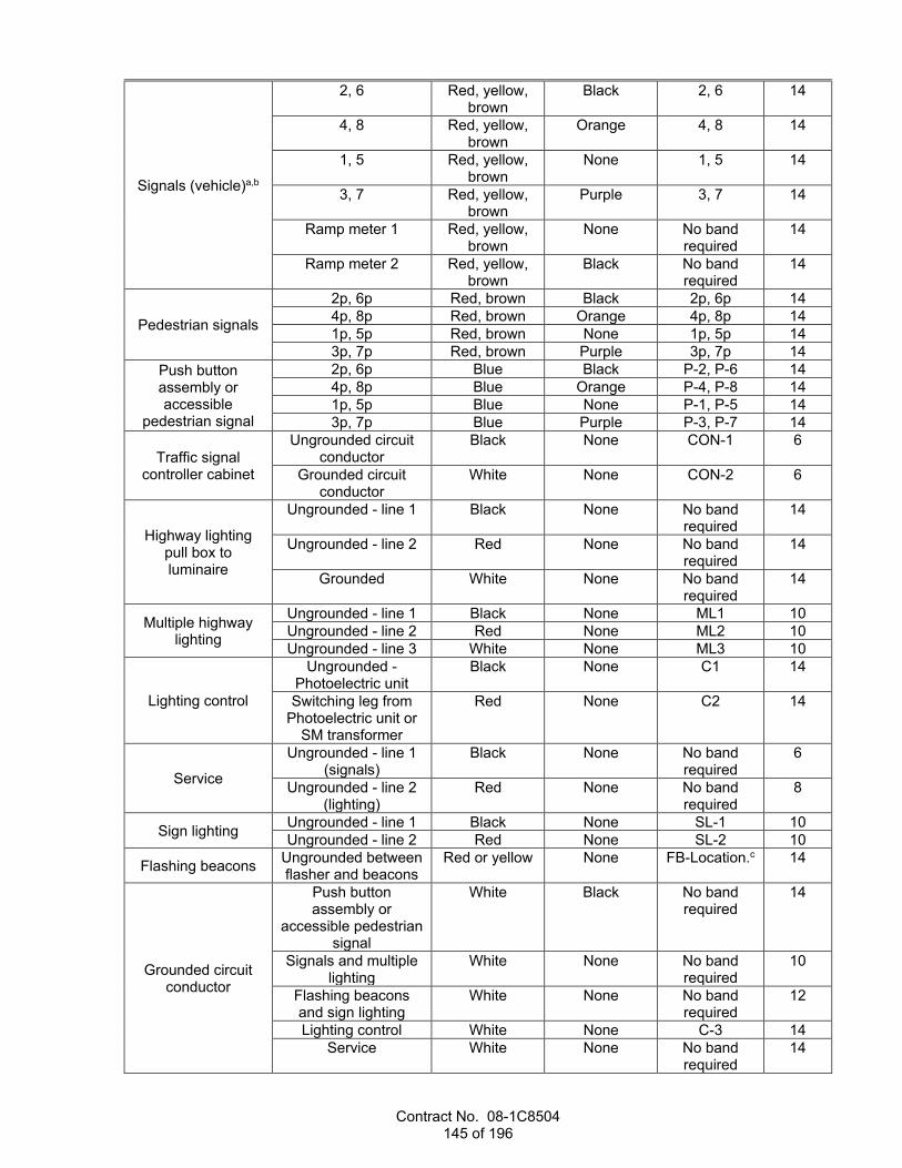
Contract No. 08-1C8504 145 of 196
Signals (vehicle)a,b
2, 6 Red, yellow, brown
Black 2, 6 14
4, 8 Red, yellow, brown
Orange 4, 8 14
1, 5 Red, yellow, brown
None 1, 5 14
3, 7 Red, yellow, brown
Purple 3, 7 14
Ramp meter 1 Red, yellow, brown
None No band required
14
Ramp meter 2 Red, yellow, brown
Black No band required
14
Pedestrian signals
2p, 6p Red, brown Black 2p, 6p 14 4p, 8p Red, brown Orange 4p, 8p 14 1p, 5p Red, brown None 1p, 5p 14 3p, 7p Red, brown Purple 3p, 7p 14
Push button assembly or accessible
pedestrian signal
2p, 6p Blue Black P-2, P-6 14 4p, 8p Blue Orange P-4, P-8 14 1p, 5p Blue None P-1, P-5 14 3p, 7p Blue Purple P-3, P-7 14
Traffic signal controller cabinet
Ungrounded circuit conductor
Black None CON-1 6
Grounded circuit conductor
White None CON-2 6
Highway lighting pull box to luminaire
Ungrounded - line 1 Black None No band required
14
Ungrounded - line 2 Red None No band required
14
Grounded White None No band required
14
Multiple highway lighting
Ungrounded - line 1 Black None ML1 10 Ungrounded - line 2 Red None ML2 10 Ungrounded - line 3 White None ML3 10
Lighting control
Ungrounded - Photoelectric unit
Black None C1 14
Switching leg from Photoelectric unit or
SM transformer
Red None C2 14
Service
Ungrounded - line 1 (signals)
Black None No band required
6
Ungrounded - line 2 (lighting)
Red None No band required
8
Sign lighting Ungrounded - line 1 Black None SL-1 10 Ungrounded - line 2 Red None SL-2 10
Flashing beacons Ungrounded between flasher and beacons
Red or yellow None FB-Location.c 14
Grounded circuit conductor
Push button assembly or
accessible pedestrian signal
White Black No band required
14
Signals and multiple lighting
White None No band required
10
Flashing beacons and sign lighting
White None No band required
12
Lighting control White None C-3 14 Service White None No band
required 14
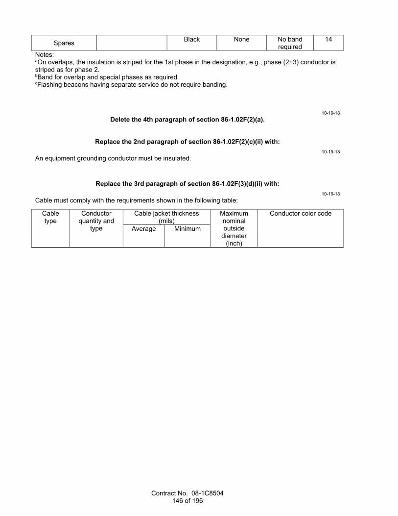
Contract No. 08-1C8504 146 of 196
Spares Black None No band required
14
Notes: aOn overlaps, the insulation is striped for the 1st phase in the designation, e.g., phase (2+3) conductor is striped as for phase 2. bBand for overlap and special phases as required cFlashing beacons having separate service do not require banding.
10-19-18 Delete the 4th paragraph of section 86-1.02F(2)(a).
Replace the 2nd paragraph of section 86-1.02F(2)(c)(ii) with: 10-19-18
An equipment grounding conductor must be insulated.
Replace the 3rd paragraph of section 86-1.02F(3)(d)(ii) with: 10-19-18
Cable must comply with the requirements shown in the following table:
Cable type
Conductor quantity and
type
Cable jacket thickness (mils)
Maximum nominal outside
diameter (inch)
Conductor color code
Average Minimum
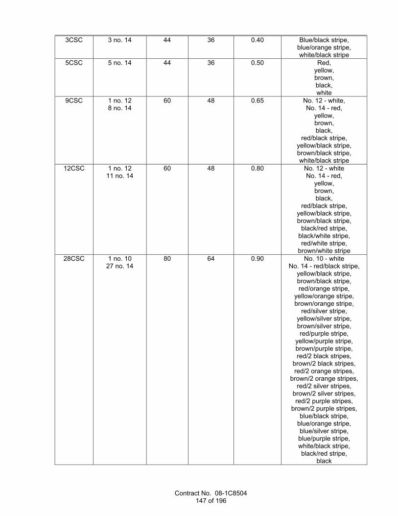
Contract No. 08-1C8504 147 of 196
3CSC 3 no. 14 44 36 0.40 Blue/black stripe, blue/orange stripe, white/black stripe
5CSC 5 no. 14 44 36 0.50 Red, yellow, brown, black, white
9CSC 1 no. 12 8 no. 14
60 48 0.65 No. 12 - white, No. 14 - red,
yellow, brown, black,
red/black stripe, yellow/black stripe, brown/black stripe, white/black stripe
12CSC 1 no. 12 11 no. 14
60 48 0.80 No. 12 - white No. 14 - red,
yellow, brown, black,
red/black stripe, yellow/black stripe, brown/black stripe,
black/red stripe, black/white stripe, red/white stripe,
brown/white stripe 28CSC 1 no. 10
27 no. 14 80 64 0.90 No. 10 - white
No. 14 - red/black stripe, yellow/black stripe, brown/black stripe, red/orange stripe,
yellow/orange stripe, brown/orange stripe,
red/silver stripe, yellow/silver stripe, brown/silver stripe, red/purple stripe,
yellow/purple stripe, brown/purple stripe, red/2 black stripes,
brown/2 black stripes, red/2 orange stripes,
brown/2 orange stripes, red/2 silver stripes,
brown/2 silver stripes, red/2 purple stripes,
brown/2 purple stripes, blue/black stripe,
blue/orange stripe, blue/silver stripe, blue/purple stripe, white/black stripe, black/red stripe,
black

Contract No. 08-1C8504 148 of 196
Replace section 86-1.02F(3)(d)(iv) with: 04-17-20
86-1.02F(3)(d)(iv) Railroad Preemption Cables A railroad preemption cable must be a 19-conductor cable having a polyvinyl chloride or polyethylene jacket. The cable jacket must be rated for 600 V(ac) and 75 degrees C.
The railroad preemption cable color code must be as shown in the following table:
Railroad Preemption Cable Color Code Conductor no. Color Code
1 Black 2 White 3 Red 4 Green 5 Orange 6 Blue 7 White/black stripe 8 Red/black stripe 9 Green/black stripe 10 Orange/black stripe 11 Blue/black stripe 12 Black/white stripe 13 Red/white stripe 14 Green/white stripe 15 Blue/white stripe 16 Black/red stripe 17 White/red stripe 18 Orange/red stripe 19 Blue/red stripe
The individual conductors in the cable must:
1. Be stranded and comply with ASTM B286 2. Have Type THW insulation 3. Be 16 AWG
Replace the 3rd paragraph of section 86-1.02G with: 10-19-18
The self-adhesive reflective labels must:
1. Be from 3 to 5 mils thick 2. Have all black capital characters on a white background 3. Extend beyond the character by a minimum of 1/4 inch
Replace the 4th paragraph of section 86-1.02H with: 10-19-18
PVC electrical tape must have a minimum thickness of 6 mils.

Contract No. 08-1C8504 149 of 196
Replace section 86-1.02K with: 04-17-20
86-1.02K Luminaires 86-1.02K(1) General A luminaire must:
1. Be self-contained, not requiring assembly. 2. Comply with UL 1598 for luminaires in wet locations. 3. Have a power supply with ANSI/IEC 60529 rating of at least IP65. 4. Weigh less than 35 lb. 5. Have a minimum 60,000 hours L70 rating under LM-80 and TM-21 at an ambient temperature of 25
degrees C. 6. Operate over a temperature range from -40 to 130 degrees F. 7. Be operationally compatible with photoelectric controls. 8. Have a nominal correlated color temperature of 3000 K under ANSI C78.377 and a color rendering
index of 70 or greater. 9. Have a maximum effective projected area of 1.4 sq ft when viewed from either side or end. 10. Comply with ANSI C136.31. 11. Have a power factor of 0.90 or greater. The total harmonic distortion, current, and voltage induced
into a power line by a luminaire must not exceed 20 percent. Test voltage will be at 120 V(ac), 240 V(ac), or 480 V(ac).
12. Comply with the maximum power consumption and isofootcandle curves as shown. 13. Be on the Authorized Material List for LED luminaires or must be submitted and passed testing for
addition to the AML. A luminaire must include a surge protection device to withstand high-repetition noise transients caused by utility line switching, lightning strikes, and other interferences. The device must protect the luminaire from damage and failure due to transient voltages and currents as defined in Tables 1 and 4 of ANSI/IEEE C64.41.2 for location category C-High. The surge protection device must comply with UL 1449 and ANSI/IEEE C62.45 based on ANSI/IEEE C62.41.2 definitions for standard and optional waveforms for location category C-High.
The luminaire must operate over the voltage range:
1. From 95 to 277 V(ac) for luminaires rated 120, 240, or 277 V(ac) 2. From 347 to 480 V(ac) for luminaires rated 480 V(ac) The fluctuations of line voltage must have no visible effect on the luminous output.
The luminaire's housing, external bolts, screws, hinges, hinge pins, and door closure devices must withstand a 1008 hour cyclic salt fog spray/UV test under ASTM D5894 and an evaluation under ASTM D714 with a blister rating of 8 or greater and no more than medium density.
The luminaire's housing must be marine-grade alloy with less than 0.2 percent copper or die cast aluminum.
The housing must be designed to prevent the buildup of water on its top surface. Exposed heat sink fins must be oriented to allow water to run off the luminaire and carry dust and other accumulated debris away from the unit. The optical assembly of the luminaire must be protected against dust and moisture intrusion to at least an ANSI/IEC 60529 rating of IP66. The power supply enclosure must be protected to at least an ANSI/IEC 60529 rating of IP43.
If the components are mounted on a down-opening door, the door must be hinged and secured to the luminaire's housing separately from other components. The door must be secured to the housing to prevent accidental opening. A safety cable must mechanically connect the door to the housing.
A luminaire must have a barrier-type terminal block secured to the housing to connect field wires. The terminal screws must be captive and equipped with wire grips for conductors up to no. 6.
Terminals must be identified and marked.

Contract No. 08-1C8504 150 of 196
If needed, each refractor or lens must be made of UV-inhibiting high-impact plastic, such as acrylic or polycarbonate, or heat and impact-resistant glass. The refractor or lens must be resistant to scratching. Polymeric materials, except for the lenses of enclosures containing either the power supply or electronic components of the luminaire, must be made of UL94 V-0 flame-retardant materials.
The luminaire must be permanently marked inside the unit and outside of its packaging box. Marking consists of:
1. Manufacturer's name or trademark 2. Month and year of manufacture 3. Model, serial, and lot numbers 4. Rated voltage, wattage, and power in VA An LED luminaire must:
1. Comply with Class A emission limits under 47 CFR 15(B) for unintentional radiators. 2. Have a power supply with:
2.1. 2 leads to accept standard 0-10 V(dc) control. 2.2. Dimming control compatible with IEC 60929, Annex E. If the control leads are open or the
analog control signal is lost, the circuit must default to 100-percent power. 2.3. Case temperature self-rise of 77 degrees F or less above ambient temperature in free air with
no additional heat sinks. 3. Not be cooled by fans or other menchanical devices. 86-1.02K(2) Roadway Luminaires A roadway luminaire must:
1. Have a housing color that matches a color no. 26152 to 26440, 36231 to 36375, or 36440 of AMS-STD-595
2. Have an ANSI C136.41-compliant, locking-type, photocontrol receptacle with dimming connections and a watertight shorting cap
3. Have an uplight rating of "U0" per IES TM-15-11 4. Have equipment identification character labels outside the unit on the side that will face the road.
Equipment identification characters consist of: 4.1. R1 for Roadway 1, R2 for Roadway 2, R3 for Roadway 3, and R4 for Roadway 4 4.2. Rated wattage
The luminaire's housing must have a slip fitter that must:
1. Fit on mast arms with outside diameters from 1-5/8 to 2-3/8 inches 2. Be adjustable to a minimum of ±5 degrees from the axis of the tenon in a minimum of 5 steps: +5,
+2.5, 0, -2.5, -5 3. Have clamping brackets that:
3.1. Are made of corrosion-resistant materials or treated to prevent galvanic reactions 3.2. Do not bottom out on the housing bosses when adjusted within the designed angular range 3.3. Do not permanently set more than 1/32 inch when tightened
86-1.02K(3) Overhead Sign Luminaires An overhead sign luminaire must:
1. Have a uniformity average to minimum ratio of 10:1 for the distribution of light reflected on a 16' wide by 12' high sign panel
2. Not allow more than 2.5 percent of the rated lumens to project above 65 degrees measured up from the horizontal plane in the direction of the sign panel
3. Mount at a maximum height of 12 inches above the top of the mounting rails 4. Mount directly to the sign structure as shown or with a mounting adapter that meets the material
requirements of the luminaire's housing

Contract No. 08-1C8504 151 of 196
Replace section 86-1.02M with: 10-19-18
86-1.02M Photoelectric Controls Photoelectric control types are as shown in the following table:
Photoelectric Control Types Control type Description
I Pole-mounted photoelectric unit. Test switch and a 15-A circuit breaker per ungrounded conductor, housed in an enclosure.
II Pole-mounted photoelectric unit. Contactor, a 15-A circuit breaker per ungrounded conductor, and test switch located in a service equipment enclosure.
III Pole-mounted photoelectric unit. Contactor, a 15-A circuit breaker per ungrounded conductor, and a test switch housed in an enclosure.
IV A photoelectric unit that plugs into a NEMA twist-lock receptacle, integral with the luminaire.
V A photoelectric unit, contactor, a 15-A circuit breaker per ungrounded conductor, and test switch located in a service equipment enclosure.
The pole-mounted adaptor for Type I, II, and III photoelectric controls must include a terminal block and cable supports or clamps to support the wires.
Photoelectric unit must:
1. Have a screen to prevent artificial light from causing cycling. 2. Have a rating of 60 Hz, 105-130 V(ac), 210-240 V(ac), or 105-240 V(ac). 3. Operate at a temperature range from -20 to 55 degrees C. 4. Consume less than 10 W. 5. Be a 3-prong, twist-lock type with a NEMA IP 65 rating, ANSI C136.10-compliant. 6. Have a fail-on state. 7. Fit into a NEMA-type receptacle. 8. Turn on from 1 to 5 footcandles and turn off from 1.5 to 5 times the turn-on level. Measurements must
be made by procedures in EEI-NEMA Standards for Physical and Electrical Interchangeability of Light-Sensitive Control Devices Used in the Control of Roadway Lighting.
Type I, II, III, and V photoelectric controls must have a test switch to allow manual operation of the lighting circuit. Switch must be:
1. Single-hole mounting, toggle type 2. 15 A, single pole and single throw 3. Labeled Auto-Test on a nameplate Photoelectric control's contactor must be:
1. Normally open 2. Mechanical-armature type with contacts of fine silver, silver alloy, or equal or better material 3. Installed to provide a minimum space of 2-1/2 inches between the contactor terminals and the
enclosure's sides The terminal blocks must be rated at 25 A, 600 V(ac), molded from phenolic or nylon material, and be the barrier type with plated-brass screw terminals and integral marking strips.
Replace section 86-1.02N with: 10-19-18
86-1.02N Fused Splice Connectors The fused splice connector for 240 and 480 V(ac) circuits must simultaneously disconnect both ungrounded conductors. The connector must not have exposed metal parts except for the head of the
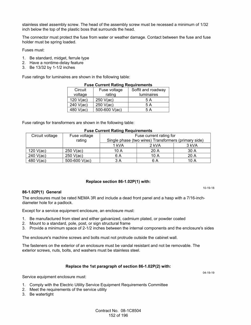
Contract No. 08-1C8504 152 of 196
stainless steel assembly screw. The head of the assembly screw must be recessed a minimum of 1/32 inch below the top of the plastic boss that surrounds the head.
The connector must protect the fuse from water or weather damage. Contact between the fuse and fuse holder must be spring loaded.
Fuses must:
1. Be standard, midget, ferrule type 2. Have a nontime-delay feature 3. Be 13/32 by 1-1/2 inches Fuse ratings for luminaires are shown in the following table:
Fuse Current Rating Requirements Circuit voltage
Fuse voltage rating
Soffit and roadway luminaires
120 V(ac) 250 V(ac) 5 A 240 V(ac) 250 V(ac) 5 A 480 V(ac) 500-600 V(ac) 5 A
Fuse ratings for transformers are shown in the following table:
Fuse Current Rating Requirements Circuit voltage Fuse voltage
rating Fuse current rating for
Single phase (two wires) Transformers (primary side) 1 kVA 2 kVA 3 kVA
120 V(ac) 250 V(ac) 10 A 20 A 30 A 240 V(ac) 250 V(ac) 6 A 10 A 20 A 480 V(ac) 500-600 V(ac) 3 A 6 A 10 A
Replace section 86-1.02P(1) with: 10-19-18
86-1.02P(1) General The enclosures must be rated NEMA 3R and include a dead front panel and a hasp with a 7/16-inch-diameter hole for a padlock.
Except for a service equipment enclosure, an enclosure must:
1. Be manufactured from steel and either galvanized, cadmium plated, or powder coated 2. Mount to a standard, pole, post, or sign structural frame 3. Provide a minimum space of 2-1/2 inches between the internal components and the enclosure's sides The enclosure's machine screws and bolts must not protrude outside the cabinet wall.
The fasteners on the exterior of an enclosure must be vandal resistant and not be removable. The exterior screws, nuts, bolts, and washers must be stainless steel.
Replace the 1st paragraph of section 86-1.02P(2) with: 04-19-19
Service equipment enclosure must:
1. Comply with the Electric Utility Service Equipment Requirements Committee 2. Meet the requirements of the service utility 3. Be watertight

Contract No. 08-1C8504 153 of 196
4. Be factory wired and manufactured from steel and galvanized or have factory-applied, rust-resistant prime and finish coats, except Types II and III
5. Be marked as specified in NEC to warn of potential electric-arc flash hazards
04-19-19 Delete the 5th paragraph of 86-1.02P(2).
Add between 6th and 7th paragraphs of section 86-1.02P(2): 10-19-18
Service equipment enclosure must have the meter view windows located on the front side of the enclosure for Types III-AF, BF, CF and DF.
Service equipment enclosure must have the meter view windows located on the back side of the enclosure for Types III-AR, BR, CR and DR.
Replace the 7th paragraph of section 86-1.02P(2) with: 04-19-19
The meter area must have a sealable, lockable, weather-tight cover that can be removed without the use of tools.
04-19-19 Delete the 2nd sentence of the 9th paragraph of section 86-1.02P(2).
10-19-18 Delete section 86-1.02P(3).
Replace the 1st paragraph of section 86-1.02Q(2) with: 04-17-20
A Department-furnished controller assembly consists of a controller cabinet with a controller unit and all auxiliary equipment required to operate the system. The Department does not furnish anchor bolts.
Replace section 86-1.02Q(4)(a) with: 10-19-18
86-1.02Q(4)(a) General The doors of a telephone demarcation cabinet must be attached using continuous aluminum steel piano hinges.
Add between the 2nd and 3rd paragraphs of section 86-1.02R(2): 10-19-18
Bracket arms must be long enough to allow proper alignment of signals and backplate installation.
Add to the end of section 86-1.02R(3): 04-17-20
Backplates for signal and lighting systems must have a 2-inch retroreflective strip on the face around the perimeter. The strip must be Type XI fluorescent yellow retroreflective sheeting on the Authorized Material List for signing and delineation materials.

Contract No. 08-1C8504 154 of 196
Replace item 2 in the list in the 5th paragraph of section 86-1.02R(4)(a)(iii) with: 10-19-18
2. Be a black color throughout, including the door, matching color no. 17038, 27038, or 37038 of AMS-STD-595
Replace section 86-1.02S(3)(c) with: 04-17-20
86-1.02S(3)(c) LED Countdown Pedestrian Signal Face Modules An LED countdown PSF module must:
1. Comply with ITE publication ST-055-E, Pedestrian Traffic Control Signal Indicators: Light Emitting Diode (LED) Signal Modules.
2. Be manufactured with materials that comply with ASTM D3935. 3. Have circuit boards that comply with TEES, chapter 1, section 6. 4. Have symbols that are at least 9 inches high and 5-1/4 inches wide each. The 2-digit countdown
display, Upraised Hand, and Walking Person indications must be electronically isolated from each other. The 3 indications must not share a power supply or interconnect circuitry.
5. Use ultra-bright-type LED rated for 60,000 hours of continuous operation. Individual LEDs must be wired such that a loss or failure of 1 LED will not result in a loss of more than 5 percent of the module's light output. Failure of an individual LED in a string must not result in a loss of an entire string or other indication.
6. Have a manual control to turn on and off the 2-digit countdown display. 7. Have the lot number, month, and year of manufacture permanently marked on the back. 8. Have prominent and permanent vertical markings for accurate indexing and orientation within the
pedestrian signal housing. Markings must be a minimum of 1 inch in height and include an up arrow and the word up or top.
Upon initial testing at 25 degrees C, the module must have at least the luminance values shown in the following table:
Luminance Values PSF module symbol Luminance (fL)
Upraised hand and 2-digit countdown timer
1,094
Walking person 1,547
The module must not exceed the power consumption requirements shown in the following table:
Maximum Power Consumption Requirements PSF module display At 24 ºC At 74 ºC
Upraised Hand 10.0 W 12.0 W Walking Person 9.0 W 12.0 W
2-digit countdown timer 6.0 W 8.0 W
If the pedestrian change interval is interrupted, then the 2-digit countdown timer and display must reset to the full pedestrian change interval before being initiated the next time. The 2-digit countdown display on the PSF module must go dark within a second after displaying "0".
Add to the beginning of section 86-1.02T: 04-19-19
Accessible pedestrian signal must be on the Authorized Material List for Accessible Pedestrian Signals.
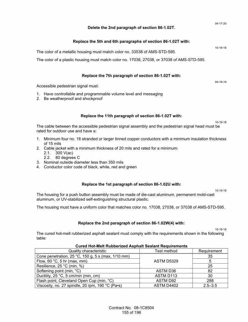
Contract No. 08-1C8504 155 of 196
04-17-20 Delete the 2nd paragraph of section 86-1.02T.
Replace the 5th and 6th paragraphs of section 86-1.02T with: 10-19-18
The color of a metallic housing must match color no. 33538 of AMS-STD-595.
The color of a plastic housing must match color no. 17038, 27038, or 37038 of AMS-STD-595.
Replace the 7th paragraph of section 86-1.02T with: 04-19-19
Accessible pedestrian signal must:
1. Have controllable and programmable volume level and messaging 2. Be weatherproof and shockproof
Replace the 11th paragraph of section 86-1.02T with: 10-19-18
The cable between the accessible pedestrian signal assembly and the pedestrian signal head must be rated for outdoor use and have a:
1. Minimum four no. 18 stranded or larger tinned copper conductors with a minimum insulation thickness of 15 mils
2. Cable jacket with a minimum thickness of 20 mils and rated for a minimum: 2.1. 300 V(ac) 2.2. 80 degrees C
3. Nominal outside diameter less than 350 mils 4. Conductor color code of black, white, red and green
Replace the 1st paragraph of section 86-1.02U with: 10-19-18
The housing for a push button assembly must be made of die-cast aluminum, permanent mold-cast aluminum, or UV-stabilized self-extinguishing structural plastic.
The housing must have a uniform color that matches color no. 17038, 27038, or 37038 of AMS-STD-595.
Replace the 2nd paragraph of section 86-1.02W(4) with: 10-19-18
The cured hot-melt rubberized asphalt sealant must comply with the requirements shown in the following table:
Cured Hot-Melt Rubberized Asphalt Sealant Requirements Quality characteristic Test method Requirement
Cone penetration, 25 °C, 150 g, 5 s (max, 1/10 mm) ASTM D5329
35 Flow, 60 °C, 5 hr (max, mm) 5 Resilience, 25 °C (min, %) 25 Softening point (min, °C) ASTM D36 82 Ductility, 25 °C, 5 cm/min (min, cm) ASTM D113 30 Flash point, Cleveland Open Cup (min, °C) ASTM D92 288 Viscosity, no. 27 spindle, 20 rpm, 190 °C (Pa•s) ASTM D4402 2.5–3.5

Contract No. 08-1C8504 156 of 196
Replace the 2nd paragraph of section 86-1.02Y with: 10-19-18
A transformer must be a dry type designed for operation on a 60 Hz supply. The transformer must have a decal showing a connection diagram. The diagram must show either color coding or wire tagging with primary (H1, H2) or secondary (X1, X2) markers and the primary and secondary voltage and volt-ampere rating. A transformer must comply with the electrical requirements shown in the following table:
Transformer Electrical Requirements Quality characteristic Requirement
Rating (V(ac)) 120/240, 120/480, 240/120, 240/480, 480/120, or 480/240
Efficiency (%) > 95 Secondary voltage regulation and tolerance from half load to full load (%)
±3
^^^^^^^^^^^^^^^^^^^^^^^^^^^^^^^^^^^^^^^^
87 ELECTRICAL SYSTEMS 04-17-20
Replace Reserved in section 87-1.01C with: 10-19-18
Submit a digital file for geographic information system mapping for:
1. Conduit 2. Pull boxes 3. Cabinets 4. Service equipment enclosures 5. Standards The digital file must consist of:
1. Longitudinal and latitude coordinates, under the WGS84 reference coordinate system. The coordinates must be in decimal format having 6 significant figures after the decimal point. Coordinates must be read at the center of pull boxes, cabinet, standards, and service equipment enclosures; and on top of conduit at 20-foot intervals before backfill.
2. Type, depth and size for conduits. 3. Type for pull boxes, standards, cabinets, and service equipment enclosures.
Replace item 4 in the list in the 1st paragraph of section 87-1.01D(2)(a) with: 10-19-18
4. Luminaires
Replace the 2nd paragraph of section 87-1.01D(2)(a) with: 10-18-19
Submit a sample size as shown in the following table:

Contract No. 08-1C8504 157 of 196
Electrical Material Sampling Contract quantity Test sample size
1–8 1 9–15 2 16–25 3 26–90 5 91–150 8
151–280 13 281–500 20 501–1200 32
Replace section 87-1.01D(2)(d) with: 10-19-18
87-1.01D(2)(d) Piezoelectric Axle Sensors Piezoelectric axle sensors test consists of:
1. Demonstrating for each sensor: 1.1. Capacitance is within 20 percent of the value shown on the sensor's data sheet 1.2. Dissipation factor is less than 0.04 nF when measured in the 20 nF range 1.3. Resistance is greater than 20 Megaohms
2. Collecting a minimum of 100 vehicle records for each lane and demonstrating: 2.1. Volume is within ±3 percent accuracy 2.2. Vehicle classification is within 95 percent accuracy by type
Replace the 7th paragraph of section 87-1.03A with: 10-19-18
Notify the Engineer immediately if an existing facility is damaged by your activities:
1. Damaged existing traffic signal systems must be repaired or replaced within 24 hours. If the system cannot be fixed within 24 hours or it is located on a structure, provide a temporary system until the system can be fixed.
2. Damaged existing lighting systems must be repaired or replaced by nightfall. If the system cannot be fixed by nightfall, provide a temporary system until the system can be fixed.
Add to the end of section 87-1.03A: 10-19-18
Collect the geographic information system mapping data.
Replace the 12th paragraph of section 87-1.03B(1) with: 10-19-18
For Type 1, 2, and 5 conduits, use threaded bushings and bond them using a jumper. For other types of conduit, use nonmetallic bushings or end bell.
Replace the 3rd paragraph of section 87-1.03B(3)(a) with: 10-19-18
Place a minimum of 2 inches of sand bedding in a trench before installing the conduit and 18 inches of slurry cement over the conduit before placing additional backfill material.

Contract No. 08-1C8504 158 of 196
10-18-19 The slurry must be pigmented to match color no. 21105 of AMS-STD-595.
Replace the 1st sentence in the 6th paragraph of section 87-1.03B(3)(c) with: 10-19-18
Backfill trench with slurry concrete under section 19-3.02E.
Replace the 9th paragraph of section 87-1.03B(3)(c) with: 10-19-18
Install innerducts as one continuous unit between vaults. Innerducts may be interrupted inside pull boxes located between vaults and cabinets.
Replace section 87-1.03C with: 10-18-19
87-1.03C Installation of Pull Boxes 87-1.03C(1) General Install pull boxes no more than 200 feet apart.
Place the cover on the box when not working in it.
87-1.03C(2) Roadway Pull Boxes 87-1.03C(2)(a) General You may install larger pull boxes than specified or shown and additional pull boxes to facilitate the work except in structures.
Install a pull box on a minimum 6-inch deep bed of crushed rock and grout it before installing conductors. The grout must be from 0.5 to 1 inch thick and sloped toward the drain hole. Place a layer of roofing paper between the grout and the crushed rock sump. Make a 1-inch drain hole through the grout at the center of the pull box.
Set the pull box such that the top is 1-1/4 inches above the surrounding grade in unpaved areas and leveled with the finished grade in sidewalks and other paved areas.
Grout around conduits that are installed through the sides of the pull box.
Bond and ground the metallic conduit before installing conductors and cables in the conduit.
Bond metallic conduits in a nonmetallic pull box using bonding bushings and bonding jumpers.
Do not install pull boxes in concrete pads, curb ramps, or driveways.
Reconstruct the sump of a pull box if disturbed by your activities. If the sump was grouted, remove and replace the grout.
87-1.03C(2)(b) Nontraffic Pull Boxes For a buried nontraffic pull box, install the electronic marker and set the box such that the top is from 6 to 8 inches below the surrounding grade. Place a 20-mil-thick plastic sheet made of HDPE or PVC virgin compounds to prevent water from entering the box.
When a pull box is in a structure, modify the base as required.
Place mortar between a nontraffic pull box and a pull box extension.
Where a nontraffic pull box is in the vicinity of a curb in an unpaved area, place the box adjacent to the back of the curb if practical.
Contract No. 08-1C8504 159 of 196
Where a nontraffic pull box is adjacent to a post or standard, place the box within 5 feet downstream from traffic if practical.
If you replace the cover on a nontraffic pull box, anchor it to the box.
Perform the electronic marker test.
87-1.03C(2)(c) Traffic Pull Boxes Place minor concrete around and under a traffic pull box as shown.
Bolt the steel cover to the box when not working in it.
Bond the steel cover to the conduit with a minimum 3-foot-long jumper and bolt it down after installing the conductors and cables.
87-1.03C(2)(d) Tamper-Resistant Pull Boxes Install the tamper-resistant pull boxes under the manufacturer's instructions.
87-1.03C(3) Structure Pull Boxes Install structure pull boxes parallel to the structure.
After removing the knockouts, flatten the surrounding area.
Bond conduit to a structure pull box using locknuts on the inside and outside of the box.
Cover pull boxes with a 1/4-inch plywood during pouring of PCC. For a no. 9 pull box, the upper edge of the plywood must fit against the lower edge of the rain tight hood.
Install no. 7 pull box with bottom flanges flush with the bottom of the box girder. Place top and bottom covers and seal the pull box during PCC pouring.
For no. 9 and 9A pull boxes:
1. Form a 1:1 chamfer around the cover 2. Use the drain hole in the center if the box is horizontal and the low end drain hole if the box is inclined 3. Mounted in a sloping parapet, drill a 1/2-inch elongated drain hole in the center if the box is horizontal
or the low end if the box is inclined
Replace section 87-1.03D with: 10-19-18
87-1.03D Reserved
Replace section 87-1.03E(2) with: 04-19-19
Dig a trench for the electrical conduits or direct burial cables. Do not excavate until the installation of the conduit or direct burial cables.
Place excavated material in a location that will not interfere with traffic or surface drainage.
After placing the conduit or direct burial cable, backfill the trench.
Compact the backfill to a minimum relative compaction of:
1. 95 percent when placed within the hinge points and in areas where pavement is to be constructed 2. 90 percent when placed outside the hinge points and not under pavement
Restore the sidewalks, pavement, and landscaping at a location before starting excavation at another location.

Contract No. 08-1C8504 160 of 196
Replace section 87-1.03E(3) with: 10-19-18
87-1.03E(3) Concrete Pads, Foundations, and Pedestals Construct foundations for standards, poles, metal pedestals, and posts under section 56-3.
Construct concrete pads, foundations, and pedestals for controller cabinets, telephone demarcation cabinets, and service equipment enclosures on firm ground.
Install anchor bolts using a template to provide proper spacing and alignment. Moisten the forms and ground before placing the concrete. Keep the forms in place until the concrete sets for at least 24 hours to prevent damage to the surface.
Use minor concrete for pads, foundations, and pedestals.
Construct a pad in front of a Type III service equipment enclosure. The pad must be 24 inches in length, 4 inches in thickness, and must match the width of the foundation.
In unpaved areas, place the top of the foundation 6 inches above the surrounding grade, except place the top:
1. 1 foot 6 inches above the grade for 336L cabinets 2. 1 foot 8 inches above the grade for Type C telephone demarcation cabinets 3. 2 inches above the grade for Type III service equipment enclosures The pad must be 2 inches above the surrounding grade in unpaved areas.
In and adjacent to the sidewalk and other paved areas, place the top of the foundation 4 inches above the surrounding grade, except place the top:
1. 1 foot 6 inches above the grade for 336L cabinets 2. 1 foot 8 inches above the grade for Type C telephone demarcation cabinets 3. Level with the finished grade for Type G and Type A cabinets and Type III service equipment
enclosures The pad must be level with the finished grade in paved areas.
Apply an ordinary surface finish under section 51-1.03F.
Allow the foundation to cure for at least 7 days before installing any equipment.
Add between the 3rd and 4th paragraphs of section 87-1.03F(1): 04-17-20
Provide conductor and cable slack to comply with the requirements shown in the following table:
Conductor and Cable Slack Requirements Location Slack (feet)
Signal standard 1 Lighting standard 1 Signal and lighting standard 1 Pull box 3 Splice 3 Controller cabinet 6 Standards with slip base 0

Contract No. 08-1C8504 161 of 196
Replace the last paragraph of section 87-1.03F(1) with: 04-19-19
Install a tracer wire.
Replace section 87-1.03F(2) with: 04-17-20
87-1.03F(2) Cables 87-1.03F(2)(a) General Reserved
87-1.03F(2)(b) Communication Cables 87-1.03F(2)(b)(i) General Terminate the ends of the communication cables as shown.
87-1.03F(2)(b)(ii) Category 5E and 6 Cables Do not splice category 5E and 6 cables.
87-1.03F(2)(b)(iii) Telephone Cables Do not splice telephone cables between the telephone demarcation point and the controller cabinet.
87-1.03F(2)(c) Copper Cables 87-1.03F(2)(c)(i) General Reserved
87-1.03F(2)(c)(ii) Detector Lead-in Cables Install a Type B or C detector lead-in cable in conduit.
Seal the ends of the lead-in cable before installing it in the conduit to prevent moisture from entering the cable.
Splice loop conductors for each direction of travel for the same phase, terminating in the same pull box, to a separate lead-in cable running from the pull box adjacent to the loop detector to a sensor unit mounted in the controller cabinet. Install the lead-in cable without splices except at the pull box when connecting to loop wire.
Verify in the presence of the Engineer that the loops are operational before making the final splices between loop conductors and the lead-in cable.
Identify and tag each lead-in cable with the detector designation at the cabinet and pull box adjacent to the loops.
87-1.03F(2)(c)(iii) Conductors Signal Cables Do not splice signal cables except for a 28-conductor cable.
Provide identification at the ends of terminated conductors in a cable as shown.
Provide identification for each cable in each pull box showing the signal standard to which it is connected except for the 28-conductor cable.
Connect conductors in a 12-conductor cable as shown in the following table:

Contract No. 08-1C8504 162 of 196
12CSC Color Code and Functional Connection Color code Termination Phase
Red Red signal 2, 4, 6, or 8 Yellow Yellow signal 2, 4, 6, or 8 Brown Green signal 2, 4, 6, or 8 Red/black stripe Red signal 1, 3, 5, or 7 Yellow/black stripe Yellow signal 1, 3, 5, or 7 Brown/black stripe Green signal 1, 3, 5, or 7 Black/red stripe Spare or as required for red or DONT
WALK --
Black/white stripe Spare or as required for yellow -- Black Spare or as required for green or WALK -- Red/white stripe Pedestrian signal DONT WALK -- Brown/white stripe Pedestrian signal WALK -- White Terminal block Neutral
Provide identification for each 28-conductor cable C1 or C2 in each pull box. The cable labeled C1 must be used for signal phases 1, 2, 3, and 4. The cable labeled C2 must be used for signal phases 5, 6, 7, and 8.
Connect conductors in a 28-conductor cable as shown in the following table:
28CSC Color Code and Functional Connection Color code Termination Phase
Red/black stripe Red signal 2 or 6 Yellow/black stripe Yellow signal 2 or 6 Brown/black stripe Green signal 2 or 6 Red/orange stripe Red signal 4 or 8 Yellow/orange stripe Yellow signal 4 or 8 Brown/orange stripe Green signal 4 or 8 Red/silver stripe Red signal 1 or 5 Yellow/silver stripe Yellow signal 1 or 5 Brown/silver stripe Green signal 1 or 5 Red/purple stripe Red signal 3 or 7 Yellow/purple stripe Yellow signal 3 or 7 Brown/purple stripe Green signal 3 or 7 Red/2 black stripes Pedestrian signal DONT WALK 2 or 6 Brown/2 black stripes Pedestrian signal WALK 2 or 6 Red/2 orange stripes Pedestrian signal DONT WALK 4 or 8 Brown/2 orange stripes Pedestrian signal WALK 4 or 8 Red/2 silver stripes Overlap A, C OLAa, OLCa Brown/2 silver stripes Overlap A, C OLAc, OLCc Red/2 purple stripes Overlap B, D OLBa, OLDa Brown/2 purple stripes Overlap B, D OLBc, OLDc Blue/black stripe Pedestrian push button 2 or 6 Blue/orange stripe Pedestrian push button 4 or 8 Blue/silver stripe Overlap A, C OLAb, OLCb Blue/purple stripe Overlap B, D OLBb, OLDb White/black stripe Pedestrian push button common -- Black/red stripe Spare -- Black Spare -- White Terminal block Neutral OL = Overlap; A, B, C, and D = Overlapping phase designation aFor red phase designation bFor yellow phase designation cFor green phase designation

Contract No. 08-1C8504 163 of 196
Use the neutral conductor only with the phases associated with that cable. Do not intermix neutral conductors from different cables except at the signal controller.
87-1.03F(2)(c)(iv) Signal Interconnect Cable Do not splice the cable unless authorized.
If splices are authorized, insulate the conductor splices with heat-shrink tubing and overlap the insulation at least 0.6 inch. Cover the splice area of the cable with heat-shrink tubing and overlap the cable jacket at least 1-1/2 inches. Provide a minimum of 3 feet of slack at each splice.
87-1.03F(2)(c)(v) Railroad Preemption Cables Do not splice railroad preemption cable from controller cabinet to railroad cabinet.
Terminate individual conductors with ferrule connectors in the controller cabinet.
Provide identification on both ends of the cable and connect the cable end in the controller cabinet as shown in the following table:
Color Code and Functional Connection Conductor no. Color Code Controller Cabinet Field
Terminal Connections Conductor Identification
1 Black Not Used Spare 2 White Not Used Spare 3 Red FT8-A145 Health Status DC+ 4 Green Not Used Spare 5 Orange FT7-A134 Simultaneous DC- 6 Blue FT7-A131 Advance DC- 7 White/black stripe Not Used Spare 8 Red/black stripe FT8-A144 Gate Down/Island 9 Green/black stripe Feld Terminal FT8-A142 Advance Pedestrian
Preemption 10 Orange/black stripe FT7-A135 Simultaneous Primary 11 Blue/black stripe FT7-A132 Advance Primary 12 Black/white stripe Not Used Spare 13 Red/white stripe FT8-A143 Gate Down/Island DC- 14 Green/white stripe FT8-A141 Advance Pedestrian
Preemption DC- 15 Blue/white stripe FT7-A133 Advance Secondary 16 Black/red stripe Not Used Spare 17 White/red stripe FT8-A146 Health Status DC- 18 Orange/red stripe FT7-A136 Simultaneous
Secondary 19 Blue/red stripe Not Used Spare
Keep all exposed conductors the same length and individually insulate spare conductors against each other.
Provide a minimum 6 feet of slack in the pull box adjacent to the railroad cabinet.
Connect the cable end in the railroad cabinet as directed by the railroad agency representative.
04-17-20 Delete the 4th paragraph of 87-1.03F(3)(a).
Replace the 1st paragraph of section 87-1.03F(3)(c)(ii) with: 10-19-18
Install a Type 1 or 2 inductive loop conductor except use Type 2 for Type E and F loop detectors.
Contract No. 08-1C8504 164 of 196
10-19-18 Delete the last paragraph of section 87-1.03G.
Replace the 4th paragraph of section 87-1.03H(2) with: 10-19-18
Use Method B as follows:
1. Cover the splice area completely with an electrical insulating coating and allow it to dry. 2. Apply 3 layers of half-lapped, PVC electrical tape. 3. Apply 2 layers of butyl-rubber, stretchable tape with liner. 4. Apply 3 layers of half-lapped, PVC, pressure-sensitive, adhesive tape. 5. Cover the entire splice with an electrical insulating coating and allow it to dry.
Replace section 87-1.03N with: 10-19-18
87-1.03N Fused Splice Connectors Install a fuse splice connector with a fuse in each ungrounded conductor for luminaires, except for overhead sign luminaires. The connector must be located in the pull box adjacent to the luminaires.
If the pull box for the roadway luminaire is tamper resistant, install a fuse splice connector with 10 A fuse in the pull box and an additional fuse splice connector with a 5 A fuse in the handhole.
Install a fuse splice connector with a fuse on primary side of transformer.
Crimp the connector terminals onto the ungrounded conductors using a tool under the manufacturer's instructions. Insulate the terminals and make them watertight.
Add to the end of section 87-1.03T: 10-19-18
When replacing an existing accessible pedestrian signal, the housing color must match the color of the existing housing.
Add to the end of section 87-1.03U: 10-19-18
When replacing an existing push button assembly, the housing color must match the color of the existing housing.
04-17-20 Delete the 9th paragraph for section 87-1.03V(2).
Add between the 1st and 2nd paragraphs of section 87-1.03Y: 04-19-19
Use a submersible type transformer inside pull boxes.
Replace the 2nd paragraph of section 87-2.03A with: 10-19-18
Tighten the cap screws of the luminaire's clamping bracket to 10 ft-lb for roadway luminaires.

Contract No. 08-1C8504 165 of 196
Replace section 87-3 with: 10-19-18
87-3 SIGN ILLUMINATION SYSTEMS 87-3.01 GENERAL Section 87-3 includes specifications for constructing sign illumination systems.
Sign illumination system includes:
1. Foundations 2. Pull boxes 3. Conduit 4. Conductors 5. Overhead sign luminaires 6. Service equipment enclosure 7. Photoelectric control The components of a sign illumination system are shown on the project plans.
87-3.02 MATERIALS Reserved
87-3.03 CONSTRUCTION Perform the conductor test.
Install overhead sign luminaires under the manufacturer's instructions.
Do not modify the sign structure or mounting channels.
Perform the operational tests for the system.
87-3.04 PAYMENT Not Used
Replace section 87-4 with: 04-17-20
87-4 SIGNAL AND LIGHTING SYSTEMS 87-4.01 GENERAL Section 87-4 includes specifications for constructing signal and lighting systems.
Signal and lighting system includes:
1. Foundations 2. Pull boxes 3. Conduit 4. Conductors and cables 5. Standards 6. Signal heads 7. Service equipment enclosure 8. Department-furnished controller assembly 9. Detectors 10. Telephone demarcation cabinet 11. Accessible pedestrian signals 12. Push button assemblies 13. Pedestrian signal heads 14. Luminaires 15. Photoelectric control 16. Fuse splice connectors
Contract No. 08-1C8504 166 of 196
17. Battery backup system 18. Flashing beacons 19. Flashing beacon control assembly The components of a signal and lighting system are shown on the project plans.
87-4.02 MATERIALS 87-4.02A General Not used
87-4.02B Railroad Preemption A wire jumper for railroad preemption must be:
1. Stranded 2. 14 AWG 3. White with red stripes 87-4.03 CONSTRUCTION 87-4.03A General Set the foundation for a standard such that the mast arm is perpendicular to the centerline of the roadway.
Tighten the cap screws of the roadway luminaire's clamping bracket to 10 ft-lb.
Label the month and year of the installation inside the luminaire housing's door.
Perform the conductor and operational tests for the system.
87-4.03B Railroad Preemption Connect the C16 harness plug to the C16 socket on the Output File no. 2LX in the controller cabinet.
Connect the terminated conductors of the C16 harness to terminal block TB9 on input panel no.1 in the controller cabinet as shown in the following table:
Input Panel No. 1 Connections Pin Label TB9 1 J-12D 4 2 J-12J 5 3 J-13D 7 4 J-13J 8 5 J-14D 10 6 J-14J 11
Terminate wire jumpers with spade connectors on both ends.
Connect three wire jumpers approximately 4 feet in length as show in the following table:
Jumper Connections Jumper Bus TB9
1 DC- 6 2 DC- 9 3 DC- 12
Connect three wire jumpers approximately 2 inches in length as show in the following table:

Contract No. 08-1C8504 167 of 196
Jumper Connections Jumper Terminal Block Pin Pin
1 TB-12 5 7 2 TB-13 5 7 3 TB-14 5 7
87-4.04 PAYMENT Not Used
Replace section 87-7.02 with: 10-19-18
87-7.02 MATERIALS Flashing beacon control assembly includes:
1. Enclosure. 2. Barrier-type terminal blocks rated for 25 A, 600 V(ac), made of molded phenolic or nylon material and
have plated-brass screw terminals and integral marking strips. 3. Solid state flasher complying with section 8 of NEMA standards publication no. TS 1 for 10 A, dual
circuits. 4. 15-A, circuit breaker per ungrounded conductor. 5. Single-hole-mounting toggle type, single-pole, single-throw switches rated at 12-A, 120 V(ac).
Switches must be furnished with an indicating nameplate reading Auto - Test. A 15-A circuit breaker may be used in place of the toggle switch.
Replace 87-8 with: 10-19-18
87-8 PEDESTRIAN HYBRID BEACON SYSTEMS 87-8.01 GENERAL 87-8.01A Summary Section 87-8 includes specifications for constructing pedestrian hybrid beacon system.
A pedestrian hybrid beacon system includes:
1. Foundations 2. Pull boxes 3. Conduit 4. Conductors and cables 5. Standards 6. Pedestrian hybrid beacon face 7. Pedestrian signal heads 8. Service equipment enclosure 9. Department-furnished controller assembly 10. Accessible pedestrian signals 11. Push button assemblies 12. Luminaires 13. Fuse splice connectors 14. Battery backup system The components of a pedestrian hybrid beacon system are shown on the project plans.
87-8.01B Definitions Reserved

Contract No. 08-1C8504 168 of 196
87-8.01C Submittals Reserved
87-8.01D Quality Assurance 87-8.01D(1) General Reserved
87-8.01D(2) Quality Control 04-17-20
Verify the sequence for the pedestrian hybrid beacon system per California MUTCD, Chapter 4F, Figure 4F-3 "Sequence for a Pedestrian Hybrid Beacon" during the operational test.
10-19-18 Test the battery backup system under section 87-1.01D(2)(c).
87-8.02 MATERIALS 87-8.02A General The system must comply with California MUTCD, Chapter 4F.
The battery backup system must comply with section 87-4.02B.
87-8.02B Pedestrian Hybrid Beacon Face A pedestrian hybrid beacon face consists of three 12-inch signal heads.
87-8.03 CONSTRUCTION Install pedestrian hybrid beacon system under sections 87-4.03A and 87-4.03B.
87-8.04 PAYMENT Not Used
Replace the 1st paragraph of section 87-12.03 with: 10-19-18
Install changeable message sign on sign structure under section 56-2.
Replace section 87-14.02 with: 10-19-18
87-14.02 MATERIALS 87-14.02A General Vehicle speed feedback sign consists of a housing, display window, and radar unit.
Sign must:
1. Comply with the California MUTCD, Chapter 2B 2. Have an operating voltage of 120 V(ac) for permanent installations 3. Have a maximum weight of 45 lb 4. Have a wind load rating of 90 mph 5. Have an operating temperature range from -34 to 165 degrees F 6. Have a retroreflective white sheeting background 87-14.02B Housings Housing must:
1. Be weatherproof (NEMA 3R or better) and vandal resistant 2. Be made of 0.09-inch-gauge welded aluminum with the outer surfaces being UV resistant 3. Have the manufacturer's name, model number, serial number, date of manufacture, rated voltage and
rated current marked inside
Contract No. 08-1C8504 169 of 196
4. Have the internal components easily accessible for field repair without removal of the sign 87-14.02C Display Windows Display window consists of a cover, LED character display, and dimming control. Character display and cover must deflect together without damage to the internal electronics and speed detection components.
Cover must be:
1. Vandal resistant and shock absorbent 2. Field replaceable with the removal of external stainless-steel, tamper proof fasteners Cover must be made of a minimum 0.25-inch-thick, shatter-resistant polycarbonate.
LED character display must:
04-17-20 1. Consist of two 7-segment, solid-state, numeric characters, which must:
1.1. Be a minimum 15 inches in height 1.2. Be visible from a minimum distance of 1500 feet and legible from a minimum distance of 750
feet 1.3. Consist of a minimum 16 LEDs, which must:
1.3.1. Be amber and have a wavelength from 590 to 600 nm and rated for minimum 60,000 hours
1.3.2. Maintain a minimum 85 percent of the initial light output after 48 months of continuous use over the temperature range
10-19-18 2. Be capable of displaying the detected vehicle speed within 1 second 3. Remain blank when no vehicles are detected within the radar detection zone 4. Have the option to flash the pre-set speed limit when the detected vehicle speed is 5 miles higher
than the pre-set speed 5. Be viewable only by the approaching traffic Dimming control must:
1. Automatically adjust the character light intensity to provide optimum character visibility and legibility under all ambient lighting conditions
2. Have minimum 3 manual dimming modes of different intensities 87-14.02D Radar Units Radar unit must:
1. Be able to detect up to 3 lanes of approaching traffic 2. Operate with an internal, low power, 24.159 GHz (K-band) 3. Be FCC approved Part 15 certified 4. Have a speed accuracy of ±1 mph 5 Have a maximum 15 W power consumption
Add to the list in the 2nd paragraph of section 87-18.01: 10-18-19
4. 12 position terminal block
Replace section 87-18.02 with: 10-18-19
87-18.02 MATERIALS Terminal block must comply with TEES, chapter 1, section 3.

Contract No. 08-1C8504 170 of 196
Replace the 2nd paragraph of section 87-18.03 with: 10-18-19
Install the terminal block on the input panel in the controller cabinet.
Connect the signal interconnect cable to the terminal block as shown on the following table:
Signal Interconnect Termination Terminal Block Color
1 BLUE 2 BLACK 3 RED 4 BLACK 5 BROWN 6 BLACK 7 GREEN 8 BLACK 9 YELLOW 10 BLACK 11 WHITE 12 BLACK
Replace 87-19 with: 10-19-18
87-19 FIBER OPTIC CABLE SYSTEMS 87-19.01 GENERAL 87-19.01A Summary Section 87-19 includes specifications for constructing fiber optic cable systems.
A fiber optic cable system includes:
1. Conduit and accessories 2. Vaults 3. Warning tape 4. Fiber optic cables 5. Fiber optic splice enclosures 6. Fiber distribution units 7. Fiber optic markers 8. Fiber optic connectors and couplers The components of a fiber optic system are shown on the project plans.
87-19.01B Definitions Reserved
87-19.01C Submittals At least 15 days before cable installation, submit:
1. Manufacturer's procedures for pulling fiber optic cable 2. Test reports from a laboratory accredited to International Standards Organization/International
Electrotechnical Commission 17025 by the American Association for Laboratory Accreditation (A2LA) or the ANSI-ASQ National Accreditation Board (ANAB) for: 2.1. Water penetration 2.2. Cable temperature cycling 2.3. Cable impact 2.4. Cable tensile loading and fiber strain 2.5. Cable compressive loading
Contract No. 08-1C8504 171 of 196
2.6. Compound flow 2.7. Cyclic flexing
3. Proof of calibration for the test equipment including: 3.1. Name of calibration facility 3.2. Date of calibration 3.3. Type of equipment, model number and serial number 3.4. Calibration result
Submit optical time-domain reflectometer data files for each test in a Microsoft Excel format.
After performing the optical time-domain reflectometer test and the power meter and light source test, submit within 4 business days a hard copy and electronic format:
1. Cable Verification Worksheet 2. Segment Verification Worksheet 3. Link Loss Budget Worksheet The worksheets are available at the Division of Construction website.
87-19.01D Quality Assurance 87-19.01D(1) General Reserved
87-19.01D(2) Quality Control Notify the Engineer 4 business days before performing field tests. Include exact location of the system or components to be tested. Do not proceed with the testing until authorized. Perform each test in the presence of the Engineer.
The optical time-domain reflectometer test consists of:
1. Inspecting the cable segment for physical damage. 2. Measuring the attenuation levels for wavelengths of 1310 and 1550 nm in both directions for each
fiber using the optical time-domain reflectometer. 3. Comparing the test results with the data sheet provided with the shipment. If there are attenuation
deviations greater than 5 percent, the test will be considered unsatisfactory and the cable segment will be rejected. The failure of any single fiber is a cause for rejection of the entire segment. Replace any rejected cable segments and repeat the test.
The power meter and light source test consists of:
1. Testing each fiber in a link using a light source at one end of the link and a power meter at the other end
2. Measuring and recording the power loss for wavelengths of 1310 and 1550 nm in both directions Index matching gel is not allowed.
Installation and splicing of the fiber optic cable system must be performed by a certified fiber optic installer.
The optical time-domain reflectometer test and the power meter and light source test must be performed by a certified fiber optic technician.
The certification for the fiber optic installer and fiber optic technician must be from an organization recognized by the International Certification Accreditations Council and must be current throughout the duration of the project.
87-19.02 MATERIALS 87-19.02A General All metal components of the fiber optic cable system must be corrosion resistant.
All connectors must be factory-installed and tested.
Contract No. 08-1C8504 172 of 196
Patch cords, pigtails, and connectors must comply with ANSI/TIA-568.
Pigtails must have a minimum 80 N pull out strength.
A splice cassette may be used in place of a pigtail and a splice tray.
Each cable reel must have a weatherproof label or tag with information specified in ANSI/ICEA S-87-640 including:
1. Contractor's name 2. Contract number 3. Number of fibers 4. Cable attenuation loss per fiber at 1310 and 1550 nm The labeled or tagged information must also be in a shipping record in a weatherproof envelope. The envelope must be removed only by the Engineer.
87-19.02B Vaults A vault must:
1. Comply with section 86-1.02C and AASHTO HS 20-44, and load tested under AASHTO M 306. 2. Be a minimum:
2.1. 4 feet wide by 4 feet high by 4 feet long nominal inside dimensions for box type. 2.2. 4 feet high by 4 feet outside diameter for round type.
3. Have a minimum access of: 3.1. 30 inches diameter for round type. 3.2. 3 feet wide by 3 feet long for box type.
4. Be precast either modular or monolithic. 5. Have cable racks installed on the interior sides. A rack must:
5.1. Be fabricated from ASTM A36 steel plate. 5.2. Support a minimum of 100 pounds per rack arm. 5.3. Support a minimum of 4 splice enclosures and a minimum of 4 cables with a minimum slack of
50 feet each. 5.4. Be hot-dip galvanized after manufacturing. 5.5. Be bonded and grounded.
6. Have a minimum: 6.1. Two 4-inch diameter knockouts on each side for box type. 6.2. Two 4-inch diameter knockouts placed every 90 degrees for round type.
7. Have a minimum 2-inch-diameter drain hole at the center of base. Entry points for knockouts must not cause the cable to exceed its maximum bend radius.
The access cover must:
1. Be a two-piece torsion-assisted sections or a minimum 30-inch-diameter cast iron. 2. Have inset lifting pull slots. 3. Have markings CALTRANS and FIBER OPTIC. 87-19.02C Fiber Optic Cable The fiber optic cable must:
1. Comply with 7 CFR parts 1755.900, 1755.901, and 1755.902, and ANSI/ICEA S-87-640 2. Be a singlemode, zero-dispersion, and have non-gel loose type buffer tubes 3. Have no splices 4. Have a Type H or Type M outer jacket 5. Be shipped on a reel 6. Have 10 feet of length on each end of the cable accessible for testing 87-19.02D Fiber Optic Splice Enclosures A fiber optic splice enclosure must:
Contract No. 08-1C8504 173 of 196
1. Not exceed 36 inches in length, 8 inches in width, and 8 inches in height 2. Be made of thermoplastic material, weather proof, chemical and UV resistant, and re-sealable 3. Accommodate a minimum of 8 internal splice trays 4. Have from 1/4 to 1 inch in diameter cable entry ports 5. Have brackets, clips and cable ties 6. Have means to anchor the dielectric member of the fiber optic cable 7. Include grounding hardware 87-19.02E Fiber Distribution Units The fiber distribution unit consists of a housing, a patch panel, a 12-multicolor pigtail, and a splice tray.
The fiber distribution unit must be self-contained and pre-assembled.
The housing must:
1. Be a 19-inch rack-mountable modular-metal enclosure 2. Be a one rack unit 3. Have cable clamps to secure buffer tube to the chassis 4. Have cable accesses with rubber grommets or similar material to prevent the cable from coming in
contact with the bare metal 5. Be weatherproof 6. Have a hinged top door with a latch or thumbscrew to hold it in the closed position A patch panel must have a minimum of 12-singlefiber type connector sleeves.
A pigtail must:
1. Be a simplex single mode fiber in a 900 µm tight buffer with a 12-inch-outer-diameter PVC jacket 2. Have a fiber optic connector attached on one end and bare fiber on the other end 3. Be at least 3 feet in length 4. Have the manufacturer's part number on the jacket Pigtails must be single-fiber or ribbon type.
87-19.02F Patch Cords Patch cords must:
1. Be a singlemode fiber in a 900 µm tight buffer with a 0.12-inch-outer-diameter PVC jacket 2. Have fiber optic connectors attached on both ends 3. Be at least 6 feet in length 4. Have manufacturer's part number on the jacket Duplex patch cords must be of round cable structure, and not have zip-cord structure.
87-19.02G Splice Trays Splice trays must:
1. Have brackets to spool incoming fibers a minimum of 2 turns. 2. Have means to secure and protect incoming buffer tubes, pigtails, and a minimum of 12 heat shrink
fusion splices. 3. Be stackable. 4. Have a snap-on or hinged cover. The cover may be transparent.
87-19.02H Fiber Optic Markers Fiber optic markers must be:
1. Type K-2 (CA) object markers for vaults or pull boxes. 2. Disk markers for paved areas and transition points from unpaved to paved areas. The disk marker
must be metallic, lead free and 4 inches in diameter, and must have a mounting stem at the center of the disk. The mounting stem must be a minimum 3 inches long and a minimum 0.70 inch in diameter.
Contract No. 08-1C8504 174 of 196
3. Non-reflective Class 1, Type F, flexible post delineators for unpaved areas. 87-19.02I Fiber Optic Connectors and Couplers Connectors must be:
1. 0.1-inch ceramic ferrule pre-radiused type 2. Capped when not used Couplers must be made of the same material as the connector's housing and have ceramic sleeves.
Singlemode fiber optic connectors must have a yellow strain relief boot or a yellow base.
87-19.03 CONSTRUCTION 87-19.03A General Perform the optical time-domain reflectometer test:
1. On the fiber optic cable upon its arrival to the job site and before its installation. Complete the Cable Verification Worksheet. Do not install the fiber optic cable until the Engineer's written approval is received.
2. After the fiber optic cable segments have been pulled, but before breakout and termination. Complete the Segment Verification Worksheet.
3. Once the passive cabling system has been installed and is ready for activation. If the measured individual fusion splice losses exceed -0.30 dB, re-splice and retest. At the conclusion of the optical time-domain reflectometer test, perform the power meter and light source test. If the measured link loss exceeds the calculated link loss, replace the unsatisfactory cable segments or splices and retest. Complete the Link Loss Budget Worksheet.
87-19.03B Vaults Installation Install a vault as shown and with the side facing the roadway a minimum of 2 feet from the edge of pavement or back of dike, away from traffic.
Install the top of the vault flush with surrounding grade in paved areas and 2 inches above the surrounding grade in unpaved areas.
Place 6 inches of minor concrete around vaults. In unpaved areas, finish top of concrete at a 2 percent slope away from cover. In paved areas, finish top of concrete to match existing slope.
Bolt the steel cover to the vault when not working in it.
87-19.03C Fiber Optic Cable Installation Install fiber optic cable by a certified installer or a representative from the fiber optic cable manufacturer during installation.
When using mechanical aids to install fiber optic cable:
1. Maintain a cable bend radius at least twenty times the outside diameter of the cable 2. Use cable grips having a ball bearing swivel 3. Use a pulling force on a cable not to exceed 500 pound-foot or manufacturer's recommended pulling
tension, whichever is less When installing the cable using the air blown method, the cable must withstand a static air pressure of 110 psi.
Lubricate the cable using a lubricant recommended by the cable manufacturer.
Install fiber optic cable without splices except where shown.
Provide a minimum of 65 feet of slack for each fiber optic cable at each vault. Divide the slack equally on each side of the splice enclosure.

Contract No. 08-1C8504 175 of 196
04-17-20 Install tracer wires in the fiber optic conduits and innerducts as shown. Provide a minimum 3 feet of slack tracer wire in each pull box and splice vault from each direction. You may splice tracer wire at intervals of not less than 500 feet and only inside splice vaults or pull boxes.
10-19-18 If a fiber optic cable and tracer wire is installed in an innerduct, pulling a separate fiber optic cable into a spare duct to replace damaged fiber will not be allowed.
Apply a non-hygroscopic filling compound to fiber optic cable openings.
Seal the ends of conduit and innerducts after cables are installed.
Install strain relief for fiber optic cable entering a fiber optic enclosure.
Identify fibers and cables by direct labeling, metal tags, or bands fastened in such a way that they will not move. Use mechanical methods for labeling.
Provide identification on each fiber optic cable or each group of fiber optic cables in each vault and at the end of terminated fibers. Fiber optic cable must be identified as shown in the following table:

Contract No. 08-1C8504 176 of 196
Cable Identificationa Sequence order
Description Code Numbers of
characters 1 Fiber type S: Singlemode 1 2 Fiber count ###: Example 048 3 3 Begin point T: TMC
H: Hub V: Video Node D: Data Node C: Cable Node TV: Camera CM: CMS E: Traffic Signal RM: Ramp Meter TM: Traffic Monitoring/ Count Station/Vehicle Count Station (VDS, TMS) HA: Highway Advisory Radio EM: Extinguishable Message Sign RW: Roadway Weather Information System WM: Weigh In Motion WS: Weigh-Station Bypass System SV: Vault SC: Splice Cabinet
1 or 2
4 Begin point county abbreviation
AA or AAA: Examples: Orange (ORA), San Mateo (SM) 2 or 3
5 Begin point route number
###: Examples: 005, 082, 114 3
6 Begin point post mile
#####: 02470 (example 024.70): Actual PM value to the 1/100 value
5
7 End Point In the same way as for Begin Point 1 or 2
8 End point county abbreviation
In the same way as for Begin Point County Abbreviation 2 or 3
9 End point route number
In the same way as Begin Point Route Number 3
10 End point post mile
In the same way as Begin Point Post Mile 5
aCable identification example: The cable code S 048 SV SM 084 02470 SV SC 082 02510 describes a singlemode, 48 strand, cable starting at a fiber optic vault in San Mateo County on Route 84 at post mile 24.70, and ending at another fiber optic vault in Santa Clara County on Route 82 at post mile 25.10.
Place labels on the cables at the following points:
1. Fiber optic vault and pull box entrances and exits 2. Splice enclosures entrance and exit 3. Fiber distribution unit entrance Lace fiber optic cable inside controller cabinets and secure to the cage.
Support the fiber optic cable within 6 inches from a termination and every 2 feet.
Contract No. 08-1C8504 177 of 196
Secure fiber optic cables to the cable racks. Store excess cable in a figure 8 fashion.
87-19.03D Fiber Optic Cable Splices Use fusion splicing for fiber optic cables.
Splice single-buffer tube cable to multi-buffer tube cable using the mid-span access method under manufacturer's instructions. Any mid-span access splice or fiber distribution unit termination must involve only those fibers being spliced as shown.
Place fiber splices in the splice enclosures installed in the vaults.
87-19.03E Splice Enclosures Installation Maintain an equal amount of slack on each side of the splice enclosure.
Secure the fiber optic splices in splice tray.
Secure the splice trays to the inner enclosure.
Label cables and buffer tubes.
Do not seal fiber splice enclosure until authorized and the power meter and light source test is performed. Seal the enclosure under manufacturer's instructions.
Flash test the outer enclosure under manufacturer's instructions in the presence of the Engineer. Visually inspect the enclosure. If bubbles are present, identify the locations where the bubbles are present, take corrective actions and repeat the flash test until no bubbles are present.
Attach the splice enclosure to the side wall of a vault or hub with a minimum 2 feet distance between the ground and the bottom of the enclosure.
Secure fiber optic cables to the chassis using cable clamps for fiber optic units.
Connect a minimum of one bonding conductor to a grounding electrode after mounting the fiber optic enclosure to the wall. If there are multiple bonding conductors, organize the conductors in a neat way.
87-19.03F Fiber Optic Distribution Unit Installation Spool incoming buffer tubes 2 feet in the splice tray and expose 1 foot of individual fibers.
Maintain a minimum 2-inch-bend radius during and after installation in the splice tray.
Splice incoming fibers in the splice tray.
Restrain each fiber in the splice tray. Do not apply stress on the fiber when located in its final position.
Secure buffer tubes near the entrance of the splice tray.
Secure splice trays under manufacturer's instructions.
Label splice tray after splicing is completed.
Install patch cords in fiber distribution units and patch panels. Permanently label each cord and each connector in the panel with the system as shown.
87-19.03G Fiber Optic Markers Installation Install fiber optic markers at 12-inch offset on the side furthest away from the edge of travel way:
1. For fiber optic cable at 500 feet apart in areas where the distance between vaults or pull boxes is greater than 500 feet
2. Adjacent to vaults and pull boxes 3. For fiber optic cable turns at:
3.1. Beginning of the turn 3.2. Middle of the arc 3.3. End of the turn
When a fiber optic cable crosses a roadway or ramp, install a disk marker over the conduit trench on:

Contract No. 08-1C8504 178 of 196
1. Every shoulder within 6 inches from the edge of pavement 2. Delineated median 3. Each side of a barrier Install markers under section 81 except each retroreflective face must be parallel to the road centerline and facing away from traffic.
87-19.04 PAYMENT Not Used
Replace section 87-20 with: 04-17-20
87-20 TEMPORARY ELECTRICAL SYSTEMS 87-20.01 GENERAL Section 87-20 includes specifications for providing, maintaining, and removing temporary electrical systems.
Temporary systems may be mounted on wood posts or trailers.
Obtain the Department's authorization for the type of temporary electrical system and its installation method.
A temporary system must operate on a continuous, 24-hour basis.
A temporary electrical system must have a primary power source and a back-up power source from:
1. Commercial utility company 2. Generator system 3. Photovoltaic system 87-20.02 MATERIALS 87-20.02A General Temporary wood poles must comply with section 48-6.
The components of a temporary system are shown on the project plans.
If you use Type UF-B cable, the minimum conductor size must be no. 12.
A back-up power source must:
1. Have an automatic transfer switch 2. Start automatically and transfer the system load upon reaching the operating voltage in the event of a
power source failure A trailer must be equipped with devices to level and plumb the temporary system.
87-20.02B Generators A generator must:
1. Be 120 V(ac) or 120/240 V(ac), 60 Hz, 2.5 kW minimum, continuous-duty type 2. Be powered by a gasoline, LPG, or diesel engine operating at approximately 1,800 rpm with an
automatic oil feed 3. Be equipped to provide automatic start-stop operation with a 12 V starting system 4. Have generator output circuits that have overcurrent protection with a maximum setting of 15 A 5. Have a spark arrester complying with Pub Cont Code § 4442 87-20.02C Automatic Transfer Switches An automatic transfer switch must provide:
Contract No. 08-1C8504 179 of 196
1. Line voltage monitoring in the event of a power outage that signals the back-up power source to start 2. Start delay, adjustable from 0 to 6 seconds, to prevent starting if the power outage is only momentary
and a stop delay, adjustable from 0 to 8 minutes, to allow the back-up power source to unload 3. Transfer delay from 0 to 120 seconds to allow the back-up power source to stabilize before
connecting to the load and retransfer delay from 0 to 32 minutes to allow the line voltage to stabilize 4. Mechanical interlock to prevent an application of power to the load from both sources and to prevent
backfeeding from the back-up power source to the primary power source 87-20.02D–87-20.02G Reserved 87-20.02H Temporary Flashing Beacon Systems A temporary flashing beacon system consists of a flashing beacon system, wood pole, and a power source.
The system must comply with the specifications for flashing beacon systems in section 87-7.
87-20.02I Temporary Lighting Systems A temporary lighting system consists of a lighting system, a power source, and wood poles.
The system must comply with the specifications for lighting systems in section 87-2.
87-20.02J Temporary Signal Systems A temporary signal system consists of a signal and lighting system, wood poles and posts, and a power source.
The system must comply with the specifications for signal and lighting systems in section 87-4, except signal heads may be mounted on a wood pole, mast arm, tether wire, or a trailer.
87-20.02K Temporary Radar Speed Feedback Sign Systems A temporary radar speed feedback sign system must comply with the specifications for a radar speed feedback sign system in section 87-14, except, the LED character display must remain blank when no vehicles are detected or when the detected vehicle speed is 10 miles less than the preset speed.
87-20.03 CONSTRUCTION 87-20.03A General Provide electrical and telecommunication services for temporary systems. Do not use existing services unless authorized.
Provide power for the temporary electrical systems.
Commercial power must be 120 V(ac) or 120/240 V(ac) single phase. Make arrangements with the utility company for providing service. Protect the power source in a locked enclosure. Provide keys to all locks to the Engineer.
Install conductors and cables in a conduit, suspended from wood poles at least 25 feet above the roadway, or use direct burial conductors and cables.
Install conduit outside the paved area at a minimum of 12 inches below grade for Type 1 and 2 conduit and at a minimum of 18 inches below grade for Type 3 conduit.
Install direct burial conductors and cables outside the paved area at a minimum depth of 24 inches below grade.
Place the portions of the conductors installed on the face of wood poles in either Type 1, 2, or 3 conduit between the point 10 feet above grade at the pole and the pull box. The conduit between the pole and the pull box must be buried at a depth of at least 18 inches below grade.
Place conductors across structures in a Type 1, 2, or 3 conduit. Attach the conduit to the outside face of the railing.
Mount the photoelectric unit at the top of the standard or wood post.
Contract No. 08-1C8504 180 of 196
You may abandon in place conductors and cables in sawed slots or in conduit installed below the ground surface.
87-20.03B–87-20.03G Reserved 87-20.03H Temporary Flashing Beacon Systems Protect each flashing beacon with a fused splice connector on the line side. Wherever conductors are run overhead, install the fused splice connector in the line side outside of the control assembly.
87-20.03I Temporary Lighting Systems Protect each luminaire with a fused splice connector on the line side. Wherever conductors are run overhead, install the fused splice connectors in the line side before entering the mast arm.
87-20.03J Temporary Signal Systems You may splice conductors that run to a terminal compartment or a signal head on a pole to the through conductors of the same phase in a pull box adjacent to the pole. Do not splice conductors or cables except in a pull box or in a NEMA 3R enclosure.
The Department provides the timing for the temporary signal.
Maintain the temporary signal except for the Department-furnished controller assembly.
87-20.03K Reserved 87-20.04 PAYMENT Not Used
Add between the 1st and 2nd paragraphs of section 87-21.03A: 04-17-20
Remove foundation under section 56-3.01C(2)(a).
Add to section 87-21.03A: 04-17-20
Remove electrical equipment, designated as a hazardous waste.
Replace item 7 in the list in the 2nd paragraph of section 87-21.03B(2) with: 10-19-18
7. Camera system
^^^^^^^^^^^^^^^^^^^^^^^^^^^^^^^^^^^^^^^^^^^^^^^^^^^^^^^^^^^^
DIVISION XI MATERIALS 90 CONCRETE
10-18-19 Add to section 90-1.01B:
10-18-19 CIP structural concrete members: CIP components of bridge structures, piling, retaining walls, sound
walls, box culverts, drainage inlets, approach slabs, bridge railing, and bridge barriers.

Contract No. 08-1C8504 181 of 196
Replace section 90-1.01C(6) with: 10-18-19
90-1.01C(6) Mix Design 90-1.01C(6)(a) General Submit the concrete mix design before using the concrete in the work and before changing the mix proportions or an aggregate source.
90-1.01C(6)(b) Cast-In-Place Structural Concrete Members For CIP structural concrete members, submit with your mix design results from the tests specified in 90-1.01D(10)(d) and the results from the tests shown in the following table:
Quality characteristic Test method Specific gravity and absorption of coarse aggregate ASTM C127 Specific gravity and absorption of fine aggregate ASTM C128 Durability index for fine aggregate California Test 229 Soundness California Test 214 Resistance to degradation ASTM C131 Organic impurities California Test 213 Chloride concentration of water for washing aggregates and mixing concrete
California Test 422
Sulfate concentration of water for washing aggregates and mixing concrete
California Test 417
Impurities in water for washing aggregates and mixing concrete
ASTM C191 or ASTM C266 and ASTM C109
Replace section 90-1.01C(8) with: 10-18-19
90-1.01C(8) Testing 90-1.01C(8)(a) General If the concrete is tested for shrinkage, submit the test data with the mix design.
If prequalification is specified, submit certified test data or trial batch test reports under section 90-1.01D(5)(b).
If 56 days are allowed for the concrete to attain the compressive strength described, submit test results under section 90-1.01D(5)(a).
90-1.01C(8)(b) Cast-In-Place Structural Concrete Members For CIP structural concrete members, submit test results within 3 business days after completing each QC test. For submittal of test results, go to:
http://dime.dot.ca.gov/
For CIP structural concrete members, include the following with the test results:
1. Contract number 2. Mix design number 3. Test sample identification number 4. Date and time of test 5. Batch plant 6. Batch number 7. Bridge number and description of element 8. Supporting data and calculations 9. Name, certification number, and signature of the QC tester

Contract No. 08-1C8504 182 of 196
If additional compressive strength test results are needed for CIP structural concrete members to facilitate your schedule, submit a plot of the strength projection curve.
Add to the end of section 90-1.01C: 10-18-19
90-1.01C(11) Quality Control Plan for Cast-In-Place Structural Concrete Members Section 90-1.01C(11) applies to CIP structural concrete members.
Submit 3 copies of the QC plan for review.
Submit an amended QC plan or an addendum to the QC plan when there are any changes to:
1. Concrete plants 2. Testing laboratories 3. Plant certification or laboratory accreditation status 4. Tester or inspector qualification status 5. QC personnel 6. Procedures and equipment 7. Material sources 8. Material testing Allow the Department 5 business days to review an amended QC plan or an addendum to the QC plan.
90-1.01C(12) Concrete Materials Quality Control Summary Report for Cast-In-Place Structural Concrete Members Section 90-1.01C(12) applies to CIP structural concrete members.
During concrete production for CIP structural concrete members, submit a concrete materials QC summary report at least once a month. The report must include:
1. Inspection reports. 2. Test results. 3. Documentation of:
3.1. Test result evaluation by the QC manager 3.2. Any discovered problems or deficiencies and the corrective actions taken 3.3. Any testing of repair work performed 3.4. Any deviations from the specifications or regular practices with explanation
4. Certificate of compliance for the structural concrete material signed by the QC manager. The certificate must state that the information contained in the report is accurate, the minimum testing frequencies specified in section 90-1.01D(10)(d) are met, and the materials comply with the Contract.
90-1.01C(13) Polymer Fibers For concrete used in concrete bridge decks or PCC deck overlays, submit:
1. Fiber manufacturer's product data and application instructions 2. Certificate of compliance for each shipment and type of fiber
Replace the 3rd paragraph of section 90-1.01D(5)(a) with: 10-18-19
If the concrete is designated by compressive strength, the strength of concrete that is not steam cured is determined from cylinders cured under Method 1 of California Test 540.

Contract No. 08-1C8504 183 of 196
Add to the end of section 90-1.01D: 10-18-19
90-1.01D(7) Qualifications for Cast-In-Place Structural Concrete Members Section 90-1.01D(7) applies to CIP structural concrete members.
QC laboratory testing personnel must have an ACI Concrete Laboratory Testing Technician, Level 1 certification or an ACI Aggregate Testing Technician, Level 2 certification, whichever certification includes the test being performed.
QC field testing personnel and field and plant inspection personnel must have an ACI Concrete Field Testing Technician, Grade I certification.
90-1.01D(8) Certifications for Cast-In-Place Structural Concrete Members Each concrete plant used for CIP structural concrete members must have a current:
1. Certification for ready mixed concrete production facilities from the National Ready Mixed Concrete Association. Plant Certification Checklist and supporting documentation must be available upon request.
2. Authorization under the Department's MPQP. Each QC testing laboratory must be an authorized laboratory with current accreditation from the AASHTO Accreditation Program for the tests performed.
90-1.01D(9) Preconstruction Meeting for Cast-In-Place Structural Concrete Members Section 90-1.01D(9) applies to CIP structural concrete members.
Before concrete placement, hold a meeting to discuss the requirements for structural concrete QC. The meeting attendees must include the Engineer, the QC manager, and at least 1 representative from each concrete plant performing CIP structural concrete activities for the Contract.
90-1.01D(10) Quality Control 90-1.01D(10)(a) General Reserved
90-1.01D(10)(b) Cast-In-Place Structural Concrete Members 90-1.01D(10)(b)(i) General Section 90-1.01D(10)(b) applies to CIP structural concrete members.
Develop, implement, and maintain a QC program that includes inspection, sampling, and testing of structural concrete materials for CIP structural concrete members.
Perform all sampling, testing, and inspecting required to control the process and to demonstrate compliance with the Contract and the authorized QC plan.
Provide a QC field inspector at the concrete delivery point while placement activities are in progress.
Provide a testing laboratory and the testing personnel for QC testing.
The QC inspector and the QC manager must be fully authorized by the Contractor to reject material.
QC testers and inspectors must be your employees or must be hired by a subcontractor providing only QC services. QC testers and inspectors must not be employed or compensated by a subcontractor or by other persons or entities hired by subcontractors who will provide other services or materials for the project.
If lightweight concrete, RSC, or SCC is used as structural concrete, you must also comply with the sampling and testing specifications of that section.
90-1.01D(10)(b)(ii) Quality Control Plan The QC plan must detail the methods used to ensure the quality of the work and provide the controls to produce concrete. The QC plan must include:

Contract No. 08-1C8504 184 of 196
1. Names and documentation of certification or accreditation of the concrete plants and testing laboratories to be used
2. Names, qualifications, and copies of certifications for the QC manager and all QC testing and inspection personnel to be used
3. Organization chart showing QC personnel and their assigned QC responsibilities 4. Example forms, including forms for certificates of compliance, hard copy test result submittals, and
inspection reports 5. Methods and frequencies for performing QC procedures, including inspections and material testing 6. Procedures to control quality characteristics, including standard procedures to address properties
outside of the specified operating range or limits, and example reports to document nonconformances and corrective actions taken
7. Procedures for verifying: 7.1. Materials are properly stored during concrete batching operations 7.2. Batch plants have the ability to maintain the concrete consistency during periods of extreme
heat and cold 7.3. Admixture dispensers deliver the correct dosage within the accuracy requirements specified 7.4. Delivery trucks have a valid National Ready Mixed Concrete Association certification card
8. Procedures for verifying that the weighmaster certificate for each load of concrete shows: 8.1. Concrete as batched complies with the authorized concrete mix design weights 8.2. Moisture corrections are being accurately applied to the aggregates 8.3. Cementitious materials are from authorized sources 8.4. Any water that is added after batching at the plant
9. Procedures for visually inspecting the concrete during discharge operations Allow the Department 5 business days to review an amended QC plan or an addendum to the QC plan.
90-1.01D(10)(b)(iii) Quality Control Manager Assign a QC manager. The QC manager must have one of the following qualifications:
1. Civil engineering license in the State 2. ACI Concrete Laboratory Testing Technician, Level 1 certification 3. NICET Level II concrete certification 4. ICC Reinforced Concrete Special Inspector certification 5. ASQ Certified Manager of Quality/Organizational Excellence with the qualifying 10 years of
experience and body of knowledge in the field of concrete During concrete placement, the QC manager must be at the plant or job site within 3 hours of receiving notification from the Engineer.
90-1.01D(10)(b)(iv) Quality Control Testing Frequencies For each mix design used to produce CIP structural concrete, perform sampling and testing in compliance with the following tables:
Aggregate QC Tests Quality characteristic Test method Minimum testing frequency
Aggregate gradation California Test 202 Once per each day of pour Sand equivalent California Test 217 Cleanness value California Test 227 Moisture content of fine aggregate
California Test 226 1–2 times per each day of pour, depending on conditions

Contract No. 08-1C8504 185 of 196
Concrete QC Tests Quality characteristic Test method Minimum testing frequency
Slump ASTM C143/C143M Once per 100 cu yd or each day of pour, whichever is more frequent, and when requested by the Engineer
Uniformitya ASTM C143/C143M, California Test 533, and California Test 529
When ordered by the Engineer
Air content, (freeze-thaw area)
California Test 504b If concrete is air entrained, once per 30 cu yd or each day of pour, whichever is more frequent
Air content, (non-freeze-thaw area)
California Test 504b If concrete is air entrained, once per 100 cu yd or each day of pour, whichever is more frequent
Temperature California Test 557 Once per 100 cu yd or each day of pour, whichever is more frequent Density California Test 518
Compressive strengthc,d California Test 521 aAs specified in section 90-1.01D(4). bUse ASTM C173/C173M for lightweight concrete. cMark each cylinder with the Contract number, the date and time of sampling, and the weighmaster certificate number. dYou may need additional test samples to facilitate your schedule.
90-1.01D(10)(b)(v) Inspection Reports Document each inspection performed by a QC inspector in an inspection report that includes:
1. Contract number 2. Mix design number 3. Date and time of inspection 4. Plant location 5. Concrete placement location 6. Batch number 7. Reviewed copies of weighmaster certificates 8. Description of the inspection performed 9. Name, certification number, and signature of the QC inspector 90-1.01D(10)(b)(vi) Rejection of Material If any of the QC concrete test results fail to comply with the specified requirements, the batch of concrete must not be incorporated in the work. Notify the Engineer. Repeat the QC concrete tests on each subsequent batch until the test results comply with the specified requirements.
If 3 consecutive batches fail to comply with the specified requirements, (1) revise concrete operations as necessary to bring the concrete into compliance and (2) increase the frequency of QC testing. The revisions must be authorized before resuming production. After production resumes, you must receive authorization before returning to the QC testing frequency authorized in the QC plan.
90-1.01D(11) Department Acceptance 90-1.01D(11)(a) General Reserved
90-1.01D(11)(b) Cast-In-Place Structural Concrete Members The Department accepts concrete incorporated into CIP structural concrete members based on only the Department's test results. QC test results will not be used for Department acceptance.

Contract No. 08-1C8504 186 of 196
Replace the table in the 1st paragraph of section 90-1.02A with: 10-18-19
Type of work
Maximum length change of laboratory cast specimens at 28 days drying (average of 3)
(percent) Paving and approach slab concrete 0.050 Bridge deck concrete 0.032
Add to the end of section 90-1.02A: 10-18-19
For new bridge decks or PCC deck overlays, fibers must comply with ASTM D7508. Microfibers must be from 1/2 to 2 inches long. Macrofibers must be from 1 to 2-1/2 inches long.
Replace the table in section 90-1.02G(6) with: 04-19-19
Type of work
Nominal Maximum Penetration Slump Penetration Slump
(in) (in) (in) (in) Concrete pavement 0–1 -- 1.5 -- Nonreinforced concrete members 0–1.5 -- 2 -- Reinforced concrete structures with:
Sections over 12 inches thick 0–1.5 1–3 2.5 5 Sections 12 inches thick or less 0–2 1–4 3 6
Concrete placed under water -- 6–8 -- 9 CIP concrete piles 2.5–3.5 5–7 4 8
Replace the introductory clause of the 6th paragraph of section 90-1.02H with: 04-19-19
For pavement, the total cementitious material must be composed of one of the following options, by weight:
Add after the 6th paragraph of section 90-1.02H: 04-19-19
For structures, the total cementitious material must be composed of one of the following options, by weight:
1. 25 percent natural pozzolan or fly ash with a CaO content of up to 10 percent and 75 percent portland cement.
2. 20 percent natural pozzolan or fly ash with a CaO content of up to 10 percent, 5 percent silica fume, and 75 percent portland cement.
3. 12 percent silica fume, metakaolin, or UFFA, and 88 percent portland cement. 4. 50 percent GGBFS and 50 percent portland cement. 5. 25 to 50 percent fly ash with a CaO content of up to 10 percent, and no natural pozzolan. The
remaining portion of the cementitious material must be portland cement or a combination of portland cement and UFFA, metakaolin, GGBFS, or silica fume.

Contract No. 08-1C8504 187 of 196
Replace section 90-1.03B(2) with: 04-19-19
90-1.03B(2) Water Method The water method must consist of keeping the concrete continuously wet by applying water for a curing period of at least 7 days after the concrete is placed.
Keep the concrete surface wet by applying water with an atomizing nozzle that forms a mist until the surface is covered with curing media. Do not allow the water to flow over or wash the concrete surface. At the end of the curing period, remove curing media.
Use any of the following curing media to retain moisture:
1. Mats, rugs, or carpets 2. Earth or sand blankets 3. Sheeting materials complying with the durability and water vapor transmission rate specified in
section 5 of ASTM C171 To ensure proper coverage during curing:
1. Cover the entire concrete surface with the curing media 2. Secure the curing media joints to retain moisture 3. Keep the curing media within 3 inches of the concrete at all points along the surface being cured Monitor concrete surface temperature during curing. Ensure that surface temperature is maintained at 140 degrees F or below. If the surface temperature exceeds 140 degrees F, determine cause and provide alternative curing methods to the Engineer for authorization.
10-19-18 Delete the 2nd paragraph of section 90-3.02A.
Replace the 2nd paragraph of section 90-4.01A with: 10-18-19
The specifications for (1) shrinkage in section 90-1.02A, (2) shrinkage reducing chemical admixture in section 51-1.02B, and (3) polymer fibers in section 51-1.02B do not apply to PC concrete members.
Add to section 90-4.01C(1): 04-19-19
Submit your QC test results for the tests performed under section 90-4.01D as an informational submittal. The QC test results must be submitted electronically through the Data Interchange for Materials Engineering website within 3 business days of completion of each QC test and must include the concrete mix design number.
^^^^^^^^^^^^^^^^^^^^^^^^^^^^^^^^^^^^^^^^
94 ASPHALTIC EMULSIONS 04-17-20
Replace section 94 with: 04-17-20
94-1.01 GENERAL 94-1.01A Summary Section 94 includes specifications for furnishing asphaltic emulsions.
94-1.01B Definitions Reserved
Contract No. 08-1C8504 188 of 196
94-1.01C Submittals Submit an SDS for each shipment of asphaltic emulsion to the job site.
If you use the asphaltic emulsion before the Department's sampling and testing is complete, submit a certificate of compliance for each shipment to the job site. The certificate of compliance must include:
1. Shipment number and date 2. Source asphalt emulsion plant, consignee, and destination 3. Type and description of material with specific gravity and quantity 4. Contract or purchase order number 5. Signature by the manufacturer of the material 6. Certified test results If no certificate of compliance is submitted, do not use asphaltic emulsion until authorized.
94-1.01D Quality Assurance Sample asphaltic emulsion under AASHTO T 40.
Store samples in clean and airtight sealed containers. Samples taken must be placed in wide mouth plastic containers and taken in the presence of the Engineer. Samples must be stored at temperatures from 40 to 120 degrees F until submitted for testing.
94-1.02 MATERIALS 94-1.02A General Asphaltic emulsions must be composed of a bituminous material uniformly emulsified with water and an emulsifying or a stabilizing agent. Polymer-modified asphaltic emulsion must contain a polymer.
Rapid-setting asphaltic emulsions must be tested within 7 days after delivery to job site. All other asphaltic emulsions must be tested within 14 days of delivery to job site. The asphaltic emulsion must be homogeneous after thorough mixing and not separated by freezing. Asphaltic emulsion separated by freezing will not be tested.
94-1.02B Slow-Setting Anionic Asphaltic Emulsions Slow-setting anionic asphaltic emulsion must comply with the requirements shown in the following table:
Slow-Setting Anionic Asphaltic Emulsion Requirements Quality characteristic Test method Requirement
Grade SS-1
Grade SS-1h
Saybolt Furol viscosity, at 25 °C (Saybolt Furol seconds)
AASHTO T 59
20–100
Storage stability test, 1 day (max, %) 1 Cement mixing test (max, %) 2.0 Sieve test (max, %) 0.10 Residue from distillation or evaporation test (min, %)a 57 Tests on residue:
Penetration, 25 °C (dmm) Ductility, 25 °C (min, mm) Solubility in trichloroethylene (min, %)
AASHTO T 49 AASHTO T 51 AASHTO T 44
100–200
400 97.5
40–90 400 97.5
aDistillation is the defining test if there is a conflict with evaporation.
94-1.02C Slow-Setting Cationic Asphaltic Emulsions Slow-setting cationic asphaltic emulsion must comply with the requirements shown in the following table:
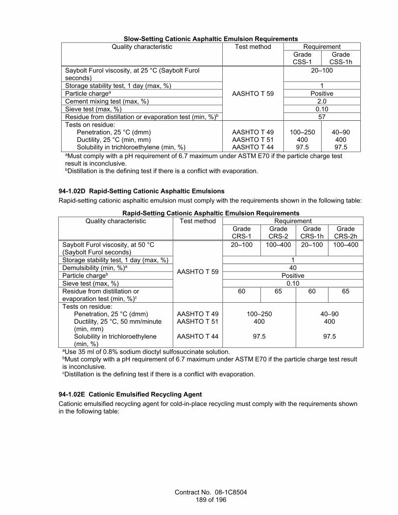
Contract No. 08-1C8504 189 of 196
Slow-Setting Cationic Asphaltic Emulsion Requirements Quality characteristic Test method Requirement
Grade CSS-1
Grade CSS-1h
Saybolt Furol viscosity, at 25 °C (Saybolt Furol seconds)
AASHTO T 59
20–100
Storage stability test, 1 day (max, %) 1 Particle chargea Positive Cement mixing test (max, %) 2.0 Sieve test (max, %) 0.10 Residue from distillation or evaporation test (min, %)b 57 Tests on residue:
Penetration, 25 °C (dmm) Ductility, 25 °C (min, mm) Solubility in trichloroethylene (min, %)
AASHTO T 49 AASHTO T 51 AASHTO T 44
100–250
400 97.5
40–90 400 97.5
aMust comply with a pH requirement of 6.7 maximum under ASTM E70 if the particle charge test result is inconclusive. bDistillation is the defining test if there is a conflict with evaporation.
94-1.02D Rapid-Setting Cationic Asphaltic Emulsions Rapid-setting cationic asphaltic emulsion must comply with the requirements shown in the following table:
Rapid-Setting Cationic Asphaltic Emulsion Requirements Quality characteristic Test method Requirement
Grade CRS-1
Grade CRS-2
Grade CRS-1h
Grade CRS-2h
Saybolt Furol viscosity, at 50 °C (Saybolt Furol seconds)
AASHTO T 59
20–100 100–400 20–100 100–400
Storage stability test, 1 day (max, %) 1 Demulsibility (min, %)a 40 Particle chargeb Positive Sieve test (max, %) 0.10 Residue from distillation or evaporation test (min, %)c
60 65 60 65
Tests on residue: Penetration, 25 °C (dmm) Ductility, 25 °C, 50 mm/minute (min, mm) Solubility in trichloroethylene (min, %)
AASHTO T 49 AASHTO T 51
AASHTO T 44
100–250
400
97.5
40–90 400
97.5
aUse 35 ml of 0.8% sodium dioctyl sulfosuccinate solution. bMust comply with a pH requirement of 6.7 maximum under ASTM E70 if the particle charge test result is inconclusive. cDistillation is the defining test if there is a conflict with evaporation.
94-1.02E Cationic Emulsified Recycling Agent Cationic emulsified recycling agent for cold-in-place recycling must comply with the requirements shown in the following table:
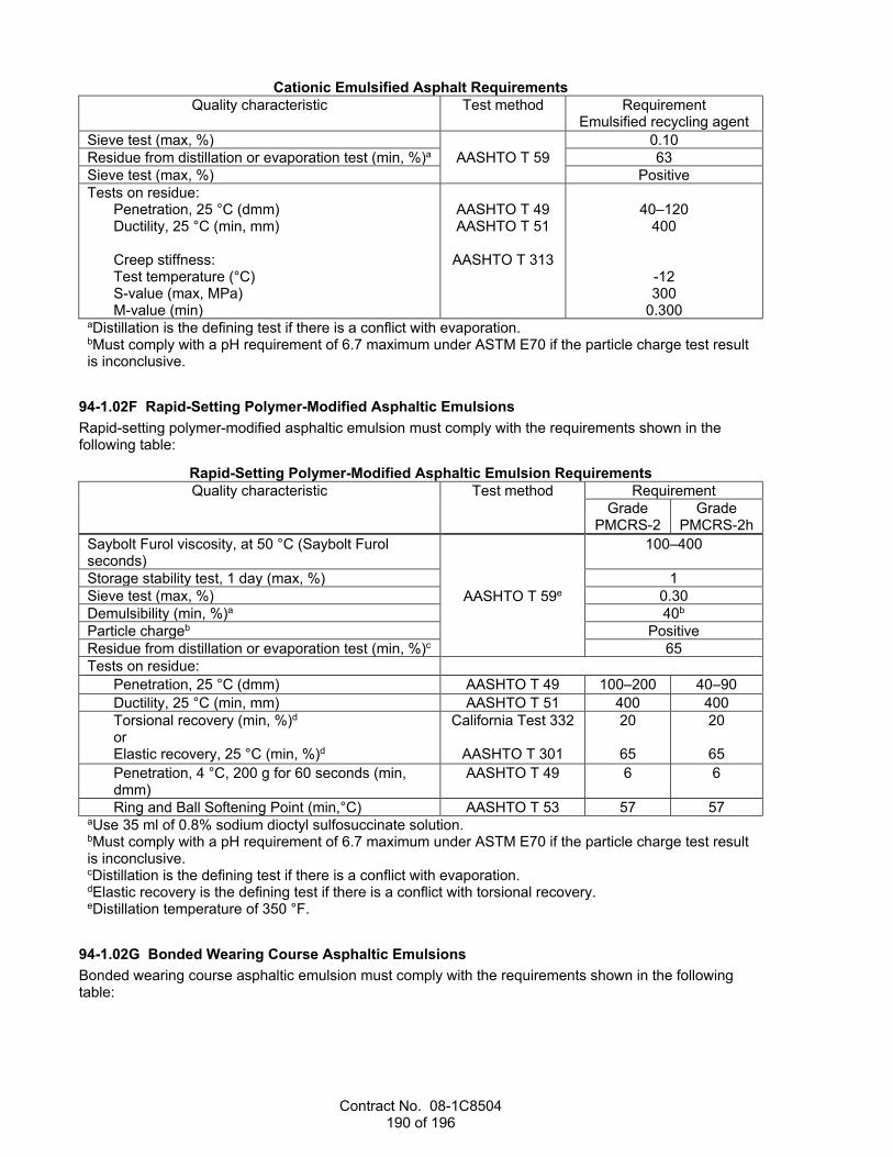
Contract No. 08-1C8504 190 of 196
Cationic Emulsified Asphalt Requirements Quality characteristic Test method Requirement
Emulsified recycling agent Sieve test (max, %)
AASHTO T 59 0.10
Residue from distillation or evaporation test (min, %)a 63 Sieve test (max, %) Positive Tests on residue:
Penetration, 25 °C (dmm) Ductility, 25 °C (min, mm) Creep stiffness: Test temperature (°C) S-value (max, MPa) M-value (min)
AASHTO T 49 AASHTO T 51
AASHTO T 313
40–120
400
-12 300
0.300 aDistillation is the defining test if there is a conflict with evaporation. bMust comply with a pH requirement of 6.7 maximum under ASTM E70 if the particle charge test result is inconclusive.
94-1.02F Rapid-Setting Polymer-Modified Asphaltic Emulsions Rapid-setting polymer-modified asphaltic emulsion must comply with the requirements shown in the following table:
Rapid-Setting Polymer-Modified Asphaltic Emulsion Requirements Quality characteristic Test method Requirement
Grade PMCRS-2
Grade PMCRS-2h
Saybolt Furol viscosity, at 50 °C (Saybolt Furol seconds)
AASHTO T 59e
100–400
Storage stability test, 1 day (max, %) 1 Sieve test (max, %) 0.30 Demulsibility (min, %)a 40b Particle chargeb Positive Residue from distillation or evaporation test (min, %)c 65 Tests on residue:
Penetration, 25 °C (dmm) AASHTO T 49 100–200 40–90 Ductility, 25 °C (min, mm) AASHTO T 51 400 400 Torsional recovery (min, %)d or Elastic recovery, 25 °C (min, %)d
California Test 332
AASHTO T 301
20
65
20
65 Penetration, 4 °C, 200 g for 60 seconds (min, dmm)
AASHTO T 49 6 6
Ring and Ball Softening Point (min,°C) AASHTO T 53 57 57 aUse 35 ml of 0.8% sodium dioctyl sulfosuccinate solution. bMust comply with a pH requirement of 6.7 maximum under ASTM E70 if the particle charge test result is inconclusive. cDistillation is the defining test if there is a conflict with evaporation. dElastic recovery is the defining test if there is a conflict with torsional recovery. eDistillation temperature of 350 °F.
94-1.02G Bonded Wearing Course Asphaltic Emulsions Bonded wearing course asphaltic emulsion must comply with the requirements shown in the following table:
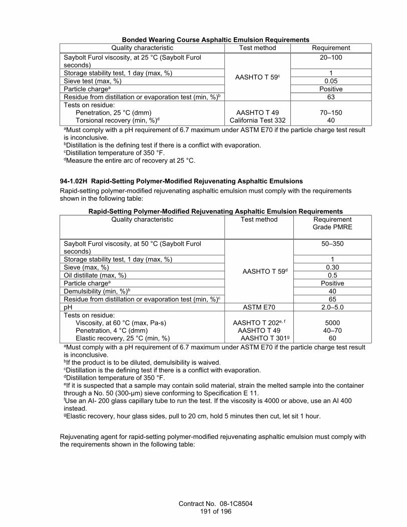
Contract No. 08-1C8504 191 of 196
Bonded Wearing Course Asphaltic Emulsion Requirements Quality characteristic Test method Requirement
Saybolt Furol viscosity, at 25 °C (Saybolt Furol seconds)
AASHTO T 59c
20–100
Storage stability test, 1 day (max, %) 1 Sieve test (max, %) 0.05 Particle chargea Positive Residue from distillation or evaporation test (min, %)b 63 Tests on residue:
Penetration, 25 °C (dmm) Torsional recovery (min, %)d
AASHTO T 49
California Test 332
70–150
40 aMust comply with a pH requirement of 6.7 maximum under ASTM E70 if the particle charge test result is inconclusive. bDistillation is the defining test if there is a conflict with evaporation. cDistillation temperature of 350 °F. dMeasure the entire arc of recovery at 25 °C.
94-1.02H Rapid-Setting Polymer-Modified Rejuvenating Asphaltic Emulsions Rapid-setting polymer-modified rejuvenating asphaltic emulsion must comply with the requirements shown in the following table:
Rapid-Setting Polymer-Modified Rejuvenating Asphaltic Emulsion Requirements Quality characteristic Test method Requirement
Grade PMRE
Saybolt Furol viscosity, at 50 °C (Saybolt Furol seconds)
AASHTO T 59d
50–350
Storage stability test, 1 day (max, %) 1 Sieve (max, %) 0.30 Oil distillate (max, %) 0.5 Particle chargea Positive Demulsibility (min, %)b 40 Residue from distillation or evaporation test (min, %)c 65 pH ASTM E70 2.0–5.0 Tests on residue:
Viscosity, at 60 °C (max, Pa-s) Penetration, 4 °C (dmm) Elastic recovery, 25 °C (min, %)
AASHTO T 202e, f
AASHTO T 49 AASHTO T 301g
5000 40–70
60 aMust comply with a pH requirement of 6.7 maximum under ASTM E70 if the particle charge test result is inconclusive. bIf the product is to be diluted, demulsibility is waived. cDistillation is the defining test if there is a conflict with evaporation. dDistillation temperature of 350 °F. eIf it is suspected that a sample may contain solid material, strain the melted sample into the container through a No. 50 (300-µm) sieve conforming to Specification E 11. fUse an AI- 200 glass capillary tube to run the test. If the viscosity is 4000 or above, use an AI 400 instead. gElastic recovery, hour glass sides, pull to 20 cm, hold 5 minutes then cut, let sit 1 hour.
Rejuvenating agent for rapid-setting polymer-modified rejuvenating asphaltic emulsion must comply with the requirements shown in the following table:

Contract No. 08-1C8504 192 of 196
Rejuvenating Agent Requirements Quality characteristic Test method Requirement
Tests on rejuvenating agent: Viscosity, at 60 °C (cSt) Flash point (min, °C) Saturate (max, % by weight) Asphaltenes (max)
AASHTO T 201 AASHTO T 48 ASTM D2007 ASTM D2007
50–175
193 30 1.0
Tests on rejuvenating agent Rolling Thin-Film Oven Test residue: Weight change (max, %) Viscosity ratio (max)a
AASHTO T 240
6.5 3
aRolling Thin-Film Oven Test (RTFOT) viscosity divided by the original viscosity.
94-1.02I Quick-Setting Asphaltic Emulsions Quick-setting asphaltic emulsion must comply with the requirements shown in the following table:
Quick-Setting Asphaltic Emulsion Requirements Quality characteristic Test method Requirement
Anionic Cationic Grade QS-1
Grade QS-1h
Grade CQS-1
Grade CQS-1h
Saybolt Furol viscosity, at 25 °C (Saybolt Furol seconds)
AASHTO T 59
15–90
Storage stability test, 1 day (max, %) 1 Particle chargea -- Positive Sieve test (max, %) 0.30 Residue from distillation or evaporation test (min, %)b
57
Tests on residue: Penetration, 25 °C (dmm) Ductility, 25 °C (min, mm) Solubility in trichloroethylene (min, %)
AASHTO T 49 AASHTO T 51 AASHTO T 44
100–200
400 97.5
40–90
400 97.5
100–200
400 97.5
40–90 400 97.5
aIf the result of the particle charge test is inconclusive; the asphaltic emulsion must be tested for pH under ASTM E70. Grade QS-1h asphaltic emulsion must have a minimum pH of 7.3. Grade CQS-1h asphaltic emulsion must have a maximum pH of 6.7. bDistillation is the defining test if there is a conflict with evaporation.
94-1.02J Quick-Setting Polymer-Modified Cationic Asphaltic Emulsions Quick-setting polymer-modified cationic asphaltic emulsion must comply with the requirements shown in the following table:
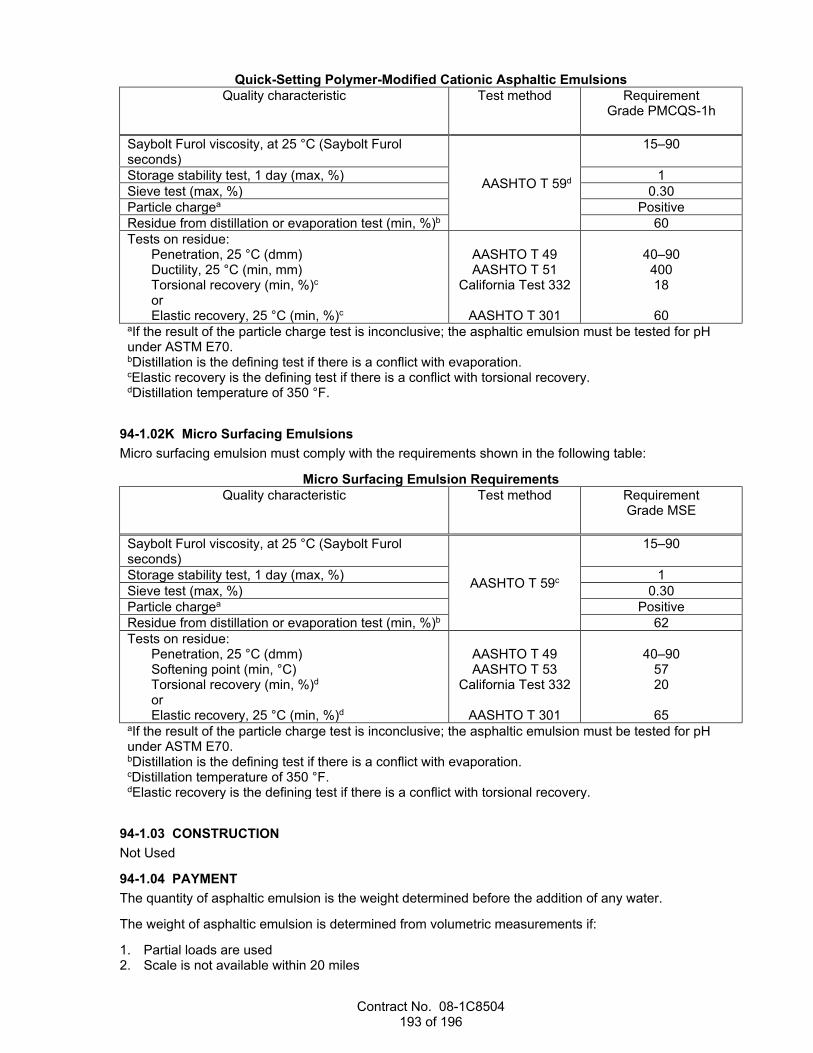
Contract No. 08-1C8504 193 of 196
Quick-Setting Polymer-Modified Cationic Asphaltic Emulsions Quality characteristic Test method Requirement
Grade PMCQS-1h
Saybolt Furol viscosity, at 25 °C (Saybolt Furol seconds)
AASHTO T 59d
15–90
Storage stability test, 1 day (max, %) 1 Sieve test (max, %) 0.30 Particle chargea Positive Residue from distillation or evaporation test (min, %)b 60 Tests on residue:
Penetration, 25 °C (dmm) Ductility, 25 °C (min, mm) Torsional recovery (min, %)c or Elastic recovery, 25 °C (min, %)c
AASHTO T 49 AASHTO T 51
California Test 332
AASHTO T 301
40–90 400 18
60 aIf the result of the particle charge test is inconclusive; the asphaltic emulsion must be tested for pH under ASTM E70. bDistillation is the defining test if there is a conflict with evaporation. cElastic recovery is the defining test if there is a conflict with torsional recovery. dDistillation temperature of 350 °F.
94-1.02K Micro Surfacing Emulsions Micro surfacing emulsion must comply with the requirements shown in the following table:
Micro Surfacing Emulsion Requirements Quality characteristic Test method Requirement
Grade MSE
Saybolt Furol viscosity, at 25 °C (Saybolt Furol seconds)
AASHTO T 59c
15–90
Storage stability test, 1 day (max, %) 1 Sieve test (max, %) 0.30 Particle chargea Positive Residue from distillation or evaporation test (min, %)b 62 Tests on residue:
Penetration, 25 °C (dmm) Softening point (min, °C) Torsional recovery (min, %)d or Elastic recovery, 25 °C (min, %)d
AASHTO T 49 AASHTO T 53
California Test 332
AASHTO T 301
40–90
57 20
65 aIf the result of the particle charge test is inconclusive; the asphaltic emulsion must be tested for pH under ASTM E70. bDistillation is the defining test if there is a conflict with evaporation. cDistillation temperature of 350 °F. dElastic recovery is the defining test if there is a conflict with torsional recovery.
94-1.03 CONSTRUCTION Not Used
94-1.04 PAYMENT The quantity of asphaltic emulsion is the weight determined before the addition of any water.
The weight of asphaltic emulsion is determined from volumetric measurements if:
1. Partial loads are used 2. Scale is not available within 20 miles

Contract No. 08-1C8504 194 of 196
3. Asphaltic emulsion is delivered in: 3.1. Trucks with each tank calibrated and accompanied by its measuring stick and calibration card 3.2. Trucks equipped with a vehicle tank meter and a calibrated thermometer that determines the
asphalt temperature at delivery
For volumetric measurements, the measured volume of asphaltic emulsion is reduced to the volume the material would occupy at 60 degrees F. One ton of asphaltic emulsion at 60 degrees F equals 240 gal. One gallon of asphaltic emulsion at 60 degrees F equals 8.33 lb.
Convert volume to weight using the factors shown in the following table:
Conversion Table t M t M t M t M
60 1.00000 83 0.99425 106 0.98850 129 0.98275 61 0.99975 84 0.99400 107 0.98825 130 0.98250 62 0.99950 85 0.99375 108 0.98800 131 0.98225 63 0.99925 86 0.99350 109 0.98775 132 0.98200 64 0.99900 87 0.99325 110 0.98750 133 0.98175 65 0.99875 88 0.99300 111 0.98725 134 0.98150 66 0.99850 89 0.99275 112 0.98700 135 0.98125 67 0.99825 90 0.99250 113 0.98675 136 0.98100 68 0.99800 91 0.99225 114 0.98650 137 0.98075 69 0.99775 92 0.99200 115 0.98625 138 0.98050 70 0.99750 93 0.99175 116 0.98600 139 0.98025 71 0.99725 94 0.99150 117 0.98575 140 0.98000 72 0.99700 95 0.99125 118 0.98550 141 0.97975 73 0.99675 96 0.99100 119 0.98525 142 0.97950 74 0.99650 97 0.99075 120 0.98500 143 0.97925 75 0.99625 98 0.99050 121 0.98475 144 0.97900 76 0.99600 99 0.99025 122 0.98450 145 0.97875 77 0.99575 100 0.99000 123 0.98425 146 0.97850 78 0.99550 101 0.98975 124 0.98400 147 0.97825 79 0.99525 102 0.98950 125 0.98375 148 0.97800 80 0.99500 103 0.98925 126 0.98350 149 0.97775 81 0.99475 104 0.98900 127 0.98325 150 0.97750 82 0.99450 105 0.98875 128 0.98300 151 0.97725
t = observed temperature in degrees F M = multiplier for reducing volumes to the basis of 60 °F
^^^^^^^^^^^^^^^^^^^^^^^^^^^^^^^^^^^^^^^^ 95 EPOXY
04-17-20 Replace section 95-1.02E with:
04-17-20 95-1.02E Epoxy Adhesive for Pavement Markers Epoxy adhesive for bonding pavement markers to concrete and HMA must comply with ASTM C881/C881M, Type IV, Grade 3, Class B or C except the gel time for epoxy adhesive may be less than 30 minutes.
Use Class B whenever the surface temperature is from 40 to 60 degrees F. Use Class C whenever the surface temperature is above 60 degrees F.
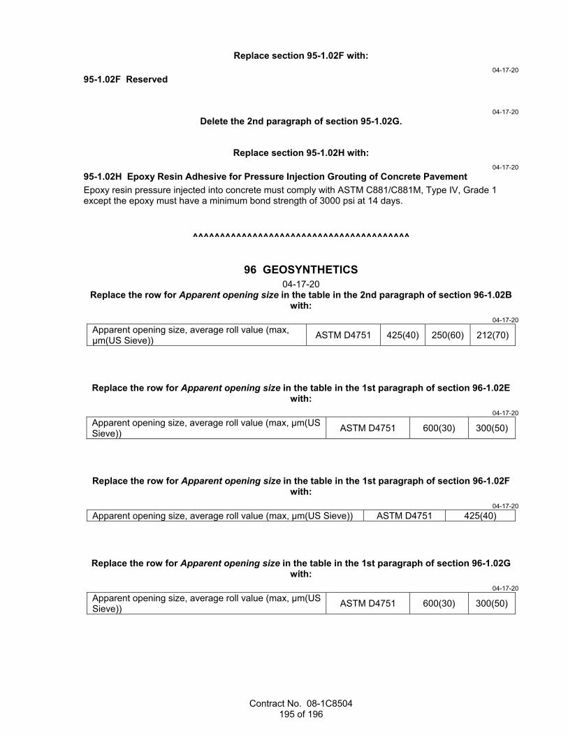
Contract No. 08-1C8504 195 of 196
Replace section 95-1.02F with: 04-17-20
95-1.02F Reserved
04-17-20 Delete the 2nd paragraph of section 95-1.02G.
Replace section 95-1.02H with: 04-17-20
95-1.02H Epoxy Resin Adhesive for Pressure Injection Grouting of Concrete Pavement Epoxy resin pressure injected into concrete must comply with ASTM C881/C881M, Type IV, Grade 1 except the epoxy must have a minimum bond strength of 3000 psi at 14 days.
^^^^^^^^^^^^^^^^^^^^^^^^^^^^^^^^^^^^^^^^
96 GEOSYNTHETICS 04-17-20
Replace the row for Apparent opening size in the table in the 2nd paragraph of section 96-1.02B with:
04-17-20 Apparent opening size, average roll value (max, µm(US Sieve)) ASTM D4751 425(40) 250(60) 212(70)
Replace the row for Apparent opening size in the table in the 1st paragraph of section 96-1.02E with:
04-17-20 Apparent opening size, average roll value (max, µm(US Sieve)) ASTM D4751 600(30) 300(50)
Replace the row for Apparent opening size in the table in the 1st paragraph of section 96-1.02F with:
04-17-20 Apparent opening size, average roll value (max, µm(US Sieve)) ASTM D4751 425(40)
Replace the row for Apparent opening size in the table in the 1st paragraph of section 96-1.02G with:
04-17-20 Apparent opening size, average roll value (max, µm(US Sieve)) ASTM D4751 600(30) 300(50)

Contract No. 08-1C8504 196 of 196
Replace the row for Apparent opening size in the table in the 1st paragraph of section 96-1.02H with:
04-17-20 Apparent opening size, average roll value (max, µm(US Sieve)) ASTM D4751 600(30) 300(50)
Replace the row for Apparent opening size in the table in the 3rd paragraph of section 96-1.02I with:
04-17-20 Apparent opening size (min and max, µm(US Sieve)) ASTM D4751 150(100)–212(70) 150(100)–212(70)
Replace the row for Apparent opening size in the table in the 2nd paragraph of section 96-1.02O with:
04-17-20 Apparent opening size (max, µm(US Sieve)) ASTM D4751 300(50) 300(50) 600(30) 300(50) 300(50)
Replace the 3rd table in the 3rd paragraph of section 96-1.02R with: 10-19-18
Cushion Fabric
Quality characteristic Test method Requirement Class 10 Class 12 Class 16 Class 24 Class 32 Class 60
Mass per unit area (oz/sq yd) ASTM D5261 10 12 16 24 32 60 Grab tensile break strength (min, lb) ASTM D4632 230 300 370 450 500 630 Grab tensile break elongation (min, %)
ASTM D4632 50
Puncture strength (min, lb) ASTM D6241 700 800 900 1100 1700 2400 Trapezoidal tear strength (min, lb) ASTM D4533 95 115 145 200 215 290 UV resistance (min, %) ASTM D7238 70