PROJECT MANUAL - BidNet
671
PROJECT MANUAL GOVERNMENT OF THE VIRGIN ISLANDS VIRGIN ISLANDS SPORTS PARKS AND RECREATION Marley Beach Waterfront Renovations Phase 1 ST. CROIX, U.S. VIRGIN ISLANDS Honorable Commissioner Derek Gabriel GOVERNMENT OF THE UNITED STATES VIRGIN ISLANDS DEPARTMENT OF PUBLIC WORKS 8244 SUBBASE ST. THOMAS, VIRGIN ISLANDS 00802 FOR Honorable Honorable Calvert A. White GOVERNMENT OF THE UNITED STATES VIRGIN ISLANDS VIRGIN ISLANDS SPORTS PARKS AND RECREATION 8201 SUBBASE SUIT 2 ST. THOMAS, V.I. 00802
-
Upload
khangminh22 -
Category
Documents
-
view
0 -
download
0
Transcript of PROJECT MANUAL - BidNet
PROJECT MANUAL
GOVERNMENT OF THE VIRGIN ISLANDS
VIRGIN ISLANDS SPORTS PARKS AND RECREATION
Marley Beach Waterfront Renovations Phase 1
ST. CROIX, U.S. VIRGIN ISLANDS
Honorable Commissioner Derek Gabriel
GOVERNMENT OF THE UNITED STATES VIRGIN ISLANDS
DEPARTMENT OF PUBLIC WORKS
8244 SUBBASE
ST. THOMAS, VIRGIN ISLANDS 00802
FOR
Honorable Honorable Calvert A. White GOVERNMENT OF THE UNITED STATES VIRGIN ISLANDS
VIRGIN ISLANDS SPORTS PARKS AND RECREATION 8201 SUBBASE SUIT 2
ST. THOMAS, V.I. 00802
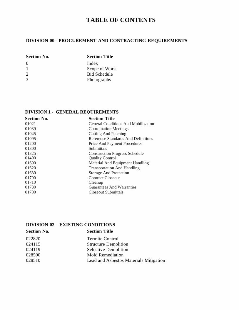
TABLE OF CONTENTS
DIVISION 00 - PROCUREMENT AND CONTRACTING REQUIREMENTS
Section No. Section Title
0 Index
1 Scope of Work
2 Bid Schedule
3 Photographs
DIVISION 1 - GENERAL REQUIREMENTS
Section No. Section Title 01021 General Conditions And Mobilization
01039 Coordination Meetings
01045 Cutting And Patching
01095 Reference Standards And Definitions
01200 Price And Payment Procedures
01300 Submittals
01325 Construction Progress Schedule 01400 Quality Control
01600 Material And Equipment Handling
01620 Transportation And Handling
01630 Storage And Protection
01700 Contract Closeout 01710 Cleanup 01730 Guarantees And Warranties
01780 Closeout Submittals
DIVISION 02 – EXISTING CONDITIONS
Section No. Section Title
022820 Termite Control
024115 Structure Demolition
024119 Selective Demolition
028500 Mold Remediation
028510 Lead and Asbestos Materials Mitigation
DIVISION 05 – METALS
Section No. Section Title
05100 Structural Steel
05300 Steel Decking
05300 Cols Formed Metal Framing
05500 Miscellaneous Metal Work
05500 Manhole Frames and Covers
DIVISION 09 - FINISHES
Section No. Section Title
092050 Plaster Trim And Accessories
092116.23 Gypsum Board Shaft Wall Assemblies
092216 Non-Structural Metal Framing
092400 Cement Plastering
092900 Gypsum Board
093013 Ceramic Tiling
095113 Acoustical Panel Ceiling
095426 Suspended Wood Ceilings
096513 Resilient Base and Accessories
096519 Resilient Tile Flooring
099113 Exterior Painting
099123 Interior Painting
DIVISION 26 – ELECTRICAL
Section No. Section Title
260500 Basic Electrical Materials And Methods
260510 Common Work Results For Electrical
260519 Low-Voltage Electrical Power Conductors And Cables
260526 Grounding And Bonding For Electrical
260529 Hangers And Supports For Electrical Systems
260533 Raceway And Boxes For Electrical Systems
260543 Underground Ducts And Raceways For Electrical Systems
260548 Vibration And Seismic Controls For Electrical Systems
260553 Identification For Electrical Systems
260923 Lighting Control Devices
262416 Panel Boards
262713 Electricity Metering
262726 Wiring Devices
262813 Fuses
262816 Enclosed Switches And Circuit Breakers
263213 Engine Generators
263600 Transfer Switches
264113 Lightning Protection For Structures
264313 Transient-Voltage Suppression For Low-Voltage Electrical Power
265100 Interior Lighting
265151 Interior Lighting
265600 Exterior Lighting
DIVISION 31 – EARTHWORK
Section No. Section Title
312110 Clearing and Grubbing
312200 Earthwork
312270 Erosion Control
DIVISION 32 - EXTERIOR IMPROVEMENTS
Section No. Section Title 323100 Decorative Metal Fences And Gates
323100 Ornamental Security Fencing And Gates
323113 Chain Link Fence And Gates
323119 Impasse II Security Steel Fence System, Ornamental Pale
323129 Wood Gates
323132 Wood Composite Fences and Gates
328000 Irrigation Systems
32900 Planting
32911 Soil Preparation
329213 Hydromulching
32920 Turf and Grasses
32930 Plants
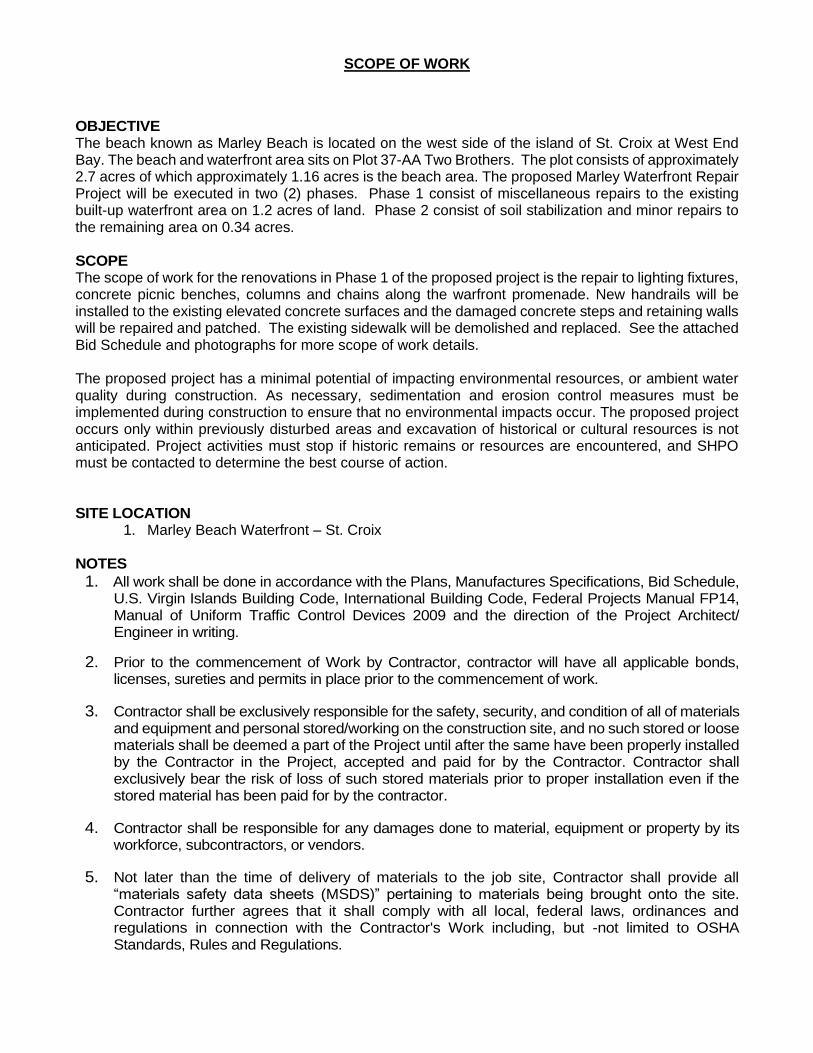
SCOPE OF WORK
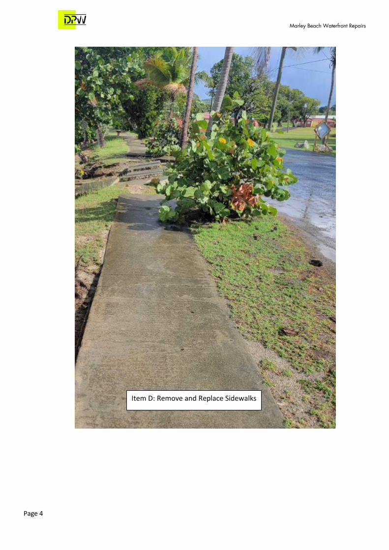
OBJECTIVE The beach known as Marley Beach is located on the west side of the island of St. Croix at West End Bay. The beach and waterfront area sits on Plot 37-AA Two Brothers. The plot consists of approximately 2.7 acres of which approximately 1.16 acres is the beach area. The proposed Marley Waterfront Repair Project will be executed in two (2) phases. Phase 1 consist of miscellaneous repairs to the existing built-up waterfront area on 1.2 acres of land. Phase 2 consist of soil stabilization and minor repairs to the remaining area on 0.34 acres. SCOPE The scope of work for the renovations in Phase 1 of the proposed project is the repair to lighting fixtures, concrete picnic benches, columns and chains along the warfront promenade. New handrails will be installed to the existing elevated concrete surfaces and the damaged concrete steps and retaining walls will be repaired and patched. The existing sidewalk will be demolished and replaced. See the attached Bid Schedule and photographs for more scope of work details. The proposed project has a minimal potential of impacting environmental resources, or ambient water quality during construction. As necessary, sedimentation and erosion control measures must be implemented during construction to ensure that no environmental impacts occur. The proposed project occurs only within previously disturbed areas and excavation of historical or cultural resources is not anticipated. Project activities must stop if historic remains or resources are encountered, and SHPO must be contacted to determine the best course of action. SITE LOCATION
1. Marley Beach Waterfront – St. Croix NOTES
1. All work shall be done in accordance with the Plans, Manufactures Specifications, Bid Schedule, U.S. Virgin Islands Building Code, International Building Code, Federal Projects Manual FP14, Manual of Uniform Traffic Control Devices 2009 and the direction of the Project Architect/ Engineer in writing.
2. Prior to the commencement of Work by Contractor, contractor will have all applicable bonds, licenses, sureties and permits in place prior to the commencement of work.
3. Contractor shall be exclusively responsible for the safety, security, and condition of all of materials and equipment and personal stored/working on the construction site, and no such stored or loose materials shall be deemed a part of the Project until after the same have been properly installed by the Contractor in the Project, accepted and paid for by the Contractor. Contractor shall exclusively bear the risk of loss of such stored materials prior to proper installation even if the stored material has been paid for by the contractor.
4. Contractor shall be responsible for any damages done to material, equipment or property by its workforce, subcontractors, or vendors.
5. Not later than the time of delivery of materials to the job site, Contractor shall provide all “materials safety data sheets (MSDS)” pertaining to materials being brought onto the site. Contractor further agrees that it shall comply with all local, federal laws, ordinances and regulations in connection with the Contractor's Work including, but -not limited to OSHA Standards, Rules and Regulations.
6. During the term of this Agreement, Contractor shall pay particular attention to the daily clean up and removal of all trash and rubbish generated on the job site by the Contractor or its vendors. Contractor shall be responsible for the removal of all rubbish and trash it has generated, from its work area on a daily basis and place all such rubbish and trash in waste containers located throughout the Project.
7. Upon the completion of the Contractor's Work, and when practical, the Contractor shall furnish the User Agency with a warranty acceptable in all respects to the User Agency to repair and/or -replace at the Contractor's sole expense all defects in materials and labor in the Contractor's Work appearing or occurring within one (1) year after the issuance of the certificate of occupancy of the premises upon which Subcontractor's Work is performed. Additionally, in the event the manufacturer of any material supplied by the Contractor to the Project exceeds the term of the Subcontractor's letter of credit or warranty, The Contractor shall further assign and deliver to the User Agency said manufacturer's warranty. Performance of warranty repair work and replacement of materials for defects occurring within the warranty period shall be the Contractor's sole and exclusive responsibility at the Contractor's sole and exclusive expense.
8. Any Work that is in addition to the work required by this Subcontract shall be construed as extra work ("EXTRA WORK"). Extra Work will be subject to prior written approval by the Department of Public Works and shall be granted or denied prior to the execution of any such Extra Work. Approved Extra Work shall be subject to the execution of a change order signed by an authorized representative of the Contractor and the Owner or Contractor which shall be executed prior to the furnishing of such materials or performance of such labor or both. Any Extra Work not so authorized in advance shall be performed or furnished at the sole expense of the Contractor, and neither the Contractor nor the Owner shall be liable or responsible to the Contractor for the payment of any such Extra Work. Extra work must be approved before it is done.
9. All materials supplied or used by the Contractor in the performance of its Work shall be as specified and approved by the Department of Public Works. Contractor shall submit all such materials to the Department of Public Works for approval prior to the installation thereof on the premises unless otherwise agreed or waived by the Department of Public Works in writing. All work and materials will be per the plans and specifications provided unless authorized in writing prior to starting the work.
10. If job is subject to inclement weather, it is the responsibility of the Contractor to keep track of these days and present to the Department of Public Works on a weekly basis to compare against their daily log. Days that are in agreement, will be placed in a change order format and will be presented with scheduled monthly payment.
11. The Contractor is contracted to provide complete construction, including code requirements, and workmanship of equal or better finishes based on the VI Building Code and to the intent of the contract documents. It is common and known that items of importance are sometimes overlooked in drawings and in specifications. If missing items would normally be included in a particular scope of work, or required for the completion of a particular trades work, then it is included in this contract and not an opportunity for change order work and be completed in all respects for the use intended as a part of this general cope.
12. Contractor agrees to furnish all labor, supervision, fasteners, tools, taxes, equipment, fuel fees, licenses, insurance and all other costs as required to perform all work covered in the construction scope of the applicable division that this Contractor represents itself as having expert knowledge in and regular engagement with Contractor shall call and cause all required inspections for his/her own work and convey all inspection results to the DPW Inspector/Engineer. If unsatisfactory results are discovered, this Contractor will immediately suspend its construction activities until such work is corrected and inspections are passed.
13. Upon reward of this contract, Contractor shall perform due diligence and shall prepare all necessary basic diagrams or layouts outlining his/her concerns. If value engineering or alterations to the plans/specifications is involved, such shall be presented to the Department of Public Works prior to the execution of the contract.
14. Contractor shall commence the work to be performed per the contract documents in accordance to the terms of this agreement commencing on the date specified and provided by the User Agency and shall complete all work by the finish date specified on the Construction Schedule or as adjusted from time to time by the Department of Public Works.
15. Under NO CIRCUMSTANCES will there be additional money granted for extra work without previous written authorization and executed change order from the User Agency.
16. Contractor shall be completely responsible and provide equipment for receiving, unloading, taking inventory, storing, protecting and signing for all materials installed under this agreement.
17. Contractor shall verify all detail and dimensions for fit of work in all regards.
18. Contractor acknowledges that he will provide the necessary manpower, required to maintain the project schedule in all phases of his/her work to include any required overtime.
19. Contractor will keep onsite material stockpiles and building workspace stockpiles to a minimum, organized and out of the way so as not to impede any other trades, and as directed by the Construction Manager.
20. Contractor is responsible for loss, theft and damage of all materials installed or otherwise until such material has been installed, approved and paid for by Contractor.
21. Contractor reserves the right, to supplement work after proper notification of non-performance has been given.
22. Contractor will furnish the names of the Subcontractors it introduces to the project.
23. Contractor will disclose the amounts of money owed to each subcontractor and submit proper lien waivers.
24. Contractor shall make himself/herself available for either weekly or biweekly meetings (as mutually agreed upon with the Department of Public Works) to discuss project progress/concerns. Any problems deemed an emergency shall be IMMEDIATELY made known to the Department of Public Works. The undersigned Contractor shall furnish all labor, equipment, machinery, material and miscellaneous items for the completion of the Project as outlined in the Contact Drawings, Specifications and Bid Schedule.
Photographs
By Department of Public Works For Department of Sports, Parks, & Recreation
Marley Beach Waterfront Repairs
Location Plan
Marley Beach Waterfront Repairs
Page 2
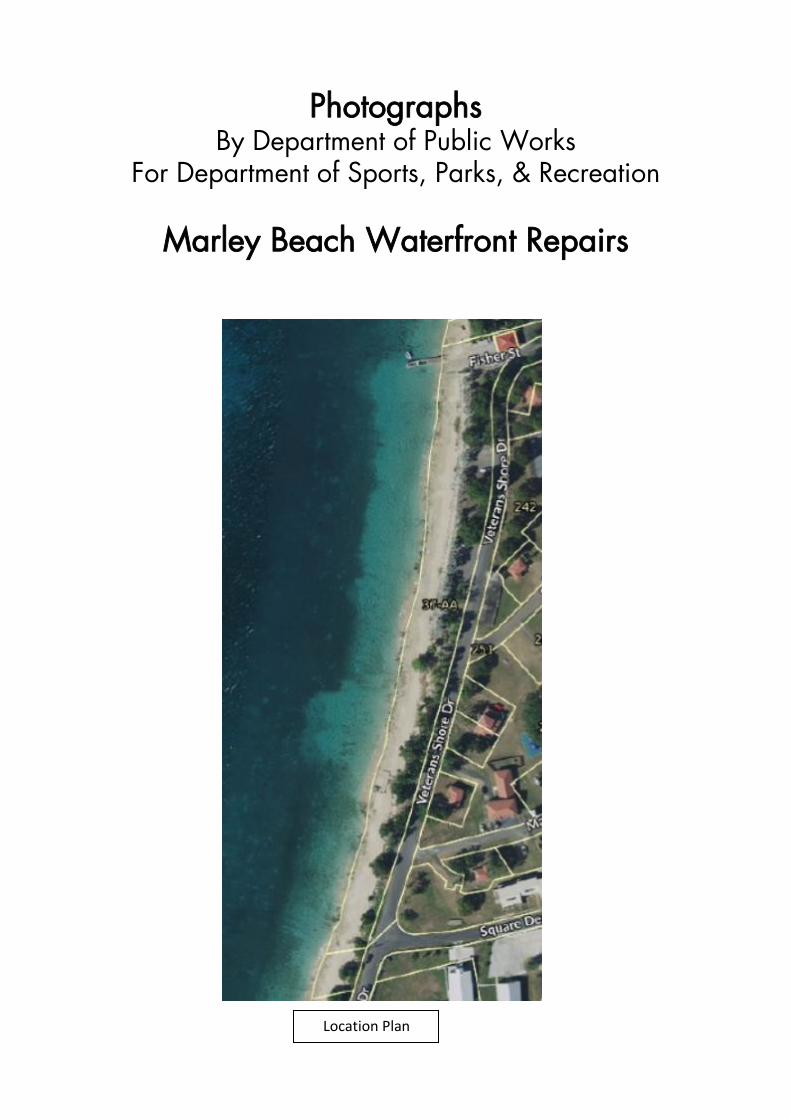
Item B: Concrete Benches
Item A: Concrete Table and 4-seat set and Benches
Marley Beach Waterfront Repairs
Page 3
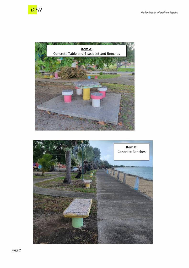
Item C: Demo Replace Existing Columns
Marley Beach Waterfront Repairs
Page 4
Item D: Remove and Replace Sidewalks

Marley Beach Waterfront Repairs
Page 5
Item E: Remove and replace all 5/8" diameter hot dip galvanized stud link chain
Match Similar Style
Marley Beach Waterfront Repairs
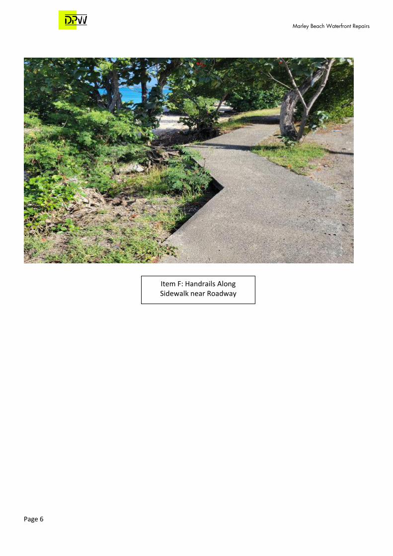
Page 6
Item F: Handrails Along Sidewalk near Roadway
Marley Beach Waterfront Repairs
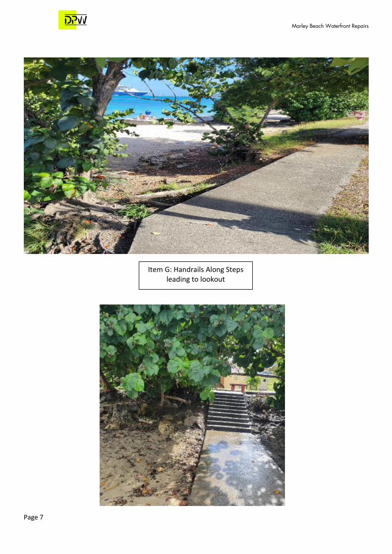
Page 7
Item G: Handrails Along Steps leading to lookout
Marley Beach Waterfront Repairs
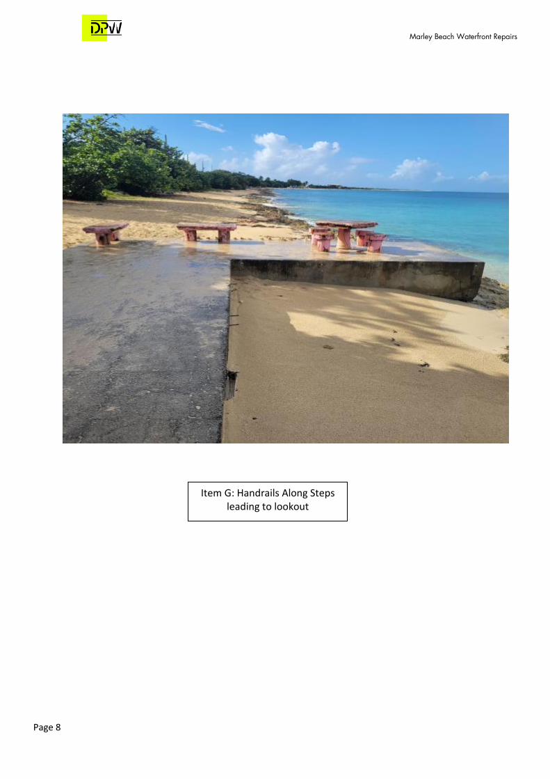
Page 8
Item G: Handrails Along Steps leading to lookout

Marley Beach Waterfront Repairs
Page 9
Item H: Install guard rail adjacent to roadway

Marley Beach Waterfront Repairs
Page 10
Item I & J:
Remove & Replace with LED Light Fixture
Marley Beach Waterfront Repairs
Page 11
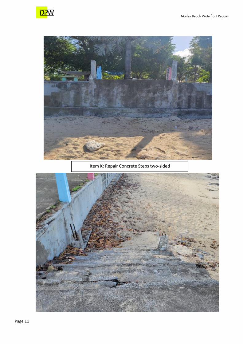
Item K: Repair Concrete Steps two-sided
Marley Beach Waterfront Repairs
Page 12
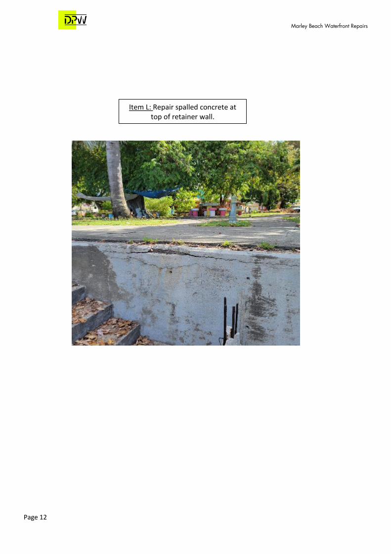
Item L: Repair spalled concrete at top of retainer wall.
Marley Beach Waterfront Repairs
Page 13
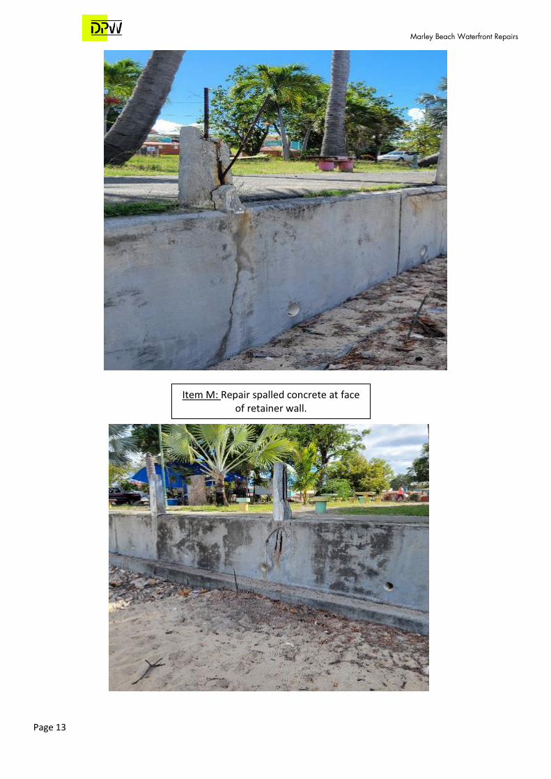
Item M: Repair spalled concrete at face of retainer wall.

Marley Beach Waterfront Repairs
Page 14
Item N: Purchase and install standalone hand sanitizing/hand washing stations
POLYJOHN
SKU: C1966729 OR EQUAL
MPN : BRA1-1000 Weight : 70.0 lb

DIVISION 1 – GENERAL REQUIREMENTS DEPARTMENT OF PUBLIC WORKS
SECTION 01039-COORDINATION AND MEETINGS DEPARTMENT OF PUBLIC WORKS,
Page 1 of 4
PART 1 - GENERAL
SECTION INCLUDES
Coordination and project conditions.
Field engineering.
Preconstruction meeting.
Site mobilization meeting.
Progress meeting.
Pre-installation meetings.
Equipment electrical characteristics and components.
Examination.
Preparation.
Cutting and Patching.
Alteration project procedures.
RELATED SECTIONS (NOT USED)
COORDINATION AND PROJECT CONDITIONS
Coordinate scheduling, submittals, and Work of the various sections of the Specifications to
ensure an efficient and orderly sequence of construction elements.
Verify all existing utility locations.
FIELD ENGINEERING
Contractor shall locate and protect all survey control and reference points, and shall accurately
replace and have verified by the Engineer any such point, which is damaged or moved, at his
own expense.
Control datum for survey is as that shown on Drawings. The survey shall establish certain
reference points and benchmarks in the immediate vicinity of the work areas. The Contractor
shall lay out all additional lines and grades and otherwise do all layout and measurements
necessary for the proper completion of the work.
Verify setbacks and easements; confirm drawings dimensions and elevations.
Provide field engineering services. Establish elevations, lines, and levels, utilizing recognized
engineering survey practices.
SECTION 01039-COORDINATION AND MEETINGS DEPARTMENT OF PUBLIC WORKS,
Page 2 of 4
The Contractor shall furnish assistance to the Engineer as requested to check the layout or
otherwise control the work. Such assistance shall be understood to include the provision of
suitable manpower to assist the Engineer in taping measurements, holding a survey rod for
checking grades and the like.
The Engineer reserves the right to inspect or check any of this work, and the Contractor shall
not claim added compensation for any delay occasioned by required as a result of the Engineer's
inspections.
PRECONSTRUCTION MEETING
Owner will schedule a meeting after Notice of Award.
Attendance Required:
Owner, Owner’s Construction Representative, Designer, and Contractor.
Agenda:
1. Submission of list of testing agency and other parties providing services on the project.
2. Procedures and processing of field decisions, submittals, and substitutions, applications for
payments, pricing request, Change Orders, and Contract closeout procedures.
3. Procedures for layout of the project, establishing controls, limits of right-of-way and
easements.
4. Scheduling.
Owner’s Representative shall record minutes and distribute copies to participants and those affected
by decisions made.
SITE MOBILIZATION MEETING
Owner’s Representative may schedule a meeting at the project site prior to construction start-up.
Attendance Required:
Owner’s Representative/Engineer, Contractor's Superintendent, and major Subcontractors.
Agenda:
1. Use of the site by Owner and Contractor.
2. Owner's requirements. Features to remain.
3. Construction facilities provided by Contractor.
4. Temporary utilities provided by Contractor.
1. Security and housekeeping procedures.
2. Schedules.
3. Application for payment procedures.
SECTION 01039-COORDINATION AND MEETINGS DEPARTMENT OF PUBLIC WORKS,
Page 3 of 4
4. Procedures for testing.
5. Procedures for maintaining record documents.
Contractor will record minutes and distribute copies to participants and those affected by decisions
made.
PROGRESS MEETINGS
Schedule and administer meetings throughout the progress of the Work at weekly intervals or
intervals agreed to by Owner’s Representative and Contractor.
Contractor shall arrange bi-weekly meetings, prepare agenda with copies for participants, and
preside at meetings.
Attendance Required:
Job superintendent, major Subcontractors suppliers, and Owner’s Representative as
appropriate to agenda topics for each meeting.
Agenda:
1. Review minutes of previous meetings.
2. Review of Work progress.
3. Field observations, problems, and decisions.
4. Identification of problems which impede planned progress.
1. Review of submittals schedule and status of submittals.
2. Review of off-site fabrication and delivery schedules.
3. Maintenance of progress schedule.
4. Corrective measures to regain projected schedule.
5. Planned progress during succeeding work period.
6. Coordination of projected progress.
7. Maintenance of quality and work standards.
8. Effect of proposed changes on progress schedule and coordination.
9. Other business relating to Work.
Contractor will record minutes and distribute copies to participants and those affected by
decisions made.
PART 2 - PRODUCTS (NOT USED)
PART 3 - EXECUTION (NOT USED)

SECTION 01039-COORDINATION AND MEETINGS DEPARTMENT OF PUBLIC WORKS,
Page 4 of 4
END OF SECTION
SECTION 01045-CUTTING AND PATCHING DEPARTMENT OF PUBLIC WORKS
Page 1 of 4
PART 1 - GENERAL
RELATED DOCUMENTS
Drawings and general provisions of Contract, including General and Supplementary Conditions
and other Division- 1 Specification Sections, apply to this Section.
SUMMARY
This Section specifies administrative and procedural requirements for cutting and patching.
Refer to other Sections for specific requirements and limitations applicable to cutting and patching
individual parts of the Work.
1. Requirements of this Section apply to mechanical and electrical installations. Refer to
Division- 23 and Division- 26 Sections for other requirements and limitations applicable to
cutting and patching mechanical and electrical installations.
2. Demolition of selected portions of the building for alterations is included in Section
"Selective Demolition."
SUBMITTALS
Cutting and Patching Proposal:
Where approval of procedures for cutting and patching is required before proceeding,
submit a proposal describing procedures well in advance of the time cutting and patching
will be performed and request approval to proceed. Include the following information,
as applicable, in the proposal:
1. Describe the extent of cutting and patching required and how it is to be performed
indicate why it cannot be avoided.
2. Describe anticipated results in terms of changes to existing construction; include changes
to structural elements and operating components as well as changes in the building's
appearance and other significant visual elements.
1. List products to be used and firms or entities that will perform Work.
2. Indicate dates when cutting and patching is to be performed.
3. List utilities that will be disturbed or affected, including those that will be relocated and
those that will be temporarily out-of-service. Indicate how long service will be disrupted.
4. Where cutting and patching involves addition of reinforcement to structural elements,
submit details and engineering calculations to show how reinforcement is integrated with
the original structure.
5. Approval by the Owner/Owner’s Representative to proceed with cutting and patching does
not waive the Owner/Owner’s Representative's right to later require complete removal and
replacement of a part of the Work found to be unsatisfactory.
QUALITY ASSURANCE
SECTION 01045-CUTTING AND PATCHING DEPARTMENT OF PUBLIC WORKS
Page 2 of 4
Requirements for Structural Work:
Do not cut and patch structural elements in a manner that would reduce their load-
carrying capacity or load-deflection ratio.
1. Obtain approval of the cutting and patching pricing proposal before cutting and patching
the following structural elements:
a. Foundation construction
b. Bearing and retaining walls
c. Structural concrete
d. Structural steel
e. Lintels
f. Timber and primary wood framing
g. Miscellaneous structural metals
h. Exterior curtain wall construction
Operational and Safety Limitations:
Do not cut and patch operating elements or safety related components in a manner that
would result in reducing their capacity to perform as intended, or result in increased
maintenance, or decreased operational life or safety.
1. Obtain approval of the cutting and patching pricing proposal before cutting and patching
the following operating elements or safety related systems:
l. Shoring, bracing, and sheeting.
m. Water, moisture, or vapor barriers.
n. Membranes and flashings.
o. Electrical wiring systems.
Visual Requirements:
Do not cut and patch construction exposed on the exterior or in occupied spaces, in a
manner that would, in the Owner’s Representative's opinion, reduce the building's aesthetic
qualities, or result in visual evidence of cutting and patching. Remove and replace Work
cut and patched in a visually unsatisfactory manner.
PART 2 - PRODUCTS
MATERIALS
Use materials that are identical to existing materials. If identical materials are not available or
cannot be used where exposed surfaces are involved, use materials that fully match existing
adjacent surfaces possible with regard to visual effect. Use materials whose installed performance
will equal or surpass that of existing materials.

SECTION 01045-CUTTING AND PATCHING DEPARTMENT OF PUBLIC WORKS
Page 3 of 4
PART 3 - EXECUTION
INSPECTION
Before cutting existing surfaces, examine surfaces to be cut and patched and conditions under
which cutting and patching is to be performed. Take corrective action before proceeding, if
unsafe or unsatisfactory conditions are encountered.
1. Before proceeding, meet at the site with parties involved in cutting and patching, including
mechanical and electrical trades. Review areas of potential interference and conflict.
Coordinate procedures and resolve potential conflicts before proceeding.
PREPARATION
Temporary Support:
Provide temporary support of Work to be cut.
Protection:
Protect existing construction during cutting and patching to prevent damage. Provide
protection from adverse weather conditions for portions of the Project that might be
exposed during cutting and patching operations.
Avoid interference with use of adjoining areas or interruption of free passage to adjoining areas.
Take all precautions necessary to avoid cutting existing pipe, conduit or ductwork serving the
building, but scheduled to be removed or relocated until provisions have been made to bypass
them.
PERFORMANCE
General:
Employ skilled workmen to perform cutting and patching. Proceed with cutting and
patching at the earliest feasible time and complete without delay.
1. Cut existing construction to provide for installation of other components or performance of
other construction activities and the subsequent fitting and patching required to restore
surfaces to their original condition.
Cutting:
Cut existing construction using methods least likely to damage elements to be retained
or adjoining construction. Where possible review proposed procedures with the original
installer; comply with the original installer's recommendations.
1. In general, where cutting is required use hand or small power tools designed for sawing or
grinding, not hammering and chopping. Cut holes and slots neatly to size required with
minimum disturbance of adjacent surfaces. Temporarily cover openings when not in use.
2. To avoid marring existing finished surfaces, cut or drill from the exposed or finished side
into concealed surfaces.
1. Cut through concrete and masonry using a cutting machine such as a carborundum saw
or diamond core drill.
SECTION 01045-CUTTING AND PATCHING DEPARTMENT OF PUBLIC WORKS
Page 4 of 4
2. Comply with requirements of applicable Sections of Division- 2 where cutting and
patching requires excavating and backfilling.
3. By-pass utility services such as pipe or conduit, before cutting, where services are shown
or required to be removed, relocated or abandoned. Cut-off pipe or conduit in walls or
partitions to be removed. Cap, valve or plug and seal the remaining portion of pipe or
conduit to prevent entrance of moisture or other foreign matter after by-passing and
cutting.
Patching:
Patch with durable seams that are as invisible as possible. Comply with specified
tolerances.
1. Where feasible, inspect and test patched areas to demonstrate integrity of the installation.
2. Restore exposed finishes of patched areas and extend finish restoration into retained
adjoining construction in a manner that will eliminate evidence of patching and refinishing.
CLEANING
Thoroughly clean areas and spaces where cutting and patching is performed or used as access.
Remove completely paint, mortar, oils, putty and items of similar nature. Thoroughly clean
piping, conduit and similar features before painting or other finishing is applied. Restore
damaged pipe covering to its original condition.
END OF SECTION
SECTION 01095 – REFERENCE STANDARDS AND DEFINITIONS DEPARTMENT OF PUBLIC WORKS
Page 1 of 4
PART 1 - GENERAL
RELATED DOCUMENTS
Drawings and general provisions of the Contract, including General and Special Provisions or
Supplementary Conditions and other Division I Specification Sections, apply to this Section.
DEFINITIONS
General:
Basic Contract definitions are included in the Conditions of the Contract.
Indicated:
The term indicated refers to graphic representations, notes, or schedules on Drawings, or
other Paragraphs of Schedules in the Specifications, and similar requirements in the
Contract Documents. Terms such as shown, noted, scheduled, and specified are used
to help the reader locate the reference. There is no limitation on location.
Directed:
Terms such as directed, requested, authorized, selected, approved, required and
permitted mean directed by the Owner’s Representative, requested by the Owner’s
Representative, and similar phrases.
Approved:
The term approved, when used in conjunction with the Owner’s Representative's action on
the Contractor's submittals, applications, and requests, is limited to the Owner’s
Representative's duties and responsibilities as stated in the Conditions of the Contract.
Regulations:
The term regulations includes laws, ordinances, statutes, and lawful orders issued by
authorities having jurisdiction, as well as rules, conventions, and agreements within the
construction industry that control performance of the Work.
Furnish:
The term furnish means supply and deliver to the Project site, ready for unloading,
unpacking, assembly, installation, and similar operations.
Install:
The term describes operations at the Project site including the actual unloading,
unpacking, assembly, erection, placing, anchoring, applying, working to dimension, and
finishing, curing, protecting, cleaning, and similar operations.
Provide:
The term provide means to furnish and install, complete and ready for the intended use.
Installer:
An installer is the Contractor or another entity engaged by the Contractor, either as an
employee, subcontractor, or contractor of lower tier, to perform a particular construction
activity, including installation, erection, application, and similar operations. Installers
are required to be experienced in the operations they are engaged to perform.

SECTION 01095 – REFERENCE STANDARDS AND DEFINITIONS DEPARTMENT OF PUBLIC WORKS
Page 2 of 4
Trades:
Using terms such as carpentry is not intended to imply that certain construction activities
must be performed by accredited or unionized individuals of a corresponding generic
name, such as carpenter. It also does not imply that requirements specified apply
exclusively to tradespersons of the corresponding generic name.
Project site:
The space available to the Contractor for performing construction activities either
exclusively or in conjunction with others performing other work as part of the Project.
The extent of the Project site is shown on the Drawings and may or may not be identical
with the description of the land on which the Project is to be built.
Testing Agencies:
A testing agency is an independent entity engaged to perform specific inspections or
tests, either at the Project site or elsewhere, or to reports on and, if required, to interpret
results of those inspections or tests.
Owner’s Representative:
Agent authorized to act on behalf of the Owner.
SPECIFICATION FORMAT AND CONTENT EXPLANATION
Specification Format:
These Specifications are organized into Divisions and Sections based on the Construction
Specification Institute's 50 - Division Format and MASTER FORMAT numbering
system.
Specification Content:
This Specification uses certain conventions regarding the style of language and the
intended meaning of certain terms, words, and phrases when used in particular situations
or circumstances. These conventions are explained as follows:
1. Abbreviated Language:
Language used in Specifications and other Contract Documents is abbreviated. Words and
meanings shall be interpreted as appropriate. Words that are implied, but not stated, shall
be interpolated as the sense requires. Singular words will be interpreted as plural and
plural words interpreted as singular where applicable as the context of the Contract
Documents indicate.
2. Imperative and streamlined language is used generally in the Specifications. Requirements
expressed in the imperative mood are to be performed by the Contractor. At certain locations
in the Text, subject language is used for clarity to describe responsibilities that must be
fulfilled indirectly by the Contractor, or by other means when so noted.
a. The words "shall be" are implied wherever a colon (:) is used within a sentence or
phrase.
INDUSTRY STANDARDS
Applicability of Standards:

SECTION 01095 – REFERENCE STANDARDS AND DEFINITIONS DEPARTMENT OF PUBLIC WORKS
Page 3 of 4
Except where the Contract Documents include more stringent requirements, applicable
construction industry standards have the same force and effect as if bound or copied
directly into the Contract Documents to the extent referenced. Such standards are made a
part of the Contract Documents by reference.
Publication Dates:
Comply with the standards in effect as of the date of the Contract Documents.
Conflicting Requirements:
Where compliance with two or more standard is specified and where the standards may
establish different or conflicting requirements for minimum quantities or quality levels,
refer requirements that are different but apparently equal and other uncertainties to the
Owner’s Representative for a decision before proceeding.
1 . Minimum Quantity or Quality Levels:
The quantity or quality level shown or specified shall be the minimum provided or
performed. The actual installation may comply exactly with the minimum quantity or
quality specified, or it may exceed the minimum within reasonable limits. To comply
with these requirements, indicated numeric values are minimum or maximum, as
appropriate, for the context of the requirements. Refer uncertainties to the Owner’s
Representative for a decision before proceeding.
Copies of Standards:
Each entity engaged in construction on the project is required to be familiar with industry
standards applicable to its construction activity. Copies of applicable standards are not
bound with the Contract Documents.
1. Where copies of standards are needed to perform a required construction activity, the
Contractor shall obtain copies directly from the publication source.
Abbreviations and Names:
Trade association names and titles of general standards are frequently abbreviated.
Where such acronyms or abbreviations are used in the Specifications or other Contract
Documents, they mean the recognized name of the trade association, standards-
generating organization, authority having jurisdiction, or other entity applicable to the
context of the Text provision. Refer to the "Encyclopedia of Associations," published
by Gale Research Co., available in most libraries.
SUBMITTALS
Permits, Licenses, and Certificates:
For the Owner’s records, submit copies of permits, licenses, certifications, inspection
reports, releases, jurisdictional settlements, notices, receipts for fee payments,
judgments, and similar documents, correspondence, and records established in
conjunction with compliance with standards and regulations bearing upon performance
of the Work.

SECTION 01095 – REFERENCE STANDARDS AND DEFINITIONS DEPARTMENT OF PUBLIC WORKS
Page 4 of 4
PART 2 - PRODUCTS (NOT APPLICABLE)
PART 3 - EXECUTION (NOT APPLICABLE)
END OF SECTION

SECTION 01200 – PRICE AND PAYMENT PROCEDURES DEPARTMENT OF PUBLIC WORKS
Page 1 of 4
PART 1 - GENERAL
SECTION INCLUDES
Procedures for preparation and submittal of applications for progress payments.
Documentation of changes in Contract Sum and Contract Time.
Change procedures.
Procedures for preparation and submittal of application for final payment.
RELATED SECTIONS: N/A
SCHEDULE OF VALUES
Submit a printed schedule on AIA Form G703 -Application and Certificate for Payment
Continuation Sheet.
Submit Schedule of Values in duplicate within 15 days after date of Owner-Contractor Agreement.
Format:
Utilize the Table of Contents of this Project Manual. Identify each line item with number
and title of the specification Section. Identify site mobilization, bonds, and insurance, and
site demobilization.
Revise schedule to list approved Change Orders, with each Application for Payment.
APPLICATIONS FOR PROGRESS PAYMENT
Payment Period:
Submit at intervals stipulated in the Agreement.
Present required information as typewritten/computer-generated form.
Form:
AIA G702 Application and Certificate for Payment and AIA G703 -Continuation Sheet
including continuation sheets when required.
For each item, provide a column for listing each of the following:
1. Item Number
2. Description of Work
3. Scheduled Values
4. Previous Applications
5. Work in Place and Stored Materials under this Application
6. Total Completed and Stored to Date of Application

SECTION 01200 – PRICE AND PAYMENT PROCEDURES DEPARTMENT OF PUBLIC WORKS
Page 2 of 4
7. Percentage of Completion
8. Balance to Finish
9. Retainage
Execute certification by signature of authorized officer.
Use data from approved Schedule of Values. Provide dollar value in each column for each line item
for portion of work performed and for stored Products.
List each authorized Change Order as a separate line item, listing Change Order number and dollar
amount as for an original time of Work.
Submit two copies of each Application for Payment.
Include the following with the application:
1. Transmittal Letter as specified for Submittals in Section 01300.
2. Construction progress schedule revised and current as specified in Section 01300.
3. Current construction photographs specified in Section 01300.
4. Partial release of liens from major Subcontractors and Vendors.
5. Affidavits attesting to off-site stored products.
When Owner’s Representative requires substantiating information, submit data justifying dollar
amounts in question. Provide one copy of date with cover letter for each copy of submittal.
Show application number and date, and line item by number and description.
MODIFICATION PROCEDURES
Owner’s Representative will advise of minor changes in the Work not involving an adjustment
to Contract Sum or Contract Time as authorized by the Conditions of the Contract by issuing
supplemental instructions on AIA Form G710.
Construction Change Directive:
Owner’s Representative may issue a document, signed by Owner, instructing
Construction Manager to proceed with a change in the Work, for subsequent inclusion
in a Change Order.
1. The document will describe changes in the Work and will designate method of determining
any change in Contract Sum or Contract Time.
2. Promptly execute the change in Work.
Pricing Request:
SECTION 01200 – PRICE AND PAYMENT PROCEDURES DEPARTMENT OF PUBLIC WORKS
Page 3 of 4
Owner’s Representative may issue a document which includes a detailed description of
a proposed change with supplementary or revised Drawings and specifications, a change
in Contract Time for executing the change with a stipulation of any overtime work
required and the period of time during which the requested price will be considered
valid. Construction Manager shall prepare and submit a fixed price quotation within
15 days.
Computation of Change in Contract Amount:
1. For change requested by Owner’s Representative for work falling under a fixed price contract,
the amount will be based on Construction Manager’s price quotation.
2. For change requested by Construction Manager, the amount will be based on the Construction
Manager's request for a Change Order as approved by Owner.
3. For pre-determined unit prices and quantities, the amount will be based on the fixed unit
prices.
4. For change ordered by Owner’s Representative without a quotation from the Construction
Manager, the amount will be determined by Owner’s Representative based on the
Construction Manager’s substantiation of costs as specified for Time and Material Work.
Substantiation of Costs:
Provide full information required for evaluation.
1. Provide the following data:
a. Quantities of products, labor, and equipment
b. Taxes, insurance, and bonds
c. Overhead and profit
d. Justification for any change in Contract Time
e. Credit for deletions from Contract, similarly documented
2. Support each claim for additional costs with additional information:
a. Origin and date of claim
b. Dates and times work was performed, and by whom
c. Time records and wage rates paid
d. Invoices and receipts for products, equipment, and subcontracts, similarly
documented
3. For Time and Material Work, submit itemized account and supporting data after
completion of change, within time limits indicated in the Conditions of the Contract.
Execution of Change Orders:
SECTION 01200 – PRICE AND PAYMENT PROCEDURES DEPARTMENT OF PUBLIC WORKS
Page 4 of 4
Owner’s Representatives will issue Change Orders for signatures of parties as provided
in the Conditions of the Contract on AIA G701.
After execution of Change Order, promptly revise Schedules of Values and Application for
Payment forms to record each authorized Change Order as a separate line item and adjust the
Contract Sum.
Promptly revise Progress Schedules to reflect any change in Contract Time, revise sub-schedules
to adjust times for other items of work affected by the change, and resubmit.
APPLICATION FOR FINAL PAYMENT
Prepare Application for Final Payment as specified for progress payments, identifying total
adjusted Contract Sum, previous payments, and sum remaining due.
Application for Final Payment will not be considered until the following have been
accomplished:
1. All closeout procedures specified in Section 01700
PART 2 - PRODUCTS- NOT USED
PART 3 - EXECUTION- NOT USED
END OF SECTION
SECTION 01300 – SUBMITTALS DEPARTMENT OF PUBLIC WORKS
Page 1 of 4
PART 1 - GENERAL
SECTION INCLUDES
Project coordination
Preconstruction meeting
Progress meetings
Progress photographs
RELATED SECTIONS
Section 01700- Execution Requirements:
Additional coordination requirements.
Section 01780- Closeout Submittals:
Project record documents.
PROJECT COORDINATION
Contractor:
The Contractor shall be responsible for overall project coordination between
subcontractors and trade contractors.
Cooperate with the Contractor in allocation of mobilization areas of site; for field offices and
storage, for personnel access, traffic, and parking facilities.
During construction, coordinate use of site and facilities through the Contractor.
Comply with Contractor procedures for intra-project communications; submittals, reports and
records, schedules, coordination drawings, and recommendations; and resolution of ambiguities
and conflicts. Particular attention should be given to the Contractor's subcontractor safety policy.
Comply with instructions of the Contractor for use of temporary utilities and construction
facilities.
Coordinate field engineering and layout work under instructions of the Contractor.
The Contractor to make the following types of submittals to Owner’s Representative:
1. Requests for Interpretation
2. Requests for Substitution
3. Shop Drawings, Product Data, and Samples
4. Test and Inspection Reports
5. Manufacturer's Instructions and Field Reports

SECTION 01300 – SUBMITTALS DEPARTMENT OF PUBLIC WORKS
Page 2 of 4
6. Applications for Payment and Change Order requests
7. Progress Schedules
8. Coordination of Drawings
9. Closeout Submittals
PART 2 - PRODUCTS (NOT USED)
PART 3 – EXECUTION
PRECONSTRUCTION MEETING
Contractor will schedule a meeting after Notice of Award and prior to mobilization.
Attendance Required:
1. Owner:
Owner’s Representative and invited Consultants
2. Contractor:
Project Manager and Job Superintendent
3. Major Sub-contractors as requested by the Owner and Contractor.
Minimum Agenda:
1. Execution of Owner-Contractor Agreement.
2. Submission of executed bonds and insurance certificates.
3. Submission of progress schedule.
4. Procedures and processing of field decisions, submittals and substitutions, applications for
payments, pricing requests, Change Orders, and Contract closeout procedures.
5. Use of premises by Owner and Contractor.
6. Construction facilities and controls provided by Owner.
7. Temporary utilities provided by Owner.
8. Survey and construction layout.
9. Security and housekeeping procedures.
10. Schedules.
11. Application for payment procedures.
12. Procedures for testing.
13. Procedures for maintaining record documents.
SECTION 01300 – SUBMITTALS DEPARTMENT OF PUBLIC WORKS
Page 3 of 4
14. Scheduling.
15. Scheduling activities of Material Testing.
Contractor shall record minutes and distribute copies within five days after meeting to participants,
with one copy to Owner’s Representative, Owner, participants, and those affected by decisions
made.
1.1 PROGRESS MEETINGS
Contractor shall schedule and administer meetings throughout the progress of the Work at maximum
bi-monthly intervals. A representative from each major trade contractor shall be required to attend
these meetings, as requested by the Owner’s Representative.
The Contractor shall make arrangements for meetings, prepare agenda with copies for participants,
and preside at meetings.
Attendance Required:
1. Contractor, Project Manager and Job Superintendent.
2. Owner's Representative.
3. Engineer/Architect.
4. Major Sub-contractors as appropriate to agenda topics for each meeting.
Minimum Agenda:
1. Review minutes of previous meetings.
2. Review of Work progress.
3. Field observations, problems, and decisions.
4. Identification of problems which impede planned progress.
5. Review of submittals schedule and status of submittals.
6. Maintenance of progress schedule.
7. Corrective measures to regain projected schedules.
8. Planned progress during succeeding work period.
9. Maintenance of quality and work standards.
10. Effect of proposed changes on progress schedule and coordination.
11. Other business relating to Work.
SECTION 01300 – SUBMITTALS DEPARTMENT OF PUBLIC WORKS
Page 4 of 4
Contractor shall record minutes and distribute copies within five days after meeting to participants,
with one copy to Owner’s Representative, Owner, participants, and those affected by decisions
made.
1.2 PROGRESS PHOTOGRAPHS
Provide photographs of site and construction throughout progress of Work produced by an
experienced photographer, acceptable to Owner’s Representative.
Take photographs on date for each application for a payment and as follows:
1. Completed demolition and Site clearing.
2. Excavations.
3. Foundations.
4. Utility Installation – depth, alignment, stub-outs
5. Final completion.
Views:
1. Provide non-aerial photographs from three cardinal views at each specified time, until Date of
Substantial Completion.
2. Consult with Owner’s Representative for instructions on views required.
3. Provide factual presentation.
4. Provide correct exposure and focus, high resolution and sharpness, maximum depth of field,
and minimum distortion.
Each Photo: Full color, jpeg format
1. Provide 3 sets on separate USB sticks
Size: 5 MB file
2. Identify each photo on file name. Identify name of Project, contract number, phase, date and
orientation of view.
Deliver USB sticks with Application for Payment and transmittal letter specified in this Section.
END OF SECTION

SECTION 01325 – CONSTRUCTION PROGRESS SCHEDULE DEPARTMENT OF PUBLIC WORKS
Page 1 of 3
PART 1 - GENERAL
SECTION INCLUDES
Preliminary schedule.
Construction progress schedule, bar chart type.
1.3 RELATED SECTIONS (NOT APPLICABLE)
1.4 SUBMITTALS
Within 10 days after date established in Notice To Proceed, submit preliminary schedule defining
planned operations for the first 30 days of Work, with a general outline for remainder of Work,
in Microsoft Project format on a USB stick.
If preliminary schedule requires revision after review, submit by email in the Microsoft Project
format a revised schedule within 10 days.
Within 30 days after review of preliminary schedule, submit draft of proposed complete schedule by
email in the Microsoft Project format for review.
Within 10 days after joint review, submit complete schedule by email in the Microsoft Project
format.
Submit updated paper schedule with each Application for Payment.
Submit the number of opaque reproductions that the Contractor requires, plus four copies which will
be retained by the Owner’s Representative.
Submit under transmittal letter form specified in Section 01300.
1.5 QUALITY ASSURANCE
Scheduler:
Contractor's personnel specialist Consultant specializing in CPM scheduling with two
years minimum experience in scheduling construction work of a complexities comparable
to this Project, and having use of computer facilities capable of delivering by email a
detailed graphic schedule in Microsoft Project format within 48 hours of request.
1.6 SCHEDULE FORMAT
Listings:
In chronological order according to the start date for each activity. Identify each activity
with the applicable Specification Section number.
Hard Copy Sheet Size: Multiples of 8-l/2 x 11 inches.
Scale and Spacing: To allow for notations and revisions.
Software Format: Microsoft Project

SECTION 01325 – CONSTRUCTION PROGRESS SCHEDULE DEPARTMENT OF PUBLIC WORKS
Page 2 of 3
PART 2 - PRODUCTS (NOT USED)
PART 3 - EXECUTION
3.1 PRELIMINARY SCHEDULE
Prepare preliminary schedule in the form of a horizontal bar chart.
3.2 CONTENT
Show complete sequence of construction by activity, with dates for beginning and completion of
each element of construction.
Identify each item by Specification Section number.
Identify Work of separate stages and other logically grouped activities.
Provide separate schedule of submittal dates for shop drawings, product data, and dates reviewed
submittals will be required from the Owner’s Representative. Indicate decision dates for selection
of finishes.
Provide legend for symbols and abbreviations used.
3.3 BAR CHARTS
Include a separate bar for each major portion of Work or operation.
3.4 REVIEW AND EVALUATION OF SCHEDULE
Participate in joint review and evaluation of schedule with Owner’s Representative at each submittal.
Evaluate project status to determine work behind schedule and work ahead of schedule.
After review, revise as necessary as result of review, and resubmit within 10 days.
3.5 UPDATING SCHEDULE
Maintain schedules to record actual start and finish dates of completed activities.
Indicate progress of each activity to date of revision, with projected completion date of each activity.
Annotate diagrams to graphically depict current status of Work.
Identify activities modified since previous submittal, major changes in Work, and other identifiable
changes.
Indicate changes required to maintain Date of Substantial Completion.
3.6 DISTRIBUTION OF SCHEDULE

SECTION 01325 – CONSTRUCTION PROGRESS SCHEDULE DEPARTMENT OF PUBLIC WORKS
Page 3 of 3
Distribute copies of updated schedules to Contractor's project site file, to Subcontractors, Suppliers,
Engineer/Architect, Owner's Representative, and other concerned parties.
Instruct recipients to promptly report, in writing, problems anticipated by projections shown in
schedules.
END OF SECTION
SECTION 01400 – QUALITY CONTROL DEPARTMENT OF PUBLIC WORKS
Page 1 of 3
PART 1 - GENERAL
SECTION INCLUDES
Quality assurance- control of installation
Tolerances
References and standards
Mock-up
Inspecting and testing laboratory services
Manufacturers' field services
RELATED SECTIONS
Section 01000 General Specifications:
Contractor's Shop and Working Drawings.
QUALITY ASSURANCE - CONTROL OF INSTALLATION
Monitor quality control over suppliers, manufacturers, Products, services, site conditions, and
workmanship, to produce Work of specified quality.
Comply with manufacturers' instructions, including each step in sequence.
Should manufacturers’ instructions conflict with Contract Documents, request clarification from
Owner’s Representative/Engineer before proceeding.
Comply with specified standards as minimum quality for the Work except where more stringent
tolerances, codes, or specified requirements indicate higher standards or more precise workmanship.
Perform Work by persons qualified to produce required and specified quality.
Verify that field measurements are as indicated on shop drawings or as instructed by the
manufacturer.
Secure Products in place with positive anchorage devices designed and sized to withstand stresses,
vibration physical distortion, or disfigurement.
TOLERANCES
Monitor fabrication and installation tolerance control of Products to produce acceptable Work. Do
not permit tolerances to accumulate.
Comply with manufacturers' tolerances conflict with Contract Documents, request clarification from
Owner’s Representative/Engineer before proceeding.
Adjust Products to appropriate dimensions; position before securing Products in place.

SECTION 01400 – QUALITY CONTROL DEPARTMENT OF PUBLIC WORKS
Page 2 of 3
REFERENCES AND STANDARDS
For Products or workmanship specified by association, trade, or other consensus standards, complies
with requirements of the standard, except when more rigid requirements are specified or are required
by applicable codes.
Conform to reference standard by date of issue current on date of Contract Documents, except where
a specific date is established by code.
Obtain copies of standards where required by product Specification Sections.
Neither the contractual relationships, duties, nor responsibilities of the parties in Contract, nor those
of the Owner’s Representative/Engineer shall be altered from the Contract Documents by mention
or inference otherwise in any reference document.
MOCK UP (NOT USED)
INSPECTION AND TESTING LABORATORY SERVICES
Owner may appoint, employ, and pay for specified services of an independent firm to perform
construction testing services.
The independent firm will perform testing and other services specified in individual sections and as
required by the Owner.
Testing reports will be submitted by the independent firm to the Owner indicating services and
indicating compliance or non-compliance with the Contract Documents.
Cooperate with independent firm; furnish safe access and assistance by incidental labor as requested.
1. Notify Owner’s Representative and/or independent firm 48 hours prior to expected time for
operations requiring services. These operations include, but are not necessarily limited to:
a. Cast-in-place concrete placement.
b. Bituminous pavement construction.
INSPECTION SERVICES
Owner may appoint, employ, and pay for specified services of an independent firm to perform
observation.
The independent firm will perform observations and other services specified in individual
Specification Sections and as required by the Owner.
Reports will be submitted by the independent firm to the Owner, in duplicate, indicating observations
and indicating compliance or non-compliance with Contract Documents.
Cooperate with independent firm; furnish safe access and assistance by incidental labor as requested.
1. Notify Owner’s Representative and /or independent firm 48 hours prior to expected time for
operations requiring services.
SECTION 01400 – QUALITY CONTROL DEPARTMENT OF PUBLIC WORKS
Page 3 of 3
Observations do not relieve Contractor to perform Work to the contract requirements.
MANUFACTURERS' FIELD SERVICES
When specified in individual Specification Sections, require material or Product suppliers or
manufacturers to provide qualified staff personnel to observe site conditions, conditions of surfaces
and installation, quality of workmanship, as applicable, and to initiate instructions when necessary.
Submit qualifications of observer to Owner 30 days in advance of required observations. Observer
subject to approval of Owner.
Report observations and site decisions or instructions given to applicators or installers that are
supplemental or contrary to manufacturers' written instructions.
PART 2 - PRODUCTS (NOT USED)
PART 3 - EXECUTION
EXAMINATION
Verify that existing site conditions and substrate surfaces are acceptable for subsequent Work.
Beginning new Work means acceptance of existing conditions.
Verify that existing substrate is capable of structural support or attachment of new Work being
applied or attached.
Examine and verify specific conditions described in individual Specification Sections.
Verify that utility services are available, of the correct characteristics, and in the correct locations.
PREPARATION
Clean substrate surfaces prior to applying next material or substance.
Seal cracks or openings of substrate prior to applying next material or substance.
Apply manufacturer required or recommended substrate primer, sealer, or conditioner prior to
applying any new material or substance in contact or bond.
END OF SECTION
SECTION 01600 – MATERIAL AND EQUIPMENT HANDLING DEPARTMENT OF PUBLIC WORKS
Page 1 of 3
PART 1 - GENERAL
REQUIREMENTS INCLUDED
Products
Transportation and Handling
Storage and Protection
Product Options
Products List
Substitutions
RELATED REQUIREMENTS
Section 01400- Quality Control:
Submittal of manufacturer's data
Section 01700- Contract Closeout:
Operation and maintenance data
PART 2 - PRODUCTS
GENERAL
Products include the material, equipment, and systems used on this Project.
Comply with the Specifications and referenced standards as minimum requirements.
Components required to be supplied in quantity within a Specification Section shall be the same, and
shall be interchangeable.
TRANSPORTATION AND HANDLING
Transport products by methods that will avoid product damage and deliver them in undamaged
condition in the manufacturer's unopened containers or packaging.
Provide equipment and personnel to handle unloading and storage of the products by methods to
prevent soiling or damage.
Promptly inspect the shipments to assure that the products comply with requirements, the quantities
are correct, and the products are undamaged.
STORAGE AND PROTECTION
Store products in accordance with the manufacturer's instructions, with intact and legible seals and
labels.
SECTION 01600 – MATERIAL AND EQUIPMENT HANDLING DEPARTMENT OF PUBLIC WORKS
Page 2 of 3
For exterior storage of fabricated products, place on sloped supports above ground. Cover the
products subject to deterioration with an impervious sheet covering; provide ventilation to avoid
condensation.
Store loose granular materials on solid surfaces in a well-drained area. Prevent mixing of the
materials with foreign matter.
Arrange storage to provide access for inspection. Periodically inspect to assure that products are
undamaged, and are maintained under required conditions.
PRODUCT OPTIONS
Products specified by Reference Standards or by Description Only: Furnish any product meeting
those standards.
Products specified by Naming One or More Manufacturers with a Provision for Substitutions:
Submit a request for substitution for any manufacturer not specifically named.
Products specified by Naming Several Manufacturers.
Products of named manufacturers meeting Specifications: No options, no substitutions will be
allowed.
PRODUCTS LIST
Within 15 days after the date of Owner-Contractor Agreement, submit a complete list of major
proposed for use, with name of the manufacturer, trade name, and model number of each product.
SUBSTITUTIONS
Only within 15 days after date of the Agreement will the Owner’s Representative/Engineer consider
requests from the Contractor for substitutions. Subsequently, substitutions will be considered only
when a product becomes unavailable due to no fault of the Contractor.
Document each request with complete data substantiating the compliance of the proposed
substitution with the Contractor Documents.
The request constitutes a representation that the Contractor:
1. Has investigated proposed product and determined that it meets or exceeds, in all respects, the
specified product.
2. Will provide the same warranty for substitution as for the specified product.
3. Will coordinate installation and make other changes which may be required for the Work to
be complete in all respects.
4. Waives claims for additional cost which may subsequently become apparent.
5. Substitutions will not be considered when they are indicated or implied on shop drawing or
product data submittals without separate written request, or when acceptance will require
substantial revision of the Contract Documents.
SECTION 01600 – MATERIAL AND EQUIPMENT HANDLING DEPARTMENT OF PUBLIC WORKS
Page 3 of 3
Substitutions will not be considered when they are indicated or implied on shop drawings or product
data submittals without separate written request, or when acceptance will require substantial revision
of the Contract Documents.
The Owner’s Representative/Engineer will determine acceptability of the proposed substitution, and
will notify the Contractor of acceptance or rejection in writing within a reasonable time.
Only one request for the substitution will be considered for each product. When substitution is not
accepted, provide the specified product.
SYSTEM DEMONSTRATION
Prior to the final inspection, demonstrate operation of the entire system to the Owner.
PART 3 - EXECUTION (NOT USED)
END OF SECTION
SECTION 01620 – TRANSPORTATION AND HANDLING DEPARTMENT OF PUBLIC WORKS
Page 1 of 1
PART 1 - GENERAL
The Contractor shall provide transportation of all equipment, materials and products furnished under
these Contract Documents to the site of the Work. In addition, the Contractor shall provide
preparation for shipment and storage, unloading, handling and re-handling, short-term storage,
extended storage, storage facilities, maintenance and protection during storage, preparation for
installation, and all other work and incidental items necessary or convenient to the Contractor for the
satisfactory prosecution and completion of the Work.
PART 2 - TRANSPORTATION
All equipment shall be suitably boxed, crafted, or otherwise protected during transportation.
PART 3 - HANDLING
All materials, and products shall be carefully handled to prevent damage or excessive deflections
during unloading or transportation. All equipment, materials, and products damaged during
transportation or handling shall be repaired or replaced by the Contractor at no additional cost to the
Authority prior to being incorporated into the Work.
Lifting and handling drawings and instructions furnished by the manufacturer or supplier shall be
strictly followed. Spreader bars or lifting beams shall be used when the distances between lifting
points exceeds that permitted by standard industry practice. Slings and chains shall be padded as
required to prevent damage to protective coatings and finishes.
Under no circumstances shall equipment or products such as pipe, structural steel, castings,
reinforcement, lumber, piles, poles, etc., be thrown or rolled off of trucks onto the ground. Tossing
of pipes and pipe fittings and accessories is an unacceptable practice. Items tossed shall be inspected
by the Owner’s Representative/Engineer and/or Architect. If the Owner’s Representative determines
that the product has been comprised, Contractor shall replace product at no additional cost to Owner.
Items such as non-metallic pipe, non-metallic conduit, flagpoles, and lighting poles shall be handled
using non-metallic slings or straps. Under no circumstance shall chains or steel cables be used to
transport or handle non-metallic products.
END OF SECTION
SECTION 01630 – STORAGE AND PROTECTION
DEPARTMENT OF PUBLIC WORKS
Page 1 of 1
PART 1 - GENERAL
Equipment shall be received, inspected, unloaded, handled, stored, maintained, and protected by the
Contractor in a suitable location on or off site, if necessary, until such time as installation is required.
Storage and protection of Contractor-furnished equipment shall be strict conformance with the
requirements of the Section entitled "General Equipment Stipulations" of these Specifications.
PART 2 - STORAGE
The Contractor shall be responsible for providing satisfactory storage facilities that are acceptable to
the Owner’s Representative/Engineer. In the event that satisfactory facilities cannot be provided on
site, satisfactory warehouse, acceptable to the Owner’s Representative/Engineer, will be provided by
the Contractor for such time until the materials and products can be accommodated at the site.
Materials, and products that are stored in a satisfactory warehouse acceptable to the Owner’s
Representative/Engineer will be eligible for progress payments as though they had been delivered to
the job site.
The Contractor shall be responsible for the maintenance and protection of all equipment, materials,
and products placed in storage and shall bear all costs of storage, preparation for transportation,
transportation, re-handling, and preparation for installation.
Equipment and products stored outdoors shall be supported above the ground on suitable wooden
blocks or braces arranged to prevent excessive deflection or bending between supports. Items such
as pipe, structural steel, and sheet construction products shall be stored with one end elevated to
facilitate drainage.
Unless otherwise permitted in writing by the Owner’s Representative/Engineer, building products
such as rough lumber, plywood, concrete block, and structural tile may be stored outdoors under a
properly secured waterproof covering.
Tarpaulins and other coverings shall be supported above the stored equipment or materials on
wooden strips to provide ventilation under the cover and minimize condensation. Tarpaulins and
covers shall be arranged to prevent ponding of water.
PVC pipe, if stored outside, shall be suitably protected from sunlight (UV) by covering with a tarp
or exterior paint. Such covering shall be completed and continual.
PART 3 - EXTENDED STORAGE (NOT USED)
END OF SECTION
SECTION 01700 – CONTRACT CLOSEOUT DEPARTMENT OF PUBLIC WORKS
Page 1 of 5
PART 1 - GENERAL
RELATED DOCUMENTS
Drawings and general provisions of Contract, including General and Supplementary Conditions and
other Division - 1 Specification Sections, apply to this Section.
SUMMARY
This Section specifies administrative and procedural requirements for project closeout, including but
not limited to:
1. Inspection procedures.
2. Project record document submittal
3. Operating and maintenance manual submittal.
4. Submittal of warranties.
5. Final cleaning.
Closeout requirements for specific construction activities are included in the appropriate Sections in
Divisions 2 through 16, including all Mechanical, Electrical and Plumbing Specifications.
SUBSTANTIAL COMPLETION
Preliminary Procedures:
Before requesting inspection for certification of Substantial Completion, complete the
following. List exceptions in the request.
1. In the Application for Payment that coincides with, or first follows, the date Substantial
Completion is claimed, show 100 percent completion for the portion of the Work claimed as
substantially complete. Include supporting documentation for completion as indicated in
these Contract Documents and a statement showing an accounting of changes to the Contract
Sum.
a. If 100 percent completion cannot be shown, include a list of incomplete items, the value
of incomplete construction, and reasons the Work is not complete.
2. Advise Owner of pending insurance change-over requirements.
3. Submit specific warranties, workmanship bonds, maintenance agreements, final
certifications and similar documents.
4. Obtain and submit releases enabling the Owner unrestricted use of the Work and access to
services and utilities; include permits and similar releases.
5. Deliver tools, extra stock, and similar items.
Inspection Procedures:
SECTION 01700 – CONTRACT CLOSEOUT DEPARTMENT OF PUBLIC WORKS
Page 2 of 5
On receipt of a request for inspection, the Owner will either proceed with inspection or
advise the Contractor of unfilled requirements. The Owner will prepare the Certificate of
Substantial Completion following inspection, or advise the Contractor of construction that
must be completed or corrected before the certificate will be issued.
6. The Owner will repeat inspection when requested and assured that the Work has been
substantially completed.
7. Results of the completed inspection will form the basis of requirements for final acceptance.
FINAL ACCEPTANCE
Preliminary Procedures:
Before requesting final inspection for certification of final acceptance and final payment,
complete the following. List exceptions in the request.
1. Submit the final payment request with releases and supporting documentation not previously
submitted and accepted. Include certificates of insurance for products and completed
operations where required.
2. Submit an updated final statement, accounting for final additional changes to the Contract
Sum.
1. Submit a certified copy of the Owner's final inspection list of items to be completed or
corrected, stating that each item has been completed or otherwise resolved for acceptance,
and the list has been endorsed and dated by the Owner’s Representative.
2. Submit consent of surety to final payment.
3. Submit a final liquidated damages settlement statement.
4. Submit evidence of final, continuing insurance coverage complying with insurance
requirements.
Re-inspection Procedure:
The Owner will re-inspect the Work upon receipt of notice that the Work, including
inspection list items from earlier inspections, has been completed, except items whose
completion has been delayed because of circumstances acceptable to the Owner’s
Representative.
1. Upon completion of re-inspection, the Owner’s Representative will prepare a certificate of
final acceptance or notify the Contractor of Work that is incomplete or of obligations that
have not been fulfilled but are required for final acceptance.
2. If necessary, re-inspection will be repeated.
RECORD DOCUMENT SUBMITTALS
General:
Do not use record documents for construction purposes; protect from deterioration and
loss in a secure, fire-resistive location; provide access to record documents for the Owner's
reference during normal working hours.
SECTION 01700 – CONTRACT CLOSEOUT DEPARTMENT OF PUBLIC WORKS
Page 3 of 5
Record Drawings:
Maintain a clean, undamaged set of blue or black line white prints of Contract Drawings
and Shop Drawings. Mark the set to show the actual installation where the installation
varies substantially from the Work as originally shown. Mark whichever drawing is most
capable of showing conditions fully and accurately; where Shop Drawings are used, record
a cross-reference at the corresponding location on the Contract Drawings. Give attention
to concealed elements that would be difficult to measure and record at a later date.
1. Mark record sets with red erasable pencil; use other colors to distinguish between variations
in separate categories of the Work.
2. Mark new information that is important to the Owner, but was not shown on Contract
Drawings or Shop Drawings.
1. Note related Change Order numbers where applicable.
2. Organize record drawing sheets into manageable sets, bind with durable paper cover sheets,
and print suitable titles, dates and other identification on the cover of each set.
Record Specifications:
Maintain one complete copy of the Project Manual, including addenda, and one copy of
other written construction documents such as Change Orders and modifications issued in
printed form during construction. Mark these documents to show substantial variations in
actual Work performed in comparison with the text of the Specifications and modifications.
Give particular attention to substitutions, selection of options and similar information on
elements that are concealed or cannot otherwise be readily discerned later by direct
observation. Note related record drawing information and Product Data.
1. Upon completion of the Work, submit record Specifications to the Owner’s Representative for
the Owner's records.
Record Product Data:
Maintain one copy of each Product Data submittal. Mark these documents to show
significant variations in actual Work performed in comparison with information submitted.
Include variations in products delivered to the site, and from the manufacturer's installation
instructions and recommendations. Give attention to concealed products and portions of
the Work which cannot otherwise be readily discerned later by direct observation. Note
related Change Orders and mark-up of record drawings and Specifications.
3. Upon completion of mark-up, submit complete set of record Product Data to the Owner’s
Representative for the Owner's records.
Record Sample Submitted:
Immediately prior to the date or dates of Substantial Completion, the Contractor will meet
at the site with the Owner’s Representative and the Owner's personnel to determine which
of the submitted Samples that have been maintained during progress of the Work are to be
transmitted to the Owner for record purposes. Comply with delivery to the Owner's Sample
storage area.
Miscellaneous Record Submittals:
SECTION 01700 – CONTRACT CLOSEOUT DEPARTMENT OF PUBLIC WORKS
Page 4 of 5
Refer to other Specification Sections for requirements of miscellaneous record-keeping and
submittals in connection with actual performance of the Work. Immediately prior to the
date or dates of Substantial Completion, complete miscellaneous records and place in good
order, properly identified and bound or filed, ready for continued use and reference.
Submit to the Owner’s Representative for the Owner's records.
PART 2 - PRODUCTS (NOT USED)
PART 3 - EXECUTION
CLOSEOUT PROCEDURES
Operating and Maintenance Instructions: Arrange for each installer of equipment that requires
regular maintenance to meet with the Owner's personnel to provide instruction in proper operation
and maintenance. If installers are not experienced in procedures, provide instruction by
manufacturer’s representatives. Include a detailed review of the following items:
1. Record documents
2. Spare parts and materials
3. Tools
4. Cleaning
5. Warranties and bonds
FINAL CLEANING
General:
General cleaning during construction is required by the General Conditions and included
in Section "Temporary Facilities".
Cleaning:
Employ experienced workers or professional cleaners for final cleaning. Clean each
surface or unit to the condition expected in a normal, commercial building cleaning and
maintenance program. Comply with manufacturer’s instructions.
1. Complete the following cleaning operations before requesting inspection for Final
Acceptance.
a. Remove labels that are not permanent labels.
b. Clean exposed exterior hard-surfaced finishes to a dust-free condition, free of stains, film
and similar foreign substances.
c. Clean the site, including landscape development areas, of rubbish, litter and other foreign
substances. Sweep paved areas broom clean; remove stains, spills and other foreign
deposits. Rake grounds that are neither paved nor planted, to a smooth even-textured
surface.
Removal of Protection:
SECTION 01700 – CONTRACT CLOSEOUT DEPARTMENT OF PUBLIC WORKS
Page 5 of 5
Remove temporary protection and facilities installed for protection of the Work during
construction.
Compliance:
Comply with regulations of authorities having jurisdiction and safety standards for
cleaning. Do not burn waste materials. Do not bury debris or excess materials on the
Owner's property. Do not discharge volatile, harmful or dangerous materials into drainage
systems. Remove waste materials from the site and dispose of in a lawful manner.
1. Where extra materials of value remaining after completion of associated Work have become
the Owner's property, arrange for disposition of these materials as directed.
END OF SECTION
SECTION 01710 – CLEANUP DEPARTMENT OF PUBLIC WORKS
Page 1 of 1
PART 1 -GENERAL
During its progress, the Work and the adjacent areas affected thereby shall be kept cleaned up and
all rubbish, surplus materials, and unneeded construction equipment shall be removed and all damage
repaired so that the public and property owners will be inconvenienced as little as possible.
Where material or debris has washed or flowed into or been placed in existing watercourses, ditches,
gutters, drains, pipe structures, as a result of Work done under this contact, or elsewhere during the
course of the Contractor's operations, such material or debris shall be entirely removed and
satisfactorily disposed of during the progress of the Work, and the ditches, channels, drains, pipes,
structures, and work, etc., shall upon completion of the Work, be left in a clean and neat condition.
On or before the completion of the Work, the Contractor shall, unless otherwise especially directed
or permitted in writing, tear down and remove all temporary buildings and structures built by him;
shall remove all temporary works, tools, and machinery or other construction equipment furnished
by him; shall remove, acceptably disinfect, and cover all organic matter and material containing
organic matter in, under, and around privies, houses, and other buildings used by him; shall remove
all rubbish from any grounds which he has occupied; and shall leave the roads and all parts of the
premises and adjacent property affected by his operations in a neat and satisfactory condition.
Upon completion of the Work, the Contractor shall remove from the sites of the subsurface
explorations all of his plant, machinery, tools, equipment, temporary work, and surplus materials;
shall, unless otherwise directed or permitted in writing, remove all rubbish from any grounds which
he has occupied; and shall leave the roads and all parts of the premises and adjacent property affected
by his operations in a neat and satisfactory condition.
The Contractor shall thoroughly clean all materials installed by him and his subcontractors, and on
completion of the Work shall deliver it undamaged and in fresh and new-appearing condition.
The Contractor shall restore or replace, when and as directed, any public or private property damaged
by his Work, equipment, or employees, to a condition at least equal to that existing immediately prior
to the beginning of operations. To this end, the Contractor shall do as required all necessary highway
or driveway, walk, and landscaping work. Suitable materials, equipment, and methods shall be used
for such restoration. The restoration of existing property or structures shall be done as promptly as
practicable as work progresses and shall not be left until the end of the contract period.
The Contractor shall submit a Waste Plan and secure a Waste permit from the VI Waste Management
Authority
END OF SECTION
SECTION 01730 – GUARANTEES AND WARRANTEES DEPARTMENT OF PUBLIC WORKS
Page 1 of 1
PART 1 - GENERAL
The Contractor shall warrant all materials, products, and workmanship provided by the Contractor
under the Contract for a period of twelve (12) months after the date of final acceptance of the Work
by the Owner.
If, during the warranty period: (a) Any materials or products furnished and/or installed by the
Contractor are found to be defective in service by reason on the Contractor's faulty process, structural
and/or mechanical design or Specifications; or (b) Any materials, or products furnished by the
Contractor shall, as soon as possible after receipt of such defective materials or products, or replace
such defective materials or products.
PART 2 - START-UP OF OPERABLE COMPONENTS
Because of the need to maintain operation during construction, it will be necessary to accept operable
components of the project at various times prior to the completion and final acceptance of the entire
project.
A component of the project, as used herein, shall include all associated structures, paving, piping,
etc.
When a component of the project has been completed, checked out, and made ready for operation,
the Contractor shall notify the Owner’s Representative/Engineer in writing that the component is
substantially complete and request an inspection for substantial completion. The Owner will
schedule the inspection within ten (I0) days of the Contractor's request. If he concurs in the
Contractor's statement, the Owner’s Representative/Engineer will notify the Contractor in writing
that the component is accepted as substantially complete. At the same time, the Owner’s
Representative/Engineer will submit to the Contractor a list of items that must be completed or
corrected before final acceptance can be given.
If a component of the project is needed in order to maintain operation during construction and if it
has been accepted as substantially complete, the Contractor shall start up the component when
directed by the Owner. Once the component has achieved stable and satisfactory operation
(minimum 95 percent availability over a 7- day period), the Contractor shall request beneficial
occupancy by the Owner. The Department, if they concur in the Contractor's statement, that stable
and satisfactory operation has been achieved, will notify the Contractor in writing within ten (10)
days that he is assuming beneficial occupancy of the component.
On the date that the Department assumes beneficial occupancy, the following shall occur:
1. The one-year warranties for the component specified in Part 1-A of this section will begin
2. The Owner will assume responsibility for operating and maintaining the component
END OF SECTION
SECTION 01780 – CLOSE OUT SUBMITTALS DEPARTMENT OF PUBLIC WORKS
Page 1 of 9
PART 1 - GENERAL
RELATED DOCUMENTS:
Drawings and general provisions of the Contract, including General and Supplementary
Conditions and other Division 1 Specification Sections, apply to this Section.
SECTION INCLUDES:
Project Record Document submittal.
Operation and Maintenance manuals.
Warranties, Bonds, Extra Stock, Permits, and Manuals.
SUBMITTALS:
Project Record Documents:
Submit documents to Owner. The following submittal procedure shall occur prior
to Final Acceptance.
1. Submit original copy of as-built drawings (Drawings & Specifications) to Owner for
review.
2. Compile and organize any drawings or schedules in the Project Manual onto sheets
of the same size as the Contract Drawings and into electronic files to submit with
other record documents.
3. Contractor will be notified within 15 workdays if the submitted documents are
acceptable.
4. Should the submittal be unacceptable for any reason, the Contractor shall make
requested modifications and resubmit to the Owner. Continue to resubmit as
necessary until the submittal is acceptable.
5. Upon acceptance of the submittal, Owners Engineer will, within 30 workdays,
incorporate the Contractor's asbuilt drawings into the Owner's Engineer’s original
Contract Documents.
Warranties, Bonds, Extra Stock, and Permits:
1. Obtain and assemble executed certificates, warranties, bonds, receipts for extra stock,
and permits signed by any authorities having jurisdiction. These may be tabbed in
the front of the General Operation and Maintenance Manual provided they do not
over-fill the binder.
2. Verify that documents are in proper form and contain full information.
3. Include originals of each in operation and maintenance manual, indexed separately
on Table of Contents.
4. Co-execute submittals when required.

SECTION 01780 – CLOSE OUT SUBMITTALS DEPARTMENT OF PUBLIC WORKS
Page 2 of 9
5. Submittal of warranties, bonds, extra stock and permit manual to match submittal
requirements.
6. Provide Table of Contents neatly typed, in complete and orderly sequence. Include
complete information for each of the following:
a. Product or work item;
b. Firm, with name of principal, address, and telephone number;
c. Scope;
d. Date of beginning of warranty or service and maintenance contract;
e. Duration of warranty or service maintenance contract;
f. Proper procedure in case of failure;
g. Instances which might affect validity of warranty or bond; and
h. Contractor, name or responsible principal, address, and telephone number.
2. Make submittals within ten days after Date of Substantial Completion.
3. For items of Work for which acceptance is delayed beyond Date of Substantial
Completion, submit within ten days after acceptance, listing the date of
acceptance as the beginning of the warranty period.
PART 2 - PRODUCTS
PROJECT RECORD DOCUMENTS:
Project Record Documents include the following:
1. Marked-up copies of Contract Drawings.
2. Marked-up copies of Project Manuals (Specifications and Detail Book, as
applicable), all volumes.
3. Addenda.
4. Reviewed and marked-up copies of shop drawings and product data.
5. Newly prepared drawings.
6. Change Orders, RFIs and other modifications to the Contract issued in printed form
during construction.
7. Owner’s Representative's Clarifications and Pricing Request with all supporting
documentation.
8. Field Authorizations.
SECTION 01780 – CLOSE OUT SUBMITTALS DEPARTMENT OF PUBLIC WORKS
Page 3 of 9
9. Record Samples.
10. Field records for variable and concealed conditions.
11. Record information on Work that is recorded only schematically.
12. Manufacturer's instruction for assembly, installation, and adjusting.
13. Other miscellaneous record documents as listed below and applicable.
a. Field records on excavations and foundations.
b. Field records on underground construction and similar work.
c. Survey showing locations and elevations of underground lines.
d. Invert elevations of drainage piping.
e. Surveys establishing building lines and levels.
f. Authorized measurements utilizing unit prices or allowances.
g. Records of plant treatment.
h. Ambient and substrate condition tests.
i. Certifications received in lieu of labels on bulk products.
j. Batch mixing and bulk delivery records.
k. Testing and qualification of tradesmen.
l. Documented qualification of installation firms and/or personnel.
m. Load and performance testing.
n. Inspections and certifications by governing authorities.
o. Leakage and water-penetration tests.
p. Final inspection and correction procedures.
PART 3 -EXECUTION
PROJECT RECORD DOCUMENTS:
Maintenance of Documents and Samples:
1. Store and maintain in field office apart from the Contract Documents used for
construction, one complete set of record documents and samples which are used to
record as-built conditions.
SECTION 01780 – CLOSE OUT SUBMITTALS DEPARTMENT OF PUBLIC WORKS
Page 4 of 9
2. Do not use Project Record Documents for construction purposes; protect from
deterioration and loss in a secure fire-resistant location. Maintain record documents
in good order and in a clean, dry, legible condition.
3. Always make record documents and samples available for review by Owner’s
Representative and the Owner.
4. Record actual revisions to the Work concurrent with construction progress.
5. Ensure entries are complete and accurate, enabling future reference by Owner.
a. Following each month Progress Schedule Meeting, Contractor shall meet with
all major subcontractors whose work is in progress at the site, including, but
not limited to mechanical, plumbing, electrical, security, fire protection, civil,
and as otherwise designated, to review all "as-built" revisions on the day-by-
day working set of "Project Record Copy" and verify installed record
information from the previous moth is properly recorded on the day-by-day
"Project Record Copy," with all revisions and pertinent information clearly
indicated.
Record Drawings and Shop Drawings:
A clean, undamaged set of Contract Drawings including coordination drawings
and shop drawings shall be kept at the job site as "as-built" record documents.
Record "as-built drawings shall be comprised of all sheets contained in the
Contract Drawings, as well as all special equipment or system drawings.
1. Mark the set to show the actual installation where the installation varies substantially
from the Work as originally shown. Mark whichever drawings that show conditions
fully and accurately. Where shop drawings, RFIs or other communication record are
used to identify a change, record a cross-reference at the corresponding location on
the Contract.
2. Drawings:
Give attention to concealed elements that would be difficult to measure and record
at a later date. Items required to be marked include, but are not limited to, the
following:
a. Indicate field changes of dimension and detail.
b. RFIs.
c. Depths of foundations below the First Floor.
d. Horizontal and vertical measurements of underground services and utilities
referenced to the building or other permanent construction.
e. Note changes of directions and locations, by dimensions and Elevations, as
utilities are actually installed.
f. Show measured locations of construction-concealed internal utilities and
appurtenances referenced to visible and accessible features of the structure.
SECTION 01780 – CLOSE OUT SUBMITTALS DEPARTMENT OF PUBLIC WORKS
Page 5 of 9
g. Record accurate locations of piping, valves, and the like.
h. Revisions to electrical circuitry.
i. Indicate details not on original Contract Drawings.
j. "X-out" conditions not constructed and appropriately annotate "note
constructed" to convey the actual "as-constructed" condition.
2. Mark record sets in a clear, legible manner, using red ink (no pencils); use other
colors to distinguish between variations in separate categories of the work. Use
'whiteout' to erase errors.
3. Mark new information that is important to the Owner, but which was not shown
on the Contract Documents or Shop Drawings.
4. Show Addenda items, Change Orders, RFI, or other means of communication used
in the construction process.
5. Show and date revisions to drawings with a "cloud" drawn around the revision.
6. Organize record drawing sheets in manageable sets, bind with durable paper cover
sheets, and print suitable titles, dates, and other identification on the cover of each
set. Where shop drawings, RFIs, or other communication record is used as a
reference, include a copy of it as part of the Record Drawings.
7. Shop Drawings:
a. Maintain as record documents; legibly annotate to record changes made after
review.
b. Include subcontractor reproducible shop drawings including as a minimum
where applicable to the project, and others as deemed appropriate. Record
Drawing shop drawings shall be easily reproducible; as appropriate and
approved by the Owner.
Project Manual(s):
During the construction period, maintain one complete copy of the Project
Manual(s), including Specifications, Detail Book(s), addenda, and one copy of
other written Construction Documents, such as Change Orders, and RFIs issued
in printed form during construction.
1. Legibly mark these documents in red ink to show substantial variations in actual work
performed in comparison with the text of the Specification and modifications. Give
particular attention to substations, selection of options, and similar information on
elements that are concealed or cannot otherwise be readily discerned later by direct
observation. Note related Record Drawing information and product data. Record at
each product section description of actual products installed, including the
following:
a. Product substitutions or alternates utilized.

SECTION 01780 – CLOSE OUT SUBMITTALS DEPARTMENT OF PUBLIC WORKS
Page 6 of 9
b. Changes made by Addenda and modifications.
2. Mark Detail Book schedules, details, etc., to indicate the actual installation where the
installation varies from the indicated in the Detail Book and modification issued.
Complete information in accordance with paragraph for all detail drawings.
3. Each prime contractor (Subcontractor) is responsible for marking up Sections that
contain its own Work.
4. General Contractor shall be responsible for collecting marked-up Sections that
contain its own work.
5. General Contractor shall be responsible for submitting the complete set of record
Specifications as specified.
Record Product Data:
1. Maintain one copy of each data Submittal, and mark-up variations in actual work in
comparison with submitted information. Include both variations in product as
delivered to the site, and variations from manufacturer's instruction and
recommendations for installation.
2. Give attention to concealed products and portions of the work which cannot
otherwise be readily discerned at a later date by direct observation. Note related
Change Orders and mark up of Record Drawings and Project Manuals.
3. Note related Change Orders and mark-up of record Drawings, where applicable.
4. Upon completion of mark-up, submit complete set to Owner’s Representative for
Owner's records.
5. Where record Product Data is required as part of maintenance manuals, submit
marked-up Product Data as an insert in the manual instead of submittal as record
Product Data.
6. Each prime contractor (Subcontractor) shall be responsible for marking up and
submitting record Product Data for its own Work.
7. Insofar as possible, insert record product data in individual sub-sections of O&M
Manuals. Refer to 3.05 below.
Record Sample Submittal:
Immediately prior to date(s) of substantial completion, Owner’s Engineer will
meet with Contractor at site, and will determine which (if any) of submitted
samples maintained by Contractor during progress of the work are to be
transmitted to Owner for record purposes. Comply with NE's instructions for
packaging, identification marking, and delivery to Owner's sample storage place.
Miscellaneous Record Submittals:

SECTION 01780 – CLOSE OUT SUBMITTALS DEPARTMENT OF PUBLIC WORKS
Page 7 of 9
Refer to paragraph above for listing of miscellaneous record documents and to
other Sections of these specifications for requirements of miscellaneous record-
keeping and submittals in connection with actual performance of the work.
Immediately prior to date of Substantial Completion, complete miscellaneous
records and place in good order, properly identified and bound or filed, ready for
continued use and reference. Submit to the Owner for their records.
OPERATION AND MAINTENANCE DATA- GENERAL:
For Each Product:
List names, addresses and telephone numbers of Subcontractors and suppliers,
including local source of supplies.
Product Data:
Mark each sheet to clearly identify specific products and component parts, and
data applicable to installation. Delete inapplicable information.
Drawings:
Supplement product data to illustrate relations of component parts of systems, to
show control and flow diagrams. Do not use Project Record Documents as
maintenance drawings.
Typed Text:
As required to supplement product data. Provide logical sequence of instructions
for each procedure, incorporating manufacturer's instructions.
OPERATION AND MAINTENANCE DATA FOR EQUIPMENT AND SYSTEMS:
(NOT USED)
OPERATION AND MAINTENANCE DATA FOR MATERIALS AND FINISHES:
(NOT USED)
OPERATION AND MAINTENANCE MANUALS: (NOT USED)
WARRANTIES, BONDS, AND PERMIT MANUAL:
Project Warranty-General:
1. If, within one (l) year after the Date of Substantial Completion of the Work, or
designated portion thereof, or within such longer period of time as may be prescribed
by law or by the terms of any applicable special warranty required by the Contract
Documents, any of the Work is found to be defective or not in accordance with the
Contract Documents, the Contractor, and where applicable, his subcontractor that
portion of the work, shall correct it promptly after receipt of a written notice from
the Owner or Owner’s Representative to do so. This obligation shall survive
Termination of the Contract. The Owner will give such notice promptly after
discovery of the condition.
2. Refer to Section 01 78 36 for administrative and procedural requirements for tracking
project warranty issues subsequent to date of Substantial Completion.
Categories of Specific Warranties:
SECTION 01780 – CLOSE OUT SUBMITTALS DEPARTMENT OF PUBLIC WORKS
Page 8 of 9
1. Warranties on the work are in several categories, including those of General
Conditions, and including (but not necessarily limited to) the following specific
categories related to individual units of work specified in the technical sections of
these specifications.
a. Special Project Warranty (Guarantee):
A warranty specifically written and signed by Contractor for a defined portion of
the work; and, where required, countersigned by subcontractor, installer,
manufacturer or other entity engaged by Contractor.
b. Specified Product Warranty:
A warranty which is required by contract documents, to be provided for a
manufactured product incorporated into the work; regardless of whether
manufacturer has published warranty without regard for specific incorporation of
product into the work, or has written and executed warranty as a direct result of
contract document requirements.
c. Coincidental Product Warranty:
A warranty which is not specifically required by contract documents (other than
as specified in this section); but which is available on a product incorporated into
the work, by virtue of the fact that manufacturer of product has published warranty
in connection with purchases and uses of product without regard for specific
applications except as otherwise limited by terms of warrantee.
2. Refer to individual sections for the determination of units of work which are required
to be specifically or individually warranted, and for the specific requirements and
terms of those warranties (or guarantees).
Disclaimer and Limitations:
Manufacturer's disclaimers and limitations on product warranties do not relieve
the Contractor of the warranty on the Work that incorporates the products.
Manufacturer's disclaimers and limitations on product warranties do not relieve
suppliers, manufacturers, and subcontractors required to countersign special
warranties with the Contractor.
General Limitations:
It is recognized the specific warranties are intended primarily to protect the Owner
against failure of the work to perform as required, and against deficient, defective,
and faulty materials and workmanship, regardless of sources.
Related Damages and Losses:
1. General:
In connection with Contractor's correction of warranted work which has failed,
remove and replace other work of project which has been damages as a result of
such failure, or must be removed and replaced to provide access for correction of
warranted work.
2. Consequential Damages:
SECTION 01780 – CLOSE OUT SUBMITTALS DEPARTMENT OF PUBLIC WORKS
Page 9 of 9
Except as otherwise indicated or required by governing regulations, Special
project warranties and product warranties are not extended to cover damage to
building contents (other than work of Contract), which occurs as a result of failure
of warranted work.
Except for items put into use with Owner’s permission, leave date of beginning of time of
warranty until the Date of Substantial completion is determined.
Reinstatement of Warranty Period:
Except as otherwise indicated, when work covered by a special project warranty
or product warranty has failed and has been corrected by replacement or
restoration, reinstate warranty by written endorsement for the time period starting
on the date of acceptance of replaced or restored work and ending upon date
original warranty would have expired if there had been no failure, with an
equitable adjustment for depreciation.
Replacement Cost, Obligations:
Upon determination that Work covered by a warranty has failed, replace or rebuild
the Work to an acceptable condition complying with requirements of Contract
Documents. Contractor shall be responsible for the cost of replacing or restoring
defective Work regardless of whether the Owner has benefited from use of the
Work through a portion of anticipated useful service life.
Owner’s Recourse:
Expressed warranties made to the Owner are in condition addition to implied
warranties and shall not limit the duties, obligations, right, and remedies otherwise
available under the law. Expressed warranty periods shall not be interpreted as
limitations on the time in which the Owner can enforce such other duties,
obligations, rights, or remedies.
Rejection of Warranties:
Owner reserves the right, at time of final acceptance or thereafter, to reject
coincidental product warranties submitted by the Contractor, which in opinion of
Owner tend to detract from or confuse interpretation of requirements of Contract
Documents.
Contractor's Procurement Obligations:
Do not purchase, subcontract for, or allow others to purchase or sub-contract for
materials or units of work for project where a special project warranty, specified
product warranty, certification or similar commitment is required, until it has
been determined that entities required to countersign such commitments are
willing to do so.
Co-execute warranties when required. Provide originals of each for inclusion in each
operation and maintenance manual.
Retain warranties and bonds until time specified for submittal.
END OF SECTION


DIVISION 2- EXISTING CONDITIONS
Page 1 of 1
SECTION 02282 – TERMITE CONTROL
Page 1 of 4
PART 1 - - GENERAL
1.1 SUMMARY
A. Provide boric acid based wood applied treatment for primary termite control, as
herein specified.
B. Limits of termite treatment are as follows:
1. Boric acid product application will be provided to wood structural
components in contact with foundations and application to bath traps,
plumbing penetration and certain foundation areas.
1.2 REFERENCES
A. General:
1. Standards listed by reference, including revisions by issuing authority, form
a part of this specification section to the extent indicated. Standards listed
are identified by issuing authority, authority abbreviation, designation
number, title or other designation established by issuing authority. Standards
subsequently referenced herein are referred to by issuing authority
abbreviation and standard designation.
B. American Wood-Preservers’ Association (AWPA); AWPA Standard M4-01:
Standard for the Care of Preservative-Treated Wood Products; 2001.
1. Requires that a preservative be applied to any end cut to protect exposed
wood not protected by pressure treatment (as in sill plates) to meet
international building code requirements.
C. International Residential Code (IRC) sections that mandate AWPA’s Standard M4
for end cut treatment:
1. Section R319: Protection Against Decay
2. Section R319.1.1 Field Treatment [of End Cuts]
3. Section R320: Protection Against Subterranean Termites
4. Section R320.1.2 Field Treatment [of End Cuts]; 2006.
D. U.S. Green Building Council:
1. LEED® for Homes Rating System, SS 5: Nontoxic Pest Control; 2008
a. Green building program assigns a maximum of two program points for the
use of nontoxic pest control methods, including a barrier treatment of all
cellulosic building material with a borate product.
1.3 SYSTEM DESCRIPTION
A. Performance Requirements:
SECTION 02282 – TERMITE CONTROL
Page 2 of 4
1. Provides structural termite protection when applied according to the
applicable sections of the U.S. Environmental Protection Agency registered
label.
1.4 RELATED DOCUMENTS
A. Drawings and general provisions of Contract, including General and Supplementary
Conditions and Division-1 Specification sections, apply to work of this section.
1.5 SUBMITTALS
B. Product Data:
1. Submit applicable manufacturer's technical data and application.
1.6 QUALITY ASSURANCE
A. In addition to requirements of these specifications, comply with manufacturer’s
instructions and recommendations for work, including preparation of structure and
application.
B. Engage a professional pest control operator, licensed in accordance with regulations
of governing authorities and trained in the application of boric acid wood applied
termiticide treatment solution.
1.7 JOB CONDITIONS
A. Restrictions:
1. Treatment will be performed when access to all structural wood members
and foundations is available. This is normally at the “dried-in” stage of
construction when all structural wood and sheathing is in place and prior to
installation of drywall, insulation, mechanical systems and electrical wiring.
Comply with handling and application instructions of the product.
1.8 SPECIFIC PRODUCT WARRANTY
A. Furnish written warranty certifying that the applied boric acid based treatment will
prevent infestation of subterranean termites and, that if subterranean termite activity
is discovered during warranty period, Contractor will re-treat structure and repair or
replace damage caused by termite infestation.
PART 2 - PRODUCTS
2.1 BORIC ACID TERMITICIDE, INSECTICIDE & FUNGICIDE
A. Termiticide requirements:
1. Boric acid based primary termiticide treatment that complies with
requirements of authorities having jurisdiction over such an application.
2. Boric acid based treatment shall be provided in a concentrated formulation
that dilutes with water or foaming agent.
SECTION 02282 – TERMITE CONTROL
Page 3 of 4
3. Provide quantity required for application at the label volume and rate for the
maximum termiticide concentration allowed for each specific use according
to the registered label.
PART 3 - EXECUTION
3.1 MANUFACTURER’S INSTRUCTIONS
A. Compliance:
1. Comply with product data, including product literature, technical bulletins
and U.S. EPA registered label.
3.2 APPLICATION
A. Site Preparation:
1. Remove foreign matter that could decrease thoroughness of treatment, such
as sawdust, away from treatment surfaces. Move building materials that
block or prevent product application to required treatment areas.
B. Application Rates:
1. Apply treatment by label directions to include:
C. The treatment of all structural wood and sill plates within 24 inches of contact with
the foundation. Apply a second application to wood within treated area when only
one or two surfaces are exposed.
D. The treatment of all cellulosic sheathing within 24 inches of the foundation.
E. The treatment of the concrete slab a minimum of 2 inches out from the wooden sill
plate.
F. The treatment of open bath traps at 8-16 ounces of treatment solution per square
foot of bath trap with the additional treatment of a 12-inch-wide band of treatment
solution on the slab area surrounding the bath trap.
G. The treatment of all pipe and plumbing penetrations with the treatment solution to a
height of two feet and extending at least 6 inches out horizontally from the
penetration onto slab surface.
H. The treatment of the inside surface of crawlspace concrete or concrete block walls
extending vertically up two feet from the soil.
I. The treatment of the inside surface of basement concrete or concrete block walls
extending vertically up two feet from the slab.
J. Treat abutting slab areas and expansion joints to cover at least six inches of slab
surface out from each side of joint or abutting slab connection.
K. The treatment of termite trails and nests on interior walls.

SECTION 02282 – TERMITE CONTROL
Page 4 of 4
END OF SECTION
SECTION 024115 – STRUCTURE DEMOLITION
Page 1 of 3
PART 1 - - GENERAL
1.1 SECTION INCLUDES
A. Structure Demolition:
1. Demolition of designated building structures.
2. Demolition of designated site improvements including paving, curbing, site
walls, and utility structures.
3. Demolition of below-grade foundations and site improvements to depth to
avoid conflict with new construction or site work.
4. Removal of hollow items or items which could collapse.
5. Salvage of designated items.
6. Protection of site work and adjacent structures.
7. Disconnection, capping, and removal of utilities.
8. Pollution control during building demolition, including noise control.
9. Removal and legal disposal of materials.
10. Protection of designated site improvements and adjacent construction,
11. Interruption, capping or removal of utilities as applicable.
B. Hazardous Materials:
1. Not present.
2. Removed under separate prior contract.
3. Removed as a part of this contract.
1.2 SUBMITTALS
A. Submit under provisions of Section 013000 - Administrative Requirements.
B. Schedule: Submit for approval demolition schedule, including schedule and
methods for capping utilities to be abandoned and maintaining existing utility
service.
1.3 QUALITY ASSURANCE
A. Codes and Regulations: Comply with governing codes and regulations. Use
experienced workers.
1.4 PRE-INSTALLATION MEETINGS
A. Convene minimum two weeks prior to starting work of this section.
SECTION 024115 – STRUCTURE DEMOLITION
Page 2 of 3
1.5 SEQUENCING
A. Immediate areas of work will not be occupied during demolition. The public,
including children, may occupy adjacent areas.
B. No responsibility for buildings and structures to be demolished will be assumed by
the Owner.
C. Ensure that products of this section are supplied to affected trades in time to prevent
interruption of construction progress.
PART 2 - PRODUCTS - NOT APPLICABLE TO THIS SECTION
PART 3 - EXECUTION
3.1 STRUCTURE DEMOLITION
A. Demolition Operations: Do not damage building elements and improvements
indicated to remain. Items of salvage value, not included on schedule of salvage
items to be returned to Owner, shall be removed from structure. Storage or sale of
items at project site is prohibited.
B. Utilities: Locate, identify, disconnect, and seal or cap off utilities in buildings to be
demolished.
C. Shoring and Bracing: Provide and maintain interior and exterior shoring and
bracing.
D. Occupied Spaces: Do not close or obstruct streets, walks, drives or other occupied
or used spaces or facilities without the written permission of the Owner and the
authorities having jurisdiction. Do not interrupt utilities serving occupied or used
facilities without the written permission of the Owner and authorities having
jurisdiction. If necessary, provide temporary utilities.
E. Operations: Cease operations if public safety or remaining structures are
endangered. Perform temporary corrective measures until operations can be
continued properly.
F. Security: Provide adequate protection against accidental trespassing. Secure project
after work hours.
3.2 SCHEDULE
A. Items for Protection During Demolition: (The following are samples only)
1. Designated site improvements, trees, and plantings.
2. Adjacent construction.
B. Items to be Salvaged for Reinstallation:
1. Handrails.
SECTION 024115 – STRUCTURE DEMOLITION
Page 3 of 3
2. Wood trim.
3. Light fixtures.
C. Items to be Salvaged for Delivery to Owner:
1. Doors and hardware.
2. Toilet accessories.
3. Light fixtures.
4. Plumbing fixtures.
5. Decorative elements.
D. Utilities Requiring Interruption, Capping, or Removal:
1. Electric.
2. Water.
3. Sewerage.
4. Cable television.
END OF SECTION
SECTION 024119 – SELECTIVE DEMOLITION
Page 1 of 5
PART 1 - GENERAL
1.1 RELATED DOCUMENTS
A. Drawings and general provisions of the Contract, including General and Supplementary
Conditions and Division 01 Specification Sections, apply to this Section.
B. Specifications throughout all Divisions of the Project Manual are directly applicable to this
Section, and this Section is directly applicable to them.
1.1 REFERENCE STANDARDS
A. The latest published edition of a reference shall be applicable to this Project unless identified
by a specific edition date.
B. All reference amendments adopted prior to the effective date of this Contract shall be
applicable to this Project.
C. All materials, installation and workmanship shall comply with all applicable requirements and
standards.
1.2 SUBMITTALS
A. Record Documents:
1. Schedule indicating proposed sequence of operations for selective demolition Work to
Owner's Representative for review prior to start of Work. Include coordination for
shutoff, capping, and continuation of utility services as required, together with details
for dust and noise control protection.
a. Provide detailed sequence of demolition and removal Work to ensure uninterrupted
progress of Owner's on-site operations.
b. Coordinate with Owner's continuing occupation of portions of existing building and
with Owner's partial occupancy of completed new addition.
c. Photographs of existing conditions of structure surfaces, equipment, and adjacent
improvements that might be misconstrued as damage related to removal operations.
File with Owner's Representative prior to start of Work.
1.3 PROJECT CONDITIONS
A. Owner will occupy portions of the building immediately adjacent to areas of selective
demolition. Conduct selective demolition Work in manner that will minimize need for
disruption of Owner's normal operations. Provide minimum of 72 hours advance notice to
Owner of demolition activities that will affect Owner's normal operations.
B. Owner assumes no responsibility for actual condition of items or structures to be demolished.
1. Conditions existing at time of inspection for bidding purposes will be maintained by
Owner insofar as practicable. However, minor variations within structure may occur
by Owner's removal and salvage operations prior to start of selective demolition Work.
SECTION 024119 – SELECTIVE DEMOLITION
Page 2 of 5
C. Promptly repair damages caused to adjacent facilities by demolition Work.
D. Conduct selective demolition operations and debris removal to ensure minimum interference
with roads, streets, walks, and other adjacent occupied or used facilities.
1. Do not close, block, or otherwise obstruct streets, walks, or other occupied or used
facilities without written permission from authorities having jurisdiction. Provide
alternate routes around closed or obstructed traffic ways if required by governing
regulations.
E. Do not use cutting torches for removal until Work area is cleared of flammable materials. At
concealed spaces, such as interior of ducts and pipe spaces, verify condition of hidden space
before starting flame cutting operations. Maintain portable fire suppression devices during
flame cutting operations.
F. Maintain existing utilities indicated to remain in service and protect them against damage
during demolition operations.
1. Do not interrupt utilities serving occupied or used facilities, except when authorized in
writing by authorities having jurisdiction. Provide temporary services during
interruptions to existing utilities, as acceptable to governing authorities.
2. Maintain fire protection services during selective demolition operations.
3. Use water sprinkling, temporary enclosures, and other methods to limit dust and dirt
migration. Comply with governing regulations pertaining to environmental protection.
a. Do not use water when it may create hazardous or objectionable conditions such as
ice, flooding, and pollution.
PART 2 - PRODUCTS
A. GENERAL
1. All materials shall meet or exceed all applicable referenced standards, federal, state and
local requirements, and conform to codes and ordinances of authorities having
jurisdiction.
B. MATERIAL OWNERSHIP
1. Except for items or materials indicated to be reused, salvaged, or otherwise indicated to
remain the Owner's property, demolished materials shall be become the Contractor's
property and shall be removed from the Site with further disposition of the
Construction's option.
2. Historical items, relics, and similar objects including, but not limited to, cornerstones
and their contents, commemorative plaques and tablets, antiques, and other items of
interest or value to the Owner, which may be encountered during demolition, remain
the Owner's property. Carefully remove and salvage each item or object in a manner to
prevent damage and deliver promptly to the Owner.
PART 3 - EXECUTION
SECTION 024119 – SELECTIVE DEMOLITION
Page 3 of 5
3.1 PREPARATION
A. Provide interior and exterior shoring, bracing, or support to prevent movement, settlement, or
collapse of areas to be demolished and adjacent facilities to remain.
B. Cease operations and notify Owner's Representative immediately if safety of structure appears
to be endangered. Take precautions to support structure until determination is made for
continuing operations.
C. Locate, identify, stub off, and disconnect utility services that are not indicated to remain.
1. Provide bypass connections as necessary to maintain continuity of service to occupied
areas of building. Provide minimum of 72 hours advance notice to Owner if shutdown
of service is necessary during changeover.
3.2 INSTALLATION
A. Installation shall meet or exceed all applicable federal, state and local requirements, referenced
standards and conform to codes and ordinances of authorities having jurisdiction.
B. All installation shall be in accordance with manufacturer’s published recommendations.
3.3 DEMOLITION
A. Perform selective demolition Work in a systematic manner. Use such methods as required to
complete Work indicated on Drawings in accordance with demolition schedule and governing
regulations.
B. Demolish concrete and masonry in small sections. Cut concrete and masonry at junctures with
construction to remain using power driven masonry saw or hand tools; do not use power driven
impact tools.
C. Locate demolition equipment throughout structure and promptly remove debris to avoid
imposing excessive loads on supporting walls, floors, or framing.
D. Provide services for effective air and water pollution controls as required by local authorities
having jurisdiction.
E. Demolish foundation walls to a depth of not less than 12 inches below existing ground surface.
Demolish and remove below grade wood or metal construction. Break up below grade
concrete slabs.
F. For interior slabs on grade, use removal methods that will not crack or structurally disturb
adjacent slabs or partitions. Use power saw where possible.
G. Completely fill below grade areas and voids resulting from demolition Work. Provide fill
consisting of approved earth, gravel, or sand, free of trash and debris, stones over 6 inches in
diameter, roots, or other organic matter.
H. Remove culvert or sewer pipe for reuse by careful excavation of all material on the top and
sides so that the pipe will not be damaged. Removal of sewer appurtenances shall be included
for removal with the pipe. Remove pipe which are unsatisfactory for reuse, and dispose of, off
the Project Site.
SECTION 024119 – SELECTIVE DEMOLITION
Page 4 of 5
I. Concrete parts of structures below the permanent ground-line shall be neatly squared off with
reinforcement cut off close to the concrete.
J. Dismantle steel structures or steel portions of structures in sections determined by the Owner's
Representative.
1. The sections shall be of such weight and dimensions which permit convenient
handling, hauling and storing.
2. Rivet and bolts connecting steel rail members, steel beams or girder spans and steel
stringers of truss spans will be removed by cutting the heads with a cold cut then
punching or drilling by a method that will not injure the member for reuse.
3. The removal of rivets and bolts from connections will not be required unless
specifically indicated.
4. Unless otherwise specified, the Contractor shall have the option of dismantling these
members by flame cutting immediately adjacent to the connection.
5. Flame-cutting will not be permitted when Drawings call for the structural unit to be
salvaged in such a manner as to permit re-erection. In such cases, all members shall be
carefully dismantled without damage, match marked with paint, and all rivets and bolts
removed from the connections.
K. Remove brick and stone structures by sledging the masonry into removal sizes. Portions of
such structures below the permanent ground-line, which will not in any manner interfere with
the proposed construction, may be left in place, but removal shall be carried at least two feet
below the permanent ground-line and neatly squared off.
L. If unanticipated mechanical, electrical, or structural elements that conflict with intended
function or design are encountered, investigate and measure both nature and extent of the
conflict. Submit report to Owner's Representative in written, accurate detail. Pending receipt
of directive from Owner's Representative, rearrange selective demolition schedule as necessary
to continue overall job progress without undue delay.
3.4 EXCAVATION AND BACKFILL
A. Back-fill to the level of the original ground-line, all excavation made in, and all openings
below, the natural ground-line caused by the removal of old structures or portions thereof.
B. That portion of the back-fill which will support any portion of the roadbed or paving shall be
placed in layers of the same thickness as those required subgrade preparation.
1. Material in each layer shall be wetted uniformly, if required, and shall be compacted to
the density required in the adjoining embankment. In places inaccessible to blading
and rolling equipment, mechanical or hand tampers shall be used to obtain the required
compaction.
2. Place that portion of the back-fill which will not support any portion of the roadbed or
paving in such a manner, and compact, to preclude settling.
3.5 DISPOSAL OF DEMOLISHED MATERIALS
SECTION 024119 – SELECTIVE DEMOLITION
Page 5 of 5
A. Remove from building Site debris, rubbish, and other materials resulting from demolition
operations. Transport and legally dispose off Site.
1. If hazardous materials are encountered during demolition operations, comply with
applicable regulations, laws, and ordinances concerning removal, handling, and
protection against exposure or environmental pollution.
2. Burning of removed materials is not permitted on the Project Site.
3.6 CLEANUP AND REPAIR
A. Upon completion of demolition Work, remove tools, equipment, and demolished materials
from the Project Site. Remove protections and leave interior areas broom clean.
B. Repair demolition performed in excess of that required. Return elements of construction and
surfaces to remain to condition existing prior to start operations. Repair adjacent construction
or surfaces soiled or damaged by selective demolition Work.
END OF SECTION

SECTION 028500- MOLD REMEDIATION
Page 1 of 14
PART 1 - GENERAL
1.1 SCOPE OF WORK
A. The Scope of work is as follows:
1. Remove all ceiling tile and grid systems, including all HVAC flex ducting and branch
lines back to main trunk ducting;
2. Remove all drywall wall systems and associated framing and office doors throughout;
3. Remove all electrical conduit back to panel-boxes in mechanical rooms;
4. Treat remaining intact plaster wall and ceiling surfaces with antimicrobial solution
and Mold inhibitor (main hallways and stairwells throughout);
5. Molding, plaster ceilings and walls, decorative columns, and light fixtures are
intended to be salvaged and should be properly cleaned and preserved when possible;
6. Each Work Area/Floor is to be fully contained, placed under negative pressure with
HEPA filtration, with adequate commercial de-humidifiers installed for the duration
of the Mold Remediation;
7. Mold Air Clearance criterion will be inside general and concentrations being like-
kind to outside readings at time of testing; and
8. Contractor is to provide a detailed Work Plan and Sequence regarding their approach
to both the asbestos and Mold scopes of work.
B. The Mold Remediation Contractor shall be aware of all conditions of the Project and is
responsible for verifying quantities and locations of all Work to be performed. Failure to do
so shall not relieve the Mold Remediation Contractor of its obligation to furnish all labor,
Personal Protection Equipment, and materials necessary to perform the Work. All Work
shall be performed in strict accordance with the Project Documents and all governing codes,
rules, regulations and guidelines. Where conflicts occur between the Project Documents and
applicable codes, rules, regulations and guidelines, the more stringent shall apply.
C. Working hours shall be as required and approved by the Owner. Mold removal activities
including, but not limited to, mold remediation area preparation, gross removal activities,
cleaning activities, waste removal, etc. may need to be performed during ‘off-hours’
(including nights and weekends). In addition, multiple mobilizations may be required to
perform the work identified in this project. The Mold Remediation Contractor shall
coordinate all Work with the facility and Owner’s representative regarding scheduling.
1.2 SUBMITTALS
A. Pre-Work Submittals:
1. Within 7 days prior to the pre-construction conference, the Mold Remediation
Contractor shall submit 3 copies of the documentation listed below:
SECTION 028500- MOLD REMEDIATION
Page 2 of 14
B. Valid Mold Remediation Contractor license.
C. Mold Remediation Work Plan. List of procedures proposed for use in performance of the
work, when required:
1. List all mold remediation areas and containments, including the quantities of
materials to be cleaned or removed in each area or containment,
2. Locations and types of all decontamination enclosures,
3. Entrances and exits to each mold remediation area and/or containments,
4. Type of remediation activity, technique for each mold remediation area and/or
containment,
5. Procedures to be utilized for any cleaning and disinfecting solutions, and the
proposed list of EPA registered biocides, disinfectants and microbial coatings to be
utilized on the project,
6. Mold remediation project notification signs to be displayed at all accessible entrances
to mold remediation areas,
7. Number and location of High Efficiency Particulate Air (HEPA) filters and exhaust
locations to the outside, with calculations for determining the number of HEPA
filters, based on a minimum of 4 air changes per hour,
8. Procedures for temporary dehumidification of mold remediation area in accordance
with contract documents, including section 2.10 of this Part
9. Location of water and electric connections for each mold remediation area,
D. Waste removal procedures and transport routes from the mold remediation area to the waste
storage container.
1. Note: Proposed work plan shall include marked-up drawing(s) of the project mold
remediation area(s) indicating proposed locations for decontamination units, negative
air exhaust, dehumidification units (inside mold remediation area), waste dumpster,
contractor parking, equipment storage, remediation area entrance/exit points, and
water and electrical supply.
E. Safety Data Sheets (SDS)
1. Provide an SDS on the EPA registered products selected for use on this project.
Substitution of alternative products is not permitted without authorization.
F. Progress Schedule:
1. Provide an estimate of manpower to be utilized and the time required for completion
of each major mold remediation area. Include estimated size, number of crews and
work shifts.
G. Project Close-out Submittals:

SECTION 028500- MOLD REMEDIATION
Page 3 of 14
1. Within 30 days of the completion of each remediation phase, the Contractor shall
submit one hard copy of the documents listed below and one copy to the
environmental consultant for review and approval and one set to be distributed to the
facility prior to Contractor’s final payment.
H. Daily Project Logs.
I. Provide the Contractor’s Acknowledgement Statement (Appendix A) that lists all Workers
used in the performance of the Project.
1.3 PRE-CONSTRUCTION CONFERENCE
A. Prior to start of preparatory Work under the Contract, the Mold Remediation Contractor shall
attend a pre-construction conference attended by the Owner, Facility Personnel, and
Environmental Consultant.
B. Agenda for this conference shall include but not limited to:
1. Mold Remediation Contractor’s scope of Work,
2. Review of pre-work submittals and on-site documentation,
3. Review of Work procedures including:
a. Job site preparation,
b. Pre-cleaning of surfaces,
c. Handling of moveable objects,
d. Mold remediation area containment, including non-moveable objects
e. Removal methods and decontamination,
f. Final inspection and clearance preparation,
4. Building occupant notifications,
5. Environmental Consultant’s duties, functions, and authority,
6. Temporary utilities,
7. Waste handling procedures and storage for disposal.
C. In conjunction with the conference the Mold Remediation Contractor shall accompany the
Owner and Environmental Consultant on a pre-construction walk-through documenting
existing conditions of finishes and furnishings, review overall Work Procedures, location of
fire exits, fire protection equipment, water supply and temporary electric tie-in.
1.4 APPLICABLE GUIDANCE DOCUMENTS, REGULATIONS AND COMPLIANCE
SECTION 028500- MOLD REMEDIATION
Page 4 of 14
A. The Mold Remediation Contractor shall comply with the following guidance documents and
regulations, pertaining to Work practices, protection of Workers, authorized visitors to the
site and property adjacent to the Work, except where more stringent requirements are
specified.
B. Guidance Documents:
1. United States Environmental Protection Agency (EPA) Mold Remediation in Schools
and Commercial Buildings, EPA 402-K-01-001.
C. Federal Regulations:
1. 29 CFR 1910.134, Respiratory Protection Standard (OSHA)
2. 29 CFR 1926, Construction Industry (OSHA)
3. 29 CFR 1926.417 and 1926.702, Lockout Tag-out (OSHA)
4. 29 CFR 1926.451 to 1926.1060, Fall Protection (OSHA)
5. 29 CFR 1910.1200, Hazard Communication Standard (OSHA)
1.5 NOTICES
A. The Mold Remediation Contractor shall provide and coordinate with the Environmental
Consultant and the Owner, regarding notification to the occupants and other Contractors in
the affected area(s) of the mold presence, description of the remedial measures to be taken
and a timetable for completion. Notification signage shall be posted at all accessible
entrances to the remediation areas.
1.6 RECORD KEEPING
A. The Mold Remediation Contractor shall maintain a Daily Project Log consisting of a three
ring binder. Prior to Mold Remediation Contractor demobilization, a copy of the completed
daily project log shall be provided to the owner’s on-site representative. During the active
remediation, a copy shall be provided daily to the Environmental Consultant. The Daily
Project Log shall be utilized each day to document the following information:
1. Date and time of the project,
2. Name of Project Manager/Project Supervisor,
3. List of mold abatement workers,
4. Brief description of daily work activities,
5. Each remediation area shall have a daily sign in and sign out sheet, and the completed
daily sign in/out sheets shall be maintained in the daily progress log,
1.7 PROJECT SUPERVISOR:
SECTION 028500- MOLD REMEDIATION
Page 5 of 14
A. The Mold Remediation Contractor shall designate a full-time Project Supervisor who is
qualified Mold Abatement Worker Supervisor to enter the mold remediation areas. The
Project Supervisor must be able to read and write English fluently, as well as communicate
in the primary language of the Workers.
B. The Project Supervisor shall maintain a Daily Project Log and transmit a copy daily to the
Environmental Consultant.
C. The Project Supervisor shall be responsible for the performance of the Work and shall
represent the Mold Remediation Contractor in all respects at the Project site. The Supervisor
shall be the primary point of contact for the Environmental Consultant.
1.8 PROJECT MONITORING & ASSESSOR INSPECTIONS
A. The Owner shall engage the services of an Environmental Consultant who shall serve as the
Owner’s Representative in regard to the performance of the mold remediation Project and
provide direction as required throughout the remediation.
B. The Mold Remediation Contractor is required to ensure cooperation of its personnel with the
Environmental Consultant for the inspection, monitoring, and clearance requirements. The
Mold Remediation Contractor shall comply with all direction given by the Environmental
Consultant during the course of the Project.
C. The Environmental Consultant shall review and approve or disapprove all submittals (pre-
work, on-site, closeout), shop drawings and schedules.
D. The Environmental Consultant shall provide visual inspections prior to the start of work and
final clearance inspection of the mold remediation areas.
E. The Environmental Consultant shall provide bulk and air sampling services when required
for the Project.
1.9 RESPIRATORY PROTECTION
A. Select respirators based upon the anticipated exposure with a minimum acceptable half-face
negative pressure respirator for all mold remediation areas, and choose from those approved
by the National Institute for Occupational Safety and Health (NIOSH).
B. Respirators shall be individually fit-tested to personnel. Fit-tested respirators shall be
permanently marked to identify the individual fitted, and use shall be limited to that
individual.
C. No respirators shall be issued to personnel without such personnel participating in a
respirator training program.
D. High Efficiency Particulate Air (HEPA) respirator filters shall be approved by NIOSH and
shall conform to the OSHA requirements in 29 CFR 1910.134.
E. A storage area for respirators shall be provided by the Mold Remediation Contractor in a
clean area of the personnel decontamination enclosure where they will be kept in a clean
environment.
SECTION 028500- MOLD REMEDIATION
Page 6 of 14
F. The Mold Remediation Contractor shall provide and make available a sufficient quantity of
respirator filters so that filter changes can be made as necessary during the work day.
G. Filters used with negative pressure air purifying respirators shall not be used any longer than
one eight (8) hour work day. Any loose respirator filters found within the mold remediation
area, must be disposed of appropriately.
H. Any authorized visitor, Worker, or supervisor found in the Mold Remediation Area not
wearing the required respiratory protection shall be removed from the Project site and not be
permitted to return.
I. The Contractor shall have at least two (2) Powered Air Purifying Respirators stored on site
designated for authorized visitors use. Appropriate respirator filters for authorized visitors
shall be made available by the Contractor.
1.10 TRAINING
A. As required by applicable federal and state laws/regulations, prior to assignment to mold
remediation work, provide yearly fit test and instruct each employee with regard to use of
respirators, and protective clothing,
B. Instruct each worker regarding site-specific safety measures and emergency egress
procedures,
C. Provide hazard communication (HAZCOM) training regarding the potential for exposure to
microbials (e.g., mold, bacteria, and fungi), cleaning agents, anti-fungal coatings, and any
other hazard(s) expected to be encountered during the mold remediation work. The training
shall include how to recognize materials contaminated with mold, bacteria, and fungi; signs
and symptoms of and hazards associated with exposure to mold, fungal, and bacterial
contamination; how to prevent contamination outside the mold remediation area; and how
employees can protect themselves from the expected exposures. Other identified hazard(s)
shall be similarly addressed.
1.11 TEMPORARY UTILITIES
A. Shut down and lock out all electrical power to the Mold Remediation Areas.
B. Where available, obtain power from the Owner’s existing system or provide temporary 120-
240 volt, single phase, three wire, 100 amp electric service with Ground Fault Circuit
Interrupters (GFCI) for all electric requirements within the Mold Remediation Area.
1. Where available, obtain from Owner's existing system. Otherwise provide power
from other sources (i.e. generator).
2. Provide temporary wiring and "weatherproof" receptacles in sufficient quantity and
location to serve all HEPA equipment and tools.
3. Provide wiring and receptacles as required by the Environmental Consultant for
project monitoring and air sampling equipment (pumps, fans, leaf blowers, etc.), if
necessary for intended tasks.
SECTION 028500- MOLD REMEDIATION
Page 7 of 14
4. All power to the Mold Remediation Area shall be brought in from outside the area
through GFCI's at the source.
C. Provide temporary lighting with "weatherproof" fixtures for all mold remediation areas
including decontamination areas.
1. The entire Mold Remediation Area shall be kept illuminated at all times.
2. Provide lighting as required by the Environmental Consultant for the purposes of
performing required inspections.
D. All temporary devices and wiring used in the Mole Remediation Area shall be capable of
decontamination procedures including HEPA vacuuming and wet-wiping.
E. Utilize domestic water service, if available, from Owner's existing system.
PART 2 - PRODUCTS
2.1 PROTECTIVE CLOTHING
A. Provide personnel utilized during the Project with disposable protective whole body clothing,
head coverings, gloves and foot coverings. Provide disposable plastic or rubber gloves to
protect hands. Cloth gloves may be worn inside the plastic or rubber for comfort, but shall
not be used alone. Make sleeves secure at the wrists and make foot coverings secure at the
ankles by the use of tape, or provide disposable coverings with elastic wrists or tops.
B. The Mold Remediation Contractor shall not under any circumstances permit any person to
enter the mold remediation areas without the appropriate protective clothing and equipment.
The Mold Remediation Contractor shall provide protective clothing for use by the
Environmental Consultant. The Mold Remediation Contractor shall furnish as many sets as
required for full-time monitoring.
C. Eye protection and hard hats shall be provided and made available for all personnel entering
any Mold Remediation Area.
D. Authorized visitors shall be provided with suitable protective clothing, headgear, eye
protection, and footwear whenever they enter the Mold Remediation Area.
2.2 HEPA FILTER EQUIPMENT
A. All negative air filtrations units and vacuum units shall be equipped with a High Efficiency
Particulate Air filters.
2.3 CLEANING & DISINFECTING AGENTS
A. Provide standard detergents to be used for cleaning and that shall be diluted in water and
used in a manner as directed by manufacturer labeling.
B. If approved for use by the Owner and Environmental Consultant in writing, any disinfecting
agents shall be utilized as directed by manufacturer labeling.
2.4 ANTI-FUNGAL COATING
SECTION 028500- MOLD REMEDIATION
Page 8 of 14
A. Provide anti-fungal coating approved for use by the Owner and Environmental Consultant in
writing.
2.5 POLYETHYLENE SHEETING
A. A. Provide fire-retardant polyethylene sheeting film in the largest sheet size possible to
minimize seams, 6-mil thick.
2.6 DUCT TAPE
A. A. Provide duct tape with an adhesive that is formulated to stick aggressively to sheet
polyethylene and other surfaces where it will be used to create a seal.
2.7 DISPOSAL BAGS
A. Provide unlabeled, 6-mil thick, leak-tight polyethylene bags.
2.8 BARRIER TAPE
A. Provide yellow or red plastic caution tape 3 inches wide. “Asbestos” or “Lead” wording on
the tape is not permitted.
2.9 DECONTAMINATION AREA
A. The Contractor shall provide a decontamination space for the purpose of separating each
mold remediation area from the non-remediation areas of the building. This space/area
provides for entering the remediation area, returning to the clean environment, cleaning of
persons and equipment, and movement of properly contained waste material.
2.10 WARNING SIGNAGE
A. Provide signage with a minimum size of 8-1/2 inches by 11 inches with a white background
on which is printed in large type with wording in the format shown below:
MOLD REMEDIATION
DO NOT ENTER
AUTHORIZED PERSONNEL ONLY
RESPIRATORS AND PROTECTIVE CLOTHING
SECTION 028500- MOLD REMEDIATION
Page 9 of 14
ARE REQUIRED IN THIS AREA

SECTION 028500- MOLD REMEDIATION
Page 10 of 14
PART 3 - EXECUTION
3.1 GENERAL REQUIREMENTS
A. The scope of work includes removal of visual fungal growth on contaminated materials. The
Mold Remediation Contractor shall generate a Mold Remediation Work Plan based upon the
contract documents. The Work Plan shall be submitted and approved prior to its
implementation. The remediation procedures shall be identified in the Work Plan for each
remediation mold remediation area based on the size, complexity and remediation methods
required.
B. The following submittals, documentation, and postings shall be maintained on-site by the
Mold Remediation Contractor during remediation activities at a location approved by the
Environmental Consultant:
1. Project documents (specifications and drawings.)
2. Approved Mold Remediation Work Plan
3. Building Occupant Notification.
4. Applicable laws and regulations.
5. Safety Data Sheets of supplies/chemicals used on the Project.
6. Disposal Site/Landfill Permit from applicable regulatory agency.
7. List of emergency telephone numbers.
8. Daily Project Log.
9. Entry/Exit Logs.
C. The following documentation shall be maintained on-site by the Environmental Consultant
during abatement activities:
1. Project Monitor Daily Log
2. Assessor’s Written Report
3. Completed Assessor Post-Remediation Visual Clearance Inspection Summaries
3.2 CONTAINMENT BARRIERS
A. When containment of the mold remediation areas is not necessary, dust suppression methods
shall be utilized.
SECTION 028500- MOLD REMEDIATION
Page 11 of 14
B. When containment of the mold remediation area is required, the Mold Remediation
Contractor must be careful not to disturb fungal contaminated building materials while
isolating mold remediation areas to prevent the release of fungal spores. Pre-cleaning of
interior surfaces shall be completed prior to the erection of the containment. Moveable
objects within the mold remediation area shall be discarded or HEPA vacuumed, wet-wiped
and removed from the area or isolated from the work. Workers shall wear respirators when
required, while installing isolation barriers if fungal contaminated surfaces (walls or surfaces
with visible settled dusts) are likely to be disturbed. The Mold Remediation Contractor shall
completely isolate the mold remediation areas for the duration of the work by sealing off all
walls, floors, openings, and fixtures in the mold remediation areas including, but not limited
to, heating and ventilation supply air ducts and diffusers and return air ducts and grilles
(HVAC system totally de-energized - no HVAC system airflow into or out of mold
remediation area), return air grilles, common return air plenums, doorways, corridors,
windows, skylights, and lighting with polyethylene sheeting held securely in place as
described in this section. The containment must be constructed to prevent the spread of mold
to areas outside the containment. Warning signage shall be posted at all accessible
containment barrier locations.
C. Containment Entry and Exit Procedures shall be established as required for the work.
D. Personnel, equipment and waste decontamination procedures shall be established as required
for the work.
3.3 NEGATIVE PRESSURE
A. The Mold Remediation Contractor shall establish a negative air pressure differential inside
the indoor enclosed mold remediation areas. Negative Pressure Systems shall be exhausted
to the exterior of the building. The Mold Remediation Contractor shall ensure that negative
air pressure differential is maintained the Environmental Consultant has determined that the
mold remediation area has passed the final inspection. If the length of the exhaust will
exceed 25ft, include adequate measures in the Mold Remediation Work Plan to maintain the
required air changes (e.g. booster fans, increased exhaust tube diameter, interior exhaust to
unoccupied area, etc.). See current federal asbestos regulations for accepted practices
regarding extending length of negative air ventilation exhaust.
3.4 WORK PROCEDURES
A. All waste shall be decontaminated and/or removed under containment. As waste is removed,
it shall be placed into a disposal container promptly. Disposal procedures, at a minimum,
shall consist of single bagging using 6-mil polyethylene bags or single wrapped with 6-mil
polyethylene sheeting. Bags shall be taped to form an airtight seal. Waste from HEPA-
filtered vacuums shall be single bagged in 6-mil polyethylene bags.
B. The Mold Remediation Contractor at all times shall keep the site and mold remediation area
free from accumulations of bagged material or rubbish caused by its operations and free from
any flammable materials or other source of fire hazard.
C. All visually contaminated materials and adjacent visually uncontaminated material shall be
cleaned and/or removed under full containment unless specified otherwise.
SECTION 028500- MOLD REMEDIATION
Page 12 of 14
D. Cleaning and disinfecting agents shall be utilized to clean all remaining surfaces within the
mold remediation area(s).
E. In the event that areas adjoining the enclosed project area become or are suspected of
becoming contaminated with spores as a result of the Mold Remediation Contractor's work,
the Mold Remediation Contractor shall thoroughly clean the affected areas. These areas
shall be subject to detailed visual inspection and potentially post-remediation clearance
sampling by the Environmental Consultant.
3.5 CLEARANCE PREPARATION
A. When containment areas are not utilized, the mold remediation area and areas used by
remedial workers for egress shall be cleaned.
B. When containment is utilized, all mold remediation area surfaces and layers of polyethylene
barrier sheeting shall be cleaned. If negative pressure is utilized, the negative air machines
shall remain in operation until notified by the Environmental Consultant of satisfactory
clearance.
3.6 POST-REMEDIATION CLEARANCE INSPECTIONS
A. After all visible accumulations of material and debris are removed the Mold Remediation
Contractor shall notify the Environmental Consultant Assessor for a post-remediation final
clearance visual inspection/assessment. The Mold Remediation Contractor and
Environmental Consultant shall conduct a thorough visual inspection of the mold
remediation area. The Environmental Consultant shall inspect the remaining building
materials for the presence of moisture, utilizing a moisture meter to test porous materials. If
during this inspection, any visible dust, debris and/or water damage is observed, visible mold
growth is present on any surface, and/or moisture elevated above material-specific levels is
detected for any impacted building material within the mold remediation area, the Mold
Remediation Contractor shall remove, re-clean, and/or dehumidify as required. The Mold
Remediation Contractor shall pay all associated costs for the re-cleaning dehumidification,
and additional post-remediation verification inspection and any sampling services.
B. Post-remediation verification sampling (if requested by the Owner) shall proceed only upon
written notice of successful post-remediation visual clearance issued by the Environmental
Consultant (Mold Assessor).
C. Application of any anti-fungal coating shall proceed only upon receipt written notice of
successful post-remediation verification visual inspection (and post-remediation verification
sampling, if requested by Owner) issued by the Environmental Consultant. The anti-fungal
coating shall not be applied prior to the post-remediation verification process.
D. Breakdown of containment shall proceed only upon receipt of clearance issued by the
Environmental Consultant Assessor and completion of anti-fungal coating application. No
person shall remove or dismantle any containment structures or materials from a project site
prior to receipt by the mold remediation contractor of satisfactory clearance as determined by
the licensed mold assessment firm and described in the NYS DOL mold law.
SECTION 028500- MOLD REMEDIATION
Page 13 of 14
E. The post-remediation Assessor inspection/assessment shall also include verification that the
underlying cause of the mold has been remediated so that it is reasonably certain that the
mold will not return to the remediated area.
3.7 POST-REMEDIATION VERIFICATION SAMPLING(IF REQUESTED BY OWNER
A. The Environmental Consultant may conduct post-remediation air or dust sampling, at
discretion of owner. Samples shall be analyzed by an AIHA accredited microbiological
laboratory.
3.8 RESTORATION OF UTILITIES, FIRESTOPPING AND FINISHES
A. After final clearance, remove locks and restore electrical and HVAC systems. All temporary
power shall be disconnected, power lockouts removed and power restored. All temporary
plumbing shall be removed.
B. Finishes damaged by the Mold Remediation Contractor including, but not limited to,
plaster/paint damage due to duct tape and spray adhesives, and floor tile lifted due to wet or
humid conditions, shall be restored and/or replaced prior to final payment. All foam and
expandable foam products and materials used to seal mold remediation area openings shall
be completely removed upon completion of remediation activities.
C. All penetrations through fire rated construction shall be fire stopped using materials and
systems tested in accordance with ASTM E814 on Projects where re-insulation is part of the
required work.
END OF SECTION

SECTION 028500- MOLD REMEDIATION
Page 14 of 14
APPENDIX A
CONTRACTOR’S ACKNOWLEDGEMENT STATEMENT
Re: Mold Remediation
_______________________________________________________________
(Project Title)
_______________________________________________________________
(Project Location)
_______________________________
(Project Number)
In consideration of the following individuals’ employment in connection with the remediation, handling,
and disposal of mold impacted materials at the referenced project, I hereby certify that the employees:
a) have received the medical examinations required by OSHA 29 CFR 1926.134;
b) have been fit tested specifically for respirators used on the Project; and
c) have received training as required
Employee Name
____________________________________
____________________________________
____________________________________
____________________________________
____________________________________
____________________________________
____________________________________
____________________________________
____________________________________
____________________________________
____________________________________
Supervisor Signature
____________________________________
SECTION 028510- LEAD AND ASBESTOS MATERIALS MITIGATION
Page 1 of 2
PART 1 - GENERAL
1.1 SUMMARY
A. This work includes demolition of surface coverings, lead abatement and asbestos abatement
services.
B. Prepare an OM Plan establishing methods to either:
1. Encapsulate the Lead and Asbestos within the building in order to allow for
occupancy of the building.
2. An interior demolition approach (i.e., an interior scrape) on all floors of the building.
1.2 SCOPE OF WORK
A. The Scope of work is as follows:
1. Remove all ceiling tile and grid systems, including all HVAC flex ducting and branch
lines back to main trunk ducting;
2. Remove all drywall wall systems and associated framing and office doors throughout;
3. Remove/abate all carpet and asbestos-containing floor tile and mastic throughout;
4. Remove all raised metal platform flooring throughout
5. Remove all destroyed furniture/abandoned office equipment/cubicles throughout;
6. Remove bathroom fixtures and flooring;
7. Scrape all loose paint and plaster from deteriorating surfaces observed in stairwells
and hallways/corridors (original plaster wall finishes) back to feathered-out intact
finishes (paint ready or plaster repair ready);
8. Remove all electrical conduit back to panel-boxes in mechanical rooms;
9. Molding, plaster ceilings and walls, decorative columns, and light fixtures are
intended to be salvaged and should be properly cleaned and preserved when possible;
10. Each Work Area/Floor is to be fully contained, placed under negative pressure with
HEPA filtration, with adequate commercial de-humidifiers installed for the duration
of the Mold Remediation;
11. Contractor is to provide generator(s) to power their electrical equipment, and water
adequate for wetting asbestos for proper removal and disposal;
12. Contractor is to provide on-site Porta-Potties for duration of project;
13. Asbestos Air Clearance criterion will be the T.E.M. Standard per each work
area/floor;

SECTION 028510- LEAD AND ASBESTOS MATERIALS MITIGATION
Page 2 of 2
14. Contractor is to provide a detailed Work Plan and Sequence regarding their
approach to the asbestos and lead abatement scopes of work.
1.3 PROJECT REQUIREMENTS:
A. All workers are required to be certified asbestos workers.
B. All workers are required to don proper PPE.
C. All workers are required to separate asbestos waste for proper disposal and provide
documentation.
D. The Owner will label any furniture, fixtures, craftsman’s finish, etc., to be
saved/moved/salvaged/ restored, etc.
E. The progress of the entire job must be documented from start to finish with
before/during/after photos.
F. Contractor must obtain all necessary permits to complete the work.
G. All bidders must be licensed, qualified, and understand how to identify the most effective
and efficient methods to complete this project.
1.4 HEALTH & SAFETY
A. Contractor must submit a Health & Safety Plan upon contract award. Removal methods and
all related work must be in conformance with U.S. Occupational Safety and Health
Administration (OSHA) regulations and all applicable state and local regulatory
requirements.
END OF SECTION

DIVISION 5- METALS Government of the Virgin Islands, Department of Public Works
SECTION 05100 – STRUCTURAL STEEL Government of the Virgin Islands, Department of Public Works
Page 1 of 11
PART 1 GENERAL
1.1 DESCRIPTION
A. Work Included in This Section:
1. Provide all labor, materials, equipment, and services, etc. required for the fabrication,
shipping, and erection of all structural steel as indicated on the Drawings, Specified herein,
or otherwise required for a complete and proper job.
2. In general, structural steel is that work defined in American Institute of Steel Construction
(AISC) "Code of Standard Practice" and may include, but shall not necessarily be limited to,
all columns, beams, base plates, leveling plates, relieving angles, angles, channels, braces,
stiffeners, separator plates, clips, connections, welding filler metal and electrodes, anchor
bolts, connection bolts, erection bolts, and all related materials as required.
3. Rigid masonry anchors welded to steel structure shall be provided as a part of the Work of
this Section.
B. Materials Furnished but Installed Elsewhere:
1. Anchor bolts, loose bearing plates, embedded angles, embedded connection plates with
studs, etc. shall be furnished under the Work of this Section and placed under the Work of
SECTION 03300: CAST-IN-PLACE CONCRETE if set in concrete, or the Work of
SECTION 04810: UNIT MASONRY AND MORTAR if set in masonry.
C. Related Work Specified Elsewhere:
1. SECTION 03300: CAST-IN-PLACE CONCRETE 2. SECTION 05400: COLD FORMED METAL
FRAMING
1.2 SUBMITTALS
A. Product Data:
Submit product data, test reports and installation instructions, steel mill report for each type;
structural steel primer paint, high-strength bolts, nuts and washers for each type.
B. Shop Drawings:
Submit shop drawings of all Work specified herein:
1. Shop drawings shall indicate all details and schedules for shop fabrication and assembly and
erection, including, but not limited to, cuts, copes, camber, connections, and holes. All
welds, both shop and field, shall be indicated by AWS "Welding Symbols" and show size,
length, and type of each weld. Provide setting drawings, templates, and direction for
installation of anchor bolts and other anchorages to be installed as a part of this Work and
the Work of other Sections.
2. Note that it shall be the responsibility of the fabricator's detailer to indicate all details
required for the proper execution of the Work, regardless of the extent to which details are
represented on the Contract Documents.
SECTION 05100 – STRUCTURAL STEEL Government of the Virgin Islands, Department of Public Works
Page 2 of 11
3. All exposed (exposed to view following project completion), connections shall be clearly
identified and detailed on the shop drawings.
4. For structural steel connections indicated to comply with design loads, include structural
analysis data prepared by the qualified professional engineer responsible for their
preparation.
5. The review of shop drawings will be for size and arrangement of principal and auxiliary
members only. Any errors in quantities and/or dimensions shown on shop drawings shall be
the responsibility of the Contractor.
C. Certifications:
Submit the following certifications:
1. Steel fabricator’s in-plant special inspections program including: registration of special
inspections program, written procedural and quality control manuals, and evidence of
periodic auditing of fabrication practices by an approved inspection agency.
2. Manufacturer's certificate of compliance for structural steel, bolts, nuts, and washers
including mechanical properties and chemical analysis, direct-tension indicators, tension-
control high strength bolt-nut-washer assemblies and shear stud connectors.
3. Manufacturer's certificate of compliance for weld filler materials.
4. Manufacture's certificate of compliance for shop primers and grout.
5. Welder's certifications.
6. Fabricator's post-fabrication certificate of compliance with the approved construction
documents.
D. Qualification Data:
Submit qualification data for the fabricator's professional engineer.
1.3 QUALITY ASSURANCE
A. All design, fabrication, and erection of structural steel shall be in accordance with the latest
editions of the following American Institute of Steel Construction (AISC) documents:
1. AISC "Specifications for Structural Steel for Buildings" including "Commentary" and
Supplements thereto as issued.
2. AISC "Code of Standard Practice for Steel Bridges and Buildings". NOTE: Delete the
following sentence from paragraph 4.2.1 of this Code: "This approval constitutes the
Owner's acceptance of all responsibility for the design adequacy of any connections
designed by the fabricator as a part of his preparation of these shop drawings."
3. AISC "Seismic Provisions for Structural Steel Buildings" and Supplements thereto.
4. AISC "Specification for the Design of Steel Hollow Structural Sections".
5. AISC "Specification for Allowable Stress Design of Single-Angle Members".

SECTION 05100 – STRUCTURAL STEEL Government of the Virgin Islands, Department of Public Works
Page 3 of 11
6. RCSC-85 "Specifications for Structural Joints Using ASTM A325 or A490 Bolts".
7. American Welding Society (AWS) D 1.1 "Structural Welding Code - Steel" and "Code for
Welding in Building Construction."
8. ASTM listed Standards by the American Society for Testing and Materials.
B. Fabricator shall be a certified member of AISC who participates in a recognized quality
assurance program. Only fabricators that maintain an agreement with an approved independent
inspection or quality control agency to conduct periodic in-plant inspections at the fabricator's
plant, at a frequency that will assure the fabricator's conformance to the requirements of the
inspection agency's approved quality control program will be approved for this project. Shop
painting applicator shall be qualified according to AISC Sophisticated Paint Endorsement or
SSPC-QP3, “Standard Procedure for Evaluating Qualifications of Shop Painting Applicators."
C. Installer shall be a certified member of AISC, who participates in the AISC Quality Certification
Program and is designated an AISC Certified Erector, Category CSE.
D. Welders and welding procedures shall be certified in accordance with AWS qualification
requirements. Welders shall have been certified or re-certified within the last five (5) years.
E. Exposed steel in finished spaces shall be free from scratches, dents, warps, scaling, and paint
runs, etc.
F. All exposed welds shall be ground smooth and prime coated to match original coating.
Additional filling and grinding shall be provided as required by the Project Manager and
Engineer, at no additional cost to the Owner.
G. Connections:
Provide details of connections required by the D/B Documents to be selected or completed by the
structural steel fabricator to withstand loads indicated and comply with other information and
restrictions indicated.
1. Select and complete connections using schematic details indicated and AISC "Manual of
Steel Construction, Load and Resistance Factor Design", Volume 2, Part 9 and AISC
"Manual of Steel Construction, Allowable Stress Design", Part 4.
2. Engineering Responsibility:
Fabricator's responsibilities s include using a qualified professional engineer, licensed in the
United States Virgin Islands to prepare structural analysis data for structural steel connections.
H. Pre-installation Conference:
A meeting shall be held to review the proposed materials, installation coordination and safety.
The following personnel shall be present at the meeting:
1. Design/Contractor (Project Manager, Superintendent)
2. Structural Steel Erector / Fabricator (Project Manager, Foreman)
3. Owner's Representative
4. Project Manager

SECTION 05100 – STRUCTURAL STEEL Government of the Virgin Islands, Department of Public Works
Page 4 of 11
1.4 TESTING AND INSPECTIONS
A. General:
Materials and fabrication procedures are subject to inspection and tests in mill, shop, and field,
conducted by a qualified testing agency. Such inspections and tests shall not relieve the
Contractor of responsibility for providing his own inspections, quality control and materials and
fabrication procedures in compliance with specified requirements. Any non-compliant materials
or fabricated components shall be removed and replaced.
B. The fabricator shall submit evidence of in plant inspections in conformance with ffiC
"Structural Tests and Inspections - Inspection of Fabricators (Section 1700).
C. Testing and inspection shall be performed as required by the building code, the Contract
Documents or as otherwise directed by the Project Manager and Engineer. The cost of field
testing and inspection shall be paid for by the Contractor. If Work is found not to conform to the
Contract Documents, the Contractor shall be responsible for the cost of all further testing.
D. The Contractor and testing agency shall examine the Contract Documents and become
thoroughly familiar with the Work and related testing and inspection requirements.
E. The Contractor shall cooperate with and facilitate testing and inspection by the testing agency.
The Contractor shall, at his own expense, furnish the testing agency, upon request, with the
following:
1. Complete set of reviewed erection drawings, shop drawings, schedules, and corrective work
procedures at the fabricating shop or in the field.
2. Cutting list, order lists, material bills, and shipping lists.
3. Information as to time and place of all rollings and shipment of material to shops.
4. Representative sample pieces requested for testing.
5. Assistance for testing materials and proper facilities for inspection of the Work, in the mill,
shop, and field.
6. Access to the fabrication plant for testing agency inspection and testing.
F. The testing agency shall conduct and interpret tests and inspections, state in each report whether
tests and items inspected comply with requirements, and specifically state any deviations.
1. The testing agency may inspect structural steel at the plant prior to shipment.
2. The testing agency shall perform an inspection of the steel frame to verify compliance with
the details indicated on the Drawings and approved shop drawings, such as bracing,
stiffening, member locations, and proper application of joint details at each connection.
3. Shop and field bolted connection inspection and testing shall be in accordance with Research
Council on Structural Connections RCSC-85 "Specification for Structural Joints Using A325
or A490 Bolts", AISC specifications and building code requirements.

SECTION 05100 – STRUCTURAL STEEL Government of the Virgin Islands, Department of Public Works
Page 5 of 11
4. Shop and field welding inspection and testing shall be in accordance with AWS D1.1
"Structural Welding Code Steel" and AISC specifications and building code requirements.
Weld inspectors shall be certified in accordance with AWS D1.1.
a. Welds in the structural seismic resisting system for buildings in Seismic Performance
Category C, D or E shall be inspected by ultrasonic testing or other approved methods in
accordance with building code requirements.
b. Column splice welds shall be tested by ultrasonic testing or other approved methods in
accordance with the building code requirements.
c. Base metal having a thickness more than 1.5 inches and subject to through-thickness weld
shrinkage strains shall be ultrasonically tested in accordance with building code
requirements.
G. The testing agency shall inspect and test (as required) all welded and bolted work. Weldments
and bolted connections that the testing agency determines to be unsatisfactory shall be corrected
without delay at the Contractor's expense and to the satisfaction of the testing agency. The
testing agency may require drawings showing proposed corrective work to be submitted for
approval.
H. The Contractor shall notify the testing agency five (5) days prior to the shipment of any
structural steel so that a paint inspection may be made. At these inspections, the dry mill
thickness of the paint film may be checked, and steel containing mill scale that can easily be
removed with the blade of a pocketknife will be subject to cleaning and repainting at the
expense of the Contractor.
I. Any material or workmanship that is rejected either in the mill, shop, or field shall be replaced
promptly by the Contractor to the satisfaction of the Project Manager and Engineer or testing
agency.
J. The fact that steel work has been accepted at the shop shall not prevent its final rejection at the
job site, or even after it has been erected, if it is found to be defective in any way.
K. At the completion of fabrication, the fabricator shall submit a certificate of compliance to the
Project Manager, Engineer, Owner and building official stating that the Work was performed in
accordance with the approved construction documents.
1.5 PRODUCT HANDLING
A. Delivery of Materials to be Installed Under Other Sections:
1. Anchor bolts, embedment plates, and other anchorage devices that are embedded in concrete
or masonry construction shall be delivered to the project site in time to be installed before
the start of cast-in-place concrete, or masonry work.
2. Provide setting drawings, templates, and directions for the installation of the anchor bolts and
other devices.
B. Storage of Materials:
1. Structural steel members that are stored at the project site shall be above ground on
platforms, skids, or other supports.
SECTION 05100 – STRUCTURAL STEEL Government of the Virgin Islands, Department of Public Works
Page 6 of 11
2. Steel shall be protected from corrosion.
3. Other materials shall be stored in a weathertight and dry place until ready for use in the
Work.
4. Packaged materials shall be stored in their original unbroken packages or containers.
PART 2 - PRODUCTS
2.1 MATERIALS
A. Structural Steel Wide Flange Shapes:
Shall conform to ASTM A992 Grade 50 unless otherwise indicated on the Structural Drawings.
B. Structural Steel Plates, Bars and Other Shapes:
Shall conform to ASTM A 36, Grade 36.
C. Structural Tubes:
Shall conform to ASTM A500, Grade B, "Cold-Formed Welded and Seamless Carbon Steel
Structural Tubing in Rounds and Shapes," or ASTM A50l, “Hot-Formed Welded and Seamless
Carbon Steel Structural Tubing" as indicated on the Structural Drawings.
D. Anchor Bolts:
Shall conform to ASTM A307 or A325 as indicated on the Structural Drawings.
E. Threaded Fasteners:
(Heavy hexagon structural bots, heavy hexagon nuts, and hardened washers) shall be quenched
and tempered medium-carbon steel bolts, nuts and washers conforming to ASTM A 325. Size
shall be 3/4" unless otherwise indicated. Where indicated as galvanized, provide units that are
hot-dip zinc coated complying with ASTMA153.
F. Direct Tension Indicators:
Shall comply with ASTM F959, type as required. TC Bolts may be used in lieu of load indicator
washers.
G. Electrodes For Welding:
Shall comply with AWS Code.
SECTION 05100 – STRUCTURAL STEEL Government of the Virgin Islands, Department of Public Works
Page 7 of 11
H. Non-Shrink Grout:
See SECTION 03300: CAST-IN-PLACE CONCRETE.
2.2 PAINTING AND PROTECTIVE COATING
A. Structural Steel Shop Primer:
Shall be Tnemec 10-1009 Grey at 2.0 - 3.0 mils DFT. Exposed steel shall be coated with
Tnemec 37H Chern Prime Universal Phenolic Primer.
B. Galvanizing Repair Paint:
Shall be high zinc-dust content paint for re-galvanizing welds in galvanized steel, with dry film
containing not less than 94% zinc dust by weight and complying with SSPC-Paint 20.
C. All ferrous metal herein Specified shall be properly cleaned and shop primed, except at the
following locations:
1. Where hot-dip galvanized steel is specified or shown, it shall not be shop primed.
2. Where sprayed-on fireproofing is specified or shown, steel shall not be shop primed.
3. Slip critical connections, surfaces to receive shear connectors (including top flanges of
beams and girders) and contact surfaces to be field welded, shall not be shop primed.
D. Surface preparation for exterior steel shall meet requirements of the Steel Structures Painting
Council SS PC-SP6 Commercial Blast Cleaning Standard. Surface preparation for interior steel
and steel to be fireproofed shall meet requirements of SS PC-SP3 Power Tool Cleaning
Standard.
E. Galvanizing:
Shall be "hot-dipped" process and shall conform to ASTM Al23. Assembled steel products shall
be hot-dip galvanized in accordance with ASTM A386, latest edition. The weight of coating
shall be as designated in Table 1 "Comparison of Coating Weight Requirements for Hot-Dip
Galvanized Products" in accordance with the class and thickness of material.
F. All hot-dip galvanizing shall be done after fabrication. Field cutting of galvanized materials
shall be approved by the Project Manager and Engineer and shall be touched-up with liquid
galvanizing as recommended by the fabricator.
G. All hot-dip galvanized materials shall be stamped to indicate ASTM designation and ounces per
square foot of zinc coating required by the specifications.
H. A notarized affidavit of compliance to the galvanizing specified shall be submitted from the
galvanizer upon request.
PART 3 - EXECUTION
3.1 FABRICATION
A. Structural Steel:
1. Steel shall be fabricated 'in strict accordance with the shop drawings and the AISC Standard
Specifications. All steel shall be shop fabricated. Field modifications shall not be permitted.
SECTION 05100 – STRUCTURAL STEEL Government of the Virgin Islands, Department of Public Works
Page 8 of 11
2. Field verify existing conditions and all dimensions prior to fabrication.
3. Provide openings in structural members required for other building components. Reinforce
openings with steel plates appropriately sized to restore cut members to original strength.
Notify the engineer prior to proceeding with proposed cuts or modifications.
4. Punch and drill steel for attachment of other materials indicated in the Drawings or
Specifications to be attached to the steel.
B. Connections:
1. Connections, unless otherwise indicated, shall be framed beam connections and shall be in
accordance with the Standard Specifications for both bolted and welded connections.
a. All vertical holes shall be 3" on center.
b. One sided or other types of eccentric connections shall not be permitted unless indicated
on the Structural Drawings.
c. The design of members and connections for any portions of the structure not indicated on
the Drawings shall be completed by the fabricator. Connections shall be capable of
supporting the maximum uniform load of the member for the span shown and the
materials specified. Connections for girders which support other beams shall be designed
for at least 1.5 times the AISC uniform load reaction. All connection design shall be
subject to approval of the Structural Engineer.
2. Welded connections shall be used on all shop connections:
a. All welded construction shall comply with AWS Code for procedures, appearance, quality
of welds and methods used to correct welding work. All welds shall develop the full
strength of the materials to be welded, unless otherwise indicated.
b. Welding shall not be done when surfaces are wet or exposed to rain, or high wind; or
when welders are exposed to inclement conditions.
c. All connections to be exposed in the finished structure shall be welded in such a manner as
to make the finished connection neat and smooth in appearance. Comply with AISC
requirements for Architecturally Exposed Structural Steel.
3. Bolted connections shall be used on all field connections, using load indicator washers, or
TC Bolts, which shall be installed in accordance with Paragraph 5(e) of the Specifications
for Structural Joints.
C. Bearing Plates:
Shall be provided under ends of beams and steel joists resting on masonry and concrete.
D. Sloped Joist Seats:
Steel fabricator shall coordinate requirements for sloped joist seats with steel joist supplier.
Provide all necessary bearing angles and supports.
E. Embedded Steel Plates and Surface Mounted Plates:
SECTION 05100 – STRUCTURAL STEEL Government of the Virgin Islands, Department of Public Works
Page 9 of 11
Shall be provided for beam framing connections to new and existing foundation walls, as
indicated on the Drawings.
F. Rigid Masonry Anchors:
Provide channel anchors of form and length as indicated. All columns and beams embedded
in CMU walls shall have masonry anchors welded at each side in the direction of the
wall unless otherwise indicated.
G. Anchor Bolts:
Column base plates shall have a minimum of four (4) three-quarter (3/4") inch diameter anchor
bolts. Anchor bolt length shall provide eight (8") inch minimum embedment plus three
(3") inch minimum hook and sufficient projection above concrete to provide one and one-half
(1-1/2'') inch minimum extension above top of base plate.
3.2 SHOP PAINTING
A. Steel for General Building:
1. Thoroughly clean all steel of loose mill scale, rust, dirt, weld spatter, and other foreign matter
by power tool cleaning, meeting the requirements of Steel Structures Painting Council
SSPC-SP-3. Grind smooth all sharp projections. Oil and grease deposits shall be removed
by solvent wiping, meeting the requirements of SSPC SP-1.
2. After steel has been properly prepared, apply primer paint to the steel surfaces by spray
method, assuring no running or sagging in accordance with manufacturer's directions, so
that coverage is not more than 400 square feet per gallon to provide a minimum dry film
of 2.0 mils. Apply two coats of shop paint to inaccessible surfaces after assembly or
erection. Change color of second coat to distinguish it from first.
B. No painting shall be done in damp weather or when the steel is wet.
C. Upon delivery to the job site, steel shall be carefully unloaded and stacked away from extended
moisture conditions such as mud.
D. After erection, the erector shall retouch all portions of the shop coat chipped or damaged during
erection, and all field welds and connections, with the same paint as used for the shop coat.
E. Parts inaccessible after assembly shall be given two coats of shop primer, preferably of different
colors.
F. All steel to receive Sprayed-on Fireproofing shall be clean, free of dirt, loose scale, and oil, but
shall not receive primer.
G. Surfaces to be field welded or high strength bolted with slip-critical connections shall not be
shop primed.
3.3 GALVANIZING
A. All exterior structural steel, including lintels, relieving angles, and other steel that has any
portion exposed to the weather, and all other steel so indicated shall be galvanized.
SECTION 05100 – STRUCTURAL STEEL Government of the Virgin Islands, Department of Public Works
Page 10 of 11
B. Products fabricated from rolled, pressed, and forged steel shapes, plates, bars and strips, shall be
hot-dip galvanized in accordance with ASTM A123, latest edition. All hot-dipped galvanized
material shall be stamped to indicate ASTM designation and ounces per square foot of zinc
coating required by the specifications. Stamp shall be the Duncan stamp as per the Duncan
Galvanizing Corp., or equivalent. Such stamps shall not be placed on portions of steel intended
to remain exposed to view.
C. The weight of coating shall be as designated in Table 1, "Comparison of Coating Weight
Requirements of Hot-Dip Galvanized Products" (ASTM Specifications) in accordance with the
class and thickness of material.
D. Only members of the American Hot-Dip Galvanizing Association, Inc. shall perform hot-dip
galvanizing.
3.4 ERECTION
A. Structural Steel:
Shall be erected in strict accordance with the Standard Specifications and Code of Standard
Practice.
3.5 ERECTION BRACING
A. Temporary erection bracing, shoring, and guying shall be provided to hold the structural
steel securely and accurately in position in a horizontal/vertical plane. Provide temporary
planking and working platforms as necessary to effectively complete the Work.
B. Bracing, shoring, and guying systems shall be designed to resist all construction and wind loads.
The systems shall be left in place until all bolting or welding is completed and all building
elements that provide lateral support for the structural frame are completed and provide a stable
structure.
C. The Contractor shall assume total responsibility for designing, installing, maintaining, and
removing all bracing, shoring, and guying required.
3.6 SETTING BASES AND BEARING PLATES
A. Clean concrete bearing surfaces to be free from bond-reducing materials. Roughen to provide
suitable bonding surfaces. Clean the bottom surface of base and bearing plates.
B. Set loose and attached base plates and bearing plates for structural members in wedges or other
adjusting devices.
C. Tighten anchor bolts after the supported members have been positioned and plumbed. Do not
remove wedges or shims, but if protruding, cut off flush with the edge of the base or bearing
plate prior to packing with grout.
D. Pack grout solidly between bearing surfaces and bases or plates to ensure that no voids remain.
Finish exposed surfaces, protect installed materials, and allow to cure in strict compliance with
the manufacturer's recommendations.
3.7 FIELD ASSEMBLY
SECTION 05100 – STRUCTURAL STEEL Government of the Virgin Islands, Department of Public Works
Page 11 of 11
A. Structural steel frames shall be accurately assembled to the lines and elevations indicated, and
within the erection tolerances specified in the Standard Specifications.
B. Members forming parts of a complete frame or structure shall be aligned and adjusted accurately
before being fastened.
C. Structural steel members shall not be field cut or modified. Splice members only where
indicated and accepted on the shop drawings.
3.8 ERECTION BOLTS
A. On exposed welded construction, remove erection bolts, fill holes with plug welds, and grind
smooth at exposed surfaces. Comply with AISC Specifications for bearing, adequacy of
temporary connections, alignment and removal of paint on surfaces adjacent to field welds. Do
not enlarge unfair holes in members by burning or by using drift pins, except in secondary
bracing members. Ream holes that must be enlarged to admit bolts.
3.9 FIELD CUTTING
A. Do not use gas cutting torches in the field for correcting fabrication errors in primary structural
framing. Cutting shall be permitted only on secondary members that are not under stress, if
approved by the Engineer.
3.10 TOUCH-UP PAINTING
A. Immediately after erection, clean field welds, bolted connections, and abraded areas of shop
paint by SSPC-SP2 hand tool cleaning or SSPC-SP3 power tool cleaning. Apply paint to
exposed areas using the same materials as used for shop painting. Apply by brush or spray to
1.5 mils dry film thickness. For hot-dip galvanized surfaces, clean damaged surfaces, abrade,
and apply galvanizing repair paint in accordance with ASTM A780.
END OF SECTION

SECTION 05300 – STEEL DECKING Government of the Virgin Islands, Department of Public Works
Page 1 of 6
PART 1 GENERAL
1.1 DESCRIPTION
A. Work Included in This Section:
1. Provide all labor, material, equipment and services, etc. required to furnish and install all
steel decking as indicated on the Drawings, Specified herein, or otherwise required for a
complete and proper job.
B. Related Work Specified Elsewhere:
1. SECTION 03300: CAST-IN-PLACE CONCRETE
2. SECTION 05100: STRUCTURAL STEEL
3. SECTION 06100: ROUGH CARPENTRY
1.2 SUBMITTALS
A. Product Data:
Submit manufacturer's specifications, deck section properties, and installation instructions for
each type of decking and accessories. Submit test data for acoustic decking and mechanical
fasteners used in lieu of welding for fastening deck to supporting structures.
B. Shop Drawings:
Submit shop drawings indicating layout and types of decking, and all details of materials, gages,
accessories, openings, anchorage, edges, finishes, welds, and other pertinent conditions.
1. The review of shop drawings will be only for conformance with the design concept of the
project and compliance with the information given in the Contract Documents. The
Contractor is responsible for quantities and dimensions to be confirmed and correlated at the
job site; for information that pertains to the fabrication processes or to techniques of
construction, and for coordination of the Work of all trades.
C. Certifications:
1. Submit deck manufacturer's certification that all products conform to the requirements of the
Contract Documents. The letter of certification shall accompany design computations when
submitting placement drawings for review.
2. Submit certificates for welding procedures and personnel.
1.3 QUALITY ASSURANCE
A. Installer qualifications:
Installer shall be experienced, completed steel deck similar in materials, and have a record of
successful in-service performance.
B. Codes and Standards:
Metal floor and roof deck shall be fabricated and erected in accordance with the following codes
SECTION 05300 – STEEL DECKING Government of the Virgin Islands, Department of Public Works
Page 2 of 6
and standards:
1. Steel Deck Institute (SDI) 'Design Manual for Composite Decks, Form Decks and Roof
Decks".
2. AISI "Specification for the Design of Cold-Formed Steel Structural Members".
3. AWS Dl.3 "Structural Welding Code- Sheet Steel".
C. Section properties shall be computed in strict accordance with the AISI Specifications. Roof
deck manufacturer's load tables shall have the approval of the Steel Deck Institute.
D. Fire-resistive Label:
Where applicable, deck shall bear Underwriters Laboratories certification for use in fire rated
assemblies as indicated elsewhere in the Drawings and Specifications.
E. Qualification of Field Welding:
All welding work shall conform AWS Structural Welding Code, most current edition. All
welders shall be qualified in accordance with AWS approved Qualification Procedures.
F. Deck Fastening Requirements:
Manufacturer shall provide deck fastening requirements to resist gross required uplift loading.
1.4 PERFORMANCE REQUIREMENTS
A. Compute the properties of metal deck sections on the basis of the effective design width as
limited by the provisions of the AISI Specifications. Provide not less than the deck section
gauge indicated.
B. Allowable Deflection:
Design and fabricate deck for a maximum deflection of L/240 of the clear span under the total
uniform dead and live load.
1.5 TESTING AND INSPECTIONS
A. General:
In-place welded and/or fastened decking shall be inspected and tested by a qualified testing
agency. Such inspections and tests shall not relieve the Contractor of responsibility for
providing his own inspections, quality control and materials and fabrication procedures in
compliance with specified requirements. Any non-compliant materials or fabricated components
shall be removed and replaced.
B. Testing and inspection:
Shall be performed as required by the building code, the Contract Documents or as otherwise
directed by the Project Manager. The cost of testing and inspection shall be paid for by the
Contractor. If Work is found not to conform to the Contract Documents, the Contractor shall be
responsible for the cost of all further testing.
SECTION 05300 – STEEL DECKING Government of the Virgin Islands, Department of Public Works
Page 3 of 6
C. Welds and/or fasteners that the testing agency determines to be unsatisfactory shall be corrected
without delay at the Contractor's expense and to the satisfaction of the testing agency.
1.6 PRODUCT HANDLING
A. Protect steel deck form corrosion, deformation, and other damage during delivery, storage, and
handling. Store deck off the ground with one end elevated for drainage. Protect decking with a
ventilated waterproof covering.
PART 2 - PRODUCTS
2.1 MATERIALS
A. Manufacturers:
Subject to compliance requirements, provide products from United Steel Deck, Inc., Wheeling
Corrugating Co. BHP Steel Building Products USA Inc,. Consolidated Systems, Inc., Epic
Metals Corp., Marlyn Steel Products, and Nucor Corp.
B. Steel for Painted Metal Roof Deck:
Fabricate panels, without top flange stiffening grooves, in compliance with SDI Specifications
and Commentary for Steel Roof Deck, ASTM A611, Grade C, D, or E minimum, 33 Ksi yield
minimum, shop primed gray or white, complying with FS TT-P-664.
C. Steel for Galvanized Metal Deck:
Fabricate panels, without top flange stiffening grooves, in compliance with SDI Specifications
and Commentary for Steel Roof Deck, in compliance with ASTM A653 and the following:
1. Roof Deck: Grade 33.
D. Sheet Metal Accessories:
Shall comply with ASTM A526, commercial quality, galvanized. Pour stops and girder filers
shall be of same materials and finish as deck, and of thickness and profile recommended by SDI
Publication 29 for overhang and slab depth.
E. Miscellaneous Steel Shapes:
Shall comply with ASTM A36.
F. Galvanizing:
Shall comply with ASTM A525, G60 unless noted otherwise.
G. Galvanizing Repair:
Where galvanized surfaces are damaged, prepare surfaces and repair in accordance with
procedures specified in ASTM A780 using a high zinc-dust content paint with dry film
containing not less than 94% zinc dust by weight, and complying with SSPC-Paint 20.
H. Primer Paint:
Shall be manufacturer's baked-on rust-inhibitive, lead-free primer paint.
SECTION 05300 – STEEL DECKING Government of the Virgin Islands, Department of Public Works
Page 4 of 6
I. Flexible Closure Strips:
Shall be manufacturer's standard vulcanized, closed-cell synthetic rubber.
2.2 FABRICATION
A. General:
Form decking in lengths to span three or more supports, with flush, telescoped, or nested end
laps at ends and interlocking or nested side laps, as indicated. Painted deck shall not be used
where sprayed-on fireproofing is required.
B. Roof Decking:
Shall be as indicated on the Drawings.
C. Metal Closure Strips:
Provide 18-gauge sheet steel shapes as required for all pour stops, closure strips screed angles,
flute closures, etc. Finish (painted or galvanized) shall match decking. Form to provide tight-
fitting closures at open ends of cells or flutes and side of decking.
D. Flexible Closure Strips:
Provide closure strips to seal bottom side of deck flutes as indicated on the Drawings.
PART 3 - EXECUTION
3.1 GENERAL
A. The installer shall examine all areas and conditions under which metal decking items are to be
installed and promptly notify the Contractor, in writing, of conditions detrimental to the proper
and timely completion of the Work. Do not proceed with the Work until all unsatisfactory
conditions have been fully corrected.
B. Decking intended to remain exposed to view shall be free from scratches, dents, warps, scaling
and paint runs.
3.2 INSTALLATION
A. General:
Comply with manufacturer’s written instructions and recommendations for types of materials,
project conditions, and intended use.
SECTION 05300 – STEEL DECKING Government of the Virgin Islands, Department of Public Works
Page 5 of 6
B. Place decking on supporting steel with corrugations perpendicular to supports and adjust to final
position with ends accurately aligned and bearing on supporting members before being
permanently fastened. End laps shall be a minimum of 2", deck bearing shall be as
recommended by the manufacturer, but not less than 2". Do not stretch or contract side lap
interlocks. End laps shall always be over supporting members.
C. Fastening Roof Deck:
1. Permanently fasten metal deck units to steel supporting members by not less than 5/8"
diameter fusion welds, or elongated welds of equal strength. Metal deck shall be welded to
all steel members contacting it.
a. Fasten to the supporting structure (minimum requirements) by welding panel ends and end
laps at a maximum spacing of six (6) inches to metal roof deck units.
2. Weld intermediate supports at a maximum spacing of twelve (12) inches.
3. Weld longitudinal edges at marginal supports at a maximum spacing of twelve (12") inches.
4. Weld or mechanically fasten side laps of adjacent units between supports at intervals not
exceeding 2'-0".
5. Fasten accessories to deck by welding.
D. Roof Openings:
Reinforce roof deck for openings as follows (unless otherwise indicated on the Drawings):
1. For openings between 8" and 15" place an angle 2" x 2" x l/4" below the deck perpendicular
to the ribs and extending 2 ribs beyond the opening. Fasten all ribs to angle with screws.
2. For openings over 15" provide a frame of angles 4" x 4" x l/4" all around, supported on bar
joists.
E. Cutting and Fitting:
Cut and neatly fit deck units and accessories around other work projecting through or adjacent to
the decking.
F. Joint Covers:
Provide metal joint covers at abutting ends and changes in direction of floor deck units, except
where taped joints are required.
G. Roof Sump Pans:
Place over openings provided in roof decking and screw/weld to top of decking surface. Space
fasteners not more than 12 inches apart and secure each corner.
H. Closure Strips:
Provide metal closure strips at open ends and edges of roof decking and in voids between
decking and duct penetrations and other construction. Weld into position to provide a complete
decking installation. Provide flexible closure strips instead of metal closure strips wherever
their use will ensure complete closure. Install with adhesive in accordance with manufacturer's
SECTION 05300 – STEEL DECKING Government of the Virgin Islands, Department of Public Works
Page 6 of 6
instructions.
I. Touch-up Painting:
Wire brush, clean and touch-up damaged areas of paint or galvanizing. Protect deck from traffic
or construction damage. Touch up shop galvanized surfaces as recommended by the deck
manufacturer.
3.3 ATTACHMENTS
A. No wires, ducts, pipes, ceilings, or other suspended items may be hung from metal roof deck.
END OF SECTION

SECTION 05300 – COLD FORMED METAL FRAMING Government of the Virgin Islands, Department of Public Works
Page 1 of 12
PART 1 GENERAL
1.1 RELATED DOCUMENTS
A. Drawings and general provisions of the Contract, including General and Supplementary
Conditions and Division I Specification Sections, apply to this Section.
1.2 SUMMARY
A. This Section includes the following:
1. Exterior non-load-bearing curtain-wall framing.
2. Ceiling joist framing.
3. Gypsum sheathing and air-infiltration barriers.
1.3 DEFINITIONS
A. Minimum Uncoated Steel Thickness:
Minimum uncoated thickness of cold-formed framing delivered to the Project site shall be not
less than 95 percent of the thickness used in the cold-formed framing design. Lesser thicknesses
shall be permitted at bends due to cold forming.
B. Producer:
Entity that produces steel sheet coil fabricated into cold-formed members.
1.4 SUBMITTALS
A. Product Data:
For each type of cold-formed metal framing product and accessory indicated.
B. Shop Drawings:
Show layout, spacing, sizes, thicknesses, and types of cold-formed metal framing; fabrication;
and fastening and anchorage details, including mechanical fasteners. Show reinforcing channels,
opening framing, supplemental framing, strapping, bracing, bridging, splices, accessories,
connection details, and attachment to adjoining Work.
1. For cold-formed metal framing indicated to comply with design loads, include structural
analysis data signed and sealed by the qualified professional engineer responsible for their
preparation.
C. Mill certificates signed by steel sheet producer or test reports from a qualified independent
testing agency indicating steel sheet complies with requirements.
D. Welding Certificates:
Copies of certificates for welding procedures and personnel.
E. Qualification Data:
For firms and persons specified in “Quality Assurance" Article to demonstrate their capabilities
and experience. Include lists of completed projects with project names and addresses, names

SECTION 05300 – COLD FORMED METAL FRAMING Government of the Virgin Islands, Department of Public Works
Page 2 of 12
and addresses of Project Managers and owners, and other information specified.
F. Product Test Reports:
From a qualified testing agency indicating that each of the following complies with requirements,
based on comprehensive testing of current products:
1. Expansion anchors.
2. Power-actuated anchors.
3. Mechanical fasteners.
4. Vertical deflection clips.
5. Miscellaneous structural clips and accessories.
G. Research/Evaluation Reports:
Evidence of cold-formed metal framing's compliance with building code in effect for Project,
from a model code organization acceptable to authorities having jurisdiction.
1.5 QUALITY ASSURANCE
A. Installer Qualifications:
An experienced installer who has completed cold formed metal framing similar in material,
design, and extent to that indicated for this Project and whose work has resulted in construction
with a record of successful in service performance.
B. Engineering Responsibility:
Engage a qualified professional engineer to prepare design calculations, Shop Drawings, and
other structural data.
C. Professional Engineer Qualifications:
A professional engineer who is legally qualified to practice in the Virgin Islands and who is
experienced in providing engineering services of the kind indicated. Engineering services are
defined as those performed for installations of cold-formed metal framing that are similar to
those indicated for this Project in material, design, and extent.

SECTION 05300 – COLD FORMED METAL FRAMING Government of the Virgin Islands, Department of Public Works
Page 3 of 12
D. Mill certificates signed by steel sheet producer or test reports from a qualified independent
testing agency indicating steel sheet complies with requirements, including uncoated steel
thickness, yield strength, tensile strength, total elongation, chemical requirements, ductility, and
galvanized-coating thickness.
E. Testing Agency Qualifications:
An independent testing agency, acceptable to authorities having jurisdiction, qualified according
to ASTM E 329 to conduct the testing indicated, as documented according to ASTM E 548.
F. Welding:
Qualify procedures and personnel according to AWS D 1.1, "Structural Welding Code--Steel,"
and AWS Dl.3, "Structural Welding Code--Sheet Steel."
G. Fire-Test-Response Characteristics:
Where metal framing is part of a fire resistance rated assembly, provide framing identical to that
of assemblies tested for fire resistance per ASTM E 119 by a testing and inspecting agency
acceptable to authorities having jurisdiction.
1. Fire-Resistance Ratings:
Indicated by GA File Numbers in GA-600, “Fire Resistance Design Manual," or by design
designations from UL’s "Fire Resistance Directory” or from the listings of another testing and
inspecting agency.
H. AISI Specifications:
Comply with AISI's "Specification for the Design of Cold Formed Steel Structural Members" or
"Load and Resistance Factor Design Specification for Cold Formed Steel Structural Members"
and the following for calculating structural characteristics of cold formed metal framing:
1. CCFSS Technical Bulletin:
"AISI Specification Provisions for Screw Connections."
I. Pre-installation Conference:
Conduct conference at Project site to comply with requirements in Division 1 Section "Project
Meetings."
J. Engineering Criteria:
The maximum allowable deflection (due to wind load) of framing supporting masonry veneer
walls shall be L/720. The maximum allowable lateral deflection of general interior partition
framing shall be L/240. Engineering of interior metal stud systems shall accommodate a lateral
load of 5 psf.
1.6 DELIVERY, STORAGE, AND HANDLING
A. Protect cold-formed metal framing from corrosion, deformation, and other damage during
delivery, storage, and handling.
B. Store cold-formed metal framing protect with a waterproof covering, and ventilate to avoid
condensation.
PART 2 - PRODUCTS
SECTION 05300 – COLD FORMED METAL FRAMING Government of the Virgin Islands, Department of Public Works
Page 4 of 12
2.1 MANUFACTURERS
A. Available Manufacturers:
Subject to compliance with requirements, manufacturers offering cold-formed metal framing that
may be incorporated into the Work include, but are not limited to, the following:
B. Manufacturers:
Subject to compliance with requirements, provide cold-formed metal framing by one of the
following:
1. Clark Steel Framing Industries.
2. Consolidated Systems, Inc.
3. Dale Industries, Inc.
4. Dietrich Industries, Inc.
5. MarinoWare; Div. of Ware Industries, Inc.
6. Steel Construction Systems.
7. Super Stud Building Products, Inc.
8. Unimast, Inc.
9. Hexaport International Ltd.
2.2 MATERIALS
A. Steel Sheet:
ASTM A 653/A 653M, structural steel, zinc coated, of grade and coating as follows:
1. Grade:
50 (340), Class 1 or 2 50 (340), Class 3.
2. Coating:
G60 (ZI80) G90 (Z275).
2.3 NON-LOAD-BEARING CURTAIN-WALL FRAMING
A. Steel Studs:
Manufacturer's standard C-shaped steel studs, of web depths indicated, punched, with stiffened
flanges, complying with ASTM C 955, and as follows:
1. Minimum Uncoated-Steel Thickness:
0.0538 inch (1.37 mm).
2. Flange Width:
1-5/8 inches (41 mm).

SECTION 05300 – COLD FORMED METAL FRAMING Government of the Virgin Islands, Department of Public Works
Page 5 of 12
B. Steel Track:
Manufacturer's standard U-shaped steel track, of web depths indicated, not punched, with
unstiffened flanges, complying with ASTM C 955, and as follows:
1. Minimum Uncoated Steel Thickness:
0.0538-inch (1.37 mm) Matching steel studs.
2. Flange Width:
1 -1/4 inches (32 mm).
C. Single Deflection Track:
Manufacturer's single, deep-leg, U-shaped steel track; not punched, with unstiffened flanges, of
web depth to contain studs while allowing free vertical movement, with flanges designed to
support horizontal and lateral loads, and as follows:
1. Minimum Uncoated-Steel Thickness:
0.0538 inch (1.37 mm).
2. Flange Width:
2 1/2 (65 mm)1/2 inch.
D. Double Deflection Tracks:
Manufacturer's double, deep-leg, U-shaped steel tracks, consisting of nested inner and outer
tracks; not punched, with unstiffened flanges.
1. Outer Track:
Of web depth to allow free vertical movement of inner track, with flanges designed to support
horizontal and lateral loads, and as follows:
a. Minimum Uncoated-Steel Thickness: 0.0538 inch (1 .37 mm).
b. Flange Width: 2 inches (50 mm)
2. Inner Track:
Of web depth indicated, and as follows:
a. Minimum Uncoated-Steel Thickness: 0.0538 inch ( 1.37 mm).
b. Flange Width: 3-1/2 inches is typical.
E. Vertical Deflection Clips:
Manufacturer's standard bypass clips, capable of accommodating upward and downward vertical
displacement of primary structure.
2.4 CEILING JOIST FRAMING
A. Steel Ceiling Joists:
Manufacturer's standard C-shaped steel sections, of web depths indicated, not punched, with
stiffened flanges, complying with ASTM C 955, and as follows:

SECTION 05300 – COLD FORMED METAL FRAMING Government of the Virgin Islands, Department of Public Works
Page 6 of 12
1. Minimum Uncoated-Steel Thickness: 0.0538 inch (1.37 mm).
2. Flange Width: 1-5/8 inches (41 mm), minimum.
2.5 FRAMING ACCESSORIES
A. Fabricate steel-framing accessories of the same material and finish used for framing members,
with a minimum yield strength of 33,000 psi (230 MPa).
B. Provide accessories of manufacturer’s standard thickness and configuration, unless otherwise
indicated, as follows:
1. Supplementary framing.
2. Bracing, bridging, and solid blocking.
3. Web stiffeners.
4. End clips.
5. Foundation clips.
6. Gusset plates.
7. Stud kickers, knee braces, and girts.
8. Joist hangers and end closures.
9. Hole reinforcing plates.
10. Backer plates.
2.6 ANCHORS, CLIPS, AND FASTENERS
A. Steel Shapes and Clips:
ASTM A 240/A 666, Stainless Steel Type 316
B. Anchor Bolts:
ASTM A 240/A 666, Stainless Steel Type 316, threaded carbon-steel hex-headed bolts and
carbon-steel nuts; and flat, hardened-steel washers.
C. Expansion Anchors:
Fabricated from corrosion-resistant materials, with capability to sustain, without failure, a load
equal to 5 times design load, as determined by testing per ASTM E 488 conducted by a qualified
independent testing agency.
D. Power-Actuated Anchors:
Fastener system of type suitable for application indicated, fabricated from corrosion resistant
materials, with capability to sustain, without failure, a load equal to 10 times design load, as
determined by testing per ASTM E 1190 conducted by a qualified independent testing agency.
SECTION 05300 – COLD FORMED METAL FRAMING Government of the Virgin Islands, Department of Public Works
Page 7 of 12
E. Mechanical Fasteners:
Corrosion resistant-coated, self-drilling, self-threading steel drill screws.
1. Head Type:
Low-profile head beneath sheathing, manufacturer’s standard elsewhere.
F. Welding Electrodes:
Comply with AWS standards.
2.7 MISCELLANEOUS MATERIALS
A. Galvanizing Repair Paint:
SSPC-Paint 20 or DOD-P-21035 ASTM A 780.
B. Nonmetallic, Non-shrink Grout:
Premixed, nonmetallic, noncorrosive, non-staining grout containing selected silica sands,
Portland cement, shrinkage-compensating agents, and plasticizing and water-reducing agents,
complying with ASTM C 1107, with fluid consistency and 30-minute working time.
C. Thermal Insulation:
ASTM C 665, Type I, un-faced mineral-fiber blankets produced by combining glass or slag
fibers with thermosetting resins.
2.8 GYPSUM SHEATHING
A. Glass-Mat Gypsum Sheathing Board:
ASTM C 1177/C 1177M.
1. Type and Thickness:
Type X, 5/8 inch (15.9 mm) thick.
2. Size:
48 by 96 inches (1219 mm by 2438 mm).
3. Available Product:
Subject to compliance with requirements, a product that may be incorporated into the Work
includes, but is not limited to, "Dens-Glass Gold" by Georgia-Pacific Corp.
2.9 SHEATHING ACCESSORIES
A. Air-Infiltration Barrier:
Asphalt-saturated organic felt, ASTM D 226, Type 1 (No. 15 asphalt felt), unperforated for use
where cavity wall rigid insulation not installed with brick veneer or where EIFS systems not
employed.
B. Fasteners:
Steel drill screws, ASTM C 954, in length recommended by sheathing manufacturer for thickness
of sheathing board to be attached, with organic polymer or other corrosion-protective coating
having a salt-spray resistance of more than 800 hours according to ASTM B 117.
SECTION 05300 – COLD FORMED METAL FRAMING Government of the Virgin Islands, Department of Public Works
Page 8 of 12
2.10 FABRICATION
A. Fabricate cold-formed metal framing and accessories plumb, square, and true to line, and with
connections securely fastened, according to manufacturer's written recommendations and
requirements in this Section.
1. Fabricate framing assemblies using jigs or templates.
2. Cut framing members by sawing or shearing; do not torch cut.
3. Fasten cold-formed metal framing members by welding or screw fastening, as standard with
fabricator. Wire tying of framing members is not permitted.
a. Comply with AWS Dl.3 requirements and procedures for welding, appearance and quality
of welds, and methods used in correcting welding work.
b. Locate mechanical fasteners and install according to Shop Drawings, with screw
penetrating joined members by not less than three exposed screw threads.
4. Fasten other materials to cold -formed metal framing by welding, bolting, or screw fastening,
according to Shop Drawings.
B. Reinforce, stiffen, and brace framing assemblies to withstand handling, delivery, and erection
stresses. Lift fabricated assemblies to prevent damage or permanent distortion.
C. Fabrication Tolerances:
Fabricate assemblies level, plumb, and true to line to a maximum allowable tolerance variation of
1/8 inch in 10 feet (1:960) and as follows:
SECTION 05300 – COLD FORMED METAL FRAMING Government of the Virgin Islands, Department of Public Works
Page 9 of 12
1. Spacing:
Space individual framing members no more than plus or minus 1/8 inch (3 mm) from plan
location. Cumulative error shall not exceed minimum fastening requirements of sheathing or
other finishing materials.
2. Squareness:
Fabricate each cold-formed metal framing assembly to a maximum out-of-square tolerance of 1/8
inch (3 mm).
PART 3 - EXECUTION
3.1 EXAMINATION
A. Examine supporting substrates and abutting structural framing for compliance with
requirements for installation tolerances and other conditions affecting performance. Proceed
with installation only after unsatisfactory conditions have been corrected.
3.2 PREPARATION
A. Grout bearing surfaces uniform and level to ensure full contact of bearing flanges or track webs
on supporting concrete or masonry construction.
3.3 INSTALLATION, GENERAL
A. Cold-formed metal framing may be shop or field fabricated for installation, or it may be field
assembled.
B. Install cold-formed metal framing according to ASTM C 1007, unless more stringent
requirements are indicated.
C. Install shop or field fabricated, cold-formed framing and securely anchor to supporting
structure.
1. Bolt or weld wall panels at horizontal and vertical junctures to produce flush, even, true-to-
line joints with maximum variation in plane and true position between fabricated panels not
exceeding 1/16 inch (1.6 mm).
D. Install cold-formed metal framing and accessories plumb, square, and true to line, and with
connections securely fastened, according to manufacturer's written recommendations and
requirements in this Section.
1. Cut framing members by sawing or shearing; do not torch cut.
2. Fasten cold-formed metal framing members by welding or screw fastening, as standard with
fabricator. Wire tying of framing members is not permitted.
a. Comply with AWS D1.3 requirements and procedures for welding, appearance and quality
of welds, and methods used in correcting welding work.
b. Locate mechanical fasteners and install according to Shop Drawings, with screw
penetrating joined members by not less than three exposed screw threads.
SECTION 05300 – COLD FORMED METAL FRAMING Government of the Virgin Islands, Department of Public Works
Page 10 of 12
E. Install framing members in one-piece lengths, unless splice connections are indicated for track
or tension members.
F. Install temporary bracing and supports to secure framing and support loads comparable in
intensity to those for which structure was designed. Maintain braces and supports in place,
undisturbed, until entire integrated supporting structure has been completed and permanent
connections to framing are secured.
G. Do not bridge building expansion and control joints with cold-formed metal framing.
Independently frame both sides of joints.
H. Install insulation in built-up exterior framing members, such as headers, sills, boxed joists, and
multiple studs at openings, that are inaccessible on completion of framing work.
I. Fasten hole reinforcing plate over web penetrations that exceed size of manufacturer's standard
punched openings.
J. Erection Tolerances:
Install cold-formed metal framing level, plumb, and true to line to a maximum allowable
tolerance variation of 1/8 inch in 10 feet (1:960) and as follows:
1. Space individual framing members no more than plus or minus 1/8 inch (3 mm) from plan
location. Cumulative error shall not exceed minimum fastening requirements of sheathing or
other finishing materials.
3.4 NON-LOAD-BEARING CURTAIN-WALL INSTALLATION
A. Install continuous tracks sized to match studs. Align tracks accurately and securely anchor to
supporting structure as indicated.
B. Fasten both flanges of studs to top and bottom track, unless otherwise indicated. Space studs as
follows:
1. Stud Spacing:
16 inches (406 mm).
C. Set studs plumb, except as needed for diagonal bracing or required for not plumb walls or
warped surfaces and similar requirements.
D. Isolate non-load-bearing steel framing from building structure to prevent transfer of vertical
loads while providing lateral support.
1. Install single deep-leg deflection tracks and anchor to building structure.
2. Install double deep-leg deflection tracks and anchor outer track to building structure.
3. Connect vertical deflection clips to bypassing infill studs and anchor to primary building
structure.
E. Install horizontal bridging in curtain-wall studs, spaced in rows indicated on Shop Drawings but
not more than 54 inches (1370 mm) apart. Fasten at each stud intersection.
1. Top Bridging for Single Deflection Track:

SECTION 05300 – COLD FORMED METAL FRAMING Government of the Virgin Islands, Department of Public Works
Page 11 of 12
Install row of horizontal bridging within 12 inches (300 mm) of single deflection track. Install a
combination of flat, taut, steel sheet straps of width and thickness indicated and stud or stud-track
solid blocking of width and thickness matching studs. Fasten flat straps to stud flanges and
secure solid blocking to stud webs or flanges.
a. Install solid blocking at centers indicated.
2. Bridging:
Cold-rolled steel channel, welded or mechanically fastened to webs of punched studs.
3. Bridging:
Combination of flat, taut, steel sheet straps of width and thickness indicated and stud-track solid
blocking of width and thickness to match studs. Fasten flat straps to stud flanges and secure
solid blocking to stud webs or flanges.
F. Install miscellaneous framing and connections, including stud kickers, web stiffeners, clip
angles, continuous angles, anchors, fasteners, and stud girts, to provide a complete and stable
curtain wall framing system.
3.5 GYPSUM SHEATHING INSTALLATION
A. General:
Install gypsum sheathing to comply with GA-253 and manufacturer’s written instructions.
B. Cut boards at penetrations, edges, and other obstructions of the work; fit tightly against abutting
construction, except provide a 3/8-inch (9-mm) setback where non-load-bearing construction
abuts structural elements.
C. Coordinate sheathing installation with flashing and joint sealant installation so these materials
are installed in the sequence and manner that prevent exterior moisture from passing through
completed exterior wall assembly.
D. Apply fasteners so screw heads bear tightly against face of sheathing boards but do not cut into
facing.
E. Do not bridge building expansion joints with sheathing; cut and space edges to match spacing of
structural support elements.
F. Vertical Installation:
Install 48-inch (1219-mm) 1200-mm wide gypsum sheathing boards vertically with vertical
edges centered over flanges of steel studs. Abut ends and edges of each board with those of
adjacent boards. Screw-attach boards at perimeter and within field of board to each steel stud at
approximately 8 inches (200 mm) O.C. and set back a minimum of 3/8 inch (9 mm) from edges
and ends of boards.
G. Air-Infiltration Barrier Application:
Cover sheathing with air-infiltration barrier as follows:
SECTION 05300 – COLD FORMED METAL FRAMING Government of the Virgin Islands, Department of Public Works
Page 12 of 12
1. Cut back air-infiltration barrier l/2 inch (13 mm) on each side of break in supporting
members at expansion- or control-joint locations.
2. Apply asphalt-saturated organic felt horizontally with 2-inch (50-mm) overlap and 6-inch
(150-mm) end lap; fasten to sheathing with corrosion-resistant staples.
3.6 FIELD QUALITY CONTROL
A. Testing:
Owner will engage a qualified independent testing agency to perform field quality-control
testing.
B. Field and shop welds will be subject to inspection and testing.
C. Testing agency will report test results promptly and in writing to Contractor and Project
Manager.
D. Remove and replace Work that does not comply with specified requirements.
E. Additional testing and inspecting, at Contractor's expense, will be performed to determine
compliance of corrected Work with specified requirements
3.7 REPAIRS AND PROTECTION
A. Galvanizing Repairs:
Prepare and repair damaged galvanized coatings on fabricated and installed cold-formed metal
framing with galvanized repair paint according to ASTM A 780 and manufacturer’s written
instructions.
B. Touchup Painting:
Wire brush, clean, and paint scarred areas, welds, and rust spots on fabricated and installed
prime-painted, cold-formed metal framing. Paint framing surfaces with same type of shop paint
used on adjacent surfaces.
C. Protect paper-surfaced gypsum sheathing that will be exposed to weather for more than 30 days
by covering exposed exterior surface of sheathing with a securely fastened air-infiltration
barrier. Apply covering immediately after sheathing is installed.
D. Protect cutouts, corners, and joints in sheathing by filling with a flexible sealant or by applying
tape recommended by sheathing manufacturer at time sheathing is applied.
E. Provide final protection and maintain conditions, in a manner acceptable to manufacturer and
Installer that ensure cold-formed metal framing is without damage or deterioration at time of
Substantial Completion.
END OF SECTION

SECTION 05500 – MISCELLANEOUS METAL WORK Government of the Virgin Islands, Department of Public Works
Page 1 of 14
PART 1 - GENERAL
1.1 DESCRIPTION
A. Work included in this Section:
1. Provide all engineering, labor, materials, equipment, and services, etc., required to engineer,
furnish, and install all miscellaneous metal work and related accessories as indicated on the
Drawings, specified herein, or otherwise required for a complete and proper job.
2. The Work shall include, but shall not necessarily be limited to:
a. Miscellaneous structural steel.
b. Miscellaneous steel plates and angles.
c. Miscellaneous steel brake metal, pans, closures, trim, and other configurations.
d. Miscellaneous carpenter's iron as required.
e. Miscellaneous frames, brackets, and supports for hardware, window systems, and
equipment including all mechanical, electrical, medical, athletic, and theatrical
equipment. Including seismic bracing for all miscellaneous metal frames, stands, and
supports.
f. Miscellaneous frames and supports for special doors, operable walls, mesh partitions,
overhead supported toilet partitions.
g. Loose lintels and relieving angles not furnished under SECTION 05100: STRUCTURAL
STEEL.
h. Steel handrails and guardrails.
i. Ladders.
j. Bollards.
k. Pit covers and frames.
l. Expansion joint covers.
m. Steel corner guards.
n. Trench drains.
o. Expanded steel treads and landings.
p. Abrasive nosing for concrete stairs.
q. Support frames for benches and counters.
r. Roof blocking fastening requirements.
s. Masonry wall top clips.

SECTION 05500 – MISCELLANEOUS METAL WORK Government of the Virgin Islands, Department of Public Works
Page 2 of 14
3. It shall be a requirement of the Work of this Section to thoroughly review all of the Contract
Documents and provide any and all miscellaneous metal work required for a complete and
proper job.
B. Related Work Specified Elsewhere:
1. SECTION 03300: CAST-IN-PLACE CONCRETE
2. SECTION 04810: UNIT MASONRY ASSEMBLIES
3. SECTION 05100: STRUCTURAL STEEL
4. DIVISION 23: MECHANICAL
5. DIVISION 26: ELECTRICAL
1.2 SUBMITTALS
A. Product Data:
Submit product data for manufactured products specified herein.
B. Shop Drawings:
1. Submit shop drawings for each item or assembly. Shop drawings shall accurately and clearly
show in detail the construction, sizes, gauges, dimensions, methods of assembly, supports,
finishes, and all other pertinent data and information.
a. Submit stair, ladder, and railing shop drawings drawn at not less than 1A" scale with
components shown in related positions. Provide larger scale custom details, control
details and dimensions not governed by job conditions. Show all required field
measurements.
b. Submit lintel fabrication schedule including location, type, size, length, and finish (primed
or galvanized coating class).
C. Certifications:
1. Submit manufacturer's certification that the stairs, platforms, railings, and ladders provided
are in full compliance with the requirements of the Contract Documents and are totally
suitable for the proposed installations when installed in accordance with the shop drawings.
2. Submit certificates indicating that each welder has satisfactorily passed AWS qualification
tests for welding processes involved and if pertinent, has undergone re-certification.
3. Steel fabricator's in-plant special inspections program including: registration of special
inspections program, written procedural and quality control manuals and evidence of
periodic auditing of fabrication practices by an approved inspection agency.
1.3 PRODUCT HANDLING
A. Delivery of Materials:
Deliver, store and handle components in such a manner as to prevent damage to finished
surfaces.
SECTION 05500 – MISCELLANEOUS METAL WORK Government of the Virgin Islands, Department of Public Works
Page 3 of 14
B. Storage of Materials:
Store components in a dry, clean location, away from uncured masonry and concrete. Cover with
tarpaulin or polyethylene sheeting.
1.4 QUALITY ASSURANCE
A. Welding Standards:
Comply with applicable provisions of ASW D1.1 "Structural Welding Code- Steel" and ASW
D1.3 "Structural Welding Code Sheet Steel."
B. Stair and railing fabricator shall be a certified member of AISC who participates in a recognized
quality assurance program and who is regularly inspected by an independent testing/inspection
agency.
1. In the absence of the above requirements, the fabricator shall be required to hire and pay for
an independent testing/inspection agency approved by the Owner, to monitor fabrication and
perform random testing of all stairs and railing fabrication procedures.
2. The fabricator shall submit evidence to the Owner indicating satisfactory completion of
projects of similar scope and that fabrication facilities are adequate to meet production
requirements.
C. Fabricator's Qualifications:
Only fabricators that maintain an agreement with an approved independent inspection or quality
control agency to conduct periodic in-plant inspections at the fabricator's plant, at a frequency
that will assure the fabricator's conformance to the requirements of the inspection agency's
approved quality control program will be approved for this project.
1.5 TESTING AND INSPECTIONS
A. General:
Stair and railing materials and fabrication procedures are subject to inspection and tests in mill,
shop, and field, conducted by a qualified testing agency. Such inspections and tests shall not
relieve the Contractor of responsibility for providing his own inspections, quality control and
materials and fabrication procedures in compliance with specified requirements. Any non-
compliant materials or fabricated components shall be removed and replaced.
SECTION 05500 – MISCELLANEOUS METAL WORK Government of the Virgin Islands, Department of Public Works
Page 4 of 14
B. The fabricator shall submit evidence of in-plant inspections in conformance with IBC
"Structural Tests and Inspections- Inspection of Fabricators (1700).
C. Testing and inspection shall be formed as required by the building code, the Contract
Documents or as otherwise directed by the Project Manager. The cost of field-testing and
inspection shall be paid for by the Owner. If Work is found not to conform to the Contract
Documents, the Contractor shall be responsible for the cost of all further testing.
D. The Contractor shall cooperate with and facilitate testing and inspection by the testing agency.
The Contractor shall, at his own expense, furnish the testing agency stair and railing shop
drawings.
E. Shop and field bolted connections and shop and field welded connections shall be inspected.
1.6 STRUCTURAL PERFORMANCE
A. Handrails and Guardrails:
Engineer, fabricate, and install handrails and guardrails to comply with requirements of ASTM
E985. ASTM E894 and to withstand the following structural loads without exceeding the
allowable design working stress of the materials involved including anchors and connections.
Apply each load to produce the maximum stress in each of component.
1. Handrails shall be rigid, free of vibration and able to withstand a concentrated force of 200
pounds applied at any point in any direction and, but not simultaneously, a uniform load of
50 pounds per foot applied in any direction.
2. Top Guardrails Member shall be rigid and able to withstand a concentrated force of 200
pounds applied at any point and in any direction and, but not simultaneously, a uniform load
of 50 pounds per foot applied in any direction, and a simultaneous uniform load of 100
pounds per foot applied vertically downward to the top of the guard.
a. Infill areas of guardrails shall be rigid and able to withstand a horizontal concentrated
force of 200 pounds applied on one square foot at any point in the system including
panels, intermediate rails, balusters, or other elements. This loading condition shall not
be applied simultaneously with the other loading conditions for guardrails.
b. Guardrail System shall withstand stresses resulting from railing system loads specified
above.
B. Ladders:
Engineer, manufacture and install ladders to support in excess of 300 pounds force concentrated
live load.
1.7 WARRANTIES
A. Ladders:
Provide manufacturer's standard product warranty for ladders against material and manufacturing
defects for five (5) years.
B. Color Galvanizing:
SECTION 05500 – MISCELLANEOUS METAL WORK Government of the Virgin Islands, Department of Public Works
Page 5 of 14
Provide manufacturer's standard product warrant against excessive corrosion, peeling, chipping,
or other failure for a period of twenty (20) years.
PART 2 - PRODUCTS ("GREEN")
2.1 GENERAL
A. Note:
It is the Owner's intent to use energy conserving, environmentally friendly materials to the
greatest extent practical. The Contractor is therefore encouraged to use recycled steel products.
B. Miscellaneous metal items shall be standard approved products, fabricated in accordance with
best shop practices and, wherever possible, shop assembled, ready for erection.
C. Metals shall be free from defects impairing strength, durability, or appearance and shall be best
commercial quality for purposes specified. Metals shall be made with structural properties to
safely sustain and withstand strains, stresses, to which they will be normally subjected.
D. Gauges herein specified are minimums and shall refer to U. S. Standard for sheet steel, plate
iron, and steel.
2.2 MATERIALS
A. Steel Plates, Shapes and Bars:
ASTM A-36.
B. Sheet Steel:
Cold-rolled: ASTM A-366
Hot-rolled: ASTM A-569
C. Steel Tubing:
Cold-formed: ASTM A-500
Hot-formed: ASTM A-501
D. Steel Pipe:
ASTM A-53.
E. Fasteners:
Provide plated fasteners complying with ASTM A 240/A 666, Stainless Steel Type 316, for
exterior use or where built into exterior walls. Select fasteners for the type, grade, and class
required.
1. Bolts and Nuts:
ASTM A307, Grade A
ASTM A563.
SECTION 05500 – MISCELLANEOUS METAL WORK Government of the Virgin Islands, Department of Public Works
Page 6 of 14
2. Machine Screws:
ANSI B18.6.3.
3. Lag Bolts:
ANSI B18.2.1.
4. Plain Washers:
Round, carbon steel, ANSI B18.22.1.
5. Lock Washers:
Helical, spring type, carbon steel, ANSI B18.21.1.
6. Expansion Anchors:
Carbon steel components zinc-plated to comply with ASTM B633.
F. Note:
The fabricator shall no stamp, stencil, or otherwise place his identification on any portion of
miscellaneous metals intended to remain exposed to view.
2.3 PAINTING AND PROTECTIVE COATING
A. General:
All ferrous metal that is not stainless steel herein specified shall be properly cleaned and shop
primed, except at the following locations:
1. Anchors that are built into masonry shall be coated with bituminous paint, unless specified to
be galvanized.
2. Ferrous metal to be encased in concrete shall be left unpainted, unless specified or noted
otherwise. Aluminum to be encased in concrete shall be coated with bituminous paint.
3. Where hot-dip galvanized metal is specified or shown, it shall not be shop primed.
4. Where spayed-on fireproofing is specified or shown, metal shall not be shop primed.
5. Where metal is scheduled to receive ceramic tile finish it shall not be shop primed.
B. Surface Preparation:
1. Exterior steel shall meet requirements of the Steel Structures Painting Council, SS PC-SP6
Commercial Blast Cleaning Standard.
2. Interior steel and steel to be fireproofed shall meet requirements of SS PC-SP3 Power Tool
Cleaning Standard.
C. Shop Primer for Ferrous Metal shall be Tnemec "37 H Chem Prime Universal Phenolic Primer,"
at 2.0- 3.0 mils DFT.
D. For items that are not stainless steel. Galvanizing Repair Paint shall be high zinc content paint
Tnemec 90-97.
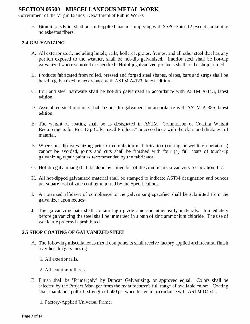
SECTION 05500 – MISCELLANEOUS METAL WORK Government of the Virgin Islands, Department of Public Works
Page 7 of 14
E. Bituminous Paint shall be cold-applied mastic complying with SSPC-Paint 12 except containing
no asbestos fibers.
2.4 GALVANIZING
A. All exterior steel, including lintels, rails, bollards, grates, frames, and all other steel that has any
portion exposed to the weather, shall be hot-dip galvanized. Interior steel shall be hot-dip
galvanized where so noted or specified. Hot-dip galvanized products shall not be shop primed.
B. Products fabricated from rolled, pressed and forged steel shapes, plates, bars and strips shall be
hot-dip galvanized in accordance with ASTM A-123, latest edition.
C. Iron and steel hardware shall be hot-dip galvanized in accordance with ASTM A-153, latest
edition.
D. Assembled steel products shall be hot-dip galvanized in accordance with ASTM A-386, latest
edition.
E. The weight of coating shall be as designated in ASTM "Comparison of Coating Weight
Requirements for Hot Dip Galvanized Products" in accordance with the class and thickness of
material.
F. Where hot-dip galvanizing prior to completion of fabrication (cutting or welding operations)
cannot be avoided, joints and cuts shall be finished with four (4) full coats of touch-up
galvanizing repair paint as recommended by the fabricator.
G. Hot-dip galvanizing shall be done by a member of the American Galvanizers Association, Inc.
H. All hot-dipped galvanized material shall be stamped to indicate ASTM designation and ounces
per square foot of zinc coating required by the Specifications.
I. A notarized affidavit of compliance to the galvanizing specified shall be submitted from the
galvanizer upon request.
J. The galvanizing bath shall contain high grade zinc and other early materials. Immediately
before galvanizing the steel shall be immersed in a bath of zinc ammonium chloride. The use of
wet kettle process is prohibited.
2.5 SHOP COATING OF GALVANIZED STEEL
A. The following miscellaneous metal components shall receive factory applied architectural finish
over hot-dip galvanizing:
1. All exterior rails.
2. All exterior bollards.
B. Finish shall be "Primergalv" by Duncan Galvanizing, or approved equal. Colors shall be
selected by the Project Manager from the manufacturer's full range of available colors. Coating
shall maintain a pull-off strength of 500 psi when tested in accordance with ASTM D4541.
1. Factory-Applied Universal Primer:
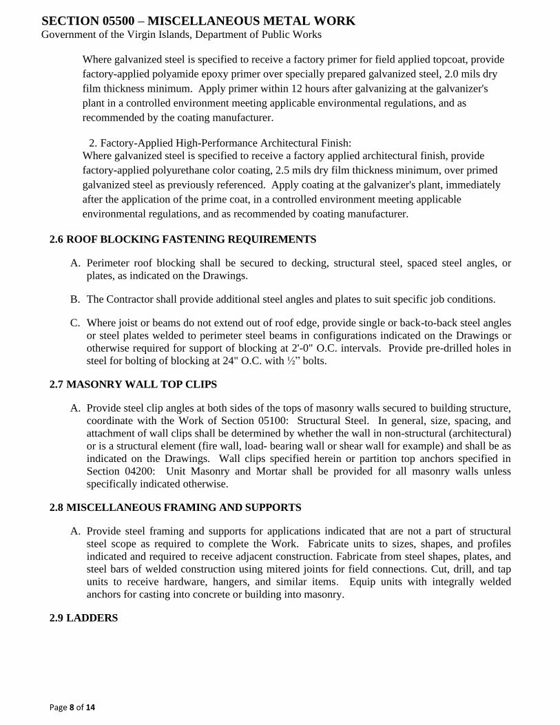
SECTION 05500 – MISCELLANEOUS METAL WORK Government of the Virgin Islands, Department of Public Works
Page 8 of 14
Where galvanized steel is specified to receive a factory primer for field applied topcoat, provide
factory-applied polyamide epoxy primer over specially prepared galvanized steel, 2.0 mils dry
film thickness minimum. Apply primer within 12 hours after galvanizing at the galvanizer's
plant in a controlled environment meeting applicable environmental regulations, and as
recommended by the coating manufacturer.
2. Factory-Applied High-Performance Architectural Finish:
Where galvanized steel is specified to receive a factory applied architectural finish, provide
factory-applied polyurethane color coating, 2.5 mils dry film thickness minimum, over primed
galvanized steel as previously referenced. Apply coating at the galvanizer's plant, immediately
after the application of the prime coat, in a controlled environment meeting applicable
environmental regulations, and as recommended by coating manufacturer.
2.6 ROOF BLOCKING FASTENING REQUIREMENTS
A. Perimeter roof blocking shall be secured to decking, structural steel, spaced steel angles, or
plates, as indicated on the Drawings.
B. The Contractor shall provide additional steel angles and plates to suit specific job conditions.
C. Where joist or beams do not extend out of roof edge, provide single or back-to-back steel angles
or steel plates welded to perimeter steel beams in configurations indicated on the Drawings or
otherwise required for support of blocking at 2'-0" O.C. intervals. Provide pre-drilled holes in
steel for bolting of blocking at 24" O.C. with ½” bolts.
2.7 MASONRY WALL TOP CLIPS
A. Provide steel clip angles at both sides of the tops of masonry walls secured to building structure,
coordinate with the Work of Section 05100: Structural Steel. In general, size, spacing, and
attachment of wall clips shall be determined by whether the wall in non-structural (architectural)
or is a structural element (fire wall, load bearing wall or shear wall for example) and shall be as
indicated on the Drawings. Wall clips specified herein or partition top anchors specified in
Section 04200: Unit Masonry and Mortar shall be provided for all masonry walls unless
specifically indicated otherwise.
2.8 MISCELLANEOUS FRAMING AND SUPPORTS
A. Provide steel framing and supports for applications indicated that are not a part of structural
steel scope as required to complete the Work. Fabricate units to sizes, shapes, and profiles
indicated and required to receive adjacent construction. Fabricate from steel shapes, plates, and
steel bars of welded construction using mitered joints for field connections. Cut, drill, and tap
units to receive hardware, hangers, and similar items. Equip units with integrally welded
anchors for casting into concrete or building into masonry.
2.9 LADDERS
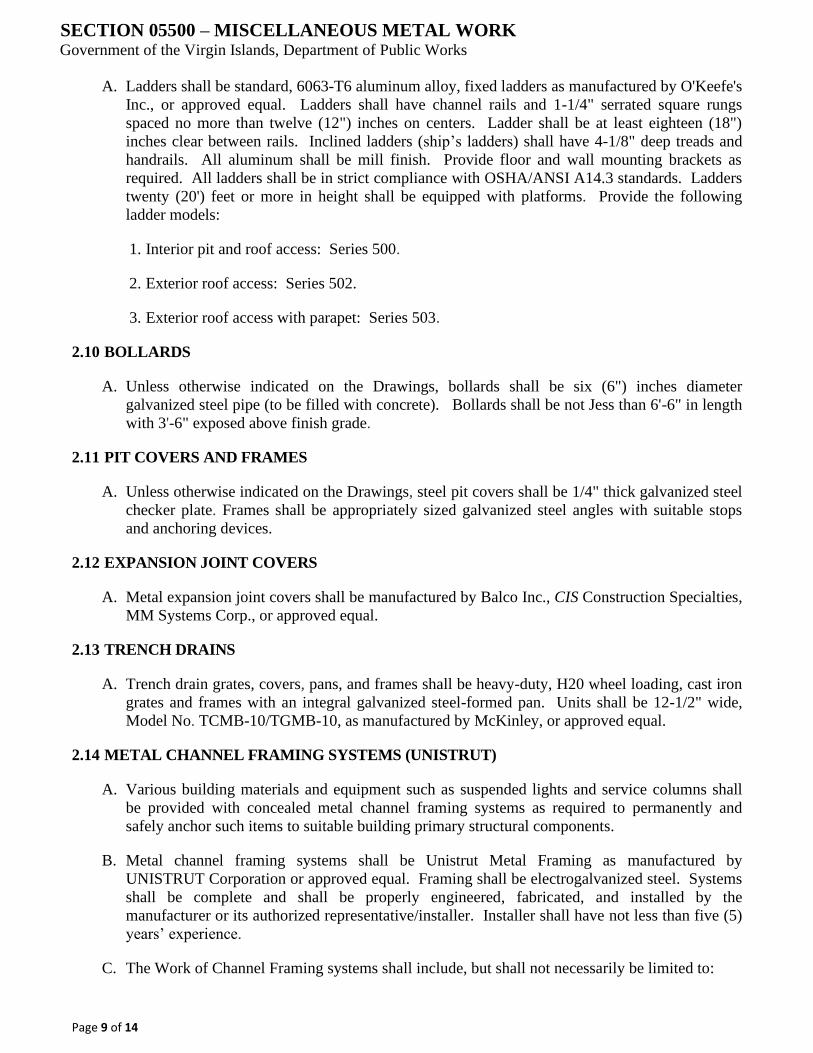
SECTION 05500 – MISCELLANEOUS METAL WORK Government of the Virgin Islands, Department of Public Works
Page 9 of 14
A. Ladders shall be standard, 6063-T6 aluminum alloy, fixed ladders as manufactured by O'Keefe's
Inc., or approved equal. Ladders shall have channel rails and 1-1/4" serrated square rungs
spaced no more than twelve (12") inches on centers. Ladder shall be at least eighteen (18")
inches clear between rails. Inclined ladders (ship’s ladders) shall have 4-1/8" deep treads and
handrails. All aluminum shall be mill finish. Provide floor and wall mounting brackets as
required. All ladders shall be in strict compliance with OSHA/ANSI A14.3 standards. Ladders
twenty (20') feet or more in height shall be equipped with platforms. Provide the following
ladder models:
1. Interior pit and roof access: Series 500.
2. Exterior roof access: Series 502.
3. Exterior roof access with parapet: Series 503.
2.10 BOLLARDS
A. Unless otherwise indicated on the Drawings, bollards shall be six (6") inches diameter
galvanized steel pipe (to be filled with concrete). Bollards shall be not Jess than 6'-6" in length
with 3'-6" exposed above finish grade.
2.11 PIT COVERS AND FRAMES
A. Unless otherwise indicated on the Drawings, steel pit covers shall be 1/4" thick galvanized steel
checker plate. Frames shall be appropriately sized galvanized steel angles with suitable stops
and anchoring devices.
2.12 EXPANSION JOINT COVERS
A. Metal expansion joint covers shall be manufactured by Balco Inc., CIS Construction Specialties,
MM Systems Corp., or approved equal.
2.13 TRENCH DRAINS
A. Trench drain grates, covers, pans, and frames shall be heavy-duty, H20 wheel loading, cast iron
grates and frames with an integral galvanized steel-formed pan. Units shall be 12-1/2" wide,
Model No. TCMB-10/TGMB-10, as manufactured by McKinley, or approved equal.
2.14 METAL CHANNEL FRAMING SYSTEMS (UNISTRUT)
A. Various building materials and equipment such as suspended lights and service columns shall
be provided with concealed metal channel framing systems as required to permanently and
safely anchor such items to suitable building primary structural components.
B. Metal channel framing systems shall be Unistrut Metal Framing as manufactured by
UNISTRUT Corporation or approved equal. Framing shall be electrogalvanized steel. Systems
shall be complete and shall be properly engineered, fabricated, and installed by the
manufacturer or its authorized representative/installer. Installer shall have not less than five (5)
years’ experience.
C. The Work of Channel Framing systems shall include, but shall not necessarily be limited to:
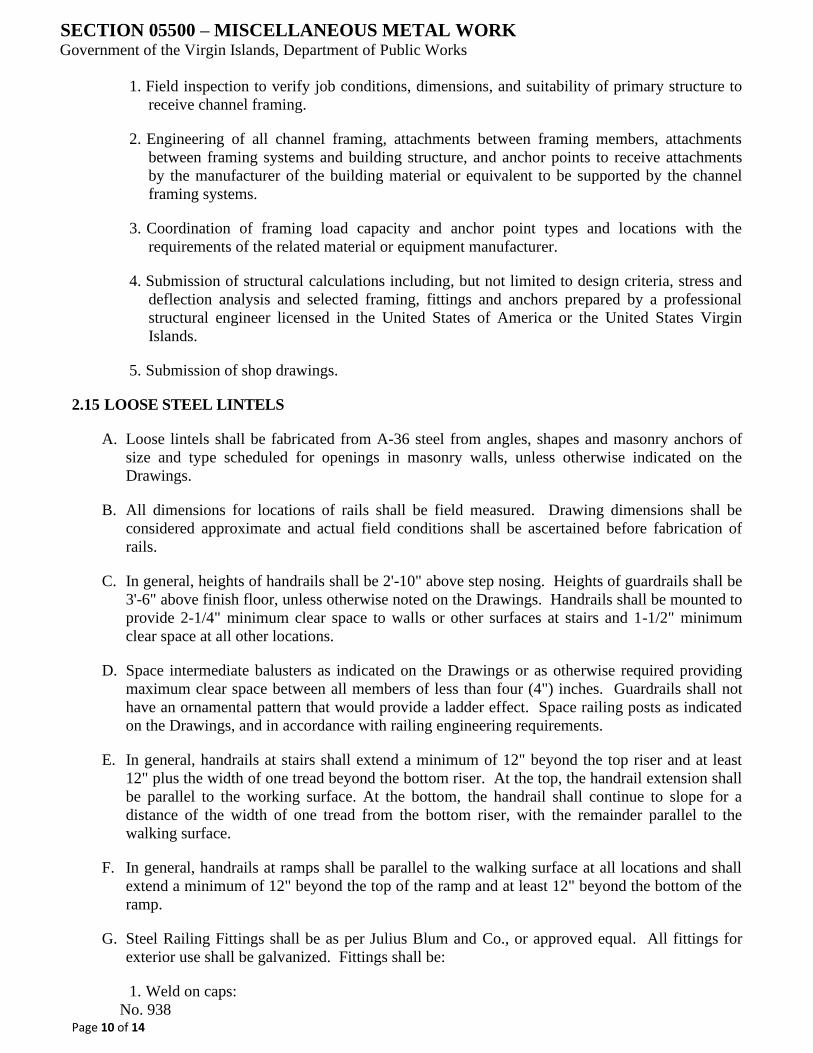
SECTION 05500 – MISCELLANEOUS METAL WORK Government of the Virgin Islands, Department of Public Works
Page 10 of 14
1. Field inspection to verify job conditions, dimensions, and suitability of primary structure to
receive channel framing.
2. Engineering of all channel framing, attachments between framing members, attachments
between framing systems and building structure, and anchor points to receive attachments
by the manufacturer of the building material or equivalent to be supported by the channel
framing systems.
3. Coordination of framing load capacity and anchor point types and locations with the
requirements of the related material or equipment manufacturer.
4. Submission of structural calculations including, but not limited to design criteria, stress and
deflection analysis and selected framing, fittings and anchors prepared by a professional
structural engineer licensed in the United States of America or the United States Virgin
Islands.
5. Submission of shop drawings.
2.15 LOOSE STEEL LINTELS
A. Loose lintels shall be fabricated from A-36 steel from angles, shapes and masonry anchors of
size and type scheduled for openings in masonry walls, unless otherwise indicated on the
Drawings.
B. All dimensions for locations of rails shall be field measured. Drawing dimensions shall be
considered approximate and actual field conditions shall be ascertained before fabrication of
rails.
C. In general, heights of handrails shall be 2'-10" above step nosing. Heights of guardrails shall be
3'-6" above finish floor, unless otherwise noted on the Drawings. Handrails shall be mounted to
provide 2-1/4" minimum clear space to walls or other surfaces at stairs and 1-1/2" minimum
clear space at all other locations.
D. Space intermediate balusters as indicated on the Drawings or as otherwise required providing
maximum clear space between all members of less than four (4") inches. Guardrails shall not
have an ornamental pattern that would provide a ladder effect. Space railing posts as indicated
on the Drawings, and in accordance with railing engineering requirements.
E. In general, handrails at stairs shall extend a minimum of 12" beyond the top riser and at least
12" plus the width of one tread beyond the bottom riser. At the top, the handrail extension shall
be parallel to the working surface. At the bottom, the handrail shall continue to slope for a
distance of the width of one tread from the bottom riser, with the remainder parallel to the
walking surface.
F. In general, handrails at ramps shall be parallel to the walking surface at all locations and shall
extend a minimum of 12" beyond the top of the ramp and at least 12" beyond the bottom of the
ramp.
G. Steel Railing Fittings shall be as per Julius Blum and Co., or approved equal. All fittings for
exterior use shall be galvanized. Fittings shall be:
1. Weld on caps:
No. 938
SECTION 05500 – MISCELLANEOUS METAL WORK Government of the Virgin Islands, Department of Public Works
Page 11 of 14
2. Round slip flanges:
No. 611 and No. 1611
3. Wall returns:
No. 665 and No. 1665
4. Brackets:
No. 386 and No. 1386
PART 3 - EXECUTION
3.1 VERIFYING CONDITIONS
A. Coordinate all work with the work of other trades. Verify all field dimensions and that the work
fits the work of other trades. Perform all cutting, fitting, and drilling required. Furnish all
necessary templates and patterns required to build items into work of other trades. Provide
holes and connections for the attachment of work of other trades.
3.2 GENERAL FABRICATION AND INSTALLATION
A. Metal surfaces shall be clean and free from mill scale, flake rust, and rust pitting, well-formed
and finished to shape and size, with sharp lines and angles and smooth surfaces. Shearing and
punching shall leave clean true lines and surfaces. Weld or rivet permanent connections. Welds
and flush rivets shall be finished flush and smooth on surfaces that will be exposed after
installation. Welds shall be continuous unless otherwise noted. Welds shall not have voids or
pockets and shall be ground to provide smooth transitions between metal surfaces. Do not use
screws or bolts where they can be avoided; where used, heads shall be countersunk, screwed up
tight and threads nicked to prevent loosening.
B. Fastenings shall be concealed where practicable. Thickness of metal and details of assembly
and supports shall give ample strength and stiffness. Joints exposed to weather shall be formed
to exclude water. Provide holes and connections for the work of other trades.
C. Castings shall be size determined by work type for which they form parts. Each member if
possible, shall be in one piece, make joints at moldings or fillets. Casting thickness shall be
uniform, sufficient to ensure perfect workmanship, required strength for design use. Make
castings clean, smooth, true to pattern, free from defects. Moldings, ornaments shall be rather
more deeply cut than indicated to counteract flattening effects of casting, finishing; exactly
reproduce form, feeling of models. Edges shall be sharp, come from molds clean, smooth,
perfect.
D. Non-slip surfaces shall be made safe for foot traffic with non-slip abrasive embedded uniformly
in wearing surface at casting time.
E. Connections and accessories shall be adequate to safely sustain, withstand stresses, strains, to
which they will be normally subjected.
1. Connections to steel unless otherwise specified shall be steel.
2. Connections to genuine wrought iron work shall be wrought iron or steel.
3. Connections to cast iron, unless otherwise specified shall be steel.

SECTION 05500 – MISCELLANEOUS METAL WORK Government of the Virgin Islands, Department of Public Works
Page 12 of 14
4. Bolts, nuts, screws for exterior work shall be electrogalvanized, unless otherwise noted.
F. Furnish all standard screws, bolts, washers, and other such fastening devices as are necessary
for attaching this work to other materials. Anchors and other connecting devices required in
concrete or masonry shall be built-in as the work progresses. NOTE: Special attention shall be
given to the firm and secure anchoring of overhead mounted materials and equipment.
G. Do cutting, punching, drilling, tapping required for attachment of other work coming in contact
with miscellaneous metal where indicated or where directions for same are given prior to or
with review of shop drawings.
H. Unless otherwise indicated, bolt, and screw heads shall be flat countersunk in exposed faces of
ornamental or finished character; elsewhere as required. Cut off bolts, screws, etc., where
exposed, flush with nuts, or other adjacent metal. Except as otherwise required, weld shop-
assembled connections; welds, bolts, or machine screws may be used for field connections.
Exposed fastenings shall be the same materials, color, and finish as metal to which they apply,
unless otherwise required.
I. Make up threaded connections tightly so that threads will be entirely concealed by fittings.
J. Work to be built in with masonry shall be of form required for anchorage, or be provided with
suitable anchors, expansion shields, toggle bolts, etc. as required for proper anchorage.
Fastening to wood plugs in masonry shall not be permitted.
K. Install all supporting members, fastening, framing, hangers, bracing, brackets, straps, bolts,
angles, and the like required to set, connect work rigidly and properly to structural steel,
masonry, other construction.
L. All items shall be installed plumb, straight, square, level and in proper elevation, plane, location
and alignment with other work.
3.3 STEEL RAILING FABRICATION AND INSTALLATION
A. Fabricate handrails and railing systems to comply with the requirements indicated for design,
dimensions, details, finish, member sizes and anchorage but not less than that required to
support structural loads.
B. Interconnect railing and handrail members by butt-welding or welding with internal connectors,
unless otherwise indicated. At tee and cross intersections, cope ends of intersecting members to
fit contour of pipe to joined end and weld all around. Form changes in direction of railings by
welding fabricated flush elbow fittings, by radius bends as indicated, or by flush radius bends.
Remove burrs and splatter.
C. Form simple and compound curves by bending pipe in jigs to produce uniform curvature for
each configuration required. Maintain cylindrical cross section of pipe throughout the entire
bend without buckling, twisting, cracking or otherwise deforming.
D. For components exposed to exterior or moist environments, provide weep holes or other means
of evacuating entrapped water. All exterior rails, fittings and brackets shall be hot-dipped
galvanized after fabrication.
SECTION 05500 – MISCELLANEOUS METAL WORK Government of the Virgin Islands, Department of Public Works
Page 13 of 14
E. Provide wall returns at all ends to adjacent surfaces and secure as required. Close exposed ends
by welding 3/16" thick steel plate in place, except where clearance of end of pipe and adjoining
wall surface is less than ¼”, or unless otherwise detailed.
F. Welds shall be continuous and thoroughly fused without undercutting or overlap. Grind
exposed welds smooth to form a uniformly smooth surface.
G. Provide miscellaneous steel for connection of rail supports as detailed on the Drawings. Do not
support railing temporarily by any means that does not satisfy structural performance
requirements.
H. Set rails plumb and aligned. Set rails horizontal or parallel to rake of stairs. Support wall
handrails on brackets, in accordance with railing engineering requirements. Space closer
together if so indicated on the Drawings. Connect railing posts to stair framing to stair framing
by direct welding, unless otherwise indicated.
I. Install handrail brackets away from handrail ends and finish ends with return fittings. Use drill-
in expansion anchors at concrete or masonry walls. Mount handrails only on gypsum board
assemblies that have been reinforced to receive railing anchors.
J. Provide expansion joints in railings at intervals not to exceed forty (40') feet. Provide slip joints
with internal sleeves extending two (2") inches beyond the joint on either side. Fasten the
internal sleeve securely on one side only. Locate expansion joints within six (6") inches of
posts.
K. Where railings are to be set in concrete, railing posts shall be set in 6" matching sleeves as
follows: Clean dust and foreign matter from sleeves. Moisten interior of hole and surrounding
surface with clean water. Mix fast setting cement with water and stir until a smooth, creamy
consistency is produced. Pour mixture into annular space until it overflows the hole. Taper
cement away from rails to promote proper drainage. Wipe off excess, leaving a build-up of
approximately 1/8".
3.4 LADDERS
A. All ladders shall be installed in strict accordance with the manufacturer's instructions, the
American Standard Safety Code for Fixed Ladders and all applicable OSHA regulations.
B. Completed ladder installations shall be rigid and free from vibration.
C. Ladders in elevator pits shall extend not less than 3'-6" above outside finish floor level as
required by OSHA and shall be located as recommended by the elevator manufacturer.
D. Exterior roof ladders shall extend no less than 3'-6" above parapet walls or upper roof surfaces
as applicable, and shall have looped returns as required by OSHA. Rungs shall be held off a
minimum of 9" off adjacent wall.
E. Interior roof hatch ladders shall extend from the floor to the roof surface. Rails shall extend to
just below the underside of the roof hatch.
F. Ladders twenty (20') feet or more in height shall be provided with cage closures as required by
OSHA.
3.5 EXPANSION JOINT COVERS
SECTION 05500 – MISCELLANEOUS METAL WORK Government of the Virgin Islands, Department of Public Works
Page 14 of 14
A. Covers shall extend full width of openings.
B. Covers shall be installed level, plumb, and flush with finish surfaces, and shall be fastened with
anchor shields and bolts in strict confidence with the manufacturer's instructions and
recommendations.
C. Provide all corners, tees, transitions, etc., as required for a complete and proper job.
D. Provide fire rated expansion joint covers with all required safing insulation and fire stopping at
fire rated locations. Entire assembly shall be installed in strict accordance with the
manufacturer's instructions and tested assemblies.
END OF SECTION

SECTION 05600 – MANHOLE FRAMES AND COVERS Government of the Virgin Islands, Department of Public Works
Page 1 of 2
PART 1 - GENERAL
1.1 REQUIREMENTS INCLUDED
A. Furnish and install cast iron manhole frames and covers on all manholes unless otherwise
shown on the Drawings.
1.2 REQUIREMENTS
A. Section 03346:
Cast-in-Place Concrete.
1.3 QUALITY ASSURANCE
A. All castings shall be at least Class 30 conforming to the ASTM Standard Specifications for
Gray Casting, Designation A48.
B. All essential details of design shall conform to the Drawings.
PART 2 - PRODUCTS
2.1 MATERIALS
A. Provide manhole frames and covers with 30-inch diameter clear opening.
B. The cover shall have the words "Sanitary Sewer" or “Storm Sewer” in a 3-inch letter cast into
the top surface.
C. Grates shall be of the type and opening size specified.
D. The castings shall be of good quality, strong, touch, even-grained cast iron, smooth, free from
scale, lumps, blisters, sand holes, and defects of every nature which would render them unfit for
the service for which they are intended.
E. Contact surfaces of covers and frame seats shall be machined at the foundry before shipment to
prevent rocking of covers in any orientation.
F. All castings shall be thoroughly cleaned and subject to a careful hammer inspection.
G. Prior to being shipped from the foundry, castings shall be sandblasted and given two coats of
coal-tar-pitch varnish, applied in a satisfactory manner so as to make a smooth coating, tough,
tenacious, and not brittle with any tendency to scale off.
H. Coatings that have been damaged in transit of handling shall be repaired by the Contractor to
the satisfaction of the Engineer.
I. Waterproof manhole frames and covers (when applicable) shall have bearing surfaces of cover
and frames machined, sealed with rubber gasket, drilled, tapped and counter sunk for cap screws
to fasten lid to frame.
PART 3 - EXECUTION
3.2 INSTALLATION

SECTION 05600 – MANHOLE FRAMES AND COVERS Government of the Virgin Islands, Department of Public Works
Page 2 of 2
A. Set manhole frames with the tops conforming accurately to the grade of the pavement or
finished ground surface or as shown on the Drawings.
B. Set frames concentric with the top of the masonry in a full bed of mortar, so that the space
between the top of the manhole masonry and the bottom flange at the frame shall be completely
filled and made watertight.
C. Place a thick ring of mortar extending to the outer edge of the masonry all around and on the top
of the bottom flange.
D. Finish the mortar so that it will be smooth and have a slight slope to shed water away from the
frame.
E. When the work on each manhole is complete, clean the frame seat and set the cover in place.
END OF SECTION
SECTION 05730- ALUMINUM HANDRAILS & RAILINGS
GOVERNMENT OF THE VIRGIN ISLANDS, DEPARTMENT OF PUBLIC WORKS
Page 1 of 7
PART 1 GENERAL
1.1 SECTION INCLUDES
A. Aluminum handrails and guardrails of the following types:
1. Picket railing systems.
2. Lateral railing systems.
1.2 RELATED SECTIONS
A. Section 03346 - Cast-in-Place Concrete.
1.3 DEFINITIONS
A. Definitions in ASTM E 985 for railing-related terms apply to this section
1.4 PERFORMANCE REQUIREMENTS
A. General: Engineer handrail and railing systems to withstand structural loads indicated.
Determine allowable design working stresses of railing materials based on the following:
1. For Aluminum: The Aluminum Association's specification for Aluminum Structures.
B. Structural Performance of Handrails and Railing Systems: Engineer, fabricate, and install
handrails and railing systems as per ASTM E 985 to withstand the following structural loads
without exceeding the allowable design working stress of the materials for handrails, railing
systems, anchors, and connections. Apply each load to produce the maximum stress in each of
the respective components comprising handrails and railing systems.
1. Top Rail of Guardrail Systems: Capable of withstanding the following loads applied as
indicated:
a. Concentrated load of 200 pounds (90.6 kg) applied at any point and in any direction.
b. Uniform load of 50 pounds per linear foot (74.3 kg/m) applied horizontally and
concurrently with uniform load of 100 pounds per linear foot (148.6 kg/m) applied
vertically downward.
c. Concentrated load need not be assumed to act concurrently with uniform loads.
2. Handrails Not Serving as Top Rails: Capable of withstanding the following loads applied as
indicated:
a. Concentrated load of 200 pounds (90.6 kg) applied at any point and in any direction.
b. Uniform load of 50 pounds per linear foot (74.3 kg/m) applied in any direction.
c. Concentrated and uniform loads need not be assumed to act concurrently.
SECTION 05730- ALUMINUM HANDRAILS & RAILINGS
GOVERNMENT OF THE VIRGIN ISLANDS, DEPARTMENT OF PUBLIC WORKS
Page 2 of 7
3. Infill Area of Guardrail Systems: Capable of withstanding a horizontal concentrated load of
200 pounds (90.6 kg) applied to 1 ft2 (0.1 m2) at any point in the system.
a. Above load need not be assumed to act concurrently with loads on top rails of railing
systems in determining stress on guard.
C. Control of Corrosion: Prevent galvanic action and other forms of corrosion by insulating metals
and other materials from direct contact with incompatible materials.
D. Thermal Movements: Allow for thermal movement resulting from the following maximum
change (range) in ambient temperature in the design, fabrication, and installation of handrails
and railings to prevent buckling, opening up of joints, overstressing of components, connections
and other detrimental effects. Base design calculation on actual surface temperatures of
materials due to both solar heat gain and nighttime sky heat loss.
1. Temperature Change (Range): 120 degrees F ambient; 180 degrees F material surfaces.
1.5 SUBMITTALS
A. Submit under provisions of Section 01300 - Submittals.
B. Product Data: Manufacturer's data sheets on each product to be used, including:
1. Preparation instructions and recommendations.
2. Storage and handling requirements and recommendations.
C. Shop drawings showing Welding, Fabrication and Installation of handrails including plans,
typical elevations, sections, details of components, and attachment to other units work.
1. Where installed products are indicated to comply with certain design loadings, include
structural computations, material properties and other information needed for structural
analysis review by the design architect and/or engineer of record.
2. Submit 3 prints of all shop drawing product data. Also submit calculations if specifically
requested by architect.
D. Samples for initial selection purposes in the form of manufacturers color chart showing full
range of colors available from factories standards: For custom color request minimum 2 inches
x 2 inches (51 mm by 51 mm) color chip from customer for color matching purposes.
1.6 QUALITY ASSURANCE
A. Manufacturer Qualifications: Minimum 5 year experience manufacturing similar products.
B. Installer Qualifications: Minimum 2 year experience installing similar products.
C. Single Source Responsibility: Obtain handrails and railing systems from a single
fabricator/manufacturer.
D. Engineering Responsibility: Engineer hand railing and railing systems by the
fabricator/manufacturer unless sizes and configurations are specifically called out on the
drawings.
SECTION 05730- ALUMINUM HANDRAILS & RAILINGS
GOVERNMENT OF THE VIRGIN ISLANDS, DEPARTMENT OF PUBLIC WORKS
Page 3 of 7
1.7 PRE-INSTALLATION MEETINGS
A. Convene minimum two weeks prior to starting work of this section.
1.8 DELIVERY, STORAGE, AND HANDLING
A. Deliver and store products in manufacturer's unopened packaging bearing the brand and
manufacturer's identification until ready for installation.
B. Store handrails and railing systems in clean, dry location, away from uncured concrete and
masonry, protected against damage.
C. Handling: Handle materials to avoid damage.
1.9 PROJECT CONDITIONS
A. Maintain environmental conditions (temperature, humidity, and ventilation) within limits
recommended by manufacturer for optimum results. Do not install products under
environmental conditions outside manufacturer's recommended limits.
1.10 SEQUENCING
A. Field Measurements: Where handrails and railings are indicated to fit to other construction,
check actual dimensions of other construction by accurate field measurements before
fabrication; show recorded measurements on final shop drawings. Coordinate fabrication
schedule with construction progress to avoid delay of Work.
1. Where field measurements cannot be made without delaying the Work, obtain guaranteed
dimensions in writing and proceed with fabrication of products without field measurements
if specifically requested to do so by architect, owner or contractor.
PART 2 PRODUCTS
2.1 MANUFACTURERS
A. Acceptable Manufacturers Subject to compliance with requirements, manufacturers offering
handrails and railing systems that may be incorporated into the Work include but are not limited
to the following:
1. AMF Building Products,
2. Poma & Sons,
3. Alumaguard
4. Aluminum Tube Railings, Inc.
5. or approved equal
2.2 MATERIALS
A. Aluminum: Alloy and temper recommended by aluminum producer and finisher for type of use
and finish indicated, with not less than the strength and durability properties of the alloy and
temper designated below for each aluminum form required:
SECTION 05730- ALUMINUM HANDRAILS & RAILINGS
GOVERNMENT OF THE VIRGIN ISLANDS, DEPARTMENT OF PUBLIC WORKS
Page 4 of 7
1. Extruded Bare & Tube- ASTM B221, alloy 6063T5/T52.
2. Extruded Structural Pipe & Tube- ASTM B 429 6063-T5/T52
3. Drawn Seamless Pipe – ASTM B 210 6083-TB32
4. Plate and Sheet – ASTM B 209 6061-T6
5. Castings: ASTM B 29, A356-T6.
2.3 WELDING MATERIALS, FASTENERS, AND ANCHORS
A. Welding Electrodes and Filler/Metal: Provide type and alloy of filler metal and electrodes as
recommended by producer of metal to be welded and as required for color match, strength, and
compatibility in fabricated items.
B. Fasteners for Anchoring Railings to Other Construction: Select fasteners of the type, grade, and
class required to produce connections that are suitable for anchoring railing to other types of
construction indicated and capable of withstanding design loadings.
1. For aluminum railings in coastal environments provide fasteners fabricated from stainless
steel or aluminum only.
C. Fasteners for Interconnecting Railing Components: Use concealed fasteners of same basic metal
as the fastened metal, unless otherwise indicated. Do not use metals that are corrosive or
incompatible with materials joined.
2.4 GROUT AND ANCHORING CEMENT
A. Non-shrink, Nonmetallic Grout: Premixed, factory-packaged, non-staining, noncorrosive,
nongaseous grout complying with ASTM C 1107. Provide grout specifically recommended by
manufacturer for interior and exterior applications.
B. Erosion-Resistant Anchoring Cement: Factory-prepackaged, non-shrink, non-staining, high
strength cement formulation for mixing with water at Project site to create pourable anchoring,
patching, and grouting compound. Provide formulation that is resistant to erosion from water
exposure or provide a sealer or waterproof coating recommended for exterior use.
2.5 FABRICATI0N
A. General: Fabricate handrails and railing systems to comply with requirements indicated for
design, dimensions, details, finish, and member sizes, including wall thickness of hollow
members, post spacings, and anchorage, but not less than those required to support structural
loads.
B. Preassemble railing systems in shop to greatest extent possible assembly. Disassemble units
only as necessary for shipping and handling limitations. Clearly mark units for field assembly
and coordinated installation. Use connections that maintain structural value of joined pieces.
C. Form changes in directions of members as follows;
1. by mitering at elbow bends
2. by insertion of prefabricated flush elbow fittings
SECTION 05730- ALUMINUM HANDRAILS & RAILINGS
GOVERNMENT OF THE VIRGIN ISLANDS, DEPARTMENT OF PUBLIC WORKS
Page 5 of 7
3. by any method indicated above, applicable to change of direction involved
D. Form simple and compound curves by bending pipe in jigs to produce uniform curvature for
each repetitive configuration required; maintain cylindrical cross section of pipe throughout.
E. Welded connections; Fabricate handrails and railing systems for connection of members by
welding. For connections made during fabrication, weld corners and seams continuously to
comply with the following;
1. Use materials and methods that minimize distortion and develop strength and corrosion
resistance of base materials.
2. Obtain fusion without undercut or overlap.
3. Remove welding flux immediately
4. At tee and cross intersections, cope ends of intersecting members to fit contour of pipe or
tube to which end is joined and weld all around.
F. Brackets, Flanges, Fittings and Anchors; Provide manufactures standard wall brackets, brackets,
miscellaneous fitting, and anchors to interconnect handrail and railing system members to other
construction. Provide inserts and other anchorage devices capable of withstanding loads
imposed on handrails and railing system. Coordinated anchorage devices with supporting
structure.
G. For railings posts set in concrete, provide preset sleeves of steel, not less than 6” long with
inside dimensions not less than ½” greater than outside diameter of the post.
H. Provide weep holes, or other means to evacuate trapped water, in hollow sections of railing
members that are exposed to exterior or to moisture from condensation or other sources.
I. Provide wall returns at ends of wall mounted handrails, unless otherwise indicated.
2.6 FINISHES: KYNAR FINISH
A. General
1. 70% PVDF coatings which meet or exceed AAMA 2605, applied in three coats (barium &
strontium chromate primer, 70% PVDF pigment coat and 70% PVDF clear coat) with a dry
film thickness of 1.6 to 2.2 mils. Aluminum must have a chrome phosphate pretreatment
conversion prior to being coated.
2. Acceptable products are PPG Duranar XL, or equivalent.
B. Chemical Pretreatment:
1. Strong Acid cleaner.
2. Acid cleaner.
3. D.I. water rinse.
4. Chrome phosphate conversion 40-90 mg/sf
SECTION 05730- ALUMINUM HANDRAILS & RAILINGS
GOVERNMENT OF THE VIRGIN ISLANDS, DEPARTMENT OF PUBLIC WORKS
Page 6 of 7
a. Any coating application system that does not contain a Chrome phosphate conversion
coating is a strictly prohibited.
5. D. I. water rinse.
6. D.I. halo and dry in place.
C. Color: PPG Duranar Standard Bone White; UC43350XL
1. Note: application of metallic finishes will result in distinct color variations when viewed
from various angles that may be undesirable. These variations are due to the metallic flakes,
application processes as well as manufacturer lot production, and may not be suitable for
uniform color presentation.
D. Application: The applicator shall be an approved or certified applicator of the paint
manufacturer and shall apply the paint in strict accordance with the manufacturer’s
requirements. Applicator shall have a minimum experience of at least 7 years with similar
coating and pretreatment processes and shall demonstrate successful long-term coating history.
Names and address of project locations may be required for physical site inspections.
PART 3 EXECUTION
3.1 EXAMINATION
A. Do not begin installation until substrates have been properly prepared.
B. If substrate preparation is the responsibility of another installer, notify Architect of
unsatisfactory preparation before proceeding.
3.2 PREPARATION
A. Coordinate setting drawings, diagrams, templates, instructions, and directions for installation of
anchorages, such as sleeves, concrete inserts, anchor bolts, and miscellaneous items having
integral anchors that are to be embedded in concrete as masonry construction. Coordinate
delivery of such items to project site.
3.3 INSTALLATION GENERAL
A. Fit exposed connections accurately together to form tight, hairline joints, except as required for
expansion.
B. Cutting, Fitting, and Placement: Perform cutting, drilling, and fitting required for installation of
handrails and railings. Set handrails and railings accurately in location, alignment, and
elevation, measured from established lines and levels and free from rack.
1. Do not weld, cut or abrade surfaces of handrails and railing components that have been
coated or finished after fabrication and are intended for field connection by mechanical or
other means.
2. Set posts plumb within a tolerance of 1/16 inch to 36 inches .
3. Align rails so that variations from level for horizontal members and from parallel with rake
of steps and ramps for sloping members do not exceed 1/16 inch in 36 inches
SECTION 05730- ALUMINUM HANDRAILS & RAILINGS
GOVERNMENT OF THE VIRGIN ISLANDS, DEPARTMENT OF PUBLIC WORKS
Page 7 of 7
C. Corrosion Protection: Coat concealed surfaces of aluminum that will come into contact with
grout, concrete, masonry, wood, or dissimilar metals with a heavy coat of paint or epoxy.
D. Adjust handrails and railing systems prior to anchoring to ensure matching alignment at abutting
joints. Space posts at intervals indicated but not less than that required by design loadings.
E. Fastening to In-Place Construction: Provide anchorage devices and fasteners where necessary
for securing handrails and railings to in-place construction.
3.4 ANCHORING POSTS
A. Anchor post in concrete by means of preset sleeves into concrete. After posts have been inserted
into sleeves, fill space between post and sleeve solid with the following anchoring material,
mixed and placed to comply with anchoring material manufacturer's directions and fill space
between post and concrete with the following anchoring material, mixed and placed to comply
with anchoring material manufacturer's directions.
1. Non-shrink, nonmetallic grout.
2. Non-shrink, nonmetallic grout or anchoring cement.
B. Leave anchoring material down approximately 1/2 inch (13 mm) to allow for final topping with
a waterproof material matching the surrounding areas by others. Whenever possible fill hole
with waterproof topping slightly higher than the adjacent surfaces and and taper away from the
post.
3.5 ANCHORING HANDRAILS TO WALLS
A. Anchor rail ends into concrete and masonry with round flanges connected to the with installed
anchors and bolts.
1. Provide bracket with 1 ½” clearance from inside face of handrail to finished wall surface.
2. Locate brackets as indicated or, if not indicated, at spacing required to support structural
loads.
3.6 CLEANING, PROTECTION AND TOUCH-UP PAINTING
A. On delivery all railing will have protective cover over cap only. Immediately upon completion
of installation of railing installer shall remove cap cover and clean all work inspection and
approval.
B. After installation the General Contractor or Owner shall be responsible for protecting railings
during the balance of construction.
C. Painted aluminum surfaces shall be cleaned with plain water containing a mild soap or
detergent. No abrasive agents or harsh chemicals are to be used.
END OF SECTION

DIVISION 9 - FINISHES GOVERNMENT OF THE U. S. VIRGIN ISLANDS, DEPARTMENT OF PUBLIC WORKS

SECTION 09200 - LATH AND PLASTER GOVERNMENT OF THE U. S. VIRGIN ISLANDS, DEPARTMENT OF PUBLIC WORKS
Page 1 of 11
PART 1 GENERAL
1.1 RELATED DOCUMENTS
A. Drawings and general provisions of Contract, including General and Supplementary Conditions and
Division 1 Specification Sections, apply to this Section.
1.2 SUMMARY
A. This Section includes the following:
1. Steel stud systems.
2. Metal lath and furring.
3. Portland cement plastering.
B. Related Sections:
The following sections contain requirements that relate to this Section:
1. None.
C. Wood framing and furring are specified in Division 6.
1.3 SUBMITTALS
A. General: Submit the following in accordance with Conditions of Contract and Division 1 Specification Sections.
B. Product data consisting of manufacturer’s product specifications and installation instructions for each
product, including data showing compliance with the requirements.
C. Samples for initial selection purposes in form of manufacturer’s color charts consisting of actual
units or sections of units at least 12 inches square showing full range of colors, textures, and patterns
available for each type of finish indicated.
1. Where finish involves normal color and texture variations, include sample sets composed of
two or more units showing full range of variations expected.
2. Include similar samples of material for joints and accessories involving color selection.
D. Samples for verification purposes in units at least 12 inches square of each type of finish indicated,
in sets for each color, texture, and pattern specified, showing full range of variations expected in
these characteristics.
1.4 QUALITY ASSURANCE
A. Fire-Resistance Ratings:
SECTION 09200 - LATH AND PLASTER GOVERNMENT OF THE U. S. VIRGIN ISLANDS, DEPARTMENT OF PUBLIC WORKS
Page 2 of 11
1. Where plaster systems with fire-resistance ratings are indicated, provide materials and
installations identical to those of applicable assemblies tested per ASTM E 119 by fire
testing laboratories acceptable to authorities having jurisdiction.
2. Provide plaster for fire-resistance rated systems that has same aggregate as specified for
similar nonrated work, unless specified aggregate has not been tested by accepted fire testing
laboratories.
B. Coordination of Work:
Coordinate layout and installation of suspension system components for suspended ceilings with
other work supported by or penetrating through ceiling.
1.5 DELIVERY, STORAGE, AND HANDLING
A. Deliver materials in original packages, containers, or bundles bearing brand name and identification
of manufacturer.
B. Store materials inside, under cover, and in manner to keep them dry, protected from weather, direct
sunlight, surface contamination, aging, corrosion, and damage from construction traffic and other
causes.
1.6 PROJECT CONDITIONS
A. Environmental Requirements, General:
Comply with requirements of referenced plaster application standards and recommendations of
plaster manufacturer for environmental conditions before, during, and after application of plaster.
B. Ventilation:
Ventilate building spaces as required to remove water in excess of that required for hydration of
plaster. Begin ventilation immediately after plaster is applied and continue until it sets.
C. Protect contiguous work from soiling, spattering, moisture deterioration and other harmful effects
that might result from plastering.
PART 2 - PRODUCTS
2.1 MANUFACTURERS
A. Available Manufacturers:
Subject to compliance with requirements, manufacturers offering products that may be
incorporated in the Work include but are not limited to the following:
1. Metal Supports:
a. Allied Structural Industries, Inc.
b. American Studco, Inc.
c. Chapman Industries, Inc.
SECTION 09200 - LATH AND PLASTER GOVERNMENT OF THE U. S. VIRGIN ISLANDS, DEPARTMENT OF PUBLIC WORKS
Page 3 of 11
d. Chicago Metallic Corp.
e. Dale Industries, Inc.
f. Dietrich Industries, Inc.
g. Gold Bond Building Products Div., National Gypsum Co.
h. Marino Industries.
i. United States Gypsum Co.
j. Expanded Metal Lath:
k. Alabama Metal Industries Corp. (AMICO)
l. Gold Bond Building Products Div., National Gypsum Co.
m. United States Gypsum Co.
n. Western Metal Lath Co.
2. Accessories:
a. Fry Reglet Corp.
b. Gold Bond Building Products Div., National Gypsum Co.
c. Keene Corp.
d. MM Systems Corp.
e. Plastic Components, Inc.
f. United States Gypsum Co.
g. Western Metal Lath Co.
2.2 METAL SUPPORTS FOR SUSPENDED AND FURRED CEILINGS (09200.A)
A. General:
Size metal ceiling supports to comply with the following, unless otherwise indicated.
B. Portland Cement Plaster Installation:
ASTM C 1063.
C. Wire for Hangers and Ties:
ASTM A 641, Class I zinc coating, soft temper.
D. Rod Hangers:
Mild steel, zinc or cadmium coated.

SECTION 09200 - LATH AND PLASTER GOVERNMENT OF THE U. S. VIRGIN ISLANDS, DEPARTMENT OF PUBLIC WORKS
Page 4 of 11
E. Flat Hangers:
Mild steel, zinc or cadmium coated or protected with rust-inhibitive paint.
F. Channels:
Cold-rolled steel, 0.05980-inch minimum thickness of base metal (uncoated), allowable bending
stress of 18,000 psi, protected with rust-inhibitive paint or galvanizing complying with ASTM A
525 for G60 coating designation, and as follows:
G. Carrying Channels:
1-1/2-inch-deep by 7/16-inch-wide flanges, 475 lbs. per 1000 feet painted, 508 lbs. per 1000 feet
galvanized.
H. Furring Channels:
3/4-inch-deep by 7/16-inch-wide flanges, 300 lbs. per 1000 feet painted, 316 lbs. per 1000 feet
galvanized.
I. Provide galvanized channels for exterior installations.
J. Hanger Anchorage Devices:
Screws, cast-in-place concrete inserts, or other devices appropriate for anchorage to the form of
structural framing indicated and whose suitability for use intended has been proven through
standard construction practices or certified test data.
K. Size devices to develop full strength of hanger but not less than 3 times calculated hanger loading,
except size direct pullout concrete inserts for 5 times calculated hanger loading.
2.3 STEEL STUDS AND RUNNERS (TRACKS) (09200.B)
A. Non-Load (Axial) - Bearing Studs and Runners (09200.Bl):
ASTM C 645 and complying with following requirements for minimum thickness of base metal
(uncoated) and other characteristics:
B. Stud Thickness:
0.034I inch, unless otherwise indicated.
C. Stud Depth:
6 inches, unless otherwise indicated.
D. Load-Bearing (Transverse and Axial) Studs and Runners (09200.B2):
ASTM C 955 and complying with the following requirements for quality, grade, and finish of
steel sheet, design thickness of base metal (uncoated), and other dimensional characteristics:
E. Metal Quality:
Zinc-coated (galvanized) steel sheet complying with ASTM A 446, Coating Designation G 90,
for grades indicated below:
1. Grade D (50,000 psi yield point) for design thicknesses of 0.0598 inch or more.
F. Stud Thickness: 0.0598 inch, unless otherwise indicated.
SECTION 09200 - LATH AND PLASTER GOVERNMENT OF THE U. S. VIRGIN ISLANDS, DEPARTMENT OF PUBLIC WORKS
Page 5 of 11
G. Stud Lip Depth: 1/4 inch.
H. Stud Depth: 6 inches, unless otherwise indicated.
2.4 VERTICAL METAL FURRING (09200.C)
A. Channel Furring and Braces:
Cold-rolled steel, 0.0598-inch min. thickness of base (uncoated) metal, allowable bending stress
of 18,000 psi, protected with rust-inhibitive paint finish or galvanizing, 3/4-inch-deep by 7/16-
inch-wide flanges, 300 lbs. per 1000 feet with painted finish, 316 lbs. per 1000 feet with
galvanized finish.
B. Hat-Channels:
Hat shaped screwable furring channels, 7/8-inch deep formed from zinc-coated (galvanized) steel
sheet minimum 0.0 I79-inch thick complying with ASTM A 446, Coating Designation G 60,
grade A (33,000 psi yield point).
C. Z-Furring Members:
Manufacturer's standard screw-type zee-shaped furring members formed from zinc-coated
(galvanized) steel sheet, 0.0179-inch min. base (uncoated) metal thickness, complying with
ASTM A 525, Coating Designation G 60, designed for mechanical attachment of insulation
boards or blankets to monolithic concrete and masonry walls.
D. Furring Brackets:
Serrated-arm type, 0.0329-inch min. thickness of base (uncoated) metal, adjustable from l/4-inch
to 2-1/4-inch wall clearance for channel furring.
2.5 LATH (09200.D)
A. Expanded Metal Lath:
Fabricate expanded metal lath from uncoated or zinc-coated (galvanized) steel sheet to produce
lath complying with ASTM C 847 for type, configuration, and other characteristics indicated
below, with uncoated steel sheet painted after fabrication into lath.
B. Diamond Mesh Lath: Comply with the following requirements:
1. Configuration: Self-furring.
2. Weight: 3.4 lbs. per sq. yd.
3. Paper Backing:
Where paper-backed diamond mesh lath is indicated, provide asphalt-impregnated paper factory-
bonded to back and complying with FS UU-B-790, for Type I, Grade D (vapor permeable), Style
C. Rib Lath:
Comply with the following requirements:
1. Configuration: Rib depth of 3/8 inch.
2. Weight: 4.0 lbs. per sq. yd.
SECTION 09200 - LATH AND PLASTER GOVERNMENT OF THE U. S. VIRGIN ISLANDS, DEPARTMENT OF PUBLIC WORKS
Page 6 of 11
D. Lath Attachment Devices:
Devices of material and type required by referenced standards and recommended by lath
manufacturer for secure attachment of lath to framing members and of lath to lath.
2.6 PLASTER ACCESSORIES FOR PORTLAND CEMENT PLASTER (09200.E)
A. General:
Comply with material provisions of ASTM C I 063; coordinate depth of accessories with
thicknesses and number of coats required.
B. Metal Corner Reinforcement:
Expanded large-mesh diamond mesh lath fabricated from zinc-alloy or welded wire mesh
fabricated from 0.0475-inch-diameter zinc-coated (galvanized) wire and specially formed to
reinforce external corners of Portland cement plaster on exterior exposures while allowing full
plaster encasement.
C. Metal Corner Beads:
Small nose corner beads fabricated from zinc alloy, with expanded flanges of large-mesh
diamond lath to allow full encasement by plaster.
D. Casing Beads:
Square-edged style, with expanded flanges and removable protective tape.
E. Control Joints:
Prefabricated, of material and type indicated below:
F. Material: Zinc coated (galvanized) steel.
G. One Piece Type: Folded pair of unperforated screeds in M-shaped configuration, with expanded
flanges.
2.7 PORTLAND CEMENT PLASTER MATERIALS (09200.F)
A. Base Coat Cements:
Type as indicated below:
1. Portland cement, ASTM C 150, Type I or II.
2. Masonry cement, ASTM C 91, Type N.
B. Finish Coat Cement:
Type as indicated below:
1. Portland cement, ASTM C 150, Type I, white.
2. Masonry cement, ASTM C 91, Type N, white.
C. Lime:
Special hydrated lime for finishing purposes, ASTM C 206, Type S, or special hydrated lime for
masonry purposes, ASTM C 207, Type S.
SECTION 09200 - LATH AND PLASTER GOVERNMENT OF THE U. S. VIRGIN ISLANDS, DEPARTMENT OF PUBLIC WORKS
Page 7 of 11
D. Sand Aggregate for Base Coats:
ASTM C 897.
E. Fiber for Base Coat:
Alkaline-resistant (AR) glass or polypropylene fibers, 1/2 inch long, free of contaminates,
manufactured for use in Portland cement plaster.
2.8 MISCELLANEOUS MATERIALS
A. Water for Mixing and Finishing Plaster:
Drinkable and free of substances capable of affecting plaster set or of damaging plaster, lath, or
accessories
B. Bonding Agent for Portland cement Plaster:
ASTM C 932
C. Acoustical Sealant:
ASTM C 919, non-oxidizing, skinning paintable types for exposed applications; nondrying, non-
hardening, non-staining, non-bleeding, gun applied sealant complying with requirement
specified in Division 7 Section "Joint Sealers" for concealed applications.
2.9 PORTLAND CEMENT PLASTER MIXES AND COMPOSITIONS
A. General:
Comply with ASTM C 926 for Portland cement plaster base and finish coat mixes as applicable
to plaster bases, materials, and other requirements indicated.
B. Portland Cement Plaster Base Coat Mixes and Compositions:
Proportion materials for respective base coats in parts by volume for cementitious materials and
in parts by volume per sum of cementitious materials for aggregates to comply with the following
requirements for each method of application and plaster base indicated. Adjust mix proportions
below within limits specified to attain workability.
C. Fiber Content:
Add fiber to following mixes after ingredients have mixed at least 2 minutes. Comply with fiber
manufacturer's directions but do not to exceed 2 lbs. per cu. ft. of cementitious materials. Reduce
aggregate quantities accordingly to maintain workability.
D. Three-Coat Work Over Metal Lath:
Base coats as indicated below:
1. Scratch Coat: l part Portland cement, 0 to 3/4 parts lime, 2-1/2 to 4 parts sand
2. Brown Coat: 1 part Portland cement, 0 to 3/4 parts lime, 3 to 5 parts sand
E. Job-Mixed Portland Cement Plaster Finish Coats:
Proportion materials for finish coats in parts by volume for cementitious materials and parts by
volume per sum of cementitious materials for aggregates to comply with the following
requirements:
SECTION 09200 - LATH AND PLASTER GOVERNMENT OF THE U. S. VIRGIN ISLANDS, DEPARTMENT OF PUBLIC WORKS
Page 8 of 11
1. 1 part Portland cement, 3/4 to 1-1/2 parts lime, 3 parts sand.
2. 1 part Portland cement, 1 part masonry cement, 3 part sand.
3. 1 part Portland cement, 1-1/2 to 2 parts lime, 3 parts sand.
4. 1 part masonry cement, 1-1/2 parts sand.
2.10 MIXING
A. Mechanically mix cementitious and aggregate materials for plasters to comply with applicable
referenced application standard and with recommendations of plaster manufacturer.
PART 3 - EXECUTION
3.1 INSTALLATION OF LATHING AND FURRING, GENERAL
A. Portland Cement Plaster Lathing and Furring Installation Standard:
Install lathing and furring materials indicated for Portland cement plaster to comply with ASTM
C 1063.
B. Install supplementary framing, blocking, and bracing at terminations in the work and for support of
equipment services, heavy trim, and similar work to comply with details indicated or, if not otherwise
indicated, to comply with applicable published recommendations of gypsum plaster manufacturer
or, if not available, of "Gypsum Construction Handbook" published by United States Gypsum Co.
C. Isolation:
Where lathing and metal support system abuts building structure horizontally and where
partition/wall work abuts overhead structure, isolate the work from structural movement
sufficiently to prevent transfer of loading into the work from the building structure. Install slip
or cushion type joints to absorb deflections but maintain lateral support.
D. Frame both sides of control and expansion joints independently, and do not bridge joints with furring
and lathing or accessories.
3.2 INSTALLATION OF STEEL STUD WALL/PARTITION SUPPORT SYSTEMS
A. General:
Install components for steel stud wall/partition support systems to comply with directions of steel
stud manufacturer for applications indicated and with the following:
1. For non-load (axial)-bearing stud systems, comply with ASTM C 754.
2. For load-bearing (axial and transverse) stud systems, comply with ASTM C 1007 and as
indicated.
B. Steel Stud Systems to Receive Metal Lath:
Comply with requirements of ML/SFA "Specifications for Metal Lathing and Furring" applicable
to each installation condition and type of metal stud system indicated.

SECTION 09200 - LATH AND PLASTER GOVERNMENT OF THE U. S. VIRGIN ISLANDS, DEPARTMENT OF PUBLIC WORKS
Page 9 of 11
C. Extend and attach partition support systems to structure above suspended ceilings, unless otherwise
indicated.
D. Extend partition support systems to finish ceilings and attach to ceiling suspension members, unless
otherwise indicated.
3.3 INSTALLATION OF VERTICAL METAL FURRING
A. Metal Furring to Receive Metal Lath:
Comply with requirements of ML/SFA "Specification for Metal Lathing and Furring" applicable
to each installation condition indicated.
3.4 METAL LATHING
A. Install expanded metal lath for the following applications where plaster base coats are required.
Provide appropriate type, configuration, and weight of metal lath selected from materials indicated
that comply with referenced lathing installation standards.
B. Vertical metal framing and furring.
3.5 INSTALLATION OF PLASTERING ACCESSORIES
A. General:
Comply with referenced lathing and furring installation standards for provision and location of
plaster accessories of type indicated. Miter or cope accessories at corners; install with tight joints
and in alignment. Attach accessories securely to plaster bases to hold accessories in place and
alignment during plastering.
B. Accessories for Portland Cement Plaster:
Provide the following types to comply with requirements indicated for location:
1. Corner Reinforcement: Install at external corners.
2. Corner Bead: Install at external corners.
3. Casing Beads: Install at terminations of plaster work unless otherwise indicated.
4. Control Joints: Install control joints at locations indicated or, if not indicated, at locations
complying with the following criteria and approved by Owner’s Representative.
a. Where an expansion or control joint occurs in surface of construction directly behind plaster
membrane.
b. Where plaster panel sizes or dimensions change, extend joints full width or height of plaster
membrane.
c. For Portland cement Plaster: Where, in surfaces of ceilings and walls, distances between and
areas within control joints exceed, respectively, the following measurements:
1) 18 feet in either direction and 144 sq. ft.

SECTION 09200 - LATH AND PLASTER GOVERNMENT OF THE U. S. VIRGIN ISLANDS, DEPARTMENT OF PUBLIC WORKS
Page 10 of 11
3.6 INSTALLATION OF SOUND-RATED PLASTER WORK
A. Where sound-rated plaster work is indicated by STC ratings or other notation, seal work at
perimeters, control joints, openings, and penetrations with a continuous bead of acoustical sealant.
Comply with ASTM C 919 and plastering manufacturer's recommendations for location of sealant
beads.
3.7 PLASTER APPLICATION, GENERAL
A. Prepare monolithic surfaces for bonded base coats and use bonding compound or agent to comply
with requirements of referenced plaster application standards for conditioning of monolithic
surfaces.
B. Tolerances:
Do not deviate more than 1/8 inch in 10'-0" from a true plane in finished plaster surfaces, as
measured by a 10'-0" straightedge placed at any location on surface.
C. Grout hollow metal frames, bases, and similar work occurring in gypsum plastered areas, with base
coat plaster material, and prior to lathing where necessary. Except where full grouting is indicated
or required for fire-resistance rating, grout at least 6 inches at each jamb anchor clip.
D. Sequence plaster application with the installation and protection of other work so that neither will be
damaged by the installation of the other.
E. Plaster flush with metal frames and other built-in metal items or accessories that act as a plaster
ground, unless otherwise indicated. Where plaster is not terminated at metal by casing beads, cut
base coat free from metal before plaster sets and groove finish coat at the junctures with metal.
F. Apply thicknesses and number of coats of plaster as indicated or as required by referenced standards.
G. Concealed Plaster:
Where plaster application will be concealed by wood paneling, above suspended ceilings and
similar locations, finish coat may be omitted; where concealed behind cabinets and similar
furnishings and equipment, apply finish coat; where used as a base for adhesive application of
tile and similar finishes, omit finish coat and coordinate thickness with overall dimension as
shown and comply with tolerances specified.
3.8 PORTLAND CEMENT PLASTER APPLICATION
A. Portland Cement Plaster Application Standard:
Apply Portland cement plaster materials, compositions, and mixes to comply with ASTM C 926.
B. Number of Coats:
Apply Portland cement plaster, of composition indicated, to comply with the following
requirements:
1. Use three-coat work over the following plaster bases:
a. Metal lath.
SECTION 09200 - LATH AND PLASTER GOVERNMENT OF THE U. S. VIRGIN ISLANDS, DEPARTMENT OF PUBLIC WORKS
Page 11 of 11
b. Concrete unit masonry.
c. Concrete, cast-in-place or precast when surface complies with ASTM C 926 for plaster
bonded direct to solid base.
d. Finish Coat: Floated finish unless otherwise indicated; match Owner’s Representative's
sample for texture and color.
C. Moist-cure Portland cement plaster base and finish coats to comply with ASTM C 926, including
recommendations for time between coats and curing in "Annex A2 Design Considerations."
3.9 CUTTING AND PATCHING
A. Cut, patch, point up, and repair plaster as necessary to accommodate other work and to restore cracks,
dents, and imperfections. Repair or replace work to eliminate blisters, buckles, excessive crazing
and check cracking, dry outs, efflorescence, sweat outs, and similar defects and where bond to the
substrate has failed.
B. Sand smooth-troweled finishes lightly to remove trowel marks and arises.
3.10 CLEANING AND PROTECTION
A. Remove temporary protection and enclosure of other work. Promptly remove plaster from door
frames, windows, and other surfaces that are not to be plastered. Repair floors, walls, and other
surfaces that have been stained, marred, or otherwise damaged during the plastering work. When
plastering work is completed, remove unused materials, containers, and equipment and clean floors
of plaster debris.
B. Provide final protection and maintain conditions, in a manner suitable to Installer that ensure plaster
work's being without damage or deterioration at time of Substantial Completion.
END OF SECTION
SECTION 09253 – SALT RETAINING WATER REPELLENT RENOVATION
STUCCO GOVERNMENT OF THE U. S. VIRGIN ISLANDS, DEPARTMENT OF PUBLIC WORKS
Page 1 of 6
PART 1 GENERAL
1.1 SUMMARY
A. Section Includes:
Application of salt-retaining water repellent stucco for masonry substrates. Specification
includes surface preparation.
B. Related Sections:
Related sections include the following:
1. Section 09772- Silicate Coatings.
1.2 REFERENCES
A. General:
The publications listed below form a part of this Specification to the extent referenced. The
publications are referred to in the text by the basic designation only.
B. Deutsches Institut fur Normung (DIN), European Standard (EN), and International Organization for
Standardization (ISO):
1. DIN EN 998-1, Specification for mortar for masonry- Part I: Rendering and plastering
mortar.
2. DIN V 18550, strength standard for render and rendering systems.
C. WTA, acronym for International Association for Science and Technology of Building Maintenance
and Monuments Preservation, www.wta.de/en.
1. Technical Bulletin 2-9-04/D, Renovation Mortar Systems.
1.3 DEFINITIONS
A. Gentle Cleaner: A detergent used to remove soiling from mineral surfaces.
B. Renovation Stucco: A dry sacked specification grade stucco mix.+
C. Base Coat: First coat of renovation stucco.
D. Finish Coat: Second coat of renovation stucco.
1.4 SYSTEM DESCRIPTION
A. Gentle Cleaner: A neutral biodegradable cleaning concentrate for gentle cleaning of mineral surfaces.
B. Renovation Stucco:
A WTA certified materials-compatible highly vapor permeable water repellent
restoration/renovation render based on trass binders and hydraulic cement with elevated salt
retention capacity. Install over mineral surfaces.

SECTION 09253 – SALT RETAINING WATER REPELLENT RENOVATION
STUCCO GOVERNMENT OF THE U. S. VIRGIN ISLANDS, DEPARTMENT OF PUBLIC WORKS
Page 2 of 6
1.5 SUBMITTALS
A. Product Data:
Submit product data showing material proposed. Submit sufficient information to determine
compliance with the Drawings and Specifications. Provide published documentation describing
materials, characteristics, and limitations.
B. Samples:
Submit samples for verification purposes, fabrication techniques and workmanship.
C. Manufacturer’s Instructions:
Submit manufacturer's instructions including technical data sheets, material safety data sheets,
mixing instructions, application requirements, special procedures, and conditions requiring
special attention.
D. LEED Submittals:
Submittals that are required to comply with requirements for LEED certification include the
following:
1. Low Emitting Materials:
Submit certification by the manufacturer confirming that products (i.e., adhesives, sealants,
paints, coatings, etc.) meet or exceed the volatile organic compound (VOC) limits set by specific
agencies or other requirements. Clearly state VOC limits in the submittal.
1.6 QUALITY ASSURANCE
A. Qualifications:
1. Manufacturer Qualifications:
Provide evidence that Manufacturer is a firm engaged in the manufacture of silicate coatings of
types required, and whose products have been in satisfactory use in similar service for a minimum
of ten years.
2. Applicator Qualifications:
Provide evidence Applicator is a firm having a minimum of three years of successful application
experience with projects similar in type and scope to that required for this Project, and approved
by the manufacturer.
B. Mock ups:
1. Prior to application of the work, fabricate and erect mock ups for each type of finish and
application to verify selections made under sample submittals and to demonstrate aesthetic
effects as well as qualities of materials and execution. Build mock ups to comply with the
following requirements using materials indicated for final unit of work. Locate mock ups as
directed by the Owner’s Representative. Demonstrate the proposed range of aesthetic effects
and workmanship to be expected in the completed work. Obtain the Owner’s
Representative's acceptance of mock ups before start of final unit of work.
2. Retain and maintain mock ups during construction in undisturbed condition as a standard for
judging completed unit of work.
SECTION 09253 – SALT RETAINING WATER REPELLENT RENOVATION
STUCCO GOVERNMENT OF THE U. S. VIRGIN ISLANDS, DEPARTMENT OF PUBLIC WORKS
Page 3 of 6
1.7 DELIVERY, STORAGE, AND HANDLING
A. Deliver materials to the Project site in suppliers or manufacturer's original wrappings and containers,
labeled with manufacturer's name, material and product brand name, and lot number, if any.
B. Store materials in their original undamaged packages and containers inside a well-ventilated area
protected from weather, moisture, soiling, extreme temperatures, and humidity.
1.8 PROJECT CONDITIONS
A. Environmental Requirements:
1. Substrate and ambient air temperature must be above 41°F (5°C).
2. Do not apply when rain is expected, in high winds, or onto hot substrates.
1.9 WARRANTY
A. Product warranty from date of Substantial Completion is 1 (one) year.
PART 2 PRODUCTS
2.1 MANUFACTURERS
A. Basis of Design:
Items specified are to establish a standard of quality for design, function, materials, compatibility,
performance, warranty, and appearance. Equivalent products by listed manufacturers are
acceptable. The Owner’s Representative is the sole judge of the basis of what is equivalent.
B. KEIM Mineral Coatings of America, Inc., 10615 Texland Blvd. #600, Charlotte, North Carolina
28273. Telephone 704-588-4811. Email [email protected].
2.2 MATERIALS
A. Gentle Cleaner: Provide detergent having these qualities:
1. Neutral pH concentrate diluted with clean water.
2. Removes well-adhering dust, fats, oil, and carbon-based pollutants from mineral surfaces.
3. Environmentally harmless and biodegradable.
4. NoVOC.
5. Basis of Design: "KEIM Stone Cleaner N", KEIM Mineral Coatings of America, Inc.
B. Renovation Stucco:
Provide dry bagged salt-retaining water repellent renovation stucco having these qualities:
1. Trass binders and hydraulic cement basis.
2. Strength corresponding to DIN V 18550, mortar category CS II and P II.
SECTION 09253 – SALT RETAINING WATER REPELLENT RENOVATION
STUCCO GOVERNMENT OF THE U. S. VIRGIN ISLANDS, DEPARTMENT OF PUBLIC WORKS
Page 4 of 6
3. Compliant to DIN EN 998-1 as a rendering and plastering mortar.
4. Certified by WTA to Technical Bulletin 2-9-04/D as a renovation mortar system for salt-
loaded substrates, high vapor permeability, and water repellency.
5. NoVOC.
6. Basis of Design: "KEIM Porosan Top Coat", KEIM Mineral Coatings of America, Inc.
2.3 EQUIPMENT
A. Tools:
1. Gentle Cleaner: Apply by brush or injected through steam cleaner or pressure washer. Clean
up with water.
2. Renovation Stucco:
Mix with continuous automatic mixing pump or paddle on drill motor. Apply using ordinary
stucco tools. Clean up with water.
2.4 FINISHES
A. Renovation Stucco base coat:
Scarify surfaces of stucco base coat to provide a key for subsequent finish stucco coat application.
B. Renovation Stucco finish coat:
Reproduce texture of surrounding surfaces or finish as directed by Owner’s Representative.
PART 3 EXECUTION
3.1 EXAMINATION
A. Verification of Conditions:
Confirm by examination the areas and conditions under which the work is to be applied for
compliance with manufacturer's instructions. Do not proceed with the work until unsatisfactory
conditions have been corrected.
1. Verify substrate is secure, sound, dry, absorbent, and free of dirt, grease, salts, oil-based
paints, release agents, curing agents, and other bond breakers.
2. Verify substrate has no pretreatments or priming materials applied.
3. Beginning of the work shall indicate acceptance of the areas and conditions as satisfactory
by the Applicator.
3.2 PREPARATION
A. Protection:
Lay ground cloths and take measures as necessary to protect surfaces subject to contact by
products specified by this Section.
B. Prepare stucco surfaces:

SECTION 09253 – SALT RETAINING WATER REPELLENT RENOVATION
STUCCO GOVERNMENT OF THE U. S. VIRGIN ISLANDS, DEPARTMENT OF PUBLIC WORKS
Page 5 of 6
1. Remove biological growth.
2. Sound existing stucco. Remove loose or delaminated layers to sound substrate.
3. Remove salt-laden debris from project site. Prevent debris from contacting unprotected
ground.
4. Remove crumbly stucco to sound substrate by high pressure water spray or by mechanical
means.
5. Do not allow salt contaminated rinse water to contact project site.
C. Remove soiling and pollutants with Gentle Cleaner: Brush Cleaning Method
1. Mechanically remove thick soil deposits.
2. Dilute 1:10 with clean water (1 part gentle cleaner to 10 parts clean water.)
3. Clean contaminated surfaces with diluted gentle cleaner. Allow to rest minimum 1 hour.
4. Reapply diluted gentle cleaner to contaminated surfaces. Rinse from bottom of facade to top
and then back down with clean water to prevent loosened soil from re-depositing onto the
cleaned surface.
D. Remove soiling and pollutants with Gentle Cleaner: Steam Cleaner or Pressure Washer Method
1. Dilute 1:10 with clean water (1 part gentle cleaner to 10 parts clean water.)
2. Add diluted gentle cleaner to additive reservoir of cleaning equipment. Adjust product
delivery for best effect.
3. Clean contaminated surfaces from bottom to top. Rinse cleaned surfaces from bottom of
facade to top and then back down with clean water to prevent loosened soil from re-
depositing onto the cleaned surface.
3.3 APPLICATION
A. Conform to reviewed product data, manufacturer's written instructions, and provisions of the
Contract Documents.
B. Plan the work properly.
C. Work ahead of the sun on shaded facades.
D. Do not apply on sun heated substrate.
E. Work to logical stopping points (corners, seams, architectural features, etc.)
F. Observe recommended minimum curing periods.
G. Unless otherwise stated below, protect from wind and rain prior to, during, and for a minimum 24
hours after application.

SECTION 09253 – SALT RETAINING WATER REPELLENT RENOVATION
STUCCO GOVERNMENT OF THE U. S. VIRGIN ISLANDS, DEPARTMENT OF PUBLIC WORKS
Page 6 of 6
H. Renovation Stucco, base coat:
I. Ensure surfaces and substrates are completely dry.
J. Brush salt formations from surfaces. Blow surfaces clean with filtered compressed air. Do not use
water.
K. Pre-wet surfaces to ensure all contact areas are dampened. Sponge off standing water.
L. Prepare renovation stucco according to product technical data sheet.
M. Place stucco into voids left from delaminated or crumbly stucco removal in one coat to plane of
existing stucco. Maximum lift 3/4 inch (20 mm). Scarify fresh stucco surface after 4 hours to key for
next lift.
N. Cure minimum 28 days.
O. Renovation Stucco, finish coat:
P. Ensure all contact areas are dry. Do not pre-wet surfaces.
Q. Prepare renovation stucco according to product technical data sheet.
R. Apply renovation stucco finish coat in one lift minimum 3/8 inch (10 mm) over all stucco surfaces
where indicated in construction documents.
S. Finish as directed in 2.4 FINISHES.
T. Protect freshly applied stucco from drying too quickly. Moist cure if necessary.
U. Cure minimum 10 days before applying silicate coating system.
3.4 CLEANING
A. Clean tools, spills, and accidental drips immediately with plenty of water.
B. Leave applications clean and premises free from residue and debris from work of this Section.
END OF SECTION
SECTION 09255 – GYPSUM BOARD ASSEMBLIES GOVERNMENT OF THE U. S. VIRGIN ISLANDS, DEPARTMENT OF PUBLIC WORKS
Page 1 of 16
PART 1 GENERAL
1.1 RELATED DOCUMENTS
Drawings and general provisions of the Contract, including General and Supplementary
Conditions and Division 1 Specification Sections, apply to this Section.
1.2 SUMMARY
A. This Section includes the following:
1. Non-load-bearing steel framing members for gypsum board assemblies.
2. Gypsum board assemblies attached to steel framing.
3. Cementitious backer units installed with gypsum board assemblies.
B. Related Sections:
The following Sections contain requirements that relate to this Section:
1. Division 6 Section "Rough Carpentry" for the following: Wood blocking and grounds.
2. Division 7 Section "Building Insulation” for thermal insulation.
3. Division 7 Section "Fire stopping" for fire stopping systems and fire-resistive-rated joint
sealants.
4. Division 9 Section "Tile" for cementitious backer units installed as substrates for ceramic
tile.
1.3 DEFINITIONS
A. Gypsum Board Construction Terminology:
Refer to ASTM C 11 and GA-505 for definitions of terms related to gypsum board assemblies
not defined in this Section or in other referenced standards.
1.4 ASSEMBLY PERFORMANCE REQUIREMENTS
A. Sound Transmission Characteristics:
For gypsum board assemblies indicated to have STC ratings, provide materials and construction
identical to those of assemblies whose STC ratings were determined per ASTM E 90 and
classified per ASTM E 413 by a qualified independent testing agency.
1.5 SUBMITTALS
A. General:
Submit the following according to Conditions of the Contract and Division 1 Specification
Sections.
B. Product data for each type of product specified.
C. Product certificates signed by manufacturers of gypsum board assembly components certifying that
their products comply with specified requirements.
SECTION 09255 – GYPSUM BOARD ASSEMBLIES GOVERNMENT OF THE U. S. VIRGIN ISLANDS, DEPARTMENT OF PUBLIC WORKS
Page 2 of 16
1.6 QUALITY ASSURANCE
A. Fire-Test-Response Characteristics:
Where fire-rated gypsum board assemblies are indicated, provide materials and construction
identical to those of assemblies tested for fire resistance per ASTM E II9 by an independent
testing and inspecting agency acceptable to authorities having jurisdiction. Fire Resistance
Ratings: As indicated by reference to GA File Numbers in GA-600 "Fire Resistance Design
Manual" or to design designations in UL "Fire Resistance Directory" or in the listing of another
testing and inspecting agency acceptable to authorities having jurisdiction.
B. Single-Source Responsibility for Steel Framing:
Obtain steel framing members for Gypsum board assemblies from a single manufacturer.
C. Single-Source Responsibility for Panel Products:
Obtain each type of Gypsum board and other panel products from a single manufacturer.
D. Single-Source Responsibility for Finishing Materials:
Obtain finishing materials from either the same manufacturer that supplies gypsum board and
other panel products or from a manufacturer acceptable to gypsum board manufacturer.
1.7 DELIVERY, STORAGE, AND HANDLING
A. Deliver materials in original packages, containers, or bundles bearing brand name and identification
of manufacturer or supplier.
B. Store materials inside under cover and keep them dry and protected against damage from weather,
direct sunlight, surface contamination, corrosion, construction traffic, and other causes. Neatly stack
Gypsum panels flat to prevent sagging.
C. Handle gypsum board to prevent damage to edges, ends, and surfaces. Do not bend or otherwise
damage metal corner beads and trim.
1.8 PROJECT CONDITIONS
A. Environmental Conditions, General:
Establish and maintain environmental conditions for applying and finishing gypsum board to
comply with ASTM C 840 and with Gypsum board manufacturer's recommendations.
B. Room Temperatures:
For non-adhesive attachment of gypsum board to framing, do not exceed 95 deg F (35 deg C).
C. Ventilation:
Ventilate building spaces, as required, for drying joint treatment materials. Avoid drafts during
hot dry weather to prevent finishing materials from drying too rapidly.
PART 2 - PRODUCTS
2.1 MANUFACTURERS
A. Available Manufacturers:
Subject to compliance with requirements, manufacturers offering products that may be
incorporated in the Work include, but are not limited to, the following:
SECTION 09255 – GYPSUM BOARD ASSEMBLIES GOVERNMENT OF THE U. S. VIRGIN ISLANDS, DEPARTMENT OF PUBLIC WORKS
Page 3 of 16
B. Steel Framing and Furring:
1. Alabama Metal Industries Corp.
2. Consolidated Systems, Inc.
3. Dale Industries, Inc.
4. Dietrich Industries, Inc.
5. Marino Industries Corp.
6. Gold Bond Building Products Div., National Gypsum Co.
7. Unimast Inc.
C. Grid Suspension Assemblies:
1. Chicago Metallic Corp.
2. National Rolling Mills Co.
3. USG Interiors, Inc.
D. Gypsum Board and Related Products:
1. Domtar Gypsum.
2. Georgia-Pacific Corp.
3. Gold Bond Building Products Div., National Gypsum Co.
2.2 STEEL FRAMING COMPONENTS FOR SUSPENDED AND FURRED CEILINGS
A. General:
Provide components complying with ASTM C 754 for materials and sizes unless otherwise
indicated.
B. Wire for Hangers and Ties: ASTM A 641, Class 1 zinc coating, soft temper.
C. Hanger Rods: Mild steel and zinc-coated or protected with rust-inhibitive paint.
D. Flat Hangers: Mild steel and zinc-coated or protected with rust-inhibitive paint.
E. Angle-Type Hangers:
Angles with legs not less than 7/8-inch-wide, formed from 0.0635-inch-thick galvanized steel
sheet complying with ASTM A 446 Coating Designation G90, with bolted connections and 5/16-
inch-diameter bolts.
F. Channels:
Cold-rolled steel, 0.05980-inch-minimum thickness of base (uncoated) metal and 7/16-inchwide
flanges, and as follows:
G. Carrying Channels: 2 inches deep, 590 lb per 1000 feet, unless otherwise indicated
SECTION 09255 – GYPSUM BOARD ASSEMBLIES GOVERNMENT OF THE U. S. VIRGIN ISLANDS, DEPARTMENT OF PUBLIC WORKS
Page 4 of 16
H. Carrying Channels: 1-1/2 inch deep, 4751b per 1000 feet, unless otherwise indicated
I. Furring Channels: 3/4 inch deep, 300 lb per 1000 feet, unless otherwise indicated
J. Finish: Rust-inhibitive paint, unless otherwise indicated
K. Finish: G-60 hot-dip galvanized coating per ASTM A 525 for framing for exterior soffits and where
indicated
L. Steel Studs for Furring Channels:
ASTM C 645, with flange edges bent back 90 deg and doubled over to form 3/16-inch minimum
lip (return), minimum thickness of base (uncoated) metal and minimum depth as follows:
1. Thickness: 0.0329 inch, unless otherwise indicated
2. Depth: As indicated
3. Protective Coating: G40 hot-dip galvanized coating per ASTM A 525
M. Steel Rigid Furring Channels:
ASTM C 645, hat-shaped, depth of 7/8 inch, and minimum thickness of base (uncoated) metal
as follows:
1. Thickness: 0.0329 inch, unless otherwise indicated.
2. Protective Coating: G90 hot-dip galvanized coating per ASTM A 525.
N. Grid Suspension System for Interior Ceilings:
ASTM C 645, manufacturer's standard direct-hung grid suspension system composed of main
beams and cross furring members that interlock to form a modular supporting network.
2.3 STEEL FRAMING FOR WALLS AND PARTITIONS
A. General:
Provide steel framing members complying with the following requirements:
B. Component Sizes and Spacing:
As indicated but not less than that required to comply with ASTM C 754 under the following
maximum deflection and lateral loading conditions: Maximum Deflection: L/240 at 5 lbf per sq.
ft.
C. Protective Coating: G40 hot-dip galvanized coating per ASTM A 525.
D. Steel Studs and Runners:
ASTM C 645, with flange edges of studs bent back 90 deg and doubled over to form 3/16-inch-
wide minimum lip (return) and complying with the following requirements for minimum
thickness of base (uncoated) metal and for depth:
1. Thickness: 0.0270 inch unless otherwise indicated
2. Thickness: 0.0329 inch where indicated
3. Depth: 3-5/8 inches, unless otherwise indicated

SECTION 09255 – GYPSUM BOARD ASSEMBLIES GOVERNMENT OF THE U. S. VIRGIN ISLANDS, DEPARTMENT OF PUBLIC WORKS
Page 5 of 16
4. Depth: 6 inches where indicated
5. Depth: 2-1/2 inches where indicated
6. Depth: 1-5/8 inch where indicated
7. Depth: 4 inches where indicated
E. Steel Rigid Furring Channels:
ASTM C 645, hat-shaped, depth and minimum thickness of base (uncoated) metal as follows:
1. Depth: 7/8 inch.
2. Thickness: 0.0329 inch, unless otherwise indicated.
F. Fasteners for Metal Framing:
Provide fasteners of type, material, size, corrosion resistance, holding power, and other properties
required to fasten steel framing and furring members securely to substrates involved; complying
with the recommendations of gypsum board manufacturers for applications indicated.
2.4 GYPSUM BOARD PRODUCTS
A. General:
Provide Gypsum Board of types indicated in maximum lengths available to minimize end-to-end
butt joints. Thickness: Provide Gypsum Board in thicknesses indicated or, if not otherwise
indicated, in 5/8 inch thicknesses to comply with ASTM C 840 for application system and support
spacing indicated.
B. Gypsum Wallboard: ASTM C 36 and as follows:
1. Type: Type X required for all assemblies
2. Type: Sag-resistant type for ceiling surfaces
C. Edges: Tapered
1. Thickness: 5/8 inch unless otherwise indicated
D. Available Products:
Subject to compliance with requirements, products that may be incorporated in the Work where
proprietary gypsum wallboard is indicated include, but are not limited to, the following:
1. Gyprock Fireguard C Gypsum Board, Domtar Gypsum.
2. Firestop Type C, Georgia-Pacific Corp.
3. Fire-Shield G, Gold Bond Building Products Div., National Gypsum Co.
4. SHEETROCK Brand Gypsum Panels, FIRECODE C Core, United States Gypsum Co.
5. SHEETROCK Brand Gypsum Panels, ULTRACODE Core, United States Gypsum Co.
E. Gypsum Backing Board for Multilayer Applications:
SECTION 09255 – GYPSUM BOARD ASSEMBLIES GOVERNMENT OF THE U. S. VIRGIN ISLANDS, DEPARTMENT OF PUBLIC WORKS
Page 6 of 16
ASTM C 442 or, where backing board is not available from manufacturer, gypsum wallboard,
ASTM C 36 and as follows:
1. Type: Type X required for all assemblies
2. Edges: Square, not tapered; or V-tongue and groove
3. Thickness: 5/8 inch unless otherwise indicated
F. Water-Resistant Gypsum Backing Board: ASTM C 630 and as follows:
1. Type: Regular, unless otherwise indicated
2. Type: Type X where required for fire-resistive-rated assemblies
3. Thickness: 5/8 inch, unless otherwise indicated
2.5 CEMENTITIOUS BACKER UNITS
A. Provide cementitious backer units complying with ANSI A118.9, of thickness and width indicated
below, and in maximum lengths available to minimize end-to-end butt joints. Width: Manufacturer’s
standard width but not less than 32 inches.
B. Available Products:
Subject to compliance with requirements, cementitious backer units that may be incorporated in
the Work include, but are not limited to, the following:
C. DomCrete Cementitious Tile-Backer Board, Domtar Gypsum.
D. Util-A-Crete Concrete Backer Board, FinPan, Inc.
E. Glas-crete Cementitious Backer Board, Glascrete, Inc.
F. Wonder-Board, Glascrete, Inc.
G. DUROCK Interior Cement Board, United States Gypsum Co.
2.6 TRIM ACCESSORIES
A. Accessories for Interior Installation:
Corner beads, edge trim, and control joints complying with ASTM C 1047 and requirements
indicated below:
B. Material:
Formed metal, plastic, or metal combined with paper, with metal complying with the following
requirement:
1. Sheet steel zinc-coated by hot-dip process.
2. Sheet steel coated with zinc by hot-dip or electrolytic processes, or with aluminum or rolled
zinc.
C. Shapes indicated below by reference to Fig. 1 designations in ASTM C 1047:
SECTION 09255 – GYPSUM BOARD ASSEMBLIES GOVERNMENT OF THE U. S. VIRGIN ISLANDS, DEPARTMENT OF PUBLIC WORKS
Page 7 of 16
1. Cornerbead on outside corners, unless otherwise indicated
2. LC-bead with both face and back flanges; face flange formed to receive joint compound.
Use LC-beads for edge trim unless otherwise indicated.
3. L-bead with face flange only; face flange formed to receive joint compound. Use Lbead
where indicated.
4. U-bead with face and back flanges; face flange formed to be left without application of joint
compound. Use U-bead where indicated.
5. One-piece control joint formed with V-shaped slot, with removable strip covering slot
opening
2.7 JOINT TREATMENT MATERIALS
A. General:
Provide joint treatment materials complying with ASTM C 475 and the recommendations of both
the manufacturers of sheet products and of joint treatment materials for each application
indicated.
B. Joint Tape for Gypsum Board:
Paper reinforcing tape, unless otherwise indicated. Use pressure-sensitive or staple-attached
open-weave glass-fiber reinforcing tape with compatible joint compound where recommended
by manufacturer of Gypsum Board and joint treatment materials for application indicated.
C. Joint Tape for Cementitious Backer Units:
Polymer-coated, open glass-fiber mesh.
D. Setting-Type Joint Compounds for Gypsum Board:
Factory-packaged, job-mixed, chemical-hardening powder products formulated for uses
indicated.
E. Where setting-type joint compounds are indicated as a taping compound only or for taping and filling
only, use formulation that is compatible with other joint compounds applied over it.
F. For prefilling gypsum board joints, use formulation recommended by Gypsum Board manufacturer
for this purpose.
G. For filling joints and treating fasteners of water-resistant Gypsum backing board behind base for
ceramic tile, use formulation recommended by the Gypsum Board manufacturer for this purpose.
H. For topping compound, use sandable formulation.
I. Drying-Type Joint Compounds for Gypsum Board:
Factory-packaged vinyl-based products complying with the following requirements for
formulation and intended use.
J. Ready-Mixed Formulation: Factory-mixed product
K. Job-Mixed Formulation: Powder product for mixing with water at Project site
SECTION 09255 – GYPSUM BOARD ASSEMBLIES GOVERNMENT OF THE U. S. VIRGIN ISLANDS, DEPARTMENT OF PUBLIC WORKS
Page 8 of 16
L. Taping compound formulated for embedding tape and for first coat over fasteners and face flanges
of trim accessories.
M. Topping compound formulated for fill (second) and finish (third) coats
N. All-purpose compound formulated for both taping and topping compounds.
O. Joint Compound for Cementitious Backer Unit:
Material recommended by cementitious backer unit manufacturer.
2.8 ACOUSTICAL SEALANT
A. Latex Acoustical Sealant:
Manufacturer's standard non-sag, paintable, non-staining latex sealant complying with ASTM C
834 and the following requirements:
B. Product is effective in reducing airborne sound transmission through perimeter joints and openings
in building construction as demonstrated by testing representative assemblies per ASTM E 90.
C. Product has flame-spread and smoke-developed ratings of less than 25 per ASTM E 84.
D. Acoustical Sealant for Concealed Joints:
Manufacturer’s standard nondrying, non-hardening, non-skinning, non-staining, gun applied,
synthetic rubber sealant recommended for sealing interior concealed joints to reduce transmission
of airborne sound.
E. Available Products:
Subject to compliance with requirements, acoustical sealants that may be incorporated in the
Work include, but are not limited to, the following:
F. Acoustical Sealant:
1. AC-20 FTR Acoustical and Insulation Sealant, Pecora Corp.
2. SHEETROCK Acoustical Sealant, United States Gypsum Co.
G. Acoustical Sealant for Concealed Joints:
1. BA-98, Pecora Corp.
2. Tremco Acoustical Sealant, Tremco, Inc.
2.9 MISCELLANEOUS MATERIALS
A. General:
Provide auxiliary materials for gypsum board construction that comply with referenced standards
and recommendations of Gypsum Board manufacturer.
B. Laminating Adhesive: Special adhesive or joint compound recommended for laminating Gypsum
panels.
C. Spot Grout: ASTM C 475, setting-type joint compound recommended for spot grouting hollow
metal door frames.
SECTION 09255 – GYPSUM BOARD ASSEMBLIES GOVERNMENT OF THE U. S. VIRGIN ISLANDS, DEPARTMENT OF PUBLIC WORKS
Page 9 of 16
D. Fastening Adhesive for Wood: ASTM C 557.
E. Fastening Adhesive for Metal: Special adhesive recommended for laminating Gypsum panels to
steel framing.
F. Steel drill screws complying with ASTM C 1002 for the following applications:
G. Fastening Gypsum Board to steel members less than 0.03 inch thick.
H. Fastening Gypsum Board to wood members.
I. Fastening Gypsum Board to gypsum board.
J. Steel drill screws complying with ASTM C 954 for fastening gypsum board to steel members from
0.033 to 0.112 inch thick.
K. Corrosion-resistant-coated steel drill screws of size and type recommended by board manufacturer
for fastening cementitious backer units.
L. Asphalt-Saturated Organic Felt: ASTM D 226, Type I (No. 15 asphalt felt), unperforated.
M. Sound Attenuation Blankets:
Unfaced mineral-fiber blanket insulation produced by combining mineral fibers of type described
below with thermosetting resins to comply with ASTM C 665 for Type I (blankets without
membrane facing):
N. Mineral-Fiber Type: Fibers manufactured from glass.
O. Polyethylene Vapor Retarder:
1. ASTM D 4397, thickness and maximum permeance rating as follows:
2. 4.0 mils, 0.19 perms.
3. 6.0 mils, 0.13 perms.
P. Vapor Retarder Tape:
Pressure-sensitive tape of type recommended by vapor retarder manufacturer for sealing joints
and penetrations in vapor retarder.
PART 3 - EXECUTION
3.1 EXAMINATION
Examine substrates to which gypsum board assemblies attach or abut, installed hollow metal
frames, cast-in-anchors, and structural framing with Installer present for compliance with
requirements for installation tolerances and other conditions affecting performance of assemblies
specified in this Section. Do not proceed with installation until unsatisfactory conditions have
been corrected.
3.2 PREPARATION
A. Ceiling Anchorages:
SECTION 09255 – GYPSUM BOARD ASSEMBLIES GOVERNMENT OF THE U. S. VIRGIN ISLANDS, DEPARTMENT OF PUBLIC WORKS
Page 10 of 16
Coordinate installation of ceiling suspension systems with installation of overhead structural
assemblies to ensure that inserts and other provisions for anchorages to building structure have
been installed to receive ceiling hangers that will develop their full strength and at spacing
required to support ceilings. Furnish concrete inserts and other devices indicated to other trades
for installation well in advance of time needed for coordination with other construction.
3.3 INSTALLING STEEL FRAMING, GENERAL
A. Steel Framing Installation Standard: Install steel framing to comply with ASTM C 754 and with
ASTM C 840 requirements that apply to framing installation.
B. Install supplementary framing, blocking, and bracing at terminations in Gypsum Board assemblies
to support fixtures, equipment services, heavy trim, grab bars, toilet accessories, furnishings, or
similar construction. Comply with details indicated and with recommendations of gypsum board
manufacturer or, if none available, with "Gypsum Construction Handbook" published by United
States Gypsum Co.
C. Isolate steel framing from building structure at locations indicated to prevent transfer of loading
imposed by structural movement. Comply with details shown on Drawings.
D. Where building structure abuts ceiling perimeter or penetrates ceiling.
E. Where partition framing and wall furring abut structure except at floor.
F. Provide slip- or cushioned-type joints as detailed to attain lateral support and avoid axial loading.
G. Do not bridge building expansion and control joints with steel framing or furring members.
Independently frame both sides of joints with framing or furring members as indicated.
3.4 INSTALLING STEEL FRAMING FOR SUSPENDED AND FURRED CEILINGS
A. Suspend ceiling hangers from building structural members and as follows:
B. Install hangers plumb and free from contact with insulation or other objects within ceiling plenum
that are not part of supporting structural or ceiling suspension system. Splay hangers only where
required to miss obstructions and offset resulting horizontal forces by bracing, counter-splaying, or
other equally effective means.
C. Where width of ducts and other construction within ceiling plenum produces hanger spacings that
interfere with the location of hangers required to support standard suspension system members,
install supplemental suspension members and hangers in form of trapezes or equivalent devices. Size
supplemental suspension members and hangers to support ceiling loads within performance limits
established by referenced standards.
D. Secure wire hangers by looping and wire-tying, either directly to structures or to inserts, eye-screws,
or other devices and fasteners that are secure and appropriate for substrate, and in a manner that will
not cause them to deteriorate or otherwise fail due to age, corrosion, or elevated temperatures.
E. Secure flat, angle, channel, and rod hangers to structure, including intermediate framing members,
by attaching to inserts, eye-screws, or other devices and fasteners that are secure and appropriate for
structure as well as for type of hanger involved, and in a manner that will not cause them to deteriorate
or fail due to age, corrosion, or elevated temperatures.
SECTION 09255 – GYPSUM BOARD ASSEMBLIES GOVERNMENT OF THE U. S. VIRGIN ISLANDS, DEPARTMENT OF PUBLIC WORKS
Page 11 of 16
F. Do not support ceilings directly from permanent metal forms. Furnish cast-in-place hanger inserts
that extend through forms.
G. Do not attach hangers to steel deck tabs.
H. Do not attach hangers to steel roof deck. Attach hangers to structural members.
I. Do not connect or suspend steel framing from ducts, pipes or conduit.
J. Sway-brace suspended steel framing with hangers used for support.
K. Install suspended steel framing components in sizes and at spacing indicated but not less than that
required by the referenced steel framing installation standard.
L. Wire Hangers: 0.1620-inch (8-gage) diameter, 4 feet O.C.
M. Carrying Channels (Main Runners)): 1-1/2 inch, 4 feet O.C.
N. Rigid Furring Channels (Furring Members): 16 inches O.C.
O. Installation Tolerances:
Install steel framing components for suspended ceilings so that cross-furring members or grid
suspension members are level to within 1/8 inch in 12 feet as measured both lengthwise on each
member and transversely between parallel members.
P. Wire-tie or clip furring members to main runners and to other structural supports as indicated.
Q. Grid Suspension System: Attach perimeter wall track or angle where grid suspension system meets
vertical surfaces. Mechanically join main beam and cross-furring members to each other and butt-
cut to fit into wall track.
R. For exterior soffits, install cross-bracing and additional framing to resist wind uplift according to
details on Drawings.
3.5 INSTALLING STEEL FRAMING FOR WALLS AND PARTITIONS
A. Install runners (tracks) at floors, ceilings, and structural walls and columns where Gypsum Board
stud assemblies abut other construction. Where studs are installed directly against exterior walls,
install asphalt felt strips between studs and wall.
B. Installation Tolerances:
Install each steel framing and furring member so that fastening surfaces do not vary more than
l/8 inch from the plane formed by the faces of adjacent framing.
C. Extend partition framing full height to structural supports or substrates above suspended ceilings,
except where partitions are indicated to terminate at suspended ceilings. Cut studs 1/2 inch short of
full height. Continue framing over frames for doors and openings and frame around ducts penetrating
partitions above ceiling to provide support for gypsum board. For STC-rated and fire-resistive-rated
partitions requiring partitions to extend to the underside of floor/roof slabs and decks or other
continuous solid structural surfaces to obtain ratings, install framing around structural and other
members extending below floor/roof slabs and decks, as needed, to support gypsum board closures
needed to make partitions continuous from floor to underside of solid structure.
SECTION 09255 – GYPSUM BOARD ASSEMBLIES GOVERNMENT OF THE U. S. VIRGIN ISLANDS, DEPARTMENT OF PUBLIC WORKS
Page 12 of 16
D. Terminate partition framing at suspended ceilings where indicated.
E. Install steel studs and furring in sizes and at spacing indicated but not less than that required by the
referenced steel framing installation standard to comply with maximum deflection and minimum
loading requirements specified.
F. Single Layer Construction: Space studs at 24 inches O.C.
G. Single and Double-Layer Construction: Space studs at 24 inches O.C.
H. Install steel studs so that flanges point in the same direction and so that leading edges or ends of each
gypsum board can be attached to open (unsupported) edges of stud flanges first.
I. Frame door openings to comply with details indicated, with GA-219, and with applicable published
recommendations of gypsum board manufacturer. Attach vertical studs at jambs with screws either
directly to frames or to jamb anchor clips on door frames; install runner track section (for cripple
studs) at head and secure to jamb studs. Extend vertical jamb studs through suspended ceilings and
attach to underside of floor or roof structure above.
J. Frame openings other than door openings to comply with details indicated or, if not indicated, in
same manner as required for door openings. Install framing below sills of openings to match framing
required above door heads.
K. Install thermal insulation as follows:
L. Erect insulation vertically and hold in place with Z-furring members spaced 24 inches O.C.
M. Except at exterior corners, securely attach narrow flanges of furring members to wall with concrete
stub nails, screws designed for masonry attachment, or powder-driven fasteners spaced 24 inches
O.C.
N. At exterior corners, attach wide flange of furring members to wall with short flange extending
beyond corner; on adjacent wall surface, screw attach short flange of furring channel to web of
attached channel. Start from this furring channel with standard width insulation panel and continue
in regular manner. At interior corners, space second member no more than 12 inches from corner
and cut insulation to fit.
O. Until gypsum board is installed, hold insulation in place with 10-inch staples fabricated from 0.0625-
inch (16-gage)-diameter tie wire and inserted through slot in web of member.
P. Install polyethylene vapor retarder where indicated to comply with the following requirements:
Q. Extend vapor retarder to extremities of areas to be protected from vapor transmission. Secure in place
with mechanical fasteners or adhesives. Extend vapor retarder to cover miscellaneous voids in
insulated substrates, including those filled with loose mineral-fiber insulation.
R. Seal vertical joints in vapor retarders over framing by lapping not less than two wall studs. Fasten
vapor retarders to framing at top, end, and bottom edges, at perimeter of wall openings, and at lap
joints; space fasteners 16 inches O.C.
S. Seal joints in vapor retarders caused by pipes, conduits, electrical boxes and similar items penetrating
vapor retarders with vapor retarder tape.
SECTION 09255 – GYPSUM BOARD ASSEMBLIES GOVERNMENT OF THE U. S. VIRGIN ISLANDS, DEPARTMENT OF PUBLIC WORKS
Page 13 of 16
T. Repair any tears or punctures in vapor retarder immediately before concealing it with the installation
of gypsum board or other construction.
3.6 APPLYING AND FINISIDNG GYPSUM BOARD, GENERAL
A. Gypsum Board Application and Finishing Standards:
Install and finish Gypsum panels to comply with ASTM C 840 and GA-216.
B. Install sound attenuation blankets where indicated prior to installing gypsum panels unless blankets
are readily installed after panels have been installed on one side.
C. Install ceiling board panels across framing to minimize the number of abutting end joints and avoid
abutting end joints in the central area of each ceiling. Stagger abutting end joints of adjacent panels
not Jess than one framing member.
D. Install wall/partition board panels to minimize the number of abutting end joints or avoid them
entirely. Stagger abutting end joints not less than one framing member in alternate courses of board.
At high walls, install panels horizontally with end abutting joints over studs and staggered.
E. Install Gypsum panels with face side out. Do not install imperfect, damaged, or damp panels. Butt
panels together for a light contact at edges and ends with not more than 1/16 inch of open space
between panels. Do not force into place.
F. Locate both edge or end joints over supports, except in ceiling applications where intermediate
supports or gypsum board back-blocking is provided behind end joints. Position adjoining panels so
that tapered edges abut tapered edges, and field-cut edges abut field-cut edges and ends. Do not place
tapered edges against cut edges or ends. Stagger vertical joints over different studs on opposite sides
of partitions. Avoid joints at corners of framed openings where possible.
G. Attach gypsum panels to steel studs so that the leading edge or end of each panel is attached to open
(unsupported) edges of stud flanges first.
H. Attach gypsum panels to framing provided at openings and cutouts.
I. Spot grout hollow metal door frames for solid core wood doors, hollow metal doors, and doors over
32 inches wide. Apply spot grout at each jamb anchor clip and immediately insert Gypsum panels
into frames.
J. Form control joints and expansion joints at locations indicated and as detailed, with space between
edges of adjoining Gypsum panels, as well as supporting framing behind Gypsum panels.
K. Cover both faces of steel stud partition framing with Gypsum panels in concealed spaces (above
ceilings, etc.), except in chase walls that are braced internally.
L. Except where concealed application is indicated or required for sound, fire, air, or smoke ratings,
coverage may be accomplished with scraps of not less than 8 sq. ft. in area.
M. Fit Gypsum panels around ducts, pipes, and conduits.
N. Where partitions intersect structural members projecting below underside of roof decks, cut gypsum
panels to fit profile formed by coffers, joists, and other structural members; allow 1/4- to-1/2-inch-
wide joints to install sealant.
SECTION 09255 – GYPSUM BOARD ASSEMBLIES GOVERNMENT OF THE U. S. VIRGIN ISLANDS, DEPARTMENT OF PUBLIC WORKS
Page 14 of 16
O. Isolate perimeter of non-load-bearing gypsum board partitions at structural abutments as detailed and
required. Provide 1/4-inch wide spaces at these locations and trim edges with U-bead edge trim
where edges of gypsum panels are exposed. Seal joints between edges and abutting structural
surfaces with acoustical sealant.
P. Where STC-rated gypsum board assemblies are indicated, seal construction at perimeters, behind
control and expansion joints, openings, and penetrations with a continuous bead of acoustical sealant
including a bead at both faces of the partitions. Comply with ASTM C 919 and manufacturer’s
recommendations for location of edge trim and closing off sound-flanking paths around or through
Gypsum Board assemblies, including sealing partitions above acoustical ceilings.
Q. Space fasteners in gypsum panels according to referenced gypsum board application and finishing
standard and manufacturer's recommendations.
3.7 GYPSUM BOARD APPLICATION METHODS
A. Single-Layer Application:
Install Gypsum wallboard panels as follows:
B. On ceilings, apply Gypsum panels prior to wall/partition board application to the greatest extent
possible and at right angles to framing, unless otherwise indicated.
C. On partitions/walls, apply gypsum panels vertically (parallel to framing), unless otherwise indicated,
and provide panel lengths that will minimize end joints.
D. On partitions/walls, apply gypsum panels horizontally (perpendicular to framing), unless parallel
application is required for fire-resistive-rated assemblies. Use maximum-length panels to minimize
end joints.
E. Wall Tile Substrates:
For substrates indicated to receive thin-set ceramic tile and similar rigid applied wall finishes,
comply with the following:
F. Install cementitious backer units at showers and where indicated to comply with ANSI A108.11.
G. Install Gypsum wallboard panels with tapered edges taped and finished to produce a flat surface
except at showers and other locations indicated to receive water-resistant panels.
H. Double-Layer Application:
Install gypsum backing board for base layers and Gypsum Wallboard for face layers. On
partitions/walls, apply base layers and face layers vertically (parallel to framing) with joints of
base layers located over stud or furring member and face layer joints offset at least one stud or
furring member with base layer joints. Stagger joints on opposite sides of partitions.
I. Single-Layer Fastening Methods:
Apply gypsum panels to supports as follows: Fasten with screws.
J. Double-Layer Fastening Methods:
Apply base layer of gypsum panels and face layer to base layer as follows:
K. Fasten base layers with screws and face layer with adhesive and supplementary fasteners.
3.8 INSTALLING TRIM ACCESSORIES

SECTION 09255 – GYPSUM BOARD ASSEMBLIES GOVERNMENT OF THE U. S. VIRGIN ISLANDS, DEPARTMENT OF PUBLIC WORKS
Page 15 of 16
A. General:
For trim accessories with back flanges, fasten to framing with the same Fasteners used to fasten
gypsum board. Otherwise, fasten trim accessories according to accessory manufacturer's
directions for type, length, and spacing of fasteners.
B. Install corner beads at external corners.
C. Install edge trim where edge of gypsum panels would otherwise be exposed or semi-exposed.
Provide edge trim type with face flange formed to receive joint compound except where other types
are indicated.
D. Install LC-bead where gypsum panels are tightly abutted to other construction and back flange can
be attached to framing or supporting substrate.
E. Install L-bead where edge trims can only be installed after gypsum panels are installed.
F. Install U-bead where indicated.
3.9 FINISHING GYPSUM BOARD ASSEMBLIES
A. General:
Apply joint treatment at gypsum board joints (both directions); flanges of corner bead, edge trim,
and control joints; penetrations; fastener heads, surface defects, and elsewhere as required to
prepare gypsum board surfaces for decoration and levels of gypsum board finish indicated.
B. Prefill open joints, rounded or beveled edges, and damaged areas using setting type joint compound.
C. Apply joint tape over gypsum board joints except those with trim accessories having concealed face
flanges not requiring taping to prevent cracks from developing in joint treatment at flange edges.
D. Apply joint tape over gypsum board joints and to trim accessories with concealed face flanges as
recommended by trim accessory manufacturer and as required to prevent cracks from developing in
joint compound at flange edges.
E. Levels of Gypsum Board Finish:
Provide the following levels of gypsum board finish per GA-214:
F. Level 1 for ceiling plenum areas, concealed areas, and where indicated, unless a higher level of finish
is required for fire-resistive-rated assemblies and sound-rated assemblies.
G. Level 2 where water-resistant gypsum backing board panels form substrates for tile, and where
indicated.
H. Level 3 for gypsum board surfaces indicated to receive medium- or heavy-textured finishes before
painting.
I. Level 4 for gypsum board surfaces indicated to receive light-textured finishes, wallcoverings, and
flat paints over light textures.
J. For level 4 gypsum board finish, embed tape in finishing compound plus two separate coats applied
over joints, angles, fastener heads, and trim accessories using one of the following combinations of
joint compounds (not including prefill), and sand between coats and after last coat.
SECTION 09255 – GYPSUM BOARD ASSEMBLIES GOVERNMENT OF THE U. S. VIRGIN ISLANDS, DEPARTMENT OF PUBLIC WORKS
Page 16 of 16
K. Where level 3 gypsum board finish is indicated, apply joint compounds specified for first and second
coat in addition to embedding coat.
L. Where level 2 gypsum board finish is indicated, apply joint specified for first coat in addition to
embedding coat.
M. Where level 1 gypsum board finish is indicated, apply joint compound specified for embedding coat.
N. Finish cementitious backer units to comply with unit manufacturer's directions.
3.10 CLEANING AND PROTECTION
A. Promptly remove any residual joint compound from adjacent surfaces.
B. Provide final protection and maintain conditions, in a manner suitable to Installer that ensures
gypsum board assemblies remain without damage or deterioration at time of Substantial Completion.
END OF SECTION
SECTION 09300 – TILES GOVERNMENT OF THE U. S. VIRGIN ISLANDS, DEPARTMENT OF PUBLIC WORKS
Page 1 of 3
PART 1 GENERAL
1.1 SUMMARY
A. Interior Tile:
B. Wall tile over tile backer board at wet areas.
C. Wall tile over concrete and concrete masonry units.
D. Floor tile over concrete slab.
E. Floor tile over plywood and wood decking.
F. Remodeling of existing tile work.
1.2 SUBMITTALS
A. Submit for approval samples, product data, and mock-ups.
1.3 QUALITY ASSURANCE
A. Comply with governing codes and regulations. Provide products of acceptable manufacturers which
have been in satisfactory use in similar service for three years. Use experienced installers. Deliver,
handle, and store materials in accordance with manufacturer's instructions.
B. Tile Materials: ANSI 118 series standard specifications.
C. Tile Installation:
ANSI 108 series standard specifications and Tile Council of America, Handbook for Ceramic
Tile Installation.
PART 2 PRODUCTS
2.1 MATERIALS
A. Manufacturers of Tile:
American Olean, Dal-Tile, Summitville Tiles, United States Ceramic Tile Co. or approved equal.
B. Manufacturers of Setting Materials:
American Olean, Bostic Construction Products, Laticrete, Mapei Corp or approved equal.
C. Glazed Wall Tile:
1. Type: Interior type body, flat tile
2. Face: [4 by 8 inches]
3. Thickness: 5/16 inch nominal thickness
4. Face: Plain face with modified square edge.
D. Unglazed Paver Tile:
SECTION 09300 – TILES GOVERNMENT OF THE U. S. VIRGIN ISLANDS, DEPARTMENT OF PUBLIC WORKS
Page 2 of 3
1. Type: Porcelain flat tile
2. Size: As indicated
3. Thickness: 1/2 inch nominal
4. Face: Plain face with square edges.
E. Glazed Paver Tile:
1. Type: Porcelain flat tile
2. Size: As indicated
3. Thickness: 1/2-inch nominal
4. Face: Plain face with square edges.
F. Tile Accessories:
1. Matching trim units.
2. Marble thresholds.
3. Stone thresholds.
4. Ceramic toilet accessories.
G. Setting Materials:
1. Latex-Portland cement mortar, ANSI A118.
2. Chemical-resistant epoxy adhesive, ANSI A118.
H. Grout:
1. Latex-Portland cement grout, ANSI A118.6.
2. Chemical-resistant epoxy grout, ANSI A118.
I. Setting Accessories:
1. Membrane waterproofing under tile.
2. Cementitious tile backer board.
J. Elastomeric Sealants:
1. One-part mildew-resistant silicone sealant for non-traffic areas.
2. Multi-part pourable urethane sealant for traffic areas.
3. Chemical-resistant sealant at chemical-resistant flooring.
SECTION 09300 – TILES GOVERNMENT OF THE U. S. VIRGIN ISLANDS, DEPARTMENT OF PUBLIC WORKS
Page 3 of 3
PART 3 EXECUTION
3.1 INSTALLATION
A. Comply with Tile Council of America and ANSI Standard Specifications for Installation for
substrate and installation required. Comply with manufacturer’s instructions and recommendations.
B. Lay tile in grid pattern with alignment grids. Layout to provide uniform joint widths and to minimize
cutting; do not use less than 1/2 tile units.
C. Provide sealant joints where recommended by TCA and approved by Owner’s Representative.
D. Grout and cure, clean and protect.
3.2 SCHEDULE
A. Tile Schedule:
1. Toilet Room Walls:
Glazed wall tile over masonry or cementitious backer unit with thin-set latex modified cement
mortar and latex-Portland cement grout.
2. Toilet Room Floors:
Unglazed paver tile over concrete slab or wood decking with chemical resistant adhesive, latex
Portland cement mortar and chemical resistant grout.
3. Other Areas:
Glazed paver tile over concrete slab or wood decking with chemical resistant adhesive, latex
Portland cement mortar and chemical resistant grout.
END OF SECTION
SECTION 093000 – TILE SETTING MATERIALS AND ACCESSORIES GOVERNMENT OF THE U. S. VIRGIN ISLANDS, DEPARTMENT OF PUBLIC WORKS
Page 1 of 53
PART 1 GENERAL
1.1 SECTION INCLUDES
A. Ceramic tile materials and applications including the following:
1. Ceramic wall tile and trim units (glazed).
2. Ceramic floor tile/mosaics and trim units (glazed or unglazed).
3. Ceramic tile pavers and trim units (glazed or unglazed).
4. Quarry tile pavers and trim units (glazed or unglazed).
5. Porcelain tile.
6. Glass tile (including mosaics).
7. Special purpose tile.
8. Decorative thin wall tile.
9. Installation adhesives, mortars, grouts and sealants.
10. Waterproofing membranes for Ceramic tile work.
11. Anti-fracture membranes for ceramic tile work.
12. Uncoupling membranes for ceramic tile work.
13. Sound control underlayment.
14. Thresholds, trim, cementitious backer units and other accessories specified herein.
1.2 RELATED SECTIONS
A. Section 03 30 00 - Cast-in-Place Concrete Cast-in-Place Concrete
B. Section 03 39 00 - Concrete Curing Concrete Curing
C. Section 03 41 10 - Plant-Precast Structural Concrete* Precast Structural Concrete
D. Section 03 53 00 - Concrete Topping Concrete Topping
E. Section 04 20 00 - Unit Masonry Unit Masonry (CMU wall substrates)
F. Section 04 40 00 - Stone Assemblies Stone Masonry
G. Section 06 10 00 - Rough Carpentry Rough Carpentry (plywood sub-floors)
H. Section 07 13 00 - HDPE Membrane Waterproofing Sheet Waterproofing
SECTION 093000 – TILE SETTING MATERIALS AND ACCESSORIES GOVERNMENT OF THE U. S. VIRGIN ISLANDS, DEPARTMENT OF PUBLIC WORKS
Page 2 of 53
I. Section 07 14 00 - Fluid-Applied Waterproofing Fluid Applied Waterproofing
J. Section 07 50 00 - Membrane Roofing Membrane Roofing
K. Section 07 91 26 - Joint Fillers Joint Sealants
L. Section 09 01 20.91 - Plaster Restoration Backing Boards and Underlayments
M. Section - 09255 Gypsum Board
N. Section - Toilet, Bath, and Laundry Accessories
1.3 REFERENCES
A. American Iron and Steel Institute (AISI) Specification for the Design of Cold-Formed Steel
Structural Members.
B. American National Standards Institute (ANSI):
1. ANSI A137.1 American National Standard Specifications For Ceramic Tile.
2. ANSI A137.2 American National Standard Specifications For Glass Tile.
3. ANSI A108.01 - A108.17 American National Standard Specifications For The Installation
Of Ceramic Tile.
4. ANSI A118.1 - A118.15 American National Standard Specifications For The Installation Of
Ceramic Tile.
5. ANSI A136.1 American National Standard Specifications For The Installation Of Ceramic
Tile.
C. American Plywood Association (APA) Y510T Plywood Design Specifications.
D. ASTM International (ASTM):
1. ASTM A82 Standard Specification for Steel Wire, Plain, for Concrete Reinforcement.
2. ASTM A185 Standard Specification for Steel Welded Wire Fabric, Plain, for Concrete
Reinforcement.
3. ASTM C33 Standard Specification for Concrete Aggregate.
4. ASTM C36 Standard Specification for Gypsum Wallboard.
5. ASTM C109 Standard Test Method for Compressive Strength of Hydraulic Cement Mortars
(Using 2-in. or 50-mm Cube Specimens).
6. ASTM C144 Standard Specification for Aggregate for Masonry Mortar.
7. ASTM C150 Standard Specification for Portland Cement.
8. ASTM C171 Standard Specification for Sheet Materials for Curing Concrete.
SECTION 093000 – TILE SETTING MATERIALS AND ACCESSORIES GOVERNMENT OF THE U. S. VIRGIN ISLANDS, DEPARTMENT OF PUBLIC WORKS
Page 3 of 53
9. ASTM C241 Standard Test Method for Abrasion Resistance of Stone Subjected to Foot
Traffic.
10. ASTM C267 Standard Test Method for Chemical Resistance of Mortars, Grouts, and
Monolithic Surfacings.
11. ASTM C482 Standard Test Method for Bond Strength of Ceramic Tile to Portland Cement.
12. ASTM C503 Standard Specification for Marble Dimension Stone (Exterior).
13. ASTM C531 Standard Test Method for Linear Shrinkage and Coefficient of Thermal
Expansion of Chemical-Resistant Mortars, Grouts, Monolithic Surfacings and Polymer
Concretes.
14. ASTM C627 Standard Test Method for Evaluating Ceramic Floor Tile Installation Systems
Using the Robinson-Type Floor Tester.
15. ASTM C794 Standard Test Method for Adhesion-in-Peel of Elastomeric Joint Sealants.
16. ASTM C847 Standard Specification for Metal Lath.
17. ASTM C905 Standard Test Method for Apparent Density of Chemical-Resistant Mortars,
Grouts, and Monolithic Surfacings.
18. ASTM C920 Standard Specification for Elastomeric Joint Sealants.
19. ASTM C955 Standard Specification for Load Bearing (Transverse and Axial) Steel Studs,
Runners (Tracks), and Bracing or Bridging for Screw Application of Gypsum Board and
Metal Plaster Bases.
20. ASTM D226 Standard Specification for Asphalt-Saturated Organic Felt Used in Roofing
And Waterproofing.
21. ASTM D227 Standard Specification for Coal-Tar Saturated Organic Felt Used in Roofing
and Waterproofing.
22. ASTM D751 Standard Test Method for Coated Fabrics.
23. ASTM D751 Standard Test Method for Rubber Property - Durometer Hardness.
24. ASTM D1248 Standard Test Method for Staining of Porous Substances by Joint Sealants.
25. ASTM D2240 Standard Test Method for Coated Fabrics.
26. ASTM D4263 Standard Test Method for Indicating Moisture in Concrete by The Plastic
Sheet Method.
27. ASTM D4397 Standard Specification for Polyethylene Sheeting for Construction,
Industrial and Agricultural Applications.
28. ASTM D4716 Standard Test Method for Determining the (In Plane) Flow Rate Per Unit
Width and Hydraulic Transmissivity of a Geo-synthetic Using a Constant Head.
SECTION 093000 – TILE SETTING MATERIALS AND ACCESSORIES GOVERNMENT OF THE U. S. VIRGIN ISLANDS, DEPARTMENT OF PUBLIC WORKS
Page 4 of 53
29. ASTM E84 Standard Test Method for Surface Burning Characteristics of Building
Materials.
30. ASTM E90 Standard Test Method for Laboratory Measurement of Airborne Sound
Transmission Loss of Building Partitions.
31. ASTM E96 Standard Test Methods for Water Vapor Transmission of Materials.
32. ASTM E413 Standard Classification for Rating Sound Insulation.
33. ASTM E492 Standard Test Method for Laboratory Measurement of Impact Sound
Transmission Through Floor-Ceiling Assemblies Using the Tapping Machine.
34. ASTM E989 Standard Classification for Determination of Impact Insulation Class (IIC).
35. ASTM E1155 Standard Test Method for Determining FF Floor Flatness and FL Floor
Levelness.
36. ASTM F1869 Standard Test Method for Measuring Moisture Vapor Emission Rate of
Concrete Subfloor Using Anhydrous Calcium Chloride.
37. ASTM 2170 Standard Test Method for Determining Relative Humidity in Concrete Floor
Slabs using in situ Probes.
38. ASTM 2420 Standard Test Method for Determining Relative Humidity on the Surface of
Concrete Floors Slabs using Relative Humidity Probe Measurement and Insulated Hood.
E. American Society of Mechanical Engineers (ASME) - ASME A112.6.3 Floor and Trench Drains.
F. Canadian Sheet Steel Building Institute (CSSBI) Lightweight Steel Framing Binder Publication
52M.
G. Federal Housing Administration (FHA) Bulletin No. 750 Impact Noise Control in Multifamily
Dwellings.
H. Housing and Urban Development (HUD) TS 28 A Guide to Airborne, Impact and Structure-borne
Noise-Control in Multifamily Dwellings.
I. International Organization for Standardization (ISO) 13007 Standards for Grouts and Adhesives.
J. Materials And Methods Standards Association (MMSA) Bulletins 1-16.
K. Metal Lath/Steel Framing Association (ML/SFA) 540 Lightweight Steel Framing Systems Manual.
L. Steel Stud Manufacturers Association (SSMA) Product Technical Information and ICBO Evaluation
Service, Inc. Report ER-4943P.
M. Terrazzo, Tile And Marble Association Of Canada (TTMAC) Specification Guide 09300 Tile
Installation Manual.
N. Tile Council Of North America (TCNA) Handbook For Ceramic, Glass, and Stone Tile Installation.
SECTION 093000 – TILE SETTING MATERIALS AND ACCESSORIES GOVERNMENT OF THE U. S. VIRGIN ISLANDS, DEPARTMENT OF PUBLIC WORKS
Page 5 of 53
1.4 SUBMITTALS
A. Submit under provisions of Section 01 30 00 - Administrative Requirements.
B. Product Data: Manufacturer's technical information for each product specified.
C. Submittal Requirements: Submit the following "Required LEED Criteria" certification items as
listed below. Refer to Division 1 for additional requirements:
1. A completed LEED Environmental Building Materials Certification Form. Information to
be supplied generally includes:
a. Manufacturing plant locations for tile installation products.
b. LEED Credits as listed in "LEED Credit Submittals"
c. Recycled content; pre-consumer or post-consumer; or;
2. UL GREENGUARD Certification Program For Chemical Emissions For Building
Materials, Finishes And Furnishings, UL 2818 or UL GREENGUARD Gold certificates
provided by the tile installation materials manufacturer on UL GREENGUARD letterhead
stating "This product has been UL GREENGUARD Gold Product Certified For Low
Chemical Emissions by the UL Environment under the UL GREENGUARD Certification
Program For Chemical Emissions For Building Materials, Finishes And Furnishings" for
each tile installation product used to verify Low VOC product information.
3. Contractor's certification of LEED Compliance: Submit Contractor's certification verifying
the installation of specified LEED Compliant products.
4. Product Cut Sheets for all materials that meet the LEED performance criteria. Submit
Product Cut Sheets with Contractor or Sub-contractor's stamp, as confirmation that
submitted products were installed on Project.
5. Material Safety Data Sheets for all applicable products.
D. LEED Credit Submittals for the following;
1. LEED Reference Guide for Green Building Design and Construction, LEED v4 MR Credit
Building Product Disclosure and Optimization - Material Ingredients: Manufacturer's
product data for tile installation materials, including Health Product Declaration (HPD) on
HPD Collaborative letterhead.
2. LEED Reference Guide for Green Building Design and Construction, LEED v4 MR Credit
Building Product Disclosure and Optimization - Sourcing of Raw Materials Option 2
(Recycled Content): Manufacturer's product data for tile installation materials.
3. LEED Reference Guide for Green Building Design and Construction, LEED v4 MR Credit:
Building Product Disclosure and Optimization - Sourcing of Raw Materials Option 2
(Regional Materials): Product data indicating location of material manufacturer for
regionally manufactured Materials (within 100 miles (161km) of project site).
SECTION 093000 – TILE SETTING MATERIALS AND ACCESSORIES GOVERNMENT OF THE U. S. VIRGIN ISLANDS, DEPARTMENT OF PUBLIC WORKS
Page 6 of 53
4. LEED Reference Guide for Green Building Design and Construction, LEED v4 Edition MR
Credit Construction and Demolition Waste Management: Path 1 (Divert 50% and Three
Material Streams) Manufacturer's packaging showing recycle symbol for appropriate
disposition in construction waste management.
5. LEED Reference Guide for Green Building Design and Construction, LEED v4 Edition MR
Credit Construction and Demolition Waste Management: Path 1 (Divert 75% and Four
Material Streams) Manufacturer's packaging showing recycle symbol for appropriate
disposition in construction waste management.
6. LEED Reference Guide for Green Building Design and Construction, LEED v4 EQ Credit
Low-Emitting Materials: Manufacturer's product data for tile installation materials,
including UL GREENGUARD Gold Certificate on UL GREENGUARD letterhead stating
product VOC emissions.
7. LEED Schools Reference Guide (Educational Projects Only), 2007 Edition Credit EQ 9
(Enhanced Acoustical Performance): Impact noise reduction test reports and product data
on sound control product(s).
8. LEED Schools Reference Guide (Educational Projects Only), 2007 Edition Credit EQ 10
(Mold Prevention): Manufacturer's packaging and/or data showing anti-microbial
protection in product(s).
E. Submit shop drawings and manufacturers' product data.
F. Submit samples of each type/style/finish/size/color of ceramic tile, mosaic, paver, trim unit or
threshold.
G. Submit manufacturers' installation instructions.
H. Submit manufacturer's certification that the materials supplied conform to ANSI A137.1 for ceramic
tile or ANSI A137.2 for glass tile.
I. Submit proof of warranty.
J. Submit Health Product Declarations (HPD) for each tile installation material.
K. Submit sample of installation system demonstrating compatibility/functional relationships between
adhesives, mortars, grouts and other components. Submit proof from ceramic tile manufacturer or
supplier verifying suitability of ceramic tile for specific application and use; including dimensional
stability, water absorption, freeze/thaw resistance (if applicable), resistance to thermal cycling, and
other characteristics that the shall project shall require. These characteristics shall be reviewed and
approved by the project design professional(s).
L. Submit list from manufacturer of installation system/adhesive/mortar/grout identifying a minimum
of three similar projects, each with a minimum of ten years service.
M. For alternate materials, at least thirty days before bid date submit independent laboratory test results
confirming compliance with specifications listed in Part 2 - Products.
1.5 QUALITY ASSURANCE

SECTION 093000 – TILE SETTING MATERIALS AND ACCESSORIES GOVERNMENT OF THE U. S. VIRGIN ISLANDS, DEPARTMENT OF PUBLIC WORKS
Page 7 of 53
A. Tile Manufacturer (Single Source Responsibility): Company specializing in ceramic tile, thin brick,
masonry veneer, mosaics, pavers, trim units and/or thresholds with three years minimum experience.
Obtain tile from a single source with resources to provide products of consistent quality in
appearance and physical properties.
B. Installation System Manufacturer (Single Source Responsibility): Company specializing in
adhesives, mortars, grouts and other installation materials with ten years minimum experience and
ISO 9001 certification. Obtain installation materials from single source manufacturer to ensure
consistent quality and full compatibility.
C. Environmental Performance Criteria: The following criteria are required for products included in this
section. Refer to Division 1 for additional requirements:
1. Adhesive products shall meet or exceed the VOC limits of South Coast Air Quality
Management District Rule (SCAQMD) #1168 and Bay Area Air Quality Management
District (BAAQMD) Reg. 8, Rule 51.
D. Submit laboratory confirmation of adhesives, mortars, grouts and other installation materials:
1. Identify proper usage of specified materials using positive analytical method.
2. Identify compatibility of specified materials using positive analytical method.
3. Identify proper color matching of specified materials using a positive analytical method.
E. Installer Qualifications: Company specializing in installation of ceramic tile, thin brick, masonry
veneer, mosaics, pavers, trim units and/or thresholds with five years documented experience with
installations of similar scope, materials and design.
F. Provide mock-up of each type/style/finish/size/color of ceramic tile, thin brick, masonry veneer,
mosaics, pavers, trim units and/or thresholds along with respective installation adhesives, mortars,
grouts and other installation materials.
G. Pre-Installation Meeting: At least three weeks prior to commencing tile work conduct a meeting at
the project site to discuss contract requirements and job conditions; require the attendance of tile
installers, representative of installation materials manufacturer, and installers of related materials;
notify Architect in advance of meeting.
1.6 DELIVERY, STORAGE, AND HANDLING
A. Acceptance at Site: deliver and store packaged materials in original containers with seals unbroken
and labels, including grade seal, intact until time of use, in accordance with manufacturer's
instructions.
B. Store ceramic tile, stone, and installation system materials in a dry location; handle in a manner to
prevent chipping, breakage, and contamination.
C. Protect latex additives, organic adhesives, epoxy adhesives and sealants from freezing or overheating
in accordance with manufacturer's instructions, store at room temperature when possible.
D. Store Portland cement mortars and grouts in a dry location.

SECTION 093000 – TILE SETTING MATERIALS AND ACCESSORIES GOVERNMENT OF THE U. S. VIRGIN ISLANDS, DEPARTMENT OF PUBLIC WORKS
Page 8 of 53
1.7 PROJECT CONDITIONS
A. Provide ventilation and protection of environment as recommended by manufacturer.
B. Prevent carbon dioxide damage to ceramic tile, thin brick, masonry veneer, mosaics, pavers, trim
units and/or thresholds as well as adhesives, mortars, grouts and other installation materials, by
venting temporary heaters to the exterior.
C. Maintain ambient temperatures not more than 100 degrees F (38 degrees C) during installation and
for a minimum of seven days after completion. Protect work for extended period and from damage
by other trades. Protect Portland cement-based mortars and grouts from direct sunlight, radiant heat,
forced ventilation (heat & cold) and drafts until cured to prevent premature evaporation of moisture.
Epoxy mortars and grouts require surface temperatures between 60 degrees F (16 degrees C) and 90
degrees F (32 degrees C) at time of installation. It is the General Contractor's responsibility to
maintain temperature control.
D. Do not install epoxy-based materials when surface temperature is over 90 degrees F (32 degrees C).
1.8 SEQUENCING AND SCHEDULING
A. Coordinate installation of tile work with related work.
B. Proceed with tile work only after curbs, vents, drains, piping, and other projections through substrate
have been installed and when substrate construction and framing of openings have been completed.
1.9 WARRANTY
A. The Contractor warrants the work of this Section to be in accordance with the Contract Documents
and free from faults and defects in materials and workmanship for a period of 25 years. The
manufacturer of adhesives, mortars, grouts and other installation materials shall provide a written
twenty-five-year warranty, which covers materials and labor - reference LATICRETE Warranty
Data Sheet 025.0 for complete details and requirements.
B. For exterior facades over steel or wood framing, the manufacturer of adhesives, mortars, grouts and
other installation materials shall provide a written fifteen-year warranty, which covers materials and
labor - reference LATICRETE Warranty Data Sheet 230.15 for complete details and requirements.
1.10 MAINTENANCE
A. Submit maintenance data under provisions of Section(s) (01 74 13) and (01 74 16) and (01 74 23).
Include cleaning methods, cleaning solutions recommended, stain removal methods, as well as
polishes and waxes recommended.
1.11 EXTRA MATERIALS STOCK
A. Upon completion of the work of this Section, deliver to the Owner 2% minimum additional tile and
trim shape of each type, color, pattern and size used in the Work, as well as extra stock of adhesives,
mortars, grouts and other installation materials for the Owner's use in replacement and maintenance.
Extra stock is to be from same production run or batch as original tile and installation materials.
PART 2 PRODUCTS
SECTION 093000 – TILE SETTING MATERIALS AND ACCESSORIES GOVERNMENT OF THE U. S. VIRGIN ISLANDS, DEPARTMENT OF PUBLIC WORKS
Page 9 of 53
2.1 MANUFACTURERS
A. Acceptable Manufacturer: LATICRETE International, Inc., which is located at: 1 LATICRETE Park
N.; Bethany, CT 06524-3423; Toll Free Tel: 800-243-4788; Tel: 203-393-0010; Fax: 203-393-1684;
Email:request info ([email protected]); Web:http://www.laticrete.com/Mvis
B. Requests for substitutions will be considered in accordance with provisions of Section 01 60 00 -
Product Requirements.
C. Obtain products from a single manufacturer.
2.2 TILE MANUFACTURERS
A. Subject to compliance with product requirements and performance requirements, provide products
by one of the following manufacturers:
B. WALL TILE MATERlALS
1. Ceramic Tile: ______.
2. Grade: ______.
3. Size: ______.
4. Edge: ______.
5. Finish: ______.
6. Color: ______.
7. Special shapes: ______.
8. Location: ______.
C. FLOOR TILE MATERlALS
1. Ceramic Tile:
2. Grade:
3. Size:
4. Edge:
5. Finish:
6. Color:
7. Special shapes:
8. Location:
2.3 INSTALLATION ACCESSORIES - CERAMIC TILE

SECTION 093000 – TILE SETTING MATERIALS AND ACCESSORIES GOVERNMENT OF THE U. S. VIRGIN ISLANDS, DEPARTMENT OF PUBLIC WORKS
Page 10 of 53
A. Waterproofing and Crack Isolation Membrane to be thin, cold applied, single component liquid and
load bearing and UL GREENGUARD Gold compliant. Reinforcing fabric to be non-woven rot-
proof specifically intended for waterproofing membrane. Waterproofing Membrane to be non-toxic,
non-flammable, and non-hazardous during storage, mixing, application and when cured. It shall be
certified by IAPMO and ICC approved as a shower pan liner and shall also meet the following
physical requirements:
1. Basis of Design: LATICRETE HYDRO BAN®*.
2. Hydrostatic Test (ASTM D4068): Pass.
3. Elongation @ break (ASTM D751): 20-30%.
4. System Crack Resistance (ANSI A118.12): Pass (High).
5. 7-day Tensile Strength (ANSI A118.10): 265 psi (1.8 MPa).
6. 7-day Shear Bond Strength (ANSI A118.10): 200 psi (1.4 MPa).
7. 28 Day Shear Bond Strength (ANSI A118.4): 214 psi (1.48 - 2.4 MPa).
8. Service Rating (TCNA/ASTM C627): Extra Heavy.
9. Total VOC Content: =0.22 mg/m3.
B. Epoxy Waterproofing Membrane to be 3 component epoxy, trowel applied specifically designed to
be used under Ceramic tile, stone or brick and requires only 24 hours prior to flood testing:
1. Basis of Design: LATAPOXY Waterproof Flashing Mortar.
2. Breaking Strength (ANSI A118.10): 450-530 psi (3.1-3.6 MPa).
3. Waterproofness (ANSI A118.10): No Water penetration.
4. 7-day Shear Bond Strength (ANSI A118.10): 110-150 psi (0.8-1 MPa).
5. 28 Day Shear Bond Strength (ANSI A118.10): 90-120 psi (0.6- 0.83 MPa).
6. 12 Week Shear Bond Strength (ANSI A118.10): 110-130 psi (0.8-0.9 MPa).
7. Total VOC Content: < 3.4 g/L.
C. Waterproofing Sheet Membrane to be thin, durable polyethylene core with a fused non-woven
polypropylene exterior surface, IAPMO approved as shower pan liner, and allow for use of either
polymer modified or un-modified tile mortars, depending upon substrate and type of tile used.
1. Basis of Design: LATICRETE HYDRO BAN Sheet Membrane.
2. Waterproofness (ASTM D4068): Pass.
3. 7-day Shear Bond Strength (ANSI A118.10): = 170 psi.
4. 7-Day Water Immersion Shear Strength (ASTM C482-09): = 100 psi.
SECTION 093000 – TILE SETTING MATERIALS AND ACCESSORIES GOVERNMENT OF THE U. S. VIRGIN ISLANDS, DEPARTMENT OF PUBLIC WORKS
Page 11 of 53
5. Service Rating (TCNA ASTM C627): Extra Heavy.
D. Lightweight, Waterproof Tile Backer Board to comprised of high-density polystyrene core and
reinforced, waterproof cementitious coating on both sides. Available in thicknesses from 1/4 inch to
2 inches (6 millimeters to 50 millimeters) and specifically designed for use in bonded tile and stone
installations.
1. Basis of Design: LATICRETE HYDRO BAN® Board.
2. Compressive Strength (ASTM D1621): 30 psi (0.2 MPa).
3. Compressive Modulus (ASTM D1621): = 1200 psi (8.3 MPa).
4. Tensile Strength (ASTM C297): 50 psi (0.3 MPa).
5. Elongation (ASTM C297): 3.1%.
6. Shear Strength (ASTM C273): 30 foot pounds (0.04 kN-meter).
7. Waterproofness (ANSI A118.10): Pass.
8. R-Value (ASTM C578): R=4.8/inch.
9. Flexural Strength (ASTM C947): = 1900 psi (13.1 MPa).
10. Temperature Limits: 160 - 220 degrees F (71 - 104 degrees C).
11. Flash Point: = 600 degrees F (316 degrees C).
E. Low Profile Linear Floor Drain to be comprised of heavy duty 304 stainless steel, specially designed
for bonded waterproofing installations, allow for large format tile use in showers with single slope
to drain, available with standard, vertical waste line and horizontal side outlet, and with flow rate of
>= eight (8) gallons per minute (30 liters per minute).
1. Basis of Design: LATICRETE HYDRO BAN Linear Drain.
F. Low Profile Bonding Flange Floor Drain to be comprised of heavy duty 304 stainless steel, specially
designed for bonded waterproofing installations, allow for elimination of pre-slope layer and primary
shower pan liner, per TCNA B422, and with flow rate of >= eight (8) gallons per minute (30 liters
per minute).
1. Basis of Design: LATICRETE HYDRO BAN Bonding Flange Drain.
G. Floor Sealer: Colorless, stain- and slip-resistant sealer, not affecting color and physical properties of
ceramic tile and stone surfaces as recommended by sealer manufacturer for application indicated.
1. Basis of Design: LATICRETE STONETECH BULLETPROOF® Sealer.
H. Wire Reinforcing: 2 inches x 2 inches (50 x 50 mm) x 16 ASW gauge or 0.0625 inch (1.6 mm)
diameter galvanized steel welded wire mesh complying with ANSI A108.02 3.7, ASTM A185 and
ASTM A82.
SECTION 093000 – TILE SETTING MATERIALS AND ACCESSORIES GOVERNMENT OF THE U. S. VIRGIN ISLANDS, DEPARTMENT OF PUBLIC WORKS
Page 12 of 53
I. Cleavage membrane: 15 pound asphalt saturated, non-perforated roofing felt complying with ASTM
D226, 15 pound coal tar saturated, non-perforated roofing felt complying with ASTM D227 or 4.0
mils (0.1 mm) thick polyethylene plastic film complying with ASTM D4397.
J. Cementitious backer board units: size and thickness as specified, complying with ANSI A118.9.
K. Thresholds: Provide marble saddles complying with ASTM C241 for abrasion resistance and ASTM
C503 for exterior use, in color, size, shape and thickness as indicated on drawings.
2.4 INSTALLATION ACCESSORLES - EXTERIOR ADHERED VENEER
A. Waterproofing / Crack Suppression / Air & Water Barrier Membrane to be thin, cold applied, single
component liquid and load bearing. Reinforcing fabric to be non-woven rot-proof specifically
intended for waterproofing membrane. Waterproofing Membrane to be non-toxic, non-flammable,
and non-hazardous during storage, mixing, application and when cured. It shall be certified by
IAPMO and ICC approved as a shower pan liner and shall also meet the following physical
requirements:
1. Basis of Design: LATICRETE MVIS Air & Water Barrier.
2. Hydrostatic Test (ASTM D4068): Pass.
3. Elongation @ Break (ASTM D751): 20-30%.
4. System Crack Resistance (ANSI A118.12): Pass (High).
5. 7-day Tensile Strength (ANSI A118.10): > 265 psi (1.8 MPa).
6. 7-day Shear Bond Strength (ANSI A118.10) > 200 psi (1.4 MPa).
7. 28 Day Shear Bond Strength (ANSI A118.4): > 214 psi (1.48 - 2.4 MPa).
8. Service Rating (TCA/ASTM C627): Extra Heavy.
9. Total VOC Content: < 0.05 mg/m3.
B. Epoxy Waterproofing Membrane/Flashing Mortar to be 3 component epoxy, trowel applied
specifically designed to be used under masonry veneer, stone or thin brick and requires only 24 hours
prior to flood testing:
1. Basis of Design: LATAPOXY Waterproof Flashing Mortar.
2. Breaking Strength (ANSI A118.10): 450-530 psi (3.1-3.6 MPa).
3. Waterproofness (ANSI A118.10): No Water penetration.
4. 7-day Shear Bond Strength (ANSI A118.10): 110-150 psi (0.8-1 MPa).
5. 28 Day Shear Bond Strength (ANSI A118.10): 90-120 psi (0.6- 0.83 MPa).
6. 12 Week Shear Bond Strength (ANSI A118.10): 110-130 psi (0.8-0.9 MPa).
7. Total VOC Content: < 3.4 g/L.
SECTION 093000 – TILE SETTING MATERIALS AND ACCESSORIES GOVERNMENT OF THE U. S. VIRGIN ISLANDS, DEPARTMENT OF PUBLIC WORKS
Page 13 of 53
C. Sealer (Exterior Masonry Veneers): Water-based formula specifically designed for topical
application on porous stones in exterior applications.
1. Basis of Design: LATICRETE STONETECH® Heavy Duty Exterior Sealer.
D. Galvanized, diamond metal lath: flat expanded type, weighing not less than 3.2 lb. per yd2 (1.4
kg/m2). Metal lath shall comply with ASTM C847.
E. Cleavage membrane: 15-pound asphalt saturated, non-perforated roofing felt complying with ASTM
D226, 15-pound coal tar saturated, non-perforated roofing felt complying with ASTM D227 or 4.0
mils (0.1 mm) thick polyethylene plastic film complying with ASTM D4397.
F. Cementitious backer board units: size and thickness as specified, complying with ANSI A118.9.
2.5 INSTALLATION MATERIALS - CERAMIC TILE
A. Sound Abatement & Crack Isolation Mat shall be load bearing, shock and vibration resistant. It shall
be certified by independent laboratory testing to meet the specified acoustical performance when
installed in a Floor Assembly with a 6 inches (150mm) concrete slab, as well as meet the following
physical requirements:
1. Basis of Design: LATICRETE 170 Sound & Crack Isolation Mat.
2. Service Rating (ASTM C627): Light.
3. Point Load (ANSI A118.12 5.2): > 1,250 psi (8.6 MPa).
4. Installed Weight (ASTM C905 Modified): 2.6 lbs./ft2 (12.8 kg/m2).
5. Delta Impact Insulation Class (AIIC; ASTM E2179): 20.
B. Sound Abatement & Crack Suppression Adhesive shall comply with ANSI A118.12, provide an
Extra Heavy rating, be UL GREENGUARD Gold compliant, and provide a minimum AIIC of 15:
1. Basis of Design: LATICRETE 125 Sound & Crack Adhesive.
2. UL GREENGUARD Certified For Low Chemical Emissions (ULCOM/GG 2818) and UL
GREENGUARD Gold Certified For Low Chemical Emissions (ULCOM/GG UL 2818).
3. Service Rating (ASTM C627): Extra Heavy.
4. Delta Impact Insulation Class (AIIC; ASTM E2179): 15.
5. Point Load (ANSI A118.12 5.2): > 1,000 psi (6.9 MPa).
6. Minimum Shear Bond Strength (ANSI A118.12): 100psi (0.7 MPa).
C. Uncoupling Membrane shall comply with ANSI A118.12, provide an Extra Heavy rating and allow
for use with ANSI A118.4 thin-bed mortars:
1. Basis of Design: LATICRETE STRATA_MAT.
SECTION 093000 – TILE SETTING MATERIALS AND ACCESSORIES GOVERNMENT OF THE U. S. VIRGIN ISLANDS, DEPARTMENT OF PUBLIC WORKS
Page 14 of 53
2. UL GREENGUARD Certified For Low Chemical Emissions (ULCOM/GG 2818) and UL
GREENGUARD Gold Certified For Low Chemical Emissions (ULCOM/GG UL 2818).
3. Service Rating (ASTM C627): Extra Heavy.
4. ANSI A118.12 (High Performance): Pass.
D. Moisture Vapor Reduction to be epoxy based and UL GREENGUARD Gold compliant as well as
meet the following physical requirements:
1. Basis of Design: LATICRETE NXT™ Vapor Reduction Coating.
2. UL GREENGUARD Certified For Low Chemical Emissions (ULCOM/GG 2818) and UL
GREENGUARD Gold Certified For Low Chemical Emissions (ULCOM/GG UL 2818).
3. Shear Bond to Concrete (ANSI A118.12-5.1.5): > 285 psi (2.0 MPa).
4. Alkalinity Resistance (ASTM C267): Pass.
5. Permeability (ASTM F1869): 9.7 lbs/1,000ft2/24 hours down to 0.2 lbs/1,000 ft2/24hours
(248µg/sm2 down to 11 µg/sm2).
6. Total VOC Content: =0.22 mg/m3.
E. Electric Radiant Heat Mat to be comprised of intertwining heat element and mesh construction and
comply with UL 1693 - Electric Radiant Heating Panels and Heating Panel Sets and UL 1673 -
Electric Space Heating Cables.
1. Basis of Design: LATICRETE Floor HEAT Mat.
F. Electric Radiant Heat Cable System to be comprised of intertwining heat element and mesh
construction and comply with UL 1693 - Electric Radiant Heating Panels and Heating Panel Sets
and UL 1673 - Electric Space Heating Cables.
1. Basis of Design: LATICRETE Floor HEAT Wire.
G. Prefabricated & pre-sloped shower pan with curb constructed of lightweight high density expanded
polystyrene. Approved by IAPMO PS 106-2012 for US & shall as a prefabricated tile-able shower
receptor and exceeds ANSI A118.10. Use only manufacturer approved adhesives and sealants for
installation.
1. Basis of Design: LATICRETE HYDRO BAN Pre-Sloped Shower pan and LATICRETE
HYDRO BAN Preformed Curb / HYDRO BAN Linear Pre-Sloped Shower Pan.
H. Latex Portland Cement Mortar for thick beds, screeds, leveling beds and scratch/plaster coats to be
weather, frost, shock resistant, UL GREENGUARD Gold compliant, and meet the following
physical requirements:
1. Basis of Design: LATICRETE 3701 Fortified Mortar.
2. UL GREENGUARD Certified For Low Chemical Emissions (ULCOM/GG 2818) and UL
GREENGUARD Gold Certified For Low Chemical Emissions (ULCOM/GG UL 2818).
SECTION 093000 – TILE SETTING MATERIALS AND ACCESSORIES GOVERNMENT OF THE U. S. VIRGIN ISLANDS, DEPARTMENT OF PUBLIC WORKS
Page 15 of 53
3. Compressive Strength (ANSI A118.4 Modified): > 4,000 psi (27.6 MPa).
4. Water Absorption (ANSI A118.6): = 5%.
5. Service Rating (TCA/ASTM C627): Extra Heavy.
6. Smoke & Flame Contribution (ASTM E84 Modified): 0.
7. Total VOC Content: =0.22 mg/m3.
I. Self-Leveling Underlayment shall be mixed with water to produce a pumpable, fast setting, free
flowing cementitious underlayment which shall be poured from 1/8 in. to 1-1/4 in. (3 to 32mm) thick
in one pour and GREENGUARD Gold compliant.
1. Basis of Design: LATICRETE NXT Level Plus and NXT Primer.
2. 28 Day Compressive Strength (ASTM C1708.): > 4000 psi (27.6 MPa).
3. Tensile Bond Strength (ASTM C1583): > 500 psi (3.5 MPa).
4. Time to Foot Traffic: 1 - 4 Hours.
5. Total VOC Content: < 0.05 mg/m3.
J. Epoxy Adhesive to be chemical resistant 100% solids epoxy with high temperature resistance,
GREENGUARD Gold compliant, conform to ISO R2, and meet the following minimum physical
requirements:
1. Basis of Design: LATAPOXY 300 Adhesive.
2. UL GREENGUARD Certified For Low Chemical Emissions (ULCOM/GG 2818) and UL
GREENGUARD Gold Certified For Low Chemical Emissions (ULCOM/GG UL 2818).
3. Compressive strength (ANSI A118.3): > 5000 psi (34.4 MPa).
4. Shear Bond Strength (ANSI A118.3): > 1250 psi (8.6 MPa).
5. Thermal Shock Resistance (ANSI A118.3): > 600 psi (4.1 MPa).
6. Tensile Strength (ANSI A118.3): > 1400 psi (9.6 MPa).
7. Shrinkage (ANSI A118.3): 0 - 0.1%.
8. Total VOC Content: =0.22 mg/m3.
9. ISO 13007 Classification: R2.
10. Cured Epoxy Adhesive to be chemically and stain resistant to ketchup, mustard, tea, coffee,
milk, soda, beer, wine, bleach (5% solution), ammonia, juices, vegetable oil, detergents,
brine, sugar, cosmetics and blood, as well as chemically resistant to dilute food acids, dilute
alkalis, gasoline, turpentine and mineral spirits.
SECTION 093000 – TILE SETTING MATERIALS AND ACCESSORIES GOVERNMENT OF THE U. S. VIRGIN ISLANDS, DEPARTMENT OF PUBLIC WORKS
Page 16 of 53
K. Modified Dry-Set Cement Thin Bed Mortar for thin set and slurry bond coats to be weather, frost,
shock resistant, non-flammable, GREENGUARD Gold compliant, conform to ISO C2TES2, and
meet the following physical requirements:
1. Basis of Design: LATICRETE 254 Platinum.
2. UL GREENGUARD Certified For Low Chemical Emissions (ULCOM/GG 2818) and UL
GREENGUARD Gold Certified For Low Chemical Emissions (ULCOM/GG UL 2818).
3. Compressive strength (ANSI A118.4): > 2500 psi (17.2 MPa).
4. Bond strength (ANSI A118.4): > 450 psi (3.1 MPa).
5. Smoke & Flame Contribution (ASTM E84 Modified): 0.
6. Total VOC Content: =0.22 mg/m3.
L. Improved Modified Dry-Set Cement Thin Bed Mortar for thin set and slurry bond coats to be
weather, frost, shock resistant, non-flammable, GREENGUARD Gold compliant, conform to ISO
C2TES2,and meet the following physical requirements:
1. Basis of Design: LATICRETE 254 Platinum.
2. UL GREENGUARD Certified For Low Chemical Emissions (ULCOM/GG 2818) and UL
GREENGUARD Gold Certified For Low Chemical Emissions (ULCOM/GG UL 2818).
3. 28 Day Porcelain Tile Shear Strength (ANSI A118.15): > 450 psi (3.1 MPa).
4. 28 Day Dry Cure / 20 Cycle Freeze-Thaw Porcelain Tile.
5. Shear Strength (ANSI A118.15): = 250 psi (1.7 MPa).
6. 7 Day Cure / 7 Day Water Immersion (ANSI A118.15): > 280 psi (1.9 MPa).
7. Extended Open Time (ANSI A118.15): > 100 psi (0.7 MPa).
8. Smoke & Flame Contribution (ASTM E84 Modified): 0.
9. Total VOC Content: =0.22 mg/m3.
M. Rapid-Setting Modified Dry-Set Cement Thin Bed Mortar to be weather, frost, shock resistant, non-
flammable, conform to EN12004:2007 + A1:2012 for Class C2FTS2 adhesive, and meet the
following physical requirements:
1. Basis of Design: LATICRETE 254R Platinum Rapid.
2. 28 Day Porcelain Tile Shear Strength (ANSI A118.4): > 400 psi (2.8MPa).
3. 7 Day Cure / 7 Day Water Immersion (ANSI A118.4): > 200 psi (1.4 MPa).
4. Shear Bond / Quarry Tile to Plywood (ANSI A118.11): > 190 psi (1.3 MPa).
5. Open Time (ANSI A118.4): >= 30 minutes.

SECTION 093000 – TILE SETTING MATERIALS AND ACCESSORIES GOVERNMENT OF THE U. S. VIRGIN ISLANDS, DEPARTMENT OF PUBLIC WORKS
Page 17 of 53
N. Modified Dry-Set Cement Thin Bed Glass Tile Adhesive to be weather, frost, shock resistant, non-
flammable, GreenGuard compliant, conform to ISO C2TS1, and meet the following physical
requirements:
1. Basis of Design: LATICRETE Glass Tile Adhesive.
2. Bond strength (ANSI A118.4 5.2.4): > 370 psi (2.55 MPa).
3. Bond strength (ANSI A118.4 5.2.3): 199 psi (1.37 MPa).
4. Total VOC Content: <=0.22 mg/m3.
O. Modified Dry-Set Cement Medium Bed Mortar to be weather, frost, shock resistant, non-flammable,
UL GREENGUARD Gold compliant, conform to EN12004:2007 + A1 :2012 for Class C2T
adhesive, and meet the following physical requirements:
1. Basis of Design: LATICRETE 255 MULTIMAX.
2. UL GREENGUARD Certified For Low Chemical Emissions (ULCOM/GG 2818) and UL
GREENGUARD Gold Certified For Low Chemical Emissions (ULCOM/GG UL 2818).
3. Compressive strength (ANSI A118.4): > 2500 psi (17.2 MPa).
4. 28 Day bond strength (ANSI A118.4): =300 psi (2.1 MPa).
5. 7 day water soak bond strength (ANSI A118.4): >=190 psi (1.3 MPa).
6. Sag Resistance (EN 1308): 0 mm.
7. Total VOC Content: =0.22 mg/m3.
P. Organic Adhesive shall be a non-flammable, water resistant, latex adhesive and shall meet the
following physical requirements:
1. Basis of Design: LATICRETE 15 Premium Mastic.
2. Open Time (ANSI A136.1): 70 minutes @ 75 degrees F (24 degrees C).
3. Color: White
4. Density (ANSI A136.1): 13.2 lbs/gal (1.6 kg/l).
5. Total VOC Content: < 36.00 g/L.
Q. Epoxy Grout (Industrial) to be non-flammable, chemical resistant 100% solids epoxy with high
temperature resistance, UL GREENGUARD Gold compliant, and meeting the following physical
requirements:
1. Basis of Design: LATICRETE SPECTRALOCK 2000 IG.
R. UL GREENGUARD Certified For Low Chemical Emissions (ULCOM/GG 2818) and UL
GREENGUARD Gold Certified For Low Chemical Emissions (ULCOM/GG UL 2818).
SECTION 093000 – TILE SETTING MATERIALS AND ACCESSORIES GOVERNMENT OF THE U. S. VIRGIN ISLANDS, DEPARTMENT OF PUBLIC WORKS
Page 18 of 53
S. Initial Set Time (ANSI A118.5): Pass (4 hours).
T. Service Set Time (ANSI A118.5): Pass (< 7 days).
U. Shrinkage (ANSI A118.3): 0.07%.
V. Sag (ANSI A118.3): Pass (No sag).
W. Shear Bond Strength (ANSI A118.3; quarry tile): 2,200 psi (15.2 MPa).
X. Compressive Strength (ANSI A118.3): 8,300 psi (57.2 MPa).
Y. Tensile Strength (ANSI A118.5): 3,000 psi (20.7 MPa).
Z. Thermal Shock Resistance (ANSI A118.3): 2,100 psi (14.5 MPa).
AA. Total VOC Content: =0.22 mg/m3.
BB. Cured Epoxy Grout to be chemically and stain resistant to ketchup, mustard, tea, coffee, milk, soda,
beer, wine, bleach (3% solution), ammonia, juices, vegetable oil, detergents, brine, sugar, cosmetics,
and blood, as well as being chemically resistant to dilute food/mineral acids, gasoline and mineral
spirits.
CC. Epoxy Grout (Commercial/Residential) shall be non-toxic, non-flammable, non-hazardous during
storage, mixing, application and when cured, UL GREENGUARD Gold compliant, and shall meet
the following physical requirements:
1. Basis of Design: LATICRETE SPECTRALOCK PRO Premium Grout.
2. UL GREENGUARD Certified For Low Chemical Emissions (ULCOM/GG 2818) and UL
GREENGUARD Gold Certified For Low Chemical Emissions (ULCOM/GG UL 2818).
3. Compressive Strength (ANSI A118.3): 3,800 psi (26.2 MPa).
4. Shear Bond Strength (ANSI A118.3): 1,100 psi (7.6 MPa).
5. Tensile Strength (ANSI A118.3): 1,100 psi (7.6 MPa).
6. Thermal Shock (ANSI A118.3): > 800 psi (5.5 MPa).
7. Water Absorption (ANSI A118.3): < 0.05%.
8. Vertical Joint Sag (ANSI A118.3): Pass.
9. Total VOC Content: =0.22 mg/m3.
10. Cured Epoxy Grout to be chemically and stain resistant to ketchup, mustard, tea, coffee,
milk, soda, beer, wine, bleach (5% solution), ammonia, juices, vegetable oil, brine, sugar,
cosmetics, and blood, as well as chemically resistant to dilute acids and dilute alkalis.
DD. Latex Portland Cement Grout to be weather, frost and shock resistant, UL GREENGUARD Gold
compliant, as well as meet the following physical requirements:
SECTION 093000 – TILE SETTING MATERIALS AND ACCESSORIES GOVERNMENT OF THE U. S. VIRGIN ISLANDS, DEPARTMENT OF PUBLIC WORKS
Page 19 of 53
1. Basis of Design: LATICRETE PERMACOLOR Select Grout.
2. UL GREENGUARD Certified For Low Chemical Emissions (ULCOM/GG 2818) and UL
GREENGUARD Gold Certified For Low Chemical Emissions (ULCOM/GG UL 2818).
3. Compressive Strength (ANSI A118.7): 3,500 psi (24.1 MPa).
4. Tensile Strength (ANSI A118.7): 510 psi (3.5 MPa).
5. Flexural Strength (ANSI A118.7): 1,250 psi (8.62 MPa).
6. Water Absorption (ANSI A118.7): < 2.8%.
7. Linear Shrinkage (ANSI A118.7): < 0.1 %.
8. Smoke & Flame Contribution (ASTM E84 Modified): 0.
9. Total VOC Content: =0.22 mg/m3.
EE. Expansion and Control Joint Sealant to be a one component, neutral cure, exterior grade silicone
sealant and meet the following requirements:
1. Basis of Design: LATICRETE LATASIL and LATICRETE LATASIL 9118 Primer.
2. Tensile Strength (ASTM C794): 280 psi (1.9 MPa).
3. Hardness (ASTM D751; Shore A): 25 (colored sealant) /15 (clear sealant).
4. Weather Resistance (QUV Weather-ometer): 10,000 hours (no change).
FF. Roof Decks (and other exterior paving applications over occupied/storage spaces) shall consist of a
Primary Roofing/Waterproofing Membrane, as specified in Section 0700 (q.v.), and a lightweight,
frost/weather resistant installation system for tile, pavers, brick and Ceramic tile that provides integral
subsurface drainage and meets the following physical requirements:
1. Basis of Design: LATICRETE Plaza and Deck System.
2. Compressive Strength (ASTM C109 Modified): 3,000 psi (20.7 MPa).
3. Hydraulic Transmissivity (ASTM D4716): 1.6 gal/minute (6.1 L/minute).
4. Service Rating (ASTM C627): Extra Heavy.
GG. Spot Bonding Epoxy Adhesive for installing tile, brick, masonry veneer, and Ceramic tile over
vertical and overhead surfaces shall be high strength, high temperature resistant, non-sag and shall
meet the following physical requirements:
1. Basis of Design: LATAPOXY 310 Stone Adhesive / LATAPOXY 310 Rapid Stone
Adhesive.
2. Thermal Shock Resistance (ANSI A118.3): > 1,000 psi (6.9 MPa).
3. Water Absorption (ANSI A118.3): 0.1 %.
SECTION 093000 – TILE SETTING MATERIALS AND ACCESSORIES GOVERNMENT OF THE U. S. VIRGIN ISLANDS, DEPARTMENT OF PUBLIC WORKS
Page 20 of 53
4. Compressive Strength (ANSI A118.3): > 8,300 psi (57.2 MPa).
5. Shear Bond Strength (ANSI A118.3 Modified): > 730 psi (5 MPa).
2.6 INSTALLATION MATERLALS - EXTERIOR ADHERED VENEER
A. Waterproofing / Crack Suppression / Air & Water Barrier Membrane to be thin, cold applied, single
component liquid and load bearing. Reinforcing fabric to be non-woven rot-proof specifically
intended for waterproofing membrane. Waterproofing Membrane to be non-toxic, non-flammable,
and non-hazardous during storage, mixing, application and when cured and meet the following
physical requirements:
1. Basis of Design: LATICRETE MVIS(tm) Air & Water Barrier.
2. 7-day Tensile Strength (ANSI A118.10): > 265 psi (1.8 MPa).
3. 7-day Shear Bond Strength (ANSI A118.10) > 200 psi (1.4 MPa).
4. 28 Day Shear Bond Strength (ANSI A118.4): > 214 psi (1.48 - 2.4 MPa).
5. Total VOC Content: < 0.05 mg/m3.
B. Latex Portland Cement Mortar for thick beds, and scratch/plaster coats to be weather, frost, shock
resistant and meet the following physical requirements:
1. Basis of Design: LATICRETE MVIS Premium Mortar Bed.
2. Compressive Strength (ANSI A118.7 Modified): > 4000 psi (27.6 MPa).
3. Total VOC Content: < 0.05 mg/m3.
C. Latex Portland Cement Thin Bed Mortar for thin set to be weather, frost, shock resistant, non-
flammable and meet the following physical requirements:
1. Basis of Design: LATICRETE MVIS Hi-Bond Veneer Mortar.
2. Compressive strength (ASTM C270): =2900 psi (20 MPa).
3. Shear bond strength (ANSI A118.4 5.2.4): =300 psi (2.1 MPa).
4. Sag on Wall (EN 1308): 0.0mm.
5. Total VOC Content: < 0.05 mg/m3.
D. Latex Portland Cement Pointing Mortar to be weather, frost and shock resistant, as well as meet the
following physical requirements:
1. Basis of Design: LATICRETE MVIS Premium Pointing Mortar.
2. Compressive Strength (ASTM C91): =4100 psi (28.3 MPa).
3. Total VOC Content: < 0.05 mg/m3.
SECTION 093000 – TILE SETTING MATERIALS AND ACCESSORIES GOVERNMENT OF THE U. S. VIRGIN ISLANDS, DEPARTMENT OF PUBLIC WORKS
Page 21 of 53
E. Expansion and Control Joint Sealant to be a one component, neutral cure, exterior grade silicone
sealant and meet the following requirements:
1. Basis of Design: LATICRETE MVIS Silicone Sealant.
2. Tensile Strength (ASTM C794): 280 psi (1.9 MPa).
3. Hardness (ASTM D751; Shore A): 25 (colored sealant) /15 (clear sealant).
4. Weather Resistance (QUV Weather meter): 10000 hours (no change).
PART 3 EXECUTION
3.1 SUBSTRATE EXAMINATION
A. Verify that surfaces to be covered with ceramic tile, mosaics, pavers, brick, masonry veneer, stone,
trim or waterproofing are:
1. Sound, rigid and conform to good design/engineering practices.
2. Systems, including the framing system and panels, over which ceramic tile will be installed
shall be in conformance with the International Residential Code (IRC) for residential
applications, the International Building Code (IBC) for commercial applications, or
applicable building codes.
3. Clean and free of dust, dirt, oil, grease, sealers, curing compounds, laitance, efflorescence,
form oil, loose plaster, paint, and scale.
4. For thin-bed Ceramic tile installations when a cementitious bonding material will be used,
including medium bed mortar: maximum allowable variation in the tile substrate - for tiles
with edges shorter than 15 inches (375mm), maximum allowable variation is 1/4 inch in 10
feet (6mm in 3m) from the required plane, with no more than 1/16 inch variation in 12 inches
(1.5mm variation in 300mm) when measured from the high points in the surface. For tiles
with at least one edge 15 inches (375mm) in length, maximum allowable variation is 1/8
inch in 10 feet (3mm in 3m) from the required plane, with no more than 1/16 inch variation
in 24 inches (1.5mm variation in 600mm) when measured from the high points in the
surface. For modular substrate units, such as exterior glue plywood panels or adjacent
concrete masonry units, adjacent edges cannot exceed 1/32-inch (0.8mm) difference in
height. For thick bed (mortar bed) Ceramic tile and stone installations, and self-leveling
methods; maximum allowable variation in the installation substrate to be (1/4 inch in 10 feet
(6mm in 3m).

SECTION 093000 – TILE SETTING MATERIALS AND ACCESSORIES GOVERNMENT OF THE U. S. VIRGIN ISLANDS, DEPARTMENT OF PUBLIC WORKS
Page 22 of 53
5. To fully evacuate water, shower pan membranes and bonded waterproofing membranes in
wet areas shall slope to and connect with a drain. Plumbing code typically requires
membranes to be sloped a minimum of 1/4 inch per ft. (6mm per 300mm) and extend at
least 3 inches (75mm) above the height of the curb or threshold. Account for the perimeter
floor height required to form adequate slopes. Membranes shall be installed over the other
horizontal surfaces in wet areas subject to deterioration, like shower seats. They shall be
sloped and configured so as to direct water to the membrane connected to the drain. The
weep holes of clamping ring drains enable water to pass from the membrane into the
plumbing system. Crushed Ceramic tile or stone, or other positive weep protectors, placed
around/over weep holes help prevent their blockage. To form a watertight seal, membranes
shall have adequate contact with the clamping ring of the drain or with the bonding area of
an integrated bonding flange.
6. Do not level with gypsum or asphalt-based compounds.
7. For substrates scheduled to receive a waterproofing and/or crack isolation membrane,
maximum amount of moisture in the concrete/mortar bed substrate shall not exceed 5
lbs./1,000 ft2 / 24 hours (283 µg/sm2) per ASTM F1869 or 75% relative humidity as
measured with moisture probes per ASTM F2170. Consult with finish materials
manufacturer to determine the maximum allowable moisture content for substrates under
their finished material. Please refer to LATICRETE TDS 183 "Drying of Concrete" and
TDS 166 "LATICRETE and Moisture Vapor Emission Rate, Relative Humidity and
Moisture Testing of Concrete", available at www.laticrete.com, for more information.
8. Dry as per American Society for Testing and Materials (ASTM) D4263 "Standard Test for
Determining Moisture in Concrete by the Plastic Sheet Method."
B. Concrete surfaces shall also be:
1. Cured a minimum of 28 days at 70 degrees F (21 degrees C), including an initial seven-day
period of wet curing.
2. Wood float finished, or better, if the installation is to be done by the thin bed method.
C. Advise General Contractor and Architect of any surface or substrate conditions requiring correction
before tile work commences. Beginning of work constitutes acceptance of substrate or surface
conditions.
2.7 SURFACE PREPARATION - CEMENTITIOUS BACKER UNIT OVER STEEL FRAMED
WALLS
A. CEMENTITIOUS BACKER UNIT (CBU) OVER STEEL FRAMING
1. Prior to commencing work, installer shall submit to Architect/Structural Engineer for
approval, shop drawings showing wall/facade construction and attachment details. All
attachments shall be designed to prevent transfer of building or structural movement to the
wall/facade.
SECTION 093000 – TILE SETTING MATERIALS AND ACCESSORIES GOVERNMENT OF THE U. S. VIRGIN ISLANDS, DEPARTMENT OF PUBLIC WORKS
Page 23 of 53
2. Lay out the CBU installation so all board edges are supported by metal framing (studs
vertically and purlins horizontally). Cut/fit CBU and add additional framing elements as
required to support board edges. Stagger boards in courses to prevent continuous vertical
joints and allow 1/8 inch -3/16 inch (3-5mm) between sheets.
3. Fasten the CBU with 7/8 inch (22mm) minimum length, non-rusting, self-imbedding screws
for metal studs (BUILDEXSYMBOL 226 "Symbol" 10 Catalog item 10-24 17/16 Wafer
T3Z or equivalent). Fasten the boards every 6 inches (150mm) at the edges and every 8
inches (200mm) in the field. Stagger placement of screws at seams. Place screws no less
than 3/8 inch (9mm), and no more than 1 inch (25mm), from board edges.
4. Tape all the board joints with the alkali resistant 2 inches (50mm) wide reinforcing mesh
provided by the CBU manufacturer imbedded in the same mortar used to install the ceramic
tile, mosaic, pavers, brick or stone.
3.2 SURFACE PREPARATION - EXTERIOR RATED SHEATHING OVER STEEL FRAMED
WALLS
A. SHEATHING (e.g. EXTERIOR OSB, EXTERIOR GRADE PLYWOOD, & OTHER EXTERIOR
RATED SHEATHING) OVER FRAMING
1. Prior to commencing work, installer shall submit to Architect/Structural Engineer for
approval, shop drawings showing wall/facade construction and attachment details. All
attachments shall be designed to prevent transfer of building or structural movement to the
wall/facade.
2. Provide adequate support of framing elements during erection to prevent racking, twisting
or bowing. Lay out the exterior rated sheathing installation so all board edges are supported
by metal framing (studs vertically and purlins horizontally). Cut/fit the exterior rated
sheathing and add additional framing elements as required to support board edges. Stagger
boards in courses to prevent continuous vertical joints and allow 1/8 inch to 3/16 inch (3 to
5mm) between sheets.
3. Fasten the exterior rated sheathing with 7/8 inch (22mm) minimum length, non-rusting, self-
imbedding screws for metal studs (BUILDEX Catalog item 10-24 17/16 Wafer T3Z or
equivalent). Fasten the boards every 6 inches (150mm) at the edges and every 8 inches
(200mm) in the field. Stagger placement of screws at seams. Place screws no less than 3/8
inch (9mm), and no more than 1 inch (25mm), from board edges.
4. Follow board manufacturer's installation instructions.
5. Compliance with design criteria and state and local building codes shall approved and
certified by a qualified structural engineer. Use more stringent design criteria when
necessary to comply with state and local building code stiffness requirements for thin
veneers.
3.3 INSTALLATION ACCESSORIES - CERAMIC TILE
A. Waterproofing and Crack Isolation Membrane (Liquid-Applied):
SECTION 093000 – TILE SETTING MATERIALS AND ACCESSORIES GOVERNMENT OF THE U. S. VIRGIN ISLANDS, DEPARTMENT OF PUBLIC WORKS
Page 24 of 53
1. Install waterproofing and crack isolation membrane in compliance with current revisions of
ANSI A108.1 (2.7 Waterproofing), ANSI A108.13, and ANSI A108.17. Review the
installation and plan the application sequence. Pre-cut LATICRETE Waterproofing/Anti-
Fracture Fabric (if required), allowing 2 inches (50mm) for overlap at ends and sides to fit
the areas as required. Roll up the pieces for easy handling and placement. Shake or stir
LATICRETE HYDRO BAN® before using.
2. Pre-Treat Cracks and Joints - Fill all substrate cracks, cold joints and control joints to a
smooth finish using a LATICRETE latex-fortified thin-set. Alternatively, a liberal coat* of
LATICRETE HYDRO BAN® applied with a paint brush or trowel shall be used to fill in
non-structural joints and cracks. Apply a liberal coat* of LATICRETE HYDRO BAN
approximately 8 inches (200mm) wide over substrate cracks, cold joints, and control joints
using a paint brush or heavy napped paint roller.
3. Pre-Treat Coves and Floor/Wall Intersections - Fill all substrate coves and floor/wall
transitions to a smooth finish and changes in plane using a LATICRETE latex-fortified thin-
set. Alternatively, a liberal coat* of LATICRETE HYDRO BAN applied with a paint brush
or trowel shall be used to fill in cove joints and floor/wall transitions < 1/8 inch (3mm) in
width. Apply a liberal coat* of LATICRETE HYDRO BAN approximately 8 inches
(200mm) wide over substrate cracks, cold joints, and control joints using a paint brush or
heavy napped paint roller.
4. Pre-Treat Drains - Drains shall be of the clamping ring type, with weepers as per ASME
A112.6.3. Apply a liberal coat* of LATICRETE HYDRO BAN around and over the bottom
half of drain clamping ring. Cover with a second liberal coat of LATICRETE HYDRO
BAN. When the LATICRETE HYDRO BAN dries, apply a bead of LATICRETE
LATASIL where the LATICRETE HYDRO BAN meets the drain throat. Install the top
half of drain clamping ring.
5. Pre-Treat Penetrations - Allow for a minimum 1/8-inch (3mm) space between drains, pipes,
lights, or other penetrations and surrounding Ceramic tile, stone or brick. Pack any gaps
around pipes, lights or other penetrations with a LATICRETE latex-fortified thin-set. Apply
a liberal coat* of LATICRETE HYDRO BAN around penetration opening. Cover the first
coat with a second liberal coat* of LATICRETE HYDRO BAN. Bring LATICRETE
HYDRO BAN up to level of tile or stone. When LATICRETE HYDRO BAN has dried to
the touch seal with LATICRETE LATASIL.
6. Main Application - Allow any pre-treated areas to dry to the touch. Apply a liberal coat* of
LATICRETE HYDRO BAN with a paint brush or heavy napped roller over substrate
including pre-treated areas and allow to dry to the touch. Install another liberal coat* of
LATICRETE HYDRO BAN over the first coat. Let the topcoat of LATICRETE HYDRO
BAN dry to the touch approximately 1 - 2 hours at 70 degrees F (21 degrees C) and 50%
RH. When the topcoat has dried to the touch inspect the surface for pinholes, voids, thin
spots or other defects. LATICRETE HYDRO BAN will dry to an olive-green color when
fully cured. Use additional LATICRETE HYDRO BAN to seal any defects.
7. Movement Joints - Apply a liberal coat* of LATICRETE HYDRO BAN, approximately 8
inches (200mm) wide over the areas. Then embed and loop the 6 inches (150mm) wide
LATICRETE Waterproofing/Anti-Fracture Fabric and allow the LATICRETE HYDRO
BAN liquid to bleed through. Immediately apply a second coat of LATICRETE HYDRO
BAN.
SECTION 093000 – TILE SETTING MATERIALS AND ACCESSORIES GOVERNMENT OF THE U. S. VIRGIN ISLANDS, DEPARTMENT OF PUBLIC WORKS
Page 25 of 53
8. * Dry coat thickness is 20 - 30 mil (0.02 - 0.03 inch or 0.5 - 0.8mm); consumption per coat
is approximately 0.01 gal/ft2 (approx. 0.4 L/m2); coverage is approximately 100 ft2 /gal
(approx. 2.5 m2/ L). LATICRETE Waterproofing/Anti-Fracture Fabric shall be used to pre-
treat cracks, joints, curves, corners, drains, and penetrations with LATICRETE HYDRO
BAN®.
9. Protection - Provide protection for newly installed membrane, even if covered with a thin-
bed ceramic tile, stone or brick installation against exposure to rain or other water for a
minimum of 2 hours at 70 degrees F (21 degrees C) and 50% RH. For temperatures between
45 degrees F and 69 degrees F (7 degrees C to 21 degrees C) allow a minimum 24-hour cure
period.
10. Flood Testing - Allow membrane to cure fully before flood testing, typically a minimum 2
hours at 70 degrees F (21 degrees C) and 50% RH. Cold conditions will require a longer
curing time. For temperatures between 50 degrees F and 69 degrees F (10 degrees C to 21
degrees C) allow a minimum 24-hour cure period prior to flood testing.
11. Use the following LATICRETE System Materials: LATICRETE HYDRO BAN
B. Waterproofing and Crack Isolation Membrane (Sheet Membrane):
1. Measure and cut all of the LATICRETE HYDRO BAN Sheet Membrane sections and
Sealing Tape strips to the proper size before mixing the substrate appropriate LATICRETE
thin set.
2. Mix the LATICRETE thin set to a fairly wet consistency but still able to hold a notch.
Dampen excessively dry porous surfaces in order to prevent premature drying and skinning
of the thin set. If skinning does occur remove thin-set and reapply using fresh mortar.
3. Pre-Treating (Corners and Coves): To create the watertight system, the installation process
will rely on the layering of components; start with the corners: Apply thin-set mortar with a
1/4-inch x 3/16 inch (6 mm x 5 mm) V-notched trowel. Press the LATICRETE HYDRO
BAN pre-formed corner firmly into the thin set. Remove any trapped air and guarantee full
adhesion to the material by spreading the thin set from the inside of the corner out using a
trowel or straightedge with rounded corners. Continue with thin-set along the floor-to-wall
transition from the corner outward for the first strip of LATICRETE HYDRO BAN Sealing
Tape. Overlap the corners by 2 inches (50 mm). Lay the tape and remove all air pockets and
excess material as with the corner piece. For any sections where two strips of LATICRETE
HYDRO BAN Sealing Tape will be joined, be certain to overlap the material by 2 inches
(50 mm). Continue with these steps around the perimeter of the installation. Treat the
vertical corners with the LATICRETE HYDRO BAN Sealing Tape next in the same
manner as the floor-to-wall transitions were installed. Overlap the corners by 2 inches (50
mm).
4. Pre-Treating (Penetrations): Treat pipe penetrations and mixing valves by applying thin-set
mortar with a 1/4-inch x 3/16-inch (6 mm x 5 mm) V-notched trowel. Slide the appropriate
collar over the pipe or mixing valve and press firmly into the thin set. The urethane rubber
will seal around the pipe or mixing valve. Remove any trapped air and guarantee full
adhesion to the material by spreading the thin set from the inside out using a trowel or
straightedge with rounded corners.
SECTION 093000 – TILE SETTING MATERIALS AND ACCESSORIES GOVERNMENT OF THE U. S. VIRGIN ISLANDS, DEPARTMENT OF PUBLIC WORKS
Page 26 of 53
5. Main Application: Important, there shall not be excessive overlapping. For example, at the
corner, the LATICRETE HYDRO BAN® Sealing Tape shall overlap the LATICRETE
HYDRO BAN Preformed Corner but not the adjacent HYDRO BAN Sealing Tape.
Continue the same method to install the first LATICRETE HYDRO BAN Sheet Membrane
section on the wall. Start in the completed corner and work your way out from the corner to
the edge of the installation. Apply the thin-set to the surface of the wall with the 1/4-inch x
3/16-inch (6 mm x 5 mm) V-notched trowel. If the surface is uneven, use a square-notched
trowel with a wider tooth up to 3/8 inch (9 mm). Be sure to comb all of the thin set in the
same direction. Install the first length of sheet membrane. It shall be easiest to unroll it up
the wall or in the direction that you combed the thin set. Remember to overlap the membrane
by a minimum of 2 inches (5 cm). Be certain to leave at least 1/4 inch (6mm) of space from
the floor. Smooth the section of LATICRETE HYDRO BAN Sheet Membrane with a flat
trowel or roller from the middle towards the outside edges to assure that no air is trapped
underneath. Follow the direction that the thin set was combed onto the substrate. Use short,
firm strokes to press out all the excess thin-set and trapped air. Carefully remove or spread
the excess thin set over the seams. Apply the thin set for the next length of LATICRETE
HYDRO BAN Sheet Membrane section. Roll the next length upwards; smoothing it as it is
pressed into the thin set. If a bulge or crease appears during the unrolling, it is OK. Simply
peel the section carefully away from the wall and reapply it so that it is flat. The sections are
to be well-pressed; the use of a roller is recommended but this shall also be accomplished
with a flat trowel. Squeeze out any extra thin set at the seams; remove the excess or spread
it uniformly down the seam. The remaining lengths shall now be installed in this same
manner. Best practice: sections of LATICRETE® HYDRO BAN® Sheet Membrane shall
be butt- jointed and the seam between the HYDRO BAN Sheet Membrane sections shall be
covered with LATICRETE HYDRO BAN Sealing Tape installed with the appropriate thin-
set. Make sure that the LATICRETE HYDRO BAN Sealing Tape overlaps each
LATICRETE HYDRO BAN Sheet Membrane section by a minimum of 2 inches (5 cm).
The floor shall be the last section installed. NOTE: Sections of LATICRETE HYDRO BAN
Sheet Membrane shall also be shingled (overlapped) during installation without the need for
LATICRETE HYDRO BAN Sealing Tape. The top section shall overlap a minimum of 2
inches (5cm) onto the bottom section of LATICRETE HYDRO BAN Sheet Membrane. If
the LATICRETE HYDRO BAN Sheet Membrane is damaged after installation apply a
patch of LATICRETE HYDRO BAN Sheet Membrane installed with the appropriate thin
set. The patch shall overlap the damaged area by a minimum of 2 inches (5 cm). Tiling shall
begin immediately after installation when a flood test is not required.
6. Clamping Ring Drains: When installing LATICRETE HYDRO BAN Sheet Membrane
with a clamping ring type drains with weepers as per ASME A112.6.3, lay the LATICRETE
HYDRO BAN Sheet Membrane over the top of the drain and cut an x where each bolt will
penetrate the membrane. Cut a hole in the membrane to allow the drain grate to be threaded
into the clamping ring. (Use of a fabric circle cutter is recommended). Install the
LATICRETE HYDRO BAN Sheet Membrane, making sure to align the previously cut
holes for the bolts and drain throat. Ensure that the weep holes are not blocked. Apply bead
of LATICRETE LATASIL to the clamping body just outside of the bolts, place clamping
ring into position and tighten bolts. Check to make sure that weep holes are not plugged by
any material.
SECTION 093000 – TILE SETTING MATERIALS AND ACCESSORIES GOVERNMENT OF THE U. S. VIRGIN ISLANDS, DEPARTMENT OF PUBLIC WORKS
Page 27 of 53
7. HYDRO BAN Bonding Flange Drains: Follow the instructions in DS 035.0 for the
installation of the LATICRETE HYDRO BAN Bonding Flange Drain in either a bonded or
unbonded mortar bed. When the mortar is cured enough to walk on, prime the top of the
LATICRETE HYDRO BAN Bonding Flange Drain, to the first 90-degree radius, and the
adjusting ring with one coat of LATICRETE HYDRO BAN. Once the LATICRETE
HYDRO BAN is dried to the touch the LATICRETE HYDRO BAN Sheet Membrane shall
be installed over it using a LATICRETE polymer fortified thin set. Ensure that the
LATICRETE HYDRO BAN Sheet Membrane extends to the first 90-degree radius of the
LATICRETE HYDRO BAN Bonding Flange Drain. Apply thin-set mortar with a 1/4-inch
x 3/16-inch (6mm x 5mm) V-notched trowel. Press the LATICRETE HYDRO BAN Sheet
Membrane firmly into the adhesive. Remove any trapped air and guarantee full adhesion to
the material by spreading the adhesive from the inside out using a trowel or straightedge
with rounded corners. The adjusting ring is installed with a polymer fortified thin set when
installing the title in order to line up the grate with the tile.
8. HYDRO BAN Linear Drains: Follow the instructions in DS 034.0 for the installation of the
HYDRO BAN Linear Drain in either a bonded or unbonded mortar bed. When the mortar
is cured enough to walk on, prime the top of the LATICRETE HYDRO BAN Linear Drain
flange, to the first 90-degree radius. Once the LATICRETE HYDRO BAN® is dried to the
touch the LATICRETE HYDRO BAN Sheet Membrane shall be installed over it using a
LATICRETE polymer fortified thin set. Apply thin-set mortar with a 1/4-inch x 3/16-inch
(6 mm x 5 mm) V-notched trowel. Press the LATICRETE HYDRO BAN Sheet Membrane
firmly into the adhesive. Remove any trapped air and guarantee full adhesion to the material
by spreading the adhesive from the inside out using a trowel or straightedge with rounded
corners.
9. Flood Testing: Allow adhesive to cure fully before flood testing, a minimum of 24 hours
after final cure at 70 degrees F (21 degrees C) and 50% RH. Cold and/or wet conditions will
require a longer curing time.
10. Control Joints: Ceramic tile, stone and brick installations shall include sealant filled joints
between the ceramic tile, stone or brick which is over any control joints in the substrate.
However, the sealant filled joints shall be offset horizontally by as much as one tile width
from the substrate control joint location to coincide with the grout joint pattern.
11. Movement Joints: Ceramic tile, stone and thin brick installations shall include expansion
joints at coves, corners, other changes in substrate plane and over any expansion joints in
the substrate. Expansion joints in ceramic tile, stone or brickwork are also required at
perimeters, at restraining surfaces, at penetrations and at the intervals described in the Tile
Council of North America, Inc. (TCNA) Handbook Installation Method EJ171. Use
LATICRETE LATASIL and backer rod.
12. Use the following LATICRETE System Materials: LATICRETE HYDRO BAN® Sheet
Membrane
C. LATICRETE HYDRO BAN BOARD: WALLS:
SECTION 093000 – TILE SETTING MATERIALS AND ACCESSORIES GOVERNMENT OF THE U. S. VIRGIN ISLANDS, DEPARTMENT OF PUBLIC WORKS
Page 28 of 53
1. Fastening (Wood Studs) - Nominal Dimensions - 2-inch x 4-inch (5 x 10 centimeters)
minimum with maximum span of 16 inches on-center. Use a minimum of 1/2 inch (12
millimeter) LATICRETE HYDRO BAN Board, for 19.2 inch on-center stud spacing use a
minimum of 5/8 inch (16millimeter) board. Fasten boards directly to studs using either
LATICRETE HYDRO BAN Board 1 1/4-inch (32 millimeter) tab washer and the
appropriate length LATICRETE HYDRO BAN Board screw for the thickness of the
LATICRETE HYDRO BAN Board. Fasteners shall be spaced 8 inches on-center. (20
centimeters). All fastener heads to be countersunk flush with surface of the board. Where
two boards meet, the LATICRETE HYDRO BAN Board tab washer and LATICRETE
HYDRO BAN Board screw are to span the interface.
2. Fastening (Steel Studs) - Minimum thickness - 25 gauge with maximum span of 16 inches
on-center (41 centimeters). Use a minimum of 1/2 inches (12 millimeters) LATICRETE
HYDRO BAN Board, for 19.2 inch on-center stud spacing use a minimum of 5/8 inch (16
millimeter) board. Fasten boards directly to studs using the LATICRETE HYDRO BAN
Board 1-1/4-inch tab washer and 1 5/8-inch LATICRETE HYDRO BAN Board screw.
Fasteners shall be spaced 8 inches on-center (20 centimeters). All washers are to be
countersunk flush with surface of the board. Where two boards meet, the LATICRETE
HYDRO BAN Board tab washer and LATICRETE HYDRO BAN Board screw are to span
the interface.
3. Installation (Option 1): The following steps shall be followed to maintain the waterproof
integrity of LATICRETE HYDRO BAN Board. Beginning at the bottom of the wall, install
LATICRETE HYDRO BAN Board to the wall studs by using the appropriate fastener and
spacing outlined in the fastening section above. For tub walls and installations with
LATICRETE HYDRO BAN Pre-Sloped Shower Pans first apply a bead of LATICRETE
HYDRO BAN Adhesive & Sealant along the top edge of the tub or in the rabbet joint for
the LATICRETE HYDRO BAN Pre-Sloped Shower Pans and then install the LATICRETE
HYDRO BAN Board. For a waterproof system using LATICRETE HYDRO BAN embed
2-inch (50 millimeter) fiberglass mesh with LATICRETE HYDRO BAN liquid
waterproofing membrane in all panel joints. All fasteners shall be completely covered with
LATICRETE HYDRO BAN® liquid waterproofing membrane to form a seal. Allow 1st
coat to dry and apply 2nd coat over all joints, corners and fasteners.

SECTION 093000 – TILE SETTING MATERIALS AND ACCESSORIES GOVERNMENT OF THE U. S. VIRGIN ISLANDS, DEPARTMENT OF PUBLIC WORKS
Page 29 of 53
4. Installation (Option 2): Fasten boards in same manner as outlined in OPTION 1. For tub
walls and installations with LATICRETE HYDRO BAN Pre-Sloped Shower Pans first
apply a bead of LATICRETE HYDRO BAN Adhesive & Sealant along the top edge of the
tub or in the rabbet joint for the LATICRETE HYDRO BAN Pre-Sloped Shower Pans and
then install the LATICRETE HYDRO BAN Board. To create a watertight system using
LATICRETE HYDRO BAN Sealing Tape, Inside or Outside Corners and Collars start with
the corners. Apply a suitable LATICRETE polymer fortified thin-set mortar with a 1/4-inch
x 3/16-inch (6-millimeter x 5 millimeter) V-notched trowel. Press the pre-formed corner
firmly into the adhesive. Remove trapped air and guarantee full adhesion to the material by
spreading the adhesive from the inside out using a trowel or straightedge with rounded
corners. Continue with thin-set along the floor-to-wall transition from the corner outward
for the first strip of LATICRETE HYDRO BAN Sealing Tape. Overlap the corners by a
minimum of 2 inches (50 millimeters). Lay the LATICRETE HYDRO BAN Sealing Tape
and remove all air pockets and excess material as with the corner piece. For any sections
where two strips of LATICRETE HYDRO BAN Sealing Tape will be joined, be certain to
overlap the material by 2 inches (50 millimeters). Continue with these steps around the
perimeter of the installation. Treat the vertical corners for the LATICRETE HYDRO BAN
Sealing Tape next in the same manner as the floor-to-wall transitions were installed. Overlap
the corners by a minimum of 2 inches (50 millimeters). Treat pipe penetrations and mixing
valves by applying thin-set mortar with a 1/4-inch x 3/16-inch (6 millimeter x 5 millimeter)
V-notched trowel. Slide the appropriate LATICRETE HYDRO BAN Collar over the pipe
or mixing valve and press firmly into the adhesive. The urethane rubber will seal around the
pipe or mixing valve. Remove any trapped air and guarantee full adhesion to the material
by spreading the adhesive from the inside out using a trowel or straightedge with rounded
corners. Fastener penetrations shall be covered with LATICRETE® HYDRO BAN®
Sealing Tape using a LATICRETE polymer fortified thin-set. Important, there shall not be
excessive overlapping. For example, at the corner, the LATICRETE HYDRO BAN Sealing
Tape that leaves the corner and protects the floor-to-wall transitions shall overlap with the
pre-formed corner piece, but not the pre-formed corner piece and the adjacent LATICRETE
HYDRO BAN Sealing Tape.
D. LATICRETE HYDRO BAN BOARD: CEILINGS:
1. Framing members do not exceed 16 inches on-center (41 centimeters). Use a minimum of
1/2 inch (12millimeter) thick LATICRETE HYDRO BAN Board. Ensure that edges of
LATICRETE HYDRO BAN Board are continuously supported. Fasten boards as outlined
in FASTENING section for WALL applications.
2. GENERAL (Floors): Surfaces shall be structurally sound, stable and rigid enough to support
ceramic/stone tile and similar finishes. Substrate deflection under all live, dead and impact
loads, including concentrated loads, shall not exceed L/360 for thin bed ceramic tile
installations or L/480 for thin bed stone installations. The tile size shall be at least 8 inches
x 8 inches (200 millimeters x 200 millimeters). Architect, builder or design professional
shall specify location of control joints. Also see TCNA Handbook, Installation Method
EJ171-Movement Joint Design Essentials, for industry guidelines.
3. Fastening (Wood Floor): Framing: Maximum 16 inches (41 centimeters) on-center joist
spacing.

SECTION 093000 – TILE SETTING MATERIALS AND ACCESSORIES GOVERNMENT OF THE U. S. VIRGIN ISLANDS, DEPARTMENT OF PUBLIC WORKS
Page 30 of 53
4. Subfloor: Minimum thickness 5/8 inch (16 millimeter) exterior grade plywood or OSB
fastened and glued firmly to joists as per TCNA Handbook, Installation Method F175-13-
Cementitious Coated Foam Backer Board. Fasten boards directly to subfloor using the
HYDRO BAN Board 1-1/4 inches (32 millimeter) tab washer and 1-5/8-inch (41
millimeter) LATICRETE HYDRO BAN Board screw. Fasteners shall be spaced a
maximum of 8 inches (203 millimeter) on-center. All fastener heads shall be countersunk
flush with surface of the board. Where two boards meet the LATICRETE HYDRO BAN
Board tab washer and LATICRETE HYDRO BAN Board screw are to span the interface.
5. Installation: Apply a setting bed of LATICRETE polymer fortified mortar over subfloor with
a 1/4 inch (6 millimeter) square notched trowel combing mortar into a ribbed bed. All boards
to be laid with staggered joints. Fasten boards as outlined in the FASTENING section above.
Fill all joints with a LATICRETE polymer fortified mortar and embed 2 inch (50 millimeter)
fiberglass mesh cement board tape in dry areas.
6. Note: LATICRETE HYDRO BAN Board is completely waterproof. If the area below the
backer board shall be kept dry, all fastener penetrations and joints shall be sealed with
LATICRETE HYDO BAN liquid waterproof membrane.
E. LATICRETE HYDRO BAN Board: CONCRETE FLOOR:
7. Installation: Concrete shall be fully cured and clean. Apply a setting bed of LATICRETE
polymer fortified mortar over concrete floor with a 1/4 inch (6 millimeter) square notched
trowel combing mortar into a ribbed bed. Depressions to be filled with mortar. Make certain
there are no voids beneath panel and that it is supported solidly. All boards to be laid with
staggered joints. Allow mortar to harden before taping joints. Fill all joints with a
LATICRETE polymer fortified mortar and embed 2 inches (50 millimeter) fiberglass mesh
cement board tape in dry areas. Note: LATICRETE HYDRO BAN Board is completely
waterproof. If the area below the backer board shall be kept dry, all fastener penetrations
and joints shall be sealed with LATICRETE HYDO BAN liquid waterproof membrane or
LATICRETE HYDRO BAN Sealing Tape and a LATICRETE polymer fortified thin set.
F. LATICRETE HYDRO BAN BOARD: COUNTERTOPS:
1. Fastening - Apply a continuous bead of LATICRETE HYDRO BAN Adhesive & Sealant
to the tops of the vertical countertop supports. Adhere the LATICRETE HYDRO BAN
Board to top of the counter. Press in place removing any excess LATICRETE HYDRO
BAN Adhesive & Sealant.

SECTION 093000 – TILE SETTING MATERIALS AND ACCESSORIES GOVERNMENT OF THE U. S. VIRGIN ISLANDS, DEPARTMENT OF PUBLIC WORKS
Page 31 of 53
2. Installation - The following steps shall be followed to maintain the waterproof integrity of
LATICRETE HYDRO BAN Board. Cut the LATICRETE HYDRO BAN Board to fit the
countertop. Leave the front end of the counter recessed in order to apply a 1/4 inch (6
millimeter) thick strip of LATICRETE HYDRO BAN Board to the front edge using the
LATICRETE HYDRO BAN Adhesive & Sealant. Fasten to the counter as described above.
Before installing adjacent boards, apply a bead of LATICRETE HYDRO BAN Adhesive
& Sealant to the edges of the first board. Install next board as outlined above. All boards
shall be fitted tightly together allowing sealant to ooze from joint. All excess sealant to be
spread thin ensuring a continuous seal at the joint. Fastener penetrations shall be covered
with LATICRETE HYDRO BAN® Sealing Tape and a LATICRETE polymer fortified
thin set. Wrap the front edge with HYDRO BAN Sealing Tape using a LATICRETE
polymer fortified thin set. Using a reciprocating saw cut out the hole for the sink. Apply
LATICRETE HYDRO BAN Adhesive & Sealant around the cut out and insert the sink.
When dry the counter shall be fully tiled.
G. LATICRETE HYDRO BAN BOARD: CURBS, SEATS AND BENCHES:
1. Installation - Measure, cut and dry fit all pieces from 2-inch (50 millimeter) LATICRETE
HYDRO BAN Board before installing. All seat or bench perimeters shall be supported by
2-inch (50 millimeter) LATICRETE HYDRO BAN Board installed vertically. Use 254
Platinum when assembling the CURBS, seats and benches. Spacing between vertical
supports shall not exceed 16 inches (40 centimeter). When installing corner seats, the
appropriate board edges to be mitered for a tighter fit. Bench and seat support shall be cut
on an angle to create a slope for the seat top. All boards shall be fitted tightly together
allowing the 254 Platinum to ooze from joint. All excess adhesive to be spread thin ensuring
a continuous seal at the joint. Exposed edges shall be wrapped with alkaline resistant tape
and 254 Platinum thin set. When the thin set is dry, waterproof using LATICRETE HYDRO
BAN, allowing the first coat to dry completely before the second coat is added. All coves
and corners shall be treated with alkaline resistant tape and a 254 Platinum thin set. When
the thin set is dry waterproof using LATICRETE HYDRO BAN allowing the first coat to
dry completely before the second coat is applied.
H. TUB SURROUNDS AND PLATFORMS:
1. Installation - When installing LATICRETE HYDRO BAN Board to tub surrounds and
platforms choose the appropriate thickness required for the application. LATICRETE
HYDRO BAN Board shall be attached to the frame, which is load bearing and fully
supported, and be installed over the lip of the tub. Follow fastening and installation
instructions above for Walls.
2. Use the following LATICRETE System Materials: LATICRETE HYDRO BAN BOARD
3.4 INSTALLATION ACCESSORIES - EXTERIOR ADHERED VENEERS
A. Weather Resistant Barrier (WRB) or equivalent - 2 layers or as detailed and specified by project
architect
1. Install as per WRB manufacturer's written installation instructions
I. Air and Water Barrier (exterior adhered veneers):
SECTION 093000 – TILE SETTING MATERIALS AND ACCESSORIES GOVERNMENT OF THE U. S. VIRGIN ISLANDS, DEPARTMENT OF PUBLIC WORKS
Page 32 of 53
1. Install the vapor permeable air and water barrier in compliance with current revisions of
manufacturer's written installation instructions. Review the installation and plan the
application sequence. Pre-cut LATICRETE Waterproofing/Anti-Fracture Fabric (if
required), allowing 2 inches (50mm) for overlap at ends and sides to fit the areas as required.
Roll up the pieces for easy handling and placement. Shake or stir LATICRETE MVIS Air
& Water Barrier before using.
2. Pre-Treat Cracks and Joints - Install sheathing panels and treat joints in accord with the
respective sheathing panel manufacturer's installation instructions, including installation of
board joint treatment. Pack any gaps around pipes, lights or other penetrations with
LATAPOXY Waterproof Flashing Mortar and allow to harden. Treat substrate joints and
seams up to 1/8 inch (3 mm) by applying a liberal coat of LATICRETE MVIS Air & Water
Barrier approximately 8 inches (200 mm) wide over seam using a paint roller (heavy
napped), brush or trowel. While LATICRETE® MVIS™ Air & Water Barrier is still wet
embed 6 inches (150 mm) wide LATICRETE Waterproofing/Anti-Fracture Fabric pressing
the fabric in firmly so that the LATICRETE MVIS Air & Water Barrier liquid bleeds
through the fabric, then immediately apply another liberal coat of LATICRETE MVIS Air
& Water Barrier liquid over the fabric using a paint roller, brush or trowel. For substrate
joints and seams greater than 1/8 inch (3 mm); fill seams to a smooth finish with a
LATICRETE Polymer Fortified Veneer Mortar. Allow mortar to set 24 hours, then treat
seams by applying a liberal coat of LATICRETE MVIS Air & Water Barrier approximately
8 inches (200 mm) wide over seam. While LATICRETE MVIS Air & Water Barrier is still
wet embed 6 inches (150mm) wide LATICRETE Waterproofing/Anti-Fracture Fabric
pressing the fabric in firmly so that the LATICRETE MVIS Air & Water Barrier liquid
bleeds through the fabric, then immediately apply another liberal coat of LATICRETE
MVIS Air & Water Barrier liquid over the fabric. LATICRETE MVIS Air & Water Barrier
will dry to a uniform olive-green color when it's dry to touch.
3. Pre-Treat Coves and Floor/Wall Intersections - Fill all substrate coves and floor/wall
transitions to a smooth finish and changes in plane using a LATICRETE latex-fortified thin-
set. Alternatively, a liberal coat of LATICRETE MVIS Air & Water Barrier applied with a
paint brush or trowel shall be used to fill in cove joints and floor/wall transitions < 1/8 inch
(3mm) in width. Apply a liberal coat* of LATICRETE MVIS Air & Water Barrier
approximately 8 inches (200mm) wide over substrate cracks, cold joints, and control joints
using a paint brush or heavy napped paint roller.
4. Movement Joint Loop (Slip Joint) Treatment - Apply a liberal coat of LATICRETE MVIS
Air & Water Barrier, approximately 8 inches (200 mm) wide over the areas. Then
immediately embed and loop the 6 inches (152 mm) wide LATICRETE
Waterproofing/Anti-Fracture Fabric into the substrate movement joint and allow to bleed
through. Then top coat with a second liberal coat of LATICRETE MVIS Air & Water
Barrier liquid fully encapsulating the LATICRETE Waterproofing/Anti-Fracture Fabric.
Repeat process to ensure that all movement joints receive two (2) layers of LATICRETE
Waterproofing/Anti-Fracture Fabric.
SECTION 093000 – TILE SETTING MATERIALS AND ACCESSORIES GOVERNMENT OF THE U. S. VIRGIN ISLANDS, DEPARTMENT OF PUBLIC WORKS
Page 33 of 53
5. Main Application - Allow any pre-treated areas to dry to the touch. Apply a liberal coat of
LATICRETE MVIS Air & Water Barrier using a paint roller (heavy napped) or paint brush
over substrate including pre-treated areas and allow to dry to the touch approximately 1- 2
hours at 70 degrees F (21 degrees C) and 50% RH. Apply a second liberal coat of
LATICRETE MVIS Air & Water Barrier over the first coat of LATICRETE MVIS Air &
Water Barrier. Let topcoat dry to the touch, approximately 1- 2 hours at 70 degrees F (21
degrees C) and 50% RH. When last coat has dried to the touch, inspect final surface for
pinholes, voids, thin spots or other defects and re-apply as necessary. LATICRETE MVIS
Air & Water Barrier will dry to a uniform olive green color when it's dry to touch. Use
additional LATICRETE MVIS Air & Water Barrier to seal pinholes, voids, thin spots or
other defects and re-apply as necessary. Bring main application of LATICRETE Air and
Water Barrier up to all penetrations through the membrane.
6. Dry coat thickness is 20 - 30 mil (0.02 - 0.03 inch or 0.5 - 0.8mm); consumption per coat is
approximately 0.01 gal/ft2 (approx. 0.4 L/m2); coverage is approximately 100 ft2 /gal
(approx. 2.5 m2/ L). LATICRETE Waterproofing/Anti-Fracture Fabric shall be used to pre-
treat cracks, joints, curves, corners, drains, and penetrations with LATICRETE MVIS Air
& Water Barrier.
7. Spray Application of LATICRETE MVIS Air & Water Barrier - Follow all installation and
surface preparation requirements outlined in this document and TDS 410M "Spraying
LATICRETE MVIS Air & Water Barrier". The sprayer being used for the application of
LATICRETE MVIS Air & Water Barrier shall be capable of producing a maximum of 3300
psi (22.8 MPa) with a flow rate of 0.95 to 1.6 GPM (3.6 to 6.0 LPM) using a 0.521 or a
0.631 reversible tip. Keep the unit filled with LATICRETE MVIS Air & Water Barrier to
ensure continuous application of liquid. The hose length shall not exceed 100' (30 m) in
length and 3/8 inch (10 mm) in diameter.
8. Apply a continuous LATICRETE MVIS™ Air & Water Barrier film with an overlapping
spray. The wet film has a sage green appearance and dries to a darker olive green color.
When the first coat has dried to a uniform olive green color, approximately 45 to 90 minutes
at 70 degrees F (21 degrees C), visually inspect the coating for any voids or pinholes. Fill
any defects with additional material and apply the second coat at right angles to the first.
The wet film thickness shall be checked periodically using a wet film gauge.
9. Check application thickness with a wet film gauge periodically as the LATICRETE MVIS
Air & Water Barrier is being applied to ensure that the appropriate thickness and coverage
is achieved. Bounce back and overspray will consume more product. To achieve the
required film thickness, the coating shall be free from pinholes and air bubbles. Bring main
application of LATICRETE Air and Water Barrier up to all penetrations through the
membrane. Do not back roll the spray applied coating. Allow the LATICRETE MVIS Air
& Water Barrier to cure in accord with the instructions in this document and TDS 410M
prior to the installation of finish materials. It is important to note that areas not scheduled to
receive the LATICRETE MVIS Air & Water Barrier shall be taped off and protected from
any potential overspray.
SECTION 093000 – TILE SETTING MATERIALS AND ACCESSORIES GOVERNMENT OF THE U. S. VIRGIN ISLANDS, DEPARTMENT OF PUBLIC WORKS
Page 34 of 53
10. Protection - Provide protection for newly installed membrane, even if covered with a thin-
bed stone, masonry veneer, or thin brick installation against exposure to rain or other water
for a minimum of 2 hours at 70 degrees F (21 degrees C) and 50% RH. For temperatures
between 45 degrees F and 69 degrees F (7 degrees C to 21 degrees C) allow a minimum 24
hour cure period.
11. Use the following LATICRETE System Materials: LATICRETE MVIS Air & Water
Barrier
3.5 INSTALLATION - EXTERIOR ADHERED VEENERS
A. Pre-float Method (exterior adhered veneers):
1. Over clean, dimensionally stable and sound concrete and masonry substrates, apply latex-
Portland cement thick-bed mortar as scratch/leveling coat in compliance with current
revision of Masonry Veneer Manufacturer's Association (MVMA) "Installation Guide for
Adhered Concrete Masonry Veneer" and/or veneer manufacturer's specific written
installation instructions. Float surface of scratch/leveling coat plumb, true and allow mortar
to set until firm. For installation of thin brick, masonry veneer, and stone, follow appropriate
"Exterior Adhered Veneers Method" for "Stacked Veneer" or "Pointed / Grouted" veneer
installations.
2. Use the following LATICRETE System Materials: LATICRETE MVIS™ Premium Mortar
Bed
J. Lath & Plaster Method (exterior adhered veneers):
1. Install cleavage membrane/water resistive barrier complying with current revision of ASTM
D226 (No. 15 Type 1), 2 separate layers of cleavage membrane/water resistive barrier
complying with ICC-ES AC38 or a combination of both using corrosion resistant fasteners
complying with ASTM C1063 Sec. 7.10.2. Install metal lath complying with the local
building code requirements and/or 2.5 lb. (1.1 kg) or 3.4 lb. (1.5 kg) diamond mesh lath
(ASTMC847-10, ASTMC1780). Apply latex-Portland cement mortar as scratch/leveling
coat over wire lath, concrete or masonry in compliance with current revision of Masonry
Veneer Manufacturer's Association (MVMA) "Installation Guide for Adhered Concrete
Masonry Veneer" and/or veneer manufacturer's specific written installation instructions
and/or ASTM C1780 Standard Practice for Installation Methods for Adhered Manufactured
Stone Masonry Veneer. Float surface of scratch/leveling coat plumb, true and allow mortar
to set until firm. For installation of thin brick, masonry veneer, or stone, follow the
appropriate "Exterior Adhered Veneers" installation method for "Stacked Veneer" or
"Pointed / Grouted" veneer installations.
2. Use the following LATICRETE System Materials: LATICRETE MVIS Premium Mortar
Bed.
K. Exterior Adhered Veneers (Tile Council of North America / Marble Institute of America
Methodology):
SECTION 093000 – TILE SETTING MATERIALS AND ACCESSORIES GOVERNMENT OF THE U. S. VIRGIN ISLANDS, DEPARTMENT OF PUBLIC WORKS
Page 35 of 53
1. Install latex Portland cement mortar in compliance with current revisions of ANSI A108.02
(3.11), A108.1B and ANSI A108.5. Use the appropriate trowel notch size to ensure proper
bedding of the tile, brick or stone selected. Work the latex Portland cement mortar into good
contact with the substrate and comb with notched side of trowel. Spread only as much latex
Portland cement mortar as shall be covered while the mortar surface is still wet and tacky.
When installing large format (> 8 inches x 8 inches/200mm x 200mm) tile/stone,
rib/button/lug back tiles, pavers or sheet mounted ceramics/mosaics, spread latex Portland
cement mortar onto the back of (i.e. ' back-butter') each piece/sheet in addition to troweling
latex Portland cement mortar over the substrate. Beat each piece/sheet into the latex Portland
cement mortar with a beating block or rubber mallet to insure full bedding and flatness.
Allow installation to set until firm. Clean excess latex Portland cement mortar from tile or
stone face and joints between pieces.
2. Use the following LATICRETE System Materials: LATICRETE MVIS Hi-Bond Veneer
Mortar.
L. Exterior Adhered Veneers (Pointed/Grouted - Masonry Veneer Manufacturer's Association
Methodology):
1. Moisten the back of each veneer unit and the top of the scratch coat so the surfaces appear
damp but are free of standing water. Install masonry veneer adhesive mortar in compliance
with current revisions of Masonry Veneer Manufacturer's Association (MVMA)
"Installation Guide for Adhered Concrete Masonry Veneer" and/or veneer manufacturer's
specific written installation instructions. Use the appropriate installation tools to ensure
proper bedding of veneer unit. Work the masonry veneer adhesive mortar into good contact
with the back of the veneer unit making sure the entire unit is buttered to a nominal 1/2 inch
(12mm) thickness. DO NOT COVER JUST THE PERIMETER! Buttered masonry veneer
units shall be firmly worked onto the scratch coat and slid slightly back and forth or with a
slight rotating motion. Allow installation to set until firm. Clean excess latex Portland
cement mortar from masonry veneer or stone face and joints between pieces. Installing
masonry veneer from the top down will minimize cleanup requirements.
2. Use the following LATICRETE System Materials: LATICRETE MVIS™ Hi-Bond Veneer
Mortar
M. Exterior Adhered Veneers (Stacked Veneer):
1. Moisten the back of each veneer unit and the top of the scratch coat so the surfaces appear
damp but are free of standing water. Install masonry veneer adhesive mortar in compliance
with current revisions of Masonry Veneer Manufacturer's Association (MVMA)
"Installation Guide for Adhered Concrete Masonry Veneer" and/or veneer manufacturer's
specific written installation instructions. Use the appropriate installation tools to ensure
proper bedding of veneer unit. Work the masonry veneer adhesive mortar into good contact
with the back of the veneer unit making sure the entire unit is buttered to a nominal 1/2 inch
(12mm) thickness. DO NOT COVER JUST THE PERIMETER! Buttered masonry veneer
units shall be firmly worked onto the scratch coat and slid slightly back and forth or with a
slight rotating motion. Allow installation to set until firm. Clean excess latex Portland
cement mortar from masonry veneer or stone face and joints between pieces. Tight fitted
masonry veneer shall be applied from the corners toward the middle of the wall, and from
the bottom toward the top of the wall.
SECTION 093000 – TILE SETTING MATERIALS AND ACCESSORIES GOVERNMENT OF THE U. S. VIRGIN ISLANDS, DEPARTMENT OF PUBLIC WORKS
Page 36 of 53
2. Use the following LATICRETE System Materials: LATICRETE MVIS Hi-Bond Veneer
Mortar.
N. Grouting or Pointing (Exterior Adhered Veneers):
O. Pointing Mortar (for joints up to 1/2 inch (12mm):
1. Allow thin brick, masonry, and stone installations to cure a minimum of 24 hours @ 70
degrees F (21 degrees C). Verify grout joints are free of dirt, debris or tile spacers. Sponge
or wipe dust/dirt off veneer face and remove any water standing in joints. Surface
temperature shall be between 40-90 degrees F (4-32 degrees C). Use 2 quarts (1.9 L) of
clean potable water for 25 lb. (11.4 kg) of LATICRETE MVIS™ Premium Pointing Mortar.
Place water in a clean mixing container and add mortar slowly. Mix with a slow speed mixer
to a smooth stiff consistency. Allow mortar to slake for 5 minutes. Remix mortar. Pointing
mortar/grout shall be installed using a grout bag, filling the joints to the desired depth,
ensuring the mortar is forced into all voids. The curing time will shall vary significantly with
temperature and humidity. Once applied allow to firm to "thumbprint" hardness, trowel,
rake and/or dry, soft bristled brush to the desired finish.
2. Use the following LATICRETE System Materials: LATICRETE MVIS™ Premium
Pointing Mortar
P. Waterproofing / Flashing:
1. To be designed and detailed by project architect / engineer. The function of wall flashing, or
through-wall flashing, is to divert moisture which shall penetrate the exterior face of the
facade or divert moisture which shall condense within the wall from water vapor migration
to or from the interior spaces. Flashings are commonly used at changes in configuration of
the facade, and between different components of the wall. Typical locations requiring
flashing are at the intersection of roof and wall assemblies, under roof parapet and wall
copings, over window and door openings, under windowsills, at shelf or relieving angles,
and at bases of hollow or cavity walls. Flashings shall always turn up against the area or
material which is being protected in order to prevent water penetration. Provision shall be
made to divert any trapped water back to the outside and away from the face of the building
facade. This is commonly done by placing weep holes, tubes or absorbent wicks from 24 -
33 inches (600 - 840 millimeters) at the base of the flashing. Flashings shall form a drip edge
and extend a minimum of 3/8 inch (10 millimeters) beyond the face of the facade to prevent
water from dripping down the face of the facade. Check local building code for proper
design, placement and implementation of flashing and weep systems. Copings, which
protect the top of a parapet wall from water penetration, shall be flashed, at a minimum, at
the joints between the coping material (metal, stone, ceramic tile, pre-cast concrete), but
preferably continuous along and beneath the entire length of the coping. Flashings which
cannot be adhered or imbedded in the wall construction are either attached to reglets, which
are prefabricated and pre-cast into the wall assembly, or attached to the wall assembly with
mechanical attachments and sealed with sealants. In selecting a flashing, it is very important
to verify compatibility of metals used in the window frame and the flashing in order to avoid
corrosion from galvanic reactions of dissimilar metals.
Q. Weeps / Pressure Equalization Vents:
SECTION 093000 – TILE SETTING MATERIALS AND ACCESSORIES GOVERNMENT OF THE U. S. VIRGIN ISLANDS, DEPARTMENT OF PUBLIC WORKS
Page 37 of 53
1. To be designed and detailed by project architect / engineer. Most building codes permit
weeps no less than 3/16 inch (5 millimeters) in diameter and spaced no more than 33 inches
(840 millimeters) on-center. Wick and tube weep spacing recommended at no more than 16
inches (400 millimeters) on-center. Install weeps and/or vent tubes through movement
joints, conforming to the size, type and composition specified and as per weep/vent
manufacturer's recommendations, on 2 feet (600 millimeters) centers minimum, and at all
locations indicated in shop drawings, plans and details. Ensure that all weeps and/or
equalization tubes are properly placed to reach the waterproofing membrane and/or cavity
they are designed to drain/vent, and are clear of dirt, debris, sealant or other obstructions.
R. Vapor Barrier:
1. Install vapor barrier, conforming to the type and composition specified and as per vapor
barrier manufacturer's recommendations, on the side of wall cavity insulation that will be
"warm in winter." Complete vapor barrier within two weeks after enclosure of the building.
Placement, composition and detail to be provided by project design professional.
S. Expansion and Control Joints: Provide control or expansion joints as located in contract drawings
and in full conformity, especially in width and depth, with architectural details.
1. Substrate joints shall carry through, full width, to surface of tile, brick or stone.
2. Install expansion joints in tile, brick or stonework over construction/cold joints or control
joints in substrates.
3. Install expansion joints where tile, brick or stone abut restraining surfaces (such as perimeter
walls, curbs, columns), changes in plane and corners.
4. Joint width and spacing depends on application - follow TCNA "Handbook for Ceramic,
Glass, and Stone Tile Installation “Detail "EJ-171 Expansion Joints" or consult sealant
manufacturer for recommendation based on project parameters.
5. Joint width: =1/8 inch (3mm) and = 1 inch (25mm).
6. Joint width: depth ~2:1 but joint depth shall be =1/8 inch (3mm) and =1/2 inch (12mm).
7. Layout (field defined by joints):
a. 1:1 length: width is optimum but shall be <= 2:1.
b. Remove all contaminants and foreign material from joint spaces/surfaces, such as dirt,
dust, oil, water, frost, setting/grouting materials, sealers and old sealant/backer. Use
LATICRETE LATASIL 9118 Primer for stainless steel, sandstone, metal, limestone
(and other porous stones), PVC, fiber reinforced cement installations.
c. Install appropriate backing material (e.g. closed cell backer rod) based on expansion joint
design and as specified in section 07 91 26 - Joint Fillers. Apply masking tape to face of
tile, brick or stone veneer. Use caulking gun, or other applicator, to completely fill joints
with sealant. Within 5-10 minutes of filling joint, ' tool' sealant surface to a smooth finish.
Remove masking tape immediately after tooling joint. Wipe excess sealant off all
surfaces immediately.

SECTION 093000 – TILE SETTING MATERIALS AND ACCESSORIES GOVERNMENT OF THE U. S. VIRGIN ISLANDS, DEPARTMENT OF PUBLIC WORKS
Page 38 of 53
8. Use the following LATICRETE System Materials: LATICRETE MVIS™Silicone Sealant
LATASIL 9118 Primer.
T. Sealer (Exterior Adhered Masonry Veneers):
1. Read entire label before using. Use only as directed. Always test in a small inconspicuous
area with a 24-hour cure time to determine ease of application and desired results. Allow
new grout installations to cure for 72 hours prior to application. Make sure surface is clean
and free of waxes and coatings. Sealer shall be applied to damp surfaces one hour after
standing water has been removed. Surface temperature is to be between 50 degrees
Fahrenheit and 80 degrees Fahrenheit (10 degrees Celsius and 26.7 degrees Celsius). Ensure
that the area is well-ventilated during application and until the surface is dry. Keep children
and pets out of the area until treated surface is dry.
a. Ensure cap is closed and sealed and shake well before use.
b. Mask off surfaces not intended to be treated.
c. Liberally apply an even coat using a paint pad, paint brush, paint roller, or low-pressure
solvent-resistant sprayer. Do not thin before using.
d. Allow sealer to penetrate the surface for 10- 15 minutes; denser materials shall require
more time for the sealer to penetrate. During this time, distribute excess sealer over the
entire area to ensure even penetration.
e. Thoroughly wipe down the entire surface with a clean, dry cloth to completely remove all
excess sealer from the surface. DO NOT ALLOW SEALER TO COMPLETELY DRY
ON THE SURFACE.
f. A second coat shall be needed for porous, absorbent surfaces. If a second coat is required,
it shall be applied one hour after the initial application as directed in steps 2 through 5.
g. If sealer was not completely wiped off and a residue appears, wipe entire surface with a
towel dampened with sealer. Use a white, nylon pad to loosen residue and follow with a
clean, white absorbent towel to remove.
h. Keep newly sealed installations free from contamination for 6 hours at 70 degrees
Fahrenheit / 21 degrees Celsius.
i. A full cure is achieved in 24 to 72 hours at 70 degrees Fahrenheit / 21 degrees Celsius.
Use of the treated surface shall resume in 6- 8 hours. If use of the surface shall resume
sooner, cover the treated surface with red rosin paper to protect it until full cure has been
achieved.
j. Rags and equipment that are wet with sealer shall be flammable. Clean up promptly after
work is completed. Clean equipment with mineral spirits and allow to dry in a well-
ventilated area. Allow rags to dry in a well-ventilated area out of reach. When, dry,
dispose of in accordance with local waste disposal regulations.
2. Recommended Surfaces: Brick; concrete / masonry; homogeneous granite; veined granite;
unpolished, honed and textured limestone; quartzite, bluestone, sandstone, slate, and
travertine
SECTION 093000 – TILE SETTING MATERIALS AND ACCESSORIES GOVERNMENT OF THE U. S. VIRGIN ISLANDS, DEPARTMENT OF PUBLIC WORKS
Page 39 of 53
3. Storage and Handling Instructions: Avoid prolonged exposure to vapors. Use in a well-
ventilated area. Do not ingest. Avoid contact with eyes and skin. KEEP OUT OF THE
REACH OF CHILDREN. Do not freeze or store above 100 degrees Fahrenheit /38 degrees
Celsius. Do not mix with other chemicals. Do not release to natural waterways.
4. Use the following LATICRETE Systems Materials:
5. LATICRETE STONETECH® Heavy Duty Exterior Sealer
U. Adjusting: Correction of defective work for a period of one year following substantial completion,
return to job and correct all defective work. Defective work includes, without limitation, tiles broken
in normal abuse due to deficiencies in setting bed, loose tiles or grout, and all other defects which
shall develop as a result of poor workmanship.
3.6 INSTALLATION - CERAMIC TILE
A. General: Install in accordance with current versions of American National Standards Institute, Inc.
(ANSI) "A108 American National Standard Specifications for Installation of Ceramic Tile" and
TCNA "Handbook for Ceramic, Glass, and Stone Tile Installation." Cut and fit , neatly around
corners, fittings, and obstructions. Perimeter pieces to be minimum half tile, brick or stone. Chipped,
cracked, split pieces and edges are not acceptable. Make joints even, straight, plumb and of uniform
width to tolerance +/- 1/16 inch over 8' (1.5mm in 2.4m). Install divider strips at junction of flooring
and dissimilar materials.
B. Vapor Reduction Coating:
1. Surface Preparation - Concrete slabs shall be clean, structurally sound, absorptive, and have
an ICRI concrete surface profile (CSP) of 3 - 5. All dirt, oil, paint, laitance, efflorescence,
sealers, curing compounds and any other bond breaking contaminants shall be removed
down to the full depth of contamination by shot blasting or other mechanical means then
swept and vacuumed clean. Use of chemicals to remove contaminants is prohibited. Use of
sweeping compound is not recommended as they shall contain oil which will act as a bond
breaker. Do not use over gypsum or asphalt-based products. Per ASTM F3010, concrete
slab to receive LATICRETE NXT Vapor Reduction Coating shall have a tensile pull-off
strength of 200 psi (1.4 MPa) or greater when tested in accordance with ASTM C1583.
Surface temperature shall be 50- 90 degrees F (10- 32 degrees C) during application and for
24 hours after installation. In all cases, the surface temperature of the prepared concrete slab
shall be warm enough to avoid condensation on the surface of the concrete.
2. Joints, Cracks, Surface Depressions and Other Irregularities - All joints and cracks shall be
evaluated and repaired if necessary, prior to installation of LATICRETE NXT Vapor
Reduction Coating. A good crack repair technique depends on knowing the causes and
selecting appropriate repair procedures that take these causes into account. Repairing a crack
without addressing the cause shall only be a temporary fix. Successful long-term repair
procedures shall address the causes of the cracks as well as the cracks themselves. Refer to
ACI 224.1R-07 for guidance on evaluation and repair of cracks in concrete. LATICRETE
product application over moving cracks and joints is not recommended.
SECTION 093000 – TILE SETTING MATERIALS AND ACCESSORIES GOVERNMENT OF THE U. S. VIRGIN ISLANDS, DEPARTMENT OF PUBLIC WORKS
Page 40 of 53
3. Moving joints (e.g. expansion joints, isolation joints, etc.) and dynamic (moving) cracks
shall be honored up through the LATICRETE NXT Vapor Reduction Coating.
LATICRETE is not responsible for vapor emission through untreated joints or for areas
where cracks shall develop later.
4. All non-moving joints and dormant cracks (e.g. saw cuts, surface cracks, grooves, control
joints, etc.) shall be cleaned out and free of all loose debris. Non-structural cracks up to 1/8
inch (3 mm) in width shall be filled with LATICRETE NXT Vapor Reduction Coating
epoxy during main application. Inspect these areas to ensure cracks are completely filled
with no voids.
5. Non-moving joints, dormant cracks greater than 1/8 inch (3 mm) wide, shall be patched with
mixture of 1 part LATICRETE NXT Vapor Reduction Coating and 3 parts clean, washed
play sand. In a suitable container, such as an empty LATICRETE NXT Vapor Reduction
Coating pail, pour 1 part LATICRETE NXT Vapor Reduction Coating pre-blended to 3
parts clean, washed play sand, using a 300 rpm drill with jiffy paddle, mix together for 2-3
minutes until the LATICRETE NXT Vapor Reduction Coating and qualified sand mixture
is consistent. Slowly pour the mixture into the crack, using the flat side of a trowel force the
epoxy/sand mixture into the crack. Surface crazing and hairline cracks do not need filling.
Construction Joints, Expansion Joints and Large moving cracks that have lost aggregate
lock (one side of crack is higher than the other) have structural implications and cannot be
repaired using this method.
6. Moisture Evaluation - Moisture testing shall be conducted in accordance with finish floor
goods and adhesive manufacturers' requirements prior to LATICRETE NXT™ Vapor
Reduction Coating application. When evaluating moisture conditions the HVAC system or
a temporary enclosure shall be operational and in place for the minimum specified time
period recommended in the moisture test standard. The concrete floor slabs and the ambient
air space above the floor shall be at service temperature and relative humidity for at least 48
hours before taking moisture measurements in the concrete slab. These conditions shall
remain throughout the test period to ensure accurate results.
a. MVER/RH less than or equal to 25 pounds (1415 µg/100%, 12 mill thickness, 133
sq.ft/gal (3.2 sq.m/L. Each full unit will yield approximately 865 ft2 (80.1 m2). Each
mini unit will yield approximately 319 ft2 (29.5 m2)
7. Mixing - Before using, store resins at room temperature 65-85 degrees F (18-30 degrees C)
for 24 hours to ensure ease of mixing. Mix Components A and B at a ratio of 1:2.3 by
volume (components are packaged into the pails to the specified ratio). Pour the A
component into the larger B component steel pail. Verify that all of the Part A liquid is
drained from pail. Mix with a slow speed drill (< 300 RPM) with a jiffy blade for 3 minutes,
assuring mixture is fully uniform and that all ribbons of contrasting shade are completely
eliminated. Pour the fully mixed material onto the substrate immediately after mixing.
SECTION 093000 – TILE SETTING MATERIALS AND ACCESSORIES GOVERNMENT OF THE U. S. VIRGIN ISLANDS, DEPARTMENT OF PUBLIC WORKS
Page 41 of 53
8. Application - Pour ribbons of LATICRETE NXT Vapor Reduction Coating onto the
prepared concrete and spread using appropriate round or square notch squeegee that is
designed to apply the desired mil thickness in a single coat. Apply an even coat making sure
to cover all areas thoroughly. Immediately following, while epoxy is still wet, use a high
quality 3/8-inch (9 mm) nap non-shedding paint roller to back-roll at 90 degrees from the
squeegee direction to help ensure full coverage and uniform thickness. Replace worn
squeegee blades and paint rollers when necessary to help ensure proper application. Use a
paint brush to apply epoxy around penetrations, columns, and any other obstructions.
Periodically check mil thickness using a LATICRETE NXT Wet Film Thickness Gauge.
Allow to cure for 12 hours at 50-90 degrees F (10-32 degrees C) prior to installation of
underlayment or finish flooring. Always consult flooring and adhesive manufacturer's
installation instructions, restrictions and confirm compatibility with LATICRETE NXT
Vapor Reduction Coating. Always test performance and compatibility of floor systems prior
to application.
9. Coverage - Each full unit will yield approximately 650 - 1040 ft2 (60.4 - 96.3 m2). Each
mini unit will yield approximately 240 - 360 ft2 (22.2 - 33.3 m2).
10. Flooring and Self-Leveling Underlayments Installation - In all cases the LATICRETE
NXT Vapor Reduction Coating surface shall be protected from traffic, dust, debris, rain, and
any other contaminants. LATICRETE NXT self-leveling underlayments shall be installed
over LATICRETE NXT Vapor Reduction Coating as soon as the epoxy is slightly tacky to
the touch with no transfer; typically, 12 hours after application depending on ambient and
substrate conditions. The maximum time to install LATICRETE NXT self-leveling
underlayments over LATICRETE NXT Vapor Reduction Coating is 24 hours. If
LATICRETE NXT Vapor Reduction Coating is left open longer than 24 hours or the
surface becomes contaminated, contact LATICRETE Technical Sales Representative.
LATICRETE NXT self-leveling underlayments require the use of LATICRETE NXT
Primer. Refer to TDS 230N for detailed primer installation instructions. If finish floor goods
are to be installed directly on top of LATICRETE NXT Vapor Reduction Coating, then the
epoxy surface shall be allowed to cure until non-tacky to the touch, typically after a
minimum of 24 hours. Always refer to finished floor manufacturer's recommendations
regarding installation instructions, restrictions, moisture conditions and compatibility.
Always test performance suitability and compatibility of finished floor systems prior to their
application. Sample surfaces shall be installed as a field test so as to be representative of
entire surface and tested for intended use.
11. Use the following LATICRETE System Materials: LATICRETE NXT™ Vapor
Reduction Coating
C. Electric Radiant Heat Mat:
SECTION 093000 – TILE SETTING MATERIALS AND ACCESSORIES GOVERNMENT OF THE U. S. VIRGIN ISLANDS, DEPARTMENT OF PUBLIC WORKS
Page 42 of 53
1. Install in compliance with latest revisions of UL (US) 1693, UL (CAN/CAS) C22.2 #217;
NEC Article 424 IX by a licensed electrician. All electrical connections shall be made by a
licensed electrician. A qualified tile installer is responsible for the placement and
encapsulation of the LATICRETE Floor Heat Mat. Carefully inspect and clean surface to
receive LATICRETE Floor HEAT mat before the installation. Remove any sharp edges or
pointed objects that might damage the heating elements. Plan and install LATICRETE Floor
Heat following the installation instructions (DS 605.9). Fully test LATICRETE Floor Heat
during the various stages of the installation to verify correct functioning. Do not install over
expansion and control joints. Fully cover and encapsulate LATICRETE Floor Heat
elements with LATICRETE 254 Platinum. Allow mortar to harden prior to the installation
of waterproofing, crack suppression or ceramic tile, mosaics, pavers, brick or stone. Do not
turn the LATICRETE Floor Heat on until the entire tile installation (including grout) has
cured for a minimum of 48 hours at 70 degrees F (21 degrees C); cooler temperatures require
longer cure times.
2. Use the following LATICRETE System Materials: LATICRETE Floor Heat Mat,
LATICRETE 254 Platinum.
3. Electric Radiant Heat - Loose Wire: Install in compliance with latest revisions of UL (US)
1693, UL (CAN/CAS) C22.2 #217; NEC Article 424 IX by a licensed electrician. All
electrical connections shall be made by a licensed electrician. A qualified tile installer is
responsible for the placement and encapsulation of the LATICRETE Floor Heat Mat.
Carefully inspect and clean surface to receive LATICRETE Floor Heat mat before the
installation. Remove any sharp edges or pointed objects that might damage the heating
elements. Plan and install LATICRETE Floor Heat following the installation instructions
(DS 601.3). Fully test LATICRETE® Floor Heat during the various stages of the
installation to verify correct functioning. Do not install over expansion and control joints.
Fully cover and encapsulate LATICRETE Floor Heat elements with LATICRETE 254
Platinum. Allow mortar to harden prior to the installation of waterproofing, crack
suppression or ceramic tile, mosaics, pavers, brick or stone. Do not turn the LATICRETE
Floor Heat on until the entire tile installation (including grout) has cured for a minimum of
48 hours at 70 degrees F (21 degrees C); cooler temperatures require longer cure times.
4. Use the following LATICRETE System Materials: LATICRETE Floor HEAT Wire,
LATICRETE 254 Platinum.
D. Bonded Thick Bed Method (Floor):
SECTION 093000 – TILE SETTING MATERIALS AND ACCESSORIES GOVERNMENT OF THE U. S. VIRGIN ISLANDS, DEPARTMENT OF PUBLIC WORKS
Page 43 of 53
1. Verify 1 inch (25mm) nominal bed thickness has been allowed. Apply LATICRETE 254
Platinum with a flat trowel as a slurry bond coat approximately 1/16 inch (1. 5mm) thick
over clean concrete slab, in compliance with current revision of ANSI A108.1A (2.2 and
5.2). Place LATICRETE 3701 Fortified Mortar Bed over slurry bond coat while
LATICRETE 254 Platinum slurry bond coat is wet and tacky. Omit reinforcing wire fabric
and fully compact bed by tamping. Spread LATICRETE 254 Platinum with flat trowel over
surface of "green"/fresh mortar bed as a slurry bond coat approximately 1/16 inch (1.5mm)
thick. Apply LATICRETE 254 Platinum slurry bond coat to back of Ceramic Tile, stone
mosaic trim unit or threshold and place each piece/sheet while slurry bond coats are wet and
tacky. Beat with a hardwood block or rubber mallet to level/imbed pieces before mortar bed
takes initial set. Clean excess mortar/adhesive from finished surfaces. For installation of tile,
brick or Ceramic tile over cured (pre-floated) latex-Portland cement thick bed mortar, follow
appropriate "Thin Bed Method" or "Medium Bed Method."
2. Use the following LATICRETE System Materials: LATICRETE 3701 Fortified Mortar,
LATICRETE 254 Platinum.
E. Thick Bed (Wire Reinforced) Method:
1. Minimum bed thickness of 2 inches (50mm) shall be maintained. Place latex-Portland
cement thick bed mortar to a depth approximately one-half finished bed thickness in
compliance with current revision of ANSI A108.01 (3.2.1.1 & 3.2.4) and A108.1B. Lay 2
inches x 2 inches (50mm x 50mm), 16 gauge (1.5mm), galvanized, welded reinforcing wire
fabric, complying with ANSI A108.02 (3.7) and ASTM A185, over mortar. Place additional
thick bed mortar over wire fabric and compact mortar by tamping with flat trowel. Screed
mortar bed level and provide correct slopes to drains. Spread latex-Portland cement thin bed
mortar with flat trowel over surface of "green"/fresh mortar bed as a slurry bond coat
approximately 1/16 inch (1.5 mm) thick. As per ANSI A108.1A (6.0) apply latex-Portland
cement mortar slurry bond coat to back of Stone, mosaic, paver, brick, Ceramic tile, trim
unit or threshold and place each piece/sheet while slurry bond coats are wet and tacky. Beat
with a hardwood block or rubber mallet to level/imbed pieces before mortar bed takes initial
set. Clean excess mortar/adhesive from finished surfaces. For installation of tile, brick or
stone over cured (pre-floated) latex-Portland cement mortar bed, follow appropriate "Thin
Bed Method" or "Medium Bed Method."
2. Use the following LATICRETE System Materials: LATICRETE 3701 Fortified Mortar,
LATICRETE 254 Platinum
F. Self-Leveling Underlayment:
1. Use LATICRETE NXT Level Plus, and related LATICRETE NXT Primer, as a self-
leveling underlayment to attain proper floor flatness.
SECTION 093000 – TILE SETTING MATERIALS AND ACCESSORIES GOVERNMENT OF THE U. S. VIRGIN ISLANDS, DEPARTMENT OF PUBLIC WORKS
Page 44 of 53
2. Surface Preparation - Concrete slabs shall have a minimum ICRI concrete surface profile
(CSP) of 3. For more detailed ICRI CSP information refer to ICRI Guideline No. 03732.
Use of chemicals to remove contaminants or to create a surface profile is not recommended.
Use of a sweeping compound is not recommended as they shall contain oil which will act
as a bond breaker. Additionally, concrete slabs shall readily absorb water, be clean, free of
oil, wax, grease, sealers, curing compounds, asphalt, paint, deicing agents, dust, dirt, loose
surface material and any other contaminant that will act as a bond breaker. In addition,
tensile strength testing of the concrete substrate, per ASTM C1583 or ICRI Guideline No.
03739, shall show a minimum of 100 psi (0.7 MPa) tensile strength prior to installation of
LATICRETE self-leveling underlayment. Any areas that do not meet 100 psi (0.7 MPa)
tensile strength shall be removed and repaired.
3. General Priming Information: All surfaces shall be primed prior to the installation of
LATICRETE NXT self-leveling underlayments. LATICRETE NXT Primer is a
concentrate and shall be diluted with clean potable water prior to application. Dilution ratio
and application methods vary depending on substrate. Always stir or shake LATICRETE
NXT Primer concentrate prior to diluting. Mix primer with clean potable water according
to the LATICRETE NXT™ Primer DILUTION / APPROXIMATE COVERAGE chart
below. Water shall always be carefully measured in order to ensure proper dilution is
achieved. Use a mixing paddle to thoroughly combine primer and water. LATICRETE
NXT Primer shall be broom, roller, mop, or spray applied. Substrate temperature shall be a
minimum 40 degrees F (4 degrees C) during primer application and throughout drying time.
Additionally, air temperature shall be maintained between 50- 90 degrees F (10- 32 degrees
C) during primer application and throughout drying time. The primed surface shall also be
protected from weather, water and direct sunlight.
4. Water Drop Test: The water drop test described in this document is a subjective, qualitative
test that shall be conducted in order to help an experienced contractor form an opinion as to
how a slab shall be primed. However, this test shall not be definitive. To help determine the
appropriate primer dilution, properly prepare slab in accordance with this guide then apply
several dime to quarter size drops of water to properly prepared surface and observe.
a. High-Suction = Water completely absorbs into surface within 15 seconds; surface shall
appear dark and wet with no visible water remaining on surface
b. Normal-Suction = Water absorbs or partially absorbs within 30 seconds but not less than
15 seconds; bead of water shall slowly shrink as it absorbs while dark, wet spot on surface
slowly expands
c. Non-Suction = Water beads up and does not absorb at all within 30 seconds; bead of water
does not shrink or absorb, wet spot on surface does not expand
5. Normal Suction Concrete: Dilute LATICRETE NXT Primer 1:3 (1 part primer to 3 parts
water). Apply a single coat of diluted Primer/water mix to the point of refusal so that the
substrate is completely covered and small puddles form in low spots. While LATICRETE
NXT Primer is still wet use a push broom to work primer into the substrate so that puddles
are spread evenly over the surface, absorbed and a uniform film has been applied. Remove
any remaining puddles by brooming and spreading over the surface. Then proceed below to
the All Suitable Substrates and Protect Primer Application sections.
SECTION 093000 – TILE SETTING MATERIALS AND ACCESSORIES GOVERNMENT OF THE U. S. VIRGIN ISLANDS, DEPARTMENT OF PUBLIC WORKS
Page 45 of 53
6. High-Suction Concrete: Apply two coats of LATICRETE NXT™ Primer allowing adequate
time to dry between coats. For the first coat, dilute LATICRETE NXT Primer 1:5 (1-part
primer to 5 parts water). Apply first coat of diluted primer/water mix to the point of refusal
so that the substrate is completely covered and small puddles form in low spots. While
primer is still wet use a push broom to work primer into the substrate so that puddles are
spread evenly over the surface, allowed to absorb and a uniform film remains on the surface.
Remove any remaining puddles by brooming and spreading over the surface. Allow the
primer to dry. The first coat is considered dry when a minimum of 3 hours dry time has
elapsed, the primer turns from milky white to clear, is dry to the touch, and there is no release
of primer from the substrate. First coat shall not be opened to trade traffic prior to installation
of second coat. If the primed floor becomes contaminated by trade traffic, construction dust,
debris, or any other bond inhibiting substance, or is exposed to water/excessive moisture
prior to second coat application, the contaminated first coat of Primer shall be completely
removed by shot blasting, scarification or other mechanical means, properly re-primed and
allowed to dry.
7. For the second coat, dilute LATICRETE NXT Primer 1:3 (1 part primer to 3 parts water).
Apply second coat of diluted primer/water mix to the point of refusal so that the substrate is
completely covered and small puddles form in low spots. While second coat of primer is
still wet use a push broom to work primer into the substrate so that puddles are spread evenly
over the surface and a uniform film has been applied. Then follow the All Suitable
Substrates and Protect Primer Application sections.
8. Exterior Glue Plywood: Dilute LATICRETE NXT Primer 5:1 (5 parts primer to 1 part
water). Using a sprayer or broom, apply a single coat of diluted primer/water mix so that the
substrate is completely covered and a uniform film has been applied and follow the All
Suitable Substrates section. Fasten galvanized diamond metal lath over entire exterior glue
plywood substrate using corrosion resistant fasteners every 6 inches (15 cm) overlapping
lath seams by 1 inch (2.5 cm) and follow the Protect Primer Application section.
9. Non-Suction Substrates: Non-Suction substrate primer dilution and application instructions
are intended for Ceramic tile, quarry tile, VCT, VAT, sheet vinyl and moisture mitigation
systems that have been properly prepared in accordance with this guide and moisture
mitigation manufacturer's instructions. Concrete slabs that are considered Non-Suction will
require additional preparation prior to primer application. See Non-Suction Concrete in the
Substrate Types/General Requirements section for more information.
10. Dilute LATICRETE NXT Primer 1:1 (1-part Primer to 1 part water). Apply a single coat
of diluted primer/water mix to the point of refusal so that the substrate is completely and
evenly covered. While primer is still wet and white, immediately lightly scatter
LATICRETE NXT self-leveling dry powder into the wet primer. Using a push broom, work
the dry powder into the wet primer/water mixture forming a slurry. Continue to broom so
that puddles are spread evenly over the surface and a uniform film has been applied. Then
follow All Suitable Substrates and Protect Primer Application. For more information on this
method contact the Technical Service Department.
SECTION 093000 – TILE SETTING MATERIALS AND ACCESSORIES GOVERNMENT OF THE U. S. VIRGIN ISLANDS, DEPARTMENT OF PUBLIC WORKS
Page 46 of 53
11. LATICRETE NXT™ Vapor Reduction Coating / Moisture Mitigation Systems: Ensure
that an acceptable system has been installed in accordance with manufacturer's instructions.
If mitigation system manufacturer requires the use of a specific Primer, follow
manufacturer's priming instructions using the required primer. If LATICRETE NXT primer
will be used follow Non-Suction Priming instructions.
12. LATICRETE NXT Underlayments and other Cement Mortar Beds: Follow High-Suction
priming instructions for priming on top of LATICRETE NXT underlayments and other
cement mortar beds.
13. All Suitable Substrates: Remove any remaining puddles by brooming and spreading evenly
over the surface. Allow the LATICRETE NXT Primer to completely dry for a minimum of
3 - 5 hours at 70 degrees F (21 degrees C) and 50% Relative Humidity. LATICRETE NXT
Primer coat is considered dry when a minimum of 3 hours dry time has elapsed, the primer
turns from milky white to clear, is dry to the touch, and there is no release of primer from
the substrate. Surface shall feel slightly tacky. Drying time will vary depending on surface
and ambient air conditions. Substrate temperature shall be a minimum 40 degrees F (4
degrees C) during primer application and throughout drying time. Additionally, air
temperature shall be maintained between 50- 90 degrees F (10- 32 degrees C) during primer
application and throughout drying time. Primer shall also be protected from weather and
direct sunlight. Temperatures below 70 degrees F (21 degrees C) and/or relative humidity
above 50% will increase drying time. Insufficient drying or poor film formation will result
in pinholes and poor bond strength and shall cause LATICRETE NXT™ self-leveling
underlayment to debond. If primer dries within 30 minutes or if a 24 hour period is exceeded
after primer application, the surface shall be primed again.
14. Protect Primer Application: When walking over new primer application prior to installation
of a LATICRETE NXT self-leveling underlayment, shoes shall be protected with clean,
slip-on type booties (i.e. Tyvek). Primed floor shall not be opened to trade traffic prior to
installation of LATICRETE NXT underlayments If the primed floor becomes contaminated
by trade traffic, construction dust, debris, or any other bond inhibiting substance, or is
exposed to water/excessive moisture prior to second coat application, the contaminated first
coat of primer shall be completely removed by shot blasting, scarification or other
mechanical means, properly re-primed and allowed to dry.
15. Mixing - LATICRETE NXT LEVEL PLUS shall be mixed with 5.0 - 5.5 quarts (4.7- 5.2L)
of water per 55 lb (25 kg) bag. Do not over water. For manual application, add product to
water and mix for 2- 3 min with a heavy duty drill (650 rpm) to obtain a lump free mix.
LATICRETE NXT Level Plus shall also be used in most pump equipment. Please consult
with a LATICRETE representative to verify equipment compatibility. A flow test shall
always be performed to ensure that the mix is homogeneous and free from separation. The
ideal flow range for LATICRETE NXT Level Plus is 11- 12 inches (280 - 300 mm) using
a LATICRETE Flow Test Kit. See TDS 235N - Flow Test Method - for more detailed
instructions on performing flow tests.
SECTION 093000 – TILE SETTING MATERIALS AND ACCESSORIES GOVERNMENT OF THE U. S. VIRGIN ISLANDS, DEPARTMENT OF PUBLIC WORKS
Page 47 of 53
16. Perimeter Isolation Strip - It is essential that all walls and building elements are isolated
from the self-leveling underlayment pours to ensure proper expansion allowance against all
restraining surfaces. Note: It is recommended to install a perimeter isolation strip before the
installation of LATICRETE NXT Level Plus. Attach the perimeter isolation strip to the
perimeter wall of the entire subfloor, as well as around the perimeter of any protrusions, in
order to isolate the floor and wall/restraining surfaces. Temporarily fasten perimeter
isolation strip in place with staples masking, duct, or carpet tape. The perimeter isolation
strip shall then be removed after the tiles have set firm. The joints shall then be filled with
LATICRETE LATASIL.
17. Main Application - Substrate temperature shall be between 40-90 degrees F (4-32 degrees
C) during application and air temperature maintained between 50- 90 degrees F (10- 32
degrees C). Protect areas from direct sunlight. Do not use damp curing methods or curing
and sealing compounds. If required to meet level tolerances, survey surface using a digital
or electronic leveling device and apply level pegs as required. Adequate ventilation shall be
provided to ensure uniform drying. Pump or pour blended material onto substrate at an
average thickness ranging between 1/8 inch to 1-1/4 inches (6 to 32 mm) for all surfaces.
Immediately following placement lightly smooth the surface and pour lines, when not using
elevation pins the use of a gauge rake will assist in controlling material depth. Do not expose
LATICRETE self-leveling underlayments to rolling dynamic loads, such as forklifts or
scissor lifts, for at least 72 hours after installation. Proper application is the responsibility of
the user. Floor will be ready for foot traffic in 1-4 hours. Finished floor goods shall be
installed as soon as 16 hours after application of LATICRETE NXT™ Level Plus, subject
to thickness, drying conditions and type of flooring materials. Coverage will be dependent
upon relative rough-ness of substrate, but the following is typical: 1/8 inch thickness is
approximately 49 ft2; 1/4 inch thickness is approx. 24 ft2; 1/2 inch thickness is approx. 12
ft2
18. Use the following LATICRETE System Materials: LATICRETE NXT Level Plus,
LATICRETE NXT Primer
G. Uncoupling Membrane:
1. Mix LATICRETE 254 Platinum to a wet consistency. Using a 1/4 inch x 1/4 inch (6mm x
6mm) square notched trowel, install LATICRETE 254 Platinum in compliance with current
revisions of ANSI A108.02 (3.11) and ANSI A108.5 1.2. Work the latex Portland cement
mortar into good contact with the substrate and comb with notched side of trowel. Spread
only as much LATICRETE 254 Platinum as shall be covered while the mortar surface is
still wet and tacky. Apply LATICRETE STRATA_MAT to the wet LATICRETE 254
Platinum with the fabric side down. Using a clean grout float, trowel or 40 lb. vinyl roller,
ensure that LATICRETE STRATA_MAT is fully embedded into the mortar. Lift a corner
of the LATICRETE STRATA_MAT to ensure that maximum coverage is achieved. Abut
the ends and sides of adjacent sheets of LATICRETE STRATA_MAT to make sure that
continuity of the uncoupling system is achieved. Allow installation to set until firm. Clean
excess mortar from face of LATICRETE® STRATA_MAT™ . For installation of tile or
stone, follow appropriate "Thin Bed Method" or "Medium Bed Method."
2. Use the following LATICRETE System Materials: LATICRETE STRATA_MAT,
LATICRETE 254 Platinum
H. Sound Abatement and Crack Isolation Mat:
SECTION 093000 – TILE SETTING MATERIALS AND ACCESSORIES GOVERNMENT OF THE U. S. VIRGIN ISLANDS, DEPARTMENT OF PUBLIC WORKS
Page 48 of 53
1. Perimeter Isolation - It is recommended to install a perimeter isolation strip before placing
and trimming LATICRETE 170 Sound & Crack Isolation Mat. Attach the perimeter
isolation strip to the perimeter wall around the entire subfloor, as well as around the
perimeter of any protrusions, in order to isolate or break the vibration transmission path
between the floor and the wall. Temporarily fasten perimeter isolation strip in place with
masking, duct or carpet tape.
2. Main Application - Use LATICRETE 254 Platinum to adhere the LATICRETE 170 Sound
& Crack Isolation Mat to the substrate. Use a 1/4-inch x 1/4 inch (6 mm x 6 mm) notched
trowel and comb mortar over substrate, apply only enough mortar as shall be covered within
25 minutes. Unroll the LATICRETE 170 Sound & Crack Isolation Mat into place, in the
thin-set adhesive mortar. Once installed, use a 25 - 45 lb. (11.3 - 20 kg) roller to embed the
LATICRETE 170 Sound & Crack Isolation Mat firmly into the adhesive mortar. Allow to
cure for 24 hours at 70 degrees F (21 degrees C). Install LATICRETE 170 Sound & Crack
Isolation Mat over the entire area to be treated. Do not overlap edges but be sure the edges
of each piece butt firmly together. Trim length of mat to desired length and width. Once
fully cured, install Ceramic tile finish as directed in appropriate "Thin Bed Method" or
"Medium Bed Method."
3. Use the following LATICRETE System Materials: LATICRETE 170 Sound & Crack
Isolation Mat.
I. Pre-float Method (interior adhered veneers):
1. Over clean, dimensionally stable and sound concrete or masonry substrates, apply thick-bed
mortar as scratch/leveling coat in compliance with current revision of A108.1A (1.0, 1.4 &
5.1). Float surface of scratch/leveling coat plumb, true and allow mortar to set until firm.
For installation of Ceramic tile follow appropriate "Thin Bed Method" or "Medium Bed
Method."
2. Use the following LATICRETE System Materials: LATICRETE 3701 Fortified Mortar,
LATICRETE 254 Platinum.
J. Lath & Plaster Method (interior adhered veneers):
1. Install cleavage membrane complying with current revision of ANSI A108.02 (3.8
Membrane or cleavage membrane). Install metal lath complying with the current revision
of ANSI A108.01 (3.3 Requirements for lathing and Portland cement plastering), ANSI
A108.02 (3.6 Metal lath) and A108.1A (1.0 - 1.2, 1.4, & 5.1). Apply latex-Portland cement
mortar as scratch/leveling coat over wire lath, concrete or masonry in compliance with
current revision of ANSI A108.01 (3.3.5.1) and A108.1A (1.4). Float surface of
scratch/leveling coat plumb, true and allow mortar to set until firm. For installation of tile,
brick or stone, follow appropriate "Thin Bed Method" or "Medium Bed Method."
2. Use the following LATICRETE System Materials: LATICRETE 3701 Fortified Mortar,
LATICRETE 254 Platinum.
K. Thin Bed Method (interior adhered veneers):
SECTION 093000 – TILE SETTING MATERIALS AND ACCESSORIES GOVERNMENT OF THE U. S. VIRGIN ISLANDS, DEPARTMENT OF PUBLIC WORKS
Page 49 of 53
1. Install latex Portland cement mortar in compliance with current revisions of ANSI A108.02
(3.11), A108.1B and ANSI A108.5. Use the appropriate trowel notch size to ensure proper
bedding of the tile, brick or stone selected. Work the latex Portland cement mortar into good
contact with the substrate and comb with notched side of trowel. Spread only as much latex
Portland cement mortar as shall be covered while the mortar surface is still wet and tacky.
When installing large format (> 8 inches x 8 inches/200mm x 200mm) tile/stone,
rib/button/lug back tiles, pavers or sheet mounted ceramics/mosaics, spread latex Portland
cement mortar onto the back of (i.e. ' back-butter') each piece/sheet in addition to trowelling
latex Portland cement mortar over the substrate. Beat each piece/sheet into the latex Portland
cement mortar with a beating block or rubber mallet to insure full bedding and flatness.
Allow installation to set until firm. Clean excess latex Portland cement mortar from tile or
stone face and joints between pieces.
2. Use the following LATICRETE System Materials: LATICRETE 254 Platinum.
L. Medium Bed Method:
1. Install latex Portland cement mortar in compliance with current revisions of ANSI A108.02
(3.11), A108.1B and ANSI A108.5. Use the appropriate trowel notch size to ensure proper
bedding of the tile, brick or stone selected. Work the latex Portland cement mortar into good
contact with the substrate and comb with notched side of trowel. Spread only as much latex
Portland cement mortar as shall be covered while the mortar surface is still wet and tacky.
When installing large format (> 8 inches x 8 inches/200mm x 200mm) tile/stone,
rib/button/lug back tiles, pavers or sheet mounted ceramics/mosaics, spread latex Portland
cement mortar onto the back of (i.e. ' back-butter') each piece/sheet in addition to trowelling
latex Portland cement mortar over the substrate. Beat each piece/sheet into the latex Portland
cement mortar with a beating block or rubber mallet to insure full bedding and flatness.
Allow installation to set until firm. Clean excess latex Portland cement mortar from tile or
stone face and joints between pieces.
2. Use the following LATICRETE System Materials: LATICRETE 255 MULTIMAX™ .
M. Epoxy Thin Bed Method:
1. Install epoxy adhesive in compliance with current revisions of ANSI A108.02 (3.14) and
ANSI A108.6. Use the appropriate trowel notch size to ensure proper bedding of the tile or
stone selected. Work the epoxy adhesive into good contact with the substrate and comb with
notched side of trowel. Spread only as much epoxy adhesive as shall be covered while the
adhesive surface is still wet and tacky. When installing large format (> 8 inches x 8
inches/200mm x 200mm) tile/stone, rib/button/lug back tiles, pavers or sheet mounted
ceramics/mosaics, spread epoxy adhesive onto the back of (i.e. ' back-butter') each
piece/sheet in addition to trowelling epoxy adhesive over the substrate. Beat each
piece/sheet into the epoxy adhesive with a beating block or rubber mallet to insure full
bedding and flatness. Allow installation to set until firm. Clean excess epoxy adhesive from
tile or stone face and joints between pieces.
2. Use the following LATICRETE System Materials: LATAPOXY 300 Adhesive.
N. Thin Bed Method (Glass Tiles):
SECTION 093000 – TILE SETTING MATERIALS AND ACCESSORIES GOVERNMENT OF THE U. S. VIRGIN ISLANDS, DEPARTMENT OF PUBLIC WORKS
Page 50 of 53
1. Ensure that the backs of the glass tiles have been thoroughly washed, rinsed, and completely
dried prior to installation. Install latex Portland cement thin-set mortar in compliance with
current revisions of ANSI A108.02 (3.11), A108.1B and ANSI A108.5. Remove any excess
setting material from in between tile edges. If voids or water spots in the adhesive are visible
through the tile, remove the tile and correct the installation. Allow the tile installation to cure
a minimum of 48 hours at 70 degrees F (21 degrees C) prior to grouting. Clean excess latex
Portland cement mortar from the face of the glass tiles and joints between pieces.
2. Use the following LATICRETE System Materials: LATICRETE Glass Tile Adhesive.
O. Sound Abatement and Crack Suppression Adhesive (Thin Bed Method):
1. Install sound abatement and crack suppression adhesive in compliance with current revisions
of ANSI A108.02 (3.11), A108.1B and ANSI A108.5. Use the appropriate trowel notch size
to ensure proper bedding of the tile, brick or stone selected. Work the sound abatement and
crack suppression adhesive into good contact with the substrate and comb with notched side
of trowel. Spread only as much sound abatement and crack suppression adhesive as shall be
covered while the mortar surface is still wet and tacky. When installing large format (> 8
inches x 8 inches/200mm x 200mm) tile/stone, rib/button/lug back tiles, pavers or sheet
mounted ceramics/mosaics, spread latex Portland cement mortar onto the back of (i.e. '
back-butter') each piece/sheet in addition to trowelling latex Portland cement mortar over
the substrate. Beat each piece/sheet into the sound abatement and crack suppression
adhesive with a beating block or rubber mallet to insure full bedding and flatness. Allow
installation to set until firm. Clean excess sound abatement and crack suppression adhesive
from tile or stone face and joints between pieces. Installations requiring sound control shall
be done with either a 1/4 inch x 3/8 inch (6mm x 9mm) square notch trowel or a 1/2 inch x
1/2 inch (12mm x 12mm) square notch trowel. Installations requiring only anti-fracture shall
be done using a 1/4 inch x 1/4 inch (6mm x 6mm) square notch trowel for maximum
coverage.
2. Use the following LATICRETE System Materials:
3. LATICRETE 125 Sound & Crack Adhesive
P. Epoxy Spot Bond Method:
1. Store resins at room temperature 70 degrees F (21 degrees C) for 24 hours before using. All
substrates shall be clean and dry when application of LATAPOXY 310 Stone Adhesive is
made. Clean and grind back of stone at areas to receive the LATAPOXY 310 Stone
Adhesive spots using a mechanical wheel grinder with a diamond wheel/blade. Remove
dust. Apply LATAPOXY 310 Stone Adhesive. Apply dabs evenly distributed on back of
the stone or tile; 5 dabs minimum, 1 in each corner and 1 in center. Cover at least 10% of
the area of each piece. Finished dab thickness shall be a minimum of 1/8 inch (3mm). After
installation of LATAPOXY 310 Stone Adhesive onto the veneer, install onto substrate and
adjust for plumb and level.
2. Approximate dab diameter required to achieve 10% coverage with 5 dabs:
a. Tile size 12 by 12 inches (300 by 300 mm), dab diameter 2 inches (50 mm).
b. Tile size 24 by 24 inches (600 by 600 mm), dab diameter 4 inches (100 mm).
SECTION 093000 – TILE SETTING MATERIALS AND ACCESSORIES GOVERNMENT OF THE U. S. VIRGIN ISLANDS, DEPARTMENT OF PUBLIC WORKS
Page 51 of 53
c. Tile size 36 by 20 inches (900 by 500 mm), dab diameter 5 inches (125 mm).
3. Use the following LATICRETE System Materials: LATAPOXY® 310 Stone Adhesive,
LATAPOXY 310 Rapid Stone Adhesive, LATAPOXY 310 Cordless Mixer.
Q. Grouting or Pointing (Interior Adhered Veneers):
1. Chemical Resistant, Water Cleanable Tile-Grouting Epoxy (ANSI A118.3): Follow
manufacturer' s recommendations for minimum cure time prior to grouting. Store liquid
components of LATICRETE SPECTRALOCK PRO Premium Grout for 24 hours @ 70-
80 degrees F (21-27 degrees C) prior to use to facilitate mixing and application. Substrate
temperature shall be 40-95 degrees F (4-35 degrees C). Verify joints are free of dirt, debris
or grout spacers. Sponge or wipe dust/dirt off tile faces and remove water standing in joints.
Apply grout release to face of absorptive, abrasive, non-slip or rough textured Ceramic tile,
pavers, bricks, stone or trim units that are not hot paraffin coated to facilitate cleaning. Install
LATICRETE SPECTRALOCK PRO Premium Grout in compliance with current revisions
of ANSI A108.02 (3.13) and ANSI A108.6 (3.0 - 4.0). Inspect grout joint for pinholes/voids
and repair them with freshly mixed LATICRETE® SPECTRALOCK® PRO Premium
Grout. Cautions: Do not use undiluted white vinegar on polished marble or limestone unless
a test spot in an inconspicuous area indicates no change in finish appearance; do not use acid
cleaners on epoxy grout less than 7 days old.
a. Use the following LATICRETE System Materials: LATICRETE SPECTRALOCK PRO
Premium Grout.
2. Polymer Fortified Cement Grout (ANSI A118.7): Allow ceramic tile installation to cure a
minimum of 24 hours @ 70 degrees F (21 degrees C). Verify grout joints are free of dirt,
debris or tile spacers. Sponge or wipe dust/dirt off veneer face and remove any water
standing in joints. Apply grout release to face of absorptive, abrasive, non-slip or rough
textured Stone, or trim units to facilitate cleaning. Surface temperature shall be between 40-
90 degrees F (4-32 degrees C). Install latex Portland cement grout in compliance with
current revisions of ANSI A108.1A (7.0 Grouting of tile), ANSI A108.02 (4.5 Cleaning
tile) and ANSI A108.10. Inspect joint for pinholes/voids and repair them with freshly mixed
grout. Do not use acid cleaners on latex Portland cement grout less than 10 days old.
a. Use the following LATICRETE System Materials: LATICRETE PERMACOLOR
Select Grout.
R. Chemical Resistant Industrial Grouting (ANSI A118.5):
1. Follow manufacturer' s recommendations for minimum cure time prior to grouting. Prior to
use, store liquid components of LATICRETE SPECTRALOCK® 2000 IG for 24 hours @
70 degrees F (21 degrees C) to facilitate mixing and application. Substrate temperature shall
be 45-90 degrees F (7-32 degrees C). Verify joints are free of dirt, debris or grout spacers.
Sponge or wipe dust/dirt off tile faces and remove water standing in joints. Apply grout
release to face of absorptive, abrasive, non-slip or rough textured ceramic tile, pavers, bricks,
stone or trim units that are not hot paraffin coated to facilitate cleaning.
2. Use the following LATICRETE System Materials: LATICRETE SPECTRALOCK 2000
IG.
SECTION 093000 – TILE SETTING MATERIALS AND ACCESSORIES GOVERNMENT OF THE U. S. VIRGIN ISLANDS, DEPARTMENT OF PUBLIC WORKS
Page 52 of 53
S. Expansion and Control Joints: Provide control or expansion joints as located in contract drawings
and in full conformity, especially in width and depth, with architectural details.
1. Substrate joints shall carry through, full width, to surface of tile, brick or stone.
2. Install expansion joints in tile, brick or stonework over construction/cold joints or control
joints in substrates.
3. Install expansion joints where tile, brick or stone abut restraining surfaces (such as perimeter
walls, curbs, columns), changes in plane and corners.
4. Joint width and spacing depends on application - follow TCNA "Handbook for Ceramic,
Glass, and Stone Tile Installation “Detail "EJ-171 Expansion Joints" or consult sealant
manufacturer for recommendation based on project parameters.
5. Joint width: >=1/8 inch (3mm) and <= 1 inch (25mm).
6. Joint width: depth ~2:1 but joint depth shall be >=1/8 inch (3mm) and <=1/2 inch (12mm).
7. Layout (field defined by joints): 1:1 length: width is optimum but shall be <= 2:1. Remove
all contaminants and foreign material from joint spaces/surfaces, such as dirt, dust, oil,
water, frost, setting/grouting materials, sealers and old sealant/backer. Use LATICRETE
LATASIL™ 9118 Primer for underwater and permanent wet area applications, or for
porous stone (e.g. limestone, sandstone etc.) installations. Install appropriate backing
material (e.g. closed cell backer rod) based on expansion joint design and as specified in
section 07 92 00. Apply masking tape to face of tile, brick or stone veneer. Use caulking
gun, or other applicator, to completely fill joints with sealant. Within 5-10 minutes of filling
joint, ' tool' sealant surface to a smooth finish. Remove masking tape immediately after
tooling joint. Wipe excess sealant off all surfaces immediately.
8. Use the following LATICRETE System Materials:
9. LATICRETE LATASIL.
10. LATICRETE LATASIL 9118 Primer.
T. Floor Sealer:
1. Read entire label before using. Use only as directed. Always test in a small inconspicuous
area with a 24-hour cure time to determine ease of application and desired results. Allow
new grout installations to cure for a minimum of 72 hours prior to application. Make sure
surface is clean and free of waxes and coatings. Sealer shall be applied to damp surfaces one
hour after standing water has been removed. Surface temperature shall be between 50
degrees Fahrenheit and 80 degrees Fahrenheit (10 degrees Celsius and 26.7 degrees
Celsius). Ensure that the area is well-ventilated during application and until the surface is
dry. Keep children and pets out of the area until treated surface is dry.
2. Use the following LATICRETE Systems Materials: LATICRETE STONETECH®
BULLETPROOF® Sealer.
3.7 CLEANING

SECTION 093000 – TILE SETTING MATERIALS AND ACCESSORIES GOVERNMENT OF THE U. S. VIRGIN ISLANDS, DEPARTMENT OF PUBLIC WORKS
Page 53 of 53
A. Clean excess mortar/epoxy from veneer surfaces with water before they harden and as work
progresses. Do not contaminate open grout/caulk joints while cleaning. Sponge and wash veneers
diagonally across joints. Do not use acids for cleaning. Polish with clean dry cloth. Remove surplus
materials and leave premises broom clean.
3.8 PROTECTION
A. Protect finished installation under provisions of section 01 50 00 - Temporary Facilities and Controls.
To avoid damage to finished tile work, schedule floor installations to begin only after all structural
work, building enclosure, and overhead finishing work are completed.
B. Keep all traffic off finished tile floors until they have fully cured. Provide up to 3/4 inch (19 mm)
thick plywood or OSB protection over non-staining Kraft paper to protect floors after installation
material shave cured. Covering the floor with polyethylene or plywood in direct contact with the
floor shall adversely affect the curing process of grout and latex/polymer fortified Portland cement
mortars.
END OF SECTION
SECTION 09511 – ACOUSTICAL PANEL CEILINGS GOVERNMENT OF THE U. S. VIRGIN ISLANDS, DEPARTMENT OF PUBLIC WORKS
Page 1 of 6
PART 1 GENERAL
1.1 SUMMARY
A. Related Documents:
B. Drawings and general provisions of the Subcontract apply to this Section.
C. Review these documents for coordination with additional requirements and information that apply
to work under this Section.
D. Section Includes:
E. Acoustical surfaces including acoustic lay-in panels, grid systems, and required installation
accessories.
F. Tie-in to existing grid system.
G. Seismic bracing of existing grid system.
H. Seismic safety wires for light fixtures.
I. Related Sections:
J. Division 01 Section "General Requirements."
K. Division 01 Section "Special Procedures."
L. Division 01 Section "Construction Waste Management."
M. Division 01 Section "Lateral Force Procedures".
N. Division 07 Section "Blanket Insulation" for acoustical insulation blankets in partitions and ceilings.
O. Division 09 Section "Painting" for field painting of lay-in panels.
P. Division 23 Sections for acoustical duct liners, sound insulated metal plenum walls, vibration
isolating supports for mechanical equipment, fire sprinklers and similar items of mechanical
equipment mounted on or in acoustical surfaces.
Q. Division 26 Sections for:
1. Light fixtures, smoke detectors and similar items of electrical equipment mounted in or on
acoustical surfaces.
2. Furnishing and installation of safety wires for recessed lighting fixtures.
1.2 REFERENCES
A. General:

SECTION 09511 – ACOUSTICAL PANEL CEILINGS GOVERNMENT OF THE U. S. VIRGIN ISLANDS, DEPARTMENT OF PUBLIC WORKS
Page 2 of 6
The following documents form part of the Specifications to the extent stated. Where differences
exist between codes and standards, the one affording the greatest protection shall apply. Unless
otherwise noted, the referenced standard edition is the current one at the time of commencement
of the Work. Refer to Division 01 Section "General Requirements" for the list of applicable
regulatory requirements.
1. ASTM International:
a. ASTM C635 - Metal Suspension Systems for Acoustical Tile and Lay-in Panel Ceilings.
b. ASTM C636- Installation of Metal Ceiling Suspension Systems -Acoustical Tile and Lay-in
Panels.
c. California Building Code (CBC) - conform to combustibility requirements for materials.
d. CBC Chapters 16 and 25 and CBC Standard No. 25-2 for the design, details and specifications
for lateral bracing requirements as modified by Division 01 Section "Lateral Force Procedures".
2. Ceilings & Interior Systems Construction Association:
a. Ceiling Systems Handbook
b. Guidelines for Seismic Restraint of Direct-Hung Suspended Ceiling Assemblies-Seismic Zones
3 & 4
3. UL- Underwriter's Laboratories System Ratings.
1.3 SUBMITTALS
Submit under provisions of Division 01 Section "General Requirements."
A. Product Data:
1. Manufacturer's specifications, installation instructions and product data on metal grid system
components, acoustical units, and all other products to be used.
2. Approved ICBO report for fasteners proposed to be used to attach acoustical ceilings to
building superstructure.
B. Shop Drawings:
Show grid layout and dimensioning, panel layouts, lighting fixtures, air diffusers, grilles, and all
other items exposed in acoustical ceilings, locations of seismic braces and hangers, and
suspension, seismic and bracing details. Show details of junctions with other work or ceiling
finishes, and special conditions.
C. Calculations showing that suspension systems will provide full compliance with seismic structural
requirements of Division 0l Section "Lateral Force Procedures". Calculations shall be checked and
sealed by a Civil or Structural Engineer licensed in the State of California.
D. Samples:
1. Acoustic panels of each type- 6 by 6 inches (150 by 150 mm) minimum.
SECTION 09511 – ACOUSTICAL PANEL CEILINGS GOVERNMENT OF THE U. S. VIRGIN ISLANDS, DEPARTMENT OF PUBLIC WORKS
Page 3 of 6
2. Grid system components, including suspension system main runner, cross runner, edge trim,
and all special shapes, in 12 inches (300 mm) lengths.
1.4 QUALITY ASSURANCE
A. Installer's Qualifications: 5 years minimum experience with and specializing in acoustical ceilings
installations.
1.5 DELIVERY, STORAGE, AND HANDLING
A. Deliver materials to project site in original, undamaged, unopened containers bearing manufacturer's
name, style, color and product number of each type of material.
B. Comply with manufacturer's recommendations for storage of materials to be used in the work.
1.6 ENVIRONMENTAL REQUIREMENTS
A. Unless otherwise required by the manufacturers of the materials, temperatures are to be maintained
at 60 degrees F. or higher, and humidity at 20 to 40 percent, prior to, during and after installation.
1.7 SEQUENCING AND SCHEDULING
A. Do not install acoustical ceilings until building is enclosed, sufficient heat is provided, dust-
generating activities have terminated, and overhead work is completed, tested and approved.
Schedule installation of acoustic units after interior wet work is dry.
1.8 EXTRA MATERIALS
A. Upon completion of work, deliver stock of replacement materials of acoustical panels used in the
work to the Project Manager. Furnish at least 3 percent extra panels, of full-size units of each type,
color and pattern of acoustical panel installed. Package extra materials in manufacturer's standard,
sealed, unopened boxes, labeled with manufacturer's name, style, number and color of unit, local
distributor's name, address and telephone number, and locations where installed in Project.
PART 2 - PRODUCTS
2.1 EXISTING MATERIALS
A. Existing suspension system scheduled to remain is [steel] [aluminum], approximately 1 1/2 inch (38
mm) high by 3/4 (18 mm) wide, white exposed face, 2 by 2 feet (600 by 600 mm) grid, except where
light fixtures occur. System is not seismically braced. New grid system shall meet and form positive
structural connection with existing system, using clips and other devices as necessary, which shall
be concealed from view. Final appearance shall appear to be one continuous grid system.
2.2 ACOUSTICAL PANEL (AP) MATERIALS
A. Type AP 1 panels are specified for offices and corridors where dusting and ease of cleaning are not
Issues.
B. USG "Millennia", 3/4 inches (19 mm) thick, 24 by 24 inches (600 mm x 600 mm), square edge,
white, mineral fiber, Class A, CAC range 35-39, NRC Range 0.65-0.75.
SECTION 09511 – ACOUSTICAL PANEL CEILINGS GOVERNMENT OF THE U. S. VIRGIN ISLANDS, DEPARTMENT OF PUBLIC WORKS
Page 4 of 6
C. Type AP 2 panel is specified for computer rooms and laboratories where dusting and ease of cleaning
are issues.
D. USG "Clean Room Class 100", Celotex, Capaul or equal, 5/8 inches (16 mm) thick, 24 by 24 inches
(600 mm x 600 mm), vinyl wrapped moisture resistant mineral fiber, square edges, STC 40- 44.
1. Class A material with a flame spread not exceeding 25 and a smoke developed rating not
exceeding 50 when tested in accord with ASTM E84.
2.3 GRID SUSPENSION SYSTEM (GS)
A. Manufacturers:
1. Chicago Metallic Corp.
2. Donn, Eastern
3. National Rolling Mills.
4. Approved Equal
B. System Description:
1. Systems shall be of steel construction as per CBC Standard 25-2 and shall consist of main
and cross runners, perimeter trim, connectors, hangers and all accessories necessary for the
complete installation.
2. All systems shall permit the installation of recessed lighting fixtures upon the flanges of the
systems and any form of splice or other obstruction which would inhibit or render such
installation of fixtures difficult will not be permitted.
3. Each intersection, splice and perimeter joint shall meet all seismic requirements of CBC
Standard 25-2.
C. Finish:
Factory finished white baked enamel over bonderized, electro-zinc-coated steel.
D. Main and Cross Runners:
1. GS 1:
15/16-inch (23 mm) flange suspension system, heavy-duty steel, grid module to suit panel size.
Include 15/16 inch (23 mm) wide perimeter trim members with shadow reveal.
2. GS 2:
9/16-inch (14 mm) flange narrow suspension system, intermediate duty steel, grid module to suit
lay-in panel size. Include 9116 inch (14 mm) wide perimeter trim members.
E. Connectors and Clips:
Manufacturer's standard
F. Hanger and Bracing Wires:
Fed. Spec. QQ-W-461, Class 1, galvanized and annealed, 12 gauge minimum
SECTION 09511 – ACOUSTICAL PANEL CEILINGS GOVERNMENT OF THE U. S. VIRGIN ISLANDS, DEPARTMENT OF PUBLIC WORKS
Page 5 of 6
G. Fasteners:
Fasteners used for attachment of acoustical ceilings to building structure shall have an approved
ICBO report.
H. Edge Sealer:
Latex adhesive designed for the purpose of sealing field-cut edges of acoustic panels, as
manufactured by Kelly-Moore, Inc., or equal
PART 3 EXECUTION
3.1 EXAMINATION
A. Surfaces shall be dry and wet work completed prior to commencing installation. Inspect surfaces to
receive acoustical work and report any defects. Starting work implies acceptance of surfaces and
existing conditions.
B. Verify that plenum surfaces are free of dirt, dust and loose construction soil and that construction
work is otherwise complete, equipment installed and that surfaces and openings which might provide
"leaks" are sealed prior to commencing installation of ceiling assembly.
3.2 INSTALLATION
A. Coordinate installation with other trades whose work adjoins or combines with acoustical ceilings.
Unless otherwise shown, equipment, fixtures, etc., applied on or within acoustical panels are to be
located symmetrically with respect to both axes. Provide grid members required to accommodate
lay-in air diffusers and similar items of mechanical equipment.
B. Except as otherwise specified to meet structural requirements, make installation of grid systems and
acoustical materials in strict accordance with approved manufacturer’s specifications or
recommendations and Drawing details. Where details and/or these Specifications are in apparent
conflict with manufacturer's recommendations, the more stringent requirement shall apply.
C. Grid Suspension Systems:
D. Structural Requirements:
1. Brace [new and existing] suspension to comply with CBC requirements a governing
resistance to lateral forces and uplift as modified by Division 01 Section "Lateral Force
Procedures".
2. Attachment to Building Superstructure: Install fasteners used to attach grid suspension
system to building superstructure in accordance with the requirements of their approved
ICBO report.
3. Install suspension systems in flat, level plane unless otherwise shown, joints in exposed
members tight and aligned without offsets. Direction of main runners, where not specifically
indicated, shall be determined by fixture layout.
4. Unless closer spacing is required by manufacturer of system, space hanger wires along main
runners at 4 feet (1.2 m) maximum. Provide special hangers as required where items above
ceiling obstruct normal hanger wires.
SECTION 09511 – ACOUSTICAL PANEL CEILINGS GOVERNMENT OF THE U. S. VIRGIN ISLANDS, DEPARTMENT OF PUBLIC WORKS
Page 6 of 6
5. Provide hold-down clips for lay-in panels where required to prevent lifting and flutter caused
by air pressures.
6. Install perimeter trim at wall and abutting vertical surfaces. Flange of trim shall be at the
same level as flanges of main and cross runners.
7. Level suspension systems to a tolerance of l/8 inches (3 mm) in 12 feet (3.6 m).
E. Unless otherwise shown on reflected ceiling plans, align grid members and tile joints parallel to
perimeter walls with pattern centered in room areas both directions.
F. Seal field-cut panel edges of Type AP 2 panels with edge sealer.
3.3 PROTECTION
A. Protect the finished installation from damage during balance of construction period. Remove any
soiled or damaged items and replace with new before acceptance of Project by LBNL.
3.4 WASTE MANAGEMENT
A. Recycle unused acoustic ceiling tile in accordance with the requirements of Division 01
“Construction Waste Management."
END OF SECTION
09651- RESILIENT TILE FLOORING INCLUDING SOLID VINYL FLOOR
TILE
GOVERNMENT OF THE U. S. VIRGIN ISLANDS, DEPARTMENT OF PUBLIC WORKS
Page 1 of 6
PART 1 GENERAL
1.1 SUMMARY
A. Section Includes: Resilient vinyl tile flooring
1.2 ACTION SUBMITTALS
A. Product Data: For each type of product indicated.
B. Manufacturer Certifications:
C. Provide certification that accurately identifies the Original Equipment Manufacturer (OEM) of
flooring furnished for this project including manufacturer’s name, address and factory location.
1. Suppliers of Private-Label flooring for this project must identify themselves as such and fully
disclose the OEM information listed above.
2. All “manufacturer” requirements in these specifications must be complied with by the OEM,
including warranties, certifications, qualifications, product data, test results, environmental
requirements, performance data, etc.
D. Provide ISO 9001 certification for the OEM of the specified products.
E. Provide ISO 14001 certification for the OEM of the specified products.
F. Provide OSHAS 18001 certification for the OEM of the specified products.
G. Shop Drawings: Showing installation details and locations of borders, patterns, locations of any floor
inserts and any seams.
H. Samples:
1. Manufacturer's color chart for selection of available floors
I. Color samples:
1. Samples as requested
1.3 INFORMATIONAL SUBMITTALS
A. Qualification Data:
B. For a qualified resilient flooring Manufacturer.
C. For a qualified resilient flooring Installer.
1.4 CLOSEOUT SUBMITTALS
A. Submit three copies of the following:
09651- RESILIENT TILE FLOORING INCLUDING SOLID VINYL FLOOR
TILE
GOVERNMENT OF THE U. S. VIRGIN ISLANDS, DEPARTMENT OF PUBLIC WORKS
Page 2 of 6
1. Manufacturer maintenance instructions.
2. Manufacturer material warranty.
3. Installer installation warranty.
1.5 QUALITY ASSURANCE
A. Manufacturer Qualifications:
1. ISO 9001 Certified.
2. ISO 14001 Certified.
3. OHSAS 18001 Certified.
4. At least ten years active experience in the manufacture and marketing of commercial resilient
flooring.
5. A provider of authorized installer training.
B. Installer Qualifications:
1. At least five years’ experience in the installation of resilient flooring.
2. Experience on at least five projects of similar size, type and complexity as this project.
3. Employer of workers for this Project who are competent in techniques required by
manufacturer for resilient flooring installation indicated.
C. Fire Test Characteristics: As determined by testing identical products according to ASTM E 648,
Class 1, by a qualified testing agency acceptable to authorities having jurisdiction.
1.6 DELIVERY, STORAGE, AND HANDLING
A. Store flooring and installation materials in protected dry spaces, with ambient temperatures
maintained within range recommended by manufacturer, but not more than 85 deg F (29 deg C).
B. Store the indoor resilient tiles in an upright position on a smooth flat surface immediately upon
delivery to Project.
1.7 FIELD CONDITIONS
A. Product Installation:
1. Maintain temperatures during installation within range recommended by manufacturer.
2. After installation, maintain temperatures within range recommended by manufacturer, but
not more than 85 deg F (29 deg C).
3. Prohibit traffic during flooring installation and for at least 48 hours after flooring installation.
09651- RESILIENT TILE FLOORING INCLUDING SOLID VINYL FLOOR
TILE
GOVERNMENT OF THE U. S. VIRGIN ISLANDS, DEPARTMENT OF PUBLIC WORKS
Page 3 of 6
4. Install flooring only after other finishing work, including painting and overhead work, has
been completed.
1.8 WARRANTY
A. Special Limited Warranty: Manufacturer's standard form in which manufacturer agrees to repair or
replace flooring that fails within specified warranty period.
B. Material warranty must be direct from the product manufacturer.
1. Material warranties from separate or third-party insurance providers are not valid.
2. Material warranties from private label distributors are not valid.
C. Failures include, but are not limited to, the following:
1. Material manufacturing defects.
2. Surface wear and deterioration to the point of wear-through.
3. Failure due to substrate moisture exposure not exceeding 92 percent relative humidity when
tested according to ASTM F2170.
D. Warranty Period: 15 years.
E. Special Limited Warranty: Installer's standard form in which installer agrees to repair or replace
flooring that fails due to poor workmanship or faulty installation within the specified warranty period.
1.9 ENVIRONMENT AND INDOOR AIR QUALITY
A. Indoor Air Quality Certification:
B. Flooring products must be compliant with the volatile organic compound emissions criteria of the
California Section 01350
C. Manufacturer Certification of Environmental Procedures:
D. Original Equipment Manufacturers (OEM) ISO 14001 Certification
1.10 COORDINATION
A. Coordinate layout and installation of flooring with other equipment.
PART 2 PRODUCTS
2.1 COMMERCIAL RESILIENT / VINYL TILE FLOORING
A. Modular tile flooring a 6mm thick modular tile with dovetail connections/ or straight seam for heat
welding. Includes a reinforced 2mm thick wear layer with pressed design, (2) fiberglass grids for
extreme dimensional stability and 100% recycled interlayer and base. Protected by surface treatment
for No Wax maintenance.
09651- RESILIENT TILE FLOORING INCLUDING SOLID VINYL FLOOR
TILE
GOVERNMENT OF THE U. S. VIRGIN ISLANDS, DEPARTMENT OF PUBLIC WORKS
Page 4 of 6
B. Product Description: Resilient / Vinyl Tile flooring as per ASTM F1700.
C. Overall Thickness: Not less than 0.24 inch (6.0 mm)
D. Wear-Layer Thickness: Not less than 0.08 inch (2.0 mm)
E. Adhesive Method: as recommended per manufacturer’s installation instructions to ensure proper
installation and performance.
F. 100% REACH Compliant.
G. Applied Finish: Manufacturer's, factory-applied, permanent UV-cured.
H. Tile Size: GTI Connect 25.6’’ x 25.6’’ (650mm x 650mm)
I. GTI Control 25’’ x 25’’ (635mm x 635mm)
J. Color and Pattern:
1. As selected by Owner from manufacturer's standard colors and patterns.
K. Performance Criteria:
L. Maximum Static Load:
1. ASTM F970: Meets requirements
M. Rolling Loads: ASTM F2753, 500 cycles @ 100lbs: Excellent, no change
N. Indentation Hardness: ASTM D2240, 95
O. Chemical & Stain Resistance: EN 423, OK
P. Coefficient of Friction: ASTM D2047, 0.80 (DRY) / 0.82 (WET)
Q. Fire Performance: ASTM E 648; Class 1
R. Slab Moisture Design Tolerance:
1. Maximum relative humidity of 92 percent when tested according to ASTM F 2170.
2. Maximum moisture vapor emission rate of 10 pounds of water per 1000 sq. ft. in 24 hours
when tested according to ASTM F1869.
PART 3 EXECUTION
3.1 EXAMINATION
A. Verify the Following:
B. The area in which the indoor resilient tile flooring will be installed is dry, weather-tight and in
compliance with specified requirements.
09651- RESILIENT TILE FLOORING INCLUDING SOLID VINYL FLOOR
TILE
GOVERNMENT OF THE U. S. VIRGIN ISLANDS, DEPARTMENT OF PUBLIC WORKS
Page 5 of 6
C. Permanent heat, lighting and ventilation systems are installed and operable.
D. Other work, including overhead work, that could cause damage, dirt, dust or otherwise interrupt
installation has been completed or suspended.
E. No foreign materials or objects are present on the substrate and that it is clean and ready for
preparation and installation.
F. Tests to verify that the moisture vapor emission rate or substrate relative humidity is within the
specified ranges.
G. The concrete slab surface deviation is no greater than 3/16 inch within 10 feet (4.5 mm within 3 m)
as described in AC1117R.
3.2 PREPARATION
A. Prepare substrates according to manufacturer's written recommendations to ensure proper adhesion
of resilient flooring system.
B. Concrete Substrates: Prepare according to ASTM F 710.
C. Verify that substrates are dry and free of sealers, curing compounds and other additives. Remove
coatings and other substances that are incompatible with adhesives using mechanical methods
recommended by manufacturer.
D. Moisture Testing: Perform ASTM F 2170 relative humidity test and proceed with installation only
after substrates have maximum relative humidity of 92 percent.
E. Use trowelable concrete based leveling and patching compound with the same moisture vapor
tolerance as the adhesive to fill depressions, holes, cracks, grooves or other irregularities in substrate.
F. Place flooring and installation materials into spaces where they will be installed at least 48 hours
before installation. Install flooring materials only after they have reached the same temperature as
space where they are to be installed.
G. Sand the surface of the concrete slab.
H. Sweep and then vacuum substrates immediately before installation. After cleaning, examine
substrate for moisture, alkaline salts, grit, dust or other contamination. Proceed with installation only
after unsatisfactory conditions have been corrected.
3.3 VINYL TILE FLOORING INSTALLATION
A. General:
Comply with resilient tile flooring manufacturer's installation instructions.
B. Take necessary precautions to minimize noise, odors, dust and inconvenience during installation.
C. Fit flooring neatly and tightly to vertical surfaces, equipment anchors, floor outlets, and other
interruptions of floor surface.
09651- RESILIENT TILE FLOORING INCLUDING SOLID VINYL FLOOR
TILE
GOVERNMENT OF THE U. S. VIRGIN ISLANDS, DEPARTMENT OF PUBLIC WORKS
Page 6 of 6
D. Extend flooring into toe spaces, door reveals, closets, and similar openings unless otherwise
indicated.
E. Lay out flooring per manufacturer’s recommendations.
3.4 CLEANING AND PROTECTION
A. Perform the following operations after completing resilient flooring installation:
B. Remove marks and blemishes from flooring surfaces.
C. Sweep and then vacuum flooring.
D. Damp-mop flooring to remove soiling.
E. Protect flooring from abrasions, indentations, and other damage from subsequent operations and
placement of equipment, during remainder of construction period.
END OF SECTION
SECTION 09680 – CARPET GOVERNMENT OF THE U. S. VIRGIN ISLANDS, DEPARTMENT OF PUBLIC WORKS
Page 1 of 5
PART 1 GENERAL
1.1 SECTION INCLUDES
A. Carpet, directed glued.
1.2 REFERENCES
A. ASTM E 84 Standard Test Method for Surface Burning Characteristics of Building Materials; 200a.
B. CRI 104 Standard for Installation of Commercial Textile Floorcovering Materials; Carpet and Rug
Institute; 1996.
1.3 SUBMITTALS
A. See Section 01300 Submittal Procedures.
B. Shop Drawings:
Indicate seaming plan, method of joining seams, direction of carpet pile and pattern, location of
edge moldings and edge bindings.
C. Product Data:
Provide data on specified products, describing physical and performance characteristics; sizes,
patterns, colors available, and method of installation.
D. Samples:
Submit two samples 12 x 12 inch in size illustrating color and pattern for each carpet material
specified.
1.4 QUALITY ASSURANCE
A. Manufacture Qualifications:
Company specializing in manufacturing specified carpet with minimum five years of
documented experience.
B. Installer Qualifications:
Company specializing in installing carpet with a minimum three years of experience.
1.5 ENVIRONMENTAL REQUIREMENTS
A. Store materials in area of installation for minimum period of 24 hours prior to installation.
B. Ventilate installation area during installation and for 72 hours after installation.
1.6 EXTRA MATERIALS
A. See Section 01600 Product Requirements, for additional requirements.
B. Provide 100 s.f. of carpeting of each type, color, and pattern specified.
PART 2 - PRODUCTS
SECTION 09680 – CARPET GOVERNMENT OF THE U. S. VIRGIN ISLANDS, DEPARTMENT OF PUBLIC WORKS
Page 2 of 5
2.1 MANUFACTURERS
A. Carpet:
Bentley Carpet Mills, Inc.
14641 E. Don Julian Rd. City of Industry, CA 91746
(800) 423-4709 / (818) 333-4585
Collins and Aikman
210 Madison Avenue
New York, NY 10016
(800) 241-4902 / (212) 578-1217
Couristan Inc.
919 Third Avenue
New York, NY 10022
(800) 223-6186 / (212) 371-4200
Healthtex and Design Weave
15305 Valley View
Santa Fe Springs, CA 90670
(800) 366-8839 / (213) 921-7209
Gulistan Carpet, JPS Carpet Corp. P.O. Box A
Aberdeen, NC 28315
(800) 729-2727 / (919) 944-2371
Harbinger
P.O. Box 1209
Calhoun, GA 30703
(800) 241-4216
Heuga USA P.O. Box 1503
LaGrange, GA 30241
(800) 868-4537
Interface Flooring Systems, Inc. P.O. Box 1503
LaGrange, GA 30241
(404) 882-1891
J&J Industries, Inc. P.O. Box 1287
Dalton, GA 30722
(800) 241-4585 / (404) 278-4454
Karastan-Bigelow
P.O. Box 27050
Greensboro, NC 27425-7050
(800) 523-5647 / (919) 665-4000
Lees Commercial Carpet, Division of Burlington Industries
P.O. Box 26027
SECTION 09680 – CARPET GOVERNMENT OF THE U. S. VIRGIN ISLANDS, DEPARTMENT OF PUBLIC WORKS
Page 3 of 5
Greensboro, NC 27420
(800) 523-5647
Mannington Carpet
P.O. Box 12281
Calhoun, GA 30701-7004
(800) 241-4206 / (404)629-730 I
Milliken Contract Carpets
P.O. Box 2956
LaGrange, GA 30241
(800) 241-4826 / (404) 883-5511
Mohawk Carpet
1755 The Exchange
Atlanta, GA 30339
(800) 554-6637 / (404) 951-6000
Mort West Mills, division of Crest Carpet Co.
205 Lexington Avenue
New York, NY 10016
(212) 889-5588
Pacific Crest Mills
31 Columbia St.
Aliso Veijo, CA 92656
(800) 222-3404 / (CA) (800)422-4455
Patrick Carpet Mills
2937 Maria St.
Rancho Dominguez, CA 90221
(800) 421-1846 / (CA) (800) 525-8540
Prince Street Technologies, Ltd.
36 Enterprise Blvd. Atlanta, GA 30336
(800) 221-3684 / (404) 691-0507
Stratton, Division of Shaw Industries
P.O. Drawer 2128
616 East Walnut Ave. Dalton, GA 30703 (404) 278-3812
Suncraft Mills
South Industrial Blvd. P.O. Box 12542
Calhoun, GA 30730+
(800) 241-4667 / (404) 629-7876
United Technical Products, Inc.
960 Turnpike St. Canton, MA 02021
(800) 225-6052 / (617) 821-1752

SECTION 09680 – CARPET GOVERNMENT OF THE U. S. VIRGIN ISLANDS, DEPARTMENT OF PUBLIC WORKS
Page 4 of 5
2.2 CARPET
A. Carpet Type CPT-I see drawings:
(09680.A- CARPET CPT-1)
B. Material:
Nylon
C. Style:
Tufted & Fusion Bonded
2.3 ACCESSORIES
A. Sub-Floor Filler:
Type recommended by carpet manufacturer
B. Tackless Strip:
Carpet gripper, of type recommended by carpet manufacturer to suit application, with attachment
devices
C. Moldings and Edge Strips:
Embossed aluminum, anodized color
D. Adhesives:
Compatible with materials being adhered
E. Seam Adhesive:
Recommended by manufacturer
F. Contact Adhesive:
Recommended by carpet manufacturer.
PART 3 - EXECUTION
3.1 EXAMINATION
A. Verify that sub-floor surfaces are smooth and flat within tolerances specified in Section 06100 and
are ready to receive carpet.
B. Verify that wall surfaces are smooth and flat within tolerances, are dust-free, and are ready to receive
carpet.
C. Verify that sub-floor surfaces are dust-free of substances which would impair bonding of adhesives
to sub-floor surfaces.
3.2 PREPARATION
A. Remove sub-floor ridges and bumps. Fill minor or local low spots, cracks, joints, holes, and other
defects with sub-floor filler.
3.3 INSTALLATION - GENERAL
SECTION 09680 – CARPET GOVERNMENT OF THE U. S. VIRGIN ISLANDS, DEPARTMENT OF PUBLIC WORKS
Page 5 of 5
A. Install carpet in accordance with manufacturer's instructions and CRI 104.
B. Verify carpet match before cutting to ensure minimal variation between dye lots.
C. Lay out carpet and locate seams in accordance with shop drawings:
D. Locate seams in area of least traffic, out of areas of pivoting traffic, and parallel to main traffic.
E. Do not locate seams perpendicular through door openings.
F. Align run of pile in same direction as anticipated traffic in same direction on adjacent pieces.
G. Locate change of color or pattern between rooms under door centerline.
H. Provide monolithic color, pattern, and texture match within any one area.
3.4 DIRECT-GLUED CARPET
A. Double cut carpet seams, with accurate pattern match. Make cuts straight, true, and unfrayed. Apply
seam adhesive to cut edges of woven carpet immediately.
B. Apply contact adhesive to floor uniformly at rate recommended by manufacturer. After sufficient
open time, press carpet into adhesive.
C. Apply seam adhesive to the base of the edge glued down. Lay adjoining piece with seam straight,
not overlapped or peaked, and free of gaps
D. Roll with appropriate roller for complete contact of adhesive to carpet backing.
E. Trim carpet neatly at walls and around interruptions.
3.5 CLEANING
A. Remove excess adhesive from floor and wall surfaces without damage.
B. Clean and vacuum carpet surfaces.
END OF SECTION

SECTION 09704 – EPOXY RESINOUS FLOORING GOVERNMENT OF THE U. S. VIRGIN ISLANDS, DEPARTMENT OF PUBLIC WORKS
Page 1 of 6
PART 1 GENERAL
1.1 DESCRIPTION
A. This section specifies a seamless flooring system with integral base.
B. Flooring consists of epoxy resin, aggregate, and finish coats for non-slip finish.
1.2 SUBMITTALS
A. Manufacturer's Literature and Data:
B. Description of product to be provided; technical data showing compliance with specifications.
C. Application and installation instructions, including proposed deviations from specifications.
D. Samples:
1. Each color specified in INTERIOR/EXTERIOR FINISHES, MATERIALS, AND FINISH
SCHEDULES.
2. Sample 300 mm (12-inch) square in each finish specified.
3. Sample showing construction from substrate to finish surface in thickness specified.
E. Certification and Approval:
1. Manufacturer's certification of material compliance.
2. Manufacturer's approval of installers.
3. Contractor's certificate of compliance with Quality Assurance requirements.
F. Warranty:
Manufacturer’s warranty of materials and installation.
1.3 QUALITY ASSURANCE
A. Single Source Responsibility:
B. Obtain primary resinous flooring materials including primers, resins, hardening agents, finish or
sealing coats from a single manufacturer.
C. Provide secondary materials only of type and from source recommended by manufacturer of primary
materials.
D. Installer trained and approved by manufacturer of primary material and having completed at least
five projects of similar size and complexity.
E. Pre-Installation Conference:
F. Arrange a meeting not less than thirty days prior to starting work.
SECTION 09704 – EPOXY RESINOUS FLOORING GOVERNMENT OF THE U. S. VIRGIN ISLANDS, DEPARTMENT OF PUBLIC WORKS
Page 2 of 6
G. Attendance
1. Contractor
2. Resident Engineer
3. Manufacturer and Installer's Representative
1.4 MATERIAL PACKAGING DELIVERY AND STORAGE
A. Deliver materials to the site in original sealed packages or containers, clearly marked with the
manufacturer's name or brand, type and color, production run number and date of manufacture.
B. Protect materials from damage and contamination in storage.
C. Maintain temperature of storage area between 15°C and 32°C (60° and 90Dp).
D. Package materials in factorypre-weighed and in single, easy to manage batches sized for ease of
handling and mixing proportions from entire package or packages.
1.5 5 WARRANTY
A. Work subject to the terms of the Article "Warranty of Construction" of Section GENERAL
CONDITIONS.
B. Extend warranty period to three years.
1.6 APPLICABLE PUBLICATIONS
A. The publication listed below form a part of this specification to the extent referenced. The
publications are referenced in the text by the basic designation only.
B. American Society for Testing and Materials (ASTM):
4. B221-05..................... Aluminum and Aluminum-Alloy Extruded Bars, Rods, Wire, Shapes,
and Tubes
5. C267-0l...................... Chemical Resistance of Mortars, Grouts, and Monolithic Surfacings
6. C413-0l..................... Absorption of Chemical-Resistant Mortars, Grouts, and Monolithic
Surfacings
7. C580-02.................... Flexural Strength and Modulus of Elasticity of Chemical Resistant
Mortars, Grouts, Monolithic Surfacings and Polymer Concretes
8. C722-04 ...................Chemical-Resistant Resin Monolithic Surfacing
9. C811-98 (R2003)..... Surface Preparation of Concrete for Application of Chemical-Resistant
Resin Monolithic Surfacings
10. C882-05.................... Bond Strength of Epoxy-Resin Systems Used with Concrete by Slant
Shear
SECTION 09704 – EPOXY RESINOUS FLOORING GOVERNMENT OF THE U. S. VIRGIN ISLANDS, DEPARTMENT OF PUBLIC WORKS
Page 3 of 6
11. 02047-04................... Static Coefficient of Friction of Polish-Coated Floor Surfaces as
Measured by the James Machine
C. National Association of Architectural Metal Manufacturers (NAAMM):
1. AMP 50l.................... Finishes for Aluminum
PART 2 - PRODUCTS
2.1 SYSTEM DESCRIPTION
A. Epoxy resinous flooring includes concrete epoxy primer, colored quartz aggregate epoxy resin
mortar, clear epoxy sealer coat, and finish coat for non-slip finish.
B. System resistant to chemicals and abrasion
2.2 EPOXY FLOORING SYSTEM
A. Conform to ASTM C722, Type A, Epoxy resin, quartz aggregate.
B. Physical Properties of flooring system addition to C722 when tested as follows:
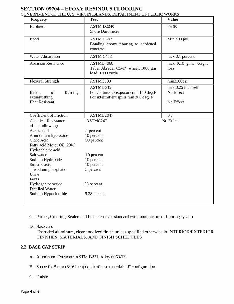
SECTION 09704 – EPOXY RESINOUS FLOORING GOVERNMENT OF THE U. S. VIRGIN ISLANDS, DEPARTMENT OF PUBLIC WORKS
Page 4 of 6
Property Test Value
Hardness ASTM D2240
Shore Durometer
75-80
Bond ASTM C882
Bonding epoxy flooring to hardened
concrete
Min 400 psi
Water Absorption ASTM C413 max 0.1 percent
Abrasion Resistance ASTMD4060
Taber Abrader CS-I7 wheel, 1000 gm
load; 1000 cycle
max 0.10 gms. weight
loss
Flexural Strength ASTMC580 min2200psi
Extent of Burning
extinguishing
Heat Resistant
ASTMD635
For continuous exposure min 140 deg.F
For intermittent spills min 200 deg. F
max 0.25 inch self
No Effect
No Effect
Coefficient of Friction ASTMD2047 0.7
Chemical Resistance ASTMC267 No Effect
of the following:
Acetic acid 5 percent
Ammonium hydroxide 10 percent
Citric Acid 50 percent
Fatty acid Motor Oil, 20W
Hydrochloric acid
Salt water 10 percent
Sodium Hydroxide 10 percent
Sulfuric acid 10 percent
Trisodium phosphate 5 percent
Urine
Feces
Hydrogen peroxide 28 percent
Distilled Water
Sodium Hypochloride 5.28 percent
C. Primer, Coloring, Sealer, and Finish coats as standard with manufacture of flooring system
D. Base cap:
Extruded aluminum, clear anodized finish unless specified otherwise in INTERIOR/EXTERIOR
FINISHES, MATERIALS, AND FINISH SCHEDULES
2.3 BASE CAP STRIP
A. Aluminum, Extruded: ASTM B221, Alloy 6063-TS
B. Shape for 5 mm (3/16 inch) depth of base material: "J" configuration
C. Finish:

SECTION 09704 – EPOXY RESINOUS FLOORING GOVERNMENT OF THE U. S. VIRGIN ISLANDS, DEPARTMENT OF PUBLIC WORKS
Page 5 of 6
1. Finish exposed surfaces in accordance with NAAMM Metal Finishes Manual.
D. Aluminum: NAAMM Amp 501
1. Clear anodic coating, AA-C22A41 chemically etched medium matte, with Architectural
Class 1, 0.7 mils or thicker
2. Colored anodic coating, AA-C22A42, chemically etched medium matte with Architectural
Class 1, 0.7 mils or thicker
PART 3 - EXECUTION
3.1 PROJECT CONDITIONS
A. Maintain temperature of materials above 21°C (70°F), for 48 hours before installation.
B. Maintain temperature of rooms where work occurs, between 21°C and 32°C (70°F and 90°F) for at
least 48 hours, before, during, and 24 hours after installation. Maintain temperature at least 21°C
(70°F) thereafter.
C. Do not install materials until building is permanently enclosed and wet construction is complete, dry,
and cured.
D. Concrete substrate cured and not less than 30 days old.
E. Area free of other trades during and for a period of 24 hours after installation.
3.2 INSTALLATION REQUIREMENTS
A. The respective manufacturer’s instructions for application and installation will be considered for use
when approved by the Project Manager.
B. Submit proposed installation deviation from this specification to the Project Manager indicating the
differences in the method of installation.
3.3 PREPARATION
A. Prepare surface in accordance with ASTM C81l except where specific manufacturer's instructions
supersede.
B. Mechanically remove bond inhibiting materials and loose or laitance materials to ensure bond.
C. Prepare wall and set base cap mold level.
D. Fill voids within the height of the wall where base is applied even with the wall surface.
E. Grind, sand, or cut away protrusions.
3.4 APPLICATION
A. Mix and apply each component of resinous flooring system in compliance with manufacturer's
specifications to produce a uniform monolithic flooring surface of 5 mm (3/ 16 inch) minimum
thickness.
SECTION 09704 – EPOXY RESINOUS FLOORING GOVERNMENT OF THE U. S. VIRGIN ISLANDS, DEPARTMENT OF PUBLIC WORKS
Page 6 of 6
B. Turn flooring up for coved 100 mm (4-inch) high base at vertical wall surfaces and penetrations.
Cove joint with floor; 6 mm (1/4 inch) radius. Round interior and external corners.
C. Apply primer over prepared substrate at manufacturer's specified rate. Coordinate timing of primer
application with application of troweled mortar to ensure optimum adhesion between resinous
flooring materials and substrate.
D. Uniformly spread mortar over substrate adjusted to manufacturer’s recommended maximum
thickness to plane line of floor.
E. Trowel finish for smooth surface on base and coved surface.
F. Grout mortar surface as specified by manufacturer and broad cast colored quartz aggregate uniformly
distributed for non-slip texture on floors to within one inch of base cove horizontal edge.
G. Apply a clear finish coat.
3.5 CURING, PROTECTION AND CLEANING
A. Cure resinous flooring materials in compliance with manufacturer's directions, taking care to prevent
contamination during stages of application and prior to completion of curing process.
B. Close area of application for a minimum of 24 hours.
C. Protect resinous flooring materials from damage and wear during construction operation.
D. Cover flooring with kraft paper.
E. Covers paper with 6 mm (1/4 inch) thick hardboard, plywood, or particle board where area is in foot
or vehicle traffic pattern, rolling or fixed scaffolding and overhead work occurs.
F. Remove temporary covering and clean resinous flooring just prior to final inspection. Use cleaning
materials and procedures recommended by resinous flooring manufacturer.
3.6 TOLERANCE
A. From line of plane: Maximum 3 mm (1/8 inch) in total distance of flooring and base.
B. From radius of cove: Maximum of 3 mm (1/8 inch) plus or 1.6 mm (1/16-inch) minus.
END OF SECTION

SECTION 09772 – SILICATE COATINGS GOVERNMENT OF THE U. S. VIRGIN ISLANDS, DEPARTMENT OF PUBLIC WORKS
Page 1 of 7
PART 1 GENERAL
1.1 SUMMARY
A. Section Includes:
Application of lime remover and three coats of silicate coating over water repellency.
Specification includes surface preparation.
B. Related Sections include the following:
1. Section 09253 - Salt-Retaining Water Repellent Renovation Stucco
1.2 REFERENCES
A. General:
The publications listed below form a part of this Specification to the extent referenced. The
publications are referred to in the text by the basic designation only.
B. ASTM (ASTM):
1. ASTM E 96, "Standard Test Methods for Water Vapor Transmission of Materials."
2. ASTM E 514, "Standard Test Method for Water Penetration and Leakage Through
Masonry."
3. ASTM G 154, "Standard Practice for Operating Fluorescent Light Apparatus for UV
Exposure of Nonmetallic Materials."
C. Deutsches lnstitut fur Normung (DIN), European Standard (EN), and International Organization for
Standardization (ISO):
1. DIN 18 363 2.4.1, manufacturing standard for silicate paint.
2. DIN EN 13 300, manufacturing standard for interior silicate paint.
3. DIN EN 1062, manufacturing standard for sol silicate paint.
D. ISO 11998, "Paints and varnishes - Determination of wet-scrub resistance and clean ability of
coatings."
E. ISO 6504-3, "Paints and varnishes- Determination of hiding power- Part 3: Determination of contrast
ratio of light-colored paints at a fixed spreading rate."
F. ISO 2813, "Paints and varnishes - Determination of specular gloss of non-metallic paint films at 20
degrees, 60 degrees and 85 degrees."
G. EN 1062-3, "Paints and varnishes- Coating materials and coating systems for exterior masonry and
concrete- Part 3: Determination of liquid water permeability."
H. DIN EN 1504-2, "Products and systems for the protection and repair of concrete structures
Definitions, requirements, quality control and evaluation of conformity - Part 2: Surface protection
systems for concrete."
SECTION 09772 – SILICATE COATINGS GOVERNMENT OF THE U. S. VIRGIN ISLANDS, DEPARTMENT OF PUBLIC WORKS
Page 2 of 7
I. DIN EN ISO 7783-2, "Coating materials and coating systems for exterior masonry and concrete –
Part 2: Determination and classification of water-vapor transmission rate (permeability)."
J. DIN 4102-A2, "Fire Behavior of Building Materials and Building Components- Part 2: Building
Components; Definitions, Requirements and Tests."
K. DIN 18363, "Construction Contract Procedures (VOB) Part C: General Technical Specifications in
Construction Contracts (ATV) Painting and Varnishing."
1.3 DEFINITIONS
A. Lime remover: A liquid silicic acid.
B. Water repellency:
A water repelling liquid that is applied to mineral surfaces prior to the application of the silicate
base coat.
C. Silicate coating base coat: The first applied coat of the silicate coating.
D. Silicate coating, intermediate coat:
The second applied coat of the silicate coating. E. Silicate coating, top coat: The third applied
coat of the silicate coating.
E. Dilution: A silicate based diluent.
1.4 SYSTEM DESCRIPTION
A. A materials-compatible highly vapor permeable decorative coating system offering severe
weathering protection for exterior exposure. Install over mineral surfaces.
B. Lime Remover:
A silicic acid based cleaner used to open sinter layers on rendered plaster surfaces to ensure they
are absorbent. May be used to remove lime efflorescence and calcium carbonate deposits from
mineral surfaces.
C. Water Repellency:
A solvent-free liquid silane that is drawn into the capillaries of the substrate and by chemical
reaction forms a micro-thin silica gel coating within repelling liquid water and salt ions by
reducing surface tensions while maintaining substrate vapor permeability.
D. Silicate Coating:
An incombustible three coat system with UV and alkaline resistant inorganic pigments in the
specified color with biocides. Coatings penetrate the surface and in a chemical reaction with the
substrate results in covalent bonds forming a hard amorphous microporous layer with extremely
high vapor permeability that is unaffected by acids, UV exposure, or air-borne pollutants.
Provides weathering protection without reducing substrate vapor permeability.
1.5 SUBMITTALS
A. Product Data:
Submit product data showing material proposed. Submit sufficient information to determine
compliance with the Drawings and Specifications. Provide published documentation describing
materials, characteristics, and limitations.

SECTION 09772 – SILICATE COATINGS GOVERNMENT OF THE U. S. VIRGIN ISLANDS, DEPARTMENT OF PUBLIC WORKS
Page 3 of 7
B. Samples:
Submit samples for verification purposes, fabrication techniques and workmanship.
C. Manufacturer's Instructions:
Submit manufacturer's instructions including technical data sheets, material safety data sheets,
mixing instructions, application requirements, special procedures, and conditions requiring
special attention.
D. LEED Submittals:
Submittals that are required to comply with requirements for LEED certification include the
following:
E. Low Emitting Materials:
Submit certification by the manufacturer confirming that products (i.e., adhesives, sealants,
paints, coatings, etc.) meet or exceed the volatile organic compound (VOC) limits set by specific
agencies or other requirements. Clearly state VOC limits in the submittal.
1.6 QUALITY ASSURANCE
A. Qualifications:
B. Manufacturer Qualifications:
Provide evidence that Manufacturer is a firm engaged in the manufacture of silicate coatings of
types required, and whose products have been in satisfactory use in similar service for a minimum
of ten years.
C. Applicator Qualifications:
1. Provide evidence Applicator is a firm having a minimum of three years of successful
application experience with projects similar in type and scope to that required for this Project
and approved by the manufacturer.
D. Mockups:
Prior to application of the work, fabricate and erect mockups for each type of finish and
application to verify selections made under sample submittals and to demonstrate aesthetic
effects as well as qualities of materials and execution. Build mockups to comply with the
following requirements using materials indicated for final unit of work. Locate mockups as
directed by the Owner’s Representative. Demonstrate the proposed range of aesthetic effects and
workmanship to be expected in the completed work. Obtain the Owner’s Representative's
acceptance of mockups before start of final unit of work.
E. Retain and maintain mockups during construction in undisturbed condition as a standard for judging
completed unit of work.
1.7 DELIVERY, STORAGE, AND HANDLING
A. Deliver materials to the Project site in supplier's or manufacturer's original wrappings and containers,
labeled with manufacturer's name, material and product brand name, and lot number, if any.
B. Store materials in their original undamaged packages and containers inside a well-ventilated area
protected from weather, moisture, soiling, extreme temperatures, and humidity.
1.8 PROJECT CONDITIONS
SECTION 09772 – SILICATE COATINGS GOVERNMENT OF THE U. S. VIRGIN ISLANDS, DEPARTMENT OF PUBLIC WORKS
Page 4 of 7
A. Environmental Requirements:
1. Substrate and ambient air temperature must be under 86º F (30 °C). Maintain temperature
during and after application.
2. Do not apply when rain is expected, in high winds, or onto hot substrates.
1.9 WARRANTY
A. Warranty period from date of Substantial Completion is 15 years.
PART 2 - PRODUCTS
2.1 MANUFACTURERS
A. Basis of Design:
Items specified are to establish a standard of quality for design, function, materials, compatibility,
performance, warranty, and appearance. Equivalent products by listed manufacturers are
acceptable. The Owner’s Representative is the sole judge of the basis of what is equivalent.
B. KEIM Mineral Coatings of America, Inc., 10615 Texland Blvd. #600, Charlotte, North Carolina
28273. Telephone 704-588-4811. Email [email protected].
2.2 MATERIALS
A. Lime Remover:
Silicic acid based cleaner that is diluted with water that reacts immediately upon application. No
VOC.
B. Basis of Design:
"KEIM Lime Remover", KEIM Mineral Coatings of America, Inc.
C. Water Repellency:
A solvent-free silane based proprietary water repellent with 100% active ingredient. Produces a
silica gel micro-coating within the capillaries of the substrate by a chemical reaction with the
humidity of the air and of the substrate. The silica gel coating breaks surface tensions preventing
water and salts migration yet maintains water vapor diffusion of substrate. Less than 10 g/l VOC.
D. Basis of Design:
"KEIM Silan 100", K.EIM Mineral Coatings of America, Inc.
E. Silicate Coating, Base Coat, Intermediate Coat, and Top Coat:
Provide silicate based opaque coating meeting or conforming to:
1. DIN 18 363 2.4.1, manufacturing standard for silicate paint.
2. DIN EN 1504-2/2.2, Products and systems for the protection and repair of concrete
structures/Surface protection systems for concrete.
3. DIN 4102-A2, non-flammable standard- will not burn.
4. ASTM E 96 Vapor Permeability- 83 perms.
SECTION 09772 – SILICATE COATINGS GOVERNMENT OF THE U. S. VIRGIN ISLANDS, DEPARTMENT OF PUBLIC WORKS
Page 5 of 7
5. ASTM G 154 Accelerated Weathering- no fading, cracking, peeling.
6. ASTM E 514 62-MPH Wind-Driven Rain Test - no water penetration.
7. With biocides.
8. Less than gram I per liter VOC (Volatile Organic Content).
F. Basis of Design:
"KEIM Royalan", KEIM Mineral Coatings of America, Inc.
G. Dilution for Silicate Coating:
Provide silicate dilution meeting or conforming to:
H. DIN 4102-A2, non-flammable standard- will not burn.
I. ASTM E 96 Vapor Permeability- 83 perms.
J. Less than l gram per liter VOC (Volatile Organic Content).
K. Basis of Design:
"KEIM Royalan Dilution", KEIM Mineral Coatings of America, Inc.
2.3 EQUIPMENT
A. Tools:
1. Lime Remover: Apply by brush or Hudson style sprayer, rinse off with low pressure spray.
2. Water Repellency: Apply by natural bristle brush, roller, or low pressure Hudson-style
sprayer.
3. Silicate Coating, Base Coat, Intermediate Coat, and Top Coat:
Apply by natural bristle facade brush, professional roller, or professional airless spray equipment
and back-roll as required for even distribution.
2.4 FINISHES
A. Lime Remover:
Leave surface clean from removed particles.
B. Silicate Coating; Base Coat, Intermediate Coat, and Top Coat:
Apply evenly to a smooth mineral matte finish without lap lines, voids, "holidays", or drips.
PART 3 - EXECUTION
3.1 EXAMINATION
A. Verification of Conditions:
Confirm by examination the areas and conditions under which the work is to be applied for
compliance with manufacturer's instructions. Do not proceed with the work until unsatisfactory
conditions have been corrected.
SECTION 09772 – SILICATE COATINGS GOVERNMENT OF THE U. S. VIRGIN ISLANDS, DEPARTMENT OF PUBLIC WORKS
Page 6 of 7
B. Verify substrate is secure, sound, dry, and absorbent, and free of dirt, grease, salts, oil-based paints,
release agents, curing agents, and other bond breakers.
C. Pressure wash surfaces exposed to airborne salts or sea water with plenty of clean water.
D. Verify substrate has no pretreatments or priming materials applied.
E. Verify Renovation Stucco finish coat has cured minimum l 0 days.
F. Verify other materials to be coated are fully cured to manufacturer recommendations.
G. Beginning of the work shall indicate acceptance of the areas and conditions as satisfactory by the
Applicator.
3.2 PREPARATION
A. Protection:
Lay ground cloths and take measures as necessary to protect surfaces subject to contact by
products specified by this Section.
3.3 APPLICATION
A. Conform to reviewed product data, manufacturer’s written instructions, and provisions of the
Contract Documents.
B. Plan the work properly.
C. Work ahead of the sun on shaded facades.
D. Work to logical stopping points (corners, seams, architectural features, etc.).
E. Apply coatings maintaining a wet edge to desired finish as indicated in FINISHES Article.
F. Protect from wind and rain prior to, during, and for a minimum 24 hours after application.
G. Lime Remover:
1. Brush off visible salt formations (efflorescence).
2. Dampen renovation stucco base coat patches and fills with clean water. When dry to touch
yet still visibly damp, proceed with lime remover.
3. Dilute lime remover l:3 with clean water (l part lime remover to 3 parts clean water.)
4. Apply to Renovation Stucco finish coat surfaces from bottom working to the top. Reaction
is immediate.
5. Rinse treated areas with clean water from bottom to top and back down to prevent loosened
particles from depositing into the surface.
6. Allow surfaces to completely dry out and inspect for salt efflorescence. Should efflorescence
reappear remove with clean water rinsing from bottom of facade to top and back down.
Repeat until efflorescence does not reappear.

SECTION 09772 – SILICATE COATINGS GOVERNMENT OF THE U. S. VIRGIN ISLANDS, DEPARTMENT OF PUBLIC WORKS
Page 7 of 7
H. Water Repellency:
1. Apply to saturation by flooding over substrate.
2. Repeat application after 10 minutes. Wipe excess material from substrate.
3. Observe 4 hours for repellency to penetrate and immediately thereafter begin application of
silicate base coat.
I. Silicate Coating:
1. Base Coat:
Dilute silicate coating with maximum 20 percent dilution (25kg with 5 liters dilution). Stir well
by hand or 600-800 RPM mixing equipment.
2. Apply base coat of diluted silicate coating.
3. Observe minimum 12 hours curing time.
J. Intermediate Coat: Do not dilute. Stir well by hand or 600-800 RPM mixing equipment.
1. Apply intermediate coat of undiluted silicate coating.
2. Observe minimum 12 hours curing time.
K. Top Coat:
Do not dilute. Stir well by hand or 600-800 RPM mixing equipment.
1. Apply top coat of undiluted silicate coating.
3.4 CLEANING
A. Lime Remover: Clean tools with clean water.
B. Water Repellency: Clean tools immediately with benzene or similar solvent.
C. Silicate Coating: Clean tools, spills, and accidental drips immediately with plenty of water.
D. Leave applications clean and premises free from residue and debris from work of this Section.
END OF SECTION
SECTION 099300 – STAINING AND TRANSPARENT FINISHING
GOVERNMENT OF THE U. S. VIRGIN ISLANDS, DEPARTMENT OF PUBLIC WORKS
Page 1 of 7
PART 1 GENERAL
1.1 RELATED DOCUMENTS
A. Drawings and general provisions of the Contract, including General and Supplementary Conditions
and Division 01 Specification Sections, apply to this Section.
1.2 SUMMARY
A. Section includes surface preparation and application of wood stains and transparent finishes.
B. Exterior Substrates:
1. Exposed framing.
2. Dressed lumber (finish carpentry or woodwork).
3. Wood-based panel products.
4. Wood decks and stairs.
5. Wood shingles and shakes (excluding roofs).
C. Interior Substrates:
1. Exposed glued-laminated beams and columns.
D. Related Requirements: None
1.3 DEFINITIONS
A. MPI Architectural Painting Specification Manual (MPI)
B. MPI Gloss Level 1: Not more than 5 units at 60 degrees and 10 units at 85 degrees, according to
ASTM D 523.
C. MPI Gloss Level 4: 20 to 35 units at 60 degrees and not less than 35 units at 85 degrees, according
to ASTM D 523.
D. MPI Gloss Level 5: 35 to 70 units at 60 degrees, according to ASTM D 523.
E. MPI Gloss Level 6: 70 to 85 units at 60 degrees, according to ASTM D 523.
F. MPI Gloss Level 7: More than 85 units at 60 degrees, according to ASTM D 523.
1.4 ACTION SUBMITTALS
A. Product Data:
For each type of product. Include preparation requirements and application instructions.
B. Include printout of current "MPI Approved Products List" for each product category specified, with
the proposed product highlighted.
SECTION 099300 – STAINING AND TRANSPARENT FINISHING
GOVERNMENT OF THE U. S. VIRGIN ISLANDS, DEPARTMENT OF PUBLIC WORKS
Page 2 of 7
C. Indicate VOC content.
D. Sustainable Design Submittals:
E. Product Data: For paints and coatings, indicating VOC content.
F. Laboratory Test Reports:
G. For paints and coatings, indicating compliance with requirements for low-emitting materials.
H. Samples for Initial Selection:
For each type of product.
I. Samples for Verification:
For each type of finish system and in each color and gloss of finish required.
J. Submit Samples on representative samples of actual wood substrates, 8 inches (200 mm) square.
K. Apply coats on Samples in steps to show each coat required for system.
L. Label each coat of each Sample.
M. Label each Sample for location and application area.
N. Product List:
Cross-reference to finish system and locations of application areas. Use same designations
indicated on Drawings and in schedules. Include color designations.
1.5 MAINTENANCE MATERIAL SUBMITTALS
A. Furnish extra materials that match products installed and that are packaged with protective covering
for storage and identified with labels describing contents.
B. Stains and Transparent Finishes: 5 percent, but not less than 1 gal. (3.8 L) of each material and color
applied.
1.6 QUALITY ASSURANCE
A. Mockups:
Apply mockups of each finish system indicated and each color selected to verify preliminary
selections made under Sample submittals, to demonstrate aesthetic effects, and to set quality
standards for materials and execution.
B. Owner’s Representative will select one surface to represent surfaces and conditions for application
of each type of finish system and substrate.
1. Vertical and Horizontal Surfaces: Provide samples of at least 100 sq. ft. (9 sq. m).
2. Other Items: Owner’s Representative will designate items or areas required.
C. Final approval of stain color selections will be based on mockups.
1. If preliminary stain color selections are not approved, apply additional mockups of additional
stain colors selected by Owner’s Representative at no added cost to Owner.
SECTION 099300 – STAINING AND TRANSPARENT FINISHING
GOVERNMENT OF THE U. S. VIRGIN ISLANDS, DEPARTMENT OF PUBLIC WORKS
Page 3 of 7
1.7 DELIVERY, STORAGE, AND HANDLING
A. Store materials not in use in tightly covered containers in well-ventilated areas.
B. Maintain containers in clean condition, free of foreign materials and residue.
C. Remove rags and waste from storage areas daily.
1.8 FIELD CONDITIONS
A. Apply finishes only when temperature of surfaces to be finished and ambient air temperatures are
under 95 deg F (35 deg C).
B. Do not apply finishes when relative humidity exceeds 85 percent, at temperatures less than 5 deg F
(3 deg C) above the dew point, or to damp or wet surfaces.
C. Do not apply exterior finishes in rain, fog, or mist.
PART 2 PRODUCTS
2.1 MANUFACTURERS
A. Basis-of-Design Product:
Subject to compliance with requirements, provide a product by one of the following:
B. Benjamin Moore & Co.
C. Dunn-Edwards Corporation.
D. Frazee Paint; Comex Group.
E. Glidden Professional.
F. PPG Architectural Finishes, Inc.
G. Sherwin-Williams Company (The).
2.2 MATERIALS, GENERAL
A. MPI Standards:
Products shall comply with MPI standards indicated and shall be listed in its "MPI Approved
Products List."
B. Material Compatibility:
C. Materials for use within each paint system shall be compatible with one another and substrates
indicated, under conditions of service and application as demonstrated by manufacturer, based on
testing and field experience.
D. For each coat in a paint system, products shall be recommended in writing by manufacturers of
topcoat for use in paint system and on substrate indicated.
E. Low-Emitting Materials:

SECTION 099300 – STAINING AND TRANSPARENT FINISHING
GOVERNMENT OF THE U. S. VIRGIN ISLANDS, DEPARTMENT OF PUBLIC WORKS
Page 4 of 7
F. Interior paints and coatings shall comply with the testing and product requirements of the California
Department of Public Health's "Standard Method for the Testing and Evaluation of Volatile Organic
Chemical Emissions from Indoor Sources Using Environmental Chambers."
G. Stain Colors:
As selected by Owner’s Representative from manufacturer's full range
PART 3 EXECUTION
3.1 EXAMINATION
A. Examine substrates and conditions, with Applicator present, for compliance with requirements for
maximum moisture content and other conditions affecting performance of the Work.
B. Maximum Moisture Content of Exterior Wood Substrates:
15 percent, when measured with an electronic moisture meter.
C. Maximum Moisture Content of Interior Wood Substrates:
13 percent, when measured with an electronic moisture meter.
D. Verify suitability of substrates, including surface conditions and compatibility with existing finishes
and primers.
E. Proceed with finish application only after unsatisfactory conditions have been corrected.
F. Beginning finish application constitutes Contractor's acceptance of substrates and conditions.
3.2 PREPARATION
A. Comply with manufacturer's written instructions and recommendations in "MPI Architectural
Painting Specification Manual" applicable to substrates indicated.
B. Remove hardware, covers, plates, and similar items already in place that are removable. If removal
is impractical or impossible because of size or weight of item, provide surface-applied protection
before surface preparation and finishing.
C. After completing finishing operations, use workers skilled in the trades involved to reinstall items
that were removed. Remove surface-applied protection if any.
D. Clean and prepare surfaces to be finished according to manufacturer's written instructions for each
substrate condition and as specified.
E. Remove dust, dirt, oil, and grease by washing with a detergent solution; rinse thoroughly with clean
water and allow to dry. Remove grade stamps and pencil marks by sanding lightly. Remove loose
wood fibers by brushing.
F. Remove mildew by scrubbing with a commercial wash formulated for mildew removal and as
recommended by stain manufacturer.
G. Exterior Wood Substrates:
H. Scrape and clean knots, and apply coat of knot sealer before applying primer.
SECTION 099300 – STAINING AND TRANSPARENT FINISHING
GOVERNMENT OF THE U. S. VIRGIN ISLANDS, DEPARTMENT OF PUBLIC WORKS
Page 5 of 7
I. Prime edges, ends, faces, undersides, and backsides of wood.
1. For solid hide stained wood, stain edges and ends after priming.
2. For varnish-coated stained wood, stain edges and ends and prime with varnish. Prime
undersides and backsides with varnish.
J. Countersink stainless steel nails, if used, and fill with putty or plastic wood filler tinted to final color.
Sand smooth when dried.
K. Interior Wood Substrates:
L. Scrape and clean knots, and apply coat of knot sealer before applying primer.
M. Apply wood filler paste to open-grain woods, as defined in "MPI Architectural Painting Specification
Manual," to produce smooth, glasslike finish.
N. Sand surfaces exposed to view and dust off.
O. After priming, fill holes and imperfections in the finish surfaces with putty or plastic wood filler.
Sand smooth when dry.
3.3 APPLICATION
A. Apply finishes according to manufacturer's written instructions and recommendations in "MPI
Architectural Painting Specification Manual."
B. Use applicators and techniques suited for finish and substrate indicated.
C. Finish surfaces behind movable equipment and furniture same as similar exposed surfaces.
D. Do not apply finishes over labels of independent testing agencies or equipment name, identification,
performance rating, or nomenclature plates.
E. Apply finishes to produce surface films without cloudiness, holidays, lap marks, brush marks, runs,
ropiness, or other surface imperfections.
3.4 CLEANING AND PROTECTION
A. At end of each workday, remove rubbish, empty cans, rags, and other discarded materials from
Project site.
B. After completing finish application, clean spattered surfaces. Remove spattered materials by
washing, scraping, or other methods. Do not scratch or damage adjacent finished surfaces.
C. Protect work of other trades against damage from finish application. Correct damage by cleaning,
repairing, replacing, and refinishing, as approved by Architect, and leave in an undamaged condition.
D. At completion of construction activities of other trades, touch up and restore damaged or defaced
finished wood surfaces.
3.5 EXTERIOR WOOD-FINISH-SYSTEM SCHEDULE
A. Wood Substrates:

SECTION 099300 – STAINING AND TRANSPARENT FINISHING
GOVERNMENT OF THE U. S. VIRGIN ISLANDS, DEPARTMENT OF PUBLIC WORKS
Page 6 of 7
Exposed framing.
B. Solid-Color, Water-Based Stain System MPI EXT 6.2B:
1. Prime Coat: Stain, exterior, water based, solid hide, matching topcoat.
2. Topcoat: Stain, exterior, water based, solid hide, MPI #16.
C. Water-Based Semitransparent Stain System MPI EXT 6.2P:
1. Prime Coat: Stain, exterior, water based, semitransparent, matching topcoat.
2. Topcoat: Stain, exterior, water based, semitransparent.
D. Wood Substrates:
Wood trim, architectural woodwork, doors, windows, wood board siding, and wood fences.
E. Solid-Color, Water-Based Stain System MPI EXT 6.3K:
1. Prime Coat: Stain, exterior, water based, solid hide, matching topcoat.
2. Topcoat: Stain, exterior, water based, solid hide, MPI #16.
F. Water-Based Semitransparent Stain System MPI EXT 6.3N:
1. Prime Coat: Stain, exterior, water based, semitransparent, matching topcoat.
2. Topcoat: Stain, exterior, water based, semitransparent.
G. Wood Substrates: Wood-based panel products.
H. Solid-Color, Water-Based Stain System MPI EXT 6.4A:
1. Prime Coat: Stain, exterior, water based, solid hide, matching topcoat.
2. Topcoat: Stain, exterior, water based, solid hide, MPI #16.
I. Water-Based Semitransparent Stain System MPI EXT 6.4L:
1. Prime Coat: Stain, exterior, water based, semitransparent, matching topcoat.
2. Intermediate Coat: Stain, exterior, water based, semitransparent, matching topcoat.
3. Topcoat: Stain, exterior, water based, semitransparent.
J. Wood Substrates:
Traffic surfaces including lumber decking and stairs.
K. Deck Stain System MPI EXT 6.5F:
1. Prime Coat: Stain, for exterior wood decks, matching topcoat.
2. Top coat: Stain, for exterior wood decks, MPI #33.
SECTION 099300 – STAINING AND TRANSPARENT FINISHING
GOVERNMENT OF THE U. S. VIRGIN ISLANDS, DEPARTMENT OF PUBLIC WORKS
Page 7 of 7
L. Wood Substrates:
Wood shingles and shakes (excluding roofs).
M. Solid-Color, Water-Based Stain System MPI EXT 6.6D:
1. Prime Coat: Stain, exterior, water based, solid hide, matching topcoat.
2. Topcoat: Stain, exterior, water based, solid hide, MPI #16.
3.6 INTERIOR WOOD -FINISH-SYSTEM SCHEDULE
A. Wood Substrates: Glued-laminated construction.
B. Solid-Color Latex Stain System MPI INT 6.1T:
1. Prime Coat: Stain, exterior, water based, solid hide, matching topcoat.
2. Topcoat: Stain, exterior, water based, solid hide, MPI #16.
C. Semitransparent Stain System MPI INT 6.1G:
1. Prime Coat: Stain, semitransparent, matching topcoat.
2. Topcoat: Stain, semitransparent, for interior wood, MPI #90.
END OF SECTION
SECTION 09900 – PAINTING GOVERNMENT OF THE U. S. VIRGIN ISLANDS, DEPARTMENT OF PUBLIC WORKS
Page 1 of 10
PART 1 ·GENERAL
1.1 RELATED DOCUMENTS
A. Drawings and general provisions of the Contract, including General and Supplementary Conditions
and Division 1 Specification Sections, apply to this Section.
1.2 SUMMARY
A. This Section includes surface preparation and field painting of the following:
B. Exposed interior items and surfaces.
C. Surface preparation, priming, and finish coats specified in this Section are in addition to shop priming
and surface treatment specified in other Sections.
D. Paint exposed surfaces, except where the paint schedules indicate that a surface or material is not to
be painted or is to remain natural. If the paint schedules do not specifically mention an item or a
surface, paint the item or surface the same as similar adjacent materials or surfaces whether or not
schedules indicate colors. If the schedules do not indicate color or finish, the Owner’s Representative
will select from standard colors and finishes available.
E. Painting includes field painting of exposed bare and covered pipes and ducts (including color
coding), hangers, exposed steel and iron work, and primed metal surfaces of mechanical and
electrical equipment.
F. Do not paint prefinished items, concealed surfaces, finished metal surfaces, operating parts, and
labels.
G. Prefinished items include the following factory-finished components:
1. Architectural woodwork and casework.
2. Elevator equipment.
3. Finished mechanical and electrical equipment.
4. Light fixtures.
5. Distribution cabinets.
H. Concealed surfaces include walls or ceilings in the following generally inaccessible spaces:
1. Ceiling plenums.
I. Finished metal surfaces include the following:
1. Anodized aluminum
2. Stainless steel
3. Chromium plate
SECTION 09900 – PAINTING GOVERNMENT OF THE U. S. VIRGIN ISLANDS, DEPARTMENT OF PUBLIC WORKS
Page 2 of 10
4. Copper
5. Bronze and brass
J. Operating parts include moving parts of operating equipment and the following:
1. Valve and damper operators
2. Linkages
3. Sensing devices
4. Motor and fan shafts
K. Labels:
Do not paint over Underwriters Laboratories (UL), Factory Mutual (FM), or other code required
labels or equipment name, identification, performance rating, or nomenclature plates.
L. Related Sections include the following:
M. Division 5 Section "Structural Steel" for shop priming structural steel
N. Division 5 Section "Metal Fabrications" for shop priming ferrous metal
O. Division 6 Section "Interior Architectural Woodwork" for shop priming interior architectural
woodwork
P. Division 8 Section "Steel Frames" for shop priming steel doors and frames
Q. Division 9 Section "Gypsum Board Assemblies" for surface preparation for gypsum board
1.3 DEFINITIONS
A. General:
Standard coating terms defined in ASTM D 16 apply to this Section.
B. Flat refers to a lusterless or matte finish with a gloss range below 15 when measured at an 85- degree
meter.
C. Eggshell refers to low-sheen finish with a gloss range between 5 and 20 when measured at a 60-
degree meter.
D. Satin refers to low-sheen finish with a gloss range between 15 and 35 when measured at a 60- degree
meter.
E. Semi-gloss refers to medium-sheen finish with a gloss range between 30 and 65 when measured at a
60-degree meter.
F. Full gloss refers to high-sheen finish with a gloss range more than 65 when measured at a 60- degree
meter.
1.4 SUBMITTALS
A. Product Data:
SECTION 09900 – PAINTING GOVERNMENT OF THE U. S. VIRGIN ISLANDS, DEPARTMENT OF PUBLIC WORKS
Page 3 of 10
For each paint system specified. Include block fillers and primers.
B. Material List:
Provide an inclusive list of required coating materials. Indicate each material and cross-reference
specific coating, finish system, and application. Identify each material by manufacturer’s catalog
number and general classification.
C. Manufacturer's Information:
Provide manufacturer’s technical information, including label analysis and instructions for
handling, storing, and applying each coating material proposed for use.
D. Certification by the manufacturer that products supplied comply with local regulations controlling
use of volatile organic compounds (VOCs).
E. Samples for Verification:
Of each color and material to be applied, with texture to simulate actual conditions.
F. Qualification Data:
For firms and persons specified in the "Quality Assurance" Article to demonstrate their
capabilities and experience. Include lists of completed projects with project names and addresses,
names and addresses of Owner’s Representative and owners, and other information specified.
1.5 QUALITY ASSURANCE
A. Applicator Qualifications:
Engage an experienced applicator who has completed painting system applications similar in
material and extent to that indicated for this Project with a record of successful in service
performance.
B. Source Limitations:
Obtain block fillers, primers, and undercoat materials for each coating system from the same
manufacturer as the finish coats.
1.6 DELIVERY, STORAGE, AND HANDLING
A. Deliver materials to the Project Site in manufacturer’s original, unopened packages and containers
bearing manufacturer’s name and label, and the following information:
B. Product name or title of material
C. Product description (generic classification or binder type)
D. Manufacturer’s stock number and date of manufacture
E. Contents by volume, for pigment and vehicle constituents
F. Thinning instructions
G. Application instructions
H. Color name and number
I. VOC content
SECTION 09900 – PAINTING GOVERNMENT OF THE U. S. VIRGIN ISLANDS, DEPARTMENT OF PUBLIC WORKS
Page 4 of 10
J. Store materials not in use in tightly covered containers in a well-ventilated area. Maintain containers
used in storage in a clean condition, free of foreign materials and residue.
K. Keep storage area neat and orderly. Remove oily rags and waste daily. Take necessary measures to
ensure that workers and work areas are protected from fire and health hazards resulting from
handling, mixing, and application.
1.7 PROJECT CONDITIONS
A. Apply water-based paints only when the temperature of surfaces to be painted and surrounding air
temperatures are below 90°F (32°C).
B. Apply solvent-thinned paints only when the temperature of surfaces to be painted and surrounding
air temperatures are below 95°F (35°C).
C. Do not apply paint when the relative humidity exceeds 85 percent; or at temperatures less than 5°F
(3°C) above the dew point; or to damp or wet surfaces.
D. Painting may continue during inclement weather if surfaces and areas to be painted are enclosed and
within temperature limits specified by manufacturer during application and drying periods.
1.8 EXTRA MATERIALS
A. Furnish extra paint materials from the same production run as the materials applied in the quantities
described below. Package paint materials in unopened, factory-sealed containers for storage and
identify with labels describing contents. Deliver extra materials to the Owner.
B. Quantity:
Furnish the Owner with a 1-gallon can of each type of finish coat of each color, taken from lots
furnished for the work.
PART 2 - PRODUCTS
2.1 MANUFACTURERS
A. Available Products:
B. Subject to compliance with requirements, products that may be incorporated into the Work include,
but are not limited to, products listed in the paint schedules.
C. Manufacturers Names:
The following manufacturers are referred to in the paint schedules by use of shortened versions
of their names, which are shown in parentheses:
1. Devoe & Raynolds Co. (Devoe).
2. Fuller-O'Brien Paints (Fuller).
3. Glidden Co. (The) (Glidden).
4. Benjamin Moore & Co. (Moore).
5. PPG Industries, Inc. (PPG).
SECTION 09900 – PAINTING GOVERNMENT OF THE U. S. VIRGIN ISLANDS, DEPARTMENT OF PUBLIC WORKS
Page 5 of 10
6. Pratt & Lambert, Inc. (P & L).
7. Sherwin-Williams Co. (S-W).
8. Martin Seymour Co. (MS).
2.2 PAINT MATERIALS, GENERAL
A. Material Compatibility:
Provide block fillers, primers, undercoats, and finish-coat materials that are compatible with one
another and the substrates indicated under conditions of service and application, as demonstrated
by manufacturer based on testing and field experience.
B. Material Quality:
Provide manufacturer’s best-quality paint material of the various coating types specified. Paint-
material containers not displaying manufacturer’s product identification will not be acceptable.
C. Proprietary Names:
Use of manufacturer’s proprietary product names to designate colors or materials is not intended
to imply that products named are required to be used to the exclusion of equivalent products of
other manufacturers. Furnish manufacturer’s material data and certificates of performance for
proposed substitutions.
D. Colors:
Match colors indicated by reference to manufacturer's color designations.
PART 3 - EXECUTION
3.1 EXAMINATION
A. Examine substrates, areas, and conditions, with the Applicator present, under which painting will be
performed for compliance with paint application requirements.
B. Do not begin to apply paint until unsatisfactory conditions have been corrected and surfaces receiving
paint are thoroughly dry.
C. Start of painting will be construed as the Applicator's acceptance of surfaces and conditions within a
particular area.
D. Coordination of Work:
Review other Sections in which primers are provided to ensure compatibility of the total system
for various substrates. On request, furnish information on characteristics of finish materials to
ensure use of compatible primers.
E. Notify the Owner’s Representative about anticipated problems using the materials specified over
substrates primed by others.
3.2 PREPARATION
A. General:

SECTION 09900 – PAINTING GOVERNMENT OF THE U. S. VIRGIN ISLANDS, DEPARTMENT OF PUBLIC WORKS
Page 6 of 10
Remove hardware and hardware accessories, plates, machined surfaces, lighting fixtures, and
similar items already installed that are not to be painted. If removal is impractical or impossible
because of the size or weight of the item, provide surface-applied protection before surface
preparation and painting.
B. After completing painting operations in each space or area, reinstall items removed using workers
skilled in the trades involved.
C. Cleaning:
Before applying paint or other surface treatments, clean the substrates of substances that could
impair the bond of the various coatings. Remove oil and grease before cleaning.
D. Schedule cleaning and painting so dust and other contaminants from the cleaning process will not
fall on wet, newly painted surfaces.
E. Surface Preparation:
Clean and prepare surfaces to be painted according to manufacturer’s written instructions for
each particular substrate condition and as specified.
F. Provide barrier coats over incompatible primers or remove and re-prime.
G. Ferrous Metals:
Clean un-galvanized ferrous metal surfaces that have not been shop coated; remove oil, grease,
dirt, loose mill scale, and other foreign substances. Use solvent or mechanical cleaning methods
that comply with the Steel Structures Painting Council's (SSPC) recommendations.
1. Blast steel surfaces clean as recommended by paint system manufacturer and according to
requirements of SSPC-SP 10.
2. Treat bare and sandblasted or pickled clean metal with a metal treatment wash coat before
priming.
3. Touch up bare areas and shop-applied prime coats that have been damaged. Wire-brush,
clean with solvents recommended by paint manufacturer, and touch up with the same primer
as the shop coat.
H. Galvanized Surfaces:
Clean galvanized surfaces with nonpetroleum-based solvents so surface is free of oil and surface
contaminants. Remove pretreatment from galvanized sheet metal fabricated from coil stock by
mechanical methods.
I. Materials Preparation:
Mix and prepare paint materials according to manufacturer’s written instructions.
J. Maintain containers used in mixing and applying paint in a clean condition, free of foreign materials
and residue.
K. Stir material before application to produce a mixture of uniform density. Stir as required during
application. Do not stir surface film into material. If necessary, remove surface film and strain
material before using.
L. Use only thinners approved by paint manufacturer and only within recommended limits.

SECTION 09900 – PAINTING GOVERNMENT OF THE U. S. VIRGIN ISLANDS, DEPARTMENT OF PUBLIC WORKS
Page 7 of 10
M. Tinting:
Tint each undercoat a lighter shade to simplify identification of each coat when multiple coats of
the same material are applied. Tint undercoats to match the color of the finish coat, but provide
sufficient differences in shade of undercoats to distinguish each separate coat.
3.3 APPLICATION
A. General:
Apply paint according to manufacturer’s written instructions. Use applicators and techniques
best suited for substrate and type of material being applied.
B. Paint colors, surface treatments, and finishes are indicated in the schedules.
C. Do not paint over dirt, rust, scale, grease, moisture, scuffed surfaces, or conditions detrimental to
formation of a durable paint film.
D. Provide finish coats that are compatible with primers used.
E. The term "exposed surfaces" includes areas visible when permanent or built-in fixtures, convector
covers, covers for finned-tube radiation, grilles, and similar components are in place. Extend coatings
in these areas, as required, to maintain the system integrity and provide desired protection.
F. Paint surfaces behind movable equipment and furniture the same as similar exposed surfaces. Before
the final installation of equipment, paint surfaces behind permanently fixed equipment or furniture
with prime coat only.
G. Paint back sides of access panels and removable or hinged covers to match exposed surfaces.
H. Finish exterior doors on tops, bottoms, and side edges the same as exterior faces.
I. Sand lightly between each succeeding enamel or varnish coat.
J. Scheduling Painting:
Apply first coat to surfaces that have been cleaned, pretreated, or otherwise prepared for painting
as soon as practicable after preparation and before subsequent surface deterioration.
K. The number of coats and the film thickness required are the same regardless of application method.
Do not apply succeeding coats until the previous coat has cured as recommended by the
manufacturer. If sanding is required to produce a smooth, even surface according to manufacturer's
written instructions, sand between applications.
L. Omit primer on metal surfaces that have been shop primed and touch up painted.
M. If undercoats, stains, or other conditions show through final coat of paint, apply additional coats until
paint film is of uniform finish, color, and appearance. Give special attention to ensure edges, corners,
crevices, welds, and exposed fasteners receive a dry film thickness equivalent to that of flat surfaces.
N. Allow sufficient time between successive coats to permit proper drying. Do not recoat surfaces until
paint has dried to where it feels firm, does not deform or feel sticky under moderate thumb pressure,
and where application of another coat of paint does not cause the undercoat to lift or lose adhesion.
O. Application Procedures:

SECTION 09900 – PAINTING GOVERNMENT OF THE U. S. VIRGIN ISLANDS, DEPARTMENT OF PUBLIC WORKS
Page 8 of 10
Apply paints and coatings by brush, roller, spray, or other applicators according to manufacturer’s
written instructions.
P. Brushes:
Use brushes best suited for the type of material applied. Use brush of appropriate size for the
surface or item being painted.
Q. Rollers:
Use rollers of carpet, velvet back, or high-pile sheep's wool as recommended by the manufacturer
for the material and texture required.
R. Spray Equipment:
Use airless spray equipment with orifice size as recommended by the manufacturer for the
material and texture required.
S. Minimum Coating Thickness:
Apply paint materials no thinner than manufacturers recommended spreading rate. Provide the
total dry film thickness of the entire system as recommended by the manufacturer.
T. Mechanical and Electrical Work:
Painting of mechanical and electrical work is limited to items exposed in equipment rooms and
in occupied spaces.
U. Mechanical items to be painted include, but are not limited to, the following:
V. Piping, pipe hangers, and supports
W. Equipment supports
X. Accessory items
Y. Electrical items to be painted include, but are not limited to, the following:
Z. Conduit and fittings
AA. Prime Coats:
Before applying finish coats, apply a prime coat of material, as recommended by the
manufacturer, to material that is required to be painted or finished and that has not been prime
coated by others. Recoat primed and sealed surfaces where evidence of suction spots or unsealed
areas in first coat appears, to ensure a finish coat with no burn through or other defects due to
insufficient sealing.
BB. Pigmented (Opaque) Finishes:
Completely cover surfaces as necessary to provide a smooth, opaque surface of uniform finish,
color, appearance, and coverage. Cloudiness, spotting, holidays, laps, brush marks, runs, sags,
ropiness, or other surface imperfections will not be acceptable.
CC. Transparent (Clear) Finishes:
Use multiple coats to produce a glass-smooth surface film of even luster. Provide a finish free of
laps, runs, cloudiness, color irregularity, brush marks, orange peel, nail holes, or other surface
imperfections.
DD. Provide satin finish for final coats.
SECTION 09900 – PAINTING GOVERNMENT OF THE U. S. VIRGIN ISLANDS, DEPARTMENT OF PUBLIC WORKS
Page 9 of 10
EE. Completed Work:
Match approved samples for color, texture, and coverage. Remove, refinish, or repaint work not
complying with requirements.
3.4 CLEANING
A. Cleanup:
At the end of each workday, remove empty cans, rags, rubbish, and other discarded paint
materials from the site.
B. After completing painting, clean glass and paint-spattered surfaces. Remove spattered paint by
washing and scraping. Be careful not to scratch or damage adjacent finished surfaces.
3.5 PROTECTION
A. Protect work of other trades, whether being painted or not, against damage by painting. Correct
damage by cleaning, repairing or replacing, and repainting, as approved by Owner’s Representative.
B. Provide "Wet Paint" signs to protect newly painted finishes. Remove temporary protective
wrappings provided by others to protect their work after completing painting operations.
C. At completion of construction activities of other trades, touch up and restore damaged or defaced
painted surfaces. Comply with procedures specified in PDCA Pl.
3.6 EXTERIOR PAINT SCHEDULE
A. Ferrous Metal:
Provide the following finish systems over exterior ferrous metal. Primer is not required on shop-
primed items.
B. Semi-gloss, Acrylic-Enamel Finish: 2 finish coats over a rust-inhibitive primer.
1. Primer:
Rust-inhibitive metal primer applied at spreading rate recommended by the manufacturer to
achieve a total dry film thickness of not less than 1.3 mils (0.033 mm).
2. First and Second Coats:
Semi-gloss, exterior, acrylic-latex enamel applied at spreading rate recommended by the
manufacturer to achieve a total dry film thickness of not less than 2.6 mils (0.066 mm).
3.7 INTERIOR PAINT SCHEDULE
A. Gypsum Board:
Provide the following finish systems over interior gypsum board surfaces:
B. Flat Acrylic Finish: 2 finish coats over a primer
C. Primer:
Latex-based, mildew inhibiting interior primer, such as Kilz2 or approved equal, applied at
spreading rate recommended by the manufacturer to achieve a total dry film thickness of not less
than 1.2 mils (0.031 mm).
D. Use only thinners approved by paint manufacturer and only within the recommended limits.
SECTION 09900 – PAINTING GOVERNMENT OF THE U. S. VIRGIN ISLANDS, DEPARTMENT OF PUBLIC WORKS
Page 10 of 10
E. First and Second Coats:
Flat, acrylic-latex-based, interior paint applied at spreading rate recommended by the
manufacturer to achieve a total dry film thickness of not less than 2.5 mils (0.064 mm).
F. Ferrous Metal:
Provide the following finish systems over ferrous metal:
G. Semi-gloss, Acrylic-Enamel Finish: One finish coat over an enamel undercoat and a primer
1. Primer:
Quick-drying, rust-inhibitive, alkyd-based or epoxy-metal primer, as recommended by the
manufacturer for this substrate, applied at spreading rate recommended by the manufacturer to
achieve a total dry film thickness of not less than 1.5 mils (0.038 mm).
2. Undercoat:
Alkyd, interior enamel undercoat or semi-gloss, acrylic-latex, interior enamel, as recommended
by the manufacturer for this substrate, applied at spreading rate recommended by the
manufacturer to achieve a total dry film thickness of not less than 1.3 mils (0.033 mm).
3. Finish Coat:
Semi-gloss, acrylic-latex, interior enamel applied at spreading rate recommended by the
manufacturer to achieve a total dry film thickness of not less than 1.3 mils (0.033 mm).
H. Zinc-Coated Metal:
Provide the following finish systems over zinc-coated metal:
I. Semi-gloss, Acrylic-Enamel Finish: 2 finish coats over a primer
1. Primer:
Galvanized metal primer applied at spreading rate recommended by the manufacturer to achieve
a total dry film thickness of not less than 1.2 mils (0.031 mm).
2. First and Second Coats:
Semi-gloss, acrylic-latex, interior enamel applied at spreading rate recommended by the
manufacturer to achieve a total dry film thickness of not less than 2.6 mils (0.066 mm).
J. Tinting:
Tint each undercoat a lighter shade to simplify identification of each coat when multiple coats of
the same material are being applied. Tint undercoats to match the color of the finish coat, but
provide sufficient difference in shade of undercoats to distinguish each separate coat.
END OF SECTION

DIVISION 26 - ELECTRICAL GOVERNMENT OF THE U. S. VIRGIN ISLANDS, DEPARTMENT OF PUBLIC WORKS
SECTION 260500 - BASIC ELECTRICAL MATERIALS AND METHODS GOVERNMENT OF THE U. S. VIRGIN ISLANDS, DEPARTMENT OF PUBLIC WORKS
Page 1 of 7
PART 1 GENERAL
1.1 RELATED DOCUMENTS
A. Drawings and general provisions of the Contract, including General and Supplementary
Conditions and Division I Specification Sections, apply to this Section.
1.2 SUMMARY
A. This Section includes the following electrical materials and methods:
1. Supporting devices for electrical components
2. Electrical Identification
3. Touchup painting
1.3 SUBMITTALS
A. General:
Submit each item in this Article according to the Conditions of the Contract and Division 1
Specification Sections.
B. Product Data for each type of product specified.
C. Samples of color, lettering style, and other graphic representation required for each
identification product for Project.
1.4 QUALITY ASSURANCE
A. Comply with NFPA 70 for components and installation.
B. Listing and Labeling:
Provide products specified in this Section that are listed and labeled.
1. The Terms "Listed and Labeled":
As defined in the National Electrical Code, Article 100.
2. Listing and Labeling Agency Qualifications A "Nationally Recognized Testing
Laboratory" (NRTL) as defined in OSHA Regulation 1910.7.
1.5 SEQUENCING AND SCHEDULING
A. Coordinate electrical equipment installation with other building components.
B. Arrange for chases, slots, and openings in building structure during progress of
construction to allow for electrical installations.
C. Coordinate installing required supporting devices and set sleeves in poured in place
concrete and other structural components as they are constructed.
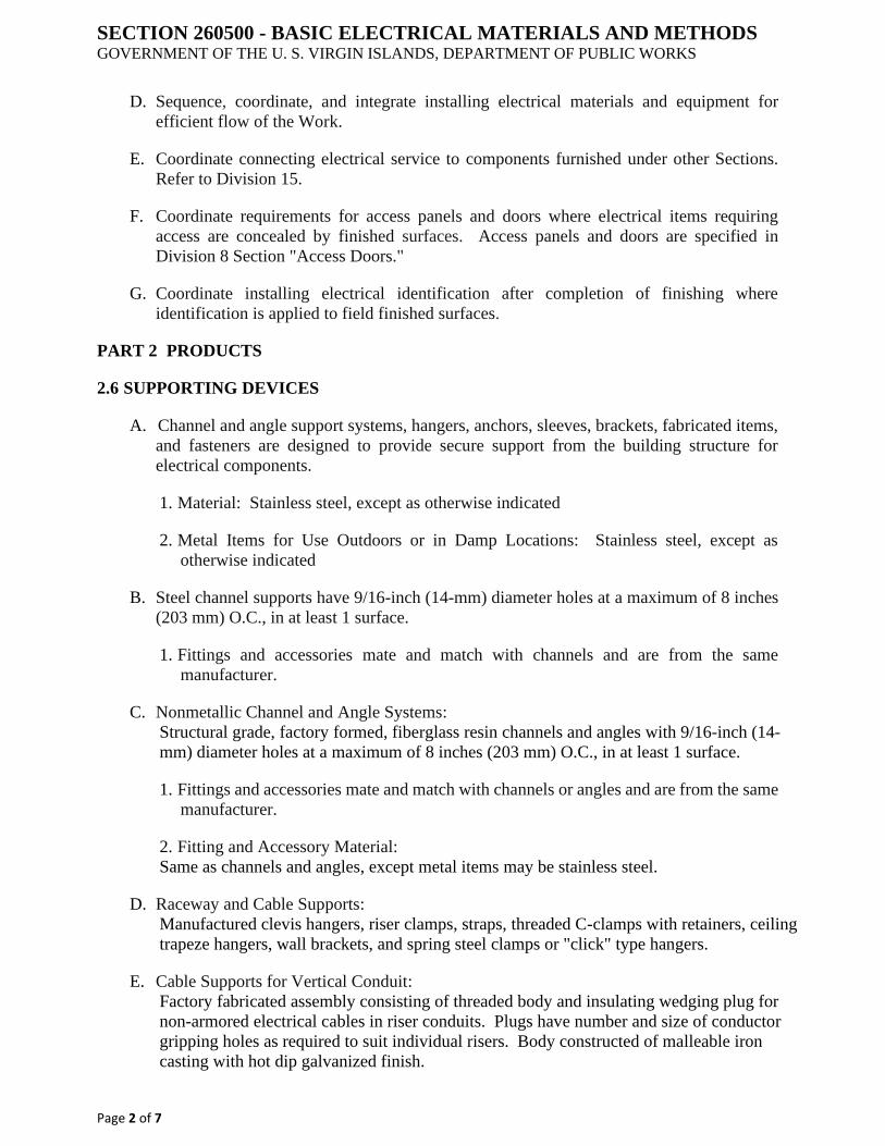
SECTION 260500 - BASIC ELECTRICAL MATERIALS AND METHODS GOVERNMENT OF THE U. S. VIRGIN ISLANDS, DEPARTMENT OF PUBLIC WORKS
Page 2 of 7
D. Sequence, coordinate, and integrate installing electrical materials and equipment for
efficient flow of the Work.
E. Coordinate connecting electrical service to components furnished under other Sections.
Refer to Division 15.
F. Coordinate requirements for access panels and doors where electrical items requiring
access are concealed by finished surfaces. Access panels and doors are specified in
Division 8 Section "Access Doors."
G. Coordinate installing electrical identification after completion of finishing where
identification is applied to field finished surfaces.
PART 2 PRODUCTS
2.6 SUPPORTING DEVICES
A. Channel and angle support systems, hangers, anchors, sleeves, brackets, fabricated items,
and fasteners are designed to provide secure support from the building structure for
electrical components.
1. Material: Stainless steel, except as otherwise indicated
2. Metal Items for Use Outdoors or in Damp Locations: Stainless steel, except as
otherwise indicated
B. Steel channel supports have 9/16-inch (14-mm) diameter holes at a maximum of 8 inches
(203 mm) O.C., in at least 1 surface.
1. Fittings and accessories mate and match with channels and are from the same
manufacturer.
C. Nonmetallic Channel and Angle Systems:
Structural grade, factory formed, fiberglass resin channels and angles with 9/16-inch (14-
mm) diameter holes at a maximum of 8 inches (203 mm) O.C., in at least 1 surface.
1. Fittings and accessories mate and match with channels or angles and are from the same
manufacturer.
2. Fitting and Accessory Material:
Same as channels and angles, except metal items may be stainless steel.
D. Raceway and Cable Supports:
Manufactured clevis hangers, riser clamps, straps, threaded C-clamps with retainers, ceiling
trapeze hangers, wall brackets, and spring steel clamps or "click" type hangers.
E. Cable Supports for Vertical Conduit:
Factory fabricated assembly consisting of threaded body and insulating wedging plug for
non-armored electrical cables in riser conduits. Plugs have number and size of conductor
gripping holes as required to suit individual risers. Body constructed of malleable iron
casting with hot dip galvanized finish.
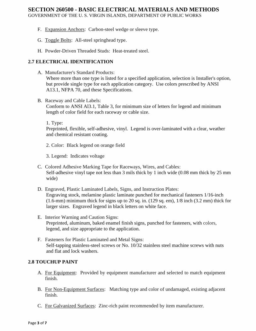
SECTION 260500 - BASIC ELECTRICAL MATERIALS AND METHODS GOVERNMENT OF THE U. S. VIRGIN ISLANDS, DEPARTMENT OF PUBLIC WORKS
Page 3 of 7
F. Expansion Anchors: Carbon-steel wedge or sleeve type.
G. Toggle Bolts: All-steel springhead type.
H. Powder-Driven Threaded Studs: Heat-treated steel.
2.7 ELECTRICAL IDENTIFICATION
A. Manufacturer's Standard Products:
Where more than one type is listed for a specified application, selection is Installer's option,
but provide single type for each application category. Use colors prescribed by ANSI
A13.1, NFPA 70, and these Specifications.
B. Raceway and Cable Labels:
Conform to ANSI Al3.1, Table 3, for minimum size of letters for legend and minimum
length of color field for each raceway or cable size.
1. Type:
Preprinted, flexible, self-adhesive, vinyl. Legend is over-laminated with a clear, weather
and chemical resistant coating.
2. Color: Black legend on orange field
3. Legend: Indicates voltage
C. Colored Adhesive Marking Tape for Raceways, Wires, and Cables:
Self-adhesive vinyl tape not less than 3 mils thick by 1 inch wide (0.08 mm thick by 25 mm
wide)
D. Engraved, Plastic Laminated Labels, Signs, and Instruction Plates:
Engraving stock, melamine plastic laminate punched for mechanical fasteners 1/16-inch
(1.6-mm) minimum thick for signs up to 20 sq. in. (129 sq. em), 1/8 inch (3.2 mm) thick for
larger sizes. Engraved legend in black letters on white face.
E. Interior Warning and Caution Signs:
Preprinted, aluminum, baked enamel finish signs, punched for fasteners, with colors,
legend, and size appropriate to the application.
F. Fasteners for Plastic Laminated and Metal Signs:
Self-tapping stainless-steel screws or No. 10/32 stainless steel machine screws with nuts
and flat and lock washers.
2.8 TOUCHUP PAINT
A. For Equipment: Provided by equipment manufacturer and selected to match equipment
finish.
B. For Non-Equipment Surfaces: Matching type and color of undamaged, existing adjacent
finish.
C. For Galvanized Surfaces: Zinc-rich paint recommended by item manufacturer.
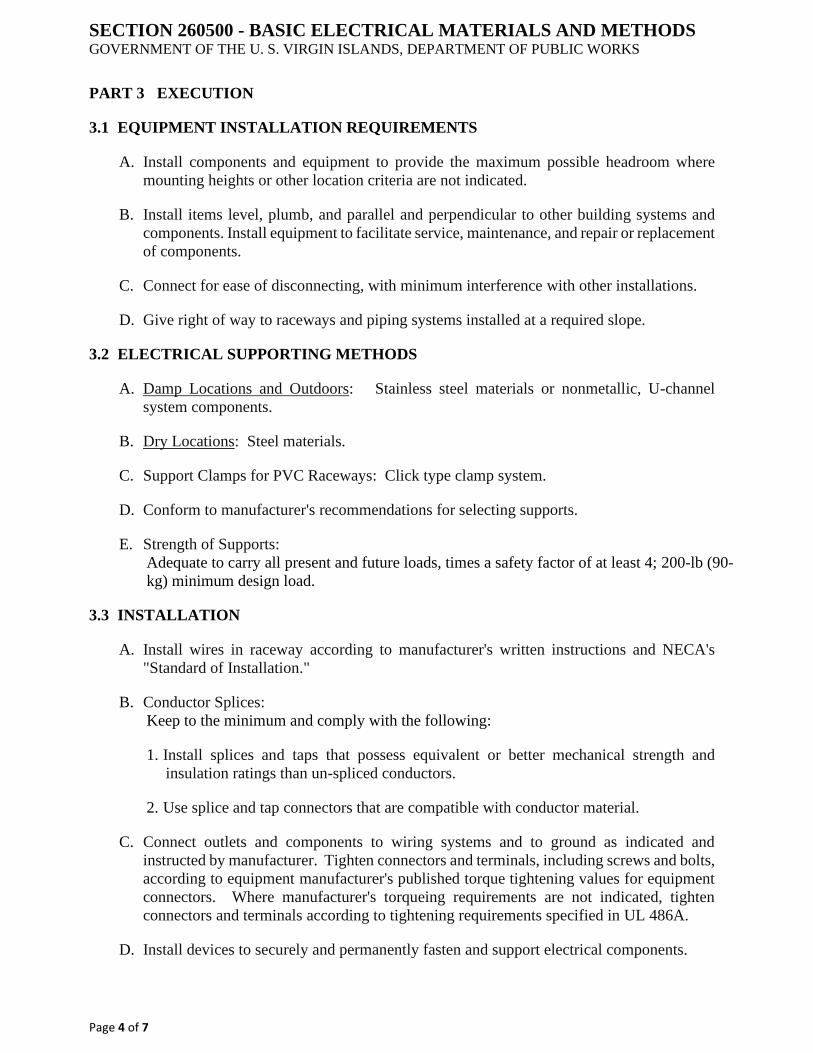
SECTION 260500 - BASIC ELECTRICAL MATERIALS AND METHODS GOVERNMENT OF THE U. S. VIRGIN ISLANDS, DEPARTMENT OF PUBLIC WORKS
Page 4 of 7
PART 3 EXECUTION
3.1 EQUIPMENT INSTALLATION REQUIREMENTS
A. Install components and equipment to provide the maximum possible headroom where
mounting heights or other location criteria are not indicated.
B. Install items level, plumb, and parallel and perpendicular to other building systems and
components. Install equipment to facilitate service, maintenance, and repair or replacement
of components.
C. Connect for ease of disconnecting, with minimum interference with other installations.
D. Give right of way to raceways and piping systems installed at a required slope.
3.2 ELECTRICAL SUPPORTING METHODS
A. Damp Locations and Outdoors: Stainless steel materials or nonmetallic, U-channel
system components.
B. Dry Locations: Steel materials.
C. Support Clamps for PVC Raceways: Click type clamp system.
D. Conform to manufacturer's recommendations for selecting supports.
E. Strength of Supports:
Adequate to carry all present and future loads, times a safety factor of at least 4; 200-lb (90-
kg) minimum design load.
3.3 INSTALLATION
A. Install wires in raceway according to manufacturer's written instructions and NECA's
"Standard of Installation."
B. Conductor Splices:
Keep to the minimum and comply with the following:
1. Install splices and taps that possess equivalent or better mechanical strength and
insulation ratings than un-spliced conductors.
2. Use splice and tap connectors that are compatible with conductor material.
C. Connect outlets and components to wiring systems and to ground as indicated and
instructed by manufacturer. Tighten connectors and terminals, including screws and bolts,
according to equipment manufacturer's published torque tightening values for equipment
connectors. Where manufacturer's torqueing requirements are not indicated, tighten
connectors and terminals according to tightening requirements specified in UL 486A.
D. Install devices to securely and permanently fasten and support electrical components.

SECTION 260500 - BASIC ELECTRICAL MATERIALS AND METHODS GOVERNMENT OF THE U. S. VIRGIN ISLANDS, DEPARTMENT OF PUBLIC WORKS
Page 5 of 7
E. Raceway Supports:
Comply with NFPA 70 and the following requirements:
1. Conform to manufacturer's recommendations for selecting and installing supports.
2. Install individual and multiple raceway hangers and riser clamps to support raceways.
Provide U bolts, clamps, attachments, and other hardware necessary for hanger
assembly and for securing hanger rods and conduits.
3. Support parallel runs of horizontal raceways together on trapeze- or bracket-type
hangers.
4. Spare Capacity:
Size supports for multiple conduits so capacity can be increased by a 25 percent minimum
in the future.
5. Support individual horizontal raceways with separate, malleable iron pipe hangers or
clamps.
6. Hanger Rods: 1/4-inch (6-mm) diameter or larger threaded steel, except as otherwise
indicated.
7. Spring Steel Fasteners:
Specifically designed for supporting single conduits or tubing. May be used in lieu of
malleable iron hangers for I-I/2-inch (38-mm) and smaller raceways serving lighting and
receptacle branch circuits above suspended ceilings and for fastening raceways to channel
and slotted angle supports.
8. In vertical runs, arrange support so the load produced by the weight of the raceway and
the enclosed conductors is carried entirely by the conduit supports, with no weight load
on raceway terminals.
F. Vertical Conductor Supports: Install simultaneously with conductors.
G. Miscellaneous Supports:
Install metal channel racks for mounting cabinets, panelboards, disconnects, control
enclosures, pull boxes, junction boxes, transformers, and other devices except where
components are mounted directly to structural features of adequate strength.
H. In open overhead spaces, cast boxes threaded to raceways need not be separately
supported, except where used for fixture support; support sheet-metal boxes directly from
the building structure or by bar hangers. Where bar hangers are used, attach the bar to
raceways on opposite sides of the box and support the raceway with an approved fastener
not more than 24 inches (610 mm) from the box.
I. Fire stopping:
Apply to cable and raceway penetrations of fire-rated floor and wall assemblies. Perform
fire stopping as specified in Division 7 Section "Fire stopping" to reestablish the original
fire resistance rating of the assembly at the penetration.
J. Fastening:
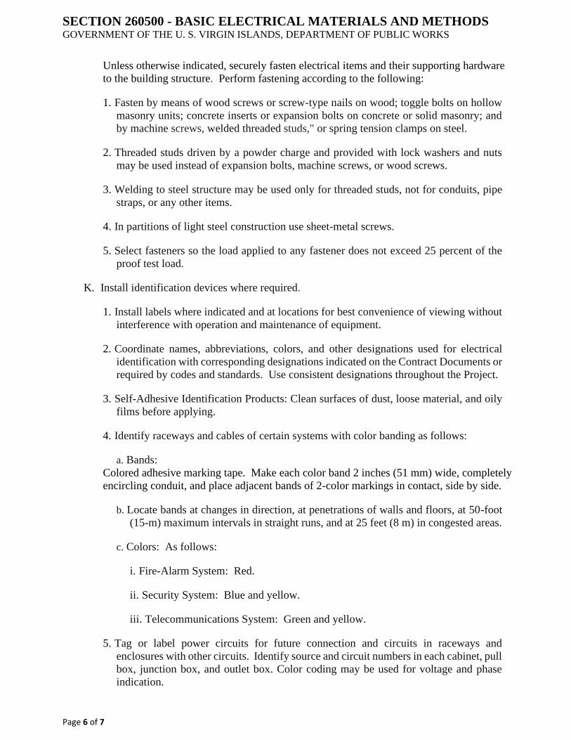
SECTION 260500 - BASIC ELECTRICAL MATERIALS AND METHODS GOVERNMENT OF THE U. S. VIRGIN ISLANDS, DEPARTMENT OF PUBLIC WORKS
Page 6 of 7
Unless otherwise indicated, securely fasten electrical items and their supporting hardware
to the building structure. Perform fastening according to the following:
1. Fasten by means of wood screws or screw-type nails on wood; toggle bolts on hollow
masonry units; concrete inserts or expansion bolts on concrete or solid masonry; and
by machine screws, welded threaded studs," or spring tension clamps on steel.
2. Threaded studs driven by a powder charge and provided with lock washers and nuts
may be used instead of expansion bolts, machine screws, or wood screws.
3. Welding to steel structure may be used only for threaded studs, not for conduits, pipe
straps, or any other items.
4. In partitions of light steel construction use sheet-metal screws.
5. Select fasteners so the load applied to any fastener does not exceed 25 percent of the
proof test load.
K. Install identification devices where required.
1. Install labels where indicated and at locations for best convenience of viewing without
interference with operation and maintenance of equipment.
2. Coordinate names, abbreviations, colors, and other designations used for electrical
identification with corresponding designations indicated on the Contract Documents or
required by codes and standards. Use consistent designations throughout the Project.
3. Self-Adhesive Identification Products: Clean surfaces of dust, loose material, and oily
films before applying.
4. Identify raceways and cables of certain systems with color banding as follows:
a. Bands:
Colored adhesive marking tape. Make each color band 2 inches (51 mm) wide, completely
encircling conduit, and place adjacent bands of 2-color markings in contact, side by side.
b. Locate bands at changes in direction, at penetrations of walls and floors, at 50-foot
(15-m) maximum intervals in straight runs, and at 25 feet (8 m) in congested areas.
c. Colors: As follows:
i. Fire-Alarm System: Red.
ii. Security System: Blue and yellow.
iii. Telecommunications System: Green and yellow.
5. Tag or label power circuits for future connection and circuits in raceways and
enclosures with other circuits. Identify source and circuit numbers in each cabinet, pull
box, junction box, and outlet box. Color coding may be used for voltage and phase
indication.
SECTION 260500 - BASIC ELECTRICAL MATERIALS AND METHODS GOVERNMENT OF THE U. S. VIRGIN ISLANDS, DEPARTMENT OF PUBLIC WORKS
Page 7 of 7
3.4 TOUCHUP PAINTING
A. Thoroughly clean damaged areas and provide primer, intermediate, and finish coats to suit
the degree of damage at each location.
B. Follow paint manufacturer's written instructions for surface preparation and for timing and
application of successive coats.
END OF SECTION
SECTION 260510- COMMON WORK RESULTS FOR ELECTRICAL GOVERNMENT OF THE U. S. VIRGIN ISLANDS, DEPARTMENT OF PUBLIC WORKS
Page 1 of 4
PART 1 GENERAL
1.5 SUMMARY
A. Section Includes:
1. Sleeves for raceways and cables
2. Sleeve seals
3. Grout
4. Common electrical installation requirements
1.6 SUBMITTALS
A. Product Data: For sleeve seals
PART 2 PRODUCTS
2.1 SLEEVES FOR RACEWAYS AND CABLES
A. Steel Pipe Sleeves: ASTM A 53/A 53M, Type E, Grade B, Schedule 40, galvanized steel, plain
ends
B. Cast Iron Pipe Sleeves:
Cast or fabricated "wall pipe," equivalent to ductile iron pressure pipe, with plain ends and
integral water stop, unless otherwise indicated.
C. Sleeves for Rectangular Openings: Galvanized sheet steel
1. Minimum Metal Thickness:
a. For sleeve cross section rectangle perimeter less than 50 inches ( 1270 mm) and no side
more than 16 inches (400 mm), thickness shall be 0.052 inch ( 1.3 mm).
b. For sleeve cross section rectangle perimeter equal to, or more than, 50 inches (1270 mm)
and 1 or more sides equal to, or more than, 16 inches (400 mm), thickness shall be 0.138
inch (3.5 mm).
2.2 SLEEVE SEALS
A. Description:
Modular sealing device, designed for field assembly, to fill annular space between sleeve and
raceway or cable.
1. Manufacturers: Subject to compliance with requirements
2. Basis of Design Product:
Subject to compliance with requirements, provide or comparable product by one of the
following:
a. Advance Products & Systems, Inc.

SECTION 260510- COMMON WORK RESULTS FOR ELECTRICAL GOVERNMENT OF THE U. S. VIRGIN ISLANDS, DEPARTMENT OF PUBLIC WORKS
Page 2 of 4
b. Calpico, Inc.
c. Metraflex Co.
d. Pipeline Seal and Insulator, Inc.
3. Sealing Elements:
EPDM, NBR interlocking links shaped to fit surface of cable or conduit. Include type and
number required for material and size of raceway or cable.
4. Pressure Plates:
Stainless steel. Include two for each sealing element.
5. Connecting Bolts and Nuts:
Stainless steel of length required to secure pressure plates to sealing elements. Include one for
each sealing element.
2.3 GROUT
A. Nonmetallic, Shrinkage Resistant Grout:
ASTM C 1107, factory packaged, nonmetallic aggregate grout, noncorrosive, no staining,
mixed with water to consistency suitable for application and a 30-minute working time.
PART 3 EXECUTION
3.4 COMMON REQUIREMENTS FOR ELECTRICAL INSTALLATION
A. Comply with NECA l.
B. Measure indicated mounting heights to bottom of unit for suspended items and to center of
unit for wall mounting items.
C. Headroom Maintenance:
If mounting heights or other location criteria are not indicated, arrange and install components
and equipment to provide maximum possible headroom consistent with these requirements.
D. Equipment:
Install to facilitate service, maintenance, and repair or replacement of components of both
electrical equipment and other nearby installations. Connect in such a way as to facilitate
future disconnecting with minimum interference with other items in the vicinity.
E. Right of Way:
Give to piping systems installed at a required slope.
3.2 SLEEVE INSTALLATION FOR ELECTRICAL PENETRATIONS
A. Electrical penetrations occur when raceways, cables, wire ways, cable trays, or busways
penetrate concrete slabs, concrete or masonry walls, or fire-rated floor and wall assemblies.
B. Concrete Slabs and Walls:
Install sleeves for penetrations unless core drilled holes or formed openings are used. Install
sleeves during erection of slabs and walls.
SECTION 260510- COMMON WORK RESULTS FOR ELECTRICAL GOVERNMENT OF THE U. S. VIRGIN ISLANDS, DEPARTMENT OF PUBLIC WORKS
Page 3 of 4
C. Use pipe sleeves unless penetration arrangement requires rectangular sleeved opening.
D. Fire Rated Assemblies:
Install sleeves for penetrations of fire rated floor and wall assemblies unless openings
compatible with firestop system used are fabricated during construction of floor or wall.
E. Cut sleeves to length for mounting flush with both surfaces of walls.
F. Extend sleeves installed in floors 2 inches (50 mm) above finished floor level.
G. Size pipe sleeves to provide l/4-inch (6.4-mm) annular clear space between sleeve and raceway
or cable, unless indicated otherwise.
H. Seal space outside of sleeves with grout for penetrations of concrete and masonry.
1. Promptly pack grout solidly between sleeve and wall so no voids remain. Tool exposed
surfaces smooth; protect grout while curing.
I. Interior Penetrations of Non-Fire Rated Walls and Floors:
Seal annular space between sleeve and raceway or cable, using joint sealant appropriate for
size, depth, and location of joint. Comply with requirements in Division 07 Section "Joint
Sealants."
J. Fire Rated Assembly Penetrations:
Maintain indicated fire rating of walls, partitions, ceilings, and floors at raceway and cable
penetrations. Install sleeves and seal raceway and cable penetration sleeves with firestop
materials. Comply with requirements in Division 07 Section "Penetration Fire stopping."
K. Roof Penetration Sleeves:
Seal penetration of individual raceways and cables with flexible boot type flashing units
applied in coordination with roofing work.
L. Aboveground, Exterior Wall Penetrations:
Seal penetrations using steel pipe sleeves and mechanical sleeve seals. Select sleeve size to
allow for l-inch (25-mm) annular clear space between pipe and sleeve for installing mechanical
sleeve seals.
M. Underground, Exterior Wall Penetrations:
Install cast-iron pipe sleeves. Size sleeves to allow for l-inch (25-mm) annular clear space
between raceway or cable and sleeve for installing mechanical sleeve seals.
3.3 SLEEVE-SEAL INSTALLATION
A. Install to seal exterior wall penetrations.
B. Use type and number of sealing elements recommended by manufacturer for raceway or cable
material and size. Position raceway or cable in center of sleeve. Assemble mechanical sleeve
seals and install in annular space between raceway or cable and sleeve. Tighten bolts against
pressure plates that cause sealing elements to expand and make watertight seal.
3.4 FIRE STOPPING

SECTION 260510- COMMON WORK RESULTS FOR ELECTRICAL GOVERNMENT OF THE U. S. VIRGIN ISLANDS, DEPARTMENT OF PUBLIC WORKS
Page 4 of 4
A. Apply fire stopping to penetrations of fire rated floor and wall assemblies for electrical
installations to restore original fire resistance rating of assembly. Fire stopping materials and
installation requirements are specified in Division 07 Section "Penetration Fire Stopping."
END OF SECTION
SECTION 260519- LOW VOLTAGE ELECTRICAL POWER CONDUCTORS
AND CABLES GOVERNMENT OF THE U. S. VIRGIN ISLANDS, DEPARTMENT OF PUBLIC WORKS
Page 1 of 4
PART 1 GENERAL
1.1 SUMMARY
A. This Section includes the following:
1. Building wires and cables rated 600 V and less
2. Connectors, splices, and terminations rated 600 V and less
3. Sleeves and sleeve seals for cables
1.2 SUBMITTALS
A. Product Data:
For each type of product indicated.
B. Field quality control test reports.
1.3 QUALITY ASSURANCE
A. Electrical Components, Devices, and Accessories:
Listed and labeled as defined in NFPA 70, Article 100, by a testing agency acceptable to
authorities having jurisdiction, and marked for intended use.
B. Comply with NFPA 70.
PART 2 PRODUCTS
2.1 CONDUCTORS AND CABLES
A. Copper Conductors: Comply with NEMA WC 70.
B. Conductor Insulation: Comply with NEMA WC 70 for Types THW and THHN-THWN.
2.2 CONNECTORS AND SPLICES
A. Available Manufacturers:
Subject to compliance with requirements, manufacturers offering products that may be
incorporated into the Work include, but are not limited to, the following:
1. AFC Cable Systems, Inc.
2. Hubbell Power Systems, Inc.
3. 0-ZJGedney; EGS Electrical Group LLC
4. 3M; Electrical Products Division
5. Tyco Electronics Corp.
B. Description:
SECTION 260519- LOW VOLTAGE ELECTRICAL POWER CONDUCTORS
AND CABLES GOVERNMENT OF THE U. S. VIRGIN ISLANDS, DEPARTMENT OF PUBLIC WORKS
Page 2 of 4
Factory-fabricated connectors and splices of size, ampacity rating, material, type, and class for
application and service indicated.
2.3 SLEEVES FOR CABLES
A. Steel Pipe Sleeves: ASTM A 53/A 53M, Type E, Grade B, Schedule 40, galvanized steel,
plain ends.
B. Coordinate sleeve selection and application with selection and application of fire stopping
specified in Division 07 Section "Penetration Fire stopping."
2.4 SLEEVE SEALS
A. Basis of Design Product:
Subject to compliance with requirements, provide or a comparable product by one of the
following:
1. Advance Products & Systems, Inc.
2. Calpico, Inc.
3. Metraflex Co.
4. Pipeline Seal and Insulator, Inc.
5. Hilti, Inc.
B. Description:
Modular sealing device, designed for field assembly, to fill annular space between sleeve and
cable.
1. Sealing Elements:
EPDM, NBR interlocking links shaped to fit surface of cable or conduit. Include type and
number required for material and size of raceway or cable.
2. Pressure Plates: Stainless steel. Include two for each sealing element.
3. Connecting Bolts and Nuts:
Stainless steel of length required to secure pressure plates to sealing elements. Include one for
each sealing element.
PART 3 EXECUTION
3.1 CONDUCTOR MATERIAL APPLICATIONS
A. Feeders: Copper. Solid for No. 10 AWG and smaller; stranded for No. 8 AWG and larger.
B. Branch Circuits: Copper. Solid for No. 10 AWG and smaller; stranded for No. 8 AWG and
larger.
3.2 CONDUCTOR INSULATION AND MULTICONDUCTOR CABLE APPLICATIONS AND
WIRING METHODS

SECTION 260519- LOW VOLTAGE ELECTRICAL POWER CONDUCTORS
AND CABLES GOVERNMENT OF THE U. S. VIRGIN ISLANDS, DEPARTMENT OF PUBLIC WORKS
Page 3 of 4
A. Service Entrance: Type THW, single conductors in raceway
B. Feeders Concealed in Ceilings, Walls, Partitions, and Crawlspaces: Type THHN-THWN,
single conductors in raceway
C. Branch Circuits Concealed in Ceilings, Walls, and Partitions: Type THHN-THWN, single
conductors in raceway.
3.3 INSTALLATION OF CONDUCTORS AND CABLES
A. Conceal cables in finished walls, ceilings, and floors, unless otherwise indicated.
B. Use manufacturer approved pulling compound or lubricant where necessary; compound used
must not deteriorate conductor or insulation. Do not exceed manufacturer's recommended
maximum pulling tensions and sidewall pressure values.
C. Use pulling means, including fish tape, cable, rope, and basket weave wire/cable grips that will
not damage cables or raceway.
D. Support cables according to Division 26 Sections "Hangers and Supports for Electrical
Systems."
E. Identify and color code conductors and cables according to Division 26 Section "Identification
for Electrical Systems."
F. Tighten electrical connectors and terminals according to manufacturer's published torque
tightening values. If manufacturer's torque values are not indicated, use those specified in UL
486A and UL 486B.
G. Make splices and taps that are compatible with conductor material and that possess equivalent
or better mechanical strength and insulation ratings than un-spliced conductors.
H. Use oxide inhibitor in each splice and tap conductor for aluminum conductors.
I. Wiring at Outlets: Install conductor at each outlet, with at least 12 inches (300 mm) of slack.
3.4 FIRESTOPPING
A. Apply fire stopping to electrical penetrations of fire rated floor and wall assemblies to restore
original fire resistance rating of assembly according to Division 07 Section "Penetration Fire
stopping."
3.5 FIELD QUALITY CONTROL
A. Perform tests and inspections and prepare test reports.
B. Tests and Inspections:
1. After installing conductors and cables and before electrical circuitry has been energized,
test service entrance and feeder conductors for compliance with requirements.
SECTION 260519- LOW VOLTAGE ELECTRICAL POWER CONDUCTORS
AND CABLES GOVERNMENT OF THE U. S. VIRGIN ISLANDS, DEPARTMENT OF PUBLIC WORKS
Page 4 of 4
2. Perform each visual and mechanical inspection and electrical test stated in NETA
Acceptance Testing Specification. Certify compliance with test parameters.
3. Infrared Scanning:
After Substantial Completion, but not more than 60 days after Final Acceptance, perform an
infrared scan of each splice in cables and conductors No. 3 AWG and larger. Remove box and
equipment covers so splices are accessible to portable scanner.
a. Follow up Infrared Scanning:
Perform an additional follow-up infrared scan of each splice 11 months after date of Substantial
Completion.
b. Instrument:
Use an infrared scanning device designed to measure temperature or to detect significant
deviations from normal values. Provide calibration record for device.
c. Record of Infrared Scanning:
Prepare a certified report that identifies splices checked and that describes scanning results.
Include notation of deficiencies detected, remedial action taken, and observations after remedial
action.
C. Test Reports: Prepare a written report to record the following:
1. Test procedures used
2. Test results that comply with requirements
3. Test results that do not comply with requirements and corrective action taken to achieve
compliance with requirements.
D. Remove and replace malfunctioning units and retest as specified above.
END OF SECTION
SECTION 260526- GROUNDING AND BONDING FOR ELECTRICAL
SYSTEMS GOVERNMENT OF THE U. S. VIRGIN ISLANDS, DEPARTMENT OF PUBLIC WORKS
Page 1 of 6
PART 1 GENERAL
1.1 SUMMARY
A. This Section includes methods and materials for grounding systems and equipment.
1.2 SUBMITTALS
A. Product Data: For each type of product indicated.
B. Field quality-control test reports.
1.3 QUALITY ASSURANCE
A. Electrical Components, Devices, and Accessories:
Listed and labeled as defined in NFPA 70, Article 100, by a testing agency acceptable to
authorities having jurisdiction, and marked for intended use.
B. Comply with UL 467 for grounding and bonding materials and equipment.
PART 2 PRODUCTS
2.1 CONDUCTORS
A. Insulated Conductors:
Copper wire or cable insulated for 600 V unless otherwise required by applicable Code or
authorities having jurisdiction.
B. Bare Copper Conductors:
1. Solid Conductors: ASTM B 3
2. Stranded Conductors: ASTM B 8
3. Tinned Conductors: ASTM B 33
4. Bonding Cable: 28 kcmil, 14 strands of No. 17 AWG conductor, 1/4 inch (6 mm) in
diameter
5. Bonding Conductor: No. 4 or No. 6 AWG, stranded conductor
6. Bonding Jumper:
Copper tape, braided conductors, terminated with copper ferrules; 1-5/8 inches (41 mm) wide
and 1/16 inch (1.6 mm) thick.
7. Tinned Bonding Jumper:
Tinned copper tape, braided conductors, terminated with copper ferrules; 1-5/8 inches (41 mm)
wide and 1/16 inch (1.6 mm) thick.
2.2 CONNECTORS
SECTION 260526- GROUNDING AND BONDING FOR ELECTRICAL
SYSTEMS GOVERNMENT OF THE U. S. VIRGIN ISLANDS, DEPARTMENT OF PUBLIC WORKS
Page 2 of 6
A. Listed and labeled by a nationally recognized testing laboratory acceptable to authorities
having jurisdiction for applications in which used, and for specific types, sizes, and
combinations of conductors and other items connected.
B. Bolted Connectors for Conductors and Pipes: Copper or copper alloy, bolted pressure type,
with at least two bolts
1. Pipe Connectors: Clamp type, sized for pipe.
C. Welded Connectors:
Exothermic welding kits of types recommended by kit manufacturer for materials being joined
and installation conditions.
2.3 GROUNDING ELECTRODES
A. Ground Rods: Copper clad steel; 3/4-inch by10 feet (19 mm by 3 m) in diameter
PART 3 EXECUTION
3.1 APPLICATIONS
A. Conductors:
Install solid conductor for No. 8 AWG and smaller, and stranded conductors for No. 6 AWG
and larger, unless otherwise indicated.
B. Underground Grounding Conductors:
Install bare copper conductor, No. 2/0 AWG minimum. Bury at least 24 inches (600 mm)
below grade.
C. Isolated Grounding Conductors:
Green colored insulation with continuous yellow stripe. On feeders with isolated ground,
identify grounding conductor where visible to normal inspection, with alternating bands of
green and yellow tape, with at least three bands of green and two bands of yellow.
D. Conductor Terminations and Connections:
1. Pipe and Equipment Grounding Conductor Terminations:
2. Bolted connectors
3. Underground Connections: Welded connectors except at test wells and as otherwise
indicated.
4. Connections to Ground Rods at Test Wells: Bolted connectors
5. Connections to Structural Steel: Welded connectors
3.2 EQUIPMENT GROUNDING
A. Install insulated equipment grounding conductors with the following items, in addition to those
required by NFPA 70:

SECTION 260526- GROUNDING AND BONDING FOR ELECTRICAL
SYSTEMS GOVERNMENT OF THE U. S. VIRGIN ISLANDS, DEPARTMENT OF PUBLIC WORKS
Page 3 of 6
1. Feeders and branch circuits
2. Lighting circuits
3. Receptacle circuits
4. Single phase motor and appliance branch circuits
5. Three phase motor and appliance branch circuits
6. Flexible raceway runs
7. Armored and metal-clad cable runs
8. Busway Supply Circuits:
9. Install insulated equipment grounding conductor from grounding bus in the switchgear,
switchboard, or distribution panel to equipment grounding bar terminal on bus way.
10. Computer and Rack Mounted Electronic Equipment Circuits:
Install insulated equipment grounding conductor in branch circuit runs from equipment area
power panels and power distribution units.
B. Air Duct Equipment Circuits:
Install insulated equipment grounding conductor to duct mounted electrical devices operating at
120 V and more, including air cleaners, heaters, dampers, humidifiers, and other duct electrical
equipment. Bond conductor to each unit and to air duct and connected metallic piping.
C. Water Heater and Heat Tracing Cables:
Install a separate insulated equipment grounding conductor to each electric water heater and
heat-tracing cable. Bond conductor to heater units, piping, connected equipment, and
components.
D. Isolated Grounding Receptacle Circuits:
Install an insulated equipment grounding conductor connected to the receptacle grounding
terminal. Isolate conductor from raceway and from panelboard grounding terminals.
Terminate at equipment grounding conductor terminal of the applicable derived system or
service, unless otherwise indicated.
E. Isolated Equipment Enclosure Circuits:
For designated equipment supplied by a branch circuit or feeder, isolate equipment enclosure
from supply circuit raceway with a nonmetallic raceway fitting listed for the purpose. Install
fitting where raceway enters enclosure and install a separate insulated equipment grounding
conductor. Isolate conductor from raceway and from panelboard grounding terminals.
Terminate at equipment grounding conductor terminal of the applicable derived system or
service, unless otherwise indicated.
F. Signal and Communication Equipment:
For telephone, alarm, voice and data, and other communication equipment, provide No. 4
AWG minimum insulated grounding conductor in raceway from grounding electrode system to
each service location, terminal cabinet, wiring closet, and central equipment location.
SECTION 260526- GROUNDING AND BONDING FOR ELECTRICAL
SYSTEMS GOVERNMENT OF THE U. S. VIRGIN ISLANDS, DEPARTMENT OF PUBLIC WORKS
Page 4 of 6
1. Service and Central Equipment Locations and Wiring Closets:
Terminate grounding conductor on a 1/4-by-2-by-12-inch (6-by-50-by-300-mm) grounding
bus.
2. Terminal Cabinets:
Terminate grounding conductor on cabinet grounding terminal.
3. Metal Poles Supporting Outdoor Lighting Fixtures:
Install grounding electrode and a separate insulated equipment grounding conductor in addition
to grounding conductor installed with branch circuit conductors.
3.3 INSTALLATION
A. Grounding Conductors:
Route along shortest and straightest paths possible, unless otherwise indicated or required by
Code. Avoid obstructing access or placing conductors where they may be subjected to strain,
impact, or damage.
B. Ground Rods:
Drive rods until tops are 2 inches (50 mm) below finished floor or final grade, unless otherwise
indicated.
1. Interconnect ground rods with grounding electrode conductor below grade and as otherwise
indicated. Make connections without exposing steel or damaging coating, if any.
2. For grounding electrode system, install at least three rods spaced at least one-rod length
from each other and located at least the same distance from other grounding electrodes,
and connect to the service grounding electrode conductor.
C. Test Wells:
Ground rod driven through drilled hole in bottom of hand hole. Hand holes are specified in
Division 26 Section "Underground Ducts and Raceways for Electrical Systems," and shall be at
least 12 inches (300 mm) deep, with cover.
1. Test Wells:
Install at least one test well for each service, unless otherwise indicated. Install at the ground
rod electrically closest to service entrance. Set top of test well flush with finished grade or
floor.
D. Bonding Straps and Jumpers:
Install in locations accessible for inspection and maintenance, except where routed through
short lengths of conduit.
1. Bonding to Structure: Bond straps directly to basic structure, taking care not to penetrate
any adjacent parts.
2. Bonding to Equipment Mounted on Vibration Isolation Hangers and Supports: Install so
vibration is not transmitted to rigidly mounted equipment.

SECTION 260526- GROUNDING AND BONDING FOR ELECTRICAL
SYSTEMS GOVERNMENT OF THE U. S. VIRGIN ISLANDS, DEPARTMENT OF PUBLIC WORKS
Page 5 of 6
3. Use exothermic-welded connectors for outdoor locations, but if a disconnect type
connection is required, use a bolted clamp.
E. Grounding and Bonding for Piping:
1. Metal Water Service Pipe:
Install insulated copper grounding conductors, in conduit, from building's main service
equipment, or grounding bus, to main metal water service entrances to building. Connect
grounding conductors to main metal water service pipes, using a bolted clamp connector or by
bolting a lug-type connector to a pipe flange, using one of the lug bolts of the flange. Where a
dielectric main water fitting is installed, connect grounding conductor on street side of fitting.
Bond metal grounding conductor conduit or sleeve to conductor at each end.
2. Water Meter Piping:
Use braided type bonding jumpers to electrically bypass water meters. Connect to pipe with a
bolted connector.
3. Bond each above ground portion of gas piping system downstream from equipment shutoff
valve.
F. Bonding Interior Metal Ducts:
Bond metal air ducts to equipment grounding conductors of associated fans, blowers, electric
heaters, and air cleaners. Install bonding jumper to bond across flexible duct connections to
achieve continuity.
3.4 FIELD QUALITY CONTROL
A. Testing Agency:
Engage a qualified testing and inspecting agency to perform the following field tests and
inspections and prepare test reports.
B. Perform the following tests and inspections and prepare test reports:
1. After installing grounding system but before permanent electrical circuits have been
energized, test for compliance with requirements.
2. Test completed grounding system at each location where a maximum ground resistance
level is specified, at service disconnect enclosure grounding terminal, and at ground test
wells.
a. Measure ground resistance not less than two full days after last trace of precipitation and
without soil being moistened by any means other than natural drainage or seepage and
without chemical treatment or other artificial means of reducing natural ground
resistance.
b. Perform tests by fall of potential method according to IEEE 81.
C. Report measured ground resistances that exceed the following values:
1. Power and Lighting Equipment or System with Capacity 500 kVA and Less: 5 ohms
SECTION 260526- GROUNDING AND BONDING FOR ELECTRICAL
SYSTEMS GOVERNMENT OF THE U. S. VIRGIN ISLANDS, DEPARTMENT OF PUBLIC WORKS
Page 6 of 6
2. Power and Lighting Equipment or System with Capacity 500 to 1000 kVA: 3 ohms
3. Power and Lighting Equipment or System with Capacity More Than I000 kVA: 3 ohms
4. Power Distribution Units or Panelboards Serving Electronic Equipment: 2 ohm(s)
D. Excessive Ground Resistance:
If resistance to ground exceeds specified values, notify Owner’s Representative promptly and
include recommendations to reduce ground resistance.
END OF SECTION

SECTION 260529- HANGERS AND SUPPORTS FOR ELECTRICAL SYSTEMS GOVERNMENT OF THE U. S. VIRGIN ISLANDS, DEPARTMENT OF PUBLIC WORKS
Page 1 of 6
PART 1 GENERAL
1.1 SUMMARY
A. Section includes:
1. Hangers and supports for electrical equipment and systems.
2. Construction requirements for concrete bases.
1.2 PERFORMANCE REQUIREMENTS
A. Delegated Design:
Design supports for multiple raceways, including comprehensive engineering analysis by a
qualified professional engineer, using performance requirements and design criteria indicated.
B. Design supports for multiple raceways capable of supporting combined weight of supported
systems and its contents.
C. Design equipment supports capable of supporting combined operating weight of supported
equipment and connected systems and components.
D. Rated Strength:
Adequate in tension, shear, and pullout force to resist maximum loads calculated or imposed
for this Project, with a minimum structural safety factor of five times the applied force.
1.3 SUBMITTALS
A. Product Data: For steel slotted support systems
B. Shop Drawings: Show fabrication and installation details and include calculations for the
following:
1. Trapeze hangers. Include Product Data for components.
2. Steel slotted channel systems. Include Product Data for components.
3. Equipment supports
C. Welding certificates
1.4 QUALITY ASSURANCE
A. Welding: Qualify procedures and personnel according to AWS Dl.l/Dl.IM, "Structural
Welding Code Steel."
B. Comply with NFPA 70.
PART 2 PRODUCTS
2.1 SUPPORT, ANCHORAGE, AND ATTACHMENT COMPONENTS
SECTION 260529- HANGERS AND SUPPORTS FOR ELECTRICAL SYSTEMS GOVERNMENT OF THE U. S. VIRGIN ISLANDS, DEPARTMENT OF PUBLIC WORKS
Page 2 of 6
A. Steel Slotted Support Systems: Comply with MFMA-4, factory fabricated components for
field assembly.
1. Manufacturers: Subject to compliance with requirements, provide products by one of the
following:
a. Allied Tube & Conduit
b. Cooper B-Line, Inc.; a division of Cooper Industries
c. ERICO International Corporation
d. GS Metals Corp.
e. Thomas & Betts Corporation
f. Unistrut; Tyco International, Ltd.
g. Wesanco, Inc.
2. Metallic Coatings: Hot-dip galvanized after fabrication and applied according to MFMA-
4.
3. Nonmetallic Coatings: Manufacturer's standard PVC, polyurethane, or polyester coating
applied according to MFMA-4.
4. Painted Coatings: Manufacturer's standard painted coating applied according to MFMA-4.
5. Channel Dimensions: Selected for applicable load criteria.
B. Raceway and Cable Supports: As described in NECA 1 and NECA 101.
C. Conduit and Cable Support Devices:
Steel hangers, clamps, and associated fittings designed for types and sizes of raceway or cable
to be supported.
D. Support for Conductors in Vertical Conduit:
Factory fabricated assembly consisting of threaded body and insulating wedging plug or plugs
for non-armored electrical conductors or cables in riser conduits. Plugs shall have number,
size, and shape of conductor gripping pieces as required to suit individual conductors or cables
supported. Body shall be malleable iron.
E. Structural Steel for Fabricated Supports and Restraints: ASTM A 36/A 36M, steel plates,
shapes, and bars; black and galvanized.
F. Mounting, Anchoring, and Attachment Components: Items for fastening electrical items or
their supports to building surfaces include the following:
1. Powder-Actuated Fasteners:
Threaded steel stud, for use in hardened Portland cement concrete, steel, or wood, with tension,
shear, and pullout capacities appropriate for supported loads and building materials where used.
a. Manufacturers: Subject to compliance with requirements, provide products by one of
the following:

SECTION 260529- HANGERS AND SUPPORTS FOR ELECTRICAL SYSTEMS GOVERNMENT OF THE U. S. VIRGIN ISLANDS, DEPARTMENT OF PUBLIC WORKS
Page 3 of 6
i. Hilti, Inc.
ii. ITW Ramset/Red Head; a division of Illinois Tool Works, Inc.
iii. MKT Fastening, LLC
iv. Simpson Strong-Tie Co., Inc.; Masterset Fastening Systems Unit
2. Mechanical Expansion Anchors:
Insert wedge type, stainless steel, for use in hardened Portland cement concrete with tension,
shear, and pullout capacities appropriate for supported loads and building materials in which
used.
a. Manufacturers: Subject to compliance with requirements, provide products by one of
the following:
i. Cooper B-Line, Inc.; a division of Cooper Industries.
ii. Empire Tool and Manufacturing Co., Inc.
iii. Hilti, Inc.
iv. ITW Ramset/Red Head; a division of Illinois Tool Works, Inc.
v. MKT Fastening, LLC.
3. Concrete Inserts:
Steel or malleable iron, slotted support system units similar to MSS Type 18; complying with
MFMA-4 or MSS SP-58.
4. Clamps for Attachment to Steel Structural Elements: MSS SP-58, type suitable for
attached structural element.
5. Through Bolts: Structural type, hex head, and high strength. Comply with ASTM A 325.
6. Toggle Bolts: All steel springhead type
7. Hanger Rods: Threaded steel
2.2 FABRICATED METAL EQUIPMENT SUPPORT ASSEMBLIES
A. Description:
Welded or bolted, structural steel shapes, shop or field fabricated to fit dimensions of supported
equipment.
B. Materials: Comply with requirements in Division 05 Section "Metal Fabrications" for steel
shapes and plates.
PART 3 EXECUTION
3.1 APPLICATION
A. Comply with NECA I and NECA 101 for application of hangers and supports for electrical
equipment and systems except if requirements in this Section are stricter.

SECTION 260529- HANGERS AND SUPPORTS FOR ELECTRICAL SYSTEMS GOVERNMENT OF THE U. S. VIRGIN ISLANDS, DEPARTMENT OF PUBLIC WORKS
Page 4 of 6
B. Maximum Support Spacing and Minimum Hanger Rod Size for Raceway:
Space supports for EMT and IMC, as required by NFPA 70. Minimum rod size shall be 1/4
inch (6 mm) in diameter.
C. Multiple Raceways or Cables:
Install trapeze type supports fabricated with steel slotted support system, sized so capacity can
be increased by at least 25 percent in future without exceeding specified design load limits.
1. Secure raceways and cables to these supports with two-bolt conduit clamps.
D. Spring steel clamps designed for supporting single conduits without bolts may be used for 1-
1/2 inch (38 mm) and smaller raceways serving branch circuits and communication systems
above suspended ceilings and for fastening raceways to trapeze supports.
3.2 SUPPORT INSTALLATION
A. Comply with NECA 1 and NECA 101 for installation requirements except as specified in this
Article.
B. Raceway Support Methods:
In addition to methods described in NECA I, EMT and IMC may be supported by openings
through structure members, as permitted in NFPA 70.
C. Strength of Support Assemblies:
Where not indicated, select sizes of components so strength will be adequate to carry present
and future static loads within specified loading limits. Minimum static design load used for
strength determination shall be weight of supported components plus 200 lb (90 kg).
D. Mounting and Anchorage of Surface Mounted Equipment and Components:
Anchor and fasten electrical items and their supports to building structural elements by the
following methods unless otherwise indicated by code:
1. To Wood: Fasten with lag screws or through bolts
2. To New Concrete: Bolt to concrete inserts
3. To Masonry: Approved toggle type bolts on hollow masonry units and expansion anchor
fasteners on solid masonry units.
4. To Existing Concrete: Expansion anchor fasteners
5. 5. Instead of expansion anchors, powder actuated driven threaded studs provided with
lock washers and nuts may be used in existing standard weight concrete, 4 inches (100
mm) thick or greater. Do not use for anchorage to lightweight-aggregate concrete or for
slabs less than 4 inches (100 mm) thick.
6. 6. To Steel: Welded threaded studs complying with AWS Dl.l/Dl.IM, with lock washers
and nuts
7. 7. To Light Steel: Sheet metal screws
8. Items Mounted on Hollow Walls and Nonstructural Building Surfaces:
SECTION 260529- HANGERS AND SUPPORTS FOR ELECTRICAL SYSTEMS GOVERNMENT OF THE U. S. VIRGIN ISLANDS, DEPARTMENT OF PUBLIC WORKS
Page 5 of 6
Mount cabinets, panelboards, disconnect switches, control enclosures, pull and junction boxes,
transformers, and other devices on slotted channel racks attached to substrate.
E. Drill holes for expansion anchors in concrete at locations and to depths that avoid reinforcing
bars.
3.3 INSTALLATION OF FABRICATED METAL SUPPORTS
A. Comply with installation requirements in Division 05 Section "Metal Fabrications" for site
fabricated metal supports.
B. Cut, fit, and place miscellaneous metal supports accurately in location, alignment, and
elevation to support and anchor electrical materials and equipment.
C. Field Welding: Comply with AWS Dl.l/Dl.IM
3.4 CONCRETE BASES
A. Construct concrete bases of dimensions indicated but not less than 4 inches (100 mm) larger
in both directions than supported unit, and so anchors will be a minimum of 10 bolt diameters
from edge of the base.
B. Use 3000-psi (20.7-MPa), 28-day compressive strength concrete. Concrete materials,
reinforcement, and placement requirements are specified in Division 03 Section "Cast-in-Place
Concrete."
C. Anchor equipment to concrete base.
1. Place and secure anchorage devices. Use supported equipment manufacturer's setting
drawings, templates, diagrams, instructions, and directions furnished with items to be
embedded.
2. Install anchor bolts to elevations required for proper attachment to supported equipment.
3. Install anchor bolts according to anchor bolt manufacturer's written instructions.
3.5 PAINTING
A. Touchup:
Clean field welds and abraded areas of shop paint. Paint exposed areas immediately after
erecting hangers and supports. Use same materials as used for shop painting. Comply with
SSPC-PA 1 requirements for touching up field painted surfaces.
1. Apply paint by brush or spray to provide minimum dry film thickness of 2.0 mils (0.05
mm).
B. Touchup:
Comply with requirements in Division 09 Painting Sections for cleaning and touchup painting
of field welds, bolted connections, and abraded areas of shop paint on miscellaneous metal.
C. Galvanized Surfaces:
Clean welds, bolted connections, and abraded areas and apply galvanizing repair paint to
comply with ASTM A 780.

SECTION 260529- HANGERS AND SUPPORTS FOR ELECTRICAL SYSTEMS GOVERNMENT OF THE U. S. VIRGIN ISLANDS, DEPARTMENT OF PUBLIC WORKS
Page 6 of 6
END OF SECTION

SECTION 260533- RACEWAY AND BOXES FOR ELECTRICAL SYSTEMS GOVERNMENT OF THE U. S. VIRGIN ISLANDS, DEPARTMENT OF PUBLIC WORKS
Page 1 of 7
PART 1 GENERAL
1.1 SUMMARY
A. This Section includes raceways, fittings, boxes, enclosures, and cabinets for electrical wiring.
B. See Division 26 Section "Underground Ducts and Raceways for Electrical Systems" for
exterior duct banks and manholes, and underground hand holes, boxes, and utility construction.
1.2 SUBMITTALS
A. Product Data: For surface raceways, wire ways and fittings, floor boxes, hinged cover
enclosures, and cabinets.
B. Shop Drawings: For custom enclosures and cabinets. Include plans, elevations, sections,
details, and attachments to other work.
1.3 QUALITY ASSURANCE
A. Electrical Components, Devices, and Accessories:
Listed and labeled as defined in NFPA 70, Article 100, by a testing agency acceptable to
authorities having jurisdiction, and marked for intended use.
B. Comply with NFPA 70.
PART 2 PRODUCTS
2.1 METAL CONDUIT AND TUBING
A. Rigid Steel Conduit: ANSI C80.1
B. IMC: ANSI C80.6
C. EMT: ANSI C80.3
D. FMC: Zinc coated steel.
E. LFMC: Flexible steel conduit with PVC jacket.
F. Fittings for Conduit (Including all Types and Flexible and Liquid tight), EMT, and Cable:
NEMA FB 1; listed for type and size raceway with which used, and for application and
environment in which installed.
1. Conduit Fittings for Hazardous (Classified) Locations: Comply with UL 886.
2. Fittings for EMT: Steel, compression type
2.2 NONMETALLIC CONDUIT AND TUBING
A. ENT: NEMA TC 13
B. RNC: NEMA TC 2, unless otherwise indicated.
SECTION 260533- RACEWAY AND BOXES FOR ELECTRICAL SYSTEMS GOVERNMENT OF THE U. S. VIRGIN ISLANDS, DEPARTMENT OF PUBLIC WORKS
Page 2 of 7
C. LFNC: UL 1660
D. Fittings for ENT and RNC: NEMA TC 3; match to conduit or tubing type and material.
E. Fittings for LFNC: UL 5l4B
2.3 METAL WIREWAYS
A. Manufacturers: Subject to compliance with requirements, provide products by one of the
following:
1. Cooper B-Line, Inc.
2. Hoffman.
3. Square D; Schneider Electric
B. Description: Sheet metal sized and shaped as indicated, NEMA 250, Type l or 3R, unless
otherwise indicated.
C. Fittings and Accessories:
Include couplings, offsets, elbows, expansion joints, adapters, hold down straps, end caps, and
other fittings to match and mate with wire ways as required for complete system.
D. Wire way Covers: Screw cover type
E. Finish: Manufacturer's standard enamel finish
2.4 NON-METALLIC WIREWAYS
A. Manufacturers: Subject to compliance with requirements, provide products by one of the
following:
1. Hoffman
2. Lamson & Sessions; Carlon Electrical Products
B. Description:
PVC plastic extruded and fabricated to size and shape indicated, with snap-on cover and
mechanically coupled connections with plastic fasteners.
C. Fittings and Accessories:
Include couplings, offsets, elbows, expansion joints, adapters, hold down straps, end caps, and
other fittings to match and mate with wire ways as required for complete system.
2.5 SURFACE RACEWAYS
A. Surface Metal Raceways: Galvanized steel with snap-on covers. Prime coating, ready for
field painting.
1. Manufacturers: Subject to compliance with requirements, provide products by one of the
following:
a. Thomas & Betts Corporation

SECTION 260533- RACEWAY AND BOXES FOR ELECTRICAL SYSTEMS GOVERNMENT OF THE U. S. VIRGIN ISLANDS, DEPARTMENT OF PUBLIC WORKS
Page 3 of 7
b. Walker Systems, Inc.; Wiremold Company
c. Wiremold Company; Electrical Sales Division
B. Surface Non-metallic Raceways:
Two-piece construction manufactured of rigid PVC with texture and color selected by Owner’s
Representative from manufacturer's standard colors.
1. Manufacturers: Subject to compliance with requirements, provide products by one of the
following:
a. Butler Manufacturing Company; Walker Division
b. Enduro Systems, Inc.; Composite Products Division
c. Hubbell Incorporated; Wiring Device-Kellems Division
d. Lamson & Sessions; Carlon Electrical Products
e. Panduit Corp.
f. Walker Systems, Inc.; Wiremold Company
g. Wiremold Company (The); Electrical Sales Division
2.6 BOXES, ENCLOSURES, AND CABINETS
A. Sheet Metal Outlet and Device Boxes: NEMA OS l.
B. Cast-Metal Outlet and Device Boxes: NEMA FB l, ferrous alloy, Type FD, with gasketed
cover.
C. Nonmetallic Outlet and Device Boxes: NEMA OS 2.
D. Metal Floor Boxes: Cast metal, fully adjustable, rectangular
E. Nonmetallic Floor Boxes: Nonadjustable, round
F. Small Sheet Metal Pull and Junction Boxes: NEMA OS I.
G. Cast-Metal Access, Pull, and Junction Boxes: NEMA FB 1, galvanized, cast iron with
gasketed cover.
H. Hinged Cover Enclosures: NEMA 250, Type l, with continuous hinge cover with flush latch,
unless otherwise indicated.
1. Metal Enclosures: Steel, finished inside and out with manufacturer's standard enamel.
2. Nonmetallic Enclosures: Plastic
I. Cabinets:
1. NEMA 250, Type 1, galvanized steel box with removable interior panel and removable
front, finished inside and out with manufacturer's standard enamel.
SECTION 260533- RACEWAY AND BOXES FOR ELECTRICAL SYSTEMS GOVERNMENT OF THE U. S. VIRGIN ISLANDS, DEPARTMENT OF PUBLIC WORKS
Page 4 of 7
2. Hinged door in front cover with flush latch and concealed hinge.
3. Key latch to match panelboards.
4. Metal barriers to separate wiring of different systems and voltage.
5. Accessory feet where required for freestanding equipment.
PART 3 EXECUTION
3.1 RACEWAY APPLICATION
A. Outdoors: Apply raceway products as specified below, unless otherwise indicated:
1. Exposed Conduit: Rigid steel conduit
2. Concealed Conduit, Aboveground: Rigid steel conduit, EMT
3. Underground Conduit: RNC, Type EPC-40-PVC, direct buried
4. Connection to Vibrating Equipment (Including Transformers and Hydraulic, Pneumatic,
Electric Solenoid, or Motor-Driven Equipment): LFMC
5. Boxes and Enclosures, Aboveground: NEMA 250, Type 3R
B. Comply with the following indoor applications, unless otherwise indicated:
1. Exposed, Not Subject to Physical Damage: EMT
2. Exposed, Not Subject to Severe Physical Damage: EMT
3. Exposed and Subject to Severe Physical Damage: Rigid steel conduit. Includes raceways
in the following locations:
a. Loading dock.
b. Corridors used for traffic of mechanized carts, forklifts, and pallet-handling units.
c. Mechanical rooms.
4. Concealed in Ceilings and Interior Walls and Partitions: EMT
5. Connection to Vibrating Equipment (Including Transformers and Hydraulic, Pneumatic,
Electric Solenoid, or Motor Driven Equipment):
FMC, except use LFMC in damp or wet locations.
6. Damp or Wet Locations: Rigid steel conduit
7. Raceways for Optical Fiber or Communications Cable: EMT
8. Boxes and Enclosures: NEMA 250, Type 1, except use NEMA 250, Type 4, nonmetallic
in damp or wet locations
C. Minimum Raceway Size: 3/4-inch (21-mm) trade size

SECTION 260533- RACEWAY AND BOXES FOR ELECTRICAL SYSTEMS GOVERNMENT OF THE U. S. VIRGIN ISLANDS, DEPARTMENT OF PUBLIC WORKS
Page 5 of 7
D. Raceway Fittings: Compatible with raceways and suitable for use and location.
1. Rigid and Intermediate Steel Conduit: Use threaded rigid steel conduit fittings, unless
otherwise indicated.
3.2 INSTALLATION
A. Comply with NECA 1 for installation requirements applicable to products specified in Part 2
except where requirements on Drawings or in this Article are stricter.
B. Keep raceways at least 6 inches (150 mm) away from parallel runs of flues and steam or hot-
water pipes. Install horizontal raceway runs above water and steam piping.
C. Complete raceway installation before starting conductor installation.
D. Support raceways as specified in Division 26 Section "Hangers and Supports for Electrical
Systems."
E. Arrange stub-ups so curved portions of bends are not visible above the finished slab.
F. Install no more than the equivalent of three 90-degree bends in any conduit run except for
communications conduits, for which fewer bends are allowed.
G. Conceal conduit and EMT within finished walls, ceilings, and floors, unless otherwise
indicated.
H. Raceways Embedded in Slabs:
1. Run conduit larger than l-inch (27-mm) trade size, parallel or at right angles to main
reinforcement. Where at right angles to reinforcement, place conduit close to slab support.
2. Arrange raceways to cross building expansion joints at right angles with expansion fittings.
3. Change from ENT to RNC, Type EPC-40-PVC, rigid steel conduit, or IMC before rising
above the floor.
I. Raceway Terminations at Locations Subject to Moisture or Vibration:
Use insulating bushings to protect conductors, including conductors smaller than No. 4 AWG.
J. Install pull wires in empty raceways. Use polypropylene or monofilament plastic line with not
less than 200-lb (90-kg) tensile strength. Leave at least 12 inches (300 mm) of slack at each
end of pull wire.
K. Raceways for Optical Fiber and Communications Cable: Install as follows:
1. 3/4-Inch (19-mm) Trade Size and Smaller: Install raceways in maximum lengths of 50 feet
(15m).
2. l-Inch (25-mm) Trade Size and Larger: Install raceways in maximum lengths of 75 feet
(23m).

SECTION 260533- RACEWAY AND BOXES FOR ELECTRICAL SYSTEMS GOVERNMENT OF THE U. S. VIRGIN ISLANDS, DEPARTMENT OF PUBLIC WORKS
Page 6 of 7
3. Install with a maximum of two 90-degree bends or equivalent for each length of raceway
unless Drawings show stricter requirements. Separate lengths with pull or junction boxes
or terminations at distribution frames or cabinets where necessary to comply with these
requirements.
L. Install raceway sealing fittings at suitable, approved, and accessible locations and fill them
with listed sealing compound. For concealed raceways, install each fitting in a flush steel box
with a blank cover plate having a finish like that of adjacent plates or surfaces. Install raceway
sealing fittings at the following points:
1. Where conduits pass from warm to cold locations, such as boundaries of refrigerated
spaces.
2. Where otherwise required by NFPA 70.
M. Expansion-Joint Fittings for RNC:
Install in each run of aboveground conduit that is located where environmental temperature
change may exceed 30°F (17°C), and that has straight-run length that exceeds 25 feet (7.6 m).
1. Install expansion joint fittings for each of the following locations, and provide type and
quantity of fittings that accommodate temperature change listed for location:
a. Outdoor Locations Not Exposed to Direct Sunlight: 125°F (70°C) temperature change.
b. Outdoor Locations Exposed to Direct Sunlight: 155°F (86°C) temperature change
c. c. Indoor Spaces Connected with the Outdoors without Physical Separation: 125°F
(70°C) temperature change
d. Attics: 135°F (75°C) temperature change
2. Install fitting(s) that provide expansion and contraction for at least 0.00041 inch per foot of
length of straight run per degree Fahrenheit (0.06 mm per meter of length of straight run
per degree Celsius) of temperature change.
3. Install each expansion joint fitting with position, mounting, and piston setting selected
according to manufacturer's written instructions for conditions at specific location at the
time of installation.
N. Flexible Conduit Connections:
Use maximum of 72 inches (1830 mm) of flexible conduit for recessed and semi recessed
lighting fixtures, equipment subject to vibration, noise transmission, or movement; and for
transformers and motors.
1. Use LFMC in damp or wet locations subject to severe physical damage.
2. Use LFMC or LFNC in damp or wet locations not subject to severe physical damage.
O. Recessed Boxes in Masonry Walls:
Saw-cut opening for box in center of cell of masonry block and install box flush with surface of
wall.
P. Set metal floor boxes level and flush with finished floor surface.

SECTION 260533- RACEWAY AND BOXES FOR ELECTRICAL SYSTEMS GOVERNMENT OF THE U. S. VIRGIN ISLANDS, DEPARTMENT OF PUBLIC WORKS
Page 7 of 7
Q. Set nonmetallic floor boxes level. Trim after installation to fit flush with finished floor surface.
3.3 FIRESTOPPING
A. Apply fire stopping to electrical penetrations of fire rated floor and wall assemblies to restore
original fire resistance rating of assembly. Fire stopping materials and installation
requirements are specified in Division 07 Section "Penetration Fire stopping."
3.4 PROTECTION
A. Provide final protection and maintain conditions that ensure coatings, finishes, and cabinets
are without damage or deterioration at time of Substantial Completion.
1. Repair damage to galvanized finishes with zinc-rich paint recommended by manufacturer.
END OF SECTION
SECTION 260543- UNDERGROUND DUCTS AND RACEWAYS FOR ELECTRICAL
SYSTEMS GOVERNMENT OF THE U. S. VIRGIN ISLANDS, DEPARTMENT OF PUBLIC WORKS
Page 1 of 10
PART 1 GENERAL
1.1 - SUMMARY:
A. This Section includes underground conduits and ducts, duct banks, manholes and other
underground utility structures.
B. Related Sections: The following Sections contain requirements that relate to this Section:
1. Division 2 Section "Earthwork" for general requirements for excavation, backfill and
related items for ducts, manholes and hand holes.
2. Division 3 Section "Cast-In-Place Concrete" for cast-in-place concrete requirements.
3. Division 7 Section "Sheet Membrane Waterproofing" for waterproofing of manholes and
hand holes.
4. Division 7 Section "Bituminous Damp proofing" for damp proofing of manholes and hand
holes.
1.2 - DEFINITIONS:
A. Duct Bank:2 or more conduits or another raceway installed underground in the same trench or
concrete envelope.
B. Manhole: An underground utility structure, large enough for a person to enter, connecting with
ducts to afford facilities for installing and maintaining cables.
C. Vault: An underground utility structure, large enough for a person to enter, connecting with
ducts to afford facilities for installing, operating, and maintaining equipment and wiring.
1.3 - SUBMITTALS:
A. General: Submit the following according to Conditions of the Contract and Division 1
Specification Sections.
B. Product data for metal accessories for manholes and hand holes, conduit and duct, duct bank
materials, and miscellaneous components.
C. Shop drawings showing details and design calculations for precast manholes and hand holes,
including reinforcing steel. Stamp drawings with seal of registered professional structural
engineer.
D. Certificate for concrete and steel used in underground precast concrete utility structures,
according to ASTM C 858.
E. Inspection report for factory inspections, according to ASTM C 1037.
F. Coordination drawings showing duct profiles and coordination with other utilities and
underground structures. Include plans and sections drawn to accurate scale.

SECTION 260543- UNDERGROUND DUCTS AND RACEWAYS FOR ELECTRICAL
SYSTEMS GOVERNMENT OF THE U. S. VIRGIN ISLANDS, DEPARTMENT OF PUBLIC WORKS
Page 2 of 10
G. Qualification data for firms and persons specified in "Quality Assurance" Article to
demonstrate their capabilities and experience. Include list of completed projects with project
names, addresses, names of Owner’s Representative and Owner, and other information
specified.
H. Field test reports indicating and interpreting test results relative to compliance with
performance requirements of "Field Quality Control" Article in Part 3 of this Section.
I. Record Documents: Show dimensioned locations of underground ducts, hand holes, and
manholes.
1.4 - QUALITY ASSURANCE:
A. Manufacturer Qualifications: Firm experienced in manufacturing underground precast
concrete utility structures of types and sizes required and similar to those indicated for this
Project. Firm must have a record of successful in-service performance.
B. Comply with NFPA 70 "National Electrical Code" and ANSI C2 "National Electrical Safety
Code" for components and installation.
C. Listing and Labeling: Provide products specified in this Section that are listed and labeled.
1. The Terms "Listed" and "Labeled": As defined in the "National Electrical Code," Article
100.
2. Listing and Labeling Agency Qualifications: A "Nationally Recognized Testing
Laboratory" (NRTL) as defined in OSHA Regulation 1910.7.
D. Coordinate layout and installation of ducts, manholes, and hand holes with final arrangement
of other utilities as determined in the field.
E. Coordinate elevations of duct bank entrances into manholes with final profiles of conduits as
determined by coordination with other utilities and underground obstructions. Revise locations
and elevations from those indicated as required to suit field conditions and ensure duct runs
drain to manholes, and as approved by the Owner’s Representative.
1.5 - DELIVERY, STORAGE, AND HANDLING:
A. Deliver ducts to site with ends capped. Store nonmetallic ducts with supports to prevent
bending, warping and deforming.
B. Store precast concrete units at site as recommended by manufacturer to prevent physical
damage. Arrange so identification markings are visible.
C. Lift and support precast concrete units only at designated lifting or supporting points.
PART 2 PRODUCTS
2.1 - MANUFACTURERS:
SECTION 260543- UNDERGROUND DUCTS AND RACEWAYS FOR ELECTRICAL
SYSTEMS GOVERNMENT OF THE U. S. VIRGIN ISLANDS, DEPARTMENT OF PUBLIC WORKS
Page 3 of 10
A. Available Manufacturers: Subject to compliance with requirements, manufacturers offering
the specified products that may be incorporated in the Work include, but are not limited to, the
following:
1. Precast Division; Carder Concrete Products.
2. Christy Concrete Products, Inc.
3. Elmhurst-Chicago Stone Co.
4. Riverton Concrete Products.
5. A. Rotondo & Sons, Inc.
6. Rotondo/Penn-Cast, Inc.
7. Smith-Midland Corp.
8. Utility Vault Co.
9. Wausau Concrete Co.
B. Frames and Covers:
1. Campbell Foundry Co.
2. East Jordan Iron Works, Inc.
3. McKinley Iron Works, Inc.
4. Neenah Foundry Co.
C. Nonmetallic Ducts:
1. Arnco Corp.
2. Breeze-Illinois, Inc.
3. CANTEX, Inc.
4. Carlon; Lamson & Sessions Company.
5. Pipe and Plastic Group; Certainteed Products Corp.
6. Cole-Flex Corp.
7. Electri-Flex Co.
8. Spiraduct, Inc.
2.2 - CONDUIT AND DUCT:
A. Rigid Steel Conduit: ANSI C80.1, galvanized.

SECTION 260543- UNDERGROUND DUCTS AND RACEWAYS FOR ELECTRICAL
SYSTEMS GOVERNMENT OF THE U. S. VIRGIN ISLANDS, DEPARTMENT OF PUBLIC WORKS
Page 4 of 10
B. Plastic-Coated Rigid Steel Conduit and Fittings: NEMA RN 1.
C. Rigid Plastic Conduit: NEMA TC 2, Schedule 40 PVC, rated for use with 90 deg C conductors
under all installation conditions.
D. PVC Conduit and Tubing Fittings: NEMA TC 3.
E. Rigid Plastic Underground Conduit: UL 651A, Type EB PVC.
2.3 - UNDERGROUND PRECAST CONCRETE UTILITY STRUCTURES:
A. Precast Units: Interlocking, mating sections, complete with accessory items, hardware, and
features as indicated. Include concrete knockout panels for conduit entrance and sleeve for
ground rod.
B. Design structure according to ASTM C 858.
C. Structural Design Loading: ASTM C 857, Class A-16.
D. Fabricate according to ASTM C 858.
E. Joint Sealant: Continuous extrusion of asphaltic butyl material with adhesion, cohesion,
flexibility, and durability properties necessary to withstand the maximum hydrostatic pressures
at the installation location with the ground water level at grade.
F. Source Quality Control: Inspect structures according to ASTM C 1037.
2.4 - ACCESSORIES:
A. Duct Supports: Rigid PVC spacers selected to provide minimum duct spacings and concrete
cover depths indicated, while supporting ducts during concreting.
B. Frames and Covers: Cast iron with cast-in legend “ELECTRIC.” Machine cover-to-frame
bearing surfaces.
C. Sump Frame and Grate: Comply with FS RR-F-621, Type VII for frame and Type I for cover.
D. Pulling Eyes in Walls: Eyebolt with reinforcing bar fastening insert. 2-inch (50 mm) diameter
eye, 1-inch (25 mm) by 4-inch (100 mm) bolt. Working load embedded in 6-inch (150 mm),
4000 psi (27.6MPa) concrete: 13,000 pounds minimum tension.
E. Pulling and Lifting Irons in Floor: 7/8 inch-diameter (21 mm), hot-dipped galvanized, bent
steel rod, stress relieved after forming, and fastened to reinforced rod. Exposed triangular
opening. Ultimate yield strength: 40,000 pounds shear and 60,000 pounds tension.
F. Bolting Inserts for Cable Stanchions: Flared, threaded inserts of noncorrosive, chemical
resistant, nonconductive thermoplastic material; 1/2-inch (12 mm) internal diameter by 2-3/4
inches (68 mm) deep, flared to 1-1/4-inch (30 mm) minimum at base. Tested ultimate pull-out
strength: 12,000 pounds minimum.

SECTION 260543- UNDERGROUND DUCTS AND RACEWAYS FOR ELECTRICAL
SYSTEMS GOVERNMENT OF THE U. S. VIRGIN ISLANDS, DEPARTMENT OF PUBLIC WORKS
Page 5 of 10
G. Expansion Anchors for Installation After Concrete is Cast: Zinc-plated carbon steel wedge
type with stainless-steel expander clip 1/2-inch (12 mm) bolt size, 5300-pound rated pull-out
strength, and 6800- pound rated shear strength minimum.
H. Cable Stanchions: Hot-rolled, hot-dipped galvanized "T" section steel, 2-1/4-inch (56 mm)
size, punched with 14 holes on 1-1/2-inch (35 mm) centers for cable arm attachment.
I. Cable Arms: 3/16-inch (5 mm) thick hot-rolled, hot-dipped galvanized sheet steel pressed to
channel shape, approximately two 12 inches (300 mm) wide by 14 inches (350 mm) long and
arranged for secure mounting in horizontal position at any position on cable stanchions.
J. Cable Support Insulators: High glaze, wet-process porcelain arranged for mounting on cable
arms.
K. Ground Rods: Solid copper clad steel, 3/4-inch (18 mm) diameter by 10-feet (3 m) length.
L. Ground Wire: Stranded bare copper, No. 6 AWG minimum.
M. Ladder: UL-listed, non-metallic, specifically designed for electrical manhole use. Minimum
length equal to the distance from the deepest manhole floor to grade. Ladder shall be
permanently installed in manhole.
N. Raceway Sealing Compound: Non-hardening, safe for human skin contact, not deleterious to
cable insulation, workable at temperatures as low as 35 degrees F (1 degrees C), withstands
temperature of 300 degrees F (149 degrees C) without slump, and adheres to clean surfaces of
plastic ducts, metallic conduits, conduit coatings, concrete, masonry, lead, cable sheaths, cable
jackets, insulation materials, and the common metals.
2.5 - CONSTRUCTION MATERIALS:
A. Damp proofing: Conform to Division 7 Section "Bituminous Damp proofing."
B. Waterproofing: Conform to Division 7 Section "Sheet Membrane Waterproofing."
C. Brick: Conform to ASTM C 55, concrete brick Type I, Grade N.
D. Mortar: Conform to ASTM C 270, Type M, except for quantities less than 2.0 cu. foot (60 L),
where packaged mix complying with ASTM C 387, Type M may be used.
E. Concrete: Conform to Division 3 Section "Cast-In-Place Concrete" for concrete and
reinforcing.
1. Strength: 4000 psi (20.7 MPa) minimum 28-day compressive strength.
2. Aggregate For Duct Encasement: 3/8 inch (10 mm) maximum size.
PART 3 EXECUTION
3.1 - APPLICATION:
A. Underground Ducts For Electrical Utility Service: Plastic conduit encased in “RED” colored
concrete.
SECTION 260543- UNDERGROUND DUCTS AND RACEWAYS FOR ELECTRICAL
SYSTEMS GOVERNMENT OF THE U. S. VIRGIN ISLANDS, DEPARTMENT OF PUBLIC WORKS
Page 6 of 10
B. Manholes: Underground precast concrete utility structures.
3.2 - EXAMINATION:
A. Examine site to receive ducts and manholes for compliance with installation tolerances and
other conditions affecting performance of the underground ducts and manholes. Do not
proceed with installation until unsatisfactory conditions have been corrected.
3.3 - EARTHWORK:
A. Excavation and Backfill: Conform to Division 31 Section "Earthwork," but do not use heavy-
duty, hydraulic-operated compaction equipment.
B. Restore surface features at areas disturbed by excavation and reestablish original grades except
as otherwise indicated. Replace removed sod as soon as possible after backfilling is completed.
Restore all areas disturbed by trenching, storing of dirt, cable laying, and other work. Restore
vegetation and include necessary top soiling, fertilizing, liming, seeding, sodding, sprigging,
or mulching. Perform according to Division 32 Section "Exterior Improvements,"
C. Warning Tape: Tape specifically manufactured for marking and locating underground utilities.
Tape shall be polyethylene film, 6 inches wide, 0.004 inches thick and a minimum strength of
1,750 psi. Tape shall carry continuous inscription naming the specific utility. Color shall be:
1. Electric – Red
D. Tape for nonmetallic utility lines shall have foil backing or wires sufficient for detection by
metal detector to a depth of 3 feet. Tape to be run continuously from manhole to manhole and
have 3 feet slack rolled up at each end.
E. Restore disturbed paving. Refer to "Cutting and Patching" in Division 32 Section "Exterior
Improvements".
3.4 - CONDUIT AND DUCT INSTALLATION:
A. Install nonmetallic conduit and duct as indicated according to manufacturer's written
instructions.
B. Slope: Pitch ducts minimum of 4 inches per 100 feet (1:300) to drain toward manholes away
from buildings and equipment. Slope ducts from a high point in runs between 2 manholes to
drain in both directions.
C. Curves and Bends: Use manufactured elbows for stub-ups at equipment and at building
entrances. Use manufactured long sweep bends. Use only factory fittings for elbows, bends
or offsets. Field bending is not permitted. Risers to grade to be PVC coated steel elbows.
D. Make joints in ducts and fittings watertight according to manufacturer's instructions. Stagger
couplings so those of adjacent ducts do not lie in the same plane.
SECTION 260543- UNDERGROUND DUCTS AND RACEWAYS FOR ELECTRICAL
SYSTEMS GOVERNMENT OF THE U. S. VIRGIN ISLANDS, DEPARTMENT OF PUBLIC WORKS
Page 7 of 10
E. Duct entrances to Manholes and Handholes: Space end bells approximately 12 inches (250
mm) on center for 6-inch ducts and varied proportionately for other duct sizes. Change from
regular spacing to end-bell spacing 10 feet (3 m) from the end bell without reducing duct line
slope and without forming a trap in the line. Grout end bells into manhole walls from both
sides to provide watertight entrances.
F. Building Entrances: Transition from underground duct to conduit 10 feet (3 m) minimum
outside the building wall. Use fittings manufactured for the purpose. Follow appropriate
installation instructions below.
1. Concrete-Encased Ducts: Install reinforcing in duct banks passing through disturbed earth
near buildings and other excavations. Coordinate duct bank with structural design to
support duct bank at wall without reducing structural or watertight integrity of building
wall.
2. Waterproofed Wall and Floor Entrances: Install a watertight entrance-sealing device with
the sealing gland assembly on the inside. Anchor device into masonry construction with 1
or more integral flanges. Secure membrane waterproofing to the device to make
permanently watertight.
G. Concrete-Encased Nonmetallic Ducts: Support on plastic separators coordinated with duct size
and required duct spacing, and install according to the following:
1. Separator Installation: Space separators close enough to prevent sagging and deforming of
ducts, and secure separators to the earth and to ducts to prevent floating during concreting.
Do not use tie wires or reinforcing steel that may form conductive or magnetic loops around
ducts or duct groups.
2. Concreting: Spade concrete carefully during pours to prevent voids under and between
conduits and at exterior surface of envelope. Do not use power-driven agitating equipment
unless specifically designed for duct bank application. Pour each run of envelope between
manholes or other terminations in 1 continuous operation. When more than one pour is
necessary, terminate each pour in a vertical plane and install 3/4-inch (18 mm) reinforcing
rod dowels extending 18 inches (450 mm) into the concrete on both sides of joint near the
corners of the envelope.
3. Reinforcing: Reinforce duct banks where they cross disturbed earth and where indicated.
4. Forms: Use the walls of the trench to form the side walls of the duct bank where the soil is
self- supporting and concrete envelope can be poured without soil inclusions, otherwise,
use forms.
5. Minimum Clearances Between Ducts: 3 inches between ducts and exterior envelope wall,
2 inches between ducts for like services, and 4 inches between power and signal ducts.
6. Depth: Except as otherwise indicated, install top of duct bank at least 36 inches below
finished grade.
SECTION 260543- UNDERGROUND DUCTS AND RACEWAYS FOR ELECTRICAL
SYSTEMS GOVERNMENT OF THE U. S. VIRGIN ISLANDS, DEPARTMENT OF PUBLIC WORKS
Page 8 of 10
H. Stub-Ups: Use rigid steel conduit for stub-ups to equipment. For equipment mounted on
outdoor concrete pads, extend steel conduit a minimum of 5 feet (1.5 m) from edge of pad.
Install insulated grounding bushings on the terminations. Couple steel conduits to the ducts
with adapters designed for the purpose and then encase coupling with 3 inches (75 mm) of
concrete.
I. Sealing: Provide temporary closure at terminations of ducts that are wired under this Project.
Seal spare ducts at terminations. Use sealing compound and plugs to withstand at least 15 psi
hydrostatic pressure.
1. Provide nylon pull string with printed footage indicators having not less than 200 pounds
tensile strength. Leave not less than 12 inches of slack at each end of the pull string. Identify
with tags at each end the origin and destination of each empty conduit and indicate same
on all empty or spare conduits on the as-built drawings.
J. Pulling Cord: Install 100-pound-test nylon cord in ducts, including spares.
K. Install raceway sealing fittings in accordance with the manufacturer’s written instructions.
Locate fittings at suitable, approved, accessible locations and fill them with UL-listed sealing
compound. For concealed raceways, install each fitting in a flush steel box with a blank cover
plate having a finish similar to that of adjacent plates or surfaces. Install raceway sealing
fittings at the following points and elsewhere as indicated:
1. Where conduits enter through a foundation wall or stub-up through a slab on grade floor.
2. Where required by the NEC.
L. Install raceway/duct sealing compound inside of all underground raceways that stub into a
building through a foundation wall or through a slab on grade floor.
3.5 - UNDERGROUND UTILITY STRUCTURE INSTALLATION:
A. Elevation: Install manholes with roof top at least 15 inches below finished grade.
B. Drainage: Install drains in bottom of units where indicated. Arrange to coordinate with
drainage provisions indicated or specified.
C. Access: Install cast-iron frame and cover. For manholes, use 30-inch cover except as indicated.
Install brick chimney to support frame and cover and to connect cover with roof opening.
Provide moisture- tight masonry joints and waterproof grouting for cast-iron frame to chimney.
Set frames in paved areas and traffic ways flush with finished grade.
D. Waterproofing: Apply waterproofing to exterior surfaces of units. Apply according to
Division 7 Section "Sheet Membrane Waterproofing." After ducts have been connected and
grouted, and prior to backfilling, waterproof joints and connections and touch up abrasions and
scars. Waterproof exterior of manhole chimneys after brick mortar has cured at least 3 days.
E. Hardware: Install removable hardware, including pulling eyes, cable stanchions, cable arms,
and insulators, as required for installation and support of cable and conductors and as indicated.
SECTION 260543- UNDERGROUND DUCTS AND RACEWAYS FOR ELECTRICAL
SYSTEMS GOVERNMENT OF THE U. S. VIRGIN ISLANDS, DEPARTMENT OF PUBLIC WORKS
Page 9 of 10
F. Hardware: Furnish removable hardware, including pulling eyes, cable stanchions, cable arms,
and insulators, for installation under another Contract. For each manhole furnish 1 stanchion
for each 30 linear inches of interior floor perimeter. In addition, furnish 1 arm for each
stanchion, 3 insulators for each arm, and a total of 3 pulling eyes. Furnish materials complete
with associated fasteners, packaged with protective covering for storage and with identification
labels clearly describing contents.
G. Field-Installed Bolting Anchors: Do not drill deeper than 3-7/8 inches (96 mm) for anchor
bolts installed in the field. Use a minimum of 2 anchors for each cable stanchion.
H. Grounding: Install ground rod through floor in each structure with top protruding 4 inches
above floor. Seal the floor opening against water penetration with waterproof non-shrink
grout. Ground exposed metal components and hardware with bare copper ground conductor.
Train conductors neatly around corners. Install on walls and roof using cable clamps secured
with expansion anchors.
I. Precast Concrete Underground Structure Installation: Install as indicated, according to
manufacturer's written instructions and ASTM C 891.
1. Install units plumb and level and with orientation and depth coordinated with arrangement
of connecting ducts to minimize bends and deflections required for proper entrances.
2. Support units on a level bed of crushed stone or gravel, graded from the 1-inch sieve to the
No. 4 sieve and compacted to same density as adjacent undisturbed earth.
3.6 - FIELD QUALITY CONTROL:
A. Testing: Demonstrate capability and compliance with requirements upon completion of
installation of underground duct and utility structures.
1. Grounding: Test manhole grounding to ensure electrical continuity of bonding and
grounding connections. Measure ground resistance at each ground rod and report results.
Use an instrument specifically designed for ground-resistance measurements.
2. Duct Integrity: Rod ducts with a ball type mandrel 1/4 inch smaller in diameter than internal
diameter of ducts. Where rodding indicates obstructions in ducts, remove the obstructions
and retest. The Contractor shall notify prior to commencing integrity testing to request
observation of procedures.
3. Water Tightness: Make internal inspection of manholes 3 months after completion of
construction for indications of water ingress. Where leakage is noted, remove water and
seal leak sources. Reinspect after 2 months and reseal remaining leak sources. Repeat
process at 2-month intervals until leaks are corrected.
B. Correct installations where possible, and retest to demonstrate compliance. Otherwise, remove
and replace defective products and retest.
3.7 - CLEANING:
A. Pull brush through full lengths of ducts. Use round bristle brush with a diameter 1/2 inch
greater than internal diameter of duct.
SECTION 260543- UNDERGROUND DUCTS AND RACEWAYS FOR ELECTRICAL
SYSTEMS GOVERNMENT OF THE U. S. VIRGIN ISLANDS, DEPARTMENT OF PUBLIC WORKS
Page 10 of 10
B. Clean internal surfaces of manholes including sump. Remove foreign material.
END OF SECTION
SECTION 260548- VIBRATION AND SEISMIC CONTROLS FOR ELECTRICAL SYSTEMS GOVERNMENT OF THE U. S. VIRGIN ISLANDS, DEPARTMENT OF PUBLIC WORKS
Page 1 of 9
PART 1 GENERAL
1.1 RELATED DOCUMENTS
A. Drawings and general provisions of the Contract, including General and Supplementary
Conditions and Division 01 Specification Sections, apply to this Section.
1.2 SUMMARY
A. This Section includes the following:
1. Isolation pads
2. Spring isolators
3. Restrained spring isolators
4. Channel support systems
5. Restraint cables
6. Hanger rod stiffeners
7. Anchorage bushings and washers
B. Related Sections include the following:
1. Section 260529 "Hangers and Supports for Electrical Systems" for commonly used
electrical supports and installation requirements.
1.3 DEFINITIONS
A. The IBC: International Building Code
B. ICC-ES: ICC-Evaluation Service
1.4 PERFORMANCE REQUIREMENTS
A. Seismic-Restraint Loading:
1. Site Class as Defined in the IBC: D
2. Assigned Seismic Use Group or Building Category as Defined in the IBC:
a. Occupancy Category: IV
b. Seismic Design Category: D
c. Component Importance Factor: 1.5
d. Component Response Modification Factor: 2.5
e. Component Amplification Factor: 1.5 for fixed equipment. 2.5. for flexible components
SECTION 260548- VIBRATION AND SEISMIC CONTROLS FOR ELECTRICAL SYSTEMS GOVERNMENT OF THE U. S. VIRGIN ISLANDS, DEPARTMENT OF PUBLIC WORKS
Page 2 of 9
3. Design Spectral Response Acceleration at Short Periods (0.2 Second): 1.1%
4. Design Spectral Response Acceleration at 1.0-Second Period: 1.8%
1.5 ACTION SUBMITTALS
A. Product Data: For the following:
1. Include rated load, rated deflection, and overload capacity for each vibration isolation
device.
2. Illustrate and indicate style, material, strength, fastening provision, and finish for each type
and size of seismic-restraint component used.
a. Tabulate types and sizes of seismic restraints, complete with report numbers and rated
strength in tension and shear as evaluated by an evaluation service member of ICC-ES
acceptable to authorities having jurisdiction.
b. Annotate to indicate application of each product submitted and compliance with
requirements.
3. Restrained Isolation Devices: Include ratings for horizontal, vertical, and combined loads.
B. Delegated Design Submittal:
For vibration isolation and seismic restraint details indicated to comply with performance
requirements and design criteria, including analysis data signed and sealed by the qualified
professional engineer responsible for their preparation.
1. Design Calculations:
Calculate static and dynamic loading due to equipment weight and operation, seismic forces
required to select vibration isolators and seismic restraints.
a. Coordinate design calculations with wind load calculations required for equipment
mounted outdoors. Comply with requirements in other electrical Sections for
equipment mounted outdoors.
2. Indicate materials and dimensions and identify hardware, including attachment and
anchorage devices.
3. Field fabricated supports
4. Seismic Restraint Details:
a. Design Analysis:
To support selection and arrangement of seismic restraints. Include calculations of combined
tensile and shear loads.
b. Details:
Indicate fabrication and arrangement. Detail attachments of restraints to the restrained items
and to the structure. Show attachment locations, methods, and spacing. Identify components,
list their strengths, and indicate directions and values of forces transmitted to the structure
during seismic events. Indicate association with vibration isolation devices.
SECTION 260548- VIBRATION AND SEISMIC CONTROLS FOR ELECTRICAL SYSTEMS GOVERNMENT OF THE U. S. VIRGIN ISLANDS, DEPARTMENT OF PUBLIC WORKS
Page 3 of 9
c. Preapproval and Evaluation Documentation:
By an evaluation service member of ICC-ES acceptable to authorities having jurisdiction,
showing maximum ratings of restraint items and the basis for approval (tests or calculations).
1.6 INFORMATIONAL SUBMITTALS
A. Coordination Drawings:
Show coordination of seismic bracing for electrical components with other systems and
equipment in the vicinity, including other supports and seismic restraints.
B. Qualification Data: For professional engineer and testing agency
C. Field quality control test reports
1.7 QUALITY ASSURANCE
A. Comply with seismic restraint requirements in the IBC unless requirements in this Section are
more stringent.
B. Seismic restraint devices shall have horizontal and vertical load testing and analysis and shall
bear anchorage preapproval OPA number from OSHPD, preapproval by ICC-ES, or
preapproval by another agency acceptable to authorities having jurisdiction, showing
maximum seismic-restraint ratings. Ratings based on independent testing are preferred to
ratings based on calculations. If preapproved ratings are not available, submittals based on
independent testing are preferred. Calculations (including combining shear and tensile loads)
to support seismic restraint designs must be signed and sealed by a qualified professional
engineer.
C. Comply with NFPA 70.
PART 2 PRODUCTS
2.1 VIBRATION ISOLATORS
A. Available Manufacturers:
Subject to compliance with requirements, manufacturers offering products that may be
incorporated into the Work include, but are not limited to, the following:
1. Ace Mountings Co., Inc.
2. Amber/Booth Company, Inc.
3. California Dynamics Corporation
4. Isolation Technology, Inc.
5. Kinetics Noise Control
6. Mason Industries
7. Vibration Eliminator Co., Inc.
8. Vibration Isolation
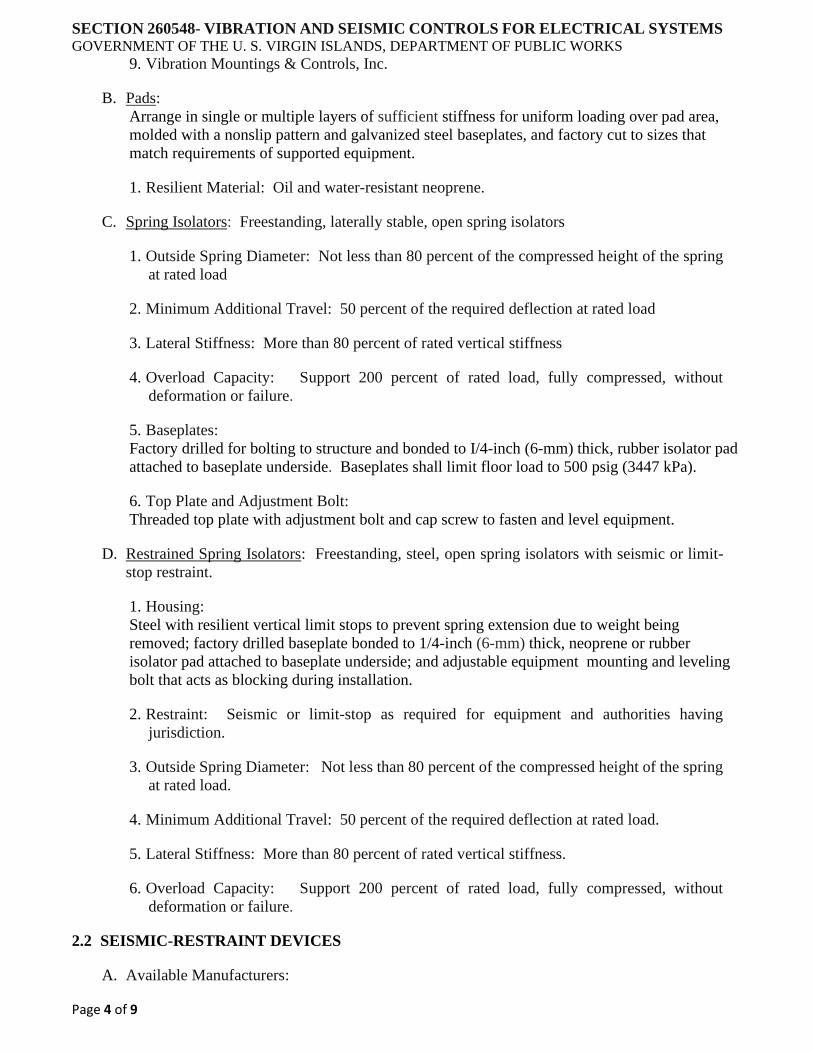
SECTION 260548- VIBRATION AND SEISMIC CONTROLS FOR ELECTRICAL SYSTEMS GOVERNMENT OF THE U. S. VIRGIN ISLANDS, DEPARTMENT OF PUBLIC WORKS
Page 4 of 9
9. Vibration Mountings & Controls, Inc.
B. Pads:
Arrange in single or multiple layers of sufficient stiffness for uniform loading over pad area,
molded with a nonslip pattern and galvanized steel baseplates, and factory cut to sizes that
match requirements of supported equipment.
1. Resilient Material: Oil and water-resistant neoprene.
C. Spring Isolators: Freestanding, laterally stable, open spring isolators
1. Outside Spring Diameter: Not less than 80 percent of the compressed height of the spring
at rated load
2. Minimum Additional Travel: 50 percent of the required deflection at rated load
3. Lateral Stiffness: More than 80 percent of rated vertical stiffness
4. Overload Capacity: Support 200 percent of rated load, fully compressed, without
deformation or failure.
5. Baseplates:
Factory drilled for bolting to structure and bonded to I/4-inch (6-mm) thick, rubber isolator pad
attached to baseplate underside. Baseplates shall limit floor load to 500 psig (3447 kPa).
6. Top Plate and Adjustment Bolt:
Threaded top plate with adjustment bolt and cap screw to fasten and level equipment.
D. Restrained Spring Isolators: Freestanding, steel, open spring isolators with seismic or limit-
stop restraint.
1. Housing:
Steel with resilient vertical limit stops to prevent spring extension due to weight being
removed; factory drilled baseplate bonded to 1/4-inch (6-mm) thick, neoprene or rubber
isolator pad attached to baseplate underside; and adjustable equipment mounting and leveling
bolt that acts as blocking during installation.
2. Restraint: Seismic or limit-stop as required for equipment and authorities having
jurisdiction.
3. Outside Spring Diameter: Not less than 80 percent of the compressed height of the spring
at rated load.
4. Minimum Additional Travel: 50 percent of the required deflection at rated load.
5. Lateral Stiffness: More than 80 percent of rated vertical stiffness.
6. Overload Capacity: Support 200 percent of rated load, fully compressed, without
deformation or failure.
2.2 SEISMIC-RESTRAINT DEVICES
A. Available Manufacturers:
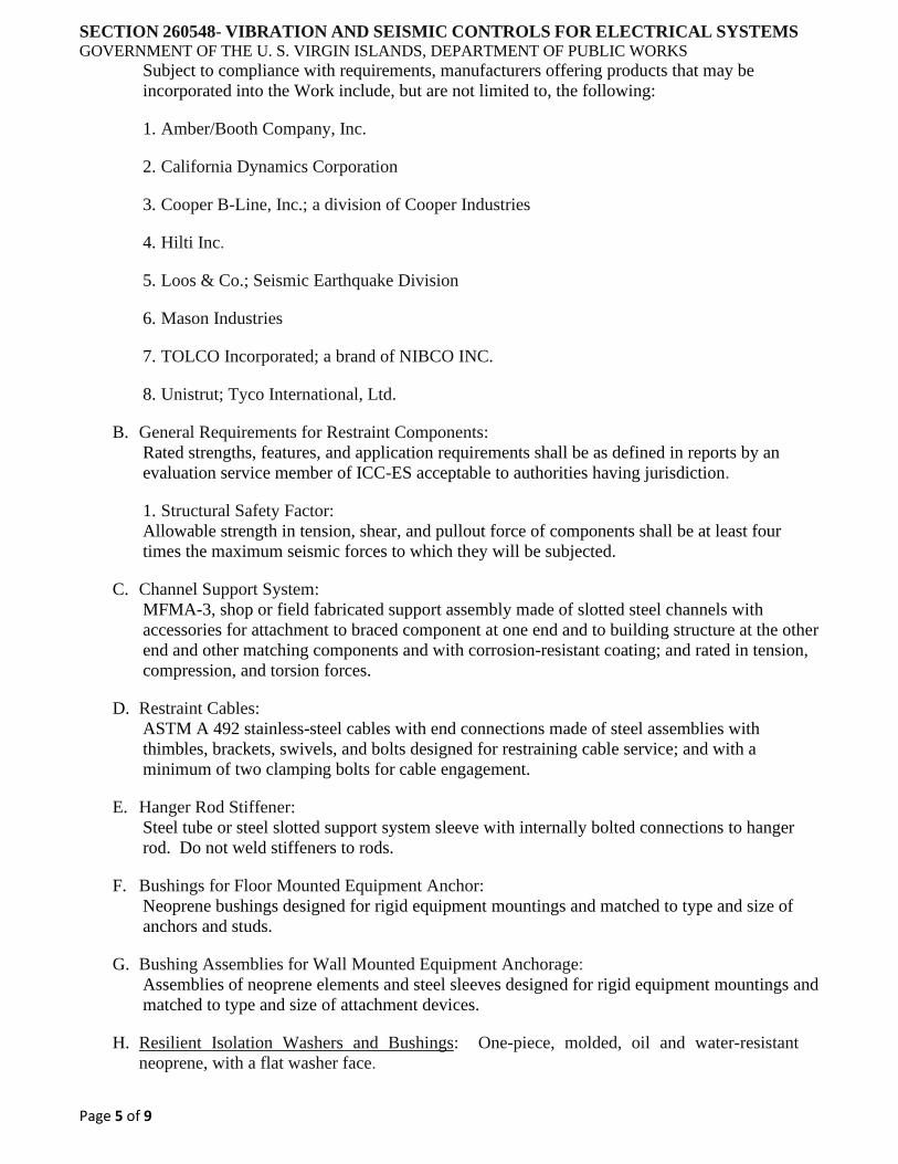
SECTION 260548- VIBRATION AND SEISMIC CONTROLS FOR ELECTRICAL SYSTEMS GOVERNMENT OF THE U. S. VIRGIN ISLANDS, DEPARTMENT OF PUBLIC WORKS
Page 5 of 9
Subject to compliance with requirements, manufacturers offering products that may be
incorporated into the Work include, but are not limited to, the following:
1. Amber/Booth Company, Inc.
2. California Dynamics Corporation
3. Cooper B-Line, Inc.; a division of Cooper Industries
4. Hilti Inc.
5. Loos & Co.; Seismic Earthquake Division
6. Mason Industries
7. TOLCO Incorporated; a brand of NIBCO INC.
8. Unistrut; Tyco International, Ltd.
B. General Requirements for Restraint Components:
Rated strengths, features, and application requirements shall be as defined in reports by an
evaluation service member of ICC-ES acceptable to authorities having jurisdiction.
1. Structural Safety Factor:
Allowable strength in tension, shear, and pullout force of components shall be at least four
times the maximum seismic forces to which they will be subjected.
C. Channel Support System:
MFMA-3, shop or field fabricated support assembly made of slotted steel channels with
accessories for attachment to braced component at one end and to building structure at the other
end and other matching components and with corrosion-resistant coating; and rated in tension,
compression, and torsion forces.
D. Restraint Cables:
ASTM A 492 stainless-steel cables with end connections made of steel assemblies with
thimbles, brackets, swivels, and bolts designed for restraining cable service; and with a
minimum of two clamping bolts for cable engagement.
E. Hanger Rod Stiffener:
Steel tube or steel slotted support system sleeve with internally bolted connections to hanger
rod. Do not weld stiffeners to rods.
F. Bushings for Floor Mounted Equipment Anchor:
Neoprene bushings designed for rigid equipment mountings and matched to type and size of
anchors and studs.
G. Bushing Assemblies for Wall Mounted Equipment Anchorage:
Assemblies of neoprene elements and steel sleeves designed for rigid equipment mountings and
matched to type and size of attachment devices.
H. Resilient Isolation Washers and Bushings: One-piece, molded, oil and water-resistant
neoprene, with a flat washer face.

SECTION 260548- VIBRATION AND SEISMIC CONTROLS FOR ELECTRICAL SYSTEMS GOVERNMENT OF THE U. S. VIRGIN ISLANDS, DEPARTMENT OF PUBLIC WORKS
Page 6 of 9
I. Mechanical Anchor:
Drilled in and stud wedge or female wedge type in zinc coated steel for interior applications
and stainless steel for exterior applications. Select anchors with strength required for anchor
and as tested according to ASTM E 488. Minimum length of eight times diameter.
J. Adhesive Anchor:
Drilled in and capsule anchor system containing polyvinyl or urethane methacrylate-based resin
and accelerator, or injected polymer or hybrid mortar adhesive. Provide anchor bolts and
hardware with zinc coated steel for interior applications and stainless steel for exterior
applications. Select anchor bolts with strength required for anchor and as tested according to
ASTM E 488.
2.3 FACTORY FINISHES
A. Finish: Manufacturer's standard prime coat finish ready for field painting.
B. Finish: Manufacturer's standard paint applied to factory assembled and tested equipment
before shipping.
1. Powder coating on springs and housings
2. All hardware shall be galvanized. Stainless steel components for exterior use.
3. Baked enamel or powder coat for metal components on isolators for interior use.
4. Color code or otherwise mark vibration isolation and seismic control devices to indicate
capacity range.
PART 3 EXECUTION
3.1 EXAMINATION
A. Examine areas and equipment to receive vibration isolation and seismic control devices for
compliance with requirements for installation tolerances and other conditions affecting
performance.
B. Examine roughing in of reinforcement and cast in place anchors to verify actual locations
before installation.
C. Proceed with installation only after unsatisfactory conditions have been corrected.
3.2 APPLICATIONS
A. Multiple Raceways or Cables:
Secure raceways and cables to trapeze member with clamps approved for application by an
evaluation service member of ICC-ES acceptable to authorities having jurisdiction.
B. Hanger Rod Stiffeners:
Install hanger rod stiffeners where indicated or scheduled on Drawings to receive them and
where required to prevent buckling of hanger rods due to seismic forces.
C. Strength of Support and Seismic Restraint Assemblies:
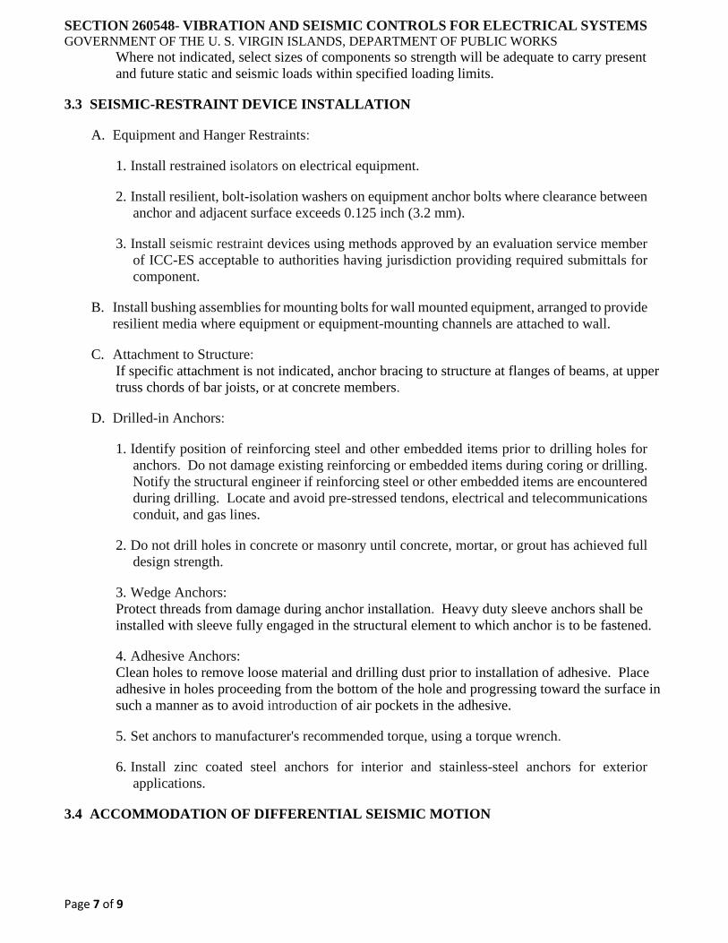
SECTION 260548- VIBRATION AND SEISMIC CONTROLS FOR ELECTRICAL SYSTEMS GOVERNMENT OF THE U. S. VIRGIN ISLANDS, DEPARTMENT OF PUBLIC WORKS
Page 7 of 9
Where not indicated, select sizes of components so strength will be adequate to carry present
and future static and seismic loads within specified loading limits.
3.3 SEISMIC-RESTRAINT DEVICE INSTALLATION
A. Equipment and Hanger Restraints:
1. Install restrained isolators on electrical equipment.
2. Install resilient, bolt-isolation washers on equipment anchor bolts where clearance between
anchor and adjacent surface exceeds 0.125 inch (3.2 mm).
3. Install seismic restraint devices using methods approved by an evaluation service member
of ICC-ES acceptable to authorities having jurisdiction providing required submittals for
component.
B. Install bushing assemblies for mounting bolts for wall mounted equipment, arranged to provide
resilient media where equipment or equipment-mounting channels are attached to wall.
C. Attachment to Structure:
If specific attachment is not indicated, anchor bracing to structure at flanges of beams, at upper
truss chords of bar joists, or at concrete members.
D. Drilled-in Anchors:
1. Identify position of reinforcing steel and other embedded items prior to drilling holes for
anchors. Do not damage existing reinforcing or embedded items during coring or drilling.
Notify the structural engineer if reinforcing steel or other embedded items are encountered
during drilling. Locate and avoid pre-stressed tendons, electrical and telecommunications
conduit, and gas lines.
2. Do not drill holes in concrete or masonry until concrete, mortar, or grout has achieved full
design strength.
3. Wedge Anchors:
Protect threads from damage during anchor installation. Heavy duty sleeve anchors shall be
installed with sleeve fully engaged in the structural element to which anchor is to be fastened.
4. Adhesive Anchors:
Clean holes to remove loose material and drilling dust prior to installation of adhesive. Place
adhesive in holes proceeding from the bottom of the hole and progressing toward the surface in
such a manner as to avoid introduction of air pockets in the adhesive.
5. Set anchors to manufacturer's recommended torque, using a torque wrench.
6. Install zinc coated steel anchors for interior and stainless-steel anchors for exterior
applications.
3.4 ACCOMMODATION OF DIFFERENTIAL SEISMIC MOTION
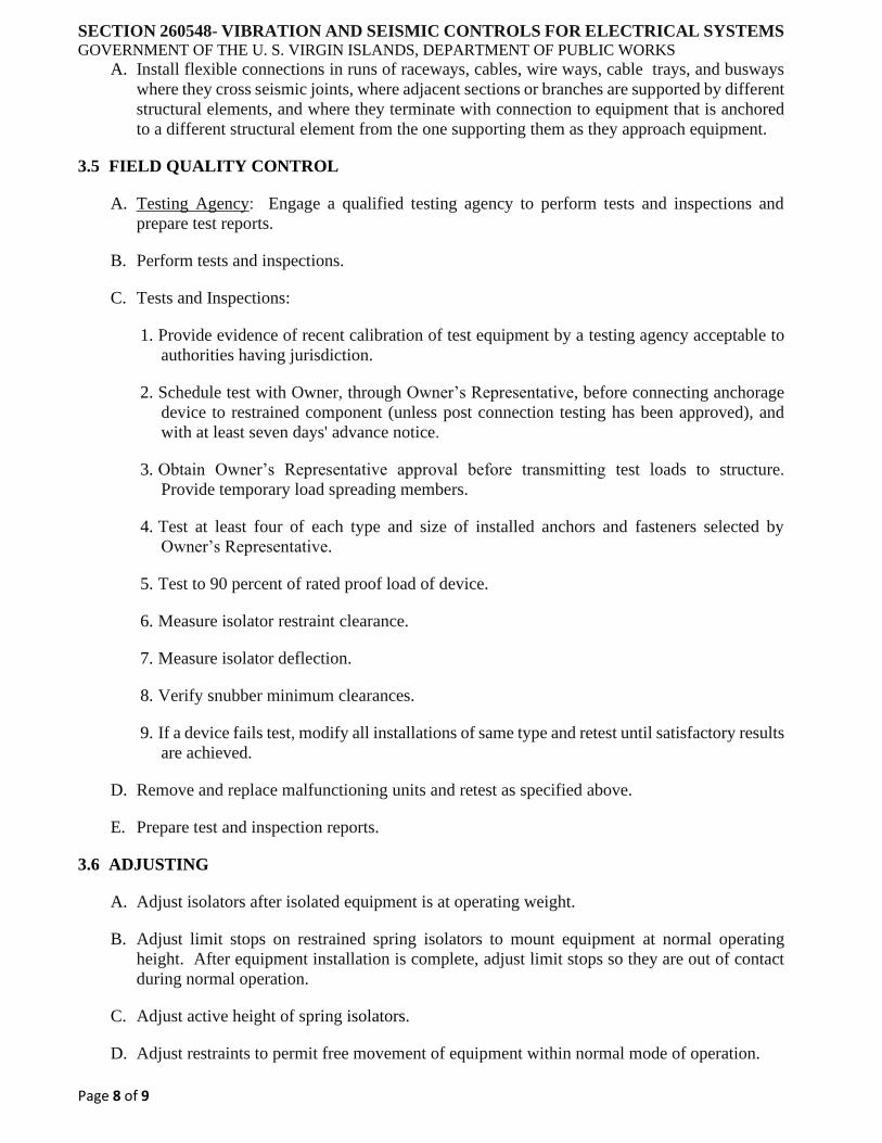
SECTION 260548- VIBRATION AND SEISMIC CONTROLS FOR ELECTRICAL SYSTEMS GOVERNMENT OF THE U. S. VIRGIN ISLANDS, DEPARTMENT OF PUBLIC WORKS
Page 8 of 9
A. Install flexible connections in runs of raceways, cables, wire ways, cable trays, and busways
where they cross seismic joints, where adjacent sections or branches are supported by different
structural elements, and where they terminate with connection to equipment that is anchored
to a different structural element from the one supporting them as they approach equipment.
3.5 FIELD QUALITY CONTROL
A. Testing Agency: Engage a qualified testing agency to perform tests and inspections and
prepare test reports.
B. Perform tests and inspections.
C. Tests and Inspections:
1. Provide evidence of recent calibration of test equipment by a testing agency acceptable to
authorities having jurisdiction.
2. Schedule test with Owner, through Owner’s Representative, before connecting anchorage
device to restrained component (unless post connection testing has been approved), and
with at least seven days' advance notice.
3. Obtain Owner’s Representative approval before transmitting test loads to structure.
Provide temporary load spreading members.
4. Test at least four of each type and size of installed anchors and fasteners selected by
Owner’s Representative.
5. Test to 90 percent of rated proof load of device.
6. Measure isolator restraint clearance.
7. Measure isolator deflection.
8. Verify snubber minimum clearances.
9. If a device fails test, modify all installations of same type and retest until satisfactory results
are achieved.
D. Remove and replace malfunctioning units and retest as specified above.
E. Prepare test and inspection reports.
3.6 ADJUSTING
A. Adjust isolators after isolated equipment is at operating weight.
B. Adjust limit stops on restrained spring isolators to mount equipment at normal operating
height. After equipment installation is complete, adjust limit stops so they are out of contact
during normal operation.
C. Adjust active height of spring isolators.
D. Adjust restraints to permit free movement of equipment within normal mode of operation.

SECTION 260548- VIBRATION AND SEISMIC CONTROLS FOR ELECTRICAL SYSTEMS GOVERNMENT OF THE U. S. VIRGIN ISLANDS, DEPARTMENT OF PUBLIC WORKS
Page 9 of 9
END OF SECTION
SECTION 260553- IDENTIFICATION FOR ELECTRICAL SYSTEMS GOVERNMENT OF THE U. S. VIRGIN ISLANDS, DEPARTMENT OF PUBLIC WORKS
Page 1 of 7
PART 1 GENERAL
1.1 SUMMARY
A. Section Includes:
1. Identification for raceways
2. Identification of power and control cables
3. Identification for conductors
4. Underground line warning tape
5. Warning labels and signs
6. Instruction signs
7. Equipment identification labels
8. Miscellaneous identification products
1.2 SUBMITTALS
A. Product Data: For each electrical identification product indicated.
1.3 QUALITY ASSURANCE
A. Comply with ANSI Al3.1.
B. Comply with NFPA 70.
C. Comply with 29 CFR 1910.144 and 29 CFR 1910.145.
D. Comply with ANSI Z535.4 for safety signs and labels.
E. Adhesive-attached labeling materials, including label stocks, laminating adhesives, and inks
used by label printers, shall comply with UL 969.
PART 2 PRODUCTS
2.1 POWER RACEWAY IDENTIFICATION MATERIALS
A. Comply with ANSI Al3.1 for minimum size of letters for legend and for minimum length of
color field for each raceway size.
B. Self-Adhesive Vinyl Labels for Raceways Carrying Circuits at 600 V or Less:
Preprinted, flexible label laminated with a clear, weather and chemical resistant coating and
matching wraparound adhesive tape for securing ends of legend label.
C. Snap Around Labels for Raceways Carrying Circuits at 600 V or Less:
Slit, pre-tensioned, flexible, preprinted, color coded acrylic sleeve, with diameter sized to suit
diameter of raceway or cable it identifies and to stay in place by gripping action.
SECTION 260553- IDENTIFICATION FOR ELECTRICAL SYSTEMS GOVERNMENT OF THE U. S. VIRGIN ISLANDS, DEPARTMENT OF PUBLIC WORKS
Page 2 of 7
D. Snap Around, Color Coding Bands for Raceways Carrying Circuits at 600 V or Less:
Slit, pre-tensioned, flexible, solid colored acrylic sleeve, 2 inches (50 mm) long, with diameter
sized to suit diameter of raceway or cable it identifies and to stay in place by gripping action.
E. Write On Tags:
Polyester tag, 0.010 inch (0.25 mm) thick, with corrosion resistant grommet and cable tie for
attachment to conductor or cable.
1. Marker for Tags: Permanent, waterproof, black ink marker recommended by tag
manufacturer.
2.2 POWER AND CONTROL CABLE IDENTIFICATION MATERIALS
A. Comply with ANSI A13.1 for minimum size of letters for legend and for minimum length of
color field for each raceway and cable size.
B. Self-Adhesive Vinyl Labels:
Preprinted, flexible label laminated with a clear, weather and chemical resistant coating and
matching wrap around adhesive tape for securing ends of legend label.
C. Write On Tags:
Polyester tag, 0.010 inch (0.25 mm) thick, with corrosion resistant grommet and cable tie for
attachment to conductor or cable.
1. Marker for Tags:
Permanent, waterproof, black ink marker recommended by tag manufacturer.
D. Snap Around Labels:
Slit, pre-tensioned, flexible, preprinted, color coded acrylic sleeve, with diameter sized to suit
diameter of raceway or cable it identifies and to stay in place by gripping action.
E. Snap Around, Color Coding Bands:
Slit, pre-tensioned, flexible, solid colored acrylic sleeve, 2 inches (50 mm) long, with diameter
sized to suit diameter of raceway or cable it identifies and to stay in place by gripping action.
2.3 CONDUCTOR IDENTIFICATION MATERIALS
A. Color Coding Conductor Tape:
Colored, self-adhesive vinyl tapes not less than 3 mils (0.08 mm) thick by 1 to 2 inches (25 to
50 mm) wide.
B. Self-Adhesive Vinyl Labels:
Preprinted, flexible label laminated with a clear, weather and chemical resistant coating and
matching wraparound adhesive tape for securing ends of legend label.
C. Marker Tapes:
Vinyl or vinyl cloth, self-adhesive wraparound type, with circuit identification legend machine
printed by thermal transfer or equivalent process.
D. Write On Tags:
Polyester tag, 0.010 inch (0.25 mm) thick, with corrosion-resistant grommet and cable tie for
attachment to conductor or cable.

SECTION 260553- IDENTIFICATION FOR ELECTRICAL SYSTEMS GOVERNMENT OF THE U. S. VIRGIN ISLANDS, DEPARTMENT OF PUBLIC WORKS
Page 3 of 7
1. Marker for Tags: Permanent, waterproof, black ink marker recommended by tag
manufacturer.
2.4 WARNING LABELS AND SIGNS
A. Comply with NFPA 70 and 29 CFR 1910.145.
B. Self-Adhesive Warning Labels:
Factory printed, multicolor, pressure sensitive adhesive labels, configured for display on front
cover, door, or other access to equipment unless otherwise indicated.
C. High Density Polyethylene (HDPE) Warning Signs:
1. Preprinted Dual Color Routed HDPE signs punched or drilled for fasteners, with colors,
legend, and size required for application.
2. 1/4-inch (6.4-mm) grommets in corners for mounting.
3. Nominal size, 7 by 10 inches (180 by 250 mm).
D. Warning label and sign shall include, but are not limited to, the following legends:
1. Multiple Power Source Warning:
"DANGER - ELECTRICAL SHOCK HAZARD - EQUIPMENT HAS MULTIPLE POWER
SOURCES."
2. Workspace Clearance Warning:
"WARNING - OSHA REGULATION - AREA IN FRONT OF ELECTRICAL EQUIPMENT
MUST BE KEPT CLEAR FOR 36 INCHES (915 MM)."
2.5 INSTRUCTION SIGNS
A. Routed, Dual Color HDPE, minimum 1/2-inch-thick for signs up to 20 sq. inches (129 sq. m)
and 3/4-inch-thick for larger sizes.
1. Routed legend with black letters on white face.
2. Punched or drilled for mechanical fasteners.
3. Framed with mitered acrylic molding and arranged for attachment at applicable equipment.
2.6 MISCELLANEOUS IDENTIFICATION PRODUCTS
A. Paint:
Comply with requirements in Division 09 painting Sections for paint materials and application
requirements. Select paint system applicable for surface material and location (exterior or
interior).
B. Fasteners for Labels and Signs:
Self-tapping, stainless steel screws or stainless-steel machine screws with nuts and flat and lock
washers.
PART 3 EXECUTION
SECTION 260553- IDENTIFICATION FOR ELECTRICAL SYSTEMS GOVERNMENT OF THE U. S. VIRGIN ISLANDS, DEPARTMENT OF PUBLIC WORKS
Page 4 of 7
3.1 INSTALLATION
A. Location:
Install identification materials and devices at locations for most convenient viewing without
interference with operation and maintenance of equipment.
B. Apply identification devices to surfaces that require finish after completing finish work.
C. Self-Adhesive Identification Products:
Clean surfaces before application, using materials and methods recommended by manufacturer
of identification device.
D. Attach signs and plastic labels that are not self-adhesive type with mechanical fasteners
appropriate to the location and substrate.
E. System Identification Color Coding Bands for Raceways and Cables:
Each color-coding band shall completely encircle cable or conduit. Place adjacent bands of
two-color markings in contact, side by side. Locate bands at changes in direction, at
penetrations of walls and floors, at 50-foot (15-m) maximum intervals in straight runs, and at
25-foot (7.6-m) maximum intervals in congested areas.
F. Underground Line Warning Tape:
During backfilling of trenches install continuous underground line warning tape directly above
line at 6 to 8 inches (150 to 200 mm) below finished grade. Use multiple tapes where width of
multiple lines installed in a common trench or concrete envelope exceeds 16 inches (400 mm)
overall.
G. Painted Identification:
Comply with requirements in Division 09 painting Sections for surface preparation and paint
application.
3.2 IDENTIFICATION SCHEDULE
A. Accessible Raceways and Metal Clad Cables, 600 V or Less, for Service, Feeder, and Branch
Circuits More Than 30 A, and 120 V to ground:
Install labels at 10-foot (3-m) maximum intervals.
B. Accessible Raceways and Cables within Buildings:
Identify the covers of each junction and pull box of the following systems with self-adhesive
vinyl labels with the wiring system legend and system voltage. System legends shall be as
follows:
1. Emergency Power
2. Power
3. UPS
C. Power Circuit Conductor Identification, 600 V or Less:
For conductors in vaults, pull and junction boxes, manholes, and hand holes, use color-coding
conductor tape to identify the phase.
1. Color Coding for Phase and Voltage Level Identification, 600 V or Less:
SECTION 260553- IDENTIFICATION FOR ELECTRICAL SYSTEMS GOVERNMENT OF THE U. S. VIRGIN ISLANDS, DEPARTMENT OF PUBLIC WORKS
Page 5 of 7
Use colors listed below for ungrounded service feeder and branch-circuit conductors.
a. Color shall be factory applied or field applied for sizes larger than No. 8 AWG, if
authorities having jurisdiction permit.
b. Colors for 208/120-V Circuits:
i. Phase A: Black
ii. Phase B: Red
iii. Phase C: Blue
c. Colors for 480/277-V Circuits:
i. Phase A: Brown
ii. Phase B: Orange
iii. Phase C: Yellow
D. Install instructional sign including the color code for grounded and ungrounded conductors
using adhesive film type labels.
E. Conductors to Be Extended in the Future:
Attach write on tags or marker tape to conductors and list source.
F. Auxiliary Electrical Systems Conductor Identification:
Identify field installed alarm, control, and signal connections.
1. Identify conductors, cables, and terminals in enclosures and at junctions, terminals, and pull
points. Identify by system and circuit designation.
2. Use system of marker tape designations that is uniform and consistent with system used by
manufacturer for factory installed connections.
3. Coordinate identification with Project Drawings, manufacturer's wiring diagrams, and the
Operation and Maintenance Manual.
G. Locations of Underground Lines:
Identify with underground-line warning tape for power, lighting, communication, and control
wiring and optical fiber cable.
1. Install underground line warning tape for both direct buried cables and cables in raceway.
H. Workspace Indication:
Install floor marking tape to show working clearances in the direction of access to live parts.
Workspace shall be as required by NFPA 70 and 29 CPR 1926.403 unless otherwise indicated.
Do not install at flush mounted panelboards and similar equipment in finished spaces.
I. Warning Labels for Indoor Cabinets, Boxes, and Enclosures for Power and Lighting: Self-
adhesive warning labels
1. Comply with 29 CPR 1910.145.
SECTION 260553- IDENTIFICATION FOR ELECTRICAL SYSTEMS GOVERNMENT OF THE U. S. VIRGIN ISLANDS, DEPARTMENT OF PUBLIC WORKS
Page 6 of 7
2. Identify system voltage with black letters and an orange background.
3. Apply to exterior of door, cover, or other access.
4. For equipment with multiple power or control sources, apply to door or cover of equipment
including, but not limited to, the following:
a. Power transfer switches
b. Controls with external control power connections
J. Operating Instruction Signs:
Install instruction signs to facilitate proper operation and maintenance of electrical systems and
items to which they connect. Install instruction signs with approved legend where instructions
are needed for system or equipment operation.
K. Emergency Operating Instruction Signs:
Install instruction signs with white legend and a red background with minimum 3/8-inch (10-
mm) high letters for emergency instructions at equipment used for power transfer.
L. Equipment Identification Labels:
On each unit of equipment, install unique designation label that is consistent with wiring
diagrams, schedules, and the Operation and Maintenance Manual. Apply labels to disconnect
switches and protection equipment, central or master units, control panels, control stations,
terminal cabinets, and racks of each system. Systems include power, lighting, control,
communication, signal, monitoring, and alarm systems unless equipment is provided with its
own identification.
1. Labeling Instructions:
a. Indoor Equipment:
Self-adhesive, engraved, laminated acrylic or melamine label. Unless otherwise indicated,
provide a single line of text with 1/2-inch (13-mm) high letters on 1-l/2-inch (38-mm) high
label; where two lines of text are required, use labels 2 inches (50 mm) high.
b. Outdoor Equipment: Engraved, laminated acrylic or melamine label.
c. Elevated Components: Increase sizes of labels and letters to those appropriate for
viewing from the floor.
d. Unless provided with self-adhesive means of attachment, fasten labels with appropriate
mechanical fasteners that do not change the NEMA or NRTL rating of the enclosure.
2. Equipment to Be Labeled:
a. Panelboards:
Typewritten directory of circuits in the location provided by panel board manufacturer. Panel
board identification shall be self-adhesive, engraved, laminated acrylic or melamine label.
b. Enclosures and electrical cabinets
c. Access doors and panels for concealed electrical items

SECTION 260553- IDENTIFICATION FOR ELECTRICAL SYSTEMS GOVERNMENT OF THE U. S. VIRGIN ISLANDS, DEPARTMENT OF PUBLIC WORKS
Page 7 of 7
d. Switchgear
e. Switchboards
f. Emergency system boxes and enclosures
g. Enclosed switches
h. Enclosed circuit breakers
i. Enclosed controllers
j. Variable-speed controllers
k. Push-button stations
l. Power transfer equipment
m. Contactors
n. Power-generating units
o. Monitoring and control equipment
p. UPS equipment
END OF SECTION
SECTION 260923- LIGHTING CONTROL DEVICES
GOVERNMENT OF THE U. S. VIRGIN ISLANDS, DEPARTMENT OF PUBLIC WORKS
Page 1 of 6
PART 1 GENERAL
1.1 SUMMARY
A. Section Includes:
1. Occupancy and Vacancy Sensor Control
B. Related Sections:
1. Section 262416 - Panelboards
2. Section 262726 - Wiring Devices: Lighting Controls
3. Section 265100 - Interior Lighting Fixtures, Lamps and Ballasts:
Fluorescent lighting ballasts controlled by central dimming control system.
1.2 REFERENCES
A. American National Standards Institute/Institute of Electrical and Electronic Engineers
(ANSI/IEEE):
1. C62.41-l991 -Recommended Practice for Surge Voltages in Low-Voltage AC Power
Circuits.
B. ASTM International (ASTM):
1. D4674-02a Standard Test Method for Accelerated Testing for Color Stability of Plastics
Exposed to Indoor Fluorescent Lighting and Window-Filtered Daylight.
C. International Electro-Technical Commission (IEC).
1. IEC 801-2 Electrostatic Discharge Testing Standard.
2. IEC/EN 60669-2-l Switches for household and similar fixed electrical installations-
electronic switches.
D. International Organization for Standardization (ISO):
1. 900l:2000- Quality Management Systems.
E. National Electrical Manufacturers Association (NEMA)
1. WD1 (R2005) - General Color Requirements for Wiring Devices.
F. Underwriters Laboratories, Inc. (UL):
1. 94 - Flammability Rating
2. 916 - Energy Management Equipment.
3. 508 (2005) - Standard for Industrial Control Equipment.

SECTION 260923- LIGHTING CONTROL DEVICES
GOVERNMENT OF THE U. S. VIRGIN ISLANDS, DEPARTMENT OF PUBLIC WORKS
Page 2 of 6
4. 244A- Appliance Controls
5. 935 (2005) - Fluorescent Ballasts
1.3 SYSTEM DESCRIPTION
A. Permanently installed
1. Ceiling mounted occupancy sensors
2. Wall switch occupancy sensors
3. Power packs
1.4 ACTION SUBMITTALS
A. Product Data: For each type of product.
B. Shop Drawings: Show installation details for occupancy and light level sensors.
C. Interconnection diagrams showing field installed wiring.
D. Include diagrams for power, signal, and control wiring.
1.5 INFORMATIONAL SUBMITTALS
A. Field quality control reports.
1.6 CLOSEOUT SUBMITTALS
A. Operation and Maintenance Data:
For each type of lighting control device to include in emergency, operation, and maintenance
manuals.
1.7 QUALITY ASSURANCE
A. Manufacturer: Minimum 10 years’ experience in manufacture of architectural lighting
controls.
B. Manufacturer's Quality System:
Registered to ISO 9001:2000 Quality Standard, including in-house engineering for product
design activities.
1.8 PROJECT CONDITIONS
A. Do not install equipment until following conditions can be maintained in spaces to receive
equipment:
1. Ambient temperature: Under 40 degrees C (104 degrees F).
2. Relative humidity: Maximum 90 percent, non-condensing.
3. Lighting control system must be protected from dust during installation.
SECTION 260923- LIGHTING CONTROL DEVICES
GOVERNMENT OF THE U. S. VIRGIN ISLANDS, DEPARTMENT OF PUBLIC WORKS
Page 3 of 6
1.9 WARRANTY
A. Provide manufacturer's 1-year parts warranty.
B. Maintenance Material submittals
C. Make ordering of new equipment for expansions, replacements, and spare parts available to
end user.
D. Make new replacement parts available for minimum of ten years from date of manufacture.
PART 2 PRODUCTS
2.1 MANUFACTURERS
A. Basis of Design Product:
Lutron Occupancy Sensors. Subject to compliance with requirements, provide product
indicated or comparable product by one of the following:
1. Bryant Electric; a Hubbell company
2. Cooper Industries, Inc.
3. Hubbell Building Automation, Inc.
4. Leviton Mfg. Company Inc.
5. Lutron Electronics Co., Inc.
6. Sensor Switch, Inc.
7. Square D; a brand of Schneider Electric.
8. Watt Stopper.
2.2 GENERAL
A. Provide system software and hardware that is designed, tested, manufactured, and warranted
by a single manufacturer.
B. Architectural Lighting Controls:
Ten-year operational life while operating continually at any temperature in an ambient
temperature range of 0°C (32°F) to 40°C (104°F) and 90 percent non-condensing relative
humidity.
C. Designed and tested to withstand discharges without impairment of performance when
subjected to discharges of 15,000 volts per IEC 801-2.
2.3 SENSOR PERFORMANCE REQUIREMENTS
A. Sensing mechanism:
1. Dual technology:

SECTION 260923- LIGHTING CONTROL DEVICES
GOVERNMENT OF THE U. S. VIRGIN ISLANDS, DEPARTMENT OF PUBLIC WORKS
Page 4 of 6
a. Utilize multiple segmented lens, with internal grooves to eliminate dust and residue
buildup.
b. Utilize an operating frequency of 32k Hz or 40 kHz that shall be crystal controlled to
operate within plus or minus 0.005 percent tolerance.
B. Field adjustable controls for time delay and sensitivity to override any adaptive features.
C. Power failure memory:
1. Controls incorporate non-volatile memory. Should power be interrupted and subsequently
restored, settings and learned parameters saved in protected memory shall not be lost.
D. Designed and tested to withstand discharges without impairment of performance when
subjected to discharges of 15,000 volts per IEC 801-2.
2.4 WIRED CEILING AND WALL MOUNT SENSORS
A. Product: LOS-CDT-500R-WH, LOS-CDT-IOOOR-WH, LOS-CDT-2000R-WH.
B. Provide all necessary mounting hardware and instructions.
C. Sensors shall be Class 2 devices.
D. Indicate viewing directions on mounting bracket for all Ceiling mount sensors.
E. Provide customizable mask to block off unwanted viewing areas for all ceiling mounted
sensors using infrared technology.
F. Provide swivel mount base for all wall mount sensors.
G. Provide an internal additional isolated relay with Normally Open, Normally Closed and
Common outputs for use with HVAC control, Data Logging and other control options.
2.5 IN-WALL OCCUPANCY SENSORS
A. Digital wall box no-neutral switch with occupancy/vacancy sensor
1. Product: MS-OPS6M-DV
2. Switch shall be rated at 120/277 Volts 6 amps Lighting / 120 Volts 3 amps Fan Loads and
shall not require a neutral connection in wall box.
a. Rated life: Minimum 100,000 cycles.
b. Load switched in manner that prevents arcing at mechanical contacts when power is
applied to load circuits.
c. Fully rated output continuous duty for inductive, capacitive, and resistive loads.
3. Utilize Infrared as its sensing mechanism coupled with Lutron XCT™ Technology for
sensing fine motions. Signal processing technology detects fine motion, passive infrared
(PIR) signals without the need to change the sensor's sensitivity threshold.
SECTION 260923- LIGHTING CONTROL DEVICES
GOVERNMENT OF THE U. S. VIRGIN ISLANDS, DEPARTMENT OF PUBLIC WORKS
Page 5 of 6
4. Occupancy/vacancy sensor can be programmed to operate as an occupancy sensor
(automatic-on and automatic-off functionality) or a vacancy sensor (manual-on and
automatic-off functionality).
5. Provide adjustable timeout for 15, 30 minutes.
6. Provide ambient light sensor to prevent lights from turning on automatically if ambient light
in room is higher than selected setting. Three settings shall be available to for selection by
the user.
7. Provide ability when switch is manually turned off, to prevent sensor from turning lights
back on automatically while room remains occupied. Once room is vacated, auto-on
feature returns to normal operation after timeout duration has exhausted.
8. Utilize air gap off, activated when user selects "off' at any control to disconnect the load
from line supply eliminating any leakage current.
9. Protect your switch from power surges during a storm or from other equipment from within
the building.
10. Design and test switches to withstand line-side surges without impairment to performance
when subjected to surges of 6,000 volts, 200 amps per ANSI/IEEE C62.41 C.
11. This ensures product design lifetime under all installation conditions. For example,
products which are not de-rated when installed in a multi-gang installation may experience
a reduced design lifetime because of an increased temperature rise.
12. Capable of operating at the rated capacity; this includes modified capacities for ganging
configurations which require the removal of fins. Operation at rated capacity shall be
possible across the full ambient temperature range, without shortening design lifetime.
13. Provide frequency compensation to assure switching capability on 50 or 60Hz lines.
14. Switches to be listed to UL 20, UL 508, ULI472, CSA C22.2 #14, NOM-003-SCFI
2.6 SENSOR POWER PACKS
A. Product: PP-277H
B. Plenum rated.
C. Control wiring between sensors and control units shall be Class 2, 18-24 AWG, stranded U.L.
Classified, TEFLON jacketed cable suitable for use in plenums.
D. Integrated, self-contained unit consisting internally of an isolated load switching control relay
and a power supply to provide low-voltage power (PP-SH does not supply power).
2.7 SOURCE QUALITY CONTROL
A. Perform full-function testing on 100 percent of all system components and panel assemblies at
the factory.
SECTION 260923- LIGHTING CONTROL DEVICES
GOVERNMENT OF THE U. S. VIRGIN ISLANDS, DEPARTMENT OF PUBLIC WORKS
Page 6 of 6
PART 3 EXECUTION
3.1 INSTALLATION
A. Install equipment in accordance with manufacturer's installation instructions.
B. Provide complete installation of system in accordance with Contract Documents.
C. Provide equipment at locations and in quantities indicated on Drawings. Provide any
additional equipment required to provide control intent.
3.2 SERVICE AND SUPPORT
A. Startup and Programming
1. Provide factory-certified field service engineer to a site visit to ensure proper system
installation and operation under following parameters:
a. Qualifications for factory-certified field service engineer:
i. Minimum experience of 2 years training in the electrical/electronic field.
ii. Certified by the equipment manufacturer on the system installed.
b. Make a visit upon completion of installation of lighting control system:
i. Verify connection and location of controls.
ii. Verify system operation control by control, zone by zone.
iii. Verify proper integration of manufacturers interfacing equipment.
iv. Obtain sign-off on system functions.
B. Tech Support
1. Provide factory direct technical support hotline 24 hours per day, 7 days per week.
3.3 MAINTENANCE
A. Capable of providing on-site service support within 24 hours anywhere in continental United
States and within 72 hours worldwide except where special visas are required.
B. Offer renewable service contract on yearly basis, to include parts, factory labor, and annual
training visits. Make service contracts available up to ten years after date of system startup.
END OF SECTION
SECTION 262416 - PANELBOARDS
GOVERNMENT OF THE U. S. VIRGIN ISLANDS, DEPARTMENT OF PUBLIC WORKS
Page 1 of 7
PART 1 GENERAL
1.1 SUMMARY
A. Section includes distribution panelboards and lighting and appliance branch-circuit
panelboards.
1.2 SUBMITTALS
A. Product Data: For each type of product indicated
B. Shop Drawings: For each panelboard and related equipment.
1. Include dimensioned plans, elevations, sections, and details. Show tabulations of installed
devices, equipment features, and ratings.
2. Detail enclosure types and details for types other than NEMA 250, Type 1.
3. Detail bus configuration, current, and voltage ratings.
4. Short-circuit current rating of panel boards and overcurrent protective devices.
5. Include evidence of NRTL listing for series rating of installed devices.
6. Detail features, characteristics, ratings, and factory settings of individual overcurrent
protective devices and auxiliary components.
7. Include wiring diagrams for power, signal, and control wiring.
8. Include time-current coordination curves for each type and rating of overcurrent protective
device included in panelboards.
C. Field quality-control reports.
D. Panelboard schedules for installation in panelboards.
E. Operation and maintenance data.
1.3 QUALITY ASSURANCE
A. Electrical Components, Devices, and Accessories:
Listed and labeled as defined in NFPA 70, by a qualified testing agency, and marked for
intended location and application.
B. Comply with NEMA PB 1.
C. Comply with NFPA 70.
1.4 WARRANTY
A. Special Warranty:
SECTION 262416 - PANELBOARDS
GOVERNMENT OF THE U. S. VIRGIN ISLANDS, DEPARTMENT OF PUBLIC WORKS
Page 2 of 7
Manufacturer's standard form in which manufacturer agrees to repair or replace transient
voltage suppression devices that fail in materials or workmanship within specified warranty
period.
1. Warranty Period: Five years from date of Substantial Completion.
PART 2 PRODUCTS
2.1 GENERAL REQUIREMENTS FOR PANELBOARDS
A. Enclosures: Flush-mounted cabinets.
1. Rated for environmental conditions at installed location.
a. Indoor Dry and Clean Locations: NEMA 250, Type I
b. Outdoor Locations: NEMA 250, Type 3R
c. Kitchen Wash-Down Areas: NEMA 250, Type 4X
d. Other Wet or Damp Indoor Locations: NEMA 250, Type 3
2. Front:
Secured to box with concealed trim clamps. For surface-mounted fronts, match box
dimensions; for flush-mounted fronts, overlap box.
3. Hinged Front Cover: Entire front trim hinged to box and with standard door within hinged
trim cover.
4. Directory Card: Inside panelboard door, mounted in transparent card holder.
B. Incoming Mains Location: Top and bottom.
C. Phase, Neutral, and Ground Buses: Hard-drawn copper, 98 percent conductivity
D. Conductor Connectors: Suitable for use with conductor material and sizes.
1. Material: Hard-drawn copper, 98 percent conductivity
2. Main and Neutral Lugs: Compression type
3. Ground Lugs and Bus Configured Terminators: Compression type
4. Feed-Through Lugs:
Compression type, suitable for use with conductor material. Locate at opposite end of bus from
incoming lugs or main device.
5. Sub-feed (Double) Lugs:
Compression type suitable for use with conductor material. Locate at same end of bus as
incoming lugs or main device.
E. Service Equipment Label:
NRTL labeled for use as service equipment for panelboards with one or more main service
disconnecting and overcurrent protective devices.
SECTION 262416 - PANELBOARDS
GOVERNMENT OF THE U. S. VIRGIN ISLANDS, DEPARTMENT OF PUBLIC WORKS
Page 3 of 7
F. Future Devices:
Mounting brackets, bus connections, filler plates, and necessary appurtenances required for
future installation of devices.
G. Panelboard Short-Circuit Current Rating:
Fully rated to interrupt symmetrical short-circuit current available at terminals.
2.2 DISTRIBUTION PANELBOARDS
A. Basis of Design Product:
Subject to compliance with requirements, provide a comparable product by one of the
following:
1. Eaton Electrical Inc.; Cutler-Hammer Business Unit
2. General Electric Company; GE Consumer & Industrial- Electrical Distribution
3. Siemens Energy & Automation, Inc.
4. Square D; a brand of Schneider Electric
B. Panelboards: NEMA PB 1, power and feeder distribution type
C. Doors: Secured with vault-type latch with tumbler lock; keyed alike.
D. Mains: Circuit breaker.
E. Branch Overcurrent Protective Devices: For Circuit-Breaker Frame Sizes 125 A and Smaller:
F. Bolt-on circuit breakers.
G. Branch Overcurrent Protective Devices: For Circuit-Breaker Frame Sizes Larger Than 125 A:
Bolt-on circuit breakers; plug-in circuit breakers where individual positive-locking device
requires mechanical release for removal.
H. Branch Overcurrent Protective Devices: Fused switches
2.3 LIGHTING AND APPLIANCE BRANCH-CIRCUIT PANELBOARDS
A. Basis of Design Product: Subject to compliance with requirements, provide a comparable
product by one of the following:
1. Eaton Electrical Inc.; Cutler-Hammer Business Unit
2. General Electric Company; GE Consumer & Industrial - Electrical Distribution
3. Siemens Energy & Automation, Inc.
4. Square D; a brand of Schneider Electric
B. Panelboards: NEMA PB 1, lighting and appliance branch-circuit type
C. Mains: Circuit breaker
SECTION 262416 - PANELBOARDS
GOVERNMENT OF THE U. S. VIRGIN ISLANDS, DEPARTMENT OF PUBLIC WORKS
Page 4 of 7
D. Branch Overcurrent Protective Devices: Bolt-on circuit breakers, replaceable without
disturbing adjacent units.
E. Contactors in Main Bus: NEMA ICS 2, Class A, electrically held, general-purpose controller,
with same short-circuits interrupting rating as panelboard.
1. External Control-Power Source: 24-V control circuit.
F. Doors: Concealed hinges; secured with flush latch with tumbler lock; keyed alike
G. Column-Type Panelboards: Narrow gutter extension, with cover, to overhead junction box
equipped with ground and neutral terminal buses.
2.4 DISCONNECTING AND OVERCURRENT PROTECTIVE DEVICES
A. Basis of Design Product: Subject to compliance with requirements, provide or comparable
product by one of the following:
1. Eaton Electrical Inc.; Cutler-Hammer Business Unit
2. General Electric Company; GE Consumer & Industrial- Electrical Distribution
3. Siemens Energy & Automation, Inc.
4. Square D; a brand of Schneider Electric
B. Molded-Case Circuit Breaker (MCCB):
Comply with UL 489, with 100% rating to meet available fault currents.
1. Thermal-Magnetic Circuit Breakers:
Inverse time-current element for low-level overloads, and instantaneous magnetic trip element
for short circuits. Adjustable magnetic trip setting for circuit breaker frame sizes 250 A and
larger.
2. Adjustable Instantaneous-Trip Circuit Breakers: Magnetic trip element with front-
mounted, field adjustable trip setting.
3. Electronic trip circuit breakers with RMS sensing; field replaceable rating plug or field
replicable electronic trip; and the following field adjustable settings:
a. Instantaneous trip.
b. Long- and short-time pickup levels.
c. Long- and short-time adjustments.
d. Ground-fault pickup level, time delay, and I2t response.
4. Current-Limiting Circuit Breakers: Frame sizes 400 A and smaller; let through ratings less
than NEMA FU l, RK-5.
5. GFCI Circuit Breakers: Single and two pole configurations with Class A ground-fault
protection (6-mA trip).

SECTION 262416 - PANELBOARDS
GOVERNMENT OF THE U. S. VIRGIN ISLANDS, DEPARTMENT OF PUBLIC WORKS
Page 5 of 7
6. Ground-Fault Equipment Protection (GFEP) Circuit Breakers: Class B ground-fault
protection (30-mA trip).
7. Arc-Fault Circuit Interrupter (AFCI) Circuit Breakers: Comply with UL 1699; 120/240-V,
single pole configuration.
8. Molded-Case Circuit-Breaker (MCCB) Features and Accessories:
a. Standard frame sizes, trip ratings, and number of poles.
b. Lugs: Compression Mechanical style, suitable for number, size, trip ratings, and
conductor materials.
c. Application Listing: Appropriate for application; Type SWD for switching fluorescent
lighting loads.
d. Ground-Fault Protection:
Integrally mounted relay and trip unit with adjustable pickup and time-delay settings, push-to-
test feature, and ground-fault indicator.
e. Communication Capability:
Circuit-breaker mounted communication module with functions and features compatible with
power monitoring and control system specified in Division 26 Section "Electrical Power
Monitoring and Control."
f. Shunt Trip: 24-V trip coil energized from separate circuit, set to trip at 75 percent of
rated voltage.
g. Handle Padlocking Device: Fixed attachment, for locking circuit-breaker handle in on
or off position.
h. Handle Clamp: Loose attachment, for holding circuit-breaker handle in on position.
C. Fused Switch: NEMA KS l, Type HD; clips to accommodate specified fuses; lockable handle
1. Fuses, and Spare-Fuse Cabinet: Comply with requirements specified in Division 26 Section
"Fuses."
2.5 ACCESSORY COMPONENTS AND FEATURES
A. Portable Test Set:
For testing functions of solid-state trip devices without removing from panelboard. Include
relay and meter test plugs suitable for testing panelboard meters and switchboard class relays.
PART 3 EXECUTION
3.1 INSTALLATION
A. Receive, inspect, handle, store and install panelboards and accessories according to NECA
407.
B. Mount top of trim 72 inches (1829 mm) above finished floor unless otherwise indicated.
SECTION 262416 - PANELBOARDS
GOVERNMENT OF THE U. S. VIRGIN ISLANDS, DEPARTMENT OF PUBLIC WORKS
Page 6 of 7
C. Mount panel board cabinet plumb and rigid without distortion of box. Mount recessed
panelboards with fronts uniformly flush with wall finish and mating with back box.
D. Install overcurrent protective devices and controllers not already factory installed.
1. Set field-adjustable, circuit-breaker trip ranges
E. Install filler plates in unused spaces.
F. Stub four l-inch (27-GRC) empty conduits from panelboard into accessible ceiling space or
space designated to be ceiling space in the future. Stub four l-inch (27-GRC) empty conduits
into raised floor space or below slab not on grade.
G. Arrange conductors in gutters into groups and bundle and wrap with wire ties.
H. Comply with NECA I.
3.2 IDENTIFICATION
A. Identify field installed conductors, interconnecting wiring, and components; provide warning
signs complying with Division 26 Section "Identification for Electrical Systems."
B. Create a directory to indicate installed circuit loads and incorporating Owner's final room
designations. Obtain approval before installing. Use a computer or typewriter to create
directory; handwritten directories are not acceptable.
C. Panelboard Nameplates:
Label each panelboard with a nameplate complying with requirements for identification
specified in Division 26 Section "Identification for Electrical Systems."
D. Device Nameplates:
Label each branch circuit device in distribution panelboards with a nameplate complying with
requirements for identification specified in Division 26 Section "Identification for Electrical
Systems."
3.3 FIELD QUALITY CONTROL
A. Perform tests and inspections.
B. Acceptance Testing Preparation:
1. Test insulation resistance for each panelboard bus, component, connecting supply, feeder,
and control circuit.
2. Test continuity of each circuit.
C. Tests and Inspections:
1. Perform each visual and mechanical inspection and electrical test stated in NETA
Acceptance Testing Specification. Certify compliance with test parameters.
2. Correct malfunctioning units on-site, where possible, and retest to demonstrate compliance;
otherwise, replace with new units and retest.

SECTION 262416 - PANELBOARDS
GOVERNMENT OF THE U. S. VIRGIN ISLANDS, DEPARTMENT OF PUBLIC WORKS
Page 7 of 7
D. Panelboards will be considered defective if they do not pass tests and inspections.
E. Prepare test and inspection reports, including a certified report that identifies panelboards
included and that describes scanning results. Include notation of deficiencies detected,
remedial action taken, and observations after remedial action.
END OF SECTION

SECTION 262713– ELECTRICITY METERING
GOVERNMENT OF THE U. S. VIRGIN ISLANDS, DEPARTMENT OF PUBLIC WORKS
Page 1 of 3
PART 1 GENERAL
1.1 SUMMARY
A. Section includes equipment for electricity metering by utility company.
1.2 SUBMITTALS
A. Product Data: For each type of product indicated.
B. Shop Drawings: Dimensioned plans and sections or elevation layouts and wiring diagrams.
C. Field quality control reports.
D. Operation and Maintenance Data:
In addition to items specified in Division 01 Section "Operation and Maintenance Data,"
include the following:
1. Application and operating software documentation
2. Software licenses
3. Software service agreement
4. Hard copies of manufacturer's operating specifications, design user's guides for software
and hardware, and PDF files on CD-ROM of the hard-copy Submittal.
1.3 QUALITY ASSURANCE
A. Electrical Components, Devices, and Accessories:
Listed and labeled as defined in NFPA 70, by a qualified testing agency, and marked for
intended location and application.
PART 2 PRODUCTS
2.1 EQUIPMENT FOR ELECTRICITY METERING BY UTILITY COMPANY
A. Meters will be furnished by Contractor and approval by utility company.
B. Current-Transformer Cabinets: Comply with requirements of electrical-power utility
company.
C. Meter Sockets: Comply with requirements of electrical-power utility company.
D. Meter Sockets: Steady state and short circuit current ratings shall meet indicated circuit
ratings.
2.2 EQUIPMENT FOR ELECTRICITY METERING BY OWNER
A. Basis of Design Product: Subject to compliance with requirements, provide product by one of
the following:
1. National Meter Industries
SECTION 262713– ELECTRICITY METERING
GOVERNMENT OF THE U. S. VIRGIN ISLANDS, DEPARTMENT OF PUBLIC WORKS
Page 2 of 3
2. Osaki Meter Sales, Inc.
3. SquareD; a brand of Schneider Electric
4. E-Mon digital metering
5. All meters must be approved by utility company prior to purchase.
B. Kilowatt-hour Meter: Electronic three phase meters, measuring electricity used
1. Voltage and Phase Configuration:
Meter shall be designed for use on circuits with voltage rating and phase configuration
indicated for its application.
2. Display:
LCD with characters not less than 0.25 inch (6 mm) high, indicating accumulative
kilowatthours and current kilowatt load. Retain accumulated kilowatt-hour in a nonvolatile
memory, until reset.
3. Display: Digital electromechanical counter, indicating accumulative kilowatt-hours.
PART 3 EXECUTION
3.1 INSTALLATION
A. Comply with equipment installation requirements in NECA 1.
B. Install meters, raceways and equipment according to utility company's written requirements.
Provide empty conduits for metering leads and extend grounding connections as required by
utility company.
C. Install modular meter center according to NECA 400 switchboard installation requirements.
D. Comply with requirements for identification specified in Division 26 Section "Identification
for Electrical
E. Systems."
1. Series Combination Warning Label: Self-adhesive type, with text as required by NFPA 70
3.2 FIELD QUALITY CONTROL
A. Perform tests and inspections.
B. Tests and Inspections:
1. Connect a load of known kilowatt rating, 1 .5 kW minimum, to a circuit supplied by metered
feeder.
2. Turn off circuits supplied by metered feeder and secure them in off condition.
3. Run test load continuously for eight hours minimum, or longer, to obtain a measurable
meter indication. Use test-load placement and setting that ensures continuous, safe
operation.

SECTION 262713– ELECTRICITY METERING
GOVERNMENT OF THE U. S. VIRGIN ISLANDS, DEPARTMENT OF PUBLIC WORKS
Page 3 of 3
4. Check and record meter reading at end of test period and compare with actual electricity
used, based on test load rating, duration of test, and sample measurements of supply voltage
at test load connection. Record test results.
C. Electricity metering will be considered defective if it does not pass tests and inspections.
D. Prepare test and inspection reports.
END OF SECTION

SECTION 262726 – WIRING DEVICES
GOVERNMENT OF THE U. S. VIRGIN ISLANDS, DEPARTMENT OF PUBLIC WORKS
Page 1 of 7
PART 1 ·GENERAL
1.1 SUMMARY
A. This Section includes the following:
1. Receptacles, receptacles with integral GFCI, and associated device plates.
2. Wall switch and exterior occupancy sensors.
1.2 SUBMITTALS
A. Product Data: For each type of product indicated
B. Shop Drawings: List of legends and description of materials and process used for pre-marking
wall plates.
C. Operation and Maintenance Data:
For wiring devices to include in all manufacturers' packing label warnings and instruction
manuals that include labeling conditions.
1.3 QUALITY ASSURANCE
A. Electrical Components, Devices, and Accessories:
Listed and labeled as defined in NFPA 70, Article 100, by a testing agency acceptable to
authorities having jurisdiction, and marked for intended use.
B. Comply with NFPA 70.
PART 2 PRODUCTS
2.1 MANUFACTURERS
A. Manufacturers' Names:
Shortened versions (shown in parentheses) of the following manufacturers' names are used in
other Part 2 articles:
1. Cooper Wiring Devices; a division of Cooper Industries, Inc. (Cooper)
2. Hubbell Incorporated; Wiring Device-Kellems (Hubbell)
3. Leviton Mfg. Company Inc. (Leviton)
4. Pass & Seymour/Legrand; Wiring Devices & Accessories (Pass & Seymour)
2.2 GENERAL WIRING-DEVICE REQUIREMENTS
A. Wiring Devices, Components, and Accessories:
Listed and labeled as defined in NFPA 70, by a qualified testing agency, and marked for
intended location and application.
B. Comply with NFPA 70.

SECTION 262726 – WIRING DEVICES
GOVERNMENT OF THE U. S. VIRGIN ISLANDS, DEPARTMENT OF PUBLIC WORKS
Page 2 of 7
C. Devices that are manufactured for use with modular plug-in connectors may be substituted
under the following conditions:
1. Connectors shall comply with UL 2459 and shall be made with stranded building wire.
2. Devices shall comply with the requirements in this Section.
D. All 125V and 250V, 20A receptacles shall be listed as weather resistant type per 2008 NEC
406.8, Receptacles in Damp and Wet Locations.
2.3 STRAIGHT BLADE RECEPTACLES
A. Convenience Receptacles, 125 V, 20 A:
Comply with NEMA WD I, NEMA WD 6 configuration 5-20R, and UL498.
1. Products: Subject to compliance with requirements, provide one of the following:
a. Cooper; 5351 (single), 5352 (duplex)
b. Hubbell; HBL5351 (single), CR5352 (duplex)
c. Leviton; 5891 (single), 5352 (duplex)
d. Pass & Seymour; 5381 (single), 5352 (duplex)
2.4 GFCI RECEPTACLES
A. General Description:
Straight blade, non-feed through type. Comply with NEMA WD 1, NEMA WD 6, UL 498,
and UL 943, Class A, and include indicator light that is lighted when device is tripped.
B. Duplex GFCI Convenience Receptacles, 125 V, 20 A:
1. Available Products:
Subject to compliance with requirements, products that may be incorporated into the Work
include, but are not limited to, the following:
a. Cooper; GF20
b. Pass & Seymour; 2084
2.5 SNAP SWITCHES
A. Comply with NEMA WD 1 and UL 20.
B. Switches, 120/277 V, 20 A:
1. Products: Subject to compliance with requirements, provide one of the following:
a. Cooper: 2221 (single pole), 2222 (two pole), 2223 (three way), 2224 (four way)
b. Hubbell: CS122l (single pole), CS1222 (two pole), CS1223 (three way), CS1224 (four
way)
SECTION 262726 – WIRING DEVICES
GOVERNMENT OF THE U. S. VIRGIN ISLANDS, DEPARTMENT OF PUBLIC WORKS
Page 3 of 7
c. Leviton: 1221-2 (single pole), 1222-2 (two pole), 1223-2 (three way), 1224-2 (four way)
d. Pass & Seymour: 20ACl (single pole), 20AC2 (two pole), 20AC3 (three way), 20AC4
(four way)
C. Pilot Light Switches, 20 A:
1. Products: Subject to compliance with requirements, provide one of the following:
a. Cooper: 2221PL for 120 V and 277 V
b. Hubbell: HPL1221PL for 120 V and 277 V
c. Leviton: 1221-PLR for 120 V, l22l-7 PLR for 277 V
d. Pass & Seymour; PS20ACl-PLR for 120 V
2. Description: Single pole, with neon-lighted handle, illuminated when switch is "ON."
D. Key Operated Switches, 120/277 V, 20 A:
1. Products: Subject to compliance with requirements, provide one of the following:
a. Cooper: 2221L
b. Hubbell: HBL 1221L
c. Leviton: 1221-2L
d. Pass & Seymour: PS20AC1-L
2. Description: Single pole, with factory supplied key in lieu of switch handle.
E. Single Pole, Double Throw, Momentary Contact, Center Off Switches, 120/277 V, 20 A; for
use with mechanically held lighting contactors.
1. Products: Subject to compliance with requirements, provide one of the following:
a. Cooper: 1995
b. Hubbell: HBL1557
c. Leviton: 1257
d. Pass & Seymour: 1251
F. Key-Operated, Single-Pole, Double-Throw, Momentary Contact, Center-Off Switches,
I20/277 V, 20 A; for use with mechanically held lighting contactors, with factory supplied key
in lieu of switch handle.
1. Products: Subject to compliance with requirements, provide one of the following:
a. Cooper: 1995L
SECTION 262726 – WIRING DEVICES
GOVERNMENT OF THE U. S. VIRGIN ISLANDS, DEPARTMENT OF PUBLIC WORKS
Page 4 of 7
b. Hubbell: HBL1557L.
c. Leviton: 1257L.
d. Pass & Seymour: 1251L
2.6 WALL PLATES
A. Single and combination types to match corresponding wiring devices.
1. Plate Securing Screws: Metal with head color to match plate finish.
2. Material for Finished Spaces: Smooth, high-impact thermoplastic.
3. Material for Unfinished Spaces: Smooth, high-impact thermoplastic.
4. Material for Damp Locations: Thermoplastic with spring loaded lift cover, and listed and
labeled for use in "wet locations."
B. Wet Location, Weatherproof Cover Plates:
NEMA 250, complying with type 3R weather resistant thermoplastic with lockable cover.
2.7 FLOOR SERVICE FITTINGS
A. Type: Modular, flush type, dual service units suitable for wiring method used
B. Compartments: Barrier separates power from voice and data communication cabling
C. Service Plate: Rectangular, solid brass with satin finish
D. Power Receptacle: NEMA WD 6 configuration 5-20R, gray finish, unless otherwise indicated
E. Voice and Data Communication Outlet: Blank cover with bushed cable opening
2.8 FINISHES
A. Color: TBD by the Owner’s Representative. Plates and screw heads shall match device color.
1. Wiring Devices Connected to Normal Power System:
White, unless otherwise indicated or required by NFPA 70 or device listing
2. Wiring Devices Connected UPS Power System: Red
3. TVSS Devices: Blue.
PART 3 EXECUTION
3.1 INSTALLATION
A. Comply with NECA 1, including the mounting heights listed in that standard, unless otherwise
noted.
B. Coordination with Other Trades:
SECTION 262726 – WIRING DEVICES
GOVERNMENT OF THE U. S. VIRGIN ISLANDS, DEPARTMENT OF PUBLIC WORKS
Page 5 of 7
1. Take steps to ensure that devices and their boxes are protected. Do not place wall finish
materials over device boxes and do not cut holes for boxes with routers that are guided by
riding against outside of the boxes.
2. Keep outlet boxes free of plaster, drywall joint compound, mortar, cement, concrete, dust,
paint, and other material that may contaminate the raceway system, conductors, and cables.
3. Install device boxes in brick or block walls so that the cover plate does not cross a joint
unless the joint is troweled flush with the face of the wall.
4. Install wiring devices after all wall preparation, including painting, is complete.
C. Conductors:
1. Do not strip insulation from conductors until just before they are spliced or terminated on
devices.
2. Strip insulation evenly around the conductor using tools designed for the purpose. Avoid
scoring or nicking of solid wire or cutting strands from stranded wire.
3. The length of free conductors at outlets for devices shall meet provisions of NFPA 70,
Article 300, without pigtails.
D. Device Installation:
1. Replace all devices that have been in temporary use during construction or that show signs
that they were installed before building finishing operations were complete.
2. Keep each wiring device in its package or otherwise protected until it is time to connect
conductors.
3. Do not remove surface protection, such as plastic film and smudge covers, until the last
possible moment.
4. Connect devices to branch circuits using pigtails that are not less than 6 inches (152 mm)
in length.
5. Use side wiring with binding-head screw terminals. Wrap solid conductor tightly
clockwise, 2/3 to 3/4 of the way around terminal screw.
6. Use a torque screwdriver when a torque is recommended or required by the manufacturer.
7. When conductors larger than No. 12 AWG are installed on 15 or 20-A circuits, splice No.
12 AWG pigtails for device connections.
8. Tighten unused terminal screws on the device.
9. When mounting into metal boxes, remove the fiber or plastic washers used to hold device
mounting screws in yokes, allowing metal-to-metal contact.
10. Every room shall have lighting control device whether indicated or not on plans.
SECTION 262726 – WIRING DEVICES
GOVERNMENT OF THE U. S. VIRGIN ISLANDS, DEPARTMENT OF PUBLIC WORKS
Page 6 of 7
11. Install a motor rated service switch at each connection to 120V fan motors whether
indicated or not on plans.
12. Receptacles installed outdoors shall be GFCI type and have rain tight "In-Use" cover.
13. Adjust outlet heights in ceramic tile walls to be entirely in or entirely out of the tile.
Outlets to be horizontal to most space conditions.
14. Coordinate device mounting with Architectural drawings prior to rough-in.
15. Device and Plate Color:
a. White: Devices connected to Normal Power Circuit.
b. Gray: Device connected to UPS Power Circuit.
c. Red: Devices connected to Emergency Power Circuit.
E. Receptacle Orientation:
1. Install ground pin of vertically mounted receptacles up, and on horizontally mounted
receptacles to the right.
F. Device Plates:
Do not use oversized or extra deep plates. Repair wall finishes and remount outlet boxes when
standard device plates do not fit flush or do not cover rough wall opening.
G. Dimmers:
1. Install dimmers within terms of their listing.
2. Verify that dimmers used for fan speed control are listed for that application.
3. Install unshared neutral conductors online and load side of dimmers according to
manufacturers' device listing conditions in the written instructions.
H. Arrangement of Devices:
1. Unless otherwise indicated, mount flush, with long dimension vertical and with grounding
terminal of receptacles on top.
2. Group adjacent switches under single, multi-gang wall plates.
3. Align vertically receptacles, light switches and fire alarm devices when shown near each
other.
3.2 IDENTIFICATION
A. Comply with Division 26 Section "Identification for Electrical Systems."
1. Receptacles:
Identify panelboard and circuit number from which served. Use hot, stamped or engraved
machine printing with black-filled lettering on face of plate, and durable wire markers or tags
inside outlet boxes.
SECTION 262726 – WIRING DEVICES
GOVERNMENT OF THE U. S. VIRGIN ISLANDS, DEPARTMENT OF PUBLIC WORKS
Page 7 of 7
3.3 FIELD QUALITY CONTROL
A. Perform tests and inspections and prepare test reports.
1. Test Instruments: Use instruments that comply with UL 1436.
2. Test Instrument for Convenience Receptacles: Digital wiring analyzer with digital readout
or illuminated LED indicators of measurement.
B. Tests for Convenience Receptacles:
1. Line Voltage: Acceptable range is 105 to 132V.
2. Percent Voltage Drop under 15-A Load: A value of 6 percent or higher is not acceptable.
3. Ground Impedance: Values of up to 2 ohms are acceptable.
4. GFCI Trip: Test for tripping values specified in UL 1436 and UL 943
5. Using the test plug, verify that the device and its outlet box are securely mounted.
6. The tests shall be diagnostic, indicating damaged conductors, high resistance at the circuit
breaker, poor connections, inadequate fault current path, defective devices, or similar
problems. Correct circuit conditions remove malfunctioning units and replace with new,
and retest as specified above.
END OF SECTION
SECTION 262813 – FUSES
GOVERNMENT OF THE U. S. VIRGIN ISLANDS, DEPARTMENT OF PUBLIC WORKS
Page 1 of 2
PART 1 GENERAL
1.1 SUMMARY
A. Section Includes:
Cartridge fuses rated 600 VAC and less for use in control circuits enclosed switches, enclosed
controllers and motor-control centers.
1.2 SUBMITTALS
A. Product Data: For each type of product indicated.
B. Operation and maintenance data
1.3 QUALITY ASSURANCE
A. Electrical Components, Devices, and Accessories:
Listed and labeled as defined in NFPA 70, by a qualified testing agency, and marked for
intended location and application.
B. Comply with NEMA FU 1 for cartridge fuses.
C. Comply with NFPA 70.
PART 2 PRODUCTS
2.1 MANUFACTURERS
A. Manufacturers:
Subject to compliance with requirements, provide products by one of the following available
manufacturers offering products that may be incorporated into the Work include, but are not
limited to, the following:
1. Cooper Bussmann, Inc.
2. Edison Fuse, Inc.
3. Ferraz Shawmut, Inc.
4. Littelfuse, Inc.
2.2 CARTRIDGE FUSES
A. Characteristics: NEMA FU 1, nonrenewable cartridge fuses with voltage ratings consistent
with circuit voltages.
PART 3 EXECUTION
3.1 FUSE APPLICATIONS
A. Motor Branch Circuits: Class RK5, time delay
B. Control Circuits: Class CC, fast acting

SECTION 262813 – FUSES
GOVERNMENT OF THE U. S. VIRGIN ISLANDS, DEPARTMENT OF PUBLIC WORKS
Page 2 of 2
3.2 INSTALLATION
A. Install fuses in fusible devices. Arrange fuses so rating information is readable without
removing fuse.
3.3 IDENTIFICATION
A. Install labels complying with requirements for identification specified in Division 26 Section
"Identification for Electrical Systems" and indicating fuse replacement information on inside
door of each fused switch and adjacent to each fuse block and holder.
END OF SECTION
SECTION 262816 – ENCLOSED SWITCHES AND CIRCUIT BREAKERS
GOVERNMENT OF THE U. S. VIRGIN ISLANDS, DEPARTMENT OF PUBLIC WORKS
Page 1 of 6
PART 1 GENERAL
1.1 SUMMARY
A. Section Includes:
1. Fusible switches
2. Non-fusible switches
3. Shunt trip switches
4. Molded case circuit breakers (MCCBs)
5. Enclosures
1.2 DEFINITIONS
A. NC: Normally closed.
B. NO: Normally open.
C. SPDT: Single pole, double throw
1.3 SUBMITTALS
A. Product Data: For each type of enclosed switch, circuit breaker, accessory, and component
indicated
B. Shop Drawings:
For enclosed switches and circuit breakers. Include plans, elevations, sections, details, and
attachments to other work.
1. Wiring Diagrams: For power, signal, and control wiring
C. Field quality-control reports
D. Operation and maintenance data
1.4 QUALITY ASSURANCE
A. Electrical Components, Devices, and Accessories:
Listed and labeled as defined in NFPA 70, by a qualified testing agency, and marked for
intended location and application.
B. Comply with NFPA 70.
PART 2 PRODUCTS
2.1 FUSIBLE SWITCHES
SECTION 262816 – ENCLOSED SWITCHES AND CIRCUIT BREAKERS
GOVERNMENT OF THE U. S. VIRGIN ISLANDS, DEPARTMENT OF PUBLIC WORKS
Page 2 of 6
A. Basis-of-Design Product: Subject to compliance with requirements, provide a comparable
product by one of the following:
1. Eaton Electrical Inc.; Cutler-Hammer Business Unit
2. General Electric Company; GE Consumer & Industrial - Electrical Distribution
3. Siemens Energy & Automation, Inc.
4. SquareD; a brand of Schneider Electric
B. Type GD, General Duty, Single Throw, 240-VAC, 800 A and Smaller:
UL 98 and NEMA KS 1, horsepower rated, with cartridge fuse interiors to accommodate
indicated fuses, lockable handle with capability to accept two padlocks, and interlocked with
cover in closed position.
C. Type HD, Heavy Duty, Single Throw, 240 and 600-VAC, 1200 A and Smaller:
UL 98 and NEMA KS 1, horsepower rated, with clips or bolt pads to accommodate indicated
fuses, lockable handle with capability to accept three padlocks, and interlocked with cover in
closed position.
D. Type HD, Heavy Duty, Six Pole, Single Throw, 240 and 600-VAC, 200 A and Smaller:
UL 98 and NEMA KS 1, horsepower rated, with clips or bolt pads to accommodate indicated
fuses, lockable handle with capability to accept three padlocks, and interlocked with cover in
closed position.
E. Type HD, Heavy Duty, Double Throw, 240 and 600-VAC, 1200 A and Smaller:
UL 98 and NEMA KS 1, horsepower rated, with clips or bolt pads to accommodate indicated
fuses, lockable handle with capability to accept three padlocks, and interlocked with cover in
closed position.
F. Accessories:
1. Equipment Ground Kit: Internally mounted and labeled for copper and aluminum ground
conductors.
2. Neutral Kit:
Internally mounted; insulated, capable of being grounded and bonded; labeled for copper and
aluminum neutral conductors.
3. Class R Fuse Kit: Provides rejection of other fuse types when Class R fuses are specified
4. Lugs: Suitable for number, size, and conductor material
5. Service Rated Switches: Labeled for use as service equipment.
2.2 SHUNT TRIP SWITCHES
A. Basis of Design Product:
Subject to compliance with requirements, provide product indicated on Drawings or/a
comparable product by one of the following:
SECTION 262816 – ENCLOSED SWITCHES AND CIRCUIT BREAKERS
GOVERNMENT OF THE U. S. VIRGIN ISLANDS, DEPARTMENT OF PUBLIC WORKS
Page 3 of 6
1. Cooper Bussmann, Inc.
2. Ferraz Shawmut, Inc.
3. Littelfuse, Inc.
B. General Requirements:
Comply with ASME A17.1, UL 50, and UL 98, with 200-kA interrupting and short-circuit
current rating when fitted with Class 1 fuses.
C. Switches:
Three poles, horsepower rated, with integral shunt trip mechanism and Class J fuse block;
lockable handle with capability to accept three padlocks; interlocked with cover in closed
position.
D. Control Circuit:
120-VAC; obtained from integral control power transformer, with primary and secondary
fuses, with a control power transformer of enough capacity to operate shunt trip, connected
pilot, and indicating and control devices.
E. Accessories:
1. Oil tight key switch for key-to-test function.
2. Oil tight ON pilot light
3. Isolated neutral lug
4. Mechanically interlocked auxiliary contacts that change state when switch is opened and
closed.
5. Form C alarm contacts that change state when switch is tripped.
6. Three pole, double throw, fire safety and alarm relay; 120-VA or 24-VDC coil voltage.
7. Three pole, double throw, fire alarm voltage monitoring relay complying with NFPA 72.
2.3 MOLDED-CASE CIRCUIT BREAKERS
A. Basis of Design Product:
Subject to compliance with requirements, provide product indicated on Drawings or/a
comparable product by one of the following:
1. Eaton Electrical Inc.; Cutler-Hammer Business Unit
2. General Electric Company; GE Consumer & Industrial - Electrical Distribution
3. Siemens Energy & Automation, Inc.
4. Square D; a brand of Schneider Electric
B. General Requirements:
SECTION 262816 – ENCLOSED SWITCHES AND CIRCUIT BREAKERS
GOVERNMENT OF THE U. S. VIRGIN ISLANDS, DEPARTMENT OF PUBLIC WORKS
Page 4 of 6
Comply with UL 489, NEMA AB 1, and NEMA AB 3, with interrupting capacity to comply
with available fault currents.
C. Thermal-Magnetic Circuit Breakers:
Inverse time-current element for low level overloads and instantaneous magnetic trip element
for short circuits. Adjustable magnetic trip setting for circuit-breaker frame sizes 250 A and
larger.
D. Electronic Trip Circuit Breakers:
Field replaceable rating plug, RMS sensing, with the following field adjustable settings:
1. Instantaneous trip
2. Long- and short-time pickup levels
3. Long- and short-time adjustments
4. Ground-fault pickup level, time delay, and I2t response
E. Current-Limiting Circuit Breakers:
Frame sizes 400 A and smaller, and let-through ratings less than NEMA FU 1, RK-5
F. Features and Accessories:
1. Standard frame sizes, trip ratings, and number of poles.
2. Lugs: Suitable for number, size, trip ratings, and conductor material
3. Application Listing:
Appropriate for application; Type SWD for switching fluorescent lighting loads
4. Ground-Fault Protection:
Comply with UL 1053; integrally mounted, self-powered type with mechanical ground-fault
indicator; relay with adjustable pickup and time-delay settings, push-to test feature, internal
memory, and shunt trip unit; and three phase, zero sequence current transformer/sensor.
5. Shunt Trip: Trip coil energized from separate circuit, with coil-clearing contact
6. Auxiliary Contacts:
Two SPDT switches with "a" and "b" contacts; "a" contacts mimic circuit breaker contacts, "b"
contacts operate in reverse of circuit breaker contacts.
7. Alarm Switch: One NC contact that operates only when circuit breaker has tripped
2.4 ENCLOSURES
A. Enclosed Switches and Circuit Breakers:
NEMA AB 1, NEMA KS 1, NEMA 250, and UL 50, to comply with environmental conditions
at installed location.
1. Indoor, Dry and Clean Locations: NEMA 250, Type 1
2. Outdoor Locations: NEMA 250, Type 3R
SECTION 262816 – ENCLOSED SWITCHES AND CIRCUIT BREAKERS
GOVERNMENT OF THE U. S. VIRGIN ISLANDS, DEPARTMENT OF PUBLIC WORKS
Page 5 of 6
3. Kitchen Wash Down Areas: NEMA 250, Type 4X
4. Other Wet or Damp, Indoor Locations: NEMA 250, Type 3
5. Indoor Locations Subject to Dust, Falling Dirt, and Dripping Noncorrosive Liquids:
NEMA 250, Type 12
PART 3 EXECUTION
3.1 INSTALLATION
A. Install individual wall mounted switches and circuit breakers with tops at uniform height
unless otherwise indicated.
B. Temporary Lifting Provisions:
Remove temporary lifting eyes, channels, and brackets and temporary blocking of moving parts
from enclosures and components.
C. Install fuses in fusible devices.
D. Comply with NECA 1.
3.2 IDENTIFICATION
A. Comply with requirements in Division 26 Section "Identification for Electrical Systems."
1. Identify field installed conductors, interconnecting wiring, and components; provide
warning signs.
2. Label each enclosure with engraved metal or laminated-plastic nameplate.
3.3 FIELD QUALITY CONTROL
A. Perform tests and inspections.
B. Acceptance Testing Preparation:
1. Test insulation resistance for each enclosed switch and circuit breaker, component,
connecting supply, feeder, and control circuit.
2. Test continuity of each circuit.
C. Tests and Inspections:
1. Perform each visual and mechanical inspection and electrical test stated in NETA
Acceptance Testing Specification. Certify compliance with test parameters.
2. Correct malfunctioning units on-site, where possible, and retest to demonstrate compliance;
otherwise, replace with new units and retest.
D. Enclosed switches and circuit breakers will be considered defective if they do not pass tests
and inspections.

SECTION 262816 – ENCLOSED SWITCHES AND CIRCUIT BREAKERS
GOVERNMENT OF THE U. S. VIRGIN ISLANDS, DEPARTMENT OF PUBLIC WORKS
Page 6 of 6
E. Prepare test and inspection reports, including a certified report that identifies enclosed switches
and circuit breakers and that describes scanning results. Include notation of deficiencies
detected, remedial action taken, and observations after remedial action.
END OF SECTION

SECTION 263213 – ENGINE GENERATORS
GOVERNMENT OF THE U. S. VIRGIN ISLANDS, DEPARTMENT OF PUBLIC WORKS
Page 1 of 13
PART 1 GENERAL
1.1 SUMMARY
A. This Section includes packaged engine-generator sets for emergency power supply with the
following features:
1. A 200-kW standby power system to supply electrical power at 208 Volts, 60 Hertz, 3 Phase.
The generator shall consist of a liquid cooled diesel engine, a synchronous AC alternator,
and system controls with all necessary accessories for a complete operating system,
including but not limited to the items as specified hereinafter.
2. Unit-mounted and remote-mounted control and monitoring.
3. Aluminum or stainless-steel outdoor enclosure to withstand 175 MPH winds and missile
impact according to Miami-Dade County, Florida USA standards or equivalent.
B. See Division 26 Section "Transfer Switches" for transfer switch including sensors and relays
to initiate automatic-starting and -stopping signals for engine-generator set.
1.2 SUBMITTALS
A. Product Data: For a packaged engine generator and accessory indicated.
B. Shop Drawings:
Detail equipment assemblies and indicate dimensions, weights, loads, required clearances,
method of field assembly, components, and location and size of each field connection.
C. Source quality control test reports.
D. Field quality control test reports.
E. Operation and maintenance data.
F. Warranty: Special warranty specified in this Section.
G. Submit the generator set's sound level in decibels at 23ft based on the configuration specified.
H. The generator set shall be applied at the listed ambient temperature and elevation. Bidders to
submit the generators rated power output at 95°F ambient and 500 feet elevation.
I. Installation / Layout dimensional drawing
J. NFPA 110 required AHJ documentation:
Prototype test report; Certification of torsional compatibility; NFPA compliance statement; and
Certification of rated load testing.
K. Alternator thermal damage and decrement curves
L. Generator protective device time current curves
1.3 QUALITY ASSURANCE
SECTION 263213 – ENGINE GENERATORS
GOVERNMENT OF THE U. S. VIRGIN ISLANDS, DEPARTMENT OF PUBLIC WORKS
Page 2 of 13
A. Installer Qualifications:
Manufacturer's authorized representative who is trained and approved for installation of units
required for this Project.
B. Manufacturer Qualifications:
A qualified manufacturer. Maintain, within 200 miles of Project site, a service center capable
of providing training, parts, and emergency maintenance repairs.
C. Supplier Qualifications:
Supplier of the generator set, and associated items shall have permanent service facilities in this
trade area. These facilities shall comprise a permanent force of factory trained service
personnel on 24-hour call, experienced in servicing this type of equipment, providing warranty
and routine maintenance service to afford the owner maximum protection. Delegation of this
service responsibility for any of the equipment listed herein will not be considered fulfillment
of these specifications. Service contracts shall also be available.
D. Electrical Components, Devices, and Accessories:
Listed and labeled as defined in NFPA 70, Article 100, by a testing agency acceptable to
authorities having jurisdiction, and marked for intended use.
E. Comply with ASME B15.1.
F. Comply with NFPA 37.
G. Comply with NFPA 70.
H. Comply with NFPA 110 requirements for Level l emergency power supply system.
I. Comply with UL 2200.
J. Engine Exhaust Emissions: Comply with applicable federal and territory government
requirements.
K. Noise Emission:
Comply with applicable federal and territory government requirements for maximum noise
level at adjacent property boundaries due to sound emitted by generator set including engine,
engine exhaust, engine cooling-air intake and discharge, and other components of installation.
L. An electric generating system, consisting of a prime mover, generator, governor, coupling and
all controls, must have been tested, as a complete unit, on a representative engineering
prototype model of the equipment to be sold.
M. The generator set must be available with the Underwriters Laboratories listing (UL2200) for a
stationary engine generator assembly.
N. The generator set must meet US EPA federal emission guidelines for stationary standby power
generation.
1.4 PROJECT CONDITIONS
A. Environmental Conditions:
Engine generator system shall withstand the following environmental conditions without
mechanical or electrical damage or degradation of performance capability:
SECTION 263213 – ENGINE GENERATORS
GOVERNMENT OF THE U. S. VIRGIN ISLANDS, DEPARTMENT OF PUBLIC WORKS
Page 3 of 13
1. Ambient Temperature: 5 to 40 degrees Celsius.
2. Altitude: Sea level to 500 feet.
3. Outdoors installation
4. Tropical Environment
1.5 WARRANTY
A. The standby electric generating system components, complete generator set and
instrumentation panel shall be warranted by the manufacturer against defective materials and
factory workmanship for a period of five (5) years. Such defective parts shall be repaired or
replaced at the manufacturer's option, free of charge for parts, labor and travel.
B. The warranty period shall commence when the standby power system is first placed into
service. Multiple warranties for individual components (engine, alternator, controls, etc.) will
not be acceptable. Satisfactory warranty documents must be provided. Also, in the judgment
of the specifying authority, the manufacturer supplying the warranty for the complete system
must have the necessary financial strength and technical expertise with all components
supplied to provide adequate warranty support.
1.6 COORDINATION
A. Coordinate size and location of concrete bases for package engine generators. Cast anchor-
bolt inserts into bases. Concrete, reinforcement, and form work requirements are specified
with concrete.
PART 2 PRODUCTS
2.1 MANUFACTURERS
A. Basis of Design Product:
Subject to compliance with requirements, provide the product indicated on Drawings or a
comparable product by one of the following:
1. Caterpillar; Engine Div.
2. Onan/Cummins Power Generation; Industrial Business Group.
3. Spectrum Detroit Diesel.
2.2 ENGINE GENERATOR SET
B. Factory-assembled and tested, engine generator set.
C. Mounting Frame:
Maintain alignment of mounted components without depending on concrete foundation; and
have lifting attachments.
D. Capacities and Characteristics:
1. Power Output Ratings:

SECTION 263213 – ENGINE GENERATORS
GOVERNMENT OF THE U. S. VIRGIN ISLANDS, DEPARTMENT OF PUBLIC WORKS
Page 4 of 13
Nominal ratings as indicated, with capacity as required to operate as a unit as evidenced by
records of prototype testing.
2. Output Connections: Three phase, four wires
3. Nameplates:
For each major system component to identify manufacturer's name and address, and model and
serial number of the component.
E. Generator Set Performance:
1. Steady-State Voltage Operational Bandwidth: 3 percent of rated output voltage from no
load to full load.
2. Transient Voltage Performance:
Not more than 20 percent variation for 50 percent step-load increase or decrease. Voltage shall
recover and remain within the steady-state operating band within three seconds.
3. Steady-State Frequency Operational Bandwidth: 0.5 percent of rated frequency from no
load to full load.
4. Steady-State Frequency Stability:
When system is operating at any constant load within the rated load, there shall be no random
speed variations outside the steady-state operational band and no hunting or surging of speed.
5. Transient Frequency Performance:
Less than 5 percent variation for 50 percent step-load increase or decrease. Frequency shall
recover and remain within the steady-state operating band within five seconds.
6. Output Waveform:
At no load, harmonic content measured line to line or line to neutral shall not exceed 5 percent
total and 3 percent for single harmonics. Telephone influence factor, determined according to
NEMA MG 1, shall not exceed 50 percent.
7. Sustained Short Circuit Current:
For a 3 phase, bolted short circuit at system output terminals, system shall supply a minimum
of 250 percent of rated full load current for not less than 10 seconds and then clear the fault
automatically, without damage to generator system components.
8. Start Time: Comply with NFPA 110, Type 10, system requirements.
2.3 ENGINE
A. The prime mover shall be a liquid cooled, diesel fueled, turbocharged after-cooled engine of
4-cycle design. It will have adequate horsepower to achieve rated kW output with at an
operating speed of 1800 RPM.
B. The engine shall support a 100% load step.
C. The system shall be sized and sequenced to allow emergency system loads as defined by NEC
700 to be transferred onto the generator(s) within 10 seconds. Non-emergency system loads
shall be sequenced onto the generator(s) as generator capacity comes on-line.
SECTION 263213 – ENGINE GENERATORS
GOVERNMENT OF THE U. S. VIRGIN ISLANDS, DEPARTMENT OF PUBLIC WORKS
Page 5 of 13
D. The generator shall accept a load step of 60 kW with a maximum frequency dip of 2 Hz.
2.4 ENGINE OIL SYSTEM
A. Full pressure lubrication shall be supplied by a positive displacement lube oil pump. The
engine shall have a replaceable oil filter(s) with internal bypass and replaceable element(s).
B. The engine shall operate on mineral based oil. Synthetic oils shall not be required. The oil
shall be cooled by an oil cooler which is integrated into the engine system.
2.5 ENGINE COOLING SYSTEM
A. The engine is to be cooled with a unit mounted radiator, fan, water pump, and closed coolant
recovery system. The coolant system shall include a coolant fill box which will provide visual
means to determine if the system has adequate coolant level.
B. The radiator shall be designed for operation in 122 degrees F, (50 degrees C) ambient
temperature.
C. The engine shall have (a) unit mounted, thermostatically controlled water jacket heater(s) to
aid in quick starting. The wattage shall be as recommended by the manufacturer.
D. Engine coolant and oil drain extensions, equipped with pipe plugs and shut-off valves, must
be provided to the outside of the mounting base for cleaner and more convenient engine
servicing.
E. A radiator fan guard must be installed for personnel safety that meets UL and OSHA safety
requirements.
2.6 ENGINE STARTING SYSTEM
A. Starting shall be by a solenoid shift, DC starting system.
B. The engine's cranking batteries shall be lead acid. The batteries shall be sized per the
manufacturer's recommendations. The batteries shall be the largest available by the
manufacturer for this generator size.
C. The batteries supplied shall meet NFPA 110 cranking requirements of 90 seconds of total crank
time. Battery specifications (type, amp-hour rating, cold cranking amps) to be provided in the
submittal.
D. The generator set shall have an engine driven, battery charging alternator with integrated
voltage regulation.
E. The generator set shall have an automatic dual rate, float equalize, 10 amp battery charger.
The charger must be protected against a reverse polarity connection. The chargers charging
current shall be monitored within the generator controller to support remote monitoring and
diagnostics. The battery charger is to be factory installed on the generator set. Due to line
voltage drop concerns, a battery charger mounted in the transfer switch will be unacceptable.
2.7 ENGINE FUEL SYSTEM

SECTION 263213 – ENGINE GENERATORS
GOVERNMENT OF THE U. S. VIRGIN ISLANDS, DEPARTMENT OF PUBLIC WORKS
Page 6 of 13
A. The engine fuel system shall be designed for operation on #2 diesel fuel or used and cleaned
vegetable oil.
B. The engine shall include a primary fuel filter, water separator, manual fuel priming pump, and
engine flexible fuel lines must be installed at the point of manufacture. Element shall be
replaceable paper type.
C. The engines suction line shall be fitted with a check valve to secure prime for the engines
injection pump.
D. The generator set shall include a secondary duplex fuel filter assembly capable of switching
filters without shutting down the engine. The filter shall remove contaminants of 10 microns
or larger.
2.8 ENGINE CONTROLS
A. Engines that are equipped with an electronic engine control module (ECM), shall monitor and
control engine functionality and seamlessly integrate with the generator set controller through
digital communications. ECM monitored parameters shall be integrated into the generator set
controllers NFPA 110 alarm and warning requirements. All ECM fault codes shall be
displayed at the generator set controller in standard language. Fault code numbers are not
acceptable.
B. For engines without ECM functionality or for any additional generator set controller
monitoring, sensors are to be conditioned to a 4-20ma signal level to enhance noise immunity
and all sensor connections shall be sealed to prevent corrosion.
C. Engine speed shall be controlled with an integrated isochronous governor function with no
change in alternator frequency from no load to full load. Steady state regulation is to be 0.25%.
2.9 ENGINE EXHAUST & INTAKE
A. The engine exhaust emissions shall meet the EPA emission requirements for standby power
generation.
B. The manufacturer shall supply its recommended stainless steel, flexible connector to couple
the engine exhaust manifold to the exhaust system. A rain cap will terminate the exhaust pipe
after the silencer. All components must be properly sized to assure operation without excessive
back pressure when installed.
C. The manufacturer shall supply a critical grade exhaust silencer as standard. For applications
with site specific sound requirements (reference Section 1.1), the silencer shall be selected to
achieve site sound levels.
D. For generator sets in a weather or sound attenuated enclosure, all exhaust piping from the
turbo-charger discharge to the silencer shall be thermally wrapped to minimize heat dissipation
inside the enclosure.
E. The engine intake air is to be filtered with engine mounted, replaceable, dry element filters.
2.10 ALTERNATOR
A. The alternator shall be the voltage and phase configuration as specified.

SECTION 263213 – ENGINE GENERATORS
GOVERNMENT OF THE U. S. VIRGIN ISLANDS, DEPARTMENT OF PUBLIC WORKS
Page 7 of 13
B. The alternator shall be a 4 pole, revolving field, stationary armature, synchronous machine.
The excitation system shall utilize a brushless exciter with a three-phase full wave rectifier
assembly protected against abnormal transient conditions by a surge protector. Photo-sensitive
components will not be permitted in the rotating exciter. The alternator shall include a
permanent magnet generator (PMG) for excitation support. The system shall supply a
minimum short circuit support current of 300% of the rating (250% for 50Hz operation) for 10
seconds. The alternator shall support _skVA with a maximum voltage dip of 5%.
C. Three phase alternators shall be 12 lead, broad range capable of supporting voltage
reconnection. Single phase alternators shall be four lead and dedicated voltage designs (600v)
shall be six lead. All leads must be extended into a NEMA 1 connection box for easy
termination. A fully rated, isolated neutral connection must be included by the generator set
manufacturer. The alternator shall use a single, sealed bearing design. The rotor shall be
connected to the engine flywheel using flexible drive disks. The stator shall be direct
connected to the engine to ensure permanent alignment. The alternator shall meet temperature
rise standards of UL2200 (120°C). The insulation system material shall be class "H" capable
of withstanding 150°C temperature rise.
D. An alternator strip heater shall be installed to prevent moisture condensation from forming on
the alternator windings. A tropical coating shall also be applied to the alternator windings to
provide additional protection against the entrance of moisture.
2.11 CONTROLS & OPERATING SEQUENCE
A. Generator Controller
1. The generator control system shall be a fully integrated microprocessor-based control
system for standby emergency engine generator meeting all requirements of NFPA 110
level I.
2. The generator control system shall be a fully integrated control system enabling remote
diagnostics and easy building management integration of all generator functions. The
generator controller shall provide integrated and digital control over all generator functions
including:
a. Engine protection, alternator protection, speed governing, voltage regulation,
synchronizing, load-sharing (real and reactive) and all related generator operations.
b. The generator controller must also provide seamless digital integration with the engine's
electronic engine control module (ECM) if so equipped.
c. Generator controller that utilizes separate voltage regulators and speed governors or do
not provide seamless integration with the engine management system are considered
less desirable.
3. The control system shall provide an environmentally sealed design including encapsulated
circuit boards and sealed automotive style plugs for all sensors and circuit board
connections. The lack of encapsulated boards, encapsulated edge cards, and encapsulated
pc ribbon cable connections are considered unacceptable.
SECTION 263213 – ENGINE GENERATORS
GOVERNMENT OF THE U. S. VIRGIN ISLANDS, DEPARTMENT OF PUBLIC WORKS
Page 8 of 13
4. Diagnostic capabilities shall include time-stamped event and alarm logs, ability to capture
operational parameters during events, simultaneous monitoring of all input or output
parameters, callout capabilities, support for multi-channel digital strip chart functionality
and .2 msec data logging capabilities.
5. In addition to standard NFPA 110 alarms, the application loads should also be protected
through instantaneous and steady state protective settings on system voltage, frequency,
and power levels.
6. The control system shall provide pre-wired customer use I/0: 4 relay outputs (user definable
functions), 4 contact inputs, 2 analog inputs, communications support via RS232, and
RS485. Additional I/0 must be an available option.
7. Customer I/0 shall be software configurable providing full access to all alarm, event, data
logging, and shutdown functionality. In addition, custom ladder logic functionality inside
the generator controller shall be supported to provide application support flexibility. The
ladder logic function shall have access to all the controller inputs and customer assignable
outputs.
8. Once utility power has returned, the two-wire start signal will be removed. The generator
contactors will open, generator will run in a cool down mode, and then generator shut
down.
9. Transfer switch supplied shall be capable of being inhibited from transferring with a contact
from the system controller. The transfer switch supplied shall also be able to shed load via
trip-to-neutral feature - the load is shed and does not reclose to a utility that may have a
fault present. For applications in which load shedding with the transfer switch is not
feasible, load shedding requirements will be evaluated and accommodated as necessary.
B. Remote emergency stop station.
1. Provide break-glass type remote emergency stop station for manual shutdown of engine.
2. Provide HDPE nameplates on station reading "Generator Emergency Stop".
2.12 ENGINE/ALTERNATOR PACKAGING
A. The engine/alternator shall be isolated from the generator frame with rubber isolators. The
packaging shall not require the addition of external spring isolators.
B. A mainline, thermal magnetic electronic LSI circuit breaker carrying the UL mark shall be
factory installed. The breaker shall be rated between 100 to 125% of the rated ampacity of the
generator set. The line side connections are to feed from the alternator, and the load side of
the breaker shall feed a paralleling switch. The breaker is to have auxiliary contact and shunt
trip. The breaker shall function as a redundant tripping device in the system. If the paralleling
switch fails to open, the generator breaker shall be shunt tripped. Each generator shall include
a cycle rated paralleling switch using proven contactor technology. The mechanism shall have
a minimum cycle life of 20,000 operations. The generator shall include a unit mounted 120-
volt convenience outlet.
2.13 SUB-BASE FUEL TANK
A. Comply with NFPA 30.
SECTION 263213 – ENGINE GENERATORS
GOVERNMENT OF THE U. S. VIRGIN ISLANDS, DEPARTMENT OF PUBLIC WORKS
Page 9 of 13
B. The packaging shall include a double wall, sub-base mounted, UL142 listed fuel tank. The
tank shall be sized to provide not less than 72 hours of run time.
C. The tank shall include fuel suction and return connections, normal and emergency vents,
secondary containment emergency vent and rupture basin sensor, mechanical fuel level
indication and a stub up area convenient for electrical conduit entry.
D. The fuel tank shall use an electric fuel sensor to provide an analog indication of fuel level. The
controller shall have a warning indication on low fuel level and provide optional shutdown
functionality for low, low fuel level.
E. The fuel tank shall have a sloped top and bottom. The sloped top allows water to run off. The
sloped bottom allows the water and other impurities in the fuel to collect near the back of the
tank away from the fuel suction point.
F. The fuel tank must be supplied by the engine-generator set manufacturer and be installed
before shipment.
G. The fuel tank shall include a fuel spill box with spill sensor, automatic overflow fill valve, and
the normal vent elevated 12 feet above grade.
2.14 OUTDOOR GENERATOR SET ENCLOSURE
A. The generator shall be packaged with a sound attenuating weather protective enclosure.
B. The enclosure shall be completely lined with sound deadening material. This material must
be of a self-extinguishing design.
C. The enclosure shall be made of aluminum or stainless steel with a minimum thickness of 14
gauge and have hinged removable doors (removable by one person) to allow access to the
engine, alternator and control panel. The hinges shall allow for door fit adjustment. Hinges
and all exposed fasteners shall be stainless steel or JS5000. The use of pop-rivets weakens the
paint system and not allowed on external painted surfaces. Each door shall have lockable
hardware with identical keys.
D. The enclosure shall be coated with electrostatic applied powder paint, baked and finished to
manufacturer's specifications. The color will be manufacturer's standard.
E. The enclosure shall utilize an upward discharging radiator hood. Due to concerns relative to
radiator damage, circulating exhaust, and prevailing winds, equipment without a radiator
discharge hood will not be acceptable.
F. The generator set silencer shall be mounted on the discharge hood of the enclosure. Due to
architectural concerns, silencers mounted on the top of the generator enclosure are not
acceptable. Generator set with silencer mounted inside the main generator compartment is
acceptable only if the silencer is thermally wrapped to minimize heat stress on the surrounding
components.
G. Interior Lights with Switch:
Factory wired, vapor proof type fixtures within housing; arranged to illuminate controls and
accessible interior. Arrange for external electrical connection.
1. AC lighting system and connection point for operation when remote source is available.
SECTION 263213 – ENGINE GENERATORS
GOVERNMENT OF THE U. S. VIRGIN ISLANDS, DEPARTMENT OF PUBLIC WORKS
Page 10 of 13
2. DC lighting system for operation when remote source and generator are both unavailable.
H. Convenience Outlets: Factory wired, GFCI. Arrange for external electrical connection.
I. Include load center electrical panel within the enclosure to feed lighting outlets, and battery
charger.
2.15 MISCELLANEOUS ITEMS
A. Supplier shall itemize loose parts that require site mounting and installation. Preference will
be shown for a generator set that factory mounts items like mufflers, battery chargers, etc.
B. Spare Parts:
1. Fuses: One spare set
C. Provide an NFPA 110 compliant alarm annunciator panels for remote indication as described
on the drawings. The panel shall have an ALARM switch that when moved to the OFF
position silences the audible alarm. A TEST/RESET switch must be included to verify the
lights are functional and reset any condition after it has cleared. The annunciator shall be
controlled using RS485 communications from the generator controller. Annunciators
requiring individual contacts and wires per indication point are not preferred.
2.16 VIBRATION ISOLATION DEVICES
A. Elastomeric Isolator Pads:
Oil and water resistant elastomer or natural rubber, arranged in single or multiple layers,
molded with a nonslip pattern and galvanized-steel base plates of sufficient stiffness for
uniform loading over pad area, and factory cut to sizes that match requirements of supported
equipment.
1. Material: Bridge-bearing neoprene, complying with AASHTO M 251
2. Durometer Rating: 30
3. Number of Layers: Two.
B. Restrained Spring Isolators: Freestanding, steel, open-spring isolators with seismic restraint
C. Housing:
Steel with resilient vertical limit stops to prevent spring extension due to wind loads or if
weight is removed; factory drilled baseplate bonded to 1/4-inch (6-mm) thick, elastomeric
isolator pad attached to baseplate underside; and adjustable equipment mounting and leveling
bolt that acts as blocking during installation.
1. Outside Spring Diameter: Not less than 80 percent of compressed height of the spring at
rated load
2. Minimum Additional Travel: 50 percent of required deflection at rated load
3. Lateral Stiffness: More than 80 percent of rated vertical stiffness

SECTION 263213 – ENGINE GENERATORS
GOVERNMENT OF THE U. S. VIRGIN ISLANDS, DEPARTMENT OF PUBLIC WORKS
Page 11 of 13
4. Overload Capacity: Support 200 percent of rated load, fully compressed, without
deformation or failure.
2.17 SOURCE QUALITY CONTROL
A. Prototype Testing:
Factory test engine generator set using same engine model, constructed of identical or
equivalent components and equipped with identical or equivalent accessories.
1. Tests: Comply with NFPA 110, Level 1 Energy Converters and with IEEE 115.
2. Report factory test results within 10 days of completion of test.
PART 3 EXECUTION
3.1 INSTALLATION
A. Comply with packaged engine-generator manufacturers' written installation and alignment
instructions and with NFPA 110.
B. Install packaged engine generator to provide access, without removing connections or
accessories, for periodic maintenance.
C. Install packaged engine generator with restrained spring isolators having a minimum
deflection of 1 inch (25 mm) on 4-inch (100-mm) high concrete base. Secure sets to anchor
bolts installed in concrete bases.
D. Electrical Wiring:
Install electrical devices furnished by equipment manufacturers but not specified to be factory
mounted.
E. Piping installation requirements are specified in Division 23 Sections. Drawings indicate
general arrangement of piping and specialties.
F. Connect fuel, cooling-system, and exhaust-system piping adjacent to packaged engine
generator to allow service and maintenance.
G. Connect engine exhaust pipe to engine with flexible connector.
H. Ground equipment according to Division 26 Section "Grounding and Bonding for Electrical
Systems."
I. Connect wiring according to Division 26 Section "Low-Voltage Electrical Power Conductors
and Cables."
J. Identify system components according to Division 23 Section "Identification for HVAC Piping
and Equipment" and Division 26 Section "Identification for Electrical Systems."
3.2 FIELD QUALITY CONTROL
A. Perform tests and inspections and prepare test reports.
1. Manufacturer's Field Service:
SECTION 263213 – ENGINE GENERATORS
GOVERNMENT OF THE U. S. VIRGIN ISLANDS, DEPARTMENT OF PUBLIC WORKS
Page 12 of 13
Engage a factory authorized service representative to inspect components, assemblies, and
equipment installations, including connections, and to assist in testing.
B. Tests and Inspections:
1. Perform tests recommended by manufacturer and each electrical test and visual and
mechanical inspection (except those indicated to be optional) for "AC Generators and for
Emergency Systems" specified in NETA Acceptance Testing Specification. Certify
compliance with test parameters.
2. NFPA 110 Acceptance Tests:
3. Perform tests required by NFPA 110 that are additional to those specified here including,
but not limited to, single-step full-load pickup test.
4. Battery Tests:
Equalize charging of battery cells according to manufacturer's written instructions. Record
individual cell voltages.
a. Measure charging voltage and voltages between available battery terminals for full-
charging and float-charging conditions. Check electrolyte level and specific gravity
under both conditions.
b. Test for contact integrity of all connectors. Perform an integrity load test and a capacity
load test for the battery.
c. Verify acceptance of charge for each element of the battery after discharge.
d. Verify that measurements are within manufacturer's specifications.
5. Battery-Charger Tests: Verify specified rates of charge for both equalizing and float-
charging conditions.
6. System Integrity Tests:
Methodically verify proper installation, connection, and integrity of each element of engine-
generator system before and during system operation. Check for air, exhaust, and fluid leaks.
7. Voltage and Frequency Transient Stability Tests:
Use recording oscilloscope to measure voltage and frequency transients for 50 and 100 percent
step-load increases and decreases and verify that performance is as specified.
8. Harmonic-Content Tests:
Measure harmonic content of output voltage under 25 percent and at 100 percent of rated linear
load. Verify that harmonic content is within specified limits.
9. Noise Level Tests:
Measure A-weighted level of noise emanating from generator set installation, including engine
exhaust and cooling air intake and discharge, at four locations, and compare measured levels
with required values.
C. Coordinate tests with tests for transfer switches and run them concurrently.

SECTION 263213 – ENGINE GENERATORS
GOVERNMENT OF THE U. S. VIRGIN ISLANDS, DEPARTMENT OF PUBLIC WORKS
Page 13 of 13
D. Leak Test: After installation, charge system and test for leaks. Repair leaks and retest until
no leaks exist.
E. Operational Test:
After electrical circuitry has been energized, start units to confirm proper motor rotation and
unit operation.
1. The supplier of the electric generating plant and associated items covered herein shall
provide factory trained technicians to check out the completed installation and to perform
an initial startup inspection to include:
a. Ensuring the engine starts (both hot and cold) within the specified time.
b. Verification of engine parameters within specification.
c. Verify no load frequency and voltage, adjusting if required.
d. Test all automatic shutdowns of the engine-generator.
F. Perform a load test for 1.5 hours using building load. In addition to the building load test, load
the generator at 30% for 30 minutes, 50 % for 30 minutes, and 100% for 60 minutes
G. Test and adjust controls and safeties. Replace damaged and malfunctioning controls and
equipment.
H. Remove and replace malfunctioning units and retest, re-inspect as specified above.
I. Retest:
Correct deficiencies identified by tests and observations and retest until specified requirements
are met.
J. Report results of tests and inspections in writing. Record adjustable relay settings and
measured insulation resistances, time delays, and other values and observations. Attach a label
or tag to each tested component indicating satisfactory completion of tests.
3.3 DEMONSTRATION
A. Engage a factory-authorized service representative to train Owner's maintenance personnel to
adjust, operate, and maintain packaged engine generators. Refer to Division 01 Section
"Demonstration and Training."
END OF SECTION
SECTION 263600 – TRANSFER SWITCHES
GOVERNMENT OF THE U. S. VIRGIN ISLANDS, DEPARTMENT OF PUBLIC WORKS
Page 1 of 7
PART 1 GENERAL
1.1 SUMMARY
A. This Section includes automatic transfer switches rated 600 V and less.
1.2 SUBMITTALS
A. Product Data: Include rated capacities, weights, operating characteristics, furnished
specialties, and accessories.
B. Shop Drawings:
Dimensioned plans, elevations, sections, and details showing minimum clearances, conductor
entry provisions, gutter space, installed features and devices, and material lists for each switch
specified.
C. Field quality control test reports
D. Operation and maintenance data
1.3 QUALITY ASSURANCE
A. Electrical Components, Devices, and Accessories:
Listed and labeled as defined in NFPA 70, Article 100, by a testing agency acceptable to
authorities having jurisdiction, and marked for intended use.
B. Comply with NEMA ICS 1.
C. Comply with NFPA 70.
D. Comply with NFPA 99.
E. Comply with NFPA 110.
F. Comply with UL 1008 unless requirements of these Specifications are stricter.
PART 2 PRODUCTS
2.1 MANUFACTURERS
A. Manufacturers:
Subject to compliance with requirements, provide products by one of the following, or
approved equivalent:
1. Contactor Transfer Switches:
a. Caterpillar; Engine Division
b. Emerson; ASCO Power Technologies, LP.
c. GE Zenith Controls
d. Onan/Cummins Power Generation; Industrial Business Group

SECTION 263600 – TRANSFER SWITCHES
GOVERNMENT OF THE U. S. VIRGIN ISLANDS, DEPARTMENT OF PUBLIC WORKS
Page 2 of 7
e. Katolight
2. Transfer Switches Using Molded-Case Switches or Circuit Breakers:
a. AC Data Systems, Inc.
b. Eaton Electrical Inc.; Cutler-Hammer
c. GE Zenith Controls
d. Hubbell Industrial Controls, Inc.
e. Lake Shore Electric Corporation
2.2 GENERAL TRANSFER-SWITCH PRODUCT REQUIREMENTS
A. Indicated Current Ratings:
Apply as defined in UL 1008 for continuous loading and total system transfer, including
tungsten filament lamp loads not exceeding 30 percent of switch ampere rating, unless
otherwise indicated.
B. Tested Fault-Current Closing and Withstand Ratings: Adequate for duty imposed by protective devices at installation locations in Project under the fault
conditions indicated, based on testing according to UL 1008.
SECTION 263600 – TRANSFER SWITCHES
GOVERNMENT OF THE U. S. VIRGIN ISLANDS, DEPARTMENT OF PUBLIC WORKS
Page 3 of 7
1. Where transfer switch includes internal fault-current protection, rating of switch and trip
unit combination shall exceed indicated fault-current value at installation location.
C. Solid State Controls:
Repetitive accuracy of all settings shall be plus or minus 2 percent or better over an operating
temperature range of up to plus 70°C.
D. Resistance to Damage by Voltage Transients:
Components shall meet or exceed voltage surge withstand capability requirements when tested
according to IEEE C62.41. Components shall meet or exceed voltage impulse withstand test of
NEMA ICS 1.
E. Electrical Operation:
Accomplish by a non-fused, momentarily energized solenoid or electric motor operated
mechanism, mechanically and electrically interlocked in both directions.
F. Switch Characteristics: Designed for continuous duty repetitive transfer of full rated current
between active power sources.
1. Limitation:
Switches using molded case switches or circuit breakers, or insulated case circuit breaker
components are not acceptable.
2. Switch Action: Double throw; mechanically held in both directions.
3. Contacts:
Silver composition or silver alloy for load-current switching. Conventional automatic transfer
switch units, rated 225 A and higher, shall have separate arcing contacts.
G. Neutral Switching: Where four-pole switches are indicated, provide neutral pole switched
simultaneously with phase poles.
H. Neutral Terminal: Solid and fully rated, unless otherwise indicated.
I. Oversize Neutral:
Ampacity and switch rating of neutral path through units indicated for oversize neutral shall be
double the nominal rating of circuit in which switch is installed.
1. Enclosures: General-purpose NEMA 250, Type 1, complying with NEMA ICS 6 and UL
508, unless otherwise indicated.
2.3 AUTOMATIC TRANSFER SWITCHES
A. Comply with Level 1 equipment according to NFPA 110.
B. Switching Arrangement:
Double throw type, incapable of pauses or intermediate position stops during normal
functioning, unless otherwise indicated.
C. Signal-Before-Transfer Contacts:
A set of normally open/normally closed dry contacts operates in advance of retransfer to
normal source. Interval is adjustable from 1 to 30 seconds.

SECTION 263600 – TRANSFER SWITCHES
GOVERNMENT OF THE U. S. VIRGIN ISLANDS, DEPARTMENT OF PUBLIC WORKS
Page 4 of 7
D. Transfer Switches Based on Molded Case Switch Components: Comply with NEMA AB 1,
UL 489, and UL 869A.
E. In-Phase Monitor:
Factory wired; internal relay controls transfer so it occurs only when the two sources are
synchronized in phase.
F. Motor Disconnect and Timing Relay:
Controls designate starters so they disconnect motors before transfer and reconnect them
selectively at an adjustable time interval after transfer. Time delay for reconnecting individual
motor loads is adjustable between 1 and 60 seconds, and settings are as indicated.
G. Programmed Neutral Switch Position:
Switch operator has a programmed neutral position arranged to provide a midpoint between the
two working switch positions, with an intentional, time-controlled pause at midpoint during
transfer.
H. Automatic Transfer Switch Features:
1. Under Voltage Sensing for Each Phase of Normal Source:
Sense low phase-to-ground voltage on each phase. Pickup voltage shall be adjustable from 85
to 100 percent of nominal, and dropout voltage is adjustable from 75 to 98 percent of pickup
value. Factory set for pickup at 90 percent and dropout at 85 percent.
2. Adjustable Time Delay:
For override of normal-source voltage sensing to delay transfer and engine start signals.
Adjustable from zero to six seconds, and factory set for one second.
3. Voltage/Frequency Lockout Relay:
Prevent premature transfer to generator. Pickup voltage shall be adjustable from 85 to 100
percent of nominal. Factory set for pickup at 90 percent. Pickup frequency shall be adjustable
from 90 to 100 percent of nominal. Factory set for pickup at 95 percent.
4. Time Delay for Retransfer to Normal Source:
Adjustable from 0 to 30 minutes, and factory set for 10 minutes to automatically defeat delay
on loss of voltage or sustained under voltage of emergency source, provided normal supply has
been restored.
5. Test Switch: Simulate normal source failure
6. Switch Position Pilot Lights: Indicate source to which load is connected
7. Source Available Indicating Lights: Supervise sources via transfer switch normal and
emergency source sensing circuits.
a. Normal Power Supervision: Green light with routed HDPE nameplate "Normal Source
Available."
b. Emergency Power Supervision: Red light with routed HDPE nameplate "Emergency
Source Available."
8. Unassigned Auxiliary Contacts: Two normally open, single pole, double throw contacts
for each switch position, rated 10 A at 240-VAC.

SECTION 263600 – TRANSFER SWITCHES
GOVERNMENT OF THE U. S. VIRGIN ISLANDS, DEPARTMENT OF PUBLIC WORKS
Page 5 of 7
9. Transfer Override Switch:
Overrides automatic retransfer control so automatic transfer switch will remain connected to
emergency power source regardless of condition of normal source. Pilot light indicates
override status.
10. Engine Starting Contacts:
One isolated and normally closed, and one isolated and normally open; rated 10 A at 32-VDC
minimum.
11. Engine Shutdown Contacts:
a. Instantaneous:
Shall initiate shutdown sequence at remote engine-generator controls after re-transfer of load to
normal source.
b. Time delay:
Adjustable from zero to five minutes, and factory set for five minutes. Contacts shall initiate
shutdown at remote engine generator controls after re-transfer of load to normal source.
12. Engine Generator Exerciser:
Solid state, programmable time switch starts engine generator and transfers load to it from
normal source for a preset time, then retransfers and shuts down engine after a preset cool
down period. Initiates exercise cycle at preset intervals adjustable from 7 to 30 days. Running
periods are adjustable from 10 to 30 minutes. Factory settings are for 7-day exercise cycle, 20-
minute running period, and 5-minute cool-down period. Exerciser features include the
following:
a. Exerciser Transfer Selector Switch: Permits selection of exercise with and without load
transfer.
b. Push button programming control with digital display of settings.
c. Integral battery operation of time switch when normal control power is not available.
2.4 SOURCE QUALITY CONTROL
A. Factory test and inspect components, assembled switches, and associated equipment. Ensure
proper operation. Check transfer time and voltage, frequency, and time delay settings for
compliance with specified requirements. Perform dielectric strength test complying with
NEMA ICS l.
PART 3 EXECUTION
3.1 INSTALLATION
A. Identify components according to Division 26 Section "Identification for Electrical Systems."
B. Set field-adjustable intervals and delays, relays, and engine exerciser clock.
3.2 CONNECTIONS
A. Ground equipment according to Division 26 Section "Grounding and Bonding for Electrical
Systems."

SECTION 263600 – TRANSFER SWITCHES
GOVERNMENT OF THE U. S. VIRGIN ISLANDS, DEPARTMENT OF PUBLIC WORKS
Page 6 of 7
B. Connect wiring according to Division 26 Section "Low-Voltage Electrical Power Conductors
and Cables."
3.3 FIELD QUALITY CONTROL
A. Manufacturer's Field Service:
Engage a factory authorized service representative to inspect, test, and adjust components,
assemblies, and equipment installations, including connections. Report results in writing.
B. Perform tests and inspections and prepare test reports.
1. Manufacturer's Field Service:
Engage a factory authorized service representative to inspect components, assemblies, and
equipment installation, including connections, and to assist in testing.
2. After installing equipment and after electrical circuitry has been energized, test for
compliance with requirements.
3. Perform each visual and mechanical inspection and electrical test stated in NETA
Acceptance Testing Specification. Certify compliance with test parameters.
4. Measure insulation resistance phase-to-phase and phase-to-ground with insulation
resistance tester. Use test voltages and procedure recommended by manufacturer. Comply
with manufacturer's specified minimum resistance.
a. Check for electrical continuity of circuits and for short circuits.
b. Inspect for physical damage, proper installation and connection, and integrity of barriers,
covers, and safety features.
c. Verify that manual transfer warnings are properly placed.
d. Perform manual transfer operation.
5. After energizing circuits, demonstrate interlocking sequence and operational function for
each switch at least three times.
a. Simulate power failures of normal source to automatic transfer switches and of
emergency source with normal source available.
b. Simulate loss of phase-to-ground voltage for each phase of normal source.
c. Verify time-delay settings.
d. Verify pickup and dropout voltages by data readout or inspection of control settings.
e. Perform contact-resistance test across main contacts and correct values 500 micro-ohms
and values for 1 pole deviating by more than 50 percent from other poles.
f. Verify proper sequence and correct timing of automatic engine starting, transfer time
delay, retransfer time delay on restoration of normal power, and engine cool-down and
shutdown.
SECTION 263600 – TRANSFER SWITCHES
GOVERNMENT OF THE U. S. VIRGIN ISLANDS, DEPARTMENT OF PUBLIC WORKS
Page 7 of 7
6. Ground-Fault Tests:
Coordinate with testing of ground-fault protective devices for power delivery from both
sources.
a. Verify grounding connections and locations and ratings of sensors.
C. Coordinate tests with tests of generator and run them concurrently.
D. Report results of tests and inspections in writing. Record adjustable relay settings and
measured insulation and contact resistances and time delays. Attach a label or tag to each
tested component indicating satisfactory completion of tests.
E. Remove and replace malfunctioning units and retest as specified above.
F. Infrared Scanning:
After Substantial Completion, but not more than 60 days after Final Acceptance, perform an
infrared scan of each switch. Remove all access panels so joints and connections are accessible
to portable scanner.
1. Follow-up Infrared Scanning:
Perform an additional follow up infrared scan of each switch 11 months after date of
Substantial Completion.
2. Instrument:
Use an infrared scanning device designed to measure temperature or to detect significant
deviations from normal values. Provide calibration record for device.
3. Record of Infrared Scanning:
Prepare a certified report that identifies switches checked and that describes scanning results.
Include notation of deficiencies detected, remedial action taken and observations after remedial
action.
3.4 DEMONSTRATION
A. Engage a factory-authorized service representative to train Owner's maintenance personnel to
adjust, operate, and maintain transfer switches and related equipment as specified below.
Refer to Division 01 Section "Demonstration and Training."
B. Coordinate this training with that for generator equipment.
END OF SECTION
SECTION 264113 – LIGHTNING PROTECTION FOR STRUCTURES
GOVERNMENT OF THE U. S. VIRGIN ISLANDS, DEPARTMENT OF PUBLIC WORKS
Page 1 of 4
PART 1 GENERAL
1.1 RELATED DOCUMENTS
A. Drawings and general provisions of the Contract, including General and Supplementary
Conditions and Division 01 Specification Sections, apply to this Section.
1.2 SUMMARY
A. Section includes lightning protection for building structures and site components.
1.3 ACTION SUBMITTALS
A. Product Data: For each type of product indicated
B. Shop Drawings: For air terminals and mounting accessories
1. Layout of the lightning protection system, along with details of the components to be used
in the installation.
2. Include indications for use of raceway, data on how concealment requirements will be met,
and calculations required by NFPA 780 for bonding of grounded and isolated metal bodies.
1.4 INFORMATIONAL SUBMITTALS
A. Qualification Data: For qualified Installer and manufacturer. Include data on listing or
certification by UL.
B. Certification, signed by Contractor, that roof adhesive is approved by manufacturer of roofing
material.
C. Field quality-control reports.
D. Comply with recommendations in NFPA 780, Annex D, "Inspection and Maintenance of
Lightning Protection Systems," for maintenance of the lightning protection system.
E. Other Informational Submittals: Plans showing dimensioned as-built locations of grounding
features, including the following:
1. Ground rods
2. Ground loop conductor
1.5 QUALITY ASSURANCE
A. Installer Qualifications:
Certified by UL or LPI as a Master Installer/Designer, trained and approved for installation of
units required for this Project.
B. System Certificate:
1. UL Master Label
SECTION 264113 – LIGHTNING PROTECTION FOR STRUCTURES
GOVERNMENT OF THE U. S. VIRGIN ISLANDS, DEPARTMENT OF PUBLIC WORKS
Page 2 of 4
2. LPI System Certificate
3. UL Master Label Recertification
C. Electrical Components, Devices, and Accessories: Listed and labeled as defined in NFPA 780,
"Definitions" Article.
1.6 COORDINATION
A. Coordinate installation of lightning protection with installation of other building systems and
components, including electrical wiring, supporting structures and building materials, metal
bodies requiring bonding to lightning protection components, and building finishes.
B. Coordinate installation of air terminals attached to roof systems with roofing manufacturer and
Installer.
C. Flashings of through-roof assemblies shall comply with roofing manufacturers' specifications.
PART 2 PRODUCTS
2.1 LIGHTNING PROTECTION SYSTEM COMPONENTS
A. Comply with UL 96 and NFPA 780.
B. Roof-Mounted Air Terminals: NFPA 780, copper unless otherwise indicated
1. Manufacturers: Subject to compliance with requirements, provide products by one of the
following:
a. Thompson Lightning Protection, Inc.
b. ERICO International Corporation
c. East Coast Lightning Equipment Inc.
d. Harger
e. Heary Bros. Lightning Protection Co. Inc.
f. Independent Protection Co.
g. Preferred Lightning Protection
h. Robbins Lightning, Inc.
2. Air Terminals More than 24 Inches (600 mm) Long: With brace attached to the terminal
at not less than half the height of the terminal.
C. Main and Bonding Conductors: Copper
D. Ground Loop Conductor: The same size and type as the main conductor except tinned
E. Ground Rods: Copper clad steel 3/4 inch (19 mm) in diameter by 10 feet (3 m) long
SECTION 264113 – LIGHTNING PROTECTION FOR STRUCTURES
GOVERNMENT OF THE U. S. VIRGIN ISLANDS, DEPARTMENT OF PUBLIC WORKS
Page 3 of 4
PART 3 EXECUTION
3.1 INSTALLATION
A. Install lightning protection components and systems according to UL 96A and NFPA 780.
B. Install conductors with direct paths from air terminals to ground connections. Avoid sharp
bends.
C. Conceal the following conductors:
1. System conductors
2. Down conductors
3. Interior conductors
4. Conductors within normal view of exterior locations at grade within 200 feet (60 m) of
building
D. Cable Connections:
Use crimped or bolted connections for all conductor splices and connections between
conductors and other components. Use exothermic welded connections in underground
portions of the system.
E. Cable Connections:
Use exothermic welded connections for all conductor splices and connections between
conductors and other components.
1. Exception: In single ply membrane roofing, exothermic-welded connections may be used
only below the roof level.
F. Air Terminals on Single-Ply Membrane Roofing: Comply with roofing membrane and
adhesive manufacturer's written instructions.
G. Bond extremities of vertical metal bodies exceeding 60 feet (18 m) in length to lightning
protection components.
H. Ground Loop:
Install ground level, potential equalization conductor and extend around the perimeter of
structure or item indicated.
1. Bury ground ring not less than 24 inches (600 mm) from building foundation.
2. Bond ground terminals to the ground loop.
3. Bond grounded building systems to the ground loop conductor within 12 feet (3.6 m) of
grade level.
I. Bond lightning protection components with intermediate level interconnection loop
conductors to grounded metal bodies of building at 60-foot (18-m) intervals.
SECTION 264113 – LIGHTNING PROTECTION FOR STRUCTURES
GOVERNMENT OF THE U. S. VIRGIN ISLANDS, DEPARTMENT OF PUBLIC WORKS
Page 4 of 4
J. Install lightning system for generator enclosures and fuel tank area.
3.2 SLEEVE AND SLEEVE SEAL INSTALLATION FOR ELECTRICAL PENETRATIONS
A. Install sleeves and sleeve seals at penetrations of exterior floor and wall assemblies. Comply
with requirements in Section 260544 "Sleeves and Sleeve Seals for Electrical Raceways and
Cabling."
3.3 CORROSION PROTECTION
A. Do not combine materials that can form an electrolytic couple that will accelerate corrosion in
the presence of moisture unless moisture is permanently excluded from junction of such
materials.
B. Use conductors with protective coatings where conditions cause deterioration or corrosion of
conductors.
3.4 FIELD QUALITY CONTROL
A. Notify Owner’s Representative at least 48 hours in advance of inspection before concealing
lightning protection components.
B. UL Inspection: Meet requirements to obtain a UL Master Label for system.
C. LPI System Inspection: Meet requirements to obtain an LPI System Certificate.
END OF SECTION
SECTION 264313 – TRANSIENT VOLTAGE SUPPRESSION FOR LOW VOLTAGE
ELECTRICAL POWER
GOVERNMENT OF THE U. S. VIRGIN ISLANDS, DEPARTMENT OF PUBLIC WORKS
Page 1 of 6
PART 1 GENERAL
1.1 SUMMARY
A. Section includes field-mounted TVSS for low-voltage (120 to 600 V) power distribution and
control equipment.
1.2 ACTION SUBMITTALS
A. Product Data:
For each type of product indicated. Include rated capacities, operating weights, electrical
characteristics, furnished specialties, and accessories.
1.3 INFORMATIONAL SUBMITTALS
A. Field quality control reports
B. Warranties: Sample of special warranties
1.4 CLOSEOUT SUBMITTALS
A. Operation and maintenance data
1.5 QUALITY ASSURANCE
A. Electrical Components, Devices, and Accessories:
Listed and labeled as defined in NFPA 70, by a testing agency, and marked for intended
location and application.
B. Comply with IEEE C62.41.2 and test devices according to IEEE C62.45.
C. Comply with NEMA LS l.
D. Comply with UL 1449 latest edition.
E. Comply with NFPA 70.
1.6 WARRANTY
A. Special Warranty:
Manufacturer's standard form in which manufacturer agrees to repair or replace components of
surge suppressors that fail in materials or workmanship within specified warranty period.
1. Warranty Period: Five years from date of Substantial Completion.
PART 2 PRODUCTS
2.1 SERVICE ENTRANCE SUPPRESSORS
A. Basis of Design Product: Subject to compliance with requirements, provide or comparable
product by one of the following:
SECTION 264313 – TRANSIENT VOLTAGE SUPPRESSION FOR LOW VOLTAGE
ELECTRICAL POWER
GOVERNMENT OF THE U. S. VIRGIN ISLANDS, DEPARTMENT OF PUBLIC WORKS
Page 2 of 6
1. ABB USA
2. AC Data Solutions
3. Advanced Protection Technologies Inc. (APT)
4. Atlantic Scientific
5. Current Technology Inc.; Danaher Power Solutions
6. Danaher Power Solutions; United Power Products
7. Eaton Electrical Inc.; Cutler-Hammer Business Unit
8. General Electric Company; GE Consumer & Industrial - Electrical Distribution
9. Intermatic, Inc.
10. LEA International
11. Leviton Mfg. Company Inc.
12. Liebert Corporation; a division of Emerson Network Power
13. Northern Technologies, Inc.; a division of Emerson Network Power
14. Siemens Energy & Automation, Inc.
15. Square D; a brand of Schneider Electric
16. Surge Suppression Incorporated.
B. Surge Protection Devices:
1. Non-modular
2. LED indicator lights for power and protection status
3. Comply with UL I4491atest edition
4. Fuses, rated at 200-kA interrupting capacity
5. Fabrication using bolted compression lugs for internal wiring
6. Integral disconnect switch
7. Redundant suppression circuits
8. Arrangement with copper bus bars and for bolted connections to phase buses, neutral bus,
and ground bus
9. Arrangement with wire connections to phase buses, neutral bus, and ground bus
SECTION 264313 – TRANSIENT VOLTAGE SUPPRESSION FOR LOW VOLTAGE
ELECTRICAL POWER
GOVERNMENT OF THE U. S. VIRGIN ISLANDS, DEPARTMENT OF PUBLIC WORKS
Page 3 of 6
10. LED indicator lights for power and protection status
C. Peak Single-Impulse Surge Current Rating: 320 kA per mode/640 kA per phase.
D. Minimum single impulse current ratings, using 8-by-20-mic.sec waveform described in IEEE
C62.41.2:
1. Line to Neutral: 70,000 A.
2. Line to Ground: 70,000 A.
3. Neutral to Ground: 50,000 A.
E. Protection modes and UL 1449 SVR for grounded wye circuits with 480Y/277 V, 208Y/l20
V, 3 phase, 4 wire circuits shall be as follows:
1. Line to Neutral: 800 V for 480Y/277 V, 400 V for 208Y/l20 V
2. Line to Ground: 800 V for 480Y/277 V, 400 V for 208Y/l20 V
3. Neutral to Ground: 800 V for 480Y/277 V, 400 V for 208Y/120 V
F. Protection modes and UL 1449 SVR for 240/l20 V, single phase, 3 wire circuits shall be as
follows:
1. Line to Neutral: 400 V
2. Line to Ground: 400 V
3. Neutral to Ground: 400 V
G. Protection modes and UL 1449 SVR for 240/l20-V, 3 phase, 4 wire circuits with high leg shall
be as follows:
1. Line to Neutral: 400 V, 800 V from high leg
2. Line to Ground: 400 V
3. Neutral to Ground: 400 V
H. Protection modes and UL 1449 SVR for 240 V, 480 V, or 600 V, 3 phase, 3 wire, delta circuits
shall be as follows:
1. Line to Line: 2000 V for 480 V, 1000 V for 240 V
2. Line to Ground: 2000 V for 480 V, 1000 V for 240 V
2.2 PANELBOARD SUPPRESSORS
A. Basis of Design Product: Subject to compliance with requirements, provide or comparable
product by one of the following:
1. ABB USA
SECTION 264313 – TRANSIENT VOLTAGE SUPPRESSION FOR LOW VOLTAGE
ELECTRICAL POWER
GOVERNMENT OF THE U. S. VIRGIN ISLANDS, DEPARTMENT OF PUBLIC WORKS
Page 4 of 6
2. AC Data Solutions
3. Advanced Protection Technologies Inc. (APT)
4. Atlantic Scientific
5. Current Technology Inc.; Danaher Power Solutions
6. Danaher Power Solutions; United Power Products
7. Eaton Electrical Inc.; Cutler-Hammer Business Unit
8. General Electric Company; GE Consumer & Industrial - Electrical Distribution
9. Intermatic, Inc.
10. LEA International
11. Leviton Mfg. Company Inc.
12. Liebert Corporation; a division of Emerson Network Power
13. Northern Technologies, Inc.; a division of Emerson Network Power
14. Siemens Energy & Automation, Inc.
15. Square D; a brand of Schneider Electric
16. Surge Suppression Incorporated.
B. Surge Protection Devices:
1. Non-modular
2. LED indicator lights for power and protection status
3. Comply with UL 1449 latest edition
4. Fuses, rated at 200-kA interrupting capacity
5. Fabrication using bolted compression lugs for internal wiring
6. Integral disconnect switch
7. Redundant suppression circuits
8. Arrangement with wire connections to phase buses, neutral bus, and ground bus
9. LED indicator lights for power and protection status
C. Peak Single-Impulse Surge Current Rating: 160 kA per mode/320 kA per phase
SECTION 264313 – TRANSIENT VOLTAGE SUPPRESSION FOR LOW VOLTAGE
ELECTRICAL POWER
GOVERNMENT OF THE U. S. VIRGIN ISLANDS, DEPARTMENT OF PUBLIC WORKS
Page 5 of 6
D. Minimum single impulse current ratings, using 8-by-20 micro-sec waveform described in
IEEE C62.41.2:
1. Line to Neutral: 70,000 A
2. Line to Ground: 70,000 A
3. Neutral to Ground: 50,000 A
E. Protection modes and UL 1449 SVR for grounded wye circuits with 480Y/277 V, 208Y/120
V, 3-phase, 4-wire circuits shall be as follows:
1. Line to Neutral: 800 V for 480Y/277 V, 400 V for 208Y/120 V
2. Line to Ground: 800 V for 480Y/277 V, 400 V for 208Y/120 V
3. Neutral to Ground: 800 V for 480Y/277 V, 400 V for 208Y/120 V
F. Protection modes and UL 1449 SVR for 240/120 V, single phase, 3-wire circuits shall be as
follows:
1. Line to Neutral: 400 V
2. Line to Ground: 400 V
3. Neutral to Ground: 400 V
G. Protection modes and UL 1449 SVR for 2401120-V, 3 phase, 4 wire circuits with high leg
shall be as follows:
1. Line to Neutral: 400 V, 800 V from high leg
2. Line to Ground: 400 V
3. Neutral to Ground: 400 V
H. Protection modes and UL 1449 SVR for 240 V, 480 V, or 600 V, 3 phase, 3 wire, delta circuits
shall be as follows:
1. Line to Line: 2000 V for 480 V, 1000 V for 240 V
2. Line to Ground: 2000 V for 480 V, 1000 V for 240 V
2.3 ENCLOSURES
A. Indoor Enclosures: NEMA 250 Type 1
B. Outdoor Enclosures: NEMA 250 Type 3R
PART 3 - EXECUTION
3.1 INSTALLATION
SECTION 264313 – TRANSIENT VOLTAGE SUPPRESSION FOR LOW VOLTAGE
ELECTRICAL POWER
GOVERNMENT OF THE U. S. VIRGIN ISLANDS, DEPARTMENT OF PUBLIC WORKS
Page 6 of 6
A. Install TVSS devices at service entrance on load side, with ground lead bonded to service
entrance ground.
B. Install TVSS devices for panelboards and auxiliary panels with conductors or buses between
suppressor and points of attachment as short and straight as possible. Do not exceed
manufacturer's recommended lead length. Do not bond neutral and ground.
1. Provide multiple, 30 A circuit breakers as a dedicated disconnecting means for TVSS unless
otherwise indicated.
3.2 FIELD QUALITY CONTROL
A. Perform tests and inspections.
1. Manufacturer's Field Service:
Engage a factory authorized service representative to inspect components, assemblies, and
equipment installations, including connections, and to assist in testing.
B. Tests and Inspections:
1. Perform each visual and mechanical inspection and electrical test stated in NETA ATS,
"Surge Arresters, Low-Voltage Surge Protection Devices" Section. Certify compliance
with test parameters.
2. After installing TVSS devices but before electrical circuitry has been energized, test for
compliance with requirements.
3. Complete startup checks according to manufacturer's written instructions.
C. TVSS device will be considered defective if it does not pass tests and inspections.
D. Prepare test and inspection reports.
3.3 STARTUP SERVICE
A. Do not energize or connect service entrance equipment, panelboards to their sources until
TVSS devices are installed and connected.
B. Do not perform insulation resistance tests of the distribution wiring equipment with the TVSS
installed. Disconnect before conducting insulation resistance tests and reconnect immediately
after the testing is over.
3.4 DEMONSTRATION
A. Engage a factory-authorized service representative to train Owner's maintenance personnel to
maintain TVSS devices.
END OF SECTION
SECTION 265100 – INTERIOR LIGHTING
GOVERNMENT OF THE U. S. VIRGIN ISLANDS, DEPARTMENT OF PUBLIC WORKS
Page 1 of 14
PART 1 - GENERAL
1.1 DESCRIPTION:
A. This section specifies the furnishing, installation, and connection of the interior lighting
systems. The terms “lighting fixture,” “fixture,” and “luminaire” are used interchangeably.
1.2 RELATED WORK
A. Section 017419, CONSTRUCTION WASTE MANAGEMENT:
B. Disposal of lamps.
C. Section 024100, DEMOLITION:
D. Removal and disposal of lamps and ballasts.
E. Section 130541, SEISMIC RESTRAINT REQUIREMENTS FOR NON-STRUCTURAL
COMPONENTS:
F. Requirement for seismic restraint for nonstructural components.
G. Section 260511, REQUIREMENTS FOR ELECTRICAL INSTALLATIONS:
H. Requirements that apply to all sections of Division 26.
I. Section 260519, LOW-VOLTAGE ELECTRICAL POWER CONDUCTORS AND
CABLES:
J. Low-voltage conductors.
K. Section 260526, GROUNDING AND BONDING FOR ELECTRICAL SYSTEMS:
L. Requirements for personnel safety and to provide a low impedance path to ground for possible
ground fault currents.
M. Section 262726, WIRING DEVICES:
N. Wiring devices used for control of the lighting systems.
1.3 QUALITY ASSURANCE
A. Quality Assurance shall be in accordance with Paragraph, QUALIFICATIONS (PRODUCTS
AND SERVICES) in Section 260511, REQUIREMENTS FOR ELECTRICAL
INSTALLATIONS.
1.4 SUBMITTALS
A. Submit in accordance with Paragraph, SUBMITTALS in Section 260511, REQUIREMENTS
FOR ELECTRICAL INSTALLATIONS, and the following requirements:
1. Shop Drawings:
SECTION 265100 – INTERIOR LIGHTING
GOVERNMENT OF THE U. S. VIRGIN ISLANDS, DEPARTMENT OF PUBLIC WORKS
Page 2 of 14
a. Submit the following information for each type of lighting fixture designated on the
LIGHTING FIXTURE SCHEDULE, arranged in order of lighting fixture designation.
b. Material and construction details include information on housing and optics system.
c. Physical dimensions and description.
d. Wiring schematic and connection diagram.
e. Installation details.
f. Energy efficiency data.
g. Photometric data based on laboratory tests complying with IES Lighting Measurements
testing and calculation guides.
h. Lamp data including lumen output (initial and mean), color rendition index (CRI), rated
life (hours), and color temperature (degrees Kelvin).
i. Ballast data including ballast type, starting method, ambient temperature, ballast factor,
sound rating, system watts, and total harmonic distortion (THD).
j. For LED lighting fixtures, submit US DOE LED Lighting Facts label, and IES L70 rated
life.
2. Manuals:
a. Submit, simultaneously with the shop drawings, complete maintenance and operating
manuals, including technical data sheets, wiring diagrams, and information for ordering
replacement parts.
b. If changes have been made to the maintenance and operating manuals originally
submitted, submit updated maintenance and operating manuals two weeks prior to the
final inspection.
3. Certifications:
4. Two weeks prior to final inspection, submit the following.
a. Certification by the Contractor that the interior lighting systems have been properly
installed and tested.
1.5 APPLICABLE PUBLICATIONS
A. Publications listed below (including amendments, addenda, revisions, supplements, and errata)
form a part of this specification to the extent referenced. Publications are referenced in the text
by designation only.
B. American Society for Testing and Materials (ASTM):
C635/C635M REV A-13 Manufacture, Performance, and Testing of Metal Suspension
Systems for Acoustical Tile and Lay-in Panel Ceilings
C. Environmental Protection Agency (EPA):
SECTION 265100 – INTERIOR LIGHTING
GOVERNMENT OF THE U. S. VIRGIN ISLANDS, DEPARTMENT OF PUBLIC WORKS
Page 3 of 14
40 CFR 261 Identification and Listing of Hazardous Waste
D. Federal Communications Commission (FCC):
CFR Title 47, Part 15 Radio Frequency Devices
E. Illuminating Engineering Society of North America (IESNA):
LM-79-08 Electrical and Photometric Measurements of Solid-State Lighting Products
LM-80-15 Measuring Lumen Maintenance of LED Light Sources
LM-82-12 Characterization of LED Light Engines and LED Lamps for Electrical and
Photometric Properties as a Function of Temperature
F. Institute of Electrical and Electronic Engineers (IEEE):
C62.41-91(R1995) Surge Voltages in Low Voltage AC Power Circuits
G. International Code Council (ICC):
IBC-15 International Building Code
H. National Electrical Manufacturer's Association (NEMA):
C78.376-14 Chromaticity of Fluorescent Lamps
C82.1-04(R2015) Lamp Ballasts – Line Frequency Fluorescent Lamp Ballasts
C82.2-02(R2016) Method of Measurement of Fluorescent Lamp Ballasts
C82.4-17 Lamp Ballasts - Ballasts for High-Intensity Discharge and Low-Pressure
Sodium (LPS) Lamps (Multiple-Supply Type)
C82.11-17 Lamp Ballasts - High Frequency Fluorescent Lamp Ballasts
LL 9-11 Dimming of T8 Fluorescent Lighting Systems
SSL 1-16 Electronic Drivers for LED Devices, Arrays, or Systems
I. National Fire Protection Association (NFPA):
70-17 National Electrical Code (NEC)
101-18 Life Safety Code
J. Underwriters Laboratories, Inc. (UL):
496-17 Lampholders
844-12 Luminaires for Use in Hazardous (Classified) Locations
924-16 Emergency Lighting and Power Equipment
1598-08 Luminaires
1574-04................ Track Lighting Systems
2108-15... Low-Voltage Lighting Systems
8750-15... Light Emitting Diode (LED) Light Sources for Use in Lighting Products
PART 2 - PRODUCTS
2.1 LIGHTING FIXTURES
A. Shall be in accordance with NFPA, UL, as shown on drawings, and as specified.
B. Sheet Metal:
1. Shall be formed to prevent warping and sagging. Housing, trim and lens frame shall be true,
straight (unless intentionally curved), and parallel to each other as designed.
SECTION 265100 – INTERIOR LIGHTING
GOVERNMENT OF THE U. S. VIRGIN ISLANDS, DEPARTMENT OF PUBLIC WORKS
Page 4 of 14
2. Wire ways and fittings shall be free of burrs and sharp edges, and shall accommodate
internal and branch circuit wiring without damage to the wiring.
3. When installed, any exposed fixture housing surface, trim frame, door frame, and lens frame
shall be free of light leaks.
4. Hinged door frames shall operate smoothly without binding. Latches shall function easily
by finger action without the use of tools.
C. Ballasts and lamps shall be serviceable while the fixture is in its normally installed position.
Ballasts shall not be mounted to removable reflectors or wire way covers unless so specified.
D. Recessed fixtures mounted in an insulated ceiling shall be listed for use in insulated ceilings.
E. Mechanical Safety:
Lighting fixture closures (lens doors, trim frame, hinged housings, etc.) shall be retained in a
secure manner by captive screws, chains, aircraft cable, captive hinges, or fasteners such that
they cannot be accidentally dislodged during normal operation or routine maintenance.
F. Metal Finishes:
1. The manufacturer shall apply standard finish (unless otherwise specified) over a corrosion-
resistant primer, after cleaning to free the metal surfaces of rust, grease, dirt and other
deposits. Edges of pre-finished sheet metal exposed during forming, stamping or shearing
processes shall be finished in a similar corrosion resistant manner to match the adjacent
surface(s). Fixture finish shall be free of stains or evidence of rusting, blistering, or flaking,
and shall be applied after fabrication.
2. Interior light reflecting finishes shall be white with not less than 85 percent reflectance,
except where otherwise shown on the drawing.
3. Exterior finishes shall be as shown on the drawings.
G. Lighting fixtures shall have a specific means for grounding metallic wire ways and housings
to an equipment grounding conductor.
H. Light Transmitting Components for Fluorescent Fixtures:
1. Shall be 100 percent virgin acrylic.
2. Flat lens panels shall have not less than 3 mm (1/8 inch) of average thickness.
3. Unless otherwise specified, lenses, reflectors, diffusers, and louvers shall be retained firmly
in a metal frame by clips or clamping ring in such a manner as to allow expansion and
contraction without distortion or cracking.
I. Lighting fixtures in hazardous areas shall be suitable for installation in Class and Division
areas as defined in NFPA 70.
J. Compact fluorescent fixtures shall be manufactured specifically for compact fluorescent lamps
with ballast integral to the fixture. Assemblies designed to retrofit incandescent fixtures are
prohibited except when specifically indicated for renovation of existing fixtures.

SECTION 265100 – INTERIOR LIGHTING
GOVERNMENT OF THE U. S. VIRGIN ISLANDS, DEPARTMENT OF PUBLIC WORKS
Page 5 of 14
2.2 BALLASTS
A. Linear Fluorescent Lamp Ballasts:
Multi-voltage (120 – 277V), electronic rapid-start type, designed for type and quantity of lamps
indicated. Ballasts shall be designed for full light output unless dimmer or bi-level control is
indicated. Ballasts shall include the following features:
1. Lamp end-of-life detection and shutdown circuit (T5 lamps only).
2. Automatic lamp starting after lamp replacement.
3. Sound Rating: Class A.
4. Total Harmonic Distortion (THD): 10 percent or less.
5. Transient Voltage Protection: IEEE C62.41.1 and IEEE C62.41.2, Category A or better.
6. Operating Frequency: 20 kHz or higher.
7. Lamp Current Crest Factor: 1.7 or less.
8. Ballast Factor: 0.87 or higher unless otherwise indicated.
9. Power Factor: 0.98 or higher.
10. EMR/RFI Interference:
Comply with CFR Title 47 Part 18 for limitations on electromagnetic and radio-frequency
interference for non-consumer equipment.
11. To facilitate multi-level lamp switching, lamps within fixture shall be wired with the
outermost lamp at both sides of the fixture on the same ballast, the next inward pair on
another ballast and so on to the innermost lamp (or pair of lamps). Within a given room,
each switch shall uniformly control the same corresponding lamp (or lamp pairs) in all
fixture units that are being controlled.
12. Where three-lamp fixtures are indicated, unless switching arrangements dictate otherwise,
utilize a common two-lamp ballast to operate the center lamp in pairs of adjacent units that
are mounted in a continuous row. The ballast fixture and slave-lamp fixture shall be factory
wired with leads or plug devices to facilitate this circuiting. Individually mounted fixtures
and the odd fixture in a row shall utilize a single-lamp ballast for operation of the center
lamp.
13. Dimming ballasts shall be as per above, except dimmable from 100% to 5% of rated lamp
lumens. Dimming ballasts shall be fully compatible with the dimming controls.
B. Low-Frequency Linear T8 Fluorescent Lamp Ballasts (allowed for Surgery Suites, Critical
Care Units, and Animal Labs):
Multi-voltage (120 – 277V), hybrid electronic-electromagnetic rapid-start type, designed for
type and quantity of lamps indicated. Ballast shall be designed for full light output. Ballasts
shall include the following features:
1. Automatic lamp starting after lamp replacement.

SECTION 265100 – INTERIOR LIGHTING
GOVERNMENT OF THE U. S. VIRGIN ISLANDS, DEPARTMENT OF PUBLIC WORKS
Page 6 of 14
2. Sound Rating: Class A
3. Total Harmonic Distortion (THD): 20 percent or less
4. Transient Voltage Protection: IEEE C62.41.1 and IEEE C62.41.2, Category A or better
5. Operating Frequency: 60 Hz
6. Lamp Current Crest Factor: 1.7 or less
7. Ballast Factor: 0.85 or higher unless otherwise indicated
8. Power Factor: 0.90 or higher
9. Interference: Comply with CFR Title 47 Part 18 for limitations on electromagnetic and
radio-frequency interference for non-consumer equipment.
10. To facilitate multi-level lamp switching, lamps within fixture shall be wired with the
outermost lamp at both sides of the fixture on the same ballast, the next inward pair on
another ballast and so on to the innermost lamp (or pair of lamps). Within a given room,
each switch shall uniformly control the same corresponding lamp (or lamp pairs) in all
fixture units that are being controlled.
11. Where three-lamp fixtures are indicated, unless switching arrangements dictate otherwise,
utilize a common two-lamp ballast to operate the center lamp in pairs of adjacent units that
are mounted in a continuous row. The ballast fixture and slave-lamp fixture shall be factory
wired with leads or plug devices to facilitate this circuiting. Individually mounted fixtures
and the odd fixture in a row shall utilize a single-lamp ballast for operation of the center
lamp.
C. Compact Fluorescent Lamp Ballasts:
Multi-voltage (120 – 277V), electronic programmed rapid-start type, designed for type and
quantity of lamps indicated. Ballast shall be designed for full light output unless dimmer or bi-
level control is indicated. Ballasts shall include the following features:
1. Lamp end of life detection and shutdown circuit
2. Automatic lamp starting after lamp replacement
3. Sound Rating: Class A
4. Total Harmonic Distortion (THD): 10 percent or less
5. Transient Voltage Protection: IEEE C62.41.1 and IEEE C62.41.2, Category A or better
6. Operating Frequency: 20 kHz or higher
7. Lamp Current Crest Factor: 1.7 or less
8. Ballast Factor: 0.95 or higher unless otherwise indicated
9. Power Factor: 0.98 or higher

SECTION 265100 – INTERIOR LIGHTING
GOVERNMENT OF THE U. S. VIRGIN ISLANDS, DEPARTMENT OF PUBLIC WORKS
Page 7 of 14
10. Interference: Comply with CFR Title 47 Part 18 for limitations on electromagnetic and
radio-frequency interference for non-consumer equipment.
11. Dimming ballasts shall be as per above, except dimmable from 100% to 5% of rated lamp
lumens. Dimming ballasts shall be fully compatible with the dimming controls.
D. Ballasts for HID fixtures:
Multi-tap voltage (120 – 480V) electromagnetic ballast for high intensity discharge lamps.
Include the following features unless otherwise indicated:
1. Ballast Circuit: Constant-wattage autotransformer or regulating high power factor type
2. Minimum Starting Temperature: 32 F (0 C) for single-lamp ballasts
3. Rated Ambient Operating Temperature: 104 F (40 C)
4. Open-circuit operation that will not reduce average life.
5. Low-Noise Ballasts:
Manufacturers' standard epoxy-encapsulated models designed to minimize audible fixture
noise.
E. Electronic ballast for HID metal-halide lamps shall include the following features unless
otherwise indicated:
1. Minimum Starting Temperature: 32-degree F (0 degree C) for single-lamp ballasts
2. Rated Ambient Operating Temperature: 130 degree F (54 degree C).
3. Lamp end of life detection and shutdown circuit
4. Sound Rating: Class A.
5. Total Harmonic Distortion (THD): 20 percent or less.
6. Transient Voltage Protection: IEEE C62.41.1 and IEEE C62.41.2, Category A or better.
7. Lamp Current Crest Factor: 1.5 or less
8. Power Factor: 0.90 or higher
9. Interference:
Comply with CFR Title 47 Part 18 for limitations on electromagnetic and radio-frequency
interference for non-consumer equipment.
10. Protection: Resettable thermal
2.3 FLUORESCENT EMERGENCY BALLAST
A. Self-contained, modular, battery-inverter unit, factory mounted within lighting fixture housing
and compatible with ballast.
1. Emergency Connection:
SECTION 265100 – INTERIOR LIGHTING
GOVERNMENT OF THE U. S. VIRGIN ISLANDS, DEPARTMENT OF PUBLIC WORKS
Page 8 of 14
Operate one fluorescent lamp(s) continuously at an output of 1100 lumens each. Connect un-
switched circuit to battery inverter unit and switched circuit to fixture ballast.
2. Test Push Button and Indicator Light:
a. Visible and accessible without opening fixture or entering ceiling space
b. Push Button:
i. Push to test type, in unit housing, simulates loss of normal power and demonstrates
unit operability.
c. Indicator Light:
i. LED indicates normal power on. Normal glow indicates trickle charge; bright glow
indicates charging at end of discharge cycle.
3. Battery: Sealed, maintenance-free, nickel-cadmium type
4. Charger: Fully automatic, solid state, constant current type with sealed power transfer relay
5. Integral Self-Test:
a. Automatically initiates test of unit emergency operation at required intervals. Test failure
is annunciated by an integral audible alarm and a flashing LED.
2.4 EMERGENCY LIGHTING UNIT
A. Complete, self-contained unit with batteries, battery charger, one or more local or remote lamp
heads with lamps, under-voltage relay, and test switch.
1. Enclosure:
Shall be impact resistant thermoplastic. Enclosure shall be suitable for the environmental
conditions in which installed.
2. Lamp Heads: Horizontally and vertically adjustable, mounted on the face of the unit, except
where otherwise indicated.
3. Lamps: Shall be sealed beam LED, rated not less than 12 watts at the specified DC voltage.
4. Battery: Shall be maintenance free nickel cadmium. Minimum normal life shall be
minimum of 10 years.
5. Battery Charger:
Dry type full-wave rectifier with charging rates to maintain the battery in fully-charged
condition during normal operation, and to automatically recharge the battery within 12 hours
following a 1-1/2 hour continuous discharge.
6. Integral Self-Test:
Automatically initiates test of unit emergency operation at required intervals. Test failure is
annunciated by an integral audible alarm and a flashing LED.
2.5 LAMPS
SECTION 265100 – INTERIOR LIGHTING
GOVERNMENT OF THE U. S. VIRGIN ISLANDS, DEPARTMENT OF PUBLIC WORKS
Page 9 of 14
A. Linear and U-shaped T5 and T8 Fluorescent Lamps:
1. Except as indicated below, lamps shall be low-mercury energy saving type, have a color
temperature between 3500 and 5000 K, a Color Rendering Index (CRI) equal or greater
than 80, average rated life equal to or greater than 24,000 hours when used with an instant
start ballast and 30,000 hours when used with a programmed or rapid start ballast (based
on 3 hour starts), and be suitable for use with dimming ballasts, unless otherwise indicated.
2. Lamps shall comply with EPA Toxicity Characteristic Leachate Procedure (TCLP)
requirements.
B. Compact Fluorescent Lamps:
1. T4, CRI 80 (minimum), color temperature 3500 K, average rated life equal to or greater
than 12,000 hours (based on 3 hour starts), and suitable for use with dimming ballasts,
unless otherwise indicated.
2. Lamps shall comply with EPA Toxicity Characteristic Leachate Procedure (TCLP)
requirements.
2.6 RADIO-INTERFERENCE-FREE FLUORESCENT FIXTURES
A. Shall be specially designed for suppressing radio-frequency energy produced within the
fixtures and shall comply with Department of Defense MIL-STD-461F and IEC IP65.
B. Lenses shall have metal mesh to prevent or reduce radio-frequency interference. The effective
light transmittance of the lenses shall be a minimum of 75 percent.
C. Fixture finish shall be anti-microbial.
D. Provide RFI line filters integral to the fixtures and wired in series with the supply circuit
conductors.
E. Ballasts shall be as specified in this Section.
2.7 WALL MOUNTED FLUORESCENT BEDLIGHT FIXTURES
A. Fixtures shall be lensed.
B. Fixtures shall be rated for 120 Volt operation and be powered through the patient wall unit per
Section 10 25 13, PATIENT BED SERVICE WALLS.
C. Provide 4 position, pull cord switch to control the upward and downward portion of the light
separately and simultaneously. Include an off position, except in single bedrooms where the
switch shall energize and de-energize the downward light only. In the single bedrooms, provide
a 2-position pull cord switch for "on-off" control of the downward lamps.
D. Provide low-voltage relays and switching integration with patient bed controls.
2.8 X-RAY FILM ILLUMINATORS
SECTION 265100 – INTERIOR LIGHTING
GOVERNMENT OF THE U. S. VIRGIN ISLANDS, DEPARTMENT OF PUBLIC WORKS
Page 10 of 14
A. Shall be the high-intensity type, flush-mounted in the walls. Multiples of the basic unit may be
combined in a common housing.
B. Shall have the following features:
1. Fluorescent lighting designed to provide uniform diffusion of the light.
2. Box dimensions approximately 530 mm (21 inches) high, 355 mm (14 inches) wide and
100 mm (4 inches) deep.
3. Housing shall be steel. Trim shall be stainless steel and shall extend approximately 40 mm
(1-1/2 inches) from the edges of the housing.
4. Viewing panel shall thermoplastic, not less than 3 mm (1/8 inch) thick.
5. Viewing panel shall have adequate dimensions so the films will not overlap the frame and
will be positioned with respect to the light source for even illumination without shadows.
6. An ON-OFF double-pole, double-throw switch.
2.9 LED EXIT LIGHT FIXTURES
A. Exit light fixtures shall meet applicable requirements of NFPA and UL.
B. Housing and door shall be die-cast aluminum.
C. For general purpose exit light fixtures, door frame shall be hinged, with latch. For vandal-
resistant exit light fixtures, door frame shall be secured with tamper-resistant screws.
D. Finish shall be satin or fine-grain brushed aluminum.
E. There shall be no radioactive material used in the fixtures.
F. Fixtures:
1. Inscription panels shall be cast or stamped aluminum a minimum of 2.25 mm (0.090 inch)
thick, stenciled with 150 mm (6 inch) high letters, baked with red color stable plastic or
fiberglass. Lamps shall be luminous Light Emitting Diodes (LED) mounted in center of
letters on red color stable plastic or fiberglass.
2. Double-Faced Fixtures: Provide double-faced fixtures where required or as shown on
drawings.
3. Directional Arrows:
Provide directional arrows as part of the inscription panel where required or as shown on
drawings. Directional arrows shall be the "chevron-type" of similar size and width as the letters
and meet the requirements of NFPA 101.
G. Voltage: Multi-voltage (120 – 277V)
2.10 LED LIGHT FIXTURES
A. General:
SECTION 265100 – INTERIOR LIGHTING
GOVERNMENT OF THE U. S. VIRGIN ISLANDS, DEPARTMENT OF PUBLIC WORKS
Page 11 of 14
1. LED light fixtures shall be in accordance with IES, NFPA, UL, as shown on the drawings,
and as specified.
2. LED light fixtures shall be Reduction of Hazardous Substances (RoHS)-compliant.
3. LED drivers shall include the following features unless otherwise indicated:
a. Minimum efficiency: 85% at full load.
b. Minimum Operating Ambient Temperature: -20˚ C. (-4˚ F.)
c. Input Voltage: 120 - 277V (±10%) at 60 Hz.
d. Integral short circuit, open circuit, and overload protection.
e. Power Factor: ≥ 0.95.
f. Total Harmonic Distortion: ≤ 20%.
g. Comply with FCC 47 CFR Part 15.
4. LED modules shall include the following features unless otherwise indicated:
a. Comply with IES LM-79 and LM-80 requirements.
b. Minimum CRI 80 and color temperature 3000˚ K unless otherwise specified in
LIGHTING FIXTURE SCHEDULE.
c. Minimum Rated Life: 50,000 hours per IES L70.
d. Light output lumens as indicated in the LIGHTING FIXTURE SCHEDULE.
B. LED Downlights:
1. Housing, LED driver, and LED module shall be products of the same manufacturer.
C. LED Troffers:
1. LED drivers, modules, and reflector shall be accessible, serviceable, and replaceable from
below the ceiling.
2. Housing, LED driver, and LED module shall be products of the same manufacturer.
PART 3 - EXECUTION
3.1 INSTALLATION
A. Installation shall be in accordance with the NEC, manufacturer's instructions, and as shown on
the drawings or specified.
B. Align, mount, and level the lighting fixtures uniformly.
SECTION 265100 – INTERIOR LIGHTING
GOVERNMENT OF THE U. S. VIRGIN ISLANDS, DEPARTMENT OF PUBLIC WORKS
Page 12 of 14
C. Wall-mounted fixtures shall be attached to the studs in the walls, or to a 20-gauge metal
backing plate that is attached to the studs in the walls. Lighting fixtures shall not be attached
directly to gypsum board.
D. Lighting Fixture Supports:
1. Shall provide support for all of the fixtures. Supports may be anchored to channels of the
ceiling construction, to the structural slab or to structural members within a partition, or
above a suspended ceiling.
2. Shall maintain the fixture positions after cleaning and re-lamping.
3. Shall support the lighting fixtures without causing the ceiling or partition to deflect.
4. Hardware for recessed lighting fixtures:
a. All fixture mounting devices connecting fixtures to the ceiling system or building
structure shall have a capacity for a horizontal force of 100 percent of the fixture weight
and a vertical force of 400 percent of the fixture weight.
b. Mounting devices shall clamp the fixture to the ceiling system structure (main grid
runners or fixture framing cross runners) at four points in such a manner as to resist
spreading of these supporting members. Each support point device shall utilize a screw
or approved hardware to "lock" the fixture housing to the ceiling system, restraining the
fixture from movement in any direction relative to the ceiling. The screw (size No. 10
minimum) or approved hardware shall pass through the ceiling member (T-bar, channel
or spline), or it may extend over the inside of the flange of the channel (or spline) that
faces away from the fixture, in a manner that prevents any fixture movement.
c. In addition to the above, the following is required for fixtures exceeding 9 kg (20 pounds)
in weight.
i. Where fixtures mounted in ASTM Standard C635 "Intermediate Duty" and "Heavy
Duty" ceilings and weigh between 9 kg and 25 kg (20 pounds and 56 pounds),
provide two 12-gauge safety hangers hung slack between diagonal corners of the
fixture and the building structure.
ii. Where fixtures weigh over 25 kg (56 pounds), they shall be independently supported
from the building structure by approved hangers. Two-way angular bracing of
hangers shall be provided to prevent lateral motion.
d. Where ceiling cross runners are installed for support of lighting fixtures, they must have
a carrying capacity equal to that of the main ceiling runners and be rigidly secured to
the main runners.
5. Surface mounted lighting fixtures:
SECTION 265100 – INTERIOR LIGHTING
GOVERNMENT OF THE U. S. VIRGIN ISLANDS, DEPARTMENT OF PUBLIC WORKS
Page 13 of 14
a. Fixtures shall be bolted against the ceiling independent of the outlet box at four points
spaced near the corners of each unit. The bolts (or stud-clips) shall be minimum 6 mm
(1/4 inch) bolt, secured to main ceiling runners and/or secured to cross runners.
Non-turning studs may be attached to the main ceiling runners and cross runners with
special non-friction clip devices designed for the purpose, provided they bolt through
the runner, or are also secured to the building structure by 12-gauge safety hangers.
Studs or bolts securing fixtures weighing in excess of 25 kg (56 pounds) shall be
supported directly from the building structure.
b. Where ceiling cross runners are installed for support of lighting fixtures, they must have
a carrying capacity equal to that of the main ceiling runners and be rigidly secured to
the main runners.
c. Fixtures less than 6.8 kg (15 pounds) in weight and occupying less than 3715 sq cm (two
square feet) of ceiling area may, when designed for the purpose, be supported directly
from the outlet box when all the following conditions are met.
i. Screws attaching the fixture to the outlet box pass through round holes (not key-hole
slots) in the fixture body.
ii. The outlet box is attached to a main ceiling runner (or cross runner) with approved
hardware.
iii. The outlet box is supported vertically from the building structure.
d. Fixtures mounted in open construction shall be secured directly to the building structure
with approved bolting and clamping devices.
6. Single or double pendant-mounted lighting fixtures:
a. Each stem shall be supported by an approved outlet box mounted swivel joint and canopy
which holds the stem captive and provides spring load (or approved equivalent)
dampening of fixture oscillations. Outlet box shall be supported vertically from the
building structure.
7. Outlet boxes for support of lighting fixtures (where permitted) shall be secured directly to
the building structure with approved devices or supported vertically in a hung ceiling from
the building structure with a nine gauge wire hanger, and be secured by an approved device
to a main ceiling runner or cross runner to prevent any horizontal movement relative to the
ceiling.
E. Furnish and install the new lamps as specified for all lighting fixtures installed under this
project, and for all existing lighting fixtures reused under this project.
F. The electrical and ceiling trades shall coordinate to ascertain that approved lighting fixtures
are furnished in the proper sizes and installed with the proper devices (hangers, clips, trim
frames, flanges, etc.), to match the ceiling system being installed.
G. Bond lighting fixtures to the grounding system as specified in Section 260526, GROUNDING
AND BONDING FOR ELECTRICAL SYSTEMS.
SECTION 265100 – INTERIOR LIGHTING
GOVERNMENT OF THE U. S. VIRGIN ISLANDS, DEPARTMENT OF PUBLIC WORKS
Page 14 of 14
H. At completion of project, replace all defective components of the lighting fixtures at no cost to
the Government.
I. Dispose of lamps per requirements of Section 017419, CONSTRUCTION WASTE
MANAGEMENT, and Section 024100, DEMOLITION.
3.2 ACCEPTANCE CHECKS AND TESTS
J. Perform the following:
1. Visual Inspection:
a. Verify proper operation by operating the lighting controls.
b. Visually inspect for damage to fixtures, lenses, reflectors, diffusers, and louvers. Clean
fixtures, lenses, reflectors, diffusers, and louvers that have accumulated dust, dirt, or
fingerprints during construction.
2. Electrical tests:
a. Exercise dimming components of the lighting fixtures over full range of dimming
capability by operating the control devices(s) in the presence of the //Resident Engineer//
//COTR//. Observe for visually detectable flicker over full dimming range and replace
defective components at no cost to the Government.
b. Burn-in all lamps that require specific aging period to operate properly, prior to
occupancy by Government. Burn-in period to be 40 hours minimum, unless specifically
recommended otherwise by the lamp manufacturer. Burn-in dimmed fluorescent and
compact fluorescent lamps for at least 100 hours at full voltage, unless specifically
recommended otherwise by the lamp manufacturer. Replace any lamps and ballasts
which fail during burn-in.
3.3 FOLLOW-UP VERIFICATION
A. Upon completion of acceptance checks and tests, the Contractor shall show by demonstration
in service that the lighting systems are in good operating condition and properly performing
the intended function.
END OF SECTION

SECTION 265151 INTERIOR LIGHTING GOVERNMENT OF THE U. S. VIRGIN ISLANDS, DEPARTMENT OF PUBLIC WORKS
Page 1 of 6
PART 1 GENERAL
1.1 RELATED DOCUMENTS
A. Drawings and general provisions of the Contract, including General and Supplementary
Conditions and Division 1 Specification Sections, apply to this Section.
1.2 SUMMARY
A. This Section includes interior lighting fixtures, lamps, ballasts, emergency lighting units, and
accessories.
1.3 DEFINITIONS
A. Emergency Lighting Unit:
A fixture with integral emergency battery powered supply and the means for controlling and
charging the battery. It is also known as an emergency light set.
B. Fixture:
A complete lighting unit, exit sign, or emergency lighting unit. Fixtures include lamps and
parts required to distribute light, position and protect lamps, and connect lamps to power
supply. Internal battery powered exit signs and emergency lighting units also include a battery
and the means for controlling and recharging the battery. Emergency lighting units include
ones with and without integral lamp heads.
C. Average Life: The time after which 50 percent fails and 50 percent survives under normal
conditions.
1.4 SUBMITTALS
A. General:
Submit each item in this Article according to the Conditions of the Contract and Division 1
Specification Sections.
B. Product Data describing fixtures, lamps, ballasts, and emergency lighting units. Arrange
Product Data for fixtures in order of fixture designation. Include data on features and
accessories and the following:
1. Outline drawings indicating dimensions and principal features of fixtures.
2. Electrical Ratings and Photometric Data: Certified results of independent laboratory tests
for fixtures and lamps.
3. Battery and charger data for emergency lighting units.
C. Maintenance data for fixtures to include in the operation and maintenance manual specified in
Division.
1.5 QUALITY ASSURANCE
A. Electrical Component Standard:
Provide components that comply with NFPA 70 and that are listed and labeled by UL where
available.
SECTION 265151 INTERIOR LIGHTING GOVERNMENT OF THE U. S. VIRGIN ISLANDS, DEPARTMENT OF PUBLIC WORKS
Page 2 of 6
B. Listing and Labeling:
Provide fixtures, emergency lighting units, and accessory components specified in this Section
that are listed and labeled for their indicated use and installation conditions on Project. The
Terms "Listed" and "Labeled" as defined in the National Electrical Code, Article 100.
1. Listing and Labeling Agency Qualifications: A "Nationally Recognized Testing
Laboratory" (NRTL) as defined in OSHA Regulation 1910.7.
C. Coordinate fixtures, mounting hardware, and trim with ceiling system and other items,
including work of other trades, required to be mounted on ceiling or in ceiling space.
1.6 WARRANTY
A. General Warranty:
The special warranty specified in this Article shall not deprive the Owner of other rights the
Owner may have under other provisions of the Contract Documents and shall be in addition to,
and run concurrent with, other warranties made by the Contractor under requirements of the
Contract Documents.
1.7 EXTRA MATERIALS
A. Furnish extra materials described below that match products installed, are packaged with
protective covering for storage, and are identified with labels describing contents.
1. Lamps: 10 lamps for every 100 of each type and rating installed. Furnish at least one of
each type.
2. Ballasts: 1 for every 100 of each type and rating installed. Furnish at least one of each type.
PART 2 PRODUCTS
2.1 MANUFACTURERS
A. Products:
Subject to compliance with requirements, provide one of the products specified in each Interior
Lighting Fixture Schedule as indicated on the drawings.
2.2 FIXTURES AND FIXTURE COMPONENTS, GENERAL
A. Metal Parts: Free from burrs, sharp comers, and edges.
B. Sheet Metal Components: Steel, except as indicated. Form and support to prevent warping
and sagging.
C. Doors, Frames, and Other Internal Access:
Smooth operating, free from light leakage under operating conditions, and arranged to permit
re-lamping without use of tools. Arrange doors, frames, lenses, diffusers, and other pieces to
prevent accidental falling during re-lamping and when secured in operating position.
D. Reflecting Surfaces: Minimum reflectance as follows, except as otherwise indicated:
1. White Surfaces: 85 percent
2. Specular Surfaces: 83 percent
SECTION 265151 INTERIOR LIGHTING GOVERNMENT OF THE U. S. VIRGIN ISLANDS, DEPARTMENT OF PUBLIC WORKS
Page 3 of 6
3. Diffusing Specular Surfaces: 75 percent
4. Laminated Silver Metallized Film: 90 percent
E. Lens glasses, Diffusers, Covers, and Globes: 100 percent virgin acrylic plastic or water white,
annealed crystal s, except as otherwise indicated.
1. Lens Thickness: 0.125-inch (3 mm) minimum; except where greater thickness is indicated.
2. Plastic: High resistance to yellowing and other changes due to aging, exposure to heat, and
UV radiation.
F. Fixture Support Components: Comply with Division 26 Section "Basic Electrical Materials
and Methods."
1. Single-Stem Hangers:
1/2-inch (12-mm) steel tubing with swivel ball fitting and ceiling canopy. Finish same as
fixture.
2. Twin-Stem Hangers:
Two, 1/2-inch (12-mm) steel tubes with single canopy arranged to mount a single fixture.
Finish same as fixture.
3. Rod Hangers: 3/16-inch (5-mm) minimum diameter, cadmium-plated, threaded steel rod
4. Hook Hanger:
Integrated assembly matched to fixture and line voltage and equipped with threaded
attachment, cord, and locking-type plug.
G. Fluorescent Fixtures: Conform to UL 1570.
H. Fluorescent Ballasts:
Electronic integrated circuit, solid-state, full-light-output, energy-efficient type compatible with
lamps and lamp combinations to which connected.
1. Certification by Electrical Testing Laboratory (ETL).
2. Labeling by Certified Ballast Manufacturers Association (CBM).
3. Type: Class P, high power factor, except as otherwise indicated
4. Sound Rating: "A" rating, except as otherwise indicated
5. Voltage: Match connected circuits
6. Lamp Flicker: Less than 5 percent.
7. Minimum Power Factor: 90 percent
8. Total Harmonic Distortion (THD) of Ballast Current: Less than 20 percent
9. Conform to FCC Regulations Part 15, Subpart J for electromagnetic interference.
10. Conform to IEEE C62.41, Category A, for resistance to voltage surges for normal and
common modes.
SECTION 265151 INTERIOR LIGHTING GOVERNMENT OF THE U. S. VIRGIN ISLANDS, DEPARTMENT OF PUBLIC WORKS
Page 4 of 6
11. Multi-lamp Ballasts: Use 2, 3, or 4 lamp ballasts for multi-lamp fixtures where possible.
12. Lamp-ballast connection method does not reduce normal rated life of lamps.
I. Exit Signs: Conform to UL 924 and the following:
1. Sign Colors: Conform to local code.
2. Minimum Height of Letters: Conform to local code
3. Arrows: Include as indicated
4. Lamps for AC Operation: Light-emitting diodes (LED), 70,000 hours minimum rated life
J. Emergency Lighting Units: Conform to UL 924. Provide self-contained units with the
following features:
1. Battery:
Sealed, maintenance-free, lead-calcium type with minimum 10-year nominal life and special
warranty.
2. Charger: Minimum 2-rate, fully automatic, solid-state type, with sealed transfer relay.
3. Operation:
Relay automatically turns lamp on when supply circuit voltage drops to 80 percent of nominal
voltage or below. Lamp automatically disconnects from battery when voltage approaches
deep-discharge level. Relay disconnects lamps and battery and automatically recharges and
floats on trickle charger when normal voltage is restored.
2.3 LAMPS
A. Comply with ANSI C78 series that is applicable to each type of lamp.
B. Fluorescent Color Temperature and Minimum Color-Rendering Index (CRI): 4800 K and 85
CRI, except as otherwise indicated.
C. Not Compact Fluorescent Lamp Life: Rated average is 20,000 hours at 3 hours per start when
used on rapid start circuits.
2.4 FINISHES
A. Manufacturer's standard, except as otherwise indicated, applied over corrosion resistant
treatment or primer, free of streaks, runs, holidays, stains, blisters, and similar defects.
PART 3 EXECUTION
3.1 INSTALLATION
A. Set units plumb, square, and level with ceiling and walls, and secure according to
manufacturer's written instructions and approved Shop Drawings. Support fixtures according
to requirements of Division 26 Section "Basic Electrical Materials and Methods."
B. Support for Recessed and Semi-recessed Grid Type Fluorescent Fixtures:
SECTION 265151 INTERIOR LIGHTING GOVERNMENT OF THE U. S. VIRGIN ISLANDS, DEPARTMENT OF PUBLIC WORKS
Page 5 of 6
Units may be supported from suspended ceiling support system. Install ceiling support system
rods or wires at a minimum of 4 rods or wires for each fixture, located not more than 6 inches
(150 mm) from fixture comers.
1. Install support clips for recessed fixtures, securely fastened to ceiling grid members, at or
near each fixture comer.
2. Fixtures Smaller than Ceiling Grid:
3. Install a minimum of 4 rods or wires for each fixture and locate at comer of ceiling grid
where fixture is located. Do not support fixtures by ceiling acoustical panels.
4. Fixtures of Sizes Less than Ceiling Grid:
Center in acoustical panel. Support fixtures independently with at least two 3/4-inch (20-mm)
metal channels spanning and secured to ceiling tees.
C. Support for Suspended Fixtures:
Brace pendants and rods over 48 inches (1200 mm) long to limit swinging. Support stem
mounted, single unit, suspended fluorescent fixtures with twin-stem hangers. For continuous
rows, use tubing or stem for wiring at one point and tubing or rod for suspension for each unit
length of chassis, including one at each end.
D. Lamping: Where specific lamp designations are not indicated, lamp units according to
manufacturer's instructions.
3.2 CONNECTIONS
A. Ground lighting unit:
Tighten electrical connectors and terminals, including grounding connections, according to
manufacturer's published torque-tightening values. Where manufacturer's torque values are not
indicated, use those specified in UL 486A and UL 486B.
3.3 FIELD QUALITY CONTROL
A. Inspect each installed fixture for damage. Replaced damaged fixtures and components.
B. Give advance notice of dates and times for field tests.
C. Provide instruments to make and record test results.
D. Tests:
Verify normal operation of each fixture after fixtures have been installed and circuits have been
energized with normal power source. Interrupt electrical energy to demonstrate proper
operation of emergency lighting installation. Include the following information in tests of
emergency lighting equipment:
1. Duration of supply.
2. Low battery voltage shutdown.
3. Normal transfer to battery source and retransfer to normal.
4. Low supply voltage transfer.
SECTION 265151 INTERIOR LIGHTING GOVERNMENT OF THE U. S. VIRGIN ISLANDS, DEPARTMENT OF PUBLIC WORKS
Page 6 of 6
E. Replace or repair malfunctioning fixtures and components, then retest. Repeat procedure until
all units operate properly.
F. Report results of tests.
G. Replace fixtures that show evidence of corrosion during Project warranty period.
3.4 ADJUSTING AND CLEANING
A. Clean fixtures after installation. Use methods and materials recommended by manufacturer.
B. Adjust aimed fixtures to provide required light intensities.
END OF SECTION
SECTION 265600- EXTERIOR LIGHTING GOVERNMENT OF THE U. S. VIRGIN ISLANDS, DEPARTMENT OF PUBLIC WORKS
Page 1 of 7
PART 1 GENERAL
1.1 DESCRIPTION
A. This section specifies the furnishing, installation, and connection of exterior fixtures, poles,
and supports. The terms “lighting fixtures”, “fixture” and “luminaire” are used
interchangeably.
1.2 RELATED WORK
A. Section 033000, CAST-IN-PLACE CONCRETE.
B. Section 090600, SCHEDULE FOR FINISHES:
Finishes for exterior light poles and luminaires.
C. Section 260511, REQUIREMENTS FOR ELECTRICAL INSTALLATIONS:
General electrical requirements and items that are common to more than one section of
Division 26.
D. Section 260519, LOW-VOLTAGE ELECTRICAL POWER CONDUCTORS AND CABLES
(600 VOLTS AND BELOW):
Low voltage power and lighting wiring.
E. Section 260526, GROUNDING AND BONDING FOR ELECTRICAL SYSTEMS:
Requirements for personnel safety and to provide a low impedance path for possible ground
fault currents.
F. Section 260533, RACEWAY AND BOXES FOR ELECTRICAL SYSTEMS:
Conduits, fittings, and boxes for raceway systems.
G. Section 260541, UNDERGROUND ELECTRICAL CONSTRUCTION: Underground
handholes and conduits.
H. Section 260923, LIGHTING CONTROLS: Controls for exterior lighting.
1.3 QUALITY ASSURANCE
A. Quality Assurance shall be in accordance with Paragraph, QUALIFICATIONS (PRODUCTS
AND SERVICES) in Section 26 05 11, REQUIREMENTS FOR ELECTRICAL
INSTALLATIONS.
1.4 SUBMITTALS
A. Submit in accordance with Paragraph, SUBMITTALS in Section 260511, REQUIREMENTS
FOR ELECTRICAL INSTALLATIONS, and the following requirements:
1. Shop Drawings:
a. Submit the following information for each type of lighting fixture designated on the
LIGHTING FIXTURE SCHEDULE, arranged in order of lighting fixture designation.
b. Material and construction details include information on housing and optics system.
c. Physical dimensions and description.
SECTION 265600- EXTERIOR LIGHTING GOVERNMENT OF THE U. S. VIRGIN ISLANDS, DEPARTMENT OF PUBLIC WORKS
Page 2 of 7
d. Wiring schematic and connection diagram.
e. Installation details.
f. Energy efficiency data.
g. Photometric data based on laboratory tests complying with IES Lighting Measurements
testing and calculation guides.
h. Lamp data including lumen output (initial and mean), color rendition index (CRI), rated
life (hours), and color temperature (degrees Kelvin).
i. Ballast data including ballast type, starting method, ambient temperature, ballast factor,
sound rating, system watts, and total harmonic distortion (THD).
j. For LED lighting fixtures, submit US DOE LED Lighting Facts label, and IES L70 rated
life.
k. Submit site plan showing all exterior lighting fixtures with fixture tags consistent with
Lighting Fixture Schedule as shown on drawings. Site plan shall show computer
generated point–by-point illumination calculations. Include lamp lumen and light loss
factors used in calculations.
2. Manuals:
a. Submit, simultaneously with the shop drawings, complete maintenance and operating
manuals, including technical data sheets, wiring diagrams, and information for ordering
replacement parts.
b. If changes have been made to the maintenance and operating manuals originally
submitted, submit updated maintenance and operating manuals two weeks prior to the
final inspection.
3. Certifications:
4. Two weeks prior to final inspection, submit the following.
a. Certification by the Contractor that the exterior lighting systems have been properly
installed and tested.
1.5 APPLICABLE PUBLICATIONS
A. Publications listed below (including amendments, addenda, revisions, supplements, and errata)
form a part of this specification to the extent referenced. Publications are referenced in the text
by designation only.
B. American Concrete Institute (ACI): 318-14 Building Code Requirements for Structural
Concrete
C. American National Standards Institute (ANSI):
H35.1/H35 1M-17 American National Standard Alloy and Temper Designation Systems for
Aluminum
D. American Society for Testing and Materials (ASTM):
SECTION 265600- EXTERIOR LIGHTING GOVERNMENT OF THE U. S. VIRGIN ISLANDS, DEPARTMENT OF PUBLIC WORKS
Page 3 of 7
A123/A123M-17 Zinc (Hot-Dip Galvanized) Coatings on Iron and Steel Products
A153/A153M-16 Zinc Coating (Hot-Dip) on Iron and Steel Hardware
B108/B108M-15 Aluminum-Alloy Permanent Mold Castings
C1089-13 Spun Cast Prestressed Concrete Poles
E. Illuminating Engineering Society of North America (IESNA):
HB-9-00 Lighting Handbook
RP-8-14 Roadway Lighting
LM-72-97(R2010) Directional Positioning of Photometric Data
LM-79-08 Approved Method for the Electrical and Photometric Measurements of
Solid-State Lighting Products
LM-80-15 Approved Method for Measuring Luminous Flux and Color Maintenance
of LED Packages, Arrays and Modules
TM-15-11 Luminaire Classification System for Outdoor Luminaires
F. National Electrical Manufacturers Association (NEMA):
C81.61-17 Electrical Lamp Bases – Specifications for Bases (Caps) for Electric
Lamps
C136.3-14 For Roadway and Area Lighting Equipment – Luminaire Attachments
ICS 2-00(R2005) Controllers, Contactors and Overload Relays Rated 600 Volts
ICS 6-93(R2016) Enclosures
G. National Fire Protection Association (NFPA):
70-17 National Electrical Code (NEC)
101-18 Life Safety Code
H. Underwriters Laboratories, Inc. (UL):
496-17 Lamp holders
773-16 Plug-In, Locking Type Photocontrols for Use with Area Lighting
773A-16 Nonindustrial Photoelectric Switches for Lighting Control
1598-08 Luminaires
8750-15................. Light Emitting Diode (LED) Equipment for Use in Lighting Products
1.6 DELIVERY, STORAGE, AND HANDLING
A. Provide manufacturer’s standard provisions for protecting pole finishes during transport,
storage, and installation. Do not store poles on ground. Store poles so they are at least 305
mm (12 inches) above ground level and growing vegetation. Do not remove factory-applied
pole wrappings until just before installing pole.
PART 2 PRODUCTS
2.1 GENERAL REQUIREMENTS
A. Luminaires, materials and equipment shall be in accordance with NEC, UL, ANSI, and as
shown on the drawings and specified.
2.2 POLES
A. General:
SECTION 265600- EXTERIOR LIGHTING GOVERNMENT OF THE U. S. VIRGIN ISLANDS, DEPARTMENT OF PUBLIC WORKS
Page 4 of 7
1. Poles shall be as shown on the drawings, and as specified. Finish shall be as specified on
the drawings.
2. The pole and arm assembly shall be designed for wind loading of 175 mph minimum, as
required by wind loading conditions at project site, with an additional 30% gust factor and
supporting luminaire(s) and accessories such as shields, banner arms, and banners that have
the effective projected areas indicated. The effective projected area of the pole shall be
applied at the height of the pole base, as shown on the drawings.
3. Poles shall be //embedded// //anchor-bolt// type designed for use with underground supply
conductors. Poles shall have hand hole having a minimum clear opening of 65 x 125 mm
(2.5 x 5 inches). Hand hole covers shall be secured by stainless steel captive screws.
4. Provide a steel-grounding stud opposite hand hole openings, designed to prevent
electrolysis when used with copper wire.
5. Provide a base cover that matches the pole in material and color to conceal the mounting
hardware pole-base welds and anchor bolts.
6. Hardware and Accessories:
7. All necessary hardware and specified accessories shall be the product of the pole
manufacturer.
8. Provide manufacturer's standard finish, as scheduled on the drawings. Where indicated on
drawings, provide finishes as indicated in Section 090600, SCHEDULE FOR FINISHES.
B. Types:
1. Concrete: Provide round or multi-sided concrete poles conforming to ASTM C1089 with
integral cast bases. Poles shall have hollow core suitable as a raceway.
2.3 FOUNDATIONS FOR POLES
A. Foundations shall be cast-in-place concrete, having 3000 psi minimum 28-day compressive
strength.
B. Foundations shall support the effective projected area of the specified pole, arm(s),
luminaire(s), and accessories, such as shields, banner arms, and banners, under wind
conditions previously specified in this section.
C. Place concrete in spirally wrapped treated paper forms for round foundations.
D. Rub-finish and round all above-grade concrete edges to approximately 6 mm (0.25-inch)
radius.
E. Anchor bolt assemblies and reinforcing of concrete foundations shall be as shown on the
drawings. Anchor bolts shall be in a welded cage or properly positioned by the tie wire to
stirrups.
F. Prior to concrete pour, install electrode per Section 260526, GROUNDING AND BONDING
FOR ELECTRICAL SYSTEMS.
2.4 LUMINAIRES
SECTION 265600- EXTERIOR LIGHTING GOVERNMENT OF THE U. S. VIRGIN ISLANDS, DEPARTMENT OF PUBLIC WORKS
Page 5 of 7
A. Luminaires shall be weatherproof, heavy duty, outdoor types designed for efficient light
utilization, adequate dissipation of lamp and ballast heat, and safe cleaning and re-lamping.
B. Illumination distribution patterns, BUG ratings and cutoff types as defined by the IESNA shall
be as shown on the drawings.
C. Incorporate ballasts in the luminaire housing, except where otherwise shown on the drawings.
D. Lenses shall be frame-mounted, heat-resistant, borosilicate glass, with prismatic refractors,
unless otherwise shown on the drawings. Attach the frame to the luminaire housing by hinges
or chain. Use heat and aging-resistant, resilient gaskets to seal and cushion lenses and
refractors in luminaire doors.
E. Pre-wire internal components to terminal strips at the factory.
F. Bracket-mounted luminaires shall have leveling provisions and clamp-type adjustable slip-
fitters with locking screws.
G. Materials shall be rustproof. Latches and fittings shall be non-ferrous metal.
H. Provide manufacturer's standard finish, as scheduled on the drawings. Where indicated on
drawings, match finish process and color of pole or support materials. Where indicated on
drawings, provide finishes as indicated in Section 090600, SCHEDULE FOR FINISHES.
I. Luminaires shall carry factory labels, showing complete, specific lamp and ballast information.
2.5 LAMPS
A. Install the proper lamps in every luminaire installed as shown on the drawings.
B. Lamps shall be general-service, LED outdoor lighting types.
C. LED sources shall meet the following requirements:
1. Operating temperature rating shall be up to 65 degrees C (150 degrees F).
2. Correlated Color Temperature (CCT): 5700K
3. Color Rendering Index (CRI): 85.
4. The manufacturer shall have performed reliability tests on the LEDs luminaires complying
with Illuminating Engineering Society (IES) LM79 for photometric performance and
LM80 for lumen maintenance and L70 life.
D. Mercury vapor lamps shall not be used.
2.6 LED DRIVERS
A. LED drivers shall meet the following requirements:
1. Drivers shall have a minimum efficiency of 85%.
2. Input Voltage: 120 to 480 (±10%) volt.
3. Power Supplies: Class I or II output.
SECTION 265600- EXTERIOR LIGHTING GOVERNMENT OF THE U. S. VIRGIN ISLANDS, DEPARTMENT OF PUBLIC WORKS
Page 6 of 7
4. Surge Protection:
The system must survive 250 repetitive strikes of “C Low” (C Low: 6kV/1.2 x 50 μs, 10kA/8 x
20 μs) waveforms at 1-minute intervals with less than 10% degradation in clamping voltage. “C
Low” waveforms are as defined in IEEE/ASNI C62.41.2-2002, Scenario 1 Location Category
C.
5. Power Factor (PF): ≥ 0.90.
6. Total Harmonic Distortion (THD): ≤ 20%.
7. Comply with FCC Title 47 CFR Part 18 Non-consumer RFI/EMI Standards.
8. Drivers shall be reduction of hazardous substances (ROHS)-compliant.
2.7 EXISTING LIGHTING SYSTEMS
A. For modifications or additions to existing lighting systems, the new components shall be
compatible with the existing systems.
B. New poles and luminaires shall have approximately the same configurations, dimensions,
lamping and reflector type as the existing poles and luminaires, except where otherwise shown
on the drawings.
PART 3 - EXECUTION
3.1 INSTALLATION
A. Install lighting in accordance with the NEC, as shown on the drawings, and in accordance with
manufacturer’s recommendations.
B. Pole Foundations:
1. Excavate only as necessary to provide sufficient working clearance for installation of forms
and proper use of tamper to the full depth of the excavation. Prevent surface water from
flowing into the excavation. Thoroughly compact backfill with compacting arranged to
prevent pressure between conductor, jacket, or sheath, and the end of conduit.
2. Set anchor bolts according to anchor-bolt templates furnished by the pole manufacturer.
3. Install poles as necessary to provide a permanent vertical position with the bracket arm in
proper position for luminaire location.
4. After the poles have been installed, shimmed, and plumbed, grout the spaces between the
pole bases and the concrete base with non-shrink concrete grout material. Provide a plastic
or copper tube, of not less than 9 mm (0.375-inch) inside diameter through the grout, tight
to the top of the concrete base to prevent moisture weeping from the interior of the pole.
C. Install lamps in each luminaire.
D. Adjust luminaires that require field adjustment or aiming.
3.2 GROUNDING
SECTION 265600- EXTERIOR LIGHTING GOVERNMENT OF THE U. S. VIRGIN ISLANDS, DEPARTMENT OF PUBLIC WORKS
Page 7 of 7
A. Ground noncurrent-carrying parts of equipment, including metal poles, luminaires, mounting
arms, brackets, and metallic enclosures, as specified in Section 260526, GROUNDING AND
BONDING FOR ELECTRICAL SYSTEMS. Where copper grounding conductor is
connected to a metal other than copper, provide specially treated or lined connectors suitable
and listed for this purpose.
3.3 ACCEPTANCE CHECKS AND TESTS
A. Verify operation after installing luminaires and energizing circuits.
END OF SECTION

SECTION 312110 - CLEARING AND GRUBBING
Government of the Virgin Islands, Department of Public Works PART 1 GENERAL
1.1 SECTION INCLUDES
A. Clearing trees, brush, and other vegetation
B. Removing stumps and root systems
C. Removing surface debris and rubbish
1.2 REFERENCED SECTIONS
A. FHWA FP-14 Standard Specifications for Construction of Roads and Bridges on Federal Highway
Projects, 2014 edition
1.3 SUBMITTALS
A. Submit Staging Plan if stumps are to be ground for mulch showing proposed staging areas and duration
of activities.
PART 2 PRODUCTS (NOT USED)
PART 3 EXECUTION
3.1 PREPARATION
A. Identify all existing utilities, structures, vegetation, and other features designated to remain.
3.2 PROTECTION
A. Protect existing utilities, structures, vegetation and other features designated to remain.
B. Protect benchmarks, survey stakes and the like from damage and displacement.
C. Paint all cut or damaged surfaces larger than 1-1/2 inches on trees or shrubs selected to remain with an
approved wound dressing. 3.3 TEMPORARY EROSION CONTROL
A. Conform to the requirements of USVI, DPNR, FP-14 and the project’s “Earth Change" permit for
temporary erosion control measures.
3.4 CLEARING
A. Clear all trees, vegetation (except grass), down timber, snags, and brush within areas required for access
to and execution of the work except for areas or features designated to remain.
B. Trees, brush, and other vegetation in areas to be cleared shall be cut off flush with or below the ground
surface.
C. Trim dead branches 1-1/2 inches or more in diameter and such other branches as may be shown on the
Plans from trees designated to remain
D. Limbs and branches to be trimmed shall be neatly cut close to the trunk or main branch. Paint all cuts 1-
1/2 inches or more in diameter with an approved wound dressing.
SECTION 312110 - CLEARING AND GRUBBING
Government of the Virgin Islands, Department of Public Works
Page 2 of 2
3.5 GRUBBING
A. Remove all stumps, root systems, matted roots, debris, and rubbish to 18 inches below the bottom of
excavation (or original ground surface, if no excavation is required).
B. Fill and compact all depressions resulting from grubbing operations to conform to adjacent soil
conditions.
C. Perform all operations so as to minimize loss of topsoil.
3.6 DISPOSAL
A. No burning of cleared or grubbed material will be allowed on site.
B. All cleared and grubbed materials shall become the sole property of the CONTRACTOR, and shall
be removed from the site.
C. If grinding stumps for mulch, conform to the approved Staging Plan for grubbing operations.
END OF SECTION
SECTION 312200-EARTHWORK
Government of the Virgin Islands, Department of Public Works
Page 1 of 8
PART 1- GENERAL
1.01 REQUIREMENTS INCLUDED
A. Without limiting the generality thereof, the work under this Section includes the furnishing of all labor,
equipment, supplies and materials and the performing of all operations in connection with but not
necessarily limited to the following items:
1. Rock blasting and removal as required, for excavation to the lines and grades indicated on the
Drawings. Note: Rock blasting will not be allowed for this project.
2. Excavation and disposal of unsuitable or excess materials. Excavation of all traces of loam within the
excavation and fill limits. Removal of all excess materials.
3. Excavation, fill, and compaction as indicated or required for the grading of the new paved drives,
walks and parking areas.
4. Base and sub-base course material under pavements, slabs and footings, including compaction.
5. Dewatering and control of water for all construction operations.
6. Protection of existing buildings, pavements and utilities to remain.
7. Dust and environmental controls.
8. Trench and pit excavation, bedding, and backfill for all utilities, including compaction.
9. Sheeting, shoring and bracing of structural and trench excavations.
B. Subsurface investigations have been executed and the results are included on the Drawings. These results
are furnished for the Contractor's general information only. The Engineer assumes no responsibility for
their completeness, accuracy or correctness. 1.02 JOB CONDITIONS
A. Utilities:
1. The locations of known buried water lines, sewer lines, telephones cables, storm drains, culverts, gas
mains, electric conduits, and other and other utilities are shown on the Drawings. No guarantee is
made as to the correctness of the locations shown and to the completeness of the information given.
The information shown is based upon a boundary survey done by BGM Engineers and Surveyors
dated May 1, 2014. It is also based upon field observation and interviews with the Owner.
2. Discontinue excavation by machinery when the excavation approaches pipes, conduits, or other
underground structures of which the approximate locations are known. Use manual excavation
methods to locate the obstructions.
B. Existing Structures:
1. Perform excavation in such a manner that will prevent any possibility of undermining and disturbing
the foundations of any existing structures and any work previously completed under this Contract.
2. Where existing buildings and other structures are in close proximity to the proposed construction,
exercise extreme caution and utilize sheeting, bracing, and whatever other precautionary measures
that may be required.
SECTION 312200-EARTHWORK
Government of the Virgin Islands, Department of Public Works
Page 2 of 8
C. Repairing Damage:
Repair, or have repaired, all damage to existing utilities, structures, lawns, other public and private
property which results from construction operations, at no additional expense to the Owner, to the
complete satisfaction of the Engineer, the utility company and the property owner.
D. Do not leave any trenches open overnight.
E. Trench Bracing:
Properly support all trenches in strict accordance with all pertinent rules and regulations. Brace, sheet,
and support trench walls in such a manner that they will be safe and that the ground alongside the
excavation will not slide or settle, and that all existing improvements of every kind, whether on public or
private property, will be fully protected from damage. In the event of damage to such improvements,
immediately make all repairs and replacements necessary to the approval of the Engineer and at no
additional cost to the Owner. PART 2- PRODUCTS
2.01 FILL MATERIAL
A. Approval Required:
All fill material shall be subject to the approval of the Engineer.
B. Notification:
For approval of fill material, notify the Engineer at least four working days in advance of intention to
import material, designate the proposed borrow area, and permit the Engineer to sample as necessary
from the borrow area for the purpose of making acceptance tests to prove the quality of the material. 2.02 ONSITE FILL MATERIAL
A. In general all on-site fill material shall be soil or soil-rock mixture that is free from organic matter and
other deleterious substance. It shall contain no rocks or lumps over six inches in greatest dimension, and
not more than 15% of the rocks or lumps shall be larger than 2 1/2 inches in greatest dimension. No on-site
fill shall be placed without the approval of the Engineer.
B. The Contractor shall not have any right of property in any suitable materials taken from any excavation.
Do not remove any such materials form the construction site without the approval of the Engineer. This
provision shall in no way relieve the Contractor of his obligations to remove and dispose of any material
determined by the Engineer to be unsuitable for backfilling.
2.03 BORROW AND BEDDING MATERIAL
A. Work Included:
Provide, place and compact borrow and bedding material in authorized excavation(s) below normal depth
and in other location(s) as shown on the Drawings and/or as requested by the Engineer and/or as specified
herein.
B. Gravel Borrow:
1. Well graded granular material suitable for placement in authorized excavations below the bottom of
the bedding layer to replace deficient excavated material, for service road construction, and other
designated uses.
2. Conform to requirements of ASTM D-1241-68, Type I, Gradation B or C.

SECTION 312200-EARTHWORK
Government of the Virgin Islands, Department of Public Works
Page 3 of 8
C. Screened Gravel or Crushed Stone (Bedding Material):
1. Screened gravel or crushed stone shall be well graded in size from 1/4 inch to 3/4 inch.
2. Clean, hard, and durable particles or fragments.
3. Sieve Analysis:
Sieve Designation
%Passing by
Weight
Square
Opening
1" 100
3/4" 90-100
3/8" 20-55
No.4 0-10
No.8 0-5
D. Sand:
1. Clean, hard and durable particles or fragments.
2. Sieve Analysis:
Sieve Designation
%Passing by
Weight
Square
Opening
3/8" 100
No.4 95-100
No.16 50-85
No.50 10-30
No.100 2-10
E. Common Borrow:
1. Common borrow shall consist of earth suitable for embankment construction. It shall be free from
frozen material, perishable rubbish, peat and other unsuitable material.
2. The moisture content shall be sufficient to provide the required compaction and stable embankment.
In no case shall the moisture content exceed 4 percent above optimum.
3. The optimum moisture content shall be determined in accordance with AASHTO T 180, Method C or
D.
2.04 OTHER MATERIALS
A. All other materials, not specifically described but required for a complete and proper installation, shall
be provided as selected by the Contractor subject to the approval of the Engineer.
B. Embankment Material:
Obtain prior approval and instructions from the Engineer prior to undertaking the excavation for pipe
placement of any fill material that has been in an embankment less than one year.
SECTION 312200-EARTHWORK
Government of the Virgin Islands, Department of Public Works
Page 4 of 8
2.05 UNSUITABLE MATERIAL
A. If, in the opinion of the Engineer, the material encountered above the indicated grade shown on the
Drawings for excavation is unsuitable material, remove the material to the widths and depths as directed
by the Engineer. Replace this material as specified in the "Backfilling, Compaction, Control and Testing"
Section of this Division.
B. If, in the opinion of the Engineer, the material encountered at or below the indicated grade shown on the
Drawings for excavation is unsuitable material, remove the material to the full width of the trench and to
a minimum depth of 12-inches below the pipe. Replace this material with thoroughly compacted, suitably
screened gravel or crushed stone bedding material.
C. All excavated materials designated by the Engineer as unsuitable shall become the property of the
Contractor and disposed of at locations acceptable to or designated by the Owner, at no additional cost to
the Owner.
PART 3- EXECUTION
3.01 EXCAVATION- EARTH
A. General:
1. Unless otherwise specifically directed or permitted by the Engineer, begin excavation at the low end
of sewer lines and proceed upgrade.
2. Perform excavation for sewers in a logical sequence.
B. Amount of Excavation:
1. Trench Width:
As shown on the Drawings or as specified for pipe installation.
2. Trench Depth:
As shown on the Drawings.
3. Open Excavation:
a. The extent of open excavation shall be controlled by prevailing conditions.
b. Open excavation shall, at all times, be confined to the limits prescribed by the Engineer.
4. Unauthorized Excavation:
a. Backfill to the specified grade any excavation beyond the limits stated above and as shown on the
Drawings (unless specifically ordered by the Engineer) with thoroughly compacted crushed stone
or screened gravel.
b. Backfilling unauthorized excavation shall be at no additional cost to the Owner.
C. Shoring and Bracing:
As the excavation progresses, install such shoring and bracing necessary to prevent caving and sliding
and to meet the requirements of the State and OSHA safety standards.
SECTION 312200-EARTHWORK
Government of the Virgin Islands, Department of Public Works
Page 5 of 8
3.02 EXCAVATION- LEDGE
A. Work Included:
1. Excavation work in ledge includes the removal of ledge and rock required for the installation of pipes
and/or structures.
2. "Ledge” and "rock” includes any natural compound, natural mixture, and chemical element in excess
of two yards in volume and required to be excavated that, in the opinion of the Engineer, can be
removed from its existing position and state only by blasting, drilling and blasting, wedging, drilling
and wedging, wedging and breaking with power hand tools, or by extending the use of an approved
excavating machine beyond normal and design wear and tear. No boulder, ledge, slab, or other single
piece of excavated material less than one cubic yard in total volume shall be considered to be rock
unless, in the opinion of the Engineer, it must be removed from its existing position by one of the
methods mentioned above.
3. All trench excavation shall be classed as earth or ledge.
B. Related Work Specified Elsewhere (When Applicable):
l. The use of explosives is not allowed.
2. Traffic regulation, when applicable, is specified in Division l.
3. When applicable, clearing, removal and replacement of paving, trench excavation, earth, backfilling,
dewatering, borrow and bedding material, manholes and catch basins are specified in the appropriate
Sections in this Division.
4. Pipe and pipe fittings, valves, gates and hydrants, when applicable, are specified in Divisions 2 and 15.
C. Existing Structures:
l. Perform excavation in such a manner that will prevent any possibility of undermining and disturbing
the foundations of any existing structures and any work previously completed under this Contract.
2. Where existing buildings and other structures are in close proximity to the proposed construction,
exercise extreme caution and utilize whatever precautionary measure that may be required.
D. Repairing Damage:
Repair, or have repaired, all damage to existing utilities, structures, lawns, and other public and private
property which results from construction operation, at no additional expense to the Owner, to the
complete satisfaction of the Engineer, the utility company, property owner, and the Owner.
E. Use of Explosives:
The use of explosives on this project is prohibited. However, when the use of explosives is necessary for
the prosecution of the Work, exercise the utmost care not to endanger life or property. The Contractor
shall be responsible for any and all damage resulting from the use of explosives. Approval must be
obtained from the Owner and other regulatory agencies prior to considering the use of explosives.
1. Store all explosives in a secure manner, in compliance with all State and local laws and ordinances,
and legally mark all such storage places. Storage shall be limited to such quantity as may be needed
for the work underway.
2. Designate as a BLASTING AREA all sites where electric blasting caps are located and where
explosive charges are being placed. Mark all blasting areas with signs as required by law.

SECTION 312200-EARTHWORK
Government of the Virgin Islands, Department of Public Works
Page 6 of 8
3. Place signs as required by law at each end of the blasting area and leave in place while the above
conditions prevail. Immediately remove signs after blasting operations or the storage of caps is over.
4. Notify each property owner and public utility company having structures in proximity to the site of
the work sufficiently in advance to enable the companies to take such steps as they may deem
necessary to protect their property. Such notice shall not relieve the Contractor of any of his
responsibility for damage resulting from his blasting operation.
5. Warn all persons within the danger zone of blasting operations and do not perform blasting work
until the area is cleared. Provide sufficient flaggers outside the danger zone to stop all approaching
traffic and pedestrians. Provide watch people during the loading period and until charges have been
exploded. Place adequate protective covering over all charges before exploding.
3.04 BACKFILLING, COMPACTION, CONTROL AND TESTING
A. Work Included:
Backfilling work includes backfilling trenches and/or excavation around structures with suitable
material removed in the course of excavating and other suitable material.
B. Related Work Specified Elsewhere (When applicable):
1. Traffic regulations are specified in Division 1.
2. Clearing, removal and replacement of paving, when applicable, are specified in the appropriate
Sections in this Division.
C. Quality Assurance:
1. Where backfill is required and/or where shown on the Drawings, compact fill to an in-place density
not less than 95 percent of the maximum density of the material in accordance with ASTM D1556
Method "B", unless otherwise indicated on the Drawings or herein.
2. Determine in-place density in accordance with ASTM DI556 or by other methods as approved by the
Engineer.
3. Have density testing performed by an independent soils laboratory as approved by the Engineer, at no
additional cost to the Owner.
4. Locations of tests (when applicable):
a. Average of one test between each manhole for interceptor sewers.
b. Average of two tests between each manhole for sewer laterals.
c. Average of one test on each side of each manhole in addition to b. above.
D. Performance:
1. General:
a. Provide and place all necessary backfill material.
b. Do not allow large masses of backfill material to be dropped into the excavation, as from a grab
bucket, in such a manner that may endanger pipes and structures.
SECTION 312200-EARTHWORK
Government of the Virgin Islands, Department of Public Works
Page 7 of 8
c. Place material in a manner that will prevent stones and lumps from becoming nested.
d. Completely fill all voids between stones with fine material.
e. Do not place backfill on or against new concrete until it has attained sufficient strength to support
loads without distortion, cracking, and other damage.
f. Deposit backfill material evenly on all sides of structures to avoid unequal soil pressures.
g. Place screened gravel, crushed rock, crushed stone, gravel borrow or sand in layers of uniform
thickness not greater than 6 inches or as shown on the Drawings.
h. Thoroughly compact each layer by means of a suitable vibrator or mechanical tamper.
i. In excavations below normal depth or where unsuitable materials are excavated, gravel borrow
may be used unless groundwater makes such usage impossible. If such is the case, then screened
gravel or crushed stone shall be used.
j. Do not backfill with, or on, frozen materials. Remove, or otherwise treat as necessary, previously
placed material that has frozen prior to placing backfill.
k. Do not mechanically or hand compact material that is, in the opinion of the Engineer, too wet. Do
not continue backfilling until the previously placed and new materials have dried sufficiently to
permit proper compaction.
l. When original excavated material is unsuitable use only approved gravel borrow for backfilling.
2. Sheeting:
a. Leave sheeting in place when damage is likely to result from its withdrawal.
b. Completely fill with suitable material and thoroughly compact all voids left by the removal of
sheeting.
3. Backfilling in Paved Areas:
a. Backfill trenches in streets and other paved areas by moistening and compacting each layer to a
minimum of 95% of the modified Proctor for the material.
b. Backfill in such a manner as to permit the rolling and compaction of the filled trench with the
adjoining material to provide the required bearing value for paving immediately after backfilling
is completed.
c. Where required, place excavated material that is acceptable to the Engineer for surfacing or
pavement sub-base, at the top of the backfill to the depths as directed by the Engineer. Bring the
surface to the required grade and rake out and remove stones.
4. Backfilling Trenches in Non-paved Areas:
a. Grade the ground to a reasonable uniformity.
b. Leave the mounding of 1” per 1’ of trench depth over the trenches in a uniform and neat condition,
satisfactory to the Engineer.
5. Bedding & Backfilling Pipelines:
SECTION 312200-EARTHWORK
Government of the Virgin Islands, Department of Public Works
Page 8 of 8
a. Install pipe bedding and cushion and primary backfill in accordance with 1 (g) above.
b. Deposit and thoroughly compact the remainder of the backfill in 12 inch layers.
6. Placing and Compacting Backfill:
a. Water Jetting:
(1) Backfill by water jetting shall not be used.
b. Puddling:
(1) Backfill puddling shall not be used.
c. Tamping:
(1) Deposit and spread the backfill material in uniform parallel layers not exceeding 6 inches thick.
(2) Tamp each layer as required to obtain a thoroughly compacted mass.
(3) If necessary, furnish and use in adequate number of power driven tampers, each weighing at
least 20 lbs.
d. Rolling:
(1) Compact material by rolling only when the width and depth of the excavation are sufficient to
accommodate the rollers, dozers, mechanical tampers, or other similar powered equipment, as
may prove to be acceptable, and when it can be performed without causing damage to pipes
installed in the excavation.
(2) Deposit and spread the backfill material in uniform parallel layers not exceeding 8 inches thick.
(3) Roll each layer as required to obtain a thoroughly compacted mass.
e. Other placing and compacting methods may be employed only when approved by the Engineer.
7. Improper Backfill:
a. When excavation and trenches have been improperly backfilled, and when settlement occurs,
reopen the excavation to the depth required, as directed by the Engineer.
b. Refill and compact the excavation or trench with suitable material and restore the surface to the
required grade and condition.
c. Excavation, backfilling, compacting work and testing performed to correct improper backfilling
shall be performed at no additional cost to the Owner.
END OF SECTION
SECTION 312270 – EROSION CONTROL
Government of the Virgin Islands, Department of Public Works
PROJECT NAME
Project Location, U.S. Virgin Islands
Page 1 of 3
PART 1 GENERAL
1.1 SECTION INCLUDES
A. Temporary erosion control measures
B. Coordination of temporary and permanent erosion control measures
1.2 REFERENCES
A. FHWA FP-14 Standard Specifications for Construction of Roads and Bridges, on Federal Highway
Projects, 2014 edition.
1.3 SUBMITTALS
A. Erosion Control Plan:
Submit prior to commencing affected work a schedule based on Project conditions showing proposed
methods, sequencing, and coordination of temporary and permanent erosion control measures. PART 2 PRODUCTS
2.1 MATERIALS
A. Stone Check Dams:
Composed of stone 3/4 - 1 inch in diameter free of organic material, debris, waste and conform to ASTM
C33; stone size No. 67.
B. Sand Bags:
Heavy cloth bags of approximately one cubic foot capacity filled with sand or gravel.
C. Matting:
Composed of straw, twisted craft paper, jute yam, wood excelsior, glass fiber, or plastic film.
D. Mulch:
Mats, netting, straw or hay, bark chips, wood fiber, or other acceptable material. Do not use musty, moldy,
caked, or otherwise low quality material.
E. Temporary Grass:
Suitable quick-growing species providing a temporary cover which will not compete with permanent grass
sown later.
F. Silt Fence:
1. Propex Silt-Stop, Mirafi 1OOX, or approved equal.
2. Supports shall be in accordance with the manufacturer's recommendations, or as required for adequate
performance.
G. Erosion Control Blankets:
1. Erosion Control Blankets used in swales shall be made of 100% straw with associated netting and/or
thread.
SECTION 312270 – EROSION CONTROL
Government of the Virgin Islands, Department of Public Works
PROJECT NAME
Project Location, U.S. Virgin Islands
Page 2 of 3
2. Erosion Control Blankets used on level spreaders shall be jute or excelsior matting.
H. Temporary Drains:
1. Flexible drains shall consist of collapsible neoprene pipe, minimum 3 inches in diameter or approved
equal.
2. Drains under traffic areas shall consist of corrugated metal of a gauge consistent with the loading
conditions.
PART 3 EXECUTION
3.1 GENERAL
A. Do not start work until Erosion Control Plan has been approved.
B. Conduct all operations in a manner and sequence that minimizes disturbance of existing protective vegetation.
C. Install permanent erosion control features at the earliest practical time. Use temporary erosion controls:
1. To control erosion when it is not practical to install permanent erosion control features.
2. To control temporary erosion not associated with permanent erosion control.
3. To correct unsatisfactory conditions that develop during construction.
D. Maintain and supplement as necessary all erosion control features and devices required to effectively prevent
migration of sediment from the work area throughout the life of the Contract.
3.2 INSTALLATION OF TEMPORARY EROSION CONTROLS
A. Temporary Grass:
Install in accordance with Section 02930 where shown on the Plans or as required to stabilize disturbed
slopes. Seed all slopes before they reach 30 feet in slope length.
B. Sediment Check Dams:
Install check dams in ditches, swales, along the toe of embankments, and at other locations required to
effectively control erosion.
C. Slope Drains:
Construct temporary slope drains where shown on the Plans or where necessary to control erosion. Protect
outlets with riprap.
D. Silt Fence:
Install where shown on the Plans and at other locations as necessary to control erosion. Support in accordance
with manufacturer's recommendations.
E. Mulch:
Install immediately after each area has been properly prepared. When seed for erosion control is sown prior
to placing the mulch, the mulch shall be placed 48 hours after seeding.
F. Erosion Control Blankets:
Install along the bed of swales or level spreaders when called for on the Plans.
SECTION 312270 – EROSION CONTROL
Government of the Virgin Islands, Department of Public Works
PROJECT NAME
Project Location, U.S. Virgin Islands
Page 3 of 3
1. Swales shall be prepared and seeded in accordance with Section 02930 prior to installation of erosion
control blankets. Install blankets starting at the upstream end unrolling downstream.
2. Level Spreaders: Place two strips of jute or excelsior matting along the lip of each level spreader.
3. Blankets should not be stretched, but allowed to lay loosely on the soil surface to achieve maximum soil
contact. Overlap and secure the blankets to the ground in accordance with the manufacturer's
recommendations.
END OF SECTION

DIVISION 32 – EXTERIOR IMPROVEMENTS Government of the Virgin Islands, Department of Public Works
SECTION 321400 – BRICK PAVERS Government of the Virgin Islands, Department of Public Works
Page 1 of 11
PART 1 - GENERAL
1.1 SECTION INCLUDES
A. Pedestrian/light vehicular pavers.
1. Heavy vehicular pavers.
2. Relieved edge pavers.
3. Relieved edge and lugged pavers.
4. Danish hand mould pavers.
5. Paver step treads.
6. Permeable pavers.
1.2 RELATED SECTIONS
A. Section 321316.23 - Stamped Concrete Paving.
B. Section 321000 - Bases, Ballasts, and Paving.
C. Section 096340 - Stone Flooring.
1.3 REFERENCES
A. ASTM International, Inc. (ASTM):
1. ASTM C 902 - Standard Specification for Pedestrian and Light Traffic Paving Brick.
2. ASTM C 1272 - Standard Specification for Heavy Vehicular Paving Brick.
1.4 SUBMITTALS
A. Submit under provisions of Section 01 30 00 - Administrative Requirements.
B. Product Data: Manufacturer's data sheets on each product to be used, including:
1. Preparation instructions and recommendations.
2. Storage and handling requirements and recommendations.
3. Cleaning methods.
C. Verification Samples: For each product and finish specified, two full-size samples representing
actual products, colors and textures.
1.5 QUALITY ASSURANCE
A. Manufacturer Qualifications: All primary products specified in this section will be supplied by
a single manufacturer with a minimum of ten years experience.

SECTION 321400 – BRICK PAVERS Government of the Virgin Islands, Department of Public Works
Page 2 of 11
B. Installer Qualifications: All products listed in this section are to be installed by a single installer
with a minimum of five years demonstrated experience in installing products of the same type
and scope as specified.
C. Mock-Up: Provide a completely assembled, typical wall areas installed with related
accessories, in composite configurations designed to fulfill the performance criteria, and
representative of the design as shown on the Drawings.
1. Locate mock-up in location as directed by the Architect.
2. Do not proceed with remaining work until workmanship is approved by Architect.
3. Mock-up area may become part of finished work, if approved by the Architect.
1.6 DELIVERY, STORAGE, AND HANDLING
A. Deliver, store and handle materials and products in strict compliance with manufacturer's
instructions and recommendations and industry standards.
B. Store materials in manufacturer's original sealed, labeled packaging until ready for installation
and in accordance with manufacturer's instructions. Protect from damage.
1.7 PROJECT CONDITIONS
A. Maintain environmental conditions (temperature, humidity and ventilation) within limits
recommended by manufacturer for optimum results. Do not install products under
environmental conditions outside manufacturer's recommended limits.
1.8 WARRANTY
A. Manufacturer's Standard Material Warranty: At project closeout, provide to Owner or Owners
Representative an executed copy of the manufacturer's standard limited warranty against
manufacturing defect, outlining its terms, conditions, and exclusions from coverage.
PART 2 PRODUCTS
2.1 MANUFACTURERS
A. Acceptable Manufacturers:
1. Endicott Clay Products Co., which is located at: 57120 707th Rd.; Endicott, NE 68350;
Tel: 402-729-3315; Fax: 402-729-5804; Email:request info ([email protected]);
Web:www.endicott.com
2. Requests for substitutions will be considered in accordance with provisions of Section
016000 - Product Requirements.
2.2 PEDESTRIAN/LIGHT VEHICULAR PAVERS
A. Pedestrian/Light Vehicular Pavers: Nominal 4 inch x 8 inch brick pavers with wirecut surface
texture (Choose size, compliance, color and pattern):
1. Actual Product Size: 4 x 8 x 1-1/4 inches (102 x 203 x 32 mm).
SECTION 321400 – BRICK PAVERS Government of the Virgin Islands, Department of Public Works
Page 3 of 11
2. Actual Product Size: 4 x 8 x 2-1/4 inches (102 x 203 x 57 mm).
3. Actual Product Size: 3-5/8 x 7-5/8 x 1-1/4 inches (102 x 203 x 32 mm).
4. Actual Product Size: 3-5/8 x 7-5/8 x 2-1/4 inches (102 x 203 x 57 mm).
5. Compliance: ASTM C 902, Class SX, Type 1.
6. Compliance: ASTM C 1272, Type R, application PS.
7. Compliance: ASTM C 1272, Type R, application PX.
8. Compliance: ASTM C 1272, Type F, application PS.
9. Compliance: ASTM C 1272, Type F, application PX.
10. Color: Rose Blend.
11. Color: Red Blend.
12. Color: Burgundy Blend.
13. Color: Bordeaux Blend.
14. Color: Copper Canyon.
15. Color: Coppertone.
16. Color: Medium Ironspot No. 77.
17. Color: Medium Ironspot No. 46.
18. Color: Dark Ironspot.
19. Color: Manganese Ironspot.
20. Pattern: Herringbone 90 degree Pattern 10 ' T' spacers/sf; including perimeter spacers.
21. Pattern: Herringbone 45 degree Pattern 10 ' T' spacers/sf; including perimeter spacers.
22. Pattern: Running Bond Pattern 10 ' T' spacers/sf; including perimeter spacers.
23. Pattern: Basket Weave Pattern 7.5 ' T' spacers/sf and 1.5 ' +' spacers/sf; including
perimeter spacers.
B. Pedestrian/Light Vehicular Pavers: Nominal 8 inch x 8 inch brick pavers with wirecut surface
texture. (Choose size, compliance, color and pattern):
1. Actual Product Size: 8 x 8 x 2-1/4 inches (203 x 203 x 57 mm).
2. Actual Product Size: 7-5/8 x 7-5/8 x 2-1/4 inches (194 x 194 x 57 mm).
3. Actual Product Size: 7-5/8 x 7-5/8 x 1-1/4 inches (194 x 194 x 32 mm).
SECTION 321400 – BRICK PAVERS Government of the Virgin Islands, Department of Public Works
Page 4 of 11
a. Surface Texture: Finished on five sides, one 8 x 8 inch face unfinished.
4. Compliance: ASTM C 902, Class SX, Type 1.
5. Compliance: ASTM C 1272, Type R, application PS.
6. Compliance: ASTM C 1272, Type R, application PX.
7. Compliance: ASTM C 1272, Type F, application PS.
8. Compliance: ASTM C 1272, Type F, application PX.
9. Color: Rose Blend.
10. Color: Red Blend.
11. Color: Burgundy Blend.
12. Color: Bordeaux Blend.
13. Color: Copper Canyon.
14. Color: Coppertone.
15. Color: Medium Ironspot No. 77.
16. Color: Medium Ironspot No. 46.
17. Color: Dark Ironspot.
18. Color: Manganese Ironspot.
19. Pattern: Herringbone 90 degree Pattern 10 ' T' spacers/sf; including perimeter spacers.
20. Pattern: Herringbone 45 degree Pattern 10 ' T' spacers/sf; including perimeter spacers.
21. Pattern: Running Bond Pattern 10 ' T' spacers/sf; including perimeter spacers.
22. Pattern: Basket Weave Pattern 7.5 ' T' spacers/sf and 1.5 ' +' spacers/sf; including
perimeter spacers.
C. Pedestrian/Light Vehicular Pavers: Nominal 4 inch x 12 inch brick pavers with wirecut surface
texture. (Choose size, compliance, color and pattern):
1. Actual Product Size: 4 x 12 x 2-1/4 inches (102 x 305 x 57 mm).
2. Actual Product Size: 3-5/8 x 11-5/8 x 2-1/4 inches (92 x 295 x 57 mm).
3. Compliance: ASTM C 902, Class SX, Type 1.
4. Compliance: ASTM C 1272, Type R, application PS.
5. Compliance: ASTM C 1272, Type R, application PX.
SECTION 321400 – BRICK PAVERS Government of the Virgin Islands, Department of Public Works
Page 5 of 11
6. Compliance: ASTM C 1272, Type F, application PS.
7. Compliance: ASTM C 1272, Type F, application PX.
8. Color: Rose Blend.
9. Color: Red Blend.
10. Color: Burgundy Blend.
11. Color: Bordeaux Blend.
12. Color: Copper Canyon.
13. Color: Coppertone.
14. Color: Medium Ironspot No. 77.
15. Color: Medium Ironspot No. 46.
16. Color: Dark Ironspot.
17. Color: Manganese Ironspot.
18. Pattern: Herringbone 90 degree Pattern 10 ' T' spacers/sf; including perimeter spacers.
19. Pattern: Herringbone 45 degree Pattern 10 ' T' spacers/sf; including perimeter spacers.
20. Pattern: Running Bond Pattern 10 ' T' spacers/sf; including perimeter spacers.
21. Pattern: Basket Weave Pattern 7.5 ' T' spacers/sf and 1.5 ' +' spacers/sf; including
perimeter spacers.
2.3 HEAVY VEHICULAR PAVERS
A. Heavy Vehicular Pavers: Nominal 4 inch x 8 inch brick pavers with wirecut surface texture
(Choose size, compliance, color and pattern):
1. Actual Product Size: 4 x 8 x 2-5/8 inches (102 x 203 x 67 mm).
2. Compliance: ASTM C 902, Class SX, Type 1.
3. Compliance: ASTM C 1272, Type R, application PS.
4. Compliance: ASTM C 1272, Type R, application PX.
5. Compliance: ASTM C 1272, Type F, application PS.
6. Compliance: ASTM C 1272, Type F, application PX.
7. Color: Rose Blend.
8. Color: Red Blend.

SECTION 321400 – BRICK PAVERS Government of the Virgin Islands, Department of Public Works
Page 6 of 11
9. Color: Burgundy Blend.
10. Color: Bordeaux Blend.
11. Color: Copper Canyon.
12. Color: Coppertone.
13. Color: Medium Ironspot No. 77.
14. Color: Medium Ironspot No. 46.
15. Color: Dark Ironspot.
16. Color: Manganese Ironspot.
17. Pattern: Herringbone 90 degree Pattern 10 ' T' spacers/sf.
18. Pattern: Herringbone 45 degree Pattern 10 ' T' spacers/sf.
19. Pattern: Running Bond Pattern 10 ' T' spacers/sf.
20. Pattern: Basket Weave Pattern 7.5 ' T' spacers/sf and 1.5 ' +' spacers/sf.
2.4 RELIEVED EDGE PAVERS
A. Relieved Edge Pavers: Nominal 4 inch x 8 inch brick pavers with wirecut surface texture
(Choose size, compliance, color and pattern):
1. Actual Product Size: 4 x 8 x 2-1/4 inches (102 x 203 x 57 mm).
2. Actual Product Size: 4 x 8 x 2-5/8 inches (102 x 203 x 67 mm).
3. Compliance: ASTM C 902, Class SX, Type 1.
4. Compliance: ASTM C 1272, Type R, application PS.
5. Compliance: ASTM C 1272, Type R, application PX.
6. Compliance: ASTM C 1272, Type F, application PS.
7. Compliance: ASTM C 1272, Type F, application PX.
8. Relieved Edges: 1/8 inch x 1/8 inch.
9. Color: Rose Blend.
10. Color: Red Blend.
11. Color: Burgundy Blend.
12. Color: Bordeaux Blend.
13. Color: Copper Canyon.
SECTION 321400 – BRICK PAVERS Government of the Virgin Islands, Department of Public Works
Page 7 of 11
14. Color: Coppertone.
15. Color: Medium Ironspot No. 77.
16. Color: Medium Ironspot No. 46.
17. Color: Dark Ironspot.
18. Color: Manganese Ironspot.
19. Pattern: Herringbone 90 degree Pattern 10 ' T' spacers/sf; including perimeter spacers.
20. Pattern: Herringbone 45 degree Pattern 10 ' T' spacers/sf; including perimeter spacers.
21. Pattern: Running Bond Pattern 10 ' T' spacers/sf; including perimeter spacers.
22. Pattern: Basket Weave Pattern 7.5 ' T' spacers/sf and 1.5 ' +' spacers/sf; including
perimeter spacers.
2.5 RELIEVED EDGE AND LUGGED PAVERS
A. Relieved Edge/Lugged Pavers: Nominal 4 inch x 8 inch brick pavers with wirecut surface
texture (Choose size, compliance, color and pattern):
1. Actual Product Size: 4 x 8 x 2-1/4 inches (102 x 203 x 57 mm).
a. Lugs: 1/8 inch (3 mm).
2. Actual Product Size: 4 x 8 x 2-1/4 inches (102 x 203 x 57 mm).
a. Lugs: 1/4 inch (6 mm).
3. Actual Product Size: 4 x 8 x 2-5/8 inches (102 x 203 x 67 mm).
a. Lugs: 1/8 inch (3 mm).
4. Actual Product Size: 4 x 8 x 2-5/8 inches (102 x 203 x 67 mm).
a. Lugs: 1/4 inch (6 mm).
5. Compliance: ASTM C 902, Class SX, Type 1.
6. Compliance: ASTM C 1272, Type R, application PS.
7. Compliance: ASTM C 1272, Type R, application PX.
8. Compliance: ASTM C 1272, Type F, application PS.
9. Compliance: ASTM C 1272, Type F, application PX.
10. Color: Rose Blend.
11. Color: Red Blend.
SECTION 321400 – BRICK PAVERS Government of the Virgin Islands, Department of Public Works
Page 8 of 11
12. Color: Burgundy Blend.
13. Color: Bordeaux Blend.
14. Color: Copper Canyon.
15. Color: Coppertone.
16. Color: Medium Ironspot No. 77.
17. Color: Medium Ironspot No. 46.
18. Color: Dark Ironspot.
19. Color: Manganese Ironspot.
2.6 HANDICAP DETECTABLE WARNING PAVERS
A. Handicap Detectable Warning Pavers: Nominal 4 inch x 8 inch brick pavers with wirecut
surface texture (Choose size, compliance, color and pattern):
1. Actual Product Size: 4 x 8 x 1-1/4 inches (102 x 203 x 32 mm).
2. Actual Product Size: 4 x 8 x 2-1/4 inches (102 x 203 x 57 mm).
3. Actual Product Size: 3-5/8 x 7-5/8 x 1-1/4 inches (92 x 194 x 32 mm).
4. Actual Product Size: 3-5/8 x 7-5/8 x 2-1/4 inches (92 x 194 x 57 mm).
5. Surface Protrusions: 8 raised protrusions per paver unit; 0.2 inches (5 mm) in height,
tapering from 0.9 inches (23 mm) at the base to 0.75 inches (19 mm).
6. Compliance: ASTM C 902, Class SX, Type 1.
7. Compliance: ASTM C 1272, Type R, application PS.
8. Compliance: ASTM C 1272, Type R, application PX.
9. Compliance: ASTM C 1272, Type F, application PS.
10. Compliance: ASTM C 1272, Type F, application PX.
11. Color: Rose Blend.
12. Color: Red Blend.
13. Color: Burgundy Blend.
14. Color: Bordeaux Blend.
15. Color: Copper Canyon.
16. Color: Coppertone.
SECTION 321400 – BRICK PAVERS Government of the Virgin Islands, Department of Public Works
Page 9 of 11
17. Color: Medium Ironspot No. 77.
18. Color: Medium Ironspot No. 46.
19. Color: Dark Ironspot.
20. Color: Manganese Ironspot.
21. Pattern: Herringbone 90 degree Pattern 10 ' T' spacers/sf; including perimeter spacers.
22. Pattern: Herringbone 45 degree Pattern 10 ' T' spacers/sf; including perimeter spacers.
23. Pattern: Running Bond Pattern 10 ' T' spacers/sf; including perimeter spacers.
24. Pattern: Basket Weave Pattern 7.5 ' T' spacers/sf and 1.5 ' +' spacers/sf; including
perimeter spacers.
1.9 DANISH HAND MOULD PAVERS
A. Danish Hand Mould Pavers: Nominal 4 inch x 8 inch brick pavers with wirecut surface texture
(Choose size, compliance, color and pattern):
1. Actual Product Size: 3-5/8 x 7-5/8 x 2-5/8 inches (92 x 194 x 67 mm).
2. Color: Coppertone.
3. Color: Medium Ironspot No. 77.
4. Color: Medium Ironspot No. 46.
5. Color: Dark Ironspot.
6. Color: Manganese Ironspot.
7. Compliance: ASTM C 902, Class SX, Type 1.
8. Pattern: Herringbone 90 degrees.
9. Pattern: Herringbone 45 degrees.
10. Pattern: Running Bond Pattern.
11. Pattern: Basket Weave Pattern.
2.7 PAVER STEP TREADS
A. Paver Step Treads: Brick paver step treads with wirecut surface texture (Choose size,
compliance, color and pattern):
1. Actual Product Size: 11-5/8 x 3-5/8 x 2-1/4 inches (295 x 92 x 57 mm).
2. Actual Product Size: 7-5/8 x 7-5/8 x 2-1/4 inches (194 x 194 x 57 mm).
3. Radiused Edges: 1/2 inch (12 mm) radius on two adjacent 3-5/8 inch (92 mm) edges.
SECTION 321400 – BRICK PAVERS Government of the Virgin Islands, Department of Public Works
Page 10 of 11
4. Compliance: ASTM C 902, Class SX, Type 1.
5. Compliance: ASTM C 1272, Type R, application PS.
6. Compliance: ASTM C 1272, Type R, application PX.
7. Compliance: ASTM C 1272, Type F, application PS.
8. Compliance: ASTM C 1272, Type F, application PX.
9. Color: Rose Blend.
10. Color: Red Blend.
11. Color: Burgundy Blend.
12. Color: Bordeaux Blend.
13. Color: Copper Canyon.
14. Color: Coppertone.
15. Color: Medium Ironspot No. 77.
16. Color: Medium Ironspot No. 46.
17. Color: Dark Ironspot.
18. Color: Manganese Ironspot.
2.8 PERMEABLE PAVERS
A. .
1.
PART 3 EXECUTION
3.1 EXAMINATION AND PREPARATION
A. Prepare substrates using the methods recommended by the manufacturer for achieving best
result for the substrates under project conditions.
B. Do not proceed with installation until substrates have been prepared using the methods
recommended by the manufacturer and deviations from manufacturer's recommended
tolerances are corrected. Commencement of installation constitutes acceptance of conditions.
C. If preparation is the responsibility of another installer, notify Architect in writing of deviations
from manufacturer's recommended installation tolerances and conditions.
3.2 INSTALLATION
A. Install pavers accordance with manufacturer's instructions and in proper relationship with
adjacent construction.

SECTION 321400 – BRICK PAVERS Government of the Virgin Islands, Department of Public Works
Page 11 of 11
3.3 PROTECTION
A. Protect installed products until completion of project.
B. Touch-up, repair or replace damaged products before Substantial Completion.
END OF SECTION
SECTION 321413 – PRECAST CONCRETE UNIT PAVING Government of the Virgin Islands, Department of Public Works
Page 1 of 20
PART 1 GENERAL
1.1 SECTION INCLUDES
A. Precast concrete unit paving including the following:
1. Non-permeable concrete pavers.
2. Permeable concrete pavers.
3. Joint sand.
4. Permeable joint opening aggregate.
5. Setting bed sand.
6. Permeable setting bed aggregate.
7. Base aggregate.
8. Permeable base aggregate.
9. Subbase aggregate.
10. Permeable subbase aggregate.
11. Geotextile.
12. Edge restraints.
13. Accessories.
1.2 RELATED SECTIONS
A. Section 312000 - Earth Moving.
B. Section 323213 - Cast-in-Place Concrete Retaining Walls.
C. Section 033000 - Cast-in-Place Concrete.
1.3 REFERENCES
A. ASTM International (ASTM):
1. ASTM C29 - Bulk Density and Voids in Aggregate Materials.
2. ASTM C33 - Standard Specification for Concrete Aggregates.
3. ASTM C67 - Standard Test Methods for Sampling and Testing Brick and Structural
Clay Tile, Section 8, Freezing and Thawing.
4. ASTM C136 - Standard Test Method for Sieve Analysis of Fine and Coarse
Aggregates.

SECTION 321413 – PRECAST CONCRETE UNIT PAVING Government of the Virgin Islands, Department of Public Works
Page 2 of 20
5. ASTM C140 - Standard Test Methods for Sampling and Testing Concrete Masonry
Units and Related Units.
6. ASTM C144 - Standard Specifications for Aggregate for Masonry Mortar.
7. ASTM D448 - Standard Classification for Sizes of Aggregate for Road and Bridge
Construction.
8. ASTM C936 - Standard Specification for Solid Concrete Interlocking Paving Units.
9. ASTM C979 - Standard Specification for Pigments for Integrally Colored Concrete.
10. ASTM C1645 - Standard Test Method for Freeze-thaw and De-icing Salt Durability
of Solid Concrete Interlocking Paving Units.
11. ASTM D698 - Test Methods for Moisture Density Relations of Soil and Soil
Aggregate Mixtures Using a 5.5 lb (24.4 N) Rammer and 12 in. (305 mm) drop.
12. ASTM D1557 - Test Methods for Moisture Density Relations of Soil and Soil
Aggregate Mixtures Using a 10-lb (44.5 N) Rammer and 18 in. (457 mm) drop.
13. ASTM D1883 - Test Method for California Bearing Ratio of Laboratory-Compacted
Soils.
14. ASTM D2940 - Graded Aggregate Material for Bases or Subbases for Highways or
Airports.
15. ASTM D4254 - Standard Test Methods for Minimum Index Density and Unit Weight
of Soils and Calculation of Relative Density.
16. ASTM D4354 - Standard Practice for Sampling of Geosynthetics for Testing.
17. ASTM D4491 - Standard Test Method for Water Permeability of Geotextiles by
Permittivity.
18. ASTM D4533 - Standard Test Method for Index Trapezoidal Tearing Strength of
Geotextiles.
19. ASTM D4632 - Standard Test Method for Grab Breaking Load and Elongation of
Geotextiles.
20. ASTM D4751 - Standard Test Method for Determining Apparent Opening Size of a
Geotextile.
21. ASTM D4759 - Standard Practice for Determining the Specifications Conformance
of Geosynthetics.
22. ASTM D4833 - Standard Test Method for Index Puncture Resistance of Geotextiles,
Geomembranes and Related Products.
23. ASTM D5261 - Standard Test Method for Measuring Mass per Unit Area of
Geotextiles.
SECTION 321413 – PRECAST CONCRETE UNIT PAVING Government of the Virgin Islands, Department of Public Works
Page 3 of 20
B. U.S. Green Building Council, Leadership in Energy and Environmental Design (LEED):
1. LEED Building Design and Construction.
1.4 SUBMITTALS
A. Submit under provisions of Section 013000 - Administrative Requirements.
B. Product Data:
1. Manufacturer's data sheets on each product to be used.
2. Preparation instructions and recommendations.
3. Storage and handling requirements and recommendations.
4. Typical installation methods.
C. Selection Samples: For each finish product specified, two complete sets of color chips
representing manufacturer's full range of available colors and patterns.
D. Verification Samples: For each finish product specified, two samples, minimum size 6 inches
(150 mm) square representing actual product, color, and patterns.
E. Shop Drawings: Include details of materials, construction and finish. Include relationship with
adjacent construction.
1.5 QUALITY ASSURANCE
A. Manufacturer Qualifications: Company specializing in manufacturing products specified in
this section with a minimum ten years documented experience.
B. Installer Qualifications: Company specializing in performing Work of this section with
minimum two years documented experience with projects of similar scope and complexity.
C. Source Limitations: Provide each type of product from a single manufacturing source to ensure
uniformity.
D. Mock-Up: Construct a mock-up with actual materials in sufficient time for Architect's review
and to not delay construction progress. Locate mock-up as acceptable to Architect and provide
temporary foundations and support.
1. Intent of mock-up is to demonstrate quality of workmanship and visual appearance.
2. If mock-up is not acceptable, rebuild mock-up until satisfactory results are achieved.
3. Retain mock-up during construction as a standard for comparison with completed
work.
4. Do not alter or remove mock-up until work is completed or removal is authorized.
1.6 DELIVERY, STORAGE, AND HANDLING
SECTION 321413 – PRECAST CONCRETE UNIT PAVING Government of the Virgin Islands, Department of Public Works
Page 4 of 20
A. Store and handle in strict compliance with manufacturer's written instructions and
recommendations.
B. Protect from damage due to weather, excessive temperature, and construction operations.
1.7 PROJECT CONDITIONS
A. Maintain environmental conditions (temperature, humidity, and ventilation) within limits
recommended by manufacturer for optimum results. Do not install products under
environmental conditions outside manufacturer's recommended limits.
1.8 EXTRA MATERIALS
B. Provide 100 square feet of each product and size used to owner for maintenance and repair.
Furnish Pavers from the same production run as installed materials.
PART 2 PRODUCTS
2.1 MANUFACTURER
A. Acceptable Manufacturer: UNILOCK®, which is located at: 287 Armstrong Ave.;
Georgetown, ON, Canada L7G 4X6; Toll Free Tel: 800-864-5625; Fax: 888-477-1707;
Email:request info ([email protected]); Web:https://unilock.com
1. Unilock Ltd, 287 Armstrong Avenue, Georgetown, ON L7G 4X6. 416-646-9000
2. Unilock New England, 35 Commerce Dr., Uxbridge, MA 01569. 508-278-4536
3. Unilock New York, 51 International Blvd., Brewster NY 10509. 845-278-6700
4. Unilock Inc., 510 Smith Street, Buffalo, NY 14210. 716-826074
5. Unilock Ohio, 12560 Sheets Rd, Rittman, OH 44270. 330-927-4000
6. Unilock Michigan, 12591Emerson Dr., Brighton, MI 48116 248-437-7037
7. Unilock Chicago, 301 E Sullivan Rd, Aurora, IL 60505. 630-892-9191
8. Unilock W4814 County Rd A, Elkhorn, WI 53121. 262-742-3890
9. email: [email protected]
10. Web: www.unilock.com.
B. Requests for substitutions will be considered in accordance with provisions of Section 016000
- Product Requirements.
2.2 PERFORMANCE REQUIREMENTS
A. Standards Compliance:
1. Provide pavers meeting the minimum material and physical properties set forth in
ASTM C936. Efflorescence is not a cause for rejection.
SECTION 321413 – PRECAST CONCRETE UNIT PAVING Government of the Virgin Islands, Department of Public Works
Page 5 of 20
2. Pigments conforming to ASTM C979.
B. Compressive Strength: 8,000 psi (55 MPa) average, with no individual unit under 7,200 psi
(50 MPa).
C. Absorption (ASTM C140): 5 percent average with no unit greater than 7 percent.
D. Resistance to Freeze-Thaw (ASTM C1645): No breakage greater than 1.0 percent loss in dry
weight of individual unit after 50 cycles.
E. Maximum allowable breakage of product is 5 percent.
F. TX Active Cement: Portland Cement complying with ASTM C150 with addition of
proprietary particles of titanium dioxide specifically engineered for use in concrete products.
1. Concrete will resist most organic and inorganic pollutants that gather on the surface
causing discoloration.
2. Concrete will remove significant amounts of environmental pollutants deemed harmful
to human health.
2.3 NON-PERMEABLE PAVERS
A. Basis of Design: Courtstone; as manufactured by Unilock (Choose color and size).
1. Color: Basalt.
2. Color: Belgian Blue.
3. Color: Dawn Mist.
4. Color: Pebble Taupe.
5. Color: Blend of Dawn Mist and Pebble Taupe.
6. Color: Blend of Belgian Blue and Basalt.
7. Color: To be selected by Architect.
8. Finish: Reala Cobblestone, timeworn finish.
9. Thickness: 6 cm (2.375 inches).
10. Sizes:
a. Random Bundle: (the following sizes sold together in one bundle)
b. XL Rectangle: 21.5 x 13 cm (8.5 x 5.125 inches).
c. Large Rectangle: 18.5 x 13 cm (7.25 x 5.125 inches).
d. Rectangle: 16.5 x 13 cm (6.5 x 5.125 inches).
e. Small Rectangle: 14.5 x 13 cm (5.75 x 5.125 inches).
SECTION 321413 – PRECAST CONCRETE UNIT PAVING Government of the Virgin Islands, Department of Public Works
Page 6 of 20
f. Square: 13 x 13 cm (.125 x 5.125 inches).
B. Basis of Design: Copthorne; as manufactured by Unilock (Choose color and size).
1. Color: Basalt.
2. Color: Burgundy Red.
3. Color: Burnt Clay.
4. Color: Old Oak.
5. Color: Steel Blue (grey).
6. Color: To be selected by Architect.
7. Finish: Reala Cobblestone, timeworn finish.
8. Size: 20 x 6.5 x 6 cm (7.875 x 2.5 x 2.375 inches).
C. Basis of Design: Richcliff; as manufactured by Unilock. (Choose color and size).
1. Color: Smoke Shale.
2. Color: Dawn Mist.
3. Color: Pebble Taupe.
4. Color: To be selected by Architect.
5. Finish: Reala Flagstone.
6. Thickness: 6 cm (2.375 inches).
7. Sizes:
a. Large Rectangle: 52.8 x 30.2 cm (20.75 x 11.875 inches).
b. Random Bundle: (the following sizes sold together in one bundle)
c. Rectangle: 30 x 22.6 cm (11.75 x 8.875 inches).
d. Small Rectangle: 22.6 x 15 cm (8.875 x 5.875 inches).
e. Square: 22.6 x 22.6 cm (8.875 x 8.875 inches).
D. Basis of Design: Town Hall; as manufactured by Unilock. (Choose color and size).
1. Color: Burgundy Red.
2. Color: Burnt Clay.
3. Color: Old Oak.

SECTION 321413 – PRECAST CONCRETE UNIT PAVING Government of the Virgin Islands, Department of Public Works
Page 7 of 20
4. Color: Basalt.
5. Color: Heritage Red.
6. Color: Heritage Clay.
7. Color: To be selected by Architect.
8. Finish: Reala Cobblestone, timeworn finish.
9. Size: 25 x 10 x 7 cm (9.875 x 3.875 x 2.75 inches).
E. Basis of Design: Umbriano; as manufactured by Unilock. (Choose color and size).
1. Color: Midnight Sky.
2. Color: Winter Marvel.
3. Color: Summer Wheat.
4. Color: French Grey.
5. Color: To be selected by Architect.
6. Edge Detail: Smooth - Zero Bevel.
7. Finish: Umbriano.
8. Sizes:
a. 60 x 60 x 7 cm (23.625 x 23.625 x 2.75 inches).
b. 30 x 60 x 7 cm (11.75 x 23.625 x 2.75 inches).
c. 40 x 40 x 7 cm (15.75 x 15.75 x 2.75 inches).
d. 40 x 20 x 7 cm (15.75 x 7.875 x 2.75 inches).
e. 20 x 20 x 7 cm (7.875 x 7.875 x 2.75 inches).
f. 20 x 40 x 7 cm (7.875 x 15.75 x 2.75 inches).
g. Beacon Hill Platform Random Bundle (the following units are sold together)
i. Large Rectangle: 5 x 35 x 6 cm (20.625 x 13.75 x 2.375 inches).
ii. Small Rectangle: 17.5 x 35 x cm (6.875 x 13.75 x 2.375 inches).
iii. Square: 35 x 35 x 6 cm (13.75 x 13.75 x 2.375 inches).
h. Beacon Hill Platform Random Bundle (the following units are sold together)
i. Large Rectangle: 52.5 x 35 x 8 cm (20.625 x 13.75 x 3.125 inches).
SECTION 321413 – PRECAST CONCRETE UNIT PAVING Government of the Virgin Islands, Department of Public Works
Page 8 of 20
ii. Small Rectangle: 17.5 x 35 x 8 cm (6.875 x 13.75 x 3.125 inches).
iii. Square: 35 x 35 x 8 cm (13.75 x 13.75 x 3.125 inches).
F. Basis of Design: Series; as manufactured by Unilock. (Choose color and size).
1. Color: Black Granite.
2. Color: To be selected by Architect.
3. Finish: Series.
4. Sizes:
a. 20 x 10 x 7 cm (7.875 x 3.875 x 2.75 inches).
G. Basis of Design: Il Campo; as manufactured by Unilock. (Choose color and size).
1. Color: Dark Charcoal
2. Color: To be selected by Architect.
3. Finish: Il Campo.
4. Sizes:
a. 20 x 10 x 7 cm (7.875 x 3.875 x 2.75 inches).
H. Basis of Design: Hollandstone; as manufactured by Unilock. (Choose color and size).
1. Color: Granite.
2. Color: Terra Cotta.
3. Color: Rustic Red.
4. Color: Sierra.
5. Color: To be selected by Architect.
6. Finish: Standard.
7. Sizes:
a. 20 x 10 x 6 cm (7.875 x 3.875 x 2.375 inches).
I. Basis of Design: Beacon Hill Flagstone; as manufactured by Unilock. (Choose color and size).
1. Color: Tuscany.
2. Color: To be selected by Architect.
SECTION 321413 – PRECAST CONCRETE UNIT PAVING Government of the Virgin Islands, Department of Public Works
Page 9 of 20
3. Finish: Flagstone Premier.
4. Sizes:
a. XL Unit: 53 x 72 x 6 cm (20.875 x 28.3 x 2.375 inches). (CDA only)
b. XL Unit: 53 x 88 x 6 cm (20.875 x 34.625 x 2.375 inches). (USA only)
c. Beacon Hill Platform Random Bundle (the following units are sold together)
d. Large Rectangle: 54 x 36 x 6 cm (21.25 x 14.125 x 2.375 inches).
e. Small Rectangle: 18 x 36 x 6 cm (7.125 x 14.125 x 2.375 inches).
f. Square: 36 x 36 x 6 cm (14.125 x 14.125 x 2.375 inches).
J. Basis of Design: Beacon Hill Smooth; as manufactured by Unilock. (Choose color and size).
1. Color: Opal
2. Color: To be selected by Architect.
3. Finish: Smooth Premier.
4. Sizes:
a. Beacon Hill Platform Random Bundle (the following units are sold together)
b. Large Rectangle: 54 x 36 x 6 cm (21.25 x 14.125 x 2.375 inches).
c. Small Rectangle: 18 x 36 x 6 cm (7.125 x 14.125 x 2.375 inches).
d. Square: 36 x 36 x 6 cm (14.125 x 14.125 x 2.375 inches).
K. Basis of Design: Tribeca Cobble; as manufactured by Unilock. (Choose color and size).
1. Color: Crystalline Basalt.
2. Color: Peppered Granite.
3. Color: To be selected by Architect.
4. Finish: Series.
5. Sizes:
a. Tribeca Cobble Platform Random Bundle (the following units are sold together)
b. Large Rectangle: 30.5 x 13 x 7 cm (12 x 5.125 x 2.75 inches).
c. Rectangle: 23 x 13 x 7 cm (14.125 x 5.125 x 2.75 inches).
d. Small Rectangle: 17.5 x 13 x 7 cm (6.875 x 5.125 x 2.75 inches).
2.4 PERMEABLE PAVERS
SECTION 321413 – PRECAST CONCRETE UNIT PAVING Government of the Virgin Islands, Department of Public Works
Page 10 of 20
A. Basis of Design: Eco-Optiloc; (Choose color and size).
1. Color: Natural.
2. Color: To be selected by Architect.
3. Finish: Standard.
4. Finish: Series.
5. Finish: Il Campo.
6. Finish: Smooth Premier.
7. Edge: Chamfer, 3 mm bevel.
8. Size and Shape: L-shape, 26 x 26 x 8 cm (10.25 x 10.25 x 3.125 inches).
B. Basis of Design: Eco-Priora; as manufactured by Unilock. (Choose color and size).
1. Color: To be selected by Architect.
2. Finish: Standard.
3. Finish: Smooth Premier.
4. Finish: Il Campo.
5. Finish: Series.
6. Finish: Umbriano.
7. Edge: Chamfer, 3 mm bevel.
8. Sizes:
a. 10 X 10: 24 x 24 x 8 cm (9.5 x 9.5 x 3.125 inches).
b. 5 X 10: 24 x 12 x 8 cm (9.5 x 4.75 x 3.125 inches).
c. 5 X 5: 12 x 12 x 8 cm (4.75 x 4.75 x 3.125 inches).
C. Basis of Design: Ecoloc as manufactured by Unilock. (Choose color and size).
1. Color: _______.
2. Finish: Standard.
3. Finish: Smooth Premier.
4. Finish: Il Campo.
5. Finish: Series.

SECTION 321413 – PRECAST CONCRETE UNIT PAVING Government of the Virgin Islands, Department of Public Works
Page 11 of 20
6. Finish: Umbriano.
7. Edge: Chamfer, 3 mm bevel.
8. Size: 22.86 x 22.86 x 7.94 cm (9 x 9 x 3.125 inches).
D. Basis of Design: Eco-Line; as manufactured by Unilock. (Choose color and size).
1. Color: __________
2. Finish: Standard.
3. Finish: Smooth Premier.
4. Finish: Il Campo.
5. Finish: Series.
6. Finish: Umbriano.
7. Edge: Chamfer, 3 mm bevel.
8. Sizes: Eco-Line Platform Random Bundle (the following units are sold together)
a. Unit A: 35.7 x 8.40 x 10 cm (14 x 3.25 x 3.875 inches).
b. Unit B: 31.7 x 8.40 x 10 cm (12.5 x 3.25 x 3.875 inches).
c. Unit C: 27.7 x 8.40 x 10 cm (10.875 x 3.25 x 3.875 inches).
d. Unit D: 23.7 x 8.40 x 10 cm (9.375 x 3.25 x 3.875 inches).
e. Unit E: 35.7 x 11.4 x 10 cm (14 x 4.5 x 3.875 inches).
f. Unit F: 31.7 x 11.4 x 10 cm (12.5 x 4.5 x 3.875 inches).
g. Unit G: 27.7 x 11.4 x 10 cm (10.875 x 4.5 x 3.875 inches).
h. Unit H: 23.7 x 11.4 x 10 cm (9.375 x 4.5 x 3.875 inches
E. Basis of Design: Eco-Promenade; as manufactured by Unilock. (Choose color and size).
1. Color: ___________.
2. Finish: Standard.
3. Finish: Smooth Premier.
4. Finish: Il Campo.
5. Finish: Series.
6. Finish: Umbriano.
SECTION 321413 – PRECAST CONCRETE UNIT PAVING Government of the Virgin Islands, Department of Public Works
Page 12 of 20
7. Edge: Chamfer, 3 mm bevel.
8. Size: 30 x 7.5 x 10 cm (11.75 x 3 x 3.875 inches).
F. Basis of Design: Town Hall; as manufactured by Unilock. (Choose color and size).
1. Color: Burgundy Red.
2. Color: Burnt Clay.
3. Color: Old Oak.
4. Color: Basalt.
5. Color: Heritage Red.
6. Color: Heritage Clay.
7. Color: To be selected by Architect.
8. Finish: Reala Cobblestone, timeworn finish.
9. Edge: Chamfer, 3 mm bevel.
10. Size: 25 x 10 x 7 cm (9.875 x 3.875 x 2.75 inches).
G. Basis of Design: Tribeca Cobble; as manufactured by Unilock. (Choose color and size).
1. Color: Crystalline Basalt.
2. Color: Peppered Granite.
3. Color: To be selected by Architect.
4. Finish: Washed.
5. Edge: Chamfer, 3 mm bevel.
6. Sizes:
a. Tribeca Cobble Platform Random Bundle (the following units are sold together)
b. Large Rectangle: 30.5 x 13 x 7 cm (12 x 5.125 x 2.75 inches).
c. Rectangle: 23 x 13 x 7 cm (14.125 x 5.125 x 2.75 inches).
d. Small Rectangle: 17.5 x 13 x 7 cm (6.875 x 5.125 x 2.75 inches).
e. Curb: 29 x 23 x 10 cm (11.375 x 9 x 3.875 inches).
2.5 JOINT SAND
A. Natural Joint Sand.
SECTION 321413 – PRECAST CONCRETE UNIT PAVING Government of the Virgin Islands, Department of Public Works
Page 13 of 20
1. Washed, clean, non-plastic, free from deleterious or foreign matter, symmetrically
shaped, natural or manufactured from crushed rock.
2. Do not use limestone screenings, stone dust, or sand for the Joint Sand material that
does not conform to conform to the grading requirements of ASTM C33.
3. Utilize sands that are as hard as practically available where concrete pavers are subject
to vehicular traffic.
4. Gradation Requirements per ASTM C144. Percent Passing Sieve Size:
a. No. 4 (4.75 mm): 100 percent.
b. No. 8 (2.36 mm): 95 to 100 percent.
c. No. 16 (1.18 mm): 70 to 100 percent.
d. No. 30 (0.600 mm): 40 to 75 percent.
e. No. 50 (0.300 mm): 10 to 30 percent.
f. No. 100 (0.150 mm): 2 to 15 percent.
g. No. 200 (0.075 mm): 0 to 1 percent.
B. Polymeric Joint Sand: Dry mix, contains polymeric binding agent, activated with water.
1. Products:
a. Techniseal RG+.
b. Unicare HP Polymeric Max Sand.
c. Do not use polymeric joint sand with Belpasso, Umbriano, Series, Il Campo,
Unigranite, or Tribeca Cobble.
2. Color: Grey.
3. Color: Tan.
4. Color: To be selected by Architect.
5. Compression Strength: proven resistance to compression of 550 PSI after drying for 7
days under controlled conditions of 73 degrees F (23 degrees C) at 50 percent
humidity).
6. Test sand sample shape: cylinder (2 inch (5 cm) dia. X 4 inch (10 cm) high).
7. Gradation Requirements per ASTM C144. Percent Passing Sieve Size:
a. No. 4 (4.75 mm): 100 percent.
b. No. 8 (2.36 mm): 95 to 100 percent.
SECTION 321413 – PRECAST CONCRETE UNIT PAVING Government of the Virgin Islands, Department of Public Works
Page 14 of 20
c. No. 16 (1.18 mm): 70 to 100 percent.
d. No. 30 (0.600 mm): 40 to 75 percent.
e. No. 50 (0.300 mm): 20 to 40 percent.
f. No. 100 (0.150 mm): 10 to 25 percent.
g. No. 200 (0.075 mm): 0 to 10 percent.
2.6 PERMEABLE JOINT OPENING AGGREGATE
A. Permeable Joint Opening Aggregate: Conforming to ASTM C33.
1. Provide washed, clean aggregates having zero plasticity, free from deleterious or
foreign matter, crushed, angular rock and contain no No. 200 sieve size aggregate
materials.
2. Gradation Requirements per ASTM D448 No. 8. Percent Passing Sieve Size:
a. 1/2 inch (12.5 mm): 100 percent.
b. 3/8 inch (9.5 mm): 85 to 100 percent.
c. No. 4 (4.75 mm): 10 to 30 percent.
d. No. 8 (2.36 mm): 0 to 10 percent.
e. No. 16 (1.18 mm): 0 to 5 percent.
B. Permeable Joint Opening Aggregate: Granite chips conforming to ASTM C33.
1. Provide washed, clean aggregates having zero plasticity, free from deleterious or
foreign matter, crushed, angular rock and contain no No. 200 sieve size aggregate
materials.
2. Supplier:
a. Kafka Granite LLC; 101 S. Weber Ave; Stratford, WI 54484; 800-852-7415.
b. Alliance Aqua-Roc.
c. SEK Perm Chip.
d. Approved equal.
e. Color: _____.
3. Gradation Requirements: Percent Passing Sieve Size:
a. 1/4 inch (6 mm): 97 to 100 percent.
b. No. 4 (4.75 mm): 70 to 83 percent.
SECTION 321413 – PRECAST CONCRETE UNIT PAVING Government of the Virgin Islands, Department of Public Works
Page 15 of 20
c. No. 8 (2.36 mm): 37 to 50 percent.
d. No. 16 (1.18 mm): 0 to 12 percent.
2.7 SETTING BED SAND
A. Setting Bed Sand.
1. Washed, clean, non-plastic, free from deleterious or foreign matter, symmetrically
shaped, natural or manufactured from crushed rock.
2. Do not use limestone screenings, stone dust, or sand for the Joint Sand material that
does not conform to conform to the grading requirements of ASTM C33.
3. Do not use mason sand or sand conforming to ASTM C 144.
4. Utilize sands that are as hard as practically available where concrete pavers are subject
to vehicular traffic.
5. Gradation Requirements per ASTM C33. Percent Passing Sieve Size:
a. 3/8 inch (9.5 mm): 100 percent.
b. No. 4 (4.75 mm): 95 to 100 percent.
c. No. 8 (2.36 mm): 85 to 100 percent.
d. No. 16 (1.18 mm): 50 to 85 percent.
e. No. 30 (0.600 mm): 25 to 60 percent.
f. No. 50 (0.300 mm): 10 to 30 percent.
g. No. 100 (0.150 mm): 2 to 10 percent.
h. No. 200 (0.075 mm): 0 to 1 percent.
2.8 PERMEABLE SETTING BED AGGREGATE
A. Permeable Setting Bed Aggregate: Conforming to ASTM C33.
1. Provide washed, clean aggregates having zero plasticity, free from deleterious or
foreign matter, crushed, angular rock and contain no No. 200 sieve size aggregate
materials.
2. Gradation Requirements per ASTM D448 No. 8. Percent Passing Sieve Size:
a. 1/2 inch (12.5 mm): 100 percent.
b. 3/8 inch (9.5 mm): 85 to 100 percent.
c. No. 4 (4.75 mm): 10 to 30 percent.
d. No. 8 (2.36 mm): 0 to 10 percent.
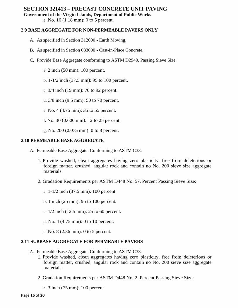
SECTION 321413 – PRECAST CONCRETE UNIT PAVING Government of the Virgin Islands, Department of Public Works
Page 16 of 20
e. No. 16 (1.18 mm): 0 to 5 percent.
2.9 BASE AGGREGATE FOR NON-PERMEABLE PAVERS ONLY
A. As specified in Section 312000 - Earth Moving.
B. As specified in Section 033000 - Cast-in-Place Concrete.
C. Provide Base Aggregate conforming to ASTM D2940. Passing Sieve Size:
a. 2 inch (50 mm): 100 percent.
b. 1-1/2 inch (37.5 mm): 95 to 100 percent.
c. 3/4 inch (19 mm): 70 to 92 percent.
d. 3/8 inch (9.5 mm): 50 to 70 percent.
e. No. 4 (4.75 mm): 35 to 55 percent.
f. No. 30 (0.600 mm): 12 to 25 percent.
g. No. 200 (0.075 mm): 0 to 8 percent.
2.10 PERMEABLE BASE AGGREGATE
A. Permeable Base Aggregate: Conforming to ASTM C33.
1. Provide washed, clean aggregates having zero plasticity, free from deleterious or
foreign matter, crushed, angular rock and contain no No. 200 sieve size aggregate
materials.
2. Gradation Requirements per ASTM D448 No. 57. Percent Passing Sieve Size:
a. 1-1/2 inch (37.5 mm): 100 percent.
b. 1 inch (25 mm): 95 to 100 percent.
c. 1/2 inch (12.5 mm): 25 to 60 percent.
d. No. 4 (4.75 mm): 0 to 10 percent.
e. No. 8 (2.36 mm): 0 to 5 percent.
2.11 SUBBASE AGGREGATE FOR PERMEABLE PAVERS
A. Permeable Base Aggregate: Conforming to ASTM C33.
1. Provide washed, clean aggregates having zero plasticity, free from deleterious or
foreign matter, crushed, angular rock and contain no No. 200 sieve size aggregate
materials.
2. Gradation Requirements per ASTM D448 No. 2. Percent Passing Sieve Size:
a. 3 inch (75 mm): 100 percent.

SECTION 321413 – PRECAST CONCRETE UNIT PAVING Government of the Virgin Islands, Department of Public Works
Page 17 of 20
b. 2-1/2 inch (63 mm): 90 to 100 percent.
c. 2 inch (50 mm): 35 to 70 percent.
d. 1-1/2 inch (37.5 mm): 0 to 15 percent.
e. 3/4 inch (19 mm): 0 to 5 percent.
2.12 GEOTEXTILE
A. Performance Requirements:
1. Grab Tensile Strength (ASTM D4632): 115 pounds.
2. Grab Tensile Elongation (ASTM D4632): 50 percent.
3. Trapezoidal Tear (ASTM D4533): 50 pounds.
4. Puncture (ASTM D4833): 65 pounds.
5. Apparent Opening Size (ASTM D4751): 0.212 mm, 70 U.S. Sieve.
6. Permittivity (ASTM D4491): 2.0 sec -1.
7. Flow Rate (ASTM D4491): 140 gal/min/s.f.
B. Geotextile Material: 4 ounce, non-woven, needle punched geotextile composed of 100 percent
polypropylene staple fibers that are inert to biological degradation and resists naturally
encountered chemicals, alkalis, and acids.
C. Products:
1. Carthage Mills FX-40HS.
2. U.S. Fabrics US 115NW.
3. Mirafi 140N.
4. Approved equal.
2.13 EDGE RESTRAINTS
A. Concrete Edge Restraint: As indicated on Drawings.
B. Plastic Edge Restraints:
1. Pave Tech Pave Edge Rigid.
2. Pave Tech Pave Edge Flexible.
3. Pave Tech Pave Edge Industrial.
4. Snap Edge One Piece Edging, 96 inches.
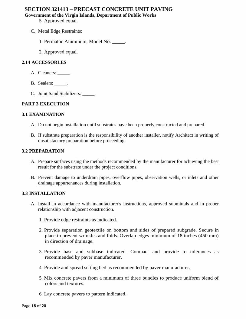
SECTION 321413 – PRECAST CONCRETE UNIT PAVING Government of the Virgin Islands, Department of Public Works
Page 18 of 20
5. Approved equal.
C. Metal Edge Restraints:
1. Permaloc Aluminum, Model No. _____.
2. Approved equal.
2.14 ACCESSORLES
A. Cleaners: _____.
B. Sealers: _____.
C. Joint Sand Stabilizers: _____.
PART 3 EXECUTION
3.1 EXAMINATION
A. Do not begin installation until substrates have been properly constructed and prepared.
B. If substrate preparation is the responsibility of another installer, notify Architect in writing of
unsatisfactory preparation before proceeding.
3.2 PREPARATION
A. Prepare surfaces using the methods recommended by the manufacturer for achieving the best
result for the substrate under the project conditions.
B. Prevent damage to underdrain pipes, overflow pipes, observation wells, or inlets and other
drainage appurtenances during installation.
3.3 INSTALLATION
A. Install in accordance with manufacturer's instructions, approved submittals and in proper
relationship with adjacent construction.
1. Provide edge restraints as indicated.
2. Provide separation geotextile on bottom and sides of prepared subgrade. Secure in
place to prevent wrinkles and folds. Overlap edges minimum of 18 inches (450 mm)
in direction of drainage.
3. Provide base and subbase indicated. Compact and provide to tolerances as
recommended by paver manufacturer.
4. Provide and spread setting bed as recommended by paver manufacturer.
5. Mix concrete pavers from a minimum of three bundles to produce uniform blend of
colors and textures.
6. Lay concrete pavers to pattern indicated.
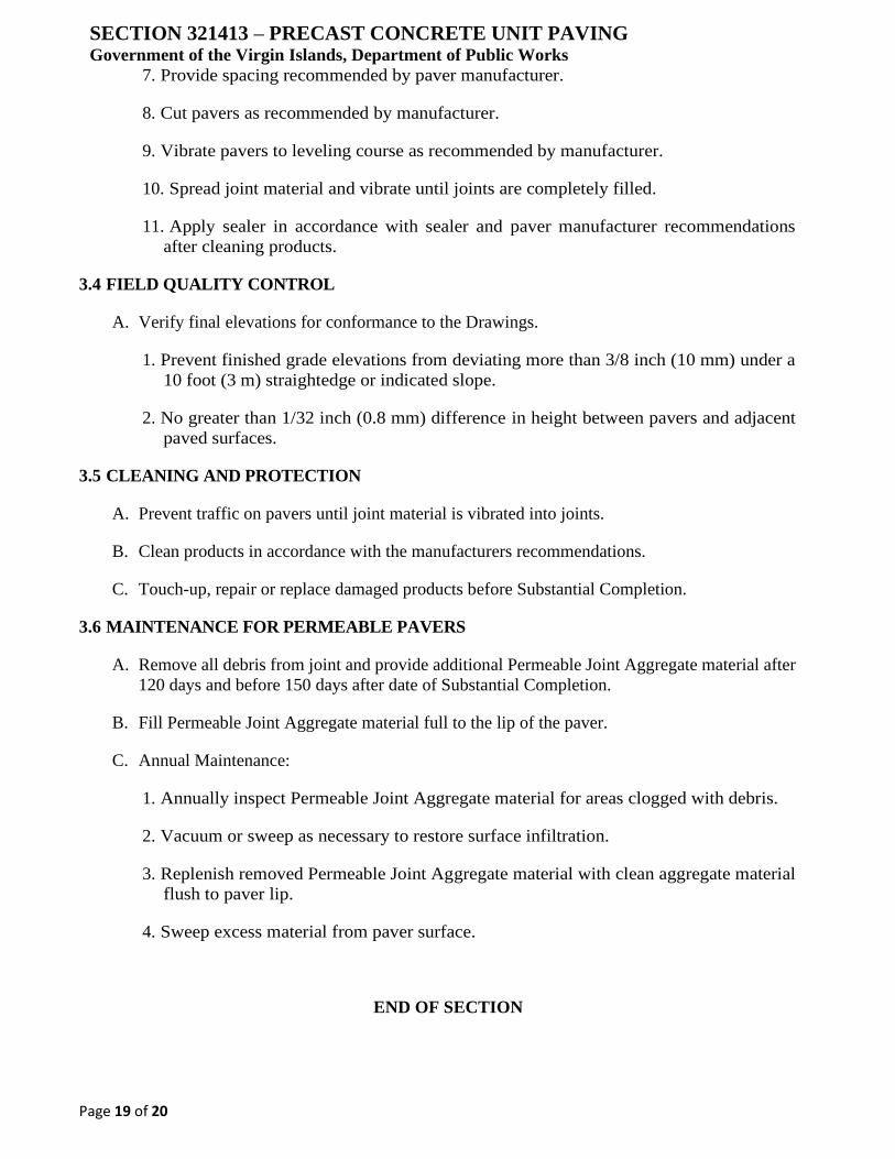
SECTION 321413 – PRECAST CONCRETE UNIT PAVING Government of the Virgin Islands, Department of Public Works
Page 19 of 20
7. Provide spacing recommended by paver manufacturer.
8. Cut pavers as recommended by manufacturer.
9. Vibrate pavers to leveling course as recommended by manufacturer.
10. Spread joint material and vibrate until joints are completely filled.
11. Apply sealer in accordance with sealer and paver manufacturer recommendations
after cleaning products.
3.4 FIELD QUALITY CONTROL
A. Verify final elevations for conformance to the Drawings.
1. Prevent finished grade elevations from deviating more than 3/8 inch (10 mm) under a
10 foot (3 m) straightedge or indicated slope.
2. No greater than 1/32 inch (0.8 mm) difference in height between pavers and adjacent
paved surfaces.
3.5 CLEANING AND PROTECTION
A. Prevent traffic on pavers until joint material is vibrated into joints.
B. Clean products in accordance with the manufacturers recommendations.
C. Touch-up, repair or replace damaged products before Substantial Completion.
3.6 MAINTENANCE FOR PERMEABLE PAVERS
A. Remove all debris from joint and provide additional Permeable Joint Aggregate material after
120 days and before 150 days after date of Substantial Completion.
B. Fill Permeable Joint Aggregate material full to the lip of the paver.
C. Annual Maintenance:
1. Annually inspect Permeable Joint Aggregate material for areas clogged with debris.
2. Vacuum or sweep as necessary to restore surface infiltration.
3. Replenish removed Permeable Joint Aggregate material with clean aggregate material
flush to paver lip.
4. Sweep excess material from paver surface.
END OF SECTION

SECTION 321413 – PRECAST CONCRETE UNIT PAVING Government of the Virgin Islands, Department of Public Works
Page 20 of 20
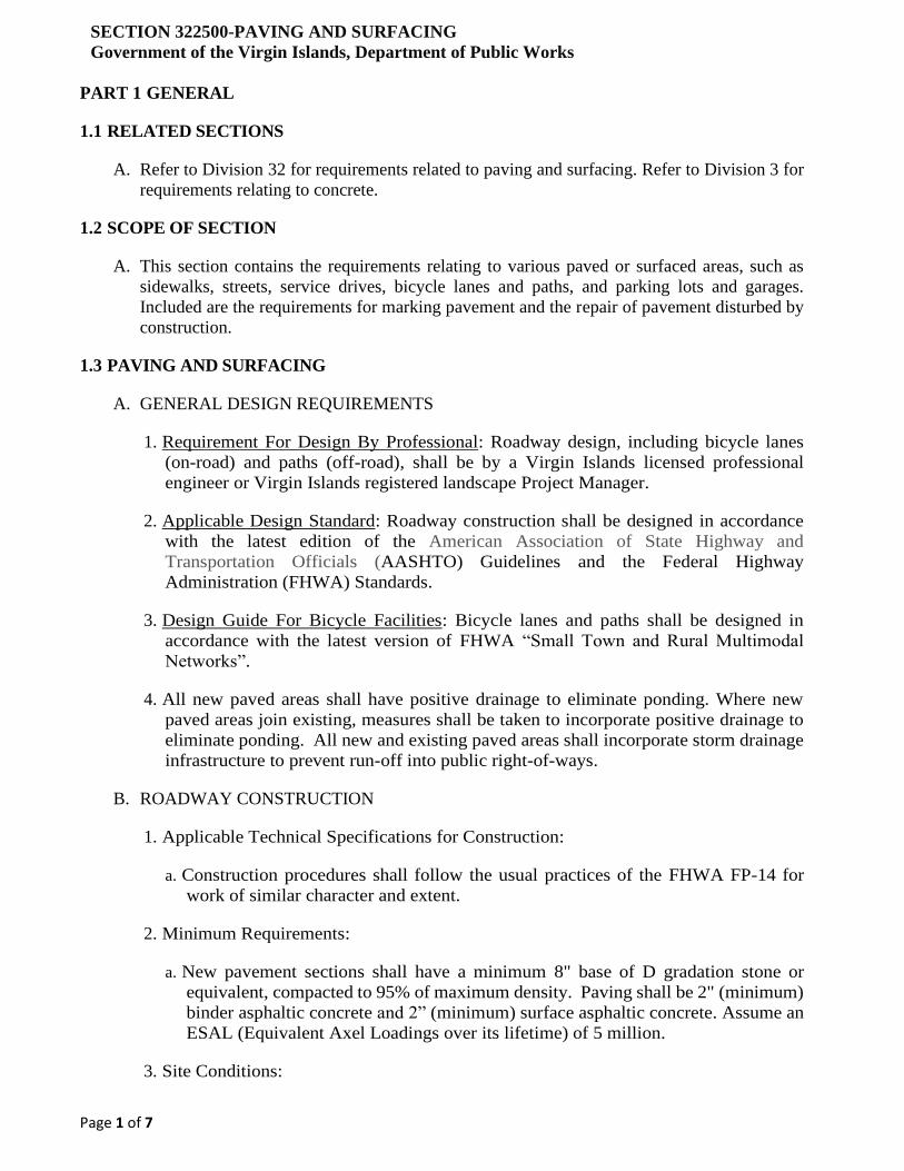
SECTION 322500-PAVING AND SURFACING
Government of the Virgin Islands, Department of Public Works
Page 1 of 7
PART 1 GENERAL
1.1 RELATED SECTIONS
A. Refer to Division 32 for requirements related to paving and surfacing. Refer to Division 3 for
requirements relating to concrete.
1.2 SCOPE OF SECTION
A. This section contains the requirements relating to various paved or surfaced areas, such as
sidewalks, streets, service drives, bicycle lanes and paths, and parking lots and garages.
Included are the requirements for marking pavement and the repair of pavement disturbed by
construction.
1.3 PAVING AND SURFACING
A. GENERAL DESIGN REQUIREMENTS
1. Requirement For Design By Professional: Roadway design, including bicycle lanes
(on-road) and paths (off-road), shall be by a Virgin Islands licensed professional
engineer or Virgin Islands registered landscape Project Manager.
2. Applicable Design Standard: Roadway construction shall be designed in accordance
with the latest edition of the American Association of State Highway and
Transportation Officials (AASHTO) Guidelines and the Federal Highway
Administration (FHWA) Standards.
3. Design Guide For Bicycle Facilities: Bicycle lanes and paths shall be designed in
accordance with the latest version of FHWA “Small Town and Rural Multimodal
Networks”.
4. All new paved areas shall have positive drainage to eliminate ponding. Where new
paved areas join existing, measures shall be taken to incorporate positive drainage to
eliminate ponding. All new and existing paved areas shall incorporate storm drainage
infrastructure to prevent run-off into public right-of-ways.
B. ROADWAY CONSTRUCTION
1. Applicable Technical Specifications for Construction:
a. Construction procedures shall follow the usual practices of the FHWA FP-14 for
work of similar character and extent.
2. Minimum Requirements:
a. New pavement sections shall have a minimum 8" base of D gradation stone or
equivalent, compacted to 95% of maximum density. Paving shall be 2" (minimum)
binder asphaltic concrete and 2” (minimum) surface asphaltic concrete. Assume an
ESAL (Equivalent Axel Loadings over its lifetime) of 5 million.
3. Site Conditions:
SECTION 322500-PAVING AND SURFACING
Government of the Virgin Islands, Department of Public Works
Page 2 of 7
4. Weather Limitations: Apply prime and tack coats. Do not apply when base is wet or
contains an excess of moisture.
5. Construct hot-mixed asphalt base course and surface course when base is dry.
6. Establish and maintain required lines and grade elevations.
7. Materials:
a. Use locally available materials that exhibit a satisfactory record of previous
installations. Shall meet or exceed the requirements of FHWA FP-14 standard
specifications for roadways and structures.
b. Aggregate Base - Crushed stone or gravel conforming to FHWA FP-14
standard specifications for roadways and structures.
c. Coarse Aggregate - Sound, angular crushed stone or crushed gravel complying with
ASTM D 692-88.
d. Fine Aggregate-Sharp edge natural sand or sand prepared from stone, gravel
complying with ASTM D 1073.
e. Mineral Filler- Rock or other inert material complying with ASTM D 242.
f. Asphalt Cement-ASTM D 3381 for viscosity graded materials. ASTM D 946 for
penetration graded material.
g. Tack Coat-Emulsified asphalt ASTM D 977.
h. Lane Marking Type H-Thermoplastic markings with Type 1 glass beads. Engineer
to verify lane marking color requirements.
8. Testing:
a. Testing of in place hot mixed asphalt courses for compliance with the requirements
for thickness and surface smoothness shall be done by the Contractor’s testing
consultant, with results transmitted to the project engineer. Repair or remove and
replace unacceptable paving at the Contractor's expense as directed by the engineer.
C. PARKING LOTS
1. Minimum Requirements:
a. New pavement sections shall have a minimum 4” subbase of D gradation stone or
equivalent, compacted to 95% of maximum density. Paving shall be 2" (minimum)
binder asphaltic concrete, and 2” surface asphaltic concrete.
D. ROAD CLOSURES AND TRAFFIC MAINTENANCE
1. In no case shall a road be closed in its entirety. At least one lane of traffic shall always
be maintained. Special permission for an off-road detour may be granted in some
cases; permission shall be obtained through the Project Manager.
SECTION 322500-PAVING AND SURFACING
Government of the Virgin Islands, Department of Public Works
Page 3 of 7
2. Temporary barricades and flagmen shall be provided in accordance with Manual of
Uniform Traffic Control Devices (MUTCD) standards.
E. BICYCLE LANES AND PATHS
1. Provision Requirement:
a. All new road construction, or major reconstruction of existing roads, shall
accommodate bicycle traffic through the provision of on-road bicycle lanes or off-
road bicycle paths. On-road bicycle lanes are preferred.
2. Connection Requirement:
3. New bicycle lanes and paths shall connect to existing bicycle lanes and paths.
4. Bicycle Lane Construction:
5. On-road bicycle lane construction shall not differ in construction (i.e. type of materials
used, level of compaction, or cross-sectional thickness of materials) from adjacent
vehicle traffic lanes.
6. Bicycle Path Construction:
7. A typical section for off-road bicycle paths would be a 10' wide path consisting of a
minimum 4" thick B graded stone or equivalent base with a minimum 2" thick
asphaltic concrete surface course.
8. Bicycle Parking and Storage Facilities:
a. Refer to Section 322840 for the requirements relating to bicycle facilities for
parking and on-site storage
F. SIDEWALKS
1. General:
a. Separate sidewalks shall be provided with all new road construction or major
reconstruction.
2. Construction Requirements:
a. Concrete sidewalks are to be a minimum of 5” thick, with welded wire mesh
reinforcement or concrete reinforced with fiber.
b. Rebar reinforcements shall be installed at sidewalk intersections.
c. Sidewalk width shall be a minimum of 5.2' and shall match surrounding sidewalk
patterns and widths if greater than 5.2'.
d. Expansion joints shall be a maximum of 18' apart with kerfs at 5' intervals.
e. Zip strips shall be used during pour at expansion joints. After strip is removed a
self-leveling urethane caulk shall be used to fill the void.
SECTION 322500-PAVING AND SURFACING
Government of the Virgin Islands, Department of Public Works
Page 4 of 7
f. Any curb radii poured at entrances shall have ADA compliant handicapped ramp
installed.
1.4 PROTECTION OF THE WORK
A. PROTECTION FROM DAMAGE
The Contractor shall adequately and fully protect all parts of the work against damage until
completed and accepted by the Engineer for maintenance. Damages shall be properly repaired
by the Contractor at no additional expense to the Government.
B. TEMPORARY BARRICADES
Throughout the duration of the Contract, the Contractor shall provide temporary barricades,
conforming to the latest edition of U.S. Department of Transportation's MUTCD, properly
lighted, to keep traffic off the current portion of the work.
C. PROTECTION OF ADJACENT SURFACES
The Contractor shall protect exposed surfaces adjacent to the work from physical damage
resulting from construction activities, and from becoming stained during application of paving
materials. The Contractor shall clean, repair, or replace, as required, surfaces damaged during
the course of the work at no additional expense to the Owner.
D. PROTECTION FROM GRAFFITI
Newly poured concrete roads, streets, curbs, or sidewalks shall be protected AND guarded from
graffiti from passersby until the concrete has sufficiently cured to resist such molestation.
Failure to prevent graffiti, or other such vandalism, shall result in the new concrete having to be
removed and replaced. This requirement shall mandate the Contractor to take the necessary
steps in preventing such incidents including, but not limited, to guarding the project after
normal working hours.
1.5 REPAIR OF PAVEMENT
A. GENERAL
1. All roads, streets, service drives, or sidewalks, whether concrete or asphalt
construction, shall be restored (repaved) within 3 days from the time of backfilling and
compaction.
2. Backfilling of all cuts through pavement shall be properly compacted to 95% of
maximum density in 6" lifts or less.
3. Cuts made through any paved surface shall be repaired in a non-discernible fashion.
4. The cross-sectional thickness of materials used in repairing a section of roadway shall
match or exceed the adjacent roadway.
5. Extensive pavement repairs shall be made in accordance with the minimum
specifications outlined above.
SECTION 322500-PAVING AND SURFACING
Government of the Virgin Islands, Department of Public Works
Page 5 of 7
B. CONCRETE PAVEMENT
Cuts through concrete shall be repaired by replacing the section between the nearest two joints
- either construction or expansion. Protect adjacent areas from damage by new work.
C. ASPHALT PAVEMENT
1. Cuts through asphalt shall be repaired so that depressions or humps do not develop. If
they do, they shall be corrected, at the Contractor's expense. Repairs shall match the
adjacent roadway surfaces.
2. Asphalt and base compaction by "normal traffic” is not permitted. Proper compaction
for the depth of the cut is required.
3. All cuts to existing bituminous concrete paving shall be saw cut where new work
adjoins pavement to remain.
D. REPAIR OF PAVEMENT MARKINGS
When cuts are made through any paved surface and the cuts extend through the pavement
markings, the replaced pavement shall be marked to match the existing.
1.6 PAVEMENT MARKING:
A. GENERAL
1. Applicable Design Standards:
All pavement marking shall be in accordance with the latest edition of the U.S. Department of
Transportation MUTCD.
2. Thermoplastic Striping:
All thermoplastic striping shall be placed on an FHWA FP-14 approved mix that minimizes the
slipperiness of the marking surface.
a. Thermoplastic traffic line paint shall be a reflectorized thermoplastic pavement
striping material applied to the road surface in a molten state by mechanical means.
It shall have surface application of glass beads which, upon cooling to normal
pavement temperature, will produce an adherent reflectorized stripe of the specified
thickness and width.
b. The markings must be capable of conforming to pavement contours, breaks and
faults through the action of traffic at normal pavement temperatures. The markings
shall have resealing characteristics, such that it is capable of fusing with itself and
previously applied thermoplastic when heated with a torch.
c. The material shall contain at least 30 percent of graded glass beads by weight. It
must contain enough titanium dioxide pigment to ensure a color like Federal
Highway White, Color No. 17886, as per Federal Standard 595.
SECTION 322500-PAVING AND SURFACING
Government of the Virgin Islands, Department of Public Works
Page 6 of 7
d. The surface must have a minimum skid resistance value of 55 BPN when tested
according to ASTM E303.
e. The material, when applied at a temperature range of 400 °F to 425 °F and a
thickness of 125 to 188 mils, shall set to bear traffic in not more than 3 minutes
when the air temperature is 60 °F. Minimum thickness shall be 125 mils.
f. The material must be resistant to deterioration due to exposure to sunlight, water, oil,
gasoline, salt or adverse weather conditions.
g. When applied to Portland concrete surfaces, the application notes above still apply,
except that a compatible surface primer/sealer shall be applied prior to the
application of the Thermoplastic material to assure proper adhesion.
3. Pavement Marking Exceptions:
a. Consult with Plans and Project Manager for pavement marking exceptions such as
directional arrows, traffic control markings, etc.
4. Existing Pavement Markings:
a. Prior to the installation of paint or thermoplastic pavement marking lines and
symbols, existing pavement markings shall be removed by a method which does
not materially damage the existing pavement surfaces.
b. Materials deposited on the pavement and adjacent surfaces as a result of the removal
of pavement markings shall be removed as the work progresses.
c. When a blast removal method is used, care must be taken to protect adjacent surfaces
and structures from flying debris.
d. Painting over, or black out painting, of existing pavement markings with black paint
or bituminous solutions shall not be allowed.
B. ROADS
1. Thermoplastic striping shall be used for traffic markings on all roads, drives, and
service drives. Material and application shall be in accordance with the latest versions
of the FHWA FP-14 "Standard Specifications for Roads and Bridges Construction
Projects".
2. To accommodate the concrete surfaces of the parking layout, pavement markings for
curbs and tire stops shall be made with latex paint.
C. PARKING GARAGES
Thermoplastic striping shall be used for traffic markings and for designating parking spaces in
all parking garages. Material and application shall be in accordance with the latest versions of
the FHWA "Standard Specifications for Roads and Bridges Construction Projects".
SECTION 322500-PAVING AND SURFACING
Government of the Virgin Islands, Department of Public Works
Page 7 of 7
D. SURFACE PARKING LOTS
Pavement markings in surface parking lots shall be made with thermoplastic.
E. BIKE PATHS AND LANES
1. Design Guide:
Pavement marking for bicycle lanes and paths shall be designed in accordance with latest
version of the FHWA “Small Town and Rural Multimodal Networks”, with additional input
from the Project Manager.
2. Curb Inlets, Storm Drains, and Other Potential Hazards:
Where hazards to bicyclists cannot be eliminated, pavement marking is required to make the
hazard more visible.
END OF SECTION
SECTION 322510-BITUMINOUS PAVEMENT
Government of the Virgin Islands, Department of Public Works
Page 1 of 3
PART 1 GENERAL
1.1 SECTION INCLUDES
A. Placing and compacting base courses
B. Temporary pavement patching
C. Permanent roadway paving and patching
1.2 REFERENCED SECTIONS
A. Section 312110 - Clearing and Grubbing
B. Section 312200 - Earthwork
1.3 REFERENCES
A. FHWA FP-14 Standard Specifications for Construction of Roads and Bridges Projects, 2014 Edition.
1.4 SUBMITTALS
A. Submit test reports of proposed aggregate sources prior to incorporating such materials into the
Project.
B. Submit Certificates of Compliance for all pavement mixtures furnished under this Section.
1.5 QUALITY ASSURANCE
A. The CONTRACTOR shall perform tests to qualify each source of materials and at sufficient
intervals to assure conformance of all materials furnished for use under this Section.
B. The "Materials and Research Engineer" or the "Engineer" shall refer to the CONTRACTOR's person
responsible for Quality Control of hot mix pavements.
C. Verification testing of material may be performed by an independent testing laboratory paid for by
the OWNER.
PART 2 PRODUCTS
2.1 MATERIALS
A. Base Courses:
1. 4” asphaltic concrete Type II Binder Section 322505
B. Bituminous Pavement:
1. 2" asphaltic concrete Type I Surface, with anti-strip additive designed for 5,000,000 ESAL.
2.2 SOURCE QUALITY CONTROL
A. Test each proposed source of aggregates for gradation and moisture-density relationship.
SECTION 322510-BITUMINOUS PAVEMENT
Government of the Virgin Islands, Department of Public Works
Page 2 of 3
B. Verification testing of materials at the asphalt plant may be performed by the OWNER to ensure
conformance with the requirements for materials furnished under this Section.
PART 3 EXECUTION
3.1 PREPARATION
A. Prepare site in accordance with Section 312110.
B. Backfill excavations in accordance with Section 332200.
C. The subgrade shall be prepared in accordance with Section 312200.
D. RECLAMATION OF PAVEMENT:
Where bituminous pavement is to be reclaimed, process the material and stockpile for reuse.
E. Exercise care in the removal of pavement so that no pavement is unnecessarily disturbed or
destroyed.
F. Mechanically cut pavement shall be removed to a straight line unless otherwise directed by the
ENGINEER.
G. Diamond saws shall be used for sawing bituminous concrete pavement. Cutting-type grader blades
will not be allowed.
3.2 PROTECTION
A. Curbs, walks, and walls are to be adequately protected and left in a clean condition.
3.3 BASE COURSES
A. Install subbase and base courses in accordance with Construction drawings.
B. The finished base course surface shall not vary more than 1/4 inch from a 10-foot straightedge
applied parallel or perpendicular to the centerline.
3.4 TEMPORARY PATCHING
A. Temporary pavement repairs shall be made before subjecting excavations to traffic and shall be
maintained until permanent pavement repairs are made.
B. Subbase and base courses and materials shall conform to the requirements for permanent pavement
repairs.
C. Temporary pavement shall consist of a single 2-inch binder course unless otherwise shown on the
Plans.
3.5 PERMANENT PATCHING
A. Cut back existing pavement from the edge of excavations to form a sharp, clean, straight edge on
undisturbed material.
SECTION 322510-BITUMINOUS PAVEMENT
Government of the Virgin Islands, Department of Public Works
Page 3 of 3
B. Apply tack coat to saw cut edges and other surfaces where bond to new pavement is required.
C. Install permanent pavement as specified below.
D. Any additional paving required by trenches wider than the limits specified in the Plan will be
performed at no additional cost to the OWNER.
3.6 PERMANENT PAVEMENT
A. Install permanent pavement in accordance with construction drawings.
B. Adjust manhole covers, catch basin grates, valve and meter boxes and the like to not less than 1/8
inch and not more than 1/2 inch below final pavement grade.
C. Apply tack coat to saw cut edges and other surfaces where bond to new pavement is required.
D. Full width permanent pavement shall consist of the lift thicknesses and types shown on the Plans.
E. Shim low, uneven, or settled areas with leveling mix before application of wearing course.
3.7 REPAIR OF SETTLED SURFACES
A. Should an area settle that the CONTRACTOR has permanently paved:
1. Saw cut and remove the affected pavement.
2. Remove base materials if necessary to ensure proper compaction of subgrade, subbase, and
base.
3. Repair as specified for permanent patching.
3.8 FIELD QUALITY CONTROL
A. Verification testing of installed materials may be performed to ensure conformance with the
requirements for materials, compaction, and surface tolerance of this Section.
END OF SECTION
SECTION 323100 – DECORATIVE METAL FENCES AND GATES
Government of the Virgin Islands, Department of Public Works
Page 1 of 16
PART 1 GENERAL
1.1 SECTION INCLUDES
A. Ornamental welded steel fence system. (Classic Commercial)
B. Ornamental rackable welded steel fence system. (Versai Commercial)
C. Ornamental rackable welded steel fence system. (Versai Assurance Commercial)
D. Ornamental rackable mechanically locked fence system. (Titan Industrial)
1.2 RELATED SECTIONS
A. Section 033000 - Cast-in-Place Concrete.
B. Section 311000 - Site Clearing.
1.3 REFERENCES
A. American Society for Testing and Materials International (ASTM).
1. ASTM D523 - Standard Test Method for Specular Gloss.
2. ASTM D1654 - Standard Test Method for Evaluation of Painted or Coated Specimens
Subjected to Corrosive Environments.
3. ASTM D2244 - Standard Practice for Calculation of Color Tolerances and Color Differences
from Instrumentally Measured Color Coordinates.
4. ASTM D2794 - Standard Test Method for Resistance of Organic Coatings to the Effects of
Rapid Deformation (Impact).
5. ASTM D3359 - Standard Test Methods for Measuring Adhesion by Tape Test.
6. ASTM F593 - Standard Specification for Stainless Steel Bolts, Hex Cap Screws, and Studs.
B. American Welding Society (AWS): AWS D1.1 - Structural Welding Code - Steel
1.4 SUBMITTALS
A. Submit under provisions of Section 01 30 00 - Administrative Requirements.
B. Manufacturer's printed product information indicating material compliance and specified options are
to be submitted prior to installation. Submit manufacturer's product data sheets on each product to
be used.
C. Shop drawings shall include plans, elevations, sections, details, and attachments to other work.
Drawings must be submitted for approval and be approved prior to installation.
D. Design data which verifies compliance with design loads specified in Performance Requirements
Article. Design data shall be signed and sealed by the qualified professional engineer responsible for
their preparation.
SECTION 323100 – DECORATIVE METAL FENCES AND GATES
Government of the Virgin Islands, Department of Public Works
Page 2 of 16
E. Submit samples for initial color selection. Submit samples of each specified finish.
1.5 QUALITY ASSURANCE
A. Manufacturing company with engineering and fabrication of custom fencing and gate systems for a
minimum of 15 years.
B. Installation company with experienced in manufacturer's products for a minimum of 5 years. The
Contractor shall provide trained laborers with prior experience in the type of construction involved
as well as experience installing the materials and techniques specified.
C. Obtain each fence system and gates through one source from a single manufacturer.
1.6 DELIVERY, STORAGE, AND HANDLING
A. Upon delivery to the jobsite, inspect all materials for damage that might have occurred during
shipment.
B. Handle and store materials in manufacturer's packaging until materials are ready to be installed.
Store materials in such a way as to prevent damage and theft.
1.7 PROJECT CONDITIONS
A. Verify actual locations of walls and other construction contiguous with fencing and gates by field
measurements before fabrication and indicate measurements on shop drawings. Provide allowance
for trimming and fitting onsite.
1.8 COORDINATION AND SCHEDULING
A. Coordinate installation of anchorages for fencing and gates. Furnish setting drawings, templates, and
directions for installing anchorages, including sleeves, concrete inserts, anchor bolts, and items with
integral anchors that are to be embedded in concrete or masonry. Deliver such items to the Project
Site in time for installation.
B. Schedule installation so wall attachments are made only to completed walls. Do not support systems
temporarily by any means that do not satisfy structural performance requirements.
1.9 WARRANTY
A. Manufacturer's Warranty: Provide manufacturer's standard 20 year limited warranty, from the date
of purchase, against defects in materials and workmanship including protection against cracking,
peeling, blistering, and corrosion (rusting).
PART 2 PRODUCTS
2.1 MANUFACTURERS
A. Acceptable Manufacturer: Fortress Fence Products, which is located at: 1720 North First Street;
Garland, TX 75040; Toll Free Tel: 844-909-1999; Fax: 972-372-0078; Email:request info
([email protected]); Web:http://www.fortressfence.com
B. Substitutions: Requests for substitutions will be considered in accordance with provisions of Section
01 60 00 - Product Requirements.
SECTION 323100 – DECORATIVE METAL FENCES AND GATES
Government of the Virgin Islands, Department of Public Works
Page 3 of 16
2.2 SITE FENCING AND GATES
A. Ornamental Welded Steel Fence Systems:
1. Basis of Design: Classic Commercial Fence Systems as manufactured by Fortress Fence
Products, a division of The Fortress Company.
2. Style: As indicated on the Drawings.
3. Style: Extended Picket (EXT).
4. Style: Spear Point Picket (SP).
5. Fence Panels: Fabricated in standard length of 90-1/2 inches (2299 mm).
a. Height: 46 inch (1168 mm).
6. Materials:
a. Rails and pickets shall be cold-rolled steel formed and welded tubing with a Grade A
minimum tensile strength of 45,000 psi (310 MPa) conforming to ASTM A653 and have
a G60 zinc coating, 0.60 oz./ft2 (0.18 kg/m2) in accordance with ASTM A653.
b. Posts shall be cold-rolled steel formed and welded tubing with a Grade A minimum tensile
strength of 45,000 psi (310 MPa) conforming to ASTM A653, have a G60 zinc coating,
0.60 oz./ft2 (0.18 kg/m2) in accordance With ASTM A653, and have a powder-coated
factory finish.
7. Components:
a. Rails: 1-1/2 inch (38 mm) square, 16 gauge.
b. Pickets: 3/4 inch (19 mm) square, 19 gauge.
c. Posts: 2-1/2 inch (63.5 mm) square, 16 gauge.
8. Gates: Provide manufacturer's standard gates and hardware.
9. Fabrication:
a. Fence Panels: Fabricated in standard length of 90-1/2 inches (2299 mm). Comply with
requirements indicated for materials, thickness, design and details of construction.
b. Welded connections shall comply with AWS standards for recommended practice in shop
welding.
c. Components shall be accurately cut and drilled to receive hardware, fasteners, and
accessories.
d. Fence panel shall be capable of meeting structural test load capabilities for a commercial
fence system referenced in table 2 of ASTM 2409.

SECTION 323100 – DECORATIVE METAL FENCES AND GATES
Government of the Virgin Islands, Department of Public Works
Page 4 of 16
e. Fence panel shall be capable of meeting coating performance requirements in table 3 of
ASTM 2409.
7. Finish:
a. Materials are coated with the Fortress Guard process including galvanization, zinc
phosphate, and architectural grade powder coat.
b. Metal parts shall be assembled and finished individually prior to shipment.
c. Galvanized steel fence components shall be cleaned with a non-petroleum solvent
followed by the application of a sealing zinc phosphate coating.
d. Immediately after sealing, a powder finish coating is applied by the electrostatic spray
process. This consists of a thermosetting carboxyl polyester resin top
Minimum Post Sizes for V2 Versai Commercial
Line of Fence Posts Panel Heights
2.5" x 16ga Up to & Including 6' height
2.5" x 14ga 7' & 8'
Versai Commercial Post Spacing by Bracket Type
Style Flat Top, Spear Top, Extended Picket and Curved Top 8' Nominal (90.5" Rail)
Bracket Types One Direction Flat Mount (EX-106), for 2-1/2" post size
One Direction Flat Mount (EX-106), for 3" post size, 95.5" post setting
Two Direction Line (EX-206), for 2-1/2" post size, 95" post setting
Three Direction Universal (EX-306), for 2-1/2" post size, 95" post setting
Swivel Flat Mount (EXS-106), for 2-1/2" post size, 95" post setting
Swivel Flat Mount (EXS-106), for 3" post size, 95.5" post setting
Versai Commercial Gate Posts Sizes
Gate Leaf Gate Height
Up to & Including 4' Over 4' Up to & Including
6'
7' & 8'
Up to 4' 2.5" x 14ga 3" x 12ga 3" x 12ga
4'1" to 6' 3" x 12ga 3" x 12ga 4" x 11ga
6'1" to 8' 3" x 12ga 4" x 11ga 4" x 11ga
B. Ornamental Rackable Welded Steel Fence Systems:
SECTION 323100 – DECORATIVE METAL FENCES AND GATES
Government of the Virgin Islands, Department of Public Works
Page 5 of 16
1. Basis of Design: Versai Commercial Fence Systems as manufactured by Fortress Fence
Products, a division of The Fortress Company.
a. Style: As indicated on the Drawings.
b. Style: Flat Top, Extended Bottom (FT).
c. Style: Flat Top, Flat Bottom (FT/FB).
d. Style: Flat Top, Flat Bottom (PL) for Swimming Pool installations
e. Style: Extended Top, Extended Bottom (EXT).
f. Style: Extended Top, Flat Bottom (EXT/FB).
g. Style: Spear Point Top, Extended Bottom (SP).
h. Style: Spear Point Top, Flat Bottom (SP/FB).
i. Style: Curve Top, Extended Bottom (CT).
j. Style: Curve Top, Flat Bottom (CT/FB).
k. Rails: 2.
l. Rails: 3.
m. Fence Panels: Fabricated in standard length of 90-1/2 inches (2299 mm).
i. Height: As indicated on the Drawings.
ii. Height: 34 inch (864 mm).
iii. Height: 40 inch (1016 mm).
iv. Height: 46 inch (1168 mm).
v. Height: 54 inch (1372 mm).
vi. Height: 58 inch (1473 mm).
vii. Height: 70 inch (1778 mm).
viii. Height: 82 inch (2083 mm).
ix. Height: 94 inch (2388 mm).
n. Airspace Between Pickets, V2 Commercial: 3-15/16 inch.
o. Materials:
SECTION 323100 – DECORATIVE METAL FENCES AND GATES
Government of the Virgin Islands, Department of Public Works
Page 6 of 16
i. Rails shall be cold-rolled steel formed U-channel and pickets shall be cold-rolled steel formed
and welded tubing, both having a Grade A minimum tensile strength of 45,000 psi (310 MPa)
conforming to ASTM A653 and have a G60 zinc coating, 0.60 oz./ft2 (0.18 kg/m2) in
accordance with ASTM A653.
ii. Posts shall be cold-rolled steel formed and welded tubing with a Grade A minimum tensile
strength of 45,000 psi (310 MPa) conforming to ASTM A653, have a G60 zinc coating, 0.60
oz./ft2 (0.18 kg/m2) in accordance with ASTM A653, and have a powder-coated factory
finish.
p. Components:
i. Rails: 1-9/16 inch (40 mm) by 1-3/16 inch (30 mm) (Leg x Web), 14 gauge.
ii. Pickets:
1) 3/4 inch (19 mm) square, 16 gauge.
2) 3/4 inch (19 mm) square, 14 gauge.
a. Posts: 2-1/2 inch (64 mm) square, 16 gauge.
b. Posts: 2-1/2 inch (64 mm) square, 14 gauge.
c. Posts: 2-1/2 inch (64 mm) square, 12 gauge.
d. Posts: 3 inch (76 mm) square, 14 gauge.
e. Posts: 3 inch (76 mm) square, 12 gauge.
f. Gates: Provide manufacturer's standard gates and hardware.
g. Fabrication:
i. Fence panels shall be fabricated in standard length of 90-1/2 inches (2299 mm). Comply with
requirements indicated for materials, thickness, design, and details of construction.
ii. Pickets are welded to the rails with a patented pin hinge system which allows the panel to rake
without metal fatigue or damage to the finish.
iii. Welded connections shall comply with AWS standards for recommended practice in shop
welding.
iv. Components shall be accurately cut and drilled to receive hardware, fasteners, and
accessories.
h. Panels shall be rackable to an 18 degree change in grade (30 inch vertical travel per panel).
i. Fence panel shall be capable of meeting structural test load capabilities for a commercial
fence system referenced in table 2 of ASTM 2409.
j. Fence panel shall be capable of meeting coating performance requirements in table 3 of
ASTM 2409.
SECTION 323100 – DECORATIVE METAL FENCES AND GATES
Government of the Virgin Islands, Department of Public Works
Page 7 of 16
2. Basis of Design: Versai Assurance Commercial Fence Systems as manufactured by Fortress
Fence Products, a division of The Fortress Company.
a. Style: As indicated on the Drawings.
b. Style: Flat Top, Extended Bottom (FT).
c. Style: Flat Top, Flat Bottom (FT/FB).
d. Style: Flat Top, Flat Bottom (PL) for Swimming Pool installations
q. Style: Extended Top, Extended Bottom (EXT).
r. Style: Extended Top, Flat Bottom (EXT/FB).
s. Style: Spear Point Top, Extended Bottom (SP).
t. Style: Spear Point Top, Flat Bottom (SP/FB).
u. Style: Curve Top, Extended Bottom (CT).
v. Style: Curve Top, Flat Bottom (CT/FB).
w. Rails: 2.
x. Rails: 3.
y. Fence Panels: Fabricated in standard length of 90-1/2 inches (2299 mm).
i. Height: As indicated on the Drawings.
ii. Height: 34 inch (864 mm).
iii. Height: 40 inch (1016 mm).
iv. Height: 46 inch (1168 mm).
v. Height: 54 inch (1372 mm).
vi. Height: 58 inch (1473 mm).
vii. Height: 70 inch (1778 mm).
viii. Height: 82 inch (2083 mm).
ix. Height: 94 inch (2388 mm).
z. Airspace Between Pickets, V2 Assurance Commercial: 3 inch.
aa. Materials:
SECTION 323100 – DECORATIVE METAL FENCES AND GATES
Government of the Virgin Islands, Department of Public Works
Page 8 of 16
i. Rails shall be cold-rolled steel formed U-channel and pickets shall be cold-rolled steel formed
and welded tubing, both having a Grade A minimum tensile strength of 45,000 psi (310 MPa)
conforming to ASTM A653 and have a G90 zinc coating, 0.90 oz./ft2 (0.18 kg/m2) in
accordance with ASTM A653.
ii. Posts shall be cold-rolled steel formed and welded tubing with a Grade A minimum tensile
strength of 45,000 psi (310 MPa) conforming to ASTM A653, have a G90 zinc coating, 0.90
oz./ft2 (0.18 kg/m2) in accordance with ASTM A653, and have a powder-coated factory
finish.
bb. Components:
i. Rails: 1-9/16 inch (40 mm) by 1-3/16 inch (30 mm) (Leg x Web), 14 gauge.
ii. Pickets:
1) 3/4 inch (19 mm) square, 16 gauge.
2) 3/4 inch (19 mm) square, 14 gauge.
cc. Posts: 2-1/2 inch (64 mm) square, 16 gauge.
dd. Posts: 2-1/2 inch (64 mm) square, 14 gauge.
ee. Posts: 2-1/2 inch (64 mm) square, 12 gauge.
ff. Posts: 3 inch (76 mm) square, 14 gauge.
gg. Posts: 3 inch (76 mm) square, 12 gauge.
hh. Gates: Provide manufacturer's standard gates and hardware.
ii. Fabrication:
i. Fence panels shall be fabricated in standard length of 90-1/2 inches (2299 mm). Comply with
requirements indicated for materials, thickness, design, and details of construction.
ii. Pickets are welded to the rails with a patented pin hinge system which allows the panel to rake
without metal fatigue or damage to the finish.
iii. Welded connections shall comply with AWS standards for recommended practice in shop
welding.
iv. Components shall be accurately cut and drilled to receive hardware, fasteners, and
accessories.
v. Panels shall be rackable to an 18 degree change in grade (30 inch vertical travel per panel).
vi. Fence panel shall be capable of meeting structural test load capabilities for a commercial
fence system referenced in table 2 of ASTM 2409.
vii. Fence panel shall be capable of meeting coating performance requirements in table 3 of
ASTM 2409.
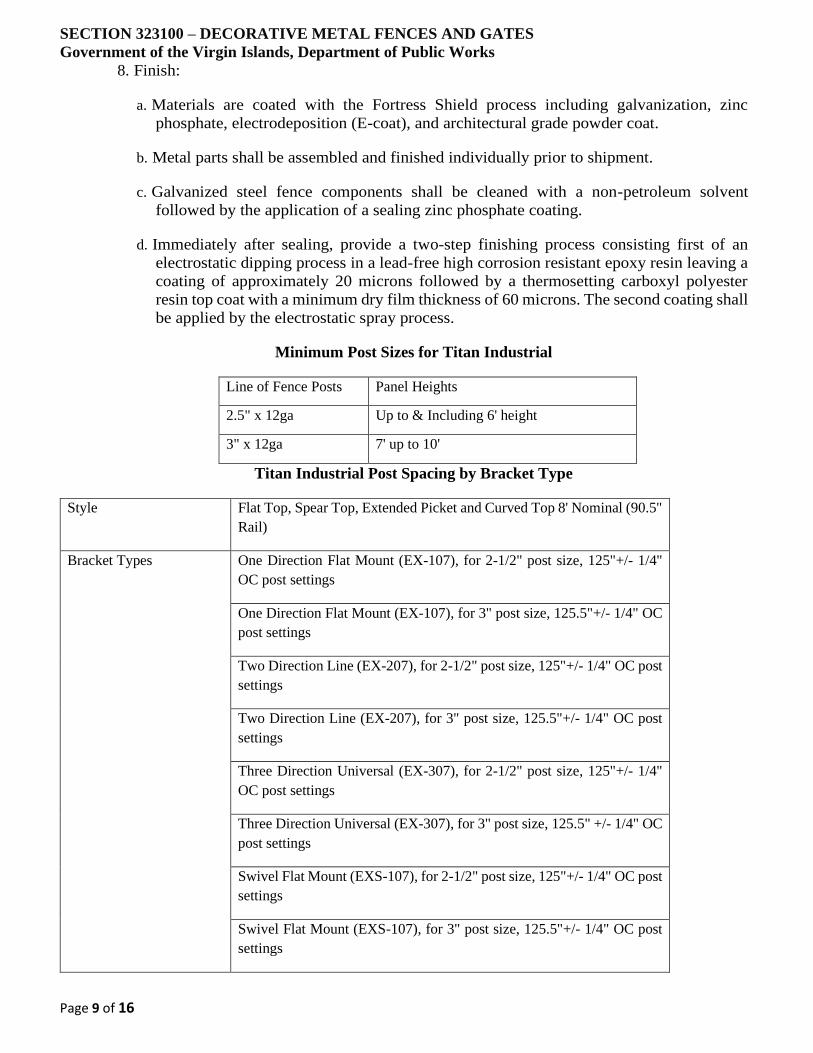
SECTION 323100 – DECORATIVE METAL FENCES AND GATES
Government of the Virgin Islands, Department of Public Works
Page 9 of 16
8. Finish:
a. Materials are coated with the Fortress Shield process including galvanization, zinc
phosphate, electrodeposition (E-coat), and architectural grade powder coat.
b. Metal parts shall be assembled and finished individually prior to shipment.
c. Galvanized steel fence components shall be cleaned with a non-petroleum solvent
followed by the application of a sealing zinc phosphate coating.
d. Immediately after sealing, provide a two-step finishing process consisting first of an
electrostatic dipping process in a lead-free high corrosion resistant epoxy resin leaving a
coating of approximately 20 microns followed by a thermosetting carboxyl polyester
resin top coat with a minimum dry film thickness of 60 microns. The second coating shall
be applied by the electrostatic spray process.
Minimum Post Sizes for Titan Industrial
Line of Fence Posts Panel Heights
2.5" x 12ga Up to & Including 6' height
3" x 12ga 7' up to 10'
Titan Industrial Post Spacing by Bracket Type
Style Flat Top, Spear Top, Extended Picket and Curved Top 8' Nominal (90.5"
Rail)
Bracket Types One Direction Flat Mount (EX-107), for 2-1/2" post size, 125"+/- 1/4"
OC post settings
One Direction Flat Mount (EX-107), for 3" post size, 125.5"+/- 1/4" OC
post settings
Two Direction Line (EX-207), for 2-1/2" post size, 125"+/- 1/4" OC post
settings
Two Direction Line (EX-207), for 3" post size, 125.5"+/- 1/4" OC post
settings
Three Direction Universal (EX-307), for 2-1/2" post size, 125"+/- 1/4"
OC post settings
Three Direction Universal (EX-307), for 3" post size, 125.5" +/- 1/4" OC
post settings
Swivel Flat Mount (EXS-107), for 2-1/2" post size, 125"+/- 1/4" OC post
settings
Swivel Flat Mount (EXS-107), for 3" post size, 125.5"+/- 1/4" OC post
settings

SECTION 323100 – DECORATIVE METAL FENCES AND GATES
Government of the Virgin Islands, Department of Public Works
Page 10 of 16
Titan Industrial Gate Posts Sizes
Gate Leaf Gate Height
Up to & Including 6' Over 6' Up to &
Including 8'
Over 8' up to and
Including 10'
Up to 4' 3" x 12ga 3" x 12ga 4" x 11ga
4'1" to 6' 3" x 12ga 3" x 12ga 4" x 11ga
6'1" to 8' 4" x 11ga 6" x 3/16" wall 6" x 3/16" wall
A. Ornamental Rackable Mechanically Locked Steel Fence Systems:
1. Basis of Design: Titan Industrial Fence Systems as manufactured by Fortress Fence
Products, a division of The Fortress Company.
a. Style: As indicated on the Drawings.
b. Style: Flat Top, Extended Bottom (FT).
c. Style: Extended Top, Extended Bottom (EXT).
d. Style: Spear Point Top, Extended Bottom (SP).
e. Style: Curve Top, Extended Bottom (CT).
f. Rails: 2.
g. Rails: 3.
h. Fence Panels: Fabricated in standard length of 92 inches (2337 mm).
i. Height: As indicated on the Drawings.
ii. Height: 34 inch (864 mm).
iii. Height: 46 inch (1168 mm).
iv. Height: 58 inch (1473 mm).
v. Height: 70 inch (1778 mm).
vi. Height: 82 inch (2083 mm).
vii. Height: 94 inch (2388 mm).
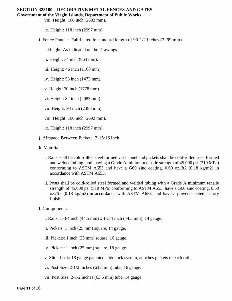
SECTION 323100 – DECORATIVE METAL FENCES AND GATES
Government of the Virgin Islands, Department of Public Works
Page 11 of 16
viii. Height: 106 inch (2692 mm).
ix. Height: 118 inch (2997 mm).
i. Fence Panels: Fabricated in standard length of 90-1/2 inches (2299 mm).
i. Height: As indicated on the Drawings.
ii. Height: 34 inch (864 mm).
iii. Height: 46 inch (1168 mm).
iv. Height: 58 inch (1473 mm).
v. Height: 70 inch (1778 mm).
vi. Height: 82 inch (2083 mm).
vii. Height: 94 inch (2388 mm).
viii. Height: 106 inch (2692 mm).
ix. Height: 118 inch (2997 mm).
j. Airspace Between Pickets: 3-15/16 inch.
k. Materials:
i. Rails shall be cold-rolled steel formed U-channel and pickets shall be cold-rolled steel formed
and welded tubing, both having a Grade A minimum tensile strength of 45,000 psi (310 MPa)
conforming to ASTM A653 and have a G60 zinc coating, 0.60 oz./ft2 (0.18 kg/m2) in
accordance with ASTM A653.
ii. Posts shall be cold-rolled steel formed and welded tubing with a Grade A minimum tensile
strength of 45,000 psi (310 MPa) conforming to ASTM A653, have a G60 zinc coating, 0.60
oz./ft2 (0.18 kg/m2) in accordance with ASTM A653, and have a powder-coated factory
finish.
l. Components:
i. Rails: 1-3/4 inch (44.5 mm) x 1-3/4 inch (44.5 mm), 14 gauge.
ii. Pickets: 1 inch (25 mm) square, 14 gauge.
iii. Pickets: 1 inch (25 mm) square, 16 gauge.
iv. Pickets: 1 inch (25 mm) square, 18 gauge.
v. Slide Lock: 18 gauge patented slide lock system, attaches pickets to each rail.
vi. Post Size: 2-1/2 inches (63.5 mm) tube, 16 gauge.
vii. Post Size: 2-1/2 inches (63.5 mm) tube, 14 gauge.
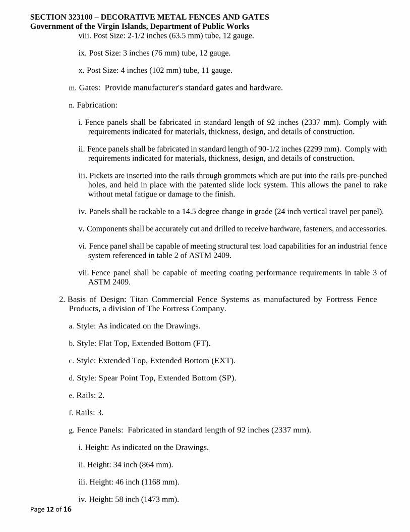
SECTION 323100 – DECORATIVE METAL FENCES AND GATES
Government of the Virgin Islands, Department of Public Works
Page 12 of 16
viii. Post Size: 2-1/2 inches (63.5 mm) tube, 12 gauge.
ix. Post Size: 3 inches (76 mm) tube, 12 gauge.
x. Post Size: 4 inches (102 mm) tube, 11 gauge.
m. Gates: Provide manufacturer's standard gates and hardware.
n. Fabrication:
i. Fence panels shall be fabricated in standard length of 92 inches (2337 mm). Comply with
requirements indicated for materials, thickness, design, and details of construction.
ii. Fence panels shall be fabricated in standard length of 90-1/2 inches (2299 mm). Comply with
requirements indicated for materials, thickness, design, and details of construction.
iii. Pickets are inserted into the rails through grommets which are put into the rails pre-punched
holes, and held in place with the patented slide lock system. This allows the panel to rake
without metal fatigue or damage to the finish.
iv. Panels shall be rackable to a 14.5 degree change in grade (24 inch vertical travel per panel).
v. Components shall be accurately cut and drilled to receive hardware, fasteners, and accessories.
vi. Fence panel shall be capable of meeting structural test load capabilities for an industrial fence
system referenced in table 2 of ASTM 2409.
vii. Fence panel shall be capable of meeting coating performance requirements in table 3 of
ASTM 2409.
2. Basis of Design: Titan Commercial Fence Systems as manufactured by Fortress Fence
Products, a division of The Fortress Company.
a. Style: As indicated on the Drawings.
b. Style: Flat Top, Extended Bottom (FT).
c. Style: Extended Top, Extended Bottom (EXT).
d. Style: Spear Point Top, Extended Bottom (SP).
e. Rails: 2.
f. Rails: 3.
g. Fence Panels: Fabricated in standard length of 92 inches (2337 mm).
i. Height: As indicated on the Drawings.
ii. Height: 34 inch (864 mm).
iii. Height: 46 inch (1168 mm).
iv. Height: 58 inch (1473 mm).
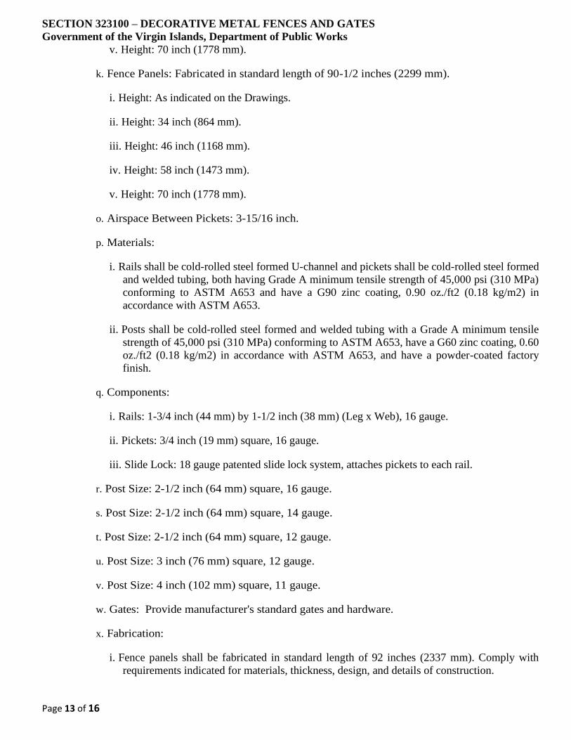
SECTION 323100 – DECORATIVE METAL FENCES AND GATES
Government of the Virgin Islands, Department of Public Works
Page 13 of 16
v. Height: 70 inch (1778 mm).
k. Fence Panels: Fabricated in standard length of 90-1/2 inches (2299 mm).
i. Height: As indicated on the Drawings.
ii. Height: 34 inch (864 mm).
iii. Height: 46 inch (1168 mm).
iv. Height: 58 inch (1473 mm).
v. Height: 70 inch (1778 mm).
o. Airspace Between Pickets: 3-15/16 inch.
p. Materials:
i. Rails shall be cold-rolled steel formed U-channel and pickets shall be cold-rolled steel formed
and welded tubing, both having Grade A minimum tensile strength of 45,000 psi (310 MPa)
conforming to ASTM A653 and have a G90 zinc coating, 0.90 oz./ft2 (0.18 kg/m2) in
accordance with ASTM A653.
ii. Posts shall be cold-rolled steel formed and welded tubing with a Grade A minimum tensile
strength of 45,000 psi (310 MPa) conforming to ASTM A653, have a G60 zinc coating, 0.60
oz./ft2 (0.18 kg/m2) in accordance with ASTM A653, and have a powder-coated factory
finish.
q. Components:
i. Rails: 1-3/4 inch (44 mm) by 1-1/2 inch (38 mm) (Leg x Web), 16 gauge.
ii. Pickets: 3/4 inch (19 mm) square, 16 gauge.
iii. Slide Lock: 18 gauge patented slide lock system, attaches pickets to each rail.
r. Post Size: 2-1/2 inch (64 mm) square, 16 gauge.
s. Post Size: 2-1/2 inch (64 mm) square, 14 gauge.
t. Post Size: 2-1/2 inch (64 mm) square, 12 gauge.
u. Post Size: 3 inch (76 mm) square, 12 gauge.
v. Post Size: 4 inch (102 mm) square, 11 gauge.
w. Gates: Provide manufacturer's standard gates and hardware.
x. Fabrication:
i. Fence panels shall be fabricated in standard length of 92 inches (2337 mm). Comply with
requirements indicated for materials, thickness, design, and details of construction.
SECTION 323100 – DECORATIVE METAL FENCES AND GATES
Government of the Virgin Islands, Department of Public Works
Page 14 of 16
ii. Fence panels shall be fabricated in standard length of 90-1/2 inches (2299 mm). Comply with
requirements indicated for materials, thickness, design, and details of construction.
iii. Pickets are inserted into the rails through grommets which are put into the rails pre-punched
holes, and held in place with the patented slide lock system. This allows the panel to rake
without metal fatigue or damage to the finish.
iv. Panels shall be rackable to a 14.5 degree change in grade (24 inch vertical travel per panel).
v. Components shall be accurately cut and drilled to receive hardware, fasteners, and accessories.
vi. Fence panel shall be capable of meeting structural test load capabilities for a commercial
fence system referenced in table 2 of ASTM 2409.
vii. Fence panel shall be capable of meeting coating performance requirements in table 3 of
ASTM 2409.
3. Finish:
a. Materials are coated with the Fortress Shield process including galvanization, zinc
phosphate, electrodeposition (E-coat), and architectural grade powder coat.
b. Metal parts are assembled and finished individually prior to shipment.
c. Galvanized steel fence components are cleaned with a non-petroleum solvent followed by
the application of a sealing zinc phosphate coating.
d. Immediately after sealing, a two-step finishing process consisting first of an electrostatic
dipping process in a lead free high corrosion resistant epoxy resin leaving a coating of
approximately 20 microns followed by a thermosetting carboxyl polyester resin top coat
with a minimum dry film thickness of 50 microns. The second coating will be applied by
the electrostatic spray process.
e. Materials are coated with the Fortress Armour process including galvanization, zinc
phosphate, epoxy powder coat, and architectural grade powder coat.
f. Metal parts are finished and assembled individually prior to shipment.
g. Galvanized steel fence components are cleaned with a non-petroleum solvent followed by
the application of a sealing zinc phosphate coating.
h. Immediately after sealing, a two-step finishing process consisting first of an epoxy powder
coat leaving a coating of approximately 20 microns followed by a thermosetting carboxyl
polyester resin top coat with a minimum dry film thickness of 60 microns. The second
coating will be applied by the electrostatic spray process.
PART 3 EXECUTION
3.1 EXAMINATION
SECTION 323100 – DECORATIVE METAL FENCES AND GATES
Government of the Virgin Islands, Department of Public Works
Page 15 of 16
A. Examine areas and conditions under which the work is to be installed, and notify the Contractor in
writing, with a copy to the Owner and the Architect, of any conditions detrimental to the proper and
timely completion of the work. Do not proceed with the work until unsatisfactory conditions have
been corrected.
3.2 PREPARATION
A. Stake layout showing locations of gates and posts per submitted shop drawings.
B. Contact applicable authorities and take necessary precautions prior to beginning any excavation
work.
3.3 INSTALLATION
A. Install fences in accordance with manufacturer's written instructions and in accordance with
authorities having jurisdiction. Installation shall conform to the specifications referenced elsewhere
in this Section and as indicated on the Drawings.
B. Refer to Division 3 for concrete specification. Recommend minimum 28 day compressive strength
of 3,000 psi (20 MPa). Crown concrete at top to shed water.
C. On-center post spacing per manufacturer's drawings.
D. For non-level installations the on-center post spacing must be measured along the grade. Ensure that
fence sections are parallel to grade within 1/4 inch (6mm) in 12 feet (3658 mm).
E. Install brackets onto fence section and posts as indicated in manufacturer's printed instructions for
specific fence style. Attach fence sections to brackets with approved fasteners and techniques.
F. Install gate in accordance with manufacturer's printed instructions and approved signoff drawings.
Do not mount gate from wall of a structure. Provide gate post on both sides of a gate. For double
drive gate installation, provide concrete center drop to foundation depth and drop rod retainers at
center. Lubricate to ensure smooth operation and verify proper latch operation.
3.4 CLEANING
A. Remove cutting and drilling chips that are attached to the fencing, post, brackets, or additions to
prevent corrosion.
B. Repair scratches and other installation-incurred damage using manufacturers recommended paint.
Use paint of the appropriate color with a zinc additive to prevent rust from forming.
C. Clean up debris and unused material, and remove from site.
3.5 PROTECTION
A. Protect finishes from damage during construction period with temporary protective coverings
approved by manufacturer. Remove protective coverings at time of Substantial Completion.
B. Restore finishes damaged during installation and construction period so no evidence remains of
correction work. Return items that cannot be refinished in field to shop; make required alterations
and refinish entire unit, or provide new units.

SECTION 323100 – DECORATIVE METAL FENCES AND GATES
Government of the Virgin Islands, Department of Public Works
Page 16 of 16
END OF SECTION
SECTION 323100 – ORNAMENTAL SECURITY FENCING AND GATES
Government of the Virgin Islands, Department of Public Works
Page 1 of 49
PART 1 GENERAL
A. This section is based on the products of Omega II Fence Systems, which is located at:
1735 St-Elzear West
Laval, QC, Canada H7L 3N6
Toll Free Tel: 800-836-6342
Tel: 450-686-9600
Fax: 450-681-7905
Email:request info ([email protected])
Web:www.omegatwo.com
B. Ornamental Steel Security Fencing and Gates Including the Following:
1. Omega II Architectural Fences.
2. Omega II Elite Fences.
3. Omega II Evolution Fences.
4. Omega II Secur Fences.
5. Omega II Harmony Fences.
6. Omega II Eco Fences.
7. Omega II Vertical Grating 10-20 Fences.
8. Omega II Vertical Grating 80-100 Fences.
9. Omega II Omega Max Fences
10. Swinging Gates.
11. Cantilever Gates.
12. Gate Operators.
13. Remote Controls.
1.1 RELATED SECTIONS
A. Section 31 10 00 - Site Clearing.
B. Section 31 20 00 - Earth Moving.
C. Section 32 90 00 - Planting.
D. Section 03 30 00 - Cast-in-Place Concrete.
SECTION 323100 – ORNAMENTAL SECURITY FENCING AND GATES
Government of the Virgin Islands, Department of Public Works
Page 2 of 49
E. Division 16 - Electrical, electrical service and connections for motor operators,
controls, limit switches, other powered devices and for system disconnect switches.
1.2 REFERENCES
A. ASTM International (ASTM):
1. ASTM A82: Cold Drawn Steel Wire, Plain, for Concrete Reinforcement.
2. ASTM A121: Standard Specification for Metallic-Coated Carbon Steel Barbed
Wire.
3. ASTM A185: Steel Welded Wire Fabric, Plain, for Concrete Reinforcement.
4. ASTM A446: Standard Specification for Steel Sheet, Zinc Coated (Galvanized)
by the Hot-Dip Process, Structural (physical) Quality.
5. ASTM A500: Standard Specification for Cold formed welded and seamless
carbon steel structural tubing in round shapes.
6. ASTM A513: Standard Specification for Electric-Resistance-Welded Carbon
and Alloy Steel Mechanical Tubing.
7. ASTM A641: Standard Specification for Zinc-Coated (Galvanized) Carbon
Steel Wire.
8. ASTM A653: Standard Specification for Steel Sheet, Zinc-Coated (Galvanized)
or Zinc-Iron Alloy-Coated (Galvannealed) by the Hot-Dip Process.
9. ASTM A787: Standard Specification for Electric-Resistance-Welded Metallic-
Coated Carbon Steel Mechanical Tubing.
10. ASTM A1008: Steel, Sheet, Cold-Rolled, Carbon, Structural, High-Strength
Low-Alloy (HSLA) and HSLA with Improved Formability.
11. ASTM B6: Standard Specification for Zinc.
12. ASTM B117: Standard Test Method of Salt Spray (Fog) Testing.
13. ASTM B221: Standard Specification for Aluminum and Aluminum-alloy
extruded bars, rods, wire, shapes and tubes.
14. ASTM D2247: Standard Practice for Testing Water Resistance of Coatings in
100% Relative Humidity.
15. ASTM D2794: Standard Test Method for Resistance of Organic Coatings to
the Effects of Rapid Deformation (Impact).
16. ASTM D3359: Standard Test Methods for Measuring Adhesion by Tape.
SECTION 323100 – ORNAMENTAL SECURITY FENCING AND GATES
Government of the Virgin Islands, Department of Public Works
Page 3 of 49
17. ASTM F626: Standard Specification for Fence Fittings.
18. ASTM F900: Standard Specification for industrial and commercial swing
gates.
19. ASTM F934: Standard Specification for Standard Colors for Polymer-Coated
Chain Link Fence Materials.
20. ASTM F1043: Standard Specification for Strength and Protective Coatings on
Steel Industrial Chain Link Fence Framework
21. ASTM F1184: Standard Specification for industrial and commercial horizontal
slide gates.
22. ASTM F1234: Standard Specification for protection coatings on steel
framework for fences.
23. ASTM F2919: Standard Specification for Welded Wire Mesh Fence Fabric
(Metallic-Coated or Polymer Coated) with Variable Mesh Patterns or Meshes
Greater than 6 square inches (3871 mm2) in Panels.
B. Canadian Standards Association (CSA):
1. CAN/CSA-A23.1, Concrete - Constituents et Execution des Travaux.
2. CAN/CSA-G164, Hot Galvanization of Irregular Objects.
3. Canadian General Standards Board (CGSB):
4. CAN/CGSB-138.1, Steel Meshes for fence.
5. CAN/CGSB-138.2, Steel mounting galvanized for fence.
6. CAN/CGSB-138.3, Installation of the latticed fences.
7. CAN/CGSB-138.4, Gates for fences.
8. CAN/CGSB-1.181, Rich zinc coating, organic, prepared.
1.3 SUBMITTALS
A. Submit under provisions of Section 01 30 00 - Administrative Requirements.
B. Product Data: Material descriptions, construction details, dimensions of individual
components and profiles, and finishes for the following:
1. Fence and gate posts, rails, and fittings.
2. Gates and hardware.
SECTION 323100 – ORNAMENTAL SECURITY FENCING AND GATES
Government of the Virgin Islands, Department of Public Works
Page 4 of 49
3. Gate operators, including operating instructions.
4. Motors: Show nameplate data, ratings, characteristics, and mounting
arrangements.
C. Shop Drawings:
1. Show locations of fence, each gate, posts, rails, and details of gate swing, or
other operation, hardware, and accessories.
2. Indicate materials, dimensions, sizes, weights, and finishes of components.
3. Include plans, elevations, sections, gate swing and other required installation
and operational clearances, and details of post anchorage, attachment and
bracing.
4. Installation procedures and instructions describing details for a typical fence
and gates.
5. Gate Operator: Show locations and details for installing operator components,
switches, and controls. Indicate motor size, electrical characteristics, drive
arrangement, mounting, and grounding provisions.
6. Wiring Diagrams: Power and control wiring, communication features, and
access control features. Differentiate between factory-installed and field-
installed wiring and between components provided by fence manufacturer and
those provided by sections.
D. Verification Samples: For each finish product specified, two samples, minimum size 6
inches (150 mm) square or long, representing actual color.
E. Qualification Data: For firms and persons specified in "Quality Assurance" article to
demonstrate their capabilities and experience. Include lists of completed projects with
project names and addresses, names and addresses of architects and owners, and other
information specified.
F. Maintenance Data: Provide a maintenance guide and parts list.
1.4 QUALITY ASSURANCE
A. Installer Qualifications: Minimum 2 years’ experience installing fences and gates
similar in material, design, and extent to those indicated for this Project and whose
work has resulted in construction with a record of successful in-service performance.
B. Source Limitations for Fences and Gates: Obtain each component for fences and gates
from one source with resources to provide fences and gates of consistent quality in
appearance and physical properties.
SECTION 323100 – ORNAMENTAL SECURITY FENCING AND GATES
Government of the Virgin Islands, Department of Public Works
Page 5 of 49
1. Electrical Components, Devices, and Accessories: listed and labeled as defined
in NFPA 70, Article 100, by a testing agency acceptable to authorities having
jurisdiction, and marked for intended use.
2. Provide gate operators that comply with UL 325.
C. Electrical Components, Devices, and Accessories: listed and labeled as defined in
NFPA 70, Article 100, by a testing agency acceptable to authorities having jurisdiction,
and marked for intended use.
D. UL Standard: Provide gate operators that comply with UL 325.
E. System Requirements: Emergency Access Requirements shall comply with
requirements of authorities having jurisdiction for automatic gate operators serving as
a required means of access.
1. Coordinate with door hardware and site security requirements.
2. Coordinate direction of entering and exiting traffic with life safety plans.
F. Mock-Up: Provide a mock-up for evaluation of overall appearance and application
workmanship.
1. Construct areas designated by Architect.
2. Do not proceed with remaining work until workmanship and material are
approved by Architect.
3. Correct mock-up installation as required to produce acceptable work.
1.5 DELIVERY, STORAGE, AND HANDLING
A. Deliver and store products in manufacturer's tagged and unopened packaging until
ready for installation.
B. Handle products in accordance with manufacturer’s instructions.
1.6 PROJECT CONDITIONS
A. Existing Utilities: Do not interrupt utilities serving facilities occupied by Owner or
others unless permitted under the following conditions:
1. Notify local utility marking services before beginning work.
2. Unless otherwise indicated in the general provisions of the contract, notify
Architect no less than two days in advance of proposed utility interruptions.
3. Do not proceed with utility interruptions without Architect's written permission.
SECTION 323100 – ORNAMENTAL SECURITY FENCING AND GATES
Government of the Virgin Islands, Department of Public Works
Page 6 of 49
B. Field Measurements: Verify layout information for fences and gates shown on
drawings in relation to property survey and existing structures. Verify dimensions by
field measurements.
1.7 WARRANTY
A. Manufacturer's Warranty: Provide manufacturer's standard ten-year limited warranty
for finish.
PART 2 PRODUCTS
2.1 MANUFACTURERS
A. Acceptable Manufacturer: Omega II Fence Systems, which is located at: 1735 St-
Elzear West; Laval, QC, Canada H7L 3N6; Toll Free Tel: 800-836-6342; Tel: 450-
686-9600; Fax: 450-681-7905; Email:request info ([email protected]);
Web:www.omegatwo.com
B. Requests for substitutions will be considered in accordance with provisions of Section
016000 - Product Requirements.
4. All substitution approval requests shall be accompanied by manufacturing
drawings and specifications, and they shall meet all specifications for design,
size, gauge of metal parts, and fabrication.
2.2 OMEGA II ARCHITECTURAL FENCES
A. Height:
1. 4 feet (1245 mm).
2. 5 feet (1549 mm).
3. 6 feet (1778 mm).
4. 8 feet (2464 mm).
5. Multiple stacked panels as shown on the Drawings.
B. Architectural Self-Supporting Steel Mesh Fence Panels:
1. 92-3/4 inch (2356 mm) wide, welded by resistance using 6 gauge - 0.192 inch
(4.88 mm) pre-galvanized steel wire, welded at each crossing to form rectangles
2 x 6 inch (50 x 150 mm).
2. Cold rolled wire with tensile strength of at least 75,000 psi (515 Mpa) and a
2,172 lbs (985 Kg) breaking strength in accordance with ASTM A185 and
A853.
SECTION 323100 – ORNAMENTAL SECURITY FENCING AND GATES
Government of the Virgin Islands, Department of Public Works
Page 7 of 49
3. One end of the vertical wires of the panel shall extend 1 inch (25 mm) from the
last or the first horizontal wire to create a spiked top or bottom depending on
installed position. The other end is cut flush.
4. Panels shall have the following number of folds at 92.75 inches (2356 mm) wide
based on the panel height:
a. 4 feet (1245 mm): 2 folds.
b. 5 feet (1549 mm): 2 folds.
c. 6 feet (1778 mm): 3 folds.
d. 8 feet (2464 mm): 4 folds.
5. Panel camber may not exceed 0.094 inch (2.5 mm).
C. Square Posts: Cold rolled 1008 grade steel to meet ASTM 500 and ASTM A787 and
the following maximum horizontal loads, length as required for installation type:
1. Installation: In ground, post length as required for local frost line requirements.
2. Installation: Surface mounted, flanged.
3. Post Size: 2 x 2 inch (50 x 50 mm) for 4’ fence:
a. 16 gauge (1.6 mm), 329 pound (149 kg) maximum horizontal load.
b. 11 gauge (3.0 mm), 578 pound (262 kg) maximum horizontal load.
4. Post Size: 3 x 3 inch (75 x 75 mm) for 4’ fence:
a. 11 gauge (3.0 mm), 1383 pound (627 kg) maximum horizontal load.
5. Post Size: 2 x 2 inch (50 x 50 mm) for 5’ fence:
b. 16 gauge (1.6 mm), 263 pound (119 kg) maximum horizontal load.
c. 11 gauge (3.0 mm), 463 pound (210 kg) maximum horizontal load.
6. Post Size: 3 x 3 inch (75 x 75 mm) for 5’ fence:
a. 11 gauge (3.0 mm), 1106 pound (501 kg) maximum horizontal load.
7. Post Size: 2 x 2 inch (50 x 50 mm) for 6’ fence:
a. 11 gauge (3.0 mm), 385 pound (175 kg) maximum horizontal load.
8. Post Size: 3 x 3 inch (75 x 75 mm) for 6’ fence:
SECTION 323100 – ORNAMENTAL SECURITY FENCING AND GATES
Government of the Virgin Islands, Department of Public Works
Page 8 of 49
a. 11 gauge (3.0 mm), 922 pound (418 kg) maximum horizontal load.
9. Post Size: 2 x 2 inch (50 x 50 mm) for 8’:
a. 11 gauge (3.0 mm), 289 pound (131 kg) maximum horizontal load.
10. Post Size: 3 x 3 inch (75 x 75 mm):
a. 11 gauge (3.0 mm), 691 pound (313 kg) maximum horizontal load.
D. Post Brackets:
1. Universal Post Bracket Kit Includes the following: 13-gauge (2.4mm) steel
collar, nut, washer and carriage bolt 1/4 x 1-1/4 inch (6.4 x 32 mm), all
galvanized steel.
a. For 90 degrees turns, use the same bracket.
b. For different angles, use universal angle brackets.
c. For 4 foot (1245 mm) high panels: Provide 4 brackets per panel.
d. For 5 foot (1549 mm) high panels: Provide 6 brackets per panel.
e. For 6 foot (1778 mm) high panels: Provide 6 brackets per panel.
f. For 8 foot (2464 mm) high panels: Provide 8 brackets per panel.
2. U-Shaped Bracket Kit, Includes the following: Stainless steel U rod 5/16 inch
(8 mm) diameter, rear flange in PVC 1-1/2" x 1-1/8 inches (37.8 x 28.4 mm),
forehead support in PVC 5/8" x 1-1/16 (15.2 x 27.5 mm) cosmetic plastic caps
and nuts (M8).
a. For 4 foot (1245 mm) high panels: Provide 4 brackets per panel.
b. For 4 foot (1230 mm) high panels: Provide 6 brackets per panel.
c. For 5 foot (1549 mm) high panels: Provide 6 brackets per panel.
d. For 6 foot (1778 mm) high panels: Provide 6 brackets per panel.
e. For 8 foot (2464 mm) high panels: Provide 8 brackets per panel.
E. Special Panel Fittings (SPF): Hot dipped galvanized steel enables panels to be fastened
to any vertical or horizontal surface, such as steel or concrete beams or wood posts.
Provide the following model:

SECTION 323100 – ORNAMENTAL SECURITY FENCING AND GATES
Government of the Virgin Islands, Department of Public Works
Page 9 of 49
1. SPF-W Kit: For mounting on a vertical surface, consisting of an L-shaped
slotted plate, which accommodates a 1-3/4'' (45 mm) vertical adjustment and a
retaining plate that hold two vertical wires when bolted together.
2. SPF-C Kit: for horizontal surfaces, uses the same "L" shaped slotted plate and
2 wire retaining plates.
3. SPF-P Kit: connects two panels together.
F. Post Caps:
1. Aluminum alloy.
2. Galvanized steel.
G. Overhang Extension:
1. Same dimensions as the post, minimum 18 in. (460 mm) long, welded to the
end square posts to form a 45 degrees angle to receive a panel of 16 in. (420
mm).
2. Provide with two fastener kits.
H. Architectural mesh panels and posts shall be zinc-coated steel wire conforming to
specification ASTM A641 (1989) Class 1, and with 4 mils polyester powder coating
as specified below.
2.3 OMEGA II ELITE FENCES
A. Height:
1. 4 feet (1230 mm).
2. 6 feet (1830 mm).
3. 8 feet (2430 mm).
4. Multiple stacked panels as shown on the Drawings.
B. Elite Steel Mesh Fence Panels:
1. Fabricated welded wire mesh panels zinc-coated steel wire conforming to
specification ASTM A641, 98-7/8inches (2511mm) wide, formed by one
vertical wire of 0.192 inch (4.88 mm) placed between two horizontal wires of
0.225 inch (5.72 mm), as per ASTM A185 and A853.
2. The wires are welded by resistance weld at each crossing to form rectangles 1-
15/16 x 7-7/8 inches (50 x 200mm).
SECTION 323100 – ORNAMENTAL SECURITY FENCING AND GATES
Government of the Virgin Islands, Department of Public Works
Page 10 of 49
3. The cold rolled wire shall have a tensile strength of at least 75,000 psi (515
Mpa) and a 3150 lbs (1430 Kg) break strength for an individual wire.
4. One end of the vertical wires of the panel shall exceed 1 inch (25 mm) from the
last or first horizontal wire creating a spiked top or bottom depending on the
position when installed. The other end is cut flush.
5. Panel camber may not exceed 0.094inch (2.5 mm).
C. Square Posts: Cold rolled 1008 grade steel to meet ASTM 500 and ASTM A787 and
the following maximum horizontal loads, length as required for installation type:
1. Installation: In ground, post length as required for local frost line requirements.
2. Installation: Surface mounted, flanged.
3. Post Size: 2 x 2 inch (50 x 50 mm) for 4’ high fences:
a. 16 gauge (1.6 mm), 329 pound (149 kg) maximum horizontal load.
b. 11 gauge (3.0 mm), 578 pound (262 kg) maximum horizontal load.
4. Post Size: 3 x 3 inch (75 x 75 mm):
a. 11 gauge (3.0 mm), 1383 pound (627 kg) maximum horizontal load.
5. Post Size: 2 x 2 inch (50 x 50 mm) for 5’ high fences:
a. 16 gauge (1.6 mm), 263 pound (119 kg) maximum horizontal load.
b. 11 gauge (3.0 mm), 463 pound (210 kg) maximum horizontal load.
6. Post Size: 3 x 3 inch (75 x 75 mm):
a. 11 gauge (3.0 mm), 1106 pound (501 kg) maximum horizontal load.
7. Post Size: 2 x 2 inch (50 x 50 mm) for 6’ high fences:
a. 11 gauge (3.0 mm), 385 pound (175 kg) maximum horizontal load.
8. Post Size: 3 x 3 inch (75 x 75 mm):
a. 11 gauge (3.0 mm), 922 pound (418 kg) maximum horizontal load.
9. Post Size: 2 x 2 inch (50 x 50 mm) for 8’ high fences:
a. 11 gauge (3.0 mm), 289 pound (131 kg) maximum horizontal load.
10. Post Size: 3 x 3 inch (75 x 75 mm):
SECTION 323100 – ORNAMENTAL SECURITY FENCING AND GATES
Government of the Virgin Islands, Department of Public Works
Page 11 of 49
a. 11 gauge (3.0 mm), 691 pound (313 kg) maximum horizontal load.
D. Post Brackets:
1. Universal Post Bracket Kit Includes the following: 13-gauge (2.4mm) steel
collar, nut, washer and carriage bolt 1/4 x 1-1/4 inch (6.4 x 32 mm), all
galvanized steel.
a. For 90 degrees turns, use the same bracket.
b. For different angles, use universal angle brackets.
c. For 4 foot (1230 mm) high panels: Provide 4 brackets per panel.
d. For 5 foot (1449 mm) high panels: Provide 6 brackets per panel.
e. For 6 foot (1830 mm) high panels: Provide 6 brackets per panel.
f. For 8 foot (2430 mm) high panels: Provide 8 brackets per panel.
2. U-Shaped Bracket Kit, Includes the following: Stainless steel U rod 5/16 inch
(8 mm) diameter, rear flange in PVC 1-1/2" x 1-1/8 inches (37.8 x 28.4 mm),
forehead support in PVC 5/8" x 1-1/16 (15.2 x 27.5 mm) cosmetic plastic caps
and nuts (M8).
a. For 4 foot (1230 mm) high panels: Provide 4 brackets per panel.
b. For 4 foot (1230 mm) high panels: Provide 6 brackets per panel.
c. For 5 foot (1449 mm) high panels: Provide 6 brackets per panel.
d. For 6 foot (1830 mm) high panels: Provide 6 brackets per panel.
e. For 8 foot (2430 mm) high panels: Provide 8 brackets per panel.
E. Special Panel Fittings (SPF): Hot dipped galvanized steel enable panels to be fastened
to any vertical or horizontal surface, such as steel or concrete beams or wood posts.
Provide the following model:
1. SPF-W Kit: For mounting on a vertical surface, consisting of an L-shaped
slotted plate, which accommodates a 1-3/4'' (45 mm) vertical adjustment and a
retaining plate that hold two vertical wires when bolted together.
2. SPF-C Kit: for horizontal surfaces, uses the same "L" shaped slotted plate and
2 wire retaining plates.
3. SPF-P Kit: connects two panels together.
F. Post Caps:
SECTION 323100 – ORNAMENTAL SECURITY FENCING AND GATES
Government of the Virgin Islands, Department of Public Works
Page 12 of 49
1. Aluminum alloy.
2. Galvanized steel.
G. Overhang Extension:
1. Same dimensions as the post, minimum 18 in. (460 mm) long, welded to the
end square posts to form a 45 degrees angle to receive a panel of 16 in. (420
mm).
2. Provide with two fastener kits.
H. Elite mesh panels and posts shall be zinc-coated steel wire conforming to specification
ASTM A641 (1989) Class 1, and with 4 mils polyester powder coating as specified
below.
2.4 OMEGA II EVOLUTION FENCES
A. Height:
1. 4 feet (1230 mm).
2. 6 feet (1830 mm).
3. 8 feet (2430 mm).
4. Multiple stacked panels as shown on the Drawings.
B. Evolution Steel Mesh Fence Panels:
1. Fabricated welded wire mesh panels zinc-coated steel wire conforming to
specification ASTM A641, 98-7/8 inches (2511mm) wide, formed by one
vertical wire of 0.192 inch (4.88 mm) placed between two horizontal wires of
0.225 inch (5.72 mm), as per ASTM A185 and A853.
2. The wires are welded by resistance weld at each crossing to form rectangles 1-
15/16 x 7-7/8 inches (50 x 200mm).
3. The cold rolled wire shall have a tensile strength of at least 75,000 psi (515
Mpa) and a 3150 lbs (1430 Kg) break strength for an individual wire.
4. One end of the vertical wires of the panel shall exceed 1 inch (25 mm) from the
last or first horizontal wire creating a spiked top or bottom depending on the
position when installed. The other end is cut flush.
C. Evolution steel mesh panels are welded at each intersection into a solid one-piece mesh
sheet. Mesh panels are hot dipped galvanized in conformity with ASTM A123/A123M
(GAW).
SECTION 323100 – ORNAMENTAL SECURITY FENCING AND GATES
Government of the Virgin Islands, Department of Public Works
Page 13 of 49
D. End-to-End Connectors: Allow panels to be connected without requiring a post in
accordance with the following:
1. Quantity per 4’ Panels: 3 Eye-U-Brackets and 4 End-to-End Connectors.
2. Quantity per 6’ Panels: 3 Eye-U-Brackets and 5 End-to-End Connectors.
3. Quantity per 8’ Panels: 4 Eye-U-Brackets and 7 End-to-End Connectors.
E. Special Panel Fittings (SPF): Hot dipped galvanized steel enables panels to be fastened
to any vertical or horizontal surface, such as steel or concrete beams or wood posts.
Provide the following model:
1. SPF-W Kit: For mounting on a vertical surface, consisting of an L-shaped
slotted plate, which accommodates a 1-3/4'' (45 mm) vertical adjustment and a
retaining plate that hold two vertical wires when bolted together.
2. SPF-C Kit: for horizontal surfaces, uses the same "L" shaped slotted plate and
2 wire retaining plates.
3. SPF-P Kit: connects two panels together.
F. Chain Link Fence Fittings: to ASTM F 626. All ferrous metal fittings shall be
galvanized.
G. Tie Wire or twist ties may be used or added if required. Minimum 9-gauge, 0.148 inch
(3.76 mm) galvanized steel or aluminum for attachment of panels to posts.
H. Stretcher bands: fabric bands and brace bands shall be galvanized pressed steel.
I. Fasteners: All nuts and bolts to be galvanized.
J. Evolution Round Fence Posts:
1. New line (intermediate), End and Corner Posts: 2-3/8-inch (60.0mm) diameter,
minimum 24 to 36 inches (610 mm to 914mm) longer than the height of the
panel for installation in the ground depending on local frost line requirements.
2. Steel Pipe Posts: Cold formed with minimum yield strength of 50,000 psi (344
MPa) and produced in accordance with ASTM F1043.
3. To upgrade an existing facility, keep the same posts or slide a new oversized
post over the existing posts using the same foundation if acceptable to the
Owner. Affix new posts with tap screws located at the base. No pull post, rail
or braces are required.
a. Evolution Round Fence Posts Brackets:
SECTION 323100 – ORNAMENTAL SECURITY FENCING AND GATES
Government of the Virgin Islands, Department of Public Works
Page 14 of 49
4. Manufacturer's standard eye-U-bracket kit designed to wrap around 2-3/8'' (60
mm) or 3-1/2 inch (88,9 mm) round posts, including one pre-galvanized 1/4
inch (32mm) wire eye-U-bracket, one 1/8 inch (3mm) thick retaining plate hot
dip galvanized, two nuts, washers and carriage bolts 5/16 x 1 1/4 inch (8 x 32
mm), all galvanized steel.
5. Hardware allows for straight line and turns, each turn requires a post. For 90
degree turns, use the manufacturer's stretcher band.
K. Evolution Post Caps:
1. Aluminum alloy.
2. Galvanized steel.
L. Evolution Swing Gates:
1. Gate Posts: Cold rolled from 1008 grade steel. Dimension corresponding to
posts including cap and SPF-W kit for adjacent panel mounting
2. Gate Frames: Fabricated in accordance with ASTM F900 using galvanized steel
members 1.90 inch (48.3 mm) outside diameter, weighing 2.28 lb/ft (3.30
kg/m), welded at all corners to create a rigid frame. Welded joints shall be
coated in accordance with ASTM A780, employing a zinc-rich paint.
a. Gates over 8 feet (2440 mm) high or 8 feet (2440 mm) wide shall have
horizontal or vertical members.
3. Gate Mesh: Filler shall match that shown in the fence section. Mesh panel to be
attached to frame with fabric bands at the external vertical members, and with
J-bolts or hook bolts to horizontal and internal vertical members. Bands and J-
bolts, hook bolts maximum of 18 inch (460 mm) centers.
4. Gate Hardware: ASTM F900 for hinges, latch, drop rods, hot-dip galvanized
steel, and sized to assure proper gate operation.
5. Hinge: Structurally designed by manufacturer to support gates without
deformation during opening and closing and capable of swinging 180 degrees
(3.14 rad) in or out.
6. Latch: Clamp-on gravity system, self-latching.
7. Double Gates Hardware: One drop bar to secure in closed position one of the
gate leaves, complete with stop pipe to engage the center drop rod, and gate
keeper mechanical device with gravity-lock system that fasten each gate leaf
when in full open position.
M. Dimensions and Nominal Weights for Gate Leafs in Single Openings:
SECTION 323100 – ORNAMENTAL SECURITY FENCING AND GATES
Government of the Virgin Islands, Department of Public Works
Page 15 of 49
1. Panel heights less than 6 feet (1830), with gates 4 ft. (1220 mm) or less.
a. Outside Diameter: 2-3/8 inches (60.3 mm). Nominal Weight: 3.12 lb/ft (4.6
kg/m).
2. Panel heights less than 6 feet (1830), with gates 4 ft. (1220 mm) to 10 ft. (3050
mm).
a. Outside Diameter: 2-7/8 inches (73.0 mm). Nominal Weight: 4.64 lb/ft (6.9
kg/m).
3. Panel heights less than 6 feet (1830), with gates 10 ft. (3050 mm) to 18 ft (5490
mm).
a. Outside Diameter: 4 inches (101.6 mm). Nominal Weight: 6.56 lb/ft (9.8
kg/m).
4. Panel heights less than 6 feet (1830), with gates 18 ft. (5490 mm) to 24 ft (7320
mm).
a. Outside Diameter: 6-1/4 inches (168.3 mm). Nominal Weight: Per
manufacturer.
5. Panel heights over 6 feet (1830), with gates up to 6 ft. (1830 mm) or less.
a. Outside Diameter: 4 inches (101.6 mm). Nominal Weight: 9.11 lb/ft (13.5
kg/m).
6. Panel heights over 6 feet (1830 mm), with gates 6 ft. (1830 mm) to 12 feet (3660
mm).
a. Outside Diameter: 6-5/8 inches (168.3 mm). Nominal Weight: 18.97 lb/ft
(28.2 kg/m).
7. Panel heights over 6 feet (1830 mm), with gates 12 ft. (3660 mm) to 18 feet
(5490 mm).
a. Outside Diameter: 8-1/4 inches (219.1 mm). Nominal Weight: 28.58 lb/ft
(42.5 kg/m).
8. Panel heights over 6 feet (1830 mm), with gates 18 ft. (5490 mm) to 24 feet
(7320 mm).
a. Outside Diameter: 2-7/8 inches (73.0 mm). Nominal Weight: 5.79 lb/ft (8.6
kg/m).
N. Gate Framing Members for Round Pipe Swing Gates:
1. For gates 6 ft. (1830 mm) or less in height or width.

SECTION 323100 – ORNAMENTAL SECURITY FENCING AND GATES
Government of the Virgin Islands, Department of Public Works
Page 16 of 49
a. Outside Diameter: 1.660 inches (42.2 mm). Nominal Weight: 1.83 lb/ft (2.7
kg/m).
2. For gates from 6 ft. (1830 mm) to 8 ft. (2440 mm) in height or width.
a. Outside Diameter: 1.9 inches (48.3 mm). Nominal Weight: 2.28 lb/ft (3.3
kg/m).
b. Provide the following for interior bracing, swing or roll gates, when required
or recommended by the manufacturer:
i. Outside Diameter: 1.660 inches (42.2 mm). Nominal Weight: 1.83 lb/ft (2.7
kg/m).
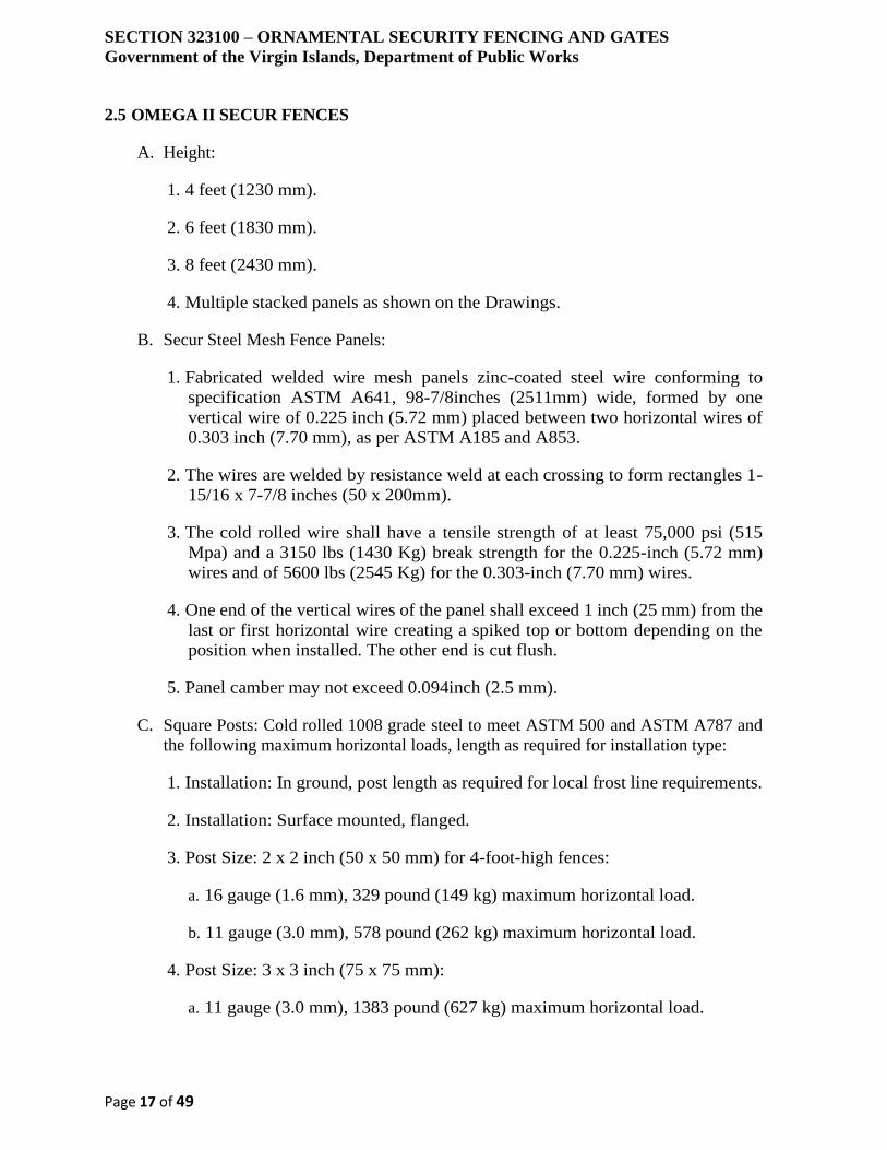
SECTION 323100 – ORNAMENTAL SECURITY FENCING AND GATES
Government of the Virgin Islands, Department of Public Works
Page 17 of 49
2.5 OMEGA II SECUR FENCES
A. Height:
1. 4 feet (1230 mm).
2. 6 feet (1830 mm).
3. 8 feet (2430 mm).
4. Multiple stacked panels as shown on the Drawings.
B. Secur Steel Mesh Fence Panels:
1. Fabricated welded wire mesh panels zinc-coated steel wire conforming to
specification ASTM A641, 98-7/8inches (2511mm) wide, formed by one
vertical wire of 0.225 inch (5.72 mm) placed between two horizontal wires of
0.303 inch (7.70 mm), as per ASTM A185 and A853.
2. The wires are welded by resistance weld at each crossing to form rectangles 1-
15/16 x 7-7/8 inches (50 x 200mm).
3. The cold rolled wire shall have a tensile strength of at least 75,000 psi (515
Mpa) and a 3150 lbs (1430 Kg) break strength for the 0.225-inch (5.72 mm)
wires and of 5600 lbs (2545 Kg) for the 0.303-inch (7.70 mm) wires.
4. One end of the vertical wires of the panel shall exceed 1 inch (25 mm) from the
last or first horizontal wire creating a spiked top or bottom depending on the
position when installed. The other end is cut flush.
5. Panel camber may not exceed 0.094inch (2.5 mm).
C. Square Posts: Cold rolled 1008 grade steel to meet ASTM 500 and ASTM A787 and
the following maximum horizontal loads, length as required for installation type:
1. Installation: In ground, post length as required for local frost line requirements.
2. Installation: Surface mounted, flanged.
3. Post Size: 2 x 2 inch (50 x 50 mm) for 4-foot-high fences:
a. 16 gauge (1.6 mm), 329 pound (149 kg) maximum horizontal load.
b. 11 gauge (3.0 mm), 578 pound (262 kg) maximum horizontal load.
4. Post Size: 3 x 3 inch (75 x 75 mm):
a. 11 gauge (3.0 mm), 1383 pound (627 kg) maximum horizontal load.
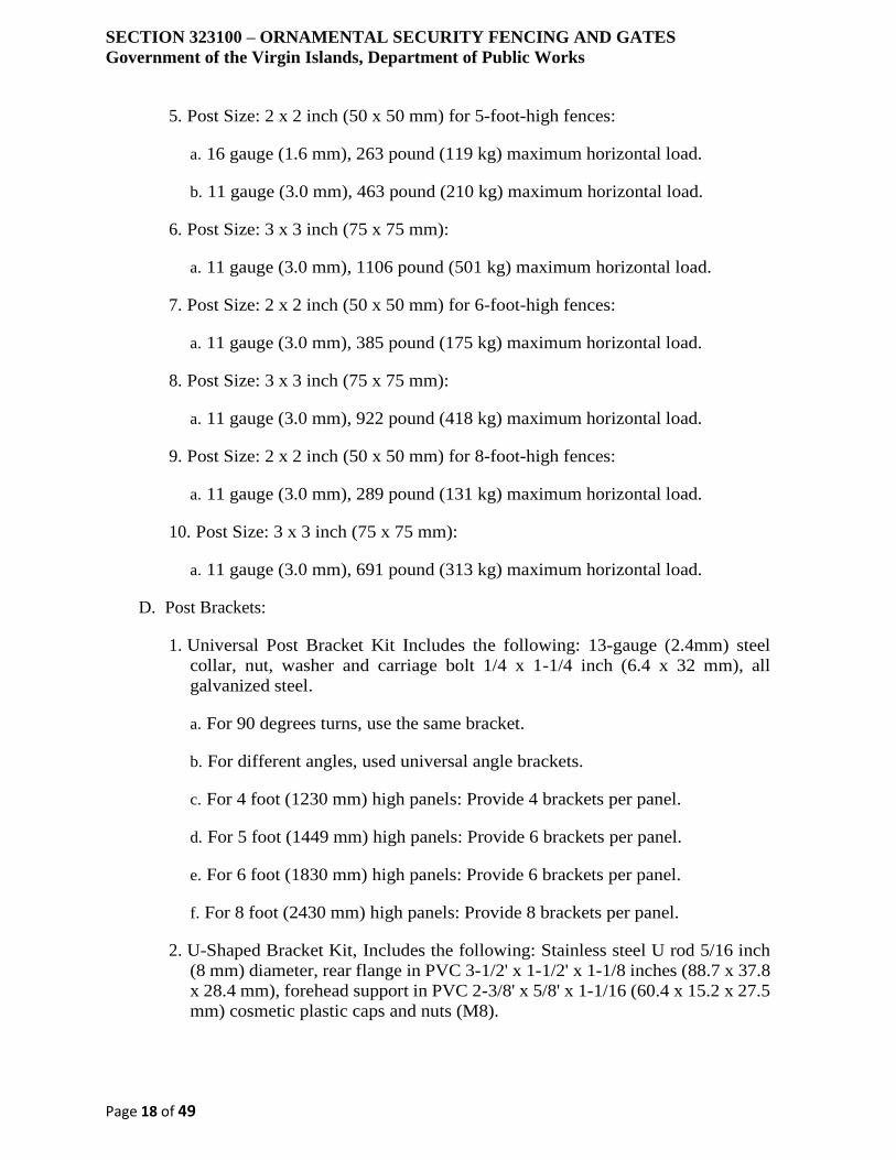
SECTION 323100 – ORNAMENTAL SECURITY FENCING AND GATES
Government of the Virgin Islands, Department of Public Works
Page 18 of 49
5. Post Size: 2 x 2 inch (50 x 50 mm) for 5-foot-high fences:
a. 16 gauge (1.6 mm), 263 pound (119 kg) maximum horizontal load.
b. 11 gauge (3.0 mm), 463 pound (210 kg) maximum horizontal load.
6. Post Size: 3 x 3 inch (75 x 75 mm):
a. 11 gauge (3.0 mm), 1106 pound (501 kg) maximum horizontal load.
7. Post Size: 2 x 2 inch (50 x 50 mm) for 6-foot-high fences:
a. 11 gauge (3.0 mm), 385 pound (175 kg) maximum horizontal load.
8. Post Size: 3 x 3 inch (75 x 75 mm):
a. 11 gauge (3.0 mm), 922 pound (418 kg) maximum horizontal load.
9. Post Size: 2 x 2 inch (50 x 50 mm) for 8-foot-high fences:
a. 11 gauge (3.0 mm), 289 pound (131 kg) maximum horizontal load.
10. Post Size: 3 x 3 inch (75 x 75 mm):
a. 11 gauge (3.0 mm), 691 pound (313 kg) maximum horizontal load.
D. Post Brackets:
1. Universal Post Bracket Kit Includes the following: 13-gauge (2.4mm) steel
collar, nut, washer and carriage bolt 1/4 x 1-1/4 inch (6.4 x 32 mm), all
galvanized steel.
a. For 90 degrees turns, use the same bracket.
b. For different angles, used universal angle brackets.
c. For 4 foot (1230 mm) high panels: Provide 4 brackets per panel.
d. For 5 foot (1449 mm) high panels: Provide 6 brackets per panel.
e. For 6 foot (1830 mm) high panels: Provide 6 brackets per panel.
f. For 8 foot (2430 mm) high panels: Provide 8 brackets per panel.
2. U-Shaped Bracket Kit, Includes the following: Stainless steel U rod 5/16 inch
(8 mm) diameter, rear flange in PVC 3-1/2' x 1-1/2' x 1-1/8 inches (88.7 x 37.8
x 28.4 mm), forehead support in PVC 2-3/8' x 5/8' x 1-1/16 (60.4 x 15.2 x 27.5
mm) cosmetic plastic caps and nuts (M8).

SECTION 323100 – ORNAMENTAL SECURITY FENCING AND GATES
Government of the Virgin Islands, Department of Public Works
Page 19 of 49
a. For 4 foot (1230 mm) high panels: Provide 4 brackets per panel.
b. For 4 foot (1230 mm) high panels: Provide 6 brackets per panel.
c. For 5 foot (1449 mm) high panels: Provide 6 brackets per panel.
d. For 6 foot (1830 mm) high panels: Provide 6 brackets per panel.
e. For 8 foot (2430 mm) high panels: Provide 8 brackets per panel.
E. Special Panel Fittings (SPF): Hot dipped galvanized steel enables panels to be fastened
to any vertical or horizontal surface, such as steel or concrete beams or wood posts.
Provide the following model:
1. SPF-W Kit: For mounting on a vertical surface, consisting of an L-shaped
slotted plate, which accommodates a 1-3/4'' (45 mm) vertical adjustment and a
retaining plate that hold two vertical wires when bolted together.
2. SPF-C Kit: for horizontal surfaces, uses the same "L" shaped slotted plate and
2 wire retaining plates.
3. SPF-P Kit: connects two panels together.
F. Post Caps:
1. Aluminum alloy for posts 2 x 2 inches (50 x 50 mm) to 4 x 4 inches (100 mm x
100 mm).
2. Galvanized steel for larger dimensions.
G. Overhang Extension:
1. Same dimensions as the post, minimum 18 in. (460 mm) long, welded to the
end square posts to form a 45 degrees angle to receive a panel of 16 in. (420
mm).
2. Provide with two fastener kits.
H. Secur mesh panels and posts shall be zinc-coated steel wire conforming to specification
ASTM A641 (1989) Class 1, and with 4 mils polyester powder coating as specified
below.
2.6 OMEGA II HARMONY FENCES
A. Height:
1. 4 feet (1289 mm).
2. 6 feet (1889 mm).
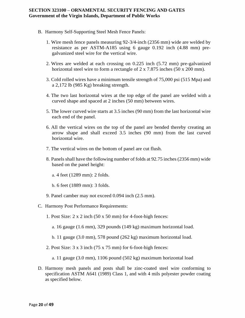
SECTION 323100 – ORNAMENTAL SECURITY FENCING AND GATES
Government of the Virgin Islands, Department of Public Works
Page 20 of 49
B. Harmony Self-Supporting Steel Mesh Fence Panels:
1. Wire mesh fence panels measuring 92-3/4-inch (2356 mm) wide are welded by
resistance as per ASTM-A185 using 6 gauge 0.192 inch (4.88 mm) pre-
galvanized steel wire for the vertical wire.
2. Wires are welded at each crossing on 0.225 inch (5.72 mm) pre-galvanized
horizontal steel wire to form a rectangle of 2 x 7.875 inches (50 x 200 mm).
3. Cold rolled wires have a minimum tensile strength of 75,000 psi (515 Mpa) and
a 2,172 lb (985 Kg) breaking strength.
4. The two last horizontal wires at the top edge of the panel are welded with a
curved shape and spaced at 2 inches (50 mm) between wires.
5. The lower curved wire starts at 3.5 inches (90 mm) from the last horizontal wire
each end of the panel.
6. All the vertical wires on the top of the panel are bended thereby creating an
arrow shape and shall exceed 3.5 inches (90 mm) from the last curved
horizontal wire.
7. The vertical wires on the bottom of panel are cut flush.
8. Panels shall have the following number of folds at 92.75 inches (2356 mm) wide
based on the panel height:
a. 4 feet (1289 mm): 2 folds.
b. 6 feet (1889 mm): 3 folds.
9. Panel camber may not exceed 0.094 inch (2.5 mm).
C. Harmony Post Performance Requirements:
1. Post Size: 2 x 2 inch (50 x 50 mm) for 4-foot-high fences:
a. 16 gauge (1.6 mm), 329 pounds (149 kg) maximum horizontal load.
b. 11 gauge (3.0 mm), 578 pound (262 kg) maximum horizontal load.
2. Post Size: 3 x 3 inch (75 x 75 mm) for 6-foot-high fences:
a. 11 gauge (3.0 mm), 1106 pound (502 kg) maximum horizontal load
D. Harmony mesh panels and posts shall be zinc-coated steel wire conforming to
specification ASTM A641 (1989) Class 1, and with 4 mils polyester powder coating
as specified below.

SECTION 323100 – ORNAMENTAL SECURITY FENCING AND GATES
Government of the Virgin Islands, Department of Public Works
Page 21 of 49
2.7 OMEGA II ECO FENCES
A. Height:
3. 4 feet (1245 mm).
4. 5 feet (1549 mm).
5. 6 feet (1778 mm).
6. 8 feet (2464 mm).
7. Multiple stacked panels.
B. Eco Self-Supporting Steel Mesh Fence Panels:
1. The OMEGA ECO system is in a combination of two panels separated by a 5''
or 6'' (125 mm or 150 mm) gap.
2. Provide with Elite Wire mesh as specified above.
3. Provide with Secur wire mesh as specified above.
4. Wire mesh fence panels are 98-5/8 inches (2505 mm) wide, welded by
resistance using 6-gauge 0.192 inch (4.88 mm) pre-galvanized steel wire,
welded at each crossing to form rectangles of 2 x 6 inches (50 x 150 mm).
5. The cold rolled wire shall have a tensile strength of at least 75,000 psi (515
Mpa) and 2,172 lbs (985 Kg) break strength.
6. One end of the vertical wires of the panel shall exceed 1 inch (25 mm) from the
last or the first horizontal wire creating a spiked top or bottom depending on
position when installed. The other end is cut flush.
7. Panels shall have the following number of folds at 92.75 inches (2356 mm) wide
based on the panel height:
a. 4 feet (1245 mm): 2 folds.
b. 5 feet (1549 mm): 2 folds.
c. 6 feet (1778 mm): 3 folds.
d. 8 feet (2464 mm): 4 folds.
8. Panel camber may not exceed 0.094inch (2.5 mm).
C. Square Posts: Cold rolled 1008 grade steel to meet ASTM 500 and ASTM A787 and
the following maximum horizontal loads, length as required for installation type:
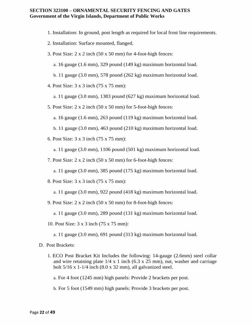
SECTION 323100 – ORNAMENTAL SECURITY FENCING AND GATES
Government of the Virgin Islands, Department of Public Works
Page 22 of 49
1. Installation: In ground, post length as required for local frost line requirements.
2. Installation: Surface mounted, flanged.
3. Post Size: 2 x 2 inch (50 x 50 mm) for 4-foot-high fences:
a. 16 gauge (1.6 mm), 329 pound (149 kg) maximum horizontal load.
b. 11 gauge (3.0 mm), 578 pound (262 kg) maximum horizontal load.
4. Post Size: 3 x 3 inch (75 x 75 mm):
a. 11 gauge (3.0 mm), 1383 pound (627 kg) maximum horizontal load.
5. Post Size: 2 x 2 inch (50 x 50 mm) for 5-foot-high fences:
a. 16 gauge (1.6 mm), 263 pound (119 kg) maximum horizontal load.
b. 11 gauge (3.0 mm), 463 pound (210 kg) maximum horizontal load.
6. Post Size: 3 x 3 inch (75 x 75 mm):
a. 11 gauge (3.0 mm), 1106 pound (501 kg) maximum horizontal load.
7. Post Size: 2 x 2 inch (50 x 50 mm) for 6-foot-high fences:
a. 11 gauge (3.0 mm), 385 pound (175 kg) maximum horizontal load.
8. Post Size: 3 x 3 inch (75 x 75 mm):
a. 11 gauge (3.0 mm), 922 pound (418 kg) maximum horizontal load.
9. Post Size: 2 x 2 inch (50 x 50 mm) for 8-foot-high fences:
a. 11 gauge (3.0 mm), 289 pound (131 kg) maximum horizontal load.
10. Post Size: 3 x 3 inch (75 x 75 mm):
a. 11 gauge (3.0 mm), 691 pound (313 kg) maximum horizontal load.
D. Post Brackets:
1. ECO Post Bracket Kit Includes the following: 14-gauge (2.6mm) steel collar
and wire retaining plate 1/4 x 1 inch (6.3 x 25 mm), nut, washer and carriage
bolt 5/16 x 1-1/4 inch (8.0 x 32 mm), all galvanized steel.
a. For 4 foot (1245 mm) high panels: Provide 2 brackets per post.
b. For 5 foot (1549 mm) high panels: Provide 3 brackets per post.

SECTION 323100 – ORNAMENTAL SECURITY FENCING AND GATES
Government of the Virgin Islands, Department of Public Works
Page 23 of 49
c. For 6 foot (1778 mm) high panels: Provide 3 brackets per post.
d. For 8 foot (2464 mm) high panels: Provide 4 brackets per post.
2. U-Shaped Bracket Kit, Includes the following: Stainless steel U rod 5/16 inch
(8 mm) diameter, rear flange in PVC 3-1/2' x 1-1/2' x 1-1/8 inches (88.7 x 37.8
x 28.4 mm), forehead support in PVC 2-3/8' x 5/8' x 1-1/16 (60.4 x 15.2 x 27.5
mm) cosmetic plastic caps and nuts (M8).
E. Special Panel Fittings (SPF): Hot dipped galvanized steel enables panels to be fastened
to any vertical or horizontal surface, such as steel or concrete beams or wood posts.
Provide the following model:
1. SPF-W Kit: For mounting on a vertical surface, consisting of an L-shaped
slotted plate, which accommodates a 1-3/4'' (45 mm) vertical adjustment and a
retaining plate that hold two vertical wires when bolted together.
2. SPF-C Kit: for horizontal surfaces, uses the same "L" shaped slotted plate and
2 wire retaining plates.
3. SPF-P Kit: connects two panels together.
F. Post Caps:
1. Aluminum alloy for posts 2 x 2 inches (50 x 50 mm) to 4 x 4 inches (100 mm x
100 mm).
2. Galvanized steel for larger dimensions.
G. Overhang Extension:
1. Same dimensions as the post, minimum 18 in. (460 mm) long, welded to the
end square posts to form a 45 degrees angle to receive a panel of 16 in. (420
mm).
2. Provide with two fastener kits.
H. Eco mesh panels and posts shall be zinc-coated steel wire conforming to specification
ASTM A641 (1989) Class 1, and with 4 mils polyester powder coating as specified
below.
2.8 OMEGA II VERTICAL GRATING 10-20 FENCES
A. Height:
1. 47.01 inches (1194 mm).
2. 78.19 inches (1986 mm).
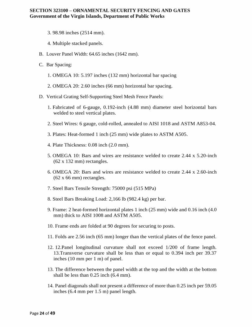
SECTION 323100 – ORNAMENTAL SECURITY FENCING AND GATES
Government of the Virgin Islands, Department of Public Works
Page 24 of 49
3. 98.98 inches (2514 mm).
4. Multiple stacked panels.
B. Louver Panel Width: 64.65 inches (1642 mm).
C. Bar Spacing:
1. OMEGA 10: 5.197 inches (132 mm) horizontal bar spacing
2. OMEGA 20: 2.60 inches (66 mm) horizontal bar spacing.
D. Vertical Grating Self-Supporting Steel Mesh Fence Panels:
1. Fabricated of 6-gauge, 0.192-inch (4.88 mm) diameter steel horizontal bars
welded to steel vertical plates.
2. Steel Wires: 6 gauge, cold-rolled, annealed to AISI 1018 and ASTM A853-04.
3. Plates: Heat-formed 1 inch (25 mm) wide plates to ASTM A505.
4. Plate Thickness: 0.08 inch (2.0 mm).
5. OMEGA 10: Bars and wires are resistance welded to create 2.44 x 5.20-inch
(62 x 132 mm) rectangles.
6. OMEGA 20: Bars and wires are resistance welded to create 2.44 x 2.60-inch
(62 x 66 mm) rectangles.
7. Steel Bars Tensile Strength: 75000 psi (515 MPa)
8. Steel Bars Breaking Load: 2,166 lb (982.4 kg) per bar.
9. Frame: 2 heat-formed horizontal plates 1 inch (25 mm) wide and 0.16 inch (4.0
mm) thick to AISI 1008 and ASTM A505.
10. Frame ends are folded at 90 degrees for securing to posts.
11. Folds are 2.56 inch (65 mm) longer than the vertical plates of the fence panel.
12. 12.Panel longitudinal curvature shall not exceed 1/200 of frame length.
13.Transverse curvature shall be less than or equal to 0.394 inch per 39.37
inches (10 mm per 1 m) of panel.
13. The difference between the panel width at the top and the width at the bottom
shall be less than 0.25 inch (6.4 mm).
14. Panel diagonals shall not present a difference of more than 0.25 inch per 59.05
inches (6.4 mm per 1.5 m) panel length.

SECTION 323100 – ORNAMENTAL SECURITY FENCING AND GATES
Government of the Virgin Islands, Department of Public Works
Page 25 of 49
E. Square Posts: For installation in the ground or on base plates to meet the following
horizontal loading requirements. Secured to posts with 3/8 x 3-1/2 inch (9.5 x 89 mm)
galvanized carriage bolts and 3/8 inch (9.5 mm) galvanized nuts.
1. 2 x 2 inches (50 x 50 mm) 11-gauge (3.0mm) posts:
a. 50 inches (1290 mm) Posts: 502.8 pounds (2442 N).
b. 82 inches (2082 mm) Posts: 339.3 pounds (1513 N).
c. 102 inches (2610 mm) Posts: 270.7 pounds (1207 N).
2. 3 x 3 inches (75 x 75 mm) 11-gauge (3.0mm) posts:
a. 50 inches (1290 mm) Posts: 1309.7 pounds (5840 N).
b. 82 inches (2082 mm) Posts: 811.3 pounds (3618 N).
c. 102 inches (2610 mm) Posts: 647.2 pounds (2886 N).
F. Flat Posts: For installation in the ground or on base plates to meet the following
horizontal loading requirements. Secured to the posts at top of frame and bottom of
frame using 3/8 x 1-1/2 inch (9.5 x 38 mm) galvanized carriage bolts and 3/8 inch (9.5
mm) galvanized nuts.
1. 2.36 x 1/4-inch (60 x 6.35 mm) Posts:
a. 50 inches (1274 mm): 241.5 pounds (1077 N).
b. 81 inches (2066 mm): 148.9 pounds (664 N).
c. 102 inches (2594 mm): 118.6 pounds (529 N).
2. 3.15 x 1/4-inch (80 x 6.35 mm) Posts:
a. 50 inches (1274 mm): 429.2 pounds (1077 N).
b. 81 inches (2066 mm): 264.6 pounds (1180 N).
c. 102 inches (2594 mm): 210.8 pounds (940 N).
G. Number of parts required to secure panels on posts:
1. For 47.01 inch (1194 mm) high panel height, provide 4 bolts, 4 nuts, support
brackets
2. For 78.19 inch (1986 mm) high panel height, provide 6 bolts, 6 nuts, and 2
support brackets.
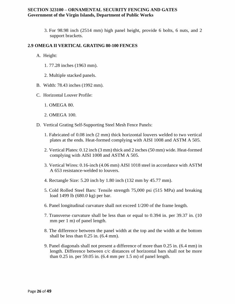
SECTION 323100 – ORNAMENTAL SECURITY FENCING AND GATES
Government of the Virgin Islands, Department of Public Works
Page 26 of 49
3. For 98.98 inch (2514 mm) high panel height, provide 6 bolts, 6 nuts, and 2
support brackets.
2.9 OMEGA II VERTICAL GRATING 80-100 FENCES
A. Height:
1. 77.28 inches (1963 mm).
2. Multiple stacked panels.
B. Width: 78.43 inches (1992 mm).
C. Horizontal Louver Profile:
1. OMEGA 80.
2. OMEGA 100.
D. Vertical Grating Self-Supporting Steel Mesh Fence Panels:
1. Fabricated of 0.08 inch (2 mm) thick horizontal louvers welded to two vertical
plates at the ends. Heat-formed complying with AISI 1008 and ASTM A 505.
2. Vertical Plates: 0.12 inch (3 mm) thick and 2 inches (50 mm) wide. Heat-formed
complying with AISI 1008 and ASTM A 505.
3. Vertical Wires: 0.16-inch (4.06 mm) AISI 1018 steel in accordance with ASTM
A 653 resistance-welded to louvers.
4. Rectangle Size: 5.20 inch by 1.80 inch (132 mm by 45.77 mm).
5. Cold Rolled Steel Bars: Tensile strength 75,000 psi (515 MPa) and breaking
load 1499 lb (680.0 kg) per bar.
6. Panel longitudinal curvature shall not exceed 1/200 of the frame length.
7. Transverse curvature shall be less than or equal to 0.394 in. per 39.37 in. (10
mm per 1 m) of panel length.
8. The difference between the panel width at the top and the width at the bottom
shall be less than 0.25 in. (6.4 mm).
9. Panel diagonals shall not present a difference of more than 0.25 in. (6.4 mm) in
length. Difference between c/c distances of horizontal bars shall not be more
than 0.25 in. per 59.05 in. (6.4 mm per 1.5 m) of panel length.
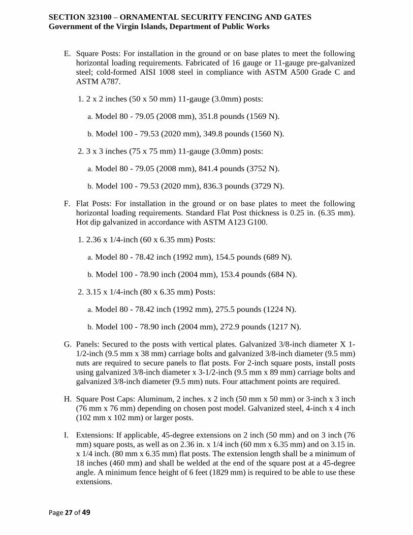
SECTION 323100 – ORNAMENTAL SECURITY FENCING AND GATES
Government of the Virgin Islands, Department of Public Works
Page 27 of 49
E. Square Posts: For installation in the ground or on base plates to meet the following
horizontal loading requirements. Fabricated of 16 gauge or 11-gauge pre-galvanized
steel; cold-formed AISI 1008 steel in compliance with ASTM A500 Grade C and
ASTM A787.
1. 2 x 2 inches (50 x 50 mm) 11-gauge (3.0mm) posts:
a. Model 80 - 79.05 (2008 mm), 351.8 pounds (1569 N).
b. Model 100 - 79.53 (2020 mm), 349.8 pounds (1560 N).
2. 3 x 3 inches (75 x 75 mm) 11-gauge (3.0mm) posts:
a. Model 80 - 79.05 (2008 mm), 841.4 pounds (3752 N).
b. Model 100 - 79.53 (2020 mm), 836.3 pounds (3729 N).
F. Flat Posts: For installation in the ground or on base plates to meet the following
horizontal loading requirements. Standard Flat Post thickness is 0.25 in. (6.35 mm).
Hot dip galvanized in accordance with ASTM A123 G100.
1. 2.36 x 1/4-inch (60 x 6.35 mm) Posts:
a. Model 80 - 78.42 inch (1992 mm), 154.5 pounds (689 N).
b. Model 100 - 78.90 inch (2004 mm), 153.4 pounds (684 N).
2. 3.15 x 1/4-inch (80 x 6.35 mm) Posts:
a. Model 80 - 78.42 inch (1992 mm), 275.5 pounds (1224 N).
b. Model 100 - 78.90 inch (2004 mm), 272.9 pounds (1217 N).
G. Panels: Secured to the posts with vertical plates. Galvanized 3/8-inch diameter X 1-
1/2-inch (9.5 mm x 38 mm) carriage bolts and galvanized 3/8-inch diameter (9.5 mm)
nuts are required to secure panels to flat posts. For 2-inch square posts, install posts
using galvanized 3/8-inch diameter x 3-1/2-inch (9.5 mm x 89 mm) carriage bolts and
galvanized 3/8-inch diameter (9.5 mm) nuts. Four attachment points are required.
H. Square Post Caps: Aluminum, 2 inches. x 2 inch (50 mm x 50 mm) or 3-inch x 3 inch
(76 mm x 76 mm) depending on chosen post model. Galvanized steel, 4-inch x 4 inch
(102 mm x 102 mm) or larger posts.
I. Extensions: If applicable, 45-degree extensions on 2 inch (50 mm) and on 3 inch (76
mm) square posts, as well as on 2.36 in. x 1/4 inch (60 mm x 6.35 mm) and on 3.15 in.
x 1/4 inch. (80 mm x 6.35 mm) flat posts. The extension length shall be a minimum of
18 inches (460 mm) and shall be welded at the end of the square post at a 45-degree
angle. A minimum fence height of 6 feet (1829 mm) is required to be able to use these
extensions.
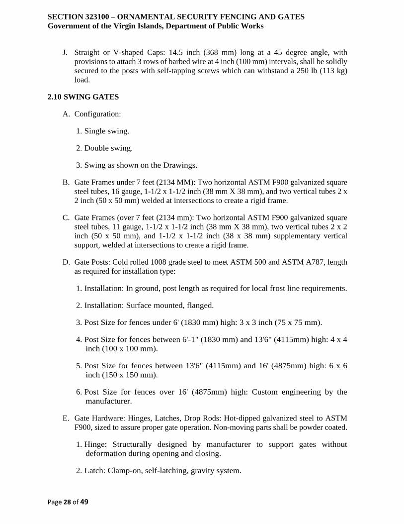
SECTION 323100 – ORNAMENTAL SECURITY FENCING AND GATES
Government of the Virgin Islands, Department of Public Works
Page 28 of 49
J. Straight or V-shaped Caps: 14.5 inch (368 mm) long at a 45 degree angle, with
provisions to attach 3 rows of barbed wire at 4 inch (100 mm) intervals, shall be solidly
secured to the posts with self-tapping screws which can withstand a 250 lb (113 kg)
load.
2.10 SWING GATES
A. Configuration:
1. Single swing.
2. Double swing.
3. Swing as shown on the Drawings.
B. Gate Frames under 7 feet (2134 MM): Two horizontal ASTM F900 galvanized square
steel tubes, 16 gauge, 1-1/2 x 1-1/2 inch (38 mm X 38 mm), and two vertical tubes 2 x
2 inch (50 x 50 mm) welded at intersections to create a rigid frame.
C. Gate Frames (over 7 feet (2134 mm): Two horizontal ASTM F900 galvanized square
steel tubes, 11 gauge, 1-1/2 x 1-1/2 inch (38 mm X 38 mm), two vertical tubes 2 x 2
inch (50 x 50 mm), and 1-1/2 x 1-1/2 inch (38 x 38 mm) supplementary vertical
support, welded at intersections to create a rigid frame.
D. Gate Posts: Cold rolled 1008 grade steel to meet ASTM 500 and ASTM A787, length
as required for installation type:
1. Installation: In ground, post length as required for local frost line requirements.
2. Installation: Surface mounted, flanged.
3. Post Size for fences under 6' (1830 mm) high: 3 x 3 inch (75 x 75 mm).
4. Post Size for fences between 6'-1" (1830 mm) and 13'6" (4115mm) high: 4 x 4
inch (100 x 100 mm).
5. Post Size for fences between 13'6" (4115mm) and 16' (4875mm) high: 6 x 6
inch (150 x 150 mm).
6. Post Size for fences over 16' (4875mm) high: Custom engineering by the
manufacturer.
E. Gate Hardware: Hinges, Latches, Drop Rods: Hot-dipped galvanized steel to ASTM
F900, sized to assure proper gate operation. Non-moving parts shall be powder coated.
1. Hinge: Structurally designed by manufacturer to support gates without
deformation during opening and closing.
2. Latch: Clamp-on, self-latching, gravity system.
SECTION 323100 – ORNAMENTAL SECURITY FENCING AND GATES
Government of the Virgin Islands, Department of Public Works
Page 29 of 49
3. Optional Keyed Lockbox: LOCINOX with single lever, one side of each gate
as shown.
4. Optional Keyed Lockbox: LOCINOX with double levers, both sides of gates.
5. Additional Hardware for Double Gates:
a. Keeper: Mechanical device with gravity-lock system to fasten each gate leaf
in fully open position.
b. Drop Bar: Secures one gate in closed position using stop pipe to engage the
center drop rod.
c. Self-Locking Device: Integral to latch, and with padlock eyes.
2.11 CANTILEVER GATES
A. Construction: 6063-T6 aluminum to ASTM B221, weighing 0.94 lb/ft (1.39 kg/m),
fabricated in accordance with ASTM F1184, Class 2.
1. Members are welded together to form rigid one-piece frames with integral top
track.
2. Provide 2 track and wheel assemblies for each gate leaf, comply with
manufacturer instructions for gates larger than 30 feet (9144 mm).
3. Vertical Uprights: 2 x 2-inch (50 x 50 mm) aluminum, welded to gate frames
approximately 8 foot (2440 mm) apart, dividing the frame into equal sections.
4. Gates over 27 feet (8230 mm): Shipped in 2 parts and field spliced with special
attachments provided by manufacturer.
B. Gate Leaf in Single Openings:
1. Cantilever Support (Overhang) for gates 6 ft. (1830 mm) to 10 ft. (3040 mm):
6.5 feet (1980 mm).
2. Cantilever Support (Overhang) for gates 11 ft. (3350 mm) to 14 ft. (4270 mm):
7.5 feet (2290 mm).
3. Cantilever Support (Overhang) for gates 15 ft. (4570 mm) to 22 ft (6710 mm):
10 feet (3040 mm).
4. Cantilever Support (Overhang for gates 23 ft. (7010 mm) to 30 ft. (9140 mm):
12 feet (3660 mm) with additional 2 inch (50 mm) square lateral support of
aluminum weighing 1.71 lb/ft. (2.54 kg/m) welded to top horizontal rail, and
with bottom rail 2 x 4 inches (50 x 100 mm).
SECTION 323100 – ORNAMENTAL SECURITY FENCING AND GATES
Government of the Virgin Islands, Department of Public Works
Page 30 of 49
5. Cantilever Support (Overhang for gates 31 ft. (9450 mm) to 35 ft (10670 mm):
13.5 feet (4120 mm) aluminum member weighing 1.71 lb/ft. (2.54 kg/m), with
2 top tracks welded together to form a dual enclosed track, with 2 truck
assemblies for each track in each gate leaf, for a total of 4 truck assemblies.
Bottom rail 2 x 4 inches (50 x 100 mm).
6. Cantilever Support (Overhang for gates 36 ft. (10970 mm) to 40 ft. (12190 mm):
16 feet (4880 mm) aluminum member weighing 1.71 lb/ft. (2.54 kg/m), with 2
top tracks welded together to form a dual enclosed track, with 2 truck
assemblies for each track in each gate leaf, for a total of 4 truck assemblies.
Bottom rail 2 x 4 inches (50 x 100 mm).
7. Cantilever Support (Overhang for gates 41 ft. (12500 mm) to 50 ft. (15240 mm):
Custom by manufacturer. Typically fabricated of 24 inch (610 mm) wide rigid
box frame truss of dual side frames, separated by square cross members and
diagonal truss rod bridging. Dual side frames each contain top track to provide
support for truss from both sides. Provide 4 trucks for each track, total 8 for
each gate leaf. Weld steel plate between top of support posts to maintain truck
assemblies in alignment with tracks.
8. As Shown on the Drawings.
C. Sliding Components:
1. Bracing: Diagonal adjustable length truss rods of 3/8 inch (9.5mm) galvanized
steel, in each panel of gate frames.
2. Top Track: Enclosed, combination one-piece track and rail of aluminum
extrusion weighing 3.72 lb/ft (5.54 kg/m), able to withstand reaction load of
2000 lb (907 kg). Track does not receive polymer coating.
3. Truck Assembly: Swivel type, zinc die cast, with 4 sealed lubricant ball bearing
rollers, 2 inches (50 mm) in diameter by 9/16 inch (14 mm) in width, and 2 side
rolling wheels to ensure truck alignment in track. Mounted on post brackets
using 7/8-inch (22 mm) diameter ball bolts with 1/2-inch (13 mm) shank.
Design truck assembly to withstand same reaction load as track assembly.
4. Gate Hangers, Latches, Brackets, Guide Assemblies, and Stops: Malleable iron
or steel, galvanized after fabrication. Provide positive latch for padlocking.
Fittings do not receive Polymer coating.
5. Bottom Guide Wheel Assemblies: Two 4-inch (100 mm) diameter rubber
wheels, straddling bottom horizontal gate rail, to allow adjustments to maintain
gate frame plumb and in proper alignment. One assembly attached to each
guidepost. Bottom guide wheel assemblies do not receive polymer coating.

SECTION 323100 – ORNAMENTAL SECURITY FENCING AND GATES
Government of the Virgin Islands, Department of Public Works
Page 31 of 49
D. Gate Posts: Square sections of 4 inch (100mm) hot-dipped galvanized steel to ASTM
A500, Grade B with a minimum yield strength of 40,000 psi (275 MPa), weighing 7.04
lb/ft (10.8 kg/m), and with minimum 1.8 oz/sq.ft. (549 g/m2) zinc coating to ASTM
F1234. Length of gate posts minimum 36 inches (914mm) more than the actual height
of the fence for installation in the ground to meet local frost line requirements.
1. Single Slide Gate: 1 latch post and 2 support posts.
2. Double Slide Gates: 1 latch post and 4 support posts for double slide gates.
2.12 GATE OPERATORS
A. System Description: Factory-assembled automatic gate operation system comprised of
UL approved components, designed for gate size, type, weight, construction, use,
traffic-flow patterns, and operation frequency. Provide with minimum two keys per
lock and the following:
1. Operator System: of size, capacity, and with features, characteristics, and
accessories suitable for Project conditions, as recommended and provided by
gate manufacturer. Complete with electric motor and factory-prewired motor
controls, remote-control stations, control devices, power disconnect switch,
obstruction detection device, and wiring from motor controls to motor.
2. Coordinate operator wiring requirements and electrical characteristics with
building electrical system.
3. Control Equipment: Comply with NEMA ICS 1, NEMA ICS 2, NEMA ICS 6,
and NFPA 70, Class 2 control circuit, maximum 24-V ac or dc.
4. Electrohydraulic Operation: Provide unit designed for mounting as shown on
the drawings; consisting of electric motor, pump, hydraulic actuator to suit gate
type, valves.
5. Enclosure: Lockable weatherproof enclosures to protect controls, operating
parts, and accessories. Include corrosion-resistant factory finish to match gates.
6. Operator shall allow motor to be removed without disturbing limit-switch
adjustment and without affecting auxiliary emergency operator.
7. Units are designed and wired for both right-hand and left-hand opening,
permitting universal installation.
B. Electrohydraulic Operation: Provide unit designed for mounting as shown on the
drawings; consisting of electric motor, pump, hydraulic actuator to suit gate type,
valves.

SECTION 323100 – ORNAMENTAL SECURITY FENCING AND GATES
Government of the Virgin Islands, Department of Public Works
Page 32 of 49
C. Electromechanical Operation: Provide unit designed for mounting as shown on the
drawings; consisting of electric motor and factory-prewired motor controls, starter,
speed control device, chain-drive assembly, brake, clutch or torque limiter, and as
follows:
1. Enclosed worm gear reducer, roller chain drive.
2. Enclosed worm gear and chain and sprocket reducers, roller chain drive.
3. V-belt and worm gear reducers, roller chain drive.
4. V-belt and chain and sprocket reducers, roller chain drive.
5. Enclosed worm gear reducer, wheel and rail drive.
D. Operation Cycle Requirements: Design gate operator to operate for not less than the
following duty and cycles per hour. One cycle equals one gate opening plus one gate
closing.
1. Medium Duty: 10 cycles per hour.
2. Heavy Duty: 25 cycles per hour.
3. Peak Duty: 20 cycles per hour at peak periods.
4. Custom: ___ cycles per hour.
5. Custom: ___ cycles per day.
E. Gate Operation Speed:
1. Minimum 45 fpm (0.229 m/s).
2. Minimum 60 fpm (0.305 m/s).
3. Minimum ___ fpm (___ m/s).
F. Electric Motors: High-starting torque, continuous-duty, insulated electric motors,
complying with NEMA MG 1, sized to start and operate size and weight of gate
considering Project's service conditions without exceeding nameplate ratings or
considering service factor.
1. Direction: Reversible.
2. Direction: Single direction.
3. Service Factor: According to NEMA MG 1, unless otherwise indicated.

SECTION 323100 – ORNAMENTAL SECURITY FENCING AND GATES
Government of the Virgin Islands, Department of Public Works
Page 33 of 49
4. Enclosure: Totally enclosed, non-ventilated or fan-cooled motors, fitted with
plugged drain, unless otherwise indicated.
5. Thermal Protection: Internal manual reset.
6. Thermal Protection: Internal automatic reset.
7. Motors Smaller Than 1/2 hp: Single phase, 60 Hz.
8. Motors Smaller Than 1/2 hp: Polyphase, 60 Hz.
9. Motors 1/2 hp and Larger: Polyphase, ___ voltage rating, 60 Hz.
10. Motor horsepower as recommended by operator manufacturer.
11. Motor horsepower as indicated on Drawings.
12. Motor horsepower: ______.
G. Limit Switches: Adjustable switches, interlocked with motor controls and set to
automatically stop gate at fully retracted and fully extended positions.
H. Emergency Release Mechanism: Quick disconnect release of operator drive system of
the following type of mechanism, permitting manual operation if operator fails. Design
system so control circuit power is disconnected during manual operation.
1. Integral fail-safe release, allowing gate to be pushed open without mechanical
devices, keys, cranks, or special knowledge.
2. Mechanical device, key, or crank-activated release.
I. Operating Features: Include the following:
1. Digital Microprocessor Control: Electronic programmable means for setting,
changing, and adjusting control features.
a. Provide unit that is isolated from voltage spikes and surges.
b. Provide unit capable of monitoring and auditing gate activity.
2. Fully Systems Compatible: With controlling circuit board capable of accepting
any type of input from external devices.
3. Master/Slave Capability: Control stations designed and wired for gate pair
operation.
4. Automatic Closing Timer: With adjustable time delay before closing.
a. Provide unit with timer cut-off switch.

SECTION 323100 – ORNAMENTAL SECURITY FENCING AND GATES
Government of the Virgin Islands, Department of Public Works
Page 34 of 49
5. Open Override Circuit: Designed to override closing commands.
6. Reversal Time Delay: Designed to protect gate system from shock load on
reversal in both directions.
7. Maximum Run Timer: Designed to prevent damage to gate system by shutting
down system if normal time to open gate is exceeded.
8. Clock Timer: 24-hour, programmable for regular events.
9. Clock Timer: Seven-day, programmable for regular events.
2.13 REMOTE CONTROLS
A. Electric controls separated from gate and motor and drive mechanism, with NEMA
ICS 6, Type 1, NEMA ICS 6, Type 4, or other type of enclosure approved by the local
jurisdiction, for mounting as shown on the drawings, and with space for additional
optional equipment.:
B. Keyed Control Station:
1. Two-position, switch-operated control station located remotely from gate, with
on and off functions. Minimum two-keys per station.
2. Three-position, switch-operated control station with open and close functions
and spring return to off position. Minimum two-keys per station.
3. Three-position, switch-operated control station with open and close functions
and spring return to off position with stop button. Minimum two-keys per
station.
C. Momentary-Contact Control Station:
1. Single-button-operated control station with open and close functions.
2. Three-button-operated control station with open, close, and stop positions.
3. Three-button-operated control station with open, close, and stop positions, and
with key switch to lock out open and close buttons. Minimum two-keys per
station.
D. Card Readers: Functions only when authorized card is presented. Provide insertion-
reader-type, face-lighted unit fully visible at night and the following:
1. Magnetically coded, single-code system activated by coded card.
2. Magnetically coded, single-code system activated by coded card and permitting
four different access time periods.
SECTION 323100 – ORNAMENTAL SECURITY FENCING AND GATES
Government of the Virgin Islands, Department of Public Works
Page 35 of 49
3. Programmable, multiple-code capability permitting validating or voiding of
individual cards.
4. Programmable, multiple-code capability permitting validating or voiding of
individual cards and permitting four different access time periods.
5. Reader Type:
a. Touch plate.
b. Swipe.
c. Insertion.
d. Proximity.
6. Timed anti-passback.
7. Limited time usage.
8. Capable of monitoring and auditing gate activity.
E. Digital Keypad Entry Unit: Functions only when authorized code is entered.
1. Multiple-code capability of not less than 5 possible individual codes.
2. Multiple-code capability of not less than 100 possible individual codes.
3. Multiple-code capability of not less than 500 possible individual codes.
4. Multiple-code capability of not less than 2,500 possible individual codes.
5. Multiple-code capability of not less than 10,000 possible individual codes.
6. Multiple-code capability as indicated.
7. Programmable using 1 to 6 digits.
8. Programmable using 1 to 6 digits and permitting up to four different access time
periods.
9. Face-lighted unit with metal-keyed keypad fully visible at night
10. Face-lighted unit with keyless-membrane keypad fully visible at night.
11. Timed anti-passback.
12. Limited time usage.

SECTION 323100 – ORNAMENTAL SECURITY FENCING AND GATES
Government of the Virgin Islands, Department of Public Works
Page 36 of 49
13. Capable of monitoring and auditing gate activity.
F. Radio Control: Digital system consisting of code-compatible universal coaxial
receiver, remote antenna with coaxial cable and mounting brackets, including:
1. Provide one radio control per gate.
2. Provide radio controls where indicated on Drawings.
3. Provide one permanently mounted transmitter per receiver.
4. Provide four portable transmitters per receiver.
5. Provide number of transmitters as recommended by the manufacturer for each
condition.
6. Provide programmable transmitter with multiple-code capability permitting
validating or voiding of not less than the following codes per channel:
a. 1000 codes per channel.
b. 10,000 codes per channel.
7. Button Transmitters:
a. Single-button-operated control station with open and close functions.
b. Three-button-operated control station with open, close, and stop positions.
c. Three-button-operated control station with open, close, and stop positions,
and with key switch to lock out open and close buttons. Minimum two-keys
per station.
d. Provide independent channels and settings to control various receiver and
gate combinations as indicated.
G. Telephone Entry System: Hands-free voice-communication system for connection to
building telephone system with digital-entry code activation of gate operator,
including:
1. Auxiliary keypad entry.
2. Residential System: Designed to be wired to same line with telephone.
3. Multiunit System: Designed to be wired to a dedicated telephone line, and the
following:
a. Capacity to access 20 telephones
SECTION 323100 – ORNAMENTAL SECURITY FENCING AND GATES
Government of the Virgin Islands, Department of Public Works
Page 37 of 49
b. Capacity to access 100 telephones
c. Include electronic directory.
H. Vehicle Loop Detector System: Automatic closing timer with adjustable time delay
before closing, electronic loop detector with detection patterns adjustable sensitivity
and frequency settings, and panel indicator light designed to detect presence or transit
of a vehicle over an embedded loop of wire and to emit a signal activating the gate
operator. Provide number of loops consisting of multiple strands of wire, number of
turns, loop size, and method of placement at location shown on Drawings, as
recommended in writing by detection system manufacturer for function indicated.
Provide with the following:
1. Timer cut-off switch.
2. Operation:
a. Designed to open and close gate.
b. Designed hold gate open until traffic clears.
c. Designed to reverse gate.
3. Loop:
a. Wire in size indicated for field assembly, and sealant.
b. Factory preformed in size indicated.
c. Installation Style:
d. Pave-over.
e. Saw-cut.
I. Vehicle Presence Detector: System with automatic closing timer and adjustable time
delay before closing and presence detector, adjustable detection pattern and sensitivity
zones, designed to detect the presence or transit of a vehicle in gate pathway by
interrupting an infrared beam in zone pattern to emit a signal activating the gate
operator, and the following:
1. Timer cut-off switch.
2. Operation:
a. Designed to open and close gate.
b. Designed hold gate open until traffic clears.
SECTION 323100 – ORNAMENTAL SECURITY FENCING AND GATES
Government of the Virgin Islands, Department of Public Works
Page 38 of 49
c. Designed to reverse gate.
3. Detector Type:
a. Retroreflective
b. Emitter/receiver.
J. Obstruction Detection Devices: Provide each motorized gate with automatic safety
sensors that cause operator to immediately function as follows:
1. Action: Reverse gate in both opening and closing cycles and hold until clear of
obstruction.
2. Action: Stop gate in opening cycle and reverse gate in closing cycle and hold
until clear of obstruction.
3. Internal Sensor: Built-in torque or current monitor senses gate is obstructed.
4. Sensor Edge: Contact-pressure-sensitive safety edge, profile, and sensitivity
designed for type of gate and component indicated, in locations as follows.
Connected to control circuit using the following:
a. Take-up cable reel.
b. Self-coiling cable.
c. Gate edge transmitter and operator receiver system.
d. Sensor edge location:
i. Along entire gate leaf leading edge.
ii. Along entire gate leaf trailing edge.
iii. Across entire gate leaf bottom edge.
iv. Along entire length of gate posts.
v. Along entire length of gate guideposts.
vi. Where indicated on Drawings.
5. Photoelectric/Infrared Sensor System: Designed to detect an obstruction in
partition's path by interruption of an infrared beam in the zone pattern without
obstruction contacting gate.
2.14 ACCESSORLES
SECTION 323100 – ORNAMENTAL SECURITY FENCING AND GATES
Government of the Virgin Islands, Department of Public Works
Page 39 of 49
A. Concrete Footing Mixture for In-Ground Installations: Unless otherwise specified in
Division 03 Concrete, provide the following:
1. Normal-weight concrete with not less than 3000 psi (20.7- Mpa) compressive
strength (28 days);
2. 3-inch (75-mm) slump and containing coarse aggregate of minimum diameter
of 0.2 inches (5 mm) to maximum of 3/4 inch (20 mm);
3. 5% to 7% air entrainment.
B. Nonshrink, Nonmetallic Grout: Premixed, factory-packaged, nonstaining,
noncorrosive, nongaseous grout complying with ASTM C1107. Provide grout,
recommended in writing by manufacturer, for exterior applications.
C. Erosion-Resistant Anchoring Cement: Factory-packaged, non-shrink, non-staining,
hydraulic-controlled expansion cement formulation for mixing with potable water at
Project site to create pourable anchoring, patching, and grouting compound. Provide
formulation resistant to erosion from water exposure without needing protection by a
sealer or waterproof coating and recommended in writing by manufacturer for exterior
applications.
D. Barbed Wire:
1. Supporting Arms: Pressed steel arms attached to post support 3 rows of barbed
wire. Arms withstand 250 lb. (113 kg) downward pull at outermost end of arm
without failure.
2. Barbed Wire: Zinc or aluminum coated steel wire to ASTM A121, double
strand, 12 gauge, twisted line wire with 4 point barbs, spaced approximately 3
inches (75 mm) on center.
3. Barbed Wire: Zinc or aluminum coated steel wire to ASTM A121, double
strand, 12 gauge, twisted line wire with 4 point barbs, spaced approximately 5
inches (125 mm) on center.
E. Mounting kit including pedestal.
F. Audio Warning Module: ADA-compliant audible alarm sounding three to five seconds
in advance of gate operation and continuing until gate stops moving.
G. Visual Warning Module: ADA-compliant visible alarm sounding three to five seconds
in advance of gate operation and continuing until gate stops moving.
1. Alarm Light Type: Constant.
2. Alarm Light Type: Strobe.
SECTION 323100 – ORNAMENTAL SECURITY FENCING AND GATES
Government of the Virgin Islands, Department of Public Works
Page 40 of 49
H. Battery Backup System: Battery-powered drive and access control system,
independent of primary drive system, opening gate if power fails.
1. External electric-powered lock with delay timer allowing time for lock to
release before gate operates. Provide with:
2. Solenoid for swing gate.
3. Magnetic for swing gate.
4. Solenoid for slide gate.
5. Magnetic for slide gate.
I. Fire box in accordance with local jurisdiction's requirements.
J. Postal box in accordance with local jurisdiction's requirements.
K. Fire strobe sensor.
L. Fire siren sensor.
M. Intercom system.
N. Instructional, Safety, and Warning Labels and Signs:
1. According to UL 325.
2. Manufacturer's standard for components and features specified.
3. As indicated on Drawings.
2.15 FINISHES
A. Zinc Coating:
1. Wire Mesh Coating: 0.5 oz./sq.ft. (150 g/m2) zinc in conformity with ASTM A
641 (1989) Class 1.
2. Fence Posts and Gate Frames Coating: Zinc coated (galvalume process) with a
minimum of 0.9 oz/sq.ft. (275 g/m2) as per ASTM A653 G90.
B. Polyester Coating: Polyester coating to be minimum 4 mils applied by an electrostatic
method to cover all surfaces of the wire mesh and post sections. Coating shall be
capable of withstanding requirements of the following tests:
1. Mechanical Adhesion: ASTMD 3359 - Method B.
2. Shock Resistance: ASTM D 2794.
SECTION 323100 – ORNAMENTAL SECURITY FENCING AND GATES
Government of the Virgin Islands, Department of Public Works
Page 41 of 49
3. Salt Spray Testing: Minimum of 1,000 hours without red rust appearance, per
ASTM B 117 (1990).
4. Humidity Resistance: ASTM D 2247, weather meter chamber.
5. Exposure to Ultraviolet Light: ASTM D1499, exposure of 1000 hours using
apparatus Type E and 63 degreesC.
C. Polyester Surface Coating Colors:
1. Standard Coating: Black, RAL 9004.
2. Gloss Coating: Signal white, RAL 9003.
3. Gloss Coating: Silver grey, RAL 7001.
4. Gloss Coating: Basalt grey, RAL 7012.
5. Gloss Coating: Fir green, RAL 6009.
6. Gloss Coating: Chocolate brown, RAL 8017.
7. Gloss Coating: Signal red, RAL 3001.
8. Textured Coating: Signal yellow, RAL 1003.
9. Textured Coating: Taupe brown.
10. Textured Coating: Sapphire blue, RAL 5003.
11. Metallic Coating: Silver.
12. Metallic Coating: Silver vein.
13. Metallic Coating: Copper vein.
14. Custom Coating: [_______] [Match RAL _____].
PART 3 EXECUTION
3.1 EXAMINATION
A. Examine areas and conditions, with Installer present, for compliance with requirements
for site clearing, earthwork, pavement work, and other conditions affecting
performance.
1. Do not begin installation before final grading is completed, unless otherwise
permitted by Architect.

SECTION 323100 – ORNAMENTAL SECURITY FENCING AND GATES
Government of the Virgin Islands, Department of Public Works
Page 42 of 49
2. Provide a verified survey of property lines and legal boundaries.
B. Proceed with installation only after unsatisfactory conditions have been corrected.
3.2 PREPARATION
A. Stake locations of fence lines, gates, and terminal posts. Do not exceed intervals of 500
feet (152.5 m) or line of sight between stakes.
B. Indicate locations of utilities, lawn sprinkler system, underground structures,
benchmarks, and property monuments marked by registered surveyor and utility
companies.
3.3 FENCE POST LAYOUT
A. Layout fencing on established boundaries inside property line.
B. Terminal Posts Layout: Locate terminal end, corner, and gate posts at changes in
horizontal or vertical alignment of:
1. 15 degrees or more.
2. 30 degrees or more.
3. As indicated on Drawings.
4. __________________
C. Post spacing for 2-inch (50 mm) posts:
1. Architectural panel 97-3/4-inch (2483 mm) center to center with an adjustment
of plus or minus 1-1/2 in. (38 mm).
2. Elite & Secur panel 103-7/8-inch (2638 mm) center to center with an adjustment
of plus or minus 1-1/2 in. (38 mm).
3. ECO Architectural panel 95-9/16-inch (2427 mm) center to center with an
adjustment of plus or minus 1-1/2 in. (38 mm).
4. OMEGA 10-20 panels fence 80-3/4-inch (2051 mm) center to center with a
adjustment of plus or minus 5/16 in. (8 mm).
5. OMEGA 80-100 panels 67-inch (1701 mm) center to center with an adjustment
of plus or minus 5/16 in. (8 mm).
D. Post spacing for 3-inch (75 mm) posts:
1. Architectural panel 98-3/4-inch (2508 mm) center to center with an adjustment
of plus or minus 1-1/2 in. (38 mm).
SECTION 323100 – ORNAMENTAL SECURITY FENCING AND GATES
Government of the Virgin Islands, Department of Public Works
Page 43 of 49
2. Elite & Secur panel 104-7/8-inch (2664 mm) center to center with an adjustment
of plus or minus 1-1/2 in. (38 mm).
3. ECO Architectural panel 95-9/16-inch (2427 mm) center to center with an
adjustment of plus or minus 1-1/2 in. (38 mm).
4. OMEGA 10-20 panels fence 81-3/4-inch (2076 mm) center to center with a
adjustment of plus or minus 5/16 in. (8 mm).
5. OMEGA 80-100 panels 68-inch (1726 mm) center to center with an adjustment
of plus or minus 5/16 in. (8 mm).
E. For Evolution 4 and 6-foot-high panel installation; Space line posts equal distant 10
feet (3050 mm) maximum center to center.
F. For Evolution 8-foot-high panel installation; Space line posts equal distance 8 feet
(2430 mm) maximum center to center.
G. Sloped Fences:
1. Step fence sections in accordance with the manufacturer's instructions.
2. Unless otherwise shown on the drawings, align a new post at each step for a
clean line.
3. Slide universal brackets on posts to desired height, always installing flush with
horizontal wire (no gap).
4. For steep slopes, provide longer posts and panels cut in half or panels in special
shapes to keep gaps under panels to a minimum.
3.4 IN-GROUND CONCRETE INSTALLATION
A. Drill or hand-excavate holes for posts to spacing indicated, in firm, undisturbed or
compacted soil.
B. Dig holes with a diameter 4 times the diameter of the post and 6 inches (150 mm)
deeper than the bottom of the post.
1. Minimum 8 inch (200 mm) in diameter and 42 inch (1070 mm) in depth.
C. Concrete forms are not necessary or recommended. Crown concrete at top to shed
water.
D. Measure, batch, and mix project-site-mixed concrete according to ASTM C 94. Pour
concrete and let cure in accordance with ACI 301 and Division 03 Section "Cast-in-
Place Concrete".
SECTION 323100 – ORNAMENTAL SECURITY FENCING AND GATES
Government of the Virgin Islands, Department of Public Works
Page 44 of 49
E. Exposed Concrete Footings: Extend concrete 2 inches (50 mm) above grade, or as
indicated on Drawings, smooth, and shape to shed water.
F. Concealed Concrete Footings: Stop footings 2 inches (50 mm) below grade or as
indicated on Drawings to allow covering with surface material.
G. Post Setting: Set posts in concrete footing. Protect portion of posts above ground from
concrete splatter. Place concrete around posts and consolidation. Using mechanical
devices to set posts is not permitted. Verify that posts are set plumb, aligned, and at
correct height and spacing, and hold in position during placement and finishing
operations until concrete is sufficiently cured.
H. Posts Set into Concrete in Sleeves: Use steel pipe sleeves preset and anchored into
concrete for installing posts. After posts have been inserted into sleeves, fill annular
space between post and sleeve with non-shrink, non-metallic grout, or anchoring
cement, mixed and placed to comply with anchoring material manufacturer's written
instructions, and finished sloped to drain water away from post.
I. Posts Set into Concrete in Voids: Form or core drill holes not less than 5 inches (125
mm) deep and 3/4 inch (20 mm) larger than outside diameter of post. Clean holes of
loose material, insert posts, and fill granular space between post and concrete with non-
shrink, non-metallic grout or anchoring cement, mixed and placed to comply with
anchoring material manufacturer's written instructions, and finished sloped to drain
water away from post.
3.5 SURFACE MOUNTED FLANGE INSTALLATION
A. Flange Post Installation: Bolt mounting plates attached to each post to slab or structure
as indicated, using expansion bolts in accordance with the manufacturer's instructions.
3.6 PANEL INSTALLATION
A. Once the post installation is complete, install the mesh sections with the Universal
Bracket kits, flush with horizontal wire of the panel (no gap).
B. Attach the panels to the posts with eye-U-bracket and tie wire or twist tie. Where two
panels meet and no post is set, join them with end-to-end connectors used for panel to
panel linkage. Do not exceed manufacturers recommended spacing. Attach panel to
corner posts with bands spaced maximum of 24 inches (2610 mm) on center.
C. Panel Installation: Installed a minimum of 1-1/4 inch (30 mm) and maximum of 2
inches (50 mm) above the ground surface.
1. Install vertical wire extensions pointing up for security.
2. Install vertical wire extensions pointing down for safety.
SECTION 323100 – ORNAMENTAL SECURITY FENCING AND GATES
Government of the Virgin Islands, Department of Public Works
Page 45 of 49
D. Upon cutting or trimming, a post or a wire mesh section, apply a zinc rich primer to
the exposed ends and finish with matching touch-up paint supplied by the
manufacturer.
E. Barbed wire: Uniformly space parallel rows of barbed wire on security side of fence.
Pull wire taut and attach to each extension arm. The extension armed is fastened to the
post.
3.7 GATE OPERATOR INSTALLATION
A. General: Install gate operators according to manufacturer's written instructions, aligned
and true to fence line and grade.
B. Excavation for Supports: Hand-excavate holes for bases, in firm, undisturbed or
compacted soil to dimensions and depths and at locations as required by gate operator
component manufacturer's written instructions and as indicated on Drawings.
C. Concrete Bases: Cast-in-place or precast concrete, made of not less than 3000 psi (20.7-
Mpa) compressive strength (28 days), depth not less than 12 inches (300 mm) below
frost line or detail on Drawings, dimensioned and reinforced according to gate operator
component manufacturer's written instructions and as indicated on Drawings.
D. Vehicle Loop Detector System Installation:
1. Cut grooves in pavement to bury and seal wire loop according to manufacturer's
written instructions.
2. Connect to equipment operated by detector.
3. Comply with NFPA 70 and manufacturer's written instructions for grounding
of electric-powered motors, controls, and other devices.
3.8 GATE INSTALLATION AND ADJUSTMENT
A. Install gate posts in accordance with manufacturer's instructions.
B. Concrete Set Gate Posts:
1. Drill holes in firm, undisturbed or compacted soil.
2. Holes shall have a diameter 4 times greater than outside dimension of post, and
depths at least 6 inches (150 mm) deeper than frost level.
3. Set post bottom 36 inches (914 mm) below surface when in firm, undisturbed
soil.
4. Excavate and set posts deeper where required for adequate support in soft and
loose soils, and for posts with heavy lateral loads.
SECTION 323100 – ORNAMENTAL SECURITY FENCING AND GATES
Government of the Virgin Islands, Department of Public Works
Page 46 of 49
5. Place concrete around posts in a continuous pour, tamp for consolidation.
6. Trowel finish around gate posts and slope to direct water away.
7. Check each post for vertical and top alignment and maintain in position during
placement and finishing operations.
C. Install gates perfectly horizontal and levelled (at junction), plumb, and secure for full
opening without interference.
D. Attach hardware with nuts inside the property making the assembly tamper-proof to
prevent unauthorized removal. Install ground-set items in concrete for anchorage.
E. Adjust hardware for smooth operation and lubricate where necessary to operate
smoothly, easily, and quietly, free from binding, warp, excessive deflection, distortion,
nonalignment, misplacement, disruption, or malfunction, throughout entire operational
range. Confirm that latches and locks engage accurately and securely without forcing
or binding.
3.9 GROUNDING AND BONDING
A. Unless otherwise indicated in Division 26 Electrical, or grounding resistance is
unusually high, provide the following.
B. Fence Grounding: Maximum intervals of 1500 feet (450 m).
C. Fences within 100 feet (30 m) of Buildings, Structures, Walkways, and Roadways:
Ground at maximum intervals of 750 feet (225 m).
D. Gates and Other Fence Openings: Ground fence on each side of opening.
1. Bond metal gates to gate posts.
2. Bond across openings, with and without gates, except openings indicated as
intentional fence discontinuities.
3. Use No. 2 AWG wire and bury it at least 18 inches (460 mm) below finished
grade.
E. Conductors: Bare, solid wire for No. 6 AWG and smaller; stranded wire for No. 4
AWG and larger.
F. Material Above Finished Grade: Copper.
G. Material Above Finished Grade: Aluminum.
H. Material On or Below Finished Grade: Copper.

SECTION 323100 – ORNAMENTAL SECURITY FENCING AND GATES
Government of the Virgin Islands, Department of Public Works
Page 47 of 49
I. 3 Bonding Jumpers: Braided copper tape, 1 inch (25 mm) wide, woven of No. 30 AWG
bare copper wire, terminated with copper ferrules.
J. Connectors and Ground Rods: Listed in UL 467.
K. Connectors for Below-Grade Use: Exothermic welded type.
L. Ground Rods: Copper-clad steel, sized 5/8 x 96 inches (16 by 2400 mm).
M. Protection at Crossings of Overhead Electrical Power Lines: Ground fence at location
of crossing and at a maximum distance of 150 feet (45 m) on each side of crossing.
N. Fences Enclosing Electrical Power Distribution Equipment: Ground as required by
IEEE C2, unless otherwise indicated.
O. Grounding Method: At each grounding location, drive a ground rod vertically until the
top is 6 in. (150 mm) below finished grade. Connect rod to fence with No. 6 AWG
conductor. Connect conductor to each fence component at the grounding location.
P. Bonding Method for Gates: Connect bonding jumper between gate post and gate frame.
Q. Connections: Make connections so possibility of galvanic action or electrolysis is
minimized. Select connectors, connection hardware, conductors, and connection
methods so metals in direct contact will be galvanically compatible.
1. Use electroplated or hot-tin-coated materials to ensure high conductivity to
make contact points closer in order of galvanic series.
2. Make connections with clean, bare metal at points of contact.
3. Make aluminum-to-steel connections with stainless-steel separators and
mechanical clamps.
4. Make aluminum-to-galvanized-steel connections with tin-plated copper
jumpers and mechanical clamps.
5. Coat and seal connections having dissimilar metals with inert material to
prevent future penetration of moisture to contact surfaces.
R. Bonding to Lightning Protection System: If fence terminates at lightning-protected
building or structure, ground the fence and bond the fence grounding conductor to
lightning protection down conductor or lightning protection grounding conductor
complying with NFPA 780
3.10 FIELD QUALITY CONTROL- GROUNDING
A. Ground-Resistance Testing Agency: Contractor shall engage a qualified independent
testing agency to perform field quality-control testing.

SECTION 323100 – ORNAMENTAL SECURITY FENCING AND GATES
Government of the Virgin Islands, Department of Public Works
Page 48 of 49
B. Ground-Resistance Testing Agency: Owner will engage a qualified independent testing
agency to perform field quality-control testing.
C. Ground-Resistance Tests: Subject completed grounding system to a megger test at each
grounding location. Measure ground resistance not less than two full days after last
trace of precipitation, without soil having been moistened by any means other than
natural drainage or seepage and without chemical treatment or other artificial means of
reducing natural ground resistance. Perform tests by two-point method according to
IEEE 81.
D. Desired Maximum Grounding Resistance Value: 25 ohms.
E. Excessive Ground Resistance: If resistance to ground exceeds desired value, notify
Architect promptly. Include recommendations to reduce ground resistance and
proposal to accomplish recommended work.
F. Report: Prepare test reports, certified by testing agency, of ground resistance at each
test location. Include observations of weather and other phenomena that may affect test
results.
3.11 GATE OPERATOR ADJUSTING
A. Gate: Adjust gate to operate smoothly, easily, and quietly, free from binding, warp,
excessive deflection, distortion, nonalignment, misplacement, disruption, or
malfunction, throughout entire operational range. Confirm that latches and locks
engage accurately and securely without forcing or binding.
B. Automatic Gate Operator: Energize circuits to electrical equipment and devices. Adjust
operators, controls, safety devices, alarms, and limit switches.
1. Electrohydraulic Operator: Purge operating system, adjust pressure and fluid
levels, and check for leaks.
2. Operational Test: After electrical circuitry has been energized, start units to
confirm proper motor rotation and unit operation. Perform tests to confirm that
operation meets desired function. Remove damaged and malfunctioning units,
replace with new units, and retest.
a. Lubricate moving parts.
3.12 GATE OPERATOR DEMONSTRATION
A. Engage a factory-authorized service representative to train Owner's personnel to adjust,
operate, and maintain gates.
1. Test and adjust operators, controls, devices and operating hardware. Replace
damaged or malfunctioning operable components.
SECTION 323100 – ORNAMENTAL SECURITY FENCING AND GATES
Government of the Virgin Islands, Department of Public Works
Page 49 of 49
2. Train Owner's personnel on procedures and schedules for starting and stopping,
troubleshooting, servicing, and maintaining equipment and schedules.
3. Review data in maintenance manuals. Refer to Division 1. For demonstration
and documentation requirements.
B. Schedule training with Owner with at least 7 days’ notice.
3.13 PROTECTION
A. Protect installed products until completion of project.
B. Touch-up, repair or replace damaged products before Substantial Completion.
END OF SECTION

SECTION 323113 – CHAIN LINK FENCE AND GATES
Government of the Virgin Islands, Department of Public Works
Page 1 of 8
PART 1 GENERAL
1.1 SECTION INCLUDES
A. Fence framework, fabric, and accessories
1. Pedestrian and vehicle gates
2. Concrete
3. Electrical grounding
1.2 CONTRACTOR PERFORMED WORK
A. Layout fence lines, gates, and terminal posts with suitable stakes (at intervals not exceeding 500
feet or line of sight).
B. Layout USC&G benchmarks, property monuments, and other underground structures with
suitable stakes.
C. Obtain excavation/soil disturbance permit for Subcontractor.
D. Furnish signs for Subcontractor to install on fence. See Part 3.
1.3 ACTION SUBMITTALS
A. Submit the following:
1. Catalog data on fabric, posts, accessories, fittings, and hardware.
2. Two legible copies of batch tickets for each load of concrete to the Owner’s
Representative.
1.4 DELIVERY, STORAGE, AND HANDLING
A. Deliver, store, and handle structural steel without damaging finish.
B. Deliver manufactured materials in original unopened packages, containers, or bundles with
manufacturer's label intact and legible.
C. Store materials off ground, under cover, and away from damp surfaces.
D. Remove damaged unlabeled or unsatisfactory materials that do not meet this specification from
the job site.
1.5 QUALITY ASSURANCE
A. Comply with the following unless otherwise noted.
Federal Specification RR-F
(http://www.dtic.mil/dtic/search/tr/)
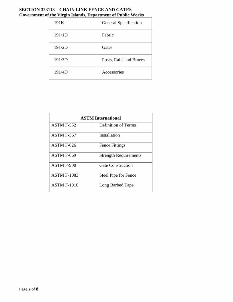
SECTION 323113 – CHAIN LINK FENCE AND GATES
Government of the Virgin Islands, Department of Public Works
Page 2 of 8
191K General Specification
191/1D Fabric
191/2D Gates
191/3D Posts, Rails and Braces
191/4D Accessories
ASTM International
ASTM F-552 Definition of Terms
ASTM F-567 Installation
ASTM F-626 Fence Fittings
ASTM F-669 Strength Requirements
ASTM F-900
ASTM F-1083
ASTM F-1910
Gate Construction
Steel Pipe for Fence
Long Barbed Tape
SECTION 323113 – CHAIN LINK FENCE AND GATES
Government of the Virgin Islands, Department of Public Works
Page 3 of 8
PART 2 PRODUCTS
2.1 MATERIALS
A. Fabric: ASTM A392, Class 1, zinc coated (1.2 ounces), steel wire/fabric, 2-inch mesh size on a
side, 9 American Wire Gauge (AWG) (0.148 inches) coated wire size, galvanized before
weaving, with twisted barbed selvages top and bottom.
B. Posts, Rails & Braces: ASTM F1083 galvanized steel pipe.
C. Galvanizing: ASTM A123, unless otherwise indicated, provide hot-dipped, zinc-coated
accessories of ferrous material with weight of zinc coating not less than 1.2 ounces per square
foot.
D. Barbed Wire: ASTM A121 metallic coated steel, Type Z zinc coating strand wire, 12-1/2 AWG
(0.099 inches) steel wire, 4 barb points, 14 AWG (0.080 inches) spaced on 5-inch centers.
E. Barbed tape: 430 stainless steel, 0.025 inches thick by minimum 1-inch wide prior to forming,
18-inch diameter single helical coil, die stamped to produce a cluster of 4 barbed points at
maximum 4 inches on center, cold rolled around a galvanized steel core wire. Aluminum ties
not acceptable.
F. Fence Fittings: ASTM F626, Standard Specification for Fence Fittings, type and components as
noted.
2.2 BASIC FENCE SYSTEM COMPONENTS
A. Terminal Posts (angles, corners, ends, and pull posts): 2-1/2-inch Schedule 40 for fence height
up to 8 feet and 3 inch Schedule 40 for fence height over 8 feet and equal to or under 16 feet.
B. Line Posts: 2-inch Schedule 40 for fabric height up to 8 feet, 2-1/2-inch Schedule 40 for fabric
height over 8 feet and equal to or under 16 feet.
C. Braces at Terminal or Gateposts: 1-1/4-inch Schedule 40.
D. Tension Rods: 3/8-inch diameter galvanized steel with turnbuckle end-fitting-type tighteners.
E. Tension Wire: 7- AWG coil spring, hard tempered carbon steel wire.
F. Tension Bars: 3/4 x 3/16-inch-thick galvanized steel. Minimum length shall be 2 inches less
than the full fabric height.
G. Tension Bands: Minimum 3/4 x 0.074 inch () galvanized steel offset bands.
H. Brace Bands: Minimum 3/4 x 0.105 inch () thick galvanized steel.
I. Brace Ends: Cupped fittings of formed steel or cast iron with ears for attaching horizontal braces
to brace bands and for connecting diagonal tension rods.
J. Wire Ties: Galvanized, steel 9 AWG with a diameter of 0.148 inches.
K. Post Caps: Formed steel, malleable cast iron, or aluminum, sized to post diameter, with set screw
retainer.
SECTION 323113 – CHAIN LINK FENCE AND GATES
Government of the Virgin Islands, Department of Public Works
Page 4 of 8
L. Hog Rings: Minimum 12 AWG galvanized steel
M. Barbed Wire Extension Arms: Galvanized pressed steel, type as specified.
N. Gate Posts:
1. Gate leaf-widths up to 6 feet: 2-1/2-inch Schedule 40.
2. Gate leaf-widths up to 12 feet: 3-1/2-inch Schedule 40.
3. Gate leaf-widths up to 18 feet: 6-inch Schedule 40.
4. Gate leaf-widths up to 23 feet: 8-inch Schedule 40.
O. Gate Frames:
1. Gate leaf-widths less than 10 feet: 1-1/2-inch Schedule 40.
2. Gate leaf-widths 10 feet to 16 feet: 2-inch Schedule 40.
3. Gate leaf-widths greater than 16 feet: 2-inch Schedule 80.
4. Diagonal tension rods for leaf-widths over 6 feet.
5. For gate leaves greater than 8 feet in any direction, provide intermediate braces placed
symmetrically so that frame members, including bracing, are spaced not further than 8
feet. Provide braces same size as those called out for fence.
P. Provide non-lift-off type gate hinges sized for gate of adequate strength with large rearing
surface for clamping in position so that hinges do not easily twist or turn with gate action.
2.3 FENCE GROUNDING
A. Grounding Cable: No. 4/0 AWG bare, stranded, soft temper copper cable conforming to ASTM
B8, Standard Specification for Concentric-Lay stranded Copper Conductors.
B. Flexible Braid: Tinned copper braid with tinned copper ferrules; minimum 250 ampere rating;
12-inch-minimum length. O-Z/Gedney Type FB.
C. Cable to Pipe Clamps: NRTL (National Recognized Testing Laboratory) listed copper alloy
connectors with silicon bronze hardware for making cable to pipe connections. O-Z/Gedney
Type ABG 1-1/2 inch and smaller, Type CG 2 inch and larger pipe diameter.
D. Flexible Braid to Pipe Clamps: NRTL listed copper alloy connectors with silicon bronze
hardware for making braid or copper bar to pipe connections. O-Z/Gedney Type RG.
2.4 CONCRETE
A. Concrete: Furnish concrete for posts and braces in accordance with Section 033046, Cast-In-
Place Concrete.
PART 3 - EXECUTION
SECTION 323113 – CHAIN LINK FENCE AND GATES
Government of the Virgin Islands, Department of Public Works
Page 5 of 8
3.1 PREPARATION
A. Notify Owner’s Representative 15 working days prior to start of construction to identify known
utilities and stake and flag locations.
B. Before installing chain-line fence, perform site clearing and grading as noted on Drawings.
C. Allow footing to cure minimum 7 days before installing fabric and other materials.
3.2 GENERAL REQUIREMENTS
A. Coat damaged galvanized finish with zinc-enriched paint.
B. Leave area of installation neat and free of debris caused by erection of fence.
C. Posts, bracing, and other structural members shall be located on the inside of the security fence.
D. Gate hardware installed in PA or higher security area that if removed would facilitate
unauthorized entry must be installed in a manner to mitigate tampering and/or removal (e.g., by
brazing, peening, or welding). Consult with LANL Physical Security.
3.3 LATCHES
A. Single gates less than 10 feet wide may use forked type latches.
B. Provide single gates, 10 feet, or more, wide, and inactive leaves of double gates with positive
latching devices at top, bottom and center of closing edges such as fork type latches with full
gate height plunger bar or rod.
C. At double gates, provide locking devices that retain both gate leaves in same plane when closed.
D. Arrange plunger bars and rods so that they engage gate stops and cannot be raised when locked.
E. Rigidly weld brackets for plunger bars holders to inactivate leaves.
F. Arrange latching mechanisms at double gates so one padlock can lock both gate leaves at center
latch integral to gate.
G. Install keepers consisting of a mechanical device for securing free end of gate when in full open
position.
3.4 POSTS
A. Space line posts equidistant at intervals not exceeding 10 feet. Measure interval parallel to grade
of proposed fence and in line of fence from center to center of post.
B. Set terminal posts (end, corner, and gate) at beginning and end of each continuous length of
fence and at abrupt changes in vertical and horizontal alignments.
C. Set fence and gate posts in concrete in holes of diameter and depth as follows:
1. Minimum Diameter: Four times outside diameter of post up to four inches and three
times for larger outside diameters.
SECTION 323113 – CHAIN LINK FENCE AND GATES
Government of the Virgin Islands, Department of Public Works
Page 6 of 8
2. Minimum Depth: 36 inches plus an additional 3 inches for each 1-foot increase in fence
height over 4 feet.
D. Post shall be centered in the concrete base within a +/- one-inch tolerance.
E. Set fence posts in a vertical position, plumb within a one-half inch tolerance over height of fence
in two planes, and in line. Backfill concrete into excavation and extend 2 inches above grade.
An alternative method is to stop footing 4 inches below grade to allow for cover with sod, black
top, or concrete slab. In either case, crown concrete at top to shed water and slope 2 inches
away from post to ground with tolerance of +0 to -1 inch. Crown shall have a troweled finish
and be free from surface contours that trap water.
F. When solid rock or concrete is encountered, without an overburden of soil, set posts in solid
rock or concrete. Depth of hole shall be twelve times the largest cross section of posts. Diameter
of hole shall be 6 inch greater than largest cross section of post.
G. The use of sleeves in order to leave voids in new concrete construction is recommended.
H. Half-fill the void with non-shrinkable hydraulic cement and force post to bottom of hole and
plumb. Thoroughly work additional grout into hole so as to leave no voids. Crown grout to
shed water.
I. Provide tension offset bands fitted around terminal posts at maximum 15-inch intervals to attach
tension bars to posts.
J. Provide brace center band to secure brace ends and tension rods to post.
K. Install post caps on all pipe post terminals: end, corner, and gate and all line posts that do not
have barbed-wire extension arms.
3.5 FABRIC
A. Place chain-link fabric on outside of the area enclosed. Posts, bracing, and other structural
members shall be located on the inside of the fence.
B. Place fabric by securing one end, applying sufficient tension to remove slack before making
attachment elsewhere. Tighten fabric to provide smooth uniform appearance free from sag.
C. Cut fabric by untwisting a picket and attach each span independently at terminal posts. Use
stretcher bars with tension bands at maximum 15-inch intervals.
D. Join rolls of wire fabric by weaving a single picket into ends of rolls to form continuous mesh.
E. Provide continuous length tension bars equal to fence height and located wherever chain link
fabric end attaches to terminal post. Thread bars through fabric ends for full height and attach
to posts by tension bands.
F. Install fence fabric 2 inches maximum above ground level. Ground level shall be defined as
compacted ground or earth material or base course below the fence fabric. Compacted material
shall extend three feet on each side of fence and along same contour as fence within +/-6 inches.

SECTION 323113 – CHAIN LINK FENCE AND GATES
Government of the Virgin Islands, Department of Public Works
Page 7 of 8
G. Fasten fence fabric with wire ties to top and bottom of line posts and at intervals not exceeding
15 inches. The final process of tightening the tie wire shall draw the fabric tightly to the post
and top rail. Wire ties shall wrap a full 360 degrees around the post and engage a full diamond
of the fence fabric. The two ends of the tie shall be twisted securely with three full twists, power
twisting is subcontractor option. Ends shall be cut off to prevent untwisting by hand. Care shall
be taken to assure ends of ties do not protrude beyond the vertical plane of the fabric.
3.6 BARBED WIRE
A. Fencing: Top fencing with [3] strands of barbed wire on each extension arm. Provide [vertical
extension arm outriggers] [single 45-degree extension arm] [double 45-degree extension arm].
Angle single extension arm away from security area or as directed by LANL Physical Security.
B. Pull taut to remove sag, firmly install barbed wire in slots of extension arms, and secure to post
or terminal arm.
C. Gate: Install barbed wire strands at 6 inches on center between extended gate frame members
above gate fabric.
3.7 BARBED TAPE
A. Top fencing with barbed tape at loop spacing of 9 inches.
B. Fencing: Provide 45-degree double extension arm with 2 strands of barbed wire in each
extension arm. Pull wire taut to remove sag, and firmly install barbed wire in most inner and
outer slot of extension arm. Attach barbed tape to barbed wire with hog rings.
C. Gate: Provide one strand of barbed wire to top of extended gate frame and pull taut to remove
sag. Secure barbed tape to barbed wire and top selvage of gate fabric with hog rings at each
loop. Barbed tape loop spacing same as fence.
3.8 GATES
A. Install gates true to opening and plumb in closed position within a vertical tolerance of one-half
inch.
B. Hang gates so that bottom of gate is as close to ground as practical (2 inches max.) while
allowing sufficient clearance for free operation through at least 90 degree in one direction from
closed position.
C. Fasten gate fabric to vertical (end) gate frame members using tension bars and bands as for fence
fabric. Fasten fabric to top and bottom gate frame members and to intermediate braces with 11
AWG wire ties or clips at minimum spacing of 14 inches on center.
D. Extend end frame members 18 inches vertically above top member of gate frame to support
barbed wire.
E. Provide tension rods as diagonal braces on gates and secure rods at gate corner only.
F. Gates installed in PA or higher security area, gate hardware shall be installed in a manner to
mitigate tampering and/or removal, e.g., by brazing, peening or welding to prevent removal with
hand tools. Hinges shall be tamper proof and installed to prevent the gate from being lifted off.
SECTION 323113 – CHAIN LINK FENCE AND GATES
Government of the Virgin Islands, Department of Public Works
Page 8 of 8
3.9 TENSION WIRE AND RAIL
A. Provide [top] and] bottom tension wire and stretch wire from end to end of each stretch of fence
at height that will enable it to be fastened to the fabric.
B. Stretch tension wire taut (not to exceed 6 inches sideway deflection) between terminal posts,
securely fasten the tension wire to the terminal posts. Tension wire shall be within 2 inches of
[top and] bottom of the fence fabric and secured to fabric with hog rings at 24 inches on center,
secure with wire ties to every third line post minimum.
C. Provide top rail and support at each post so that a continuous brace from end to end of each
stretch of fence is formed. Fasten fabric to the top rail at intervals not exceeding 24 inches.
Securely fasten top rail to terminal posts and join with sleeves or coupling to allow for expansion
and contraction. The rail sleeve must be fabricated to prevent movement along the rail.
3.10 ELECTRICAL GROUNDING
A. Bond gateposts on both sides of gate openings using direct buried grounding cable and cable to
pipe clamps. Bond gateposts to gates using flexible braid and flexible braid to pipe clamps.
Ground posts on both ends of gates; steel posts set in concrete will be considered as adequately
grounded.
B. Ground permanent metallic fences crossed by overhead power at every third post for a distance
of 50 feet from the crossing; chain link fences with steel post set in concrete will be considered
as adequately grounded.
C. Ground metal fences surrounding substations and switching stations to station ground system in
accordance with the National Electrical Safety Codes and IEEE Std. 80.
3.11 EXCAVATION, BACKFILL, AND COMPACTION
A. Refer to Section 31 2000, Earth Moving.
3.12 SIGN INSTALLATION (GFE)
A. Install government furnished property signs or no trespassing signs in areas as indicated by the
Owners Representative.
B. Signs will generally be 24” x 24” or smaller and shall be attached to the wire fabric by the use
of, as specified, hog rings.
C. General sign locations will be located on all gates, 25 feet each side of gates, and at visible
distances along the fence line, not to exceed 300 feet.
END OF SECTION
SECTION 323119 – IMPASSE II®- HIGH SECURITY STEEL FENCE SYSTEM,
ORNAMENTAL PALE Government of the Virgin Islands, Department of Public Works
Page 1 of 6
PART 1 - GENERAL
1.1 WORK INCLUDED
A. The contractor shall provide all labor, materials and appurtenances necessary for installation of
the steel corrugated pale security fence system defined herein.
1.2 RELATED WORK
A. Section 312200 - Earthwork
B. Section 03346 - Concrete
1.3 SYSTEM DESCRIPTION
A. The manufacturer shall supply a total steel ornamental pale high security fence system of the
Ameristar® (specify Impasse II® or Impasse II Anti-Scale) model, (specify Trident™,
Stronghold™ or Gauntlet™) design. The system shall include all components (i.e., pales, rails,
posts, gates and hardware) required.
1.4 QUALITY ASSURANCE
A. The contractor shall provide laborers and supervisors who are thoroughly familiar with the type
of construction involved and materials and techniques specified.
1.5 REFERENCES
A. ASTM A653/A653M - Standard Specification for Steel Sheet, Zinc-Coated (Galvanized) or
Zinc-Iron Alloy Coated (Galvannealed) by the Hot-Dip Process.
B. ASTM B117 - Practice for Operating Salt-Spray (Fog) Apparatus.
C. ASTM D523 - Test Method for Specular Gloss.
D. ASTM D714 - Test Method for Evaluating Degree of Blistering in Paint.
E. ASTM D1654 - Test Method for Evaluation of Painted or Coated Specimens Subjected to
Corrosive Environments.
F. ASTM D2244 - Test Method for Calculation of Color Differences from Instrumentally
Measured Color Coordinates.
G. ASTM D2794 - Test Method for Resistance of Organic Coatings to the Effects of Rapid
Deformation (Impact).
H. ASTM D3359 - Test Method for Measuring Adhesion by Tape Test.
I. ASTM F2408 – Ornamental Fences Employing Galvanized Steel Tubular Pickets.
1.6 SUBMITTAL
A. The manufacturer's submittal package shall be provided prior to installation.
SECTION 323119 – IMPASSE II®- HIGH SECURITY STEEL FENCE SYSTEM,
ORNAMENTAL PALE Government of the Virgin Islands, Department of Public Works
Page 2 of 6
1.7 PRODUCT HANDLING AND STORAGE
A. Upon receipt at the job site, all materials shall be checked to ensure that no damage occurred
during shipping or handling. Materials shall be stored in such a manner to ensure proper
ventilation and drainage, and to protect against damage, weather, vandalism and theft.
1.8 PRODUCT WARRANTY
A. All structural fence components (i.e. rails, pales, and posts) shall be warranted within specified
limitations, by the manufacturer for a period of 15 years from date of original purchase.
Warranty shall cover any defects in material finish, including cracking, peeling, chipping,
blistering or corroding.
PART 2 - MATERIALS
2.1 MANUFACTURER
A. The steel ornamental pale high security fence system shall conform to Ameristar (specify
Impasse II or Impasse II Anti-Scale) model, (specify Trident, Stronghold or Gauntlet) (specify
2-Rail or 3-Rail) style manufactured by Ameristar Perimeter Security Inc., in Tulsa, Oklahoma.
2.2 MATERIAL
A. Steel material for fence framework (i.e., corrugated pales, rails and posts), when galvanized
prior to forming, shall conform to the requirements of ASTM A924/A924M, with a minimum
yield strength of 45,000 psi (310 MPa). The steel shall be hot-dip galvanized to meet the
requirements of ASTM A653/A653M with a minimum zinc coating weight of 0.90 oz/ft2 (276
g/m2), Coating Designation G-90.
B. Material for corrugated pales shall be a nominal 2.75” x .75” x 14 Ga. The cross-sectional shape
of the rails shall conform to the manufacturer's Impasse II® rail design a nominal 2” x 2” x 11
Ga. Pre-drilled holes in the Impasse II® rail shall be spaced 6” on center, providing a pale
airspace of no greater than 3.25” or Pre-drilled holes in the Impasse II Anti-Scale rail shall be
spaced 4.1875” on center, providing a pale airspace of no greater than 1.5” (38mm).
Tamperproof fasteners shall be used to fasten each pale to rail at every intersection. Fence posts
and gate posts shall meet the minimum size requirements of Table 1.
C. If applicable - Material for steel Impasse II privacy screening shall be 18ga. preformed slats,
providing complete screening coverage between pales and at pale to post connections. Impasse
II privacy screening shall provide screening from top rail to bottom rail, and be capable of
traversing terrain without impeding the raking capabilities of the fencing panel. Privacy
screening not available for Impasse II Anti-Scale model.
2.3 FABRICATION
A. Pales, rails and posts shall be pre-cut to specified lengths. Impasse II rails shall be pre-punched
to accept tamperproof security fasteners. Post flange shall be pre-punched to accept rail to post
attachment. Post web shall be punched providing a clear opening for interior of rails to align
throughout the entire system for affixing conduit, video cabling, IDS wiring, and other
components for a complete systems integration. Impasse II rails shall be attached to post flange
providing a bracket-less design at each intermediate post.
SECTION 323119 – IMPASSE II®- HIGH SECURITY STEEL FENCE SYSTEM,
ORNAMENTAL PALE Government of the Virgin Islands, Department of Public Works
Page 3 of 6
B. The manufactured galvanized framework shall be subjected to the PermaCoat® thermal
stratification coating process (high-temperature, in-line, multi-stage, multi-layer) including, as
a minimum, a six-stage pretreatment/wash, an electrostatic spray application of an epoxy base,
and a separate electrostatic spray application of a polyester finish. The base coat shall be a
thermosetting epoxy powder coating (gray in color) with a minimum thickness of 2 mils
(0.0508mm). The topcoat shall be a “no-mar” TGIC polyester powder coat finish with a
minimum thickness of 2 mils (0.0508mm). The color shall be (specify Black, Bronze, White,
or Desert Sand). The stratification-coated framework shall be capable of meeting the
performance requirements for each quality characteristic shown in Table 2.
D. Completed panels shall be capable of supporting a 400 lb. load (applied at midspan) without
permanent deformation. Panels shall be biasable to a 30˚ change in grade.
C. Impasse II fence system shall be designed to minimize the system impedance to comply with
IEEE grounding requirements. No additional grounding material, beyond the structure
grounding lug installation, will be required to create a safe low resistance fence system. By way
of fence construction, the entire fence system is inherently grounded without the need for any
additional work. Grounding location at the post is for taking the fence system to site ground.
D. Swing gates shall be fabricated using 2” sq. x 12ga rail, 2” sq. x 12ga. gate ends, and 2.75” x
.75” x 0.075 pales. Gates that exceed 6’ in width will have a 2” sq. x 11ga. intermediate upright.
All rail and upright intersections shall be joined by welding. All pale and rail intersections shall
also be joined by welding.
E. Sliding cantilever gates shall be TransPort IS design matching style, height, and color of fence
system. The dual enclosed track slide gate shall be an aluminum component design using tracks,
uprights, pales, hardware, fittings, and fasteners. Gate installation shall comply with latest
ASTM F2200 standards for automated gates, regardless if the gate is of manual operation.
F. Pedestrian swing gates shall be self-closing, having a gate leaf no larger than 48”
width. Integrated hinge-closer set (2 qty) shall be ADA compliant that shall include a variable
speed and final snap adjustment with compact design (no greater than 5” x 6” footprint). Hinge-
closer set (2 qty) shall be tested to a minimum of 500,000 cycles and capable of self-closing
gates up to a maximum gate weight of 260 lbs. and maximum weight load capacity of 1,500
lbs. Hinge-closer device shall be externally mounted with tamper-resistant security fasteners,
with full range of adjustability, horizontal (.5” - 1.375”) and vertical (0 - .5”). Maintenance free
hinge-closer set shall be tested to operate in temperatures of negative 20 F to 200 F degrees, and
swings to negative 2 degrees to ensure reliable final lock engagement.
PART 3 EXECUTION
3.1 PREPARATION
A. All new installation shall be laid out by the contractor in accordance with the construction plans.
3.2 FENCE INSTALLATION
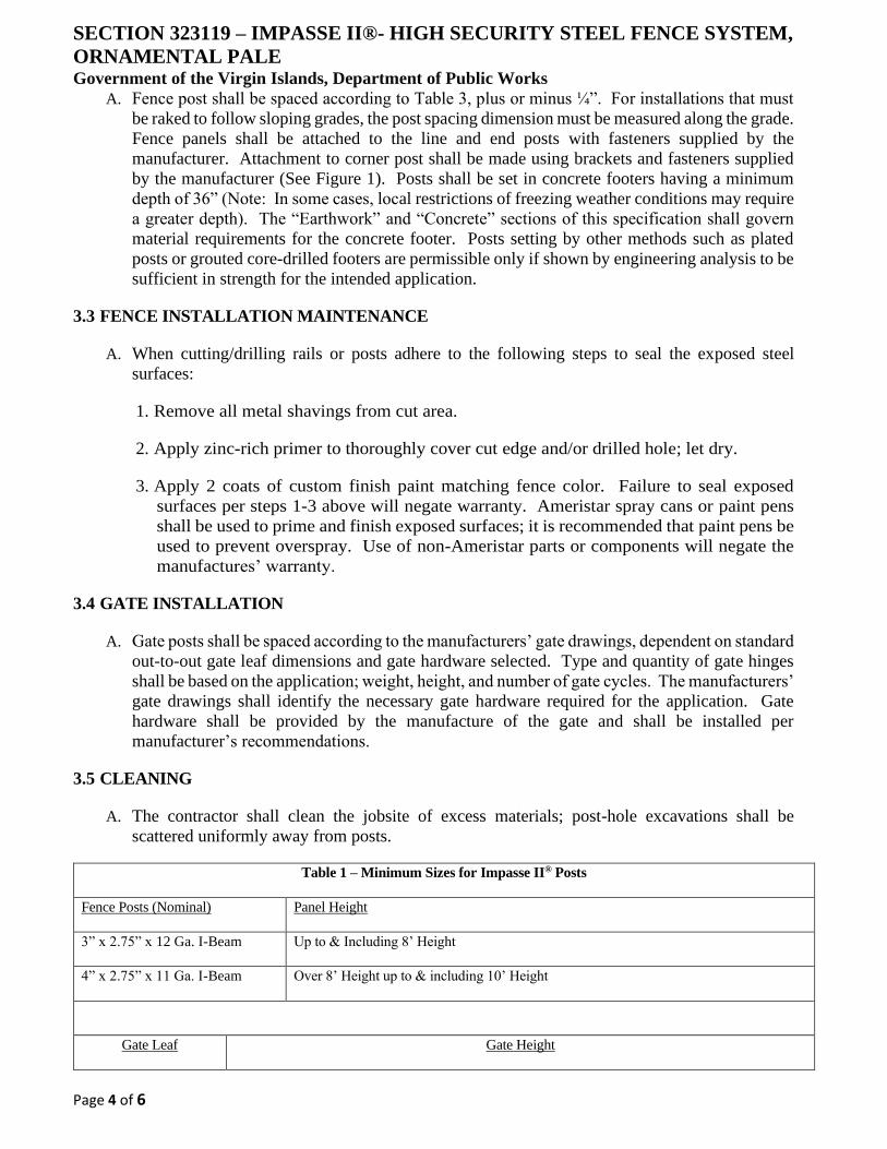
SECTION 323119 – IMPASSE II®- HIGH SECURITY STEEL FENCE SYSTEM,
ORNAMENTAL PALE Government of the Virgin Islands, Department of Public Works
Page 4 of 6
A. Fence post shall be spaced according to Table 3, plus or minus ¼”. For installations that must
be raked to follow sloping grades, the post spacing dimension must be measured along the grade.
Fence panels shall be attached to the line and end posts with fasteners supplied by the
manufacturer. Attachment to corner post shall be made using brackets and fasteners supplied
by the manufacturer (See Figure 1). Posts shall be set in concrete footers having a minimum
depth of 36” (Note: In some cases, local restrictions of freezing weather conditions may require
a greater depth). The “Earthwork” and “Concrete” sections of this specification shall govern
material requirements for the concrete footer. Posts setting by other methods such as plated
posts or grouted core-drilled footers are permissible only if shown by engineering analysis to be
sufficient in strength for the intended application.
3.3 FENCE INSTALLATION MAINTENANCE
A. When cutting/drilling rails or posts adhere to the following steps to seal the exposed steel
surfaces:
1. Remove all metal shavings from cut area.
2. Apply zinc-rich primer to thoroughly cover cut edge and/or drilled hole; let dry.
3. Apply 2 coats of custom finish paint matching fence color. Failure to seal exposed
surfaces per steps 1-3 above will negate warranty. Ameristar spray cans or paint pens
shall be used to prime and finish exposed surfaces; it is recommended that paint pens be
used to prevent overspray. Use of non-Ameristar parts or components will negate the
manufactures’ warranty.
3.4 GATE INSTALLATION
A. Gate posts shall be spaced according to the manufacturers’ gate drawings, dependent on standard
out-to-out gate leaf dimensions and gate hardware selected. Type and quantity of gate hinges
shall be based on the application; weight, height, and number of gate cycles. The manufacturers’
gate drawings shall identify the necessary gate hardware required for the application. Gate
hardware shall be provided by the manufacture of the gate and shall be installed per
manufacturer’s recommendations.
3.5 CLEANING
A. The contractor shall clean the jobsite of excess materials; post-hole excavations shall be
scattered uniformly away from posts.
Table 1 – Minimum Sizes for Impasse II® Posts
Fence Posts (Nominal) Panel Height
3” x 2.75” x 12 Ga. I-Beam Up to & Including 8’ Height
4” x 2.75” x 11 Ga. I-Beam Over 8’ Height up to & including 10’ Height
Gate Leaf Gate Height
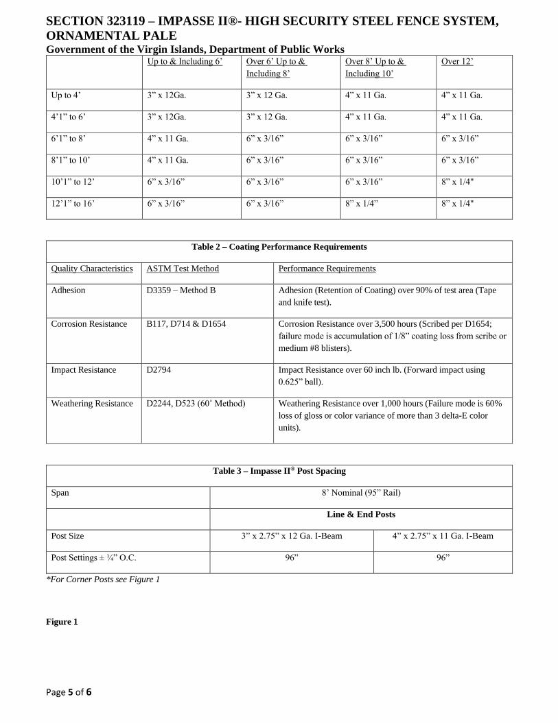
SECTION 323119 – IMPASSE II®- HIGH SECURITY STEEL FENCE SYSTEM,
ORNAMENTAL PALE Government of the Virgin Islands, Department of Public Works
Page 5 of 6
Up to & Including 6’ Over 6’ Up to &
Including 8’
Over 8’ Up to &
Including 10’
Over 12’
Up to 4’ 3” x 12Ga. 3” x 12 Ga. 4” x 11 Ga. 4” x 11 Ga.
4’1” to 6’ 3” x 12Ga. 3” x 12 Ga. 4” x 11 Ga. 4” x 11 Ga.
6’1” to 8’ 4” x 11 Ga. 6” x 3/16” 6” x 3/16” 6” x 3/16”
8’1” to 10’ 4” x 11 Ga. 6” x 3/16” 6” x 3/16” 6” x 3/16”
10’1” to 12’ 6” x 3/16” 6” x 3/16” 6” x 3/16” 8” x 1/4"
12’1” to 16’ 6” x 3/16” 6” x 3/16” 8” x 1/4” 8” x 1/4"
Table 2 – Coating Performance Requirements
Quality Characteristics ASTM Test Method Performance Requirements
Adhesion D3359 – Method B Adhesion (Retention of Coating) over 90% of test area (Tape
and knife test).
Corrosion Resistance B117, D714 & D1654 Corrosion Resistance over 3,500 hours (Scribed per D1654;
failure mode is accumulation of 1/8” coating loss from scribe or
medium #8 blisters).
Impact Resistance D2794 Impact Resistance over 60 inch lb. (Forward impact using
0.625” ball).
Weathering Resistance D2244, D523 (60˚ Method) Weathering Resistance over 1,000 hours (Failure mode is 60%
loss of gloss or color variance of more than 3 delta-E color
units).
Table 3 – Impasse II® Post Spacing
Span 8’ Nominal (95” Rail)
Line & End Posts
Post Size 3” x 2.75” x 12 Ga. I-Beam 4” x 2.75” x 11 Ga. I-Beam
Post Settings ± ¼” O.C. 96” 96”
*For Corner Posts see Figure 1
Figure 1

SECTION 323119 – IMPASSE II®- HIGH SECURITY STEEL FENCE SYSTEM,
ORNAMENTAL PALE Government of the Virgin Islands, Department of Public Works
Page 6 of 6
END OF SECTION
SECTION 323129 – WOOD GATES
Government of the Virgin Islands, Department of Public Works
Page 1 of 37
PART 1 GENERAL
1.1 SECTION INCLUDES
A. Western red cedar wood gates of the following types:
1. Signature series.
2. Rose City series.
3. Sherwood series.
4. Craftsman series.
5. Moderna series.
6. Portland series.
7. Windsor series.
8. Monterey GatePak.
1.2 RELATED WORK
A. Section 31 20 00 - Earth Moving.
B. Section 32 10 00 - Bases, Ballasts, and Paving.
C. Section 32 31 13 - Chain Link Fences and Gates.
D. Section 03 30 00 - Cast-in-Place Concrete.
E. Section 04 20 00 - Unit Masonry.
1.3 SUBMITTALS
A. Submit under provisions of Section 01 30 00 - Administrative Requirements.
B. Product Data: Manufacturer's data sheets on each product to be used, including:
1. Preparation instructions and recommendations.
2. Storage and handling requirements and recommendations.
3. Installation methods.
C. Shop Drawings: Include plans, elevations, sections, details, and attachments to other
work.
SECTION 323129 – WOOD GATES
Government of the Virgin Islands, Department of Public Works
Page 2 of 37
1. Include coordinated dimensions for adjacent construction specified in other
Sections.
D. Verification Samples: For each finish product specified, two samples, representing
actual product, color, and finish.
E. Closeout Submittals: Provide manufacturer's maintenance instructions that include
recommendations for periodic checking and adjustment, cleaning and maintenance.
1.4 QUALITY ASSURANCE
A. Manufacturer Qualifications: Five years or more experience in manufacture of gates
specified.
B. Installer: Experienced with installation of similar products, and acceptable to the
manufacturer.
1.5 DELIVERY, STORAGE, AND HANDLING
A. Store products in the manufacturer's unopened packaging until ready for installation.
B. Protect finished surfaces from soiling or damage during handling and installation.
1.6 PROJECT CONDITIONS
A. Maintain environmental conditions (temperature, humidity, and ventilation) within
limits recommended by manufacturer for optimum results. Do not install products
under environmental conditions outside manufacturer's recommended limits.
1.7 WARRANTY
A. Manufacturer's Warranty: Provide manufacturer's standard 1 year limited warranty for
materials.
PART 2 PRODUCTS
2.1 MANUFACTURER
A. Acceptable Manufacturer: Pacific Gate Works, which is located at: 13780 S.W.
Galbreath Dr. Bldg. A; Sherwood, OR 97140; Toll Free Tel: 855-854-4283; Tel: 503-
688-1216; Fax: 503-925-8910; Email:request info ([email protected]);
Web:pacificgateworks.com
B. Requests for substitutions will be considered in accordance with provisions of Section
01 60 00 - Product Requirements.
2.2 WESTERN RED CEDAR GATES
A. Basis of Design: Signature series as manufactured by Pacific Gate Works.

SECTION 323129 – WOOD GATES
Government of the Virgin Islands, Department of Public Works
Page 3 of 37
1. Single Swing Gate:
a. Top Arch Profile: Flattop.
b. Top Arch Profile: Archtop.
c. Top Arch Profile: Reverse archtop.
d. Width: 36 in (914 mm).
e. Width: 42 in (1067 mm).
f. Width: 48 in (1219 mm).
g. Width: Custom, as indicated on the Drawings.
h. Height at Shoulder of Gate: 48 in (1219 mm).
i. Height at Shoulder of Gate: 58 in (1473 mm).
j. Height at Shoulder of Gate: 70 in (1854 mm).
k. Height at Shoulder of Gate: 82 in (2083 mm).
l. Height at Shoulder of Gate: Custom, as indicated on the Drawings.
m. Frame Thickness: 1-1/2 in (38 mm).
n. Frame Thickness: 2-1/8 in (54 mm).
o. Clavos: One side.
p. Clavos: Both sides.
q. Exterior Protective Finish: None.
r. Exterior Protective Finish: Teak tone transparent stain.
s. Exterior Protective Finish: Chestnut tone, semi-transparent stain.
t. Exterior Protective Finish: Oxford brown tone, semi-transparent stain.
u. Copper Caps: Increased protection from moisture runoff.
i. Copper sheet: 0.020 in (0.51 mm). Custom fit for each gate order.
ii. Attached by copper coated fasteners.
v. Gate Swing: Hinge on left, swing into yard.
SECTION 323129 – WOOD GATES
Government of the Virgin Islands, Department of Public Works
Page 4 of 37
w. Gate Swing: Hinge on left, swing into street.
x. Gate Swing: Hinge on right, swing into yard.
y. 3Gate Swing: Hinge on right, swing into street.
z. Hardware Bundle: None.
aa. Hardware Bundle: Modern.
bb. Hardware Bundle: Contemporary.
cc. Hardware Bundle: Conventional.
dd. Construction:
i. Material: Western red cedar; clear-grade, kiln-dried.
1) Tongue and Groove Panels: 5/8 in (16 mm) thick.
ii. Joinery: Mortise and tenon.
iii. Gate Weight: 40 to 70 lbs (18.14 to 31.75 kg) per door.
2. Double Swing Walk through Gate:
a. Top Arch Profile: Flattop.
b. Top Arch Profile: Archtop.
c. Top Arch Profile: Reverse archtop.
d. Top Arch Profile: Compound archtop.
e. Top Arch Profile: Reverse compound archtop.
f. Width: 72 in (1829 mm); two 36 in (914 mm) gates.
g. Width: 84 in (2134 mm); two 42 in (1067 mm) gates.
h. Width: 96 in (2438 mm); two 48 in (1219 mm) gates.
i. Width: Custom, as indicated on the Drawings.
j. Height at Shoulder of Gate: 48 in (1219 mm).
k. Height at Shoulder of Gate: 58 in (1473 mm).
l. Height at Shoulder of Gate: 70 in (1854 mm).
SECTION 323129 – WOOD GATES
Government of the Virgin Islands, Department of Public Works
Page 5 of 37
m. Height at Shoulder of Gate: 82 in (2083 mm).
n. Height at Shoulder of Gate: Custom, as indicated on the Drawings.
o. Frame Thickness: 1-1/2 in (38 mm).
p. Frame Thickness: 2-1/8 in (54 mm).
q. Clavos: One side.
r. Clavos: Both sides.
s. Exterior Protective Finish: None.
t. Exterior Protective Finish: Teak tone transparent stain.
u. Exterior Protective Finish: Chestnut tone, semi-transparent stain.
v. Exterior Protective Finish: Oxford brown tone, semi-transparent stain.
w. Copper Caps: Increased protection from moisture runoff.
i. Copper sheet: 0.020 in (0.51 mm). Custom fit for each gate order.
ii. Attached by copper coated fasteners.
x. Gate Swing: Into yard.
y. Gate Swing: Into street.
z. Hardware Bundle: None.
aa. Hardware Bundle: Modern.
bb. Hardware Bundle: Contemporary.
cc. Construction:
i. Material: Western red cedar; clear-grade, kiln-dried.
1) Tongue and Groove Panels: 5/8 in (16 mm) thick.
SECTION 323129 – WOOD GATES
Government of the Virgin Islands, Department of Public Works
Page 6 of 37
i. Joinery: Mortise and tenon.
ii. Gate Weight: 40 to 70 lbs (18.14 to 31.75 kg) per door.
3. Driveway Gate: Manual Double Swing gates, with manufacturer's standard cane
bolt.
a. Top Arch Profile: Flattop.
b. Top Arch Profile: Archtop.
c. Top Arch Profile: Reverse archtop.
d. Top Arch Profile: Compound archtop.
e. Top Arch Profile: Reverse Compound archtop.
f. Width: 120 in (3048 mm); two 60 in (1524 mm) gates.
g. Width: 144 in (3658 mm); two 72 in (1829 mm) gates.
h. Width: 168 in (4267 mm); two 84 in (2134 mm) gates.
i. Width: Custom, as indicated on the Drawings.
j. Height at Shoulder of Gate: 48 in (1219 mm).
k. Height at Shoulder of Gate: 58 in (1473 mm).
l. Height at Shoulder of Gate: 70 in (1854 mm).
m. Height at Shoulder of Gate: 82 in (2083 mm).
n. Height at Shoulder of Gate: Custom, as indicated on the Drawings.
o. Gate Frame Thickness: 2-1/8 in (54 mm).
p. Clavos: One side.
q. Clavos: Both sides.
r. Exterior Protective Finish: None.
s. Exterior Protective Finish: Teak tone transparent stain.
t. Exterior Protective Finish: Chestnut tone, semi-transparent stain.
u. Exterior Protective Finish: Oxford brown tone, semi-transparent stain.
v. Copper Caps: Increased protection from moisture runoff.
SECTION 323129 – WOOD GATES
Government of the Virgin Islands, Department of Public Works
Page 7 of 37
i. Copper sheet: 0.020 in (0.51 mm). Custom fit for each gate order.
ii. Attached by copper coated fasteners.
w. Gate Swing: Into yard.
x. Hardware Bundle: None.
y. Hardware Bundle: Modern.
z. Hardware Bundle: Contemporary.
aa. Construction:
i. Material: Western red cedar; clear-grade, kiln-dried.
1) Tongue and Groove Panels: 5/8 in (16 mm) thick.
ii. Joinery: Mortise and tenon.
iii. Steel support frame, with integrated ball bearing hinges.
iv. Receiver plates: Quantity of 4.
v. Cane Bolts: Quantity of 2, 18 in (457 mm) long, non-lockable.
1) Stainless steel, powder coated black.
bb. Gate Weight: 140 to 200 lbs (63.50 to 90.72 kg) per door.
B. Basis of Design: Rose City series as manufactured by Pacific Gate Works.
1. Single Swing Gate:
a. Top Arch Profile: Flattop.
b. Top Arch Profile: Archtop.
c. Top Arch Profile: Reverse archtop.
d. Width: 36 in (914 mm).
e. Width: 42 in (1067 mm).
f. Width: 48 in (1219 mm).
g. Width: Custom, as indicated on the Drawings.
h. Height at Shoulder of Gate: 48 in (1219 mm).
SECTION 323129 – WOOD GATES
Government of the Virgin Islands, Department of Public Works
Page 8 of 37
i. Height at Shoulder of Gate: 58 in (1473 mm).
j. Height at Shoulder of Gate: 70 in (1854 mm).
k. Height at Shoulder of Gate: 82 in (2083 mm.
l. Height at Shoulder of Gate: Custom, as indicated on the Drawings.
m. Frame Thickness: 1-1/2 in (38 mm).
n. Frame Thickness: 2-1/8 in (54 mm).
o. Exterior Protective Finish: None.
p. Exterior Protective Finish: Teak tone transparent stain.
q. Exterior Protective Finish: Chestnut tone, semi-transparent stain.
r. Exterior Protective Finish: Oxford brown tone, semi-transparent stain.
s. Copper Caps: Increased protection from moisture runoff.
i. Copper sheet: 0.020 in (0.51 mm). Custom fit for each gate order.
ii. Attached by copper coated fasteners.
t. Gate Swing: Hinge on left, swing into yard.
u. Gate Swing: Hinge on left, swing into street.
v. Gate Swing: Hinge on right, swing into yard.
w. Gate Swing: Hinge on right, swing into street.
x. Hardware Bundle: None.
y. Hardware Bundle: Modern.
z. Hardware Bundle: Contemporary.
aa. Hardware Bundle: Conventional.
bb. Construction:
i. Material: Western red cedar; clear-grade, kiln-dried.
1) Tongue and Groove Panels: 5/8 in (16 mm) thick.
ii. Joinery: Mortise and tenon.
SECTION 323129 – WOOD GATES
Government of the Virgin Islands, Department of Public Works
Page 9 of 37
iii. Pickets (WxT): 5/8 x 3-1/2 in (16 x 89 mm)
1) Spacing Between Pickets: 3 in (76 mm).
cc. Gate Weight: 40 to 70 lbs (18.14 to 31.75 kg) per door.
2. Double Swing Walk through Gate:
a. Top Arch Profile: Flattop.
b. Top Arch Profile: Archtop.
c. Top Arch Profile: Reverse archtop.
d. Top Arch Profile: Compound archtop.
e. Top Arch Profile: Reverse compound archtop.
f. Width: 72 in (1829 mm); two 36 in (914 mm) gates.
g. Width: 84 in (2134 mm); two 42 in (1067 mm) gates.
h. Width: 96 in (2438 mm); two 48 in (1219 mm) gates.
i. Width: Custom, as indicated on the Drawings.
j. Height at Shoulder of Gate: 48 in (1219 mm).
k. Height at Shoulder of Gate: 58 in (1473 mm).
l. Height at Shoulder of Gate: 70 in (1854 mm).
m. Height at Shoulder of Gate: 82 in (2083 mm).
n. Height at Shoulder of Gate: Custom, as indicated on the Drawings.
o. Frame Thickness: 1-1/2 in (38 mm).
p. Frame Thickness: 2-1/8 in (54 mm).
q. Exterior Protective Finish: None.
r. Exterior Protective Finish: Teak tone transparent stain.
s. Exterior Protective Finish: Chestnut tone, semi-transparent stain.
t. Exterior Protective Finish: Oxford brown tone, semi-transparent stain.
u. Copper Caps: Increased protection from moisture runoff.
SECTION 323129 – WOOD GATES
Government of the Virgin Islands, Department of Public Works
Page 10 of 37
i. Copper sheet: 0.020 in (0.51 mm). Custom fit for each gate order.
ii. Attached by copper coated fasteners.
v. Gate Swing: Into yard.
w. Gate Swing: Into street.
x. Hardware Bundle: None.
y. Hardware Bundle: Modern.
z. Hardware Bundle: Contemporary.
aa. Construction:
i. Material: Western red cedar; clear-grade, kiln-dried.
1) Tongue and Groove Panels: 5/8 in (16 mm) thick.
ii. Joinery: Mortise and tenon.
iii. Pickets (WxT): 5/8 x 3-1/2 in (16 x 89 mm).
1) Spacing Between Pickets: 3 in (76 mm).
iv. Gate Weight: 40 to 70 lbs (18.14 to 31.75 kg) per door.
3. Driveway Gate: Manual Double Swing gates require cane bolts on both doors.
a. Top Arch Profile: Flattop.
b. Top Arch Profile: Archtop.
c. Top Arch Profile: Reverse archtop.
d. Top Arch Profile: Compound archtop.
e. Top Arch Profile: Reverse Compound archtop.
f. Width: 120 in (3048 mm); two 60 in (1524 mm) gates.
g. Width: 144 in (3658 mm); two 72 in (1829 mm) gates.
h. Width: 168 in (4267 mm); two 84 in (2134 mm) gates.
i. Width: Custom, as indicated on the Drawings.
j. Height at Shoulder of Gate: 48 in (1219 mm).
SECTION 323129 – WOOD GATES
Government of the Virgin Islands, Department of Public Works
Page 11 of 37
k. Height at Shoulder of Gate: 58 in (1473 mm).
l. Height at Shoulder of Gate: 70 in (1854 mm).
m. Height at Shoulder of Gate: 82 in (2083 mm).
n. Height at Shoulder of Gate: Custom, as indicated on the Drawings.
o. Gate Frame Thickness: 2-1/8 in (54 mm).
p. Exterior Protective Finish: None.
q. Exterior Protective Finish: Teak tone transparent stain.
r. Exterior Protective Finish: Chestnut tone, semi-transparent stain.
s. Exterior Protective Finish: Oxford brown tone, semi-transparent stain.
t. Copper Caps: Increased protection from moisture runoff.
i. Copper sheet: 0.020 in (0.51 mm). Custom fit for each gate order.
ii. Attached by copper coated fasteners.
u. Gate Swing: Into yard.
v. Hardware Bundle: None.
w. Hardware Bundle: Modern.
x. Hardware Bundle: Contemporary.
y. Construction:
i. Material: Western red cedar; clear-grade, kiln-dried.
1) Tongue and Groove Panels: 5/8 in (16 mm) thick.
SECTION 323129 – WOOD GATES
Government of the Virgin Islands, Department of Public Works
Page 12 of 37
ii. Joinery: Mortise and tenon.
iii. Steel support frame, with integrated ball bearing hinges.
iv. Receiver plates: Quantity of 4.
v. Cane Bolts: Quantity of 2, 18 in (457 mm) long, non-lockable.
1) Stainless steel, powder coated black.
vi. Pickets (WxT): 5/8 x 3-1/2 in (16 x 89 mm)
1) Spacing Between Pickets: 3 in (76 mm).
vii. Gate Weight: 140 to 200 lbs (63.50 to 90.72 kg) per door.
C. Basis of Design: Sherwood series as manufactured by Pacific Gate Works.
1. Single Swing Gate:
a. Top Arch Profile: Flattop.
b. Top Arch Profile: Archtop.
c. Top Arch Profile: Reverse archtop.
d. Width: 36 in (914 mm).
e. Width: 42 in (1067 mm).
f. Width: 48 in (1219 mm).
g. Width: Custom, as indicated on the Drawings.
h. Height at Shoulder of Gate: 48 in (1219 mm).
i. Height at Shoulder of Gate: 58 in (1473 mm).
j. Height at Shoulder of Gate: 70 in (1854 mm).
k. Height at Shoulder of Gate: 82 in (2083 mm).
l. Height at Shoulder of Gate: Custom, as indicated on the Drawings.
m. Frame Thickness: 1-1/2 in (38 mm).
n. Frame Thickness: 2-1/8 in (54 mm).
o. Clavos: One side.
SECTION 323129 – WOOD GATES
Government of the Virgin Islands, Department of Public Works
Page 13 of 37
p. Clavos: Both sides.
q. Exterior Protective Finish: None.
r. Exterior Protective Finish: Teak tone transparent stain.
s. Exterior Protective Finish: Chestnut tone, semi-transparent stain.
t. Exterior Protective Finish: Oxford brown tone, semi-transparent stain.
u. Copper Caps: Increased protection from moisture runoff.
i. Copper sheet: 0.020 in (0.51 mm). Custom fit for each gate order.
ii. Attached by copper coated fasteners.
v. Gate Swing: Hinge on left, swing into yard.
w. Gate Swing: Hinge on left, swing into street.
x. Gate Swing: Hinge on right, swing into yard.
y. Gate Swing: Hinge on right, swing into street.
z. Hardware Bundle: None.
aa. Hardware Bundle: Modern.
bb. Hardware Bundle: Contemporary.
cc. Hardware Bundle: Conventional.
dd. Construction:
i. Material: Western red cedar; clear-grade, kiln-dried.
1) Tongue and Groove Panels: 5/8 in (16 mm) thick.
ii. Joinery: Mortise and tenon.
iii. Window: 13 x 13 in (330 x 330 mm) with 8 x 8 in (203 x 203 mm) opening.
1) Speakeasy grille with peek door.
SECTION 323129 – WOOD GATES
Government of the Virgin Islands, Department of Public Works
Page 14 of 37
iv. Gate Weight: 40 to 70 lbs (18.14 to 31.75 kg) per door.
2. Double Swing Walk through Gate:
a. Top Arch Profile: Flattop.
b. Top Arch Profile: Archtop.
c. Top Arch Profile: Reverse archtop.
d. Top Arch Profile: Compound archtop.
e. Top Arch Profile: Reverse compound archtop.
f. Width: 72 in (1829 mm); two 36 in (914 mm) gates.
g. Width: 84 in (2134 mm); two 42 in (1067 mm) gates.
h. Width: 96 in (2438 mm); two 48 in (1219 mm) gates.
i. Width: Custom, as indicated on the Drawings.
j. Height at Shoulder of Gate: 48 in (1219 mm).
k. Height at Shoulder of Gate: 58 in (1473 mm).
l. Height at Shoulder of Gate: 70 in (1854 mm).
m. Height at Shoulder of Gate: 82 in (2083 mm).
n. Height at Shoulder of Gate: Custom, as indicated on the Drawings.
o. Frame Thickness: 1-1/2 in (38 mm).
p. Frame Thickness: 2-1/8 in (54 mm).
q. Clavos: One side.
r. Clavos: Both sides.
s. Exterior Protective Finish: None.
t. Exterior Protective Finish: Teak tone transparent stain.
u. Exterior Protective Finish: Chestnut tone, semi-transparent stain.
v. Exterior Protective Finish: Oxford brown tone, semi-transparent stain.
w. Copper Caps: Increased protection from moisture runoff.
SECTION 323129 – WOOD GATES
Government of the Virgin Islands, Department of Public Works
Page 15 of 37
i. Copper sheet: 0.020 in (0.51 mm). Custom fit for each gate order.
ii. Attached by copper coated fasteners.
x. Gate Swing: Into yard.
y. Gate Swing: Into street.
z. Hardware Bundle: None.
aa. Hardware Bundle: Modern.
bb. Hardware Bundle: Contemporary.
cc. Construction:
i. Material: Western red cedar; clear-grade, kiln-dried.
1) Tongue and Groove Panels: 5/8 in (16 mm) thick.
i. Joinery: Mortise and tenon.
ii. Window: 13 x 13 in (330 x 330 mm) with 8 x 8 in (203 x 203 mm) opening.
1) Speakeasy grille with peek door.
i. Gate Weight: 40 to 70 lbs (18.14 to 31.75 kg) per door.
3. Driveway Gate: Manual Double Swing gates require cane bolts on both doors.
a. Top Arch Profile: Flattop.
b. Top Arch Profile: Archtop.
c. Top Arch Profile: Reverse archtop.
d. Top Arch Profile: Compound archtop.
e. Top Arch Profile: Reverse Compound archtop.
f. Width: 120 in (3048 mm); two 60 in (1524 mm) gates.
g. Width: 144 in (3658 mm); two 72 in (1829 mm) gates.
h. Width: 168 in (4267 mm); two 84 in (2134 mm) gates.
i. Width: Custom, as indicated on the Drawings.
j. Height at Shoulder of Gate: 48 in (1219 mm).
SECTION 323129 – WOOD GATES
Government of the Virgin Islands, Department of Public Works
Page 16 of 37
k. Height at Shoulder of Gate: 58 in (1473 mm).
l. Height at Shoulder of Gate: 70 in (1854 mm).
m. Height at Shoulder of Gate: 82 in (2083 mm).
n. Height at Shoulder of Gate: Custom, as indicated on the Drawings.
o. Gate Frame Thickness: 2-1/8 in (54 mm).
p. Clavos: One side.
q. Clavos: Both sides.
r. Exterior Protective Finish: None.
s. Exterior Protective Finish: Teak tone transparent stain.
t. Exterior Protective Finish: Chestnut tone, semi-transparent stain.
u. Exterior Protective Finish: Oxford brown tone, semi-transparent stain.
v. Copper Caps: Increased protection from moisture runoff.
i. Copper sheet: 0.020 in (0.51 mm). Custom fit for each gate order.
ii. Attached by copper coated fasteners.
w. Gate Swing: Into yard.
x. Hardware Bundle: None.
y. Hardware Bundle: Modern.
z. Hardware Bundle: Contemporary.
aa. Construction:
i. Material: Western red cedar; clear-grade, kiln-dried.
1) Tongue and Groove Panels: 5/8 in (16 mm) thick.

SECTION 323129 – WOOD GATES
Government of the Virgin Islands, Department of Public Works
Page 17 of 37
ii. Joinery: Mortise and tenon.
iii. Window: 13 x 13 in (330 x 330 mm) with 8 x 8 in (203 x 203 mm) opening.
1) Speakeasy grille with peek door.
iv. Steel support frame, with integrated ball bearing hinges.
v. Receiver plates: Quantity of 4.
vi. Cane Bolts: Quantity of 2, 18 in (457 mm) long, non-lockable.
1) Stainless steel, powder coated black.
vii. Gate Weight: 140 to 200 lbs (63.50 to 90.72 kg) per door.
D. Basis of Design: Craftsman series as manufactured by Pacific Gate Works.
1. Single Swing Gate:
a. Top Arch Profile: Flattop.
b. Top Arch Profile: Archtop.
c. Top Arch Profile: Reverse archtop.
d. Width: 36 in (914 mm).
e. Width: 42 in (1067 mm).
f. Width: 48 in (1219 mm).
g. Width: Custom, as indicated on the Drawings.
h. Height at Shoulder of Gate: 48 in (1219 mm).
i. Height at Shoulder of Gate: 58 in (1473 mm).
j. Height at Shoulder of Gate: 70 in (1854 mm).
k. Height at Shoulder of Gate: 82 in (2083 mm).
l. Height at Shoulder of Gate: Custom, as indicated on the Drawings.
m. Frame Thickness: 1-1/2 in (38 mm).
n. Frame Thickness: 2-1/8 in (54 mm).
o. Exterior Protective Finish: None.
SECTION 323129 – WOOD GATES
Government of the Virgin Islands, Department of Public Works
Page 18 of 37
p. Exterior Protective Finish: Teak tone transparent stain.
q. Exterior Protective Finish: Chestnut tone, semi-transparent stain.
r. Exterior Protective Finish: Oxford brown tone, semi-transparent stain.
s. Copper Caps: Increased protection from moisture runoff.
i. Copper sheet: 0.020 in (0.51 mm). Custom fit for each gate order.
ii. Attached by copper coated fasteners.
t. Gate Swing: Hinge on left, swing into yard.
u. Gate Swing: Hinge on left, swing into street.
v. Gate Swing: Hinge on right, swing into yard.
w. Gate Swing: Hinge on right, swing into street.
x. Hardware Bundle: None.
y. Hardware Bundle: Modern.
z. Hardware Bundle: Contemporary.
aa. Hardware Bundle: Conventional.
bb. Construction:
i. Material: Western red cedar; clear-grade, kiln-dried.
1) Tongue and Groove Panels: 5/8 in (16 mm) thick.
ii. Joinery: Mortise and tenon.
iii. Window at top of gate: Precision profiled steel.
1) Sand blasted and powder coated, black.
iv. Gate Weight: 40 to 70 lbs (18.14 to 31.75 kg) per door.
2. Double Swing Walk through Gate:
a. Top Arch Profile: Flattop.
b. Top Arch Profile: Archtop.
c. Top Arch Profile: Reverse archtop.
SECTION 323129 – WOOD GATES
Government of the Virgin Islands, Department of Public Works
Page 19 of 37
d. Top Arch Profile: Compound archtop.
e. Top Arch Profile: Reverse compound archtop.
f. Width: 72 in (1829 mm); two 36 in (914 mm) gates.
g. Width: 84 in (2134 mm); two 42 in (1067 mm) gates.
h. Width: 96 in (2438 mm); two 48 in (1219 mm) gates.
i. Width: Custom, as indicated on the Drawings.
j. Height at Shoulder of Gate: 48 in (1219 mm).
k. Height at Shoulder of Gate: 58 in (1473 mm).
l. Height at Shoulder of Gate: 70 in (1854 mm).
m. Height at Shoulder of Gate: 82 in (2083 mm).
n. Height at Shoulder of Gate: Custom, as indicated on the Drawings.
o. Frame Thickness: 1-1/2 in (38 mm).
p. Frame Thickness: 2-1/8 in (54 mm).
q. Exterior Protective Finish: None.
r. Exterior Protective Finish: Teak tone transparent stain.
s. Exterior Protective Finish: Chestnut tone, semi-transparent stain.
t. Exterior Protective Finish: Oxford brown tone, semi-transparent stain.
u. Copper Caps: Increased protection from moisture runoff.
i. Copper sheet: 0.020 in (0.51 mm). Custom fit for each gate order.
ii. Attached by copper coated fasteners.
v. Gate Swing: Into yard.
w. Gate Swing: Into street.
x. Hardware Bundle: None.
y. Hardware Bundle: Modern.
z. Hardware Bundle: Contemporary.
SECTION 323129 – WOOD GATES
Government of the Virgin Islands, Department of Public Works
Page 20 of 37
aa. Construction:
i. Material: Western red cedar; clear-grade, kiln-dried.
1) Tongue and Groove Panels: 5/8 in (16 mm) thick.
ii. Joinery: Mortise and tenon.
iii. Window at top of gate: Precision profiled steel.
1) Sand blasted and powder coated, black.
bb. Gate Weight: 40 to 70 lbs (18.14 to 31.75 kg) per door.
3. Driveway Gate: Manual Double Swing gates require cane bolts on both doors.
a. Top Arch Profile: Flattop.
b. Top Arch Profile: Archtop.
c. Top Arch Profile: Reverse archtop.
d. Top Arch Profile: Compound archtop.
e. Top Arch Profile: Reverse Compound archtop.
f. Width: 120 in (3048 mm); two 60 in (1524 mm) gates.
g. Width: 144 in (3658 mm); two 72 in (1829 mm) gates.
h. Width: 168 in (4267 mm); two 84 in (2134 mm) gates.
i. Width: Custom, as indicated on the Drawings.
j. Height at Shoulder of Gate: 48 in (1219 mm).
k. Height at Shoulder of Gate: 58 in (1473 mm).
l. Height at Shoulder of Gate: 70 in (1854 mm).
m. Height at Shoulder of Gate: 82 in (2083 mm).
n. Height at Shoulder of Gate: Custom, as indicated on the Drawings.
o. Gate Frame Thickness: 2-1/8 in (54 mm).
p. Exterior Protective Finish: None.
q. Exterior Protective Finish: Teak tone transparent stain.

SECTION 323129 – WOOD GATES
Government of the Virgin Islands, Department of Public Works
Page 21 of 37
r. Exterior Protective Finish: Chestnut tone, semi-transparent stain.
s. Exterior Protective Finish: Oxford brown tone, semi-transparent stain.
t. Copper Caps: Increased protection from moisture runoff.
i. Copper sheet: 0.020 in (0.51 mm). Custom fit for each gate order.
ii. Attached by copper coated fasteners.
u. Gate Swing: Into yard.
v. Hardware Bundle: None.
w. Hardware Bundle: Modern.
x. Hardware Bundle: Contemporary.
y. Construction:
i. Material: Western red cedar; clear-grade, kiln-dried.
1) Tongue and Groove Panels: 5/8 in (16 mm) thick.
ii. Joinery: Mortise and tenon.
iii. Window at top of gate: Precision profiled steel.
1) Sand blasted and powder coated, black.
iv. Steel support frame, with integrated ball bearing hinges.
v. Receiver plates: Quantity of 4.
vi. Cane Bolts: Quantity of 2, 18 in (457 mm) long, non-lockable.
1) Stainless steel, powder coated black.
vii. Gate Weight: 140 to 200 lbs (63.50 to 90.72 kg) per door.
E. Basis of Design: Moderna series as manufactured by Pacific Gate Works.
1. Single Swing Gate:
a. Top Arch Profile: Flattop.
b. Top Arch Profile: Archtop.
c. Top Arch Profile: Reverse archtop.
SECTION 323129 – WOOD GATES
Government of the Virgin Islands, Department of Public Works
Page 22 of 37
d. Width: 36 in (914 mm).
e. Width: 42 in (1067 mm).
f. Width: 48 in (1219 mm).
g. Width: Custom, as indicated on the Drawings.
h. Height at Shoulder of Gate: 48 in (1219 mm).
i. Height at Shoulder of Gate: 58 in (1473 mm).
j. Height at Shoulder of Gate: 70 in (1854 mm).
k. Height at Shoulder of Gate: 82 in (2083 mm).
l. Height at Shoulder of Gate: Custom, as indicated on the Drawings.
m. Frame Thickness: 1-1/2 in (38 mm).
n. Frame Thickness: 2-1/8 in (54 mm).
o. Exterior Protective Finish: None.
p. Exterior Protective Finish: Teak tone transparent stain.
q. Exterior Protective Finish: Chestnut tone, semi-transparent stain.
r. Exterior Protective Finish: Oxford brown tone, semi-transparent stain.
s. Copper Caps: Increased protection from moisture runoff.
i. Copper sheet: 0.020 in (0.51 mm). Custom fit for each gate order.
ii. Attached by copper coated fasteners.
t. Gate Swing: Hinge on left, swing into yard.
u. Gate Swing: Hinge on left, swing into street.
v. Gate Swing: Hinge on right, swing into yard.
w. Gate Swing: Hinge on right, swing into street.
x. Hardware Bundle: None.
y. Hardware Bundle: Modern.
z. Hardware Bundle: Contemporary.
SECTION 323129 – WOOD GATES
Government of the Virgin Islands, Department of Public Works
Page 23 of 37
aa. Hardware Bundle: Conventional.
bb. Construction:
i. Material: Western red cedar; clear-grade, kiln-dried.
1) Tongue and Groove Panels: 5/8 in (16 mm) thick.
ii. Joinery: Mortise and tenon.
iii. Gate Weight: 40 to 70 lbs (18.14 to 31.75 kg) per door.
2. Double Swing Walk through Gate:
a. Top Arch Profile: Flattop.
b. Top Arch Profile: Archtop.
c. Top Arch Profile: Reverse archtop.
d. Top Arch Profile: Compound archtop.
e. Top Arch Profile: Reverse compound archtop.
f. Width: 72 in (1829 mm); two 36 in (914 mm) gates.
g. Width: 84 in (2134 mm); two 42 in (1067 mm) gates.
h. Width: 96 in (2438 mm); two 48 in (1219 mm) gates.
i. Width: Custom, as indicated on the Drawings.
j. Height at Shoulder of Gate: 48 in (1219 mm).
k. Height at Shoulder of Gate: 58 in (1473 mm).
l. Height at Shoulder of Gate: 70 in (1854 mm).
m. Height at Shoulder of Gate: 82 in (2083 mm).
n. Height at Shoulder of Gate: Custom, as indicated on the Drawings.
o. Frame Thickness: 1-1/2 in (38 mm).
p. Frame Thickness: 2-1/8 in (54 mm).
q. Exterior Protective Finish: None.
r. Exterior Protective Finish: Teak tone transparent stain.

SECTION 323129 – WOOD GATES
Government of the Virgin Islands, Department of Public Works
Page 24 of 37
s. Exterior Protective Finish: Chestnut tone, semi-transparent stain.
t. Exterior Protective Finish: Oxford brown tone, semi-transparent stain.
u. Copper Caps: Increased protection from moisture runoff.
i. Copper sheet: 0.020 in (0.51 mm). Custom fit for each gate order.
ii. Attached by copper coated fasteners.
v. Gate Swing: Into yard.
w. Gate Swing: Into street.
x. Hardware Bundle: None.
y. Hardware Bundle: Modern.
z. Hardware Bundle: Contemporary.
aa. Construction:
i. Material: Western red cedar; clear-grade, kiln-dried.
1) Tongue and Groove Panels: 5/8 in (16 mm) thick.
ii. Joinery: Mortise and tenon.
iii. Gate Weight: 40 to 70 lbs (18.14 to 31.75 kg) per door.
3. Driveway Gate: Manual Double Swing gates require cane bolts on both doors.
a. Top Arch Profile: Flattop.
b. Top Arch Profile: Archtop.
c. Top Arch Profile: Reverse archtop.
d. Top Arch Profile: Compound archtop.
e. Top Arch Profile: Reverse Compound archtop.
f. Width: 120 in (3048 mm); two 60 in (1524 mm) gates.
g. Width: 144 in (3658 mm); two 72 in (1829 mm) gates.
h. Width: 168 in (4267 mm); two 84 in (2134 mm) gates.
i. Width: Custom, as indicated on the Drawings.
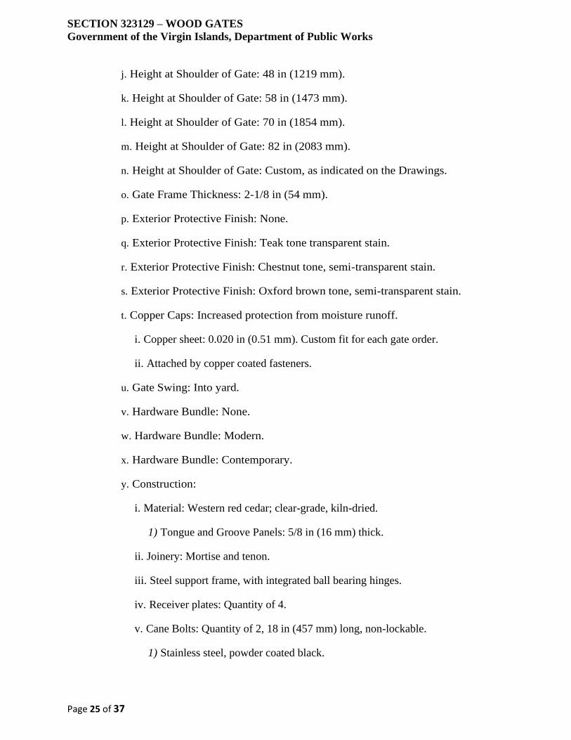
SECTION 323129 – WOOD GATES
Government of the Virgin Islands, Department of Public Works
Page 25 of 37
j. Height at Shoulder of Gate: 48 in (1219 mm).
k. Height at Shoulder of Gate: 58 in (1473 mm).
l. Height at Shoulder of Gate: 70 in (1854 mm).
m. Height at Shoulder of Gate: 82 in (2083 mm).
n. Height at Shoulder of Gate: Custom, as indicated on the Drawings.
o. Gate Frame Thickness: 2-1/8 in (54 mm).
p. Exterior Protective Finish: None.
q. Exterior Protective Finish: Teak tone transparent stain.
r. Exterior Protective Finish: Chestnut tone, semi-transparent stain.
s. Exterior Protective Finish: Oxford brown tone, semi-transparent stain.
t. Copper Caps: Increased protection from moisture runoff.
i. Copper sheet: 0.020 in (0.51 mm). Custom fit for each gate order.
ii. Attached by copper coated fasteners.
u. Gate Swing: Into yard.
v. Hardware Bundle: None.
w. Hardware Bundle: Modern.
x. Hardware Bundle: Contemporary.
y. Construction:
i. Material: Western red cedar; clear-grade, kiln-dried.
1) Tongue and Groove Panels: 5/8 in (16 mm) thick.
ii. Joinery: Mortise and tenon.
iii. Steel support frame, with integrated ball bearing hinges.
iv. Receiver plates: Quantity of 4.
v. Cane Bolts: Quantity of 2, 18 in (457 mm) long, non-lockable.
1) Stainless steel, powder coated black.
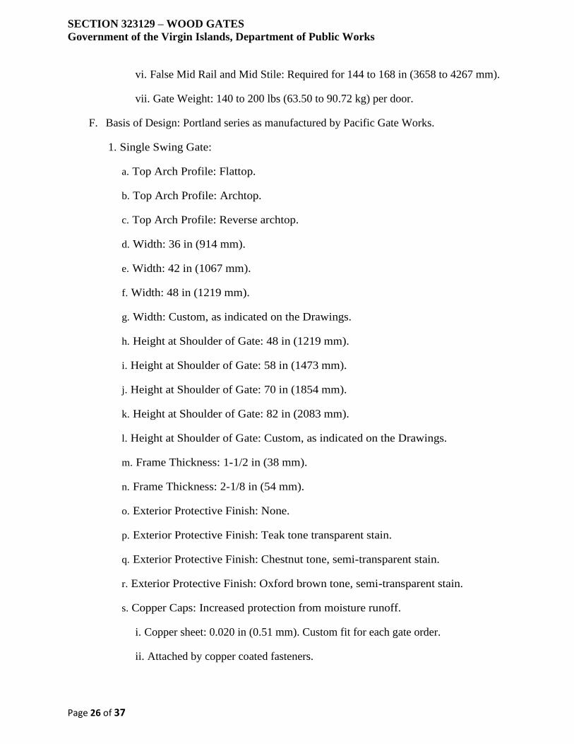
SECTION 323129 – WOOD GATES
Government of the Virgin Islands, Department of Public Works
Page 26 of 37
vi. False Mid Rail and Mid Stile: Required for 144 to 168 in (3658 to 4267 mm).
vii. Gate Weight: 140 to 200 lbs (63.50 to 90.72 kg) per door.
F. Basis of Design: Portland series as manufactured by Pacific Gate Works.
1. Single Swing Gate:
a. Top Arch Profile: Flattop.
b. Top Arch Profile: Archtop.
c. Top Arch Profile: Reverse archtop.
d. Width: 36 in (914 mm).
e. Width: 42 in (1067 mm).
f. Width: 48 in (1219 mm).
g. Width: Custom, as indicated on the Drawings.
h. Height at Shoulder of Gate: 48 in (1219 mm).
i. Height at Shoulder of Gate: 58 in (1473 mm).
j. Height at Shoulder of Gate: 70 in (1854 mm).
k. Height at Shoulder of Gate: 82 in (2083 mm).
l. Height at Shoulder of Gate: Custom, as indicated on the Drawings.
m. Frame Thickness: 1-1/2 in (38 mm).
n. Frame Thickness: 2-1/8 in (54 mm).
o. Exterior Protective Finish: None.
p. Exterior Protective Finish: Teak tone transparent stain.
q. Exterior Protective Finish: Chestnut tone, semi-transparent stain.
r. Exterior Protective Finish: Oxford brown tone, semi-transparent stain.
s. Copper Caps: Increased protection from moisture runoff.
i. Copper sheet: 0.020 in (0.51 mm). Custom fit for each gate order.
ii. Attached by copper coated fasteners.
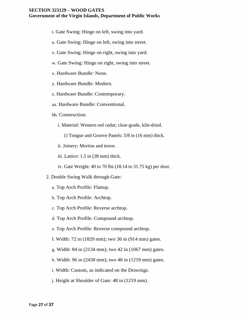
SECTION 323129 – WOOD GATES
Government of the Virgin Islands, Department of Public Works
Page 27 of 37
t. Gate Swing: Hinge on left, swing into yard.
u. Gate Swing: Hinge on left, swing into street.
v. Gate Swing: Hinge on right, swing into yard.
w. Gate Swing: Hinge on right, swing into street.
x. Hardware Bundle: None.
y. Hardware Bundle: Modern.
z. Hardware Bundle: Contemporary.
aa. Hardware Bundle: Conventional.
bb. Construction:
i. Material: Western red cedar; clear-grade, kiln-dried.
1) Tongue and Groove Panels: 5/8 in (16 mm) thick.
ii. Joinery: Mortise and tenon.
iii. Lattice: 1.5 in (38 mm) thick.
iv. Gate Weight: 40 to 70 lbs (18.14 to 31.75 kg) per door.
2. Double Swing Walk through Gate:
a. Top Arch Profile: Flattop.
b. Top Arch Profile: Archtop.
c. Top Arch Profile: Reverse archtop.
d. Top Arch Profile: Compound archtop.
e. Top Arch Profile: Reverse compound archtop.
f. Width: 72 in (1829 mm); two 36 in (914 mm) gates.
g. Width: 84 in (2134 mm); two 42 in (1067 mm) gates.
h. Width: 96 in (2438 mm); two 48 in (1219 mm) gates.
i. Width: Custom, as indicated on the Drawings.
j. Height at Shoulder of Gate: 48 in (1219 mm).
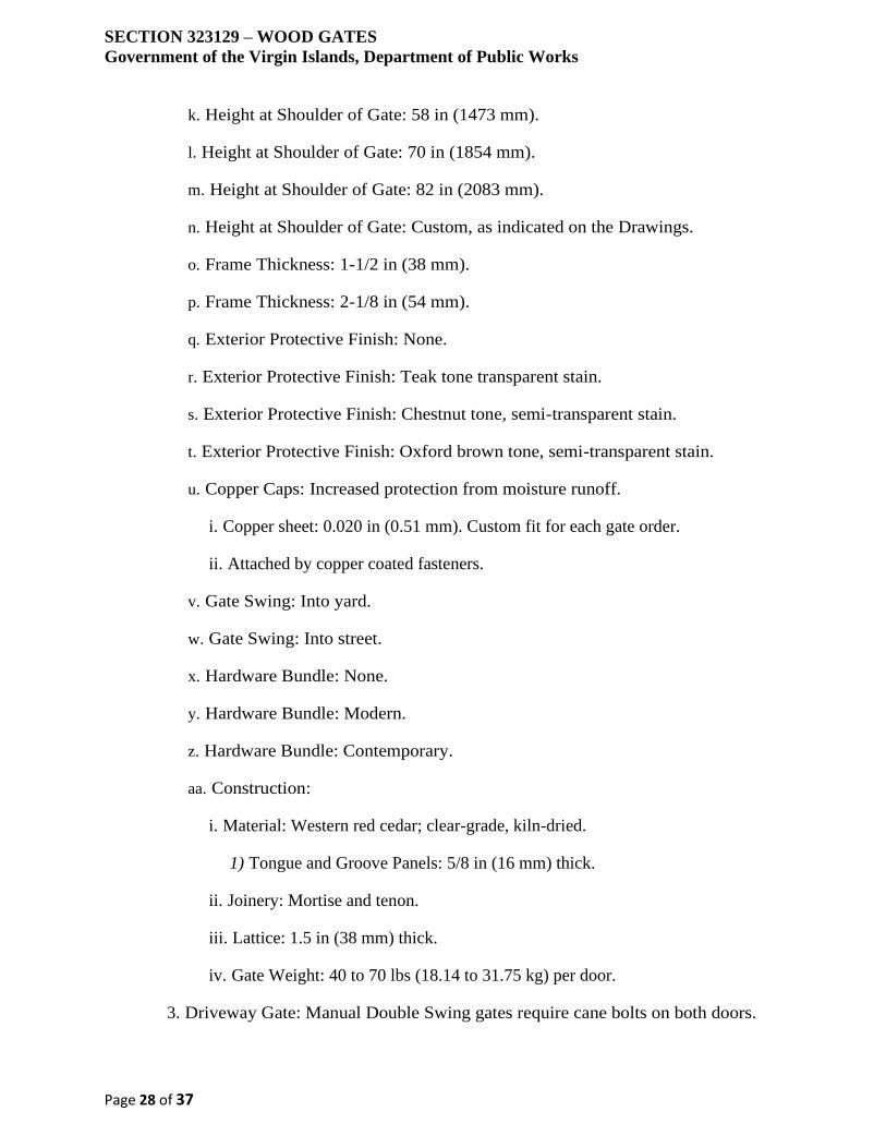
SECTION 323129 – WOOD GATES
Government of the Virgin Islands, Department of Public Works
Page 28 of 37
k. Height at Shoulder of Gate: 58 in (1473 mm).
l. Height at Shoulder of Gate: 70 in (1854 mm).
m. Height at Shoulder of Gate: 82 in (2083 mm).
n. Height at Shoulder of Gate: Custom, as indicated on the Drawings.
o. Frame Thickness: 1-1/2 in (38 mm).
p. Frame Thickness: 2-1/8 in (54 mm).
q. Exterior Protective Finish: None.
r. Exterior Protective Finish: Teak tone transparent stain.
s. Exterior Protective Finish: Chestnut tone, semi-transparent stain.
t. Exterior Protective Finish: Oxford brown tone, semi-transparent stain.
u. Copper Caps: Increased protection from moisture runoff.
i. Copper sheet: 0.020 in (0.51 mm). Custom fit for each gate order.
ii. Attached by copper coated fasteners.
v. Gate Swing: Into yard.
w. Gate Swing: Into street.
x. Hardware Bundle: None.
y. Hardware Bundle: Modern.
z. Hardware Bundle: Contemporary.
aa. Construction:
i. Material: Western red cedar; clear-grade, kiln-dried.
1) Tongue and Groove Panels: 5/8 in (16 mm) thick.
ii. Joinery: Mortise and tenon.
iii. Lattice: 1.5 in (38 mm) thick.
iv. Gate Weight: 40 to 70 lbs (18.14 to 31.75 kg) per door.
3. Driveway Gate: Manual Double Swing gates require cane bolts on both doors.

SECTION 323129 – WOOD GATES
Government of the Virgin Islands, Department of Public Works
Page 29 of 37
a. Top Arch Profile: Flattop.
b. Top Arch Profile: Archtop.
c. Top Arch Profile: Reverse archtop.
d. Top Arch Profile: Compound archtop.
e. Top Arch Profile: Reverse Compound archtop.
f. Width: 120 in (3048 mm); two 60 in (1524 mm) gates.
g. Width: 144 in (3658 mm); two 72 in (1829 mm) gates.
h. Width: 168 in (4267 mm); two 84 in (2134 mm) gates.
i. Width: Custom, as indicated on the Drawings.
j. Height at Shoulder of Gate: 48 in (1219 mm).
k. Height at Shoulder of Gate: 58 in (1473 mm).
l. Height at Shoulder of Gate: 70 in (1854 mm).
m. Height at Shoulder of Gate: 82 in (2083 mm).
n. Height at Shoulder of Gate: Custom, as indicated on the Drawings.
o. Gate Frame Thickness: 2-1/8 in (54 mm).
p. Exterior Protective Finish: None.
q. Exterior Protective Finish: Teak tone transparent stain.
r. Exterior Protective Finish: Chestnut tone, semi-transparent stain.
s. Exterior Protective Finish: Oxford brown tone, semi-transparent stain.
t. Copper Caps: Increased protection from moisture runoff.
i. Copper sheet: 0.020 in (0.51 mm). Custom fit for each gate order.
ii. Attached by copper coated fasteners.
u. Gate Swing: Into yard.
v. Construction:
i. Material: Western red cedar; clear-grade, kiln-dried.
SECTION 323129 – WOOD GATES
Government of the Virgin Islands, Department of Public Works
Page 30 of 37
1) Tongue and Groove Panels: 5/8 in (16 mm) thick.
ii. Joinery: Mortise and tenon.
iii. Lattice: 1.5 in (38 mm) thick.
iv. support frame, with integrated ball bearing hinges.
v. Receiver plates: Quantity of 4.
vi. Cane Bolts: Quantity of 2, 18 in (457 mm) long, non-lockable.
1) Stainless steel, powder coated black.
vii. False Mid Rail and Mid Stile: Required for 144 to 168 in (3658 to 4267 mm).
viii. Gate Weight: 140 to 200 lbs (63.50 to 90.72 kg) per door.
G. Basis of Design: Windsor series as manufactured by Pacific Gate Works.
1. Single Swing Gate:
a. Top Arch Profile: Flattop.
b. Top Arch Profile: Archtop.
c. Top Arch Profile: Reverse archtop.
d. Width: 36 in (914 mm).
e. Width: 42 in (1067 mm).
f. Width: 48 in (1219 mm).
g. Width: Custom, as indicated on the Drawings.
h. Height at Shoulder of Gate: 48 in (1219 mm).
i. Height at Shoulder of Gate: 58 in (1473 mm).
j. Height at Shoulder of Gate: 70 in (1854 mm).
k. Height at Shoulder of Gate: 82 in (2083 mm).
l. Height at Shoulder of Gate: Custom, as indicated on the Drawings.
m. Frame Thickness: 2-1/8 in (54 mm).
n. Frame Thickness: 3 in (76 mm).
SECTION 323129 – WOOD GATES
Government of the Virgin Islands, Department of Public Works
Page 31 of 37
o. Exterior Protective Finish: None.
p. Exterior Protective Finish: Teak tone transparent stain.
q. Exterior Protective Finish: Chestnut tone, semi-transparent stain.
r. Exterior Protective Finish: Oxford brown tone, semi-transparent stain.
s. Copper Caps: Increased protection from moisture runoff.
i. Copper sheet: 0.020 in (0.51 mm). Custom fit for each gate order.
ii. Attached by copper coated fasteners.
t. Gate Swing: Hinge on left, swing into yard.
u. Gate Swing: Hinge on left, swing into street.
v. Gate Swing: Hinge on right, swing into yard.
w. Gate Swing: Hinge on right, swing into street.
x. Hardware Bundle: None.
y. Hardware Bundle: Modern.
z. Hardware Bundle: Contemporary.
aa. Hardware Bundle: Conventional.
bb. Construction:
i. Material: Western red cedar; clear-grade, kiln-dried.
1) Pickets (WxT): 2 x 1.5 in (51 x 38 mm).
2) Spacing Between Pickets: 3 in (76 mm).
ii. Joinery: Mortise and tenon.
iii. Raised Panels: 1 in (25 mm) thick.
iv. Gate Weight: 50 to 95 lbs (22.68 to 43.09 kg) per door.
2. Double Swing Walk through Gate:
a. Top Arch Profile: Flattop.
b. Top Arch Profile: Archtop.
SECTION 323129 – WOOD GATES
Government of the Virgin Islands, Department of Public Works
Page 32 of 37
c. Top Arch Profile: Reverse archtop.
d. Top Arch Profile: Compound archtop.
e. Top Arch Profile: Reverse compound archtop.
f. Width: 72 in (1829 mm); two 36 in (914 mm) gates.
g. Width: 84 in (2134 mm); two 42 in (1067 mm) gates.
h. Width: 96 in (2438 mm); two 48 in (1219 mm) gates.
i. Width: Custom, as indicated on the Drawings.
j. Height at Shoulder of Gate: 48 in (1219 mm).
k. Height at Shoulder of Gate: 58 in (1473 mm).
l. Height at Shoulder of Gate: 70 in (1854 mm).
m. Height at Shoulder of Gate: 82 in (2083 mm).
n. Height at Shoulder of Gate: Custom, as indicated on the Drawings.
o. Frame Thickness: 2-1/8 in (54 mm).
p. Frame Thickness: 3 in (76 mm).
q. Exterior Protective Finish: None.
r. Exterior Protective Finish: Teak tone transparent stain.
s. Exterior Protective Finish: Chestnut tone, semi-transparent stain.
t. Exterior Protective Finish: Oxford brown tone, semi-transparent stain.
u. Copper Caps: Increased protection from moisture runoff.
i. Copper sheet: 0.020 in (0.51 mm). Custom fit for each gate order.
ii. Attached by copper coated fasteners.
v. Gate Swing: Into yard.
w. Gate Swing: Into street.
x. Hardware Bundle: None.
y. Hardware Bundle: Driveway Gate.
SECTION 323129 – WOOD GATES
Government of the Virgin Islands, Department of Public Works
Page 33 of 37
z. Construction:
i. Material: Western red cedar; clear-grade, kiln-dried.
1) Pickets (WxT): 2 x 1.5 in (51 x 38 mm).
2) Spacing Between Pickets: 3 in (76 mm).
ii. Joinery: Mortise and tenon.
iii. Raised Panels: 1 in (25 mm) thick.
iv. Gate Weight: 50 to 95 lbs (22.68 to 43.09 kg) per door.
3. Driveway Gate: Manual Double Swing gates require cane bolts on both doors.
a. Top Arch Profile: Flattop.
b. Top Arch Profile: Archtop.
c. Top Arch Profile: Reverse archtop.
d. Top Arch Profile: Compound archtop.
e. Top Arch Profile: Reverse Compound archtop.
f. Width: 120 in (3048 mm); two 60 in (1524 mm) gates.
g. Width: 144 in (3658 mm); two 72 in (1829 mm) gates.
h. Width: 168 in (4267 mm); two 84 in (2134 mm) gates.
i. Width: Custom, as indicated on the Drawings.
j. Height at Shoulder of Gate: 48 in (1219 mm).
k. Height at Shoulder of Gate: 58 in (1473 mm).
l. Height at Shoulder of Gate: 70 in (1854 mm).
m. Height at Shoulder of Gate: 82 in (2083 mm).
n. Height at Shoulder of Gate: Custom, as indicated on the Drawings.
o. Frame Thickness: 2-1/8 in (54 mm).
p. Frame Thickness: 3 in (76 mm).
q. Exterior Protective Finish: None.
SECTION 323129 – WOOD GATES
Government of the Virgin Islands, Department of Public Works
Page 34 of 37
r. Exterior Protective Finish: Teak tone transparent stain.
s. Exterior Protective Finish: Chestnut tone, semi-transparent stain.
t. Exterior Protective Finish: Oxford brown tone, semi-transparent stain.
u. Copper Caps: Increased protection from moisture runoff.
i. Copper sheet: 0.020 in (0.51 mm). Custom fit for each gate order.
ii. Attached by copper coated fasteners.
v. Gate Swing: Into yard.
w. Hardware Bundle: None.
x. Hardware Bundle: Modern.
y. Hardware Bundle: Contemporary.
z. Construction:
i. Material: Western red cedar; clear-grade, kiln-dried.
1) Pickets (WxT): 2 x 1.5 in (51 x 38 mm).
2) Spacing Between Pickets: 3 in (76 mm).
ii. Joinery: Mortise and tenon.
iii. Raised Panels: 1 in (25 mm) thick.
iv. Steel support frame, with integrated ball bearing hinges.
v. Receiver plates: Quantity of 4.
vi. Cane Bolts: Quantity of 2, 18 in (457 mm) long, non-lockable.
1) Stainless steel, powder coated black.
vii. Gate Weight: 170 to 250 lbs (77.11 to 113.40 kg) per door.
H. Basis of Design: Monterey GatePak series as manufactured by Pacific Gate Works.
1. Single Swing Gate:
a. Top Arch Profile: Flattop.
b. Width: 42 in (1067 mm).

SECTION 323129 – WOOD GATES
Government of the Virgin Islands, Department of Public Works
Page 35 of 37
c. Height: 70 in (1854 mm).
d. Height: Custom, as indicated on the Drawings.
e. Frame Thickness: 1-1/2 in (38 mm).
f. Exterior Protective Finish: None.
g. Gate Swing: Hinge on left, swing into yard.
h. Gate Swing: Hinge on left, swing into street.
i. Gate Swing: Hinge on right, swing into yard.
j. Gate Swing: Hinge on right, swing into street.
k. Hardware:
i. Latch: Quantity of 1.
1) Handle: 7 in (178 mm) tall. Operable from both sides.
2) Material: Steel with powder coated, rust resistant, black finish.
3) Padlock Eyes: Included.
4) Installation screws.
ii. Jambs: May be used for installation between masonry, block walls, and columns.
Quantity of 2.
1) Material: Premium, clear western red cedar.
2) Jamb Dimensions (DxWxH): 1.5 x 3.5 x 72 in (38 x 89 x 1829 mm).
iii. Hinges: Heavy duty, commercial grade butt style.
1) Self-closing.
2) Installation screws.
l. Construction:
i. Material: Western red cedar; clear-grade, kiln-dried.
1) Tongue and Groove Panels: 1 in (25 mm) thick.
ii. Joinery: Mortise and tenon.
iii. Gate Weight: 40 to 70 lbs (18.14 to 31.75 kg) per door.
SECTION 323129 – WOOD GATES
Government of the Virgin Islands, Department of Public Works
Page 36 of 37
PART 3 EXECUTION
3.1 EXAMINATION AND PREPARATION
A. Examine substrates for compliance with requirements for installation tolerances and
other conditions affecting performance.
B. Do not begin installation until substrates have been properly prepared.
C. If substrate preparation is the responsibility of another installer, notify Architect of
unsatisfactory preparation before proceeding.
3.2 INSTALLATION
A. Install products in strict accordance with manufacturer's instructions and approved
submittals. Follow manufacturer's recommendations.
B. Post Installation: Posts are not provided by the gate manufacturer and shall be provided
by the Subcontractor for the Work of this Section.
1. Post Size: 4 x 6 in (102 x 152 mm); actual dimensions, 3.5 x 5.5 in (89 x 140
mm).
a. The face side of post, the 5.5 in (140 mm) side, must be aligned with the gate.
2. Post Size (If the gate is 48 to 60 in (1219 to 1524 mm) wide, use a 6 x 6 in (1829
x 1829 mm) post minimum): 6 x 6 (152 x 152 mm); actual dimension, 5.5 x 5.5
in (140 x 140 mm).
3. Footing Depth: One half of exposed post height, or depth of local frost line plus
2 in (51 mm) whichever is greater. 20 in (508 mm) minimum.
4. Hole Depth: 14 to 16 in (354 to 406 mm).
a. Base Gravel in Footing: 3 in (76 mm).
3.3 PROTECTION
A. Take protective measures to prevent exposure to other construction activity. Protect
installed products until completion of project.
3.4 CLEANING
A. Clean surfaces to remove soiling, stains, dust, and dirt using materials acceptable to
manufacturer.
B. Touch-up, repair or replace damaged products and defective work, as directed by
Architect.

SECTION 323129 – WOOD GATES
Government of the Virgin Islands, Department of Public Works
Page 37 of 37
C. Leave installation area clean, free of residue and debris resulting from work of this
Section.
END OF SECTION
SECTION 323132 – WOOD COMPOSIT FENCES AND GATES
Government of the Virgin Islands, Department of Public Works
Page 1 of 7
PART 1 GENERAL
1.1 SECTION INCLUDES
A. Wood composite fences.
B. Wood composite gates.
C. Excavation for posts.
1.2 RELATED SECTIONS
A. Section 03 30 00 - Cast-in-Place Concrete.
B. Section 06 73 00 - Composite Decking.
1.3 REFERENCES
A. ASTM C 94 - Standard Specification for Ready-Mixed Concrete.
B. ASTM C 177 - Standard Test Method for Steady-State Heat Flux Measurements and
Thermal Transmission Properties by Means of the Guarded-Hot-Plate Apparatus.
C. ASTM D 143 - Standard Test Methods for Small Clear Specimens of Timber.
D. ASTM D 198 - Standard Test Methods of Static Tests of Lumber in Structural Sizes.
E. ASTM D 1037 - Standard Test Methods for Evaluating Properties of Wood-Base Fiber
and Particle Panel Materials.
F. ASTM D 1413 - Standard Test Method for Wood Preservatives by Laboratory Soil-
Block Cultures.
G. ASTM D 1761 - Standard Test Methods for Mechanical Fasteners in Wood.
H. ASTM D1929 - Standard Test Method for Determining Ignition Temperature of
Plastics.
I. ASTM D 2047 - Standard Test Method for Static Coefficient of Friction of Polish-
Coated Flooring Surfaces as Measured by the James Machine.
J. ASTM D 2394 - Standard Methods for Simulated Service Testing of Wood and Wood-
Base Finish Flooring.
K. ASTM D 2395 - Standard Test Methods for Specific Gravity of Wood and Wood-
Based Materials.
L. ASTM D 4761 - Standard Test Methods for Mechanical Properties of Lumber and
Wood-Base Structural Material.

SECTION 323132 – WOOD COMPOSIT FENCES AND GATES
Government of the Virgin Islands, Department of Public Works
Page 2 of 7
M. ASTM E 84 - Standard Test Method for Surface Burning Characteristics of Building
Materials.
N. ASTM F 1679 - Standard Test Method for Using a Variable Incidence Tribometer
(VIT).
O. American Wood Preservers Association (AWPA) E1-06 - Standard Method for
Laboratory Evaluation to Determine Resistance to Subterranean Termites.
1.4 DESIGN / PERFORMANCE REQUIREMENTS
A. Design Requirements: Design fence system to withstand Miami/Dade County 110
MPH steady wind and 130 MPH gusting wind tests.
1.5 SUBMITTALS
A. Submit under provisions of Section 01 30 00 - Administrative Requirements.
B. Product Data: Manufacturer's data sheets on each product to be used indicating sizes,
profiles, surface finishes, and performance characteristics, and including:
1. Preparation instructions and recommendations.
2. Storage and handling requirements and recommendations.
3. Installation methods.
4. Instructions on care and cleaning of composite wood products.
C. Verification Samples: For each finish product specified, two samples, minimum size 9
inches (229 mm) square, representing actual product, color, and patterns.
D. Manufacturer's Certificates: Certify products meet or exceed specified requirements.
E. Closeout Submittals: Provide manufacturer's maintenance instructions that include
recommendations for cleaning and maintenance.
1.6 DELIVERY, STORAGE, AND HANDLING
A. Deliver, store and handle products in accordance with the manufacturer's instructions.
B. Store level and flat, off ground or floor, with supports at each end and maximum 24
inches on center.
C. Do not stack wood composite over 8 feet (203 mm) high.
D. Cover wood composite with waterproof covering, vented to prevent moisture buildup.
1.7 WARRANTY

SECTION 323132 – WOOD COMPOSIT FENCES AND GATES
Government of the Virgin Islands, Department of Public Works
Page 3 of 7
A. Provide manufacturer's 25-year residential warranty / 10 year commercial warranty
providing coverage against checking, splitting, splintering, rotting, structural damage
from termites, and fungal decay of wood composite.
PART 2 PRODUCTS
2.1 MANUFACTURERS
A. Acceptable Manufacturer: Trex Fencing, which is located at: 160 Exeter Dr.;
Winchester, VA 22603; Email:request info (); Web:www.trexfencing.com
1. Requests for substitutions will be considered in accordance with provisions of
Section 01 60 00 - Product Requirements.
2.2 MATERIALS
A. Wood composite: Reclaimed wood and plastic with integral coloring; free from toxic
chemicals and preservatives:
1. Characteristics:
a. Abrasion resistance: 0.01 inch wear per 1000 revolutions, tested to ASTM D
2394.
b. Hardness: 1124 pounds, tested to ASTM D 143.
c. Self ignition temperature: 743 degrees F, tested to ASTM D 1929.
d. Flash ignition temperature: 698 degrees F, tested to ASTM D 1929.
e. Flame spread rating: 80, tested to ASTM E 84.
f. Water absorption, 24 hour immersion, tested to ASTM D 1037:
i. Sanded surface: 4.3 percent.
ii. Unsanded surface: 1.7 percent.
g. Thermal expansion coefficient, 36 inch long samples:
i. Width: 35.2 x 10⁻⁶ to 42.7 x 10⁻⁶.
SECTION 323132 – WOOD COMPOSIT FENCES AND GATES
Government of the Virgin Islands, Department of Public Works
Page 4 of 7
ii. Length: 16.1 x 10⁻⁶ to 19.2 x 10⁻⁶.
h. Fastener withdrawal, tested to ASTM D 1761:
i. Nail: 163 pounds per inch.
ii. Screw: 558 pounds per inch.
i. Static coefficient of friction:
i. Dry: 0.53 to 0.55, tested to ASTM D 2047.
ii. Dry: 0.59 to 0.70, tested to ASTM F 1679.
iii. Wet: 0.70 to 0.75, tested to ASTM F 1679.
j. Fungus resistance, white and brown rot: No decay, tested to ASTM D 1413.
k. Termite resistance: 9.6 rating, tested to AWPA E-1.
l. Specific gravity: 0.91 to 0.95, tested to ASTM D 2395.
m. Compression:
i. Parallel: 1806 PSI ultimate, 550 PSI design, tested to ASTM D 198.
ii. Perpendicular: 1944 PSI ultimate, 625 PSI design, tested to ASTM D 143.
n. Tensile strength: 854 PSI ultimate, 250 PSI design, tested to ASTM D 198.
o. Shear strength: 561 PSI ultimate, 200 PSI design, tested to ASTM D 143.
p. Modulus of rupture: 1423 PSI ultimate, 250 PSI design, tested to ASTM D
4761.
q. Modulus of elasticity: 175,000 PSI ultimate, 100,000 PSI design, tested to
ASTM D 4761.
r. Thermal conductivity: 1.57 BTU per inch per hour per square foot at 85
degrees F, tested to ASTM C 177.
2.3 COMPONENTS
A. Fence System: Seclusions Privacy Fence System.
1. Fence height:
a. 4 feet.
SECTION 323132 – WOOD COMPOSIT FENCES AND GATES
Government of the Virgin Islands, Department of Public Works
Page 5 of 7
b. 6 feet.
c. 8 feet.
d. 10 feet.
e. 12 feet.
f. Custom height as indicated on the Drawings.
2. Components:
a. Fence posts.
b. Post caps:
i. Pyramid.
ii. Flat.
iii. Crown.
c. Top rail
d. Aluminum bottom rail inserts.
e. Bottom rail covers/Pickets, 67 inch.
f. Bottom rail covers/Pickets, 91 inch.
g. Fence brackets.
3. Surface texture: Smooth.
4. Color:
a. Saddle.
b. Winchester Grey.
c. Woodland Brown.
2.4 ACCESSORLES
A. Fasteners: 1-5/8 inch galvanized or corrosion-resistant coated steel. Provide finish nails
where applicable.
B. Concrete: Provide as Specified in Section 03 30 00 - Cast-in-Place Concrete; minimum
4000 PSI compressive strength at 28 days, with a 3 to 5 inch slump.
SECTION 323132 – WOOD COMPOSIT FENCES AND GATES
Government of the Virgin Islands, Department of Public Works
Page 6 of 7
C. Concrete: Provide concrete conforming to ASTM C 94; minimum 4000 PSI
compressive strength at 28 days, with a 3 to 5 inch slump.
D. Gate Hardware:
1. Provide two Trex hinges per gate leaf minimum, and size to gate weight and
conditions.
2. Provide center gate stop and drop rod for double gates.
3. Provide with latching mechanism.
4. Provide with padlock provisions.
PART 3 EXECUTION
3.1 EXAMINATION
A. Do not begin installation until substrates have been properly prepared.
B. If substrate preparation is the responsibility of another installer, notify Architect of
unsatisfactory preparation before proceeding.
3.2 PREPARATION
A. Clean surfaces thoroughly prior to installation.
B. Prepare surfaces using the methods recommended by the manufacturer for achieving
the best result for the substrate under the project conditions.
3.3 INSTALLATION
A. Install in accordance with manufacturer's instructions.
B. Cut and drill wood composite using carbide tipped blades.
C. Space posts maximum 8 feet on center.
D. Drill post holes into undisturbed or compacted soil; excavate deeper in soft or loose
soils and for posts with heavy lateral loads.
E. Drill posts to 12 inch diameter. Locate bottom of post 30 inches below grade or below
frost line whichever is greater.
F. Place top of concrete 2 inches below finished grade.
G. Place top of concrete flush with finished grade.
H. Place top of concrete 2 inches above finished grade.
SECTION 323132 – WOOD COMPOSIT FENCES AND GATES
Government of the Virgin Islands, Department of Public Works
Page 7 of 7
I. Screw fence brackets to posts with four 1-5/8 inch long exterior screws.
J. Cut top rails, pickets, bottom rail covers and aluminum bottom rails to lengths required.
K. Slide bottom rail covers over aluminum bottom rail pieces.
L. Position aluminum bottom rail on fence brackets with deeper side of rail channel facing
downward.
M. Cut end pickets to height to provide clearance under brackets and screw to posts.
N. Insert pickets into bottom rail, interlocking adjacent pieces.
O. Position top rail and screw attach to top brackets with 1-5/8 inch long exterior screws.
P. Use finish nails to secure pickets to rails if the pickets are not tightly interlocked.
Q. Place post caps over post tops and secure with construction adhesive or four finish
nails.
3.4 CLEANING
A. Clean wood composite to remove stains:
5. Mold, mildew, and berry and leaf stains: Clean surfaces with conventional deck
wash containing detergent or sodium hypochlorite.
6. Rust and ground-in dirt: Clean surfaces with cleaner containing oxalic or
phosphoric acid.
7. Oil and grease: Clean surfaces with detergent containing degreasing agent.
3.5 PROTECTION
A. Protect installed products until completion of project.
B. Touch-up, repair or replace damaged products before Substantial Completion.
END OF SECTION
SECTION 328000 – IRRIGATION SYSTEMS
Government of the Virgin Islands, Department of Public Works
Page 1 of 18
PART 1 GENERAL
1.1 RELATED DOCUMENTS
A. Drawings and general provisions of the Contract, including General Conditions and
Division 01 Specification Sections, apply to this Section.
B. Specifications throughout all Divisions of the Project Manual are directly applicable to
this Section, and this Section is directly applicable to them.
1.2 SUMMARY
A. This Section specifies the requirements for providing the Irrigation System as indicated
on the Drawings and/or electronic files such as .dwg, pdf, etc.
B. Contractor shall provide Irrigation System as a complete system including but not
limited to: heads, valves, valve boxes, control wire splice boxes, control wiring, electric
controller, piping circuits, and all accessories, including electric power source
coordination and installation.
1.3 QUALITY ASSURANCE
A. Available Manufacturers - Subject to compliance with specified requirements,
manufacturers offering products which may be incorporated in the work are included
in the specifications or denoted on the Drawings, and/or electronic files such as .dwg,
pdf, etc.
B. Installation of Irrigation System shall be performed under the direction and supervision
of a currently licensed State of Texas Irrigator with not less than 5 years of direct design
and installation experience in this type of work.
C. Reference Standards Applicable to this Section:
1. ANSI: American National Standards Institute
a. Z55.1: Gray Finishes for Industrial Apparatus and Equipment
2. ASTM: American Society for Testing and Materials
a. B88: Specifications for Seamless Copper water tube.
b. D 1785: Specifications for Poly Vinyl Chloride (PVC) Plastic Pipe,
Schedules 40, 80, and 120.
c. D 2241: Specification for Poly Vinyl Chloride (PVC) Pressure-Rated Pipe
(SDR Series)
d. D 2466: Specification for Poly Vinyl Chloride (PVC) Plastic Pipe Fittings,
Schedule 80
SECTION 328000 – IRRIGATION SYSTEMS
Government of the Virgin Islands, Department of Public Works
Page 2 of 18
e. D 2564: Specification for Solvent Cements for Poly Vinyl Chloride (PVC)
Plastic Pipe and Fittings
f. F 690: Practice for Underground Installation of Thermoplastic Pressure
Piping Irrigation Systems
3. AWWA: American Water Works Association
a. C 500: Gate Valves, 3 inches through 48 inches NPS, for Water and Sewage
Systems
b. C 506: Backflow Prevention Devices, Reduced Pressure Principle and
Double Check Valve Types
4. ICC: International Code Council
a. IBC: International Building Code
b. IPC: International Plumbing Code
5. NEMA: National Electrical Manufacturer's Assoc.
a. 250: Enclosures for Electrical Equipment (1000 Volts Maximum)
6. NFPA: National Fire Protection Association
a. NFPA 70 (NEC): National Electric Code
7. NSF: National Sanitation Foundation
a. No. 14 - Plastic Piping System Components and Related Materials
8. Chapter 344 – Texas Water Code-Regulations governing irrigation
9. Chapter 290 – Texas Water Code-Regulations governing backflow installation
and inspections
10. Chapter 37 Texas Water Code- Regulations governing irrigation licensing
11. Chapter 1903 Texas Water Code – Regulations governing irrigation licensing.
D. The contractor shall maintain a Record Drawing as prescribed by Section 01 78 39.
This record or log shall include all changes and modifications to the original plan on a
daily basis. Upon completion of the project, these changes contained in the Record
Drawing shall be incorporated into the design, notes, etc on all of the designs,
documents, etc, and will be provided to the Owner in the form of a completed Record
Drawing.
E. This record or log must be maintained on the job site during normal business hours.
SECTION 328000 – IRRIGATION SYSTEMS
Government of the Virgin Islands, Department of Public Works
Page 3 of 18
F. The Contractor shall provide a completed “As Built” Drawing to the Owner at the
completion of the project. This Record Drawing shall be in the form of paper copy as
well as a .DWG formatted CD.
1.4 SUBMITTALS
A. SYSTEM DESIGN
1. The Irrigation System design shall be a complete Irrigation System including
but not limited to: heads, valves, valve boxes, control wire splice boxes, control
wiring, electric controller, piping circuits, and all accessories, including electric
power source coordination and installation. This design shall be scaled to a
1:20 scale. This design shall be provided to the Owner. This design shall be
provided on paper following generally accepted industry standards utilizing a
title block, page numbers, page descriptions, and all other pertinent data relating
to the Irrigation System. The design shall include the following:
2. A hydraulic calculation for the worst-case scenario irrigation head in the worst
case irrigation zone shall be provided. This calculation shall provide the “actual
head pressure” for this identified sprinkler head and shall be representative for
the system.
3. A hydraulic calculation showing the “design pressure” for the worst-case
scenario irrigation head in the worst case irrigation zone shall be provided.
4. The licensed irrigator or Landscape Architect shall affix their seal over these
hydraulic calculations.
5. The manufacturer’s recommended pressure for each product used shall be noted
on the design and hydraulic section.
6. Location of Heads - Represent design location as accurately as possible. Make
minor adjustments on site with approval of the irrigation designer or Landscape
Architect as necessary to ensure consistent and even spacing where applicable.
The goal for the design is 100% coverage, head to head spacing, and matched
precipitation rate (MPR) application. Set all heads minimum 4” from back of
curb and 4" from edge of concrete walls.
7. The design shall utilize a “center fed” valve configuration and progressive pipe
sizing of all irrigation lines. If appropriate, the use of a looped main is
preferred. When a looped main is used, there shall be independent isolation
valves at each leg of the looped main.
8. The Irrigation System design shall comply with a maximum velocity of 5 linear
feet per second through the discharge piping of the Irrigation System.
SECTION 328000 – IRRIGATION SYSTEMS
Government of the Virgin Islands, Department of Public Works
Page 4 of 18
9. The system shall have the landscape beds and turf on separate zones. Rotors
and spray shall also be on different zones. If drip is used, it shall utilize pressure
compensation, pressure regulation, and pressure filtration.
10. The design shall include a sheet(s) titled “Typical Exploded Views”. This
sheet shall show detail of specific installation applications. All major
component utilized on the project shall have a “Typical Exploded View”
11. A statement on the irrigation designer or Landscape Architect’s letterhead
shall be included that indicates the irrigation design provided to the Owner is
in 100% compliance with all prevailing city codes, ordinances, and the TCEQ
standards, rules, and regulations. In addition, the document will contain the
seal of either the licensed irrigator or the Landscape Architect.
12. Submit an ET (Evapotranspiration) based schedule indicating length of time
each valve is to be open to produce a given amount of precipitation for the ET
value of July. In addition, submit the recommended monthly adjustment rates
in percentages for the ET of the other eleven months. Include any schedules
deemed appropriate for any “watering windows” that may be imposed by the
Authority Having Jurisdiction (AHJ) and/or requested by the Owner.
B. Product Data
1. Submit manufacturer's technical data, specifications, installation instructions
and all shop drawings of the sprinkler heads, automatic valves, controllers,
backflow preventers, connections, details, and related items to the Grounds and
Landscape Department.
2. Submit the manufacturer’s operation instructions for all applicable irrigation
components.
3. Submit maintenance instructions on all items requiring manufacturer's standard
detail submittal.
C. Water Tap Connections
4. All fees, permits, and costs associated with the installation of the landscape
irrigation water meter(s) shall be the responsibility of the Contractor unless
otherwise directed by the Owner. The Owner will be responsible for any
deposits dictated by the AHJ.
D. Water
1. Potable water to be supplied by Owner. Contractor shall make provisions for all
connections required.
E. Permits and Inspections
SECTION 328000 – IRRIGATION SYSTEMS
Government of the Virgin Islands, Department of Public Works
Page 5 of 18
1. Copies of all required permits and inspections and their associated fees shall be
part of this contract and are the responsibility of the Contractor. A copy of all
inspections shall be forwarded to the University of Texas, MD Anderson
Grounds and Landscape Department.
1.5 PRODUCT DELIVERY AND HANDLING
A. Materials, where appropriate, shall be delivered in manufacturer's unopened packaging
labeled to indicate manufacturer's name and product identification. Ensure that
packaging and labeling remain intact until installation. Materials shall be stored
protected from the elements, including direct sunlight.
B. Pipes shall be handled to prevent being damaged and to maintain their straightness.
Pipe ends shall be wrapped. Pipes shall be stored on beds the full length of the pipes.
Damaged or dented pipes or fittings shall not be used.
C. At no time will pipe joints other than swing joints; be accepted at lengths that are less
than 20 feet in length.
1.6 EXTRA MATERIALS
A. Refer to Section 01 78 46 for Maintenance Material Requirements.
1.7 DEFINITIONS
A. Irrigation Main - Irrigation main is the piping from the water source(s) to control
valves. Irrigation main is that pipe which is on the pressure side of irrigation control
valves. This definition shall include looped mains and sub-looped mains.
B. Irrigation Lateral Lines - Irrigation lateral line is the piping from the control valves to
the irrigation heads. Lateral line is that pipe which is on the non-pressure side of
irrigation control valves.
PART 2 PRODUCTS
2.1 PIPES
A. Markings - Thermoplastic pipes shall be marked in accordance with ASTM D 1785
and ASTM D 2241 as applicable and shall bear the NSF mark in accordance with NSF
14.
B. Irrigation Main Pipe - ASTM D 2231, PVC, 1120 or 1220, Schedule 40. or Class 200.
C. Irrigation Lateral Line Pipe
1. Pipes 3/4-inch diameter and larger: ASTM D 2231, PVC, 1120 or 1220, SDR
21.0, 200 PSI

SECTION 328000 – IRRIGATION SYSTEMS
Government of the Virgin Islands, Department of Public Works
Page 6 of 18
2. Pipes 1/2-inch diameter: ASTM D 2241, PVC, 1120 or 1220, SDR 13.5, 315
PSI
D. Copper Tubing - ASTM B 88, Type K
2.2 FITTINGS FOR SOLVENT WELDED JOINTS
A. Schedule 40: ASTM D 2466
B. Schedule 80: ASTM D 2467
2.3 SOLVENT CEMENT FOR SOLVENT WELDED JOINTS
A. IPS Weld-On PVC Cement: IPS Corporation, 455 West Victoria Street, Compton, Ca
90220; 1-800-421-2677.
1. Weld-On 700 for PVC pipe up to 4” and /or Weld-On 710 for PVC pipe up to
2”.
2. In the event PVC pipe is greater than 4” then a Weld-On 704 series “medium”
body shall be used.
B. IPS Weld-On Primer: IPS Corporation, 455 West Victoria Street, Compton, Ca 90220;
1-800-421-2677.
1. Weld-On P-68 or P-70 primer shall be used for surface preparation for all PVC
pipe and fittings prior to cement applications.
2.4 FITTINGS FOR THREADED JOINTS
A. ASTM D 2466, PVC, Schedule 80.
2.5 SEALANT FOR THREADED JOINTS UNDER CONSTANT PRESSURE
A. No liquid Teflon or “pipe dope” shall be used on any threaded electric irrigation control
valve.
B. A high-quality MIL-SPEC (MIL-T-27730) Teflon tape shall be used for threaded
electric irrigation control valves.
C. All other types of threaded joints under constant pressure may use RECTOR SEAL
LIQUID TEFLON by Rector Seal Corp., 2830 Produce Row, Houston, Texas 77023,
(713) 928-6423, or approved equal.
2.6 SLEEVES UNDER PAVING FOR CONTROL WIRE AND IRRIGATION LINES
A. ASTM D 2466, PVC, Schedule 40, sized as shown on Drawings.
SECTION 328000 – IRRIGATION SYSTEMS
Government of the Virgin Islands, Department of Public Works
Page 7 of 18
B. In the event the sleeve is not shown on plan or an additional sleeve is to be installed,
the sleeve shall be at a minimum two (2) pipe sizes larger than the pipe that is to be
routed through the sleeve.
C. For sleeves that are to be used specifically for control wires only, the sleeve shall be a
1-1/2” sleeve
D. All sleeves shall extend a minimum of 12” beyond the obstacle that was sleeved.
E. All sleeves shall be marked and located on the Record Drawings by one of the methods
listed below:
1. A minimum of two measurements from two known and fixed positions that
terminate at the end of the sleeve.
2. A GPS (Global Positioning System) fix in degrees, minutes, and seconds for the
longitude and latitude location of the end of the sleeve.
F. All sleeves shall have an identification marker installed in the concrete at the point
where the sleeve is located. These markers shall be Berntsen Survey markers as
provided by Berntsen International Inc., P.O. Box Madison, WI 53708-8670.
Telephone number: 800-356-7388
1. The markers shall be a 3 ½” Aluminum domed concrete marker, part number
C-35-D as per Berntsen International Inc.
2. The markers shall have at the minimum, the following information stamped on
them: MD Anderson. Irrigation Sleeve Sleeve Size in inches
3. Marker layout shall be approved by MD Anderson, and Grounds and Landscape
Department prior to placing final order for the markers.
4. The markers shall be installed as per the manufacturer’s specifications.
2.7 IRRIGATION SPRINKLER HEADS
A. All rotor and spray sprinkler heads and all landscape irrigation drip line shall be
provided by Rain Bird, 6991 E. South point Road, Tucson, As, 85706. Telephone 520-
741-6100 unless specifically authorized by MD Anderson, Grounds and Landscape
Department.
B. Spray Heads
1. Spray heads shall be Rain Bird 1800 series sprinkler heads with the height as
indicated on the design or design legend. Under no conditions will an 1802
series sprinkler head be installed.
SECTION 328000 – IRRIGATION SYSTEMS
Government of the Virgin Islands, Department of Public Works
Page 8 of 18
2. The nozzles shall be from the “MPR” series unless otherwise indicated on the
design.
3. All 1800 series sprinkler heads shall have filters installed.
4. SAM-PRS (Seal-A-Matic check valve and in-stem pressure regulation)
sprinkler heads shall be installed on all projects where the turf area is adjoined
by a pedestrian walk path. They are not required in areas other than low
drainage or areas that are specifically called for in the design. All other areas
will use the standard 1800’s as specified.
5. If adjustments of radius are required on a specific design that reduces the radius
of a given nozzle by more than 25%, then a Rain Bird PCS (Pressure
Compensating Screen) with the appropriate color shall be installed.
6. All sprinklers shall be connected to irrigation lateral lines by “swing joints”.
These swing joints shall be constructed via flexible PVC with a street elbow on
one end and a coupler on the other end. These constructed swing joints shall
be solvent welded with “hot glue” and shall be constructed at least 24 hours
prior to installation.
7. The nozzles on pop-up spray head body shall be as shown on Drawings and
shall be capable of covering the radius as designated on Drawings.
C. Rotor Heads
1. Rotor heads shall be from the Rain Bird product line. When the site conditions
permit, Rain Bird 5000 series rotor heads with MPR nozzles shall be used.
When site conditions dictate larger diameter rotors, the designer shall utilize
Matched Precipitation Rate design concepts in the nozzle selection.
D. Drip Irrigation
1. Drip irrigation products shall be from the Rain Bird product line.
2. All use of drip irrigation that is incorporated into the design shall utilize the
following items:
a. All drip applications shall utilize “Pressure Compensation” type products and
a uniform regulated pressure.
b. All drip applications shall utilize a pressure regulator incorporated into the
valve configuration.
c. All drip applications shall have air/vacuum relief valves and flush flow
valves installed as per manufactures specifications.
SECTION 328000 – IRRIGATION SYSTEMS
Government of the Virgin Islands, Department of Public Works
Page 9 of 18
d. All drip applications shall incorporate a Rain Bird Automatic Filter kit with
each section of drip. The drain line from this filter shall be routed to either
a drain approved by the Owner, or to an area where it can be discharged via
an impact type head with a large nozzle. Under no circumstances shall the
drain line be “day lighted”. The stainless-steel mesh screen shall be a 150-
micron mesh. The valve configuration shall be sized according to the
manufacturer’s specifications.
3. When site conditions permit, utilize the Rain Bird Landscape Drip line. The
spacing standards shall be:
a. 12” spacing – sandy soil conditions
b. 18” spacing – loam soil conditions
c. 24” spacing – clay soil conditions
d. Design preference is for use of uniform rows, centers fed zones, and
maximum spacing not exceeding the manufacturer’s specifications.
4. The drip shall be designed and installed as per the manufacturer’s
recommendations.
2.8 ELECTRIC REMOTE-CONTROL VALVES
A. Remote control irrigation zone valves shall be manufactured by Rain Bird, 6991 E.
Southpoint Road, Tucson, Az, 85706. Telephone 520-741-6100. These valves will be
Rain Bird PEB Normally Closed (N.C.) series valves with the size shown on the design.
B. A Normally Open (N.O.) master valve shall be used with the RainMaster DX2
controller. This master valve shall be as per RainMaster specification.
2.9 REMOTE CONTROL VALVE TAGS
A. Remote control valve tags shall be plastic tags with plastic wire to attach numbered tag
to valve.
2.10 VALVE BOX
A. Valve boxes shall be heavy duty plastic 17 inch by 11-3/4 inch by 12-inch depth, black
with black cover. Valve box shall be non-hinged, bolt type by Carson Industries, Inc.,
1925 Street, LaVerne, CA 91750, (213) 732-6265, or approved equal.
2.11 CONTROL WIRE SPLICE BOXES
A. Control wire splice boxes shall be heavy duty plastic 10-inch diameter by 10-1/4-inch-
deep, black with black cover, No. 910-12B, by Carson Industries, Inc. or approved
equal.
SECTION 328000 – IRRIGATION SYSTEMS
Government of the Virgin Islands, Department of Public Works
Page 10 of 18
2.12 GRAVEL BACKFILL
A. Gravel backfill for valve boxes and control wire splice boxes shall be 3/8-inch diameter
pea gravel.
2.13 ELECTRIC CONTROLLER(S)
A. Controllers shall be RainMaster DX2 Evolution by RainMaster Irrigation Systems,
3910-B Royal Avenue, Simi Valley, California 93063 (805)527-4498
1. The DX2 Evolution controller shall be used on all projects unless otherwise
specified by MD Anderson, Grounds and Landscape Department.
2. The DX2 Controllers shall be housed in wall mounted Stainless Steel cabinets
provided by RainMaster unless otherwise specified.
3. In areas where a wall mount controller is not feasible a Stainless-Steel Pedestal
mount controller will be used.
4. All DX2 controllers shall have the lighting protection kit installed and shall be
grounded and installed as per manufacturer’s specifications.
5. Coordinate with the Owner as to the communication source for the connectivity
to the Central Control system.
a. Once the communications source is determined, the appropriate
communications equipment shall be provided as specified under the
“communications” specifications.
6. The number of zones per each controller shall be determined by the irrigation
designer or Landscape Architect based on site conditions, water sources,
watering windows, and input from the Owner. All controllers specified shall
have a capacity to add an additional two zones of irrigation to the number of
zones needed without exceeding the controller’s capacity.
7. Install the appropriately sized flow sensor as per Rainmaster installation
specifications.
8. A master valve shall be used in conjunction with the DX2 controller. The
master valve shall be a normally open (N.O.) valve as specified by RainMaster.
B. Equipment Associated with RainMaster Central Control
1. Master Valve
a. A master valve shall be installed on all Irrigation Systems that utilize a DX2
Controller unless otherwise specified by the Owner. The master valve shall
be as specified by RainMaster.
SECTION 328000 – IRRIGATION SYSTEMS
Government of the Virgin Islands, Department of Public Works
Page 11 of 18
2. Flow Sensor
a. The flow sensor shall be a Rainmaster flow sensor sized as per the
RainMaster specifications for the main line pipe size and flow.
b. A DX-Flow sensing circuit board will be required for flow sensors
c. Each flow sensor will require EV-CAB-SEN flow sensing cable. The
maximum allowable distance is 2000’ linear feet.
3. Communications
a. The appropriate type of communications equipment, including cards, wire,
and devices shall be specified to correspond with each controller that is used.
The Contractor shall coordinate with the Owner as to the connectivity of
each device and the existing Central Control software.
4. Rain Switch
a. A wireless rain switch by Hunter shall be installed as per manufacturer’s
specifications utilizing the normally open (N.O.) lead. A conventional hard
wire switch will be used when wireless is not compatible. Coordinate with
the RainMaster distributor to obtain the required interface kit- “DXCID-
KIT”.
2.14 IRRIGATION CONTROL WIRE
A. Wire: Solid copper wire, NEC type UF, UL listed for direct burial in ground.
Minimum size: No. 14 AWG. No. 12 UF for runs over 1000 LF.
B. The wires for all irrigation control valves shall be red in color.
C. The common wires for all irrigation control valves shall be white in color.
D. Splicing Material shall be King Wire Connectors, Tan in color, by King Innovation,
3801 Lloyd King Drive, St. Charles, Mo 63304. A new King wire connector shall be
used for every electrical connection
E. An extra “transient” or spare wire shall be installed. This “transient” wire shall be
yellow in color and will be labeled as spare in the controller.
2.15 BACKFLOW PREVENTER
A. Backflow Preventers shall be bronze and copper, pressure vacuum breaker (PVB)
assembly Febco model 765 or reduced pressure device (RPZ) model 825 YA by Febco
Sales, Inc. (CMB Industries), P.O. Box 8070, Fresno, CA 93747, (209) 252-0791, or
approved equal. Size as per Drawings.
SECTION 328000 – IRRIGATION SYSTEMS
Government of the Virgin Islands, Department of Public Works
Page 12 of 18
B. The backflow devices shall be installed in accordance with the manufacturer, TCEQ,
and local codes and standards.
C. The backflow device(s) shall be installed in an enclosure by StrongBox, V.I.T.
Products, Inc., 800.729-1314.
1. The enclosure shall be the “Smooth Touch Vandal Resistant Backflow
Enclosure” model sized as per the backflow device. It shall be powder coated
the standard dark green color.
2. Each enclosure shall include a “PolarBearier” insulated blanket sized to fit the
backflow device.
3. Each enclosure shall be installed on Contractor built enclosure pad. The holes
for the irrigation lines shall be large enough in diameter so as to accommodate
foam insulation wrap around the irrigation pipe so as to protect against freeze
and chafing. There shall be a drainage area so as to alleviate any standing water
inside the enclosure.
a. The pad shall be adequately anchored and shall have the concrete sleeved
where the irrigation lines protrude through the concrete.
b. The pad shall have pea gravel no larger than 3/8” diameter installed in the
Contractor installed drainage hole in the bottom of the pad.
c. The pad shall have a mechanism installed that will allow the enclosure pad
to lock the enclosure to the pad.
d. The Owner will provide padlocks to the Contractor. The Contractor shall
ensure all enclosures are locked.
e. The pad shall be installed in locations as per the manufacturer’s
specifications in a location approved by M D Anderson, Grounds and
Landscape Department.
2.16 GATE VALVES
A. Gate Valves shall comply with AWWA C-500. Valves up to 3-inch size shall be 125-
pound, bronze body, bronze-mounted, non-rising stem with solid wedge gates. The
size shall correspond to the main line they are attached to.
2.17 QUICK COUPLING VALVES
A. Quick coupling valves shall have heavy duty brass construction, durable thermoplastic
rubber cover, stainless steel internal valve spring, two-piece body design. These valves
shall be sized as 1”.
B. Provide four valve keys with 3/4-inch swivel hose ells.

SECTION 328000 – IRRIGATION SYSTEMS
Government of the Virgin Islands, Department of Public Works
Page 13 of 18
C. The Quick Coupling valves shall be installed as per the “typical exploded view” found
on the detail sheets. The 1” size shall supersede any sizing that may be shown on an
“exploded view”.
D. Coordinate location of the Quick Coupling valves with M D Anderson, Grounds and
Landscape Department.
PART 3 EXECUTION
3.1 TRENCHING AND BACKFILLING
A. General - Contractor shall comply with Division 31 of these Specifications. Excavate
straight and true with bottom uniformly sloped to low points. Protect existing lawns
and plantings. Remove and replant as necessary to complete installation. Replace
damaged lawn areas and plants with new products to restore to existing installation's
original condition.
B. Minimum Cover - Provide 18-inch minimum cover over top of installed irrigation main
piping. Provide 12-inch minimum cover over top of installed irrigation lateral line
piping. Provide 2 inches of earth between parallels and wire. Parallels shall be laid
side-by-side, not stacked.
C. Backfill - Backfill with clean material from excavation after obtaining Landscape
Architect's approval. Remove organic material, as well as rocks and debris larger than
1 inch in diameter. Place acceptable backfill in 6-inch lifts and water jet all trenches.
D. Existing Lawns - Where trenching is required across existing lawns, (or in event of
changes or repairs after new lawn has been established), uniformly cut strips of sod 6
inches wider than trench. Remove sod in rolls of suitable size for handling and keep
moistened until replanted.
1. Backfill trench to within 6 inches of finished grade and compact. Continue fill
with acceptable topsoil and compact to bring sod even with existing lawn.
2. Replant sod within 2 days after removal, roll and water generously.
3. Resod and restore to original condition all sod areas not in healthy condition
equal to adjoining lawns 30 days after replanting.
3.2 INSTALLATION
A. General - Unless otherwise indicated, Contractor shall comply with requirements of
the governing International Plumbing Code and Chapter 344 of the Texas Water Code.
Verify all applicable irrigation codes.
B. Pipes
SECTION 328000 – IRRIGATION SYSTEMS
Government of the Virgin Islands, Department of Public Works
Page 14 of 18
1. Piping Mains and Laterals - Lay out sprinkler mainlines and perform line
adjustments and site modifications to laterals prior to excavation. Lay pipe on
solid subbase, uniformly sloped without humps or depressions.
2. PVC Pipe Assembly
a. Cut PVC pipe, square and de-burr. Use PVC pipe cutter when possible.
Clean pipe and fittings using primer as recommended by the PVC pipe
manufacturer. Use purple tinted primer to aid in visual inspection.
b. Apply a thin even flow coat of PVC solvent cement to the pipe first, then the
inside of the fitting. Utilize the appropriate size applicator and the correct
temperature range of solvent weld material for the size of the pipe. Cure
joints as recommended by the manufacturer and keep pipe and fitting out of
service during curing period. Construct watertight joints equal or greater in
strength than the pipe. Do not tap pipe at fittings.
3. Install plastic pipe in dry weather, when temperature is above 40 degrees F. and
in accordance with manufacturer's written instructions. Allow joints to cure at
least 24 hours at temperature above 40 degrees F. before testing.
4. Plastic pipe shall be snaked in the trenches in a manner to provide for expansion
and contraction as recommended by pipe manufacturer.
C. Sleeves Under Paving - The majority of sleeves under paving are existing as shown on
Drawings. Where boring is required for new sleeves (refer to Drawings), it shall be a
"wet bore." Install sleeves 12" beyond edge of pavement. Perform trench and backfill
in accordance with these specifications.
D. Irrigation Heads
1. Flush irrigation lines with full head of water and install heads after hydrostatic
test is completed.
2. Install heads at manufacturer's recommended heights. Activate the zone valve
and flush out the heads.
3. Locate part-circle heads to maintain a minimum distance of 4 inches from walls
and 4 inches from other boundaries, unless otherwise indicated.
4. Check for uniformity of coverage and pattern correctness. Adjust for 100%
coverage where required.
5. Install nozzles as indicated on the design.
6. Adjust arcs and radius at the stated manufacturer’s pressure. Adjust the flow
control valve until this pressure is obtained at the last head on each zone.
SECTION 328000 – IRRIGATION SYSTEMS
Government of the Virgin Islands, Department of Public Works
Page 15 of 18
E. Electric Remote-Control Valves
1. Adjust automatic control valves to provide flow rate at rated operating pressure
required for each irrigation section.
2. Install valves in valve boxes, arranged for easy adjustment and removal. Locate
valves to ensure ease of access for maintenance such that no physical
interference with other elements of the project exists.
3. Install a 3’ expansion coil at each valve.
F. Remote Control Valve Tags - One Remote Control Valve Tag shall be attached to stem
of each electric remote-control valve. Tags shall be numbered sequentially. Numbers
shall correspond to station numbers and controller numbers. Provide tags and
corresponding numbers for wires pulled for future valves.
G. Valve Boxes - Install valve boxes to cover electric remote-control valves. Top of valve
box shall be flush with finished grade. Bury minimum 4 bricks under base of each box
as support.
H. Control Wire Splice Boxes - Install control wire splice box to cover any splice in
control wire. Top of valve box shall be flush with finished grade. Bury minimum 4
bricks under base of each box as support. Install control wire splice box to cover wires
pulled for future valves.
I. Gravel Backfill - Backfill valve boxes and control wire splice boxes with gravel,
minimum 6-inch depth.
J. Electric Controller
1. Controllers shall be fully grounded as per the manufacturer’s specifications.
2. Connect remote control valves to controller in clockwise sequence to
correspond with stations 1, 2, 3, successively.
3. Provide M D Anderson, Grounds and Landscape Department with a size
reduced copy of the irrigation plan.
4. Provide two keys to Owner. Keys to be matched with existing controller key
locking mechanisms.
5. Power to Controller & Locations: Locations shown on plan for controllers is
approximate. Final location shall be determined on site by Owner. Contractor
shall supply 120 VAC to controller from adjacent existing power sources.
Follow local governing codes in electrical work.
SECTION 328000 – IRRIGATION SYSTEMS
Government of the Virgin Islands, Department of Public Works
Page 16 of 18
6. Take an ohm reading on all irrigation electric control valves and spare wiring
prior to connection to the controller. Note the ohms readings on the Record
Drawing.
K. Irrigation Control Wires
1. Provide 24-volt system for control of automatic circuit-section valves of
underground Irrigation System. Provide unit capacity to suit number of circuits
indicated.
2. Install control wires with irrigation mains and laterals in common trench where
possible. Lay control wires neatly together to side of pipe. Provide 3’
expansion coils at valves, corners, bores and snake wire in trench to allow for
contraction. Tape wires in bundles at 10-foot intervals. Line splices will be
allowed on runs of 500 Ft. or more. Splices shall be made and placed in control
wire splice boxes.
3. Common ground wire shall be white. No other wires shall be white.
4. Supply one extra wire, for each direction of run, to valve which is located the
greatest distance from the controller. Extra wire shall be yellow and labeled as
spare in the controller.
5. Color of wire from controller to control valve shall be consistent to each valve.
Red shall be used for the zone valves.
6. Provide 12-inch-long expansion loop within 3 feet of each wire connection and
splice on runs of wire 100 feet or longer.
L. Backflow Preventers
1. Make required connection to water supply according to local codes and
manufacturer's written instructions.
2. Install pressure type backflow devices at required grade in accordance with the
local Plumbing Code. Exposed mainline and mainline risers above PVC pipe
main elevation shall be copper. Install a brass union in the riser on the upstream
and downstream of the device.
3. Install the “StrongBox” and insulation blanket as per manufacturer’s
recommendations.
4. Provide an isolation valve (gate valve) prior to the PVB. Install a valve box as
per specifications over the valve. Locate the valve on the as built drawings
utilizing one of the following methods.
a. A minimum of two measurements from two known and fixed positions that
terminate at the end of the sleeve.
SECTION 328000 – IRRIGATION SYSTEMS
Government of the Virgin Islands, Department of Public Works
Page 17 of 18
b. A GPS (Global Positioning System) fix in degrees, minutes, and seconds for
the longitude and latitude location of device.
5. Have the PVB tested. Provide the Owner a copy of this inspection.
M. The Contractor shall maintain a Record Drawing. This Record Drawing shall include
all changes and modifications to the original plan on a daily basis. Upon completion
of the project, these changes contained in the Record Drawing shall be noted on all of
the designs, documents, etc, and will be provided to the Owner in the form of a
completed Record Drawing.
3.3 TESTING
A. General - Notify Landscape Architect 48 hours in advance when testing will be
conducted. Conduct tests in presence of Landscape Architect and a representative of
M D Anderson, Grounds and Landscape Department.
B. Hydrostatic Test - Test irrigation main line, before backfilling trenches, to a hydrostatic
pressure of not less than 100 psi for 1 hour. Piping may be tested in sections to expedite
work. Remove and repair or replace piping and connections which do not pass
hydrostatic testing. System shall not lose more than 1-1/2 gallons of water in 1 hour.
C. Shut off mainline at backflow preventer during non-working hours until Contractor has
demonstrated the mainline is stable.
D. Operational Testing - Perform operational testing after hydrostatic testing is completed,
backfill is in place, and irrigation heads are adjusted to final position.
1. Demonstrate to Landscape Architect that system meets coverage requirements,
is as specified and indicated, and that automatic controls function properly.
2. Coverage requirements are based on operation of one circuit at a time.
3. After completion of grading, sodding, and rolling of grass areas, carefully adjust
lawn sprinkler heads so they will be flush with or not more than 1/2 inch above
finished grade. Set shrub sprinkler heads not more than 1/2 inch above top of
mulch.
3.4 MAINTENANCE
A. Contractor shall coordinate with the Owner on the implementation of the initial ET
based irrigation schedule.
B. Contractor shall correctly maintain the Irrigation System during the installation process
and throughout the landscaping maintenance service period as specified in Section 32
91 20 - Exterior Landscape Maintenance.

SECTION 328000 – IRRIGATION SYSTEMS
Government of the Virgin Islands, Department of Public Works
Page 18 of 18
C. Contractor shall provide Record Drawings for new work, showing dimensioned
location of valves, meters, vacuum breakers, controllers, and mainline. Contractor
shall request reproducible mylars form the Landscape Architect in preparation of
Record Drawings.
END OF SECTION
SECTION 329000 – PLANTING
Government of the Virgin Islands, Department of Public Works
Page 1 of 9
PART 1 - GENERAL
1.1 RELATED DOCUMENTS
A. Drawings and general provisions of the Contract, including General and
Supplementary Conditions and Division 01 Specification Sections, apply to this
Section.
1.2 SUMMARY
A. Section includes planting soils specified by composition of the mixes.
B. Related Requirements:
1. Section 32930 PLANTS for placing planting soil for plantings.
1.3 DEFINITIONS
A. AAPFCO: Association of American Plant Food Control Officials.
B. Backfill: The earth used to replace or the act of replacing earth in an excavation.
This can be amended or unamended soil as indicated.
C. CEC: Cation exchange capacity.
D. Compost: The product resulting from the controlled biological decomposition of
organic material that has been sanitized through the generation of heat and
stabilized to the point that it is beneficial to plant growth.
E. Duff Layer: A surface layer of soil, typical of forested areas, that is composed of
mostly decayed leaves, twigs, and detritus.
F. Imported Soil: Soil that is transported to Project site for use.
G. Layered Soil Assembly: A designed series of planting soils, layered on each other,
that together produce an environment for plant growth.
H. Manufactured Soil: Soil produced by blending soils, sand, stabilized organic soil
amendments, and other materials to produce planting soil.
I. NAPT: North American Proficiency Testing Program. An SSSA program to assist
soil-, plant-, and water-testing laboratories through interlaboratory sample
exchanges and statistical evaluation of analytical data.
J. Organic Matter: The total of organic materials in soil exclusive of undecayed plant
and animal tissues, their partial decomposition products, and the soil biomass; also
called "humus" or "soil organic matter."

SECTION 329000 – PLANTING
Government of the Virgin Islands, Department of Public Works
Page 2 of 9
K. Planting Soil: Existing, on-site soil; imported soil; or manufactured soil that has
been modified as specified with soil amendments and perhaps fertilizers to produce
a soil mixture best for plant growth.
L. RCRA Metals: Hazardous metals identified by the EPA under the Resource
Conservation and Recovery Act.
M. SSSA: Soil Science Society of America.
N. Subgrade: Surface or elevation of subsoil remaining after excavation is complete,
or the top surface of a fill or backfill before planting soil is placed.
O. Subsoil: Soil beneath the level of subgrade; soil beneath the topsoil layers of a
naturally occurring soil profile, typified by less than 1 percent organic matter and
few soil organisms.
P. Surface Soil: Soil that is present at the top layer of the existing soil profile. In
undisturbed areas, surface soil is typically called "topsoil"; but in disturbed areas
such as urban environments, the surface soil can be subsoil.
Q. USCC: U.S. Composting Council.
1.4 ACTION SUBMITTALS
A. Product Data: For each type of product.
2. Include recommendations for application and use.
3. Include test data substantiating that products comply with requirements.
4. Include sieve analyses for aggregate materials.
5. Material Certificates: For each type of imported soil and soil mix before
delivery to the site, according to the following:
a. Manufacturer's qualified testing agency's certified analysis of standard
products.
b. Analysis of fertilizers, by a qualified testing agency, made according to
AAPFCO methods for testing and labeling and according to AAPFCO's
SUIP #25.
c. Analysis of nonstandard materials, by a qualified testing agency, made
according to SSSA methods, where applicable.
B. Samples: For each bulk-supplied material, 1-quart volume of each in sealed
containers labeled with content, source, and date obtained. Each Sample shall be
typical of the lot of material to be furnished; provide an accurate representation of
composition, color, and texture.
SECTION 329000 – PLANTING
Government of the Virgin Islands, Department of Public Works
Page 3 of 9
1.5 QUALITY ASSURANCE
A. Testing Agency Qualifications: An independent, state-operated, or university-
operated laboratory; experienced in soil science, soil testing, and plant nutrition;
with the experience and capability to conduct the testing indicated; and that
specializes in types of tests to be performed.
1.6 PRECONSTRUCTION TESTING
A. Preconstruction Soil Analyses: For each unamended soil type, perform testing on
soil samples and furnish soil analysis and a written report containing soil-
amendment and fertilizer recommendations by a qualified testing agency
performing the testing according to "Soil- Sampling Requirements" and "Testing
Requirements" articles.
1. Have testing agency identify and label samples and test reports according to
sample collection and labeling requirements.
1.7 SOIL-SAMPLING REQUIREMENTS
A. Sample Collection and Labeling: Have samples taken and labeled by Contractor
in presence of Owner’s Representative.
1. Number and Location of Samples: Minimum of three representative soil
samples for each soil to be used or amended for landscaping purposes.
2. Procedures and Depth of Samples: As directed by Owner’s Representative.
3. Labeling: Label each sample with the date, location keyed to a site plan or other
location system, visible soil condition, and sampling depth.
1.8 TESTING REQUIREMENTS
A. General: Perform tests on soil samples according to requirements in this article.
B. Physical Testing:
1. Soil Texture: Soil-particle, size-distribution analysis by one of the following
methods according to SSSA's "Methods of Soil Analysis - Part 1-Physical and
Mineralogical Methods":
a. Sieving Method: Report sand-gradation percentages for very coarse, coarse,
medium, fine, and very fine sand; and fragment-gradation (gravel)
percentages for fine, medium, and coarse fragments; according to USDA
sand and fragment sizes.
b. Hydrometer Method: Report percentages of sand, silt, and clay.

SECTION 329000 – PLANTING
Government of the Virgin Islands, Department of Public Works
Page 4 of 9
2. Total Porosity: Calculate using particle density and bulk density according to
SSSA's "Methods of Soil Analysis - Part 1-Physical and Mineralogical
Methods."
3. Water Retention: According to SSSA's "Methods of Soil Analysis - Part 1-
Physical and Mineralogical Methods."
4. Saturated Hydraulic Conductivity: According to SSSA's "Methods of Soil
Analysis - Part 1-Physical and Mineralogical Methods"; at 85% compaction,
according to ASTM D 698 (Standard Proctor).
C. Chemical Testing:
1. CEC: Analysis by sodium saturation at pH 7 according to SSSA's "Methods of
Soil Analysis - Part 3- Chemical Methods."
D. Fertility Testing: Soil-fertility analysis, including the following:
1. Percentage of organic matter.
2. CEC, calcium percent of CEC, and magnesium percent of CEC.
3. Soil reaction (acidity/alkalinity pH value).
4. Buffered acidity or alkalinity.
5. Nitrogen ppm.
6. Phosphorous ppm.
7. Potassium ppm.
8. Manganese ppm.
9. Manganese-availability ppm.
10. Zinc ppm.
11. Zinc availability ppm.
12. Copper ppm.
13. Sodium ppm and sodium absorption ratio.
14. Soluble-salts ppm.
15. Presence and quantities of problem materials including salts and metals cited
in the Standard protocol. If such problem materials are present, provide
additional recommendations for corrective action.
SECTION 329000 – PLANTING
Government of the Virgin Islands, Department of Public Works
Page 5 of 9
16. Other deleterious materials, including their characteristics and content of each.
E. Organic-Matter Content: Analysis using loss-by-ignition method according to
SSSA's "Methods of Soil Analysis - Part 3- Chemical Methods."
F. Recommendations: Based on the test results, state recommendations for soil
treatments and soil amendments to be incorporated to produce satisfactory planting
soil suitable for healthy, viable plants indicated. Include, at a minimum,
recommendations for nitrogen, phosphorous, and potassium fertilization, and for
micronutrients.
1. Fertilizers and Soil Amendment Rates: State recommendations in weight per
1000 sq. ft. for 6-inch depth of soil.
2. Soil Reaction: State the recommended liming rates for raising pH or sulfur for
lowering pH according to the buffered acidity or buffered alkalinity in weight
per 1000 sq. ft. for 6-inch depth of soil.
1.9 DELIVERY, STORAGE, AND HANDLING
A. Packaged Materials: Deliver packaged materials in original, unopened containers
showing weight, certified analysis, name and address of manufacturer, and
compliance with state and Federal laws if applicable.
B. Bulk Materials:
1. Do not dump or store bulk materials near structures, utilities, walkways and
pavements, or on existing turf areas or plants.
2. Provide erosion-control measures to prevent erosion or displacement of bulk
materials, discharge of soil-bearing water runoff, and airborne dust reaching
adjacent properties, water conveyance systems, or walkways.
3. Do not move or handle materials when they are wet or frozen.
4. Accompany each delivery of bulk fertilizers and soil amendments with
appropriate certificates.
PART 2 - MATERIALS
2.1 PLANTING SOILS SPECIFIED BY COMPOSITION
A. General: Soil amendments, fertilizers, and rates of application specified in this
article are guidelines that may need revision based on testing laboratory's
recommendations after preconstruction soil analyses are performed.
SECTION 329000 – PLANTING
Government of the Virgin Islands, Department of Public Works
Page 6 of 9
B. Planting-Soil Type for turf and planting beds: Existing, on-site surface soil, with
the duff layer, if any, retained and stockpiled on-site; modified to produce viable
planting soil. Blend existing, on-site surface soil with soil amendments, per
Owner’s standards.
2.2 INORGANIC SOIL AMENDMENTS
A. Lime: ASTM C 602, agricultural liming material containing a minimum of 80
percent calcium carbonate equivalent and as follows:
1. Class: T, with a minimum of 99 percent passing through a No. 8 sieve and a
minimum of 75 percent passing through a No. 60 sieve.
2. Class: O, with a minimum of 95 percent passing through a No. 8 sieve and a
minimum of 55 percent passing through a No. 60 sieve.
3. Form: Provide lime in form of ground dolomitic limestone.
B. Sulfur: Granular, biodegradable, and containing a minimum of 90 percent
elemental sulfur, with a minimum of 99 percent passing through a No. 6 sieve and
a maximum of 10 percent passing through a No. 40 sieve.
C. Iron Sulfate: Granulated ferrous sulfate containing a minimum of 20 percent iron
and 10 percent sulfur.
D. Perlite: Horticultural perlite, soil amendment grade.
E. Agricultural Gypsum: Minimum 90 percent calcium sulfate, finely ground with 90
percent passing through a No. 50 sieve.
F. Sand: Clean, washed, natural or manufactured, free of toxic materials, and
according to ASTM C 33/C 33M.
2.3 ORGANIC SOIL AMENDMENTS
A. Compost: Well-composted, stable, and weed-free organic matter produced by
composting feedstock and bearing USCC's "Seal of Testing Assurance."
B. Manure: Well-rotted, unleached, stable or cattle manure containing not more than
25 percent by volume of straw, sawdust, or other bedding materials; free of toxic
substances, stones, sticks, soil, weed seed, debris, and material harmful to plant
growth.
PART 3 - EXECUTION
3.1 GENERAL
A. Place planting soil and fertilizers according to requirements in other Specification
Sections and as indicated in the drawings.
SECTION 329000 – PLANTING
Government of the Virgin Islands, Department of Public Works
Page 7 of 9
B. Verify that no foreign or deleterious material or liquid such as paint, paint washout,
concrete slurry, concrete layers or chunks, cement, plaster, oils, gasoline, diesel
fuel, paint thinner, turpentine, tar, roofing compound, or acid has been deposited
in planting soil.
C. Proceed with placement only after unsatisfactory conditions have been corrected.
3.2 PLACING AND MIXING PLANTING SOIL OVER EXPOSED SUBGRADE
A. General: Apply and mix unamended soil with amendments on-site to produce
required planting soil. Do not apply materials or till if existing soil or subgrade is
frozen, muddy, or excessively wet.
B. Subgrade Preparation: Till subgrade to a minimum depth of 4 inches. Remove
stones larger than 1-1/2 inches in any dimension and sticks, roots, rubbish, and
other extraneous matter and legally dispose of them off Owner's property.
1. Apply, add soil amendments, and mix approximately half the thickness of
unamended soil over prepared, loosened subgrade according to "Mixing"
Paragraph below. Mix thoroughly into top 2 inches of subgrade. Spread
remainder of planting soil.
C. Mixing: Spread unamended soil to total depth of 6 inches or as indicated on
Drawings, but not less than required to meet finish grades after mixing with
amendments and natural settlement. Do not spread if soil or subgrade is frozen,
muddy, or excessively wet.
1. Amendments: Apply soil amendments evenly on surface, and thoroughly blend
them with unamended soil to produce planting soil.
D. Compaction: Compact each blended lift of planting soil to 75 to 82 percent of
maximum Standard Proctor density according to ASTM D 698 and tested in-place.
E. Finish Grading: Grade planting soil to a smooth, uniform surface plane with loose,
uniformly fine texture. Roll and rake, remove ridges, and fill depressions to meet
finish grades.
3.3 BLENDING PLANTING SOIL IN PLACE
A. General: Mix amendments with in-place, unamended soil to produce required
planting soil. Do not apply materials or till if existing soil or subgrade is frozen,
muddy, or excessively wet.
B. Preparation: Till unamended, existing soil only in planting areas free of existing
tree roots and outside of critical root zones, to a minimum depth of 6 inches.
Remove stones larger than 1-1/2 inches in any dimension and sticks, roots, rubbish,
and other extraneous matter and legally dispose of them off Owner's property.

SECTION 329000 – PLANTING
Government of the Virgin Islands, Department of Public Works
Page 8 of 9
C. Mixing: Apply soil amendments evenly on surface, and thoroughly blend them into
full depth of unamended, in-place soil to produce planting soil.
D. Finish Grading: Grade planting soil to a smooth, uniform surface plane with loose,
uniformly fine texture. Roll and rake, remove ridges, and fill depressions to meet
finish grades.
3.4 PROTECTION
A. Protection Zone: Identify protection zones according to local standards.
B. Protect areas of in-place soil from additional compaction, disturbance, and
contamination. Prohibit the following practices within these areas except as
required to perform planting operations:
1. Storage of construction materials, debris, or excavated material.
2. Parking vehicles or equipment.
3. Vehicle traffic.
4. Foot traffic.
5. Erection of sheds or structures.
6. Impoundment of water.
7. Excavation or other digging unless otherwise indicated.
C. If planting soil or subgrade is over compacted, disturbed, or contaminated by
foreign or deleterious materials or liquids, remove the planting soil and
contamination; restore the subgrade as directed by Owner and replace
contaminated planting soil with new planting soil.
3.5 CLEANING
A. Protect areas adjacent to planting-soil preparation and placement areas from
contamination. Keep adjacent paving and construction clean and work area in an
orderly condition.
B. Remove surplus soil and waste material including excess subsoil, unsuitable
materials, trash, and debris and legally dispose of them off Owner's property unless
otherwise indicated.
1. Dispose of excess subsoil and unsuitable materials on-site where directed by
Owner.

SECTION 329000 – PLANTING
Government of the Virgin Islands, Department of Public Works
Page 9 of 9
END OF SECTION

SECTION 329113- SOIL PREPARATION Government of the Virgin Islands, Department of Public Works
PROJECT NAME
Project Location, U.S. Virgin Islands
Page 1 of 9
PART 1 - GENERAL
1.1 RELATED DOCUMENTS
A. Drawings and general provisions of the Contract, including General and
Supplementary Conditions and Division 01 Specification Sections, apply to this
Section.
1.2 SUMMARY
A. Section includes planting soils specified by composition of the mixes.
B. Related Requirements:
1. Section 32930 PLANTS for placing planting soil for plantings.
1.1 DEFINITIONS
A. AAPFCO: Association of American Plant Food Control Officials.
B. Backfill: The earth used to replace or the act of replacing earth in an excavation.
This can be amended or unamended soil as indicated.
C. CEC: Cation exchange capacity.
D. Compost: The product resulting from the controlled biological decomposition of
organic material that has been sanitized through the generation of heat and
stabilized to the point that it is beneficial to plant growth.
E. Duff Layer: A surface layer of soil, typical of forested areas, that is composed of
mostly decayed leaves, twigs, and detritus.
F. Imported Soil: Soil that is transported to Project site for use.
G. Layered Soil Assembly: A designed series of planting soils, layered on each other,
that together produce an environment for plant growth.
H. Manufactured Soil: Soil produced by blending soils, sand, stabilized organic soil
amendments, and other materials to produce planting soil.
I. NAPT: North American Proficiency Testing Program. An SSSA program to assist
soil-, plant-, and water-testing laboratories through interlaboratory sample
exchanges and statistical evaluation of analytical data.
J. Organic Matter: The total of organic materials in soil exclusive of undecayed plant
and animal tissues, their partial decomposition products, and the soil biomass; also
called "humus" or "soil organic matter."

SECTION 329113- SOIL PREPARATION Government of the Virgin Islands, Department of Public Works
PROJECT NAME
Project Location, U.S. Virgin Islands
Page 2 of 9
K. Planting Soil: Existing, on-site soil; imported soil; or manufactured soil that has
been modified as specified with soil amendments and perhaps fertilizers to produce
a soil mixture best for plant growth.
L. RCRA Metals: Hazardous metals identified by the EPA under the Resource
Conservation and Recovery Act.
M. SSSA: Soil Science Society of America.
N. Subgrade: Surface or elevation of subsoil remaining after excavation is complete,
or the top surface of a fill or backfill before planting soil is placed.
O. Subsoil: Soil beneath the level of subgrade; soil beneath the topsoil layers of a
naturally occurring soil profile, typified by less than 1 percent organic matter and
few soil organisms.
P. Surface Soil: Soil that is present at the top layer of the existing soil profile. In
undisturbed areas, surface soil is typically called "topsoil"; but in disturbed areas
such as urban environments, the surface soil can be subsoil.
Q. USCC: U.S. Composting Council.
1.2 ACTION SUBMITTALS
A. Product Data: For each type of product.
1. Include recommendations for application and use.
2. Include test data substantiating that products comply with requirements.
3. Include sieve analyses for aggregate materials.
4. Material Certificates: For each type of imported soil and soil mix before
delivery to the site, according to the following:
a. Manufacturer's qualified testing agency's certified analysis of standard
products.
b. Analysis of fertilizers, by a qualified testing agency, made according to
AAPFCO methods for testing and labeling and according to AAPFCO's
SUIP #25.
c. Analysis of nonstandard materials, by a qualified testing agency, made
according to SSSA methods, where applicable.
SECTION 329113- SOIL PREPARATION Government of the Virgin Islands, Department of Public Works
PROJECT NAME
Project Location, U.S. Virgin Islands
Page 3 of 9
B. Samples: For each bulk-supplied material, 1-quart volume of each in sealed
containers labeled with content, source, and date obtained. Each Sample shall be
typical of the lot of material to be furnished; provide an accurate representation of
composition, color, and texture.
1.3 QUALITY ASSURANCE
A. Testing Agency Qualifications: An independent, state-operated, or university-
operated laboratory; experienced in soil science, soil testing, and plant nutrition;
with the experience and capability to conduct the testing indicated; and that
specializes in types of tests to be performed.
1.4 PRECONSTRUCTION TESTING
A. Preconstruction Soil Analyses: For each unamended soil type, perform testing on
soil samples and furnish soil analysis and a written report containing soil-
amendment and fertilizer recommendations by a qualified testing agency
performing the testing according to "Soil- Sampling Requirements" and "Testing
Requirements" articles.
1. Have testing agency identify and label samples and test reports according to
sample collection and labeling requirements.
1.5 SOIL-SAMPLING REQUIREMENTS
B. Sample Collection and Labeling: Have samples taken and labeled by Contractor
in presence of Owner’s Representative.
1. Number and Location of Samples: Minimum of three representative soil
samples for each soil to be used or amended for landscaping purposes.
2. Procedures and Depth of Samples: As directed by Owner’s Representative.
3. Labeling: Label each sample with the date, location keyed to a site plan or other
location system, visible soil condition, and sampling depth.
1.6 TESTING REQUIREMENTS
A. General: Perform tests on soil samples according to requirements in this article.
B. Physical Testing:
1. Soil Texture: Soil-particle, size-distribution analysis by one of the following
methods according to SSSA's "Methods of Soil Analysis - Part 1-Physical and
Mineralogical Methods":

SECTION 329113- SOIL PREPARATION Government of the Virgin Islands, Department of Public Works
PROJECT NAME
Project Location, U.S. Virgin Islands
Page 4 of 9
a. Sieving Method: Report sand-gradation percentages for very coarse, coarse,
medium, fine, and very fine sand; and fragment-gradation (gravel)
percentages for fine, medium, and coarse fragments; according to USDA
sand and fragment sizes.
b. Hydrometer Method: Report percentages of sand, silt, and clay.
2. Total Porosity: Calculate using particle density and bulk density according to
SSSA's "Methods of Soil Analysis - Part 1-Physical and Mineralogical
Methods."
3. Water Retention: According to SSSA's "Methods of Soil Analysis - Part 1-
Physical and Mineralogical Methods."
4. Saturated Hydraulic Conductivity: According to SSSA's "Methods of Soil
Analysis - Part 1-Physical and Mineralogical Methods"; at 85% compaction,
according to ASTM D 698 (Standard Proctor).
C. Chemical Testing:
1. CEC: Analysis by sodium saturation at pH 7 according to SSSA's "Methods of
Soil Analysis - Part 3- Chemical Methods."
D. Fertility Testing: Soil-fertility analysis, including the following:
1. Percentage of organic matter.
2. CEC, calcium percent of CEC, and magnesium percent of CEC.
3. Soil reaction (acidity/alkalinity pH value).
4. Buffered acidity or alkalinity.
5. Nitrogen ppm.
6. Phosphorous ppm.
7. Potassium ppm.
8. Manganese ppm.
9. Manganese-availability ppm.
10. Zinc ppm.
11. Zinc availability ppm.

SECTION 329113- SOIL PREPARATION Government of the Virgin Islands, Department of Public Works
PROJECT NAME
Project Location, U.S. Virgin Islands
Page 5 of 9
12. Copper ppm.
13. Sodium ppm and sodium absorption ratio.
14. Soluble-salts ppm.
15. Presence and quantities of problem materials including salts and metals cited
in the Standard protocol. If such problem materials are present, provide
additional recommendations for corrective action.
16. Other deleterious materials, including their characteristics and content of each.
E. Organic-Matter Content: Analysis using loss-by-ignition method according to
SSSA's "Methods of Soil Analysis - Part 3- Chemical Methods."
F. Recommendations: Based on the test results, state recommendations for soil
treatments and soil amendments to be incorporated to produce satisfactory planting
soil suitable for healthy, viable plants indicated. Include, at a minimum,
recommendations for nitrogen, phosphorous, and potassium fertilization, and for
micronutrients.
1. Fertilizers and Soil Amendment Rates: State recommendations in weight per
1000 sq. ft. for 6-inch depth of soil.
2. Soil Reaction: State the recommended liming rates for raising pH or sulfur for
lowering pH according to the buffered acidity or buffered alkalinity in weight
per 1000 sq. ft. for 6-inch depth of soil.
1.7 DELIVERY, STORAGE, AND HANDLING
A. Packaged Materials: Deliver packaged materials in original, unopened containers
showing weight, certified analysis, name and address of manufacturer, and
compliance with state and Federal laws if applicable.
B. Bulk Materials:
1. Do not dump or store bulk materials near structures, utilities, walkways and
pavements, or on existing turf areas or plants.
2. Provide erosion-control measures to prevent erosion or displacement of bulk
materials, discharge of soil-bearing water runoff, and airborne dust reaching
adjacent properties, water conveyance systems, or walkways.
3. Do not move or handle materials when they are wet or frozen.
4. Accompany each delivery of bulk fertilizers and soil amendments with
appropriate certificates.
SECTION 329113- SOIL PREPARATION Government of the Virgin Islands, Department of Public Works
PROJECT NAME
Project Location, U.S. Virgin Islands
Page 6 of 9
PART 2 - MATERIALS
2.1 PLANTING SOILS SPECIFIED BY COMPOSITION
A. General: Soil amendments, fertilizers, and rates of application specified in this
article are guidelines that may need revision based on testing laboratory's
recommendations after preconstruction soil analyses are performed.
B. Planting-Soil Type for turf and planting beds: Existing, on-site surface soil, with
the duff layer, if any, retained and stockpiled on-site; modified to produce viable
planting soil. Blend existing, on-site surface soil with soil amendments, per
Owner’s standards.
2.2 INORGANIC SOIL AMENDMENTS
A. Lime: ASTM C 602, agricultural liming material containing a minimum of 80
percent calcium carbonate equivalent and as follows:
1. Class: T, with a minimum of 99 percent passing through a No. 8 sieve and a
minimum of 75 percent passing through a No. 60 sieve.
2. Class: O, with a minimum of 95 percent passing through a No. 8 sieve and a
minimum of 55 percent passing through a No. 60 sieve.
3. Form: Provide lime in form of ground dolomitic limestone.
B. Sulfur: Granular, biodegradable, and containing a minimum of 90 percent
elemental sulfur, with a minimum of 99 percent passing through a No. 6 sieve and
a maximum of 10 percent passing through a No. 40 sieve.
C. Iron Sulfate: Granulated ferrous sulfate containing a minimum of 20 percent iron
and 10 percent sulfur.
D. Perlite: Horticultural perlite, soil amendment grade.
E. Agricultural Gypsum: Minimum 90 percent calcium sulfate, finely ground with 90
percent passing through a No. 50 sieve.
F. Sand: Clean, washed, natural or manufactured, free of toxic materials, and
according to ASTM C 33/C 33M.
2.3 ORGANIC SOIL AMENDMENTS
A. Compost: Well-composted, stable, and weed-free organic matter produced by
composting feedstock and bearing USCC's "Seal of Testing Assurance."

SECTION 329113- SOIL PREPARATION Government of the Virgin Islands, Department of Public Works
PROJECT NAME
Project Location, U.S. Virgin Islands
Page 7 of 9
B. Manure: Well-rotted, unleached, stable or cattle manure containing not more than
25 percent by volume of straw, sawdust, or other bedding materials; free of toxic
substances, stones, sticks, soil, weed seed, debris, and material harmful to plant
growth.
PART 3 - EXECUTION
3.1 GENERAL
A. Place planting soil and fertilizers according to requirements in other Specification
Sections and as indicated in the drawings.
B. Verify that no foreign or deleterious material or liquid such as paint, paint washout,
concrete slurry, concrete layers or chunks, cement, plaster, oils, gasoline, diesel
fuel, paint thinner, turpentine, tar, roofing compound, or acid has been deposited
in planting soil.
C. Proceed with placement only after unsatisfactory conditions have been corrected.
3.2 PLACING AND MIXING PLANTING SOIL OVER EXPOSED SUBGRADE
A. General: Apply and mix unamended soil with amendments on-site to produce
required planting soil. Do not apply materials or till if existing soil or subgrade is
frozen, muddy, or excessively wet.
B. Subgrade Preparation: Till subgrade to a minimum depth of 4 inches. Remove
stones larger than 1-1/2 inches in any dimension and sticks, roots, rubbish, and
other extraneous matter and legally dispose of them off Owner's property.
1. Apply, add soil amendments, and mix approximately half the thickness of
unamended soil over prepared, loosened subgrade according to "Mixing"
Paragraph below. Mix thoroughly into top 2 inches of subgrade. Spread
remainder of planting soil.
G. Mixing: Spread unamended soil to total depth of 6 inches or as indicated on
Drawings, but not less than required to meet finish grades after mixing with
amendments and natural settlement. Do not spread if soil or subgrade is frozen,
muddy, or excessively wet.
1. Amendments: Apply soil amendments evenly on surface, and thoroughly blend
them with unamended soil to produce planting soil.
H. Compaction: Compact each blended lift of planting soil to 75 to 82 percent of
maximum Standard Proctor density according to ASTM D 698 and tested in-place.
SECTION 329113- SOIL PREPARATION Government of the Virgin Islands, Department of Public Works
PROJECT NAME
Project Location, U.S. Virgin Islands
Page 8 of 9
I. Finish Grading: Grade planting soil to a smooth, uniform surface plane with loose,
uniformly fine texture. Roll and rake, remove ridges, and fill depressions to meet
finish grades.
3.3 BLENDING PLANTING SOIL IN PLACE
A. General: Mix amendments with in-place, unamended soil to produce required
planting soil. Do not apply materials or till if existing soil or subgrade is frozen,
muddy, or excessively wet.
B. Preparation: Till unamended, existing soil only in planting areas free of existing
tree roots and outside of critical root zones, to a minimum depth of 6 inches.
Remove stones larger than 1-1/2 inches in any dimension and sticks, roots, rubbish,
and other extraneous matter and legally dispose of them off Owner's property.
C. Mixing: Apply soil amendments evenly on surface, and thoroughly blend them into
full depth of unamended, in-place soil to produce planting soil.
D. Finish Grading: Grade planting soil to a smooth, uniform surface plane with loose,
uniformly fine texture. Roll and rake, remove ridges, and fill depressions to meet
finish grades.
3.4 PROTECTION
A. Protection Zone: Identify protection zones according to local standards.
B. Protect areas of in-place soil from additional compaction, disturbance, and
contamination. Prohibit the following practices within these areas except as
required to perform planting operations:
1. Storage of construction materials, debris, or excavated material.
2. Parking vehicles or equipment.
3. Vehicle traffic.
4. Foot traffic.
5. Erection of sheds or structures.
6. Impoundment of water.
7. Excavation or other digging unless otherwise indicated.
SECTION 329113- SOIL PREPARATION Government of the Virgin Islands, Department of Public Works
PROJECT NAME
Project Location, U.S. Virgin Islands
Page 9 of 9
C. If planting soil or subgrade is over compacted, disturbed, or contaminated by
foreign or deleterious materials or liquids, remove the planting soil and
contamination; restore the subgrade as directed by Owner and replace
contaminated planting soil with new planting soil.
3.5 CLEANING
A. Protect areas adjacent to planting-soil preparation and placement areas from
contamination. Keep adjacent paving and construction clean and work area in an
orderly condition.
B. Remove surplus soil and waste material including excess subsoil, unsuitable
materials, trash, and debris and legally dispose of them off Owner's property unless
otherwise indicated.
1. Dispose of excess subsoil and unsuitable materials on-site where directed by
Owner.
END OF SECTION
SECTION 329213 – HYDROMULCHING
Government of the Virgin Islands, Department of Public Works
Page 1 of 5
PART 1 GENERAL
1.1 RELATED DOCUMENTS
A. Drawings and general provisions of the Contract, including General and
Supplementary Conditions and Division 01 Specification Sections, apply to this
Section.
B. Specifications throughout all Divisions of the Project Manual are directly applicable to
this Section, and this Section is directly applicable to them.
1.2 SUMMARY
A. This section specifies the requirements for preparing ground and providing seed,
topsoil, water and fertilizer necessary for hydromulching.
1.3 SUBMITTALS
A. Seed Certification - Certification shall be submitted from the supplier for each type of
seed specified. Certification shall accompany the delivery of the seed and shall indicate
that the seed is in accordance with the requirements of the Texas Seed Law.
B. Fertilizer Certification - Certification shall be submitted from the fertilizer
manufacturer as to the chemical analysis of the fertilizer, a listing of the elements
contained therein and their percentages. Certification shall also indicate that the
fertilizer is in accordance with the requirements of the Texas Fertilizer Law.
1.4 PRODUCT HANDLING
A. Seed Delivery - Each variety of seed shall be delivered in separate bags or containers,
labeled to indicate pure live seed, name and type of seed.
B. Fertilizer Delivery - Fertilizer shall be delivered in the manufacturer's unopened
containers, labeled to indicate the manufacturer's name and product identification.
Containers shall be stored protected from ground contact and from the elements.
1.5 GUARANTEE
A. A written guarantee shall be provided guaranteeing to maintain the treated areas in a
healthy, vigorous, undamaged condition for a period of 60 days beginning on the date
of written acceptance of the work.
B. Contractor shall guarantee a full stand of grass, 95% cover with no bare areas in excess
of six inches diameter.
C. Guarantee shall provide for timely filling, leveling and repairing eroded areas,
reseeding areas exhibiting lack of healthy growth, and mowing as necessary to
maintain a neat appearance.

SECTION 329213 – HYDROMULCHING
Government of the Virgin Islands, Department of Public Works
Page 2 of 5
PART 2 PRODUCTS
2.1 MATERIALS
A. Type - Turfgrass seed shall be appropriate to season. The seed shall be harvested
within 1 year prior to planting, free of Johnsongrass, field bind weed, dodder seed, and
free of other weed seed to the limits allowable under the Federal Seed Act and
applicable seed laws. The seed shall be extra fancy grade, treated with fungicide, and
shall have a germination and purity that will produce, after allowance for Federal Seed
Act tolerances, a pure live seed content of not less than 85 percent, using the formula:
% Purity x % Germanation = % Pure Live Seed. Seed shall be labeled in accordance
with U.S. Department of Agriculture rules and regulations.
B. Amounts
Item Rate Per 1000 Sq. Ft.
Seed As per season, see below
Fertilizer 7 lbs.
Water As needed
Real Virgin Wood Minimum 50 lbs. to achieve
Fiber Mulch Covering of seeded area
C. Spring/Summer Planting (April 15 to Sept. 15)
1. Hulled Bermuda - 2 lbs./1000 Sq. Ft.
D. Fall/Winter Planting (September 15 to April 15)
1. Winter Rye - 10 lbs./1000 Sq. Ft.
2. If Rye grass is installed, the Contractor shall reseed with Bermuda in the spring
(May 1) after removing remaining Rye grass.
E. Fertilize as per paragraph B.
2.2 TOPSOIL
A. Topsoil shall be friable clay loam surface soil reasonably free of clay lumps, stones,
weeds, roots and other objectionable material, a product of on site operations.
2.3 FIRE ANT INSECTICIDE

SECTION 329213 – HYDROMULCHING
Government of the Virgin Islands, Department of Public Works
Page 3 of 5
A. Spot treat fire ant insecticide in the entire area of seeding as Per Section 32 90 00 -
Planting.
2.4 FERTILIZER FOR FERTILIZING
A. (Tank Mix) shall be Magestic Gro (18-5-9) as per section 32 90 00 – Planting, grade,
pelleted, uniform in composition, free flowing, and suitable for application with
approved equipment. The fertilizer shall be delivered to the site in bags or other
convenient containers, each fully labeled, conforming to the applicable State fertilizer
laws, and bearing the name or trademark and warranty of the producer.
2.5 WOOD CELLULOSE FIBER MULCH
A. Wood cellulose fiber mulch, for use with the hydraulic application of grass seed and
fertilizer, shall consist of specially prepared wood cellulose fiber. It shall be processed
in such a manner that it will not contain germination or growth inhibiting factors. It
shall be dyed an appropriate color to allow visual metering of its application. The wood
cellulose fibers shall have the property of becoming evenly dispersed and suspended
when agitated in water. When sprayed uniformly on the surface of the soil, the fibers
shall form a blotter-like groundcover that readily absorbs water and allows infiltration
to the underlying soil. Weight specifications from suppliers for all applications shall
refer only to air-dry weight of the fiber, a standard equivalent to 19 percent moisture.
The mulch material shall be supplied in packages having a gross weight not in excess
of 100 pounds and be marked by the manufacturer to show the dry weight content.
Suppliers shall be prepared to certify that laboratory and field-testing of their product
has been accomplished and that it meets all of the foregoing requirements.
2.6 SLURRY MIX COMPONENTS PER ACRE
A. Wood Cellulose Fiber Mulch - 2,000 pounds
B. Grass Seed - As Specified
C. Fertilizer (18-5-9) - As Specified
PART 3 EXECUTION
3.1 INSPECTIONS
A. Surfaces indicated to be seeded shall be inspected to verify that all preparatory work in
the area has been completed. Seeding shall not start until all preparatory work has been
completed. Requests for inspections shall be made at least two days prior to anticipated
date of inspection.
3.2 PREPARATION
A. All areas to receive seed shall be stripped and/or treated with a contact herbicide prior
to seeding as necessary to remove weeds, unless otherwise noted on drawings.
SECTION 329213 – HYDROMULCHING
Government of the Virgin Islands, Department of Public Works
Page 4 of 5
B. Areas to receive seeding shall be loosened by manual or mechanical means to a depth
of 1 1/2 inches, leveled and fine graded by hand raking. All stones (1" in diameter and
larger in the top 2" of soil), tree stumps, brush, roots, vegetation, rubbish, and other
foreign matter shall be removed from the site. No foreign matter may be buried on the
site. All tree stumps must be removed to a depth of two (2) feet below finish subgrade.
C. Weather Limitations – Proceed with planting only when existing and forecasted
weather conditions permit.
3.3 APPLICATION
A. Special Mulching Equipment and Procedures: Hydraulic equipment used for the
application of fertilizer, seed, and slurry of prepared wood fiber mulch shall have a
built-in agitation system with an operating capacity sufficient to agitate, suspend, and
homogeneously mix a slurry containing up to forty (40) pounds of fiber plus a
combined total of seventy (70) pounds of fertilizer solids for each one hundred (100)
gallons of water. The slurry distribution lines shall be large enough to prevent
stoppage. The discharge line shall be equipped with a set of hydraulic spray nozzles
that provide even distribution of the slurry on the slopes to be seeded. The slurry tank
shall have a minimum capacity of eight hundred (800) gallons and shall be mounted
on a traveling unit which may be either self-propelled or drawn with a separate unit
which will place the slurry tank and spray nozzles within sufficient proximity to the
areas to be seeded so as to provide uniform distribution without waste. The Owner's
Representative may authorize equipment with smaller tank capacity provided that the
equipment has the necessary agitation system and sufficient pump capacity to spray the
slurry in a uniform coat.
B. Mixing: Care shall be taken that the slurry preparation takes place on the site of the
work. Spraying shall commence immediately when the tank is full.
C. Operators of hydro mulching equipment shall be thoroughly experienced in this type
of application. Apply specified slurry mix in a motion to form a uniform mat at
specified rate. The operator shall spray the area with a uniform, visible coat by using
the green color of the wood pulp as a guide. Keep hydro mulch within areas designated
and keep from contact with other plant material. Slurry mixture, which has not been
applied within four (4) hours of mixing, shall not be used and shall be removed from
the site.
D. After installation, the Contractor shall not operate any equipment over the covered area.
Immediately after application, thoroughly wash off any plant material, planting areas,
or paved areas not intended to receive slurry mix. Keep all paved and planting areas
clean during maintenance operations.
E. Seeded Areas: If, in the opinion of the Landscape Architect, unplanted skips and areas
are noted after hydro mulching, the Contractor shall be required to seed the planted
areas with the grasses that were to have been planted at no additional cost to the Owner.
3.4 MAINTENANCE OF HYDROSEEDED AREAS
SECTION 329213 – HYDROMULCHING
Government of the Virgin Islands, Department of Public Works
Page 5 of 5
A. After installation, hydroseeded areas shall be watered in an amount and as often as
necessary to keep seed beds moistened to their full depth for a period of two weeks.
B. After initial two weeks of watering, seeded areas shall be watered and maintained to
insure a healthy, vigorous growth throughout the installation period and the landscape
maintenance period.
3.5 CLEANUP AND PROTECTION
A. Promptly remove soil and debris created by lawn work from paved areas.
3.6 MAINTENANCE
A. Seeded areas shall be maintained in good condition throughout the duration of the
project and the maintenance period in accordance with the maintenance described in
Section 32 91 20.
END OF SECTION
SECTION 329300- PLANTS Government of the Virgin Islands, Department of Public Works
Page 1 of 12
PART 1 GENERAL
1.1 RELATED DOCUMENTS AND STANDARDS
A. Drawings and general provisions of the Contract, including General and
Supplementary Conditions and Division 01 Specification Sections, apply to this
Section.
B. Specifications throughout all Divisions of the Project Manual are directly applicable to
this Section, and this Section is directly applicable to them.
1. Section 312000 - Earth Moving.
2. ANSI: American National Standards Institute
a. Z60.1: Nursery Stock
3. Association of Official Agriculture Chemists
4. FS: Federal Specifications and Standards
a. Q-P-166E: Peat, Moss; Peat, Humus; and Peat, Reed-Sedge
5. NBS: National Bureau of Standards
a. PS23: Perlite Product Standard
1.2 SUMMARY
A. This Section specifies the requirements for providing planting materials and their
installation as indicated and scheduled. For grass installation refer to Section 32 92 23
– Sodding, and Section 32 92 13 – Hydromulching. For maintenance, refer to Section
32 91 20 – Exterior Landscape Maintenance.
1.3 SECTION INCLUDES
A. Trees, shrubs, plants and groundcover.
B. Topsoil and soil amendments.
C. Initial maintenance of planting materials.
D. Pruning and relocation of existing plant materials.
1.4 SUBMITTALS
A. Submit under provisions of Section 01 30 00 - Administrative Requirements.
B. Product Data: Manufacturer's data sheets on each product to be used, including:

SECTION 329300- PLANTS Government of the Virgin Islands, Department of Public Works
Page 2 of 12
1. Preparation instructions and recommendations.
2. Storage and handling requirements and recommendations.
3. Installation methods.
4. Manufacturer's or vendor's certified analysis of soil amendments.
5. Fertilizer certification as to the chemical analysis of the fertilizer, a listing of
the elements contained therein and their percentages
C. Maintenance Data: Submit maintenance data, including maintenance schedule. Submit
typewritten instructions, including manufacturer's recommendations and instructions
recommending procedures to be established by Owner for maintenance of planting
work. Submit instructions prior to expiration of Contractor's required maintenance
period.
D. Notices: Submit 48-hour written notice prior to turnover to Owner for watering and
maintenance.
E. Warranty: Warrant trees and shrubs for a period of one year after date of Substantial
Completion, against defects including death and unsatisfactory growth and except for
defects resulting from neglect by Owner, abuse by others, or natural phenomena.
Replace unsatisfactory plant material at end of warranty period at no additional expense
to the Owner. One replacement is required.
F. Work Schedule: Contractor shall submit a work schedule for all planting work prior
to purchase and installation of plant material.
G. Submittals: Submit samples of topsoil, mulch and prepared backfill mix.
H. Prepare an ET based irrigation schedule for all trees. This irrigation schedule shall
include the amount of water to be applied to the trees and when the application is to be
applied. This data can be provided in ET, precipitation rates, inches per hour, or inches
per month.
I. Prepare an ET based irrigation schedule for all shrubs. This irrigation schedule shall
include the amount of water to be applied to the shrubs and when the application is to
be applied. This data can be provided in ET, precipitation rates, inches per hour, or
inches per month.
J. Prepare an ET based irrigation schedule for all turf grass. This irrigation schedule shall
include the amount of water to be applied to the turf grass and when the application is
to be applied. This data can be provided in ET, precipitation rates, inches per hour, or
inches per month.
1.5 QUALITY ASSURANCE
SECTION 329300- PLANTS Government of the Virgin Islands, Department of Public Works
Page 3 of 12
A. Installer Qualifications: Installation of planting work shall be performed by a single
firm specializing in landscape and planting work. Contractor shall be licensed by the
Texas Association of Nurserymen, shall possess an agricultural certificate, shall be a
licensed pest applicator, and shall have not less than 5 years of experience in this type
of work.
1. Trees, Shrubs, and Groundcovers:
a. Provide plants of quantity, size, genus, species and variety shown and
scheduled for planting work and complying with recommendations and
requirements of ANSI Z60.1 "American Standard for Nursery Stock."
Provide healthy, vigorous stock, grown in recognized nursery in accordance
with good horticultural practice and free of disease, insects, eggs, larvae and
defects such as knots, sunscald, injuries, abrasions, or disfigurement.
b. Label each plant with securely attached waterproof tag bearing legible
designation of botanical and common name.
B. Compliance: Ship planting materials with Certificates of Inspection as required by
governing authorities. Comply with all applicable local and federal requirements
regarding materials, methods of work, and disposal of excess and waste materials.
C. Substitutions: Do not make substitutions unless approved in writing by Owner. If
specified planting material is not obtainable, submit proof of non-availability to Owner
together with proposal for use of equivalent material. Contractor shall submit proposal
in a timely manner as to not impact project completion or installation of other work.
D. Analysis and Standards: All packaged products shall be delivered in original
manufacturer's sealed containers. For unpackaged materials, submit analysis by
recognized laboratory made in accordance with methods established by the Association
of Official Agriculture Chemists, wherever applicable. Testing: Laboratory testing for
suitable soil amendments and fertilizer.
E. Inspection: Notify Owner at least 2 weeks prior to installation, of location where
materials that have been selected for planting may be inspected, either at place of
growth or the site prior to planting. Plant material will be inspected for compliance
with requirements for genus, species, variety, size and quality. Owner retains right to
further inspect trees for size and conditions of balls and root systems, insects, injuries
and latent defects, and to reject unsatisfactory or defective material at any time during
progress of work. Contractor shall remove rejected trees immediately from site and
replace with specified materials. Plant material not installed in accordance with
Contract Documents will be rejected.
1.6 PRE-INSTALLATION MEETINGS
A. Convene minimum two weeks prior to starting work of this section.
1.7 DELIVERY, STORAGE, AND HANDLING

SECTION 329300- PLANTS Government of the Virgin Islands, Department of Public Works
Page 4 of 12
A. Packaged Materials: Deliver packaged materials in fully labeled original containers
showing weight, analysis and name of manufacturer. Protect materials from
deterioration during delivery, and while stored at site.
B. Plants
1. Do not drop stock during delivery.
2. Materials shall not be pruned prior to installation unless otherwise approved by
Owner in writing. Do not bend or bind-tie trees and shrubs in such a manner
as to damage bark, break branches or destroy natural shape. Provide protective
covering during delivery.
3. Deliver plants after preparation for planting has been completed and plant
immediately. If planting is delayed more than 7 hours after delivery, set plants
in shade, protect from weather and mechanical damage. Keep roots moist by
covering with mulch, burlap or other acceptable means of retaining moisture,
and water as needed.
4. Do not remove container grown stock from containers before time of planting
and water immediately after delivery and prior to planting.
1.8 PROJECT CONDITIONS
A. Maintain environmental conditions (temperature, humidity, and ventilation) within
limits recommended by manufacturer for optimum results. Do not install products
under environmental conditions outside supplier's recommended limits.
B. Proceed with and complete planting work in a timely manner, working within seasonal
limitations for each kind of planting work required.
1.9 SEQUENCING
A. Work Scheduling: Proceed with and complete planting work in a timely manner,
working within seasonal limitations for each kind of planting work required.
B. Planting Time:
1. Correlate planting with specified maintenance periods to provide maintenance
from date of Substantial Completion. Ensure that products of this section are
supplied to affected trades in time to prevent interruption of construction
progress.
2. Plant trees, shrubs and groundcover after final grades are established and prior
to planting of lawns, unless otherwise directed by Owner in writing. If planting
occurs after lawn work, protect lawn areas and promptly repair damage to lawns
resulting from planting operations.
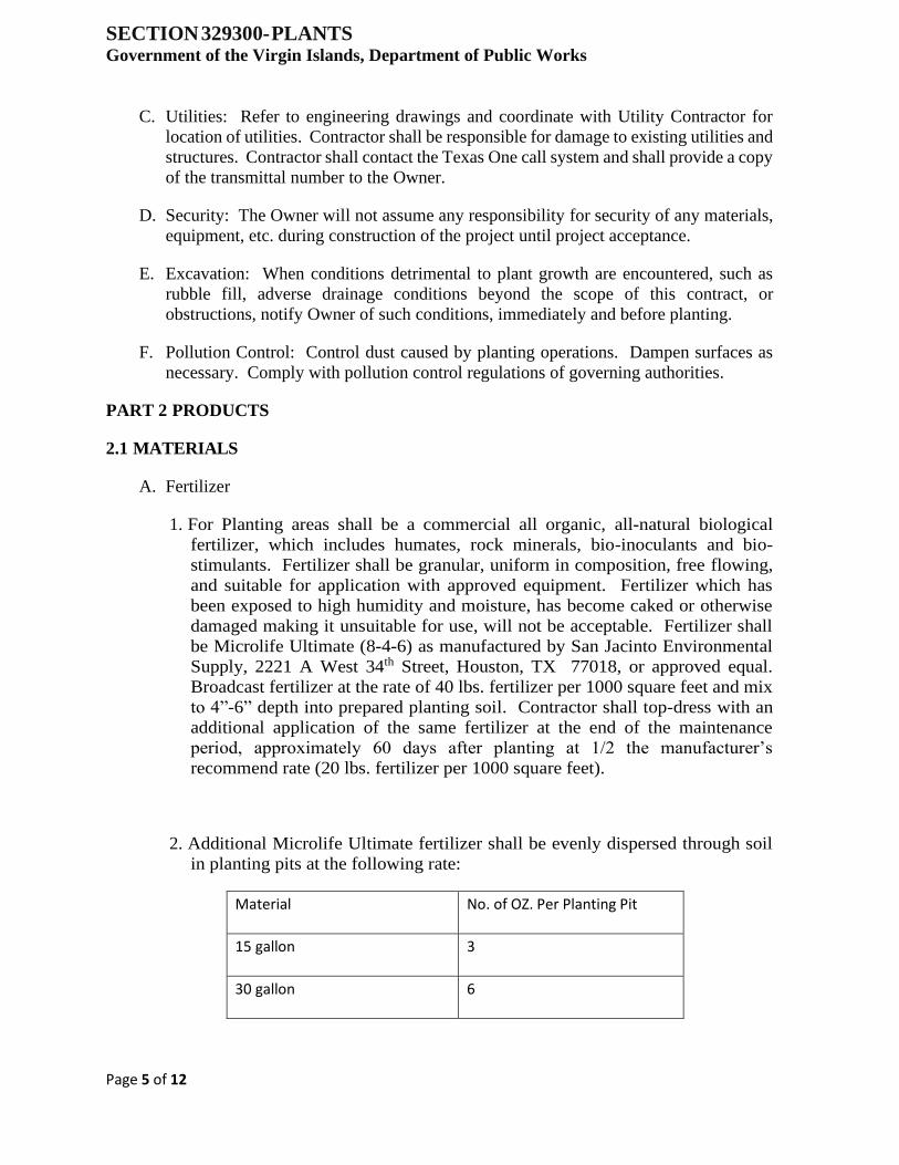
SECTION 329300- PLANTS Government of the Virgin Islands, Department of Public Works
Page 5 of 12
C. Utilities: Refer to engineering drawings and coordinate with Utility Contractor for
location of utilities. Contractor shall be responsible for damage to existing utilities and
structures. Contractor shall contact the Texas One call system and shall provide a copy
of the transmittal number to the Owner.
D. Security: The Owner will not assume any responsibility for security of any materials,
equipment, etc. during construction of the project until project acceptance.
E. Excavation: When conditions detrimental to plant growth are encountered, such as
rubble fill, adverse drainage conditions beyond the scope of this contract, or
obstructions, notify Owner of such conditions, immediately and before planting.
F. Pollution Control: Control dust caused by planting operations. Dampen surfaces as
necessary. Comply with pollution control regulations of governing authorities.
PART 2 PRODUCTS
2.1 MATERIALS
A. Fertilizer
1. For Planting areas shall be a commercial all organic, all-natural biological
fertilizer, which includes humates, rock minerals, bio-inoculants and bio-
stimulants. Fertilizer shall be granular, uniform in composition, free flowing,
and suitable for application with approved equipment. Fertilizer which has
been exposed to high humidity and moisture, has become caked or otherwise
damaged making it unsuitable for use, will not be acceptable. Fertilizer shall
be Microlife Ultimate (8-4-6) as manufactured by San Jacinto Environmental
Supply, 2221 A West 34th Street, Houston, TX 77018, or approved equal.
Broadcast fertilizer at the rate of 40 lbs. fertilizer per 1000 square feet and mix
to 4”-6” depth into prepared planting soil. Contractor shall top-dress with an
additional application of the same fertilizer at the end of the maintenance
period, approximately 60 days after planting at 1/2 the manufacturer’s
recommend rate (20 lbs. fertilizer per 1000 square feet).
2. Additional Microlife Ultimate fertilizer shall be evenly dispersed through soil
in planting pits at the following rate:
Material No. of OZ. Per Planting Pit
15 gallon 3
30 gallon 6
SECTION 329300- PLANTS Government of the Virgin Islands, Department of Public Works
Page 6 of 12
65 gallon 12
100 gallon 18
200 gallon 36
SECTION 329300- PLANTS Government of the Virgin Islands, Department of Public Works
Page 7 of 12
3. Fertilizer for turf areas shall be Majestic Gro (18-5-9) as manufactured by San
Jacinto Environmental Supply or approved equal commercial blend of high
quality, low salt synthetic fertilizer, 50% slow-release, with Houactinite (as
carrier), 3% Fe, 8% Sulfur, 1% Mg and Micronutrients including Zinc, Boron,
Copper, Molybdenum and Potassium Sulfate. Fertilizer shall be free flowing
and suitable for application with approved equipment. Fertilizer which has
been exposed to high humidity and moisture, has become caked or otherwise
damaged making it unsuitable for use will not be acceptable. Fertilizer shall be
applied at the rate of one 50 lb. bag per 7500 square feet to all turf areas and
raked into the topsoil prior to application of sod. For hydromulched areas,
Majestic Gro fertilizer shall be mixed in the tank at the rate specified in Section
02921 – Hydromulch. Contractor shall top-dress all sod and hydromulch areas
with an additional application of Majestic Gro fertilizer approximately 60 days
after planting, at half the manufacturer’s recommended rate (one 50 lb. bag per
15,000 square feet). Apply preventative fire-ant treatment over all sod and
hydromulch areas during the 60-day maintenance period.
B. Sharp Sand: Sand shall be thoroughly washed, coarse grade sharp, construction or
brick sand, free of clay balls, weeds, and grass. So-called cushion sand, blow sand, or
creek silt is not acceptable for substitution where sharp sand is specified.
C. Herbicide
1. Apply pre-emergent herbicide over all planting areas prior to spreading mulch
at the rate of 7 lbs. per 1000 square feet.
2. If necessary, contact herbicide shall be Roundup by Monsanto, 800 N.
Lindbergh, St. Louis, MO 63167, 314-694-1000, or approved equal. Apply
Roundup only if necessary and if approved by Owner or Owner’s
representative. Do not exceed manufacturer’s recommended rate of
application.
D. Mulch for top dressing: Organic mulch free from deleterious materials and suitable for
top dressing of trees, shrubs or plants. Mulch shall be composted, well-rotted, blended
double-shredded hardwood mulch (70%) and composted pine bark mulch (30%), black
or dark brown in color. Mulch pieces shall not exceed 2” in any dimension. No dyes,
mushroom compost or other additives shall be used to artificially enhance the
appearance of the level of composting.
E. Biological Inoculant: MicroGro Granular as manufactured by San Jacinto
Environmental Supply, or approved equal multi-purpose biological inoculant with
humates, select sugars and bio-stimulants. Apply to all seasonal, perennial and
groundcover areas at the rate of 10 lbs. per 1000 square feet.
SECTION 329300- PLANTS Government of the Virgin Islands, Department of Public Works
Page 8 of 12
F. Compost for bed prep/soil backfill mix: Compost must be made from organic
materials. Compost must contain less than 1% by dry weight of inert contaminants
such as glass, plastic, rocks, etc. Industrial or hazardous waste cannot be used in the
production of the compost (i.e. boiler ash, rice hull ash, etc.). Compost shall be free of
fillers such as rice hulls or pine bark. Compost shall not exceed the heavy metal limits
as specified in the US EPA Part 503 Regulations.
1. Contractor shall furnish copies of manufacturer’s literature, certifications,
sources, samples, or laboratory analytical data for the following items:
Certificates of inspection required for transportation shall accompany each
shipment of materials. Provide certificates to Owner.
G. Testing:
1. If herbicide contamination is suspected, then a radish/rye-grass growth trial
must be performed. For delivered material, test one grab sample for each fifty
(50) cubic yards of bulk material delivered to the site. Testing will be at the
expense of Contractor. Deviations greater than plus or minus twenty (20%)
percent from control data may be grounds for rejection of mixes tested. Non-
conforming materials shall not be used and shall be removed from the site.
H. Biological, physical and chemical specifications:
I. Biological Specifications: Stability/Maturity (Carbon Dioxide Evolution Rate) Shall
be less than 8 mg CO2-C per g OM (organic matter) per day and greater than 6.0 on
the SolvitaTM Compost Maturity Test.
1. Biological components: Bacteria (active) - Minimum of 15-25 micrograms per
gram of compost; Bacteria (total) - minimum of 150 micrograms per gram of
compost; Fungus (active) - minimum of 15-25 micrograms per gram of
compost; Fungus (total) - minimum of 150 micrograms per gram of compost;
Fungus (hyphal diameter) – should be greater than 1 mm; Protozoa: flagellates
- 8,000 or higher per gram of compost; amoebae - 8,000 or higher per gram of
compost; ciliates - 50-100 or higher per gram of compost; Root Feeding
Nematodes should not be present (beneficial nematodes are a benefit).
J. PHYSICAL Specifications: Moisture Content - 30-60%, wet weight basis; Moisture
Holding Capacity - 75-200% of dry weight; Organic Matter Content - 30-70% (40-
50% preferred), dry weight basis; Particle Size: Standard Grade Compost - 100%
passing through a 1” rectangular mesh screen or smaller; Fine Grade Compost - 100%
passing through a 3/8” rectangular mesh screen or smaller; Bulk Density - 700-1,200
(800-1,000 preferred), pounds per cubic yard; Electrical Conductivity (Soluble Salt
Concentration) - 10 dS/m (mmhos/cm.) maximum, (2.0-3.6 or less preferred).
SECTION 329300- PLANTS Government of the Virgin Islands, Department of Public Works
Page 9 of 12
K. CHEMICAL Specifications: pH 6.0-8.5; Total Salinity-2,000 ppm or lower; Chemical
components (H2O extraction): Nitrogen-10 ppm or higher, Phosphorus-100 ppm or
higher, Potassium- 400 ppm or higher, Calcium-2000 ppm or higher, Magnesium-200
ppm or higher, Zinc-6 ppm or higher, Iron-25 ppm or higher, Manganese - 8 ppm or
higher, Copper-1 ppm or higher, Sodium-1000 ppm or less, Sulfur-10 ppm or higher,
Boron-1 ppm or higher.
L. Root Stimulator: Root stimulator shall be Super Seaweed as manufactured by San
Jacinto Environmental Supply or approved equal.
M. Soil Acidifier: 90% Sulfur.
N. Fire Ant Prevention: Award as manufactured by Syngenta, 1800 Concord Pike,
Wilmington, DE 19850 or Amdro as manufactured by Ambrands, 2255 Cumberland
Parkway Building 600-B, Atlanta, GA, 30339, or approved equal. Preventative fire
ant control shall be broadcast over all landscaped area at manufacturer’s recommended
rate of 1 ½ lbs. per acre.
O. Insecticide: No insecticide shall be applied on this site without the permission of the
Owner.
P. Prepared Planting Backfill Mix: Shall be 33% topsoil, 33% sharp sand, and 33%
organic compost or approved commercially available soil mix.
Q. Topsoil
1. Provide topsoil which is a fertile, friable, natural loam or sandy loam, surface
soil, free of subsoil, clay lumps, brush, weeds and other litter, and free of roots,
stumps, stones larger than 2 inches in any dimension and other extraneous or
toxic matter harmful to plant growth.
2. Obtain topsoil only from naturally, well-drained sites where topsoil occurs in a
depth of not less than 4 inches. Topsoil shall not be collected from sites that
are infected with growth of, or the reproductive parts of noxious weeds,
especially nut grass. Topsoil shall not be stripped, collected or deposited while
wet. Topsoil shall not be excessively acid or alkaline or contain toxic
substances which may be harmful to plant growth. Topsoil shall be without
admixture of subsoil.
R. Steel Edging: Edging shall be Ryerson steel or approved equal, 4” x 3/16” thick green
in color.
S. Filter Fabric – Filter fabric shall be non-woven filter bond. Soil separator as
manufactured by DeWitt Co. with a minimum permeability rate of 219 gals./SF/minute
or approved equal.
SECTION 329300- PLANTS Government of the Virgin Islands, Department of Public Works
Page 10 of 12
T. Plant Materials: Provide specimen quality plant material as described in Construction
Documents. Each individual species of plant material shall be obtained and provided
from a single source.
U. Wood Headers and Edging: All heart redwood or pressure treated southern yellow pine.
PART 3 EXECUTION
3.1 EXAMINATION
A. Do not begin installation until substrates have been properly prepared.
B. If substrate preparation is the responsibility of another installer, notify Owner’s
Representative of unsatisfactory preparation before proceeding.
3.2 PLANTING BEDS
A. Prepare surfaces using the methods recommended by the manufacturer for achieving
the best result for the substrate under the project conditions.
1. Strip existing vegetation and 1” soil to remove root layer. Excavate entire
planting beds 4” below finished grade.
2. Dispose of soil removed from planting beds excavations. Do not mix with
planting soil or use as backfill.
B. Till bottom of planter 2”-4” leaving bottom of planter un-compacted. Backfill with
minimum 8” (after settling) of prepared soil backfill mix. Prepare topsoil by mixing
fertilizer with loam. Install soil mix to a depth of 18 inches in plant beds.
C. Apply fertilizer and evenly distribute through top 6” of soil. For seasonal, groundcover
and perennial areas, apply biological inoculants and evenly distribute through soil.
3.3 TREES AND SHRUBS
A. Install materials in accordance with approved submittals. Install landscape work in
proper relation with adjacent construction and with uniform appearance. Coordinate
with work of other sections.
B. Excavate as required for trees and shrubs.
C. Apply fertilizer at a rate of 2 pounds of actual nitrogen per 1000 sq. ft. for plant beds
and 2 pounds per inch of trunk for tree pits.
D. Set stock on layer of planting soil mixture, plumb and slightly above adjacent finished
planting grades. Place additional backfill mix around base and sides of ball and work
each layer to settle backfill and eliminate voids and air pockets. Layer and distribute
additional fertilizer in planting hole at specified rate. Water entire bed thoroughly,
adjusting plant if settling occurs.
SECTION 329300- PLANTS Government of the Virgin Islands, Department of Public Works
Page 11 of 12
E. Treat entire areas of planting and tree root balls with:
1. Broadcast application of pre-emergent herbicide at manufacturer's
recommended rate in all planting areas (except seasonal beds) prior to applying
mulch.
2. Broadcast application of fire ant insecticide at manufacturer's recommended
rate in all planting areas, after mulching.
3. Mulching: Immediately after planting has been completed, mulch tree wells and
plant beds. Provide not less than 2” thickness of composted hardwood & pine
bark mulch in planting beds and 3” thickness at all trees.
F. Provide maintenance and watering until turnover to Owner for maintenance and
watering. Replace damaged materials and dead or unhealthy plants prior to turnover to
Owner.
3.4 PROTECTION
A. During planting work, keep pavements clean and work area in an orderly condition.
Sweep site and remove trash at end of each workday as necessary.
B. Protect planting work and materials from damage due to planting operations,
operations by other contractors and trades and trespassers. Maintain protection during
installation periods. Treat, repair or replace damaged planting work as directed by
Owner.
C. Stockpile, haul from site, and legally dispose of waste materials and debris.
Accumulation will not be permitted. Maintain haul and disposal routes clear, clean,
and free of debris. On-site burning of combustible cleared materials will not be
permitted.
D. Upon completion of work, clean areas within Contract limits, remove tools, supplies
and equipment. Wash down curbs and pavement areas. Scrub curbs and walks as
necessary to insure a clean surface. Provide site clean and free of materials and suitable
for use as intended.
3.5 INSPECTION AND ACCEPTANCE
A. When planting work is completed and at the completion of maintenance period, Owner
will inspect to determine acceptability.
B. When inspected planting work does not comply with the Contract Document
requirements, replace rejected work and continue specified maintenance until re-
inspected by Owner and found to be acceptable. Contractor shall remove rejected
plants and materials promptly from site.

SECTION 329300- PLANTS Government of the Virgin Islands, Department of Public Works
Page 12 of 12
C. Contractor shall correctly maintain all planting during the installation process and
throughout the landscaping maintenance service period as specified in Section 32 91
20 - Exterior Landscape Maintenance.
D. Touch-up, repair or replace damaged products before Substantial Completion.
END OF SECTION