f5l - The Old Car Manual Project
46
-
Upload
khangminh22 -
Category
Documents
-
view
4 -
download
0
Transcript of f5l - The Old Car Manual Project


BREATH 8l
Right Side - Wau kesha Mo d e l 19 0 -G l - GlB
left Side - Wau kesha Mod e l 19 0- G l - GlB

~f5l~t~ FLYWHEEL
T IM INGe MARK
II)
I'I:
Right Side - Waukesha Model 180 -G L - GLB
Left Side - W au kesha Mode l 180-GL - G LB

4 WAUKESHA MODELS 190 , 185 , 180
CONTENTS
PAGE
DESCRIPTION 5-7
General _____________ ________ 5Crankcase 5
Crankshaft 6Bearings 6Governor 6Ign ition 7
Carburetion 7Water Pump 7
Oil Pump 7
LUBRICAT10N 8-13
Oil Quant ity 8Oil Changes 8
Selecting Oil ViscosityOil Temperature Method 8Estimated Oil Temp. 9
Additive Type Oils 9
Special Industrial Service 10Accessory Lubrication 10Oil Filters 10
Oil Pressure Control 11Oiling System 11Rocker Arms 13
COOLING SYSTEM 14-17Anti-Freeze 14
Cooling System Capacities 14Thermostat Removal 14Thermostat Testi ng 15Cleaning Cooling System 15
Commercial Cleaners 16
Cooling Fans 16
Fan Belts 16
Replacing Fan Belts 16
Air Cleaners :...___ 17
SERVICE ADJUSTMENTS 18-25Ign ition 18
PAGE
Distributor Timing 19Magne to 20
Magneto Maintenance 21
Magneto Timing ~----- 21Valve Clearance Adju stment 22Resett ing the Governor 22
Gasoline Carburetors 23
Carburetor Adju stments 24Gas-Fuel Conversion 24Volume Tanks 25
REPAIR AND OVERHAUL 26-33Disassembly 26Oil Pan Removal 26
Cylinder Sleeve Removal 27Camshaft 27
Cam Followers 28
Valve and Mechanism- Repair __ 28Compression Checks 29Valve Mechanism ._ 29Guides and Seats 29
Valve Gri nding 30Hand Gri nding 30
Seat Insert Replacement - - - - - - -31-33
REASSEMBLY 34-40
Installing Cylinder Sleeves 34Cylinder Head Gasket Crush 35Piston Fitting 35
Bearing Ad justment 37Side Clearances 38
Running Clearance 38
Replacing Cylinder Head 39
Flywheel Alignm ent 40
CLEARANCES AND L1MITS 41-4 5Model 190 41
Model 185 43
Model 180 43

WAUKESHA MODELS 190, 185, 180
DESCRIPTION
5
GEN ERALT he Waukesha 190, 185, 180 series engines are of overhead valve, wet
sleeve construc t ion, a ll incorp orating the sa me gen era l design fea tures. The190 and 185 models are six-cylinde r engines; the 180 model is a fo ur-cy linderengine.
DDI ENSIO NS
BORE AN D STROKE CYL. D ISPLACDIENT
190G L - GLB180GL - GL B185 G L -GLB
3.75 x -I3.5 x 3.753.5 x 3.75
646
265 Cubic inches144 Cubic inch es216 Cubic inch es
These engines a re desig ned to g ive ex te nde d se rvice life witho ut specialize d or unusua l mainte nance t ech n iq ues. Clean oil in th e proper qu antity ;cle an, so ft, cooling water; and r eg ular attenti on to such it ems as air cle aners ,spark p lugs, fue l st ra iner s, and oil filt er s wi ll in sure cont inue d reliableperform an ce.
CRANKCA SEFor maximum rigidi ty and accurate be aring al ignment, t he crankcase
and cylinder block is ca st as a single un it . Bearing cr oss walls and wate rba ffle s a re ge nerous ly fillet ed and he avy top diap hrag ms and bottom
Left Side - Cron kease, 190-GLB

6 WAUKESHA MODELS 190 , 185, 180
flanges loca t e and s up por t the cylinder s leeves . The s lee ves are exposedto cooling water for practica lly th eir en t ire length a nd are sea led w ithtwo r ubber ring s at t he lower end an d the cy linder head g asket at thetop. 1(0 specia l tool s are need ed fo r in stallat io n or removal o f these s leeves .
CRANKSHAFTThe crankshafts used in th e 190. 185 and 180 series engines a re heat
treated and p reci s ion g round stee l io rgings. These shaf ts are iully bala ncedboth s ta t ica lly and dynam ically . T he m irror fin is hed crankpins a nd mainbeari ng journa ls are hel d to ex t re melv c lose tol erances t o acco m moda teprecis ion bearing she lls w it ho u t th e nec essity for field fitt in g.
I t is im portan t t hat t he own er be acq ua int ed with th e se ve ra l types ofcra nks hafts i ro m th e st a ndpoin t oi orde r in g se rvice p arts . A ll crankshaftsu sed in r ecen t M odel 190 oil field engines a re drill ed ior pressur e lubricat ionto th e co nn ec t ing rod lo w er end bearings. O t he r 190 se r ies engines areeq u ip pe d w it h a metered jet luhr icat ion syst em and incorporat ed oil tran sf err ecesses in the main b earing journal s bu t a re not dri lled . Thi s is d iscussedunder oiling syst em.
A ll cra n ks hafts used in th e 185 an d 180 ser ies engines a re eq u ippe d withoi l transfer recesses for m et ered jet lubr ica t ion . C u r re n t production Model180 engin es em p loy counterba lanced sha i ts wi t h 2)i " diam eter crankp ins .A very la rg e n um ber of engines have, how ever , been built with a co nvent io na l crankshaft a nd 2" diam et er cran kpins . It is possibl e to conver t anea rl ie r eng ine a t ti me oi overhaul to a cc o m m oda t e a co u nterha lanced sha ft .b ut t h is change will p robab ly r eq uire some minor rework in g oi the cran kca se for clearance. pl us re p lacem ent oi th e con nect ing rods . p istons. id lergear sha ft , and th e idler gear hushing s up port.
Sectional View - Gove rno r
GOVERNORA se lf -co nta ined, g earvdriven
governor is m ounted within th egear cove r and a sm a ll proj ect-
BEARINGSPreci sion type copper-l ead m a in and connecting rod hea r ings p erm it
field r eplacement when need ed without line horing. Th e flang ed u pper andlower ha lv es' oi th e ce nter main hearing absorbs thrus t lo a ds on the 180m od el a n d s ince it is al so of theprec ision type, no specia l endplay ad j ustment s are required.The sa me th ing applies t o the# 3 bearing s in the 185 and 190engines. Steel-backed, bab bittlined bushing-s s up por t both thegear end oi th e ca mshaft an d th eid ler g-ear sha i t . Piston p in s arefu ll -float ing- in a diamond-boredbronze b ush ing in the connectingrods.

WAUKESHA MODELS 190, 185, 180 7
ing hou sin g . This governor is of the fa miliar two- weig ht, centrifugal ty pe,and req ui re s no adjustment o t her t han estab lishing th e desired high idl espeed. A screw type surge adj ustment is al so provided .
IGNITIONIgnit ion may be with eithe r a fixed-timing. vertically or flange-mounted
magnet o. or with a di stributor and coil. \ Yith the except ion of the flangemounted magnet o. used on Model 190 oil field eng ines and which is drivenfr om the engine gear t ra in , th e ig nition unit is drawn by a spline and keyon th e o il pump drive sha ft upper enc!' Adjustment a nd timing of these unit sare disc ussed under D I STR IB UT O R T BII K G. or. MAGKET O THd ING.
CARBURETIONF or use wi th gaso lin e or kerosen e, a standard diaphragm-type fuel
p ump is used and driven from an eccentric on the camshaft. Carburetorsmay be for gas only , for gasolin e only, or of the gas-gaso line type asspecified. Carb uretor adj ustm en t s are discussed un der a separate heading.
WATER PUMPT h e water pump requires no specia l lubr icat ion , packing or a ttention
du ring it s ser vice lif e. An internal sea l is used in combination wi t h a uni ttype ball bearing a nd p ump shaf t to provide a simple, rugged ly constructedwater pump.
Water Pump
OIL PUMPA high-capacity, spr ing- loade d va ne -type pu mp. driven by a sp ira l gear
fr om the ca ms haft provide s o il un cl er pressure to th e lubri cating syst em ofthe 190. 18j a nd 180 eng ines, Thi s pump is of \'ery simple. rugg ed const r ucti on s ince th e only movi ng parts a re the drive sha ft a nd t wo van es. Theoil inl et screen is sus pe nde d from the oil inlet pipe in such a manner as tofloat fr eely and p ick up th e clean oil from the s urf ace of the supply in th eo il pan . In rec ent Model 190 oil field eng ines w ith t he main bearing oilg rooves in both upper and lo wer in sert s , a gea r type oil pump is used .

8 WAUKESHA MODELS 190, 185, 180
LUBRICATIONOIL QUANTITY
The oil capacities of the eng ines in this ser ies a re listed in the tabular .data in the back of this manual. R em ember that the qua nt it ies listed arefor the oil pan. Filters o r oth er extern al devices requir ing oil will necessitate an additional quantity. T o det ermine exactly how much additionaloi l is needed, fill the crankcase w it h the recommended quantity, r un theengine for a few minutes, and add enoug h oil in a m easured amount toagain bring the level to F ULL on the dipstick. Once the total a mo unt hasbeen es t ab lis hed it may all be poured in at the sa m e tim e on su bsequ entoil changes.
OIL CHANGES
The cra nkcase level sh ould be ch ecke d pnor to each day's eng ineope rat ion an d at th e sa me tim e t he co ndit ion of the oil as rev ealed on thebayonet gauge should b e ob served ca refully . Replace oil at any time it isplainly diluted, broken down, th icken ed by s lu dg e, or ot herwise deteriorated.A good r ule is to change it every 50 hours unt il experie nce shows t hatthe particu lar oil in use wi ll remain se rviceable for a longer time. \ Vh enever oil is changed , th e filt ers m us t be serviced, If it is desired to use oillonger than 100 hours of acti ve duty, it is suggest ed t hat the lubrica t ionengineer of the oil supp lier be consulted. N ot a ll oi ls in every type ofengine will give maxim um se rvice, t herefore be ca re ful t o examine t h eoi l after the fir st draining to det ermine wh ether it is standing up in ser vice.T rial pe riods of 10 hours are sugg es t ed a nd a t the end of such periods.ma ke careful in sp ection s for s ludg ing , fro thing and emulsification. Suchconditions ca ll for more fr equent chang es or a different oil. In winteroperation, low oil temperatures (below 170 degree, F. ) are particu larlylikely to cau se slu dg e for mation. T emperature cont rol devices-curtains,shutters and so on-e-sh ou ld be used if n eeded in order to ho ld the oi ltemperature around 180 degrees, F . Butan e, natural g as and ot her fuel snot t endin g . to dilute oil may cont r ibute m ateri ally to g re a te r oi l life ifoperating co ndit ions are suit able.
SELECTING OIL VISCOSITY-OIL TEMPERATURE METHODAll ot he r thing s suc h as oi l type a n d qua lity be ing eq ua l, t h e principle
factor in choosing the p ro per oil vi scosi ty is the op erating te mpe rat ureof the oil in the crankca se. It is thi s te mperat ure that establishes therunning vi sc osity of the oil ; hence, the so-calle d O IL TEMPERATUREmethod of se lect ing oi l v is cos ity will b e explained first .
1. Make one or m ore check rt111 S under actual op erating co n di t ions ofspeed and load. Use SA E 20/ 20 'vV oil for this t est. Not e the temperatu rerange of the oil in the crankca se by mean s of an accurate oi l t emper aturegauge immersed in th e oil.
2. Find th e temperature ra.nge noted in the ab ove test in th e tabulationbelow. The proper oil vi scosity for these op erating conditi ons wi ll befound directly to the right. If di fferent kinds of se rvice cause the loadsand operating conditions to vary, re-check the oil t emperature as above

WAUKESHA MODELS 190 , 185, 180 9
an d se lect an oil of lighter or hea vier visco si ty as required by the newconditi ons .
. Oi l Opera t ingTemperatures
210-250° F .180-210 ° F.to 180° F .
SA E Vi sc osityNum be rs
3020j 20W
lOW, Vh ere oi ls are required for st a r t ing at low temperature, m ult i-viscosity
oi ls can be used w hich will g ive lo w enough viscos ity for star t ing and st illprovide th e p roper SA E grarl e in dicat ed in th e a bove tab le for th e opera t ingt emp era t ure.
OIL VISCOSITY RECOMMENDATION FOR HEAVY DUTY SERVICEHeavy du ty se r vice is cons idered to b e an average load excee d ing on e
ha lf max im um engine power . To det er min e t h e correct SA E g ra de of oilselect th e co r re ct SAE oil number fro m the above tab le af te r m easuring thecra nkc as e oi l temperatu re.
LIGHT DUTY SERVICEL igh t duty ser vice is co ns ide re d t o be a n a verage load not ex ceeding
one -ha lf m axim um eng ine po w er . For eng ines ope ra t ing in light duty se r vic ea n oil of one SA E g rade ligh t er vi sco sity th a n for hea vy duty ser vice canbe used.
ESTIMATED OIL TEMPERATUREW hen th e act ua l opera t ing oil tempera t ure is not known, a n es t im ate of
t he SA E oil g rade to u se can be made by assum ing th e oi l t emperature w illbe 130 degrees abo ve th e a ir t em p eratu re in hea vy duty se rv ice. For example :A t an a ir tem peratu re of 70° F, es t ima te d oil t em pe ra t ure wo uld b e 200 ° F.Use SAE 20j20vV as indicat ed in th e ab o ve t abl e. N ote : This is on ly anes ti ma te, s ince the type of in s tall ati on det ermin es th e amount of ai r circ u lation fo r coo ling aro un d the o il pa n . A ct ua l cra nkcase op er ating oil temperat u res should be m ea sured w h enever po ssibl e.
OPERATING TEMPERATURESE ngines operated w it h low oil t empera t ures bel ow 160 dcg . F . can be
ex pect ed t o show excess ive s ludg ing a nd wear. E ngin cs op er a t ed w it h hi g hoil t empera tu res a bove 230 deg. may expe r ie nc e lacquer ing a nd ring s t icking. The undesirab le eff ects of operat ing at abnormall y lo w or h ig h t emperat ures can b e a llev ia t ed to som e extent by th e u se of addit ive type oils .
ADDITIVE TYPE OILSPractica lly a ll oil co m panies a re ma rk etin g additi ve t ype oils t o m eet
service r eq ui r em ents com mon t o industri al eng in e operation. T he perfo r ma nce levels of t hese oils under eng inc opera ti ng co n dit ions a re definedby t he foll o wi ng th ree military spe cifica t io ns :
M IL- L-2 104A ( F ormerly 1\:1 I L-0 -210 4) Hun w it h 0.35% su lph urM IL- L -2104A ( For m er ly M] L-0-2104) R un wit h I % sulphurSu perio r L ubri ca nt (Ser ies 2)

10 WAUKESHA MODELS 190, 185, 180
The I n tern a l Co mb us t ion E ng ine I nst it ute, 201 N ort h W ell s St re et,Chicago 6, Ill inois, has pub lish ed a list of o il brand names represented by
. t heir suppliers as m eet in g th e a bove se rvice requ irem ent s. · Th is list indi cat es the three mi litary spec ificat ions as type s A, 13, and C, respective ly .(T h is is in no way related to the Waukesha Motor Co mpany's visc osit yclass ifica t ion o f eng ine models by E ng ine Class A , B, and C.)
For ave ra g e heavy du ty industri al service Wauk esh a Motor Companyrecommen ds t he usc of type A oils for bot h di esel and car bureto r t yp e eng ines.F or severe service, resu lti ng from ext re mely h igh or low op erat in g t emperat ures, or fo r high su lphur fue ls (above 0.5% for diesel fu el ), or fo r ope rat ingco n di t ions giving ex cess ive pi ston ring co king, Type 13 oils a re recommended.Type C oi ls should be co nsidered on ly fo r t he most unusual operat ing condi ti ons and after co ns u lt ing t he W aukesha M otor Co mpa ny.
MINIMUM VISCOSITYT he oil te m pe ra t ure cha rt is a rrang ed on the basi s of providing a m1111
mum viscos it y for eac h cla ss of eng ine t hroug hout th e ope ra t ing t emperature range. T he minim um sta n da rd Saybo lt v isc osit ies are 54, 62, a nd 72for engine Class A, 13 , a nd C, resp ecti vel y .
SPECIAL INDUSTRIAL SERVICESExtra preca utions are necessa ry to in sure ad eq ua te lubri ca t ion of in dus
t rial engines t hat m ust be started after I011g periods at rest or a fter st a ndingin a co ld p lace . They sho uld be fille d w ith fre sh wa rm oil a nd r un idle fo r afew minu tes to permit the lubricat ion sys tem to fill and ensure oil reach inga ll pa rts of t he engine.
ACCESSORY LUBRICATIONM agneto or di st ributor ignition units re quire no spe cial lubr icat ion .
Occas iona l application of a very sm all qua nt it y of lig ht oil or petroleumjell y to t he breaker cam wi ll be helpful in red ucing wear on the breakerpoint ca m sho e.
O ther a~cessories su ch as ge ne ra to rs, and st ar te rs sho u ld be lub ri catedin accordanc e with their manufacture r 's recommendati on s. Ordinari ly , ad rop or t wo of light engine oil in t he oil cups is ad equ ate for long pe r iod sof operat ion. Over-o iling is usua lly ha rm ful to elect r ica l devices.
OIL FILTERSA lt hough som e variat ions may appear in th e oi l-filter in stallations used
on t h ese engine s, t he same g en era l pr incipl es of main tenance apply to mostof t he m . I n a ll cases th e manufa ct urer 's recom menda tions ac compa nyin gthe filter, or the inst ruct ion la bel app lied to the side of th e filt er should befollowed carefully. The filt ers so met imes s upplied w it h th e engine as itlea ves t he fac tory a re re p laced as compl ete unit s by u nscrew in g t he can-likeca r tridges fro m t he base mount ing on t he engine .
Wh en a filter is provi de d with a p rop erly fu nct ioning by -pass va lve ,th e bl ocking off of the filt er by dirt w ill no t s ta rve th e engine of oi l ; on t heot her ha nd, dirt like that blocki ng t he filt er is t he n p ro ba bly passing throughthe bea ring s.

WAUKESHA MODElS 190, 185, 180 11
Because of the abo ve possibility , th e recommendation s for filt er ch ang escoincide w ith re commendations for o il change. If the o il shows evidence ofs ludge fo rmation or improper filt er op era t io n, it should be cha ngeel and t hefilter ele m en t as w ell. A lso a che ck shou ld b e made t o see that t he o il a ndwater temperatu res a re within th e desi red rang e.
If ex p erie nce in d icates th e practica bility o f running lubri cating oil formaximum p er iods bet w een ch an g es. t he n t he filt er s may be co nsidered assa t is fac tory for this period of opera t io n. Tn a ll cases t he filter ele me nts shou ldbe cha ng ed at t he time of oil cha nge.
OIL PRESSURE CO NTROL
U nde r a ll no rmal condition s th e van e or gea r typ e oil pump w ill provi deadequ a t e oil pressure . In th ose cn gin es using t h e va ne type pump, 25-30 Lbs.is the no rmal r unning pressure. In Mod el 190 oil fi eld eng ines using full g roove bearings with t he g ear type pump an d t he st i fTcr r elief va lve spr ing ,40 Lbs. oil p ressure is norm a l. Th e oil p ress ure g a uge should be no ted imm ed ia t ely u po n start ing t he cnginc and shou ld in d icat e pressu re w it h in atleas t 30 seconds, A ho t eng inc will norm a lly have a lo w p ressure at id lespeeds . A co ld en g ine normall y sho ws a high oil pressure un t il warmed up.If, wit h th e proper g rade o f oil and th e eng ine wa r m eel up and running atnormal govern ed speed, th e o il p ressure is unu sually h ig h or low, th e following co r rect ive measures may be tr icd :
1. Clean t he re lief valve, sp r ing, se a t, and passa g e of dirt a nd ca rbon.
2. Check o il t emperature, and co nd it ion of oil.
3. If th e reli ef va lve sp r ing and th e oil are in good co nd it ion, be sure toch eck t he pressure g a uge a nd it s co nnect ions before going furt her.
4. A co m mon source of lo w oil p ressure is clog g in g of t he o il pump intakesc reen w ith s ludg e a nd ca rbo n . R em o ve such dep osi t s w it h lacquer thinn eror ot her so lve n t .
S. U nusua l looseness , g roo vi ng o r dam ag e to the ma in bea ring s o r oilpu mp w ill a lso ca use lo w oil pressure. S uch co nd it io ns ca ll for re p lace me ntof wo r n part s .
6. Occas io na lly it may be desirabl e to inc rease th e relief va lve spr ing t en sio nby in ser t ing one or t wo washer's behind it.
7, Use of full circ u lar g ro O\'cd bcari ng s in t he 190 cn gin es in con ju nct io nwit h t he van e type oil pum p is not rccomm cn dcd a nd may ca use lo w oilp ressure.
OILI NG SYSTEMThe o iling sys t em em ploycd o n th e Mod el 190 o il fi eld engines provides
fu ll oil press u re to th e cra nksha ft hcarin g s a nd rods . th cn m et cring thi s o ils upply throu gh sma ll pocket s in th e cra nk journa ls t o th e accesso ry gea rsa nd va lve m echanism.
O il en te rs th e va ne or gea r pu m p t hrough th e floa ting o il scr een whichp icks up from th e cleaner upper su r face of th e oil supply . Leaving the

12 WAUKESHA MODELS 190, 185 , 180
Sectional View - Va ne Type Oil Pump
O il leaving t he fron t main bearin g t hrough th e passage syste mdescribed above is co nducte d inpart t o a sma ll jet just above theca m sha ft dri ve g ea r. Thi s oil flood st he m eshing surf aces of the cra nksha ft g ear, ca m g ea r, and governordri ve g ear. Part of th is oil al solubricat es th e governor shaft bush ing vi a a drill ed conn ecting passage. A bran ch of t hi s pa ssa g e isbl anked off at a loca t ion for anid ler g ear.
A m et ered jet lubrication sys te mis used in ot he r 190, 180 and 185Metered Jet Lubrication Schematic
pressu re side of t he pu mp va ne. the oi l passes up ward th rough a pa ssage inthe p ump support a nd is fo rced into th e main o il ga lle ry ext ending t he len gth
of th e r ight side of the eng ine .
At t he fro nt of t he gallery (gcarcov er end ) a pressu re relief va lveof th e non-adj ustable type prev entsexc essive pressure bui ld-u p. Drilledpa ssages co n duc t t he oi l from th ega llery to t he main bear ing s. T h efran t a nd rear main bea ring cra nksha ft journa ls are provided withsma ll po cke t s w h ich a re so a lignedas to index with t he in coming oi lpassag e a nd bridg e across the journal to an outgo in g oil pa ssage. Thi shappens for a bri ef portion of eachrevolut ion of th e sha ft. Th us, th epressure oil is fed across to a second oil pa ssa g e in a m etere d vo lum efor di stri but ion to ot her locationsdescr ib ed below .

WAUKESHA MODELS 190, 18 5 , 180 13
o
Schematic - O il Passages inFront of Cro n kca se
ser ies eng ine s - oi l fr om the intermed iate m a in he ari ng m e t erin gslots is co nd ucted to t he secondg a lle ry ex te nd ing th e leng t h of t heeng ine . This ga llery has sm a ll jet sloc ated d ir ectly above th e o il hol esin t he upper flanks of th e co n ne cting rod bea r ing s whe n th e co nnect ing rod s a re in the prop erposit ion to rece ive lubri cation . T heout let s , or je ts, meter t h e co rrectam ount of oil into eac h of the rodbea rin g s. Because of the met eringeffect of both th e ro ta t ing cra nk sh a ft a nd t he j et s. oil supply to theco nnect ing rod bea ring s and cy linder wa lls is not aff ect ed by w ea rof t he rod bearings as may occ urwhe n fu ll pressure is used to thesepart s.
Oi l lea ving t he out let ho le of t he rea r main bearing eac h tim e t he p ock et sin th e crank journal ind ex. passe s up wa rd t hrou gh dri lled passag es in th e
. cra nkcase a nd cy linder head to a tube fitt in g on th e head. From this fit ti ngoil passes to th e hollow rocker ar m sha ft and t hen t o eac h rock er arm int urn to p ro vide co nt ro lled o iling of t he rockers, va lv es, an d g u ides.
A fter lubrica ting t he ro cker a nd va lve m echa nism t he o il feeds ba ckby g ravity to th e space a round th e push ro ds an d on clo w n to th e tappetcompart ment where it is co lle ct ed in a la rg e g a lle ry located jus t above t hecamshaft. Drill ed ho les met er t he oil a nd permit it to flow downward a ndsupply the cam jo urn a l with o il.
ROCKER ARM OIL HOLE
ROCKER ARMSR ecent produ ction eng ines o f t he model 180. 185 an d 190 se r ies a re b u ilt
wit h roc ker a r ms inco rpora t ing oilho les off set 30° from the form ervertica l po sit ion as sho wn in theaccompa ny ing illu s t r a t ion . N och a nge wa s mad e in t he ro ck erarm sha ft.
Se rv ice rocker arm s will a lsocha nge t o t he la t est type and atte ntion is ca lle d to the fact thata lthough t he two rocker arm typescan be in tercha ng ed in complet esets on a ny eng ine, th e old a ndthe ne w t yp es sho uld n ev er hem ix ed to gether a nd used on th esa me engine . A tte mpts to use bothtypes of ro ckers on t he same engi ne
~~J "
~. ~
• 1
...

14 WAUKESHA MODELS 190 , 185, 180
w ill ser io us ly disturb t h e lu br ica t ion. ln addi t ion, th e olde r type rocker wa slubrica t ed th rou gh a pressu re lin e fitt ing wi th a re lief ho le. If a chang eover to a set of ne w rocker arms is mad e, the rclicved fitt ing sho uld bereplaced with a s ta ndard undril led fitt ing.
I denti fication of the t w o rocker designs is readi ly made by the st ra igh tt hrough drilling of the oil pa ssag e through the bush ing in th e ea rl ier ro cker.If no bushing is in the rocker, it will be possible to make id entificat ion byinspecting for t he sho rt ra d ia l groov e ex t en d ing fro m th e t op o il hole aroundthe in ner bore for 45° in t he new ro ckers.
COOLI NG SYSTEMU nder normal co n dit ions, th e heat sen sit ive t hermostat in the water
out let w ill ma intain t empera t urcs with in th e desir ed limi t s o f 170° t o 180° F .D uring co ld w eather it may be necessary to cover part of t he ra diator arcat o hold t hese lim it s and pre ven t co nde ns at ion and engin e w ear. Use clean,soft wat er on ly .
ANTI-FREEZEW hen adding anti -freeze, mea sure th e capacity of the en t ire cooling
sys t em; then add an t i-f rceze on a percen ta g c basis ac cordin g to the low estanti cipat ed t em perat ure. The fo llo wing t abl e may be used for calcula t ingth e amou nt of an ti -freeze needed.
Pure Mcthyl Denatured \ \f ood Ethyle ne Glycol Radi at or F reezes a tGlycer inc D eg rcc sW ood Alco ho l Alcoho l ( ..Prcs ton c" ) ( G.P. A.) F. C.
13% 17% 16% 37% + 20 - 720% 26% 25% 55% + 10 - 1227% 34% 33% 70% 0 - 1832% 40% 39% 81% - 10 -2337% 46% 44% 92% -20 - 2940% 53% 48% 100% - 30 - 35
To prevent rust w he n usi ng st ra ig h t a lcohol a nd water solut ions . a ndwh en using water a lo ne, add one ounce of soluble o il for cvc ry gallon ofcoo la n t in the sys t em.
COOLING SYSTEM CAPA CITIES
Bare Enginc
190 93/z qt s,185 9;4 qt s.180 6 y.4 qt s.
P er iodi c additio n s o f a n t i- frcczcevaporation. Use a hy drom eter typeis s t rong enough.
Standa rd U ni tw ith Radiator
19 3/z qt s.19;4 qts.163/z qts.
wi ll be re qu irc d to co m pe nsa te fort cst g auge t o be sure the solu t ion
THERMOSTAT REMOVALThermostats se ldo m need rep lac ement in serv ice but checking about
twice each ye a r is good practi ce. T o remove t he t hermostat, first re move

W AUKESHA MODELS 190, 185, 180 15
Testin g Thermos ta t
the s mall hou sing at t he forward end of th e engine head. If the rad iatorhose shows signs of breaking or det eriora t ion when flex ed to remove theho using, re place it. When re-assembling the t hermostat on hou sing , be surea new gas ke t is used be tween t he head and t he ho using.
THERMOSTAT TESTING
T hermo stats shou ld be test ed in hot water for proper ope ning . A bucketor other container should be filled with sufficient water to co ver the thermost ats and fitted with a good qua lity t hermometer sus pe nde d in th e waterso t ha t the sens it ive porti on does not res t dir ectl y on th e bucket bottomor side. A stove or torch is used to bring the water to a heat range of 160°F.while th e t hermostat is subm erg ed in the water. Stir the water for ev enheating. As the t emperatu repa sse s th e 160 ° -165° range, thet herm ostat shou ld start to openand sho u ld be complet ely ope nwh en th e temperature re ac he s185° -190° F . Lift ing th e th ermos ta t into t he colder t emperatureof th e sur rounding a ir shou ld ~ca use a prono unced closing act ionand th e unit should clo se entirely
.within a short time.
CLEANIN G COOLING SYSTEM
Wh en clea n, soft wa te r is usedas a co olant, and w hen theprop er inhibi tors and anti -freezesolut ions are used, radia tor andcooling p a s s a g e accum ulation swill not be excess ive . Abo ut onceeach year, however , th e enginewi ll benefit if t he cooling system is cleaned of sludge andse dime nt . A washi ng soda solut ion ' w ill ordinari ly do t h is jobsa t isfacto r ily. To clean t he cooling sys te m . . .
1. Drain syst em and m ea su re water volume.
2. Replace half of m ea su red volu me with fre sh water.
3. Boil other ha lf of volume and 'add washing soda unt il no mo re willdissol ve.
4. Add hot soda solut ion to cooling sys tem (fill up ) .
. 5. Operate eng ine normally for 24 ho urs.
6. Drai n, flush , refil l with clean water to which a soluble oi l has beenadded in a proportion of 1 ounce per g~llon of wate r.
'\.

16 WAUKESHA MO DELS 190, 185, 180
COMMERCIAL CLEANERSIt is r eco gn ized t hat a nu m ber of excelle n t commercial cooling sys t em
cle aners are a vailable. T he ~WAUKESHA MOTOR CO M PA N Y suggests ,how ever, that an ope ra to r co nside ring the use of suc h a clea ner first investig a te it s possible reacti on w it h t he coppe r a nd bron ze parts in the eng ine . Ifsuch a cleane r is u sed, fo llo w the manufac t u re r 's r ecommendation s carefully.
COOLING FANSA bo ut the on ly maintena nc e work en counte re d in connection wi t h cool
ing fa ns w ill be the occasional straig hten ing of a blade damag ed in somemanner and the rep lac ement of fan be lt s. In t he ca se of s ligh t ly be ntblades, it is im portant to remember that inaccura te bl a de a lignment canca use co nsi derab le rough ne ss and vibra t ion as w ell as inefficient coo linga nd bea r ing wear. H ence, ben t blad es sh ould b e brou ght into track, adj ustedto the sa m e ang le as t he ot he r bl ades, and examin ed for secur ity of the hubattachment and po ssi ble cra cks in the spide r area.
REPLACING FAN BELTSThe fa n dri ve pulleys used on
th ese engines a re of the movableflang e type. By increasing t he dist an ce bet ween t h e p ulley flang esthe belt is permitted to slip deep erinto the "\T" and t hus loses it st en sion enough to be re moved orin stall ed.
1. L oo sen the lock nut on themo va ble fla ng e.
2. Slip t he outside flan g e aroun don th e inn er hub so tha t t h isspace bet w een t he flang e is in creased. It may b e necessary toFan Belt Ten sion Adju stmen t
FAN BELTSP eriodi c replacem ent of fan be lts is goo d insu rance against damaged
radi ators a nd inoppor t un e shut do wns. Provis ion has been m ade to re duceth e st re t ch b e t w e e n t he fan pull ey a nd t he drive pull ey on th e en
g ine a nd th is adjus t m ent shouldb e used to in st all the belt. A t tempt ing to force t he belt overthe pu lley while it is under t ens ion is almost certa in to da mag et h e belt . A lso , if t he engine is tobe shut down for ex te nded per iods,fa n belt t en si on sho u ld b e reli eved .Belt s st re t ched t igh t, but w it houtth e working act ion of normal use,w ill deter io rate.

WAUKESHA MODELS 190, 185, 180 17
t ap the flan g e slight ly or use a dr ift to turn it . Badly st uck flang-es may befreed w it h pe ne trat ing oil.
.3. R emove t he old be lt , in stall th e new bel t, a nd re-tighte n the pu lleyflan g es u nt il the belt shows a reasonable t en si on. A be lt m ust never beso ti ght as to feel tau t a nd st iff when flex ed side ways man ua lly. Whengripped with the t h umb and forefinger m id-way between t h e twopulley s, the belt sho uld permit flexi ng about :).4" .
AIR CLEAN ERS
With t h e except ion of adequate supplies of clean oil an d wate r probably no other si ngle service it em co nt ributes so much to engine life as aproperly working air cleane r. This is part ic ular ly t rue under industr ia land agric ult ura l ope rat ing co n dit ions, but surp rising amount s of ab ras ivedirt a re present in mo st a tmospheres. W hen carrie d in to the engin e t hroughthe ca rb ureto r, such abras ives rapidly wear away cylinder w a lls, valve st emsbearing s an d ot he r working part s.
Althou gh var ious ins ta lla t ions wi ll have diff erenc es in air cleanertypes and arrange ments, it is important for the operator to rea lize thatt he co mmon purpose of a ll ai r cl eaners is to collect dir t a nd grit. Thust he cleaner it se lf must b e cleaned as of te n as dirt accumula t ions st a r t t obuild up . Somet imes this m ay b e several times each day if co n ditions areespecia lly bad.
Follow t he di rections a ttached to the cleaner if any are presen t. If nodirections are vis ible, examin e t h e clean er t o de termine whether it is anoil bat h type or not. Oi l ba t h cleaner s have an oil reservoir in wh icht he di rt is trapped as a thick sludg e. Wip e or wash out suc h accu mula t ion sand replen ish the reservoir to t he in dicated level with clean eng ine. oil.Both oil bath and sc reen typ e cleaners have a metal mesh or wool thruwhich the air pa sse s. O rdina ril y th e un it co nta in ing t hi s material shouldbe washed clean in solvent , allowed to drain ; t hen di pped in lig h t oil anda llowed to drain again at each cleani ng. T h e a bove in structions are forgaso line or gas engines only, not for Diesels .

18 WAUKESHA MODELS 190, 185 , 1'80
SERVI CE ADJUSTMENTS
to br ea k er case, free dom from oi l andT ry new co n de nser if in doubt.
IGN ITIONThe eng in es III this se ries m ay b e equippe d w it h eit her batter y or
magneto ig nit ion . R egardless of the type of ignition employed, top engineperformance dep ends on each unit in the igniti on system being properl yadjust ed and in good conditi on .
T he fo llowing tabu lation w ill be fo und usef ul when checking' throughthe ignition system . DO NOT S LIGH T M I NOR POI N T S, THEY A R EALL IMPORTANT.
Spark PlugsCh eck for correct he at ra nge in pl ug m anufacturer's ch art. Examin e
for cracked porcelain, lea kag e, burned elec trodes, dep osits on centerin sulator, correct ga p, good wash ers and clean t hreads an d se at ingsurface . Remember, a plug may appear sat is factory and still mi s-fir e.
L ead W ire sCh eck for sound, unb urn ed, in sulation wi t hout cracks, brea ks or oil
contamination. T erminals at ea ch end sho uld se at firm ly on clean, uncor roded contacts.
Distributor CapCh eck for se cure seat ing, paint or ha irline crac ks. Use fine san d
paper , not emery ; clean exter io r and in te rio r fr ee from oil, grime.powdered m etal. Clean co rros ion from terminal socke ts.
Distributor RotorCheck for cleanliness, fir m se at ing, sh iny center contact arm co n
tact not ero de d short nor strik ing cap co ntact lu g s.
Breaker Poin t sCh eck for wear on fiber ca m fo llo w er ; secure mount in g ; t ight, clean,
w ell-ins ulate d low-t ension wi re; spring breaker conditi on ; poin t contacts meeting squa rely an d no t excessively pitted; point moveme nt (ga p).0l 8'~ - .020fl.
CondenserCheck for secure g ro un d
g rease, w ire co nnection so lid.
Breaker HousingCheck fo r in t erior cl eanl in ess, freedom from oil and grease, m ove
ment of ce ntrifuga l advance syst em without looseness or slack in parts .
Distributor Sh aftT est m anually at breaker ca m for excess iv e bushing clearance.
(W obble)
TimingUse simp le light ci rcu it across points t o es t ab lis h correct point
op en ing wi th fly wheel marks .
Coil1£ a co il is suspecte d as defect ive, t est by re placing with one known
to be good .

WAUKESHA MODELS 190 , 185 , 180 19
Setting DistributorPoint Clearance .
DISTRIBUTOR TIMINGT he break er point clearance mu st al ways be adj usted to t he proper
.018" to .020" befo re t im ing the di str ibutor. A lt hough poin ts do no t haveto b e a bsolutely fr ee of pits a nd g rey oxide in order to perform sa t is
S lightNever
fac tori ly, badly cratered and b urned poin t s shou ld be rep laced.ro ughness may be cleane d up partia lly wi th a point file or stone.use abrasi ve paper.
Use a dial indicator or fee lergauge to adjust point cl ea rance.A s show n in the accompanyingillus t rati on, ho wever, a fee lergaug e meas ures bet ween the hi ghspots only. When a distributoris so badly wo rn that the rotorshaft is no long er held cen ter edin it s bushing , it is impossibleto adj ust po ints a nd t im ing accurately . Clearances are adjus te din t he conven t iona l manner byturning the eccent ric screw loca ting th e fixed point. Do not forg et to re -tigh te n t he fixed pointclamp sc re w afte r adj us t ing.
Wh en the breaker point cl ea rance is accura te ly adju st ed , the flywheel s hould be t u rned to theD IST position on the co mpressionst ro ke for # 1 cy linder . This m aybe determined by bringing th e firemark on th e flywheel to t he centerof t he t im ing ho le in the fly w heelhousin g . At th e sam e t im e makesure that bot h va lves on numberon e cy linder a re closed, or remove number one spa rk plu g andfeel th e co mpress ion w ith thethumb.
The exact timi ng of t he spa rk depends on th e actua l breakage of elec trica l co n tac t ac ross th e points. H en ce, checking fo r th e apparent me chanical se pa ra t ion wit h feeler stock, ce llo phane, a n d so on is apt to be mi slead ingdepending on the co nd ition o f the points and th e skill of the operator. T oassure ac curate timing, make up a sim ple light circuit consi sting of anautomotive light bu lb with solde red-on leads o r a socke t with lead wi resattached. Clip or wed ge on e lea d to the un grou nded side of the st a r t ingbattery, a nd attach t he other lead to th e p r im a ry wi re con nec t ion at th eside of t he di stributor.
With the above installation, if the bulb is lit th e points a re clo sedand the di stributor sho uld be shifted sligh t ly to det ermine the point of

20 WAUKESHA MODElS 190, 185 , 180
opemng where the light just goes ou t. The d is t ribu to r clamp may nowb e tightened a nd the flywh eel turned ba ckwards a bou t a quarter of arevolution a nd then brought forward to wa rds the ti ming mark on the flywheel a s before. The lig ht shou ld just go out as th e DlST mark on t hefly w h eel ce nters in the flywh ee l hou s ing opening. '
Si nce the eng in e is se t fo r nu m ber one cylinder firi ng, in sta ll t he di st r ibut or cap and s ta r t in sta lling the spa rk p lug wires w it h number one int he hol e to w hich the rotor po ints a n d work ing clockwise around the cap.
I t is best to in stall a wire a t the di stributor, and then wi thout in stalling any more, fo llow up that wi r e a n d se cure it to the proper spa rk plug infiring order. T ake each in turn t o a void co n fusion. Note: If th e o il p um phas been rem o ved, r eins t a ll it so th e di stributor or magneto dri ve key way
is aligned as sho w n in the accorn panying illustration.
Comp ressionStrc ke # 1
Steps in Timing Ig nitio n
MAGNETO
T he vcrtica lly or flang e-m ountedmagnetos used on th is cng ine ser iesarc a ll s im ila r wi t h r e ga r d toro utine in sta l lat io n and ma in tenance. I na sm uch, howev er, asdiffercn t engi ne sp ee ds r equire different igni tion timing. th e impulseco uplings a re set for co rrespondin gl y differ ent lag angles. This isdone to prot ect th e pe rson sta r t ingt he engine aga in st injury fromkick hack. \ Vhcn r ep la cin g magn ctos , th erefore, th e new mag'nctosho u ld hear t he sa me lag anglcdesignation as the o rigina l.
The impul se coupling makess ta r t ing ea s ier a nd preven ts dangerous kickback by sna pping them agnct o ro to r ra p idl y fo r a ho t terspark and a t th e sa m e t im e retardin g igniti on until th e pi ston iswell past t op ce n t er . At a ll normal engine spe eds th e impulsecoupling is a u to ma t ica lly di seng aged and in no way effec ts engineperformance.
Minor se rv ic ing of the m agnetois con fined to cl eanin g , replacem ent a nd adjustment of thebreaker points . More ex tens ive r epair and overha ul operations re-
Distrib utor PointClearance Corred ;Points just Op en ing
FINAL TIM ING
Rola te Distributoras nee de d 10 findex e c! poin t op eningposit ion where lightgoes cct . Do no t li meon wron g slope of com.
BothVal ve s
~~!Q:- C1o se d
•
. 'B ~' " , 0 ,
-e-

WAUKESHA MODELS 190, 185, 180 21
quire sp ecia lize d t rammg a n dequipment and shou ld thereforebe m ade only at authorized overha ul agenci es.
MAGNETO MAINTENANCE
From t h e mainte nance s t a ndpoint, most of the principles app ly ing t o di stributors can beapplied to magnetos. Clea nliness,fre ed om from dirt, grea se and
burning and so on, are equa lly Distributo r and Magn eto Drive Keywayimporta n t . P oint cl earance a d-justment to .0 14"-.016" is accompl ished in th e sa me manner as with th ed is t r ibu tor.
The cam lubricat ing felt w ick should be re- lubricated at intervals witha sm a ll quant ity of S A E 50 or 60 oi l. Avoid ove r-lubricat ion.
MAGNETO TIMING
The magneto timing procedure foll ows ver y close ly th e ste ps g ive n fortiming the di stributor. The engine must be turned over until th e " M AG"mark is ce nte re d in th e timing hol eand nu mber on e pi ston is approa ch ing top ce n te r , co mpre ss io n st roke .Thi s is the point at w hich firin goc curs when t he eng ine is r un ningand th e impul se coupling has disengaged. H en ce, thi s is al so t hepoint at which th e breaker co netacts must ju s t begin to se paratewhen th e magneto is ro tated inth e d ir ection indicated by th ea r row on th e nam e-pl a t e.
When the impulse co upling isengaged, as it is when st a r t ing tot ime th e magn et o, it m ust b e di seng age d in order not to incorporate it s lag ang le in th e timingpro cedure. The eas ies t way to doth is is t o turn the magnet o impulsecoupling back wards as n eeded to Magneto - Cove r Removed
ali gn the ro tor tip with t he terminal co nnect ing to number one sparkp lug. R everse rotat ion automatically di sengag es the impu lse unit . Withthe breaker poin t co ver op en, it wi ll be se en that the points just close asthe ro to r lines up w it h the terminal. R otate the impu lse coupling veryslig h t ly in t he opposite (nor m a l) d irection eno ugh to just ope n t he poin ts.
22 WAUKESHA MODELS 190, 185, 180
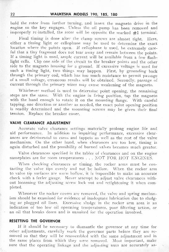
hold the rotor from furth er turning, and in sert the magneto drive in theeng ine so the key engages. U n less th e oil pump ha s been removed andimprop erly re-install ed , th e rotor will be opposite th e marke d # 1 terminal.
Final timing is don e a fter th e clam p sc rews are a lmos t tight. Here,eit her a timing light o r ce llopha ne may be used t o de te r m ine t he ex actlocation w here the points op en. ] f cellophan e is used, be ex t re m ely careful that a t iny fr agment do es not t car away and rem a in between the points .If a timing light is used , am pl e curren t will b e availab le from a fe w flash light cell s. Cl ip one side of the circ u it t o th e breaker points and t he ot hers ide to the magnet o hou sing for a g ro u nd. If excess ive vo ltag e is used forsuch a timing light , t wo things may happen . First, by g ro un ding backthrough the pr ima ry co il, which has too much resi stance to permit passageof a s ma ll voltag e, erronco us resul t s w ill be obtained . Seco ndly, passag c ofcur re n t th rough th c primary wires may ca u se weakening of t he magneto.
Whi ch ev er method is used to det erminc point op ening , t he remainings tc ps a rc thc sa m e. With th e eng ine in firing po sition, tap th e magnetowith th e hand enoug h to ro ta tc it on the mounting flan g e. With carefultapping , one direction or anoth er as n eed ed , the ex ac t point opening positionis readily det ermin ed and th e mounting screws may be given thei r finalt en si on. R eplace the breaker cover .
VALVE CLEARANCE ADJUSTMEN T
Accurat e va lve clearance se t t ings materiall y prolong eng ine life andaid perf ormance. In addit ion to impai r ing per fo rmanc e, excess ive clea ra nc es are detrimental to ca ms and tappet s as well as the rest of t he va lvem echa ni sm. O n the other ha nd, wh en cl ea rances are too low, ti m ing isaga in d is t urbed and t h e poss ibili ty of burned va lves becom es much g rea ter.
Valve cl earances specified in th e tabl es of clearanc es a n d on t he eng inenam epl at es a re fo r room temperat ures . . . NOT FOR H O T ENG I NES.
When checking cl ea rances or timing, t h e ro cker a rm s must be con-. tact ing t he va lve tips eve nly a nd not be holl ow. Wh en t he rocker arm
to va lve t ip surfaces are wo r n holl ow, it is impossibl e t o ma ke an accura techeck w it h a fee lcr g a ugc. Neve r a t t emp t to adjust va lve cleara nces without loosen ing th e a djus t ing scre w lock nu t and retigh t eni ng it wh en corn p let ed.
W hen ev er th e rocker co ve rs a re rem oved , th e valv e and spring m echanism should be ex a m in ed for evidence of in adequate lubrication due t o slu dging or p lugg ed oil lilies . E xcessi ve slu dg e in the rocker a r m area is anindicat ion of too low oil op era t ing t emperatures, poor filt ering ac t ion, ora n o il t ha t breaks do wn and is unsuited for the operat ion in vol ved .
RESETTING THE GOVERNOR
If it should be n ecessary to dismantl e the governor a t a ny tim e foro t he r adjust m ent s , carefu lly mark th e governor pa rts befo re they are removed so t hat t he y w ill be reassembled w it h t he same adj us tm ent a nd int he same p laces from whi ch th ey w ere removed. Most im portant , makesure that t he operat ing linkage a nd th e adj ust ing nu t s are accurately as-

WAUKESHA MODELS 190, 185, 180 23
semb led exactly as before to prev ent improper positioning of the but t er flyva lve. A lso, be sure the lock nuts are in p lace and secu rely tightened topreven t change in the len gth of any of the linkag e. Not ice ca re fu lly, and'ma rk, the po sition of the butterfly va lve so that it goes back exactly asbefore. If th ese precautions a re followed , the governor shou ld op erateexac t ly as b efore whe n it is again put into ser vice provi ded the tension ofthe governor spr ing and th e lengt h of the operating ro ds ha ve not beenchanged. Variation fr om th e prop er speed ca n be correct ed by adj usting theten si on of t he regulating sp r ing . In creasing the t en sion in creases the maximum speed, a nd decr ea sing th e t en sion decreases th e maximum spe ed.
GASOLINE CARBURETORS
Ca r bur tors should not be adjusted, interchanged , or rep laced indiscr im ina tely . They are id ent ified by st am ped tags rivet ed to t he float bow lcover, and when ordering parts or replacem ent ca r bure tors a lways g ivea ll t he infor m ati on on th e tag plus the eng in e se r ia l a nd specificat ionnumber.
Ca rbure tor ser vice consis t s la rg ely of mai ntai ning the fue l supp ly ina clea n condit ion, m akin g p roper ad jus tments at ra re in ter va ls. and leaving t he carburetor a lon e wh en no sp ecifi c a tt ent ion is need ed . More carburet ors a re ru in ed by tam pe ring t han by hard ser vice.
When it becomes ne cessary to perform major cleaning and serv iceope ra ti ons, t he ca rbure to r manufact urer's specia l bulletin fo r th e unit athan d sho u ld be followed wi t hou t deviation .
BACK -SUCTIONECONOMIZER
ICHOKE
Sectio na l Vie w - Gasol ine Carbure tor

24 WAUKESHA MODELS 190, 185, 180
GAS FUEL CONVERSION
The Marvel She bler carburetor sused on most of these enginesmay be adapted t o natural gas orliqu id butane operation. This isac complishe d by the in stallationof a tubular gas jet in the thread edfitt ing a t th e bottom of the ca rburetor body. In addition, it willbe necessary to provi de ·E ns ignMod el-F pressu re regulator and
TO O ILER -..
GA $OLl NELl N E
"",--,- _J'
Qo
IDLEFUELLI N E
Installation - Gaseou sFuel Co nversion
CARBURETOR ADJUSTMENTS
T he throttle stop screw should be screwed in (clockwise) against thestop to hold the throttle just slightly open. Adju st the throttle stop screwto obtain the desir ed low idling speed of the engine.
Adjust the idling adj usting screw to obtain smooth idl ing when engineha s become thoroughly warm ed up. Turning the scre w in (clockwise) cutsoff air, making the idl ing mixture r icher; w hile turning it ou t (ant i-clockwi se) admits more air, making the mixture leaner.
If it becomes necessary to t ur n the screw in to less then 0 turn off theseat to obtain good idling of the engine, it would indicate either an air leakor a re striction in the flow of fue l for id ling. Look for air leaks at t hemanifold flange; at carburetor throttle body to intake gasket, and atcarburetor bowl to cov er gasket, du e to loo sened as sembly screws or da maged gaskets. A badly worn throttle shaft wi ll produce sufficient air leakage to affect t he id ling mixture.
Dirt or other foreign matter in the idling jet calibration wi ll re strictthe flow of fuel for id ling and affect the mixture. If the idling jet becomescompletely clogged, it w ill be impossib le to ru n the engine at idling spe edregardless of adjustment of th e idl ing adjustment screw.
Some models of th is ser ies are s upplied with a main jet adjustment .Turning the needle clo ckwise cuts off fuel making the medium and high
speed mixtures leaner. The needleshould be adjusted to give highest manifold vacuum (or highestRPM on a tachometer ) for a setthrottle position. If en gine isequipped with spee d governor, setthe throttle to hold th e eng inespeed ju st below the governedspeed while adjusti ng the main jetadjustment. If adj us tment is se ttoo lean, th e engine will lackpower and th e fue l eco no my al sowill be poor. If set too ri ch, th eengine will be sluggish and thefu el economy poo r.

WAUKESHA MODELS 190, 185 , .180 25
t he necessary fittings and lines. When using liquid butane, a fuel vaporizer wi ll a lso be needed . For use with natural gas, a lin e pressure regulatorpre ce de d by a gas scr ubbe r is usually emp loyed. T o de te rm ine the ex ac t'requirem ents to conve rt a g ive n engine to gas or liqui d bu tane carburetioncons u lt th e Service Divi sion, Waukesh a Motor Co mpany, g iv ing th e enginese ria l a n d specification number.
VOLUME TANKST h ere a re many cases where it is advisa b le t o in corp orate a volume
tank on engines op erating on natural gas fu el. This is n ecessary due tothe rapid req ui re me nt for gas whe n t he engine is accelerated such as forhoi sting ser vice or w he n quick changes in load oc cur.
The question of det crm ini ng th e size of th ese tanks has been in ve s ti gate d by th e Ensig n Carb ure to r Compa ny and it is adv ised that a vo lumeof four to five times th e engine di splacem ent volume sho uld be sat is factory.The fo llowing form ula may be fo llo wed to det ermine specific engine requi rem ents.
< _ Eng. Di splac cm cnt ( in cubic in ches ) x 4 or 5Tank (Cubic Ft. ) - 1728
For desir ed tank volume in ga llo ns, di v ide by 231 in stead of 1728.

26 WAUKESHA MODELS 190, 185, 180
REPAIR AN D OVERHAULDISASSEMBLYThe disa ssembly a nd overha ul of engines in this series requ ires no un
usual or specia l shop equipmen t . The follo wing factors are very importantand should not be ov erlooked :
1. D O NOT MI X O R CONFUSE ENGIN E PARTS. Mark for positionon di sa ssembly; tag assemblies fro m different engi nes; ident ify parts reground to special sizes.
2. DO NOT MIX BOLTS, CAP SCREWS AN D WASH ERS. Capscre wsand like parts are of a length, ma teria l and heat-treatmen t suite d to theplaces wher e they are used .
3. INSP ECT AS ENGINE I S D ISASS E MBLED. O nce engine part s havebeen disassembled and cleaned, ma ny va luabl e indications of engine con dit ion are lost .
4. P RO T E CT D E LI CAT E P A RT S A N D SURFACES. Do not pile engineparts , ig nit ion eq uipme nt , carbure tors and so on . O il it em s th at a relikely to rust. Tape surface s subject to scra tc hing or ni cking duringrepair operat ion .
5. CL EAN THO R O U GH L Y. No engine is complete ly overha uled if it isnot cleaned interna lly and ex tern a lly to new-part co ndit ion. Do notoverlook remo ving ch emical clea ners fro m oil pa ssage s and cast ingpockets .
6. W O R K A CCU RATELY. Use preci sion gauges whe re needed ; followtables of clea rances and tig h tening torque va lues.
OI L PAN REMOVALMa ny of the oil pans used on engine s
OI LPAN
! ,FLYWHEEl'HOU SING": :
~CLEARANCE~
HE RE NORMALDO NOT TRYTO REMOVE
O il Pan Bolt Install ation
in this se r ies are held at the rearflange by two long , specia l bol tsextending down wa rd throug h th efly wheel housin g . Thi s is necessa ry in order to provide adequategasket pressu re in this area andat the sa me t ime avoid p laci ngthe oil pan bolt s in an in accessib le po siti on . These lon gcapscrews must be removed before wi t hdr awing the oil pan.
O n rein stalling these capscre ws it wi ll be fou nd thatt he heads do not seat on theflywh eel hou sing . This is doneto in sure full pressure at thepan gasket. A ttempting to seatthe heads against the fly wheelhou sing will st r ip the threadsat th e oil pan to rear oi l sealjoin t .

WAUKESHA MODELS 190, 185, 180 27
CYLIN DER SLEEVE REMOV ALRemoval of the wet-t ype cylinder sleeve is not difficu lt s ince the only
subs t an t ia l force required is that needed to loo sen the rubber sea l r ings .A scre w- jack pull er made of a through bolt , a plate . t o match the low erend of the s leeve, an d a bridge of ha rdwood or metal o ver the top of thesleeve w ill serve as a rem oving to ol. W hen t h e rubber rings have b eenloosened the sleeve may b e lift ed ou t by hand. Rubber rings must not bere-u sed .
CAM SHA FTCa mshaft removal req uires prior rem ova l of t he oil pump an d it s drive
assembly, the distributor a n d dr ive assembly, and in the ca se of a fu el pumpw it h th e shoe r idi ng direct ly on th e ca mshaft this to o must be removed .U nless the engine is inverted on a work stan d or tipped on it s s ide on atable, the ca m fo llo we rs m ust b e lifted and h eld clear of the cam lobeswhi le the camshaft is withdrawn.
W ithdraw t he camshaft by pulling gcnt ly and maki ng sure that th elobes a re n ot catching in th e bushing or case. R emova l of t he g ear requir esan a rbo r prcss, and mandrel an d a suit able support plate to ho ld the gear.
Ca m, Gear, Bushing a nd Tappet
R epl ac em ent of the gca rs in the ca msha ft drive t ra in I S no t recomm end ed as a field procedure b ecause of th e need fo r se lect ing gears wi t hthe prop er r unni ng clearances. When circumstances co mpe l gea r re placem ent, no te t hat th e gears are stampe d "oversize," " standard" or " undersize" as in t he fo llowing examples . . .. "S"-standa rd; "2S"- .002"sma ll on p it ch dia meter ; "2L"- .002"-large on pit ch diameter; and so on

28 WAUKESHA MODELS 190, 185, 180
up to max im ums of .006" larg e or sm all. To re -t ime t he engine, adjustt he gears so as to pla ce the t iming marks in t he re lationsh ip sho wn in t heaccompanying diag ram. The idler gear, shown in dot ted lines in t his drawing, is used for an inject ion pump drive an d is in stalled in Di esel engineson ly . I n gas-gaso line versions, t he oi l pa ssage to t he idl er spindle locationof t hi s gear is bla nked off by a pressed- in s t ee l cup.
CAM FOLLOWERSThe cam fo llowers may be re
moved by working from th e underside oi t he cra nkcase af ter t hecamsha ft is re moved. Keep eachcam fo llower in or der as re moveda nd re-ins tall in the sa me p lace.W hen a worn or damaged ca m follow er is found, a lways in sp ectwith part icular ca re t he camlob e up on w hich it was operat ing .
VALVES AND MECHANISM - REPAIRValves req uire gri nding at va ri
ous in t er val s duri ng t he engineservice life. Th ese intervals cannot be spe cified exactly beca use anu mber of variab le fa ctors entert he pi ct ure , ofte n without the engi ne opera tor 's knowledge. O ft hese fac tors, the io llowing have beento m ake for reduc ed va lve life :
Valve Timing M arks
found to a g reater or lesser cl eg ree
1. Fuels that break down to iorm deposit s that unparr seat co ntact andprevent heat conduction .
2. D eposit s fro m eit he r fue ls or oils t hat acc um ulate on the valve st emsand ca use s t icking and b urning .
3. Oil not reaching ro ck er a rms due to clogged lin es, im prop er fitt ingco nne ct ions, and sludging.
4. Shutting clown a hot eng inc w it ho ut id lin g for a few minut es. Exha ustva lves t hat happen to be off seat whe n engi ne stops may warp so t hatburning occ urs on re-starting .
5. Tappet clearances not properly maintai ned so that at least .008 to .010"is present w he n run ni ng.
6. Lean fue l mix tu re due to Improper ca rburetor or adjustmen t.
7. Pre-ignition du e to w rong p lugs, car bo n deposits, excess ive oper atingt emperatu re s .

WAUKESHA MO DELS 190, 185 , 180 29
COM PRESSIO N CHECKSA com press io n check is the best m ethod of deter m ining w hen valves
n eed g r in d ing. Since different pi stons wi ll develo p di fferent cranking compress ion pressures du e to compression ratio variation s, n o specific figuresare given for t h is test . T h e most s ig nifica nt thing is for t he pressures onthe indivi du al cy lin de rs to match w ith a fair degree of eveness. If it isfelt th at com pression may be leaking pa st th e p iston r ings , inj ect somehea vy engine oi l th ro ugh the spa rk plug hole before making the te st .This w ill tempo ra ri ly sea l the ri ng s. I n addit ion, a quick knowl edge ofva lve co n dit ion may b e gained by listen ing a t t he ca rburetor en t ra nc e(d isconnect air cl eaner) and t h e ex haust outlet w hile the engin e is cranke dover. Piston ring blow-by m ay be hea rd at the oi l-fill er op ening as thep istons are s low ly brought onto compress ion and the air a llo w ed t o seeppast . If valves are leaking bad ly, th e pi ston r ing leakag e may no t benoticeable. A nothe r in d icat ion of lea king va lves is an unst eady intakemanifold vacu um reading, particularly at id le .
VALVE MECHANISMW hen the push rods have been wit hdrawn t hey should b e tagged or
other wi se marke d so that each rod may b e rep la ced in it s own ta ppe t.E xamin e each rod to mak e sure it is s t ra igh t , an d that both u pp er andlow er en ds a re in good condition . R eplace - do not st raig h te n - any thatare ben t , and if t here are any of t he ball a n d socket fitt ings t hat showsig ns of wear beyon d t he case h ardeni ng , re p lace these a lso . Sockets a tthe ro ck er arm en d m ust not be use d if they are worn so deep that th e upperedge rides t h e adjusting lock nut or t he ro ck er arm a t any point .
T h e en d of each va lv e st em is fitted w ith a sha llow stee l r et ainer thatsurroun ds the en d of the valve spr ing , and is held to t he st em by a p ai rof wedge k eepers. These wedge keep er s must be removed before t he va lveca n be withdrawn . To rel ease t he wedge s from t he recess in t he sp ringre taine r, it is on ly necessary to p ush t he retainer do wn against the sp ringu ntil t he wedges fa ll away from the va lve st em . \ Vea k or cocked spr ingssho uld b e di scarded and new ones in stalled w he n re-asse mbl ing. Note theseal washers and g uard on th e in take valves so thay lIlay b e co rrectl y reasse mb led.
GUIDES AND SEATSUpon removing each valve exam ine it carefully. Re move a ll carbon
a nd burne d oi l and ch eck th e valve st em and it s fit in the g uide . Excessivew ear in eit her the s te m or g u ide w ill make it impossible t o secure a tightseat by gri nding unless th e valve ox g ui de , and possibly both, are re p laced.Specia l no t ice of the ex haus t va lve g ui de a nd valve st em shoulder sho uldbe taken to make sure th e g u ide docs not proj ect in to t he valve gas passag e, an d that t he shou lder on the valve stem is sharp . This shoulde rshould be s lig ht ly be low the t op of t he va lve g uide w hen the va lve isse ated. Thus, any ac cumulation of carbon around th e g uide and ste m w illbe shea red off each ti m e the valve is lifted, a nd in this way prevent va lvest ick ing.

30 WAUKESHA MODELS 190, 185, 180
'N om va lve g ui de s s hould be replaced w it h new ones . T he g uide s a rea pressed fit in th e he ad cas t ing, a n d ser vice g u ides are es pecia lly machinedto press in place, and g ive prop er s te m clea rance w it ho ut fur t he r machining . O n the ot he r hand, the va lve seat in th e he ad M U ST be re-cut concen t r ic w it h t he new g u ide wh en ev er new g uides are installed .
The acc uracy of t he mach ine m ethod of va lve gr.inding dep ends ent ire lyupon the condi tio n of t hc va lve g ui dc a nd th c pi lot m andrel' s fit , both inth e g u ide it self , an d th e hub of th c gr indcr sto ne . It is vitally important,therefore, t o m ake su re that th e mandrel is a snug push fit in t he va lve 'guide, a n d will not wobble at the upper en cl. If it does ha ve any uppcr -endmo vem ent th e seat w ill not be g ro u nd true. Gu idcs that are worn toomuch to g ive the ma n dre l so lid support should be repl aced before grindin g is attempted. The make r 's in structions for d ressin g th e grin d ing wh eelmust be fo llowed to secure smooth, accura te sea ts .
VALVE GRINDINGModern valve s arc m uch harder than form crly so that a va lve g rin di ng
machine is much quick er and marc ac curat e than hand g rind ing. 1f machineg rindi ng equ ip me nt fo r both va lves and sea ts is not immediately at hand,it w ill of te n sa ve t im e a n d mon ey, as well as prod uci ng a better jo b if thehead and va lve assembl y are sen t to a local specia lis t . E ven if hand gri ndingis employed, t h e valve s t ems an d g uide s m ust be a good fit w it ho ut wobb leto in sure a co ncen t r ic seat and a tigh t valve.
HAND GRINDINGApply a good, medium grin d ing co m po und spa r ing ly a ro und the ent ire
va lve seat, s lip a lig h t li fting spr ing over t h e s t em , lubri cate the ste m, a nddrop th e va lve in to it s o rig ina l place in t h e cy lin der head. The sp ring shouldjust barely hold t he ' va lve off it s sea t . P lace the g rin ding tool in the twohol es or slot in th e head of the va lve to bc g m un cl. P ress dow n un ti l t he valv eis se ate d. T urn the va lve a qu arter turn. first in one direct ion th cn in t hco ther. D o thi s three or four tim es, R elease the pressure on t he valv e, a n d th elitt le spr ing wi ll lift it off it s seat . No w t u rn t he va lve ab ou t 10 or 15 degrccsto a nother po sition, a nd repeat th e gri nd ing. Do th is un t il all th e co mpoun dis r ubbed off the va lve seat . Withdraw the va lve, and put on som e freshcompound. R ep cat th e gr indi ng operation .
Clea n t he valve and it s se a t occ asio nally to see how th e g r in ding is progressing. Wh en all pits a nd g rooves ha ve di sa pp eared , clean the va lve an dva lve seat , and place eig h t or t en cqua lly spaced marks w ith a soft lead pcn cilon t he se at . T hen drop the valv e in place, g ive it a quarter t urn, and re moveit . A perfect sea t will be indicated if every pe nc il mark shows where the valvehas r ubbed it. If any pencil m a rks arc left untou ched, co ntin ue t he g rin ding.W h en the g ri nding is co mplet ed , check t he valve seat for concentri city witha di al in d ica tor, then o il th e va lve s t e rn, cl ean a ll traces of t he g rind ingco mpound fro m the valve cha mber and ports, and RE-A S SEMB L E E A CHVAL V E I N ITS O WN O PEN IN G.

WAUKESHA MODELS 190 , 185, 180 31
REM O VA L AND INSTALLATION OF SEAT INSERTSExte nded ser vice life may no rm all y be ex pected from valve in ser ts
which have been insta lled prop erl y . S ince in serts must resi st severe andre pe ate d contact s from t he va lve, th e act ion of hot gase s, a n d t he rever sest r es ses of rapid heati ng and cooling. minor n egli g en ce or Jack of tech niq ue onthe part of th e mechan ic will be mag ni fied and resu lt in se r vice troub le.
H ere. m echa nica l secur ity of t he inser t in th e b lock is not al on e enough toin sure successful op eration . Many examples m ay be found wh ere comparati vely cr ude s ta king or ce nte r punch meth ods retain ed t he in sert more o r lesssn ugly but at t he sa me t ime failed to provid e good m et a l to met al co ntact b etween t he in sert heat con duct ing sur faces an d t he h ead. Failu re of t he valve,th e in sert, or th e bl ock ca st ing is alm ost inevi tabl e under these conditions.
GUIDE REPLACEMENTIf it has been det ermined t hat val ve guid e rep lac em ent is required , thi s
ope ra t ion shou ld be don e at thi s ti m e. O ld g uid es may be re moved with asuit a ble pu lle r or by rea mi ng to a thin shell a nd co lla psing t he m . N ew g uid esare presse d in p lace on a n a rbo r press with t h e a id of a mand rel. Serviceg ui de s are especia lly machin ed to prov id e proper ste m cleara nce w ithou tfurth er reami ng aft er in stallation.
Shim Hereif Nece ssa ry
Removing Peened Meta l
Wh en removing seat in sertsit wi ll be nece ssa ry to employ acut t er to re move t he m et al thatis pe en ed ov er th e edge. If th is isnot done, more meta l than necessa ry is brok en a way and th e n ewin sert m ust be of excessive ov ers ize in order to clean up the co unt crbo rc, Th e accompa ny ing ill ust ration show s th e g enera l outli neof Sioux cu tt er. . Th is same t oo lmay be emp loy ed to provide a lig h tcutt ing ac ti on fo r cleaning up th eco unterbore af te r insert r emova l.I t is \'er y im por tant tha t th e pil oting of th e cutte r permit cu tt ingto m icrom et er di m en sions as required. A ll co u nt erbo res sho uld becl ea n a nd smoot h with a radiu s ofa pp ro xi ma tely .015 to .020 a t ti lebottom corne r to prevent a sha rpbrea k on co ntour wh ere the count erbore wall m eet s th e co unterbo re bottom s urface. Wh en th e peen ed m etalhas bee n rem ov ed , th e in se rt s may be pu lled wit h a pu ller mad e up for t hi spurpose. I t has be en reported th at a bead of m etal app lied to the inn erdiam et er of the in sert with an elect ri c arc w elder, will ca u se su fficie ntshrin kag e to eas e in sert r emoval materia lly. Users of this m ethod a re
REMOVING INSERTS

32 WAUKESHA MODelS 190, 185, 180
ca u t ion ed aga inst in volving th e arc heat o r m etal wi t h the main cas t ing. Al so .spatter ings fro m th e a rc m us t be th oroughly clean ed fro m th e va lve po rtpassage walls to prevent th em fr om enter ing the cngine during subsequent ope rati on .
ENLARGIN G" COUNTERBORE
I nsta ll a . s nug fittin g pi lot ofthe co r rect di amet er in the g uide sand u sc th e sa me cutter" or o ne oft hi s t ype, to re-si ze th e ins er tcounterbore to t he correc t s ize forth e new oversize insert . By subtracting th c or ig ina l co un te rbo rcd iamet er fr om t he diam eter of theor ig in a l insert, the correct a mo untof cr us h may be establ ished . Measu re th e diameter of the new in scr ts a nd s ubt ract t h e fig ure obtai ned for the crush fr om thisdiam et er to determ in e th e co r re ctcutting diam et er for which t he
Counterbo re Cutter cutter must be se t . T hese tools area vailabl e fr om such rn anu fa ctur
ers a s Alber tson & Co m pa ny. Inc. ( S ioux) .
CRUSH
The cr us h for any givcn engin c an d inser t co m binat io n is a very cr it ica ld im en sion a nd has been cs t a b lis hed at th e fact ory by long ex pericn cc . Att em pt s to o ver-crush t hc in sert s a lmos t a lways resu lt s in th e in sert loosen ingin ser vice . Th is is t lic r esu lt of a mcta ll u rgical co nd it io n w he re by th e ex pa n eled met a l takes a perm an ent set while hot and t hereafter n ev er re turnsto it s origi na l dimcnsions.
SHRINK ING INS ERTSS hr inking ofTel's the most pract ica l and sa t is tact ory method of in s ta ll
ing t hc inse rt s wi t ho ut u nde sirab le scra p ing or broach in g of m eta l fro m thes idc of th e co un tc rborc. V cry lo w t emper aturcs ma y bc obtained by im m er sing several sma ll chun ks of dry icc in a co n ta ine r of alcoho l or gasolin e.T o insure sq ua rc ness in cntc r ihg a nd dr ivin g th c inse rt in the cou nt erbore,it is im po rtant to p ro vide a d riv ing t oo l p ilot ed in t he va lve g u ide, S uch atool is easi ly mad e up or a da p te d from tlie valve g u idc in stall in g m andrelby s lipp ing a s t urdy washer- like driving p la t c so me w hat la rger than thein ser t over the mandrel pil ot .
DRIVING INSERTSP re pare t he co unterbo rc by checking fo r cleanl ine ss a nd free do m fro m
bu rr edgcs. S upport th e bl ock so lid ly an d co uvcnicnt ly fo r d ri ving. . Us inga pair of forcep s or a hooked wire, qu ick ly lif t th e ch illed insert fro m t hed ry-ice bath and locate it over t he co u ntc rbo rc so t he cham fer on the in sert

WAUKESHA MODELS 190, 185, 180 33
lo wer edge is en te red sq uarely. St a rt th e dri vin gmandrel pilot in th e va lve guide, bring the drivingface against th e insert upper surface accurately ,a nd tap th e mandrel fir m ly w it h a medium w eig hthammer. 1f se vere hamm ering seems to be requi red. th e co unterbore is not th e correc t size, theinsert was not chi lled eno ugh, or it was no t s ta r te dinto th e counterbore stra ight and true.
PEEN IN G INSERTSFactory insta lle d va lve in serts w ill usually
sho w a narrow flan g e of m etal worked ove r thein sert up per edge w it h a specia l tool. Si nce thism et ho d is not a va ilab le for fie ld appli cation, amanua l p eening operation is em p loye d to achi evethe sa me resu lt and se cure the in sert in th e co unterbore by th e po siti ve clamping act ion of t he peenedover materi al. It is sugges te d t hat th e operatormake up a too l a long t he gene ra l lin es illustratedand th en check th e peening tool on a scrap part if Peening Insertpossib le. This will in dicate the proper we ight ofhamm er b low, th e best radius at w h ich to se t t he t oo l, a nd th e general patte r n of peen ed m etal that m ay be expec t ed . A magni fy in g g lass is ve ryuseful in ex am in ing t he peen in g for ov er-h amm ering crack ing.
ROCKER ARM OVERHAUL
Th e wear on th e rocker arm sha ft an d b ush ings will ordi nari ly be quiteligh t, p ro vidi ng ade quate oi l circ u la t ion to t hose parts is mai ntai ned . Neve rth eless, no cylinder h ead overha ul a nd valve job is co mple te wit ho ut carefulins pec tio n of t he rock er bush ing s, rocker shaft b eari ng surf aces, valve contac t end of th e rocker arms, an d th e adjust ing screw. Micromet er meas ure men t will re vea l sha ft out-o f-r ound, a nd intern a l bu shi ng wear m ay bedet ected by t ryi ng t he ro cker arm for looseness on a ne w sha ft or wit hinsi de m icro meters. N ew bu shing s may be pressed in pl ace a nd reamed to size.
The rocke r tip a re a s hou ld presen t a smoot h su rface to b ear aga in stthe va lve stem . L ig ht g ri nd ing will clea n up wo r n spots th at wou ld otherw is e int erf ere with prop er va lve ad justment . By th e same token , the adjusting screw a t t he opposi t e end of t he roc ker a rm sho u ld t urn fr eely witho ute vidence of th read damag e, th e wear ing surface should be smooth and polish ed wit ho u t pe netrat ion of the harden ed exter io r, an d the mati ng soc ke tin th e pu sh rod shou ld appe ar eq ua lly go od. Excess ive wear of eit he r part,such as wo uld pe r mit the rock er to ride on t he edge of th e socket , for ex amp le, re q uire s repl acem en t of th e worn pa r t s .

34 WAUKESHA MODELS 190, 185, 180
REASSEMBLY
Evening Up Rubber Ring s
It is not unusual wh en fitt ingth is t yp e of s leeve to find it necessa ry to wit h draw the slee ve , resoa p and even up th e rings, a ndre- install it several times beforeobtaining an out- of-round re ading
have occu rred due to inaccurat e p lac ecan b e do ne ,with a clamping loa d on
the top of the sl ee ve and a dial in dic a tor of the exten sion arm, threecontact type.
T he clamping ac tion may beobtained from any accura te ly bui ltring that s im ulates t he cy lin derh ea d pressure a nd is r etained byth e head st u ds . If a co ns ide rablenumber of sleeves are to be replaced over a period of time, it mayprove co nven ien t to make up aclampin g tool fro m a di scardedcy linder head w it h op enings cu tout t o a llow th e ga uge to dropthrough into th e cy lin der.
Chec kin g Sleeve fo r Dis tor tion
INSTALLING CYLINDER SLEEVESThere are se ve ra l important points to not e on installing the slee ves.
First in importance is the use of se a l rings that are fr esh a nd elast ic. Donot use ag ed and harden ed ring s since t hese w ill not compress ev enly andsleeve distortion w ill re sult. Also,the ring seat ing surfaces must beclean and we ll lubricated w it hliqu id soap . D o not use engineo il on rubber r ings. After s lippingthe rings over the slee ve and intot he grooves, r un a p en ci l or likein st ru ment around under the ringto di st ribute t h e r ubbe r materialaround t he sleeve more evenly .
After the rubber r ings and surrounding area are w ell soaped,a lign the sleev e in the crankcaseand forc e it home with a smart,firm t hrust of the hands. I-Iea vyhamm ering or driving is unnecessary and undesirable.
When all slee ves a re in pl ace,it is good practice to ch eck thesleeve bore s fo r di stortion that mightment of the sea l r in g materia l. This

WAUKESHA MODELS 190, 185, 180 35
within the limits of .001"-.00 2" . U neven di stribution of t he r ubber ring scauses this trouble. A lways make this check in the sea l r ing area .
In connection w it h the above check for out-o f-ro und, it may be moreconvenient to make a gauging piston by re -grinding a n ov ersize pi ston tojust s lide throu g h t he sleeve within the prop er tol erances. Such a gaugerequires som e skill and judgment in use since forcing it th rough a di storteds leeve wi ll not correct the di stortion and may cause sc ore ma rks or scra t ches .
Cy linder Hea d Gasket Crush
GASKET CRUSHON SLEEVE
o
CYLINDER HEAD GASKET CRUSHIn orde r to prevent s leeve move
ment and sea l the water a t thejoint between th e upper sleeveflange and th e cra nkcas e, the sleevemu st proj ect a few thousandthsab ove th e cra nkc ase deck. Thisdistance is important and a definiteand measurable amount must exi st .In effect, this proj ection providesa localized crush in a concentrated area around the top of eachsleev e. I n case no proj ection isfou nd, consult th e Service Di vi sion,W A UKESHA M OTOR CO MPA NY.
T he operator is ca ut ioned againstusing head g as kcts other thanthose specified by t he ,,¥A U K E-
SH A M OTO R CO M P A N Y. Casesha vc been re porte d where gasketsof somew ha t ha rd er material haveov er loa ded t he sleeve flan g e a ndst a r te d cracks in t h is area . Byth e same token , t ig h te n cy linderhold down nuts to the correcttorque va lue. A cy linde r headgaskct in obviously g oo d co nditi on may be re-u sed. It is poorecon omy, however, to ri sk cnginedam agc and ex t ra labor if th egaskct is at all doubtful.
PISTON FITTINGProper fitt ing of pi stons requ ires
at lea st fo ur different precis ion.checks. These are: Ring ga p, r ingside clearance, pin clearan ce in bossand pi ston skir t to sleeve clearanc e.
Ring g aps a re ea sily ch ecked Checking Ring Gap

36 WAUKESHA MODELS 190, 185, 180
Checking Piston RingSide Clea ra nce
with a feeler gauge. S lip a pi ston r ing into th e sleeve. S lide a pi stonin to the slee ve above it . P ush the piston up against the ring to s qua re th eri ng wi th the bore. Move t he pi ston out of the way a nd m ea sure the gapin the ring with a fee ler g a uge. Those rings wit h gaps less than specified inthe table of limits in the back of this manual shou ld be carefully dressedoff with a flat cu t file unti l th e correct clearance is' obtained . Contra ry topo p ular imp ression, fai rly w id e ring gaps, n ea r the top limit, a re far lessdet r im ental to engine performance than gaps which are to o tight.
Piston ring side clearance musta lways be checke d wh en fitt ingring s to pi stons which have beenin ser vice. Tn this case, t he objectof t he check is to spo t any p ist on sin which th e ring grooves may haveworn ex ce ssive ly wide. A pistonin t h is co ndit ion mu st b e rep laced .To check side clea rance, select api ece of feel er s tock of t he maximum clea rance specified in thetabl e o f limits. With the ring inplac e, in sert the feeler if po ssiblebet ween t he r ing la n d a nd thering he ld w ell back in t he groove.If th c feeler slides in at any point,it indicatcs the clearance is at orover allowable maximum. A sn ugfit o f th e feeler points to furth erco nside ration by the operator as tow het her th e pi ston warrants rein st a llation since th e groove we aris a t th c top lim it . On a ll pi stonspassing th c abov e check, mak e a n in spection fo r minim um clearance with afee ler of the m inimum thickness spec ified in the t ab le of limits. This feclershou ld slide fre ely all around th e g roove as th e pi st on and rin g a re rotated .
Piston pin fitting is a job requ ir ing g rea t preci sion a nd pin a nd pi stonasse mb lies a re usually so ld in match ed set s. O versi zes of .003" a nd .005"a re availab le, however, if de sired, Th e sp ecified pin cleara nce will permit ahand "push" fit at ordinary ro om temperatures.
A pin that is loose cno ugh to drop t hro ugh the pi ston by it s own wcigh t,is ordinarily considered too loose. From th e service st a ndpo int, a fit of th isvariety, if not du e to severely worn parts, wi ll cause a n eng ine to be somewhat noi sy but wi ll no t nccessaril y impair performance or reduce cng inc lif e.Moreover, field exper ience has show n that ev en pe rf ectly fitt ed pins will oft cn"drop" through because of t emperature va r ia t ions at th e fa ctory an d th e poin tof in stallation .

WAUKESHA MODELS 190 , 185 , 180 37
If oversi ze pins are installed , do not forget to check t he fit of the pinin the conn ecting rod bus hing since t he new pin will be too snug in a standa rdro d.
P ist on to s leeve clearance is probably t he most critical dimen sion inth e ent ire pi ston fitti ng sequence. Pi ston s are so ld for re-dimen sion ed sleevesin .010", .020" and .040" ove rs izes. Al so, they a re so ld in sem i-finished co ndition for these engines and it is po ssibl e fo r a piston of g ive n oversize to bere-g roun d to a smaller ove rsize as needed.
To take the clearance, se lec t api ece of 0 " wide feeler stock 8 to10" long and of the desired skir tclearance . Attach th e feeler stockto an accurate spring sca le asshown in the accompanying illu st ration. In vert the pi ston andsupport it w it h on e hand w hileho lding the feeler and spring sca lein t he ot her ha nd. P lace th e fee lerstock in th e slee ve and low er t hepiston in to po sit ion in such amanner t ha t th e feeler s toc k isspaced 90 ° fr om th e piston pin.H old the p ist on and withdraw th efeeler s tock. If the correct clearance is present, t he ten sion required to w ithdra w th e feelershou ld re ad 5-10 po unds on t hescale. T oo low or too high a sca lerea din g indicates too much or toolittle cl ea rance.
When fitting a pi st on to a n ewor accurate ly re-sized sleeve, th esleeve inner diame ter should bethe sam e at top and bo ttom. Therefore, the clearance ma y be takenat eit he r end. I n sleeves th at havebeen worn, b ut not resi zed , sometap er g iv ing ex tra cl earance att he top of the sleeve is likely . I n
Checking Piston to Sleeve Clearance such ca ses, th e clearan ce m ust be. che ck ed at th e bottom of the sle eve
where the wear is least and th e fit is close st. R em ember, the skir t of t hepiston fit s closer than the r ing lands. A lways check skir t cl earance, not landclearance.
BEARING ADJUSTMENTA ll main and co nne cting ro d bearings in these engine s a re of the steel
backe d, precis ion ty pe. Beca use of the ex t re me ly close machining of t hi s

38 WAUKESHA MODELS 190, 185, 180
t ype of bea ring , no fitting, filing, scraping , boring or other adj ustment isrequired or permissib le . Replacement m ust be in co mp let e bearing units.N eve r r eplace only one half of a bea ring. Service bearings are availablein .020" and .040" undersize fo r use on regro und cranks hafts . Never attemptto a djus t a bea ring by filing, grinding or lapping .the bearing ca p. T he
l bea ring sea ts are preci sion bored w it h the caps in place. H en ce, any metalremoved fro m eit he r s ide forever prevents proper fitti ng of a co nne ct ing ro dbe a ring in the ro d, and in the case of a cran kcase, makes the ent ire ca seunsuit ed for further use .
Be sure that the bearings seat on abso lu te ly clean surfaces and that theback of the bea ring is w ipe d perfectly clean. The slightest bit of dirt orcarbon s queezed between t he back of a bearing and it s seat can ca use rapi dbearing fa ilure du e to a local ized high spot.
Equa lly important in obtaining maximu m bea ring life is t h e correctt en sion on the bearing ca p nuts. P u ll down on a ll nut s evenly, going fromone side of the bear ing' to the ot her. Apply fina l t ension with t orqu e wrenchusing a slow st eady pu ll and holding t he w rench "on torque" for a fewsecon ds when t he proper value is reached. Desir ed torqu e values w ill befound in the table of limits at th e en d of t h is manual. Previous over-torquing,or some other damage to the bolt or n ut is somet imes encoun tered and wi llbe fe lt by the torque "softe n ing' up" so that th e nut can be t urned w it houtapprec iable in crea se in wrench tens ion. Never allow a bo lt and nut in t h iscondition to remain in an eng ine.
Cra nks haft en d t hr us t is controlle d by th e flange on t he center mainbear ing on t he 180 and t h e n umb er 3 bearing on t he 185 and 190. Therefore,t here is no n ecessity for ad j ustment of th is at assembly . Excessive end pl ayrequire s bea ring repl acem ent. A lways be sure t ha t some end pl ay definit elyis present!
SIDE CLEARANCESA lt hough less cr it ica l t han t h e b earing running clearances, no bearing
should b e assem bled w ithout ch eck ing side clearance. Thi s may be don e byforcin g th e ro d fully to one side or the other and in serti ng feeler betwe en thecrankcheek a nd the bea ring en d. Shaft end p lay is m ea sured w it h a feel erbetween t he sh aft flang e a nd th e main b earin g flan g e w hen t he shaft is atfull forwa rd or rearward position. A dial ind ica tor ma y also b e use d forthis purpose. Cons u lt the tab le of limits for the prop er cl ea rances.
RUNNING CLEARANCESE v en in the case of preCISIOn bearings, it is good m echanical practice
to check r unni ng clearances w he n in stalling bearing s. There are severalm ethod s of doing this, some of w hich are merely ch ecks of w he t her anyclearance exi sts and others that g ive an indication of how much clearance ispresent. T he familia r t est of conn ecting ro d be aring clearance cons is ts ofmanua lly gripping th e rod . cap after th e bear ing bo lt s are ti ghtened andattempting t o mo ve the bearing fr0 111 s ide to side in the d ir ec tion . of endclearance. A we ll-fi tted b earing is usually just loose enough to be "snappe d"fr0111 side to side w it h out ac t ua lly feel in g so loose as to push eas ily . Some-

WAUKESHA M ODELS 190, 185 , 180 39
ti m es a slightly sn ug bearing wi ll not mo ve under finger pressure but w illmove readily under light b low s from a so ft -face hammer. This is usuallyconside red as sat is fac to ry providing the engine is g iven adequa te break-int ime. I n the final ana lysis, this t est is a matter of judgment a nd is notaltogether su itable fo r genera l use .
A sim ilar test on ' main b ea rings co ns ists of tighten in g eac h b ea ringcap in turn a nd t urning th e shaft to det ec t bind. Again, th e diff er en ce bet weenti ght and "abo ut ri ght" is a matter of judgment.
More accurate t ests may be ca r ri ed out w it h fu se wire or wit h a specia lcrushing gauge mater ia l that s queezes bet ween the shaft a nd t h e bea ring toflatten in to a m ea surable ga uge.
I t is em phas ize d t hat any unusua l be n ding or run-out in a crankshaftmakes it impossible to fit bearing s ac curately . For this r ea son, t he ti me spe ntin making a r un-out ch eck at overhaul is we ll wort h w hile. A lso, m agnet icins pe ct ion of t he crankshaft and ot her st ressed parts is re com me nde d if thepro pe r equip ment is available.
DO N O T FORGET TO COAT A LL R U NNI NG SUR FACESWITH CL E AN, FRE SH ENGIN E O IL W HEN I N STALLI N G NEWBEA RI NGS!
REPLACIN G CYLINDER HEADFirst , make sure that any oil leads w hich may be drilled in t he he ad
to fe ed the rocker arm s, as we ll as the drill ed oil leads in the cy linde r b lock,are clean to in sure full oiling of th e valve mecha nis m .
A torque w re nch w h en used according to the tab le at t he rear of thisbook w ill prevent ove rs t ra ining st uds , while in surin g a tight joint. T heorder of tighteni ng is a lso im portant. As shown in the t ypi cal case, t he holddo wn stu ds sho uld b e tigh ten ed in two or t hree success ive stages start ingwith t he center a n d w or ki ng toward eac h end alternately . This w ill in sureeve n pressure over t he ent ire surface of t he cylinder he ad a nd gaske t. If theouts ide n uts are pull ed up firs t in s tead of t he ce nter ones, t he head w ill beco cked, an d t h e gaske t w ill no t fit t ight eno ugh to prevent bl owing outbetw een cy linders. A to rque wrenc h, where used accord in g to t h e maker' sdi rect ions, is the bes t way of se tting up cy linder h ead nu t s to in sure fu lltens ion w it ho ut excessive st ra in that m ig ht stretch t h e stu ds . D o not neglec tt o co nnect the oil lead to t he rocker a r m shaft. Test it to b e sure it is notclogged.
Cylinder Head Tighter,in g Sequ ence

40 WAUKESHA MODELS 190, 185 , 180
FLYWHEEL AND HOUSING ALIGNMENTWhen ever the fly wh eel or fly wheel hou sing have been re moved, or
w he never a clutch assemb ly is ins t a lle d, t he run-out of bo th the fly wheel a ndflywheel housing shou ld be ch eck ed . T h ese part s are ca re fu lly ali gned at t hefac tory and t he hou sing face and bore are fini sh machined in p la ce. Severesho cks a n d jars during ship me nt or t r an sporting , however, may ca use deflection to so me degree. Moreo ver, it is w ell to ch eck the fit of t he pilot bearingin the pil ot bearing bore and fo r lubri cation of t he pilot.
Clutch - Exploded View
In order to be sure that grease is going to reach th e pi lot bearin g whe nt he clutch is in use, it is nec essa ry to b e su re that the g re ase channel t h rought h e clu t ch sh aft is fu ll of the pro per g re ase at installa t ion . By packing th ischannel, the op er ator can eliminate doubt and overl ubr icat ion or , equa llybad, no lubri cation at a ll. In any case, t he recomm enda t ion s and in st r uctionsfr om the clu tc h manufacture r sho uld be used.

WAUKESHA MODELS 190, 185, 180 4 1
190-GL BAluminum All oy
CLEARANCES AND WEAR LIMITSGENERAL Models 190-GL, 190-GLB
Bore-3 ;Y.4 " Stroke-4"Disp lacement-265 (C ubic I nches)Oil Sump Capacity-7 Qts.
PISTONS 190-GLMater ial . . . . . . . . . . . . . . . . Cast Iron AlloyPi st on Land Clearance with bo re :
Top Land. . . . . . . . . . . . .0 14"-.0 19"2nd L an d... ... . . .. .. .008"-.013"3rd L and . . . . . .. . ... . .008"-.013"4th Land . . . . . . . . . . . . . .008"-.013"
.031"-.036"
.03 1"-.036"
.031"-.036"
.031"-.036"
T ap er-Face Compress ion 3, 190-GLCompress ion 2. Scraper 1, 190- GL B
O il
Ring Width
.1240-.1235 }
.1240-.1235
.1240-.1235
.249 -.2485
Skirt Clearance to giye 5 to 10 lb. pull with ca st iron pi st on s, 4 to 9 lb .pull w ith al uminum pi st on s, usin g one 0 x .002" feeler and oneo x .0015" feeler.
Pi stons arc removed fr om top .R ing Type
" lax. W ea r Max.Ring Ga p B efore Gr oove Clea rance Before
R ep lacing Replacing
T op - .015"-.023" .045" Top - .002 "- .0035" .006"2n d - .015"-.023" .045" 2nd - .0015"-.003 n .006"3rd - .015"-.023" .045" 3rd .00 15"-.003 rr .006"-
4th - .010"-.020" 04- " 4th .0015"-.003 " .006". J -
PISTON PINClearance in Pi ston - Li ght thumb pu sh at room temper ature.Pi ston Pin is held in position by circula r spr ing retainer s in annular
g rooves mach ined in pi st on.
CONNECTING RODD esired Clea ra nce Assembled to Cra nkpin .0005"-.0015"Side Clea ra nce (T otal) .0075"-. 0135"Ma nner of Adjustment : Replace Be ar ingsT ype of Connec t ing Rod Bearing : PrecisionN umb er of Connec t ing Ro d Bo lt s: TwoT en sion Re comme nded on N ut s : 675-700 in . Lbs.; "Place T ype", 900-
925 in. L bs. .Distance Between Cen ter of Large and Small E nd of Conn ect ing Rod
6.750"-6.745"
. CRANKSHAFTDiameter of Main Be ar ing Journals - 2.625"-2.624"Diamet er of Connecting Rod Bearing J ournal s, 190-GL - 2.250"-2.249" ,
190-G LB - 2.4375 "-2.4365" , 190-GL B oi l field - 2.625"-2.624"

4 2 WAUKESHA MODELS 190, 185, 180
Clearances and Wear Limits, Concluded - Models 190- GL, 190-GLBCRAN KSHAFT- Concluded
Running Clearance in Main Bear ings .0005"-.003", Oil ClearanceE nd Clea rance - .0045" -.0085" Maxi mu m Wear .012"End P lay is R eg ula ted By Fit at 3r d Main Be~ring.
Main Bearing Adjustment: Replace Precis ion BearingsTension fo r Tighten ing Main Be arings-1300-1350 in . Lbs.Gear, press fit on shaft .000" -.0015" ti ght .
CAMSHAFTRunning Clearance- .0015"-.003" Maximum W ear .005"E nd Thrust Take n U p Be twe en Cams haft Gea r and Thrust B utt on .
IDLER GEARRunning Clea rance- .0015"-.002"
ROCKER ARMSRunning Cleara nc e on Rocker Shaft- .0015"-.0035"
GOVERNOR GEARBacklash-.002"-.003 "
CYLINDER HEADMaterial: Cast IronT en sion Recom mended for T ig ht ening Cy linde r Head-
1100-1200 in . Lbs . 190-G L 190-G L BE xhaust valve in sert O .D ... . 1.4425"-1.4415" 1.505"-1.503 "Bore in cy linde r head . . . . . . 1.4375"-1.4365" 1.500 "-1.499 "Counterbor e depth . . . . . . . . . . .260" - .263" .260" - .263"V alve Seat A ngle 45 °-3/ 64" Wide
VALVE, VALVE SPRING AND VA LVE GUIDESValve Lift-Intake and Exhaust-ll /32"Diameter of Intake Val ve H ead- l -13 /32"- 190-GL, 1-17/32"
190-GLBDiameter of E xhaust Val vc H ead -1-9/32" - 190-G L, 1-13 /32"
- 190-G L BValve Ste m Clearance in Guide, Intake- .0015 "-.0035"Valve Stem Clearance in Gu ide, Exhaus t-.0025" -.0045"Maximum W ear Before R epl acing- .003 "Valve Stem Diameter-Int ake .373"-.372"Valve Stem D ia met er- Exhau st .372"-.371"Valve Spring Free Lengt h- 2-25/ 32"Valve Closed-Spring Length 1-15/16" CompoP ress. 48 L bs. -+- 4 Lbs.Valve Open- Sp ring Length 1-19/32" Co mpoPress. 71 Lbs. -+- 6 L bs ,Valve Timing: Align Gear T eet h Marked "C" at E ngine AssemblyV alve Running Cleara nce, Cold
Intake .009" -.011" E xhaus t .015"- .017"TIM IN G GEARS
Each Timing Gear is marked for fit t ing with letter " S" signifyingStandard Size, or, 2S or 2L to signify Small or Large, .002", .004" ,or .006 ".
FLYWHEELT en sion for Tightening Flywheel Bolts - 800 to 825 in . L bs.

WAUKESHA MODELS 190, 185 , 180 43
CLEARANCES AND WEAR LIMITSModels 180-GL, 180-GLB and 185-GL, 185-GLB
Aluminum A lloy
6 Cylinder
Oil-l
fro m top .
R ing Type
Top Comprcss ion- 3, 180-185-G LTop Compression - 2, Scraper, 1, 180-185-G L B
R ing W idth
.1240-.1235
.1240-.1235
.1240-.1235
.249 -.2485
GENERAL (Models 180- GL, 180-GLB)Bore-3;/z" Stroke-3~ " ·
Disp lacement - 144 (C ubic Inches )Oil Sump Capacity-5 Qts.
GENERAL (Models 185-GL, 185-GLB)Bo re-3;/z" Stroke-3~ "
Di splacement-216 (Cubic Inches )Oil Sump Capacity-8;/z Qts.All ot he r dimen sions are th e sa me as Models 180-GL, 180-G L B
PISTONSMateri al. . . . . . . . . . . . . . . . Cast Iron AlloyP isto n La nd Clea rance with hare:
T op L and.. . . .. . . . . .. .014" -.019" .024"-.028"2nd Lan d . . . . . . . . . . . . .008" -.013" .024"-.028 "3rd L and . . . . . . . . . . . . . .e08" -.013" .020" -.024"4th L and. . . . . . . . . . . . . .eC8"-.0 13" .020"-.024"
Skirt Clea rance of 180- GL and 185-G L to g ive 5 to 10 lb. pull with ca stiron pisto ns, 3 to 8 lb. pull with a lumin um pis tons. using one ;/z x.003" fee ler. For 180-G L B and 185-GLB use one :J.:i x .002" feeler,3 to 9 lb . pu ll.
Pi st on s are removed
R in g Gap
T op - .010"-.020"2nd - .0 10"-.020"3rd - .010"-.020"4t h - .010"-.020"
Max. W ear Befor e R eplacing
.045"
.045"
.045 "
.045"Groove Clea ra nce
Cas t Iro nT op - .002"-.0035"2nd - .0015"- . 003"3rd - .0015"-. 003"4th - .00 15"-. 003"
A lum inum
.002" -.0035"
.002" -.0035"
.002" -.0035".00 15"- .003"
Ma x. ' Vea r Before Replacing
.006"
.006"
.006"
.006"PISTON PIN
Cle arance in Pi ston - Light t'humb pu sh at roo m temper ature.Pi ston pi n is held in position by circ ular spr ing ret ainers in annular
g rooves ma chined in pi ston.. CON NECTIN G ROD
Desir ed Fi tted Clearance-.0005"-.0015"Side Clearance (T otal )- .0075"-.0135"Manner of Adjustment : Replace Bearing

44 WAUKESHA MODELS 190, 185, 180
Clearance and Wear Limits, ContinuedModels 180-GL, 180- GLB and 185-GL, 185- GLB
CO NN ECTIN G RODS - ConcludedType of Connect ing Rod Bearing-PrecisionNumber of Conne ct ing Rod Bolts- TwoT en sion R eco mmended on N ut - 550-660 in. L bs., dry; 525-550 in.
Lbs., oil. .Distance Between Center of Large and Small End of Connecti ng Ro d
6.750-6.745
CRANKSHAFTD iamet er Main Bea rings- 2.250"-2.249"D ia me te r Connect ing Rod Bearings - 2.000" -1.999" (GL ) 2.250 " -
2.249" (GL B)R unning Clearance of Xla in Be arings - .0002" -.0028" , Oi l Clearanc e.End Clea rance - .0045"-.0085" Maximum "'lear .012"E n d P lay is Regulated at Cente r Main Bearing.Main Bearing Adjust ment : Replace Precis ion Bearings.T ension for Tighte ning Ma in Bearings- 1050-1100 in. Lbs."'.
CAMSHAFTRunning Clearance-- .0015"-.003" Maxim um "Year .005"End Thrust T aken Up Between Camsh aft Gear and Thrust Button.
IDLER GEARRunning Clearance-.0015"-.002"
GOVERNOR GEARRunning Clea ra nce-.002"-.003"
CYLINDER HEADMaterial : Cas t I ro nTension Recommen ded for Tighteni ng Cy linder H ead -
1100 to 1200 in . Lbs.Exhaust valve insert O . D. - 1.4425"-1.4415Bo re in cy linder head - 1.4375"-.1.4365"Counterbo re de pth - .200"-.263"V alve Seat Angle 45 °- 3/ 64" W ide
VALVE, VALVE SPRING AND VALVE GUID ESValve Lift-Intake .3125" E xhaust .281"D iameter In take Valve H ea d-1-5 / 16" ( GL ) ; 1-13/ 32" (GL B)Diam eter Exhaust VaIn Head-1 -1/8" (GL ) ; 1-9/ 32" (GLB)Valve St em Clearance in Guide-Intake .0015"-.0035"V alve Ste m Clea rance in Guide- Exhaust .0025"-.0045"Maxim um "Year Before Replacing- .003 "V alve Stem Diamet er-Intake .372" -.373"Va lve Ste m Diamet er - Exhaust .371"-.372"Valve Spring Free L en g th-2-25/32"Valve Clos ed-Spring Le ngth-1-15/ 16" Ca mp. Pressure 48 L bs . -+
4 Lbs.
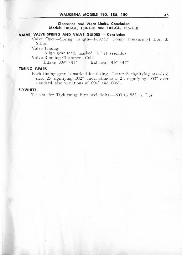
WAUKESHA MODELS 190, 185 , 180 45
Clearance and Wear lim its, ConcludedModels 180- GL, 180-GLB and 185- GL, 185 -GLB
VALVE, VALVE SPRING AND VALVE GUIDES - ConcludedValve O pen-Spring L ength- 1-19/32" Ca mp . P ressure 71 Lbs. -+
6 Lbs.V alve Timing :
Al ign gear teeth marked " C" at assemblyValve Running Clearance- Cold
Intake .009"- .01 1" Exhau st .015"-.017"
TIMING GEARSEach timing gea r is marked for fitti ng. L etter S signify ing standa rd
size . 2S sign ifying .002" under standard. 2L sig nifying .002" ov erstandard, al so va r iat ions of .004 " and .006".
FLYWHEELT en sion for Tightening F lywh eel Bol ts - 800 t o 825 111. Lbs.