
CAR PART IV OPERATIONS REGULATIONS CAR-OPS 1 ...
505
CAR PART IV OPERATIONS REGULATIONS CAR-OPS 1 COMMERCIAL & PRIVATE AIR TRANSPORTATION (AEROPLANES) UNCONTROLLED COPY WHEN DOWNLOADED Check with GCAA Website to verify current version before using
-
Upload
khangminh22 -
Category
Documents
-
view
0 -
download
0
Transcript of CAR PART IV OPERATIONS REGULATIONS CAR-OPS 1 ...

CAR PART IV
OPERATIONS REGULATIONS
CAR-OPS 1
COMMERCIAL & PRIVATE AIR TRANSPORTATION (AEROPLANES)
UNCONTROLLED COPY WHEN DOWNLOADED Check with GCAA Website to verify current version before using

Issue: 04 Page 1 of 505 Issue Date: October 2015
Rev.: 02 Revision Date: September 2016
FOREWORD
1. The UAE General Civil Aviation Authority, known in these regulations as the “Authority” has implemented CAR-OPS 1 based on the European Joint Aviation Requirements (JAR), with a view to harmonizing legislation and to regulate commercial air transport and private operations of aeroplanes.
2. ICAO Annex 6 has been selected to provide the basic structure of CAR–OPS and for Air Operator Certification and Private Operator Authorization, but with additional sub-division where considered appropriate. The content of Annex 6 has been used and added to, where acceptable.
3. The Authority has adopted associated compliance or interpretative material wherever possible and, unless specifically stated otherwise, clarification will be based on this material or other JAR/EASA documentation.
4. Future development of the requirements of CAR–OPS will be in accordance with Notice of Proposed Amendment (NPA) procedure, if the GCAA thinks an NPA is required. These procedures allow for the amendment of CAR–OPS to be harmonized with amendments to EASA and ICAO Annexes in a timely manner. Typographical errors, or minor changes that do not affect the industry will be published and introduced without NPA (Notice of Proposed Amendment).
5. Definitions and abbreviations of terms used in CAR–OPS that are considered generally applicable are contained in CAR Part 1- Definitions and Abbreviations. However, definitions and abbreviations of terms used in CAR–OPS that are specific to a Subpart of CAR–OPS are normally given in the Subpart concerned or, exceptionally, in the associated compliance or interpretative material.
6. Conformity with the advisory material (AC OPS) is mandatory unless there exist other means of compliance meet the equivalent level of safety, acceptable to the Authority.
Note: Any person who considers that there may be alternative AMCs or IEMs to those published should submit details to the Authority, for alternatives to be properly considered. Should there be an error, inform Policy and Regulations section [email protected] or obtain clarification through [email protected]
7. Document structure and Formatting
8. It is important to note down that CAR-OPS 1 has not been amended following the date of applicability of CAR-FCL and CAR-CC. Consequently, when there is conflict with CAR-FCL or CAR-CC, CAR-FCL and CC will prevail.
SUB PART A-S CAR-OPS 1.1XX Title of the applicable regulations Followed by AC OPS 1.1XX Advisory Circullar Sub Titile or specific paragraph of the regulations AMC 1.1XX Acceptable Means of Compliance Sub Titile or specific paragraph of the regulations IEM 1.1XX Interpretative Explanatory Material Sub Titile or specific paragraph of the regulations GM 1.1XX Guidance Material Sub Titile or specific paragraph of the regulations At the end of the SUB PART Appendix to the CAR-OPS 1.1XX SUB PART B … etc Footer Issue no: XX (Issue number) Page X of XXX (Page) Issue Date: MMM YYYY Rev.XX (Revision number) Revision: MMM YYYY

Issue: 04 Page 2 of 505 Issue Date: October 2015
Rev.: 02 Revision Date: September 2016
RECORD OF AMENDMENTS AND DATE OF EFFECTIVITY
Revision No.
Date of issue
Reissue July 2009
Reissue November 2009
Reissue July 2010
Reissue September 2010
Reissue July 2011
Re issue February 2013
Reissue October 2014
Reissue October 2015
Date of effectivity: 1 January 2016
Issue 04 Revision 01
January 2016
Date of entry into force: 1 February 2016.
However, a transition period of 1 year to comply with CAR-OPS 1.1135 is granted. So, up to 31 December 2016 included, CAR-OPS 1.1135 at Issue 03 Revision 00 shall
apply.
Issue 04 Revision 02
September 2016
Date of entry into force: 1 September 2016.
Issue: 04 Page 3 of 505 Issue Date: October 2015
Rev.: 02 Revision Date: September 2016
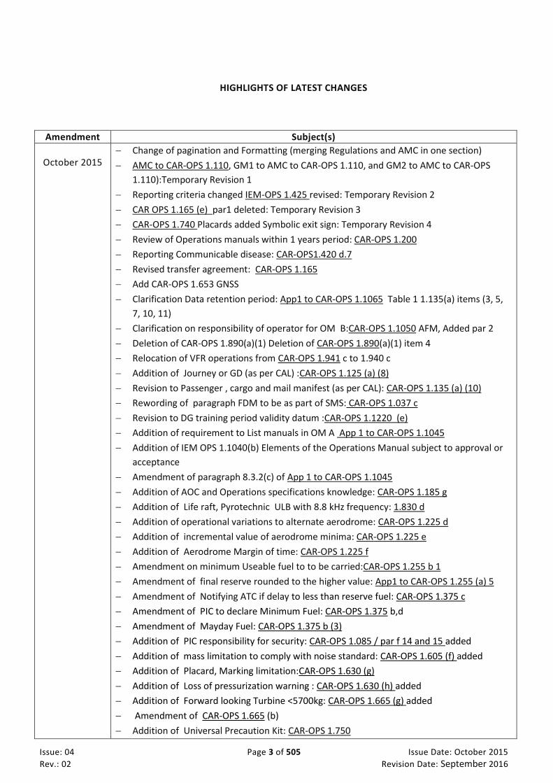
HIGHLIGHTS OF LATEST CHANGES
Amendment Subject(s)
October 2015
Change of pagination and Formatting (merging Regulations and AMC in one section)
AMC to CAR-OPS 1.110, GM1 to AMC to CAR-OPS 1.110, and GM2 to AMC to CAR-OPS
1.110):Temporary Revision 1
Reporting criteria changed IEM-OPS 1.425 revised: Temporary Revision 2
CAR OPS 1.165 (e) par1 deleted: Temporary Revision 3
CAR-OPS 1.740 Placards added Symbolic exit sign: Temporary Revision 4
Review of Operations manuals within 1 years period: CAR-OPS 1.200
Reporting Communicable disease: CAR-OPS1.420 d.7
Revised transfer agreement: CAR-OPS 1.165
Add CAR-OPS 1.653 GNSS
Clarification Data retention period: App1 to CAR-OPS 1.1065 Table 1 1.135(a) items (3, 5,
7, 10, 11)
Clarification on responsibility of operator for OM B:CAR-OPS 1.1050 AFM, Added par 2
Deletion of CAR-OPS 1.890(a)(1) Deletion of CAR-OPS 1.890(a)(1) item 4
Relocation of VFR operations from CAR-OPS 1.941 c to 1.940 c
Addition of Journey or GD (as per CAL) :CAR-OPS 1.125 (a) (8)
Revision to Passenger , cargo and mail manifest (as per CAL): CAR-OPS 1.135 (a) (10)
Rewording of paragraph FDM to be as part of SMS: CAR-OPS 1.037 c
Revision to DG training period validity datum :CAR-OPS 1.1220 (e)
Addition of requirement to List manuals in OM A App 1 to CAR-OPS 1.1045
Addition of IEM OPS 1.1040(b) Elements of the Operations Manual subject to approval or
acceptance
Amendment of paragraph 8.3.2(c) of App 1 to CAR-OPS 1.1045
Addition of AOC and Operations specifications knowledge: CAR-OPS 1.185 g
Addition of Life raft, Pyrotechnic ULB with 8.8 kHz frequency: 1.830 d
Addition of operational variations to alternate aerodrome: CAR-OPS 1.225 d
Addition of incremental value of aerodrome minima: CAR-OPS 1.225 e
Addition of Aerodrome Margin of time: CAR-OPS 1.225 f
Amendment on minimum Useable fuel to to be carried:CAR-OPS 1.255 b 1
Amendment of final reserve rounded to the higher value: App1 to CAR-OPS 1.255 (a) 5
Amendment of Notifying ATC if delay to less than reserve fuel: CAR-OPS 1.375 c
Amendment of PIC to declare Minimum Fuel: CAR-OPS 1.375 b,d
Amendment of Mayday Fuel: CAR-OPS 1.375 b (3)
Addition of PIC responsibility for security: CAR-OPS 1.085 / par f 14 and 15 added
Addition of mass limitation to comply with noise standard: CAR-OPS 1.605 (f) added
Addition of Placard, Marking limitation:CAR-OPS 1.630 (g)
Addition of Loss of pressurization warning : CAR-OPS 1.630 (h) added
Addition of Forward looking Turbine <5700kg: CAR-OPS 1.665 (g) added
Amendment of CAR-OPS 1.665 (b)
Addition of Universal Precaution Kit: CAR-OPS 1.750

Issue: 04 Page 4 of 505 Issue Date: October 2015
Rev.: 02 Revision Date: September 2016
Amendment of Medical Kit: AMC CAR-OPS 1.755
Addition of HUD or equivalent display : CAR-OPS 1.785
Reformating/numbering of CAR-OPS 1.790 and adddition of Fire extinguishing lavatory :
CAR-OPS 1.790 (b)
Addition of To highlight met inflight observation: CAR-OPS 1. 340 e
Addition of Operator SMS in managing Fatigue Risk: CAR-OPS 1.037 (h)
Addition of PH SMS shall maintain safety risk register: CAR-OPS 1.037 (i)
Addition of Non crew member station restrictions :CAR-OPS 1.310 c
Addition of Controlled rest guidance material added: AC OPS 1.310 (a) (3)
Addition of Threat and error management training: CAR-OPS 1.965 (a) 5 added
Replacement of “a member of the crew” by “an operating crewmember” in CAR-OPS
1.1115
Addition of Standard provision added: CAR-OPS 1.1120
Absolute limit on Flying and Cumulative Duty Hours revised : CAR-OPS 1.1125
Addition of Leave added : CAR-OPS 1.1126
Addition of Various part added: CAR-OPS 1.1127
Addition of Max Duty time added various conditions: CAR-OPS 1.1135
Amendment of 15 month to 12 month record keeping: CAR-OPS 1.1140
Deletion of CAR-OPS 1.1130
Deletion of IEM OPS 1.1045(c) Operations Manual Structure item 6
Addition of CAR-OPS 1.867 ADS-B (OUT and IN) following NPA 09-2014
January 2016 The below changes have been made following CATCC 18 th meeting and additional comments received with regards to lack of consistency between the highlight of changes and the track bars in the document. Other changes have been introduced aiming at relaxing the requirement or providing more guidance to industry. Changes made to section “RECORD OF AMENDMENTS AND DATE OF EFFECTIVITY”:
- Replace “September 2015” by “October 2015”
- Addition of Issue 04 Revision 01 dated January 2016
Changes made to section “HIGHLIGHTS OF LATEST CHANGE”: - Replacement of “October 2014” by “October 2015” for Issue 04 Revision 00
- Replacement of “Addition of Placard, Marking limitation: CAR-OPS 1.630 (a) 2” by
“Addition of Placard, Marking limitation: CAR-OPS 1.630 (g)”
- Deletion of “Addition of Forward looking Turbine <5700kg: CAR-OPS 1.665 (h) added”
from the highlight of latest change table for Issue 04 Revision 00.
- Replacement of “Addition of Threat and error management training: CAR-OPS 1.941
(a) 5 added“ by “Addition of Threat and error management training: CAR-OPS 1.965 (a)
5 added“
- Deletion of “CAR OPS 1.165 (e) par1 deleted: Temporary Revision 3” from the highlight
of latest change table for Issue 04 Revision 00 since 1.165(e)(1) not deleted.
- Replacement of “Amendment of Notifying ATC if delay to less than reserve fuel: CAR-
OPS 1.375 b” by “Amendment of Notifying ATC if delay to less than reserve fuel: CAR-
OPS 1.375 c”
- Deletion of “Addition of Elements in Operations manual requiring approval CAR-OPS
1.1045 c” from the highlight of latest change table for Issue 04 Revision 00 since no
change made since Issue 03 Revision 00.
- Addition of “Deletion of IEM OPS 1.1045(c) Operations Manual Structure item 6” since
it was added.
- Replacement of “Amendment of PIC to declare Minimum Fuel: CAR-OPS 1.375 b” by

Issue: 04 Page 5 of 505 Issue Date: October 2015
Rev.: 02 Revision Date: September 2016
“Amendment of PIC to declare Minimum Fuel: CAR-OPS 1.375 d”.
- Replacement of “Deletion of CAR-OPS 1.890(a)(1)” by “Deletion of CAR-OPS 1.890(a)(1)
item 4”.
Replacement of “Addition of Life raft, Pyrotechnic ULB with 8.8 MHz frequency: 1.830
d” by “Addition of Life raft, Pyrotechnic ULB with 8.8 kHz frequency: 1.830 d”.
- Addition of “Addition of CAR-OPS 1.867 ADS-B (OUT and IN) following NPA 09-2014”.
Replacement of “Clarification Data retention period: App1 to CAR-OPS 1.1065 add
1.135 (a)(3,5,7,10,11” by “Clarification Data retention period: App1 to CAR-OPS 1.1065
Table 1 addition of reference to 1.135 (a)(3,5,7,10,11)”.
Replacement of “Addition of paragraph 8.3.2. (c) PBN to App 1 to CAR-OPS 1.1045“ by
“Amendment of paragraph 8.3.2(c) of App 1 to CAR-OPS 1.1045”
Replacement of “Amendment of Excessive sink rate and unsafe terrain clearance : CAR-
OPS 1.665 (b) “ by “Amendment of CAR-OPS 1.665 (b)”
Replacement of “Adddition of Fire extinguishing lavatory : CAR-OPS 1.790 (b) “ by
“Reformating/numbering of CAR_OPS 1.790 and dddition of Fire extinguishing lavatory
: CAR-OPS 1.790 (b)”
- Replacement of “Amendment of Medical Kit: CAR-OPS 1.755” by “Amendment of
Medical Kit: AMC CAR-OPS 1.755”
Replacement of “Addition of Responsibility added: CAR-OPS 1.1115” by “Replacement
of “a member of the crew” by “an operating crewmember” in CAR-OPS 1.1115”
Other changes made: - AC OPS 1.037(c): mistakenly labeled as CAR-OPS 1.037.
- CAROPS 1.037 (a) reworded to refer to CAR X
- CAR-OPS 1.630(a): reformatted to conform to CAR-OPS 1 at Issue 03 revision 00.
- CAR-OPS 1.750: typo error corrected “fuids” replaced by “fluids”.
- CAR-OPS 1.1605(f) missed out from Issue 04 Revision 00.
- CAR-OPS 1.630 (h): added since missed out from Issue 04 Revision 00.
- CAR-OPS 1.1125(b) and (c): renamed CAR-OPS 1.1125(a) and (b) respectively.
- CAR-OPS 1.740: universal symbolic signs may be authorized as equivalent to scripts.
- IEM OPS 1.243: renamed as AC OPS 1.243.
- Under the newly renamed AC OPS 1.243: Replacement of “shall” by “should” and
replacement of “Avdanced RNP Navigation” by “RNP Navigation”.
- CAR-OPS 1.1050: replacement of “The operator shall assure that Operations Manuals part B that is refered to Manufacture documentation are kept up-to-date.” by “The operator shall ensure that Operations Manuals part B referring to Manufacture documentation is kept up-to-date.”
- CAR-OPS 1.830: title changed and CAR-OPS 1.830(d) amended. - AMC OPS 1.866: replacement of all “shall” by “should”. - GM OPS 1.160: added - Subpart Q: as per track bars (track bars are raised against Issue 03 Revision 00)
September 2016
- Item 8 in Foreword added
- CAR-OPS 1.037(a) wording changed without impact on the intended purpose
- Typo Error on AC OPS 1.037 and AC OPS 1.730 corrected with few structural changes
without impact on the intended purpose
- Aligning 1.1065 storage periods from 3 to 6 months to align with 1.1140
- SSR Transponder required by CAR-OPS 1.866 capable of ADS-B Out changed and
aligned with date of CAR-OPS 1.867.
- CAR-OPS 1.1135 at Issue 03 Revision 00 added to facilitae reading
- Deadline for free-halon fire extingusihers changed under 1.790(b) Fire extinguishers

Issue: 04 Page 6 of 505 Issue Date: October 2015
Rev.: 02 Revision Date: September 2016
and changed to 31 December 2018.

Issue: 04 Page 7 of 505 Issue Date: October 2015
Rev.: 02 Revision Date: September 2016
TABLE OF CONTENTS
FOREWORD 1
RECORD OF AMENDMENTS AND DATE OF EFFECTIVITY .................................................... 2
HIGHLIGHTS OF LATEST CHANGES ..................................................................................... 3
SUB PART A. APPLICABILITY ............................................................................................ 18
CAR-OPS 1.001 Applicability ...................................................................................................... 18 CAR-OPS 1.002 Reserved .......................................................................................................... 18 CAR-OPS 1.003 Terminology ...................................................................................................... 18
SUB PART B. GENERAL ..................................................................................................... 20
CAR-OPS 1.005 General ............................................................................................................ 20 AC to Appendix 1 to CAR-OPS 1.005 (a) Operations of performance class B aeroplanes .......................................... 20
CAR-OPS 1.010 Exemptions ....................................................................................................... 21 CAR-OPS 1.015 Operational Directives ....................................................................................... 21 CAR-OPS 1.020 Laws, Regulations and Procedures – Operator’s Responsibilities ........................... 21 CAR-OPS 1.025 Common Language ............................................................................................ 21 CAR-OPS 1.030 Minimum Equipment Lists – Operator’s Responsibilities....................................... 22 CAR-OPS 1.035 Quality system .................................................................................................. 22
AMC OPS 1.035 Quality - System ............................................................................................................................... 22 IEM OPS 1.035 Quality System – Organisation examples .......................................................................................... 30
CAR-OPS 1.037 Safety Management System ............................................................................... 31 IEM OPS 1.037 Safety Management System; ............................................................................................................. 32 AC OPS 1.037(c) Flight Data Monitoring Programme ................................................................................................. 32 AC OPS 1.037(d) Flight Data Monitoring event example ........................................................................................... 34 AC OPS 1.037(f) Occurrence Reporting Scheme ......................................................................................................... 35 AC OPS 1.037(h) Safety risk register ........................................................................................................................... 36
CAR-OPS 1.040 Additional crew members .................................................................................. 37 CAR-OPS 1.045 Reserved .......................................................................................................... 37 CAR-OPS 1.050 Search and rescue information ........................................................................... 37 CAR-OPS 1.055 Information on emergency and survival equipment carried .................................. 37 CAR-OPS 1.060 Ditching ............................................................................................................ 37 CAR-OPS 1.065 Carriage of weapons of war and munitions of war ............................................... 37
IEM OPS 1.065 Carriage of weapons of war and munitions of war ............................................................................ 37 CAR-OPS 1.070 Carriage of sporting weapons and ammunition .................................................... 38
IEM OPS 1.070 Carriage of sporting weapons ............................................................................................................ 38 CAR-OPS 1.075 Method of carriage of persons............................................................................ 39 CAR-OPS 1.080 Duties of flight operations officer/flight dispatcher ............................................. 39 CAR-OPS 1.085 Crew responsibilities ......................................................................................... 39
AC OPS 1.085(e)(3) Crew responsibilities ................................................................................................................... 41 CAR-OPS 1.090 Authority of the commander .............................................................................. 41 CAR-OPS 1.095 Authority to taxi an aeroplane ........................................................................... 41 CAR-OPS 1.100 Admission to flight deck ..................................................................................... 41 CAR-OPS 1.105 Unauthorised carriage ....................................................................................... 42 CAR-OPS 1.110 Portable electronic devices ................................................................................ 42
AMC OPS 1.110 PED ................................................................................................................................................... 42 GM1 to AMC OPS 1.110 ............................................................................................................................................. 44 GM2 to AMC OPS 1.110 ............................................................................................................................................. 45
CAR-OPS 1.115 Physchoactive substances .................................................................................. 45 CAR-OPS 1.120 Endangering safety ............................................................................................ 45 CAR-OPS 1.125 Documents to be carried .................................................................................... 45

Issue: 04 Page 8 of 505 Issue Date: October 2015
Rev.: 02 Revision Date: September 2016
CAR-OPS 1.130 Manuals to be carried ........................................................................................ 46 AMC OPS 1.130 Manuals to be carried ...................................................................................................................... 46
CAR-OPS 1.135 Additional information and forms to be carried ................................................... 46 CAR-OPS 1.140 Information retained on the ground ................................................................... 47 CAR-OPS 1.145 Power to inspect ............................................................................................... 47
AC OPS 1.145 Power to inspect .................................................................................................................................. 47 CAR-OPS 1.150 Production of documentation and records .......................................................... 48 CAR-OPS 1.155 Preservation of documentation .......................................................................... 48 CAR-OPS 1.160 Preservation, production and use of flight recorder recordings ............................. 48
GM OPS 1.160 Preservation of Recordings ................................................................................................................ 49 AC OPS 1.160(a)(1)&(2) Preservation of Recordings .................................................................................................. 49
CAR-OPS 1.165 Leasing ............................................................................................................. 49 AC OPS 1.165(c)(2) Leasing of aeroplanes between a UAE operator and any entity ................................................. 52 AMC OPS 1.165(e) Transfer Agreement as State of Registry under article 83bis ...................................................... 53 AMC OPS 1.165(f) Transfer Agreement as State of Operator under article 83bis ..................................................... 53
CAR- OPS 1.170 Reserved .......................................................................................................... 54 Appendix 1 to CAR-OPS 1.005(a) Operations of performance Class B aeroplanes. .......................... 55 Appendix 1 to CAR-OPS 1.125 Documents to be carried .............................................................. 63 Appendix 1 to CAR-OPS 1.135 Additional information and forms to be carried .............................. 63
SUB PART C. OPERATOR CERTIFICATION AND SUPERVISION ....................................... 64
CAR-OPS 1.175 General rules for Air Operator Certification/Authorisation ................................... 64 IEM OPS 1.175 The management organisation of an AOC/Authorisation holder ...................................................... 66 IEM OPS 1.175(c)(2) Principal place of business ........................................................................................................ 66 AC Appendix 2(b)(4) to OPS 1.175 Nominated Postholders – Competence .............................................................. 66 AC OPS 1.175(i) Nominated Postholders – Competence ........................................................................................... 66 AC OPS 1.175(i) Nominated Postholders – Full time employment ............................................................................ 67 AC OPS 1.175(j) Combination of nominated postholder’s responsibilities ................................................................ 68 AC OPS 1.175(j) & (k) Employment of staff ................................................................................................................ 68
CAR-OPS 1.180 Issue, variation and continued validity of an AOC/Authorisation ........................... 68 CAR-OPS 1.185 Administrative requirements.............................................................................. 69 CAR-OPS 1.190 Reserved .......................................................................................................... 69 Appendix 1 to CAR-OPS 1.175 Contents and conditions of the Air Operator Certificate .................. 70 Appendix 2 to CAR-OPS 1.175 Management & organisation of an AOC/Authority holder ............... 74
SUB PART D. OPERATIONAL PROCEDURES .................................................................... 76
CAR-OPS 1.195 Operational Control ........................................................................................... 76 AC OPS 1.195 Operational Control ............................................................................................................................. 76
CAR-OPS 1.200 Operations manual ............................................................................................ 76 CAR-OPS 1.205 Competence of operations personnel.................................................................. 76
AC OPS 1.205 Competence of Operations personnel................................................................................................. 76 CAR-OPS 1.210 Establishment of procedures .............................................................................. 76
AMC OPS 1.210(a) Establishment of procedures ....................................................................................................... 77 IEM OPS 1.210(b) Establishment of procedures ........................................................................................................ 77 IEM OPS 1.210(c) Critical phases of flight .................................................................................................................. 79
CAR-OPS 1.215 Use of Air Traffic Services .................................................................................. 79 CAR-OPS 1.216 In-flight Operational Instructions ........................................................................ 79
AC OPS 1.216 In-flight Operational Instructions ........................................................................................................ 79 CAR-OPS 1.220 Authorisation of Aerodromes by the Operator ..................................................... 79
IEM OPS 1.220 Authorisation of aerodromes ............................................................................................................ 79 CAR-OPS 1.225 Aerodrome Operating Minima ............................................................................ 80 CAR-OPS 1.230 Instrument departure and approach procedures .................................................. 80 CAR-OPS 1.235 Noise abatement procedures ............................................................................. 81 CAR-OPS 1.240 Routes and areas of operation............................................................................ 81 CAR-OPS 1.241 Operation in defined airspace with RVSM ........................................................... 81 CAR-OPS 1.243 Operations in areas with specified navigation performance requirements ............. 82

Issue: 04 Page 9 of 505 Issue Date: October 2015
Rev.: 02 Revision Date: September 2016
AC OPS 1.243 Operations in areas with specific navigation performance requirements .......................................... 82 CAR-OPS 1.245 Two-engined aeroplanes without ETOPS Approval ............................................... 82
IEM OPS 1.245(a) Two-engined aeroplanes without ETOPS Approval ....................................................................... 84 AMC OPS 1.245(a)(2) Operation of non-ETOPS compliant twin turbojet aeroplanes ................................................ 84 Appendix 1 to AMC OPS 1.245(a)(2) Power supply to essential services ................................................................... 88
CAR-OPS 1.246 Extended range operations with two-engined aeroplanes (ETOPS) ........................ 88 CAR-OPS 1.250 Establishment of minimum flight altitudes .......................................................... 88
IEM OPS 1.250 Establishment of Minimum Flight Altitudes ...................................................................................... 89 CAR-OPS 1.255 Fuel policy ........................................................................................................ 92
AMC OPS 1.255 Fuel Policy ......................................................................................................................................... 94 IEM OPS 1.255(c)(3)(i) Contingency Fuel .................................................................................................................... 97 AC OPS 1.255 Contingency Fuel Statistical Method ................................................................................................... 97
CAR-OPS 1.260 Carriage of Persons with Reduced Mobility ......................................................... 97 IEM OPS 1.260 Carriage of persons with Reduced Mobility ....................................................................................... 98
CAR-OPS 1.265 Carriage of inadmissible passengers, deportees or persons in custody ................... 98 CAR-OPS 1.270 Stowage of baggage and cargo ........................................................................... 98
AMC OPS 1.270 Cargo carriage in the passenger cabin ............................................................................................. 98 CAR-OPS 1.275 Reserved .......................................................................................................... 99 CAR-OPS 1.280 Passenger Seating ............................................................................................. 99
AC OPS 1.280 Passenger Seating ................................................................................................................................ 99 IEM OPS 1.280 Passenger Seating .............................................................................................................................. 99
CAR-OPS 1.285 Passenger briefing ............................................................................................. 99 CAR-OPS 1.290 Flight preparation ............................................................................................ 101 CAR-OPS 1.295 Selection of aerodromes ................................................................................... 101
IEM OPS 1.295(c)(1)(ii) Separate runways................................................................................................................ 102 CAR-OPS 1.297 Planning minima for IFR flights .......................................................................... 102
AC OPS 1.297(b)(2) Planning Minima for Alternate Aerodromes ............................................................................ 104 AMC OPS 1.297 Application of aerodrome forecasts ............................................................................................... 105
CAR-OPS 1.300 Submission of ATS Flight Plan ............................................................................ 106 AMC OPS 1.300 Submission of ATS Flight plan ......................................................................................................... 106
CAR-OPS 1.305 Refuelling/defuelling with passengers ............................................................... 106 IEM OPS 1.305 Refuelling/Defuelling with passengers ............................................................................................ 106
CAR-OPS 1.307 Refuelling/Defuelling with wide-cut fuel ............................................................ 106 IEM OPS 1.307 Refuelling/Defuelling with wide-cut fuel ......................................................................................... 106
CAR-OPS 1.308 Push back and Towing ...................................................................................... 107 AC OPS 1.308 Push Back and Towing ....................................................................................................................... 108
CAR-OPS 1.310 Crew Members at stations ................................................................................ 108 AC OPS 1.310(a)(3) Controlled rest on flight deck.................................................................................................... 108 IEM OPS 1.310(b) Cabin crew seating positions ....................................................................................................... 110
CAR-OPS 1.313 Use of headset ................................................................................................. 110 CAR-OPS 1.315 Assisting means for emergency evacuation ........................................................ 110 CAR-OPS 1.320 Seats, safety belts and harnesses ....................................................................... 110 CAR-OPS 1.325 Securing of passenger cabin and galley(s) ........................................................... 111 CAR-OPS 1.327 Safeguarding of cabin crew and passengers ........................................................ 111 CAR-OPS 1.330 Accessibility of emergency equipment ............................................................... 111 CAR-OPS 1.335 Smoking on board ............................................................................................ 111 CAR-OPS 1.340 Meteorological Conditions ................................................................................ 111 CAR-OPS 1.345 Ice and other contaminants – ground procedures ............................................... 112
AC OPS 1.345 Ice and other contaminants Procedures............................................................................................ 112 CAR-OPS 1.346 Ice and other contaminants – flight procedures .................................................. 120
AC OPS 1.346 Flight in expected or actual icing conditions ..................................................................................... 120 CAR-OPS 1.350 Fuel and oil supply ........................................................................................... 121 CAR-OPS 1.355 Take-off conditions........................................................................................... 121 CAR-OPS 1.360 Application of take-off minima .......................................................................... 121 CAR-OPS 1.365 Minimum flight altitudes .................................................................................. 122 CAR-OPS 1.370 Simulated abnormal situations in flight .............................................................. 122 CAR-OPS 1.375 In-flight fuel management ................................................................................. 122

Issue: 04 Page 10 of 505 Issue Date: October 2015
Rev.: 02 Revision Date: September 2016
CAR-OPS 1.380 Reserved ......................................................................................................... 123 CAR-OPS 1.385 Use of supplemental oxygen ............................................................................. 123 CAR-OPS 1.390 Cosmic radiation .............................................................................................. 123
AC OPS 1.390(a)(1) Assessment of Cosmic Radiation .............................................................................................. 124 AC OPS 1.390(a)(2) Working Schedules and Record Keeping ................................................................................... 124 AC OPS 1.390(a)(3) Explanatory Information ........................................................................................................... 125
CAR-OPS 1.395 Ground proximity detection .............................................................................. 125 CAR-OPS 1.398 Use of Airborne Collision Avoidance System (ACAS) ............................................ 125
AC OPS 1.398 Use of Airborne Collision Avoidance System (ACAS) ......................................................................... 125 AMC OPS 1.398 Vertical speed recommendation to avoid TCAS RA ........................................................................ 126
CAR-OPS 1.400 Approach and landing conditions ....................................................................... 126 IEM OPS 1.400 Approach and Landing Conditions ................................................................................................... 126
CAR-OPS 1.405 Commencement and continuation of approach .................................................. 126 CAR-OPS 1.410 Operating procedures – Threshold crossing height .............................................. 127 CAR-OPS 1.415 Journey log ...................................................................................................... 127 CAR-OPS 1.420 Occurrence reporting ........................................................................................ 127 CAR-OPS 1.425 Deficiencies reported by an Inspecting Authority ................................................ 130
AC OPS 1.425 Deficiencies reported by an Inspecting Authority ............................................................................. 130 IEM OPS 1.425 Inspecting Authority ........................................................................................................................ 130
Appendix 1 to CAR-OPS 1.255 Fuel Policy .................................................................................. 131 Appendix 2 to CAR-OPS 1.255 Location of the 3% EnRoute Alternate (3%ERA) aerodrome for the purpose of reducing contingency fuel to 3% .............................................................................. 134 Appendix 1 to CAR-OPS 1.270 Stowage of baggage and cargo ..................................................... 136 Appendix 1 to CAR-OPS 1.305 Refuelling/defuelling with passengers embarking, on board or disembarking 137
SUB PART E. ALL WEATHER OPERATIONS .................................................................... 138
CAR-OPS 1.430 Aerodrome Operating Minima – General ............................................................ 138 AMC OPS 1.430(b)(4) Landing Minima of failed Equipment .................................................................................... 139 IEM OPS 1.430 Documents containing information related to AWO ....................................................................... 142 ACJ OPS 1.430 CONTINUOUS DESCENT FINAL APPROACH (CDFA) ........................................................................... 142 ACJ OPS to Appendix 1 (New) to CAR-OPS 1.430(d) Aerodrome Operating Minima ............................................... 153 IEM to Appendix 1 to CAR-OPS 1.430 Aerodrome Operating Minima ..................................................................... 155 IEM to Appendix 1 to CAR-OPS 1.430, par(d)&(e) RVR Category II & III ................................................................... 155 IEM to Appendix 1 to CAR-OPS 1.430, par (e)(5) - Table 8 Crew actions in case of autopilot failure ...................... 157 IEM to Appendix 1 to CAR-OPS 1.430, paragraph (f) Visual Manoeuvring (circling) ................................................ 158 ACJ OPS to Appendix 1 (New) to CAR-OPS 1.430(h) ................................................................................................. 159 ACJ to Appendix 1 to CAR-OPS 1.430, paragraph (j) ................................................................................................. 160
CAR-OPS 1.435 Terminology ..................................................................................................... 163 CAR-OPS 1.440 Low visibility operations – General operating rules ............................................. 164
AC to Appendix 1 to CAR-OPS 1.440 Operational Demonstrations .......................................................................... 164 IEM to Appendix 1 to CAR-OPS 1.440 (b) Criteria for CAT II/III approach and autoland .......................................... 165
CAR-OPS 1.445 Low visibility operations – Aerodrome considerations ......................................... 166 CAR-OPS 1.450 Low visibility operations – Training and Qualifications ........................................ 166
IEM OPS 1.450(g)(1) Low Visibility Operations - Training & Qualifications .............................................................. 166 CAR-OPS 1.455 Low visibility operations – Operating Procedures ................................................ 167 CAR-OPS 1.460 Low visibility operations – Minimum equipment ................................................. 167 CAR-OPS 1.465 VFR Operating minima ...................................................................................... 167 Appendix 1 Old and New to CAR-OPS 1.430 Aerodrome Operating Minima ................................. 168 Appendix 1 to CAR-OPS 1.440 Low Visibility Operations – General Operating Rules ...................... 183 Appendix 1 to CAR-OPS 1.450 Low Visibility Operations – Training & Qualifications ..................... 186 Appendix 1 to CAR-OPS 1.455 Low Visibility Operations – Operating procedures ......................... 194 Appendix 1 to CAR-OPS 1.465 Minimum Visibilities for VFR Operations ....................................... 196
SUB PART F. PERFORMANCE GENERAL ........................................................................ 197
CAR-OPS 1.470 Applicability ..................................................................................................... 197

Issue: 04 Page 11 of 505 Issue Date: October 2015
Rev.: 02 Revision Date: September 2016
CAR-OPS 1.475 General ........................................................................................................... 197 AMC OPS 1.475(b) Landing - Reverse Thrust Credit ................................................................................................. 198 IEM OPS 1.475(b) Factoring of Automatic Landing Distance Performance Data (Perf Class A Aeroplanes) ............ 198
CAR-OPS 1.480 Terminology ..................................................................................................... 198
SUB PART G. PERFORMANCE CLASS A ......................................................................... 200
CAR-OPS 1.485 General ........................................................................................................... 200 IEM OPS 1.485(b) General – Wet and Contaminated Runway data ......................................................................... 200
CAR-OPS 1.490 Take-off ........................................................................................................... 200 IEM OPS 1.490(c)(3) Take-off – Runway surface condition ...................................................................................... 201 IEM OPS 1.490(c)(6) Loss of runway length due to alignment ................................................................................. 201
CAR-OPS 1.495 Take-off obstacle clearance ............................................................................... 203 IEM OPS 1.495(a) Take-off obstacle clearance ......................................................................................................... 204 AMC OPS 1.495(c)(4) Take-off obstacle clearance ................................................................................................... 204 AMC OPS 1.495(d)(1) & (e)(1) Required Navigational Accuracy .............................................................................. 205 IEM OPS 1.495(f) Engine failure procedures ............................................................................................................ 205
CAR-OPS 1.500 En-route – One Engine Inoperative .................................................................... 206 AMC OPS 1.500 En-Route – One Engine Inoperative ............................................................................................... 206
CAR-OPS 1.505 En-route – Two Engines Inoperative ................................................................... 207 CAR-OPS 1.510 Landing – Destination And Alternate Aerodromes ............................................... 208
IEM OPS 1.510(b) and (c) Landing – Destination and Alternate Aerodromes .......................................................... 208 AMC OPS 1.510 & 1.515 Landing – Destination and Alternate Aerodromes Landing – Dry Runways ..................... 209
CAR-OPS 1.515 Landing – Dry Runways ..................................................................................... 209 IEM OPS 1.515(c) Landing – Dry runway .................................................................................................................. 210
CAR-OPS 1.520 Landing – Wet and contaminated runways ......................................................... 210 Appendix 1 to CAR-OPS 1.495(c)(3) Approval of increased bank angles ....................................... 211 Appendix 1 to CAR-OPS 1.515(a)(3) Steep Approach Procedures ................................................. 212 Appendix 1 to CAR-OPS 1.515(a)(4) Short Landing Operations .................................................... 213 Appendix 2 to CAR-OPS 1.515(a)(4) Airfield Criteria for Short Landing Operations ........................ 214
SUB PART H. PERFORMANCE CLASS B ......................................................................... 215
CAR-OPS 1.525 General ........................................................................................................... 215 CAR-OPS 1.530 Take-off ........................................................................................................... 215
AMC OPS 1.530(c)(4) Take-Off Performance Correction Factors ............................................................................. 216 IEM OPS 1.530(c)(4) Take-Off Performance Correction Factors .............................................................................. 216 AMC OPS 1.530(c)(5) Runway Slope ......................................................................................................................... 216
CAR-OPS 1.535 Take-off Obstacle Clearance – Multi-Engined Aeroplanes .................................... 217 IEM OPS 1.535 Obstacle Clearance in Limited Visibility ........................................................................................... 218 AMC OPS 1.535(a) Take-off Flight Path Construction .............................................................................................. 218 IEM OPS 1.535(a) Take-off flight path construction ................................................................................................. 219
CAR-OPS 1.540 En-Route – Multi-engined aeroplanes ................................................................ 222 IEM OPS 1.540 En-Route .......................................................................................................................................... 222
CAR-OPS 1.542 En-Route – Single-engine aeroplanes ................................................................. 222 IEM OPS 1.542 En-route – Single-engined Aeroplanes ............................................................................................ 222 AMC OPS 1.542(a) En-Route - Single-engine aeroplanes ......................................................................................... 223
CAR-OPS 1.545 Landing – Destination and Alternate Aerodromes ............................................... 223 CAR-OPS 1.550 Landing – Dry runway ....................................................................................... 223
AMC OPS 1.550(b)(3) Landing Distance Correction Factors ..................................................................................... 224 AMC OPS 1.550(b)(4) Runway Slope ........................................................................................................................ 224 IEM OPS 1.550(c) Landing – Dry Runway ................................................................................................................. 224
CAR-OPS 1.555 Landing – Wet and Contaminated Runways ........................................................ 225 IEM OPS 1.555(a) Landing on Wet Grass Runways .................................................................................................. 226
Appendix 1 to CAR-OPS 1.525(b) General .................................................................................. 227 Appendix 1 to CAR-OPS 1.535(b)(1) & (c)(1) Take-off Flight Path ................................................. 229 Appendix 1 to CAR-OPS 1.550(a) Steep Approach Procedures ..................................................... 230 Appendix 2 to CAR-OPS 1.550(a) Short Landing Operations ........................................................ 231

Issue: 04 Page 12 of 505 Issue Date: October 2015
Rev.: 02 Revision Date: September 2016
SUB PART I. PERFORMANCE CLASS C ......................................................................... 232
CAR-OPS 1.560 General ........................................................................................................... 232 CAR-OPS 1.565 Take-off ........................................................................................................... 232
IEM OPS 1.565(d)(3) Take-off ................................................................................................................................... 233 IEM OPS 1.565(d)(6) Loss of runway length due to alignment ................................................................................. 233 AMC OPS 1.565(d)(4) Runway Slope ........................................................................................................................ 235
CAR-OPS 1.570 Take-off Obstacle Clearance .............................................................................. 236 AMC OPS 1.570(d) Take-off Flight Path .................................................................................................................... 237 AMC OPS 1.570(e)(1) & (f)(1) Required navigational accuracy ................................................................................ 237
CAR-OPS 1.575 En-Route – All Engines Operating....................................................................... 238 CAR-OPS 1.580 En-Route – One Engine Inoperative .................................................................... 238 CAR-OPS 1.585 En-Route –Two Engines Inoperative ................................................................... 239
AMC OPS 1.580 En-Route – One Engine Inoperative ............................................................................................... 239 CAR-OPS 1.590 Landing – Destination and Alternate Aerodromes ............................................... 240
AMC OPS 1.590 & 1.595 Landing – Destination and Alternate Aerodromes ........................................................... 240 CAR-OPS 1.595 Landing – Dry Runways ..................................................................................... 240
AMC OPS 1.595(b)(3) Landing Distance Correction Factors ..................................................................................... 241 AMC OPS 1.595(b)(4) Runway Slope ........................................................................................................................ 241 IEM OPS 1.595(c) Landing Runway ........................................................................................................................... 241
CAR-OPS 1.600 Landing – Wet and Contaminated Runways ........................................................ 242
SUB PART J. MASS AND BALANCE ................................................................................ 243
CAR-OPS 1.605 General ........................................................................................................... 243 IEM OPS 1.605(e) Fuel density ................................................................................................................................. 243 AC OPS 1.605 Mass values ........................................................................................................................................ 243 AMC to Appendix 1 to CAR-OPS 1.605 Accuracy of weighing equipment ............................................................... 244 IEM to Appendix 1 to CAR-OPS 1.605 Centre of gravity limits ................................................................................. 244
CAR-OPS 1.607 Terminology ..................................................................................................... 244 CAR-OPS 1.610 Loading, mass and balance ................................................................................ 245 CAR-OPS 1.615 Mass values for crew ........................................................................................ 245 CAR-OPS 1.620 Mass values for passengers and baggage ............................................................ 245
AMC OPS 1.620(a) Passenger mass established by use of a verbal statement ........................................................ 248 IEM OPS 1.620(d)(2) Holiday Charter ....................................................................................................................... 248 IEM OPS 1.620(g) Statistical evaluation of passenger and baggage mass data ....................................................... 248 IEM OPS 1.620(h) & (i) Adjustment of standard masses .......................................................................................... 252 AMC to Appendix 1 to CAR-OPS 1.620(g) Guidance on passenger weighing surveys .............................................. 252 IEM to Appendix 1 to CAR-OPS 1.620(g) Guidance on passenger weighing surveys ............................................... 252
CAR-OPS 1.625 Mass and balance documentation ..................................................................... 254 IEM to Appendix 1 to CAR-OPS 1.625 Mass and balance documentation ............................................................... 255
Appendix 1 to CAR-OPS 1.605 Mass and Balance – General ........................................................ 256 Appendix 1 to CAR-OPS 1.620(f) Definition of the area for flights within the region ..................... 259 Appendix 1 to CAR-OPS 1.620(g) Procedure for establishing revised standard mass values for passengers and baggage .......................................................................................................... 260 Appendix 1 to CAR-OPS 1.625 Mass and Balance Documentation ................................................ 262
SUB PART K. INSTRUMENTS AND EQUIPMENT .............................................................. 264
CAR-OPS 1.630 General introduction ........................................................................................ 264 IEM OPS 1.630 Instruments and Equipment - Approval and Installation ................................................................. 265
CAR-OPS 1.635 Circuit protection devices ................................................................................. 266 CAR-OPS 1.640 Aeroplane operating lights ................................................................................ 266 CAR-OPS 1.645 Windshield wipers ............................................................................................ 266 CAR-OPS 1.650 Day VFR operations .......................................................................................... 266 CAR-OPS 1.652 IFR or night operations – ................................................................................... 268
AMC OPS 1.650/1.652 Flight and Navigational Instruments and Associated Equipment ........................................ 270 IEM OPS 1.650/1.652 Flight and Navigational Instruments and Associated Equipment ......................................... 270 AMC OPS 1.650/1.652(i) Flight and Navigational Instruments and Associated Equipment ..................................... 271

Issue: 04 Page 13 of 505 Issue Date: October 2015
Rev.: 02 Revision Date: September 2016
IEM OPS 1.650(p)/1.652(s) Headset, boom microphone & associated equipment ................................................. 272 AMC OPS 1.652(d) & (k)(2) Flight & Navigational Instruments & Associated Equipment ........................................ 272
CAR-OPS 1.653 GNSS ............................................................................................................... 272 AMC OPS 1.653 GNSS ............................................................................................................................................... 272
CAR-OPS 1.655 Additional equipment for single pilot operation under IFR .................................. 272 CAR-OPS 1.660 Altitude alerting system .................................................................................... 273 CAR-OPS 1.665 Ground proximity warning system and terrain awareness warning system ........... 273 CAR-OPS 1.668 Airborne Collision Avoidance System ................................................................. 274
IEM OPS 1.668 Airborne Collision Avoidance System .............................................................................................. 274 CAR-OPS 1.670 Airborne weather radar equipment and Winshear warning system ...................... 274 CAR-OPS 1.675 Equipment for operations in icing conditions ...................................................... 275
AC OPS 1.680(a)(2) Quarterly Radiation Sampling ................................................................................................... 275 CAR-OPS 1.680 Cosmic radiation detection equipment ............................................................... 276 CAR-OPS 1.685 Flight crew interphone system .......................................................................... 276 CAR-OPS 1.690 Crew member interphone system ...................................................................... 276
AMC OPS 1.690(b)(6) Crew member interphone system ......................................................................................... 277 IEM OPS 1.690(b)(7) Crew member interphone system .......................................................................................... 277
CAR-OPS 1.695 Public address system ....................................................................................... 277 CAR-OPS 1.700 Cockpit voice recorders–1 ................................................................................. 278
AC OPS 1.700 Cockpit Voice Recorders .................................................................................................................... 279 AC OPS 1.700, 1.705 & 1.710 Cockpit Voice Recorders ............................................................................................ 279
CAR-OPS 1.705 Cockpit voice recorders–2 ................................................................................. 280 AC OPS 1.705/1.710 Cockpit Voice Recorders .......................................................................................................... 280
CAR-OPS 1.710 Cockpit voice recorders–3 ................................................................................. 281 CAR-OPS 1.715 Flight data recorders–1 ..................................................................................... 281
AC OPS 1.715 Flight Data Recorders......................................................................................................................... 283 AC OPS 1.715(g) Extensive Modifications of Aeroplane Systems ............................................................................. 283 AC OPS 1.715, 1.720 & 1.725 Flight Data Recorders ................................................................................................ 284
CAR-OPS 1.720 Flight data recorders–2 ..................................................................................... 285 AC OPS 1.720 /1.725 Flight Data Recorders ............................................................................................................. 286
CAR-OPS 1.725 Flight data recorders–3 ..................................................................................... 287 CAR-OPS 1.727 Combination Recorder ...................................................................................... 288
AC OPS 1.727 Combination recorders.................................................................................................................. 288 CAR-OPS 1.730 Seats, seat safety belts, harnesses and child restraint devices .............................. 288
AC OPS 1.730(a)(3) Seats, seat safety belts, harnesses & child restraint devices ................................................ 289 CAR-OPS 1.731 Fasten Seat belt and No Smoking signs ............................................................... 291 CAR-OPS 1.735 Internal doors and curtains ............................................................................... 291 CAR-OPS 1.740 Placards ........................................................................................................... 291
IEM OPS 1.740 Placards ............................................................................................................................................ 292 CAR-OPS 1.745 First-Aid Kits .................................................................................................... 292
AMC OPS 1.745 First-Aid Kits ................................................................................................................................... 292 CAR-OPS 1.750 Universal Precaution Kit ................................................................................... 293
AMC OPS 1.750 Universal Protection Kit content .................................................................................................... 293 CAR-OPS 1.755 Emergency Medical Kit ..................................................................................... 294
AMC OPS 1.755 Emergency Medical Kit ................................................................................................................... 294 CAR-OPS 1.760 First-aid oxygen................................................................................................ 295
IEM OPS 1.760 First-aid Oxygen ............................................................................................................................... 296 CAR-OPS 1.765 Reserved ......................................................................................................... 296 CAR-OPS 1.770 Supplemental oxygen – pressurised aeroplanes .................................................. 296
IEM OPS 1.770 Supplemental Oxygen ...................................................................................................................... 298 AC OPS 1.770(b)(2)(v) Supplemental Oxygen ........................................................................................................... 298
CAR-OPS 1.775 Supplemental oxygen – Non-pressurised aeroplanes ........................................... 298 CAR-OPS 1.780 Crew Protective Breathing Equipment ................................................................ 299 CAR-OPS 1.785 HUD or Equivalent Displays ............................................................................... 300 CAR-OPS 1.790 Fire extinguishers ............................................................................................. 300
AMC OPS 1.790 Fire Extinguishers ........................................................................................................................... 301 CAR-OPS 1.795 Crash axes and crowbars ................................................................................... 301

Issue: 04 Page 14 of 505 Issue Date: October 2015
Rev.: 02 Revision Date: September 2016
CAR-OPS 1.800 Marking of break-in points ................................................................................ 302 CAR-OPS 1.805 Means for emergency evacuation ...................................................................... 303 CAR-OPS 1.810 Megaphones .................................................................................................... 303
AMC OPS 1.810 Megaphones ................................................................................................................................... 304 CAR-OPS 1.815 Emergency lighting ........................................................................................... 304 CAR-OPS 1.820 Emergency Locator Transmitter ......................................................................... 305
AC OPS 1.820 Emergency Locator Transmitter (ELT)................................................................................................ 305 CAR-OPS 1.825 Life Jackets ...................................................................................................... 306
IEM OPS 1.825 Life Jackets ....................................................................................................................................... 306 CAR-OPS 1.830 Extended overwater flights ............................................................................... 306
AMC OPS 1.830(b)(2) Life-rafts and ELT for extended overwater flights ................................................................. 307 AMC OPS 1.830(d) .................................................................................................................................................... 307
CAR-OPS 1.835 Survival equipment .......................................................................................... 307 IEM OPS 1.835 Survival Equipment .......................................................................................................................... 308 AMC OPS 1.835(c) Survival Equipment .................................................................................................................... 308
CAR-OPS 1.840 Seaplanes and amphibians – Miscellaneous equipment ....................................... 308 Appendix 1 to CAR-OPS 1.715 Flight data recorders - 1 - List of parameters to be recorded ........... 310 Appendix 1 to CAR-OPS 1.720 Flight data recorders - 2 - List of parameters to be recorded ........... 313 Appendix 1 to CAR-OPS 1.725 Flight data recorders - 3 - List of parameters to be recorded ........... 314 Appendix 1 to CAR-OPS 1.770 Supplemental Oxygen Minimum Requirements ............................. 315 Appendix 1 to CAR-OPS 1.775 Supplemental Oxygen for non-pressurised Aeroplanes .................. 316
Appendix 1 to AC OPS 1.720/1.725 .......................................................................................................................... 317 Appendix 1 to CAR-OPS 1.785 HUD, VS or Equivalent ................................................................. 320
SUB PART L. COMMUNICATION AND NAVIGATION EQUIPMENT ................................... 331
CAR-OPS 1.845 General introduction ........................................................................................ 331 IEM OPS 1.845 Communication and Navigation Equipment - Approval and Installation ........................................ 331
CAR-OPS 1.850 Radio Equipment .............................................................................................. 332 CAR-OPS 1.855 Audio Selector Panel ........................................................................................ 332 CAR-OPS 1.860 Radio equipment for VFR routes navigated by reference to visual landmarks ........ 333 CAR-OPS 1.865 Communication and Navigation equipment for operations under IFR, or under VFR over routes not navigated by reference to visual landmarks ....................................................... 333
AMC OPS 1.865 Combinations of Instruments and Integrated Flight Systems ........................................................ 334 AC OPS 1.865(c)(1)(i) IFR operations without ADF system ....................................................................................... 334 AC OPS 1.865(e) FM Immunity Equipment Standards ............................................................................................. 334
CAR-OPS 1.866 Transponder equipment ................................................................................... 335 AMC OPS 1.866 Transponder Equipment ................................................................................................................. 335
CAR-OPS 1.867 ADS-B (OUT and IN) .......................................................................................... 338 AMC OPS 1.867 ADS-B .............................................................................................................................................. 338
CAR-OPS 1.870 Additional navigation equipment for operations in MNPS airspace ...................... 339 IEM OPS 1.870 Additional Navigation Equipment for operations in MNPS Airspace ............................................... 339
CAR-OPS 1.872 Equipment for operation in defined airspace with RVSM ..................................... 339
SUB PART M. AEROPLANE MAINTENANCE .................................................................... 340
SUB PART N. FLIGHT CREW ............................................................................................ 341
CAR-OPS 1.940 Composition of Flight Crew ............................................................................... 341 AMC OPS 1.940(a)(4) Crewing of inexperienced flight crew members .................................................................... 342
CAR-OPS 1.941 Initial training .................................................................................................. 342 CAR-OPS 1.943 Initial Operator’s Crew Resource Management (CRM) training ............................. 343
AC OPS (AMC) 1.943/1.945(a)(9)/1.955(b)(6)/1.965(e) Crew Resource Management (CRM) ................................. 343 AC OPS (IEM) 1.943/1.945(a)(9)/1.955(b)(6)/1.965(e) Crew Resource Management (CRM) .................................. 347
CAR-OPS 1.945 Conversion training and checking ...................................................................... 348 AMC OPS 1.945 Conversion Course Syllabus ............................................................................................................ 349 IEM OPS 1.945 Line Flying under Supervision .......................................................................................................... 351 AMC OPS 1.945(a)(9) Crew Resource Management - Use of Automation ............................................................... 351
CAR-OPS 1.950 Differences training and Familiarisation training ................................................. 352

Issue: 04 Page 15 of 505 Issue Date: October 2015
Rev.: 02 Revision Date: September 2016
CAR-OPS 1.955 Nomination as commander ............................................................................... 352 CAR-OPS 1.960 Commanders holding a Commercial Pilot Licence ................................................ 353 CAR-OPS 1.965 Recurrent training and checking ........................................................................ 353
AMC OPS 1.965(c) Line checks ................................................................................................................................. 355 AMC OPS 1.965(d) Emergency and Safety Equipment Training ............................................................................... 355 IEM OPS 1.965 Recurrent training and checking ...................................................................................................... 356 AMC to Appendix 1 to CAR-OPS 1.965 Pilot incapacitation training ........................................................................ 356 IEM OPS 1.965(b)(2) pilot proficiency ...................................................................................................................... 357
CAR-OPS 1.968 Pilot qualification to operate in either pilot’s seat .............................................. 357 CAR-OPS 1.970 Recent experience ............................................................................................ 357
AMC OPS 1.970 Recency .......................................................................................................................................... 357 IEM OPS 1.970(a)(2) Co-pilot proficiency ................................................................................................................. 357
CAR-OPS 1.975 Route and Aerodrome Competence qualification ................................................ 358 AMC OPS 1.975 Route and aerodrome competence qualification .......................................................................... 358
CAR-OPS 1.978 Alternative Training and Qualification Programme .............................................. 359 AC OPS 1.978 Terminology ....................................................................................................................................... 360 AC to Appendix 1 to CAR-OPS 1.978(b)(1) Requirements, Scope and Documentation of the Programme ............. 361 AC to Appendix 1 to CAR-OPS 1.978(b)(2) Task Analysis .......................................................................................... 361 AC to Appendix 1 to CAR-OPS 1.978(b)(3) Training Programme .............................................................................. 362 AC to Appendix 1 to CAR-OPS 1.978(b)(4) Training Personnel ................................................................................. 362 AC to Appendix 1 to CAR-OPS 1.978(b)(5) Feedback Loop ....................................................................................... 363 AC to Appendix 1 to CAR-OPS 1.978(b)(6) Crew Performance Measurement and Evaluation ................................ 363 AC to Appendix 1 to CAR-OPS 1.978(b)(9) Data Monitoring/Analysis Programme .................................................. 364 AC to Appendix 1 to CAR-OPS 1.978(c)(1)(i) Safety Case ......................................................................................... 365
CAR-OPS 1.980 Operation on more than one type or variant ...................................................... 366 AMC OPS 1.980 Operation on more than one type or variant ................................................................................. 367 AMC OPS 1.980(b) Methodology - Use of Operator Difference Requirement (ODR) Tables ................................... 368 IEM OPS 1.980(b) Operation on more than one type or variant - Philosophy and Criteria ..................................... 371
CAR-OPS 1.981 Operation of helicopters and aeroplanes............................................................ 373 CAR-OPS 1.985 Training records ............................................................................................... 373
IEM OPS 1.985 Training records ............................................................................................................................... 373 Appendix 1 to CAR-OPS 1.940 In-flight relief of flight crew members .......................................... 374 Appendix 2 to CAR-OPS 1.940 Single pilot operations under IFR or at night ................................. 375 Appendix 1 to CAR-OPS 1.945 Operator’s Conversion Course ...................................................... 376 Appendix 1 to CAR-OPS 1.965 Recurrent training and checking – Pilots ....................................... 377 Appendix 2 to CAR-OPS 1.965 Recurrent training and checking – System Panel Operators ............ 381 Appendix 1 to CAR-OPS 1.968 Pilot qualification to operate in either pilot’s seat ......................... 382 Appendix 1 to CAR-OPS 1.978 Alternative Training and Qualification Programme ........................ 383 Appendix 1 to CAR-OPS 1.980 Operation on more than one type or variant ................................. 385
SUB PART O. CABIN CREW.............................................................................................. 387
CAR-OPS 1.988 Applicability ................................................................................................. 387 IEM OPS 1.988 Additional crew members assigned to specialist duties .................................................................. 387
CAR-OPS 1.989 Terminology ................................................................................................. 387 CAR-OPS 1.990 Number and composition of cabin crew ......................................................... 387
IEM OPS 1.990 Number and Composition of Cabin Crew ........................................................................................ 388 CAR-OPS 1.995 Minimum requirements ................................................................................ 389
AMC OPS 1.995(a)(2) Minimum requirements ........................................................................................................ 389 CAR-OPS 1.996 Single cabin crew operations ......................................................................... 389 CAR-OPS 1.1000 Senior cabin crew members ........................................................................... 390
IEM OPS 1.1000(c) Senior Cabin Crew Training ........................................................................................................ 390 CAR-OPS 1.1005 Initial training .............................................................................................. 391
AC OPS 1.1005/1.1010/1.1015 Crew Resource Management Training ................................................................... 391 AC OPS 1.1005/1.1010/1.1015/1.1020 Representative Training Devices ................................................................ 394 IEM to Appendix 1 to CAR-OPS 1.1005/1.1010/1.1015/1.1020 Crowd Control....................................................... 394 IEM to Appendix 1 to CAR-OPS 1.1005/1.1010/1.1015/1.1020 Training Methods ................................................. 395 IEM to Appendix 1 to CAR-OPS 1.1010/1.1015 Conversion and recurrent training................................................. 395

Issue: 04 Page 16 of 505 Issue Date: October 2015
Rev.: 02 Revision Date: September 2016
CAR-OPS 1.1010 Conversion and Differences training ............................................................... 395 CAR-OPS 1.1012 Familiarisation ............................................................................................. 396
AMC OPS 1.1012 Familiarisation .............................................................................................................................. 396 CAR-OPS 1.1015 Recurrent training ........................................................................................ 397
IEM OPS 1.1015 Recurrent training .......................................................................................................................... 398 CAR-OPS 1.1020 Refresher training ......................................................................................... 398
AMC OPS 1.1020 Refresher Training ........................................................................................................................ 398 IEM OPS 1.1020(a) Refresher training ...................................................................................................................... 399
CAR-OPS 1.1025 Checking ...................................................................................................... 399 AMC OPS 1.1025 Checking ....................................................................................................................................... 399
CAR-OPS 1.1030 Operation on more than three type or variant ................................................ 399 AC OPS 1.1030 Operation on more than one type or variant .................................................................................. 400
CAR-OPS 1.1035 Training records ........................................................................................... 401 IEM OPS 1.1035 Training records ............................................................................................................................. 401
Appendix 1 to CAR-OPS 1.1005 Initial training ........................................................................... 402 Appendix 1 to CAR-OPS 1.1010 Conversion and Differences training ........................................... 405 Appendix 1 to CAR-OPS 1.1015 Recurrent training ..................................................................... 408 Appendix 2 to CAR-OPS 1.1005/1.1010/1.1015 Training ............................................................. 410 Appendix 3 to CAR-OPS 1.1005/1.1010/1.1015 Medical Aspects and First Aid Training ................. 412 Appendix 1 to CAR-OPS 1.1020 Refresher training ..................................................................... 413
SUB PART P. MANUALS, LOGS AND RECORDS ............................................................. 414
CAR-OPS 1.1040 General Rules for Operations Manuals ........................................................... 414 IEM OPS 1.1040(b) Elements of the Operations Manual subject to approval or acceptance .................................. 415 IEM OPS 1.1040(c) Operations Manual - Language .................................................................................................. 421
CAR-OPS 1.1045 Operations Manual – structure and contents .................................................. 422 AMC OPS 1.1045 Operations Manual Contents ....................................................................................................... 422 IEM OPS 1.1045(a) Standard Operating Procedures (SOP) ...................................................................................... 423 IEM OPS 1.1045(c) Operations Manual Structure .................................................................................................... 425
CAR-OPS 1.1050 Aeroplane Flight Manual ............................................................................... 434 CAR-OPS 1.1055 Journey log .................................................................................................. 434
IEM OPS 1.1055(a)(12) Signature or equivalent ....................................................................................................... 434 IEM OPS 1.1055(b) Journey log ................................................................................................................................ 435 IEM to Appendix 1 to CAR-OPS 1.1045 Operations Manual Contents ..................................................................... 435
CAR-OPS 1.1060 Operational flight plan .................................................................................. 435 CAR-OPS 1.1065 Document storage periods ............................................................................ 436 CAR-OPS 1.1070 Operator’s Continuous Airworthiness Management Exposition ........................ 436 CAR-OPS 1.1071 Aeroplane Technical Log ................................................................................ 436 Appendix 1 to CAR-OPS 1.1045 Operations Manual Contents ..................................................... 437 Appendix 1 to CAR-OPS 1.1065 Document storage periods ......................................................... 454
SUB PART Q. FLIGHT/DUTY TIME AND REST REQUIREMENTS ...................................... 456
CAR-OPS 1.1100 Applicability ................................................................................................. 456 CAR-OPS 1.1105 General principles ......................................................................................... 456 CAR-OPS 1.1110 Terminologies .............................................................................................. 456 CAR-OPS 1.1115 Responsibilities of operator and crew members .............................................. 458 CAR-OPS 1.1120 Standard provisions applicable to a scheme .................................................... 459
GM1 to 1.1120(d): .................................................................................................................................................... 459 AMC1 to 1.1120(d): for Air Carriers .......................................................................................................................... 461 AMC2 to 1.1120(d): for non-scheduled and private operators ................................................................................ 462
CAR-OPS 1.1125 Absolute Limits on Flying Time and Duty Period .............................................. 462 CAR-OPS 1.1126 Duty cycle and days off ................................................................................. 463 CAR-OPS 1.1127 Other considerations .................................................................................... 463
AMC1 to 1.1127(c)(iii) .............................................................................................................................................. 470 GM1 to 1.1127(e)(i) .................................................................................................................................................. 470
CAR-OPS 1.1130 Reserved ...................................................................................................... 470

Issue: 04 Page 17 of 505 Issue Date: October 2015
Rev.: 02 Revision Date: September 2016
CAR–OPS 1.1135 Cabin crew requirements (applicable up to 31 st December 2016) ...................... 470 CAR-OPS 1.1135 Cabin crew requirements (applicable from 1st January 2017) ............................ 471 CAR-OPS 1.1140 Records to be maintained .............................................................................. 473
SUB PART R. TRANSPORT OF DANGEROUS GOODS BY AIR ........................................ 476
CAR-OPS 1.1145 General ........................................................................................................ 476 AC OPS (IEM) 1.1150(a)(5) & (a)(6) Terminology ..................................................................................................... 476
CAR-OPS 1.1150 Terminology ................................................................................................. 476 CAR-OPS 1.1155 Approval to Transport Dangerous Goods ........................................................ 478 CAR-OPS 1.1160 Scope ........................................................................................................... 478
AC OPS 1.1160(a) Medical Aid for a Patient ............................................................................................................. 479 AC OPS (IEM) 1.1160(b) Dangerous goods on an aeroplane .................................................................................... 479 AC OPS (IEM) 1.1160(c)(1) Scope – Dangerous goods carried by passengers or crew ............................................. 479
CAR-OPS 1.1165 Limitations on the Transport of Dangerous Goods ........................................... 481 AC OPS (IEM) 1.1165(b) States concerned with exemptions ................................................................................... 481
CAR-OPS 1.1190 Reserved ...................................................................................................... 482 CAR-OPS 1.1195 Acceptance of Dangerous Goods .................................................................... 482 CAR-OPS 1.1200 Inspection for Damage, Leakage or Contamination .......................................... 483 CAR-OPS 1.1205 Removal of Contamination ............................................................................ 483 CAR-OPS 1.1210 Loading Restrictions ...................................................................................... 484 CAR-OPS 1.1215 Provision of Information ............................................................................... 484
AC OPS 1.1215(c)(1) Information to the Commander .............................................................................................. 485 AC OPS (AMC) 1.1215(e) Information in the Event of Inflight Emergency ............................................................... 485
CAR-OPS 1.1220 Training programmes .................................................................................... 486 AC (AMC) OPS 1.1220 Training ................................................................................................................................. 486
CAR-OPS 1.1225 Dangerous Goods Incident and Accident Reports ............................................ 488 AC OPS (AMC) 1.1225 Dangerous Goods Incident & Accident Reports ................................................................... 488
CAR-OPS 1.1230 Reserved ...................................................................................................... 488 Appendix 1 to CAR-OPS 1.1225 Dangerous goods incident and accident reports ........................... 489
SUB PART S. SECURITY .................................................................................................. 490
CAR-OPS 1.1235 Security requirements ................................................................................... 490 CAR-OPS 1.1240 Training programmes .................................................................................... 490
AC OPS 1.1240 Training programmes ....................................................................................................................... 490 CAR-OPS 1.1245 Reporting acts of unlawful interference.......................................................... 490 CAR-OPS 1.1250 Aeroplane search procedure checklist ............................................................ 490 CAR-OPS 1.1255 Flight crew compartment security .................................................................. 490

SUBPART A - APPLICABILITY
Issue: 04 Page 18 of 505 Issue Date: October 2015
Rev.: 02 Revision Date: September 2016
CAR-OPS 1
SUB PART A. APPLICABILITY
CAR-OPS 1.001 Applicability
(a) CAR–OPS 1 prescribes requirements applicable to the operation of any civil aeroplane for the purpose of commercial air transportation by any operator whose principal place of business is in the United Arab Emirates; and
(b) For private operators, except where exempted.
CAR-OPS 1.002 Reserved
CAR-OPS 1.003 Terminology
Terms used in this Subpart and not defined in CAR–1 have the following meaning:
(a) Air Transport Operator. An Air Transport Operator is a commercial operator of an aeroplane
engaged in transportation of passengers, cargo and mail for remuneration or hire offering service to the public on demand and not to a published schedule.
(b) Air Carrier. An Air Carrier is a commercial operator of an aeroplane engaged in the
transportation of passengers, cargo and mail for remuneration or hire and offering services to the public in accordance with a published schedule.
(c) Commercial Activities. Unless otherwise specified by the Authority, the following operations are categorized as commercial operations;
(1) Sightseeing flights ( A to A or A to B within UAE airspace );
(2) Aerial work operations, including:
(i) Agricultural operations (ii) External load operations (iii) Aerial photography and survey (a) Aerial reconnaissance (iv) Aerial advertising (v) Air shows and aerial demonstrations (vi) Carriage and dropping of parachutists (operator of aircraft) (vii) Navigation aid calibration (viii) Other activities as determined by the Authority.

SUBPART A - APPLICABILITY
Issue: 04 Page 19 of 505 Issue Date: October 2015
Rev.: 02 Revision Date: September 2016
(d) Operator. An operator means a person, organisation or enterprise engaged in or offering to engage in an aeroplane operation. The definition, as used in this Part, applies to Private and Commercial operators as applicable.
(e) Private Operator. Private operator means a person, organisation or enterprise engaged in the
carriage of persons or cargo not for hire or reward.

SUBPART B - GENERAL
Issue: 04 Page 20 of 505 Issue Date: October 2015
Rev.: 02 Revision Date: September 2016
SUB PART B. GENERAL
CAR-OPS 1.005 General
(a) An operator shall not operate an aeroplane for the purpose of commercial air transportation other than in accordance with CAR–OPS Part 1. For operations of Performance Class B aeroplanes; alleviated requirements, can be found in Appendix 1 to CAR-OPS 1.005(a).
(b) An operator regulated under this regulation shall comply with the requirements of CAR-M of CAR Part V.
(c) Each aeroplane shall be operated in compliance with the terms of its Certificate of Airworthiness and within the approved limitations contained in its Aeroplane Flight Manual.
(d) All Synthetic Training Devices (STD), such as Flight Simulators or Flight Training Devices (FTD), replacing an aeroplane for training and/or checking purposes are to be qualified in accordance with CAR-STD requirements and user approved by the Authority for the exercises to be conducted.
AC to Appendix 1 to CAR-OPS 1.005 (a) Operations of performance class B aeroplanes
(See Appendix 1 to CAR-OPS 1.005(a) Operations of performance Class B aeroplanes.)
1 CAR-OPS 1.037; Safety Management System; For operations of performance class B aeroplanes, a simplified programme is sufficient which may
consist of the following. Collecting case based material (such as accident reports relating to the type of operation) and
submit/distribute that information material to the crew members concerned; or Collection and use of information from flight safety seminars (such as AOPA flight safety seminars
etc.)
2 Appendix 2 to CAR-OPS 1.175; The management and organisation of an AOC holder
Supervision - The supervision of personnel may be undertaken by the appropriate nominated postholder(s) subject to time available.
3 CAR M; Technical Log
4 CAR-OPS 1.1070; CAME –Continuous Airworthiness Management Exposition:
The CAME can be simplified as relevant to the operation to be conducted.
5 Subpart R; Transport of Dangerous goods by air
CAR-OPS 1.1145, 1.1155, 1.1160, 1.1165, 1.1215, 1.1220 and 1.1225 are applicable to all operators. The remainder of this Subpart applies only when the operator seeks or holds an approval to carry dangerous goods.
6 Subpart S; Security
CAR-OPS 1.1235 - Security requirements are applicable when operating in states where the national security programme applies to the operations covered in this Subpart.
CAR-OPS 1.1240 - Training programmes shall be adapted to the kind of operations performed. A self -study training programme may be acceptable for VFR operations.
7 Appendix 1 to CAR-OPS 1.005(a), subparagraph (a)(3)
Civil twilight ends in the evening when the centre of the sun's disc is 6 degrees below the horizon and begins in the morning when the centre of the sun's disc is 6 degrees below the horizon.

SUBPART B - GENERAL
Issue: 04 Page 21 of 505 Issue Date: October 2015
Rev.: 02 Revision Date: September 2016
8 CAR-OPS 1.290(b)(2)
Where a Configuration Deviation List (CDL) is provided for aeroplanes of this size, it is included in the Aeroplane Flight Manual (AFM) or an equivalent document.
CAR-OPS 1.010 Exemptions
The Authority may exceptionally grant an exemption from the provisions of CAR–OPS 1 when satisfied that there is a need and, subject to compliance with any supplementary condition the Authority considers necessary in order to ensure an acceptable level of safety in the particular case.
CAR-OPS 1.015 Operational Directives
(a) The Authority may direct by means of an Operational Directive that an operation shall be prohibited, limited or subject to certain conditions, in the interests of safe opera tions.
(b) Operational Directives state:
(1) The reason for issue; (2) Applicability and duration; and (3) Action required by the operator(s).
(c) Operational Directives are supplementary to the provisions of CAR-OPS 1.
CAR-OPS 1.020 Laws, Regulations and Procedures – Operator’s Responsibilities
(a) An operator must ensure that:
(1) All employees are made aware that they shall comply with the laws, regulations and procedures of those States in which operations are conducted and which are pertinent to the performance of their duties; and
(2) All crew members are familiar with the laws, regulations and procedures pertinent to the performance of their duties.
CAR-OPS 1.025 Common Language
(a) An operator must ensure that all crew members can communicate in a common language.
(b) An operator must ensure that all operations personnel are able to understand the language in which those parts of the Operations Manual which pertain to their duties and responsibilities are written.
(c) Aeroplane pilots who are required to use the radio telephone aboard an aircraft shall demonstrate the ability to speak and understand the English language as used for radiotelephony communications.
(d) As of 05 March, 2008, aeroplane pilots, shall demonstrate the ability to speak and understand
the English language to the level specified in the language proficiency requirements in ICAO Annex 1, Appendix.
(e) As of 05 March, 2008, the language proficiency of aeroplane pilots, who demonstrate proficiency
below the Expert Level (Level 6) as stated in the ICAO Annex 1, Appendix, shall be formally

SUBPART B - GENERAL
Issue: 04 Page 22 of 505 Issue Date: October 2015
Rev.: 02 Revision Date: September 2016
evaluated at intervals in accordance with an individual’s demonstrated proficiency level, as follows:
(1) those demonstrating proficiency at the Operational Level (Level 4) shall be evaluated once
every three years; and
(2) those demonstrating proficiency at the Extended Level (Level 5) shall be evaluated once every six years.
CAR-OPS 1.030 Minimum Equipment Lists – Operator’s Responsibilities
(a) An operator shall establish, for each aeroplane, a Minimum Equipment List (MEL) approved by the Authority. This shall be based upon, but no less restrictive than, the relevant Master Minimum Equipment List (MMEL) (if this exists) accepted by the Authority.
(b) An operator shall not operate an aeroplane other than in accordance with the MEL unless permitted by the Authority. Any such permission will in no circumstances permit operation outside the constraints of the MMEL.
CAR-OPS 1.035 Quality system (See AMC OPS 1.035 and IEM OPS 1.035)
(a) An operator shall establish one Quality System and designate one Quality Manager to monitor compliance with, and the adequacy of, procedures required to ensure safe operational practices and airworthy aeroplanes. Compliance monitoring must include a feed-back system to the Accountable Manager (See also CAR-OPS 1.175(h)) to ensure corrective action as necessary.
(b) The Quality System must include a Quality Assurance Programme that contains procedures designed to verify that all operations are being conducted in accordance with all applicable requirements, standards and procedures.
(c) The Quality System and the Quality Manager must be acceptable to the Authority.
(d) The quality system must be described in relevant documentation.
(e) Notwithstanding sub-paragraph (a) above, the Authority may accept the nomination of two Quality Managers, one for operations and one for maintenance, provided that the operator has designated one Quality Management Unit to ensure that the Quality System is applied uniformly throughout the entire operation.
AMC OPS 1.035 Quality - System
See CAR-OPS 1.035 Quality system
1 Introduction
1.1 In order to show compliance with CAR-OPS 1.035, an operator should establish his Quality System in accordance with the instructions and information contained in the following paragraphs:
2 General
2.1 Terminology
a. The terms used in the context of the requirement for an operator’s Quality System have the following meanings:

SUBPART B - GENERAL
Issue: 04 Page 23 of 505 Issue Date: October 2015
Rev.: 02 Revision Date: September 2016
i. Accountable Manager. The person acceptable to the Authority who has corporate authority for ensuring that all operations and maintenance activities can be financed and carried out to the standard required by the Authority, and any additional requirements defined by the operator.
ii. Quality Assurance. All those planned and systematic actions necessary to provide adequate confidence that operational and maintenance practices satisfy given requirements.
iii. Quality Manager. The manager, acceptable to the Authority, responsible for the management of the Quality System, monitoring function and requesting corrective actions.
2.2 Quality Policy
2.2.1 An operator should establish a formal written Quality Policy Statement that is a commitment by the Accountable Manager as to what the Quality System is intended to achieve. The Quality Policy should reflect the achievement and continued compliance with CAR-OPS 1 together with any additional standards specified by the operator.
2.2.2 The Accountable Manager is an essential part of the AOC holder’s management organisation. With regard to the text in CAR-OPS 1.175 (h) and the above terminology, the term ‘Accountable Manager’ is intended to mean the Chief Executive / President / Managing Director / Director General / General Manager etc. of the operator’s organisation, who by virtue of his position has overall responsibility (including financial) for managing the organisation .
2.2.3 The Accountable Manager will have overall responsibility for the Quality System including the frequency, format and structure of the internal management evaluation activities as prescribed in paragraph 4.9 below.
2.3 Purpose of the Quality System
2.3.1 The Quality System should enable the operator to monitor compliance with CAR-OPS 1, the Operations Manual, the Operator's Continuous Airworthiness Management Exposition, and any other standards specified by that operator, or the Authority, to ensure safe operations and airworthy aircraft.
2.4 Quality Manager
2.4.1 The function of the Quality Manager to monitor compliance with, and the adequacy of, procedures required to ensure safe operational practices and airworthy aeroplanes, as required by CAR-OPS 1.035(a), may be carried out by more than one person by means of different, but complementary, Quality Assurance Programmes.
2.4.2 The primary role of the Quality Manager is to verify, by monitoring activity in the fields of flight operations, maintenance, crew training and ground operations, that the standards required by the Authority, and any additional requirements defined by the operator, are being carried out under the supervision of the relevant Nominated Postholder.
2.4.3 The Quality Manager should be responsible for ensuring that the Quality Assurance Programme is properly established, implemented and maintained.
2.4.4 The Quality Manager should:
a. Have direct access to the Accountable Manager;
b. Not be one of the nominated post holders; and
c. Have access to all parts of the operator’s and, as necessary, any sub-contractor’s organisation.
2.4.5 In the case of small/very small operators (See paragraph 7.3 below), the posts of the Accountable Manager and the Quality Manager may be combined. However, in this event, quality audits should be
SUBPART B - GENERAL
Issue: 04 Page 24 of 505 Issue Date: October 2015
Rev.: 02 Revision Date: September 2016
conducted by independent personnel. In accordance with paragraph 2.4.4.b above, it will not be possible for the Accountable Manager to be one of the nominated postholders.
3 Quality System
3.1 Introduction
3.1.1 The operator’s Quality System should ensure compliance with and adequacy of operational and maintenance activities requirements, standards and operational procedures.
3.1.2 The operator should specify the basic structure of the Quality System applicable to the operation.
3.1.3 The Quality System should be structured according to the size and complexity of the operation to be monitored (‘small operators’ see also paragraph 7 below).
3.2 Scope
3.2.1 As a minimum, the Quality System should address the following:
a. The provisions of CAR-OPS;
b. The operator’s additional standards and operating procedures;
c. The operator’s Quality Policy;
d. The operator’s organisational structure;
e. Responsibility for the development, establishment and management of the Quality System;
f. Documentation, including manuals, reports and records;
g. Quality Procedures;
h. Quality Assurance Programme;
i. The required financial, material, and human resources;
j. Training requirements.
3.2.2 The quality system should include a feedback system to the Accountable Manager to ensure that corrective actions are both identified and promptly addressed. The feedback system should also specify who is required to rectify discrepancies and non-compliance in each particular case, and the procedure to be followed if corrective action is not completed within an appropriate timescale.
3.3 Relevant Documentation
3.3.1 Relevant documentation includes the relevant part of the Operations Manual and the Operator’s Continous Airworthiness Management Exposition, which may be included in a separate Quality Manual.
3.3.2 In addition, relevant documentation should also include the following:
a. Quality Policy;
b. Terminology;
c. Specified operational standards;
d. A description of the organisation;
e. The allocation of duties and responsibilities;
f. Operational procedures to ensure regulatory compliance;
g. Safety Management System;
h. The Quality Assurance Programme, reflecting;
i. Schedule of the monitoring process;
ii. Audit procedures;
iii. Reporting procedures;

SUBPART B - GENERAL
Issue: 04 Page 25 of 505 Issue Date: October 2015
Rev.: 02 Revision Date: September 2016
iv. Follow-up and corrective action procedures;
v. Recording system;
i. The training syllabus; and
j. Document control.
4 Quality Assurance Programme (See CAR-OPS 1.035(b).)
4.1 Introduction
4.1.1 The Quality Assurance Programme should include all planned and systematic actions necessary to provide confidence that all operations and maintenance are conducted in accordance with all applicable requirements, standards and operational procedures.
4.1.2 When establishing a Quality Assurance Programme, consideration should, at least, be given to the paragraphs 4.2 to 4.9 below:
4.2 Quality Inspection
4.2.1 The primary purpose of a quality inspection is to observe a particular event/action/document etc., in order to verify whether established operational procedures and requirements are followed during the accomplishment of that event and whether the required standard is achieved.
4.2.2 Typical subject areas for quality inspections are:
a. Actual flight operations;
b. Ground De-icing/Anti-icing;
c. Flight Support Services;
d. Load Control;
e. Maintenance;
f. Technical Standards; and
g. Training Standards.
4.3 Audit
4.3.1 An audit is a systematic, and independent comparison of the way in which an operation is being conducted against the way in which the published operational procedures say it should be conducted.
4.3.2 Audits should include at least the following quality procedures and processes:
a. A statement explaining the scope of the audit;
b. Planning and preparation;
c. Gathering and recording evidence; and
d. Analysis of the evidence.
4.3.3 Techniques which contribute to an effective audit are:
a. Interviews or discussions with personnel;
b. A review of published documents;
c. The examination of an adequate sample of records;
d. The witnessing of the activities which make up the operation; and
e. The preservation of documents and the recording of observations.
4.4 Auditors

SUBPART B - GENERAL
Issue: 04 Page 26 of 505 Issue Date: October 2015
Rev.: 02 Revision Date: September 2016
4.4.1 An operator should decide, depending on the complexity of the operation, whether to make use of a dedicated audit team or a single auditor. In any event, the auditor or audit team should have relevant operational and/or maintenance experience.
4.4.2 The responsibilities of the auditors should be clearly defined in the relevant documentation.
4.5 Auditor’s Independence
4.5.1 Auditors should not have any day-to-day involvement in the area of the operation and/or maintenance activity which is to be audited. An operator may, in addition to using the services of full -time dedicated personnel belonging to a separate quality department, undertake the monitoring of specific areas or activities by the use of part-time auditors. An operator whose structure and size does not justify the establishment of full-time auditors, may undertake the audit function by the use of part-time personnel from within his own organisation or from an external source under the terms of an agreement acceptable to the Authority. In all cases the operator should develop suitable procedures to ensure that persons directly responsible for the activities to be audited are not selected as part of the auditing team. Where external auditors are used, it is essential that any external specialist is familiar with the type of operation and/or maintenance conducted by the operator.
4.5.2 The operator’s Quality Assurance Programme should identify the persons within the company who have the experience, responsibility and authority to:
a. Perform quality inspections and audits as part of ongoing Quality Assurance;
b. Identify and record any concerns or findings, and the evidence necessary to substantiate such concerns or findings;
c. Initiate or recommend solutions to concerns or findings through designated reporting channels;
d. Verify the implementation of solutions within specific timescales;
e. Report directly to the Quality Manager.
4.6 Audit Scope
4.6.1 Operators are required to monitor compliance with the operational procedures they have designed to ensure safe operations, airworthy aircraft and the serviceability of both operational and safety equipment. In doing so they should as a minimum, and where appropriate, monitor:
a. Organisation;
b. Plans and Company objectives;
c. Operational Procedures;
d. Flight Safety;
e. Operator certification (AOC/Operations specification);
f. Supervision;
g. Aircraft Performance;
h. All Weather Operations;
i. Communications and Navigational Equipment and Practices;
j. Mass, Balance and Aircraft Loading;
k. Instruments and Safety Equipment;
l. Manuals, Logs, and Records;
m. Flight and Duty Time Limitations, Rest Requirements, and Scheduling;
n. Aircraft Maintenance/Operations interface;

SUBPART B - GENERAL
Issue: 04 Page 27 of 505 Issue Date: October 2015
Rev.: 02 Revision Date: September 2016
o. Use of the MEL;
p. Maintenance Programmes and Continued Airworthiness;
q. Airworthiness Directives management;
r. Maintenance Accomplishment;
s. Defect Deferral;
t. Flight Crew;
u. Cabin Crew;
v. Dangerous Goods;
w. Security;
x. Training.
4.7 Audit Scheduling
4.7.1 A Quality Assurance Programme should include a defined audit schedule and a periodic review cycle area by area. The schedule should be flexible, and allow unscheduled audits when trends are identified. Follow-up audits should be scheduled when necessary to verify that corrective action was carried out and that it was effective.
4.7.2 An operator should establish a schedule of audits to be completed during a specified calendar period. All aspects of the operation should be reviewed within every period of 12 months in accordance with the programme unless an extension to the audit period is accepted as explained below. An operator may increase the frequency of audits at his discretion but should not decrease the frequency without the agreement of the Authority. It is considered unlikely that an interval between audits greater than 24 months would be acceptable for any audit topic.
4.7.3 When an operator defines the audit schedule, significant changes to the management, organisation, operation, or technologies should be considered as well as changes to the regulatory requirements.
4.8 Monitoring and Corrective Action
4.8.1 The aim of monitoring within the Quality System is primarily to investigate and judge its effectiveness and thereby to ensure that defined policy, operational, and maintenance standards are continuously complied with. Monitoring activity is based upon quality inspections, audits, corrective action and follow-up. The operator should establish and publish a quality procedure to monitor regulatory compliance on a continuing basis. This monitoring activity should be aimed at eliminating the causes of unsatisfactory performance.
4.8.2 Any non-compliance identified as a result of monitoring should be communicated to the manager responsible for taking corrective action or, if appropriate, the Accountable Manager. Such non -compliance should be recorded, for the purpose of further investigation, in order to determine the cause and to enable the recommendation of appropriate corrective action.
4.8.3 The Quality Assurance Programme should include procedures to ensure that corrective actions are taken in response to findings. These quality procedures should monitor such actions to verify their effectiveness and that they have been completed. Organisational responsibility and accountability for the implementation of corrective action resides with the department cited in the report identifying the finding. The Accountable Manager will have the ultimate responsibility for resourcing the corrective action and ensuring, through the Quality Manager, that the corrective action has re -established compliance with the standard required by the Authority, and any additional requirements defined by the operator.
4.8.4 Corrective action
a. Subsequent to the quality inspection/audit, the operator should establish:
i. The seriousness of any findings and any need for immediate corrective action;
ii. The origin of the finding;

SUBPART B - GENERAL
Issue: 04 Page 28 of 505 Issue Date: October 2015
Rev.: 02 Revision Date: September 2016
iii. What corrective actions are required to ensure that the non-compliance does not recur;
iv. A schedule for corrective action;
v. The identification of individuals or departments responsible for implementing corrective action;
vi. Allocation of resources by the Accountable Manager, where appropriate.
4.8.5 The Quality Manager should:
a. Verify that corrective action is taken by the manager responsible in response to any finding of non-compliance;
b. Verify that corrective action includes the elements outlined in paragraph 4.8.4 above;
c. Monitor the implementation and completion of corrective action;
d. Provide management with an independent assessment of corrective action, implementation and completion;
e. Evaluate the effectiveness of corrective action through the follow-up process.
4.9 Management Evaluation
4.9.1 A management evaluation is a comprehensive, systematic, documented review by the management of the quality system, operational policies and procedures, and should consider:
a. The results of quality inspections, audits and any other indicators;
b. The overall effectiveness of the management organisation in achieving stated objectives.
4.9.2 A management evaluation should identify and correct trends, and prevent, where possible, future non-conformities. Conclusions and recommendations made as a result of an evaluation should be submitted in writing to the responsible manager for action. The responsible manager should be an individual who has the authority to resolve issues and take action.
4.9.3 The Accountable Manager should decide upon the frequency, format, and structure of internal management evaluation activities.
4.10 Recording
4.10.1 Accurate, complete, and readily accessible records documenting the results of the Quality Assurance Programme should be maintained by the operator. Records are essential data to enable an operator to analyse and determine the root causes of non-conformity, so that areas of non-compliance can be identified and addressed.
4.10.2 The following records should be retained for a period of 5 years:
a. Audit Schedules;
b. Quality inspection and Audit reports;
c. Responses to findings;
d. Corrective action reports;
e. Follow-up and closure reports; and
f. Management Evaluation reports.
5 Quality Assurance Responsibility for Sub-Contractors
5.1 Sub-Contractors
5.1.1 Operators may decide to sub-contract out certain activities to external agencies for the provision of services related to areas such as:
a. Ground De-icing/Anti-icing;
SUBPART B - GENERAL
Issue: 04 Page 29 of 505 Issue Date: October 2015
Rev.: 02 Revision Date: September 2016
b. Maintenance;
c. Ground handling;
d. Flight Support (including Performance calculations, flight planning, navigation database and despatch);
e. Training;
f. Manual preparation.
5.1.2 The ultimate responsibility for the product or service provided by the sub-contractor always remains with the operator. A written agreement should exist between the operator and the sub-contractor clearly defining the safety related services and quality to be provided. The sub-contractor’s safety related activities relevant to the agreement should be included in the operator’s Quality Assurance Programme.
5.1.3 The operator should ensure that the sub-contractor has the necessary authorisation/approval when required and commands the resources and competence to undertake the task. If the operator requires the sub-contractor to conduct activity which exceeds the sub-contractor’s authorisation/approval, the operator is responsible for ensuring that the sub-contractor’s quality assurance takes account of such additional requirements.
6 Quality System Training
6.1 General
6.1.1 An operator should establish effective, well planned and resourced quality related briefing for all personnel.
6.1.2 Those responsible for managing the Quality System should receive training covering:
a. An introduction to the concept of the Quality System;
b. Quality management;
c. The concept of Quality Assurance;
d. Quality manuals;
e. Audit techniques;
f. Reporting and recording; and
g. The way in which the Quality System will function in the company.
6.1.3 Time should be provided to train every individual involved in quality management and for briefing the remainder of the employees. The allocation of time and resources should be governed by the size and complexity of the operation concerned.
6.2 Sources of Training
6.2.1 Quality management courses are available from the various National or International Standards Institutions, and an operator should consider whether to offer such courses to those likely to be involved in the management of Quality Systems. Operators with sufficient appropriately qualified staff should consider whether to carry out in-house training.
7 Organisations with 20 or less full time employees
7.1 Introduction
The requirement to establish and document a Quality System, and to employ a Quality Manager applies to all operators. References to large and small operators elsewhere in the requirements are governed by aircraft capacity (i.e more or less than 20 seats) and by mass (greater or less than 10 tonnes Maximum Take-Off Mass). Such terminology is not relevant when considering the scale of an operation and the Quality System required. In the context of quality systems therefore, operators should be categorised according to the number of full time staff employees.

SUBPART B - GENERAL
Issue: 04 Page 30 of 505 Issue Date: October 2015
Rev.: 02 Revision Date: September 2016
7.2 Scale of Operation
7.2.1 Operators who employ 5 or less full time staff are considered to be ‘very small’ while those employing between 6 and 20 full time employees are regarded as ‘small’ operators as far as quality systems are concerned. Full-time in this context means employed for not less than 35 hours per week excluding vacation periods. Staff must have an employment contract and hold a UAE residence visa.
7.2.2 Complex quality systems could be inappropriate for small or very small operators and the clerical effort required to draw up manuals and quality procedures for a complex system may stretch th eir resources. It is therefore accepted that such operators should tailor their quality systems to suit the size and complexity of their operation and allocate resources accordingly.
7.3 Quality Systems for small/very small Operators
7.3.1 For small and very small operators it may be appropriate to develop a Quality Assurance Programme that employs a checklist. The checklist should have a supporting schedule that requires completion of all checklist items within a specified timescale, together with a statement acknowledging completion of a periodic review by top management. An occasional independent overview of the checklist content and achievement of the Quality Assurance should be undertaken.
7.3.2 The ‘small’ operator may decide to use internal or external auditors or a combination of the two. In these circumstances it would be acceptable for external specialists and or qualified organisations to perform the quality audits on behalf of the Quality Manager.
7.3.3 If the independent quality audit function is being conducted by external auditors, the audit schedule should be shown in the relevant documentation.
7.3.4 Whatever arrangements are made, the operator retains the ultimate responsibility for the quality system and especially the completion and follow-up of corrective actions.
IEM OPS 1.035 Quality System – Organisation examples
See CAR-OPS 1.035
The following diagrams illustrate two typical examples of Quality organisations. 1. Quality System within the AOC holder’s organisation when the AOC holder also holds a AMO approval.
2. Quality Systems related to a holder’s organisation where aircraft maintenance is contracted out to a
approved organisation which is not integrated with the AOC/authorisation holder:
Note: The Quality System and Quality Audit Programme of the AOC/authorisation holder should assure that the maintenance carried out by the approved organisation is in accordance with requirements specified by the AOC/authorisation holder.
Quality Assurance
Approved Maintenance Organisation
Maintenance Quality
Assurance Quality
Assurance Operations
Accountable
Manager
Quality
Manager

SUBPART B - GENERAL
Issue: 04 Page 31 of 505 Issue Date: October 2015
Rev.: 02 Revision Date: September 2016
CAR-OPS 1.037 Safety Management System (a) An operator shall establish and implement a safety management system as specified by CAR PART
X acceptable to the Authority.
(b) A safety management system shall clearly define lines of safety accountability throughout the operator’s organisation, including a direct accountability for safety on the part of senior management.
(c) An operator that operates aeroplanes of a maximum certificated take-off mass in excess of 27000
kg shall establish and maintain a flight data analysis programme as part of its Safety Management System. (See AC 1.037(c)).
(d) A flight data analysis programme shall be non-punitive and contain adequate safeguards to
protect the source(s) of the data. (See AC 1.037(d)) (e) An operator shall establish a flight safety documents system, for the use and guidance of
operational personnel, as part of its safety management system. (f) Safety management system shall include an occurrence reporting scheme to enable the collation
and assessment of relevant incident and accident reports in order to identify adverse trends or to address deficiencies in the interests of flight safety. Post Holder SMS shall ensure that the scheme shall protect the identity of the reporter and include the possibility that reports may be submitted anonymously (See AC OPS 1.037 (f)).
(g) evaluation of relevant information relating to accidents and incidents and the promulgation of
related information, but not the attribution of blame; (h) The Operator shall manage fatigue risks within the constraints of their approved Flight and Duty Time
Schemes. If supplemental mitigations are required for Fatigue hazards identified as part of their SMS,
operators shall introduce documented company rules to supplement the Flight and Duty Time scheme
rules to demonstrably control their fatigue related risks.
(i) The SMS Post Holder shall implement and maintain an updated “safety risk register” accessible to Authority, including fatigue hazards ref to AC OPS 1.037(h)
Accountable Manager
Quality Manager
Maintenance
CAR 145 AMO Organisation
Quality Assurance Operations
Quality Assurance
Quality Assurance
Approved Maintenance Organisation
Quality Manager
Quality System
Accountable Manager
Quality System
AOC Holder Organisation

SUBPART B - GENERAL
Issue: 04 Page 32 of 505 Issue Date: October 2015
Rev.: 02 Revision Date: September 2016
IEM OPS 1.037 Safety Management System;
Guidance material for the establishment of a SMS can be found in ICAO Safety Management System Manual (Doc 9852)
AC OPS 1.037(c) Flight Data Monitoring Programme
See CAR-OPS 1.037(c)
1. Flight Data Monitoring (FDM) is the pro-active and non-punitive use of digital flight data from routine operations to improve aviation safety.
2. The accountable manager of the safety management system Postholder), which includes establishing
and maintaining the FDM programme, is accountable for the discovery of issues and the transmission of these to the relevant manager(s) responsible for the process(es) concerned. The latter are accountable for taking appropriate and practicable safety action within a reasonable period of time that reflects the severity of the issue.
Note: While an operator may contract the operation of a flight data analysis programme to another party the overall responsibility remains with the operator’s safety management system.
3. An FDM programme will allow an operator to: 3.1 Identify areas of operational risk and quantify current safety margins. 3.2 Identify and quantify operational risks by highlighting when non-standard, unusual or unsafe
circumstances occur. 3.3 Use the FDM information on the frequency of occurrence, combined with an estimation of the level
of severity, to assess the safety risks and to determine which may become unacceptable if the discovered trend continues.
3.4 Put in place appropriate procedures for remedial action once an unacceptable risk, either actually
present or predicted by trending, has been identified. 3.5 Confirm the effectiveness of any remedial action by continued monitoring. 4. Flight Data Monitoring Analysis Techniques: 4.1 Exceedence Detection: This looks for deviations from flight manual limits, and standard operating
procedures. A set of core events should be selected to cover the main areas of interest to the operator. A sample list is in the Appendix. The event detection limits should be continuously reviewed to reflect the operator’s current operating procedures.
4.2 All Flights Measurement: A system that defines what is normal practice. This may be accomplished by
retaining various snapshots of information from each flight. 4.3 Statistics: A series of measures collected to support the analysis process. These would be expected
to include the numbers of flights flown and analysed, aircraft and sector details sufficient to generate rate and trend information.
5. Flight Data Monitoring Analysis, Assessment and Process Control Tools: The effective assessment of
information obtained from digital flight data is dependant on the provision of appropriate information technology tool sets. A programme suite may include: Annotated data trace displays, engineering unit listings, visualisation for the most significant incidents, access to interpretative material, links to other safety information, and statistical presentations.

SUBPART B - GENERAL
Issue: 04 Page 33 of 505 Issue Date: October 2015
Rev.: 02 Revision Date: September 2016
6. Education and Publication: Sharing safety information is a fundamental principle of aviation safety in helping to reduce accident rates. The operator should pass on the lessons learnt to all relevant personnel and, where appropriate, industry. Similar media to air safety systems may be used. These may include: Newsletters, flight safety magazines, highlighting examples in training and simu lator exercises, periodic reports to industry and the regulatory authority.
7. Accident and incident data requirements specified in CAR-OPS 1.160 take precedence over the
requirements of an FDM programme. In these cases the FDR data should be retained as part of the investigation data and may fall outside the de-identification agreements.
8. Every crew member has a responsibility to report events described in CAR-OPS 1.085(b) using the
company occurrence reporting scheme detailed in CAR-OPS 1.037 (f). Mandatory Occurrence Reporting is a requirement under CAR-OPS 1.420. Significant risk-bearing incidents detected by FDM will therefore normally be the subject of mandatory occurrence reporting by the crew. If this is not the case then they should submit a retrospective report that will be included under the safety management system process without prejudice.
9. The data recovery strategy should ensure a sufficiently representative capture of flight information
to maintain an overview of operations. Data analysis should be performed sufficiently frequently to enable action to be taken on significant safety issues.
10. The data retention strategy should aim to provide the greatest safety benefits practicable from the
available data. A full data set should be retained until the action and review processes are complete; thereafter, a reduced data set relating to closed issues can be maintained for longer term trend analysis. Programme managers may wish to retain samples of de-identified full-flight data for various safety purposes (detailed analysis, training, benchmarking etc.).
11. Data Access and Security policy should restrict information access to authorised persons. When data
access is required for airworthiness and maintenance purposes, a procedure should be in place to prevent disclosure of crew identity.
12. Procedure Document; this document signed by all parties (airline management, flight crew member
representatives nominated either by the union or the flight crew themselves) will, as a minimum, define:
a) The aim of the FDM programme.
b) A data access and security policy that should restrict access to information to specifically authorised persons identified by their position.
c) The method to obtain de-identified crew feedback on those occasions that require specific flight follow-up for contextual information; where such crew contact is required the authorised person(s) need not necessarily be the programme manager, or safety manager, but could be a third party (broker) mutually acceptable to unions or staff and management.
d) The data retention policy and accountability including the measures taken to ensure the security of the data.
e) The conditions under which, on rare occasions, advisory briefing or remedial training should take place; this should always be carried out in a constructive and non-punitive manner.
f) The conditions under which the confidentiality may be withdrawn for reasons of gross negligence or significant continuing safety concern.
g) The participation of flight crew member representative(s) in the assessment of the data, the action and review process and the consideration of recommendations.
h) The policy for publishing the findings resulting from FDM.

SUBPART B - GENERAL
Issue: 04 Page 34 of 505 Issue Date: October 2015
Rev.: 02 Revision Date: September 2016
13. Airborne systems and equipment used to obtain FDM data will range from an already instal led full
Quick Access Recorder, in a modern aircraft with digital systems, to a basic crash protected recorder in an older or less sophisticated aircraft. The analysis potential of the reduced data set available in the latter case may reduce the safety benefits obtainable. The operator shall ensure that FDM use does not adversely affect the serviceability of equipment required for accident investigation.
14. It is recommended that an operator of an aeroplane of a maximum certificated take off mass in
excess of 20,000 kg should establish and maintain a flight data monitoring programme as part of its SMS.
AC OPS 1.037(d) Flight Data Monitoring event example
See CAROPS 1.037 (d) The following table provides examples of FDM events that may be further developed using operator and aeroplane specific limits. The table is considered illustrative and not exhaustive. The event and parameter value should be documented and accessible to the flight crew member to give awareness to the reportable exceedance.
Event Group
Description
Rejected take-Off High Speed Rejected take-off
Take-off Pitch Pitch rate high on take-off Pitch attitude high during take-off
Unstick Speeds
Unstick speed high Unstick speed low
Height Loss in Climb-out
Initial climb height loss 20 ft AGL to 400 ft AAL Initial climb height loss 400 ft to 1500 ft AAL
Slow Climb-out Excessive time to 1000 ft AAL after take-off
Climb-out Speeds
Climb out speed high below 400 ft AAL Climb out speed high 400 ft AAL to 1000 ft AAL Climb out speed low 35 ft AGL to 400 ft AAL Climb out speed low 400 ft AAL to 1500 ft AAL
High Rate of Descent High rate of descent below 2000 ft AGL
Go-around Go-around below 1000 ft AAL Go-around above 1000 ft AAL
Low Approach Low on approach
Glideslope
Deviation under glideslope Deviation above glideslope (below 600 ft AGL)
Approach Power Low power on approach
Approach Speeds
Approach speed high within 90 sec of touchdown Approach speed high below 500 ft AAL Approach speed high below 50 ft AGL Approach speed low within 2 minutes of touchdown
Landing Flap
Late land flap (not in position below 500 ft AAL) Reduced flap landing Flap load relief system operation
Landing Pitch Pitch attitude high on landing Pitch attitude low on landing

SUBPART B - GENERAL
Issue: 04 Page 35 of 505 Issue Date: October 2015
Rev.: 02 Revision Date: September 2016
Bank Angles
Excessive bank below 100 ft AGL Excessive bank 100 ft AGL to 500 ft AAL Excessive bank above 500 ft AGL Excessive bank near ground (below 20 ft AGL)
Normal Acceleration
High normal acceleration on ground High normal acceleration in flight flaps up (+/- increment) High normal acceleration in flight flaps down(+/- increment) High normal acceleration at landing
Abnormal Configuration
Take-off configuration warning Early configuration change after take-off (flap) Speed brake with flap Speedbrake on approach below 800 ft AAL Speedbrake not armed below 800 ft AAL
Ground Proximity Warning
GPWS operation - hard warning GPWS operation - soft warning GPWS operation - windshear warning GPWS operation - false warning
TCAS Warning TCAS operation – Resolution Advisory
Margin to Stall/Buffet
Stickshake False stickshake Reduced lift margin except near ground Reduced lift margin at take-off Low buffet margin (above 20000 ft)
Flight Manual Limitations
Vmo exceedence Mmo exceedence Flap placard speed exceedence Gear down speed exceedence Gear selection up/down speed exceedence Flap/ Slat altitude exceedence Maximum operating altitude exceedence
AC OPS 1.037(f) Occurrence Reporting Scheme
See CAROPS 1.037(f)
1. The overall objective of the scheme described in CAR-OPS 1.037(f) is to use reported information to improve the level of flight safety and not to attribute blame.
2. The detailed objectives of the scheme are:
a. To enable an assessment of the safety implications of each relevant incident and accident to be made, including previous similar occurrences, so that any necessary action can be initiated; and
b. To ensure that knowledge of relevant incidents and accidents is disseminated so that other persons and organisations may learn from them.
3. The scheme is an essential part of the overall monitoring function; it is complementary to the normal day to day procedures and ‘control’ systems and is not intended to duplicate or supersede any of them. The scheme is a tool to identify those occasions where routine procedures have failed. (Occurrences that have to be reported and responsibilities for submitting reports are described in CAR-OPS 1.420.)
4. Occurrences should remain in the database when judged reportable by the person submitting the report as the significance of such reports may only become obvious at a later date.
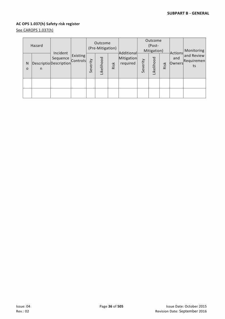
SUBPART B - GENERAL
Issue: 04 Page 36 of 505 Issue Date: October 2015
Rev.: 02 Revision Date: September 2016
AC OPS 1.037(h) Safety risk register
See CAROPS 1.037(h)
Hazard
Incident Sequence
Description
Existing Controls
Outcome (Pre-Mitigation)
Additional Mitigation required
Outcome (Post-
Mitigation) Actions
and Owners
Monitoring and Review Requiremen
ts No
Description
Seve
rity
Like
liho
od
Ris
k
Seve
rity
Like
liho
od
Ris
k

SUBPART B - GENERAL
Issue: 04 Page 37 of 505 Issue Date: October 2015
Rev.: 02 Revision Date: September 2016
CAR-OPS 1.040 Additional crew members
An operator shall ensure that crew members who are not required flight or cabin crew members, have also been trained in, and are proficient to perform, their assigned duties.
CAR-OPS 1.045 Reserved CAR-OPS 1.050 Search and rescue information
An operator shall ensure that essential information pertinent to the intended flight concerning search and rescue services is easily accessible on the flight deck.
CAR-OPS 1.055 Information on emergency and survival equipment carried
An operator shall ensure that there are available for immediate communication to rescue coordination centres, lists containing information on the emergency and survival equipment carried on board all of his aeroplanes. The information shall include, as applicable, the number, colour and type of life -rafts and pyrotechnics, details of emergency medical supplies, water supplies and the type and frequencies of emergency portable radio equipment.
CAR-OPS 1.060 Ditching
An operator shall not operate an aeroplane with an approved passenger seating configuration of more than 30 passengers on overwater flights at a distance from land suitable for making an emergency landing, greater than 120 minutes at cruising speed, or 400 nautical miles, whichever is the lesser, unless the aeroplane complies with the ditching requirements prescribed in the applicable airworthiness code.
CAR-OPS 1.065 Carriage of weapons of war and munitions of war (See IEM OPS 1.065)
(a) An operator shall not transport weapons of war and munitions of war by air unless an approval to do so has been granted by all States concerned.
(b) An operator shall ensure that weapons of war and munitions of war are:
(1) Stowed in the aeroplane in a place which is inaccessible to passengers during flight; and (2) In the case of firearms, unloaded, unless, before the commencement of the flight, approval has
been granted by all States concerned that such weapons of war and munitions of war may be carried in circumstances that differ in part or in total from those indicated in this sub-paragraph.
(c) An operator shall ensure that the commander is notified before a flight begins of the details and location on board the aeroplane of any weapons of war and munitions of war intended to be carried.
IEM OPS 1.065 Carriage of weapons of war and munitions of war
See CAR-OPS 1.065 See CAR Part VII
1. There is no internationally agreed definition of weapons of war and munitions of war. Some States
may have defined them for their particular purposes or for national need.
2. It should be the responsibility of the operator to check, with the State(s) concerned, whether or not a particular weapon or munition is regarded as a weapon of war or munition of war. In this context, States which may be concerned with granting approvals for the carriage of weapons of war or munitions of war are those of origin, transit, overflight and destination of the consignment and the State of the operator.

SUBPART B - GENERAL
Issue: 04 Page 38 of 505 Issue Date: October 2015
Rev.: 02 Revision Date: September 2016
3. Where weapons of war or munitions of war are also dangerous goods by definition (e.g. torpedoes, bombs, etc.), Subpart R will also apply. (See also IEM OPS 1.070.)
CAR-OPS 1.070 Carriage of sporting weapons and ammunition (See IEM OPS 1.070 Carriage of sporting weapons)
(a) An operator shall take all reasonable measures to ensure that any sporting weapons intended to be carried by air are reported to him.
(b) An operator accepting the carriage of sporting weapons shall ensure that they are:
(1) Stowed in the aeroplane in a place which is inaccessible to passengers during flight unless the Authority has determined that compliance is impracticable and has accepted that other procedures might apply; and
(2) In the case of firearms or other weapons that can contain ammunition, unloaded.
(c) Ammunition for sporting weapons may be carried in passengers’ checked baggage, subject to certain limitations, in accordance with the Technical Instructions (See CAR-OPS 1.1160(b)(5)) as defined in CAR-OPS 1.1150(a)(15).
IEM OPS 1.070 Carriage of sporting weapons
See CAR-OPS 1.070 and CAR Part VII
1. There is no internationally agreed definition of sporting weapons. In general they may be any weapon which is not a weapon of war or munition of war (See IEM OPS 1.065). Sporting weapons include hunting knives, bows and other similar articles. An antique weapon, which at one time may have been a weapon of war or munition of war, such as a musket, may now be regarded as a sporting weapon.
2. A firearm is any gun, rifle or pistol which fires a projectile.
3. In the absence of a specific definition, for the purpose of CAR-OPS and in order to provide some guidance to operators, the following firearms are generally regarded as being sporting weapons:
a. Those designed for shooting game, birds and other animals;
b. Those used for target shooting, clay-pigeon shooting and competition shooting, providing the weapons are not those on standard issue to military forces;
c. Airguns, dart guns, starting pistols, etc.
4. A firearm, which is not a weapon of war or munition of war, should be treated as a sporting weapon for the purposes of its carriage on an aeroplane.
5. Other procedures for the carriage of sporting weapons may need to be considered if the aeroplane does not have a separate compartment in which the weapons can be stowed. These procedures should take into account the nature of the flight, its origin and destination, and the possibility of unlawful interference. As far as possible, the weapons should be stowed so they are not immediately accessible to the passengers (e.g. in locked boxes, in checked baggage which is stowed under other baggage or under fixed netting). If procedures other than those in CAR-OPS 1.070(b)(1) are applied, the commander should be notified accordingly.

SUBPART B - GENERAL
Issue: 04 Page 39 of 505 Issue Date: October 2015
Rev.: 02 Revision Date: September 2016
CAR-OPS 1.075 Method of carriage of persons
(a) An operator shall take all reasonable measures to ensure that no person is in any part of an aeroplane in flight which is not a part designed for the accommodation of persons unless temporary access has been granted by the commander to any part of the aeroplane:
(1) For the purpose of taking action necessary for the safety of the aeroplane or of any person, animal or goods therein; or
(2) In which cargo or stores are carried, being a part which is designed to enable a person to have access thereto while the aeroplane is in flight.
CAR-OPS 1.080 Duties of flight operations officer/flight dispatcher
(a) A flight operations officer/flight dispatcher in conjunction with a method of control and supervision of flight operations shall:
(1) Assist the pilot-in-command in flight preparation and provide the relevant information; and (2) Assist the pilot-in-command in preparing the operational and ATS flight plans, sign when
applicable and file the ATS flight plan with the appropriate ATS unit; and (3) Furnish the pilot-in-command while in flight, by appropriate means, with information which
may be necessary for the safe conduct of the flight.
(b) In the event of an emergency, a flight operations officer/flight dispatcher shall: (1) initiate such procedures as outlined in the operations manual while avoiding taking any
action that would conflict with ATC procedures; and (2) convey safety-related information to the pilot-in-command that may be necessary for the
safe conduct of the flight, including information related to any amendments to the flight plan that become necessary in the course of the flight.
CAR-OPS 1.085 Crew responsibilities
(a) A crew member shall be responsible for the proper execution of his duties that:
(1) Are related to the safety of the aeroplane and its occupants; and (2) Are specified in the instructions and procedures laid down in the Operations Manual.
(b) A crew member shall:
(1) Report to the commander any fault, failure, malfunction or defect which he believes may affect the airworthiness or safe operation of the aeroplane including emergency systems.
(2) Report to the commander any incident that endangered, or could have endangered, the safety of operation; and
(3) Make use of the operator’s occurrence reporting schemes in accordance with AMC OPS 1.035 (f). In all such cases, a copy of the report(s) shall be communicated to the commander concerned.
(c) Nothing in paragraph (b) above shall oblige a crew member to report an occurrence which has already been reported by another crew member.
(d) A crew member shall not perform duties on an aeroplane:
(1) While under the influence of any psychoactive substance that may affect his faculties in a manner contrary to safety;
(2) Until a reasonable time period has elapsed after deep water diving;

SUBPART B - GENERAL
Issue: 04 Page 40 of 505 Issue Date: October 2015
Rev.: 02 Revision Date: September 2016
(3) Following blood donation except when a reasonable time period has elapsed;
(4) If he is in any doubt of being able to accomplish his assigned duties; or
(5) If he knows or suspects that he is suffering from fatigue, or feels unfit to the extent that the flight may be endangered.
(e) A crew member shall be subject to appropriate requirements on the consumption of alcohol which shall
be established by the operator and acceptable by the Authority, and which shall not be less restrictive
than the following:
A crew member shall not:
(1) Consume alcohol less than 12 hours prior to the specified reporting time for flight duty or the commencement of standby;
(2) Commence a flight duty period with a blood alcohol level in excess of 0·2 promille;
(3) Consume alcohol during the flight duty period or whilst on standby.
(f) The commander shall:
(1) Be responsible for the safety and security of all crew members, passengers and cargo on board, as soon as he arrives on board, until he leaves the aeroplane at the end of the flight;
(2) Be responsible for the operation and safety and security of the aeroplane from the moment the aeroplane is first ready to move for the purpose of taxiing prior to take-off until the moment it finally comes to rest at the end of the flight and the engine(s) used as primary propulsion units are shut down;
(3) Have authority to give all commands he deems necessary for the purpose of securing the safety of the aeroplane and of persons or property carried therein;
(4) Have authority to disembark any person, or any part of the cargo, which, in his opinion, may represent a potential hazard to the safety of the aeroplane or its occupants;
(5) Not allow a person to be carried in the aeroplane who appears to be under the influence of alcohol or drugs or Physchoactive substances to the extent that the safety of the aeroplane or its occupants is likely to be endangered;
(6) Have the right to refuse transportation of inadmissible passengers, deportees or persons in custody if their carriage poses any risk to the safety of the aeroplane or its occupants;
(7) Ensure that all passengers are briefed on the location of emergency exits and the location and use of relevant safety and emergency equipment;
(8) Ensure that all operational procedures and check lists are complied with in accordance with the Operations Manual;
(9) Not permit any crew member to perform any activity during take-off, initial climb, final approach and landing except those duties required for the safe operation of the aeroplane;
(10) Not permit:
(i) A flight data recorder to be disabled, switched off or erased during flight nor permit recorded data to be erased after flight in the event of an accident or an incident subject to mandatory reporting;
(ii) A cockpit voice recorder to be disabled or switched off during flight unless he believes that the recorded data, which otherwise would be erased automatically, should be preserved for incident or accident investigation nor permit recorded data

SUBPART B - GENERAL
Issue: 04 Page 41 of 505 Issue Date: October 2015
Rev.: 02 Revision Date: September 2016
to be manually erased during or after flight in the event of an accident or an incident subject to mandatory reporting;
(11) Decide whether or not to accept an aeroplane with unserviceabilities allowed by the CDL or MEL; and
(12) Ensure that the pre-flight inspection has been carried out. (13) Ensure that at least one member of the flight crew holds a valid licence authorising
operations of the type of radio transmitting equipment to be used (14) Be responsible for ensuring that a flight is not commenced if any flight crew member is
incapacitated from performing duties by any cause such as injury, sickness, fatigue, the effects of any psychoactive substance; and
(15) Be responsible for ensuring that a flight is not continued beyond the nearest suitable aerodrome when flight crew members’ capacity to perform functions is significantly reduced by impairment of faculties from causes such as fatigue, sickness or lack of oxygen.
(g) The commander or the pilot to whom conduct of the flight has been delegated shall, in an emergency situation that requires immediate decision and action, take any action he considers necessary under the circumstances. In such cases he may deviate from rules, operational procedures and methods in the interest of safety.
AC OPS 1.085(e)(3) Crew responsibilities
See CAR-OPS 1.085(e)(3)
Information on the effects of medication, drugs /physchoactive substances, other treatments and alcohol, is to be found in CAR FCL Part 3 Medical, IEM FCL 3.040.
CAR-OPS 1.090 Authority of the commander
An operator shall take all reasonable measures to ensure that all persons carried in the aeroplane obey all lawful commands given by the commander for the purpose of securing the safety of the aeroplane and of persons or property carried therein.
CAR-OPS 1.095 Authority to taxi an aeroplane (a) An operator shall take all reasonable steps to ensure that an aeroplane in his charge is not taxied
on the movement area of an aerodrome by a person other than a flight crew member, unless that person, seated at the controls: (1) Has been duly authorised by the operator or a designated agent and is competent to;
(i) taxi the aeroplane;
(ii) use the radio telephone; and
(2) Has received instruction in respect of aerodrome layout, routes, signs, marking, lights, air traffic control signals and instructions, phraseology and procedures, and is able to conform to the operational standards required for safe aeroplane movement at the aerodrome.
CAR-OPS 1.100 Admission to flight deck
(a) An operator must ensure that no person, other than a flight crew member assigned to a flight, is admitted to, or carried in, the flight deck unless that person is:

SUBPART B - GENERAL
Issue: 04 Page 42 of 505 Issue Date: October 2015
Rev.: 02 Revision Date: September 2016
(1) An operating crew member;
(2) A representative of the Authority responsible for certification, licensing or inspection if this is required for the performance of his official duties; or
(3) Permitted by, and carried in accordance with instructions contained in the Operations Manual.
(b) The commander shall ensure that:
(1) In the interests of safety, admission to the flight deck does not cause distraction and/or interfere with the flight’s operation; and
(2) All persons carried on the flight deck are made familiar with the relevant safety procedures.
(c) The final decision regarding the admission to the flight deck shall be the responsibility of the commander.
CAR-OPS 1.105 Unauthorised carriage
An operator shall take all reasonable measures to ensure that no person secretes himself or secretes cargo on board an aeroplane.
CAR-OPS 1.110 Portable electronic devices (See AMC OPS 1.110 PED, GM1 to AMC OPS 1.110, and GM2 to AMC OPS 1.110)
An operator shall not permit any person to use, and take all reasonable measures to ensure that no person does use, on board an aeroplane, a portable electronic device that can adversely affect the performance of the aeroplane’s systems and equipment.
AMC OPS 1.110 PED
(See CAR-OPS 1.110 Portable electronic devices)
GENERAL
(a) Scope
This AMC provides means to prevent portable electronic devices (PEDs) on board aircraft adversely affect the performance of the aircraft’s systems and equipment. It addresses operation of PEDs in the different aircraft zones – passenger compartment, flight compartment, and cargo compartments. Furthermore, it addresses the specific case of PEDs qualified and under configuration control by the operator - controlled PEDs (C-PEDs) - for which the operator gives some credit.
(b) Restrictions on the use of PEDs in the passenger compartment
If an operator permits passengers to use PEDs on board its aircraft, procedures should be in place to control their use. The operator should ensure that all crew members and ground personnel are trained to enforce the restrictions on this equipment in line with these procedures.
These procedures should ensure the following:
(1) As the general principle all PEDs (including transmitting PEDs (T-PEDs)) are switched-off at the start of the flight when the passengers have boarded and all doors have been closed, until a passenger door has been opened at the end of the flight.

SUBPART B - GENERAL
Issue: 04 Page 43 of 505 Issue Date: October 2015
Rev.: 02 Revision Date: September 2016
(2) The following exceptions from the above general principle may be granted under the responsibility of the operator: (i) Medical equipment necessary to support physiological functions does not need to be switched-off. (ii) The use of PEDs, excluding T-PEDs, may be permitted during all phases of flight. (iii) T-PEDs may be used during non-critical phases of flight, excluding taxiing, if the aircraft is equipped
with a system or otherwise certified allowing the operation of such technology during flight. The restrictions coming from the corresponding aircraft certification as documented in the aircraft flight manual (AFM), or equivalent document(s), stay in force.
(iv) Use of cellphone may be permitted after an aircraft has left active runway after landing. (v) The use of C-PEDs during critical phases of flight, however, may only be permitted if the operator has
accounted for this situation in its assessment. (vi) The commander may permit the use of any kind of PED when the aircraft is stationary during
prolonged departure delays, provided that sufficient time is available to check the passenger compartment before the flight proceeds. Similarly, after landing, the commander may authorize the use of any kind of PED in the event of a prolonged delay for a parking/gate position (even though doors are closed and the engines are running).
(3) Announcements should be made during boarding of the aircraft to inform passengers of the restrictions applicable to PEDs (in particular to T-PEDs) before fastening their seat belts.
(4) Where in-seat electrical power supplies are available for passenger use the following should apply: (i) Information cards giving safety instructions are provided to the passengers; (ii) PEDs should be disconnected from any in-seat electrical power supply, during taxiing, take-off,
approach, landing, and during abnormal or emergency conditions; and (iii) Flight crew and cabin crew should be aware of the proper means to switch-off in-seat power supplies
used for PEDs.
(5) During boarding and any phase of flight: (i) Appropriate coordination between flight crew and cabin crew is defined to deal with interference or
other safety problems associated with PEDs; (ii) passenger use of equipment during the flight is monitored; (iii) suspect equipment is switched off; and (iv) particular attention is given to passenger misuse of equipment that could include a built-in
transmitting function.
(6) Thermal runaways of batteries, in particular lithium batteries, and potential resulting fire can be handled properly.
(7) Appropriate coordination between flight crew and cabin crew should be defined to deal with interference or other safety problems associated with PEDs.
(8) The commander may for any reason and during any phase of flight require deactivation and stowage of PEDs.
(9) Occurrences of suspected or confirmed interference that have potential safety implications should be reported to the competent authority. Where possible, to assist follow-up and technical investigation, reports should describe the offending device, identify the brand name and model number, its location in the aircraft at the time of the occurrence, interference symptoms and the results of actions taken by the crew.
The cooperation of the device owner should be sought by obtaining contact details.
(10) Special requests to operate a PED or T-PED during any phase of the flight for specific reasons (e.g. for security measures) should be handled properly.
(c) Restrictions on the use of PEDs in the flight compartment
Due to the higher risk of interference and potential for distracting crew from their duties, PEDs should not be used in the flight compartment. However, the operator may allow the use of PEDs, e.g. to assist the flight crew in their duties, if procedures are in place to ensure the following:

SUBPART B - GENERAL
Issue: 04 Page 44 of 505 Issue Date: October 2015
Rev.: 02 Revision Date: September 2016
(1) The conditions for the use of PEDs in-flight are specified in the operations manual, otherwise they should be switched off and stowed during all phases of flight.
(2) The PEDs do not pose a loose-item risk or other hazard. (3) During critical phases of flight only those C-PEDs are operated, for which the operator has demonstrated
that the radio frequency (RF) interference levels are below those considered acceptable for the specific aircraft environment. Guidance for such test is provided in (e) below.
(4) During pre-flight procedures, e.g. when loading route information into navigation systems or when monitoring fuel loading, no T-PED should be operated. In all other cases, flight crew and other persons on board the aircraft involved in dispatching the aircraft should observe the same restrictions as applicable to passengers.
(5) These restrictions should not preclude use of a T-PED (specifically a mobile phone) by the flight crew to deal with an emergency. However, reliance should not be predicated on a T-PED for this purpose.
(d) PEDs not accessible during the flight
PEDs should be switched off, when not accessible for deactivation during flight. This should apply especially to PEDs contained in baggage or transported as part of the cargo. The operator may allow deviation for PEDs for which tests have demonstrated their safe operation. Other precautions, such as transporting in shielded, metal boxes, may also be used to mitigate associated risks.
In case an automated function is used to deactivate a T-PED, the unit should be qualified for safe operation on board the aircraft.
(e) Test methods
The means to demonstrate that the RF radiations (intentional or non-intentional) are tolerated by aircraft systems should be as follows:
(1) The radio frequency (RF) emissions of PEDs should meet the levels as defined by EUROCAE ED-14E/RTCA DO 160E Section 21 Category M for operation in the passenger compartment and EUROCAE ED-14E/RTCA DO 160E Section 21 Category H for operation in the cargo bay. Later revisions of those documents may be used for testing. The assessment of intentional transmissions of T-PEDs is excluded from those test standards and needs to be addressed separately.
(2) When the operator intends to allow the operation of T-PEDs, its assessment should follow the principles set out in EUROCAE ED-130.
The GCAA reminds to consider the applicable telecommunication regulations before allowing the use of transmitting functions on-board aircraft.
GM1 to AMC OPS 1.110
DEFINITIONS
(a) Definition and categories of PEDs
PEDs are any kind of electronic device, typically but not limited to consumer electronics, brought on board the aircraft by crew members, passengers, or as part of the cargo and that are not included in the approved aircraft configuration. All equipment that is able to consume electrical energy falls under this definition. The electrical energy can be provided from internal sources as batteries (chargeable or non-rechargeable) or the devices may also be connected to specific aircraft power sources.
PEDs fall into three categories:
(1) Non-intentional transmitters can non-intentionally radiate RF transmissions. This category includes, but is not limited to, computing equipment, cameras, radio receivers, audio and video reproducers, electronic games and toys. In addition, portable, non-transmitting devices provided to assist crew members in their duties are included in this category. The category is identified as PED.

SUBPART B - GENERAL
Issue: 04 Page 45 of 505 Issue Date: October 2015
Rev.: 02 Revision Date: September 2016
(2) Intentional transmitters can radiate RF transmissions on specific frequencies as part of their intended function. In addition they may radiate non-intentional transmissions like any PED. The term ‘transmitting PED’ (T-PED) is used to identify the transmitting capability of the PED. Intentional transmitters are transmitting devices such as RF based remote control equipment, which may include some toys, two-way radios (sometimes referred to as private mobile radio), mobile phones of any type, satellite phones, computer with mobile phone data connection, wireless fidelity (WIFI) or Bluetooth capability. After deactivation of the transmitting capability, e.g. by activating the so called ‘flight mode’ or ‘flight safety mode’, the T-PED remains a PED having non-intentional emissions.
(3) A controlled PED (C-PED) is subject to administrative control by the operator. This will include, inter alia, tracking the location of the devices to specific aircraft or persons and ensuring that no unauthorized changes are made to the hardware, software or databases. A controlled PED will also be subject to procedures to ensure that it is maintained to the latest amendment state. C-PEDs can be assigned to the category of non-intentional transmitters (PEDs) or intentional transmitters (T-PEDs).
(b) Definition of the switched-off status
Many PEDs are not completely disconnected from the internal power source when switched off. The switching function may leave some remaining functionality e.g. data storage, timer, clock, etc. These devices can be considered switched off when in the deactivated status. The same applies for devices having no transmit capability and operated by coin cells without further deactivation capability, e.g. wrist watches.
GM2 to AMC OPS 1.110
FIRE CAUSED BY PEDs
A detailed discussion of fire caused by PEDs can be found in CAA UK CAP 789 edition 2, chapter 31, section 6 Fires in the cabin caused by PEDs2 and CAA PAPER 2003/4, Dealing With In-Flight Lithium Battery Fires in Portable Electronic Devices, M.J. Lain, D.A. Teagle, J. Cullen, V. Dass3.
CAR-OPS 1.115 Physchoactive substances
An operator shall not permit any person to enter or be in, and take all reasonable measures to ensure that no person enters or is in, an aeroplane when under the influence of Physchoactive substances to the extent that the safety of the aeroplane or its occupants is likely to be endangered.
CAR-OPS 1.120 Endangering safety
(a) An operator shall take all reasonable measures to ensure that no person recklessly or negligently acts or omits to act:
(1) So as to endanger an aeroplane or person therein;
(2) So as to cause or permit an aeroplane to endanger any person or property.
(b) If an emergency situation which endangers the safety of the aeroplane or persons becomes known first to the flight operations officer/flight dispatcher, he shall take necessary action to notify the appropriate authorities of the nature of the situation without delay and requests for assistance if required.
CAR-OPS 1.125 Documents to be carried (See Appendix 1 to CAR-OPS 1.125)
(a) An operator shall ensure that the following are carried on each flight:
SUBPART B - GENERAL
Issue: 04 Page 46 of 505 Issue Date: October 2015
Rev.: 02 Revision Date: September 2016
(1) The Certificate of Registration; (2) The Certificate of Airworthiness; (3) The original or a copy of the Noise Certificate (if applicable), including an English translation,
where one has been provided by the Authority responsible for issuing the noise certificate ; (4) The original or a certified true copy of the Air Operator Certificate and a copy of Operations
Specification relevant to the aeroplane type, issued in conjunction with the certificate; (5) The Aircraft Radio Station Licence; (6) The original or a copy of the Insurance Certificate(s), which cover the aircraft, its crew,
passengers and third party liability clauses. (7) Airworthiness Review Certificates (ARC) if applicable (8) Journey Log or General Declaration.
(b) Each flight crew member shall, on each flight, carry a valid flight crew licence with appropriate rating(s) for the purpose of the flight.
(c) For operations of A to A or A to B operations within UAE paragraph a(1) and a(2) may be in a carry in
readable certified true copy format.
CAR-OPS 1.130 Manuals to be carried See: AMC OPS 1.130 Manuals to be carried & CAAP 18 EFB
An operator shall ensure that:
1) The current parts of the Operations Manual relevant to the duties of the crew are carried on each flight
2) Those parts of the Operations Manual which are required for the conduct of a flight are easily accessible to the crew on board the aeroplane; and
3) The current Aeroplane Flight Manual is carried in the aeroplane unless the Authority has accepted that the Operations Manual prescribed in CAR-OPS 1.1045, Appendix 1, Part B contains relevant information for that aeroplane.
AMC OPS 1.130 Manuals to be carried
See CAR-OPS 1.130
The carriage of an approved electronic version of the Operations Manual is acceptable.
CAR-OPS 1.135 Additional information and forms to be carried (See Appendix 1 to CAR-OPS 1.135)
(a) An operator shall ensure that, in addition to the documents and manuals prescribed in CAR-OPS 1.125 and CAR-OPS 1.130, the following information and forms, relevant to the type and area of operation, are carried on each flight:
(1) Operational Flight Plan containing at least the information required in CAR-OPS 1.1060 Operational flight plan
(2) Operator’s technical log system; (3) Details of the filed ATS flight plan; (4) Appropriate NOTAM/AIP/AIRAC/AIC/AIS briefing documentation; (5) Appropriate meteorological information; (6) Mass and balance documentation as specified in Subpart J;

SUBPART B - GENERAL
Issue: 04 Page 47 of 505 Issue Date: October 2015
Rev.: 02 Revision Date: September 2016
(7) Notification of special categories of passenger such as security personnel, if not considered as crew, handicapped persons, inadmissible passengers, deportees and persons in custody;
(8) Notification of special loads including dangerous goods including written information to the commander as prescribed in AC OPS (IEM) 1.1160(c)(1) Scope – Dangerous goods carried by passengers or crew;
(9) Current maps and charts and associated documents as prescribed in CAR-OPS 1.290 Flight preparation (b)(7)
(10) Passenger manifest, cargo manifest, mail declaration, navigation certificates etc; (if applicable) and
(11) Forms to comply with the reporting requirements of the Authority and the operator.
(b) The Authority may permit the information detailed in sub-paragraph (a) above, or parts thereof, to be presented in a form other than on printed paper. An acceptable standard of accessibility, usability and reliability must be assured.
CAR-OPS 1.140 Information retained on the ground
(a) An operator shall ensure that:
(1) At least for the duration of each flight or series of flights;
(i) Information relevant to the flight and appropriate for the type of operation is preserved on the ground; and
(ii) The information is retained until it has been duplicated at the place at which it will be stored in accordance with CAR-OPS 1.1065 Document storage periods ; or, if this is impracticable,
(iii) The same information is carried in a fireproof container in the aeroplane.
(b) The information referred to in subparagraph (a) above includes:
(1) A copy of the operational flight plan where appropriate; (2) Copies of the relevant part(s) of the aeroplane technical log; (3) Route specific NOTAM documentation if specifically edited by the operator; (4) Mass and balance documentation if required as CAR-OPS 1.625 Mass and balance
documentation refers); and (5) Special loads notification.
CAR-OPS 1.145 Power to inspect See CAR-OPS 1.145 Power to inspect
An operator shall ensure that any person authorised by the Authority is permitted at any time to board and fly in any aeroplane operated in accordance with an AOC or authorization issued by that Authority and to enter and remain on the flight deck provided that the commander may refuse access to the flight deck if, in his opinion, the safety of the aeroplane would thereby be endangered.
AC OPS 1.145 Power to inspect
(See CAR-OPS 1.145 Power to inspect) a) All inspectors authorized to conduct safety oversight are in possession of credentials identifying them as
inspectors employed by the GCAA, particularly flight operations (pilots) and cabin safety. b) The safety oversight of operators is conducted on a continuous basis, based on schedule and periodic
random inspections of all aspects of the operation. c) The scope of inspection are headquarters, station facility, aerodrome (or heliport), apron and en-route
inspections, the Enroute inspection will be inspected by Flight operatinos which mainly be in flight deck, and cabin safety.

SUBPART B - GENERAL
Issue: 04 Page 48 of 505 Issue Date: October 2015
Rev.: 02 Revision Date: September 2016
CAR-OPS 1.150 Production of documentation and records
(a) An operator shall:
(1) Give any person authorised by the Authority access to any documents and records which are related to flight operations or maintenance; and
(2) Produce all such documents and records, when requested to do so by the Author ity, within a reasonable period of time.
(b) The commander shall, within a reasonable time of being requested to do so by a person authorised by an Authority, produce to that person the documentation required to be carried on board.
CAR-OPS 1.155 Preservation of documentation
(a) An operator shall ensure that:
(1) Any original documentation, or copies thereof, that he is required to preserve is preserved for the required retention period even if he ceases to be the operator of the aeroplane; and
(2) Where a crew member, in respect of whom an operator has kept a record in accordance with Subpart Q, becomes a crew member for another operator, that record is made available to the new operator.
CAR-OPS 1.160 Preservation, production and use of flight recorder recordings (AC OPS 1.160(a)(1)&(2) Preservation of Recordings)
(a) Preservation of recordings
(1) Following an accident, the operator of an aeroplane on which a flight recorder is carried shall, to the extent possible, preserve the original recorded data pertaining to that accident, as retained by the recorder for a period of 60 days unless otherwise directed by the investigating authority.
(2) Unless prior permission has been granted by the Authority, following an incident that is subject to mandatory reporting, the operator of an aeroplane on which a flight recorder is carried shall, to the extent possible, preserve the original recorded data pertaining to that incident, as retained by the recorder for a period of 60 days unless otherwise directed by the investigating authority.
(3) Additionally, when the Authority so directs, the operator of an aeroplane on which a flight recorder is carried shall preserve the original recorded data for a period of 60 days unless otherwise directed by the investigating authority.
(4) When a flight data recorder is required to be carried aboard an aeroplane, the operator of that aeroplane shall:
(i) Save the recordings for the period of operating time as required by CAR-OPS 1.715, 1.720 and 1.725 except that, for the purpose of testing and maintaining flight data recorders, up to one hour of the oldest recorded material at the time of testing may be erased; and

SUBPART B - GENERAL
Issue: 04 Page 49 of 505 Issue Date: October 2015
Rev.: 02 Revision Date: September 2016
(ii) Keep a document which presents the information necessary to retrieve and convert the stored data into engineering units.
(b) Production of recordings. The operator of an aeroplane on which a flight recorder is carried shall, within a reasonable time after being requested to do so by the Authority, produce any recording made by a flight recorder which is available or has been preserved.
(c) Use of recordings
(1) The cockpit voice recorder recordings may not be used for purposes other than for the investigation of an accident or incident subject to mandatory reporting except with the consent of all crew members concerned.
(2) The flight data recorder recordings may not be used for purposes other than for the investigation of an accident or incident subject to mandatory reporting except when such records are:
(i) Used by the operator for airworthiness or maintenance purposes only; or
(ii) De-identified; or
(iii) Disclosed under secure procedures.
GM OPS 1.160 Preservation of Recordings
The need for removal of the recorders from the aircraft is determined by the investigating authority with due regard to the seriousness of an occurrence and the circumstances, including the impact on the operation. An operator may require the investigating authority to stop the preservation of recording after the completetion of investigation.
AC OPS 1.160(a)(1)&(2) Preservation of Recordings
See CAR-OPS 1.160(a)(1) and (2)
In CAR-OPS 1.160(a)(1) and (2), the phrase ‘to the extent possible’ means that either :
1. There may be technical reasons why all of the data cannot be preserved; or
2. The aeroplane may have been despatched with unserviceable recording equipment as permitted by the
MEL Policy.
CAR-OPS 1.165 Leasing (See AC OPS 1.165(c)(2) Leasing of aeroplanes between a UAE operator and any entity)
(a) Terminology
Terms used in this paragraph have the following meaning:

SUBPART B - GENERAL
Issue: 04 Page 50 of 505 Issue Date: October 2015
Rev.: 02 Revision Date: September 2016
(1) Dry lease – Is when the aeroplane is operated under the AOC or authorization of the lessee. (2) Wet lease – Is when the aeroplane is operated under the AOC or authorization of the lessor. (3) Damp lease – Is when the aeroplane is operated under the AOC or authorization of the lessor
with partial crew.
(b) General requirements for leasing
(1) When an applicant for an AOC or an existing operator wishes to lease aircraft, the applicant or operator should provide to the authority with the following information:
(i) the aircraft type, model and serial number
(ii) the name and address of the registered owner (iii) State of Registry, nationality and registration marks (iv) Certificate of Airworthiness and statement from the registered owner that the aircraft
fully complies with the airworthiness requirements of the State of Registry (v) Name, address and signature of lessee or person responsible for operational control
of the aircraft under the lease agreement, including a statement that such individual and the parties to the lease agreement fully understand their respective responsibilities under the applicable regulations
(vi) copy of the lease agreement or description of lease provisions (vii) duration of the lease
(viii) area of operation
(2) On completion of review and liaison with other competent authorities, determination as to which party to the lease agreement is in fact responsible for conduct of the operations will be made considering the responsibilities of the parties under the lease agreement for:
(i) flight crewmember licensing and training
(ii) cabin crewmember training (iii) airworthiness of the aircraft and the performance of maintenance (iv) operational control, including dispatch and flight following (v) scheduling of flight and cabin crew members
(vi) signing the maintenance release
(c) Leasing of aeroplanes between a UAE operator and any entity
(1) Dry lease-in
(i) A UAE operator shall not dry lease-in an aeroplane from an entity unless approved by the Authority. Any conditions which are part of this approval must be included in the lease agreement.
(ii) A UAE operator shall ensure that, with regard to aeroplanes that are dry leased-in, any differences from the requirements prescribed in Subparts K, L, and/or CAR M, are notified to and are acceptable to the Authority.
(2) Wet lease-in
(See AC OPS 1.165(c)(2) Leasing of aeroplanes between a UAE operator and any entity)
(i) A UAE operator shall not wet lease-in an aeroplane from an entity without the approval of the Authority.

SUBPART B - GENERAL
Issue: 04 Page 51 of 505 Issue Date: October 2015
Rev.: 02 Revision Date: September 2016
(ii) A UAE operator shall ensure that, with regard to aeroplanes that are wet leased-in:
(A) The safety standards of the lessor with respect to maintenance and operation are equivalent to CARs;
(B) The lessor is an operator holding an AOC issued by a State which is a signatory to the Chicago Convention:
(C) The aeroplane has a standard Certificate of Airworthiness issued in accordance with ICAO Annex 8.
(D) Any requirement made applicable by the lessee’s Authority is complied with.
(3) Dry lease-out
(i) A UAE operator may dry lease-out an aeroplane for the purpose of commercial or private air transportation to any operator of a State which is signatory to the Chicago Convention provided that the following conditions are met:
(A) The Authority has exempted the operator from the relevant provisions of CAR–OPS Part 1 and, after the foreign regulatory authority has accepted responsibility in writing for surveillance of the maintenance and operation of the aeroplane(s), has removed the aeroplane from its AOC; and
(B) The aeroplane is maintained according to an approved maintenance programme.
(4) Wet lease-out. A UAE operator providing an aeroplane and complete crew to another entity and retaining all the functions and responsibilities prescribed in Subpart C, shall remain the operator of the aeroplane.
(5) Damp lease-out. A UAE operator providing an aeroplane and flight crew to another entity and retaining all the functions and responsibilities prescribed in Subpart C shall remain the operator of the aeroplane.
(d) Leasing of aeroplanes at short notice.
In circumstances where a UAE operator is faced with an immediate, urgent and unforeseen need for a replacement aeroplane, the approval required by sub-paragraph (c)(2)(i) above may be deemed to have been given, provided that:
(1) The lessor is an operator holding an AOC issued by a State which is a signatory to the Chicago Convention; and
(2) The lease-in period does not exceed 5 consecutive days; and (3) The Authority is immediately notified of the use of this provision.
(e) Transfer Agreements as State of Registry under article 83bis. Transfer of functions and duties as State of Registry under article 83bis of the Chicago Convention (See AMC OPS 1.165 (e))
(1) The UAE may, by agreement with other foreign State, accept the transfer of all or part of the foreign State’s functions and duties as State of Operator in respect of a foreign-registered aircraft under Articles 12 (Rules of Air), 30 (Aircraft Radio Equipment), 31 (Certificate of Airworthiness) and 32(a) (Licenses of Personnel) of the Chicago Convention.

SUBPART B - GENERAL
Issue: 04 Page 52 of 505 Issue Date: October 2015
Rev.: 02 Revision Date: September 2016
(2) In case the UAE, as a State of the operator, decides to accept functions and duties from the State of Registry in respect to Articles 12 (Rules of Air), 30 (Aircraft Radio Equipment), 31 (Certificate of Airworthiness) and 32(a) (Licenses of Personnel) of the Chicago Convention, the Civil Aviation Regulations applicable to UAE registered aircraft for the issuance/renewal of licenses/certificates will be applicable to the foreign registered aircraft in respect to the responsibilities that have been transferred to the UAE.
(3) The transfer shall not have effect in respect of other Contracting States of ICAO before either the agreement between States in which it is embodied has been registered with the Council of ICAO and made public pursuant to Article 83bis of the Convention, or the existence and scope of the agreement have been directly communicated to the Civil Aviation Authorities of the other Contracting State or States concerned
(f) Transfer Agreement as State of Operator under article 83bis.
Transfer of functions and duties as State of Operator under article 83bis of the Chicago Convention
( See AMC OPS 1.165 (f))
(1) The UAE may, by agreement with other foreign State, accept the transfer of all or part of the foreign State’s functions and duties as State of Operator in respect of a foreign-registered aircraft under Articles 12 (Rules of Air), 30 (Aircraft Radio Equipment), 31 (Certificate of Airworthiness) and 32(a) (Licenses of Personnel) of the Chicago Convention.
(2) In case the UAE, as a State of the operator, decides to accept functions and duties from the State of Registry in respect to Articles 12 (Rules of Air), 30 (Aircraft Radio Equipment), 31 (Certificate of Airworthiness) and 32(a) (Licenses of Personnel) of the Chicago Convention, the Civil Aviation Regulations applicable to UAE registered aircraft for the issuance/renewal of licenses/certificates will be applicable to the foreign registered aircraft in respect to the responsibilities that have been transferred to the UAE.
(3) The transfer shall not have effect in respect of other Contracting States of ICAO before either the agreement between States in which it is embodied has been registered with the Council of ICAO and made public pursuant to Article 83bis of the Convention, or the existence and scope of the agreement have been directly communicated to the Civil Aviation Authorities of the other Contracting State or States concerned.
AC OPS 1.165(c)(2) Leasing of aeroplanes between a UAE operator and any entity
(See CAR-OPS 1.165 (c)2)
1. Reserved
2. The Authority may approve individually UAE operators provided that:
(a) The lessor is an operator holding an AOC issued by a State which is a signatory to the Convention on
International Civil Aviation; and

SUBPART B - GENERAL
Issue: 04 Page 53 of 505 Issue Date: October 2015
Rev.: 02 Revision Date: September 2016
(b) Unless otherwise agreed by the Authority of the lessee, the lessee audits the operation of the lessor
to confirm compliance with operating and aircrew training standards equivalent to CAR-OPS 1,
maintenance standards equivalent to CAR 145, and aircraft certification standards as prescribed; and
(c) The routes intended to be flown are contained within the authorised areas of operations specified in
the AOC of the lessor; and
(d) (Reserved)
(e) For the duration of the lease, the flight and duty time limitations and rest requirements used by the
lessor are not more permissive than apply in CAR-OPS.
3. Lessors, when first approved by the Authority, and any revalidations, remain valid for a period not
exceeding 12 months.
Note 1. The lessee is responsible for providing information to the Authority to support the initial application and any revalidations.
AMC OPS 1.165(e) Transfer Agreement as State of Registry under article 83bis
Transfer of functions and duties as State of Registry under article 83bis of the Chicago Convention (see CAR-OPS 1.165 (e))
The UAE should carry out the following evaluation before entering into agreement to transfer its
responsabilities:
(a) ensure that the foreign State is a party to Article 83bis;
(b) carry out an assessment of the capability of the foreign State accepting the transfer, including the recognition of duties and functions under Articles 12 (Rules of Air), 30 (Aircraft Radio Equipment), 31 (Certificate of Airworthiness) and 32(a) (Licenses of Personnel) of the Chicago Convention issued/renewed by the foreign State;
(c) ensure that the commercial agreement (for example, the lease) includes terms that give rise to the transfer agreement. The aircraft concerned shall be clearly identified in the agreement by including reference to the aircraft type, registration and serial number.
Note: the duration of the transfer agreement shall not exceed the period covered by the corresponding
commercial agreement. Accordingly, the period of validity of the transfer should be mentioned in the
transfer agreement taking into consideration that the registration of the aircraft concerned will not be
changed.
Note: The duties and functions to be transferred must be mentioned specifically in the transfer agreement as, in absence of such mention, they are deemed to remain with the GCAA.
AMC OPS 1.165(f) Transfer Agreement as State of Operator under article 83bis
Acceptance of transfer of functions and duties as State of Operator under article 83bis of the Chicago Convention (see CAR-OPS 1.165 (f))

SUBPART B - GENERAL
Issue: 04 Page 54 of 505 Issue Date: October 2015
Rev.: 02 Revision Date: September 2016
The UAE, as a State of the operator, should carry out the following evaluation before accepting the transfer of responsabilities from the State of Registry:
(a) ensure that the foreign State is a party to Article 83bis;
(b) ensure that the commercial agreement (for example, the lease) includes terms that give rise to the transfer agreement including the recognition, by the UAE, of issuing/renewing licences/certificates under Articles 12 (Rules of Air), 30 (Aircraft Radio Equipment), 31 (Certificate of Airworthiness) and 32(a) (Licenses of Personnel) of the Chicago Convention which were issued/renewed by the State of Registry. The aircraft concerned shall be clearly identified in the agreement by including reference to the aircraft type, registration and serial number;
Note: the duration of the transfer agreement shall not exceed the period covered by the corresponding commercial agreement. Accordingly, the period of validity of the transfer should be mentioned in the transfer agreement taking into consideration that the registration of the aircraft concerned will not be changed.
(c) ensure that the UAE operator continuously carries a certified true copy of the transfer agreement and AOC under which the aircraft is operated at all times, while the transfer agreement is in force.
Note: The duties and functions to be accepted by the UAE under Articles 12 (Rules of Air), 30 (Aircraft Radio Equipment), 31 (Certificate of Airworthiness) and 32(a) (Licenses of Personnel) of the Chicago Convention must be mentioned specifically in the transfer agreement as, in absence of such mention, they are deemed to remain with the State of Registry.
CAR- OPS 1.170 Reserved

SUBPART B - GENERAL
Issue: 04 Page 55 of 505 Issue Date: October 2015
Rev.: 02 Revision Date: September 2016
Appendix 1 to CAR-OPS 1.005(a) Operations of performance Class B aeroplanes.
See CAR-OPS 1.005 General
(a) Terminology
(1) A to A operations – Take-off and landing are made at the same place. (2) A to B operations – Take-off and landing are made at different places. (3) Night – The hours between the end of evening civil twilight and the beginning of morning civil
twilight or such other period between sunset and sunrise, as may be prescr ibed by the appropriate authority. (See Appendix 1 to CAR-OPS 1.005(a) Operations of performance Class B aeroplanes. Para 7)
(b) Operations, to which this Appendix is applicable, may be conducted in accordance with the following alleviations.
(1) CAR-OPS 1.035 Quality system
(See AC OPS 1.175(j) Combination of nominated postholder’s responsibilities par 2.4.5 / par 7 for small operator) .
In the case of a very small operator, the post of Quality Manager may be held by a nominated postholder if external auditors are used. This applies also where the accountable manager is holding one or several of the nominated posts.
(2) CAR-OPS 1.037 SafetyManagement System:
(See Appendix 1 to CAR-OPS 1.005(a) Operations of performance Class B aeroplanes.)
(3) CAR-OPS 1.075 Methods of carriage of persons:
Not required for VFR operations of single engine aeroplanes.
(4) CAR-OPS 1.100 Admission to the flight deck:
(i) An operator must establish rules for the carriage of passengers in a pilot seat.
(ii) The commander must ensure that;
(A) Carriage of passengers in a pilot seat does not cause distraction and/or interference with the operation of the flight; and
(B) The passenger occupying a pilot seat is made familiar with the relevant restrictions and safety procedures.
(5) CAR-OPS 1.105 Unauthorised Carriage:
Not required for VFR operations of single engine aeroplanes.
(6) CAR-OPS 1.135 Additional information and forms to be carried:
(i) For A to A VFR operations of single engine aeroplanes by day, the following documents need not be carried:

SUBPART B - GENERAL
Issue: 04 Page 56 of 505 Issue Date: October 2015
Rev.: 02 Revision Date: September 2016
(A) Operational Flight Plan;
(B) Aeroplane Technical Log;
(C) NOTAM/AIS briefing documentation;
(D) Meteorological Information;
(E) Notification of special categories of passengers ... etc.; and
(F) Notification of special loads including dangerous goods ... etc.
(ii) For A to B VFR operations of single engine aeroplanes by day. Notification of special categories of passengers as described in CAR-OPS 1.135 (a)(7) does not need to be carried.
(iii) For A to B VFR operations by day, the Operational Flight Plan may be in a simplified form and must meet the needs of the type of operation.
(7) CAR-OPS 1.215 Use of Air Traffic Services:
For VFR operations of single engine aeroplanes by day, non-mandatory contact with ATS shall be maintained to the extent appropriate to the nature of the operation. Search and rescue services must be ensured in accordance with CAR-OPS 1.300.
(8) CAR-OPS 1.225 Aerodrome Operating Minima:
For VFR operations, the standard VFR operating minima will normally cover this requirement. Where necessary, the operator shall specify additional requirements taking into account such factors as radio coverage, terrain, nature of sites for take-off and landing, flight conditions and ATS capacity
(9) CAR-OPS 1.235 Noise abatement procedures:
Not applicable to VFR operations of single engine aeroplanes.
(10) CAR-OPS 1.240 Routes and Areas of Operation:
Subparagraph (a)(1) is not applicable to A to A VFR operations of single engine aeroplanes by day.
(11) CAR-OPS 1.250 Establishment of minimum flight altitudes:
For VFR operations by day, this requirement is applicable as follows. An operator shall ensure that operations are only conducted along such routes or within such areas for which a safe terrain clearance can be maintained and shall take account of such factors as temperature, terrain, unfavourable meteorological conditions (e.g. severe turbulence and descending air currents, corrections for temperature and pressure variations from standard values).
(12) CAR-OPS 1.255 Fuel Policy:

SUBPART B - GENERAL
Issue: 04 Page 57 of 505 Issue Date: October 2015
Rev.: 02 Revision Date: September 2016
(i) For A to A Flights - An operator shall specify the minimum fuel contents at which a flight must end. This minimum, final reserve, fuel must not be less than the amount needed to fly for a period of 45 minutes.
(ii) For A to B Flights – An operator shall ensure that the pre-flight calculation of usable fuel required for a flight includes;
(A) Taxi fuel - Fuel consumed before take-off, if significant; and
(B) Trip fuel (Fuel to reach the destination); and
(C) Reserve fuel -
(1) Contingency fuel - Fuel that is not less than 5% of the planned trip fuel or, in the event of in-flight replanning, 5% of the trip fuel for the remainder of the flight; and
(2) Final reserve fuel - Fuel to fly for an additional period of 45 minutes (piston engines) or 30 minutes (turbine engines); and
(D) Alternate fuel - Fuel to reach the destination alternate via the destination, if a destination alternate is required
(E) Extra fuel – Fuel that the commander may require in addition to that required under subparagraphs (A) – (D) above.
(13) CAR-OPS 1.265 Carriage of inadmissible passengers, deportees or persons in custody:
For VFR operations of single engine aeroplanes and where it is not intended to carry inadmissible passengers, deportees or persons in custody, an operator is not required to establish procedures for the carriage of such passengers.
(14) CAR-OPS 1.280 Passenger Seating:
Not Applicable to VFR operations of single engine aeroplanes.
(15) CAR-OPS 1.285 Passenger Briefing:
Demonstration and briefing shall be given as appropriate to the kind of operations. In single pilot operations, the pilot may not be allocated tasks distracting him from his flying duties.
(16) CAR-OPS 1.290 Flight Preparation:
(i) Operational Flight Plan for A to A operations - Not Required.
(ii) A to B operations under VFR by day - An operator shall ensure that a simplified form of an operational flight plan which is relevant to the type of operation is completed for each flight.
(17) CAR-OPS 1.295 Selection of aerodromes:
Not applicable to VFR operations. The necessary instructions for the use of aerodromes and sites for take-off and landing are to be issued with reference to CAR-OPS 1.220.

SUBPART B - GENERAL
Issue: 04 Page 58 of 505 Issue Date: October 2015
Rev.: 02 Revision Date: September 2016
(18) CAR-OPS 1.310 Crew members at stations:
For VFR operations, instructions on this matter are required only where two pilot operations are conducted.
(19) CAR-OPS 1.375 In-flight fuel management:
Appendix 1 to CAR-OPS 1.375 is not required to be applied to VFR operations of single engine aeroplanes by day.
(20) CAR-OPS 1.405 Commencement and continuation of approach:
Not applicable to VFR operations.
(21) CAR-OPS 1.410 Operating procedures - threshold crossing height:
Not applicable to VFR operations.
(22) CAR-OPS f to 1.460, including appendices:
Not applicable to VFR operations.
(23) CAR-OPS 1.530 Take-off:
(i) Subparagraph (a) applies with the following addition. The Authority may, on a case by case basis, accept other performance data produced by the operator and based on demonstration and/or documented experience. Subparagraphs (b) and (c) apply with the following addition. Where the requirements of this paragraph cannot be complied with due to physical limitations relating to extending the runway and there is a clear public interest and necessity for the operation, the Authority may accept, on a case by case basis, other performance, not conflicting with the Aeroplane Flight Manual, data relating to special procedures, produced by the operator based on demonstration and/or documented experience.
(ii) An operator wishing to conduct operations according to subparagraph (i) must have the prior approval of the Authority issuing the AOC. Such an approval will:
(A) Specify the type of aeroplane;
(B) Specify the type of operation;
(C) Specify the aerodrome(s) and runways concerned;
(D) Restrict the take-off to be conducted under VMC;
(E) Specify the crew qualification, and
(F) Be limited to aeroplanes where the firsts type certificate was first issued before 1 January 2005.
(iii) The operation must be accepted by the state in which the aerodrome is located.
(24) CAR-OPS 1.535 Take-off Obstacle Clearance – Multi-Engined aeroplanes:

SUBPART B - GENERAL
Issue: 04 Page 59 of 505 Issue Date: October 2015
Rev.: 02 Revision Date: September 2016
(i) Subparagraphs (a)(3), (a)(4), (a)(5), (b)(2), (c)(1), (c)(2) and the Appendix are not applicable to VFR operations by day.
(ii) For IFR or VFR operations by day, sub-paragraphs (b) and (c) apply with the following variations.
(A) Visual course guidance is considered available when the flight visibility is 1500 m or more
(B) The maximum corridor width required is 300 m when flight visibility is 1500 m or more.
(25) CAR-OPS 1.545 Landing Destination and Alternate Aerodromes:
(i) The paragraph applies with the following addition. Where the requirements of this paragraph cannot be complied with due to physical limitations relating to extending the runway and there is a clear public interest and operational necessity for the operation, the Authority may accept, on a case by case basis, other performance data, not conflicting with the Aeroplane Flight Manual relating to special procedures, produced by the operator based on demonstration and/or documented experience.
(ii) An operator wishing to conduct operations according to subparagraph (I) must have prior approval of the Authority issuing the AOC. Such an approval will:
(A) Specify the type of aeroplane;
(B) Specify the type of operation;
(C) Specify the aerodrome(s) and runways concerned;
(D) Restrict the final approach and landing to be conducted under VMC;
(E) Specify the crew qualification, and
(F) Be limited to aeroplanes where the type certificate was first issued before 1 January 2005.
(iii) The operation must be accepted by the state in which the aerodrome is located.
(26) CAR-OPS 1.550 Landing Dry Runways:
(i) The paragraph applies with the following addition. Where the requirements of this paragraph cannot be complied with due to physical limitations relating to extending the runway and there is a clear public interest and operational necessity for the operation, the Authority may accept, on a case by case basis, other performance data, not conflicting with the Aeroplane Flight Manual, relating to special procedures, produced by the operator based on demonstration and/or documented experience.
(ii) An operator wishing to conduct operations according to subparagraph (i) must have prior approval of the Authority issuing the AOC. Such an approval will:
(A) Specify the type of aeroplane;

SUBPART B - GENERAL
Issue: 04 Page 60 of 505 Issue Date: October 2015
Rev.: 02 Revision Date: September 2016
(B) Specify the type of operation;
(C) Specify the aerodrome(s) and runways concerned;
(D) Restrict the final approach and landing to be conducted under VMC;
(E) Specify the crew qualification; and
(F) Be limited to aeroplanes where the first type certificate was issued before 1 January 2005.
(iii) The operation must be accepted by the state in which the aerodrome is located.
(27) CAR-OPS 1.640 Aeroplane operating lights:
The Authority may grant an exemption from some or all of the requirements of subparagraph (a) for the operation of single engine aeroplanes, operated under VFR by day local area flight / training flight, without an electrical generating system. This is subject to approval of local DCA .
(28) CAR-OPS 1.650 Day VFR operations:
Paragraph 1.650 is applicable with the following addition. Single engine aeroplanes, first issued with an individual certificate of airworthiness before 22 May 1995, may be exempted from the requirements of subparagraphs (f), (g), (h) and (i) by the Authority if the fulfilment would require retrofitting.
(29) CAR-M Continuous Airworthiness Management Exposition
The CAME may be adapted to the operation to be conducted.
(30) CAR-M Operator’s technical log system:
(31) CAR-OPS 1.940 Composition of Flight Crew:
Subparagraphs (a)(2), (a)(4), and (b) are not applicable to VFR operations by day, except that (a)(4) must be applied in full where 2 pilots are required by CAR-OPS Part 1.
(32) CAR-OPS 1.945 Conversion training and checking:
(i) Subparagraph (a)(7) - Line flying under supervision (LIFUS) may be performed on any aeroplane within the applicable class. The amount of LIFUS required is dependant on the complexity of the operations to be performed.
(ii) Subparagraph (a)(8) is not required.
(33) CAR-OPS 1.955 Nomination as commander:
Subparagraph (b) applies as follows.
The Authority may accept an abbreviated command course relevant to the type of operation conducted.
(34) CAR-OPS 1.960 Commanders holding a Commercial Pilot Licence
SUBPART B - GENERAL
Issue: 04 Page 61 of 505 Issue Date: October 2015
Rev.: 02 Revision Date: September 2016
Subparagraph (a)(1)(i) is not applicable to VFR operations by day.
(35) CAR-OPS 1.965 Recurrent training and checking:
(i) Subparagraph (a)(1) shall be applied as follows for VFR operations by day. All training and checking shall be relevant to the type of operation and class of aeroplane on which the flight crew member operates with due account taken of any specialised equipment used.
(ii) Subparagraph (a)(3(ii) applies as follows. Training in the aeroplane may be conducted by a Class Rating Examiner (CRE), a Flight Examiner (FE) or a Type Rating Examiner (TRE).
(iii) Subparagraph (a)(4)(i) applies as follows. Operator proficiency check may be conducted by a Type Rating Examiner (TRE), Class Rating Examiner (CRE) or by a suitably qualified commander nominated by the operator and acceptable to the Authority, trained in CRM concepts and the assessment of CRM skills.
(iv) Sub-paragraph (b)(2) shall be applicable as follows for VFR operations by day. - In those cases where the operations are conducted during seasons not longer than 8 consecutive months, 1 operator proficiency check is sufficient. This proficiency check must be undertaken before commencing commercial air transport operations.
(36) CAR-OPS 1.968 Pilot qualification for either pilot's seat:
Appendix 1 is not applicable to VFR operations of single engine aeroplanes by day.
(37) CAR-OPS 1.975 Route and Aerodrome Competence:
(i) For VFR operations by day, subparagraphs (b), (c) and (d) are not applicable, except that the operator shall ensure that in the cases where a special approval by the state of the aerodrome is required, the associated requirements are observed.
(ii) For IFR operations or VFR operations by night, as an alternative to subparagraphs (b) - (d), route and aerodrome competence may be revalidated as follows.
(A) Except for operations to the most demanding aerodromes, by completion of at least 10 sectors within the area of operation during the preceding 12 months in addition to any required self briefing.
(B) Operations to the most demanding aerodromes may be performed only if
(1) The commander has been qualified at the aerodrome within the preceding 36 months; by a visit as an operating flight crew member or as an observer.
(2) The approach is performed in VMC from the applicable minimum sector altitude; and
(3) An adequate self-briefing has been made prior to the flight

SUBPART B - GENERAL
Issue: 04 Page 62 of 505 Issue Date: October 2015
Rev.: 02 Revision Date: September 2016
(38) CAR-OPS 1.980 More than one type or variant:
(i) Not applicable if operations are limited to single pilot classes of piston engine aeroplanes under VFR by day.
(ii) For IFR and VFR Night Operations, the requirement in Appendix 1 to CAR-OPS 1.980, subparagraph (d)(2)(i) for 500 hours in the relevant crew position before exercising the privileges of 2 licence endorsements, is reduced to 100 hours or sectors if one of the endorsements is related to a class. A check flight must be completed before the pilot is released for duties as Commander
(39) CAR-OPS 1.981 Operation of helicopters and aeroplanes:
Subparagraph (a)(1) is not applicable if operations are limited to single pilot classes of piston engine aeroplanes .
(40) CAR-OPS 1.1045 Operations Manual – structure and contents:
See AMC OPS 1.1045 Operations Manual Contents
(41) CAR-OPS 1.1060 Operational flight plan:
Not required for A to A VFR Day operations. For A to B VFR Day operations the requirement is applicable but the flight plan may be in a simplified form relevant to the kind of operations conducted. (cf. CAR-OPS 1.135).
(42) CAR-OPS 1.1070 CAME – Continuing Airworthiness Management Exposition :
The CAME may be adapted to the operation to be conducted. (See Appendix 1 to CAR-OPS 1.005(a) Operations of performance Class B aeroplanes.)
(43) CAR-OPS 1.1071 Aeroplane technical log:
Applicable as indicated for CAR-M Operator’s technical log system.
(44) Subpart R - Transport of dangerous goods by air:
(See Appendix 1 to CAR-OPS 1.005(a) Operations of performance Class B aeroplanes. / AC to Appendix 1 to CAR-OPS 1.1005(a)
(45) CAR-OPS 1.1235 Security requirements:
(See Appendix 1 to CAR-OPS 1.005(a) Operations of performance Class B aeroplanes.)
(46) CAR-OPS 1.1240 Training programmes:
The training programmes shall be adapted to the kind of operations performed. A self -study training programme may be acceptable for VFR operations.
SUBPART B - GENERAL
Issue: 04 Page 63 of 505 Issue Date: October 2015
Rev.: 02 Revision Date: September 2016
Appendix 1 to CAR-OPS 1.125 Documents to be carried See CAR-OPS 1.125 Documents to be carried
In case of loss or theft of documents specified in CAR-OPS 1.125, the operation is allowed to continue until the flight reaches the base or a place where a replacement document can be provided.
Appendix 1 to CAR-OPS 1.135 Additional information and forms to be carried See CAR-OPS 1.135 Additional information and forms to be carried
The Authority may authorize an alleviation against the non-carriage of specific documents for flights within the Emirates FIR.

SUBPART C - OPERATOR CERTIFICATION AND SUPERVISION
Issue: 04 Page 64 of 505 Issue Date: October 2015
Rev.: 02 Revision Date: September 2016
SUB PART C. OPERATOR CERTIFICATION AND SUPERVISION
CAR-OPS 1.175 General rules for Air Operator Certification/Authorisation See Appendix 1 to CAR-OPS 1.175 Contents and conditions of the Air Operator Certificate The air operator certificate shall contain at least the following:
(1) the State of the Operator and the issuing authority;
(2) the air operator certificate number and its expiration date;
(3) the operator name, trading name (if different) and address of the principal place of business;
(4) the date of issue and the name, signature and title of the authority representative; and
(5) in an attachment of the air operator certificate, the contact details of operational management at which operational management can be contacted.
Note 1: Appendix 1 to CAR-OPS 1.175 Contents and conditions of the Air Operator Certificate
Note 2: Appendix 2 to this paragraph specifies the management and organisation requirements.
Note 3: Unless otherwise specified by the Authority, all private aircraft shall meet these requirements for the issuance of an authorization to operate.
(a) An operator shall not operate an aeroplane for the purpose of commercial/private air transportation otherwise than under, and in accordance with, the terms and conditions of an Air Operator Certificate (AOC)/Authorization.
(b) An applicant for an AOC/Authorization, or variation of an AOC/Authorization, shall allow the Authority to examine all safety aspects of the proposed operation.
(c) An applicant for an AOC/Authorization must:
(1) Not hold an AOC/Authorization issued by another Authority unless specifically approved by the Authorities concerned;
(2) Have his principal place of business and, if any, his registered office located in the UAE; (See IEM OPS 1.175(c)(2) Principal place of business and CAAP 8);
(3) Have registered the aeroplanes which are to be operated under the AOC/Authorization in the UAE; and
(4) Satisfy the Authority that he is able to conduct safe operations.
(d) Notwithstanding sub-paragraph (c)(3) above, an operator may operate, with the mutual agreement of the Authority issuing the AOC/Authorization and another Authority, aeroplanes registered on the national register of the second-named Authority.
(e) An operator shall grant the Authority access to his organisation and aeroplanes and shall ensure that, with respect to maintenance, access is granted to any associated CAR 145 maintenance organisation, to determine continued compliance with CAR–OPS.
(f) An AOC/Authorization will be varied, suspended or revoked if the Authority is no longer satisfied that the operator can maintain safe operations.
(g) The operator must satisfy the Authority that;

SUBPART C - OPERATOR CERTIFICATION AND SUPERVISION
Issue: 04 Page 65 of 505 Issue Date: October 2015
Rev.: 02 Revision Date: September 2016
(1) Its organisation and management are suitable and properly matched to the scale and scope of the operation; and
(2) Procedures for the supervision of operations have been defined.
(h) The operator must have nominated an Accountable Manager acceptable to the Authority who has corporate authority for ensuring that all operations and maintenance activities can be financed and carried out to the standard required by the Authority. (See AMC OPS 1.035)
(i) The operator must have nominated post holders, acceptable to the Authority, who are responsible for the management and supervision of the following areas,
(1) Flight operations;
(2) The maintenance system;
(3) Crew training;
(4) Ground operations;
(5) Aviation Security;
(6) Quality Assurance.
(7) SMS
(See AC OPS 1.175(i) Nominated Postholders – Competence)
(j) A person may hold more than one of the nominated posts if acceptable to the Authority but, for operators who employ 21 or more full time staff, a minimum of two persons are required to cover all the areas of responsibility with the exception to the Quality Assurance. (See AC OPS 1.175(j) & (k) Employment of staff)
(k) For operators who employ 20 or less full time staff, one or more of the nominated posts may be filled by the Accountable Manager if acceptable to the Authority. (See AC OPS 1.175 j)
(l) The operator must ensure that every flight is conducted in accordance with the provisions of the Operations Manual.
(m) The operator must arrange appropriate ground handling facilities to ensure the safe handling of its flights. Operator shall ensure that any inadequacy of facilities observed in the course of operations is reported to the authority responsible for them without undue delay .
(n) The operator must ensure that its aeroplanes are equipped and its crews are qualified, as required for the area and type of operation.
(o) The operator must comply with the maintenance requirements, in accordance with CAR V Chapter 4 CAR M, for all aeroplanes operated under the terms of its AOC/Authorization.
(p) The operator must provide the Authority with a copy of the Operations Manual, as specified in Subpart P and all amendments or revisions to it.
(q) The operator must maintain operational support facilities at the main operating base, appropriate for the area and type of operation.

SUBPART C - OPERATOR CERTIFICATION AND SUPERVISION
Issue: 04 Page 66 of 505 Issue Date: October 2015
Rev.: 02 Revision Date: September 2016
(r) The operator shall be subjected to a continued surveillance conducted by the Authority and must ensure that the required standards of operations established are maintained.
IEM OPS 1.175 The management organisation of an AOC/Authorisation holder
See CAR-OPS 1.175 (g)-(o)
1 Function and Purpose
1.1 The safe conduct of air operations is achieved by an operator and an Authority working in harmony towards a common aim. The functions of the two bodies are different, well defined, but complementary. In essence, the operator complies with the standards set through putting in place a sound and competent management structure. The Authority working within a framework of law (statutes), sets and monitors the standards expected from operators.
2 Responsibilities of Management
2.1 The responsibilities of management related to CAR-OPS Part 1 should include at least the following five main functions:
a. Determination of the operator’s flight safety policy;
b. Allocation of responsibilities and duties and issuing instructions to individuals, sufficient for implementation of company policy and the maintenance of safety standards;
c. Monitoring of flight safety standards;
d. Recording and analysis of any deviations from company standards and ensuring corrective action;
e. Evaluating the safety record of the company in order to avoid the development of undesirable trends.
IEM OPS 1.175(c)(2) Principal place of business
See CAR-OPS 1.175(c)(2)
1 CAR-OPS 1.175(c)(2) requires an operator to have his principal place of business located in the UAE.
2 In order to ensure proper jurisdiction over the operator, the term ‘principal place of business’ is interpreted as meaning the State in which the administrative headquarters and the operator’s financial, operational and maintenance management are based.
AC Appendix 2(b)(4) to OPS 1.175 Nominated Postholders – Competence
Occupying a managerial post induces fatigue consequently Flight & Duty Time requirements (subpart Q) also apply to those staff combining office work and flying duty. It is responsibility of the operator and post -holder/ concerned manager to evaluate the risk and ensure that an acceptable level of safety is ensured considering that Subpart Q applies to them in totality. However, the Operator may decide and implement a mechanism (acceptable to the GCAA and endorsed in OM-A) that would allow a balanced combination of both type of duties with due consideration to office working patterns, flexible allocation of flight duties, and time off. The proposed mechanism should be based on block time off from managerial and flight duties, quantified as per the amount of time off entitled by office staff (weekends and holidays), considering disrupted flight patterns (24 hour per 7 days week) and overtime.
AC OPS 1.175(i) Nominated Postholders – Competence
See CAR-OPS 1.175(i)
1. General. Nominated Postholders should, in the normal way, be expected to satisfy the Authority that they possess the appropriate experience and licensing requirements which are listed in paragraphs 2 to 6 below. In particular cases, and exceptionally, the Authority may accept a nomination which does
SUBPART C - OPERATOR CERTIFICATION AND SUPERVISION
Issue: 04 Page 67 of 505 Issue Date: October 2015
Rev.: 02 Revision Date: September 2016
not meet the requirements in full but, in this circumstance, the nominee should be able to demonstrate experience which the Authority will accept as being comparable and also the ability to perform effectively the functions associated with the post and with the scale of the operation.
2. Nominated postholders should have:
2.1 Practical experience and expertise in the application of aviation safety standards and safe operating practices;
2.2 Comprehensive knowledge of:
a. CAR-OPS and any associated requirements and procedures;
b. The AOC holder's Operations Specifications;
c. The need for, and content of, the relevant parts of the AOC holder's Operations Manual;
2.3 Familiarity with Quality Systems;
2.4 Appropriate management experience in a comparable organisation; and
2.5 Five years relevant work experience of which at least two years should be from the aeronautical industry in an appropriate position.
3. Flight Operations. The nominated postholder or his deputy should hold a valid Flight Crew Licence appropriate to the type of operation conducted under the AOC in accordance with the following:
3.1 If the AOC/Authorization includes aeroplanes certificated for a minimum crew of 2 pilots - An Airline Transport Pilot's Licence issued or validated by the Authority:
3.2 If the AOC/Authorization is limited to aeroplanes certificated for a minimum crew of 1 pilot - A Commercial Pilot's Licence, and if appropriate to the operation, an Instrument Rating issued or validated by the Authority.
4. Maintenance System. The nominated postholder should possess the following:
4.1 Relevant engineering degree, or aircraft maintenance technician with additional education acceptable to the Authority. ‘Relevant engineering degree’ means an engineering degree from Aeronautical, Mechanical, Electrical, Electronic, Avionic or other studies relevant to the maintenance of aircraft/aircraft components.
4.2 Thorough familiarity with the organisation's Continuous Airworthiness Management Exposition.
4.3 Knowledge of the relevant type(s) of aircraft.
4.4 Knowledge of maintenance methods.
5. Crew Training. The nominated postholder or his deputy should be a current Type Rating Instructor on a type/class operated under the AOC/Authorization.
5.1 The nominated Postholder should have a thorough knowledge of the AOC/Authorization holder’s crew training concept for Flight Crew and for Cabin Crew when relevant.
6. Ground Operations. The nominated postholder should have a thorough knowledge of the AOC/Authorization holder’s ground operations concept.
7. Security. The nominated postholder should have a thorough knowledge of the National Civil Aviation Security Programme, the operator’s security programme, security training requirements and threat assessment.
AC OPS 1.175(i) Nominated Postholders – Full time employment
See CAR-OPS 1.175(i)
1. A nominated postholder must be;
(a) In full time employment with the organisation;

SUBPART C - OPERATOR CERTIFICATION AND SUPERVISION
Issue: 04 Page 68 of 505 Issue Date: October 2015
Rev.: 02 Revision Date: September 2016
(b) Hold an employment contract with the organisation; and
(c) Hold a valid UAE residence visa.
AC OPS 1.175(j) Combination of nominated postholder’s responsibilities
See CAR-OPS 1.175(j)
1. The acceptability of a single person holding several posts, possibly in combination with being the accountable manager as well, will depend upon the nature and scale of the operation. The two main areas of concern are competence and an individual’s capacity to meet his responsibilities.
2. As regards competence in the different areas of responsibility, there should not be any difference from the requirements applicable to persons holding only one post.
3. The capacity of an individual to meet his responsibilities will primarily be dependent upon the scale of the operation. However the complexity of the organisation or of the operation may prevent, or limit, combinations of posts which may be acceptable in other circumstances.
4. In most circumstances, the responsibilities of a nominated postholder will rest with a single individual. However, in the area of ground operations, it may be acceptable for these responsibilities to be split, provided that the responsibilities of each individual concerned are clearly defined.
5. The intent of CAR-OPS 1.175 is neither to prescribe any specific organisational hierarchy within the operator’s organisation nor to prevent an Authority from requiring a certain hierarchy before it is satisfied that the management organisation is suitable.
AC OPS 1.175(j) & (k) Employment of staff
See CAR-OPS 1.175(j) & (k)
In the context of CAR-OPS 1.175(j) & (k), the expression "full-time staff" means members of staff who are employed for not less than 35 hours per week excluding vacation periods. For the purpose of establishing the scale of operation, administrative staff, not directly involved in operations or maintenance, should be excluded.
For operators who employ 21 or more full time staff, the Authority may accept, on a case by case basis depending on the complexity and size of operations, the QA Post Holder to hold the SMS position as well subject to an independent SMS audit being performed by an independent person .
CAR-OPS 1.180 Issue, variation and continued validity of an AOC/Authorisation
(a) An operator will not be granted an AOC/Authorisation, or a variation to an AOC/Authorisation, and that AOC/Authorisation will not remain valid unless:
(1) Aeroplanes operated have a valid Certificate of Airworthiness; (2) The maintenance system has been approved by the Authority in accordance with CAR PART
V, Chapter 4, CAR M; and (3) He has satisfied the Authority that he has the ability to:
(i) Establish and maintain an adequate organisation; (ii) Establish and maintain a quality system in accordance with CAR-OPS 1.035 (iii) Comply with required training programmes; (iv) Comply with maintenance requirements, consistent with the nature and extent of the
operations specified, including the relevant items prescribed in CAR-OPS 1.175(g) to (o); and
(v) Comply with CAR-OPS 1.175.

SUBPART C - OPERATOR CERTIFICATION AND SUPERVISION
Issue: 04 Page 69 of 505 Issue Date: October 2015
Rev.: 02 Revision Date: September 2016
(vi) Comply with Safety Management System requirements as prescribed in CAR-OPS 1.037.
(b) Notwithstanding the provisions of CAR-OPS 1.185(f), the operator must notify the Authority as soon as practicable of any changes to the information submitted in accordance with CAR-OPS 1.185(a) below.
(c) If the Authority is not satisfied that the requirements of subparagraph (a) above have been met, the Authority may require the conduct of one or more demonstration flights, operated as if they were commercial air transport flights.
CAR-OPS 1.185 Administrative requirements
(a) An operator shall ensure that the following information is included in the initial application for an AOC/Authorisation and, when applicable, any variation or renewal applied for:
(1) The official name and business name, address and mailing address of the applicant;
(2) A description of the proposed operation;
(3) A description of the management organisation;
(4) The name of the accountable manager;
(5) The names of major post holders, including those responsible for flight operations, the
maintenance system, crew training, aviation security, quality assurance and ground
operations together with their qualifications and experience; and
(6) The Operations Manual.
(b) In respect of the operator’s maintenance system only, the following information must be included in the initial application for an AOC/authorisation and, when applicable, any variation or renewal applied for, and for each aeroplane type to be operated):
(1) The operator's CAME ;
(2) The operator’s aeroplane maintenance programme(s);
(3) The aeroplane technical log;
(4) Where appropriate, the technical specification(s) of the maintenance contract(s) between
the operator and any approved maintenance organisation;
(5) The number of aeroplanes.
(c) The application for an initial issue of an AOC/authorisation must be submitted at least 90 days before the date of intended operation except that the Operations Manual may be submitted later but not less than 60 days before the date of intended operation.
(d) The application for the variation of an AOC/authorisation must be submitted at least 30 days, or as otherwise agreed, before the date of intended operation.
(e) The application for the renewal of an AOC must be submitted at least 30 days, or as otherwise agreed, before the end of the existing period of validity.
(f) Other than in exceptional circumstances, the Authority must be given at least 10 days prior notice of a proposed change of a nominated post holder.
(g) The operator shall ensure that pilots are knowledgable with the descriptions and the authorisations that its contained in its AOC and Operations Specifications and to add AOC and Operations specifications specimen and its descriptions in the administration and control of the operations manual part A.
CAR-OPS 1.190 Reserved

SUBPART C - OPERATOR CERTIFICATION AND SUPERVISION
Issue: 04 Page 70 of 505 Issue Date: October 2015
Rev.: 02 Revision Date: September 2016
Appendix 1 to CAR-OPS 1.175 Contents and conditions of the Air Operator Certificate Sample AOC
AIR OPERATOR CERTIFICATE 2 UNITED ARAB EMIRATES
3 GENERAL CIVIL AVIATION AUTHORITY
4AOC No: 6 Emirates CAE Flight Training
10 OPERATIONAL POINTS OF CONTACT: Contact details, at which operational management can be contacted without undue delay, are listed in: 11 Operations Specifications page 4
4AT-023 7 Dba Trading Name:
OTHER NAME
5 Expiry date: 8Address :
23-Sep-10 Operator Address
Ras Al Khaimah, UAE
9 Phone
+971505066264
9 Fax
97142111600
9 Email
This certificate certifies that : 12 Operator name is authorized to perform: commercial air operations, as defined in the attached operations specification, in accordance with the operations manual and 13 UAE Civil Aviation Regulations.
14 Date of Issue: 15 Name & Signature : Mohammad Saif Alsuwaidi
23 September 2010 Title: Director General
Notes: 1. Fot the use of the Operator. 2. Name of the State of the Operator. 3. Identification of the issuing authority of the State of the Operator. 4. AOC number, AC: Air Carrier, AT: Air Transport, PO:Private Operator. 5. Date after which the AOC ceases to be valid (dd-mm-yyyy). 6. Operator’s registered name. 7. Operator’s trading name, if different. “dba” (for “doing business as”). 8. Operator’s principal place of business address. 9. Operator’s principal place of telephone, fax and E-mail. 10. The contact details include the telephone and fax numbers, including the country code, and the e -mail
address (if available) at which operational management can be contacted without undue delay for issues related to flight operations, airworthiness, flight and cabin crew competency, dangerous goods and other matters as appropriate will be in operations specifications.
11. Insert the controlled document, carried on board, in which the contact details are listed, with the appropriate paragraph or page reference, e.g.: “Contact details an listed in the operations manual,

SUBPART C - OPERATOR CERTIFICATION AND SUPERVISION
Issue: 04 Page 71 of 505 Issue Date: October 2015
Rev.: 02 Revision Date: September 2016
Gen/Basic, Chapter 1, 1.1 “ or “... are listed in the operations specifications, page 1” or are listed in an attachment to this document “.
12. Operator ‘s registered name. 13. Insertion of reference to the appropriate civil aviation regulations. 14. Issuance date oftheAOC (dd-mm-yyyy). 15. Title, name and signature of the authority representative. In addition, an official stamp may be applied
on the AOC.

SUBPART C - OPERATOR CERTIFICATION AND SUPERVISION
Issue: 04 Page 72 of 505 Issue Date: October 2015
Rev.: 02 Revision Date: September 2016
Content and format of Operations Specifications
OPERATIONS SPECIFICATIONS
UAE GCAA (Subject to the approved conditions in the
operations manual)
Phone no : +9714211500 Fax no : +9714211500 EMAIL: [email protected]
2 AOC#: AC-0013 Operator name: ABC AIR 4 Date : DD MMM YYYY
Dba 3 : Other name 4 Name & Sign:
5 Aircraft models: Ref to page 2 Section A
6 Type of Operations: Ref to page 2 Section B 6 Others: Ref to page 2 Section B
Passenger Cargo
Others: Ref to page 2 Section B
7 Area of Operations: Sample: World wide, North America, Asia Pacific, Europe
8 Special Limitations: Sample: 1. VFR Day Only 2. For UAE Operations, No Operations Specification required.
SPECIAL AUTHORISATION Yes No 9 SPECIFIC APPROVAL
REMARKS
Dangerous Goods
Ref to page 3 Section P
Low Visibility Operations
10 Approach & Landing
CAT: RVR: m DH ft *
Ref to page 2 Section C
11 Take Off
RVR: m* (See remarks)
Ref to page 2 Section C
12 RVSM
N/A
Ref to page 2 Section F2
13ETOPS
N/A
Maximum diversion time14: _____
minutes Ref to page 2 Section F1
15 Navigations Specifications for PBN Operations
16 Ref to page 2 Section E
Continuing Airworthiness 17 Ref to page 3 Section L
18 Others:
Ref to page 3 Section P
See remark for any item not filled or for specific approval / authorisation Notes.— * See Attachment of Operations Specifications 1. Telephone , fax and E-mail contact details of the authority. 2. Associated AOC number. 3. Operator’s registered name and the operator’s trading name, if different. “dba” (for “doing business as”).
SUBPART C - OPERATOR CERTIFICATION AND SUPERVISION
Issue: 04 Page 73 of 505 Issue Date: October 2015
Rev.: 02 Revision Date: September 2016
4. Issuance date of the operations specifications (dd-mm-yyyy) and signature of the authority representative. 5. Commercial Aviation Safety Team (CAST)/ICAO designation of the aircraft make, model and series, or
master series 6. Other type of transportation to be specified (e.g. emergency medical service). 7. Geographical area(s) of authorized operation (by geographical coordinates or specific routes, flight
information region or national or regional boundaries). 8. List the applicable special limitations (e.g. VFR only, day only). 9. List in this column the most permissive criteria for each approval or the approval type (with appropriate
criteria). 10. Precision approach category (CAT I, II, IIIA, IIIB or IIIC). Only the minimum RVR in metres and decision
height in feet will be display. One line is used per listed approach category. 11. Minimum take-off RVR in metres. One line per approval may be used if different approvals are
granted). 12. “Not applicable (N/A)” box may be checked only if the aircraft maximum ceiling is below FL 290. 13. Extended range operations (ETOPS) currently applies only to twin-engined aircraft. 14. The threshold distance may also be listed (in NM), as well as the engine type. 15. Performance-based navigation (PBN): one line is used for each PBN specification authorization (e.g.
RNAV 10, RNAV 1, RNP 4), with appropriate limitations or conditions listed in the “Specific Approvals” and/or “Remarks” columns.
16. Limitations, conditions and regulatory basis for operational approval associated with the performance-based navigation specifications (e.g. GNSS, DME/DME/IRU). See Performance-based Navigation Manual (Doc 9613).
17. Insert the name of the person/organisation responsible for ensuring that the continuing airworthiness of the aircraft is maintained and the regulation that requires the work, i.e. within the AOC regulation or a specific approval (e.g. EC2042/2003, Part M, Subpart G).
18. Other authorizations or data can be entered here, using one line (or one multi-line block) per authorization (e.g. special approach authorization, MNPS, approved navigation performance).
Note 1: An Authorisation issued to a Private Operator may contain similar content and conditions Refer also to CAAP 8 Air Operator Certifications for detail operations specifications

SUBPART C - OPERATOR CERTIFICATION AND SUPERVISION
Issue: 04 Page 74 of 505 Issue Date: October 2015
Rev.: 02 Revision Date: September 2016
Appendix 2 to CAR-OPS 1.175 Management & organisation of an AOC/Authority holder
(a) General An operator must have a sound and effective management structure in order to ensure the safe conduct of air operations. Nominated post holders must have managerial competency together with appropriate technical/operational qualifications in aviation.
(b) Nominated post holders
(1) A description of the functions and the responsibilities of the nominated post holders, including their names, must be contained in the Operations Manual and the Authority must be given notice in writing of any intended or actual change in appointments or functions.
(2) The operator must make arrangements to ensure continuity of supervision in the absence of nominated post holders.
(3) A person nominated as a post holder by the holder of an AOC/Authority must not be nominated as a post holder by the holder of any AOC/Authority, unless acceptable to the Authorities concerned.
(4) Persons nominated as post holders must be contracted to work sufficient hours to fulfil the management functions associated with the scale and scope of the operation (See AC to Appendix 2(b)(4) OPS 1.175).
(c) Adequacy and supervision of staff
(1) Crew members. The operator must employ sufficient flight and cabin crew for the planned operation, trained and checked in accordance with Subpart N and Subpart O as appropriate.
(2) Ground Staff
(i) The number of ground staff is dependent upon the nature and the scale of operations. Operations and ground handling departments, in particular, must be staffed by trained personnel who have a thorough understanding of their responsibilities within the organisation.
(ii) An operator contracting other organisations to provide certain services, retains responsibility for the maintenance of proper standards. In such circumstances, a nominated post holder must be given the task of ensuring that any contractor employed meets the required standards.
(iii) All ground handling operations must be described in a relevant section of Operations
Manual or in a separate volume (Ground Handling Manual).
(3) Supervision
(i) The number of supervisors to be appointed is dependent upon the structure of the operator and the number of staff employed.
(ii) (ii) The duties and responsibilities of these supervisors must be defined, and any other commitments arranged so that they can discharge their supervisory responsibilities.
(iii) The supervision of crew members and ground staff must be exercised by individuals possessing experience and personal qualities sufficient to ensure the attainment of the standards specified in the operations manual.
(4) Accommodation facilities

SUBPART C - OPERATOR CERTIFICATION AND SUPERVISION
Issue: 04 Page 75 of 505 Issue Date: October 2015
Rev.: 02 Revision Date: September 2016
1) An operator must ensure that working space available at each operating base is sufficient for personnel pertaining to the safety of flight operations. Consideration must be given to the needs of ground staff, those concerned with operational control, the storage and display of essential records, and flight planning by crews.
2) Office services must be capable, without delay, of distributing operational instructions and other information to all concerned.
(5) Documentation. The operator must make arrangements for the production of manuals, amendments and other documentation.

SUBPART D - OPERATIONAL PROCEDURES
Issue: 04 Page 76 of 505 Issue Date: October 2015
Rev.: 02 Revision Date: September 2016
SUB PART D. OPERATIONAL PROCEDURES
CAR-OPS 1.195 Operational Control
(See AC OPS 1.195 Operational Control)
An operator shall:
(a). Establish and maintain a method of exercising operational control approved by the Authority; and
(b). Exercise operational control over any flight operated under the terms of his AOC/Authorization. (c). Employ a Flight Operations Officer/ Flight Dispatcher, in conjunction with an approved methods
of flight supervision requiring the services of licensed flight operations officer/flight dispatcher shall be licensed in accordance with the provision of CAR Part II
AC OPS 1.195 Operational Control
See CAR-OPS 1.195
1. Operational control means the exercise by the operator, in the interest of safety, of responsibility for the initiation, continuation, termination or diversion of a flight. There is a requirement for licensed flight dispatchers, additionally a full flight watch system for ETOPS operations.
2. The organisation and methods established to exercise operational control should be inc luded in the operations manual and should cover at least a description of responsibilities concerning the initiation, continuation, termination or diversion of each flight.
CAR-OPS 1.200 Operations manual
An operator shall provide an Operations Manual in accordance with Subpart P for the use and guidance of operations personnel, and it shall be reviewed, amended or revised as necessary to ensure that the information contained therein is kept up to date. The reviews shall be documented and the maximum interval between the reviews, amendments or revisions shall be 1 year (one year).
CAR-OPS 1.205 Competence of operations personnel (See AC OPS 1.205 Competence of Operations personnel)
An operator shall ensure that all personnel assigned to, or directly involved in, ground and flight operations are properly instructed, have demonstrated their abilities in their particular duties and are aware of their responsibilities and the relationship of such duties to the operation as a whole.
AC OPS 1.205 Competence of Operations personnel
See CAR-OPS 1.205 If an operator employs Flight Operations Officers in conjunction with a method of Operational Control as defined in CAR-OPS 1.195, training for these personnel should be based on relevant parts of ICAO Doc 7192 D3. This training should be described in Subpart D of the Operations Manual .
CAR-OPS 1.210 Establishment of procedures (See AMC OPS 1.210.(a), IEM OPS 1.210.(b), IEM OPS 1.210.(c))

SUBPART D - OPERATIONAL PROCEDURES
Issue: 04 Page 77 of 505 Issue Date: October 2015
Rev.: 02 Revision Date: September 2016
(a) An operator shall establish procedures and instructions, for each aeroplane type, containing ground staff and crew members’ duties for all types of operation on the ground and in flight. ( See AMC OPS 1.210(a) Establishment of procedures)
(b) An operator shall establish a check-list system to be used by crew members for all phases of operation of the aeroplane under normal, abnormal and emergency conditions as applicable, to ensure that the operating procedures in the Operations Manual are followed. (See IEM OPS 1.210(b) Establishment of procedures)
(c) An operator shall not require a crew member to perform any activities during critical phases of the flight other than those required for the safe operation of the aeroplane. (See IEM OPS 1.210(c) Critical phases of flight)
(d) An operator shall issue operating instructions and provide information on aeroplane climb performance with all engines operating to enable the pilot-in-command to determine the climb gradient that can be achieved during the departure phase for the existing take-off conditions and intended take-off technique. This information should be included in the operations manual.
AMC OPS 1.210(a) Establishment of procedures
See CAR-OPS 1.210 (a)
1. An operator should specify the contents of safety briefings for all cabin crew members prior to the commencement of a flight or series of flights.
2. An operator should specify procedures to be followed by cabin crew with respect to:
(a) Arming and disarming of slides;
(b) The operation of cabin lights, including emergency lighting;
(c) The prevention and detection of cabin, oven and toilet fires;
(d) Action to be taken when turbulence is encountered; and
(e) Actions to be taken in the event of an emergency and/or an evacuation.
IEM OPS 1.210(b) Establishment of procedures
See CAR-OPS 1.210 (b)
When an operator establishes procedures and a checklist system for use by cabin crew with respect to the aeroplane cabin, at least the following items should be taken into account:

SUBPART D - OPERATIONAL PROCEDURES
Issue: 04 Page 78 of 505 Issue Date: October 2015
Rev.: 02 Revision Date: September 2016
ITEM PRE-TAKE-OFF IN-FLIGHT PRE-LANDING POST-LANDING
1. Brief of cabin crew by the senior cabin crew member prior to commencement of a flight or series of flights.
X
2. Check of safety equipment in accordance with operator's policies and procedures.
X
3. Security checks as required by Subpart S (CAR-OPS 1.1250).
X X
4. Supervision of passenger embarkation and disembarkation (CAR-OPS 1.075; CAR-OPS 1.105; CAR-OPS 1.270; CAR-OPS 1.280; CAR-OPS 1.305).
X X
5. Securing of passenger cabin (e.g. seat belts, cabin cargo/baggage etc.(CAR-OPS 1.280; CAR-OPS 1.285; CAR-OPS 1.310).
X X
6. Securing of galleys and stowage of equipment (CAR-OPS 1.325).
X X
7. Arming of door slides. X X
8. Safety information to passengers (CAR-OPS 1.285). X X X X
9. Cabin secure’ report to flight crew. X if required X
10. Operation of cabin lights. X if required X
11. 1Cabin crew at crew stations for take-off and landing.(CAR-OPS 1.310, CAR-OPS 1.210(c)/IEM OPS 1.210(c)).
X X X
12. Surveillance of passenger cabin. X X X X
13. Prevention and detection of fire in the cabin (including the combi-cargo area), crew rest areas, galleys and toilets and instructions for actions to be taken.
X X X X
14. Action to be taken when turbulence is encountered or in-flight incidents (pressurisation failure, medical emergency etc.). (See also CAR-OPS 1.320 and CAR-OPS 1.325).
X
15. Disarming of door slides. X
16. Reporting of any deficiency and/or unserviceability of equipment and/or any incident (See also CAR-OPS 1.420).
X X X X

SUBPART D - OPERATIONAL PROCEDURES
Issue: 04 Page 79 of 505 Issue Date: October 2015
Rev.: 02 Revision Date: September 2016
IEM OPS 1.210(c) Critical phases of flight
See CAR-OPS 1.210 (c) Critical phases of flight are the take -off run, the take-off flight path, the final approach, the landing, including the landing roll, and any other phases of flight at the discretion of the commander. (See also CAR-OPS 1.085(f)(9)
CAR-OPS 1.215 Use of Air Traffic Services
An operator shall ensure that Air Traffic Services are used for all flights whenever available.
CAR-OPS 1.216 In-flight Operational Instructions See AC OPS 1.216
An operator shall ensure that his in-flight operational instructions involving a change to the air traffic flight plan shall, when practicable, be coordinated with the appropriate Air Traffic Service unit before transmission to an aeroplane.
AC OPS 1.216 In-flight Operational Instructions
See CAR-OPS 1.216 When co-ordination with an appropriate Air Traffic Service unit has not been possible, in-flight operational instructions do not relieve a commander of responsibility for obtaining an appropriate clearance from an Air Traffic Service unit, if applicable, before making a change in flight plan.
CAR-OPS 1.220 Authorisation of Aerodromes by the Operator
(See IEM OPS 1.220 Authorisation of aerodromes)
An operator shall only authorise use of aerodromes that are adequate for the type(s) of aeroplane and operation(s) concerned.
IEM OPS 1.220 Authorisation of aerodromes
See CAR-OPS 1.220
1. When defining aerodromes for the type of aeroplane(s) and operation(s) concerned, an operator should take account of the following:
2. An adequate aerodrome is an aerodrome which the operator considers to be satisfactory, taking account of the applicable performance requirements and runway characteristics. In addition, it should be anticipated that, at the expected time of use, the aerodrome will be available and equipped with necessary ancillary services, such as ATS, sufficient lighting, communications, weather reporting, navaids and emergency services / Rescue and Fire Fighting Services.
(a) For an ETOPS en-route alternate aerodrome, the following additional points should be considered:
i. The availability of an ATC facility; and
ii. The availability of at least one letdown aid (ground radar would so qualify) for an instrument approach.

SUBPART D - OPERATIONAL PROCEDURES
Issue: 04 Page 80 of 505 Issue Date: October 2015
Rev.: 02 Revision Date: September 2016
CAR-OPS 1.225 Aerodrome Operating Minima
(a) An operator shall specify aerodrome operating minima, established in accordance with CAR-OPS 1.430 for each departure, destination or alternate aerodrome authorised to be used in accordance with CAR-OPS 1.220.
(b) Any increment imposed by the Authority must be added to the minima specified in accordance with sub-paragraph (a) above.
(c) The minima for a specific type of approach and landing procedure are considered applicable if:
(1) The ground equipment shown on the respective chart required for the intended procedure is operative;
(2) The aeroplane systems required for the type of approach are operative;
(3) The required aeroplane performance criteria are met; and
(4) The crew is qualified accordingly.
(d) The GCAA may approve operational variations to alternate aerodrome selection criteria based on the
results of a specific safety risk assessment conducted by the operator which demonstrates how an
equivalent level of safety will be maintained. The specific safety risk assessment shall include at least
the:
(1) capabilities of the operator;
(2) overall capability of the aeroplane and its systems;
(3) available aerodrome technologies, capabilities and infrastructure;
(4) quality and reliability of meteorological information;
(5) identified hazards and safety risks associated with each alternate aerodrome variation; and
(6) specific mitigation measures.
Note.— Guidance on performing a safety risk assessment and on determining variations, including examples of variations, is contained in the Flight Planning and Fuel Management Manual (Doc 9976) and the Safety Management Manual (SMM) (Doc 9859).
(e) To ensure that an adequate margin of safety is observed in determining whether or not an approach
and landing can be safely carried out at each alternate aerodrome, the operator shall specify
appropriate incremental values for height of cloud base and visibility, acceptable to the GCAA, to be
added to the operator’s established aerodrome operating minima.
(f) The margin of time established by the operator for the estimated time of use of an aerodrome shall be
approved by the GCAA.
Note.— Guidance on establishing an appropriate margin of time for the estimated time of use of an aerodrome is contained in the Flight Planning and Fuel Management Manual (Doc 9976).
CAR-OPS 1.230 Instrument departure and approach procedures
(a) An operator shall ensure that instrument departure and approach procedures established by the State in which the aerodrome is located are used.
(b) Notwithstanding sub-paragraph (a) above, a commander may accept an ATC clearance to deviate from a published departure or arrival route, provided obstacle clearance criteria are observed and full account is taken of the operating conditions. The final approach must be flown visually or in accordance with the established instrument approach procedure.

SUBPART D - OPERATIONAL PROCEDURES
Issue: 04 Page 81 of 505 Issue Date: October 2015
Rev.: 02 Revision Date: September 2016
(c) Different procedures to those required to be used in accordance with sub-paragraph (a) above may only be implemented by an operator provided they have been approved by the State in which the aerodrome is located, if required, and accepted by the Authority.
CAR-OPS 1.235 Noise abatement procedures
(a) An operator shall establish operating procedures for noise abatement during instrument flight operations in compliance with ICAO PANS OPS Volume 1 (Doc 8168–OPS/611).
(b) Take-off climb procedures for noise abatement specified by an operator for any one aeroplane type should be the same for all aerodromes.
CAR-OPS 1.240 Routes and areas of operation
(a) An operator shall ensure that operations are only conducted along such routes or within such areas, for which:
(1) Ground facilities and services, including meteorological services, are provided which are adequate for the planned operation;
(2) The performance of the aeroplane intended to be used is adequate to comply with minimum flight altitude requirements;
(3) The equipment of the aeroplane intended to be used meets the minimum requirements for the planned operation;
(4) Appropriate maps and charts are available (CAR-OPS 1.135(a)(9) refers); (5) If two-engined aeroplanes are used, adequate aerodromes are available within the
time/distance limitations of CAR-OPS 1.245. (6) If single-engine aeroplanes are used, surfaces are available which permit a safe forced
landing to be executed.
(b) An operator shall ensure that operations are conducted in accordance with any restriction on the routes or the areas of operation, imposed by the Authority.
CAR-OPS 1.241 Operation in defined airspace with RVSM (See CAR-OPS 1.872 & CAAP 5)
(a) An operator shall not operate an aeroplane in defined portions of airspace where, based on Regional Air Navigation Agreement, a vertical separation minimum of 300m (1000ft) applies unless approved to do so by the Authority (RVSM Approval) provided that;
(1) The vertical navigation performance capability of the aeroplane satisfies the requirements specified in Appendix 4 to Annex 6;
(2) The operator has instituted appropriate procedures in respect of continued airworthiness (maintenance and repair) practices and programmes; and
(3) The operator has instituted appropriate flight crew procedures for operations in RVSM airspace.
(b) The State of the Operator, in consultation with the State of Registry if appropriate, shall ensure
that, adequate provisions exist for: (1) Receiving the reports of height-keeping performance issued by the monitoring agencies
established in accordance with Annex 11; and (2) Taking immediate corrective action for individual aircraft, or aircraft type groups, identified in
such reports as not complying with the height-keeping requirements for operation in airspace where RVSM is applied.

SUBPART D - OPERATIONAL PROCEDURES
Issue: 04 Page 82 of 505 Issue Date: October 2015
Rev.: 02 Revision Date: September 2016
CAR-OPS 1.243 Operations in areas with specified navigation performance requirements
(See AC OPS 1.243)
(a) An operator shall ensure that an aeroplane operated in areas, or through portions of airspace, or on routes where navigation performance requirements have been specified, is certified according to these regulations, and, if required that the Authority has granted the relevant operational approval. (See CAROPS 1.865, 1.870, 1.872)
(b) An operator of an aeroplane operating in areas referred to in (a) shall ensure that all contingency
procedures, specified by the authority responsible for the airspace concerned, have been included in
the Operations Manual.
AC OPS 1.243 Operations in areas with specific navigation performance requirements
See CAR-OPS 1.243
1. The requirements and procedures relating to areas in which minimum navigation performance specifications are prescribed, based on Regional Air Navigation Agreements, are covered (as indicated for the type of navigation performance specification) in the fol lowing documentation:
(a) MNPS - ICAO DOC 7030;
(b) CAAP 52 PBN Operational Approval
(c) PBN information and associated procedures - ICAO DOC 9613;
(d) EUROCONTROL Standards on Area Navigation to comply with RNP/RNAV.
2. The following explanatory material has been developed to explain the subject of Performance Based Navigation(PBN), Required Navigation Performance (RNP) and RNAV more fully:
a) CAAP 52 PBN Operational Approval
b) UAE GCAA PBN Operational Approval Handbook
3. GNSS equipment should be in compliance with the RNP Navigation requirements of ICAO document 9613 Performance Based Navigation Manual, certified in accordance with UAE CAAP 52 and the UAE PBN handbook.
CAR-OPS 1.245 Two-engined aeroplanes without ETOPS Approval Maximum distance from an adequate aerodrome for two-engined aeroplanes without an ETOPS Approval
(a) Unless specifically approved by the Authority in accordance with CAR-OPS 1.246(a) (ETOPS Approval), an operator shall not operate a two-engined aeroplane over a route which contains a point further from an adequate aerodrome than, in the case of:
(1) Performance Class A aeroplanes with either:
(i) A maximum approved passenger seating configuration of 20 or more; or
(ii) A maximum take-off mass of 45360kg or more,
the distance flown in 60 minutes at the one-engine-inoperative cruise speed determined in accordance with subparagraph (b) below;
(2) Performance Class A aeroplanes with:

SUBPART D - OPERATIONAL PROCEDURES
Issue: 04 Page 83 of 505 Issue Date: October 2015
Rev.: 02 Revision Date: September 2016
(i) A maximum approved passenger seating configuration of 19 or less; and
(ii) A maximum take-off mass less than 45360 kg,
the distance flown in 120 minutes or, if approved by the Authority, up to 180 minutes for turbo-jet aeroplanes, at the one-engine-inoperative cruise speed determined in accordance with subparagraph (b) below (See AMC OPS 1.245(a)(2) Operation of non-ETOPS compliant twin turbojet aeroplanes);
(3) Performance Class B or C aeroplanes:
(i) The distance flown in 120 minutes at the one-engine-inoperative cruise speed determined in accordance with subparagraph (b) below; or
(ii) 300 nautical miles, whichever is less. (See IEM OPS 1.245(a) Two-engined aeroplanes without ETOPS Approval);.)
(b) An operator shall determine a speed for the calculation of the maximum distance to an adequate aerodrome for each two-engined aeroplane type or variant operated, not exceeding VMO, based
upon the true airspeed that the aeroplane can maintain with one-engine-inoperative under the following conditions:
(1) International Standard Atmosphere (ISA); (2) Level flight:
(i) For turbojet aeroplanes at:
(A) FL 170; or (B) At the maximum flight level to which the aeroplane, with one engine
inoperative, can climb, and maintain, using the gross rate of climb specified in the AFM, whichever is less.
(ii) For propeller driven aeroplanes at:
(A) FL 80; or (B) At the maximum flight level to which the aeroplane, with one engine
inoperative, can climb, and maintain, using the gross rate of climb specified in the AFM, whichever is less.
(3) Maximum continuous thrust or power on the remaining operating engine; (4) An aeroplane mass not less than that resulting from:
(i) Take-off at sea-level at maximum take-off mass; and (ii) All engines climb to the optimum long range cruise altitude; and (iii) All engines cruise at the long range cruise speed at this altitude, until the time
elapsed since take-off is equal to the applicable threshold prescribed in subparagraph (a) above.
(c) An operator must ensure that the following data, specific to each type or variant, is included in the Operations Manual:
(1) The one-engine-inoperative cruise speed determined in accordance with subparagraph (b) above; and
(2) The maximum distance from an adequate aerodrome determined in accordance with subparagraphs (a) and (b) above.

SUBPART D - OPERATIONAL PROCEDURES
Issue: 04 Page 84 of 505 Issue Date: October 2015
Rev.: 02 Revision Date: September 2016
Note: The speeds and altitudes (flight levels) specified above are only intended to be used for establishing the maximum distance from an adequate aerodrome.
IEM OPS 1.245(a) Two-engined aeroplanes without ETOPS Approval
Maximum distance from an adequate aerodrome for two -engined aeroplanes without ETOPS Approval
See CAR-OPS 1.245
Notes:
1. MAPSC - Maximum Approved Passenger Seating Configuration 2. MTOM - Maximum Take-Off Mass
AMC OPS 1.245(a)(2) Operation of non-ETOPS compliant twin turbojet aeroplanes
Operation of non-ETOPS compliant twin turbojet aeroplanes between 120 and 180 minutes from an adequate aerodrome See CAR-OPS 1.245(a)(2)
1. As prescribed in CAR-OPS 1.245(a)(2), an operator may not operate a twin turbo-jet powered aeroplane having a maximum approved passenger seating configuration of 19 or less and a MTOM less than 45360Kg beyond 120 minutes from an adequate aerodrome at the one engine inoperative cruise speed calculated in accordance with CAR-OPS 1.245(b) unless approved by the Authority. This 120 minute threshold may be exceeded by no more than 60 minutes. In order for operations between 120 and 180 minutes to be approved, due account should be taken of the aeroplane’s design and capabilities (as outlined below) and an operator’s experience related to such operations. An operator should ensure that the following items are addressed. Where necessary, information should be included in the Operations Manual and the Operator’s Continuous Airworthiness Management Exposition.
Note: Mention of “the aeroplane’s design” in paragraph 1 above does not imply any additional Type Design Approval requirements (beyond the applicable original Type Certification requirements) before the Authority will permit operations beyond the 120 minute threshold.
2. Systems capability - Aeroplanes should be certificated to CS-25 as appropriate (or equivalent). With respect to the capability of the aeroplane systems, the objective is that the aeroplane is capable of a safe diversion from the maximum diversion distance with particular emphasis on operations with one
Performance Class A
MAPSC 20 or more seat
60 minutes
Performance Class A
MTOM 45360 kg 60 minutes
Performance Class A
MAPSC 19 or less amd MTOM less than 45360 kg
120-180 minutes for turbojet airplane if approved by authority
Performance Class B or C
120minutes Or 300 nm (Whichever the less)

SUBPART D - OPERATIONAL PROCEDURES
Issue: 04 Page 85 of 505 Issue Date: October 2015
Rev.: 02 Revision Date: September 2016
engine inoperative or with degraded system capability. To this end, the operator should give consideration to the capability of the following systems to support such a diversion:
(a) Propulsion systems - The aeroplane power plant should meet the applicable requirements prescribed in CS-25 and CS-E or equivalents, concerning engine type certification, installation and system operation. In addition to the performance standards established by the Authority at the time of engine certification, the engines should comply with all subsequent mandatory safety standards specified by the Authority, including those necessary to maintain an acceptable level of reliability. In addition, consideration should be given to the effects of extended duration single engine operation (e.g. the effects of higher power demands such as bleed and electrical).
(b) Airframe systems - With respect to electrical power, three or more reliable (as defined by CS-25 or equivalent) and independent electrical power sources should be available, each of which should be capable of providing power for all essential services (See Appendix 1). For single engine operations, the remaining power (electrical, hydraulic, pneumatic) should continue to be available at levels necessary to permit continued safe flight and landing, and to provide those services necessary for the overall safety of the passengers and crew. As a minimum, following the failure of any two of the three electrical power sources, the remaining source should be capable of providing power for all of the items necessary for the duration of any diversion. If one or more of the required electrical power sources are provided by an APU, hydraulic system or Air Driven Generator/Ram Air Turbine (ADG/RAT), the following criteria should apply as appropriate:
i. To ensure hydraulic power (Hydraulic Motor Generator) reliability, it may be necessary to provide two or more independent energy sources.
ii. The ADG/RAT, if fitted, should not require engine dependent power for deployment.
iii. The APU should meet the criteria in sub-paragraph c below.
(c) APU - The APU, if required for extended range operations, should be Certificated as an essential APU and should meet the applicable CS-25 provisions.
(d) Fuel supply system - Consideration should include the capability of the fuel supply system to provide sufficient fuel for the entire diversion taking account of aspects such as fuel boost and fuel transfer.
3. Powerplant Events and corrective action.
(a) All powerplant events and operating hours should be reported by the operator to the Airframe and Engine manufacturers as well as to the Authority in the State of the operator.
(b) These events should be evaluated by the operator in consultation with his Authority and with the engine and airframe manufacturers. The Authority may consult with the type design authority to ensure that world wide data is evaluated.
(c) Where statistical assessment alone may not be applicable eg where the fleet size or accumulated flight hours are small, individual powerplant events should be reviewed on a case by case basis.
(d) The evaluation or statistical assessment, when available, may result in corrective action or the application of operational restrictions.
Note: Powerplant events could include engine shut downs, both on ground and inflight, (excluding normal training events) including flameout, occurrences where the intended thrust level was not achieved or where crew action was taken to reduce thrust below the normal level for whatever reason, and unscheduled removals.
4. Maintenance: The operator’s maintenance requirements should address the following:
(a) Release to service - A pre-departure check, additional to the pre-flight inspection required by CAR M should be reflected in the Operator’s Continues Airworthiness Management Exposition. These checks should be conducted and certified by an organisation appropriately approved/accepted in accordance with CAR 145 or by an appropriately trained flight crew

SUBPART D - OPERATIONAL PROCEDURES
Issue: 04 Page 86 of 505 Issue Date: October 2015
Rev.: 02 Revision Date: September 2016
member prior to an extended range flight to ensure that all maintenance actions are complete and all fluid levels are at prescribed levels for the flight duration.
(b) Engine oil consumption programmes - Such programmes are intended to support engine condition trend monitoring (See below).
(c) Engine condition trend monitoring programme - A programme for each powerplant that monitors engine performance parameters and trends of degradation that provides for maintenance actions to be undertaken prior to significant performance loss or mechanical failure.
(d) Arrangements to ensure that all corrective actions required by the type design authority are implemented.
5. Flight Crew Training: Flight crew training for this type of operation should include, in addition to the requirements of CAR-OPS 1 Sub part N, particular emphasis on the following:
(a) Fuel management - Verifying required fuel on board prior to departure and monitoring fuel on board en-route including calculation of fuel remaining. Procedures should provide for an independent cross-check of fuel quantity indicators (e.g. fuel flow used to calculate fuel burned compared to indicated fuel remaining). Confirmation that the fuel remaining is sufficient to satisfy the critical fuel reserves.
(b) Procedures for single and multiple failures in flight that may give rise to go/no-go and diversion decisions - Policy and guidelines to aid the flight crew in the diversion decision making process and the need for constant awareness of the closest suitable alternate aerodrome in terms of time.
(c) One-engine inoperative performance data - Drift down procedures and one-engine inoperative service ceiling data.
(d) Weather reports and flight requirements - METAR and TAF reports and obtaining in flight weather updates on en-route alternate, destination and destination alternate aerodromes. Consideration should also be given to forecast winds (including the accuracy of the forecast compared to actual wind experienced during flight) and meteorological conditions along the expected flight path at the one-engine inoperative cruising altitude and throughout the approach and landing.
(e) Pre-departure check - Flight crew members who are responsible for the pre-departure check of an aeroplane (See paragraph 3.a above), should be fully trained and competent to do so. The training programme required, which should be approved by the Authority, should cover all relevant maintenance actions with particular emphasis on checking required fluid levels.
6. MEL - The MEL should take into account all items specified by the manufacturer relevant to operations in accordance with this AMC.
7. Dispatch/Flight Planning Requirements: The operator’s dispatch requirements should address the following:
(a) Fuel and oil supply - An aeroplane should not be dispatched on an extended range flight unless it carries sufficient fuel and oil to comply with the applicable operational requirements and any additional reserves determined in accordance with sub-paragraphs (a)(i) (ii) and (iii) below.
(i) Critical fuel scenario - The critical point is the furthest point from an alternate aerodrome assuming a simultaneous failure of an engine and the pressurisation system. For those aeroplanes that are type certificated to operate above Flight Level 450, the critical point is the furthest point from an alternate aerodrome assuming an engine failure. The operator should carry additional fuel for the worst case fuel burn condition (one engine vs two engines operating), if this is greater than the addit ional fuel calculated in accordance with AMC OPS 1.255 1.6 a and b, as follows:
A. Fly from the critical point to an alternate aerodrome:

SUBPART D - OPERATIONAL PROCEDURES
Issue: 04 Page 87 of 505 Issue Date: October 2015
Rev.: 02 Revision Date: September 2016
- At 10000ft; or
- At 25000ft or the single-engine ceiling, whichever is lower, provided that all occupants can be supplied with and use supplemental oxygen for the time required to fly from the critical point to an alternate aerodrome; or
- At the single-engine ceiling, provided that the aeroplane is type certificated to operate above Flight Level 450.
B. Descend and hold at 1500 feet for 15 minutes in ISA conditions;
C. Descend to the applicable MDA/DH followed by a missed approach (taking into account the complete missed approach procedure); followed by
D. A normal approach and landing.
(ii) Ice protection - Additional fuel used when operating in icing conditions (e.g. operation of ice protection systems (engine/airframe as applicable)) and, when manufacturer’s data is available, take account of ice accumulation on unprotected surfaces if icing conditions are likely to be encountered during a diversion;
(iii) APU operation - If an APU has to be used to provide additional electrical power, consideration should be given to the additional fuel required.
(b) Communication facilities - The availability of communications facilities in order to allow reliable two-way voice communications between the aeroplane and the appropriate air traffic control unit at one-engine inoperative cruise altitudes.
(c) Aircraft Technical Log review to ensure proper MEL procedures, deferred items, and required maintenance checks completed.
(d) En-route alternate aerodrome(s) - Ensuring that en-route alternate aerodromes are available for the intended route, within 180 minutes based upon the one-engine inoperative cruise speed which is a speed within the certificated limits of the aeroplane, selected by the operator and approved by the regulatory authority, and confirmation that, based on the available meteorological information, the weather conditions at en-route alternate aerodromes are at or above the applicable minima for the period of time during which the aerodrome(s) may be used. (See also CAR-OPS 1.297).
Planning minima
Type of Approach
Planning Minima (RVR visibility required & ceiling if applicable)
Aerodrome with
at least 2 separate approach procedures based on 2 separate aids serving 2 separate runways (See IEM OPS 1.295 (c)(1)(ii))
at least 2 separate approach procedures based on 2 separate aids serving 1 runway
or
at least 1 approach procedure based on 1 aid serving 1 runway
Precision Approach Cat II, III (ILS, MLS)
Precision Approach Cat I Minima
Non-Precision Approach Minima
Precision Approach Cat I (ILS, MLS)
Non-Precision Approach Minima
Circling minima or, if not available, non-precision approach minima plus 200 ft / 1000 m
Non-Precision Approach
The lower of non-precision approach minima plus 200 ft / 1000 m or circling minima
The higher of circling minima or non-precision approach minima plus 200 ft / 1000 m
Circling Approach
Circling minima

SUBPART D - OPERATIONAL PROCEDURES
Issue: 04 Page 88 of 505 Issue Date: October 2015
Rev.: 02 Revision Date: September 2016
Appendix 1 to AMC OPS 1.245(a)(2) Power supply to essential services
1. Any one of the three electrical power sources referred to in sub-paragraph 2.b of AMC OPS 1.245(a)(2) should be capable of providing power for essential services which should normally include:
(a) Sufficient instruments for the flight crew providing, as a minimum, attitude, heading, airspeed and altitude information;
(b) Appropriate pitot heating;
(c) Adequate navigation capability;
(d) Adequate radio communication and intercommunication capability;
(e) Adequate flight deck and instrument lighting and emergency lighting;
(f) Adequate flight controls;
(g) Adequate engine controls and restart capability with critical type fuel (from the stand-point of flame-out and restart capability) and with the aeroplane initially at the maximum relight altitude;
(h) Adequate engine instrumentation;
(i) Adequate fuel supply system capability including such fuel boost and fuel transfer functions that may be necessary for extended duration single or dual engine operation;
(j) Such warnings, cautions and indications as are required for continued safe f light and landing;
(k) Fire protection (engines and APU);
(l) Adequate ice protection including windshield de-icing; and
(m) Adequate control of the flight deck and cabin environment including heating and pressurisation.
2. The equipment (including avionics) necessary for extended diversion times should have the ability to operate acceptably following failures in the cooling system or electrical power systems.
CAR-OPS 1.246 Extended range operations with two-engined aeroplanes (ETOPS) (See CAAP 21)
(a). An operator shall not conduct operations beyond the threshold distance determined in accordance with CAR-OPS 1.245 unless approved to do so by the Authority (ETOPS approval).
(b). Prior to conducting an ETOPS flight, an operator shall ensure that a suitable ETOPS en-route alternate is available, within either the approved diversion time or a diversion time based on the MEL generated serviceability status of the aeroplane, whichever is shorter. (See also CAR-OPS 1.297 (d))
(c). An Operator shall ensure that ETOPS training is provided to Flight Crew member in order to qualify for ETOPS approval. (See also CAR-OPS 1.975 (e))
CAR-OPS 1.250 Establishment of minimum flight altitudes (See IEM OPS 1.250 Establishment of Minimum Flight Altitudes )
(a) An operator shall establish minimum flight altitudes and the methods to determine those altitudes for all route segments to be flown which provide the required terrain clearance taking into account the requirements of Subparts F to I.
(b) Every method for establishing minimum flight altitudes must be approved by the Authority. (c) Where minimum flight altitudes established by States over-flown are higher than those
established by the operator, the higher values shall apply.

SUBPART D - OPERATIONAL PROCEDURES
Issue: 04 Page 89 of 505 Issue Date: October 2015
Rev.: 02 Revision Date: September 2016
(d) An operator shall take into account the following factors when establishing minimum flight altitudes:
(1) The accuracy with which the position of the aeroplane can be determined;
(2) The probable inaccuracies in the indications of the altimeters used;
(3) The characteristics of the terrain (e.g. sudden changes in the elevation) along the routes or in the areas where operations are to be conducted.
(4) The probability of encountering unfavourable meteorological conditions (e.g. severe turbulence and descending air currents); and
(5) Possible inaccuracies in aeronautical charts.
(6) Airspace restriction / Special use airspace
(e) In fulfilling the requirements prescribed in sub-paragraph (d) above due consideration shall be given to:
(1) Corrections for temperature and pressure variations from standard values;
(2) The ATC requirements; and
(3) Any foreseeable contingencies along the planned route.
IEM OPS 1.250 Establishment of Minimum Flight Altitudes
See CAR-OPS 1.250
1 The following are examples of some of the methods available for calculating minimum flight altitudes.
2 KSS Formula
2.1 Minimum obstacle clearance altitude (MOCA). MOCA is the sum of:
i. The maximum terrain or obstacle elevation whichever is highest; plus
ii. 1000 ft for elevation up to and including 6000 ft; or
iii 2000 ft for elevation exceeding 6000 ft rounded up to the next 100 ft.
2.1.1 The lowest MOCA to be indicated is 2000 ft.
2.1.2 From a VOR station, the corridor width is defined as a borderline starting 5 nm either side of the VOR, diverging 4° from centreline until a width of 20 nm is reached at 70 nm out, thence paralleling the centreline until 140 nm out, thence again diverging 4° until a maximum width of 40 nm is reached at 280 nm out. Thereafter the width remains constant (see figure 1).
VOR 10NM 20NM 40NM (Maximum Width) 70NM 140NM 280NM
FIGURE 1

SUBPART D - OPERATIONAL PROCEDURES
Issue: 04 Page 90 of 505 Issue Date: October 2015
Rev.: 02 Revision Date: September 2016
2.1.3 From an NDB, similarly, the corridor width is defined as a borderline starting 5 nm either side of the NDB diverging 7° until a width of 20 nm is reached 40 nm out, thence paralleling the centreline until 80 nm out, thence again diverging 7° until a maximum width of 60 nm is reached 245 nm out. Thereafter the width remains constant (See figure 2).
2.1.4 MOCA does not cover any overlapping of the corridor.
2.2 Minimum off-route altitude (MORA). MORA is calculated for an area bounded by every or every second LAT/LONG square on the Route Facility Chart (RFC)/Terminal Approach Chart (TAC) and is based on a terrain clearance as follows:
i. Terrain with elevation up to 6000 ft (2000 m) – 1000 ft above the highest terrain and obstructions;
ii. Terrain with elevation above 6000 ft (2000 m) – 2000 ft above the highest terrain and obstructions.
3 Jeppesen Formula (See figure 3)
3.1 MORA is a minimum flight altitude computed by Jeppesen from current ONC or WAC charts. Two types of MORAs are charted which are:
i. Route MORAs e.g. 9800a; and
ii. Grid MORAs e.g. 98.
3.2 Route MORA values are computed on the basis of an area extending 10 nm to either side of route centreline and including a 10 nm radius beyond the radio fix/reporting point or mileage break defining the route segment.
3.3 MORA values clear all terrain and man-made obstacles by 1000 ft in areas where the highest terrain elevation or obstacles are up to 5000 ft. A clearance of 2000 ft is provided above all terrain or obstacles which are 5 001 ft and above.
NDB
10NM 20NM 60NM (Maximum Width) 40NM 80NM 245NM
FIGURE 2

SUBPART D - OPERATIONAL PROCEDURES
Issue: 04 Page 91 of 505 Issue Date: October 2015
Rev.: 02 Revision Date: September 2016
3.4 A Grid MORA is an altitude computed by Jeppesen and the values are shown within each Grid formed by charted lines of latitude and longitude. Figures are shown in thousands and hundreds of feet (omitting the last two digits so as to avoid chart congestion). Values followed by ± are believed not to exceed the altitudes shown. The same clearance criteria as explained in paragraph 3.3 above apply.

SUBPART D - OPERATIONAL PROCEDURES
Issue: 04 Page 92 of 505 Issue Date: October 2015
Rev.: 02 Revision Date: September 2016
FIGURE 3
4 ATLAS Formula
4.1 Minimum safe En-route Altitude (MEA). Calculation of the MEA is based on the elevation of the highest point along the route segment concerned (extending from navigational aid to navigational aid) within a distance on either side of track as specified below:
i. Segment length up to 100 nm –10 nm (See Note 1 below).
ii. Segment length more than 100 nm–10% of the segment length up to a maximum of 60 nm See Note 2 below).
Note 1: This distance may be reduced to 5 nm within TMAs where, due to the number and type of available navigational aids, a high degree of navigational accuracy is warranted.
Note 2: In exceptional cases, where this calculation results in an operationally impracticable value, an additional special MEA may be calculated based on a distance of not less than 10 nm either side of track. Such special MEA will be shown together with an indication of the actual width of protected airspace.
4.2 The MEA is calculated by adding an increment to the elevation specified above as appropriate:
- Elevation of highest point Increment
- Not above 5000 ft 1500 ft
- Above 5000 ft but not above 10000 ft 2000 ft
- Above 10000 ft 10% of elevation plus 1000 ft
Note: For the last route segment ending over the initial approach fix, a reduction to 1000 ft is permissible within TMAs where, due to the number and type of available navigation aids, a high degree of navigational accuracy is warranted.
- The resulting value is adjusted to the nearest 100 ft.
4.3 Minimum safe Grid Altitude (MGA). Calculation of the MGA is based on the elevation of the highest point within the respective grid area.
The MGA is calculated by adding an increment to the elevation specified above as appropriate:
Elevation of highest point Increment
Not above 5000 ft 1500 ft
Above 5000 ft but not above 10000 ft 2000 ft
Above 10000 ft 10% of elevation + 1000 ft The resulting value is adjusted to the nearest 100 ft.
CAR-OPS 1.255 Fuel policy
(See AMC OPS 1.255 Fuel Policy)
(a) An operator must establish a fuel policy for the purpose of flight planning and in-flight re-planning to ensure that every flight carries sufficient fuel for the planned operation and reserves to cover deviations from the planned operation.
(b) An operator shall ensure that the planning of flights is at least based upon (1) and (2) below:
(1) Procedures contained in the Operations Manual and data derived from:

SUBPART D - OPERATIONAL PROCEDURES
Issue: 04 Page 93 of 505 Issue Date: October 2015
Rev.: 02 Revision Date: September 2016
(i) Current aeroplane specific data derived from a fuel consumption monitoring system, if available or
(ii) if the current aeroplane specific data is not available, Data provided by the aeroplane manufacturer;
(2) The operating conditions under which the flight is to be conducted including:
(i) Realistic aeroplane fuel consumption data;
(ii) Anticipated masses;
(iii) Current or current and forcasted meteorological conditions;
(iv) Notices to Airmen
(v) Air Navigation Services Provider(s) restrictions or anticipated delay and
(vi) The effect of deferred maintenance action and or configurations deviations.
(c) An operator shall ensure that the pre-flight calculation of usable fuel required for a flight includes:
(1) Taxi fuel; and
(2) Trip fuel; and
(3) Reserve fuel consisting of:
(i) Contingency fuel (See IEM OPS 1.255(c)(3)(i) Contingency Fuel);
(ii) Alternate fuel, if a destination alternate aerodrome is required. (This does not preclude selection of the departure aerodrome as the destination alternate aerodrome);
(iii) Final reserve fuel; and
(iv) Additional fuel, if required by the type of operation (e.g. ETOPS); and
(4) Extra fuel if required by the commander.
(d) An operator shall ensure that in-flight replanning procedures for calculating usable fuel required when a flight has to proceed along a route or to a destination other than originally planned includes:
(1) Trip fuel for the remainder of the flight;
(2) Reserve fuel consisting of:
(i) Contingency fuel; and
(ii) Alternate fuel, if a destination alternate aerodrome is required. (This does not preclude selection of the departure aerodrome as the destination alternate aerodrome); and

SUBPART D - OPERATIONAL PROCEDURES
Issue: 04 Page 94 of 505 Issue Date: October 2015
Rev.: 02 Revision Date: September 2016
(iii) Final reserve fuel; and
(iv) Additional fuel, if required by the type of operation (e.g. ETOPS); and
(3) Extra fuel if required by the commander.
AMC OPS 1.255 Fuel Policy
See CAR-OPS 1.255
An operator should base the company fuel policy, including calculation of the amount of fuel to be carried, on the following planning criteria:
1 The amount of:
1.1 Taxi fuel, which should not be less than the amount, expected to be used prior to take -off. Local conditions at the departure aerodrome and APU consumption should be taken into account.
1.2 Trip fuel, which should include:
(a) Fuel for take-off and climb from aerodrome elevation to initial cruising level/altitude, taking into account the expected departure routing;
(b) Fuel from top of climb to top of descent, including any step climb/descent;
(c) Fuel from top of descent to the point where the approach is initiated, taking into account the expected arrival procedure; and
(d) Fuel for approach and landing at the destination aerodrome.
1.3 Contingency fuel, which should be the higher of (a) or (b) below:
(a) Either:
i. 5% of the planned trip fuel or, in the event of in-flight replanning, 5% of the trip fuel for the remainder of the flight; or
ii. Not less than 3% of the planned trip fuel or, in the event of in-flight replanning, 3% of the trip fuel for the remainder of the flight, provided that an en-route alternate is available according to AC OPS 1.295, or
iii. An amount of fuel sufficient for 20 minutes flying time based upon the planned trip fuel consumption provided that the operator has established a fuel consumption monitoring programme for individual aeroplanes and uses valid data determined by means of such a programme for fuel calculation; or
iv. An amount of fuel based on a statistical method approved by the Authority which ensures an appropriate statistical coverage of the deviation from the planned to the actual trip fuel. This method is used to monitor the fuel consumption on each city pair/aeroplane combination and the operator uses this data for a statistical analysis to calculate contingency fuel for that city pair/aeroplane combination.
Note 1. As an example, the following values of statistical coverage of the deviation from the planned to the actual trip fuel have been agreed:
(a) 99% coverage plus 3% of the trip fuel, if the calculated flight time is less than 2 hours,
or more than 2 hours and no suitable en-route alternate is available; (b) 99% coverage if the calculated flight time is more than 2 hours and a suitable en-
route alternate is available; (c) 90% coverage if:
i. the calculated flight time is more than 2 hours; and ii. a suitable en-route alternate is available; and

SUBPART D - OPERATIONAL PROCEDURES
Issue: 04 Page 95 of 505 Issue Date: October 2015
Rev.: 02 Revision Date: September 2016
iii. at the destination aerodrome 2 separate runways are available and useable, one of which is equipped with an ILS/MLS, and the weather condit ions are in compliance with CAR-OPS 1.295(c)(1)(ii); or the ILS/MLS is operational to Cat II/III operating minima and the weather conditions are at or above 500ft/2 500m.
Note 2. The fuel consumption data base used in conjunction with these values is base d on fuel
consumption monitoring for each route/aeroplane combination over a rolling two year period.
(b) An amount to fly for 5 minutes at holding speed at 1500 ft (450 m) above the destination aerodrome in Standard Conditions.
1.4 Alternate fuel, which should be sufficient for:
a. A missed approach from the applicable MDA/DH at the destination aerodrome to missed approach altitude, taking into account the complete missed approach procedure;
b. A climb from missed approach altitude to cruising level/altitude;
c. The cruise from top of climb to top of descent;
d. Descent from top of descent to the point where the approach is initiated, taking into account the expected arrival procedure; and
e. Executing an approach and landing at the destination alternate aerodrome selected in accordance with CAR-OPS 1.295.
f. If, in accordance with CAR-OPS 1.295(d), two destination alternates are required, alternate fuel should be sufficient to proceed to the alternate which requires the greater amount of alternate fuel.
1.5 Final reserve fuel, which should be:
(a) For aeroplanes with reciprocating engines, fuel to fly for 45 minutes; or
(b) For aeroplanes with turbine power units, fuel to fly for 30 minutes at holding speed at 1500 ft (450 m) above aerodrome elevation in standard conditions, calculated with the estimated mass on arrival at the alternate or the destination, when no alternate is required.
1.6 The minimum additional fuel which should permit:
(a) Holding for 15 minutes at 1500 ft (450 m) above aerodrome elevation in standard conditions, when a flight is operated without a destination alternate; and
(b) Following the possible failure of a power unit or loss of pressurisation, based on the assumption that such a failure occurs at the most critical point along the route, the aeroplane to:
i. Descend as necessary and proceed to an adequate aerodrome; and
ii. Hold there for 15 minutes at 1500 ft (450 m) above aerodrome elevation in standard conditions; and
iii. Make an approach and landing,
except that additional fuel is only required, if the minimum amount of fuel calculated in accordance with sub-paragraphs 1.2 to 1.5 above is not sufficient for such an event.
1.7 Extra fuel, which should be at the discretion of the commander.
2 Decision Point Procedure. If an operator’s fuel policy includes planning to a destination aerodrome via a decision point along the route, the amount of fuel should be the greater of 2.1 or 2.2 below:
2.1 The sum of:
(a) Taxi fuel;
(b) Trip fuel to the destination aerodrome, via the decision point;

SUBPART D - OPERATIONAL PROCEDURES
Issue: 04 Page 96 of 505 Issue Date: October 2015
Rev.: 02 Revision Date: September 2016
(c) Contingency fuel equal to not less than 5% of the estimated fuel consumption from the decision point to the destination aerodrome;
(d) Alternate fuel, if a destination alternate is required;
(e) Final reserve fuel;
(f) Additional fuel; and
(g) Extra fuel if required by the commander; or,
2.2 The sum of:
(a) Taxi fuel;
(b) The estimated fuel consumption from the departure aerodrome to a suitable en-route alternate, via the decision point;
(c) Contingency fuel equal to not less than 3% of the estimated fuel consumption from the departure aerodrome to the en-route alternate;
(d) Final reserve fuel;
(e) Additional fuel; and
(f) Extra fuel if required by the commander.
3 Isolated aerodrome procedure. If an operator’s fuel policy includes planning to an isolated aerodrome for which a destination alternate does not exist, the amount of fuel at departure should include:
3.1 Taxi fuel;
3.2 Trip Fuel;
3.3 Contingency Fuel calculated in accordance with sub-paragraph 1.3 above;
3.4 Additional Fuel if required, but not less than:
(a) For aeroplanes with reciprocating engines, fuel to fly for 45 minutes plus 15% of the flight time planned to be spent at cruising level, or two hours, whichever is less; or
(b) For aeroplanes with turbine engines, fuel to fly for two hours at normal cruise consumption after arriving overhead the destination aerodrome, including final reserve fuel; and
3.5 Extra Fuel if required by the commander.
4 Pre-determined point procedure. If an operator’s fuel policy includes planning to a destination alternate where the distance between the destination aerodrome and the destination alternate is such that a flight can only be routed via a predetermined point to one of these aerodromes, the amount of fuel should be the greater of (4.1) or (4.2) below:
4.1 The sum of:
(a) Taxi Fuel;
(b) Trip Fuel from the departure aerodrome to the destination aerodrome, via the predetermined point;
(c) Contingency Fuel calculated in accordance with sub-paragraph 1.3 above;
(d) Additional Fuel if required, but not less than:
i. For aeroplanes with reciprocating engines, fuel to fly for 45 minutes plus 15% of the flight time planned to be spent at cruising level or two hours, whichever is less; or
ii. For aeroplanes with turbine engines, fuel to fly for two hours at normal cruise consumption after arriving overhead the destination aerodrome,
including Final Reserve Fuel; and

SUBPART D - OPERATIONAL PROCEDURES
Issue: 04 Page 97 of 505 Issue Date: October 2015
Rev.: 02 Revision Date: September 2016
(e) Extra Fuel if required by the commander; or
4.2 The sum of:
(a) Taxi Fuel;
(b) Trip Fuel from the departure aerodrome to the alternate aerodrome, via the predetermined point;
(c) Contingency Fuel calculated in accordance with sub-paragraph 1.3 above;
(d) Additional Fuel if required, but not less than:
i. For aeroplanes with reciprocating engines: fuel to fly for 45 minutes; or
ii. For aeroplanes with turbine engines: fuel to fly for 30 minutes at holding speed at 1500 ft (450 m) above aerodrome elevation in standard conditions; including Final Reserve Fuel; and
(e) Extra Fuel if required by the commander.
IEM OPS 1.255(c)(3)(i) Contingency Fuel
See CAR-OPS 1.255(c)(3)(i)
1 At the planning stage, not all factors which could have an influence on the fuel consumption to th e destination aerodrome can be foreseen. Therefore, contingency fuel is carried to compensate for items such as:
i. Deviations of an individual aeroplane from the expected fuel consumption data;
ii. Deviations from forecast meteorological conditions; and
iii. Deviations from planned routings and/or cruising levels/altitudes.
AC OPS 1.255 Contingency Fuel Statistical Method
See Appendix 1 to CAR-OPS 1.255 (a)(3)(i)(D) 1. As an example, the following values of statistical coverage of the deviation from the planned to the actual trip
fuel provides appropriate statistical coverage:
a. 99% coverage plus 3% of the trip fuel, if the calculated flight time is less than two hours, or more than two hours and no suitable enroute alternate aerodrome is available;
b. 99% coverage if the calculated flight time is more than two hours and a suitable enroute alternate aerodrome is available;
c. 90% coverage if:
i. the calculated flight time is more than two hours; and
ii. a suitable enroute alternate aerodrome is available; and
iii. at the destination aerodrome two ( 2) separate runways are available and usable, one of which is equipped with an ILS/MLS, and the weather conditions are in compliance with CAR-OPS 1.295(c)(1)(ii); or the ILS/MLS is operational to Cat II/III operating minima and the weather conditions are at or above 500ft/2500m.
2. The fuel consumption database used in conjunction with these values shall be based on fuel consumption monitoring for each route/aeroplane combination over a rolling two year period.
CAR-OPS 1.260 Carriage of Persons with Reduced Mobility (SeeIEM OPS 1.260 Carriage of persons with Reduced Mobility)
(a) An operator shall establish procedures for the carriage of Persons with Reduced Mobility (PRMs).

SUBPART D - OPERATIONAL PROCEDURES
Issue: 04 Page 98 of 505 Issue Date: October 2015
Rev.: 02 Revision Date: September 2016
(b) An operator shall ensure that PRMs are not allocated, nor occupy, seats where their presence could:
(1) Impede the crew in their duties; (2) Obstruct access to emergency equipment; or (3) Impede the emergency evacuation of the aeroplane.
(c) The commander must be notified when PRMs are to be carried on board.
IEM OPS 1.260 Carriage of persons with Reduced Mobility
See CAR-OPS 1.260
1. A person with reduced mobility (PRM) is understood to mean a person whose mobility is reduced due to physical incapacity (sensory or locomotory), an intellectual deficiency, age, illness or any other cause of disability when using transport and when the situation needs special attention and the adaptation to a person’s need of the service made available to all passengers.
2. In normal circumstances PRMs should not be seated adjacent to an emergency exit.
3. In circumstances in which the number of PRMs forms a significant proportion of the total number of passengers carried on board:
(a) The number of PRMs should not exceed the number of able-bodied persons capable of assisting with an emergency evacuation; and
(b) The guidance given in paragraph 2 above should be followed to the maximum extent possible.
CAR-OPS 1.265 Carriage of inadmissible passengers, deportees or persons in custody
An operator shall establish procedures for the transportation of inadmissible passengers, deportees or persons in custody to ensure the safety of the aeroplane and its occupants. The commander must be notified when the above-mentioned persons are to be carried on board.
CAR-OPS 1.270 Stowage of baggage and cargo
(See Appendix 1 to CAR-OPS 1.270 & AMC OPS 1.270 Cargo carriage in the passenger cabin)
(a) An operator shall establish procedures to ensure that only such hand baggage is taken into the passenger cabin as can be adequately and securely stowed.
(b) An operator shall establish procedures to ensure that all baggage and cargo on board, which might cause injury or damage, or obstruct aisles and exits if displaced, is placed in stowages designed to prevent movement.
AMC OPS 1.270 Cargo carriage in the passenger cabin
See CAR-OPS 1.270
1. In establishing procedures for the carriage of cargo in the passenger cabin of an aeroplane, an operator should observe the following:
(a) That dangerous goods are not permitted (See also CAR-OPS 1.1210(a));
(b) That a mix of the passengers and live animals should not be permitted except for pets (weighing not more than 8 kg) and guide dogs;
(c) That the weight of the cargo does not exceed the structural loading limit(s) of the cabin floor or seat(s);
(d) That the number/type of restraint devices and their attachment points should be capable of restraining the cargo in accordance with CS-25 or equivalent;

SUBPART D - OPERATIONAL PROCEDURES
Issue: 04 Page 99 of 505 Issue Date: October 2015
Rev.: 02 Revision Date: September 2016
(e) That the location of the cargo should be such that, in the event of an emergency evacuation, it will not hinder egress nor impair the cabin crew’s view.
CAR-OPS 1.275 Reserved
CAR-OPS 1.280 Passenger Seating
(See IEM OPS 1.280 Passenger Seating & AC OPS 1.280 Passenger Seating)
An operator shall establish procedures to ensure that passengers are seated where, in the event that an emergency evacuation is required, they may best assist and not hinder evacuation from the aeroplane.
AC OPS 1.280 Passenger Seating
See CAR-OPS 1.280 See IEM OPS 1.280
1. An operator should establish procedures to ensure that:
(a) Those passengers who are allocated seats which permit direct access to emergency exits, appear to be reasonably fit, strong and able to assist the rapid evacuation of the aeroplane in an emergency after an appropriate briefing by the crew:
(b) In all cases, passengers who, because of their condition, might hinder other passengers during an evacuation or who might impede the crew in carrying out their duties, should not be allocated seats which permit direct access to emergency exits. If the operator is unable to establish procedures which can be implemented at the time of passenger ‘check -in’, he should establish an alternative procedure acceptable to the Authority that the correct seat allocation will, in due course, be made.
IEM OPS 1.280 Passenger Seating
See CAR-OPS 1.280
1. The following categories of passengers are among those who should not be allocated to, or directed to seats which permit direct access to emergency exits:
(a) Passengers suffering from obvious physical, or mental, handicap to the extent that they would have difficulty in moving quickly if asked to do so;
(b) Passengers who are either substantially blind or substantially deaf to the extent that they might not readily assimilate printed or verbal instructions given;
(c) Passengers who because of age or sickness are so frail that they have difficulty in moving quickly;
(d) Passengers who are so obese that they would have difficulty in moving quickly or reaching and passing through the adjacent emergency exit;
(e) Children (whether accompanied or not) and infants;
(f) Deportees or prisoners in custody; and,
(g) Passengers with animals.
Note: “Direct access” means a seat from which a passenger can proceed directly to the exit without entering an aisle or passing around an obstruction.
CAR-OPS 1.285 Passenger briefing
An operator shall ensure that:

SUBPART D - OPERATIONAL PROCEDURES
Issue: 04 Page 100 of 505 Issue Date: October 2015
Rev.: 02 Revision Date: September 2016
(a) General.
(1) Passengers are given a verbal briefing about safety matters. Parts or all of the briefing may be provided by an audio-visual presentation.
(2) Passengers are provided with a safety briefing card on which picture type instructions indicate the operation of emergency equipment and exits likely to be used by passengers.
(b) Before take-off
(1) Passengers are briefed on the following items if applicable:
(i) Smoking regulations;
(ii) Back of the seat to be in the upright position and tray table stowed;
(iii) Location of emergency exits;
(iv) Location and use of floor proximity escape path markings;
(v) Stowage of hand baggage;
(vi) Restrictions on the use of portable electronic devices; and
(vii) The location and the contents of the safety briefing card, and,
(2) Passengers receive a demonstration of the following:
(i) The use of safety belts and/or safety harnesses, including how to fasten and
unfasten the safety belts and/or safety harnesses;
(ii) The location and use of oxygen equipment if required (CAR-OPS 1.770 and CAR-OPS
1.775 refer). Passengers must also be briefed to extinguish all smoking materials
when oxygen is being used; and
(iii) The location and use of life jackets if required (CAR-OPS 1.825 refers).
(c) After take-off
(1) Passengers are reminded of the following if applicable:
(i) Smoking regulations; and (ii) Use of safety belts and/or safety harnesses including the safety benefits of having safety
belts fastened when seated irrespective of seat belt sign illumination.
(d) Before landing
(1) Passengers are reminded of the following if applicable:
(i) Smoking regulations;
(ii) Use of safety belts and/or safety harnesses;
(iii) Back of the seat to be in the upright position and tray table stowed;
(iv) Re-stowage of hand baggage; and
(v) Restrictions on the use of portable electronic devices.
(e) After landing

SUBPART D - OPERATIONAL PROCEDURES
Issue: 04 Page 101 of 505 Issue Date: October 2015
Rev.: 02 Revision Date: September 2016
(1) Passengers are reminded of the following:
(i) Smoking regulations; and (ii) Use of safety belts and/or safety harnesses.
(f) In an emergency during flight, passengers are instructed in such emergency action as may be appropriate to the circumstances.
CAR-OPS 1.290 Flight preparation
(a) An operator shall ensure that an operational flight plan is completed for each intended flight. The operational flight plan shall be approved and signed by the commander and, where applicable, signed by the flight dispatcher.
(b) The commander shall not commence a flight unless he is satisfied that:
(1) The aeroplane is airworthy; (2) The aeroplane is not operated contrary to the provisions of the Configuration Deviation List
(CDL); (3) The instruments and equipment required for the flight to be conducted, in accordance with
Subparts K and L, are available; (4) The instruments and equipment are in operable condition except as provided in the MEL; (5) Those parts of the operations manual which are required for the conduct of the flight are
available; (6) The documents, additional information and forms required to be available by CAR-OPS 1.125
and CAR-OPS 1.135 are on board; (7) Current maps, charts and associated documentation or equivalent data are available to cover
the intended operation of the aeroplane including any diversion which may reasonably be expected. This shall include any conversion tables necessary to support operations where metric heights, altitudes and flight levels must be used;
(8) Ground facilities and services required for the planned flight are available and adequate; (9) The provisions specified in the operations manual in respect of fuel, oil and oxygen
requirements, minimum safe altitudes, aerodrome operating minima and availability of alternate aerodromes, where required, can be complied with for the planned flight;
(10) The load is properly distributed and safely secured; (11) The mass of the aeroplane, at the commencement of take-off roll, will be such that the flight
can be conducted in compliance with Subparts F to I as applicable; and (12) Any operational limitation in addition to those covered by sub-paragraphs (9) and (11) above
can be complied with.
CAR-OPS 1.295 Selection of aerodromes
(a) An operator shall establish procedures for the selection of destination and/or alternate aerodromes in accordance with CAR-OPS 1.220 when planning a flight.
(b) An operator must select and specify in the operational flight plan a take-off alternate aerodrome if it would not be possible to return to the aerodrome of departure for meteorological or performance reasons. The take-off alternate aerodrome in relation to the departure aerodrome shall be located within:
(1) For two-engined aeroplanes, either:
(i) One hour flight time at a one-engine-inoperative cruising speed according to the AFM in still air standard conditions based on the actual take-off mass; or
(ii) The operator’s approved ETOPS diversion time, subject to any MEL restriction, up to a maximum of two hours, at the one-engine-inoperative cruising speed according to

SUBPART D - OPERATIONAL PROCEDURES
Issue: 04 Page 102 of 505 Issue Date: October 2015
Rev.: 02 Revision Date: September 2016
the AFM in still air standard conditions based on the actual take-off mass for aeroplanes and crews authorised for ETOPS; or
(2) Two hours flight time at a one-engine-inoperative cruising speed according to the AFM in still air standard conditions based on the actual take-off mass for three and four-engined aeroplanes; and
(3) If the AFM does not contain a one-engine-inoperative cruising speed, the speed to be used for calculation must be that which is achieved with the remaining engine(s) set at maximum continuous power.
(c) An operator must select at least one destination alternate for each IFR flight unless:
(1) Both:
(i) The duration of the planned flight from take-off to landing or in the event of inflight replanning in accordance with CAR-OPS 1.255(d), the remaining flight time to destination aerodrome does not exceed 6 hours; and
(ii) Two separate runways are available and useable at the destination and the appropriate weather reports or forecasts for the destination aerodrome, or any combination thereof, indicate that for the period from one hour before until one hour after the expected time of arrival at destination aerodrome, the ceiling will be at least 2000 ft or circling height + 500 ft, whichever is greater, and the visibility will be at least 5 km. or
(2) The destination aerodrome is isolated.
(d) An operator must select two destination aerodrome alternates when:
(1) The appropriate weather reports or forecasts for the destination aerodrome, or any combination thereof, indicate that during a period commencing 1 hour before and ending 1 hour after the estimated time of arrival, the weather conditions will be below the applicable planning minima; or
(2) No meteorological information is available.
(e) An operator shall specify any required alternate(s) including ETOPS in the operational and ATC flight plan.
IEM OPS 1.295(c)(1)(ii) Separate runways
See CAR-OPS 1.295(c)(1)(ii)
1. Runways on the same aerodrome are considered to be separate runways when:
i. They are separate landing surfaces which may overlay or cross such that if one of the runways is blocked, it will not prevent the planned type of operations on the other runway; and
ii. Each of the landing surfaces has a separate approach procedure based on a separate aid.
CAR-OPS 1.297 Planning minima for IFR flights
(a) Planning minima for a take-off alternates aerodrome. An operator shall only select an aerodrome as a take-off alternate aerodrome when the appropriate weather reports or forecasts or any combination thereof indicate that, during a period commencing 1 hour before and ending 1 hour after the estimated time of arrival at the aerodrome, the weather conditions will be at or above the applicable landing minima specified in accordance with CAR-OPS 1.225. The ceiling must be taken into account when the only approaches available are non-precision and/or circling

SUBPART D - OPERATIONAL PROCEDURES
Issue: 04 Page 103 of 505 Issue Date: October 2015
Rev.: 02 Revision Date: September 2016
approaches. Any limitation related to one engine inoperative operations must be taken into account.
(b) Planning minima for a destination aerodromes (except isolated destination aerodromes) . An operator shall only select the destination aerodrome when :
(1) the appropriate weather reports or forecasts, or any combination thereof, indicate that, during a period commencing 1 hour before and ending 1 hour after the estimated time of arrival at the aerodrome, the weather conditions will be at or above the applicable planning minima as follows:
(i) RVR/visibility specified in accordance with CAR-OPS 1.225; and (ii) For a non-precision approach or a circling approach, the ceiling at or above MDH; or
(2) two (2) destination alternate aerodrome are selected under CAR-OPS 1.295(d)
(c) Planning minima for a
(1) Destination Alternate Aerodrome (2) Isolated Aerodrome (3) 3% ERA Aerodrome (4) Enroute alternate aerodrome required at the planning stage
An operator shall not select an aerodrome as an en-route alternate aerodrome unless the appropriate weather reports or forecasts, or any combination thereof, indicate that, during a period commencing 1 hour before and ending 1 hour after the expected time of arrival at the aerodrome, the weather conditions will be at or above the planning minima in accordance with Table 1 below. (See also AMC OPS 1.255, paragraph 1.3.a.ii.)
Table 1 Planning minima – En-route and destination alternates
Type of approach Planning Minima
Cat II and III Cat I (Note 1)
Cat I Non-precision (Notes 1 & 2)
Non-precision Non-precision (Notes 1 & 2) plus 200 ft/1000 m
Circling Circling
Note 1 RVR.
Note 2 The ceiling must be at or above the MDH.
(d) Planning minima for an ETOPS en-route alternate aerodrome. An operator shall only select an aerodrome as an ETOPS en-route alternate aerodrome when the appropriate weather reports or forecasts, or any combination thereof, indicate that, during a period commencing 1 hour before and ending 1 hour after the expected time of arrival at the aerodrome, the weather conditions will be at or above the planning minima prescribed in Table 2 or 3 below, and in accordance with the operator’s ETOPS approval. An operator shall include in his Operations Manual either Table 2 or Table 3, but not a combination of both, for use in determining the operating minima at the planned ETOPS enroute alternate aerodrome

SUBPART D - OPERATIONAL PROCEDURES
Issue: 04 Page 104 of 505 Issue Date: October 2015
Rev.: 02 Revision Date: September 2016
Table 2 Planning minima – ETOPS
Type of Approach
Planning Minima
(RVR/visibility required & ceiling if applicable)
Aerodrome with
at least 2 separate approach procedures based on 2 separate aids serving 2 separate runways (See IEM OPS 1.295 (c)(1)(ii))
at least 2 separate approach procedures based on 2 separate aids serving 1 runway or, at least 1 approach procedure based on 1 aid serving 1 runway
Precision Approach Cat II, III (ILS,MLS)
Precision Approach Cat I Minima
Non-Precision Approach Minima
Precision Approach Cat I (ILS,MLS)
Non-Precision Approach Minima
Circling minima or, if not available, non-precision approach minima plus 200 ft/1000m
Non-Precision Approach
The lower of non-precision approach minima plus 200 ft/1000m or circling minima
The higher of circling minima or non-precision approach minima plus 200 ft/1000m
Circling Approach
Circling minima
Table 3 Planning minima – ETOPS
Approach Facility Configuration Alternate Airfield Ceiling Alternate Airfield Ceiling
For aerodromes with at least one operational navigation facility providing a precision or nonprecision runway approach procedure or a circling manoeuvre from an instrument approach procedure
A ceiling derived by adding 400 feet to the authorised DH, MDH (DA/MDA) or circling minima
A visibility derived by adding 1500 meters to the authorised landing minima
The weather minima below apply at aerodromes are equipped with precision or nonprecision approaches on at least two separate runways (two separate landing surfaces)
For aerodromes with at least two operational navigation facilities providing a precision or nonprecision runway approach procedure to separate suitable runways
A ceiling derived by adding 200 feet to the higher of the authorised DH/MDH (DA/MDA) for the approaches
A visibility derived by adding 800 meters to the higher of the two authorised landing minima
AC OPS 1.297(b)(2) Planning Minima for Alternate Aerodromes
See CAR-OPS 1.297(b)(2)
‘Non precision minima' in CAR-OPS 1.297, Table 1, means the next highest minimum that is available in the prevailing wind and serviceability conditions; Localiser Only approaches, if published, are considered to be ‘non precision’ in this context. It is recommended that operators wishing to publish Tables of planning minima choose values that are likely to be appropriate on the majority of occasions (e.g. regardless of wind direction). Unserviceabilities must, however, be fully taken into account.

SUBPART D - OPERATIONAL PROCEDURES
Issue: 04 Page 105 of 505 Issue Date: October 2015
Rev.: 02 Revision Date: September 2016
AMC OPS 1.297 Application of aerodrome forecasts
See CAR-OPS 1.297
APPLICATION OF AERODROME FORECASTS (TAF & TREND) TO PRE-FLIGHT PLANNING (ICAO Annex 3 refers)
1. APPLICATION OF INITIAL PART OF TAF (For aerodrome planning minima see JAR-OPS 1.297)
a) Applicable time period : From the start of the TAF validity period up to the time of applicability of the first subsequent 'FM...*' or 'BECMG' or, if no 'FM' or BECMG' is given, up to the end of the validity period of the TAF.
b) Application of forecast: The prevailing weather conditions forecast in the initial part of the TAF should be fully applied with the exception of the mean wind and gusts (and crosswind) which should be applied in accordance
with the policy in the column ' BECMG AT and FM' in the table below. This may however be overruled temporarily by a 'TEMPO' or 'PROB**' if applicable acc. to the table below.
2. APPLICATION OF FORECAST FOLLOWING CHANGE INDICATORS IN TAF AND TREND
FM (alone) and
BECMG AT:
BECMG (alone), BECMG FM, BECMG TL ,
BECMG FM ...* TL, in case of:TEMPO (alone), TEMPO FM, TEMPO TL, TEMPO FM ... TL, PROB30/40 (alone) PROB TEMPO
TAF or TREND for Deterioration and Deterioration Improvement D e t e r i o r a t i o n Improvement Deterioration and
AERODROME PLANNED
AS:
Improvement Transient/Showery Conditions
in connection with short-lived weather
phenomena, e.g. thunderstorms, showers
Persistent Conditions
in connection with e.g. haze, mist, fog,
dust/sandstorm, continuous precipitation
In any case Improvement
DESTINATION
at ETA ±1 HR
Applicable from the
start of the
change.
Applicable from the
time of start
of the change.
Applicable from the
time of end
of the change.
Not applicable Applicable
TAKE–OFF ALTERNATE
at ETA ± 1 HR
Mean wind: Should be within required
limits;
DEST. ALTERNATE
at ETA ± 1 HR
Mean wind:
Should be within
required limits;
Mean wind: Should
be within required
limits;
Mean wind: Should
be within required
limits;
Gusts: May be disregardedDeterioration may be
disregarded;
Improvement should
be disregarded
ENROUTE ALTERNATE
at ETA ± 1 HR
(See JAR-OPS AMC 1.255)
Gusts: May be
disregarded.
Gusts: May be disre-
garded.
Gusts: May be disre-
garded.
Mean wind and gusts exceeding
required limits may be disregarded. Should be
disregarded.
including mean
wind and gusts.
ETOPS ENRT ALTN
at earliest/latest ETA ± 1 HR
Applicable from the
time of start of
change;
Applicable from the
time of start of
change;
Applicable from the
time of end of the
change;
Applicable if below applicable landing
minima
Applicable if below applicable landing
minima
Mean wind:
Should be within
required limits;
Mean wind: Should
be within required
limits;
Mean wind: Should
be within required
limits;
Mean wind: Should be within required
limits;
Mean wind: Should be within required
limits;
Gusts exceeding
crosswind limits
should be fully
applied.
Gusts exceeding
crosswind limits
should be fully
applied.
Gusts exceeding
crosswind limits
should be fully
applied;.
Gusts exceeding crosswind limits should
be fully applied.
Gusts exceeding crosswind limits should
be fully applied.
Note 1: "Required limits" are those contained in the Operations Manual.
Note 2: If promulgated aerodrome forecasts do not comply with the requirements of ICAO Annex 3, operators should ensure that guidance in the application of these reports is provided.
* The space following ‘FM’ should always include a time group e.g. ‘FM1030’.

SUBPART D - OPERATIONAL PROCEDURES
Issue: 04 Page 106 of 505 Issue Date: October 2015
Rev.: 02 Revision Date: September 2016
CAR-OPS 1.300 Submission of ATS Flight Plan
(See AMC OPS 1.300)
An operator shall ensure that a flight is not commenced unless an ATS flight plan has been submitted, or adequate information has been deposited in order to permit alerting services to be activated if r equired.
AMC OPS 1.300 Submission of ATS Flight plan
See CAR-OPS 1.300
1. Flights without ATS flight plan. When unable to submit or to close the ATS flight plan due to lack of ATS facilities or any other means of communications to ATS, an operator should establish procedures, instructions and a list of authorised persons to be responsible for alerting search and rescue services.
2. To ensure that each flight is located at all times, these instructions should:
(a) Provide the authorised person with at least the information required to be included in a VFR Flight plan, and the location, date and estimated time for re-establishing communications;
(b) If an aeroplane is overdue or missing, provide for notification to the appropriate ATS or Search and Rescue facility; and
(c) Provide that the information will be retained at a designated place until the completion of the flight.
CAR-OPS 1.305 Refuelling/defuelling with passengers Refuelling/defuelling with passengers embarking, on board or disembarking
(See Appendix 1 to CAR-OPS 1.305) (See IEM OPS 1.305)
An operator shall ensure that no aeroplane is refuelled/defuelled with Avgas or wide cut type fuel (e.g. Jet-B or equivalent) or when a mixture of these types of fuel might occur, when passengers are embarking, on board or disembarking. In all other cases necessary precautions must be taken and the aeroplane must be properly manned by qualified personnel ready to initiate and direct an evacuation of the aeroplane by the most practical and expeditious means available.
IEM OPS 1.305 Refuelling/Defuelling with passengers
Refuelling/Defuelling with passengers embarking, on board or disembarking See CAR-OPS 1.305
When re/defuelling with passengers on board, ground servicing activities and work inside the aeroplane, such as catering and cleaning, should be conducted in such a manner that they do not create a hazard and that the aisles and emergency doors are unobstructed.
CAR-OPS 1.307 Refuelling/Defuelling with wide-cut fuel
(See IEM OPS 1.307)
An operator shall establish procedures for refuelling/defuelling with wide-cut fuel (e.g. Jet-B or equivalent) if this is required.
IEM OPS 1.307 Refuelling/Defuelling with wide-cut fuel
See CAR-OPS 1.307

SUBPART D - OPERATIONAL PROCEDURES
Issue: 04 Page 107 of 505 Issue Date: October 2015
Rev.: 02 Revision Date: September 2016
1. ‘Wide cut fuel’ (designated JET B, JP-4 or AVTAG) is an aviation turbine fuel that falls between gasoline and kerosene in the distillation range and consequently, compared to kerosene (JET A or JET A1), it has the properties of higher volatility (vapour pressure), lower flash point and lower freezing point.
2. Wherever possible, an operator should avoid the use of wide-cut fuel types. If a situation arises such that only wide-cut fuels are available for refuelling/defuelling, operators should be aware that mixtures of wide-cut fuels and kerosene turbine fuels can result in the air/fuel mixture in the tank being in the combustible range at ambient temperatures. The extra precautions set out below are advisable to avoid arcing in the tank due to electrostatic discharge. The risk of this type of ar cing can be minimised by the use of a static dissipation additive in the fuel. When this additive is present in the proportions stated in the fuel specification, the normal fuelling precautions set out below are considered adequate.
3. Wide-cut fuel is considered to be “involved” when it is being supplied or when it is already present in aircraft fuel tanks.
4. When wide-cut fuel has been used, this should be recorded in the Technical Log. The next two uplifts of fuel should be treated as though they too involved the use of wide-cut fuel.
5. When refuelling/defuelling with turbine fuels not containing a static dissipator, and where wide -cut fuels are involved, a substantial reduction on fuelling flow rate is advisable. Reduced flow rate, as recommended by fuel suppliers and/or aeroplane manufacturers, has the following benefits:
(a) It allows more time for any static charge build-up in the fuelling equipment to dissipate before the fuel enters the tank;
(b) It reduces any charge which may build up due to splashing; and
(c) Until the fuel inlet point is immersed, it reduces misting in the tank and consequently the extension of the flammable range of the fuel.
6. The flow rate reduction necessary is dependent upon the fuelling equipment in use and the type of filtration employed on the aeroplane fuelling distribution system. It is difficult, therefore, to quote precise flow rates. Reduction in flow rate is advisable whether pressure fuelling or over -wing fuelling is employed.
7. With over-wing fuelling, splashing should be avoided by making sure that the delivery nozzle extends as far as practicable into the tank. Caution should be exercised to avoid damaging bag tanks with the nozzle.
CAR-OPS 1.308 Push back and Towing (See AC OPS 1.308)
(a) The operator shall ensure that all push back and towing procedures comply with appropriate aviation
standards and procedures.
(b) The operator shall ensure that pre- or post taxi positioning of the aeroplane is not executed by
towbarless towing unless
(1) an aeroplane is protected by its own design from damage to the nose wheel steering system due to
towbarless towing operation, or
(2) a system/procedure is provided to alert the flight crew that such damage may have or has occurred,
or

SUBPART D - OPERATIONAL PROCEDURES
Issue: 04 Page 108 of 505 Issue Date: October 2015
Rev.: 02 Revision Date: September 2016
(3) the towbarless towing vehicle is designed to prevent damage to the aeroplane type.
AC OPS 1.308 Push Back and Towing
See CAR-OPS 1.308
Towbarless towing should be based on the applicable SAE ARP (Aerospace Recommended Practices), i.e.4852B/4853B/5283/5284/5285 (as amended).
CAR-OPS 1.310 Crew Members at stations
(a) Flight crew members
(1) During take-off and landing each flight crew member required to be on flight deck duty shall be at his station.
(2) During all other phases of flight each flight crew member required to be on flight deck duty shall remain at his station unless his absence is necessary for the performance of his duties in connection with the operation, or for physiological needs provided at least one suitably qualified pilot remains at the controls of the aeroplane at all times.
(3) During all phases of flight each flight crew member required to be on flight deck duty shall remain alert. If a lack of alertness is encountered, appropriate countermeasures shall be used. If unexpected fatigue is experienced a controlled rest procedure, organised by the commander, can be used if workload permits (See AC OPS 1.310(a)(3)). Controlled rest taken in this way may never be considered to be part of a rest period for purposes of calculating flight time limitations nor used to justify any duty period.
(b) Cabin crew members. On all the decks of the aeroplane that are occupied by passengers, required cabin crew members shall be seated at their assigned stations during take-off and landing during critical phases of flight. (See IEM OPS 1.310(b).)
(c) An operator shall ensure that any person carrying duties in the passenger compartment other than those required for the intended the flight is: :
1. is not confused by the passengers with the cabin crew members;
2. does not impede cabin crew members in their duties; and
3. does not occupy cabin crew members assigned stations.
AC OPS 1.310(a)(3) Controlled rest on flight deck
See CAR-OPS 1.310 (a) (3) Controlled rest periods have been shown to effectively improve alertness at critical stages of flight such as
approach and landing after a long flight. These controlled rest periods should therefore be considered as a
useful management tool to mitigate the effects of the onset of sudden or unexpected fatigue.
The Controlled Rest Plan is subdivided as follows;
1. Planning
2. Pre Rest
3. Rest Period

SUBPART D - OPERATIONAL PROCEDURES
Issue: 04 Page 109 of 505 Issue Date: October 2015
Rev.: 02 Revision Date: September 2016
4. Post Rest
1. Planning - No more than 40 minutes rest should be planned or taken at one time to avoid ‘sleep
inertia’ on awakening. It is important to plan and allow 20 minutes after wake up without duties or
briefing to allow the resting pilot to overcome potential sleep inertia.
Handover of duties and wake up arrangements should be reviewed and agreed.
Make other crew aware that controlled rest is taking place to avoid unnecessary
interruptions.
Controlled rest should be taken in an operating seat and not, for example, lying on the flight
deck floor.
Controlled rest should be planned carefully to avoid planned changes of flight level, IATA In-
Flight Broadcast Procedure segments, any flight segment involving the use of escape routes
or areas of anticipated poor weather e.g. thunderstorms avoidance.
Controlled rest procedures should not be used on any sectors where augment flight crew for
in-flight rest is provided, without assessing the risk of sleep inertia due to deep sleep on the
flight deck.
Autopilot and auto-thrust/throttle systems should be operational.
Controlled rest should only be taken in the cruise portion of flight, after the top of climb scan
and with last wake-up no later than 40 minutes before top of descent.
The commander should ensure that the other flight crew member(s) are adequately briefed
to carry out the duties of the resting crew member e.g. radio if required.
The PF should be fully able to exercise control of the aeroplane at all times. Any system
intervention that requires a cross check should be deferred until the rest has finished, or, if in
an emergency, the resting crew member should be awakened and asked to crosscheck
carefully. Be acutely aware that the effects of sleep inertia could potentially negatively
impact decision making.
The commander should inform the Senior Cabin Crew Member of the controlled rest plan.
The PF should discreetly contact a nominated Cabin Crew member at least once every 20
minutes to confirm continued alertness. If a period of greater than 20 minutes elapses
without contact, the nominated Cabin Crew member should immediately initiate contact with
the PF.
2. Pre Rest Period – A short pre rest period should be allowed for rest preparation. This should include
an operational briefing, confirmation with ATC that PFs communications are operational, completion
of tasks in progress and attention to physiological needs of either. An ad hoc checklist is highly
recommended.
3. Rest Period
Personal equipment e.g. eyeshades, neck supports and ear plugs are permitted for the resting
pilot.
PF should wear a headset during periods of controlled rest.
PF should establish contact with the Cabin Crew at least once every 20 minutes.
PF cannot leave his seat for any reason, including physiological breaks.
The resting pilot should remain in his operating seat, with seat belt fastened and shoulder
harness blocked, and moves the seat fully aft.
4. Post Rest Period –
Advise nominated Cabin Crew member that controlled rest period is over.

SUBPART D - OPERATIONAL PROCEDURES
Issue: 04 Page 110 of 505 Issue Date: October 2015
Rev.: 02 Revision Date: September 2016
Conduct an orientation briefing to include at least, geographical location, terrain, escape
routes if required and ATC current clearance.
IEM OPS 1.310(b) Cabin crew seating positions
See CAR-OPS 1.310(b)
1 When determining cabin crew seating positions, the operator should ensure that they are:
i. Close to a floor level exit;
ii. Provided with a good view of the area(s) of the passenger cabin for which the cabin crew member is responsible; and
iii. Evenly distributed throughout the cabin in the above order of priority.
2 Paragraph 1 above should not be taken as implying that, in the event of there being more such cabin crew stations than required cabin crew, the number of cabin crew members should be increased.
CAR-OPS 1.313 Use of headset
(a) Each flight crew member required to be on flight deck duty shall wear the headset with boom
microphone or equivalent required by CAR-OPS 1.650(p) and/or 1.652(s) and use it as the primary device
to listen to the voice communications with Air Traffic Services:
(1) on the ground:
(i) when receiving the ATC departure clearance via voice communication,
(ii) when engines are running,
(2) in flight below transition altitude or 10,000 feet, which ever is higher, and
(3) whenever deemed necessary by the commander.
(b) In the conditions of paragraph (a) above, the boom microphone or equivalent shall be in a position which
permits its use for two-way radio communications.
CAR-OPS 1.315 Assisting means for emergency evacuation
An operator shall establish procedures to ensure that before taxiing, take-off and landing, and when safe and practicable to do so, an assisting means for emergency evacuation that deploys automatically, is armed.
CAR-OPS 1.320 Seats, safety belts and harnesses
(a) Crew members
(1) During take-off and landing, and whenever deemed necessary by the commander in the interest of safety, each crew member shall be properly secured by all safety belts and harnesses provided.
(2) During other phases of the flight each flight crew member on the flight deck shall keep his safety belt fastened while at his station.
(b) Passengers
(1) Before take-off and landing, and during taxiing, and whenever deemed necessary in the interest of safety, the commander shall ensure that each passenger on board occupies a seat or berth with his safety belt, or harness where provided, properly secured.

SUBPART D - OPERATIONAL PROCEDURES
Issue: 04 Page 111 of 505 Issue Date: October 2015
Rev.: 02 Revision Date: September 2016
(2) An operator shall make provision for, and the commander shall ensure that multiple occupancy of aeroplane seats may only be allowed on specified seats and does not occur other than by one adult and one infant who is properly secured by a supplementary loop belt or other restraint device.
CAR-OPS 1.325 Securing of passenger cabin and galley(s)
(a) An operator shall establish procedures to ensure that before taxiing, take-off and landing all exits and escape paths are unobstructed.
(b) The commander shall ensure that before take-off and landing, and whenever deemed necessary in the interest of safety, all equipment and baggage is properly secured.
CAR-OPS 1.327 Safeguarding of cabin crew and passengers
An operator shall make provision and establish procedures for safeguarding of cabin crew and passengers in pressurized aeroplanes in the event of loss of pressurization. Cabin crew shall be safeguarded so as to ensure reasonable probability of their retaining consciousness during any emergency descent which may be necessary in the event of pressurization and, in addition, cabin crew should have such means of protection as will enable them to administer first aid to passengers during stabilised flight. Passengers shall be safeguarded by such devices or operational procedures as will ensure reasonable probability of their surviving the effects of hypoxia in the event of loss of pressurization.
CAR-OPS 1.330 Accessibility of emergency equipment
The commander shall ensure that relevant emergency equipment remains easily accessible for immediate use.
CAR-OPS 1.335 Smoking on board
(a) The commander shall ensure that no person on board is allowed to smoke:
(1) Whenever deemed necessary in the interest of safety;
(2) While the aeroplane is on the ground unless specifically permitted in accordance with procedures defined in the Operations Manual;
(3) Outside designated smoking areas, in the aisle(s) and in the toilet(s);
(4) In cargo compartments and/or other areas where cargo is carried which is not stored in flame resistant containers or covered by flame resistant canvas; and
(5) In those areas of the cabin where oxygen is being supplied.
CAR-OPS 1.340 Meteorological Conditions
(a) On an IFR flight a commander shall only:
(1) Commence take-off; or (2) Continue beyond the point from which a revised flight plan applies in the event of in -flight
replanning, when information is available indicating that the expected weather conditions

SUBPART D - OPERATIONAL PROCEDURES
Issue: 04 Page 112 of 505 Issue Date: October 2015
Rev.: 02 Revision Date: September 2016
at the time of arrival at the destination and/or required alternate aerodrome(s) prescribed in CAR-OPS 1.295 are at or above the planning minima, prescribed in CAR-OPS 1.297.
(b) On an IFR flight a commander shall only continue towards the planned destination aerodrome when the latest information available indicates that, at the expected time of arrival, the weather conditions at the destination, or at least one destination alternate aerodrome, are at or above the applicable aerodrome operating minima.
(c) On an IFR flight, a commander shall only continue beyond :
(1) The decision point when using reduced contigency fuel procedure (See appendix 1 to CAR-OPS 1.255 par (b)); or
(2) The pre-determined point when using the pre-determined point procedure (See Appendix 1 to CAR-OPS 1.255 Fuel Policy)when information is available indicating that the expected weather conditions at the time of arrival at the destination and/or required alternate aerodrome(s) prescribed in CAR-OPS 1.295 are at or above the applicable aerodrome operating minima prescribed in CAR-OPS 1.225.
(d) On a VFR flight a commander shall only commence take-off when appropriate weather reports or forecasts or any combination thereof indicate that the meteorological conditions along the route or that part of the route to be flown under VFR will, at the appropriate time, be such as to render compliance with these rules possible.
(e) The pilot in command should make a Meteorological observation information inflight.
Note.— The procedures for making meteorological observations on board aircraft in flight and for recording and reporting them are contained in Annex 3, the PANS-ATM (Doc 4444) and the appropriate Regional Supplementary Procedures (Doc 7030).
CAR-OPS 1.345 Ice and other contaminants – ground procedures
(See AC OPS 1.345)
(a) An operator shall establish procedures to be followed when ground de-icing and anti-icing and related inspections of the aeroplane(s) are necessary.
(b) A commander shall not commence take-off unless the external surfaces are clear of any deposit which might adversely affect the performance and/or controllability of the aeroplane except as permitted in the Aeroplane Flight Manual.
AC OPS 1.345 Ice and other contaminants Procedures
1. General
(a) Any deposit of frost, ice, snow or slush on the external surfaces of an aeroplane may drastically
affect its flying qualities because of reduced aerodynamic lift, increased drag, modified stability and control characteristics. Furthermore, freezing deposits may cause moving parts, such as elevators, ailerons, flap actuating mechanism etc., to jam and create a potentially hazardous condition. Propeller/engine/APU/ systems performance may deteriorate due to the presence of frozen contaminants to blades, intakes and components. Also, engine operation may be seriously affected by the ingestion of snow or ice, thereby causing engine stall or compressor damage. In addition, ice/frost may form on certain external surfaces (e.g. wing upper and lower surfaces, etc.) due to the effects of cold fuel/structures, even in ambient temperatures well above 0° C.
(b) The procedures established by the operator for de-icing and/or anti-icing in accordance with
CAR-OPS 1.345 are intended to ensure that the aeroplane is clear of contamination so that degradation of aerodynamic characteristics or mechanical interference will not occur and,

SUBPART D - OPERATIONAL PROCEDURES
Issue: 04 Page 113 of 505 Issue Date: October 2015
Rev.: 02 Revision Date: September 2016
following anti-icing, to maintain the airframe in that condition during the appropriate holdover time. The de-icing and/or anti-icing procedures should therefore include requirements, including type-specific, taking into account manufacturer’s recommendations and cover:
I. Contamination checks, including detection of clear ice and under-wing frost.
Note: limits on the thickness/area of contamination published in the AFM or other manufacturers’
documentation should be followed;
II. ii De-icing and/or anti-icing procedures including procedures to be followed if de-icing
and/or antiicing procedures are interrupted or unsuccessful;
III. iii Post treatment checks;
IV. iv Pre take-off checks;
V. v Pre take-off contamination checks;
VI. vi The recording of any incidents relating to de-icing and/or anti-icing; and
VII. vii The responsibilities of all personnel involved in de-icing and/or anti-icing.
(c) Under certain meteorological conditions de-icing and/or anti-icing procedures may be ineffective
in providing sufficient protection for continued operations. Examples of these conditions are freezing rain, ice pellets and hail, heavy snow, high wind velocity, fast dropping OAT or any time when freezing precipitation with high water content is present. No Holdover Time Guidelines exist for these conditions.
(d) Material for establishing operational procedures can be found, for example, in:
ICAO Annex 3, Meteorological Service for International Air Navigation;
ICAO Doc 9640-AN/940”Manual of aircraft ground de-icing/anti-icing operations”;
ISO 11075 (*) ISO Type I fluid;
ISO 11076 (*) Aircraft de-icing/anti-icing methods with fluids;
ISO 11077 (*) Self propelled de-icing/anti-icing vehicles-functional requirements;
ISO 11078 (*) ISO Type II fluid;
AEA ”Recommendations for de-icing/anti-icing of aircraft on the ground”;
AEA “Training recommendations and background information for de-icing/anti-icing of aircraft
on the ground”;
EUROCAE ED-104/SAE AS 5116 Minimum operational performance specification for ground ice
detection systems;
SAE ARP 4737 Aircraft de-icing/anti-icing methods;
SAE AMS 1424 Type I fluids;
SAE AMS 1428 Type II, III and IV fluids;
SAE ARP 1971 Aircraft De-icing Vehicle, Self-Propelled, Large and Small Capacity;
SAE ARD 50102 Forced air or forced air/fluid equipment for removal of frozen contaminants;
SAE ARP 5149 Training Programme Guidelines for De-icing/Anti-icing of Aircraft on Ground.
(*) The revision cycle of ISO documents is infrequent and therefore the documents quoted may not reflect the latest industry standards.
2. Terminology

SUBPART D - OPERATIONAL PROCEDURES
Issue: 04 Page 114 of 505 Issue Date: October 2015
Rev.: 02 Revision Date: September 2016
Terms used in the context of this AC have the following meanings. Explanations of other definitions may be found elsewhere in the documents listed in 1 d. In particular, meteorological definitions may be found in ICAO doc. 9640.
(a) Anti-icing. The procedure that provides protection against the formation of frost or ice and accumulation of snow on treated surfaces of the aeroplane for a limited period of time (holdover time).
(b) Anti-icing fluid. Anti-icing fluid includes but is not limited to the following:
(i) Type I fluid if heated to min 60° C at the nozzle;
(ii) Mixture of water and Type I fluid if heated to min 60°C at the nozzle;
(iii) Type II fluid;
(iv) Mixture of water and Type II fluid;
(v) Type III fluid;
(vi) Mixture of water and Type III fluid;
(vii) Type IV fluid;
(viii) Mixture of water and Type IV fluid.
NOTE: On uncontaminated aeroplane surfaces Type II, III and IV anti-icing fluids are normally applied unheated.
(c) Clear ice. A coating of ice, generally clear and smooth, but with some air pockets. It forms on
exposed objects, the temperature of which are at, below or slightly above the freezing temperature, by the freezing of super-cooled drizzle, droplets or raindrops.
(d) Conditions conducive to aeroplane icing on the ground. Freezing fog, freezing precipitatio n,
frost, rain or high humidity (on cold soaked wings), mixed rain and snow and snow.
(e) Contamination. Contamination in this context is understood as all forms of frozen or semi -frozen moisture such as frost, snow, slush, or ice.
(f) Contamination check. Check of aeroplane for contamination to establish the need for de-icing.
(g) De-icing. The procedure by which frost, ice, snow or slush is removed from an aeroplane in order
to provide uncontaminated surfaces.
(h) De-icing fluid. Such fluid includes, but is not limited to, the following:
(i) Heated water;
(ii) Type I fluid;
(iii) Mixture of water and Type I fluid;
(iv) Type II fluid;
(v) Mixture of water and Type II fluid;
(vi) Type III fluid;
(vii) Mixture of water and Type III fluid;
(viii) Type IV fluid;
(ix) Mixture of water and Type IV fluid.
NOTE: De-icing fluid is normally applied heated to ensure maximum efficiency.

SUBPART D - OPERATIONAL PROCEDURES
Issue: 04 Page 115 of 505 Issue Date: October 2015
Rev.: 02 Revision Date: September 2016
(i) De-icing/anti-icing. This is the combination of de-icing and anti-icing performed in either one or two steps.
(j) Ground Ice Detection System (GIDS). System used during aeroplane ground operations to inform
the ground crew and/or the flight crew about the presence of frost, ice, snow or slush on the aeroplane surfaces.
(k) Holdover time (HOT). The estimated period of time for which an anti-icing fluid is expected
toprevent the formation of frost or ice and the accumulation of snow on the treated surfaces of an aeroplane on the ground in the prevailing ambient conditions.
(l) Lowest Operational Use Temperature (LOUT). The lowest temperature at which a fluid has been
tested and certified as acceptable in accordance with the appropriate aerodynamic acceptance test whilst still maintaining a freezing point buffer of not less than:
(m) 10° C for a type I de-icing/anti-icing fluid, (n) 7° C for type II, III or IV de-/anti-icing fluids. (o) Post treatment check. An external check of the aeroplane after de-icing and/or anti-icing
treatment accomplished from suitably elevated observation points (e.g. from the de -icing equipment itself or other elevated equipment) to ensure that the aeroplane is free from any frost, ice, snow, or slush.
(p) Pre-take-off check. An assessment, normally performed from within the flight deck, to validate
the applied holdover time. (q) Pre-take-off contamination check. A check of the treated surfaces for contamination, performed
when the hold-over-time has been exceeded or if any doubt exists regarding the continued effectiveness of the applied anti-icing treatment. It is normally accomplished externally, just before the commencement of the take-off run.
3. Fluids
(a) Type I fluid. Due to its properties, Type I fluid forms a thin, liquid-wetting film on surfaces to
which it is applied which, under certain weather conditions, gives a very limited holdover time. With this type of fluid, increasing the concentration of fluid in the fluid/water mix does not provide any extension in holdover time.
(b) Type II and type IV fluids contain thickeners which enable the fluid to form a thicker liquid-
wetting film on surfaces to which it is applied. Generally, this fluid provides a longer holdover time than Type I fluids in similar conditions. With this type of fluid, the holdover time can be extended by increasing the ratio of fluid in the fluid/water mix.
(c) Type III fluid: a thickened fluid intended especially for use on aeroplanes with low rotation
speeds. (d) Fluids used for de-icing and/or anti-icing should be acceptable to the operator and the aeroplane
manufacturer. These fluids normally conform to specifications such as SAE AMS 1424, 1428 or equivalent. Use of non-conforming fluids is not recommended due to their characteristics not being known.
Note: The anti-icing and aerodynamic properties of thickened fluids may be seriously degraded by, for example, inappropriate storage, treatment, application, application equipment and age.

SUBPART D - OPERATIONAL PROCEDURES
Issue: 04 Page 116 of 505 Issue Date: October 2015
Rev.: 02 Revision Date: September 2016
4. Communications
4.1 Before aeroplane treatment.
When the aeroplane is to be treated with the flight crew on board, the flight and ground crews should confirm the fluid to be used, the extent of treatment required, and any aeroplane type specific procedure(s) to be used. Any other information needed to apply the HOT tables should be exchanged.
4.2 Anti-icing code
(a) The operator’s procedures should include an anti-icing code, which indicates the treatment the aeroplane has received. This code provides the flight crew with the minimum details necessary to estimate a holdover time (See para 5 below) and confirms that the aeroplane is free of contamination.
(b) The procedures for releasing the aeroplane after the treatment should therefore provide the
Commander with the anti-icing code.
(c) Anti-icing Codes to be used (examples):
(i) ”Type I“ at (start time) – To be used if anti-icing treatment has been performed with a Type I
fluid;
(ii) ”Type II/100“ at (start time) – To be used if anti-icing treatment has been performed with
undiluted Type II fluid;
(iii) ”Type II/75“ at (start time) – To be used if anti-icing treatment has been performed with a
mixture of 75% Type II fluid and 25% water;
(iv) ”Type IV/50“ at (start time) – To be used if anti-icing treatment has been performed with a
mixture of 50% Type IV fluid and 50% water.
Note 1: When a two-step de-icing/anti-icing operation has been carried out, the Anti-Icing Code is determined by the second step fluid. Fluid brand names may be included, if desired.
4.3 After Treatment
Before reconfiguring or moving the aeroplane, the flight crew should receive a confirmation from the ground crew that all de-icing and/or anti-icing operations are complete and that all personnel and equipment are clear of the aeroplane.
5. Holdover protection
(a) Holdover protection is achieved by a layer of anti-icing fluid remaining on and protecting
aeroplane surfaces for a period of time. With a one-step de-icing/anti-icing procedure, the holdover time (HOT) begins at the commencement of de-icing/anti-icing. With a two-step procedure, the holdover time begins at the commencement of the second (anti -icing) step. The holdover protection runs out:
SUBPART D - OPERATIONAL PROCEDURES
Issue: 04 Page 117 of 505 Issue Date: October 2015
Rev.: 02 Revision Date: September 2016
(i) At the commencement of take-off roll (due to aerodynamic shedding of fluid) or
(ii) When frozen deposits start to form or accumulate on treated aeroplane surfaces, thereby
indicating the loss of effectiveness of the fluid.
(b) The duration of holdover protection may vary subject to the influence of factors other than
those specified in the holdover time (HOT) tables. Guidance should be provided by the operator to take account of such factors which may include: (i) Atmospheric conditions, e.g. exact type and rate of precipitation, wind direction and velocity,
relative humidity and solar radiation and
(ii) The aeroplane and its surroundings, such as aeroplane component inclination angle, contour
and surface roughness, surface temperature, operation in close proximity to other aeroplanes
(jet or propeller blast) and ground equipment and structures.
(c) Holdover times are not meant to imply that flight is safe in the prevailing conditions if the
specified holdover time has not been exceeded. Certain meteorological conditions, such as freezing drizzle or freezing rain, may be beyond the certification envelope of the aeroplane.
(d) The operator should publish in the Operations Manual the holdover times in the form of a table
or diagram to account for the various types of ground icing conditions and the different types and concentrations of fluids used. However, the times of protection shown in these tables are to be used as guidelines only and are normally used in conjunction with pre-take-off check.
(e) References to usable HOT tables may be found in the ‘AEA recommendations for de -/anti-icing
aircraft on the ground’.
6. Procedures to be used. Operator’s procedures should ensure that:
(a) When aeroplane surfaces are contaminated by ice, frost, slush or snow, they are de-iced prior to
take-off; according to the prevailing conditions. Removal of contaminants may be performed with mechanical tools, fluids (including hot water), infra-red heat or forced air, taking account of aeroplane type specific requirements.
(b) Account is taken of the wing skin temperature versus OAT, as this may affect:
(i) The need to carry out aeroplane de-icing and/or anti-icing; and
(ii) The performance of the de-icing/anti-icing fluids.
(c) When freezing precipitation occurs or there is a risk of freezing precipitation occurring, which
would contaminate the surfaces at the time of take-off, aeroplane surfaces should be anti-iced. If both de-icing and anti-icing are required, the procedure may be performed in a one or two-step process depending upon weather conditions, available equipment, available fluids and the desired holdover time. One-step deicing/ anti-icing means that de-icing and anti-icing are carried out at the same time using a mixture of deicing/ anti-icing fluid and water. Two-step de-

SUBPART D - OPERATIONAL PROCEDURES
Issue: 04 Page 118 of 505 Issue Date: October 2015
Rev.: 02 Revision Date: September 2016
icing/anti-icing means that de-icing and anti-icing are carried out in two separate steps. The aeroplane is first de-iced using heated water only or a heated mixture of deicing/anti-icing fluid and water. After completion of the de-icing operation a layer of a mixture of deicing/anti-icing fluid and water, or of de-icing/anti-icing fluid only, is to be sprayed over the aeroplane surfaces. The second step will be applied, before the first step fluid freezes, typically within three minutes and, if necessary, area by area.
(d) When an aeroplane is anti-iced and a longer holdover time is needed/desired, the use of a less
diluted Type II or Type IV fluid should be considered.
(e) All restrictions relative to Outside Air Temperature (OAT) and fluid application (including, but not necessarily limited to temperature and pressure), published by the fluid manufacturer and/or aeroplane manufacturer, are followed. Procedures, limitations and recommendations to prevent the formation of fluid residues are followed.
(f) During conditions conducive to aeroplane icing on the ground or after de-icing and/or anti-icing,
an aeroplane is not dispatched for departure unless it has been given a contamination check or a post treatment check by a trained and qualified person. This check should cover all treated surfaces of the aeroplane and be performed from points offering sufficient accessibility to these parts. To ensure that there is no clear ice on suspect areas, it may be necessary to make a physical check (e.g. tactile).
(g) The required entry is made in the Technical Log. (
(h) The Commander continually monitors the environmental situation after the performed
treatment. Prior to take-off he performs a pre-take-off check, which is an assessment whether the applied HOT is still appropriate. This pre-take-off check includes, but is not limited to, factors such as precipitation, wind and OAT.
(i) If any doubt exists as to whether a deposit may adversely affect the aeroplane’s performance
and/or controllability characteristics, the Commander should require a pre-take-off contamination check to be performed in order to verify that the aeroplane’s surfaces are free of contamination. Special methods and/or equipment may be necessary to perform this check, especially at night time or in extremely adverse weather conditions. If this check cannot be performed just prior take-off, re- treatment should be applied.
(j) When re-treatment is necessary, any residue of the previous treatment should be removed and a
completely new de-icing/anti-icing treatment applied. (k) When a Ground Ice Detection System (GIDS) is used to perform an aeroplane surfaces check
prior to and/or after a treatment, the use of GIDS by suitably trained personnel should be a part of the procedure.
7. Special operational considerations
(a) When using thickened de-icing/anti-icing fluids, the operator should consider a two-step
deicing/anti-icing procedure, the first step preferably with hot water and/or non thickened fluids.
(b) The use of de-icing/anti-icing fluids has to be in accordance with the aeroplane manufacturer’s
documentation. This is particular true for thickened fluids to assure sufficient flow-off during take-off.

SUBPART D - OPERATIONAL PROCEDURES
Issue: 04 Page 119 of 505 Issue Date: October 2015
Rev.: 02 Revision Date: September 2016
(c) The operator should comply with any type-specific operational requirement(s) such as an aeroplane mass decrease and/or a take-off speed increase associated with a fluid application.
(d) The operator should take into account any flight handling procedures (stick force, rotation speed
and rate, take-off speed, aeroplane attitude etc.) laid down by the aeroplane manufacturer when associated with a fluid application.
(e) The limitations or handling procedures resulting from c and/or d above should be part of the
flight crew pre take-off briefing.
8. Special maintenance considerations
(a) General
The operator should take proper account of the possible side-effects of fluid use. Such effects may include, but are not necessarily limited to, dried and/or re-hydrated residues, corrosion and the removal of lubricants.
(b) Special considerations due to residues of dried fluids. The operator should establish procedures to prevent or detect and remove residues of dried fluid. If necessary the operator should establish appropriate inspection intervals based on t he recommendations of the airframe manufacturers and/or own experience:
(i) Dried fluid residues.
Dried fluid residue could occur when surfaces has been treated but the aircraft has not subsequently been flown and not been subject to precipitation. The fluid may then have dried on the surfaces;
(ii) Re-hydrated fluid residues.
Repetitive application of thickened de-icing/anti-icing fluids may lead to the subsequent formation/build up of a dried residue in aerodynamically quiet areas, such as cavities and gaps. This residue may re-hydrate if exposed to high humidity conditions, precipitation, washing, etc., and increase to many times its original size/volume. This residue will freeze if exposed to conditions at or below 0° C. This may cause moving parts such as elevators, ailerons, and flap actuating mechanisms to stiffen or jam in flight. Re-hydrated residues may also form on exterior surfaces, which can reduce lift, increase drag and stall speed. Re-hydrated residues may also collect inside control surface structures and cause clogging of drain holes or imbalances to flight controls. Residues may also collect in hidden areas: around flight control hinges, pulleys, grommets, on cables and in gaps;
(iii) Operators are strongly recommended to request information about the fluid dry-out and
rehydration characteristics from the fluid manufacturers and to select products with optimised
characteristics;
(iv) Additional information should be obtained from fluid manufacturers for handling, storage,
application and testing of their products.

SUBPART D - OPERATIONAL PROCEDURES
Issue: 04 Page 120 of 505 Issue Date: October 2015
Rev.: 02 Revision Date: September 2016
9. Training
(a) An operator should establish appropriate initial and recurrent de-icing and/or anti-icing training
programmes (including communication training) for flight crew and those of his ground crew who are involved in de-icing and/or anti-icing.
(b) These de-icing and/or anti-icing training programmes should include additional training if any of
the following will be introduced:
(i) A new method, procedure and/or technique;
(ii) A new type of fluid and/or equipment; and (iii) A new type(s) of aeroplane.
10. Subcontracting (See AMC OPS 1.035 sections 4 and 5)
(a) The operator should ensure that the subcontractor complies with the operator’s quality and
training/qualification requirements together with the special requirements in respect of:
(b) De-icing and/or anti-icing methods and procedures; (c) Fluids to be used, including precautions for storage and preparation for use; (d) Specific aeroplane requirements (e.g. no-spray areas, propeller/engine de-icing, APU operation
etc.); (e) Checking and communications procedures.
CAR-OPS 1.346 Ice and other contaminants – flight procedures
(a) An operator shall establish procedures for flights in expected or actual icing conditions. ( See AC OPS 1.346 and CAR-OPS 1.675)
(b) A commander shall not commence a flight nor intentionally fly into expected or actual icing conditions unless the aeroplane is certificated and equipped to cope with such conditions.
AC OPS 1.346 Flight in expected or actual icing conditions
See CAR-OPS 1.346
1. The procedures to be established by an operator should take account of the design, the equipment or the configuration of the aeroplane and also of the training which is needed. For these reasons, different aeroplane types operated by the same company may require the development of different procedures. In every case, the relevant limitations are those which are defined in the Aeroplane Flight Manual (AFM) and other documents produced by the manufacturer.
2. For the required entries in the Operations Manual, the procedural principles which apply to flight in icing conditions are referred to under Appendix 1 to CAR-OPS 1.1045, A 8.3.8 and should be cross-referenced, where necessary, to supplementary, type-specific data under B 4.1.1.
3. Technical content of the Procedures. The operator should ensure that the procedures take account of the following:
(a) CAR-OPS 1.675;
(b) The equipment and instruments which must be serviceable for flight in icing conditions;

SUBPART D - OPERATIONAL PROCEDURES
Issue: 04 Page 121 of 505 Issue Date: October 2015
Rev.: 02 Revision Date: September 2016
(c) The limitations on flight in icing conditions for each phase of flight. These limitations may be imposed by the aeroplane’s de-icing or anti-icing equipment or the necessary performance corrections which have to be made;
(d) The criteria the Flight Crew should use to assess the effect of icing on the performance and/or controllability of the aeroplane;
(e) The means by which the Flight Crew detects, by visual cues or the use of the aeroplane’s ice detection system, that the flight is entering icing conditions; and
(f) The action to be taken by the Flight Crew in a deteriorating situation (which may develop rapidly) resulting in an adverse affect on the performance and/or contro llability of the aeroplane, due to either:
i. the failure of the aeroplane’s anti-icing or de-icing equipment to control a build-up of ice, and/or
ii. ice build-up on unprotected areas.
4. Training for despatch and flight in expected or actual icing conditions. The content of the Operations Manual, Part D, should reflect the training, both conversion and recurrent, which Flight Crew, Cabin Crew and all other relevant operational personnel will require in order to comply with the procedures for despatch and flight in icing conditions.
4.1 For the Flight Crew, the training should include:
(a) Instruction in how to recognise, from weather reports or forecasts which are available before flight commences or during flight, the risks of encountering icing conditions along the p lanned route and on how to modify, as necessary, the departure and in-flight routes or profiles;
(b) Instruction in the operational and performance limitations or margins;
(c) The use of in-flight ice detection, anti-icing and de-icing systems in both normal and abnormal operation; and
(d) Instruction in the differing intensities and forms of ice accretion and the consequent action which should be taken.
4.2 For the Cabin Crew, the training should include;
(a) Awareness of the conditions likely to produce surface contamination; and
(b) The need to inform the Flight Crew of significant ice accretion.
CAR-OPS 1.350 Fuel and oil supply
A commander shall only commence a flight or continue in the event of inflight replanning when he is satisfied that the aeroplane carries at least the planned amount of usable fuel and oil to complete the flight safely, taking into account the expected operating conditions.
CAR-OPS 1.355 Take-off conditions
Before commencing take-off, a commander must satisfy himself that, according to the information available to him, the weather at the aerodrome and the condition of the runway intended to be used should not prevent a safe take-off and departure.
CAR-OPS 1.360 Application of take-off minima
Before commencing take-off, a commander must satisfy himself that the RVR or visibility in the take-off direction of the aeroplane is equal to or better than the applicable minimum.

SUBPART D - OPERATIONAL PROCEDURES
Issue: 04 Page 122 of 505 Issue Date: October 2015
Rev.: 02 Revision Date: September 2016
CAR-OPS 1.365 Minimum flight altitudes
(See IEM OPS 1.250)
The commander or the pilot to whom conduct of the flight has been delegated shall not fly below specified minimum altitudes except when necessary for take-off or landing.
CAR-OPS 1.370 Simulated abnormal situations in flight
An operator shall establish procedures to ensure that abnormal or emergency situations requiring the application of part or all of abnormal or emergency procedures and simulation of IMC by artificial means, are not simulated during commercial air transportation flights.
CAR-OPS 1.375 In-flight fuel management
An operator must establish policies and procedures approved by the GCAA to ensure that in-flight fuel checks and fuel management are carried out according to the following criteria:
(a) Inflight Fuel Check
(1) A commander must ensure that fuel checks are carried out inflight at regular intervals. The usable remaining fuel must be recorded and evaluated to:
(i) compare actual consumption with planned consumption;
(ii) check that the usable remaining fuel is sufficient to complete the flight, in accordance with paragraph (b) ‘Inflight fuel management’ below; and
(iii) determine the expected usable fuel remaining on arrival at the destination aerodrome.
(2) The relevant fuel data must be recorded.
(b) Inflight fuel management.
(1) The flight must be conducted so that the expected usable fuel remaining on arrival at the destination aerodrome is not less than:
(i) the required alternate fuel plus final reserve fuel, or
(ii) the final reserve fuel if no alternate aerodrome is required
(2) However, if, as a result of an inflight fuel check, the expected usable fuel remaining on arrival at the destination aerodrome is less than:
(i) the required alternate fuel plus final reserve fuel, the commander must take into account the traffic and the operational conditions prevailing at the destination aerodrome, at the destination alternate aerodrome and at any other adequate aerodrome, in deciding whether to proceed to the destination aerodrome or to divert so as as to perform a safe landing with not less than final reserve fuel, or
(ii) the final reserve fuel if no alternate aerodrome is required, the commander must take appropriate action and proceed to an adequate aerodrome so as to perform a safe landing with not less than final reserve fuel.
(3) The commander shall declare an emergency “MAYDAY MAYDAY MAYDAY FUEL “ when calculated usable fuel on landing, at the nearest adequate aerodrome where a safe landing can be performed, is less than final reserve fuel.
(4) Additional conditions for specific procedures.
(i) On a flight using the RCF procedure, in order to proceed to the Destination 1 aerodrome, the commander must ensure that the usable fuel remaining at the decision point is at least the total of:
(A) Trip fuel from the decision point to the Destination 1 aerodrome; and

SUBPART D - OPERATIONAL PROCEDURES
Issue: 04 Page 123 of 505 Issue Date: October 2015
Rev.: 02 Revision Date: September 2016
(B) Contingency fuel equal to 5% of trip fuel from the decision point to the Destination 1 aerodrome; and
(C) Destination 1 aerodrome alternate fuel, if a Destination 1 alternate aerodrome is required; and (D) Final reserve fuel
(ii) On a flight using the PDP procedure in order to proceed to the destination aerodrome, the commander must ensure that the usable fuel remaining at the PDP is at least the total of:
(A) Trip fuel from the PDP to the destination aerodrome; and (B) Contingency fuel from the PDP to the destination aerodrome calculated in accordance with
Appendix 1 to CAR-OPS 1.255 Paragraph (a)(3); and (C) Fuel required according to Appendix 1 to CAR-OPS 1.255 Paragraph (c)(1)(iv)
(c) The pilot-in-command shall request delay information from ATC when unanticipated circumstances may
result in landing at the destination aerodrome with less than the final reserve fuel plus any fuel required
to proceed to an alternate aerodrome or the fuel required to operate to an isolated aerodrome.
(d) The pilot-in-command shall advise ATC of a minimum fuel state by declaring MINIMUM FUEL when,
having committed to land at a specific aerodrome, the pilot calculates that any change to the existing
clearance to that aerodrome may result in landing with less than the planned final reserve fuel.
Note 1.— The declaration of MINIMUM FUEL informs ATC that all planned aerodrome options have been reduced to a specific aerodrome of intended landing and any change to the existing clearance ma y result in landing with less than the planned final reserve fuel. This is not an emergency situation but an indication that an emergency situation is possible should any additional delay occur.
Note 2.— Guidance on declaring minimum fuel is contained in the Flight Planning and Fuel Management Manual (Doc 9976).
CAR-OPS 1.380 Reserved
CAR-OPS 1.385 Use of supplemental oxygen
A commander shall ensure that flight crew members engaged in performing duties essential to the safe operation of an aeroplane in flight use supplemental oxygen continuously whenever cabin altitude exceeds 10000 ft for a period in excess of 30 minutes and whenever the cabin altitude exceeds 13000 ft.
CAR-OPS 1.390 Cosmic radiation
(a) An operator shall take account of the in-flight exposure to cosmic radiation of all crew members while on duty (including positioning) and shall take the following measures for those crew liable to be subject to exposure of more than 1 mSv per year (See AC OPS 1.390(a)(1));
(1) Assess their exposure
(2) Take into account the assessed exposure when organising working schedules with a view to reduce the doses of highly exposed crew members (See AC OPS 1.390(a)(2));
(3) Inform the crew members concerned of the health risks their work involves (See AC OPS 1.390(a)(3));
(4) Ensure that the working schedules for female crew members, once they have notified the operator that they are pregnant, keep the equivalent dose to the foetus as low as can reasonably be achieved and in any case ensure that the dose does not exceed 1 mSv for the remainder of the pregnancy;
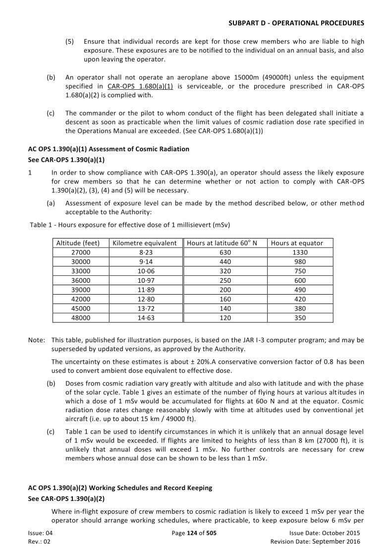
SUBPART D - OPERATIONAL PROCEDURES
Issue: 04 Page 124 of 505 Issue Date: October 2015
Rev.: 02 Revision Date: September 2016
(5) Ensure that individual records are kept for those crew members who are liable to high exposure. These exposures are to be notified to the individual on an annual basis, and also upon leaving the operator.
(b) An operator shall not operate an aeroplane above 15000m (49000ft) unless the equipment specified in CAR-OPS 1.680(a)(1) is serviceable, or the procedure prescribed in CAR-OPS 1.680(a)(2) is complied with.
(c) The commander or the pilot to whom conduct of the flight has been delegated shall initiate a descent as soon as practicable when the limit values of cosmic radiation dose rate specified in the Operations Manual are exceeded. (See CAR-OPS 1.680(a)(1))
AC OPS 1.390(a)(1) Assessment of Cosmic Radiation
See CAR-OPS 1.390(a)(1)
1 In order to show compliance with CAR-OPS 1.390(a), an operator should assess the likely exposure for crew members so that he can determine whether or not action to comply with CAR-OPS 1.390(a)(2), (3), (4) and (5) will be necessary.
(a) Assessment of exposure level can be made by the method described below, or other method acceptable to the Authority:
Table 1 - Hours exposure for effective dose of 1 millisievert (mSv)
Altitude (feet) Kilometre equivalent Hours at latitude 60o N Hours at equator
27000 8·23 630 1330
30000 9·14 440 980
33000 10·06 320 750
36000 10·97 250 600
39000 11·89 200 490
42000 12·80 160 420
45000 13·72 140 380
48000 14·63 120 350
Note: This table, published for illustration purposes, is based on the JAR I-3 computer program; and may be superseded by updated versions, as approved by the Authority.
The uncertainty on these estimates is about ± 20%.A conservative conversion factor of 0.8 has been used to convert ambient dose equivalent to effective dose.
(b) Doses from cosmic radiation vary greatly with altitude and also with latitude and with the phase of the solar cycle. Table 1 gives an estimate of the number of flying hours at various alt itudes in which a dose of 1 mSv would be accumulated for flights at 60o N and at the equator. Cosmic radiation dose rates change reasonably slowly with time at altitudes used by conventional jet aircraft (i.e. up to about 15 km / 49000 ft).
(c) Table 1 can be used to identify circumstances in which it is unlikely that an annual dosage level of 1 mSv would be exceeded. If flights are limited to heights of less than 8 km (27000 ft), it is unlikely that annual doses will exceed 1 mSv. No further controls are necessary for crew members whose annual dose can be shown to be less than 1 mSv.
AC OPS 1.390(a)(2) Working Schedules and Record Keeping
See CAR-OPS 1.390(a)(2)
Where in-flight exposure of crew members to cosmic radiation is likely to exceed 1 mSv per year the operator should arrange working schedules, where practicable, to keep exposure below 6 mSv per

SUBPART D - OPERATIONAL PROCEDURES
Issue: 04 Page 125 of 505 Issue Date: October 2015
Rev.: 02 Revision Date: September 2016
year. For the purpose of this regulation crew members who are likely to be exposed to more than 6 mSv per year are considered highly exposed and individual records of exposure to cosmic radiation should be kept for each crew member concerned.
AC OPS 1.390(a)(3) Explanatory Information
See CAR-OPS 1.390(a)(3)
Operators should explain the risks of occupational exposure to cosmic radiation to their crew members. Female crew members should know of the need to control doses during pregnancy, and the operator consequently notified so that the necessary dose control measures can be introduced.
CAR-OPS 1.395 Ground proximity detection
When undue proximity to the ground is detected by any flight crew member or by a ground proximity warning system, the commander or the pilot to whom conduct of the flight has been delegated shall ensure that corrective action is initiated immediately to establish safe flight conditions.
CAR-OPS 1.398 Use of Airborne Collision Avoidance System (ACAS)
(See AC OPS 1.398)
An operator shall establish procedures to ensure that:
(a) When ACAS is installed and serviceable, it shall be used in flight in a mode that enables Resolution Advisories (RA) to be produced unless to do so would not be appropriate for conditions existing at the time.
(b) When undue proximity to another aircraft (RA) is detected by ACAS, the commander or the pilot to whom conduct of the flight has been delegated must ensure that any corrective action indicated by RA is initiated immediately, unless doing so would jeopardize the safety of the aeroplane;
The corrective action must:
(i) Never be in a sense opposite to that indicated by the RA.
(ii) Be in the correct sense indicated by the RA even if this is in conflict with the vertical
element of an ATC instruction.
(iii) Be the minimum possible to comply with the RA indication.
(c) Prescribed ACAS ATC communications are specified.
(d) When the conflict is resolved the aeroplane is promptly returned to the terms of the ATC instructions or clearance.
AC OPS 1.398 Use of Airborne Collision Avoidance System (ACAS)
See CAR-OPS 1.398
The ACAS operational procedures and training programmes established by the operator should take into account CAAP 29 for Operators on Training Programmes for the Use of ACAS". This CAAP incorporates advice contained in:

SUBPART D - OPERATIONAL PROCEDURES
Issue: 04 Page 126 of 505 Issue Date: October 2015
Rev.: 02 Revision Date: September 2016
(a) ICAO Annex 10 Volume 4;
(b) ICAO Doc 8168 PANS OPS Volume 1;
(c) ICAO Doc 4444 PANS RAC Part X paragraph 3.1.2; and
(d) ICAO guidance material “ACAS Performance - Based Training Objectives” (published under Attachment E to State letter AN 7/1.3.7.2-97/77.)
(e) ICAO Manual 9863
AMC OPS 1.398 Vertical speed recommendation to avoid TCAS RA
See CAR-OPS 1.398 Aeroplane operating procedures for rates of climb and descent
Unless otherwise specified in an ATC instruction, to avoid unnecessary ACAS RA in aircraft at or approaching adjacent altitudes or flight levels, operators should specify procedures by which an aeroplane climbing or descending to an assigned altitude or flight level, especially with an autopilot engaged, may do so at a rate less than 8 m/sec or 1500 ft/min (depending on the instrumentation available) throughout the last 300 m (1000 ft) of climb or descent to the assigned level when the pilot is made aware of another aircraft at or approaching an adjacent altitude or flight level.
CAR-OPS 1.400 Approach and landing conditions
(See IEM OPS 1.400)
Before commencing an approach to land, the commander must satisfy himself that, according to the information available to him, the weather at the aerodrome and the condition of the runway intended to be used should not prevent a safe approach, landing or missed approach, having regard to the performance information contained in the Operations Manual.
IEM OPS 1.400 Approach and Landing Conditions
See CAR-OPS 1.400 The in-flight determination of the landing distance should be based on the latest available report,
preferably not more than 30 minutes before the expected landing time.
CAR-OPS 1.405 Commencement and continuation of approach
(a) The commander or the pilot to whom conduct of the flight has been delegated may commence an instrument approach regardless of the reported RVR/Visibility but the approach shall not be continued beyond the outer marker, or equivalent position, if the reported RVR/visibility is less than the applicable minima.
(b) Where RVR is not available, RVR values may be derived by converting the reported visibility in accordance with Appendix 1 to CAR-OPS 1.430, sub-paragraph (h).
(c) If, after passing the outer marker or equivalent position in accordance with (a) above, the reported RVR/visibility falls below the applicable minimum, the approach may be continued to DA/H or MDA/H.
(d) Where no outer marker or equivalent position exists, the commander or the pilot to whom conduct of the flight has been delegated shall make the decision to continue or abandon the approach before descending below 1000 ft above the aerodrome on the final approach segment.
SUBPART D - OPERATIONAL PROCEDURES
Issue: 04 Page 127 of 505 Issue Date: October 2015
Rev.: 02 Revision Date: September 2016
If the MDA/H is at or above 1000 ft above the aerodrome, the operator shall establish a height, for each approach procedure, below which the approach shall not be continued if the RVR/visibility is less than the applicable minima.
(e) The approach may be continued below DA/H or MDA/H and the landing may be completed provided that the required visual reference is established at the DA/H or MDA/H and is maintained.
(f) The touch-down zone RVR is always controlling. If reported and relevant, the mid point and stop end RVR are also controlling. The minimum RVR value for the mid-point is 125 m or the RVR required for the touch-down zone if less, and 75 m for the stop-end. For aeroplanes equipped with a roll-out guidance or control system, the minimum RVR value for the mid-point is 75 m.
Note. “Relevant”, in this context, means that part of the runway used during the high speed phase of the landing down to a speed of approximately 60 knots.
CAR-OPS 1.410 Operating procedures – Threshold crossing height
An operator must establish operational procedures designed to ensure that an aeroplane being used to conduct precision approaches crosses the threshold by a safe margin, with the aeroplane in the landing configuration and attitude.
CAR-OPS 1.415 Journey log
A commander shall ensure that the Journey log is completed.
CAR-OPS 1.420 Occurrence reporting
Detailed reporting requirements are stipulated in CAR PART VI, Chapter 3 4.2 and 10.2.2 and CAAP 22.
(a) Terminology
(1) Incident An occurrence, other than an accident, associated with the operation of an aircraft which affects or could affect the safety of operation.
(2) Serious Incident An incident involving circumstances indicating that an accident nearly occurred.
(3) Accident An occurrence associated with the operation of an aircraft which takes place between the time any person boards the aircraft with the intention of flight until such time as all persons have disembarked, in which:
(i) a person is fatally or seriously injured as a result of:
(A) being in the aircraft;
(B) direct contact with any part of the aircraft, including parts which have become detached from the aircraft; or,
(C) direct exposure to jet blast;

SUBPART D - OPERATIONAL PROCEDURES
Issue: 04 Page 128 of 505 Issue Date: October 2015
Rev.: 02 Revision Date: September 2016
except when the injuries are from natural causes, self-inflicted or inflicted by other persons, or when the injuries are to stowaways hiding outside the areas normally available to the passengers and crew: or
(ii) the aircraft sustains damage or structural failure which adversely affects the structural strength, performance or flight characteristics of the aircraft; and would normally require major repair or replacement of the affected component; except for engine failure or damage, when the damage is limited to the engine, its cowlings or accessories; or for damage limited to propellers, wing tips, antennas, tyres, brakes, fairings, small dents or puncture holes in the aircraft skin: or
(iii) the aircraft is missing or is completely inaccessible.
(b) Incident Reporting An operator shall establish procedures for reporting incidents taking into account responsibilities described below and circumstances described in sub-paragraph (d) below.
(1) CAR-OPS 1.085(b) specifies the responsibilities of crew members for reporting incidents that endanger, or could endanger, the safety of operation.
(2) The commander or the operator of an aeroplane shall submit a report to the Authority of any incident that endangers or could endanger the safety of operation.
(3) Reports must be despatched within 72 hours of the time when the incident was identified unless exceptional circumstances prevent this.
(4) A commander shall ensure that all known or suspected technical defects and all exceedances of technical limitations occurring while he was responsible for the flight are recorded in the aircraft technical log. If the deficiency or exceedance of technical limitations endangers or could endanger the safety of operation, the commander must in addition initiate the submission of a report to the Authority in accordance with paragraph (b)(2) above.
(5) In the case of incidents reported in accordance with sub- paragraphs (b)(1), (b)(2) and (b)(3) above, arising from, or relating to, any failure, malfunction or defect in the aeroplane, its equipment or any item of ground support equipment, or which cause or might cause adverse effects on the continuing airworthiness of the aeroplane, the operator must also inform the organisation responsible for the design or the supplier or, if applicable, the organisation responsible for continued airworthiness, at the same time as a report is submitted to the Authority.
(c) Accident and Serious Incident Reporting An operator shall establish procedures for reporting accidents and serious incidents taking into account responsibilities described below and circumstances described in sub-paragraph (d) below.
(1) A commander shall notify the operator of any accident or serious incident occurring while he was responsible for the flight. In the event that the commander is incapable of providing such notification, this task shall be undertaken by any other member of the crew if they are able to do so, note being taken of the succession of command specified by the operator.
(2) An operator shall ensure that the Authority in the State of the operator, the nearest appropriate Authority (if not the Authority in the State of the operator), and any other organisation required by the State of the operator to be informed, are notified by the quickest means available of any accident or serious incident and - in the case of accidents

SUBPART D - OPERATIONAL PROCEDURES
Issue: 04 Page 129 of 505 Issue Date: October 2015
Rev.: 02 Revision Date: September 2016
only - at least before the aeroplane is moved unless exceptional circumstances prevent this.
(3) The commander or the operator of an aeroplane shall submit a report to the Authority in the State of the operator within 72 hours of the time when the accident or serious incident occurred.
(d) Specific Reports. Occurrences for which specific notification and reporting methods must be used are described below;
(1) Air Traffic Incidents A commander shall without delay notify the air traffic service unit concerned of the incident and shall inform them of his intention to submit an air traffic incident report after the flight has ended whenever an aircraft in flight has been endangered by:
(i) A near collision with any other flying device;
(ii) Faulty air traffic procedures or lack of compliance with applicable procedures by air traffic services or by the flight crew;
(iii) Failure of air traffic services facilities.
In addition, the commander shall notify the Authority of the incident.
(2) Airborne Collision Avoidance System Resolution Advisory A commander shall notify the air traffic service unit concerned and submit an ACAS report to the Authority whenever an aircraft in flight has manoeuvred in response to an ACAS Resolution Advisory.
(3) Bird Hazards and Strikes
(i) A commander shall immediately inform the local air traffic service unit whenever a potential bird hazard is observed.
(ii) If he is aware that a bird strike has occurred, a commander shall submit a written bird strike report after landing to the Authority whenever an aircraft for which he is responsible suffers a bird strike that results in significant damage to the aircraft or the loss or malfunction of any essential service. If the bird strike is discovered when the commander is not available, the operator is responsible for submitting the report.
(4) Dangerous Goods Incidents and Accidents. An operator shall report dangerous goods incidents and accidents to the Authority and the appropriate Authority in the State where the accident or incident occurred, as provided for in Appendix 1 to CAR-OPS 1.1225. The first report shall be despatched within 72 hours of the event unless exceptional circumstances prevent this and include the details that are known at that time. If necessary, a subsequent report must be made as soon as possible giving whatever additional information has been established. (See also CAR-OPS 1.1225)
(5) Unlawful Interference Following an act of unlawful interference on board an aircraft, the commander or, in his absence, the operator shall submit a report as soon as practicable to the local Authority and to the Authority in the State of the operator. (See also CAR-OPS 1.1245)

SUBPART D - OPERATIONAL PROCEDURES
Issue: 04 Page 130 of 505 Issue Date: October 2015
Rev.: 02 Revision Date: September 2016
(6) Encountering Potential Hazardous Conditions A commander shall notify the appropriate air traffic services unit as soon as practicable whenever a potentially hazardous condition such as an irregularity in a ground or navigational facility, a meteorological phenomenon or a volcanic ash cloud is encountered during flight.
(7) Health related incidents requiring immediate action: the commander shall notify the appropriate air traffic services unit to relay information to destination aerodrome, as soon as he/she becomes aware or suspects that there is a traveler onboard suffering from communicable disease. The operator shall ensure that the operations manual contain information to handle health related information, particularly communicable disease.
CAR-OPS 1.425 Deficiencies reported by an Inspecting Authority IEM OPS 1.425 Inspecting Authority An operator shall:
(a) notify, immediately but no later than 72 hours from the date of inspection, to the GCAA principal inspector
copying Foreign Operators Affairs on [email protected], the deficiencies/findings reported by an Inspecting
Authority during its inspection of the operator’s aircraft;
(b) provide the Inspecting Authority, copying the GCAA, with the corrective/preventative action plan no later
than 30 days from receiving date of the inspection report;
(c) upon request from the GCAA , coordinate with the respective department of the GCAA (i.e. Department of
Airworthiness ,Department of Flight Operations and Department of licensing) prior to response to the
Inspecting Authority on the corrective/ preventive action plan.
(d) Notify the GCAA when the Inspecting Authority confirms closure of deficiencies/findings.
(e) also ensure compliance with (a), (b) (c) and (d) for aircraft under a lease agreement (See CAR-OPS 1.165).
AC OPS 1.425 Deficiencies reported by an Inspecting Authority
See CAR-OPS 1.425 Deficiencies reported by an Inspecting Authority
For deficiencies raised by all member states to the EASA SAFA programme, the corrective/preventive action plan should be uploaded onto the EASA centralised database by the operator. Access rights to the database, can be obtained through https://safa.easa.europa.eu/user/selfregister and is limited to two user names per operator.
IEM OPS 1.425 Inspecting Authority
See CAR-OPS 1.425 Deficiencies reported by an Inspecting Authority Inspecting Authority is the National Aviation Authority which performs inspections on aircraft under the operational control of the UAE while abroad.
For any unresolved/pending issues with the inspecting authority, the GCAA SAFA national coordinator can be contacted on [email protected]

SUBPART D - OPERATIONAL PROCEDURES
Issue: 04 Page 131 of 505 Issue Date: October 2015
Rev.: 02 Revision Date: September 2016
Appendix 1 to CAR-OPS 1.255 Fuel Policy See CAR-OPS 1.255
An operator must base the company fuel policy, including calculation of the amount of fuel to be on board for departure, on the following planning criteria:
(a) Basic Procedure
The usable fuel to be on board for departure must be the amount of:
(1) Taxi fuel, which shall not be less than the amount, expected to be used prior to takeoff. Local conditions at the departure aerodrome and APU consumption shall be taken into account.
(2) Trip fuel, which shall include:
(i). Fuel for takeoff and climb from aerodrome elevation to initial cruising level/altitude, taking into account the expected departure routing; and
(ii). Fuel from top of climb to top of descent, including any step climb/descent; and (iii). Fuel from top of descent to the point where the approach is initiated, taking into account
the expected arrival procedure; and (iv). Fuel for approach and landing at the destination aerodrome.
(3) Contingency fuel, except as provided for in Paragraph (b) ‘Reduced Contingency Fuel’, which shall be the higher of (3)(i) or (3)(ii) below:
(i). Either:
(A) 5% of the planned trip fuel or, in the event of inflight replanning, 5% of the trip fuel for the remainder of the flight; or
(B) Not less than 3% of the planned trip fuel or, in the event of inflight replanning, 3% of the trip fuel for the remainder of the flight, provided that an enroute alternate aerodrome is available in accordance with Appendix 2 to CAR-OPS 1.255; or
(C) An amount of fuel sufficient for 20 minutes flying time based upon the planned trip fuel consumption provided that the operator has established a fuel consumption monitoring programme for individual aeroplanes and uses valid data determined by means of such a programme for fuel calculation; or
(D) An amount of fuel based on a statistical method approved by the Authority which ensures an appropriate statistical coverage of the deviation from the planned to the actual trip fuel. This method is used to monitor the fuel consumption on each city pair/aeroplane combination and the operator uses this data for a statistical analysis to calculate contingency fuel for that city pair/aeroplane combination. (See ACJ OPS 1.255).
(ii). An amount to fly for 5 minutes at holding speed at 1 500 ft (450 m), above the destination aerodrome in Standard Conditions.
(4) Alternate fuel which shall:
(i). include:
(A) Fuel for a missed approach from the applicable MDA/DH at the destination aerodrome to missed approach altitude, taking into account the complete missed approach procedure; and
(B) Fuel for climb from missed approach altitude to cruising level/altitude, taking into account the expected departure routing; and
(C) Fuel for cruise from top of climb to top of descent, taking into account the expected routing; and
(D) Fuel for descent from top of descent to the point where the approach is initiated, taking into account the expected arrival procedure; and
(E) Fuel for executing an approach and landing at the destination alternate aerodrome selected in accordance with CAR-OPS
SUBPART D - OPERATIONAL PROCEDURES
Issue: 04 Page 132 of 505 Issue Date: October 2015
Rev.: 02 Revision Date: September 2016
(ii). where two destination alternate aerodromes are required in accordance with CAR-OPS 1.295(d), be sufficient to proceed to the alternate aerodrome which requires the greater amount of alternate fuel.
(5) Final reserve fuel, for each type and variant should be rounded up to an easily recall figure , which shall be:
(i). For aeroplanes with reciprocating engines, fuel to fly for 45 minutes; or
(ii). For aeroplanes with turbine engines, fuel to fly for 30 minutes at holding speed at 1 500 ft (450 m) above aerodrome elevation in standard conditions, calculated with the estimated mass on arrival at the destination alternate aerodrome or the destination aerodrome, when no destination alternate aerodrome is required.
(6) The minimum additional fuel, which shall permit: (i). The aeroplane to descend as necessary and proceed to an adequate alternate aerodrome in
the event of engine failure or loss of pressurisation, whichever requires the greater amount of fuel based on the assumption that such a failure occurs at the most critical point along the route, and
(A) hold there for 15 minutes at 1 500 ft (450 m) above aerodrome elevation in standard conditions; and
(B) make an approach and landing,
except that additional fuel is only required, if the minimum amount of fuel calculated in accordance with subparagraphs (a)(2) to (a)(5) above is not sufficient for such an event, and
(ii). Holding for 15 minutes at 1 500 ft (450 m) above destination aerodrome elevation in standard conditions, when a flight is operated without a destination alternate aerodrome;
(7) Extra fuel, which shall be at the discretion of the commander.
(b) Reduced Contingency Fuel (RCF) Procedure
If an operator’s fuel policy includes preflight planning to a Destination 1 aerodrome (commercial destination) with a reduced contingency fuel procedure using a decision point along the route and a Destination 2 aerodrome (optional refuel destination), the amount of usable fuel, on board for departure, shall be the greater of (b)(1) or (b)(2) below:
(1) The sum of:
(i) Taxi fuel; and (ii) Trip fuel to the Destination 1 aerodrome, via the decision point; and (iii) Contingency fuel equal to not less than 5% of the estimated fuel consumption from the
decision point to the Destination 1 aerodrome; and (iv) Alternate fuel or no alternate fuel if the decision point is at less than six hours from the
Destination 1 aerodrome and the requirements of CAR-OPS 1.295(c)(1)(ii) are fulfilled; and
(v) Final reserve fuel; and (vi) Additional fuel; and (vii) Extra fuel if required by the commander.
(2) The sum of:
(i) Taxi fuel; and (ii) Trip fuel to the Destination 2 aerodrome, via the decision point; and

SUBPART D - OPERATIONAL PROCEDURES
Issue: 04 Page 133 of 505 Issue Date: October 2015
Rev.: 02 Revision Date: September 2016
(iii) Contingency fuel equal to not less than the amount calculated in accordance with subparagraph (a)(3) above from departure aerodrome to the Destination 2 aerodrome; and
(iv) Alternate fuel, if a Destination 2 alternate aerodrome is required; and (v) Final reserve fuel; and (vi) Additional fuel; and (vii) Extra fuel if required by the commander.
(c) PreDetermined Point (PDP) Procedure
If an operator’s fuel policy includes planning to a destination alternate aerodrome where the distance between the destination aerodrome and the destination alternate aerodrome is such that a flight can only be routed via a predetermined point to one of these aerodromes, the amount of usable fuel, on board for departure, shall be the greater of (c)(1) or (c)(2) below:
(1) The sum of:
(i) Taxi fuel; and (ii) Trip fuel from the departure aerodrome to the destination aerodrome, via the
predetermined point; and (iii) Contingency fuel calculated in accordance with subparagraph (a)(3)above; and (iv) Additional fuel if required, but not less than:
(A) For aeroplanes with reciprocating engines, fuel to fly for45 minutes plus 15% of the flighttime planned to be spent at cruising level or two hours, whichever is less;or
(B) For aeroplanes with turbine engines, fuel to fly for two hours at normal cruise consumption above the destination aerodrome,
This shall not be less than final reserve fuel; and
(v) Extra fuel if required by the commander; or
(2) The sum of:
(i) Taxi fuel; and (ii) Trip fuel from the departure aerodrome to the destination alternate aerodrome, via the
predetermined point; and (iii) Contingency fuel calculated in accordance with subparagraph (a)(3)above; and (iv) Additional fuel if required, but not less than:
(A) For aeroplanes with reciprocating engines, fuel to fly for45 minutes; or
(B) For aeroplanes with turbine engines, fuel to fly for 30minutes at holding speed at 1 500 ft(450 m) above the destination alternate aerodrome elevation in standard conditions;
This shall not be less than finalreserve fuel; and
(v) Extra fuel if required by the commander.
(d) Isolated Aerodrome Procedure
If an operator’s fuel policy includes planning to an isolated aerodrome, the last possible point of diversion to any available enroute alternate aerodrome shall be used as the predetermined point. See paragraph (c) above.

SUBPART D - OPERATIONAL PROCEDURES
Issue: 04 Page 134 of 505 Issue Date: October 2015
Rev.: 02 Revision Date: September 2016
Figure 1 Location of the 3% EnRoute Alternate (3% ERA) aerodrome for the purposes of reducing contingency fuel to 3%
-
DEPARTURE
Circle centred on planned route at a distance from the destination equal to 25% of the total flight plan distance or 20% of the total flight plan dist ance plus 50 NM, whichever is greater = 915 NM
Radius equal to 20% of the total flight plan distance = 732 NM
Airways route, distance 3660 NM Circle, radius 732 NM, centred on a point 915 NM from the destination.
Shading indicates the areeas in which the en route alternate should be located.
HALFWAY POINT
DESTINATION

SUBPART D - OPERATIONAL PROCEDURES
Issue: 04 Page 135 of 505 Issue Date: October 2015
Rev.: 02 Revision Date: September 2016
Appendix 2 to CAR-OPS 1.255 Location of the 3% EnRoute Alternate (3%ERA) aerodrome for the purpose of reducing contingency fuel to 3% (See Appendix 1 to CAR-OPS 1.255 (a)(3)(i)(B))
The 3% ERA aerodrome shall be located within a circle having a radius equal to 20% of the total flight plan distance, the centre of which lies on the planned route at a distance from the destination aerodrome of 25% of the total flight plan distance, or at least 20% of the total fli ght plan distance plus 50 nm, whichever is greater, all distances are to be calculated in stil l air conditions (See figure 1. Location of the 3% EnRoute Alternate (3% ERA) aerodrome for the purposes of reducing contingency fuel to 3%.)

SUBPART D - OPERATIONAL PROCEDURES
Issue: 04 Page 136 of 505 Issue Date: October 2015
Rev.: 02 Revision Date: September 2016
Appendix 1 to CAR-OPS 1.270 Stowage of baggage and cargo
(a) Procedures established by an operator to ensure that hand baggage and cargo is adequately and securely stowed must take account of the following:
(1) Each item carried in a cabin must be stowed only in a location that is capable of restraining it;
(2) Mass limitations placarded on or adjacent to stowages must not be exceeded;
(3) Underseat stowages must not be used unless the seat is equipped with a restraint bar and the baggage is of such size that it may adequately be restrained by this equipment;
(4) Items must not be stowed in toilets or against bulkheads that are incapable of restraining articles against movement forwards, sideways or upwards and unless the bulkheads carry a placard specifying the greatest mass that may be placed there;
(5) Baggage and cargo placed in lockers must not be of such size that they prevent latched doors from being closed securely;
(6) Baggage and cargo must not be placed where it can impede access to emergency equipment; and
(7) Checks must be made before take-off, before landing, and whenever the fasten seat belts signs are illuminated or it is otherwise so ordered to ensure that baggage is stowed where it cannot impede evacuation from the aircraft or cause injury by falling (or other movement) as may be appropriate to the phase of flight.

SUBPART D - OPERATIONAL PROCEDURES
Issue: 04 Page 137 of 505 Issue Date: October 2015
Rev.: 02 Revision Date: September 2016
Appendix 1 to CAR-OPS 1.305 Refuelling/defuelling with passengers embarking, on board or disembarking
(a) An operator must establish operational procedures for re/defuelling with passengers embarking, on board or disembarking to ensure the following precautions are taken:
(1) One qualified person must remain at a specified location during fuelling operations with passengers on board. This qualified person must be capable of handling emergency procedures concerning fire protection and fire-fighting, handling communications and initiating and directing an evacuation;
(2) A two-way communication shall be established and shall remain available by the aeroplane’s inter-communication system or other suitable means between the ground crew supervising the refuelling and the qualified personnel on board the aeroplane;
(3) Crew, staff and passengers must be warned that re/defuelling will take place;
(4) ‘Fasten Seat Belts’ signs must be off;
(5) ‘NO SMOKING’ signs must be on, together with interior lighting to enable emergency exits to be identified;
(6) Passengers must be instructed to unfasten their seat belts and refrain from smoking;
(7) Sufficient qualified personnel must be on board and be prepared for an immediate emergency evacuation;
(8) If the presence of fuel vapour is detected inside the aeroplane, or any other hazard arises during re/defuelling, fuelling must be stopped immediately;
(9) The ground area beneath the exits intended for emergency evacuation and slide deployment areas must be kept clear; and
(10) Provision is made for a safe and rapid evacuation.

SUBPART E - ALL WEATHER OPERATIONS
Issue: 04 Page 138 of 505 Issue Date: October 2015
Rev.: 02 Revision Date: September 2016
SUB PART E. ALL WEATHER OPERATIONS
CAR-OPS 1.430 Aerodrome Operating Minima – General
(See Appendix 1 Old and New to CAR-OPS 1.430 Aerodrome Operating Minima & ACJ OPS 1.430 CONTINUOUS DESCENT FINAL APPROACH (CDFA)
See Appendix 1 (New) to CAR-OPS 1.430
1. Introduction
1.1. Controlled-Flight-Into-Terrain (CFIT) is a major causal category of accident and hull loss in commercial
aviation. Most CFIT accidents occur in the final approach segment of non-precision approaches; the use
of stabilised-approach criteria on a continuous descent with a constant, predetermined vertical path is
seen as a major improvement in safety during the conduct of such approaches. Operators should ensure
that the following techniques are adopted as widely as possible, for all approaches.
1.2. The elimination of level flight segments at Minimum Descent Altitude (MDA) close to the ground during
approaches, and the avoidance of major changes in attitude and power / thrust close to the runway
which can destabilise approaches, are seen as ways to reduce operational risks significantly.
1.3. For completeness this ACJ also includes criteria which should be considered to ensure the stability of an
approach (in terms of the aeroplane’s energy and approach-path control).
1.4. The term Continuous Descent Final Approach (CDFA) has been selected to cover a technique for any type
of non-precision approach
1.5. Non-precision approaches operated other than using a constant pre-determined vertical path or when
the facility requirements and associated conditions do not meet the conditions specified in Para 2.4
below RVR penalties apply. However, this should not preclude an operator from applying CDFA
technique to such approaches. Those operations should be classified as special letdown procedures,
since it has been shown that such operations, flown without additional training, may lead to
inappropriately steep descent to the MDA(H), with continued descent below the MDA(H) in an attempt
to gain (adequate) visual reference.
1.6. The advantages of CDFA are:
(a) The technique enhances safe approach operations by the utilisation of standard operating practices;
(b) The profile reduces the probability of infringement of obstacle-clearance along the final approach
segment and allows the use of MDA as DA;
(c) The technique is similar to that used when flying an ILS approach, including when executing the
missed approach and the associated go-around manoeuvre;
(d) The aeroplane attitude may enable better acquisition of visual cues;
(e) The technique may reduce pilot workload;
(f) The Approach profile is fuel efficient;
(g) The Approach profile affords reduced noise levels;
(h) The technique affords procedural integration with APV approach operations;
SUBPART E - ALL WEATHER OPERATIONS
Issue: 04 Page 139 of 505 Issue Date: October 2015
Rev.: 02 Revision Date: September 2016
(i) When used and the approach is flown in a stabilised manner is the safest approach technique for all
approach operations.
2. CDFA (Continuous Descent Final Approach)
2.1. Continuous Descent Final Approach. A specific technique for flying the final approach segment of a non-
precision instrument approach procedure as a continuous descent, without level-off, from an
altitude/height at or above the final approach fix altitude/height to a point approximately 15m (50 ft)
above the landing runway threshold or the point where the flare manoeuvre should begin for the type of
aircraft flown.
2.2. An approach is only suitable for application of CDFA technique when it is flown along a predetermined
vertical slope (See sub- paragraph (a) below) which follows a designated or nominal vertical profile (See
sub-paragraphs (b) and (c) below):
(a) Predetermined Approach Slope: Either the designated or nominal vertical profile of an approach.
(i) Designated Vertical Profile: A continuous vertical approach profile which forms part of the
approach procedure design. APV is considered to be an approach with a designated vertical
profile.
(ii) Nominal Vertical Profile: A vertical profile not forming part of the approach procedure design, but
which can be flown as a continuous descent.
Note:The nominal vertical profile information may be published or displayed (on the approach chart)
to the pilot by depicting the nominal slope or range / distance vs height.
Approaches with a nominal vertical profile are considered to be: NDB, NDB/DME; (i) VOR, VOR/DME;
(ii) LLZ, LLZ/DME;
(iii) VDF, SRA or
(iv) RNAV/LNAV.
2.3. Stabilised Approach (SAp). An approach which is flown in a controlled and appropriate manner in terms
of configuration, energy and control of the flight path from a pre-determined point or altitude/height
down to a point 50 feet above the threshold or the point where the flare manoeuvre is initiated if higher.
(a) The control of the descent path is not the only consideration when using the CDFA technique.
Control of the aeroplane’s configuration and energy is also vital to the safe conduct of an approach.
(b) The control of the flight path, described above as one of the requirements for conducting an SAp,
should not be confused with the path requirements for using the CDFA technique. The pre-
determined path requirements for conducting SAp are established by the operator and published in
the Operations Manual (OM) Part B; guidance for conducting SAp operations is given in paragraph 5
below.
(c) The predetermined approach slope requirements for applying the CDFA technique are established
by:

SUBPART E - ALL WEATHER OPERATIONS
Issue: 04 Page 140 of 505 Issue Date: October 2015
Rev.: 02 Revision Date: September 2016
(i) The instrument-procedure design when the approach has a designated vertical profile;
(ii) The published ‘nominal’ slope information when the approach has a nominal vertical profile;
(iii) The designated final-approach segment minimum of 3nm, and maximum, when using timing
techniques, of 8nm.
(d) A Stabilised Approach will never have any level segment of flight at DA(H) (or MDA(H) as applicable).
This enhances safety by mandating a prompt go-around manoeuvre at DA(H) (or MDA(H))
(e) An approach using the CDFA technique will always be flown as an SAp, since this is a requirement for
applying CDFA; however, an SAp does not have to be flown using the CDFA technique, for example a
visual approach.
2.4. Approach with a designated vertical profile using the CDFA technique:
(a) The optimum angle for the approach slope is 3 degrees, and the gradient should preferably not
exceed 6.5 percent which equates to a slope of 3.77 degrees, (400 ft/NM) for procedures intended
for conventional aeroplane types/classes and/or operations. In any case, conventional approach
slopes should be limited to 4.5 degrees for Category A and B aeroplanes and 3.77 degrees for
Category C and D aeroplanes, which are the upper limits for applying the CDFA technique. A 4.5
degree approach slope is the upper limit for certification of conventional aeroplanes
(b) The approach is to be flown utilising operational flight techniques and onboard navigation system(s)
and navigation aids to ensure it can be flown on the desired vertical path and track in a stabilised
manner, without significant vertical path changes during the final-segment descent to the runway.
APV is included.
(c) The approach is flown to a DA(H).
(d) No MAPt is published for these procedures.
2.5. Approach with a nominal vertical profile using the CDFA technique:
(a) The optimum angle for the approach slope is 3 degrees, and the gradient should preferably not
exceed 6.5 percent which equates to a slope of 3.77 degrees, (400 ft/NM) for procedures intended
for conventional aeroplane types / class and / or operations. In any case, conventional approaches
should be limited to 4.5 degrees for Category A and B aeroplanes and 3.77 degrees for Category C
and D aeroplanes, which are the upper limits for applying CDFA technique. A 4.5 degree approach
slope is the upper limit for certification of conventional aeroplanes.
(b) The approach should meet at least the following facility requirements and associated conditions.
NDB, NDB/DME, VOR, VOR/DME, LLZ, LLZ/DME, VDF, SRA, RNAV(LNAV) with a procedure which
fulfils the following criteria:
(i) The final approach track off-set $ 5degrees except for Category A and B aeroplanes, where the
approach-track off-set is $ 15 degrees; and
(ii) A FAF, or another appropriate fix where descent is initiated is available; and
(iii) The distance from the FAF to the THR is less than or equal to 8 NM in the case of timing; or
(iv) The distance to the threshold (THR) is available by FMS/RNAV or DME; or
(v) The minimum final-segment of the designated constant angle approach path should not be
less than 3 NM from the THR unless approved by the Authority.

SUBPART E - ALL WEATHER OPERATIONS
Issue: 04 Page 141 of 505 Issue Date: October 2015
Rev.: 02 Revision Date: September 2016
(c) CDFA may also be applied utilising the following:
(a) RNAV/LNAV with altitude/height cross checks against positions or distances from the THR; or
(iii) Height crosscheck compared with DME distance values.
(d) The approach is flown to a DA(H).
(e) The approach is flown as an SAp.
Note: Generally, a MAPt is published for these procedures.
3. Operational Procedures
3.1. A MAPt should be specified to apply CDFA with a nominal vertical profile as for any non-precision
approach.
3.2. The flight techniques associated with CDFA employ the use of a predetermined approach slope. The
approach, in addition, is flown in a stabilised manner, in terms of configuration, energy and control of
the flight path. The approach should be flown to a DA(H) at which the decision to land or go-around is
made immediately. This approach technique should be used when conducting:
3.2.1.1. All non-precision approaches (NPA) meeting the specified CDFA criteria in Para 2.4; and
3.2.1.2. All approaches categorised as APV.
3.3. The flight techniques and operational procedures prescribed above should always be applied; in
particular with regard to control of the descent path and the stability of the aeroplane on the approach
prior to reaching MDA(H). Level flight at MDA(H) should be avoided as far as practicable. In addition
appropriate procedures and training should be established and implemented to facilitate the applicable
elements of paragraphs 4, 5 and 8. Particular emphasis should be placed on subparagraphs 4.8, 5.1 to 5.7
and 8.4.
3.4. In cases where the CDFA technique is not used with high MDA(H), it may be appropriate to make an
early descent to MDA(H) with appropriate safeguards to include the above training requirements, as
applicable, and the application of a significantly higher RVR/Visibility.
3.5. For Circling Approaches (Visual Manoeuvring), all the applicable criteria with respect to the stability of
the final descent path to the runway should apply. In particular, the control of the desired final nominal
descent path to the threshold should be conducted to facilitate the techniques described in paragraphs 4
and 5 of this ACJ.
3.5.1. Stabilisation during the final straight-in segment for a circling approach should ideally be
accomplished by 1000 ft above aerodrome elevation for turbo-jet aeroplanes.

SUBPART E - ALL WEATHER OPERATIONS
Issue: 04 Page 142 of 505 Issue Date: October 2015
Rev.: 02 Revision Date: September 2016
3.5.2. For a circling approach where the landing runway threshold and appropriate visual landing aids may
be visually acquired from a point on the designated or published procedure (prescribed tracks),
stabilisation should be achieved not later than 500 ft above aerodrome elevation. It is however
recommended that the aeroplane be stabilised when passing 1000 ft above aerodrome elevation.
3.5.3. When a low-level final turning manoeuvre is required in order to align the aeroplane visually with
the landing runway, a height of 300 ft above the runway threshold elevation, or aerodrome
elevation as appropriate, should be considered as the lowest height for approach stabilisation with
wings level.
3.5.4. Dependent upon aeroplane type/class the operator may specify an appropriately higher minimum
stabilisation height for circling approach operations.
3.5.5. The operator should specify in the OM the procedures and instructions for conducting circling
approaches to include at least:
(a) The minimum required visual reference; and
(b) The corresponding actions for each segment of the circling manoeuvre; and
(c) The relevant go-around actions if the required visual reference is lost.
(d) The visual reference requirements for any operations with a prescribed track circling
manoeuvre to include the MDA(H) and any published MAPt.
3.6. Visual Approach. All the applicable criteria with respect to the stability of the final descent path to the
runway should apply to the operation of visual approaches. In particular, the control of the desired final
nominal descent path to the threshold should be conducted to facilitate the appropriate techniques and
procedures described in paragraphs 6 and 7 of this proposed ACJ.
3.6.1. Stabilisation during the final straight-in segment for a visual approach should ideally be
accomplished by 500 ft above runway threshold elevation for turbo-jet aeroplanes.
3.6.2. When a low level final turning manoeuvre is required in order to align the aeroplane with the
landing runway, a minimum height of 300 ft above the runway threshold elevation (or aerodrome
elevation as appropriate) should be considered as the lowest height for visual approach stabilisation
with wings level.
3.6.3. Dependent upon aeroplane type/class, the operator may specify an appropriately higher minimum
stabilisation height for visual approach operations.
3.6.4. The operator should specify in the OM the procedures and instructions for conducting visual
approaches to include at least:
(a) The minimum required visual reference; and
(b) The corresponding actions if the required visual reference is lost during a visual approach
manoeuvre; and
(c) The appropriate go around actions.

SUBPART E - ALL WEATHER OPERATIONS
Issue: 04 Page 143 of 505 Issue Date: October 2015
Rev.: 02 Revision Date: September 2016
3.7. The control of the descent path using the CDFA technique ensures that the descent path to the runway
threshold is flown using either:
(a) A variable descent rate or flight path angle to maintain the desired path, which may be verified
by appropriate crosschecks; or
(b) A pre-computed constant rate of descent from the FAF, or other appropriate fix which is able
to define a descent point and/or from the final approach segment step-down fix; or
(c) Vertical guidance, including APV.
The above techniques also support a common method for the implementation of flight -director-guided or auto-coupled RNAV(VNAV) or GLS approaches.
3.8. Missed Approach - The manoeuvre associated with the vertical profile of the missed approach should be
initiated not later than reaching the MAPt or the DA(H) specified for the approach, whichever occurs
first. The lateral part of the missed approach procedure must be flown via the MAPt unless otherwise
stated on the approach chart.
3.9. In case the CDFA technique is not used the approach should be flown to an altitude/height at or above
the MDA(H) where a level flight segment at or above MDA(H) may be flown to the MAPt.
3.10. In case the CDFA technique is not used when flying an approach, an operator should implement
procedures to ensure that early descent to the MDA(H) will not result in a subsequent flight below
MDA(H) without adequate visual reference. These procedures could include:
(a) Awareness of radio altimeter information with reference to the approach profile;
(b) Enhanced Ground Proximity Warning System and / or Terrain Awareness information;
(c) Limitation of rate of descent;
(d) Limitation of the number of repeated approaches;
(e) Safeguards against too early descents with prolonged flight at MDA(H);
(f) Specification of visual requirements for the descent from the MDA(H).
4. Flight techniques
4.1. The CDFA technique can be used on almost any published non-precision approach when the control of
the descent path is aided by either:
4.1.1. A recommended descent rate, based on estimated ground speed, which may be provided on the
approach chart; or
4.1.2. The descent path as depicted on the chart.
4.2. In order to facilitate the requirement of paragraph 4.1.2 above, the operator should either provide
charts which depict the appropriate cross check altitudes/heights with the corresponding appropriate
range information, or such information should be calculated and provided to the flight-crew in an
appropriate and useable format.

SUBPART E - ALL WEATHER OPERATIONS
Issue: 04 Page 144 of 505 Issue Date: October 2015
Rev.: 02 Revision Date: September 2016
4.3. For approaches flown coupled to a designated descent path using computed electronic glide-slope
guidance (normally a 3 degree path), the descent path should be appropriately coded in the flight
management system data base and the specified navigational accuracy (RNP) should be determined and
maintained throughout the operation of the approach.
4.4. With an actual or estimated ground speed, a nominal vertical profile and required descent rate, the
approach should be flown by crossing the FAF configured and on-speed. The tabulated or required
descent rate is established and flown to not less than the DA(H), observing any step-down crossing
altitudes if applicable.
4.5. To assure the appropriate descent path is flown, the pilot not-flying should announce crossing altitudes
as published fixes and other designated points are crossed, giving the appropriate altitude or height for
the appropriate range as depicted on the chart. The pilot flying should promptly adjust the rate of
descent as appropriate.
4.6. With the required visual reference requirements established, the aeroplane should be in position to
continue descent through the DA(H) or MDA(H) with little or no adjustment to attitude or thrust/power.
4.7. When applying CDFA on an approach with a nominal vertical profile to a DA(H), it may be necessary to
apply an add-on to the published minima (vertical profile only) to ensure sufficient obstacle clearance.
The add on, if applicable, should be published in the OM – (Aerodrome Operating Minima). However, the
resulting procedure minimum will still be referred to as the DA(H) for the approach.
4.8. Operators should establish a procedure to ensure that an appropriate callout (automatic or oral) is made
when the aeroplane is approaching DA(H). If the required visual references are not established at DA(H),
the missed-approach procedure is to be executed promptly. Visual contact with the ground alone is not
sufficient for continuation of the approach. With certain combinations of DA(H), RVR and approach
slope, the required visual references may not be achieved at the DA(H) in spite of the RVR being at or
above the minimum required for the conduct of the approach. The safety benefits of CDFA are negated if
prompt go-around action is not initiated.
4.9. The following bracketing conditions in relation to angle of bank, rate of descent and thrust /power
management are considered to be suitable for most aeroplane types/class to ensure the predetermined
vertical path approach is conducted in a stabilised manner:
4.9.1. Bank angle: As prescribed in the AOM, should generally be less than 30 degrees;
4.9.2. Rate of descent (ROD): The target ROD should not exceed 1000 fpm. The ROD should deviate by no
more than + 300 feet per minute (fpm) from the target ROD. Prolonged rates of descent which differ
from the target ROD by more than 300 fpm indicate that the vertical path is not being maintained in
a stabilised manner. The ROD should not exceed 1200 fpm except under exceptional circumstances,
which have been anticipated and briefed prior to commencing the approach; for example, a strong
tailwind. Note: zero rate of descent may be used when the descent path needs to be regained from
below the profile. The target ROD may need to be initiated prior to reaching the required descent
point (typically 0.3NM before the descent point, dependent upon ground speed, which may vary for
each type/class of aeroplane). See (c) below.

SUBPART E - ALL WEATHER OPERATIONS
Issue: 04 Page 145 of 505 Issue Date: October 2015
Rev.: 02 Revision Date: September 2016
4.9.3. Thrust/power management: The limits of thrust/power and the appropriate range should be
specified in the OM, Part B or equivalent documents
4.10. Transient corrections/ Overshoots: The above-specified range of corrections should normally be used to
make occasional momentary adjustments in order to maintain the desired path and energy of the
aeroplane. Frequent or sustained overshoots should require the approach to be abandoned and a go-
around initiated. A correction philosophy should be applied similar to that described in paragraph 5
below.
4.11. The relevant elements of paragraph 4 above should, in addition, be applied to approaches not flown
using the CDFA technique; the procedures thus developed, thereby ensure a controlled flight path to
MDA(H). Dependent upon the number of step down fixes and the aeroplane type/class, the aeroplane
should be appropriately configured to ensure safe control of the flight path prior to the final descent to
MDA(H).
5. Stabilisation of energy/speed and configuration of the aeroplane on the approach
5.1. The control of the descent path is not the only consideration. Control of the aeroplane’s configuration
and energy is also vital to the safe conduct of an approach.
5.2. The approach should be considered to be fully stabilised when the aeroplane is:
(a) tracking on the required approach path and profile; and
(b) in the required configuration and attitude; and
(c) flying with the required rate of descent and speed; and
(d) flying with the appropriate thrust/power and trim.
5.3. The following flight path control criteria should be met and maintained when the aeroplane passes the
gates described in paragraphs 5.6 and 5.7 below.
5.4. The aeroplane is considered established on the required approach path at the appropriate energy for
stable flight using the CDFA technique when:
(a) It is tracking on the required approach path with the correct track set, approach aids tuned
and identified as appropriate to the approach type flown and on the required vertical profile;
and
(b) It is at the appropriate attitude and speed for the required target ROD with the appropriate
thrust/power and trim.
5.5. It is recommended to compensate for strong wind/gusts on approach by speed increments given in the
Aeroplane Operations Manual (AOM). To detect windshear and magnitude of winds aloft, all available
aeroplane equipment such as FMS, INS, etc. should be used.
5.6. It is recommended that stabilisation during any straight-in approach without visual reference to the
ground should be achieved at the latest when passing 1,000 ft above runway threshold elevation. For
approaches with a designated vertical profile applying CDFA, a later stabilisation in speed may be

SUBPART E - ALL WEATHER OPERATIONS
Issue: 04 Page 146 of 505 Issue Date: October 2015
Rev.: 02 Revision Date: September 2016
acceptable if higher than normal approach speeds are required by ATC procedures or allowed by the
OM. Stabilisation should, however, be achieved not later than 500 ft above runway threshold elevation.
5.7. For approaches where the pilot has visual reference with the ground, stabilisation should be achieved
not later than 500 ft above aerodrome elevation. However, it is recommended that the aeroplane should
be stabilised when passing 1,000 ft above runway threshold elevation.
5.8. The relevant elements of paragraph 5 above should in addition be applied to approaches not flown using
the CDFA technique; the procedures thus developed ensure that a controlled and stable path to MDA(H)
is achieved. Dependent upon the number of step down fixes and the aeroplane type/class, the aeroplane
should be appropriately configured to ensure safe and stable flight prior to the final descent to MDA(H).
6. Visual Reference and path-control below MDA(H) when not using the CDFA technique
6.1. In addition to the requirements stated in Appendix 1 to CAR-OPS 1.430, the pilot should have attained a
combination of visual cues to safely control the aeroplane in roll and pitch to maintain the final approach
path to landing. This must be included in the standard operating procedures and reflected in the OM.
7. Operational Procedures and Instructions for using the CDFA technique or not
7.1. The operator should establish procedures and instructions for flying approaches using the CDFA
technique and not. These procedures should be included in the OM and should include the duties of the
flight crew during the conduct of such operations.
(a) The operator should publish in the OM the requirements stated in paragraphs 4 and 5 above, as
appropriate to the aeroplane type or class to be operated.
(b) The checklists should be completed as early as practicable and preferably before commencing final
descent towards the DA(H).
7.2. The operator’s manuals should at least specify the maximum ROD for each aeroplane type/class
operated and the required visual reference to continue the approach below:
(1) The DA(H) when applying CDFA;
(2) MDA(H) when not applying CDFA.
7.3. The operator should establish procedures which prohibit level flight at MDA(H) without the flight crew
having obtained the required visual references.
Note: It is not the intention of this paragraph to prohibit level flight at MDA(H) when conducting a circling
approach, which does not come within the definition of the CDFA technique.
7.4. The operator should provide the flight crew with:
(a) Unambiguous details of the technique used (CDFA or not).

SUBPART E - ALL WEATHER OPERATIONS
Issue: 04 Page 147 of 505 Issue Date: October 2015
Rev.: 02 Revision Date: September 2016
(b) The corresponding relevant minima should include:
(i) Type of decision, whether DA(H) or MDA(H);
(ii) MAPt as applicable;
(iii) Appropriate RVR/Visibility for the approach classification and aeroplane category.
7.5. Specific types/class of aeroplane, in particular certain Performance Class B and Class C aeroplanes, may
be unable to comply fully with the requirements of this ACJ relating to the operation of CDFA. This
problem arises because some aeroplanes must not be configured fully into the landing configuration
until required visual references are obtained for landing, because of inadequate missed-approach
performance engine out. For such aeroplanes, the operator should either:
(a) Obtain approval from the Authority for an appropriate modification to the stipulated procedures
and flight techniques prescribed herein; or
(b) Increase the required minimum RVR to ensure the aeroplane will be operated safely during the
configuration change on the final approach path to landing.
8. Training
8.1. The operator should ensure that, prior to using the CDFA technique or not (as appropriate), each flight
crew member undertakes:
8.1.1. The appropriate training and checking as required by Subpart N. Such training should cover the
techniques and procedures appropriate to the operation which are stipulated in paragraphs 4 and 5
of this ACJ
8.1.2. The operator’s proficiency check should include at least one approach to a landing or go around as
appropriate using the CDFA technique or not. The approach should be operated to the lowest
appropriate DA(H) or MDA(H) as appropriate; and, if conducted in a Simulator, the approach should
be operated to the lowest approved RVR.
Note. The approach required by paragraph 8.1.2 is not in addition to any manoeuvre currently required by either
CAR-FCL or CAR-OPS 1. The requirement may be fulfilled by undertaking any currently required approach
(engine out or otherwise) other than a precision approach, whilst using the CDFA technique.
8.2. The policy for the establishment of constant predetermined vertical path and approach stability are to be
enforced both during initial and recurrent pilot training and checking. The relevant training procedures
and instructions should be documented in the OM.
8.3. The training should emphasise the need to establish and facilitate joint crew procedures and CRM to
enable accurate descent path control and the requirement to establish the aeroplane in a stable
condition as required by the operator’s operational procedures. If barometric vertical navigation is used
the crews should be trained in the errors associated with these systems.
8.4. During training emphasis should be placed on the flight crew’s need to:

SUBPART E - ALL WEATHER OPERATIONS
Issue: 04 Page 148 of 505 Issue Date: October 2015
Rev.: 02 Revision Date: September 2016
(a) Maintain situational awareness at all times, in particular with reference to the required vertical and
horizontal profile;
(b) Ensure good communication channels throughout the approach;
(c) Ensure accurate descent-path control particularly during any manually-flown descent phase. The
non-operating/non-handling pilot should facilitate good flight path control by:
(i) Communicating any altitude/height crosschecks prior to the actual passing of the
range/altitude or height crosscheck;
(ii) Prompting, as appropriate, changes to the target ROD;
(iii) Monitoring flight path control below DA/MDA.
(d) Understand the actions to be taken if the MAPt is reached prior to the MDA(H).
(e) Ensure that the decision to go around must, at the latest, have been taken upon reaching the DA(H)
or MDA(H).
(f) Ensure that prompt go around action is taken immediately when reaching DA(H) if the required visual
reference has not been obtained as there may be no obstacle protection if the go-around manoeuvre
is delayed.
(g) Understand the significance of using the CDFA technique to a DA(H) with an associated MAPt and the
implications of early go around manoeuvres.
(h) Understand the possible loss of the required visual reference (due to pitch-change/climb) when not
using the CDFA technique for aeroplane types/classes which require a late change of configuration
and/or speed to ensure the aeroplane is in the appropriate landing configuration.
8.5. Additional specific training when not using the CDFA technique with level flight at or above MDA(H).
8.5.1. The training should detail:
(a) The need to facilitate good CRM; with good flight-crew communication in particular.
(b) The additional known safety risks associated with the ‘dive-and-drive’ approach philosophy which
may be associated with non-CDFA.
(c) The use of DA(H) during approaches flown using the CDFA technique.
(d) The significance of the MDA(H) and the MAPt where appropriate.
(e) The actions to be taken at the MAPt and the need to ensure the aeroplane remains in a stable
condition and on the nominal and appropriate vertical profile until the landing.
(f) The reasons for increased RVR/Visibility minima when compared to the application of CDFA.
(g) The possible increased obstacle infringement risk when undertaking level flight at MDA(H) without
the required visual references.
(h) The need to accomplish a prompt go around manoeuvre if the required visual reference is lost.
(i) The increased risk of an unstable final approach and an associated unsafe landing if a rushed
approach is attempted either from:
(i) Inappropriate and close-in acquisition of the required visual reference; (ii) Unstable aeroplane energy and or flight path control.
(b) The increased risk of CFIT (See introduction).
9. Approvals
9.1. The procedures which are flown with level flight at/or above MDA(H) must be approved by the Authority
and listed in the OM.

SUBPART E - ALL WEATHER OPERATIONS
Issue: 04 Page 149 of 505 Issue Date: October 2015
Rev.: 02 Revision Date: September 2016
9.2. Operators should classify aerodromes where there are approaches which require level flight at/or above
MDA(H) as being B and C categorised. Such aerodrome categorisation will depend upon the operator’s
experience, operational exposure, training programme(s) and flight crew qualification(s).
9.3. Exemptions granted in accordance with CAR-OPS 1.430, paragraph (d)(2) should be limited to locations
where there is a clear public interest to maintain current operations. The exemptions should be based on
the operators experience, training programme and flight crew qualification. The exemptions should be
reviewed at regular intervals and should be terminated as soon as facilities are improved to allow SAp or
CDFA.
ACJ OPS to Appendix 1 (New) to CAR-OPS 1.430(d) Aerodrome Operating Minima
Determination of RVR / Visibility Minima for Category I, APV and non-precision approaches 1. Introduction 1.1 The minimum RVR values for the conduct of Category I, APV and non-precision approaches shall be the higher of the values derived from Table 5 or 6 of Appendix 1(New) to CAR-OPS 1.430(d). 1.2 The tables are to be used for the determination of all applicable operational RVR values except as prescribed in paragraph 1.3 below. 1.3 With the approval of the Authority, the formula below may be used with the actual approach slope and or the actual length of the approach lights for a particular runway. This formula may also be used with the approval of the Authority to calculate the applicable RVR for special (one-off) approach operations which are allowed under CAR-OPS 1.430 paragraph (d) (4). 1.4 When the formula is utilised as described above, the calculation conventions and methodologies described in the notes applicable to Paragraph 2 below should be used. 2. Derivation of Minimum RVR Values. 2.1 The values in Table 5 in Appendix 1 to CAR-OPS 1.430(d) are derived from the formula below:
Required RVR/Visibility (m) = DH/MDH (ft) x 0.3048 - length of approach lights (m)
Note 1: a is the calculation angle, being a default value of 3.00 degrees increasing in steps of 0.10 degrees for each line in Table 5 up to 3.77 degrees and then remains constant.
Note 2: The default value for the length of the approach lights is equal to the minimum length of the
various systems described in Table 4 in Appendix 1 to CAR-OPS 1.430(d). Note 3: The values derived from the above formula have been rounded to the nearest 50 metres up to a
value of 800 metres RVR and thereafter to the nearest 100 metres. Note 4: The DH/MDH intervals in Table 5 have been selected to avoid anomalies caused by the rounding
of the calculated OCA(H). Note 5: The height intervals, referred in Note 4 above, are 10 feet up to a DH/MDH of 300 feet, 20 feet
up to a DH/MDH of 760 feet and then 50 feet for DH/MDH above 760 feet.

SUBPART E - ALL WEATHER OPERATIONS
Issue: 04 Page 150 of 505 Issue Date: October 2015
Rev.: 02 Revision Date: September 2016
Note 6: The minimum value of the table is 550 metres.
2.2 With the approval of the Authority, the formula may be used to calculate the applicable RVR value for approaches with approach-slopes of greater than 4.5 degrees. 3. Approach Operations with an RVR of less than 750m (800m for single-pilot operations) 3.1 Providing the DH is not more than 200 ft, approach operations are almost unrestricted with a runway which is equipped with FALS, RTZL and RCLL. Under these circumstances, the applicable RVR of less than 750m (800m for single-pilot operations) may be taken directly from Table 5. The ILS should not be promulgated as restricted in AIPs, NOTAMS or other documents. Unacceptable ILS restrictions would include limitations on the use of the localiser and / or glideslope below a certain height, prohibitions on its use auto-coupled or limitations on the ILS classification. 3.2 Without RTZL and RCLL in order to be able to operate to the RVR values of less than 750m (800m for single-pilot operations) in Table 5, the approach must be conducted utilising an approved HUDLS (or equivalent approved system), or be flown as a coupled approach or flight-director-flown approach (Note: not for single-pilot operations) to a DH of not greater than 200 ft. The equivalent system could for instance be an approved HUD which is not certificated as a landing system but is able to provide adequate guidance cues. Other devices may also be suitable, such as Enhanced/Synthetic Vision Systems (E/SVS) or other hybrids of such devices. 4. Description of Approach Lighting Systems 4.1 The following table describes the types of approach lighting systems which are acceptable for calculation of the aerodrome operating minima. The systems described are basically the ICAO systems as described in Annex 14. However, the table also contains shorter systems which are acceptable for operational use. This is concurrent with the fact that approach lighting systems may sometimes be adjusted to the conditions existing before the threshold. Additionally the table describes the FAA approach lighting systems which are considered to be corresponding for calculation of aerodrome operating minima.
CAR-OPS Class of Facility Length, configuration and intensity of approach lights
FALS (Full Approach Light
System)
Precision approach category I lighting system as specified in Annex 14, high intensity lights, 720 m or more FAA: ALSF1, ALSF2, SSALR, MALSR, high or medium intensity and/or flashing lights, 720 m or more
IALS (Inter mediate
Approach Light System)
JAA: Simplified Approach Light System as specified in Annex 14, high intensity lights, 420 – 719 m FAA: MALSF, MALS, SALS/SALSF, SSALF, SSALS, high or medium intensity and/or flashing lights, 420 – 719 m
BALS (Basic Approach Light
System)
JAA: High, medium or low intensity lights, 210 - 419 m including one crossbar FAA: ODALS, high or medium intensity or flashing lights 210 - 419 m
NALS (No Approach Light
System) JAA: Approach Light System shorter than 210 m or no approach lights
IEM to Appendix 1 to CAR-OPS 1.430 Aerodrome Operating Minima)
(a) An operator shall establish, for each aerodrome planned to be used, aerodrome operating minima that are not lower than the values given in Appendix 1. The method of determination of such minima

SUBPART E - ALL WEATHER OPERATIONS
Issue: 04 Page 151 of 505 Issue Date: October 2015
Rev.: 02 Revision Date: September 2016
must be acceptable to the Authority. Such minima shall not be lower than any that may be established for such aerodromes by the State in which the aerodrome is located, except when specifically approved by that State.
The use of HUD, HUDLS or EVS may allow operations with lower visibilities than normally associated with the aerodrome operating minima. States which promulgate aerodrome operating minima may also promulgate regulations for reduced visibility minima associated with the use of HUD or EVS.
2. Notwithstanding paragraph (a)(1) above, in-flight calculation of minima for use at unplanned alternate aerodromes and/or for approaches utilising EVS shall be carried out in accordance with a method acceptable to the Authority.
(b) In establishing the aerodrome operating minima which will apply to any particular operation, an operator must take full account of:
(2) The type, performance and handling characteristics of the aeroplane; (3) The composition of the flight crew, their competence and experience; (4) The dimensions and characteristics of the runways which may be selected for use; (5) The adequacy and performance of the available visual and non-visual ground aids; AMC OPS
1.430(b)(4) Landing Minima of failed Equipment) (6) The equipment available on the aeroplane for the purpose of navigation and/or control of
the flight path, as appropriate, during the take-off, the approach, the flare, the landing, roll-out and the missed approach;
(7) The obstacles in the approach, missed approach and the climb-out areas required for the execution of contingency procedures and necessary clearance;
(8) The obstacle clearance altitude/height for the instrument approach procedures; and (9) The means to determine and report meteorological conditions. (10) The flight technique to be used during the final approach.
(c) The aeroplane categories referred to in this Subpart must be derived in accordance with the method given in Appendix 2 to CAR-OPS 1.430(c).
(d) Sap (Stabilised Approvach) and CDFA (Continuous Descent Final Approaches)
(2) All approaches shall be flown as stabilised approaches (SAp) unless otherwise approved by the Authority for a particular approach to a particular runway.
(3) All non-precision approaches shall be flown using the continuous descent final approaches (CDFA) technique unless otherwise approved by the Authority for a particular approach to a particular runway. When calculating the minima in accordance with Appendix 1 (New), the operator shall ensure that the applicable minimum RVR isincreased by 200 metres (m) for Cat A/B aeroplanes and by 400 m for Cat C/D aeroplanes for approaches not flown using the CDFA technique, providing that the resulting RVR/CMV value does not exceed 5000m.
(4) Notwithstanding the requirements in (d)(2) above, an Authority may exempt an operator from the requirement to increase the RVR when not applying the CDFA technique.
(5) Exemptions as described in paragraph (d)(3) must be limited to locations where there is a clear public interest to maintain current operations. The exemptions must be based on the operator’s experience, training programme and flight crew qualification. The exemptions must be reviewed at regular intervals and must be terminated as soon as facilities are improved to allow application of the CDFA technique (See ACJ OPS 1.430).
(e) (e)Applicability and Excemptions
(1) An operator must ensure that either Appendix 1 (Old) or Appendix 1 (New) to CAR-OPS 1.430 is applied. However, an operator must ensure that Appendix 1 (New) to CAR-OPS 1.430 is applied not later than three years after publication date.

SUBPART E - ALL WEATHER OPERATIONS
Issue: 04 Page 152 of 505 Issue Date: October 2015
Rev.: 02 Revision Date: September 2016
(2) Notwithstanding the requirements in (e)(1) above, an Authority may exempt an operator from the requirement to increase the RVR above 1500 m (Cat A/B aeroplanes) or above 2400 m (Cat C/D aeroplanes), when approving an operation to a particular runway where it is not practicable to fly an approach using the CDFA technique or where the criteria in paragraph (c) of Appendix 1 (New) to CAR-OPS 1.430 cannot be met.
(3) Exemptions as described in paragraph (e)(2) must be limited to locations where there is a clear public interest to maintain current operations. The exemptions must be based on the operator’s experience, training programme and flight crew qualification. The exemptions must be reviewed at regular intervals and must be terminated as soon as facilities are improved to allow application of the CDFA technique.
AMC OPS 1.430(b)(4) Landing Minima of failed Equipment
Effect on Landing Minima of temporarily failed or downgraded Ground Equipment See CAR-OPS 1.430(b)(4)
1 Introduction
1.1 This AMC provides operators with instructions for flight crews on the effects on landing minima of temporary failures or downgrading of ground equipment.
1.2 Aerodrome facilities are expected to be installed and maintained to the standards prescribed in ICAO Annexes 10 and 14. Any deficiencies are expected to be repaired without unnecessary delay.
2 General. These instructions are intended for use both pre-flight and in-flight. It is not expected however that the commander would consult such instructions after passing the outer marker or equivalent position. If failures of ground aids are announced at such a late stage, the approach could be continued at the commander’s discretion. If, however, failures are announced before such a late stage in the approach, their effect on the approach should be considered as described in Tables 1A and 1B below, and the approach may have to be abandoned to allow this to happen.
3 Operations with no Decision Height (DH)
3.1 An operator should ensure that, for aeroplanes authorised to conduct no DH operations with the lowest RVR limitations, the following applies in addition to the content of Tables 1A and 1B, below:
i. RVR. At least one RVR value must be available at the aerodrome;
ii. Runway lights
(a) No runway edge lights, or no centre lights – Day – RVR 200 m; Night – Not allowed;
(b) No TDZ lights – No restrictions;
(c) No standby power to runway lights – Day – RVR 200 m; Night – not allowed.
4. Conditions applicable to Tables 1A & 1B
i. Multiple failures of runway lights other than indicated in Table 1B are not acceptable.
ii. Deficiencies of approach and runway lights are treated separately.
iii. Category II or III operations. A combination of deficiencies in runway lights and RVR assessment equipment is not allowed.
iv. Failures other than ILS affect RVR only and not DH. TABLE 1A - Failed or downgraded equipment - effect on landing minima
FAILED OR DOWNGRADED EFFECT ON LANDING MINIMA
01
.12
.01
2-E
-2 A
me
nd
me
nt
3

SUBPART E - ALL WEATHER OPERATIONS
Issue: 04 Page 153 of 505 Issue Date: October 2015
Rev.: 02 Revision Date: September 2016
EQUIPMENT CAT III B (Note 1)
CAT III A CAT II CAT I NON PRECISION
ILS stand-by transmitter Not allowed No effect
Outer Marker No effect if replaced by published equivalent position
Not applicable
Middle Marker No effect No effect unless used as
MAPT
Touch Down Zone RVR assessment system
May be temporarily replaced with midpoint RVR if approved by the State of the aerodrome. RVR may be reported by human observation
No effect
Midpoint or Stopend RVR No effect
Anemometer for R/W in use No effect if other ground source available
Celiometer No effect
Note 1 For Cat III B operations with no DH, see also paragraph 3, above.

SUBPART E - ALL WEATHER OPERATIONS
Issue: 04 Page 154 of 505 Issue Date: October 2015
Rev.: 02 Revision Date: September 2016
TABLE 1B - Failed or downgraded equipment - effect on landing minima
FAILED OR DOWNGRADED EQUIPMENT
EFFECT ON LANDING MINIMA
CAT III B (Note 1)
CAT III A CAT II CAT I NON PRECISION
Approach lights Not allowed for operations with DH > 50 ft
Not allowed Minima as for nil facilities
Approach lights except the last 210 m
No effect Not allowed Minima as for nil facilities
Approach lights except the last 420 m
No effect Minima as for intermediate facilities
Standby power for approach lights No effect No effect
Whole runway light system Not allowed Day Minima as for nil facilities Night - Not allowed
Edge lights Day only; Night - not allowed
Centreline lights Day - RVR 300 m Night - not allowed
Day - RVR 300 m
Night - 550 m
No effect
Centreline lights spacing increased to 30 m
RVR 150 m No effect
Touch Down Zone lights Day - RVR 200 m Night - 300 m
Day - RVR 300 m Night - 550 m
No effect
Standby power for runway lights Not allowed No effect
Taxiway light system No effect - except delays due to reduced movement rate
Note 1 For Cat III B operations with no DH, see also paragraph 3, above.

SUBPART E - ALL WEATHER OPERATIONS
Issue: 04 Page 155 of 505 Issue Date: October 2015
Rev.: 02 Revision Date: September 2016
IEM OPS 1.430 Documents containing information related to AWO
See CAR-OPS 1, Subpart E
1 The purpose of this IEM is to provide operators with a list of documents related to AWO.
(a) ICAO Annex 2 / Rules of the Air;
(b) ICAO Annex 6 / Operation of Aircraft, Part I;
(c) ICAO Annex 10 / Telecommunications Vol 1;
(d) ICAO Annex 14 / Aerodromes Vol 1;
(e) ICAO Doc 8186 / PANS - OPS Aircraft Operations;
(f) ICAO Doc 9365 / AWO Manual;
(g) ICAO Doc 9476 / SMGCS Manual (Surface Movement Guidance And Control Systems);
(h) ICAO Doc 9157 / Aerodrome Design Manual;
(i) ICAO Doc 9328 / Manual for RVR Assessment;
(j) ECAC Doc 17, Issue 3 (partly incorporated in CAR-OPS); and
(k) CS-AWO (Airworthiness Certification).
ACJ OPS 1.430 CONTINUOUS DESCENT FINAL APPROACH (CDFA)
See Appendix 1 (New) to CAR-OPS 1.430
10. Introduction
10.1. Controlled-Flight-Into-Terrain (CFIT) is a major causal category of accident and hull loss in commercial
aviation. Most CFIT accidents occur in the final approach segment of non-precision approaches; the use
of stabilised-approach criteria on a continuous descent with a constant, predetermined vertical path is
seen as a major improvement in safety during the conduct of such approaches. Operators should ensure
that the following techniques are adopted as widely as possible, for all approaches.
10.2. The elimination of level flight segments at Minimum Descent Altitude (MDA) close to the ground during
approaches, and the avoidance of major changes in attitude and power / thrust close to the runway
which can destabilise approaches, are seen as ways to reduce operational risks significantly.
10.3. For completeness this ACJ also includes criteria which should be considered to ensure the stability of an
approach (in terms of the aeroplane’s energy and approach-path control).
10.4. The term Continuous Descent Final Approach (CDFA) has been selected to cover a technique for any
type of non-precision approach
10.5. Non-precision approaches operated other than using a constant pre-determined vertical path or when
the facility requirements and associated conditions do not meet the conditions specified in Para 2.4
below RVR penalties apply. However, this should not preclude an operator from applying CDFA
technique to such approaches. Those operations should be classified as special letdown procedures,
since it has been shown that such operations, flown without additional training, may lead to

SUBPART E - ALL WEATHER OPERATIONS
Issue: 04 Page 156 of 505 Issue Date: October 2015
Rev.: 02 Revision Date: September 2016
inappropriately steep descent to the MDA(H), with continued descent below the MDA(H) in an attempt
to gain (adequate) visual reference.
10.6. The advantages of CDFA are:
(j) The technique enhances safe approach operations by the utilisation of standard operating practices;
(k) The profile reduces the probability of infringement of obstacle-clearance along the final approach
segment and allows the use of MDA as DA;
(l) The technique is similar to that used when flying an ILS approach, including when executing the
missed approach and the associated go-around manoeuvre;
(m) The aeroplane attitude may enable better acquisition of visual cues;
(n) The technique may reduce pilot workload;
(o) The Approach profile is fuel efficient;
(p) The Approach profile affords reduced noise levels;
(q) The technique affords procedural integration with APV approach operations;
(r) When used and the approach is flown in a stabilised manner is the safest approach technique for all
approach operations.
11. CDFA (Continuous Descent Final Approach)
11.1. Continuous Descent Final Approach. A specific technique for flying the final approach segment of a non-
precision instrument approach procedure as a continuous descent, without level-off, from an
altitude/height at or above the final approach fix altitude/height to a point approximately 15m (50 ft)
above the landing runway threshold or the point where the flare manoeuvre should begin for the type of
aircraft flown.
11.2. An approach is only suitable for application of CDFA technique when it is flown along a predetermined
vertical slope (See sub- paragraph (a) below) which follows a designated or nominal vertical profile (See
sub-paragraphs (b) and (c) below):
(a) Predetermined Approach Slope: Either the designated or nominal vertical profile of an approach.
(iv) Designated Vertical Profile: A continuous vertical approach profile which forms part of the
approach procedure design. APV is considered to be an approach with a designated vertical
profile.
(v) Nominal Vertical Profile: A vertical profile not forming part of the approach procedure design, but
which can be flown as a continuous descent.
Note:The nominal vertical profile information may be published or displayed (on the approach chart)
to the pilot by depicting the nominal slope or range / distance vs height.
Approaches with a nominal vertical profile are considered to be: NDB, NDB/DME; (v) VOR, VOR/DME;
(vi) LLZ, LLZ/DME;
(vii) VDF, SRA or
(viii) RNAV/LNAV.

SUBPART E - ALL WEATHER OPERATIONS
Issue: 04 Page 157 of 505 Issue Date: October 2015
Rev.: 02 Revision Date: September 2016
11.3. Stabilised Approach (SAp). An approach which is flown in a controlled and appropriate manner in terms
of configuration, energy and control of the flight path from a pre-determined point or altitude/height
down to a point 50 feet above the threshold or the point where the flare manoeuvre is initiated if higher.
(a) The control of the descent path is not the only consideration when using the CDFA technique.
Control of the aeroplane’s configuration and energy is also vital to the safe conduct of an approach.
(b) The control of the flight path, described above as one of the requirements for conducting an SAp,
should not be confused with the path requirements for using the CDFA technique. The pre-
determined path requirements for conducting SAp are established by the operator and published in
the Operations Manual (OM) Part B; guidance for conducting SAp operations is given in paragraph 5
below.
(c) The predetermined approach slope requirements for applying the CDFA technique are established
by:
(iv) The instrument-procedure design when the approach has a designated vertical profile;
(v) The published ‘nominal’ slope information when the approach has a nominal vertical profile;
(vi) The designated final-approach segment minimum of 3nm, and maximum, when using timing
techniques, of 8nm.
(d) A Stabilised Approach will never have any level segment of flight at DA(H) (or MDA(H) as applicable).
This enhances safety by mandating a prompt go-around manoeuvre at DA(H) (or MDA(H))
(e) An approach using the CDFA technique will always be flown as an SAp, since this is a requirement for
applying CDFA; however, an SAp does not have to be flown using the CDFA technique, for example a
visual approach.
11.4. Approach with a designated vertical profile using the CDFA technique:
(a) The optimum angle for the approach slope is 3 degrees, and the gradient should preferably not
exceed 6.5 percent which equates to a slope of 3.77 degrees, (400 ft/NM) for procedures intended
for conventional aeroplane types/classes and/or operations. In any case, conventional approach
slopes should be limited to 4.5 degrees for Category A and B aeroplanes and 3.77 degrees for
Category C and D aeroplanes, which are the upper limits for applying the CDFA technique. A 4.5
degree approach slope is the upper limit for certification of conventional aeroplanes
(b) The approach is to be flown utilising operational flight techniques and onboard navigation system(s)
and navigation aids to ensure it can be flown on the desired vertical path and track in a stabilised
manner, without significant vertical path changes during the final-segment descent to the runway.
APV is included.
(c) The approach is flown to a DA(H).
(d) No MAPt is published for these procedures.
11.5. Approach with a nominal vertical profile using the CDFA technique:
(a) The optimum angle for the approach slope is 3 degrees, and the gradient should preferably not
exceed 6.5 percent which equates to a slope of 3.77 degrees, (400 ft/NM) for procedures intended
for conventional aeroplane types / class and / or operations. In any case, conventional approaches

SUBPART E - ALL WEATHER OPERATIONS
Issue: 04 Page 158 of 505 Issue Date: October 2015
Rev.: 02 Revision Date: September 2016
should be limited to 4.5 degrees for Category A and B aeroplanes and 3.77 degrees for Category C
and D aeroplanes, which are the upper limits for applying CDFA technique. A 4.5 degree approach
slope is the upper limit for certification of conventional aeroplanes.
(b) The approach should meet at least the following facility requirements and associated conditions.
NDB, NDB/DME, VOR, VOR/DME, LLZ, LLZ/DME, VDF, SRA, RNAV(LNAV) with a procedure which
fulfils the following criteria:
(vi) The final approach track off-set $ 5degrees except for Category A and B aeroplanes, where the
approach-track off-set is $ 15 degrees; and
(vii) A FAF, or another appropriate fix where descent is initiated is available; and
(viii) The distance from the FAF to the THR is less than or equal to 8 NM in the case of timing; or
(ix) The distance to the threshold (THR) is available by FMS/RNAV or DME; or
(x) The minimum final-segment of the designated constant angle approach path should not be
less than 3 NM from the THR unless approved by the Authority.
(c) CDFA may also be applied utilising the following:
(c) RNAV/LNAV with altitude/height cross checks against positions or distances from the THR; or
(vi) Height crosscheck compared with DME distance values.
(d) The approach is flown to a DA(H).
(e) The approach is flown as an SAp.
Note: Generally, a MAPt is published for these procedures.
12. Operational Procedures
12.1. A MAPt should be specified to apply CDFA with a nominal vertical profile as for any non-precision
approach.
12.2. The flight techniques associated with CDFA employ the use of a predetermined approach slope. The
approach, in addition, is flown in a stabilised manner, in terms of configuration, energy and control of
the flight path. The approach should be flown to a DA(H) at which the decision to land or go-around is
made immediately. This approach technique should be used when conducting:
12.2.1.1. All non-precision approaches (NPA) meeting the specified CDFA criteria in Para 2.4; and
12.2.1.2. All approaches categorised as APV.
12.3. The flight techniques and operational procedures prescribed above should always be applied; in
particular with regard to control of the descent path and the stability of the aeroplane on the approach
prior to reaching MDA(H). Level flight at MDA(H) should be avoided as far as practicable. In addition
appropriate procedures and training should be established and implemented to facilitate the applicable
elements of paragraphs 4, 5 and 8. Particular emphasis should be placed on subparagraphs 4.8, 5.1 to 5.7
and 8.4.

SUBPART E - ALL WEATHER OPERATIONS
Issue: 04 Page 159 of 505 Issue Date: October 2015
Rev.: 02 Revision Date: September 2016
12.4. In cases where the CDFA technique is not used with high MDA(H), it may be appropriate to make an
early descent to MDA(H) with appropriate safeguards to include the above training requirements, as
applicable, and the application of a significantly higher RVR/Visibility.
12.5. For Circling Approaches (Visual Manoeuvring), all the applicable criteria with respect to the stability of
the final descent path to the runway should apply. In particular, the control of the desired final nominal
descent path to the threshold should be conducted to facilitate the techniques described in paragraphs 4
and 5 of this ACJ.
12.5.1. Stabilisation during the final straight-in segment for a circling approach should ideally be
accomplished by 1000 ft above aerodrome elevation for turbo-jet aeroplanes.
12.5.2. For a circling approach where the landing runway threshold and appropriate visual landing aids
may be visually acquired from a point on the designated or published procedure (prescribed tracks),
stabilisation should be achieved not later than 500 ft above aerodrome elevation. It is however
recommended that the aeroplane be stabilised when passing 1000 ft above aerodrome elevation.
12.5.3. When a low-level final turning manoeuvre is required in order to align the aeroplane visually with
the landing runway, a height of 300 ft above the runway threshold elevation, or aerodrome
elevation as appropriate, should be considered as the lowest height for approach stabilisation with
wings level.
12.5.4. Dependent upon aeroplane type/class the operator may specify an appropriately higher
minimum stabilisation height for circling approach operations.
12.5.5. The operator should specify in the OM the procedures and instructions for conducting circling
approaches to include at least:
(e) The minimum required visual reference; and
(f) The corresponding actions for each segment of the circling manoeuvre; and
(g) The relevant go-around actions if the required visual reference is lost.
(h) The visual reference requirements for any operations with a prescribed track circling
manoeuvre to include the MDA(H) and any published MAPt.
12.6. Visual Approach. All the applicable criteria with respect to the stability of the final descent path to the
runway should apply to the operation of visual approaches. In particular, the control of the desired final
nominal descent path to the threshold should be conducted to facilitate the appropriate techniques and
procedures described in paragraphs 6 and 7 of this proposed ACJ.
12.6.1. Stabilisation during the final straight-in segment for a visual approach should ideally be
accomplished by 500 ft above runway threshold elevation for turbo-jet aeroplanes.
12.6.2. When a low level final turning manoeuvre is required in order to align the aeroplane with the
landing runway, a minimum height of 300 ft above the runway threshold elevation (or aerodrome

SUBPART E - ALL WEATHER OPERATIONS
Issue: 04 Page 160 of 505 Issue Date: October 2015
Rev.: 02 Revision Date: September 2016
elevation as appropriate) should be considered as the lowest height for visual approach stabilisation
with wings level.
12.6.3. Dependent upon aeroplane type/class, the operator may specify an appropriately higher
minimum stabilisation height for visual approach operations.
12.6.4. The operator should specify in the OM the procedures and instructions for conducting visual
approaches to include at least:
(d) The minimum required visual reference; and
(e) The corresponding actions if the required visual reference is lost during a visual approach
manoeuvre; and
(f) The appropriate go around actions.
12.7. The control of the descent path using the CDFA technique ensures that the descent path to the runway
threshold is flown using either:
(d) A variable descent rate or flight path angle to maintain the desired path, which may be verified
by appropriate crosschecks; or
(e) A pre-computed constant rate of descent from the FAF, or other appropriate fix which is able
to define a descent point and/or from the final approach segment step-down fix; or
(f) Vertical guidance, including APV.
The above techniques also support a common method for the implementation of flight -director-guided or auto-coupled RNAV(VNAV) or GLS approaches.
12.8. Missed Approach - The manoeuvre associated with the vertical profile of the missed approach should be
initiated not later than reaching the MAPt or the DA(H) specified for the approach, whichever occurs
first. The lateral part of the missed approach procedure must be flown via the MAPt unless otherwise
stated on the approach chart.
12.9. In case the CDFA technique is not used the approach should be flown to an altitude/height at or above
the MDA(H) where a level flight segment at or above MDA(H) may be flown to the MAPt.
12.10. In case the CDFA technique is not used when flying an approach, an operator should implement
procedures to ensure that early descent to the MDA(H) will not result in a subsequent flight below
MDA(H) without adequate visual reference. These procedures could include:
(g) Awareness of radio altimeter information with reference to the approach profile;
(h) Enhanced Ground Proximity Warning System and / or Terrain Awareness information;
(i) Limitation of rate of descent;
(j) Limitation of the number of repeated approaches;
(k) Safeguards against too early descents with prolonged flight at MDA(H);
(l) Specification of visual requirements for the descent from the MDA(H).
13. Flight techniques

SUBPART E - ALL WEATHER OPERATIONS
Issue: 04 Page 161 of 505 Issue Date: October 2015
Rev.: 02 Revision Date: September 2016
13.1. The CDFA technique can be used on almost any published non-precision approach when the control of
the descent path is aided by either:
13.1.1. A recommended descent rate, based on estimated ground speed, which may be provided on the
approach chart; or
13.1.2. The descent path as depicted on the chart.
13.2. In order to facilitate the requirement of paragraph 4.1.2 above, the operator should either provide
charts which depict the appropriate cross check altitudes/heights with the corresponding appropriate
range information, or such information should be calculated and provided to the flight-crew in an
appropriate and useable format.
13.3. For approaches flown coupled to a designated descent path using computed electronic glide-slope
guidance (normally a 3 degree path), the descent path should be appropriately coded in the flight
management system data base and the specified navigational accuracy (RNP) should be determined and
maintained throughout the operation of the approach.
13.4. With an actual or estimated ground speed, a nominal vertical profile and required descent rate, the
approach should be flown by crossing the FAF configured and on-speed. The tabulated or required
descent rate is established and flown to not less than the DA(H), observing any step-down crossing
altitudes if applicable.
13.5. To assure the appropriate descent path is flown, the pilot not-flying should announce crossing altitudes
as published fixes and other designated points are crossed, giving the appropriate altitude or height for
the appropriate range as depicted on the chart. The pilot flying should promptly adjust the rate of
descent as appropriate.
13.6. With the required visual reference requirements established, the aeroplane should be in position to
continue descent through the DA(H) or MDA(H) with little or no adjustment to attitude or thrust/power.
13.7. When applying CDFA on an approach with a nominal vertical profile to a DA(H), it may be necessary to
apply an add-on to the published minima (vertical profile only) to ensure sufficient obstacle clearance.
The add on, if applicable, should be published in the OM – (Aerodrome Operating Minima). However, the
resulting procedure minimum will still be referred to as the DA(H) for the approach.
13.8. Operators should establish a procedure to ensure that an appropriate callout (automatic or oral) is
when the aeroplane is approaching DA(H). If the required visual references are not established at DA(H),
the missed-approach procedure is to be executed promptly. Visual contact with the ground alone is not
sufficient for continuation of the approach. With certain combinations of DA(H), RVR and approach
slope, the required visual references may not be achieved at the DA(H) in spite of the RVR being at or
above the minimum required for the conduct of the approach. The safety benefits of CDFA are negated if
prompt go-around action is not initiated.
SUBPART E - ALL WEATHER OPERATIONS
Issue: 04 Page 162 of 505 Issue Date: October 2015
Rev.: 02 Revision Date: September 2016
13.9. The following bracketing conditions in relation to angle of bank, rate of descent and thrust /power
management are considered to be suitable for most aeroplane types/class to ensure the predetermined
vertical path approach is conducted in a stabilised manner:
13.9.1. Bank angle: As prescribed in the AOM, should generally be less than 30 degrees;
13.9.2. Rate of descent (ROD): The target ROD should not exceed 1000 fpm. The ROD should deviate by
no more than + 300 feet per minute (fpm) from the target ROD. Prolonged rates of descent which
differ from the target ROD by more than 300 fpm indicate that the vertical path is not being
maintained in a stabilised manner. The ROD should not exceed 1200 fpm except under exceptional
circumstances, which have been anticipated and briefed prior to commencing the approach; for
example, a strong tailwind. Note: zero rate of descent may be used when the descent path needs to
be regained from below the profile. The target ROD may need to be initiated prior to reaching the
required descent point (typically 0.3NM before the descent point, dependent upon ground speed,
which may vary for each type/class of aeroplane). See (c) below.
13.9.3. Thrust/power management: The limits of thrust/power and the appropriate range should be
specified in the OM, Part B or equivalent documents
13.10. Transient corrections/ Overshoots: The above-specified range of corrections should normally be used
to make occasional momentary adjustments in order to maintain the desired path and energy of the
aeroplane. Frequent or sustained overshoots should require the approach to be abandoned and a go-
around initiated. A correction philosophy should be applied similar to that described in paragraph 5
below.
13.11. The relevant elements of paragraph 4 above should, in addition, be applied to approaches not flown
using the CDFA technique; the procedures thus developed, thereby ensure a controlled flight path to
MDA(H). Dependent upon the number of step down fixes and the aeroplane type/class, the aeroplane
should be appropriately configured to ensure safe control of the flight path prior to the final descent to
MDA(H).
14. Stabilisation of energy/speed and configuration of the aeroplane on the approach
14.1. The control of the descent path is not the only consideration. Control of the aeroplane’s configuration
and energy is also vital to the safe conduct of an approach.
14.2. The approach should be considered to be fully stabilised when the aeroplane is:
(e) tracking on the required approach path and profile; and
(f) in the required configuration and attitude; and
(g) flying with the required rate of descent and speed; and
(h) flying with the appropriate thrust/power and trim.
14.3. The following flight path control criteria should be met and maintained when the aeroplane passes the
gates described in paragraphs 5.6 and 5.7 below.
14.4. The aeroplane is considered established on the required approach path at the appropriate energy for
stable flight using the CDFA technique when:

SUBPART E - ALL WEATHER OPERATIONS
Issue: 04 Page 163 of 505 Issue Date: October 2015
Rev.: 02 Revision Date: September 2016
(c) It is tracking on the required approach path with the correct track set, approach aids tuned
and identified as appropriate to the approach type flown and on the required vertical profile;
and
(d) It is at the appropriate attitude and speed for the required target ROD with the appropriate
thrust/power and trim.
14.5. It is recommended to compensate for strong wind/gusts on approach by speed increments given in the
Aeroplane Operations Manual (AOM). To detect windshear and magnitude of winds aloft, all available
aeroplane equipment such as FMS, INS, etc. should be used.
14.6. It is recommended that stabilisation during any straight-in approach without visual reference to the
ground should be achieved at the latest when passing 1,000 ft above runway threshold elevation. For
approaches with a designated vertical profile applying CDFA, a later stabilisation in speed may be
acceptable if higher than normal approach speeds are required by ATC procedures or allowed by the
OM. Stabilisation should, however, be achieved not later than 500 ft above runway threshold elevation.
14.7. For approaches where the pilot has visual reference with the ground, stabilisation should be achieved
not later than 500 ft above aerodrome elevation. However, it is recommended that the aeroplane should
be stabilised when passing 1,000 ft above runway threshold elevation.
14.8. The relevant elements of paragraph 5 above should in addition be applied to approaches not flown
using the CDFA technique; the procedures thus developed ensure that a controlled and stable path to
MDA(H) is achieved. Dependent upon the number of step down fixes and the aeroplane type/class, the
aeroplane should be appropriately configured to ensure safe and stable flight prior to the final descent to
MDA(H). 15. Visual Reference and path-control below MDA(H) when not using the CDFA technique
15.1. In addition to the requirements stated in Appendix 1 to CAR-OPS 1.430, the pilot should have attained a
combination of visual cues to safely control the aeroplane in roll and pitch to maintain the final approach
path to landing. This must be included in the standard operating procedures and reflected in the OM.
16. Operational Procedures and Instructions for using the CDFA technique or not
16.1. The operator should establish procedures and instructions for flying approaches using the CDFA
technique and not. These procedures should be included in the OM and should include the duties of the
flight crew during the conduct of such operations.
(c) The operator should publish in the OM the requirements stated in paragraphs 4 and 5 above, as
appropriate to the aeroplane type or class to be operated.
(d) The checklists should be completed as early as practicable and preferably before commencing final
descent towards the DA(H).

SUBPART E - ALL WEATHER OPERATIONS
Issue: 04 Page 164 of 505 Issue Date: October 2015
Rev.: 02 Revision Date: September 2016
16.2. The operator’s manuals should at least specify the maximum ROD for each aeroplane type/class
operated and the required visual reference to continue the approach below:
(3) The DA(H) when applying CDFA;
(4) MDA(H) when not applying CDFA.
16.3. The operator should establish procedures which prohibit level flight at MDA(H) without the flight crew
having obtained the required visual references.
Note: It is not the intention of this paragraph to prohibit level flight at MDA(H) when conducting a circling
approach, which does not come within the definition of the CDFA technique.
16.4. The operator should provide the flight crew with:
(c) Unambiguous details of the technique used (CDFA or not).
(d) The corresponding relevant minima should include:
(iv) Type of decision, whether DA(H) or MDA(H);
(v) MAPt as applicable;
(vi) Appropriate RVR/Visibility for the approach classification and aeroplane category.
16.5. Specific types/class of aeroplane, in particular certain Performance Class B and Class C aeroplanes, may
be unable to comply fully with the requirements of this ACJ relating to the operation of CDFA. This
problem arises because some aeroplanes must not be configured fully into the landing configuration
until required visual references are obtained for landing, because of inadequate missed-approach
performance engine out. For such aeroplanes, the operator should either:
(a) Obtain approval from the Authority for an appropriate modification to the stipulated procedures
and flight techniques prescribed herein; or
(b) Increase the required minimum RVR to ensure the aeroplane will be operated safely during the
configuration change on the final approach path to landing.
17. Training
17.1. The operator should ensure that, prior to using the CDFA technique or not (as appropriate), each flight
crew member undertakes:
17.1.1. The appropriate training and checking as required by Subpart N. Such training should cover the
techniques and procedures appropriate to the operation which are stipulated in paragraphs 4 and 5
of this ACJ
17.1.2. The operator’s proficiency check should include at least one approach to a landing or go around
as appropriate using the CDFA technique or not. The approach should be operated to the lowest
appropriate DA(H) or MDA(H) as appropriate; and, if conducted in a Simulator, the approach should
be operated to the lowest approved RVR.

SUBPART E - ALL WEATHER OPERATIONS
Issue: 04 Page 165 of 505 Issue Date: October 2015
Rev.: 02 Revision Date: September 2016
Note. The approach required by paragraph 8.1.2 is not in addition to any manoeuvre currently required by either
CAR-FCL or CAR-OPS 1. The requirement may be fulfilled by undertaking any currently required approach
(engine out or otherwise) other than a precision approach, whilst using the CDFA technique.
17.2. The policy for the establishment of constant predetermined vertical path and approach stability are to
be enforced both during initial and recurrent pilot training and checking. The relevant training
procedures and instructions should be documented in the OM.
17.3. The training should emphasise the need to establish and facilitate joint crew procedures and CRM to
enable accurate descent path control and the requirement to establish the aeroplane in a stable
condition as required by the operator’s operational procedures. If barometric vertical navigation is used
the crews should be trained in the errors associated with these systems.
17.4. During training emphasis should be placed on the flight crew’s need to:
(i) Maintain situational awareness at all times, in particular with reference to the required vertical and
horizontal profile;
(j) Ensure good communication channels throughout the approach;
(k) Ensure accurate descent-path control particularly during any manually-flown descent phase. The
non-operating/non-handling pilot should facilitate good flight path control by:
(iv) Communicating any altitude/height crosschecks prior to the actual passing of the
range/altitude or height crosscheck;
(v) Prompting, as appropriate, changes to the target ROD;
(vi) Monitoring flight path control below DA/MDA.
(l) Understand the actions to be taken if the MAPt is reached prior to the MDA(H).
(m) Ensure that the decision to go around must, at the latest, have been taken upon reaching the DA(H)
or MDA(H).
(n) Ensure that prompt go around action is taken immediately when reaching DA(H) if the required visual
reference has not been obtained as there may be no obstacle protection if the go-around manoeuvre
is delayed.
(o) Understand the significance of using the CDFA technique to a DA(H) with an associated MAPt and the
implications of early go around manoeuvres.
(p) Understand the possible loss of the required visual reference (due to pitch-change/climb) when not
using the CDFA technique for aeroplane types/classes which require a late change of configuration
and/or speed to ensure the aeroplane is in the appropriate landing configuration.
17.5. Additional specific training when not using the CDFA technique with level flight at or above MDA(H).
17.5.1. The training should detail:
(j) The need to facilitate good CRM; with good flight-crew communication in particular.
(k) The additional known safety risks associated with the ‘dive-and-drive’ approach philosophy which
may be associated with non-CDFA.
(l) The use of DA(H) during approaches flown using the CDFA technique.
(m) The significance of the MDA(H) and the MAPt where appropriate.
(n) The actions to be taken at the MAPt and the need to ensure the aeroplane remains in a stable
condition and on the nominal and appropriate vertical profile until the landing.

SUBPART E - ALL WEATHER OPERATIONS
Issue: 04 Page 166 of 505 Issue Date: October 2015
Rev.: 02 Revision Date: September 2016
(o) The reasons for increased RVR/Visibility minima when compared to the application of CDFA.
(p) The possible increased obstacle infringement risk when undertaking level flight at MDA(H) without
the required visual references.
(q) The need to accomplish a prompt go around manoeuvre if the required visual reference is lost.
(r) The increased risk of an unstable final approach and an associated unsafe landing if a rushed
approach is attempted either from:
(i) Inappropriate and close-in acquisition of the required visual reference; (ii) Unstable aeroplane energy and or flight path control.
(d) The increased risk of CFIT (See introduction).
18. Approvals
18.1. The procedures which are flown with level flight at/or above MDA(H) must be approved by the
Authority and listed in the OM.
18.2. Operators should classify aerodromes where there are approaches which require level flight at/or above
MDA(H) as being B and C categorised. Such aerodrome categorisation will depend upon the operator’s
experience, operational exposure, training programme(s) and flight crew qualification(s).
18.3. Exemptions granted in accordance with CAR-OPS 1.430, paragraph (d)(2) should be limited to locations
where there is a clear public interest to maintain current operations. The exemptions should be based on
the operators experience, training programme and flight crew qualification. The exemptions should be
reviewed at regular intervals and should be terminated as soon as facilities are improved to allow SAp or
CDFA.
ACJ OPS to Appendix 1 (New) to CAR-OPS 1.430(d) Aerodrome Operating Minima
Determination of RVR / Visibility Minima for Category I, APV and non-precision approaches 1. Introduction 1.1 The minimum RVR values for the conduct of Category I, APV and non-precision approaches shall be the higher of the values derived from Table 5 or 6 of Appendix 1(New) to CAR-OPS 1.430(d). 1.2 The tables are to be used for the determination of all applicable operational RVR values except as prescribed in paragraph 1.3 below. 1.3 With the approval of the Authority, the formula below may be used with the actual approach slope and or the actual length of the approach lights for a particular runway. This formula may also be used with the approval of the Authority to calculate the applicable RVR for special (one-off) approach operations which are allowed under CAR-OPS 1.430 paragraph (d) (4). 1.4 When the formula is utilised as described above, the calculation conventions and methodologies described in the notes applicable to Paragraph 2 below should be used. 2. Derivation of Minimum RVR Values. 2.1 The values in Table 5 in Appendix 1 to CAR-OPS 1.430(d) are derived from the formula below:

SUBPART E - ALL WEATHER OPERATIONS
Issue: 04 Page 167 of 505 Issue Date: October 2015
Rev.: 02 Revision Date: September 2016
Required RVR/Visibility (m) = DH/MDH (ft) x 0.3048 - length of approach lights (m)
Note 1: a is the calculation angle, being a default value of 3.00 degrees increasing in steps of 0.10 degrees for each line in Table 5 up to 3.77 degrees and then remains constant.
Note 2: The default value for the length of the approach lights is equal to the minimum length of the
various systems described in Table 4 in Appendix 1 to CAR-OPS 1.430(d). Note 3: The values derived from the above formula have been rounded to the nearest 50 metres up to a
value of 800 metres RVR and thereafter to the nearest 100 metres. Note 4: The DH/MDH intervals in Table 5 have been selected to avoid anomalies caused by the rounding
of the calculated OCA(H). Note 5: The height intervals, referred in Note 4 above, are 10 feet up to a DH/MDH of 300 feet, 20 feet
up to a DH/MDH of 760 feet and then 50 feet for DH/MDH above 760 feet. Note 6: The minimum value of the table is 550 metres.
2.2 With the approval of the Authority, the formula may be used to calculate the applicable RVR value for approaches with approach-slopes of greater than 4.5 degrees. 3. Approach Operations with an RVR of less than 750m (800m for single-pilot operations) 3.1 Providing the DH is not more than 200 ft, approach operations are almost unrestricted with a runway which is equipped with FALS, RTZL and RCLL. Under these circumstances, the applicable RVR of less than 750m (800m for single-pilot operations) may be taken directly from Table 5. The ILS should not be promulgated as restricted in AIPs, NOTAMS or other documents. Unacceptable ILS restrictions would include limitations on the use of the localiser and / or glideslope below a certain height, prohibitions on its use auto-coupled or limitations on the ILS classification. 3.2 Without RTZL and RCLL in order to be able to operate to the RVR values of less than 750m (800m for single-pilot operations) in Table 5, the approach must be conducted utilising an approved HUDLS (or equivalent approved system), or be flown as a coupled approach or flight-director-flown approach (Note: not for single-pilot operations) to a DH of not greater than 200 ft. The equivalent system could for instance be an approved HUD which is not certificated as a landing system but is able to provide adequate guidance cues. Other devices may also be suitable, such as Enhanced/Synthetic Vision Systems (E/SVS) or other hybrids of such devices. 4. Description of Approach Lighting Systems 4.1 The following table describes the types of approach lighting systems which are acceptable for calculation of the aerodrome operating minima. The systems described are basically the ICAO systems as described in Annex 14. However, the table also contains shorter systems which are acceptable for operational use. This is concurrent with the fact that approach lighting systems may sometimes be adjusted to the conditions existing before the threshold. Additionally the table describes the FAA approach lighting systems which are considered to be corresponding for calculation of aerodrome operating minima.
CAR-OPS Class of Facility Length, configuration and intensity of approach lights
FALS (Full Approach Light
System)
Precision approach category I lighting system as specified in Annex 14, high intensity lights, 720 m or more FAA: ALSF1, ALSF2, SSALR, MALSR, high or medium intensity and/or

SUBPART E - ALL WEATHER OPERATIONS
Issue: 04 Page 168 of 505 Issue Date: October 2015
Rev.: 02 Revision Date: September 2016
flashing lights, 720 m or more
IALS (Inter mediate
Approach Light System)
JAA: Simplified Approach Light System as specified in Annex 14, high intensity lights, 420 – 719 m FAA: MALSF, MALS, SALS/SALSF, SSALF, SSALS, high or medium intensity and/or flashing lights, 420 – 719 m
BALS (Basic Approach Light
System)
JAA: High, medium or low intensity lights, 210 - 419 m including one crossbar FAA: ODALS, high or medium intensity or flashing lights 210 - 419 m
NALS (No Approach Light
System) JAA: Approach Light System shorter than 210 m or no approach lights
IEM to Appendix 1 to CAR-OPS 1.430 Aerodrome Operating Minima
See Appendix 1 to CAR-OPS 1.430
The minima stated in this Appendix are based upon the experience of commonly used approach aids. This is not meant to preclude the use of other guidance systems such as Head Up Display (HUD) and Enhanced Visual Systems (EVS) but the applicable minima for such systems will need to be developed as the need arises.
IEM to Appendix 1 to CAR-OPS 1.430, par(d)&(e) RVR Category II & III
Establishment of minimum RVR for Category II and III Operations See Appendix 1 to CAR-OPS 1.430, paragraphs (d) and (e) or (f) and (g) for New CAR-OPS 1.430
1 General
1.1 When establishing minimum RVR for Category II and III Operations, operators should pay attention to the following information which originates in ECAC Doc 17 3rd Edition, Subpart A. It is retained as background information and, to some extent, for historical purposes although there may be some conflict with current practices.
1.2 Since the inception of precision approach and landing operations various methods have been devised for the calculation of aerodrome operating minima in terms of decision height and runway visual range. It is a comparatively straightforward matter to establish the decision height for an operati on but establishing the minimum RVR to be associated with that decision height so as to provide a high probability that the required visual reference will be available at that decision height has been more of a problem.
1.3 The methods adopted by various States to resolve the DH/RVR relationship in respect of Category II and Category III operations have varied considerably. In one instance there has been a simple approach which entailed the application of empirical data based on actual operating experience in a particular environment. This has given satisfactory results for application within the environment for which it was developed. In another instance a more sophisticated method was employed which utilised a fairly complex computer programme to take account of a wide range of variables. However, in the latter case, it has been found that with the improvement in the performance of visual aids, and the increased use of automatic equipment in the many different types of new aircraft, most of the variables cancel each other out and a simple tabulation can be constructed which is applicable to a wide range of aircraft. The basic principles which are observed in establishing the values in such a table are that the scale of visual reference required by a pilot at and below decision height depends on the task that he has to carry out, and that the degree to which his vision is obscured depends on the obscuring medium, the general rule in fog being that it becomes more dense with increase in height. Research using flight simulators coupled with flight trials has shown the following:

SUBPART E - ALL WEATHER OPERATIONS
Issue: 04 Page 169 of 505 Issue Date: October 2015
Rev.: 02 Revision Date: September 2016
(a) Most pilots require visual contact to be established about 3 seconds above decision height though it has been observed that this reduces to about 1 second when a fail -operational automatic landing system is being used;
(b) To establish lateral position and cross-track velocity most pilots need to see not less than a 3 light segment of the centre line of the approach lights, or runway centre line, or runway edge lights;
(c) For roll guidance most pilots need to see a lateral element of the ground pattern, i.e. an approach lighting cross bar, the landing threshold, or a barrette of the touchdown zone lighting; and
(d) To make an accurate adjustment to the flight path in the vertical plane, such as a flare, using purely visual cues, most pilots need to see a point on the ground which has a low or zero rate of apparent movement relative to the aircraft.
(e) With regard to fog structure, data gathered in the United Kingdom over a twenty-year period have shown that in deep stable fog there is a 90% probability that the slant visual range from eye heights higher than 15ft above the ground will be less that the horizontal visibility at ground level, i.e. RVR. There are at present no data available to show what the relationship is between the Slant Visual Range and RVR in other low visibility conditions such as blowing snow, dust or heavy rain, but there is some evidence in pilot reports that the lack of contrast between visual aids and the background in such conditions can produce a relationship similar to that observed in fog.
2 Category II Operations
2.1 The selection of the dimensions of the required visual segments which are used for Category II operations is based on the following visual requirements:
(a) A visual segment of not less than 90 metres will need to be in view at and below decision height for pilot to be able to monitor an automatic system;
(b) A visual segment of not less than 120 metres will need to be in view for a pilot to be able to maintain the roll attitude manually at and below decision height; and
(c) For a manual landing using only external visual cues, a visual segment of 225 metres will be required at the height at which flare initiation starts in order to provide the pilot with sight of a point of low relative movement on the ground.
3 Category III fail passive operations
3.1 Category III operations utilising fail-passive automatic landing equipment were introduced in the late 1960’s and it is desirable that the principles governing the establishment of the minimum RVR for such operations be dealt with in some detail.
3.2 During an automatic landing the pilot needs to monitor the performance of the aircraft system, not in order to detect a failure which is better done by the monitoring devices built into the system, but so as to know precisely the flight situation. In the final stages he should establish visual contact and, by the time he reaches decision height, he should have checked the aircraft position relative to the approach or runway centre-line lights. For this he will need sight of horizontal elements (for roll reference) and part of the touchdown area. He should check for lateral position and cross -track velocity and, if not within the pre-stated lateral limits, he should carry out a go-around. He should also check longitudinal progress and sight of the landing threshold is useful for this purpose, as is sight of the touchdown zone lights.
3.3 In the event of a failure of the automatic flight guidance system below decision height, there are two possible courses of action; the first is a procedure which allows the pilot to complete the landing manually if there is adequate visual reference for him to do so, or to initiate a go -around if there is not; the second is to make a go-around mandatory if there is a system disconnect regardless of the pilot’s assessment of the visual reference available.

SUBPART E - ALL WEATHER OPERATIONS
Issue: 04 Page 170 of 505 Issue Date: October 2015
Rev.: 02 Revision Date: September 2016
(a) If the first option is selected then the overriding requirement in the determination of a minimum RVR is for sufficient visual cues to be available at and below decision height for the pilot to be able to carry out a manual landing. Data presented in Doc 17 showed that a minimum value of 300 metres would give a high probability that the cues needed by the pilot to assess the aircraft in pitch and roll will be available and this should be the minimum RVR for this procedure.
(b) The second option, to require a go-around to be carried out should the automatic flight-guidance system fail below decision height, will permit a lower minimum RVR because the visual reference requirement will be less if there is no need to provide for the possibility of a manual landing. However, this option is only acceptable if it can be shown that the probability of a system failure below decision height is acceptably low. It should be recognised that the inclination of a pilot who experiences such a failure would be to continue the landing manually but the results of flight trials in actual conditions and of simulator experiments show that pilots do not always recognise that the visual cues are inadequate in such situations and present recorded data reveal that pilots’ landing performance reduces progressively as the RVR is reduced below 300 metres. It should further be recognised that there is some risk in carrying out a manual go-around from below 50ft in very low visibility and it should therefore be accepted that if an RVR lower than 300 metres is to be authorised, the flight deck procedure should not normally allow the pilot to continue the landing manually in such conditions and the aeroplane system should be sufficiently reliable for the go-around rate to be low.
3.4 These criteria may be relaxed in the case of an aircraft with a fail-passive automatic landing system which is supplemented by a head-up display which does not qualify as a fail-operational system but which gives guidance which will enable the pilot to complete a landing in the event of a failure of the automatic landing system. In this case it is not necessary to make a go-around mandatory in the event of a failure of the automatic landing system when the RVR is less than 300 metres.
4 Category III fail operational operations - with a Decision Height
4.1 For Category III operations utilising a fail-operational landing system with a Decision Height, a pilot should be able to see at least 1 centre line light.
4.2 For Category III operations utilising a fail-operational hybrid landing system with a Decision Height, a pilot should have a visual reference containing a segment of at least 3 consecutive lights of the runway centre line lights.
5 Category III fail operational operations - with No Decision Height
5.1 For Category III operations with No Decision Height the pilot is not required to see the runway prior to touchdown. The permitted RVR is dependent on the level of aeroplane equipment.
5.2 A CAT III runway may be assumed to support operations with no Decision Height unless specifically restricted as published in the AIP or NOTAM.
IEM to Appendix 1 to CAR-OPS 1.430, par (e)(5) - Table 8 Crew actions in case of autopilot failure
Crew actions in case of autopilot failure at or below decision height in fail-passive Category III operations. See Appendix 1 to CAR-OPS 1.430, par (e)(5) Table 8
For operations to actual RVR values less than 300m, a go-around is assumed in the event of an autopilot failure at or below DH.
This means that a go-around is the normal action. However the wording recognises that there may be circumstances where the safest action is to continue the landing. Such circumstances include the height at which the failure occurs, the actual visual references, and other malfunctions. This would typically apply to the late stages of the flare.
In conclusion it is not forbidden to continue the approach and complete the landing when the commander or the pilot to whom the conduct of the flight has been delegated, determines that this is the safest course of action.

SUBPART E - ALL WEATHER OPERATIONS
Issue: 04 Page 171 of 505 Issue Date: October 2015
Rev.: 02 Revision Date: September 2016
Operational instructions should reflect the information given in this IEM and the operators policy.
IEM to Appendix 1 to CAR-OPS 1.430, paragraph (f) Visual Manoeuvring (circling)
See Appendix 1 to CAR-OPS 1.430, paragraph (f)
1 The purpose of this IEM is to provide operators with supplemental information regarding the application of aerodrome operating minima in relation to circling approaches.
2 Conduct of flight - General
2.1 For these procedures, the applicable visibility is the meteorological visibility (VIS).
2.2 The MDA/H and OCA/H minimums included in the procedure are related to aerodrome elevation.
3 Missed approach
3.1 If the decision to carry out a missed approach is taken when the aircraft is positioned on the approach axis (track) defined by radio-navigation aids, the published missed approach procedure must be followed. If visual reference is lost while circling to land from an instrument approach, the missed approach specified for that particular instrument approach must be followed. It is expected that the pilot will make an initial climbing turn toward the landing runway and overhead the aerodrome where he will establish the aeroplane in a climb on the missed approach track. Inasmuch as the circling manoeuvre may be accomplished in more than one direction, different patterns will be required to establish the aeroplane on the prescribed missed approach course depending on its position at the time visual reference is lost unless otherwise prescribed.
3.2 If the instrument approach procedure is carried out with the aid of an ILS, the Missed Approach Point (MAPt) associated with an ILS procedure without glide path (GP out procedure) should be taken in account.
4 Instrument approach followed by visual manoeuvring (circling) without prescribed tracks
4.1 Before visual reference is established, but not below MDA/H - The flight should follow the corresponding instrument approach procedure.
4.2 At the beginning of the level flight phase at or above the MDA/H - From the beginning of the level flight phase, the instrument approach track determined by radio navigation aids should be maintained until:
(a) The pilot estimates that, in all probability, visual contact with the runway or runway environment will be maintained during the entire procedure;
(b) The pilot estimates that his aircraft is within the circling area before commencing circling; and
(c) The pilot is able to determine his aircraft’s position in relation to the runway with the aid of the external references.
4.3 If the conditions in paragraph 4.2 above are not met by the MAPt, a missed approach must be carried out in accordance with the instrument approach procedure.
4.4 After the aeroplane has left the track of the corresponding instrument approach procedure, the flight phase outbound from the runway should be limited to the distance which is required to align the aeroplane for the final approach. Flight manoeuvres should be conducted within the circling area and in such way that visual contact with the runway or runway environment is maintained at all times.
4.5 Flight manoeuvres should be carried out at an altitude/height which is not less than the circling minimum descent/altitude height (MDA/H).

SUBPART E - ALL WEATHER OPERATIONS
Issue: 04 Page 172 of 505 Issue Date: October 2015
Rev.: 02 Revision Date: September 2016
4.6 Descent below MDA/H should not be initiated until the threshold of the runway to be used has been identified and the aeroplane is in a position to continue with a normal rate of descent and land within the touchdown zone.
5 Instrument approach followed by a visual manoeuvring (circling) with prescribed track
5.1 Before visual reference is established, but not below MDA/H - The flight should follow the corresponding instrument approach procedure.
5.2 The aeroplane should be established in level flight at or above the MDA/H and the instrument approach track determined by the radio navigation aids maintained until visual contact can be achieved and maintained. At the divergence point, the aeroplane should leave the instrument approach track and the published routing and heights followed.
5.3 If the divergence point is reached before the necessary visual reference is acquired, a missed approach procedure should be initiated not later than the MAPt and carried out in accordance with the instrument approach procedure.
5.4 The instrument approach track determined by radio navigation aids should only be left at the prescribed divergence point when only the published routing and heights should be followed.
5.5 Unless otherwise specified in the procedure, final descent should not be initiated until the threshold of the runway to be used has been identified and the aeroplane is in a position to continue with a normal rate of descent and land within the touchdown zone.
ACJ OPS to Appendix 1 (New) to CAR-OPS 1.430(h)
[The ACJ is new text] 1 Introduction 1.1 Enhanced vision systems use sensing technology to improve a pilot’s ability to detect objects, such as runway lights or terrain, which may otherwise not be visible. The image produced from the sensor and/or image processor can be displayed to the pilot in a number of ways including use of a head up display. The systems can be used in all phases of flight and can improve situational awareness. In particular, infrared systems can display terrain during operations at night, improve situational awareness du ring night and low-visibility taxiing, and may allow earlier acquisition of visual references during instrument approaches. 2. Background to EVS rule 2.1 The rule for EVS was developed after an operational evaluation of two different EVS systems, along with data and support kindly provided by the FAA. Approaches using EVS were flown in a variety of conditions including fog, rain and snow showers, as well as at night to aerodromes located in mountainous terrain. The infrared EVS performance can vary depending on the weather conditions encountered. Therefore, the Rule takes a conservative approach to cater for the wide variety of conditions which may be encountered. It may be necessary to amend the Rule in future to take account of greater operational experience. 2.2 A rule for the use of EVS during take off has not been developed. The systems evaluated did not perform well when the RVR was below 300 metres. There may be some benefit for use of EVS during take off with greater visibility and reduced lighting; however, such operations would need to be evaluated. 2.3 The Rule has been developed to cover use of infrared systems only. Other sensing technologies are not intended to be excluded; however, their use will need to be evaluated to determine the appropriateness of this, or any other rule. During the development of the Rule material in CAR-OPS 1.430 (h), it was envisaged what equipment should be fitted to the aeroplane, as a minimum. Given the present state of technological development, it is considered that a HUD is an essential element of the EVS equipment. 2.4 In order to avoid the need for tailored charts for approaches utilising EVS, it is envisaged that an operator

SUBPART E - ALL WEATHER OPERATIONS
Issue: 04 Page 173 of 505 Issue Date: October 2015
Rev.: 02 Revision Date: September 2016
will use Table 9 to determine the applicable RVR at the commencement of the approach. 3. Additional Operational requirements 3.1 An enhanced vision system equipment certificated for the purpose of Appendix 1 to CAR-OPS 1.403(h) should have:
(i) A head up display system (capable of displaying, airspeed, vertical speed, aircraft attitude, heading, altitude, command guidance as appropriate for the approach to be flown, path deviation indications, flight path vector, and flight path angle reference cue and the EVS imagery), (ii) For two-pilot operation, a head-down view of the EVS image, or other means of displaying the EVS-derived information easily to the pilot monitoring the progress of the approach. Note: If the aircraft is equipped with a radio altimeter, it will be used only as enhanced terrain awareness during approach using EVS and will be not taken into account for the operational procedures development
4. Two-pilot operations 4.1 For operations in RVRs below 550 m, two-pilot operation will be required. 4.2 The requirement for a head-down view of the EVS image is intended to cover for multi-pilot philosophy, whereby the pilot not-flying (PNF) is kept in the ‘loop’ and CRM does not break down. The PNF can be very isolated from the information necessary for monitoring flight progress and decision making if the PF is the only one to have the EVS image .
ACJ to Appendix 1 to CAR-OPS 1.430, paragraph (j)
[The ACJ is intended to replace the current IEM to Appendix 1 to CAR-OPS 1.430 paragraph (f) which should be deleted in to] Terminology: XLS= ILS/MLS/GLS etc Visual Manoeuvring (circling) 1 The purpose of this ACJ is to provide operators with supplemental information regarding the application of
aerodrome operating minima in relation to circling approaches. 2 Conduct of flight – General 2.1 The Minimum Descent Height (MDH) and Obstacle Clearance Height (OCH) included in the procedure are
referenced to aerodrome elevation. 2.2 The Minimum Descent Altitude (MDA) is referenced to mean sea level. 2.3 For these procedures, the applicable visibility is the meteorological visibility (VIS). 3 Instrument approach followed by visual manoeuvring (circling) without prescribed tracks 3.1 When the aeroplane is on the initial instrument approach, before visual reference is stabilised, but not below MDH/MDA - the aeroplane should follow the corresponding instrument approach procedure until the appropriate instrument Missed Approach Point (MAPt) is reached. 3.2 At the beginning of the level flight phase at or above the MDH/MDA, the instrument approach track determined by radio navigation aids, RNAV, RNP or XLS should be maintained until: (a) The pilot estimates that, in all probability, visual contact with the runway of intended landing or the runway environment will be maintained during the entire circling procedure; and (b) The pilot estimates that the aeroplane is within the circling area before commencing circling; and (c) The pilot is able to determine the aeroplane’s position in relation to the runway of intended landing with

SUBPART E - ALL WEATHER OPERATIONS
Issue: 04 Page 174 of 505 Issue Date: October 2015
Rev.: 02 Revision Date: September 2016
the aid of the appropriate external references. 3.3 When reaching the published instrument MAPt and the conditions stipulated in paragraph 3.2 above, are unable to be established by the pilot, a missed approach should be carried out in accordance with that instrument approach procedure. See paragraph 5. 3.4 After the aeroplane has left the track of the initial (letdown) instrument approach, the flight phase outbound from the runway should be limited to an appropriate distance, which is required to align the aeroplane onto the final approach. Such manoeuvres should be conducted to enable the aeroplane: (a) To attain a controlled and stable descent path to the intended landing runway; and (b) Remain within the circling area and in such way that visual contact with the runway of intended landing or runway environment is maintained at all times. 3.5 Flight manoeuvres should be carried out at an altitude/height that is not less than the circling MDH/MDA. 3.6 Descent below MDH/MDA should not be initiated until the threshold of the runway to be used has been appropriately identified and the aeroplane is in a position to continue with a normal rate of descent and land within the touchdown zone. 4 Instrument approach followed by a visual manoeuvring (circling) with prescribed track 4.1 The aeroplane should remain on the initial instrument approach or letdown procedure until one of the following is reached: (a) The prescribed divergence point to commence circling on the prescribed track; or (b) The appropriate initial instrument MAPt. 4.2 The aeroplane should be established on the instrument approach track determined by the radio navigation aids, RNAV, RNP, or XLS in level flight at or above the MDH/MDA at or by the circling manoeuvre divergence point. 4.3 If the divergence point is reached before the required visual reference is acquired, a missed approach should be initiated not later than the initial instrument approach MAPt and completed in accordance with the initial instrument approach procedure. 4.4 When commencing the prescribed track-circling manoeuvre at the published divergence point, the subsequent manoeuvres should be conducted to comply with the published routing and promulgated heights/altitudes. 4.5 Unless otherwise specified, once the aeroplane is established on the prescribed track(s), the promulgated visual reference should not be required to be maintained unless: (a) Required by the Authority; (b) The Circling MAPt (if published) is reached. 4.6 If the prescribed track-circling manoeuvre has a published MAPt and the required visual reference has not been obtained a missed approach should be executed in accordance with paragraphs 5.2 and 5.3 below. 4.7 Subsequent further descent below MDH/MDA should only commence when the required visual reference is obtained. 4.8 Unless otherwise specified in the procedure, final descent should not be initiated from MDH/MDA until the threshold of the intended landing runway has been appropriately identified and the aeroplane is in a position to continue with a normal rate of descent and land within the touchdown zone. 5 Missed approach

SUBPART E - ALL WEATHER OPERATIONS
Issue: 04 Page 175 of 505 Issue Date: October 2015
Rev.: 02 Revision Date: September 2016
5.1 Missed Approach during Instrument Approach prior to Circling (a) If the decision to carry out a missed approach is taken when the aeroplane is positioned on the instrument approach track defined by radio-navigation aids RNAV, RNP, or XLS, and before commencing the circling manoeuvre, the published missed approach for the instrument approach should be followed. (b) If the instrument approach procedure is carried out with the aid of an XLS or Stabilised Approach (SAp), the (MAPt) associated with an XLS procedure without glide path (GP out procedure) or the SAp, where applicable, should be used. 5.2 If a prescribed missed approach is published for the circling manoeuvre, this overrides the manoeuvres prescribed below. 5.3 If visual reference is lost while circling to land after the aeroplane has departed from the initial instrument approach track, the missed approach specified for that particular instrument approach should be followed. It is expected that the pilot will make an initial climbing turn toward the intended landing runway and continue overhead the aerodrome where the pilot will establish the aeroplane in a climb on the instrument missed approach track. 5.4 The aeroplane should not leave the visual manoeuvring (circling) area, which is obstacle protected, unless: (a) Established on the appropriate missed approach track; or (b) At Minimum Sector Altitude (MSA) 5.5 All turns should (See Note 1 below) be made in the same direction and the aeroplane should remain within the circling protected area while climbing to either: (a) The altitude assigned to any published circling missed approach manoeuvre if applicable; (b) The altitude assigned to the missed approach of the initial instrument approach; (c) The Minimum Sector Altitude (MSA); (d) The Minimum Holding Altitude (MHA) applicable for transition to a holding facility or fix, or continue to climb to a Minimum Safe Altitude; or (e) As directed by ATS (C).
Note: 1. When the go-around is commenced on the “downwind” leg of the circling manoeuvre, an “S” turn may be undertaken to align the aeroplane on the initial instrument approach missed approach path, provided the aeroplane remains within the protected circling area. Note: 2. The commander should be responsible for ensuring adequate terrain clearance during the above-stipulated manoeuvres, particularly during the execution of a missed approach initiated by ATS.
5.6 In as much as the circling manoeuvre may be accomplished in more than one direction, different patterns will be required to establish the aeroplane on the prescribed missed approach course depending on its position at the time visual reference is lost. In particular, all turns are to be in the prescribed direction if this is restricted, e.g. to the west/east (left or right hand) to remain within the protected circling area. 5.7 If a missed approach procedure is promulgated for the runway (XX) onto which the aeroplane is conducting a circling approach and the aeroplane has commenced a manoeuvre to align with the runway; the missed approach for this direction may be accomplished. The ATS should be informed of the intention to fly the promulgated missed approach procedure for runway XX. 5.8 When the option described in paragraph 5.7 above is undertaken the commander should whenever possible, advise at the earliest opportunity, the ATS(C) of the intended go around procedure. This dialogue should, if possible occur during the initial approach phase and include the intended missed approach to be flown and the level off altitude. 5.9 In addition to 5.8 above, the commander should advise ATS(C) when any go around has commenced the height / altitude the aeroplane is climbing to and the position the aeroplane is proceeding towards and or heading the aeroplane is established on.

SUBPART E - ALL WEATHER OPERATIONS
Issue: 04 Page 176 of 505 Issue Date: October 2015
Rev.: 02 Revision Date: September 2016
-
CAR-OPS 1.435 Terminology
(a) Terms used in this Subpart and not defined in CAR–1 have the following meaning:
(1) Circling. The visual phase of an instrument approach to bring an aircraft into position for landing on a runway which is not suitably located for a straight-in approach.
(2) Low Visibility Procedures (LVP). Procedures applied at an aerodrome for the purpose of ensuring safe operations during: Lower than Standard Category I, Other than Standard Category II, Category II and III approaches and Low Visibility Take-offs.
(3) Low Visibility Take-Off (LVTO). A take-off where the Runway Visual Range (RVR) is less than 400 m.
(4) Flight control system. A system which includes an automatic landing system and/or a hybrid landing system.
(5) Fail-Passive flight control system. A flight control system is fail-passive if, in the event of a failure, there is no significant out-of-trim condition or deviation of flight path or attitude but the landing is not completed automatically. For a fail-passive automatic flight control system the pilot assumes control of the aeroplane after a failure.
(6) Fail-Operational flight control system. A flight control system is fail-operational if, in the event of a failure below alert height, the approach, flare and landing, can be completed automatically. In the event of a failure, the automatic landing system will operate as a fail -passive system.
(7) Fail-operational hybrid landing system. A system which consists of a primary fail-passive automatic landing system and a secondary independent guidance system enabling the pilot to complete a landing manually after failure of the primary system.
(8) Visual approach. An approach when either part or all of an instrument approach procedure is not completed and the approach is executed with visual reference to the terrain.
(9) Continuous Descent Final Approach (CDFA). A specific technique for flying the final-approach segment of a non-precision instrument approach procedure as a continuous descent, without level-off, from an altitude / height at or above the Final Approach Fix altitude / height to a point approximately 15m (50ft) above the landing runway threshold or the point where the flare manoeuvre should begin for the type of aeroplane flown.
(10) Stabilised Approach (SAp). An approach which is flown in a controlled and appropriate manner in terms of configuration, energy and control of the flight path from a pre-determined point or altitude/height down to a point 50 feet above the threshold or the point where the flare manoeuvre is initiated if higher.
(11) Head-Up Display (HUD). A display system which presents flight information into the pilot’s forward external field of view and which does not significantly restrict the external view.
(12) Head-Up Guidance Landing System (HUDLS). The total airborne system which provides head-up guidance to the pilot during the approach and landing and/or go-around. It includes all sensors, computers, power supplies, indications and controls. A HUDLS is typically used for primary approach guidance to decision heights of 50 ft.
(13) Hybrid Head-Up Display Landing System (Hybrid HUDLS). A system which consists of a primary fail-passive automatic landing system and a secondary independent HUD/HUDLS enabling the pilot to complete a landing manually after failure of the primary system.
Note: Typically, the secondary independent HUD/HUDLS provides guidance which normally takes the form of command information, but it may alternatively be situation (or deviation) information.
(14) Enhanced Vision System (EVS). An electronic means of displaying a real-time image of the external scene through the use of imaging sensors.
(15) Converted Meteorological Visibility (CMV). A value (equivalent to an RVR) which is derived from

SUBPART E - ALL WEATHER OPERATIONS
Issue: 04 Page 177 of 505 Issue Date: October 2015
Rev.: 02 Revision Date: September 2016
the reported meteorological visibility, as converted in accordance with the requirements in this subpart.
(16) Lower than Standard Category I Operation. A Category I Instrument Approach and Landing Operation using Category I DH, with an RVR lower than would normally be associated with the applicable DH.
(17) Other than Standard Category II Operation. A Category II Instrument Approach and Landing Operation to a runway where some or all of the elements of the ICAO Annex 14 Precision Approach Category II lighting system are not available.
(18) GNSS Landing System (GLS). An approach operation using augmented GNSS information to provide guidance to the aircraft based on its lateral and vertical GNSS position. (It uses geometric altitude reference for its final approach slope.)
CAR-OPS 1.440 Low visibility operations – General operating rules
(See Appendix 1 to CAR-OPS 1.440)
(a) An operator shall not conduct Category II, Other than Standard Category II or III operations unless:
(1) Each aeroplane concerned is certificated for operations with decision heights below 200 ft, or no decision height, and equipped in accordance with CS–AWO or an equivalent accepted by the Authority;
(2) A suitable system for recording approach and/or automatic landing success and failure is established and maintained to monitor the overall safety of the operation;
(3) The operations are approved by the Authority;
(4) The flight crew consists of at least 2 pilots; and
(5) Decision Height is determined by means of a radio altimeter.
(6) RVR information is provided
(b) An operator shall not conduct low visibility take-offs in less than 150 m RVR (Category A, B and C aeroplanes) or 200 m RVR (Category D aeroplanes) unless approved by the Authority.
(c) An operator shall not conduct Lower than Standard Category I operations unless approved by the Authority.
AC to Appendix 1 to CAR-OPS 1.440 Operational Demonstrations
See CAR-OPS 1.440 Low visibility operations – General operating rules 1 General
1.1 Demonstrations may be conducted in line operations, or any other flight where the Operator's procedures are being used.
1.2 In unique situations where the completion of 100 successful landings could take an unreasonably long period of time due to factors such as a small number of aeroplanes in the fleet, limited opportunity to use runways having Category II/III procedures, or inability to obtain ATS sensitive area protection during good weather conditions, and equivalent reliability assurance can be achieved, a reduction in the required number of landings may be considered on a case -by-case basis. Reduction of the number of landings to be demonstrated requires a justification for the

SUBPART E - ALL WEATHER OPERATIONS
Issue: 04 Page 178 of 505 Issue Date: October 2015
Rev.: 02 Revision Date: September 2016
reduction, and prior approval from Authority. However, at the operator's option, demonstrations may be made on other runways and facilities. Sufficient information should be collected to determine the cause of any unsatisfactory performance (e.g. sensitive area was not protected).
1.3 If an operator has different variants of the same type of aeroplane utilising the same basic flight control and display systems, or different basic flight control and display systems on the same type/classes of aeroplane, the operator should show that the various variants have satisfactory performance, but the operator need not conduct a full operational demonstration for each variant.
1.4 Not more than 30% of the demonstration flights should be made on the same runway.
2 Data Collection For Operational Demonstrations
2.1 Data should be collected whenever an approach and landing is attempted utilising the Category II/ III system, regardless of whether the approach is abandoned, unsatisfactory, or is concluded successfully.
2.2 The data should, as a minimum, include the following information:
(a) Inability to initiate an Approach. Identify deficiencies related to airborne equipment which preclude initiation of a Category II/III approach.
(b) Abandoned Approaches. Give the reasons and altitude above the runway at which approach was discontinued or the automatic landing system was disengaged.
(c) Touchdown or Touchdown and Roll-out Performance. Describe whether or not the aircraft landed satisfactorily (within the desired touchdown area) with lateral velocity or cross track error which could be corrected by the pilot or automatic system so as to remain within the lateral confines of the runway without unusual pilot skill or technique. The approximate lateral and longitudinal position of the actual touchdown point in relation to the runway centreline and the runway threshold, respectively, should be indicated in the report. This report should also include any Category II/III system abnormalities which required manual intervention by the pilot to ensure a safe touchdown or touchdown and roll-out, as appropriate.
3 Data Analysis
3.1 3.1Unsuccessful approaches due to the following factors may be excluded from the analysis:
(a) ATS Factors. Examples include situations in which a flight is vectored too close to the final approach fix/point for adequate localiser and glide slope capture, lack of protection of ILS sensitive areas, or ATS requests the flight to discontinue the approach.
(b) Faulty Navaid Signals. Navaid (e.g. ILS localiser) irregularities, such as those caused by other aircraft taxiing, over-flying the navaid (antenna).
(c) Other Factors. Any other specific factors that could affect the success of Category II/III operations that are clearly discernible to the flight crew should be reported.
IEM to Appendix 1 to CAR-OPS 1.440 (b) Criteria for CAT II/III approach and autoland
Criteria for a successful CAT II/III approach and automatic landing See Appendix 1 to CAR-OPS 1.440, paragraph (b)
1. The purpose of this IEM is to provide operators with supplemental information regarding the criteria for a successful approach and landing to facilitate fulfilling the requirements prescribed in Appendix 1 to CAR-OPS 1.440, paragraph (b).
2. An approach may be considered to be successful if:
2.1. From 500 feet to start of flare:
(a) Speed is maintained as specified in AC-AWO 231, paragraph 2 ‘Speed Control’; and
(b) No relevant system failure occurs; and

SUBPART E - ALL WEATHER OPERATIONS
Issue: 04 Page 179 of 505 Issue Date: October 2015
Rev.: 02 Revision Date: September 2016
2.2. From 300 feet to DH:
(a) No excess deviation occurs; and
(b) No centralised warning gives a go-around command (if installed).
3. An automatic landing may be considered to be successful if:
(e) No relevant system failure occurs;
(f) No flare failure occurs;
(g) No de-crab failure occurs (if installed);
(h) Longitudinal touchdown is beyond a point on the runway 60 metres after the threshold and before the end of the touchdown zone lighting (900 metres from the threshold);
(i) Lateral touchdown with the outboard landing gear is not outside the touchdown zone lighting edge;
(j) Sink rate is not excessive;
(k) Bank angle does not exceed a bank angle limit; and
(l) No roll-out failure or deviation (if installed) occurs.
4. More details can be found in CS-AWO.
CAR-OPS 1.445 Low visibility operations – Aerodrome considerations
(a) An operator shall not use an aerodrome for Category II or III operations unless the aerodrome is approved for such operations by the State in which the aerodrome is located.
(b) An operator shall verify that Low Visibility Procedures (LVP) have been established, and will be enforced, at those aerodromes where low visibility operations are to be conducted.
(c) An operator shall not conduct instrument approach and landing operations in less than 800 m visibility (aerodrome operating minima) unless RVR information is provided
CAR-OPS 1.450 Low visibility operations – Training and Qualifications
(See Appendix 1 to CAR-OPS 1.450)
(a) An operator shall ensure that, prior to conducting Low Visibility Take-Off, Lower than Standard Category I, Other than Standard Category II, Category II and III operations or approaches utilising EVS:
(1) Each flight crew member:
(ii) Completes the training and checking requirements prescribed in Appendix 1 including Flight Simulator training in operating to the limiting values of RVR/CMV and Decision Height appropriate to the operator’s Category II/III approval; and
(iii) Is qualified in accordance with Appendix 1;
(2) The training and checking is conducted in accordance with a detailed syllabus approved by the Authority and included in the Operations Manual. This training is in addition to that prescribed in Subpart N; and
(3) The flight crew qualification is specific to the operation and the aeroplane type.
IEM OPS 1.450(g)(1) Low Visibility Operations - Training & Qualifications
See Appendix 1 to CAR-OPS 1.450
SUBPART E - ALL WEATHER OPERATIONS
Issue: 04 Page 180 of 505 Issue Date: October 2015
Rev.: 02 Revision Date: September 2016
The number of approaches referred to in 1.450(g)(1) includes one approach and landing that may be conducted in the aeroplane using approved Category II/III procedures. This approach and landing may be conducted in normal line operation or as a training flight. It is assumed that such flights will only be conducted by pilots qualified in accordance CAR-OPS 1.940 and qualified for the particular category of operation.
CAR-OPS 1.455 Low visibility operations – Operating Procedures
(See Appendix 1 to CAR-OPS 1.455)
(a) An operator must establish procedures and instructions to be used for Low Visibility Take -Off, approaches utilising EVS, Lower than Standard Category I, Other than Standard Category II, and Category II and III operations. These procedures must be included in the Operations Manual and contain the duties of flight crew members during taxiing, take-off, approach, flare, landing, roll-out and missed approach as appropriate.
(b) The commander shall satisfy himself that:
(1) The status of the visual and non-visual facilities is sufficient prior to commencing a Low Visibility Take-Off, an Approach utilising EVS, a Lower than Standard Category I, an Other than Standard Category II, or a Category II or III approach;
(2) Appropriate LVPs are in force according to information received from Air Traffic Services, before commencing a Low Visibility Take-off, a Lower than Standard Category I, an Other than Standard Category II, or a Category II or III approach; and
(3) The flight crew members are properly qualified prior to commencing a Low Visibility Take -off in an RVR of less than 150 m (Category A, B and C aeroplanes) or 200 m (Cat D aeroplanes), an Approach utilising EVS, a Lower than Standard Category I, an Other than Standard Category II, or a Category II or III approach.
CAR-OPS 1.460 Low visibility operations – Minimum equipment
(a) An operator must include in the Operations Manual the minimum equipment that has to be serviceable at the commencement of a Low Visibility Take-off, a Lower than Standard Category I approach, an Other than Standard Category II approach, an approach utilising EVS, or a Category II or III approach in accordance with the AFM or other approved document.
(b) The commander shall satisfy himself that the status of the aeroplane and of the relevant airborne systems is appropriate for the specific operation to be conducted.
CAR-OPS 1.465 VFR Operating minima (See Appendix 1 to CAR-OPS 1.465)
(a) An operator shall ensure that:
(1) VFR flights are conducted in accordance with the Visual Flight Rules and in accordance with the Table in Appendix 1 to CAR-OPS 1.465.
(2) Special VFR flights are not commenced when the visibility is less than 3 km and not otherwise conducted when the visibility is less than 1·5 km.

SUBPART E - ALL WEATHER OPERATIONS
Issue: 04 Page 181 of 505 Issue Date: October 2015
Rev.: 02 Revision Date: September 2016
Appendix 1 Old and New to CAR-OPS 1.430 Aerodrome Operating Minima (See IEM to Appendix 1 to CAR-OPS 1.430)
(See ACJ OPS 1.430)
(a) Take-off Minima
(1) General
(i) Take-off minima established by the operator must be expressed as visibility or RVR limits, taking into account all relevant factors for each aerodrome planned to be used and the aeroplane characteristics. Where there is a specific need to see and avoid obstacles on departure and/or for a forced landing, additional conditions (e.g. ceiling) must be specified.
(ii) The commander shall not commence take-off unless the weather conditions at the aerodrome of departure are equal to or better than applicable minima for landing at that aerodrome unless a suitable take-off alternate aerodrome is available.
(iii) When the reported meteorological visibility is below that required for take-off and RVR is not reported, a take-off may only be commenced if the commander can determine that the RVR/visibility along the take-off runway is equal to or better than the required minimum.
(iv) When no reported meteorological visibility or RVR is available, a take-off may only be commenced if the commander can determine that the RVR/visibility along the take-off runway is equal to or better than the required minimum.
(2) Visual reference. The take-off minima must be selected to ensure sufficient guidance to control the aeroplane in the event of both a discontinued take-off in adverse circumstances and a continued take-off after failure of the critical power unit.
(3) Required RVR/Visibility
(i) For multi-engined aeroplanes, whose performance is such that, in the event of a critical power unit failure at any point during take-off, the aeroplane can either stop or continue the take-off to a height of 1500 ft above the aerodrome while clearing obstacles by the required margins, the take-off minima established by an operator must be expressed as RVR/Visibility values not lower than those given in Table 1 below except as provided in paragraph (4).

SUBPART E - ALL WEATHER OPERATIONS
Issue: 04 Page 182 of 505 Issue Date: October 2015
Rev.: 02 Revision Date: September 2016
Table 1 – RVR/Visibility for take-off
Take-off RVR/Visibility
Facilities RVR/Visibility (Note 3)
Nil (Day only) 500 m
Runway edge lighting and/or centreline marking 250/300 m (Notes 1 & 2)
Runway edge and centreline lighting 200/250 m (Note 1)
Runway edge and centreline lighting and multiple RVR information 150/200 m (Notes 1 & 4)
Note 1: The higher values apply to Category D aeroplanes. Note 2: For night operations at least runway edge and runway end lights are required. Note 3: The reported RVR/Visibility value representative of the initial part of the take-off
run can be replaced by pilot assessment. Note 4: The required RVR value must be achieved for all of the relevant RVR report ing
points with the exception given in Note 3 above.
(ii) For multi-engined aeroplanes whose performance is such that they cannot comply with the performance conditions in sub-paragraph (a)(3)(i) above in the event of a critical power unit failure, there may be a need to re-land immediately and to see and avoid obstacles in the take-off area. Such aeroplanes may be operated to the following take-off minima provided they are able to comply with the applicable obstacle clearance criteria, assuming engine failure at the height specified. The take-off minima established by an operator must be based upon the height from which the one engine inoperative net take-off flight path can be constructed. The RVR minima used may not be lower than either of the values given in Table 1 above or Table 2 below.
Table 2 – Assumed engine failure height above the runway versus RVR/Visibility
Take-off RVR/Visibility – flight path
Assumed engine failure height above the take-off runway
RVR/Visibility (Note 2)
< 50 ft 200 m
51 – 100 ft 300 m
101 – 150 ft 400 m
151 – 200 ft 500 m
201 – 300 ft 1000 m
> 300 ft 1500 m (Note 1)
Note 1: 1500 m is also applicable if no positive take-off flight path can be constructed.
Note 2: The reported RVR/Visibility value representative of the initial part of the take-off run can be replaced by pilot assessment.
(iii) When reported RVR, or meteorological visibility is not available, the commander shall not commence take-off unless he can determine that the actual conditions satisfy the applicable take-off minima.
(4) Exceptions to sub-paragraph (a)(3)(i) above:
(i) Subject to the approval of the Authority, and provided the requirements in paragraphs (A) to (E) below have been satisfied, an operator may reduce the

SUBPART E - ALL WEATHER OPERATIONS
Issue: 04 Page 183 of 505 Issue Date: October 2015
Rev.: 02 Revision Date: September 2016
take-off minima to 125 m RVR (Category A, B and C aeroplanes) or 150 m RVR (Category D aeroplanes) when:
(A) Low Visibility Procedures are in force;
(B) High intensity runway centreline lights spaced 15 m or less and high intensity edge lights spaced 60 m or less are in operation;
(C) Flight crew members have satisfactorily completed training in a Flight Simulator;
(D) A 90 m visual segment is available from the cockpit at the start of the take-off run; and
(E) The required RVR value has been achieved for all of the relevant RVR reporting points.
For Appendix 1 to CAR-OPS 1.430 (Old) continue to paragraph (a) (4) (ii) below
(ii) Subject to the approval of the Authority, an operator of an aeroplane using either:
(A) An approved lateral guidance system; or,
(B) An approved HUD / HUDLS
for take-off may reduce the take-off minima to an RVR less than 125 m (Category A, B and C aeroplanes) or 150 m (Category D aeroplanes) but not lower than 75 m provided runway protection and facilities equivalent to Category III landing operations are available.
(b) Category I, APV and Non-precision Approach Operations
(1) A Category I approach operation is a precision instrument approach and landing using ILS, MLS, GLS (GNSS/GBAS) or PAR with a decision height not lower than 200 ft and with an RVR not less than 550 m, unless accepted by the Authority.
(2) A Non-Precision Approach (NPA) operation is an instrument approach using any of the facilities described in Table 3 (System Minima), with a MDH or DH not lower than 250 ft and an RVR/CMV of not less than 750 m, unless accepted by the Authority.
(3) An APV operation is an instrument approach which utilises lateral and vertical guidance, but does not meet the requirements established for precision approach and landing operations, with a DH not lower than 250 ft and a runway visual range of not less than 600m unless approved by the Authority.
(4) Decision Height (DH). An operator must ensure that the decision height to be used for an approach is not lower than:
(i) The minimum height to which the approach aid can be used without the required visual reference; or
(ii) The OCH for the category of aeroplane; or
(iii) The published approach procedure decision height where applicable; or
(iv) 200 ft for Category I approach operations; or
(v) The system minimum in Table 3; or

SUBPART E - ALL WEATHER OPERATIONS
Issue: 04 Page 184 of 505 Issue Date: October 2015
Rev.: 02 Revision Date: September 2016
(vi) The lowest decision height specified in the Aeroplane Flight Manual (AFM) or equivalent document, if stated; whichever is higher.
(5) Minimum Descent Height (MDH). An operator must ensure that the minimum descent height for an approach is not lower than:
(i) The OCH for the category of aeroplane; or
(ii) The system minimum in Table 3; or
(iii) The minimum descent height specified in the Aeroplane Flight Manual (AFM) if stated;
whichever is higher.
(6) Visual Reference. A pilot may not continue an approach below MDA/MDH unless at least one of the following visual references for the intended runway is distinctly visible and identifiable to the pilot:
(i) Elements of the approach light system;
(ii) The threshold;
(iii) The threshold markings;
(iv) The threshold lights;
(v) The threshold identification lights;
(vi) The visual glide slope indicator;
(vii) The touchdown zone or touchdown zone markings;
(viii) The touchdown zone lights;
(ix) Runway edge lights; or
(x) Other visual references accepted by the Authority.
Table 3 – System minima vs facilities
System minima Facility Lowest DH / MDH
Localizer with or without DME 250 ft
SRA (terminating at ½ NM) 250 ft
SRA (terminating at 1 NM) 300 ft
SRA (terminating at 2 NM or more) 350 ft
RNAV / LNAV 300 ft
VOR 300 ft
VOR/DME 250 ft
NDB 350 ft
NDB/DME 300 ft
VDF 350 ft
(c) Criteria for establishing RVR / Converted Met Visibility (Ref Table 6)
(1) In order to qualify for the lowest allowable values of RVR/CMV detailed in Table 6 (applicable to each approach grouping) the instrument approach shall meet at least the following facility requirements and associated conditions:
(i) Instrument approaches with designated vertical profile up to and including 4.5° for
Category A and B aeroplanes, or 3.77° for Category C and D aeroplanes, unless other approach angles are approved by the Authority, where the facilities are:
(A) ILS / MLS / GLS / PAR; or
(B) APV; and

SUBPART E - ALL WEATHER OPERATIONS
Issue: 04 Page 185 of 505 Issue Date: October 2015
Rev.: 02 Revision Date: September 2016
where the final approach track is offset by not more than 15 degrees for Category A and B aeroplanes or by not more than 5 degrees for Category C and D aeroplanes.
(ii) Instrument approaches flown using the CDFA technique with a nominal vertical profile, up to and including 4.5° for Category A and B aeroplanes, or 3.77° for Category C and D aeroplanes, unless other approach angles are approved by the Authority where the facilities are NDB, NDB/DME, VOR, VOR/DME, LLZ, LLZ/DME, VDF, SRA or RNAV/LNAV, with a final-approach segment of at least 3NM, which also fulfil the following criteria:
(A) The final approach track is offset by not more than 15 degrees for Category A and B aeroplanes or by not more than 5 degrees for Category C and D aeroplanes; and
(B) The FAF or another appropriate fix where descent is initiated is available, or distance to THR is available by FMS/RNAV or DME; and
(C) If the MAPt is determined by timing, the distance from FAF to THR is < 8 NM.
(iii) Instrument approaches where the facilities are NDB, NDB/DME, VOR, VOR/DME, LLZ, LLZ/DME, VDF, SRA or RNAV/LNAV, not fulfilling the criteria in paragraph (c)(1)(ii) above, or with an MDH > 1200ft .
(2) The missed approach, after an approach has been flown using the CDFA technique, shall be
executed when reaching the decision altitude (height) or the MAPt, whichever occurs first. The lateral part of the missed approach procedure must be flown via the MAPt unless otherwise stated on the approach chart.
(d) Determination of RVR / CMV / Visibility Minima for Category I, APV and Non-Precision Approach operations
(See ACJ to Appendix 1 to CAR-OPS 1.430, paragraph (d))
(1) The minimum RVR / CMV / Visibility shall be the highest of the values derived from Ta ble 5 or Table 6 but not greater than the maximum values shown in Table 6 where applicable
(2) The values in Table 5 are derived from the formula below.
Required RVR/Visibility (m) =
[(DH/MDH (ft) x 0.3048) / tanα] - length of approach lights (m)
Note 1: α is the calculation angle, being a default value of 3.00 degrees increasing in steps (3) With the approval of the Authority, the formula may be used with the actual approach
slope and/or the actual length of the approach lights for a particular runway. (4) If the approach is flown with a level flight segment at or above MDA/H, 200 metres shall be
added for Cat A and B aeroplane and 400 metres for Cat C and D aeroplane to the minimum RVR / CMV value resulting from the application of Tables 5 and 6. Note: The added value corresponds to the time/distance required to establish the aeroplane on the final descent.
(5) An RVR of less than 750 metres as indicated in Table 5 may be used:
(i) for Category I approach operations to runways with FALS (See below), Runway Touchdown Zone Lights (RTZL) and Runway Centreline Lights (RCLL) provided that the DH is not more than 200 ft; or
(ii) for Category I approach operations to runways without RTZL and RCLL when using an approved HUDLS, or equivalent approved system, or when conducting a coupled approach or flight-director-flown approach to a DH equal to or greater than 200 ft. The ILS must not be promulgated as a restricted facility; or

SUBPART E - ALL WEATHER OPERATIONS
Issue: 04 Page 186 of 505 Issue Date: October 2015
Rev.: 02 Revision Date: September 2016
(iii) for APV approach operations to runways with FALS, RTZL and RCLL when using an approved HUD.
(6) The Authority may approve RVR values lower than those given in Table 5, for HUDLS and auto-land operations in accordance with paragraph (e) of this Appendix.
(7) The visual aids comprise standard runway day markings and approach and ru nway lighting (runway edge lights, threshold lights, runway end lights and in some cases also touch-down zone and/or runway centre line lights). The approach light configurations acceptable are classified and listed in Table 4 below.
(8) Notwithstanding the requirements in paragraph (d)(7) above, the authority may approve
that RVR values relevant to a Basic Approach Lighting System (BALS) are used on runways where the approach lights are restricted in length below 210m due to terrain or water, but where at least one cross-bar is available.
(9) For night operations or for any operation where credit for runway and approach lights is required, the lights must be on and serviceable except as provided for in AMC OPS 1.430 (b)(4) (Effects of unserviceable equipment)
Table 4 - Approach light systems
CAR-OPS Class of Facility Length, configuration and intensity of approach lights
FALS (Full Approach Light System) ICAO: Precision Approach CAT I Lighting System (HIALS 720m ≥) Distance Coded Centreline, Barrette Centreline
IALS (Inter-mediate Approach Light System) ICAO: Simple Approach Lighting System (HIALS 420 - 719m) Single Source, Barrette
BALS (Basic Approach Light System) Any other Approach Lighting System (HIALS, MIALS or ALS 210-419m
NALS (No Approach Light System) Any other Approach Lighting System (HIALS, MIALS or ALS <210m) or No Approach Lights
A list of the corresponding FAA approach lighting systems is contained in ACJ OPS 1.430
Table 5 –RVR / CMV (See Table 11) vs DH / MDH
CAR-OPS Class of Facility Length, configuration and intensity of approach lights
FALS (Full Approach Light System)
ICAO: Precision Approach CAT I Lighting System (HIALS 720m ≥) Distance Coded Centreline, Barrette Centreline
IALS (Inter-mediate Approach Light System) ICAO: Simple Approach Lighting System (HIALS 420 - 719m) Single Source, Barrette
BALS (Basic Approach Light System) Any other Approach Lighting System (HIALS, MIALS or ALS 210-419m
NALS (No Approach Light System) Any other Approach Lighting System (HIALS, MIALS or ALS <210m) or No Approach Lights
A list of the corresponding FAA approach lighting systems is contained in ACJ OPS 1.430
Table 5 –RVR / CMV (See Table 11) vs DH / MDH
DH or MDH
Class of Lighting Facility
FALS IALS BALS NALS

SUBPART E - ALL WEATHER OPERATIONS
Issue: 04 Page 187 of 505 Issue Date: October 2015
Rev.: 02 Revision Date: September 2016
See para (d)(5), (d)(6) and (d)(10) about RVR < 750 m
Ft Metres
200 - 210 550 750 1000 1200
211 - 220 550 800 1000 1200
221 - 230 550 800 1000 1200
231 - 240 550 800 1000 1200
241 - 250 550 800 1000 1300
251 - 260 600 800 1100 1300
261 - 280 600 900 1100 1300
281 - 300 650 900 1200 1400
301 - 320 700 1000 1200 1400
321 - 340 800 1100 1300 1500
341 - 360 900 1200 1400 1600
361 - 380 1000 1300 1500 1700
381 - 400 1100 1400 1600 1800
401 - 420 1200 1500 1700 1900
421 - 440 1300 1600 1800 2000
441 - 460 1400 1700 1900 2100
461 - 480 1500 1800 2000 2200
481 - 500 1500 1800 2100 2300
501 - 520 1600 1900 2100 2400
521 - 540 1700 2000 2200 2400
541 - 560 1800 2100 2300 2500
561 - 580 1900 2200 2400 2600
581 - 600 2000 2300 2500 2700
601 - 620 2100 2400 2600 2800
621 - 640 2200 2500 2700 2900
641 - 660 2300 2600 2800 3000
661 - 680 2400 2700 2900 3100
681 - 700 2500 2800 3000 3200
701 - 720 2600 2900 3100 3300
721 - 740 2700 3000 3200 3400
741 - 760 2700 3000 3300 3500
761 - 800 2900 3200 3400 3600
801 - 850 3100 3400 3600 3800
851 - 900 3300 3600 3800 4000
901 - 950 3600 3900 4100 4300
951 - 1000 3800 4100 4300 4500
1001 - 1100 4100 4400 4600 4900
1101 - 1200 4600 4900 5000 5000
1201 and above 5000 5000 5000 5000
Table 6 - Minimum and Maximum applicable RVR / Converted Met visibility (See Table 11) for all instrument approaches down to CAT I Minima (Lower & Upper cut-off limits):
Aeroplane category
RVR / CMV A B C D

SUBPART E - ALL WEATHER OPERATIONS
Issue: 04 Page 188 of 505 Issue Date: October 2015
Rev.: 02 Revision Date: September 2016
Facility/ Conditions (m)
ILS, MLS, GLS, PAR & APV Min According to Table 5
Max 1500 1500 2400 2400
NDB, NDB/DME, VOR, VOR/DME, LLZ, LLZ/DME, VDF, SRA,
Min 750 750 750 750
RNAV/LNAV with a procedure which fulfils the criteria in par (c)(1)(ii):
Max 1500 1500 2400 2400
For NDB, NDB/DME, VOR, VOR/DME, LLZ, LLZ/DME, VDF, SRA, RNAV/LNAV: - not fulfilling the criteria in par (c)(1)(ii) above, or - with a DH or MDH 1200 ft>= 1200ft
Min 1000 1000 1200 1200
Max According to Table 5 if flown using the CDFA technique, otherwise an add-on of 200/400 m applies to the values in
Table 5 but not to result in a value exceeding 5000 m.
(10) Single pilot operations. For single pilot operations, an operator must calculate the minimum RVR/visibility for all approaches in accordance with CAR-OPS 1.430 and this Appendix.
(i) An RVR of less than 800 metres as indicated in Table 5 may be used for Category I approaches provided any of the following is used at least down to the applicable DH:
(A) a suitable autopilot, coupled to an ILS or MLS which is not promulgated as restricted; or
(B) an approved HUDLS (including, where appropriate, EVS), or equivalent approved system.
(ii) Where RTZL and/or RCLL are not available, the minimum RVR/CMV shall not be less than 600 m.
(iii) An RVR of less than 800 metres as indicated in Table 5 may be used for APV operations to runways with FALS, RTZL and RCLL when using an approved HUDLS, or equivalent approved system
or when conducting a coupled approach to a DH equal to or greater than 250 ft.
(e) Lower than Standard Category I Operations
(1) Decision Height.
A Lower than Standard Category I Operation decision height must not be lower than:
(i) The minimum decision height specified in the AFM, if stated; or
(ii) The minimum height to which the precision approach aid can be used without the required visual reference; or
(iii) The OCH for the category of aeroplane; or
(iv) The decision height to which the flight crew is authorised to operate; or
(v) 200 ft.
whichever is higher. (2) Type of facility.
An ILS / MLS which supports a Lower than Standard Category I operation must be an unrestricted facility with a straight-in course (≤ 3º offset) and the ILS must be certificated to:
(i). Class I/T/1 for operations to a minimum of 450m RVR; or
(ii). Class II/D/2 for operations to less than 450m RVR.
(iii). Single ILS facilities are only acceptable if Level 2 performance is provided.

SUBPART E - ALL WEATHER OPERATIONS
Issue: 04 Page 189 of 505 Issue Date: October 2015
Rev.: 02 Revision Date: September 2016
(3) Required RVR/CMV.
The lowest minima to be used by an operator for Lower than Standard Category I operations are stipulated in Table 6a below:
Table 6a - Lower Than Standard Category I Minimum RVR/CMV vs Approach Light System
Lower than Standard Category I Minima
DH(ft)
Class of Lighting Facility
FALS IALS BALS NALS
RVR/CMV (Metres)
200 210 400 500 600 750
211 220 450 550 650 800
221 230 500 600 700 900
231 240 500 650 750 1000
241 249 550 700 800 1100
Note 1: The visual aids comprise standard runway day markings, approach lighting, runway edge lights, threshold lights, runway end lights and, for operations below 450m, shall include touch-down zone and/or runway centre line lights.
(4) Visual reference. A pilot shall not continue an approach below decision height unless visual reference containing a segment of at least 3 consecutive lights being the centre line of the approach lights, or touchdown zone lights, or runway centre line lights, or runway edge lights, or a combination of these is attained and can be maintained. This visual reference must include a lateral element of the ground pattern, i.e. an approach lighting crossbar or the landing threshold or a barrette of the touchdown zone lighting unless the operation is conducted utilising an approved HUDLS useable to at least 150ft.
(5) Approval.
To conduct Lower than Standard Category I operations:
(i) The approach shall be flown auto-coupled to an auto-land; or an approved HUDLS shall be used to at least 150ft above the threshold.
(ii) The aeroplane shall be certificated in accordance with CS-AWO to conduct Category II operations;
(iii) The auto-land system shall be approved for Category IIIA operations;
(iv) In service proving requirements shall be completed in accordance with Appendix 1 to CAR-OPS 1.440paragraph (h);
(v) Training specified in Appendix 1 to CAR-OPS 1.450 paragraph (h) shall be completed, this shall include training and checking in a Flight Simulator using the appropriate ground and visual aids at the lowest applicable RVR;
(vi) The Operator must ensure that Low Visibility procedures are established and in operation at the intended aerodrome of landing; and
(vii) The Operator shall be approved by the Authority.
(f) Precision approach – Category II and other than Standard Category II Operations
(1) General.

SUBPART E - ALL WEATHER OPERATIONS
Issue: 04 Page 190 of 505 Issue Date: October 2015
Rev.: 02 Revision Date: September 2016
(i) A Category II operation is a precision instrument approach and landing using ILS or MLS with:
(A) A decision height below 200 ft but not lower than 100 ft; and
(B) A runway visual range of not less than 300 m.
(ii) An other than Standard Category II operation is a precision instrument approach and landing using ILS or MLS which meets facility requirements as established in paragraph (iii) below with:
(A) A decision height below 200 ft but not lower than 100 ft; (See Table 7b below) and
(B) A runway visual range of not less than 350/400 m. (See Table 7b below)
(iii) The ILS / MLS that supports other than a Standard Category II operation shall be an unrestricted facility with a straight in course (≤ 3º offset) and the ILS shall be certificated to:
(A) Class I/T/1 for operations down to 450m RVR and to a DH of 200 ft or more; or,
(B) Class II/D/2 for operations in RVRs of less than 450m or to a DH of less than 200ft.
Single ILS facilities are only acceptable if Level 2performance is provided.
(2) Decision Height. An operator must ensure that the decision height for:
(i) Other than Standard Category II and Category II operations is not lower than:
(A) The minimum decision height specified in the AFM, if stated; or
(B) The minimum height to which the precision approach aid can be used without the required visual reference; or
(C) The OCH for the category of aeroplane; or
(D) The decision height to which the flight crew is authorised to operate; or
(E) 100 ft. whichever is higher.
(3) Visual reference.
A pilot may not continue an approach below either the Category II or the other than Standard Category II decision height determined in accordance with sub-paragraph (d)(2) above unless visual reference containing a segment of at least 3 consecutive lights being the centre line of the approach lights, or touchdown zone lights, or runway centre line lights, or runway edge lights, or a combination of these is attained and can be maintained. This visual reference must include a lateral element of the ground pattern, i.e. an approach lighting crossbar or the landing threshold or a barrette of the touchdown zone lighting unless the operation is conducted utilising an approved HUDLS to touchdown.
(4) CAT II minima and Other than Standard Category II Operations
(i) Required RVR. The lowest minima to be used by an operator for Category II operations are:
Table 7a – RVR for Cat II Operations vs DH Category II minima

SUBPART E - ALL WEATHER OPERATIONS
Issue: 04 Page 191 of 505 Issue Date: October 2015
Rev.: 02 Revision Date: September 2016
Auto-coupled/ Approved HUDLS to below DH (Note 1a)
DH(ft) RVR/Aeroplane Cat A, B & C RVR/Aeroplane Cat D
100 – 120 300 m 300/350 m (note 2a)
121 – 140 400 m 400 m
141 and above 450 m 450 m
Note 1a: The reference to ‘auto-coupled to below DH / Approved HUDLS’ in this table means continued use of the automatic flight control system or the HUDLS down to a height of 80% of the DH. Thus airworthiness requirements may, through minimum engagement height for the automatic flight control system, affect the DH to be applied.
Note 2a: 300 m may be used for a Category D aeroplane conducting an auto-land.
(See IEM to Appendix 1 (New) to CAR-OPS 1.430 paragraphs (f) and (g).
(ii) Required RVR.
The lowest minima to be used by an operator for other than Standard Category II operations are:
Table 7b - Other than Standard Category II Minimum RVR vs Approach Light System
Other than Standard Category II Minima
DH (ft)
Auto-land or Approved HUDLS utilized to touchdown Class of Lighting Facility
FALS IALS BALS NALS
See para (d)(5), (d)(6) and (d)(10) about RVR < 750m
CAT C CAT D CAT A - D CAT A - D CAT A - D
100-120 350 400 450 600 700
121-140 400 450 500 600 700
141-160 450 500 500 600 750
161-199 450 500 550 650 750
Note: The visual aids required to conduct Other than Standard Category II Operations comprise standard runway day markings and approach and runway lighting (runway edge lights, threshold lights, runway end lights). For operations in RVR of 400 m or less, centre line lights must be available. The approach light configurations are classified and listed in Table 4 above.
(iii) To conduct other than Standard Category II operations the operator must ensure that appropriate Low Visibility procedures are established and in operation at the intended aerodrome of landing.
(g) Precision approach – Category III operations
(1) General. Category III operations are subdivided as follows:
(i) Category III A operations. A precision instrument approach and landing using ILS or MLS with:
(A) A decision height lower than 100 ft; and
(B) A runway visual range not less than 200 m.
(ii) Category III B operations. A precision instrument approach and landing using ILS or MLS

SUBPART E - ALL WEATHER OPERATIONS
Issue: 04 Page 192 of 505 Issue Date: October 2015
Rev.: 02 Revision Date: September 2016
with:
(A) A decision height lower than 100 ft, or no decision height; and
(B) A runway visual range lower than 200 m but not less than 75 m.
Note: Where the decision height (DH) and runway visual range (RVR) do not fall with in the same Category, the RVR will determine in which Category the operation is to be considered.
(2) Decision Height. For operations in which a decision height is used, an operator must ensure that the decision height is not lower than:
(i) The minimum decision height specified in the AFM, if stated; or
(ii) The minimum height to which the precision approach aid can be used without the required visual reference; or
(iii) The decision height to which the flight crew is authorised to operate.
(3) No Decision Height Operations. Operations with no decision height may only be conducted if:
(i) The operation with no decision height is authorised in the AFM; and
(ii) The approach aid and the aerodrome facilities can support operations with no decision height; and
(iii) The operator has an approval for CAT III operations with no decision height.
Note: In the case of a CAT III runway it may be assumed that operations with no decision height can be supported unless specifically restricted as published in the AIP or NOTAM.
(4) Visual reference
(i) For Category IIIA operations, and for Category IIIB operations conducted either with fail -passive flight control systems, or with the use of an approved HUDLS, a pilot may not continue an approach below the decision height determined in accordance with sub-paragraph (g)(2) above unless a visual reference containing a segment of at least 3 consecutive lights being the centreline of the approach lights, or touchdown zone lights, or runway centreline lights, or runway edge lights, or a combination of these is attained and can be maintained.
(ii) For Category IIIB operations conducted either with fail -operational flight control systems or with a fail-operational hybrid landing system (comprising e.g. a HUDLS) using a decision height a pilot may not continue an approach below the Decision Height, determined in accordance with sub-paragraph (e)(2) above, unless a visual reference containing at least one centreline light is attained and can be maintained.
(5) Required RVR. The lowest minima to be used by an operator for Category III operations are:
Table 8 – RVR for Cat III Operations vs DH and roll-out control/guidance system
Category III minima
Category Decision Height (ft.) (Note
3) Roll-out Control/ Guidance
System RVR (m.)
IIIA Less than 100 ft Not required 200 m (Note 1)
IIIB Less than 100 ft Fail-passive 150 m (Notes 1& 2)
IIIB Less than 50 ft Fail-passive 125 m
IIIB Less than 50 ft or No DH Fail-operational (Note 4) 75 m
Note 1: For fail-passive operations see IEM to Appendix 1 (Old/New) to CAR-OPS 1.430,

SUBPART E - ALL WEATHER OPERATIONS
Issue: 04 Page 193 of 505 Issue Date: October 2015
Rev.: 02 Revision Date: September 2016
paragraph (g)(5). Crew actions in case of autopilot failure at or below decision height in fail-passive Category III operations.
Note 2: For aeroplanes certificated in accordance with CS-AWO 321(b)(3) or equivalent. Note 3: Flight control system redundancy is determined under CS-AWO by the minimum
certificated decision height. Note 4: The fail-operational system referred to may consist of a fail-operational hybrid
system. (See IEM to Appendix 1 (New) to CAR-OPS 1.430 (f) & (g).)
(h) Enhanced Vision Systems (See ACJ to Appendix 1 to CAR-OPS 1.430(h))
(1) A pilot using an enhanced visionsystem certificated for the purpose of thisparagraph and used in accordance withthe procedures and limitations of theapproved flight manual, may:
(i) Continue an approach below DH or MDH to 100 feet above the threshold elevation of the runway provided that at least one of the following visual references is displayed and identifiable on the enhanced vision system:
(A) Elements of the approach lighting; or
(B) The runway threshold, identified by at least one of the following:
the beginning of the runway landing surface, the threshold lights, the threshold identification lights; and the touchdown zone, identified by at least one of the following: the runway touchdown zone landing surface, the touchdown zone lights, the touchdown zone markings or the runway lights.
(ii) Reduce the calculated RVR/CMV for the approach from the value in column 1 of Table 9 below to the value in column 2:

SUBPART E - ALL WEATHER OPERATIONS
Issue: 04 Page 194 of 505 Issue Date: October 2015
Rev.: 02 Revision Date: September 2016
Table 9 –Approach utilising EVS RVR/CMV Reduction vs Normal RVR/CMV
RVR/CMV Normally required
RVR/CMV for approach utilising
EVS
RVR/CMV Normally required
RVR/CMV for approach utilising
EVS
550 350 2700 1800
600 400 2800 1900
650 450 2900 1900
700 450 3000 2000
750 500 3100 2000
800 550 3200 2100
900 600 3300 2200
1000 650 3400 2200
1100 750 3500 2300
1200 800 3600 2400
1300 900 3700 2400
1400 900 3800 2500
1500 1000 3900 2600
1600 1100 4000 2600
1700 1100 4100 2700
1800 1200 4200 2800
1900 1300 4300 2800
2000 1300 4400 2900
2100 1400 4500 3000
2200 1500 4600 3000
2300 1500 4700 3100
2400 1600 4800 3200
2500 1700 4900 3200
2600 1700 5000 3300
(2) Paragraph (h)(1) above may onlybe used for ILS, MLS, PAR, GLS and APV Operations with a DH no lower than 200 feet or an approach flown using approvedvertical flight path guidance to a MDH or DH no lower than 250 feet.
(3) A pilot may not continue an approach below 100 feet above runwaythreshold elevation for the intended runway, unless at least one of the visual references specified below is distinctlyvisible and identifiable to the pilot withoutreliance on the enhanced vision system:
(A) The lights or markings of the threshold; or
(B) The lights or markings of the touchdown zone.
(j) Circling
(1) Minimum Descent Height (MDH). The MDH for circling shall be the higher of:
(i) The published circling OCH for theaeroplane category; or
(ii) The minimum circling heightderived from Table 10 below; or
(iii) The DH / MDH of the preceding instrument approach procedure.
(2) Minimum Descent Altitude (MDA). The MDA for circling shall be calculated by adding the published aerodrome elevation to the MDH, as determined by (1) above.
(3) Visibility. The minimum visibility for circling shall be the higher of:
(i) The circling visibility for the aeroplane category, if published; or
(ii) The minimum visibility derivedfrom Table 10 below; or

SUBPART E - ALL WEATHER OPERATIONS
Issue: 04 Page 195 of 505 Issue Date: October 2015
Rev.: 02 Revision Date: September 2016
(iii) The RVR/CMV derived from Tables 5 and 6 for the precedinginstrument approach procedure.
(4) Notwithstanding the requirementsin sub paragraph (3) above, an Authority may exempt an operator from the requirement to increase the visibility above that derived from Table 10.
(5) Exemptions as described inpara (4) must be limited to locations where there is a clear public interest tomaintain current operations. The exemptions must be based on the operator’s experience, training programme and flight crew qualification. The exemptions must bereviewed at regular intervals.
Table 10 – Minimum Visibility and MDH for circling vs. aeroplane category
MDH (ft)
Aeroplane Category
A B C D
400 500 600 700
Minimum meteorological visibility(m) 1500 1600 2400 3600
(6) Circling with prescribed tracks is an accepted procedure within the meaning of this
paragraph. (See IEM to Appendix 1 (Old/New) to CAR-OPS 1.430 (f)) (See ACJ to Appendix 1 toCAR-OPS 1.430, paragraph (j)).
(k) Visual Approach.
An operator shall not use an RVR of less than 800 m for a visual approach.
(l) Conversion of Reported Meteorological Visibility to RVR/CMV. (1) An operator must ensure thata meteorological visibility to RVR/CMV conversion is not used
for takeoff, for calculating any other required RVRminimum less than 800 m, or when reported RVR is available. Note: If the RVR is reported as being above the maximum value assessed by the aerodrome operator, e.g. “RVR more than 1 500 metres”, it is not considered to be a reported value for the purpose of this paragraph.
(2) When converting meteorological visibility to RVR in all other circumstances than those in sub-paragraph (l)(1) above, an operator must ensure that the following Table is used:
Table 11 – Conversion of Met visibility to RVR/CMV
Lighting elements in operation
RVR/CMV= Reported Met. Visibility x
Day Night
HI approach and runway lighting 1·5 2·0
Any type of lighting installation other than above 1·0 1·5
No lighting 1·0 Not applicable
SUBPART E - ALL WEATHER OPERATIONS
Issue: 04 Page 196 of 505 Issue Date: October 2015
Rev.: 02 Revision Date: September 2016
Appendix 1 to CAR-OPS 1.440 Low Visibility Operations – General Operating Rules
(a) General. The following procedures apply to the introduction and approval of low visibility operations.
(b) Operational Demonstration. The purpose of the operational demonstration is to determine or validate the use and effectiveness of the applicable aircraft flight guidance systems, including HUDLS if appropriate, training, flight crew procedures, maintenance programme, and manuals applicable to the Category II/III programme being approved.
(1) At least 30 approaches and landings must be accomplished in operations using the Category II/III systems installed in each aircraft type if the requested DH is 50 ft or higher. If the DH is less than 50 ft, at least 100 approaches and landings will need to be accomplished unless otherwise approved by the Authority.
(2) If an operator has different variants of the same type of aircraft utilising the same basic flight control and display systems, or different basic flight control and display systems on the same type of aircraft, the operator must show that the various variants have satisfactory performance, but the operator need not conduct a full operational demonstration for each variant. The Authority may also accept a reduction of the number of approach and landings based on credit given for the experience gained by another operator with an AOC issued in accordance with CAR-OPS 1 using the same aeroplane type or variant and procedures.
(3) If the number of unsuccessful approaches exceeds 5 % of the total (e.g. unsatisfactory landings, system disconnects) the evaluation programme must be extended in steps of at least 10 approaches and landings until the overall failure rate does not exceed 5 %.
(c) Data Collection For Operational Demonstrations. Each applicant must develop a data collection method (e.g. a form to be used by the flight crew) to record approach and landing performance. The resulting data and a summary of the demonstration data shall be made available to the Authority for evaluation.
(d) Data Analysis. Unsatisfactory approaches and/or automatic landings shall be documented and analysed.
(e) Continuous Monitoring
(1) After obtaining the initial authorisation, the operations must be continuously monitored by the operator to detect any undesirable trends before they become hazardous. Flight crew reports may be used to achieve this.
(2) The following information must be retained for a period of 12 months:
(i) The total number of approaches, by aeroplane type, where the airborne Category II or III equipment was utilised to make satisfactory, actual or practice, approaches to the applicable Category II or III minima; and
(ii) Reports of unsatisfactory approaches and/or automatic landings, by aerodrome and aeroplane registration, in the following categories:
(A) Airborne equipment faults;

SUBPART E - ALL WEATHER OPERATIONS
Issue: 04 Page 197 of 505 Issue Date: October 2015
Rev.: 02 Revision Date: September 2016
(B) Ground facility difficulties;
(C) Missed approaches because of ATC instructions; or
(D) Other reasons.
(3) An operator must establish a procedure to monitor the performance of the automatic landing system or HUDLS to touchdown performance, as appropriate, of each aeroplane.
(f) Transitional periods
(1) Operators with no previous Category II or III experience
(i) An operator without previous Category II or III operational experience may be approved for Category II or IIIA operations, having gained a minimum experience of 6 months of Category I operations on the aeroplane type.
(ii) On completing 6 months of Category II or IIIA operations on the aeroplane type the operator may be approved for Category IIIB operations. When granting such an approval, the Authority may impose higher minima than the lowest applicable for an additional period. The increase in minima will normally only refer to RVR and/or a restriction against operations with no decision height and must be selected such that they will not require any change of the operational procedures.
(2) Operators with previous Category II or III experience.
(i) An operator with previous Category II or III experience may obtain authorisation for a reduced transition period by application to the Authority.
(ii) An Operator authorised for Category II or III operations using auto-coupled approach procedures, with or without auto-land, and subsequentlyintroducing manually flown Category II or III operations using a HUDLS shallbe considered to be a "New CategoryII/III operator" for the purposes of thedemonstration period provisions.
(g) Maintenance of Category II, Category III and LVTO equipment. Maintenance instructions for the on-board guidance systems must be established by the operator, in liaison with the manufacturer, and included in the operator’s aeroplane maintenance programme prescribed in CAR-OPS 1.910 Maintenance Programme which must be approved by the Authority.
(h) Eligible Aerodromes and Runways
(1) Each aeroplane type/ runway combination must be verified by the successful completion of at least one approach and landing in Category II or better conditions, prior to commencing Category III operations.
(2) For runways with irregular pre-threshold terrain or other foreseeable or known deficiencies, each aeroplane type/on-board equipment/runway combination must be verified by operations in Standard Category I or better conditions, prior to commencing Lower than Standard Category I, Category II, Other than Standard, Category II or III operations.

SUBPART E - ALL WEATHER OPERATIONS
Issue: 04 Page 198 of 505 Issue Date: October 2015
Rev.: 02 Revision Date: September 2016
(3) If an operator has different variants of the same type of aircraft in accordance with sub paragraph 4 below, utilising the same basic flight control and display systems, or different basic flight control and display systems on the same type of aircraft in accordance with sub-paragraph 4 below,, the operator must show that the variants have satisfactory operational performance, but the operator need not conduct a full operational demonstration for each variant/runway combination.
(4) For the purpose of paragraph (h), an aeroplane type or variant of an aeroplane type is deemed to be the same type/variant of aeroplane if that type/variant has the same or similar:
(i) Level of technology, including the:
(A) FGS and associated displays and controls;
(B) The FMS and level of integration with the FGS;
(C) Use of HUDLS.
(ii) Operational procedures, including:
(A) Alert height;
(B) Manual landing /automatic landing;
(C) No decision height operations;
(D) Use of HUD/HUDLS in hybrid operations.
(iii) Handling characteristics, including:
(A) Manual landing from automatic or HUDLS guided approach;
(B) Manual go-around from automatic approach;
(C) Automatic/manual roll out.
(5) Operators using the same aeroplane type/class or variant of atype in accordance with paragraph 4 above may take credit from each others’ experience and records in complying with this paragraph.
(6) Operators conducting Other than Standard Category II operationsshall comply with Appendix 1 to CAR-OPS 1.440 - Low Visibility Operations –General Operating Rules applicable toCategory II operations.

SUBPART E - ALL WEATHER OPERATIONS
Issue: 04 Page 199 of 505 Issue Date: October 2015
Rev.: 02 Revision Date: September 2016
Appendix 1 to CAR-OPS 1.450 Low Visibility Operations – Training & Qualifications
(a) General. An operator must ensure that flight crew member training programmes for Low Visibility Operations include structured courses of ground, Flight Simulator and/or flight training. The operator may abbreviate the course content as prescribed by sub-paragraphs (2) and (3) below provided the content of the abbreviated course is acceptable to the authority.
(1) Flight crew members with no Category II or Category III experience must complete the full training programme prescribed in sub-paragraphs (b), (c) and (d) below.
(2) Flight crew members with Category II or Category III experience with a similar type of operation (auto-coupled / auto-land, HUDLS/Hybrid HUDLS or EVS) or Category II with manual land if appropriate with another acceptable operator may undertake :
(i) Abbreviated ground-training course if operating a different type/class from that on which
the previous Category II or Category III experience was gained; (ii) Abbreviated ground, Flight Simulator and/or flight training course if operating
the same type/class and variant of the same type or class on which the previous Category II or Category III experience was gained. The abbreviated course is to include at least the requirements of subparagraphs (d)(1), (d)(2)(i) or (d)(2)(ii) as appropriate and (d)(3)(i). With the approval of the Authority, the operator may reduce the number of approaches/landings required by sub-paragraph (d)(2)(i) if the type/class or the variant of the type or class has the same or similar :
(A) Level of technology - flight control/guidance system (FGS); and
(B) Operational Procedures;
(C) Handling characteristics (See paragraph 4 below); as the previously operated type or class, otherwise the requirement of (d)(2)(i) has to be met in full.
(D) Use of HUDLS/Hybrid HUDLS;
(E) Use of EVS.
(3) Flight crew members with Category II or Category III experience with the operator may undertake an abbreviated ground, Flight Simulator and/or flight training course.
The abbreviated course when changing :
(i) Aeroplane type/class is to include at least the requirements of sub-paragraphs (d)(1), (d)(2)(i) or (d)(2)(ii) as appropriate and (d)(3)(i);
(ii) To a different variant of aeroplane within the same type or class rating that has the same or similar:
(A) Level of technology - flight control/guidance system (FGS); and (B) Operational procedures - integrity; (C) Handling characteristics (See paragraph 4 below); (D) Use of HUDLS/Hybrid HUDLS; (E) Use of EVS as the previously operated type or class, then a difference course or
familiarisation appropriate to the change of variant fulfils the abbreviated course requirements.
(iii) To a different variant of aeroplane within the same type or class rating that

SUBPART E - ALL WEATHER OPERATIONS
Issue: 04 Page 200 of 505 Issue Date: October 2015
Rev.: 02 Revision Date: September 2016
has a significantly different: (A) Level of technology - flight control/guidance system (FGS); and (B) Operational procedures -integrity; (C) Handling characteristics (See paragraph 4 below); (D) Use of HUDLS/Hybrid HUDLS; (E) Use of EVS
then the requirements of subparagraphs (d)(1), (d)(2)(i) or (d)(2)(ii) as appropriate
and (d)(3)(i) shall be fulfilled. With the approval of the Authority the operator may reduce the number of approaches/landings required by sub-paragraph (d)(2)(i).
(4) An operator must ensure when undertaking Category II or Category III operations
with different variant(s) of aeroplane within the same type or class rating that the differences and/or similarities of the aeroplanes concerned justify such operations, taking account at least the following:
(i) the level of technology, including the: (A) FGS and associated displays and controls; (B) The Flight Management System and its integration or not with the FGS; (C) Use of HUD/HUDLS with hybrid systems and/or EVS.
(ii) Operational procedures, including: (A) Fail-passive/fail-operational alert height; (B) Manual landing/automatic landing; (C) No decision height operations; (D)Use of HUD/HUDLS with hybrid
systems. (iii) Handling characteristics, including:
(A) Manual landing from automatic HUDLS and/or EVS guided approach; (B) Manual go-around from automatic approach; (C) Automatic/manual roll out.
(b) Ground Training. An operator must ensure that the initial ground training course for Low Visibility Operations covers at least:
(1) The characteristics and limitations of the ILS and/or MLS; (2) The characteristics of the visual aids; (3) The characteristics of fog; (4) The operational capabilities and limitations of the particular airborne system to include
HUD symbology and EVS characteristics if appropriate; (5) The effects of precipitation, ice accretion, low level wind shear and turbulence; (6) The effect of specific aeroplane malfunctions; (7) The use and limitations of RVR assessment systems; (8) The principles of obstacle clearance requirements; (9) Recognition of and action to be taken in the event of failure of ground equipment; (10) The procedures and precautions to be followed with regard to surface movement
during operations when the RVR is 400 m or less and any additional procedures required for take-off in conditions below 150 m (200 m for Category D aeroplanes);
(11) The significance of decision heights based upon radio altimeters and the effect of terrain profile in the approach area on radio altimeter readings and on the automati c approach/landing systems;
(12) The importance and significance of Alert Height if applicable and the action in the event of any failure above and below the Alert Height;
(13) The qualification requirements for pilots to obtain and retain approval to conduct Low Visibility Take-offs and Category II or III operations; and

SUBPART E - ALL WEATHER OPERATIONS
Issue: 04 Page 201 of 505 Issue Date: October 2015
Rev.: 02 Revision Date: September 2016
(14) The importance of correct seating and eye position.
(c) Flight Simulator training and/or flight training
(1) An operator must ensure that Flight Simulator and/or flight training for Low Visibility Operations includes:
(i) Checks of satisfactory functioning of equipment, both on the ground and in flight;
(ii) Effect on minima caused by changes in the status of ground installations;
(iii) Monitoring of
(A) Automatic flight control systems and autoland status annunciators with emphasis on the action to be taken in the event of failures of such systems;
(B) HUD/HUDLS/EVS guidance status and annunciators as appropriate, to include Head Down Displays.
(iv) Actions to be taken in the event of failures such as engines, electrical systems, hydraulics or flight control systems;
(v) The effect of known unserviceabilities and use of minimum equipment lists;
(vi) Operating limitations resulting from airworthiness certification;
(vii) Guidance on the visual cues required at decision height together with information on maximum deviation allowed from glidepath or localiser; and
(viii) The importance and significance of Alert Height if applicable and the action in the event of any failure above and below the Alert Height.
(2) An operator must ensure that each flight crew member is trained to carry out his duties and instructed on the coordination required with other crew members. Maximum use should be made of Flight Simulators.
(3) Training must be divided into phases covering normal operation with no aeroplane or equipment failures but including all weather conditions which may be encountered and detailed scenarios of aeroplane and equipment failure which could affect Category II or III operations. If the aeroplane system involves the use of hybrid or other special systems (such as HUD/HUDLS or enhanced vision equipment) then flight crew members must practise the use of these systems in normal and abnormal modes during the Flight Simulator phase of training.
(4) Incapacitation procedures appropriate to Low Visibility Take-offs and Category II and III operations shall be practised.
(5) For aeroplanes with no Flight Simulator available to represent that specific aeroplane operators must ensure that the flight training phase specific to the visual scenarios of Category II operations is conducted in a specifically approved Flight Simulator. Such training must include a minimum of 4 approaches. The training and procedures that are type specific shall be practised in the aeroplane.

SUBPART E - ALL WEATHER OPERATIONS
Issue: 04 Page 202 of 505 Issue Date: October 2015
Rev.: 02 Revision Date: September 2016
(6) Initial Category II and III training shall include at least the following exercises:
(i) Approach using the appropriate flight guidance, autopilots and control systems installed in the aeroplane, to the appropriate decision height and to include transition to visual flight and landing;
(ii) Approach with all engines operating using the appropriate flight guidance systems, autopilots, HUDLS and/or EVS and control systems installed in the aeroplane down to the appropriate decision height followed by missed approach; all without external visual reference;
(iii) Where appropriate, approaches utilising automatic flight systems to provide automatic flare, landing and roll-out; and
(iv) Normal operation of the applicable system both with and without acquisition of visual cues at decision height.
(7) Subsequent phases of training must include at least:
(i) Approaches with engine failure at various stages on the approach;
(ii) Approaches with critical equipment failures (e.g. electrical systems, autoflight systems, ground and/or airborne ILS/MLS systems and status monitors);
(iii) Approaches where failures of autoflight equipment and/or HUD/HUDLS/EVS at low level require either;
(A) Reversion to manual flight to control flare, landing and roll out or missed approach; or
(B) Reversion to manual flight or a downgraded automatic mode to control missed approaches from, at or below decision height including those which may result in a touchdown on the runway;
(iv) Failures of the systems which will result in excessive localiser and/or glideslope deviation, both above and below decision height, in the minimum visual conditions authorised for the operation. In addition, a continuation to a manual landing must be practised if a head-up display forms a downgraded mode of the automatic system or the head-up display forms the only flare mode; and
(v) Failures and procedures specific to aeroplane type or variant.
(8) The training programme must provide practice in handling faults which require a reversion to higher minima.
(9) The training programme must include the handling of the aeroplane when, during a fail passive Category III approach, the fault causes the autopilot to disconnect at or below decision height when the last reported RVR is 300 m or less.
(10) Where take-offs are conducted in RVRs of 400 m and below, training must be established to cover systems failures and engine failure resulting in continued as well as rejected take-offs.
SUBPART E - ALL WEATHER OPERATIONS
Issue: 04 Page 203 of 505 Issue Date: October 2015
Rev.: 02 Revision Date: September 2016
(11) The training programme mustinclude, where appropriate, approacheswhere failures of the HUDLS and/or EVSequipment at low level require either:
(i) Reversion to head down displays to control missed approach; or
(ii) Reversion to flight with no, or downgraded, HUDLS Guidance to control missed approaches from decision height or below, including those which may result in a touchdown on the runway.
(12) An operator shall ensure that when undertaking Low Visibility Take-off, Lower than Standard Category I, Other than Standard Category II, and Category II and III Operations utilising a HUD/HUDLS or Hybrid HUD/HUDLS or an EVS, that the training and checking programme includes, where appropriate, the use of the HUD/HUDLS in normal operations during all phases of flight.
(d) Conversion Training Requirements to conduct Low Visibility Take-off, Lower than Standard Category I, Other than Standard Category II, Approach utilising EVS and Category II and III Operations. An operator shall ensure that each flight crew member completes the following Low Visibility Procedures training if converting to a new type or variant of aeroplane in which Low Visibility Take-off Lower than Standard Category I, Other than Standard Category II Approaches utilising EVS with an RVR of 800m or less and Category II and III Operations will be conducted.
The flight crew member experience requirements to undertake an abbreviated course are prescribed in sub-paragraphs (a)(2) and (a)(3), above:
(1) Ground Training. The appropriate requirements prescribed in sub-paragraph (b) above, taking into account the flight crew member’s Category II and Category III training and experience.
(2) Flight Simulator Training and/or Flight training.
(i) A minimum of 6 (8 for HUDLS with or without EVS) approaches and/or landings in a Flight Simulator. The requirement for 8 HUDLS approaches may be reduced to 6 when conducting Hybrid HUDLS operations. See sub-paragraph (4)(i) below.
(ii) Where no Flight Simulator is available to represent that specific aeroplane, a minimum of 3 (5 for HUDLS and/or EVS) approaches including at least 1 go-around is required on the aeroplane. For Hybrid HUDLS operations a minimum of 3 approaches are required, including at least 1 go-around.
(iii) Appropriate additional training if any special equipment is required such as head-up displays or enhanced vision equipment. When approach operations utilising EVS are conducted with an RVR of less than 800m, a minimum of 5 approaches, including at least one go-around are required on the aeroplane.
(3) Flight Crew Qualification. The flight crew qualification requirements are specific to the operator and the type of aeroplane operated.
(i) The operator must ensure that each flight crew member completes a check before conducting Category II or III operations.
(ii) The check prescribed in sub-paragraph (i) above may be replaced by successful completion of the Flight Simulator and/or flight training prescribed in sub-paragraph (d)(2) above.

SUBPART E - ALL WEATHER OPERATIONS
Issue: 04 Page 204 of 505 Issue Date: October 2015
Rev.: 02 Revision Date: September 2016
(4) Line Flying under Supervision. An operator must ensure that each flight crew member undergoes the following line flying under supervision (LIFUS):
(i) For Category II when a manual landing or a HUDLS approach to touchdown is required, a minimum of is required, a minimum of:
(A) 3 landings from autopilot disconnect;
(B) 4 landings with HUDLS used to touchdown; except that only 1 manual landing (2 using HUDLS to touchdown) is required when the training required in sub-paragraph (d)(2) above has been carried out in a Flight Simulator qualified for zero flight time conversion.
(ii) For Category III, a minimum of 2 autolands except that
(A) Only 1 autoland is required when the training required in sub-paragraph (d)(2) above has been carried out in a Flight Simulator usable for zero flight time conversion.
(B) No autoland is required during LIFUS when the training required in sub-paragraph (d)(2) above has been carried out in a Flight Simulator qualified for zero flight time (ZFT) conversion and the flight crew member successfully completed the ZFT type rating conversion course;
(C) The flight crew member, trained and qualified in accordance with paragraph (B) above, is qualified to operate during the conduct of LIFUS to the lowest approved DA(H) and RVR as stipulated in the Operations Manual.
(iii) For Category III approaches using HUDLS to touchdown a minimum of 4 approaches.
(e) Type and command experience.
(1) Before commencing Category II/III operations, the following additional requirements are applicable to commanders, or pilots to whom conduct of the flight may be delegated, who are new to the aeroplane type:
(i) 50 hours or 20 sectors on the type, including line flying under supervision; and
(ii) 100 m must be added to the applicable Category II when the operations requires CATII manual landing or use of HUDLS to touchdown until:
(A) a total of 100 hours or 40 sectors, including LIFUS has been achieved on the type; or
(B) a total of 50 hours or 20 sectors, including LIFUS has been achieved on the type where the flight crew member has been previously qualified for Category II manual landing operations with a JAA operator.
(C) For HUDLS operations the sector requirements in paragraphs (e) (1) and (e) (2) (i) shall always be applicable, the hours on type/class does not fulfil the requirement.
(2) Before commencing Category III operations, the following additional requirements are
SUBPART E - ALL WEATHER OPERATIONS
Issue: 04 Page 205 of 505 Issue Date: October 2015
Rev.: 02 Revision Date: September 2016
applicable to commanders, or pilots to whom conduct of the flight may be delegated, who are new to the aeroplane type:
(i) 50 hours or 20 sectors on the type, including line flying under supervision; and
(ii) 100 m must be added to the applicable Category II or Category III RVR minima unless he has previously qualified for Category II or III operations with a JAA operator, until a total of 100 hours or 40 sectors, including line flying under supervision, has been achieved on the type.
(3) The Authority may authorise a reduction in the above command experience requirements for flight crew members who have Category II or Category III command experience.
(f) Low Visibility Take-Off with RVR less than 150/200 m
(1) An operator must ensure that prior to authorisation to conduct take-offs in RVRs below 150 m (below 200 m for Category D aeroplanes) the following training is carried out:
(i) Normal take-off in minimum authorised RVR conditions;
(ii) Take-off in minimum authorised RVR conditions with an engine failure between V1 and V2, or as soon as safety considerations permit; and
(iii) Take-off in minimum authorised RVR conditions with an engine failure before V1 resulting in a rejected take-off.
(2) An operator must ensure that the training required by sub-paragraph (1) above is carried out in a Flight Simulator. This training must include the use of any special procedures and equipment. Where no Flight Simulator is available to represent that specific aeroplane, the Authority may approve such training in an aeroplane without the requirement for minimum RVR conditions. (See Appendix 1 to CAR-OPS 1.965.)
(3) An operator must ensure that a flight crew member has completed a check before conducting low visibility take-offs in RVRs of less than 150 m (less than 200 m for Category D aeroplanes) if applicable. The check may only be replaced by successful completion of the Flight Simulator and/or flight training prescribed in sub-paragraph (f)(1) on conversion to an aeroplane type.
(g) Recurrent Training and Checking – Low Visibility Operations
(1) An operator must ensure that, in conjunction with the normal recurrent training and operator proficiency checks, a pilot’s knowledge and ability to perform the tasks associated with the particular category of operation for which he is authorised is checked. The required number of approaches to be undertaken in the Flight Simulator within the validity period of the operator proficiency check (as prescribed in CAR-OPS 1.965(b)) is to be a minimum of two, , (4 when HUDLS and/or EVS is utilised to touchdown) one of which must be a landing at the lowest approved RVR; in addition one (2 for HUDLS and/or operations utilising EVS) of these approaches may be substituted by an approach and landing in the aeroplane using approved Category II or III procedures. One missed approach shall be flown during the conduct of the operator proficiency check. If the operator is authorised to conduct take-off with RVR less than 150/200 m, at least one LVTO to the lowest applicable minima

SUBPART E - ALL WEATHER OPERATIONS
Issue: 04 Page 206 of 505 Issue Date: October 2015
Rev.: 02 Revision Date: September 2016
shall be flown during the conduct of the operator proficiency check. (See IEM OPS 1.450(g)(i).)
(2) For Category III operations an operator must use a Flight Simulator.
(3) An operator must ensure that, for Category III operations on aeroplanes with a fail passive flight control system, including HUDLS, a missed approach is completed at least once over the period of three consecutive operator proficiency checks as the result of an autopilot failure at or below decision height when the last reported RVR was 300 m or less.
(4) The Authority may authorise recurrent training and checking for Category II and LVTO operations in an aeroplane type where no Flight Simulator to represent that specific aeroplane or an acceptable alternate is available.
Note: Recency for LVTO and Category II/III based upon automatic approaches and/or auto-lands is maintained by the recurrent training and checking as prescribed in this paragraph.
(h) Additional Training Requirements for Operators conducting Lower than Standard Category I, Approaches utilising EVS and Other than Standard Category II Operations.
(1) Operators conducting Lower than Standard Category I operations shall comply with the requirements of Appendix 1 to CAR-OPS 1.450 – Low Visibility Operations – Training & Qualifications applicable to Category II operations to include the requirements applicable to HUDLS (if appropriate). The operator may combine these additional requirements where appropriate provided that the operational procedures are compatible. During conversion training the total number of approaches required shall not be additional to the requirements of CAR-OPS Subpart N provided the training is conducted utilising the lowest applicable RVR. During recurrent training and checking the operator may also combine the separate requirements provided the above operational procedure requirement is met, provided that at least one approach using Lower than Standard Category I minima is conducted at least once every 18 months.
(2) Operators conducting Other than Standard Category II operations shall comply with the requirements of Appendix 1 to CAR-OPS 1.450 – Low Visibility Operations – Training & Qualifications applicable to Category II operations to include the requirements applicable to HUDLS (if appropriate). The operator may combine these additional requirements where appropriate provided that the operational procedures are compatible. During conversion training the total number of approaches required shall not be less than that required to complete Category II training utilising a HUD/HUDLS. During recurrent training and checking the operator may also combine the separate requirements provided the above operational procedure requirement is met, provided that at least one approach using Other than Standard Category II minima is conducted at least once every 18 months.
(3) Operators conducting Approach Operations utilising EVS with RVR of 800m or less shall comply with the requirements of Appendix 1 to CAR-OPS 1.450 – Low Visibility Operations – Training & Qualifications applicable to Category II operations to include the requirements applicable to HUD (if appropriate). The operator may combine these additional requirements where appropriate provided that the operational procedures are compatible. During conversion training the total number of approaches required shall not be less than that required to complete Category II training utilising a HUD. During recurrent training and checking the operator may also combine the separate requirements provided the above operational procedure requirement is met, provided that at least one approach utilising EVS is conducted at least once every 12 months.

SUBPART E - ALL WEATHER OPERATIONS
Issue: 04 Page 207 of 505 Issue Date: October 2015
Rev.: 02 Revision Date: September 2016
Appendix 1 to CAR-OPS 1.455 Low Visibility Operations – Operating procedures
(a) General. Low Visibility Operations include:
(1) Manual take-off (with or without electronic guidance systems or HUDLS/Hybrid HUD/HUDLS);
(2) Auto-coupled approach to below DH, with manual flare, landing and roll -out;
(3) Approach flown with the use of a HUDLS/Hybrid HUD/HUDLS and/or EVS);
(4) Auto-coupled approach followed by auto-flare, autolanding and manual roll-out; and
(5) Auto-coupled approach followed by auto-flare, autolanding and auto-roll-out, when the applicable RVR is less than 400 m.
Note 1: A hybrid system may be used with any of these modes of operations.
Note 2: Other forms of guidance systems or displays may be certificated and approved.
(b) Procedures and Operating Instructions
(1) The precise nature and scope of procedures and instructions given depend upon the airborne equipment used and the flight deck procedures followed. An operator must clearly define flight crew member duties during take-off, approach, flare, roll-out and missed approach in the Operations Manual. Particular emphasis must be placed on flight crew responsibilities during transition from non-visual conditions to visual conditions, and on the procedures to be used in deteriorating visibility or when failures occur. Special attention must be paid to the distribution of flight deck duties so as to ensure that the workload of the pilot making the decision to land or execute a missed approach enables him to devote himself to supervision and the decision making process.
(2) An operator must specify the detailed operating procedures and instructions in the Operations Manual. The instructions must be compatible with the limitations and mandatory procedures contained in the Aeroplane Flight Manual and cover the following items in particular:
(i) Checks for the satisfactory functioning of the aeroplane equipment, both before departure and in flight;
(ii) Effect on minima caused by changes in the status of the ground installations and airborne equipment;
(iii) Procedures for the take-off, approach, flare, landing, roll-out and missed approach;
(iv) Procedures to be followed in the event of failures, warnings to include HUD/HUDLS/EVS and other non-normal situations;
(v) The minimum visual reference required;
(vi) The importance of correct seating and eye position;
(vii) Action which may be necessary arising from a deterioration of the visual reference;

SUBPART E - ALL WEATHER OPERATIONS
Issue: 04 Page 208 of 505 Issue Date: October 2015
Rev.: 02 Revision Date: September 2016
(viii) Allocation of crew duties in the carrying out of the procedures according to sub-paragraphs (i) to (iv) and (vi) above, to allow the Commander to devote himself mainly to supervision and decision making;
(ix) The requirement for all height calls below 200 ft to be based on the radio altimeter and for one pilot to continue to monitor the aeroplane instruments until the landing is completed;
(x) The requirement for the Localiser Sensitive Area to be protected;
(xi) The use of information relating to wind velocity, windshear, turbulence, runway contamination and use of multiple RVR assessments;
(xii) Procedures to be used for (A) Lower than Standard Category I; (B) Other than Standard Category II; (C) Approaches utilising EVS; and (D) practice approaches and landing on runways at which the full Category II or Category III aerodrome procedures are not in force;
(xiii) Operating limitations resulting from airworthiness certification; and
(xiv) Information on the maximum deviation allowed from the ILS glide path and/or localiser.

SUBPART E - ALL WEATHER OPERATIONS
Issue: 04 Page 209 of 505 Issue Date: October 2015
Rev.: 02 Revision Date: September 2016
Appendix 1 to CAR-OPS 1.465 Minimum Visibilities for VFR Operations
Airspace class A B C D E (Note 1)
F G
Above 900 m (3000 ft)
AMSL or above 300 m
(1000 ft) above terrain,
whichever is the higher
At and below 900 m
(3000 ft) AMSL or 300 m
(1000 ft) above terrain,
whichever is the higher
Distance from cloud
1500 m horizontally
300 m (1000 ft) vertically
Clear of cloud and in sight of the surface
Flight visibility 8 km at and above 3050 m (10000 ft) AMSL (Note 1)
5 km below 3050 m (10000 ft) AMSL 5 km (Note 3)
Note 1 VMC Minima for Class A airspace are included for guidance but do not imply acceptance of VFR fligths in Class A airspace.
Note 2. When the height of the transition altitude is lower than 3 050 m (10000 ft) AMSL, FL 100 should be used in lieu of 10000ft.
Note 3 Cat A and B aeroplanes may be operated in flight visibilities down to 3000 m, provided the appropriate ATS authority permits use of a flight visibility less than 5 km, and the circumstances are such, that the probability of encounters with other traffic is low, and the IAS is 140 kt or less.

SUBPART F - PERFORMANCE GENERAL
Issue: 04 Page 210 of 505 Issue Date: October 2015
Rev.: 02 Revision Date: September 2016
SUB PART F. PERFORMANCE GENERAL
CAR-OPS 1.470 Applicability
(a). An operator shall ensure that multi-engine aeroplanes powered by turbopropeller engines with a maximum approved passenger seating configuration of more than 9 or a maximum take-off mass exceeding 5700 kg, and all multi-engine turbojet powered aeroplanes are operated in accordance with Subpart G (Performance Class A).
(b). An operator shall ensure that propeller driven aeroplanes with a maximum approved passenger seating configuration of 9 or less, and a maximum take-off mass of 5700 kg or less are operated in accordance with Subpart H (Performance Class B).
(c). An operator shall ensure that aeroplanes powered by reciprocating engines with a maximum approved passenger seating configuration of more than 9 or a maximum take -off mass exceeding 5700 kg are operated in accordance with Subpart I (Performance Class C).
(d). Where full compliance with the requirements of the appropriate Subpart cannot be shown due to specific design characteristics (eg supersonic aeroplanes or seaplanes), the operator shall apply approved performance standards that ensure a level of safety equivalent to that of the appropriate Subpart.
(e). An operator must ensure, if applicable, that the aeroplane is operated within the mass limitations imposed by compliance with the applicable noise certification Standards in Annex 16, Volume I, unless otherwise authorized in exceptional circumstances for a certain aerodrome or a runway where there is no noise disturbance problem, by the competent authority of the State in which the aerodrome is situated.
CAR-OPS 1.475 General
(a) An operator shall ensure that the mass of the aeroplane:
(1) At the start of the take-off;
or, in the event of in-flight replanning
(2) At the point from which the revised operational flight plan applies,
is not greater than the mass at which the requirements of the appropriate Subpart can be complied with for the flight to be undertaken, allowing for expected reductions in mass as the flight proceeds, and for such fuel jettisoning as is provided for in the particular requirement.
(b) An operator shall ensure that the approved performance Data contained in the Aeroplane Flight Manual is used to determine compliance with the requirements of the appropriate Subpart, supplemented as necessary with other data acceptable to the Authority as prescribed in the relevant Subpart. When applying the factors prescribed in the appropriate Subpart, account may be taken of any operational factors already incorporated in the Aeroplane Flight Manual performance data to avoid double application of factors. (See AMC OPS 1.475(b) & IEM OPS 1.475(b)).
(c) When showing compliance with the requirements of the appropriate Subpart, due account shall be taken of aeroplane configuration, environmental conditions and the operation of systems which have an adverse effect on performance.
(d) For performance purposes, a damp runway, other than a grass runway, may be considered to be dry.
(e) An operator shall take account of charting accuracy when assessing compliance with the takeoff requirements of the applicable subpart.

SUBPART F - PERFORMANCE GENERAL
Issue: 04 Page 211 of 505 Issue Date: October 2015
Rev.: 02 Revision Date: September 2016
AMC OPS 1.475(b) Landing - Reverse Thrust Credit
See CAR-OPS 1.475(b)
Landing distance data included in the AFM (or POH etc.) with credit for reverse thrust can only be considered to be approved for the purpose of showing compliance with the applicable requirements if it contains a specific statement from the appropriate airworthiness authority that it complies with a recognised airworthiness code (e.g. FAR 23/25, CS 23/25, BCAR Section ‘D‘/’K’).
IEM OPS 1.475(b) Factoring of Automatic Landing Distance Performance Data (Perf Class A Aeroplanes)
See CAR-OPS 1.475(b)
1 In those cases where the landing requires the use of an automatic landing system, and the distance published in the Aeroplane Flight Manual (AFM) includes safety margins equivalent to those contained in CAR-OPS 1.515(a)(1) and CAR-OPS 1.520, the landing mass of the aeroplane should be the lesser of:
(a) The landing mass determined in accordance with CAR-OPS 1.515(a)(1) or CAR-OPS 1.520 as appropriate; or
(b) The landing mass determined for the automatic landing distance for the appropriate surface condition as given in the AFM, or equivalent document. Increments due to system features such as beam location or elevations, or procedures such as use of overspeed, should also be included.
CAR-OPS 1.480 Terminology
(a) Terms used in Subparts F, G, H, I and J, and not defined in CAR–1, have the following meaning:
(1) Accelerate-stop distance available (ASDA). The length of the take-off run available plus the length of stopway, if such stopway is declared available by the appropriate Authority and is capable of bearing the mass of the aeroplane under the prevailing operating conditions.
(2) Contaminated runway. A runway is considered to be contaminated when more than 25% of the runway surface area (whether in isolated areas or not) within the required length and width being used is covered by the following:
(i) Surface water more than 3 mm (0·125 in) deep, or by slush, or loose snow, equivalent to more than 3 mm (0·125 in) of water;
(ii) Snow which has been compressed into a solid mass which resists further compression and will hold together or break into lumps if picked up (compacted snow); or
(iii) Ice, including wet ice.
(3) Damp runway. A runway is considered damp when the surface is not dry, but when the moisture on it does not give it a shiny appearance.

SUBPART F - PERFORMANCE GENERAL
Issue: 04 Page 212 of 505 Issue Date: October 2015
Rev.: 02 Revision Date: September 2016
(4) Dry runway. A dry runway is one which is neither wet nor contaminated, and includes those paved runways which have been specially prepared with grooves or porous pavement and maintained to retain ‘effectively dry’ braking act ion even when moisture is present.
(5) Landing distance available (LDA). The length of the runway which is declared available by the appropriate Authority and suitable for the ground run of an aeroplane landing.
(6) Maximum approved passenger seating configuration. The maximum passenger seating capacity of an individual aeroplane, excluding pilot seats or flight deck seats and cabin crew seats as applicable, used by the operator, approved by the Authority and specified in the Operations Manual.
(7) Take-off distance available (TODA). The length of the take-off run available plus the length of the clearway available.
(8) Take-off mass. The take-off mass of the aeroplane shall be taken to be its mass, including everything and everyone carried at the commencement of the take-off run.
(9) Take-off run available (TORA). The length of runway which is declared available by the appropriate Authority and suitable for the ground run of an aeroplane taking off.
(10) Wet runway. A runway is considered wet when the runway surface is covered with water, or equivalent, less than specified in sub-paragraph (a)(2) above or when there is sufficient moisture on the runway surface to cause it to appear reflective, but without significant areas of standing water.
(b) The terms ‘accelerate-stop distance’, ‘take-off distance’, ‘take-off run’, ‘net take-off flight path’, ‘one engine inoperative en-route net flight path’ and ‘two engines inoperative en-route net flight path’ as relating to the aeroplane have their meanings defined in the airworthiness requirements under which the aeroplane was certificated, or as specified by the Authority if it finds that definition inadequate for showing compliance with the performance operating limitations.

SUBPART G - PERFORMANCE CLASS A
Issue: 04 Page 213 of 505 Issue Date: October 2015
Rev.: 02 Revision Date: September 2016
SUB PART G. PERFORMANCE CLASS A
CAR-OPS 1.485 General
(a) An operator shall ensure that, for determining compliance with the requirements of this Subpart, the approved performance data in the Aeroplane Flight Manual is supplemented as necessary with other data acceptable to the Authority if the approved performance Data in the Aeroplane Flight Manual is insufficient in respect of items such as:
(1) Accounting for reasonably expected adverse operating conditions such as take-off and landing on contaminated runways; and
(2) Consideration of engine failure in all flight phases.
(b) An operator shall ensure that, for the wet and contaminated runway case, performance data determined in accordance with CS-25 or equivalent acceptable to the Authority is used. (See IEM OPS 1.485(b).)
IEM OPS 1.485(b) General – Wet and Contaminated Runway data
See CAR-OPS 1.485(b)
If the performance data has been determined on the basis of measured runway friction coefficient, the operator should use a procedure correlating the measured runway friction coefficient and the effective braking coefficient of friction of the aeroplane type over the required speed range for the existing runway conditions.
CAR-OPS 1.490 Take-off
(a) An operator shall ensure that the take-off mass does not exceed the maximum take-off mass specified in the Aeroplane Flight Manual for the pressure altitude and the ambient temperature at the aerodrome at which the take-off is to be made.
(b) An operator must meet the following requirements when determining the maximum permitted take-off mass:
(1) The accelerate-stop distance must not exceed the accelerate-stop distance available;
(2) The take-off distance must not exceed the take-off distance available, with a clearway distance not exceeding half of the take-off run available;
(3) The take-off run must not exceed the take-off run available;
(4) Compliance with this paragraph must be shown using a single value of V1 for the
rejected and continued take-off; and
(5) On a wet or contaminated runway, the take-off mass must not exceed that permitted for a take-off on a dry runway under the same conditions.
(c) When showing compliance with sub-paragraph (b) above, an operator must take account of the following:
(1) The pressure altitude at the aerodrome;

SUBPART G - PERFORMANCE CLASS A
Issue: 04 Page 214 of 505 Issue Date: October 2015
Rev.: 02 Revision Date: September 2016
(2) The ambient temperature at the aerodrome; and
(3) The runway surface condition and the type of runway surface (See IEM OPS 1.490(c)(3));
(4) The runway slope in the direction of take-off;
(5) Not more than 50% of the reported head-wind component or not less than 150% of the reported tailwind component; and
(6) The loss, if any, of runway length due to alignment of the aeroplane prior to take-off. (See IEM OPS 1.490(c)(6).)
IEM OPS 1.490(c)(3) Take-off – Runway surface condition
See CAR-OPS 1.490(c)(3)
1 Operation on runways contaminated with water, slush, snow or ice implies uncertainties with regard to runway friction and contaminant drag and therefore to the achievable performance and control of the aeroplane during take-off, since the actual conditions may not completely match the assumptions on which the performance information is based. In the case of a contaminated runway, the first option for the commander is to wait until the runway is cleared. If this is impracticable, he may consider a take-off, provided that he has applied the applicable performance adjustments, and any further safety measures he considers justified under the prevailing conditions.
2 An adequate overall level of safety will only be maintained if operations in accordance with CS-25 are limited to rare occasions. Where the frequency of such operations on contaminated runways is not limited to rare occasions, operators should provide additional measures ensuring an equivalent level of safety. Such measures could include special crew training, additional distance factoring and more restrictive wind limitations.
IEM OPS 1.490(c)(6) Loss of runway length due to alignment
See CAR-OPS 1.490(c)(6)
1 Introduction
1.1 The length of the runway which is declared for the calculation of TODA, ASDA and TORA, does not account for line-up of the aeroplane in the direction of take-off on the runway in use. This alignment distance depends on the aeroplane geometry and access possibility to the runway in use. Accountability is usually required for a 90° taxiway entry to the runway and 180° turnaround on the runway. There are two distances to be considered:
(a) The minimum distance of the mainwheels from the start of the runway for determining TODA and TORA,”L”; and
(b) The minimum distance of the most forward wheel(s) from the start of the runway for determining ASDA,”N”.
N L
Start of the Runway

SUBPART G - PERFORMANCE CLASS A
Issue: 04 Page 215 of 505 Issue Date: October 2015
Rev.: 02 Revision Date: September 2016
Where the aeroplane manufacturer does not provide the appropriate data, the calculation method given in paragraph 2 may be use to determine the alignment distance.
2. Alignment Distance Calculation
The distances mentioned in (a) and (b) of paragraph 1 above are:
90° ENTRY 180° TURNAROUND
L= RM + X RN + Y
N= RM + X + WB RN + Y + WB
Where : RN = A + WN =
WB + WN
Cos(90°-α)
And : B + WM = WB tan(90°-α) + WM
X = Safety distance of outer main wheel during turn to the edge of the runway
Y = Safety distance of outer nose wheel during turn to the edge of the runway
NOTE: Minimum edge safety distances for X and Y are specified in FAA AC 150/5300-13 and ICAO Annex 14 paragraph 3.8.3
RN = Radius of turn of outer nose wheel
RM = Radius of turn of outer main wheel
WN = Distance from aeroplane centre-line to outer nose wheel
WM = Distance from aeroplane centre-line to outer main wheel
WB = Wheel base

SUBPART G - PERFORMANCE CLASS A
Issue: 04 Page 216 of 505 Issue Date: October 2015
Rev.: 02 Revision Date: September 2016
α = Steering angle
CAR-OPS 1.495 Take-off obstacle clearance
(a) An operator shall ensure that the net take-off flight path clears all obstacles by a vertical distance of at least 35 ft or by a horizontal distance of at least 90 m plus 0·125 x D, where D is the horizontal distance the aeroplane has travelled from the end of the take-off distance available or the end of the take-off distance if a turn is scheduled before the end of the take-off distance available. For aeroplanes with a wingspan of less than 60 m a horizontal obstacle clearance of half the aeroplane wingspan plus 60 m, plus 0·125 x D may be used. (See IEM OPS 1.495(a).)
(b) When showing compliance with sub-paragraph (a) above, an operator must take account of the following:
(1) The mass of the aeroplane at the commencement of the take-off run;
(2) The pressure altitude at the aerodrome;
(3) The ambient temperature at the aerodrome; and
(4) Not more than 50% of the reported head-wind component or not less than 150% of the reported tailwind component.
(c) When showing compliance with sub-paragraph (a) above:
(1) Track changes shall not be allowed up to the point at which the net take-off flight path has achieved a height equal to one half the wingspan but not less than 50 ft above the elevation of the end of the take-off run available. Thereafter, up to a height of 400 ft it is assumed that the aeroplane is banked by no more than 15°. Above 400 ft height bank angles greater than 15°, but not more than 25° may be scheduled;
(2) Any part of the net take-off flight path in which the aeroplane is banked by more than 15° must clear all obstacles within the horizontal distances specified in sub-paragraphs (a), (d) and (e) of this paragraph by a vertical distance of at least 50 ft; and
(3) An operator must use special procedures, subject to the approval of the Authority, to apply increased bank angles of not more than 20º between 200 ft and 400 ft, or not more than 30º above 400 ft (See Appendix 1 to CAR-OPS 1.495(c)(3)).
(4) Adequate allowance must be made for the effect of bank angle on operating speeds and flight path including the distance increments resulting from increased operating speeds. (See AMC OPS 1.495(c)(4)).
(d) When showing compliance with sub-paragraph (a) above for those cases where the intended flight path does not require track changes of more than 15°, an operator need not consider those obstacles which have a lateral distance greater than:
(1) 300 m, if the pilot is able to maintain the required navigational accuracy through the obstacle accountability area (See AMC OPS 1.495(d)(1) & (e)(1); or

SUBPART G - PERFORMANCE CLASS A
Issue: 04 Page 217 of 505 Issue Date: October 2015
Rev.: 02 Revision Date: September 2016
(2) 600 m, for flights under all other conditions.
(e) When showing compliance with sub-paragraph (a) above for those cases where the intended flight path does require track changes of more than 15°, an operator need not consider those obstacles which have a lateral distance greater than:
(1) 600 m, if the pilot is able to maintain the required navigational accuracy through the obstacle accountability area (See AMC OPS 1.495 (d)(1) & (e)(1)); or
(2) 900 m for flights under all other conditions.
(f) An operator shall establish contingency procedures to satisfy the requirements of CAR-OPS 1.495 and to provide a safe route, avoiding obstacles, to enable the aeroplane to either comply with the en-route requirements of CAR-OPS 1.500, or land at either the aerodrome of departure or at a take-off alternate aerodrome (See IEM OPS 1.495(f)).
IEM OPS 1.495(a) Take-off obstacle clearance
See CAR-OPS 1.495(a)
1 In accordance with the definitions used in preparing the take-off distance and take-off flight path Data provided in the Aeroplane Flight Manual:
(a) The net take-off flight path is considered to begin at a height of 35 ft above the runway or clearway at the end of the take-off distance determined for the aeroplane in accordance with sub-paragraph (b) below.
(b) The take-off distance is the longest of the following distances:
i. 115% of the distance with all engines operating from the start of the take-off to the point at which the aeroplane is 35 ft above the runway or clearway; or
ii. The distance from the start of the take-off to the point at which the aeroplane is 35 ft above the runway or clearway assuming failure of the critical engine occurs at the point corresponding to the decision speed (V1) for a dry runway; or
iii. If the runway is wet or contaminated, the distance from the start of the take-off to the point at which the aeroplane is 15 ft above the runway or clearway assuming failure of the critical engine occurs at the point corresponding to the decision speed (V1) for a wet or contaminated runway.
CAR-OPS 1.495(a) specifies that the net take-off flight path, determined from the data provided in the Aeroplane Flight Manual in accordance with sub-paragraphs 1(a) and 1(b) above, must clear all relevant obstacles by a vertical distance of 35 ft. When taking off on a wet or contaminated runway and an engine failure occurs at the point corresponding to the decision speed (V1) for a wet or contaminated runway, this implies that the aeroplane can initially be as much as 20 ft below the net take-off flight path in accordance with sub-paragraph 1 above and, therefore, may clear close-in obstacles by only 15 ft. When taking off on wet or contaminated runways, the operator should exercise special care with respect to obstacle assessment, especially if a take-off is obstacle limited and the obstacle density is high.
AMC OPS 1.495(c)(4) Take-off obstacle clearance
See CAR-OPS 1.495(c)
1 The Aeroplane Flight Manual generally provides a climb gradient decrement for a 15° bank turn. For bank angles of less than 15°, a proportionate amount should be applied, unless the manufacturer or Aeroplane Flight Manual has provided other data.

SUBPART G - PERFORMANCE CLASS A
Issue: 04 Page 218 of 505 Issue Date: October 2015
Rev.: 02 Revision Date: September 2016
2 Unless otherwise specified in the Aeroplane Flight Manual or other performance or operating manuals from the manufacturer, acceptable adjustments to assure adequate stall margins and gradient corrections are provided by the following:
BANK SPEED GRADIENT CORRECTION
15° V2 1 x Aeroplane Flight Manual 15° Gradient Loss
20° V2 + 5 kt 2 x Aeroplane Flight Manual 15° Gradient Loss
25° V2 + 10 kt 3 x Aeroplane Flight Manual 15° Gradient Loss
AMC OPS 1.495(d)(1) & (e)(1) Required Navigational Accuracy
See CAR-OPS 1.495(d)(1) & (e)(1)
1 Flight-deck systems. The obstacle accountability semi-widths of 300 m (See CAR-OPS 1.495(d)(1)) and 600 m (See CAR-OPS 1.495(e)(1)) may be used if the navigation system under one-engine-inoperative conditions provides a two standard deviation (2 s) accuracy of 150 m and 300 m respectively.
2 Visual Course Guidance
2.1 The obstacle accountability semi-widths of 300 m (See CAR-OPS 1.495(d)(1)) and 600 m (See CAR-OPS 1.495(e)(1)) may be used where navigational accuracy is ensured at all relevant points on the flight path by use of external references. These references may be considered visible from the flight deck if they are situated more than 45° either side of the intended track and with a depression of not greater than 20° from the horizontal.
2.2 For visual course guidance navigation, an operator should ensure that the weather conditions prevailing at the time of operation, including ceiling and visibility, are such that the obstacle and/or ground reference points can be seen and identified. The Operations Manual should specify, for the aerodrome(s) concerned, the minimum weather conditions which enable the flight crew to continuously determine and maintain the correct flight path with respect to ground reference points, so as to provide a safe clearance with respect to obstructions and terrain as follows:
(a) The procedure should be well defined with respect to ground reference points so that the track to be flown can be analysed for obstacle clearance requirements;
(b) The procedure should be within the capabilities of the aeroplane with respect to forward speed, bank angle and wind effects;
A written and/or pictorial description of the procedure should be provided for crew use;
The limiting environmental conditions (such as wind, the lowest cloud base, ceiling, visibility, day/night, ambient lighting, obstruction lighting) should be specified.
IEM OPS 1.495(f) Engine failure procedures
See CAR-OPS 1.495(f)
If compliance with CAR-OPS 1.495(f) is based on an engine failure route that differs from the all engine departure route or SID normal departure, a “deviation point” can be identified where the engine failure route deviates from the normal departure route. Adequate obstacle clearance along the normal departure with failure of the critical engine at the deviation point will normally be available. However, in certain situations the obstacle clearance along the normal departure route may be marginal and should be checked to ensure that, in case of an engine failure after the deviation point, a flight can safely proceed along the normal departure.

SUBPART G - PERFORMANCE CLASS A
Issue: 04 Page 219 of 505 Issue Date: October 2015
Rev.: 02 Revision Date: September 2016
CAR-OPS 1.500 En-route – One Engine Inoperative
(See AMC OPS 1.500)
(a) An operator shall ensure that the one engine inoperative en-route net flight path data shown in the Aeroplane Flight Manual, appropriate to the meteorological conditions expected for the flight, complies with either sub-paragraph (b) or (c) at all points along the route. The net flight path must have a positive gradient at 1500 ft above the aerodrome where the landing is assumed to be made after engine failure. In meteorological conditions requiring the operation of ice protection systems, the effect of their use on the net flight path must be taken into account.
(b) The gradient of the net flight path must be positive at least 1000 ft above all terrain and obstructions along the route within 9·3 km (5 nm) on either side of the intended track.
(c) The net flight path must permit the aeroplane to continue flight from the cruising altitude to an aerodrome where a landing can be made in accordance with CAR-OPS 1.515 or 1.520 as appropriate, the net flight path clearing vertically, by at least 2000 ft, all terrain and obstructions along the route within 9·3 km (5 nm) on either side of the intended track in accordance with sub-paragraphs (1) to (4) below:
(1) The engine is assumed to fail at the most critical point along the route;
(2) Account is taken of the effects of winds on the flight path;
(3) Fuel jettisoning is permitted to an extent consistent with reaching the aerodrome with the required fuel reserves, if a safe procedure is used; and
(4) The aerodrome where the aeroplane is assumed to land after engine failure must meet the following criteria:
(i) The performance requirements at the expected landing mass are met; and
(ii) Weather reports or forecasts, or any combination thereof, and field condition reports indicate that a safe landing can be accomplished at the estimated time of landing.
(d) When showing compliance with CAR-OPS 1.500, an operator must increase the width margins of subparagraphs (b) and (c) above to 18·5 km (10 nm) if the navigational accuracy does not meet the 95% containment level.
AMC OPS 1.500 En-Route – One Engine Inoperative
See CAR-OPS 1.500
1 The high terrain or obstacle analysis required for showing compliance with CAR-OPS 1.500 may be carried out in one of two ways, as explained in the following three paragraphs.
2 A detailed analysis of the route should be made using contour maps of the high terrain and plotting the highest points within the prescribed corridor’s width along the route. The next step is to determine whether it is possible to maintain level flight with one engine inoperative 1000 ft above the highest point of the crossing. If this is not possible, or if the associated weight penalties are unacceptable, a driftdown procedure should be worked out, based on engine failure at the most critical point and clearing critical obstacles during the driftdown by at least 2000 ft. The minimum cruise altitude is determined by the intersection of the two

SUBPART G - PERFORMANCE CLASS A
Issue: 04 Page 220 of 505 Issue Date: October 2015
Rev.: 02 Revision Date: September 2016
driftdown paths, taking into account allowances for decision making (See Figure 1). This method is time consuming and requires the availability of detailed terrain maps.
3 Alternatively, the published minimum flight altitudes (Minimum En route Altitude, MEA, or Minimum Off Route Altitude, MORA) may be used for determining whether one engine inoperative level flight is feasible at the minimum flight altitude or if it is necessary to use the published minimum flight altitudes as the basis for the driftdown construction (See Figure 1). This procedure avoids a detailed high terrain contour analysis but may be more penalising than taking the actual terrain profile into account as in paragraph 2.
4 In order to comply with CAR-OPS 1.500(c), one means of compliance is the use of MORA and, with CAR-OPS 1.500(d), MEA provided that the aeroplane meets the navigational equipment standard assumed in the definition of MEA.
Figure 1
Note: MEA or MORA normally provide the required 2000 ft obstacle clearance for driftdown. However, at and below 6000 ft altitude, MEA and MORA cannot be used directly as only 1000 ft. clearance is ensured.
CAR-OPS 1.505 En-route – Two Engines Inoperative
For Aeroplanes With Three Or More Engines
(a) An operator shall ensure that at no point along the intended track will an aeroplane having three or more engines be more than 90 minutes, at the all-engines long range cruising speed at standard temperature in still air, away from an aerodrome at which the performance requirements applicable at the expected landing mass are met unless it complies with sub-paragraphs (b) to (f) below.
(b) The two engines inoperative en-route net flight path data must permit the aeroplane to continue the flight, in the expected meteorological conditions, from the point where two engines are assumed to fail simultaneously, to an aerodrome at which it is possible to land and come to a complete stop when using the prescribed procedure for a landing with two engines inoperative. The net flight path must clear vertically, by at least 2000 ft all terrain and obstructions along the route within 9·3 km (5 nm) on either side of the intended track. At altitudes and in meteorological conditions requiring ice protection systems to be operable, the effect of their use on the net flight path data must be taken into account. If
MINIMUM CRUISE ALTITUDE (See par 3) MINIMUM CRUISE ALTITUDE (See par 2) MINIMUM FLIGHT ALTITUDE
Par 3 2000 FT MINIMUM FLIGHT ALTITUDE 2000 FT

SUBPART G - PERFORMANCE CLASS A
Issue: 04 Page 221 of 505 Issue Date: October 2015
Rev.: 02 Revision Date: September 2016
the navigational accuracy does not meet the 95% containment level, an operator must increase the width margin given above to 18·5 km (10 nm).
(c) The two engines are assumed to fail at the most critical point of that portion of the route where the aeroplane is more than 90 minutes, at the all engines long range cruising speed at standard temperature in still air, away from an aerodrome at which the performance requirements applicable at the expected landing mass are met.
(d) The net flight path must have a positive gradient at 1500 ft above the aerodrome where the landing is assumed to be made after the failure of two engines.
(e) Fuel jettisoning is permitted to an extent consistent with reaching the aerodrome with the required fuel reserves, if a safe procedure is used.
(f) The expected mass of the aeroplane at the point where the two engines are assumed to fail must not be less than that which would include sufficient fuel to proceed to an aerodrome where the landing is assumed to be made, and to arrive there at least 1500 ft directly over the landing area and thereafter to fly level for 15 minutes.
CAR-OPS 1.510 Landing – Destination And Alternate Aerodromes
(See AMC OPS 1.510 and 1.515)
(a) An operator shall ensure that the landing mass of the aeroplane determined in accordance with CAR-OPS 1.475(a) does not exceed the maximum landing mass specified for the altitude and the ambient temperature expected for the estimated time of landing at the destination and alternate aerodrome.
(b) For instrument approaches with a missed approach gradient greater than 2·5% an operator shall verify that the expected landing mass of the aeroplane allows a missed approach with a climb gradient equal to or greater than the applicable missed approach gradient in the one-engine inoperative missed approach configuration and speed (See Certification Specification CS-25). The use of an alternative method must be approved by the Authority (See IEM OPS 1.510(b) & (c)).
(c) For instrument approaches with decision heights below 200 ft, an operator must verify that the expected landing mass of the aeroplane allows a missed approach gradient of climb, with the critical engine failed and with the speed and configuration used for go -around of at least 2·5%, or the published gradient, whichever is the greater (See Certification Specification CS-AWO). The use of an alternative method must be approved by the Authority ( IEM OPS 1.510(b) & (c)).
IEM OPS 1.510(b) and (c) Landing – Destination and Alternate Aerodromes
See CAR-OPS 1.510(b) and (c)
The required missed approach gradient may not be achieved by all aeroplanes when operating at or near maximum certificated landing mass and in engine-out conditions. Operators of such aeroplanes should consider mass, altitude and temperature limitations and wind for the missed approach. As an alternative method, an increase in the decision altitude/height or minimum descent altitude/height and/or a contingency procedure (See CAR-OPS 1.495(f)) providing a safe route and avoiding obstacles, can be approved.

SUBPART G - PERFORMANCE CLASS A
Issue: 04 Page 222 of 505 Issue Date: October 2015
Rev.: 02 Revision Date: September 2016
AMC OPS 1.510 & 1.515 Landing – Destination and Alternate Aerodromes Landing – Dry Runways
See CAR-OPS 1.510 & 1.515
In showing compliance with CAR-OPS 1.510 and CAR-OPS 1.515, the operator should use either pressure altitude or geometric altitude for his operation and this should be reflected in the Operations Manual.
CAR-OPS 1.515 Landing – Dry Runways
(See AMC OPS 1.510 and 1.515)
(a) An operator shall ensure that the landing mass of the aeroplane determined in accordance with CAR-OPS 1.475(a) for the estimated time of landing at the destination aerodrome and at any alternate aerodrome allows a full stop landing from 50 ft above the threshold:
(1) For turbo-jet powered aeroplanes, within 60% of the landing distance available; or
(2) For turbo-propeller powered aeroplanes, within 70% of the landing distance available;
(3) For Steep Approach procedures the Authority may approve the use of landing distance Data factored in accordance with sub-paragraphs (a)(1) and (a)(2) above as appropriate, based on a screen height of less than 50 ft, but not less than 35 ft. (See Appendix 1 to CAR-OPS 1.515(a)(3).)
(4) When showing compliance with sub-paragraphs (a)(1) and (a)(2) above, the Authority may exceptionally approve, when satisfied that there is a need (See Appendix 1), the use of Short Landing Operations in accordance with Appendices 1 and 2 together with any other supplementary conditions that the Authority considers necessary in order to ensure an acceptable level of safety in the particular case.
(b) When showing compliance with sub-paragraph (a) above, an operator must take account of the following:
(1) The altitude at the aerodrome;
(2) Not more than 50% of the head-wind component or not less than 150% of the tailwind component; and
(3) The runway slope in the direction of landing if greater than +/-2%.
(c) When showing compliance with sub-paragraph (a) above, it must be assumed that:
(1) The aeroplane will land on the most favourable runway, in still air; and
(2) The aeroplane will land on the runway most likely to be assigned considering the probable wind speed and direction and the ground handling characteristics of the aeroplane, and considering other conditions such as landing aids and terrain. (See IEM OPS 1.510 (c)
(d) If an operator is unable to comply with sub-paragraph (c)(1) above for a destination aerodrome having a single runway where a landing depends upon a specified wind component, an aeroplane may be despatched if 2 alternate aerodromes are designated which permit full compliance with sub-paragraphs (a), (b) and (c). Before commencing an

SUBPART G - PERFORMANCE CLASS A
Issue: 04 Page 223 of 505 Issue Date: October 2015
Rev.: 02 Revision Date: September 2016
approach to land at the destination aerodrome the commander must satisfy himself that a landing can be made in full compliance with CAR-OPS 1.510 and sub-paragraphs (a) and (b) above.
(e) If an operator is unable to comply with sub-paragraph (c)(2) above for the destination aerodrome, the aeroplane may be despatched if an alternate aerodrome is designated which permits full compliance with sub-paragraphs (a), (b) and (c).
IEM OPS 1.515(c) Landing – Dry runway
See CAR-OPS 1.515(c)
1 CAR-OPS 1.515(c) establishes two considerations in determining the maximum permissible landing mass at the destination and alternate aerodromes.
2 Firstly, the aeroplane mass will be such that on arrival the aeroplane can be landed within 60%or 70% (as applicable) of the landing distance available on the most favourable (normally the longest)runway in still air. Regardless of the wind conditions, the maximum landing mass for an aerodrome/aeroplane configuration at a particular aerodrome, cannot be exceeded.
3 Secondly, consideration should be given to anticipated conditions and circumstances. The expected wind, or ATC and noise abatement procedures, may indicate the use of a different runway. These factors may result in a lower landing mass than that permitted under paragraph 2 above, in which case, to show compliance with CAR-OPS 1.515(a), despatch should be based on this lesser mass.
4 The expected wind referred to in paragraph 3 is the wind expected to exist at the time of arrival.
CAR-OPS 1.520 Landing – Wet and contaminated runways
(a) An operator shall ensure that when the appropriate weather reports or forecasts, or a combination thereof, indicate that the runway at the estimated time of arrival may be wet, the landing distance available is at least 115% of the required landing distance, determined in accordance with CAR-OPS 1.515.
(b) An operator shall ensure that when the appropriate weather reports or forecasts, or a combination thereof, indicate that the runway at the estimated time of arrival may be contaminated, the landing distance available must be at least the landing distance determined in accordance with sub-paragraph (a) above, or at least 115% of the landing distance determined in accordance with approved contaminated landing distance data or equivalent, accepted by the Authority, whichever is greater.
(c) A landing distance on a wet runway shorter than that required by sub-paragraph (a) above, but not less than that required by CAR-OPS 1.515 (a), may be used if the Aeroplane Flight Manual includes specific additional information about landing distances on wet runways.
(d) A landing distance on a specially prepared contaminated runway shorter than that required by sub-paragraph (b) above, but not less than that required by CAR-OPS 1.515 (a), may be used if the Aeroplane Flight Manual includes specific additional information about landing distances on contaminated runways.
(e) When showing compliance with sub-paragraphs (b), (c) and (d) above, the criteria of CAR-OPS 1.515 shall be applied accordingly except that CAR-OPS 1.515 (a)(1) and (2) shall not be applied to sub-paragraph (b) above.

SUBPART G - PERFORMANCE CLASS A
Issue: 04 Page 224 of 505 Issue Date: October 2015
Rev.: 02 Revision Date: September 2016
Appendix 1 to CAR-OPS 1.495(c)(3) Approval of increased bank angles
(a) For the use of increased bank angles requiring special approval, the following criteria shall be met:
(1) The Aeroplane Flight Manual must contain approved data for the required increase of operating speed and data to allow the construction of the flight path considering the increased bank angles and speeds.
(2) Visual guidance must be available for navigation accuracy.
(3) Weather minima and wind limitations must be specified for each runway and approved by the Authority.
(4) Training in accordance with CAR-OPS 1.975.

SUBPART G - PERFORMANCE CLASS A
Issue: 04 Page 225 of 505 Issue Date: October 2015
Rev.: 02 Revision Date: September 2016
Appendix 1 to CAR-OPS 1.515(a)(3) Steep Approach Procedures
(a) The Authority may approve the application of Steep Approach procedures using glideslope angles of 4·5° or more and with screen heights of less than 50 ft but not less than 35 ft, provided that the following criteria are met:
(1) The Aeroplane Flight Manual must state the maximum approved glideslope angle, any other limitations, normal, abnormal or emergency procedures for the steep approach as well as amendments to the field length data when using steep approach criteria;
(2) A suitable glidepath reference system comprising at least a visual glidepath indicating system must be available at each aerodrome at which steep approach procedures are to be conducted; and
(3) Weather minima must be specified and approved for each runway to be used with a steep approach. Consideration must be given to the following:
(i) The obstacle situation;
(ii) The type of glidepath reference and runway guidance such as visual aids, MLS, 3D–NAV, ILS, LLZ, VOR, NDB;
(iii) The minimum visual reference to be required at DH and MDA;
(iv) Available airborne equipment;
(v) Pilot qualification and special aerodrome familiarisation;
(vi) Aeroplane Flight Manual limitations and procedures; and
(vii) Missed approach criteria.

SUBPART G - PERFORMANCE CLASS A
Issue: 04 Page 226 of 505 Issue Date: October 2015
Rev.: 02 Revision Date: September 2016
Appendix 1 to CAR-OPS 1.515(a)(4) Short Landing Operations
(a) For the purpose of CAR-OPS 1.515(a)(4) the distance used for the calculation of the permitted landing mass may consist of the usable length of the declared safe area plus the declared landing distance available. The Authority may approve such operations in accordance with the following criteria:
(1) Demonstration of the need for Short Landing Operations. There must be a clear public interest and operational necessity for the operation, either due to the remoteness of the airport or to physical limitations relating to extending the runway.
(2) Aeroplane and Operational Criteria.
(i) Short landing operation will only be approved for aeroplanes where the vertical distance between the path of the pilot’s eye and the path of the lowest part of the wheels, with the aeroplane established on the normal glide path, does not exceed 3 metres;
(ii) When establishing aerodrome operating minima the visibility/RVR must not be less than 1·5 km. In addition, wind limitations must be specified in the Operation Manual; and
(iii) Minimum pilot experience, training requirements and special aerodrome familiarisation must be specified for such operations in the Operations Manual.
(3) It is assumed that the crossing height over the beginning of the usable length of the declared safe area is 50 ft.
(4) Additional criteria. The Authority may impose such additional conditions as are deemed necessary for a safe operation taking into account the aeroplane type characteristics, orographic characteristics in the approach area, available approach aids and missed approach/baulked landing considerations. Such additional conditions may be, for instance, the requirement for VASI/PAPI – type visual slope indicator system.

SUBPART G - PERFORMANCE CLASS A
Issue: 04 Page 227 of 505 Issue Date: October 2015
Rev.: 02 Revision Date: September 2016
Appendix 2 to CAR-OPS 1.515(a)(4) Airfield Criteria for Short Landing Operations
(a) The use of the safe area must be approved by the airport authority.
(b) The useable length of the declared safe area under the provisions of 1.515(a)(4), and this Appendix, must not exceed 90 metres.
(c) The width of the declared safe area shall not be less than twice the runway width or twice the wing span, whichever is the greater, centred on the extended runway centre line.
(d) The declared safe area must be clear of obstructions or depressions which would endanger an aeroplane undershooting the runway and no mobile object shall be permitted on the declared safety area while the runway is being used for short landing operations.
(e) The slope of the declared safe area must not exceed 5% upward nor 2% downward in the direction of landing.
(f) For the purpose of this operation, the bearing strength requirement of CAR-OPS 1.480(a)(5) need not apply to the declared safe area.

SUBPART H - PERFORMANCE CLASS B
Issue: 04 Page 228 of 505 Issue Date: October 2015
Rev.: 02 Revision Date: September 2016
SUB PART H. PERFORMANCE CLASS B
CAR-OPS 1.525 General
(a) Except where approved by the Authority, an operator shall not operate a single-engine aeroplane:
(1) At night; or (2) In Instrument Meteorological Conditions except under Special Visual Flight Rules. (3) Shall ensure that the airworthiness certification of the aeroplane is appropriate and that
the overall level of safety intended by the provisions of Annexes 6 and 8 is provided by: (i). The reliability of the turbine engine;
(ii). The operator’s maintenance procedures, operating practices, flight dispatch procedures and crew training programmes; and
(iii). Equipment and other requirements provided in accordance with Appendix 3 to Annex 6; and
(iv). Shall have an engine trend monitoring system: and (v). Aeroplanes for which the individual certificate of airworthiness is first issued on or
after 1 January 2005 shall have an automatic trend monitoring system.
Note: Limitations on the operation of single-engine aeroplanes are covered by CAR-OPS 1.240(a)(6).
(b) An operator shall treat two-engine aeroplanes which do not meet the climb requirements of Appendix 1 to CAR-OPS 1.525(b) as single-engine aeroplanes.
CAR-OPS 1.530 Take-off
(a) An operator shall ensure that the take-off mass does not exceed the maximum take-off mass specified in the Aeroplane Flight Manual for the pressure altitude and the ambient temperature at the aerodrome at which the take-off is to be made.
(b) An operator shall ensure that the unfactored take-off distance, as specified in the Aeroplane Flight Manual does not exceed:
(1) When multiplied by a factor of 1·25, the take-off run available; or
(2) When stopway and/or clearway is available, the following:
(i) The take-off run available;
(ii) When multiplied by a factor of 1·15, the take-off distance available; and
(iii) When multiplied by a factor of 1·3, the accelerate-stop distance available.
(c) When showing compliance with sub-paragraph (b) above, an operator shall take account of the following:
(1) The mass of the aeroplane at the commencement of the take-off run;
(2) The pressure altitude at the aerodrome;
(3) The ambient temperature at the aerodrome;

SUBPART H - PERFORMANCE CLASS B
Issue: 04 Page 229 of 505 Issue Date: October 2015
Rev.: 02 Revision Date: September 2016
(4) The runway surface condition and the type of runway surface (See AMC OPS 1.530(c)(4) & IEM OPS 1.530(c)(4));
(5) The runway slope in the direction of take-off (See AMC OPS 1.530(c)(5)); and
(6) Not more than 50% of the reported head-wind component or not less than 150% of the reported tail-wind component.
AMC OPS 1.530(c)(4) Take-Off Performance Correction Factors
See CAR-OPS 1.530(c)(4) Unless otherwise specified in the Aeroplane Flight Manual or other performance or operating
manuals from the manufacturers, the variables affecting the take-off performance and the associated factors that should be applied to the Aeroplane Flight Manual data are shown in the table below. They should be applied in addition to the operational factors as prescribed in CAR-OPS 1.530(b).
SURFACE TYPE CONDITION
FACTOR
Dry 1·20
Wet 1·30
Paved Wet 1·00
Notes:
1. The soil is firm when there are wheel impressions but no rutting.
2. When taking off on grass with a single engined aeroplane, care should be taken to assess the rate of acceleration and consequent distance increase.
3. When making a rejected take-off on very short grass which is wet, and with a firm subsoil, the surface may be slippery, in which case the distances may increase significantly.
IEM OPS 1.530(c)(4) Take-Off Performance Correction Factors
See CAR-OPS 1.530(c)(4) Due to the inherent risks, operations from contaminated runways are inadvisable, and should be
avoided whenever possible. Therefore, it is advisable to delay the take-off until the runway is cleared. Where this is impracticable, the commander should also consider the excess runway length available including the criticality of the overrun area.
AMC OPS 1.530(c)(5) Runway Slope
See CAR-OPS 1.530(c)(5) Unless otherwise specified in the Aeroplane Flight Manual, or other performance or operating
manuals from the manufacturers, the take-off distance should be increased by 5% for each 1% of upslope except that correction factors for runways with slopes in excess of 2% require the acceptance of the Authority.

SUBPART H - PERFORMANCE CLASS B
Issue: 04 Page 230 of 505 Issue Date: October 2015
Rev.: 02 Revision Date: September 2016
CAR-OPS 1.535 Take-off Obstacle Clearance – Multi-Engined Aeroplanes
(See IEM OPS 1.535)
(a) An operator shall ensure that the take-off flight path of aeroplanes with two or more engines, determined in accordance with this sub-paragraph, clears all obstacles by a vertical margin of at least 50 ft, or by a horizontal distance of at least 90 m plus 0·125 x D, where D is the horizontal distance travelled by the aeroplane from the end of the take-off distance available or the end of the take-off distance if a turn is scheduled before the end of the take-off distance available except as provided in sub-paragraphs (b) and (c) below. For aeroplanes with a wingspan of less than 60 m a horizontal obstacle clearance of half the aeroplane wingspan plus 60 m, plus 0.125 x D may be used. When showing compliance with this sub-paragraph (See AMC OPS 1.535(a) & IEM OPS 1.535(a)) it must be assumed that:
(1) The take-off flight path begins at a height of 50 ft above the surface at the end of the take-off distance required by CAR-OPS 1.530(b) and ends at a height of 1500 ft above the surface;
(2) The aeroplane is not banked before the aeroplane has reached a height of 50 ft above the surface, and that thereafter the angle of bank does not exceed 15°;
(3) Failure of the critical engine occurs at the point on the all engine take-off flight path where visual reference for the purpose of avoiding obstacles is expected to be lost;
(4) The gradient of the take-off flight path from 50 ft to the assumed engine failure height is equal to the average all-engine gradient during climb and transition to the en-route configuration, multiplied by a factor of 0·77; and
(5) The gradient of the take-off flight path from the height reached in accordance with sub-paragraph (4) above to the end of the take-off flight path is equal to the one engine inoperative en-route climb gradient shown in the Aeroplane Flight Manual.
(b) When showing compliance with sub-paragraph (a) above for those cases where the intended flight path does not require track changes of more than 15°, an operator need not consider those obstacles which have a lateral distance greater than:
(1) 300 m, if the flight is conducted under conditions allowing visual course guidance navigation, or if navigational aids are available enabling the pilot to maintain the intended flight path with the same accuracy (See Appendix 1 to CAR-OPS 1.535(b)(1) & (c)(1)); or
(2) 600 m, for flights under all other conditions.
(c) When showing compliance with sub-paragraph (a) above for those cases where the intended flight path requires track changes of more than 15°, an operator need not consider those obstacles which have a lateral distance greater than:
(1) 600 m for flights under conditions allowing visual course guidance navigation ( See Appendix 1 to CAR-OPS 1.535(b)(1) & (c)(1));
(2) 900 m for flights under all other conditions.
(d) When showing compliance with sub-paragraphs (a), (b) and (c) above, an operator must take account of the following:
(1) The mass of the aeroplane at the commencement of the take-off run; (2) The pressure altitude at the aerodrome; (3) The ambient temperature at the aerodrome; and (4) Not more than 50% of the reported head-wind component or not less than 150% of the
reported tail-wind component.

SUBPART H - PERFORMANCE CLASS B
Issue: 04 Page 231 of 505 Issue Date: October 2015
Rev.: 02 Revision Date: September 2016
IEM OPS 1.535 Obstacle Clearance in Limited Visibility
See CAR-OPS 1.535 1 The intent of the complementary requirements CAR-OPS 1.535 and Appendix 1 to CAR-OPS 1.430
sub-paragraph (a)(3)(ii) is to enhance safe operation with Performance Class B aeroplanes in conditions of limited visibility. Unlike the Performance Class A Airworthiness requirements, those for Performance Class B do not necessarily provide for engine failure in all phases of flight. It is accepted that performance accountability for engine failure need not be considered until a height of 300 ft i s reached.
2 The weather minima given in Appendix 1 to CAR-OPS 1.430 sub-paragraph (a)(3)(ii) up to and
including 300 ft imply that if a take-off is undertaken with minima below 300 ft a one engine inoperative flight path must be plotted starting on the all-engine take-off flight path at the assumed engine failure height. This path must meet the vertical and lateral obstacle clearance specified in CAR-OPS 1.535. Should engine failure occur below this height, the associated visibility is taken as being the minimum which would enable the pilot to make, if necessary, a forced landing broadly in the direction of the take-off. At or below 300 ft, a circle and land procedure is extremely inadvisable. Appendix 1 to CAR-OPS 1.430 sub-paragraph (a)(3)(ii) specifies that, if the assumed engine failure height is more than 300 ft, the visibility must be at least 1500 m and, to allow for manoeuvring, the same minimum visibility should apply whenever the obstacle clearance criteria for a continued take -off cannot be met.
AMC OPS 1.535(a) Take-off Flight Path Construction
See CAR-OPS 1.535(a) 1 Introduction. For demonstrating that an aeroplane clears all obstacles vertically, a flight path should
be constructed consisting of an all-engine segment to the assumed engine failure height, followed by an engine-out segment. Where the Aeroplane Flight Manual does not contain the appropriate data, the approximation given in paragraph 2 below may be used for the all-engine segment for an assumed engine failure height of 200 ft, 300 ft, or higher.
2 Flight Path Construction 2.1 All-Engines Segment (50 ft to 300 ft). The average all-engines gradient for the all-engines flight path
segment starting at an altitude of 50 ft at the end of the take-off distance ending at or passing through the 300 ft point is given by the following formula:
Y300 =
0.57 (YERC)
1+(VERC2-V2
2)/564
Note: The factor of 0.77 as required by CAR-OPS 1.535(a)(4) is already included where: Y300 = Average all-engines gradient from 50 ft to 300 ft YERC = Scheduled all engines en-route gross climb gradient VERC = En-route climb speed, all engines knots TAS V2 = Take-off speed at 50 ft, knots TAS (See IEM OPS 1.535(a), Figure 1a for graphical presentation) 2.2 All-Engines Segment (50 ft to 200 ft). (May be used as an alternative to 2.1 where weather minima
permits) The average all-engine gradient for the all-engine flight path segment starting at an altitude

SUBPART H - PERFORMANCE CLASS B
Issue: 04 Page 232 of 505 Issue Date: October 2015
Rev.: 02 Revision Date: September 2016
of 50 ft at the end of the take-off distance ending at or passing through the 200 ft point is given by the following formula:
Y200 =
0.51 (YERC)
1+(VERC2-V2
2)/3388
Note: The factor of 0.77 as required by CAR-OPS 1.535(a)(4) is already included where: Y200 = Average all-engines gradient from 50 ft to 200 ft YERC = Scheduled all engines en-route gross climb gradient VERC = En-route climb speed, all engines, knots TAS V2 = Take-off speed at 50 ft, knots TAS (See IEM OPS 1.535(a), Figure 1b for graphical presentation) 2.3 All-Engines Segment (above 300 ft). The all-engines flight path segment continuing from an altitude
of 300 ft is given by the AFM en-route gross climb gradient, multiplied by a factor of 0·77. 2.4 The One Engine Inoperative Flight Path. The one engine inoperative flight path is given by the one
engine inoperative gradient chart contained in the AFM. 3 Worked examples of the method given above are contained in IEM OPS 1.535(a).
IEM OPS 1.535(a) Take-off flight path construction
See CAR-OPS 1.535(a) 1 This IEM provides examples to illustrate the method of take-off flight path construction given in AMC
OPS 1.535(a). The examples shown below are based on an aeroplane for which the Aeroplane Flight Manual shows, at a given mass, altitude, temperature and wind component the following performance data:
Factored take-off distance – 1000 m
Take-off speed, V2 – 90 kt
En-route climb speed, VERC – 120 kt
En-route all-engine climb gradient, YERC – 0·200
En-route one engine inoperative climb gradient, YERC-1 0·032
(a) Assumed Engine Failure Height 300 ft. The average all-engine gradient from 50 ft to 300 ft may be read from Figure 1a (page 2–H–8) or calculated with the following formula:
Y300 =
0.57 (YERC)
1+(VERC2-V2
2)/5647
Note: The factor of 0.77 as required by CAR-OPS 1.535(a)(4) is already included where: Y300 = Average all-engines gradient from 50 ft to 300 ft YERC = Scheduled all engines en-route gross climb gradient VERC = En-route climb speed, all engines knots TAS V2 = Take-off speed at 50 ft, knots TAS

SUBPART H - PERFORMANCE CLASS B
Issue: 04 Page 233 of 505 Issue Date: October 2015
Rev.: 02 Revision Date: September 2016
500
Y300=0.032
400
300 50’ clearance
200 Y300=0.054 Y300 =
0.57 * 0.20 -0.054
1+(1202 - 902)/5647
100 Max Obstacle Height
50’
-1000 0 1000 2000 Dist (m)
(b) Assumed engine failure height 200 ft. The average all-engine gradient from 50 ft to 200 ft may be read from Figure 1b (page 2–H–9) or calculated with the following formula:
Y200 =
0.51 (YERC)
1+(VERC2-V2
2)/3388
Note: The factor of 0.77 as required by CAR-OPS 1.535(a)(4) is already included where: Y200 = Average all-engines gradient from 50 ft to 200 ft YERC = Scheduled all engines en-route gross gradient VERC = En-route climb speed, all engines, knots TAS V2 = Take-off speed at 50 ft, knots TAS
Y300 =
0.51 * 0.20 -0.036
Y300=0.032
400 1+(1202 - 902)/3388
300 50’ clearance
200 Y200=0.036
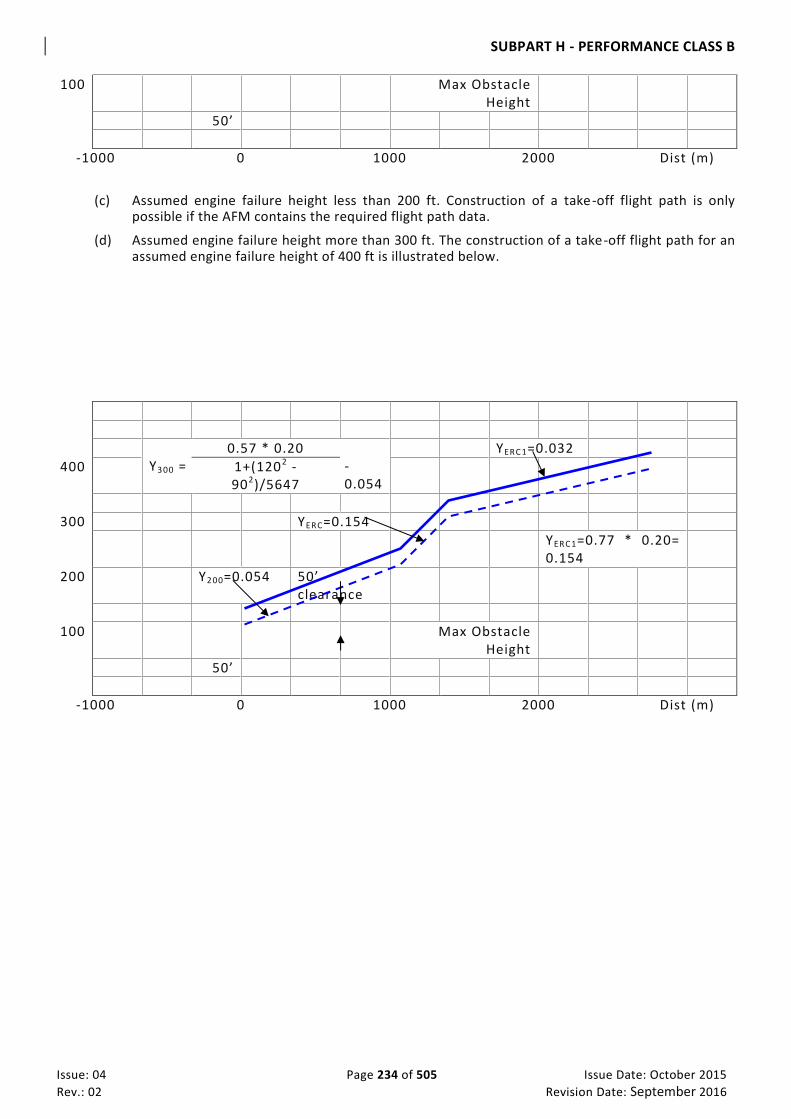
SUBPART H - PERFORMANCE CLASS B
Issue: 04 Page 234 of 505 Issue Date: October 2015
Rev.: 02 Revision Date: September 2016
100 Max Obstacle Height
50’
-1000 0 1000 2000 Dist (m)
(c) Assumed engine failure height less than 200 ft. Construction of a take-off flight path is only possible if the AFM contains the required flight path data.
(d) Assumed engine failure height more than 300 ft. The construction of a take-off flight path for an assumed engine failure height of 400 ft is illustrated below.
Y300 =
0.57 * 0.20 -0.054
YERC 1=0.032
400 1+(1202 - 902)/5647
300 YERC=0.154
YERC 1=0.77 * 0.20= 0.154
200 Y200=0.054 50’ clearance
100 Max Obstacle Height
50’
-1000 0 1000 2000 Dist (m)

SUBPART H - PERFORMANCE CLASS B
Issue: 04 Page 235 of 505 Issue Date: October 2015
Rev.: 02 Revision Date: September 2016
CAR-OPS 1.540 En-Route – Multi-engined aeroplanes (See IEM OPS 1.540)
(a) An operator shall ensure that the aeroplane, in the meteorological conditions expected for the flight, and in the event of the failure of one engine, with the remaining engines operating within the maximum continuous power conditions specified, is capable of continuing flight at or above the relevant minimum altitudes for safe flight stated in the Operations Manual to a point 1000 ft above an aerodrome at which the performance requirements can be met.
(b) When showing compliance with sub-paragraph (a) above:
(1) The aeroplane must not be assumed to be flying at an altitude exceeding that at which the rate of climb equals 300 ft per minute with all engines operating within the maximum continuous power conditions specified; and
(2) The assumed en-route gradient with one engine inoperative shall be the gross gradient of descent or climb, as appropriate, respectively increased by a gradient of 0·5%, or decreased by a gradient of 0·5%.
IEM OPS 1.540 En-Route
See CAR-OPS 1.540
1. The altitude at which the rate of climb equals 300 ft per minute is not a restriction on the maximum cruising altitude at which the aeroplane can fly in practice, it is merely the maximum altitude from which the driftdown procedure can be planned to start.
2. Aeroplanes may be planned to clear en-route obstacles assuming a driftdown procedure, having first
increased the scheduled en-route one engine inoperative descent data by 0·5% gradient.
CAR-OPS 1.542 En-Route – Single-engine aeroplanes
(See AMC OPS 1.542)
(a) An operator shall ensure that the aeroplane, in the meteorological conditions expected for the flight, and in the event of engine failure, is capable of reaching a place at which a safe forced landing can be made. For landplanes, a place on land is required, unless otherwise approved by the Authority. (See AMC OPS 1.542 (a).)
(b) When showing compliance with sub-paragraph (a) above:
(1) The aeroplane must not be assumed to be flying, with the engine operating within the maximum continuous power conditions specified, at an altitude exceeding that at which the rate of climb equals 300 ft per minute; and
(2) The assumed en-route gradient shall be the gross gradient of descent increased by a gradient of 0·5%.
IEM OPS 1.542 En-route – Single-engined Aeroplanes
See CAR-OPS 1.542
1. In the event of an engine failure, single-engine aeroplanes have to rely on gliding to a point suitable for a safe forced landing. Such a procedure is clearly incompatible with flight above a cloud layer which extends below the relevant minimum safe altitude.

SUBPART H - PERFORMANCE CLASS B
Issue: 04 Page 236 of 505 Issue Date: October 2015
Rev.: 02 Revision Date: September 2016
2. Operators should first increase the scheduled engine-inoperative gliding performance data by 0·5%
gradient when verifying the en-route clearance of obstacles and the ability to reach a suitable place for a forced landing.
3. The altitude at which the rate of climb equals 300 ft per minute is not a restriction on the maximum
cruising altitude at which the aeroplane can fly in practice, it is merely the maximum altitude from which the engine-inoperative procedure can be planned to start.
AMC OPS 1.542(a) En-Route - Single-engine aeroplanes
See CAR-OPS 1.542(a)
CAR-OPS 1.542(a) requires an operator to ensure that in the event of an engine failure, the aeroplane should be capable of reaching a point from which a successful forced landing can be made. Unless otherwise specified by the Authority, this point should be 1000ft above the intended landing area.
CAR-OPS 1.545 Landing – Destination and Alternate Aerodromes
(See AMC OPS 1.545 & 1.550)
An operator shall ensure that the landing mass of the aeroplane determined in accordance with CAR-OPS 1.475(a) does not exceed the maximum landing mass specified for the altitude and the ambient temperature expected for the estimated time of landing at the destination and alternate aerodrome.
CAR-OPS 1.550 Landing – Dry runway
(See AMC OPS 1.545 & 1.550)
(a) An operator shall ensure that the landing mass of the aeroplane determined in accordance with CAR-OPS 1.475(a) for the estimated time of landing allows a full stop landing from 50 ft above the threshold within 70% of the landing distance available at the destination aerodrome and at any alternate aerodrome.
(1) The Authority may approve the use of landing distance data factored in accordance with this paragraph based on a screen height of less than 50 ft, but not less than 35 ft. (See Appendix 1 to CAR-OPS 1.550(a).)
(2) The Authority may approve Short Landing Operations in accordance with the criteria in Appendix 2 to CAR-OPS 1.550(a).
(b) When showing compliance with sub-paragraph (a) above, an operator shall take account of the following:
(1) The altitude at the aerodrome;
(2) Not more than 50% of the head-wind component or not less than 150% of the tail-wind component.
(3) The runway surface condition and the type of runway surface (See AMC OPS 1.550(b)(3)); and
(4) The runway slope in the direction of landing (See AMC OPS 1.550(b)(4));

SUBPART H - PERFORMANCE CLASS B
Issue: 04 Page 237 of 505 Issue Date: October 2015
Rev.: 02 Revision Date: September 2016
(c) For despatching an aeroplane in accordance with sub-paragraph (a) above, it must be assumed that:
(1) The aeroplane will land on the most favourable runway, in stil l air; and
(2) The aeroplane will land on the runway most likely to be assigned considering the probable wind speed and direction and the ground handling characteristics of the aeroplane, and considering other conditions such as landing aids and terrain. (See IEM OPS 1.550(c).)
(d) If an operator is unable to comply with sub-paragraph (c)(2) above for the destination aerodrome, the aeroplane may be despatched if an alternate aerodrome is designated which permits full compliance with sub-paragraphs (a), (b) and (c) above.
AMC OPS 1.550(b)(3) Landing Distance Correction Factors
See CAR-OPS 1.550(b)(3) Unless otherwise specified in the Aeroplane Flight Manual, or other performance or operating
manuals from the manufacturers, the variable affecting the landing performance and the associated factor that should be applied to the Aeroplane Flight Manual data is shown in the table below. It should be applied in addition to the operational factors as prescribed in CAR-OPS 1.550(a).
SURFACE TYPE FACTOR
Grass (on firm soil up to 20 cm long) 1·15
Note: The soil is firm when there are wheel impressions but no rutting
AMC OPS 1.550(b)(4) Runway Slope
See CAR-OPS 1.550(b)(4) Unless otherwise specified in the Aeroplane Flight Manual, or other performance or operating manuals from
the manufacturer, the landing distances required should be increased by 5% for each 1% of downslope except that correction factors for runways with slopes in excess of 2% need the acceptance of the Authority.
IEM OPS 1.550(c) Landing – Dry Runway
See CAR-OPS 1.550(c
1. CAR-OPS 1.550(c) establishes two considerations in determining the maximum permissible landing mass at the destination and alternate aerodromes.
2. Firstly, the aeroplane mass will be such that on arrival the aeroplane can be landed within 70% of the
landing distance available on the most favourable (normally the longest) runway in still air. Regardless of the wind conditions, the maximum landing mass for an aerodrome/aeroplane configuration at a particular aerodrome, cannot be exceeded.
3. Secondly, consideration should be given to anticipated conditions and circumstances. The expected
wind, or ATC and noise abatement procedures, may indicate the use of a different runway. These factors may result in a lower landing mass than that permitted under paragraph 2 above, in which case, to show compliance with CAR-OPS 1.550(a), despatch should be based on this lesser mass.

SUBPART H - PERFORMANCE CLASS B
Issue: 04 Page 238 of 505 Issue Date: October 2015
Rev.: 02 Revision Date: September 2016
4. The expected wind referred to in paragraph 3 is the wind expected to exist at the time of arrival.
CAR-OPS 1.555 Landing – Wet and Contaminated Runways
(a) An operator shall ensure that when the appropriate weather reports or forecasts, or a combination thereof, indicate that the runway at the estimated time of arrival may be wet, the landing distance available is equal to or exceeds the required landing distance, determined in accordance with CAR-OPS 1.550, multiplied by a factor of 1·15. (See IEM OPS 1.555(a).)
(b) An operator shall ensure that when the appropriate weather reports or forecasts, or a combination thereof, indicate that the runway at the estimated time of arrival may be contaminated, the landing distance, determined by using data acceptable to the Authority for these conditions, does not exceed the landing distance available.
(c) A landing distance on a wet runway shorter than that required by sub-paragraph (a) above, but not less than that required by CAR-OPS 1.550(a), may be used if the Aeroplane Flight Manual includes specific additional information about landing distances on wet runways.

SUBPART H - PERFORMANCE CLASS B
Issue: 04 Page 239 of 505 Issue Date: October 2015
Rev.: 02 Revision Date: September 2016
IEM OPS 1.555(a) Landing on Wet Grass Runways
See CAR-OPS 1.555(a) 1 When landing on very short grass which is wet, and with a firm subsoil, the surface may be slippery,
in which case the distances may increase by as much as 60% (1.60 factor). 2 As it may not be possible for a pilot to determine accurately the degree of wetness of the grass,
particularly when airborne, in cases of doubt, the use of the wet factor (1.15) is recommended.

SUBPART H - PERFORMANCE CLASS B
Issue: 04 Page 240 of 505 Issue Date: October 2015
Rev.: 02 Revision Date: September 2016
Appendix 1 to CAR-OPS 1.525(b) General Take-off & Landing Climb
The requirements of this Appendix are based on CS-23.
(a) Take-off Climb
(1) All Engines Operating
(i) The steady gradient of climb after take-off must be at least 4% with:
(A) Take-off power on each engine;
(B) The landing gear extended except that if the landing gear can be retracted in not more than 7 seconds, it may be assumed to be retracted;
(C) The wing flaps in the take-off position(s); and
(D) A climb speed not less than the greater of 1·1 VMC and 1·2 VS1.
(2) One Engine Inoperative
(i) The steady gradient of climb at an altitude of 400 ft above the take-off surface must be measurably positive with:
(A) The critical engine inoperative and its propeller in the minimum drag position;
(B) The remaining engine at take-off power;
(C) The landing gear retracted;
(D) The wing flaps in the take-off position(s); and
(E) A climb speed equal to that achieved at 50 ft.
(ii) The steady gradient of climb must be not less than 0·75% at an altitude of 1500 ft above the take-off surface with:
(A) The critical engine inoperative and its propeller in the minimum drag position;
(B) The remaining engine at not more than maximum continuous power;
(C) The landing gear retracted;
(D) The wing flaps retracted; and
(E) A climb speed not less than 1·2 VS1.
(b) Landing Climb
(1) All Engines Operating
(i) The steady gradient of climb must be at least 2·5% with:

SUBPART H - PERFORMANCE CLASS B
Issue: 04 Page 241 of 505 Issue Date: October 2015
Rev.: 02 Revision Date: September 2016
(A) Not more than the power or thrust that is available 8 seconds after initiation of movement of the power controls from the minimum flight idle position;
(B) The landing gear extended;
(C) The wing flaps in the landing position; and
(D) A climb speed equal to VREF.
(2) One engine Inoperative
(i) The steady gradient of climb must be not less than 0·75% at an altitude of 1500 ft above the landing surface with:
(A) The critical engine inoperative and its propeller in the minimum drag position;
(B) The remaining engine at not more than maximum continuous power;
(C) The landing gear retracted;
(D) The wing flaps retracted; and
(E) A climb speed not less than 1·2 VS1.

SUBPART H - PERFORMANCE CLASS B
Issue: 04 Page 242 of 505 Issue Date: October 2015
Rev.: 02 Revision Date: September 2016
Appendix 1 to CAR-OPS 1.535(b)(1) & (c)(1) Take-off Flight Path Visual Course Guidance Navigation
In order to allow visual course guidance navigation, an operator must ensure that the weather conditions prevailing at the time of operation including ceiling and visibility, are such that the obstacle and/or ground reference points can be seen and identified. The Operations Manual must specify, for the aerodrome(s) concerned, the minimum weather conditions which enable the flight crew to continuously determine and maintain the correct flight path with respect to ground reference points, so as to provide a safe clearance with respect to obstructions and terrain as follows:
(a) The procedure must be well defined with respect to ground reference points so that the track to be flown can be analysed for obstacle clearance requirements;
(b) The procedure must be within the capabilities of the aeroplane with respect to forward speed, bank angle and wind effects;
(c) A written and/or pictorial description of the procedure must be provided for crew use; and
(d) The limiting environmental conditions must be specified (e.g. wind, cloud, visibility, day/night, ambient lighting, obstruction lighting).

SUBPART H - PERFORMANCE CLASS B
Issue: 04 Page 243 of 505 Issue Date: October 2015
Rev.: 02 Revision Date: September 2016
Appendix 1 to CAR-OPS 1.550(a) Steep Approach Procedures
(a) The Authority may approve the application of Steep Approach procedures using glideslope angles of 4.5° or more, and with screen heights of less than 50 ft but not less than 35 ft, provided that the following criteria are met:
(1) The Aeroplane Flight Manual must state the maximum approved glideslope angle, any other limitations, normal, abnormal or emergency procedures for the steep approach as well as amendments to the field length data when using steep approach criteria;
(2) A suitable glide path reference system, comprising at least a visual glidepath indicating system, must be available at each aerodrome at which steep approach procedures are to be conducted; and
(3) Weather minima must be specified and approved for each runway to be used with a steep approach. Consideration must be given to the following:
(i) The obstacle situation;
(ii) The type of glidepath reference and runway guidance such as visual aids, MLS, 3D–NAV, ILS, LLZ, VOR, NDB;
(iii) The minimum visual reference to be required at DH and MDA;
(iv) Available airborne equipment;
(v) Pilot qualification and special aerodrome familiarisation;
(vi) Aeroplane Flight Manual limitations and procedures; and
(vii) Missed approach criteria.

Issue: 04 Page 244 of 505 Issue Date: October 2015
Rev.: 02 Revision Date: September 2016
Appendix 2 to CAR-OPS 1.550(a) Short Landing Operations
(a) For the purpose of CAR-OPS 1.550(a)(2), the distance used for the calculation of the permitted landing mass may consist of the usable length of the declared safe area plus the declared landing distance available. The Authority may approve such operations in accordance with the following criteria:
(1) The use of the declared safe area must be approved by the aerodrome authority;
(2) The declared safe area must be clear of obstructions or depressions which would endanger an aeroplane undershooting the runway, and no mobile object shall be permitted on the declared safe area while the runway is being used for short landing operations;
(3) The slope of the declared safe area must not exceed 5% upward slope nor 2% downward slope in the direction of landing;
(4) The useable length of the declared safe area under the provisions of this Appendix shall not exceed 90 metres;
(5) The width of the declared safe area shall not be less than twice the runway width, centred on the extended runway centreline;
(6) It is assumed that the crossing height over the beginning of the usable length of the declared safe area shall not be less than 50ft.
(7) For the purpose of this operation, the bearing strength requirement of CAR-OPS 1.480(a)(5) need not apply to the declared safe area.
(8) Weather minima must be specified and approved for each runway to be used and shall not be less than the greater of VFR or non-precision approach minima;
(9) Pilot requirements must be specified (CAR-OPS 1.975(a) refers);
(10) The Authority may impose such additional conditions as are necessary for safe operation taking into account the aeroplane type characteristics, approach aids and missed approach/baulked landing considerations.

SUBPART I - PERFORMANCE CLASS C
Issue: 04 Page 245 of 505 Issue Date: October 2015
Rev.: 02 Revision Date: September 2016
SUB PART I. PERFORMANCE CLASS C
CAR-OPS 1.560 General
An operator shall ensure that, for determining compliance with the requirements of this Subpart, the approved performance Data in the Aeroplane Flight Manual is supplemented, as necessary, with other Data acceptable to the Authority if the approved performance Data in the Aeroplane Flight Manual is insufficient.
CAR-OPS 1.565 Take-off
(a) An operator shall ensure that the take-off mass does not exceed the maximum take-off mass specified in the Aeroplane Flight Manual for the pressure altitude and the ambient temperature at the aerodrome at which the take-off is to be made.
(b) An operator shall ensure that, for aeroplanes which have take-off field length data contained in their Aeroplane Flight Manuals that do not include engine failure accountability, the distance from the start of the take-off roll required by the aeroplane to reach a height of 50 ft above the surface with all engines operating within the maximum take-off power conditions specified, when multiplied by a factor of either:
(1) 1·33 for aeroplanes having two engines; or
(2) 1·25 for aeroplanes having three engines; or
(3) 1·18 for aeroplanes having four engines,
does not exceed the take-off run available at the aerodrome at which the take-off is to be made.
(c) An operator shall ensure that, for aeroplanes which have take-off field length data contained in their Aeroplane Flight Manuals which accounts for engine failure, the following requirements are met in accordance with the specifications in the Aeroplane Flight Manual:
(1) The accelerate-stop distance must not exceed the accelerate-stop distance available;
(2) The take-off distance must not exceed the take-off distance available, with a clearway distance not exceeding half of the take-off run available;
(3) The take-off run must not exceed the take-off run available;
(4) Compliance with this paragraph must be shown using a single value of V1 for the rejected
and continued take-off; and
(5) On a wet or contaminated runway the take-off mass must not exceed that permitted for a take-off on a dry runway under the same conditions.
(d) When showing compliance with sub-paragraphs (b) and (c) above, an operator must take account of the following:
(1) The pressure altitude at the aerodrome;
(2) The ambient temperature at the aerodrome;
(3) The runway surface condition and the type of runway surface (See IEM OPS 1.565(d)(3));

SUBPART I - PERFORMANCE CLASS C
Issue: 04 Page 246 of 505 Issue Date: October 2015
Rev.: 02 Revision Date: September 2016
(4) The runway slope in the direction of take-off (See AMC OPS 1.565(d)(4));
(5) Not more that 50% of the reported head-wind component or not less than 150% of the reported tail-wind component; and
(6) The loss, if any, of runway length due to alignment of the aeroplane prior to take-off. (See IEM OPS 1.565(d)(6).)
IEM OPS 1.565(d)(3) Take-off
See CAR-OPS 1.565(d)(3) Operation on runways contaminated with water, slush, snow or ice implies uncertainties with regard
to runway friction and contaminant drag and therefore to the achievable performance and control of the aeroplane during take-off, since the actual conditions may not completely match the assumptions on which the performance information is based. An adequate overall level of safety can, therefore, only be maintained if such operations are limited to rare occasions. In case of a contaminated runway the first option for the commander is to wait until the runway is cleared. If this is impracticable, he may consider a take-off, provided that he has applied the applicable performance adjustments, and any further safety measures he considers justified under the prevailing conditions.
IEM OPS 1.565(d)(6) Loss of runway length due to alignment
See CAR-OPS 1.565(d)(6) 1 Introduction 1.1 The length of the runway which is declared for the calculation of TODA, ASDA and TORA, does not
account for line-up of the aeroplane in the direction of take-off on the runway in use. This alignment distance depends on the aeroplane geometry and access possibility to the runway in use. Accountability is usually required for a 90° taxiway entry to the runway and 180° turnaround on the runway. There are two distances to be considered:
(a) The minimum distance of the mainwheels from the start of the runway for determining TODA
and TORA, “L”; and
(b) The minimum distance of the most forward wheel(s) from the start of the runway determining ASDA, “N”.
Where the aeroplane manufacturer does not provide the appropriate data, the calculation method
given in paragraph 2 may be use to determine the alignment distance.
N L
Start of the Runway

SUBPART I - PERFORMANCE CLASS C
Issue: 04 Page 247 of 505 Issue Date: October 2015
Rev.: 02 Revision Date: September 2016
WN
RN
A
WB
B
WM
RM

SUBPART I - PERFORMANCE CLASS C
Issue: 04 Page 248 of 505 Issue Date: October 2015
Rev.: 02 Revision Date: September 2016
2. Alignment Distance Calculation The distances mentioned in (a) and (b) of paragraph 1 above are:
90° ENTRY 180° TURNAROUND
L= RM + X RN + Y
N= RM + X + WB RN + Y + WB
Where : RN = A + WN =
WB + WN
Cos(90°-α)
And : B + WM =
WB tan(90°-α) + WM
X = Safety distance of outer main wheel during turn to the edge of the runway Y = Safety distance of outer nose wheel during turn to the edge of the runway NOTE: Minimum edge safety distances for X and Y are specified in FAA AC 150/5300-13 and ICAO Annex 14
paragraph 3.8.3 RN = Radius of turn of outer nose wheel RM = Radius of turn of outer main wheel WN = Distance from aeroplane centre-line to outer nose wheel WM = Distance from aeroplane centre-line to outer main wheel WB = Wheel base a = Steering angle
AMC OPS 1.565(d)(4) Runway Slope
See CAR-OPS 1.565(d)(4)

SUBPART I - PERFORMANCE CLASS C
Issue: 04 Page 249 of 505 Issue Date: October 2015
Rev.: 02 Revision Date: September 2016
Unless otherwise specified in the Aeroplane Flight Manual, or other performance or operating manuals from the manufacturers, the take-off distance should be increased by 5% for each 1% of upslope except that correction factors for runways with slopes in excess of 2% need the acceptance of the Authority.
CAR-OPS 1.570 Take-off Obstacle Clearance
(a) An operator shall ensure that the take-off flight path with one engine inoperative clears all obstacles by a vertical distance of at least 50 ft plus 0·01 x D, or by a horizontal distance of at least 90 m plus 0·125 x D, where D is the horizontal distance the aeroplane has travelled from the end of the take-off distance available. For aeroplanes with a wingspan of less than 60 m a horizontal obstacle clearance of half the aeroplane wingspan plus 60 m, plus 0.125 x D may be used.
(b) The take-off flight path must begin at a height of 50 ft above the surface at the end of the take-off distance required by CAR-OPS 1.565(b) or (c) as applicable, and end at a height of 1500 ft above the surface.
(c) When showing compliance with sub-paragraph (a) above, an operator must take account of the following:
(1) The mass of the aeroplane at the commencement of the take-off run;
(2) The pressure altitude at the aerodrome;
(3) The ambient temperature at the aerodrome; and
(4) Not more than 50% of the reported head-wind component or not less than 150% of the reported tail-wind component.
(d) When showing compliance with sub-paragraph (a) above, track changes shall not be allowed up to that point of the take-off flight path where a height of 50 ft above the surface has been achieved. Thereafter, up to a height of 400 ft it is assumed that the aeroplane is banked by no more than 15°. Above 400 ft height bank angles greater than 15°, but not more than 25° may be scheduled. Adequate allowance must be made for the effect of bank angle on operating speeds and flight path including the distance increments resulting from increased operating speeds. ( See AMC OPS 1.570(d).)
(e) When showing compliance with sub-paragraph (a) above for those cases which do not require track changes of more than 15°, an operator need not consider those obstacles which have a lateral distance greater than:
(1) 300 m, if the pilot is able to maintain the required navigational accuracy through the obstacle accountability area (See AMC OPS 1.570(e)(1) & (f)(1)); or
(2) 600 m, for flights under all other conditions.
(f) When showing compliance with sub-paragraph (a) above for those cases which do require track changes of more than 15°, an operator need not consider those obstacles which have a lateral distance greater than:
(1) 600 m, if the pilot is able to maintain the required navigational accuracy through the obstacle accountability area (See AMC OPS 1.570(e)(1) & (f)(1)); or
(2) 900 m for flights under all other conditions.

SUBPART I - PERFORMANCE CLASS C
Issue: 04 Page 250 of 505 Issue Date: October 2015
Rev.: 02 Revision Date: September 2016
(g) An operator shall establish contingency procedures to satisfy the requirements of CAR-OPS 1.570 and to provide a safe route, avoiding obstacles, to enable the aeroplane to either comply with the en-route requirements of CAR-OPS 1.580, or land at either the aerodrome of departure or at a take-off alternate aerodrome.
AMC OPS 1.570(d) Take-off Flight Path
See CAR-OPS 1.570(d) 1 The Aeroplane Flight Manual generally provides a climb gradient decrement for a 15° bank
turn. Unless otherwise specified in the Aeroplane Flight Manual or other performance or operating manuals from the manufacturer, acceptable adjustments to assure adequate stall margins and gradient corrections are provided by the following:
BANK SPEED GRADIENT CORRECTION 15° V2 1 x Aeroplane Flight Manual 15° Gradient Loss
20° V2 + 5 kt 2 x Aeroplane Flight Manual 15° Gradient Loss
25° V2 + 10 kt 3 x Aeroplane Flight Manual 15° Gradient Loss
2 For bank angles of less than 15°, a proportionate amount may be applied, unless the
manufacturer or Aeroplane Flight Manual has provide d other data.
AMC OPS 1.570(e)(1) & (f)(1) Required navigational accuracy
See CAR-OPS 1.570(e)(1) & (f)(1) 1 Flight-deck systems. The obstacle accountability semi -widths of 300 m (See CAR-OPS
1.570(e)(1)) and 600 m (See CAR-OPS 1.570(f)(1)) may be used if the navigation system under one-engine-inoperative conditions provides a two standard deviation (2 s) accuracy of 150 m and 300 m respectively.
2 Visual Course Guidance 2.1 The obstacle accountability semi-widths of 300 m (See CAR-OPS 1.570(e)(1)) and 600 m
(See CAR-OPS 1.570(f)(1)) may be used where navigational accuracy is ensured at all relevant points on the flight path by use of external references. These references may be considered visible from the flight deck i f they are situated more than 45° either side of the intended track and with a depression of not greater than 20° from the horizontal.
2.2 For visual course guidance navigation, an operator should ensure that the weather
conditions prevailing at the time of operation, including ceiling and visibility, are such that the obstacle and/or ground reference points can be seen and identified. The Operations Manual should specify, for the aerodrome(s) concerned, the minimum weather conditions which enable the flight crew to continuously determine and maintain the correct flight path with respect to ground reference points, so as to provide a safe clearance with respect to obstructions and terrain as follows:
(a) The procedure should be well defined with respect to gro und reference points so that
the track to be flown can be analysed for obstacle clearance requirements;
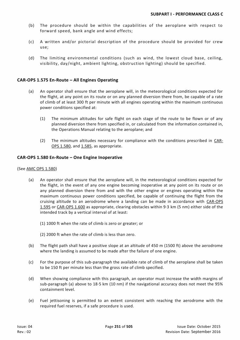
SUBPART I - PERFORMANCE CLASS C
Issue: 04 Page 251 of 505 Issue Date: October 2015
Rev.: 02 Revision Date: September 2016
(b) The procedure should be within the capabilities of the aeroplane with respect to forward speed, bank angle and wind effects;
(c) A written and/or pictorial description of the procedure should be provided for crew
use; (d) The limiting environmental conditions (such as wind, the lowest cloud base, ceiling,
visibility, day/night, ambient lighting, obstruction lighting) should be specified.
CAR-OPS 1.575 En-Route – All Engines Operating
(a) An operator shall ensure that the aeroplane will, in the meteorological conditions expected for the flight, at any point on its route or on any planned diversion there from, be capable of a rate of climb of at least 300 ft per minute with all engines operating within the maximum continuous power conditions specified at:
(1) The minimum altitudes for safe flight on each stage of the route to be flown or of any planned diversion there from specified in, or calculated from the information contained in, the Operations Manual relating to the aeroplane; and
(2) The minimum altitudes necessary for compliance with the conditions prescribed in CAR-OPS 1.580, and 1.585, as appropriate.
CAR-OPS 1.580 En-Route – One Engine Inoperative
(See AMC OPS 1.580)
(a) An operator shall ensure that the aeroplane will, in the meteorological conditions expected for the flight, in the event of any one engine becoming inoperative at any point on its route or on any planned diversion there from and with the other engine or engines operating within the maximum continuous power conditions specified, be capable of continuing the flight from the cruising altitude to an aerodrome where a landing can be made in accordance with CAR-OPS 1.595 or CAR-OPS 1.600 as appropriate, clearing obstacles within 9·3 km (5 nm) either side of the intended track by a vertical interval of at least:
(1) 1000 ft when the rate of climb is zero or greater; or
(2) 2000 ft when the rate of climb is less than zero.
(b) The flight path shall have a positive slope at an altitude of 450 m (1500 ft) above the aerodrome where the landing is assumed to be made after the failure of one engine.
(c) For the purpose of this sub-paragraph the available rate of climb of the aeroplane shall be taken to be 150 ft per minute less than the gross rate of climb specified.
(d) When showing compliance with this paragraph, an operator must increase the width margins of sub-paragraph (a) above to 18·5 km (10 nm) if the navigational accuracy does not meet the 95% containment level.
(e) Fuel jettisoning is permitted to an extent consistent with reaching the aerodrome with the required fuel reserves, if a safe procedure is used.

SUBPART I - PERFORMANCE CLASS C
Issue: 04 Page 252 of 505 Issue Date: October 2015
Rev.: 02 Revision Date: September 2016
CAR-OPS 1.585 En-Route –Two Engines Inoperative En-Route – Aeroplanes With Three Or More Engines, Two Engines Inoperative
(a) An operator shall ensure that, at no point along the intended track, will an aeroplane having three or more engines be more than 90 minutes at the all-engine long range cruising speed at standard temperature in still air, away from an aerodrome at which the performance requirements applicable at the expected landing mass are met unless it complies with sub-paragraphs (b) to (e) below.
(b) The two-engines inoperative flight path shown must permit the aeroplane to continue the flight, in the expected meteorological conditions, clearing all obstacles within 9·3 km (5 nm) either side of the intended track by a vertical interval of at least 2000 ft, to an aerodrome at which the performance requirements applicable at the expected landing mass are met.
(c) The two engines are assumed to fail at the most critical point of that portion of the route where the aeroplane is more than 90 minutes, at the all engines long range cruising speed at standard temperature in still air, away from an aerodrome at which the performance requirements applicable at the expected landing mass are met.
(d) The expected mass of the aeroplane at the point where the two engines are assumed to fail must not be less than that which would include sufficient fuel to proceed to an aerodrome where the landing is assumed to be made, and to arrive there at an altitude of a least 450 m (1500 ft) directly over the landing area and thereafter to fly level for 15 minutes.
(e) For the purpose of this sub-paragraph the available rate of climb of the aeroplane shall be taken to be 150 ft per minute less than that specified.
(f) When showing compliance with this paragraph, an operator must increase the width margins of sub-paragraph (a) above to 18·5 km (10 nm) if the navigational accuracy does not meet the 95% containment level.
(g) Fuel jettisoning is permitted to an extent consistent with reaching the aerodrome with the required fuel reserves, if a safe procedure is used.
AMC OPS 1.580 En-Route – One Engine Inoperative
See CAR-OPS 1.580 The high terrain or obstacle analysis required for showing compliance with CAR-OPS 1.580 can be carried
out by making a detailed analysis of the route using contour maps of the high terrain, and plotting the highest points within the prescribed corridor width along the route. The next step is to determine whether it is possible to maintain level flight with one engine inoperative 1000 ft above the highest point of the crossing. If this is not possible, or if the associated weight penalties are unacceptable, a drift-down procedure must be evaluated, based on engine failure at the most critical point, and must show obstacle clearance during the drift-down by at least 2000 ft. The minimum cruise altitude is determined from the drift-down path, taking into account allowances for decision making, and the reduction in the scheduled rate of climb (See Figure 1).
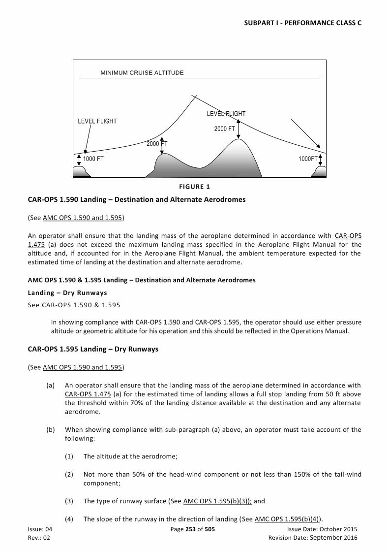
SUBPART I - PERFORMANCE CLASS C
Issue: 04 Page 253 of 505 Issue Date: October 2015
Rev.: 02 Revision Date: September 2016
FIGURE 1
CAR-OPS 1.590 Landing – Destination and Alternate Aerodromes
(See AMC OPS 1.590 and 1.595)
An operator shall ensure that the landing mass of the aeroplane determined in accordance with CAR-OPS 1.475 (a) does not exceed the maximum landing mass specified in the Aeroplane Flight Manual for the altitude and, if accounted for in the Aeroplane Flight Manual, the ambient temperature expected for the estimated time of landing at the destination and alternate aerodrome.
AMC OPS 1.590 & 1.595 Landing – Destination and Alternate Aerodromes
Landing – Dry Runways
See CAR-OPS 1.590 & 1.595 In showing compliance with CAR-OPS 1.590 and CAR-OPS 1.595, the operator should use either pressure
altitude or geometric altitude for his operation and this should be reflected in the Operations Manual.
CAR-OPS 1.595 Landing – Dry Runways
(See AMC OPS 1.590 and 1.595)
(a) An operator shall ensure that the landing mass of the aeroplane determined in accordance with CAR-OPS 1.475 (a) for the estimated time of landing allows a full stop landing from 50 ft above the threshold within 70% of the landing distance available at the destination and any alternate aerodrome.
(b) When showing compliance with sub-paragraph (a) above, an operator must take account of the following:
(1) The altitude at the aerodrome;
(2) Not more than 50% of the head-wind component or not less than 150% of the tail-wind component;
(3) The type of runway surface (See AMC OPS 1.595(b)(3)); and
(4) The slope of the runway in the direction of landing (See AMC OPS 1.595(b)(4)).
MINIMUM CRUISE ALTITUDE
LEVEL FLIGHT LEVEL FLIGHT 2000 FT 2000 FT 1000 FT 1000FT

SUBPART I - PERFORMANCE CLASS C
Issue: 04 Page 254 of 505 Issue Date: October 2015
Rev.: 02 Revision Date: September 2016
(c) For despatching an aeroplane in accordance with sub-paragraph (a) above it must be assumed that:
(1) The aeroplane will land on the most favourable runway in still air; and
(2) The aeroplane will land on the runway most likely to be assigned considering the probable wind speed and direction and the ground handling characteristics of the aeroplane, and considering other conditions such as landing aids and terrain. (See IEM OPS 1.595(c).)
(d) If an operator is unable to comply with sub-paragraph (c)(2) above for the destination aerodrome, the aeroplane may be despatched if an alternate aerodrome is designated which permits full compliance with sub-paragraphs (a), (b) and (c).
AMC OPS 1.595(b)(3) Landing Distance Correction Factors
See CAR-OPS 1.595(b)(3) Unless otherwise specified in the Aeroplane Flight Manual or other performance or operating manuals
from the manufacturers, the variables affecting the landing performance and the associated factors to be applied to the Aeroplane Flight Manual data are shown in the table below. It should be applied in addition to the factor specified in CAR-OPS 1.595(a).
SURFACE TYPE FACTOR
Grass (on firm soil up to 13 cm long) 1·20
Note: The soil is firm when there are wheel impressions but no rutting.
AMC OPS 1.595(b)(4) Runway Slope
See CAR-OPS 1.595(b)(4) Unless otherwise specified in the Aeroplane Flight Manual, or other performance or operating manuals
from the manufacturer, the landing distances required should be increased by 5% for each 1% of downslope.
IEM OPS 1.595(c) Landing Runway
See CAR-OPS 1.595(c) 1 CAR-OPS 1.595(c) establishes two considerations in determining the maximum permissible landing mass
at the destination and alternate aerodromes. 2 Firstly, the aeroplane mass will be such that on arrival the aeroplane can be landed within 70% of the
landing distance available on the most favourable (normally the longest) runway in still air. Regardless of the wind conditions, the maximum landing mass for an aerodrome/aeroplane configuration at a particular aerodrome, cannot be exceeded.
3 Secondly, consideration should be given to anticipated conditions and circumstances. The expected wind,
or ATC and noise abatement procedures, may indicate the use of a different runway. These factors may result in a lower landing mass than that permitted under paragraph 2 above, in which case, to show compliance with CAR-OPS 1.595(a), despatch should be based on this lesser mass.

SUBPART I - PERFORMANCE CLASS C
Issue: 04 Page 255 of 505 Issue Date: October 2015
Rev.: 02 Revision Date: September 2016
4 The expected wind referred to in paragraph 3 is the wind expected to exist at the time of arrival.
CAR-OPS 1.600 Landing – Wet and Contaminated Runways
(a) An operator shall ensure that when the appropriate weather reports or forecasts, or a combination thereof, indicate that the runway at the estimated time of arrival may be wet, the landing distance available is equal to or exceeds the required landing distance, determined in accordance with CAR-OPS 1.595, multiplied by a factor of 1·15.
(b) An operator shall ensure that when the appropriate weather reports or forecasts, or a combination thereof, indicate that the runway at the estimated time of arrival may be contaminated, the landing distance determined by using data acceptable to the Authority for these conditions, does not exceed the landing distance available.

SUBPART J - MASS AND BALANCE
Issue: 04 Page 256 of 505 Issue Date: October 2015
Rev.: 02 Revision Date: September 2016
SUB PART J. MASS AND BALANCE
CAR-OPS 1.605 General
(See Appendix 1 to CAR-OPS 1.605)
(a) An operator shall ensure that during any phase of operation, the loading, mass and centre of gravity of the aeroplane complies with the limitations specified in the approved Aeroplane Flight Manual, or the Operations Manual if more restrictive.
(b) An operator must establish the mass and the centre of gravity of any aeroplane by actual weighing prior to initial entry into service and thereafter at intervals of 4 years if individual aeroplane masses are used and 9 years if fleet masses are used. The accumulated effects of modifications and repairs on the mass and balance must be accounted for and properly documented. Furthermore, aeroplanes must be reweighed if the effect of modifications on the mass and balance is not accurately known.
(c) An operator must determine the mass of all operating items and crew members included in the aeroplane dry operating mass by weighing or by using standard masses. The influence of their position on the aeroplane centre of gravity must be determined.
(d) An operator must establish the mass of the traffic load, including any ballast, by actual weighing or determine the mass of the traffic load in accordance with standard passenger and baggage masses as specified in CAR-OPS 1.620.
(e) An operator must determine the mass of the fuel load by using the actual density or, if not known, the density calculated in accordance with a method specified in the Operations Manual. (See IEM OPS 1.605(e).)
(f) An aerolane shall be operated, if applicable, within the mass limitations imposed by compliance with the applicable noise certification Standards in Annex 16, Volume I, unless otherwise authorized in exceptional circumstances for a certain aerodrome or a runway where there is no noise disturbance problem, by the competent authority of the State in which the aerodrome is situated.
IEM OPS 1.605(e) Fuel density
See CAR-OPS 1.605(e)
1 If the actual fuel density is not known, the operator may use the standard fuel density values specified in the Operations Manual for determining the mass of the fuel load. Such standard values should be based on current fuel density measurements for the airports or areas concerned. Typical fuel density values are:
a. Gasoline (piston engine fuel) – 0·71
b. Jet fuel JP 1 – 0·79
c. Jet fuel JP 4 – 0·76
d. Oil – 0·88
AC OPS 1.605 Mass values
See CAR-OPS 1.605
In accordance with ICAO Annex 5 and the International System of Units (SI), the actual and limiting masses of aeroplanes, the payload and its constituent elements, the fuel load etc, are expressed in CAR-OPS 1 in units of mass (kg). However, in most approved Flight Manuals and other operational documentation, these quantities are published as weights in accordance with the common language. In the SI system, a weight is a force rather than a mass. Since the use of the term ‘weight’ does not cause any problem in the day-to-day handling of aeroplanes, its continued use in operational applications and publications is acceptable.

SUBPART J - MASS AND BALANCE
Issue: 04 Page 257 of 505 Issue Date: October 2015
Rev.: 02 Revision Date: September 2016
AMC to Appendix 1 to CAR-OPS 1.605 Accuracy of weighing equipment
See Appendix 1 to CAR-OPS 1.605, paragraph (a)(4)(iii)
1 The mass of the aeroplane as used in establishing the dry operating mass and the centre of gravity must be established accurately. Since a certain model of weighing equipment is used for initial and periodic weighing of aeroplanes of widely different mass classes, one single accuracy criterion for weighing equipment cannot be given. However, the weighing accuracy is considered satisfactory if the following accuracy criteria are met by the individual scales/cells of the weighing equipment used:
a. For a scale/cell load below 2000 kg – an accuracy of ± 1%;
b. For a scale/cell load from 2000 kg to 20000 kg – an accuracy of ± 20 kg; and
c. For a scale/cell load above 20000 kg – an accuracy of ± 0·1 %.
IEM to Appendix 1 to CAR-OPS 1.605 Centre of gravity limits
See Appendix 1 to CAR-OPS 1.605, sub-paragraph (d)
1 In the Certificate Limitations section of the Aeroplane Flight Manual, forward and aft centre of gravity (CG) limits are specified. These limits ensure that the certification stability and control criteria are met throughout the whole flight and allow the proper trim setting for take-off. An operator should ensure that these limits are observed by defining operational procedures or a CG envelope which compensates for deviations and errors as listed below:
1.1 Deviations of actual CG at empty or operating mass from published values due, for example, to weighing errors, unaccounted modifications and/or equipment variations.
1.2 Deviations in fuel distribution in tanks from the applicable schedule.
1.3 Deviations in the distribution of baggage and cargo in the various compartments as compared with the assumed load distribution as well as inaccuracies in the actual mass of baggage and cargo.
1.4 Deviations in actual passenger seating from the seating distribution assumed when preparing the mass and balance documentation. (See Note)
1.5 Deviations of the actual CG of cargo and passenger load within individual cargo compartments or cabin sections from the normally assumed mid position.
1.6 Deviations of the CG caused by gear and flap positions and by application of the prescribed fuel usage procedure (unless already covered by the certified limits).
1.7 Deviations caused by in-flight movement of cabin crew, pantry equipment and passengers.
Note: Large CG errors may occur when ‘free seating’ (freedom of passengers to select any seat when entering the aeroplane) is permitted. Although in most cases reasonably even longitudinal passenger seating can be expected, there is a risk of an extreme forward or aft seat selection causing very large and unacceptable CG errors (assuming that the balance calculation is done on the basis of an assumed even distribution). The largest errors may occur at a load factor of approximately 50% if all passengers are seated in either the forward or aft half of the cabin. Statistical analysis indicates that the risk of such extreme seating adversely affecting the CG is greatest on small aeroplanes.
CAR-OPS 1.607 Terminology
(a) Dry Operating Mass. The total mass of the aeroplane ready for a specific type of operation excluding all usable fuel and traffic load. This mass includes items such as:
(1) Crew and crew baggage;
(2) Catering and removable passenger service equipment; and
(3) Potable water and lavatory chemicals.

SUBPART J - MASS AND BALANCE
Issue: 04 Page 258 of 505 Issue Date: October 2015
Rev.: 02 Revision Date: September 2016
(b) Maximum Zero Fuel Mass. The maximum permissible mass of an aeroplane with no usable fuel. The mass of the fuel contained in particular tanks must be included in the zero fuel mass when it is explicitly mentioned in the Aeroplane Flight Manual limitations.
(c) Maximum Structural Landing Mass. The maximum permissible total aeroplane mass upon landing under normal circumstances.
(d) Maximum Structural Take Off Mass. The maximum permissible total aeroplane mass at the start of the take-off run.
(e) Passenger classification.
(1) Adults, male and female, are defined as persons of an age of 12 years and above.
(2) Children are defined as persons of an age of two years and above but who are less than 12 years of age.
(3) Infants are defined as persons who are less than 2 years of age.
(f) Traffic Load. The total mass of passengers, baggage and cargo, including any non-revenue load.
CAR-OPS 1.610 Loading, mass and balance
An operator shall specify, in the Operations Manual, the principles and methods involved in the loading and in the mass and balance system that meet the requirements of CAR-OPS 1.605. This system must cover all types of intended operations.
CAR-OPS 1.615 Mass values for crew
(a) An operator shall use the following mass values to determine the dry operating mass:
(1) Actual masses including any crew baggage; or
(2) Standard masses, including hand baggage, of 85 kg for flight crew members and 75 kg for cabin crew members; or
(3) Other standard masses acceptable to the Authority.
(b) An operator must correct the dry operating mass to account for any additional baggage. The position of this additional baggage must be accounted for when establishing the centre of gravity of the aeroplane.
CAR-OPS 1.620 Mass values for passengers and baggage
(a) An operator shall compute the mass of passengers and checked baggage using either the actual weighed mass of each person and the actual weighed mass of baggage or the standard mass values specified in Tables 1 to 3 below except where the number of passenger seats available is less than 10. In such cases passenger mass may be established by use of a verbal statement by or on behalf of each passenger and adding to it a pre-determined constant to account for hand baggage and clothing (See AMC OPS 1.620(a)). The procedure specifying when to select actual or standard masses and the procedure to be followed when using verbal statements must be included in the Operations Manual.

SUBPART J - MASS AND BALANCE
Issue: 04 Page 259 of 505 Issue Date: October 2015
Rev.: 02 Revision Date: September 2016
(b) If determining the actual mass by weighing, an operator must ensure that passengers’ personal belongings and hand baggage are included. Such weighing must be conducted immediately prior to boarding and at an adjacent location.
(c) If determining the mass of passengers using standard mass values, the standard mass values in Tables 1 and 2 below must be used. The standard masses include hand baggage and the mass of any infant below 2 years of age carried by an adult on one passenger seat. Infants occupying separate passenger seats must be considered as children for the purpose of this sub-paragraph.
(d) Mass values for passengers – 20 passenger seats or more
(1) Where the total number of passenger seats available on an aeroplane is 20 or more, the standard masses of male and female in Table 1 are applicable. As an alternative, in cases where the total number of passenger seats available is 30 or more, the ‘All Adult’ mass values in Table 1 are applicable.
(2) For the purpose of Table 1, holiday charter means a charter flight solely intended as an element of a holiday travel package. The holiday charter mass values apply provided that not more than 5% of passenger seats installed in the aeroplane are used for the non-revenue carriage of certain categories of passengers (See IEM OPS 1.620(d)(2)).
Table 1
Passenger seats: 20 and more 30 and more
Male Female All adult
All flights except holiday charters
88 kg 70 kg 84 kg
Holiday charters 83 kg 69 kg 76 kg
Children 35 kg
(e) Mass values for passengers – 19 passenger seats or less.
(1) Where the total number of passenger seats available on an aeroplane is 19 or less, the standard masses in Table 2 are applicable.
(2) On flights where no hand baggage is carried in the cabin or where hand baggage is accounted for separately, 6 kg may be deducted from the above male and female masses. Articles such as an overcoat, an umbrella, a small handbag or purse, reading material or a small camera are not considered as hand baggage for the purpose of this sub-paragraph.
Table 2
Passenger seats 1 – 5 6 – 9 10 – 19
Male 104 kg 96 kg 92 kg
Female 86 kg 78 kg 74 kg

SUBPART J - MASS AND BALANCE
Issue: 04 Page 260 of 505 Issue Date: October 2015
Rev.: 02 Revision Date: September 2016
Children 35 kg 35 kg 35 kg
(f) Mass values for baggage
(1) Where the total number of passenger seats available on the aeroplane is 20 or more the standard mass values given in Table 3 are applicable for each piece of checked baggage. For aeroplanes with 19 passenger seats or less, the actual mass of checked baggage, determined by weighing, must be used.
(2) For the purpose of Table 3:
(i) Domestic flight means a flight with origin and destination within the borders of the UAE;
(ii) Flights within the region means flights, other than Domestic flights, whose origin and destination are within the area specified in Appendix 1 to CAR-OPS 1.620(f); and
(iii) Intercontinental flight, other than flights within the region, means a flight with origin and destination in different continents.
Table 3 – 20 or more passenger seats
Type of flight Baggage standard mass
Domestic 11 kg
Within the region 13 kg
Intercontinental 15 kg
All other 13 kg
(g) If an operator wishes to use standard mass values other than those contained in Tables 1 to 3 above, he must advise the Authority of his reasons and gain its approval in advance. He must also submit for approval a detailed weighing survey plan and apply the statistical analysis method given in Appendix 1 to CAR-OPS 1.620(g). After verification and approval by the Authority of the results of the weighing survey, the revised standard mass values are only applicable to that operator. The revised standard mass values can only be used in circumstances consistent with those under which the survey was conducted. Where revised standard masses exceed those in Tables 1–3, then such higher values must be used. (See IEM OPS 1.620(g).)
(h) On any flight identified as carrying a significant number of passengers whose masses, including hand baggage, are expected to exceed the standard passenger mass, an operator must determine the actual mass of such passengers by weighing or by adding an adequate mass increment. (See IEM OPS 1.620(h) & (i).)
(i) If standard mass values for checked baggage are used and a significant number of passengers check in baggage that is expected to exceed the standard baggage mass, an operator must determine the actual mass of such baggage by weighing or by adding an adequate mass increment. (See IEM OPS 1.620 (h) & (i).)

SUBPART J - MASS AND BALANCE
Issue: 04 Page 261 of 505 Issue Date: October 2015
Rev.: 02 Revision Date: September 2016
(j) An operator shall ensure that a commander is advised when a non-standard method has been used for determining the mass of the load and that this method is stated in the mass and balance documentation.
AMC OPS 1.620(a) Passenger mass established by use of a verbal statement
See CAR-OPS 1.620(a)
1 When asking each passenger on aeroplanes with less than 10 passenger seats for his/her mass (weight), specific constants should be added to account for hand baggage and clothing. These constants should be determined by the operator on the basis of studies relevant to his p articular routes, etc. and should not be less than:
a. For clothing - 4 kg; and
b. For hand baggage - 6 kg.
2 Personnel boarding passengers on this basis should assess the passenger’s stated mass and the mass of passengers’ clothing and hand baggage to check that they are reasonable. Such personnel should have received instruction on assessing these mass values. Where necessary, the stated mass and the specific constants should be increased so as to avoid gross inaccuracies.
IEM OPS 1.620(d)(2) Holiday Charter
See CAR-OPS 1.620(d)(2)
A “charter flight solely intended as an element of a holiday travel package” is a flight where the entire passenger capacity is hired by one or more Charterer(s) for the carriage of passengers who are travelling, all or in part by air, on a round- or circle-trip basis for holiday purposes. Categories of passengers such as company personnel, tour operators’ staff, representatives of the press, Authority officials etc. can be included within the 5% alleviation without negating the use of holiday charter mass values.
IEM OPS 1.620(g) Statistical evaluation of passenger and baggage mass data
See CAR-OPS 1.620(g)
1 Sample size (See also Appendix 1 to CAR-OPS 1.620(g)).
1.1 For calculating the required sample size it is necessary to make an estimate of the standard deviation on the basis of standard deviations calculated for similar populations or for preliminary surveys. The precision of a sample estimate is calculated for 95% reliability or ‘significance’, i.e. there is a 95% probability that the true value falls within the specified confidence interval around the estimated value. This standard deviation value is also used for calculating the standard passenger mass.
1.2 As a consequence, for the parameters of mass distribution, i.e. mean and standard deviation, three cases have to be distinguished:
a. µ, σ = the true values of the average passenger mass and standard deviation, which are unknown and which are to be estimated by weighing passenger samples.
b. µ’, σ’ = the ‘a priori’ estimates of the average passenger mass and the standard deviation, i.e. values resulting from an earlier survey, which are needed to determine the current sample size.
c. x, s = the estimates for the current true values of m and s, calculated from the sample.
The sample size can then be calculated using the following formula:
n≥
(1.96*σ’*100)2
(e’* µ)2
where:

SUBPART J - MASS AND BALANCE
Issue: 04 Page 262 of 505 Issue Date: October 2015
Rev.: 02 Revision Date: September 2016
n = number of passengers to be weighed (sample size)
e’r = allowed relative confidence range (accuracy) for the estimate of µ by x (See also equation in paragraph 3).
NOTE: The allowed relative confidence range specifies the accuracy to be achieved when estimating the true mean. For example, if it is proposed to estimate the true mean to within ± 1%, then e’ r will be 1 in
the above formula. 1.96 = value from the Gaussian distribution for 95% significance level of the resulting
confidence interval.
2 Calculation of average mass and standard deviation. If the sample of passengers weighed is drawn at random, then the arithmetic mean of the sample (x) is an unbiased estimate of the true average mass (µ) of the population.
2.1 Arithmetic mean of sample
where:
xj = mass values of individual passengers (sampling units).
2.2 Standard deviation
where:
xj – = deviation of the individual value from the sample mean.
3. Checking the accuracy of the sample mean. The accuracy (confidence range) which can be ascribed to the sample mean as an indicator of the true mean is a function of the standard deviation of the sample which has to be checked after the sample has been evaluated. This is done using the formula:
er=
1.96*σ’*100 (%)
√n * x
whereby er should not exceed 1% for an all adult average mass and not exceed 2% for an average male and/or female mass. The result of this calculation gives the relative accuracy of the estimate of µ at the 95% significance level. This means that with 95% probabilit y, the true average mass µ lies within the interval:
x ±
1.96*s
√n
4. Example of determination of the required sample size and average passenger mass
x
x
n
j
j
n
1
s
(x x)
n 1
j2
j 1
n

SUBPART J - MASS AND BALANCE
Issue: 04 Page 263 of 505 Issue Date: October 2015
Rev.: 02 Revision Date: September 2016
4.1 Introduction. Standard passenger mass values for mass and balance purposes require passenger weighing programs be carried out. The following example shows the various steps required for establishing the sample size and evaluating the sample data. It is provided primarily for those who are not well versed in statistical computations. All mass figures used throughout the example are entirely fictitious.
4.2 Determination of required sample size. For calculating the required sample size, estimates of the standard (average) passenger mass and the standard deviation are needed. The ‘a priori’ estimates from an earlier survey may be used for this purpose. If such estimates are not available, a small representative sample of about 100 passengers has to be weighed so that the required values can be calculated. The latter has been assumed for the example.
Step 1: estimated average passenger mass Step 2: estimated standard deviation
Step 3: required sample size.
The required number of passengers to be weighed should be such that the confidence range, e' r,
does not exceed 1% as specified in paragraph 3.
n ≥ (1.96*20.20*100)2
(1*70.6)2
n ≥ 3145
n≥ (1.96*σ’*100)2
n
e r
( * ' * )
( ' * ' )
1 96 100 2
2
n xj (kg) n xj (xj – x) (xj – x)2
1 79·9 1 79·9 +9·3 86·49 2 68·1 2 68·1 –2·5 6·25 3 77·9 3 77·9 +7·3 53·29 4 74·5 4 74·5 +3·9 15·21 5 54·1 5 54·1 –16·5 272·25 6 62·2 6 62·2 –8·4 70·56 7 89·3 7 89·3 +18·7 349·69 8 108·7 8 108·7 +38·1 1 451·61 . . . . . .
85 63·2 85 63·2 –7·4 54·76 86 75·4 86 75·4 –4·8 23·04
86
Σ J=1
6 071·6
86 Σ
J=1
6 071·6
34683·40
µ’ = x Σxj n
= 6 071·6 = 70.6 kg 86
√ Σ(xj-x)2 n-1
34683.40
86 -1
20.20 kg

SUBPART J - MASS AND BALANCE
Issue: 04 Page 264 of 505 Issue Date: October 2015
Rev.: 02 Revision Date: September 2016
√n * x
n≥
(1.96*20.20*100)2
(1*70.6)2
n ≥ 3145
The result shows that at least 3 145 passengers have to be weighed to achieve the
r is chosen as 2% the result would be n ≥ 786.
Step 4: after having established the required sample size a plan for weighing the passengers is to be worked out, as specified in Appendix 1 to CAR-OPS 1.620(g).
4.3 Determination of the passenger average mass
Step 1: Having collected the required number of passenger mass values, the average passenger mass can be calculated. For the purpose of this example it has been assumed that 3180 passengers were weighed. The sum of the individual masses amounts to 231 186·2 kg.
n = 3180
= 231186.2 n 3180
= 72.7
Step 2: calculation of the standard deviation.
For calculating the standard deviation the method shown in paragraph 4.2 step 2 should be applied.
s = √ [745145.2/(3180-1)]
s = 15·31 kg
Step 3: calculation of the accuracy of the sample mean.
e r = 1.96 * s * 100
(%) √n * x
e r = 1.96*15.31*100
(%) √3180*72.7
e r = 0.73%
X kgj
j
231186 21
3180
( )x xj 2 745145 20
s
x x
n
j
( )2
1

SUBPART J - MASS AND BALANCE
Issue: 04 Page 265 of 505 Issue Date: October 2015
Rev.: 02 Revision Date: September 2016
Step 4: calculation of the confidence range of the sample mean.
x ± 1.96*15.31 √3180
72.7 ± 0.5 KG
The result of this calculation shows that there is a 95% probability of the actual mean for all
passengers lying within the range 72·2 kg to 73·2 kg.
IEM OPS 1.620(h) & (i) Adjustment of standard masses
See CAR-OPS 1.620(h) & (i) 1. When standard mass values are used, CAR-OPS 1.620 (h) and 1.620(i) require the operator to identify
and adjust the passenger and checked baggage masses in cases where significant numbers of passengers or quantities of baggage are suspected of exceeding the standard values. This requirement implies that the Operations Manual should contain appropriate directives to ensure that:
(a) Check-in, operations and cabin staff and loading personnel report or take appropriate action
when a flight is identified as carrying a significant number of passengers whose masses, including hand baggage, are expected to exceed the standard passenger mass, and/or groups of passengers carrying exceptionally heavy baggage (eg. military personnel or sports teams); and
(b) On small aeroplanes, where the risks of overload and/or CG errors are the greatest, commanders
pay special attention to the load and its distribution and make proper adjustments.
AMC to Appendix 1 to CAR-OPS 1.620(g) Guidance on passenger weighing surveys
See Appendix 1 to CAR-OPS 1.620(g), sub-paragraph (c)(4)
1 Operators seeking approval to use standard passenger masses differing from those prescribed in CAR-OPS 1.620, Tables 1 and 2, on similar routes or networks may pool their weighing surveys provided that:
(a) The Authority has given prior approval for a joint survey;
(b) The survey procedures and the subsequent statistical analysis meet the criteria of Appendix 1 to CAR-OPS 1.620(g); and
(c) In addition to the joint weighing survey results, results from individual operators participating in the joint survey should be separately indicated in order to validate the joint survey results.
IEM to Appendix 1 to CAR-OPS 1.620(g) Guidance on passenger weighing surveys
See Appendix 1 to CAR-OPS 1.620(g)
1 This IEM summarises several elements of passenger weighing surveys and provides explanatory and interpretative information.
2 Information to the Authority. An operator should advise the Authority about the intent of the passenger weighing survey, explain the survey plan in general terms and obtain prior approval to proceed (CAR-OPS 1.620(g) refers).
3 Detailed survey plan
xs
n
1 96 *

SUBPART J - MASS AND BALANCE
Issue: 04 Page 266 of 505 Issue Date: October 2015
Rev.: 02 Revision Date: September 2016
3.1 An operator should establish and submit for approval to the Authority a detailed weighing survey plan that is fully representative of the operation, i.e. the network or route under consideration and the survey should involve the weighing of an adequate number of passengers (CAR-OPS 1.620(g)).
3.2 A representative survey plan means a weighing plan specified in terms of weighing locations, dates and flight numbers giving a reasonable reflection of the operator’s timetable and/or area of operation (See Appendix 1 to CAR-OPS 1.620(g), sub-paragraph (a)(1)).
3.3 The minimum number of passengers to be weighed is the highest of the following (See Appendix 1 to CAR-OPS 1.620(g) sub-paragraph (a)):
(a) The number that follows from the general requirement that the sample should be representative of the total operation to which the results will be applied; this will often prove to be the overriding requirement; or
(b) The number that follows from the statistical requirement specifying the accuracy of the resulting mean values which should be at least 2% for male and female standard masses and 1% for all adult standard masses, where applicable. The required sample size can be estimated on the basis of a pilot sample (at least 100 passengers) or from previous surveys. If analysis of the results of the survey indicates that the requirements on the accuracy of the mean values for male or female standard masses or all adult standard masses, as applicable, are not met, an additional number of representative passengers should be weighed in order to satisfy the statistical requirements.
3.4 To avoid unrealistically small samples a minimum sample size of 2000 passengers (males + females) is also required, except for small aeroplanes where in view of the burden of the large number of flights to be weighed to cover 2000 passengers, a lesser number is considered acceptable.
4 Execution of weighing programme
4.1 At the beginning of the weighing programme it is important to note, and to account for, the data requirements of the weighing survey report (See paragraph 7 below).
4.2 As far as is practicable, the weighing programme should be conducted in accordance with the specified survey plan.
4.3 Passengers and all their personal belongings should be weighed as close as possible to the boarding point and the mass, as well as the associated passenger category (male/female/child), s hould be recorded.
5 Analysis of results of weighing survey
5.1 The data of the weighing survey should be analysed as explained in IEM OPS 1.620(g). To obtain an insight to variations per flight, per route etc. this analysis should be carried out in sever al stages, i.e. by flight, by route, by area, inbound/outbound, etc. Significant deviations from the weighing survey plan should be explained as well as their possible effect(s) on the results.
6 Results of the weighing survey
6.1 The results of the weighing survey should be summarised. Conclusions and any proposed deviations from published standard mass values should be justified. The results of a passenger weighing survey are average masses for passengers, including hand baggage, which may lead to proposals to adjust the standard mass values given in CAR-OPS 1.620 Tables 1 and 2. As stated in Appendix 1 to CAR-OPS 1.620(g), sub-paragraph (c), these averages, rounded to the nearest whole number may, in principle, be applied as standard mass values for males and females on aeroplanes with 20 and more passenger seats. Because of variations in actual passenger masses, the total passenger load also varies and statistical analysis indicates that the risk of a significant overload becomes unacceptable for aeroplanes with less that 20 seats. This is the reason for passenger mass increments on small aeroplanes.
6.2 The average masses of males and females differ by some 15 kg or more and because of uncertainties in the male/female ratio the variation of the total passenger load is greater if all adult standard masses are used than when using separate male and female standard masses. Statistical analysis

SUBPART J - MASS AND BALANCE
Issue: 04 Page 267 of 505 Issue Date: October 2015
Rev.: 02 Revision Date: September 2016
indicates that the use of all adult standard mass values should be limited to aeroplanes with 30 passenger seats or more.
6.3 As indicated in Appendix 1 to CAR-OPS 1.620(g), standard mass values for all adults must be based on the averages for males and females found in the sample, taking into account a reference male/female ratio of 80/20 for all flights except holiday charters where a ratio of 50/50 applies. An operator may, based on the data from his weighing programme, or by proving a different male/female ratio, apply for approval of a different ratio on specific routes or flights.
7 Weighing survey report
7.1 The weighing survey report, reflecting the content of paragraphs 1–6 above, should be prepared in a standard format as follows:
WEIGHING SURVEY REPORT
1 Introduction
– Objective and brief description of the weighing survey
2 Weighing survey plan
– Discussion of the selected flight number, airports, dates, etc.
– Determination of the minimum number of passengers to be weighed.
– Survey plan.
3 Analysis and discussion of weighing survey results
– Significant deviations from survey plan (if any).
– Variations in means and standard deviations in the network.
– Discussion of the (summary of) results.
4 Summary of results and conclusions
– Main results and conclusions.
– Proposed deviations from published standard mass values.
Attachment 1
Applicable summer and/or winter timetables or flight programmes.
Attachment 2
Weighing results per flight (showing individual passenger masses and sex); means and standard deviations per flight, per route, per area and for the total network.
CAR-OPS 1.625 Mass and balance documentation
(See Appendix 1 to CAR-OPS 1.625)
(a) An operator shall establish mass and balance documentation prior to each flight specifying the load and its distribution. The mass and balance documentation must enable the commander to determine that the load and its distribution is such that the mass and balance limits of the aeroplane are not exceeded. The person preparing the mass and balance documentation must be named on the document. The person supervising the loading of the aeroplane must confirm by signature that the load and its distribution are in accordance with the mass and balance documentation. This document must be acceptable to the commander, his acceptance being indicated by countersignature or equivalent. (See also CAR-OPS 1.1055(a)(12).)
(b) An operator must specify procedures for Last Minute Changes to the load.

SUBPART J - MASS AND BALANCE
Issue: 04 Page 268 of 505 Issue Date: October 2015
Rev.: 02 Revision Date: September 2016
(c) Subject to the approval of the Authority, an operator may use an alternative to the procedures required by paragraphs (a) and (b) above.
IEM to Appendix 1 to CAR-OPS 1.625 Mass and balance documentation
See Appendix 1 to CAR-OPS 1.625
For Performance Class B aeroplanes, the CG position need not be mentioned on the mass and balance documentation if, for example, the load distribution is in accordance with a precalculated balance table or if it can be shown that for the planned operations a correct balance can be ensured, whatever the real load is.

SUBPART J - MASS AND BALANCE
Issue: 04 Page 269 of 505 Issue Date: October 2015
Rev.: 02 Revision Date: September 2016
Appendix 1 to CAR-OPS 1.605 Mass and Balance – General
See CAR-OPS 1.605
(a) Determination of the dry operating mass of an aeroplane
(1) Weighing of an aeroplane
(i) New aeroplanes are normally weighed at the factory and are eligible to be placed into operation without reweighing if the mass and balance records have been adjusted for alterations or modifications to the aeroplane. Aeroplanes transferred from a UAE, JAA or EASA operator with an approved mass control programme to a UAE operator with an approved programme need not be weighed prior to use by the receiving operator unless more than 4 years have elapsed since the last weighing.
(ii) The individual mass and centre of gravity (CG) position of each aeroplane shall be re-established periodically. The maximum interval between two weighings must be defined by the operator and must meet the requirements of CAR-OPS 1.605(b). In addition, the mass and the CG of each aeroplane shall be re-established either by:
(A) Weighing; or
(B) Calculation, if the operator is able to provide the necessary justification to prove the validity of the method of calculation chosen,
whenever the cumulative changes to the dry operating mass exceed ± 0·5% of the maximum landing mass or the cumulative change in CG position exceeds 0·5% of the mean aerodynamic chord.
(2) Fleet mass and CG position
(i) For a fleet or group of aeroplanes of the same model and configuration, an average dry operating mass and CG position may be used as the fleet mass and CG position, provided that the dry operating masses and CG positions of the individual aeroplanes meet the tolerances specified in sub-paragraph (ii) below. Furthermore, the criteria specified in sub-paragraphs (iii), (iv) and (a)(3) below are applicable.
(ii) Tolerances
(A) If the dry operating mass of any aeroplane weighed, or the calculated dry operating mass of any aeroplane of a fleet, varies by more than ±0·5% of the maximum structural landing mass from the established dry operating fleet mass or the CG position varies by more than ±0·5 % of the mean aero-dynamic chord from the fleet CG, that aeroplane shall be omitted from that fleet. Separate fleets may be established, each with differing fleet mean masses.
(B) In cases where the aeroplane mass is within the dry operating fleet mass tolerance but its CG position falls outside the permitted fleet tolerance, the aeroplane may still be operated under the applicable dry operating fleet mass but with an individual CG position.
(C) If an individual aeroplane has, when compared with other aeroplanes of the fleet, a physical, accurately accountable difference (e.g. galley or seat con-figuration), that causes exceedance of the fleet tolerances, this aeroplane may

SUBPART J - MASS AND BALANCE
Issue: 04 Page 270 of 505 Issue Date: October 2015
Rev.: 02 Revision Date: September 2016
be maintained in the fleet provided that appropriate corrections are applied to the mass and/or CG position for that aeroplane.
(D) Aeroplanes for which no mean aerodynamic chord has been published must be operated with their individual mass and CG position values or must be subjected to a special study and approval.
(iii) Use of fleet values
(A) After the weighing of an aeroplane, or if any change occurs in the aeroplane equipment or configuration, the operator must verify that this aeroplane falls within the tolerances specified in sub-paragraph (2)(ii) above.
(B) Aeroplanes which have not been weighed since the last fleet mass evaluation can still be kept in a fleet operated with fleet values, provided that the individual values are revised by computation and stay within the tolerances defined in sub-paragraph (2)(ii) above. If these individual values no longer fall within the permitted tolerances, the operator must either determine new fleet values fulfilling the conditions of sub-paragraphs (2)(i) and (2)(ii) above, or operate the aeroplanes not falling within the limits with their individual values.
(C) To add an aeroplane to a fleet operated with fleet values, the operator must verify by weighing or computation that its actual values fall within the tolerances specified in sub-paragraph (2)(ii) above.
(iv) To comply with sub-paragraph (2)(i) above, the fleet values must be updated at least at the end of each fleet mass evaluation.
(3) Number of aeroplanes to be weighed to obtain fleet values
(i) If ‘n’ is the number of aeroplanes in the fleet using fleet values, the operator must at least weigh, in the period between two fleet mass evaluations, a certain number of aeroplanes defined in the Table below:
Number of aeroplanes in the fleet Minimum number of weighings
2 or 3 n
4 to 9 n + 3 2
10 or more n + 51 10
(ii) In choosing the aeroplanes to be weighed, aeroplanes in the fleet which have not been weighed for the longest time shall be selected.
(iii) The interval between 2 fleet mass evaluations must not exceed 48 months.
(4) Weighing procedure
(i) The weighing must be accomplished either by the manufacturer or by an approved maintenance organisation.

SUBPART J - MASS AND BALANCE
Issue: 04 Page 271 of 505 Issue Date: October 2015
Rev.: 02 Revision Date: September 2016
(ii) Normal precautions must be taken consistent with good practices such as:
(A) Checking for completeness of the aeroplane and equipment;
(B) Determining that fluids are properly accounted for;
(C) Ensuring that the aeroplane is clean; and
(D) Ensuring that weighing is accomplished in an enclosed building.
(iii) Any equipment used for weighing must be properly calibrated, zeroed, and used in accordance with the manufacturer’s instructions. Each scale must be calibrated either by the manufacturer, by a civil department of weights and measures or by an appropriately authorised organisation within 2 years or within a time period defined by the manufacturer of the weighing equipment, whichever is less. The equipment must enable the mass of the aeroplane to be established accurately. (See AMC to Appendix 1 to CAR-OPS 1.605 para(a)(4)(iii).)
(b) Special standard masses for the traffic load. In addition to standard masses for passengers and checked baggage, an operator can submit for approval to the Authority standard masses for other load items.
(c) Aeroplane loading
(1) An operator must ensure that the loading of its aeroplanes is performed under the supervision of qualified personnel.
(2) An operator must ensure that the loading of the freight is consistent with the data used for the calculation of the aeroplane mass and balance.
(3) An operator must comply with additional structural limits such as the floor strength limitations, the maximum load per running metre, the maximum mass per cargo compartment, and/or the maximum seating limits.
(d) Centre of gravity limits
(1) Operational CG envelope. Unless seat allocation is applied and the effects of the number of passengers per seat row, of cargo in individual cargo compartments and of fuel in individual tanks is accounted for accurately in the balance calculation, operational margins must be applied to the certificated centre of gravity envelope. In determining the CG margins, possible deviations from the assumed load distribution must be considered. I f free seating is applied, the operator must introduce procedures to ensure corrective action by flight or cabin crew if extreme longitudinal seat selection occurs. The CG margins and associated operational procedures, including assumptions with regard to passenger seating, must be acceptable to the Authority. (See IEM to Appendix 1 to CAR-OPS 1.605 para(d))
(2) In-flight centre of gravity. Further to sub-paragraph (d)(1) above, the operator must show that the procedures fully account for the extreme variation in CG travel during flight caused by passenger/crew movement and fuel consumption/transfer.

SUBPART J - MASS AND BALANCE
Issue: 04 Page 272 of 505 Issue Date: October 2015
Rev.: 02 Revision Date: September 2016
Appendix 1 to CAR-OPS 1.620(f) Definition of the area for flights within the region
For the purposes of CAR-OPS 1.620(f), flights within the region, other than domestic flights, are flights conducted within the area as agreed to by the Authority.
SUBPART J - MASS AND BALANCE
Issue: 04 Page 273 of 505 Issue Date: October 2015
Rev.: 02 Revision Date: September 2016
Appendix 1 to CAR-OPS 1.620(g) Procedure for establishing revised standard mass values for passengers and baggage (See IEM to Appendix 1 to CAR-OPS 1.620 (g))
(a) Passengers
(1) Weight sampling method. The average mass of passengers and their hand baggage must be determined by weighing, taking random samples. The selection of random samples must by nature and extent be representative of the passenger volume, considering the type of operation, the frequency of flights on various routes, in/outbound flights, applicable season and seat capacity of the aeroplane.
(2) Sample size. The survey plan must cover the weighing of at least the greatest of:
(i) A number of passengers calculated from a pilot sample, using normal statistical procedures and based on a relative confidence range (accuracy) of 1% for all adult and 2% for separate male and female average masses (the statistical procedure, complemented with a worked example for determining the minimum required sample size and the average mass, is included in IEM OPS 1.620(g)); and
(ii) For aeroplanes:
(A) With a passenger seating capacity of 40 or more, a total of 2000 passengers; or
(B) With a passenger seating capacity of less than 40, a total number of 50 x (the passenger seating capacity).
(3) Passenger masses. Passenger masses must include the mass of the passengers’ belongings which are carried when entering the aeroplane. When taking random samples of passenger masses, infants shall be weighed together with the accompanying adult. (See also CAR-OPS 1.620(c)(d) and (e).)
(4) Weighing location. The location for the weighing of passengers shall be selected as close as possible to the aeroplane, at a point where a change in the passenger mass by disposing of or by acquiring more personal belongings is unlikely to occur before the passengers board the aeroplane.
(5) Weighing machine. The weighing machine to be used for passenger weighing shall have a capacity of at least 150 kg. The mass shall be displayed at minimum graduations of 500 g. The weighing machine must be accurate to within 0·5% or 200 g whichever is the greater.
(6) Recording of mass values. For each flight included in the survey, the mass of the passengers, the corresponding passenger category (i.e. male/female/children) and the flight number must be recorded.
(b) Checked baggage. The statistical procedure for determining revised standard baggage mass values based on average baggage masses of the minimum required sample size is basically the same as for passengers and as specified in sub-paragraph (a)(1) (See also IEM OPS 1.620(g)); For baggage, the relative confidence range (accuracy) amounts to 1%. A minimum of 2000 pieces of checked baggage must be weighed.
(c) Determination of revised standard mass values for passengers and checked baggage

SUBPART J - MASS AND BALANCE
Issue: 04 Page 274 of 505 Issue Date: October 2015
Rev.: 02 Revision Date: September 2016
(1) To ensure that, in preference to the use of actual masses determined by weighing, the use of revised standard mass values for passengers and checked baggage does not adversely affect operational safety, a statistical analysis (IEM OPS 1.620(g)); must be carried out. Such an analysis will generate average mass values for passengers and baggage as well as other data.
(2) On aeroplanes with 20 or more passenger seats, these averages apply as revised standard male and female mass values.
(3) On smaller aeroplanes, the following increments must be added to the average passenger mass to obtain the revised standard mass values:
Number of passenger seats Required mass increment
1 – 5 incl. 16 kg
6 – 9 incl. 8 kg
10 – 19 incl. 4 kg
Alternatively, all adult revised standard (average) mass values may be applied on aeroplanes with 30 or more passenger seats. Revised standard (average) checked baggage mass values are applicable to aeroplanes with 20 or more passenger seats.
(4) Operators have the option to submit a detailed survey plan to the Authority for approval and subsequently a deviation from the revised standard mass value provided this deviating value is determined by use of the procedure explained in this Appendix. Such deviations must be reviewed at intervals not exceeding 5 years. (See AMC to Appendix 1 to CAR-OPS 1.620(g), sub-paragraph (c)(4).)
(5) All adult revised standard mass values must be based on a male/female ratio of 80/20 in respect of all flights except holiday charters which are 50/50. If an operator wishes to obtain approval for use of a different ratio on specific routes or flights then data must be submitted to the Authority showing that the alternative male/female ratio is conservative and covers at least 84% of the actual male/female ratios on a sample of at least 100 representative flights.
(6) The average mass values found are rounded to the nearest whole number in kg. Checked baggage mass values are rounded to the nearest 0.5 kg figure, as appropriate.

SUBPART J - MASS AND BALANCE
Issue: 04 Page 275 of 505 Issue Date: October 2015
Rev.: 02 Revision Date: September 2016
Appendix 1 to CAR-OPS 1.625 Mass and Balance Documentation
See IEM to Appendix 1 to CAR-OPS 1.625
(a) Mass and balance documentation
(1) Contents
(i) The mass and balance documentation must contain the following information:
(A) The aeroplane registration and type;
(B) The flight identification number and date;
(C) The identity of the Commander;
(D) The identity of the person who prepared the document;
(E) The dry operating mass and the corresponding CG of the aeroplane;
(F) The mass of the fuel at take-off and the mass of trip fuel;
(G) The mass of consumables other than fuel;
(H) The components of the load including passengers, baggage, freight and ballast
(I) The Take-off Mass, Landing Mass and Zero Fuel Mass;
(J) The load distribution;
(K) The applicable aeroplane CG positions; and
(L) The limiting mass and CG values.
(ii) Subject to the approval of the Authority, an operator may omit some of this Data from the mass and balance documentation.
(2) Last Minute Change. If any last minute change occurs after the completion of the mass and balance documentation, this must be brought to the attention of the commander and the last minute change must be entered on the mass and balance documentation. The maximum allowed change in the number of passengers or hold load acceptable as a last minute change must be specified in the Operations Manual. If this number is exceeded, new mass and balance documentation must be prepared.
(b) Computerised systems. Where mass and balance documentation is generated by a computerised mass and balance system, the operator must verify the integrity of the output data. He must establish a system to check that amendments of his input data are incorporated properly in the system and that the system is operating correctly on a continuous basis by verifying the output data at intervals not exceeding 6 months.
(c) Onboard mass and balance systems. An operator must obtain the approval of the Authority if he wishes to use an onboard mass and balance computer system as a primary source for despatch.

SUBPART J - MASS AND BALANCE
Issue: 04 Page 276 of 505 Issue Date: October 2015
Rev.: 02 Revision Date: September 2016
(d) Datalink. When mass and balance documentation is sent to aeroplanes via datalink, a copy of the final mass and balance documentation as accepted by the commander must be available on the ground.

SUBPART K - INSTRUMENTS AND EQUIPMENT
Issue: 04 Page 277 of 505 Issue Date: October 2015
Rev.: 02 Revision Date: September 2016
SUB PART K. INSTRUMENTS AND EQUIPMENT
CAR-OPS 1.630 General introduction
(See IEM OPS 1.630)
(a) An operator shall ensure that a flight does not commence unless
(1) the instruments and equipment required under this Subpart are:
(1) Install as such that the failure of any single unit required for either communications or navigation purposes or both will not result in the failure of another unit required for communications or navigation purposes.
(2) Approved, except as specified in sub-paragraph (c), and installed in accordance with the requirements applicable to them, including the minimum performance standard and the operational and airworthiness requirements; and
(3) In operable condition for the kind of operation being conducted except as provided in the MEL (CAR-OPS 1.030 refers).
(4) Placards, listings, instrument markings, or combinations thereof, containing those operating limitations prescribed by the certificating authority of the State of Registry acceptable to the GCAA for visual presentation, are displayed in the aeroplane.
(b) Instruments and equipment minimum performance standards are those prescribed in the applicable Technical Standard Orders (TSO) unless different performance standards are prescribed in the operational or airworthiness codes. Instruments and equipment complying with design and performance specifications other than TSO on the date of CAR–OPS implementation may remain in service, or be installed, unless additional requirements are prescribed in this Subpart. Instruments and equipment that have already been approved do not need to comply with a revised TSO or a revised specification, other than TSO, unless a retroactive requirement is prescribed.
(c) The following items shall not be required to have an equipment approval:
(1) Fuses referred to in CAR-OPS 1.635;
(2) Electric torches referred to in CAR-OPS 1.640(a)(4);
(3) An accurate time piece referred to in CAR-OPS 1.650(b) & 1.652(b);
(4) Chart holder referred to in CAR–OPS 1.652 (n).
(5) First-aid kits referred to in CAR-OPS 1.745;
(6) Emergency medical kit referred to in CAR-OPS 1.755;
(7) Megaphones referred to in CAR-OPS 1.810;
(8) Survival and pyrotechnic signalling equipment referred to in CAR-OPS 1.835(a) and (c); and
(9) Sea anchors and equipment for mooring, anchoring or manoeuvring seaplanes and amphibians on water referred to in CAR-OPS 1.840.
(10) Child restraint devices referred to in CAR-OPS 1.730(a)(3).

SUBPART K - INSTRUMENTS AND EQUIPMENT
Issue: 04 Page 278 of 505 Issue Date: October 2015
Rev.: 02 Revision Date: September 2016
(d) If equipment is to be used by one flight crew member at his station during flight, it must be readily operable from his station. When a single item of equipment is required to be operated by more than one flight crew member it must be installed so that the equipment is readily operable from any station at which the equipment is required to be operated.
(e) Those instruments that are used by any one flight crew member shall be so arranged as to permit the flight crew member to see the indications readily from his station, with the minimum practicable deviation from the position and line of vision which he normally assumes when looking forward along the flight path. Whenever a single instrument is required in an aeroplane operated by more than 1 flight crew member it must be installed so that the instrument is visible from each applicable flight crew station.
(f) An operator shall not employ electronic navigation data products that have been processed for application in the air and on the ground unless; (1) Approved, ensuring that the procedures including process applied and the products
delivered have met acceptable standards of integrity; and (2) That the products are compatible with the intended function of the equipment that will use
them. (3) Ensure continues monitoring for both process and products.
(g) An operator shall implement procedures that ensure the timely distribution and insertion of current
and unaltered electronic navigation data to all aircraft that require it.
(h) An operator shall not operate a pressurized aeroplane for which the individual certificate of
airworthiness was first issued on or after 1 January 1990 intended to be operated at flight altitudes
at which the atmospheric pressure is less than 376 hPa unless, it is equipped with a device to provide
positive warning to the flight crew of any dangerous loss of pressurization.
IEM OPS 1.630 Instruments and Equipment - Approval and Installation
See CAR-OPS 1.630
1 For Instruments and Equipment required by CAR-OPS 1 Subpart K, “Approved” means that compliance with the applicable TSO design requirements and performance specifications, or equivalent, in force at the time of the equipment approval application, has been demonstrated. Where a TSO does not exist, the applicable airworthiness standards apply unless otherwise prescribed in CAR-OPS 1 or CAR M.
2 “Installed” means that the installation of Instruments and Equipment has been demonstrated to comply with the applicable airworthiness requirements of CS-23/CS-25, or the relevant code used for Type Certification, and any applicable requirement prescribed in CAR-OPS 1.
3 Instruments and Equipment approved in accordance with design requirements and performance specifications other than TSOs, before the applicability dates prescribed in CAR-OPS 1.001(b), are acceptable for use or installation on aeroplanes operated for the purpose of commercial air transportation provided that any relevant CAR-OPS requirement is complied with.
4 When a new version of a TSO (or of a specification other than a TSO) is issued, Instruments and Equipment approved in accordance with earlier requirements may be used or installed on aeroplanes operated for the purpose of commercial air transportation provided that such Instruments and Equipment are operational, unless removal from service or withdrawal is required by means of an amendment to CAR-OPS 1 or CAR M.

SUBPART K - INSTRUMENTS AND EQUIPMENT
Issue: 04 Page 279 of 505 Issue Date: October 2015
Rev.: 02 Revision Date: September 2016
CAR-OPS 1.635 Circuit protection devices
An operator shall not operate an aeroplane in which fuses are used unless there are spare fuses available for use in flight equal to at least 10% of the number of fuses of each rating or three of each rating whichever is the greater.
CAR-OPS 1.640 Aeroplane operating lights
An operator shall not operate an aeroplane unless it is equipped with:
(a) For flight by day:
(1) Anti-collision light system;
(2) Lighting supplied from the aeroplane’s electrical system to provide adequate illumination for all instruments and equipment essential to the safe operation of the aeroplane;
(3) Lighting supplied from the aeroplane’s electrical system to provide illumination in all passenger compartments; and
(4) An electric torch for each required crew member readily accessible to crew members when seated at their designated station.
(b) For flight by night, in addition to equipment specified in paragraph (a) above:
(1) Navigation/position lights; and
(2) Two landing lights or a single light having two separately energised filaments; and
(3) Lights to conform with the International regulations for preventing collisions at sea if the aeroplane is a Seaplane or an Amphibian.
CAR-OPS 1.645 Windshield wipers
An operator shall not operate an aeroplane with a maximum certificated take-off mass of more than 5700 kg unless it is equipped at each pilot station with a windshield wiper or equivalent means to maintain a clear portion of the windshield during precipitation.
CAR-OPS 1.650 Day VFR operations Flight and navigational instruments and associated equipment
(See AMC OPS 1.650/1.652)(See IEM OPS 1.650/1.652)
An operator shall not operate an aeroplane by day in accordance with Visual Flight Rules (VFR) unless it is equipped with the flight and navigational instruments and associated equipment and, where applicable, under the conditions stated in the following sub-paragraphs:
(a) A magnetic compass;
(b) An accurate timepiece showing the time in hours, minutes, and seconds;
(c) A sensitive pressure altimeter calibrated in feet with a sub-scale setting, calibrated in hectopascals/millibars, adjustable for any barometric pressure likely to be set during flight;

SUBPART K - INSTRUMENTS AND EQUIPMENT
Issue: 04 Page 280 of 505 Issue Date: October 2015
Rev.: 02 Revision Date: September 2016
(d) An airspeed indicator calibrated in knots;
(e) A vertical speed indicator;
(f) A turn and slip indicator, or a turn co-ordinator incorporating a slip indicator;
(g) An attitude indicator;
(h) A stabilised direction indicator; and
(i) A means of indicating in the flight crew compartment the outside air temperature calibrated in degrees Celsius (See AMC OPS 1.650(i) & 1.652(i)).
(j) For flights which do not exceed 60 minutes duration, which take off and land at the same aerodrome, and which remain within 50 nm of that aerodrome, the instruments prescribed in sub-paragraphs (f), (g) and (h) above, and sub-paragraphs (k)(4), (k)(5) and (k)(6) below, may all be replaced by either a turn and slip indicator, or a turn co-ordinator incorporating a slip indicator, or both an attitude indicator and a slip indicator.
(k) Whenever two pilots are required the second pilot’s station shall have separate instruments as follows:
(1) A sensitive pressure altimeter calibrated in feet with a sub-scale setting calibrated in hectopascals/millibars, adjustable for any barometric pressure likely to be set during flight;
(2) An airspeed indicator calibrated in knots;
(3) A vertical speed indicator;
(4) A turn and slip indicator, or a turn co-ordinator incorporating a slip indicator;
(5) An attitude indicator; and
(6) A stabilised direction indicator.
(l) Each airspeed indicating system must be equipped with a heated pitot tube or equivalent means for preventing malfunction due to either condensation or icing for: Aeroplanes with a maximum certificated take-off mass in excess of 5700 kg or having a maximum approved passenger seating configuration of more than 9;
(m) Whenever duplicate instruments are required, the requirement embraces separate displays for each pilot and separate selectors or other associated equipment where appropriate.
(n) All aeroplanes must be equipped with means for indicating when power is not adequately supplied to the required flight instruments; and
(o) All aeroplanes with compressibility limitations not otherwise indicated by the required airspeed indicators shall be equipped with a Mach number indicator at each pilot’s station.
(p) An operator shall not conduct Day VFR operations unless the aeroplane is equipped with a headset with boom microphone or equivalent for each flight crew member on flight deck duty (See IEM OPS 1.650(p)/1.652(s)).

SUBPART K - INSTRUMENTS AND EQUIPMENT
Issue: 04 Page 281 of 505 Issue Date: October 2015
Rev.: 02 Revision Date: September 2016
CAR-OPS 1.652 IFR or night operations – Flight and navigational instruments and associated equipment
(See AMC OPS 1.650/1.652)(See IEM OPS 1.650/1.652)
An operator shall not operate an aeroplane in accordance with Instrument Flight Rules (IFR) or by night in accordance with Visual Flight Rules (VFR) unless it is equipped with the flight and navigational instruments and associated equipment and, where applicable, under the conditions stated in the fol lowing sub-paragraphs:
(a) A magnetic compass;
(b) An accurate time-piece showing the time in hours, minutes and seconds;
(c) Two sensitive pressure altimeters calibrated in feet with sub-scale settings, calibrated in hectopascals/millibars, adjustable for any barometric pressure likely to be set during flight. These altimeters must have counter drum-pointer or equivalent presentation.
(d) An airspeed indicating system with heated pitot tube or equivalent means for preventing malfunctioning due to either condensation or icing including a warning indication of pitot heater failure. The pitot heater failure warning indication requirement does not apply to those aeroplanes with a maximum approved passenger seating configuration of 9 or less or a maximum certificated take-off mass of 5700 kg or less and issued with an individual Certificate of Airworthiness prior to 1 April 1998 (See AMC OPS 1.652(d) & (k)(2));
(e) A vertical speed indicator;
(f) A turn and slip indicator;
(g) An attitude indicator;
(h) A stabilised direction indicator;
(i) A means of indicating in the flight crew compartment the outside air temperature calibrated in degrees Celsius (See AMC OPS 1.650 (i) & 1.652(i)); and
(j) Two independent static pressure systems, except that for propeller driven aeroplanes with maximum certificated take-off mass of 5700 kg or less, one static pressure system and one alternate source of static pressure is allowed.
(k) Whenever two pilots are required the second pilot’s station shall have separate instruments as follows:
(1) A sensitive pressure altimeter calibrated in feet with a sub-scale setting, calibrated in hectopascals/millibars, adjustable for any barometric pressure likely to be set during flight and which may be one of the 2 altimeters required by sub-paragraph (c) above. Not later than 1 April 2002 these altimeters must have counter drum-pointer or equivalent presentation.
(2) An airspeed indicating system with heated pitot tube or equivalent means for preventing malfunctioning due to either condensation or icing including a warning indication of pitot heater failure. The pitot heater failure warning indication requirement does not apply to those aeroplanes with a maximum approved passenger seating configuration of 9 or less or

SUBPART K - INSTRUMENTS AND EQUIPMENT
Issue: 04 Page 282 of 505 Issue Date: October 2015
Rev.: 02 Revision Date: September 2016
a maximum certificated take-off mass of 5700 kg or less and issued with an individual Certificate of Airworthiness prior to 1 April 1998 (See AMC OPS 1.652(d) & (k)(2));
(3) A vertical speed indicator;
(4) A turn and slip indicator;
(5) An attitude indicator; and
(6) A stabilised direction indicator.
(l) Those aeroplanes with a maximum certificated take-off mass in excess of 5700 kg or having a maximum approved passenger seating configuration of more than 9 seats must be equipped with an additional, standby, attitude indicator (artificial horizon), capable of being used from either pilot’s station, that:
(1) Is powered continuously during normal operation and, after a total failure of the normal electrical generating system is powered from a source independent of the normal electrical generating system;
(2) Provides reliable operation for a minimum of 30 minutes after total failure of the normal electrical generating system, taking into account other loads on the emergency power supply and operational procedures;
(3) Operates independently of any other attitude indicating system;
(4) Is operative automatically after total failure of the normal electrical generating system; and
(5) Is appropriately illuminated during all phases of operation, except for aeroplanes with a maximum certificated take-off mass of 5700 kg or less, equipped with a standby attitude indicator in the left-hand instrument panel.
(m) In complying with sub-paragraph (l) above, it must be clearly evident to the flight crew when the standby attitude indicator, required by that sub-paragraph, is being operated by emergency power. Where the standby attitude indicator has its own dedicated power supply there s hall be an associated indication, either on the instrument or on the instrument panel, when this supply is in use.
(n) A chart holder in an easily readable position which can be illuminated for night operations.
(o) If the standby attitude instrument system is certificated according to CS 25 or equivalent, the turn and slip indicators may be replaced by slip indicators.
(p) Whenever duplicate instruments are required, the requirement embraces separate displays for each pilot and separate selectors or other associated equipment where appropriate;
(q) All aeroplanes must be equipped with means for indicating when power is not adequately supplied to the required flight instruments; and
(r) All aeroplanes with compressibility limitations not otherwise indicated by the required airspeed indicators shall be equipped with a Mach number indicator at each pilot’s station.

SUBPART K - INSTRUMENTS AND EQUIPMENT
Issue: 04 Page 283 of 505 Issue Date: October 2015
Rev.: 02 Revision Date: September 2016
(s) An operator shall not conduct IFR or night operations unless the aeroplane is equipped with a headset with boom microphone or equivalent for each flight crew member on flight deck duty and a transmit button on the control wheel for each required pilot. (See IEM OPS 1.650(p)/1.652(s).)
AMC OPS 1.650/1.652 Flight and Navigational Instruments and Associated Equipment
See CAR-OPS 1.650/1.652
1 Individual requirements of these paragraphs may be met by combinations of instruments or by integrated flight systems or by a combination of parameters on electronic displays provided that the information so available to each required pilot is not less than that provided by the instruments and associated equipment as specified in this Subpart.
2 The equipment requirements of these paragraphs may be met by alternative means of compliance when equivalent safety of the installation has been shown during type certification approval of the aeroplane for the intended kind of operation.
IEM OPS 1.650/1.652 Flight and Navigational Instruments and Associated Equipment
See CAR-OPS 1.650/1.652
SERIAL FLIGHTS UNDER VFR FLIGHTS UNDER IFR OR AT NIGHT
INSTRUMENT SINGLE PILOT
TWO PILOTS REQUIRED
MAX T/O MASS AUTH>5700 kg OR MAX PASS>9 Pax
SINGLE PILOT TWO PILOTS REQUIRED
MAX T/O MASS AUTH>5700 kg OR MAX PASS>9 Pax
(a) (b) (c ) (d) (e) (f) (g)
1 Magnetic Compass
1 1 1 1 1 1
2 Accurate Time Piece
1 1 1 1 1 1
3 OAT Indicator 1 1 1 1 1 1
4 Sensitive Pressure Altimeter
1 2 2 2 Note (5)
2 Note (5)
2 Note (5)
5 Air Speed Indicator
1 2 2 1 2 2
6 Heated Pitot system
2 1 2 2
7 Pitot heat failure Indicator
2
8 Vertical Speed Indicator
1 2 2 1 2 2
9 Turn and slip Indicator OR Turn Co-ordinator
1 Note (1)
2 Notes
(1) & (2)
2 Notes (1) & (2)
1 Note(4)
2 Note (4)
2 Note (4)

SUBPART K - INSTRUMENTS AND EQUIPMENT
Issue: 04 Page 284 of 505 Issue Date: October 2015
Rev.: 02 Revision Date: September 2016
10 Attitude Indicator
1 Note (1)
2 Notes
(1) & (2)
2 Notes (1) & (2)
1 2 2
11 Gyroscopic Direction Indicator
1 Note (1)
2 Notes
(1) & (2)
2 Notes (1) & (2)
1 2 2
12 Standby Attitude Indicator
1
13 Mach Number Indicator
See Note (3) for all aeroplanes
NOTES :
(1) For local flights (A to A, 50 Nm radius, not more than 60 minutes duration) the instruments at Serials 9(b) 10(b) and 11 (b) may be replaced by EITHER a turn and slip indicator, OR a turn co-ordinator, OR both an attitude indicator and a slip indicator.
(2) The substitute instruments permitted by Note (1) shall be provided at each pilot's station.
(3) Serial 13 - A Mach number indicator is required for each pilot whenever compressibility limitations are not otherwise indicated by airspeed indicators.
(4) For IFR or at night, a Turn and Slip indicator, or a slip indicator and a third (standby) attitude indicator certificated according to CS-25 or equivalent, is required.
(5) Neither Three pointers, nor drum pointer altimeters satisfy the requirement.
AMC OPS 1.650/1.652(i) Flight and Navigational Instruments and Associated Equipment
See CAR-OPS 1.650(i) & 1.652(i)
A means to indicate outside air temperature indicator may be an air temperature indicator which provides indications that are convertible to outside air temperature.
SUBPART K - INSTRUMENTS AND EQUIPMENT
Issue: 04 Page 285 of 505 Issue Date: October 2015
Rev.: 02 Revision Date: September 2016
IEM OPS 1.650(p)/1.652(s) Headset, boom microphone & associated equipment
See CAR-OPS 1.650(p)/1.652(s)
A headset, as required by CAR-OPS 1.650(p) and CAR-OPS 1.652(s), consists of a communication device which includes an earphone(s) to receive and a microphone to transmit audio signals to the aeroplane’s communication system. To comply with the minimum performance requirem ents, the earphone(s) and microphone should match with the communication system’s characteristics and the flight deck environment. The headset should be adequately adjustable to fit the pilot’s head. Headset boom microphones should be of the noise cancelling type.
AMC OPS 1.652(d) & (k)(2) Flight & Navigational Instruments & Associated Equipment
See CAR-OPS 1.652(d) & (k)(2)
A combined pitot heater warning indicator is acceptable provided that a means exists to identify the failed heater in systems with two or more sensors.
CAR-OPS 1.653 GNSS (See AMC OPS 1.653)
An operator shall not operate an aeroplane under IFR after 07 December 2017 unless it is equipped with GNSS equipment having the capabilities set out in AMC OPS 1.653 GNSS.
AMC OPS 1.653 GNSS
See CAR-OPS 1.653 GCAA Mandatory Minimum Navigation System is TSO-C 145 /146 /196 or RNP capable aircraft as approved by the GCAA. Note 1: TSO-C 145 /146 /196 (or later versions) GNSS are recommended as this standard of GNSS equipment may be required to meet later nav igation and ADS-B
approvals. Note 2: The above represents minimum equipment requirements. Some operations under the PBN may require more than one GNSS unit to be fitt ed.
CAR-OPS 1.655 Additional equipment for single pilot operation under IFR
An operator shall not conduct single pilot IFR operations unless the aeroplane is equipped with an autopilot with at least altitude hold and heading mode.

SUBPART K - INSTRUMENTS AND EQUIPMENT
Issue: 04 Page 286 of 505 Issue Date: October 2015
Rev.: 02 Revision Date: September 2016
CAR-OPS 1.660 Altitude alerting system
(a) An operator shall not operate a turbine propeller powered aeroplane with a maximum certificated take -off mass in excess of 5700 kg or having a maximum approved passenger seating configuration of more than 9 seats or a turbojet powered aeroplane unless it is equipped w ith an altitude alerting system capable of:
(1) Alerting the flight crew upon approaching a preselected altitude; and (2) Alerting the flight crew by at least an aural signal, when deviating from a preselected altitude,
except for aeroplanes with a maximum certificated take-off mass of 5700 kg or less having a maximum approved passenger seating configuration of more than 9 and first issued with an individual certificate of airworthiness before 1 April 1972.
CAR-OPS 1.665 Ground proximity warning system and terrain awareness warning system
(a) An operator shall not operate a turbine powered aeroplane having a maximum certificated take-off mass in excess of 5700 kg or a maximum approved passenger seating configuration of more than 9 unless it is equipped with a ground proximity warning system.
(b) The ground proximity warning system must automatically provide, by means of aural signals, which may be supplemented by visual signals, timely and distinctive warning to the flight crew of :
(i) excessive sink rate,
(ii) unsafe terrain clearance,
(iii) excessive altitude loss after take-off or go-around,
(iv) unsafe terrain clearance while not in landing configuration;
A) gear not locked down;
B) flaps not in a landing position; and
(v) excessive descent below the instrument glide path.
(c) An operator shall not operate a turbine powered aeroplane having a maximum certificated take -off mass in excess of 15000 kg or having a maximum approved passenger seating configuration of more than 30
(d) unless it is equipped with a ground proximity warning system that includes a predictive terrain hazard warning function (Terrain Awareness and Warning System – TAWS)
(e) An operator shall not operate a turbine powered aeroplane having a maximum certificated take -off mass in excess of 5700 kg but not more than 15000 kg or a maximum approved passenger seating configuration of more than 9 but not more than 30 unless it is equipped with a ground proximity warning system that includes a predictive terrain hazard warning function (Terrain Awareness and Warning System – TAWS).
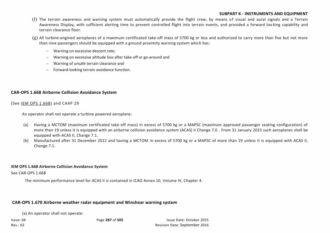
SUBPART K - INSTRUMENTS AND EQUIPMENT
Issue: 04 Page 287 of 505 Issue Date: October 2015
Rev.: 02 Revision Date: September 2016
(f) The terrain awareness and warning system must automatically provide the flight crew, by means o f visual and aural signals and a Terrain Awareness Display, with sufficient alerting time to prevent controlled flight into terrain events, and provided a forward loo king capability and terrain clearance floor.
(g) All turbine-engined aeroplanes of a maximum certificated take-off mass of 5700 kg or less and authorized to carry more than five but not more than nine passengers should be equipped with a ground proximity warning system which has :
Warning on excessive descent rate;
Warning on excessive altitude loss after take-off or go-around and
Warning of unsafe terrain clearance and
Forward-looking terrain avoidance function.
CAR-OPS 1.668 Airborne Collision Avoidance System
(See IEM OPS 1.668) and CAAP 29
An operator shall not operate a turbine powered aeroplane:
(a) Having a MCTOM (maximum certificated take-off mass) in excess of 5700 kg or a MAPSC (maximum approved passenger seating configuration) of more than 19 unless it is equipped with an airborne collision avoidance system (ACAS) II Change 7.0 . From 31 January 2015 such aeroplanes shall be equipped with ACAS II, Change 7.1.
(b) Manufactured after 31 December 2012 and having a MCTOM in excess of 5700 kg or a MAPSC of more than 19 unless it is equipped with ACAS II, Change 7.1.
IEM OPS 1.668 Airborne Collision Avoidance System
See CAR-OPS 1.668
The minimum performance level for ACAS II is contained in ICAO Annex 10, Volume IV, Chapter 4.
CAR-OPS 1.670 Airborne weather radar equipment and Winshear warning system
(a) An operator shall not operate:

SUBPART K - INSTRUMENTS AND EQUIPMENT
Issue: 04 Page 288 of 505 Issue Date: October 2015
Rev.: 02 Revision Date: September 2016
(1) A pressurised aeroplane; or
(2) An unpressurised aeroplane which has a maximum certificated take-off mass of more than 5700 kg; or
(3) An unpressurised aeroplane having a maximum approved passenger seating configuration of more than 9 seats after 1 April 1999, unless it is equipped with airborne weather radar equipment whenever such an aeroplane is being operated at night or in instrument meteoro logical conditions in areas where thunderstorms or other potentially hazardous weather conditions (wind shear), regarded as detectable with airborne weather radar, may be expected to exist along the route.
(b) For propeller driven pressurised aeroplanes having a maximum certificated take-off mass not exceeding 5700 kg with a maximum approved passenger seating configuration not exceeding 9 seats the airborne weather radar equipment may be replaced by other equipment capable of detecting thunderstorms and other potentially hazardous weather conditions (wind shear), regarded as detectable with airborne weather radar equipment, subject to approval by the Authority.
(c) All turbo-jet aeroplanes of a maximum certificated take-off mass in excess of 5700 kg or authorized to carry more than nine passengers should be equipped with a forward-looking wind shear warning system capable of; (1) Providing the pilot with a timely aural and visual warning of wind shear ahead of the aircraft, and the information required to permit the pilot to
safely commence and continue a missed approach or go-around or to execute an escape manoeuvre if necessary. (2) Providing an indication to the pilot when the limits specified for the certification of automatic landing equipment are being approached, when
such equipment is in use.
CAR-OPS 1.675 Equipment for operations in icing conditions
(a) An operator shall not operate an aeroplane in expected or actual icing conditions unless it is certificated and equipped to operate in icing co nditions.
(b) An operator shall not operate an aeroplane in expected or actual icing conditions at night unless it is equipped with a means to illuminate or detect the formation of ice. Any illumination that is used must be of a type that will not cause glare or reflection that would hand icap crew members in the performance of their duties.
AC OPS 1.680(a)(2) Quarterly Radiation Sampling
See CAR-OPS 1.680(a)(2)
1. Compliance with CAR-OPS 1.680(a)(2) may be shown by conducting quarterly radiation sampling during aeroplane operation using the following criter ia:
(a) The sampling should be carried out in conjunction with a Radiological Agency or similar organisation acceptable to the Authority;

SUBPART K - INSTRUMENTS AND EQUIPMENT
Issue: 04 Page 289 of 505 Issue Date: October 2015
Rev.: 02 Revision Date: September 2016
(b) Sixteen route sectors which include flight above 49000 ft should be sampled every quarter (three months). Where less than six teen route sectors which include flight above 49000 ft are achieved each quarter, then all sectors above 49000 ft should be sampled.;
(c) The cosmic radiation recorded should include both the neutron and non-neutron components of the radiation field.
2. The results of the sampling, including a cumulative summary quarter on quarter, sho uld be reported to the Authority under arrangements acceptable to the Authority.
CAR-OPS 1.680 Cosmic radiation detection equipment
(a) An operator shall not operate an aeroplane above 15000 m (49000 ft) unless:
(1) It is equipped with an instrument to measure and indicate continuously the dose rate of total cosmic radiation being received (i.e. the total of ionizing and neutron radiation of galactic and solar origin) and the cumulative dose on each flight, or
(2) A system of on-board quarterly radiation sampling acceptable to the authority is established (See AMC OPS 1.680(a)(2)).
CAR-OPS 1.685 Flight crew interphone system
An operator shall not operate an aeroplane on which a flight crew of more than one is required unless it is equipped with a f light crew interphone system, including headsets and microphones, not of a handheld type, for use by all members of the flight crew .
CAR-OPS 1.690 Crew member interphone system
(a) An operator shall not operate an aeroplane with a maximum certificated take-off mass exceeding 15000 kg or having a maximum approved passenger seating configuration of more than 19 unless it is equipped with a crew member interphone system.
(b) The crew member interphone system required by this paragraph must:
(1) Operate independently of the public address system except for handsets, headsets, microphones, selector switches and signalling devices;
(2) Provide a means of two-way communication between the flight crew compartment and:

SUBPART K - INSTRUMENTS AND EQUIPMENT
Issue: 04 Page 290 of 505 Issue Date: October 2015
Rev.: 02 Revision Date: September 2016
(i) Each passenger compartment;
(ii) Each galley located other than on a passenger deck level; and
(iii) Each remote crew compartment that is not on the passenger deck and is not easily accessible from a passenger compartment;
(3) Be readily accessible for use from each of the required flight crew stations in the flight crew co mpartment;
(4) Be readily accessible for use at required cabin crew member stations close to each separate or pair of floor level emergency exits;
(5) Have an alerting system incorporating aural or visual signals for use by flight crew members to alert the cabin crew and for use by cabin crew members to alert the flight crew;
(6) Have a means for the recipient of a call to determine whether it is a normal call or an emergency call ( See AMC OPS 1.690(b)(6)); and
(7) Provide on the ground a means of two-way communication between ground personnel and at least two flight crew members. ( See IEM OPS 1.690(b)(7)).
AMC OPS 1.690(b)(6) Crew member interphone system
See CAR-OPS 1.690(b)(6)
1 The means of determining whether or not an interphone call is a normal or an emergency call may be one or a combination of th e following:
i. Lights of different colours;
ii. Codes defined by the operator (e.g. Different number of rings for normal and emergency calls);
iii. Any other indicating signal acceptable to the Authority.
IEM OPS 1.690(b)(7) Crew member interphone system
See CAR-OPS 1.690(b)(7)
At least one interphone system station for use by ground personnel should be, where practicable, so located that the personnel using the system may avoid detection from within the aeroplane.
CAR-OPS 1.695 Public address system
(a) An operator shall not operate an aeroplane with a maximum approved passenger seating configuration of more than 19 unless a public address system is installed.

SUBPART K - INSTRUMENTS AND EQUIPMENT
Issue: 04 Page 291 of 505 Issue Date: October 2015
Rev.: 02 Revision Date: September 2016
(b) The public address system required by this paragraph must:
(1) Operate independently of the interphone systems except for handsets, headsets, microphones, selector switches and signalling devices;
(2) Be readily accessible for immediate use from each required flight crew member station;
(3) For each required floor level passenger emergency exit which has an adjacent cabin crew seat, have a microphone which is read ily accessible to the seated cabin crew member, except that one microphone may serve more than one exit, provided the proximity of the exits allows unassisted verbal communication between seated cabin crew members;
(4) Be capable of operation within 10 seconds by a cabin crew member at each of those stations in the compartment from which its use is accessible; and
(5) Be audible and intelligible at all passenger seats, toilets and cabin crew seats and work stations.
CAR-OPS 1.700 Cockpit voice recorders–1
(See AC OPS 1.700)
(a) An operator shall not operate an aeroplane which:
(1) Is multi-engine turbine powered and has a maximum approved passenger seating configuration of more than 9; or
(2) Has a maximum certificated take-off mass over 5700 kg,
unless it is equipped with a cockpit voice recorder which, with reference to a time scale, records:
(i) Voice communications transmitted from or received on the flight deck by radio;
(ii) The aural environment of the flight deck, including without interruption, the audio signals received from each boom and mask microphone in use;
(iii) Voice communications of flight crew members on the flight deck using the aeroplane’s interphone system;
(iv) Voice or audio signals identifying navigation or approach aids introduced into a headset or speaker; and
(v) Voice communications of flight crew members on the flight deck using the public address system, if installed.

SUBPART K - INSTRUMENTS AND EQUIPMENT
Issue: 04 Page 292 of 505 Issue Date: October 2015
Rev.: 02 Revision Date: September 2016
(b) The cockpit voice recorder shall be capable of retaining information recorded during at least the last 2 hours of its operation except that, for those aeroplanes with a maximum certificated take-off mass of 5700 kg or less, this period may be reduced to 30 minutes.
(c) The cockpit voice recorder must start automatically to record prior to the aeroplane moving under its own power and continue to record until the termination of the flight when the aeroplane is no longer capable of moving under its own power. In addition, depending on th e availability of electrical power, the cockpit voice recorder must start to record as early as possible during the cockpit checks prior to engine start at the beginning of the flight until the cockpit checks immediately following engine shutdown at the end of the flight.
(d) The cockpit voice recorder must have a device to assist in locating that recorder in water.
AC OPS 1.700 Cockpit Voice Recorders
See CAR-OPS 1.700 The operational performance requirements for Cockpit Voice Recorders should be those laid down in EUROCAE Document ED56A (Min imum Operational Performance Requirements For Cockpit Voice Recorder Systems) December 1993.
AC OPS 1.700, 1.705 & 1.710 Cockpit Voice Recorders
See CAR-OPS 1.705 and 1.710
Summary table of applicable requirements
MCTOM
ALL AEROPLANE (See CAR-OPS 1.710 CVR-3) ALL AEROPLANE (See CAR-OPS 1.700
CVR-1)
5700kg NO REQUIREMENT
ALL MULTIENGINE TURBINE POWERED AEROPLANE with a MAPSC >9 seat (Applicability 1 April 2000) (See CAR-OPS 1.705 CVR-2)
ALL MULTIENGINE TURBINE POWERED AEROPLANE with a MAPSC >9 seat (Applicability 1 April 2000) (See CAR-OPS 1.700 CVR-1)
0 1.1.1990 1.4.1998 Date of issue of 1st CofA MCTOM : Max Certificated Take off Mass MAPSC: Max Approved Passenger seating configurations

SUBPART K - INSTRUMENTS AND EQUIPMENT
Issue: 04 Page 293 of 505 Issue Date: October 2015
Rev.: 02 Revision Date: September 2016
CAR-OPS 1.705 Cockpit voice recorders–2
(See AC OPS 1.705/1.710)
(a) An operator shall not operate any multi-engined turbine aeroplane which has a maximum certificated take-off mass of 5700 kg or less and a maximum approved passenger seating configuration of more than 9, unless it is equipped with a cockpit voice recorder which records:
(1) Voice communications transmitted from or received on the flight deck by radio;
(2) The aural environment of the flight deck, including where practicable, without interruption, the audio signals received from each boom and mask microphone in use;
(3) Voice communications of flight crew members on the flight deck using the aeroplane’s interphone system;
(4) Voice or audio signals identifying navigation or approach aids introduced into a headset or speaker; and
(5) Voice communications of flight crew members on the flight deck using the public address system, if installed.
(b) The cockpit voice recorder shall be capable of retaining information recorded during at least the last 30 m inutes of its operation.
(c) The cockpit voice recorder must start to record prior to the aeroplane moving under its own power and continue to record unti l the termination of the flight when the aeroplane is no longer capable of moving under its own power. In addition, depending on the availability of electrical power, the cockpit voice recorder must start to record as early as possible during the cockpit checks, prior to the flight until the coc kpit checks immediately following engine shutdown at the end of the flight.
(d) The cockpit voice recorder must have a device to assist in locating that recorder in water.
AC OPS 1.705/1.710 Cockpit Voice Recorders
See CAR-OPS 1.705/1.710
Account should be taken of the operational performance requirements for Cockpit Voice Recorders as laid down in EUROCAE Documents ED56 or ED56A (Minimum Operational Performance Requirements For Cockpit Voice Recorder Systems) dated February 1988 and December 1993 respe ctively.

SUBPART K - INSTRUMENTS AND EQUIPMENT
Issue: 04 Page 294 of 505 Issue Date: October 2015
Rev.: 02 Revision Date: September 2016
CAR-OPS 1.710 Cockpit voice recorders–3
(See AC OPS 1.705/1.710)
(a) An operator shall not operate any aeroplane with a maximum certificated take-off mass over 5700 kg unless it is equipped with a cockpit voice recorder which records:
(1) Voice communications transmitted from or received on the flight deck by radio;
(2) The aural environment of the flight deck;
(3) Voice communications of flight crew members on the flight deck using the aeroplane’s interphone system;
(4) Voice or audio signals identifying navigation or approach aids introduced into a headset or speaker; and
(5) Voice communications of flight crew members on the flight deck using the public address system, if installed.
(b) The cockpit voice recorder shall be capable of retaining information recorded during at least the last 30 minutes of its operation.
(c) The cockpit voice recorder must start to record prior to the aeroplane moving under its own power and continue to record unti l the termination of the flight when the aeroplane is no longer capable of moving under its own power.
(d) The cockpit voice recorder must have a device to assist in locating that recorder in water.
CAR-OPS 1.715 Flight data recorders–1
(See Appendix 1 to CAR-OPS 1.715)

SUBPART K - INSTRUMENTS AND EQUIPMENT
Issue: 04 Page 295 of 505 Issue Date: October 2015
Rev.: 02 Revision Date: September 2016
(See AC OPS 1.715)
(a) An operator shall not operate any aeroplane which:
(1) Is multi-engine turbine powered and has a maximum approved passenger seating configuration of more than 9; or
(2) Has a maximum certificated take-off mass over 5700 kg,
unless it is equipped with a flight data recorder that uses a digital method of recording and storing data and a method of re adily retrieving that data from the storage medium is available.
(b) The flight data recorder shall be capable of retaining the data recorded during at least the last 25 hours of its operation except that, for those aeroplanes with a maximum certificated take-off mass of 5700 kg or less, this period may be reduced to 10 hours.
(c) The flight data recorder must, with reference to a timescale, record:
(1) The parameters listed in Tables A1 or A2 of Appendix 1 to CAR-OPS 1.715 as applicable;
(2) For those aeroplanes with a maximum certificated take-off mass over 27000 kg, the additional parameters listed in Table B of Appendix 1 to CAR-OPS 1.715;
(3) For aeroplanes specified in (a) above, the flight data recorder must record any dedicated parameters relating to novel or uni que design or operational characteristics of the aeroplane as determined by the Authority during type or supplemental type certification; a nd
(4) For aeroplanes equipped with electronic display system the parameters listed in Table C of Appendix 1 to CAR-OPS 1.715., except that, for aeroplanes first issued with an individual Certificate of Airworthiness before 20 August 2002 those parameters for which:
(i) The sensor is not available; or
(ii) The aeroplane system or equipment generating the data needs to be modified; or
(iii) The signals are incompatible with the recording system;
do not need to be recorded if acceptable to the Authority.
(d) Data must be obtained from aeroplane sources which enable accurate correlation with information d isplayed to the flight crew.
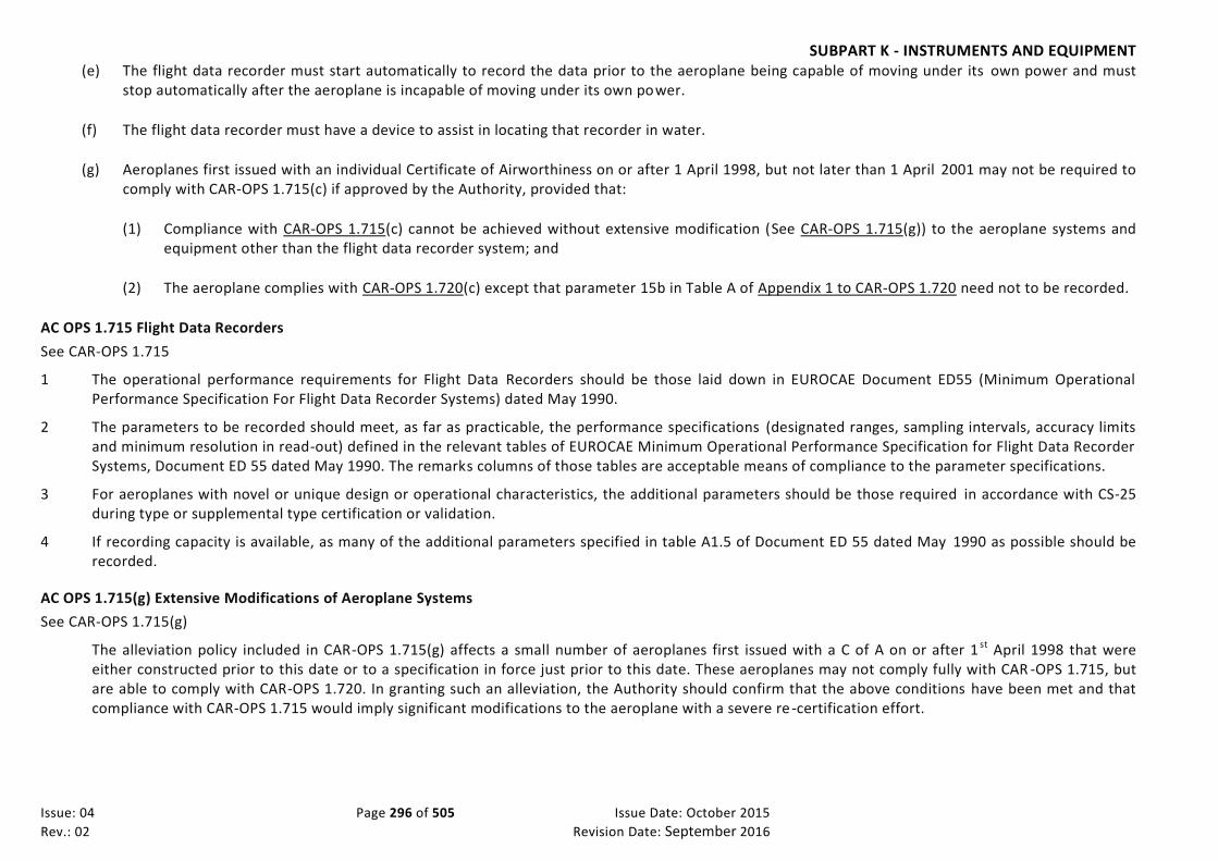
SUBPART K - INSTRUMENTS AND EQUIPMENT
Issue: 04 Page 296 of 505 Issue Date: October 2015
Rev.: 02 Revision Date: September 2016
(e) The flight data recorder must start automatically to record the data prior to the aeroplane being capable of moving under its own power and must stop automatically after the aeroplane is incapable of moving under its own power.
(f) The flight data recorder must have a device to assist in locating that recorder in water.
(g) Aeroplanes first issued with an individual Certificate of Airworthiness on or after 1 April 1998, but not later than 1 April 2001 may not be required to comply with CAR-OPS 1.715(c) if approved by the Authority, provided that:
(1) Compliance with CAR-OPS 1.715(c) cannot be achieved without extensive modification (See CAR-OPS 1.715(g)) to the aeroplane systems and equipment other than the flight data recorder system; and
(2) The aeroplane complies with CAR-OPS 1.720(c) except that parameter 15b in Table A of Appendix 1 to CAR-OPS 1.720 need not to be recorded.
AC OPS 1.715 Flight Data Recorders
See CAR-OPS 1.715
1 The operational performance requirements for Flight Data Recorders should be those laid down in EUROCAE Document ED55 (Minimum Operational Performance Specification For Flight Data Recorder Systems) dated May 1990.
2 The parameters to be recorded should meet, as far as practicable, the performance specifications (designated ranges, sampling intervals, accuracy limits and minimum resolution in read-out) defined in the relevant tables of EUROCAE Minimum Operational Performance Specification for Flight Data Recorder Systems, Document ED 55 dated May 1990. The remarks columns of those tables are acceptable means of compliance to the parameter specifications.
3 For aeroplanes with novel or unique design or operational characteristics, the additional parameters should be those required in accordance with CS-25 during type or supplemental type certification or validation.
4 If recording capacity is available, as many of the additional parameters specified in table A1.5 of Document ED 55 dated May 1990 as possible should be recorded.
AC OPS 1.715(g) Extensive Modifications of Aeroplane Systems
See CAR-OPS 1.715(g)
The alleviation policy included in CAR-OPS 1.715(g) affects a small number of aeroplanes first issued with a C of A on or after 1 st April 1998 that were either constructed prior to this date or to a specification in force just prior to this date. These aeroplanes may not comply fully with CAR -OPS 1.715, but are able to comply with CAR-OPS 1.720. In granting such an alleviation, the Authority should confirm that the above conditions have been met and that compliance with CAR-OPS 1.715 would imply significant modifications to the aeroplane with a severe re -certification effort.

SUBPART K - INSTRUMENTS AND EQUIPMENT
Issue: 04 Page 297 of 505 Issue Date: October 2015
Rev.: 02 Revision Date: September 2016
AC OPS 1.715, 1.720 & 1.725 Flight Data Recorders
See CAR-OPS 1.715, 1.720 and 1.725
Summary table of applicable requirements and parameters recorded
MCTOM
See Appendix 1 to CAR-OPS 1.725 See Appendix 1 to CAR-OPS 1.720
See Appendix 1 to CAR-OPS 1.715
TURBINE POWERED AEROPLANES
Table A (1.725) param. 1 - 5; and
For aeroplanes of a type first type certificated after 30.09.69 Table B (1.725) param. 6 – 15b
TURBINE POWERED AEROPLANES
Table A (1.725) param. 1 - 5; and
For aeroplanes of a type first type certificated after 30.09.69 Table B (1.725) param. 6 - 15b; and
If sufficient capacity is available on FDR system remaining Table B (1.725) parameters
ALL AEROPLANES
Table A (1.720) param. 1 - 15b; and
Table B (1.720) param. 16 - 32
ALL AEROPLANES
Table A1 (1.715) param. 1 - 17; and
Table B (1.715) param. 18 - 32; and
Table C (EFIS) param. 33 - 42; and
Param. relating to novel or unique design features
27000 kg
TURBINE POWERED AEROPLANES
Table A (1.725) Param. 1 - 5
TURBINE POWERED
AEROPLANES Table A (1.725)
param. 1 - 5
TURBINE POWERED AEROPLANES
Table A (1.725) param. 1 - 5; and
If sufficient capacity is available on FDR system Table B (1.725) parameters 6 - 15b
ALL AEROPLANES
Table A (1.720) param. 1 - 15b
ALL AEROPLANES
Table A1 (1.715) param. 1 - 17; and
Table C (EFIS) param. 33 - 42; and
Param. relating to novel or unique design features
5700 kg
No Requirement
No Requirement
No Requirement
No Requirement
MULTI-ENGINE TURBINE POWERED AEROPLANES
MASPC > 9
Table A2 (1.715) param. 1 - 17; and
Table C (EFIS) param. 33 - 42; and
Param. relating to novel or unique design features
01.01.87 01.01.89 01.06.90 01.04.98 Date of First Issuance of Individual
Note 1: Alleviation not included in this table Note 2: MCTOM = Maximum Certificated Take Off Mass Note 3: MAPSC = Maximum Approved Passenger Seating Configuration

Issue: 04 Page 298 of 505 Issue Date: October 2015
Rev.: 02 Revision Date: September 2016
CAR-OPS 1.720 Flight data recorders–2
(See Appendix 1 to CAR-OPS 1.720)
(See AC OPS 1.720/1.725)
(a) An operator shall not operate any aeroplane first issued with an individual certificate of airworthiness on or after 1 June 1990 up to and including 31 March 1998 which has a maximum certificated take-off mass over 5700 kg unless it is equipped with a flight data recorder that uses a digital method of recording and storing data and a method of readily retrieving that data from the storage medium is available.
(b) The flight data recorder shall be capable of retaining the data recorded during at least the last 25 hours of its operation.
(c) The flight data recorder must, with reference to a timescale, record:
(1) The parameters listed in Table A of Appendix 1 to CAR-OPS 1.720; and
(2) For those aeroplanes with a maximum certificated take-off mass over 27000 kg the additional parameters listed in Table B of Appendix 1 to CAR-OPS 1.720.
(d) For those aeroplanes having a maximum certificated take-off mass of 27000 kg or below, if acceptable to the Authority, parameters 14 and 15b of Table A of Appendix 1 to CAR-OPS 1.720 need not be recorded, when any of the following conditions are met:
(1) The sensor is not readily available,
(2) Sufficient capacity is not available in the flight recorder system,
(3) A change is required in the equipment that generates the data.
(e) For those aeroplanes having a maximum certificated take-off mass over 27000 kg, if acceptable to the Authority, the following parameters need not be recorded: 15b of Table A of Appendix 1 to CAR-OPS 1.720, and 23, 24, 25, 26, 27, 28, 29, 30 and 31 of Table B of Appendix 1, if any of the following conditions are met:
(1) The sensor is not readily available,
(2) Sufficient capacity is not available in the flight data recorder system,
(3) A change is required in the equipment that generates the data,
(4) For navigational data (NAV frequency selection, DME distance, latitude, longitude, ground speed and drift) the signals are not available in digital form.
(f) Individual parameters that can be derived by calculation from the other recorded parameters, need not to be recorded if acceptable to the Authority.
(g) Data must be obtained from aeroplane sources which enable accurate correlation with information displayed to the flight crew.

Issue: 04 Page 299 of 505 Issue Date: October 2015
Rev.: 02 Revision Date: September 2016
(h) The flight data recorder must start to record the data prior to the aeroplane being capable of moving under its own power and must stop after the aeroplane is incapable of moving under its own power.
(i) The flight data recorder must have a device to assist in locating that recorder in water.
AC OPS 1.720 /1.725 Flight Data Recorders
See CAR-OPS 1.720 /1.725 See Appendix 1 to AC OPS 1.720 /1.725
1 The parameters to be recorded should meet the performance specifications (designated ranges, recording intervals and accuracy limits) defined in Table 1 of Appendix 1 to AC-OPS 1.720/1.725. Remarks in Table 1 of Appendix 1 to AC-OPS 1.720/1.725 are acceptable means of compliance to the parameters requirements.
2 Flight data recorder systems, for which the recorded parameters do not comply with the performance specifications of Table 1 of Appendix 1 to AC-OPS 1.720/1.725 (i.e. range, sampling intervals, accuracy limits and recommended resolution readout) may be acceptable to the Authority.
3 For all aeroplanes, so far as practicable, when further recording capacity is available, the recording of the following additional parameters should be considered:
(a) Remaining parameters in Table B of Appendix 1 to CAR-OPS 1.720 or CAR-OPS 1.725 as applicable;
(b) Any dedicated parameter relating to novel or unique design or operational characteristics of the aeroplane;
(c) Operational information from electronic display systems, such as EFIS, ECAM or EICAS, with the following order of priority:
I. parameters selected by the flight crew relating to the desired flight path, e.g. barometric pressure setting, selected altitude, selected airspeed, decision height, and autoflight system engagement and mode indications if not recorded from another source;
II. display system selection/status, e.g. SECTOR, PLAN, ROSE, NAV, WXR, COMPOSITE, COPY, etc;
III. warning and alerts;
IV. the identity of displayed pages from emergency procedures and checklists.
(d) retardation information including brake application for use in the investigation of landing overruns or rejected take offs; and
(e) additional engine parameters (EPR, N1, EGT, fuel flow, etc.)
4. For the purpose of CAR-OPS 1.720(d), 1.720(e) and 1.725(c)(2), the alleviation should be acceptable only when adding the recording of missing parameters to the existing flight data recorder system would require a major upgrade of the system itself. Account should be taken of the following:
(a) The extent of the modification required
(b) The down-time period; and
(c) Equipment software development.
5. For the purpose of CAR-OPS 1.720(d), 1.720(e), 1.725(c)(2) and 1.725(c)(3) "capacity available" refers to the space on both Flight Data Acquisition Unit and the flight data recorder not allocated for recording the required parameters, or the parameters recorded for the purpose of CAR-OPS 1.037 (Safety Management System) as acceptable to the Authority.
6. For the purpose of CAR-OPS 1.720(d)(1), 1.720(e)(1), 1.725(c)(2)(i) and 1.725(c)(3) a sensor is considered "readily available" when it is already available or can be easily incorporated.

Issue: 04 Page 300 of 505 Issue Date: October 2015
Rev.: 02 Revision Date: September 2016
CAR-OPS 1.725 Flight data recorders–3
(See Appendix 1 to CAR-OPS 1.725)
(See AC OPS 1.720/1.725)
(a) An operator shall not operate any turbine-engined aeroplane first issued with an individual Certificate of Airworthiness, before 1 June 1990 which has a maximum certificated take-off mass over 5700 kg unless it is equipped with a flight data recorder that uses a digital method of recording and storing data and a method of readily retrieving that data from the storage medium is available .
(b) The flight data recorder shall be capable of retaining the data recorded during at least the last 25 hours of its operation.
(c) The flight data recorder must, with reference to a timescale, record:
(1) The parameters listed in Table A of Appendix 1 to CAR-OPS 1.725.
(2) For those aeroplanes with a maximum certificated take-off mass over 27000 kg that are of a type first type certificated after 30 September 1969, the additional parameters from 6 to 15b of Table B of Appendix 1 to CAR-OPS 1.725 of this paragraph. The following parameters need not be recorded, if acceptable to the Authority: 13, 14 and 15b in Table B of Appendix 1 to CAR-OPS 1.725 when any of the following conditions are met:
(i) The sensor is not readily available,
(ii) Sufficient capacity is not available in the flight recorder system,
(iii) A change is required in the equipment that generates the data;
and
(3) When sufficient capacity is available on a flight recorder system, the sensor is readily available and a change is not required in the equipment that generates the data:
(i) For aeroplanes first issued with an individual Certificate of Airworthiness on or after 1 January 1989, with a maximum certificated take off mass of over 5700 kg but not more than 27000 kg, parameters 6 to 15b of Table B of Appendix 1 to CAR-OPS 1.725; and
(ii) For aeroplanes first issued with an individual Certificate of Airworthiness on or after 1 January 1987, with a maximum certificated take off mass of over 27000 kg the remaining parameters of Table B of Appendix 1 to CAR-OPS 1.725 .
(d) Individual parameters that can be derived by calculation from the other recorded parameters, need not to be recorded if acceptable to the Authority.
(e) Data must be obtained from aircraft sources which enable accurate correlation with information displayed to the flight crew.
(f) The flight data recorder must start to record the data prior to the aeroplane being capable of moving under its own power and must stop after the aeroplane is incapable of moving under its own power.

Issue: 04 Page 301 of 505 Issue Date: October 2015
Rev.: 02 Revision Date: September 2016
(g) The flight data recorder must have a device to assist in locating that recorder in water.
CAR-OPS 1.727 Combination Recorder
(See AC-OPS 1.727)
(a) Compliance with Cockpit Voice recorder and flight data recorder requirements may be achieved by:
(1) One combination recorder if the aeroplane has to be equipped with a cockpit voice recorder or with a flight data recorder only; or
(2) One combination recorder if the aeroplane with a maximum certificated take-off mass of 5700 kg or less has to be equipped with a cockpit voice recorder and a flight data recorder; or
(3) Two combination recorders if the aeroplane with a maximum take-off mass over 5700 kg has to be equipped with a cockpit voice recorder and a flight data recorder.
(b) A combination recorder is a flight recorder that records:
(1) all voice communications and aural environment required by the relevant cockpit voice recorder paragraph; and
(2) all parameters required by the relevant flight data recorder paragraph, with the same specifications required by those paragraphs.
AC OPS 1.727 Combination recorders
(See CAR-OPS 1.727)
When two combination recorders are installed, one should be located near the cockpit, in order to minimise the risk of a data loss due to the failure of the wiring that gather data to the recorder. The other should be located at the rear of the aeroplane in order to minimise the risk of a data loss due to recorder damage in the case of a crash.
CAR-OPS 1.730 Seats, seat safety belts, harnesses and child restraint devices
(a) An operator shall not operate an aeroplane unless it is equipped with:
(1) A seat or berth for each person who is aged two years or more;
(2) A safety belt, with or without a diagonal shoulder strap, or a safety harness for use in each passenger seat for each passenger aged 2 years or more;
(3) A child restraint device, acceptable to the Authority, for each infant (See AC OPS 1.730(a)(3)
Seats, seat safety belts, harnesses & child restraint devices;)
(4) Except as provided in sub-paragraph (b) below, a safety belt with shoulder harness for each flight crew seat and for any seat alongside a pilot’s seat incorporating a device which will automatically restrain the occupant’s torso in the event of rapid deceleration;

Issue: 04 Page 302 of 505 Issue Date: October 2015
Rev.: 02 Revision Date: September 2016
(5) Except as provided in sub-paragraph (b) below, a safety belt with shoulder harness for each cabin crew seat and observer’s seats. However, this requirement does not preclude use of passenger seats by cabin crew members carried in excess of the required cabin crew complement; and
(6) Seats for cabin crew members located near required floor level emergency exits except that, if the emergency evacuation of passengers would be enhanced by seating cabin crew members elsewhere, other locations are acceptable. The seats shall be forward or rearward facing within 15° of the longitudinal axis of the aeroplane.
(b) All safety belts with shoulder harness must have a single point release.
(c) A safety belt with a diagonal shoulder strap for aeroplanes with a maximum certificated take-off mass not exceeding 5700 kg or a safety belt for aeroplanes with a maximum certificated take-off mass not exceeding 2 730 kg may be permitted in place of a safety belt with shoulder harness if it is not reasonably practicable to fit the latter.
AC OPS 1.730(a)(3) Seats, seat safety belts, harnesses & child restraint devices
(See CAR-OPS 1.730 (a)(3) )1. General
A child restraint device (CRD) is considered to be acceptable if:
(a) It is a ‘supplementary loop belt’ manufactured with the same techniques and the same materials of the approved safety belts; or
(b) It complies with paragraph 2.
2. Acceptable CRDs
Provided the CRD can be installed properly on the respective aircraft seat, the fol lowing CRDs are considered “acceptable”:
2.1 Types of CRDs
(a) CRDs approved for use in aircraft only by any JAA authority, the FAA or Transport Canada (on the basis of a national technical standard) and marked accordingly.
(b) CRDs approved for use in motor vehicles according to the UN standard ECE R 44, -03 or later
series of Amendments; or
(c) CRDs approved for use in motor vehicles and aircraft according to Canadian CMVSS 213/213.1; or
(d) CRDs approved for use in motor vehicles and aircraft according to US FMVSS No 213 and are
manufactured to these standards on or after February 26, 1985. US approved CRDs manufactured after this date must bear the following labels in red lettering:
1) “THIS CHILD RESTRAINT SYSTEM CONFORMS TO ALL APPLICABLE FEDERAL
MOTOR VEHICLE SAFETY STANDARDS“ and
2) “THIS RESTRAINT IS CERTIFIED FOR USE IN MOTOR VEHICLES AND AIRCRAFT“.
(e) CRDs qualified for use in aircraft according to the German “Qualification Procedure for Child Restraint Systems for Use in Aircraft“ (TÜV Doc.: TÜV/958-01/2001).
2.2 Devices approved for use in cars manufactured and tested to standards equivalent to those listed in
2.1 (a) to (e) inclusive, which are acceptable to the authority. The device must be marked with an

Issue: 04 Page 303 of 505 Issue Date: October 2015
Rev.: 02 Revision Date: September 2016
associated qualification sign, which shows the name of the qualification organisation and a specific identification number, related to the associated qualification project.
2.3 The qualifying organization shall be a competent and independent organization that is acceptable to
the authority. 3. Location 3.1 Forward facing CRDs may be installed on both forward and rearward facing passenger seats but only
when fitted in the same direction as the passenger seat on which it is positioned. Rearward facing CRDs can only be installed on forward facing passenger seats. A CRD may not be installed within the radius of action of an airbag, unless it is obvious that the airbag is de-activated or it can be demonstrated that there is no negative impact from the airbag.
3.2 A child in a restraint device should be located as near to a floor level exit as feasible. 3.3 A child in a restraint device should be seated in accordance with CAR-OPS 1.280 and IEM OPS 1.280,
“Passenger Seating“ so as to not hinder evacuation for any passenger. 3.4 A child in a restraint device should neither be located in the row leading to an emergency exit nor
located in a row immediately forward or aft of an emergency exit. A window passenger seat is the preferred location. An aisle passenger seat or a cross aisle passenger seat is not recommended. Other locations may be acceptable provided the access of neighbour passengers to the nearest aisle is not obstructed by the CRD.
3.5 In general, only one CRD per row segment is recommended. More than one CRD per row segment is
allowed if the children are from the same family or travelling group provided the children are accompanied by a responsible person sitting next to them.
3.6 A Row Segment is the fraction of a row separated by two aisles or by one aisle and the aircraft
fuselage. 4. Installation 4.1 CRDs shall only be installed on a suitable aircraft seat with the type of connecting device they are
approved or qualified for. E.g., CRDs to be connected by a three point harness only (most rearward facing baby CRDs currently available) shall not be attached to an aircraft seat with a lap belt only, a CRD designed to be attached to a vehicle seat by means of rigid bar lower anchorages (ISO-FIX or US equivalent) only, shall only be used on aircraft seats that are equipped with such connecting devices and shall not be attached by the aircraft seat lap belt. The method of connecting must be clearly shown in the manufacturer’s instructions to be provided with each CRD.
4.2 All safety and installation instructions must be followed carefully by the responsible person
accompanying the infant. Cabin crew should prohibit the use of any inadequately installed CRD or not qualified seat.
4.3 If a forward facing CRD with a rigid backrest is to be fastened by a lap belt, the restraint device sho uld
be fastened when the backrest of the passenger seat on which it rests is in a reclined position. Thereafter, the backrest is to be positioned upright. This procedure ensures better tightening of the CRD on the aircraft seat if the aircraft seat is reclinable.
4.4 The buckle of the adult safety belt must be easily accessible for both opening and closing, and must
be in line with the seat belt halves (not canted) after tightening. 4.5 Forward facing restraint devices with an integral harness must not be installed such that the adult
safety belt is secured over the child. 5. Operation 5.1 Each CRD shall remain secured to a passenger seat during all phases of flight, unless it is properly
stowed when not in use.

Issue: 04 Page 304 of 505 Issue Date: October 2015
Rev.: 02 Revision Date: September 2016
5.2 Where a CRD is adjustable in recline it must be in an upright position for all occasions when
passenger restraint devices are required to be used according to CAR-OPS 1.320(b)(1).]
CAR-OPS 1.731 Fasten Seat belt and No Smoking signs
An operator shall not operate an aeroplane in which all passenger seats are not visible from the flight deck, unless it is equipped with a means of indicating to all passengers and cabin crew when seat belts shall be fastened and when smoking is not allowed.
CAR-OPS 1.735 Internal doors and curtains
An operator shall not operate an aeroplane unless the following equipment is installed:
(a) In an aeroplane with a maximum approved passenger seating configuration of more than 19 passengers, a door between the passenger compartment and the flight deck compartment with a placard ‘crew only’ and a locking means to prevent passengers from opening it without the permission of a member of the flight crew;
(b) A means for opening each door that separates a passenger compartment from another compartment that has emergency exit provisions. The means for opening must be readily accessible;
(c) If it is necessary to pass through a doorway or curtain separating the passenger cabin from other areas to reach any required emergency exit from any passenger seat, the door or curt ain must have a means to secure it in the open position;
(d) A placard on each internal door or adjacent to a curtain that is the means of access to a passenger emergency exit, to indicate that it must be secured open during take off and landing; and
(e) A means for any member of the crew to unlock any door that is normally accessible to passengers and that can be locked by passengers.
CAR-OPS 1.740 Placards (See IEM OPS 1.740) An operator shall not operate an aeroplane unless the following placards are installed;
(a) Every exit from the aircraft shall be marked with the words "Exit" and "Emergency Exit” in both English and Arabic script, or with universal symbolic exit signs.
(b) Every exit from and to the aircraft shall be marked with instructions in English and Arabic or with
universal symbolic exit signs to indicate the correct method of opening the exit. The markings shall be placed on or near the inside surface of the door or other closure of the exit and, if it is operable, from the outside of the aircraft on or near the exterior surface.
(c) Every safety related placards intended to be used by passengers and external emergency
evacuation crew shall be in both Arabic and English scripts or with universal symbolic signs. Bilingual placards shall meet the applicable airworthiness requirements.

Issue: 04 Page 305 of 505 Issue Date: October 2015
Rev.: 02 Revision Date: September 2016
IEM OPS 1.740 Placards
(See CAR-OPS 1.740)
1. The markings required must:
(a) be painted, or affixed by other equally permanent means;
(b) be red in colour, and in any case in which the colour of the adjacent back-ground is such as to render red markings not readily visible,
(c) be outlined in white or some other contrasting colour in such a manner as to render them readily visible; be kept at all times clean and un-obscured.
(d) Arabic script is written by connected letters. (e) If they are symbolic signs, then the exit universal symbols standard acceptable to EASA, FAA &
Transport Canada are considered acceptable for respective State of Design aircraft .
2. Placards required by CAR-OPS 1.740 (c) are:
(a). Break in marking, if applicable, is an example of a safety related placard to be use by external
emergency evacuation crew. (b). Examples of safety related placards to be used by passengers are “Fasten Seat Belts”, “No
Smoking Signs” etc.
CAR-OPS 1.745 First-Aid Kits (See AMC OPS 1.745)
(a) An operator shall not operate an aeroplane unless it is equipped with first -aid kits, readily accessible for use, to the following scale:
Number of passenger
seats installed
Number of First-Aid
Kits required
1 to 100 1
101 to 200 2
201 to 300 3
301 to 400 4
401 to 500 5
501 or more 6
(b) An operator shall ensure that first-aid kits are:
(1) Inspected periodically to confirm, to the extent possible, that contents are maintained in the condition necessary for their intended use; and
(2) Replenished at regular intervals, in accordance with instructions contained on their labels, or as circumstances warrant.
AMC OPS 1.745 First-Aid Kits
See CAR-OPS 1.745
The following should be included in the First-Aid Kits:

Issue: 04 Page 306 of 505 Issue Date: October 2015
Rev.: 02 Revision Date: September 2016
Ground/Air visual signal code for use by survivors (may be contained in / as separate kit).
Antiseptic swabs (10/pack)
Bandage: adhesive strips
Bandage: gauze 7.5 cm × 4.5 m
Bandage: triangular; safety pins
Dressing: burn 10 cm × 10 cm
Dressing: compress, sterile 7.5 cm × 12 cm
Dressing: gauze, sterile 10.4 cm × 10.4 cm
Tape: adhesive 2.5 cm (roll)
Steri-strips (or equivalent adhesive strip)
Hand cleanser or cleansing towelettes
Pad with shield, or tape, for eye
Scissors: 10 cm
Tape: Adhesive, surgical 1.2 cm × 4.6 m
Tweezers: splinter
Disposable gloves (multiple pairs)
Thermometers (non-mercury)
Mouth-to-mouth resuscitation mask with one-way valve
First-aid manual, current edition
Incident record form
Mild to moderate analgesic
Antiemetic
Nasal decongestant
Antacid
Antihistamine
A list of contents in at least 2 languages (English and one other). This should include information on the effects and side effects of drugs carried.
NOTE: An eye irrigator whilst not required to be carried in the first-aid kit should, where possible, be available for use on the ground.
+ For aeroplanes with more than 9 passenger seats installed.
CAR-OPS 1.750 Universal Precaution Kit (See AMC OPS 1.750) Aeroplanes which are required to carry at least one cabin crew member as part of the operating crew, requires to have one universal precaution kit (two for aeroplanes authorized to carry more than 250 passengers) for the use of cabin crew members in managing incidents of ill health associated with a case of suspected communicable disease, or in the case of illness involving contact with body fluids, such as blood, urine, vomit and faeces and to protect the cabin crew members who are assisting potentially infectious cases of suspected communicable disease.
AMC OPS 1.750 Universal Protection Kit content
The Universal Protection Kit shall contain as minimum the following — Dry powder that can convert small liquid spill into a sterile granulated gel

Issue: 04 Page 307 of 505 Issue Date: October 2015
Rev.: 02 Revision Date: September 2016
— Germicidal disinfectant for surface cleaning — Skin wipes — Face/eye mask (separate or combined) — Gloves (disposable) — Protective apron — Large absorbent towel — Pick-up scoop with scraper — Bio-hazard disposal waste bag — Instructions
CAR-OPS 1.755 Emergency Medical Kit
(See AMC OPS 1.755)
(a) An operator shall not operate an aeroplane with a maximum approved passenger seating configuration of more than 30 seats unless it is equipped with an emergency medical kit if any point on the planned route is more than 60 minutes flying time (at normal cruising speed) from an aerodrome at which qualified medical assistance could be expected to be available.
(b) The commander shall ensure that drugs or Physchoactive substances are not administered except by qualified doctors, nurses or similarly qualified personnel.
(c) Conditions for carriage
(1) The emergency medical kit must be dust and moisture proof and shall be carried under security conditions, where practicable, on the flight deck; and
(2) An operator shall ensure that emergency medical kits are:
(i) Inspected periodically to confirm, to the extent possible, that the contents are maintained in the condition necessary for their intended use; and
(ii) Replenished at regular intervals, in accordance with instructions contained on their labels, or as circumstances warrant.
AMC OPS 1.755 Emergency Medical Kit
See CAR-OPS 1.755
The following should be included in the emergency medical kit carried in the aeroplane:
MEDICAL KIT — Stethoscope — Sphygmomanometer (electronic preferred) — Airways, oropharyngeal (three sizes) — Syringes (appropriate range of sizes ) — Needles (appropriate range of sizes) — Intravenous catheters (appropriate range of sizes) — Antiseptic wipes — Gloves (disposable) — Needle disposal box — Urinary catheter — System for delivering intravenous fluids — Venous tourniquet

Issue: 04 Page 308 of 505 Issue Date: October 2015
Rev.: 02 Revision Date: September 2016
— Sponge gauze — Tape – adhesive — Surgical mask — Emergency tracheal catheter (or large gauge intravenous cannula) — Umbilical cord clamp — Thermometers (non-mercury) — Basic life support cards — Bag-valve mask — Flashlight and batteries MEDICATION
Anti-smasmodic e.g. hyascene
Medication for Hypoglycaemia, hypertonic glucose and/or glucagon
Digoxin — Epinephrine 1:1 000 — Antihistamine – injectable — Dextrose 50% (or equivalent) – injectable: 50 ml — Nitroglycerin tablets, or spray — Major analgesic — Sedative anticonvulsant – injectable — Antiemetic – injectable — Bronchial dilator – inhaler — Atropine – injectable — Adrenocortical steroid – injectable — Diuretic – injectable — Medication for postpartum bleeding — Sodium chloride 0.9% (minimum 250 ml) — Acetyl salicylic acid (aspirin) for oral use — Oral beta blocker If a cardiac monitor is available (with or without an AED) add to the above list: — Epinephrine 1:10 000 (can be a dilution of epinephrine 1:1 000)
A list of contents in at least 2 languages (English and one other). This should include information on the effects and side effects of physchoactive substances carried.
CAR-OPS 1.760 First-aid oxygen (See IEM OPS 1.760)
(a) An operator shall not operate a pressurised aeroplane, above 25000 ft, when a cabin crew member is required to be carried, unless it is equipped with a supply of undiluted oxygen for passengers who, for physiological reasons, might require oxygen following a cabin depressurisation. The amount of oxygen shall be calculated using an average flow rate of at least 3 litres Standard Temperature Pressure Dry (STPD)/minute/person and shall be sufficient for the remainder of the flight after cabin depressurisation when the cabin altitude exceeds 8000 ft but does not exceed 15000 ft, for at least 2% of the passengers carried, but in no case for less than one person. There shall be a sufficient number of dispensing units, but in no case less than two, with a means for cabin crew to use the supply. The dispensing units may be of a portable type.
(b) The amount of first-aid oxygen required for a particular operation shall be determined on the basis of cabin pressure altitudes and flight duration, consistent with the operating procedures established for each operation and route.

Issue: 04 Page 309 of 505 Issue Date: October 2015
Rev.: 02 Revision Date: September 2016
(c) The oxygen equipment provided shall be capable of generating a mass flow to each user of at least four litres per minute, STPD. Means may be provided to decrease the flow to not less than two litres per minute, STPD, at any altitude.
IEM OPS 1.760 First-aid Oxygen
See CAR-OPS 1.760
1 First–aid oxygen is intended for those passengers who, having been provided with the supplemental oxygen required under CAR-OPS 1.770, still need to breathe undiluted oxygen when the amount of supplemental oxygen has been exhausted.
2 When calculating the amount of first-aid oxygen, an operator should take into account the fact that, following a cabin depressurisation, supplemental oxygen as calculated in accordance with Appendix 1 to CAR-OPS 1.770 should be sufficient to cope with hypoxic problems for:
(a) all passengers when the cabin altitude is above 15000 ft; and
(b) a proportion of the passengers carried when the cabin altitude is between 10000 ft and 15000 ft.
3 For the above reasons, the amount of first-aid oxygen should be calculated for the part of the flight after cabin depressurisation during which the cabin altitude is between 8000 ft and 15000 ft, when supplemental oxygen may no longer be available.
4 Moreover, following cabin depressurisation an emergency descent should be carried out to the lowest altitude compatible with the safety of the flight. In addition, in these circumstances, the aeroplane should land at the first available aerodrome at the earliest opportunity.
5 The conditions above should reduce the period of time during which the first-aid oxygen may be required and consequently should limit the amount of first-aid oxygen to be carried on board.
CAR-OPS 1.765 Reserved
CAR-OPS 1.770 Supplemental oxygen – pressurised aeroplanes (See Appendix 1 to CAR-OPS 1.770) (See AMC OPS 1.770) (a) General
(1) An operator shall not operate a pressurised aeroplane at pressure altitudes above 10000 ft unless supplemental oxygen equipment, capable of storing and dispensing the oxygen supplies required by this paragraph, is provided.
(2) The amount of supplemental oxygen required shall be determined on the basis of cabin pressure altitude, flight duration and the assumption that a cabin pressurisation failure will occur at the pressure altitude or point of flight that is most critical from the standpoint of oxygen need, and that, after the failure, the aeroplane will descend in accordance with emergency procedures specified in the Aeroplane Flight Manual to a safe altitude for the route to be flown that will allow continued safe flight and landing.
(3) Following a cabin pressurisation failure, the cabin pressure altitude shall be considered the same as the aeroplane pressure altitude, unless it is demonstrated to the Authority that no probable failure of the cabin or pressurisation system will result in a cabin pressure altitude equal to the aeroplane pressure altitude. Under these circumstances, the demonstrated maximum cabin pressure altitude may be used as a basis for determination of oxygen supply.
(b) Oxygen equipment and supply requirements

Issue: 04 Page 310 of 505 Issue Date: October 2015
Rev.: 02 Revision Date: September 2016
(1) Flight crew members
(i) Each member of the flight crew on flight deck duty shall be supplied with supplemental oxygen in accordance with Appendix 1. If all occupants of flight deck seats are supplied from the flight crew source of oxygen supply then they shall be considered as flight crew members on flight deck duty for the purpose of oxygen supply. Flight deck seat occupants, not supplied by the flight crew source, are to be considered as passengers for the purpose of oxygen supply.
(ii) Flight crew members, not covered by sub-paragraph (b)(1)(i) above, are to be considered as passengers for the purpose of oxygen supply.
(iii) Oxygen masks shall be located so as to be within the immediate reach of flight crew members whilst at their assigned duty station.
(iv) Oxygen masks for use by flight crew members in pressurised aeroplanes operating at pressure altitudes above 25000 ft, shall be a quick donning type of mask.
(2) Cabin crew members, additional crew members and passengers
(i) Cabin crew members and passengers shall be supplied with supplemental oxygen in accordance with Appendix 1, except when sub-paragraph (v) below applies. Cabin crew members carried in addition to the minimum number of cabin crew members required, and additional crew members, shall be considered as passengers for the purpose of oxygen supply.
(ii) Aeroplanes intended to be operated at pressure altitudes above 25000 ft shall be provided sufficient spare outlets and masks and/or sufficient portable oxygen units with masks for use by all required cabin crew members. The spare outlets and/or portable oxygen units are to be distributed evenly throughout the cabin to ensure immediate availability of oxygen to each required cabin crew member regardless of his location at the time of cabin pressurisation failure.
(iii) Aeroplanes intended to be operated at pressure altitudes above 25000 ft shall be provided an oxygen dispensing unit connected to oxygen supply terminals immediately available to each occupant, wherever seated. The total number of dispensing units and outlets shall exceed the number of seats by at least 10%. The extra units are to be evenly distributed throughout the cabin.
(iv) Aeroplanes intended to be operated at pressure altitudes above 25000 ft or which, if operated at or below 25000 ft, cannot descend safely within 4 minutes to 13000 ft, and for which the individual certificate of airworthiness was first issued on or after 9 November 1998, shall be provided with automatically deployable oxygen equipment immediately available to each occupant, wherever seated. The total number of dispensing units and outlets shall exceed the number of seats by at least 10%. The extra units are to be evenly distributed throughout the cabin.
(v) The oxygen supply requirements, as specified in Appendix 1, for aeroplanes not certificated to fly above 25000 ft, may be reduced to the entire flight time between 10000 ft and 13000 ft cabin pressure altitudes for all required cabin crew members and for at least 10% of the passengers if, at all points along the route to be flown, the aeroplane is able to descend safely within 4 minutes to a cabin pressure alt itude of 13000 ft.
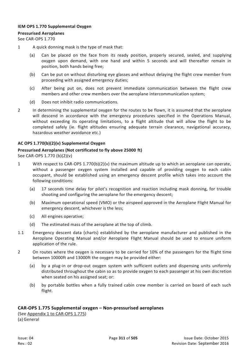
Issue: 04 Page 311 of 505 Issue Date: October 2015
Rev.: 02 Revision Date: September 2016
IEM OPS 1.770 Supplemental Oxygen
Pressurised Aeroplanes See CAR-OPS 1.770
1 A quick donning mask is the type of mask that:
(a) Can be placed on the face from its ready position, properly secured, sealed, and supplying oxygen upon demand, with one hand and within 5 seconds and will thereafter remain in position, both hands being free;
(b) Can be put on without disturbing eye glasses and without delaying the flight crew member from proceeding with assigned emergency duties;
(c) After being put on, does not prevent immediate communication between the flight crew members and other crew members over the aeroplane intercommunication system;
(d) Does not inhibit radio communications.
2 In determining the supplemental oxygen for the routes to be flown, it is assumed that the aeroplane will descend in accordance with the emergency procedures specified in the Operations Manual, without exceeding its operating limitations, to a flight altitude that will allow the flight to be completed safely (ie. flight altitudes ensuring adequate terrain clearance, navigational accuracy, hazardous weather avoidance etc.)
AC OPS 1.770(b)(2)(v) Supplemental Oxygen
Pressurised Aeroplanes (Not certificated to fly above 25000 ft) See CAR-OPS 1.770 (b)(2)(v)
1 With respect to CAR-OPS 1.770(b)(2)(v) the maximum altitude up to which an aeroplane can operate, without a passenger oxygen system installed and capable of providing oxygen to each cabin occupant, should be established using an emergency descent profile which takes into account the following conditions:
(a) 17 seconds time delay for pilot’s recognition and reaction including mask donning, for trouble shooting and configuring the aeroplane for the emergency descent;
(b) Maximum operational speed (VMO) or the airspeed approved in the Aeroplane Flight Manual for emergency descent, whichever is the less;
(c) All engines operative;
(d) The estimated mass of the aeroplane at the top of climb.
1.1 Emergency descent data (charts) established by the aeroplane manufacturer and published in the Aeroplane Operating Manual and/or Aeroplane Flight Manual should be used to ensure uniform application of the rule.
2 On routes where the oxygen is necessary to be carried for 10% of the passengers for the fli ght time between 10000ft and 13000ft the oxygen may be provided either:
(a) by a plug-in or drop-out oxygen system with sufficient outlets and dispensing units uniformly distributed throughout the cabin so as to provide oxygen to each passenger at his own disc retion when seated on his assigned seat; or:
(b) by portable bottles when a fully trained cabin crew member is carried on board of each such flight.
CAR-OPS 1.775 Supplemental oxygen – Non-pressurised aeroplanes (See Appendix 1 to CAR-OPS 1.775) (a) General

Issue: 04 Page 312 of 505 Issue Date: October 2015
Rev.: 02 Revision Date: September 2016
(1) An operator shall not operate a non-pressurised aeroplane at altitudes above 10000 ft unless supplemental oxygen equipment, capable of storing and dispensing the oxygen supplies required, is provided.
(2) The amount of supplemental oxygen for sustenance required for a particular operation shall be determined on the basis of flight altitudes and flight duration, consistent with the operating procedures established for each operation in the Operations Manual and with the routes to be flown, and with the emergency procedures specified in the Operations Manual.
(3) An aeroplane intended to be operated at pressure altitudes above 10000 ft shall be provided with equipment capable of storing and dispensing the oxygen supplies required.
(b) Oxygen supply requirements
(1) Flight crew members. Each member of the flight crew on flight deck duty shall be supplied with supplemental oxygen in accordance with Appendix 1. If all occupants of flight deck seats are supplied from the flight crew source of oxygen supply then they shall be considered as flight crew members on flight deck duty for the purpose of oxygen supply.
(2) Cabin crew members, additional crew members and passengers. Cabin crew members and passengers shall be supplied with oxygen in accordance with Appendix 1. Cabin crew members carried in addition to the minimum number of cabin crew members required, and additional crew members, shall be considered as passengers for the purpose of oxygen supply.
CAR-OPS 1.780 Crew Protective Breathing Equipment
(a) An operator shall not operate a pressurised aeroplane or, after 1 April 2000, an unpressurised aeroplane with a maximum certificated take-off mass exceeding 5700 kg or having a maximum approved seating configuration of more than 19 seats unless:
(1) It has equipment to protect the eyes, nose and mouth of each flight crew member while on flight deck duty and to provide oxygen for a period of not less than 15 minutes. The supply for Protective Breathing Equipment (PBE) may be provided by the supplemental oxygen required by CAR-OPS 1.770(b)(1) or CAR-OPS 1.775(b)(1). In addition, when the flight crew is more than one and a cabin crew member is not carried, portable PBE must be carried to protect the eyes, nose and mouth of one member of the flight crew and to provide breathing gas for a period of not less than 15 minutes; and
(2) It has sufficient portable PBE to protect the eyes, nose and mouth of all required cabin crew members and to provide breathing gas for a period of not less than 15 minutes.
(b) PBE intended for flight crew use must be conveniently located on the flight deck and be easily accessible for immediate use by each required flight crew member at their assigned duty station.
(c) PBE intended for cabin crew use must be installed adjacent to each required cabin crew member duty station.
(d) An additional, easily accessible portable PBE must be provided and located at or adjacent to the hand fire extinguishers required by CAR-OPS 1.790(c) and (d) except that, where the fire extinguisher is located inside a cargo compartment, the PBE must be stowed outside but adjacent to the entrance to that compartment.

Issue: 04 Page 313 of 505 Issue Date: October 2015
Rev.: 02 Revision Date: September 2016
(e) PBE while in use must not prevent communication where required by CAR-OPS 1.313, CAR-OPS 1.685, CAR-OPS 1.690, CAR-OPS 1.810 and CAR-OPS 1.850.
CAR-OPS 1.785 HUD or Equivalent Displays (See Appendix 1 to CAR-OPS 1.785 HUD, VS or Equivalent)
An operator shall not operate an aeroplane equipped with a HUD or equivalent displays, EVS, SVS or CVS, or
any combination of those systems into a hybrid system unless:
(a) An approval has been issued by the Authority for the operational use of such displays,
(b) The equipment meets the appropriate airworthiness certification requirements;
(c) The operator has carried out a safety risk assessment of the operations supported by the HUD or equivalent displays, EVS, SVS or CVS;
(d) The operator has established and documented the procedures for the use of, and training requirements for, a HUD or equivalent displays, EVS, SVS or CVS
(e) The criteria for the use of such systems for the safe operation of an aeroplane as described in Appendix 1 to CAR-OPS 1.785 HUD, VS or Equivalent is complied with as applicable.
CAR-OPS 1.790 Fire extinguishers
(See AMC OPS 1.790 Fire Extinguishers)
(a) An operator shall not operate an aeroplane unless hand fire extinguishers are provided for use in crew, passenger and, as applicable, cargo compartments and galleys in accordance with the following:
(i) The type and quantity of extinguishing agent must be suitable for the kinds of fires likely to occur in the compartment where the extinguisher is intended to be used and, for personnel compartments, must minimise the hazard of toxic gas concentration;
(ii) At least one hand fire extinguisher, containing Halon 1211 (bromochlorodifluoro-methane, CBrCIF2), or equivalent as the extinguishing agent, must be conveniently located on the flight
deck for use by the flight crew; (iii) At least one hand fire extinguisher must be located in, or readily accessible for use in, each
galley not located on the main passenger deck; (iv) At least one readily accessible hand fire extinguisher must be available for use in each Class A
or Class B cargo or baggage compartment and in each Class E cargo compartment that is accessible to crew members in flight; and
(v) At least the following number of hand fire extinguishers must be conveniently located in the passenger compartment(s):
Maximum approved passenger seating configuration
Number of Extinguishers
7 to 30 1
31 to 60 2
61 to 200 3
201 to 300 4
301 to 400 5
401 to 500 6
501 to 600 7
601 or more 8

Issue: 04 Page 314 of 505 Issue Date: October 2015
Rev.: 02 Revision Date: September 2016
When two or more extinguishers are required, they must be evenly distributed in the passenger compartment.
(vi) At least one of the required fire extinguishers located in the passenger compartment of an aeroplane with a maximum approved passenger seating configuration of at least 31, and not more than 60, and at least two of the fire extinguishers located in the passenger compartment of an aeroplane with a maximum approved passenger seating configuration of 61 or more must contain Halon 1211 (bromochlorodi-fluoromethane, CBrCIF2), or equivalent
as the extinguishing agent.
(b) An operator shall ensure that any agent used in a built-in fire extinguisher for each lavatory disposal receptacle for towels, paper or waste in an aeroplane for which the individual certificate of airworthiness is first issued on or after 31 December 2011 and any extinguishing agent used in a portable fire extinguisher in an aeroplane for which the individual certificate of airworthiness is first issued on or after 31 December 2018:
(i) meets the applicable minimum performance requirements of the State of Registry acceptable to the GCAA; and
(ii) is not of a type listed in the 1987 Montreal Protocol on Substances that Deplete the Ozone Layer as it appears in the Eighth Edition of the Handbook for the Montreal Protocol on Substances that Deplete the Ozone Layer, Annex A, Group II.
AMC OPS 1.790 Fire Extinguishers
See CAR-OPS 1.790 Fire extinguishers
1 The number and location of hand fire extinguishers should be such as to provide adequate availability for use, account being taken of the number and size of the passenger compartments, the need to minimise the hazard of toxic gas concentrations and the location of toilets, galleys etc. These considerations may result in the number being greater than the minimum prescribed.
2 There should be at least one fire extinguisher suitable for both flammable fluid and electrical equipment fires installed on the flight deck. Additional extinguishers may be required fo r the protection of other compartments accessible to the crew in flight. Dry chemical fire extinguishers should not be used on the flight deck, or in any compartment not separated by a partition from the flight deck, because of the adverse effect on vision during discharge and, if non-conductive, interference with electrical contacts by the chemical residues.
3 Where only one hand fire extinguisher is required in the passenger compartments it should be located near the cabin crew member’s station, where provided.
4 Where two or more hand fire extinguishers are required in the passenger compartments and their location is not otherwise dictated by consideration of paragraph 1 above, an extinguisher should be located near each end of the cabin with the remainder distributed throughout the cabin as evenly as is practicable.
5 Unless an extinguisher is clearly visible, its location should be indicated by a placard or sign. Appropriate symbols may be used to supplement such a placard or sign.
CAR-OPS 1.795 Crash axes and crowbars
(a) An operator shall not operate an aeroplane with a maximum certificated take-off mass exceeding 5700 kg or having a maximum approved passenger seating configuration of more than 9 seats unless it is equipped with at least one crash axe or crowbar located on the flight deck.
(b) Crash axes and crowbars located in the passenger compartment must not be vis ible to passengers.

Issue: 04 Page 315 of 505 Issue Date: October 2015
Rev.: 02 Revision Date: September 2016
CAR-OPS 1.800 Marking of break-in points
An operator shall ensure that, if areas of the fuselage suitable for break-in by rescue crews in emergency are marked on an aeroplane, such areas shall be marked as shown below. The colour of the markings shall be red or yellow, and if necessary they shall be outlined in white to contrast with the background. If the corner markings are more than 2 metres apart, intermediate lines 9 cm x 3 cm shall be inserted so that there is no more than 2 metres between adjacent marks.

Issue: 04 Page 316 of 505 Issue Date: October 2015
Rev.: 02 Revision Date: September 2016
9cm 9cm
9cm
3cm 3cm
Not over 2m
3cm
CAR-OPS 1.805 Means for emergency evacuation
(a) An operator shall not operate an aeroplane with passenger emergency exit sill heights:
(1) Which are more than 1·83 metres (6 feet) above the ground with the aeroplane on the ground and the landing gear extended; or
(2) Which would be more than 1·83 metres (6 feet) above the ground after the collapse of, or failure to extend of, one or more legs of the landing gear and for which a Type Certificate was first applied for on or after 1 April 2000, unless it has equipment or devices available at each exit, where sub-paragraphs (1) or (2) apply, to enable passengers and crew to reach the ground safely in an emergency.
(b) Such equipment or devices need not be provided at overwing exits if the designated place on the aeroplane structure at which the escape route terminates is less than 1·83 metres (6 feet) from the ground with the aeroplane on the ground, the landing gear extended, and the flaps in the take off or landing position, whichever flap position is higher from the ground.
(c) In aeroplanes required to have a separate emergency exit for the flight crew and:
(1) For which the lowest point of the emergency exit is more than 1·83 metres (6 feet) above the ground with the landing gear extended; or,
(2) For which a Type Certificate was first applied for on or after 1 April 2000, would be more than 1·83 metres (6 ft) above the ground after the collapse of, or failure to extend of, one or more legs of the landing gear, there must be a device to assist all members of the flight crew in descending to reach the ground safely in an emergency.
CAR-OPS 1.810 Megaphones
(See AMC OPS 1.810)
(a) An operator shall not operate an aeroplane with a maximum approved passenger seating configuration of more than 60 and carrying one or more passengers unless it is equipped with

Issue: 04 Page 317 of 505 Issue Date: October 2015
Rev.: 02 Revision Date: September 2016
portable battery-powered megaphones readily accessible for use by crew members during an emergency evacuation, to the following scales:
(1) For each passenger deck:
Passenger seating configuration Number of Megaphones Required
61 to 99 1
100 or more 2
(2) For aeroplanes with more than one passenger deck, in all cases when the total passenger seating configuration is more than 60, at least 1 megaphone is required.
AMC OPS 1.810 Megaphones
See CAR-OPS 1.810
Where one megaphone is required, it should be readily accessible from a cabin crew member’s assigned seat. Where two or more megaphones are required, they should be suitably distributed in the passenger cabin(s) and readily accessible to crew members assigned to direct emergency evacuations. This does not necessarily require megaphones to be positioned such that they can be reached by a crew member when strapped in a cabin crew member’s seat.
CAR-OPS 1.815 Emergency lighting
(a) An operator shall not operate a passenger carrying aeroplane which has a maximum approved passenger seating configuration of more than 9 unless it is provided with an emergency lighting system having an independent power supply to facilitate the evacuation of the aeroplane. The emergency lighting system must include:
(1) For aeroplanes which have a maximum approved passenger seating configuration of mo re than 19:
(i) Sources of general cabin illumination;
(ii) Internal lighting in floor level emergency exit areas; and
(iii) Illuminated emergency exit marking and locating signs.
(iv) For aeroplanes for which the application for the type certificate or equivalent was filed before 1 May 1972, and when flying by night, exterior emergency lighting at all overwing exits, and at exits where descent assist means are required.
(v) For aeroplanes for which the application for the type certificate or equivalent was filed on or after 1 May 1972, and when flying by night, exterior emergency lighting at all passenger emergency exits.
(vi) For aeroplanes for which the type certificate was first issued on or after 1 January 1958, floor proximity emergency escape path marking system in the passenger compartment(s).
(2) For aeroplanes which have a maximum approved passenger seating configuration of 19 or less and are certificated to CS-23 or CS–25:
(i) Sources of general cabin illumination;

Issue: 04 Page 318 of 505 Issue Date: October 2015
Rev.: 02 Revision Date: September 2016
(ii) Internal lighting in emergency exit areas; and
(iii) Illuminated emergency exit marking and locating signs.
(3) For aeroplanes which have a maximum approved passenger seating configuration of 19 or less and are not certificated to CS–23 or CS–25, sources of general cabin illumination.
(b) After 1 April 1998 an operator shall not, by night, operate a passenger carrying aeroplane which has a maximum approved passenger seating configuration of 9 or less unless it is provided with a source of general cabin illumination to facilitate the evacuation of the aeroplane. The system may use dome lights or other sources of illumination already fitted on the aeroplane and which are capable of remaining operative after the aeroplane’s battery has been switched off.
CAR-OPS 1.820 Emergency Locator Transmitter
(See AC OPS 1.820)
(a) An operator shall not operate an aeroplane with 19 passengers seat or more unless it is equipped with two ELT in which, one shall be automatic.
(b) All aeroplanes authorized to carry less than 19 passengers shall be equipped with at least one automatic ELT.
(c) An operator shall not operate aeroplane unless it is equipped with any type of ELT capable of transmitting on 121.5 MHz and 406 MHz.
(d) An operator shall ensure that all ELTs that are capable of transmitting on 406 MHz shall be coded in accordance with ICAO Annex 10 and registered with the national agency responsible for initiating Search and Rescue or another nominated agency for Coding registration refer to TRA (Telecommunication Regulation Authority).
AC OPS 1.820 Emergency Locator Transmitter (ELT)
See CAR-OPS 1.820, CAR-OPS 1.830(c) and CAR-OPS 1.835(b) 1. An Emergency Locator Transmitter (ELT) is a generic term describing equipment which broadcasts
distinctive signals on designated frequencies and, depending on application, may be activated by impact or be manually activated. An ELT is one of the following:
(a) Automatic Fixed (ELT(AF)). An automatically activated ELT which is permanently attached to an
aircraft;
(b) Automatic Portable (ELT(AP)). An automatically activated ELT which is rigidly attached to an aircraft but readily removable from the aircraft;
(c) Automatic Deployable (ELT(AD)). An ELT, which is rigidly attached to the aircraft and which is
automatically deployed and activated by impact, and, in some cases, also by hydrostatic sensors. Manual deployment is also provided;
(d) Survival ELT (ELT(S)). An ELT which is removable from an aircraft, stowed so as to facilitate its
ready use in an emergency, and manually activated by survivors.
2. An automatic portable ELT, (ELT(AP)), as installed in accordance with CAR-OPS 1.820, may be used to replace one ELT(S) provided that it meets the ELT(S) requirements. A water activated ELT(S) is not an ELT(AP).]

Issue: 04 Page 319 of 505 Issue Date: October 2015
Rev.: 02 Revision Date: September 2016
CAR-OPS 1.825 Life Jackets
(See IEM OPS 1.825)
(a) Land aeroplanes. An operator shall not operate a land aeroplane:
(1) When flying over water and at a distance of more than 50 nautical miles from the shore; or
(2) When taking off or landing at an aerodrome where the take-off or approach path is so disposed over water that in the event of a mishap there would be a likelihood of a ditching, unless it is equipped with life jackets equipped with a survivor locator light, for each person on board. Each life jacket must be stowed in a position easily accessible from the seat or berth of the person for whose use it is provided. Life jackets for infants may be substituted by other approved flotation devices equipped with a survivor locator light.
(b) Seaplanes and amphibians. An operator shall not operate a seaplane or an amphibian on water unless it is equipped with life jackets equipped with a survivor locator light, for each person on board. Each life jacket must be stowed in a position easily accessible from the seat or berth of the person for whose use it is provided. Life jackets for infants may be substituted by other approved flotation devices equipped with a survivor locator light.
IEM OPS 1.825 Life Jackets
See CAR-OPS 1.825
For the purpose of CAR-OPS 1.825, seat cushions are not considered to be flotation devices.
CAR-OPS 1.830 Extended overwater flights
(a) On overwater flights, an operator shall not operate an aeroplane at a distance away from land, which is suitable for making an emergency landing, greater than that corresponding to:
(1) 120 minutes at cruising speed or 400 nautical miles, whichever is the lesser, for aeroplanes capable of continuing the flight to an aerodrome with the critical power unit(s) becoming inoperative at any point along the route or planned diversions; or
(2) 30 minutes at cruising speed or 100 nautical miles, whichever is the lesser, for all other aeroplanes, unless the equipment specified in sub-paragraphs (b) and (c) below is carried.
(b) Sufficient life-rafts to carry all persons on board. Unless excess rafts of enough capacity are provided, the buoyancy and seating capacity beyond the rated capacity of the rafts must accommodate all occupants of the aeroplane in the event of a loss of one raft of the largest rated capacity. The life-rafts shall be equipped with:
(1) A survivor locator light; and
(2) Life saving equipment including means of sustaining life as appropriate to the flight to be undertaken (See AMC OPS 1.830(b)(2)); and
(c) At least two survival Emergency Locator Transmitters (ELT(S)) capable of transmitting on the distress frequencies prescribed in ICAO Annex 10, Volume V, Chapter 2. (See AC OPS 1.820)
(d) At the earliest practicable date but not later than 1 January 2020, on all aeroplanes of a maximum certificated take-off mass of over 27 000 kg involved in commercial operations shall be equipped with a securely attached underwater locating device operating at a frequency of 8.8 kHz, unless:

Issue: 04 Page 320 of 505 Issue Date: October 2015
Rev.: 02 Revision Date: September 2016
(1) The aeroplane is operated over routes on which it is not at a distance of more than 180 NM from the shore or (2) The aeroplane is equipped with an automatic mean to determine the location of the point of end of flight within 6 NM accuracy (following an accident where the aeroplane is severely damaged).
AMC OPS 1.830(b)(2) Life-rafts and ELT for extended overwater flights
See CAR-OPS 1.830(b)(2)
1 The following should be readily available with each life-raft:
(a) Means for maintaining buoyancy;
(b) A sea anchor:
(c) Life-lines, and means of attaching one life-raft to another;
(d) Paddles for life-rafts with a capacity of 6 or less;
(e) Means of protecting the occupants from the elements;
(f) A water resistant torch;
(g) Signalling equipment to make the pyrotechnical distress signals described in ICAO Annex 2;
(h) 100 g of glucose tablet for each 4, or fraction of 4, persons which the life-raft is designed to carry:
(i) At least 2 litres of drinkable water provided in durable containers or means of making sea water drinkable or a combination of both; and
(j) First-aid equipment.
2 As far as practicable, items listed above should be contained in a pack.
AMC OPS 1.830(d)
Underwater locator beacon (ULB) performance requirements should be equivalent to SAE AS6254, Minimum Performance Standard for Low Frequency Underwater Locating Devices (Acoustic) (Self-Powered), or equivalent documents. This automatically activated underwater locating device should operate for a minimum of 30 days and should not be installed in wings or empennage.
CAR-OPS 1.835 Survival equipment
(See IEM OPS 1.835)
An operator shall not operate an aeroplane across areas in which search and rescue would be especially difficult unless it is equipped with the following:
(a) Signalling equipment to make the pyrotechnical distress signals described in ICAO Annex 2;
(b) At least one ELT(S) capable of transmitting on the distress frequencies prescribed in ICAO Annex 10, Volume V, Chapter 2 (See AC OPS 1.820); and
(c) Additional survival equipment for the route to be flown taking account of the number of persons on board (See AMC OPS 1.835 (c)), except that the equipment specified in sub-paragraph (c) need not be carried when the aeroplane either:
(1) Remains within a distance from an area where search and rescue is not especially difficult corresponding to:

Issue: 04 Page 321 of 505 Issue Date: October 2015
Rev.: 02 Revision Date: September 2016
(i) 120 minutes at the one engine inoperative cruising speed for aeroplanes capable of continuing the flight to an aerodrome with the critical power unit(s) becoming inoperative at any point along the route or planned diversions; or
(ii) 30 minutes at cruising speed for all other aeroplanes,
or,
(2) For aeroplanes certificated to CS–25 or equivalent, no greater distance than that corresponding to 90 minutes at cruising speed from an area suitable for making an emergency landing.
IEM OPS 1.835 Survival Equipment
See CAR-OPS 1.835
1 The expression ‘Areas in which search and rescue would be especially difficult’ should be interpreted in the context of this CAR as meaning:
(a) Areas so designated by the State responsible for managing search and rescue; or
(b) Areas that are largely uninhabited and where:
i. The State responsible for managing search and rescue has not published any information to confirm that search and rescue would not be especially difficult; and
ii. The State referred to in (a) above does not, as a matter of policy, designate areas as being especially difficult for search and rescue.
AMC OPS 1.835(c) Survival Equipment
See CAR-OPS 1.835(c)
1 At least the following survival equipment should be carried when required:
(a) 2 litres of drinkable water for each 50, or fraction of 50, persons on board provided in durable containers;
(b) One knife;
(c) One set of Air/Ground codes;
In addition, when polar conditions are expected, the following should be carried:
(d) A means for melting snow;
(e) Sleeping bags for use by 1/3 of all persons on board and space blankets for the remainder or space blankets for all passengers on board;
(f) 1 Arctic/Polar suit for each crew member carried.
2 If any item of equipment contained in the above list is already carried on board the aeroplane in accordance with another requirement, there is no need for this to be duplicated.
CAR-OPS 1.840 Seaplanes and amphibians – Miscellaneous equipment
(a) An operator shall not operate a seaplane or an amphibian on water unless it is equipped with:
(1) A sea anchor and other equipment necessary to facilitate mooring, anchoring or manoeuvring the aircraft on water, appropriate to its size, weight and handling characteristics; and

Issue: 04 Page 322 of 505 Issue Date: October 2015
Rev.: 02 Revision Date: September 2016
(2) Equipment for making the sound signals prescribed in the International Regulations for preventing collisions at sea, where applicable.

Issue: 04 Page 323 of 505 Issue Date: October 2015
Rev.: 02 Revision Date: September 2016
Appendix 1 to CAR-OPS 1.715 Flight data recorders - 1 - List of parameters to be recorded
Table A1 - Aeroplanes with a maximum certificated take-off mass of over 5700 kg
Note: The number in the left hand column reflect the Serial Numbers depicted in EUROCAE document ED55
No. Parameter
1 Time or relative time count
2 Pressure altitude
3 Indicated airspeed
4 Heading
5 Normal acceleration
6 Pitch attitude
7 Roll attitude
8 Manual radio transmission keying
9 Propulsive thrust/ power on each engine and cockpit thrust/power lever position if applicable
10 Trailing edge flap or cockpit control selection
11 Leading edge flap or cockpit control selection
12 Thrust reverse status
13 Ground spoiler position and/or speed brake selection
14 Total or outside air temperature
15 Autopilot, autothrottle and AFCS mode and engagement status
16 Longitudinal acceleration (Body axis)
17 Lateral acceleration

Issue: 04 Page 324 of 505 Issue Date: October 2015
Rev.: 02 Revision Date: September 2016
Table A2 - Aeroplanes with a maximum certificated take-off mass of 5700 kg or below
Note: The number in the left hand column reflect the Serial Numbers depicted in EUROCAE document ED55
No. Parameter
1 Time or relative time count
2 Pressure altitude
3 Indicated airspeed
4 Heading
5 Normal acceleration
6 Pitch attitude
7 Roll attitude
8 Manual radio transmission keying
9 Propulsive thrust/ power on each engine and cockpit thrust/power lever position if applicable
10 Trailing edge flap or cockpit control selection
11 Leading edge flap or cockpit control selection
12 Thrust reverse status
13 Ground spoiler position and/or speed brake selection
14 Total or outside air temperature.
15 Autopilot/autothrottle engagement status
16 Angle of attack (if a suitable sensor is available)
17 Longitudinal acceleration (Body axis)
Table B - Additional parameters for aeroplanes with a maximum certificated take-off mass of over 27000 kg
Note: The number in the left hand column reflect the Serial Numbers depicted in EUROCAE document ED55
No. Parameter
18 Primary flight controls - Control surface position and/or pilot input (pitch, roll, yaw)
19 Pitch trim position
20 Radio altitude
21 Vertical beam deviation (ILS Glide path or MLS Elevation)
22 Horizontal beam deviation ( ILS Localiser or MLS Azimuth)
23 Marker Beacon Passage
24 Warnings
25 Reserved ( Navigation receiver frequency selection is recommended)
26 Reserved (DME distance is recommended)
27 Landing gear squat switch status or air/ground status
28 Ground Proximity Warning System
29 Angle of attack
30 Low pressure warning (hydraulic and pneumatic power)
31 Groundspeed
32 Landing gear or gear selector position
Table C - Aeroplanes equipped with electronic display systems
Note: The number in the centre column reflect the Serial Numbers depicted in EUROCAE document ED55 table A1.5

Issue: 04 Page 325 of 505 Issue Date: October 2015
Rev.: 02 Revision Date: September 2016
No. No. Parameter
33 6 Selected barometric setting (Each pilot station )
34 7 Selected altitude
35 8 Selected speed
36 9 Selected mach
37 10 Selected vertical speed
38 11 Selected heading
39 12 Selected flight path
40 13 Selected decision height
41 14 EFIS display format
42 15 Multi function /Engine / Alerts display format

Issue: 04 Page 326 of 505 Issue Date: October 2015
Rev.: 02 Revision Date: September 2016
Appendix 1 to CAR-OPS 1.720 Flight data recorders - 2 - List of parameters to be recorded
Table A - Aeroplanes with a maximum certificated take-off mass of over 5700 Kg
No Parameter
1 Time or relative time count
2 Pressure altitude
3 Indicated Airspeed
4 Heading
5 Normal Acceleration
6 Pitch attitude
7 Roll attitude
8 Manual radio transmission keying unless an alternate means to synchronise FDR and CVR recordings is provided
9 Power on each engine
10 Trailing edge flap or cockpit control selection
11 Leading edge flap or cockpit control selection
12 Thrust reverse position (for turbojet aeroplanes only)
13 Ground spoiler position and/or speed brake selection
14 Outside air temperature or Total Air Temperature
15a
15b
Autopilot engagement status
Autopilot operating modes, autothrottle and AFCS systems engagement status and operating modes.
Table B - Additional parameters for aeroplanes with a maximum certificated take-off mass over 27000 kg
No Parameter
16 Longitudinal acceleration
17 Lateral acceleration
18 Primary flight controls - Control surface position and/or pilot input (pitch, roll and yaw)
19 Pitch trim position
20 Radio altitude
21 Glide path deviation
22 Localiser deviation
23 Marker beacon passage
24 Master warning
25 NAV 1 and NAV 2 frequency selection
26 DME 1 and DME 2 distance
27 Landing gear squat switch status
28 Ground proximity warning system
29 Angle of attack
30 Hydraulics, each system (low pressure)
31 Navigation data
32 Landing gear or gear selector position

Issue: 04 Page 327 of 505 Issue Date: October 2015
Rev.: 02 Revision Date: September 2016
Appendix 1 to CAR-OPS 1.725 Flight data recorders - 3 - List of parameters to be recorded
Table A - Aeroplanes with a maximum certificated take-off mass of over 5700 Kg
No Parameter
1 Time or relative time count
2 Pressure altitude
3 Indicated Airspeed
4 Heading
5 Normal Acceleration
Table B – Additional parameters for aeroplanes with a maximum certificated take-off mass of over 27000 kg
No Parameter
6 Pitch attitude
7 Roll attitude
8 Manual radio transmission keying unless an alternate means to synchronise the FDR and CVR recordings is provided
9 Power on each engine
10 Trailing edge flap or cockpit control selection
11 Leading edge flap or cockpit control selection
12 Thrust reverse position (for turbojet aeroplanes only)
13 Ground spoiler position and/or speed brake selection
14 Outside air temperature or Total air temperature
15a
15b
Autopilot engagement status
Autopilot operating modes, autothrottle and AFCS, systems engagement status and operating modes.
16 Longitudinal acceleration
17 Lateral acceleration
18 Primary flight controls – Control surface position and/or pilot input (pitch, roll and yaw)
19 Pitch trim position
20 Radio altitude
21 Glide path deviation
22 Localiser deviation
23 Marker beacon passage
24 Master warning
25 NAV 1 and NAV 2 frequency selection
26 DME 1 and DME 2 distance
27 Landing gear squat switch status
28 Ground proximity warning system
29 Angle of attack
30 Hydraulics, each system (low pressure)
31 Navigation data ( latitude, longitude, ground speed and drift angle)
32 Landing gear or gear selector position

Issue: 04 Page 328 of 505 Issue Date: October 2015
Rev.: 02 Revision Date: September 2016
Appendix 1 to CAR-OPS 1.770 Supplemental Oxygen Minimum Requirements Minimum Requirements for Supplemental Oxygen for Pressurised Aeroplanes (Note 1)
(a) (b)
SUPPLY FOR: DURATION AND CABIN PRESSURE ALTITUDE
1. All occupants of flight deck seats on flight deck duty
Entire flight time when the cabin pressure altitude exceeds 13000 ft and entire flight time when the cabin pressure altitude exceeds 10000 ft but does not exceed 13000 ft after the first 30 minutes at those altitudes, but in no case less than:
(i) 30 minutes for aeroplanes certificated to fly at altitudes not exceeding 25000 ft (Note 2)
(ii) 2 hours for aeroplanes certificated to fly at altitudes more than 25000 ft (Note 3).
2. All required cabin crew members
Entire flight time when cabin pressure altitude exceeds 13000 ft but not less than 30 minutes (Note 2), and entire flight time when cabin pressure altitude is greater than 10000 ft but does not exceed 13000 ft after the first 30 minutes at these altitudes.
3. 100% of passengers (Note 5) Entire flight time when the cabin pressure altitude exceeds 15000 ft but in no case less than 10 minutes.(Note 4)
4. 30% of passengers (Note 5) Entire flight time when the cabin pressure altitude exceeds 14000 ft but does not exceed 15000 ft.
5. 10% of passengers (Note 5) Entire flight time when the cabin pressure altitude exceeds 10000 ft but does not exceed 14000 ft after the first 30 minutes at these altitudes.
Note 1: The supply provided must take account of the cabin pressure altitude and descent profile for the routes concerned.
Note 2: The required minimum supply is that quantity of oxygen necessary for a constant rate of descent from the aeroplane’s maximum certificated operating altitude to 10000 ft in 10 minutes and followed by 20 minutes at 10000 ft.
Note 3: The required minimum supply is that quantity of oxygen necessary for a constant rate of descent from the aeroplane’s maximum certificated operating altitude to 10000 ft in 10 minutes and followed by 110 minutes at 10000 ft. The oxygen required in CAR-OPS 1.780(a)(1) may be included in determining the supply required.
Note 4: The required minimum supply is that quantity of oxygen necessary for a constant rate of descent from the aeroplane’s maximum certificated operating altitude to 15000 ft in 10 minutes.
Note 5: For the purpose of this table ‘passengers’ means passengers actually carried and includes infants.

Issue: 04 Page 329 of 505 Issue Date: October 2015
Rev.: 02 Revision Date: September 2016
Appendix 1 to CAR-OPS 1.775 Supplemental Oxygen for non-pressurised Aeroplanes Table 1
(a) (b)
SUPPLY FOR: DURATION AND PRESSURE ALTITUDE
1. All occupants of flight deck seats on flight deck duty
Entire flight time at pressure altitudes above 10000 ft
2. All required cabin crew members
Entire flight time at pressure altitudes above 13000 ft and for any period exceeding 30 minutes at pressure altitudes above 10000 ft but not exceeding 13000 ft
3. 100% of passengers (See Note)
Entire flight time at pressure altitudes above 13000 ft.
4. 10% of passengers (See Note)
Entire flight time after 30 minutes at pressure altitudes greater than 10000 ft but not exceeding 13000 ft.
Note: For the purpose of this table ‘passengers’ means passengers actually carried and includes infants under the age of 2.

Issue: 04 Page 330 of 505 Issue Date: October 2015
Rev.: 02 Revision Date: September 2016
Appendix 1 to AC OPS 1.720/1.725
See AC OPS 1.720/1.725
TABLE 1 – Parameters Performance Specifications
sn. Parameter Range Sampling Interval in seconds
Accuracy limits (sensor input compared to FDR readout)
Recommended Resolution in readout
Remarks
1 Time or relative time count
24 hours 4 ±0·125% per hour
1 second UTC time preferred where available, otherwise elapsed time
2 Pressured altitude
-1000 ft to maximum certificated altitude of aircraft +5000 ft
1 ±100 ft to ±700 ft
5 ft For altitude record error see CS-TSO C124
3 Indicated airspeed
50 kt to max VSO
Max VSO to 1·2 Vd
1 ±5% ±3 %
1kt
Vso stalling speed or minimum steady flight speed in the landing configuration VdF design diving speed
4 Heading 360º 1 ±2º 0·5º
5 Normal acceleration
-3 g to +6 g 0·125 ±
0·125 ±1% of maximum range excluding a datum error of ± 5%
0·004 g
6 Pitch attitude ±75º 1 ±2º 0·5º
7 Roll attitude ±180º 1 ±2º 0·5º
8 Manual radio transmission keying
Discrete 1 - -
On-off (one discrete). An FDR/CVR time synchronisation signal complying with EUROCAE Document ED55 dated May 1990 paragraph 4.2.1 is an acceptable alternative means of compliance
9 Power on each engine
Full range
Each engine each second
±2% 0·2% of full range
Sufficient parameters e.g. EPR/N, or Torque/Np as appropriate to the particular engine should be recorded to determine power
10 Trailing edge flap or cockpit control selection
Full range or each discrete position
2 ±5% or as pilot’s indicator
0·5% of full range
11 Leading edge flap or cockpit control selection
Full range or each discrete position
2 - 0·5% of full range
12 Thrust reverser position
Stowed, in transit, and reverse
Each reverser each second
±2% unless higher accuracy uniquely required
-
13 Ground spoiler and/or speed brake selection
Full range or each discrete position
1 ±2º 0·2% of full range
14
Outside air temperatures or Total air temperature
Sensor range 2 - 0·3º

Issue: 04 Page 331 of 505 Issue Date: October 2015
Rev.: 02 Revision Date: September 2016
sn. Parameter Range Sampling Interval in seconds
Accuracy limits (sensor input compared to FDR readout)
Recommended Resolution in readout
Remarks
15a
15b
Autopilot engagement status Autopilot operating modes, autothrottle and AFCS systems engagement status and operating modes
A suitable combination of discretes
1 -
16 Longitudinal acceleration
± 1 g 0·25
± 1·5% of maximum range excluding a datum error of ± 5%
0·004 g
17 Lateral acceleration
±1 g 0·25
±1·5% of maximum range excluding a datum error of ±5%
0·004 g
18
Primary flight controls. Control surface positions and/or pilot input (pitch, roll, yaw)
Full range 1
±2º unless higher accuracy uniquely required
0·2% of full range
For aeroplanes with conventional control systems ‘or’ applies For aeroplanes with non-mechanical control systems ‘and’ applies For aeroplanes with split surfaces a suitable combination of inputs is acceptable in lieu of recording each surface separately
19 Pitch trim position
Full range 1
±3% unless higher accuracy uniquely required
0·3% of full range
20 Radio altitude -20 ft to +2500 ft
1
±2 ft or ±3% whichever is greater below 500 ft and ±5% above 500 ft
1 ft below 500 ft, 1 ft +5% of full range above 500 ft
As installed. Accuracy limits are recommended
21 Glide path deviation
Signal range 1 ±3% 0·3% of full range
As installed. Accuracy limits are recommended
22 Localiser deviation
Signal range 1 ±3% 0·3% of full range
As installed. Accuracy limits are recommended
23 Marker beacon passage
Discrete 1 – – A single discrete is acceptable for all markers
24 Master warning Discrete 1 – –
25 NAV 1 and 2 frequency selection
Full range 4 As installed –
26 DME 1 and 2 distance
0-200 nm 4 As installed –
Recording of latitude and longitude from INS or other navigation system is a preferred alternative

Issue: 04 Page 332 of 505 Issue Date: October 2015
Rev.: 02 Revision Date: September 2016
sn. Parameter Range Sampling Interval in seconds
Accuracy limits (sensor input compared to FDR readout)
Recommended Resolution in readout
Remarks
27 Landing gear squat switch status
Discrete 1 – –
28 Ground proximity warning system (GPWS)
Discrete 1 – –
29 Angle of attack Full range 0·5 As installed 0·3% of full range
30 Hydraulics Discrete(s) 2 – –
31 Navigation data As installed 1 As installed –
32 Landing gear or gear selector position
Discrete 4 As installed –

Issue: 04 Page 333 of 505 Issue Date: October 2015
Rev.: 02 Revision Date: September 2016
TABLE B – Additional information to be considered
(a) Operational information from electronic display systems, such as Electronic Flight Instruments Systems (EFIS), Electronic Centralised Aircraft Monitor (ECAM) and Engine Indications and Crew Alerting System (EICAS). Use the following order of priority:
1. Parameters selected by the flight crew relating to the desired flight path, e.g.
barometric pressure setting, selected altitude, selected airspeed, decision height, and autoflight system engagement and mode indications if not recorded from another source;
2. Display system selection/status, e.g. SECTOR, PLAN, ROSE, NAV, WXR, COMPOSITE, COPY; 3. Warnings and alerts; 4. The identity of displayed pages for emergency procedures and checklists.
(b) Retardation information including brake application for use in the investigation of
landing over-runs and rejected take-offs; and (c) Additional engine parameters (EPR, N1 EGT, fuel flow, etc.).
Appendix 1 to CAR-OPS 1.785 HUD, VS or Equivalent Head Up Display (HUD), Vision System (VS) or Equivalent (See CAR-OPS 1.785 )
Introduction
The material in this attachment provides guidance for certified HUD and vision systems intended for operational use in aircraft engaged in international air navigation. A HUD, vision systems and hybrid systems may be installed and operated to provide guidance, enhance situational awareness and/or to obtain an operational credit by establishing minima below the aerodrome operating minima, for approach ban purposes, or reducing the visibility requirements or requiring fewer ground facilities as compensated for by airborne capabilities. HUD and vision systems may be installed separately or together as part of a hybrid system. Any operational credit to be obtained from their use require approval from the State of Registry.
Note 1. “Vision systems” is a generic term referring to the existing systems designed to provide images, i.e. enhanced vision systems (EVS), synthetic vision systems (SVS) and combined vision systems (CVS).
Note 2. Operational credit can be granted only within the limits of the design approval.
Note 3. Currently, operational credit has been given only to vision systems containing an image sensor providing a real-time image of the actual external scene on the HUD.
1. HUD and equivalent displays
1.1 General
1.1.1 A HUD presents flight information into the pilot’s forward external field of view without significantly restricting that external view.
1.1.2 A variety of flight information may be presented on a HUD depending on the intended flight operation, flight conditions, systems capabilities and operational approval. A HUD may include, but is not limited to, the following:
(a) airspeed;

Issue: 04 Page 334 of 505 Issue Date: October 2015
Rev.: 02 Revision Date: September 2016
(b) altitude;
(c) heading;
(d) vertical speed;
(e) angle of attack;
(f) flight path or velocity vector;
(g) attitude with bank and pitch references;
(h) course and glide path with deviation indications;
(i) status indications (e.g. navigation sensor, autopilot, flight director); and
(j) alerts and warning displays (e.g. ACAS, wind shear, ground proximity warning).
1.2 Operational applications
1.2.1 Flight operations with a HUD can improve situational awareness by combining flight information located on head-down displays with the external view to provide pilots with more immediate awareness of relevant flight parameters and situation information while they continuously view the external scene. This improved situational awareness can also reduce errors in flight operations and improve the pilot’s ability to transition between instrument and visual references as meteorological conditions change. Flight operations applications may include the following:
(a) enhanced situational awareness during all flight operations, but especially during taxi, take-off, approach and landing;
(b) reduced flight technical error during take-off, approach and landing; and
(c) improvements in performance due to precise prediction of touchdown area, tail strike awareness/warning and rapid recognition of and recovery from unusual attitudes.
1.2.2 A HUD may be used for the following purposes:
(a) to supplement conventional flight deck instrumentation in the performance of a particular task or operation. The primary cockpit instruments remain the primary means for manually controlling or manoeuvring the aircraft; and
(b) as a primary flight display;
(i) information presented by the HUD may be used by the pilot in lieu of scanning head-down displays. Operational approval of a HUD for such use allows the pilot to control the aircraft by reference to the HUD for approved ground or flight operations; and
(ii) information presented by the HUD may be used as a means to achieve additional navigation or control performance. The required information is displayed on the HUD. Operational credit, in the form of lower minima, for a HUD used for this purpose may be approved for a particular aircraft or automatic flight control system. Additional credit may also be allowed when conducting HUD operations in situations where automated systems are otherwise used.
1.2.3 A HUD, as a stand-alone system, may qualify for operations with reduced visibility or RVR or replace some parts of the ground facilities such as touchdown zone and/or centre line lights. Examples and references to publications in this regard can be found in the Manual of All-Weather Operations (Doc 9365).
1.2.4 A HUD equivalent display is one that has at least the following characteristics; a head-up presentation not requiring transition of visual attention from head down to head up; displays sensor- derived imagery conformal with the pilots external view; permits simultaneous view of the EVS sensor imagery, required aircraft flight symbology, and the external view; and display characteristics and dynamics are suitable for manual control of the aircraft. Before such systems can be used, the appropriate airworthiness and operational approvals should be obtained.

Issue: 04 Page 335 of 505 Issue Date: October 2015
Rev.: 02 Revision Date: September 2016
1.3 HUD training
1.3.1 Training requirements should be established, monitored and approved by the State of the Operator or the State of Registry for general aviation. Training requirements should include requirements for recent experience if the State determines that these requirements are significantly different than the current requirements for the use of conventional head-down instrumentation.
1.3.2 HUD training should address all flight operations for which the HUD is designed and operationally approved. Some training elements may require adjustments based on whether the aeroplane has a single or dual HUD installation. Training should include contingency procedures required in the event of head-up display degradation or failure. HUD training should include the following elements as applicable to the intended use:
(a) an understanding of the HUD, its flight path, energy management concepts and symbology. This should include operations during critical flight events (e.g. ACAS Traffic Advisory/Resolution Advisory upset and wind shear recovery, engine or system failure);
(b) HUD limitations and normal procedures, including maintenance and operational checks performed to ensure normal system function prior to use. These checks include pilot seat adjustment to attain and maintain appropriate viewing angles and verification of HUD operating modes;
(c) HUD use during low visibility operations, including taxi, take-off, instrument approach and landing in both day and night conditions. This training should include the transition from head- down to head-up and head-up to head-down operations;
(d) failure modes of the HUD and the impact of the failure modes or limitations on crew performance;
(e) crew coordination, monitoring and verbal call-out procedures for single HUD installations with head-down monitoring for the pilot not equipped with a HUD and head-up monitoring for the pilot equipped with a HUD;
(f) crew coordination, monitoring and verbal call-out procedures for dual HUD installations with use of a HUD by the pilot flying the aircraft and either head-up or head-down monitoring by the other pilot;
(g) consideration of the potential for loss of situational awareness due to "tunnel vision" (also known as cognitive tunnelling or attention tunnelling);
(h) any effects that weather, such as low ceilings and visibilities, may have on the performance of a
(i) HUD; and
(j) HUD airworthiness requirements.
2. Vision systems
2.1 General
2.1.1 Vision systems can display electronic real-time images of the actual external scene achieved through the use of image sensors (EVS) or display synthetic images, which are derived from the on-board avionic systems (SVS). Vision systems can also consist of a combination of these two systems or combined vision systems (CVS). Such a system may display electronic real-time images of the external scene using the EVS component of the system. However, the merging of EVS and SVS into a CVS is dependent on the intended function (e.g. whether or not there is intent to achieve operational credit).

Issue: 04 Page 336 of 505 Issue Date: October 2015
Rev.: 02 Revision Date: September 2016
2.1.2 The information from vision systems may be displayed on a head-up or head-down display. When enhanced vision imagery is displayed on a HUD, it should be presented to the pilot’s forward external field of view without significantly restricting that external view.
2.1.3 The enhanced position fixing and guidance provided by SVS may provide additional safety for all phases of flight especially low visibility taxi, take-off, approach and landing operations.
2.1.4 Light emitting diode (LED) lights may not be visible to infrared-based vision systems due to the fact that LED lights are not incandescent and they do not have a significant heat signature. Operators of such vision systems will need to acquire information about the LED implementation programmes at aerodromes where they operate.
2.2 Operational applications
2.2.1 Flight operations with enhanced vision image sensors allow the pilot to view an image of the external scene obscured by darkness or other visibility restrictions. When the external scene is partially obscured, enhanced vision imaging may allow the pilot to acquire an image of the external scene earlier than with natural or unaided vision. The improved acquisition of an image of the external scene may improve situational awareness.
2.2.2 Vision system imagery may also allow pilots to detect terrain or obstructions on the runway or taxiways. A vision system image can also provide visual cues to enable earlier runway alignment and a more stabilized approach.
2.2.3 The combined display of aircraft performance, guidance and imagery may allow the pilot to maintain a more stabilized approach and smoothly transition from enhanced visual references to natural visual references.
2.3 Vision systems training
2.3.1 Training requirements should be established, monitored and approved by the State of the Operator. Training requirements should include recency of experience requirements if the State of the Operator determines that these requirements are significantly different than the current requirements for the use of a HUD without enhanced vision imagery or conventional head-down instrumentation.
2.3.2 Training should address all flight operations for which the vision system is approved. This training should include contingency procedures required in the event of system degradation or failure. Training for situational awareness should not interfere with other required operations. Training for operational credit should also require training on the applicable HUD used to present the enhanced visual imagery. Training should include the following elements as applicable:
(a) an understanding of the system characteristics and operational constraints;
(b) normal procedures, controls, modes and system adjustments (e.g. sensor theory including radiant versus thermal energy and resulting images);
(c) operational constraints, normal procedures, controls, modes and system adjustments;
(d) limitations;
(e) airworthiness requirements;
(f) vision system display during low visibility operations, including taxi, take-off, instrument approach and landing; system use for instrument approach procedures in both day and night conditions;
(g) failure modes and the impact of failure modes or limitations upon crew performance, in particular, for two-pilot operations;
(h) crew coordination and monitoring procedures and pilot call-out responsibilities;

Issue: 04 Page 337 of 505 Issue Date: October 2015
Rev.: 02 Revision Date: September 2016
(i) transition from enhanced imagery to visual conditions during runway visual acquisition;
(j) rejected landing: with the loss of visual cues of the landing area, touchdown zone or rollout area;
(k) any effects that weather, such as low ceilings and visibilities, may have on the performance of the vision system; and
(l) effects of aerodrome lighting using LED lights.
2.4 Operational concepts
2.4.1 Instrument approach operations that involve the use of vision systems include the instrument phase and the visual phase. The instrument phase ends at the published MDA/H or DA/H unless a missed approach is initiated. The continued approach to landing from MDA/H or DA/H will be conducted using visual references. The visual references will be acquired by use of an EVS or CVS, natural vision or a combination of the two.
2.4.2 Down to a defined height, typically 30 m (100 ft), the visual references will be acquired by means of the vision system. Below this height the visual references should be solely based on natural vision. In the most advanced applications, the vision system is expected to be able to be used down to touchdown without the requirement for natural vision acquisition of visual references. Using the EVS or CVS does not change the classification of an instrument approach procedure, since the published DA/H remains unchanged and manoeuvring below DA/H is conducted by visual references acquired by means of the an EVS or CVS.
2.4.3 In addition to the operational credit that EVS/CVS is able to provide, these systems may also provide an operational and safety advantage through improved situational awareness, earlier acquisition of visual references and smoother transition to references by natural vision. These advantages are more pronounced for Type A approach operations than for Type B approach operations.

Issue: 04 Page 338 of 505 Issue Date: October 2015
Rev.: 02 Revision Date: September 2016
Figure 2.B-1. EVS operations — transition from instrument to visual references
2.5 Visual references
2.5.1 The required visual references do not change due to the use of an EVS or CVS, but those references are allowed to be acquired by means of either vision system until a certain height during the approach.
2.5.2 In regions that have developed requirements for operations with vision systems, the visual references are indicated in Figure 2.B-1.
EVS OPERATIONS Visual Segment = Visual Manoeuvering Instrument segment
MDA/MDH, DA/DH
H Above THR (H=30m(100ft) or 60m(200ft)
Reference by Natural Vision
Reference by HUD& EVS
Ref by internal guidance HUD + Possibly EVS
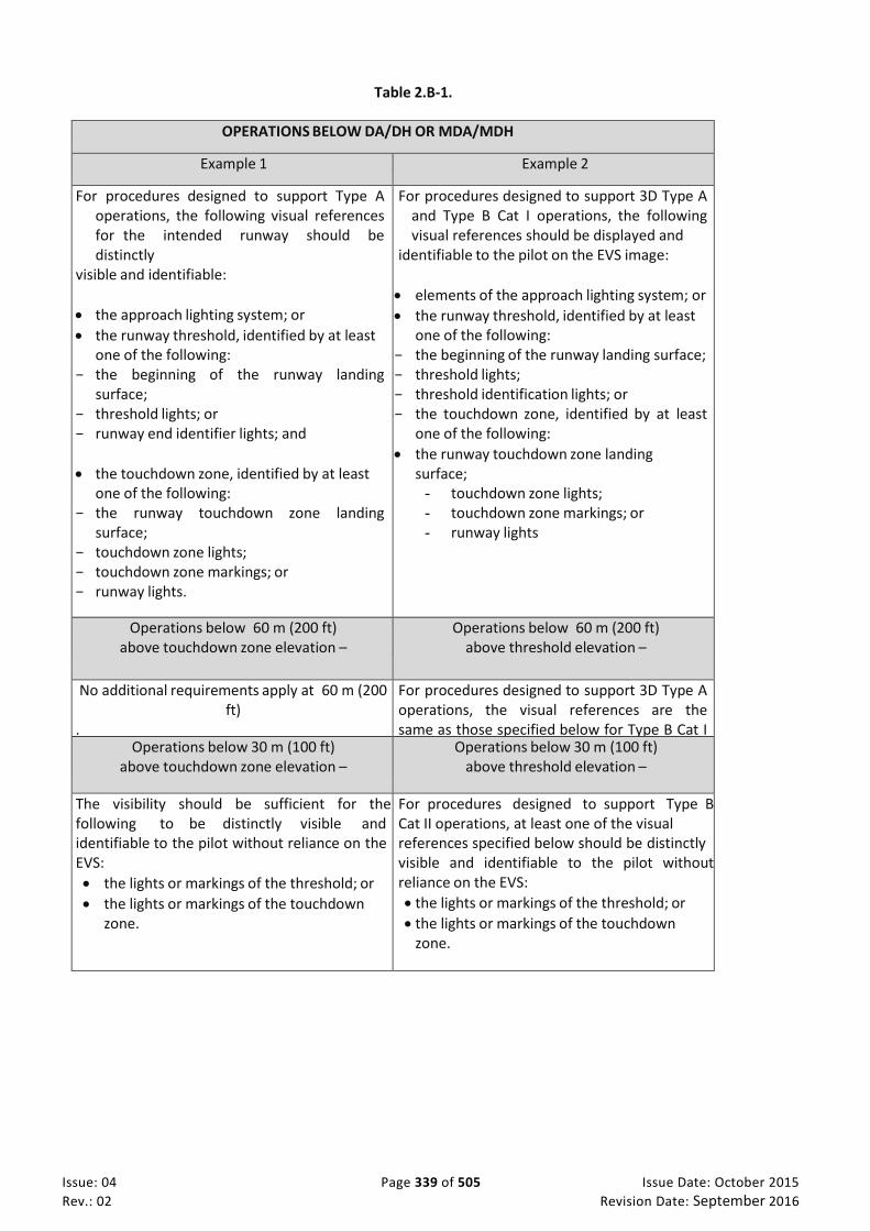
Issue: 04 Page 339 of 505 Issue Date: October 2015
Rev.: 02 Revision Date: September 2016
Table 2.B-1.
OPERATIONS BELOW DA/DH OR MDA/MDH
Example 1 Example 2
For procedures designed to support Type A operations, the following visual references for the intended runway should be distinctly
visible and identifiable:
the approach lighting system; or
the runway threshold, identified by at least one of the following:
− the beginning of the runway landing surface;
− threshold lights; or − runway end identifier lights; and
the touchdown zone, identified by at least one of the following:
− the runway touchdown zone landing surface;
− touchdown zone lights; − touchdown zone markings; or − runway lights.
For procedures designed to support 3D Type A and Type B Cat I operations, the following visual references should be displayed and
identifiable to the pilot on the EVS image:
elements of the approach lighting system; or
the runway threshold, identified by at least one of the following:
− the beginning of the runway landing surface; − threshold lights; − threshold identification lights; or − the touchdown zone, identified by at least
one of the following:
the runway touchdown zone landing surface;
- touchdown zone lights; - touchdown zone markings; or - runway lights
Operations below 60 m (200 ft) above touchdown zone elevation –
Operations below 60 m (200 ft) above threshold elevation –
No additional requirements apply at 60 m (200 ft)
.
For procedures designed to support 3D Type A operations, the visual references are the same as those specified below for Type B Cat I operations. Operations below 30 m (100 ft)
above touchdown zone elevation – Operations below 30 m (100 ft)
above threshold elevation –
The visibility should be sufficient for the following to be distinctly visible and identifiable to the pilot without reliance on the EVS:
the lights or markings of the threshold; or
the lights or markings of the touchdown zone.
For procedures designed to support Type B Cat II operations, at least one of the visual references specified below should be distinctly visible and identifiable to the pilot without reliance on the EVS:
the lights or markings of the threshold; or
the lights or markings of the touchdown zone.

Issue: 04 Page 340 of 505 Issue Date: October 2015
Rev.: 02 Revision Date: September 2016
3. Hybrid systems
3.1 A hybrid system generically means that two or more systems are combined. The hybrid system
typically has improved performance compared to each of the component systems, which in turn may qualify for operational credit. Vision systems are normally part of a hybrid system, e.g. EVS is typically combined with a HUD. Including more components in the hybrid system normally enhances the performance of the system.
3.2 Table 2.B-2 provides some examples of hybrid system components. Any combination of the listed
systems may constitute a hybrid system. The degree of operational credit that may be given to a hybrid system depends on its performance (accuracy, integrity and availability) as assessed and determined by the certification and operational approval processes.
Table 2.B-2. Examples of hybrid system components
Systems based on image sensors Systems not based on image sensors EVS
Passive infrared sensors
Active infrared sensors
Passive millimetre wave radiometer
Active millimetre wave radar
SVS
Autoflight systems, flight control computers, automatic landing systems
Systems for position fixing
CVS (where the EVS component as above qualifies for operational credit)
CVS (the SVS component)
HUD, equivalent display
ILS, GNSS
4. Operational credits
4.1 Aerodrome operating minima are expressed in terms of minimum visibility/RVR and MDA/H or DA/H. With respect to operational credit this means that the visibility/RVR requirements, established in the instrument approach procedure, may be reduced or satisfied for aircraft equipped with appropriately approved vision systems such as EVS. Reasons for granting operational credit may be when aircraft are better equipped than what was originally considered when designing the instrument approach procedure or when runway visual aids considered in the design of the procedure are not available but can be compensated by on-board equipment.
4.2 Credits related to visibility/RVR can be given using at least three concepts. The first concept is to reduce the required RVR which will allow the aircraft to continue the approach beyond the approach ban point with a reported RVR lower than what was established for the approach procedure. Where a minimum visibility is prescribed, a second concept to grant operational credit may be used. In this case, the required minimum visibility is kept unchanged, but it is satisfied by means of the on-board equipment, typically an EVS. The result of both these concepts is that operations are allowed in meteorological conditions where otherwise they would not be possible. A third concept is to give operational credit by allowing operations in visibility/RVR which are not lower than those established for the approach procedure, but the approach operation is conducted with less facilities on the ground. One example of the latter is to allow category II operations without touchdown and/or centre line lights, compensated by additional on-board equipment, e.g. a HUD.
4.3 Granting operational credits does not affect the classification of an instrument approach procedure since, instrument approach procedures are designed to support a given instrument approach operation (i.e. Type, Category). However, the design of those procedures may not take into consideration on-board equipment that may compensate for facilities on the ground.

Issue: 04 Page 341 of 505 Issue Date: October 2015
Rev.: 02 Revision Date: September 2016
4.4 In order to provide optimum service, the ATS may have to be informed about the capabilities of the better-equipped aircraft, e.g. which is the minimum RVR required.
4.5 In addition to the operational credit that HUD, vision systems and hybrid systems are able to provide, these systems will also provide an operational and safety advantage through improved situational awareness, earlier acquisition of visual references and smoother transition to references by natural vision. These advantages are more pronounced for 3D Type A approach operations than for Type B approach operations.
5. Operational Procedures
5.1 It is not prohibited to use vision systems in connection with circling. However, due to the system layout of a vision system and the nature of a circling procedure, key visual references can be obtained only by natural vision, and operational credit is not feasible for existing vision systems. The vision system may provide additional situational awareness.
5.2 The operational procedures associated with the use of a HUD, vision systems and hybrid systems should be included in the operations manual. The instructions in the operations manual should include:
(a) any limitation that is imposed by the airworthiness or operational approvals;
(b) how operational credit affects:
(1) flight planning with respect to destination and alternate aerodromes;
(2) ground operations;
(3) flight execution, e.g. approach ban and minimum visibility;
(4) crew resource management that takes into account the equipment configuration, e.g. the pilots may have different presentation equipment;
(5) standard operating procedures, e.g. use of autoflight systems, call-outs that may be particular to the vision system or hybrid system, criteria for stabilized approach;
(6) ATS flight plans and radio communication.
6. Approvals
6.1 General
6.1.1 An operator that wishes to conduct operations with a HUD or equivalent display, vision system or hybrid system will need to obtain certain approvals (See Annex 6, Part I, 4.2.8.1.1 and 6.23, and the corresponding requirements in Annex 6, Parts II and III). The extent of the approvals will depend on the intended operation and the complexity of the equipment.
6.1.2 Enhanced vision imagery may be used to improve situational awareness without a specific operational approval. However, the standard operating procedures for these types of operations need to be specified in the operations manual. An example of this type of operation may include an EVS or an SVS on a head-down display that is used only for situational awareness of the surrounding area of the aircraft during ground operations where the display is not in the pilot’s primary field of view. For enhanced situational awareness, the installation and operational procedures need to ensure that the operation of the vision system does not interfere with normal procedures or the operation or use of other aircraft systems. In some cases, modifications to these normal procedures for other aircraft systems or equipment may be necessary to ensure compatibility.
6.1.3 When a vision system or a hybrid system with vision systems imagery is used for operational credit, operational approvals will typically require that the imagery be combined with flight guidance and presented on a HUD. Operational approvals may require that this information also be

Issue: 04 Page 342 of 505 Issue Date: October 2015
Rev.: 02 Revision Date: September 2016
presented on a head-down display. Operational credit may be applied for any flight operation, but credit for instrument approach and take-off operations is most common.
6.1.4 When the application for approval relates to operational credits for systems not including a vision system, the guidance in this attachment may be used to the extent applicable as determined by the State of the Operator or the State of Registry for general aviation.
6.1.5 Operators should be aware that some States may require some information about the operational credit(s) which has been granted by the State of the Operator or the State of Registry for general aviation. Typically the approval from that State will have to be presented, and in some cases the State of the Aerodrome may wish to issue an approval or to validate the original approval.
6.2 Approvals for operational credit
To obtain operational credit the operator will need to specify the desired operational credit and submit a suitable application. The content of a suitable application should include:
(a) Applicant details —– required for all approval requests. The official name and business or trading name(s), address, mailing address, e-mail address and contact telephone/fax numbers of the applicant.
Note.— For AOC holders, the company name, AOC number and e-mail address should be required.
(b) Aircraft details — required for all approval requests. Aircraft make(s), model(s) and registration mark(s).
(c) Operator’s vision system compliance list. The contents of the compliance list are included in Table 2.B-3. The compliance list should include the information that is relevant to the approval requested and the registration marks of the aircraft involved. If more than one type of aircraft/fleet is included in a single application a completed compliance list should be included for each aircraft/fleet.
(d) Documents to be included with the application. Copies of all documents referred to in column 4 of the operator's vision system compliance list (Table 2.B-3) should be included when returning the completed application form to the civil aviation authority. There should no need to send complete manuals; only the relevant sections/pages should be required.
(e) Name, title and signature.

Issue: 04 Page 343 of 505 Issue Date: October 2015
Rev.: 02 Revision Date: September 2016
Table 2.B-3. Example of an AOC vision system compliance list
Main heading
Expanded areas to be addressed by the application / Sub-requirements
Operator’s operations manual
reference or document reference
1. Reference documents used in compiling the submission
The submission should be based on current up-to-date regulatory material. A compliance statement showing how the criteria of the applicable regulations and requirements have been satisfied.
2. Aircraft flight manual (AFM)
A copy of the relevant AFM entry showing the aircraft certification basis for the vision system and any operational conditions.
3. Feedback and reporting of significant problems
An outline of the process for the reporting of failures in the operational use of procedures. Note.— In particular, significant problems with the vision system/ HUD systems, reporting on circumstances/locations where the vision system was unsatisfactory.
4. Instrument approach chart provider and operating minima
The name of the provider of the relevant instrument approach charts. Confirmation that all aerodrome operating minima are established in accordance with criteria specified by the relevant authority.
5. Operations manual entries and SOP
Manufacturer/operator developed. Manufacturer’s procedures are recommended as a starting point and should include at least the items in the sub-requirements below.
Sub Requirements
Definitions. Check crew qualified for vision system/HUD operations. MEL handling. Equipment required for vision system operations. Types of approach where vision systems can be used. Statement that the autopilot/flight director should be used whenever possible. Minimum visual references for landing. Approach ban and RVR. Stabilized approach criteria. Correct seating and eye position. Crew coordination, e.g. duties of the pilot flying and the pilot not flying:
- limitations; - designation of handling and non- handling pilots; - use of automatic flight control system; - checklist handling; - approach briefing; - radio communications handling; - monitoring and cross-checking of instruments and radio aids; and - use of the repeater display by the pilot not flying.
Contingency procedures including:
failures above and below decision height;
ILS deviation warnings;
autopilot & auto-throttle disconnect;
electrical failures;
engine failure;
failures and loss of visual references at or below decision height;
vision system/HUD failure below normal decision height;
wind shear;
ACAS warnings;
EGPWS warnings.
6. Safety risk assessment
Sub requirements: Operator’s safety risk assessment

SUBPART L - COMMUNICATION AND NAVIGATION EQUIPMENT
Issue: 04 Page 344 of 505 Issue Date: October 2015
Rev.: 02 Revision Date: September 2016
SUB PART L. COMMUNICATION AND NAVIGATION EQUIPMENT
CAR-OPS 1.845 General introduction
(See IEM OPS 1.845)
(a) An operator shall ensure that a flight does not commence unless the communication and navigation equipment required under this Subpart is:
(1) Approved and installed in accordance with the requirements applicable to them, including the minimum performance standard and the operational and airworthiness requirements;
(2) Installed such that the failure of any single unit required for either communication or navigation purposes, or both, will not result in the failure of another unit required for communications or navigation purposes.
(3) In operable condition for the kind of operation being conducted except as provided in the MEL (CAR-OPS 1.030 refers); and
(4) So arranged that if equipment is to be used by one flight crew member at his station during flight it must be readily operable from his station. When a single item of equipment is required to be operated by more than one flight crew member it must be installed so that the equipment is readily operable from any station at which the equipment is required to be operated.
(b) Communication and navigation equipment minimum performance standards are those prescribed in the applicable Technical Standard Orders (TSO) unless different performance standards are prescribed in the operational or airworthiness codes. Communication and navigation equipment complying with design and performance specifications other than TSO on the date of CAR–OPS implementation may remain in service, or be installed, unless additional requirements are prescribed in this Subpart. Communication and navigation equipment which has already been approved does not need to comply with a revised TSO or a revised specification, other than TSO, unless a retroactive requirement is prescribed.
IEM OPS 1.845 Communication and Navigation Equipment - Approval and Installation
See CAR-OPS 1.845
1 For Communication and Navigation Equipment required by CAR-OPS 1 Subpart L, “Approved” means that compliance with the applicable TSO design requirements and performance specifications, or equivalent, in force at the time of the equipment approval application, has been demonstrated. Where a TSO does not exist, the applicable airworthiness standards or equivalent apply unless otherwise prescribed in CAR-OPS 1 or CAR M.
2 “Installed” means that the installation of Communication and Navigation Equipment has been demonstrated to comply with the applicable airworthiness requirements of CS-23/CS-25, or the relevant code used for Type Certification, and any applicable requirement prescribed in CAR -OPS 1.
3 Communication and Navigation Equipment approved in accordance with design requirements and performance specifications other than TSOs, before the applicability dates prescribed in CAR-OPS 1.001(b), are acceptable for use or installation on aeroplanes operated for the purpose of commercial air transportation provided that any relevant CAR-OPS requirement is complied with.

SUBPART L - COMMUNICATION AND NAVIGATION EQUIPMENT
Issue: 04 Page 345 of 505 Issue Date: October 2015
Rev.: 02 Revision Date: September 2016
4 When a new version of a TSO (or of a specification other than a CS_TSO) is issued, Communication and Navigation Equipment approved in accordance with earlier requirements may be used or installed on aeroplanes operated for the purpose of commercial air transportation provided that such Communication and Navigation Equipment are operational, unless removal from service or withdrawal is required by means of an amendment to CAR-OPS 1 or CAR M.
CAR-OPS 1.850 Radio Equipment
(a) An operator shall not operate an aeroplane unless it is equipped with radio required for the kind of operation being conducted.
(b) Where two independent (separate and complete) radio systems are required under this Subpart, each system must have an independent antenna installation except that, where rigidly supported non-wire antennae or other antenna installations of equivalent reliability are used, only one antenna is required.
(c) The radio communication equipment required to comply with paragraph (a) above must also provide for communications on the aeronautical emergency frequency 121·5 MHz.
CAR-OPS 1.855 Audio Selector Panel
An operator shall not operate an aeroplane under IFR unless it is equipped with an audio selector panel accessible to each required flight crew member.

SUBPART L - COMMUNICATION AND NAVIGATION EQUIPMENT
Issue: 04 Page 346 of 505 Issue Date: October 2015
Rev.: 02 Revision Date: September 2016
CAR-OPS 1.860 Radio equipment for VFR routes navigated by reference to visual landmarks
An operator shall not operate an aeroplane under VFR over routes that can be navigated by reference to visual landmarks, unless it is equipped with the radio communication equipment necessary under normal operating conditions to fulfil the following:
(a) Communicate with appropriate ground stations;
(b) Communicate with appropriate air traffic control facilities from any point in controlled airspace within which flights are intended; and
(c) Receive meteorological information;
CAR-OPS 1.865 Communication and Navigation equipment for operations under IFR, or under VFR over routes not navigated by reference to visual landmarks
(See AMC OPS 1.865)
(a) An operator shall not operate an aeroplane under IFR, or under VFR over routes that cannot be navigated by reference to visual landmarks, unless the aeroplane is equipped with radio communication and SSR transponder and navigation equipment in accordance with the requirements of air traffic services in the area(s) of operation.
(b) Radio equipment. An operator shall ensure that radio equipment comprises not less than;
(1) two independent radio communication systems necessary under normal operating conditions to communicate with an appropriate ground station from any point on the route including diversions; and
(2) SSR transponder equipment as required for the route being flown.
(c) Navigation equipment. An operator shall ensure that navigation equipment
(1) Comprises not less than:
(i) One VOR receiving system, one ADF system, one DME except that an ADF system need not be installed provided that the use of ADF is not required in any phase of the planned flight (See AC OPS 1.865(c)(1)(i));
(ii) One ILS or MLS where ILS or MLS is required for approach navigation purposes;
(iii) One Marker Beacon receiving system where a Marker Beacon is required for approach navigation purposes;
(iv) An Area Navigation System when area navigation is required for the route being flown;
(v) An additional DME system on any route, or part thereof, where navigation is based only on DME signals;
(vi) An additional VOR receiving system on any route, or part thereof, where navigation is based only on VOR signals; and

SUBPART L - COMMUNICATION AND NAVIGATION EQUIPMENT
Issue: 04 Page 347 of 505 Issue Date: October 2015
Rev.: 02 Revision Date: September 2016
(vii) An additional ADF system on any route, or part thereof, where navigation is based only on NDB signals, or
(2) Complies with the Required Navigation Performance (RNP) Type for operation in the airspace concerned. (See also AC OPS 1.243.)
(d) An operator may operate an aeroplane that is not equipped with an ADF or with the navigation equipment specified in sub-paragraph(s) (c)(1)(vi) and/or (c)(1)(vii) above, provided that it is equipped with alternative equipment authorised, for the route being flown, by the Authority. The reliability and the accuracy of alternative equipment must allow safe navigation for the intended route.
(e) When operating in regional airspace requiring FM immunity performance standards, an operator shall ensure that VHF communication equipment, ILS Localiser and VOR receivers installed on aeroplanes to be operated in IFR are of a type that has been approved as complying with the FM immunity performance standards (See AC OPS 1.865(e)).
AMC OPS 1.865 Combinations of Instruments and Integrated Flight Systems
See CAR-OPS 1.865
Individual requirements of CAR-OPS 1.865 may be met by combinations of instruments or by integrated flight systems or by a combination of parameters on electronic displays provided that the information so available to each required pilot is not less than that provided by the instruments and associated equipment specified.
AC OPS 1.865(c)(1)(i) IFR operations without ADF system
See CAR-OPS 1.865(c)(1)(i) 1 To perform IFR operations without an ADF system installed, an operator should consider the
following guidelines on equipment carriage, operational procedures and training criteria. 2 The removal/non installation of ADF equipment from an aeroplane may only be done where it is not
essential for navigation, provided that alternative equipment giving equivalent or enhanced navigation capability is carried. This may be accomplished by the carriage of an additional VOR receiver or a GNSS receiver approved for IFR operations.
3 For IFR operations without ADF, an operator should ensure that:
(a) route segments that rely solely on ADF for navigation are not flown;
(b) A firm commitment is made not to fly any ADF/NDB procedures;
(c) Tthat the MEL has been amended to take account of the non-carriage of ADF; (d) That the Operations Manual does not reference any procedures based on NDB signals for the
aeroplanes concerned; (e) That flight planning and dispatch procedures are consistent with the above mentioned criteria.
4 The removal of ADF should be taken into account by the operator in the initial and recurrent training
of flight crew.
AC OPS 1.865(e) FM Immunity Equipment Standards
See CAR-OPS 1.865(e)

SUBPART L - COMMUNICATION AND NAVIGATION EQUIPMENT
Issue: 04 Page 348 of 505 Issue Date: October 2015
Rev.: 02 Revision Date: September 2016
1 FM immunity performance Standards for ILS Localiser, VOR receivers and VHF communication receivers have been incorporated in ICAO Annex 10, Volume I - Radio Navigation Aids Fifth Edition dated July 1996, Chapter 3, Paragraphs 3.1.4, 3.3.8 and Volume III, Part II - Voice Communications Systems, Paragraph 2.3.3.
2 Acceptable equipment standards, consistent with ICAO Annex 10, are contained in EUROCAE Minimum Operational Performance Specifications, documents ED-22B for VOR receivers, ED-23B for VHF communication receivers and ED-46B for LOC receivers and the corresponding RTCA documents DO-186, DO-195 and DO-196.
Note: Operations within the UAE FIR do not require FM Immunity.
CAR-OPS 1.866 Transponder equipment (See AMC OPS 1.866 Transponder Equipment)
(a) An operator shall not operate an aeroplane unless it is equipped with;
(1) A pressure altitude reporting SSR (secondary surveillance radar) transponder; and
(2) any other SSR transponder capability required for the route being flown.
b) An operator shall ensure that by 7 December 2017, that aeroplane:
(1) operating under IFR, are equipped with SSR transponders having the capabilities set out in AMC OPS 1.866 Part 1;
(2) with a maximum certified take-off mass exceeding 5700 kg or having a maximum cruising true airspeed capability greater than 250 knots, operating flights under IFR or within controlled airspace are equipped with SSR transponders having, in addition to the capabilities set out in AMC OPS 1.866 Part 1 and 2. The ADS-B functionality shall be installed no later than the date mandating ADS-B (See CAR-OPS 1.867);
(3) with a maximum certified take-off mass exceeding 5700 kg or having a maximum cruising true airspeed capability greater than 250 knots, operating flights under IFR or within controlled airspace, are equipped with SSR transponders having, in addition to the capabilities set out in AMC OPS 1.866 Part 1, 2 and 3. The ADS-B functionality shall be installed no later than the date mandating ADS-B (See CAR-OPS 1.867).
c) An operator shall ensure that aircraft equipped in accordance with paragraph b) and having a maximum certified take-off mass exceeding 5700 kg or having a maximum cruising true airspeed capability greater than 250 knots operate with antenna diversity as prescribed in paragraph 3.1.2.10.4 of Annex 10 to the Chicago Convention, Volume IV, Fourth Edition including all amendments up to No 85.
AMC OPS 1.866 Transponder Equipment
(See CAR-OPS 1.866) a. Part 1: SSR transponder capabilities
1. The minimum capability for the secondary surveillance transponder should be Mode S Level 2 certified in
accordance with paragraphs 2.1.5.1.2, 2.1.5.1.7 and 3.1.2.10 of Annex 10 to the Chicago Convention,
Volume IV, Fourth Edition including all amendments up to No 85.
2. Each implemented transponder register should be compliant with the corresponding section of ICAO
document 9871 (2nd edition).
3. The following data items should be made available to the transponder and be transmitted by the
transponder via the Mode S protocol and in accordance with the formats specified in ICAO document 9871
(2nd edition):
a) 24-bit ICAO aircraft address;
b) Mode A code;
c) pressure altitude;

SUBPART L - COMMUNICATION AND NAVIGATION EQUIPMENT
Issue: 04 Page 349 of 505 Issue Date: October 2015
Rev.: 02 Revision Date: September 2016
d) flight status (on the ground or airborne);
e) data link capability report;
— airborne collision avoidance system (ACAS) capability, — Mode S specific services capability, — aircraft identification capability, — squitter capability, — surveillance identifier capability, — common usage Ground Initiated Comms.-B (GICB) capability report (indication of change), — Mode S subnetwork version number;
f) common usage GICB capability report;
g) aircraft identification;
h) special position indication (SPI);
i) emergency status (general emergency, no communications, unlawful interference) including the use of
specific Mode A codes to indicate different emergency states;
j) ACAS active resolution advisories when the aircraft is equipped with Traffic alert and collision
avoidance system II (TCAS II).
4. Other data items may be made available to the transponder.
5. The data items referred to in point 4 should only be transmitted by the transponder via the Mode S
protocol if the aircraft and equipment certification process covers the transmission of these data items via
the Mode S protocol.
6. The continuity of transponder functionality supporting the Mode S protocol should be equal to or less than
2. 10 -4 per flight hour (i.e. mean time between failure equal to or greater than 5 000 flight hours).
Part 2: SSR transponder capabilities
1. The minimum capability for the secondary surveillance transponder should be Mode S Level 2 certified in
accordance with paragraphs 2.1.5.1.2, 2.1.5.1.6, 2.1.5.1.7 and 3.1.2.10 of Annex 10 to the Chicago
Convention, Volume IV, Fourth Edition including all amendments up to No 85.
2. Each implemented transponder register should be compliant with the corresponding section of ICAO
document 9871 (2nd edition).
3. The following data items should be made available to the transponder and be transmitted by the
transponder via Version 2 of the extended squitter (ES) ADS-B protocol in accordance with the formats
specified in ICAO document 9871 (2nd edition):
(a) 24-bit ICAO aircraft address;
(b) aircraft identification;
(c) Mode A code;
(d) special position indication (SPI) using the same source as for the same parameter specified in Part A;
(e) emergency status (general emergency, no communications, unlawful interference) using the same
source as for the same parameter specified in Part A;
(f) ADS-B version number (equal to 2);
(g) ADS-B emitter category;
(h) geodetic horizontal position in accordance with the world geodetic system revision 1984 (WGS84)
latitude and longitude, both while airborne or on the ground;
(i) geodetic horizontal position quality indicators (corresponding to the integrity containment bound
(NIC), 95 % navigation accuracy category for position (NAC p ), source integrity level (SIL) and system
design assurance level (SDA));
(j) pressure altitude using the same source as for the same parameter specified in Part A;
(k) geometric altitude in accordance with the world geodetic system revision 1984 (WGS84), provided in
addition and encoded as a difference to pressure altitude;

SUBPART L - COMMUNICATION AND NAVIGATION EQUIPMENT
Issue: 04 Page 350 of 505 Issue Date: October 2015
Rev.: 02 Revision Date: September 2016
(l) geometric vertical accuracy (GVA);
(m) velocity over ground, both while airborne (east/west and north/south airborne velocity over ground)
or on the ground (surface heading/ground track and movement);
(n) velocity quality indicator corresponding to navigation accuracy category for velocity (NAC v );
(o) coded aircraft length and width;
(p) global navigation satellite system (GNSS) antenna offset;
(q) vertical rate: barometric vertical rate using the same source as for the same parameter specified in the
data item in point 2 (g) of Part C when the aircraft is required and capable to transmit this data item
via the Mode S protocol, or Global Navigation Satellite System (GNSS) vertical rate;
(r) mode control panel/flight control unit (MCP/FCU) selected altitude using the same source as for the
same parameter specified in Part C when the aircraft is required and capable to transmit this data item
via the Mode S protocol;EN L 305/44 Official Journal of the European Union 23.11.2011
(s) barometric pressure setting (minus 800 hectoPascals) using the same source as for the same
parameter specified in Part C when the aircraft is required and capable to transmit this data item via
the Mode S protocol;
(t) ACAS active resolution advisories when the aircraft is equipped with TCAS II using the same source as
for the same parameter specified in Part A.
4. Surveillance data items (the data items in point 3(h), (k) and (m)) and their quality indicator data items
(the data items in point 3(i), (l) and (n)) should be provided to the transponders on the same physical
interface.
5. The data source connected to the transponder and providing the data items in point 3(h) and (i) should
meet the following data integrity requirements:
(a) horizontal position (data item in point 3(h)) source integrity level (SIL, expressed with respect to NIC)
should be equal to or less than 10 -7 per flight-hour;
(b) horizontal position (data item in point 3(h)) integrity time to alert (leading to a change of the NIC
quality indicator), if on-board monitoring is required to meet the horizontal position source integrity
level, should be equal to or less than 10 seconds.
6. The primary data source providing the data items in point 3(h) and (i) should be at least compatible with
GNSS receivers that perform receiver autonomous integrity monitoring (RAIM) and fault detection and
exclusion (FDE), along with the output of corresponding measurement status information, as well as
integrity containment bound and 95 % accuracy bound indications.
7. The system integrity level of the data sources providing the data items in point 3(f), (g), (k) to (p) should be
equal to or less than 10 -5 per flight-hour.
8. The quality indicator information (NIC, NACp, SIL, SDA, NACv and GVA) (the data items in point 3(i), (l) and
(n)) should express the actual performance of the selected data source as valid at the time of applicability
of the measurement of the data items in point 3(h), (k) and (m)).
9. With respect to the processing of the data items in point 3(a) to (t), the transponder system integrity level
for the extended squitter ADS-B protocol, including any interconnecting avionics to the transponder,
should be equal to or less than 10 -5 per flight-hour.
10. The total latency of the horizontal position data (the data items in point 3(h) and (i)) should be equal to or
less than 1,5 second in 95 % of all transmissions.
11. The uncompensated latency of the horizontal position data (data item in point 3(h)) should be equal to or
less than 0,6 second in 95 % of the cases and should be equal to or less than 1,0 second in 99,9 % of all
transmissions.
12. The total latency of the ground speed data items (the data items in point 3(m) and (n)) should be equal to
or less than 1,5 second in 95 % of all transmissions.
13. If the transponder is set to use a Mode A conspicuity code of 1000 then the broadcast of Mode A code
information via the extended squitter ADS-B protocol should be inhibited.

SUBPART L - COMMUNICATION AND NAVIGATION EQUIPMENT
Issue: 04 Page 351 of 505 Issue Date: October 2015
Rev.: 02 Revision Date: September 2016
14. Other data items may be made available to the transponder.
15. Except for military reserved formats, the data items referred to in point 14 should only be transmitted by
the transponder via the extended squitter ADS-B protocol if the aircraft and equipment certification
process covers the transmission of these data items via the extended squitter ADS-B protocol.
16. The continuity of transponder functionality supporting the ADS-B protocol should be equal to or less than
2. 10 -4 per flight hour (i.e. mean time between failure equal to or greater than 5 000 flight hours).
Part 3: SSR transponder additional capabilities
1. Each transponder register that is implemented should be compliant with the corresponding section of
ICAO document 9871 (2nd edition).
2. The following data items should be made available to the transponder and be transmitted by the
transponder as requested by the ground-based surveillance chain, via the Mode S protocol and in
accordance with the formats specified in ICAO document 9871 (2nd edition):
(a) MCP/FCU selected altitude;
(b) roll angle;
(c) true track angle;
(d) ground speed;
(e) magnetic heading;
(f) indicated airspeed (IAS) or mach number;
(g) vertical rate (barometric or baro-inertial);
(h) barometric pressure setting (minus 800 hectoPascals);
(i) track angle rate or true airspeed if track angle rate is not available.
(j) Other data items may be made available to the transponder.
3. The data items referred to in point 3 should only be transmitted by the transponder via the Mode S
protocol if the aircraft and equipment certification process covers the transmission of these data items
via the Mode S protocol.
CAR-OPS 1.867 ADS-B (OUT and IN) (See AMC OPS 1.867 ADS-B) ADS-B means automatic dependent surveillance - broadcast, a surveillance technique in which aircraft automatically provide, via a data link, data derived from on-board navigation and position-fixing systems. It refers to a surveillance technology where ADS-B Out equipped aircraft broadcast position, altitude, velocity, and other information in support of both air-to-ground and air-to-air surveillance applications.
a) ADS-B OUT An operator shall not operate an aeroplane under IFR after 01 January 2020, unless it is equipped with ADS-B OUT.
b) ADS-B IN
An operator shall not operate an aeroplane equipped with the ADS-B IN capability unless approved by the GCAA.
AMC OPS 1.867 ADS-B
(See CAR-OPS 1.867 ADS-B ) ADS-B capability should be demonstrated against Certification Specifications - Airborne Communications, Navigation and Surveillance (CS-ACNS) contained in Annex I to ED Annex I to ED Decision 2013/031 or equivalent accepted by the GCAA.

SUBPART L - COMMUNICATION AND NAVIGATION EQUIPMENT
Issue: 04 Page 352 of 505 Issue Date: October 2015
Rev.: 02 Revision Date: September 2016
CAR-OPS 1.870 Additional navigation equipment for operations in MNPS airspace (IEM OPS 1.870 Additional Navigation Equipment for operations in MNPS Airspace and CAAP 6 MNPS )
(a) An operator shall not operate an aeroplane in MNPS airspace unless it is equipped with navigation equipment that complies with minimum navigation performance specifications prescribed in ICAO Doc 7030 in the form of Regional Supplementary Procedures.
(b) The navigation equipment required by this paragraph must be visible and usable by either pilot seated at his duty station.
(c) For unrestricted operation in MNPS airspace an aeroplane must be equipped with two independent Long Range Navigation Systems (LRNS).
(d) For operation in MNPS airspace along notified special routes an aeroplane must be equipped with one Long Range Navigation System (LRNS), unless otherwise specified.
IEM OPS 1.870 Additional Navigation Equipment for operations in MNPS Airspace
(See CAR-OPS 1.870)
1 A Long Range Navigation System may be one of the following:
(a) One Inertial Navigation System (INS).
(b) One Global Navigation Satellite System (GNSS).
(c) One navigation system using inputs from one or more Inertial Reference Systems (IRS), or any other MNPS approved sensor system.
2 To conform to the Long range navigation System Specification, a GNSS and its operational use should be approved in accordance with the relevant requirements for MNPS airspace.
3. An integrated navigation system which offers equivalent functional availability, integrity and redundancy, when approved may, for the purpose of this requirement, be considered as two independent Long Range Navigation Systems.
CAR-OPS 1.872 Equipment for operation in defined airspace with RVSM (See CAAP 5 RVSM)
(a) An operator shall ensure that aeroplanes operated in RVSM airspace are equipped with:
(1) Two independent altitude measurement systems;
(2) An altitude alerting system;
(3) An automatic altitude control system; and
(4) A secondary surveillance radar (SSR) transponder with altitude reporting system that can be connected to the altitude measurement system in use for altitude keeping.

SUBPART M - AEROPLANE MAINTENANCE
Issue: 04 Page 353 of 505 Issue Date: October 2015
Rev.: 02 Revision Date: September 2016
SUB PART M. AEROPLANE MAINTENANCE
(a) An operator shall not operate an aeroplane unless it is maintained and released to service by an organisation appropriately approved/accepted in accordance with CAR 145 except that pre-flight inspections need not necessarily be carried out by the CAR 145 organisation. Non commercial Air Transport Aeroplane with MCTOM of less than 5700 KGs can be maintained by CAR M Subpart F Organisations
(b) Aeroplane continuing airworthiness requirements needed in order to comply with the operator
certification requirements in OPS 1.180 are those stipulated in CAR Part V, Chapter 4.
Refer to CAR PART V, Chapter 3 and Chapter 4

SUBPART N - FLIGHT CREW
Issue: 04 Page 354 of 505 Issue Date: October 2015
Rev.: 02 Revision Date: September 2016
SUB PART N. FLIGHT CREW
CAR-OPS 1.940 Composition of Flight Crew
(See Appendix 1 & 2 to CAR-OPS1.940)
(a) An operator shall ensure that:
(1) The composition of the flight crew and the number of flight crew members at designated crew stations are both in compliance with, and no less than the minimum specified in, the Aeroplane Flight Manual (AFM);
(2) The flight crew includes additional flight crew members when required by the type of operation, and is not reduced below the number specified in the Operations Manual;
(3) All flight crew members hold an applicable and valid licence acceptable to the Authority and are suitably qualified and competent to conduct the duties assigned to them;
(4) Procedures are established, acceptable to the Authority, to prevent the crewing together of inexperienced flight crew members (See AMC OPS 1.940(a)(4));
(5) One pilot amongst the flight crew, qualified as a pilot-in-command in accordance with the requirements
governing Flight Crew Licences, is designated as the commander who may delegate the conduct of the
flight to another suitably qualified pilot; and
(6) When a dedicated System Panel Operator is required by the AFM, the flight crew includes one crew member who holds a Flight Engineer’s licence or is a suitably qualified flight crew member and acceptable to the Authority.
(7) When engaging the services of crew members from other organisation or other individuals, there shall be an agreement in place to ensure the legal aspects and the requirements of Subpart N are complied with. In this respect, particular attention must be paid to the total number of aircraft types or variants that a flight crew member may fly for the purposes of commercial air transportation, which must not exceed the requirements prescribed in CAR-OPS 1.980 and CAR-OPS 1.981, including when his services are engaged by another operator. For crew members serving the operator as a commander, initial operator’s Crew Resource Management (CRM) training shall be completed before commencing unsupervised line flying. However, for crew members serving the operator as a commander, initial CRM training shall be completed before commencing unsupervised line flying unless the crew member has previously completed an initial operator’s CRM course.
(8) The flight crew include at least one member who holds a flight navigator licence in all operations where, as determined by the Authority, navigation necessary for the safe conduct of the flight cannot be adequately accomplished by the pilots from the pilot station.
(9) Crew composition for VFR day flight may be performed by single Pilot.
(b) Minimum flight crew for operations under IFR or at night. For operations under IFR or at night, an operator shall ensure that:
(1) For all turbo-propeller aeroplanes with a maximum approved passenger seating configuration of more than 9 and for all turbojet aeroplanes, the minimum flight crew is 2 pilots; or
(2) Aeroplanes other than those covered by sub-paragraph (b)(1) above are operated by a single pilot provided that the requirements of Appendix 2 to CAR-OPS 1.940 are satisfied. If the requirements of Appendix 2 are not satisfied, the minimum flight crew is 2 pilots.
(c) Minimum flight crew for operations under VFR.

SUBPART N - FLIGHT CREW
Issue: 04 Page 355 of 505 Issue Date: October 2015
Rev.: 02 Revision Date: September 2016
For VFR Operations single engine aeroplane with MAPSC of 9 seat or less or MTOM of 5700kg or below, single pilot commercial operations may be performed with minimum pilot as describes in AFM. This is applicable for A to A operations or A to B operations within UAE or within the region subject to acceptability by applicable states.
AMC OPS 1.940(a)(4) Crewing of inexperienced flight crew members
See CAR-OPS 1.940(a)(4)
1 An operator should consider that a flight crew member is inexperienced, following completion of a Type Rating or command course, and the associated line flying under supervision, until he has achieved on the Type either:
(a) 100 flying hours and flown 10 sectors within a consolidation period of 120 consecutive days; or
(b) 150 flying hours and flown 20 sectors (no time limit).
2 A lesser number of flying hours or sectors, subject to any other conditions which the Authority may impose, may be acceptable to the Authority when:
(a) A new operator is commencing operations; or
(b) An operator introduces a new aeroplane type; or
(c) Flight crew members have previously completed a type conversion course with the same operator; or
(d) The aeroplane has a Maximum Take-off Mass below 10 tonnes or a Maximum Approved Passenger Seating Configuration of less than 20.
CAR-OPS 1.941 Initial training
An operator shall ensure that each flight crew member successfully complete initial training. An Operator shall establish and maintain an initial ground and flight training programme, approved by the authority which ensures that all flight crew members are adequately trained to perform their assigned duties. (a) The training programme shall:
(1) include indoctrination training comprises of operator’s and regulatory requirements (2) include ground and flight training facilities and properly qualified instructors (3) consist of ground and flight training in the type(s) of aeroplane on which the flight crew members
serves (4) include proper flight crew coordination and training in all types of emergency and abnormal
situations or procedures caused by power plant, airframe or systems malfunctions, fire or other abnormalities
(5) include training in knowledge and skills related to visual and instrument flight procedures for the intended area of operation, human performance including threat and error management and in the transport of dangerous goods
(6) ensure that all flight crew members know the functions for which they are responsible and the relation of these functions to the functions of other crew members, particularly in regard to abnormal or emergency procedures
(7) training be given on a recurrent basis and shall include an assessment of competence
(b) The requirement for recurrent flight training in a particular type of aeroplane shall be considered fulfilled by;

SUBPART N - FLIGHT CREW
Issue: 04 Page 356 of 505 Issue Date: October 2015
Rev.: 02 Revision Date: September 2016
(1) the use, to the extent deemed feasible by the authority, of flight simulation training devices approved by the authority for that purpose or
(2) the completion within the appropriate period of the proficiency check required by CAR-OPS 1.943, 1.945, 1.950, 1.965
CAR-OPS 1.943 Initial Operator’s Crew Resource Management (CRM) training (See AC OPS (IEM) 1.943/ 1.945(a)(9)/1.955(b)(6)/ 1.965(e)) (See AC OPS (AMC) 1.943/ 1.945(a)(9)/1.955(b)(6)/ 1.965(e))
(a) When a flight crew member has not previously completed initial Operator’s Crew Resource Management (CRM) training (either new employees or existing staff), then the operator shall ensure that the flight crew member completes an initial CRM training course. New employees shall complete initial Operator’s CRM Training within their first year of joining an operator. Flight crew who are already operating as flight crew members in commercial air transportation and who have not completed CRM training before shall complete an initial operator’s CRM training course.
(b) If the flight crew member has not previously been trained in Human Factors then a theoretical course, based on the human performance and limitations programme for the ATPL (See the requirements applicable to the issue of Flight Crew Licences) shall be completed before the initial Operator’s CRM training or combined with the initial Operator’s CRM training.
(c) Initial CRM training shall be conducted by at least one CRM trainer acceptable to the Authority who may be assisted by experts in order to address specific areas. (See AC OPS (AMC) 1.943/ 1.945(a)(9)/1.955(b)(6)/ 1.965(e)).
(d) Initial CRM training is conducted in accordance with a detailed course syllabus included in the Operations Manual.
AC OPS (AMC) 1.943/1.945(a)(9)/1.955(b)(6)/1.965(e) Crew Resource Management (CRM)
See CAR-OPS 1.943/1.945(a)(9)/1.955(b)(6)/1.965(e)/1.965(a)(3)(iv) See AC OPS (IEM) 1.943/1.945(a)(9)/1.955(b)(6)/1.965(e)
1 General
1.1 Crew Resource Management (CRM) is the effective utilisation of all available resources (e.g. crew members, aeroplane systems, supporting facilities and persons) to achieve safe and efficient operation.
1.2 The objective of CRM is to enhance the communication and management skills of the flight cre w member concerned. The emphasis is placed on the non-technical aspects of flight crew performance.
2 Initial CRM Training
2.1 Initial CRM training programmes are designed to provide knowledge of, and familiarity with, human factors relevant to flight operations. The course duration should be a minimum of one day for single pilot operations and two days for all other types of operations. It should cover all elements in Table 1, column (a) to the level required by column (b) (Initial CRM training).
(a) A CRM trainer should possess group facilitation skills and should at least:
i. Have current commercial air transport experience as a flight crew member; and have either:

SUBPART N - FLIGHT CREW
Issue: 04 Page 357 of 505 Issue Date: October 2015
Rev.: 02 Revision Date: September 2016
(A) Successfully passed the Human Performance and Limitations (HPL) examination whilst recently obtaining the ATPL (See the requirements applicable to the issue of Flight Crew Licences); or,
(B) If holding a Flight Crew Licence acceptable under CAR-OPS 1.940(a)(3) prior to the introduction of HPL into the ATPL syllabus, followed a theoretical HPL course covering the whole syllabus of the HPL examination.
ii. Have completed initial CRM training; and
iii. Be supervised by suitably qualified CRM training personnel when conducting their first initial CRM training session; and
iv. Have received additional education in the fields of group management, group dynamics and personal awareness.
(b) Notwithstanding paragraph (a) above, and when acceptable to the Authority;
i. A flight crew member holding a recent qualification as a CRM trainer may continue to be a CRM trainer even after the cessation of active flying duties;
ii. An experienced non-flight crew CRM trainer having a knowledge of HPL, may also continue to be a CRM trainer;
iii. A former flight crew member having knowledge of HPL may become a CRM trainer if he maintains adequate knowledge of the operation and aeroplane type and meets the provisions of paragraphs 2.2a ii, iii and iv.
2.3 An operator should ensure that initial CRM training addresses the nature of the operations of the company concerned, as well as the associated procedures and the culture of the company. This will include areas of operations which produce particular difficulties or involve adverse climatic conditions and any unusual hazards.
2.4 If the operator does not have sufficient means to establish initial CRM training, use may be made of a course provided by another operator, or a third party or training organisation acceptable to the Authority. In this event the operator should ensure that the content of the course meets his operational requirements. When crew members from several companies follow the same course, CRM core elements should be specific to the nature of operations of the companies and the trainees concerned.
2.5 A flight crew member’s CRM skills should not be assessed during initial CRM training.
3 Conversion Course CRM training
3.1 If the flight crew member undergoes a conversion course with a change of aeroplane type, all elements in Table 1, column (a) should be integrated into all appropriate phases of the operato r’s conversion course and covered to the level required by column (c) (conversion course when changing type), unless the two operators use the same CRM training provider.
3.2 If the flight crew member undergoes a conversion course with a change of operator , all elements in Table 1, column (a) should be integrated into all appropriate phases of the operator’s conversion course and covered to the level required by column (d) (conversion course when changing operator).
3.3 A flight crew member should not be assessed when completing elements of CRM training which are part of an operator’s conversion course.
4 Command course CRM training
4.1 An operator should ensure that all elements in Table 1, column (a) are integrated into the command course and covered to the level required by column (e) (command course).
4.2 A flight crew member should not be assessed when completing elements of CRM training which are part of the command course, although feedback should be given.
5 Recurrent CRM training

SUBPART N - FLIGHT CREW
Issue: 04 Page 358 of 505 Issue Date: October 2015
Rev.: 02 Revision Date: September 2016
5.1 An operator should ensure that :
(a) Elements of CRM are integrated into all appropriate phases of recurrent training every year; and that all elements in Table 1, column (a) are covered to the level required by column (f) (recurrent training); and that modular CRM training covers the same areas over a maximum period of 3 years.
(b) Relevant modular CRM training is conducted by CRM trainers qualified according to paragraph 2.2.
5.2 A flight crew member should not be assessed when completing elements of CRM training which are part of recurrent training.
6 Implementation of CRM
6.1 The following table indicates which elements of CRM should be included in each type of training:
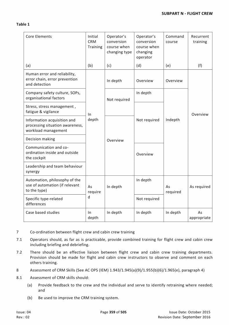
SUBPART N - FLIGHT CREW
Issue: 04 Page 359 of 505 Issue Date: October 2015
Rev.: 02 Revision Date: September 2016
Table 1
Core Elements Initial CRM Training
Operator’s conversion course when changing type
Operator’s conversion course when changing operator
Command course
Recurrent training
(a) (b) (c) (d) (e) (f)
Human error and reliability, error chain, error prevention and detection
In depth
In depth
Overview
Overview
Overview
Company safety culture, SOPs, organisational factors
Not required
In depth
Indepth
Stress, stress management , fatigue & vigilance
Not required Information acquisition and processing situation awareness, workload management
Overview Decision making
Communication and co-ordination inside and outside the cockpit
Overview
Leadership and team behaviour synergy
Automation, philosophy of the use of automation (if relevant to the type)
As required
In depth
In depth
As required
As required
Specific type-related differences
Not required
Case based studies In depth
In depth In depth In depth As appropriate
7 Co-ordination between flight crew and cabin crew training
7.1 Operators should, as far as is practicable, provide combined training for flight crew and cabin crew including briefing and debriefing.
7.2 There should be an effective liaison between flight crew and cabin crew training departments. Provision should be made for flight and cabin crew instructors to observe and comment on each others training.
8 Assessment of CRM Skills (See AC OPS (IEM) 1.943/1.945(a)(9)/1.955(b)(6)/1.965(e), paragraph 4)
8.1 Assessment of CRM skills should:
(a) Provide feedback to the crew and the individual and serve to identify retraining where needed; and
(b) Be used to improve the CRM training system.

SUBPART N - FLIGHT CREW
Issue: 04 Page 360 of 505 Issue Date: October 2015
Rev.: 02 Revision Date: September 2016
8.2 Prior to the introduction of CRM skills assessment, a detailed description of the CRM methodology including terminology used, acceptable to the Authority, should be published in the Operations Manual.
8.3 Operators should establish procedures including retraining, to be applied in the event that personnel do not achieve or maintain the required standards (Appendix 1 to 1.1045, Section D, paragraph 3.2 refers).
8.4 If the operator proficiency check is combined with the Type Rating revalidation/renewal check, the assessment of CRM skills will satisfy the Multi Crew Co-operation requirements of the Type Rating revalidation/renewal. This assessment will not affect the validity of the Type Rating.
AC OPS (IEM) 1.943/1.945(a)(9)/1.955(b)(6)/1.965(e) Crew Resource Management (CRM)
See CAR-OPS 1.943/1.945(a)(9)/1.955(b)(6)/1.965(e) See AC OPS (AMC) 1.943/1.945(a)(9)/1.955(b)(6)/1.965(e)
1 CRM training should reflect the culture of the operator and be conducted by means of both classroom training and practical exercises including group discussions and accident and serious incident reviews to analyse communication problems and instances or examples of a lack of information or crew management.
2 Whenever it is practicable to do so, consideration should be given to conducting relevant parts of CRM training in synthetic training devices which reproduce, in an acceptable way, a realistic operational environment and permit interaction. This includes, but is not limited to, simulators with appropriate LOFT scenarios.
3 It is recommended that, whenever possible, initial CRM training be conducted in a group session outside the company premises so that the opportunity is provided for flight crew members to interact and communicate away from the pressures of their usual working environment.
4 Assessment of CRM Skills
4.1 Assessment of CRM skills is the process of observing, recording, interpreting and evaluating debriefing crews’ and crew member’s, where appropriate, pilot performance and knowledge against a required standard using an acceptable methodology in the context of overall performance. It includes the concept of self-critique, and feedback which can be given continuously during training or in summary following a check. In order to enhance the effectiveness of the programme this methodology should, where possible, be agreed with flight crew representatives.
4.2 NOTECHS or other acceptable methods ofCRM skills assessment should be used included in an overall assessment of the flight crew members performance and be in accordance with approved standards. Suitable methods of assessment should be established, together with t . The selection criteria and training requirements of the assessors and their relevant qualifications, knowledge and skills should be established.
4.3 Individual assessments are not appropriate until the crew member has completed the initial CRM course and completed the first OPC. For first CRM skills assessment, the following methodology is considered satisfactory: Methodology of CRM skills assessment:
(a) An operator should establish the CRM training programme including an agreed terminology. This should be evaluated with regard to methods, length of training, depth of subjects and effectiveness.
(b) A training and standardisation programme for training personnel should then be established.
(c) The assessment should be based on the following principles:
i. only observable, repetitive behaviours are assessed,

SUBPART N - FLIGHT CREW
Issue: 04 Page 361 of 505 Issue Date: October 2015
Rev.: 02 Revision Date: September 2016
ii. the assessment should positively reflect any CRM skills that result in enhanced safety, iii. assessments should include behaviour which contributes to a technical failure, such
technical failure being errors leading to an event which requires debriefing by the person conducting the line check,
iv. the crew and, where needed, the individual are orally debriefed.
4.4 De-identified summaries of all CRM assessments by the operator should be used to provide feedback
to update and improve the operator’s CRM training.] 5. Levels of Training.
(a) Overview. When Overview training is required it will normally be instructional in style. Such training should refresh knowledge gained in earlier training.
(b) In Depth. When In Depth Training is required it will normally be interactive in style and should
include, as appropriate, case studies, group discussions, role play and consolidation of knowledge and skills. Core elements should be tailored to the specific needs of the training phase being undertaken.
CAR-OPS 1.945 Conversion training and checking (See Appendix 1 to CAR-OPS 1.945 / AMC OPS 1.945 / IEM OPS 1.945) (See AC OPS (AMC) 1.943/ 1.945(a)(9)/1.955(b)(6)/ 1.965(e)) (See AC OPS (IEM) 1.943/ 1.945(a)(9)/1.955(b)(6)/ 1.965(e))
(a) An operator shall ensure that:
(1) A flight crew member completes a Type Rating course which satisfies the requirements applicable to the issue of Flight Crew Licences when changing from one type of aeroplane to another type or class for which a new type or class rating is required;
(2) A flight crew member completes an operator’s conversion course before commencing unsupervised line flying:
(i) When changing to an aeroplane for which a new type or class rating is required; or
(ii) When changing operator;
(3) Conversion training is conducted by suitably qualified personnel in accordance with a detailed course syllabus included in the Operations Manual. The operator shall ensure that the personnel integrating elements of CRM into conversion training are suitably qualified;
(4) The amount of training required by the operator’s conversion course is determined after due note has been taken of the flight crew member’s previous training as recorded in his training records prescribed in CAR-OPS 1.985;
(5) The minimum standards of qualification and experience required of flight crew members before undertaking conversion training are specified in the Operations Manual;
(6) Each flight crew member undergoes the checks required by CAR-OPS 1.965(b) and the training and checks required by CAR-OPS 1.965(d) before commencing line flying under supervision;

SUBPART N - FLIGHT CREW
Issue: 04 Page 362 of 505 Issue Date: October 2015
Rev.: 02 Revision Date: September 2016
(7) Upon completion of line flying under supervision, the check required by CAR-OPS 1.965(c) is undertaken;
(8) Once an operator’s conversion course has been commenced, a flight crew member does not undertake flying duties on another type or class until the course is completed or terminated; and
(9) Elements of CRM training are integrated into the conversion course.
(See AMC OPS 1.945, IEM OPS 1.945, AC OPS (AMC) 1.943/ 1.945(a)(9)/1.955(b)(6)/ 1.965(e)), AC OPS (IEM) 1.943/ 1.945(a)(9)/1.955(b)(6)/ 1.965(e))
(b) In the case of changing aeroplane type or class, the check required by 1.965(b) may be combined with the type or class rating skill test under the requirements applicable to the issue of Flight Crew Licences.
(c) The operator’s conversion course and the Type or Class Rating course required for the issue of Flight Crew Licences may be combined.
(d) A pilot, undertaking a ZFTT course, shall:
(1) Commence Line Flying Under Supervision as soon as possible within 21 days after completion of the skill test. If Line Flying Under Supervision has not been commenced within the 21 days, the operator shall provide appropriate training acceptable to the Authority.
(2) Complete the six take-offs and landings required in Appendix 1 CAR-FCL 1.261(c)(2) in a
flight simulator, qualified in accordance with CAR–STD and user approved by the Authority, not later than 21 days after the completion of the skill test. This simulator session shall be conducted by a TRI(A) occupying a pilot's seat. When approved by the Authority, the number of take-offs and landings may be reduced. If these take-offs and landings have not been performed within the 21 days, the operator shall provide refresher training acceptable to the Authority.
(3) Conduct the first four take-offs and landings of the Line Flying Under Supervision in the
aeroplane under the supervision of a TRI(A) occupying a pilot’s seat. When approved by the Authority, the number of take-offs and landings may be reduced.
AMC OPS 1.945 Conversion Course Syllabus
See CAR-OPS 1.945 and Appendix 1 to CAR-OPS 1.945
1 General
1.1 Type rating training when required may be conducted separately or as part of conversion training. When the type rating training is conducted as part of conversion training, the conversion training programme should include all the requirements of CAR– PART II.
2 Ground training
2.1 Ground training should comprise a properly organised programme of ground instruction by training staff with adequate facilities, including any necessary audio, mechanical and visual aids. However, if the aeroplane concerned is relatively simple, private study may be adequate if the operator provides suitable manuals and/or study notes.
2.2 The course of ground instruction should incorporate formal tests on such matters as aeroplane systems, performance and flight planning, where applicable.

SUBPART N - FLIGHT CREW
Issue: 04 Page 363 of 505 Issue Date: October 2015
Rev.: 02 Revision Date: September 2016
3 Emergency and safety equipment training and checking
3.1 On the initial conversion course and on subsequent conversion courses as applicable, the following should be addressed:
(a) Instruction on first aid in general (Initial conversion course only); Instruction on first aid as relevant to the aeroplane type of operation and crew complement including where no cabin crew are required to be carried (Initial and subsequent);
(b) Aeromedical topics including:
i. Hypoxia;
ii. Hyperventilation;
iii. Contamination of the skin/eyes by aviation fuel or hydraulic or other fluids;
iv. Hygiene and food poisoning; and
v. Malaria;
(c) The effect of smoke in an enclosed area and actual use of all relevant equipment in a simulated smoke-filled environment;
(d) The operational procedures of security, rescue and emergency services.
(e) Survival information appropriate to their areas of operation (e.g. polar, desert, jungle or sea) and training in the use of any survival equipment required to be carried.
(f) A comprehensive drill to cover all ditching procedures should be practised where flotation equipment is carried. This should include practice of the actual donning and inflation of a lifejacket, together with a demonstration or film of the inflation of life-rafts and/or slide-rafts and associated equipment. This practice should, on an initial conversion course, be conducted using the equipment in water, although previous certificated training with another operator or the use of similar equipment will be accepted in lieu of further wet-drill training.
(g) Instruction on the location of emergency and safety equipment, correct use of all appropriate drills, and procedures that could be required of flight crew in different emergency situations. Evacuation of the aeroplane (or a representive training device) by use of a slide where fitted should be included when the Operations Manual procedure requires the early evacuation of flight crew to assist on the ground.
4 Aeroplane/STD training
4.1 Flying training should be structured and sufficiently comprehensive to familiarise the flight crew member thoroughly with all aspects of limitations and normal /abnormal and emergency procedures associated with the aeroplane and should be carried out by suitably qualified Type Rating Instructors and/or Type Rating Examiners. For specialised operations such as steep approaches, ETOPS All Weather Operations or QFE operations, additional training should be carried out.
4.2 In planning aeroplane/STD training on aeroplanes with a flight crew of two or more, particula r emphasis should be placed on the practice of Line Orientated Flying Training (LOFT) with emphasis on Crew Resource Management (CRM).
4.3 Normally, the same training and practice in the flying of the aeroplane should be given to copilots as well as commanders. The ‘flight handling’ sections of the syllabus for commanders and copilots alike should include all the requirements of the operator proficiency check required by CAR-OPS 1.965.
4.4 Unless the type rating training programme has been carried out in a Flight Simulator usable for zero flight-time (ZFT) conversion, the training should include at least 3 takeoffs and landings in the aeroplane.
5 Line flying under supervision
5.1 Following completion of aeroplane/STD training and checking as part of the operator’s conversion course, each flight crew member should operate a minimum number of sectors and/or flying hours
SUBPART N - FLIGHT CREW
Issue: 04 Page 364 of 505 Issue Date: October 2015
Rev.: 02 Revision Date: September 2016
under the supervision of a flight crew member nominated by the operator and acceptable to the Authority.
5.2 The minimum sectors/hours should be specified in the Operations Manual and should be determined by the following:
(a) Previous experience of the flight crew member;
(b) Complexity of the aeroplane; and
(c) The type and area of operation.
5.3 A line check in accordance with CAR-OPS 1.945(a) (7) should be completed upon completion of line flying under supervision.
6 System Panel Operator
6.1 Conversion training for system panel operators should approximate to that of pilots.
6.2 If the flight crew includes a pilot with duties of a systems panel operator, he should, after training and the initial check in these duties, operate a minimum number of sectors under the supervision of a nominated additional flight crew member. The minimum figures should be specified in the Operations Manual and should be selected after due note has been taken of the complexity of the aeroplane and the experience of the flight crew member.
IEM OPS 1.945 Line Flying under Supervision
See CAR-OPS 1.945
1 Introduction
1.1 Line flying under supervision provides the opportunity for a flight crew member to carry into practice the procedures and techniques he has been made familiar with during the ground and flying training of a conversion course. This is accomplished under the supervision of a flight crew member specifically nominated and trained for the task. At the end of line flying under supervision the respective crew member should be able to perform a safe and efficient flight conducted within the tasks of his crew ember station.
1.2 The following minimum figures for details to be flown under supervision are guidelines for operators to use when establishing their individual requirements.
2 Turbo jet aircraft
(a) Co-pilot undertaking first conversion course:
i. Total accumulated 100 hours or minimum 40 sectors;
(b) Co-pilot upgrading to commander:
i. Minimum 20 sectors when converting to a new type;
ii. Minimum 10 sectors when already qualified on the aeroplane type.
AMC OPS 1.945(a)(9) Crew Resource Management - Use of Automation
See CAR-OPS 1.945(a)(9)
1 The conversion course should include training in the use and knowledge of automation and in the recognition of systems and human limitations associated with the use of automation. An operator should therefore ensure that a flight crew member receives training on:
(a) The application of the operations policy concerning the use of automation as stated in the Operations Manual; and
(b) System and human limitations associated with the use of automation.

SUBPART N - FLIGHT CREW
Issue: 04 Page 365 of 505 Issue Date: October 2015
Rev.: 02 Revision Date: September 2016
2 The objective of this training should be to provide appropriate knowledge, skills and behavioural patterns for managing and operating automated systems. Special attention should be given to how automation increases the need for crews to have a common understanding of the way in which the system performs, and any features of automation which make this understanding difficult.
CAR-OPS 1.950 Differences training and Familiarisation training
(a) An operator shall ensure that a flight crew member completes:
(1) Differences training which requires additional knowledge and training on an appropriate training device or the aeroplane;
(i) When operating another variant of an aeroplane of the same type or another type of the same class currently operated; or
(ii) When changing equipment and/or procedures on types or variants currently operated;
(2) Familiarisation training which requires the acquisition of additional knowledge:
(i) When operating another aeroplane of the same type; or
(ii) When changing equipment and/or procedures on types or variants currently operated.
(b) The operator shall specify in the Operations Manual when such differences training or familiarisation training is required.
CAR-OPS 1.955 Nomination as commander
(a) An operator shall ensure that for upgrade to commander from co-pilot and for those joining as commanders:
(1) A minimum level of experience, acceptable to the Authority, is specified in the Operations Manual; and
(2) For multi-crew operations, the pilot completes an appropriate command course.
(b) The command course required by sub-paragraph (a)(2) above must be specified in the Operations Manual and include at least the following:
(1) Training in an STD (including Line Orientated Flying Training) and/or flying training;
(2) An operator proficiency check operating as commander;
(3) Commander’s responsibilities;
(4) Line training in command under supervision. A minimum of 10 sectors is required for pilots already qualified on the aeroplane type;
(5) Completion of a commander’s line check as prescribed in CAR-OPS 1.965(c) and route and aerodrome competence qualification as prescribed in CAR-OPS 1.975; and

SUBPART N - FLIGHT CREW
Issue: 04 Page 366 of 505 Issue Date: October 2015
Rev.: 02 Revision Date: September 2016
(6) Elements of Crew Resource Management.
(See AC OPS (AMC) 1.943/ 1.945(a)(9)/1.955(b)(6)/ 1.965(e)), AC OPS (IEM) 1.943/ 1.945(a)(9)/1.955(b)(6)/ 1.965(e))
CAR-OPS 1.960 Commanders holding a Commercial Pilot Licence
(a) An operator shall ensure that:
(1) A Commercial Pilot Licence (CPL) holder does not operate as a commander of an aeroplane certificated in the Aeroplane Flight Manual for single pilot operations unless:
(i) When conducting passenger carrying operations under Visual Flight Rules (VFR) outside a radius of 50 nm from an aerodrome of departure, the pilot has a minimum of 500 hours total flight time on aeroplanes or holds a valid Instrument Rating; or
(ii) When operating on a multi-engine type under Instrument Flight Rules (IFR), the pilot has a minimum of 700 hours total flight time on aeroplanes which includes 400 hours as pilot-in-command in accordance with the requirements governing Flight Crew Licenses, of which 100 hours have been under IFR including 40 hours multi-engine operation. The 400 hours as pilot-in-command may be substituted by hours operating as co-pilot on the basis of two hours co-pilot is equivalent to one hour as pilot-in-command provided those hours were gained within an established multi -pilot crew system prescribed in the Operations Manual;
(2) In addition to sub-paragraph (a)(1)(ii) above, when operating under IFR as a single pilot, the requirements prescribed in Appendix 2 to CAR-OPS 1.940 are satisfied; and
(3) In multi-pilot crew operations, in addition to sub-paragraph (a)(1) above, and prior to the pilot operating as commander, the command course prescribed in CAR-OPS 1.955(a)(2) is completed.
CAR-OPS 1.965 Recurrent training and checking (See Appendix 1 to CAR-OPS 1.965 Recurrent training and checking – Pilots & 2 to CAR-OPS 1.965) (See AC OPS (AMC) 1.943/1.945(a)(9)/1.955(b)(6)/1.965(e) Crew Resource Management (CRM), AC OPS (AMC)
1.943/1.945(a)(9)/1.955(b)(6)/1.965(e)) (See AC OPS (IEM) 1.943/1.945(a)(9)/1.955(b)(6)/1.965(e)) (See IEM OPS 1.965)
(a) General. An operator shall ensure that:
(1) Each flight crew member undergoes recurrent training and checking and that all such training and checking is relevant to the type or variant of aeroplane on which the flight crew member operates;
(2) A recurrent training and checking programme is established in the Operations Manual and approved by the Authority;
(3) Recurrent training is conducted by the following personnel:
(i) Ground and refresher training – by suitably qualified personnel;
SUBPART N - FLIGHT CREW
Issue: 04 Page 367 of 505 Issue Date: October 2015
Rev.: 02 Revision Date: September 2016
(ii) Aeroplane/STD training - by a Type Rating Instructor (TRI), Class Rating Instructor (CRI) or in the case of the STD content, a Synthetic Flight Instructor (SFI), providing that the TRI, CRI or SFI satisfies the operator's experience and knowledge requirements sufficient to instruct on the items specified in paragraphs (a)(1)(i)(A) and (B) of Appendix 1 to CAR-OPS 1.965;
(iii) Emergency and safety equipment training – by suitably qualified personnel; and
(iv) Crew Resource Management (CRM):
(A) Integration of CRM elements into all their phases of the recurrent training - by all the personnel conducting recurrent training. The operator shall ensure that all personnel conducting recurrent training are suitably qualified to integrate elements of CRM into this training;
(B) Modular CRM training – by at least one CRM trainer acceptable to the Authority (See AMC OPS 1.943/1.945(a)(9)/1.955(b)(6)/ 1.965(e)) who may be assisted by experts in order to address specific areas.
(4) Recurrent checking is conducted by the following personnel:
(i) Operator proficiency check – by a Type Rating Examiner (TRE), Class Rating Examiner (CRE) or, if the check is conducted in a STD a TRE, CRE or a Synthetic Flight Examiner (SFE), trained in CRM concepts and the assessment of CFM skills;
(ii) Line checks – by suitably qualified commanders nominated by the operator and acceptable to the Authority;
(iii) Emergency and safety equipment checking – by suitably qualified personnel.
(5) The recurrent training programme shall include knowledge, skills and attitudes related “Threat and Error Management (TEM)”, based in relevant aspect of the actual operation and the updated safety information from the operator’s SMS according its “Safety Risk Register”.
(b) Operator Proficiency Check
(1) An operator shall ensure that:
(i) Each flight crew member undergoes operator proficiency checks to demonstrate his competence in carrying out normal, abnormal and emergency procedures; and
(ii) The check is conducted without external visual reference when the flight crew member will be required to operate under IFR.
(iii) Each flight crew member undergoes operator proficiency checks as part of a normal flight crew complement.
(2) Except where stated in (3) below, the period of validity of an operator proficiency check shall be 6 calendar months in addition to the remainder of the month of issue. If issued within the final 2 calendar months of validity of a previous operator proficiency check, the period of validity shall extend from the date of issue until 6 calendar months from the expiry date of that previous operator proficiency check.

SUBPART N - FLIGHT CREW
Issue: 04 Page 368 of 505 Issue Date: October 2015
Rev.: 02 Revision Date: September 2016
(3) The period of validity of an operator proficiency check for private aeroplanes below a maximum certificated take-off mass of 5700 kg, and not turbo jet, shall be 12 calendar months in addition to the remainder of the month of issue. If issued within the final 2 calendar months of validity of a previous operator proficiency check, the period of validity shall extend from the date of issue until 12 calendar months from the expiry date of that previous operator proficiency check.
(c) Line Check. An operator shall ensure that each flight crew member undergoes a line check on the aeroplane to demonstrate his competence in carrying out normal line operations described in the Operations Manual. The period of validity of a line check shall be 12 calendar months, in addition to the remainder of the month of issue. If issued within the final 2 calendar months of validity of a previous line check the period of validity shall extend from the date of issue until 12 calendar months from the expiry date of that previous line check. (See AMC OPS 1.965(c) Line checks).
(d) Emergency and Safety Equipment training and checking. An operator shall ensure that each flight crew member undergoes training and checking on the location and use of all emergency and safety equipment carried. The period of validity of an emergency and safety equipment check shall be 12 calendar months in addition to the remainder of the month of issue. If issued within the final 2 calendar months of validity of a previous emergency and safety check, the period of validity shall extend from the date of issue until 12 calendar months from the expiry date of that previous emergency and safety equipment check. (See AMC OPS 1.965(d)).
(e) CRM. An operator shall ensure that:
(1) Elements of CRM are integrated into all appropriate phases of the recurrent training, and;
(2) Each flight crew member undergoes specific modular CRM training. All major topics of CRM training shall be covered over a period not exceeding 3 years;
(f) Ground and Refresher training. An operator shall ensure that each flight crew member undergoes ground and refresher training at least every 12 calendar months. If the training is conducted within 3 calendar months prior to the expiry of the 12 calendar months period, the next ground and refresher training must be completed within 12 calendar months of the original expiry date of the previous ground and refresher training.
(g) Aeroplane/STD training. An operator shall ensure that each flight crew member undergoes aeroplane/STD training at least every 12 calendar months. If the training is conducted within 2 calendar months prior to the expiry of the 12 calendar months period, the next aeroplane/STD training must be completed within 12 calendar months of the original expiry date of the previous aeroplane/STD training.
AMC OPS 1.965(c) Line checks
See CAR-OPS 1.965 (c)
1 Where a pilot is required to operate as pilot flying and pilot non-flying, he should be checked on one sector as pilot flying and on another sector as pilot non-flying.
2 However, where an operator’s procedures require integrated flight preparation, integrated cockpit initialisation and that each pilot performs both flying and non-flying duties on the same sector, then the line check may be performed on a single sector.
AMC OPS 1.965(d) Emergency and Safety Equipment Training
See CAR-OPS 1.965(d)

SUBPART N - FLIGHT CREW
Issue: 04 Page 369 of 505 Issue Date: October 2015
Rev.: 02 Revision Date: September 2016
1 The successful resolution of aeroplane emergencies requires interaction between flight crew and cabin crew and emphasis should be placed on the importance of effective co-ordination and two-way communication between all crew members in various emergency situations.
2 Emergency and Safety Equipment training should include joint practice in aeroplane evacuations so that all who are involved are aware of the duties other crew members should perform. When such practice is not possible, combined flight crew and cabin crew training should include joint discussion of emergency scenarios.
3 Emergency and safety equipment training should, as far as is practicable, take place in conjunction with cabin crew undergoing similar training with emphasis on co-ordinated procedures and two-way communication between the flight deck and the cabin.
IEM OPS 1.965 Recurrent training and checking
See CAR-OPS 1.965
1 Line checks, route and aerodrome competency and recent experience requirements are intended to ensure the crew member’s ability to operate efficiently under normal conditions, whereas other checks and emergency and safety equipment training are primarily intended to prepare the crew member for abnormal/emergency procedures.
2 The line check is performed in the aeroplane. All other training and checking should be performed in the aeroplane of the same type or an STD or, an approved flight simulator or, in the case of emergency and safety equipment training, in a representative training device. The type of equipment used for training and checking should be representative of the instrumentation, equipment and layout of the aeroplane type operated by the flight crew member.
3 Line Checks
3.1 The line check is considered a particularly important factor in the development, maintenance and refinement of high operating standards, and can provide the operator with a valuable indication of the usefulness of his training policy and methods. Line checks are a test of a flight crew member’s ability to perform a complete line operation satisfactorily, including preflight and postflight procedures and use of the equipment provided, and an opportunity for an overall assessment of his ability to perform the duties required as specified in the Operations Manual. The route chosen should be such as to give adequate representation of the scope of a pilot’s normal operations. When weather conditions preclude a manual landing, an automatic landing is acceptable. The line check is not intended to determine competence on any particular route. The commander, or any pilot who may be required to relieve the commander, should also demonstrate his ability to ‘manage’ the operation and take appropriate command decisions.
4 Proficiency Training and Checking
4.1 When an STD is used, the opportunity should be taken, where possible, to use Line Oriented Flying Training (LOFT).
4.2 Proficiency training and checking for System Panel Operators should, where practicable, take place at the same time a pilot is undergoing proficiency training and checking.
AMC to Appendix 1 to CAR-OPS 1.965 Pilot incapacitation training
See Appendix 1 to CAR-OPS 1.965, paragraph (a)(1)
1 Procedures should be established to train flight crew to recognise and handle pilot incapacitat ion. This training should be conducted every year and can form part of other recurrent training. It should take the form of classroom instruction, discussion or video or other similar means.
2 If a Flight Simulator is available for the type of aeroplane operated, practical training on pilot incapacitation should be carried out at intervals not exceeding 3 years.

SUBPART N - FLIGHT CREW
Issue: 04 Page 370 of 505 Issue Date: October 2015
Rev.: 02 Revision Date: September 2016
IEM OPS 1.965(b)(2) pilot proficiency
See CAR-OPS 1.965(b)(2)
The 6 calendar months in addition to the remainder of the month means if the pilot performs proficiency check on 5th January 2013, the validity will expire by 23:59 hrs of 31 July 2013,
While if the applicant performs Proficiency check 2 months before the expiry (31 July 2013), the next proficiency check will expire by 31st January 2014 at 23:59 hrs.
CAR-OPS 1.968 Pilot qualification to operate in either pilot’s seat (See Appendix 1 to CAR-OPS 1.968)
(a) An operator shall ensure that:
(1) A pilot who may be assigned to operate in either pilot’s seat completes appropriate training and checking; and
(2) The training and checking programme is specified in the Operations Manual and is acceptable to the Authority.
CAR-OPS 1.970 Recent experience
(a) An operator shall ensure that:
(1) A pilot is not assigned to operate an aeroplane as part of the minimum certificated crew, either as pilot flying or pilot non-flying, unless he has carried out three take-offs and three landings in the previous 90 days as pilot flying in an aeroplane, or in a flight simulator, of the same type/class.
(2) A pilot who does not hold a valid instrument rating is not assigned to operate an aeroplane
at night as commander unless he has carried out at least one landing at night in the preceding 90 days as pilot flying in an aeroplane, or in a flight simulator, of the same type/class.
(b) The 90 day period prescribed in sub-paragraphs (a)(1) and (2) above may be extended up to a
maximum of 120 days by line flying under the supervision of a Type Rating Instructor or Examiner. For periods beyond 120 days, the recency requirement is satisfied by a training flight or use of a Flight Simulator or the aeroplane type to be used.
AMC OPS 1.970 Recency
See CAR-OPS 1.970
When using a Flight Simulator for meeting the landing requirements in CAR-OPS 1.970(a)(1) and (a)(2), complete visual traffic patterns or complete IFR procedures starting from the Initial Approach Fix should be flown.
IEM OPS 1.970(a)(2) Co-pilot proficiency
See CAR-OPS 1.970(a)(2)
A co-pilot serving at the controls means that that pilot is either pilot flying or pilot non-flying. The only required take-off and landing proficiency for a co-pilot is the operator’s and type-rating proficiency checks.

SUBPART N - FLIGHT CREW
Issue: 04 Page 371 of 505 Issue Date: October 2015
Rev.: 02 Revision Date: September 2016
CAR-OPS 1.975 Route and Aerodrome Competence qualification (See AMC OPS 1.975)
(a) An operator shall ensure that, prior to being assigned as commander or as pilot to whom the conduct of the flight may be delegated by the commander, the pilot has obtained adequate knowledge of the route to be flown and of the aerodromes (including alternates), facilities and procedures to be used.
(b) The period of validity of the route and aerodrome competence qualification shall be 12 calendar months in addition to the remainder of:
(1) The month of qualification; or
(2) The month of the latest operation on the route or to the aerodrome.
(c) Route and aerodrome competence qualification shall be revalidated by operating on the route or to the aerodrome within the period of validity prescribed in sub-paragraph (b) above.
(d) If revalidated within the final 2 calendar months of validity of previous route and aerodrome competence qualification, the period of validity shall extend from the date of revalidation until 12 calendar months from the expiry date of that previous route and aerodrome competence qualification.
(e) An operator shall ensure that, prior to being assigned as flight crew members on an ETOPS flight, the flight crew has obtained adequate knowledge of the ETOPS procedures and philosophy including the ETOPS route to be flown and of the aerodromes (including alternates).
AMC OPS 1.975 Route and aerodrome competence qualification
See CAR-OPS 1.975
1 Route competence
1.1 Route competence training should include knowledge of:
(a) Terrain and minimum safe altitudes;
(b) Seasonal meteorological conditions;
(c) Meteorological, communication and air traffic facilities, services and procedures;
(d) Search and rescue procedures; and
(e) Navigational facilities associated with the route along which the flight is to take place.
1.2 Depending on the complexity of the route, as assessed by the operator, the following methods of familiarisation should be used:
(a) For the less complex routes, familiarisation by self-briefing with route documentation, or by means of programmed instruction; and
(b) For the more complex routes, in addition to sub-paragraph 1.2.a above, inflight familiarisation as a commander, co-pilot or observers under supervision, or familiarisation in a Synthetic Training Device using a database appropriate to the route concerned.
2 Aerodrome competence
2.1 The Operations Manual should specify a method of categorisation of aerodromes and specify the requirements necessary for each of these categories. If the least demanding aerodromes are Category A, Category B and C would be applied to progressively more demanding aerodromes. The
SUBPART N - FLIGHT CREW
Issue: 04 Page 372 of 505 Issue Date: October 2015
Rev.: 02 Revision Date: September 2016
Operations Manual should specify the parameters which qualify an aerodrome to be considered Category A and then provide a list of those aerodrome categorised as B or C.
2.2 All aerodromes to which an operator operates should be categorised in one of these three categories. The operator’s categorisation should be acceptable to the Authority.
3 Category A. An aerodrome which satisfies all of the following requirements:
(a) An approved instrument approach procedure;
(b) At least one runway with no performance limited procedure for take-off and/or landing;
(c) Published circling minima not higher than 1000 feet above aerodrome level; and
(d) Night operations capability.
4 Category B. An aerodrome which does not satisfy the Category A requirements or which requires extra considerations such as:
(a) Non-standard approach aids and/or approach patterns; or
(b) Unusual local weather conditions; or
(c) Unusual characteristics or performance limitations; or
(d) Any other relevant considerations including obstructions, physical layout, lighting etc.
4.1 Prior to operating to a Category B aerodrome, the commander should be briefed, or self -briefed by means of programmed instruction, on the Category B aerodrome(s) concerned and should certify that he has carried out these instructions.
5 Category C. An aerodrome which requires additional considerations to a Category B aerodrome.
5.1 Prior to operating to a Category C aerodrome, the commander should be briefed and visit the aerodrome as an observer and/or undertake instruction in a Flight Simulator. This instruction should be certified by the operator.
6. Information related to RFSS (Rescue and Fire Fighting Services) shall be described in the operations manuals for aerodrome informations against aircraft Fire Fighting required
CAR-OPS 1.978 Alternative Training and Qualification Programme (See Appendix 1 to CAR-OPS 1.978) (See AC OPS 1.978)
(a) An operator, following a minimum of two years continuous operations, may substitute the training and
checking requirements for flight crew specified in Appendix 1 to CAR-OPS 1.978(a) by an Alternative
Training and Qualification Programme (ATQP) approved by the Authority. The two years continuous
operations may be reduced at the discretion of the Authority.
(b) The ATQP must contain training and checking which establishes and maintains a level of proficiency
demonstrated to be at least not less than the level of proficiency achieved by following the provisions of
CAR-OPS 1.945, 1.965 and 1.970. The standard of flight crew training and qualification shall be established
prior to the introduction of ATQP; the required ATQP training and qualification standards shall also be
specified.
(c) An operator applying for approval to implement an ATQP shall provide the Authority with an
implementation plan in accordance with paragraph (c) of Appendix 1 to CAR-OPS 1.978.

SUBPART N - FLIGHT CREW
Issue: 04 Page 373 of 505 Issue Date: October 2015
Rev.: 02 Revision Date: September 2016
(d) In addition to the checks required by CAR-OPS 1.965 and 1.970 an operator shall ensure that each flight
crew member undergoes a Line Orientated Evaluation (LOE).
(1) The Line Orientated Evaluation (LOE) shall be conducted in a simulator. The LOE may be undertaken
with other approved ATQP training.
(2) The period of validity of a LOE shall be 12 calendar months, in addition to the remainder of the
month of issue. If issued within the final 3 calendar months of validity of a previous LOE the period of
validity shall extend from the date of issue until 12 calendar months from the expiry date of that
previous LOE.
(e) After 2 years of operating within an approved ATQP an operator may, with the approval of the
Authority, extend the periods of validity of CAR-OPS 1.965 and 1.970 as follows:
(1) Operator proficiency check – 12 calendar months in addition to the remainder of the month of issue. If issued within the final 3 calendar months of validity of a previous operator proficiency check, the period of validity shall extend from the date of issue until 12 calendar months from the expiry date of that previous operator proficiency check.
(2) Line Check - 24 calendar months in addition to the remainder of the month of issue. If
issued within the final 6 calendar months of validity of a previous line check, the period of validity shall extend from the date of issue until 24 calendar months from the expiry date of that previous line check. The line check may be combined with a Line Oriented Quality Evaluation (LOQE) with the approval of the authority.
(3) Emergency and Safety equipment checking – 24 calendar months in addition to the
remainder of the month of issue. If issued within the final 6 calendar months of validity of a previous check, the period of validity shall extend from the date of issue until 24 calendar months from the expiry date of that previous check.
(f) The ATQP shall be the responsibility of a nominated post holder.]
AC OPS 1.978 Terminology
See CAR-OPS 1.978 and Appendix 1 to CAR-OPS 1.978 1 Terminology 1.1 Line Oriented Evaluation (LOE). LOE is an evaluation methodology used in the ATQP to evaluate
trainee performance, and to validate trainee proficiency. LOEs consist of flight simulator scenarios that are developed by the operator in accordance with a methodology approved as part of the ATQP. The LOE should be realistic and include appropriate weather scenarios and in addition should fall within an acceptable range of difficulty. The LOE should include the use of validated event sets to provide the basis for event based assessment. See paragraph 1.4 below.
1.2 Line Oriented Quality Evaluation (LOQE). LOQE is one of the tools used to help evaluate the overall
performance of an operation. LOQEs consist of line flights that are observed by appropriately qualified operator personnel to provide feedback to validate the ATQP. The LOQE should be designed to look at those elements of the operation that are unable to be monitored by FDM or Advanced FDM programmes.

SUBPART N - FLIGHT CREW
Issue: 04 Page 374 of 505 Issue Date: October 2015
Rev.: 02 Revision Date: September 2016
1.3 Skill based training. Skill based training requires the identification of specific knowledge and skills.
The required knowledge and skills are identified within an ATQP as part of a task analysis and are used to provide targeted training.
1.4 Event based Assessment. This is the assessment of flight crew to provide assurance that the required
knowledge and skills have been acquired. This is achieved within an LOE. Feedback to the flight crew is an integral part of event based assessment.
AC to Appendix 1 to CAR-OPS 1.978(b)(1) Requirements, Scope and Documentation of the Programme
See Appendix 1 to CAR-OPS 1.978(b)(1) 1 The documentation should demonstrate how the operator should establish the scope and
requirements of the programme. The documentation should include: 1.1 How the ATQP should enable the operator to establish an alternative training programme that
substitutes the requirements as listed in CAR-OPS 1 E and N. The programme should demonstrate that the operator is able to improve the training and qualification standards of flight crew to a level that exceeds the standard prescribed in CAR-OPS 1.
1.2 The operator’s training needs and established operational and training objectives. 1.3 How the operator defines the process for designing of and gaining approval for the operator’s flight
crew qualification programmes. This should include quantified operational and training objectives identified by the operator’s internal monitoring programmes. External sources may also be used.
1.4 How the programme will:
(a) Enhance safety;
(b) Improve training and qualification standards of flight crew; (c) Establish attainable training objectives; (d) Integrate CRM in all aspects of training; (e) Develop a support and feedback process to form a self-correcting training system; (f) Institute a system of progressive evaluations of all training to enable consistent and uniform
monitoring of the training undertaken by flight crew;
(g) Enable the operator to be able to respond to the new aeroplane technologies and changes in the operational environment;
(h) Foster the use of innovative training methods and technology for flight crew instruction and the
evaluation of training systems; (i) Make efficient use of training resources, specifically to match the use of training media to the
training needs.
AC to Appendix 1 to CAR-OPS 1.978(b)(2) Task Analysis
See Appendix 1 to CAR-OPS 1.978(b)(2)

SUBPART N - FLIGHT CREW
Issue: 04 Page 375 of 505 Issue Date: October 2015
Rev.: 02 Revision Date: September 2016
1 For each aeroplane type/class to be included within the ATQP the operator should establish a systematic review that determines and defines the various tasks to be undertaken by the flight crew when operating that type(s)/class. Data from other types/class may also be used. The analysis should determine and describe the knowledge and skills required to complete the various tasks specific to the aeroplane type/class and/or type of operation. In addition the analysis should identify the appropriate behavioural markers that should be exhibited. The task analysis should be suitably validated in accordance with Appendix 1 to CAR-OPS 1.978(c)(iii). The task analysis, in conjunction with the data gathering programme(s) permit the operator to establish a programme of targeted training together with the associated training objectives described in AC to Appendix 1 to CAR -OPS 1.978(b)(3) paragraph (c) below.
AC to Appendix 1 to CAR-OPS 1.978(b)(3) Training Programme
See Appendix 1 to CAR-OPS 1.978(b)(3) 1 The training programme should have the following structure: 1.1 Curriculum. 1.2 Daily lesson plan. 2 The curriculum should specify the following elements: 2.1 Entry requirements: A list of topics and content, describing what training level will be required before
start or continuation of training. 2.2 Topics: A description of what will be trained during the lesson; 2.3 Targets/Objectives
(a) Specific target or set of targets that have to be reached and fulfilled before the training course can be continued.
(b) Each specified target should have an associated objective that is identifiable both by the flight
crew and the trainers.
(c) Each qualification event that is required by the programme should specify the training that is required to be undertaken and the required standard to be achieved. (See paragraph 1.4 below)
3 Each lesson/course/training or qualification event should have the same basic structure. The topics
related to the lesson have to be listed and the lesson targets should be unambiguous. 4 Each lesson/course or training event whether classroom, CBT or simulator should specify the
required topics with the relevant targets to be achieved.
AC to Appendix 1 to CAR-OPS 1.978(b)(4) Training Personnel
See Appendix 1 to CAR-OPS 1.978(b)(4) 1 Personnel who perform training and checking of flight crew in an operator’s ATQP should receive the
following additional training on: 1.1 ATQP principles and goals;

SUBPART N - FLIGHT CREW
Issue: 04 Page 376 of 505 Issue Date: October 2015
Rev.: 02 Revision Date: September 2016
1.2 Knowledge/skills/behaviour as learned from task analysis; 1.3 LOE/ LOFT Scenarios to include triggers / markers / event sets / observable behaviour; 1.4 Qualification standards; 1.5 Harmonisation of assessment standards; 1.6 Behavioural markers and the systemic assessment of CRM; 1.7 Event sets and the corresponding desired knowledge/skills and behaviour of the flight crew; 1.8 The processes that the operator has implemented to validate the training and qualification standards
and the instructors part in the ATQP quality control; and 1.9 LOQE.
AC to Appendix 1 to CAR-OPS 1.978(b)(5) Feedback Loop
See Appendix 1 to CAR-OPS 1.978(b)(5) 1 The feedback should be used as a tool to validate that the curricula are implemented as specified by
the ATQP; this enables substantiation of the curriculum, and that proficiency and training objectives have been met. The feedback loop should include data from operations flight data monitoring, advanced FDM programme and LOE/LOQE programmes. In addition the evaluation process shall describe whether the overall targets/objectives of training are being achieved and shall prescribe any corrective action that needs to be undertaken.
2 The programmes established quality control mechanisms should at least review the following: 2.1 Procedures for approval of recurrent training; 2.2 ATQP instructor training approvals; 2.3 Approval of event set(s) for LOE/LOFT; 2.4 Procedures for conducting LOE and LOQE.
AC to Appendix 1 to CAR-OPS 1.978(b)(6) Crew Performance Measurement and Evaluation
See Appendix 1 to CAR-OPS 1.978(b)(6) 1 The qualification and checking programmes should include at least the following elements: 1.1 A specified structure; 1.2 Elements to be tested/examined; 1.3 Targets and/or standards to be attained; 1.4 The specified technical and procedural knowledge and skills, and behavioural markers to be
exhibited. 2 An LOE event should comprise of tasks and sub-tasks performed by the crew under a specified set of
conditions. Each event has one or more specific training targets/objectives, which require the performance of a specific manoeuvre, the application of procedures, or the opportunity to practise

SUBPART N - FLIGHT CREW
Issue: 04 Page 377 of 505 Issue Date: October 2015
Rev.: 02 Revision Date: September 2016
cognitive, communication or other complex skills. For each event the proficiency that is r equired to be achieved should be established. Each event should include a range of circumstances under which the crews’ performance is to be measured and evaluated. The conditions pertaining to each event should also be established and they may include the prevailing meteorological conditions (ceiling, visibility, wind, turbulence etc.); the operational environment (navigation aid inoperable etc.); and the operational contingencies (non-normal operation etc.).
3 The markers specified under the operator’s ATQP should form one of the core elements in
determining the required qualification standard. A typical set of markers are shown in the table below:
EVENT MARKER
Awareness of Aeroplane Systems:
1 Monitors and reports changes in automation status.
2 Applies closed loop principle in all relevant situations.
3 Uses all channels for updates.
4 Is aware of remaining technical resources.
4 The topics / targets integrated into the curriculum have to be measurable and progression on any training/course is only allowed if the targets are fulfilled.
AC to Appendix 1 to CAR-OPS 1.978(b)(9) Data Monitoring/Analysis Programme
See Appendix 1 to CAR-OPS 1.978(b)(9) 1 The data analysis programme should consist of: 1.1 A Flight Data Monitoring (FDM) programme: This programme should include systematic evaluation of
operational data derived from equipment that is able to record the flight profile and relevant operational information during flights conducted by the operator’s aeroplane. Data collection should reach a minimum of 60% of all relevant flights conducted by the operator before ATQP approval is granted. This proportion may be increased at the discretion of the Authority.
1.2 An Advanced FDM when an extension to the ATQP is requested: An advanced FDM programme is determined by the level of integration with other safety initiatives implemented by the operator, such as the operator’s Quality System. The programme should include both systematic evaluations of data from an FDM programme and flight crew training events for the relevant crews. Data collection should reach a minimum of 80% of all relevant flights and training conducted by the operator. This proportion may be varied at the discretion of the Authority.
2 The purpose of either an FDM or advanced FDM programme is to enable the operator to: 2.1 Provide data to support the programme’s implementation and justify any changes to the ATQP; 2.2 Establish operational and training objectives based upon an analysis of the operational environment; 2.3 Monitor the effectiveness of flight crew training and qualification. 3 Data Gathering. 3.1 FDM programmes should include a system that captures flight data, and then transforms the data
into an appropriate format for analysis. The programme should generate information to assist the operations safety personnel in analysing the data. The analysis should be made available to the ATQP postholder.
3.2 The data gathered should:
(a) Include all fleets that plan to operate under the ATQP;
(b) Include all crews trained and qualified under the ATQP;

SUBPART N - FLIGHT CREW
Issue: 04 Page 378 of 505 Issue Date: October 2015
Rev.: 02 Revision Date: September 2016
(c) Be established during the implementation phase of ATQP; and
(d) Continue throughout the life of the ATQP.
4 Data Handling. 4.1 The operator should establish a process, which ensures the strict adherence to any data handling
protocols, agreed with flight crew representative bodies, to ensure the confidentiality of individual flight crew members.
4.2 The data handling protocol should define the maximum period of time that detailed FDM or
advanced FDM programme data, including exceedences, should be retained. Trend data may be retained permanently.
5 An operator that has an acceptable operations flight data monitoring programme prior to the
proposed introduction of ATQP may, with the approval of the Authority, use re levant data from other fleets not part of the proposed ATQP.
AC to Appendix 1 to CAR-OPS 1.978(c)(1)(i) Safety Case
See Appendix 1 to CAR-OPS 1.978(c)(1)(i) 1 Safety Case 1.1 A documented body of evidence that provides a demonstrable and valid justification that the
programme (ATQP) is adequately safe for the given type of operation. The safety case should encompass each phase of implementation of the programme and be applicable over the lifetime of the programme that is to be overseen.
1.2 The safety case should:
(a) Demonstrate the required level of safety;
(b) Ensure the required safety is maintained throughout the lifetime of the programme;
(c) Minimise risk during all phases of the programmes implementation and operation. 2 Elements of a Safety Case: 2.1 Planning: Integrated and planned with the operation (ATQP) that is to be justified; 2.2 Criteria: Develop the applicable criteria - See paragraph 3 below; 2.3 `Documentation: Safety related documentation – including a safety checklist; 2.4 Programme of implementation: To include controls and validity checks; 2.5 Oversight: Review and audits. 3 Criteria for the establishment of a Safety Case. 3.1 The Safety Case should:
(a) Be able to demonstrate that the required or equivalent level of safety is maintained throughout all phases of the programme, including as required by paragraph (c) below;

SUBPART N - FLIGHT CREW
Issue: 04 Page 379 of 505 Issue Date: October 2015
Rev.: 02 Revision Date: September 2016
(b) Be valid to the application and the proposed operation (ATQP); (c) Be adequately safe and ensure the required regulatory safety standards or approved equivale nt
safety standards are achieved; (d) Be applicable over the entire lifetime of the programme; (e) Demonstrate Completeness and Credibility of the programme; (f) Be fully documented; (g) Ensure integrity of the operation and the maintenance of the operations and training infra-
structure; (h) Ensure robustness to system change; (i) Address the impact of technological advance, obsolescence and change; (j) Address the impact of regulatory change.
4 In accordance with Appendix 1 to CAR-OPS 1.978 paragraph (c) the operator may develop an
equivalent method other than that specified above.
CAR-OPS 1.980 Operation on more than one type or variant (See Appendix 1 to CAR-OPS 1.980)
(See AMC OPS 1.980)
(a) An operator shall ensure that a flight crew member does not operate on more than one type or variant, unless: the flight crew member is competent to do so.
(b) When considering operations of more than one type or variant, an operator shall ensure that the differences and/or similarities of the aeroplanes concerned justify such operations, taking account of the following:
(1) The level of technology;
(2) Operational procedures;
(3) Handling characteristics. (See AMC OPS 1.980(b) and IEM OPS 1.980(b))
(c) An Operator shall ensure that a flight crew member operating more than one type or variant complies with all of the requirements prescribed in Subpart N for each type or variant unless the Authority has approved the use of credit(s) related to the training, checking and recent experience requirements.
(d) An operator shall specify appropriate procedures and/or operational restrictions, approved by the Authority, in the Operations Manual, for any operation on more than one type or variant covering:
(1) The flight level crew members' minimum experience level;
(2) The minimum experience level on one type or variant before beginning training for and operation of another type or variant;
(3) The process whereby flight crew qualified on one type or variant will be trained and qualified on another type or variant; and
(4) All applicable recent experience requirements for each type or variant.

SUBPART N - FLIGHT CREW
Issue: 04 Page 380 of 505 Issue Date: October 2015
Rev.: 02 Revision Date: September 2016
AMC OPS 1.980 Operation on more than one type or variant
See CAR-OPS 1.980
1 Terminology
1.1 The terms used in the context of the requirement for operation of more than one type or variant have the following meaning:
(a) Base aeroplane. An aeroplane, or a group of aeroplanes, designated by an operator and used as a reference to compare differences with other aeroplane types/variants within an operator’s fleet.
(b) Aeroplane variant. An aeroplane, or a group of aeroplanes, with the same characteristics but which have differences from a base aeroplane which require additional flight crew knowledge, skills, and or abilities that affect flight safety.
(c) Credit. The acceptance of training, checking or recent experience on one type or variant as being valid for another type or variant because of sufficient similarities between the two types or variants.
(d) Differences training. See CAR-OPS 1.950(a)(1).
(e) Familiarisation training. See CAR-OPS 1.950(a)(2).
(f) Major change. A change, or changes, within an aeroplane type or related type, which significantly affect the flight crew interface with the aeroplane (e.g. flight characteristics, procedures, design/number of propulsion units, change in number of required flight crew).
(g) Minor change. Any change other than a major change.
(h) Operator Difference Requirements (ODRs). A formal description of differences between types or variants flown by a particular operator.
1.2 Training and checking difference levels
(a) Level A
i. Training. Level A training can be adequately addressed through self-instruction by a crew member through page revisions, bulletins or differences handouts. Level A introduces a different version of a system or component which the crew member has already shown the ability to use and understand. The differences result in no, or only minor, changes in procedures.
ii. Checking. A check related to differences is not required at the time of training. However, the crew member is responsible for acquiring the knowledge and may be checked during proficiency checking.
(b) Level B
i. Training. Level B training can be adequately addressed through aided instruction such as slide/tape presentation, computer based instruction which may be interactive, video or classroom instruction. Such training is typically used for part-task systems requiring knowledge and training with, possibly, partial application of procedures (eg. fuel or hydraulic systems etc.).
ii. Checking. A written or oral check is required for initial and recurrent differences training.
(c) Level C
i Training. Level C training should be accomplished by use of “hands on” STDs qualified according to CAR-STD 2A, Level 1 or higher. The differences affect skills, abilities as well as knowledge but do not require the use of “real time” devices. Such training covers both normal and non-normal procedures (for example for flight management systems).
ii. Checking. An STD used for training level C or higher is used for a check of conversion and recurrent training. The check should utilise a “real time” flight environment such as the

SUBPART N - FLIGHT CREW
Issue: 04 Page 381 of 505 Issue Date: October 2015
Rev.: 02 Revision Date: September 2016
demonstration of the use of a flight management system. Manoeuvres not related to the specific task do not need to be tested.
(d) Level D
i Training. Level D training addresses differences that affect knowledge, skills and abilities for which training will be given in a simulated flight environment involving, “real time” flight manoeuvres for which the use of an STD qualified according to CAR-STD 2A, Level 1 would not suffice, but for which motion and visual clues are not required. Such training would typically involve an STD as defined in CAR-STD 2A, Level 2.
ii Checking. A proficiency check for each type or variant should be conducted following both initial and recurrent training. However, credit may be given for manoeuvres common to each type or variant and need not be repeated. Items trained to level D differences may be checked in STDs qualified according to CAR-STD 2A, Level 2. Level D checks will therefore comprise at least a full proficiency check on one type or variant and a partial check at this level on the other.
(e) Level E
i. Training. Level E provides a realistic and operationally oriented flight environment achieved only by the use of Level C or D Flight Simulators or the aeroplane itself. Level E training should be conducted for types and variants which are significantly different from the base aeroplane and/or for which there are significant differences in handling qualities.
ii. Checking. A proficiency check on each type or variant should be conducted in a level C or D Flight Simulator or the aeroplane itself. Either training or checking on each Level E type or variant should be conducted every 6 months. If training and checking are alternated, a check on one type or variant should be followed by training on the other so that a crew member receives at least one check every 6 months and at least one check on each type or variant every 12 months.
AMC OPS 1.980(b) Methodology - Use of Operator Difference Requirement (ODR) Tables
See CAR-OPS 1.980(b) See also IEM OPS 1.980(b)
1 General
1.1 Use of the methodology described below is acceptable to the Authority as a means of evaluating aeroplane differences and similarities to justify the operation of more than one type or variant, and when credit is sought.
2 ODR Tables
2.1 Before requiring flight crew members to operate more than one type or variant, operators should first nominate one aeroplane as the Base Aeroplane from which to show differences with the second aeroplane type or variant, the ‘difference aeroplane’, in terms of technology (systems), procedures, pilot handling and aeroplane management. These differences, known as Operator Difference Requirements (ODR), preferably presented in tabular format, constitute part of the justification for operating more than one type or variant and also the basis for the associated differences/familiarisation training for the flight crew.
3 The ODR Tables should be presented as follows:
3.1 Table 1 - ODR 1 – General
BASE AEROPLANE: DIFFERENCE AEROPLANE:
COMPLIANCE METHOD
GENERAL DIFFERENCES FLT CHAR PROC CHNG
Training Checking Recent Experience

SUBPART N - FLIGHT CREW
Issue: 04 Page 382 of 505 Issue Date: October 2015
Rev.: 02 Revision Date: September 2016
General description of aircraft (dimensions weight, limitations, etc.)
Identification of the relevant differences between the base aeroplane and the difference aeroplane.
Impact on flight characteristics (performance and/or handling)
Impact on procedures (Yes or No)
Assessment of the difference levels according to Table 4
3.2 Table 2 - ODR 2 - systems
BASE AEROPLANE: DIFFERENCE AEROPLANE:
COMPLIANCE METHOD
SYSTEM DIFFERENCES FLT CHAR PROC CHNG
Training Checking Recent Experience
Brief description of systems and subsystems classified according to the ATA 100 index.
list of differences for each relevant subsystem between the base aeroplane and the difference aeroplane.
Impact on flight characteristics (performance and/or handling)
Impact on procedures (Yes or No)
Assessment of the difference levels according to Table 4
3.3 Table 3 - ODR 3 - manoeuvres
BASE AEROPLANE: DIFFERENCE AEROPLANE:
COMPLIANCE METHOD
MANOEUVRES
DIFFERENCES FLT CHAR PROC CHNG
Training Checking Recent Experience
Described according to phase of flight (gate, taxi, flight, taxi, gate)
List of relevant differences for each manoeuvre between the base aeroplane and the difference aeroplane.
Impact on flight characteristics (performance and/or handling)
Impact on procedures (Yes or No)
Assessment of the difference levels according to Table 4
4 Compilation of ODR Tables
4.1 ODR 1 - Aeroplane general
(a) The general characteristics of the difference aeroplane should be compared with the base aeroplane with regard to:
i. General dimensions and aeroplane design;
ii. Flight deck general design;
iii. Cabin layout;
iv. Engines (number, type and position);
v. Limitations (flight envelope).

SUBPART N - FLIGHT CREW
Issue: 04 Page 383 of 505 Issue Date: October 2015
Rev.: 02 Revision Date: September 2016
4.2 ODR 2 - Aeroplane systems
(a) Consideration should be given to differences in design between the difference aeroplane and the base aeroplane. This comparison should be completed using the ATA 100 index to establish system and subsystem classification and then an analysis performed for each index item with respect to main architectural, functional and/or operations elements, including controls and indications on the systems control panel.
4.3 ODR 3 - Aeroplane manoeuvres (operational differences)
(a) Operational differences encompass normal, abnormal and emergency situations and include any change in aeroplane handling and flight management. It is necessary to establish a list of operational items for consideration on which an analysis of differences can be made. The operational analysis should take the following into account:
i. Flight deck dimensions (e.g. size, cut-off angle and pilot eye height);
ii. Differences in controls (eg. design, shape, location, function);
iii. Additional or altered function (flight controls) in normal or abnormal conditions;
iv. Procedures;
v. Handling qualities (including inertia) in normal and abnormal configurations;
vi. Performance in manoeuvres;
vii. Aeroplane status following failure;
viii. Management (e.g. ECAM, EICAS, navaid selection, automatic checklists).
4.4 Once the differences for ODR 1, ODR 2 and ODR 3 have been established, the consequences of differences evaluated in terms of Flight Characteristics (FLT CHAR) and Change of Procedures (PROC CHNG) should be entered into the appropriate columns.
4.5 Difference Levels - crew training , checking and currency
4.5.1 The final stage of an operator’s proposal to operate more than one type or variant is to establish crew training, checking and currency requirements. This may be established by applying the coded difference levels from Table 4 to the Compliance Method column of the ODR Tables.
5 Differences items identified in the ODR systems as impacting flight characteristics, and/or procedures, should be analysed in the corresponding ATA section of the ODR manoeuvres. Normal, abnormal and emergency situations should be addressed accordingly.
6 Table 4 - Difference Levels versus training
Difference Level Method/Minimum Specification for
Training Device
A: Represents knowledge requirement. Self Instruction through operating bulletins or differences handouts
B: Aided instruction is required to ensure crew understanding, emphasise issues, aid retention of information, or : aided instruction with partial application of procedures
Aided instrucion e.g. computer based training (CBT), class room instruction or video tapes. Interactive CBT
C: For variants having part task differences affecting skills or abilities as well as knowledge. Training device required to ensure attainment and retention of crew skills
STD (CAR-STD 2A, Level 1)
D: Full task differences affecting knowledge, skills and/or abilities using STDs capable of performing flight manoeuvres.
STD (CAR-STD 2A, Level 2)

SUBPART N - FLIGHT CREW
Issue: 04 Page 384 of 505 Issue Date: October 2015
Rev.: 02 Revision Date: September 2016
E: Full tasks differences requiring high fidelity environment to attain and maintain knowledge skills and abilities.
STD (CAR-STD 1A, Level C)
Note: Levels A and B require familiarisation training, levels C, D and E require differences training. For Level E, the nature and extent of the differences may be such that it is not possible to fly both types or variants with a credit in accordance with Apppendix 1 to CAR-OPS 1.980, sub-paragraph (d)(7).
IEM OPS 1.980(b) Operation on more than one type or variant - Philosophy and Criteria
See CAR-OPS 1.980(b)
1 Philosophy
1.1 The concept of operating more than one type or variant depends upon the experience, knowledge and ability of the operator and the flight crew concerned.
1.2 The first consideration is whether or not the two aeroplane types or variants are sufficiently similar to allow the safe operation of both.
1.3 The second consideration is whether or not the types or variants are sufficiently similar for the training, checking and recent experience items completed on one type or variant to replace those required on the similar type or variant. If these aeroplanes are similar in these respects, then it is possible to have credit for training, checking and recent experience. Otherwise, all training, checking and recent experience requirements prescribed in Subpart N should be completed for each type or variant within the relevant period without any credit.
2 Differences between aeroplane types or variants
2.1 The first stage in any operator’s submission for crew multi-type or variant operations is to consider the differences between the types or variants. The principal differences are in the following three areas:
(a) Level of technology. The level of technology of each aircraft type or variant under consideration encompasses at least the following design aspects :
i. Flight deck layout (e.g. design philosophy chosen by a manufacturer);
ii. Mechanical versus electronic instrumentation;
iii. Presence or absence of Flight Management System (FMS);
iv. Conventional flight controls (hydraulic, electric or manual controls) versus fly -by-wire;
v. Side-stick versus conventional control column;
vi. Pitch trim systems;
vii. Engine type and technology level (e.g. jet/turboprop/piston, with or without automatic protection systems.
(b) Operational differences. Consideration of operational differences involves mainly the pilot machine interface, and the compatibility of the following:
i. Paper checklist versus automated display of checklists or messages (e.g. ECAM, EICAS) during all procedures;
ii. Manual versus automatic selection of navaids;
iii. Navigation equipment;
iv. Aircraft weight and performance.
(c) Handling characteristics. Consideration of handling characteristics includes control response, crew perspective and handling techniques in all stages of operation. This encompasses flight and ground characteristics as well as performance influences (eg. number of engines). The

SUBPART N - FLIGHT CREW
Issue: 04 Page 385 of 505 Issue Date: October 2015
Rev.: 02 Revision Date: September 2016
capabilities of the autopilot and autothrust systems may affect handling characteristics as well as operational procedures.
3 Training, checking and crew management. Alternating training and proficiency checking may be permitted if the submission to operate more than one type or variant shows clearly that there are sufficient similarities in technology, operational procedures and handling characteristics.
4 An example of completed ODR tables for an operator’s proposal for flight crews to operate more than one type or variant may appear as follows:
Table 1 - ODR 1 - AEROPLANE GENERAL
BASE AEROPLANE: ‘X’ DIFFERENCE AEROPLANE: ‘Y’
COMPLIANCE METHOD
GENERAL DIFFERENCES FLT
CHAR PROC CHNG
Training Checking Recent
Experience
Flight Deck Same flight deck arrangement, 2 observers seats on ‘Y’
NO NO A / /
Cabin ‘Y’ max certificated passenger capacity: 335, ‘X’: 179
NO NO A / /
Table 2 - ODR 2 – SYSTEMS
BASE AEROPLANE: ‘X’ DIFFERENCE AEROPLANE: ‘Y’
COMPLIANCE METHOD
SYSTEMS DIFFERENCES FLT
CHAR PROC CHNG
Training
Checking
Recent Experience
21 Air Conditioning
- Trim air system - packs - cabin temperature
NO NO NO
YES NO YES
B
B
B
22 Auto flight
- FMGS architecture - FMGES functions - reversion modes
NO NO NO
NO YES YES
B C D
B C D
B B D
23 Communications
Table 3 - ODR 3 - MANOEUVRES

SUBPART N - FLIGHT CREW
Issue: 04 Page 386 of 505 Issue Date: October 2015
Rev.: 02 Revision Date: September 2016
BASIC AEROPLANE: ‘X’ DIFFERENCE AEROPLANE: ‘Y’
COMPLIANCE METHOD
MANOEUVRES
DIFFERENCES FLT CHAR
PROC CHNG
Training
Checking Recent Experience
Taxi - Pilot eye height, turn radius, - two engine taxi (1&4)
YES
NO
NO
NO
D
A
D
/
/
/
Take-off Flight Characteristics in ground law
YES NO E E E
Rejected take-off
Reverser actuation logic
YES NO D D D
Take-off engine failure
- V1/V r split - Pitch attitude/lateral control
YES(P)* YES(H)*
NO NO
B E
B E
B
*P = Performance, H = Handling
CAR-OPS 1.981 Operation of helicopters and aeroplanes
(a) When a flight crew member operates both helicopters and aeroplanes:
(1) An operator shall ensure that operations of helicopter and aeroplane are limited to one type of each.
(2) The operator shall specify appropriate procedures and/or operational restrictions, approved by the Authority, in the Operations Manual.
CAR-OPS 1.985 Training records (See IEM OPS 1.985)
(a) An operator shall:
(1) Maintain records of all training, checking and qualification prescribed in CAR-OPS 1.945, 1.955, 1.965, 1.968 and 1.975 undertaken by a flight crew member; and
(2) Make the records of all conversion courses and recurrent training and checking available, on request, to the flight crew member concerned.
IEM OPS 1.985 Training records
See CAR-OPS 1.985
A summary of training should be maintained by the operator to show a flight crew member’s completion of each stage of training and checking.

SUBPART N - FLIGHT CREW
Issue: 04 Page 387 of 505 Issue Date: October 2015
Rev.: 02 Revision Date: September 2016
Appendix 1 to CAR-OPS 1.940 In-flight relief of flight crew members
(a) A flight crew member may be relieved in flight of his duties at the controls by another suitably qualified flight crew member.
(b) Relief of the Commander
(1) The commander may delegate conduct of the flight to:
(i) Another qualified commander; or
(ii) For operations only above FL200, a pilot qualified as detailed in sub-paragraph (c) below.
(c) Minimum requirements for a pilot relieving the commander
(1) Valid Airline Transport Pilot Licence;
(2) Conversion training and checking (including Type Rating training) as prescribed in CAR-OPS 1.945;
(3) All recurrent training and checking as prescribed in CAR-OPS 1.965 and CAR-OPS 1.968; and
(4) Route competence qualification as prescribed in CAR-OPS 1.975.
(d) Relief of the co-pilot
(1) The co-pilot may be relieved by:
(i) Another suitably qualified pilot; or
(ii) A cruise relief co-pilot qualified as detailed in sub-paragraph (e) below.
(e) Minimum requirements for Cruise Relief Co-Pilot
(1) Valid Commercial Pilot Licence with Instrument Rating;
(2) Conversion training and checking, including Type Rating training, as prescribed in CAR-OPS 1.945 except the requirement for take-off and landing training;
(3) All recurrent training and checking as prescribed in CAR-OPS 1.965 except the requirement for take-off and landing training; and
(4) To operate in the role of co-pilot in the cruise only and not below FL 200.
(5) Recent experience as prescribed in CAR-OPS 1.970 is not required. The pilot shall, however, carry out Flight Simulator recency and refresher flying skill training at intervals not exceeding 90 days. This refresher training may be combined with the training prescribed in CAR-OPS 1.965.
(f) Relief of the system panel operator. A system panel operator may be relieved in flight by a crew member who holds a Flight Engineer’s licence or by a flight crew member with a qualification acceptable to the Authority.
SUBPART N - FLIGHT CREW
Issue: 04 Page 388 of 505 Issue Date: October 2015
Rev.: 02 Revision Date: September 2016
Appendix 2 to CAR-OPS 1.940 Single pilot operations under IFR or at night
(a) Aeroplanes referred to in CAR-OPS 1.940(b)(2) may be operated by a single pilot under IFR or at night when the following requirements are satisfied:
(1) The operator shall include in the Operations Manual a pilot’s conversion and recurrent training programme which includes the additional requirements for a single pilot operation;
(2) In particular, the cockpit procedures must include:
(i) Engine management and emergency handling;
(ii) Use of normal, abnormal and emergency checklists;
(iii) ATC communication;
(iv) Departure and approach procedures;
(v) Autopilot management; and
(vi) Use of simplified in-flight documentation;
(3) The recurrent checks required by CAR-OPS 1.965 shall be performed in the single-pilot role on the type or class of aeroplane in an environment representative of the operation;
(4) The pilot shall have a minimum of 50 hours flight time on the specific type or class of aeroplane under IFR of which 10 hours is as commander; and
(5) The minimum required recent experience for a pilot engaged in a single-pilot operation under IFR or at night shall be 5 IFR flights, including 3 instrument approaches, carried out during the preceding 90 days on the type or class of aeroplane in the single-pilot role. This requirement may be replaced by an IFR instrument approach check on the type or class of aeroplane.
SUBPART N - FLIGHT CREW
Issue: 04 Page 389 of 505 Issue Date: October 2015
Rev.: 02 Revision Date: September 2016
Appendix 1 to CAR-OPS 1.945 Operator’s Conversion Course (See AMC OPS 1.945) (See AC OPS (AMC) 1.943/1.945(a)(9)/1.955(b)(6)/1.965(e)) (See AC OPS (IEM) 1.943/1.945(a)(9)/1.955(b)(6)/1.965(e)) (See IEM OPS 1.945)
(a) An operator’s conversion course shall include:
(1) Ground training and checking including aeroplane systems, normal, abnormal and emergency procedures;
(2) Emergency and safety equipment training and checking which must be completed before aeroplane training commences;
(3) Aeroplane/STD training and checking; and
(4) Line flying under supervision and line check.
(b) The conversion course shall be conducted in the order set out in sub-paragraph (a) above.
(c) [Elements of Crew Resource Management shall be integrated into the conversion course, and conducted by suitably qualified personnel.]
(d) Elements of Crew Resource Management shall be integrated into the conversion course, and conducted by suitably qualified personnel.
(e) When a flight crew member has not previously completed an operator’s conversion course, the operator shall ensure that in addition to sub-paragraph (a) above, the flight crew member undergoes general first aid training and, if applicable, ditching procedures training using the equipment in water.

SUBPART N - FLIGHT CREW
Issue: 04 Page 390 of 505 Issue Date: October 2015
Rev.: 02 Revision Date: September 2016
Appendix 1 to CAR-OPS 1.965 Recurrent training and checking – Pilots (See AMC OPS 1.965) (See AC OPS (AMC) 1.943/1.945(a)(9)/1.955(b)(6)/1.965(e)) (See AC OPS (IEM) 1.943/1.945(a)(9)/1.955(b)(6)/1.965(e)) (See IEM OPS 1.965)
(a) Recurrent Training – Recurrent training shall comprise:
(1) Ground and refresher training
(i) The ground and refresher training programme shall include:
(A) Aeroplane systems;
(B) Operational procedures and requirements including ground de-/anti-icing (See AMC OPS 1.345(a)) and pilot incapacitation (See AMC to Appendix 1 to CAR-OPS 1.965); and
(C) Accident/Incident and occurrence review.
(ii) Knowledge of the ground and refresher training shall be verified by a questionnaire or other suitable methods.
(2) Aeroplane/STD training
(i) The aeroplane/STD training programme shall be established such that all major failures of aeroplane systems and associated procedures will have been covered in the preceding 3 year period.
(ii) When engine-out manoeuvres are carried out in an aeroplane, the engine failure shall be simulated.
(iii) Aeroplane/STD training may be combined with the operator proficiency check.
(3) Emergency and Safety Equipment Training
(i) Emergency and safety equipment training may be combined with emergency and safety equipment checking and shall be conducted in an aeroplane or a suitable alternative training device.
(ii) Every year the emergency and safety equipment training programme must include the following:
(A) Actual donning of a lifejacket where fitted;
(B) Actual donning of protective breathing equipment where fitted;
(C) Actual handling of fire extinguishers;
(D) Instruction on the location and use of all emergency and safety equipment carried on the aeroplane;
(E) Instruction on the location and use of all types of exits; and
SUBPART N - FLIGHT CREW
Issue: 04 Page 391 of 505 Issue Date: October 2015
Rev.: 02 Revision Date: September 2016
(F) Security procedures.
(iii) Every 3 years the programme of training must include the following:
(A) Actual operation of all types of exits;
(B) Demonstration of the method used to operate a slide where fitted;
(C) Actual fire-fighting using equipment representative of that carried in the aeroplane on an actual or simulated fire except that, with Halon extinguishers, an alternative method acceptable to the Authority may be used;
(D) The effects of smoke in an enclosed area and actual use of all relevant equipment in a simulated smoke-filled environment;
(E) Actual handling of pyrotechnics, real or simulated, where fitted; and
(F) Demonstration in the use of the life-raft(s) where fitted.
(4) Crew Resource Management (CRM)
(i) Elements of CRM shall be integrated into all appropriate phases of recurrent training; and
(ii) A specific modular CRM training programme shall be established such that all major topics of CRM training are covered over a period not exceeding 3 years, as follows:
(A) Human error and reliability, error chain, error prevention and detection;
(B) Company safety culture, SOPs, organisational factors;
(C) Stress, stress management, fatigue and vigilance;
(D) Information acquisition and processing, situation awareness, workload management;
(E) Decision making;
(F) Communication and co-ordination inside and outside the cockpit;
(G) Leadership and team behaviour, synergy;
(H) Automation and philosophy of the use of Automation (if relevant to the type);
(I) Specific type-related differences;
(J) Case based studies;
(K) Additional areas which warrant extra attention, as identified by the safety management system (See CAR-OPS 1.037)
(iii) Operators shall establish procedures to update their CRM recurrent training programme. Revision of the Programme shall be conducted over a period not exceeding 3 years. The revision of the programme shall take into account the de-

SUBPART N - FLIGHT CREW
Issue: 04 Page 392 of 505 Issue Date: October 2015
Rev.: 02 Revision Date: September 2016
identified results of the CRM assessments of crews, and information identified by the safety management system).
(b) Recurrent checking. Recurrent checking shall comprise:
(1) Operator proficiency checks
(i) Where applicable, operator proficiency checks shall include the following manoeuvres:
(A) Rejected take-off when a Flight Simulator is available to represent that specific aeroplane, otherwise touch drills only;
(B) Take-off with engine failure between V1 and V2 or as soon as safety
considerations permit;
(C) Precision instrument approach to minima with, in the case of multi -engined aeroplanes, one engine inoperative;
(D) Non-precision approach to minima;
(E) Missed approach on instruments from minima with, in the case of multi-engined aeroplanes, one engine inoperative; and
(F) Landing with one engine inoperative. For single-engined aeroplanes a practice forced landing is required.
(ii) When engine out manoeuvres are carried out in an aeroplane, the engine failure must be simulated.
(iii) In addition to the checks prescribed in sub-paragraphs (i)(A) to (F) above, the requirements applicable to the revalidation or renewal of the aircraft Type or Class Rating must be completed every 12 months and may be combined with the operator proficiency check.
(iv) For a pilot operating VFR only, the checks prescribed in sub-paragraphs (i)(C) to (E) above may be omitted except for an approach and go-around in a multi-engined aeroplane with one engine inoperative.
(v) Operator proficiency checks must be conducted by a Type Rating Examiner.
(2) Emergency and safety equipment checks. The items to be checked shall be those for which training has been carried out in accordance with sub-paragraph (a)(3) above.
(3) Line checks;
(i) Line checks must establish the ability to perform satisfactorily a complete line operation including pre-flight and post-flight procedures and use of the equipment provided, as specified in the Operations Manual.
(ii) The flight crew must be assessed on their CRM skills in accordance with a methodology acceptable to the Authority and published in the Operations Manual. The purpose of such assessment is to:

SUBPART N - FLIGHT CREW
Issue: 04 Page 393 of 505 Issue Date: October 2015
Rev.: 02 Revision Date: September 2016
(A) Provide feedback to the crew collectively and individually and serve to identify retraining; and
(B) Be used to improve the CRM training system.
(iii) CRM assessment alone shall not be used as a reason for a failure of the line check.
(iv) When pilots are assigned duties as pilot flying and pilot non-flying they must be checked in both functions.
(v) Line checks must be completed in an aeroplane.
(vi) Line checks must be conducted by commanders nominated by the operator and acceptable to the Authority. The person conducting the line check, who is described in CAR-OPS 1.965(a)(4)(ii), shall be trained in CRM concepts and the assessment of CRM skills and shall occupy an observer’s seat where installed. In the case of longhaul operations where additional operating flightcrew are carried, the person may fulfil the function of a cruise relief pilot and shall not occupy either pilot’s seat during take-off, departure, initial cruise, descent, approach and landing. His CRM assessments shall solely be based on observations made during the initial briefing, cabin briefing, cockpit briefing and those phases where he occupies the observer’s seat.

SUBPART N - FLIGHT CREW
Issue: 04 Page 394 of 505 Issue Date: October 2015
Rev.: 02 Revision Date: September 2016
Appendix 2 to CAR-OPS 1.965 Recurrent training and checking – System Panel Operators
(a) The recurrent training and checking for System Panel Operators shall meet the requirements for pilots and any additional specific duties, omitting those items that do not apply to System Panel Operators.
(b) Recurrent training and checking for System Panel Operators shall, whenever possible, take place concurrently with a pilot undergoing recurrent training and checking.
(c) A line check shall be conducted by a commander nominated by the operator and acceptable to the Authority or by a System Panel Operator Type Rating Instructor or Examiner.

SUBPART N - FLIGHT CREW
Issue: 04 Page 395 of 505 Issue Date: October 2015
Rev.: 02 Revision Date: September 2016
Appendix 1 to CAR-OPS 1.968 Pilot qualification to operate in either pilot’s seat
(a) Commanders whose duties also require them to operate in the right-hand seat and carry out the duties of co-pilot, or commanders required to conduct training or examining duties from the right-hand seat, shall complete additional training and checking as specified in the Operations Manual, concurrent with the operator proficiency checks prescribed in CAR-OPS 1.965(b). This additional training must include at least the following:
(1) An engine failure during take-off;
(2) A one engine inoperative approach and go-around; and
(3) A one engine inoperative landing.
(b) When engine-out manoeuvres are carried out in an aeroplane, the engine failure must be simulated.
(c) When operating in the right-hand seat, the checks required by CAR–OPS for operating in the left-hand seat must, in addition, be valid and current.
(d) A pilot relieving the commander shall have demonstrated, concurrent with the operator proficiency checks prescribed in CAR-OPS 1.965(b), practice of drills and procedures which would not, normally, be the relieving pilot’s responsibility. Where the differences between left and right seats are not significant (for example because of use of autopilot) then practice may be conducted in either seat.
(e) A pilot other than the commander occupying the left-hand seat shall demonstrate practice of drills and procedures, concurrent with the operator proficiency checks prescribed in CAR-OPS 1.965(b), which would otherwise have been the commander’s responsibility acting as pilot non -flying. Where the differences between left and right seats are not significant (for example because of use of autopilot) then practice may be conducted in either seat.

SUBPART N - FLIGHT CREW
Issue: 04 Page 396 of 505 Issue Date: October 2015
Rev.: 02 Revision Date: September 2016
Appendix 1 to CAR-OPS 1.978 Alternative Training and Qualification Programme (See AC to Appendix 1 to CAR-OPS 1.978(b)(1) to (b)(9)) (See AC to Appendix 1 to CAR-OPS 1.978(c)(1)(i ))
(a) An operator’s ATQP may apply to the following requirements that relate to training and qualifications:
(1) CAR-OPS 1.450 and Appendix 1 to CAR-OPS 1.450 - Low Visibility Operations – Training and
Qualifications;
(2) CAR-OPS 1.945 Conversion training and checking and Appendix 1 to CAR-OPS 1.945; (3) CAR-OPS 1.950 Differences training and familiarisation training; (4) CAR-OPS 1.955 paragraph (b) -Nomination as commander; (5) CAR-OPS 1.965 Recurrent training and checking and Appendices 1 and 2 to CAR-OPS 1.965;
(6) CAR-OPS 1.980 Operation on more than one type or variant and Appendix 1 to CAR-OPS
1.980.
(b) Components of the ATQP - An Alternative Training and Qualification Programme shall comprise the following:
(1) Documentation that details the scope and requirements of the programme; (2) A task analysis to determine the tasks to be analysed in terms of:
(i) knowledge; (ii) the required skills; (iii) the associated skill based training; and, where appropriate (iv) the validated behavioural markers.
(3) Curricula – the curriculum structure and content shall be determined by task analysis, and
shall include proficiency objectives including when and how those objectives shall be met. The process for curriculum development shall be acceptable to the Authority;
(4) A specific training programme for:
(i) each aeroplane type/class within the ATQP; (ii) the instructors (CRI/SFI/TRI), and other personnel undertaking flight crew
instruction; (iii) the examiners (CRE/SFE/TRE); to include a method for the standardisation of the
instructors and examiners;
(5) A feedback loop for the purpose of curriculum validation and refinement, and to ascertain that the programme meets its proficiency objectives;

SUBPART N - FLIGHT CREW
Issue: 04 Page 397 of 505 Issue Date: October 2015
Rev.: 02 Revision Date: September 2016
(6) A method for the assessment of flight crew both during conversion and recurrent training and checking. The assessment process shall include event-based assessment as part of the LOE. The method of assessment shall comply with the provisions of CAR-OPS 1.965;
(7) An integrated system of quality control, that ensures compliance with all the requirements
processes and procedures of the programme; (8) A process that describes the method to be used if the monitoring and evaluation
programmes do not ensure compliance with the established proficiency and qualification standards for flight crew;
(9) A Data Monitoring/Analysis programme.
(c) Implementation - The operator shall develop an evaluation and implementation strategy acceptable to the Authority; the following requirements shall be fulfilled:
(1) The implementation process shall include the following stages:
(i) A safety case that substantiates the validity of:
(A) The revised training and qualification standards when compared with the
standards achieved under CAR-OPS 1 prior to the introduction of ATQP. (B) Any new training methods implemented as part of ATQP. If approved by the
Authority the operator may establish an equivalent method other than a formal safety case.
(ii) Undertake a task analysis as required by paragraph (b)(2) above in order to establish
the operator’s programme of targeted training and the associated training objectives.
(iii) A period of operation whilst data is collected and analysed to ensure the efficacy of
the safety case or equivalent and validate the task analysis. During this period the operator shall continue to operate to the pre-ATQP CAR-OPS 1 requirements. The length of this period shall be agreed with the authority;
(2) The operator may then be approved to conduct training and qualification as specified
under the ATQP.]

SUBPART N - FLIGHT CREW
Issue: 04 Page 398 of 505 Issue Date: October 2015
Rev.: 02 Revision Date: September 2016
Appendix 1 to CAR-OPS 1.980 Operation on more than one type or variant (See AMC OPS 1.980)
(a) When a flight crew member operates more than one aeroplane class, type or variant, listed in CAR-FCL and associated procedures for class-single pilot and/or CAR-FCL and associated procedures for type-single pilot but not within a single licence endorsement, an operator must comply with the following:
(1) A flight crew member shall not operate more than:
(i) Three piston engined aeroplane types or variants; or
(ii) Three turbo-propellor aeroplane types or variants; or
(iii) One turbo-propellor aeroplane type or variant and one piston engined aeroplane type or variant; or.
(vi) One turbo-propellor aeroplane type or variant and any aeroplane within a particular class.
(2) CAR-OPS 1.965 for each type or variant operated unless the operator has demonstrated specific procedures and/or operational restrictions which are acceptable to the Authority.
(b) When a flight crew member operates more than one aeroplane type or variant within one or more licence endorsement, [as defined by CAR-FCL and associated procedures for type-multi pilot] an operator shall ensure that:
(1) The minimum flight crew complement specified in the Operations Manual is the same for each type or variant to be operated;
(2) A flight crew member does not operate more than two aeroplane types or variants for which a separate licence endorsement is required; and
(3) Only aeroplanes within one licence endorsement are flown in any one flight duty period unless the operator has established procedures to ensure adequate time for preparation.
Note: In cases where more than one licence endorsement is involved, see sub-paragraphs (c) and (d) below.
(c) When a flight crew member operates more than one aeroplane type or variant, listed in CAR-FCL and associated procedures for type-single pilot and type-multi pilot but not within a single licence endorsement, an operator must comply with:
(1) Subparagraphs (b)(1), (b)(2) and (b)(3) above; and
(2) Subparagraph (d) below.
(d) When a flight crew member operates more than one aeroplane type or variant listed [in CAR-FCL and associated procedures for type-multi pilot] but not within a single licence endorsement, an operator must comply with the following:
(1) Subparagraphs (b)(1), (b)(2) and (b)(3) above;
(2) Before exercising the privileges of 2 licence endorsements:

SUBPART N - FLIGHT CREW
Issue: 04 Page 399 of 505 Issue Date: October 2015
Rev.: 02 Revision Date: September 2016
(i) Flight crew members must have completed two consecutive operator proficiency checks and must have 500 hours in the relevant crew position in commercial air transport operations with the same operator.
(ii) In the case of a pilot having experience with an operator and exercising the privileges of 2 licence endorsements, and then being promoted to command with the same operator on one of those types, the required minimum experience as commander is 6 months and 300 hours, and the pilot must have completed 2 consecutive operator proficiency checks before again being eligible to exercise 2 licence endorsements.
(3) Before commencing training for and operation of another type or variant, flight crew members must have completed 3 months and 150 hours flying on the base aeroplane which must include at least one proficiency check.
(4) After completion of the initial line check on the new type, 50 hours flying or 20 sectors must be achieved solely on aeroplanes of the new type rating.
(5) CAR-OPS 1.970 for each type operated unless credits have been allowed by the Authority in accordance with sub-paragraph (7) below.
(6) The period within which line flying experience is required on each type must be specified in the Operations Manual.
(7) Where credits are sought to reduce the training and checking and recent experience requirements between aeroplane types, the operator must demonstrate to the Authority which items need not be repeated on each type or variant because of similarities (See AMC OPS 1.980(c) and IEM OPS 1.980(c)).
(i) CAR-OPS 1.965(b) requires two operator proficiency checks every year. When credit is given in accordance with sub-paragraph (7) above for operator proficiency checks to alternate between the two types, each operator proficiency check revalidates the operator proficiency check for the other type. Provided that the period between proficiency checks for revalidation or renewal of type rating does not exceed that prescribed in CAR-FCL 1 for each type, the CAR-FCL requirements will be satisfied. In addition relevant and approved recurrent training must be specified in the Operations Manual.
(ii) CAR-OPS 1.965(c) requires one line check every year. When credit is given in accordance with sub-paragraph (7) above for line checks to alternate between types or variants, each line check revalidates the line check for the other type or variant.
(iii) Annual emergency and safety equipment training and checking must cover all requirements for each type.
(8) CAR-OPS 1.965 for each type or variant operated unless credits have been allowed by the Authority in accordance with sub-paragraph (7) above.
(e) When a flight crew member operates combinations of aeroplane types or variants [as defined in CAR-FCL and associated procedures for class-single pilot and CAR-FCL and associated procedures for type-multi pilot] an operator must demonstrate that specific procedures and/or operational restrictions are approved in accordance with CAR-OPS 1.980(d).

SUBPART O - CABIN CREW
Issue: 04 Page 400 of 505 Issue Date: October 2015
Rev.: 02 Revision Date: September 2016
SUB PART O. CABIN CREW
CAR-OPS 1.988 Applicability (See IEM OPS 1.988)
(a) A cabin crew member is a person who is assigned by the operator to undertake tasks in the cabin and shall be identifiable by virtue of an operator’s cabin crew uniform to passengers as a cabin crew member. Such persons shall comply with the requirements of this Subpart and any other applicable requirements of CAR-OPS 1.
(b) Other personnel, such as medical staff, security staff, child minders, escorts, technical staff,
entertainers, interpreters, who undertake tasks in the cabin, shall not wear a uniform which might identify them to passengers as a cabin crew member unless they comply with the requirements of this Subpart and any other applicable requirements of CAR-OPS 1.
IEM OPS 1.988 Additional crew members assigned to specialist duties
See CAR-OPS 1.988
The additional crew members solely assigned to specialist duties to whom the requirements of Subpart O are not applicable include the following:
i. Child minders/escorts;
ii. Entertainers;
iii. Ground engineers;
iv. Interpreters;
v. Medical personnel;
vi. Secretaries; and
vii. Security staff.
CAR-OPS 1.989 Terminology Cabin Crew Member; A crew member, other than a Flight Crew Member, who performs in the interests of safety of passengers, duties assigned by the operator or the commander of the aeroplane.
CAR-OPS 1.990 Number and composition of cabin crew (See IEM OPS 1.990)
(a) An operator shall not operate an aeroplane with a maximum approved passenger seating configuration of more than 19, when carrying one or more passengers, unless at least one cabin crew member is included in the crew for the purpose of performing duties, specified in the Operations Manual, in the interests of the safety of passengers.
(b) When complying with sub-paragraph (a) above, an operator shall ensure that the minimum number of cabin crew is the greater of:
(1) One cabin crew member for every 50, or fraction of 50, passenger seats installed on the same deck of the aeroplane; or
(2) The number of cabin crew who actively participated in the aeroplane cabin during the relevant emergency evacuation demonstration, or who were assumed to have taken part in the relevant analysis, except that, if the maximum approved passenger seating

SUBPART O - CABIN CREW
Issue: 04 Page 401 of 505 Issue Date: October 2015
Rev.: 02 Revision Date: September 2016
configuration is less than the number evacuated during the demonstration by at least 50 seats, the number of cabin crew may be reduced by 1 for every whole multiple of 50 seats by which the maximum approved passenger seating configuration falls below the certificated maximum capacity.
(c) The Authority may under exceptional circumstances require an operator to include in the crew additional cabin crew members.
(d) In unforeseen circumstances the required minimum number of cabin crew may be reduced provided that:
(1) The number of passengers has been reduced in accordance with procedures specified in the Operations Manual; and
(2) A report is submitted to the Authority after completion of the flight.
(e) An operator shall ensure that when engaging the services of cabin crew members who are self -employed and/or working on a freelance or part-time basis, the requirements of Subpart O are complied with. In this respect, particular attention must be paid to the total number of aircraft types or variants that a cabin crew member may fly for the purposes of commercial air transportation, which must not exceed the requirements prescribed in CAR-OPS 1.1030, including when his services are engaged by another operator.
IEM OPS 1.990 Number and Composition of Cabin Crew
See CAR-OPS 1.990
1 The demonstration or analysis referred to in CAR-OPS 1.990(b)(2) should be that which is the most applicable to the type, or variant of that type, and the seating configuration used by the operator.
2 With reference to CAR-OPS 1.990(b), the Authority may require an increased number of cabin crew members in excess of the requirements of CAR-OPS 1.990 on certain types of aeroplane or operations. Factors which should be taken into account include:
(a) The number of exits;
(b) The type of exits and their associated slides;
(c) The location of exits in relation to cabin crew seats and the cabin layout;
(d) The location of cabin crew seats taking into account cabin crew duties in an emergency evacuation including:
i. Opening floor level exits and initiating stair or slide deployment;
ii. Assisting passengers to pass through exits; and
iii. Directing passengers away from inoperative exits, crowd control and passenger flow management;
(e) Actions required to be performed by cabin crew in ditchings, including the deployment of slide -rafts and the launching of life-rafts.
3 When the number of cabin crew is reduced below the minimum required by CAR-OPS 1.990(b), for example in the event of incapacitation or non-availability of cabin crew, the procedures to be specified in the Operations Manual should result in consideration being given to at least the following:
(a) Reduction of passenger numbers;
(b) Re-seating of passengers with due regard to exits and other applicable aeroplane limitations; and
(c) Relocation of cabin crew and any change of procedures.

SUBPART O - CABIN CREW
Issue: 04 Page 402 of 505 Issue Date: October 2015
Rev.: 02 Revision Date: September 2016
4 When scheduling cabin crew for a flight, an operator should establish procedures which take account of the experience of each cabin crew member such that the required cabin crew includes some cabin crew members who have at least 3 months operating experience as a cabin crew member.
CAR-OPS 1.995 Minimum requirements
(a) An operator shall ensure that each cabin crew member:
(1) Is at least 18 years of age; (2) Holds the required medical certificate and is medically fit to discharge the duties specified in
the Operations Manual (See AMC OPS 1.995(a)(2)); and (3) Remains medically fit to discharge the duties specified in the Operations Manual.
(b) An operator shall ensure that each cabin crew member is competent to perform his duties in accordance with procedures specified in the Operations Manual.
AMC OPS 1.995(a)(2) Minimum requirements
See CAR-OPS 1.995(a)(2)
1 The initial medical examination and any re-assessment of cabin crew members must be conducted by, or under the supervision of, a medical practitioner acceptable to the Authority.
2 An operator should maintain a medical record for each cabin crew member.
3 The medical requirements for each cabin crew member are stated in CAR Part II:
CAR-OPS 1.996 Single cabin crew operations
(a) An operator shall ensure that each cabin crew member who does not have previous comparable
experience, must complete the following before operating as a single cabin crew member:
(1) Training in addition to that required by CAR-OPS 1.1005 and CAR-OPS 1.1010 shall include
particular emphasis on the following to reflect single cabin crew operations:
(i) Responsibility to the commander for the conduct of cabin safety and emergency
procedure(s) specified in the Operations Manual,
(ii) Importance of co-ordination and communication with the flight crew, management of
unruly or disruptive passengers,
(iii) Review of operator’s requirements and legal requirements,
(iv) Documentation,
(v) Accident and incident reporting,
(vi) Flight and duty time limitations.
(2) Familiarisation flying of at least 20 hours and 15 sectors. Familiarisation flights shall be
conducted under the supervision of a suitably experienced cabin crew member on the
aeroplane type to be operated. See AMC OPS 1.1012 (3).
(b) An operator shall ensure, before a cabin crew member is assigned to operate as a single cabin crew
member, that this cabin crew member is competent to perform his duties in accordance with the
procedures specified in the Operations Manual. Suitability for single cabin crew operations shall be

SUBPART O - CABIN CREW
Issue: 04 Page 403 of 505 Issue Date: October 2015
Rev.: 02 Revision Date: September 2016
addressed in the criteria for cabin crew selection, recruitment, training and assessment of
competence.
CAR-OPS 1.1000 Senior cabin crew members (a) An operator shall nominate a senior cabin crew member whenever more than one cabin crew
member is assigned. For operations when more than one cabin crew member is assigned, but only one cabin crew member is required, the operator shall nominate one cabin crew member to be responsible to the commander.
(b) The senior cabin crew member shall have responsibility to the commander for the conduct and
co-ordination of normal and emergency procedure(s) specified in the Operations Manual. During turbulence, in the absence of any instructions from the flight crew, the senior cabin crew member shall be entitled to discontinue non-safety related duties and advise the flight crew of the level of turbulence being experienced and the need for the fasten seat belt signs to be switched on. This should be followed by the cabin crew securing the passenger cabin and other applicable areas.
(c) Where required by CAR-OPS 1.990 to carry more than one cabin crew member, an operator shall not appoint a person to the post of senior cabin crew member unless that person has at least one year’s experience as an operating cabin crew member and has completed an appropriate course. (See IEM OPS 1.1000 (c).)
(d) An operator shall establish procedures to select the next most suitably qualified cabin crew member to operate as senior cabin crew member in the event of the nominated senior cabin crew member becoming unable to operate. Such procedures must be acceptable to the Authority and take account of a cabin crew member’s operational experience.
(e) CRM Training: An operator shall ensure that all relevant elements in Appendix 2 to CAR -OPS 1.1005/1.1010/1.1015 Table 1, Column (a) are integrated into the training and covered to the level required by Column (f), Senior Cabin Crew Course.
IEM OPS 1.1000(c) Senior Cabin Crew Training
See CAR-OPS 1.1000 Senior cabin crew members
Training for senior cabin crew members should include:
1 Pre-flight Briefing:
(a) Operating as a crew;
(b) Allocation of cabin crew stations and responsibilities; and
(c) Consideration of the particular flight including:
i. Aeroplane type;
ii. Equipment;
iii. Area and type of operation including ETOPS; and
iv. Categories of passengers, including the disabled, infants and stretcher cases;
2 Co-operation within the crew:
(a) Discipline, responsibilities and chain of command;
(b) Importance of co-ordination and communication; and
(c) Pilot incapacitation;
SUBPART O - CABIN CREW
Issue: 04 Page 404 of 505 Issue Date: October 2015
Rev.: 02 Revision Date: September 2016
3 Review of operators’ requirements and legal requirements:
(a) Passengers safety briefing, safety cards;
(b) Securing of galleys;
(c) Stowage of cabin baggage;
(d) Electronic equipment;
(e) Procedures when fuelling with passengers on board;
(f) Turbulence; and
(g) Documentation;
4 Human Factors and Crew Resource Management
(Where practicable, this should include the participation of Senior Cabin Crew Members in flight simulator Line Oriented Flying Training exercises);
5 Accident and incident reporting; and
6 Flight and duty time limitations and rest requirements.
CAR-OPS 1.1005 Initial training (See Appendix 1 to CAR-OPS 1.1005) (See Appendix 2 to CAR-OPS 1.1005/1.1010/1.1015) (See AC OPS 1.1005/1.1010/1.1015) (See AC OPS 1.1005/1.1010/1.1015/1.1020)
An operator shall ensure that each cabin crew member successful ly completes initial training.
The training programme must be approved by the Authority, in accordance with Appendix 1 to CAR-OPS 1.1005, and the checking prescribed in CAR-OPS 1.1025 before undertaking conversion training.
An operator shall ensure that Initial Training or Conversion Training is conducted in a structured and realistic manner, in accordance with Appendix 1 to CAR-OPS 1.1005 & 1.1045 Part D;
AC OPS 1.1005/1.1010/1.1015 Crew Resource Management Training
(See CAR-OPS 1.1005 Initial training, Error! Not a valid bookmark self-reference., CAR-OPS 1.1015 Recurrent training and Appendix 2 to CAR-OPS 1.1005/1.1010/1.1015 Training.) 1 Introduction 1.1 Crew Resource Management (CRM) should be the effective utilisation of all available resources (e.g.
crew members, aeroplane systems, and supporting facilities) to achieve safe and efficient operation. 1.2 The objective of CRM should be to enhance the communication and management skills of the crew
member, as well as the importance of effective co-ordination and two-way communication between all crew members.
1.3 CRM training should reflect the culture of the operator, the scale and scope of the operation
together with associated operating procedures and areas of operation which produce particular difficulties.
2 General Principles for CRM Training for Cabin Crew
SUBPART O - CABIN CREW
Issue: 04 Page 405 of 505 Issue Date: October 2015
Rev.: 02 Revision Date: September 2016
2.1 Cabin crew CRM training should focus on issues related to cabin crew duties, and therefore, should be different from flight crew CRM training. However, the co-ordination of the tasks and functions of flight crew and cabin crew should be addressed.
2.2 Whenever it is practicable to do so, operators should provide combined training for flight crew and
cabin crew, including feedback, as appropriate to Appendix 2 to CAR-OPS 1.1005/1.1010/1/1.1015 Table 1, Columns (d), (e) and (f). This is of particular importance for senior cabin crew members.
2.3 Where appropriate, CRM principles should be integrated into relevant parts of cabin crew training. 2.4 CRM training should include group discussions and the review of accidents and incidents (case based
studies). 2.5 Whenever it is practicable to do so, relevant parts of CRM training should form part of the training
conducted in cabin mock-ups or aircraft. 2.6 CRM training should take into account the items listed in Appendix 2 to CAR-OPS
1.1005/1.1010/1/1.1015 Table 1. CRM training courses should be conducted in a structured and realistic manner.
2.7 The operator should be responsible for the quality of all CRM training, including any training
provided by sub-contractors/third parties (in accordance with CAR-OPS 1.035 and AMC-OPS 1.035, paragraph 5.1).
2.8 CRM training for cabin crew should include, an Introductory CRM Course, Operator’s CRM Training,
and Aeroplane Type Specific CRM, all of which may be combined. 2.9 There should be no assessment of CRM skills. Feedback from instructors or members of the group on
individual performance should be given during training to the individuals concerned. 3 Introductory CRM Course 3.1 The Introductory CRM Course should provide cabin crew members with a basic knowledge of Human
Factors relevant to the understanding of CRM. 3.2 Cabin crew members from different operators may attend the same Introductory CRM Course
provided that operations are similar (See paragraph 1.3). 4 Operator’s CRM Training 4.1 Operator’s CRM training should be the application of the knowledge gained in the Introductory CRM
Course to enhance communication and co-ordination skills of cabin crew members relevant to the operator’s culture and type of operation.
5 Aeroplane Type Specific CRM 5.1 Aeroplane Type Specific CRM should be integrated into all appropriate phases of the operator’s
conversion training on the specific aeroplane type. 5.2 Aeroplane Type Specific CRM should be the application of the knowledge gained in previous CRM
training on the specifics related to aircraft type, including, narrow/wide bodied aeroplanes, single/multi deck aeroplanes, and flight crew and cabin crew composition.
6 Annual Recurrent Training
SUBPART O - CABIN CREW
Issue: 04 Page 406 of 505 Issue Date: October 2015
Rev.: 02 Revision Date: September 2016
6.1 When a cabin crew member undergoes annual recurrent training, CRM training should be integrated into all appropriate phases of the recurrent training and may include stand-alone modules.
6.2 When CRM elements are integrated into all appropriate phases of the recurrent training, the CRM
elements should be clearly identified in the training syllabus. 6.3 Annual Recurrent CRM Training should include realistic operational situations. 6.4 Annual Recurrent CRM Training should include areas as identified by the operator’s safety
management system (See CAR-OPS 1.037). 7 CRM Training for Senior Cabin Crew 7.1 CRM training for Senior Cabin Crew Members should be the application of knowledge gained in
previous CRM training and operational experience relevant to the specific duties and responsibilities of a Senior Cabin Crew Member.
7.2 The senior cabin crew member should demonstrate ability to manage the operation and take
appropriate leadership/management decisions. 8 CRM Instructor Qualifications 8.1 The operator should ensure that all personnel conducting relevant training are suitably qualified to
integrate elements of CRM into all appropriate training programmes. 8.2 A training and standardisation programme for CRM instructors should be established. 8.3 Cabin crew CRM instructors should:
(a) Have suitable experience of commercial air transport as a cabin crew member; and
(b) Have received instruction on Human Factors Performance Limitations (HPL); and (c) Have completed an Introductory CRM Course and the Operator’s CRM training; and (d) Have received instructions in training skills in order to conduct CRM courses; and
(e) Be supervised by suitably qualified CRM instructors when conducting their first CRM training
course. 8.4 An experienced non-cabin crew CRM instructor may continue to be a cabin crew CRM instructor,
provided that the provisions of paragraph 8.3 b) to e) are satisfied and that a satisfactory knowledge has been demonstrated of the nature of the operation and the relevant specific aeroplane types. In such circumstances, the operator should be satisfied that the instructor has a suitable knowledge of the cabin crew working environment.
8.5 Instructors integrating elements of CRM into conversion, recurrent training, or Senior Cabin Crew
Member training, should have acquired relevant knowledge of human factors and have completed appropriate CRM training.
9 Co-ordination between flight crew and cabin crew training departments 9.1 There should be an effective liaison between flight crew and cabin crew training departments.
Provision should be made for flight and cabin crew instructors to observe and comment on each others training. Consideration should be given to creating flight deck scenarios on video for playback

SUBPART O - CABIN CREW
Issue: 04 Page 407 of 505 Issue Date: October 2015
Rev.: 02 Revision Date: September 2016
to all cabin crew during recurrent training, and to providing the opportunity for cabin crew, particularly senior cabin crew, to participate in Flight Crew LOFT exercises.
AC OPS 1.1005/1.1010/1.1015/1.1020 Representative Training Devices
(See CAR-OPS 1.1005 Initial training, Error! Not a valid bookmark self-reference., CAR-OPS 1.1015 Recurrent training and Appendix 2 to CAR-OPS 1.1005/1.1010/1.1015 Training.)
1 A representative training device may be used for the training of cabin crew as an alternative to the use of the actual aeroplane or required equipment.
2 Only those items relevant to the training and testing intended to be given, should accurately represent the aeroplane in the following particulars:
(a) Layout of the cabin in relation to exits, galley areas and safety equipment stowage;
(b) Type and location of passenger and cabin crew seats;
(c) Where practicable, exits in all modes of operation (particularly in relation to method of operation, their mass and balance and operating forces) including failure of power assist systems where fitted; and
(d) Safety equipment of the type provided in the aeroplane (such equipment may be ‘training use only’ items and, for oxygen and protective breathing equipment, units charged with or without oxygen may be used).
3 When determining whether an exit can be considered to be a variant of another type, the following
factors should be assessed:
(a) Exit arming/disarming;
(b) Direction of movement of the operating handle;
(c) Direction of exit opening;
(d) Power assist mechanisms;
(e) Assist means, e.g. evacuation slides
IEM to Appendix 1 to CAR-OPS 1.1005/1.1010/1.1015/1.1020 Crowd Control
See Appendix 1 to CAR-OPS 1.1005/1.1010/1.1015/1.1020
1 Crowd control
1.1 Operators should provide training in the application of crowd control in various emergency situations. This training should include:
(a) Communications between flight crew and cabin crew and use of all communications equipment, including the difficulties of co-ordination in a smoke-filled environment;
(b) Verbal commands;
(c) The physical contact that may be needed to encourage people out of an exit and onto a slide;
(d) The re-direction of passengers away from unusable exits;
(e) The marshalling of passengers away from the aeroplane;
(f) The evacuation of disabled passengers; and
(g) Authority and leadership.

SUBPART O - CABIN CREW
Issue: 04 Page 408 of 505 Issue Date: October 2015
Rev.: 02 Revision Date: September 2016
IEM to Appendix 1 to CAR-OPS 1.1005/1.1010/1.1015/1.1020 Training Methods
See Appendix 1 to CAR-OPS 1.1005/1.1010/1.1015/1.1020
Training may include the use of mock-up facilities, video presentations, computer based training and other types of training. A reasonable balance between the different training methods should be achieved.
IEM to Appendix 1 to CAR-OPS 1.1010/1.1015 Conversion and recurrent training
See Appendix 1 to CAR-OPS 1.1010/1.1015
1 A review should be carried out of previous initial training given in accordance with CAR-OPS 1.1005 in order to confirm that no item has been omitted. This is especially important for cabin crew members first transferring to aeroplanes fitted with life-rafts or other similar equipment.
2 Fire and smoke training requirements
Training requirement/interval Required activity
First conversion to aeroplane type (e.g. new entrant)
Actual fire fighting and handling equipment
(Note 1)
Every year during recurrent training
Handling equipment
Every 3 years during recurrent training
Actual fire fighting and handling equipment
(Note 1)
Subsequent a/c conversion (Note 1) (Note 1) (Notes 2 & 3)
New fire fighting equipment Handling equipment
NOTES:
1. Actual fire fighting during training must include use of at least one fire extinguisher and extinguishing agent as used on the aeroplane type. An alternative extinguishing agent may be used in place of Halon.
2. Fire fighting equipment is required to be handled if it is different to that previously used.
3. Where the equipment between aeroplane types is the same, training is not required if within the validity of the 3 year check.
CAR-OPS 1.1010 Conversion and Differences training (See Appendix 1 to CAR-OPS 1.1010) (See Appendix 2 to CAR-OPS 1.1005/1.1010/1.1015/1.1020) (See AC OPS 1.1005/1.1010/1.1015/1.1020) (See AC OPS 1.1005/1.1010/1.1015/1.1020)
(a) An operator shall ensure that each cabin crew member has completed appropriate training, as specified in the Operations Manual, before undertaking assigned duties as follows:
(1) Conversion training; A conversion course must be completed before being:
(i) First assigned by the operator to operate as a cabin crew member; or
(ii) Assigned to operate another aeroplane type; and
(2) Differences training. Differences training must be completed before operating:

SUBPART O - CABIN CREW
Issue: 04 Page 409 of 505 Issue Date: October 2015
Rev.: 02 Revision Date: September 2016
(i) On a variant of an aeroplane type currently operated; or
(ii) With different safety equipment, safety equipment location, or normal and emergency procedures on currently operated aeroplane types or variants.
(b) An operator shall determine the content of the conversion or differences training taking account of the cabin crew member’s previous training as recorded in the cabin crew member’s training records required by CAR-OPS 1.1035.
(c) An operator shall ensure that:
(1) Conversion training is conducted in a structured and realistic manner, in accordance with Appendix 1 to CAR-OPS 1.1010;
(2) Differences training is conducted in a structured manner; and
(3) Conversion training, and if necessary differences training, includes the use of all safety equipment and all normal and emergency procedures applicable to the type or variant of aeroplane and involves training and practice on either a representative training device or on the actual aeroplane.
(d) Conversion and Differences training programmes, in accordance with Appendix 1 to CAR-OPS 1.1010, must be approved by the Authority.
(e) An operator shall ensure that each cabin crew member before being first assigned to duties, completes the Operator’s CRM Training and Aeroplane Type Specific CRM, in accordance with Appendix 1 to CAR-OPS 1.1010(k). Cabin crew who are already operating as cabin crew members with an operator, and who have not previously completed the Operator’s CRM Training, shall complete this training by the time of the next required recurrent training and checking in accordance with Appendix 1 to CAR-OPS 1.1010 (k), including Aeroplane Type Specific CRM, as relevant.
CAR-OPS 1.1012 Familiarisation (See AMC OPS 1.1012)
An operator shall ensure that, following completion of conversion training, each cabin crew member undertakes familiarisation prior to operating as one of the minimum number of cabin crew required by CAR-OPS 1.990.
AMC OPS 1.1012 Familiarisation
See CAR-OPS 1.1012
1 New entrant cabin crew
1.1 Each new entrant cabin crew member having no previous comparable operating experience should:
(a) Participate in a visit to the aeroplane to be operated; and
(b) Participate in familiarisation flights as described in paragraph 3 below.
2 Cabin crew operating on a subsequent aeroplane type
2.1 A cabin crew member assigned to operate on a subsequent aeroplane type with the same operator should either:
(a) Participate in a familiarisation flight as described in paragraph 3 below; or
(b) Participate in an aeroplane visit to the aeroplane to be operated.

SUBPART O - CABIN CREW
Issue: 04 Page 410 of 505 Issue Date: October 2015
Rev.: 02 Revision Date: September 2016
3 Familiarisation Flights
3.1 During familiarisation flights, the cabin crew member should be additional to the minimum number of cabin crew required by CAR-OPS 1.990.
3.2 Familiarisation flights should be conducted under the supervision of the senior cabin crew member.
3.3 Familiarisation flights should be structured and involve the cabin crew member in the participation of safety related pre-flight, in-flight and post-flight duties.
3.4 Familiarisation flights should be operated with the cabin crew member in the operator’s uniform.
3.5 Familiarisation flights should form part of the training record for each cabin crew member.
4 Aeroplane visits
4.1 The purpose of aeroplane visits is to familiarise each cabin crew member with the aeroplane environment and its equipment. Accordingly, aeroplane visits should be conducted by suitably qualified persons and in accordance with a syllabus described in the Operations Manual, Part D. The aeroplane visit should provide an overview of the aeroplane’s exterior, interior and systems including the following:
(a) Interphone and public address systems;
(b) Evacuation alarm systems;
(c) Emergency lighting;
(d) Smoke detection systems;
(e) Safety/emergency equipment;
(f) Flight deck;
(g) Cabin crew stations;
(h) Toilet compartments;
(i) Galleys, galley security and water shut-off;
(j) Cargo areas if accessible from the passenger compartment during flight;
(k) Circuit breaker panels located in the passenger compartment;
(l) Crew rest areas;
(m) Exit location and its environment.
4.2 An aeroplane familiarisation visit may be combined with the conversion training required by CAR -OPS 1.1010(c)(3).
CAR-OPS 1.1015 Recurrent training (See Appendix 1 to CAR-OPS 1.1015) (See Appendix 2 to CAR-OPS 1.1005/1.1010/1.1015) (See AC OPS 1.1005/1.1010/1.1015) (See AC OPS 1.1005/1.1010/1.1015/1.1020)
(a) An operator shall ensure that each cabin crew member undergoes recurrent training, covering the actions assigned to each crew member in normal and emergency procedures and drills relevant to the type(s) and/or variant(s) of aeroplane on which they operate in accordance with Appendix 1 to CAR-OPS 1.1015.
(b) An operator shall ensure that the recurrent training and checking programme, approved by the Authority, includes theoretical and practical instruction, together with individual practice, as prescribed in Appendix 1 to CAR-OPS 1.1015.

SUBPART O - CABIN CREW
Issue: 04 Page 411 of 505 Issue Date: October 2015
Rev.: 02 Revision Date: September 2016
(c) An operator shall ensure Recurrent Training or Conversion Training is conducted in a structured and realistic manner, in accordance with Appendix 1 to CAR-OPS 1.1015 and Appendix 1 to CAR-OPS 1.1045 Part D
(d) The period of validity of recurrent training and the associated checking required by CAR-OPS 1.1025 shall be 12 calendar months in addition to the remainder of the month of issue. If issued within the final 2 calendar months of validity of a previous check, the period of validity shall extend from the date of issue until 12 calendar months from the expiry date of that previous check.
(e) Fire and Smoke Training. An operator shall ensure that -whenever it is required- the fire and smoke training shall include:
1) Emphasis on the responsibility of cabin crew to deal promptly with emergencies involving fire and smoke and, in particular, emphasis on the importance of identifying the actual sour ce of the fire;
2) The importance of informing the flight crew immediately, as well as the specific actions necessary for co-ordination and assistance, when fire or smoke is discovered;
3) The necessity for frequent checking of potential fire-risk areas including toilets, and the associated smoke detectors;
4) The classification of fires and the appropriate type of extinguishing agents and procedures for particular fire situations, the techniques of application of extinguishing agents, the consequences of misapplication, and of use in a confined space; and
5) The general procedures of ground-based emergency services at aerodromes.
IEM OPS 1.1015 Recurrent training
(See CAR-OPS 1.1015 Recurrent training)
Operators should ensure that a formalised course of recurrent training is provided for cabin crew in order to ensure continued proficiency with all equipment relevant to the aeroplane types that they operate.
CAR-OPS 1.1020 Refresher training (See Appendix 1 to CAR-OPS 1.1020) (See AMC OPS 1.1020) (See AC OPS 1.1005/1.1010/1.1015/1.1020)
An operator shall ensure that a) each cabin crew member who has been absent from all flying duties for more than 6 months and still
remains within the period of validity of the previous check required by CAR-OPS 1.1025(b)(3) completes refresher training specified in the Operations Manual as prescribed in Appendix 1 to CAR-OPS 1.1020 (See IEM OPS 1.1020(a)).the refresher training programme, approved by the Authority, includes theoretical and practical instruction, together with individual practice, as prescribed in Appendix 1 to CAR-OPS 1.1020.
b) all elements of refresher training are conducted by suitably qualified persons. c) refresher training is conducted in a structured and realistic manner, in accordance with Appendix 1 to
CAR-OPS 1.1015 and Appendix 1 to CAR-OPS 1.1020 d) when a cabin crew member has not been absent from all flying duties, but has not, during the
preceding 6 months, undertaken duties on a type of aeroplane as a cabin crew member required by CAR-OPS 1.990 (b), before undertaking such duties on that type, the cabin crew member either:
(1) Completes refresher training on the type; or
(2) Operates two re-familiarisation sectors as defined in AMC OPS 1.1012 paragraph 3.
AMC OPS 1.1020 Refresher Training
See CAR-OPS 1.1020
In developing the content of any refresher training programme prescribed in CAR-OPS 1.1020, operators should consider (in consultation with the Authority) whether, for aeroplanes with complex

SUBPART O - CABIN CREW
Issue: 04 Page 412 of 505 Issue Date: October 2015
Rev.: 02 Revision Date: September 2016
equipment or procedures, refresher training may be necessary for periods of absence that are less than the 6 months prescribed in CAR-OPS 1.1020(a).
IEM OPS 1.1020(a) Refresher training
See CAR-OPS 1.1020(a) See AMC OPS 1.1020
An operator may substitute recurrent training for refresher training if the re-instatement of the cabin crew member’s flying duties commences within the period of validity of the last recurrent training and checking. If the period of validity of the last recurrent training and checking has expired, conversion training is required.
CAR-OPS 1.1025 Checking (See AMC OPS 1.1025)
(a) An operator shall ensure that during or following completion of the training required by CAR-OPS 1.1005, 1.1010 and 1.1015, each cabin crew member undergoes a check covering the training received in order to verify his proficiency in carrying out normal and emergency safety duties. These checks must be performed by personnel acceptable to the Authority.
(b) An operator shall ensure that each cabin crew member undergoes checks as follows:
(1) Initial training. The items listed in Appendix 1 to CAR-OPS 1.1005;
(2) Conversion and Differences training. The items listed in Appendix 1 to CAR-OPS 1.1010; and
(3) Recurrent training. The items listed in Appendix 1 to CAR-OPS 1.1015 as appropriate.
AMC OPS 1.1025 Checking
See CAR-OPS 1.1025
1 Elements of training which require individual practical participation should be combined with practical checks.
2 The checks required by CAR-OPS 1.1025 should be accomplished by the method appropriate to the type of training including:
(a) Practical demonstration; and/or
(b) Computer based assessment; and/or
(c) In-flight checks; and/or
(d) Oral or written tests.
CAR-OPS 1.1030 Operation on more than three type or variant (See AC OPS 1.1030)
(a) An operator shall ensure that each cabin crew member does not operate on more than three aeroplane types except that, with the approval of the Authority, the cabin crew member may operate on four aeroplane types, provided that for at least two of the types:

SUBPART O - CABIN CREW
Issue: 04 Page 413 of 505 Issue Date: October 2015
Rev.: 02 Revision Date: September 2016
(1) Non-type specific normal and emergency procedures are identical; and
(2) Safety equipment and type specific normal and emergency procedures are similar.
(b) For the purposes of sub-paragraph (a) above, variants of an aeroplane type are considered to be different types if they are not similar in each of the following aspects:
(1) Emergency exit operation;
(2) Location and type of portable safety equipment; and
(3) Type specific emergency procedures.
AC OPS 1.1030 Operation on more than one type or variant
See CAR-OPS 1.1030
1 For the purposes of CAR-OPS 1.1030(b)(1), when determining similarity of exit operation the following factors should be assessed to justify the finding of similarity:
(a) Exit arming/disarming;
(b) Direction of movement of the operating handle;
(c) Direction of exit opening;
(d) Power assist mechanisms;
(e) Assist means, e.g. evacuation slides.
(f) Self-help exits, for example Type III and Type IV exits, need not be included in this assessment.
2 For the purposes of CAR-OPS 1.1030(a)(2) and (b)(2), when determining similarity of location and type of portable safety equipment the following factors should be assessed to justify the finding of similarity:
(a) All portable safety equipment is stowed in the same, or in exceptional circumstances, in substantially the same location;
(b) All portable safety equipment requires the same method of operation;
(c) Portable safety equipment includes:
i. Fire fighting equipment;
ii. Protective Breathing Equipment (PBE);
iii. Oxygen equipment;
iv. Crew lifejackets;
v. Torches;
vi. Megaphones;
vii. First aid equipment;
viii. Survival equipment and signalling equipment;
ix. Other safety equipment where applicable.
3 For the purposes of sub-paragraph of CAR-OPS 1.1030(a)(2) and (b)(3), type specific emergency procedures include, but are not limited, to the following:
(a) Land and water evacuation;
(b) In-flight fire;
(c) Decompression;

SUBPART O - CABIN CREW
Issue: 04 Page 414 of 505 Issue Date: October 2015
Rev.: 02 Revision Date: September 2016
(d) Pilot incapacitation.
4 When changing aeroplane type or variant during a series of flights, the cabin crew safety briefing required by AMC OPS 1.210(a), should include a representative sample of type specific normal and emergency procedures and safety equipment applicable to the actual aeroplane type to be operated.
CAR-OPS 1.1035 Training records (See IEM OPS 1.1035)
(a) An operator shall:
(1) Maintain records of all training and checking required by CAR-OPS 1.1005, 1.1010, 1.1015, 1.1020 and 1.1025; and
(2) Make the records of all initial, conversion and recurrent training and checking available, on request, to the cabin crew member concerned.
IEM OPS 1.1035 Training records
See CAR-OPS 1.1035
An operator should maintain a summary of training to show a trainee’s completion of every stage of training and checking.

SUBPART O - CABIN CREW
Issue: 04 Page 415 of 505 Issue Date: October 2015
Rev.: 02 Revision Date: September 2016
Appendix 1 to CAR-OPS 1.1005 Initial training See IEM to Appendix 1 to CAR-OPS 1.1005/1.1010/1.1015/1.1020
An operator shall ensure that all elements of initial training are conducted by suitably qualified persons.
(a) Safety and Emergency Training. An operator shall ensure that the following training includes:
(1) Pilot incapacitation. An operator shall ensure that, unless the minimum flight crew is more than two, each cabin crew member is trained in the procedure for flight crew member incapacitation and shall operate the seat and harness mechanisms. Training in the use of flight crew members’ oxygen system and use of the flight crew members’ check lists, where required by the operator’s SOP’s, shall be conducted by a practical demonstration.
(2) Touch-drills by each cabin crew member for opening normal and emergency exits for passenger evacuation,
(3) The location and handling of emergency equipment, including oxygen systems, and the donning by each cabin crew member of lifejackets, portable oxygen and protective breathing equipment (PBE);
(4) Incident and accident review; (5) Operation and opening of exits (6) Demonstration of the operation of all other exits; (7) Demonstration in the use of life rafts and slide rafts. (8) Pyrotechnic (9) Emergency Exit Training, covering:
i. Normal and emergency exit door operations ( Including failure of power assist systems where fitted) and action and forces required to operate and deploy evacuation slides in an aeroplane or representative training device and flight deck windows (where fitted) or other escape hatch;
ii. Evacuation slide training: descends an evacuation slide in an aeroplane or a representative training device from a height representative of the aeroplane main deck sill height;
iii. Use of pyrotechnics (Actual or representative devices); and iv. Demonstration of the use of the life-raft, or slide-raft, where fitted.
(b) Fire and Smoke Training. An operator shall ensure that fire and smoke training includes:
(1) Emphasis on the responsibility of cabin crew to deal promptly with emergencies involving fire and smoke and, in particular, emphasis on the importance of identifying the actual source of the fire;
(2) The importance of informing the flight crew immediately, as well as the specific actions necessary for co-ordination and assistance, when fire or smoke is discovered;
(3) The necessity for frequent checking of potential fire-risk areas including toilets, and the associated smoke detectors;
(4) The classification of fires and the appropriate type of extinguishing agents and procedures for particular fire situations, the techniques of application of extinguishing agents, the consequences of misapplication, and of use in a confined space; and
(5) The general procedures of ground-based emergency services at aerodromes. (6) Realistic and practical training in the use of all fire-fighting equipment, representative of that
carried in the aeroplane including : protective clothing, extinguishing a fire characteristic of an aeroplane interior fire except that, in the case of Halon extinguishers, an alternative extinguishing agent may be used; and the donning and use of protective breathing equipment by each cabin crew member in an enclosed, simulated smoke-filled environment.

SUBPART O - CABIN CREW
Issue: 04 Page 416 of 505 Issue Date: October 2015
Rev.: 02 Revision Date: September 2016
(c) Water Survival Training. An operator shall ensure that water survival training includes the actual donning and use of personal flotation equipment in water by each cabin crew member. Before first operating on an aeroplane fitted with life-rafts or other similar equipment, training must be given on the use of this equipment, as well as actual practice in water.
(d) Survival Training. An operator shall ensure that survival training is appropriate to the areas of operation, (e.g. polar, desert, jungle or sea).
(e) Medical aspects and First Aid. An operator shall ensure that medical and first aid training includes:
(1) Instruction on first aid and the use of first-aid kits;
(2) First aid associated with survival training and appropriate hygiene; and
(3) The physiological effects of flying and with particular emphasis on hypoxia.
(f) Passenger handling. An operator shall ensure that training for passenger handling includes the following:
(1) Advice on the recognition and management of passengers who are, or become, intoxicated with alcohol or are under the influence of drugs or Physchoactive substances or are aggressive;
(2) Methods used to motivate passengers and the crowd control necessary to expedite an aeroplane evacuation;
(3) Regulations covering the safe stowage of cabin baggage (including cabin service items) and the risk of it becoming a hazard to occupants of the cabin or otherwise obstructing or damaging safety equipment or aeroplane exits;
(4) The importance of correct seat allocation with reference to aeroplane mass and balance. Particular emphasis shall also be given on the seating of disabled passengers, and the necessity of seating able-bodied passengers adjacent to unsupervised exits;
(5) Duties to be undertaken in the event of encountering turbulence including securing the cabin;
(6) Precautions to be taken when live animals are carried in the cabin;
(7) Dangerous Goods training as prescribed in Subpart R; and
(8) Security procedures, including the provisions of Subpart S.
(g) Communication. An operator shall ensure that, during training, emphasis is placed on the importance of effective communication between cabin crew and flight crew including technique, common language and terminology.
(h) Discipline and responsibilities. An operator shall ensure that each cabin crew member receives training on:
(1) The importance of cabin crew performing their duties in accordance with the Operations Manual;

SUBPART O - CABIN CREW
Issue: 04 Page 417 of 505 Issue Date: October 2015
Rev.: 02 Revision Date: September 2016
(2) Continuing competence and fitness to operate as a cabin crew member with special regard to flight and duty time limitations and rest requirements;
(3) An awareness of the aviation regulations relating to cabin crew and the role of the Authority;
(4) General knowledge of relevant aviation terminology, theory of flight, passenger distribution, meteorology and areas of operation;
(5) Pre-flight briefing of the cabin crew and the provision of necessary safety information with regard to their specific duties;
(6) The importance of ensuring that relevant documents and manuals are kept up-to-date with amendments provided by the operator;
(7) The importance of identifying when cabin crew members have the authority and responsibility to initiate an evacuation and other emergency procedures; and
(8) The importance of safety duties and responsibilities and the need to respond promptly and effectively to emergency situations.
(i) Crew Resource Management. An operator shall ensure that CRM training satisfies the following:
(1) Introductory CRM Course:
(i) An operator shall ensure that a cabin crew member has completed an Introductory CRM Course before being first assigned to operate as a cabin crew member. Cabin crew who are already operating as cabin crew members in commercial air transportation and who have not previously completed an introductory course, shall complete an Introductory CRM Course by the time of the next required recurrent training and/or checking.
(ii) The training elements in Appendix 2 to CAR-OPS 1.1005/1.1010/1/1.1015 Table 1,
Column (a) shall be covered to the level required in Column (b), Introductory CRM Course.
(iii) The Introductory CRM Course shall be conducted by at least one cabin crew CRM
instructor.

SUBPART O - CABIN CREW
Issue: 04 Page 418 of 505 Issue Date: October 2015
Rev.: 02 Revision Date: September 2016
Appendix 1 to CAR-OPS 1.1010 Conversion and Differences training
See IEM to Appendix 1 to CAR-OPS 1.1005/1.1010/1.1015/1.1020
(a) General. An operator shall ensure that:
(1) Conversion and differences training is conducted by suitably qualified persons; and
(2) During conversion and differences training, training is given on the location, removal and use of all safety and survival equipment carried on the aeroplane, as well as all normal and emergency procedures related to the aeroplane type, variant and configuration to be operated.
(b) Fire and smoke training. An operator shall ensure that:
(1) Each cabin crew member is given realistic and practical training in the use of all fire fighting equipment including protective clothing representative of that carried in the aeroplane. This training must include:
(i) Each cabin crew member extinguishing a fire characteristic of an aeroplane interior fire except that, in the case of Halon extinguishers, an alternative extinguishing agent may be used; and
(ii) The donning and use of protective breathing equipment by each cabin crew member in an enclosed, simulated smoke-filled environment –
(c) Operation of doors and exits. An operator shall ensure that:
(1) Each cabin crew member operates and actually opens each type or variant of all normal and emergency exits for passenger evacuation in the normal and emergency modes, including failure of power assist systems where fitted. This is to include the action and forces required to operate and deploy evacuation slides. This training shall be conducted in an aeroplane or representative training device; and
(2) The operation of all other exits, such as flight deck windows is demonstrated.
(d) Evacuation slide training. An operator shall ensure that:
(1) Each cabin crew member descends an evacuation slide from a height representative of the aeroplane main deck sill height;
(2) The slide is fitted to an aeroplane or a representative training device.
(e) Evacuation procedures and other emergency situations. An operator shall ensure that:
(1) Emergency evacuation training includes the recognition of planned or unplanned evacuations on land or water. This training must include recognition of when exits are unusable or when evacuation equipment is unserviceable; and
(2) Each cabin crew member is trained to deal with the following:
(i) An in-flight fire, with particular emphasis on identifying the actual source of the fire;
(ii) Severe air turbulence;

SUBPART O - CABIN CREW
Issue: 04 Page 419 of 505 Issue Date: October 2015
Rev.: 02 Revision Date: September 2016
(iii) Sudden decompression, including the donning of portable oxygen equipment by each cabin crew member; and
(iv) Other in-flight emergencies.
(f) Crowd control. An operator shall ensure that training is provided on the practical aspects of crowd control in various emergency situations, as applicable to the aeroplane type.
(g) Pilot incapacitation. An operator shall ensure that, unless the minimum flight crew is more than two, each cabin crew member is trained in the procedure for flight crew member incapacitation and shall operate the seat and harness mechanisms. Training in the use of flight crew members’ oxygen system and use of the flight crew members’ check lists, where required by the operator’s SOP’s, shall be conducted by a practical demonstration.
(h) Safety equipment. An operator shall ensure that each cabin crew member is given realistic training on, and demonstration of, the location and use of safety equipment including the following:
(1) Slides, and where non self-supporting slides are carried, the use of any associated ropes;
(2) Life-rafts and slide-rafts, including the equipment attached to, and/or carried in, the raft;
(3) Lifejackets, infant lifejackets and flotation cots;
(4) Dropout oxygen system;
(5) First-aid oxygen;
(6) Fire extinguishers;
(7) Fire axe or crow-bar;
(8) Emergency lights including torches;
(9) Communications equipment, including megaphones;
(10) Survival packs, including their contents;
(11) Pyrotechnics (Actual or representative devices);
(12) First-aid kits, their contents and emergency medical equipment; and
(13) Other cabin safety equipment or systems where applicable.
(i) Passenger Briefing/Safety Demonstrations. An operator shall ensure that training is given in the preparation of passengers for normal and emergency situations in accordance with CAR-OPS 1.285.
(j) An operator shall ensure that all appropriate CAR–OPS requirements are included in the training of cabin crew members.
(k) Crew Resource Management. An operator shall ensure that:

SUBPART O - CABIN CREW
Issue: 04 Page 420 of 505 Issue Date: October 2015
Rev.: 02 Revision Date: September 2016
(1) Each cabin crew member completes the Operator’s CRM Training covering the training elements in Appendix 2 to CAR-OPS 1.1005/1.1010/1.1015 Table 1, Column (a) to the level required in Column (c) before undertaking subsequent Aeroplane Type Specific CRM and/or recurrent CRM Training.
(2) When a cabin crew member undertakes a conversion course on another aeroplane type,
the training elements in Appendix 2 to CAR-OPS 1.1005/1.1010/1.1015 Table 1, Column (a) shall be covered to the level required in Column (d), Aeroplane Type Specific CRM.
(3) The Operator’s CRM Training and Aeroplane Type Specific CRM shall be conducted by a
least one cabin crew CRM instructor.

SUBPART O - CABIN CREW
Issue: 04 Page 421 of 505 Issue Date: October 2015
Rev.: 02 Revision Date: September 2016
Appendix 1 to CAR-OPS 1.1015 Recurrent training See IEM to Appendix 1 to CAR-OPS 1.1010/1.1015 See IEM to Appendix 1 to CAR-OPS 1.1005/1.1015/1.1020 See IEM to Appendix 1 to CAR-OPS 1.1005/1.1010/1.1015/1.1020
(a) An operator shall ensure that recurrent training is conducted by suitably qualified persons. (b) An operator shall ensure that every 12 calendar months the programme of practical training includes
the following:
(1) For more than two crew, each cabin crew member is trained in the procedure for flight crew member incapacitation and shall operate the flight crew members’ seat and harness mechanisms. Training in the use of the flight crew members’ oxygen system and use of flight crew member’s check lists, where required by the operator’s SOP’s, shall be conducted by a practical demonstration
(2) Evacuation procedures including crowd control techniques;
(3) Touch-drills by each cabin crew member for opening normal and emergency exits for passenger evacuation;
(4) The location and handling of emergency equipment, including oxygen systems, and the donning by each cabin crew member of lifejackets, portable oxygen and protective breathing equipment (PBE);
(5) First aid and the contents of the first-aid kit(s);
(6) Stowage of articles in the cabin; (including cabin service items) and the risk of them becoming a hazard to occupants of the cabin or otherwise obstructing or damaging safety equipment or aeroplane exits;
(7) Duties to be undertaken in the event of encountering turbulence including securing the cabin;
(8) Security procedures, including the provisions of Subpart S.;
(9) Incident and accident review; and
(10) Crew Resource Management. An operator shall ensure that CRM training satisfies the following:
(i) The training elements in Appendix 2 to CAR-OPS 1.1005/1.1010/1/1.1015 Table 1,
Column (a) shall be covered within a three year cycle to the level required by Column (e), Annual Recurrent CRM Training.
(ii) The definition and implementation of this syllabus shall be managed by a cabin crew
CRM instructor.
1. When CRM training is provided by stand-alone modules, it shall be conducted by at least one cabin crew CRM instructor.
(c) An operator shall ensure that, at intervals not exceeding 3 years, recurrent training also includes:
(1) Each cabin crew member operating and actually opening each type or variant of normal and emergency exit in the normal and emergency modes, including failure of power assist systems where fitted. This is to include the action and forces required to operate and

SUBPART O - CABIN CREW
Issue: 04 Page 422 of 505 Issue Date: October 2015
Rev.: 02 Revision Date: September 2016
deploy evacuation slides. This training shall be conducted in an aeroplane or representative training device;
(2) Demonstration of the operation of all other exits including flight deck windows;
(3) Each cabin crew member being given realistic and practical training in the use of all fire-fighting equipment, including protective clothing, representative of that carried in the aeroplane. This training must include:
(i) Each cabin crew member extinguishing a fire characteristic of an aeroplane interior fire except that, in the case of Halon extinguishers, an alternative extinguishing agent may be used; and
(ii) The donning and use of protective breathing equipment by each cabin crew member in an enclosed, simulated smoke-filled environment.
(4) Use of pyrotechnics (Actual or representative devices); and
(5) Demonstration of the use of the life-raft, or slide-raft, where fitted.
(6) Evacuation slide training by ensuring that:
(i) Each cabin crew member descends an evacuation slide from a height representative of the aeroplane main deck sill height;
(ii) The slide is fitted to an aeroplane or a representative training device.
(7) An operator shall ensure that all appropriate CAR–OPS requirements are included in the training of cabin crew members.
(8) Survival Training. An operator shall ensure that theoretical survival training is covered for the recurrent training that is appropriate to the areas of operation, (e.g. polar, desert, jungle or sea).

SUBPART O - CABIN CREW
Issue: 04 Page 423 of 505 Issue Date: October 2015
Rev.: 02 Revision Date: September 2016
Appendix 2 to CAR-OPS 1.1005/1.1010/1.1015 Training (See AC OPS 1.1005/1.1010/1,1015)
(1) The CRM training syllabi, together with CRM methodology and terminology, shall be included in the Operations Manual.
(2) Table 1 indicates which elements of CRM shall be included in each type of training.
Training Elements (a)
Introductory CRM Course
(b)
Operator’s CRM
Training
(c)
Aeroplane Type
Specific CRM (d)
Annual Recurrent
CRM Training
(e)
Senior Cabin Crew Course
(f)
General Principles
Human factors in aviation General instructions on CRM principles and objectives
In depth
Not required
Not required
Not required
Overview
Human performance and limitations
From the perspective of the individual cabin crew member
Personality awareness, human error and reliability, attitudes and behaviours, self-assessment
In depth
Not required
Not required
Stress and stress management Not required
Overview (3 year cycle)
Fatigue and vigilance
Assertiveness
Situation awareness, information acquisition and processing
From the perspective of the whole aeroplane crew
Error prevention and detection
Not required
In depth
Relevant to the type(s)
Overview (3 year cycle)
Reinforcement (relevant to the Senior cabin crew duties)
Shared situation awareness, information acquisition & processing
Workload management
Effective communication and coordination between all crew members including the flight crew as well as inexperienced cabin crew members, cultural differences
Leadership, co-operation, synergy, decision-making, delegation
Individual and team responsibilities, decision making, and actions
Identification and management of the passenger human factors : crowd control, passenger stress, conflict management, medical factors
Specifics related to aeroplane types (narrow / wide bodies, single / multi deck) flight crew and cabin crew composition and number of passengers
Not required
In depth

SUBPART O - CABIN CREW
Issue: 04 Page 424 of 505 Issue Date: October 2015
Rev.: 02 Revision Date: September 2016
Table 1 CRM Training:
Note: In Column (d), if relevant aeroplane type specific case based studies are not available, then case based studies relevant to the scale and scope of the operation shall be considered
From the perspective of the operator and the organisation
Company safety culture, SOPs, organisational factors, factors linked to the type of operations
Not required
In depth
Relevant to the type(s)
Overview (3 year cycle)
Reinforcement (relevant to the Senior cabin crew duties)
Effective communication and coordination with other operational personnel and ground services
Participation in cabin safety incident and accident reporting
Case based studies (See note) Required Required

SUBPART O - CABIN CREW
Issue: 04 Page 425 of 505 Issue Date: October 2015
Rev.: 02 Revision Date: September 2016
Appendix 3 to CAR-OPS 1.1005/1.1010/1.1015 Medical Aspects and First Aid Training (See Appendix 1 to CAR-OPS1.1005 )(See Appendix 1 to CAR-OPS1.1010) (See Appendix 1 to CAR-OPS1.1015) )
(a) )Medical laspects and first aid training shall include the following subjects:
(1) Physiology of flight including oxygen requirements and hypoxia;
(2) Medical emergencies in aviation including: (i) Asthma; (ii) Choking; (iii) Heart attacks; (iv) Stress reactions and allergic reactions; (v) Shock; (vi) Stroke; (vii) Epilepsy; (viii) Diabetes; (ix) Air rsickness; (x) Hyperventilation; (xi) Gastrointestinal disturbances; and (xii) Emergency childbirth;
(3) Practical cardiopulmonary resuscitation by each cabin crew member having regard to the aeroplane environment and using a specifically designed dummy;
(4) Basic first aid and survival training including care of : (i) The unconscious; (ii) Burns ; (iii) Wounds; and (iv) Fractures and soft tissue injuries;
(5) Travel health and hygiene including: (i) The risk of contact with infectious diseases especially when operating into tropical and
subtropical areas. Reporting of infectious diseases protection from infection and avoidance of waterborne and foodborne illness .Training shall include the means to reduce such risks;
(ii) Hygiene on board; (iii) Death on board; (iv) Handling of clinical waste; (v) Aircraft disinsection; and (vi) Alertness management, physiological effects of fatigue, sleep physiology, circadian rhythm
and time zone changes; (vii) The use of appropriate aeroplane equipment including first aid kits, emergency medical kits,
first aid oxygen and emergency medical equipment.

SUBPART O - CABIN CREW
Issue: 04 Page 426 of 505 Issue Date: October 2015
Rev.: 02 Revision Date: September 2016
Appendix 1 to CAR-OPS 1.1020 Refresher training See IEM to Appendix 1 to CAR-OPS 1.1005/1.1010/1.1015/1.1020 – Training Methods
(a) An operator shall ensure that refresher training is conducted by suitable qualified persons and, for each cabin crew member, includes at least the following:
(1) Pilot incapacitation. An operator shall ensure that, unless the minimum flight crew is more than two, each cabin crew member is trained in the procedure for flight crew member incapacitation and shall operate the seat and harness mechanisms. Training in the use of flight crew members’ oxygen system and use of the flight crew members’ check lists, where required by the operator’s SOP’s, shall be conducted by a practical demonstration.
(2) Evacuation procedures including crowd control techniques; (3) The operation and actual opening of each type or variant of normal and emergency exit in
the normal and emergency modes, including failure of power assist systems where fitted. This is to include the action and forces required to operate and deploy evacuation slides. This training shall be conducted The operation and actual opening of all normal and emergency exits for passenger evacuation in an aeroplane or representative training device;
(4) Demonstration of the operation of all other exits including flight deck windows; and (5) The location and handling of emergency equipment, including oxygen systems, and the
donning of lifejackets, portable oxygen and protective breathing equipment.

SUBPART P - MANUALS, LOGS AND RECORDS
Issue: 04 Page 427 of 505 Issue Date: October 2015
Rev.: 02 Revision Date: September 2016
SUB PART P. MANUALS, LOGS AND RECORDS
CAR-OPS 1.1040 General Rules for Operations Manuals
(a) An operator shall ensure that the Operations Manual contains all instructions and information necessary for operations personnel to perform their duties and all crew member have been trained in, and are proficient to perform their duties.
(b) An operator shall ensure that the contents of the Operations Manual, including all amendments or revisions, do not contravene the conditions contained in the Air Operator Certificate (AOC) or any applicable regulations and are accepted, or, where applicable, approved by, the Authority. (See IEM OPS 1.1040(b).)
(c) Unless otherwise approved by the Authority, an operator must prepare the Operations Manual in the English language. In addition, an operator may translate and use that manual, or parts thereof, into another language. (See IEM OPS 1.1040(c).)
(d) Should it become necessary for an operator to produce new Operations Manuals or major parts/volumes thereof, he must comply with sub-paragraph (c) above.
(e) An operator may issue an Operations Manual in separate volumes.
(f) An operator shall ensure that all operations personnel have easy access to a copy of each part of the Operations Manual which is relevant to their duties. In addition, the operator shall supply crew members with a personal copy of, or sections from, Parts A and B of the Operations Manual as are relevant for personal study.
(g) An operator shall ensure that the Operations Manual is amended or revised so that the instructions and information contained therein are kept up to date. The operator shall ensure that all operations personnel are made aware of such changes that are relevant to their duties . Approval, acceptance or notification to GCAA is required as appropriate, prior to making any changes to the manual,
(h) Each holder of an Operations Manual, or appropriate parts of it, shall keep it up to date with the amendments or revisions supplied by the operator.
(i) An operator shall supply the Authority with intended amendments and revisions in advance of the effective date. When the amendment concerns any part of the Operations Manual which must be approved in accordance with CAR–OPS, this approval shall be obtained before the amendment becomes effective. When immediate amendments or revisions are required in the interest of safety, they may be published and applied immediately, provided that any approval required has been applied for.
(j) An operator shall incorporate all amendments and revisions required by the Authority.
(k) An operator must ensure that information taken from approved documents, and any amendment of such approved documentation, is correctly reflected in the Operations Manual and that the Operations Manual contains no information contrary to any approved documentation. However, this requirement does not prevent an operator from using more conservative data and procedures.
(l) An operator must ensure that the contents of the Operations Manual are presented in a form in which they can be used without difficulty. The design of the Operations Manual shall observe Human Factors principles.

SUBPART P - MANUALS, LOGS AND RECORDS
Issue: 04 Page 428 of 505 Issue Date: October 2015
Rev.: 02 Revision Date: September 2016
(m) An operator may be permitted by the Authority to present the Operations Manual or parts
thereof in a form other than on printed paper. In such cases, an acceptable level of accessibility, usability and reliability must be assured.
(n) The use of an abridged form of the Operations Manual does not exempt the operator from the requirements of CAR-OPS 1.130.
IEM OPS 1.1040(b) Elements of the Operations Manual subject to approval or acceptance
See CAR-OPS 1.1040 General Rules for Operations Manuals par (b) 1 A number of the provisions of CAR-OPS require the prior approval of the Authority. As a
consequence, the related sections of the Operations Manual should be subject to special attention. In practice, there are two possible options:
(a) The Authority approves a specific item (e.g. with a written response to an application) which is
then included in the Operations Manual. In such cases, the Authority merely checks that the Operations Manual accurately reflects the content of the approval. In other words, such text has to be acceptable to the Authority; or
(b) An operator’s application for an approval includes the related, proposed, Operations Manual
text in which case, the Authority’s written approval encompasses approval of the text. 2 In either case, it is not intended that a single item should be subject to two separate approval s. 3 The following list indicates only those elements of the Operations Manual which require specific
approval or Acceptance by the Authority as part of Administration and control of the operations manuals.

SUBPART P - MANUALS, LOGS AND RECORDS
Issue: 04 Page 429 of 505 Issue Date: October 2015
Rev.: 02 Revision Date: September 2016
NO CAR-OPS
REQUIREMENT Approval or acceptance
Subject OM reference
reflecting requirement
1 1.005 (d) Approval Approval of STD’s used/ User Approval
2 App. 1 to 1.005(a) (b)(23)(i) Acceptance
acceptance of other Take-off performance data produced by the operator and based on demonstration or documented experience
3
App. 1 to 1.005(a) (b)(23)(i)
Acceptance
acceptance of other Take-off performance, not conflicting with the Aeroplane Flight Manual, data relating to the special procedures, produced by the operator and based on demonstration or documented experience
4
App. 1 to 1.005(a) (b)(25)(i)
Acceptance
acceptance of other Landing Destination and Alternate Aerodromes performance, not conflicting with the Aeroplane Flight Manual, data relating to the special procedures, produced by the operator and based on demonstration or documented experience
5
App. 1 to 1.005(a) (b)(26)(i)
Acceptance
acceptance of other Landing Dry Runways performance, not conflicting with the Aeroplane Flight Manual, data relating to the special procedures, produced by the operator and based on demonstration or documented experience
6 App. 1 to 1.005(a) (b)(33) Acceptance
acceptance of abbreviated command course relevant to the type of operation conducted
7
App. 1 to 1.005(a) (b)(35)(iii)
Acceptance
acceptance of OPC conducted by a Type Rating Examiner, Class Rating Examiner or by a suitably qualified commander nominated by the operator trained in CRM concepts and the assessment of CRM skills
8 App. 1 to 1.005(a) (b)(46) Acceptance
acceptance of a self study training programme for VFR operations
9 1.030(a) Approval Approval of the MEL required
10 1.030(a) Approval Content of MMEL to be accepted (MEL requires Approval )
11 1.035 (c )
Acceptance Quality system (including quality assurance - procedures) and quality manager to be acceptable
12 1.035 (e)
Acceptance Nomination of 2 Quality Managers (Operations and Engineering) to be acceptable
13 1.065 (a)
Approval Approvals by all States concerned (origin, overflight and destination) for the transport of weapons of war and munitions of war
14 1.065 (b)(2)
Approval Approval by all States concerned for the carriage of weapons , unloaded, to differ from the requirement (b)(2)
15 1.070 Acceptance Alternative procedures for stowage acceptable
16 1.085 (e)
Acceptance acceptance of appropriate requirements on the consumption of alcohol which shall be established by the Operator
17 1.130 (a)(3)
Acceptance Authority may accept that the Ops. Manual contains necessary Flight Manual information
18 1.135 (b)
Acceptance Operational documents, if not on printed paper, to be to an acceptable standard of accessibility etc.
19 1.165(b)(2)(i)
Approval Approval of leasing arrangements between operators in all cases except 'wet lease-out'
20 1.165(c)(1)(i) Approval Approval for dry lease-in
21 1.165(c)(2)(i) Approval Approval for wet lease-in from an entity
22 1.165(c)(1)(ii) Acceptance (Dry lease-in); acceptance of any 'differences' in instrumentation
23 1.175 (c)(1)
Approval Approval for an operator to hold an AOC from another Authority if Approved by both
24 1.175 (h) Acceptance Accountable manager to be acceptable
25 1.175 (i) Acceptance Nominated postholders to be acceptable
26 1.175 (j)
Acceptance Person holding more than one of the nominated posts to be acceptable
27 1.175 (k)
Acceptance Operators employing 20 or less full time staff , one or more of the nominated posts being filled by the Accountable Manager to be

SUBPART P - MANUALS, LOGS AND RECORDS
Issue: 04 Page 430 of 505 Issue Date: October 2015
Rev.: 02 Revision Date: September 2016
acceptable
28 App. 1 to 1.175 (e)
Approval Approval to alter the basic requirement to list aircraft registrations on the AOC
29 App. 2 to 1.175 (b)(3) Acceptance
acceptance of nomination as postholder on more than one AOC
30 1.180(a)(2)
Approval Approval of the maintenance system for issue/variation/continued validity of AOC
31 1.195 Approval Approval of method of exercising operational control
32 1.230(c)
Approval Approval by the State in which an aerodrome is located to vary the specified aerodrome approach and departure procedures
33 1.230(c)
Approval Variation of the approach and departure procedures in any State to be acceptable in addition to the State's Approval
34 1.241
Approval RVSM Approval for operation in airspace where reduced vertical separation minima apply
35 1.243
Approval MNPS Approval for operation in defined areas or a defined portion of airspace where special navigation performance is required
36 1.243
Approval RNAV Approval for operation in defined areas or a defined portion of airspace where special navigation performance is required
37 1.243
Approval RNP Approval for operation in defined areas or a defined portion of airspace where special navigation performance is required
38 1.245
Approval Maximum distance from an adequate aerodrome for two-engined aeroplanes without an ETOPS Approval
39 1.245 (a)(2) Approval Approval to operate in accordance with 1.245 (a)(2)
40 1.246
Approval Approval of Extended range operations with two-engined aeroplanes (ETOPS)
41 1.250 Approval Approval of method of establishing minimum altitudes
42 App. 1 to 1.255 (a)(3)(i)(D)
Approval
Approval (by the Authority) of an amount of fuel based on a statistical method which ensures an appropriate statistical coverage of the deviation from the planned to the actual trip fuel.
43 CAR-OPS 1.375 Approval In-flight fuel management
44 1.430
Acceptance Method of determining Aerodrome Operating Minima to be acceptable
45 App. 1 (OLD) to 1.430 (a)(4)(i) Approval
Approval of Reduced take-off minima in accordance with 1.430 (a)(4)(i)
46 App. 1 (NEW) to 1.430 (a)(4)(i) Approval
Approval of Reduced take-off minima in accordance with 1.430 (a)(4)(i)
47 App. 1 (OLD) to 1.430 (a)(4)(ii) Approval
Approval of Reduced take-off minima in accordance with 1.430 (a)(4)(ii)
48 App. 1 (NEW) to 1.430 (a)(4)(ii) Approval
Approval of Reduced take-off minima in accordance with 1.430 (a)(4)(ii)
49 App. 1 (NEW) to 1.430 (b)(3) Approval
Approval of Reduced take-off minima in accordance with 1.430 (b)(3)
50 App. 1 (NEW) to 1.430 (c)(1)(i) Approval
Approval of criteria for establishing RVR/Converted Met Visibility in accordance with 1.430 (c )(1)(i)
51 App. 1 (NEW) to 1.430 (c)(1)(ii) Approval
Approval of criteria for establishing RVR/Converted Met Visibility in accordance with 1.430 (c )(1)(ii)
52 App. 1 (NEW) to 1.430 (d)(3)
Approval
Approval of Determination of RVR/CMV/Visibility minima for Category I, APV and non-precision approach operations in accordance with 1.430 (d )(3)
53 App. 1 (NEW) to 1.430 (d)(6)
Approval
Approval of Determination of RVR/CMV/Visibility minima for Category I, APV and non-precision approach operations in accordance with 1.430 (d )(6)
54 App. 1 (NEW) to 1.430 (d)(8)
Approval
Approval of Determination of RVR/CMV/Visibility minima for Category I, APV and non-precision approach operations in accordance with 1.430 (d )(8)
55 App. 1 (NEW) to 1.430 (e)(5) Approval
Approval in accordance with 1.430 (e)(5)
56 App. 1 (OLD) to Acceptance Other visual references to be acceptable
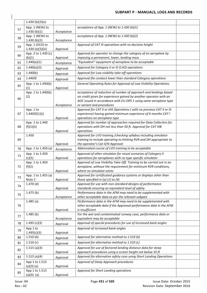
SUBPART P - MANUALS, LOGS AND RECORDS
Issue: 04 Page 431 of 505 Issue Date: October 2015
Rev.: 02 Revision Date: September 2016
1.430 (b)(3)(x)
57 App. 1 (NEW) to 1.430 (b)(1) Acceptance
acceptance of App. 1 (NEW) to 1.430 (b)(1)
58 App. 1 (NEW) to 1.430 (b)(2) Acceptance
acceptance of App. 1 (NEW) to 1.430 (b)(2)
59 App. 1 (OLD) to 1.430 (e)(3)(iii) Approval
Approval of CAT III operations with no decision height
60 App. 2 to 1.430 (c) (b)(1) Approval
Approval for operator to change the category of an aeroplane by imposing a permanent, lower, landing mass
61 1.440(a)(1) Acceptance "Equivalent" equipment of aeroplane to be acceptable
62 1.440(a)(3) Approval Approval for Category II or III (LVO) operations
63 1.440(b) Approval Approval for Low visibility take-off operations
64 1.440© Approval Approval fto conduct lower than standard Category operations
65 App. 1 to 1.440(b) (1) Approval
General Operating Rules for Approval of Low Visibility Operations
66
App. 1 to 1.440(b) (2)
Acceptance
acceptance of reduction of number of approach and landings based on credit given for experience gained by another operator with an AOC issued in accordance with EU-OPS 1 using same aeroplane type or variant and procedures
67 App. 1 to 1.440(f)(1)(i)
Approval
Approval for CAT II or IIIA Operations ( with no previous CAT II or III experience) having gained minimum experience of 6 months CAT I operations on aeroplane type
68 App. 1 to 1.440 (f)(1)(ii)
Approval
Approval for number of approaches required for Data Collection for operations with DH not less than 50 ft. Approval for CAT IIIB operations
69 1.450
Approval
Approval for LVO training /checking syllabus including simulator training to include operating to limiting RVR and DH appropriate to the operator’s Cat II/III Approval
70 App. 1 to 1.450 (a) Acceptance Abbreviated course of LVO training to be acceptable
71 App. 1 to 1.450 (c)(5) Approval
Approval of other simulator for visual scenarios of Category II operations for aeroplanes with no type specific simulator
72 App. 1 to 1.450 (f)(2)
Approval
Approval of Low Visibility Take-Off. Training to be carried out in an aeroplane, without the requirement for minimum RVR conditions, where no simulator exists
73 App. 1 to 1.455 (a) Note 2 Approval
Approval for certificated guidance systems or displays other than those specified in (a) (1) to (4)
74 1.470 (d)
Approval Approval for use with non-standard designs of performance standards ensuring an equivalent level of safety
75 1.475 (b)
Acceptance Performance data in the AFM may need to be supplemented with other acceptable data as per the relevant subpart
76 1.485 (a)
Approval
Performance data in the AFM may need to be supplemented with other acceptable data if the Approved performance date in the AFM is insufficient
77 1.485 (b)
Acceptance For the wet and contaminated runway case, performance data or equivalent may be acceptable
78 1.495 (c)(3) Approval Approval of special procedures for use of increased bank angles
79 App 1 to 1.495(c)(3) Approval
Approval of increased bank angles
80 1.510 (b) Approval Approval for alternative method to 1.510 (b)
81 1.510 (c) Approval Approval for alternative method to 1.510 (c)
82 1.515 (a)(3)
Approval Approval for use of factored landing distance data for steep approach procedures using a screen height not below 35 ft
83 1.515 (a)(4) Approval Approval for alternative safety case using Short Landing Operations
84 App 1 to 1.515 (a)(3) (a) Approval
Approval of Steep Approach procedures
85 App 1 to 1.515 (a)(4) (a) Approval
Approval for Short Landing operations
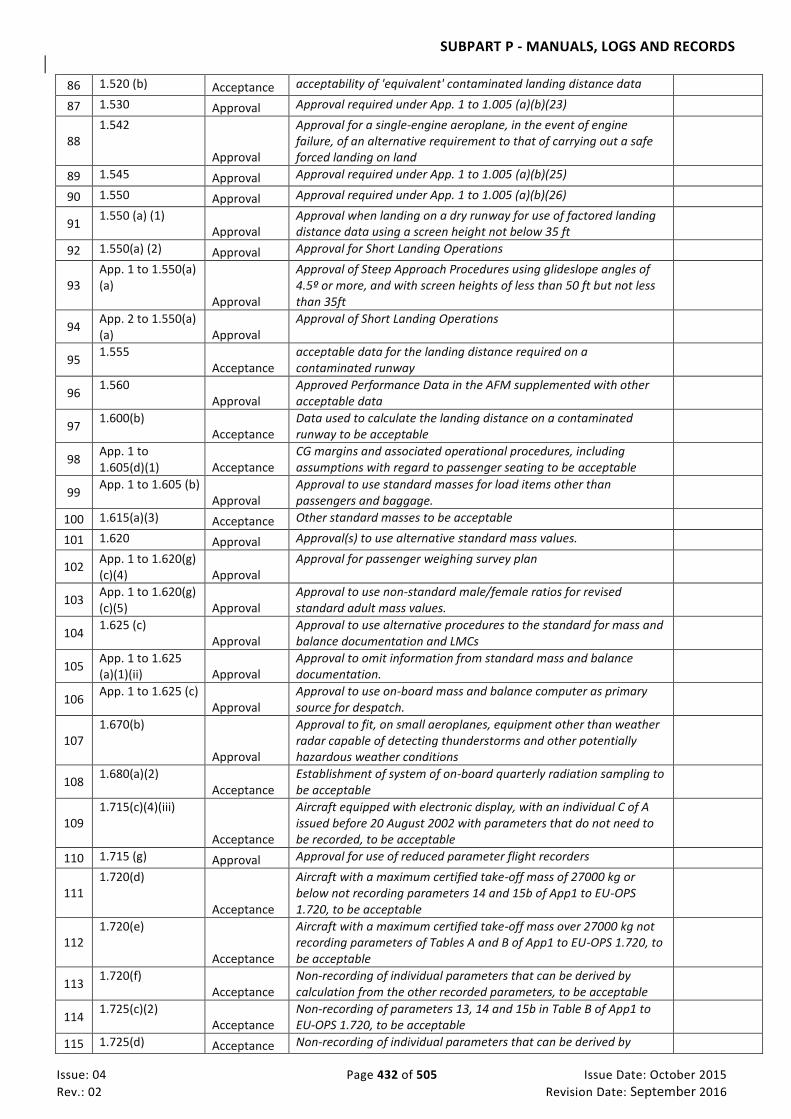
SUBPART P - MANUALS, LOGS AND RECORDS
Issue: 04 Page 432 of 505 Issue Date: October 2015
Rev.: 02 Revision Date: September 2016
86 1.520 (b) Acceptance acceptability of 'equivalent' contaminated landing distance data
87 1.530 Approval Approval required under App. 1 to 1.005 (a)(b)(23)
88 1.542
Approval
Approval for a single-engine aeroplane, in the event of engine failure, of an alternative requirement to that of carrying out a safe forced landing on land
89 1.545 Approval Approval required under App. 1 to 1.005 (a)(b)(25)
90 1.550 Approval Approval required under App. 1 to 1.005 (a)(b)(26)
91 1.550 (a) (1)
Approval Approval when landing on a dry runway for use of factored landing distance data using a screen height not below 35 ft
92 1.550(a) (2) Approval Approval for Short Landing Operations
93 App. 1 to 1.550(a) (a)
Approval
Approval of Steep Approach Procedures using glideslope angles of 4.5º or more, and with screen heights of less than 50 ft but not less than 35ft
94 App. 2 to 1.550(a) (a) Approval
Approval of Short Landing Operations
95 1.555
Acceptance acceptable data for the landing distance required on a contaminated runway
96 1.560
Approval Approved Performance Data in the AFM supplemented with other acceptable data
97 1.600(b)
Acceptance Data used to calculate the landing distance on a contaminated runway to be acceptable
98 App. 1 to 1.605(d)(1) Acceptance
CG margins and associated operational procedures, including assumptions with regard to passenger seating to be acceptable
99 App. 1 to 1.605 (b)
Approval Approval to use standard masses for load items other than passengers and baggage.
100 1.615(a)(3) Acceptance Other standard masses to be acceptable
101 1.620 Approval Approval(s) to use alternative standard mass values.
102 App. 1 to 1.620(g) (c)(4) Approval
Approval for passenger weighing survey plan
103 App. 1 to 1.620(g) (c)(5) Approval
Approval to use non-standard male/female ratios for revised standard adult mass values.
104 1.625 (c)
Approval Approval to use alternative procedures to the standard for mass and balance documentation and LMCs
105 App. 1 to 1.625 (a)(1)(ii) Approval
Approval to omit information from standard mass and balance documentation.
106 App. 1 to 1.625 (c)
Approval Approval to use on-board mass and balance computer as primary source for despatch.
107 1.670(b)
Approval
Approval to fit, on small aeroplanes, equipment other than weather radar capable of detecting thunderstorms and other potentially hazardous weather conditions
108 1.680(a)(2)
Acceptance Establishment of system of on-board quarterly radiation sampling to be acceptable
109 1.715(c)(4)(iii)
Acceptance
Aircraft equipped with electronic display, with an individual C of A issued before 20 August 2002 with parameters that do not need to be recorded, to be acceptable
110 1.715 (g) Approval Approval for use of reduced parameter flight recorders
111 1.720(d)
Acceptance
Aircraft with a maximum certified take-off mass of 27000 kg or below not recording parameters 14 and 15b of App1 to EU-OPS 1.720, to be acceptable
112 1.720(e)
Acceptance
Aircraft with a maximum certified take-off mass over 27000 kg not recording parameters of Tables A and B of App1 to EU-OPS 1.720, to be acceptable
113 1.720(f)
Acceptance Non-recording of individual parameters that can be derived by calculation from the other recorded parameters, to be acceptable
114 1.725(c)(2)
Acceptance Non-recording of parameters 13, 14 and 15b in Table B of App1 to EU-OPS 1.720, to be acceptable
115 1.725(d) Acceptance Non-recording of individual parameters that can be derived by

SUBPART P - MANUALS, LOGS AND RECORDS
Issue: 04 Page 433 of 505 Issue Date: October 2015
Rev.: 02 Revision Date: September 2016
calculation from the other recorded parameters, to be acceptable
116 1.730(a)(3) Acceptance Child restraint Device to be acceptable
117 1.730(a)(6)
Acceptance Alternative to location of seats for cabin crew members near required floor level emergency exits to be acceptable
118 1.740 Acceptance Universal Symbol Placard to be acceptable
119 1.825 (a)(2)
Approval Approval for other Approved flotation devices equipped with a survivor locator light to be substituted for life jackets for infants
120 1.825 (b)
Approval
Approval for other Approved flotation devices, on seaplanes and amphibians, equipped with a survivor locator light to be substituted for life jackets for infants
121 1.940(a)(3)
Acceptance All flight crewmembers hold an applicable and valid licence to be acceptable
122 1.940(a)(4)
Acceptance Procedure to prevent crewing together of inexperienced flight crew members to be acceptable
123 1.940(a)(6)
Acceptance
When a dedicated system panel operator is required by the AFM the flight crew includes one member who holds a Flight Engineers Licence or is a suitably qualified crew member to be acceptable
124 App. 1 to1.940 (f) Acceptance System of relief of dedicated system panel operator to be acceptable
125 1.943(c)
Acceptance Initial CRM training to be conducted by at least one acceptable CRM trainer
126 1.945 Acceptance Syllabus of conversion training to be acceptable
127 1.945 (d)(1)
Acceptance Appropriate training, If Line Flying Under Supervision has not been commenced within the 21 days, to be acceptable
128 1.945 (d)(2)
Approval Approval to reduce the number of take-offs and landings, when recommended by a Joint Operational Evaluation Board (JOEB)
129 1.945 (d)(2) Acceptance Refresher training to be acceptable
130 1.945 (d)(3)
Approval Approval to reduce the number of take-offs and landings, when recommended by a Joint Operational Evaluation Board (JOEB)
131 1.955(a)(1) Acceptance Minimum level of experience to be acceptable
132 1.965(a)(2) Approval Approval of flight crew recurrent training and checking programme.
133 1.965(a)(3)(iv) (B)
Acceptance Modular CRM training to be conducted by at least one acceptable CRM trainer
134 1.965(a)(4)(ii)
Acceptance Nomination by Operator of suitably qualified Commander for the conduct of Line Check to be acceptable
135 App. 1 to 1.965 (a)(3)(iii)(C) Acceptance
Alternative method to Halon extinguishers for actual fire fighting using representative equipment to be acceptable
136 App. 1 to 1.965 (b)(3)(ii) Acceptance
Methodology of assessment of CRM Skills to be acceptable
137 App. 2 to 1.965(c)
Acceptance
Nomination by Operator of suitably qualified Commander or System Panel Operator Type Rating Instructor or Examiner for the conduct of Line Check to be acceptable
138 1.968(a)(2)
Acceptance Pilot qualification training and checking programme to be acceptable
139 1.978 (a) Approval Approval of Alternative Training and Qualification Programme
140 1.978 (e) Approval Approval of Alternative Training and Qualification Programme
141 1.978 (e) (2)
Approval Approval to combine Line check with a Line Oriented Quality Evaluation
142 App. 1 to 1.978 (b) (3) Acceptance
Process for curriculum development to be acceptable
143 App. 1 to 1.978 (c) Acceptance Evaluation and implementation strategy to be acceptable
144 App. 1 to 1.978 (c) (1)(i) Approval
Approval of an equivalent method other than a formal
145 1.980 Approval Operation on more than one type or variant tobe approved
146 1.980(c)
Approval
Approval of the use of credit(s) related to training, checking and recency for a flight crew member operating more than one type or variant if not all requirements prescribed in Subpart N for each type

SUBPART P - MANUALS, LOGS AND RECORDS
Issue: 04 Page 434 of 505 Issue Date: October 2015
Rev.: 02 Revision Date: September 2016
or variant are complied with
147 1.980(d)
Approval Approval of procedures for flight crew to operate more than one type or variant
148 App. 1 to 1.980(a)(2) Acceptance
Specific procedures and/or operational restrictions , other than EU-OPS 1.965, to be acceptable
149 App. 1 to 1.980 (d)(7)(i) Approval
Approval for relevant recurrent training to be specified in Ops Manual If OPCs alternate between two types
150 1.981(a)(2)
Approval Approval for flight crew members to operate both helicopters and aeroplanes
151 1.1000(d)
Acceptance Procedure to select next most suitably qualified cabin crew in the event of senior cabin crew unable to operate, to be acceptable
152 1.1005 Approval Approval for cabin crew initial training
153 1.1010 Approval Approval for Conversion and Differences training programmes
154 1.1015(b) Approval Approval of content of cabin crew recurrent training programme
155 1.1030(a) Approval Approval for cabin crew to operate on more than three types.
156
1.1040 (b)
Approval
Contents of the Operations Manual, including any amendments or revisions, do not contravene the conditions in the AOC or any applicable regulations and are acceptable to or, where applicable, Approved by, the Authority
157 1.1040(c)
Approval Approval for an operator to prepare the Ops Manual in a language other than English.
158 1.1040 (m)
Acceptance Assured level of accessibility, usability and reliability to be acceptable
159 1.1045(c) Acceptance Detailed structure of the Operations Manual to be acceptable
160 1.1060(b)
Acceptance acceptance to omit items which are readily available in other documentation from the operational flight plan
161 App. 1 to 1.1065 Acceptance Form of information /documentation storage to be acceptable
162 1.1105 1.2
Approval Approval of Reporting times that realistically reflect the time for safety related ground duties
163 1.1105 6.1
Approval Approval of an operation based on an extended FDP including a break, subject to the provisions of Article 8.
164 1.1155 Approval Approval to transport dangerous goods
165 1.1195 Acceptance acceptance of Dangerous Goods
166 1.1220 (a) Approval Approval of staff training programmes
167 1.1240
Approval
Approval of security training programmes including unlawful interference /sabotage / hi-jacking, and the minimisation of the consequences
168 1.1255
Acceptance Means or procedure for cabin crew to notify flight crew of suspicious activity or cabin security breaches to be acceptable
IEM OPS 1.1040(c) Operations Manual - Language
See CAR-OPS 1.1040(c) 1 CAR-OPS 1.1040(c) requires the Operations Manual to be prepared in the English language. However,
it is recognised that there may be circumstances where approval for the use of another language, for part or all of the Operations Manual, is justifiable. The criteria on which such an approval may be based should include at least the following:
(a) The language(s) commonly used by the operator;
(b) The language of related documentation used, such as the AFM; (c) Size of the operation;

SUBPART P - MANUALS, LOGS AND RECORDS
Issue: 04 Page 435 of 505 Issue Date: October 2015
Rev.: 02 Revision Date: September 2016
(d) Scope of the operation i.e. domestic or international route structure; (e) Type of operation e.g. VFR/IFR; and (f) The period of time requested for the use of another language.
CAR-OPS 1.1045 Operations Manual – structure and contents (See Appendix 1 to CAR-OPS 1.1045) (See AMC OPS 1.1045)
(a) From 1 January 2006, an operator shall ensure that the main structure of the Operations Manual is as follows:
Part A. General/Basic
This part shall comprise all non type-related operational policies, instructions and procedures needed for a safe operation.
Part B. Aeroplane Operating Matters
This part shall comprise all type-related instructions and Standard Operating Procedures (SOPs) needed for a safe operation. It shall take account of any differences between types, variants or individual aeroplanes used by the operator. (See IEM OPS 1.1045(a) Standard Operating Procedures (SOP)
Part C. Route and Aerodrome Instructions and Information
This part shall comprise all instructions and information needed for the area of operation.
Part D. Training
This part shall comprise all training instructions for personnel required for a safe operation.
(b) An operator shall ensure that the contents of the Operations Manual are in accordance with Appendix 1 to CAR-OPS 1.1045 and relevant to the area and type of operation.
(c) An operator shall ensure that the detailed structure of the Operations Manual is acceptable to the Authority. (See IEM OPS 1.1045(c).)
AMC OPS 1.1045 Operations Manual Contents
See CAR-OPS 1.1045 1 Appendix 1 to CAR-OPS 1.1045 prescribes in detail the operational policies, instructions, procedures
and other information to be contained in the Operations Manual in order that operations personnel can satisfactorily perform their duties. When compiling an Operations Manual, an operator may take advantage of the contents of other relevant documents. Material produced by the operator for Part B of the Operations Manual may be supplemented with or substituted by applicable parts of the Aeroplane Flight Manual required by CAR-OPS 1.1050 or, where such a document exists, by an Aeroplane Operating Manual produced by the manufacturer of the aeroplane. In the case of performance class B aeroplanes. it is acceptable that a “Pilot Operating Handbook” (POH) or equivalent document is used as Part B of the Operations Manual, provided that the POH covers the necessary items.For Part C of the Operations Manual, material produced by the operator may be supplemented with or substituted by applicable Route Guide material produced by a specialised

SUBPART P - MANUALS, LOGS AND RECORDS
Issue: 04 Page 436 of 505 Issue Date: October 2015
Rev.: 02 Revision Date: September 2016
professional company. 2 If an operator chooses to use material from another source in his Operations Manual he should
either copy the applicable material and include it directly in the relevant part of the Operations Manual, or the Operations Manual should contain a statement to the effect that a specific manual(s) (or parts thereof) may be used instead of the specified part(s) of the Operations Manual.
3 If an operator chooses to make use of material from an alternative source (e.g . a Route Manual
producer, an aeroplane manufacturer or a training organisation) as explained above, this does not absolve the operator from the responsibility of verifying the applicability and suitability of this material. (See CAR-OPS 1.1040(k)). Any material received form an external source should be given its status by a statement in the Operations Manual.
IEM OPS 1.1045(a) Standard Operating Procedures (SOP)
1. Operators shall establish standard operating procedures (SOPs) and the use of checklist that shall be used
by flight crew prior to, during and after all phases of operations, and in emergency, to ensure compliance with the operating procedures contained in the aircraft operating manual and the aeroplane flight manual or other documents associated with the certificate of airworthiness and otherwise in the operations manual, are followed. The design and utilisation of checklists shall observe Human Factors principles. These document shall form a part of Operations Manual Part B, that provide guidance to flight operations personnel to ensure safe, efficient logical and predictable means of carrying out flight procedures. To achieve these objectives, SOPs should unambiguously express;
(a) what the task is: (b) when the task is going to be conducted (time and sequence);
(c) by whom the task is going to be conducted;
(d) how the task is going to be done(actions);
(e) what the sequence of actions consist of; and
(f) what type of feedback is to be provided as a result of the actions (verbal call -outs, instrument
indications, switch positions and etc)
2. To ensure compatibility with specific operational environments and compliance by flight operations personnel, SOPs design should take into account:
(a) the nature of the operator’s environment and type of operation; (b) the operational philosophy, including crew coordination;
(c) the training philosophy, including human performance training;
(d) the operator’s corporate culture, including the degree of flexibility to be built into SOPs
design;
(e) the level of experience of different user groups, such as flight crew, aircraft maintenance engineers and cabin attendants;
(f) resourse conservation policies, such as fuel conservation or wear on power plants and
systems
SUBPART P - MANUALS, LOGS AND RECORDS
Issue: 04 Page 437 of 505 Issue Date: October 2015
Rev.: 02 Revision Date: September 2016
(g) flight deck automation, including flight deck and systems layout and supporting documents
(h) the compatibility between SOPs and operationsal documentation; and
(i) procedural deviation during abnormal/unforeseen situation.
3. Flight operations personnel should be involved in the development of SOPS. Operators should establish a
formal process of feedback from flight operations personnel to ensure standardization, compliance and evaluation of reasons for non-compliance during SOPs implementation and use. 4. Operators shall establish checklists as an integral part of SOPs. Checklist should describe the actions
relevant to specific phases of operations (engine start, taxi, take off, etc) that flight crew must perform or verify and which relate to flight safety. Checklist should also provide a framework for verifying aircraft and systems configuration that guard against vulnerabilities in human performance.
5. Operators shall establish crew briefing as an integral part of SOPs. Crew briefing communicate duties,
standardise activities, ensure that a plan of action is shared by crew members and enhance crew situational awareness.
6. Flight crew briefing shall be conducted for, but not limited to, the following phases of operations
(a) pre-flight; (b) departure; and
(c) arrival
7. Pre-flight briefing shall include both flight crew and cabin crew. The briefings should focus on crew
coordination as well as aircraft operational issues. They should include, but not be limited to:
(a) any information necessary for the flight, including unserviceable equipment or abnormalities that may affect operational or passenger safety requirements;
(b) essential communications, and emergency and safety procedures; and
(c) weather conditions
8. Flight crew departure briefings should prioritise all relevant conditions that exist for the take-off and
climb. They should include, but not limited to:
(a) runway in use, aircraft configuration and take-off speeds; (b) departure procedures;
(c) departure routes;
(d) navigation and communication equipment set-up;
(e) aerodrome, terrain and performance restriction, including noise abatement procedures (if
applicable);
(f) take-off alternates (if applicable);
(g) any item(s) included in minimum equipment list (if applicable);

SUBPART P - MANUALS, LOGS AND RECORDS
Issue: 04 Page 438 of 505 Issue Date: October 2015
Rev.: 02 Revision Date: September 2016
(h) review of applicable emergency procedure; and
(i) applicable standard call-outs
9. Flight crew arrival briefings should prioritise all relevant conditions that exist for the desent,
approach and landing. They should include, but not limited to
(a) terrain restriction and minimum safe altitudes during descent; (b) arrival routes; (c) instrument or visual approach procedures and runway in use;
(d) operational minima, aircraft configuration, and landing speeds;
(e) navigation and communication equipment set-up;
(f) missed approach procedures;
(g) alternate aerodrome and fuel considerations;
(h) review of applicable emergency procedures;
(i) applicable standard call-outs; and
(j) cold temperature correction
IEM OPS 1.1045(c) Operations Manual Structure
See CAR-OPS 1.1045(c) & Appendix 1 to CAR-OPS 1.1045 Operations Manual Contents 1 CAR-OPS 1.1045(a) prescribes the main structure of the Operations Manual as follows: Part A – General/Basic; Part B – Aeroplane Operating Matters – Type related; Part C – Route and Aerodrome Instructions and Information; Part D – Training. 2 CAR-OPS 1.1045 (c) requires the operator to ensure that the detailed structure of the Operations
Manual is acceptable to the Authority. 3 Appendix 1 to CAR-OPS 1.1045 Operations Manual Contents contains a comprehensively detailed and
structured list of all items to be covered in the Operations Manual. Since it is believed that a high degree of standardisation of Operations Manuals will lead to improved overall flight safety, it is strongly recommended that the structure described in this IEM should be used by operators as far as possible. A List of Contents based upon Appendix 1 to CAR-OPS 1.1045 is given below.
4 Manuals which do not comply with the recommended structure may require a longer time to be
accepted/approved by the Authority. 5 To facilitate comparability and usability of Operations Manuals by new personnel, formerly employed

SUBPART P - MANUALS, LOGS AND RECORDS
Issue: 04 Page 439 of 505 Issue Date: October 2015
Rev.: 02 Revision Date: September 2016
by another operator, operators are recommended not to deviate from the numbering system used in Appendix 1 to CAR-OPS 1.1045 Operations Manual Contents. If there are sections which, because of the nature of the operation, do not apply, it is recommended that operators maintain the numbering system described below and insert ‘Not applicable’ or ‘Reserved’ where appropriate.

SUBPART P - MANUALS, LOGS AND RECORDS
Issue: 04 Page 440 of 505 Issue Date: October 2015
Rev.: 02 Revision Date: September 2016
Operations Manual Structure
(List of Contents)
Part A GENERAL/BASIC 0 ADMINISTRATION AND CONTROL OF OPERATIONS MANUAL 0.1. Introduction 0.2 System of amendment and revision 1 ORGANISATION AND RESPONSIBILITIES 1.1 Organisational structure 1.2 Names of nominated postholders 1.3 Responsibilities and duties of operations management personnel 1.4 Authority, duties and responsibilities of the commander 1.5. Duties and responsibilities of crew members other than the commander 2 OPERATIONAL CONTROL AND SUPERVISION 2.1 Supervision of the operation by the operator 2.2 System of promulgation of additional operational instructions and information 2.3 Safety Management System 2.4 Operational control 2.5 Powers of Authority 3 QUALITY SYSTEM 4 CREW COMPOSITION 4.1 Crew Composition 4.2 Designation of the commander 4.3. Flight crew incapacitation 4.4 Operation on more than one type 5 QUALIFICATION REQUIREMENTS 5.1 Description of licence, qualification/competency, training, checking requirements etc. 5.2 Flight crew 5.3 Cabin crew 5.4 Training, checking and supervisory personnel 5.5 Other operations personnel 6 CREW HEALTH PRECAUTIONS 6.1 Crew health precautions 7 FLIGHT TIME LIMITATIONS 7.1 Flight and Duty Time limitations and Rest requirements 7.2 Exceedances of flight and duty time limitations and/or reduction of rest periods 8 OPERATING PROCEDURES 8.1 Flight Preparation Instructions 8.1.1 Minimum Flight Altitudes

SUBPART P - MANUALS, LOGS AND RECORDS
Issue: 04 Page 441 of 505 Issue Date: October 2015
Rev.: 02 Revision Date: September 2016
8.1.2 Criteria for determining the usability of aerodromes 8.1.3 Methods for the determination of Aerodrome Operating Minima 8.1.4 En-route Operating Minima for VFR flights or VFR portions of a flight 8.1.5 Presentation and Application of Aerodrome and En Route Operating Minima 8.1.6 Interpretation of meteorological information 8.1.7 Determination of the quantities of fuel, oil and water methanol carried 8.1.8 Mass and Centre of Gravity 8.1.9 ATS Flight Plan 8.1.10 Operational Flight Plan 8.1.11 Operator’s Aeroplane Technical Log 8.1.12 List of documents, forms and additional information to be carried 8.2 Ground Handling Instructions 8.2.1 Fuelling procedures 8.2.2 Aeroplane, passengers and cargo handling procedures related to safety 8.2.3 Procedures for the refusal of embarkation 8.2.4 De-icing and Anti-icing on the Ground 8.2.5 Subcontracting policy 8.2.6 Handling processes 8.2.7 Staff training 8.3 Flight Procedures 8.3.1 VFR/IFR policy 8.3.2 Navigation Procedures 8.3.3 Altimeter setting procedures 8.3.4 Altitude alerting system procedures 8.3.5 Ground Proximity Warning System procedures 8.3.6 Policy and procedures for the use of TCAS/ACAS 8.3.7 Policy and procedures for in-flight fuel management 8.3.8 Adverse and potentially hazardous atmospheric conditions 8.3.9 Wake Turbulence 8.3.10 Crew members at their stations 8.3.11 Use of safety belts for crew and passengers 8.3.12 Admission to Flight Deck 8.3.13 Use of vacant crew seats 8.3.14 Incapacitation of crew members 8.3.15 Cabin Safety Requirements 8.3.16 Passenger briefing procedures 8.3.17 Procedures for aeroplanes operated whenever required cosmic or solar radiation detection equipment is
carried 8.4 All Weather Operations 8.5 ETOPS 8.6 Use of the Minimum Equipment and Configuration Deviation List(s) 8.7 Non revenue flights 8.8 Oxygen Requirements 9 DANGEROUS GOODS AND WEAPONS 10 SECURITY 11 HANDLING OF ACCIDENTS AND OCCURRENCES 12 RULES OF THE AIR

SUBPART P - MANUALS, LOGS AND RECORDS
Issue: 04 Page 442 of 505 Issue Date: October 2015
Rev.: 02 Revision Date: September 2016
SUBPART P - MANUALS, LOGS AND RECORDS
Issue: 04 Page 443 of 505 Issue Date: October 2015
Rev.: 02 Revision Date: September 2016
Part B AEROPLANE OPERATING MATTERS TYPE RELATED 0 GENERAL INFORMATION AND UNITS OF MEASUREMENT 1 LIMITATIONS 2 NORMAL PROCEDURES 3 ABNORMAL AND EMERGENCY PROCEDURES 4 PERFORMANCE 4.1 Performance data 4.2 Additional performance data 5 FLIGHT PLANNING 6 MASS AND BALANCE 7 LOADING 8 CONFIGURATION DEVIATION LIST 9 MINIMUM EQUIPMENT LIST 10 SURVIVAL AND EMERGENCY EQUIPMENT INCLUDING OXYGEN 11 EMERGENCY EVACUATION PROCEDURES 11.1 Instructions for preparation for emergency evacuation 11.2 Emergency evacuation procedures 12 AEROPLANE SYSTEMS

SUBPART P - MANUALS, LOGS AND RECORDS
Issue: 04 Page 444 of 505 Issue Date: October 2015
Rev.: 02 Revision Date: September 2016
Part C ROUTE AND AERODROME INSTRUCTIONS AND INFORMATION Part D TRAINING 1 TRAINING SYLLABI AND CHECKING PROGRAMMES – GENERAL 1.1 General 1.2 Amendment and Revision 2 TRAINING SYLLABI AND CHECKING PROCEDURES 2.1 Flight Crew Chapter 1 Organisation Structure
1.1 Organisation Structure
Chapter 2 Training and checking personnel 2.1 Appointment of Flight Crew Training Staff 2.2 Not used 2.3 Duties and Responsibilities 2.3.1 Training and Check Captains 2.3.2 Training First Officers 2.3.3 Procedures to be applied in the event that personnel do not achieve or maintain the required
standard 2.4 Qualifications and Experience 2.4.1 General 2.4.2 TRI(MPA) Minimum Requirements 2.4.3 TRE- Minimum Requirements 2.4.4 SFI- Minimum Requirements 2.4.5 SFE- Minimum Requirements 2.4.6 Commanders nominated for Line Training and Checks 2.4.7 TRI/TRE/SFI/SFE- Reauthorisation and Renewal
2.4.7.1 TRI (MPA) Rating 2.4.7.2 TRE Authorisation 2.4.7.3 SFI Authorisation 2.4.7.4 SFE Authorisation
Chapter 3 Administration 3.1 General 3.2 Mandatory Requirements 3.3 Records 3.4 Minimum Qualification/Experience Levels
3.4.1 Commander- Multi Pilot Aeroplanes 3.4.2 Commander- Single Pilot Aeroplanes 3.4.3 Pilot-in-Command Relieving the Commander 3.4.4 Co Pilot 3.4.5 Relief Co Pilot 3.4.6 Upgrade to Commander 3.4.7 System Panel Operator (Flight Engineer) 3.4.8 Relief System Panel Operator (Flight Engineer) 3.4.9 Operations on more than one type or variant, Authority Approval Required
3.5 Period of Validity 3.5.1 Operator Proficiency check 3.5.2 Line Check 3.5.3 Annual Emergency and safety Equipment Check 3.5.4 Triennial Emergency and Safety Equipment Check 3.5.5 Crew Resource Management 3.5.6 Ground and Refresher Training 3.5.7 Pilot Qualification to operate in either pilot’s seat 3.5.8 Route and Aerodrome Competence Qualification-PIC 3.5.9 Recent Experience- PIC Single Pilot Operations

SUBPART P - MANUALS, LOGS AND RECORDS
Issue: 04 Page 445 of 505 Issue Date: October 2015
Rev.: 02 Revision Date: September 2016
3.5.10 Recent Experience-PIC Multi Pilot Operations 3.5.11 Recent Experience-Co Pilot 3.5.12 Recent Experience-LVTO and Category II/III 3.5.13 Instrument Rating-(Aeroplane)
Chapter 4 Training Policy 4.1 Instructor and Check Personnel
4.1.1 General 4.1.2 Selection 4.1.3 Training-Commanders Nominated for Line Training and Checks 4.1.4 Training-TRI/TRE 4.1.5 Training-Training First Officer
Chapter 5 Conversion Training and Checking 5.1 General 5.2 Ground Training 5.3 Emergency and Safety equipment Training 5.4 CRM Training 5.5 Synthetic Training Device/Aeroplane Training
5.5.1 General 5.5.2 Synthetic Training Device Training 5.5.3 Aeroplane Training
5.6 Flying Test and Checks 5.7 Line Flying Under Supervision 5.8 Low Visibility Operations
5.8.1 General 5.8.2 Ground Training 5.8.3 Synthetic Training Device Training and/or Flight Training 5.8.4 Flight Crew Qualification 5.8.5 Line Flying Under Supervision 5.8.6 Type and Command Experience 5.8.7 Low Visibility Take Off with RVR less than 150 meters
5.9. ETOPS Training and Checking 5.9.1 ETOPS Training 5.9.2 ETOPS Check Program
5.10 RVSM Training 5.11 System Panel Operator (Flight Engineer)
Chapter 6 Route competence Training Chapter 7 Difference and Familiarisation Training Chapter 8 Recurrent Training
8.1 General 8.2 Ground and Refresher 8.3 Aeroplane/Synthetic Training device 8.4 Emergency and Safety Equipment
8.4.1 General 8.4.2 Annual 8.4.3 Triennial
8.5 CRM 8.6 Single Pilot Operations Under IFR or at Night 8.7 System Panel Operator (Flight Engineer)
Chapter 9 Recurrent Checking
91. General 9.2 Operator Proficiency check 9.3 Emergency and Safety Equipment Check 9.4 Line check 9.5 Single Pilot Operations Under IFR or at Night 9.6 System Panel Operator (Flight Engineer)

SUBPART P - MANUALS, LOGS AND RECORDS
Issue: 04 Page 446 of 505 Issue Date: October 2015
Rev.: 02 Revision Date: September 2016
Chapter 10 Command Training
10.1 Minimum Experience Levels 10.2 Command course
Chapter 11 Pilot qualification to operate in either Pilot’s Seat Chapter 12 Training Records and Checking Forms
Form 1-Type or Class Rating Form 2-Operator Proficiency Check/or Combined OPC/LPC Form 3-Certificate of Test\ Form 4- Instrument Rating Renewal Form 5-Certificates for Low Visibility Operations and other Special Qualifications
Appendices A Conversion Training and checking-Ground Syllabus B Conversion Training and Checking-CRM C Conversion Training and Checking-Synthetic Training Devices D Conversion Training and checking-Low Visibility Operations- Ground Training E Conversion Training and Checking-Low Visibility Operations-Approved Flight Simulator Training and/or Flight Training F Operator Proficiency Check G Line Check
2.2 Cabin Crew Training and Checking
1 Introduction 2 Senior cabin crew member 3 Initial Training 4 Conversion and differences Training 5 Familiarisation 6 Recurrent Training 7 Refresher Training 8 Checking 9 Training Records
2.3 Training Syllabus For Transportation of Dangerous Goods: Operations Personnel Concerned including Crew Members
1 Introduction 2 For Operators who do not hold a Permanent Approval to Carry Dangerous Goods 3 For Operators who do hold a Permanent Approval to Carry Dangerous Goods
2.4. Training Syllabus For Transportation of Dangerous Goods: Operations Personnel other than Crew Members
1 Introduction 2 For Operators who do not hold a Permanent Approval to Carry Dangerous Goods 3 For Operators who do hold a Permanent Approval to Carry Dangerous Goods 4 Areas of Training 5 Further Information
3 PROCEDURES
3.1 Procedures for training and checking 3.2Procedures to ensure that abnormal or emergency situations are not simulated during commercial air
transportation flights 4 DOCUMENTATION AND STORAGE

SUBPART P - MANUALS, LOGS AND RECORDS
Issue: 04 Page 447 of 505 Issue Date: October 2015
Rev.: 02 Revision Date: September 2016
CAR-OPS 1.1050 Aeroplane Flight Manual
An operator shall keep a current approved Aeroplane Flight Manual or equivalent document for each aeroplane that it operates.
The operator shall ensure that Operations Manuals part B that is refered to Manufacture documentation are kept up-to-date.
CAR-OPS 1.1055 Journey log
(a) An operator shall retain the following information for each flight in the form of a Journey Log:
(1) Aeroplane registration;
(2) Date;
(3) Name(s) of crew member(s);
(4) Duty assignment of crew member(s);
(5) Place of departure;
(6) Place of arrival;
(7) Time of departure (off-block time);
(8) Time of arrival (on-block time);
(9) Hours of flight;
(10) Nature of flight;
(11) Incidents, observations (if any); and
(12) Commander’s signature (or equivalent). (See IEM OPS 1.1055 (a)(12).)
(b) An operator may be permitted not to keep an aeroplane journey log, or parts thereof, by the Authority if the relevant information is available in other documentation. (See IEM OPS 1.1055(b).)
(c) An operator shall ensure that all entries are made concurrently and that they are permanent in nature.
IEM OPS 1.1055(a)(12) Signature or equivalent
See CAR-OPS 1.1055(a)(12) 1 CAR-OPS 1.1055 requires a signature or its equivalent. This IEM gives an example of how this can be
arranged where normal signature by hand is impracticable and it is desirable to arrange the equivalent verification by electronic means.
2 The following conditions should be applied in order to make an electronic signature the equivalent of
a conventional hand-written signature:
i. Electronic ‘signing’ should be achieved by entering a Personal Identification Number (PIN) code

SUBPART P - MANUALS, LOGS AND RECORDS
Issue: 04 Page 448 of 505 Issue Date: October 2015
Rev.: 02 Revision Date: September 2016
with appropriate security etc;
ii. Entering the PIN code should generate a print-out of the individual’s name and professional capacity on the relevant document(s) in such a way that it is evident, to anyone having a need for that information, who has signed the document;
iii. The computer system should log information to indicate when and where each PIN code has been entered;
iv. The use of the PIN code is, from a legal and responsibility point of view, considered to be fully equivalent to signature by hand;
v. The requirements for record keeping remain unchanged; and.
vi. All personnel concerned should be made aware of the conditions associated with electronic signature and should confirm this in writing.
IEM OPS 1.1055(b) Journey log
See CAR-OPS 1.1055(b) The ‘other documentation’ referred to in this paragraph might include such items as the operational
flight plan, the aeroplane technical log, flight report, crew lists etc.
IEM to Appendix 1 to CAR-OPS 1.1045 Operations Manual Contents
1 With reference to Operations Manual Section A, paragraph 8.3.17, on cosmic radiation, limit values
should be published in the Operations Manual only after the results of scientific research are available and internationally accepted.
2 With reference to Operations Manual Section B, paragraph 9 (Minimum Equipment List) and 12
(Aeroplane Systems) operators should give consideration to using the ATA number system when allocating chapters and numbers for aeroplane systems.
CAR-OPS 1.1060 Operational flight plan
(a) An operator must ensure that the operational flight plan used and the entries made during flight contain the following items:
(1) Aeroplane registration;
(2) Aeroplane type and variant;
(3) Date of flight;
(4) Flight identification;
(5) Names of flight crew members;
(6) Duty assignment of flight crew members;
(7) Place of departure;
(8) Time of departure (actual off-block time, take-off time);
(9) Place of arrival (planned and actual);

SUBPART P - MANUALS, LOGS AND RECORDS
Issue: 04 Page 449 of 505 Issue Date: October 2015
Rev.: 02 Revision Date: September 2016
(10) Time of arrival (actual landing and on-block time);
(11) Type of operation (ETOPS, VFR, Ferry flight, etc.);
(12) Route and route segments with checkpoints/waypoints, distances, time and tracks;
(13) Planned cruising speed and flying times between check-points/waypoints. Estimated and actual times overhead;
(14) Safe altitudes and minimum levels;
(15) Planned altitudes and flight levels;
(16) Fuel calculations (records of in-flight fuel checks);
(17) Fuel on board when starting engines;
(18) Alternate(s) for destination and, where applicable, take-off and en-route, including information required in sub-paragraphs (12), (13), (14), and (15) above;
(19) Initial ATS Flight Plan clearance and subsequent re-clearance;
(20) In-flight re-planning calculations; and
(21) Relevant meteorological information.
(b) Items which are readily available in other documentation or from another acceptable source or are irrelevant to the type of operation may be omitted from the operational flight plan.
(c) An operator must ensure that the operational flight plan and its use are described in the Operations Manual.
(d) An operator shall ensure that all entries on the operational flight plan are made concurrently and that they are permanent in nature.
CAR-OPS 1.1065 Document storage periods
An operator shall ensure that all records and all relevant operational and technical information for each individual flight, are stored for the periods prescribed in Appendix 1 to CAR-OPS 1.1065.
CAR-OPS 1.1070 Operator’s Continuous Airworthiness Management Exposition
An operator shall keep a current approved Continuous Airworthiness Management Exposition as prescribed in CAR M.
CAR-OPS 1.1071 Aeroplane Technical Log
An operator shall keep an aeroplane technical log as prescribed in Operator’s technical log system in CAR-M.

SUBPART P - MANUALS, LOGS AND RECORDS
Issue: 04 Page 450 of 505 Issue Date: October 2015
Rev.: 02 Revision Date: September 2016
Appendix 1 to CAR-OPS 1.1045 Operations Manual Contents (See IEM to Appendix 1 to CAR-OPS 1.1045)
An operator shall ensure that the Operations Manual contains the following:
A. GENERAL/BASIC
0 ADMINISTRATION AND CONTROL OF OPERATIONS MANUAL
0.1 Introduction
(a) A statement that the manual complies with all applicable regulations and with the terms and conditions of the applicable Air Operator Certificate/Authorization.
(b) List the element of operations manual that requires approval and acceptance
(c) A statement that the manual contains operational instructions that are to be complied with by the relevant personnel.
(d) A list and brief description of the various parts, their contents, applicability and use.
(e) Explanations and definitions of terms and words needed for the use of the manual.
0.2 System of amendment and revision
(a) Details of the person(s) responsible for the issuance and insertion of amendments and revisions.
(b) A record of amendments and revisions with insertion dates and effective dates.
(c) A statement that handwritten amendments and revisions are not permitted except in situations requiring immediate amendment or revision in the interest of safety.
(d) A description of the system for the annotation of pages and their effective dates.
(e) A list of effective pages.
(f) Annotation of changes (on text pages and, as far as practicable, on charts and diagrams).
(g) Temporary revisions.
(h) A description of the distribution system for the manuals, amendments and revisions.
1 ORGANISATION AND RESPONSIBILITIES
1.1 Organisational structure. A description of the organisational structure including the general company organigram and operations department organigram. The organigram must depict the relationship between the Operations Department and the other Departments of the company. In particular, the subordination and reporting lines of all Divisions, Departments etc, which pertain to the safety of flight operations, must be shown.
1.2 Nominated postholders. The name of each nominated postholder responsible for flight operations, the maintenance system, crew training and ground operations, as prescribed in CAR-OPS 1.175(i). A description of their function and responsibilities must be included.

SUBPART P - MANUALS, LOGS AND RECORDS
Issue: 04 Page 451 of 505 Issue Date: October 2015
Rev.: 02 Revision Date: September 2016
1.3 Responsibilities and duties of operations management personnel. A description of the duties, responsibilities and authority of operations management personnel pertaining to the safety of flight operations and the compliance with the applicable regulations.
1.4 Authority, duties and responsibilities of the commander. A statement defining the authority, duties and responsibilities of the commander.
1.5. Duties and responsibilities of crew members other than the commander.
2 OPERATIONAL CONTROL AND SUPERVISION
2.1 Supervision of the operation by the operator. A description of the system for supervision of the operation by the operator (See CAR-OPS 1.175(g)). This must show how the safety of flight operations and the qualifications of personnel are supervised. In particular, the procedures related to the following items must be described:
(a) Licence and qualification validity;
(b) Competence of operations personnel; and
(c) Control, analysis and storage of records, flight documents, additional information and data.
2.2 System of promulgation of additional operational instructions and information. A description of any system for promulgating information which may be of an operational nature but is supplementary to that in the Operations Manual. The applicability of this information and the responsibilities for its promulgation must be included.
2.3 Safety Management System. A description of the main aspects of the flight safety programme. (See CAR-OPS 1.037).
2.4 Operational control. A description of the procedures and responsibilities necessary to exercise operational control with respect to flight safety.
2.5 Powers of the Authority. A description of the powers of the Authority and guidance to staff on how to facilitate inspections by Authority personnel.
3 QUALITY SYSTEM
A description of the quality system adopted including at least:
(a) Quality policy;
(b) A description of the organisation of the Quality System; and
(c) Allocation of duties and responsibilities.
4 CREW COMPOSITION
4.1 Crew Composition. An explanation of the method for determining crew compositions taking account of the following:
(a) The type of aeroplane being used;
SUBPART P - MANUALS, LOGS AND RECORDS
Issue: 04 Page 452 of 505 Issue Date: October 2015
Rev.: 02 Revision Date: September 2016
(b) The area and type of operation being undertaken;
(c) The phase of the flight;
(d) The minimum crew requirement and flight duty period planned;
(e) Experience (total and on type), recency and qualification of the crew members; and
(f) The designation of the commander and, if necessitated by the duration of the flight, the procedures for the relief of the commander or other members of the flight crew. (See Appendix 1 to CAR-OPS 1.940.)
(g) The designation of the senior cabin crew member and, if necessitated by the duration of the flight, the procedures for the relief of the senior cabin crew member and any other member of the cabin crew.
4.2 Designation of the commander. The rules applicable to the designation of the commander.
4.3 Flight crew incapacitation. Instructions on the succession of command in the event of flight crew incapacitation.
4.4 Operation on more than one type. A statement indicating which aeroplanes are considered as one type for the purpose of:
(a) Flight crew scheduling; and
(b) Cabin crew scheduling.
5 QUALIFICATION REQUIREMENTS
5.1 A description of the required licence, rating(s), qualification/competency (e.g. for routes and aerodromes), experience, training, checking and recency for operations personnel to conduct their duties. Consideration must be given to the aeroplane type, kind of operation and composition of the crew.
5.2 Flight crew
(a) Commander.
(b) Pilot relieving the commander.
(c) Co-pilot.
(d) Pilot under supervision.
(e) System panel operator.
(f) Operation on more than one type or variant.
5.3 Cabin crew.
(a) Senior cabin crew member.
(b) Cabin crew member.

SUBPART P - MANUALS, LOGS AND RECORDS
Issue: 04 Page 453 of 505 Issue Date: October 2015
Rev.: 02 Revision Date: September 2016
(1) Required cabin crew member.
(2) Additional cabin crew member and cabin crew member during familiarisation flights.
(c) Operation on more than one type or variant.
5.4 Training, checking and supervision personnel.
(a) For flight crew.
(b) For cabin crew.
5.5 Other operations personnel
6 CREW HEALTH PRECAUTIONS
6.1 Crew health precautions. The relevant regulations and guidance to crew members concerning health including:
(a) Physchoactive substances;
(b) Sleeping tablets;
(c) Pharmaceutical preparations;
(d) Immunisation;
(e) Deep diving;
(f) Blood donation;
(g) Meal precautions prior to and during flight;
(h) Sleep and rest; and
(i) Surgical operations.
7 FLIGHT TIME LIMITATIONS
7.1 Flight and Duty Time Limitations and Rest Requirements. The scheme developed by the operator in accordance with Subpart Q.
7.2 Exceedances of flight and duty time limitations and/or reductions of rest periods. Conditions under which flight and duty time may be exceeded or rest periods may be reduced and the procedures used to report these modifications.
8 OPERATING PROCEDURES
8.1 Flight Preparation Instructions. As applicable to the operation:
8.1.1 Minimum Flight Altitudes. A description of the method of determination and application of minimum altitudes including:
(a) A procedure to establish the minimum altitudes/flight levels for VFR flights; and
(b) A procedure to establish the minimum altitudes/flight levels for IFR flights.
8.1.2 Criteria and responsibilities for the authorisation of the use of aerodromes taking into account the applicable requirements of Subparts D, E, F, G, H, I and J.

SUBPART P - MANUALS, LOGS AND RECORDS
Issue: 04 Page 454 of 505 Issue Date: October 2015
Rev.: 02 Revision Date: September 2016
8.1.3 Methods for establishing aerodrome operating minima. The method for establishing aerodrome operating minima for IFR flights in accordance with CAR–OPS 1 Subpart E. Reference must be made to procedures for the determination of the visibility and/or runway visual range and for the applicability of the actual visibility observed by the pilots, the reported visibility and the reported runway visual range.
8.1.4 En-route Operating Minima for VFR Flights or VFR portions of a flight and, where single engined aeroplanes are used, instructions for route selection with respect to the availability of surfaces which permit a safe forced landing.
8.1.5 Presentation and Application of Aerodrome and En-route Operating Minima
8.1.6 Interpretation of meteorological information. Explanatory material on the decoding of MET forecasts and MET reports relevant to the area of operations, including the interpretation of conditional expressions.
8.1.7 Determination of the quantities of fuel, oil and water methanol carried. The methods by which the quantities of fuel, oil and water methanol to be carried are determined and monitored in flight. This section must also include instructions on the measurement and distribution of the fluid carried on board. Such instructions must take account of all circumstances likely to be encountered on the flight, including the possibility of in-flight replanning and of failure of one or more of the aeroplane’s power plants. The system for maintaining fuel and oil records must also be described.
8.1.8 Mass and Centre of Gravity. The general principles of mass and centre of gravity including:
(a) Definitions;
(b) Methods, procedures and responsibilities for preparation and acceptance of mass and centre of gravity calculations;
(c) The policy for using standard and/or actual masses;
(d) The method for determining the applicable passenger, baggage and cargo mass;
(e) The applicable passenger and baggage masses for various types of operations and aeroplane type;
(f) General instruction and information necessary for verification of the various types of mass and balance documentation in use;
(g) Last Minute Changes procedures;
(h) Specific gravity of fuel, oil and water methanol; and
(i) Seating policy/procedures.
8.1.9 ATS Flight Plan. Procedures and responsibilities for the preparation and submission of the air traffic services flight plan. Factors to be considered include the means of submission for both individual and repetitive flight plans.
8.1.10 Operational Flight Plan. Procedures and responsibilities for the preparation and acceptance of the operational flight plan. The use of the operational flight plan must be described including samples of the operational flight plan formats in use.

SUBPART P - MANUALS, LOGS AND RECORDS
Issue: 04 Page 455 of 505 Issue Date: October 2015
Rev.: 02 Revision Date: September 2016
8.1.11 Operator’s Aeroplane Technical Log. The responsibilities and the use of the operator’s Aeroplane Technical Log must be described, including samples of the format used.
8.1.12 List of documents, forms and additional information to be carried.
8.2 Ground Handling Instructions
8.2.1 Fuelling procedures. A description of fuelling procedures, including:
(a) Safety precautions during refuelling and defuelling including when an APU is in operation or when a turbine engine is running and the prop-brakes are on;
(b) Refuelling and defuelling when passengers are embarking, on board or disembarking; and
(c) Precautions to be taken to avoid mixing fuels.
8.2.2 Aeroplane, passengers and cargo handling procedures related to safety. A description of the handling procedures to be used when allocating seats and embarking and disembarking passengers and when loading and unloading the aeroplane. Further procedures, aimed at achieving safety whilst the aeroplane is on the ramp, must also be given. Handling procedures must include:
(a) Children/infants, sick passengers and Persons with Reduced Mobility;
(b) Transportation of inadmissible passengers, deportees or persons in custody;
(c) Permissible size and weight of hand baggage;
(d) Loading and securing of items in the aeroplane;
(e) Special loads and classification of load compartments;
(f) Positioning of ground equipment;
(g) Operation of aeroplane doors;
(h) Safety on the ramp, including fire prevention, blast and suction areas;
(i) Start-up, ramp departure and arrival procedures including push-back and towing operations;
(j) Servicing of aeroplanes;
(k) Documents and forms for aeroplane handling; and
(l) Multiple occupancy of aeroplane seats.
8.2.3 Procedures for the refusal of embarkation. Procedures to ensure that persons who appear to be intoxicated or who demonstrate by manner or physical indications that they are under the influence of Physchoactive substances, are refused embarkation. This does not apply to medical patients under proper care.
8.2.4 De-icing and Anti-icing on the ground. A description of the de-icing and anti-icing policy and procedures for aeroplanes on the ground. These shall include descriptions of the types and effects of icing and other contaminants on aeroplanes whilst stationary, during ground

SUBPART P - MANUALS, LOGS AND RECORDS
Issue: 04 Page 456 of 505 Issue Date: October 2015
Rev.: 02 Revision Date: September 2016
movements and during take-off. In addition, a description of the fluid types used must be given including:
(a) Proprietary or commercial names;
(b) Characteristics;
(c) Effects on aeroplane performance;
(d) Hold-over times; and
(e) Precautions during usage.
8.3 Flight Procedures
8.3.1 VFR/IFR Policy. A description of the policy for allowing flights to be made under VFR, or of requiring flights to be made under IFR, or of changing from one to the other.
8.3.2 Navigation Procedures. A description of all navigation procedures relevant to the type(s) and area(s) of operation. Consideration must be given to:
(a) Standard navigational procedures including policy for carrying out independent cross-checks of keyboard entries where these affect the flight path to be followed by the aeroplane;
(b) MNPS and POLAR navigation and navigation in other designated areas;
(c) PBN (RNP and RNAV);
(d) In-flight replanning;
(e) Procedures in the event of system degradation; and
(f) RVSM.
8.3.3 Altimeter setting procedures including use, where appropriate, of
- metric altimetry and conversion tables, and - QFE operating procedures.
8.3.4 Altitude alerting system procedures
8.3.5 Ground Proximity Warning System/ Terrain Avoidance Warning System. Procedures and instructions required for the avoidance of controlled flight into terrain, including limitations on high rate of descent near the surface (the related training requirements are covered in D.2.1).
8.3.6 Policy and procedures for the use of TCAS/ACAS
8.3.7 Policy and procedures for in-flight fuel management
8.3.8 Adverse and potentially hazardous atmospheric conditions. Procedures for operating in, and/or avoiding, adverse and potentially hazardous atmospheric conditions including:

SUBPART P - MANUALS, LOGS AND RECORDS
Issue: 04 Page 457 of 505 Issue Date: October 2015
Rev.: 02 Revision Date: September 2016
(a) Thunderstorms;
(b) Icing conditions;
(c) Turbulence;
(d) Windshear;
(e) Jetstream;
(f) Volcanic ash clouds;
(g) Heavy precipitation;
(h) Sand storms;
(i) Mountain waves; and
(j) Significant Temperature inversions.
8.3.9 Wake Turbulence. Wake turbulence separation criteria, taking into account aeroplane types, wind conditions and runway location.
8.3.10 Crew members at their stations. The requirements for crew members to occupy their assigned stations or seats during the different phases of flight or whenever deemed necessary in the interest of safety and also include procedures for controlled rest on the flight deck.
8.3.11 Use of safety belts for crew and passengers. The requirements for crew members and passengers to use safety belts and/or harnesses during the different phases of flight or whenever deemed necessary in the interest of safety.
8.3.12 Admission to Flight Deck. The conditions for the admission to the flight deck of persons other than the flight crew. The policy regarding the admission of Inspectors from the Authority must also be included.
8.3.13 Use of vacant crew seats. The conditions and procedures for the use of vacant crew s eats.
8.3.14 Incapacitation of crew members. Procedures to be followed in the event of incapacitation of crew members in flight. Examples of the types of incapacitation and the means for recognising them must be included.
8.3.15 Cabin Safety Requirements. Procedures covering:
(a) Cabin preparation for flight, in-flight requirements and preparation for landing including procedures for securing the cabin and galleys;
(b) Procedures to ensure that passengers are seated where, in the event that an emergency evacuation is required, they may best assist and not hinder evacuation from the aerop lane;
(c) Procedures to be followed during passenger embarkation and disembarkation; and
(d) Procedures when refuelling/defuelling with passengers embarking, on board or disembarking.
(e) Smoking on board.

SUBPART P - MANUALS, LOGS AND RECORDS
Issue: 04 Page 458 of 505 Issue Date: October 2015
Rev.: 02 Revision Date: September 2016
8.3.16 Passenger briefing procedures. The contents, means and timing of passenger briefing in accordance with CAR-OPS 1.285.
8.3.17 Procedures for aeroplanes operated whenever required cosmic or solar radiation detection equipment is carried. Procedures for the use of cosmic or solar radiation detection equipment and for recording its readings including actions to be taken in the event that limit values specified in the Operations Manual are exceeded. In addition, the procedures, including ATS procedures, to be followed in the event that a decision to descend or re-route is taken.
8.3.18 Policy on the use of Autopilot and Autothrottle.
8.4 AWO. A description of the operational procedures associated with All Weather Operations. (See also CAR-OPS Subparts D & E).
8.5 ETOPS. A description of the ETOPS operational procedures. (See AMC 20-xxx).
8.6 Use of the Minimum Equipment and Configuration Deviation List(s)
8.7 Non revenue flights. Procedures and limitations for:
(a) Training flights;
(b) Test flights;
(c) Delivery flights;
(d) Ferry flights;
(e) Demonstration flights; and
(f) Positioning flights, including the kind of persons who may be carried on such flights.
8.8 Oxygen Requirements
8.8.1 An explanation of the conditions under which oxygen must be provided and used.
8.8.2 The oxygen requirements specified for:
(a) Flight crew;
(b) Cabin crew; and
(c) Passengers.
9 DANGEROUS GOODS AND WEAPONS
9.1 Information, instructions and general guidance on the transport of dangerous goods including:
(a) Operator’s policy on the transport of dangerous goods;
(b) Guidance on the requirements for acceptance, labelling, handling, stowage and segregation of dangerous goods;

SUBPART P - MANUALS, LOGS AND RECORDS
Issue: 04 Page 459 of 505 Issue Date: October 2015
Rev.: 02 Revision Date: September 2016
(c) Special notification requirements in the event of an accident or occurrence when dangerous goods are being carried];
(d) Procedures for responding to emergency situations involving dangerous goods;
(e) Duties of all personnel involved as per CAR-OPS 1.1215; and
(f) Instructions on the carriage of the operator’s employees.
9.2 The conditions under which weapons, munitions of war and sporting weapons may be carried.
10 SECURITY
10.1 Security instructions and guidance of a non-confidential nature which must include the authority and responsibilities of operations personnel. Policies and procedures for handling and reporting crime on board such as unlawful interference, sabotage, bomb threats, and hijacking must also be included.
10.2 A description of preventative security measures and training.
Note: Parts of the security instructions and guidance may be kept confidential.
11 HANDLING, NOTIFYING AND REPORTING OCCURRENCES
Procedures for the handling, notifying and reporting occurrences. This section must include:
(a) Definition of occurrences and of the relevant responsibilities of all persons involved;
(b) Illustrations of forms used for reporting all types of occurrences (or copies of the forms themselves), instructions on how they are to be completed, the addresses to which they should be sent and the time allowed for this to be done;
(c) In the event of an accident, descriptions of which company departments, Authorities and other organisations that have to be notified, how this will be done and in what sequence;
(d) Procedures for verbal notification to air traffic service units of incidents involving ACAS RAs, bird hazards, and hazardous conditions;
(e) Procedures for submitting written reports on air traffic incidents, ACAS RAs, bird strikes, dangerous goods incidents or accidents, and unlawful interference;
(f) Reporting procedures to ensure compliance with CAR-OPS 1.085(b) and 1.420. These procedures must include internal safety related reporting procedures to be followed by crew members, designed to ensure that the commander is informed immediately of any incident that has endangered, or may have endangered, safety during flight and that he is provided with all relevant information.
12 RULES OF THE AIR
Rules of the Air including:
(a) Visual and instrument flight rules;
(b) Territorial application of the Rules of the Air;

SUBPART P - MANUALS, LOGS AND RECORDS
Issue: 04 Page 460 of 505 Issue Date: October 2015
Rev.: 02 Revision Date: September 2016
(c) Communication procedures including COM-failure procedures;
(d) Information and instructions relating to the interception of civil aeroplanes(procedures and visual signals);
(e) The circumstances in which a radio listening watch is to be maintained;
(f) Signals;
(g) Time system used in operation;
(h) ATC clearances, adherence to flight plan and position reports;
(i) Visual signals used to warn an unauthorised aeroplane flying in or about to enter a restricted, prohibited or danger area;
(j) Procedures for pilots observing an accident or receiving a distress transmission;
(k) The ground/air visual codes for use by survivors, description and use of signal aids; and
(l) Distress and urgency signals.
13 LEASING
A description of the operational arrangements for leasing, associated procedures and management responsibilities.
B AEROPLANE OPERATING MATTERS – TYPE RELATED AND STANDARD OPERATING PROCEDURES (SOP)
(See IEM OPS 1.1045 (a)
All Part B manuals including SOP, if in separate volumes, are to be listed in Part A under GENERAL/BASIC, 0 Adminsitration and Control of Operations Manual. Part B manual shall take in to account of the differences between types, and variants of types, under the following headings:
0 GENERAL INFORMATION AND UNITS OF MEASUREMENT
0.1 General Information (e.g. aeroplane dimensions), including a description of the units of measurement used for the operation of the aeroplane type concerned and conversion tables.
1 LIMITATIONS
1.1 A description of the certified limitations and the applicable operational limitations including:
(a) Certification status (eg. CS–23, CS–25, ICAO Annex 16 (CS–36 and CS–34) etc);
(b) Passenger seating configuration for each aeroplane type including a pictorial presentation;
(c) Types of operation that are approved (e.g. VFR/IFR, CAT II/III, RNP Type, flights in known icing conditions etc.);
(d) Crew composition;

SUBPART P - MANUALS, LOGS AND RECORDS
Issue: 04 Page 461 of 505 Issue Date: October 2015
Rev.: 02 Revision Date: September 2016
(e) Mass and centre of gravity;
(f) Speed limitations;
(g) Flight envelope(s);
(h) Wind limits including operations on contaminated runways;
(i) Performance limitations for applicable configurations;
(j) Runway slope;
(k) Limitations on wet or contaminated runways;
(l) Airframe contamination; and
(m) System limitations.
2 NORMAL PROCEDURES
(See IEM OPS 1.1045 (a))
2.1 The normal procedures and duties assigned to the crew, the appropriate check-lists, the system for use of the check-lists, crew briefing, applicable standard callouts and a statement covering the necessary coordination procedures between flight and cabin crew. The following normal procedures and dut ies must be included:
(a) Pre-flight;
(b) Pre-departure;
(c) Altimeter setting and checking;
(d) Taxi, Take-Off and Climb;
(e) Noise abatement;
(f) Cruise and descent;
(g) Approach, Landing preparation and briefing;
(h) VFR Approach;
(i) Instrument approach;
(j) Visual Approach and circling;
(k) Missed Approach;
(l) Normal Landing;
(m) Post Landing; and
(n) Operation on wet and contaminated runways.

SUBPART P - MANUALS, LOGS AND RECORDS
Issue: 04 Page 462 of 505 Issue Date: October 2015
Rev.: 02 Revision Date: September 2016
3 ABNORMAL AND EMERGENCY PROCEDURES
3.1 The abnormal and emergency procedures and duties assigned to the crew, the appropriate check-lists, the system for use of the check-lists and a statement covering the necessary co-ordination procedures between flight and cabin crew. The following abnormal and emergency procedures and duties must be included:
(a) Crew Incapacitation;
(b) Fire and Smoke Drills;
(c) Unpressurised and partially pressurised flight;
(d) Exceeding structural limits such as overweight landing;
(e) Exceeding cosmic radiation limits;
(f) Lightning Strikes;
(g) Distress Communications and alerting ATC to Emergencies;
(h) Engine failure;
(i) System failures;
(j) Guidance for Diversion in case of Serious Technical Failure;
(k) Ground Proximity Warning;
(l) TCAS Warning;
(m) Windshear;
(n) Emergency Landing/Ditching; and
(o) Departure Contingency Procedures
4 PERFORMANCE
4.0 Performance data must be provided in a form in which it can be used without difficulty.
4.1 Performance data. Performance material which provides the necessary data for compliance with the performance requirements prescribed in CAR–OPS 1 Subparts F, G, H and I must be included to allow the determination of:
(a) Take-off climb limits – Mass, Altitude, Temperature;
(b) Take-off field length (dry, wet, contaminated);
(c) Net flight path data for obstacle clearance calculation or, where applicable, take-off flight path;
(d) The gradient losses for banked climbouts;
(e) En-route climb limits;

SUBPART P - MANUALS, LOGS AND RECORDS
Issue: 04 Page 463 of 505 Issue Date: October 2015
Rev.: 02 Revision Date: September 2016
(f) Approach climb limits;
(g) Landing climb limits;
(h) Landing field length (dry, wet, contaminated) including the effects of an in-flight failure of a system or device, if it affects the landing distance;
(i) Brake energy limits; and
(j) Speeds applicable for the various flight stages (also considering wet or contaminated runways).
4.1.1. Supplementary data covering flights in icing conditions. Any certificated performance related to an allowable configuration, or configuration deviation, such as anti -skid inoperative, must be included.
4.1.2. If performance Data, as required for the appropriate performance class, is not available in the approved AFM, then other data acceptable to the Authority must be included. Alternatively, the Operations Manual may contain cross-reference to the approved Data contained in the AFM where such Data is not likely to be used often or in an emergency.
4.2 Additional Performance Data. Additional performance data where applicable including:
(a) All engine climb gradients;
(b) Drift-down data;
(c) Effect of de-icing/anti-icing fluids;
(d) Flight with landing gear down;
(e) For aeroplanes with 3 or more engines, one engine inoperative ferry flights; and
(f) Flights conducted under the provisions of the CDL.
5 FLIGHT PLANNING
5.1 Data and instructions necessary for pre-flight and in-flight planning including factors such as speed schedules and power settings. Where applicable, procedures for engine(s)-out operations, ETOPS (particularly the one-engine-inoperative cruise speed and maximum distance to an adequate aerodrome determined in accordance with CAR-OPS 1.245) and flights to isolated aerodromes must be included.
5.2 The method for calculating fuel needed for the various stages of flight, in accordance with CAR-OPS 1.255.
6 MASS AND BALANCE
Instructions and data for the calculation of the mass and balance including:
(a) Calculation system (e.g. Index system);
(b) Information and instructions for completion of mass and balance documentation, including manual and computer generated types;

SUBPART P - MANUALS, LOGS AND RECORDS
Issue: 04 Page 464 of 505 Issue Date: October 2015
Rev.: 02 Revision Date: September 2016
(c) Limiting masses and centre of gravity for the types, variants or individual aeroplanes used by the operator; and
(d) Dry Operating mass and corresponding centre of gravity or index.
7 LOADING
Procedures and provisions for loading and securing the load in the aeroplane.
8 CONFIGURATION DEVIATION LIST
The Configuration Deviation List(s) (CDL), if provided by the manufacturer, taking account of the aeroplane types and variants operated including procedures to be followed when an aeroplane is being despatched under the terms of its CDL.
9 MINIMUM EQUIPMENT LIST
The Minimum Equipment List (MEL) taking account of the aeroplane types and variants operated and the type(s)/area(s) of operation. The MEL must include the navigational equipment and take into account the required navigation performance for the route and area of operation.
10 SURVIVAL AND EMERGENCY EQUIPMENT INCLUDING OXYGEN
10.1 A list of the survival equipment to be carried for the routes to be flown and the procedures for checking the serviceability of this equipment prior to take-off. Instructions regarding the location, accessibility and use of survival and emergency equipment and its associated check list(s) must also be included.
10.2 The procedure for determining the amount of oxygen required and the quantity that is available. The flight profile, number of occupants and possible cabin decompression must be considered. The information provided must be in a form in which it can be used without difficulty.
11 EMERGENCY EVACUATION PROCEDURES
11.1 Instructions for preparation for emergency evacuation including crew co-ordination and emergency station assignment.
11.2 Emergency evacuation procedures. A description of the duties of all members of the crew for the rapid evacuation of an aeroplane and the handling of the passengers in the event of a forced landing, ditching or other emergency.
12 AEROPLANE SYSTEMS
A description of the aeroplane systems, related controls and indications and operating instructions. ( See IEM to Appendix 1 to CAR-OPS 1.1045.)
C ROUTE AND AERODROME INSTRUCTIONS AND INFORMATION
1 Instructions and information relating to communications, navigation and aerodromes including minimum flight levels and altitudes for each route to be flown and operating minima for each aerodrome planned to be used, including:

SUBPART P - MANUALS, LOGS AND RECORDS
Issue: 04 Page 465 of 505 Issue Date: October 2015
Rev.: 02 Revision Date: September 2016
(a) Minimum flight level/altitude;
(b) Operating minima for departure, destination and alternate aerodromes;
(c) Communication facilities and navigation aids;
(d) Runway data and aerodrome facilities;
(e) Approach, missed approach and departure procedures including noise abatement procedures;
(f) COM-failure procedures;
(g) Search and rescue facilities in the area over which the aeroplane is to be flown;
(h) Information related to RFFS (Rescue and Fire Fighting Services) protection shall be desribed in the operators Operations Manual for aerodrome information against aircraft Fire Fighting required.
(i) A description of the aeronautical charts that must be carried on board in relation to the type of flight and the route to be flown, including the method to check their validity;
(j) Availability of aeronautical information and MET services;
(k) En-route COM/NAV procedures;
(l) Aerodrome categorisation for flight crew competence qualification (See AMC OPS 1.975); and
(m) Special aerodrome limitations (performance limitations and operating procedures etc.).
D TRAINING
1 Training syllabi and checking programmes for all operations personnel assigned to operational duties in connection with the preparation and/or conduct of a flight.
2 Training syllabi and checking programmes must include:
2.1 For flight crew. All relevant items prescribed in Subparts E and N;
2.2 For cabin crew. All relevant items prescribed in Subpart O;
2.3 For operations personnel concerned, including crew members:
(a) All relevant items prescribed in Subpart R (Transport of Dangerous Goods by Air); and
(b) All relevant items prescribed in Subpart S (Security).
2.4 For operations personnel other than crew members (e.g. despatcher, handling personnel etc .). All other relevant items prescribed in CAR–OPS pertaining to their duties.
3 Procedures
3.1 Procedures for training and checking.

SUBPART P - MANUALS, LOGS AND RECORDS
Issue: 04 Page 466 of 505 Issue Date: October 2015
Rev.: 02 Revision Date: September 2016
3.2 Procedures to be applied in the event that personnel do not achieve or maintain the required standards.
3.3 Procedures to ensure that abnormal or emergency situations requiring the application of part or all of abnormal or emergency procedures and simulation of IMC by artificial means, are not simulated during commercial air transportation flights.
4 Description of documentation to be stored and storage periods. (See Appendix 1 to CAR-OPS 1.1065.)

SUBPART P - MANUALS, LOGS AND RECORDS
Issue: 04 Page 467 of 505 Issue Date: October 2015
Rev.: 02 Revision Date: September 2016
Appendix 1 to CAR-OPS 1.1065 Document storage periods
An operator shall ensure that the following information/documentation is stored in an acceptable form, accessible to the Authority, for the periods shown in the Tables below.
Note: Additional information relating to maintenance records is prescribed in CARMMaintenance Records.
Table 1 – Information used for the preparation and execution of a flight
Information used for the preparation & execution of flight as in CAR-OPS 1.135
Operational flight plan 3 months
Aeroplane Technical log 24 months after the date of last entry
Route specific NOTAM/AIS briefing documentation if edited by the operator
3 months
Mass and balance documentation 6 months
Notification of special loads including written information to the commander about dangerous goods
3 months
Completed Flight Preparations Forms requested by CAR-OPS 1.135(a) items (3, 5, 7, 10, 11)
3 months
Table 2 – Reports
Reports
Journey log 3 months
Flight report(s) for recording details of any occurrence, as prescribed in CAR-OPS 1.420, or any event which the commander deems necessary to report/record
6 months
Reports on exceedances of duty and/or reducing rest periods 3 months
Fuel and oil records 3 months
Table 3 – Flight crew records
Flight Crew Records
Flight, Duty and Rest time 15 months
Licence As long as the flight crew member is exercising the privileges of licence for operator
Conversion training and checking 3 years
Command course (including checking) 3 years
Recurrent training and checking 3 years
Training and checking to operate in either pilot’s seat 3 years
Recent experience (CAR-OPS 1.970 refers) 15 months
Route and aerodrome competence (CAR-OPS 1.975) 3 years

SUBPART P - MANUALS, LOGS AND RECORDS
Issue: 04 Page 468 of 505 Issue Date: October 2015
Rev.: 02 Revision Date: September 2016
Training and qualification for specific operations when required by CAR–OPS (e.g. ETOPS CATII/III operations)
3 years
Dangerous Goods training as appropriate 3 years
Table 4 – Cabin crew records
Cabin Crew Records
Flight, Duty and Rest Time Initial training, conversion and differences training (including checking)
15 months As long as the cabin crew member is employed by the operator
Recurrent training and refresher (including checking)
Until 12 months after the cabin crew member has left the employ of the operator
Dangerous Goods training as appropriate 3 years
Table 5 – Records for other operations personnel
Records for other operations personnel
Training/qualification records of other personnel for whom an approved training programme is required by CAR–OPS
Last 2 training records
Table 6 – Other records
Other Records
Records on cosmic and solar radiation dosage
Until 12 months after the crew member has left the employ of the operator
Quality System records 5 years
Safety Management System records 5 years
Dangerous Goods Transport Document 3 months after completion of the flight
Dangerous Goods Acceptance Checklist 3 months after completion of the flight

SUBPART Q - FLIGHT/DUTY TIME AND REST REQUIREMENTS
Issue: 04 Page 469 of 505 Issue Date: October 2015
Rev.: 02 Revision Date: September 2016
SUB PART Q. FLIGHT/DUTY TIME AND REST REQUIREMENTS
CAR-OPS 1.1100 Applicability The Authority has established the following regulations specifying the limitations applicable to the flight time and flight duty periods for crew members. These regulations also make provision for adequate rest periods to ensure that fatigue occurring either in a flight or successive flights, or accumulated over a period of time due to these and other tasks, does not endanger the safety of a flight. This subpart is applicable to UAE registered aeroplanes, as well as foreign registered aeroplanes operated under a UAE Air Operators Certificate. In particular;
(a) Commercial Air Transport operations, or operations operated by an air transport undertaking. (b) Private use operations of turbo-jet and turbo-propeller aeroplanes.
This subpart applies to flight crews and cabin crews only.
CAR-OPS 1.1105 General principles The prime objective of a flight and duty time limitation scheme shall ensure that crew members are adequately rested at the beginning of each flying duty period (FDP), and whilst flying is suffic iently free from fatigue so that they can operate to a satisfactory level of efficiency and safety in all normal and abnormal situations. Aircraft operators are expected to appreciate the relationship between the frequency and pattern of scheduled FDPs and rest periods and time off, and give due consideration to the cumulative effects of long working hours interspersed with minimum rest. Factors to be considered when planning duty periods shall include;
(a) The allocation of work patterns, which avoid such undesirable practices as;
(1) alternating day/night duties, (2) the positioning of crews so that a serious disruption of established sleep/work patterns
occur, (3) the scheduling of rest periods between 18 and 30 hours especially after long flights
crossing multiple time zones.
(b) planning days off and notifying crews well in advance, (c) Internal consultation to agree basic roster concepts, which ensure adequate rest prior to flight
but, within that constraint.
CAR-OPS 1.1110 Terminologies The FDTL scheme submitted for approval shall adopt the terminologies and terms used in this subpart have the following meanings:

SUBPART Q - FLIGHT/DUTY TIME AND REST REQUIREMENTS
Issue: 04 Page 470 of 505 Issue Date: October 2015
Rev.: 02 Revision Date: September 2016
Acclimatised: When a crew member has spent 3 consecutive local nights on the ground
within a local time zone band, which is two hours wide, and is able to take uninterrupted nights sleep The crew member will remain acclimatised thereafter until a duty period finishes at a place where local time differs by more than 2 hours from that at the point of departure.
Augmented flight crew: A flight crew that comprises more than the minimum number required to operate the aeroplane and in which each flight crew member can leave his or her assigned post and be replaced by another appropriately qualified flight crew member for the purpose of in-flight rest.
Cabin Crewmember: An appropriately qualified crew member, other than a flight crew member, who is assigned by an operator to perform duty related to safety of flight and passengers during operations of aircraft.
Commander: The pilot in command: The pilot designated by the operator being in command and charged with the safe conduct of a flight.
Contactable: A short period of time during the day, other than a day off, during which the operator requires a crew member to be at an agreed location for the purpose of giving notification of a duty period, which will commence not less than 10 hours ahead. The contactable period shall be nominated by the operator and acceptable to the Authority
Crew member: A person assigned by an operator to perform duty on an aircraft.
Days Off : Periods of relaxation free from all duties. A single day off shall include two local nights (minimum of 34 hours period). Consecutive days off shall include a further local night for each additional consecutive day off. A rest period may be included as part of a day off.
Dispatch crew: A fully qualified and current flight/cabin crew member authorized to carry out pre-flight duties as defined by an operator.
Duty: Any task that crew member is required by the Operator to perform, including, for example, flight duty, administrative work, training, positioning and standby when it is likely to induce fatigue. Administrative work has to be understood as any task that a crew member is required to carry out associated with the business of an AOC holder, which is accepted or approved by GCAA under the regulatory framework.
Duty Period A period which starts when flight crew or cabin crew members are required by an Operator to report for or to commence a duty and ends when that person is free from all duties.
Early start: Any duty that is commenced in the period 0500-0659 hours local time.
Fatigue: A physiological state of reduced mental or physical performance capability resulting from sleep loss or extended wakefulness, circadian phase, or workload (mental and/or physical activity) that can impair a crew member’s alertness and ability to safely operate an aircraft or perform safety-related duties.
Flight Crew member: A licensed crew member charged with duties essential to the operation of an aircraft during a flight duty period such as Pilots and Flight Engineers.
Flight Duty Period (FDP): A period which commences when a crew member is required to report for duty that includes a flight or a series of flights and which finishes when the aeroplane finally comes to rest at the end of the last flight on which he/she is a crew member.
Flight time/ Block Hours — aeroplanes
The total time from the moment an aeroplane first moves for the purpose of taking off until the moment it finally comes to rest at the end of the flight. Note.—“Flight time” as here defined is synonymous with the term “block to block” time or “chock to chock” time in general usage which is measured from the time an aeroplane first moves for the purpose of taking off until it finally stops at the end of the flight.
FTL variation:
Any operation conducted outside the limits of the prescriptive FTL regulation, and under a specific approval by the GCAA on the basis of a risk assessment provided by the operator and assessed by GCAA to provide a level of safety equivalent to, or better than, that achieved through the prescriptive fatigue management regulations.

SUBPART Q - FLIGHT/DUTY TIME AND REST REQUIREMENTS
Issue: 04 Page 471 of 505 Issue Date: October 2015
Rev.: 02 Revision Date: September 2016
Late finish A duty is a Late Finish when the duty finishes in the period 0100 to 0159 hours local time
Local Night: A period of 8 hours falling between 2200 hours and 0800 hours local time.
Operating crew member: a crew member carrying out his/her duties in an aircraft during a flight that is required for the safety of the aeroplane and its occupants, according to their licenses or authorisation.
Positioning: The practice of transferring crews from place to place as passengers in surface or air transport at the behest of the Operator.
Reporting Time: The time at which a crew member is required by an operator to report for any duty.
Rest Period: A continuous and defined subsequent to and/or prior to duty, during which flight or cabin crew members are free of all duties .
Rostered/Planned duty: A duty period, or series of duty periods, with stipulated start and finish times, notified by the operator to crews in advance.
Rostering Period: A number of consecutive weeks, usually 4, but defined by the operator.
Scheduled Duty: The allocation of a specific flight or flights or other duties to a crew member within the pre-notified rostered/planned series of duty periods.
Sector: Segment of a Flight Duty Period (FDP) between an aircraft first moving for the purpose of taking off until it comes to rest after landing on the designated parking position
Split Duty: A flying duty period, which consists of two or more sectors, separated by less than a minimum rest period.
Standby Duty: A period during which an Operator places constraints on a crew member who would otherwise be off duty. However, it shall not include any time during which an Operator requires a crew member to be contactable for the purpose of giving notification of a duty, which is due to start 10 hours or more ahead.
Suitable Accommodation: A well furnished bedroom, which is subject to minimum noise, is well ventilated, and has the facility to control the levels of light and temperature.
Travelling: All time spent by a crew member transiting between the place of rest, and the place of reporting for duty.
Unforeseen operational circumstance:
An unplanned event, such as unforecast weather, equipment malfunction, or air traffic delay that is beyond the control of the operator.
Week: A period of seven consecutive days starting at any set time and on set day as specified and stated by the Operator.
CAR-OPS 1.1115 Responsibilities of operator and crew members A crew member shall not fly, and an operator shall not require that crew member to fly, if either has reason to believe that he/she is suffering, or is likely to suffer while flying, from such fatigue as may endanger the safety of the aircraft or of its occupants. In addition:
(a) Operator
It is the responsibility of the operator to prepare duty rosters sufficiently in advance to provide the opportunity for crews to plan adequate pre-duty rest. Operators shall establish minimum periods of notification of duty for operating crews, or where this not practicable due to the nature of the operation, shall establish in advance minimum periods of notification of days off, during which a crew member will not be required for any duties. Training of rostering staff shall include guidance on the effects of disturbing circadian rhythms and sleep deprivation. Away from base the operator shall provide for crew members both the opportunity and facilities for adequate pre-flight rest, in suitable accommodation. When an operator employs a crew member on an irregular basis, then that employer shall ensure that the crew member satisfies the provision of the approved scheme. Furthermore, operators shall satisfy themselves that crew members, who undertake other employment, if allowed by the operator, still have the opportunity to enjoy adequate pre-flight rest.

SUBPART Q - FLIGHT/DUTY TIME AND REST REQUIREMENTS
Issue: 04 Page 472 of 505 Issue Date: October 2015
Rev.: 02 Revision Date: September 2016
(b) Crew Member Responsibility for preventing the onset of fatigue cannot rest on the operator alone. Crew members shall ensure that they are not in breach of the operator’s scheme. They shall make optimum use of the opportunities and facilities for rest provided, and plan and use their rest periods properly. Crew members are reminded that they are not entitled to act as an operating crewmember of an aircraft if they know or suspect that their physical or mental condition renders them temporarily unfit so to act.
CAR-OPS 1.1120 Standard provisions applicable to a scheme
(a) Subject to the maxima and minima specified in this subpart, it is incumbent on the operator to establish maximum FDPs and minimum rest periods appropriate to the nature of flight operations undertaken.
(b) An operator of an aircraft shall have a scheme for the regulation of flight and duty times of
crews. The scheme shall be approved by the Authority and be included in the Operations Manual for the benefit of all crew members and the staff concerned with the preparation and day to day management of rostering and scheduling.
(c) Although operators must plan their schemes in accordance with the requirements, it is
recognised that the standard provisions will not necessarily satisfy every type of operation. In these circumstances operators may apply for FTL Variation to the standard provisions at least 30 days, or as otherwise agreed, before the date of the intended operation.. Consideration will only be given where an operator can show that any proposal will ensure a better or equivalent level of protection against fatigue than the basic requirements.
(d) Approval of FTL Variation by GCAA:
The GCAA may grant variations to the FTL requirements contained in this Subpart provided the operator demonstrates to the GCAA, on the basis of a risk assessment, that an equivalent level of safety is ensured. GCAA may impose additional requirements prior to the approval of the variations to the prescriptive scheme.. A validation flight may be conducted by the GCAA before or after the issuance of each route FTL variation scheme.
Note: Any existing approved Flight Time Variation to the prescriptive scheme shall remain in force until the time a re-assessment is required. Such re-assessment shall be conducted considering the AMC or GM to 1.1120(d).
GM1 to 1.1120(d):
The application and approval process sequentially are as follows:
(i) Submission of an operational plan by the operator including the Fatigue Risk Assessment. These will
involve the following:
Authorization to commence trial by the GCAA.
Assessment by the GCAA.
(ii) Validation results and final approval by the GCAA.

SUBPART Q - FLIGHT/DUTY TIME AND REST REQUIREMENTS
Issue: 04 Page 473 of 505 Issue Date: October 2015
Rev.: 02 Revision Date: September 2016
Note: The GCAA will conduct an ongoing safety oversight which may include Validation Flights. The aim of this validation is to assess the implementation and effectiveness of the preventive and mitigating risk controls, as well to gather operational data and information relevant to the FTL variation standards adequacy.
Such variations to the FTL should be designed in accordance with the operational experience of each operator, and procedures accepted by the GCAA and taking into account other relevant factors such as current scientific knowledge, as well as including appropriaterisk controls mechanisms. The following elements may be considered to devevlop a risk assessment:
1. Scientific and Technical considerations.
AOC holders should consider general scheduling principles based on fatigue science, at the time of planning, issuance, amendment and analysis of crew rosters. Below are included some of those principles:
a. The perfect schedule for the human body is daytime duties with unrestricted sleep at night. Anything else is a compromise.
b. The circadian body clock does not adapt fully to altered schedules such as night work. It does adapt progressively to a new time zone, but full adaptation usually takes longer than the 24‐48 hours of most layovers.
c. Whenever a duty period overlaps a crewmember’s usual sleep time, it can be expected to restrict sleep. Examples include early duty start times, late duty end times, and night work.
d. The more that a duty period overlaps a crewmember’s usual sleep time, the less sleep the crewmember is likely to obtain. Working right through the usual night time sleep period is the worst case scenario.
e. Night duty also requires working through the time in the circadian body clock cycle when self‐rated fatigue and mood are worst and additional effort is required to maintain alertness and performance.
f. Across consecutive duties with restricted sleep, crewmembers will accumulate a sleep debt and fatigue‐related impairment will increase.
g. Sufficient rest periods to recover from sleep debt considering lenght and frequency of the rest periods.
2. Safety Case.
For each AOC holder intending to apply for a FTL variation, a “safety case” for risk assessment is set on the basis of the assessment that demonstrate an acceptable level of alertness of the crew during the whole FDP, as well unforeseen circumstances for extended FDP scenarios considered in the variation limits (unforeseen circumstances may be based on their in-service experiences and likely scenarios). Therefore the related provided facilities should been assessed and moni toring:
(a) Inflight rest facilities, as CRC or alternatives one in case of unforeseen circumstances.
(b) Suitable accommodation during layover.
3. Select and implement preventive and mitigating controls. Following controls and mitigations are
considered:
(a) The aircraft chosen for the route has the best available on‐board crew rest facilities.
(b) All crewmembers flying the new operation receive specific education on personal and organizational strategies for managing fatigue on the operation. This includes discussion on how to make best use of in‐flight and layover sleep opportunities.

SUBPART Q - FLIGHT/DUTY TIME AND REST REQUIREMENTS
Issue: 04 Page 474 of 505 Issue Date: October 2015
Rev.: 02 Revision Date: September 2016
(c) Sufficent flight crew to ensure that a single captain does not have sole command responsibility for entire flight.
(d) There is a clear policy on the distribution of inflight rest opportunities, so that crewmembers can plan how best to use them.
(e) Each crewmember has sufficient rest opportunities in flight.
(f) Meals may be taken by the flight crew on the flight deck, in order to maximize the amount of time for sleep during in‐flight rest periods.
(g) The layover hotel has been carefully vetted to ensure that it provides adequate facilities for sleep, eating, and exercise.
(h) A procedure is implemented between the Operator and the layover hotel to provide notification of delays without having to wake crewmembers.
(i) There are clear procedures on the management of flight delays.
(j) There are clear procedures on the management of flight diversions.
4. The following common parameters are to be considered in the application for variation for singular or
cluster of routes:
(a) Time zone
(b) Departure time windows
(c) FDP extensions
(d) Operational complexity
(e) Crew composition
(f) Rest type facility
AMC1 to 1.1120(d): for Air Carriers
APPLICATION AND APPROVAL PROCESS The application and approval process should starts with the submission of an operational plan by the operator including the following documentation:
(a) FTL Variation scheme (sample to be discussed with GCAA)
(b) On-board crew rest scheme, including extended FDPs and delayed scenarios
(c) Risk assessment focuses on the crew members’ ability to operate the aircraft or perform safety-related duties during the whole FDP.
(d) A contingency plan for flights to UAE from outstation with Depleted Crew Complement
FTL VARITION SCHEME
The FTL VARITION SCHEME should consider the following:
(a) Pre-flight Rostering Requirements:
All crew members should be acclamatised prior to operating a flight or a standby when departing from home base.
(b) A scheme should be established by the Operator to: i. provide guidance to the crew on the expected pre-flight preparations and in flight rest

SUBPART Q - FLIGHT/DUTY TIME AND REST REQUIREMENTS
Issue: 04 Page 475 of 505 Issue Date: October 2015
Rev.: 02 Revision Date: September 2016
period.
ii. provide guidance to the crew on the minimum rest when away from base.
iii. provide guidance to the crew on the minimum rest between consecutive flights.
iv. determine the maximum number of pairings per calendar month.
v. determine the requirement for replacement of crew due to flight disruptions at home base or away from base.
vi. determine the crew compliment and composition.
AMC2 to 1.1120(d): for non-scheduled and private operators
The non-scheduled or the private operator should ensure that the following documents to be submitted:
(a) Two years historical data for Pilots & Cabin Crew in terms of their duty and flying hours.
(b) Two years historical data for Pilots & Cabin Crew days off.
(c) Two years historical data for Pilots & Cabin Crew un-flown days.
(d) Two years historical data for the aircraft hours as per the fleet.
(e) A Comparison table of the regulation and the proposed changes, reason for the change, reference from an
international regulation if any.
(f) A Safety Case that includes a risk assessment to ensure a better or equivalent level of protection against
fatigue than the basic requirements.
(g) An official request for the variation quoting full responsibility for the request.
(h) An appropriate monitoring, reliability and oversight mechanism is included.
(i) After the issuance of the FTL variation approval, will conduct an inflight FTL variation assessment or survey
the crew members.
(j) The approval letter is valid for six months subject to variation assessment results and the crew feedback.
Note: Unless otherwise specified in this Subpart Q, the UK Civil Aviation Authority document Civil Aviation
Publication, CAP 371 or any other superseding publication may be used as additional guidance in the process of assessment of operator schemes.
CAR-OPS 1.1125 Absolute Limits on Flying Time and Duty Period
a. No person shall act as an operating crew member of the flight crew of an aircraft if at the beginning of the
flight the aggregate of all his previous flight times;
(1) during the period of 28 (twenty eight) consecutive days expiring at the end of the day on which the flight begins exceeds 100 (one hundred) block hours: or
(2) during the period of 12 (twelve months) expiring at the end of the previous month exceeds 900 (nine hundred) block hours:
b. The maximum cumulative duty hours for Flight crew of an aeroplane shall not exceed;
(1) 55 hours in any 7 consecutive days, but may be increased to 60 hours, when rostered duty covering a series of duty periods, once commenced, is subject to unforeseen delays.
(2) 95 hours in any any 14 consecutive days; and

SUBPART Q - FLIGHT/DUTY TIME AND REST REQUIREMENTS
Issue: 04 Page 476 of 505 Issue Date: October 2015
Rev.: 02 Revision Date: September 2016
(3) 190 hours in any any 28 consecutive days.
CAR-OPS 1.1126 Duty cycle and days off
A Crew member:
(a) shall not be on duty more than 7 consecutive days between days off, but may be positioned, and may operate only, under unforeseen circumstances, to the usual operating base on the eighth day, provided they are then allocated at least 2 consecutive days off, and
(b) shall have 2 consecutive days off in any consecutive 14 days following the previous 2 consecutive days off, and
(c) shall have a minimum of 7 days off in any consecutive 28 days, and
(d) shall have an average of at least 8 days off in each consecutive 28-day period, averaged over three (3) such periods.
CAR-OPS 1.1127 Other considerations
a. Late finishes/Early starts/Night Duties
The conditions set in this paragraph only apply when a crew member is acclimatised.
1. Sleep deprivation, leading to the onset of fatigue, can arise if an Operating Crew Member is required to report early for duty on a number of consecutive days. Therefore, not more than 3 consecutive duties that occur in any part of the period 0100 to 0659 hours local time can be undertaken, nor will there be more than 4 such duties in any 7 consecutive days. Any run of consecutive duties (Late Finishes or Nights or Early Starts) can only be broken by a period of not less than 34 consecutive hours free from such duties. This 34 consecutive hours may include a duty that is not an Early, Late or Night duty. However, Operating Crew Members who are employed on a regular early morning duty for a maximum of 5 consecutive duties will work to the following:
(i) The minimum rest period before the start of such a series of duties will be 24 hours. (ii) The duty will not exceed 9 hours, irrespective of the sectors flown. (iii) At the finish of such a series of duties, Operating Crew Members will have a minimum of 63
hours free of all duties.
2. Should any duties be scheduled to be carried out within any part of the period 0200 to 0459 hours local time, for a minimum of 2 and a maximum of 3 consecutive nights, then Operating Crew Members will finish the duty preceding this series of duties by 2100 hours local time before covering the block of consecutive night duties, such that the Operating Crew Members can take a rest period during a local night.
Note: Operators may replace the above paragraph with one of the following choices, either Options A and B
OR Options B and C. The operator may roster Operating Crew Members for either 2 or 3 consecutive nights, but must ensure that the duty preceding this series of duties finishes by 2359 hours local time (2 nights) or 2100 hours local time (3 nights) as appropriate. If it is preferred to retain the present contents then attention must be paid to the notes attached to the Options listed (below). These notes list the actions to be followed in the event that duty is inadvertently extended beyond the cut -off times (i.e. 2100 or 2359 hours).
Option A
Should any duties be scheduled to be carried out within any part of the period 0200 and 0459 hours local time, for 3 consecutive nights, then crew members will finish the duty preceding this series of duties by 2100 hours local time before commencing the block of consecutive night duties, such that the Operating

SUBPART Q - FLIGHT/DUTY TIME AND REST REQUIREMENTS
Issue: 04 Page 477 of 505 Issue Date: October 2015
Rev.: 02 Revision Date: September 2016
Crew Members can take a rest period during a local night. If the duty immediately prior to the 3 consecutive night duties extends beyond 2100 hours local time and the individual Operating Crew Member is willing to continue with the planned roster, (i.e. 3 consecutive night duties) then provided that duty preceding this series of duties finishes no later than 2359 hours local time, the schedule may continue.
Note 1: Under this Option, if the operating Crew member chooses not to continue the planned roster (after finishing duty between 2100 and 2359 hours local time) then only the planned first and second night duties that impinge on any part of the period 0200 to 0459 hours local time may be undertaken.
Note 2: Under this Option, if the duty finishes after 2359 hours local time, then only the first of the 3 consecutive night duties that impinge on any part of the period 0200 to 0459 hours local time may be undertaken.
Option B - 2 consecutive night duties
Should any duties be scheduled to be carried out within any part of the period 0200 and 0459 hours local time, for 2 consecutive nights, then Operating Crew Members will finish the duty preceding this series of duties by 2359 hours local time before commencing the block of 2 consecutive night duties, such that the crew members can take a rest period during a local night.
Note: Under this Option in the event of 2359 hours being exceeded, then only the first of the 2 planned consecutive night duties that impinge on any part of the period 0200 to 0459 hours local time may be undertaken.
Option C - 3 consecutive night duties
Should any duties be scheduled to be carried out within any part of the period 0200 and 0459 hours local time, for 3 consecutive nights, then crew members will finish the duty preceding this series of duties by 2100 hours local time before commencing the block of consecutive night duties, such that the crew members can take a rest period during a local night.
Note 1: Under this Option in the event of 2100 hours being exceeded, then only the first of the 3 planned consecutive night duties that impinge on any part of the period 0200 to 0459 hours local time may be undertaken.
Note 2: In all cases the limits in paragraph 1 and 2 or must not be exceeded (i.e. maximum of 3 consecutive nights and 4 in 7 consecutive days).
2.1 However, Operating Crew Members who are employed on a regular night duty for a maximum of 5
consecutive nights will work to the following:
(i) The minimum rest period before the start of such a series of duties will be 24 hours.
(ii) The duty will not exceed 8 hours, irrespective of the sectors flown.
(iii) At the finish of such a series of duties crew members will have a minimum of 54 hours free of all duties.
2.1.1 Options for night operations
If an operator elects to roster 4 or 5 consecutive night duties, then the criteria laid down in paragraph 2.1 must be complied with and must form part of the approved FTL scheme. Operators are reminded that the normal days off requirements must be met (i.e. the 54 hours off between two blocks of 5 nights is only 1 proper day off). However, if operators find that

SUBPART Q - FLIGHT/DUTY TIME AND REST REQUIREMENTS
Issue: 04 Page 478 of 505 Issue Date: October 2015
Rev.: 02 Revision Date: September 2016
this part of the Scheme is too restrictive then one of the following options may be employed but, if used, must be fully complied with:
(i) When crew are employed on duty for a total of 20 hours or less during 5 consecutive night duties, (i.e. maximum duty each night is 4 hours) the 54 hours free from all duties will meet the "Days Off" requirements for each 28 consecutive day period. Any positioning flights must be completed within the 20 hours duty.
(ii) When crew are employed on duty for a total of more than 20 hours but not more than 40 hours during 5 consecutive night duties, the first 54 hours (between week 1 and week 2) may be counted as 2 "Days Off". For the 28 consecutive day period that starts on the first night of the first duty, crew must be given a minimum of a further 5 "Days Off" (average of a further 6 days). Any positioning flights must be completed within the 40 hours duty.
(iii) When crew are employed on duty which requires full use of 40 hours duty during 5 consecutive night duties plus a maximum of 3 hours positioning (pre- and post-total) then:
(a) allowable flying hours (month and year) will be reduced to the following:
(1) a maximum of 75 hours in any 28 consecutive days with a maximum of 60 hours in 28
consecutive days averaged over three 28 day periods, and;
(2) 600 hours in any 12 consecutive months.
(3) a minimum of 9 "Days Off” in any 28 consecutive days will be granted;
(4) any increase in duty over 40 hours during the block of 5 consecutive night duties is to be
added to the subsequent 54 hours rest period which may not be reduced.
2.1.2 General rules
To be applied when an operator utilises i), ii) or iii) of paragraph 2.1.1
(i) The exercise of "Commander's Discretion" is limited to 1 hour per night with a total of 2 hours allowed during any 5 consecutive night cycle. Any duty worked in excess of 40 hours by use of "Commander's Discretion" must also be added to the subsequent 54 hours rest which may not be reduced.
(ii) The absolute maximum duty permitted during a block of 5 consecutive night duties is 45 hours (40 hours, plus 3 hours positioning, plus 2 hours "Commander's Discretion", as per paragraphs 2.1.1 iii) and 2.1.2 i) above).
(iii) Crew cannot be rostered for more than 8 hours per night, except when working to paragraph 2.1.1 iii) above.
(iv) Combination of split duties and extension of FDP by in-flight rest are not permitted.
(v) "Commander's Discretion" to reduce rest is not permitted.
Note: For 5 consecutive earlies, the same rule as in 2.1.2 i) above applies (i.e. maximum 1 hour discretion per day and a total of 2 hours in the 5 day cycle).
3. Air Taxi/Sole Use Charter - Interrupted Rest
If, prior to the start of an FDP, a crew member's rest period is interrupted for operational reasons between 2300 and 0700 hours local time, the following shall apply: If the disturbance happens earlier than 1 hour before the planned departure from the crew member's place of rest, the time elapsed between that disturbance and the departure time from the place of rest minus 1 hour, shall count as part of the subsequent FDP.

SUBPART Q - FLIGHT/DUTY TIME AND REST REQUIREMENTS
Issue: 04 Page 479 of 505 Issue Date: October 2015
Rev.: 02 Revision Date: September 2016
Note: The phrase `operational reasons' applies to such actions as contacting the customer, checking weather, liaison with ATC or any action pertaining to the planned flight. It is anticipated that operators with a 24 hour support organisation will provide these services or crew, leaving their crew members undisturbed.
b. Extension of Flying duty period by In-flight relief
(i) When any additional Operating Crew Member is carried to provide in-flight relief with the intent of extending an FDP, that individual shall hold qualifications which are equal or superior to those held by the crew member who is to be rested. To take advantage of this facility the division of duty and rest between crew members must be kept in balance. It is unnecessary for the relieving crew member to rest in between the times relief is provided for other crew members.
(ii) When in-flight relief is utilized, there must be for the crew members resting, a comfortable reclining seat provided with foot, legs and arm rests, or a crew rest compartment with a bunk or equivalent flat-bed first or business class seat, separated by at least a side seat (where possible) from any passenger and screened from the flight deck,
(iii) As a contingency procedure in case of unforeseen circumstances that make the accepted in-flight rest facility unserviceable, an equivalent rest facility according the configuration/layout of the passenger cabin has to be assigned to the affected crew member.
Note:
GCAA, on individual operator application, will accept an exception for the minimum condition in-flight rest facilities for cabin crew, on listed aircrafts without certified Crew Rest Compartment, if: Reserved seats for resting are located in an exclusive row for cabin crew, without any passenger seated, and seats should be able to be reclined. The row location has to be notified to GCAA and subject to its acceptance.
(iv) A total in-flight rest of less than three hours does not allow for the extension of anFDP, but where the total in-flight rest, which need not be consecutive, is three hours or more, then the permitted FDP may be extended as follows:
If rest is taken in a bunk or equivalent flat bed seat: A period equal to one half of the total rest taken, provided that the maximum FDP permissible shall be 18 hours or 19 hours in the case of Cabin Crew Member
If rest is taken in a seat: A period equal to one third of the total rest taken, provided that the maximum FDP permissible shall be 15 hours or 16 hours in the case of Cabin Crew Member.
c. Split duty
(i) When an FDP consists of two or more sectors/duties, of which one can be a positioning journey counted
as a sector, but separated by less than a minimum rest period, then the FDP may be extended beyond
that permitted by the amounts indicated below:
Consecutive Hours Rest Maximum Extension of FDP
Less than 3 hours Nil
3 to 10 hours A period equal to half of the consecutive hours taken.
(ii) The rest period shall not include the time allowed for immediate post-flight duties and pre-flight duties, a
minimum total of 30 minutes. The actual time allowed for immediate post-flight duties and pre-flight
duties shall be specified by the operator in its Operation Manual (OMA). When the rest period is 6 hours
or less it will suffice if a quiet and comfortable place, not open to the public, if provided with a
comfortable reclining seats [reclining more than 40 degrees and provide foot and leg rest] , or bunk are

SUBPART Q - FLIGHT/DUTY TIME AND REST REQUIREMENTS
Issue: 04 Page 480 of 505 Issue Date: October 2015
Rev.: 02 Revision Date: September 2016
available. If the rest period is more than 6 consecutive hours, then suitable accommodation must be
provided.
(iii) When rest is taken in the aircraft on the ground,
(a) In-flight rest facilities acceptable standards are applicable, and
(b) Minimum standards of noise, temperature, light and ventilation are to be specified in the Operations Manual. Such arrangements will only be permitted when the Operating Crew have adequate control of the temperature and ventilation within the aircraft, and passengers are not on board.
d. Rest period
(i) The aircraft operator must notify all crew members in good time of a flying duty period so that sufficient and uninterrupted pre-flight rest can be obtained. When away from base the operator must provide the crew with the opportunity and the facilities for adequate pre-flight rest. The operator must provide suitable accommodation. When flights are carried out at such short notice that it is impracticable for an operator to arrange suitable accommodation, then this responsibility devolves to the aircraft commander.
(ii) The minimum rest period which must be provided before undertaking a flying duty period shall be:
(1) at least as long as the preceding duty period, or
(2) 12 hours
(3) whichever is the greater.
(iii) When away from base, in the case when the rest period earned by a crew member is 12 hours, and suitable accommodation is provided by the operator, then that rest period may be reduced by one hour. In such circumstances, if the travelling time between the aerodrome and the accommodation is more than 30 minutes each way then the rest period must be increased by the amount the total time spent travelling exceeding one hour. The room allocated to the crew member must be available for occupation for a minimum of 10 hours. This sub-paragraph does not apply to rest periods that exceed 12 hours.
(iv) Exceptionally at home base, individual crew members may be asked to exercise their discretion to reduce rest by up to a maximum of one hour but only to a minimum of 12 hours for flight crew and 11 hours for cabin crew. If discretion is used, it is the responsibility of the operator and the crew member to inform the commander of the flight immediately following the rest period that a reduced rest period has been taken.
(v) If the preceding duty period, which includes any time spent on positioning, exceeded 18 hours, then the ensuing rest period must include a local night.
(vi) The rest period following a sequence of reduced rest and then an extended FDP, cannot be reduced.
(vii) After being called out from a standby duty the length of minimum rest shall be determined by the length of standby duty, plus any time spent on positioning, and anyFDP completed.
(viii) Crew members who inform an operator that they are having difficulty in achieving adequate pre-flight rest must be given the opportunity to consult an aviation medical specialist.
e. Aircraft commander’s discretion to extend a flying duty period.
(i) An aircraft commander may, at his discretion, and after taking note of the circumstances of other members of the crew, extend an FDP beyond that permitted in paragraph 1.1127(j), provided he is satisfied that the flight can be made safely. The extension shall be calculated according to what actually happens, not on what was planned to happen. An extension of 3 hours is the maximum permitted, except in cases of emergency (See Note 1);

SUBPART Q - FLIGHT/DUTY TIME AND REST REQUIREMENTS
Issue: 04 Page 481 of 505 Issue Date: October 2015
Rev.: 02 Revision Date: September 2016
(ii) The operator's scheme shall include guidance to aircraft commanders on the limits within which discretion may be exercised, and shall include specific limits to which a commander may extend the flying duty period. In a Flying Duty Period involving 2 or more sectors up to a maximum of 2 hours discretion may be exercised prior to the first and subsequent sectors. On a single sector flight and immediately prior to the last sector on a multi-sector flight, a commander may utilise the full amount of discretion authorised by the operator.
(iii) A commander may exercise discretion to extend an FDP following a reduced rest period, only exceptionally, and then only to the extent necessary to allow for unforeseen circumstances that become apparent during the last sector.
(iv) Whenever a commander extends an FDP, it shall be reported to his employer on a Discretion Report Form, either in the format of Appendix A or on a form acceptable to the GCAA. If the extension is greater than 2 hours, or when exercised after any reduced rest period, then the operator shall submit the commander's written report, together with the operator's comments to the GCAA, within 14 days of the aircraft's return to base.
Note: In respect of an extension of a flying duty period, an emergency is a situation which in the judgement of the commander presents a serious risk to the health or safety of crew and passengers, or endangers the lives of others (includes security reasons). Discretion reports may be used by the GCAA to assess the realism of particular schedules.
f. Mixed duties
(i) When a crew member is required to report for duty in advance of the stipulated report time for a scheduled flight, to carry out a task at the behest of the company, then the time spent on that task shall be part of the subsequent FDP.
(ii) Mixed Simulator and Aircraft Flying When a Flight Crew Member flies in the simulator, either on a check or training flight, or as a Training Captain or Instructor, and then within the same Duty Period flies as a Flight Crew Member on a public transport flight, all the time spent in the simulator is counted in full towards the subsequent FDP. Simulator flying does not count as a sector, but the FDP allowable is calculated from the report time of the simulator detail.
g. Travelling Time
(i) Travelling time, other than that time spent on positioning, does not count as duty.
(ii) When crew members are required to travel from their home to an aerodrome other than the one from which they normally operate, any travelling time over and above the journey time from home to the usual operating aerodrome shall be classed as positioning. Notional times for any additional travelling shall be agreed between the operator and the GCAA.
h. Positioning
(i) All time spent on positioning at the behest of the company shall count as Duty Time, but positioning does not count as a sector when calculating the FDP. In these circumstances the FDP commences not later than the time at which the Operating Crew Member reports for the positioning journey, or positions in accordance with paragraph g.2.
(ii) If, after a Positioning journey, the Operating Crew Member spends less than a minimum rest period at suitable accommodation provided by the company, and then carries out an FDP, the positioning will be counted as a sector if a split duty is claimed when calculating the allowable FDP. If it is not, a split duty FDP will not be used.
i. Delayed Reporting Time in a Single FDP
(i) When an Operating Crew Member is informed of a delay to the reporting time due to a changed schedule, before leaving the place of rest, the FDP shall be calculated as follows. When the delay is

SUBPART Q - FLIGHT/DUTY TIME AND REST REQUIREMENTS
Issue: 04 Page 482 of 505 Issue Date: October 2015
Rev.: 02 Revision Date: September 2016
less than 4 hours, the maximum FDP allowed shall be based on the original report time and the FDP shall start at the actual report time. Where the delay is 4 hours or more, the maximum FDP shall be based on the more limiting time band of the planned and the actual report time and the FDP starts 4 hours after the original report time.
(ii) When an operator informs a crew member before leaving the place of rest of a delay in reporting time of 10 hours or more ahead, and that crew member is not further disturbed by the operator until a mutually agreed hour, then that elapsed time is classed as a rest period. If, upon the resumption of duty, further delays occur, then the appropriate criteria in this paragraph and paragraph 1 above shall be applied to the re-arranged reporting time.
j. Maximum FDP
(i) An operator shall specify standard reporting times that realistically reflect the time for safety related ground duties as approved by the GCAA. Pre-flight duties are part of the FDP; a minimum of 30 minutes duty will be allowed for post-flight activities. The time spent between reporting for a flight and the completion of post-flight tasks determines the length of the subsequent rest period. If this "period" for post FDP duties is routinely exceeded then the post FDP duty period stated in the scheme must be revised to better represent the actual time taken.
(ii) A non-standard reporting time designed to take advantage of an increased FDP from a more favourable time band, must not be used.
(iii) Table A applies when the FDP starts at a place where the crew member is acclimatised; Table B applies at other times:
Table A – Two or more Flight Crew- Acclimatised
Local Time of Start
Sectors
1 2 3 4 5 6 7 8 or more
06:00-07:59 13 12¼ 11½ 10¾ 10 09½ 09 09
08:00-12:59 14 13¼ 12½ 11¾ 11 10½ 10 09½
13:00-17:59 13 12¼ 11½ 10¾ 10 09½ 09 09
18:00-21:59 12 11¼ 10½ 09¾ 09 09 09 09
22:00-05:59 11 10¼ 09½ 09 09 09 09 09
Table B Two or more Flight Crew - Not Acclimatised
Note: The practice of inserting a short duty into a rest period of between 18 and 30 hours. In order to
produce a rest period of less than 18 hours, thereby taking advantage of the longer FDP contained in Table B, is not permitted.
Length of preceding rest (hours)
Sectors
1 2 3 4 5 6 7or more
Up to 18 or over 30 13 12¼ 11½ 10¾ 10 09¼ 09
Between 18 and 30 11½ 11 10½ 09¾ 09 09 09

SUBPART Q - FLIGHT/DUTY TIME AND REST REQUIREMENTS
Issue: 04 Page 483 of 505 Issue Date: October 2015
Rev.: 02 Revision Date: September 2016
k. Limits on Two Flight Crew when schedule Flight Time is more than 07 hours (not applicable to
Cabin Crew)
When an aeroplane flight crew is only two pilots, the allowable FDP shall be calculated as follows. A sector scheduled for more than 7 hours is considered as a multi-sector flight, as below:
Scheduled Sector Length / Times Acclimatized Not Acclimatized
Sector Length over 7 hours but not more than 9 hours
2 sectors 4 sectors
Sector Length over 9 hours but not more than 11 hours
3 sectors 4 sectors
Sector Length over 11 hours 4 sectors Not applicable
The appropriate table (A or B) is then entered with the start time of the duty period and the ‘factored’ number of sectors, to determine the allowable FDP. When an additional, current, type rated pilot is an Operating Crew Member, then these limits do not apply and the permissible FDP is determined by entering Table A or B with time of start and the actual sectors planned.
AMC1 to 1.1127(c)(iii)
FAA Advisory Circular AC 121-31 provides an acceptable standards.
GM1 to 1.1127(e)(i)
The maximum allowable FDP should be determined by the planned block times and factored number of sectors as applicable. The factored number of sectors should be increased by the additional number of sectors in case of a diversion.
CAR-OPS 1.1130 Reserved
CAR–OPS 1.1135 Cabin crew requirements (applicable up to 31st December 2016) The limitations, which shall be applied to cabin crew, are those applicable to flight crew members, but with the following differences:
(a) A FDP can be 1 hour longer than that permitted for flight crew. The FDP and limits set on early starts for cabin crew shall be based on the time at which the flight crew report for their FDP.
(b) Minimum rest periods can be 1 hour shorter than those required by the flight crew. (c) The combined sum of standby time and subsequent FDP can be 1 hour longer than that
permitted to flight crew. (d) The maximum duty hours for cabin crew shall not exceed;

SUBPART Q - FLIGHT/DUTY TIME AND REST REQUIREMENTS
Issue: 04 Page 484 of 505 Issue Date: October 2015
Rev.: 02 Revision Date: September 2016
(2) 60 hours in one week, but may be increased to 65 hours, when a rostered duty covering a series of duty periods, once commenced, is subject to unforeseen delays,
(3) 105 hours in any 2 consecutive weeks, and (4) 210 hours in any 4 consecutive weeks.
(e) The annual and 28 day limits on flying hours appertaining to flight crew need not be applied. (f) The limits relating to two pilot flight crew long range operations do not apply.
CAR-OPS 1.1135 Cabin crew requirements (applicable from 1st January 2017)
The limitations, which shall be applied to cabin crew, are those applicable to flight crew members, but with the following differences:
(g) A FDP can be 1 hour longer than that permitted for flight crew. The FDP and limits set on early starts for cabin crew shall be based on the time at which the flight crew report for their FDP. Cabin crew FDP shall start at the report time of the Cabin Crew
(h) The minimum rest period which will be provided before undertaking a flying duty period shall be:
(5) at least as long as the preceding duty period less 1 hour; or
(6) 11 hours;
whichever is the greater.
(i) The combined sum of standby time and subsequent FDP can be 1 hour longer than that permitted to flight crew.
(j) The maximum duty hours for cabin crew shall not exceed
(1) 60 hours in any 7 consecutive days, but may be increased to 65 hours, when a rostered duty covering a series of duty periods, once commenced, is subject to unforeseen delays,
(2) 105 hours in any 14 consecutive days; and
(3) 210 hours in any 28 consecutive days.
(k) No Cabin Crew Member shall act as an Operating Crew Member of an aircraft if at the beginning of the flight the aggregate of all his/her previous flight times;
(1) during the period of 28 (twenty eight) consecutive days expiring at the end of the day on which the flight begins exceeds 100 (one hundred) Block Hours or
(2) during the period of 12 (twelve) consecutive months expiring at the end of the previous month exceeds 1000 (one thousand) Block hours.
(l) Not withstanding (d) and (e), the following shall be considered:
(1) For crews that exclusively operate short and medium haul routes:
No Cabin Crew Member shall act as an Operating Crew Member of an aircraft if at the beginning of the flight the aggregate of all his/her previous flight times;
(i) during the period of 28 (twenty eight) consecutive days expiring at the end of the day on which the flight begins exceeds 120 (one hundred and twenty) Block Hours or during the period of 12 (twelve months) expiring at the end of the previous month exceeds 1200 (one thousand and two hundred) Block hours.
The Cabin crew members who fly above 100 block hours in 28 consecutive days and/or 1000 block hours. in 12 consecutive months shall fulfill the following conditions:
A. Minimum of 8 days-off in any 28 consecutive days

SUBPART Q - FLIGHT/DUTY TIME AND REST REQUIREMENTS
Issue: 04 Page 485 of 505 Issue Date: October 2015
Rev.: 02 Revision Date: September 2016
B. A total of 26 days-off in any 84 consecutive day period
C. A total of 104 days off in any consecutive 12 month period excluding annual leave entitlement.
(ii) The maximum Duty Hours for Cabin Crew members shall not exceed;
A. 60 hours in any 7 consecutive days, but may be increased to 65 hours, when a rostered duty covering a series of duty periods, once commenced, is subject to unforeseen delays,
B. 105 hours in any 14 consecutive days,
C. 200 hours in any 28 consecutive days;. and
D. 600 hours in any 84 consecutive days.
(2) For crews that operate long hauls or mixed long, medium and short haul routes:
(i). Subset 1:
No Cabin Crew Member shall act as an Operating Crew Member of an aircraft if at the beginning of the flight the aggregate of all his/her previous flight times;
A. during the period of 28 (twenty eight) consecutive days expiring at the end of the day on which the flight begins exceeds 115 (one hundred and fifteen ) Block Hours or during the period of 12 (twelve months) expiring at the end of the previous month exceeds 1200 (one thousand and two hundred) Block hours
B. The Cabin crew members who fly above 100 block hours in 28 consecutive days and/or 1000 block hours in 12 consecutive months shall fulfill the following conditions:
Minimum of 8 days-off in any 28 consecutive days A total of 26 days-off in any consecutive 84-dayperiod (if two or more 14 consecutive
dayperiods exceeds 100 block hours each one) A total of 94 days off in any consecutive 12 month period excluding annual leave
entitlement. C. The maximum Duty Hours for Cabin Crew members shall not exceed;
60 hours in any 7 consecutive days, but may be increased to 65 hours, when a rostered duty covering a series of duty periods, once commenced, is subject to unforeseen delays,
115 hours in any 14 consecutive days;
200 hours in any 28 consecutive days; and
555 hours in any 84 consecutive days.
(ii). Subset 2
No Cabin Crew Member shall act as an Operating Crew Member of an aircraft if at the beginning of the flight the aggregate of all his/her previous flight times;
A. during the period of 28 (twenty eight) consecutive days expiring at the end of the day on
which the flight begins exceeds 120 (one hundred and twenty ) Block Hours or during the period of 12 (twelve months) expiring at the end of the previous month exceeds 1200 (one thousand and two hundred) Block hours.
B. The Cabin crew members who fly above 100 block hours in 28 consecutive days and/or 1000 block hours in 12 consecutive months shall fulfil the following conditions:
Minimum of 8 days-off in any 28 consecutive days
A total of 26 days-off in any 84 consecutive day period (if two or more 28 consecutive day periods exceeds 100 block hours each one)

SUBPART Q - FLIGHT/DUTY TIME AND REST REQUIREMENTS
Issue: 04 Page 486 of 505 Issue Date: October 2015
Rev.: 02 Revision Date: September 2016
A total of 100 days off in any consecutive 12 month period excluding annual leave entitlement.
C. The maximum Duty Hours for Cabin Crew members shall not exceed;
60 hours in any 7 consecutive days, but may be increased to 65 hours, when a rostered duty covering a series of duty periods, once commenced, is subject to unforeseen delays,
115 hours in any 14 consecutive days;
200 hours in any 28 consecutive days; and
600 hours in any 84 consecutive days.
CAR-OPS 1.1140 Records to be maintained (See Appendix 1 to CAR-OPS 1.1065) (a) Records for the flight, duty and rest periods of all staff shall be kept for a period of at least 15months
from the date of the last relevant entry. These records shall include;
(2) For each crew member: The beginning, end and duration of each duty or FDP, and function performed during the period. In addition;
(i) Duration of each rest period prior to a FDP or standby duty period, and
(ii) Dates of days off, and
(iii) 7 Consecutive day totals of duty
(iv) 14 consecutive day totals of duty
(v) 28 consecutive day totals of duty
(vi) The 12 consecutive month totals of duty
(vii) 28-day and 12 consecutive months Block Hour durations
(3) For each flight crew member:
(i) Daily and 7 consecutive day periodflying hours, in addition to (a)(1) above.
(4) In case of augmented crew and in-flight rest is performed:
(i) For the aircraft Commander, the beginning, end and duration of each Block Time. (ii) For all other Flight Crew Members, the beginning, end and the duration of each
Block Time expressed, as the time at the controls as an Operating Crew Member. (iii) For cabin crew, beginning, end and the duration of each Block Time expressed as
the time on service as Operating Crew member.
(b) Additionally, operators shall retain all aircraft commander’s discretion reports of extended FDPs, extended flying hours, and reduced rest periods for a period of at least 6 months after the event.

SUBPART Q - FLIGHT/DUTY TIME AND REST REQUIREMENTS
Issue: 04 Page 487 of 505 Issue Date: October 2015
Rev.: 02 Revision Date: September 2016
Appendix A Commander's Discretion Report - Extension ofFlying Duty Period/Flying Hours
Part A Operator Aircraft Type: .................................................. Flight Number: ..................................................... Commander: ..................................................... ............. Date: ........................................ ...........................
Note: If discretion exercised for part crew or individuals state name(s) and operating capacity
below. An aircraft commander may, at his discretion, and after taking note of the circumstances of
other members of the crew, extend an FDP beyond the Allowable FDP.
Part B Voyage Details:
1. Crew acclimatised YES/NO 2. Length of preceding rest - 18 to 30 hrs/under 3. 18 or over 30 Hrs. Hrs. Mins Allowable FDP from Table A or B 4. Split duty: actual time off.......... time on................... Credit................. . 5. In-flight relief (more than 03 hours); rest taken........... bunk/seat ...............Credit .................. 6. Revised allowable FDP
Voyage Details
Schedule (Planned) Actual Crew
Place UTC Local UTC Local
No.
Rank Name
Duty to start
Duty started
1
Depart Departed 2
Arrive Arrived 3
Depart Departed 4
Arrive Arrived 5
Depart Departed 6
Arrive Arrived 7
Depart Departed 8
Arrive Arrived 9
Depart Departed 10
Arrive Arrived 11
FDP to end
FDP ended 12
Actual FDP 13

SUBPART Q - FLIGHT/DUTY TIME AND REST REQUIREMENTS
Issue: 04 Page 488 of 505 Issue Date: October 2015
Rev.: 02 Revision Date: September 2016
Appendix B Commander's Discretion Report - Reduction of Rest
Note: All times to be recorded as date/time six-figure groups, expressed in both UTC and Local time.
Part A Operator Aircraft Type
Flight Number
Commander
Date
Note: If discretion exercised for part crew or individuals state name(s) and operating capacity below.
UTC Local
Part B Last duty started
Last duty ended
Calculated earliest next available
Actual start of next FDP
Rest earned Hours
Rest period reduced by
Crew affected:
Amount of Commander's Discretion Exercised........................... Hrs/Mins Planned FDP......................... Actual FDP......................... Allowed FDP......................... Extension......................... Length of preceding rest................. Time over 06 hours spent on Stand-by................. Was the FDP preceded by Stand-by-duty? YES/NO
Note: If rest is taken in a bunk (Up to 18 Hrs.). A period equal to one half of the total of rest taken, provided that the FDP shall not exceed ( *) hours; (*) hours in the case of cabin crew. If rest is taken in a seat (Up to 15 Hrs.). A period equal to one third of the total of rest taken, provided that the FDP permissible shall not exceed (*) hours; (*) hours in the case of cabin crew. Extension of Flying Duty Period by Split Duty (3 – 10) A period equal to half the consecutive hours rest taken

SUB PART R TRANSPORT OF DANGEROUS GOODS BY AIR
Issue: 04 Page 489 of 505 Issue Date: October 2015
Rev.: 02 Revision Date: September 2016
SUB PART R. TRANSPORT OF DANGEROUS GOODS BY AIR
CAR-OPS 1.1145 General
An operator must comply with the applicable provisions contained in the Technical Instructions, irrespective of whether:
(a) the flight is wholly or partly within or wholly outside the territory of a state; or
(b) an approval to carry dangerous goods in accordance with CAR-OPS 1.1155 is held.]
AC OPS (IEM) 1.1150(a)(5) & (a)(6) Terminology
Dangerous Goods Accident and Incident See CAR-OPS 1.1150(a)(5) & (a)(6) As a dangerous goods accident (See CAR-OPS 1.1150(a)(5)) and dangerous goods incident (See CAR-OPS 1.1150(a)(6)) may also constitute an aircraft accident, serious incident or incident the criteria for the reporting both types of occurrence should be satisfied.
CAR-OPS 1.1150 Terminology
(a) Terms used in this Subpart have the following meanings:
(1) Acceptance Check List. A document used to assist in carrying out a check on the external appearance of packages of dangerous goods and their associated documents to determine that all appropriate requirements have been met.
(2) Approval. For the purposes only of compliance with CAR-OPS 1.1165(b)(2), an authorisation referred to in the Technical Instructions and issued by an authority, for the transport of dangerous goods which are normally forbidden for transport or for other reasons, as specified in the Technical Instructions;]
(3) Cargo Aircraft. Any aircraft which is carrying goods or property but not passengers. In this context the following are not considered to be passengers:
(i) A crew member;
(ii) An operator’s employee permitted by, and carried in accordance with, the instructions contained in the Operations Manual;
(iii) An authorised representative of an Authority; or
(iv) A person with duties in respect of a particular shipment on board.
(4) Dangerous Goods. Articles or substances which are capable of posing a risk to health, safety, property or the environment and which are shown in the list of dangerous goods in the Technical Instructions or which are classified according to those Instructions.]
(5) Dangerous Goods Accident. An occurrence associated with and related to the transport of dangerous goods which results in fatal or serious injury to a person or major property damage. (See AC OPS (IEM) 1.1150(a)(5) & (a)(6).)
(6) Dangerous Goods Incident. An occurrence, other than a dangerous goods accident, associated with and related to the transport of dangerous goods, not necessarily occurring on board an aircraft, which results in injury to a person, property damage, fire, breakage,

SUB PART R TRANSPORT OF DANGEROUS GOODS BY AIR
Issue: 04 Page 490 of 505 Issue Date: October 2015
Rev.: 02 Revision Date: September 2016
spillage, leakage of fluid or radiation or other evidence that the integrity of the packaging has not been maintained. Any occurrence relating to the transport of dangerous goods which seriously jeopardises the aircraft or its occupants is also deemed to constitute a dangerous goods incident. (See AC OPS (IEM) 1.1150(a)(5) & (a)(6).)
(7) Dangerous Goods Transport Document. A document which is specified by the Technical Instructions. It is completed by the person who offers dangerous goods for air transport and contains information about those dangerous goods.
(8) Exemption. For the purposes only of compliance with this Subpart, an authorisation referred to in the Technical Instructions and issued by all the authorities concerned, providing relief from the requirements of the Technical Instructions.]
(9) Freight Container. A freight container is an article of transport equipment for radioactive materials, designed to facilitate the transport of such materials, either packaged or unpackaged, by one or more modes of transport. (Note: See Unit Load Device where the dangerous goods are not radioactive materials.)
(10) Handling Agent. An agency which performs on behalf of the operator some or all of the latter’s functions including receiving, loading, unloading, transferring or othe r processing of passengers or cargo.
(11) Overpack. An enclosure used by a single shipper to contain one or more packages and to form one handling unit for convenience of handling and stowage. (Note: a unit load device is not included in this definition.)
(12) Package. The complete product of the packing operation consisting of the packaging and its contents prepared for transport.
(13) Packaging. Receptacles and any other components or materials necessary for the receptacle to perform its containment function.
(14) Serious Injury. An injury which is sustained by a person in an accident and which:
i. Requires hospitalisation for more than 48 hours, commencing within seven days from the date the injury was received; or
ii. Results in a fracture of any bone (except simple fractures of fingers, toes or nose); or iii. Involves lacerations which cause severe haemorrhage, nerve, muscle or tendon
damage; or iv. Involves injury to any internal organ; or v. Involves second or third degree burns, or any burns affecting more than 5% of the body
surface; or vi. Involves verified exposure to infectious substances or injurious radiation.
(15) Technical Instructions. The latest effective edition of the Technical Instructions for the Safe Transport of Dangerous Goods by Air, including the Supplement and any Addendum, approved and published by decision of the Council of the International Civil Aviation Organisation. (Doc 9284–AN/905)
(16) Unit Load Device. Any type of aircraft container, aircraft pallet with a net, or aircraft pallet with a net over an igloo. (Note: an overpack is not included in this definition; for a container containing radioactive materials see the definition for freight container.)

SUB PART R TRANSPORT OF DANGEROUS GOODS BY AIR
Issue: 04 Page 491 of 505 Issue Date: October 2015
Rev.: 02 Revision Date: September 2016
CAR-OPS 1.1155 Approval to Transport Dangerous Goods (a) An operator shall not transport dangerous goods unless approved to do so by the Authority.
(b) Before the issue of an approval for the transport of dangerous goods, the operator shall satisfy
the Authority that adequate training has been given, that all relevant documents (e.g. for gro und handling, aeroplane handling, training) contain information and instructions on dangerous goods, and that there are procedures in place to ensure the safe handling of dangerous goods at all stages of air transport.
Note: The exempt ion or approval indicated in CAR-OPS 1.1165(b) (1) or (2) is in addition to the above
and the conditions in (b) may not necessarily apply. ]
CAR-OPS 1.1160 Scope Articles and substances which would otherwise be classed as dangerous goods but which are not subject to the Technical Instructions in accordance with Part 1 and 8 of those Instructions are excluded from the provisions of this subpart providing that:
(a) when placed on board with the approval of the operator to provide, during flight, medical aid to a patient (See AC OPS 1.1160(a)), they are:
(1) carried for use in flight; or are part of the permanent equipment of the aeroplane when it
has been adapted for specialized use for medical evacuation; or carried on a flight made by the same aeroplane to collect a patient or after that patient has been delivered when it is impracticable to load or unload the goods at the time of the flight on which the patient is carried but with the intention that they be off-loaded as soon as practicable; and
(2) when placed on board with the approval of the operator to provide, during flight, medical
aid to a patient the dangerous goods shall be restricted to the following and which must be kept in the position in which they are used or stowed securely when not in use and they are secured properly during take off and landing and at all other times when deemed necessary by the commander in the interests of safety:
(i) Gas cylinders which must have been manufactured specifically for the purpose of
containing and transporting that particular gas;
(ii) Psychoactive substances and other medical matter which must be under the control of trained personnel during the time when they are in use in the aeroplane;
(iii) Equipment containing wet cell batteries which must be kept and, when necessary
secured, in an upright position to prevent spillage of the electrolyte
(b) They are required to be aboard the aeroplane and are in accordance with the relevant CARs or for operating reasons (See AC OPS 1.1160(b)), although articles and substances intended as replacements or which have been removed for replacement must be transported on an aeroplane as specified in the Technical Instructions.
(c) They are in baggage:
(1) Carried by passengers or crew members in accordance with the Technical Instructions.
(See AC OPS 1.1160(c)(1)); or
(2) Which has been separated from its owner during transit (e.g: lost baggage or improperly routed baggage) but which is carried by the operator. (See AC OPS 1.1160(c)(1)).

SUB PART R TRANSPORT OF DANGEROUS GOODS BY AIR
Issue: 04 Page 492 of 505 Issue Date: October 2015
Rev.: 02 Revision Date: September 2016
AC OPS 1.1160(a) Medical Aid for a Patient
See CAR-OPS 1.1160(a) 1 Gas cylinders, medications, other medical material (such as sterilising wipes) and wet cell or lithium
batteries are the dangerous goods which are normally provided for use in flight as medical aid for a patient. However, what is carried may depend on the needs of the patient. These dangerous goods are not those which are a part of the normal equipment of the aeroplane.]
AC OPS (IEM) 1.1160(b) Dangerous goods on an aeroplane
Dangerous goods on an aeroplane in accordance with the relevant regulations or for operating reasons See CAR-OPS 1.1160(b)
1 Dangerous goods required to be on board an aeroplane in accordance with the relevant CARs or for operating reasons are those which are for:
(a) The airworthiness of the aeroplane;
(b) The safe operation of the aeroplane; or
(c) The health of passengers or crew.
(d) Such dangerous goods include but are not limited to:
(e) Batteries;
(f) Fire extinguishers;
(g) First-aid kits;
(h) Insecticides/Air fresheners;
(i) Life saving appliances; and
(j) Portable oxygen supplies.
AC OPS (IEM) 1.1160(c)(1) Scope – Dangerous goods carried by passengers or crew
See CAR-OPS 1.1160(c)(1)
1 The Technical Instructions exclude some dangerous goods from the requirements normally applicable to them when they are carried by passengers or crew members, subject to certain conditions.
2 For the convenience of operators who may not be familiar with the Technical Instructions, these requirements are repeated below.
3 The dangerous goods which each passenger or crew member can carry are:
(a) Alcoholic beverages containing more than 24% but not exceeding 70% alcohol by volume, when in retail packagings not exceeding 5 litres and with a total not exceeding 5 litres per person;
(b) Non-radioactive medicinal or toilet articles (including aerosols, hair sprays, perfumes, medicines containing alcohol); and, in checked baggage only, aerosols which are non-flammable, non-toxic and without subsidiary risk, when for sporting or home use. [Release valves on aerosols must be protected by a cap or other suitable means to prevent inadvertent release.] The net quantity of each single article should not exceed 0·5 litre or 0·5 kg and the total net quantity of all articles should not exceed 2 litres or 2 kg;
(c) Safety matches or a lighter for the person’s own use and when carried on the person. ‘Strike anywhere’ matches, lighters containing unabsorbed liquid fuel (other than liquefied gas), lighter fuel and lighter refills are not permitted;
(d) A hydrocarbon gas-powered hair curler, providing the safety cover is securely fitted over the heating element. Gas refills are not permitted;
SUB PART R TRANSPORT OF DANGEROUS GOODS BY AIR
Issue: 04 Page 493 of 505 Issue Date: October 2015
Rev.: 02 Revision Date: September 2016
(e) Small cylinders of a gas of division 2.2 worn for the operation of mechanical limbs and spare cylinders of a similar size if required to ensure an adequate supply for the duration of the journey;
(f) Radioisotopic cardiac pacemakers or other devices (including those powered by lithium batteries) implanted in a person, or radio-pharmaceuticals contained within the body of a person as a result of medical treatment;
(g) A small medical or clinical thermometer containing mercury, for the person’s own use, when in its protective case;
(h) Dry ice, when used to preserve perishable items, providing the quantity of dry ice does not exceed 2 kg and the package permits the release of the gas. Carriage may be in carry -on (cabin) or checked baggage, but when in checked baggage the operator’s agreement is required;
(i) When carriage is allowed by the operator, small gaseous oxygen or air cylinders for medical use;
(j) When carriage is allowed by the operator, not more than two small cylinders, or other suitable gas of division 2.2, fitted into a self-inflating life-jacket and not more than two spare cylinders;
(k) When carriage is allowed by the operator, wheelchairs or other battery-powered mobility aids with non-spillable batteries, providing the equipment is carried as checked baggage. The battery should be securely attached to the equipment, be disconnected and the terminals insulated to prevent accidental short circuits;
(l) When carriage is allowed by the operator, wheelchairs or other battery-powered mobility aids with spillable batteries, providing the equipment is carried as checked baggage. When the equipment can be loaded, stowed, secured and unloaded always in an upright position, the battery should be securely attached to the equipment, be disconnected and the terminals insulated to prevent accidental short circuits. When the equipment cannot be kept upright, the battery should be removed and carried in a strong, rigid packaging, which should be leak-tight and impervious to battery fluid. The battery in the packaging should be protected against accidental short circuits, be held upright and be surrounded by absorbent material in sufficient quantity to absorb the total liquid contents. The package containing the battery should have on it ‘Battery wet, with wheelchair’ or ‘Battery wet, with mobility aid’, bear a ‘Corrosives’ la bel and be marked to indicate its correct orientation. The package should be protected from upset by securement in the cargo compartment of the aeroplane. The commander should be informed of the location of a wheelchair or mobility aid with an installed battery or of a packed battery;
(m) When carriage is allowed by the operator, cartridges for weapons, (UN0012 and UN0014 only) in Division 1.4S providing they are for that person’s own use, they are securely boxed and in quantities not exceeding 5 kg gross mass and they are in checked baggage. Cartridges with explosive or incendiary projectiles are not permitted. Allowances for more than one person must not be combined into one or more packages.;
Note: Division 1.4S is a classification assigned to an explosive. It refers to cartridges which are packed or designed so that any dangerous effects from the accidental functioning of one or more cartridges in a package are confined within the package unless it has been degraded by fire, when the dangerous effects are limited to the extent that they do not hinder fire fighting or other emergency response efforts in the immediate vicinity of the package. Cartridges for sporting use are likely to be within Division 1.4S.
(n) When carriage is allowed by the operator, a mercurial barometer or mercurial thermometer in carry-on (cabin) baggage when in the possession of a representative of a government weather bureau or similar official agency. The barometer or thermometer should be packed in a strong packaging having inside a sealed inner liner or bag of strong leak-proof and puncture resistant material impervious to mercury closed in such a way as to prevent the escape of mercury from the package irrespective of its position. The commander should be informed when such a barometer or thermometer is to be carried;

SUB PART R TRANSPORT OF DANGEROUS GOODS BY AIR
Issue: 04 Page 494 of 505 Issue Date: October 2015
Rev.: 02 Revision Date: September 2016
(o) When carriage is allowed by the operator, heat producing articles (i.e. battery operated equipment, such as under-water torches and soldering equipment, which if accidentally activated will generate extreme heat which can cause a fire), providing the articles are in carry-on (cabin) baggage. The heat producing component or energy source should be removed to prevent accidental functioning;
(p) With the approval of the operator(s), one avalanche rescue backpack per person equippe d with a pyrotechnic trigger mechanism containing not more than 200 mg net of division 1.4S and not more than 250 mg of compressed gas in division 2.2. The backpack must be packed in such a manner that it cannot be accidentally activated. The airbags within the backpack must be fitted with pressure relief valves;
(q) Consumer electronic devices (watches, calculating machines, cameras, cellphones, lap top computers, camcorders, etc.) containing lithium or lithium ion cells or batteries when carried by passengers or crew for personal use. Spare batteries must be individually protected so as to prevent short circuits and carried in carry on baggage only. In addition, each spare battery must not exceed the following quantities:
• For lithium metal or lithium alloy batteries, lithium content of not more than 2 grams; or
for lithium ion batteries, an aggregate equivalent lithium content of not more than 8 grams.
• Lithium ion batteries with an aggregate equivalent lithium content of more than 8 grams
but not more than 25 grams may be carried in carry on baggage if they are individually protected so as to prevent short circuits and are limited to two spare batteries per person.
4. The list in the Technical Instructions of items permitted for carriage by passengers or crew may be
revised periodically and CAR-OPS may not always reflect the current list. Consequently the latest version of the Technical Instructions should also be consulted.]
CAR-OPS 1.1165 Limitations on the Transport of Dangerous Goods
(a) An operator shall ensure that articles and substances [or other goods declared as dangerous goods]that are specifically identified by name or [generally described in the Technical Instructions as being forbidden for transport under any circumstances are not carried on any aeroplane.
(b) (See AC OPS (IEM) 1.1165(b)) An operator shall not carry articles and substances or other goods declared as dangerous goods that are identified in the Technical Instructions as being forbidden for transport in normal circumstances unless the following requirements of those Instructions have been met:
(1) The necessary exemptions have been granted by all the States concerned under the requirements of
the Technical Instructions;
or
(2) An approval [has been granted by all the State(s) concerned on those occasions when the Technical
Instructions indicate that only such approval is required.]
AC OPS (IEM) 1.1165(b) States concerned with exemptions
See CAR-OPS 1.1165(b)

SUB PART R TRANSPORT OF DANGEROUS GOODS BY AIR
Issue: 04 Page 495 of 505 Issue Date: October 2015
Rev.: 02 Revision Date: September 2016
1. The Technical Instructions provide that in certain circumstances dangerous goods, which are normally
forbidden on an aeroplane, may be carried. These circumstances include cases of extreme urgency or
when other forms of transport are inappropriate or when full compliance with the prescribed
requirements is contrary to the public interest. In these circumstances all the States concerned may grant
exemptions from the provisions of the Technical Instructions provided that every effort is made to
achieve an overall level of safety which is equivalent to that provided by the Technical Instructions.
[Although exemptions are most likely to be granted for the carriage of dangerous goods which are not
permitted in normal circumstances, they may also be granted in other circumstances, such as when the
packaging to be used is not provided for by the appropriate packing method or the quantity in the
packaging is greater than that permitted. The Instructions also make provision for some dangerous goods
to be carried when an approval has been granted only by the State of Origin, providing specific conditions,
which are laid down in the Technical Instructions, are met.
2. The States concerned are those of origin, transit, overflight and destination of the consignment and that
of the operator. However, the Technical Instructions allow for the State of overflight to consider an
application for exemption based solely on whether an equivalent level of safety has been achieved, if
none of the other criteria for granting an exemption are relevant.
3. The Technical Instructions provide that exemptions and approvals are granted by the "appropriate
national authority", which is intended to be the authority responsible for the particular aspect against
which the exemption or approval is being sought. The Instructions do not specify who should seek
exemptions and, depending on the legislation of the particular State, this may mean the operator, the
shipper or an agent. If an exemption or approval has been granted to other than an operator, the
operator should ensure a copy has been obtained before the relevant flight. The operator should ensure
all relevant conditions on an exemption or approval are met.
4. The exemption or approval referred to in CAR-OPS 1.1165(b) is in addition to the approval required by
CAR-OPS 1.1155.]
CAR-OPS 1.1190 Reserved CAR-OPS 1.1195 Acceptance of Dangerous Goods
(a) An operator shall not accept dangerous goods unless:
(1) The package, overpack or freight container has been inspected in accordance with the
acceptance procedures in the Technical Instructions.
(2) Except when otherwise specified in the Technical Instructions, they are accompanied by two copies of a dangerous goods transport document.
(3) The English language is used for:
(i) Package marking and labelling; and
(ii) The dangerous goods transport document in addition to any other language requirements.

SUB PART R TRANSPORT OF DANGEROUS GOODS BY AIR
Issue: 04 Page 496 of 505 Issue Date: October 2015
Rev.: 02 Revision Date: September 2016
(b) An operator shall use an acceptance check list which shall allow for all relevant details to be checked
and shall be in such form as will allow for the recording of the results of the acceptance check by
manual, mechanical or computerised means.]
CAR-OPS 1.1200 Inspection for Damage, Leakage or Contamination
(a) An operator shall ensure that:
(1) Packages, overpacks and freight containers are inspected for evidence of leakage or damage immediately prior to loading on an aeroplane or into a unit load device, as specified in the Technical Instructions;
(2) A unit load device is not loaded on an aeroplane unless it has been inspected as required by the Technical Instructions and found free from any evidence of leakage from, or damage to, the dangerous goods contained therein;
(3) Leaking or damaged packages, overpacks or freight containers are not loaded on an aeroplane;
(4) Any package of dangerous goods found on an aeroplane and which appears to be damaged or leaking is removed or arrangements made for its removal by an appropriate authority or organisation. In this case the remainder of the consignment shall be inspected to ensure it is in a proper condition for transport and that no damage or contamination has occurred to the aeroplane or its load; and
(5) Packages, overpacks and freight containers are inspected for signs of damage or leakage upon unloading from an aeroplane or from a unit load device and, i f there is evidence of damage or leakage, the area where the dangerous goods were stowed is inspected for damage or contamination.
CAR-OPS 1.1205 Removal of Contamination
(a) An operator shall ensure that:
(1) Any contamination resulting from the leakage from, or damage to articles or packages containing dangerous goods is removed without delay and steps are taken to nullify any hazard as specified in the Technical Instructions
(2) An aeroplane which has been contaminated by radioactive materials is immediately taken out of service and not returned until the radiation level at any accessible surface and the non-fixed contamination are not more than the values specified in the Technical Instructions.
(b) In the event of a non-compliance with any limit in the Technical Instructions applicable to radiation level or contamination,
(1) The operator must:
(i) Ensure the shipper is informed if the non-compliance is identified during transport;
(ii) Take immediate steps to mitigate the consequences of the non-compliance;
(iii) Communicate the non-compliance to the shipper and relevant competent authority(ies),
respectively, as soon as practicable and immediately whenever an emergency situation has
developed or is developing;

SUB PART R TRANSPORT OF DANGEROUS GOODS BY AIR
Issue: 04 Page 497 of 505 Issue Date: October 2015
Rev.: 02 Revision Date: September 2016
(2) The operator must also, within the scope of his responsibilities:
(i) investigate the non-compliance and its causes, circumstances and consequences;
(ii) Take appropriate action, to remedy the causes and circumstances that led to the non-compliance
and to prevent a recurrence of similar circumstances that led to the non-compliance;
(iii) Communicate to the relevant competent authority(ies) on the causes of the non-compliance
and on corrective or preventative actions taken or to be taken.
CAR-OPS 1.1210 Loading Restrictions
(a) Passenger Cabin and Flight Deck. An operator shall ensure that dangerous goods are not carried in an aeroplane cabin occupied by passengers or on the flight deck, except as specified in the Technical Instructions.
(b) Cargo Compartments. An operator shall ensure that dangerous goods are loaded, segregated,
stowed and secured on an aeroplane as specified in the Technical Instructions.
(c) Dangerous Goods Designated for Carriage Only on Cargo Aircraft. An operator shall ensure that packages of dangerous goods bearing the ‘Cargo Aircraft Only’ label are carried on a cargo aircraft and loaded as specified in the Technical Instructions.
CAR-OPS 1.1215 Provision of Information
(a) Information to personnel. An operator must provide such information in the operations manual and/or other appropriate manuals as will enable personnel to carry out their responsibilities with regard to the transport of dangerous goods as specified in the Technical Instructions, including the actions to be taken in the event of emergencies involving dangerous goods. Where applicable, such information must also be provided to his handling agent.
(b) Information to Passengers and Other Persons
(1) An operator shall ensure that information is promulgated as required by the Technical
Instructions so that passengers are warned as to the types of goods which they are forbidden from transporting aboard an aeroplane; and
(2) An operator shall ensure that notices are provided at acceptance points for cargo giving
information about the transport of dangerous goods.
(c) Information to the Commander. An operator shall ensure that:
(1) written information is provided to the commander about the dangerous goods to be carried on an aeroplane, as specified in the Technical Instructions;
(2) information for use in responding to inflight emergencies is provided, as specified in the
Technical Instructions;
(3) a legible copy of the written information to the commander is retained on the ground at a readily accessible location until after the flight to which the written information refers.

SUB PART R TRANSPORT OF DANGEROUS GOODS BY AIR
Issue: 04 Page 498 of 505 Issue Date: October 2015
Rev.: 02 Revision Date: September 2016
This copy, or the information contained in it, must be readily accessible to the aerodromes of last departure and next scheduled arrival point, until after the flight to which the information refers;
(4) where dangerous goods are carried on a flight which takes place wholly or partially outside
the territory of a State, the English language is used for the written information to the commander in addition to any other language requirements. (See Table 1 of Appendix 1 to CAR-OPS 1.1065 for the document storage period).
(d) Information in the Event of an Aeroplane Incident or Accident.
(1) The operator of an aeroplane which is involved in an aeroplane incident shall, on request,
provide any information as required by the Technical Instructions.
(2) The operator of an aeroplane which is involved in an aeroplane accident or serious incident shall without delay, provide any information as required by the Technical Instructions.
(3) The operator of an aeroplane shall include procedures in appropriate manuals and
accident contingency plans to enable this information to be provided.
(e) Information in the Event of an In-flight Emergency (See AC OPS 1.1215(e)).
(1) If an in-flight emergency occurs the commander shall, as soon as the situation permits, inform the appropriate air traffic services unit of any dangerous goods carried as cargo on board the aeroplane as specified in the Technical Instructions.]
AC OPS 1.1215(c)(1) Information to the Commander
See CAR-OPS 1.1215(c)(1)
If the volume of information provided to the commander is such that it would be impracticable to transmit it in the event of an in-flight emergency, a summary of the information should be provided to the commander by the operator, containing at least the quantities and class or division of the dangerous goods in each cargo compartment.]
AC OPS (AMC) 1.1215(e) Information in the Event of Inflight Emergency
See CAR-OPS 1.1215(e) 1. To assist the ground services in preparing for the landing of an aeroplane in an emergency situation,
it is essential that adequate and accurate information about any dangerous goods carried on board as cargo be given to the appropriate air traffic services unit. Wherever possible this information should include the proper shipping name and/or the UN/ID number, the class/division and for Class 1 the compatibility group, any identified subsidiary risks(s), the quantity and the location on board the aeroplane.
2. When it is not possible to include all the information, those parts thought most relevant in the
circumstances should be given, such as the UN/ID numbers or classes/divisions and quantity or a summary of the quantities and class/division in each cargo compartment. As an alternative, a telephone number can be given from where a copy of the written information to the commander can be obtained during the flight.
3. It is accepted that due to the nature of the in-flight emergency, the situation may never permit the
commander to inform the appropriate air traffic services unit of the dangerous goods carried as cargo on board the aeroplane.].

SUB PART R TRANSPORT OF DANGEROUS GOODS BY AIR
Issue: 04 Page 499 of 505 Issue Date: October 2015
Rev.: 02 Revision Date: September 2016
CAR-OPS 1.1220 Training programmes (See AC OPS (AMC) 1.1220)
(a) An operator shall establish and maintain staff training programmes, as required by the Technical Instructions, which shall be approved by the Authority.
(b) An operator must ensure that staff receive training in the requirements commensurate with
their responsibilities. (c) An operator must ensure that training is provided or verified upon the employment of a person
in a position involving the transport of dangerous goods by air. (d) An operator shall ensure that all staff who receive training undertake a test to verify
understanding of their responsibilities. (e) An operator shall ensure that all staff who require dangerous goods training receive recurrent
training at intervals of not longer than 2 years. The recurrent training can be anticipated by a maximum of 90 days without loss of continuity of the
24-month recurrent training pattern. (f) An operator shall ensure that records of dangerous goods training are maintained for all staff as
required by the Technical Instructions.
(g) An operator shall ensure that his handling agent’s staff are trained as required by the Technical Instructions.
AC (AMC) OPS 1.1220 Training
See CAR-OPS 1.1220
1 Application for Approval of Training Programmes
Applications for approval of training programmes should indicate how the training will be carried out. Training intended to give general information and guidance may be by any means including handouts, leaflets, circulars, slide presentations, videos, etc, and may take place on-the-job or off-the-job. Training intended to give an in-depth and detailed appreciation of the whole subject or particular aspects of it should be by formal training courses, which should include a written examination, the successful passing of which will result in the issue of the proof of qualification. Applications for formal training courses should include the course objectives, the training programme syllabus/curricula and examples of the written examination to be undertaken.
2 Instructors. Instructors should have knowledge not only of training techniques but also of the transport of dangerous goods by air, in order that the subject be covered fully and questions adequately answered.
3 Aspects of training. The aspects of training specified in the Technical Instructions are applicable whether the training is for general information and guidance or to give an in-depth and detailed appreciation. The extent to which any aspect of training should be covered is dependent upon whether it is for general information or to give in-depth appreciation. Additional aspects not identified in the Technical Instructions may need to be covered, or some aspects omitted, depending on the responsibilities of the individual.
4 Levels of Training
(a) Where it is intended to give an in-depth and a detailed appreciation of the whole subject or of the area(s) being covered, such that the person being trained gains in knowledge so as to be able to apply the detailed requirements of the Technical Instructions. This training should include

SUB PART R TRANSPORT OF DANGEROUS GOODS BY AIR
Issue: 04 Page 500 of 505 Issue Date: October 2015
Rev.: 02 Revision Date: September 2016
establishing, by means of a written examination covering all the areas of the training programme, that a required minimum level of knowledge has been acquired; or
(b) Where it is intended to give general information and guidance about the area(s) being covered, such that the person being trained receives an overall awareness of the subject. This training should include establishing by means of a written or oral examination covering all areas of the training programme, that a required minimum level of knowledge has been acquired.
5 How to Achieve Training 5.1 Training providing general information and guidance is intended to give a general appreciation of the
requirements for the transport by air of dangerous goods. It may be achieved by means of handouts, leaflets, circulars, slide presentations, videos, etc, or a mixture of several of these means. The training does not need to be given by a formal training course and may take place ‘on-the-job’ or ‘off-the-job’.
5.2 Training providing in-depth guidance and a detailed appreciation of the whole subject or particular
areas of it is intended to give a level of knowledge necessary for the application of the requirements for the transport by air of dangerous goods. It should be given by a formal training course which takes place at a time when the person is not undertaking normal duties. The course may be by means of tuition or as a self-study programme or a mixture of both of these. It should cover all the areas of dangerous goods relevant to the person receiving the training, although areas not likely to be relevant may be omitted (for instance, training in the transport of radioactive materials may be excluded where they will not be carried by the operator).]
6 Training in Emergency Procedures.
(a) Except for crew members whose emergency procedures training is covered in sub-paragraphs 6b or 6c (as applicable) below:
i. Dealing with damaged or leaking packages; and
ii. Other actions in the event of ground emergencies arising from dangerous goods;
(b) For flight crew members:
i. Actions in the event of emergencies in flight occurring in the passenger cabin or in the cargo compartments; and
ii. The notification to Air Traffic Services should an in-flight emergency occur (See CAR-OPS 1.1215(e)).
(c) For crew members other than flight crew members:
i. Dealing with incidents arising from dangerous goods carried by passengers; or
ii. Dealing with damaged or leaking packages in flight.
7 Recurrent training should cover the areas relevant to initial Dangerous Goods training unless the responsibility of the individual has changed.
8 Test to verify understanding. It is necessary to have some means of establishing that a person has gained an understanding as a result of training; this is achieved by requiring the person to undertake a test. The complexity of the test, the manner of conducting it and the questions asked should be commensurate with the duties of the person being trained; and the test should demonstrate that the training has been adequate. If the test is completed satisfactorily a certificate should be issued confirming this.

SUB PART R TRANSPORT OF DANGEROUS GOODS BY AIR
Issue: 04 Page 501 of 505 Issue Date: October 2015
Rev.: 02 Revision Date: September 2016
CAR-OPS 1.1225 Dangerous Goods Incident and Accident Reports (See AC OPS (AMC) 1.1225)
(a) An operator shall report dangerous goods incidents and accidents to the Authority and the appropriate Authority in the State where the accident or incident occurred, as provided for in Appendix 1 to CAR-OPS 1.1225. The first report shall be despatched within 72 hours of the event unless exceptional circumstances prevent this and include the details that are known at that time. If necessary, a subsequent report must be made as soon as possible giving whatever additional information has been established.
(b) An operator shall also report to the Authority and the appropriate Authority in the State where
the event occurred, the finding of undeclared or misdeclared dangerous goods discovered in cargo or passengers’ baggage as provided for in Appendix 1 to CAR-OPS 1.1225. The first report must be despatched within 72 hours of the discovery unless exceptional circumstances prevent this and include the details that are known at that time. If necessary, a subsequent report must be made as soon as possible giving whatever additional information has been established.
AC OPS (AMC) 1.1225 Dangerous Goods Incident & Accident Reports
See CAR-OPS 1.1225
Use of a standard form for the reporting of dangerous goods incidents and accidents would assist the Authorities and enable them to establish quickly the essential details of an occurrence. The following form has been developed for such use and its correct and full completion means that all the details required by Appendix 1 to CAR-OPS 1.1225 would have been covered. It may be sent to the relevant Authorities by any appropriate means including fax, mail, electronic mail,
CAR-OPS 1.1230 Reserved

SUBPART S - SECURITY
Issue: 04 Page 502 of 505 Issue Date: October 2015
Rev.: 02 Revision Date: September 2016
Appendix 1 to CAR-OPS 1.1225 Dangerous goods incident and accident reports 1. An operator shall ensure that any type of dangerous goods incident or accident is reported,
irrespective of whether the dangerous goods are contained in cargo, mail, passengers’ baggage or crew baggage. The finding of undeclared or misdeclared dangerous goods in cargo, mail or baggage shall also be reported.
2. The first report shall be despatched within 72 hours of the event unless exceptional circumstances
prevent this. It may be sent by any means, including e-mail, telephone or fax. This report shall include the details that are known at that time, under the headings identified in paragraph 3. If necessary, a subsequent report shall be made as soon as possible giving all the details that were not known at the time the first report was sent. If a report has been made verbally, written confirmation shall be sent as soon as possible.
3. The first and any subsequent report shall be as precise as possible and contain such of the following
data that are relevant:
a. Date of the incident or accident or the finding of undeclared or misdeclared dangerous goods;
b. Location, the flight number and flight date;
c. Description of the goods and the reference number of the air waybill, pouch, baggage tag, ticket, etc;
d. Proper shipping name (including the technical name, if appropriate) and UN/ID number, when known;
e. Class or division and any subsidiary risk;
f. Type of packaging, and the packaging specification marking on it;
g. Quantity;
h. Name and address of the shipper, passenger, etc;
i. Any other relevant details;
j. Suspected cause of the incident or accident;
k. Action taken;
l. Any other reporting action taken; and
m. Name, title, address and telephone number of the person making the report. 4 Copies of relevant documents and any photographs taken should be attached to a report.

SUBPART S - SECURITY
Issue: 04 Page 503 of 505 Issue Date: October 2015
Rev.: 02 Revision Date: September 2016
SUB PART S. SECURITY
CAR-OPS 1.1235 Security requirements
An operator shall ensure that all appropriate personnel are familiar, and comply, with the relevant requirements of the national security programmes of the State of the operator.
CAR-OPS 1.1240 Training programmes
(See AC OPS 1.1240)
An operator shall establish, maintain and conduct approved training programmes which enable the operator’s crew members to take appropriate action to prevent acts of unlawful interference, such as sabotage or unlawful seizure of aeroplanes and to minimise the consequences of such events, should they occur. The training programme shall be compatible with the National Aviation Security Programme. Individual crew member shall have knowledge and competence of all relevant elements of the training programme.
AC OPS 1.1240 Training programmes
See CAR-OPS 1.1240
Individual crew member knowledge and competence should be based on the relevant elements described in ICAO doc 9811, “Manual of the implementation of the Security provisions of Annex 6” and ECAC DOC 30 part “Training for Cockpit and Cabin crew”.
CAR-OPS 1.1245 Reporting acts of unlawful interference
Following an act of unlawful interference on board an aeroplane the commander or, in his absence the operator, shall submit, without delay, a report of such an act to the designated local authority and the Authority in the State of the operator.
CAR-OPS 1.1250 Aeroplane search procedure checklist
An operator shall ensure that there is on board a checklist of the procedures to be followed in search of a bomb or Improvised Explosive Device (IED) in case of suspected sabotage and for inspecting aeroplanes for concealed weapons, explosives or other dangerous devices where a well founded suspicion exists that the aeroplane may be the object of an act of unlawful interference. The checklist shall be supported by guidance on the appropriate course of action to be taken should a bomb or suspicious object be found and information on the least-risk bomb location specific to the aeroplane where provided by the Type Certificate holder.
CAR-OPS 1.1255 Flight crew compartment security
(a) In all aeroplanes which are equipped with a flight crew compartment door, this door shall be capable of being locked, and means or procedures acceptable to the Authority shall be provided or established by which the cabin crew can discreetly notify the flight crew in the event of suspicious activity or security breaches in the cabin.
(b) All passenger-carrying aeroplanes of a maximum certificated take-off mass in excess of 45500 kg or with a Maximum Approved Passenger Seating Configuration greater than 60, on international commercial operations, shall be equipped with an approved flight crew compartment door that is capable of being locked and unlocked from each pilot’s station and designed to resist

SUBPART S - SECURITY
Issue: 04 Page 504 of 505 Issue Date: October 2015
Rev.: 02 Revision Date: September 2016
penetration by small arms fire and grenade shrapnel, and to resist forcible intrusion by unauthorized persons and meet the requirements of EASA Certification Specification CS-25. The design of this door shall not hinder emergency operations, as required in EASA Certification Specification CS-25.
(c) In all aeroplanes which are equipped with a flight crew compartment door in accordance with sub-paragraph (b):
(1) This door shall be closed and locked from the time all external doors are closed following embarkation until any such doors are open for disembarkation except when necessary to permit access and egress by authorized persons to access or egress in compliance with National Aviation Security Programme;
(2) means shall be provided for monitoring from either pilot’s station the area outside the flight crew compartment to the extent necessary to identify persons requesting entry to the flight crew compartment and to detect suspicious behaviour or potential threat.