technical regulations - FIA
63
INTERNATIONAL MOTOR SPORTS ASSOCIATION AUTOMOBILE CLUB DE L’OUEST One Daytona Blvd. Daytona Beach, FL 32114 (O) +1 (386) 310-6500 www.imsa.com Circuit des 24 Heures CS21928 72019 Le Mans Cedex 2 www.lemans.org TECHNICAL REGULATIONS Revision Date: March 25 th , 2022
-
Upload
khangminh22 -
Category
Documents
-
view
0 -
download
0
Transcript of technical regulations - FIA

INTERNATIONAL MOTOR SPORTS ASSOCIATION
AUTOMOBILE CLUB DE L’OUEST
One Daytona Blvd. Daytona Beach, FL 32114 (O) +1 (386) 310-6500 www.imsa.com
Circuit des 24 Heures CS21928 72019 Le Mans Cedex 2 www.lemans.org
TECHNICAL REGULATIONS Revision Date: March 25th, 2022

Table of content ARTICLE 0: FOREWORD.......................................................................................4 ARTICLE 1: DEFINITIONS .....................................................................................4
1.1 ‘’LE MANS DAYTONA h’’ ............................................................... 4 1.2 Manufacturer ................................................................................... 4 1.3 Automobile ...................................................................................... 4 1.4 Land vehicle .................................................................................... 4 1.5 Bodywork ........................................................................................ 4 1.6 Wheel centre line ............................................................................ 4 1.7 Height measurements..................................................................... 4 1.8 Distances ........................................................................................ 4 1.9 Wheel .............................................................................................. 5 1.10 Complete wheel .............................................................................. 5 1.11 Automobile make ............................................................................ 5 1.12 Event ............................................................................................... 5 1.13 Weight ............................................................................................. 5 1.14 Cockpit and Chassis ....................................................................... 5 1.15 Sprung suspension ......................................................................... 5 1.16 Survival cell ..................................................................................... 5 1.17 Camera ........................................................................................... 5 1.18 Camera housing ............................................................................. 5 1.19 Cockpit padding .............................................................................. 5 1.20 Brake caliper ................................................................................... 5 1.21 Electronically controlled .................................................................. 5 1.22 Closed-loop electronic control system (active system) .................. 6 1.23 Power train ...................................................................................... 6 1.24 Power unit ....................................................................................... 6 1.25 Energy Recovery System (ERS) .................................................... 6 1.26 Motor Generator Unit - Kinetic (MGU) ............................................ 6 1.27 Energy Store System (ESS) ........................................................... 6 1.28 DC-DC converter ............................................................................ 6 1.29 Internal Combustion Engine (ICE) .................................................. 6 1.30 Rotary engine.................................................................................. 6 1.31 Auxiliary oil tank .............................................................................. 6 1.32 High pressure fuel pump ................................................................ 6 1.33 Fuel Flow Meter (FFM) ................................................................... 6 1.34 Engine BSFC .................................................................................. 6 1.35 Gearbox .......................................................................................... 6 1.36 Differential ....................................................................................... 6 1.37 Ride height ...................................................................................... 7 1.38 Cartesian coordinate system .......................................................... 7
1.38.1 Complete car ......................................................................7 1.38.2 For the survival cell .............................................................7
ARTICLE 2: GENERAL PRINCIPLES ....................................................................7 2.1 Role of the ACO/IMSA and basic principles ................................... 7 2.2 Amendments to the regulations ...................................................... 7 2.3 Dangerous construction .................................................................. 7 2.4 Compliance with the regulations..................................................... 7 2.5 Measurements ................................................................................ 8 2.6 Duty of Competitor .......................................................................... 8
ARTICLE 3: BODYWORK AND DIMENSIONS ......................................................8 3.1 Overall dimensions ......................................................................... 8
3.1.1 Height ........................................................................................8 3.1.2 Bodywork Width ........................................................................8 3.1.3 Overhangs ................................................................................8 3.1.4 Overall length ............................................................................8 3.1.5 Wheelbase ................................................................................8
3.2 Doors .............................................................................................. 8 3.3 Windscreen and glass areas .......................................................... 8
3.3.1 Windscreen ...............................................................................8 3.3.2 Glazing ......................................................................................8
3.4 Bodywork ........................................................................................ 9 3.4.1 General .....................................................................................9 3.4.2 Upper bodywork ........................................................................9 3.4.3 Bodywork visibility criteria ...................................................... 14
3.5 Underside of the car ..................................................................... 14 3.5.1 General .................................................................................. 14 3.5.2 Reference plane .................................................................... 14 3.5.3 Rear diffuser .......................................................................... 15 3.5.4 Lateral parts ........................................................................... 15 3.5.5 Front inboard floor ................................................................. 16 3.5.6 Front outboard floor ............................................................... 16 3.5.7 Front part ............................................................................... 17 3.5.8 Ground clearance .................................................................. 19
3.5.9 Skid block ............................................................................... 19 3.6 Rear wing ..................................................................................... 20
3.6.1 Wing elements ........................................................................ 20 3.6.2 Mounting of the rear wing and vertical supports .................... 21 3.6.3 End plates............................................................................... 21
3.7 Engine cover fin ............................................................................ 21 3.8 Exhaust pipe outlet ....................................................................... 22 3.9 Aerodynamic criteria ..................................................................... 22
3.9.1 Homologation process ........................................................... 22 3.9.2 Definition of “Aerodynamic configuration” .............................. 22 3.9.3 Criteria .................................................................................... 22
3.10 Deflection ...................................................................................... 22 3.10.1 General deflection ............................................................ 23 3.10.2 Front bodywork parts ....................................................... 23 3.10.3 Engine cover .................................................................... 23 3.10.4 Engine cover fin ............................................................... 23 3.10.5 Mounting of the rear wing and vertical supports .............. 23 3.10.6 Rear wing ......................................................................... 23 3.10.7 Wing support .................................................................... 24 3.10.8 Front skid block ................................................................ 24 3.10.9 Rear skid block ................................................................. 24
3.11 Bodywork construction ................................................................. 24 3.11.1 General ............................................................................. 24 3.11.2 Tolerances ........................................................................ 24
3.12 Aerodynamic stability ................................................................... 24 ARTICLE 4: WEIGHT ........................................................................................... 25
4.1 Minimum weight ........................................................................... 25 4.2 Weight distribution ........................................................................ 25 4.3 Ballast ........................................................................................... 25 4.4 Liquids .......................................................................................... 25
ARTICLE 5: POWER UNIT................................................................................... 25 5.1 General ......................................................................................... 25
5.1.1 Definition .......................................................................................... 25 5.1.2 Powertrain Performance .................................................................. 25
5.2 Engine .......................................................................................... 26 5.2.1 Definition .......................................................................................... 26 5.2.2 Parameters ....................................................................................... 26 5.2.3 Engine Control ................................................................................. 27
5.3 ERS .............................................................................................. 27 5.3.1 Definition .......................................................................................... 27 5.3.2 MGU ................................................................................................. 28 5.3.3 MCU/Inverter .................................................................................... 28 5.3.4 DC-DC .............................................................................................. 28 5.3.5 ESS .................................................................................................. 28 5.3.6 Electrical cabling and connectors .................................................... 29 5.3.7 Cooling system................................................................................. 29 5.3.8 Vehicle Control Unit (VCU) .............................................................. 29 5.3.9 Brake-By-Wire (BBW) ...................................................................... 29 5.3.10 ERS General Performance ............................................................ 29 5.3.11 ERS Operational Modes Supported .............................................. 30 5.3.12 ERS Arbitration .............................................................................. 30
5.4 Power unit torque demand ........................................................... 30 5.5 Power unit control ......................................................................... 30 5.6 Engine fuel systems ..................................................................... 31 5.7 Engine ancillaries ......................................................................... 31 5.9 Materials and construction – General .......................................... 31 5.10 Anti-stall ........................................................................................ 31
ARTICLE 6: FUEL SYSTEM ................................................................................ 31 6.1 Principles ...................................................................................... 31 6.2 Fuel tanks ..................................................................................... 31 6.3 Fittings and piping ........................................................................ 32 6.4 Fuel tank fillers and breather pipes .............................................. 32 6.5 Refuelling ...................................................................................... 32 6.6 Fuel Flow Metering - FFM ............................................................ 33 6.7 Fuel draining and sampling .......................................................... 33 6.8 Energy per stint ............................................................................ 33
ARTICLE 7: ENGINE OIL AND COOLANT SYSTEMS AND CHARGE AIR COOLING ............................................................................................................. 33
7.1 Location of oil tanks ...................................................................... 33 7.2 Longitudinal location of oil system ............................................... 33 7.3 Transversal location of oil system ................................................ 33 7.4 Coolant header tanks ................................................................... 34 7.5 Oil and coolant lines ..................................................................... 34 7.6 Oil catch tank ................................................................................ 34 7.7 Hydraulic systems ........................................................................ 34

LMDh – TECHNICAL REGULATIONS
Page | 3 March 25th, 2022
7.7.1 Hydraulic Lines ...................................................................... 34 ARTICLE 8: ELECTRICAL SYSTEMS ................................................................ 34
8.1 Compliance and safety provisions ................................................ 34 8.2 Auxiliary circuits and battery ......................................................... 35 8.3 Lighting Equipment ....................................................................... 35
8.3.1 At the Front: ........................................................................... 35 8.3.2 At the Rear: ............................................................................ 35 8.3.3 On the Sides: ......................................................................... 36
8.4 ACO/IMSA Logging Requirements ............................................... 36 8.5 Data acquisition ............................................................................ 36 8.6 Telemetry ...................................................................................... 36 8.7 Track signal information display ................................................... 37 8.8 Safety Lights ................................................................................. 37
ARTICLE 9: TRANSMISSION ............................................................................. 37 9.1 Transmission types ....................................................................... 37 9.2 Clutch ............................................................................................ 37 9.3 Traction control ............................................................................. 37 9.4 Clutch disengagement .................................................................. 37
9.4.1 External neutral and general circuit breaker switches .......... 37 9.5 Gearbox ........................................................................................ 37 9.6 Gear ratios .................................................................................... 37 9.7 Reverse ......................................................................................... 37 9.8 Gear changing .............................................................................. 38 9.9 Differential ..................................................................................... 38 9.10 Differential output .......................................................................... 38 9.11 Differential usage rules ................................................................. 38
ARTICLE 10: SUSPENSION AND STEERING SYSTEMS................................. 38 10.1 Suspension design and geometry ................................................ 38 10.2 Suspension adjustment ................................................................ 38 10.3 Suspension members ................................................................... 39 10.4 Steering ......................................................................................... 39
10.4.2 Steering column ............................................................... 39 ARTICLE 11: BRAKE SYSTEM ........................................................................... 40
11.1 Brake circuits and pressure distribution ....................................... 40 11.2 Brake calipers ............................................................................... 40 11.3 Brake discs and pads ................................................................... 40 11.4 Brake cooling ducts ...................................................................... 40 11.5 Brake pressure modulation ........................................................... 40 11.6 Liquid cooling ................................................................................ 40 11.7 Rear brake control system ............................................................ 40
ARTICLE 12: WHEELS AND TYRES .................................................................. 41 12.1 Location ........................................................................................ 41 12.2 Number of wheels ......................................................................... 41 12.3 Complete wheel dimensions (rim and tire) ................................... 41 12.4 Wheel material .............................................................................. 41 12.5 Wheel dimensions (rim) ................................................................ 41 12.6 Treatment of tyres ......................................................................... 42 12.7 Wheel assembly ........................................................................... 42 12.8 Pneumatic jacks ............................................................................ 42
ARTICLE 13: COCKPIT AND SURVIVAL CELL ................................................. 42 13.1 Principles ...................................................................................... 42 13.2 Bottom plane of the survival cell ................................................... 42 13.3 Position of the driver’s feet ........................................................... 43 13.4 Position of the steering wheel ....................................................... 43 13.5 Driver's position in relation with the field of visibility ..................... 43 13.6 Volumes for the driver and passenger legs – Template H2 ......... 43
13.6.1 Geometrical definitions .................................................... 43 13.6.2 Equipment permitted in these volumes ........................... 44
13.7 Volume for the driver and the passenger bodies – Template H3. 44 13.8 Volume for the driver and the passenger heads – Template H4 . 45
13.8.1 Geometrical definitions for the driver and the passenger heads 45
13.9 Equipment in the cockpit .............................................................. 45 13.10 Cockpit access .............................................................................. 46
13.10.1 Principles ......................................................................... 46 13.10.2 Door openings ................................................................. 46 13.10.3 Cockpit exit time .............................................................. 46 13.10.4 Test for helmet removal ................................................... 46
13.11 Driver's field of frontal visibility ..................................................... 46 13.11.1 Geometrical definition ...................................................... 46 13.11.2 Equipment restriction ....................................................... 47
13.12 Driver's field of lateral visibility ...................................................... 47 13.12.1 Geometrical definition ...................................................... 47 13.12.2 Equipment restriction ....................................................... 48
13.13 Cockpit temperature ..................................................................... 48 13.14 Fuel tank compartment ................................................................. 48 13.15 Fuel Flow Metering installation volume ........................................ 48 13.16 ESS compartment ......................................................................... 49 13.17 ESS to ERS compartment ............................................................ 49
13.18 Survival cell identification ............................................................. 49 13.19 Survival cell characteristics .......................................................... 49
ARTICLE 14: SAFETY EQUIPMENT ................................................................... 49 14.1 General ......................................................................................... 49 14.2 Fire extinguishers ......................................................................... 49 14.3 Drivers Master switch ................................................................... 50 14.4 Rear view mirrors ......................................................................... 50 14.5 Safety belts ................................................................................... 51 14.6 Cockpit head padding................................................................... 51 14.7 Cockpit leg padding ...................................................................... 52 14.8 Wheel retention ............................................................................ 52 14.9 Wheel tethers ............................................................................... 52 14.10 Seat .............................................................................................. 53 14.11 Frontal Head Restraints ............................................................... 53 14.12 Towing eyes ................................................................................. 53 14.13 Lifting devices ............................................................................... 53 14.14 General electrical safety ............................................................... 54 14.15 Electronic Control Unit.................................................................. 54 14.16 General Circuit Breaker ................................................................ 54 14.17 Cables, lines, electrical equipment .............................................. 55 14.18 Protection against electrical shock ............................................... 56 14.19 Equipotential bonding ................................................................... 56 14.20 Isolation resistance requirements ................................................ 56 14.21 Additional protection measures for the AC circuit ........................ 56 14.22 Isolation surveillance of chassis and power circuit ...................... 56 14.23 Power circuit ................................................................................. 56 14.24 Power bus ..................................................................................... 56 14.25 Power circuit wiring ...................................................................... 56 14.26 Power circuit connectors, automatic disconnection ..................... 56 14.27 Insulation strength of cables ........................................................ 56 14.28 Overcurrent trip (fuses) ................................................................ 56 14.29 Safety Indicators ........................................................................... 56 14.30 Charging units .............................................................................. 57 14.31 Battery Management System ....................................................... 57 14.32 Accident data recorders (ADR) and high-speed accident cameras – For ACO competition only ............................................................................ 57 14.33 Medical light.................................................................................. 57
ARTICLE 15: SAFETY STRUCTURES ................................................................ 57 15.1 Rollover structures ....................................................................... 57
15.1.1 General prescriptions ....................................................... 57 15.1.2 Rear rollover structure...................................................... 57 15.1.3 Rollover structures approval ............................................ 58
15.2 Survival cell .................................................................................. 58 15.2.1 General prescriptions ....................................................... 58 15.2.2 Survival cell shape control ............................................... 58 15.2.3 Supplementary panel ....................................................... 59 15.2.4 Survival cell approval ....................................................... 59
15.3 Front Impact Absorbing Structure - FIAS ..................................... 59 15.3.1 General prescriptions ....................................................... 59 15.3.2 Approval ........................................................................... 60
15.4 Rear Impact Absorbing Structure - RIAS ..................................... 60 15.4.1 General prescriptions ....................................................... 60 15.4.2 Approval ........................................................................... 60
15.5 Modifications................................................................................. 60 ARTICLE 16: MATERIALS ................................................................................... 60
16.1 General ......................................................................................... 60 16.2 Magnesium ................................................................................... 60 16.3 Titanium ........................................................................................ 60
ARTICLE 17: FUEL .............................................................................................. 60 17.1 Supplying ...................................................................................... 60 17.2 Specifications ............................................................................... 61
17.2.1 Petrol ................................................................................ 61 ARTICLE 18: TELEVISION CAMERAS AND TIMING TRANSPONDERS ......... 61
18.1 Presence of cameras and camera housings ............................... 61 18.2 Driving camera ............................................................................. 61 18.3 Transponders ............................................................................... 61
ARTICLE 19: HOMOLOGATION .......................................................................... 61 19.1 Principles ...................................................................................... 61
19.1.1 Modifications to the original homologation may be requested for the following reasons: ......................................................... 61 19.1.2 Modifications requested for safety, reliability, serviceability, end-of-commercialisation or cost saving reasons: ................................... 61 19.1.3 Modifications requested for performance reasons: ......... 61
19.2 Car Homologation ........................................................................ 61 19.5 Homologation calendar ................................................................ 62
19.5.1 Base homologation .......................................................... 62 19.5.2 Homologation extensions ................................................. 62
ARTICLE 20: BALANCE OF PERFORMANCE ................................................... 63 ARTICLE 21: FINAL TEXT ................................................................................... 63

ARTICLE 0: FOREWORD
These regulations set out the technical requirements for cars to be eligible to compete in the LMDh sportscar events organized by the ACO and/or IMSA. The base car (spine) for these cars will be shared with the LMP2 2024 platform and, as such, most of the structure and chassis will be cost capped. The Chassis Constructor has the following obligations:
• mandatory homologation of an LMP2 2024;
• availability of a complete LMP2 2024 to customer in maximum 6 months. To complete the homologation of an LMDh car, ACO/IMSA should receive the complete spare parts list with prices. The sum of the part prices forming the spine must not be more than 140% of the selling price of the spine. The maximum selling price of this defined spine is 345 000 €. Departures from this base will be in the following areas:
• Bodywork, with a price of the floor and diffuser that must not be greater than the LMP2
• ICE and associated electronics
• Common P2 rear axle hybrid system as defined within these regulations
• Dampers
• Wheels Brakes system (discs and disc bells, pads, calipers) with a maximum selling price of a complete car set of brake discs and pads at 24 000€. All LMDh common assemblies and components (i.e. hybrid parts, regulatory systems and sensors…) should not be modified in any way.
ARTICLE 1: DEFINITIONS
1.1 ‘’LE MANS DAYTONA h’’
A closed automobile designed solely for speed races on circuits or closed courses homologated by a Manufacturer. 1.2 Manufacturer
A recognized automobile manufacturer producing more than 2,500 vehicles annually for public consumption and public road use.
1.3 Automobile
A land vehicle running on at least four non-aligned complete wheels, of which two front wheels are used for steering and two rear wheels for propulsion.
1.4 Land vehicle
A locomotive device propelled by its own means, moving by constantly taking real support on the earth's surface, of which the propulsion and steering are under the control of a driver aboard the vehicle.
1.5 Bodywork
All entirely sprung parts of the car in contact with the external air stream, except cameras and the parts definitely associated with the mechanical functioning of the engine, transmission and running gear. Airboxes, radiators and engine exhausts are considered to be part of the bodywork.
1.6 Wheel centre line
The centre line of any wheel shall be deemed to be half-way between two straight edges, perpendicular to the surface on which the car is standing, placed against opposite sides of the complete wheel at the centre of the tyre tread.
1.7 Height measurements
All height measurements related to the car will be taken normal to and from the reference plane. 1.8 Distances

LMDh – TECHNICAL REGULATIONS
Page | 5 March 25th, 2022
All measurements relative to wheel centre lines, car centre plane and survival cell planes will be taken parallel to the reference plane.
1.9 Wheel
Flange and rim. 1.10 Complete wheel
Wheel and inflated tyre. The complete wheel is considered part of the suspension system. 1.11 Automobile make
An automobile make corresponds to a complete car. The engine shall be branded with that of the car manufacturer or a recognized engine manufacturer (reference Article 1.2). The Manufacturer’s name must be clear and visible.
1.12 Event
Any ACO/IMSA Sanctioned event for any year, the duration of which is defined by the appropriate sanctioning body 1.13 Weight
It is the weight of the car without the driver, at all times during the Event. It may be measured without fuel on-board.
1.14 Cockpit and Chassis
Cockpit The volume which accommodates the driver and the passenger. The cockpit is the internal volume inside the chassis which is defined by the top of the car, the floor, the doors, the side panels, the glass areas and the front and rear bulkheads.
Chassis Entirely sprung part of the structure of the vehicle, to which all the suspension and/or spring loads are transmitted, extending longitudinally from the foremost suspension mounting point on the chassis to the rearmost suspension mounting point on the chassis. Mechanical components are not part of the chassis even if they are fully or partially load-bearing.
1.15 Sprung suspension
The means whereby all complete wheels are suspended from the unit comprising the survival cell/power unit/gearbox by a spring medium.
1.16 Survival cell
The continuous structure containing the fuel tank, and the cockpit and the parts of the ESS and ERS. 1.17 Camera
Television cameras the dimensions of which are defined. 1.18 Camera housing
A device which is identical in shape and weight to a camera and which is supplied by the relevant competitor for fitting to his car in lieu of a camera.
1.19 Cockpit padding
Non-structural parts placed within the cockpit for the sole purpose of improving driver comfort and safety. All such material must be quickly removable without the use of tools.
1.20 Brake caliper
All parts of the braking system outside the survival cell, other than brake discs, brake pads, caliper pistons, components directly associated with the system referred to in Article 11.7, brake hoses and fittings, which are stressed when subjected to the braking pressure. Bolts or studs which are used for attachment are not considered to be part of the braking system.
1.21 Electronically controlled
Any command system or process that utilises semi-conductor or thermionic technology. A simple open-loop non-automatic electrical switch activated by the driver acting on one or more system(s) is not considered to be an electronic control. Such a system is also called passive.

LMDh – TECHNICAL REGULATIONS
Page | 6 March 25th, 2022
1.22 Closed-loop electronic control system (active system)
A closed-loop electronic control system is a system in which:
• An actual value (controlled variable) is continuously monitored;
• The "feed-back" signal is compared with a desired value (reference variable);
• The system is then automatically adjusted according to the result of that comparison. Such a system is also called active.
1.23 Power train
The engine, MGU-K and associated torque transmission systems, up to the drive shafts torque measurements. 1.24 Power unit
The internal combustion engine, complete with its ancillaries, any energy recovery system and all actuation systems necessary to make them function at all times.
1.25 Energy Recovery System (ERS)
A system that is designed to recover energy from the car, store that energy and make it available to propel the car and, optionally, to drive any ancillaries and actuation systems necessary for its proper function.
1.26 Motor Generator Unit - Kinetic (MGU)
The Motor Generator Unit is the electrical machine mechanically linked to the drive train as part of the ERS. 1.27 Energy Store System (ESS)
The ESS cells (including any clamping plates), electrical connections between cells and its safety control electronics. 1.28 DC-DC converter
An electronic circuit connected to the ESS and whose function is to regulate multi-level voltage outputs for use by the electrical and electronic components of the car and power unit. A DC-DC converter may only consume energy from the energy store and cannot recover energy into the Energy Store. The components directly supplied by the DC-DC or indirectly supplied through the non ERS energy storage cannot be used to propel the car or to provide energy to the pressure charging system
1.29 Internal Combustion Engine (ICE)
The internal combustion engine including ancillaries and actuator systems necessary for its proper function. 1.30 Rotary engine
Engine of the type covered by the NSU Wankel patents. 1.31 Auxiliary oil tank
An auxiliary oil tank is a singular vessel connected to the engine whose sole function is to hold engine oil for the replenishment of the engine lubrication system.
1.32 High pressure fuel pump
A mechanical device whose sole function is to compress the fuel to the pressure required for the high-pressure injection. It may be electronically controlled.
1.33 Fuel Flow Meter (FFM)
A sensor whose function is to measure the flow of the fuel passing through it. 1.34 Engine BSFC
The BFSC (Brake Specific Fuel Consumption) is a measure of the fuel efficiency of a system. It is the rate of fuel consumed by the system divided by the power produced by the system.
1.35 Gearbox
A gearbox is defined as all the parts in the drive line which transfer torque from the Power Unit output shafts to the drive shafts (the drive shafts being defined as those components which transfer drive torque from the sprung mass to the un-sprung mass). It includes all components whose primary purpose is for the transmission of power or mechanical selection of gears, bearings associated with these components and the casing in which they are housed.
1.36 Differential

LMDh – TECHNICAL REGULATIONS
Page | 7 March 25th, 2022
A differential is defined as a gear train that permits two drive shafts connected to two different wheels of the same drive train to rotate at different speeds while being driven by a third shaft.
1.37 Ride height
Distance between the reference plane and the ground. The front ride height (FRH) will be taken at the front axle centre line and the rear ride height (RRH) at the rear axle centre line.
1.38 Cartesian coordinate system
1.38.1 Complete car The three-dimensional cartesian coordinate system, with origin O being on the reference surface at vertical position of front axle centre and axis lines X, Y and Z, oriented as shown by the arrows must be used. The X direction is in the reference plane backward, the Y direction is toward the right, the Z direction is toward the top.
1.38.2 For the survival cell The reference will be defined on a case by case basis according to the following principles:
• Xsc: forward face of rear rollover structure, parallel to X0;
• Ysc: car centre line, identical to Y0;
• Zsc: survival cell reference plane, parallel to Z0 at the lowest point of the survival cell. ‘sc’ for Survival Cell.
ARTICLE 2: GENERAL PRINCIPLES
2.1 Role of the ACO/IMSA and basic principles
The following technical regulations are issued by the ACO/IMSA. What is not expressly permitted by the present regulations is prohibited. The car must be, in any circumstances, under the control of the driver.
2.2 Amendments to the regulations
These Technical Regulations apply to the Championship taking place and referred to in the title (“the Championship”) and may only be changed after 1st January of the year under exceptional circumstances, save for changes made by the ACO/IMSA for safety reasons which may come into effect without notice or delay.
2.3 Dangerous construction
It is the responsibility of the constructor and manufacturer to produce a safe car. ACO/IMSA may request any testing or information to ensure the safe construction of the car. The stewards may prohibit from competition or exclude a vehicle whose construction is deemed to be dangerous.
2.4 Compliance with the regulations
Automobiles must comply with: 1. these regulations and its Appendixes 2. homologation forms and other officially supplied relevant information as drawings, specifications, etc… 3. Balance of Performance (BoP) adjustments 4. Endurance Committee decisions (WEC) and IMSA Technical Committee decisions (IMSA)
in their entirety at all times during an Event. Should a constructor/manufacturer wish to introduce a new design or system or feel that any aspect of these regulations is unclear, clarification may be sought from the ACO/IMSA Technical Department(s) and for WEC competition validated with the Endurance Committee. If clarification relates to any new design or system, correspondence must include:

LMDh – TECHNICAL REGULATIONS
Page | 8 March 25th, 2022
a. A full description of the design or system. b. Drawings or schematics where appropriate. c. The constructor/manufacturer’s opinion concerning the immediate implications on other parts of the car of any
proposed new design. d. The constructor/manufacturer’s opinion concerning any possible long-term consequences or new developments
which may come from using any such new designs or systems. e. The precise way or ways in which the constructor/manufacturer feels the new design or system will enhance the
performance of the car. 2.5 Measurements
All measurements must be made while the car is stationary on a flat horizontal surface. Infinite precision can be assumed on certain dimensions provided it is clear that such an assumption is not being made in order to circumvent or subvert the intention of the relevant regulation.
2.6 Duty of Competitor
It is the duty of each competitor to satisfy the ACO/IMSA technical delegates and the stewards that his/her automobile complies with these regulations in their entirety at all times during an Event. The design of the car, its components and systems shall, with the exception of safety features, demonstrate their compliance with these regulations by means of physical inspection of hardware or materials. No mechanical design may rely upon software inspection as a means of ensuring its compliance.
ARTICLE 3: BODYWORK AND DIMENSIONS
3.1 Overall dimensions
3.1.1 Height No part of the bodywork except from the ACO/IMSA antenna device and the necessary fairing described in the Appendixes to these Regulations may be more than 1060 mm above the reference plane.
3.1.2 Bodywork Width The overall bodywork width of the car must not exceed 2000 mm.
3.1.3 Overhangs No part of the car may be more than:
• 1100 mm forward of the front wheel centre line
• 850 mm rearward of the rear wheel centre line for rear wing
• 750 mm rearward of the rear wheel centre line for bodywork
3.1.4 Overall length The overall bodywork length must not exceed 5100 mm.
3.1.5 Wheelbase The car will be designed with a wheelbase of 3148 mm and an allowance of +/-5mm for setup adjustments.
3.2 Doors
Doors must provide a normal access to the cockpit through the opening as specified in Article 13.10.2. Opening (hinges) or locking (locks) devices must be designed to allow a quick release of the entire door in case of emergency from the interior as from the exterior of the cockpit with the use of gloves. Hinges and locks must be marked in a signal colour.
3.3 Windscreen and glass areas
3.3.1 Windscreen Mandatory, made of one piece of polycarbonate (minimum thickness of 6 mm), or equivalent material. The forward most point of the windscreen must be 900 mm +/- 50 mm ahead of the rear face of the survival cell front rollover structure. The windscreen must be able to be removed by the marshals with the use of a #4 Allen key and with a maximum of 16 Tridair bolts. Electrical demisting allowed.
3.3.2 Glazing

LMDh – TECHNICAL REGULATIONS
Page | 9 March 25th, 2022
Side windows made of polycarbonate (minimum thickness of 2.0 mm) are mandatory. An additional frame and any driver’s cooling intake/scoop may be added, but it must be solidly fixed and it must not obstruct the driver’s lateral vision defined in Article 13.12; An opening of 40 cm² minimum for extracting air from the cockpit must be made on the rear part of each side window or each cockpit access.
3.4 Bodywork
3.4.1 General Only one bodywork may be homologated. Only one bodywork adjustable aerodynamic device or devices assembly (such as a front or rear wing, flap, dive-plane, gurney, etc…) may be used. Whatever the position of this device, the car must fulfil the aerodynamic criteria defined in these Regulations at all times. The method of adjustment for those adjustable devices is: rotation for wing/flap and removal for dive-plane and gurneys. If gurney(s) or dive planes are used for the adjustable aerodynamic device, trimmed version parts can be homologated providing they are fulfilling the aerodynamic criteria defined in these Regulations. Movable and/or deformable bodywork parts/elements are forbidden when the car is in motion. The addition of foil/film/tape over bodywork split lines must be as described in the homologation form. Any system operated automatically and/or controlled by the driver to modify any airflow when the car is in motion is forbidden, unless explicitly authorized by the present regulations. For cockpit cooling purpose, a cooling fan is authorized provided that the electrical power is less than 150 W and the outlet is within the cockpit. As a principle, air through flow is not allowed except for standard cooling purposes (cockpit, engine, hybrid system, gearbox, brakes) and specific flap purposes (splitter and rear wing). 3.4.2 Upper bodywork 3.4.2.1 Free Boxes Upper bodywork geometry is free inside designated free box volumes provided that all criteria in Article 3 and sub-articles are respected, the geometry complies with the relevant driver cockpit access and visibility templates detailed in Article 13. The following images illustrate the permitted Free Boxes:
Free box volumes defined as follows: i) Free box F1 A prismatic extrusion from the front of the car back to the front axle centre line using the section as illustrated below. The geometric limits of the volume are:
• Bounded by the front extremity of the car and the front axle centre line in X direction
• Symmetrically distributed about the car centre line to the car maximum width
• Planes located on and 700 mm above the reference plane outboard of a width of 1000 mm.
• Planes located 50 mm and 600 mm above the reference plane over a width of 1000 mm.

LMDh – TECHNICAL REGULATIONS
Page | 10 March 25th, 2022
ii) Free Box F2 A volume extending from the front axle centre line to the rearmost extremity of the car with rear wing removed. The geometric limits of the volume are:
• Bounded by the front axle centre line and the rearmost extremity of the car with the rear wing removed in X direction
• Symmetrically distributed about the car centre line to the car maximum width
• Free box volumes for front inboard floor and front outboard floor devices (Articles 3.5.5 and 3.5.6 respectively) subtracted
• Underfloor lower surface defined in Article 3.5.1 The variable Z heights are:
• Vertically between underfloor upper surface and 700 mm above reference plane, linearly tapering outboard of planes located 500 mm and 550 mm from car centre line. Longitudinal planes located on and 400 mm rearwards of front axle centre line.
• Vertically between underfloor upper surface and 725 mm above reference plane outboard of a plane 550 mm from car centre line. Longitudinal planes located on 400 mm rearwards of front axle centre line and rear axle centre line.
• Vertically between 200 mm and 725 mm above reference plane outboard of a plane 550 mm from car centre line. Longitudinal planes located on rear axle centre line and rear bodywork extremity.
• Vertically between underfloor upper surface and 600 mm above reference plane inboard of a plane 550 mm from car centre line. Longitudinal planes located on front axle centre line and rear bodywork extremity.
iii) Free Box F3 A prismatic extrusion located behind chassis and above Free Box F2 intended to permit styling freedom to engine cover surface. The geometric limits of the volume are:
• Bounded in X direction by the vertical front face of the rear rollover structure (Xsc) and rear bodywork extremity
• Linear taper between fin vertical extremity and 600 mm above reference plane located at rear face of Free Box F4 and rear bodywork extremity respectively

LMDh – TECHNICAL REGULATIONS
Page | 11 March 25th, 2022
• Linear taper in plan view symmetrically distributed over widths of maximum chassis width at Xsc and 500 mm about car centre line
iv) Free Box F4 A prismatic extrusion rearward of the forward-most point of the homologated ICE air intake. The geometric limits of the volume are:
• Bounded in X direction by forward-most point of the homologated ICE air intake and Xsc.
• 320 mm symmetrically distributed about the longitudinal centre line of the car
• In the Z direction between the highest point of the engine cover fin and the survival cell external surface
3.4.2.2 Quick-release fixings All quick-release fixings must be visible from the outside and clearly indicated (arrows in any contrasting colour). 3.4.2.3 Bodywork joints in the vicinity of the refuelling coupling systems All joints must be designed to prevent any leakage into the engine compartment or into the cockpit. External parts of the refuelling coupling may be visible from the outside. 3.4.2.4 Chassis bond on panels Chassis bonds, if in compliance with all vision and accessibility template requirements, are permitted:
• On the front portion of the chassis they must lie within the permitted and relevant Free Boxes
• On the survival cell surfaces above Z600 mm (represented below in cyan). They must lie within a 40mm surface offset of the homologated survival cell outer surface.

LMDh – TECHNICAL REGULATIONS
Page | 12 March 25th, 2022
3.4.2.5 Air intakes
a) They must comply with Article 3.4.3. b) They must not protrude beyond the perimeter of the bodywork as viewed from above and must not move relative to
the bodywork (except for front brake duct providing that the inlet surface is more than 100 mm away from bodywork). c) They must not protrude more than 50 mm (100 mm for the engine air intakes) over the surface of the bodywork.
Measurement made vertically from the highest point of the air intake opening down to a horizontal bodywork element at least 100 mm wide across.
d) If located on the top of the car, area defined by the upper line of the windscreen, the side windows and the vertical and transverse plane tangent to the rearmost point of the door openings, air intake(s) must be located rearward of the highest point of the windscreen.
e) Brake cooling: To adjust brake cooling, it will be allowed to blank partially or totally the entry of the brake cooling duct(s) with adhesive tape and/or flat rigid plates (typically blanking added on mesh).
3.4.2.6 Front fender opening
a) One or more cut-outs are compulsory above each front wheel. b) As viewed from above the cut out(s) must:
i. have a combined area no less than 145 725 mm2 ii. have the mean centre of area lie on the front wheel centre line axis. iii. have the outer most edge positioned no less than 30 mm from the front fender outer edge when measured in
the Y direction. iv. have the inner most edge positioned no more than 350 mm from the front fender outer edge when measured
in the Y direction. v. have the forward most point located no more than 370 mm ahead of the front wheel centre line axis when
measured in the X direction. vi. have the rearward most point located not more than 370 mm behind the front wheel centre line axis when
measured in the X direction. c) Louvers may be added inside the cut-out plan area but must not extend above the base fender surface. If louvers
are included inside the cut-out plan area the net “exposed” area must be no less than 145 725 mm2.
3.4.2.7 Rear fender opening
a) One or more cut-outs are compulsory above each rear wheel. b) As viewed from above the cutout(s) must:
i. have a combined area no less than 100 700 mm2. ii. have the mean centre of area lie on the rear wheel centre line axis. iii. have the outer most edge positioned no less than 50 mm from the rear fender outer edge when measured in
the Y direction. iv. have the inner most edge positioned no more than 400 mm from the rear fender outer edge when measured
in the Y direction.

LMDh – TECHNICAL REGULATIONS
Page | 13 March 25th, 2022
v. have the forward most point located no more than 370 mm ahead of the front wheel centre line axis when measured in the X direction.
vi. have the rearward most point located not more than 370 mm behind the front wheel centre line axis when measured in the X direction.
c) Louvers may be added inside the cut-out plan area but must not extend above the base fender surface. If louvers are included inside the cut-out plan area the net “exposed” area must be no less than 100 700 mm2.
3.4.2.8 Minimum height bodywork surface When viewed from above all visible parts of the upper bodywork must not extend below a surface defined by:
• A linear taper between a point 400 mm above the reference located 400 mm ahead of the survival cell rear face and a point 450 mm above the reference plane located at the survival cell rear face. Taper width equal to maximum bodywork width minus 300 mm symmetrically distributed about longitudinal car centre line.
• Minimum height of 450 mm from the reference surface between the cockpit rear face and a vertical and transverse plane 415 mm forward of the rear axle centre line. Width equal to maximum bodywork width minus 300 mm symmetrically distributed about longitudinal car centre line.
• A linear taper between a point 415 mm forward of the rear axle centre line, 450 mm above the reference plane and a point 450 mm rearward of the rear axle centre line, 300 mm above the reference plane. Taper width of 1200 mm symmetrically distributed about longitudinal car centre line.
3.4.2.9 Rear bodywork exit area When measured on a plane parallel to the YZ plane at car rear extremity the area bounded by the bodywork trailing edge profile, vertical lines located laterally +/-600 mm away from the XZ plane and a horizontal line 200 mm above reference plane must be greater than 160 000 mm2. Bodywork trailing edge profile must be symmetrical about the longitudinal centre line of the car. Examples of different iso-area bodywork TE profiles possible:

LMDh – TECHNICAL REGULATIONS
Page | 14 March 25th, 2022
3.4.3 Bodywork visibility criteria 3.4.3.1 Bodywork viewed from the side When viewed from the side the bodywork must cover the whole circumference of the complete wheels above the axle centrelines level with no empty space or cut-out in the bodywork except for the opening described in Articles 3.2.4.6 and 3.2.4.7. Wheel arches must be open exclusively as viewed from outside.
3.5 Underside of the car
3.5.1 General Rearward of the front axle centre line and except for the skid block (Article 3.5.9) and diffuser components (Article 3.5.3), no entirely sprung part must protrude below the reference plane. The only openings permitted are the lift car jack holes, holes for sensors measuring the ground clearance, closed hatches (maintenance operations and datum pads access), the ESS exhaust vent and the overflow fuel pipe. Geometric components defined in Articles 3.5.2-3.5.6 illustrated by underbody CAD template file: ‘’LMDH_UNDERBODY_TEMPLATE_CAD_MODEL_D10.0’’ Underbody CAD templates surface colour key: ✓ Fixed surfaces - Red ✓ Variable or optional surfaces - Cyan ✓ Floor modularity surfaces - Magenta ✓ Free box volumes - Green ✓ Car reference geometry – Black
Base underfloor:
Base underfloor with diffuser add-ons and free boxes:
3.5.2 Reference plane

LMDh – TECHNICAL REGULATIONS
Page | 15 March 25th, 2022
a) A reference surface, flat, continuous, rigid and complying with the underbody CAD template file is mandatory underneath the car. The underneath of the reference surface will serve as a reference for checking all vertical height measurements for the complete car.
b) For all the vertical dimensions specific to survival cell, a parallel surface integrally part of the bottom of the survival cell must be used as specific reference (as described in Article 1.37.2 and Article 13.2).
3.5.3 Rear diffuser
a) One inclined surface (rear diffuser), continuous and rigid is mandatory underneath the car and at the rear. b) It must be inclined relative to the reference surface and it must comply with the maximum volume (dimensions and
geometrical shapes) defined by the underbody CAD template file. c) A maximum radius of 25 mm is authorised to connect the rear diffuser to the vertical panels. d) A vertical extension may be added to the existing diffuser lateral panels, extending to a maximum of 10 mm below
the reference plane. The vertical extension must not extend further forwards than the most forward part of the existing diffuser lateral panel. The leading edge of the vertical extension may be trimmed as desired.
e) A maximum of eight vertical fins may be added to the rear diffuser. Their surfaces:
• Must be perpendicular to the reference plane
• Must be positioned symmetrically about car centre line
• May extend to a maximum of 10 mm below the reference plane
3.5.4 Lateral parts
a) These are the parts situated on both sides of the reference surface (see Articles 3.5.1 and 3.5.2). Rearward of the front axle centre line, they must form an inclined plane relative to the reference surface, according to the underbody CAD template file.
b) Bodywork joints in areas 1 and 3: To join up with the other parts of the bodywork, lateral parts may be exclusively curved upwards with a maximum radius of 50 mm. If the rear tyre fairing detailed in Article 3.5.4.f is fitted to the car the area 3 radius will need to be sized appropriately to intersect the fairing vertical rear face without intersecting the face lower edge.
c) Bodywork joints in area 2: To join up with the other parts of the bodywork, lateral parts may be exclusively curved upwards with a 50 +/-1 mm radius, up to the overall width of the car. Within volumes “OUTER FLOOR” in the underbody CAD template file the floor width may be varied by up to 100 mm
d) In the volume bounded by:
• Vertical plane located at diffuser lateral extremity
• Diffuser outer wall surface extrapolated vertically to fully intersect a horizontal plane located 200 mm above the reference plane
• A horizontal plane located 5 mm above the reference plan
• A horizontal plane located 200 mm above the reference plane
• Vertical planes located at diffuser rear extremity and 465 mm ahead of diffuser rear extremity. Bodywork must be added which connects the rear fender bodywork and diffuser outer wall. This volume is represented by volume “FREE BOX VOLUME – OB DIFFUSER” in the underbody CAD template file. When viewed from the side and from underneath the bodywork surfaces must be continuous (all surfaces must be visible from the side and from underneath and be continuous) and be devoid of (not limited to) fences, winglets, turning vanes and wing profiles. When viewed from the rear the lowest point of the bodywork surface trailing edge must not be higher than 100 mm above the reference plane.

LMDh – TECHNICAL REGULATIONS
Page | 16 March 25th, 2022
e) A gurney device is permitted outboard of the diffuser lateral panels. The lower face of the device must be located
on the inclined plane of the underfloor lateral part. f) A rear tyre fairing represented by surfaces “REAR TYRE FAIRINGS” in the underbody CAD template may be fitted
to the car. The position of the fairing in the X direction is fixed relative to the rear axle centre line. The position of the fairing in the Y and Z directions is fixed. The rear corner radius shown by the yellow surface in the below image can be varied up to a maximum of 50 mm.
3.5.5 Front inboard floor A single pair of 2D extruded (in Z direction) turning vanes located symmetrically about the longitudinal car centre line will be permitted in volumes represented by volume “FREE BOX VOLUME – FRONT FLOOR TURNING VANES” in the underbody CAD template file. These will be a constant thickness of between 5 mm and 10mm. The turning vanes must be connected to Area 1 of the underfloor. Each turning vane may be additionally connected to the chassis using a single stay only if no bodywork detailed in Article 3.5.7.f is fitted to the car. If bodywork detailed in Article 3.5.7.f is fitted to the car the turning vanes must fit within the plan view silhouette of the bodywork and not extend above the bodywork surface visible from underneath the car. A fillet of up to 10 mm may be applied at the junction between the turning vanes and the bodywork. 3.5.6 Front outboard floor A maximum of six vertical fences positioned symmetrically about the car centre line may be added in the volume defined by:
• 300 mm rearwards of front axle centre line.
• 550 mm rearwards of front axle centre line.
• From 500 mm to outer floor edge each side of car centre line.
• Reference plane to mandated floor surface. This volume is represented by volume “FREE BOX VOLUME – OB FRONT FLOOR VANES” in the underbody CAD template file. Fences must be of constant section and at least 4 mm thick. A maximum radius of 10 mm may be applied at the intersection between fin and floor surfaces.

LMDh – TECHNICAL REGULATIONS
Page | 17 March 25th, 2022
3.5.7 Front part a) In the area situated:
• forward of the front axle centre line
• over a minimum width of 1000 mm Any sprung part of the car must be situated more than 50 mm above the reference surface. Furthermore, any bodywork in this area which permits airflow to pass between the upper and lower surfaces of the chassis and/or nosebox (e.g. S-duct) is not permitted. Any sprung part of the car must be situated more than 50 mm above the reference surface.
b) In the area situated:
• backward of the front contour of the car,
• 400 mm forward of the front axle centre line,
• up to the overall width of the car, all visible parts of bodywork from the underside must:
• form a continuous surface, without openings, slots or cut-outs,
• comply with rigidity criteria mentioned in 3.10.2. c) Additional overhang provision for nose box length:
In order to permit greater freedom regarding front impact absorbing structure (FIAS) length the bodywork is permitted to extend forwards up to a maximum of 1100 mm ahead of front axle centre line. When viewed from above that bodywork must sit within a surface defined by:
• A linear taper between a line 400 mm long and 1100 mm ahead of the front axle centre line and a line 1000 mm long and located 1000 mm ahead of the rear wheel centre line (lines symmetrically positioned about car centre line),
• A rectangle of width 1000 mm (symmetrically distributed about car centre line) located 1000 mm ahead of front axle centre line and at the rearmost face of the FIAS.
Minimum permitted bodywork in this area height is 100 mm above the reference plane.
d) In the volume defined by:
• Rearwards of the splitter leading edge
• Forward of the splitter trailing edge
• 850 mm on each side of the car centre line
• Below Z +200 mm from reference surface All splitter surfaces (with the exception of the flap) visible from the underneath of the car must form a continuous surface without cuts, openings, slots, cut-outs, fences, winglets, turning vanes and wing profiles. In this volume any section of the splitter surface visible from underneath with a XZ aligned plane positioned in Y must have only one leading edge and a maximum of one trailing edge. A 30 mm diameter sphere must make a single contact from below and from above this surface (mould face). In the volume defined by:
• Rearwards of the splitter trailing edge
• Forward of the front axle centre line
• 850 mm on each side of the car centre line
• Below Z +200 mm from reference surface All bodywork surfaces visible from the underneath of the car must form a continuous surface without winglets, turning vanes and wing profiles. Flap devices are permitted in the front bodywork area, with the express purpose to flap the main splitter profile at its trailing edge. The flap geometry must:
• Have its leading edge positioned above the upper-most point of the splitter trailing edge when measured in the Z direction.

LMDh – TECHNICAL REGULATIONS
Page | 18 March 25th, 2022
• Utilise a single closed section extruded in the Y direction located between 350 mm and 550 mm either side of car centre line which must not protrude into the front wheel arch area.
• Have a chord dimension no greater than 200 mm
• Be located between Z +100 mm and Z +250 mm from the reference plane
• Be located between YZ aligned planes located at the most rearward point of the splitter trailing edge over the flap span and at front axle centre line.
• Be attached to the splitter using a single support between the splitter and flap upper surfaces. Only the portion of the flap geometry located in the Y direction between 350 mm and 550 mm may be used as a bodywork adjustable aerodynamic device. No bodywork except the survival cell is permitted within a volume located above and rearwards of the flap geometry defined by:
• 350 mm and 550 mm either side of car centre line
• YZ aligned planes located on the front axle centre line and at the most rearward point of flap trailing edge when the flap is in its homologated position
• XY aligned planes located at the flap trailing edge upper-most point and a plane 75 mm above it when the flap is in its homologated position
e) The splitter shape must have the same or lower area than a reference area defined by:
• A vertical plane located 500 mm ahead of the front axle centre line,
• A vertical plane located 1000 mm ahead of the front axle centre line,
• Vertical planes distributed symmetrically about longitudinal centre line of the car over a width equal to the front bodywork maximum width.
The reference area must have 50 mm radii applied to the front angles. The shape may extend forwards into a styling area defined by:
• A vertical plane located 1000 mm ahead of the front axle centre line,
• A vertical plane located 1100 mm ahead of the front axle centre line,
• Vertical planes distributed symmetrically about longitudinal centre line of the car over a width equal to the front bodywork maximum width.
The planform area located in the styling area must be removed from the planform area located in the reference area. Splitter spanwise height as detailed in Article 3.5.7.a must be respected. When viewed from below the outer-most angles must have a minimum radius of 50 mm, all other angles must have a minimum radius of 25 mm.
Examples of different splitter planform shapes possible:
f) In the volumes represented by volume “FREE BOX VOLUME – FRONT FLOOR TURNING VANES” in the
underbody CAD template file a single pair of surfaces symmetrically distributed about the longitudinal car centre line and visible from underneath of the car may be added with each surface forming a continuous surface without cuts, openings, slots and cut outs. Outboard of a ZX aligned plane located 230 mm either side of the car centre line any bodywork must be extruded in the Y direction with an intersection of the bodywork and a ZX aligned plane giving only one leading edge and no trailing edge. The planform profile of the continuous surface outer edge is free. In plan view each surface must cover the area bounded by:
• A YZ aligned plane located at the forward-most point of the intersection between bodywork and a ZX aligned plane located 230 mm from car centre line
• A ZX aligned plane located 230 mm from car centre line
• The rear, rear inboard corner and inboard faces of volume ““FREE BOX VOLUME – FRONT FLOOR TURNING VANES”

LMDh – TECHNICAL REGULATIONS
Page | 19 March 25th, 2022
On the surface visible from underneath, a 30 mm diameter sphere must make a single contact from below and from above this surface (mould face). The front floor turning vanes detailed in Article 3.5.5 are to be ignored when evaluating this surface.
g) For each wheel, a simple brake flange is allowed to channel the air cooling along the inner face of the brake disc,
only inside the volume defined by:
• The plane defined by the inner friction face of the brake disc (when new),
• The plane parallel to the inner friction face of the brake disc (when new) offset by 40 mm towards the inside of the car,
• The inner diameter of the rim. Outside of the volume defined above (brake flange), the brake ducts and the cooling hoses should only have a cooling purpose to channel the air to the brake disc and calliper, without having any contribution to the aerodynamic performance of the car. Therefore, the pipes should have a simple shape, without aerodynamic profiles, fences or winglets attached to them. They also should not fill in the volume inside the rim. The number of hoses / ducts are not limited but their total section should not be greater than 200 cm² per wheel. The hoses or ducts must not be at less than 40 mm from top surface of the splitter trailing edge and flap trailing edge. For each wheel, an additional cooling device is allowed, only inside the volume defined by:
• The plane defined by the inner friction face of the brake disc (when new),
• The plane parallel to the outer friction face of the brake disc (when new) offset by 20 mm towards the outside of the car,
• The inner diameter of the rim. 3.5.8 Ground clearance
a) Any system, other than the suspension, which is designed to modify the ground clearance is not permitted (see Article 10.2.2).
b) No sprung part of the car is allowed lower than the plane generated by the reference surface, except the mandatory skid block described below and diffuser geometry from articles 3.5.3.d and 3.5.3.e.
3.5.9 Skid block One skid block must be affixed underneath the reference plane. It must:
• be made from a maximum of 4 parts
• comply with the Drawing below
• the minimum thickness of any point on the friction area is 20 mm (see Drawing below);
• have no holes, cut outs or pockets on its lower surface other than: o those necessary to fix the skid block o those necessary for the lift car jacks o the one necessary to access rear ‘datum’ pads (see Article 13.2)
the rear datum pad should not be protected.
• when in vertical projection of the front and rear friction areas, have no holes, cut outs or pockets on its upper face
• the monobloc front and rear parts (described in Drawing below) must be made from a homogeneous material with a density between 1.3 and 1.45
• the curved part (described in Drawing below) must be made from a material with a mean density of less than 2
• be fixed symmetrically about the centre line of the car in such a way that no air may pass between it and the reference plane
• the leading and trailing edges of the skid block must be chamfered to a depth of 21 mm over a longitudinal distance of 200 mm
• A seal with maximum diameter 3 mm is acceptable if its thickness is non-existent when skid block is fitted
• As viewed from below, fasteners used to attach the skid block to the reference plane must: o be fitted in order that their entire lower surfaces are visible from beneath the car and are no more than 19 mm
from reference plane. o two additional fasteners (one for the front part and one for the rear part) made of titanium must be used to
attach the skid block. They must be symmetrical along the car centre line and be in the friction areas. The dimensions must be 40 mm (longitudinally) x 40 mm (transversally). Their lower surfaces must be visible from beneath the car and must be at 25 mm from the reference plane when new.

LMDh – TECHNICAL REGULATIONS
Page | 20 March 25th, 2022
3.6 Rear wing
An adjustable (adjustable only if the rear wing is the adjustable device) rear wing device must be fitted at the rear of the car all times. The complete wing assembly is made up of the following elements:
• Wing elements
• Vertical supports
• Endplates 3.6.1 Wing elements
a) A maximum of two wing element(s) is permitted (mainplane and flap). If a flap element is used its chord must be less than that of the mainplane. Each element must be created using a single closed profile which may be scaled and twisted along the length of the rear wing. The trailing edge of the mainplane must be a constant height above the reference plane and have a constant longitudinal position. If two wing elements are utilised the minimum distance between the elements (slot gap) must be a constant value when measured using an intersection of the wing elements and a vertical plane parallel to the Y direction. The element(s) must fit within a volume measuring 300 mm horizontally x 150 mm vertically x 1900 mm transversely in all designed positions. The volume must be positioned such that:
• the upper face of the volume is situated no more than 965 mm above the reference plane,
• the rear face of the volume must be maximum at 100 mm rearwards of the rearmost part of the bodywork.
b) The wing must be mounted so that it is not adjustable from within the cockpit

LMDh – TECHNICAL REGULATIONS
Page | 21 March 25th, 2022
c) A dual element design must feature a fixed position of the flap relative to the mainplane. d) A “gurney” device may be fitted to the upper surface of the rearmost element providing it remains inside the 300 x
150 x 1900 volume detailed above in all design positions.
3.6.2 Mounting of the rear wing and vertical supports a) The rear wing must be rigidly attached to the car (rigidly attached means not having any degree of freedom) using
a single over-wing support or single/twin under-wing support(s) connected between the rear wing mainplane and the transmission casing. Any local fixation of the rear wing elements between each other should not offer any degree of freedom.
b) Single over-wing support design criteria:
• If the support is not in the continuity of the fin the length is limited at 400 mm maximum horizontally
• The support must be in compliance with all the points of Article 3.7.
• Surfaces must be flat and parallel to the longitudinal centre line of the car.
• The leading edge may be made round (constant radius) and the rear edge (trailing edge) may be bevelled no more than 20 mm
c) Under-wing support design criteria: A single/twin under-wing support design must have support(s) which:
• Use an identical profile which is symmetrical about its major axis. Each support must be a constant extrusion along their span.
• For a single support must be positioned symmetrically about the longitudinal centre line of the car.
• For twin supports must be positioned symmetrically about the longitudinal centre line of the car with a maximum lateral spacing of 300 mm measured at the most outboard point of each support.
• Fully intersect the lower surface of the rear wing mainplane. Lower surface defined as mainplane surface visible when viewed from below.
3.6.3 End plates
a) They may be in two parts (one on the rear wing and the other on the bodywork). b) The part fitted on the rear wing must fit into a rectangle of 765 mm x 350 mm, must have a minimum area of 1000
cm², and must have a minimum dimension of 300 mm horizontally x 150 mm vertically c) They may be fixed to the bodywork on condition that they comply with Article 3.10.5. d) They must have a minimum constant thickness of 10 mm with a minimum constant radius of 5 mm. e) Above the lower surface of the rear wing element volume the surfaces shall be flat and parallel to the vertical plane
passing through the longitudinal centre line of the car. f) The surfaces may be non-planar below the lower face of the rear wing element volume. g) The surfaces may be positioned laterally such that they are between a ZX aligned plane located 50 mm inboard of
the rear wing outboard position and the most outboard position. h) Apart from the fixations to the bodywork permitted above, no bodywork elements must be attached onto the end
plates.
3.7 Engine cover fin
A vertical rigid fin is compulsory. This fin must be:
• Longitudinal and parallel to the car centre line
• Perfectly located on the longitudinal axis of the car with equal thickness either side of the centre line. The fin must have a constant thickness (between 10 mm minimum and 20 mm maximum). With the car on its wheels, the visible area (in lateral view) of the fin must be greater than 300 000 mm2 from both sides. The fin must be continuous without any holes or openings: The inlet for engine air intake may be integrated into the fin, on condition that all prescriptions of Article 3.7 are complied with (except thickness that may not be constant over a maximum length of 1400 mm). No other device can be attached to this fin. The top edge must have a maximum height of between 1050 mm and 1060 mm above the reference plane.

LMDh – TECHNICAL REGULATIONS
Page | 22 March 25th, 2022
The top edge may not be straight in a zone compromised between the leading edge and 100 mm rearward of the windscreen upper edge provided it is situated no less than 1000 mm above the reference plane. The windscreen upper edge is defined as the X position of the most rearward point of the windscreen at Y=0. The trailing edge of the fin must be a minimum of 50 mm ahead of the rear wing box forward face. This constraint does not apply to the rear wing support if it locally extends the fin. The bottom edge may not be more than 25 mm above bodywork surface. The fin must cover a minimum of 65% of the area bounded by:
• Top edge maximum height
• 150 mm below maximum height
• 50 mm ahead and 1450 mm ahead of rear wing box forward face. General fin edge geometry constraints:
• The leading edge and top edge of the fin may be made round with a constant radius (the radius must be equal to half of the fin thickness).
• The trailing edge may be bevelled or have an elliptical form on no more than 20 mm.
• A maximum radius of 50 mm is permitted between top/leading edge, top/trailing edge, bottom/leading edge and bottom/trailing edge.
• If the fin is attached to the engine cover a maximum radius of 50 mm is permitted between both parts.
3.8 Exhaust pipe outlet
As principle, any device that can take advantage of exhaust flow to affect any aerodynamic characteristic of the car is forbidden e.g., it is forbidden to take advantage of exhaust flow to dynamically effect the tunnel of diffuser or intent to seal its edges, in both situations in the expectation to improve the diffuser’s aerodynamic behaviour. Exhaust outlets are only permitted in one of the following locations:
• Ahead of the rear wheels exiting the sidepods
• Through the engine cover
3.9 Aerodynamic criteria
3.9.1 Homologation process To be homologated, all the Aerodynamic Configurations of the car must fulfil the aerodynamic criteria. These criteria will be controlled in the official ACO/IMSA wind tunnel. All the aerodynamic configurations will be submitted to a full scan of ride heights to extract the aerodynamic maps (drag, downforce for different car attitudes). All cars must be presented for wind tunnel testing in their most aerodynamically performant configuration. The homologation procedure is described in the Appendixes to these Technical Regulations. 3.9.2 Definition of “Aerodynamic configuration” An Aerodynamic configuration is defined by a combination of:
• Complete Bodywork
• Front Wing or Rear wing angle
• Brake blanking (presented during wind tunnel tests and satisfying the required aerodynamic criteria will be homologated
• Any further elements deemed appropriated by ACO/IMSA (e.g. gurneys, fillers, dive planes, louvers, etc). Brake blanking will be homologated and must be:
• simple closing plates on duct inlets
• presented during wind tunnel tests
• satisfy the required aerodynamic criteria Other types of blanking including power unit cooling options are forbidden. 3.9.3 Criteria To be homologated, all cars must achieve aerodynamic performance within the Target Window for which the criteria is set out in the appendices to these Technical Regulations.
3.10 Deflection

LMDh – TECHNICAL REGULATIONS
Page | 23 March 25th, 2022
3.10.1 General deflection The ACO/IMSA reserves the right to introduce load/deflection tests on any part of the bodywork which appears to be (or is suspected of), moving whilst the car is in motion. Constructors must supply the pads and adapters following instructions from ACO/IMSA. Among other criteria, the ACO/IMSA will consider the linearity of the load/deflection curve over the elastic deformation area. Any non-linearity must be only on the plastic deformation area. As a principle, at any point, in any direction X/Y/Z, no bodywork part should move more than 5 mm when loaded (push/pull) with 100 N. The way of application will depend on the particular shape of the part to be tested and the retained mean will not introduce specific stress in the part (capable to directly influence its behaviour). Under application of the load, the part must still respect the technical regulations. Brushes, rubber boots, rubber sealing will only be accepted to prevent rubber pick-up (such devices if requested must be presented prior to the homologation process). 3.10.2 Front bodywork parts No point of bodywork described in Article 3.5.7 (front splitter) must deflect more than 15mm vertically when a combination of the following vertical loads is applied. The main load will be applied vertically downward by eight M5 inserts structurally integrated in the part and reachable in the bottom surface. As basic requirements, these inserts must:
• Be positioned symmetrically regarding the longitudinal vertical plane of the car.
• One row of four located at 100 mm from the front splitter trailing edge, with the two lateral ones at 100 mm from maximum car width and the two remaining such that all four are equidistant.
• One row of four located 100mm rearwards of the splitter leading edge with two lateral ones at 100 mm from maximum car width and the two remaining such that all four are equidistant.
• If the M5 inserts cannot be located in the positions above due to the construction of the underside front area, alternative positions may be agreed with the ACO/IMSA.
The load will be equally applied on each insert up to a total of 8000 N. 3.10.3 Engine cover The rearmost part of the engine cover must deflect no more than 5 mm vertically when a load of 100 N is applied. The load may be applied at any point along the trailing edge or the gurney. These loads will be applied using a suitable 15 mm wide adapter which must be supplied by the constructor. The load/deflection ratio must be constant for a maximum load of 200 N and a maximum deflection of 10 mm. 3.10.4 Engine cover fin A static load test using a 400 mm long channel tool, 60 mm high internal, with maximum radius of 5mm on all internal edges positioned over the top edge of the fin, will be applied. The middle of the channel can be positioned anywhere along the top edge of the fin (with the rearmost position being the rear axle of the car) so that it will not overhang either end (side view blend radius will be ignored). The load will be applied at the centre of the 400mm channel. This test will be carried out twice on the fin in situ so that mountings to the chassis / bodywork are also tested. For each test the deflection of the fin can be no more than 100 mm (at any points) for a load of 1000 N and any permanent deformation must be less than 3 mm after the load has been released for 1 minute. 3.10.5 Mounting of the rear wing and vertical supports With the attachments of the end plates to the bodywork disconnected, the wing support(s) must be able to withstand a vertical load of 10 kN, equally applied on the surface of the rear wing. 3.10.6 Rear wing All the load/deflection tests described below must be carried out with the wing fitted on the car. The load/deflection ratio must be constant over the whole functioning range of the rear wing. The rearmost part of the rear wing must deflect no more than 2.5 mm vertically when a load of 100 N is applied. The load may be applied at any point along the trailing edge. These loads will be applied using a suitable 15 mm wide adapter which must be supplied by the competitor. The load/deflection ratio must be constant over the entire operating range of the wing and applies for a maximum load of 200 N and a maximum deflection of 5 mm.

LMDh – TECHNICAL REGULATIONS
Page | 24 March 25th, 2022
3.10.7 Wing support With the attachments of the end plates to the bodywork and rear flap connected, (as in track condition), no point of the mainplane nor vertical support(s) (see Article 3.6.2) may deflect no more than 15 mm vertically when following combined vertical loads are applied:
• A load of 2400 N applied on the surface of the mainplane. The load will be applied in a downward direction uniformly and simultaneously at a point in x representing from 25 to 75% of the chord length of the main plane and at points which are 164 mm, 452 and 740 mm about the centre line through 6 distinct similar pads of 200 mm width, and extending from the leading edge of the wing to its trailing edge or the point of overlay of the flap if existing. Their uppermost surface will be horizontal before application of 400 N load and above the upper point of the flap.
• A load of 1000 N pulling downwards on each wing endplate. 3.10.8 Front skid block The front part of the skid block must deflect no more than 5mm vertically when a 2500 N load is applied vertically at any point of the friction surface. The load will be applied in an upward direction using a 50 mm diameter ram. Stays or structures between the front of the bodywork lying on the reference plane and the survival cell may be present, provided they don’t allow non-linear deflection or speed dependant deflection during any part of the test including the release of the load. The front part of the skid block may deflect no more than 15 mm vertically when a load able to lift the front wheels from the ground is applied. 3.10.9 Rear skid block The rear part of the skid block must deflect no more than 5 mm vertically when a 5000 N load is applied vertically at any point of the friction surface. The load will be applied in an upward direction using a 50 mm diameter ram. Stays or structures between the front of the bodywork lying on the reference plane and the survival cell may be present, provided they don’t allow non-linear deflection or speed dependant deflection during any part of the test including the release of the load.
3.11 Bodywork construction
3.11.1 General In order to avoid the spread of debris on the track following an accident, the outer skins of the front bodywork in the vicinity of the front wheels, must be made predominantly from materials which are included for the specific purpose of containing debris. The ACO/IMSA must be satisfied that all such parts are constructed in order to achieve the stated objective. 3.11.2 Tolerances To help overcome any possible manufacturing problems, and precluding any design which may contravene any part of these regulations, the following tolerances are permitted on bodywork:
• +/- 1 mm on the survival cell
• +/- 2 mm across all underbody CAD template surfaces
• +/- 3 mm across the remaining surfaces
• Other tolerances can be specified in homologation document Bodywork tolerances and wheel positioning:
1. The bodywork must fulfil the technical regulations requirements with a tolerance described above (i.e. +/- 3 mm and +/- 2 mm for the underbody surfaces).
2. By design, the front axle centreline is aligned with the leading edge of the front skid block and the rear axle centreline is aligned with the beginning of the rear chamfer of the rear skid block when new – theoretical axle centrelines.
3. The front and rear overhangs will be defined as per the above definition and must respect the technical regulations requirements.
4. The front and rear wheel can move when adjusting their geometries. The tolerance for the front and rear wheel positioning will be +/- 5 mm and must respect the technical regulations requirements.
3.12 Aerodynamic stability

LMDh – TECHNICAL REGULATIONS
Page | 25 March 25th, 2022
Compliance with Article 2.3, ACO/IMSA’s expectation is a manufacturer car will be aerodynamically stable at all times regardless of the aerodynamic configuration. Each car must fulfil a number of safety criteria to ensure a minimum aerodynamic stability. The manufacturer should demonstrate the above criteria by submitting to ACO/IMSA CFD computation results in a comprehensive report. The complete procedure and acceptance requirements for these criteria are described in the aerodynamic homologation process that can be found in the Appendixes to these regulations.
ARTICLE 4: WEIGHT
4.1 Minimum weight
The weight of the car, without fuel and without driver, must not be less than 1030 kg at all times during the competition. The checking of the weight of any part that may have been replaced during the event is at the discretion of the Scrutineers.
4.2 Weight distribution
The weight distribution (the front wheels versus the complete car) must be homologated and with a tolerance of +/-0.5%. For this check, the car must be complete without fuel and without driver. When checked during the competition the measured weight distribution must comply with the homologated value within the specified tolerance.
4.3 Ballast
Ballast may be used provided it is secured in the designated areas and in such a way that tools are required for its removal. It must be possible to fix seals if deemed necessary by the ACO/IMSA technical delegates. Movable ballast is forbidden. Cars must be engineered in order to be able to accept a maximum of +50 kg of BOP ballast (above the minimum car weight). BOP ballast must be fitted between the front and rear wheel axles. All ballast positioned within the perimeter of the crash test components must be present during the crash tests. No ballast is allowed in the vertical projection of the front and rear impact absorbing structures.
4.4 Liquids
The weight may be checked at any time during the competition with the quantity of liquids remaining in the tanks, but at the end of the practice sessions or the race the car will have all fuel drained before being weighed.
ARTICLE 5: POWER UNIT
5.1 General
5.1.1 Definition Unless explicitly permitted for a specific application, the use of any device, other than the engine described in Article 5.2 connected to the rear drivetrain, and the ERS described in Article 5.3 to propel the car, is not permitted. 5.1.2 Powertrain Performance The Powertrain performance must be submitted, approved and homologated according to the procedure detailed in Article 19 of these regulations. The Powertrain performance must not exceed, at any time, the power curve (with low and high margins to be adjusted for BoP reasons) described below:
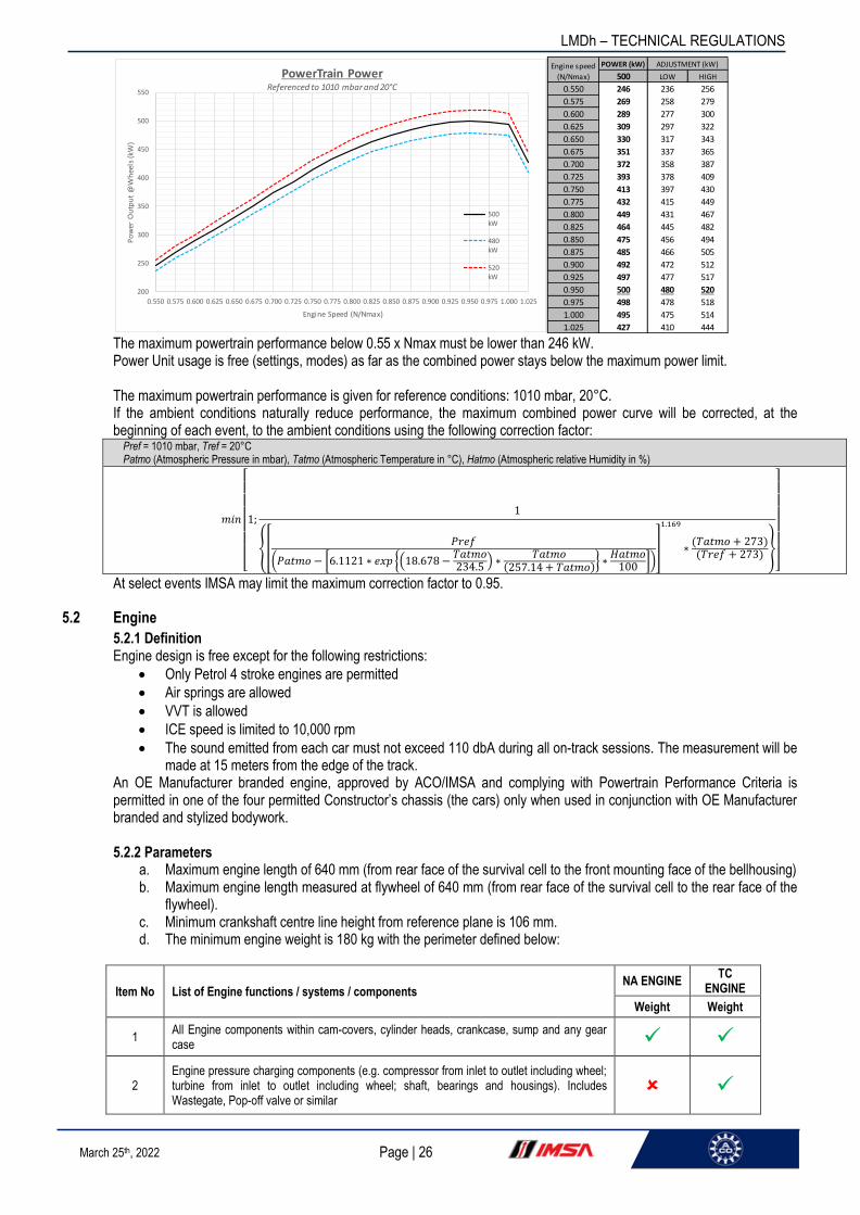
LMDh – TECHNICAL REGULATIONS
Page | 26 March 25th, 2022
The maximum powertrain performance below 0.55 x Nmax must be lower than 246 kW. Power Unit usage is free (settings, modes) as far as the combined power stays below the maximum power limit. The maximum powertrain performance is given for reference conditions: 1010 mbar, 20°C. If the ambient conditions naturally reduce performance, the maximum combined power curve will be corrected, at the beginning of each event, to the ambient conditions using the following correction factor:
Pref = 1010 mbar, Tref = 20°C Patmo (Atmospheric Pressure in mbar), Tatmo (Atmospheric Temperature in °C), Hatmo (Atmospheric relative Humidity in %)
𝑚𝑖𝑛
[
1;1
{[𝑃𝑟𝑒𝑓
(𝑃𝑎𝑡𝑚𝑜 − [6.1121 ∗ 𝑒𝑥𝑝 {(18.678 −𝑇𝑎𝑡𝑚𝑜234.5
) ∗𝑇𝑎𝑡𝑚𝑜
(257.14 + 𝑇𝑎𝑡𝑚𝑜)} ∗
𝐻𝑎𝑡𝑚𝑜100 ])
]
1.169
∗(𝑇𝑎𝑡𝑚𝑜 + 273)(𝑇𝑟𝑒𝑓 + 273)
}
]
At select events IMSA may limit the maximum correction factor to 0.95.
5.2 Engine
5.2.1 Definition Engine design is free except for the following restrictions:
• Only Petrol 4 stroke engines are permitted
• Air springs are allowed
• VVT is allowed
• ICE speed is limited to 10,000 rpm
• The sound emitted from each car must not exceed 110 dbA during all on-track sessions. The measurement will be made at 15 meters from the edge of the track.
An OE Manufacturer branded engine, approved by ACO/IMSA and complying with Powertrain Performance Criteria is permitted in one of the four permitted Constructor’s chassis (the cars) only when used in conjunction with OE Manufacturer branded and stylized bodywork. 5.2.2 Parameters
a. Maximum engine length of 640 mm (from rear face of the survival cell to the front mounting face of the bellhousing) b. Maximum engine length measured at flywheel of 640 mm (from rear face of the survival cell to the rear face of the
flywheel). c. Minimum crankshaft centre line height from reference plane is 106 mm. d. The minimum engine weight is 180 kg with the perimeter defined below:
Item No List of Engine functions / systems / components NA ENGINE
TC ENGINE
Weight Weight
1 All Engine components within cam-covers, cylinder heads, crankcase, sump and any gear case ✓ ✓
2 Engine pressure charging components (e.g. compressor from inlet to outlet including wheel; turbine from inlet to outlet including wheel; shaft, bearings and housings). Includes Wastegate, Pop-off valve or similar
✓
POWER (kW)
500 LOW HIGH
0.550 246 236 256
0.575 269 258 279
0.600 289 277 300
0.625 309 297 322
0.650 330 317 343
0.675 351 337 365
0.700 372 358 387
0.725 393 378 409
0.750 413 397 430
0.775 432 415 449
0.800 449 431 467
0.825 464 445 482
0.850 475 456 494
0.875 485 466 505
0.900 492 472 512
0.925 497 477 517
0.950 500 480 520
0.975 498 478 518
1.000 495 475 514
1.025 427 410 444
Engine speed
(N/Nmax)
ADJUSTMENT (kW)
200
250
300
350
400
450
500
550
0.550 0.575 0.600 0.625 0.650 0.675 0.700 0.725 0.750 0.775 0.800 0.825 0.850 0.875 0.900 0.925 0.950 0.975 1.000 1.025
Po
wer
Ou
tpu
t @
Wh
eels
(kW
)
Engine Speed (N/Nmax)
PowerTrain Power Referenced to 1010 mbar and 20°C
500kW
480kW
520kW

LMDh – TECHNICAL REGULATIONS
Page | 27 March 25th, 2022
3 Engine air inlet system from Air filter to cylinder head (e.g. Pipes, Intercooler, plenum, trumpets, throttles) but excluding turbocharger components. ✓ ✓
4 Engine exhaust system from the engine exhaust flange up to the exit ✓ ✓
5 Engine mounted fuel system components: (e.g. High-Pressure fuel hose, fuel rail, fuel injectors, accumulators) ✓ ✓
6 Engine mounted electrical components (e.g. wiring loom, sensors, actuators, ignition coils, alternator, spark plugs) ✓ ✓
7
All Engine coolant pumps, oil pumps, scavenge pumps, oil air separators and fuel high pressure pumps (delivering more than 10 bar) including any of the following associated components: motors, actuators, filters, brackets, supports, screws, nuts, dowels, washers, cables, oil or air seals. All tubes or hoses between components of the Engine. Excludes hydraulic pump.
✓ ✓
8 Engine main oil tank, catch tanks, and any breather system connected to them and associated filters, brackets, support, screws, nuts, dowels, washers, cables, tubes, hoses, oil or air seals
9 Any ECU or associated device containing programmable semiconductors or containing high power switching device and associated brackets, support, screws, nuts, dowels, washers or cables used for Engine
10 Any actuators needed to make the Engine function at all times ✓ ✓
11 Water system accumulators used for Engine ✓ ✓
12 Heat exchangers and their associated accessories (included but not limited to tubes, hoses, supports, brackets and fasteners) used for Engine ✓ ✓
13 Hydraulic system (e.g. pumps, accumulators) used for Engine
14 Hydraulic system servo valve(s) and actuator(s) for Engine control used for Engine ✓ ✓
15 Fuel feed pumps delivering less than 10 bars and their associated accessories (included but not limited to tubes, hoses, supports, brackets and fasteners).
16 Any ancillary equipment associated with the Engine air valve system such as regulators or compressors. ✓ ✓
17 Studs used to mount Engine to chassis or gearbox mounted on engine ✓ ✓
18 Flywheel, clutch and clutch actuation system between the Engine and the gearbox. ✓ ✓
19 Engine oil
20 Liquids used for Engine. Excludes engine oil.
21 Ballast mounted on the Engine ✓ ✓
22 Wiring harnesses which are not ordinarily part of a power unit.
23 Additional structural engine side subframe ✓ ✓
5.2.3 Engine Control
a. Torque based engine control methodology required.
5.3 ERS
5.3.1 Definition a. Common Single-Source Hybrid (ERS) Kit b. Major ERS components included in kit:
i. Energy Storage System (ESS) ii. Motor Generator Unit (MGU) iii. Inverter / Motor Control Unit (MCU) iv. DC-DC converter (DCDC) v. Low Voltage (LV) and High Voltage (HV) cabling vi. Rear Brake Circuit Proportioning System / Brake-By-Wire (BBW) vii. Vehicle Control Unit (VCU)

LMDh – TECHNICAL REGULATIONS
Page | 28 March 25th, 2022
viii. ERS Cooling Pumps ix. ESS Comparment Closing Panel and Power Electronics Mounting Frame x. ERS Charging Unit (Charger)
c. All ERS Kit components are sealed units providing no serviceability to either teams, LMDh manufacturers, chassis constructors, or scrutineers. All service and repairs must only be carried out by the supplying party.
d. ERS system designed and constructed to comply with FIA Appendix J Article 253.18 standards. e. ERS system must always be operated within prescibed limits of Hybrid System Manual and Performance Equity
Model. Failure to operate within these limits may result in reduced service life and automatic performance de-rating.
5.3.2 MGU
a. Position: P2 Off-Axis mounted to front of gearbox with integral gear mesh to clutch shaft. b. MGU serves as replacement for traditional alternator and starter motor c. Gearing from MGU output to the clutch shaft will be interchangeable to allow for the different behaviors of the various
ICE units in service. i. MGU gear ratio is homologated and subject to ACO/IMSA approval. ii. MGU maximum speed of 20,000 rpm must never be exceeded at any time
d. MGU Package integrated inside the bellhousing and mounted to common gearbox. i. Minimum clearances to MGU must be respected. No interference permitted with MGU Exclusion Zone
identified in most recent Gearbox CAD Model, which is available upon request.
e. MGU is liquid cooled.
5.3.3 MCU/Inverter MCU/Inverter will be mounted in the ESS compartment and is liquid cooled. 5.3.4 DC-DC
a. DC-DC converter mounts within the ESS compartment and is liquid cooled. b. DC-DC converter input voltage is equivalent to expected range of ESS operating voltage from minimum to maximum
State of Charge (SoC). c. DC-DC converter output is connected to main 12 V vehicle electrical disconnect (master switch). d. DC-DC converter supplies up to 4.8 kW, split between ERS systems and all non-ERS vehicle systems. ERS system
DC supply will be controlled. 5.3.5 ESS
a. Packaging: ESS mounts within the ESS compartment accessible from the underside of the survival cell.

LMDh – TECHNICAL REGULATIONS
Page | 29 March 25th, 2022
b. Performance within SoC operating range at typical operating temperature is sufficient to enable continuous deployment at all WEC and IMSA circuits at Maximum ERS Power Level defined by ACO/IMSA.
5.3.6 Electrical cabling and connectors
a. ERS power and control cables included in ERS kit. b. Total run length from the ESS to Inverter and MGU shall be equalized across all constructor variants for equivalency
on losses and mass. 5.3.7 Cooling system
a. Common cooling components for ERS system includes two coolant pumps and ESS compartment coolant lines. b. Cooling performance criteria must be respected at all times and must be designed by constructors to achieve this
throughout a 24-hour event. c. Minimum cooling requirements: See ERS system documentation d. Cooling liquid mixture for the MGU/MCU/DCDC can be chosen in a range between 50% glycol / 50% water and 5%
glycol / 95% water using the glycol additive defined in the Hybrid System Documentation Package e. Cooling liquid for the ESS is defined in the Hybrid System Documentation Package
5.3.8 Vehicle Control Unit (VCU)
a. Control Architecture: i. VCU is Highest-level controller for the ERS system and any associated subsystem controls (i.e. MCU and
BBW). o VCU is interface between LMDh manufacturer’s ICE ECU and ERS/BBW systems Bi-Directional real time
telemetry. o Public CAN bus between VCU and LMDh manufacturer’s ICE ECU. o ERS monitoring. o Respond to demand signals for torque, regeneration, deployment. o Integrates into scrutineering logger architecture.
ii. No direct communication between ECU and ERS components is permitted, but some commands/requests may be mirrored by VCU to ERS components.
iii. Some parameter tables may be unique to each LMDh and will be controlled by homologation b. Security/Permissions:
i. VCU configuration, software, and settings not accessible by teams, chassis constructors, and LMDh manufacturers.
ii. Software version must be respected iii. ACO/IMSA will have necessary tools to verify software and parameter tables
5.3.9 Brake-By-Wire (BBW)
a. Automatic electronic proportioning of rear braking circuit to assist driver with brake balance between hydraulic brake torque and electrical regeneration torque
b. Control shared by Torque Master (OEM ECU) and VCU c. Utilizes traditional dual master cylinders and balance bar or tandem master cylinder d. Pass-through standby mode to ensure full hydraulic braking in the event electrical regeneration torque is not available e. BBW parameters may be unique to each LMDh manufacturer and will be controlled by homologation
5.3.10 ERS General Performance
a. Stored energy (100 to 0% usable SoC): up to 1.3 kWh, subject to conditions b. Deployment power at wheel:
Engine speed ERS30 ERS50
(N/Nmax) 30 50
0.550 15 25
0.575 16 27
0.600 17 29
0.625 19 31
0.650 20 33
0.675 21 35
0.700 22 37
0.725 24 39
0.750 25 41
0.775 26 43
0.800 27 45
0.825 28 46
0.850 29 48
0.875 29 49
0.900 30 49
0.925 30 50
0.950 30 50
0.975 30 50
1.000 30 49
1.025 26 43

LMDh – TECHNICAL REGULATIONS
Page | 30 March 25th, 2022
i. Le Mans and Daytona: 30 kW curve maximum ii. All other WEC and IMSA circuits: Up to 50 kW curve maximum, defined by ACO/IMSA.
c. Regeneration power at wheel: See equity model.
5.3.11 ERS Operational Modes Supported
a. ERS System is capable of supporting the following operation: i. Regen: Braking Only, Off-Throttle, Traction Limited, Free ii. Deployment: Driver Initiated (Conditionally Limited), Free iii. Limp-home mode (driving at limited speed with ERS-only)
5.3.12 ERS Arbitration
a. ERS commands and data flow are arbitrated by ACO/IMSA through a combination of the ACO/IMSA Vehicle Controller and ACO/IMSA Scrutineering Logger. This is performed using the CAN inputs, hardwired sensor inputs, and communication buses indicated in the following diagram:
5.4 Power unit torque demand
5.4.1 The only means by which positive torque to rear power train may be requested is a single foot (accelerator) pedal mounted inside the survival cell and only actuated by the driver. Positive torque is understood to be when the sum of both homologated torque sensors per axle is positive on a 0.2s average. 5.4.2 Designs which allow specific points along the accelerator pedal travel range to be identified by the driver or assist him to hold a position are not permitted. 5.4.3 For safety reasons, whenever the ICE is not running, and the car is stopped and in ready to move condition (including, but not limited to: ERS active), two simultaneous actions (one of them being hand-operated) are required from the driver to demand positive torque.
5.5 Power unit control
5.5.1 Homologated sensors must be fitted which measure the torques supplied to each driveshaft (Technical List n°89). Driveshafts must be designed for ±5500 Nm sensor calibration range and associated calibration cycle. These signals must be provided to the ACO/IMSA datalogger. Installation details can be found in the appendixes to these regulations. Any device, system or procedure the purpose and/or effect of which is to deceive the measures taken or signals sent by these sensors is prohibited. 5.5.2 The frequency of any variation on torque demand of the MGU is restricted to less than 50 Hz when the following are all true:
• Throttle Pedal Position > 0 (demanding positive torque at wheels)

LMDh – TECHNICAL REGULATIONS
Page | 31 March 25th, 2022
• Car speed < 160 kph
• Gear change is not active
5.6 Engine fuel systems
5.6.1 Homologated "Fuel Flow Meter" (as defined in Article 6.6) must be integrated into the fuel system according to Article 6.6. Fuel flow meter information are to be sent directly to the ACO/IMSA data logger without going through the competitor electronic unit. 5.6.2 Furthermore, all fuel delivered to the engine must pass through this homologated meter, and must all be delivered to the combustion chambers by the fuel injectors.
5.7 Engine ancillaries
Engine ancillaries can be mechanically or electrically driven. Any electrically driven ancillary cannot be linked mechanically to any drivetrain, including the power unit. No alternator, no starter motor.
5.9 Materials and construction – General
Unless explicitly permitted for a specific application, the following materials may not be used anywhere on the power unit: a. Magnesium based alloys. b. Metal Matrix Composites (MMC’s) containing more than 2.0% volume/volume of other ceramic, metallic, carbon or
intermetallic phase which is not soluble in the liquid phase at 100°C above the melting point of the metallic matrix. c. Intermetallic materials. d. Alloys containing more than 5% by weight of Platinum, Ruthenium, Iridium or Rhenium. e. Copper based alloys containing more than 2.75% Beryllium. f. Any other alloy class containing more than 0.25% Beryllium. g. Tungsten base alloys. h. Ceramics and ceramic matrix composites. i. Aluminium based alloys containing more than 2.5 weight % Lithium j. Materials containing nanomaterials. k. Thermal insulation containing unbound nanomaterials
5.10 Anti-stall
If a car is equipped with a stall prevention system, and in order to avoid the possibility of a car involved in an accident being left with the engine running, all such systems must be configured to stop the engine no more than ten seconds after activation if no action from driver.
ARTICLE 6: FUEL SYSTEM
6.1 Principles
6.1.1 All fuel pumps must be in operation only when the engine is running or being started. 6.1.2 Feed pumps supplying the collector from the tank may be switched on during a pit-stop by means of a specific human action on a switch different from the main one in order to activate again the fuel pumps after they have been stopped with engine stop or engine stall.
6.2 Fuel tanks
6.2.1 The fuel tank must be a single rubber bladder conforming to or exceeding the specifications of FIA Standard FT5-1999. A list of approved materials may be found in Technical List No.1. 6.2.2 When viewed from top, all the fuel stored on board the car must be located:
• No more than 500 mm from the longitudinal axis of the car
• Behind Template H3 and no more than 500 mm from Xsc plane. 6.2.3 A maximum of 1 litre of fuel may be kept outside the survival cell, but only that which is necessary for the normal running of the engine. 6.2.4 The pressure of the low-pressure circuit (including the FFM) is limited to 10 bar maximum. A fuel pressure above 10 bar is considered as high pressure.

LMDh – TECHNICAL REGULATIONS
Page | 32 March 25th, 2022
6.3 Fittings and piping
6.3.1 All apertures in the fuel tank must be closed by hatches or fittings which are secured to metallic or composite bolt rings bonded to the inside of the bladder. The total area of any such hatches or fittings which are in contact with the fuel may not exceed 70000 mm². Bolt hole edges must be no less than 5 mm from the edge of the bolt ring, hatch or fitting. 6.3.2 All fuel lines between the fuel tank and the engine must have a self-sealing breakaway valve. This valve must separate at less than 50% of the load required to break the fuel line fitting or to pull it out of the fuel tank. 6.3.3 No lines containing fuel may pass through the cockpit. 6.3.4 All lines must be fitted in such a way that any leakage cannot result in the accumulation of fuel in the cockpit. 6.3.5 All components containing fuel at a pressure greater than 10 bar must be located outside the fuel tank. 6.3.6 Any equipment included in the tank walls (air vents, inlets, outlets, tank fillers, inter tank connectors and access openings) must be metal or composite made fittings and must be bonded inside the fuel tank. 6.3.7 Fuel lines between the fuel tank and the homologated fuel flow meters must include a self-sealing breakaway valve, the parts of which must separate under a load less than half the load required to break the fuel line fitting or to pull it out of the fuel tank. Fuel flow meters and fuel lines between fuel flow meter and fuel system must be insulated from heat coming from the power train. 6.3.8 Low pressure fuel lines must have a minimum burst pressure 2 times more than the maximum operating pressure of at a maximum operating temperature of 135°C. 6.3.9 High pressure fuel lines must have a minimum burst pressure 2 times more than the maximum operating pressure at a maximum operating temperature of 135°C. 6.3.10 Any device, system or procedure the purpose and/or effect of which is to increase the flow rate after the measurement point is prohibited.
6.4 Fuel tank fillers and breather pipes
6.4.1 Fuel tank fillers must not protrude beyond the bodywork. Any breather pipe connecting the fuel tank to the atmosphere must be designed to avoid liquid leakage when the car is running or if upside down and its outlet:
• Must not be less than 250 mm from the cockpit opening;
• Must be placed where they would not be vulnerable in the event of an accident;
• Must not protrude beyond the surface of the bodywork;
• Must be fitted with a gravity actuated roll-over valve, a float chamber ventilation valve and a blow-off valve with a maximum over pressure of 200 mbar, working when the float chamber ventilation valve is closed;
• May exit through the reference plane. 6.4.2 All fuel tank fillers, air vents and breathers must be designed to ensure an efficient locking action which reduces the risk of an accidental opening following a crash impact or incomplete locking after refuelling. 6.4.3 Cars must be fitted with combined fuel tank fillers and vents. Fuel tank fillers must be able to be fitted each side of the car. 6.4.4 Both fillers and air vents must be equipped with leak proof dry break couplings complying with the dead man principle and therefore without any retaining device when in open position. 6.4.5 Couplings dimensions: Appendix J Drawing 252-5 (version B) exclusively. 6.4.6 At least one proximity sensor is mandatory to forbid the start of the ICE and any powering electrical motor while the coupling is connected to the car.
6.5 Refuelling

LMDh – TECHNICAL REGULATIONS
Page | 33 March 25th, 2022
6.5.1 The refuelling equipment (with the car number affixed) and the tank of the car shall always remain at the outside ambient temperature and atmospheric pressure. It must always in compliance with Appendix A. 6.5.2 No fuel intended for immediate use in a car may be more than ten degrees centigrade below ambient temperature. When assessing compliance, the ambient temperature will be that recorded by the ACO/IMSA appointed weather service provider one hour before any practice session or two hours before the race. This information will also be displayed on the WEC timing monitors or IMSA video feed. 6.5.3 The use of any device on board the car to decrease the temperature of the fuel is forbidden. Any device or system the purpose and/or effect of which is to increase the fuel storage capacity on board is prohibited. Any device or system whose principle is not strictly linked to gravity is prohibited.
6.6 Fuel Flow Metering - FFM
6.6.1 The use of one homologated fuel flow meter is mandatory. It must be calibrated by a certified laboratory according to each series specific regulations:
• WEC competition requires a fuel flow meter from FIA Technical List 45 calibrated by a certified laboratory according to FIA Technical List 44.
• IMSA competition requires Sentronics GT-100-01 with a certified calibration from Sentronics. Calibrations are only valid for 150 hours of fuel flow time.
6.6.2 The fuel flow meter must be placed before the high-pressure fuel pump on the feed line. The complete fuel flow feeding the high-pressure fuel pump must go through the fuel flow meter. Any fuel return will not be taken in account. 6.6.3 An ACO/IMSA pressure sensor which directly measures the fuel pressure in the feed line of the fuel flow meter is compulsory. 6.6.4 The installation of the FFM must be done in accordance with Article 13.15.
6.7 Fuel draining and sampling
6.7.1 Competitors must provide a means of removing all fuel from the car. 6.7.2 Competitors must ensure that a 1.0 litre sample of fuel may be taken from the car at any time during the Event. After a practice session, if a car has not been driven back to the pits under its own power, it will be required to supply the above-mentioned sample plus the amount of fuel that would have been consumed to drive back to the pits. The additional amount of fuel will be determined by the ACO/IMSA. 6.7.3 The car must be fitted with a self-sealing connector for sampling fuel. This connector must be FIA approved (Technical list 5) and be fitted on the feed line to, and before, the high-pressure pump on the engine (it can be with the FFM connectors). If an electric pump on board the car cannot be used to remove the fuel an externally connected one may be used provided it is evident that a representative fuel sample is being taken. If an external pump is used it must be possible to connect the ACO/IMSA sampling hose to it and any hose between the car and pump must be -3 in diameter and not exceed 2 m in length. 6.7.4 The sampling procedure must not necessitate starting the engine or the removal of bodywork (other than the cover over the refuelling connector).
6.8 Energy per stint
The energy used per stint must not exceed E (in kJ), defined for each event by series specific Balance of Performance tables.
ARTICLE 7: ENGINE OIL AND COOLANT SYSTEMS AND CHARGE AIR COOLING
7.1 Location of oil tanks
All oil storage tanks must be situated between the front wheel axis and the rearmost gearbox casing longitudinally and must be no further than the lateral extremities of the survival cell are from the longitudinal axis of the car.
7.2 Longitudinal location of oil system
No other part of the car containing oil may be situated behind the complete rear wheels.
7.3 Transversal location of oil system

LMDh – TECHNICAL REGULATIONS
Page | 34 March 25th, 2022
No part of the car containing oil may be more than 900 mm from the car centre plane.
7.4 Coolant header tanks
Coolant system pressure is limited to 4.75 barA when water-based coolant is used.
7.5 Oil and coolant lines
7.5.1 No lines containing coolant or lubricating oil may pass through the cockpit. 7.5.2 All lines must be fitted in such a way that any leakage cannot result in the accumulation of fluid in the cockpit. 7.5.3 No hydraulic fluid lines may have removable connectors inside the cockpit. 7.5.4 Low pressure lubrication oil lines must have a minimum burst pressure of 41 bars at a maximum operating temperature of 135°C.
7.6 Oil catch tank
7.6.1 The open type sump breather(s) (if any) must vent into a 2.7-litre minimum capacity catch tank. 7.6.2 In order to avoid the risk of oil being sprayed on the track, an additional secure tank of 1 litre minimum must be inserted between the catch tank and the air vent according to the drawing below. 7.6.3 The main function of this secure tank is to ensure that the breather of the catch tank contain no oil or oil vapor. If the oil vapours are treated properly upstream this secure tank, it must remain empty permanently. 7.6.4 The secure tank must:
• be separated from the catch tank,
• have 100 mm height (measured internally),
• have a constant section all along the height (with exception for a maximum 10mm radius in the bottom),
• be equipped with the sensor homologated by the ACO/IMSA.
• This tank and sensor must be implemented as shown on the drawing below in order to detect the oil overflow. 7.6.5 If the maximum level is reached, the competitor must enter immediately into his garage to drain the catch tank.
7.7 Hydraulic systems
7.7.1 Hydraulic Lines Hydraulic system pressure is limited to 300 bar. All hydraulic fluid lines must have a minimum burst pressure 2 times more than operating pressure at the maximum operating temperature of 204°C. Only hydraulic fluid lines with self-sealing couplings or screwed connectors are permitted inside the cockpit. The lines must be fitted in such a way that any leakage cannot result in accumulation of fluid in the cockpit. Flexible lines must have swaged or crimped connectors and an outer braid resistant to abrasion and flame.
ARTICLE 8: ELECTRICAL SYSTEMS
8.1 Compliance and safety provisions
Closed-loop electronic control systems are forbidden unless expressly permitted by the present regulations. It is expressly allowed in the following cases:
• for any electrical motor (for example but not restricted to: wiper motor, fuel pump, electrically controlled gear shift…);
• for a single gear selection mechanism;
Separation wall

LMDh – TECHNICAL REGULATIONS
Page | 35 March 25th, 2022
• for a single clutch actuation mechanism;
• for engine (ICE) control;
• for MGU control respecting Article 5 requirements;
• for the A/C system;
• for auxiliary electrical circuit management control (power box). The ACO/IMSA must be able to test the operation of any compulsory electronic safety systems at any time during an Event.
8.2 Auxiliary circuits and battery
8.2.1 The auxiliary battery must be located either in the cockpit in the place of the passenger or in the ESS compartment and must be strongly secured. If in the cockpit, the battery must be entirely protected in a leak-proof box made of insulating material and in accordance with article 13.9.2. The battery fixation must be designed to withstand 70g deceleration in any direction. 8.2.2 The competitor must provide the power necessary (16 volts maximum) for the operation of the compulsory devices (Data logger, ADR, promotor information display, …). 8.2.3 The auxiliary battery must never be used to recharge the traction battery or ES. Throughout the duration of the event, the battery supplying the auxiliary electrical circuit must have a voltage below 60 volts. 8.2.4 The auxiliary circuit consists of all the parts of the electrical equipment used to operate the internal combustion engine, for signalling, lighting or communication. The parts used to operate the engine include but are not limited to: throttle, ignition, injection, intake, lubrication, fuel supply, cooling and turbo. The equipment to start the engine and the HV ancillaries are excluded.
8.3 Lighting Equipment
Lighting equipment must always be in working order. Cars must be fitted with: 8.3.1 At the Front: 8.3.1.1 Two main headlights as a minimum, homologated, symmetrical to the longitudinal centre line of the car and separated by a minimum of 1300 mm, the measurement being taken to the centre of the headlights; Headlights must produce a white beam. 8.3.1.2 Direction indicators on each side. Orange coloured, they must simultaneously flash when the speed limitation for compliance with conditions of Slow Zones and Full Course Yellow is applied. A strategy for Slow Zones and Full Course Yellow speed limitation must be implemented in the car. Flashing frequency of 4 Hz (0.125 sec ON followed by 0.125 sec OFF). If the rain light is activated, the flashing should be in opposition of phase with the rain lights. 8.3.1.3 Identification light No car identification lights may interfere with safety lights (ERS/medical) in positioning and in colour (no variation of blue, red or green colour). As example and not limited to: behind the wind screen some similar colours will not be allowed. Inside the front lights compartment, any colour will be allowed. 8.3.1.4 Main headlights cooling fan A cooling fan is authorized per each headlight unit provided that:
• its only function is to adjust the temperature of the main headlight unit;
• the electrical power is less than 5 W;
• the fan outlet is within the bodywork. 8.3.2 At the Rear: 8.3.2.1 Two red lights and two "Stop" lights fitted symmetrically about the longitudinal centre line of the car and separated by a minimum of 1500 mm, the measurement being taken to the centre of the rear lights. An alarm by flashing of the ‘’stop’’ lights must be activated if loss of acceleration is greater than 0.4g within 0.2 second for at least 0.2 second. The frequency of the flash to be achieved by 0.25sec ON ; 0.25 sec OFF. Brake lights flashing must be deactivated when the car accelerates by more than 0.2g positive. When triggered, flashing must be latched for a minimum of 2 seconds.

LMDh – TECHNICAL REGULATIONS
Page | 36 March 25th, 2022
In any case Brake lights flashing must be deactivated as soon as brake pedal is pressed (goes to solid brake light on as normal when driver applies the brakes). 8.3.2.2 Two “Rain" or "Fog" lights located at the rear, the highest and outermost possible on each side symmetrically to the longitudinal centre line of the car. They have to be homologated in accordance to FIA Standard 8874-2019 Grade 1(Technical List 46). Both lights should have a flashing frequency of 4 Hz (0.125 sec ON followed by 0.125 sec OFF). Two levels of brightness modes must be implemented:
• Level High - full brightness mode for day time
• Level Low - reduced brightness mode for night These two modes can be automatically linked to the high beam command, but the driver must be able to select it in case of exceptional request (heavy rain/fog during night, car running in high beam in case of low beam failure, …). To implement the two modes, the technical requirements are: Apply a pulse width modulation signal (PWM) at 300 Hz frequency on the inhibit input, and use a duty cycle of 70% for day mode and 30% for night mode. The side of the rain lights must be kept uncovered (no sticker, paint, etc.) in order to guarantee its cooling. 8.3.2.3 Direction indicators on each side. Orange coloured, they must simultaneously flash when the speed limitation for compliance with conditions of Slow Zones and Full Course Yellow is applied. A strategy for Slow Zones and Full Course Yellow speed limitation should be implemented in the car. Flashing frequency of 4 Hz (0.125 sec ON followed by 0.125 sec OFF). If the rain light is activated the flashing should be in opposition of phase with the rain lights. 8.3.3 On the Sides: A display module for timing information as described in Appendix to these Regulations must be fitted on each side of the car.
8.4 ACO/IMSA Logging Requirements
The ACO/IMSA mandatory logging sensors must be as described in the appendices to these Regulations. All ACO/IMSA logging sensors must be provided by the approved ACO/IMSA supplier (Technical list 46 for WEC). They must be directly connected to the ACO/IMSA logger. Unless specified, the signal of those sensors will be sent to the competitor through CAN. The ACO/IMSA logging sensors wiring loom including the homologated flow meters and torque measuring units must be manufactured by the Constructor/Manufacturer and approved by the ACO/IMSA. The only allowed GPS is the ACO/IMSA GPS from the mandatory logging system and must be positioned horizontally on the top of the engine air intake with a separation of 500 mm from any other antennas. The ACO/IMSA datalogger must be installed inside the cockpit, close to the ADR sensor to avoid possible cable damage in case of crash.
8.5 Data acquisition
The ACO/IMSA must have unlimited access to the following ECU information before, during and after any track session: a. Application parameter configurations. b. Logged data and events. c. Real-time telemetry data and events.
Data acquisition is limited to permitted sensors. The list of the sensors fitted in the car must be homologated, and all homologated sensors must be fitted to the car at all times. The only sensors permitted are listed in Appendix to these Regulations (There is no restriction on the number of each type unless stated).
8.6 Telemetry
8.6.1 The use of an ACO/IMSA series specific telemetry system is compulsory. No other telemetry system may be installed and/or used. A Standard logging table containing the channels listed in Appendix to these Regulations is mandatory. 8.6.2 The only communication between car and pits are as follows: - Legible messages on a signalling pit board. - The driver’s body movements. - Telemetry signals from the car to the pits via the ACO/IMSA series specific telemetry system. - Two-way radio communications between the driver and his pit. All such communication must be open and accessible to the ACO/IMSA.

LMDh – TECHNICAL REGULATIONS
Page | 37 March 25th, 2022
8.7 Track signal information display
All cars must be fitted with a compulsory marshalling display.
8.8 Safety Lights
Two safety lights LED’s modules including the ERS status lights and the medical light provided by the approved ACO/IMSA supplier (Technical list 46) must be installed on the car. These modules must be located near the external extinguisher switch and visible on both sides of the lower part of the windscreen.
ARTICLE 9: TRANSMISSION
9.1 Transmission types
The engine transmission system must only drive the rear wheels.
9.2 Clutch
9.2.1 Only one clutch device is authorised for the ICE. 9.2.2 The minimum and maximum travel positions of the clutch operating device must correspond to the clutch fully engaged normal rest position and fully disengaged (incapable of transmitting any useable torque) positions respectively. 9.2.3 The amount by which the clutch is engaged must be controlled solely and directly by the driver with the exception of:
a. Stall prevention. b. Gearshifts.
9.2.4 Any device or system which notifies the driver of the amount of clutch slip or engagement is not permitted.
9.3 Traction control
Cars may be equipped with a closed loop system or device which is capable of preventing the wheels from spinning under power or of compensating for excessive torque demand by the driver.
9.4 Clutch disengagement
All cars must be fitted with a means of disengaging the clutch for a minimum of fifteen minutes in the event of the car coming to rest with the engine stopped and in gear, making possible to push or to tow it. This system must be in working order throughout the Event even if the main hydraulic, pneumatic or electrical systems on the car have failed. If a pneumatic assistance device is used, a compressed air bottle of a maximum capacity of 0.5 dm3 fitted outside the cockpit is allowed. 9.4.1 External neutral and general circuit breaker switches See Article 14.16.
9.5 Gearbox
The only gearbox allowed is the one designated and homologated by ACO/IMSA.
9.6 Gear ratios
9.6.1 The number of forward gear ratios must be 7. All ratios 1 through 7 must be installed. 9.6.2 No more than 2 different sets of gear ratios may be homologated. Each set includes the MGU drop, bevel and final drive. Each set is discrete and no part of it can be interchanged with another set.
a. Homologated Gear Set 1 is targeted for Le Mans and Daytona and must be capable of achieving 340 kph without exceeding Nmax (using 349 mm tyre radius for the calculation)
b. Homologated Gear Set 2 is targeted for most other WEC and IMSA circuits c. Competitors are free to select from the Homologated Gear Sets at each event.
9.6.3 Gears must be made from steel, homologated and purchased directly from the designated ACO/IMSA gearbox supplier.
9.7 Reverse

LMDh – TECHNICAL REGULATIONS
Page | 38 March 25th, 2022
The car must be able to be driven in reverse by the driver at any time during the Event.
9.8 Gear changing
9.8.1 Automatic gear changes are considered a driver aid and are therefore not permitted. For the purposes of gear changing, the clutch and power unit torque may not be under the control of the driver. 9.8.2 Instantaneous gearshifts are forbidden. A consequent engine cut must be applied for a minimum of 30 ms. 9.8.3 Gear change mechanism must operate using the designated and homologated ACO/IMSA pneumatic actuator (Xtrac P1254 IVA) and compressor (Mega-Line Compressor GT).
9.9 Differential
Only the mechanical limited slip differentials designated and homologated by ACO/IMSA is allowed.
9.10 Differential output
The axle of the gearbox outputs to the driveshaft should be positioned at 1203 +/-1mm from rear face of survival cell.
9.11 Differential usage rules
Braking torque transfer: Absolute value of the difference of torque applied to the inside and outside wheels of the same axle through the differential when braking. The rear braking torque transfer must not exceed the total torque curves defined by ACO/IMSA. Details of the management of the Differential Performance can be found in the Appendixes to these regulations.
ARTICLE 10: SUSPENSION AND STEERING SYSTEMS
10.1 Suspension design and geometry
10.1.1 Cars must be fitted with sprung suspension. 10.1.2 Any suspension system fitted to the front wheels must be so arranged that its response results only from changes in load applied to the front wheels. 10.1.3 Any suspension system fitted to the rear wheels must be so arranged that its response results only from changes in load applied to the rear wheels. 10.1.4 Any system the purpose of which is to hydraulically link dampers and/or the 3rd suspension element is forbidden. 10.1.5 Double wishbones is the only suspension kinematic allowed. 10.1.6 No more than three dampers per axle are allowed. 10.1.7 The following systems are forbidden:
• Mass damper: Moving mass linked to the wheel located on the sprung weight with the sole objective of tuning the natural frequency of the suspension and/or tire contact patch load variations.
• Inerter damper: Rotating mass linked to the wheel located on the sprung weight with the sole objective of tuning the natural frequency of the suspension and/or tire contact patch load variations. Fluid inertance is also considered as inerter damper.
• G-damper: Moving mass located on the sprung weight with the sole objective of controlling the suspension depending on acceleration.
• Any part of the suspension, subject to the wheel load and leading to a change in ground clearance, is only allowed to have a constant or a progressive stiffness as function of the element deflection. Digressive or collapsible elements, being mechanically, hydraulically or gas operated, are prohibited.
10.2 Suspension adjustment
10.2.1 No adjustment may be made to any suspension system from inside the cockpit except for the front and rear anti-roll bars. Front and rear anti-roll bar adjustments must be:
• through movement of one hand operated lever/knob, with no link with any input/output of the car

LMDh – TECHNICAL REGULATIONS
Page | 39 March 25th, 2022
• manual, mechanical (hydraulic actuation is allowed with the sole purpose of replacing cables functionality), bijective, with no degree of freedom
• the resulting change in stiffness must be directly linked to that movement, with no other function than adjusting the anti-roll bars
• will be subject to prior approval by ACO/IMSA. The lever/knob must be positioned outside of driver leg (H2), body (H3) and head (H4) Templates.
10.2.2 Any system, other than the suspension parts, whatever the functioning principle, activated or not by the driver the purpose of which is to modify the ground clearance is forbidden. 10.2.3 Electrically controlled shock absorbers are forbidden. 10.2.4 The car must be used on track within the following ride height limits:
• 110 mm maximum dynamic axle ride height (front and rear)
• 100 mm maximum static ride height (front and rear) 10.2.5 The suspension kinematics (inboard or outboard links with suspension members) may be adjusted only by using the homologated parts.
10.3 Suspension members
10.3.1 One non-structural part is allowed on each suspension arm provided that:
• The width/height ratio of the profile does not exceed 3 per arm,
• The shape of the protection is symmetrical,
• The maximum thickness of the profile is equal to the maximum height of the profile of the suspension arm on which the protection is fixed plus 3 mm.
10.3.2 The suspension members must:
• be made from a homogeneous metal
• not be chromium plated
• have a profile which width/height ratio does not exceed 3.0 and 6.0 at the joints
• be mandatorily fitted with an anti-intrusion bar at the base of the front suspension wishbones with a minimum projection on (xz) plane of 50cm².
10.4 Steering
10.4.1 The design and geometry of the steering system is free, provided that there is a continuous mechanical link between the steering wheel and the front wheels of the car. 10.4.2 Steering column The steering column must be approved by the FIA in accordance with the approval procedure of safety structures for sports cars. 10.4.3 No part of the steering wheel or column, nor any part fitted to them, may be closer to the driver than a plane formed by the entire rear edge of the steering wheel rim. All parts fixed to the steering wheel must be fitted in such a way as to minimise the risk of injury in the event of a driver’s head making contact with any part of the wheel assembly. 10.4.4 Four-wheel steering is forbidden. 10.4.5 Power steering is allowed but such system may not carry out any function other than reduce the physical effort required to steer the car and must allow the steering to continue to function when all hydraulic and/or electric power is shut down. 10.4.6 A quick release system of the steering wheel is mandatory. The quick release mechanism must consist of a flange concentric to the steering wheel axis, coloured yellow through anodization or any other durable yellow coating, and installed on the steering column behind the steering wheel. The release must be operated by pulling the flange along the steering wheel axis. The release of the steering wheel must open the power circuit. 10.4.7 The re-alignment of the steered wheels, as defined by the position of the inboard attachment of the relevant suspensions members that remain a fixed distance from each other, must be uniquely defined by a monotonic function of the rotational position of a single steering wheel.

LMDh – TECHNICAL REGULATIONS
Page | 40 March 25th, 2022
ARTICLE 11: BRAKE SYSTEM
11.1 Brake circuits and pressure distribution
11.1.1 With the exception of a power unit, all cars must be equipped with only one brake system. This system must solely be comprised of two separate hydraulic circuits operated by one pedal, one circuit operating on the two front wheels and the other on the two rear wheels. This system must be designed so that if a failure occurs in one circuit the pedal will still operate the brakes in the other. The only connection allowed between the two circuits is a mechanical system for adjusting the brake force balance between the front and rear axles. 11.1.2 The brake system must be designed in order that the force exerted on the brake pads within each circuit are the same at all times. 11.1.3 Any powered device, other than the system referred to in Article 11.7, which is capable of altering the configuration or affecting the performance of any part of the brake system is forbidden. 11.1.4 Any change to, or modulation of, the brake system whilst the car is on the track must be made by the driver's direct physical input or by the system referred to in Article 11.7, and may not be pre-set. 11.1.5 Sensors to collect information, stop lights switches or mechanical brake pressure controls adjustable by means of tools are not considered as "systems" and they must be fitted at the exit of the master-cylinders. 11.1.6 No device or system is permitted between the master-cylinders and the calipers, except for the system described in Article 11.7.
11.2 Brake calipers
11.2.1 All brake calipers must be made from aluminium materials with a modulus of elasticity no greater than 80 Gpa. 11.2.2 No more than two attachments may be used to secure each brake caliper to the car. 11.2.3 No more than one caliper, with a maximum of six pistons, is permitted on each wheel. 11.2.4 The section of each caliper piston must be circular.
11.3 Brake discs and pads
11.3.1 No more than one brake disc is permitted on each wheel which must have the same rotational velocity as the wheel it is connected to. 11.3.2 All discs must have a maximum outside diameter of 381 mm. Spline disc bell mounting is recommended. 11.3.3 No more than two rigid brake pads are permitted on each wheel. 11.3.4 The disc and pads stack height when new should not be lower than100 mm on the front and 82 mm on the rear.
11.4 Brake cooling ducts
See Article 3.4.2.5.
11.5 Brake pressure modulation
11.5.1 No braking system may be designed to prevent wheels from locking when the driver applies pressure to the brake pedal. 11.5.2 Any power braking function is forbidden, except for the system described in Article 11.7.
11.6 Liquid cooling
Liquid cooling of the brakes is forbidden.
11.7 Rear brake control system

LMDh – TECHNICAL REGULATIONS
Page | 41 March 25th, 2022
The pressure in the rear braking circuit may be provided by the approved Brake-By-Wire system as defined in Article 5.3.9, which is a powered control system provided that:
a. The driver brake pedal is connected to a hydraulic master cylinder that generates a pressure source that can be applied to the rear braking circuit if the powered system is disabled.
b. Ensures a design of the braking system that can achieve similar deceleration levels to normal operation when calipers are activated only by the force applied by the driver on the brake pedal without any further braking power coming from the MGU system or from any hydraulic high-pressure brake devices, in order to ensure safety should there be a failure of the electrical system.
c. Have no closed-loop control on the wheel slip. d. The rear left and rear right pressure will be identical.
ARTICLE 12: WHEELS AND TYRES
12.1 Location
As viewed from above and front, the wheels aligned for the car to proceed straight ahead, the complete wheels and their attachment must not be visible above the horizontal plane passing through the axle centre line with the exception of the bodywork cutouts defined in Articles 3.4.2.6 and 3.2.4.7.
12.2 Number of wheels
The number of wheels is fixed at four. Only one specification on the front axle and one on rear axle is allowed.
12.3 Complete wheel dimensions (rim and tire)
12.3.1 Complete wheel diameter must not exceed 28". 12.3.2 Complete wheel width and diameter will be measured horizontally at axle height, with the wheel held in a vertical position and when fitted with new tyres inflated to 2.0 bar. 12.3.3 Maximum complete wheel width must be according to the following table:
Front Rear
Tyre dimension 29/71-18 34/71-18
Max. complete wheel width 13.5’’ 15’’
12.4 Wheel material
Wheels must be made from homogeneous alloys. It must be produced as integral part, without welding and/or cavities.
12.5 Wheel dimensions (rim)
12.5.1 Maximum wheel width must be according to the following table:
Front Rear
Tyre dimension 29/71-18 34/71-18
Max. wheel (rim) width 12.5’’ 14’’
12.5.2 Wheel diameter must not exceed 18". 12.5.3 Wheel weight must be greater than:
• 8.75 kg for the front
• 9.25 kg for the rear Those minimum weights do not include valves, wheel fasteners, balance weights and tyre pressure/temperature monitoring devices. 12.5.4 Wheel must comply with the following specifications:
a) The diameters measured at the level of the inner and outer rim edges of a wheel must be identical, with a tolerance of +/- 1.5 mm;
It must not be more than 19.2 mm maximum in height. b) The design of the wheel must meet the general requirements of the tyre supplier for the mounting and dismounting of
tyres including allowance for sensors and valves. c) The wheel design cannot be handed between left and right designs.

LMDh – TECHNICAL REGULATIONS
Page | 42 March 25th, 2022
12.5.5 When fitted on the car every part of the complete wheel assembly has to turn at rim speed. 12.5.6 When viewed perpendicular to the plane formed by the outer face of the wheel and between the diameters of 150 mm and 400 mm the wheel may have projected area of no greater than 46 000 mm2.
12.6 Treatment of tyres
Tyres may only be inflated with air or nitrogen. Use of a traction compound or any substance that might alter the physical properties of a tire as supplied by its manufacturer is prohibited.
12.7 Wheel assembly
12.7.1 The only parts which may be physically attached to the wheel in addition to the tyre are valves for filling and discharging the tyre, wheel fasteners, balance weights, drive pegs, tyre pressure and temperature monitoring devices. For the avoidance of doubts, removable wheel/hub caps are not permitted. 12.7.2 The wheel must be attached to the car with a single fastener. The outer diameter of the fastener must not exceed 110 mm and the axial length must not exceed 75 mm. The wheel fastener may not attach or mount any part to the car except the wheel assembly described in Article 12.7.1. Competitors may not modify the wheel nuts as homologated. 12.7.3 A complete wheel must contain a single fixed internal gas volume. No valves, bleeds or permeable membranes are permitted other than to inflate or deflate the tyre whilst the car is stationary. Pressure control valves are not permitted. Valve caps must be in place while the car is on track.
12.8 Pneumatic jacks
Permitted. However, on the starting grid, the coupling function to connect the air hose onto the air jacks must have a system that maintains the car on the air jacks when the air hose is removed. It is forbidden to carry on board compressed air bottles for their operation.
ARTICLE 13: COCKPIT AND SURVIVAL CELL
13.1 Principles
The cockpit must provide the best protection for the driver positioned on the left-hand side of the car. The cockpit must be designed in such a way that any leakage cannot result in accumulation of fluid in it. It must be possible to fit a homologated and unmodified driver’s seat (see Drawing in Article 14.10) and the mandatory protections mentioned in Article 14.6 (Headrest) and Article 15.2.1 (Survival cell - General prescription). The roll-over structures/supports of the survival cell must be symmetrical with respect to the car centre line. All the dimensions and positionings are referred in the Survival cell reference CAD file: ‘’ LMDh_COCKPIT_TEMPLATES’’.
13.2 Bottom plane of the survival cell
Four ‘datum’ pads must be included on the car to provide structural references for scrutineering purposes. All pad positions must be validated by ACO/IMSA before the survival cell manufacturing commences:
• A ‘datum’ pad of 50 mm must be included on the lower surface of the survival cell positioned on the longitudinal car centre line and 50 mm forward of front axle centre line. The pad must be recessed into the chassis by a minimum of 2 mm.
• Two ‘datum’ pads of 50 mm diameter must be located at the bottom of the survival cell. The pads must be recessed into the survival cell by a minimum of 2 mm and their centres should be positioned:
a. On driver side: 50 mm forward from the front face of the rear rollover structure and 350 mm from car centre line
b. On passenger side: 200 mm rearward from the front face of the rear rollover structure and 250 mm from car centre line
• A ‘datum’ pad of 50 mm diameter must be positioned underneath the gearbox, on the car centre line and 120 mm rearwards of the front face of the gearbox. A spacer should be bolted to the rear datum and bring a reference pad at Z0 (upper face of skid block) with the M5 thread in its centre.
The position of each ‘datum’ pad will be homologated (with the distance to the reference plane). For each ‘datum’ pad, a M5 thread in the middle of the pad must provide a means of easy access during scrutineering with removal of the mandatory 50 mm diameter protection. To improve the bodywork junction, the protection can have a shoulder up to 70 mm diameter.

LMDh – TECHNICAL REGULATIONS
Page | 43 March 25th, 2022
The bottom plane of the survival cell structure (Zsc , parallel to Z0) must include a rectangle of 700 mm (longitudinally) x 800 mm (laterally) including the ESS access panel. The ESS panel may be recessed by a maximum of 1 mm. Typically, this plane will be the lowest plane of the survival cell and be the reference (Zsc). The maximum distance between Z0 and Zsc will be 3 mm.
13.3 Position of the driver’s feet
The face of the foremost pedal, when in the inoperative position, must be situated no less than 300 mm rearward of the survival cell bulkhead. The face of the foremost pedal, when in the operative position, must be:
• situated no less than 250 mm rearward of the survival cell bulkhead
• rearward of the front wheel centre line
• will be used as reference for Article 13.6.1. Drawing of pedals in relation to inserts in the cockpit to be supplied in advance of the homologation of the car.
13.4 Position of the steering wheel
The reference for the steering wheel will be the intersection of:
• the steering wheel plane (passing through the centre of the zone of the driver hands grip);
• the steering column axis. The centre of the steering wheel must match with:
• the centre line of the driver’s seat;
• the steering wheel centre shall be positioned at 165 mm minimum from the car centre line;
• the top of the steering wheel (an additional part of maximum 20mm height can be added on the top of steering wheel) should be positioned at least 650 mm above the Zsc plane.
The edge of the dashboard must be at a minimum of 50 mm from the complete steering wheel, whatever its operational position, (should the collapsible part of the steering column be shorter by 50 mm, no part of the steering wheel should get in contact with the dashboard).
13.5 Driver's position in relation with the field of visibility
The foremost point of the padding of the headrest at the level of contact with the rear face of the helmet must be at 85 mm (or 95 mm in case of additional padding as described in Article 14.6.2) forward Xsc plane; With the driver at the wheel, the top of the helmet must be between 80 mm and 100 mm from any line situated in a X-Z plane connecting the top of the minimum heights specified for the front and rear rollover structures over the helmet.
13.6 Volumes for the driver and passenger legs – Template H2
13.6.1 Geometrical definitions Two identical volumes must be provided for the legs of both occupants. Their lower faces must lie on the same plane, be parallel (or inclined by 100 mm maximum for the forward edge) to the reference surface and cannot be located more than 200 mm above the Zsc plane. Their inboard vertical planes must be symmetrical to the centre plane of Template H3 and not overlapping. A radius of 50 mm maximum can be implemented on the outer and forward edges. The dimensions of the driver volume must be:
• In length (X axis): from the foremost position of the driver's feet described in Article 13.3 to the steering wheel reference described in Article 13.4;
• The forward face of Template H2 must be at 1570 mm from Xsc (if H2 is inclined, the volume will be twisted such as the front and rear face must remain parallel in the Xsc plane);
• In width (Y axis): minimum 355 mm;
• In height (Z axis): minimum 350 mm.

LMDh – TECHNICAL REGULATIONS
Page | 44 March 25th, 2022
13.6.2 Equipment permitted in these volumes All allowed parts to intrude inside the leg template should not present a radius of less than 15 mm except for the complete pedal system and associated parts. The only components allowed to intrude into these volumes, are:
a. The steering column and its universal joints; b. The pedals, the related looms, foot-rest and pedal adjustment system; c. The suspension arms pick-up points if not a danger for the driver; d. The windscreen wiper mechanism and its motor; e. Equipment needed for driving fitted on a panel that must be removable; f. Driver leg padding and leg padding covers; g. Driver leg padding support and air jack on the passenger side; h. Auxiliary batteries in compliance with Article 8.2 into the volume for the passenger; i. The ESS compartment can intrude into the passenger leg Template H2; j. AC system if used, the BBW, pedal feel emulator, only in passenger area; k. The driver’s seat (Article 14.10).
However, components c), d), e) above are not allowed in the area between 1100 mm and 800 mm forward of Xsc plane on the driver’s side. Nothing is allowed to protrude into the interior of the empty volume of the driver side padding (see Drawing 14.7.1).
13.7 Volume for the driver and the passenger bodies – Template H3
The cockpit (doors closed) must allow the insertion of the Template H3. The dimensions and position of the Template H3 are defined by the Survival Cell reference CAD file. The rearmost point of the template H3 must be at 20 mm forward of the Xsc plane. The Template H3 must be centred with the longitudinal car centreline. The upper face of the template must be horizontal and at 500 mm from the Zsc plane. For this check, equipment mentioned in Article 13.9 may be removed. All the points of the survival cell that delimit Template H3 at the sides, the front and rear must be at least 500 mm above the Zsc plane.

LMDh – TECHNICAL REGULATIONS
Page | 45 March 25th, 2022
13.8 Volume for the driver and the passenger heads – Template H4
13.8.1 Geometrical definitions for the driver and the passenger heads The cockpit (doors closed) must allow the insertion of the Template H4. The dimensions and position of the Template H4 are defined by the Survival Cell reference CAD file. The back face will be positioned 20 mm forward of the Xsc plane. The Template H4 must be centred with the longitudinal car centreline. Its bottom faces must be parallel to the survival cell reference plane and at least 500 mm above the Zsc plane. For this check, equipment mentioned in Article 13.9 may be removed.
13.9 Equipment in the cockpit
13.9.1 Are permitted only outside the two volumes defined in Ar.13.6:
• safety equipment and structures which are not part of the survival cell,
• fire extinguisher,
• auxiliary battery (see Article 13.9.2),
• tool kit,
• seat,
• driving controls,
• driver cooling system and venting ducts (see Article 13.9.5),
• electronic equipment,
• drink system,
• ballast,
• jacks,
• door locking mechanism. 13.9.2 The auxiliary batteries are permitted in the cockpit. These components must be covered by a rigid and efficient protective material in the event of a crash if a danger for the driver. 13.9.3 Nothing may hinder the cockpit exit (see Article 13.10.3). 13.9.4 The way the equipment permitted is fitted in the cockpit is subject to ACO/IMSA Technical Delegates assessment and approval. All fittings must be able to withstand 25g deceleration in any direction.

LMDh – TECHNICAL REGULATIONS
Page | 46 March 25th, 2022
13.9.5 Are permitted but only outside the driver volume defined in Article 13.6 and respecting Article 13.11:
• driver cooling system,
• ventilation ducts.
13.10 Cockpit access
13.10.1 Principles The driver must be able to enter and egress the cockpit without it being necessary to remove any part of the car other than the steering wheel and opening the door. When exiting from the passenger side, the headrest may also be removed. The driver, seated normally with his seat belts fastened and with the steering wheel removed must be able to raise both legs together so that his knees are past the plane of the steering wheel in the rearward direction. This action must not be prevented by any part of the car. 13.10.2 Door openings In order to ensure that the door openings giving access to the cockpit are of adequate size, they must:
• Allow the insertion of the Template H6, the dimensions and position of which are defined by the Survival Cell reference CAD file;
• For this test, the lower surfaces of the templates will be held parallel to the reference surface, at the same height, and their rear edges aligned transversally;
• The rearmost face of the templates will be positioned at 120 mm from the Xsc plane;
• The driver templates will be moved transversally until their flat vertical inner surfaces are 150 mm from the car centre line;
• The passenger Template will be the symmetry of the driver Template from the car centre line;
• The lower face will be positioned at least 500 mm above the Zsc plane;
• The seat and all padding, including fixings, may be removed, as well as the doors.
13.10.3 Cockpit exit time The cockpit must be designed so as to allow the driver wearing his complete driving equipment, being seated in a normal position with the seat belts fastened and the steering wheel in place to egress in 7 seconds maximum (driver's side) and in 9 seconds maximum (passenger's side). 13.10.4 Test for helmet removal With the driver seated in his normal driving position in the car which he is entered to race, wearing a cervical collar appropriate to his size and with the seat harness tightened, a member of the medical service must demonstrate that the helmet which the driver will wear in the race can be removed from his head without bending the neck or spinal column.
13.11 Driver's field of frontal visibility
13.11.1 Geometrical definition The visibility from the cockpit with the driver seated in a racing position must be in compliance with the following requirement: The cockpit must allow the insertion of the Frontal Visibility Template V1 (defined by the Survival Cell reference CAD file) through the windscreen opening. Its rear vertical face must coincide with the forward vertical face of Template H4. The centre plane of the volume must be at car centre line. The lower edge of its rear vertical face must be positioned at least at 585 mm above the Zsc plane. The top face of Template V1 should be positioned between 30 mm to 50 mm from the top face of Template H4.

LMDh – TECHNICAL REGULATIONS
Page | 47 March 25th, 2022
13.11.2 Equipment restriction The only components allowed to intrude in this area, are:
• the windscreen and windscreen wiper;
• the antennas and pitot tubes;
• the air ducts for the cockpit ventilation, with a maximum height of 40 mm in front vision. Their outlets may not minimize the front vision of the driver;
• Marshalling Display and driver’s display (within same height of Marshalling Display);
• the rear-view camera display;
• the FIA high speed camera (WEC).
13.12 Driver's field of lateral visibility
13.12.1 Geometrical definition The visibility from the cockpit with the driver seated in the racing position must be in compliance with the following requirement: The cockpit must allow the insertion of the Lateral Visibility Template V2 (defined by the Survival Cell reference CAD file) through the side windows. The most rearwards vertical edge must be positioned at 121 mm from the Xsc plane. The inner face of both volumes must be separated by 800 mm (symmetrically along the car centre line). The inner lower edge of both volumes must be between 321 mm and 341 mm from the top plane of Template H4.

LMDh – TECHNICAL REGULATIONS
Page | 48 March 25th, 2022
13.12.2 Equipment restriction Excepting the padding and support for the driver’s head, the rear-view mirrors and the door hinges/mechanisms, no bodywork is permitted in these two volumes. The projection of the volumes representing the intersections between the rear-view mirrors (with supports) and the side visibility templates on the car longitudinal plane (plane X-Z) should have an area less than 150 cm² per mirror projected.
13.13 Cockpit temperature
The ambient temperature will be displayed by the official timing monitors. It will be measured in the shade and out of the wind. An effective natural and/or forced ventilation must maintain the temperature around the driver when the car is in motion at:
• 32 °C maximum when the ambient temperature is less than or equal to 25°C;
• a temperature less than or equal to ambient temperature +7°C if it is above 25°C. These temperature criteria should be respected in less than 8 minutes after a car stop. It is permitted to have air flow adjustment accessible from the driver. A homologated temperature sensor is imposed inside the cockpit at Z810 and on the centre line of the car. The sensor must be shielded from direct draught as per following drawing:
13.14 Fuel tank compartment
The complete fuel tank must be positioned inside the survival cell and behind Template H3. This compartment must be entirely sealed with the cockpit and a fireproof bulkhead must separate the fuel cell and fuel lines from the cockpit, the ESS and the engine compartments. Any holes in the fireproof bulkhead must be of the minimum size for the passage of controls and cables, and must be completely sealed. The minimum useable fuel tank volume must be 110 litres in order to allow the car to make 12 laps of the Le Mans circuit.
13.15 Fuel Flow Metering installation volume
13.15.1 A volume with minimum dimensions must be provided for installation of the Fuel Flow Meters in a position that is not at risk in the case of a crash. Whatever the dimensions of the installation volume, articles 13.15.2 and 13.15.3 must be fulfilled at any time. 13.15.2 This equipment must be able to be exchanged individually, quickly in case of failure. A change during a session (race included) could be required at the discretion of the ACO/IMSA.

LMDh – TECHNICAL REGULATIONS
Page | 49 March 25th, 2022
13.15.3 This equipment must be ventilated by air coming directly from the outside of the car and exiting outside the car in order to provide a temperature as close as the ambient. The temperature of the fuel flow meter body will be recorded.
13.16 ESS compartment
The ESS must be positioned inside the survival cell compartment on the passenger side. The ESS must be accessible from the bottom of the survival cell. This compartment must be entirely sealed from the cockpit and the fuel tank compartment. The ESS should be fixed to the ESS closing panel. This panel must be attached to the survival cell and ensure sufficient protection of the ESS. The DC-DC and MCU must be fixed to the ESS and be encapsulated in the ESS compartment. For the avoidance of doubt, the ESS compartment must be integral part of the survival cell.
13.17 ESS to ERS compartment
An ESS to ERS compartment must be entirely sealed from the cockpit and the fuel tank compartment. All the separation panels must be tested according to the safety test described for the ESS compartment in the Appendixes to these Regulations.
13.18 Survival cell identification
Every survival cell must incorporate three transponders described in the Appendixes to these Regulations for identification purposes. These transponders must be a permanent part of the survival cell, be accessible for verification at any time and be positioned as follow (+/-50 mm):
a. On the top of the survival cell, in line with the front axle and on the car centre line; b. Inside the cockpit on the left hand-hand side, in line with the foremost point of the door opening and at 100 mm from
the bottom of the door opening; c. Inside the cockpit on the right hand-hand side, in line with the foremost point of the door opening and at 100 mm
from the bottom of the door opening.
13.19 Survival cell characteristics
The minimum weight of the survival cell is 95 Kg, considering the weight perimeter described below:
Item No
List of survival cell functions/systems/components Weight
1 Safety structure including the cockpit, the fuel tank compartment, the ESS compartment ✓
2 All the fuel tank, ESS closing panels and their fixings ✓
3 Supplementary panels ✓
4 All built-in fixing components ✓
5 Driver leg padding support ✓
6 Ballast to adjust the survival cell minimum weight up to 5 kg ✓
7 Ballast
8 All removable fixing components (crash box, engine, sidepods…)
9 Windscreen and doors
10 All survival cell mechanical internal component (suspension related components, steering related components, pedals and mountings, seat, headrest, battery, electric related components…)
ARTICLE 14: SAFETY EQUIPMENT
14.1 General
As a general principle, it is the duty of the constructor/manufacturer and/or competitor to demonstrate that the car is of safe construction. A device must prevent powered movement of the vehicle whenever the driver is not fully seated in the driver's seat. Any type of adhesive covering the lever of a switch or a push button for Safety is strictly forbidden.
14.2 Fire extinguishers
14.2.1 All cars must be equipped with an extinguishing system in compliance with FIA Standard 8865-2015. The system must be used in accordance with the manufacturer's instructions and with Technical List n°52, and in accordance with Appendix J - Article 253-7.2 except as regards the means of triggering.

LMDh – TECHNICAL REGULATIONS
Page | 50 March 25th, 2022
The only authorized extinguishing agents are: Novec 130 or FX G-TEC FE36. 14.2.2 Any triggering system having its own source of energy is permitted, provided it is possible to operate all extinguishers should the main electrical circuits of the car fail. The driver must be able to trigger the extinguishing system manually when seated normally with his safety belts fastened and the steering wheel in place. Furthermore, a means of triggering from the outside must be combined with the circuit breaker switches described in Article 14.16. They must be marked with a letter "E" in red at least 80 mm tall, with a line thickness of at least 8 mm, inside a white circle of at least 100 mm diameter with a red edge with a line thickness of at least 4 mm. This identification must be self-reflecting.
There must be two external switches, that must:
• be located, one on each side of the car symmetrically to the car centre line, below a line under Z dashboard +40 mm, in front of the A-Pillar and fixed to the survival cell;
• be less than 350 mm from the door openings;
• be designed such that a marshal is unable to accidentally reenergise the power circuit,
• be fitted with a horizontal handle or ring that can be operated from a distance by a hook. 14.2.3 All extinguisher nozzles must be installed in such a way that they are not directly pointed at the driver.
14.3 Drivers Master switch
The driver, when seated normally with the safety belts fastened and the steering wheel in place, must be able to cut off the electrical circuits to the ignition, all fuel pumps, and the ERS System by means of a spark proof circuit breaker switch. The switch must be mechanically protected against accidental engaging. This switch must be located on the dashboard and must be clearly marked by a symbol showing a red spark in a white edged blue triangle. The operation is specified in Appendix J – Article 253-18.16 (Except the "creep" control) and in Drawing N°10. Drawing No10 is for illustrative purposes, the detail and layout is up to the competitor, however the following electrical states must be possible: P0 – All car electrical power is off P1 – Main power is supplied but the vehicle is unable to move (ESS and Engine not powered) P2 – The car is able to move (front and rear day-light position lights ON)
14.4 Rear view mirrors
14.4.1 All cars must have two mirrors mounted so that the driver has visibility to the rear and both sides of the car. 14.4.2 The reflective surface of each mirror must be greater than 100 cm². 14.4.3 The technical delegates must be satisfied by a practical demonstration that the driver, when seated normally, can clearly define following vehicles. For this purpose, the driver shall be required to identify any letter or number, 75 mm high and 50 mm wide, placed anywhere on boards behind the car, the positions of which are detailed below: Height : From 400 mm to 1000 mm from the ground. Width : From 0 mm to 5000 mm either side of the car centre plane. It will be permitted to use rear view camera from 0 mm to 2000 mm. Position : 5 m behind the rear wheel centre line. 14.4.4 There must be a day/night mode for the rear-view mirrors. It may be done with a film. 14.4.5 It is permitted to add cameras on the car and screens inside the cockpit for rear and front/side vision. Cameras and screens must have a day/night mode. The cameras are allowed to protrude over the maximum height of the car at the condition that a specific allowance is given during Homologation of the car. The purpose of their design cannot be to provide any aerodynamic benefit. 14.4.6 Mirrors are not considered part of the Upper Bodywork with respect to 3.4.2. All mirrors are subject to ACO/IMSA approval.

LMDh – TECHNICAL REGULATIONS
Page | 51 March 25th, 2022
14.5 Safety belts
Safety belt mounting points must be approved by the FIA in accordance with the procedure for the approval of safety structures for sports cars. The shoulder belts anchorage must be installed such that they provide to the belts a recommended angle between 0 and 5° (down) in reference with horizontal when the driver in seated in racing conditions. The shoulder belt anchorage points on the car shall be symmetrical about the centre line of the driver’s seat. When viewed from above, it is recommended that the converging angle between the belts be approximately 20°-25° and never out of the 10°-25° range. Safety belts in compliance with FIA Standard 8853-2016 (Technical List n°57) are compulsory. Straps must be securely fixed to the car. A single kit of safety belts must be used according to Appendix J - Article 253.6.3.
14.6 Cockpit head padding
14.6.1 All cars must be equipped with an area of padding for the driver’s head which: a. must respect the dimensions from the drawing below; b. must have its lower horizontal surface positioned 565 mm from the Zsc plane; c. must be centred with the seat; d. are so arranged that they can be removed from the car as three parts (driver’s door, behind the driver and the
rearmost side part, the foremost side part); e. the rear part of the headrest must be located by two horizontal pegs and two quick release fixings, which are clearly
indicated and easily removable without tools. No tape or similar material may be used to cover the fixings of the headrest;
f. are made from a material featuring in the FIA Technical List 17 (Headrest materials for Sports Cars); g. are covered, in all areas where the driver’s head is likely to make contact, with two plies of Aramid fibre/epoxy resin
composite pre-preg material in plain either both consisting of 60 g/m² fabric, or consisting of one 60g/m² fabric and one 170g/m² fabric, with a cured resin content of 50% (+/-5%) by weight;
h. no surface treatment on aramid cover is permitted except paint and additional flock spraying on the contact surface to the helmet. The used product must be capable to minimize the friction of the surface when in contact with the helmet;
i. must not present discontinuity area of material (removal parts, door) more than 10 mm between all parts; j. must have no recess for the Frontal Head Restraint device; k. If it is necessary to design the lateral part on passenger side as mobile, at least one proximity sensor is mandatory
to forbid the start of the ICE and any powering electrical motor unless the protection is in full safe and locked position; l. must be approved by the FIA in accordance with the approval procedure of safety structures for sports cars. The
minimum notice is 8 weeks from the foreseen test dates;

LMDh – TECHNICAL REGULATIONS
Page | 52 March 25th, 2022
14.6.2 The first area of the headrest for the driver’s head must be positioned behind him and be 85 mm thick. If necessary, and only for driver comfort, an additional piece of padding no greater than 10 mm thick may be attached to this headrest provided it is made from the same material which incorporates a low friction surface. 14.6.3 The second area of padding for the driver’s head must be positioned on both sides and be 85 mm thick. If necessary, and only for driver comfort, an additional piece of padding no greater than 20 mm thick may be attached to this headrest provided it is made from the same material which incorporates a low friction surface. Furthermore, any void between these areas of padding and the area described in Article 14.6.2 must also be completely filled with the same material. Adaptation of the section of the forward lateral parts will be allowed in the area described "ZONE ARM" (Drawing 14.6.1) providing that in any vertical transversal section a minimum area of 1500 mm² is respected. 14.6.4 All of the padding described above must be so installed that if movement of the driver's head, in any expected trajectory during an accident, were to compress the foam fully at any point, his helmet would not make contact with any structural part of the car.
14.7 Cockpit leg padding
14.7.1 In order to minimise the risk of leg injury during an accident, additional areas of padding must be fitted each side of, and above, the driver’s legs. The vertical transversal minimum section on driver side must conform to the following Drawing.
14.7.2 These areas of padding must:
a. be made from a material featuring in the FIA Technical List 17 (Headrest materials for Sports Cars); b. be no less than 25 mm thick over their entire area; c. extend between 100 mm rearward from the rearmost position of the pedals (foot pad) and 150 mm forward of the
steering wheel reference described in Article 13.4; d. cover the height described in Article 13.6.1; e. support a load of 7 kN applied in the Y axis from the free leg volume outwards at the centre of the area by a 100
mm diameter hemispherical pad; Local modifications and/or trimming of the cockpit leg padding may be authorized subject to ACO/IMSA approval.
14.8 Wheel retention
A method of retaining the wheels by providing an automatic safety retain of the nut must be installed. The manufacturer must demonstrate the robustness of the system. The retention mechanism has to withstand a static loosening torque of 30% of the nominal tightening torque. The mechanism must pass a static test during the homologation procedure.
14.9 Wheel tethers
14.9.1 In order to help prevent a wheel becoming separated in the event of all suspension members connecting it to the car failing, provision must be made to accommodate flexible tethers. The sole purpose of the tethers is to prevent a wheel becoming separated from the car, they must perform no other function. 14.9.2 The tethers and their attachments must also be designed in order to help prevent a wheel making contact with the windscreen during an accident.

LMDh – TECHNICAL REGULATIONS
Page | 53 March 25th, 2022
14.9.3 Each wheel must be fitted with two tethers. The tethers must be homologated in accordance with FIA 8864-2013 standard (FIA Technical List 37). The energy absorption of each cable shall not be less than 8 kJ over the first 400 mm of displacement. 14.9.4 Each tether must have its own separate attachments at both ends which:
• are able to withstand a tensile force of 80 kN in any direction within a cone of 45° (included angle) measured from the load line of the relevant suspension member.
• are separated by at least 100 mm (measured between the centres of the two attachment points) on the survival cell or gearbox.
• are separated by at least 90° radially with respect to the axis of the wheel and at least 100 mm (measured between the centres of the two attachment points) on each wheel/upright assembly.
• are able to accommodate tether end fitting loops with a minimum inside diameter according to the indication on the homologation label on the cable.
14.9.5 Furthermore, no suspension member (wishbone) may contain more than one tether. 14.9.6 Each tether must have a minimum length of 400 mm.
14.10 Seat
The driver’s lateral and dorsal support must be achieved by the seat and the basic areas of support must be in compliance with dimensions on the following Drawing. The top face of the shoulder support must be horizontal and at least 530 mm from the Zsc plane. It is recommended that the shape of the dorsal support targets an angle of 55° tangent at L1 on spine. The lateral and dorsal body supports must be approved by the FIA in accordance with the approval procedure of safety structures for sports cars. The minimum notice is 8 weeks from the foreseen test dates. Any seat insert must be made from a material featuring in FIA Technical List n°50.
14.11 Frontal Head Restraints
No Frontal Head Restraint worn by the driver may be less than 25 mm from any structural part of the car when he/she is seated in his/her normal driving position.
14.12 Towing eyes
Front and rear towing eyes must:
• be designed such that the temperature of the towing eyes is less than 50° at any time;
• be rigid, made from steel, with no opportunity of failing, have an inner diameter between 80 mm and 100 mm and be 5 mm minimum thick (round section for not cutting or damaging the straps used by the marshals);
• be securely fitted to the chassis/structure by means of a metallic rigid piece (cable hoops are not permitted);
• be within the perimeter of the bodywork as viewed from above;
• be visible from outside, easily identified and painted in yellow, red or orange; they must have an arrow (of signal colour and be self-reflecting) on the bodywork which shows the point where to grab the eye;
• allow the towing of a car stuck in a gravel bed. If towing eyes are integrated in the bodywork, there must be a tape/handle to operate them for marshals with gloves on. This tape/handle must also be of signal colour. Covering towing eyes is strictly forbidden.
14.13 Lifting devices
Two anchor points are mandatory on the top of the car in order to lift it with a crane.

LMDh – TECHNICAL REGULATIONS
Page | 54 March 25th, 2022
These anchor points must consist of 2 lifting bushes integrated in the structure of the top of the car (see Drawing below). They must permit the car to be lifted safely to an altitude of 1.5 metres above ground. The car angle must be less than 25° with the car complete and with 50% of fuel in the tank. The bushes must be easily accessible and the location specifically marked as follows:
• with a circle of 5mm thick (of signal colour and self-reflecting) around the opening. In case the bushes are not visible from the side, arrows (of signal colour and self-reflecting) must be used to make them visible from the side (one per side).
• The opening area must be covered to avoid the risk of possible track debris preventing insertion of the lifting pin in case of need. The covering sticker needs to allow the correct and complete insertion of the lifting pin without effort or either needs to be easily pealable by a marshal wearing gloves. Any kind of rigid cover is forbidden.
Their relative distance must comply with the distance on the lifting boom: 320 mm to 400 mm. The maximum angle of bushes compared to vertical is 45°.
14.14 General electrical safety
Specifications are specified in Appendix J – Article 253-18.1 (except for 18.1.f). The maximum peak voltage on the car must never exceed 1000 V except on MGU-phases cables.
14.15 Electronic Control Unit
The ECU must be designed to run from a car supply system provided by an auxiliary battery and through the auxiliary circuit, as defined by Article 8.3.2.
14.16 General Circuit Breaker
Specifications are specified in Appendix J – Article 253 18 (18.17 except for 18.17.c)-d)-f). See Drawing below for the general switching diagram. All vehicles must be equipped with a general circuit breaker, of a sufficient capacity and which can be operated easily by a trigger button from the driver’s seat when the driver is seated in a normal and upright position, with the safety belts fastened and the steering wheel in place, and also from the outside, to cut off all electric transmission devices.

LMDh – TECHNICAL REGULATIONS
Page | 55 March 25th, 2022
14.16.1 Neutral and general circuit breaker switches The external neutral switch and the general circuit breaker switch (according to Article 14.16) must be coupled in a single switch so that a marshal can disengage the clutch and switch off all electric devices from the outside. They must:
a. be two identical switches, each of them located on each side of the car symmetrically to the car centre line, below a line under Z dashboard + 40 mm, in front of the A-Pillar and fixed to the survival cell;
b. be less than 350 mm from the door openings; c. be less than 70 mm from the extinguisher switches defined in Article 14.2.2; d. be of the type push button or lever; e. with the device defined as above; f. switch off all electrical circuits (auxiliary and power circuits) inside the car and to isolate the ES from the power circuit; g. be designed such that a marshal is unable to accidentally re-energize the power circuit; h. the switches must be marked with two self-reflecting stickers as follows:
• a red spark in a white-edged blue triangle. The angle of the triangle where the spark is pointing to, must point to the switch;
• a letter "N" in red at least 40 mm tall, with a line thickness of at least 4 mm, inside a white circle of at least 50mm diameter with a red edge with a line thickness of at least 2 mm.
• The height of both symbols must be at least 100 mm.
• It must be self-reflecting. It is prohibited to cover this switch/button in any way whatsoever.
In a crash, all energy sources of the Power Circuit must be switched off automatically by electric switches or contactors and the full ES must be isolated. Those arrangements must be validated by the failure mode analysis submitted by the homologation. General specifications are laid down in Appendix J – Article 251-3.1.14.1.c and Article 253-18.18.
14.17 Cables, lines, electrical equipment
The specifications specified in Appendix J – Article 253 (18.2.a is not applicable). Brake lines, electrical cables and electrical equipment must be protected against any risk of damage (stones, corrosion, mechanical failure, etc.) when fitted outside the vehicle, and against any risk of fire and electrical shock when fitted inside the bodywork. All electrical cables working with a voltage over 60 V must stay inside the X/Y plan above the survival cell reference plane.
LMDh – TECHNICAL REGULATIONS
Page | 56 March 25th, 2022
14.18 Protection against electrical shock
Protection must be guaranteed according to Appendix J –Article 253-18.7, except Article 253 18.7.e.
14.19 Equipotential bonding
To mitigate the failure mode where a high voltage is AC coupled onto the car’s low voltage system, it is mandatory that all major conductive parts of the body are equipotentiality bonded to the car chassis with wires or conductive parts of an appropriate dimension. See Appendix J – Article 253-18.8.
14.20 Isolation resistance requirements
All electrically live parts must be protected against accidental contact as specified in Appendix J – Article 253-18.9.
14.21 Additional protection measures for the AC circuit
Additional protection measures are specified in Appendix J –Article 253-18.9.1.
14.22 Isolation surveillance of chassis and power circuit
An isolation surveillance system must be used to monitor the status of the isolation barrier between the voltage class B system and the chassis. Configurations are specified in Appendix J – Article 253-18.10.
14.23 Power circuit
Power circuit specifications are specified in Appendix J – Article 253-18.11.
14.24 Power bus
Specifications are specified in Appendix J – Article 253- 18.12.
14.25 Power circuit wiring
The power circuit comprises the ES, the converter (chopper) for the drive motor(s), the contactor(s) of the general circuit breaker, fuses, the generator(s) and the drive motor(s). All cable and wire specifications are specified in Appendix J – Article 253-18.13.
14.26 Power circuit connectors, automatic disconnection
Power circuit connectors may not have live contacts on either the plug or the receptacle unless they are correctly mated. Specifications are specified in Appendix J – Article 253-18.14. Power circuit connectors environmental sealing must at least correspond to the standard:
• IP 55 in mated condition
• IP 2X in disconnected state
14.27 Insulation strength of cables
All electrically live parts must be protected against accidental contact according to Appendix J – Article 253-18.15.
14.28 Overcurrent trip (fuses)
Fuses and circuit breakers (but never the motor circuit breaker) count as overcurrent trips. Extra fast electronic circuit fuses and fast fuses are appropriate. Overcurrent trips are specified in Appendix J – Article 253-18.19.
14.29 Safety Indicators
The specifications laid out in Appendix J – Article 253 18.22 are applicable. All indicators must have a viewing angle of at least 120° and a luminous flux of at least 8 lumens. The mandatory fitted safety light is detailed in FIA Technical List n°46. a. ES safety light All cars must be fitted with the ES safety lights. These must be:
• in working order throughout the event even if the main hydraulic or pneumatic on the car have failed;
• located as follows, with homologated positions: o On the dashboard, 1 Green indicator (made of 2 redundant lights) and 1 Red indicator (made of 2 redundant
lights), specified and sourced by the team. The dashboard indicator(s) may present two brightness levels (night and day).
LMDh – TECHNICAL REGULATIONS
Page | 57 March 25th, 2022
o Close to the 2 Neutral and General Circuit Breaker Switches on both sides of the vehicle the mandatory ES safety light. This is detailed in FIA Technical List n°46 and encompasses ES safety (red and green) and the medical light (blue), article 14.33.
• powered for at least 15 minutes after the general circuit breaker is activated.
• marked with a “HIGH VOLTAGE” symbol.
ERS Status Light ERS Status
GREEN SAFE
RED DANGER
(System Defect)
b. Ready-to-move light In order to indicate that the car can move if the throttle pedal is activated, the front day lights and the rear position light of the car must be activated. Whilst charging with the control system powered, the ready-to-move light must flash “on” for less than 0.05-0.25 seconds and “off” for 2 1 seconds. It must flash "on" for 0.5 seconds and "off" for 0.5 seconds if, when the system has been requested to energise, the bus voltage has not exceeded 50 V.
Switch Position Front day-light and Rear position-light
Threshold On Duration Off Duration
In P2
Car stand Still Always on
Car on torque Always on
Switching P1 to P2 <50 V 500 ms 500 ms
Switching P2 to P1 Off
Charging 50 ms 2000 ms
14.30 Charging units
Only ACO/IMSA approved charging units may be used to charge the ESS.
14.31 Battery Management System
For lithium batteries, it is mandatory to have a control on the temperature, current and voltage and to isolate all loads in case of failure.
14.32 Accident data recorders (ADR) and high-speed accident cameras – For ACO competition only
Accident Data Recorders and High-Speed Accident cameras are compulsory and must be fitted and operated in accordance with the instructions of the FIA (see Appendixes).
14.33 Medical light
In order to give rescue crews an immediate indication of accident severity each car must be fitted with two warning lights connected to the ACO/IMSA data logger. These must be part of the ES safety lights module and installed as described in article 8.8.
ARTICLE 15: SAFETY STRUCTURES
15.1 Rollover structures
15.1.1 General prescriptions Two safety rollover structures (front and rear) are mandatory. They must be:
• At least 935 mm above the survival cell reference plane at the front over a minimum width of 350 mm, and 945 mm above the survival cell reference plane at the rear over a minimum width of 450 mm.
• Separated by a minimum of 600 mm
• Be symmetrical to the longitudinal vertical plane of the car. 15.1.2 Rear rollover structure Whatever the shape of the survival cell, there must be a structural link from the top of the rear rollover structure to the rearmost face of the survival cell.

LMDh – TECHNICAL REGULATIONS
Page | 58 March 25th, 2022
• Must have a minimum overall length of 375 mm measured at the level of the mountings on the survival cell (i.e. at 500 mm minimum from the survival cell reference plane);
• no part of the engine block, cylinder heads, cam covers and visible element of the engine fixations inserted in the survival cell is allowed at a distance less than 375 mm as measured from the front vertical face of the rear rollover structure;
• the rollover structure must not obscure sight of any part of the engine (engine block and head cylinders), when viewed from directly above the car and from the side;
• The vertical front face of the rear rollover structure will be considered as a reference surface in X direction (Xsc). It must extend over the entire cockpit on the driver and passenger side and above Z500;
• The rear face of the survival cell must have an area greater than 180 000 mm² at 375 mm minimum from Xsc;
• The central part of the face on engine side must be designed to permit installation of engine frontal oil tank. (cf drawing below). Viewed from the front, this structure must be symmetric about the longitudinal centreline of the car.
15.1.3 Rollover structures approval Each rollover structure must be approved by the FIA in accordance with the approval procedure of safety structures for sports cars (Appendix to the Technical Regulations).
15.2 Survival cell
15.2.1 General prescriptions A 25 mm hole is mandatory on the top of the survival cell to allow the passage of cables between the cockpit and the mandatory official equipment installed on the top of the bodywork. The chassis structure must include a monobloc and continuous survival cell including the fuel tank, the ESS, extending from the vertical plane at least 300 mm in front of the driver's feet (as described in Article 13.3) to at least 375 mm behind the Xsc plane. The survival cell must provide lateral protection up to a minimum height of 500 mm from the survival cell reference plane along the total length of the cockpit access. 15.2.2 Survival cell shape control The form of the survival cell external surface will be regulated (in lateral view) using an XY orientated plane located on the car centre line, the bottom of the windscreen must be at 900 +/-50 mm from the rear face of the front roll over structure. The form of the survival cell external surface will be regulated using an intersection of the surface with an XY orientated plane located between 500mm above the reference plane, 50mm below the rollover structure and a YZ orientated plane at the following chassis positions:
• the rear face of the front rollover structure; the resulting surface intersection curve must contain a convex radius no smaller than 300mm and no concave radius. Local exception could be done for door hinges.
• the front face of the rear rollover structure (Xsc);

LMDh – TECHNICAL REGULATIONS
Page | 59 March 25th, 2022
the resulting surface intersection curve must contain a convex radius no smaller than 275mm and no concave radius. Local exception may be possible for cockpit ventilation outlet, FFM compartment and door handles.
15.2.3 Supplementary panel Once the requirements of Articles 15.2.4 and 15.3.2 have been met, in order to give additional protection to the driver in the event of a side impact, supplementary panels must be permanently attached to each side of the survival cell with an appropriate adhesive (specification in the Appendix to the Technical Regulations) which has been applied over its entire surface including all overlapping joints (defined hereunder). The supplementary panels described in Art.15.2.3.1 and Art.15.2.3.2 may be made from one part. Rebates shall be permitted only for the attachment of external bodywork with the approval of the FIA. 15.2.3.1 Supplementary panel – Leg Template (Forward intrusion panel) The panel, made in one part per side, must comply with the precise lay-up instructions which may be found in the Appendix to the Technical Regulations or a representative panel of the same specification must pass a strength test. Details of the test procedure may be found in the Appendix to the Technical Regulations (Forward intrusion panel). Furthermore, parts to this specification must cover the parts of the survival cell that lie in an area which, in side view:
• in X direction, cover symmetrically with respect to the car centre line the area lying between the front plane most forward point of the volume for the driver’s legs (as defined in Article 13.6) up to the rear face of Template H2. A 25 mm horizontal linear taper may be included at both ends. This panel must overlap the panel defined by Article 15.2.3.2 along all joining edges by a minimum of 25mm.
• in Z direction, it must extend from the lower plane up to the upper plane of the volume for the driver’s and passenger’s legs (as defined in Article 13.5).
Cut-outs in this panel totalling 15 000 mm² per side are permitted for fitting around wiring loom holes and essential fixings. 15.2.3.2 Supplementary panel – Body Template and Fuel tank (Secondary intrusion pane) The panel, made in one part per side, must comply with the precise lay-up instructions which may be found in the Appendix to the Technical Regulations or a representative panel of the same specification must pass a strength test. Details of the test procedure may be found in the Appendix to the Technical Regulations (Secondary intrusion panel). Furthermore, parts to this tested specification must cover the parts of the survival cell that lie in an area which, in side view:
• in X direction, cover the area lying between 25 mm forward of the rear face of Template H2 and the rear face of the survival cell. A 50mm horizontal linear taper may be included at both ends.
• in Z direction, cover the area lying between the Z50 plane and Z450 plane, with local exception for the ESS exit channel.
Cut-outs in this panel totalling 25 000 mm² per side are permitted for fitting around wiring loom holes, ESS ventilation holes and essential fixings. 15.2.4 Survival cell approval The survival cell must be approved by the FIA in accordance with the approval procedure of safety structures for sports cars that can be found in the Appendixes to these Technical Regulations. The minimum notice is 8 weeks from the foreseen test dates.
15.3 Front Impact Absorbing Structure - FIAS
15.3.1 General prescriptions A FIAS must be fitted in front of the survival cell. This structure should not be an integral part of the survival cell, but it must be securely attached with a minimum of 4 fixations. The design of this structure is free but must meet the following points:
LMDh – TECHNICAL REGULATIONS
Page | 60 March 25th, 2022
• Every outside structural cross section between two vertical and transversal planes positioned respectively 150 mm and 450mm behind its most forward point, must allow fitting a rectangular section of 24000 mm², with both horizontal and vertical dimensions being greater than 80 mm.
• Forward a vertical and transversal plane positioned 450 mm behind its most forward point, the complete impact absorbing structure has to be between 150 mm and 500 mm above the reference surface.
15.3.2 Approval The FIAS must be approved by the ACO/FIA/IMSA in accordance with the approval procedure of safety structures for sports cars. The minimum notice is 8 weeks from the foreseen test dates.
15.4 Rear Impact Absorbing Structure - RIAS
15.4.1 General prescriptions A RIAS must be fitted behind the gearbox symmetrically about the car centre line and no more than 200 mm forward of the rearmost point of the bodywork. The perimeter of the most rearward vertical and transversal face of the rear absorbing structure must form a continuous and closed section with a minimum height of 100 mm maintained over a minimum width of 130 mm. The centre of this 100 mm tall and 130 mm wide rectangular section must be between Z250 plane and Z300 plane. Each corner may incorporate a radius no greater than 10 mm. The extrusion in pure longitudinal direction toward the front, over a length of 300 mm, of the perimeter of the most rearward face, should not protrude from the most outboard faces of the rear absorbing structure. This structure is considered as a bodywork element. It must be constructed from materials which will not be substantially affected by the temperatures it is likely to be subjected to during use. The sole additional components allowed to be fitted on this structure are the rear wing pillars, the jacks, the towing eye, the engine cover and the floor and/or rear diffuser. 15.4.2 Approval The RIAS must be approved by the FIA in accordance with the approval procedure of safety structures for sports cars. The minimum notice is 8 weeks from the foreseen test dates.
15.5 Modifications
Any modification of a safety structure approved by the FIA must be submitted by the car Constructor/Manufacturer to the ACO/IMSA Technical Department. The latter reserves the right to require that new tests be carried out to proceed with the approval of the modification.
ARTICLE 16: MATERIALS
16.1 General
No parts of the car may be made from metallic materials which have a specific modulus of elasticity greater than 40 GPa / (g/cm3). Tests to establish conformity will be carried out in accordance with FIA Test Procedure 03/03 (Appendix to the Technical Regulations).
16.2 Magnesium
For parts made from magnesium-based alloys: - The use of sheet less than 3 mm thick is forbidden. - For cast or machined parts, wall thicknesses of less than 3mm are forbidden. Local exceptions may be allowed.
16.3 Titanium
The use of parts made from titanium is forbidden, except for dedicated braking parts (e.g. caliper’s pistons, bobbins, disc bells…), the fasteners described in article 3.5.9 and engine parts with agreement from ACO/IMSA.
ARTICLE 17: FUEL
17.1 Supplying
The Organiser will supply only one type of fuel which must be used by all cars without making any modification to its chemical composition.

LMDh – TECHNICAL REGULATIONS
Page | 61 March 25th, 2022
17.2 Specifications
17.2.1 Petrol Specification can be provided upon request.
ARTICLE 18: TELEVISION CAMERAS AND TIMING TRANSPONDERS
18.1 Presence of cameras and camera housings
All cars must be fitted with operational cameras or camera housings as designated by the ACO or IMSA at all times throughout the Event. A camera in conformity with Technical list 46 pointing rearwards is mandatory. Its signal will be connected to the official TV.
18.2 Driving camera
A unique onboard camera system for driving analysis with acquisition data is allowed but must be homologated and the location and fixation are mandatory to be homologated by the car manufacturer (capable to accept a 25g deceleration without coming loose, the camera must not disturb the driver’s visibility, neither his exit or extraction in case of emergency).
18.3 Transponders
All cars must be fitted with two operational timing transponders as supplied by the officially appointed timekeepers. These transponders must be fitted in strict accordance with the instructions detailed in the Appendix to the Technical Regulations. Competitors must use their best endeavours to ensure that the transponders are in working order at all times. Front transponder (main) must be 1580 +/-50 mm from the front of the car. Rear transponder (backup) must be at 3550 +/-100 mm the front of the car.
ARTICLE 19: HOMOLOGATION
19.1 Principles
A Manufacturer may homologate its car (from 2022 until 2027) and the homologations will be valid until December 2027. Manufacturers may use temporary homologations during the 2022 championships. 19.1.1 Modifications to the original homologation may be requested for the following reasons:
a. Safety, reliability, serviceability, end-of-commercialisation or cost saving b. Performance
19.1.2 Modifications requested for safety, reliability, serviceability, end-of-commercialisation or cost saving reasons: They must respect the following procedure:
• According to the applicable homologation procedure.
• Applications must provide all necessary supporting information including, where appropriate, clear evidence of race failures.
• If the ACO/IMSA is satisfied, in its absolute discretion, that these changes are acceptable and in line with the BOP process, they will confirm to the manufacturer concerned that their request is Approved.
19.1.3 Modifications requested for performance reasons: Must respect the following conditions:
• Requested according to the calendar set in Article 19.5.
• According to the applicable homologation procedure.
• Applications must provide all necessary supporting information including the targeted performance improvement, its evolution and, if relevant, an updated datasheet.
• If the ACO/IMSA is satisfied, in its absolute discretion, that these changes are acceptable and in line with the BOP process, they will confirm to the manufacturer concerned that their request is Approved.
19.2 Car Homologation
19.2.1 Any manufacturer intending to homologate a car for use by a competitor in ACO/IMSA competition during the 2022-2027 period must submit to the ACO/IMSA a chassis homologation dossier according to the calendar set in Article 19.5.1. 19.2.2 The homologation dossier must include:

LMDh – TECHNICAL REGULATIONS
Page | 62 March 25th, 2022
CAD drawings and other documents as required by the Appendixes to these Regulations. The homologation forms whose template can be found in the Appendixes to these regulations. 19.2.3 A car will be homologated once a complete homologation dossier has been submitted by the relevant manufacturer and has been approved by the ACO/IMSA. 19.2.4 The homologation will be valid for five championship seasons (until December 2027). 19.2.5 A manufacturer may apply to the ACO/IMSA during the course of the homologation period to carry out modifications to its homologated chassis according to Article 19.1. 19.2.6 Any new car manufacturer, intending to homologate a car during the 2022-2027 period must provide the ACO/IMSA with preliminary details of the car according to the calendar set in Article 19.5 in addition to the homologation dossier as per Article 19.2.1 and Article 19.2.2. In order to homologate the submitted car, the ACO/IMSA must also be satisfied, at its absolute discretion, that such a car could fairly and equitably be allowed to compete with other homologated car. 19.2.7 Both the manufacturer and users of a homologated car must take whatever steps are required at any time by the ACO/IMSA, in its absolute discretion, to demonstrate that a car used at an Event is in conformity with the corresponding car homologation dossier.
19.5 Homologation calendar
19.5.1 Base homologation
12 m
onth
11 m
onth
10 m
onth
9 m
onth
8 m
onth
7 m
onth
6 m
onth
5 m
onth
4 m
onth
3 m
onth
2 m
onth
1 m
onth
RE
F
CAR HOMOLOGATION – Homologation deadlines steps to be achieved – REF is date of first event
Letter of intent
General presentation ✓
Draft CAD survival cell submission ✓
Draft CAD bodywork/styling submission ✓
Draft CAD mechanical submission ✓
CFD ACO/IMSA approval ✓
Safety test validated ✓
Final CAD survival cell submission ✓
Draft homologation documents submission ✓
Full scale wind tunnel test ✓
Bodywork scan and car inspection ✓
Final CAD bodywork submission (as passed) ✓
Final CAD mechanical submission ✓
Final homologation documents ✓
19.5.2 Homologation extensions
6 m
onth
5 m
onth
4 m
onth
3 m
onth
2 m
onth
1 m
onth
15 d
ay
RE
F
SAFETY, RELIABILITY, SERVICEABILITY, END-OF-COMMERCIALISATION, COST SAVING (Article 19.1.2)
General presentation ✓
Homologation documents - Draft ✓
Homologation documents – Final ✓

LMDh – TECHNICAL REGULATIONS
Page | 63 March 25th, 2022
ARTICLE 20: BALANCE OF PERFORMANCE
a. To maintain competitive equivalency between Cars within the Class, and between Classes, ACO/IMSA uses the Balance of Performance process to mandate adjustments to the Specification.
b. Performance is evaluated using observed performance data; including, but not limited to, the ACO/IMSA Scrutineering data logger and official Timing and Scoring.
c. To adjust the performance of the car, the following adjustments can be done:
• Weight
• Power
• Energy per Stint
• Refuelling Time
• Modification of the aerodynamic configuration
• Any other adjustment that may deemed appropriate
ARTICLE 21: FINAL TEXT
The final text for these regulations shall be the English version should any dispute arise over their interpretation.