TVCC_CTE Project Manual 09.30.19 - BidNet
640
09.20.2019 650 COLLEGE BLVD ONTARIO, OREGON CAREER & TECHINICAL EDUCATION CENTER TREASURE VALLEY COMMUNITY COLLEGE PERMIT SET EDA IN#: 07 01 07417 P R O J E C T M A N U A L Volume 2 of 2 | Divisions 21-33 OWNER Treasure Valley Community College 650 College Blvd Ontario, OR 97914 541.881.8822 ARCHITECT/ENGINEER CTA Architects Engineers 800 W. Main Ste. 800 Boise ID, 83702 208.336.4900 Contact: Amy Lindgren
-
Upload
khangminh22 -
Category
Documents
-
view
3 -
download
0
Transcript of TVCC_CTE Project Manual 09.30.19 - BidNet

09.20.2019
650 COLLEGE BLVD ONTARIO, OREGON CAREER & TECHINICAL EDUCATION CENTER
TREASURE VALLEY COMMUNITY COLLEGE
PERMIT SET EDA IN#: 07 01 07417
P
R
O
J
E
C
T
M
A
N
U
A
L
Volume 2 of 2 | Divisions 21-33
OWNER
Treasure Valley Community College
650 College Blvd
Ontario, OR 97914
541.881.8822
ARCHITECT/ENGINEER
CTA Architects Engineers 800 W. Main Ste. 800 Boise ID, 83702 208.336.4900 Contact: Amy Lindgren

TREASURE VALLEY COMMUNITY COLLEGE - CTE TVCC_CTE
ONTARIO, OR
�
TABLE OF CONTENTS 1
TABLE OF CONTENTS
VOLUME 1 OF 2
DIVISION 00 - PROCUREMENT AND CONTRACTING REQUIREMENTS
NOTICE OF IMPROVEMENT
OREGON DOCUMENTS
INVITATION TO BID - STATE OF OREGON
EXHIBIT 1 - PRICE SUBMITTAL FORM
EXHIBIT 2 - BID BOND - STATE OF OREGON
EXHIBIT 3 - PERFORMANCE BOND - STATE OF OREGON
EXHIBIT 4 - PAYMENT BOND - STATE OF OREGON
EXHIBIT 5 - SAMPLE PUBLIC IMPROVEMENT AGREEMENT FORM
EXHIBIT 6 - GENERAL CONDITIONS FOR PUBLIC IMPROVEMENT CONTRACTS -
STATE OF OREGON
EXHIBIT 7 - SUPPLEMENTAL GENERAL CONDITIONS
EXHIBIT 8 - CONTRACT CLOSEOUT COMPLIANCE CHECKLIST
EDA DOCUMENTS
DAVIS-BACON WAGE RATE
CERTIFICATION REGARDING LOBBYING LOWER TIER COVERED
TRANSACTIONS
NOTICE OF REQUIREMENTS FOR AFFIRMATIVE ACTION TO ENSURE EQUAL
EMPLOYMENT OPPORTUNITY
EDA CONTRACTING PROVISIONS FOR CONSTRUCTION PROJECTS
EDA PROJECT SIGN
GEOTECHNICAL ENGINEERING REPORT - DATED 2/6/2019
SPECIFICATIONS
DIVISION 01 - GENERAL REQUIREMENTS
011000 SUMMARY ........................................................................................................................ 1-4
012300 ALTERNATES ................................................................................................................... 1-2
012500 SUBSTITUTION PROCEDURES ..................................................................................... 1-4
SUBSTITUTION REQUEST FORM ................................................................................. 1-2
012600 CONTRACT MODIFICATION PROCEDURES .............................................................. 1-4
012900 PAYMENT PROCEDURES .............................................................................................. 1-4
013200 CONSTRUCTION PROGRESS DOCUMENTATION ..................................................... 1-8
013300 SUBMITTAL PROCEDURES ......................................................................................... 1-10
014000 QUALITY REQUIREMENTS ......................................................................................... 1-10
014200 REFERENCES .................................................................................................................... 1-2
015000 TEMPORARY FACILITIES AND CONTROLS .............................................................. 1-8
017300 EXECUTION .................................................................................................................... 1-10
017419 CONSTRUCTION WASTE MANAGEMENT AND DISPOSAL .................................... 1-4
017700 CLOSEOUT PROCEDURES ............................................................................................. 1-6
017823 OPERATION AND MAINTENANCE DATA .................................................................. 1-8
017839 PROJECT RECORD DOCUMENTS ................................................................................. 1-2

TREASURE VALLEY COMMUNITY COLLEGE - CTE TVCC_CTE
ONTARIO, OR
�
TABLE OF CONTENTS 2
017900 DEMONSTRATION AND TRAINING ............................................................................ 1-6
DIVISION 02 - EXISTING CONDITIONS
024119 SELECTIVE DEMOLITION ............................................................................................. 1-8
DIVISION 03 - CONCRETE
033000 CAST-IN-PLACE CONCRETE ...................................................................................... 1-16
033543 POLISHED CONCRETE FINISHING .............................................................................. 1-4
DIVISION 04 - MASONRY (NOT USED)
DIVISION 05 - METALS
051200 STRUCTURAL STEEL FRAMING ................................................................................. 1-8
053100 STEEL DECKING .............................................................................................................. 1-6
054000 COLD-FORMED METAL FRAMING .............................................................................. 1-8
055000 METAL FABRICATIONS ................................................................................................. 1-8
DIVISION 06 - WOOD, PLASTICS, AND COMPOSITES
061053 MISCELLANEOUS ROUGH CARPENTRY .................................................................... 1-4
061600 SHEATHING ...................................................................................................................... 1-4
064116 PLASTIC-LAMINATE-CLAD ARCHITECTURAL CABINETS ................................... 1-8
066400 PLASTIC PANELING........................................................................................................ 1-4
DIVISION 07 - THERMAL AND MOISTURE PROTECTION
070150.19 PREPARATION FOR REROOFING ................................................................................. 1-4
071113 BITUMINOUS DAMPPROOFING ................................................................................... 1-2
072100 THERMAL INSULATION ................................................................................................ 1-6
072419 WATER-DRAINAGE EXTERIOR INSULATION AND FINISH SYSTEM (EIFS) ... 1-10
072726 FLUID-APPLIED MEMBRANE AIR BARRIERS ........................................................... 1-8
074213.13 FORMED METAL WALL PANELS ............................................................................... 1-10
074293 SOFFIT PANELS ............................................................................................................... 1-8
075423 THERMOPLASTIC POLYOLEFIN (TPO) ROOFING .................................................. 1-14
076200 SHEET METAL FLASHING AND TRIM ...................................................................... 1-10
077200 ROOF ACCESSORIES ...................................................................................................... 1-6
079200 JOINT SEALANTS .......................................................................................................... 1-12
DIVISION 08 - OPENINGS
081113 HOLLOW METAL DOORS AND FRAMES .................................................................... 1-8
081416 FLUSH WOOD DOORS .................................................................................................... 1-6
083613 SECTIONAL DOORS ...................................................................................................... 1-10
084113 ALUMINUM-FRAMED ENTRANCES AND STOREFRONTS ................................... 1-12
087100 DOOR HARDWARE ....................................................................................................... 1-34
088000 GLAZING ......................................................................................................................... 1-12
DIVISION 09 - FINISHES
092216 NON-STRUCTURAL METAL FRAMING ...................................................................... 1-6
092900 GYPSUM BOARD ............................................................................................................. 1-6
093013 CERAMIC TILING .......................................................................................................... 1-10
095113 ACOUSTICAL PANEL CEILINGS .................................................................................. 1-8
096513 RESILIENT BASE AND ACCESSORIES ........................................................................ 1-6
096813 TILE CARPETING ............................................................................................................. 1-8

TREASURE VALLEY COMMUNITY COLLEGE - CTE TVCC_CTE
ONTARIO, OR
�
TABLE OF CONTENTS 3
097200 WALL COVERINGS ......................................................................................................... 1-6
099123 PAINTING .......................................................................................................................... 1-8
DIVISION 10 - SPECIALTIES
101400 EXTERIOR SIGNAGE ...................................................................................................... 1-6
101423.16 ROOM-IDENTIFICATION PANEL SIGNAGE ............................................................... 1-6
102113.13 METAL TOILET COMPARTMENTS .............................................................................. 1-6
102239 FOLDING PANEL PARTITIONS ..................................................................................... 1-8
102600 WALL AND DOOR PROTECTION ................................................................................. 1-6
102800 TOILET, BATH, AND LAUNDRY ACCESSORIES ....................................................... 1-6
104413 FIRE PROTECTION CABINETS ...................................................................................... 1-6
104416 FIRE EXTINGUISHERS.................................................................................................... 1-4
108213 EXTERIOR GRILLES SCREENS ..................................................................................... 1-8
DIVISION 11 - EQUIPMENT (NOT USED)
DIVISION 12 - FURNISHINGS
122413 ROLLER WINDOW SHADES .......................................................................................... 1-6
123623.13 PLASTIC-LAMINATE-CLAD COUNTERTOPS ............................................................. 1-6
DIVISION 13 - 20 (NOT USED)
VOLUME 2 OF 2
DIVISION 21 - FIRE SUPPRESSION
211313 FIRE SPRINKLER SYSTEM........................................................................................... 1-22
DIVISION 22 - PLUMBING
220800 SERVICE HOT WATER COMMISSIONING REQUIREMENTS .................................. 1-8
221113 FACILITY WATER DISTRIBUTION .............................................................................. 1-4
221116 DOMESTIC WATER PIPING ........................................................................................... 1-6
221119 DOMESTIC WATER PIPING SPECIALTIES .................................................................. 1-8
221123 DOMESTIC WATER PUMPS ........................................................................................... 1-4
221313 FACILITY SANITARY SEWERS ..................................................................................... 1-4
221316 SANITARY WASTE AND VENT PIPING ..................................................................... 1-10
221319 SANITARY WASTE PIPING SPECIALTIES .................................................................. 1-6
221413 STORM DRAINAGE PIPING ........................................................................................... 1-8
221513 GENERAL-SERVICE COMPRESSED-AIR PIPING ....................................................... 1-6
223100 DOMESTIC WATER SOFTENERS .................................................................................. 1-6
223400 FUEL-FIRED DOMESTIC WATER HEATERS .............................................................. 1-6
224000 PLUMBING FIXTURES .................................................................................................... 1-6
224500 EMERGENCY PLUMBING FIXTURES .......................................................................... 1-6
224700 DRINKING FOUNTAINS ................................................................................................ 1-4
DIVISION 23 - HVAC
230500 COMMON WORK RESULTS FOR PLUMBING AND HVAC EQUIPMENT ............ 1-12
230513 COMMON MOTOR REQUIREMENTS FOR PLUMBING AND HVAC
EQUIPMENT ...................................................................................................................... 1-6
230519 METERS AND GAGES FOR PLUMBING AND HVAC PIPING ................................... 1-6
230523 GENERAL-DUTY VALVES FOR PLUMBING AND HVAC PIPING ........................... 1-6

TREASURE VALLEY COMMUNITY COLLEGE - CTE TVCC_CTE
ONTARIO, OR
�
TABLE OF CONTENTS 4
230529 HANGERS AND SUPPORTS FOR PLUMBING AND HVAC PIPING AND
EQUIPMENT ...................................................................................................................... 1-8
230548 SEISMIC CONTROLS FOR PLUMBING AND HVAC .................................................. 1-6
230553 IDENTIFICATION FOR PLUMBING AND HVAC PIPING AND EQUIPMENT ......... 1-4
230593 TESTING, ADJUSTING, AND BALANCING FOR HVAC ............................................ 1-8
230700 PLUMBING AND HVAC INSULATION ....................................................................... 1-12
230800 COMMISSIONING OF HVAC .......................................................................................... 1-6
230900 INSTRUMENTATION AND CONTROL FOR HVAC .................................................. 1-20
230993 SEQUENCE OF OPERATIONS FOR HVAC CONTROLS ............................................. 1-2
231123 NATURAL-GAS PIPING ................................................................................................ 1-10
232300 REFRIGERANT PIPING ................................................................................................... 1-4
233113 METAL DUCTS ............................................................................................................... 1-12
233116 NONMETAL DUCTS ........................................................................................................ 1-4
233300 AIR DUCT ACCESSORIES ............................................................................................ 1-10
233423 HVAC POWER VENTILATORS ...................................................................................... 1-6
233425 WELDING EXHAUST COLLECTION SYSTEM ............................................................ 1-6
233533 LISTED KITCHEN VENTILATION SYSTEM EXHAUST DUCTS .............................. 1-6
233713 DIFFUSERS, REGISTERS, AND GRILLES .................................................................... 1-4
233813 COMMERCIAL-KITCHEN HOODS ................................................................................ 1-8
235100 BREECHINGS, CHIMNEYS, AND STACKS .................................................................. 1-4
237200 AIR-TO-AIR ENERGY RECOVERY EQUIPMENT ....................................................... 1-4
237400 PACKAGED ROOFTOP HVAC EQUIPMENT ............................................................... 1-8
238126 SPLIT SYSTEM AIR CONDITIONERS AND HEAT PUMPS ............................................ 1-4
238128 VARIABLE REFRIGERANT VOLUME AND SPLIT-SYSTEM AIR-CONDITIONING
UNITS ................................................................................................................................. 1-8
238239 ELECTRIC HEATERS ....................................................................................................... 1-4
DIVISION 24 - 25 (NOT USED)
DIVISION 26 - ELECTRICAL
260300 DEMOLITION / REMODEL ............................................................................................. 1-2
260500 COMMON WORK RESULTS FOR ELECTRICAL ......................................................... 1-6
260519 LOW-VOLTAGE ELECTRICAL POWER CONDUCTORS AND CABLES ................. 1-8
260526 GROUNDING AND BONDING FOR ELECTRICAL SYSTEMS .................................. 1-8
260529 HANGERS AND SUPPORTS FOR ELECTRICAL SYSTEMS ...................................... 1-6
260533 RACEWAYS AND BOXES FOR ELECTRICAL SYSTEMS ........................................ 1-12
260548.16 SEISMIC CONTROLS FOR ELECTRICAL SYSTEMS .................................................. 1-6
260553 IDENTIFICATION FOR ELECTRICAL SYSTEMS ........................................................ 1-6
260573.13 SHORT-CIRCUIT STUDIES ............................................................................................. 1-6
260573.19 ARC-FLASH HAZARD ANALYSIS ................................................................................ 1-8
260923 LIGHTING CONTROL DEVICES .................................................................................. 1-10
262416 PANELBOARDS ................................................................................................................ 1-6
262726 WIRING DEVICES .......................................................................................................... 1-10
262813 FUSES ................................................................................................................................. 1-4
262816 ENCLOSED SWITCHES AND CIRCUIT BREAKERS .................................................. 1-6
263100 PHOTOVOLTAIC COLLECTORS ................................................................................... 1-6
265119 LED INTERIOR LIGHTING ............................................................................................. 1-8
265219 EMERGENCY AND EXIT LIGHTING ............................................................................ 1-8
265619 LED EXTERIOR LIGHTING ............................................................................................ 1-8
DIVISION 27 - COMMUNICATIONS

TREASURE VALLEY COMMUNITY COLLEGE - CTE TVCC_CTE
ONTARIO, OR
�
TABLE OF CONTENTS 5
270500 COMMON WORK RESULTS FOR COMMUNICATIONS ............................................ 1-4
271100 COMMUNICATIONS EQUIPMENT ROOM FITTINGS ................................................ 1-6
271200 TVCC NETWORK CABLING SPECIFICATIONS ........................................................ 1-68
DIVISION 28 - ELECTRONIC SAFETY AND SECURITY
280500 COMMON WORK RESULTS FOR ELECTRONIC SAFETY AND SECURITY .......... 1-4
283100 FIRE DETECTION AND ALARM .................................................................................. 1-16
DIVISION 29 - 30 (NOT USED)
DIVISION 31 - EARTHWORK
311000 SITE CLEARING ............................................................................................................... 1-2
312000 EARTH MOVING .............................................................................................................. 1-4
DIVISION 32 - EXTERIOR IMPROVEMENTS
321216 ASPHALT PAVING ......................................................................................................... 1-10
321313 CAST-IN-PLACE CONCRETE ....................................................................................... 1-10
321723 PAVEMENT MARKINGS ................................................................................................. 1-2
328400 PLANTING IRRIGATION .............................................................................................. 1-16
329113 SOIL PREPARATION ..................................................................................................... 1-10
329200 TURF AND GRASSES ...................................................................................................... 1-8
329300 PLANTS ............................................................................................................................ 1-16
DIVISION 33 - UTILITIES
330500 COMMON WORK RESULTS FOR UTILITIES .............................................................. 1-6
334100 STORM UTILITY DRAINAGE PIPING........................................................................... 1-4
END OF TABLE OF CONTENTS

TREASURE VALLEY COMMUNITY COLLEGE - CTE TVCC_CTE
ONTARIO, OR
�
TABLE OF CONTENTS 6
THIS PAGE INTENTIONALLY LEFT BLANK

TREASURE VALLEY COMMUNITY COLLEGE - CTE TVCC_CTE
ONTARIO, OR
FIRE SPRINKLER SYSTEM 211313 - 1
SECTION 211313 - FIRE SPRINKLER SYSTEM
PART 1 - GENERAL
1.1 SCOPE
A. Furnish and install an automatic sprinkler system to protect Treasure Valley Community
College, Career and Technical Education Center as indicated herein and as shown on the
preliminary working Plans. Connect system to a water supply of sufficient pressure to ensure
full and sustained water discharge immediately from sprinklers when opened by fire at rated
heat temperatures. Water supply shall conform to NFPA water supply requirements with
considerations given to the reliability of the public or private water supply, taking into account
probable minimum pressure conditions. The Contractor shall verify site water pressure before
submitting Working Plans.
B. All portions of the systems shall be installed in accordance with the preliminary working plans,
Details, and Specifications and as required by jurisdictional authorities and codes. The position
is taken that the Owner is entitled to a project which meets or exceeds the minimum
requirements of nationally recognized fire protection standards. All efforts and installations
shall be directed toward this end. Where there is conflict between the preliminary working plans
and/or Specifications, and the requirements of the jurisdictional authorities or codes, the conflict
shall be brought to the attention of the Engineer of Record at least ten (10) days prior to Bidding
or be resolved at no cost to the Owner. If the Contractor has not identified conflicts to the
Engineer of Record, he shall be responsible for complying with the most stringent code or
preliminary working drawing methods.
C. Substitution requests shall be submitted to the Architect and Engineer of Record at least ten (10)
days prior to Bidding and shall conform to the instructions set forth in the Substitution
Procedures section of Division 01.
D. The intent of these Specifications is to describe the complete systems to be installed, including
minor details of work or materials not specifically mentioned or shown, but necessary for the
successful operation and completion of the installation.
E. Work to be performed under this Section shall include, but not be limited to the following:
1. Excavation, backfill and compaction for the fire sprinkler system supply within 5'-0" of
the building.
2. Automatic fire sprinkler systems:
a. Wet pipe flow switch system.
1) Pipe and fittings.
2) Hangers and supports.
3) Earthquake bracing.
4) Valves.
5) Alarms.
6) Flow and Tamper Switches.
TREASURE VALLEY COMMUNITY COLLEGE - CTE TVCC_CTE
ONTARIO, OR
FIRE SPRINKLER SYSTEM 211313 - 2
7) Specialties.
b. Dry pipe system.
1) Pipe and fittings.
2) Hangers and supports.
3) Earthquake bracing.
4) Dry pipe Valves.
5) Alarms.
6) Pressure and Tamper Switches.
7) Air Compressor, Trim, and vibration dampening components.
8) Specialties.
F. The following areas shall be furnished with an automatic fire protection system of type or types
indicated or as required:
1. Entire Building: Wet systems
2. Overhangs/Canopies as described in the preliminary working plans: Dry System
1.2 RELATED WORK
A. All work performed under this Section of the specifications shall be subject to the requirements
of both the General and Special Conditions.
B. Examine the complete bid document drawing set and the above referenced Specification parts
thoroughly before submitting a Proposal for accomplishment of work in this Section.
1.3 REGULATORY AGENCIES
A. The term jurisdictional authority used in this Section of the Specification shall include, as
applicable, but not be limited to the following:
1. Ontario Building Department.
2. Ontario Fire Marshal
3. Insurance Services Office or Insuring Authority Having Jurisdiction.
4. Owner.
B. The design and installation of all systems of fire protection shall conform to all requirements of
applicable codes and publications herein defined:
1. International Building Code (2015).
2. International Fire Code (2015)
3. Oregon Fire Code (2014)
4. NFPA 13 (2013)
5. NFPA 25 (2014)
6. NFPA 72 (2013)
7. All State and local ordinances.
8. Underwriters' Laboratories.
9. American Society of Testing Materials.

TREASURE VALLEY COMMUNITY COLLEGE - CTE TVCC_CTE
ONTARIO, OR
FIRE SPRINKLER SYSTEM 211313 - 3
10. American National Standards Institute.
11. Occupational Safety and Health Administration.
1.4 SUBMITTALS
A. The successful Contractor shall provide submittal data as required under other portions of this
Specification. Submittals shall conform to the instructions set forth in the General and Special
Conditions of these Specifications entitled Shop Drawings and Submittals.
1. The "Working plans" shall be submitted to the engineer for approval of intent of
"Preliminary Plans" per state of Oregon requirements.
B. Installer Reliability: The Installer shall possess a valid State of Oregon Fire Sprinkler
Contractor's license. The Installer shall have been actively and successfully engaged in the
installation of commercial automatic sprinkler systems for the past three years.
C. Materials and Equipment: All equipment and devices shall be of a make and type listed by UL,
FM, or other nationally recognized testing laboratory for the specific purpose for which it is
used.
D. Submit Working Plans (Floor Plans - detailed Working Plans), showing dimensions, ducts,
lights, or other items affecting the fire protection systems to jurisdictional agencies for review
and approval. All items identified in NFPA 13 for proper Working Plans shall be complied
with. The Engineer of Record will reject all Submittals not in compliance. Submit all
necessary Working Plans to authorities having jurisdiction. Concurrently, six (6) sets shall be
sent to the Engineer of Record for review (alternately, an electronic submittal of to-scale
Working Plans will be acceptable). After approvals from jurisdictional agencies have been
returned to the Contractor, they shall be submitted to the Engineer of Record for final
acceptance. These final acceptance sets shall have all agencies' stamps of review and
acceptance.
E. Working Plans shall be prepared in AutoCAD, Revit, or compatible software.
F. The Engineer of Record's review will be for general location only. It will be the Contractor's
responsibility to check all drawings for interferences and to do shop fabrication from
measurements taken at the job site.
G. Work on the Project shall not begin until Plans have been reviewed by the Engineer of Record.
H. Six (6) sets of full catalog information shall be submitted for approval for all materials intended
for use on this Project (alternately, an electronic submittal of to-scale Working Plans will be
acceptable). Catalog information indicating more than one item shall be highlighted to clearly
indicate the proposed equipment.
I. Record Drawings required per paragraph 1.6 and Operation and Maintenance Manuals required
per paragraph 1.7 shall be submitted for approval.
J. Prepare detailed Working Plans that are signed by a NICET Level III, Level IV Sprinkler
Technician or a Registered Professional Engineer practicing in the field of Fire Protection
Engineering. As the Working Drawing and Calculation review is for technical adequacy only,

TREASURE VALLEY COMMUNITY COLLEGE - CTE TVCC_CTE
ONTARIO, OR
FIRE SPRINKLER SYSTEM 211313 - 4
the installer remains responsible for correcting any conflicts with other trades and building
construction that arise during installation. Partial Submittals will not be accepted. Material
Submittals shall be approved prior to purchase or delivery to the job site. Suitably bind
Submittals in notebooks or binders and provide index referencing the appropriate Specification
Section. Submittals shall include, but not be limited to, the following:
1. Qualifications:
a. Provide a copy of the installing Contractor's fire sprinkler state Contractor's
license.
b. Provide a copy of the NICET certification for the NICET Level III, Level IV
Sprinkler Technician who prepared and signed the detailed Working Plans or the
Oregon License number of the Registered Professional Engineer practicing in the
field of Fire Protection Engineering.
2. Hydraulic calculations in accordance with NFPA 13 and with design information given
on the preliminary working plans and in the specifications.
K. Manufacturer's Data Sheets: Provide for materials and equipment proposed for use on the
system. Include listing information and installation instructions in data sheets. Where data
sheet describes items in addition to that item being submitted, clearly identify proposed item on
the sheet.
L. Re-submittals: A summary of submittal changes will be required for each re-submittal. This
summary should briefly reiterate the original comment and give specific direction on how the
issue was resolved. Changes made that are not a result of submittal review comments shall be
clearly identified in this summary as well.
1.5 JOB CONDITIONS
A. The Contractor shall investigate the structural, mechanical, electrical, and finished conditions
affecting the piping, and shall arrange the equipment accordingly; furnish required fittings,
offsets and accessories. Route fire protection piping to avoid interference with duct work and
drain piping. In the event it becomes necessary to make field changes in pipe locations due to
building construction, the Contractor shall consult with the Engineer of Record before making
any changes. Any such changes required shall be made without added cost to the Owner.
B. The Contractor shall determine, and be responsible for, the proper locations and type of inserts
for hangers, chases, sleeves, and other openings in the construction required for fire protection
work, and shall obtain this information well in advance of the construction progress to avoid
delay of the work.
C. All fees and permits specifically required for fire protection work, not obtained by others as
specified elsewhere shall be applied for and paid for by this Contractor.
D. All systems of fire protection shall be installed by a licensed (for the location of installation)
Fire Protection Contractor, fully experienced in fire protection installation as specified herein.
Fire Protection Contractors may be required to provide in writing, specific information as to
successfully completed projects and references to show cause as to why they should be
considered acceptable to the Engineer of Record.

TREASURE VALLEY COMMUNITY COLLEGE - CTE TVCC_CTE
ONTARIO, OR
FIRE SPRINKLER SYSTEM 211313 - 5
E. Fire protection system shutdowns shall be coordinated and implemented by the Contractor as
preplanned impairments per NFPA 25 Chapter 15 and its related Annexes. Where any fire
protection system will be placed out of service for more than 10 hours in a 24-hour period, an
approved fire watch shall be provided until the system is restored to normal working order.
Impairments shall be coordinated with the Owner and other trades to minimize conflict and
inconvenience.
1.6 RECORD DRAWINGS
A. One approved set of preliminary working plans and one set of Working Plans shall be
maintained on the job at all times.
B. One set of "As-Built" Drawings shall be kept on the job at all times. "As-Built" Drawings shall
be kept current daily. "As-Built" Drawings shall be available at all times to Engineer of Record
for review and use.
C. One reproducible set of "As-Built" Drawings shall be provided to the Engineer of Record upon
completion of the work.
1.7 OPERATION AND MAINTENANCE MANUALS
A. Three (3) sets of operating and maintenance instructions shall be provided to the Owner upon
completion. Manuals shall include, as a minimum, the following:
1. "As-Built" Drawings.
2. Revised hydraulic calculations based on "As-Built" Drawings.
3. Catalog cut sheets of all materials installed.
4. Equipment maintenance manuals.
5. Contractor's Material and Test Certificates.
6. Certification of Owner Training.
7. Contractor Guarantee and Warranty.
8. "As-Built" AutoCAD drawing (.dwg) file or equal on CD disk.
B. One (1) factory-bound edition of NFPA 25 shall be provided to the Owner.
1.8 TRAINING
A. The Fire Protection Contractor shall instruct the Owner in the operation of the systems.
Instruction shall continue until the Owner is fully satisfied that he understands the operation of
his system.
B. Contractor shall obtain Owner's dated signature that all training has been accomplished and is
acceptable to the Owner.

TREASURE VALLEY COMMUNITY COLLEGE - CTE TVCC_CTE
ONTARIO, OR
FIRE SPRINKLER SYSTEM 211313 - 6
1.9 GUARANTEES AND WARRANTIES
A. The Fire Protection Contractor shall guarantee to the Owner in writing, all equipment and
workmanship for a period of one (1) year after the fire protection system has been placed in
continuous service and has been accepted by all authorities having jurisdiction.
B. The Fire Protection Contractor shall not be held responsible for improper or negligent
maintenance by the Owner after operating and maintenance indoctrination has been given to the
Owner.
PART 2 - PRODUCTS
2.1 SPRINKLERS
A. Acceptable Manufacturers:
1. Tyco.
2. Victaulic.
3. Viking.
4. Reliable.
B. Install sprinklers from reviewed Working Plans.
C. All sprinklers shall be of similar design and from a single manufacturer.
D. The operating temperature of sprinklers shall be as required by the specific location of
installation.
E. Extended coverage sprinklers shall not be used unless specified in the preliminary working
plans.
F. Sprinklers shall conform to the requirements of NFPA 13, as indicated in the preliminary
working plans, and as follows:
1. Brass upright or pendent may be used in all attic, mechanical, storage or other non-public
spaces.
2. Recessed shall be used in all finished areas, offices, patient rooms, etc. unless otherwise
noted.
3. Where surface mounted obstructions will not allow for recessed installation, two-piece
escutcheons may be used to extend sprinklers to a maximum deflector distance as
allowed by NFPA or U.L. listing with prior approval of the architect.
4. Sidewall sprinklers may be used in accordance with listing and jurisdictional
requirements.
5. All sprinklers shall be quick-response glass bulb type when applicable.
6. Dry pendent sprinklers shall be used in all areas subject to freezing when the sprinklers
are supplied from a heated area wet system.
7. Dry pendent sprinklers shall be used in Dry Pipe systems, Preaction systems, etc. per
NFPA 13.

TREASURE VALLEY COMMUNITY COLLEGE - CTE TVCC_CTE
ONTARIO, OR
FIRE SPRINKLER SYSTEM 211313 - 7
8. Sprinklers with deflectors less than 7'-6" above the finished floor shall have sprinkler
guards.
9. Sprinklers located below grated mezzanines shall be of the intermediate level type with
water shields and guards.
10. Pendent sprinklers in mechanical rooms, electrical rooms, and janitor closets shall have
sprinkler guards.
G. Escutcheons for seismic areas shall be oversized expansion plate type to allow 1 inch clearance.
2.2 FLEXIBLE SPRINKLER HOSE FITTINGS
A. Acceptable Manufacturers:
1. FlexHead Industries, Inc.
2. VicFlex Victaulic.
B. Flexible sprinkler hose fittings for use in commercial suspended and gypsum board ceilings
may be used as a contractors' option to hard pipe armover and drops per NFPA and installed per
the manufacturers' listing.
C. All flexible sprinkler hose fittings shall be UL listed and FM approved.
D. Provide flexible hose assemblies and end fittings with 100 percent Type 304 Stainless steel,
with a 175 psi maximum rated pressure. Flexible hose assemblies shall be fully welded non
mechanical fittings, braided, leak tested with minimum 1 inch true bore internal corrugated hose
diameter.
E. Flexible hose assemblies shall have G90 galvanized steel ceiling bracket, direct attachment
type, having integrated snap on clip ends positively attached to the ceiling using tamper re-
sistant screws. Provide flexible hose attachment with removable hub type with set screw.
2.3 PIPE AND FITTINGS-INTERIOR
A. Interior piping for automatic sprinkler system shall conform to NFPA 13 and as follows:
1. Pipe and fittings shall be products manufactured in the United States of America.
2. Wet system sprinkler piping above ground with threaded fittings shall be Schedule 40,
Eddy-Thread, Mega-Thread, or equal black steel pipe with a corrosion resistance rating
equal to or greater than 1.0. Threaded thinwall pipe with a CRR less than 1.0 shall not be
used.
3. Fittings for threaded and coupled pipe shall consist of cast iron, ductile iron, or malleable
threaded fittings joined with Teflon tape thread sealing compound or pipe joint
compound. Pressure rating of fittings shall be as required for application.
4. Wet system sprinkler piping above ground with grooved fittings for sizes 2-1/2-inch and
larger shall be roll grooved Schedule 10, Eddy-Flow, Mega-Flow, or equal black steel
pipe with a corrosion resistance rating equal to or greater than 1.0
5. Fittings for grooved end pipe shall consist of Tyco Grinnell Series ductile iron or equal
ductile iron couplings and fittings in accordance with NFPA 13. Gaskets shall be as
recommended by the manufacturer for the application.

TREASURE VALLEY COMMUNITY COLLEGE - CTE TVCC_CTE
ONTARIO, OR
FIRE SPRINKLER SYSTEM 211313 - 8
6. All above ground dry or preaction sprinkler systems piping 2-inch and smaller shall be
galvanized Schedule 40 pipe and hot dipped galvanized threaded fittings. Sizes 2-1/2-
inch and larger shall be roll grooved galvanized Schedule 10 pipe. Fittings shall be
galvanized or painted. Grooved pipe couplings shall be painted. Grooved pipe gasket
type and lubrication shall be as recommended by the manufacturer for the application.
7. Dry system pipe that is field roll grooved shall be cleaned, prepped, and cold galvanized
before installation. Preparation and application of cold galvanized finish shall be per the
finish manufacturer's recommendations.
B. Fittings for plain end pipe shall not be used.
C. Mechanical Outlet or Strap Outlet type fittings shall not be used in new system installations.
D. CPVC piping shall not be used.
E. Alternate piping systems approved by NFPA 13 may be allowed with prior approval of the
Engineer of Record.
F. All piping shall be identified with pre-manufactured piping identification labels.
G. All drain piping and fittings shall be galvanized.
H. All Fire Department Connection piping and fittings up-stream of check valve shall be
galvanized.
I. All wet system sprinkler pipe shall be supplied with a factory-applied antibacterial coating.
Antibacterial coating shall be proven to minimize the effects of Microbiologically Influenced
Corrosion (MIC) and shall be compatible with all system components.
2.4 HANGERS AND SUPPORTS
A. Space pipe hangers in accordance with the requirements of NFPA 13. Construct hangers,
hanger rods, inserts and clamps as approved by the same.
2.5 EARTHQUAKE BRACING
A. Furnish and install all earthquake bracing as required by NFPA 13, Authority Having
Jurisdiction, Owner's insurer, and as follows:
1. Seismic Coefficient (Cp) force factor requirements are provided and shown on the
preliminary working plans.
2. In structures of seismic design categories D the requirements for the hangers and piping
shall follow the requirements of ASCE standard 7-10.
3. Install seismic restraints on piping. Comply with NFPA 13 requirements for seismic-
restraint device materials and installation.
4. Seismic expansion loops shall be Metraflex or equal with a minimum of 4" of movement
listed for fire sprinkler systems.

TREASURE VALLEY COMMUNITY COLLEGE - CTE TVCC_CTE
ONTARIO, OR
FIRE SPRINKLER SYSTEM 211313 - 9
2.6 VALVES
A. Acceptable Manufacturers:
1. Mueller.
2. Kennedy.
3. Nibco.
4. Tyco.
5. AGF.
6. United Brass.
7. Victaulic.
8. Watts.
B. Gate valves shall be approved indicating type as required by NFPA 13. Check valves shall be
as required by NFPA 13. Test and drain valves shall be approved brass globe, angle, or ball
valves. Locate sprinkler system isolation valves as shown on the drawings and as required per
NFPA 13 complete with a tamper alarm switch.
C. Interior:
1. Interior Gate:
a. Make: Nibco.
b. Sizes: 2-1/2 inches, 3 inches, 4 inches, 6 inches and 8 inches.
c. Ends: Flanged.
d. Model: F-607-OTS.
2. Interior Butterfly:
a. Make: Tyco
b. Sizes: 2-1/2 inches through 10 inches.
c. Ends: Grooved.
d. Model: BFV-N
Note: Butterfly valves may be used in lieu of OS&Y valves at the Contractor's option
for 2-1/2 inches and larger valves. Exception: Suction side of Fire Pumps shall be OS&Y
valves.
3. Interior Butterfly (Normally Closed):
a. Make: Victaulic
b. Sizes: 2 inches through 8 inches.
c. Ends: Grooved.
d. Model: FireLock 707C
4. Ball Valve:
a. Make: Watts
b. Sizes: 1/4-inch to 2 inches.
c. Ends: Threaded.
d. Model: WBV
TREASURE VALLEY COMMUNITY COLLEGE - CTE TVCC_CTE
ONTARIO, OR
FIRE SPRINKLER SYSTEM 211313 - 10
5. Check Valves:
a. Make: Tyco
b. Sizes: 2-1/2 inches, 3 inches, 4 inches and 6 inches.
c. Ends: Grooved.
d. Model: CV-1F.
6. Drain Valves Interior:
a. Make: United Brass
b. Sizes: 1/2-inch through 2 inches.
c. Ends: Threaded.
d. Model: 125 SUL
7. Test N Drain:
a. Make: AGF.
b. Sizes: 1 inch through 2 inches.
c. Ends: Threaded.
d. Model: 1011, 1000, and 1011T.
2.7 BACKFLOW PREVENTION DEVICES
A. Acceptable Manufacturers:
1. Febco.
2. Ames.
3. Watts.
B. Install new backflow prevention devices as required by the Water Authority Having
Jurisdiction.
C. Devices shall be UL or FM approved.
D. Hydraulic flow rate shall fall below the UL Tested flow rate of the device.
E. All reduced pressure backflow prevention devices shall be provided with an air gap drain with
splash guard and piped to the exterior or adequate floor drain with galvanized pipe and fittings.
2.8 FIRE DEPARTMENT CONNECTIONS
A. Acceptable Manufacturers:
1. Potter Roemer.
2. Croker.
B. Furnish and install where shown on Plans and approved by Authority Having Jurisdiction fire
department connections, complete with clapper, plugs and chains.
C. Finish shall consist of (Rough Brass).

TREASURE VALLEY COMMUNITY COLLEGE - CTE TVCC_CTE
ONTARIO, OR
FIRE SPRINKLER SYSTEM 211313 - 11
D. Fire department connections shall be set 2 feet 6 inches above grade.
E. Connections for sprinkler system shall be indexed "auto spkr". The indexing shall be "cast in"
by the manufacturer. Required indexing shall be permanently installed directly above the
connection.
F. Connection shall be a two-way inlet complete with interior single swing clapper, brass plugs,
and chain and shall have threads to meet the local fire department requirements. Provide an
automatic ball-drip piped to exterior with galvanized pipe.
G. Number of outlets shall be provided to allow a maximum of 250 GPM per inlet of combined
fire sprinkler and inside hose stream demands.
2.9 SPECIALTIES
A. Fire Seals:
1. Where piping passes through walls, floors or other building construction which by code
requires a fire rating, approved fire rated assemblies shall be used. Proposed protection
shall be submitted for approval. Plans shall clearly indicate details and locations of
required protection.
B. Escutcheon Plates:
1. Where exposed piping passes through finish work, chrome plated wall plates or other
wall plate finishes acceptable to the Engineer of Record, shall be installed. All wall plates
shall be metal.
2. Split wall plates or escutcheons shall only be used in remodel projects. Split wall plates
or escutcheons shall be installed to fit snugly around piping. All wall plates shall be
metal.
3. Solid galvanized wall plates shall be used at both sides of all exterior walls.
C. Valve Identification:
1. All valves within the building shall have permanently marked identification signs
provided in accordance with NFPA 13 standards. Signs shall be manufactured and not
hand written. Signs shall be hung with galvanized or chrome chain.
D. Spare Sprinkler Supply:
1. Furnish and install a supply of extra sprinklers of each type and degree link installed in
the project, complete with mountable cabinet. Mount cabinet on wall next to sprinkler
entry; provide wrenches for each type of sprinkler installed in cabinet. Provide a list of
all sprinklers installed throughout the property in the spare sprinkler cabinet as required
by NFPA 13.
E. Piping Identification:
1. All piping shall be identified at 40' maximum spacing and a minimum of one
identification label per room. Labels shall be Seton wrap around style or equal.

TREASURE VALLEY COMMUNITY COLLEGE - CTE TVCC_CTE
ONTARIO, OR
FIRE SPRINKLER SYSTEM 211313 - 12
2.10 WET SYSTEM RISER MANIFOLD
A. Acceptable Manufacturers:
1. Tyco
2. Viking
3. Reliable
B. Install Riser manifold complete with necessary integral test and drain valve with test orifice,
and pressure relief valve where shown on the drawings. Assembly shall have an integral flow
switch with contacts for wiring to the fire alarm system.
C. The manifold shall be ductile iron and finished in corrosion resistant red paint.
D. The manifold shall be UL listed and FM approved.
E. A Tyco CV-1F check valve shall be provided at the base of each wet system riser manifold.
Ensure adequate distance between check valve and waterflow alarm switch per switch
manufacturer's installation instructions.
2.11 DRY PIPE VALVE
A. Acceptable Manufacturers:
1. Tyco
2. Viking
3. Reliable
B. Install dry pipe valve complete with necessary drain valves, pressure switches, check valves,
etc., as required by NFPA 13 where shown on the drawings. Assembly shall have pressure
switch with contacts for wiring to the fire alarm system.
C. Provide low air alarm switch and pressure flow switch.
D. Fire sprinkler sub-contractor shall coordinate all electrical requirements with Fire Alarm (Divi-
sion 28) and Electrical (Division 26) requirements and with the fire alarm and electrical contrac-
tors.
2.12 FORWARD FLOW TEST HEADER
A. Acceptable Manufacturers:
1. Potter Roemer (5800 series). Wall plate 5900 series style (custom engraved - "Backflow
Test outlet").
2. Croker (6610 series). Wall plate 6700 series style (custom engraved - "Backflow Test
outlet").
B. Furnish and install where shown on plans.
C. Set test connections 3 feet above exterior grade or as required by the Fire Marshal.

TREASURE VALLEY COMMUNITY COLLEGE - CTE TVCC_CTE
ONTARIO, OR
FIRE SPRINKLER SYSTEM 211313 - 13
D. Provide custom brass finish plate indicating "Forward Flow Test" and Caps with Chains.
2.13 ELECTRICAL DEVICES
A. All electrical devices shall be coordinated with Electrical (Division 26) and Fire Alarm (Section
283100) requirements for compatibility of voltages and manufacturer.
B. Tamper Switch:
1. Potter OSYSU-2.
2. Potter PCVS-2.
3. Potter RBVS.
C. Flow Switch:
1. Potter VSR.
2. Potter VSR-S.
D. Waterflow Pressure Alarm Switch:
1. Potter PS10-2A.
E. Low Air Pressure Alarm Switch:
1. Potter PS40-2A.
F. Air Maintenance Device:
1. General Air Products AMD-1
G. Air Compressor:
1. General Air Products OL Series (riser mounted)
2. Provide with manufacturer's air compressor manufacturer's Magnetic line starter.
3. Provide with manufacturer's vibration isolation attachments and flexible hose assembly.
H. Audio/Visual Alarm Indicating Appliances:
1. Audio/Visual units shall provide a common enclosure for the fire alarm audible and
visual alarm devices. The housing shall be designed to accommodate either horns, bells,
or chimes. The unit shall be complete with a tamper resistant, Pyramidal shaped lens
with "Fire" lettering visible from a 180 degree field of view. Integral Xenon strobe shall
provide a minimum light output of 4.5 candela at 24VDC at a 45 flashes per minute rate.
Xenon strobes shall provide a 4-wire connection to insure properly supervised in/out
system connection. Unit shall be complete with all mounting hardware including
backbox.
PART 3 - EXECUTION

TREASURE VALLEY COMMUNITY COLLEGE - CTE TVCC_CTE
ONTARIO, OR
FIRE SPRINKLER SYSTEM 211313 - 14
3.1 DESIGN CRITERIA
A. Working Plan Information: Provide working plans, calculations, materials, equipment,
installation, inspection, and testing of the automatic sprinkler system in accordance with the
requirements of NFPA 13 and the following:
1. Recommendations in annexes shall be treated as requirements.
2. Sprinkler Protection: To determine spacing and sizing, apply the following coverage
classifications:
a. See occupancy design table and notes on the preliminary working plans.
b. Request clarification from the Architect for any hazard classification not identified.
3. Perform hydraulic calculations in accordance with NFPA 13 utilizing the Area/Density
method. Provide a hydraulic placard for each zone, occupancy hazard, and each floor of
the building minimum.
4. The room design method is not allowed unless indicated in the preliminary working
plans.
5. Quick response sprinkler reductions are not allowed unless indicated on the preliminary
working plans.
6. Minimum design areas shall be 1500 sf, including residential sprinkler designs unless
otherwise indicated on the preliminary working plans.
7. Flexible sprinkler assemblies shall be included in hydraulic calculations using the UL
listing equivalent length of Schedule 40, nominal 1 inch diameter pipe, with a minimum
of 4 bends.
8. Hydraulic calculated demand including hose stream requirements shall fall no less than
10 psi below the available water supply curve.
9. Velocities shall not exceed 20 feet per second in any pipe.
10. Water Supply: Base water supply on a flow test as indicated on the preliminary working
plans.
B. The preliminary working plans indicate approximate locations of sprinklers and conceptual
routing of piping. Final spacing and layout is the responsibility of this contractor and final
approval of the layout and routing is to be by the Engineer of Record.
C. The fire protection system supplier shall design the piping to supply the system. Piping shall be
laid out so as not to interfere with the installation of other piping, ductwork, light fixtures, or
equipment.
D. The entire sprinkler system is not shown on Plans. The intent is to provide complete sprinkler
systems as required. This Contractor shall be responsible for surveying the site, existing
construction, new construction, and the complete contract document set and prepare Working
Plans for the total system.
E. All piping shall be run concealed wherever possible. Where piping is run exposed, special
notation on Contractor's Working Plans to that effect shall be evident and conspicuous on the
Working Plans. Any piping determined to be a problem shall be relocated at no cost to the
Owner.
F. System piping to be hydraulically calculated in accordance with NFPA 13 Chapter 22 (2010).

TREASURE VALLEY COMMUNITY COLLEGE - CTE TVCC_CTE
ONTARIO, OR
FIRE SPRINKLER SYSTEM 211313 - 15
3.2 INSTALLATION
A. Furnish sprinkler system with the following components:
1. Systems shall be equipped with a supervised isolation valve and an approved flow alarm
connected to the building fire alarm system.
2. A Fire Department Connection shall be installed on the system side of the water supply
check valve complete with its own check valve and ball drip.
3. A main drain shall be installed on each riser or sectional zone control valve and shall
drain to the exterior or to an adequate drain connection.
4. Auxiliary drains shall be provided when a change in piping direction prevents drainage of
sections of branch lines or mains through the main drain valve.
5. A test pipe of not less than 1 inch diameter terminating in an orifice equivalent to one
sprinkler shall be provided for each system or sectional zone.
6. Exterior alarm shall be installed as near as practical to Fire Department Connection with
identification sign. Exterior horn/strobe shall be wired to alarm system.
B. Installation shall be accomplished by the licensed Contractor. Provide a qualified technician,
experienced in the installation and operation of the type of system being installed, to supervise
the installation and testing of the system.
C. Delivery, storage, and handling of materials to and on the construction site shall be consistent
with good practices, manufacturers' requirements, and the following procedures. Components
shall be protected from moisture, dirt, and debris. Storage shall be elevated above grade and
protected from damage. Provide adequate ventilation to prevent condensation. Deliver piping
and valves with protective caps installed; if removal of protection is required for inspection,
reinstall for storage. Store piping in a manner to prevent sagging or bending. CPVC or other
plastic piping shall be protected from direct sunlight. Any deficiencies discovered in the
delivery, storage, or handling of materials shall be recorded and remedied immediately in such a
way as to minimize damage and preserve the integrity of the system and components.
D. Installation of Piping:
1. Ensure the ends of all sprinkler system pipes are smooth and free of any burrs or fins. To
help reduce the potential for accelerated internal pipe corrosion of longitudinally welded
black steel pipe, install such pipe with the weld line rotated at least 45 degree in
relationship to the floor (for reference, the weld line points at the floor at 0 degree).
2. Dry and preaction systems: Internally and externally cold galvanize all threaded and roll
grooved ends cut in the field. Properly clean the pipe per manufacturer's instruction
before applying the finish.
3. Accurately cut pipe to measurements established by the installer and work into place
without springing or forcing. In any situations where bending of the pipe is required, use
a standard pipe-bending template.
4. Steel-Piping, Cut-Grooved Joints: Cut square-edge groove in end of pipe according to
AWWA C606. Assemble coupling with housing, gasket, lubricant, and bolts. Join steel
pipe and grooved-end fittings according to AWWA C606 for steel-pipe joints.
5. Install concealed piping in spaces that have finished ceilings. Pipe installed near
equipment shall not block or encroach on equipment access or impede maintenance.
Where ceiling mounted equipment exists, install sprinklers so as not to obstruct the
movement or operation of the equipment or block access. Sidewall sprinklers may need
to be utilized.
TREASURE VALLEY COMMUNITY COLLEGE - CTE TVCC_CTE
ONTARIO, OR
FIRE SPRINKLER SYSTEM 211313 - 16
6. Locate piping in stairways as near to the ceiling as possible to prevent tampering by
unauthorized personnel, and to provide a minimum headroom clearance of seven feet six
inches. To prevent an obstruction to egress, provide piping clearances in accordance with
NFPA 101.
7. Install flanges, flange adapters, or couplings for grooved-end piping on valves, apparatus,
and equipment having NPS 2-1/2" and larger end connections.
8. Flanged Joints: Select appropriate gasket material in size, type, and thickness suitable for
water service. Join flanges with gasket and bolts according to ASME B31.9.
9. Threaded Joints: Thread pipe with tapered pipe threads according to ASME B1.20.1. Cut
threads full and clean using sharp dies. Ream threaded pipe ends to remove burrs and
restore full ID. Join pipe fittings and valves as follows:
a. Apply appropriate tape or thread compound to external pipe threads.
b. Damaged Threads: Do not use pipe or pipe fittings with threads that are corroded
or damaged.
10. Dissimilar-Material Piping Joints: Make joints using adapters compatible with materials
of both piping systems.
E. Installation of Valves:
1. Install unions adjacent to each valve in pipes NPS 2" and smaller.
2. Install valves having threaded connections with unions at each piece of equipment
arranged to allow easy access, service, maintenance, and equipment removal without
system shutdown. Provide separate support where necessary.
3. Install valves in horizontal piping with stem at or above the pipe center.
4. Install valves in position to allow full stem movement.
F. Welding: Conform to the requirements and recommendations of NFPA 13.
G. Drains: Pipe drains to discharge at safe points outside of the building or to sight cones attached
to drains of adequate size to readily carry the full flow from each drain under maximum
pressure. Do not provide a direct drain connection to sewer system or discharge into sinks.
Install drum drips and drains where necessary and required by NFPA 13. Locations of drains
shall be indicated on shop and as-built drawings. A map of all drain locations shall be
permanently affixed to a visible location near the fire riser to aid in their identification.
H. Waterflow Alarm Switches: Install waterflow switch and adjacent valves in easily accessible
locations.
I. Inspector's Test Connection: Install and supply in conformance with NFPA 13, locate in a
secured area, and discharge to the exterior of the Building.
J. Affix cutout disks, which are created by cutting holes in the walls of pipe for flow switches and
non-threaded pipe connections to the respective waterflow switch or pipe connection near to the
pipe from where they were cut.
K. Sleeves: Provide for pipes passing through masonry or concrete Schedule 10 pipe. Provide
space between the pipe and the sleeve in accordance with NFPA 13. Seal this space with a UL
Listed through penetration fire stop material per UL assembly listings.
TREASURE VALLEY COMMUNITY COLLEGE - CTE TVCC_CTE
ONTARIO, OR
FIRE SPRINKLER SYSTEM 211313 - 17
L. Seals: Seal all interior fire rated wall penetrations with fire caulk. Seal all exterior wall
penetrations with fire calk or foam insulation and silicone sealing to maintain the fire rating and
thermal/moisture integrity of the wall system.
M. Provide pressure gauge at each water flow alarm switch location, riser or feed main, at each
sprinkler test connection at the top of each standpipe, at the inlet side of all double check or
reduced pressure backflow assembly, and at each main drain connection. Include pressure
gages with connection not less than NPS ¼" and with soft-metal seated globe valve, arranged
for draining pipe between gage and valve. Install gages to permit removal, and install where
they are not subject to freezing.
N. Provide a pressure relief valve at each system riser or zone riser as required.
O. For each fire department connection, provide the symbolic sign given in NFPA 170 and locate 8
to 10 feet above each connection location. Size sign 18 by 18 inches with the symbol being at
least 14 by 14 inches.
P. Securely attach identification signs and tags to control valves, drain valves, and test valves.
Locate hydraulic placard information signs at each sectional control valve where there is a zone
water flow switch. A map of any isolation valves installed in the building at locations other
than on the fire riser in the riser room shall be permanently affixed to a visible location near the
fire riser to aid in their identification.
Q. Repair damage to the building or equipment resulting from the installation of the sprinkler
system by the installer at no additional expense to the Owner.
R. Where details of installation are not given, the installation shall be made using manufacturer's
recommended practices or at the direction of the Engineer of Record. Coordinate draft-curtains
with the General contractor as required for application specific combustible concealed
sprinklers and application specific attic sprinklers.
S. This Contractor shall complete the fire protection systems ready for operation, in all respects, as
soon as possible. When system is complete and ready for continuous operation, activate the
system for its intended use. After system has been activated for continuous use, water charges
will be paid by the Owner.
T. This Contractor shall remove from the building all rubbish and unused materials due to or
connected with this installation. This contractor is responsible for proper removal and disposal
of all demolition items, as indicated on the plans or no longer required for a complete
operational system, in conformance with the Division 01 - General Requirements.
U. All piping and components shall be cleaned and left ready for painting in good condition and
free of damage, leakage, and corrosion.
3.3 TESTING
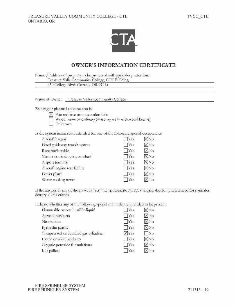
A. This Contractor shall call for inspection and complete Contractor's Material and Test
Certificates per NFPA 13 Chapter 10 "Underground Piping", Chapter 24 (2010) "Systems
Acceptance". The Forms shall be signed by the Authority Having Jurisdiction.

TREASURE VALLEY COMMUNITY COLLEGE - CTE TVCC_CTE
ONTARIO, OR
FIRE SPRINKLER SYSTEM 211313 - 18
B. The backflow device shall be forward flow tested per NFPA 13 Chapter 24 (2010) "Systems
Acceptance".
C. The entire sprinkler system shall be hydrostatically tested at not less than 200 psig pressure for a
period of not less than two (2) hours with no pressure drop in the system.
D. The underground fire service main shall be hydrostatically tested at not less than 200 psig
pressure for a period of not less than two (2) hours with + or - 5 psi pressure drop in the system
maximum per NFPA 24. Coordinate these requirements with the general contractor.
E. All testing shall be witnessed by a representative of the Engineer of Record or Owner.
F. Where jurisdictional authority's or NFPA 13 standards are more stringent than the above test,
they shall prevail.
TREASURE VALLEY COMMUNITY COLLEGE - CTE TVCC_CTE
ONTARIO, OR
FIRE SPRINKLER SYSTEM 211313 - 19

TREASURE VALLEY COMMUNITY COLLEGE - CTE TVCC_CTE
ONTARIO, OR
FIRE SPRINKLER SYSTEM 211313 - 20

TREASURE VALLEY COMMUNITY COLLEGE - CTE TVCC_CTE
ONTARIO, OR
FIRE SPRINKLER SYSTEM 211313 - 21
END OF SECTION 21 1313

TREASURE VALLEY COMMUNITY COLLEGE - CTE TVCC_CTE
ONTARIO, OR
FIRE SPRINKLER SYSTEM 211313 - 22
THIS PAGE INTENTIONALLY LEFT BLANK

TREASURE VALLEY COMMUNITY COLLEGE - CTE TVCC_CTE
ONTARIO, OR
SERVICE HOT WATER COMMISSIONING REQUIREMENTS 220800 - 1
SECTION 220800 - SERVICE HOT WATER COMMISSIONING REQUIREMENTS
PART 1 - GENERAL
1.1 SUMMARY
A. The purpose of this Section is to specify the Division 22 responsibilities and participation in the
commissioning process.
B. Organization of the commissioning program is primarily the responsibility of the Commissioning
Authority. Execution of the program is primarily the responsibility of the Contractor with support
from the Division 22 Subcontractor.
C. Division 22 Contractor shall cooperate with the Commissioning Authority in the following
manner:
1. Allow sufficient time before final completion dates so that installation verification, start-
up, test, adjust and balance, controls point-to-point checkout, system check-out and
functional testing can be accomplished for all needed equipment. Tasks need to be shown
on project schedule.
2. Participate as needed in the Controls Summit meeting.
3. Participate as needed in the Lighting Summit meeting.
4. Complete startup of the plumbing equipment and systems. Provide copies of completed
manufactures startup forms or Commissioning Authority provided system check-out forms
5. Assistance in testing, adjusting and balancing back check.
6. Complete and endorse all system readiness forms provided by the Commissioning
Authority to assure that Division 22 equipment and systems are fully operational and ready
for functional testing.
7. Assemble a copy of all records of Code Authority inspections and approvals to be
submitted to the Commissioning Authority.
8. Providing qualified personnel to operate equipment and systems as required to assist the
Commissioning Authority with functional testing to verify performance of
equipment/system.
9. Providing equipment, materials, and labor necessary to correct deficiencies found during
the commissioning process which fulfill contract and warranty requirements. Deficiencies
need to be corrected without undue delay.
10. Put all plumbing systems and equipment into full operation, and continue the operation of
the same during each working day of commissioning.
11. Provide operation and maintenance information and as-built drawings so that they can be
used during functional testing and training.
12. Providing training for the systems specified in Division 22 with coordination of Owner by
the Contractor.
1.2 SCOPE OF COMMISSIONING
A. The following are to be commissioned:

TREASURE VALLEY COMMUNITY COLLEGE - CTE TVCC_CTE
ONTARIO, OR
SERVICE HOT WATER COMMISSIONING REQUIREMENTS 220800 - 2
1. Domestic Hot Water
B. Other equipment and systems explicitly identified elsewhere in Contract Documents as requiring
commissioning.
1.3 RELATED REQUIREMENTS
A. Drawings and general provisions of contract documents.
B. Division 01 Specification Sections applicable to related scope of work outlined above.
C. Division 22 Specification Sections identify the requirements for plumbing systems relating to the
installation of plumbing equipment and systems, particularly with respect to equipment and
system testing, start-up and performance demonstration/observation.
1.4 TERMS
A. Acceptable Performance: A component or system being able to meet specified design parameters
under actual load, including satisfactory documented completion of all functional performance
tests, and resolution of outstanding issues.
B. Commissioning Authority: A dedicated commissioning group certified to perform
commissioning activities and hired to verify that the systems achieve acceptable performance.
The person performing the testing of the system. This person is knowledgeable in the systems
being tested.
C. Commissioning Team: The term used to define the overall group associated with performing
commissioning work, including designated representatives of the Owner, Facilities Staff, Design
Professionals, Construction Team, and the Commissioning Authority.
D. Construction Team: The term used to define the overall group responsible for performing the
work required to comply with the Contract Documents, including the Construction Manager,
Contractor, the Mechanical Contractor and associated subcontractors, the Electrical Contractor
and associates subcontractors.
E. Design Intent: The ideas and documentation behind design decisions that were made to meet the
Owner's project requirements. The design intent describes the systems, components, conditions
and methods to provide a fully functioning building.
F. Functional Performance Testing: Full range of checks, tests and demonstrations carried out to
determine that all components, sub-systems, systems, and interfaces between the systems
function in accordance with the Contract Documents. In this context, function includes all modes
and sequences of control and operation, all interlocks and conditional control responses, and all
specified responses to abnormal emergency conditions.
TREASURE VALLEY COMMUNITY COLLEGE - CTE TVCC_CTE
ONTARIO, OR
SERVICE HOT WATER COMMISSIONING REQUIREMENTS 220800 - 3
PART 2 - PRODUCTS
2.1 TEST EQUIPMENT
A. The Contractor will provide all standard testing equipment required to perform startup and initial
checkout and required Functional Testing; unless otherwise noted such testing equipment will
NOT become the property of Owner.
B. Calibration Tolerances: The Contractor will provide testing equipment of sufficient quality and
accuracy to test and/or measure system performance with the tolerances specified. If not
otherwise noted, the following minimum requirements apply:
1. Temperature Sensors and Digital Thermometers: Certified calibration within past year to
accuracy of 1 deg F and resolution of ± 0.5 deg F.
2. Pressure Sensors: Accuracy of ± 2.0 percent of the value range being measured (not full
range of meter), calibrated within the last year.
3. Calibration: According to the manufacturer's recommended intervals and when dropped or
damaged; affix calibration tags or keep certificates readily available for inspection.
C. Equipment-Specific Tools: Where special testing equipment, tools and instruments are specific
to a piece of equipment, are only available from the vendor, and are required in order to
accomplish startup or Functional Testing, provide such equipment, tools, and instruments as part
of the work at no extra cost to Owner; such equipment, tools, and instruments are to become the
property of Owner.
D. Independent equipment and software for monitoring flows, currents, status, pressures, etc. of
equipment that is required for Functional Tests will be provided by the Contractor or
Commissioning Authority and will not become the property of the Owner.
PART 3 - EXECUTION
3.1 GENERAL
A. The Contractor and Contractors shall be responsible for performing all procedures presented in
the specification and contract drawings, unless otherwise specified. The Commissioning Agent
will witness system start up and functional performance for all systems listed in this Division.
3.2 WORK PRIOR TO FUNCTIONAL TESTING
A. A commissioning plan will be developed by the Commissioning Authority and approved by the
Owner's Representative.
1. Division 22 is obligated to assist the Commissioning Authority in preparing the
commissioning plan by providing all necessary information pertaining to the actual
equipment and installation.
2. If system modifications/clarifications are called for in the contractual requirements of this
and related Sections of work, they will be made at no additional cost to the Owner.

TREASURE VALLEY COMMUNITY COLLEGE - CTE TVCC_CTE
ONTARIO, OR
SERVICE HOT WATER COMMISSIONING REQUIREMENTS 220800 - 4
3. If Contractor-initiated system changes have been made that alter the commissioning
process, the Contractor will notify the Owner's Representative for approval.
B. Specific responsibilities of Division 22 are as follows:
1. Participate in any efforts to finalize sequences of operations with Owner, Designers, and
Commissioning Authority. The schedule should allow sufficient time before final
completion dates so that installation verification, start-up, test, adjust and balance, controls
point-to-point checkout, system check-out and functional testing can be accomplished for
all needed equipment. Tasks need to be shown on project schedule
2. Normal start-up services required to bring each system and sub-system into a fully
operational state per the contract documents and related directives, clarifications, change
orders, etc. This includes motor rotational check, cleaning, filling, purging, control
sequences of operation, leak testing, full-load and part-load performance, etc.
3. Collect and provide to the Commissioning Authority specification required documentation
as requested and outlined in the Commissioning Field Notebook.
4. Review the Commissioning Field Notebook, Commissioning Plan, Project Communication
Reports, and Issues Resolution Log and submit comments to the Commissioning Authority
as needed.
5. Provide equipment submittals for systems to be commissioned to the Commissioning
Authority.
6. Provide Commissioning Authority with controls system wiring diagrams and narrative
sequences of operation in time for use in preparing the functional test procedures.
7. Participate as needed in the Controls Summit meeting.
8. Participate as needed in the Lighting Summit meeting.
9. Participate in commissioning meetings with the Commissioning Authority.
10. Provide preliminary TAB report, indicating all actual field values recorded, field notes, and
outstanding deficiencies, to the Commissioning Authority prior to initiation of back
checking of TAB work. These reports shall be incorporated in the Commissioning Field
Notebook. Assistance in testing, adjusting and balancing back check.
11. Complete and endorse all system readiness forms provided by the Commissioning
Authority to assure that Division 22 equipment and systems are fully operational and ready
for functional testing.
12. Provide schedule of activities, forms, and other documentation to the Commissioning
Authority and Owner's Representative at least two (2) weeks minimum prior to any startup
or testing required by the Contract Documents.
13. Assemble a copy of all records of Code Authority inspections and approvals to be
submitted to the Commissioning Authority. Place documentation in Commissioning Field
Notebook.
14. Issue System Readiness form for each set of equipment to the Commissioning Authority
upon completion of all component installation, start-up documentation, system work and
testing requirements per specification for all Contractors.
15. Provide qualified personnel for participation in site inspections, commissioning tests,
including seasonal testing required and warranty end testing required after the initial
commissioning.
16. Provide engineering and technical expertise to oversee and direct the correction of
deficiencies found during the commissioning process. This includes providing equipment,
materials, and labor necessary to correct deficiencies found during the commissioning
process which fulfill contract and warranty requirements. Deficiencies need to be corrected
without undue delay.

TREASURE VALLEY COMMUNITY COLLEGE - CTE TVCC_CTE
ONTARIO, OR
SERVICE HOT WATER COMMISSIONING REQUIREMENTS 220800 - 5
17. Put all plumbing systems and equipment into full operation, and continue the operation of
the same during each working day of commissioning.
18. Note any inconsistencies or deficiencies in system operations and enforce system
compliance or recommend to the Commissioning Authority, Owner's Representative and
A/E modifications to system design, which will enhance system performance.
19. In the event that a functional test fails, the cause of failure shall be determined and rectified
as soon as possible, and then retested. If more than two functional tests of the same
system(s) are required, all costs for additional testing may be borne by the Contractor, at
the Owner's discretion.
20. Operate equipment and systems, as required, for functional performance testing. This
includes, but is not limited to; manipulating the appropriate controls systems to achieve the
expected response for the functional test procedure.
21. Participate in the fine-tuning or troubleshooting of system performance if either of these
measures becomes necessary.
22. Review operation and maintenance information and as-build drawings provided by the
various subcontractors and vendors for verification, organization, and distribution. Report
any discrepancies to Commissioning Authority and the Owner's Representative.
23. Submit complete operation and maintenance information, and as-built drawings in
electronic form to the Commissioning Authority for review. (PDF preferred)
24. Obtain all documentation from completed installation audit forms, startup forms, and
functional performance tests and assemble the components in the Commissioning Field
Notebook and submit the completed notebook to the Commissioning Authority for review
and approval.
25. Oversee and provide training for the systems specified in all specification Divisions with
coordination by the Mechanical and Electrical Subcontractors.
26. Provide documentation of training for the systems specified.
C. Factory start-up services for key equipment and systems specified in Division 22. The Division
22 Contractor shall coordinate this work with the manufacturer and the Commissioning
Authority.
D. The Contractor will not begin the functional testing until each system is completely installed and
system readiness form has been approved by the Commissioning Authority.
1. Functional testing is intended to begin upon completion of a system. The Commissioning
Authority will not begin the functional testing process until each system is complete and
documented. If possible, testing may proceed prior to the completion of systems and/or
sub-systems if expediting this work is in the best interests of the Owner. Testing prior to
system completion will have a cost impact. Start of functional testing before system
completion will not relieve Division 22 from completing those systems as per the schedule.
2. Red-lined as-built drawings shall be available during commissioning.
3.3 PARTICIPATION IN FUNCTIONAL TESTING
A. Provide skilled technicians to start-up and debug all systems within the Division 22 work
(particularly with controls equipment). These same technicians shall be made available to assist
the Commissioning Authority in completing the commissioning program as it relates to each
system and their technical specialty. Work schedules, time required for testing, etc., will be
requested by the Commissioning Authority and coordinated by the Contractor. Contractor will

TREASURE VALLEY COMMUNITY COLLEGE - CTE TVCC_CTE
ONTARIO, OR
SERVICE HOT WATER COMMISSIONING REQUIREMENTS 220800 - 6
ensure the qualified technician(s) are available and present during the agreed upon schedules, and
of sufficient duration to complete the necessary tests, adjustments and/or problem resolutions.
1. The Commissioning Authority reserves the right to judge the appropriateness and
qualifications of the technicians relative to each item of equipment, system, and/or sub-
system. Qualifications of technicians include expert knowledge relative to the specific
equipment involved, adequate documentation and tools to service/commission the
equipment, and an attitude/willingness to work with the Commissioning Authority to get
the job done. A liaison or intermediary between the Commissioning Authority with a
qualified factory representative does not constitute the availability of a qualified technician
for purposes of this work.
B. System problems and discrepancies may require additional technician time which shall be made
available for the subsequent commissioning periods until required system performance is
obtained.
C. The objective of functional performance testing is to advance the building systems from a state
of substantial completion to full dynamic operation in accordance with the specified design
requirements and design intent.
D. The Commissioning Authority shall direct system-testing protocols which, when implemented
by the Contractor, will allow the Commissioning Authority to observe, evaluate, identify
deficiencies, recommend modifications, tune, and document the systems and systems' equipment
performance over a range control modes of operation.
3.4 WORK TO RESOLVE DEFICIENCIES
A. Maladjustments, misapplied equipment, and/or deficient performance under varying loads will
result in a system that does not meet Acceptable Performance. Correction of work will be
completed under the direction of the Owner's Representative and Architect, with input from the
Contractor, Equipment Supplier, and Commissioning Authority. Whereas all members will have
input and the opportunity to discuss, debate, and work out problems, the Architect/Engineer-of-
Record will have final jurisdiction on the necessary work to be done to achieve performance
and/or design intent.
B. Corrective work shall be completed in a timely fashion to permit timely completion of the
commissioning process.
1. Experimentation to render system performance will be permitted.
a. If the Architect deems the experimentation work to be ineffective or untimely as it
relates to the commissioning process, the Architect will notify the Owner
indicating the nature of the problem, expected steps to be taken, and the deadline
for completion of activities.
b. If deadlines pass without resolution of the problem, the Owner reserves the right
to obtain supplementary services and/or equipment to resolve the problem.
c. Costs incurred to solve the problem in an expeditious manner will be the
Contractor's responsibility.
TREASURE VALLEY COMMUNITY COLLEGE - CTE TVCC_CTE
ONTARIO, OR
SERVICE HOT WATER COMMISSIONING REQUIREMENTS 220800 - 7
3.5 PERFORMANCE PERIOD
A. Upon successful completion of functional test procedures, a performance period of 15
consecutive calendar days shall commence on first day following the last performance test. This
period shall be completed prior to final acceptance of the project. In event of failure to meet
standard of performance during any initiated performance period, it is not required that one 15-
calendar day period expire in order for another performance period to begin.
B. If equipment or system operation demonstrates continuing compliance with specified
requirements for a period of 15 consecutive calendar days from commencement date of
performance period, it shall be deemed to have met the standard of performance.
C. Equipment will not be accepted by the Owner and final payment will not be made by the Owner
until acceptable performance is met.
3.6 SEASONAL COMMISSIONING AND OCCUPANCY VARIATIONS
A. Seasonal commissioning pertains to testing under full-load conditions during peak heating and
peak cooling seasons, as well as part-load conditions in the spring and fall. Initial commissioning
will be done as soon as contract work is completed regardless of season. All equipment and
systems will be tested to their peak seasonal conditions. If this cannot be done during the time
functional testing is being performed that portion of the test will have to be done during peak
season to observe full-load performance. Heating equipment will be tested during winter design
extremes. Cooling equipment will be tested during summer design extremes with a fully
occupied building. The Contractor will be responsible to participate in the initial and the alternate
peak season test of the systems performance.
B. Subsequent commissioning may be required under conditions of occupancy or use. All
equipment and systems affected by occupancy variations will be tested to observe system
performance. The Contractor will be responsible to participate in the initial and the alternate
occupancy sensitive testing of systems to provide verification of adequate performance.
C. Discrepancies discovered with the Contractor's equipment or workmanship during alternate
testing periods will be handled as warranty items if the owner has taken position of the facility.
3.7 RETESTING AND RECOMMISSIONING
A. Contractor is responsible for correction of deficiencies and retesting at no extra cost to Owner; if
a deficiency is not corrected and retested immediately, the Commissioning Authority will
document the deficiency.
1. Deficiencies are any condition in the installation or function of a component, piece of
equipment or system that is not in compliance with the Contract Documents or does not
perform properly.
2. When the deficiency has been corrected, the Contractor needs to notify the Commissioning
Authority that the item is ready to be retested; the Commissioning Authority will
reschedule the test and the Contractor shall retest.
3. Identical or Near-Identical Items: If ten percent, or three, whichever is greater, of identical
or near-identical items fail to perform due to material or manufacturing defect, all items
will be considered defective; provide a proposal for correction within 2 weeks after

TREASURE VALLEY COMMUNITY COLLEGE - CTE TVCC_CTE
ONTARIO, OR
SERVICE HOT WATER COMMISSIONING REQUIREMENTS 220800 - 8
notification of defect, including provision for testing sample installations prior to
replacement of all items.
4. The Contractor will be allowed one retest by the Commissioning Authority after initial
testing of the equipment. If equipment fails testing a second time the Contractor shall bear
the cost of Owner and Commissioning Authority's time for any additional retesting.
5. Contractor shall bear the cost of Owner and Commissioning Authority's time for any re-
testing if the test failed due to failure to execute the relevant system readiness forms and/or
system check-out forms correctly and any subsequent retests.
3.8 TRAINING
A. The Division 22 Contractor will be required to participate in the training of the Owner's
engineering and maintenance staff for each mechanical system and the related components.
Training may be conducted in a classroom setting, with system and component documentation,
and suitable classroom training aids, or in the field with the specific equipment. The type of
training will be per the Owner's option.
B. A training plan will be developed by the Contractor outlining equipment that requires training.
The plan shall include who will perform the training, when the training will occur, and the
required duration of the training. Once the training plan is developed the Owner will provide a
list of the appropriate personnel attending the training.
C. Training sessions should cover using the Operations & Maintenance Manuals and as-built
drawings assembled by the Contractor as tools for understanding and troubleshooting
components, equipment and systems. This material needs to be supplied to the Owner a minimum
of two weeks prior to training taking place to allow participants time to review the material. This
helps focus training needs of the O & M staff.
D. Detailed requirements for training and instruction are contained in other Sections of these
Contract Documents. The Contractor needs to document what training has taken place and those
that have attended training.
3.9 MISCELLANEOUS SUPPORT
A. Division 22 shall remove and replace covers of plumbing equipment, open access panels, etc., to
permit Contractor, Architect, Owner's Representative, and Commissioning Authority to observe
equipment and controllers provided. Furnish ladders and flashlights as necessary.
END OF SECTION 220800

TREASURE VALLEY COMMUNITY COLLEGE - CTE TVCC_CTE
ONTARIO, OR
FACILITY WATER DISTRIBUTION 221113 - 1
SECTION 221113 - FACILITY WATER DISTRIBUTION
PART 1 GENERAL
1.1 SECTION INCLUDES
A. Force water piping, underground structures, and specialties.
1.2 RELATED SECTIONS
A. Common work results for utilities: Section 330500.
1.3 QUALITY STANDARDS
A. Provide experienced, well-trained workers competent to complete the work as specified.
B. All work shall comply with governing building and safety codes.
1.4 SUBMITTALS
A. See Section 013300 - Submittal Procedures.
B. Submit manufacture's certification that pipe, fittings, valves, fire hydrants, and appurtenance
meet or exceed specified requirements.
C. Submit manufacture's installation instructions and maintain copy at the job site.
1.5 PROJECT RECORD DOCUMENTS
A. Accurately record actual location of constructed pipeline and other appurtenance in relation to
existing permanent benchmarks.
B. Provide copy of record documents to Owner prior to issuance of substantial completion.
1.6 DELIVERY, STORAGE AND HANDLING
A. Handle and store pipe manufacture's recommendations and in a manner which prevents shock,
damage or excessive exposure to sunlight and contamination.
B. Protect gasket material form sunlight and contamination.
PART 2 PRODUCTS

TREASURE VALLEY COMMUNITY COLLEGE - CTE TVCC_CTE
ONTARIO, OR
FACILITY WATER DISTRIBUTION 221113 - 2
2.1 PIPE
A. See Civil, Mechanical and Plumbing Drawings and/or Specifications.
B. Water lines shall be ductile iron pipe class 52.
C. When a corrosive potential condition is encountered, all ductile iron pipe and fittings will be
polyethylene encased with an 8 mil tubing meeting manufacturer and AWWA Standards
D All pipe shall be pressure rated for 150 psi and all valves and fittings shall be pressure rated at
352 psi for ductile iron. All fittings shall be factory cement lined and coated.
E. Service line shall be Type K Copper Tubing meeting ASTM B88 or Polyethylene meeting
ASTM D3035 or ASTM D2737 may be acceptable for conditions where corrosive soils are
present, with approval of the City.
2.2 ACCESSORIES
A. See Civil, Mechanical and Plumbing Drawings and/or Specifications
B. Water valves shall be the same size as the water main. Main line valves shall be resilient seated
gate valves meeting the requirements of AWWA C509.
C. Corporation stops shall be Ford FB-1000 Iron pipe x CTS Pack Joint.
D. Fire Hydrant shall be Mueller 250 Super Centurion meeting the requirements of SD-404
Standard drawing for City of Ontario Standards for Public Works Construction.
PART 3 EXECUTION
3.1 EXAMINATION
A. Verify existing conditions before starting work.
B. Verification of conditions: Verify that field measurements, surfaces, substrates and conditions
are as required, and ready to receive work.
C. Report in writing to Owner & Engineer any prevailing conditions that will adversely affect
satisfactory execution of any Work required by this Sections. Do not proceed with Work until
all unsatisfactory conditions have been corrected.
D. By beginning Work, Contractor accepts all conditions and assumes responsibility for correcting
unsuitable conditions encountered at no additional cost to the Owner.
3.2 PREPARATIONS
A. Hand trim excavations to required elevations. Correct over excavation with fine aggregate.

TREASURE VALLEY COMMUNITY COLLEGE - CTE TVCC_CTE
ONTARIO, OR
FACILITY WATER DISTRIBUTION 221113 - 3
B. Remove large stones or other hard matter which could damage pipe or impede consistent
backfilling.
C. For Services cut pipe ends square, ream pipe and tube ends and remove burrs. For mains, cut
pipe ends square and bevel per manufacturer's recommendations.
D. Remove scale and dirt, on inside and outside, before assembly.
E. Prepare pipe for connections to equipment with flanges, unions, plain end and push-on, or
mechanical joints
3.3 BEDDING
A. Excavate pipe trench and place bedding material in accordance with Section 330500 for work
on the Section.
3.4 INSTALLATION - PIPE AND FITTINGS
A. Maintain separation of water main from sanitary and storm sewer piping in accordance with
local or state code.
B. Install pipe and fittings in accordance with AWWA C600 and/or AWWA C605, manufacture's
published instructions and local or state requirements.
C. Install pipe to allow for expansion and contraction without stressing pipe or joints or a specified
by pipe manufacturer.
D. Connections with Existing Pipelines: Where connections are made between new Work and
Existing piping, make connection using suitable fittings for conditions encountered. Make each
connection with existing pipe at time and under conditions which least interfere with operation
of existing pipeline and in accordance with local and state code.
E. Tees for service lateral shall be installed at 100 percent slope an 1/16 or 1/8 bends shall be
installed to provide proper grade for service laterals.
F. Backfill trench in accordance with Section 330500.
3.5 FIELD QUALITY CONTROL
A. A hydrostatic test shall be made on the watertight joint types as proposed. Only on sample joint
of each type selected by Owner representative needs testing. However, if the sample joint fails
because of faulty design or workmanship, an additional sample joint may be tested.
Performance requirements for joints in reinforced concrete pipe shall conform to ASHTO M
198 or ASTM C 443. Test requirements for joints in PVC pipe shall conform to ASTM D 3212
or ASTM C 361.
END OF SECTION 221113

TREASURE VALLEY COMMUNITY COLLEGE - CTE TVCC_CTE
ONTARIO, OR
FACILITY WATER DISTRIBUTION 221113 - 4
THIS PAGE INTENTIONALLY LEFT BLANK
TREASURE VALLEY COMMUNITY COLLEGE - CTE TVCC_CTE
ONTARIO, OR
DOMESTIC WATER PIPING 221116 - 1
SECTION 221116 - DOMESTIC WATER PIPING
PART 1 - GENERAL
1.1 RELATED DOCUMENTS
A. Drawings and general provisions of the Contract, including General and Supplementary
Conditions and Division 01 Specification Sections, apply to this Section.
1.2 SUMMARY
A. This Section includes domestic water piping and water meters inside the building.
1.3 SUBMITTALS
A. Product Data: For pipe, tube, fittings, and couplings
B. Water Samples: Specified in Part 3 "Cleaning" Article.
1.4 QUALITY ASSURANCE
A. Piping materials shall bear label, stamp, or other markings of specified testing agency.
B. Comply with NSF 61, "Drinking Water System Components - Health Effects; Sections 1
through 9," for potable domestic water piping and components.
1.5 DELIVERY, STORAGE, AND HANDLING
A. Deliver piping with factory-applied end caps. Maintain end caps through shipping, storage, and
handling to prevent pipe-end damage and to prevent entrance of dirt, debris, and moisture.
B. Protect stored piping from moisture and dirt. Elevate above grade. Do not exceed structural
capacity of floor when storing inside.
C. Protect flanges, fittings, and specialties from moisture and dirt.
D. Store plastic piping protected from direct sunlight. Support to prevent sagging and bending.

TREASURE VALLEY COMMUNITY COLLEGE - CTE TVCC_CTE
ONTARIO, OR
DOMESTIC WATER PIPING 221116 - 2
PART 2 - PRODUCTS
2.1 MANUFACTURERS
A. In other Part 2 articles where titles below introduce lists, the following requirements apply to
product selection:
1. Available Manufacturers: Subject to compliance with requirements, manufacturers
offering products that may be incorporated into the Work include, but are not limited to,
manufacturers specified.
2.2 PIPING MATERIALS
A. Refer to Part 3 "Pipe and Fitting Applications" Article for applications of pipe, tube, fitting, and
joining materials.
B. Transition Couplings for Aboveground Pressure Piping: Coupling or other manufactured fitting
the same size as, with pressure rating at least equal to and ends compatible with, piping to be
joined.
2.3 COPPER TUBE AND FITTINGS
A. Soft Copper Tube: ASTM B 88, Types K and L, water tube, annealed temper.
1. Copper Pressure Fittings: ASME B16.18, cast-copper-alloy or ASME B16.22, wrought-
copper, solder-joint fittings. Furnish wrought-copper fittings if indicated.
2. Bronze Flanges: ASME B16.24, Class 150, with solder-joint ends. Furnish Class 300
flanges if required to match piping.
3. Copper Unions: MSS SP-123, cast-copper-alloy, hexagonal-stock body, with ball-and-
socket, metal-to-metal seating surfaces, and solder-joint or threaded ends.
B. Hard Copper Tube: ASTM B 88, Types L, water tube, drawn temper.
1. Copper Pressure Fittings: ASME B16.18, cast-copper-alloy or ASME B16.22, wrought-
copper, solder-joint fittings. Furnish wrought-copper fittings if indicated.
2. Bronze Flanges: ASME B16.24, Class 150, with solder-joint ends. Furnish Class 300
flanges if required to match piping.
3. Copper Unions: MSS SP-123, cast-copper-alloy, hexagonal-stock body, with ball-and-
socket, metal-to-metal seating surfaces, and solder-joint or threaded ends.
4. Copper, Grooved-End Fittings: ASTM B 75 copper tube or ASTM B 584 bronze
castings.
a. Grooved-End-Tube Couplings: Copper-tube dimensions and design similar to
AWWA C606. Include ferrous housing sections, gasket suitable for hot water, and
bolts and nuts.

TREASURE VALLEY COMMUNITY COLLEGE - CTE TVCC_CTE
ONTARIO, OR
DOMESTIC WATER PIPING 221116 - 3
PART 3 - EXECUTION
3.1 PIPE AND FITTING APPLICATIONS
A. Transition and special fittings with pressure ratings at least equal to piping rating may be used
in applications below, unless otherwise indicated.
B. Flanges may be used on aboveground piping, unless otherwise indicated.
C. Under-Building-Slab, Domestic Water Piping on trap primers all sizes: Soft copper tube, Type
L; copper pressure fittings; and brazed joints.
D. Aboveground Domestic Water Piping: Use the following piping materials:
1. NPS 6 and Smaller: Hard copper tube, Type L; copper pressure fittings; and soldered
joints.
2. NPS 1/2 to NPS 2: Hard copper tube, Type L with plain ends; copper pressure fittings;
and pro-press joints.
a. Rigid tools pro-press system.
3.2 VALVE APPLICATIONS
A. Drawings indicate valve types to be used. Where specific valve types are not indicated, the
following requirements apply:
1. Shutoff Duty: Use bronze ball valves for piping NPS 2 and smaller. Use cast-iron
butterfly valves with flanged ends for piping NPS 2-1/2 and larger.
2. Throttling Duty: Use bronze ball or globe valves for piping NPS 2 and smaller. Use
cast-iron butterfly valves with flanged ends for piping NPS 2-1/2 and larger.
3. Hot-Water-Piping, Balancing Duty: Calibrated balancing valves.
4. Drain Duty: Hose-end drain valves.
B. Install shutoff valve close to water main on each branch and riser serving plumbing fixtures or
equipment, on each water supply to equipment, and on each water supply to plumbing fixtures
that do not have supply stops. Use ball valves for piping NPS 2 and smaller. Use butterfly
valves for piping NPS 2-1/2 and larger.
C. Install drain valves for equipment at base of each water riser, at low points in horizontal piping,
and where required to drain water piping.
1. Install hose-end drain valves at low points in water mains, risers, and branches.
2. Install stop-and-waste drain valves where indicated.
D. Install calibrated balancing valves in each hot-water circulation return branch and discharge side
of each pump and circulator. Set calibrated balancing valves partly open to restrict but not stop
flow.

TREASURE VALLEY COMMUNITY COLLEGE - CTE TVCC_CTE
ONTARIO, OR
DOMESTIC WATER PIPING 221116 - 4
3.3 PIPING INSTALLATION
A. Install under-building-slab copper tubing according to CDA's "Copper Tube Handbook."
B. Install sleeve with water stop and mechanical sleeve seal at each service pipe penetration
through foundation wall. Select number of interlocking rubber links required to make
installation watertight.
C. Install shutoff valve, hose-end drain valve, strainer, pressure gage, and test tee with valve,
inside the building at each domestic water service entrance.
D. Install domestic water piping level and plumb.
3.4 JOINT CONSTRUCTION
A. Soldered Joints: Use ASTM B 813, water-flushable, lead-free flux; ASTM B 32, lead-free-
alloy solder; and ASTM B 828 procedure, unless otherwise indicated.
3.5 HANGER AND SUPPORT INSTALLATION
A. Install hangers for copper tubing with the following maximum horizontal spacing and minimum
rod diameters:
1. NPS 3/4 and Smaller: 60 inches with 3/8-inch rod.
2. NPS 1 and NPS 1-1/4: 72 inches with 3/8-inch rod.
3. NPS 1-1/2 and NPS 2: 96 inches with 3/8-inch rod.
4. NPS 2-1/2: 108 inches with 1/2-inch rod.
5. NPS 3 to NPS 5: 10 feet with 1/2-inch rod.
6. NPS 6: 10 feet with 5/8-inch rod.
B. Install supports for vertical copper tubing every 10 feet.
C. Support piping and tubing not listed above according to MSS SP-69 and manufacturer's written
instructions.
3.6 CONNECTIONS
A. Drawings indicate general arrangement of piping, fittings, and specialties.
B. Install piping adjacent to equipment and machines to allow service and maintenance.
C. Connect domestic water piping to exterior water-service piping. Use transition fitting to join
dissimilar piping materials.
D. Connect domestic water piping to water-service piping with shutoff valve, and extend and
connect to the following:
1. Water Heaters: Cold-water supply and hot-water outlet piping in sizes indicated, but not
smaller than sizes of water heater connections.

TREASURE VALLEY COMMUNITY COLLEGE - CTE TVCC_CTE
ONTARIO, OR
DOMESTIC WATER PIPING 221116 - 5
2. Plumbing Fixtures: Cold- and hot-water supply piping in sizes indicated, but not smaller
than required by plumbing code.
3. Equipment: Cold- and hot-water supply piping as indicated, but not smaller than
equipment connections. Provide shutoff valve and union for each connection. Use
flanges instead of unions for NPS 2-1/2 and larger.
3.7 FIELD QUALITY CONTROL
A. Inspect domestic water piping as follows:
1. Do not enclose, cover, or put piping into operation until it has been inspected and
approved by authorities having jurisdiction.
2. During installation, notify authorities having jurisdiction at least 24 hours before
inspection must be made. Perform tests specified below in presence of authorities having
jurisdiction:
a. Roughing-in Inspection: Arrange for inspection of piping before concealing or
closing-in after roughing-in and before setting fixtures.
b. Final Inspection: Arrange final inspection for authorities having jurisdiction to
observe tests specified below and to ensure compliance with requirements.
3. Reinspection: If authorities having jurisdiction find that piping will not pass test or
inspection, make required corrections and arrange for reinspection.
4. Reports: Prepare inspection reports and have them signed by authorities having
jurisdiction.
B. Test domestic water piping as follows:
1. Fill domestic water piping. Check components to determine that they are not air bound
and that piping is full of water.
2. Test for leaks and defects in new piping and parts of existing piping that have been
altered, extended, or repaired. If testing is performed in segments, submit separate report
for each test, complete with diagram of portion of piping tested.
3. Leave new, altered, extended, or replaced domestic water piping uncovered and
unconcealed until it has been tested and approved. Expose work that was covered or
concealed before it was tested.
4. Cap and subject piping to static water pressure of 50 psig above operating pressure,
without exceeding pressure rating of piping system materials. Isolate test source and
allow to stand for four hours. Leaks and loss in test pressure constitute defects that must
be repaired.
5. Repair leaks and defects with new materials and retest piping or portion thereof until
satisfactory results are obtained.
6. Prepare reports for tests and required corrective action.
3.8 ADJUSTING
A. Perform the following adjustments before operation:
1. Close drain valves, hydrants, and hose bibbs.

TREASURE VALLEY COMMUNITY COLLEGE - CTE TVCC_CTE
ONTARIO, OR
DOMESTIC WATER PIPING 221116 - 6
2. Open shutoff valves to fully open position.
3. Open throttling valves to proper setting.
4. Adjust balancing valves in hot-water-circulation return piping to provide adequate flow.
a. Adjust calibrated balancing valves to flows indicated.
5. Remove plugs used during testing of piping and plugs used for temporary sealing of
piping during installation.
6. Remove and clean strainer screens. Close drain valves and replace drain plugs.
7. Remove filter cartridges from housings and verify that cartridges are as specified for
application where used and are clean and ready for use.
8. Check plumbing specialties and verify proper settings, adjustments, and operation.
3.9 CLEANING
A. Clean and disinfect potable and non-potable domestic water piping as follows:
1. Purge new piping before using.
2. Use purging and disinfecting procedures prescribed by authorities having jurisdiction or,
if methods are not prescribed, procedures described in either AWWA C651 or AWWA
C652 or as described below:
a. Flush piping system with clean, potable water until dirty water does not appear at
outlets.
b. Fill and isolate system according to either of the following:
1) Fill system or part thereof with water/chlorine solution with at least 50 ppm
of chlorine. Isolate with valves and allow to stand for 24 hours.
2) Fill system or part thereof with water/chlorine solution with at least 200
ppm of chlorine. Isolate and allow to stand for three hours.
c. Flush system with clean, potable water until no chlorine is in water coming from
system after the standing time.
d. Submit water samples in sterile bottles to authorities having jurisdiction. Repeat
procedures if biological examination shows contamination.
B. Prepare and submit reports of purging and disinfecting activities.
C. Clean interior of domestic water piping system. Remove dirt and debris as work progresses.
END OF SECTION 221116

TREASURE VALLEY COMMUNITY COLLEGE - CTE TVCC_CTE
ONTARIO, OR
DOMESTIC WATER PIPING SPECIALTIES 221119 - 1
SECTION 221119 - DOMESTIC WATER PIPING SPECIALTIES
PART 1 - GENERAL
1.1 RELATED DOCUMENTS
A. Drawings and general provisions of the Contract, including General and Supplementary
Conditions and Division 01 Specification Sections, apply to this Section.
1.2 SUMMARY
A. This Section includes the following domestic water piping specialties:
1. Vacuum breakers.
2. Backflow preventers.
3. Balancing valves.
4. Temperature-actuated water mixing valves.
5. Strainers.
6. Outlet boxes.
7. Wall hydrants.
8. Drain valves.
9. Water hammer arresters.
10. Trap-seal primer valves.
1.3 PERFORMANCE REQUIREMENTS
A. Minimum Working Pressure for Domestic Water Piping Specialties: 125 psig, unless otherwise
indicated.
1.4 SUBMITTALS
A. Product Data: For each type of product indicated.
B. Operation and Maintenance Data: For domestic water piping specialties to include in
emergency, operation, and maintenance manuals.
1.5 QUALITY ASSURANCE
A. NSF Compliance:
1. Comply with NSF 14, "Plastics Piping Components and Related Materials," for plastic
domestic water piping components.
2. Comply with NSF 61, "Drinking Water System Components - Health Effects; Sections 1
through 9."
TREASURE VALLEY COMMUNITY COLLEGE - CTE TVCC_CTE
ONTARIO, OR
DOMESTIC WATER PIPING SPECIALTIES 221119 - 2
PART 2 - PRODUCTS
2.1 VACUUM BREAKERS
A. Hose-Connection Vacuum Breakers:
1. Available Manufacturers: Subject to compliance with requirements, manufacturers
offering products that may be incorporated into the Work include, but are not limited to,
the following:
a. Arrowhead Brass Products, Inc.
b. Cash Acme.
c. Conbraco Industries, Inc.
d. Legend Valve.
e. MIFAB, Inc.
f. Prier Products, Inc.
g. Watts Industries, Inc.; Water Products Div.
h. Woodford Manufacturing Company.
i. Zurn Plumbing Products Group; Light Commercial Operation.
2. Standard: ASSE 1011.
3. Body: Bronze, nonremovable, with manual drain.
4. Outlet Connection: Garden-hose threaded complying with ASME B1.20.7.
5. Finish: Rough bronze.
2.2 BACKFLOW PREVENTERS
A. Reduced-Pressure-Principle Backflow Preventers:
1. Available Manufacturers: Subject to compliance with requirements, manufacturers
offering products that may be incorporated into the Work include, but are not limited to,
the following:
a. Ames Co.
b. Conbraco Industries, Inc.
c. FEBCO; SPX Valves & Controls.
d. Flomatic Corporation.
e. Watts Industries, Inc.; Water Products Div.
f. Zurn Plumbing Products Group; Wilkins Div.
2. Standard: ASSE 1013.
3. Operation: Continuous-pressure applications.
4. Pressure Loss: 12 psig maximum, through middle 1/3 of flow range.
5. Accessories:
a. Valves: Ball type with threaded ends on inlet and outlet of NPS 2 and smaller;
outside screw and yoke gate-type with flanged ends on inlet and outlet of NPS
2-1/2 and larger.
b. Air-Gap Fitting: ASME A112.1.2, matching backflow-preventer connection.

TREASURE VALLEY COMMUNITY COLLEGE - CTE TVCC_CTE
ONTARIO, OR
DOMESTIC WATER PIPING SPECIALTIES 221119 - 3
2.3 BALANCING VALVES
A. Copper-Alloy Calibrated Balancing Valves:
1. Available Manufacturers: Subject to compliance with requirements, manufacturers
offering products that may be incorporated into the Work include, but are not limited to,
the following:
a. Armstrong International, Inc.
b. Flo Fab Inc.
c. ITT Industries; Bell & Gossett Div.
d. NIBCO INC.
e. TAC Americas.
f. Taco, Inc.
g. Watts Industries, Inc.; Water Products Div.
2. Type: Ball or Y-pattern globe valve with two readout ports and memory setting
indicator.
3. Body: Brass or bronze,
4. Size: Same as connected piping, but not larger than NPS 2.
5. Accessories: Meter hoses, fittings, valves, differential pressure meter, and carrying case.
2.4 TEMPERATURE-ACTUATED WATER MIXING VALVES
A. Individual-Fixture, Water Tempering Valves:
1. Available Manufacturers: Subject to compliance with requirements, manufacturers
offering products that may be incorporated into the Work include, but are not limited to,
the following:
a. Cash Acme.
b. Conbraco Industries, Inc.
c. Honeywell Water Controls.
d. Lawler Manufacturing Company, Inc.
e. Leonard Valve Company.
f. Powers; a Watts Industries Co.
g. Watts Industries, Inc.; Water Products Div.
h. Zurn Plumbing Products Group; Wilkins Div.
2. Standard: ASSE 1016, thermostatically controlled water tempering valve.
3. See Plumbing Fixture Schedule on Drawing.
2.5 STRAINERS FOR DOMESTIC WATER PIPING
A. Y-Pattern Strainers:
1. Pressure Rating: 125 psig minimum, unless otherwise indicated.
2. Body: Bronze for NPS 2 and smaller; cast iron with interior lining complying with
AWWA C550 or FDA-approved, epoxy coating and for NPS 2-1/2 and larger.
TREASURE VALLEY COMMUNITY COLLEGE - CTE TVCC_CTE
ONTARIO, OR
DOMESTIC WATER PIPING SPECIALTIES 221119 - 4
3. End Connections: Threaded for NPS 2 and smaller; flanged for NPS 2-1/2 and larger.
4. Screen: Stainless steel with round perforations, unless otherwise indicated.
5. Drain: Factory-installed, hose-end drain valve.
2.6 OUTLET BOXES
A. Icemaker Outlet Boxes:
1. Available Manufacturers: Subject to compliance with requirements, manufacturers
offering products that may be incorporated into the Work include, but are not limited to,
the following:
a. Acorn Engineering Company.
b. IPS Corporation.
c. LSP Products Group, Inc.
d. Oatey.
2. Mounting: Recessed.
3. Material and Finish: Plastic box and faceplate.
4. Faucet: Valved fitting complying with ASME A112.18.1. Include NPS 1/2 or smaller
copper tube outlet.
5. Supply Shutoff Fitting: NPS 1/2 gate, globe, or ball valve and NPS 1/2 copper, water
tubing.
2.7 WALL HYDRANTS
A. Nonfreeze Wall Hydrants:
1. Available Manufacturers: Subject to compliance with requirements, manufacturers
offering products that may be incorporated into the Work include, but are not limited to,
the following:
a. Josam Company.
b. MIFAB, Inc.
c. Prier Products, Inc.
d. Smith, Jay R. Mfg. Co.; Division of Smith Industries, Inc.
e. Tyler Pipe; Wade Div.
f. Watts Drainage Products Inc.
g. Woodford Manufacturing Company.
h. Zurn Plumbing Products Group; Light Commercial Operation.
2. Standard: ASME A112.21.3M for exposed-outlet, self-draining wall hydrants.
3. See Plumbing Fixture Schedule on Drawing.
2.8 DRAIN VALVES
A. Ball-Valve-Type, Hose-End Drain Valves:

TREASURE VALLEY COMMUNITY COLLEGE - CTE TVCC_CTE
ONTARIO, OR
DOMESTIC WATER PIPING SPECIALTIES 221119 - 5
1. Standard: MSS SP-110 for standard-port, two-piece ball valves.
2. Pressure Rating: 400 psig minimum CWP.
3. Size: NPS 3/4.
4. Body: Copper alloy.
5. Ball: Chrome-plated brass.
6. Seats and Seals: Replaceable.
7. Handle: Vinyl-covered steel.
8. Inlet: Threaded or solder joint.
9. Outlet: Threaded, short nipple with garden-hose thread complying with ASME B1.20.7
and cap with brass chain.
B. Stop-and-Waste Drain Valves:
1. Standard: MSS SP-110 for ball valves or MSS SP-80 for gate valves.
2. Pressure Rating: 200 psig minimum CWP or Class 125.
3. Size: NPS 3/4.
4. Body: Copper alloy or ASTM B 62 bronze.
5. Drain: NPS 1/8 side outlet with cap.
2.9 WATER HAMMER ARRESTERS
A. Water Hammer Arresters:
1. Available Manufacturers: Subject to compliance with requirements, manufacturers
offering products that may be incorporated into the Work include, but are not limited to,
the following:
a. AMTROL, Inc.
b. Josam Company.
c. MIFAB, Inc.
d. Sioux Chief Manufacturing Company, Inc.
e. Smith, Jay R. Mfg. Co.; Division of Smith Industries, Inc.
f. Tyler Pipe; Wade Div.
g. Watts Drainage Products Inc.
h. Zurn Plumbing Products Group; Specification Drainage Operation.
2. Standard: ASSE 1010 or PDI-WH 201.
3. Type: Metal bellows or Copper tube with piston.
4. Size: ASSE 1010, Sizes AA and A through F or PDI-WH 201, Sizes A through F.
2.10 TRAP-SEAL PRIMER VALVES
A. Supply-Type, Trap-Seal Primer Valves:
1. Available Manufacturers: Subject to compliance with requirements, manufacturers
offering products that may be incorporated into the Work include, but are not limited to,
the following:
a. MIFAB, Inc.
TREASURE VALLEY COMMUNITY COLLEGE - CTE TVCC_CTE
ONTARIO, OR
DOMESTIC WATER PIPING SPECIALTIES 221119 - 6
b. Sioux Chief Manufacturing Company, Inc.
c. Smith, Jay R. Mfg. Co.; Division of Smith Industries, Inc.
d. Watts Industries, Inc.; Water Products Div.
e. Precision Plumbing Products
2. Standard: ASSE 1018.
3. Pressure Rating: 125 psig minimum.
4. See Plumbing Fixture Schedule on drawing.
B. Drainage-Type, Trap-Seal Primer Valves:
1. Available Manufacturers: Subject to compliance with requirements, manufacturers
offering products that may be incorporated into the Work include, but are not limited to,
the following:
a. MIFAB, Inc.
b. Sioux Chief Manufacturing Company, Inc.
c. Smith, Jay R. Mfg. Co.; Division of Smith Industries, Inc.
d. Watts Industries, Inc.; Water Products Div.
e. Precision Plumbing Products
2. Standard: ASSE 1044, lavatory P-trap with NPS 3/8 minimum, trap makeup connection.
3. Size: NPS 1-1/4 minimum.
4. Material: Chrome-plated, cast brass.
2.11 TRAP-SEAL PRIMER SYSTEMS
A. Trap-Seal Primer Systems:
1. Available Manufacturers: Subject to compliance with requirements, manufacturers
offering products that may be incorporated into the Work include, but are not limited to,
the following:
a. MIFAB, Inc.
b. Sioux Chief Manufacturing Company, Inc.
c. Smith, Jay R. Mfg. Co.; Division of Smith Industries, Inc.
d. Watts Industries, Inc.; Water Products Div.
e. Precision Plumbing Products
2. Standard: ASSE 1044,
3. Piping: NPS 3/4, ASTM B 88, Type L; copper, water tubing.
4. Cabinet: Surface-mounting steel box with stainless-steel cover.
5. Electric Controls: 24-hour timer, solenoid valve, and manual switch for 120-V ac power.
6. Vacuum Breaker: ASSE 1001.
7. Number Outlets: Four.
8. Size Outlets: NPS 1/2.

TREASURE VALLEY COMMUNITY COLLEGE - CTE TVCC_CTE
ONTARIO, OR
DOMESTIC WATER PIPING SPECIALTIES 221119 - 7
PART 3 - EXECUTION
3.1 INSTALLATION
A. Refer to Section 230500 "Common Work Results for Plumbing and HVAC Equipment" for
piping joining materials, joint construction, and basic installation requirements.
B. Install backflow preventers in each water supply to mechanical equipment and systems and to
other equipment and water systems that may be sources of contamination. Comply with
authorities having jurisdiction.
1. Locate backflow preventers in same room as connected equipment or system.
2. Install drain for backflow preventers with atmospheric-vent drain connection with air-gap
fitting, fixed air-gap fitting, or equivalent positive pipe separation of at least two pipe
diameters in drain piping and pipe to floor drain. Locate air-gap device attached to or
under backflow preventer. Simple air breaks are not acceptable for this application.
3. Do not install bypass piping around backflow preventers.
C. Install balancing valves in locations where they can easily be adjusted.
D. Install temperature-actuated water mixing valves with check stops or shutoff valves on inlets
and with shutoff valve on outlet.
1. Install thermometers and water regulators if specified.
2. Install cabinet-type units recessed in or surface mounted on wall as specified.
E. Install Y-pattern strainers for water on supply side of each and pump.
F. Install outlet boxes recessed in wall. Install 2-by-4-inch fire-retardant-treated-wood blocking
wall reinforcement between studs.
G. Install water hammer arresters in water piping according to PDI-WH 201.
H. Install supply-type, trap-seal primer valves with outlet piping pitched down toward drain trap a
minimum of 1 percent, and connect to floor-drain body, trap, or inlet fitting. Adjust valve for
proper flow.
3.2 CONNECTIONS
A. Piping installation requirements are specified in other Mechanical Sections. Drawings indicate
general arrangement of piping and specialties.
3.3 FIELD QUALITY CONTROL
A. Perform the following tests and prepare test reports:
1. Test each pressure vacuum breaker and reduced-pressure-principle backflow preventer
according to authorities having jurisdiction and the device's reference standard.

TREASURE VALLEY COMMUNITY COLLEGE - CTE TVCC_CTE
ONTARIO, OR
DOMESTIC WATER PIPING SPECIALTIES 221119 - 8
B. Remove and replace malfunctioning domestic water piping specialties and retest as specified
above.
3.4 ADJUSTING
A. Set field-adjustable flow set points of balancing valves.
B. Set field-adjustable temperature set points of temperature-actuated water mixing valves.
END OF SECTION 221119

TREASURE VALLEY COMMUNITY COLLEGE - CTE TVCC_CTE
ONTARIO, OR
DOMESTIC WATER PUMPS 221123 - 1
SECTION 221123 - DOMESTIC WATER PUMPS
PART 1 - GENERAL
1.1 RELATED DOCUMENTS
A. Drawings and general provisions of the Contract, including General and Supplementary
Conditions and Division 01 Specification Sections, apply to this Section.
1.2 SUMMARY
A. This Section includes the following all-bronze and bronze-fitted centrifugal pumps for domestic
cold- and hot-water circulation:
1. High velocity cartridge circulator.
1.3 SUBMITTALS
A. Product Data: For each type and size of domestic water pump specified. Include certified
performance curves with operating points plotted on curves; and rated capacities of selected
models, furnished specialties, and accessories.
B. Operation and Maintenance Data: For domestic water pumps to include in emergency,
operation, and maintenance manuals.
1.4 QUALITY ASSURANCE
A. Electrical Components, Devices, and Accessories: Listed and labeled as defined in NFPA 70,
Article 100, by a testing agency acceptable to authorities having jurisdiction, and marked for
intended use.
B. UL Compliance: Comply with UL 778 for motor-operated water pumps.
PART 2 - PRODUCTS
2.1 MANUFACTURERS
A. In other Part 2 articles where titles below introduce lists, the following requirements apply to
product selection:
1. Available Manufacturers: Subject to compliance with requirements, manufacturers
offering products that may be incorporated into the Work include, but are not limited to,
manufacturers specified.

TREASURE VALLEY COMMUNITY COLLEGE - CTE TVCC_CTE
ONTARIO, OR
DOMESTIC WATER PUMPS 221123 - 2
2.2 HIGH VELOCITY CARTRIDGE CIRCULATOR
A. Available Manufacturers:
1. Armstrong Pumps Inc.
2. Bell & Gossett Domestic Pump; ITT Industries.
3. Grundfos Pumps Corp.
4. Taco, Inc.
B. Description: Factory-assembled and -tested, single-stage, close-coupled, in-line, sealless
centrifugal pumps.
1. Pump and Motor Assembly: Hermetically sealed, replaceable-cartridge-type unit with
motor and impeller on common shaft and designed for installation with pump and motor
shaft mounted horizontally.
2. Casing: Bronze, with threaded companion-flange connections.
3. Impeller: Corrosion-resistant material.
4. Motor: Single speed, unless otherwise indicated.
2.3 CONTROLS
A. Thermostats: Electric; adjustable for control of hot-water circulation pump.
1. Available Manufacturers:
a. Honeywell International, Inc.
b. Square D.
c. White-Rodgers Div.; Emerson Electric Co.
2. Type: Water-immersion sensor, for installation in hot-water circulation piping.
3. Range: 100 to 240 deg F.
4. Operation of Pump: On or off.
5. Settings: Base on Temp of start pump at 5 deg F below service temp and stop pump at
5 deg F over service temp.
6. See Plumbing Drawing for schedule.
PART 3 - EXECUTION
3.1 EXAMINATION
A. Examine roughing-in of domestic-water-piping system to verify actual locations of connections
before pump installation.
3.2 PUMP INSTALLATION
A. Comply with HI 1.4.

TREASURE VALLEY COMMUNITY COLLEGE - CTE TVCC_CTE
ONTARIO, OR
DOMESTIC WATER PUMPS 221123 - 3
B. Install pumps with access for periodic maintenance including removal of motors, impellers,
couplings, and accessories.
C. Independently support pumps and piping so weight of piping is not supported by pumps and
weight of pumps is not supported by piping.
D. Install in-line, seal-less centrifugal pumps with motor and pump shafts horizontal.
3.3 CONTROL INSTALLATION
A. Install immersion-type thermostats in hot-water return piping.
3.4 CONNECTIONS
A. Drawings indicate general arrangement of piping, fittings, and specialties.
B. Install piping adjacent to pumps to allow service and maintenance.
C. Connect domestic water piping to pumps. Install suction and discharge piping equal to or
greater than size of pump nozzles.
1. Install shutoff valve and strainer on suction side of pumps, and check valve and throttling
valve on discharge side of pumps. Install valves same size as connected piping.
2. Install pressure gages at suction and discharge of pumps. Install at integral pressure-gage
tappings where provided or install pressure-gage connectors in suction and discharge
piping around pumps.
D. Ground equipment according to Section 260526 "Grounding and Bonding for Electrical
Systems."
E. Connect thermostats to pumps that they control.
3.5 STARTUP SERVICE
A. Engage a factory-authorized service representative to perform startup service.
1. Complete installation and startup checks according to manufacturer's written instructions.
2. Check piping connections for tightness.
3. Clean strainers on suction piping.
4. Set thermostats for automatic starting and stopping operation of pumps.
5. Perform the following startup checks for each pump before starting:
a. Verify bearing lubrication.
b. Verify that pump is free to rotate by hand and that pump for handling hot liquid is
free to rotate with pump hot and cold. If pump is bound or drags, do not operate
until cause of trouble is determined and corrected.
c. Verify that pump is rotating in the correct direction.

TREASURE VALLEY COMMUNITY COLLEGE - CTE TVCC_CTE
ONTARIO, OR
DOMESTIC WATER PUMPS 221123 - 4
6. Prime pump by opening suction valves and closing drains, and prepare pump for
operation.
7. Start motor.
8. Open discharge valve slowly.
9. Adjust temperature settings on thermostats.
END OF SECTION 221123

TREASURE VALLEY COMMUNITY COLLEGE - CTE TVCC_CTE
ONTARIO, OR
FACILITY SANITARY SEWER 221313 - 1
SECTION 221313 - FACILITY SANITARY SEWERS
PART 1 GENERAL
1.1 SECTION INCLUDES
A. Gravity and force sanitary sewer piping, underground structures, and specialties.
1.2 RELATED SECTIONS
A. Common work results for utilities: Section 330500
1.3 QUALITY STANDARDS
A. Provide experienced, well-trained workers competent to complete the work as specified.
B. All work shall comply with governing building and safety codes.
1.4 SUBMITTALS
A. See Section 013300 - Submittal Procedures.
B. Submit manufacture's certification that pipe, fittings, clean outs, manholes, and appurtenance
meet or exceed specified requirements.
C. Submit manufacture's installation instructions and maintain copy at the job site.
1.5 PROJECT RECORD DOCUMENTS
A. Accurately record actual location of constructed pipeline and other appurtenance in relation to
existing permanent benchmarks.
B. Provide copy of record documents to Owner prior to issuance of substantial completion.
1.6 DELIVERY, STORAGE AND HANDLING
A. Handle and store pipe manufacture's recommendations and in a manner which prevents shock,
damage or excessive exposure to sunlight and contamination.
B. Protect gasket material form sunlight and contamination.
PART 2 PRODUCTS
TREASURE VALLEY COMMUNITY COLLEGE - CTE TVCC_CTE
ONTARIO, OR
FACILITY SANITARY SEWER 221313 - 2
2.1 PIPE
A. See Civil, Mechanical and Plumbing Drawings and/or Specifications.
B. Gravity Sewer pipe with diameter of 4-inch to 15-inch shall be solid wall PVC pipe shall
conform to ASTM D 3034 or SDR 35. Gravity Sewer pipe with diameter of 18-inch to 36-inch
shall be solid wall PVC pipe shall conform to ASTM F 679.
2.2 ACCESSORIES
A. See Civil, Mechanical and Plumbing Drawings and/or Specifications
B. Manholes shall conform to ASTM C 478.
PART 3 EXECUTION
3.1 EXAMINATION
A. Verify existing conditions before starting work.
B. Verification of conditions: Verify that field measurements, surfaces, substrates and conditions
are as required, and ready to receive work.
C. Report in writing to Owner & Engineer any prevailing conditions that will adversely affect
satisfactory execution of any Work required by this Sections. Do not proceed with Work until
all unsatisfactory conditions have been corrected.
D. By beginning Work, Contractor accepts all conditions and assumes responsibility for correcting
unsuitable conditions encountered at no additional cost to the Owner.
3.2 PREPARATIONS
A. Hand trim excavations to required elevations. Correct over excavation with fine aggregate.
B. Remove large stones or other hard matter which could damage pipe or impede consistent
backfilling.
C. For Services cut pipe ends square, ream pipe and tube ends and remove burrs. For mains, cut
pipe ends square and bevel per manufacturer's recommendations.
D. Remove scale and dirt, on inside and outside, before assembly.
E. Prepare pipe for connections to equipment with flanges, unions, plain end and push-on, or
mechanical joints.

TREASURE VALLEY COMMUNITY COLLEGE - CTE TVCC_CTE
ONTARIO, OR
FACILITY SANITARY SEWER 221313 - 3
3.3 BEDDING
A. Excavate pipe trench and place bedding material in accordance with Section 330500 for work
on the section.
3.4 INSTALLATION - PIPE AND FITTINGS
A. Maintain separation of water main from sanitary and storm sewer piping in accordance with
local or state code.
B. Locator wire is required for all sewer pipes and manholes. The wire shall be 12 AWG UF with
green colored insulation and fastened to the top of the pipe with duct tape at intervals not
exceeding ten feet. The locator wire shall be installed outside the manhole at the grade ring
joint.
C. Install pipe and fittings in accordance with ASTM D3034 and/or ASTM D2751, manufacture's
published instructions and local or state requirements.
D. Install pipe to allow for expansion and contraction without stressing pipe or joints or a specified
by pipe manufacturer.
E. Connections with Existing Pipelines: Where connections are made between new Work and
Existing piping, make connection using suitable fittings for conditions encountered. Make each
connection with existing pipe at time and under conditions which least interfere with operation
of existing pipeline and in accordance with local and state code.
F. Tees for service lateral shall be installed at 100 percent slope an 1/16 or 1/8 bends shall be
installed to provide proper grade for service laterals.
G. Backfill trench in accordance with Section 330500.
3.5 FIELD QUALITY CONTROL
A. A hydrostatic test shall be made on the watertight joint types as proposed. Only on sample joint
of each type selected by Owner representative needs testing. However, if the sample joint fails
because of faulty design or workmanship, an additional sample joint may be tested.
Performance requirements for joints in reinforced concrete pipe shall conform to ASHTO M
198 or ASTM C 443. Test requirements for joints in PVC pipe shall conform to ASTM D 3212
or ASTM C 361.
B. All tracer lines shall be tested after backfilling is compete. A low-Voltage source shall be
connected to the tracer contacts, and a magnetic locator shall be used at intervals not greater
than 100 feet, to determine whether the pipe can be located with the magnetic locator. The
contractor shall supply the necessary testing equipment and personnel at no additional cost.
Faulty tracer wire shall be repaired by the contractor and retested.
END OF SECTION 221313

TREASURE VALLEY COMMUNITY COLLEGE - CTE TVCC_CTE
ONTARIO, OR
FACILITY SANITARY SEWER 221313 - 4
THIS PAGE INTENTIONALLY LEFT BLANK
TREASURE VALLEY COMMUNITY COLLEGE - CTE TVCC_CTE
ONTARIO, OR
SANITARY WASTE AND VENT PIPING 221316 - 1
SECTION 221316 - SANITARY WASTE AND VENT PIPING
PART 1 - GENERAL
1.1 RELATED DOCUMENTS
A. Drawings and general provisions of the Contract, including General and Supplementary
Conditions and Division 01 Specification Sections, apply to this Section.
1.2 SUMMARY
A. Section Includes:
1. Pipe, tube, and fittings.
1.3 PERFORMANCE REQUIREMENTS
A. Components and installation shall be capable of withstanding the following minimum working
pressure unless otherwise indicated:
1. Soil, Waste, and Vent Piping: 10-foot head of water.
B. Seismic Performance: Soil, waste, and vent piping and support and installation shall withstand
the effects of earthquake motions determined according to ASCE/SEI 7.
1.4 SUBMITTALS
A. Product Data: For each type of product indicated.
1.5 QUALITY ASSURANCE
A. Piping materials shall bear label, stamp, or other markings of specified testing agency.
B. Comply with NSF/ANSI 14, "Plastics Piping Systems Components and Related Materials," for
plastic piping components. Include marking with "NSF-dwv" for plastic drain, waste, and vent
piping and "NSF-sewer" for plastic sewer piping.
PART 2 - PRODUCTS
2.1 PIPING MATERIALS
A. Comply with requirements in "Piping Schedule" Article for applications of pipe, tube, fitting
materials, and joining methods for specific services, service locations, and pipe sizes.

TREASURE VALLEY COMMUNITY COLLEGE - CTE TVCC_CTE
ONTARIO, OR
SANITARY WASTE AND VENT PIPING 221316 - 2
2.2 HUBLESS, CAST-IRON SOIL PIPE AND FITTINGS
A. Manufacturers: Subject to compliance with requirements, provide products by one of the
following:
1. AB&I Foundry.
2. Charlotte Pipe and Foundry Company.
3. Tyler Pipe.
B. Below Grade Pipe and Fittings: All below grade Hubless Cast Iron Soil Pipe and fittings shall
conform to the requirements of CISPI Standard 301 and ASTM A 888. All pipe & fittings shall
be American made and tested, no imported pipe is acceptable.
C. Above Grade Pipe and Fittings: All above grade Hubless Cast Iron Pipe and fittings shall
conform to the requirements of CISPI Standard 301 and ASTM-888 and shall be marked with
the Cast Iron Soil Pipe Institutes collective trademarks. All pipe and fittings shall be American
made and tested, no imported pipe is acceptable.
D. Documentation: At the request of the engineer the manufacturer shall furnish the following
information to confirm Compliance with CISPI 301:
1. Radiation Screening records.
2. Mechanical Testing records.
3. Chemical Testing records.
4. Dimensional Inspection reports.
5. Certificate letter from manufacturer with legal name and address.
E. CISPI, Hubless-Piping Couplings: Couplings shall conform to CISPI standard 310.
1. Manufacturers: Subject to compliance with requirements, available manufacturers
offering products that may be incorporated into the Work include, but are not limited to,
the following:
a. ANACO-Husky.
b. Dallas Specialty & Mfg. Co.
c. Fernco Inc.
d. Matco-Norca, Inc.
e. MIFAB, Inc.
f. Mission Rubber Company; a division of MCP Industries, Inc.
g. Stant.
h. Tyler Pipe.
2. Standards: ASTM C 1277 and CISPI 310.
3. Description: Stainless-steel corrugated shield with stainless-steel bands and tightening
devices; and ASTM C 564, rubber sleeve with integral, center pipe stop.
F. Cast-Iron, Hubless-Piping Couplings:
1. Manufacturers: Subject to compliance with requirements, available manufacturers
offering products that may be incorporated into the Work include, but are not limited to,
the following:

TREASURE VALLEY COMMUNITY COLLEGE - CTE TVCC_CTE
ONTARIO, OR
SANITARY WASTE AND VENT PIPING 221316 - 3
a. MG Piping Products Company.
2. Standard: ASTM C 1277.
3. Description: Two-piece ASTM A 48/A 48M, cast-iron housing; stainless-steel bolts and
nuts; and ASTM C 564, rubber sleeve with integral, center pipe stop.
2.3 PVC PIPE AND FITTINGS
A. Solid-Wall PVC Pipe: ASTM D 2665, drain, waste, and vent.
B. PVC Socket Fittings: ASTM D 2665, made to ASTM D 3311, drain, waste, and vent patterns
and to fit Schedule 40 pipe.
C. Adhesive Primer: ASTM F 656.
1. Adhesive primer shall have a VOC content of 550 g/L or less when calculated according
to 40 CFR 59, Subpart D (EPA Method 24).
D. Solvent Cement: ASTM D 2564.
1. PVC solvent cement shall have a VOC content of 510 g/L or less when calculated
according to 40 CFR 59, Subpart D (EPA Method 24).
2.4 SPECIALTY PIPE FITTINGS
A. Transition Couplings:
1. General Requirements: Fitting or device for joining piping with small differences in
OD's or of different materials. Include end connections same size as and compatible with
pipes to be joined.
2. Fitting-Type Transition Couplings: Manufactured piping coupling or specified piping
system fitting.
3. Unshielded, Nonpressure Transition Couplings:
a. Manufacturers: Subject to compliance with requirements, available manufacturers
offering products that may be incorporated into the Work include, but are not
limited to, the following:
1) Dallas Specialty & Mfg. Co.
2) Fernco Inc.
3) Mission Rubber Company; a division of MCP Industries, Inc.
4) Plastic Oddities; a division of Diverse Corporate Technologies, Inc.
b. Standard: ASTM C 1173.
c. Description: Elastomeric, sleeve-type, reducing or transition pattern. Include
shear ring and corrosion-resistant-metal tension band and tightening mechanism on
each end.
d. Sleeve Materials:

TREASURE VALLEY COMMUNITY COLLEGE - CTE TVCC_CTE
ONTARIO, OR
SANITARY WASTE AND VENT PIPING 221316 - 4
1) For Cast-Iron Soil Pipes: ASTM C 564, rubber.
2) For Plastic Pipes: ASTM F 477, elastomeric seal or ASTM D 5926, PVC.
3) For Dissimilar Pipes: ASTM D 5926, PVC or other material compatible
with pipe materials being joined.
4. Shielded, Nonpressure Transition Couplings:
a. Manufacturers: Subject to compliance with requirements, available manufacturers
offering products that may be incorporated into the Work include, but are not
limited to, the following:
1) Cascade Waterworks Mfg. Co.
2) Mission Rubber Company; a division of MCP Industries, Inc.
b. Standard: ASTM C 1460.
c. Description: Elastomeric or rubber sleeve with full-length, corrosion-resistant
outer shield and corrosion-resistant-metal tension band and tightening mechanism
on each end.
B. Dielectric Fittings:
1. General Requirements: Assembly of copper alloy and ferrous materials with separating
nonconductive insulating material. Include end connections compatible with pipes to be
joined.
2. Dielectric Unions:
a. Manufacturers: Subject to compliance with requirements, available manufacturers
offering products that may be incorporated into the Work include, but are not
limited to, the following:
1) Capitol Manufacturing Company.
2) Central Plastics Company.
3) Hart Industries International, Inc.
4) Jomar International Ltd.
5) Matco-Norca, Inc.
6) McDonald, A. Y. Mfg. Co.
7) Watts Regulator Co.; a division of Watts Water Technologies, Inc.
8) Wilkins; a Zurn company.
b. Description:
1) Standard: ASSE 1079.
2) Pressure Rating: 125 psig minimum at 180 deg F.
3) End Connections: Solder-joint copper alloy and threaded ferrous.

TREASURE VALLEY COMMUNITY COLLEGE - CTE TVCC_CTE
ONTARIO, OR
SANITARY WASTE AND VENT PIPING 221316 - 5
PART 3 - EXECUTION
3.1 PIPING INSTALLATION
A. Drawing plans, schematics, and diagrams indicate general location and arrangement of piping
systems. Indicated locations and arrangements were used to size pipe and calculate friction
loss, expansion, pump sizing, and other design considerations. Install piping as indicated unless
deviations to layout are approved on coordination drawings.
B. Install piping in concealed locations unless otherwise indicated and except in equipment rooms
and service areas.
C. Install piping indicated to be exposed and piping in equipment rooms and service areas at right
angles or parallel to building walls. Diagonal runs are prohibited unless specifically indicated
otherwise.
D. Install cast iron piping for the first 10 feet-0 inch of below grade piping from the dishwasher
drain to a point of transition to PVC piping (if used).
E. Install piping above accessible ceilings to allow sufficient space for ceiling panel removal.
F. Install piping to permit valve servicing.
G. Install piping at indicated slopes.
H. Install piping free of sags and bends.
I. Install fittings for changes in direction and branch connections.
J. Install piping to allow application of insulation.
K. Install seismic restraints on piping. Comply with requirements for seismic-restraint devices
specified in Division 23 Section 230548 "Seismic Controls for Plumbing and HVAC."
L. Make changes in direction for soil and waste drainage and vent piping using appropriate
branches, bends, and long-sweep bends. Sanitary tees and short-sweep 1/4 bends may be used
on vertical stacks if change in direction of flow is from horizontal to vertical. Use long-turn,
double Y-branch and 1/8-bend fittings if two fixtures are installed back to back or side by side
with common drain pipe. Straight tees, elbows, and crosses may be used on vent lines. Do not
change direction of flow more than 90 degrees. Use proper size of standard increasers and
reducers if pipes of different sizes are connected. Reducing size of drainage piping in direction
of flow is prohibited.
M. Lay buried building drainage piping beginning at low point of each system. Install true to
grades and alignment indicated, with unbroken continuity of invert. Place hub ends of piping
upstream. Install required gaskets according to manufacturer's written instructions for use of
lubricants, cements, and other installation requirements. Maintain swab in piping and pull past
each joint as completed.

TREASURE VALLEY COMMUNITY COLLEGE - CTE TVCC_CTE
ONTARIO, OR
SANITARY WASTE AND VENT PIPING 221316 - 6
N. Install soil and waste drainage and vent piping at the following minimum slopes unless
otherwise indicated:
1. Horizontal Sanitary Drainage Piping: 2 percent downward in direction of flow for piping
NPS 3 and smaller; 1 percent downward in direction of flow for piping NPS 4 and larger
2. Vent Piping: 1 percent down toward vertical fixture vent or toward vent stack.
O. Install cast-iron soil piping according to CISPI's "Cast Iron Soil Pipe and Fittings Handbook,"
Chapter IV, "Installation of Cast Iron Soil Pipe and Fittings."
1. Install encasement on underground piping according to ASTM A 674 or
AWWA C105/A 21.5.
P. Install underground PVC piping according to ASTM D 2321.
Q. Plumbing Specialties:
1. Install cleanouts at grade and extend to where building sanitary drains connect to building
sanitary sewers in sanitary drainage gravity-flow piping. Comply with requirements for
cleanouts specified in Division 22 Section 221319 "Sanitary Waste Piping Specialties."
2. Install drains in sanitary drainage gravity-flow piping. Comply with requirements for
drains specified in Division 22 Section 221319 "Sanitary Waste Piping Specialties."
R. Do not enclose, cover, or put piping into operation until it is inspected and approved by
authorities having jurisdiction.
S. Install sleeves for piping penetrations of walls, ceilings, and floors.
T. Install sleeve seals for piping penetrations of concrete walls and slabs.
U. Install escutcheons for piping penetrations of walls, ceilings, and floors.
V. Exposed PVC Piping: Protect plumbing vents exposed to sunlight with two coats of water-based
latex paint.
3.2 JOINT CONSTRUCTION
A. Join hubless, cast-iron soil piping according to CISPI 310 and CISPI's "Cast Iron Soil Pipe and
Fittings Handbook" for hubless-piping coupling joints.
B. Threaded Joints: Thread pipe with tapered pipe threads according to ASME B1.20.1. Cut
threads full and clean using sharp dies. Ream threaded pipe ends to remove burrs and restore
full ID. Join pipe fittings and valves as follows:
1. Apply appropriate tape or thread compound to external pipe threads unless dry seal
threading is specified.
2. Damaged Threads: Do not use pipe or pipe fittings with threads that are corroded or
damaged. Do not use pipe sections that have cracked or open welds.

TREASURE VALLEY COMMUNITY COLLEGE - CTE TVCC_CTE
ONTARIO, OR
SANITARY WASTE AND VENT PIPING 221316 - 7
C. Plastic, Nonpressure-Piping, Solvent-Cement Joints: Clean and dry joining surfaces. Join pipe
and fittings according to the following:
1. Comply with ASTM F 402 for safe-handling practice of cleaners, primers, and solvent
cements.
2. PVC Piping: Join according to ASTM D 2855 and ASTM D 2665 Appendixes.
3.3 SPECIALTY PIPE FITTING INSTALLATION
A. Transition Couplings:
1. Install transition couplings at joints of piping with small differences in OD's.
2. In Drainage Piping: Unshielded, nonpressure transition couplings.
a. NPS 1-1/2 and Smaller: Fitting-type transition couplings.
b. NPS 2 and Larger: Pressure transition couplings.
B. Dielectric Fittings:
1. Install dielectric fittings in piping at connections of dissimilar metal piping and tubing.
2. Dielectric Fittings for NPS 2 and Smaller: Use dielectric nipples.
3. Dielectric Fittings for NPS 2-1/2 to NPS 4: Use dielectric flanges.
3.4 VALVE INSTALLATION
A. General valve installation requirements are specified in Division 23 Section 230523 "General-
Duty Valves for Plumbing and HVAC Piping."
3.5 HANGER AND SUPPORT INSTALLATION
A. Comply with requirements for seismic-restraint devices specified in Division 23 Section 230548
"Seismic Controls for Plumbing and HVAC."
B. Comply with requirements for pipe hanger and support devices and installation specified in
Division 23 Section 230529 "Hangers and Supports for Plumbing and HVAC Piping and
Equipment."
1. Install carbon-steel pipe hangers for horizontal piping in noncorrosive environments.
2. Install carbon-steel pipe support clamps for vertical piping in noncorrosive environments.
3. Install stainless-steel pipe support clamps for vertical piping in corrosive environments.
4. Vertical Piping: MSS Type 8 or Type 42, clamps.
5. Install individual, straight, horizontal piping runs:
a. 100 Feet and Less: MSS Type 1, adjustable, steel clevis hangers.
b. Longer than 100 Feet: MSS Type 43, adjustable roller hangers.
c. Longer than 100 Feet if Indicated: MSS Type 49, spring cushion rolls.
TREASURE VALLEY COMMUNITY COLLEGE - CTE TVCC_CTE
ONTARIO, OR
SANITARY WASTE AND VENT PIPING 221316 - 8
6. Multiple, Straight, Horizontal Piping Runs 100 Feet or Longer: MSS Type 44, pipe rolls.
Support pipe rolls on trapeze.
7. Base of Vertical Piping: MSS Type 52, spring hangers.
C. Support horizontal piping and tubing within 12 inches of each fitting, valve, and coupling.
D. Support vertical piping and tubing at base and at each floor.
E. Rod diameter may be reduced one size for double-rod hangers, with 3/8-inch minimum rods.
F. Install hangers for cast-iron soil piping with the following maximum horizontal spacing and
minimum rod diameters:
1. NPS 1-1/2 and NPS 2: 60 inches with 3/8-inch rod.
2. NPS 3: 60 inches with 1/2-inch rod.
3. NPS 4 and NPS 5: 60 inches with 5/8-inch rod.
4. NPS 6 and NPS 8: 60 inches with 3/4-inch rod.
5. Spacing for 10-foot lengths may be increased to 10 feet. Spacing for fittings is limited to
60 inches.
G. Install supports for vertical cast-iron soil piping every 15 feet.
H. Install supports for vertical steel piping every 15 feet.
I. Support piping and tubing not listed above according to MSS SP-69 and manufacturer's written
instructions.
3.6 CONNECTIONS
A. Drawings indicate general arrangement of piping, fittings, and specialties.
B. Connect soil and waste piping to exterior sanitary sewerage piping. Use transition fitting to join
dissimilar piping materials.
C. Connect drainage and vent piping to the following:
1. Plumbing Fixtures: Connect drainage piping in sizes indicated, but not smaller than
required by plumbing code.
2. Plumbing Fixtures and Equipment: Connect atmospheric vent piping in sizes indicated,
but not smaller than required by authorities having jurisdiction.
3. Plumbing Specialties: Connect drainage and vent piping in sizes indicated, but not
smaller than required by plumbing code.
4. Install test tees (wall cleanouts) in conductors near floor and floor cleanouts with cover
flush with floor.
5. Equipment: Connect drainage piping as indicated. Provide shutoff valve if indicated and
union for each connection. Use flanges instead of unions for connections NPS 2-1/2 and
larger.
D. Where installing piping adjacent to equipment, allow space for service and maintenance of
equipment.

TREASURE VALLEY COMMUNITY COLLEGE - CTE TVCC_CTE
ONTARIO, OR
SANITARY WASTE AND VENT PIPING 221316 - 9
E. Make connections according to the following unless otherwise indicated:
1. Install unions, in piping NPS 2 and smaller, adjacent to each valve and at final connection
to each piece of equipment.
2. Install flanges, in piping NPS 2-1/2 and larger, adjacent to flanged valves and at final
connection to each piece of equipment.
3.7 IDENTIFICATION
A. Identify exposed sanitary waste and vent piping. Comply with requirements for identification
specified in Division 23 Section 230553 "Identification for Plumbing and HVAC Piping and
Equipment."
3.8 FIELD QUALITY CONTROL
A. During installation, notify authorities having jurisdiction at least 24 hours before inspection
must be made. Perform tests specified below in presence of authorities having jurisdiction.
1. Roughing-in Inspection: Arrange for inspection of piping before concealing or closing-in
after roughing-in and before setting fixtures.
2. Final Inspection: Arrange for final inspection by authorities having jurisdiction to
observe tests specified below and to ensure compliance with requirements.
B. Reinspection: If authorities having jurisdiction find that piping will not pass test or inspection,
make required corrections and arrange for reinspection.
C. Reports: Prepare inspection reports and have them signed by authorities having jurisdiction.
D. Test sanitary drainage and vent piping according to procedures of authorities having jurisdiction
or, in absence of published procedures, as follows:
1. Test for leaks and defects in new piping and parts of existing piping that have been
altered, extended, or repaired. If testing is performed in segments, submit separate report
for each test, complete with diagram of portion of piping tested.
2. Leave uncovered and unconcealed new, altered, extended, or replaced drainage and vent
piping until it has been tested and approved. Expose work that was covered or concealed
before it was tested.
3. Roughing-in Plumbing Test Procedure: Test drainage and vent piping except outside
leaders on completion of roughing-in. Close openings in piping system and fill with
water to point of overflow, but not less than 10-foot head of water. From 15 minutes
before inspection starts to completion of inspection, water level must not drop. Inspect
joints for leaks.
4. Finished Plumbing Test Procedure: After plumbing fixtures have been set and traps
filled with water, test connections and prove they are gastight and watertight. Plug vent-
stack openings on roof and building drains where they leave building. Introduce air into
piping system equal to pressure of 1-inch wg. Use U-tube or manometer inserted in trap
of water closet to measure this pressure. Air pressure must remain constant without
introducing additional air throughout period of inspection. Inspect plumbing fixture
connections for gas and water leaks.
5. Repair leaks and defects with new materials and retest piping, or portion thereof, until
satisfactory results are obtained.
TREASURE VALLEY COMMUNITY COLLEGE - CTE TVCC_CTE
ONTARIO, OR
SANITARY WASTE AND VENT PIPING 221316 - 10
6. Prepare reports for tests and required corrective action.
3.9 CLEANING AND PROTECTION
A. Clean interior of piping. Remove dirt and debris as work progresses.
B. Protect drains during remainder of construction period to avoid clogging with dirt and debris
and to prevent damage from traffic and construction work.
C. Place plugs in ends of uncompleted piping at end of day and when work stops.
3.10 PIPING SCHEDULE
A. Flanges and unions may be used on aboveground pressure piping unless otherwise indicated.
B. Aboveground in ceiling space, Condensate-Drain Piping: Type M (C) or DWV, drawn-temper
copper tubing, wrought-copper fittings, and soldered joints.
C. Aboveground on roof, Condensate-Drain Piping: Solid wall schedule 40 PVC pipe with PVC
socket fittings and solvent cemented joints.
3.11 PIPING SCHEDULE
A. Flanges and unions may be used on aboveground pressure piping unless otherwise indicated.
B. Aboveground, soil and waste piping shall be any of the following:
1. Hubless, cast-iron soil pipe and fittings
2. Solid-wall PVC pipe, PVC socket fittings, and solvent-cemented joints.
C. Aboveground, vent piping shall be any of the following:
1. Hubless, cast-iron soil pipe and fittings
2. Solid-wall PVC pipe, PVC socket fittings, and solvent-cemented joints.
D. Underground, soil, waste, and vent piping shall be any of the following:
1. Hubless, cast-iron soil pipe and fittings
2. Solid-wall PVC pipe, PVC socket fittings, and solvent-cemented joints.
END OF SECTION 221316
TREASURE VALLEY COMMUNITY COLLEGE - CTE TVCC_CTE
ONTARIO, OR
SANITARY WASTE PIPING SPECIALTIES 221319 - 1
SECTION 221319 - SANITARY WASTE PIPING SPECIALTIES
PART 1 - GENERAL
1.1 RELATED DOCUMENTS
A. Drawings and general provisions of the Contract, including General and Supplementary
Conditions and Division 01 Specification Sections, apply to this Section.
1.2 SUMMARY
A. This Section includes the following drainage piping specialties:
1. Cleanouts.
2. Floor drains.
3. Floor sinks.
4. Grease interceptors.
5. Roof drains.
1.3 SUBMITTALS
A. Product Data: For each type of product indicated. Include rated capacities, operating
characteristics, and accessories.
B. Operation and Maintenance Data: For drainage piping specialties to include in operation and
maintenance manuals.
1.4 QUALITY ASSURANCE
A. Drainage piping specialties shall bear label, stamp, or other markings of specified testing
agency.
B. Electrical Components, Devices, and Accessories: Listed and labeled as defined in NFPA 70,
Article 100, by a testing agency acceptable to authorities having jurisdiction, and marked for
intended use.
C. Comply with NSF 14, "Plastics Piping Components and Related Materials," for plastic sanitary
and storm piping specialty components.
1.5 COORDINATION
A. Coordinate size and location of roof penetrations.
TREASURE VALLEY COMMUNITY COLLEGE - CTE TVCC_CTE
ONTARIO, OR
SANITARY WASTE PIPING SPECIALTIES 221319 - 2
PART 2 - PRODUCTS
2.1 CLEANOUTS
A. Exposed Metal Cleanouts:
1. Available Manufacturers: Subject to compliance with requirements, manufacturers
offering products that may be incorporated into the Work include, but are not limited to,
the following:
a. Josam Company; Josam Div.
b. MIFAB, Inc.
c. Smith, Jay R. Mfg. Co.; Division of Smith Industries, Inc.
d. Tyler Pipe; Wade Div.
e. Watts Drainage Products Inc.
f. Zurn Plumbing Products Group; Specification Drainage Operation.
2. Standard: ASME A112.36.2M for cast iron for cleanout test tee.
3. Size: Same as connected drainage piping.
B. Metal Floor Cleanouts:
1. Available Manufacturers: Subject to compliance with requirements, manufacturers
offering products that may be incorporated into the Work include, but are not limited to,
the following:
a. Josam Company; Josam Div.
b. Oatey.
c. Sioux Chief Manufacturing Company, Inc.
d. Smith, Jay R. Mfg. Co.; Division of Smith Industries, Inc.
e. Tyler Pipe; Wade Div.
f. Watts Drainage Products Inc.
g. Zurn Plumbing Products Group; Specification Drainage Operation.
2. Standard: ASME A112.36.2M for threaded, adjustable housing cleanout.
3. Size: Same as connected branch.
2.2 FLOOR DRAINS
A. Cast-Iron Floor Drains:
1. Available Manufacturers: Subject to compliance with requirements, manufacturers
offering products that may be incorporated into the Work include, but are not limited to,
the following:
a. Commercial Enameling Co.
b. Josam Company; Josam Div.
c. MIFAB, Inc.
d. Prier Products, Inc.

TREASURE VALLEY COMMUNITY COLLEGE - CTE TVCC_CTE
ONTARIO, OR
SANITARY WASTE PIPING SPECIALTIES 221319 - 3
e. Smith, Jay R. Mfg. Co.; Division of Smith Industries, Inc.
f. Tyler Pipe; Wade Div.
g. Watts Drainage Products Inc.
h. Zurn Plumbing Products Group; Specification Drainage Operation.
2. Standard: ASME A112.6.3. See Plumbing Fixture Schedule on Drawing.
3. Pattern: Floor drain.
2.3 FLOOR SINKS
A. Cast-Iron Floor Sink:
1. Available Manufacturers: Subject to compliance with requirements, manufacturers
offering products that may be incorporated into the Work include, but are not limited to,
the following:
a. Commercial Enameling Co.
b. Josam Company; Josam Div.
c. MIFAB, Inc.
d. Prier Products, Inc.
e. Smith, Jay R. Mfg. Co.; Division of Smith Industries, Inc.
f. Tyler Pipe; Wade Div.
g. Watts Drainage Products Inc.
h. Zurn Plumbing Products Group; Specification Drainage Operation.
2. Standard: ASME A112.6.7. See Plumbing Fixture Schedule on Drawing.
3. Pattern: Floor sink.
2.4 ROOF DRAINS
A. Metal Roof Drains:
1. Available Manufacturers: Subject to compliance with requirements, manufacturers
offering products that may be incorporated into the Work include, but are not limited to,
the following:
a. Josam Company; Josam Div.
b. Smith, Jay R. Mfg. Co.; Division of Smith Industries, Inc.
c. Watts Drainage Products Inc.
d. Zurn Plumbing Products Group; Specification Drainage Operation.
2. Standard: ASME A112.21.2M.
3. Pattern: Roof drain.
4. Body Material: Cast iron
5. Outlet: Bottom.
6. Dome Material: Cast iron.
7. Underdeck Clamp: Required.
8. Sump Receiver: Required.

TREASURE VALLEY COMMUNITY COLLEGE - CTE TVCC_CTE
ONTARIO, OR
SANITARY WASTE PIPING SPECIALTIES 221319 - 4
2.5 GREASE INTERCEPTORS
A. Grease Interceptors:
1. Available Manufacturers: Subject to compliance with requirements, manufacturers
offering products that may be incorporated into the Work include, but are not limited to,
the following:
a. Smith, Jay R. Mfg. Co.; Division of Smith Industries, Inc.
b. Watts Drainage Products Inc.
c. Zurn Plumbing Products Group; Specification Drainage Operation.
2. Standard: ASME A112.14.3 for intercepting and retaining fats, oils, and greases from
food preparation wastewater.
3. Body Material: Cast iron or steel.
4. Interior Lining: Corrosion-resistant enamel
5. Flow Rate: 25 gpm.
6. Grease Retention Capacity: 50 lbs.
7. Cleanout: Integral.
8. Mounting: Above floor.
9. Flow-Control Fitting: Required.
10. Operation: Manual cleaning.
2.6 MISCELLANEOUS DRAINAGE PIPING SPECIALTIES
A. Floor-Drain, Trap-Seal Primer Fittings:
1. Description: Cast iron, with threaded inlet and threaded or spigot outlet, and trap-seal
primer valve connection.
2. Size: Same as floor drain outlet with NPS 1/2 side inlet.
B. Air-Gap Fittings:
1. Standard: ASME A112.1.2, for fitting designed to ensure fixed, positive air gap between
installed inlet and outlet piping.
2. Body: Bronze or cast iron.
3. Inlet: Opening in top of body.
4. Outlet: Larger than inlet.
5. Size: Same as connected waste piping and with inlet large enough for associated indirect
waste piping.
PART 3 - EXECUTION
3.1 INSTALLATION
A. Refer to Section 230500 "Common Work Results for Plumbing and HVAC Equipment" for
piping joining materials, joint construction, and basic installation requirements.

TREASURE VALLEY COMMUNITY COLLEGE - CTE TVCC_CTE
ONTARIO, OR
SANITARY WASTE PIPING SPECIALTIES 221319 - 5
B. Install cleanouts in aboveground piping and building drain piping according to the following,
unless otherwise indicated:
1. Size same as drainage piping up to NPS 4. Use NPS 4 for larger drainage piping unless
larger cleanout is indicated.
2. Locate at each change in direction of piping greater than 45 degrees.
3. Locate at minimum intervals of 50 feet for piping NPS 4 and smaller and 100 feet for
larger piping.
4. Locate at base of each vertical soil and waste stack.
C. For floor cleanouts for piping below floors, install cleanout deck plates with top flush with
finished floor.
D. For cleanouts located in concealed piping, install cleanout wall access covers, of types
indicated, with frame and cover flush with finished wall.
E. Install floor drains at low points of surface areas to be drained. Set grates of drains flush with
finished floor, unless otherwise indicated.
1. Position floor drains for easy access and maintenance.
2. Set floor drains below elevation of surrounding finished floor to allow floor drainage.
Set with grates depressed according to the following drainage area radii:
a. Radius, 30 Inches or Less: Equivalent to 1 percent slope, but not less than 1/4-inch
total depression.
b. Radius, 30 to 60 Inches: Equivalent to 1 percent slope.
3. Install floor-drain flashing collar or flange so no leakage occurs between drain and
adjoining flooring. Maintain integrity of waterproof membranes where penetrated.
4. Install individual traps for floor drains connected to sanitary building drain, unless
otherwise indicated.
F. Install through-penetration firestop assemblies in plastic conductors and stacks at floor
penetrations.
G. Install floor-drain, trap-seal primer fittings on inlet to floor drains that require trap-seal primer
connection.
1. Exception: Fitting may be omitted if trap has trap-seal primer connection.
2. Size: Same as floor drain inlet.
H. Install air-gap fittings on draining-type backflow preventers and on indirect-waste piping
discharge into sanitary drainage system.
I. Install sleeve flashing device with each riser and stack passing through floors with waterproof
membrane.
J. Install frost-resistant vent terminals on each vent pipe passing through roof. Maintain 1-inch
clearance between vent pipe and roof substrate.

TREASURE VALLEY COMMUNITY COLLEGE - CTE TVCC_CTE
ONTARIO, OR
SANITARY WASTE PIPING SPECIALTIES 221319 - 6
K. Install expansion joints on vertical stacks and conductors. Position expansion joints for easy
access and maintenance.
L. Install traps on plumbing specialty drain outlets. Omit traps on indirect wastes unless trap is
indicated.
M. Install escutcheons at wall, floor, and ceiling penetrations in exposed finished locations and
within cabinets and millwork. Use deep-pattern escutcheons if required to conceal protruding
pipe fittings.
3.2 CONNECTIONS
A. Piping installation requirements are specified in other Plumbing Sections. Drawings indicate
general arrangement of piping, fittings, and specialties.
B. Install piping adjacent to equipment to allow service and maintenance.
3.3 FIELD QUALITY CONTROL
A. Tests and Inspections:
1. Leak Test: After installation, charge system and test for leaks. Repair leaks and retest
until no leaks exist.
2. Test and adjust controls and safeties. Replace damaged and malfunctioning controls and
equipment.
3.4 PROTECTION
A. Protect drains during remainder of construction period to avoid clogging with dirt or debris and
to prevent damage from traffic or construction work.
B. Place plugs in ends of uncompleted piping at end of each day or when work stops.
END OF SECTION 221319

TREASURE VALLEY COMMUNITY COLLEGE - CTE TVCC_CTE
ONTARIO, OR
STORM DRAINAGE PIPING 221413 - 1
SECTION 221413 - STORM DRAINAGE PIPING
PART 1 - GENERAL
1.1 RELATED DOCUMENTS
A. Drawings and general provisions of the Contract, including General and Supplementary
Conditions and Division 01 Specification Sections, apply to this Section.
1.2 SUMMARY
A. This Section includes the following storm drainage piping inside the building:
1. Pipe, tube, and fittings.
2. Roof drains and fittings.
1.3 PERFORMANCE REQUIREMENTS
A. Components and installation shall be capable of withstanding the following minimum working-
pressure, unless otherwise indicated:
1. Storm Drainage Piping: 10-foot head of water.
B. Seismic Performance: Soil, waste, and vent piping and support and installation shall be capable
of withstanding the effects of seismic events determined according to ASCE 7, "Minimum
Design Loads for Buildings and Other Structures.
1.4 SUBMITTALS
A. Product Data: For pipe, tube, fittings, and couplings.
1.5 QUALITY ASSURANCE
A. Piping materials shall bear label, stamp, or other markings of specified testing agency.
B. Comply with NSF 14, "Plastics Piping Systems Components and Related Materials," for plastic
piping components. Include marking with "NSF-drain" for plastic drain piping and "NSF-
sewer" for plastic sewer piping.

TREASURE VALLEY COMMUNITY COLLEGE - CTE TVCC_CTE
ONTARIO, OR
STORM DRAINAGE PIPING 221413 - 2
PART 2 - PRODUCTS
2.1 PIPING MATERIALS
A. Refer to Part 3 "Piping Applications" Article for applications of pipe, tube, fitting, and joining
materials.
2.2 HUBLESS CAST-IRON SOIL PIPE AND FITTINGS
A. Manufacturers: Subject to compliance with requirements, provide products by one of the
following:
1. AB&I Foundry.
2. Charlotte Pipe and Foundry Company.
3. Tyler Pipe.
B. Below Grade Pipe and Fittings: All below grade Hubless Cast Iron Soil Pipe and fittings shall
conform to the requirements of CISPI Standard 301 and ASTM A 888. All pipe and fittings
shall be American made and tested, no imported pipe is acceptable.
C. Above Grade Pipe and Fittings: All above grade Hubless Cast Iron Pipe and fittings shall
conform to the requirements of CISPI Standard 301 and ASTM-888 and shall be marked with
the Cast Iron Soil Pipe Institutes collective trademarks. All pipe & fittings shall be American
made and tested, no imported pipe is acceptable.
D. Documentation: At the request of the engineer the manufacturer shall furnish the following
information to confirm Compliance with CISPI 301:
1. Radiation Screening records.
2. Mechanical Testing records.
3. Chemical Testing records.
4. Dimensional Inspection reports.
5. Certificate letter from manufacturer with legal name and address.
E. Standard, Shielded, Stainless-Steel Couplings: CISPI 310, with stainless-steel corrugated
shield; stainless-steel bands and tightening devices; and ASTM C 564, rubber sleeve.
1. Available Manufacturers:
a. ANACO.
b. Fernco, Inc.
c. Ideal Div.; Stant Corp.
d. Mission Rubber Co.
e. Tyler Pipe; Soil Pipe Div.
F. Heavy-Duty, Shielded, Stainless-Steel Couplings: With stainless-steel shield, stainless-steel
bands and tightening devices, and ASTM C 564, rubber sleeve.
1. Available Manufacturers:

TREASURE VALLEY COMMUNITY COLLEGE - CTE TVCC_CTE
ONTARIO, OR
STORM DRAINAGE PIPING 221413 - 3
a. ANACO.
b. Fernco, Inc.
c. Ideal Div.; Stant Corp.
d. Mission Rubber Co.
e. Tyler Pipe; Soil Pipe Div.
2.3 PVC PIPE AND FITTINGS
A. Solid-Wall PVC Pipe: ASTM D 2665, drain, waste, and vent.
2.4 ROOF DRAINS
A. Metal Roof Drains:
1. Available Manufacturers: Subject to compliance with requirements, manufacturers
offering products that may be incorporated into the Work include, but are not limited to,
the following:
a. Josam Company; Josam Div.
b. MIFAB, Inc.
c. Smith, Jay R. Mfg. Co.; Division of Smith Industries, Inc.
d. Tyler Pipe; Wade Div.
e. Watts Drainage Products Inc.
f. Zurn Plumbing Products Group; Specification Drainage Operation.
2. Standard: ASME A112.21.2M.
3. See Plumbing Fixture Schedule on Drawing.
2.5 MISCELLANEOUS DRAINAGE PIPING SPECIALTIES
A. Conductor Nozzles:
1. Description: Bronze body with threaded inlet and bronze wall flange with mounting
holes.
2. Size: Same as connected conductor.
PART 3 - EXECUTION
3.1 PIPING APPLICATIONS
A. Flanges and unions may be used on aboveground pressure piping, unless otherwise indicated.
B. Aboveground storm drainage piping shall be any of the following:
1. Hubless cast-iron soil pipe and fittings; standard, and heavy-duty shielded, stainless-steel
couplings; and coupled joints.
2. Solid-wall PVC pipe, PVC socket fittings, and solvent-cemented joints.
TREASURE VALLEY COMMUNITY COLLEGE - CTE TVCC_CTE
ONTARIO, OR
STORM DRAINAGE PIPING 221413 - 4
C. Underground storm drainage piping shall be any of the following:
1. Hubless cast-iron soil pipe and fittings; standard, and heavy-duty shielded, stainless-steel
couplings; and coupled joints.
2. Solid-wall PVC pipe, PVC socket fittings, and solvent-cemented joints.
3.2 PIPING INSTALLATION
A. Coordinate with civil drawings for storm sewer and drainage piping outside the building.
B. Basic piping installation requirements are specified in Section 230500 "Common Work Results
for Plumbing and HVAC Equipment."
C. Install seismic restraints on piping. Seismic-restraint devices are specified in Section 230548
"Seismic Controls for Plumbing and HVAC."
D. Install cleanouts at grade and extend to where building storm drains connect to building storm
sewers. Cleanouts are specified in Plumbing Sections.
E. Install cast-iron sleeve with water stop and mechanical sleeve seal at each service pipe
penetration through foundation wall. Select number of interlocking rubber links required to
make installation watertight. Sleeves and mechanical sleeve seals are specified in Section
230500 "Common Work Results for Plumbing and HVAC Equipment."
F. Install wall-penetration fitting system at each service pipe penetration through foundation wall.
Make installation watertight.
G. Install cast-iron soil piping according to CISPI's "Cast Iron Soil Pipe and Fittings Handbook,"
Chapter IV, "Installation of Cast Iron Soil Pipe and Fittings."
H. Make changes in direction for storm piping using appropriate branches, bends, and long-sweep
bends. Do not change direction of flow more than 90 degrees. Use proper size of standard
increasers and reducers if pipes of different sizes are connected. Reducing size of drainage
piping in direction of flow is prohibited.
I. Lay buried building drain piping beginning at low point of each system. Install true to grades
and alignment indicated, with unbroken continuity of invert. Place hub ends of piping
upstream. Install required gaskets according to manufacturer's written instructions for use of
lubricants, cements, and other installation requirements. Maintain swab in piping and pull past
each joint as completed.
J. Install storm drainage piping at the following minimum slopes, unless otherwise indicated:
1. Horizontal Storm Drain: 1 percent downward in direction of flow for piping NPS 3 and
smaller; 1 percent downward in direction of flow for piping NPS 4 and larger.
2. Horizontal Storm-Drainage Piping: 2 percent downward in direction of flow.
K. Sleeves are not required for cast-iron soil piping passing through concrete slabs-on-grade if slab
is without membrane waterproofing.
TREASURE VALLEY COMMUNITY COLLEGE - CTE TVCC_CTE
ONTARIO, OR
STORM DRAINAGE PIPING 221413 - 5
L. Install PVC storm drainage piping according to ASTM D 2665.
M. Install underground PVC storm drainage piping according to ASTM D 2321.
N. Do not enclose, cover, or put piping into operation until it is inspected and approved by
authorities having jurisdiction.
3.3 JOINT CONSTRUCTION
A. Basic piping joint construction requirements are specified in Section 230500 "Common Work
Results for Plumbing and HVAC Equipment."
B. Hubless Cast-Iron Soil Piping Coupled Joints: Join according to CISPI 310 and CISPI's "Cast
Iron Soil Pipe and Fittings Handbook" for hubless-coupling joints.
C. PVC Nonpressure Piping Joints: Join piping according to ASTM D 2665.
3.4 HANGER AND SUPPORT INSTALLATION
A. Seismic-restraint devices are specified in Section 230548 "Seismic Controls for Plumbing and
HVAC."
B. Pipe hangers and supports are specified in Section 230529 "Hangers and Supports for Plumbing
and HVAC Piping and Equipment." Install the following:
1. Vertical Piping: MSS Type 8 or Type 42, clamps.
2. Individual, Straight, Horizontal Piping Runs: According to the following:
a. 100 Feet and Less: MSS Type 1, adjustable, steel clevis hangers.
b. Longer than 100 Feet: MSS Type 43, adjustable roller hangers.
c. Longer than 100 Feet, if indicated: MSS Type 49, spring cushion rolls.
3. Multiple, Straight, Horizontal Piping Runs 100 Feet or Longer: MSS Type 44, pipe rolls.
Support pipe rolls on trapeze.
4. Base of Vertical Piping: MSS Type 52, spring hangers.
C. Support vertical piping and tubing at base and at each floor.
D. Install hangers for PVC piping with the following maximum horizontal spacing and minimum
rod diameters:
1. NPS 1-1/2 and NPS 2: 48 inches with 3/8-inch rod.
2. NPS 3: 48 inches with 1/2-inch rod.
3. NPS 4 and NPS 5: 48 inches with 5/8-inch rod.
4. NPS 6: 48 inches with 3/4-inch rod.
E. Install supports for vertical PVC piping every 48 inches.
F. Support piping and tubing not listed above according to MSS SP-69 and manufacturer's written
instructions.

TREASURE VALLEY COMMUNITY COLLEGE - CTE TVCC_CTE
ONTARIO, OR
STORM DRAINAGE PIPING 221413 - 6
G. Install hangers for cast-iron soil piping with the following maximum horizontal spacing and
minimum rod diameters:
1. NPS 1-1/2 and NPS 2: 60 inches with 3/8-inch rod.
2. NPS 3: 60 inches with 1/2-inch rod.
3. NPS 4 and NPS 5: 60 inches with 5/8-inch rod.
4. NPS 6 and NPS 8: 60 inches with 3/4-inch rod.
5. Spacing for 10-foot lengths may be increased to 10 feet. Spacing for fittings is limited to
60 inches.
3.5 CONNECTIONS
A. Drawings indicate general arrangement of piping, fittings, and specialties.
B. Connect interior storm drainage piping to exterior storm drainage piping. Use transition fitting
to join dissimilar piping materials.
C. Connect storm drainage piping to roof drains and storm drainage specialties.
3.6 FIELD QUALITY CONTROL
A. During installation, notify authorities having jurisdiction at least 24 hours before inspection
must be made. Perform tests specified below in presence of authorities having jurisdiction.
1. Roughing-in Inspection: Arrange for inspection of piping before concealing or closing-in
after roughing-in.
2. Final Inspection: Arrange for final inspection by authorities having jurisdiction to
observe tests specified below and to ensure compliance with requirements.
B. Reinspection: If authorities having jurisdiction find that piping will not pass test or inspection,
make required corrections and arrange for reinspection.
C. Reports: Prepare inspection reports and have them signed by authorities having jurisdiction.
D. Test storm drainage piping according to procedures of authorities having jurisdiction or, in
absence of published procedures, as follows:
1. Test for leaks and defects in new piping and parts of existing piping that have been
altered, extended, or repaired. If testing is performed in segments, submit separate report
for each test, complete with diagram of portion of piping tested.
2. Leave uncovered and unconcealed new, altered, extended, or replaced storm drainage
piping until it has been tested and approved. Expose work that was covered or concealed
before it was tested.
3. Test Procedure: Test storm drainage piping, except outside leaders, on completion of
roughing-in. Close openings in piping system and fill with water to point of overflow,
but not less than 10-foot head of water. From 15 minutes before inspection starts to
completion of inspection, water level must not drop. Inspect joints for leaks.
4. Repair leaks and defects with new materials and retest piping, or portion thereof, until
satisfactory results are obtained.

TREASURE VALLEY COMMUNITY COLLEGE - CTE TVCC_CTE
ONTARIO, OR
STORM DRAINAGE PIPING 221413 - 7
5. Prepare reports for tests and required corrective action.
3.7 CLEANING
A. Clean interior of piping. Remove dirt and debris as work progresses.
B. Protect drains during remainder of construction period to avoid clogging with dirt and debris
and to prevent damage from traffic and construction work.
C. Place plugs in ends of uncompleted piping at end of day and when work stops.
END OF SECTION 221413

TREASURE VALLEY COMMUNITY COLLEGE - CTE TVCC_CTE
ONTARIO, OR
STORM DRAINAGE PIPING 221413 - 8
THIS PAGE INTENTIONALLY LEFT BLANK

TREASURE VALLEY COMMUNITY COLLEGE - CTE TVCC_CTE
ONTARIO, OR
GENERAL-SERVICE COMPRESSED-AIR PIPING 221513 - 1
SECTION 221513 - GENERAL-SERVICE COMPRESSED-AIR PIPING
PART 1 - GENERAL
1.1 RELATED DOCUMENTS
A. Drawings and general provisions of the Contract, including General and Supplementary
Conditions and Division 01 Specification Sections, apply to this Section.
1.2 SUMMARY
A. This Section includes piping and related specialties for general-service compressed-air systems
operating at 200 psig and less.
1.3 DEFINITIONS
A. EPDM: Ethylene-propylene-diene terpolymer rubber.
B. FPM: Vinylidene fluoride-hexafluoropropylene copolymer rubber.
C. High-Pressure Compressed-Air Piping: System of compressed-air piping and specialties
operating at pressures between 125 and 200 psig.
D. Low-Pressure Compressed-Air Piping: System of compressed-air piping and specialties
operating at pressures of 125 psig and less.
E. NBR: Acrylonitrile-butadiene rubber.
1.4 SUBMITTALS
A. Product Data: For the following:
1. Pipes, tubes, and fittings.
1.5 QUALITY ASSURANCE
A. Brazing: Qualify processes and operators according to ASME Boiler and Pressure Vessel
Code: Section IX, "Welding and Brazing Qualifications," or AWS B2.2, "Standard for Brazing
Procedure and Performance Qualification."
B. Welding: Qualify processes and operators according to ASME Boiler and Pressure Vessel
Code: Section IX, "Welding and Brazing Qualifications."
C. Comply with ASME B31.1, "Power Piping," for high-pressure compressed-air piping.

TREASURE VALLEY COMMUNITY COLLEGE - CTE TVCC_CTE
ONTARIO, OR
GENERAL-SERVICE COMPRESSED-AIR PIPING 221513 - 2
D. Comply with ASME B31.9, "Building Services Piping," for low-pressure compressed-air
piping.
PART 2 - PRODUCTS
2.1 MANUFACTURERS
A. Available Manufacturers: Subject to compliance with requirements, manufacturers offering
products that may be incorporated into the Work include, but are not limited to, the
manufacturers specified.
1. Piping:
a. Central Sprinkler Company.
b. Grinnell Corp.
c. Star Pipe Products, Inc.
d. Victaulic Company of America.
e. Ward Manufacturing, Inc.
2.2 PIPING MATERIALS
A. Refer to Part 3 "Piping Applications" Article for applications of pipe, tube, fitting, and joining
materials.
2.3 PIPES, TUBES, AND FITTINGS
A. Copper Tube: ASTM B 88, Type K or L, seamless, drawn-temper, water tube. Provide Type K
if indicated.
1. Wrought-Copper Fittings: ASME B16.22, solder-joint pressure type or MSS SP-73,
wrought copper with dimensions for brazed joints.
2. Cast-Copper-Alloy Flanges: ASME B16.24, Class 150 or 300. Provide Class 300 if
indicated.
3. Copper Unions: ASME B16.22 or MSS SP-123.
4. Copper Grooved-End Fittings: ASTM B 75, copper tube or ASTM B 584, bronze
castings and made by keyed-coupling manufacturer.
a. Copper-Tubing Keyed Couplings: Copper-tube dimensions and design similar to
AWWA C606. Include ferrous housing sections, NBR gasket suitable for
compressed air, and bolts and nuts. Provide FPM gasket if indicated.
B. Transition Couplings for Metal Piping: Metal coupling or other manufactured fitting same size
as, with pressure rating at least equal to and ends compatible with, piping to be joined.

TREASURE VALLEY COMMUNITY COLLEGE - CTE TVCC_CTE
ONTARIO, OR
GENERAL-SERVICE COMPRESSED-AIR PIPING 221513 - 3
2.4 JOINING MATERIALS
A. Refer to Section 230500 "Common Work Results for HVAC" for joining materials not in this
Section.
2.5 VALVES
A. General-Duty Valves: Refer to Section 230523 "General-Duty Valves for HVAC Piping" for
metal ball, butterfly, check, gate, and globe general-duty valves.
2.6 IDENTIFICATION
A. Refer to Section 230553 "Identification for HVAC Piping and Equipment" for identification of
piping, valves, gages, and specialties.
PART 3 - EXECUTION
3.1 PIPING APPLICATIONS
A. Install nipples, flanges, unions, transition and special fittings, and valves with pressure ratings
same as or higher than system pressure rating used in applications below, unless otherwise
indicated.
B. Joining of Dissimilar Metal Piping: Use dielectric fittings. Refer to Section 230500 "Common
Work Results for HVAC" for dielectric fitting types.
1. NPS 2 and Smaller: Dielectric unions.
2. NPS 2-1/2 to NPS 4: Dielectric flanges.
C. Specialty and Equipment Flanged Connections: Use cast-copper-alloy companion flange with
gasket and brazed joint for connection to copper tube.
D. Pressure Compressed-Air Piping: Use the following piping materials for each size range:
1. NPS 2-1/2 to NPS 4: Copper tube, wrought-copper fittings, and brazed joints.
3.2 PIPING INSTALLATION
A. Refer to Section 230500 "Common Work Results for HVAC" for basic piping installation.
B. Install air and drain piping with 1 percent slope downward in direction of airflow.
3.3 VALVE INSTALLATION
A. Refer to Section 230500 "Common Work Results for HVAC" for basic piping and valve
installation.

TREASURE VALLEY COMMUNITY COLLEGE - CTE TVCC_CTE
ONTARIO, OR
GENERAL-SERVICE COMPRESSED-AIR PIPING 221513 - 4
B. Install metal general-duty valves according to Section 230523 "General-Duty Valves for HVAC
Piping."
C. Install shutoff valve at each connection to and from general-service compressed-air specialties,
equipment, and accessories. Install strainer if indicated.
3.4 JOINT CONSTRUCTION
A. Refer to Section 230500 "Common Work Results for HVAC" for basic piping joint
construction.
B. Join copper tubing with brazed joints. Use silver-composition or copper-phosphorus-
composition filler metal and comply with CDA's "Copper Tube Handbook," Section VII,
"Brazed Joints."
C. Dissimilar Metal Piping Material Joints: Use dielectric fittings.
3.5 HANGER AND SUPPORT INSTALLATION
A. Refer to Section 230548 "Vibration and Seismic Controls for HVAC Piping and Equipment" for
seismic-restraint devices.
B. Refer to Section 230529 "Hangers and Supports for HVAC Piping and Equipment" for pipe
hanger and support devices. Install the following:
1. Vertical Piping: MSS Type 8 or 42, clamps.
2. Individual, Straight, Horizontal Piping Runs: According to the following:
a. 100 Feet and Less: MSS Type 1, adjustable, steel, clevis hangers.
b. Longer Than 100 Feet: MSS Type 43, adjustable, roller hangers.
C. Install supports according to Section 230529 "Hangers and Supports for HVAC Piping and
Equipment."
D. Support horizontal piping within 12 inches of each fitting and coupling.
E. Support vertical piping and tubing at base and at each floor.
F. Rod diameter may be reduced 1 size for double-rod hangers, with 3/8-inch minimum rods.
G. Install hangers for copper tubing with the following maximum horizontal spacing and minimum
rod diameters:
1. NPS 1/4: 60 inches with 3/8-inch rod.
2. NPS 3/8 and NPS 1/2: 72 inches with 3/8-inch rod.
3. NPS 3/4: 84 inches with 3/8-inch rod.
4. NPS 1: 96 inches with 3/8-inch rod.
5. NPS 1-1/4: 108 inches with 3/8-inch rod.
6. NPS 1-1/2: 10 feet with 3/8-inch rod.
7. NPS 2: 11 feet with 3/8-inch rod.

TREASURE VALLEY COMMUNITY COLLEGE - CTE TVCC_CTE
ONTARIO, OR
GENERAL-SERVICE COMPRESSED-AIR PIPING 221513 - 5
8. NPS 2-1/2: 13 feet with 1/2-inch rod.
9. NPS 3: 14 feet with 1/2-inch rod.
H. Install supports for vertical copper tubing every 10 feet.
3.6 CONNECTIONS
A. Drawings indicate general arrangement of piping, fittings, and specialties.
B. Install piping adjacent to specialties and equipment to allow service and maintenance.
C. Connect piping to air compressors, accessories, and specialties with shutoff valve and union or
flanged connection.
3.7 FIELD QUALITY CONTROL
A. Perform the following field tests and inspections and prepare test reports:
1. Test and adjust piping safety controls. Replace damaged and malfunctioning safety
controls.
2. Piping Leak Tests: Test new and modified parts of existing piping. Cap and fill general-
service compressed-air piping with oil-free dry air or gaseous nitrogen to pressure of 50
psig above system operating pressure, but not less than 150 psig. Isolate test source and
let stand for four hours to equalize temperature. Refill system, if required, to test
pressure; hold for two hours with no drop in pressure.
a. Repair leaks and retest until no leaks exist.
3. Report results in writing.
END OF SECTION 221513

TREASURE VALLEY COMMUNITY COLLEGE - CTE TVCC_CTE
ONTARIO, OR
GENERAL-SERVICE COMPRESSED-AIR PIPING 221513 - 6
THIS PAGE INTENTIONALLY LEFT BLANK

TREASURE VALLEY COMMUNITY COLLEGE - CTE TVCC_CTE
ONTARIO, OR
DOMESTIC WATER SOFTENERS 223100 - 1
SECTION 223100 - DOMESTIC WATER SOFTENERS
PART 1 - GENERAL
1.1 RELATED DOCUMENTS
A. Drawings and general provisions of the Contract, including General and Supplementary
Conditions and Division 01 Specification Sections, apply to this Section.
1.2 SUMMARY
A. This Section includes commercial water softeners.
1. Chemicals.
2. Water testing kits.
1.3 DEFINITIONS
A. ABS: Acrylonitrile-butadiene-styrene plastic.
B. FRP: Fiberglass-reinforced plastic.
C. PE: Polyethylene plastic.
D. PVC: Polyvinyl chloride plastic.
1.4 SUBMITTALS
A. Product Data: For the following:
1. Water Softeners. Include rated capacities, operating characteristics, furnished specialties,
and accessories.
2. Water testing kits.
B. Shop Drawings: For water softeners. Include plans, elevations, sections, details, and
connections to piping systems.
1. Wiring Diagrams: Power, signal, and control wiring.
C. Manufacturer Certificates: Signed by manufacturers certifying that water softeners comply with
requirements.
D. Operation and Maintenance Data: For water softeners to include in emergency, operation, and
maintenance manuals.
E. Warranty: Special warranty specified in this Section.

TREASURE VALLEY COMMUNITY COLLEGE - CTE TVCC_CTE
ONTARIO, OR
DOMESTIC WATER SOFTENERS 223100 - 2
1.5 QUALITY ASSURANCE
A. Product Options: Drawings indicate size, profiles, and dimensional requirements of water
softeners and are based on the specific system indicated. Refer to Division 01 Section 016000
"Product Requirements."
B. Electrical Components, Devices, and Accessories: Listed and labeled as defined in NFPA 70,
Article 100, by a testing agency acceptable to authorities having jurisdiction, and marked for
intended use.
C. ASME Compliance for FRP Tanks: Fabricate and label mineral tanks to comply with ASME
Boiler and Pressure Vessel Code: Section X, where indicated.
1.6 COORDINATION
A. Coordinate size and location of concrete bases.
1.7 WARRANTY
A. Special Warranty: Manufacturer's standard form in which manufacturer agrees to repair or
replace components of water softener that fail in materials or workmanship within specified
warranty period.
1. Failures include, but are not limited to, the following:
a. Structural failures of mineral and brine tanks.
b. Faulty operation of controls.
c. Deterioration of metals, metal finishes, and other materials beyond normal use.
d. Attrition loss of resin exceeding 3 percent per year.
e. Mineral washed out of system during service run or backwashing period.
f. Effluent turbidity greater and color darker than incoming water.
g. Fouling of underdrain system, gravel, and resin, with turbidity or by dirt, rust, or
scale from softener equipment or soft water, while operating according to
manufacturer's written operating instructions.
2. Commercial Water Softener, Warranty Period: From date of Substantial Completion.
a. Mineral Tanks: Five years.
b. Brine Tanks: Two years.
c. Controls: Five years.
d. Underdrain Systems: Five years.
1.8 MAINTENANCE SERVICE
A. Maintenance: Submit two copies of manufacturer's "Agreement for Continued Service and
Maintenance," before Substantial Completion, for Owner's acceptance. Offer terms and
conditions for furnishing chemicals and providing continued testing and servicing to include

TREASURE VALLEY COMMUNITY COLLEGE - CTE TVCC_CTE
ONTARIO, OR
DOMESTIC WATER SOFTENERS 223100 - 3
replacing materials and equipment. Include one-year term of agreement with option for one-
year renewal.
PART 2 - PRODUCTS
2.1 MANUFACTURERS
A. In other Part 2 articles where titles below introduce lists, the following requirements apply to
product selection:
1. Available Manufacturers: Subject to compliance with requirements, manufacturers
offering products that may be incorporated into the Work include, but are not limited to,
manufacturers specified.
2.2 COMMERCIAL WATER SOFTENERS
A. Description: Factory-assembled, pressure-type water softener.
1. Available Manufacturers:
a. Alamo Water Treatment; Ecodyne Water Treatment.
b. Culligan International Company.
c. Kinetico Incorporated.
2. Comply with NSF 61, "Drinking Water System Components--Health Effects."
3. Configuration: Twin unit with two mineral tanks and one brine tank.
4. Mineral Tanks: FRP, pressure-vessel quality.
a. Construction: Non-ASME code.
b. Pressure Rating: 100 psig minimum.
c. Wetted Components: Suitable for water temperatures from 40 to at least 100
deg F.
d. Freeboard: 50 percent minimum for backwash expansion above normal resin bed
level.
e. Upper Distribution System: Single, point type, fabricated from galvanized-steel
pipe and fittings.
f. Lower Distribution System: Hub and radial-arm or header-lateral type; fabricated
from nonmetallic pipe and fittings with individual, fine-slotted, nonclogging
plastic strainers; arranged for even flow distribution through resin bed.
5. Controls: Automatic; factory mounted on unit and factory wired.
a. Adjustable duration of various regeneration steps.
b. Push-button start and complete manual operation.
c. Electric time clock and switch for automatic operation, except for manual return to
service.
d. Sequence of Operation: Program multiport pilot-control valve to automatically
pressure-actuate main operating valve through steps of regeneration.

TREASURE VALLEY COMMUNITY COLLEGE - CTE TVCC_CTE
ONTARIO, OR
DOMESTIC WATER SOFTENERS 223100 - 4
e. Pointer on pilot-control valve shall indicate cycle of operation.
f. Means of manual operation of pilot-control valve if power fails.
6. Brine Tank: Combination measuring and wet-salt storing system.
a. Tank and Cover Material: Fiberglass, 3/16-inch thick; or molded PE, 3/8-inch
thick.
b. Brine Valve: Float operated and plastic fitted for automatic control of brine
withdrawn and freshwater refill.
c. Size: Large enough for at least four regenerations at full salting.
7. Factory-Installed Accessories:
a. Piping, valves, tubing, and drains.
b. Sampling cocks.
c. Main-operating-valve position indicators.
d. Water meters.
2.3 CHEMICALS
A. Mineral: High-capacity, sulfonated-polystyrene ion-exchange resin that is stable over entire pH
range with good resistance to bead fracture from attrition or shock.
B. Salt for Brine Tanks: High-purity sodium chloride, free of dirt and foreign material. Rock and
granulated forms are not acceptable.
1. Form: Processed, food-grade salt pellets.
2.4 WATER TESTING SETS
A. Description: Manufacturer's standard water-hardness testing apparatus and chemicals with
testing procedure instructions. Include metal container suitable for wall mounting.
2.5 SOURCE QUALITY CONTROL
A. Hydrostatically test mineral tanks before shipment to minimum of one and one-half times
pressure rating.
B. Prepare test reports.
PART 3 - EXECUTION
3.1 CONCRETE BASES
A. Coordinate physical size of water softener system for concrete housekeeping base.

TREASURE VALLEY COMMUNITY COLLEGE - CTE TVCC_CTE
ONTARIO, OR
DOMESTIC WATER SOFTENERS 223100 - 5
3.2 WATER SOFTENER INSTALLATION
A. Install commercial water softener equipment on concrete bases, level and plumb. Maintain
manufacturer's recommended clearances. Arrange units so controls and devices that require
servicing are accessible. Anchor mineral and brine tanks and floor-mounting accessories to
substrate.
B. Install seismic restraints for tanks and floor-mounting accessories and anchor to building
structure.
C. Install brine lines and fittings furnished by equipment manufacturer but not specified to be
factory installed.
D. Prepare mineral-tank distribution system and underbed for minerals and place specified mineral
into mineral tanks.
E. Install water testing sets mounted on wall, unless otherwise indicated, and near water softeners.
3.3 CONNECTIONS
A. Piping installation requirements are specified in other Plumbing Sections. Drawings indicate
general arrangement of piping, fittings, and specialties.
B. Install piping adjacent to equipment to allow service and maintenance.
C. Make piping connections between water-softener-unit headers and dissimilar-metal water
piping with dielectric fittings. Dielectric fittings are specified in Section 230500 "Common
Work for Plumbing and HVAC Equipment."
D. Install shutoff valves on raw-water inlet and soft-water outlet piping of each mineral tank, and
on inlet and outlet headers.
1. Metal general-duty valves are specified in Section 230523 "General-Duty Valves for
Plumbing and HVAC Piping."
2. Exception: Water softeners with factory-installed shutoff valves at locations indicated.
E. Install valved bypass water piping around water softeners.
1. Metal general-duty valves are specified in Section 230523 "General-Duty Valves for
Plumbing and HVAC Piping."
2. Water piping is specified in Section 221116 "Domestic Water Piping."
F. Install drains as indirect wastes to spill into open drains or over floor drains.
G. Ground equipment according to Section 260526 "Grounding and Bonding for Electrical
Systems."

TREASURE VALLEY COMMUNITY COLLEGE - CTE TVCC_CTE
ONTARIO, OR
DOMESTIC WATER SOFTENERS 223100 - 6
3.4 FIELD QUALITY CONTROL
A. Manufacturer's Field Service: Engage a factory-authorized service representative to
inspect, test, and adjust field-assembled components and equipment installation, including
connections, and to assist in field testing. Report results in writing.
B. Perform the following field tests and inspections and prepare test reports:
1. Leak Test: After installation, charge system and test for leaks. Repair leaks and retest
until no leaks exist.
2. Operational Test: After electrical circuitry has been energized, start units to confirm
proper unit operation.
3. Test and adjust controls and safeties. Replace damaged and malfunctioning controls and
equipment.
C. Remove and replace malfunctioning water softeners that do not pass tests and inspections and
retest as specified above.
3.5 STARTUP SERVICE
A. Engage a factory-authorized service representative to perform startup service.
1. Complete installation and startup checks according to manufacturer's written instructions.
B. Add water to brine tanks and fill with salt.
C. Sample water softener effluent after startup and at three consecutive seven-day intervals (total
of four samples), and prepare certified test reports for required water performance
characteristics. Comply with the following:
1. ASTM D 1067, "Test Methods for Acidity or Alkalinity of Water."
2. ASTM D 1068, "Test Methods for Iron in Water."
3. ASTM D 1126, "Test Method for Hardness in Water."
END OF SECTION 223100
TREASURE VALLEY COMMUNITY COLLEGE - CTE TVCC_CTE
ONTARIO, OR
FUEL-FIRED DOMESTIC WATER HEATERS 223400 - 1
SECTION 223400 - FUEL-FIRED DOMESTIC WATER HEATERS
PART 1 - GENERAL
1.1 RELATED DOCUMENTS
A. Drawings and general provisions of the Contract, including General and Supplementary
Conditions and Division 01 Specification Sections, apply to this Section.
1.2 SUMMARY
A. This Section includes the following fuel-fired water heaters:
1. Commercial, high-efficiency, power direct-vented, gas water heaters.
2. Water heater accessories.
1.3 SUBMITTALS
A. Product Data: For each type and size of water heater indicated. Include rated capacities,
operating characteristics, furnished specialties, and accessories.
B. Product Certificates: For each type of commercial water heater, signed by product
manufacturer.
C. Manufacturer Seismic Qualification Certification: Submit certification that commercial water
heaters, accessories, and components will withstand seismic forces defined in Section 230548
"Seismic Controls for Plumbing and HVAC." Include the following:
1. Basis for Certification: Indicate whether withstand certification is based on actual test of
assembled components or on calculation.
a. The term "withstand" means "the unit will remain in place without separation of
any parts from the device when subjected to the seismic forces specified."
2. Dimensioned Outline Drawings of Equipment Unit: Identify center of gravity and locate
and describe mounting and anchorage provisions.
3. Detailed description of equipment anchorage devices on which the certification is based
and their installation requirements.
D. Source quality-control test reports.
E. Field quality-control test reports.
F. Operation and Maintenance Data: For water heaters to include in emergency, operation, and
maintenance manuals.
G. Warranty: Special warranty specified in this Section.

TREASURE VALLEY COMMUNITY COLLEGE - CTE TVCC_CTE
ONTARIO, OR
FUEL-FIRED DOMESTIC WATER HEATERS 223400 - 2
1.4 QUALITY ASSURANCE
A. Source Limitations: Obtain same type of water heaters through one source from a single
manufacturer.
B. Product Options: Drawings indicate size, profiles, and dimensional requirements of water
heaters and are based on the specific system indicated. Refer to Division 01 Section 016000
"Product Requirements."
C. Electrical Components, Devices, and Accessories: Listed and labeled as defined in NFPA 70,
Article 100, by a testing agency acceptable to authorities having jurisdiction, and marked for
intended use.
D. Comply with NSF 61, "Drinking Water System Components - Health Effects; Sections 1
through 9" for all components that will be in contact with potable water.
1.5 COORDINATION
A. Coordinate size and location of concrete bases with Architectural and Structural Drawings.
1.6 WARRANTY
A. Special Warranty: Manufacturer's standard form in which manufacturer agrees to repair or
replace components of fuel-fired water heaters that fail in materials or workmanship within
specified warranty period.
1. Failures include, but are not limited to, the following:
a. Structural failures including storage tank and supports.
b. Faulty operation of controls.
c. Deterioration of metals, metal finishes, and other materials beyond normal use.
2. Warranty Period(s): From date of Substantial Completion:
a. Commercial, Gas Water Heaters:
1) Storage Tank: Five years.
2) Controls and Other Components: Five years.
b. Compression Tanks: One year.
PART 2 - PRODUCTS
2.1 MANUFACTURERS
A. In other Part 2 articles where titles below introduce lists, the following requirements apply to
product selection:

TREASURE VALLEY COMMUNITY COLLEGE - CTE TVCC_CTE
ONTARIO, OR
FUEL-FIRED DOMESTIC WATER HEATERS 223400 - 3
1. Available Manufacturers: Subject to compliance with requirements, manufacturers
offering products that may be incorporated into the Work include, but are not limited to,
manufacturers specified.
2.2 COMMERCIAL, GAS WATER HEATERS
A. Commercial, High-Efficiency, Gas Water Heaters: Comply with ANSI Z21.10.3/CSA 4.3.
1. Available Manufacturers:
a. Bradford White Corporation.
b. Lochinvar Corporation.
c. Rheem Water Heater Div.; Rheem Manufacturing Company.
d. Ruud Water Heater Div.; Rheem Manufacturing Company.
e. Smith, A. O. Water Products Company.
f. State Industries, Inc.
2. Description: Manufacturer's proprietary design to provide at least 95 percent combustion
efficiency at optimum operating conditions. Following features and attributes may be
modified or omitted if water heater otherwise complies with requirements for
performance.
3. Storage-Tank Construction: ASME-code steel with 150 psig minimum working-pressure
rating.
a. Tappings: Factory fabricated of materials compatible with tank. Attach tappings
to tank before testing.
1) NPS 2 and Smaller: Threaded ends according to ASME B1.20.1.
2) NPS 2-1/2 and Larger: Flanged ends according to ASME B16.5 for steel
and stainless-steel flanges, and according to ASME B16.24 for copper and
copper-alloy flanges.
b. Interior Finish: Comply with NSF 61 barrier materials for potable-water tank
linings, including extending finish into and through tank fittings and outlets.
c. Lining: Glass complying with NSF 61 barrier materials for potable-water tank
linings, including extending lining into and through tank fittings and outlets.
4. Factory-Installed, Storage-Tank Appurtenances:
a. Anode Rod: Replaceable magnesium.
b. Dip Tube: Provide unless cold-water inlet is near bottom of tank.
c. Drain Valve: Corrosion-resistant metal complying with ASSE 1005.
d. Insulation: Comply with ASHRAE/IESNA 90.1. Surround entire storage tank
except connections and controls.
e. Jacket: Steel with enameled finish.
f. Combination Temperature and Pressure Relief Valves: ANSI Z21.22/CSA 4.4.
Include one or more relief valves with total relieving capacity at least as great as
heat input, and include pressure setting less than water heater working-pressure
rating. Select one relief valve with sensing element that extends into storage tank.

TREASURE VALLEY COMMUNITY COLLEGE - CTE TVCC_CTE
ONTARIO, OR
FUEL-FIRED DOMESTIC WATER HEATERS 223400 - 4
5. Burner or Heat Exchanger: Comply with UL 795 or approved testing agency
requirements for high-efficiency water heaters and for natural-gas fuel.
6. Temperature Control: LCD control system including operational history.
7. Safety Controls: Automatic, high-temperature-limit and low-water cutoff devices or
systems.
2.3 COMPRESSION TANKS
A. Description: Steel, pressure-rated tank constructed with welded joints and factory-installed,
butyl-rubber diaphragm. Include air precharge to minimum system-operating pressure at tank.
1. Available Manufacturers:
a. AMTROL Inc.
b. Armstrong Pumps, Inc.
c. Flexcon Industries.
d. State Industries, Inc.
e. Taco, Inc.
f. Watts Regulator Co.
2. Construction:
a. Tappings: Factory-fabricated steel, welded to tank before testing and labeling.
Include ASME B1.20.1 pipe thread.
b. Interior Finish: Comply with NSF 61 barrier materials for potable-water tank
linings, including extending finish into and through tank fittings and outlets.
c. Air-Charging Valve: Factory installed.
2.4 WATER HEATER ACCESSORIES
A. Gas Shutoff Valves: ANSI Z21.15/CGA 9.1, manually operated. Furnish for installation in
piping.
B. Gas Pressure Regulators: ANSI Z21.18, appliance type. Include pressure rating, capacity, and
pressure differential required between gas supply and water heater.
C. Gas Automatic Valves: ANSI Z21.21, appliance, electrically operated, on-off automatic valve.
D. Combination Temperature and Pressure Relief Valves: Include relieving capacity at least as
great as heat input, and include pressure setting less than water heater working-pressure rating.
Select each relief valve with sensing element that extends into storage tank.
1. Gas Water Heaters: ANSI Z21.22/CSA 4.4.
E. Pressure Relief Valves: Include pressure setting less than working-pressure rating of water
heater.
1. Gas Water Heaters: ANSI Z21.22/CSA 4.4.

TREASURE VALLEY COMMUNITY COLLEGE - CTE TVCC_CTE
ONTARIO, OR
FUEL-FIRED DOMESTIC WATER HEATERS 223400 - 5
F. Drain Pans: Corrosion-resistant metal with raised edge. Provide dimensions not less than base
of water heater and include drain outlet not less than NPS 3/4.
G. Piping-Type Heat Traps: Field-fabricated piping arrangement according to
ASHRAE/IESNA 90.1.
2.5 SOURCE QUALITY CONTROL
A. Test and inspect water heater storage tanks, specified to be ASME-code construction, according
to ASME Boiler and Pressure Vessel Code.
B. Hydrostatically test commercial water heater storage tanks before shipment to minimum of one
and one-half times pressure rating.
C. Prepare test reports.
PART 3 - EXECUTION
3.1 WATER HEATER INSTALLATION
A. Install commercial water heaters on concrete bases. Coordinate size with general contractor.
B. Install water heaters level and plumb, according to layout drawings, original design, and
referenced standards. Maintain manufacturer's recommended clearances. Arrange units so
controls and devices needing service are accessible.
C. Install seismic restraints for commercial water heaters. Anchor to substrate.
D. Install gas water heaters according to NFPA 54.
E. Install gas shutoff valves on gas supplies to gas water heaters without shutoff valves.
F. Install gas pressure regulators on gas supplies to gas water heaters without gas pressure
regulators if gas pressure regulators are required to reduce gas pressure at burner.
G. Install combination temperature and pressure relief valves in top portion of storage tanks. Use
relief valves with sensing elements that extend into tanks. Extend commercial-water-heater,
relief-valve outlet, with drain piping same as domestic water piping in continuous downward
pitch, and discharge by positive air gap onto closest floor drain.
H. Install water heater drain piping as indirect waste to spill by positive air gap into open drains or
over floor drains. Install hose-end drain valves at low points in water piping for water heaters
that do not have tank drains.
I. Install thermometer on outlet piping of water heaters. Refer to Section 230519 "Meters and
Gages for Plumbing and HVAC Piping" for thermometers.
J. Fill water heaters with water.

TREASURE VALLEY COMMUNITY COLLEGE - CTE TVCC_CTE
ONTARIO, OR
FUEL-FIRED DOMESTIC WATER HEATERS 223400 - 6
K. Charge compression tanks with air.
3.2 CONNECTIONS
A. Piping installation requirements are specified in other related Sections. Drawings indicate
general arrangement of piping, fittings, and specialties.
B. Install piping adjacent to water heaters to allow service and maintenance. Arrange piping for
easy removal of water heaters.
C. Ground equipment according to Section 260526 "Grounding and Bonding for Electrical
Systems."
3.3 FIELD QUALITY CONTROL
A. Manufacturer's Field Service: Engage a factory-authorized service representative to inspect,
test, and adjust field-assembled components and equipment installation, including connections,
and to assist in field testing. Report results in writing.
B. Perform the following field tests and inspections and prepare test reports:
1. Leak Test: After installation, test for leaks. Repair leaks and retest until no leaks exist.
2. Operational Test: After electrical circuitry has been energized, confirm proper operation.
3. Test and adjust controls and safeties. Replace damaged and malfunctioning controls and
equipment.
C. Remove and replace water heaters that do not pass tests and inspections and retest as specified
above.
END OF SECTION 223400

TREASURE VALLEY COMMUNITY COLLEGE - CTE TVCC_CTE
ONTARIO, OR
PLUMBING FIXTURES 224000 - 1
SECTION 224000 - PLUMBING FIXTURES
PART 1 - GENERAL
1.1 RELATED DOCUMENTS
A. Drawings and general provisions of the Contract, including General and Supplementary
Conditions and Division 01 Specification Sections, apply to this Section.
1.2 SUMMARY
A. This Section includes the following conventional plumbing fixtures and related components:
1. Faucets for lavatories, sinks.
2. Flushometers.
3. Toilet seats.
4. Protective shielding guards.
5. Fixture supports.
6. Commercial sinks
7. Water closets.
8. Urinals.
9. Lavatories.
10. Service Basin.
1.3 SUBMITTALS
A. Product Data: For each type of plumbing fixture indicated. Include selected fixture and trim,
fittings, accessories, appliances, appurtenances, equipment, and supports. Indicate materials
and finishes, dimensions, construction details, and flow-control rates.
B. Operation and Maintenance Data: For plumbing fixtures to include in emergency, operation,
and maintenance manuals.
1.4 QUALITY ASSURANCE
A. Source Limitations: Obtain plumbing fixtures, faucets, and other components of each category
through one source from a single manufacturer.
1. Exception: If fixtures, faucets, or other components are not available from a single
manufacturer, obtain similar products from other manufacturers specified for that
category.
B. Electrical Components, Devices, and Accessories: Listed and labeled as defined in NFPA 70,
Article 100, by a testing agency acceptable to authorities having jurisdiction, and marked for
intended use.

TREASURE VALLEY COMMUNITY COLLEGE - CTE TVCC_CTE
ONTARIO, OR
PLUMBING FIXTURES 224000 - 2
C. Regulatory Requirements: Comply with requirements in ICC A117.1, "Accessible and Usable
Buildings and Facilities"; Public Law 90-480, Americans with Disabilities Act and
Architectural Barriers Act Accessibility Guidelines (36 CFR, Part 1191: ADAABAAG), as
prepared by the U.S. Access Board, including Facilities Management and Construction "School
Facilities Design Handbook/Space Templates," issued June 25, 2007. (U.S. Code, Title 25,
Section 2005)
D. Regulatory Requirements: Comply with requirements in Public Law 102-486, "Energy Policy
Act," about water flow and consumption rates for plumbing fixtures.
E. 2017 Oregon Plumbing Specialty Code with Amendments and all local requirements.
F. NSF Standard: Comply with NSF 61, "Drinking Water System Components--Health Effects,"
for fixture materials that will be in contact with potable water.
G. Select combinations of fixtures and trim, faucets, fittings, and other components that are
compatible.
H. Comply with the following applicable standards and other requirements specified for plumbing
fixtures:
1. Enameled, Cast-Iron Fixtures: ASME A112.19.1M.
2. Porcelain-Enameled, Formed-Steel Fixtures: ASME A112.19.4M.
3. Stainless-Steel Commercial, Handwash Sinks: NSF 2 construction.
4. Vitreous-China Fixtures: ASME A112.19.2M.
I. Comply with the following applicable standards and other requirements specified for lavatory
and sink faucets:
1. Backflow Protection Devices for Faucets with Side Spray: ASME A112.18.3M.
2. Backflow Protection Devices for Faucets with Hose-Thread Outlet: ASME A112.18.3M.
3. Diverter Valves for Faucets with Hose Spray: ASSE 1025.
4. Faucets: ASME A112.18.1.
5. Hose-Connection Vacuum Breakers: ASSE 1011.
6. Hose-Coupling Threads: ASME B1.20.7.
7. Integral, Atmospheric Vacuum Breakers: ASSE 1001.
8. NSF Potable-Water Materials: NSF 61.
9. Pipe Threads: ASME B1.20.1.
10. Sensor-Actuated Faucets and Electrical Devices: UL 1951.
11. Supply Fittings: ASME A112.18.1.
12. Brass Waste Fittings: ASME A112.18.2.
J. Comply with the following applicable standards and other requirements specified for
miscellaneous fittings:
1. Atmospheric Vacuum Breakers: ASSE 1001.
2. Brass and Copper Supplies: ASME A112.18.1.
3. Brass Waste Fittings: ASME A112.18.2.
4. Sensor-Operation Flushometers: ASSE 1037 and UL 1951.

TREASURE VALLEY COMMUNITY COLLEGE - CTE TVCC_CTE
ONTARIO, OR
PLUMBING FIXTURES 224000 - 3
K. Comply with the following applicable standards and other requirements specified for
miscellaneous components:
1. Flexible Water Connectors: ASME A112.18.6.
2. Floor Drains: ASME A112.6.3.
3. Hose-Coupling Threads: ASME B1.20.7.
4. Off-Floor Fixture Supports: ASME A112.6.1M.
5. Pipe Threads: ASME B1.20.1.
6. Supply and Drain Protective Shielding Guards: ICC A117.1.
PART 2 - PRODUCTS
2.1 SEE PLUMBING FIXTURE SCHEDULE ON DRAWINGS
A. Products are specified by naming acceptable products to establish required quality and function.
Subject to compliance with requirements, the products of other manufacturers that are of equal
quality and function and that are approved by the Architect may be incorporated into the Work.
1. Comply with Section 012500 "Substitution Procedures" to submit for approval of
products not named as acceptable products.
PART 3 - EXECUTION
3.1 EXAMINATION
A. Examine roughing-in of water supply and sanitary drainage and vent piping systems to verify
actual locations of piping connections before plumbing fixture installation.
B. Examine cabinets, counters, floors, and walls for suitable conditions where fixtures will be
installed.
C. Proceed with installation only after unsatisfactory conditions have been corrected.
3.2 INSTALLATION
A. Assemble plumbing fixtures, trim, fittings, and other components according to manufacturers'
written instructions.
B. Install off-floor supports, affixed to building substrate, for wall-mounting fixtures.
1. Use carrier supports with waste fitting and seal for back-outlet fixtures.
2. Use carrier supports without waste fitting for fixtures with tubular waste piping.
3. Use chair-type carrier supports with rectangular steel uprights for accessible fixtures.
C. Install back-outlet, wall-mounting fixtures onto waste fitting seals and attach to supports.
D. Install wall-mounting fixtures with tubular waste piping attached to supports.

TREASURE VALLEY COMMUNITY COLLEGE - CTE TVCC_CTE
ONTARIO, OR
PLUMBING FIXTURES 224000 - 4
E. Install counter-mounting fixtures in and attached to casework.
F. Install fixtures level and plumb according to roughing-in drawings.
G. Install water-supply piping with stop on each supply to each fixture to be connected to water
distribution piping. Attach supplies to supports or substrate within pipe spaces behind fixtures.
Install stops in locations where they can be easily reached for operation.
1. Exception: Use ball, gate, or globe valves if supply stops are not specified with fixture.
Valves are specified in Section 230523 "General-Duty Valves for Plumbing and HVAC
Piping."
H. Install trap and tubular waste piping on drain outlet of each fixture to be directly connected to
sanitary drainage system.
I. Install tubular waste piping on drain outlet of each fixture to be indirectly connected to drainage
system.
J. Install toilet seats on water closets.
K. Install faucet-spout fittings with specified flow rates and patterns in faucet spouts if faucets are
not available with required rates and patterns. Include adapters if required.
L. Install water-supply flow-control fittings with specified flow rates in fixture supplies at stop
valves.
M. Install faucet flow-control fittings with specified flow rates and patterns in faucet spouts if
faucets are not available with required rates and patterns. Include adapters if required.
N. Install traps on fixture outlets.
1. Exception: Omit trap on fixtures with integral traps.
2. Exception: Omit trap on indirect wastes, unless otherwise indicated.
O. Install escutcheons at piping wall ceiling penetrations in exposed, finished locations and within
cabinets and millwork. Use deep-pattern escutcheons if required to conceal protruding fittings.
Escutcheons are specified in Section 230500 "Common Work Results for Plumbing and HVAC
Equipment."
P. Seal joints between fixtures and walls, floors, and countertops using sanitary-type, one-part,
mildew-resistant silicone sealant. Match sealant color to fixture color. Sealants are specified in
Division 07 Section 079200 "Joint Sealants."
3.3 CONNECTIONS
A. Piping installation requirements are specified in other related Sections. Drawings indicate
general arrangement of piping, fittings, and specialties.
B. Connect fixtures with water supplies, stops, and risers, and with traps, soil, waste, and vent
piping. Use size fittings required to match fixtures.
TREASURE VALLEY COMMUNITY COLLEGE - CTE TVCC_CTE
ONTARIO, OR
PLUMBING FIXTURES 224000 - 5
3.4 FIELD QUALITY CONTROL
A. Verify that installed plumbing fixtures are categories and types specified for locations where
installed.
B. Check that plumbing fixtures are complete with trim, faucets, fittings, and other specified
components.
C. Inspect installed plumbing fixtures for damage. Replace damaged fixtures and components.
D. Test installed fixtures after water systems are pressurized for proper operation. Replace
malfunctioning fixtures and components, then retest. Repeat procedure until units operate
properly.
3.5 ADJUSTING
A. Operate and adjust faucets and controls. Replace damaged and malfunctioning fixtures, fittings,
and controls.
B. Adjust water pressure at faucets and flushometer valves to produce proper flow and stream.
C. Replace washers and seals of leaking and dripping faucets and stops.
3.6 CLEANING
A. Clean fixtures, faucets, and other fittings with manufacturers' recommended cleaning methods
and materials. Do the following:
1. Remove faucet spouts and strainers, remove sediment and debris, and reinstall strainers
and spouts.
2. Remove sediment and debris from drains.
B. After completing installation of exposed, factory-finished fixtures, faucets, and fittings, inspect
exposed finishes and repair damaged finishes.
3.7 PROTECTION
A. Provide protective covering for installed fixtures and fittings.
B. Do not allow use of plumbing fixtures for temporary facilities unless approved in writing by
Owner.
END OF SECTION 224000

TREASURE VALLEY COMMUNITY COLLEGE - CTE TVCC_CTE
ONTARIO, OR
PLUMBING FIXTURES 224000 - 6
THIS PAGE INTENTIONALLY LEFT BLANK

TREASURE VALLEY COMMUNITY COLLEGE - CTE TVCC_CTE
ONTARIO, OR
EMERGENCY PLUMBING FIXTURES 224500 - 1
SECTION 224500 - EMERGENCY PLUMBING FIXTURES
PART 1 - GENERAL
1.1 RELATED DOCUMENTS
A. Drawings and general provisions of the Contract, including General and Supplementary
Conditions and Division 01 Specification Sections, apply to this Section.
1.2 SUMMARY
A. This Section includes the following emergency plumbing fixtures:
1. Combination units, eyewash and shower.
2. Water-tempering equipment.
1.3 DEFINITIONS
A. Accessible Fixture: Emergency plumbing fixture that can be approached, entered, and used by
people with disabilities.
B. Cooled Water: Cooled potable water produced by water cooler.
C. Plumbed Emergency Plumbing Fixture: Fixture with fixed, potable-water supply.
D. PVC: Polyvinyl chloride plastic.
E. Self-Contained Emergency Plumbing Fixture: Fixture with flushing-fluid-solution supply.
F. Tepid: Approximately 85 deg F temperature.
1. Allowable Variation: Plus or minus 5 deg F.
1.4 SUBMITTALS
A. Product Data: Include flow rates and capacities; shipping, installed, and operating weights;
furnished specialties; and accessories for each product indicated.
B. Shop Drawings: Diagram power, signal, and control wiring and differentiate between
manufacturer-installed and field-installed wiring.
C. Product Certificates: Submit certificates of performance testing specified in "Source Quality
Control" Article.
D. Field Test Reports: Indicate and interpret test results for compliance with performance
requirements.

TREASURE VALLEY COMMUNITY COLLEGE - CTE TVCC_CTE
ONTARIO, OR
EMERGENCY PLUMBING FIXTURES 224500 - 2
E. Maintenance Data: For emergency plumbing fixtures, include maintenance manuals.
1.5 QUALITY ASSURANCE
A. Electrical Components, Devices, and Accessories: Listed and labeled as defined in NFPA 70,
Article 100, by a testing agency acceptable to authorities having jurisdiction, and marked for
intended use.
B. ANSI Standard: Comply with ANSI Z358.1, "Emergency Eyewash and Shower Equipment."
C. Regulatory Requirements: Comply with requirements in ICC A117.1, "Accessible and Usable
Buildings and Facilities"; Public Law 90-480, "Architectural Barriers Act"; and Public Law
101-336, "Americans with Disabilities Act"; about plumbing fixtures for people with
disabilities.
D. Regulatory Requirements: Comply with requirements in U.S. Architectural & Transportation
Barriers Compliance Board's "Uniform Federal Accessibility Standards (UFAS), 1985-494-
187" about plumbing fixtures for people with disabilities.
E. Regulatory Requirements: Comply with requirements in Public Law 102-486, "Energy Policy
Act," about water flow and consumption rates for plumbing fixtures.
F. NSF Standard: Comply with NSF 61, "Drinking Water System Components--Health Effects,"
for fixture materials that will be in contact with potable water.
1.6 COORDINATION
A. Coordinate roughing-in and final plumbing fixture locations, and verify that fixtures can be
installed to comply with original design and referenced standards.
PART 2 - PRODUCTS
2.1 MANUFACTURERS
A. For fixture descriptions in other Part 2 articles where the subparagraph titles "Available
Products" and "Products" introduce a list of manufacturers and their products, the following
requirements apply for product selection:
1. Available Products: Subject to compliance with requirements, products that may be
incorporated into the Work include, but are not limited to, the products specified in other
Part 2 articles.
2.2 COMBINATION UNITS
A. Combination Units: Plumbed, freestanding type with emergency shower and eye/face wash
equipment.

TREASURE VALLEY COMMUNITY COLLEGE - CTE TVCC_CTE
ONTARIO, OR
EMERGENCY PLUMBING FIXTURES 224500 - 3
1. Available Products:
a. Bradley Corporation.
b. Chicago Faucet Co.
c. Encon Safety Products.
d. Guardian Equipment Co.
e. Haws Corporation.
f. Lab Safety Supply, Inc.
g. Murdock, Inc.
h. Speakman Co.
i. WaterSaver Faucet Co.
j. Western Emergency Equipment.
2. See Plumbing Fixture schedule on drawings.
2.3 WATER-TEMPERING EQUIPMENT
A. Hot and Cold-Water-Tempering Equipment: Factory-fabricated equipment including water
thermostatic mixing valve designed to provide 85 deg F potable water at emergency plumbing
fixtures, to maintain temperature at plus or minus 5 deg F throughout required 15-minute test
period, and in case of unit failure to continue cold-water flow, with union connections, controls,
corrosion-resistant metal piping, and enclosure.
1. Available Products:
a. Bradley Corporation.
b. Encon Safety Products.
c. Haws Corporation.
d. Lawler Manufacturing Co., Inc.
e. Leonard Valve Co.
f. Speakman Co.
g. Western Emergency Equipment.
2.4 SOURCE QUALITY CONTROL
A. Certify performance of plumbed emergency plumbing fixtures by independent testing agency
acceptable to authorities having jurisdiction.
PART 3 - EXECUTION
3.1 EXAMINATION
A. Examine roughing-in for water piping systems to verify actual locations of piping connections
before plumbed emergency plumbing fixture installation. Proceed with installation only after
unsatisfactory conditions have been corrected.

TREASURE VALLEY COMMUNITY COLLEGE - CTE TVCC_CTE
ONTARIO, OR
EMERGENCY PLUMBING FIXTURES 224500 - 4
3.2 EMERGENCY PLUMBING FIXTURE INSTALLATION
A. Assemble emergency plumbing fixture piping, fittings, control valves, and other components
according to manufacturer's written instructions.
B. Install fixtures level and plumb.
C. Fasten fixtures to substrate.
D. Install shutoff valves in water-supply piping to fixtures. Use ball, gate, or globe valve if
specific type valve is not indicated. Install valves chained or locked in open position if
permitted. Install valves in locations where they can easily be reached for operation. Refer to
Section 230523 "General-Duty Valves for Plumbing and HVAC Piping" for general-duty
shutoff valves.
1. Exception: Omit shutoff valves on supplies to emergency equipment if prohibited by
authorities having jurisdiction.
E. Install shutoff valve and strainer in steam piping and shutoff valve in condensate return piping.
F. Install dielectric fitting in supply piping to fixture if piping and fixture connections are made of
different metals. Refer to Section 230500 "Common Work Results for Plumbing and HVAC
Equipment" for dielectric fittings.
G. Install trap and waste to wall on drain outlet of fixture receptors that are indicated to be directly
connected to drainage system.
H. Install escutcheons on piping wall and ceiling penetrations in exposed, finished locations. Refer
to Section 230500 "Common Work Results for Plumbing and HVAC Equipment" for
escutcheons.
3.3 CONNECTIONS
A. Piping installation requirements are specified in other related Sections. Drawings indicate
general arrangement of piping, fittings, and specialties.
B. Connect hot and cold-water-supply piping to hot- and cold-water-tempering equipment.
Connect output from water-tempering equipment to emergency plumbing fixtures.
C. Indirectly connect emergency plumbing fixture receptors without trapped drain outlet to
sanitary or storm drainage piping.
3.4 FIELD QUALITY CONTROL
A. Mechanical-Component Testing: After plumbing connections have been made, test for
compliance with requirements. Verify ability to achieve indicated capacities and temperatures.
B. Repair or replace malfunctioning units. Retest as specified above after repairs or replacements
are made.

TREASURE VALLEY COMMUNITY COLLEGE - CTE TVCC_CTE
ONTARIO, OR
EMERGENCY PLUMBING FIXTURES 224500 - 5
C. Report test results in writing.
3.5 ADJUSTING
A. Adjust or replace fixture flow regulators for proper flow.
B. Adjust equipment temperature settings.
END OF SECTION 224500

TREASURE VALLEY COMMUNITY COLLEGE - CTE TVCC_CTE
ONTARIO, OR
EMERGENCY PLUMBING FIXTURES 224500 - 6
THIS PAGE INTENTIONALLY LEFT BLANK

TREASURE VALLEY COMMUNITY COLLEGE - CTE TVCC_CTE
ONTARIO, OR
DRINKING FOUNTAINS 224700 - 1
SECTION 224700 - DRINKING FOUNTAINS
PART 1 - GENERAL
1.1 RELATED DOCUMENTS
A. Drawings and general provisions of the Contract, including General and Supplementary
Conditions and Division 01 Specification Sections, apply to this Section.
1.2 SUMMARY
A. This Section includes the following drinking fountains and related components:
1. Drinking fountains.
2. Fixture supports.
1.3 DEFINITIONS
A. Accessible Drinking Fountain: Fixture that can be approached and used by people with
disabilities.
B. Drinking Fountain: Fixture with nozzle for delivering stream of water for drinking.
C. Fitting: Device that controls flow of water into or out of fixture.
D. Fixture: Drinking fountain or water cooler unless one is specifically indicated.
E. Water Cooler: Electrically powered fixture for generating and delivering cooled drinking water.
1.4 SUBMITTALS
A. Product Data: For each fixture indicated. Include rated capacities, furnished specialties, and
accessories.
B. Operation and Maintenance Data: For fixtures to include in emergency, operation, and
maintenance manuals.
1.5 QUALITY ASSURANCE
A. Electrical Components, Devices, and Accessories: Listed and labeled as defined in NFPA 70,
Article 100, by a testing agency acceptable to authorities having jurisdiction, and marked for
intended use.

TREASURE VALLEY COMMUNITY COLLEGE - CTE TVCC_CTE
ONTARIO, OR
DRINKING FOUNTAINS 224700 - 2
B. Regulatory Requirements: Comply with requirements in ICC A117.1, "Accessible and Usable
Buildings and Facilities"; Public Law 90-480, "Architectural Barriers Act"; and Public Law
101-336, "Americans with Disabilities Act"; for fixtures for people with disabilities.
C. NSF Standard: Comply with NSF 61, "Drinking Water System Components--Health Effects,"
for fixture materials that will be in contact with potable water.
D. ARI Standard: Comply with ARI's "Directory of Certified Drinking Water Coolers" for style
classifications.
E. Regulatory Requirements: Comply with requirements in ICC A117.1, "Accessible and Usable
Buildings and Facilities"; Public Law 90-480, Americans with Disabilities Act and
Architectural Barriers Act Accessibility Guidelines (36 CFR, Part 1191: ADAABAAG), as
prepared by the U.S. Access Board, including Facilities Management and Construction "School
Facilities Design Handbook/Space Templates," issued June 25, 2007. (U.S. Code, Title 25,
Section 2005)
PART 2 - PRODUCTS
2.1 PRESSURE WATER COOLERS - SEE PLUMBING FIXTURE SCHEDULE ON
DRAWINGS
2.2 FIXTURE SUPPORTS
A. Available Manufacturers: Subject to compliance with requirements, manufacturers offering
products that may be incorporated into the Work include, but are not limited to, the following:
1. Josam Co.
2. MIFAB Manufacturing, Inc.
3. Smith, Jay R. Mfg. Co.
4. Tyler Pipe; Wade Div.
5. Watts Drainage Products Inc.; a div. of Watts Industries, Inc.
6. Zurn Plumbing Products Group; Specification Drainage Operation.
B. Description: ASME A112.6.1M, drinking fountain carriers. Include vertical, steel uprights
with feet and tie rods and bearing plates with mounting studs matching fixture to be supported.
1. Type I: Hanger-type carrier with two vertical uprights.
2. Type II: Bilevel, hanger-type carrier with three vertical uprights.
3. Supports for Accessible Fixtures: Include rectangular, vertical, steel uprights instead of
steel pipe uprights.

TREASURE VALLEY COMMUNITY COLLEGE - CTE TVCC_CTE
ONTARIO, OR
DRINKING FOUNTAINS 224700 - 3
PART 3 - EXECUTION
3.1 EXAMINATION
A. Examine roughing-in for water and waste piping systems to verify actual locations of piping
connections before fixture installation. Verify that sizes and locations of piping and types of
supports match those indicated.
B. Examine walls and floors for suitable conditions where fixtures are to be installed.
C. Proceed with installation only after unsatisfactory conditions have been corrected.
3.2 APPLICATIONS
A. Use carrier off-floor supports for wall-mounting fixtures, unless otherwise indicated.
B. Use chrome-plated brass or copper tube, fittings, and valves in locations exposed to view. Plain
copper tube, fittings, and valves may be used in concealed locations.
3.3 INSTALLATION
A. Install off-floor supports affixed to building substrate and attach wall-mounting fixtures, unless
otherwise indicated.
B. Install fixtures level and plumb. For fixtures indicated for children, install at height required by
authorities having jurisdiction.
C. Install water-supply piping with shutoff valve on supply to each fixture to be connected to water
distribution piping. Use ball valve. Install valves in locations where they can be easily reached
for operation. Valves are specified in Section 230523 "General-Duty Valves for Plumbing and
HVAC Piping."
D. Install trap and waste piping on drain outlet of each fixture to be connected to sanitary drainage
system.
E. Install pipe escutcheons at wall penetrations in exposed, finished locations. Use deep-pattern
escutcheons where required to conceal protruding pipe fittings. Escutcheons are specified in
Section 230500 "Common Work Results for Plumbing and HVAC Equipment."
F. Seal joints between fixtures and walls and floors using sanitary-type, one-part, mildew-resistant,
silicone sealant. Match sealant color to fixture color. Sealants are specified in Division 07
Section 079200 "Joint Sealants."
3.4 CONNECTIONS
A. Piping installation requirements are specified in other related Sections. Drawings indicate
general arrangement of piping, fittings, and specialties.

TREASURE VALLEY COMMUNITY COLLEGE - CTE TVCC_CTE
ONTARIO, OR
DRINKING FOUNTAINS 224700 - 4
B. Connect fixtures with water supplies, stops, and risers, and with traps, soil, waste, and vent
piping. Use size fittings required to match fixtures.
3.5 FIELD QUALITY CONTROL
A. Water Cooler Testing: After electrical circuitry has been energized, test for compliance with
requirements. Test and adjust controls and safeties.
1. Remove and replace malfunctioning units and retest as specified above.
2. Report test results in writing.
3.6 ADJUSTING
A. Adjust fixture flow regulators for proper flow and stream height.
3.7 CLEANING
A. After completing fixture installation, inspect unit. Remove paint splatters and other spots, dirt,
and debris. Repair damaged finish to match original finish.
B. Clean fixtures, on completion of installation, according to manufacturer's written instructions.
END OF SECTION 224700

TREASURE VALLEY COMMUNITY COLLEGE - CTE TVCC_CTE
ONTARIO, OR
COMMON WORK RESULTS FOR PLUMBING AND HVAC EQUIPMENT 230500 - 1
SECTION 230500 - COMMON WORK RESULTS FOR PLUMBING AND HVAC EQUIPMENT
PART 1 - GENERAL
1.1 RELATED DOCUMENTS
A. Drawings and general provisions of the Contract, including General and Supplementary
Conditions and Division 01 Specification Sections, apply to this Section.
1.2 SUMMARY
A. This Section includes the following:
1. Record Documents, Maintenance Manuals, and General Provisions for mechanical work.
2. Piping materials and installation instructions common to most piping systems.
3. Transition fittings.
4. Dielectric fittings.
5. Mechanical sleeve seals.
6. Sleeves.
7. Escutcheons.
8. Mechanical demolition.
9. Equipment installation requirements common to equipment sections.
10. Painting and finishing.
11. Supports and anchorages.
1.3 SUBMITTALS
A. Product Data: For the following:
1. Dielectric fittings.
2. Mechanical sleeve seals.
3. Escutcheons.
1.4 QUALITY ASSURANCE
A. Steel Support Welding: Qualify processes and operators according to AWS D1.1, "Structural
Welding Code--Steel."
B. Steel Pipe Welding: Qualify processes and operators according to ASME Boiler and Pressure
Vessel Code: Section IX, "Welding and Brazing Qualifications."
1. Comply with provisions in ASME B31 Series, "Code for Pressure Piping."
2. Certify that each welder has passed AWS qualification tests for welding processes
involved and that certification is current.
TREASURE VALLEY COMMUNITY COLLEGE - CTE TVCC_CTE
ONTARIO, OR
COMMON WORK RESULTS FOR PLUMBING AND HVAC EQUIPMENT 230500 - 2
C. Electrical Characteristics for Mechanical Equipment: Equipment of higher electrical
characteristics may be furnished provided such proposed equipment is approved in writing by
the engineer and connecting electrical services, circuit breakers, and conduit sizes are
appropriately modified without added cost to Project. If minimum energy ratings or efficiencies
are specified, equipment shall comply with requirements.
1.5 COORDINATION
A. Arrange for pipe spaces, chases, slots, and openings in building structure during progress of
construction, to allow for mechanical installations.
B. Coordinate installation of required supporting devices and set sleeves in poured-in-place
concrete and other structural components as they are constructed.
C. Coordinate requirements for access panels and doors for mechanical items requiring access that
are concealed behind finished surfaces.
1.6 FEES AND PERMITS
A. Contractor shall apply and pay for all permits, inspections, reviews, etc. required by the
authorities having jurisdiction.
1. This shall include the cost of extending the natural gas service from the utility company
main line to the building meter, setting the meter and regulator and all related utility
company costs.
2. The Contractor shall include in his/her Bid all system development or similarly named
fee imposed by the serving utility company or governing entity (City, County, etc.).
1.7 RECORD DOCUMENTS
A. Prepare Record Documents in accordance with the requirements in Division 01 Section 017700
"Closeout Procedures." In addition to the requirements specified in Division 01, indicate the
following installed conditions:
1. Ductwork mains and branches, size and location, for both exterior and interior; locations
of dampers and other control devices; filters, boxes, and terminal units requiring periodic
maintenance or repair.
2. Mains and branches of piping systems, with valves and control devices located and
numbered, concealed unions located, and with items requiring maintenance located (ie.
traps, strainers, tanks, etc.). Refer to Section 230553 "Identification for Plumbing and
HVAC Piping and Equipment." Indicate actual inverts and horizontal locations of
underground piping.
3. Equipment locations (exposed and concealed) dimensioned from prominent building
lines.
4. Approved substitutions, Contract Modifications, and actual equipment and materials
installed. Revise equipment schedules.
5. Contract Modifications, actual equipment and materials installed.

TREASURE VALLEY COMMUNITY COLLEGE - CTE TVCC_CTE
ONTARIO, OR
COMMON WORK RESULTS FOR PLUMBING AND HVAC EQUIPMENT 230500 - 3
1.8 MAINTENANCE MANUALS
A. Prepare maintenance manuals in accordance with Division 01 Section 017700 "Closeout
Procedures." In addition to the requirements specified in Division 01. Assemble O & M
Manuals as follows:
1. Compile three copies of Operating and Maintenance Manuals for the mechanical systems
and equipment. The manuals shall be provided to the Architect for approval complete
and at one time, prior to requesting final payment. Partial or separate data will be
returned for completion.
2. Manuals shall be assembled in three-ring binders. Binders shall be 3 inches thick or less
and more than one binder shall be used for each set of data if required to prevent
overfilling of one binder. Binders shall have plastic coating with correct name of the
Project permanently attached to the spine. All information shall be arranged in Sections
and each Section shall have a blank buff colored, heavy paper divider with a protruding
tab clearly labeled. Sections shall be arranged in the same order that the equipment is
listed in the Specification and each Specification Section shall have a separate tab. Shop
Drawings which are larger than 8-1/2 inches by 11 inches shall be individually folded so
they are 8-1/2 inches by 11 inches or less and inserted behind the appropriate tab.
3. Tabs shall be labeled and arranged as follows:
a. Index: Furnish under the first tab an index of Sections listing name of Section and
Specification numbers.
b. Equipment Manufacturers: Furnish under the second tab a complete typed list of
equipment suppliers and manufacturers representative including type of
equipment, name, address and phone number. The company listed here should be
the one which could furnish replacement parts and offer technical information
about the equipment.
c. Valve Directory: Furnish under this tab a typed copy of the valve chart required.
d. Product Literature: Each tab, starting with the fourth shall contain the name of a
Specification Section. Behind each tab shall be the previously submitted and
approved Shop Drawing, factory published operation and maintenance instructions
and parts lists.
4. Upon completion and approval of the booklets, one copy shall be given to the Architect,
and two to the Owner. Using the booklet, the Mechanical Contractor shall explain in
detail and instruct the Owner's operating personnel in the correct operation and
maintenance of the equipment.
1.9 GENERAL PROVISIONS FOR MECHANICAL WORK
A. Interferences: Project design took into account potential interferences between trades (e.g.
mechanical ductwork with piping or with electrical light fixtures), however, not every
interference has been eliminated. It shall be the responsibility of the Bidder and potential
Contractor to field verify all mechanical piping and duct routing, making allowances for
existing beams, pipes, ducts, hangers, and other obstructions. Provide HVAC duct offsets and
transitions as required maintaining duct aspect ratios within 10 percent of design. The cost
associated with interferences shall be included in the Base Bid.
B. Examination of Project Drawings:

TREASURE VALLEY COMMUNITY COLLEGE - CTE TVCC_CTE
ONTARIO, OR
COMMON WORK RESULTS FOR PLUMBING AND HVAC EQUIPMENT 230500 - 4
1. The Drawings (Plans, elevations, flow schematics, etc.) for the mechanical work are
intended to convey Scope of Work and to indicate the general arrangements and locations
of end-use equipment, systems, etc., and the approximate sizes thereof.
2. The Contractor shall determine the exact location and mounting heights of equipment,
rough-ins, and the exact routing and positioning of piping/ductwork equipment so as to
best fit the layout of the job. Scaling of the Drawings will not be sufficient for
determining these locations. Where job conditions require reasonable changes in
indicated arrangements and locations, such changes shall be made, by the Contractor, at
no additional cost to the Client.
3. Because of the scale of the Drawings, certain basic items/materials and quantities thereof,
(e.g. fittings, connectors, flanges, unions, pipe wells, couplings, hangers, sleeves, clamps,
screws, hooks, inserts, pipe/duct mounted - meters, gauges, sensors, etc.) may not be
shown, but where such items are required by other Sections of the Specifications or
where they are required for proper installation of the Work, such items shall be furnished
and installed and the cost thereof, reflected in the Base Bid.
4. The determination of quantities of HVAC and plumbing end-use systems and equipment
required shall be made by the Contractor from the Drawings. Interferences and quantities
and locations of basic items/materials may not be indicated on the Drawings and will
require field verification and determination by the Contractor.
5. The Contractor shall coordinate the location and method of support of the piping/duct
systems with that of all installations under other Divisions and Sections of the
Specifications.
PART 2 - PRODUCTS
2.1 MANUFACTURERS
A. In other Part 2 articles where subparagraph titles below introduce lists, the following
requirements apply for product selection:
1. Available Manufacturers: Subject to compliance with requirements, manufacturers
offering products that may be incorporated into the Work include, but are not limited to,
the manufacturers specified.
2.2 PIPE, TUBE, AND FITTINGS
A. Refer to individual Division 23 piping Sections for pipe, tube, and fitting materials and joining
methods.
B. Pipe Threads: ASME B1.20.1 for factory-threaded pipe and pipe fittings.
2.3 JOINING MATERIALS
A. Refer to individual Division 23 piping Sections for special joining materials not listed below.
B. Pipe-Flange Gasket Materials: Suitable for chemical and thermal conditions of piping system
contents.
TREASURE VALLEY COMMUNITY COLLEGE - CTE TVCC_CTE
ONTARIO, OR
COMMON WORK RESULTS FOR PLUMBING AND HVAC EQUIPMENT 230500 - 5
1. ASME B16.21, nonmetallic, flat, asbestos-free, 1/8-inch maximum thickness unless
thickness or specific material is indicated.
a. Full-Face Type: For flat-face, Class 125, cast-iron and cast-bronze flanges.
b. Narrow-Face Type: For raised-face, Class 250, cast-iron and steel flanges.
2. AWWA C110, rubber, flat face, 1/8-inch thick, unless otherwise indicated; and full-face
or ring type, unless otherwise indicated.
C. Flange Bolts and Nuts: ASME B18.2.1, carbon steel, unless otherwise indicated.
D. Solder Filler Metals: ASTM B 32, lead-free alloys. Include water-flushable flux according to
ASTM B 813.
E. Brazing Filler Metals: AWS A5.8, BcuP Series, copper-phosphorus alloys for general-duty
brazing, unless otherwise indicated; and AWS A5.8, BAg1, silver alloy for refrigerant piping,
unless otherwise indicated.
F. Welding Filler Metals: Comply with AWS D10.12 for welding materials appropriate for wall
thickness and chemical analysis of steel pipe being welded.
G. Solvent Cements for Joining Plastic Piping:
1. PVC Piping: ASTM D 2564. Include primer according to ASTM F 656.
2.4 TRANSITION FITTINGS
A. Plastic-to-Metal Transition Fittings: PVC one-piece fitting with manufacturer's Schedule 80
equivalent dimensions; one end with threaded brass insert, and one solvent-cement-joint end.
1. Available Manufacturers:
a. Eslon Thermoplastics.
B. Plastic-to-Metal Transition Adaptors: One-piece fitting with manufacturer's SDR 11 equivalent
dimensions; one end with threaded brass insert, and one solvent-cement-joint end.
1. Available Manufacturers:
a. Thompson Plastics, Inc.
2.5 DIELECTRIC FITTINGS
A. Description: Combination fitting of copper alloy and ferrous materials with threaded, solder-
joint, plain, or weld-neck end connections that match piping system materials.
B. Insulating Material: Suitable for system fluid, pressure, and temperature.
C. Dielectric Unions: Factory-fabricated, union assembly, for 250 psig minimum working
pressure at 180 deg F.
TREASURE VALLEY COMMUNITY COLLEGE - CTE TVCC_CTE
ONTARIO, OR
COMMON WORK RESULTS FOR PLUMBING AND HVAC EQUIPMENT 230500 - 6
1. Available Manufacturers:
a. Central Plastics Company.
b. Epco Sales, Inc.
c. Hart Industries, International, Inc.
d. Watts Industries, Inc., Water Products Div.
e. Zurn Industries, Inc., Wilkins Div.
D. Dielectric Flanges: Factory-fabricated, companion-flange assembly, for 150 or 300 psig
minimum working pressure as required to suit system pressures.
1. Available Manufacturers:
a. Central Plastics Company.
b. Epco Sales, Inc.
c. Watts Industries, Inc.; Water Products Div.
E. Dielectric-Flange Kits: Companion-flange assembly for field assembly. Include flanges, full-
face- or ring-type neoprene or phenolic gasket, phenolic or polyethylene bolt sleeves, phenolic
washers, and steel backing washers.
1. Available Manufacturers:
a. Advance Products & Systems, Inc.
b. Calpico, Inc.
c. Central Plastics Company.
d. Pipeline Seal and Insulator, Inc.
2. Separate companion flanges and steel bolts and nuts shall have 150 or 300 psig minimum
working pressure where required to suit system pressures.
F. Dielectric Couplings: Galvanized-steel coupling with inert and noncorrosive, thermoplastic
lining; threaded ends; and 300 psig minimum working pressure at 225 deg F.
1. Available Manufacturers:
a. Calpico, Inc.
b. Lochinvar Corp.
G. Dielectric Nipples: Electroplated steel nipple with inert and noncorrosive, thermoplastic lining;
plain, threaded, or grooved ends; and 300 psig minimum working pressure at 225 deg F.
1. Available Manufacturers:
a. Perfection Corp.
b. Precision Plumbing Products, Inc.
c. Sioux Chief Manufacturing Co., Inc.
d. Victaulic Co. of America.

TREASURE VALLEY COMMUNITY COLLEGE - CTE TVCC_CTE
ONTARIO, OR
COMMON WORK RESULTS FOR PLUMBING AND HVAC EQUIPMENT 230500 - 7
2.6 SLEEVES
A. Galvanized-Steel Sheet: 0.0239-inch minimum thickness; round tube closed with welded
longitudinal joint.
B. Steel Pipe: ASTM A 53, Type E, Grade B, Schedule 40, galvanized, plain ends.
C. Cast Iron: Cast or fabricated "wall pipe" equivalent to ductile-iron pressure pipe, with plain
ends and integral waterstop, unless otherwise indicated.
2.7 ESCUTCHEONS
A. Description: Manufactured wall and ceiling escutcheons and floor plates, with an ID to closely
fit around pipe, tube, and insulation of insulated piping and an OD that completely covers
opening.
B. One-Piece, Deep-Pattern Type: Deep-drawn, box-shaped brass with polished chrome-plated
finish.
1. One-Piece, Cast-Brass Type: With set screw and polished chrome-plated.
C. Split-Plate, Cast-Brass or Stamped-Steel Type: With concealed hinge, spring clips and chrome-
plated finish.
D. Split-Casting, Floor-Plate Type: Cast brass with concealed hinge and set screw.
PART 3 - EXECUTION
3.1 MECHANICAL DEMOLITION
A. Refer to Division 01 Sections for general demolition requirements and procedures.
B. Disconnect, demolish, and remove mechanical systems, equipment, and components indicated
to be removed.
1. Piping to Be Removed: Remove portion of piping indicated to be removed and cap or
plug remaining piping with same or compatible piping material.
2. Piping to Be Abandoned in Place: Drain piping and cap or plug piping with same or
compatible piping material.
3. Equipment to Be Removed: Disconnect and cap services and remove equipment.
4. Equipment to Be Removed and Reinstalled: Disconnect and cap services and remove,
clean, and store equipment; when appropriate, reinstall, reconnect, and make equipment
operational.
5. Equipment to Be Removed and Salvaged: Disconnect and cap services and remove
equipment and deliver to Owner.
TREASURE VALLEY COMMUNITY COLLEGE - CTE TVCC_CTE
ONTARIO, OR
COMMON WORK RESULTS FOR PLUMBING AND HVAC EQUIPMENT 230500 - 8
C. If pipe, insulation, or equipment to remain is damaged in appearance or is unserviceable,
remove damaged or unserviceable portions and replace with new products of equal capacity and
quality.
3.2 PIPING SYSTEMS - COMMON REQUIREMENTS
A. Drawing Plans, schematics, and diagrams indicate general location and arrangement of piping
systems. Indicated locations and arrangements were used to size pipe and calculate friction
loss, expansion, pump sizing, and other design considerations. Install piping as indicated unless
deviations to layout are approved on Coordination Drawings.
B. Install piping in concealed locations, unless otherwise indicated and except in equipment rooms
and service areas.
C. Install piping indicated to be exposed and piping in equipment rooms and service areas at right
angles or parallel to building walls. Diagonal runs are prohibited unless specifically indicated
otherwise.
D. Install piping above accessible ceilings to allow sufficient space for ceiling panel removal.
E. Install piping to permit valve servicing.
F. Install piping at indicated slopes.
G. Install piping free of sags and bends.
H. Install fittings for changes in direction and branch connections.
I. Install piping to allow application of insulation.
J. Select system components with pressure rating equal to or greater than system operating
pressure.
K. Install escutcheons for penetrations of walls, ceilings, and floors according to the following:
1. New Piping:
a. Piping with Fitting or Sleeve Protruding from Wall: One-piece, deep-pattern type.
b. Chrome-Plated Piping: One-piece, cast-brass type with polished chrome-plated
finish.
c. Insulated Piping: One-piece, stamped-steel type with spring clips.
d. Bare Piping at Wall and Floor Penetrations in Finished Spaces: One-piece, cast-
brass type with polished chrome-plated finish.
e. Bare Piping at Ceiling Penetrations in Finished Spaces: One-piece cast-brass type
with polished chrome-plated finish.
f. Bare Piping in Unfinished Service Spaces: Split plate, cast-brass or stamped steel
type with polished chrome-plated finish.
L. Sleeves are not required for core-drilled holes.
TREASURE VALLEY COMMUNITY COLLEGE - CTE TVCC_CTE
ONTARIO, OR
COMMON WORK RESULTS FOR PLUMBING AND HVAC EQUIPMENT 230500 - 9
M. Install sleeves for pipes passing through concrete and masonry walls and concrete floor and roof
slabs.
1. Cut sleeves to length for mounting flush with both surfaces.
a. Exception: Extend sleeves installed in floors of mechanical equipment areas or
other wet areas 2 inches above finished floor level. Extend cast-iron sleeve fittings
below floor slab as required to secure clamping ring if ring is specified.
2. Install sleeves in new walls and slabs as new walls and slabs are constructed.
3. Install sleeves that are large enough to provide 1/4-inch annular clear space between
sleeve and pipe or pipe insulation. Use the following sleeve materials:
a. Steel Pipe Sleeves: For pipes smaller than NPS 6.
b. Steel Sheet Sleeves: For pipes NPS 6 and larger.
c. Stack Sleeve Fittings: For pipes penetrating floors with membrane waterproofing.
Secure flashing between clamping flanges. Install section of cast-iron soil pipe to
extend sleeve to 2 inches above finished floor level. Refer to Division 07 Section
076200 "Sheet Metal Flashing and Trim" for flashing.
4. Except for underground wall penetrations, seal annular space between sleeve and pipe or
pipe insulation, using joint sealants appropriate for size, depth, and location of joint.
N. Aboveground, Exterior-Wall Pipe Penetrations: Seal penetrations using sleeves and mechanical
sleeve seals. Select sleeve size to allow for 1 inch annular clear space between pipe and sleeve
for installing mechanical sleeve seals.
1. Install steel pipe for sleeves smaller than 6 inches in diameter.
2. Install cast-iron "wall pipes" for sleeves 6 inches and larger in diameter.
3. Mechanical Sleeve Seal Installation: Select type and number of sealing elements
required for pipe material and size. Position pipe in center of sleeve. Assemble
mechanical sleeve seals and install in annular space between pipe and sleeve. Tighten
bolts against pressure plates that cause sealing elements to expand and make watertight
seal.
O. Underground, Exterior-Wall Pipe Penetrations: Install cast-iron "wall pipes" for sleeves. Seal
pipe penetrations using mechanical sleeve seals. Select sleeve size to allow for 1 inch annular
clear space between pipe and sleeve for installing mechanical sleeve seals.
1. Mechanical Sleeve Seal Installation: Select type and number of sealing elements
required for pipe material and size. Position pipe in center of sleeve. Assemble
mechanical sleeve seals and install in annular space between pipe and sleeve. Tighten
bolts against pressure plates that cause sealing elements to expand and make watertight
seal.
P. Fire-Barrier Penetrations: Maintain indicated fire rating of walls, partitions, ceilings, and floors
at pipe penetrations. Seal pipe penetrations with firestop materials.
TREASURE VALLEY COMMUNITY COLLEGE - CTE TVCC_CTE
ONTARIO, OR
COMMON WORK RESULTS FOR PLUMBING AND HVAC EQUIPMENT 230500 - 10
3.3 PIPING JOINT CONSTRUCTION
A. Join pipe and fittings according to the following requirements.
B. Ream ends of pipes and tubes and remove burrs. Bevel plain ends of steel pipe.
C. Remove scale, slag, dirt, and debris from inside and outside of pipe and fittings before
assembly.
D. Soldered Joints: Apply ASTM B 813, water-flushable flux, unless otherwise indicated, to tube
end. Construct joints according to ASTM B 828 or CDA's "Copper Tube Handbook," using
lead-free solder alloy complying with ASTM B 32.
E. Brazed Joints: Construct joints according to AWS's "Brazing Handbook," "Pipe and Tube"
Chapter, using copper-phosphorus brazing filler metal complying with AWS A5.8.
F. Threaded Joints: Thread pipe with tapered pipe threads according to ASME B1.20.1. Cut
threads full and clean using sharp dies. Ream threaded pipe ends to remove burrs and restore
full ID. Join pipe fittings and valves as follows:
1. Apply appropriate tape or thread compound to external pipe threads unless dry seal
threading is specified.
2. Damaged Threads: Do not use pipe or pipe fittings with threads that are corroded or
damaged. Do not use pipe sections that have cracked or open welds.
G. Welded Joints: Construct joints according to AWS D10.12, using qualified processes and
welding operators according to Part 1 "Quality Assurance" Article.
H. Flanged Joints: Select appropriate gasket material, size, type, and thickness for service
application. Install gasket concentrically positioned. Use suitable lubricants on bolt threads.
I. Plastic Piping Solvent-Cement Joints: Clean and dry joining surfaces. Join pipe and fittings
according to the following:
1. Comply with ASTM F 402 for safe-handling practice of cleaners, primers, and solvent
cements.
2. ABS Piping: Join according to ASTM D 2235 and ASTM D 2661 Appendixes.
3. PVC Nonpressure Piping: Join according to ASTM D 2855.
J. Plastic Nonpressure Piping Gasketed Joints: Join according to ASTM D 3212.
3.4 PIPING CONNECTIONS
A. Make connections according to the following, unless otherwise indicated:
1. Install unions, in piping NPS 2 and smaller, adjacent to each valve and at final connection
to each piece of equipment.
2. Install flanges, in piping NPS 2-1/2 and larger, adjacent to flanged valves and at final
connection to each piece of equipment.

TREASURE VALLEY COMMUNITY COLLEGE - CTE TVCC_CTE
ONTARIO, OR
COMMON WORK RESULTS FOR PLUMBING AND HVAC EQUIPMENT 230500 - 11
3. Dry Piping Systems: Install dielectric unions and flanges to connect piping materials of
dissimilar metals.
4. Wet Piping Systems: Install dielectric coupling and nipple fittings to connect piping
materials of dissimilar metals.
3.5 EQUIPMENT INSTALLATION - COMMON REQUIREMENTS
A. Install equipment to allow maximum possible headroom unless specific mounting heights are
indicated.
B. Install equipment level and plumb, parallel and perpendicular to other building systems and
components in exposed interior spaces, unless otherwise indicated.
C. Install mechanical equipment to facilitate service, maintenance, and repair or replacement of
components. Connect equipment for ease of disconnecting, with minimum interference to other
installations. Extend grease fittings to accessible locations.
D. Install equipment to allow right of way for piping installed at required slope.
3.6 PAINTING
A. Painting of mechanical systems, equipment, and components is specified in Division 09.
B. Damage and Touchup: Repair marred and damaged factory-painted finishes with materials and
procedures to match original factory finish.
END OF SECTION 230500

TREASURE VALLEY COMMUNITY COLLEGE - CTE TVCC_CTE
ONTARIO, OR
COMMON WORK RESULTS FOR PLUMBING AND HVAC EQUIPMENT 230500 - 12
THIS PAGE INTENTIONALLY LEFT BLANK

TREASURE VALLEY COMMUNITY COLLEGE - CTE TVCC_CTE
ONTARIO, OR
COMMON MOTOR REQUIREMENTS FOR PLUMBING AND HVAC EQUIPMENT 230513 - 1
SECTION 230513 - COMMON MOTOR REQUIREMENTS FOR PLUMBING AND HVAC
EQUIPMENT
PART 1 - GENERAL
1.1 RELATED DOCUMENTS
A. Drawings and general provisions of the Contract, including General and Supplementary
Conditions and Division 01 Specification Sections, apply to this Section.
1.2 SUMMARY
A. This Section includes basic requirements for factory-installed and field-installed motors.
1.3 DEFINITIONS
A. Factory-Installed Motor: A motor installed by motorized-equipment manufacturer as a
component of equipment.
B. Field-Installed Motor: A motor installed at Project site and not factory installed as an integral
component of motorized equipment.
1.4 SUBMITTALS
A. Product Data for Field-Installed Motors: For each type and size of motor, provide nameplate
data and ratings; shipping, installed, and operating weights; mounting arrangements; size, type,
and location of winding terminations; conduit entry and ground lug locations; and information
on coatings or finishes.
B. Shop Drawings for Field-Installed Motors: Dimensioned Plans, Elevations, Sections, and
Details, including required clearances and service space around equipment. Include the
following:
1. Each installed unit's type and details.
2. Nameplate legends.
3. Diagrams of power and control wiring. Provide schematic wiring diagram for each type
of motor and for each control scheme.
C. Operation and Maintenance Data: For field-installed motors to be included in operation and
maintenance manuals.
1.5 QUALITY ASSURANCE
A. Source Limitations: Obtain field-installed motors of a single type through one source from a
single manufacturer.

TREASURE VALLEY COMMUNITY COLLEGE - CTE TVCC_CTE
ONTARIO, OR
COMMON MOTOR REQUIREMENTS FOR PLUMBING AND HVAC EQUIPMENT 230513 - 2
B. Electrical Components, Devices, and Accessories: Listed and labeled as defined in NFPA 70,
Article 100, by a testing agency acceptable to authorities having jurisdiction, and marked for
intended use.
C. Comply with NFPA 70.
1.6 COORDINATION
A. Coordinate features of motors, installed units, and accessory devices. Provide motors that are:
1. Compatible with the following:
a. Magnetic controllers.
b. Multispeed controllers.
c. Reduced-voltage controllers.
2. Designed and labeled for use with variable frequency controllers, and suitable for use
throughout speed range without overheating.
3. Matched to torque and horsepower requirements of the load.
4. Matched to ratings and characteristics of supply circuit and required control sequence.
B. Coordinate motor support with requirements for driven load; access for maintenance and motor
replacement; installation of accessories, belts, belt guards; and adjustment of sliding rails for
belt tensioning.
C. Coordinate size and location of concrete bases. Cast anchor-bolt inserts into bases. Concrete,
reinforcement, and formwork requirements are specified in Division 03 Section.
PART 2 - PRODUCTS
2.1 MOTOR REQUIREMENTS
A. Motor requirements apply to factory-installed and field-installed motors except as follows:
1. Different ratings, performance, or characteristics for a motor are specified in another
Section.
2. Manufacturer for a factory-installed motor requires ratings, performance, or
characteristics, other than those specified in this Section, to meet performance specified.
2.2 MOTOR CHARACTERISTICS
A. Motors 3/4 HP and Larger: Three phase.
B. Motors Smaller Than 3/4 HP: Single phase.
C. Frequency Rating: 60 Hz.

TREASURE VALLEY COMMUNITY COLLEGE - CTE TVCC_CTE
ONTARIO, OR
COMMON MOTOR REQUIREMENTS FOR PLUMBING AND HVAC EQUIPMENT 230513 - 3
D. Voltage Rating: NEMA standard voltage selected to operate on nominal circuit voltage to
which motor is connected.
E. Service Factor: 1.15 for open drip proof motors; 1.0 for totally enclosed motors.
F. Duty: Continuous duty at ambient temperature of 105 deg F and at altitude of 3300 feet above
sea level.
G. Capacity and Torque Characteristics: Sufficient to start, accelerate, and operate connected loads
at designated speeds, at installed altitude and environment, with indicated operating sequence,
and without exceeding nameplate ratings or considering service factor.
H. Enclosure: Open drip proof.
2.3 POLYPHASE MOTORS
A. Description: NEMA MG 1, Design B, medium induction motor.
B. Efficiency: AC polyphase induction motors NEMA Nominal Efficiency shall meet or exceed
the efficiency standards listed. The NEMA Nominal Rating is identified on the motor
nameplate.
Motors (full load)
HP 1200 RPM 1800 3600
1 82.5 85.5 77.0
1.5 86.5 86.5 84.0
2 87.5 86.5 85.5
3 88.5 89.5 85.5
5 89.5 89.5 86.5
7.5 90.2 91.0 88.5
10 91.7 91.7 89.5
15 91.7 93.0 90.2
20 92.4 93.0 91.0
25 93.0 93.6 91.7
30 93.6 94.1 91.7
C. Stator: Copper windings, unless otherwise indicated.

TREASURE VALLEY COMMUNITY COLLEGE - CTE TVCC_CTE
ONTARIO, OR
COMMON MOTOR REQUIREMENTS FOR PLUMBING AND HVAC EQUIPMENT 230513 - 4
1. Multispeed motors shall have separate winding for each speed.
D. Rotor: Squirrel cage, unless otherwise indicated.
E. Bearings: Double-shielded, prelubricated ball bearings suitable for radial and thrust loading.
F. Temperature Rise: Match insulation rating, unless otherwise indicated.
G. Insulation: Class F, unless otherwise indicated.
H. Code Letter Designation:
1. Motors 15 HP and Larger: NEMA starting Code F or G.
2. Motors Smaller Than 15 HP: Manufacturer's standard starting characteristic.
I. Enclosure: Cast iron for motors 7.5 hp and larger; rolled steel for motors smaller than 7.5 hp.
1. Finish: Gray enamel.
2.4 POLYPHASE MOTORS WITH ADDITIONAL REQUIREMENTS
A. Motors Used with Reduced-Inrush Controllers: Match wiring connection requirements for
controller with required motor leads. Provide terminals in motor terminal box, suited to control
method.
B. Motors Used with Variable Frequency Controllers: Ratings, characteristics, and features
coordinated with and approved by controller manufacturer.
1. Designed with critical vibration frequencies outside operating range of controller output.
2. Temperature Rise: Matched to rating for Class B insulation.
3. Insulation: Class H.
4. Thermal Protection: Comply with NEMA MG 1 requirements for thermally protected
motors.
C. Rugged-Duty Motors: Totally enclosed, with 1.25 minimum service factor, greased bearings,
integral condensate drains, and capped relief vents. Windings insulated with nonhygroscopic
material.
1. Finish: Chemical-resistant paint over corrosion-resistant primer.
D. Source Quality Control: Perform the following tests on each motor according to NEMA MG 1:
1. Measure winding resistance.
2. Read no-load current and speed at rated voltage and frequency.
3. Measure locked rotor current at rated frequency.
4. Perform high-potential test.

TREASURE VALLEY COMMUNITY COLLEGE - CTE TVCC_CTE
ONTARIO, OR
COMMON MOTOR REQUIREMENTS FOR PLUMBING AND HVAC EQUIPMENT 230513 - 5
2.5 SINGLE-PHASE MOTORS
A. Type: One of the following, to suit starting torque and requirements of specific motor
application:
1. Permanent-split capacitor.
2. Split-phase start, capacitor run.
3. Capacitor start, capacitor run.
B. Shaded-Pole Motors: For motors 1/20 hp and smaller only.
C. Thermal Protection: Internal protection to automatically open power supply circuit to motor
when winding temperature exceeds a safe value calibrated to temperature rating of motor
insulation. Thermal-protection device shall automatically reset when motor temperature returns
to normal range.
D. Bearings: Ball type for belt-connected motors and other motors with high radial forces on
motor shaft; sealed, prelubricated-sleeve type for other single-phase motors.
PART 3 - EXECUTION
3.1 FIELD-INSTALLED MOTOR INSTALLATION
A. Anchor each motor assembly to base, adjustable rails, or other support, arranged and sized
according to manufacturer's written instructions. Attach by bolting. Level and align with load
transfer link.
B. Install motors on concrete bases complying with Division 03.
C. Comply with mounting and anchoring requirements specified in Section 230548 "Seismic
Controls for Plumbing and HVAC."
3.2 FIELD QUALITY CONTROL FOR FIELD-INSTALLED MOTORS
A. Prepare for acceptance tests as follows:
1. Align motors, bases, shafts, pulleys, and belts. Tension belts according to manufacturer's
written instructions.
2. Verify bearing lubrication.
3. Run each motor with its controller. Demonstrate correct rotation, alignment, and speed at
motor design load.
4. Test interlocks and control features for proper operation.
5. Verify that current and voltage for each phase is within nameplate rating and NEMA MG
1 tolerances.
B. Manufacturers' Field Service: Engage a factory-authorized service representative to inspect,
test, and adjust field-assembled components and equipment installation, including connections,
and to field test. Report results in writing.

TREASURE VALLEY COMMUNITY COLLEGE - CTE TVCC_CTE
ONTARIO, OR
COMMON MOTOR REQUIREMENTS FOR PLUMBING AND HVAC EQUIPMENT 230513 - 6
C. Perform the following field tests and prepare test reports:
1. Perform electrical tests and visual and mechanical inspections including tests and
inspections stated in NETA ATS on field-installed motors. Certify compliance with test
parameters.
2. Correct malfunctioning units on-site, where possible, and retest to demonstrate
compliance; otherwise, replace with new units and retest.
END OF SECTION 230513

TREASURE VALLEY COMMUNITY COLLEGE - CTE TVCC_CTE
ONTARIO, OR
METERS AND GAGES FOR PLUMBING AND HVAC PIPING 230519 - 1
SECTION 230519 - METERS AND GAGES FOR PLUMBING AND HVAC PIPING
PART 1 - GENERAL
1.1 RELATED DOCUMENTS
A. Drawings and general provisions of the Contract, including General and Supplementary
Conditions and Division 01 Specification Sections, apply to this Section.
1.2 SUMMARY
A. This Section includes the following meters and gages for mechanical systems:
1. Thermometers.
2. Gages.
3. Test plugs.
1.3 SUBMITTALS
A. Product Data: For each type of product indicated; include performance curves, Shop Drawings,
operation and maintenance data.
PART 2 - PRODUCTS
2.1 MANUFACTURERS
A. In other Part 2 articles where titles below introduce lists, the following requirements apply to
product selection:
1. Available Manufacturers: Subject to compliance with requirements, manufacturers
offering products that may be incorporated into the Work include, but are not limited to,
manufacturers specified.
2.2 SOLAR DIGITAL THERMOMETERS
A. Manufacturers:
1. Ashcroft.
2. Trerice, H. O. Co.
3. MILJOCO Corporation
4. Weiss Instruments, Inc.
5. Weksler Instruments.
B. Case: High Impact ABS Plastic or cast aluminum.

TREASURE VALLEY COMMUNITY COLLEGE - CTE TVCC_CTE
ONTARIO, OR
METERS AND GAGES FOR PLUMBING AND HVAC PIPING 230519 - 2
C. Resolution: 0.10 deg F
D. Recalibration: Internal potentiometer.
E. Display: LCD, black, digits 9/16-inch or larger.
F. Connector: Adjustable type, 180 degrees in vertical plane, 360 degrees in horizontal plane, with
locking device.
G. Stem: Aluminum.
H. Sensor: Glass passivated thermistor.
I. Accuracy: Greater valve of 1 deg F, or 1 percent of reading.
J. Range: -40 deg F to 300 deg F, field switchable to deg C.
K. Power: No external power required. Functions with 10 lux of illumination.
2.3 METAL CASE, LIQUID-IN-GLASS THERMOMETERS
A. Available Manufacturers:
1. Palmer - Wahl Instruments Inc.
2. Trerice, H. O. Co.
3. MILJOCO Corporation
4. Weiss Instruments, Inc.
B. Case: Die-cast aluminum, 7 inches long.
C. Tube: Red or blue reading, organic filled, with magnifying lens. Mercury is not acceptable.
D. Tube Background: Satin-faced, nonreflective aluminum with permanently etched scale
markings.
E. Window: Glass.
F. Connector: Adjustable type, 180 degrees in vertical plane, 360 degrees in horizontal plane, with
locking device.
G. Stem: Metal, for installation in mounting bracket or well and of length to suit installation.
H. Mounting Bracket for Ducts: Flanged fitting for attachment to duct and made to hold
thermometer stem.
I. Accuracy: Plus or minus 1 percent of range or plus or minus 1 scale division to maximum of
1.5 percent of range.

TREASURE VALLEY COMMUNITY COLLEGE - CTE TVCC_CTE
ONTARIO, OR
METERS AND GAGES FOR PLUMBING AND HVAC PIPING 230519 - 3
2.4 THERMOWELLS
A. Manufacturers: Same as manufacturer of thermometer being used.
B. Description: Pressure-tight, socket-type metal fitting made for insertion into piping and of type,
diameter, and length required to hold thermometer.
2.5 PRESSURE GAGES
A. Available Manufacturers:
1. Ashcroft Commercial Instrument Operations; Dresser Industries; Instrument Div.
2. Ernst Gage Co.
3. Eugene Ernst Products Co.
4. Marsh Bellofram.
5. MILJOCO Corporation
6. Palmer - Wahl Instruments Inc.
7. Trerice, H. O. Co.
8. Weiss Instruments, Inc.
9. Weksler Instruments Operating Unit; Dresser Industries; Instrument Div.
B. Direct-Mounting, Dial-Type Pressure Gages: Indicating-dial type complying with ASME
B40.100.
1. Case: Liquid-filled type, drawn steel or cast aluminum, 4-1/2 inches diameter.
2. Pressure-Element Assembly: Bourdon tube, unless otherwise indicated.
3. Pressure Connection: Brass, NPS 1/4, bottom-outlet type unless back-outlet type is
indicated.
4. Movement: Mechanical, with link to pressure element and connection to pointer.
5. Dial: Satin-faced, nonreflective aluminum with permanently etched scale markings.
6. Pointer: Red or other dark-color metal.
7. Window: Glass.
8. Ring: Metal.
9. Accuracy: Grade A, plus or minus 1 percent of middle half scale.
10. Vacuum-Pressure Range: 30-in. Hg of vacuum to 15 psig of pressure.
11. Range for Fluids under Pressure: Two times operating pressure.
C. Pressure-Gage Fittings:
1. Valves: NPS 1/4 brass or stainless-steel needle type.
2. Syphons: NPS 1/4 coil of brass tubing with threaded ends.
3. Snubbers: ASME B40.5, NPS 1/4 brass bushing with corrosion-resistant, porous-metal
disc of material suitable for system fluid and working pressure.
2.6 TEST PLUGS
A. Available Manufacturers:
1. Flow Design, Inc.

TREASURE VALLEY COMMUNITY COLLEGE - CTE TVCC_CTE
ONTARIO, OR
METERS AND GAGES FOR PLUMBING AND HVAC PIPING 230519 - 4
2. Peterson Equipment Co., Inc.
3. Sisco Manufacturing Co.
4. Trerice, H. O. Co.
5. Watts Industries, Inc.; Water Products Div.
B. Description: Corrosion-resistant brass or stainless steel body with core inserts and gasketed and
threaded cap, with extended stem for units to be installed in insulated piping.
C. Minimum Pressure and Temperature Rating: 500 psig at 200 deg F.
D. Core Inserts: One or two self-sealing rubber valves.
1. Insert material for air, water, oil, or gas service at 20 to 200 deg F shall be CR.
2. Insert material for air or water service at minus 30 to plus 275 deg F shall be EPDM.
PART 3 - EXECUTION
3.1 APPLICATIONS
A. Install meters and gages as indicated.
B. Provide the following temperature ranges for thermometers:
1. Domestic Hot Water and Recirculated Domestic Hot water: 30 to 180 deg F, with
2-degree scale divisions.
2. Domestic Cold Water: 0 to 100 deg F, with 2-degree scale divisions.
3.2 GAGE APPLICATIONS
A. Install liquid filled pressure gauges as noted on Drawings.
B. Install liquid-filled-case-type pressure gages at suction and discharge of each pump.
3.3 INSTALLATIONS
A. Install direct-mounting thermometers and adjust vertical and tilted positions.
B. Install thermowells with socket extending one-third of diameter of pipe and in vertical position
in piping tees where thermometers are indicated.
C. Install direct-mounting pressure gages in piping tees with pressure gage located on pipe at most
readable position.
D. Install ball-valve and snubber fitting in piping for each pressure gage for fluids (except steam).
E. Install test plugs in tees in piping.

TREASURE VALLEY COMMUNITY COLLEGE - CTE TVCC_CTE
ONTARIO, OR
METERS AND GAGES FOR PLUMBING AND HVAC PIPING 230519 - 5
3.4 ADJUSTING
A. Adjust faces of meters and gages to proper angle for best visibility.
END OF SECTION 230519

TREASURE VALLEY COMMUNITY COLLEGE - CTE TVCC_CTE
ONTARIO, OR
METERS AND GAGES FOR PLUMBING AND HVAC PIPING 230519 - 6
THIS PAGE INTENTIONALLY LEFT BLANK

TREASURE VALLEY COMMUNITY COLLEGE - CTE TVCC_CTE
ONTARIO, OR
GENERAL-DUTY VALVES FOR PLUMBING AND HVAC PIPING 230523 - 1
SECTION 230523 - GENERAL-DUTY VALVES FOR PLUMBING AND HVAC PIPING
PART 1 - GENERAL
1.1 RELATED DOCUMENTS
A. Drawings and general provisions of the Contract, including General and Supplementary
Conditions and Division 01 Specification Sections, apply to this Section.
1.2 SUMMARY
A. This Section includes general duty valves common to several mechanical piping systems.
1.3 SUBMITTALS
A. General: Submit each item in this Article according to the Conditions of the Contract and
Division 01 Specification Sections.
B. Product Data for each valve type. Include body material, valve design, pressure and
temperature classification, end connection details, seating materials, trim material and
arrangement, dimensions and required clearances, and installation instructions. Include list
indicating valve and its application.
1.4 QUALITY ASSURANCE
A. ASME Compliance: Comply with ASME B31.9 for building services piping and ASME B31.1
for power piping.
B. MSS Compliance: Comply with the various MSS Standard Practice documents referenced.
PART 2 - PRODUCTS
2.1 MANUFACTURERS
A. Available Manufacturers: Subject to compliance with requirements, manufacturers offering
products that may be incorporated in the Work include, but are not limited to, the following:
1. Ball Valves:
a. Conbraco Industries, Inc.; Apollo Division.
b. Milwaukee Valve Company, Inc.
c. Hammond Valve.
d. Kitz Corporation of America.
e. Victaulic Company of America.
TREASURE VALLEY COMMUNITY COLLEGE - CTE TVCC_CTE
ONTARIO, OR
GENERAL-DUTY VALVES FOR PLUMBING AND HVAC PIPING 230523 - 2
f. NIBCO, Inc.
g. Watts Industries, Inc.
2. Butterfly Valves:
a. Crane Company; Valves and Fitting Division.
b. General Signal; DeZurik Unit.
c. Grinnell Corp.
d. Hammond Valve.
e. Keystone Valve USA, Inc.
f. Kitz Corporation of America.
g. Line, Mark Controls Corporation.
h. Milwaukee Valve Company, Inc.
i. NIBCO Inc.
j. Victaulic Company of America.
3. Swing Check Valves:
a. Crane Company; Valves and Fitting Division.
b. Hammond Valve.
c. Kitz Corporation of America.
d. Milwaukee Valve Company, Inc.
e. NIBCO, Inc.
f. Powell: Wm. Powell Company (The).
g. Victaulic Company of America.
h. Watts Industries, Inc.
2.2 BASIC, COMMON FEATURES
A. Design: Rising stem or rising outside screw and yoke stems, except as specified below.
1. Nonrising stem valves may be used only where headroom prevents full extension of
rising stems.
B. Pressure and Temperature Ratings: As indicated in the "Application Schedule" of Part 3 of this
Section and as required to suit system pressures and temperatures.
C. Sizes: Same size as upstream pipe, unless otherwise indicated.
D. Operators: Use specified operators and handwheels, except provide the following special
operator features:
1. Handwheels: For valves other than quarter turn.
2. Lever Handles: For quarter-turn valves 6 inches and smaller, except for plug valves,
which shall have square heads.
3. Chain-Wheel Operators: For valves 4 inches and larger, installed 96 inches or higher
above finished floor elevation.
E. Extended Stems: Where insulation is indicated or specified, provide extended stems arranged to
receive insulation.

TREASURE VALLEY COMMUNITY COLLEGE - CTE TVCC_CTE
ONTARIO, OR
GENERAL-DUTY VALVES FOR PLUMBING AND HVAC PIPING 230523 - 3
F. Bypass and Drain Connections: Comply with MSS SP-45 bypass and drain connections.
G. Threads: ASME B1.20.1.
H. Flanges: ASME B16.1 for cast iron, ASME B16.5 for steel, and ASME B16.24 for bronze
valves.
2.3 BALL VALVES
A. Ball Valves, 2 Inches and Smaller: MSS SP-110, Class 150, 600 psi CWP, ASTM B 584
bronze body and bonnet, 2-piece construction; chrome-plated brass ball, standard port for 1/2-
inch valves and smaller and conventional port for 3/4-inch valves and larger; blowout proof;
bronze or brass stem; Teflon seats and seals. Ball valves shall be full-port type for steam
condensate applications as indicated.
1. Operator: Vinyl-covered steel lever handle.
2. Stem Extension: For valves installed in insulated piping.
B. End Connection: Threaded.
2.4 BUTTERFLY VALVES
A. Butterfly Valves: MSS SP-67, 200 psi CWP, 150 psi maximum pressure differential, ASTM A
126 cast-iron body and bonnet, extended neck, stainless-steel stem, EPDM sleeve and stem
seals, wafer, lug, or grooved style:
1. Disc Type: Nickel-plated ductile iron for HVAC and plumbing.
2. Operator for Sizes 2 Inches to 6 Inches: Lever handle with latch lock.
3. Operator for Sizes 8 Inches to 24 Inches: Gear operator with position indicator.
B. Valves shall be capable of bubble-tight dead-end shut-off at full rated pressure without the need
of a downstream blind flange.
2.5 CHECK VALVES
A. Swing Check Valves, 2 Inches and Smaller: MSS SP-80; Class 125, 200 psi CWP, or Class
150, 300 psi CWP; horizontal swing, Y-pattern, ASTM B 62 cast-bronze body and cap, rotating
bronze disc with rubber seat or composition seat.
B. End Connection: Threaded.
C. Swing Check Valves, 2-1/2 Inches and Larger: MSS SP-71, Class 125, 200 psi CWP, ASTM A
126 cast-iron body and bolted cap, horizontal-swing bronze disc, flanged or grooved end
connections.

TREASURE VALLEY COMMUNITY COLLEGE - CTE TVCC_CTE
ONTARIO, OR
GENERAL-DUTY VALVES FOR PLUMBING AND HVAC PIPING 230523 - 4
PART 3 - EXECUTION
3.1 EXAMINATION
A. Examine piping system for compliance with requirements for installation tolerances and other
conditions affecting performance of valves. Do not proceed with installation until
unsatisfactory conditions have been corrected.
B. Examine valve interior for cleanliness, freedom from foreign matter, and corrosion. Remove
special packing materials, such as blocks, used to prevent disc movement during shipping and
handling.
C. Operate valves from fully open to fully closed positions. Examine guides and seats made
accessible by such operation.
D. Examine threads on valve and mating pipe for form and cleanliness.
E. Examine mating flange faces for conditions that might cause leakage. Check bolting for proper
size, length, and material. Check gasket material for proper size, material composition suitable
for service, and freedom from defects and damage.
F. Do not attempt to repair defective valves; replace with new valves.
3.2 INSTALLATION
A. Install valves as indicated, according to manufacturer's written instructions.
B. Install valves with unions or flanges at each piece of equipment arranged to allow servicing,
maintenance, and equipment removal without system shutdown.
C. Locate valves for easy access and provide separate support where necessary.
D. Install valves in horizontal piping with stem at or above the center of the pipe.
E. Install valves in a position to allow full stem movement.
F. For chain-wheel operators, extend chains to 60 inches above finished floor elevation.
G. Installation of Check Valves: Install for proper direction of flow as follows:
1. Swing Check Valves: Horizontal position with hinge pin level.
2. Silent Check Valves: Horizontal or vertical position.
3.3 VALVE END SELECTION
A. Select valves with the following ends or types of pipe/tube connections:
1. Copper Tube Size, 2 Inches and Smaller: Threaded ends.

TREASURE VALLEY COMMUNITY COLLEGE - CTE TVCC_CTE
ONTARIO, OR
GENERAL-DUTY VALVES FOR PLUMBING AND HVAC PIPING 230523 - 5
3.4 APPLICATION SCHEDULE
A. General Application: Use gate, ball, and butterfly valves for shutoff duty; globe, ball, and
butterfly for throttling duty. Refer to piping system Specification Sections for specific valve
applications and arrangements. Select trim to suit piping systems:
B. Domestic Water Systems: Use the following valve types.
1. Ball Valves: Class 150, 600 psi CWP, with stem extension.
2. Butterfly Valves: Nickel-plated ductile iron, aluminum bronze, or elastomer-coated
ductile iron disc; EPDM or Buna N sleeve and stem seals.
3. Bronze Swing Check: Class 125, with rubber seat.
4. Check Valves: Class 125, swing or wafer type as indicated.
3.5 ADJUSTING
A. Adjust or replace packing after piping systems have been tested and put into service, but before
final adjusting and balancing. Replace valves if leak persists.
END OF SECTION 230523

TREASURE VALLEY COMMUNITY COLLEGE - CTE TVCC_CTE
ONTARIO, OR
GENERAL-DUTY VALVES FOR PLUMBING AND HVAC PIPING 230523 - 6
THIS PAGE INTENTIONALLY LEFT BLANK

TREASURE VALLEY COMMUNITY COLLEGE - CTE TVCC_CTE
ONTARIO, OR
HANGERS AND SUPPORTS FOR PLUMBING AND HVAC PIPING AND EQUIPMENT 230529 - 1
SECTION 230529 - HANGERS AND SUPPORTS FOR PLUMBING AND HVAC PIPING AND
EQUIPMENT
PART 1 - GENERAL
1.1 RELATED DOCUMENTS
A. Drawings and general provisions of the Contract, including General and Supplementary
Conditions and Division 01 Specification Sections, apply to this Section.
1.2 SUMMARY
A. Section Includes:
1. Metal pipe hangers and supports.
2. Trapeze pipe hangers.
3. Metal framing systems.
4. Fastener systems.
5. Equipment supports.
1.3 DEFINITIONS
A. MSS: Manufacturers Standardization Society of The Valve and Fittings Industry Inc.
1.4 SUBMITTALS
A. Product Data: For each type of product indicated.
1.5 QUALITY ASSURANCE
A. Structural Steel Welding Qualifications: Qualify procedures and personnel according to
AWS D1.1/D1.1M, "Structural Welding Code - Steel."
B. Pipe Welding Qualifications: Qualify procedures and operators according to ASME Boiler and
Pressure Vessel Code.
PART 2 - PRODUCTS
2.1 METAL PIPE HANGERS AND SUPPORTS
A. Carbon-Steel Pipe Hangers and Supports:
1. Description: MSS SP-58, Types 1 through 58, factory-fabricated components.

TREASURE VALLEY COMMUNITY COLLEGE - CTE TVCC_CTE
ONTARIO, OR
HANGERS AND SUPPORTS FOR PLUMBING AND HVAC PIPING AND EQUIPMENT 230529 - 2
2. Galvanized Metallic Coatings: Pregalvanized or hot dipped.
3. Nonmetallic Coatings: Plastic coating, jacket, or liner.
4. Padded Hangers: Hanger with fiberglass or other pipe insulation pad or cushion to
support bearing surface of piping.
5. Hanger Rods: Continuous-thread rod, nuts, and washer made of carbon steel.
B. Copper Pipe Hangers:
1. Description: MSS SP-58, Types 1 through 58, copper-coated-steel, factory-fabricated
components.
2. Hanger Rods: Continuous-thread rod, nuts, and washer made of copper-coated steel.
2.2 TRAPEZE PIPE HANGERS
A. Description: MSS SP-69, Type 59, shop- or field-fabricated pipe-support assembly made from
structural carbon-steel shapes with MSS SP-58 carbon-steel hanger rods, nuts, saddles, and U-
bolts.
2.3 METAL FRAMING SYSTEMS
A. MFMA Manufacturer Metal Framing Systems:
1. Manufacturers: Subject to compliance with requirements, available manufacturers
offering products that may be incorporated into the Work include, but are not limited to,
the following:
a. Allied Tube & Conduit.
b. Cooper B-Line, Inc.
c. Flex-Strut Inc.
d. GS Metals Corp.
e. Thomas & Betts Corporation.
f. Unistrut Corporation; Tyco International, Ltd.
g. Wesanco, Inc.
2. Description: Shop- or field-fabricated pipe-support assembly for supporting multiple
parallel pipes.
3. Standard: MFMA-4.
4. Channels: Continuous slotted steel channel with inturned lips.
5. Channel Nuts: Formed or stamped steel nuts or other devices designed to fit into channel
slot and, when tightened, prevent slipping along channel.
6. Hanger Rods: Continuous-thread rod, nuts, and washer made of carbon steel.
7. Metallic Coating: Electroplated zinc.
8. Paint Coating: Acrylic.
9. Plastic Coating: PVC.

TREASURE VALLEY COMMUNITY COLLEGE - CTE TVCC_CTE
ONTARIO, OR
HANGERS AND SUPPORTS FOR PLUMBING AND HVAC PIPING AND EQUIPMENT 230529 - 3
2.4 FASTENER SYSTEMS
A. Powder-Actuated Fasteners: Threaded-steel stud, for use in hardened portland cement concrete
with pull-out, tension, and shear capacities appropriate for supported loads and building
materials where used.
B. Mechanical-Expansion Anchors: Insert-wedge-type, zinc-coated steel anchors, for use in
hardened portland cement concrete; with pull-out, tension, and shear capacities appropriate for
supported loads and building materials where used.
2.5 EQUIPMENT SUPPORTS
A. Description: Welded, shop- or field-fabricated equipment support made from structural carbon-
steel shapes.
2.6 MISCELLANEOUS MATERIALS
A. Structural Steel: ASTM A 36/A 36M, carbon-steel plates, shapes, and bars; black and
galvanized.
B. Grout: ASTM C 1107, factory-mixed and -packaged, dry, hydraulic-cement, nonshrink and
nonmetallic grout; suitable for interior and exterior applications.
1. Properties: Nonstaining, noncorrosive, and nongaseous.
2. Design Mix: 5000-psi, 28-day compressive strength.
PART 3 - EXECUTION
3.1 HANGER AND SUPPORT INSTALLATION
A. Metal Pipe-Hanger Installation: Comply with MSS SP-69 and MSS SP-89. Install hangers,
supports, clamps, and attachments as required to properly support piping from the building
structure.
B. Metal Trapeze Pipe-Hanger Installation: Comply with MSS SP-69 and MSS SP-89. Arrange
for grouping of parallel runs of horizontal piping, and support together on field-fabricated
trapeze pipe hangers.
1. Pipes of Various Sizes: Support together and space trapezes for smallest pipe size or
install intermediate supports for smaller diameter pipes as specified for individual pipe
hangers.
2. Field fabricate from ASTM A 36/A 36M, carbon-steel shapes selected for loads being
supported. Weld steel according to AWS D1.1/D1.1M.
C. Metal Framing System Installation: Arrange for grouping of parallel runs of piping, and
support together on field-assembled metal framing systems.
D. Fastener System Installation:
TREASURE VALLEY COMMUNITY COLLEGE - CTE TVCC_CTE
ONTARIO, OR
HANGERS AND SUPPORTS FOR PLUMBING AND HVAC PIPING AND EQUIPMENT 230529 - 4
1. Install powder-actuated fasteners for use in lightweight concrete or concrete slabs less
than 4 inches thick in concrete after concrete is placed and completely cured. Use
operators that are licensed by powder-actuated tool manufacturer. Install fasteners
according to powder-actuated tool manufacturer's operating manual.
2. Install mechanical-expansion anchors in concrete after concrete is placed and completely
cured. Install fasteners according to manufacturer's written instructions.
E. Install hangers and supports complete with necessary attachments, inserts, bolts, rods, nuts,
washers, and other accessories.
F. Equipment Support Installation: Fabricate from welded-structural-steel shapes.
G. Install hangers and supports to allow controlled thermal and seismic movement of piping
systems, to permit freedom of movement between pipe anchors, and to facilitate action of
expansion joints, expansion loops, expansion bends, and similar units.
H. Install lateral bracing with pipe hangers and supports to prevent swaying.
I. Install building attachments within concrete slabs or attach to structural steel. Install additional
attachments at concentrated loads, including valves, flanges, and strainers, NPS 2-1/2 and larger
and at changes in direction of piping. Install concrete inserts before concrete is placed; fasten
inserts to forms and install reinforcing bars through openings at top of inserts.
J. Load Distribution: Install hangers and supports so that piping live and dead loads and stresses
from movement will not be transmitted to connected equipment.
K. Pipe Slopes: Install hangers and supports to provide indicated pipe slopes and to not exceed
maximum pipe deflections allowed by ASME B31.9 for building services piping.
L. Insulated Piping:
1. Attach clamps and spacers to piping.
a. Piping Operating Above Ambient Air Temperature: Clamp may project through
insulation.
b. Piping Operating Below Ambient Air Temperature: Use thermal-hanger shield
insert with clamp sized to match OD of insert for pipes 2 inches and larger. Run
insulation continuously through hanger and install a galvanized Type 40 insulation
shield between hanger and insulation for pipes smaller than 2 inches.
c. Do not exceed pipe stress limits allowed by ASME B31.9 for building services
piping.
2. Where indicated, install MSS SP-58, Type 39, protection saddles if insulation without
vapor barrier is indicated. Fill interior voids with insulation that matches adjoining
insulation.
3. Install MSS SP-58, Type 40, protective shields on cold piping with vapor barrier smaller
than 2 inches. Shields shall span an arc of 180 degrees.
4. Shield Dimensions for Pipe: Not less than the following:
a. NPS 1/4 to NPS 3-1/2: 12 inches long and 0.048-inch thick.
b. NPS 4: 12 inches long and 0.06-inch thick.

TREASURE VALLEY COMMUNITY COLLEGE - CTE TVCC_CTE
ONTARIO, OR
HANGERS AND SUPPORTS FOR PLUMBING AND HVAC PIPING AND EQUIPMENT 230529 - 5
c. NPS 5 and NPS 6: 18 inches long and 0.06-inch thick.
d. NPS 8 to NPS 14: 24 inches long and 0.075-inch thick.
e. NPS 16 to NPS 24: 24 inches long and 0.105-inch thick.
3.2 EQUIPMENT SUPPORTS
A. Fabricate structural-steel stands to suspend equipment from structure overhead or to support
equipment above floor.
B. Grouting: Place grout under supports for equipment and make bearing surface smooth.
C. Provide lateral bracing, to prevent swaying, for equipment supports.
3.3 METAL FABRICATIONS
A. Cut, drill, and fit miscellaneous metal fabrications for equipment supports.
B. Fit exposed connections together to form hairline joints. Field weld connections that cannot be
shop welded because of shipping size limitations.
C. Field Welding: Comply with AWS D1.1/D1.1M procedures for shielded, metal arc welding;
appearance and quality of welds; and methods used in correcting welding work; and with the
following:
1. Use materials and methods that minimize distortion and develop strength and corrosion
resistance of base metals.
2. Obtain fusion without undercut or overlap.
3. Remove welding flux immediately.
4. Finish welds at exposed connections so no roughness shows after finishing and so
contours of welded surfaces match adjacent contours.
3.4 ADJUSTING
A. Hanger Adjustments: Adjust hangers to distribute loads equally on attachments and to achieve
indicated slope of pipe.
B. Trim excess length of continuous-thread hanger and support rods.
3.5 PAINTING
A. Touchup: Clean field welds and abraded areas of shop paint. Paint exposed areas immediately
after erecting hangers and supports. Use same materials as used for shop painting. Comply
with SSPC-PA 1 requirements for touching up field-painted surfaces.
1. Apply paint by brush or spray to provide a minimum dry film thickness of 2.0 mils.
B. Touchup: Cleaning and touchup painting of field welds, bolted connections, and abraded areas
of shop paint on miscellaneous metal are specified in Division 09 painting Sections.

TREASURE VALLEY COMMUNITY COLLEGE - CTE TVCC_CTE
ONTARIO, OR
HANGERS AND SUPPORTS FOR PLUMBING AND HVAC PIPING AND EQUIPMENT 230529 - 6
C. Galvanized Surfaces: Clean welds, bolted connections, and abraded areas and apply
galvanizing-repair paint to comply with ASTM A 780.
3.6 HANGER AND SUPPORT SCHEDULE
A. Specific hanger and support requirements are in Sections specifying piping systems and
equipment.
B. Comply with MSS SP-69 for pipe-hanger selections and applications that are not specified in
piping system Sections.
C. Use hangers and supports with galvanized metallic coatings for piping and equipment that will
not have field-applied finish.
D. Use nonmetallic coatings on attachments for electrolytic protection where attachments are in
direct contact with copper tubing.
E. Use carbon-steel pipe hangers and supports and attachments for general service applications.
F. Use copper-plated pipe hangers and copper attachments for copper piping and tubing.
G. Use padded hangers for piping that is subject to scratching.
H. Horizontal-Piping Hangers and Supports: Unless otherwise indicated and except as specified in
piping system Sections, install the following types:
Pipe Size Pipe Material MSS
Hanger
Type
Manufacturer/Model Notes
1/2" - 4" Bare Steel Type 1 ANVIL Fig. 65
5" - 14" Bare Steel Type 1 ANVIL Fig. 260
1/2" - 4" Bare Copper Type 9 ANVIL Fig. CT-99
or CT-65
1/2" - 4" Insulated Copper (Hot) Type 9 ANVIL Fig. CT-99
or CT-65
1/2" - 12" Insulated Steel (Hot) Type 1 ANVIL Fig. 300 Hanger may contact
pipe.
1/2" - 1-1-2" Insulated Copper and
Steel (Cold)
Type 1 ANVIL Fig. 300
with shield
No pipe contact
allowed.
2" - 12" Insulated Copper and
Steel (Cold)
Type 1 ANVIL Fig. 300
with shield and
insert
No pipe contact
allowed.

TREASURE VALLEY COMMUNITY COLLEGE - CTE TVCC_CTE
ONTARIO, OR
HANGERS AND SUPPORTS FOR PLUMBING AND HVAC PIPING AND EQUIPMENT 230529 - 7
2" - 8" Cast Iron Sewer Type 1 ANVIL Fig. 260
1/2" - 4" Bare PVC Type 1 ANVIL Fig. 65
Epoxy Coated
5" - 18" Bare PVC Type 1 ANVIL Fib. 260
(Epoxy Coated)
I. Vertical-Piping Clamps: Unless otherwise indicated and except as specified in piping system
Sections, install the following types:
1. Extension Pipe or Riser Clamps (MSS Type 8): For support of pipe risers NPS 3/4 to
NPS 24.
2. Carbon- or Alloy-Steel Riser Clamps (MSS Type 42): For support of pipe risers NPS 3/4
to NPS 24 if longer ends are required for riser clamps.
J. Hanger-Rod Attachments: Unless otherwise indicated and except as specified in piping system
Sections, install the following types:
1. Steel Turnbuckles (MSS Type 13): For adjustment up to 6 inches for heavy loads.
2. Steel Clevises (MSS Type 14): For 120 to 450 deg F piping installations.
3. Swivel Turnbuckles (MSS Type 15): For use with MSS Type 11, split pipe rings.
4. Malleable-Iron Sockets (MSS Type 16): For attaching hanger rods to various types of
building attachments.
5. Steel Weldless Eye Nuts (MSS Type 17): For 120 to 450 deg F piping installations.
K. Building Attachments: Unless otherwise indicated and except as specified in piping system
Sections, install the following types:
1. Steel or Malleable Concrete Inserts (MSS Type 18): For upper attachment to suspend
pipe hangers from concrete ceiling.
2. Top-Beam C-Clamps (MSS Type 19): For use under roof installations with bar-joist
construction, to attach to top flange of structural shape.
3. Side-Beam or Channel Clamps (MSS Type 20): For attaching to bottom flange of beams,
channels, or angles.
4. Center-Beam Clamps (MSS Type 21): For attaching to center of bottom flange of beams.
5. Welded Beam Attachments (MSS Type 22): For attaching to bottom of beams if loads
are considerable and rod sizes are large.
6. C-Clamps (MSS Type 23): For structural shapes.
7. Top-Beam Clamps (MSS Type 25): For top of beams if hanger rod is required tangent to
flange edge.
8. Side-Beam Clamps (MSS Type 27): For bottom of steel I-beams.
9. Steel-Beam Clamps with Eye Nuts (MSS Type 28): For attaching to bottom of steel I-
beams for heavy loads.
10. Linked-Steel Clamps with Eye Nuts (MSS Type 29): For attaching to bottom of steel I-
beams for heavy loads, with link extensions.
11. Malleable-Beam Clamps with Extension Pieces (MSS Type 30): For attaching to
structural steel.
12. Welded-Steel Brackets: For support of pipes from below or for suspending from above
by using clip and rod. Use one of the following for indicated loads:

TREASURE VALLEY COMMUNITY COLLEGE - CTE TVCC_CTE
ONTARIO, OR
HANGERS AND SUPPORTS FOR PLUMBING AND HVAC PIPING AND EQUIPMENT 230529 - 8
a. Light (MSS Type 31): 750 lb.
b. Medium (MSS Type 32): 1500 lb.
c. Heavy (MSS Type 33): 3000 lb.
13. Side-Beam Brackets (MSS Type 34): For sides of steel or wooden beams.
14. Plate Lugs (MSS Type 57): For attaching to steel beams if flexibility at beam is required.
15. Horizontal Travelers (MSS Type 58): For supporting piping systems subject to linear
horizontal movement where headroom is limited.
L. Saddles and Shields: Unless otherwise indicated and except as specified in piping system
Sections, install the following types:
1. Steel-Pipe-Covering Protection Saddles (MSS Type 39): To fill interior voids with
insulation that matches adjoining insulation.
2. Protection Shields (MSS Type 40): Of length recommended in writing by manufacturer
to prevent crushing insulation.
3. Thermal-Hanger Shield Inserts: For supporting insulated pipe.
M. Comply with MSS SP-69 for trapeze pipe-hanger selections and applications that are not
specified in piping system Sections.
N. Use powder-actuated fasteners or mechanical-expansion anchors instead of building
attachments where required in concrete construction.
END OF SECTION 230529

TREASURE VALLEY COMMUNITY COLLEGE - CTE TVCC_CTE
ONTARIO, OR
SEISMIC CONTROLS FOR PLUMBING AND HVAC 230548 - 1
SECTION 230548 - SEISMIC CONTROLS FOR PLUMBING AND HVAC
PART 1 - GENERAL
1.1 RELATED DOCUMENTS
A. Drawings and general provisions of the Contract, including General and Supplementary
Conditions and Division 01 Specification Sections, apply to this Section.
1.2 SUMMARY
A. This Section includes the following:
1. Seismic snubbers.
2. Restraining braces and cables.
3. Restrained isolators.
B. The requirements of this seismic restraint Section are in addition to other requirements as
specified for support and attachment of equipment and mechanical services.
1.3 DEFINITIONS
A. IBC: International Building Code.
1.4 PERFORMANCE REQUIREMENT
A. Seismic-Restraint Loading:
1. Seismic Design Category as Defined in the IBC: C.
2. Assigned Seismic Use Group or Building Category as Defined in the IBC: II.
a. Component Importance Factor: (1.0) for all ductwork, equipment and piping
except (1.5) for Natural gas piping, or other identified hazardous piping indicated.
b. Component Response Modification Factor: As required by IBC 2015 and ASCE
7-10 for specific component.
c. Component Amplification Factor: As required by IBC 2015 and ASCE 7-10 for
specific component.
3. Design Spectral Response Acceleration at Short Periods (0.2 Second): See Drawing
S001.
4. Design Spectral Response Acceleration at 1-Second Period: See Drawing S001.
1.5 SUBMITTALS
A. Product Data: For the following:

TREASURE VALLEY COMMUNITY COLLEGE - CTE TVCC_CTE
ONTARIO, OR
SEISMIC CONTROLS FOR PLUMBING AND HVAC 230548 - 2
1. Illustrate and indicate style, material, strength, fastening provision, and finish for each
type and size of seismic-restraint component used.
a. Tabulate types and sizes of seismic restraints, complete with report numbers and
rated strength in tension and shear.
b. Annotate to indicate application of each product submitted and compliance with
requirements.
2. Interlocking Snubbers: Include ratings for horizontal, vertical, and combined loads.
1.6 QUALITY ASSURANCE
A. Comply with seismic-restraint requirements in the IBC unless requirements in this Section are
more stringent.
B. Welding: Qualify procedures and personnel according to AWS D1.1/D1.1M, "Structural
Welding Code - Steel."
C. Seismic restraint products shall be of the same manufacturer.
D. Seismic-restraint devices shall have horizontal and vertical load testing and analysis and shall
bear anchorage preapproval OPA number from OSHPD, preapproval by ICC-ES, or
preapproval by another agency acceptable to authorities having jurisdiction, showing maximum
seismic-restraint ratings. Ratings based on independent testing are preferred to ratings based on
calculations. If preapproved ratings are not available, submittals based on independent testing
are preferred. Calculations (including combining shear and tensile loads) to support seismic-
restraint designs must be signed and sealed by a qualified professional engineer.
E. All piping and ductwork is to be retrained to meet code requirements. The seismic restraint
manufacturer will provide documentation on maximum restraint spacing for various cable sizes
and anchors. In addition, the seismic restraint manufacturer will provide support documentation
containing adequate information to allow the installation contractor to make reasonable field
modifications to suit special case conditions.
F. Seismic Restraint Designers/Manufacturers: Subject to compliance with requirements provide
seismic design services and products by one of the following:
1. Amber/Booth Co. Inc.
2. Kinetics Noise Control.
3. Mason Industries.
PART 2 - PRODUCTS
2.1 RESTRAINED ISOLATORS
A. Restrained Mounts: All-directional mountings with seismic restraint.
TREASURE VALLEY COMMUNITY COLLEGE - CTE TVCC_CTE
ONTARIO, OR
SEISMIC CONTROLS FOR PLUMBING AND HVAC 230548 - 3
1. Materials: Ductile-iron or welded steel housing containing two separate and opposing,
oil-resistant rubber or neoprene elements that prevent central threaded element and
attachment hardware from contacting the housing during normal operation.
2. Neoprene: Shock-absorbing materials compounded according to the standard for bridge-
bearing neoprene as defined by AASHTO.
B. Restrained Spring Isolators: Freestanding, steel, open-spring isolators with seismic or limit-stop
restraint.
1. Housing: Steel with resilient vertical-limit stops to prevent spring extension due to
weight being removed; factory-drilled baseplate bonded to 1/4-inch thick, neoprene or
rubber isolator pad attached to baseplate underside; and adjustable equipment mounting
and leveling bolt that acts as blocking during installation.
2. Restraint: Seismic or limit stop as required for equipment and authorities having
jurisdiction.
3. Outside Spring Diameter: Not less than 80 percent of the compressed height of the
spring at rated load.
4. Minimum Additional Travel: 50 percent of the required deflection at rated load.
5. Lateral Stiffness: More than 80 percent of rated vertical stiffness.
6. Overload Capacity: Support 200 percent of rated load, fully compressed, without
deformation or failure.
2.2 SEISMIC-RESTRAINT DEVICES
A. General Requirements for Restraint Components: Rated strengths, features, and applications
shall be as defined in reports by an agency acceptable to authorities having jurisdiction.
1. Structural Safety Factor: Allowable strength in tension, shear, and pullout force of
components shall be at least four times the maximum seismic forces to which they will be
subjected.
B. Snubbers: Factory fabricated using welded structural-steel shapes and plates, anchor bolts, and
replaceable resilient isolation washers and bushings.
1. Anchor bolts for attaching to concrete shall be seismic-rated, drill-in, and stud-wedge or
female-wedge type.
2. Resilient Isolation Washers and Bushings: Oil- and water-resistant neoprene.
3. Maximum 1/4-inch air gap, and minimum 1/4-inch thick resilient cushion.
C. Channel Support System: MFMA-3, shop- or field-fabricated support assembly made of slotted
steel channels with accessories for attachment to braced component at one end and to building
structure at the other end and other matching components and with corrosion-resistant coating;
and rated in tension, compression, and torsion forces.
D. Restraint Cables: ASTM A 603 galvanized steel cables pre-stretched with end connections
made of steel assemblies with thimbles, brackets, swivel, and bolts designed for restraining
cable service; and with a minimum of two clamping bolts for cable engagement.
E. Hanger Rod Stiffener: Steel tube or steel slotted-support-system sleeve with internally bolted
connections or reinforcing steel angle clamped to hanger rod.

TREASURE VALLEY COMMUNITY COLLEGE - CTE TVCC_CTE
ONTARIO, OR
SEISMIC CONTROLS FOR PLUMBING AND HVAC 230548 - 4
F. Bushings for Floor-Mounted Equipment Anchor Bolts: Neoprene bushings designed for rigid
equipment mountings, and matched to type and size of anchor bolts and studs.
G. Bushing Assemblies for Wall-Mounted Equipment Anchorage: Assemblies of neoprene
elements and steel sleeves designed for rigid equipment mountings, and matched to type and
size of attachment devices used.
H. Resilient Isolation Washers and Bushings: One-piece, molded, oil- and water-resistant
neoprene, with a flat washer face.
PART 3 - EXECUTION
3.1 EXAMINATION
A. Examine areas and equipment to receive seismic control devices for compliance with
requirements for installation tolerances and other conditions affecting performance.
B. Examine roughing-in of reinforcement and anchors to verify actual locations before installation.
C. Proceed with installation only after unsatisfactory conditions have been corrected.
3.2 APPLICATIONS
A. Multiple Pipe Supports: Secure pipes to trapeze member with clamps approved for application
by an agency acceptable to authorities having jurisdiction.
B. Hanger Rod Stiffeners: Install hanger rod stiffeners where indicated or scheduled on shop
drawings to receive them and where required to prevent buckling of hanger rods due to seismic
forces.
C. Strength of Support and Seismic-Restraint Assemblies: Where not indicated, select sizes of
components so strength will be adequate to carry present and future static and seismic loads
within specified loading limits.
3.3 SEISMIC-RESTRAINT DEVICE INSTALLATION
A. Installation of all seismic restraint materials shall be installed according to the manufacturer's
installation instructions and project shop drawings.
B. Equipment Restraints:
1. Install seismic snubbers on HVAC equipment mounted on vibration isolators. Locate
snubbers as close as possible to vibration isolators and bolt to equipment base and
supporting structure. Snubbers are not needed if restrained isolators are used.
2. Install resilient bolt isolation washers on equipment anchor bolts where clearance
between anchor and adjacent surface exceeds 0.125-inch.
3. Install seismic-restraint devices using methods approved by an agency acceptable to
authorities having jurisdiction providing required submittals for component.

TREASURE VALLEY COMMUNITY COLLEGE - CTE TVCC_CTE
ONTARIO, OR
SEISMIC CONTROLS FOR PLUMBING AND HVAC 230548 - 5
C. Piping Restraints:
1. Comply with requirements in MSS SP-127.
2. Space lateral supports and longitudinal supports as required for the site spectral response.
3. Brace a change of direction longer than 12 feet.
D. Install cables so they do not bend across edges of adjacent equipment or building structure.
E. Install seismic-restraint devices using methods approved by an agency acceptable to authorities
having jurisdiction providing required submittals for component.
F. Install bushing assemblies for anchor bolts for floor-mounted equipment, arranged to provide
resilient media between anchor bolt and mounting hole in concrete base.
G. Install bushing assemblies for mounting bolts for wall-mounted equipment, arranged to provide
resilient media where equipment or equipment-mounting channels are attached to wall.
H. Attachment to Structure: If specific attachment is not indicated, anchor bracing to structure at
flanges of beams, at upper truss chords of bar joists, or at concrete members.
3.4 ACCOMMODATION OF DIFFERENTIAL SEISMIC MOTION
A. Install flexible connections in piping where they cross seismic joints, where adjacent sections or
branches are supported by different structural elements, and where the connections terminate
with connection to equipment that is anchored to a different structural element from the one
supporting the connections as they approach equipment.
END OF SECTION 230549

TREASURE VALLEY COMMUNITY COLLEGE - CTE TVCC_CTE
ONTARIO, OR
SEISMIC CONTROLS FOR PLUMBING AND HVAC 230548 - 6
THIS PAGE INTENTIONALLY LEFT BLANK

TREASURE VALLEY COMMUNITY COLLEGE - CTE TVCC_CTE
ONTARIO, OR
IDENTIFICATION FOR PLUMBING AND HVAC PIPING AND EQUIPMENT 230553 - 1
SECTION 230553 - IDENTIFICATION FOR PLUMBING AND HVAC PIPING AND EQUIPMENT
PART 1 - GENERAL
1.1 RELATED DOCUMENTS
A. Drawings and general provisions of the Contract, including General and Supplementary
Conditions and Division 01 Specification Sections, apply to this Section.
1.2 SUMMARY
A. This Section includes the following mechanical identification materials and their installation:
1. Equipment markers.
2. Pipe markers.
3. Valve Tags
1.3 QUALITY ASSURANCE
A. ASME Compliance: Comply with ASME A13.1, "Scheme for the Identification of Piping
Systems," for letter size, length of color field, colors, and viewing angles of identification
devices for piping.
B. NFPA Compliance: Comply with NFPA 5000, "Building Construction and Safety Code."
1.4 COORDINATION
A. Coordinate installation of identifying devices with completion of covering and painting of
surfaces where devices are to be applied.
B. Coordinate installation of identifying devices with location of access panels and doors.
C. Install identifying devices before installing acoustical ceilings and similar concealment.
PART 2 - PRODUCTS
2.1 EQUIPMENT IDENTIFICATION DEVICES
A. Equipment Markers: Engraved, color-coded laminated plastic. Include contact-type, permanent
adhesive.
1. Terminology: Match schedules as closely as possible.
2. Data:

TREASURE VALLEY COMMUNITY COLLEGE - CTE TVCC_CTE
ONTARIO, OR
IDENTIFICATION FOR PLUMBING AND HVAC PIPING AND EQUIPMENT 230553 - 2
a. Name and plan number.
b. Equipment service.
c. Design capacity.
d. Other design parameters such as pressure drop, entering and leaving conditions,
and speed.
3. Size: 2-1/2 by 4 inches for control devices, dampers, and valves; 4-1/2 by 6 inches for
equipment.
2.2 PIPING IDENTIFICATION DEVICES
A. Manufactured Pipe Markers, General: Preprinted, color-coded, with lettering indicating service,
and showing direction of flow.
1. Colors: Comply with ASME A13.1, unless otherwise indicated.
2. Lettering: Use piping system terms indicated and abbreviate only as necessary for each
application length.
3. Pipes with OD, Including Insulation, Less Than 6 inches: Full-band pipe markers
extending 360 degrees around pipe at each location.
4. Pipes with OD, Including Insulation, 6 inches and Larger: Either full-band or strip-type
pipe markers at least three times letter height and of length required for label.
5. Arrows: Integral with piping system service lettering to accommodate both directions; or
as separate unit on each pipe marker to indicate direction of flow.
B. Pretensioned Pipe Markers: Precoiled semirigid plastic formed to cover full circumference of
pipe and to attach to pipe without adhesive.
C. Shaped Pipe Markers: Preformed semirigid plastic formed to partially cover circumference of
pipe and to attach to pipe with mechanical fasteners that do not penetrate insulation vapor
barrier.
D. Self-Adhesive Pipe Markers: Plastic with pressure-sensitive, permanent-type, self-adhesive
back.
E. Plastic Tape: Continuously printed, vinyl tape at least 3 mils thick with pressure-sensitive,
permanent-type, self-adhesive back.
1. Width for Markers on Pipes with OD, Including Insulation, Less Than 6 inches: 3/4-inch
minimum.
2. Width for Markers on Pipes with OD, Including Insulation, 6 inches or Larger: 1-1/2
inches minimum.
2.3 VALVE TAGS
A. Valve Tags: Stamped or engraved with 1/4-inch letters for piping system abbreviation and 1/2-
inch numbers, with numbering scheme approved by Engineer. Provide 5/32-inch hole for
fastener.
1. Material: 0.032-inch thick brass or aluminum.

TREASURE VALLEY COMMUNITY COLLEGE - CTE TVCC_CTE
ONTARIO, OR
IDENTIFICATION FOR PLUMBING AND HVAC PIPING AND EQUIPMENT 230553 - 3
2. Valve-Tag Fasteners: Brass wire-link or beaded chain; or S-hook.
PART 3 - EXECUTION
3.1 APPLICATIONS, GENERAL
A. Products specified are for applications referenced in other related Sections. If more than single-
type material, device, or label is specified for listed applications, selection is Installer's option.
3.2 EQUIPMENT IDENTIFICATION
A. Install equipment markers with permanent adhesive on or near each major item of mechanical
equipment.
1. Letter Size: Minimum 1/4-inch for name of units if viewing distance is less than 24
inches, 1/2-inch for viewing distances up to 72 inches, and proportionately larger
lettering for greater viewing distances. Include secondary lettering two-thirds to three-
fourths the size of principal lettering.
2. Data: Distinguish among multiple units, indicate operational requirements, indicate
safety and emergency precautions, warn of hazards and improper operations, and identify
units.
3. Locate markers where accessible and visible. Include markers for the following general
categories of equipment:
a. Fire department hose valves and hose stations.
b. Fuel-burning units, including boilers, furnaces, heaters, and rooftop units.
c. Pumps, compressors, chillers, condensers, and similar motor-driven units.
d. Heat exchangers, cooling towers, heat recovery units, and similar equipment.
e. Fans, blowers, mixing boxes and VAV boxes.
f. Packaged HVAC central-station air handling units.
g. Tanks and pressure vessels.
3.3 PIPING IDENTIFICATION
A. Install manufactured pipe markers indicating service on each piping system. Install with flow
indication arrows showing direction of flow.
1. Pipes with OD, Including Insulation, Less Than 6 inches: Self-adhesive pipe markers.
Use color-coded, self-adhesive plastic tape, at least 3/4-inch wide, lapped at least 1-1/2
inches at both ends of pipe marker, and covering full circumference of pipe.
2. Pipes with OD, Including Insulation, 6 inches and Larger: Self-adhesive pipe markers.
Use color-coded, self-adhesive plastic tape, at least 1-1/2 inches wide, lapped at least 3
inches at both ends of pipe marker, and covering full circumference of pipe.
B. Locate pipe markers where piping is exposed in finished spaces; machine rooms; accessible
maintenance spaces such as shafts, tunnels, and plenums; exterior nonconcealed locations and
concealed ceiling spaces as follows:

TREASURE VALLEY COMMUNITY COLLEGE - CTE TVCC_CTE
ONTARIO, OR
IDENTIFICATION FOR PLUMBING AND HVAC PIPING AND EQUIPMENT 230553 - 4
1. Near each valve and control device.
2. Near each branch connection, excluding short takeoffs for fixtures and terminal units.
Where flow pattern is not obvious, mark each pipe at branch.
3. Near penetrations through walls, floors, ceilings, and nonaccessible enclosures.
4. At access doors, manholes, and similar access points that permit view of concealed
piping.
5. Access doors to fire and smoke dampers shall be labeled to read "Fire Damper,"
"Fire/Smoke Damper," "Smoke Damper," as applicable. (NFPA 5000, 8.8.8.4(6) and
8.10.5.4(6)).
6. Near major equipment items and other points of origination and termination.
7. Spaced at maximum intervals of 50 feet along each run. Reduce intervals to 25 feet in
areas of congested piping and equipment.
8. On piping above removable acoustical ceilings at intervals of 50 feet.
3.4 VALVE-TAG INSTALLATION
A. Install tags on valves and control devices in piping systems, except check valves; valves within
factory-fabricated equipment units; plumbing fixture supply stops; shutoff valves; faucets;
convenience and lawn-watering hose connections; and HVAC terminal devices and similar
roughing-in connections of end-use fixtures and units. List tagged valves in a valve schedule.
1. Valve-Tag Size and Shape: 1-1/2 inches.
2. Valve-Tag Color: Natural brass or aluminum.
3.5 CLEANING
A. Clean faces of mechanical identification devices.
END OF SECTION 230553

TREASURE VALLEY COMMUNITY COLLEGE - CTE TVCC_CTE
ONTARIO, OR
TESTING, ADJUSTING, AND BALANCING FOR HVAC 230593 - 1
SECTION 230593 - TESTING, ADJUSTING, AND BALANCING FOR HVAC
PART 1 - GENERAL
1.1 RELATED DOCUMENTS
A. Drawings and general provisions of the Contract, including General and Supplementary
Conditions and Division 01 Specification Sections, apply to this Section.
1.2 SUMMARY
A. This Section includes TAB to produce design objectives for all air and water systems.
1.3 SUBMITTALS
A. Qualification Data: Within 30 days from Contractor's Notice to Proceed, submit 2 copies of
evidence that TAB firm and this Project's TAB team members meet the qualifications specified
in "Quality Assurance" Article.
B. Sample Report Forms: Submit one set of sample TAB report forms.
C. Certified TAB reports.
1.4 QUALITY ASSURANCE
A. TAB Firm Qualifications: Engage a TAB firm certified by either AABC or NEBB.
B. The Test and Balance Contractor shall be an independent consultant. The firm shall be
independent of all Contractors including the Mechanical and Temperature Controls Contractor.
C. TAB Conference: Meet with Owner's representatives to develop a mutual understanding of the
details. Ensure the participation of TAB team members, equipment manufacturers' authorized
service representatives, HVAC controls installers, and other support personnel. Provide seven
days' advance notice of scheduled meeting time and location.
1. Agenda Items: Include at least the following:
a. Submittal distribution requirements.
b. The Contract Documents examination report.
c. TAB plan.
d. Work schedule and Project-site access requirements.
e. Coordination and cooperation of trades and subcontractors.
f. Coordination of documentation and communication flow.
D. Certification of TAB Reports: Certify TAB field data reports. This certification includes the
following:

TREASURE VALLEY COMMUNITY COLLEGE - CTE TVCC_CTE
ONTARIO, OR
TESTING, ADJUSTING, AND BALANCING FOR HVAC 230593 - 2
1. Review field data reports to validate accuracy of data and to prepare certified TAB
reports.
2. Certify that TAB team complied with approved TAB plan and the procedures specified
and referenced in this Specification.
E. TAB Report Forms: Use standard forms from NEBB's "Procedural Standards for Testing,
Adjusting, and Balancing of Environmental Systems." Or from SMACNA's "HVAC Systems -
Testing, Adjusting, and Balancing."
F. Instrumentation Calibration: Calibrate instruments at least every six months or more frequently
if required by instrument manufacturer.
1. Keep an updated record of instrument calibration that indicates date of calibration and the
name of party performing instrument calibration.
1.5 COORDINATION
A. Coordinate the efforts of factory-authorized service representatives for systems and equipment,
HVAC controls installers, and other mechanics to operate HVAC systems and equipment to
support and assist TAB activities.
B. Notice: Provide seven days' advance notice for each test. Include scheduled test dates and
times.
C. Perform TAB after leakage and pressure tests on air and water distribution systems have been
satisfactorily completed.
PART 2 - PRODUCTS (Not Used)
PART 3 - EXECUTION
3.1 EXAMINATION
A. Examine the Contract Documents to become familiar with Project requirements and to discover
conditions in systems' designs that may preclude proper TAB of systems and equipment.
1. Verify that balancing devices, such as test ports, gage cocks, thermometer wells, flow-
control devices, balancing valves and fittings, and manual volume dampers, are required
by the Contract Documents. Verify that quantities and locations of these balancing
devices are accessible and appropriate for effective balancing and for efficient system and
equipment operation.
B. Examine system and equipment installations to verify that they are complete and that testing,
cleaning, adjusting, and commissioning specified in individual Sections have been performed.
C. Examine HVAC system and equipment installations to verify that indicated balancing devices,
such as test ports, gage cocks, thermometer wells, flow-control devices, balancing valves and
TREASURE VALLEY COMMUNITY COLLEGE - CTE TVCC_CTE
ONTARIO, OR
TESTING, ADJUSTING, AND BALANCING FOR HVAC 230593 - 3
fittings, and manual volume dampers, are properly installed, and that their locations are
accessible and appropriate for effective balancing and for efficient system and equipment
operation.
D. Examine systems for functional deficiencies that cannot be corrected by adjusting and
balancing.
E. Examine HVAC equipment to ensure that clean filters have been installed, bearings are greased,
belts are aligned and tight, and equipment with functioning controls is ready for operation.
F. Examine strainers for clean screens and proper perforations.
G. Examine system pumps to ensure absence of entrained air in the suction piping.
H. Examine equipment for installation and for properly operating safety interlocks and controls.
I. Report deficiencies discovered before and during performance of TAB procedures. Observe
and record system reactions to changes in conditions. Record default set points if different from
indicated values.
3.2 PREPARATION
A. Complete system readiness checks and submit a system readiness report to the Project Engineer.
Verify the following:
1. Permanent electrical power wiring is complete.
2. Automatic temperature-control systems are operational.
3. Equipment and duct access doors are securely closed.
4. Balance, smoke, and fire dampers are open.
5. Isolating and balancing valves are open and control valves are operational.
6. Ceilings are installed in critical areas where air-pattern adjustments are required and
access to balancing devices is provided.
7. Windows and doors can be closed so indicated conditions for system operations can be
met.
3.3 GENERAL PROCEDURES FOR TESTING AND BALANCING
A. Perform testing and balancing procedures on each system according to the procedures contained
in NEBB's "Procedural Standards for Testing, Adjusting, and Balancing of Environmental
Systems" or SMACNA's "HVAC Systems - Testing, Adjusting, and Balancing" and this
Section.
B. Cut insulation, ducts, pipes, and equipment cabinets for installation of test probes to the
minimum extent necessary to allow adequate performance of procedures. After testing and
balancing, close probe holes and patch insulation with new materials identical to those removed.
Restore vapor barrier and finish according to insulation Specifications for this Project.
TREASURE VALLEY COMMUNITY COLLEGE - CTE TVCC_CTE
ONTARIO, OR
TESTING, ADJUSTING, AND BALANCING FOR HVAC 230593 - 4
C. Mark equipment and balancing device settings with paint or other suitable, permanent
identification material, including damper-control positions, valve position indicators, fan-speed-
control levers, and similar controls and devices, to show final settings.
3.4 GENERAL PROCEDURES FOR BALANCING AIR SYSTEMS
A. Prepare test reports for both fans and outlets. Obtain manufacturer's outlet factors and
recommended testing procedures. Crosscheck the summation of required outlet volumes with
required fan volumes.
B. For variable-air-volume systems, develop a plan to simulate diversity.
C. Determine the best locations in main and branch ducts for accurate duct airflow measurements.
D. Check airflow patterns from the outside-air louvers and dampers and the return- and exhaust-air
dampers, through the supply-fan discharge and mixing dampers.
E. Verify that motor starters are equipped with properly sized thermal protection.
F. Check dampers for proper position to achieve desired airflow path.
G. Check for airflow blockages.
H. Check condensate drains for proper connections and functioning.
I. Check for proper sealing of air-handling unit components.
J. Check for proper sealing of air duct system.
K. Manually adjust deflectors in slot diffusers to achieve horizontal airflow.
3.5 TOLERANCES
A. Set HVAC system airflow and water flow rates within the following tolerances:
1. Supply, Return, and Exhaust Fans and Equipment with Fans: Plus 5 to minus 10 percent.
2. Air Outlets and Inlets: 0 to plus 10 percent.
3.6 PROCEDURES FOR CONSTANT-VOLUME AIR SYSTEMS
A. Adjust fans to deliver total indicated airflows within the maximum allowable fan speed listed by
fan manufacturer.
1. Measure total airflow.
a. Where sufficient space in ducts is unavailable for Pitot-tube traverse
measurements, measure airflow at terminal outlets and inlets and calculate the total
airflow.

TREASURE VALLEY COMMUNITY COLLEGE - CTE TVCC_CTE
ONTARIO, OR
TESTING, ADJUSTING, AND BALANCING FOR HVAC 230593 - 5
2. Measure fan static pressures as follows to determine actual static pressure:
a. Measure outlet static pressure as far downstream from the fan as practical and
upstream from restrictions in ducts such as elbows and transitions.
b. Measure static pressure directly at the fan outlet or through the flexible connection.
c. Measure inlet static pressure of single-inlet fans in the inlet duct as near the fan as
possible, upstream from the flexible connection, and downstream from duct
restrictions.
d. Measure inlet static pressure of double-inlet fans through the wall of the plenum
that houses the fan.
3. Measure static pressure across each component that makes up an air-handling unit,
rooftop unit, and other air-handling and -treating equipment.
a. Report the cleanliness status of filters and the time static pressures are measured.
4. Measure static pressures entering and leaving other devices, such as sound traps, heat-
recovery equipment, and air washers, under final balanced conditions.
5. Review Record Documents to determine variations in design static pressures versus
actual static pressures. Calculate actual system-effect factors. Recommend adjustments to
accommodate actual conditions.
6. Obtain approval from Construction Manager for adjustment of fan speed higher or lower
than indicated speed. Comply with requirements in HVAC Sections for air-handling units
for adjustment of fans, belts, and pulley sizes to achieve indicated air-handling-unit
performance.
7. Do not make fan-speed adjustments that result in motor overload. Consult equipment
manufacturers about fan-speed safety factors. Modulate dampers and measure fan-motor
amperage to ensure that no overload will occur. Measure amperage in full-cooling, full-
heating, economizer, and any other operating mode to determine the maximum required
brake horsepower.
B. Adjust volume dampers for main duct, submain ducts, and major branch ducts to indicated
airflows within specified tolerances.
1. Measure airflow of submain and branch ducts.
a. Where sufficient space in submain and branch ducts is unavailable for Pitot-tube
traverse measurements, measure airflow at terminal outlets and inlets and calculate
the total airflow for that zone.
2. Measure static pressure at a point downstream from the balancing damper, and adjust
volume dampers until the proper static pressure is achieved.
3. Remeasure each submain and branch duct after all have been adjusted. Continue to adjust
submain and branch ducts to indicated airflows within specified tolerances.
C. Measure air outlets and inlets without making adjustments.
1. Measure terminal outlets using a direct-reading hood or outlet manufacturer's written
instructions and calculating factors.

TREASURE VALLEY COMMUNITY COLLEGE - CTE TVCC_CTE
ONTARIO, OR
TESTING, ADJUSTING, AND BALANCING FOR HVAC 230593 - 6
D. Adjust air outlets and inlets for each space to indicated airflows within specified tolerances of
indicated values. Make adjustments using branch volume dampers rather than extractors and the
dampers at air terminals.
1. Adjust each outlet in same room or space to within specified tolerances of indicated
quantities without generating noise levels above the limitations prescribed by the
Contract Documents.
2. Adjust patterns of adjustable outlets for proper distribution without drafts.
3.7 FINAL REPORT
A. General: Computer printout in letter-quality font, on standard bond paper, in three-ring binder,
tabulated and divided into sections by tested and balanced systems.
B. Include a certification sheet in front of binder signed by the testing and balancing engineer.
1. Include a list of instruments used for procedures, along with proof of calibration.
C. General Report Data: In addition to form titles and entries, include the following data in the
final report, as applicable:
1. Title page.
2. Name and address of TAB firm.
3. Project name.
4. Project location.
5. Architect's/Engineer's name and address.
6. Contractor's name and address.
7. Report date.
8. Signature of TAB firm who certifies the report.
9. Table of Contents with the total number of pages defined for each Section of the report.
Number each page in the report.
10. Summary of contents including the following:
a. Indicated versus final performance.
b. Notable characteristics of systems.
c. Description of system operation sequence if it varies from the Contract
Documents.
11. Notes to explain why certain final data in the body of reports varies from indicated
values.
12. Test conditions for fans and pump performance forms including the following:
a. Settings for outside-, return-, and exhaust-air dampers.
b. Conditions of filters.
c. Cooling coil, wet- and dry-bulb conditions.
d. Fan drive settings including settings and percentage of maximum pitch diameter.
e. Inlet vane settings for variable-air-volume systems.
f. Settings for supply-air, static-pressure controller.
g. Other system operating conditions that affect performance.

TREASURE VALLEY COMMUNITY COLLEGE - CTE TVCC_CTE
ONTARIO, OR
TESTING, ADJUSTING, AND BALANCING FOR HVAC 230593 - 7
D. Digital copy: Prepare a digital copy of the final report in PDF format, containing the same
information as the hard-copy report binder. Include digital bookmarks corresponding to
tabulated Sections of the hard copy binder.
3.8 INSPECTIONS
A. Initial Inspection:
1. After testing and balancing are complete, operate each system and randomly check
measurements to verify that the system is operating according to the final test and balance
readings documented in the final report.
2. Check the following for each system:
a. Measure airflow of at least 10 percent of air outlets.
b. Measure room temperature at each thermostat/temperature sensor. Compare the
reading to the set point.
c. Verify that balancing devices are marked with final balance position.
d. Note deviations from the Contract Documents in the final report.
B. Final Inspection:
1. After initial inspection is complete and documentation by random checks verifies that
testing and balancing are complete and accurately documented in the final report, request
that a final inspection be made by Owner's representative.
2. The TAB contractor's test and balance engineer shall conduct the inspection in the
presence of owner's representative.
3. Owner's representative shall randomly select measurements, documented in the final
report, to be rechecked. Rechecking shall be limited to either 10 percent of the total
measurements recorded or the extent of measurements that can be accomplished in a
normal 8-hour business day.
4. If rechecks yield measurements that differ from the measurements documented in the
final report by more than the tolerances allowed, the measurements shall be noted as
"FAILED."
5. If the number of "FAILED" measurements is greater than 10 percent of the total
measurements checked during the final inspection, the testing and balancing shall be
considered incomplete and shall be rejected.
C. TAB Work will be considered defective if it does not pass final inspections. If TAB Work fails,
proceed as follows:
1. Recheck all measurements and make adjustments. Revise the final report and balancing
device settings to include all changes; resubmit the final report and request a second final
inspection.
2. If the second final inspection also fails, Owner may contract the services of another TAB
contractor to complete TAB Work according to the Contract Documents and deduct the
cost of the services from the original TAB contractor's final payment.
D. Prepare test and inspection reports.

TREASURE VALLEY COMMUNITY COLLEGE - CTE TVCC_CTE
ONTARIO, OR
TESTING, ADJUSTING, AND BALANCING FOR HVAC 230593 - 8
3.9 ADDITIONAL TESTS
A. Within 90 days of completing TAB, perform additional testing and balancing to verify that
balanced conditions are being maintained throughout and to correct unusual conditions.
B. Seasonal Periods: If initial TAB procedures were not performed during near-peak summer and
winter conditions, perform additional testing, inspecting, and adjusting during near-peak
summer and winter conditions.
END OF SECTION 230593

TREASURE VALLEY COMMUNITY COLLEGE - CTE TVCC_CTE
ONTARIO, OR
PLUMBING AND HVAC INSULATION 230700 - 1
SECTION 230700 - PLUMBING AND HVAC INSULATION
PART 1 - GENERAL
1.1 SUMMARY
A. This Section includes pipe, duct, and equipment insulation.
1.2 SUBMITTALS
A. Product data for each type of mechanical insulation identifying k-value, thickness, jackets
(factory and field applied) and accessories.
1.3 QUALITY ASSURANCE
A. Fire Performance Characteristics: Conform to the following characteristics for insulation
including facings, cements, and adhesives, when tested according to ASTM E 84, by UL or
other testing or inspecting organization acceptable to the authority having jurisdiction. Label
insulation with appropriate markings of testing laboratory.
1. Interior Insulation: Flame spread rating of 25 or less and a smoke developed rating of 50
or less.
2. Exterior Insulation: Flame spread rating of 75 or less and a smoke developed rating of
150 or less.
1.4 COORDINATION
A. Coordinate size and location of supports, hangers, and insulation shields specified in Section
230529 "Hangers and Supports for Plumbing and HVAC Piping and Equipment."
B. Coordinate clearance requirements with piping Installer for piping insulation application, duct
Installer for duct installation application, and equipment Installer for equipment insulation
application. Before preparing piping and ductwork Shop Drawings, establish and maintain
clearance requirements for installation of insulation.
1.5 SEQUENCING AND SCHEDULING
A. Schedule insulation application after pressure testing of piping and duct systems.
B. Schedule insulation application after installation and testing of heat trace tape.

TREASURE VALLEY COMMUNITY COLLEGE - CTE TVCC_CTE
ONTARIO, OR
PLUMBING AND HVAC INSULATION 230700 - 2
PART 2 - PRODUCTS
2.1 MANUFACTURERS
A. Available Manufacturers: Subject to compliance with requirements, manufacturers offering
products that may be incorporated in the Work include, but are not limited to, the following:
1. Glass Fiber:
a. CertainTeed Corporation.
b. Knauf Fiberglass.
c. Manville/Schuller.
d. Owens-Corning Fiberglas Corporation.
e. E-Insulation.
2. Flexible Elastomeric Cellular:
a. Armstrong World Industries, Inc.
b. IMCOA Corporation.
c. Rubatex Corporation.
3. Fire Protection System:
a. Certainteed Corporation.
b. Johns Manville.
c. Thermal Ceramics.
d. 3M Fire Barrier.
2.2 GLASS FIBER
A. Material: Inorganic glass fibers, bonded with a thermosetting resin.
B. Jacket: All-service, factory-applied, laminated glass-fiber-reinforced, flame-retardant kraft
paper and aluminum foil skrim backing having pressure sensitive self-sealing lap.
C. Board: ASTM C 612, Class 2, semi-rigid jacketed board.
1. Thermal Conductivity: 0.23 average maximum, at 75 deg F mean temperature.
2. Density: 3.0 pcf average maximum.
D. Blanket: ASTM C 553, Type I, Class B-2, jacketed flexible blankets.
1. Thermal Conductivity: 0.27 at compressed thickness, at 75 deg F mean temperature.
2. Density: 0.75lb/cu. ft.
E. Preformed Pipe Insulation: ASTM C 547, Class 1, rigid pipe insulation, factory applied all-
service jacket with self seal lap.
1. Thermal Conductivity: 0.26 average maximum at 75 deg F mean temperature.
2. Density: 5 lb/cu. ft average maximum.

TREASURE VALLEY COMMUNITY COLLEGE - CTE TVCC_CTE
ONTARIO, OR
PLUMBING AND HVAC INSULATION 230700 - 3
F. Vapor Barrier Coating: Waterproof coating recommended by insulation manufacturer for
outside service.
2.3 FLEXIBLE ELASTOMERIC CELLULAR
A. Material: Flexible expanded closed-cell structure with smooth skin on both sides.
1. Tubular Materials: ASTM C 534, Type I.
2. Sheet Materials: ASTM C 534, Type II.
B. Thermal Conductivity: 0.27 average maximum at 75 deg F.
C. Coating: Water based latex enamel coating recommended by insulation manufacturer.
2.4 FIRE PROTECTION SYSTEM
A. Fire-Rated Blanket: High-temperature, flexible, blanket insulation with foil, scrim, kraft paper
jacket that is tested and certified to provide a 1-hour fire rating.
1. General: UL classified filler material, flame spread 5, smoke developed 5, R value per
ASTM C 518 - 4.5 at 70 deg F.
2. Physical Properties: Service range to 2300 deg F, melting point of 3200 deg F, color
white.
3. Foil Physical Properties: Puncture resistance - Beach 100 units minimum, tensile
strength M.D. 40 lbs/in2 width average, C.D. 40 lb/in2 width average, light reflectance
90.5percent.
4. System Components: Carbon steel banding, insulation pins and speed clips.
2.5 ADHESIVES
A. Flexible Elastomeric Cellular Insulation Adhesive: Solvent-based, contact adhesive
recommended by insulation manufacturer. Comply with MIL-A-24179A, Type II, Class 1.
2.6 FIELD APPLIED JACKETS
A. PVC Jacketing: High-impact, ultra-violet-resistant PVC, 30-mils thick, roll stock ready for
shop or field cutting and forming to indicated sizes.
1. Mastic/Adhesive: As recommended by insulation manufacturer.
B. PVC Fitting Covers: Factory-fabricated fitting covers manufactured from 30-mil-thick, high-
impact, ultra-violet-resistant PVC.
1. Mastic around fitting to pipe insulation.
C. Aluminum Jacket: ASTM B 209, 3003 Alloy, H-14 temper, roll stock ready for shop or field
cutting and forming to indicated sizes.

TREASURE VALLEY COMMUNITY COLLEGE - CTE TVCC_CTE
ONTARIO, OR
PLUMBING AND HVAC INSULATION 230700 - 4
1. Finish and Thickness: Smooth finish, 0.016-inch thick for interior applications and
0.020-inch thick for exterior applications.
2. Moisture Barrier for Indoor Applications: 1 mil thick, heat-bonded polyethylene and
kraft paper.
3. Moisture Barrier for Outdoor Applications: 3 mil thick, heat-bonded polyethylene and
kraft paper.
4. Elbows: Preformed 45-degree and 90-degree, short- and long-radius elbows, same
material, finish, and thickness as jacket.
2.7 ACCESSORIES AND ATTACHMENTS
A. Bands: 3/4-inch wide, in one of the following materials compatible with jacket:
1. Aluminum: 0.007-inch thick.
2. 1/8-inch by 1/8-inch Rapid Penetrating point screws for non vapor barrier application.
B. Wire: 14 gauge nickel copper alloy, 16 gauge, soft-annealed stainless steel, or 160 gauge, soft-
annealed galvanized steel.
C. Cupped Head Weld Pins- 1-1/2-inch diameter cupped head, mild, annealed steel with zinc
plating.
D. Corner Angles: 28 gauge, 1 inch by 1 inch aluminum, adhered to 2-inch by 2-inch kraft paper.
E. Anchor Pins: Capable of supporting 20 pounds each. Provide anchor pins and speed washers
of sizes and diameters as recommended by the manufacturer for insulation type and thickness.
F. ASJ Tape: White vapor-retarder tape matching factory-applied jacket with acrylic adhesive,
complying with ASTM C 1136 and UL listed.
1. Width: 3 inches.
2. Thickness: 11.5 mils.
3. Adhesion: 90 ounces force/inch in width.
4. Elongation: 2 percent.
5. Tensile Strength: 40 lbf/inch in width.
6. ASJ Tape Disks and Squares: Precut disks or squares of ASJ tape.
G. Foil/Skrim/Kraft Tape: Vapor barrier tape with rubber adhesive and UL listed and 25/20 rated.
1. Width: 2 inches.
2. Thickness: 3.7 mils.
3. Adhesion: 85 ounces force/inch in width.
4. Elongation: 5 percent.
5. Tensile Strength: 45 lbf/inch in width.
2.8 SEALING COMPOUNDS-MASTIC
A. Vapor Barrier Compound: Water-based, fire-resistive composition.

TREASURE VALLEY COMMUNITY COLLEGE - CTE TVCC_CTE
ONTARIO, OR
PLUMBING AND HVAC INSULATION 230700 - 5
1. Water Vapor Permeance: 0.08 perm maximum.
2. Temperature Range: Minus 20 to 180 deg F.
B. Weatherproof Sealant: Flexible-elastomer-based, vapor-barrier sealant designed to seal metal
joints.
1. Water Vapor Permeance: 0.02 perm maximum.
2. Temperature Range: Minus 50 to 250 deg F.
3. Color: Aluminum.
PART 3 - EXECUTION
3.1 PREPARATION
A. Surface Preparation: Clean, dry, and remove foreign materials such as rust, scale, and dirt.
3.2 INSTALLATION, GENERAL
A. Refer to schedules at the end of this Section for materials, forms, jackets, and thicknesses
required for each mechanical system.
B. Select accessories compatible with materials suitable for the service. Select accessories that do
not corrode, soften, or otherwise attack the insulation or jacket in either the wet or dry state.
C. Install vapor barriers on insulated pipes, ducts, and equipment where indicated and defined in
insulation service chart.
D. Apply insulation material, accessories, and finishes according to the manufacturer's printed
instructions.
E. Seal joints and seams to maintain vapor barrier on insulation requiring a vapor barrier.
F. Seal penetrations for hangers, supports, anchors, and other projections in insulation requiring a
vapor barrier.
G. Keep insulation materials dry during application and finishing.
H. Items Not Insulated: Unless otherwise indicated do not apply insulation to the following
systems, materials, and equipment:
1. Metal ducts with duct liner.
2. Flexible connectors for ducts and pipes.
3. Testing laboratory labels and stamps.
4. Nameplates and data plates.
5. Access panels and doors in air distribution systems.
6. Chrome-plated pipes and fittings, except for plumbing fixtures for the disabled.
7. Backflow prevention device.

TREASURE VALLEY COMMUNITY COLLEGE - CTE TVCC_CTE
ONTARIO, OR
PLUMBING AND HVAC INSULATION 230700 - 6
3.3 PIPE INSULATION INSTALLATION, GENERAL
A. Tightly butt longitudinal seams and end joints.
B. Apply insulation continuously over fittings, valves, and specialties.
C. Apply insulation with a minimum number of joints.
D. Apply insulation with all service jackets as follows:
1. Pull jacket tight and smooth.
2. Cover circumferential joints with butt strips, at least 3 inches wide, and of same material
as insulation jacket.
3. Longitudinal Seams: Overlap seams at least 1-1/2 inches. Apply insulation with
longitudinal seams at bottom of pipe. Clean and dry surface to receive self-sealing lap.
4. At penetrations in jackets for thermometers and pressure gauges, fill and seal voids with
mastic.
5. Repair damaged insulation jackets, except metal jackets, by applying jacket material
around damaged jacket. Extend patch at least 2 inches in both directions beyond
damaged insulation jacket and around the entire circumference of the pipe.
E. Roof Penetrations: Apply insulation for interior applications to a point even with the top of the
roof flashing. Seal with vapor barrier coating. Apply insulation for exterior applications butted
tightly to interior insulation ends. Extend metal jacket for exterior insulation outside roof
flashing at least 2 inches below top of roof flashing. Seal metal jacket to roof flashing with
vapor barrier coating.
F. Exterior Wall Penetrations: For penetrations of below grade exterior walls, terminate insulation
flush with mechanical sleeve seal. Seal terminations with vapor barrier coating.
G. Interior Walls and Partitions Penetrations: Apply insulation continuously through walls and
partitions, except fire-rated walls and partitions.
H. Fire-Rated Walls and Partitions Penetrations: Terminate insulation at penetrations through fire-
rated walls and partitions. Seal insulation ends with vapor barrier coating. Seal around
penetration with firestopping or fire-resistant joint sealer.
I. Floor Penetrations: Terminate insulation underside of floor assembly and at floor support at top
of floor.
J. Flanges, Fittings, and Valves - Interior Exposed and Concealed: Coat pipe insulation ends with
mastic. Apply premolded, precut, or field-fabricated segments of insulation around flanges,
unions, valves, and fittings. Make joints tight.
1. Use same material and thickness as adjacent pipe insulation.
2. Overlap nesting insulation by 2 inches or 1-pipe diameter, which ever is greater.
3. Insulate elbows with blanket insulation inserts.
4. Cover insulation, except for metal jacketed insulation, with PVC fitting covers and seal
circumferential joints with butt strips.
TREASURE VALLEY COMMUNITY COLLEGE - CTE TVCC_CTE
ONTARIO, OR
PLUMBING AND HVAC INSULATION 230700 - 7
K. Hangers and Anchors: Apply insulation continuously through hangers and around anchor
attachments. For vapor barrier application piping, extend insulation on anchor legs a minimum
of 12 inches and taper and seal insulation ends.
1. Install insulation to tightly join the insert. Seal insulation to insulation inserts with
adhesive or sealing compound recommended by insulation material manufacturer. Refer
to "Hangers and Supports" for thermal-hanger shield inserts.
2. Cover inserts with jacket material matching adjacent pipe insulation. Install shields over
jacket, arranged to protect jacket from tear or puncture by hanger, support, and shield.
3.4 GLASS FIBER PIPE INSULATION INSTALLATION
A. Seal exposed seams and joint ends, with mastic.
3.5 FLEXIBLE ELASTOMERIC PIPE INSULATION INSTALLATION
A. Slip insulation on the pipe before making connections wherever possible. Seal joints with
adhesive. Where the slip-on technique is not possible, use longitudinally precut insulation and
apply to the pipe. Seal seams and joints with adhesive.
B. Valves, Fittings, and Flanges: Cut insulation segments from pipe or sheet insulation. Bond to
valve, fitting, and flange and seal joints with adhesive.
1. Miter cut materials to cover soldered elbows and tees.
2. Fabricate sleeve fitting covers from flexible elastomeric cellular insulation for screwed
valves, fittings, and specialties. Miter cut materials. Overlap adjoining pipe insulation.
3.6 EQUIPMENT INSULATION INSTALLATION, GENERAL
A. Ensure insulation materials to fit as closely as possible to the equipment and to fit contours of
equipment. Stagger end joints.
B. Secure sections of insulation in place with bands spaced at 12-inch centers, except for flexible
elastomeric cellular insulation.
C. Finishing: Except for flexible elastomeric cellular insulation, see Insulation schedule for
jacketing.
3.7 GLASS FIBER EQUIPMENT INSULATION INSTALLATION
A. Secure insulation with anchor pins and speed washers.
B. Space anchors at maximum intervals of 18 inches in both directions and not more than 3 inches
from edges and joints.

TREASURE VALLEY COMMUNITY COLLEGE - CTE TVCC_CTE
ONTARIO, OR
PLUMBING AND HVAC INSULATION 230700 - 8
3.8 FLEXIBLE ELASTOMERIC EQUIPMENT INSULATION INSTALLATION
A. Install sheets of the largest manageable size.
B. Apply full coverage of adhesive to the surfaces of the equipment and to the insulation.
C. Butt insulation joints firmly together and apply adhesive to insulation edges at joints.
D. Coat exterior installations with manufacturer's coating and install by manufacturer's installation
instructions.
3.9 DUCT INSULATION
A. Install block and board insulation as follows:
1. Adhesive and Band Attachment: Secure block and board insulation tight and smooth
with at least 50 percent coverage of adhesive. Install bands spaced 12 inches apart.
Protect insulation under bands and at exterior corners with metal corner angles. Fill
joints, seams, and chipped edges with vapor barrier compound. Install metal corner
angles on all outside corners to provide a neat finished appearance.
2. Speed Washers or Weld Pins Attachment: Secure insulation tight and smooth with speed
washers or welded pin attachments. Space anchor pins 18 inches apart each way and 3
inches from insulation joints. Apply mastic to insulation in contact, open joints, breaks,
punctures, and voids in insulation.
B. Blanket Insulation: Install tight and smooth. Secure to ducts having long sides or diameters as
follows:
1. 24 Inches and Larger: Anchor pins spaced 12 inches apart each way.
2. Overlap joints 3 inches.
3. Seal joints, breaks, and punctures with vapor barrier tape, matching jacket material.
3.10 FIELD APPLIED JACKETS
A. Install metal jacket with 2 inches overlap at longitudinal and butt joints. Overlap longitudinal
joints to shed water. Seal butt joints with weatherproof sealant recommended by insulation
manufacturer. Secure jacket with stainless-steel draw bands 12 inches on center and at butt
joints.
B. Install the PVC jacket with 1 inch overlap at longitudinal and butt joints and seal with adhesive.
3.11 FINISHES
A. Flexible Elastomeric Cellular Insulation: After adhesive has fully cured, apply 2 coats of
manufacturer's recommended protective coating to exposed insulation.
B. Exterior insulated ductwork and equipment shall have a weatherproof coating applied over the
insulation.

TREASURE VALLEY COMMUNITY COLLEGE - CTE TVCC_CTE
ONTARIO, OR
PLUMBING AND HVAC INSULATION 230700 - 9
3.12 FIRE-RATED INSULATION SYSTEM INSTALLATION
A. Where fire-rated insulation system is indicated, secure system to ducts and duct hangers and
supports to maintain a continuous UL-listed fire rating.
B. Insulate duct access panels and doors to achieve same fire rating as duct.
3.13 INSULATION SCHEDULES
A. General: Abbreviations used in the following schedules include:
1. Field-Applied Jackets: PVC - PVC, A - Aluminum, SS - Stainless Steel, Glass Cloth.
2. Pipe Sizes: NPS - Nominal Pipe Size.
3. Materials: GF - Glass Fiber, FE - Flexible Elastomeric, FPS - Fire Protection System.
B. Pipe Insulation:
APPLICATION NOMINAL
PIPE SIZE
INSULATION
MATERIAL
THICKNESS
(INCHES)
INSERTS
OR
SHIELDS
NOTE 1
VAPOR
BARRIER
FIELD
APPLIED
JACKET
DOMESTIC
COLD WATER
ALL GF, FE 1 NO YES NONE
RAIN WATER
AND
OVERFLOW
ALL GF 1 NO NO NONE
DOMESTIC
HOT WATER
< 1-1/2 GF, FE 1 NO NO NONE
DOMESTIC
HOT WATER
1-1/2 - 4 GF, FE 1-1/2 NO NO NONE
DOMESTIC HW
RECIRC.
ALL GF, FE
1-1/2
NO NO NONE
PLUMBING
VENTS WITHIN
6 FT OF ROOF
OUTLET
ALL GF 1 NO NO NONE
INSIDE
BUILDING,
CONCEALED
REFRIGERANT
ALL FE 1 NO NO NONE
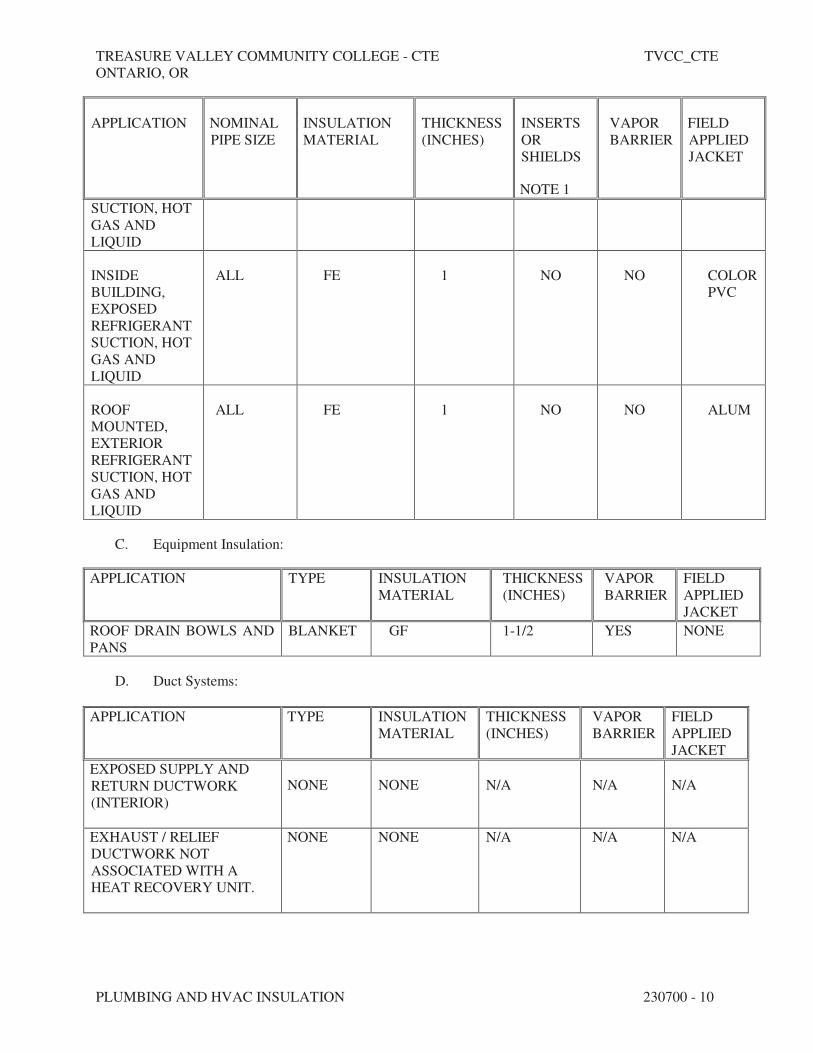
TREASURE VALLEY COMMUNITY COLLEGE - CTE TVCC_CTE
ONTARIO, OR
PLUMBING AND HVAC INSULATION 230700 - 10
APPLICATION NOMINAL
PIPE SIZE
INSULATION
MATERIAL
THICKNESS
(INCHES)
INSERTS
OR
SHIELDS
NOTE 1
VAPOR
BARRIER
FIELD
APPLIED
JACKET
SUCTION, HOT
GAS AND
LIQUID
INSIDE
BUILDING,
EXPOSED
REFRIGERANT
SUCTION, HOT
GAS AND
LIQUID
ALL FE 1 NO NO COLOR
PVC
ROOF
MOUNTED,
EXTERIOR
REFRIGERANT
SUCTION, HOT
GAS AND
LIQUID
ALL FE 1 NO NO ALUM
C. Equipment Insulation:
APPLICATION TYPE INSULATION
MATERIAL
THICKNESS
(INCHES)
VAPOR
BARRIER
FIELD
APPLIED
JACKET
ROOF DRAIN BOWLS AND
PANS
BLANKET GF 1-1/2 YES NONE
D. Duct Systems:
APPLICATION TYPE INSULATION
MATERIAL
THICKNESS
(INCHES)
VAPOR
BARRIER
FIELD
APPLIED
JACKET
EXPOSED SUPPLY AND
RETURN DUCTWORK
(INTERIOR)
NONE NONE N/A N/A N/A
EXHAUST / RELIEF
DUCTWORK NOT
ASSOCIATED WITH A
HEAT RECOVERY UNIT.
NONE NONE N/A N/A N/A

TREASURE VALLEY COMMUNITY COLLEGE - CTE TVCC_CTE
ONTARIO, OR
PLUMBING AND HVAC INSULATION 230700 - 11
CONCEALED SUPPLY AND
RETURN (INTERIOR)
BLANKET GF R-6 YES NONE
ALL DUCTWORK
UPSTREAM AND
DOWNSTREAM OF A
HEAT RECOVERY UNIT
(INTERIOR)
BLANKET GF R-6 YES NONE
SUPPLY AND RETURN
(EXTERIOR)
BOARD GF R-8 YES SAJ
RANGE HOOD EXHAUST
SEE FIRE PROTECTION PRODUCT DESCRIPTION
END OF SECTION 230700

TREASURE VALLEY COMMUNITY COLLEGE - CTE TVCC_CTE
ONTARIO, OR
PLUMBING AND HVAC INSULATION 230700 - 12
THIS PAGE INTENTIONALLY LEFT BLANK

TREASURE VALLEY COMMUNITY COLLEGE - CTE TVCC_CTE
ONTARIO, OR
COMMISSIONING OF HVAC 230800 - 1
SECTION 230800 - COMMISSIONING OF HVAC
PART 1 - GENERAL
1.1 SUMMARY
A. Section includes commissioning process requirements for HVAC&R systems, assemblies, and
equipment.
B. Commissioning process shall be executed in accordance with the requirements of Section C408
of the 2012 International Energy Conservation Code (IECC). Nothing in this Specification shall
be construed as allowing a commissioning process that does not comply with the IECC
requirements.
C. Related Sections:
1. Section 230593 "Testing, Adjusting and Balancing for HVAC."
D. This Section includes work to be performed by the CxA, the Mechanical Contractor, and others.
The Mechanical Contractor and their subcontractors and suppliers must coordinate all work
with CxA as required.
1.2 DEFINITIONS
A. Commissioning Plan: A document that outlines the organization, schedule, allocation of
resources, and documentation requirements of the commissioning process.
B. CxA: Commissioning Authority.
C. HVAC&R: Heating, Ventilating, Air Conditioning, and Refrigeration.
D. Systems, Subsystems, Equipment, and Components: Where these terms are used together or
separately, they shall mean "as-built" systems, subsystems, equipment, and components.
E. IECC: The 2015 International Energy Conservation Code.
1.3 CONTRACTOR'S RESPONSIBILITIES
A. Perform commissioning tests at the direction of the CxA.
B. Attend construction phase controls coordination meeting.
C. Attend testing, adjusting, and balancing review and coordination meeting.
D. Participate in HVAC&R system, assemblies, equipment, and component maintenance
orientation and inspection as directed by the CxA.

TREASURE VALLEY COMMUNITY COLLEGE - CTE TVCC_CTE
ONTARIO, OR
COMMISSIONING OF HVAC 230800 - 2
E. Provide information requested by the CxA for commissioning documentation. Information to be
provided includes but is not limited to:
1. Plan for delivery and review of submittals, systems manuals, and other documents and
reports.
2. Identification of installed systems, assemblies, equipment, and components including
design changes that occurred during the construction phase.
3. Process and schedule for completing construction checklists and manufacturer's prestart
and startup checklists for HVAC&R systems, assemblies, equipment, and components to
be verified and tested.
4. Certificate of completion certifying that installation, prestart checks, and startup
procedures have been completed.
5. Certificate of readiness certifying that HVAC&R systems, subsystems, equipment, and
associated controls are ready for testing.
6. Test and inspection reports and certificates.
7. Corrective action documents.
8. Verification of testing, adjusting, and balancing reports.
F. Provide measuring instruments and logging devices to record test data, and provide data
acquisition equipment to record data for the complete range of testing for the required test
period. Install devices as requested by CxA.
1.4 CxA'S RESPONSIBILITIES
A. Prepare the commissioning plan, preliminary commissioning report, and final commissioning
report.
B. Provide Project-specific construction checklists and commissioning process test procedures for
actual HVAC&R systems, assemblies, equipment, and components to be furnished and installed
as part of the construction contract.
C. Direct commissioning testing.
D. Verify testing, adjusting, and balancing of Work are complete.
E. Provide test data, inspection reports, and certificates in Systems Manual.
1.5 COMMISSIONING PLAN
A. The CxA shall prepare a commissioning plan in accordance with the requirements of IECC
Section C408.2.1.
1. Submit a copy of the plan at least one week prior to the intended start date of
commissioning tests and procedures.
B. The Commissioning plan shall include, at a minimum
1. A narrative description of the activities that will be accomplished during each phase of
commissioning, including the personnel intended to accomplish each of the activities.

TREASURE VALLEY COMMUNITY COLLEGE - CTE TVCC_CTE
ONTARIO, OR
COMMISSIONING OF HVAC 230800 - 3
2. A listing of the specific equipment, appliances or systems to be tested and a description
of the tests to be performed.
3. Functions to be tested, including but not limited to calibrations and economizer controls.
4. Conditions under which the test will be performed. At a minimum, testing shall affirm
winter and summer design conditions and full outside air conditions.
5. Measurable criteria for performance.
1.6 PRELIMINARY COMMISSIONING REPORT
A. The CxA shall prepare a Preliminary Commissioning Report in accordance with the
requirements of IECC Section C408.2.4. At a minimum, the report shall identify:
1. Itemization of deficiencies found during testing that have not been corrected at the time
of report preparation
2. Deferred tests that cannot be performed at the time of report preparation because of
climatic conditions.
3. Climatic conditions required for performance of the deferred test.
1.7 FINAL COMMISSIONING REPORT
A. The CxA shall prepare a Final Commissioning Report in accordance with the requirements of
IECC Section C408.2.5.4. At a minimum the report shall include:
1. Results of functional performance tests.
2. Disposition of deficiencies found during testing including details of corrective measures
used or proposed.
3. Functional performance test procedures used during the commissioning process including
measurable criteria for test acceptance.
4. Description of any tests that were deferred to a later time due to climatic conditions.
1.8 SUBMITTALS
A. Certificates of readiness.
B. Certificates of completion of installation, prestart, and startup activities.
C. Commissioning Plan.
D. Preliminary Commissioning Report.
E. Final Commissioning Report.

TREASURE VALLEY COMMUNITY COLLEGE - CTE TVCC_CTE
ONTARIO, OR
COMMISSIONING OF HVAC 230800 - 4
PART 2 - PRODUCTS (Not Used)
PART 3 - EXECUTION
3.1 TESTING PREPARATION
A. Certify that HVAC&R systems, subsystems, and equipment have been installed, calibrated, and
started and are operating according to the Contract Documents.
B. Certify that HVAC&R instrumentation and control systems have been completed and
calibrated, that they are operating according to the Contract Documents, and that pretest set
points have been recorded.
C. Certify that testing, adjusting, and balancing procedures have been completed and that testing,
adjusting, and balancing reports have been submitted, discrepancies corrected, and corrective
work approved.
D. Set systems, subsystems, and equipment into operating mode to be tested (e.g., normal
shutdown, normal auto position, normal manual position, unoccupied cycle, emergency power,
and alarm conditions).
E. Inspect and verify the position of each device and interlock identified on checklists.
F. Check safety cutouts, alarms, and interlocks.
G. Testing Instrumentation: Contractor shall install measuring instruments and logging devices to
record test data as directed by the CxA.
3.2 TESTING AND BALANCING VERIFICATION
A. Prior to performance of testing and balancing Work, provide copies of reports, sample forms,
checklists, and certificates to the CxA.
B. Notify the CxA at least 7 days in advance of testing and balancing Work, and provide access for
the CxA to witness testing and balancing Work.
C. Provide technicians, instrumentation, and tools to verify testing and balancing of HVAC&R
systems at the direction of the CxA.
1. The CxA will notify testing and balancing Contractor 7 days in advance of the date of
field verification. Notice will not include data points to be verified.
2. The testing and balancing Contractor shall use the same instruments (by model and serial
number) that were used when original data were collected.
3. Failure of an item includes, other than sound, a deviation of more than 10 percent.
Failure of more than 10 percent of selected items shall result in rejection of final testing,
adjusting, and balancing report. Variations in background noise must be considered.
4. Remedy the deficiency and notify the CxA so verification of failed portions can be
performed.

TREASURE VALLEY COMMUNITY COLLEGE - CTE TVCC_CTE
ONTARIO, OR
COMMISSIONING OF HVAC 230800 - 5
3.3 GENERAL TESTING REQUIREMENTS
A. Provide technicians, instrumentation, and tools to perform commissioning test at the direction of
the CxA.
B. Scope of HVAC&R testing shall include entire HVAC&R installation, from central equipment
for heat generation and refrigeration through distribution systems to each conditioned space.
Testing shall include measuring capacities and effectiveness of operational and control
functions.
C. Test all operating modes, interlocks, control responses, and responses to abnormal or
emergency conditions, and verify proper response of building automation system controllers
and sensors.
D. The CxA, with input from the Mechanical Contractor, testing and balancing Contractor, and
Temperature Controls Contractor, shall prepare detailed testing plans, procedures, and
checklists for HVAC&R systems, subsystems, and equipment.
E. Tests will be performed using design conditions whenever possible.
F. Simulated conditions may need to be imposed using an artificial load when it is not practical to
test under design conditions. Before simulating conditions, calibrate testing instruments.
Provide equipment to simulate loads. Set simulated conditions as directed by the CxA and
document simulated conditions and methods of simulation. After tests, return settings to normal
operating conditions.
G. The CxA may direct that set points be altered when simulating conditions is not practical.
H. The CxA may direct that sensor values be altered with a signal generator when design or
simulating conditions and altering set points are not practical.
I. If tests cannot be completed because of a deficiency outside the scope of the HVAC&R system,
document the deficiency and report it to the Engineer. After deficiencies are resolved,
reschedule tests.
J. If the testing plan indicates specific seasonal testing, complete appropriate initial performance
tests and documentation and schedule seasonal tests.
3.4 HVAC&R SYSTEMS, SUBSYSTEMS, AND EQUIPMENT TESTING PROCEDURES
A. Instrumentation and Control System Testing: Contractor shall assist the CxA with preparation
of testing plans to ensure that equipment is operating per the
B. Pipe system cleaning, flushing, hydrostatic tests, and chemical treatment requirements are
specified in Division 23 piping Sections. Mechanical Contractor shall prepare a pipe system
cleaning, flushing, and hydrostatic testing plan. Provide cleaning, flushing, testing, and treating
plan and final reports to the CxA. Plan shall include the following:
1. Sequence of testing and testing procedures for each section of pipe to be tested, identified
by pipe zone or sector identification marker. Markers shall be keyed to Drawings for

TREASURE VALLEY COMMUNITY COLLEGE - CTE TVCC_CTE
ONTARIO, OR
COMMISSIONING OF HVAC 230800 - 6
each pipe sector, showing the physical location of each designated pipe test section.
Drawings keyed to pipe zones or sectors shall be formatted to allow each section of
piping to be physically located and identified when referred to in pipe system cleaning,
flushing, hydrostatic testing, and chemical treatment plan.
2. Description of equipment for flushing operations.
3. Minimum flushing water velocity.
4. Tracking checklist for managing and ensuring that all pipe sections have been cleaned,
flushed, hydrostatically tested, and chemically treated.
C. HVAC&R System Testing: Provide technicians, instrumentation, tools, and equipment to test
performance of HVAC&R systems. The CxA shall determine the sequence of testing and
testing procedures for each equipment item and pipe section to be tested.
D. Vibration and Sound Tests: Provide technicians, instrumentation, tools, and equipment to test
performance of vibration isolation and seismic controls.
END OF SECTION 230800

TREASURE VALLEY COMMUNITY COLLEGE - CTE TVCC_CTE
ONTARIO, OR
INSTRUMENTATION AND CONTROL FOR HVAC 230900 - 1
SECTION 230900 - INSTRUMENTATION AND CONTROL FOR HVAC
PART 1 - GENERAL
1.1 RELATED DOCUMENTS
A. Drawings and general provisions of the Contract, including General and Supplementary
Conditions and Division 01 Specifications Sections, apply to this Section.
B. All work of this Division shall be coordinated and provided by the single Temperature Control
(TC) Contractor.
1.2 SUMMARY
A. This Section includes control equipment for the HVAC systems and components, including
control components for equipment that is not supplied with factory-wired controls.
B. All work of this Division shall be coordinated and provided by the single Temperature Control
(TC) Contractor.
1.3 CONTROL SYSTEM DESCRIPTION
A. All points of user interface shall be on standard PCs that do not require the purchase of any
special software from the manufacturer for use as a building operations terminal. The primary
point of interface on these PC's will be a standard Web Browser.
B. The TC Contractor work shall consist of the provision of all labor, materials, tools, equipment,
software, software licenses, software configurations and database entries, interfaces, wiring,
tubing, installation, labeling, engineering, calibration, documentation, samples, submittals,
testing, commissioning, training services, permits and licenses, transportation, shipping,
handling, administration, supervision, management, insurance, temporary protection, cleaning,
cutting and patching, warranties, services, and items, even though these may not be specifically
mentioned in these Division documents which are required for the complete, fully functional
and commissioned BAS.
1.4 SUBMITTALS
A. Shop Drawings, Product Data, and Samples:
1. At a minimum, submit the following:
a. BAS network architecture diagrams including all nodes and interconnections.
b. Systems schematics, sequences and flow diagrams.
c. Points schedule for each point in the BAS, including: Point Type, Object Name,
Expanded ID, Display Units, Controller type, and Address.
TREASURE VALLEY COMMUNITY COLLEGE - CTE TVCC_CTE
ONTARIO, OR
INSTRUMENTATION AND CONTROL FOR HVAC 230900 - 2
d. Samples of Graphic Display screen types and associated menus.
e. Detailed Bill of Material list for each system or application, identifying quantities,
part numbers, descriptions, and optional features.
f. Control Damper Schedule including a separate line for each damper provided
under this section and a column for each of the damper attributes, including: Code
Number, Fail Position, Damper Type, Damper Operator, Duct Size, Damper Size,
Mounting, and Actuator Type.
g. Details of all BAS interfaces and connections to the work of other trades.
h. Product data sheets or marked catalog pages including part number, photo and
description for all products including software.
1.5 RECORD DOCUMENTATION
A. Operation and Maintenance Manuals:
1. Three (3) digital copies of the Operation and Maintenance Manuals shall be provided to
the Owner's Representative upon completion of the project. The entire Operation and
Maintenance Manual shall be furnished on flash drive media, and include the following
for the BAS provided:
a. Table of contents.
b. As-built system record drawings. Computer Aided Drawings (CAD) record
drawings shall represent the as-built condition of the system and incorporate all
information supplied with the approved submittal.
c. Manufacturer's product data sheets or catalog pages for all products including
software.
d. System Operator's manuals.
e. Archive copy of all site-specific databases and sequences.
f. BAS network diagrams.
g. Interfaces to all third-party products and work by other trades.
h. The Operation and Maintenance Manual CD shall be self-contained, and include
all necessary software required to access the product data sheets. A logically
organized table of contents shall provide dynamic links to view and print all
product data sheets. Viewer software shall provide the ability to display, zoom,
and search all documents.
PART 2 - PRODUCTS
2.1 FACILITY MANAGEMENT SYSTEM (FMS) GENERAL
A. The FMS shall use an open architecture and fully support a multi-vendor environment. To
accomplish this effectively, all Network Controllers shall support open communication protocol
standards and integrate a wide variety of third-party devices and applications. The system shall
be designed for use on the Internet, or intranets using off the shelf, industry standard
technology compatible with other owner provided networks.
B. The FMS shall consist of the following:
TREASURE VALLEY COMMUNITY COLLEGE - CTE TVCC_CTE
ONTARIO, OR
INSTRUMENTATION AND CONTROL FOR HVAC 230900 - 3
1. Standalone Network Controller(s).
2. Custom Application Controller(s).
3. Input/Output Module(s).
4. Local Display Device(s).
5. Distributed User Interface(s).
6. Network processing, data storage and communications equipment.
7. Other components required for a complete and working FMS.
C. The system shall be modular in nature, and shall permit expansion of both capacity and
functionality through the addition of sensors, actuators, controllers and operator devices.
D. System architectural design shall eliminate dependence upon any single device for alarm
reporting and control execution. The failure of any single component or network connection
shall not interrupt the execution of control strategies at other operational devices.
2.2 FACILITY MANAGEMENT SYSTEM ARCHITECTURE
A. Automation Network:
1. The automation network shall be based on a PC industry standard of Ethernet TCP/IP.
Where used, LAN controller cards shall be standard "off the shelf" products available
through normal PC vendor channels.
2. The FMS shall network multiple user interface clients, automation engines, system
controllers and application-specific controllers. Provide application and data server(s) as
required for systems operation.
3. The automation network shall be capable of operating at a communication speed of 100
Mbps, with full peer-to-peer network communication.
4. Network Controllers shall reside on the automation network.
5. The automation network will be compatible with other enterprise-wide networks. Where
indicated, the automation network shall be connected to the enterprise network and share
resources with it by way of standard networking devices and practices.
6. Java-based systems are not acceptable.
B. Control Network:
1. Network Controllers shall provide supervisory control over the control network and shall
support the following communication protocol:
a. BACnet Standard MS/TP Bus Protocol ASHRAE SSPC-135, Clause 9.
2. Control networks shall provide either "Peer-to-Peer," Master-Slave, or Supervised Token
Passing communications, and shall operate at a minimum communication speed of 9600
baud.
3. DDC Controllers shall reside on the control network.
4. Control network communication protocol shall be BACnet Standard MS/TP Bus
Protocol ASHRAE SSPC-135.
5. A BACnet Protocol Implementation Conformance Statement shall be provided for each
controller device (master or slave) that will communicate on the BACnet MS/TP Bus.

TREASURE VALLEY COMMUNITY COLLEGE - CTE TVCC_CTE
ONTARIO, OR
INSTRUMENTATION AND CONTROL FOR HVAC 230900 - 4
C. Integration:
1. Hardwired:
a. Analog and digital signal values shall be passed from one system to another via
hardwired connections.
b. There will be one separate physical point on each system for each point to be
integrated between the systems.
2. Direct Protocol (Integrator Panel):
a. The FMS shall include appropriate hardware equipment and software to allow bi-
directional data communications between the FMS and 3rd party manufacturers'
control panels. The FMS shall receive, react to, and return information from
multiple building systems, including but not limited to the chillers, boilers,
variable frequency drives, power monitoring system, and medical gas.
b. All data required by the application shall be mapped into the Network Controller
database, and shall be transparent to the operator.
c. Point inputs and outputs from the third-party controllers shall have real-time
interoperability with FMS software features such as: Control Software, Energy
Management, Custom Process Programming, Alarm Management, Historical Data
and Trend Analysis, Totalization, and Local Area Network Communications.
3. BACnet Protocol Integration - BACnet:
a. The neutral protocol used between systems will be BACnet over Ethernet and
comply with the ASHRAE BACnet standard 135-2003.
b. A complete Protocol Implementation Conformance Statement (PICS) shall be
provided for all BACnet system devices.
c. The ability to command, share point object data, change of state (COS) data and
schedules between the host and BACnet systems shall be provided.
2.3 USER INTERFACE
A. Dedicated Web Based User Interface: Utilize a standard PC web browser.
B. Distributed Web Based User Interface:
1. All features and functions of the dedicated user interface previously defined in this
document shall be available on any computer connected directly or via a wide area or
virtual private network (WAN/VPN) to the automation network and conforming to the
following specifications.
2. The software shall run on the Microsoft Internet Explorer (11.0 or higher) browser.
3. Java-based systems will not be allowed.
C. User Interface Application Components:
1. The operation of the control system shall be independent of the user interface, which
shall be used for operator communications only. Systems that rely on an operator

TREASURE VALLEY COMMUNITY COLLEGE - CTE TVCC_CTE
ONTARIO, OR
INSTRUMENTATION AND CONTROL FOR HVAC 230900 - 5
workstation to provide supervisory control over controller execution of the sequences of
operations or system communications shall not be acceptable.
2. Alarms:
a. Alarms shall be routed directly from Network Controllers to PCs and servers. It
shall be possible for specific alarms from specific points to be routed to specific
PCs and servers. The alarm management portion of the user interface shall, at the
minimum, provide the following functions:
1) Log date and time of alarm occurrence.
2) Generate a "Pop-Up" window, with audible alarm, informing a user that an
alarm has been received.
3) Allow a user, with the appropriate security level, to acknowledge,
temporarily silence, or discard an alarm.
4) Provide an audit trail on hard drive for alarms by recording user
acknowledgment, deletion, or disabling of an alarm. The audit trail shall
include the name of the user, the alarm, the action taken on the alarm, and a
time/date stamp.
5) Provide the ability to send alarms requiring acknowledgment at the user
interface, and / or direct alarms to an e-mail address and/or text messaging.
6) Any attribute of any object in the system may be designated to report an
alarm.
3. Schedules:
a. A graphical display for time-of-day scheduling and override scheduling of
building operations shall be provided. At a minimum, the following functions shall
be provided:
1) Weekly Schedules.
2) Exception Schedules.
3) Monthly Calendars.
b. Weekly schedules shall be provided for each group of equipment with a specific
time use schedule.
c. It shall be possible to define one or more exception schedules for each schedule
including references to calendars.
d. Monthly calendars shall be provided that allow for simplified scheduling of
holidays and special days for a minimum of five years in advance. Holidays and
special days shall be user-selected with the pointing device or keyboard, and shall
automatically reschedule equipment operation as previously defined on the
exception schedules.
4. Password:
a. Multiple-level password access protection shall be provided to allow the
user/manager to user interface control, display, and database manipulation
capabilities deemed appropriate for each user, based on an assigned password.
b. Each user shall have the following: a user name, a password, and access levels.

TREASURE VALLEY COMMUNITY COLLEGE - CTE TVCC_CTE
ONTARIO, OR
INSTRUMENTATION AND CONTROL FOR HVAC 230900 - 6
5. Dynamic Color Graphics:
a. The graphics application program shall be supplied as an integral part of the User
Interface. Browser or Workstation applications that rely only upon HTML pages
shall not be acceptable.
b. The graphics applications shall include a create/edit function and a runtime
function. The system architecture shall support an unlimited number of graphics
documents (graphic definition files) to be generated and executed.
c. The graphics shall be able to display and provide animation based on real-time
data that is acquired, derived, or entered.
d. Graphics Runtime Functions: A maximum of 16 graphic applications shall be able
to execute at any one time on a user interface or workstation with 4 visible to the
user. Each graphic application shall be capable of the following functions:
1) All graphics shall be fully scalable.
2) The graphics shall support a maintained aspect ratio.
3) Multiple fonts shall be supported.
4) Unique background shall be assignable on a per graphic basis.
5) The color of all animations and values on displays shall indicate if the status
of the object attribute.
e. Operation from Graphics: It shall be possible to change values (setpoints) and
states in system controlled equipment by using drop-down windows accessible via
the pointing device.
f. Graphic Editing Tool: A graphic editing tool shall be provided that allows for the
creation and editing of graphic files. The graphic editor shall be capable of
performing/defining all animations, and defining all runtime binding.
1) The graphic editing tool shall in general provide for the creation and
positioning of point objects by dragging from tool bars or drop-downs and
positioning where required.
2) In addition, the graphic editing tool shall be able to add additional content
to any graphic by importing backgrounds in the SVG, BMP or JPG file
formats.
g. Historical trending and data collection.
h. Each Automation Engine shall store trend and point history data for all analog and
digital inputs and outputs, as follows:
1) Any point, physical or calculated, may be designated for trending.
2) Each Automation Engine shall have the capability to store multiple samples
for each physical point and software variable based upon available memory,
including an individual sample time/date stamp. Points may be assigned to
multiple history trends with different collection parameters.
6. Trend Data Viewing and Analysis:
a. Provide a trend viewing utility that shall have access to all database points.
b. It shall be possible to retrieve any historical database point for use in displays and
reports by specifying the point name and associated trend name.

TREASURE VALLEY COMMUNITY COLLEGE - CTE TVCC_CTE
ONTARIO, OR
INSTRUMENTATION AND CONTROL FOR HVAC 230900 - 7
c. The trend viewing utility shall have the capability to define trend study displays to
include multiple trends.
d. Displays shall be able to be single or stacked graphs with on-line selectable
display characteristics, such as ranging, color, and plot style.
e. Display magnitude and units shall both be selectable by the operator at any time
without reconfiguring the processing or collection of data. This is a zoom
capability.
f. Display magnitude shall automatically be scaled to show full graphic resolution of
the data being displayed.
g. Trend studies shall be capable of calculating and displaying calculated variables
including highest value, lowest value and time based accumulation.
2.4 NETWORK CONTROLLERS (NWC)
A. Network Controllers:
1. The Network Controller (NWC) shall be a fully user-programmable, supervisory
controller. The NWC shall monitor the network of distributed application-specific
controllers, provide global strategy and direction, and communicate on a peer-to-peer
basis with other Network Controllers.
2. Automation Network: The NWC shall reside on the automation network and shall
support a subnet of system controllers.
3. User Interface: Each NWC shall have the ability to deliver a web based User Interface
(UI) as previously described. All computers connected physically or virtually to the
automation network shall have access to the web based UI.
a. The web based UI software shall be imbedded in the NWC or Web Server.
Systems that require a local copy of the system database on the user's personal
computer are not acceptable.
b. The NWC shall support a minimum of two concurrent users.
c. The web based user shall have the capability to access all system data through the
workstation.
d. Remote users connected to the network through an Internet Service Provider (ISP)
shall also have limited or total system access based on the password matrix.
e. The NWC shall have the capability of generating web based UI graphics.
f. Systems that support UI Graphics from a central database or require the graphics
to reside on the user's personal computer are not acceptable.
g. Systems that require workstation software or modified web browsers are not
acceptable.
4. Processor: The NWC shall be microprocessor-based with a minimum word size of 32
bits. The NWC shall be a multi-tasking, multi-user, and real-time digital control
processor. Standard operating systems shall be employed. NWC size and capability shall
be sufficient to fully meet the requirements of this Specification.
5. Memory: Each NWC shall have sufficient memory to support its own operating system,
databases, and control programs, and to provide supervisory control for all control level
devices.
6. Hardware Real Time Clock: The NWC shall include an integrated, hardware-based,
real-time clock.
TREASURE VALLEY COMMUNITY COLLEGE - CTE TVCC_CTE
ONTARIO, OR
INSTRUMENTATION AND CONTROL FOR HVAC 230900 - 8
7. Communications Ports: The NWC shall provide LON or BACnet communication ports
and ports for operation of operator Input/Output (I/O) devices, such as industry-standard
computers, modems, and portable operator's terminals.
8. Diagnostics: The NWC shall continuously perform self-diagnostics, communication
diagnosis, and diagnosis of all panel components. The Network Controller shall provide
both local and remote annunciation of any detected component failures, low battery
conditions, or repeated failures to establish communication.
9. Power Failure: In the event of the loss of normal power, the NWC shall continue to
operate for a user adjustable period of up to 10 minutes after which there shall be an
orderly shutdown of all programs to prevent the loss of database or operating system
software.
a. During a loss of normal power, the control sequences shall go to the normal
system shutdown conditions. All critical configuration data shall be saved into
Flash memory.
b. Upon restoration of normal power and after a minimum off-time delay, the
controller shall automatically resume full operation without manual intervention
through a normal soft-start sequence.
10. Certification: The NWC shall be listed by Underwriters Laboratories (UL).
11. Controller Network: The NWC shall support the following communication protocols on
the controller network:
a. The NWC shall support BACnet Standard MS/TP Bus Protocol ASHRAE SSPC-
135, Clause 9 on the controller network.
1) A BACnet Protocol Implementation Conformance Statement shall be
provided for each controller device (master or slave) that will communicate
on the BACnet MS/TP Bus.
2) The Conformance Statements shall be submitted 10 day prior to bidding.
3) The NWC shall support a minimum of 100 control devices.
2.5 DDC SYSTEM CONTROLLERS
A. Custom Application Controllers (CAC):
1. The Custom Application Controller (CAC) shall be a fully user-programmable, digital
controller that communicates via BACnet MS/TP protocol.
2. Controllers shall be factory programmed with a continuous adaptive tuning algorithm
that senses changes in the physical environment and continually adjusts loop tuning
parameters appropriately.
3. The CAC shall accommodate the direct wiring of analog and binary I/O field points.
4. The CAC shall support the following types of inputs and outputs:
a. Universal Inputs shall be configured to monitor any of the following:
1) Analog Input, Voltage Mode.
2) Analog Input, Current Mode.
3) Analog Input, Resistive Mode.
TREASURE VALLEY COMMUNITY COLLEGE - CTE TVCC_CTE
ONTARIO, OR
INSTRUMENTATION AND CONTROL FOR HVAC 230900 - 9
4) Binary Input, Dry Contact Maintained Mode.
5) Binary Input, Pulse Counter Mode.
b. Binary Inputs shall be configured to monitor either of the following:
1) Dry Contact Maintained Mode.
2) Pulse Counter Mode.
c. Analog Outputs shall be configured to output either of the following:
1) Analog Output, Voltage Mode.
2) Analog Output, Current Mode.
d. Binary Outputs shall output the following:
1) 24 VAC Triac.
e. Configurable Outputs shall be capable of the following:
1) Analog Output, Voltage Mode.
2) Binary Output Mode.
5. The CAC shall have the capability to execute complex control sequences involving
direct wired I/O points as well as input and output devices communicating over the field
bus.
6. The CAC shall support, but not be limited to, the following:
a. Hot water, chilled water/central plant applications.
b. Built-up air handling units for special applications.
c. Terminal units.
d. Special programs as required for systems control.
B. Third Party BACnet Monitoring:
1. All controls interface critical to the operation of equipment shall be hard-wired to the DDC
system. Including but not limited to HVAC equipment, chillers, boilers, variable frequency
drives, power monitoring systems, and medical gas systems.
2. Upon a loss of network communications, the equipment shall continue to operate in a stand-
alone mode.
3. When 3rd party BACnet communication is required, a BACnet connection shall be used to
acquire additional operational and monitoring parameters not critical to the control of the
equipment. BACnet IP communication is preferred. If serial communications are used, a
serial-to-Ethernet converter will be required. If Modbus communications are used, a
Modbus-to-BACnet converter will be required.
2.6 FIELD DEVICES
A. Networked Thermostats:

TREASURE VALLEY COMMUNITY COLLEGE - CTE TVCC_CTE
ONTARIO, OR
INSTRUMENTATION AND CONTROL FOR HVAC 230900 - 10
1. The Networked Thermostats shall be capable of controlling the following:
a. Rooftop units - see sequence of operations on drawings.
b. Cabinet heaters or unit heaters.
c. Finned-tube radiation.
2. The Networked Thermostat shall communicate over the Field Controller Bus.
a. The Networked Thermostat shall support remote read/write and parameter
adjustment from the web based User Interfaceable through a Network Controller.
3. The Networked Thermostat shall include an intuitive User Interface providing plain text
messages with backlit display.
4. The Networked Thermostats shall provide the flexibility to support the following inputs:
a. Integral Indoor Air Temperature Sensor.
b. Duct Mount Air Temperature Sensor.
c. Remote Indoor Air Temperature Sensor with Occupancy Override and LED
Indicator.
d. Two configurable binary inputs.
5. The Networked Thermostats shall provide the flexibility to support the following
outputs:
a. Three Speed Fan Control.
b. On/Off Control.
c. Floating Control.
d. Proportional (0 to 10V) Control.
6. The Networked Thermostat shall provide the flexibility to adjust the following
parameters:
a. Adjustable Temporary Occupancy from 0 to 24 hours.
b. Adjustable heating/cooling deadband from 2 deg F to 5 deg F.
c. Adjustable heating/cooling cycles per hour from 4 to 8.
7. The Networked Thermostat shall employ nonvolatile electrically erasable programmable
read-only memory (EEPROM) for all adjustable parameters.
B. Network Sensors (NS):
1. The Network Sensors (NS) shall have the ability to monitor the following variables as
required by the systems sequence of operations:
a. Zone temperature.
b. Zone setpoint.
2. The NS shall transmit the zone information back to the controller on the Sensor-Actuator
Bus (SA Bus) using BACnet Standard protocol SSPC-135, Clause 9 or Lon Bus.
3. The Network Sensors shall include the following items:

TREASURE VALLEY COMMUNITY COLLEGE - CTE TVCC_CTE
ONTARIO, OR
INSTRUMENTATION AND CONTROL FOR HVAC 230900 - 11
a. A backlit Liquid Crystal Display (LCD) to indicate the Temperature, Humidity
and Setpoint.
b. An LED to indicate the status of the override feature.
c. A button to initiate a timed override command.
4. The NS shall have a phone jack connection.
2.7 INPUT DEVICES
A. General Requirements:
1. Installation, testing, and calibration of all sensors, transmitters, and other input devices
shall be provided to meet the system requirements.
B. Temperature Sensors:
1. General Requirements:
a. Sensors and transmitters shall be provided, as outlined in the input/output
summary and sequence of operations.
b. The temperature sensor shall be of the resistance type RTDs or Thermistors.
c. The following point types (and the accuracy of each) are required, and their
associated accuracy values include errors associated with the sensor, lead wire,
and A to D conversion:
Point Type Accuracy
Room Temp + .5 deg F.
Duct Temperature + .5 deg F.
All Others + .75 deg F.
2. Vandal Proof Room Temperature Sensors:
a. Room sensors shall be constructed for wall box mounting.
3. Standard Room Temperature Sensors with Integral Display:
a. Room sensors shall be constructed for either surface or wall box mounting.
b. Room sensors shall have an integral LCD display and keypad with the following
capabilities:
1) Display room temperatures.
2) Display and adjust room comfort setpoint.
3) Timed override request push button with LED status for activation of after-
hours operation.
4. Outside Air Sensors:

TREASURE VALLEY COMMUNITY COLLEGE - CTE TVCC_CTE
ONTARIO, OR
INSTRUMENTATION AND CONTROL FOR HVAC 230900 - 12
a. Outside air sensors shall be designed to withstand the environmental conditions to
which they will be exposed. They shall also be provided with a solar shield.
b. Sensors exposed to wind velocity pressures shall be shielded by a perforated plate
that surrounds the sensor element.
c. Temperature transmitters shall be of NEMA 3R construction and rated for ambient
temperatures.
5. Duct Mount Sensors:
a. Duct mount sensors shall mount in an electrical box through a hole in the duct,
and be positioned so as to be easily accessible for repair or replacement.
b. Duct sensors shall be insertion type and constructed as a complete assembly,
including lock nut and mounting plate.
c. For outdoor air duct applications, a weatherproof mounting box with weatherproof
cover and gasket shall be used.
6. Averaging Sensors:
a. For ductwork greater in any dimension than 48 inches and/or where air
temperature stratification exists, an averaging sensor with multiple sensing points
shall be used.
b. For plenum applications, such as mixed air temperature measurements, a string of
sensors mounted across the plenum shall be used to account for stratification
and/or air turbulence. The averaging string shall have a minimum of 4 sensing
points per 12-foot long segment.
c. Capillary supports at the sides of the duct shall be provided to support the sensing
string.
C. Differential Pressure Transmitters:
1. General Air and Water Pressure Transmitter Requirements:
a. Pressure transmitters shall be constructed to withstand 100 percent pressure over-
range without damage, and to hold calibrated accuracy when subject to a
momentary 40 percent over-range input.
b. Pressure transmitters shall transmit a 0 to 5 VDC, 0 to 10 VDC, or 4 to 20 mA
output signal.
c. Differential pressure transmitters used for flow measurement shall be sized to the
flow sensing device, and shall be supplied with Tee fittings and shut-off valves in
the high and low sensing pick-up lines to allow the balancing Contractor and
Owner permanent, easy-to-use connection.
d. A minimum of a NEMA 1 housing shall be provided for the transmitter.
Transmitters shall be located in accessible local control panels.
D. Status and Safety Switches:
1. General Requirements:
a. Switches shall be provided to monitor equipment status, safety conditions, and
generate alarms at the FMS when a failure or abnormal condition occurs. Safety
TREASURE VALLEY COMMUNITY COLLEGE - CTE TVCC_CTE
ONTARIO, OR
INSTRUMENTATION AND CONTROL FOR HVAC 230900 - 13
switches shall be provided with two sets of contacts and shall be interlock wired to
shut down respective equipment.
2. Current Sensing Switches:
a. The current sensing switch shall be self-powered with solid-state circuitry and a
dry contact output. It shall consist of a current transformer, a solid state current
sensing circuit, adjustable trip point, solid state switch, SPDT relay, and an LED
indicating the on or off status. A conductor of the load shall be passed through the
window of the device. It shall accept over-current up to twice its trip point range.
b. Current sensing switches shall be used for run status for fans, pumps, and other
miscellaneous motor loads.
c. Current sensing switches shall be calibrated to show a positive run status only
when the motor is operating under load. A motor running with a broken belt or
coupling shall indicate a negative run status.
3. Low Temperature Limit Switches:
a. The low temperature limit switch shall be of the manual reset type with Double
Pole/Single Throw snap acting contacts rated for 16 amps at 120VAC.
b. The sensing element shall be a minimum of 15 feet in length and shall react to the
coldest 18-inch section. Element shall be mounted horizontally across duct in
accordance with manufacturers recommended installation procedures.
c. For large duct areas where the sensing element does not provide full coverage of
the air stream, additional switches shall be provided as required to provide full
protection of the air stream.
d. The low temperature limit switch shall be equal to Johnson Controls A70.
2.8 OUTPUT DEVICES
A. Actuators:
1. General Requirements:
a. Damper and valve actuators shall be electronic.
2. Electronic Damper Actuators:
a. Electronic damper actuators shall be direct shaft mount.
b. Modulating and two-position actuators shall be provided as required by the
sequence of operations. Damper sections shall be sized Based on actuator
manufacturer's recommendations for face velocity, differential pressure and
damper type. The actuator mounting arrangement and spring return feature shall
permit normally open or normally closed positions of the dampers, as required. All
actuators (except terminal units) shall be furnished with mechanical spring return
unless otherwise specified in the sequences of operations. All actuators shall have
external adjustable stops to limit the travel in either direction, and a gear release to
allow manual positioning.

TREASURE VALLEY COMMUNITY COLLEGE - CTE TVCC_CTE
ONTARIO, OR
INSTRUMENTATION AND CONTROL FOR HVAC 230900 - 14
c. Modulating actuators shall accept 24 VAC or VDC power supply, consume no
more than 15 VA, and be UL listed. The control signal shall be 2-10 VDC or 4-20
mA.
B. Control Dampers: Furnished by Sheet Metal Contractor.
1. The Sheet Metal Contractor shall furnish all automatic dampers. All automatic dampers
shall be sized for the application by the Contractor or as specifically indicated on the
Drawings.
2. All dampers used for throttling airflow shall be of the opposed blade type arranged for
normally open or normally closed operation, as required. The damper is to be sized so
that, when wide open, the pressure drop is a sufficient amount of its close-off pressure
drop to shift the characteristic curve to near linear.
3. All dampers used for two-position, open/close control shall be parallel blade type
arranged for normally open or closed operation, as required.
4. Damper frames and blades shall be constructed of either galvanized steel or aluminum.
Maximum blade length in any section shall be 60 inches. Damper blades shall be 16-
gauge minimum and shall not exceed eight (8) inches in width. Damper frames shall be
16-gauge minimum hat channel type with corner bracing. All damper bearings shall be
made of reinforced nylon, stainless steel or oil-impregnated bronze. Dampers shall be
tight closing, low leakage type, with synthetic elastomeric seals on the blade edges and
flexible stainless steel side seals. Dampers of 48 inch by 48 inch size shall not leak in
excess of 8.0 cfm per square foot when closed against 4 inch w.g. static pressure when
tested in accordance with AMCA Std. 500.
5. Airfoil blade dampers of double skin construction with linkage out of the air stream shall
be used whenever the damper face velocity exceeds 1500 FPM or system pressure
exceeds 2.5 inch w.g., but no more than 4000 FPM or 6 inch w.g.
6. One piece rolled blade dampers with exposed or concealed linkage may be used with
face velocities of 1500 FPM or below.
7. Multiple section dampers may be jack-shafted to allow mounting of piston pneumatic
actuators and direct connect electronic actuators. Each end of the jackshaft shall receive
at least one actuator to reduce jackshaft twist.
C. Control Relays:
1. Control Pilot Relays:
a. Control pilot relays shall be of a modular plug-in design with retaining springs or
clips.
b. Mounting Bases shall be snap-mount.
c. DPDT, 3 PDT, or 4 PDT relays shall be provided, as appropriate for application.
d. Contacts shall be rated for 10 amps at 120 VAC.
e. Relays shall have an integral indicator light and check button.
D. Electronic Signal Isolation Transducers:
1. A signal isolation transducer shall be provided whenever an analog output signal from
the FMS is to be connected to an external control system as an input (such as a chiller
control panel), or is to receive as an input signal from a remote system.
2. The signal isolation transducer shall provide ground plane isolation between systems.

TREASURE VALLEY COMMUNITY COLLEGE - CTE TVCC_CTE
ONTARIO, OR
INSTRUMENTATION AND CONTROL FOR HVAC 230900 - 15
3. Signals shall provide optical isolation between systems.
2.9 MISCELLANEOUS DEVICES
A. Local Control Panels:
1. All control panels shall be factory constructed, incorporating the Temperature Control
manufacturer's standard designs and layouts. All control panels shall be UL inspected
and listed as an assembly and carry a UL 508 label listing compliance. Control panels
shall be fully enclosed, with perforated sub-panel, hinged door, and slotted flush latch.
2. In general, the control panels shall consist of the DDC controller(s), display module as
specified and indicated on the plans, and I/O devices—such as relays, transducers, and so
forth that are not required to be located external to the control panel due to function.
Where specified the display module shall be flush mounted in the panel face unless
otherwise noted.
3. All I/O connections on the DDC controller shall be provide via removable or fixed screw
terminals.
4. Low and line voltage wiring shall be segregated. All provided terminal strips and wiring
shall be UL listed, 300-volt service and provide adequate clearance for field wiring.
5. All wiring shall be neatly installed in plastic trays or tie-wrapped.
6. A convenience 120 VAC duplex receptacle shall be provided in each enclosure, fused
on/off power switch, and required transformers.
B. Power Supplies:
1. DC power supplies shall be sized for the connected device load. Total rated load shall
not exceed 75 percent of the rated capacity of the power supply.
2. Input: 120 VAC +10 percent, 60Hz.
3. Output: 24 VDC.
4. Line Regulation: +0.05 percent for 10 percent line change.
5. Load Regulation: +0.05 percent for 50 percent load change.
6. Ripple and Noise: 1 mV rms, 5 mV peak to peak.
7. An appropriately sized fuse and fuse block shall be provided and located next to the
power supply.
8. A power disconnect switch shall be provided next to the power supply.
PART 3 - PERFORMANCE / EXECUTION
3.1 FMS SPECIFIC REQUIREMENTS
A. General: Install all control equipment including motorized dampers, valves and actuators
according to manufacturer's written installation instructions.
B. Programming: Implement all features of programs to specified requirements and as required to
satisfy the sequence of operation. Programming and adjustments required during the building
startup and warranty period shall be provided at no additional cost.
TREASURE VALLEY COMMUNITY COLLEGE - CTE TVCC_CTE
ONTARIO, OR
INSTRUMENTATION AND CONTROL FOR HVAC 230900 - 16
C. Graphic Displays:
1. Provide a color graphic system flow diagram display for each system with all points as
indicated on the point list. All terminal unit graphic displays shall be from a standard
design library. At a minimum provide graphics for the following:
a. Floor Plan views with all zones indicated. Provide colored shading to provide
indication of zone temperature difference from set point.
b. Air handler views showing all components of air handling system including
dampers, valves, fans, coils, filters and related building exhaust and/or relief
systems. The graphics shall include all points to related to each controlled device.
2. User shall access the various system schematics via a graphical penetration scheme
and/or menu selection.
D. Actuation/Control Type:
1. Actuator Application:
a. All damper and valve actuation shall be electric.
b. All modulating damper and valve actuators shall be - 0 10 vdc proportional.
3.2 WIRING INSTALLATION
A. FMS Wiring:
1. All conduit, wiring, accessories and wiring connections required for the installation of
the Facility Management System including power wiring for all controllers shall be
provided by the TC Contractor unless specifically shown on the Electrical Drawings
under Division 26 Electrical. All wiring shall comply with the requirements of
applicable portions of Division 26 and all local and national electric codes, unless
specified otherwise in this Section.
2. The sizing, type and provision of cable, conduit, cable trays, and raceways shall be the
design responsibility of the TC Contractor. If complications arise, however, due to the
incorrect selection of cable, cable trays, raceways and/or conduit by the TC Contractor,
the Contractor shall be responsible for all costs incurred in replacing the selected
components.
3. Class 2 Wiring:
a. All Class 2 (24 VAC or less) wiring shall be installed in conduit unless otherwise
specified.
b. Conduit is not required for Class 2 wiring in concealed accessible locations. Class
2 wiring not installed in conduit shall be supported every 5 feet from the building
structure utilizing metal hangers designed for this application. Wiring shall be
installed parallel to the building structural lines. All wiring shall be installed in
accordance with local code requirements.
4. Class 2 signal wiring and 24 VAC power can be run in the same conduit. Power wiring
120 VAC and greater cannot share the same conduit with Class 2 signal wiring.
TREASURE VALLEY COMMUNITY COLLEGE - CTE TVCC_CTE
ONTARIO, OR
INSTRUMENTATION AND CONTROL FOR HVAC 230900 - 17
5. Provide for complete grounding of all applicable signal and communications cables,
panels and equipment so as to ensure system integrity of operation. Ground cabling and
conduit at the panel terminations. Avoid grounding loops.
B. FMS Line Voltage Power Source:
1. 120-volt AC circuits used for the Facility Management System shall be taken from
existing panel boards and circuit breakers. Power for building automation system
controls is the responsibility of the Temperature Control Contractor.
C. FMS Raceway:
1. All wiring shall be installed in conduit or raceway except as noted elsewhere in this
specification. Minimum control wiring conduit size 1/2-inch.
2. Where it is not possible to conceal raceways in finished locations, surface raceway
(Wiremold) may be used as approved by the Architect.
3. All conduits and raceways shall be installed level, plumb, at right angles to the building
lines and shall follow the contours of the surface to which they are attached.
4. Flexible Metal Conduit shall be used for vibration isolation and shall be limited to 3 feet
in length when terminating to vibrating equipment. Flexible Metal Conduit may be used
within partition walls. Flexible Metal Conduit shall be UL listed.
D. Penetrations:
1. Provide fire stopping for all penetrations used by dedicated FMS conduits and raceways.
2. All openings in fire proofed or fire stopped components shall be closed by using
approved fire resistive sealant.
3. All wiring passing through penetrations, including walls shall be in conduit or enclosed
raceway.
4. Penetrations of floor slabs shall be by core drilling. All penetrations shall be plumb, true,
and square.
E. FMS Identification Standards:
1. Node Identification. All nodes shall be identified by a permanent label fastened to the
enclosure. Labels shall be suitable for the node location.
2. Cable types specified in Item A shall be color coded for easy identification and
troubleshooting.
F. FMS Panel Installation:
1. The FMS panels and cabinets shall be located as indicated at an elevation of not less than
three feet from the bottom edge of the panel to the finished floor. Each cabinet shall be
anchored per the manufacturer's recommendations.
2. The FMS Contractor shall be responsible for coordinating panel locations with other
trades and electrical and Mechanical Contractors.
G. HVAC Input Devices - General:
1. All Input devices shall be installed per the manufacturer recommendation.

TREASURE VALLEY COMMUNITY COLLEGE - CTE TVCC_CTE
ONTARIO, OR
INSTRUMENTATION AND CONTROL FOR HVAC 230900 - 18
2. Locate components of the FMS in accessible local control panels wherever possible.
3. The mechanical contractor shall install all in-line devices such as temperature wells,
pressure taps, airflow stations, etc.
4. Input Flow Measuring Devices shall be installed in strict compliance with ASME
guidelines affecting non-standard approach conditions.
5. Outside Air Sensors:
a. Sensors shall be installed with a rain proof, perforated cover, mounted on the
North wall to minimize solar radiant heat impact or located in a continuous intake
flow adequate to monitor outside air conditions accurately.
6. Space Sensors:
a. Shall be mounted per ADA requirements.
b. Provide lockable tamper-proof covers in public areas and/or where indicated on
the Plans.
7. Low Temperature Limit Switches:
a. Install on the discharge side of the first water coil in the air stream.
b. Mount element horizontally across duct in a serpentine pattern insuring each
square foot of coil is protected by 1 foot of sensor.
c. For large duct areas where the sensing element does not provide full coverage of
the air stream, provide additional switches as required to provide full protection of
the air stream.
3.3 TRAINING
A. The TC Contractor shall provide the following training services:
1. One day of on-site training by a system technician who is fully knowledgeable of the
specific installation details of the Project shall be performed following substantial
completion of the project. This orientation shall, at a minimum, consist of a review of
the project as-built drawings, the FMS software layout and naming conventions, and a
walk through of the facility to identify panel and device locations.
2. One day of additional training shall be given one month prior to the end of 1 year
warranty period.
3.4 ACCEPTANCE TESTING
A. Sequence Verification: The Contractor shall notify the Owner's representative or the engineer
when the systems are performing as specified in the Sequence of Operation. Instruct the
engineer on access to the building's control system and provide with proper username and
password to verify that all systems are operating as specified. At the engineer's request the
Control Contractor shall demonstrate that specific sequences are operating as intended. Include
a minimum of 8 hours of on site time with the engineer verifying systems operation. The
Control Contractor shall simulate conditions and change set points as directed by the engineer
TREASURE VALLEY COMMUNITY COLLEGE - CTE TVCC_CTE
ONTARIO, OR
INSTRUMENTATION AND CONTROL FOR HVAC 230900 - 19
to prove compliance. Make changes as required to meet the sequence of operation and at
conclusion of sequence verification process, initiate point trending as directed by the engineer.
All software changes needed for proper system operation during the warranty period shall be
made at the expense of the Contractor.
B. Remote Monitoring: The Contractor shall provide labor to insure engineer can monitor the
temperature control system from the Engineer's office.
C. Point Trending: The Temperature Control Contractor shall set up trending on any point
requested by the engineer to verify that control loops are operating as intended and meets the
design intent. At a minimum provide trends for a one week time period for the following
points:
1. Space Temperatures (+/- 1 deg of Setpoint) at 10 minute intervals.
2. Duct Static Pressure (+/- 10 percent of control range) at 1 minute intervals.
3. Heating Water Temperatures (+/- 2 deg F of setpoint) at 5 minute intervals.
4. Differential Water Pressure for Pump Control (+/- 10 percent of control range) at 1
minute intervals.
5. Equipment Staging (ON/ OFF status) at 5 minute intervals.
6. Economizer Modulation (percent open) at 1 minute intervals.
END OF SECTION 230900

TREASURE VALLEY COMMUNITY COLLEGE - CTE TVCC_CTE
ONTARIO, OR
INSTRUMENTATION AND CONTROL FOR HVAC 230900 - 20
THIS PAGE INTENTIONALLY LEFT BLANK

TREASURE VALLEY COMMUNITY COLLEGE - CTE TVCC_CTE
ONTARIO, OR
SEQUENCE OF OPERATIONS FOR HVAC CONTROLS 230993 - 1
SECTION 230993 - SEQUENCE OF OPERATIONS FOR HVAC CONTROLS
PART 1 - GENERAL
1.1 DESCRIPTION OF WORK
A. Sequence of operation is hereby defined as the manner and method by which controls function.
Requirements for each type of control system operation are specified in this Section.
1.2 RECORD DOCUMENTATION
A. Operation and Maintenance Manuals:
1. Three (3) copies of the Operation and Maintenance Manuals shall be provided to the
Owner's Representative upon completion of the project.
a. Table of contents.
b. As-built system record drawings.
c. System Operator's manuals.
PART 2 - PRODUCTS (Not Used)
PART 3 - EXECUTION
3.1 HVAC SYSTEM CONTROL SEQUENCES - See Sequences on Drawing M302.
3.2 CHECKOUT AND TESTING
A. Startup Testing: Provide Owner Representative and Engineer with schedule for startup testing.
Owner's Representative shall be present during any or all startup testing activities. Complete
startup testing and verify operational control of system before notifying Owner of system
demonstration.
1. Calibrate and prepare for service each instrument, control, and accessory equipment
furnished within Division 23.
2. Verify that control wiring is properly connected and free of shorts and ground faults.
Verify that terminations are tight.
3. Enable control systems and verify each input device's calibration. Calibrate each device
according to manufacturer's recommendations.
4. Verify that binary output devices such as relays, solenoid valves, two-position actuators
and control valves, and magnetic starters, operate properly and that normal positions are
correct.
5. Verify that analog output devices such as I/Ps and actuators are functional, that start and
span are correct, and that direction and normal positions are correct. Check control valves

TREASURE VALLEY COMMUNITY COLLEGE - CTE TVCC_CTE
ONTARIO, OR
SEQUENCE OF OPERATIONS FOR HVAC CONTROLS 230993 - 2
and automatic dampers to ensure proper action and closure. Make necessary adjustments
to valve stem and damper blade travel.
6. Prepare a log documenting startup testing of each input and output device, with
technician's initials certifying each device has been tested and calibrated.
7. Verify that system operates according to sequences of operation. Simulate and observe
each operational mode by overriding and varying inputs and schedules.
8. Alarms and Interlocks:
a. Check each alarm with an appropriate signal at a value that will trip the alarm.
b. Trip interlocks using field contacts to check logic and to ensure that actuators fail
in the proper direction.
c. Test interlock actions by simulating alarm conditions to check initiating value of
variable and interlock action.
3.3 SEQUENCE OF OPERATION DEMONSTRATION AND ACCEPTANCE
A. Demonstration: Prior to acceptance, perform the following performance tests to demonstrate
system operation and compliance with specification after and in addition to tests specified in
Division 23 (Checkout and Testing). Provide Engineer with log documenting completion of
startup tests.
1. Engineer will be present to observe and review system demonstration. Notify Engineer at
least 10 days before system demonstration begins.
2. Demonstration shall follow process outlined herein. Complete approved checklists and
forms for each system as part of system demonstration.
3. Demonstrate actual field operation of each sequence of operation as specified in Division
23. Provide at least two persons equipped with two-way communication. Demonstrate
calibration and response of any input and output points requested by Engineer. Provide
and operate test equipment required to prove proper system operation.
4. Demonstrate compliance with sequences of operation through each operational mode.
5. Demonstrate each of the following:
6. Tests that fail to demonstrate proper system operation shall be repeated after Contractor
makes necessary repairs or revisions to hardware or software to successfully complete
each test.
B. Acceptance: System shall not be accepted until completed demonstration forms and checklists
are submitted and approved (Submittals).
C. Promptly rectify all listed deficiencies and submit to the Engineer that this has been done.
END OF SECTION 230993
TREASURE VALLEY COMMUNITY COLLEGE - CTE TVCC_CTE
ONTARIO, OR
NATURAL-GAS PIPING 231123 - 1
SECTION 231123 - NATURAL-GAS PIPING
PART 1 - GENERAL
1.1 RELATED DOCUMENTS
A. Drawings and general provisions of the Contract, including General and Supplementary
Conditions and Division 01 Specification Sections, apply to this Section.
1.2 SUMMARY
A. Section Includes:
1. Pipes, tubes, and fittings.
2. Piping specialties.
3. Piping and tubing joining materials.
4. Valves.
1.3 DEFINITIONS
A. Finished Spaces: Spaces other than mechanical and electrical equipment rooms, furred spaces,
pipe and duct shafts, unheated spaces immediately below roof, spaces above ceilings,
unexcavated spaces, crawlspaces, and tunnels.
B. Exposed, Interior Installations: Exposed to view indoors. Examples include finished occupied
spaces and mechanical equipment rooms.
C. Exposed, Exterior Installations: Exposed to view outdoors or subject to outdoor ambient
temperatures and weather conditions. Examples include rooftop locations.
1.4 PERFORMANCE REQUIREMENTS
A. Minimum Operating-Pressure Ratings:
1. Piping and Valves: 100 psig minimum unless otherwise indicated.
A. Natural-Gas System Pressures within Buildings: Two pressure ranges. Primary pressure is
more than 0.5 psig but not more than 2 psig, and is reduced to secondary pressure of 0.5 psig or
less.
1.5 SUBMITTALS
A. Product Data: For each type of the following:
1. Piping specialties.
TREASURE VALLEY COMMUNITY COLLEGE - CTE TVCC_CTE
ONTARIO, OR
NATURAL-GAS PIPING 231123 - 2
2. Valves. Include pressure rating, capacity, settings, and electrical connection data of
selected models.
3. Pressure regulators. Indicate pressure ratings and capacities.
4. Dielectric fittings.
1.6 QUALITY ASSURANCE
A. Pipe Welding Qualifications: Qualify procedures and operators according to ASME Boiler and
Pressure Vessel Code.
1.7 DELIVERY, STORAGE, AND HANDLING
A. Handling Flammable Liquids: Remove and dispose of liquids from existing natural-gas piping
according to requirements of authorities having jurisdiction.
B. Deliver pipes and tubes with factory-applied end caps. Maintain end caps through shipping,
storage, and handling to prevent pipe end damage and to prevent entrance of dirt, debris, and
moisture.
C. Store and handle pipes and tubes having factory-applied protective coatings to avoid damaging
coating, and protect from direct sunlight.
1.8 PROJECT CONDITIONS
A. Perform site survey, research public utility records, and verify existing utility locations. Contact
utility-locating service for area where Project is located.
PART 2 - PRODUCTS
2.1 PIPES, TUBES, AND FITTINGS
A. Steel Pipe: ASTM A 53/A 53M, black steel, Schedule 40, Type E or S, Grade B.
1. Malleable-Iron Threaded Fittings: ASME B16.3, Class 150, standard pattern.
2. Wrought-Steel Welding Fittings: ASTM A 234/A 234M for butt welding and socket
welding.
3. Unions: ASME B16.39, Class 150, malleable iron with brass-to-iron seat, ground joint,
and threaded ends.
4. Forged-Steel Flanges and Flanged Fittings: ASME B16.5, minimum Class 150,
including bolts, nuts, and gaskets of the following material group, end connections, and
facings:
a. Material Group: 1.1.
b. End Connections: Threaded or butt welding to match pipe.
c. Lapped Face: Not permitted underground.

TREASURE VALLEY COMMUNITY COLLEGE - CTE TVCC_CTE
ONTARIO, OR
NATURAL-GAS PIPING 231123 - 3
d. Gasket Materials: ASME B16.20, metallic, flat, asbestos free, aluminum o-rings,
and spiral-wound metal gaskets.
e. Bolts and Nuts: ASME B18.2.1, carbon steel aboveground and stainless steel
underground.
2.2 PIPING SPECIALTIES
A. Appliance Flexible Connectors:
1. Indoor, Fixed-Appliance Flexible Connectors: Comply with ANSI Z21.24.
2. Indoor, Movable-Appliance Flexible Connectors: Comply with ANSI Z21.69.
3. Outdoor, Appliance Flexible Connectors: Comply with ANSI Z21.75.
4. Operating-Pressure Rating: 0.5 psig.
5. End Fittings: Zinc-coated steel.
6. Threaded Ends: Comply with ASME B1.20.1.
7. Maximum Length: 72 inches
B. Y-Pattern Strainers:
1. Body: ASTM A 126, Class B, cast iron with bolted cover and bottom drain connection.
2. End Connections: Threaded ends for NPS 2 and smaller; flanged ends for NPS 2-1/2 and
larger.
3. Strainer Screen: 40-mesh startup strainer, and perforated stainless-steel basket with 50
percent free area.
4. CWP Rating: 125 psig.
2.3 JOINING MATERIALS
A. Joint Compound and Tape: Suitable for natural gas.
B. Welding Filler Metals: Comply with AWS D10.12/D10.12M for welding materials appropriate
for wall thickness and chemical analysis of steel pipe being welded.
2.4 MANUAL GAS SHUTOFF VALVES
A. General Requirements for Metallic Valves, NPS 2 and Smaller: Comply with ASME B16.33.
1. CWP Rating: 125 psig.
2. Threaded Ends: Comply with ASME B1.20.1.
3. Dryseal Threads on Flare Ends: Comply with ASME B1.20.3.
4. Tamperproof Feature: Locking feature for valves indicated in "Underground Manual Gas
Shutoff Valve Schedule" and "Aboveground Manual Gas Shutoff Valve Schedule"
Articles.
5. Listing: Listed and labeled by an NRTL acceptable to authorities having jurisdiction for
valves 1 inch and smaller.
6. Service Mark: Valves 1-1/4 inches to NPS 2 shall have initials "WOG" permanently
marked on valve body.

TREASURE VALLEY COMMUNITY COLLEGE - CTE TVCC_CTE
ONTARIO, OR
NATURAL-GAS PIPING 231123 - 4
B. General Requirements for Metallic Valves, NPS 2-1/2 and Larger: Comply with ASME
B16.38.
1. CWP Rating: 125 psig.
2. Flanged Ends: Comply with ASME B16.5 for steel flanges.
3. Tamperproof Feature: Locking feature for valves indicated in "Underground Manual Gas
Shutoff Valve Schedule" and "Aboveground Manual Gas Shutoff Valve Schedule"
Articles.
4. Service Mark: Initials "WOG" shall be permanently marked on valve body.
C. Two-Piece, Full-Port, Brass Ball Valves with Brass Trim: MSS SP-110.
1. Body: Forged brass.
2. Ball: Brass.
3. Stem: Brass; blowout proof.
4. Seats: Reinforced TFE; blowout proof.
5. Packing: Threaded-body packnut design with adjustable-stem packing.
6. Ends: Threaded, flared, or socket as indicated in "Underground Manual Gas Shutoff
Valve Schedule" and "Aboveground Manual Gas Shutoff Valve Schedule" Articles.
7. CWP Rating: 600 psig.
8. Listing: Valves NPS 1 and smaller shall be listed and labeled by an NRTL acceptable to
authorities having jurisdiction.
9. Service: Suitable for natural-gas service with "WOG" indicated on valve body.
2.5 SERVICE METERS (FURNISHED AND INSTALLED BY UTILITY)
2.6 DIELECTRIC FITTINGS
A. General Requirements: Assembly of copper alloy and ferrous materials with separating
nonconductive insulating material. Include end connections compatible with pipes to be joined.
B. Dielectric Unions:
1. Description:
a. Standard: ASSE 1079.
b. Pressure Rating: 125 psig minimum at 180 deg FEnd Connections: Solder-joint
copper alloy and threaded ferrous.
2.7 PRESSURE REGULATORS
A. General Requirements:
1. Single stage and suitable for natural gas.
2. Steel jacket and corrosion-resistant components.
3. Elevation compensator.
4. End Connections: Threaded for regulators NPS 2 and smaller; flanged for regulators
NPS 2-1/2 and larger.

TREASURE VALLEY COMMUNITY COLLEGE - CTE TVCC_CTE
ONTARIO, OR
NATURAL-GAS PIPING 231123 - 5
B. Line Pressure Regulators: Comply with ANSI Z21.80.
1. Manufacturers: Subject to compliance with requirements, available manufacturers
offering products that may be incorporated into the Work include, but are not limited to,
the following:
a. Actaris.
b. American Meter Company.
c. Eclipse Combustion, Inc.
d. Fisher Control Valves and Regulators; Division of Emerson Process Management.
e. Invensys.
f. Maxitrol Company.
g. Richards Industries; Jordan Valve Div.
2. Body and Diaphragm Case: Cast iron or die-cast aluminum.
3. Springs: Zinc-plated steel; interchangeable.
4. Diaphragm Plate: Zinc-plated steel.
5. Seat Disc: Nitrile rubber resistant to gas impurities, abrasion, and deformation at the
valve port.
6. Orifice: Aluminum; interchangeable.
7. Seal Plug: Ultraviolet-stabilized, mineral-filled nylon.
8. Single-port, self-contained regulator with orifice no larger than required at maximum
pressure inlet, and no pressure sensing piping external to the regulator.
9. Pressure regulator shall maintain discharge pressure setting downstream, and not exceed
150 percent of design discharge pressure at shutoff.
10. Overpressure Protection Device: Factory mounted on pressure regulator.
11. Atmospheric Vent: Factory- or field-installed, stainless-steel screen in opening if not
connected to vent piping.
12. Maximum Inlet Pressure: 2 psig.
C. Appliance Pressure Regulators: Comply with ANSI Z21.18.
1. Manufacturers: Subject to compliance with requirements, available manufacturers
offering products that may be incorporated into the Work include, but are not limited to,
the following:
a. Canadian Meter Company Inc.
b. Eaton Corporation; Controls Div.
c. Harper Wyman Co.
d. Maxitrol Company.
e. SCP, Inc.
2. Body and Diaphragm Case: Die-cast aluminum.
3. Springs: Zinc-plated steel; interchangeable.
4. Diaphragm Plate: Zinc-plated steel.
5. Seat Disc: Nitrile rubber.
6. Seal Plug: Ultraviolet-stabilized, mineral-filled nylon.
7. Factory-Applied Finish: Minimum three-layer polyester and polyurethane paint finish.
8. Regulator may include vent limiting device, instead of vent connection, if approved by
authorities having jurisdiction.
9. Maximum Inlet Pressure: 2 psig.

TREASURE VALLEY COMMUNITY COLLEGE - CTE TVCC_CTE
ONTARIO, OR
NATURAL-GAS PIPING 231123 - 6
PART 3 - EXECUTION
3.1 EXAMINATION
A. Examine roughing-in for natural-gas piping system to verify actual locations of piping
connections before equipment installation.
B. Proceed with installation only after unsatisfactory conditions have been corrected.
3.2 PREPARATION
A. Close equipment shutoff valves before turning off natural gas to premises or piping section.
B. Inspect natural-gas piping according to NFPA 54 to determine that natural-gas utilization
devices are turned off in piping section affected.
C. Comply with NFPA 54 requirements for prevention of accidental ignition.
3.3 INDOOR PIPING INSTALLATION
A. Comply with NFPA 54 for installation and purging of natural-gas piping.
B. Drawing plans, schematics, and diagrams indicate general location and arrangement of piping
systems. Indicated locations and arrangements are used to size pipe and calculate friction loss,
expansion, and other design considerations. Install piping as indicated unless deviations to
layout are approved on Coordination Drawings.
C. Arrange for pipe spaces, chases, slots, sleeves, and openings in building structure during
progress of construction, to allow for mechanical installations.
D. Install piping in concealed locations unless otherwise indicated and except in equipment rooms
and service areas.
E. Install piping indicated to be exposed and piping in equipment rooms and service areas at right
angles or parallel to building walls. Diagonal runs are prohibited unless specifically indicated
otherwise.
F. Install piping above accessible ceilings to allow sufficient space for ceiling panel removal.
G. Locate valves for easy access.
H. Install natural-gas piping at uniform grade of 2 percent down toward drip and sediment traps.
I. Install piping free of sags and bends.
J. Install fittings for changes in direction and branch connections.
K. Verify final equipment locations for roughing-in.

TREASURE VALLEY COMMUNITY COLLEGE - CTE TVCC_CTE
ONTARIO, OR
NATURAL-GAS PIPING 231123 - 7
L. Comply with requirements in Sections specifying gas-fired appliances and equipment for
roughing-in requirements.
M. Drips and Sediment Traps: Install drips at points where condensate may collect, including
service-meter outlets. Locate where accessible to permit cleaning and emptying. Do not install
where condensate is subject to freezing.
1. Construct drips and sediment traps using tee fitting with bottom outlet plugged or capped.
Use nipple a minimum length of 3 pipe diameters, but not less than 3 inches long and
same size as connected pipe. Install with space below bottom of drip to remove plug or
cap.
N. Conceal pipe installations in walls, pipe spaces, utility spaces, above ceilings, below grade or
floors, and in floor channels unless indicated to be exposed to view.
O. Concealed Location Installations:
1. Above Accessible Ceilings: Natural-gas piping, fittings, valves, and regulators may be
installed in accessible spaces without containment conduit.
2. In Walls or Partitions: Protect tubing installed inside partitions or hollow walls from
physical damage using steel striker barriers at rigid supports.
a. Exception: Tubing passing through partitions or walls does not require striker
barriers.
3. Prohibited Locations:
a. Do not install natural-gas piping in or through circulating air ducts, clothes or trash
chutes, chimneys or gas vents (flues), ventilating ducts, or dumbwaiter or elevator
shafts.
b. Do not install natural-gas piping in solid walls or partitions.
P. Use eccentric reducer fittings to make reductions in pipe sizes. Install fittings with level side
down.
Q. Connect branch piping from top or side of horizontal piping.
R. Install unions in pipes NPS 2 and smaller, adjacent to each valve, at final connection to each
piece of equipment. Unions are not required at flanged connections.
S. Do not use natural-gas piping as grounding electrode.
T. Install strainer on inlet of each line-pressure regulator and automatic or electrically operated
valve.
U. Install sleeves for piping penetrations of walls, ceilings, and floors.
V. Install sleeve seals for piping penetrations of concrete walls and slabs.
W. Install escutcheons for piping penetrations of walls, ceilings, and floors.

TREASURE VALLEY COMMUNITY COLLEGE - CTE TVCC_CTE
ONTARIO, OR
NATURAL-GAS PIPING 231123 - 8
3.4 VALVE INSTALLATION
A. Install manual gas shutoff valve for each gas appliance ahead of corrugated stainless-steel
tubing, aluminum, or copper connector.
3.5 PIPING JOINT CONSTRUCTION
A. Ream ends of pipes and tubes and remove burrs.
B. Remove scale, slag, dirt, and debris from inside and outside of pipe and fittings before
assembly.
C. Threaded Joints:
1. Thread pipe with tapered pipe threads complying with ASME B1.20.1.
2. Cut threads full and clean using sharp dies.
3. Ream threaded pipe ends to remove burrs and restore full inside diameter of pipe.
4. Apply appropriate tape or thread compound to external pipe threads unless dryseal
threading is specified.
5. Damaged Threads: Do not use pipe or pipe fittings with threads that are corroded or
damaged. Do not use pipe sections that have cracked or open welds.
D. Welded Joints:
1. Construct joints according to AWS D10.12/D10.12M, using qualified processes and
welding operators.
2. Bevel plain ends of steel pipe.
3. Patch factory-applied protective coating as recommended by manufacturer at field welds
and where damage to coating occurs during construction.
E. Flanged Joints: Install gasket material, size, type, and thickness appropriate for natural-gas
service. Install gasket concentrically positioned.
3.6 HANGER AND SUPPORT INSTALLATION
A. Comply with requirements for pipe hangers and supports specified in Section 230529 "Hangers
and Supports for Plumbing and HVAC Piping and Equipment."
B. Install hangers for horizontal steel piping with the following maximum spacing and minimum
rod sizes:
1. NPS 1 and Smaller: Maximum span, 96 inches; minimum rod size, 3/8-inch.
2. NPS 1-1/4: Maximum span, 108 inches; minimum rod size, 3/8-inch.
3. NPS 1-1/2 and NPS 2: Maximum span, 108 inches; minimum rod size, 3/8-inch.
4. NPS 2-1/2 to NPS 3-1/2: Maximum span, 10 feet; minimum rod size, 1/2-inch.

TREASURE VALLEY COMMUNITY COLLEGE - CTE TVCC_CTE
ONTARIO, OR
NATURAL-GAS PIPING 231123 - 9
3.7 CONNECTIONS
A. Connect to utility's gas main according to utility's procedures and requirements.
B. Install natural-gas piping electrically continuous, and bonded to gas appliance equipment
grounding conductor of the circuit powering the appliance according to NFPA 70.
C. Install piping adjacent to appliances to allow service and maintenance of appliances.
D. Connect piping to appliances using manual gas shutoff valves and unions. Install valve within
72 inches of each gas-fired appliance and equipment. Install union between valve and
appliances or equipment.
E. Sediment Traps: Install tee fitting with capped nipple in bottom to form drip, as close as
practical to inlet of each appliance.
3.8 LABELING AND IDENTIFYING
A. Comply with requirements in Section 230553 "Identification for Plumbing and HVAC Piping
and Equipment" for piping and valve identification.
3.9 PAINTING
A. Paint exposed, exterior metal piping, valves, service regulators, service meters and meter bars,
earthquake valves, and piping specialties, except components, with factory-applied paint or
protective coating.
1. Alkyd System: MPI EXT 5.1D.
a. Prime Coat: Alkyd anticorrosive metal primer.
b. Intermediate Coat: Exterior alkyd enamel matching topcoat.
c. Color: To match building exterior colors and white when exposed on the roof.
B. Damage and Touchup: Repair marred and damaged factory-applied finishes with materials and
by procedures to match original factory finish.
3.10 FIELD QUALITY CONTROL
A. Perform tests and inspections.
B. Tests and Inspections:
1. Test, inspect, and purge natural gas according to NFPA 54 and authorities having
jurisdiction.
C. Natural-gas piping will be considered defective if it does not pass tests and inspections.
D. Prepare test and inspection reports.
TREASURE VALLEY COMMUNITY COLLEGE - CTE TVCC_CTE
ONTARIO, OR
NATURAL-GAS PIPING 231123 - 10
3.11 OUTDOOR PIPING SCHEDULE
A. Aboveground natural-gas piping shall be one of the following:
1. Steel pipe with malleable-iron fittings and threaded joints.
2. Steel pipe with wrought-steel fittings and welded joints.
3.12 INDOOR PIPING SCHEDULE FOR SYSTEM PRESSURES LESS THAN 0.5 PSIG
A. Aboveground, distribution piping shall be one of the following:
1. Steel pipe with malleable-iron fittings and threaded joints.
2. Steel pipe with wrought-steel fittings and welded joints.
3.13 INDOOR PIPING SCHEDULE FOR SYSTEM PRESSURES MORE THAN 0.5 PSIG AND
LESS THAN 5 PSIG
A. Aboveground, branch piping NPS 1.5 inches and smaller shall be the following:
1. Steel pipe with malleable-iron fittings and threaded joints.
B. Aboveground, distribution piping larger than 1.5 inches shall be the following:
1. Steel pipe with steel welding fittings and welded joints.
3.14 ABOVEGROUND MANUAL GAS SHUTOFF VALVE SCHEDULE
A. Distribution piping valves for pipe sizes NPS 2 and smaller shall be one of the following:
1. One-piece, bronze ball valve with bronze trim.
2. Two-piece, full-port, bronze ball valves with bronze trim.
B. Distribution piping valves for pipe sizes NPS 2-1/2 and larger shall be one of the following:
1. Two-piece, full-port, bronze ball valves with bronze trim.
2. Bronze plug valve.
C. Valves in branch piping for single appliance shall be one of the following:
1. One-piece, bronze ball valve with bronze trim.
2. Two-piece, full-port, bronze ball valves with bronze trim.
END OF SECTION 231123
TREASURE VALLEY COMMUNITY COLLEGE - CTE TVCC_CTE
ONTARIO, OR
REFRIGERANT PIPING 232300 - 1
SECTION 232300 - REFRIGERANT PIPING
PART 1 - GENERAL
1.1 RELATED DOCUMENTS
A. Drawings and general provisions of the Contract, including General and Supplementary
Conditions and Division 01 Specification Sections, apply to this Section.
1.2 SUMMARY
A. This Section includes refrigerant piping used for air-conditioning applications.
1.3 SUBMITTALS
A. Product Data: For each type of product listed.
B. Refer to Specification Section 238128 "Variable Refrigerant Volume and Split-System
Air-Conditioning Units" for information regarding VRF system shop drawings.
C. Maintenance Data: For refrigerant valves and piping specialties to include in maintenance
manuals specified in Division 01.
1.4 QUALITY ASSURANCE
A. ASHRAE Standard: Comply with ASHRAE 15, "Safety Code for Mechanical Refrigeration."
B. ASME Standard: Comply with ASME B31.5, "Refrigeration Piping."
C. UL Standard: Provide products complying with UL 207, "Refrigerant-Containing Components
and Accessories, Nonelectrical"; or UL 429, "Electrically Operated Valves."
1.5 COORDINATION
A. Coordinate layout and installation of refrigerant piping and suspension system components with
other construction, including light fixtures, HVAC equipment, fire-suppression-system
components, and partition assemblies.
B. Coordinate pipe sleeve installations for foundation wall penetrations.
C. Coordinate installation of roof curbs, equipment supports, and roof penetrations. These items
are specified in Division 07 Section 077200 "Roof Accessories."
D. Coordinate pipe sleeve installations for penetrations in exterior walls and floor assemblies.

TREASURE VALLEY COMMUNITY COLLEGE - CTE TVCC_CTE
ONTARIO, OR
REFRIGERANT PIPING 232300 - 2
E. Coordinate pipe fitting pressure classes with products specified in related Sections.
PART 2 - PRODUCTS
2.1 MANUFACTURERS
A. Available Manufacturers: Subject to compliance with requirements, manufacturers offering
products that may be incorporated into the Work include, but are not limited to, the following:
1. Refrigerants:
a. Allied Signal, Inc./Fluorine Products; Genetron Refrigerants.
b. DuPont Company; Fluorochemicals Div.
c. Elf Atochem North America, Inc.; Fluorocarbon Div.
d. ICI Americas Inc./ICI KLEA; Fluorochemicals Bus.
2. Refrigerant Valves and Specialties:
a. Climate & Industrial Controls Group; Parker-Hannifin Corp.; Refrigeration & Air
Conditioning Division.
b. Danfoss Electronics, Inc.
c. Emerson Electric Company; Alco Controls Div.
d. Henry Valve Company.
e. Sporlan Valve Company.
2.2 COPPER TUBE AND FITTINGS
A. Drawn-Temper Copper Tube: ASTM B 280, Type ACR.
B. Annealed-Temper Copper Tube: ASTM B 280, Type ACR
C. Wrought-Copper Fittings and Unions: ASME B16.22.
D. Brazing Filler Metals: AWS A5.8, Classification BAg-1silver.
E. Flexible Connectors: 500 psig minimum operating pressure; seamless tin-bronze core, high-
tensile bronze-braid covering, and solder-joint end connections: dehydrated, pressure tested,
minimum 7 inches long.
2.3 REFRIGERANT PIPING SPECIALTIES
A. Flexible Connectors: 500 psig maximum operating pressure; seamless tin-bronze or stainless-
steel core, high-tensile bronze brade covering, with solder end connections and synthetic
covering; dehydrated, pressure tested, minimum 7 inches long.

TREASURE VALLEY COMMUNITY COLLEGE - CTE TVCC_CTE
ONTARIO, OR
REFRIGERANT PIPING 232300 - 3
2.4 REFRIGERANTS
A. Adhere to variable refrigerant flow system manufacturer listed type and quantity.
B. Only HFC refrigerants allowed.
PART 3 - EXECUTION
3.1 PIPING APPLICATIONS
A. Aboveground, within Building: Type ACR drawn-copper tubing.
3.2 PIPING INSTALLATION
A. Install refrigerant piping according to ASHRAE 15.
B. Basic piping installation requirements are specified in Section 230500 "Common Work Results
for Plumbing and HVAC Equipment."
C. Install piping as short and direct as possible, with a minimum number of joints, elbows, and
fittings.
D. Arrange piping to allow inspection and service of compressor and other equipment. Install
valves and specialties in accessible locations to allow for service and inspection.
E. Install piping with adequate clearance between pipe and adjacent walls and hangers or between
pipes for insulation installation. Use sleeves through floors, walls, or ceilings, sized to permit
installation of full-thickness insulation.
F. Install copper tubing in rigid or flexible conduit in locations where copper tubing will be
exposed to mechanical injury.
G. Install piping in strict accordance with VRF manufacturer's installation requirements.
H. Install union to allow at connections to compressors and evaporators.
I. When brazing, remove solenoid-valve coils and sight glasses; also remove valve stems, seats,
and packing, and accessible internal parts of refrigerant specialties. Do not apply heat near
expansion valve bulb.
J. Hanger, support, and anchor products are specified in Section 230529 "Hangers and Supports
for Plumbing and HVAC Piping and Equipment."
K. Install hangers for copper tubing with the following maximum spacing and minimum rod sizes:
1. NPS 1/2: Maximum span, 60 inches; minimum rod size, 1/4-inch.
2. NPS 5/8: Maximum span, 60 inches; minimum rod size, 1/4-inch.
3. NPS 1: Maximum span, 72 inches; minimum rod size, 1/4-inch.
4. NPS 1-1/4: Maximum span, 96 inches; minimum rod size, 3/8-inch.
TREASURE VALLEY COMMUNITY COLLEGE - CTE TVCC_CTE
ONTARIO, OR
REFRIGERANT PIPING 232300 - 4
5. NPS 1-1/2: Maximum span, 96 inches; minimum rod size, 3/8-inch.
6. NPS 2: Maximum span, 96 inches; minimum rod size, 3/8-inch.
L. Support vertical runs at each floor.
3.3 PIPE JOINT CONSTRUCTION
A. Braze joints according to Section 230500 "Common Work Results for Plumbing and HVAC
Equipment."
B. Fill pipe and fittings with an inert gas nitrogen or carbon dioxide during brazing to prevent scale
formation.
3.4 FIELD QUALITY CONTROL
A. Test and inspect refrigerant piping according to ASME B31.5, Chapter VI.
1. Test refrigerant piping, specialties, and receivers. Isolate compressor, condenser,
evaporator, and safety devices from test pressure.
2. Test high- and low-pressure side piping of each system at not less than the lower of the
design pressure or the setting of pressure relief device protecting high and low side of
system.
a. System shall maintain test pressure at the manifold gage throughout duration of
test.
b. Test joints and fittings by brushing a small amount of soap and glycerine solution
over joint.
c. Fill and pressure test refrigerant piping system per VRF manufacturers suggested
installation instructions.
d. Remake leaking joints using new materials and retest until satisfactory results are
achieved.
3.5 ADJUSTING
A. Adjust and test piping in strict accordance with VRF manufacturer's written installation
instructions.
END OF SECTION 232300

TREASURE VALLEY COMMUNITY COLLEGE - CTE TVCC_CTE
ONTARIO, OR
METAL DUCTS 233113 - 1
SECTION 233113 - METAL DUCTS
PART 1 - GENERAL
1.1 RELATED DOCUMENTS
A. Drawings and general provisions of the Contract, including General and Supplementary
Conditions and Division 01 Specification Sections, apply to this Section.
1.2 SUMMARY
A. Section Includes:
1. Rectangular ducts and fittings.
2. Single-wall round ducts and fittings.
3. Duct liner.
1.3 DEFINITIONS
A. NUSIG: National Uniform Seismic Installation Guidelines.
1.4 WORK INCLUDED
A. Provide an installed duct system which will supply the air quantities indicated by the Drawings
and have the lowest possible friction loss with the least possible leakage loss. System static
pressure loss for each system shall not exceed that which is indicated in the equipment schedule
as external static pressure or in the fan schedule as static pressure and shall include the losses of
all accessories. Friction losses shall be minimized by reduction in the number of offsets and
elbows by pre-planning the duct system installation and coordination with other trades to
prevent interferences. Maintain access to accessories requiring maintenance, service, and
inspection. Radius elbows are preferred for turns to minimize friction, noise, and vibrations,
and especially for sections having large volume or higher velocities and sections which may
have turbulence.
B. Provide and/or construct materials, ductwork, joints, transformations, splitters, dampers, and
access doors as specified herein for the sheet metal ductwork as shown on Drawings.
1.5 QUALITY ASSURANCE
A. NFPA Compliance:
1. NFPA 90A, "Installation of Air Conditioning and Ventilating Systems."
2. NFPA 90B, "Installation of Warm Air Heating and Air Conditioning Systems."
TREASURE VALLEY COMMUNITY COLLEGE - CTE TVCC_CTE
ONTARIO, OR
METAL DUCTS 233113 - 2
PART 2 - PRODUCTS
2.1 MANUFACTURERS
A. In other Part 2 articles where titles below introduce lists, the following requirements apply to
product selection:
1. Available Manufacturers: Subject to compliance with requirements, manufacturers
offering products that may be incorporated into the Work include, but are not limited to,
manufacturers specified.
2.2 SHEET METAL MATERIALS
A. Comply with SMACNA's "HVAC Duct Construction Standards--Metal and Flexible" for
acceptable materials, material thicknesses, and duct construction methods, unless otherwise
indicated. Sheet metal materials shall be free of pitting, seam marks, roller marks, stains,
discolorations, and other imperfections.
B. Galvanized Sheet Steel: Comply with ASTM A 653/A 653M.
1. Galvanized Coating Designation: G90.
2. Finishes for Surfaces Exposed to View: Mill phosphatized.
C. Aluminum Sheets: Comply with ASTM B 209 Alloy 3003, H14 temper; with mill finish for
concealed ducts, and standard, one-side bright finish for duct surfaces exposed to view.
D. Tie Rods: Galvanized steel, 1/4-inch minimum diameter for lengths 36 inches or less; 3/8-inch
minimum diameter for lengths longer than 36 inches.
2.3 DUCT LINER
A. Fibrous-Glass Liner: Comply with NFPA 90A or NFPA 90B and with NAIMA AH124.
1. Manufacturers:
a. CertainTeed Corporation; Insulation Group.
b. Johns Manville.
c. Knauf Insulation.
d. Owens Corning.
2. Materials: ASTM C 1071; surfaces exposed to airstream shall be coated to prevent
erosion of glass fibers.
a. Thickness: 1 inch.
b. Thermal Conductivity (k-Value): 0.26 at 75 deg F mean temperature.
c. Fire-Hazard Classification: Maximum flame-spread index of 25 and smoke-
developed index of 50 when tested according to ASTM E 84.
d. Liner Adhesive: Comply with NFPA 90A or NFPA 90B and with ASTM C 916.

TREASURE VALLEY COMMUNITY COLLEGE - CTE TVCC_CTE
ONTARIO, OR
METAL DUCTS 233113 - 3
e. Mechanical Fasteners: Galvanized steel suitable for adhesive attachment,
mechanical attachment, or welding attachment to duct without damaging liner
when applied as recommended by manufacturer and without causing leakage in
duct.
1) Tensile Strength: Indefinitely sustain a 50-lb tensile, dead-load test
perpendicular to duct wall.
2) Fastener Pin Length: As required for thickness of insulation and without
projecting more than 1/8-inch into airstream.
3) Adhesive for Attaching Mechanical Fasteners: Comply with fire-hazard
classification of duct liner system.
2.4 SEALANT MATERIALS
A. Joint and Seam Sealants, General: The term "sealant is not limited to materials of adhesive or
mastic nature but includes tapes and combinations of open-weave fabric strips and mastics.
B. Joint and Seam Tape: Not acceptable.
C. Tape Sealing System: Woven-fiber tape impregnated with gypsum mineral compound and
modified acrylic/silicone activator to react exothermically with tape to form hard, durable,
airtight seal.
D. Water-Based Joint and Seam Sealant: One-part flexible, adhesive sealant, resistant to UV light
when cured, UL 723 listed, and complying with NFPA requirements for Class 1 ducts.
E. Solvent-Based Joint and Seam Sealant: One-part, nonsag, solvent-release-curing, polymerized
butyl sealant formulated with a minimum of 75 percent solids.
F. Flanged Joint Mastic: One-part, acid-curing, silicone, elastomeric joint sealant complying with
ASTM C 920, Type S, Grade NS, Class 25, Use O.
G. Flange Gaskets: Butyl rubber or EPDM polymer with polyisobutylene plasticizer.
2.5 HANGERS AND SUPPORTS
A. Hanger Materials: Galvanized sheet steel or threaded steel rod.
1. Hangers Installed in Corrosive Atmospheres: Electrogalvanized, all-thread rods or
galvanized rods with threads painted with zinc-chromate primer after installation.
2. Strap and Rod Sizes: Comply with SMACNA's "HVAC Duct Construction Standards--
Metal and Flexible" for steel sheet width and thickness and for steel rod diameters.
3. Galvanized-steel straps attached to aluminum ducts shall have contact surfaces painted
with zinc-chromate primer.
B. Duct Attachments: Sheet metal screws, blind rivets, or self-tapping metal screws; compatible
with duct materials.
C. Trapeze and Riser Supports: Steel shapes complying with ASTM A 36/A 36M.

TREASURE VALLEY COMMUNITY COLLEGE - CTE TVCC_CTE
ONTARIO, OR
METAL DUCTS 233113 - 4
1. Supports for Galvanized-Steel Ducts: Galvanized-steel shapes and plates.
2.6 RECTANGULAR DUCT FABRICATION
A. Fabricate ducts, elbows, transitions, offsets, branch connections, and other construction
according to SMACNA's "HVAC Duct Construction Standards--Metal and Flexible" and
complying with requirements for metal thickness, reinforcing types and intervals, tie-rod
applications, and joint types and intervals.
1. Lengths: Fabricate rectangular ducts in lengths appropriate to reinforcement and rigidity
class required for pressure class.
2. Deflection: Duct systems shall not exceed deflection limits according to SMACNA's
"HVAC Duct Construction Standards--Metal and Flexible."
B. Transverse Joints: Prefabricated slide-on joints and components constructed using
manufacturer's guidelines for material thickness, reinforcement size and spacing, and joint
reinforcement.
1. Manufacturers:
a. Ductmate Industries, Inc.
b. Nexus Inc.
c. Ward Industries, Inc.
C. Formed-On Flanges: Construct according to SMACNA's "HVAC Duct Construction
Standards--Metal and Flexible," Figure 1-4, using corner, bolt, cleat, and gasket details.
1. Manufacturers:
a. Ductmate Industries, Inc.
b. Lockformer.
2. Duct Size: Maximum 30 inches wide and up to 2-inch wg pressure class. Longitudinal
Seams: Pittsburgh lock sealed with noncuring polymer sealant (only on all medium and
high pressure ductwork).
D. Cross Breaking or Cross Beading: Cross break or cross bead duct sides 12 inches and larger
and 20 gage or less, with more than 10 sq. ft. of nonbraced panel area.
E. Transitions:
1. Do not exceed 1 inch in 7 inches of slope for increase-in-area transitions.
2. Do not exceed 1 inch in 4 inches of slope for decrease-in-area transitions, 1 inch in
7 inches is preferable.
3. Do not exceed 45 degrees on the entering or leaving side for angle of transitions at
connections to equipment without the use of approved vanes.
F. Elbows:

TREASURE VALLEY COMMUNITY COLLEGE - CTE TVCC_CTE
ONTARIO, OR
METAL DUCTS 233113 - 5
1. Fabricate ells using one of the following Specifications: The fabrication methods are
listed in order of preference. Use radius elbows wherever possible. Use square elbows
only when available space prevents the use of radius elbows.
a. Unvaned, long radius elbow with the throat radius equal to 3/4 of the width of the
duct and with a full heel radius.
b. 6-inch throat radius with full radius, single thickness vanes and full heel radius.
c. Square elbows with airfoil, double thickness turning vanes.
d. Maximum unsupported length of vanes shall be 36 inches. Securely fasten vanes
to runners. Secure vanes in stable position. Construct vane edges to project
tangents parallel to duct sides.
2. Turning Vanes:
a. True airfoil design; smoothly-rounded entry nose with extended trailing edge.
Generated sound power level shall not exceed 54 decibels in band 4 at 2000 FPM
in a 24-inch by 24-inch duct.
b. Manufacturer: Equal to Aero/Dyne Co., High Efficiency Profile, HEP. Contact
Aero/Dyne Co. at 1215 High Street, Suite 103, Auburn, CA 95603. (Telephone
#800-522-2423).
c. Fabricate assemblies with side rails; install vanes on design centers of 2.4 inches
across the full diagonal dimension of the elbow.
d. Submit manufacturer's product data for review.
G. Branch Connections:
1. Pressure Classification 2 Inches and Less:
a. Rectangular branch from rectangular main: 45 degree entry with all corners closed
as shown in Figure 4-6.
b. Round branches: High-efficiency take-offs if shown on Drawings, otherwise use
spin-in fitting without scoop.
c. Parallel flow branches: See Figure 4-5.
d. Space duct joints to avoid cutting them for branch take offs and outlet collars.
2.7 APPLICATION OF LINER IN RECTANGULAR DUCTS
A. Adhere a single layer of indicated thickness of duct liner with at least 90 percent adhesive
coverage at liner contact surface area.
B. Apply adhesive to transverse edges of liner facing upstream that do not receive metal nosing.
C. Butt transverse joints without gaps and coat joint with adhesive.
D. Fold and compress liner in corners of rectangular ducts or cut and fit to ensure butted-edge
overlapping.
E. Do not apply liner in rectangular ducts with longitudinal joints, except at corners of ducts,
unless duct size and standard liner product dimensions make longitudinal joints necessary.

TREASURE VALLEY COMMUNITY COLLEGE - CTE TVCC_CTE
ONTARIO, OR
METAL DUCTS 233113 - 6
F. Secure liner with mechanical fasteners 4 inches from corners and at intervals not exceeding
12 inches transversely; at 3 inches from transverse joints and at intervals not exceeding
18 inches longitudinally.
G. Secure transversely oriented liner edges facing the airstream with metal nosings that have either
channel or "Z" profiles or are integrally formed from duct wall. Fabricate edge facings at the
following locations:
1. Fan discharges.
2. Intervals of lined duct preceding unlined duct.
3. Upstream edges of transverse joints in ducts where air velocities are greater than
2500 fpm or where indicated.
2.8 ROUND AND FLAT-OVAL DUCT AND FITTING FABRICATION
A. Diameter as applied to flat-oval ducts in this Article is the diameter of a round duct with a
circumference equal to the perimeter of a given size of flat-oval duct.
B. Round, Spiral Lock Seam Ducts: Fabricate supply ducts according to SMACNA's "HVAC
Duct Construction Standards--Metal and Flexible."
1. Manufacturers:
a. Accu-Duct.
b. McGill AirFlow Corporation.
c. Norlock.
d. Omniduct.
e. SEMCO Incorporated.
f. Ventline.
g. Sheet Metal Contractors, Inc.
C. Duct Joints:
1. Ducts up to 20 Inches in Diameter: Interior, center-beaded slip coupling, sealed before
and after fastening, attached with sheet metal screws.
2. Ducts 21 to 72 Inches in Diameter: Three-piece, gasketed, flanged joint consisting of two
internal flanges with sealant and one external closure band with gasket.
a. Manufacturers:
1) Ductmate Industries, Inc.
2) Lindlab Inc.
3) McGill AirFlow Corporation.
4) SEMCO Incorporated.
5) Sheet Metal Contractors, Inc.
D. 90 Degree Tees and Laterals and Conical Tees: Fabricate to comply with SMACNA's "HVAC
Duct Construction Standards--Metal and Flexible," with metal thicknesses specified for
longitudinal-seam straight ducts. Tees shall be conical. Saddle taps or straight tees shall not be
used.

TREASURE VALLEY COMMUNITY COLLEGE - CTE TVCC_CTE
ONTARIO, OR
METAL DUCTS 233113 - 7
E. Diverging-Flow Fittings: Fabricate with reduced entrance to branch taps and with no excess
material projecting from fitting onto branch tap entrance.
F. Two piece mitered elbows shall not be used.
G. The leading edge of all vanes in ducts over 20-inch diameter is to be hemmed with 1/2-inch
foldback. Turning vanes in ducts over 24 inches are to be reinforced by stays or sectional
construction to limit unsupported length to 24 inches. Vanes shall be minimum of 20 gauge.
H. Reduction of divided flow fittings to conical span section in the 36 common reductions in sizes
4-inch through 22-inch.
I. Galvanized areas damaged by welding to be coated with corrosion resistant aluminum paint.
J. Fabricate elbows using die-formed, gored, pleated, or mitered construction. Bend radius of die-
formed, gored, and pleated elbows shall be 1-1/2 times duct diameter. Unless elbow
construction type is indicated, fabricate elbows as follows:
1. Mitered-Elbow Radius and Number of Pieces: Welded construction complying with
SMACNA's "HVAC Duct Construction Standards--Metal and Flexible," unless otherwise
indicated.
2. Round Mitered Elbows: Welded construction with the following metal thickness for
pressure classes from minus 2 to plus 2-inch wg:
a. Ducts 3 to 36 Inches in Diameter: 22 gage.
3. 90 Degree, 2-Piece, Mitered Elbows: Use only for supply systems or for material-
handling Class A or B exhaust systems and only where space restrictions do not permit
using radius elbows. Fabricate with single-thickness turning vanes.
4. Round Elbows 8 Inches and Less in Diameter: Fabricate die-formed elbows for 45 and
90 degree elbows and pleated elbows for 30, 45, 60, and 90 degrees only. Fabricate
nonstandard bend-angle configurations or nonstandard diameter elbows with gored
construction.
5. Round Elbows 9 through 14 Inches in Diameter: Fabricate gored or pleated elbows for
30, 45, 60, and 90 degrees unless space restrictions require mitered elbows. Fabricate
nonstandard bend-angle configurations or nonstandard diameter elbows with gored
construction.
6. Round Elbows Larger Than 14 Inches in Diameter Elbows: Fabricate gored elbows
unless space restrictions require mitered elbows.
7. Die-Formed Elbows for Sizes through 8 Inches in Diameter and All Pressures 20 gage
thick with 2-piece welded construction.
8. Round Gored-Elbow Metal Thickness: Same as non-elbow fittings specified above.
9. Pleated Elbows for Sizes through 14 Inches in Diameter and Pressures through 10-Inch
wg: 26 gage.

TREASURE VALLEY COMMUNITY COLLEGE - CTE TVCC_CTE
ONTARIO, OR
METAL DUCTS 233113 - 8
PART 3 - EXECUTION
3.1 DUCT APPLICATIONS
A. Static-Pressure Classes: Unless otherwise indicated, construct ducts according to the following:
1. Supply Ducts: 2-inch wg.
2. Return Ducts (Negative Pressure): 1-inch wg.
3. Exhaust Ducts (Negative Pressure): 1-inch wg.
B. All ducts shall be galvanized steel except as follows:
1. Dishwasher Hood Exhaust Ducts:
a. Aluminum, with seams and laps arranged on top of duct.
3.2 DUCT INSTALLATION
A. Drawing plans, schematics, and diagrams indicate general location and arrangement of duct
system. Indicated duct locations, configurations, and arrangements were used to size ducts and
calculate friction loss for air-handling equipment sizing and for other design considerations.
Install duct systems as indicated unless deviations to layout are approved.
B. Install ducts according to SMACNA's "HVAC Duct Construction Standards - Metal and
Flexible" unless otherwise indicated.
C. Install round ducts in maximum practical lengths.
D. Install ducts with fewest possible joints.
E. Install factory- or shop-fabricated fittings for changes in direction, size, and shape and for
branch connections. Secure fittings with screws. Install screws at intervals of 10 inches, with a
minimum of (3) screws per fitting. Seal all joints and seams.
F. Unless otherwise indicated, install ducts vertically and horizontally, and parallel and
perpendicular to building lines.
G. Install ducts close to walls, overhead construction, columns, and other structural and permanent
enclosure elements of building.
H. Install ducts with a clearance of 1 inch, plus allowance for insulation thickness.
I. Route ducts to avoid passing through transformer vaults and electrical equipment rooms and
enclosures.
J. Where ducts pass through non-fire-rated interior partitions and exterior walls and are exposed to
view, cover the opening between the partition and duct or duct insulation with sheet metal
flanges of same metal thickness as the duct. Overlap openings on four sides by at least 1-1/2
inches.

TREASURE VALLEY COMMUNITY COLLEGE - CTE TVCC_CTE
ONTARIO, OR
METAL DUCTS 233113 - 9
K. Protect duct interiors with sheet metal or plastic sheet covers from moisture, construction debris
and dust, and other foreign materials until system is energized. Comply with SMACNA's "Duct
Cleanliness for New Construction Guidelines," Intermediate Level.
L. Intermediate duct reinforcement to be same as duct material.
M. Do not exceed 45 degrees for easement transition angle.
N. Insulation: Where Drawings and Specifications require ducts to be insulated, make provisions
for neat insulation finish around damper operating quadrants, splitter adjusting clamps, access
doors, and similar operating devices. Metal collar equivalent in depth to insulation thickness
and of suitable size to which insulation may be finished used for this purpose shall be attached
to the duct. Linings in air ducts shall meet the Erosion Test Method described in UL
Publication no. 181.
O. Counterflashing: Counterflash ductwork penetrating roof.
3.3 INSTALLATION OF EXPOSED DUCTWORK
A. Protect ducts exposed in finished spaces from being dented, scratched, or damaged.
B. Trim duct sealants flush with metal. Create a smooth and uniform exposed bead. Do not use
two-part tape sealing system.
C. Grind welds to provide smooth surface free of burrs, sharp edges, and weld splatter. When
welding stainless steel with a No. 3 or 4 finish, grind the welds flush, polish the exposed welds,
and treat the welds to remove discoloration caused by welding.
D. Maintain consistency, symmetry, and uniformity in the arrangement and fabrication of fittings,
hangers and supports, duct accessories, and air outlets.
E. Repair or replace damaged sections and finished work that does not comply with these
requirements.
3.4 HANGER AND SUPPORT INSTALLATION
A. Comply with SMACNA's "HVAC Duct Construction Standards - Metal and Flexible,"
Chapter 4, "Hangers and Supports."
B. Building Attachments: Structural-steel fasteners appropriate for construction materials to which
hangers are being attached.
C. Hanger Spacing: Comply with SMACNA's "HVAC Duct Construction Standards - Metal and
Flexible," Table 4-1, "Rectangular Duct Hangers Minimum Size," and Table 4-2, "Minimum
Hanger Sizes for Round Duct," for maximum hanger spacing; install hangers and supports
within 24 inches of each elbow and within 48 inches of each branch intersection.
D. Hangers Exposed to View: Threaded rod and angle or channel supports.

TREASURE VALLEY COMMUNITY COLLEGE - CTE TVCC_CTE
ONTARIO, OR
METAL DUCTS 233113 - 10
E. Support vertical ducts with steel angles or channel secured to the sides of the duct with welds,
bolts, sheet metal screws, or blind rivets; support at each floor and at a maximum intervals of 16
feet.
F. Install upper attachments to structures. Select and size upper attachments with pull-out, tension,
and shear capacities appropriate for supported loads and building materials where used.
G. Support round ducts from building structure with galvanized steel hangers as recommended in
SMACNA manual. Secure hangers to masonry portion of building by means of inserts or other
acceptable anchors.
3.5 SEISMIC-RESTRAINT-DEVICE INSTALLATION
A. Install ducts with hangers and braces designed to support the duct and to restrain against seismic
forces required by applicable building codes. Comply with SMACNA's "Seismic Restraint
Manual: Guidelines for Mechanical Systems." or ASCE/SEI 7.
B. Select seismic-restraint devices with capacities adequate to carry present and future static and
seismic loads.
C. Install cables so they do not bend across edges of adjacent equipment or building structure.
D. Install cable restraints on ducts that are suspended with vibration isolators.
E. Install seismic-restraint devices using methods approved by an agency acceptable to authorities
having jurisdiction.
F. Attachment to Structure: If specific attachment is not indicated, anchor bracing and restraints to
structure, to flanges of beams, to upper truss chords of bar joists, or to concrete members.
3.6 CONNECTIONS
A. Make connections to equipment with flexible connectors complying with Division 23 Section
233300 "Air Duct Accessories."
B. Comply with SMACNA's "HVAC Duct Construction Standards - Metal and Flexible" for
branch, outlet and inlet, and terminal unit connections.
3.7 FIELD QUALITY CONTROL
A. Duct System Cleanliness Tests:
1. Visually inspect duct system to ensure that no visible contaminants are present.
3.8 DUCT CLEANING
A. Mechanical Cleaning Methodology:

TREASURE VALLEY COMMUNITY COLLEGE - CTE TVCC_CTE
ONTARIO, OR
METAL DUCTS 233113 - 11
1. Clean metal duct systems using mechanical cleaning methods that extract contaminants
from within duct systems and remove contaminants from building.
2. Use vacuum-collection devices that are operated continuously during cleaning. Connect
vacuum device to downstream end of duct sections so areas being cleaned are under
negative pressure.
3. Use mechanical agitation to dislodge debris adhered to interior duct surfaces without
damaging integrity of metal ducts, duct liner, or duct accessories.
4. Clean coils and coil drain pans according to NADCA 1992. Keep drain pan operational.
Rinse coils with clean water to remove latent residues and cleaning materials; comb and
straighten fins.
5. Provide drainage and cleanup for wash-down procedures.
3.9 AIR TEST AND BALANCE
A. Prepare the system for tests as specified in Section 230593 "Testing, Adjusting, and Balancing
for HVAC" and correct deficiencies found by the Test and Balance firm.
B. Duct dimensions shown on Drawings indicate inside clear dimensions. Make allowances for
duct requiring internal sound lining, or insulation to provide "inside clear"(IC) dimensions.
C. In addition to the requirements above, add supplemental bracing as necessary to prevent sagging
and drumming, and/or vibration.
END OF SECTION 233113

TREASURE VALLEY COMMUNITY COLLEGE - CTE TVCC_CTE
ONTARIO, OR
METAL DUCTS 233113 - 12
THIS PAGE INTENTIONALLY LEFT BLANK

TREASURE VALLEY COMMUNITY COLLEGE - CTE TVCC_CTE
ONTARIO, OR
NONMETAL DUCTS 233116 - 1
SECTION 233116 - NONMETAL DUCTS
PART 1 - GENERAL
1.1 RELATED DOCUMENTS
A. Drawings and general provisions of the Contract, including General and Supplementary
Conditions and Division 01 Specification Sections, apply to this Section.
1.2 SUMMARY
A. Section Includes:
1. Fabric ducts and fittings.
B. Related Sections:
1. Division 23 Section 230593 "Testing, Adjusting, and Balancing for HVAC" for testing,
adjusting, and balancing requirements for nonmetal ducts.
2. Division 23 Section 233113 "Metal Ducts" for single-wall, rectangular and round ducts.
3. Division 23 Section 233300 "Air Duct Accessories" for dampers, duct-mounting access
doors and panels, turning vanes, and flexible ducts.
1.3 QUALITY ASSURANCE
A. Building Codes and Standards:
1. Product must be Classified by Underwriter's Laboratories in accordance with the 25/50
flame spread/smoke developed requirements of NFPA 90A and are also classified in
accordance with ICC Evaluation Service AC167 and UL 2518.
2. All product sections must be labeled with the logo and classification marking of Under-
writer's Laboratories.
1.4 DESIGN AND QUALITY CONTROL
A. Manufacturer must have documented design support information including duct sizing, vent and
orifice location, vent and orifice sizing, length, and suspension. Parameters for design,
including maximum air temperature, velocity, pressure and fabric permeability, shall be
considered and documented.
1.5 SUBMITTALS
A. Product Data: Submit manufacturer's specifications on materials and manufactured products
used for work of this Section.

TREASURE VALLEY COMMUNITY COLLEGE - CTE TVCC_CTE
ONTARIO, OR
NONMETAL DUCTS 233116 - 2
B. Building Code Data: Submit UL file number under which product is Classified by Underwriter's
Laboratories for both NFPA 90A and ICC AC167.
C. Shop Drawings:
1. Fittings.
2. Hangers and supports, including methods for duct and building attachment.
3. Submit manufacturer's drawings indicating size and placement of dispersion units, and
mounting instructions.
4. Submit manufacturer's performance data for each fabric duct system, including airflow
rate, inlet velocity, static pressure and exit velocity out of duct system.
1.6 WARRANTY
A. Manufacturer must provide a 10 Year Product Warranty for products supplied for the fabric
portion of this system as well as a Design and Performance Warranty.
1.7 DELIVERY, STORAGE AND HANDLING
A. Protect fabric system and components from damage during shipping, storage and handling.
B. Where possible, store products inside and protect from weather. Where necessary to store
outside, store above grade and enclose with a vented waterproof wrapping.
PART 2 - PRODUCTS
2.1 MANUFACTURER
A. Subject to compliance with requirements, available manufacturers offering products that may be
incorporated into the Work include but are not limited to, the following in manufactured in the
United States:
1. FabricAir, Inc.
312-A Swanson Drive
Lawrenceville, GA 30043
Phone: (502) 493-2210
FAX: (502) 493-4002
Email: [email protected]
2. DuctSox® Corporation
4343 Chavenelle Road
Dubuque, IA 52002
Phone: (866) DUCTSOX or (563) 589-2777
FAX: (866) 398-1646 or (563) 589-2754
Email: www.DuctSox.com

TREASURE VALLEY COMMUNITY COLLEGE - CTE TVCC_CTE
ONTARIO, OR
NONMETAL DUCTS 233116 - 3
2.2 AIR DISTRIBUTION SYSTEM; FABRIC
A. Fabric: Air diffusers shall be constructed of a coated woven fire retardant and permeable fabric
complying with the following physical characteristics:
1. Fabric Construction: 100 percent Flame Retardant Polyester.
2. Weight: 8.8 oz./yd2 per ASTM D3776.
3. Shrinkage: Max 0.5 percent per DIN EN 26630.
4. Color: Coordinate with Architect.
5. Air Permeability: 0 cfm/ft2 per ASTM D737.
6. Temperature Range: -40 deg F to 284 deg F.
7. Fire Retardancy: Classified by Underwriters Laboratories in accordance with the flame
spread/smoke developed requirements of NFPA 90-A, ICC AC167 and UL 2518.
B. Fabrication Requirements:
1. Air dispersion accomplished by using conical aerodynamic nozzles. Diameter of nozzles
to be 3/4-inch height and be minimum 1/2-inch.
2. Size, quantity, and location of orifices to be specified and approved by manufacturer and
engineer.
3. Inlet connection to metal duct via fabric draw band with anchor patches as supplied by
manufacturer. Anchor patches to be secured to metal duct via. zip screw fastener -
supplied by Contractor.
4. Inlet connection includes zipper for easy removal / maintenance.
5. Lengths to include required zippers as specified by manufacturer.
6. System to include Adjustable Flow Devices to balance turbulence, airflow and
distribution as needed. Flow restriction device shall include ability to adjust the airflow
resistance from 0.06 - 0.60 in w.g. static pressure.
7. End cap includes zipper for easy maintenance.
8. Fabric system shall include connectors to accommodate suspension system listed below.
9. Any deviation from a straight run shall be made using a gored elbow or an efficiency tee.
Normal 90 degree elbows are 5 gores and the radius of the elbow is 1.5 times the
diameter of the fabric duct.
C. Design Parameters:
1. Fabric systems shall be designed from 0.25-inch water gage minimum to 3.1-inches
maximum, with 0.5-inch as the standard.
2. Fabric system shall be limited to design temperatures between -40 deg F and 284 deg F.
3. Design CFM, static pressure and diffuser length shall be designed or approved by the
manufacturer.
4. Do not use fabric diffusers in concealed locations.
5. Use fabric diffusers only for positive pressure air distribution components of the
mechanical ventilation system.
D. Suspension Hardware (one of following):
1. Tension Cable: System shall be installed using a tension cable system including a single
(one row) located 3 inches above top-dead-center (one row) or 3 inches above the 10 and
2 o'clock locations of the fabric duct system. Two row supports are required for systems
of 32-inch diameter and larger. Hardware to include cable, eye bolts, cable clamps and

TREASURE VALLEY COMMUNITY COLLEGE - CTE TVCC_CTE
ONTARIO, OR
NONMETAL DUCTS 233116 - 4
turnbuckle(s) as required. System attachment shall be made using nylon snap clips spaced
24 inches. Component options include (must specify per area if multiple on same
project):
a. Galvanized steel cable.
b. Stainless steel cable.
c. Plastic coated stainless steel cable.
PART 3 - EXECUTION
3.1 INSTALLATION OF AIR DISTRIBUTION SYSTEM; FABRIC:
A. Install chosen suspension system in accordance with the requirements of the manufacturer.
Instructions for installation shall be provided by the manufacturer with product.
3.2 CLEANING AND PROTECTION:
A. Clean air handling unit and ductwork prior to the fabric duct system unit-by-unit as it is
installed. Clean external surfaces of foreign substance which may cause corrosive deterioration
of facing.
B. Temporary Closure: At ends of ducts which are not connected to equipment or distribution
devices at time of ductwork installation, cover with polyethylene film or other covering which
will keep the system clean until installation is completed.
C. If fabric duct systems become soiled during installation, they should be removed and cleaned
following the manufacturers standard terms of laundry.
END OF SECTION 233116

TREASURE VALLEY COMMUNITY COLLEGE - CTE TVCC_CTE
ONTARIO, OR
AIR DUCT ACCESSORIES 233300 - 1
SECTION 233300 - AIR DUCT ACCESSORIES
PART 1 - GENERAL
1.1 RELATED DOCUMENTS
A. Drawings and general provisions of the Contract, including General and Supplementary
Conditions and Division 01 Specification Sections, apply to this Section.
1.2 SUMMARY
A. Section Includes:
1. Manual volume dampers.
2. Flange connectors.
3. Turning vanes.
4. Duct-mounted access doors.
5. Grease duct access panel assemblies.
6. Flexible connectors.
7. Flexible ducts.
8. Duct accessory hardware.
1.3 SUBMITTALS
A. Product Data: For each type of product indicated.
B. Operation and Maintenance Data: For air duct accessories to include in operation and
maintenance manuals.
1.4 QUALITY ASSURANCE
A. Comply with NFPA 90A, "Installation of Air Conditioning and Ventilating Systems," and with
NFPA 90B, "Installation of Warm Air Heating and Air Conditioning Systems."
B. Comply with AMCA 500-D testing for damper rating.
C. Comply with NFPA 5000, "Building Construction and Safety Code."
PART 2 - PRODUCTS
2.1 MATERIALS
A. Comply with SMACNA's "HVAC Duct Construction Standards - Metal and Flexible" for
acceptable materials, material thicknesses, and duct construction methods unless otherwise

TREASURE VALLEY COMMUNITY COLLEGE - CTE TVCC_CTE
ONTARIO, OR
AIR DUCT ACCESSORIES 233300 - 2
indicated. Sheet metal materials shall be free of pitting, seam marks, roller marks, stains,
discolorations, and other imperfections.
B. Galvanized Sheet Steel: Comply with ASTM A 653/A 653M.
1. Galvanized Coating Designation: G60.
2. Exposed-Surface Finish: Mill phosphatized.
C. Stainless-Steel Sheets: Comply with ASTM A 480/A 480M, Type 304, and having a No. 2
finish for concealed ducts and finish for exposed ducts.
D. Aluminum Sheets: Comply with ASTM B 209, Alloy 3003, Temper H14; with mill finish for
concealed ducts and standard, 1-side bright finish for exposed ducts.
E. Extruded Aluminum: Comply with ASTM B 221, Alloy 6063, Temper T6.
F. Reinforcement Shapes and Plates: Galvanized-steel reinforcement where installed on
galvanized sheet metal ducts; compatible materials for aluminum and stainless-steel ducts.
G. Tie Rods: Galvanized steel, 1/4-inch minimum diameter for lengths 36 inches or less; 3/8-inch
minimum diameter for lengths longer than 36 inches.
2.2 MANUAL VOLUME DAMPERS
A. Standard, Steel, Manual Volume Dampers:
1. Manufacturers:
a. Air Balance Inc.; a division of Mestek, Inc.
b. American Warming and Ventilating; a division of Mestek, Inc.
c. Cesco Products.
d. Flexmaster U.S.A., Inc.
e. Greenheck Fan Corporation.
f. McGill AirFlow LLC.
g. METALAIRE, Inc.
h. Nailor Industries Inc.
i. Penn Ventilation.
j. Ruskin Company.
k. Vent Products Company, Inc.
2. Standard leakage rating, with linkage outside airstream.
3. Suitable for horizontal or vertical applications.
4. Frames:
a. Hat-shaped, galvanized-steel channels, 0.064-inch minimum thickness.
b. Mitered and welded corners.
c. Flanges for attaching to walls and flangeless frames for installing in ducts.
5. Blades:
a. Multiple or single blade.

TREASURE VALLEY COMMUNITY COLLEGE - CTE TVCC_CTE
ONTARIO, OR
AIR DUCT ACCESSORIES 233300 - 3
b. Parallel- or opposed-blade design.
c. Stiffen damper blades for stability.
d. Galvanized-steel, 0.064-inch thick.
6. Blade Axles: Galvanized steel.
7. Bearings:
a. Molded synthetic.
b. Dampers in ducts with pressure classes of 3-inch wg or less shall have axles full
length of damper blades and bearings at both ends of operating shaft.
8. Tie Bars and Brackets: Galvanized steel.
B. Standard, Aluminum, Manual Volume Dampers:
1. Manufacturers: Subject to compliance with requirements, available manufacturers
offering products that may be incorporated into the Work include, but are not limited to,
the following:
a. Air Balance Inc.; a division of Mestek, Inc.
b. American Warming and Ventilating; a division of Mestek, Inc.
c. Cesco Products.
d. Flexmaster U.S.A., Inc.
e. McGill AirFlow LLC.
f. METALAIRE, Inc.
g. Penn Ventilation Company.
h. Nailor Industries Inc.
i. Ruskin Company.
j. Vent Products Company, Inc.
2. Standard leakage rating, with linkage outside airstream.
3. Suitable for horizontal or vertical applications.
4. Frames: Hat-shaped, 0.10-inch- thick, aluminum sheet channels; frames with flanges for
attaching to walls and flangeless frames for installing in ducts.
5. Blades:
a. Multiple or single blade.
b. Parallel- or opposed-blade design.
c. Stiffen damper blades for stability.
d. Roll-Formed Aluminum Blades: 0.10-inch- thick aluminum sheet.
e. Extruded-Aluminum Blades: 0.050-inch- thick extruded aluminum.
6. Blade Axles: Stainless Steel.
7. Bearings:
a. Molded synthetic.
b. Dampers in ducts with pressure classes of 3-inch wg or less shall have axles full
length of damper blades and bearings at both ends of operating shaft.
8. Tie Bars and Brackets: Aluminum.

TREASURE VALLEY COMMUNITY COLLEGE - CTE TVCC_CTE
ONTARIO, OR
AIR DUCT ACCESSORIES 233300 - 4
2.3 FLANGE CONNECTORS
A. Manufacturers:
1. Ductmate Industries, Inc.
2. Nexus PDQ; Division of Shilco Holdings Inc.
3. Ward Industries, Inc.; a division of Hart & Cooley, Inc.
B. Description: Add-on or roll-formed, factory-fabricated, slide-on transverse flange connectors,
gaskets, and components.
C. Material: Galvanized steel.
D. Gage and Shape: Match connecting ductwork.
2.4 TURNING VANES
A. Manufacturers:
1. Aerodyne, Inc.
2. Ductmate Industries, Inc.
3. Duro Dyne Inc.
4. METALAIRE, Inc.
5. SEMCO Incorporated.
6. Ward Industries, Inc.; a division of Hart & Cooley, Inc.
B. Manufactured Turning Vanes for Metal Ducts: Curved blades of galvanized sheet steel; support
with bars perpendicular to blades set for ducts over 36 inches; set into vane runners suitable for
duct mounting.
1. Acoustic Turning Vanes: Fabricate airfoil-shaped aluminum extrusions with perforated
faces and fibrous-glass fill.
C. Manufactured Turning Vanes for Nonmetal Ducts: Fabricate curved blades of resin-bonded
fiberglass with acrylic polymer coating; support with bars perpendicular to blades set for ducts
over 36 inches; set into vane runners suitable for duct mounting.
D. General Requirements: Comply with SMACNA's "HVAC Duct Construction Standards - Metal
and Flexible"; Figures 2-3, "Vanes and Vane Runners," and 2-4, "Vane Support in Elbows."
E. Vane Construction: Single wall.
F. Vane Construction: Single wall for ducts up to 48 inches wide and double wall for larger
dimensions.
G. Install turning vanes in all square and rectangular elbows.
2.5 DUCT-MOUNTED ACCESS DOORS
A. Manufacturers:

TREASURE VALLEY COMMUNITY COLLEGE - CTE TVCC_CTE
ONTARIO, OR
AIR DUCT ACCESSORIES 233300 - 5
1. American Warming and Ventilating; a division of Mestek, Inc.
2. Cesco Products; a division of Mestek, Inc.
3. Ductmate Industries, Inc.
4. Flexmaster U.S.A., Inc.
5. Greenheck Fan Corporation.
6. McGill AirFlow LLC.
7. Nailor Industries Inc.
8. Ventfabrics, Inc.
9. Ward Industries, Inc.; a division of Hart & Cooley, Inc.
B. Duct-Mounted Access Doors: Fabricate access panels according to SMACNA's "HVAC Duct
Construction Standards - Metal and Flexible"; Figures 2-10, "Duct Access Doors and Panels,"
and 2-11, "Access Panels - Round Duct."
1. Door:
a. Double wall, rectangular.
b. Galvanized sheet metal with insulation fill and thickness as indicated for duct
pressure class.
c. Vision panel.
d. Hinges and Latches: 1-by-1-inch butt or piano hinge and cam latches.
e. Fabricate doors airtight and suitable for duct pressure class.
2. Frame: Galvanized sheet steel, with bend-over tabs and foam gaskets.
3. Number of Hinges and Locks:
a. Access Doors Less Than 12 Inches Square: No hinges and two sash locks.
b. Access Doors up to 18 Inches Square: Two hinges and two sash locks.
c. Access Doors up to 24 by 48 Inches: Three hinges and two compression
latches with outside and inside handles.
d. Access Doors Larger Than 24 by 48 Inches: Four hinges and two compression
latches with outside and inside handles.
C. Pressure Relief Access Door:
1. Door and Frame Material: Galvanized sheet steel.
2. Door: Single wall with metal thickness applicable for duct pressure class.
3. Operation: Open outward for positive-pressure ducts and inward for negative-pressure
ducts.
4. Factory set at 10-inch wg.
5. Doors close when pressures are within set-point range.
6. Hinge: Continuous piano.
7. Latches: Cam.
8. Seal: Neoprene or foam rubber.
9. Insulation Fill: 1-inch- thick, fibrous-glass or polystyrene-foam board.
2.6 GREASE DUCT ACCESS PANEL ASSEMBLIES
A. Manufacturers:

TREASURE VALLEY COMMUNITY COLLEGE - CTE TVCC_CTE
ONTARIO, OR
AIR DUCT ACCESSORIES 233300 - 6
1. Ductmate Industries, Inc.
2. Flame Gard, Inc.
3. 3M.
B. Labeled according to UL 1978 by an NRTL.
C. Panel and Frame: Minimum thickness 0.0428-inch stainless steel.
D. Fasteners: Stainless steel. Panel fasteners shall not penetrate duct wall.
E. Gasket: Comply with NFPA 96; grease-tight, high-temperature ceramic fiber, rated for
minimum 2000 deg F.
F. Minimum Pressure Rating: 10-inch wg, positive or negative.
2.7 FLEXIBLE CONNECTORS
A. Manufacturers:
1. Ductmate Industries, Inc.
2. Duro Dyne Inc.
3. Ventfabrics, Inc.
4. Ward Industries, Inc.; a division of Hart & Cooley, Inc.
B. Materials: Flame-retardant or noncombustible fabrics.
C. Coatings and Adhesives: Comply with UL 181, Class 1.
D. Metal-Edged Connectors: Factory fabricated with a fabric strip 3-1/2 inches wide attached to 2
strips of 2-3/4-inch- wide, 24 gage thick, galvanized sheet steel or 0.032-inch- thick aluminum
sheets. Provide metal compatible with connected ducts.
E. Indoor System, Flexible Connector Fabric: Glass fabric double coated with neoprene.
1. Minimum Weight: 26 oz./sq. yd.
2. Tensile Strength: 480 lbf/inch in the warp and 360 lbf/inch in the filling.
3. Service Temperature: Minus 40 to plus 200 deg F.
F. Outdoor System, Flexible Connector Fabric: Glass fabric double coated with weatherproof,
synthetic rubber resistant to UV rays and ozone.
1. Minimum Weight: 24 oz./sq. yd.
2. Tensile Strength: 530 lbf/inch in the warp and 440 lbf/inch in the filling.
3. Service Temperature: Minus 50 to plus 250 deg F.
G. High-Corrosive-Environment System, Flexible Connectors: Glass fabric with chemical-
resistant coating.
1. Minimum Weight: 14 oz./sq. yd.
2. Tensile Strength: 450 lbf/inch in the warp and 340 lbf/inch in the filling.
3. Service Temperature: Minus 67 to plus 500 deg F.

TREASURE VALLEY COMMUNITY COLLEGE - CTE TVCC_CTE
ONTARIO, OR
AIR DUCT ACCESSORIES 233300 - 7
2.8 FLEXIBLE DUCTS
A. Manufacturers:
1. Flexmaster U.S.A., Inc.
2. Hart and Cooley, Inc.
3. JP Lampborn.
4. McGill AirFlow LLC.
5. Ward Industries, Inc.; a division of Hart & Cooley, Inc.
B. Insulated, Flexible Duct: UL 181, Class 1, 2-ply vinyl film supported by helically wound,
spring-steel wire; fibrous-glass insulation; polyethylene vapor-barrier film. Fabricated with
acoustically transparent nylon inner fabric mechanically locked without adhesives.
1. Pressure Rating: 6-inch wg positive and 1.0-inch wg negative.
2. Maximum Air Velocity: 5500 fpm.
3. Temperature Range: Minus 20 to plus 250 deg F.
C. Flexible Duct Connectors:
1. Clamps: Nylon strap in sizes 3 through 18 inches, to suit duct size.
2. Non-Clamp Connectors: Adhesive.
2.9 DUCT ACCESSORY HARDWARE
A. Instrument Test Holes: Cast iron or cast aluminum to suit duct material, including screw cap
and gasket. Size to allow insertion of pitot tube and other testing instruments and of length to
suit duct-insulation thickness.
B. Adhesives: High strength, quick setting, neoprene based, waterproof, and resistant to gasoline
and grease.
PART 3 - EXECUTION
3.1 INSTALLATION
A. Install duct accessories according to applicable details in SMACNA's "HVAC Duct
Construction Standards - Metal and Flexible" for metal ducts and in NAIMA AH116, "Fibrous
Glass Duct Construction Standards," for fibrous-glass ducts.
B. Install duct accessories of materials suited to duct materials; use galvanized-steel accessories in
galvanized-steel and fibrous-glass ducts, stainless-steel accessories in stainless-steel ducts, and
aluminum accessories in aluminum ducts.
C. Install backdraft dampers at inlet of exhaust fans or exhaust ducts as close as possible to exhaust
fan unless otherwise indicated.

TREASURE VALLEY COMMUNITY COLLEGE - CTE TVCC_CTE
ONTARIO, OR
AIR DUCT ACCESSORIES 233300 - 8
D. Install volume dampers at points on supply, return, and exhaust systems where branches extend
from larger ducts. Where dampers are installed in ducts having duct liner, install dampers with
hat channels of same depth as liner, and terminate liner with nosing at hat channel.
1. Install aluminum volume dampers in aluminum ducts.
E. Set dampers to fully open position before testing, adjusting, and balancing.
F. Install duct access doors on sides of ducts to allow for inspecting, adjusting, and maintaining
accessories and equipment at the following locations:
1. On both sides of duct coils.
2. Downstream from manual volume dampers, control dampers, backdraft dampers, and
equipment.
3. Adjacent to and close enough to fire or smoke dampers, to reset or reinstall fusible links.
Access doors for access to fire or smoke dampers having fusible links shall be pressure
relief access doors and shall be outward operation for access doors installed upstream
from dampers and inward operation for access doors installed downstream from dampers.
4. Elsewhere as indicated.
G. Install access doors with swing against duct static pressure.
H. Access Door Sizes:
1. One-Hand or Inspection Access: 8 by 5 inches.
2. Two-Hand Access: 12 by 6 inches.
3. Head and Hand Access: 18 by 10 inches.
4. Head and Shoulders Access: 21 by 14 inches.
5. Body Access: 25 by 14 inches.
6. Body plus Ladder Access: 25 by 17 inches.
I. Label access doors according to Division 23 Section 230553 "Identification for Plumbing and
HVAC Piping and Equipment" to indicate the purpose of access door.
J. Install flexible connectors to connect ducts to equipment.
K. Connect flexible ducts to metal ducts with liquid adhesive plus tape.
L. Install duct test holes where required for testing and balancing purposes.
M. Install thrust limits at centerline of thrust, symmetrical on both sides of equipment. Attach
thrust limits at centerline of thrust and adjust to a maximum of 1/4-inch movement during start
and stop of fans.
N. Install louvers in accordance with manufacturer's instructions and details for a weatherproof
system. Caulk perimeter with color matched non-shrink and non-hardening caulk. Coordinate
installation with General Contractor and architectural installation details.
3.2 FIELD QUALITY CONTROL
A. Tests and Inspections:

TREASURE VALLEY COMMUNITY COLLEGE - CTE TVCC_CTE
ONTARIO, OR
AIR DUCT ACCESSORIES 233300 - 9
1. Operate dampers to verify full range of movement.
2. Inspect locations of access doors and verify that purpose of access door can be
performed.
3. Inspect turning vanes for proper and secure installation.
END OF SECTION 233300

TREASURE VALLEY COMMUNITY COLLEGE - CTE TVCC_CTE
ONTARIO, OR
AIR DUCT ACCESSORIES 233300 - 10
THIS PAGE INTENTIONALLY LEFT BLANK

TREASURE VALLEY COMMUNITY COLLEGE - CTE TVCC_CTE
ONTARIO, OR
HVAC POWER VENTILATORS 233423 - 1
SECTION 233423 - HVAC POWER VENTILATORS
PART 1 - GENERAL
1.1 RELATED DOCUMENTS
A. Drawings and general provisions of the Contract, including General and Supplementary
Conditions and Division 01 Specification Sections, apply to this Section.
1.2 SUMMARY
A. This Section includes the following:
1. Utility set fans.
2. Upblast roof exhaust fans.
3. In-line centrifugal fans.
1.3 PERFORMANCE REQUIREMENTS
A. Project Altitude: Base fan-performance ratings on actual Project site elevations.
1.4 SUBMITTALS
A. Product Data: Include rated capacities, furnished specialties, and accessories for each type of
product indicated and include the following:
1. Certified fan performance curves with system operating conditions indicated.
2. Certified fan sound-power ratings.
3. Motor ratings and electrical characteristics, plus motor and electrical accessories.
4. Material thickness and finishes, including color charts.
5. Dampers, including housings, linkages, and operators.
6. Roof curbs.
7. Fan speed controllers.
B. Operation and Maintenance Data: For power ventilators to include in emergency, operation,
and maintenance manuals.
1.5 QUALITY ASSURANCE
A. Electrical Components, Devices, and Accessories: Listed and labeled as defined in NFPA 70,
Article 100, by a testing agency acceptable to authorities having jurisdiction, and marked for
intended use.
B. AMCA Compliance: Products shall comply with performance requirements and shall be
licensed to use the AMCA-Certified Ratings Seal.
TREASURE VALLEY COMMUNITY COLLEGE - CTE TVCC_CTE
ONTARIO, OR
HVAC POWER VENTILATORS 233423 - 2
C. NEMA Compliance: Motors and electrical accessories shall comply with NEMA standards.
D. UL Standard: Power ventilators shall comply with UL 705.
1.6 DELIVERY, STORAGE, AND HANDLING
A. Deliver fans as factory-assembled unit, to the extent allowable by shipping limitations, with
protective crating and covering.
B. Disassemble and reassemble units, as required for moving to final location, according to
manufacturer's written instructions.
C. Lift and support units with manufacturer's designated lifting or supporting points.
1.7 COORDINATION
A. Coordinate size and location of structural-steel support members.
B. Coordinate installation of roof curbs, equipment supports, and roof penetrations. These items
are specified in Division 07 Section 077200 "Roof Accessories."
PART 2 - PRODUCTS
2.1 UTILITY SET FANS
A. Available Manufacturers: Subject to compliance with requirements, manufacturers offering
products that may be incorporated into the Work include, but are not limited to, the following:
1. Carnes Company HVAC.
2. Loren Cook Company.
3. Penn Ventilation.
4. Greenheck Fan Corp.
B. Description: Direct- or belt-driven centrifugal fans consisting of housing, wheel, fan shaft,
bearings, motor and disconnect switch, drive assembly, curb base, and accessories.
C. Housing: Fabricated of galvanized steel with side sheets fastened with a deep lock seam or
welded to scroll sheets.
1. Housing Discharge Arrangement: Adjustable to eight standard positions.
D. Fan Wheels: Single-width, single inlet; welded to cast-iron or cast-steel hub and spun-steel
inlet cone, with hub keyed to shaft.
E. Fan Shaft: Turned, ground, and polished steel; keyed to wheel hub.
F. Accessories:

TREASURE VALLEY COMMUNITY COLLEGE - CTE TVCC_CTE
ONTARIO, OR
HVAC POWER VENTILATORS 233423 - 3
1. Inlet and Outlet: Flanged.
2. Access Door: Gasketed door in scroll with latch-type handles.
3. Drain Connections: NPS 3/4 threaded coupling drain connection installed at lowest point
of housing.
4. Vibration Isolators:
a. Type: Spring isolators.
2.2 CENTRIFUGAL UPBLAST ROOF EXHAUST FANS
A. Available Manufacturers: Subject to compliance with requirements, manufacturers offering
products that may be incorporated into the Work include, but are not limited to, the following:
1. Acme Engineering and Manufacturing Company.
2. Carnes Company HVAC.
3. Loren Cook Company.
4. New York Blower Company (The).
5. Penn Ventilation.
6. Greenheck Fan Corp.
B. Description: Direct- or belt-driven centrifugal fans consisting of housing, wheel, fan shaft,
bearings, motor and disconnect switch, drive assembly, curb base, and accessories.
C. Housing: Removable, spun-aluminum, dome top and outlet baffle square, one-piece, aluminum
base with venturi inlet cone.
1. Upblast Units: Provide spun-aluminum discharge baffle to direct discharge air upward,
with rain and snow drains and grease collector, where applicable.
2. Hinged Subbase: Galvanized-steel hinged arrangement permitting service and
maintenance.
D. Fan Wheels: Aluminum hub and wheel with backward-inclined blades.
E. Belt-Driven Drive Assembly: Resiliently mounted to housing, with the following features:
1. Fan Shaft: Turned, ground, and polished steel; keyed to wheel hub.
2. Shaft Bearings: Permanently lubricated, permanently sealed, self-aligning ball bearings.
3. Pulleys: Cast-iron, adjustable-pitch motor pulley.
4. Fan and motor isolated from exhaust airstream.
F. Accessories:
1. Disconnect Switch: Provided by Electrical Contractor.
2. Bird Screens: Removable, 1/2-inch mesh, aluminum or brass wire.
3. Dampers: Counterbalanced, parallel-blade, backdraft dampers mounted in curb base;
factory set to close when fan stops.
G. Roof Curbs: Galvanized steel; mitered and welded corners; 1-1/2 inches thick, rigid, fiberglass
insulation adhered to inside walls; and 1-1/2-inch wood nailer. Size as required to suit roof
opening and fan base.

TREASURE VALLEY COMMUNITY COLLEGE - CTE TVCC_CTE
ONTARIO, OR
HVAC POWER VENTILATORS 233423 - 4
1. Overall Height: 12 inches.
2. Pitch Mounting: Manufacture curb for roof slope.
3. Metal Liner: Galvanized steel.
4. Mounting Pedestal: Galvanized steel with removable access panel.
5. Vented Curb: Unlined with louvered vents in vertical sides.
2.3 IN-LINE CENTRIFUGAL FANS
A. Available Manufacturers: Subject to compliance with requirements, manufacturers offering
products that may be incorporated into the Work include, but are not limited to, the following:
B. Manufacturers: Subject to compliance with requirements, provide products by one of the
following:
1. ACME Engineering and Manufacturing Company.
2. Carnes Company HVAC.
3. Loren Cook Company.
4. New York Blower Company (The).
5. Penn Ventilation.
6. Greenheck Fan Corp.
C. Description: In-line, direct-driven centrifugal fans consisting of housing, wheel, outlet guide
vanes, fan shaft, bearings, motor and disconnect switch, drive assembly, mounting brackets, and
accessories.
D. Housing: Split, spun aluminum with aluminum straightening vanes, inlet and outlet flanges,
and support bracket adaptable to floor, side wall, or ceiling mounting.
E. Direct-Driven Units: Motor mounted in airstream, factory wired to disconnect switch located
on outside of fan housing.
F. Fan Wheels: Aluminum, airfoil blades welded to aluminum hub.
2.4 MOTORS
A. Enclosure Type: Totally enclosed, fan cooled.
2.5 SOURCE QUALITY CONTROL
A. Sound-Power Level Ratings: Comply with AMCA 301, "Methods for Calculating Fan Sound
Ratings from Laboratory Test Data." Factory test fans according to AMCA 300, "Reverberant
Room Method for Sound Testing of Fans." Label fans with the AMCA-Certified Ratings Seal.

TREASURE VALLEY COMMUNITY COLLEGE - CTE TVCC_CTE
ONTARIO, OR
HVAC POWER VENTILATORS 233423 - 5
PART 3 - EXECUTION
3.1 INSTALLATION
A. Install power ventilators level and plumb.
B. Secure roof-mounting fans to roof curbs with cadmium-plated hardware. Refer to Division 07
Section 077200 "Roof Accessories" for installation of roof curbs.
C. Install units with clearances for service and maintenance.
D. Label units according to requirements specified in Section 230553 "Identification for Plumbing
and HVAC Piping and Equipment."
3.2 CONNECTIONS
A. Duct installation and connection requirements are specified in other related Sections. Drawings
indicate general arrangement of ducts and duct accessories. Make final duct connections with
flexible connectors. Flexible connectors are specified in Section 233300 "Air Duct
Accessories."
B. Install ducts adjacent to power ventilators to allow service and maintenance.
3.3 FIELD QUALITY CONTROL
A. Perform the following field tests and inspections and prepare test reports:
1. Verify that shipping, blocking, and bracing are removed.
2. Verify that unit is secure on mountings and supporting devices and that connections to
ducts and electrical components are complete. Verify that proper thermal-overload
protection is installed in motors, starters, and disconnect switches.
3. Verify that cleaning and adjusting are complete.
4. Disconnect fan drive from motor, verify proper motor rotation direction, and verify fan
wheel free rotation and smooth bearing operation. Reconnect fan drive system, align and
adjust belts, and install belt guards.
5. Adjust belt tension.
6. Adjust damper linkages for proper damper operation.
7. Verify lubrication for bearings and other moving parts.
8. Verify that manual and automatic volume control and fire and smoke dampers in
connected ductwork systems are in fully open position.
9. Disable automatic temperature-control operators, energize motor and adjust fan to
indicated rpm, and measure and record motor voltage and amperage.
10. Shut unit down and reconnect automatic temperature-control operators.
11. Remove and replace malfunctioning units and retest as specified above.
B. Test and adjust controls and safeties. Replace damaged and malfunctioning controls and
equipment.

TREASURE VALLEY COMMUNITY COLLEGE - CTE TVCC_CTE
ONTARIO, OR
HVAC POWER VENTILATORS 233423 - 6
3.4 ADJUSTING
A. Adjust damper linkages for proper damper operation.
B. Adjust belt tension.
C. Refer to Section 230593 "Testing, Adjusting, and Balancing for HVAC" for testing, adjusting,
and balancing procedures.
D. Replace fan and motor pulleys as required to achieve design airflow.
E. Lubricate bearings.
END OF SECTION 233423

TREASURE VALLEY COMMUNITY COLLEGE - CTE TVCC_CTE
ONTARIO, OR
WELDING EXHAUST COLLECTION SYSTEM 233425 - 1
SECTION 233425 - WELDING EXHAUST COLLECTION SYSTEM
PART 1 - GENERAL
1.1 RELATED DOCUMENTS
A. Drawings and general provisions of the Contract, including General and Supplementary
Conditions and Division 01 Specification Sections, apply to this Section.
1.2 SUMMARY
A. This Section includes the following:
1. Welding collection system.
2. Welding exhaust collection duct system.
1.3 PERFORMANCE REQUIREMENTS
A. Project Altitude: Base fan-performance ratings on actual Project site elevation 2,150 ft. above
sea level.
1.4 SUBMITTALS
A. Product Data: Include rated capacities, furnished specialties, and accessories for each type of
product indicated and include the following:
1. Certified fan performance curves with system operating conditions indicated.
2. Certified fan sound-power ratings.
3. Motor ratings and electrical characteristics, plus motor and electrical accessories.
4. Material thickness and finishes.
5. Dampers, including housings, linkages, and operators.
6. Welding exhaust collector including weather protection, duct silencer, return air final
filter, remote start/stop switch, gauges and controllers.
7. Wiring Diagrams: Power, signal, and control wiring.
B. Operation and Maintenance Data: For welding exhaust collector to include in emergency,
operation, and maintenance manuals.
1.5 QUALITY ASSURANCE
A. Electrical Components, Devices, and Accessories: Listed and labeled as defined in NFPA 70,
Article 100, by a testing agency acceptable to authorities having jurisdiction, and marked for
intended use.

TREASURE VALLEY COMMUNITY COLLEGE - CTE TVCC_CTE
ONTARIO, OR
WELDING EXHAUST COLLECTION SYSTEM 233425 - 2
B. AMCA Compliance: Products shall comply with performance requirements and shall be
licensed to use the AMCA-Certified Ratings Seal.
C. NEMA Compliance: Motors and electrical accessories shall comply with NEMA standards.
1.6 DELIVERY, STORAGE, AND HANDLING
A. Deliver fans as factory-assembled unit, to the extent allowable by shipping limitations, with
protective crating and covering.
B. Disassemble and reassemble units, as required for moving to final location, according to
manufacturer's written instructions.
C. Lift and support units with manufacturer's designated lifting or supporting points.
1.7 COORDINATION
A. Coordinate size and location of structural-steel support members.
B. Coordinate size and location of concrete bases. Cast anchor-bolt inserts into bases.
PART 2 - PRODUCTS
2.1 WELDING EXHAUST COLLECTING SYSTEM - See Drawings.
A. Available Manufacturers: Subject to compliance with requirements, manufacturers offering
products that may be incorporated into the Work include, but are not limited to, the following:
1. Camfil Air Pollution Control.
2. Lincoln Electric.
B. Description: Furnish a complete filter bank system that is designed to accommodate nearly any
welding/cutting application. It is equipped with an automatic cleaning mechanism and dust bin
below the filter to collect the particulate. The cleaning mechanism is designed to eliminate
filter clogging. The frame is constructed of heavy gauge steel tubes and channels and heavy
gauge steel sheeting. The entire structure is sealed weather tight with a polyester coating.
Neoprene gaskets are used to seal the filter air and weather tight.
C. Filter cartridges: MERV-16 cylinder type filter cartridges shall be arranged in a horizontal
orientation. They shall be serviced from outside the collector through a front access port.
D. The welding exhaust collector fan shall be single-width inlet capable of operating over the
entire range in accordance with the equipment schedule.
1. Fan housings are to be heavy gauge, continuously welded construction. Housings are to
be reinforced with rigid bracing to increase structural integrity and prevent vibration.
Housing inlet cones shall be aerodynamically designed and spun providing a minimum

TREASURE VALLEY COMMUNITY COLLEGE - CTE TVCC_CTE
ONTARIO, OR
WELDING EXHAUST COLLECTION SYSTEM 233425 - 3
separation of airflow. Wheel diameters and outlet areas shall be in accordance with the
standard dimensions adopted by AMCA for centrifugal fans.
E. Accessories:
1. Factory installed magnehelic gauge across main filter cartridge.
2. Dust Bin.
3. Compressed air pulse jet filter cleaning system.
4. Companion Flanges: Rolled flanges for duct connections of same material as housing.
5. Access Door: Gasketed door in scroll with latch-type handles.
2.2 CONTROLS
A. Manufacturer's Electrical Control System:
1. Include variable frequency drive and airflow controller to maintain the design airflow to
maintain constant velocity airflow as filter load. Pressure range 0-20-inch w.c.
2. Control system to include soft motor start.
3. Indoor installation NEMA Type 12 enclosure.
4. Window for VFD display.
5. Delta P on-demand cleaning.
6. Start/Stop push buttons.
7. Control panel disconnect.
8. Control power transformer.
9. Running light.
10. Approvals: UL/CUL.
2.3 WELDING EXHAUST COLLECTION FAN MOTORS
A. All motors furnished shall be designed, manufactured, and tested in accordance with the latest
applicable standards of NEMA, ANSI, IEEE, and ASTM. Motors must meet or exceed CEE
Premium Efficiency™ full load efficiencies. The Consortium for Energy Efficiency (CEE).
B. Motors shall be premium efficiency severe duty type, NEMA Design B.
2.4 WELDING EXHAUST COLLECTION SPARK ARRESTOR SYSTEM
A. Furnish and install spark arrestor system to serve the grinding room exhaust.
B. The following equipment shall be provided with the welding exhaust collection spark arrestor:
1. Dust Bin: Ducted directly from spark arrestor.
2.5 WELDING EXHAUST COLLECTION DUCTWORK
A. Submittals / Product Data: For each type of product indicated.
TREASURE VALLEY COMMUNITY COLLEGE - CTE TVCC_CTE
ONTARIO, OR
WELDING EXHAUST COLLECTION SYSTEM 233425 - 4
B. Description: Furnish a complete welding exhaust duct system interconnecting Owner furnished
welding equipment to the Welding Exhaust Collection System including duct work, hangers and
accessories. All ductwork associated with the welding exhaust collection system should be
round. Rectangular duct is not permitted.
C. Galvanized: ASTM A527 with a G90 rating.
D. Temp rating is 500 Deg. F with no breakdown of zinc - Zinc melting point is 740 deg. F.
E. All ducting and its components shall have been tested to 80 inch WG using the following
gauged reference:
1. All sizes use 18 gauge material thickness.
F. Fittings and Accessories:
1. All standard branch fittings shall be produced on a 30-60 degree angle.
2. Provide flexible extraction arm according to M001, M002 schedules.
G. Non Clamp Together Round Duct and Fittings shall comply with SMACNA "HVAC Duct
Construction Standards – Metal and Flexible", based on indicated static pressure class unless
otherwise indicated.
1. General material requirements shall comply with SMACNA "HVAC Duct Construction
Standards – Metal and Flexible" for acceptable materials, material thickness, and duct
construction methods.
2.6 HANGERS AND SUPPORTS
A. All hangers and supports for serving the welding exhaust collection ductwork shall be sized
to support the weight of the ductwork plus the weight of water to fill the duct half full with
water. Refer to the mechanical drawings for schedule of water weight per linear foot of duct.
B. Hanger Rods for Noncorrosive Environments: Cadmium-plated steel rods and nuts.
C. Strap and Rod Sizes: Comply with SMACNA's "HVAC Duct Construction Standards - Metal
and Flexible."
D. Duct Attachments: Sheet metal screws, blind rivets, or self-tapping metal screws; compatible
with duct materials.
E. Trapeze and Riser Supports:
1. Supports for Galvanized-Steel Ducts: Galvanized-steel shapes and plates.
2. Supports for Aluminum Ducts: Aluminum or galvanized steel coated with zinc
chromate.

TREASURE VALLEY COMMUNITY COLLEGE - CTE TVCC_CTE
ONTARIO, OR
WELDING EXHAUST COLLECTION SYSTEM 233425 - 5
2.7 SOURCE QUALITY CONTROL
A. Sound-Power Level Ratings: Comply with AMCA 301, "Methods for Calculating Fan Sound
Ratings from Laboratory Test Data." Factory test fans according to AMCA 300, "Reverberant
Room Method for Sound Testing of Fans." Label fans with the AMCA-Certified Ratings Seal.
B. Fan Performance Ratings: Establish flow rate, pressure, power, air density, speed of rotation,
and efficiency by factory tests and ratings according to AMCA 210, "Laboratory Methods of
Testing Fans for Rating."
PART 3 - EXECUTION
3.1 WELDING EXHAUST COLLECTION SYSTEM INSTALLATION
A. Install welding exhaust collector level and plumb.
B. Assemble collection unit per manufacturer's installation guidelines and install in accordance
with manufacturer's installation and maintenance instructions.
C. Contractor shall protect the collector inlet and outlet during construction to prevent construction
debris from entering the collector prior to making duct connection to the unit. Do not operate
fan system until filters are in place.
D. Factory trained technicians shall inspect and commission all components including: collection
system, spark arrestor system, and electrical connections.
E. Support units using restrained spring isolators having a static deflection of 1 inch. Vibration-
and seismic-control devices are specified in Section 230548 "Vibration and Seismic Controls
for HVAC Piping and Equipment."
1. Secure vibration and seismic controls to concrete bases using anchor bolts cast in
concrete base.
F. Install floor-mounting units on concrete bases designed to withstand, without damage to
equipment, the seismic force required by code.
G. Install units with clearances for service and maintenance.
H. Label units according to requirements specified in Section 230553 "Identification for Plumbing
and HVAC Piping and Equipment."
3.2 WELDING EXHAUST DUCT SCHEDULE
A. Fabricate ducts with galvanized sheet steel except as otherwise indicated and as follows:
1. Exhaust Air Ducts Connected to Welding Exhaust Collector:
a. 30-60 degree takeoffs shall be used in the welding exhaust collector ductwork.

TREASURE VALLEY COMMUNITY COLLEGE - CTE TVCC_CTE
ONTARIO, OR
WELDING EXHAUST COLLECTION SYSTEM 233425 - 6
B. Pressure Class: Negative 15-inch wg.
1. Minimum SMACNA Seal Class: C.
C. Return Air (Clean Air) Ducts Connected to Welding Exhaust Collector:
1. Round and oval ductwork downstream of abort gate shall be spiral seam
construction. Flanged duct connections with gasket seals shall be used for all return air
ductwork.
2. Pressure Class: Positive 3-inch wg.
3. Minimum SMACNA Seal Class: C.
3.3 CONNECTIONS
A. Duct installation and connection requirements are specified in other related Sections. Drawings
indicate general arrangement of ducts and duct accessories.
B. Install ducts adjacent to welding exhaust collector to allow service and maintenance.
C. Install welding exhaust collection ducts and fittings per manufacturer's written instructions.
D. Connect wiring and ground equipment and ductwork according to Division 26 Electrical
Specifications.
3.4 FIELD QUALITY CONTROL
A. Perform the following field tests and inspections and prepare test reports:
1. Verify that shipping, blocking, and bracing are removed.
2. Verify that unit is secure on mountings and supporting devices and that connections to
ducts and electrical components are complete. Verify that proper thermal-overload
protection is installed in motors, starters, and disconnect switches.
3. Verify that cleaning and adjusting are complete.
4. Disconnect fan drive from motor, verify proper motor rotation direction, and verify fan
wheel free rotation and smooth bearing operation. Reconnect fan drive system, align and
adjust belts, and install belt guards.
5. Verify lubrication for bearings and other moving parts.
6. Verify that manual and automatic volume control and fire and smoke dampers in
connected ductwork systems are in fully open position.
7. Disable automatic temperature-control operators, energize motor and adjust fan to
indicated rpm, and measure and record motor voltage and amperage.
8. Shut unit down and reconnect automatic temperature-control operators.
9. Remove and replace malfunctioning units and retest as specified above.
B. Test and adjust controls and safeties. Replace damaged and malfunctioning controls and
equipment.
END OF SECTION 233425
TREASURE VALLEY COMMUNITY COLLEGE - CTE TVCC_CTE
ONTARIO, OR
LISTED KITCHEN VENTILATION SYSTEM EXHAUST DUCTS 233533 - 1
SECTION 233533 - LISTED KITCHEN VENTILATION SYSTEM EXHAUST DUCTS
PART 1 - GENERAL
1.1 SUMMARY
A. Section Includes:
1. Listed grease ducts.
2. Access doors.
1.2 ACTION SUBMITTALS
A. Product Data: For each type of product.
1. Include construction details, material descriptions, dimensions of individual components
and profiles, and finishes for listed grease ducts.
B. Shop Drawings: For listed grease ducts.
1. Include plans, elevations, sections, and attachment details.
2. Include details of equipment assemblies. Indicate dimensions, weights, loads, required
clearances, method of field assembly, components, and location and size of each field
connection.
3. Detail fabrication and assembly of hangers and seismic restraints.
1.3 INFORMATIONAL SUBMITTALS
A. Welding certificates.
1.4 QUALITY ASSURANCE
A. Welding Qualifications: Qualify procedures and personnel according to the following:
1. AWS D1.1/D1.1M, "Structural Welding Code - Steel," for hangers and supports.
2. AWS D9.1/D9.1M, "Sheet Metal Welding Code," for shop and field welding of joints
and seams in listed grease ducts and field-fabricated grease ducts.
PART 2 - PRODUCTS
2.1 LISTED GREASE DUCTS
A. Available Manufacturers:
TREASURE VALLEY COMMUNITY COLLEGE - CTE TVCC_CTE
ONTARIO, OR
LISTED KITCHEN VENTILATION SYSTEM EXHAUST DUCTS 233533 - 2
1. CaptiveAire
2. Heat-Fab, Inc.
3. Metal-Fab, Inc.
4. Protech Systems, Inc.
5. Schebler, Inc.
6. Selkirk Inc.; Selkirk Metalbestos and Air Mate.
7. Simpson Dura-Vent Co., Inc.; Subsidiary of Simpson Manufacturing Co.
8. Van-Packer Company, Inc.
B. Description: Factory-fabricated, -listed, and -labeled, double-wall ducts tested according to
UL 1978 and rated for 500 deg F continuously, or 2000 deg F for 30 minutes; with positive or
negative duct pressure and complying with NFPA 211.
C. Construction: Inner shell and outer jacket separated by at least a 2-inch annular space filled with
high-temperature, ceramic-fiber insulation.
1. Inner Shell: ASTM A 666, 18 gauge Type 304 or Type 316 stainless steel.
2. Outer Jacket: 16 gauge Aluminized steel or 18 gauge Stainless steel where concealed. 18
gauge or thicker Stainless steel where exposed.
D. Gaskets and Flanges: Ensure that gaskets and sealing materials are rated at 1500 deg F
minimum.
E. Hood Connectors: Constructed from same material as grease duct with internal or external
continuously welded or brazed joints.
F. Accessories: Tees, elbows, increasers, terminations, adjustable roof flashings, storm collars,
support assemblies, thimbles, firestop spacers, and fasteners; fabricated from similar materials
and designs as vent-pipe straight sections; all listed for same assembly. Include unique
components required to comply with NFPA 96 including cleanouts, transitions, adapters, and
drain fittings.
G. Grease Duct Supports: Construct duct bracing and supports from non-combustible material.
1. Design bracing and supports to carry static and seismic loads within stress limitations of
the International Building Code.
2. Ensure that bolts, screws, rivets and other mechanical fasteners do not penetrate duct
walls.
H. Comply with ASTM E 2336.
I. Factory Tests: Test and inspect fire resistance of grease duct system according to
ASTM E 2336 in presence of Owner.
1. Allow consultant two days' minimum notification before test is performed.
2.2 ACCESS DOORS
A. Available Manufacturers:

TREASURE VALLEY COMMUNITY COLLEGE - CTE TVCC_CTE
ONTARIO, OR
LISTED KITCHEN VENTILATION SYSTEM EXHAUST DUCTS 233533 - 3
1. 3M.
2. Acudor Products, Inc.
3. CaptiveAire.
4. Ductmate Industries, Inc.
5. Sachwin Products, Inc.
B. Description: Factory-fabricated, -listed, and -labeled, double-wall maintenance access doors
tested according to UL 1978 and rated for 500 deg F continuously, or 2000 deg F for 30
minutes; with positive or negative duct pressure and complying with NFPA 211.
1. Construction: 0.0625-inch ASTM A 666, Type 304 or Type 316 stainless-steel inner shell
and aluminized-steel or stainless-steel outer cover with two handles.
2. Fasteners: Stainless-steel bolts and wing nuts.
a. Ensure that bolts do not penetrate interior of duct space.
3. Maintenance Access Door Dimensions: 12 inches by 12 inches.
a. Where duct dimensions preclude the use of a 12-inch by 12-inch door, the opening
shall be not less than 12 inches on one side and shall be large enough to provide
access for cleaning and maintenance.
b. Ensure at least 1-inch clearance is provided between door and edge of ductwork on
all sides.
4. Door Label: Mark door with uppercase lettering as follows: "ACCESS PANEL. DO NOT
OBSTRUCT."
PART 3 - EXECUTION
3.1 EXAMINATION
A. Examine areas and conditions for compliance with requirements for installation tolerances and
other conditions affecting performance of the Work.
B. Proceed with installation only after unsatisfactory conditions have been corrected.
3.2 INSTALLATION
A. Coordinate installation of roof curbs, equipment supports, and roof penetrations. Comply with
requirements in Section 077200 "Roof Accessories."
B. Coordinate connections to kitchen exhaust hoods with requirements in Section 233813
"Commercial-Kitchen Hoods."
C. Coordinate connections to exhaust fans with requirements in Section 233423 "HVAC Power
Ventilators."

TREASURE VALLEY COMMUNITY COLLEGE - CTE TVCC_CTE
ONTARIO, OR
LISTED KITCHEN VENTILATION SYSTEM EXHAUST DUCTS 233533 - 4
D. Comply with minimum clearances from combustibles and minimum termination heights
according to product listing or NFPA 211 and UL 2221, whichever is most stringent.
E. Install airtight maintenance access doors where indicated.
F. Seal between sections of grease exhaust ducts according to manufacturer's written installation
instructions, using sealants recommended by manufacturer.
G. Connections: Make grease duct connections according to the International Mechanical Code.
1. Grease duct to exhaust fan connections: Connect grease ducts to inlet side of fan using
flanges, gaskets, and bolts.
2. Grease duct to hood connections:
a. Make grease duct to hood joints connections using internal or external
continuously welded or brazed joints.
H. Support ducts at intervals recommended by manufacturer to support weight of ducts and
accessories, without applying loading on kitchen hoods.
1. Securely attach supports and bracing to structure.
I. Grease Duct Enclosures: Comply with requirements of the International Building Code and
ASTM E 2336.
J. Repair damage to adjacent materials caused by listed kitchen ventilation system exhaust ducts
installation.
K. Slope: Grease duct shall slope not less than 1/4-inch per foot toward the hood or toward a
grease reservoir.
1. Except: Where horizontal ducts exceed 75 feet in length, the slope shall be not less than 1
inch per foot.
L. Grease Reservoirs
1. Install grease reservoirs in the bottom of horizontal ductwork and the bottommost section
of duct risers. Install in accordance with manufacturer instructions.
2. Reservoir dimensions shall be as follows:
a. Duct larger than 12 inches in all dimensions: Reservoir not less than 12 inches by
12 inches.
b. Duct less than 12 inches in a dimension: Reservoir not more than 2 inches smaller
than the duct in that dimension.
3. Reservoir depth: 1 inch or greater.
4. Drainage: Sloped to point for drainage.
M. Access Doors / Cleanouts:
1. Provide grease duct access doors at grease reservoirs.

TREASURE VALLEY COMMUNITY COLLEGE - CTE TVCC_CTE
ONTARIO, OR
LISTED KITCHEN VENTILATION SYSTEM EXHAUST DUCTS 233533 - 5
2. Access doors shall not be more than 20 feet apart, and not more than 10 feet from any
change in direction greater than 45 degrees.
3. Doors shall be located on the vertical faces of the duct whenever possible. Where it is
not possible to locate doors on the vertical faces, doors shall be located on the top of the
ductwork, with provisions to ensure accessibility.
3.3 FIELD QUALITY CONTROL
A. Perform air leakage test in presence of Owner before concealment of any portion of the grease
duct system.
1. Notify Owner a minimum of two days before test is performed.
END OF SECTION 233533

TREASURE VALLEY COMMUNITY COLLEGE - CTE TVCC_CTE
ONTARIO, OR
LISTED KITCHEN VENTILATION SYSTEM EXHAUST DUCTS 233533 - 6
THIS PAGE INTENTIONALLY LEFT BLANK

TREASURE VALLEY COMMUNITY COLLEGE - CTE TVCC_CTE
ONTARIO, OR.
DIFFUSERS, REGISTERS, AND GRILLES 233713 - 1
SECTION 233713 - DIFFUSERS, REGISTERS, AND GRILLES
PART 1 - GENERAL
1.1 RELATED DOCUMENTS
A. Drawings and general provisions of the Contract, including General and Supplementary
Conditions and Division 01 Specification Sections, apply to this Section.
1.2 SUMMARY
A. This Section includes diffusers, registers, and grilles for all HVAC systems.
1.3 DEFINITIONS
A. Diffuser: Circular, square, or rectangular air distribution outlet, generally located in the ceiling
and comprised of deflecting members discharging supply air in various directions and planes
and arranged to promote mixing of primary air with secondary room air.
B. Grille: A louvered or perforated covering for an opening in an air passage, which can be
located in a sidewall, ceiling, or floor.
C. Register: A combination grille and damper assembly over an air opening.
1.4 SUBMITTALS
A. Product Data: For each model indicated, include the following:
1. Data Sheet: For each type of air outlet and inlet, and accessory furnished; indicate
construction, finish, color and mounting details. Include materials and methods of
assembly.
2. Performance Data: Include throw and drop, static-pressure drop, and noise ratings for
each type of air outlet and inlet.
1.5 QUALITY ASSURANCE
A. Product Options: Drawings and schedules indicate specific requirements of diffusers, registers,
and grilles and are based on the specific requirements of the systems indicated. Other
manufacturers' products with equal performance characteristics may be considered. Refer to
Division 01 Section 012500 "Substitution Procedures."
PART 2 - PRODUCTS

TREASURE VALLEY COMMUNITY COLLEGE - CTE TVCC_CTE
ONTARIO, OR.
DIFFUSERS, REGISTERS, AND GRILLES 233713 - 2
2.1 MANUFACTURERS
A. Available Manufacturers: Subject to compliance with requirements, manufacturers offering
products that may be incorporated in the Work include, but are not limited to, the following:
1. Krueger.
2. Price Industries.
3. Titus.
2.2 SOURCE QUALITY CONTROL
A. Testing: Test performance according to ASHRAE 70, "Method of Testing for Rating the
Performance of Air Outlets and Inlets."
PART 3 - EXECUTION
3.1 EXAMINATION
A. Examine areas where diffusers, registers, and grilles are to be installed for compliance with
requirements for installation tolerances and other conditions affecting performance of
equipment. Do not proceed with installation until unsatisfactory conditions have been
corrected.
3.2 INSTALLATION
A. Install diffusers, registers, and grilles level and plumb, according to manufacturer's written
instructions, Coordination Drawings, original design, and referenced standards.
B. Ceiling-Mounted Outlets and Inlets: Drawings indicate general arrangement of ducts, fittings,
and accessories. Air outlet and inlet locations have been indicated to achieve design
requirements for air volume, noise criteria, airflow pattern, throw, and pressure drop. Make
final locations where indicated, as much as practicable. For units installed in lay-in ceiling
panels, locate units in the center of the panel. Where architectural features or other items
conflict with installation, notify Architect for a determination of final location.
C. Install diffusers, registers, and grilles with airtight connection to ducts and to allow service and
maintenance of dampers, air extractors, and fire dampers.
3.3 ADJUSTING
A. After installation, adjust diffusers, registers, and grilles to air patterns indicated, or as directed,
before starting air balancing.
3.4 CLEANING

TREASURE VALLEY COMMUNITY COLLEGE - CTE TVCC_CTE
ONTARIO, OR.
DIFFUSERS, REGISTERS, AND GRILLES 233713 - 3
A. After installation of diffusers, registers, and grilles, inspect exposed finish. Clean exposed
surfaces to remove burrs, dirt, and smudges. Replace diffusers, registers, and grilles that have
damaged finishes.
END OF SECTION 233713

TREASURE VALLEY COMMUNITY COLLEGE - CTE TVCC_CTE
ONTARIO, OR.
DIFFUSERS, REGISTERS, AND GRILLES 233713 - 4
THIS PAGE INTENTIONALLY LEFT BLANK

TREASURE VALLEY COMMUNITY COLLEGE - CTE TVCC_CTE
ONTARIO, OR
COMMERCIAL-KITCHEN HOODS 233813 - 1
SECTION 233813 - COMMERCIAL-KITCHEN HOODS
PART 1 - GENERAL
1.1 RELATED DOCUMENTS
A. Drawings and general provisions of the Contract, including General and Supplementary
Conditions and Division 01 Specification Sections, apply to this Section.
1.2 SUMMARY
A. This Section includes Type I and Type II commercial kitchen hoods.
1.3 DEFINITIONS
A. Listed Hood: A hood tested according to UL 710 by a testing agency acceptable to authorities
having jurisdiction.
B. Standard Hood: A hood that complies with design, construction, and performance criteria of
applicable national and local codes.
C. Type I Hood: A hood designed for grease exhaust applications.
D. Type II Hood: A hood designed for heat and steam removal and other nongrease applications.
1.4 SUBMITTALS
A. Product Data: For the following:
1. Hoods.
2. Grease removal devices.
3. Fire-suppression systems.
4. Lighting fixtures.
B. Shop Drawings:
1. Show plan view, elevation view, sections, roughing-in dimensions, service requirements,
duct connection sizes, and attachments to other work.
2. Show cooking equipment plan and elevation to confirm minimum code-required
overhang.
3. Indicate performance, exhaust and makeup air airflow and pressure loss, at actual Project-
site elevation.
4. Indicate method of attaching hangers to building structure.
5. Show exhaust and makeup air ducts, and fittings connecting to hoods.
6. Show water-supply and drain piping.
7. Show control cabinets.

TREASURE VALLEY COMMUNITY COLLEGE - CTE TVCC_CTE
ONTARIO, OR
COMMERCIAL-KITCHEN HOODS 233813 - 2
8. Show fire-protection piping, actuation devices, and manual control devices.
9. Detail equipment assemblies and indicate dimensions, weights, loads, required
clearances, method of field assembly, components, and location and size of each field
connection.
10. Wiring Diagrams: Power, signal, and control wiring.
C. Piping Diagrams: Detail fire-suppression piping and components and differentiate between
manufacturer-installed and field-installed piping. Include roughing-in requirements for drain
connections. Show cooking equipment plan and elevation to illustrate fire-suppression nozzle
locations.
1.5 QUALITY ASSURANCE
A. Electrical Components, Devices, and Accessories: Listed and labeled as defined in NFPA 70,
Article 100, by a testing agency acceptable to authorities having jurisdiction, and marked for
intended use.
B. NSF Compliance: Fabricate hoods according to NSF 2, "Food Equipment."
C. SMACNA Compliance:
1. Comply with SMACNA's "Kitchen Equipment Fabrication Guidelines," Appendix 1,
"Guidelines for Seismic Restraints of Kitchen Equipment."
2. Fabricate hoods to comply with SMACNA's "HVAC Duct Construction Standards:
Metal and Flexible," second edition.
D. Comply with NFPA 5000, 16.3.2.2.1, 55.10; NFPA 96 and NFPA 17A.
1.6 COORDINATION
A. Coordinate equipment layout and installation with other Work, including light fixtures, HVAC
equipment, fire-suppression, and fire alarm system components. (NFPA 17A, 5.2.1.9)
PART 2 - PRODUCTS
2.1 MANUFACTURERS
A. Available Manufacturers: Subject to compliance with requirements, manufacturers offering
products that may be incorporated into the Work include, but are not limited to, the following:
1. Commercial Kitchen Hoods:
a. Captive-Aire Systems.
b. Duo-Aire, Inc.
c. Gaylord Industries, Inc.
d. Greenheck.
e. Halton Company.

TREASURE VALLEY COMMUNITY COLLEGE - CTE TVCC_CTE
ONTARIO, OR
COMMERCIAL-KITCHEN HOODS 233813 - 3
2. Wet-Chemical Fire-Suppression Systems:
a. Ansul Incorporated; a Tyco International Ltd. Company.
b. Badger Fire Protection, Inc.
c. Fenwall Safety Systems, Inc.; Div. of Kidde Technologies, Inc.
d. Pyro Chem, Inc.
2.2 HOOD MATERIALS
A. Stainless-Steel Sheet: ASTM A 666, Type 304.
1. Minimum Thickness: 0.03-inch.
2. General: Comply with SSINA's "Finishes for Stainless Steel" for recommendations for
applying and designating finishes.
3. Remove tool and die marks and stretch lines or blend into finish. Grind and polish
surfaces to produce uniform, directionally textured, polished finish indicated, free of
cross scratches. Run grain with long dimension of each piece.
4. Concealed Stainless-Steel Surfaces: ASTM A 480/A 480M, No. 2B finish (bright, cold-
rolled, unpolished finish).
5. Exposed Surfaces: ASTM A 480/A 480M, No. 6 finish (satin, directional polish).
6. Exposed Surfaces: ASTM A 480/A 480M, No. 7 finish (satin, reflective, directional
polish).
7. When polishing is completed, passivate and rinse surfaces. Remove embedded foreign
matter and leave surfaces chemically clean.
B. Carbon-Steel Sheets: ASTM A 366/A 366M, cold-rolled sheets; commercial quality; with
oiled, exposed matte finish.
C. Galvanized Steel Sheet: Lock-forming quality; ASTM A 653/A 653M, G90 coating
designation; mill-phosphatized finish for surfaces of ducts exposed to view.
1. Minimum Thickness: 0.03-inch.
D. Zinc-Coated Steel Shapes: ASTM 36/A 36M, zinc coated according to ASTM A 123/A 123M
requirements.
E. Sealant: ASTM C 920; Type S, Grade NS, Class 25, Use NT. Elastomeric sealant shall be NSF
certified for commercial kitchen hood application. Sealants, when cured and washed, shall
comply with requirements in 21 CFR, Section 177.2600, for use in areas that come in contact
with food.
1. Color: As selected by Architect from manufacturer's full range.
2. Backer Rod: Closed-cell polyethylene, in diameter larger than joint width.
F. Sound Dampening: NSF-certified, nonabsorbent, hard-drying, sound-deadening compound for
permanent adhesion to metal in minimum 1/8-inch thickness that does not chip, flake, or blister.
G. Gaskets: NSF certified for end-use application indicated; of resilient rubber, neoprene, or PVC
that is nontoxic, stable, odorless, nonabsorbent, and unaffected by exposure to foods and
cleaning compounds, and passes testing according to UL 710.

TREASURE VALLEY COMMUNITY COLLEGE - CTE TVCC_CTE
ONTARIO, OR
COMMERCIAL-KITCHEN HOODS 233813 - 4
2.3 HOOD FABRICATION, GENERAL
A. Welding: Use welding rod of same composition as metal being welded. Use methods that
minimize distortion and develop strength and corrosion resistance of base metal. Make ductile
welds free of mechanical imperfections such as gas holes, pits, or cracks.
1. Welded Butt Joints: Full-penetration welds for full-joint length. Make joints flat,
continuous, and homogenous with sheet metal without relying on straps under seams,
filling in with solder, or spot welding.
2. Grind exposed welded joints flush with adjoining material and polish to match adjoining
surfaces.
3. Where fasteners are welded to underside of equipment, finish reverse side of weld
smooth and flush.
4. Coat concealed stainless-steel welded joints with metallic-based paint to prevent
corrosion.
5. After zinc-coated steel is welded, clean welds and abraded areas and apply SSPC-Paint
20, high-zinc-dust-content, galvanizing repair paint to comply with ASTM A 780/A
780M.
B. For metal butt joints, comply with SMACNA's "Kitchen Equipment Fabrication Guidelines."
C. Where stainless steel is joined to a dissimilar metal, use stainless-steel welding material or
fastening devices.
D. Form metal with break bends that are not flaky, scaly, or cracked in appearance; where breaks
mar uniform surface appearance of material, remove marks by grinding, polishing, and
finishing.
E. Sheared Metal Edges: Finish free of burrs, fins, and irregular projections.
F. In food zones, as defined in NSF, fabricate surfaces free from exposed fasteners.
G. Cap exposed fastener threads, including those inside cabinets, with stainless-steel lock washers
and stainless-steel cap (acorn) nuts.
H. Fabricate pipe slots on equipment with turned-up edges sized to accommodate service and
utility lines and mechanical connections.
I. Fabricate enclosures, including panels, housings, and skirts, to conceal service lines, operating
components, and mechanical and electrical devices including those inside cabinets, unless
otherwise indicated.
J. Fabricate seismic restraints according to SMACNA's "Kitchen Equipment Fabrication
Guidelines," Appendix 1, "Guidelines for Seismic Restraints of Kitchen Equipment."
K. Fabricate enclosure panels to ceiling and wall as follows:
1. Fabricate panels on three sides with same material as hood, and extend from ceiling to
top of hood canopy and from canopy to wall.
2. Wall Offset Spacer: Minimum of 3 inches.

TREASURE VALLEY COMMUNITY COLLEGE - CTE TVCC_CTE
ONTARIO, OR
COMMERCIAL-KITCHEN HOODS 233813 - 5
3. Wall Shelves and Overshelves: Fabricate according to SMACNA's "Kitchen Equipment
Fabrication Guidelines," with minimum 0.0625-inch thick, stainless-steel shelf tops.
2.4 TYPE I EXHAUST HOOD FABRICATION
A. Weld all joints exposed to grease with continuous welds and make grease removal devices and
makeup air diffusers easily accessible for cleaning.
1. Hoods shall be listed and labeled, according to UL 710, by a testing agency acceptable to
authorities having jurisdiction.
2. Include access panels as required for access to fire dampers and fusible links.
3. Exhaust-Duct Collars: Minimum 0.0625-inch thick stainless steel at least 3 inches long,
continuously welded to top of hood and at corners. Fabricate a collar with a 0.5-inch
wide duct flange.
B. Hood Configuration: Exhaust and makeup air.
1. Makeup air shall be introduced through laminar-flow-type perforated metal panels on
front of hood canopy.
C. Hood Style: Wall-mounted canopy
D. Grease Removal Devices: Removable, stainless-steel, filter/baffle grease filters with spring-
loaded fastening. Fabricate with minimum 0.0781-inch thick stainless steel for filter frame and
removable collection cup and trough. Exposed surfaces shall be pitched to drain to collection
cup. Filters/baffles shall comply with UL 1046, "Grease Filters for Exhaust Ducts."
E. Removable Grease Extractor: Removable, stainless-steel extractor, at least 0.0781-inch thick.
Hood with extractor must be tested according to UL 710.
F. Light Fixtures: UL-listed, recessed fixtures and lamps with lenses sealed vaportight. Wiring
shall be installed in stainless-steel conduit on hood exterior. Number and location of fixtures
shall provide a minimum of 70 fc on cooking surface below hood.
1. Switches shall be mounted on front panel of hood canopy.
G. Wet-Chemical Fire-Suppression System: Pre-engineered distribution piping designed for
automatic detection and release or manual release of fire-suppression agent by hood operator.
Fire-suppression system shall be listed and labeled by a testing agency acceptable to authorities
having jurisdiction.
1. Steel Pipe, NPS 2 and Smaller: ASTM A 53/A 53M, Type S, Grade A, Schedule 40,
plain ends.
2. Malleable-Iron Threaded Fittings: ASME B16.3, Classes 150 and 300.
3. Pipe Covers: Chrome-plated aluminum tubing.
4. Piping, fusible links and release mechanism, tank containing the suppression agent, and
controls shall be factory installed. Controls shall be in stainless-steel control cabinet
mounted on hood. Furnish manual pull station for wall mounting adjacent to hood.
Exposed piping shall be covered with stainless-steel sleeves. Exposed fittings shall be
chrome plated.
TREASURE VALLEY COMMUNITY COLLEGE - CTE TVCC_CTE
ONTARIO, OR
COMMERCIAL-KITCHEN HOODS 233813 - 6
5. Liquid Extinguishing Agent: Noncorrosive, low-pH liquid.
6. Furnish an electric-operated, gas shutoff valve with clearly marked open and closed
indicator for field installation.
7. Fire-suppression system controls shall be integrated with controls for fans, lights, and
fuel supply and located in a single cabinet for each group of hoods immediately adjacent.
8. Wiring shall have color-coded, numbered terminal blocks and grounding bar. Spare
terminals for fire alarm, optional wiring to start fan with fire alarm, red pilot light to
indicate fan operation, and control switches shall all be factory wired in control cabinet
with relays or starters.
H. Hood Controls: Single, hood-mounting control cabinet shall control groups of adjacent hoods
and shall be fabricated of stainless steel.
1. Exhaust Fan: On-off switches shall start and stop the exhaust fan. Interlock exhaust fan
with fire-suppression system to operate fan during fire-suppression-agent release and to
remain in operation until manually stopped.
2. High-Temperature Control: Alarm shall sound and cooking equipment shall shut down
before hood discharge temperature rises to actuation temperature of fire-suppression
system.
PART 3 - EXECUTION
3.1 EXAMINATION
A. Examine substrates and conditions, with Installer present, for compliance with requirements for
installation tolerances and other conditions affecting installation.
B. Examine roughing-in for piping systems to verify actual locations of piping connections before
equipment installation.
C. Proceed with installation only after unsatisfactory conditions have been corrected.
3.2 INSTALLATION
A. Install hoods level and plumb.
B. Complete field assembly of hoods where required.
1. Make closed butt and contact joints that do not require filler.
2. Grind field welds on stainless-steel equipment smooth, and polish to match adjacent
finish. Comply with welding requirements in Part 2 "General Hood Fabrication" Article.
C. Install hoods and associated services with clearances and access for maintaining, cleaning, and
servicing hoods, grease removal devices, and fire-suppression systems according to
manufacturer's written instructions and requirements of authorities having jurisdiction.
D. Make cutouts in hoods where required to run service lines and to make final connections.

TREASURE VALLEY COMMUNITY COLLEGE - CTE TVCC_CTE
ONTARIO, OR
COMMERCIAL-KITCHEN HOODS 233813 - 7
E. Securely anchor and attach items and accessories to walls, floors, or bases with stainless-steel
fasteners, unless otherwise indicated.
F. Install hoods to operate free from vibration.
G. Install seismic restraints according to SMACNA's "Kitchen Equipment Fabrication Guidelines,"
Appendix 1, "Guidelines for Seismic Restraints for Kitchen Equipment."
H. Install trim strips and similar items requiring fasteners in a bed of sealant. Fasten with stainless-
steel fasteners at 48 inches o.c. maximum.
I. Install sealant in joints between equipment and abutting surfaces with continuous joint backing,
unless otherwise indicated. Provide airtight, watertight, vermin-proof, sanitary joints.
J. Install lamps, with maximum recommended wattage, in equipment with integral lighting.
3.3 CONNECTIONS
A. Install piping adjacent to machine with clearance to allow service and maintenance.
B. Duct Connections: Comply with applicable requirements in Section 233300 "Air Duct
Accessories" for flexible connectors on makeup air supply duct. Weld exhaust-duct
connections.
C. Fire-Suppression Piping: Install piping connections for remote-mounted suppression systems
according to NFPA 17, "Wet Chemical Extinguishing Systems."
D. Ground equipment.
E. Tighten electrical connectors and terminals according to manufacturer's published torque-
tightening values. If manufacturer's torque values are not indicated, use those specified in UL
486A and UL 486B.
3.4 FIELD QUALITY CONTROL
A. Testing: Owner will engage a qualified testing agency to perform the following field quality-
control testing:
B. Testing: See Section 230593 "Testing, Adjusting and Balancing."
C. Testing: Engage a qualified testing agency to perform the following field quality-control
testing.
D. Manufacturer's Field Service: Engage a factory-authorized service representative to inspect
field-assembled components and equipment installation, including piping and electrical
connections. Report results in writing.
1. Test each equipment item for proper operation. Repair or replace equipment that is
defective, including units that operate below required capacity or that operate with
excessive noise or vibration.

TREASURE VALLEY COMMUNITY COLLEGE - CTE TVCC_CTE
ONTARIO, OR
COMMERCIAL-KITCHEN HOODS 233813 - 8
2. Test and adjust controls and safeties. Replace damaged and malfunctioning controls and
equipment.
3. Test motors and rotating equipment for proper rotation and lubricate moving parts
according to manufacturer's written instructions.
4. Test liquid-carrying and water, drain, and gas components for leaks. Repair or replace
leaking components.
E. Remove malfunctioning units, replace with new units, and retest as specified above.
3.5 ADJUSTING
A. Set initial temperatures, and calibrate sensors.
B. Set field-adjustable switches.
3.6 CLEANING
A. Remove protective coverings and clean and sanitize hoods and associated services, both inside
and out, according to manufacturer's written instructions.
B. Remove paint splatters and other spots, dirt, and debris. Repair damaged finish to match
original finish.
END OF SECTION 233813

TREASURE VALLEY COMMUNITY COLLEGE - CTE TVCC_CTE
ONTARIO, OR
BREECHINGS, CHIMNEYS, AND STACKS 235100 - 1
SECTION 235100 - BREECHINGS, CHIMNEYS, AND STACKS
PART 1 - GENERAL
1.1 SUMMARY
A. This Section includes the following:
1. Listed single or double-wall vents.
1.2 SUBMITTALS
A. Product Data: Manufacturers literature with material gages, product listing and furnished
accessories.
1.3 QUALITY ASSURANCE
A. Source Limitations: Obtain listed system components through one source from a single
manufacturer.
B. Welding: Qualify procedures and personnel according to AWS D1.1/D1.1M, "Structural
Welding Code--Steel," for hangers and supports and AWS D9.1/D9.1M, "Sheet Metal Welding
Code," for shop and field welding of joints and seams in vents, breechings, and stacks.
C. Certified Sizing Calculations: Manufacturer shall certify venting system sizing calculations.
PART 2 - PRODUCTS
2.1 MANUFACTURERS
A. In other Part 2 Articles where titles below introduce lists, the following requirements apply to
product selection:
1. Available Manufacturers: Subject to compliance with requirements, manufacturers
offering products that may be incorporated into the Work include, but are not limited to,
the following:
a. American Metal Products; MASCO Corporation.
b. Cleaver-Brooks; Div. of Aqua-Chem Inc.
c. FAMCO.
d. Hart & Cooley, Inc.
e. Heat-Fab, Inc.
f. Industrial Chimney Company.
g. LSP Products Group, Inc.
h. Metal-Fab, Inc.

TREASURE VALLEY COMMUNITY COLLEGE - CTE TVCC_CTE
ONTARIO, OR
BREECHINGS, CHIMNEYS, AND STACKS 235100 - 2
i. Schebler Co. (The).
j. Selkirk Inc.; Selkirk Metalbestos and Air Mate.
k. Simpson Dura-Vent Co., Inc.; Subsidiary of Simpson Manufacturing Co.
l. Tru-Flex Metal Hose Corp.
m. Van-Packer Company, Inc.
2.2 LISTED TYPE B VENTS
A. Available Manufacturers:
1. Hart & Cooley, Inc.
2. Heat-Fab, Inc.
3. Metal-Fab, Inc.
4. Protech Systems, Inc.
5. Schebler, Inc.
6. Selkirk Inc.; Selkirk Metalbestos and Air Mate.
7. Simpson Dura-Vent Co., Inc.; Subsidiary of Simpson Manufacturing Co.
8. Van-Packer Company, Inc.
B. Description: Double-wall metal vents tested according to UL 441 and rated for 480 deg F
continuously for Type B, or 550 deg F continuously for Type BW; with neutral or negative flue
pressure complying with NFPA 211.
C. Construction: Inner shell and outer jacket separated by at least 1/4-inch airspace.
D. Inner Shell: Aluminum alloy or stainless steel.
E. Outer Jacket: Galvanized or aluminized steel.
F. Accessories: Tees, elbows, increasers, draft-hood connectors, terminations, adjustable roof
flashings, storm collars, support assemblies, thimbles, firestop spacers, and fasteners; fabricated
from similar materials and designs as vent-pipe straight sections; all listed for same assembly.
1. Termination: Round chimney top designed to exclude minimum 98 percent of rainfall.
2. Termination: Antibackdraft.
2.3 LISTED SPECIAL GAS VENTS
A. Available Manufacturers:
1. Metal-Fab, Inc.
2. Protech Systems, Inc.
3. Schebler, Inc.
B. Description: Double-wall metal vents tested according to UL 1738 and rated for 480 deg F
continuously, with positive or negative flue pressure complying with NFPA 211 and suitable for
condensing-gas appliances.
C. Construction: Inner shell and outer jacket separated by at least 1/2-inch airspace.
TREASURE VALLEY COMMUNITY COLLEGE - CTE TVCC_CTE
ONTARIO, OR
BREECHINGS, CHIMNEYS, AND STACKS 235100 - 3
D. Inner Shell: ASTM A 959, Type 29-4C stainless steel.
E. Outer Jacket: Aluminized steel.
F. Accessories: Tees, elbows, increasers, draft-hood connectors, terminations, adjustable roof
flashings, storm collars, support assemblies, thimbles, firestop spacers, and fasteners; fabricated
from similar materials and designs as vent-pipe straight sections; all listed for same assembly.
1. Termination: Manufacturers standard wall or any roof termination as indicated.
2.4 LISTED BUILDING-HEATING-APPLIANCE CHIMNEYS
A. Available Manufacturers:
1. Hart & Cooley, Inc.
2. Heat-Fab, Inc.
3. Metal-Fab, Inc.
4. Protech Systems, Inc.
5. Schebler, Inc.
6. Selkirk Inc.; Selkirk Metalbestos and Air Mate.
7. Simpson Dura-Vent Co., Inc.; Subsidiary of Simpson Manufacturing Co.
8. Van-Packer Company, Inc.
B. Description: Double-wall metal vents tested according to UL 103 and rated for 1000 deg F
continuously, or 1700 deg F for 10 minutes; with neutral or negative flue pressure complying
with NFPA 211.
C. Construction: Inner shell and outer jacket separated by at least a 1 inch annular space filled
with high-temperature, ceramic-fiber insulation.
D. Inner Shell: ASTM A 666, Type 304 stainless steel.
E. Description: Double-wall metal vents tested according to UL 103 and UL 959 and rated for
1400 deg F continuously, or 1800 deg F for 10 minutes; with positive or negative flue pressure
complying with NFPA 211.
F. Outer Jacket: Galvanized or aluminized steel.
G. Accessories: Tees, elbows, increasers, draft-hood connectors, terminations, adjustable roof
flashings, storm collars, support assemblies, thimbles, firestop spacers, and fasteners; fabricated
from similar materials and designs as vent-pipe straight sections; all listed for same assembly.
1. Termination: Round chimney top designed to exclude 98 percent of rainfall.
2.5 GUYING AND BRACING MATERIALS
A. Cable: Three galvanized, stranded wires of a size determined by the manufacturer.

TREASURE VALLEY COMMUNITY COLLEGE - CTE TVCC_CTE
ONTARIO, OR
BREECHINGS, CHIMNEYS, AND STACKS 235100 - 4
PART 3 - EXECUTION
3.1 INSTALLATION OF LISTED VENTS AND CHIMNEYS
A. Locate to comply with minimum clearances from combustibles and minimum termination
heights according to product listing or NFPA 211, whichever is most stringent.
B. Support vents at intervals recommended by manufacturer to support weight of vents and all
accessories, without exceeding appliance loading.
C. Slope breechings down in direction of appliance, with condensate drain connection at lowest
point piped to nearest drain.
D. Connect base section to foundation using anchor lugs of size and number recommended by
manufacturer.
E. Join sections with acid-resistant joint cement to provide continuous joint and smooth interior
finish.
F. Erect stacks plumb to finished tolerance of no more than 1 inch out of plumb from top to
bottom.
3.2 CLEANING
A. After completing system installation, including outlet fittings and devices, inspect exposed
finish. Remove burrs, dirt, and construction debris and repair damaged finishes.
B. Clean breechings internally, during and after installation, to remove dust and debris. Clean
external surfaces to remove welding slag and mill film. Grind welds smooth and apply touchup
finish to match factory or shop finish.
C. Provide temporary closures at ends of breechings, chimneys, and stacks that are not completed
or connected to equipment.
END OF SECTION 235100
TREASURE VALLEY COMMUNITY COLLEGE - CTE TVCC_CTE
ONTARIO, OR
AIR-TO-AIR ENERGY RECOVERY EQUIPMENT 237200 - 1
SECTION 237200 - AIR-TO-AIR ENERGY RECOVERY EQUIPMENT
PART 1 - GENERAL
1.1 RELATED DOCUMENTS
A. Drawings and general provisions of the Contract, including General and Supplementary
Conditions and Division 01 Specification Sections, apply to this Section.
1.2 SUMMARY
A. Section Includes:
1. Packaged energy recovery units.
1.3 SUBMITTALS
A. Product Data: For each type of product indicated. Include rated capacities, furnished
specialties, and accessories.
B. Shop Drawings: For air-to-air energy recovery equipment. Include plans, elevations, sections,
details, and attachments to other work.
1. Detail equipment assemblies and indicate dimensions, weights, loads, required
clearances, method of field assembly, components, and location and size of each field
connection.
2. Wiring Diagrams: For power, signal, and control wiring.
C. Operation and Maintenance Data: For air-to-air energy recovery equipment to include in
maintenance manuals.
1.4 QUALITY ASSURANCE
A. Electrical Components, Devices, and Accessories: Listed and labeled as defined in NFPA 70,
by a qualified testing agency, and marked for intended location and application.
B. ARI Compliance: Capacity ratings for air-to-air energy recovery equipment shall comply with
ARI 1060, "Rating Air-to-Air Energy Recovery Equipment."
C. ASHRAE Compliance: Capacity ratings for air-to-air energy recovery equipment shall comply
with ASHRAE 84, "Method of Testing Air-to-Air Heat Exchangers."
D. NRCA Compliance: Roof curbs for roof-mounted equipment shall be constructed according to
recommendations of NRCA.

TREASURE VALLEY COMMUNITY COLLEGE - CTE TVCC_CTE
ONTARIO, OR
AIR-TO-AIR ENERGY RECOVERY EQUIPMENT 237200 - 2
E. UL Compliance: Packaged heat recovery ventilators shall comply with requirements in
UL 1812, "Ducted Heat Recovery Ventilators."
1.5 COORDINATION
A. Coordinate layout and installation of air-to-air energy recovery equipment and suspension
system with other construction that penetrates ceilings or is supported by them, including light
fixtures, HVAC equipment, fire-suppression system, and partition assemblies.
B. Coordinate sizes and locations of roof curbs, equipment supports, and roof penetrations with
actual equipment provided.
PART 2 - PRODUCTS
2.1 PACKAGED ENERGY RECOVERY UNITS
A. Manufacturers: Subject to compliance with requirements, provide products by one of the
following:
1. Greenheck Fan Corporation.
2. Lennox.
3. Loren Cook Company.
4. RenewAire, Inc.
B. Housing: Manufacturer's standard bolted construction with corrosion-protection coating and
exterior finish, hinged access doors with neoprene gaskets for inspection and access to internal
parts, minimum 1-inch- thick thermal three pound density foil faced insulation, knockouts for
electrical and piping connections, exterior drain connection, and lifting lugs. The unit shall be of
utilizing corrosion resistant fasteners. Housing shall be minimum 18 gauge galvanized steel.
Duct collars shall be provided as standard manufactured and tested to meet NFPA 90A and UL
181 requirements.
C. Heat Recovery Device: Static plate, heat and humidity transfer.
D. Supply and Exhaust Fans: Forward-curved, centrifugal fan with flexible duct connections.
1. Motor and Drive: Electrically Commutated Direct driven.
2. Comply with NEMA designation, temperature rating, service factor, enclosure type, and
efficiency requirements for motors specified in Division 23 Section 230513 "Common
Motor Requirements for Plumbing and HVAC Equipment."
3. Motor Sizes: Minimum size as indicated. If not indicated, large enough so driven load
will not require motor to operate in service factor range above 1.0.
4. Controllers, Electrical Devices, and Wiring: Comply with requirements for electrical
devices and connections specified in Division 26 Sections.
5. Blower and motor assemblies shall slide out for easy inspection.
E. Extended-Surface, Disposable Panel Filters:
1. Comply with NFPA 90A.

TREASURE VALLEY COMMUNITY COLLEGE - CTE TVCC_CTE
ONTARIO, OR
AIR-TO-AIR ENERGY RECOVERY EQUIPMENT 237200 - 3
2. Provide minimum arrestance according to ASHRAE 52.1, and a minimum efficiency
reporting value (MERV) according to ASHRAE 52.2.
3. Provide filter holding frames arranged for flat or angular orientation, with access doors
on both sides of unit. Filters shall be removable from one side or lift out from access
plenum.
4. Factory-fabricated, dry, extended-surface type.
5. Thickness: 2 inches.
6. Merv (ASHRAE 52.2): 8.
7. Media: Fibrous material formed into deep V-shaped pleats and held by self-supporting
wire grid.
8. Mounting Frames: Welded, galvanized steel with gaskets and fasteners, suitable for
bolting together into built-up filter banks.
F. Piping and Wiring: Fabricate units with space within housing for piping and electrical conduits.
Wire motors and controls so only external connections are required during installation.
1. Indoor Enclosure: NEMA 250, Type 12 enclosure contains relays, starters, and terminal
strip.
2. Outdoor Enclosure: NEMA 250, Type 3R enclosure contains relays, starters, and
terminal strip.
3. Include nonfused disconnect switches.
4. Speed controller to vary fan capacity.
G. Accessories:
1. Intake and exhaust air streams shall be have 2-inch- thick filters.
2. Low-Leakage, Isolation Dampers: galvanized-steel dampers with compressible jamb
seals and extruded-vinyl blade edge seals, and electric damper operator factory wired.
3. Duct flanges.
4. Hinged access doors.
PART 3 - EXECUTION
3.1 EXAMINATION
A. Examine areas and conditions, with Installer present, for compliance with requirements for
installation tolerances and other conditions affecting performance of the Work.
B. Examine casing insulation materials and filter media before air-to-air energy recovery
equipment installation. Reject insulation materials and filter media that are wet, moisture
damaged, or mold damaged.
C. Examine roughing-in for electrical services to verify actual locations of connections before
installation.
D. Proceed with installation only after unsatisfactory conditions have been corrected.

TREASURE VALLEY COMMUNITY COLLEGE - CTE TVCC_CTE
ONTARIO, OR
AIR-TO-AIR ENERGY RECOVERY EQUIPMENT 237200 - 4
3.2 INSTALLATION
A. Install fixed-plate heat exchangers so supply and exhaust airstreams flow in opposite directions.
1. Install duct access doors in both supply and exhaust ducts, both upstream and
downstream, for access to heat exchanger. Access doors and panels are specified in
Division 23 Section 233300 "Air Duct Accessories."
B. Install units with clearances for service and maintenance.
C. Install new filters at completion of equipment installation and before testing, adjusting, and
balancing.
3.3 CONNECTIONS
A. Comply with requirements for ductwork specified in Division 23 Section 233113 "Metal
Ducts."
3.4 FIELD QUALITY CONTROL
A. Manufacturer's Field Service: Engage a factory-authorized service representative to inspect,
test, and adjust components, assemblies, and equipment installations, including connections.
B. Perform tests and inspections.
1. Manufacturer's Field Service: Engage a factory-authorized service representative to
inspect components, assemblies, and equipment installations, including connections, and
to assist in testing.
C. Tests and Inspections:
1. Operational Test: After electrical circuitry has been energized, start units to confirm
proper motor rotation and unit operation.
2. Adjust seals and purge.
3. Test and adjust controls and safeties. Replace damaged and malfunctioning controls and
equipment.
4. Set initial temperature and humidity set points.
5. Set field-adjustable switches and circuit-breaker trip ranges as indicated.
D. Air-to-air energy recovery equipment will be considered defective if it does not pass tests and
inspections.
E. Prepare test and inspection reports.
END OF SECTION 237200

TREASURE VALLEY COMMUNITY COLLEGE - CTE TVCC_CTE
ONTARIO, OR
PACKAGED ROOFTOP HVAC EQUIPMENT 237400 - 1
SECTION 237400 - PACKAGED ROOFTOP HVAC EQUIPMENT
PART 1 - GENERAL
1.1 RELATED DOCUMENTS
A. Drawings and general provisions of the Contract, including General and Supplementary
Conditions and Division 01 Specification Sections, apply to this Section.
1.2 SUBMITTALS
A. Product Data: Include manufacturer's technical data for each model indicated, including rated
capacities, dimensions, required clearances, characteristics, furnished specialties, and
accessories.
B. Shop Drawings: Detail equipment assemblies and indicate dimensions, weights, loads, required
clearances, method of field assembly, components, and location and size of each field
connection. Prepare the following by or under the supervision of a qualified professional
engineer:
1. Detail mounting, securing, and flashing of roof curb to roof structure. Indicate
coordinating requirements with roof membrane system.
2. Wiring Diagrams: Power, signal, and control wiring.
C. Operation and Maintenance Data: For packaged outdoor HVAC equipment to include in
emergency, operation, and maintenance manuals.
1.3 QUALITY ASSURANCE
A. Product Options: Drawings indicate size, profiles, and dimensional requirements of packaged
outdoor HVAC equipment and are based on the specific system indicated. Refer to Division 01
Section 012500, "Substitution Procedures" for requirements for proposed substitutions.
B. Electrical Components, Devices, and Accessories: Listed and labeled as defined in NFPA 70,
Article 100, by a testing agency acceptable to authorities having jurisdiction, and marked for
intended use.
C. Fabricate and label refrigeration system to comply with ASHRAE 15, "Safety Code for
Mechanical Refrigeration."
D. Energy-Efficiency Ratio: Equal to or greater than prescribed by ASHRAE 90.1, "Energy
Efficient Design of New Buildings except Low-Rise Residential Buildings."
E. Comply with NFPA 54 for gas-fired furnace Section.
F. Unit shall be certified in accordance with UL Standard 1995/CSA C22.2 No. 236, Safety
Standard for Heating and Cooling Equipment.

TREASURE VALLEY COMMUNITY COLLEGE - CTE TVCC_CTE
ONTARIO, OR
PACKAGED ROOFTOP HVAC EQUIPMENT 237400 - 2
G. AHRI Certification: Units shall be AHRI certified and listed.
H. Safety: Certification by ETL and ETL US listed.
I. AHRI Compliance for Units with Capacities 135,000 Btuh and More: Rate packaged outdoor
HVAC equipment capacity according to AHRI 340/360, "Commercial and Industrial Unitary
Air-Conditioning and Heat Pump Equipment."
1. Sound Power Level Ratings: Comply with AHRI 270, "Sound Rating of Outdoor
Unitary Equipment." Estimated sound power levels (dB) shall be shown on the unit
ratings sheet.
1.4 COORDINATION
A. Coordinate installation of manufacturer provided roof curbs, equipment supports, and roof
penetrations.
B. Coordinate size, location, and installation of rooftop air-conditioner manufacturer's roof curbs
and equipment supports with roof installer.
1.5 WARRANTY
A. Warranty: Manufacturer's standard form in which manufacturer agrees to replace components
of packaged outdoor HVAC equipment that fail in materials or workmanship within specified
warranty period. Manufacturer's warranty is in addition to, and not a limitation of, other rights
Owner may have under Contract Documents.
1. Limited 10 years Aluminized Heat Exchanger.
2. Limited 5 years on compressors.
3. Limited 1 year all other covered components.
PART 2 - PRODUCTS
2.1 MANUFACTURERS
A. In other Part 2 articles where subparagraph titles below introduce lists, the following
requirements apply for product selection:
1. Available Manufacturers: Subject to compliance with requirements, manufacturers
offering products that may be incorporated into the Work include, but are not limited to,
the manufacturers specified.
2.2 PACKAGED OUTDOOR HVAC EQUIPMENT
A. Available Manufacturers:
1. Lennox Industries Inc.
TREASURE VALLEY COMMUNITY COLLEGE - CTE TVCC_CTE
ONTARIO, OR
PACKAGED ROOFTOP HVAC EQUIPMENT 237400 - 3
2. Carrier Corporation.
3. Trane.
4. York.
5. Daikin.
B. Description: Factory assembled and tested; designed for exterior installation; consisting of
compressor, indoor and outside refrigerant coils, indoor fan and outside coil fan, refrigeration
and temperature controls, filters, dampers, exhaust fans, and heat exchangers. Include run test
report of completed unit to include leak testing and pressure testing.
1. Unit components shall be labeled, including electrical and controls.
2. Wiring diagram shall match factory installed wiring and shall be affixed to the interior of
the control compartments hinged access door.
3. Unit nameplate shall be affixed to the exterior of the unit.
C. Cabinet:
1. General Fabrication Requirements for Casings: Formed and reinforced double-wall
insulated panels, fabricated to allow removal for access to internal parts and components,
with joints between sections sealed.
2. Exterior Casing Material: Galvanized steel with factory-painted finish, with pitched roof
panels and knockouts with grommet seals for electrical and piping connections and lifting
lugs.
3. Casing Insulation and Adhesive: Comply with NFPA 90A or NFPA 90B.
a. Materials: ASTM C 1071, Type I.
b. Liner Adhesive: Comply with ASTM C 916, Type I.
4. Air Leakage: Cabinet shall not exceed 1 percent of total airflow when tested at 3 times
the minimum external static pressure provided in AHRI Standard 340/360. Sealing shall
be included between panels and between access doors and openings.
5. Access to filters, dampers, cooling coils, heaters, exhaust fans, compressors, and
electrical and controls components shall be through hinged access doors with zinc cast
lockable handles. Full length stainless steel piano hinges shall be included on the doors.
D. Condensate Drain Pans: Formed sections of 304 stainless-steel sheet, a minimum of 2 inches
deep, and complying with ASHRAE 62.1-2010.
1. Drain Connections: Threaded nipple both sides of drain pan.
E. Indoor Fan: Direct-Driven Supply-Air Fans: Statically and dynamically balanced, double inlet
type with permanently lubricated, variable speed motor resiliently mounted in the fan inlet.
F. Exhaust Fans for RTU units:
1. Exhaust dampers shall be sized for 100 percent relief or exhaust.
2. Fans and motors shall be dynamically balanced.
3. Access to exhaust fans shall be through double wall, hinged access doors with lockable
handles.
G. Outside Coil Fan: Propeller type, directly driven by permanently lubricated motor.

TREASURE VALLEY COMMUNITY COLLEGE - CTE TVCC_CTE
ONTARIO, OR
PACKAGED ROOFTOP HVAC EQUIPMENT 237400 - 4
H. Refrigerant Coils: Designed for use with R-410A refrigerant, aluminum-plate fin and seamless
copper tube in steel casing with equalizing-type vertical distributor.
1. Furnished with factory installed thermostatic expansion valves.
I. Compressor(s): Hermetic scroll compressor(s) with integral vibration isolators, internal
overcurrent and over temperature protection, internal pressure relief, and crankcase heater.
J. Refrigeration System:
1. Scroll Type Compressor(s).
2. Outside coil and fan.
3. Indoor coil and fan.
4. Four-way reversing valve and suction line accumulator.
5. Check valves.
6. Expansion valves with replaceable thermostatic elements.
7. High capacity filter/driers.
8. Manual reset High-pressure switches.
9. Automatic reset Low-pressure switches.
10. Thermostats for coil freeze-up protection during low-ambient temperature operation or
loss of air.
11. Independent refrigerant circuits.
12. Brass service valves installed in discharge and liquid lines.
13. Charge of refrigerant, Refrigerant R-410A.
K. Filters: RTU-units shall include 2-inch MERV 8 filters.
L. Heat Exchanger for RTU Units: Aluminized steel construction for natural gas-fired burners
with high altitude kit and the following controls:
1. Redundant type gas heat valve with manual shutoff.
2. Direct spark pilot ignition.
3. Fan and limit control.
4. Safety switches.
M. Dampers for RTU Units: Linked damper blades, for 0 to 100 percent outside air, with fully
modulating, spring-return damper motor and hood.
1. Outdoor Air Damper Maximum Leakage Rate: 4 CFM/sq. ft. at 1-inch w.g.
2. Return Air Damper Maximum Leakage Rate: 4 CFM/sq. ft. at 1-inch w.g.
3. Damper Reliability: 60,000 cycles minimum.
N. Economizer for RTU Units: Return- and outside-air dampers, outside-air filter, and hood.
1. Control: Electronic-control system uses outside-air dry bulb to adjust mixing dampers.
2. Relief Damper: Powered exhaust fan, forward curved, barometric relief - SEE
SCHEDULE ON DRAWINGS.
O. Power Connection: Provide for single connection of power to unit with unit-mounted
disconnect switch accessible from outside unit and control-circuit transformer with built-in
circuit breaker.
TREASURE VALLEY COMMUNITY COLLEGE - CTE TVCC_CTE
ONTARIO, OR
PACKAGED ROOFTOP HVAC EQUIPMENT 237400 - 5
P. Unit Controls: Units shall include terminal block for BMS integration, but a fully functional
package shall be provided.
Q. Unit greater than 2000 CFM shall be provided with a safety shutdown terminal block for field
installation of a smoke detector which shuts off the units' control circuit.
R. Roof Curb: Steel with corrosion-protection coating, fully gasketed, and factory-installed wood
nailer; complying with NRCA standards; minimum height of 14 inches.
PART 3 - EXECUTION
3.1 INSTALLATION
A. Install units level and plumb, maintaining manufacturer's recommended clearances.
B. Curb Support: Install roof curb on roof structure, level and secure, according to NRCA's "Low-
Slope Membrane Roofing Construction Details Manual," Illustration "Raised Curb Detail for
Rooftop Air Handling Units and Ducts." Install and secure packaged outdoor HVAC equipment
on curbs and coordinate roof penetrations and flashing with roof construction.
C. Unit Support: Install unit level on structural curbs. Coordinate wall penetrations and flashing
with wall construction. Secure units to structural support per structural details on drawings.
3.2 CONNECTIONS
A. Piping installation requirements are specified in other Division 23 Sections. Drawings indicate
general arrangement of piping, fittings, and specialties.
B. Install piping adjacent to machine to allow service and maintenance.
1. Gas Piping: Comply with applicable requirements in Division 23 Sections regarding fuel
gas piping. Connect gas piping to burner, full size of gas train inlet, and connect with
union and shutoff valve with sufficient clearance for burner removal and service.
C. Duct installation requirements are specified in other Division 23 Sections. Drawings indicate
the general arrangement of ducts. The following are specific connection requirements:
1. Remove roof decking only as required for passage of ducts. Do not cut out decking
under entire roof curb.
2. Connect supply ducts to rooftop unit with flexible duct connectors specified in Division
23 Section 233300 "Air Duct Accessories."
3. Terminate return-air duct through roof curb and insulate space between roof and bottom
of unit with 2-inch thick, acoustic duct liner.
D. Electrical System Connections: Comply with applicable requirements in Division 26 Sections
for power wiring, switches, and motor controls.
TREASURE VALLEY COMMUNITY COLLEGE - CTE TVCC_CTE
ONTARIO, OR
PACKAGED ROOFTOP HVAC EQUIPMENT 237400 - 6
E. Ground equipment according to Division 26 Section 260526 "Grounding and Bonding for
Electrical Systems."
F. Tighten electrical connectors and terminals according to manufacturer's published torque-
tightening values. If manufacturer's torque values are not indicated, use those specified in UL
486A and UL 486B.
3.3 FIELD QUALITY CONTROL
A. Manufacturer's Field Service: Engage a factory-authorized service representative to inspect,
test, and adjust field-assembled components and equipment installation, including connections,
and to assist in field testing. Report results in writing.
B. Perform the following field quality-control tests and inspections and prepare test reports:
1. After installing packaged outdoor HVAC equipment and after electrical circuitry has
been energized, test units for compliance with requirements.
2. Inspect for and remove shipping bolts, blocks, and tie-down straps.
3. Operational Test: After electrical circuitry has been energized, start units to confirm
proper motor rotation and unit operation.
4. Test and adjust controls and safeties. Replace damaged and malfunctioning controls and
equipment.
C. Remove malfunctioning units, replace with new units, and retest as specified above.
3.4 STARTUP SERVICE
A. Engage a factory-authorized service representative to perform startup service.
B. Complete installation and startup checks according to manufacturer's written instructions and do
the following:
1. Inspect for visible damage to unit casing.
2. Inspect for visible damage to furnace combustion chamber.
3. Inspect for visible damage to compressor, air-cooled outside coil, and fans.
4. Inspect internal insulation.
5. Verify that labels are clearly visible.
6. Verify that clearances have been provided for servicing.
7. Verify that controls are connected and operable.
8. Verify that filters are installed.
9. Clean outside coil and inspect for construction debris.
10. Clean furnace flue and inspect for construction debris.
11. Connect and purge gas line.
12. Adjust vibration isolators.
13. Inspect operation of dampers.
14. Inspect fan-wheel rotation for movement in correct direction without vibration and
binding.
15. Start unit according to manufacturer's written instructions.

TREASURE VALLEY COMMUNITY COLLEGE - CTE TVCC_CTE
ONTARIO, OR
PACKAGED ROOFTOP HVAC EQUIPMENT 237400 - 7
a. Complete startup sheets and attach copy with Contractor's startup report.
16. Inspect and record performance of interlocks and protective devices; verify sequences.
17. Operate unit for an initial period as recommended or required by manufacturer.
18. Perform the following operations for both minimum and maximum firing and adjust
burner for peak efficiency. Adjust pilot to stable flame.
a. Measure gas pressure on manifold.
b. Measure combustion-air temperature at inlet to combustion chamber.
c. Measure flue-gas temperature at furnace discharge.
d. Perform flue-gas analysis. Measure and record flue-gas carbon dioxide and
oxygen concentration.
e. Measure supply-air temperature and volume when burner is at maximum firing
rate and when burner is off. Calculate useful heat to supply air.
19. Adjust and inspect high-temperature limits.
20. Inspect outside-air dampers for proper stroke and interlock with return-air dampers.
21. Start refrigeration system and measure and record the following:
a. Coil leaving-air, dry- and wet-bulb temperatures.
b. Coil entering-air, dry- and wet-bulb temperatures.
c. Outside-air, dry-bulb temperature.
d. Outside-air-coil, discharge-air, dry-bulb temperature.
22. Inspect controls for correct sequencing of heating, mixing dampers, refrigeration, and
normal and emergency shutdown.
23. Measure and record the following minimum and maximum airflows. Plot fan volumes on
fan curve.
a. Supply-air volume.
b. Return-air volume.
c. Relief-air volume.
d. Outside-air intake volume.
24. Simulate maximum cooling demand and inspect the following:
a. Compressor refrigerant suction and hot-gas pressures.
b. Short circuiting of air through outside coil or from outside coil to outside-air
intake.
25. Verify operation of remote panel, including pilot-light operation and failure modes.
Inspect the following:
a. High-limit heat exchanger.
b. Warm-up for morning cycle.
c. Freezestat operation.
d. Economizer to limited outside-air changeover.
e. Alarms.

TREASURE VALLEY COMMUNITY COLLEGE - CTE TVCC_CTE
ONTARIO, OR
PACKAGED ROOFTOP HVAC EQUIPMENT 237400 - 8
26. After startup and performance testing, change filters, vacuum heat exchanger and cooling
and outside coils, lubricate bearings, adjust belt tension, and inspect operation of power
vents.
3.5 ADJUSTING
A. Adjust initial temperature and humidity set points.
B. Set field-adjustable switches and circuit-breaker trip ranges as indicated.
C. Occupancy Adjustments: When requested within 12 months of date of Substantial Completion,
provide on-site assistance in adjusting system to suit actual occupied conditions. Provide up to
two visits to site outside normal occupancy hours for this purpose, without additional cost.
END OF SECTION 237400

TREASURE VALLEY COMMUNITY COLLEGE - CTE TVCC_CTE
ONTARIO, OR
SPLIT SYSTEM AIR CONDITIONERS AND HEAT PUMPS 238126 - 1
SECTION 238126 - SPLIT SYSTEM AIR CONDITIONERS AND HEAT PUMPS
PART 1 - GENERAL
1.1 RELATED DOCUMENTS
A. Drawings and general provisions of the Contract, including General and Supplementary
Conditions and Division 01 Specification Sections, apply to this Section.
1.2 SUMMARY
A. This Section includes split-system air-conditioning and heat pump units consisting of separate
evaporator-fan and compressor-condenser components. Units may be connected to ducts.
1.3 SUBMITTALS
A. Product Data: Include rated capacities, furnished specialties, and accessories for each type of
product indicated.
B. Operation and Maintenance Data: For split-system air-conditioning units to include in
operation and maintenance manuals.
1.4 QUALITY ASSURANCE
A. Electrical Components, Devices, and Accessories: Listed and labeled as defined in NFPA 70,
Article 100, by a testing agency acceptable to authorities having jurisdiction, and marked for
intended use.
1.5 COORDINATION
A. Coordinate size and location of concrete bases for units. Cast anchor-bolt inserts into bases.
Concrete, reinforcement, and formwork are specified in Division 03 Section 033000 "Cast-in-
Place Concrete."
1.6 WARRANTY
A. General Warranty: Special warranty specified in this Article shall not deprive Owner of other
rights Owner may have under other provisions of the Contract Documents and shall be in
addition to, and run concurrent with, other warranties made by Contractor under requirements
of the Contract Documents.

TREASURE VALLEY COMMUNITY COLLEGE - CTE TVCC_CTE
ONTARIO, OR
SPLIT SYSTEM AIR CONDITIONERS AND HEAT PUMPS 238126 - 2
PART 2 - PRODUCTS
2.1 MANUFACTURERS
A. Manufacturers: Subject to compliance with requirements, provide products by one of the
following:
1. Carrier Air Conditioning; Div. of Carrier Corporation.
2. Mitsubishi Electronics America, Inc.; HVAC Division.
3. Trane Company (The); Unitary Products Group.
4. LG
5. Daikin AC, Inc.
2.2 WALL OR CEILING MOUNTED, EVAPORATOR-FAN COMPONENTS
A. Cabinet: Enameled steel with removable panels on front and ends and discharge drain pans
with drain connection.
B. Refrigerant Coil: Copper tube, with mechanically bonded aluminum fins, complying with
ARI 210/240, and with electronic linear expansion valve metering device. The expansion valve
shall be controlled by a microprocessor controlled step motor.
C. Fan: Direct drive fan. The fan shall be statically and dynamically balanced and run on a motor
with permanently lubricated bearings. The indoor fan shall consist of four speeds.
D. Fan Motors:
1. Special Motor Features: Multitapped, multispeed with internal thermal protection and
permanent lubrication.
E. Filters: Removable and washable.
F. A dry air holding charge shall be provided in the indoor fan section.
2.3 AIR-COOLED, COMPRESSOR-CONDENSER COMPONENTS
A. Casing: Steel, finished with baked enamel with removable panels for access to controls, weep
holes for water drainage, and mounting holes in base. Provide brass service valves, fittings, and
gage ports on exterior of casing.
B. Compressor: The compressor shall be a DC twin rotor rotary compressor with variable speed
inverter drive. The compressor shall be driven by inverter circuit to control compressor speed.
Provide a minimal amount of current shall be automatically, intermittently applied to
compressor motor windings to maintain sufficient heat to vaporize any refrigerant. No
crankcase heater is needed.
TREASURE VALLEY COMMUNITY COLLEGE - CTE TVCC_CTE
ONTARIO, OR
SPLIT SYSTEM AIR CONDITIONERS AND HEAT PUMPS 238126 - 3
C. Refrigerant Coil: Copper tube, with mechanically bonded aluminum fins, complying with ARI
210/240, and with liquid subcooler. The outdoor condensing unit shall have an accumulator and
high pressure safety switch.
D. Fan: Aluminum-propeller type, directly connected to motor.
E. Motor: Permanently lubricated, with integral thermal-overload protection.
F. Refrigerant: R-410A. The outdoor unit shall be pre-charged with R-410A refrigerant in
refrigerant tubing.
G. The outdoor condensing unit shall be compatible with different types of indoor fan coil units,
ceiling suspended, ducted, wall mounted or four way recessed ceiling cassette.
H. The outdoor condensing unit shall be equipped with an electronic control board that interfaces
with indoor fan coil unit to perform all necessary operation functions.
I. Heat Pump Unit: Reversing valve and low-temperature air cut-off thermostat. Operation to -20
on heat pump unit. Unit shall be matched to indoor unit with capacities as shown on the
drawings with R410A refrigerant. Provide service valves, scroll compressor, internal pressure
relief valve, internal thermal overload, high pressure switch, loss of charge switch, filter drier
and balanced refrigeration system. Unit shall 13.0 minimum SEER and 70 dBA sound level.
2.4 ACCESSORIES
A. The control system shall contain a microprocessor for indoor units and one microprocessor for
outdoor units. The indoor microprocessor shall be the capabilities to monitoring return air
temperature, indoor coil temperature, receiving and processing commands from wired controller
and controlling the outdoor unit. Provide a 24VDC for control signal between the indoor and
outdoor unit.
B. Thermostat: Wired remote controller functioning to remotely control compressor and
evaporator fan, with the following features:
1. Compressor time delay.
2. 24-hour time control of system stop and start.
3. LCD display indicating built in temperature sensor, set-point temperature, time setting,
operating mode, timer and fan speed.
4. Fan-speed selection, including auto setting.
5. 12/24 volts control voltage from wired controller to indoor unit.
C. Refrigerant Line Kits: Annealed, ARC type copper suction and liquid lines factory cleaned,
dried, pressurized, and sealed; factory-insulated suction line with flared fittings at both ends;
individually insulated in flexible, closed cell elastomeric material with thermal conductivity
equal to 0.27 BTU-inch/hour per sqft per deg F. and flame spread index of less than 25 tested by
ASTM E84.

TREASURE VALLEY COMMUNITY COLLEGE - CTE TVCC_CTE
ONTARIO, OR
SPLIT SYSTEM AIR CONDITIONERS AND HEAT PUMPS 238126 - 4
PART 3 - EXECUTION
3.1 INSTALLATION
A. Install units level and plumb.
B. Install evaporator-fan components using manufacturer's standard mounting devices securely
fastened to building structure.
C. Install ground-mounting, compressor-condenser components on 4-inch thick, reinforced
concrete base; 4 inches larger on each side than unit. Concrete, reinforcement, and formwork
are specified in Division 03 Section 033000 "Cast-in-Place Concrete." Coordinate anchor
installation with concrete base.
D. Install seismic restraints.
E. Install and connect precharged refrigerant tubing to component's quick-connect fittings. Install
tubing to allow access to unit.
3.2 CONNECTIONS
A. Piping installation requirements are specified in other related Sections. Drawings indicate
general arrangement of piping, fittings, and specialties.
B. Install piping adjacent to unit to allow service and maintenance.
C. Unless otherwise indicated, connect piping with unions and shutoff valves to allow units to be
disconnected without draining piping. Refer to piping system Sections for specific valve and
specialty arrangements.
D. Ground equipment.
3.3 FIELD QUALITY CONTROL
A. Inspect, test, and adjust field-assembled components and equipment installation, including
connections. Demonstrate that unit operates in all modes of operation. Report results in writing
including measures return, supply and outdoor temperatures.
3.4 DEMONSTRATION
A. Train Owner's maintenance personnel to adjust, operate, and maintain units. Refer to Division
01 Section 017700 "Closeout Procedures."
END OF SECTION 238126

TREASURE VALLEY COMMUNITY COLLEGE - CTE TVCC_CTE
ONTARIO, OR
VARIABLE REFRIGERANT VOLUME AND SPLIT-SYSTEM
AIR-CONDITIONING UNITS 238128 - 1
SECTION 238128 - VARIABLE REFRIGERANT VOLUME AND SPLIT-SYSTEM AIR-
CONDITIONING UNITS
PART 1 - GENERAL
1.1 RELATED DOCUMENTS
A. Drawings and general provisions of the Contract, including General and Supplementary
Conditions and Division 01 Specification Sections, apply to this Section.
1.2 SUMMARY
A. Section includes factory engineered variable refrigerant volume (VRF) system consisting of
indoor air conditioning units (heating and cooling), outdoor air-source heat pumps/air
condensing units, refrigerant flow control devices (branch selector, branch controllers or heat
recovery units) and all related controls and accessories noted herein and on Contract Drawings.
B. The system shall be a heat recovery type system allowing simultaneous heating and cooling
operation and split system heat pumps including multiple evaporator, direct expansion air
cooled units with variable speed compressors, indoor fan coil units and controllers. The specific
method of proving simultaneous heating and cooling varies with different manufacturers. At a
minimum, the number of independent zones showing on the Contract Documents based on the
basis of design manufacturer shall not be decreased.
C. Proposed systems shall take into account project site altitude and ambient operating
temperatures when designing their systems.
D. Refer to Division 23, Specification Section 232300 "Refrigerant Piping" for field supplied
refrigerant piping, refrigerant and refrigerant specialties.
1.3 SUBMITTALS
A. Product Data: For each type of product. Include rated capacities, operating characteristics, and
furnished specialties and accessories.
B. Shop Drawings:
1. Provide engineered system flow diagrams similar to basis of design system shown on
contract documents. The Drawing to show pipe sizing, lengths, fittings, necessary
refrigerant charge and control wiring for the complete system.
2. These shop Drawings to include heating-cooling capacities of indoor and outdoor
systems, system diversity, electrical requirements, sound data and related.
3. Include details of equipment assemblies. Indicate dimensions, weights, loads, required
clearances, method of field assembly, components, and location and size of each field
connection. Piping size in accordance with manufacturer's recommendation. Provide
certificate of approval from manufacturer
TREASURE VALLEY COMMUNITY COLLEGE - CTE TVCC_CTE
ONTARIO, OR
VARIABLE REFRIGERANT VOLUME AND SPLIT-SYSTEM
AIR-CONDITIONING UNITS 238128 - 2
1.4 QUALITY ASSURANCE
A. The units shall be listed by Electrical Laboratories (ETL) and bear the ETL label.
B. All wiring to be in accordance with the National Electric Code (NEC).
C. The system shall be produced in an ISO 9001 and ISO 14001 registered facility. The system
shall be factory tested for safety and function.
D. The outdoor units shall be fully charged HFC type refrigerant. Systems using HCFC
refrigerants are not allowed. Additional charge (field installed) may be required for a fully
charged system.
E. Installer's Qualifications: The system shall be installed by a factory trained and certified or
licensed contractor. Training and certification shall be by the VRF manufacturer or authorized
manufacturers' agent. Untrained contractors who wish to bid this Project may contact the local
authorized manufacturers' service agent to arrange training prior to bid day.
F. Designer's qualifications: Proposed systems shall be designed or reviewed by manufacturer or
manufacturers authorized service agent.
G. Startup service shall be by factory authorized agent. This startup agent shall assist independent
third party Commissioning Authority (CxA) on final commissioning of system. Startup
personnel shall perform all troubleshooting, adjusting and repair of system as required for a
completely functional system.
1.5 WARRANTY
A. Manufacturers' standard warranty but no less than 12-months from substantial completion.
Installing contractor must adhere to manufactures' design, installation and startup requirements
to achieve warranty.
B. Compressors shall have manufacturers' limited 5-year warranty on compressors. Compressor
warranty shall be limited to manufacturing defects only.
1.6 DELIVERY, STORAGE AND HANDLING
A. The units shall be stored and handled in strict accordance with manufacturers'
recommendations. All equipment shall be protected from extreme temperatures and protected
from construction and site debris.
PART 2 - PRODUCTS
2.1 MANUFACTURERS
A. In other Part 2 articles where subparagraph titles below introduce lists, the following
requirements apply for product selection:

TREASURE VALLEY COMMUNITY COLLEGE - CTE TVCC_CTE
ONTARIO, OR
VARIABLE REFRIGERANT VOLUME AND SPLIT-SYSTEM
AIR-CONDITIONING UNITS 238128 - 3
1. Available Manufacturers: Subject to compliance with requirements, manufacturers
offering products that may be incorporated into the Work include, but are not limited to,
the manufacturers specified.
2.2 VARIABLE REFRIGERANT FLOW SYSTEMS
A. Available Manufactures:
1. Daikin.
2. Mitsubishi Electric.
3. LG.
2.3 OUTDOOR UNITS
A. System description: Outdoor units shall be integral part of a complete engineered variable
refrigerant volume system with all main components provided by a single manufacturer.
Complete system shall be air-source heat pump/air cooled condensing unit allowing
simultaneous heating-cooling, heat recovery and multiple zones of indoor units.
B. The outdoor units shall be factory assembled and pre-wired with all necessary electronic and
refrigeration controls. The outdoor unit shall be single unit or a series of outdoor units, factory
combined to meet capacity requirements of project site. System shall include all safety devices,
refrigerant accessories, reversing valves, solenoid valves and related.
C. The outdoor unit cabinet shall be completely weather proof and corrosion resistant. The unit
enclosure shall be constructed of steel and coated with baked enamel or similar corrosion
protection paint.
D. The outdoor unit shall be capable of operating at site conditions including ambient winter and
summer temperatures listed and project altitude. System shall be capable of operating over the
following ranges at a minimum:
1. Heating Only: -13 deg F to 75 deg F with no de-rate of capacity listed in schedule.
2. Cooling Only: 22 deg F to 110 deg F.
3. Simultaneous Heating and Cooling: -4 deg F to 77 deg F.
4. System diversity shall not exceed values listed on Drawings.
E. Refrigeration Plant: Plant shall include compressors, condensers, reversing valves and related
assemblies for completely operational, factory furnished system. Plant shall have digitally
controlled oil separator and 'intelligent' oil management system. Plant factory furnished
components included but are not limited to; solenoid valves, crankcase heater, thermal and over
current protection, DC bus protection, high refrigerant pressure switch, defrost heating of
condenser coil and anti-short cycle protection of compressors. System shall also include control
circuit fuses and inverter overload protection.
1. Compressors: Variable speed scroll compressor with a minimum of turndown of 20
percent of single compressors rated capacity. Each compressor shall be equipped with
high pressure switch, thermal overload protection and crank case heater. Compressor(s)
shall be mounted on manufacturer's recommended vibration isolators. Multi-compressor

TREASURE VALLEY COMMUNITY COLLEGE - CTE TVCC_CTE
ONTARIO, OR
VARIABLE REFRIGERANT VOLUME AND SPLIT-SYSTEM
AIR-CONDITIONING UNITS 238128 - 4
units may use variable speed first stage and constant speed second stage scroll
compressors.
2. Outdoor Fan: Variable speed propeller type fan setup from factory to deliver air against
free discharge (0-inch W.C.) resistance but selectable up to 0.15-inch W.C. in field. Fan
shall be permanently lubricated and include thermal over load protection. Fan shall be
configured for vertical discharge and include a steel fan guard. Fan shall be mounted on
manufacturers' recommended vibration isolators. Fan size and quantity based on
manufacturer selection to meet scheduled operating capacities shown on Drawings.
3. Outdoor Coil: Copper tube with mechanically bonded aluminum fins. Coil circuitry and
fin design to be based on manufacturers' standard design. Outdoor coil shall be protected
by metal guard. The coil fins shall have a factory applied corrosion protection coating.
F. Electrical System: Control voltage and phase shall be as shown on Contract Drawings.
Outdoor unit shall be capable of operating within + or - 10 percent of listed nameplate voltage
without damage to unit. The electrical system shall include transformers for internal control
devices.
G. Control Wiring: Control wiring between indoor and outdoor units shall be via daisy chain
configuration of 2-conductor wire similar to RS485 communication wire. Coordinate with
installing Contractor whether wire is shielded or non-shielded.
2.4 REFRIGERANT CONTROL/DISTRIBUTION DEVICES.
A. Branch selectors (BS), branch circuit (BC) or heat recovery unit (HRU) shall be integral part of
complete VRF system and furnished by manufacturer. Devices shall be factory assembled,
piped and wired and tested for proper operation at factory. Cabinet construction shall be
galvanized steel and these units are designed to be installed indoors. Depending on
manufacturer, the following devices shall be included with refrigerant control devices:
1. Designed for simultaneous heating and cooling and include controller for optimal control
of refrigerant distribution.
2. Shall include a tube-in-tube or similar heat exchanger for refrigerant heat recovery.
3. Electronic expansion valves for refrigerant control.
4. Sound absorption thermal insulation made of flame and heat resistant polyethylene or
similar insulation. Insulation shall maintain sound pressure levels below 45 db on unit.
5. Integral drain pan and condensate drain connection for field installation of condensate
drain.
6. Unit shall have electrical and control interface for connection to complete VRF system.
2.5 INDOOR UNITS
A. Cassette Type Units: Four way throw cassette type indoor unit designed to sit flush in ceiling.
Indoor units shall be factory piped and wired and run tested at factory. Physical size of unit
shall be as noted on Drawings. Unit shall include controller that integrates with outdoor units,
refrigerant control devices and VRF control system. Controller shall include self-diagnostic
function, auto restart and run-test switch. The indoor unit is by same manufacturer as complete
VRF system and is purpose built for heating, cooling and heat recovery VRF operation.

TREASURE VALLEY COMMUNITY COLLEGE - CTE TVCC_CTE
ONTARIO, OR
VARIABLE REFRIGERANT VOLUME AND SPLIT-SYSTEM
AIR-CONDITIONING UNITS 238128 - 5
1. Cabinet shall be designed to recess into ceiling and be constructed of steel in
manufacturers' standard paint scheme. Four-way throw grilles shall allow manually
adjustment of air flow pattern or be automatically controlled via integral control system.
Cabinet shall allow field connection of outdoor air duct. Return grille shall be located in
center of supply air grilles.
2. Refrigerant control shall by controlled by electronic thermal expansion valve controlled
by integral control system. Furnish system with overflow condensate switch that
deactivates indoor unit cooling plant upon hi condensate levels.
3. Indoor fan shall be direct drive and be statically and dynamically balanced at factory.
Multi-speed motor shall be permanently lubricated. Fan is designed for free discharge
but must be capable of delivering specified airflow with the inclusion of high-
performance filter listed in this Specification.
4. Coil shall be copper tube with mechanically bonded aluminum fins. Coils shall be
factory tested at factory. Factory installed drain pan shall be located below the indoor
coil.
5. Provide condensate pump or condensate lift device allowing condensate to be delivered
to 'overhead' condensate main line. Refer to Drawings for additional information.
Minimum lift shall be 20 inches.
6. Unit shall have electrical and control interface for connection to compete VRF system.
7. Maximum sound power levels shall be as noted on Drawings.
B. Concealed, ducted type units: Low profile horizontally mounted fan coil unit specifically
designed for VRF system. Indoor units shall be factory piped and wired and run tested at
factory. Unit shall include controller that integrates with outdoor units, refrigerant control
devices and VRF control system. Controller shall include self-diagnostic function, auto restart
and run-test switch. The indoor unit is by same manufacturer as complete VRF system and is
purpose built for heating, cooling and heat recovery VRF operation.
1. Cabinet shall be purpose-built, low profile unit designed for horizontal discharge and
horizontal inlet of airflow. Cabinet shall be galvanized steel construction and can be
unfinished (unpainted). Cabinet shall be constructed with flame and heat resistant, sound
absorbing thermal insulation. Access panels for electrical and control devices shall be
provided and clearly marked.
2. Refrigerant control shall by controlled by electronic thermal expansion valve controlled
by integral control system.
3. Indoor fan shall be direct drive and be statically and dynamically balanced at factory.
Fan motor shall be high efficiency electrical commutated (ECM) type motor for enhanced
system performance. Fan system shall have multiple setting for fan CFM and external
static pressure combinations. Motor shall be permanently lubricated.
4. Coil shall be copper tube with mechanically bonded aluminum fins. Coils shall be
factory tested at factory. Factory installed drain pan shall be located below the indoor
coil.
5. Provide condensate pump or condensate lift device allowing condensate to be delivered
to 'overhead' condensate main line. Refer to Drawings for additional information.
Minimum lift shall be 24 inches.
6. Unit shall have electrical and control interface for connection to compete VRF system.
7. Maximum sound power pressure values shall be as noted on Drawings.

TREASURE VALLEY COMMUNITY COLLEGE - CTE TVCC_CTE
ONTARIO, OR
VARIABLE REFRIGERANT VOLUME AND SPLIT-SYSTEM
AIR-CONDITIONING UNITS 238128 - 6
2.6 CONTROL SYSTEM
A. Plant control system: Each specific VRF plant Condensing outdoor units and subsequent indoor
units and refrigerant control devices shall be capable of independent scheduling via central
controller. Each plant controller shall have battery backup and all software required to operate
the system shall reside at this level. If loss of central controller, BMS or workstation occurs, the
system shall be capable of operating on own based on latest input values. Control wiring from
plant controller to indoor unit/refrigeration control devices shall be via daisy chain 2-conductor
system or similar. The plant controller shall include LCD or similar display revealing operating
status, operating mode, alarms and related points. The complete control system shall integrate to
a web interface.
B. Zone Level Controls: Individual indoor units shall be equipped with wired (wireless devices
not allowed) low voltage temperature sensor or wall mounted controller with integral
temperature sensor. Sensor shall be integrated with complete VRF control system. Sensor shall
be wall mounted type and individually addressable through central system. Zone temperature
sensor/controller shall include following characteristics:
1. On/off control.
2. Temperature adjustment (set point).
3. Room temperature.
4. Mode selection (heating/cooling).
5. Fans speed adjustment.
6. LCD or similar display.
C. BMS Gateway: VRF system shall be provided with a BMS gateway for integration of controls
with BMS.
PART 3 - EXECUTION
3.1 OUTDOOR UNIT INSTALLATION
A. Install outdoor units on manufactured support structure as shown on Drawings. Provide
isolation valves on refrigerant suction, hot gas and liquid lines for individual servings of
outdoor condensing units. Provide approved flexible refrigerant pipe connection on unit. Install
unit level and plumb.
B. Adhere to manufacturers' installation instructions when combing several outdoor units into a
single system (twinning).
C. Furnish and install refrigerant piping in strict accordance with VRF manufacturers' installation
guidelines and shop Drawings. Refer to Division 23 Section 232300 "Refrigeration Piping" for
additional information regarding refrigeration piping. Install piping to allow service of
equipment.
D. Outdoor Condensing units shall be provided pre-charge with refrigerant. Contractor shall
provide additional refrigerant charge to completely charge VRF system including refrigerant
lines and indoor units. Adhere to VRF manufacturer for final refrigerant charge required on the
system. Use only refrigerants specified by VRF manufacturer.

TREASURE VALLEY COMMUNITY COLLEGE - CTE TVCC_CTE
ONTARIO, OR
VARIABLE REFRIGERANT VOLUME AND SPLIT-SYSTEM
AIR-CONDITIONING UNITS 238128 - 7
E. Connect power and control wiring in strict accordance to manufacturers written instructions.
Refer to Division 26 for specific requirement on line and low voltage wiring and conduit
installation.
3.2 INDOOR UNITS
A. Install units as noted on Drawings and in accordance with manufacturers' written installation
instructions. Maintain service access including filter and control-electrical access. Install unit
level and plumb.
B. Cassette type units shall fit flush with ceiling. Refer to Drawings for ceiling types. Where
installed in acoustical tile (lay-in) ceilings, coordinate provision of additional T-bar grid
accessories as required and necessary.
C. Where outdoor air is brought directly to indoor unit, provide flexible duct (flex duct) in lengths
outlined in Division 23 Section 233113 "Metal Ducts" and Division 23 Section 233300 "Air
Duct Accessories" and as noted on Drawings.
D. On ducted units, provide flexible connection on inlet and outlet connections as noted on
Drawings.
E. Install refrigerant piping in accordance with VRF manufacturers written instructions. Route
piping to maintain service clearances of unit.
F. Install condensate drain piping as noted on Drawings. Provide cleanouts as noted.
G. Connect refrigerant piping to refrigerant control/distribution devices in accordance to
manufacturers written instructions. Provide isolation valves on upstream piping (Outdoor
condensing unit side of device).
H. Locate refrigerant control devices above accessible ceilings or provide access hatch for service.
I. Locate refrigerant control devices that are loud in non occupied areas or provide sound
dampening insulation to reduce noise.
J. Install condensate drain piping on refrigerant control device as required.
K. Connect power and control wiring in strict accordance to manufacturers written instructions.
Refer to Division 26 for specific requirement on line and low voltage wiring and conduit
installation.
3.3 CONTROLS
A. Install controls and wiring in accordance with VRF manufactures installation requirements.
Coordinate control installation with Temperature Controls Contractor and Div 26. Arrange for
required AC power required for individually controller with Division 26. Coordinate provision
of conduit required for controls with Division 26.

TREASURE VALLEY COMMUNITY COLLEGE - CTE TVCC_CTE
ONTARIO, OR
VARIABLE REFRIGERANT VOLUME AND SPLIT-SYSTEM
AIR-CONDITIONING UNITS 238128 - 8
3.4 FIELD QUALITY CONTROL
A. Engage in a factory authorized startup personnel to inspection, test and startup complete VRF
system. Testing and startup shall be in strict accordance with VRF manufacturers'
requirements.
B. Provide written startup report of system and report any defects or issues with system.
C. Remove and replace any malfunctioning devices.
D. Owner training shall be by factory authorized personnel.
E. Adjust fan settings and assist Test and Balance Contractor during balancing procedure.
END OF SECTION 238128

TREASURE VALLEY COMMUNITY COLLEGE - CTE TVCC_CTE
ONTARIO, OR
ELECTRIC HEATERS 238239 - 1
SECTION 238239 - ELECTRIC HEATERS
PART 1 - GENERAL
1.1 RELATED DOCUMENTS
A. Drawings and general provisions of the Contract, including General and Supplementary
Conditions and Division 01 Specification Sections, apply to this Section.
1.2 SUMMARY
A. Section includes propeller unit heaters with electric-resistance heating coils.
B. Section includes wall heaters with propeller fans and electric-resistance heating coils.
1.3 ACTION SUBMITTALS
A. Product Data: For each type of product.
1. Include rated capacities, operating characteristics, furnished specialties, and accessories.
1.4 CLOSEOUT SUBMITTALS
A. Operation and Maintenance Data: For propeller unit heaters to include in emergency, operation,
and maintenance manuals.
PART 2 - PRODUCTS
2.1 MANUFACTURERS
A. Available Manufacturers: Subject to compliance with requirements, manufacturers offering
products that may be incorporated into the Work include, but are not limited to, the
manufacturers specified.
1. Berko Electric Heating; a division of Marley Engineered Products.
2. Chromalox, Inc.; a division of Emerson Electric Company.
3. Indeeco.
4. Markel Products; a division of TPI Corporation.
5. Marley Electric Heating; a division of Marley Engineered Products.
6. QMark Electric Heating; a division of Marley Engineered Products.

TREASURE VALLEY COMMUNITY COLLEGE - CTE TVCC_CTE
ONTARIO, OR
ELECTRIC HEATERS 238239 - 2
2.2 DESCRIPTION
A. Assembly including chassis, electric heating coil, fan, motor, and controls. Comply with
UL 2021.
B. Electrical Components, Devices, and Accessories: Listed and labeled as defined in NFPA 70, by
a qualified testing agency, and marked for intended location and application.
2.3 ELECTRIC HEATER
A. Front Panel: Extruded-aluminum bar grille with removable panels fastened with tamperproof
fasteners.
B. Finish: Baked enamel over baked-on primer with manufacturer's standard color selected by
Architect, applied to factory-assembled and -tested wall and ceiling heaters before shipping.
C. Airstream Surfaces: Surfaces in contact with the airstream shall comply with requirements in
ASHRAE 62.1.
D. Surface-Mounted Cabinet Enclosure: Steel with finish to match cabinet.
2.4 PERFORMANCE REQUIREMENTS
A. ASHRAE/IESNA 90.1 Compliance: Applicable requirements in ASHRAE/IESNA 90.1,
Section 6 - "Heating, Ventilating, and Air-Conditioning."
2.5 COILS
A. Electric-Resistance Heating Coil: Nickel-chromium heating wire, free from expansion noise and
60-Hz hum, embedded in magnesium oxide refractory and sealed in steel or corrosion-resistant
metallic sheath with fins no closer than 0.16-inch. Element ends shall be enclosed in terminal
box. Fin surface temperature shall not exceed 550 deg F at any point during normal operation.
1. Circuit Protection: One-time fuses in terminal box for overcurrent protection and limit
controls for high-temperature protection of heaters.
2. Wiring Terminations: Stainless-steel or corrosion-resistant material.
2.6 FAN AND MOTOR
A. Fan: Propeller type with aluminum wheel directly mounted on motor shaft in the fan venturi.
B. Motor: Permanently lubricated. Comply with requirements in Section 230513 "Common Motor
Requirements for Plumbing and HVAC Equipment."
2.7 CONTROLS
A. Control Devices:

TREASURE VALLEY COMMUNITY COLLEGE - CTE TVCC_CTE
ONTARIO, OR
ELECTRIC HEATERS 238239 - 3
1. Integral thermostat.
PART 3 - EXECUTION
3.1 EXAMINATION
A. Examine areas to receive propeller unit heaters for compliance with requirements for
installation tolerances and other conditions affecting performance of the Work.
B. Examine roughing-in for electrical connections to verify actual locations before heater
installation.
C. Proceed with installation only after unsatisfactory conditions have been corrected.
3.2 INSTALLATION
A. Install propeller unit heaters to comply with NFPA 90A.
B. Install units level and plumb.
C. Suspend propeller unit heaters from structure with all-thread hanger rods and elastomeric
hangers. Hanger rods and attachments to structure are specified in Section 230529 "Hangers and
Supports for Plumbing and HVAC Piping and Equipment."
D. Install wall-mounted thermostats and switch controls in electrical outlet boxes at heights to
match lighting controls. Verify location of thermostats and other exposed control sensors with
Drawings and room details before installation.
3.3 CONNECTIONS
A. Comply with safety requirements in UL 1995.
B. Ground equipment according to Section 260526 "Grounding and Bonding for Electrical
Systems."
C. Connect wiring according to Section 260519 "Low-Voltage Electrical Power Conductors and
Cables."
3.4 FIELD QUALITY CONTROL
A. Perform the following tests and inspections:
1. Operational Test: After electrical circuitry has been energized, start units to confirm
proper motor rotation and unit operation.
2. Operate electric heating elements through each stage to verify proper operation and
electrical connections.
TREASURE VALLEY COMMUNITY COLLEGE - CTE TVCC_CTE
ONTARIO, OR
ELECTRIC HEATERS 238239 - 4
3. Test and adjust controls and safety devices. Replace damaged and malfunctioning
controls and equipment.
B. Units will be considered defective if they do not pass tests and inspections.
C. Prepare test and inspection reports.
3.5 ADJUSTING
A. Adjust initial temperature set points.
3.6 DEMONSTRATION
A. Engage a factory-authorized service representative to train Owner's maintenance personnel to
adjust, operate, and maintain propeller unit heaters.
END OF SECTION 238239

TREASURE VALLEY COMMUNITY COLLEGE - CTE TVCC_CTE
ONTARIO, OR.
DEMOLITION/REMODEL 260300 - 1
SECTION 260300 - DEMOLITION/REMODEL
PART 1 - GENERAL
1.1 DESCRIPTION
A. This Section describes general requirements and methods of execution relating to the
Demolition of portions of the electrical system for the Project.
1.2 DEMOLITION/REMODEL WORK
A. The Contractor shall carefully examine the Drawings and Specifications, visit the project site,
and make note of all existing conditions, dimensions, and limitations prior to Bid and make
allowances thereto.
B. No Change Orders shall be issued due to the Contractor's lack of knowledge of the existing
conditions of the Project and of the amount and difficulty of the remodel and/or demolition
work necessary for a complete installation of the systems shown.
C. The Contractor shall also notify all corporations, companies, individuals or local authorities
owning, or having jurisdiction over existing utilities and services which interfere in any manner
with the execution of the Work under this Contract, and shall remove, relocate or protect such
utilities or equipment as required by the parties having jurisdiction over same.
D. If existing active or nonactive services (which may not be shown on Plans) are encountered that
require relocation or disconnecting, the Electrical Contractor shall make written request for
decision on proper handling of the services. The Electrical Contractor shall not proceed with
the Work until so authorized by the Architect.
E. When areas of the existing buildings are adjacent to the area of construction in which work is
going on and are occupied, then this Contractor shall arrange the Work so as to reduce to a
minimum the periods of interruption or outages in the various services.
F. Not less than one week before any system is to be put out of service, the Contractor shall notify
and coordinate with other trades and the Owner of such necessity including the extent of the
Work to be done during the outage, possible length of time required for that phase of the Work,
and the desired time at which the outage is to begin.
G. Carefully lay out all work in advance to minimize cutting, channeling, or drilling. Where
necessary, all cutting and patching shall be done in a manner approved by the Architect. Do not
endanger the stability of the structure. Restore any damaged surfaces to original conditions.
Contractor at fault to assume all costs.
H. Remove or relocate existing conduits, wires, equipment, devices, or fixtures indicated on
Drawings and as required by remodel operations. Where the reuse of existing conduits, wires,
devices, or fixture is permitted, verify that wiring is continuous. Existing outlets or junction
boxes shall not be rendered inaccessible by structural changes made to the building. Where

TREASURE VALLEY COMMUNITY COLLEGE - CTE TVCC_CTE
ONTARIO, OR.
DEMOLITION/REMODEL 260300 - 2
existing walls are being furred out or refinished, extend existing outlets and devices to new
surface as required.
I. Existing equipment which is indicated as being removed and not indicated for re-use shall be
disposed of unless stated otherwise. Remove and dispose of any material, except fluorescent
lamps and ballasts. Contractor shall be responsible for disposal of all removed lamps and
ballasts. Ballasts may contain PCB's and shall be disposed of according to environmental
regulations.
PART 2 - PRODUCTS (Not Used)
PART 3 - EXECUTION (Not Used)
END OF SECTION 260300

TREASURE VALLEY COMMUNITY COLLEGE - CTE TVCC_CTE
ONTARIO, OR.
COMMON WORK RESULTS FOR ELECTRICAL 260500 - 1
SECTION 260500 - COMMON WORK RESULTS FOR ELECTRICAL
PART 1 - GENERAL
1.1 RELATED DOCUMENTS
A. Drawings and general provisions of the Contract, including General and Supplementary
Conditions and Division 01 Specification Sections, apply to this Section and all Division 26.
1.2 SUMMARY
A. Section Includes:
1. Electrical equipment coordination and installation.
2. Sleeves for raceways and cables.
3. Sleeve seals.
4. Grout.
5. Common electrical installation requirements.
1.3 QUALITY ASSURANCE
A. Comply with latest adopted IBC Codes, NFPA Codes, Elevator Codes, ANSI, UL, ADAAG,
and applicable Local and State Codes. Also comply with Utility Company regulations, industry
standards and Construction Documents.
B. Work shall be done by only trained, licensed and experienced workmen familiar with the
requirements.
C. All microprocessor based equipment and software with equipment shall utilize 4 digits for the
year part of all dates. A two digit date shall be an option for only for printing at Owner's
preference.
1.4 EXTENT OF DRAWINGS / SPECIFICATION
A. Drawings indicate intent and general layout of electrical systems for the Project. Drawings are
partly diagrammatic and do not indicate all fittings and accessories which may be required.
Provide such fittings and accessories as required to form a complete and operating system in
general conformance with Specifications and Drawings.
1.5 PRIOR APPROVALS
A. All products submitted for prior approval shall be received by the Engineer 10 business days
prior to Bid. Supply technical data, photometrics and dimensional Drawings showing that
substitutes are equal to product specified. Faxed prior approvals will not be accepted.

TREASURE VALLEY COMMUNITY COLLEGE - CTE TVCC_CTE
ONTARIO, OR.
COMMON WORK RESULTS FOR ELECTRICAL 260500 - 2
1.6 DISCREPANCIES
A. Prior to submitting Bid, Contractor shall refer any apparent discrepancies or omissions to
Engineer for clarification. The more stringent provisions shall take precedence where codes,
Specifications and Drawings differ with one another. The Contractor shall Bid the more
expensive requirement, unless discrepancy is addressed by Addendum prior to Bid.
1.7 TEMPORARY LIGHTING/POWER
A. Provide temporary electrical power and lighting for all trades that require service during the
course of this Project. Provide temporary service and distribution as required. Comply with the
NEC and OSHA requirements. Energy Costs by General Contractor.
1.8 SHOP DRAWING SUBMITTALS
A. General: Follow the procedures specified in Division 01 Section "Submittal Procedures."
Submit for final and official approval through the General Contractor.
B. Electronic Submittals: Identify and incorporate information in each electronic submittal file as
follows:
1. Assemble complete submittal package into a single indexed file incorporating submittal
requirements of a single Specification Section and transmittal form with links enabling
navigation to each item.
2. Name file with submittal number or other unique identifier, including revision identifier.
a. File name shall use project identifier and Specification Section number followed
by a decimal point and then a sequential number (e.g., LNHS-061000.01).
Resubmittals shall include an alphabetic suffix after another decimal point (e.g.,
LNHS-061000.01.A).
3. Provide means for insertion to permanently record Contractor's review and approval
markings and action taken by Architect and Construction Manager.
4. Transmittal Form for Electronic Submittals: Use electronic form acceptable to Owner,
containing the following information:
a. Project name.
b. Date.
c. Name and address of Architect.
d. Name of Construction Manager.
e. Name of Contractor.
f. Names of subcontractor, manufacturer, and supplier.
g. Category and type of submittal.
h. Submittal purpose and description.
i. Specification Section number and title.
j. Specification paragraph number or drawing designation and generic name for each
of multiple items.
k. Indication of full or partial submittal.
l. Transmittal number.

TREASURE VALLEY COMMUNITY COLLEGE - CTE TVCC_CTE
ONTARIO, OR.
COMMON WORK RESULTS FOR ELECTRICAL 260500 - 3
m. Submittal and transmittal distribution record.
n. Remarks.
1.9 SEQUENCING AND SCHEDULING
A. Coordinate electrical equipment installation with other building components.
B. Arrange for chases, slots, and openings in building structure during progress of construction to
allow for electrical installations.
C. Coordinate installing required supporting devices and set sleeves in poured-in-place concrete
and other structural components as they are constructed.
D. Sequence, coordinate, and integrate installing electrical materials and equipment for efficient
flow of the Work. Coordinate installing large equipment requiring positioning prior to closing
in the building.
E. Coordinate connecting electrical service to components furnished under other Sections.
F. Coordinate connecting electrical systems with exterior underground and overhead utilities and
services. Comply with requirements of governing regulations, franchised service companies,
and controlling agencies.
1.10 RECORD DOCUMENTS
A. Prepare Record Documents in accordance with the requirements in Division 01 Section
"Closeout Procedures." In addition to the requirements specified in Division 01, indicate the
following installed conditions:
1. Actual location of all electrical service gear/feeders, panel/motor/special equipment
feeders, all major underground or underslab conduits, all conduit stubs for future use, any
change in branch circuitry from Drawings, key junction boxes and pull boxes not
indicated on Drawings, any control locations or indicator lights not shown on Drawings.
2. Addendum items, Change Order items and all changes made to Drawings from Bidding
phase through to Project completion.
3. Actual equipment and materials installed. Where manufacturer and catalog number are
indicated on Drawings, generally or in fixture or equipment schedules, change to reflect
actual products installed.
4. Change service panel and branch panel breaker locations and schedules to reflect actual
installed conditions.
1.11 MAINTENANCE MANUALS
A. Prepare maintenance manuals in accordance with Division 01 Section "Closeout Procedures." In
addition to the requirements specified in Division 01. Assemble O & M Manuals as follows:
1. Compile Operating and Maintenance Manuals for the electrical systems and equipment.
The manuals shall be provided to the Architect for approval complete and at one time,

TREASURE VALLEY COMMUNITY COLLEGE - CTE TVCC_CTE
ONTARIO, OR.
COMMON WORK RESULTS FOR ELECTRICAL 260500 - 4
prior to requesting final payment. Partial or separate data will be returned for
completion.
2. Manuals shall be assembled in three-ring binders. Binders shall be 3 inches thick or less
and have slip sleeve jacket on binder side and front. More than one binder shall be used
for each set of data if required to prevent overfilling of one binder. All information shall
be arranged in Sections and each Section shall have a blank buff colored, heavy paper
divider with a protruding tab clearly labeled. Sections shall be arranged in the same order
that the equipment is listed in the Specification and each Specification Section shall have
a separate tab. Shop Drawings which are larger than 8-1/2-inch by 11 inch shall be
individually folded so they are 8-1/2-inch by 11 inch or less and inserted behind the
appropriate tab.
3. Tabs shall be labeled and arranged as follows:
a. Index: Furnish under the first tab an index of Sections listing name of Section and
Specification numbers.
b. Equipment Manufacturers: Furnish under the second tab a complete typed list of
equipment suppliers and manufacturers representative including type of
equipment, name, address and phone number. The company listed here should be
the one which could furnish replacement parts and offer technical information
about the equipment.
c. Product Literature: Each tab, starting with the third shall contain the name of a
Specification Section. Behind each tab shall be the previously submitted and
approved Shop Drawing, factory published operation and maintenance instructions
and parts lists. Also include description of function, normal operating
characteristics and limitations, engineering data and tests, and complete
nomenclature and commercial numbers of replacement parts. Manufacturer's
printed operating procedures to include start-up, break-in, and routine and normal
operating instructions; regulation, control, stopping, shutdown, and emergency
instructions; and summer and winter operating instructions. Maintenance
procedures for routine preventative maintenance and troubleshooting; disassembly,
repair, and reassembly; aligning and adjusting instructions. Servicing instructions
and lubrication charts and schedules.
4. Upon completion and approval of the booklets, one copy shall be given to the Architect,
and two to the Owner. Using the booklet, the Electrical Contractor shall explain in detail
and instruct the Owner's operating personnel in the correct operation and maintenance of
the equipment.
1.12 COORDINATION
A. Coordinate arrangement, mounting, and support of electrical equipment:
1. To allow maximum possible headroom unless specific mounting heights that reduce
headroom are indicated.
2. To provide for ease of disconnecting the equipment with minimum interference to other
installations.
3. To allow right of way for piping and conduit installed at required slope.
4. So connecting raceways, cables, wireways, cable trays, and busways will be clear of
obstructions and of the working and access space of other equipment.

TREASURE VALLEY COMMUNITY COLLEGE - CTE TVCC_CTE
ONTARIO, OR.
COMMON WORK RESULTS FOR ELECTRICAL 260500 - 5
B. Coordinate installation of required supporting devices and set sleeves in cast-in-place concrete,
masonry walls, and other structural components as they are constructed.
C. Coordinate location of access panels and doors for electrical items that are behind finished
surfaces or otherwise concealed.
D. Coordinate sleeve selection and application with selection and application of firestopping.
PART 2 - PRODUCTS (Not Used)
PART 3 - EXECUTION
3.1 COMMON REQUIREMENTS FOR ELECTRICAL INSTALLATION
A. Comply with NECA 1.
B. Measure indicated mounting heights to bottom of unit for suspended items and to center of unit
for wall-mounting items.
C. Headroom Maintenance: If mounting heights or other location criteria are not indicated,
arrange and install components and equipment to provide maximum possible headroom
consistent with these requirements.
D. Equipment: Install to facilitate service, maintenance, and repair or replacement of components
of both electrical equipment and other nearby installations. Connect in such a way as to
facilitate future disconnecting with minimum interference with other items in the vicinity.
E. Right of Way: Give to piping systems installed at a required slope.
END OF SECTION 260500

TREASURE VALLEY COMMUNITY COLLEGE - CTE TVCC_CTE
ONTARIO, OR.
COMMON WORK RESULTS FOR ELECTRICAL 260500 - 6
THIS PAGE INTENTIONALLY LEFT BLANK

TREASURE VALLEY COMMUNITY COLLEGE - CTE TVCC_CTE
ONTARIO, OR.
LOW-VOLTAGE ELECTRICAL POWER CONDUCTORS AND CABLES 260519 - 1
SECTION 260519 - LOW-VOLTAGE ELECTRICAL POWER CONDUCTORS AND CABLES
PART 1 - GENERAL
1.1 RELATED DOCUMENTS
A. Drawings and general provisions of the Contract, including General and Supplementary
Conditions and Division 01 Specification Sections, apply to this Section.
1.2 SUMMARY
A. Section Includes:
1. Copper building wire rated 600 V or less.
2. Aluminum building wire rated 600 V or less.
3. Metal-clad cable, Type MC, rated 600 V or less.
4. Photovoltaic cable, Type PV, rated 2000 V or less.
5. Connectors, splices, and terminations rated 600 V and less.
B. Related Requirements:
1. Section 271200 "TVCC Network Cabling Specification" for twisted pair cabling used for
data circuits.
1.3 DEFINITIONS
A. PV: Photovoltaic.
B. RoHS: Restriction of Hazardous Substances.
C. VFC: Variable-frequency controller.
1.4 ACTION SUBMITTALS
A. Product Data: For each type of product.
B. Product Schedule: Indicate type, use, location, and termination locations.
1.5 QUALITY ASSURANCE
A. Testing Agency Qualifications: Member company of NETA.
1. Testing Agency's Field Supervisor: Certified by NETA to supervise on-site testing.

TREASURE VALLEY COMMUNITY COLLEGE - CTE TVCC_CTE
ONTARIO, OR.
LOW-VOLTAGE ELECTRICAL POWER CONDUCTORS AND CABLES 260519 - 2
PART 2 - PRODUCTS
2.1 COPPER BUILDING WIRE
A. Description: Flexible, insulated and uninsulated, drawn copper current-carrying conductor with
an overall insulation layer or jacket, or both, rated 600 V or less.
B. Manufacturers: Subject to compliance with requirements, available manufacturers offering
products that may be incorporated into the Work include, but are not limited to the following:
1. Alpha Wire Company.
2. American Bare Conductor.
3. Belden Inc.
4. Cerro Wire LLC.
5. Encore Wire Corporation.
6. General Cable Technologies Corporation.
7. Okonite Company (The).
8. Service Wire Co.
9. Southwire Company.
10. WESCO.
C. Standards:
1. Listed and labeled as defined in NFPA 70, by a qualified testing agency, and marked for
intended location and use.
2. RoHS compliant.
3. Conductor and Cable Marking: Comply with wire and cable marking according to UL's
"Wire and Cable Marking and Application Guide."
D. Conductors: Copper, complying with ASTM B3 for bare annealed copper and with ASTM B8
for stranded conductors.
E. Conductor Insulation:
1. Type THHN and Type THWN-2: Comply with UL 83.
2. Type XHHW-2: Comply with UL 44.
2.2 ALUMINUM BUILDING WIRE
A. Description: Flexible, insulated and uninsulated, drawn aluminum current-carrying conductor
with an overall insulation layer or jacket, or both, rated 600 V or less.
B. Manufacturers: Subject to compliance with requirements, available manufacturers offering
products that may be incorporated into the Work include, but are not limited to the following:
1. Alpha Wire Company.
2. American Bare Conductor.
3. Belden Inc.
4. Cerro Wire LLC.

TREASURE VALLEY COMMUNITY COLLEGE - CTE TVCC_CTE
ONTARIO, OR.
LOW-VOLTAGE ELECTRICAL POWER CONDUCTORS AND CABLES 260519 - 3
5. Encore Wire Corporation.
6. General Cable Technologies Corporation.
7. Okonite Company (The).
8. Southwire Company.
9. WESCO.
C. Standards:
1. Listed and labeled as defined in NFPA 70, by a qualified testing agency, and marked for
intended location and use.
2. RoHS compliant.
3. Conductor and Cable Marking: Comply with wire and cable marking according to UL's
"Wire and Cable Marking and Application Guide."
D. Conductors: Aluminum, complying with ASTM B800 and ASTM B801.
E. Conductor Insulation:
1. Type THHN and Type THWN-2: Comply with UL 83.
2. Type XHHW-2: Comply with UL 44.
2.3 METAL-CLAD CABLE, TYPE MC
A. Description: A factory assembly of one or more current-carrying insulated conductors in an
overall metallic sheath.
B. Manufacturers: Subject to compliance with requirements, available manufacturers offering
products that may be incorporated into the Work include, but are not limited to the following:
1. Alpha Wire Company.
2. American Bare Conductor.
3. Belden Inc.
4. Encore Wire Corporation.
5. General Cable Technologies Corporation.
6. Okonite Company (The).
7. Service Wire Co.
8. Southwire Company.
9. WESCO.
C. Standards:
1. Listed and labeled as defined in NFPA 70, by a qualified testing agency, and marked for
intended location and use.
2. Comply with UL 1569.
3. RoHS compliant.
4. Conductor and Cable Marking: Comply with wire and cable marking according to UL's
"Wire and Cable Marking and Application Guide."
D. Circuits:

TREASURE VALLEY COMMUNITY COLLEGE - CTE TVCC_CTE
ONTARIO, OR.
LOW-VOLTAGE ELECTRICAL POWER CONDUCTORS AND CABLES 260519 - 4
1. Single circuit and multi-circuit with color-coded conductors.
2. Power-Limited Fire-Alarm Circuits: Comply with UL 1424.
E. Conductors: Copper, complying with ASTM B3 for bare annealed copper and with ASTM B8
for stranded conductors. Aluminum, complying with ASTM B800 and ASTM B801.
F. Ground Conductor: Insulated.
G. Conductor Insulation:
1. Type TFN/THHN/THWN-2: Comply with UL 83.
2. Type XHHW-2: Comply with UL 44.
H. Armor: Steel or Aluminum, interlocked.
I. Jacket: PVC applied over armor.
2.4 PHOTOVOLTAIC CABLE, TYPE PV
A. Description: Flexible, insulated and uninsulated, drawn copper current-carrying conductor with
an overall insulation layer or jacket, or both, rated 600 V.
B. Manufacturers: Subject to compliance with requirements, available manufacturers offering
products that may be incorporated into the Work include, but are not limited to the following:
1. Encore Wire Corporation.
2. General Cable; General Cable Corporation.
3. Service Wire Co.
4. Southwire Company.
C. Standards:
1. Listed and labeled as defined in NFPA 70, by a qualified testing agency, and marked for
intended location and use.
2. RoHS compliant.
3. Conductor and Cable Marking: Comply with wire and cable marking according to UL's
"Wire and Cable Marking and Application Guide."
D. Conductors: Copper, complying with ASTM B3 for bare annealed copper and with ASTM B8
for stranded conductors.
E. Conductor Insulation: Comply with UL 44 and UL 4703.
2.5 CONNECTORS AND SPLICES
A. Description: Factory-fabricated connectors, splices, and lugs of size, ampacity rating, material,
type, and class for application and service indicated; listed and labeled as defined in NFPA 70,
by a qualified testing agency, and marked for intended location and use.

TREASURE VALLEY COMMUNITY COLLEGE - CTE TVCC_CTE
ONTARIO, OR.
LOW-VOLTAGE ELECTRICAL POWER CONDUCTORS AND CABLES 260519 - 5
B. Manufacturers: Subject to compliance with requirements, available manufacturers offering
products that may be incorporated into the Work include, but are not limited to the following:
1. 3M Electrical Products.
2. AFC Cable Systems; a part of Atkore International.
3. Gardner Bender.
4. Hubbell Power Systems, Inc.
5. Ideal Industries, Inc.
6. ILSCO.
7. NSi Industries LLC.
8. O-Z/Gedney; a brand of Emerson Industrial Automation.
9. Service Wire Co.
10. TE Connectivity Ltd.
11. Thomas & Betts Corporation; A Member of the ABB Group.
C. Jacketed Cable Connectors: For steel and aluminum jacketed cables, zinc die-cast with set
screws, designed to connect conductors specified in this Section.
D. Lugs: One piece, seamless, designed to terminate conductors specified in this Section.
1. Material: Copper or Aluminum.
2. Type: One or Two hole with standard barrels.
3. Termination: Compression.
PART 3 - EXECUTION
3.1 CONDUCTOR MATERIAL APPLICATIONS
A. Feeders: Copper for feeders smaller than No. 4 AWG; copper or aluminum for feeders No. 4
AWG and larger. Conductors shall be solid for No. 10 AWG and smaller; stranded for No. 8
AWG and larger.
B. Branch Circuits: Copper. Solid for No. 12 AWG and smaller; stranded for No. 10 AWG and
larger.
C. Power-Limited Fire Alarm and Control: Solid for No. 12 AWG and smaller.
3.2 CONDUCTOR INSULATION AND MULTICONDUCTOR CABLE APPLICATIONS AND
WIRING METHODS
A. Service Entrance: Type THHN/THWN-2, single conductors in raceway or Type XHHW-2,
single conductors in raceway.
B. Feeders Concealed in Ceilings, Walls, Partitions, and Crawlspaces: Type THHN/THWN-2,
single conductors in raceway.

TREASURE VALLEY COMMUNITY COLLEGE - CTE TVCC_CTE
ONTARIO, OR.
LOW-VOLTAGE ELECTRICAL POWER CONDUCTORS AND CABLES 260519 - 6
C. Feeders Concealed in Concrete, below Slabs-on-Grade, and Underground:
Type THHN/THWN-2, single conductors in raceway or Type XHHW-2, single conductors in
raceway.
D. Branch Circuits Concealed in Ceilings, Walls, and Partitions: Type THHN/THWN-2, single
conductors in raceway.
E. Branch Circuits Concealed in Concrete, below Slabs-on-Grade, and Underground:
Type THHN/THWN-2, single conductors in raceway.
F. PV Circuits: Copper. Solid for No. 10 AWG and smaller; stranded for No. 8 AWG and larger.
3.3 CONDUCTOR INSULATION AND MULTICONDUCTOR CABLE APPLICATIONS AND
WIRING METHODS
A. Service Entrance: Type THHN/THWN-2, single conductors in raceway or Type XHHW-2,
single conductors in raceway.
B. Exposed Feeders: Type THHN/THWN-2, single conductors in raceway or Type XHHW-2,
single conductors in raceway.
C. Feeders Concealed in Ceilings, Walls, Partitions, and Crawlspaces: Type THHN/THWN-2,
single conductors in raceway.
D. Feeders Concealed in Concrete, below Slabs-on-Grade, and Underground:
Type THHN/THWN-2, single conductors in raceway or Type XHHW-2, single conductors in
raceway.
E. Exposed Branch Circuits, Including in Crawlspaces: Type THHN/THWN-2, single conductors
in raceway.
F. Branch Circuits Concealed in Ceilings, Walls, and Partitions: Type THHN/THWN-2, single
conductors in raceway or Metal-clad cable, Type MC.
G. Branch Circuits Concealed in Concrete, below Slabs-on-Grade, and Underground:
Type THHN/THWN-2, single conductors in raceway.
H. Cord Drops and Portable Appliance Connections: Type SO, hard service cord with stainless-
steel, wire-mesh, strain relief device at terminations to suit application.
I. PV Circuits: Type USE-2 for PV source circuits rated at 600 V or less.
3.4 INSTALLATION OF CONDUCTORS AND CABLES
A. Conceal cables in finished walls, ceilings, and floors unless otherwise indicated.
B. Complete raceway installation between conductor and cable termination points according to
Section 260533 "Raceways and Boxes for Electrical Systems" prior to pulling conductors and
cables.

TREASURE VALLEY COMMUNITY COLLEGE - CTE TVCC_CTE
ONTARIO, OR.
LOW-VOLTAGE ELECTRICAL POWER CONDUCTORS AND CABLES 260519 - 7
C. Use manufacturer-approved pulling compound or lubricant where necessary; compound used
must not deteriorate conductor or insulation. Do not exceed manufacturer's recommended
maximum pulling tensions and sidewall pressure values.
D. Use pulling means, including fish tape, cable, rope, and basket-weave wire/cable grips that will
not damage cables or raceway.
E. Install exposed cables parallel and perpendicular to surfaces of exposed structural members, and
follow surface contours where possible.
F. Support cables according to Section 260529 "Hangers and Supports for Electrical Systems."
3.5 CONNECTIONS
A. Tighten electrical connectors and terminals according to manufacturer's published torque-
tightening values. If manufacturer's torque values are not indicated, use those specified in
UL 486A-486B.
B. Make splices, terminations, and taps that are compatible with conductor material and that
possess equivalent or better mechanical strength and insulation ratings than unspliced
conductors.
1. Use oxide inhibitor in each splice, termination, and tap for aluminum conductors.
C. Wiring at Outlets: Install conductor at each outlet, with at least 6 inches of slack.
D. Comply with requirements in Section 283100 "Fire Detection and Alarm" for connecting,
terminating, and identifying wires and cables.
3.6 IDENTIFICATION
A. Identify and color-code conductors and cables according to Section 260553 "Identification for
Electrical Systems."
B. Identify each spare conductor at each end with identity number and location of other end of
conductor, and identify as spare conductor.
3.7 FIRESTOPPING
A. Apply firestopping to electrical penetrations of fire-rated floor and wall assemblies to restore
original fire-resistance rating of assembly.
3.8 FIELD QUALITY CONTROL
A. Manufacturer's Field Service: Engage a factory-authorized service representative to test and
inspect components, assemblies, and equipment installations, including connections.
END OF SECTION 260519

TREASURE VALLEY COMMUNITY COLLEGE - CTE TVCC_CTE
ONTARIO, OR.
LOW-VOLTAGE ELECTRICAL POWER CONDUCTORS AND CABLES 260519 - 8
THIS PAGE INTENTIONALLY LEFT BLANK

TREASURE VALLEY COMMUNITY COLLEGE - CTE TVCC_CTE
ONTARIO, OR.
GROUNDING AND BONDING FOR ELECTRICAL SYSTEMS 260526 - 1
SECTION 260526 - GROUNDING AND BONDING FOR ELECTRICAL SYSTEMS
PART 1 - GENERAL
1.1 RELATED DOCUMENTS
A. Drawings and general provisions of the Contract, including General and Supplementary
Conditions and Division 01 Specification Sections, apply to this Section.
1.2 SUMMARY
A. Section includes grounding and bonding systems and equipment.
B. Section includes grounding and bonding systems and equipment, plus the following special
applications:
1. Underground distribution grounding.
2. Foundation steel electrodes.
1.3 ACTION SUBMITTALS
A. Product Data: For each type of product indicated.
1.4 INFORMATIONAL SUBMITTALS
A. Coordination Drawings: Plans showing dimensioned locations of grounding features specified
in "Field Quality Control" Article, including the following:
1. Ground rods.
2. Grounding arrangements and connections for separately derived systems.
B. Qualification Data: For testing agency and testing agency's field supervisor.
C. Field quality-control reports.
1.5 CLOSEOUT SUBMITTALS
A. Operation and Maintenance Data: For grounding to include in emergency, operation, and
maintenance manuals.
1. In addition to items specified in Section 017823 "Operation and Maintenance Data,"
include the following:
a. Plans showing as-built, dimensioned locations of system described in "Field
Quality Control" Article, including the following:
TREASURE VALLEY COMMUNITY COLLEGE - CTE TVCC_CTE
ONTARIO, OR.
GROUNDING AND BONDING FOR ELECTRICAL SYSTEMS 260526 - 2
1) Ground rods.
2) Grounding arrangements and connections for separately derived systems.
b. Instructions for periodic testing and inspection of grounding features at grounding
connections for separately derived systems based on NETA MTS and NFPA 70B.
1) Tests shall determine if ground-resistance or impedance values remain
within specified maximums, and instructions shall recommend corrective
action if values do not.
2) Include recommended testing intervals.
1.6 QUALITY ASSURANCE
A. Testing Agency Qualifications: Certified by NETA.
PART 2 - PRODUCTS
2.1 SYSTEM DESCRIPTION
A. Electrical Components, Devices, and Accessories: Listed and labeled as defined in NFPA 70, by
a qualified testing agency, and marked for intended location and application.
B. Comply with UL 467 for grounding and bonding materials and equipment.
2.2 MANUFACTURERS
A. Manufacturers: Subject to compliance with requirements, available manufacturers offering
products that may be incorporated into the Work include, but are not limited to the following:
1. Advanced Lightning Technology, Ltd.
2. Burndy; Part of Hubbell Electrical Systems.
3. Dossert; AFL Telecommunications LLC.
4. ERICO International Corporation.
5. Fushi Copperweld Inc.
6. Galvan Industries, Inc.; Electrical Products Division, LLC.
7. Harger Lightning & Grounding.
8. ILSCO.
9. O-Z/Gedney; a brand of Emerson Industrial Automation.
10. Robbins Lightning, Inc.
11. SIEMENS Industry, Inc.; Energy Management Division.
12. Thomas & Betts Corporation; A Member of the ABB Group.
2.3 CONDUCTORS
A. Insulated Conductors: Copper or tinned-copper wire or cable insulated for 600 V unless
otherwise required by applicable Code or authorities having jurisdiction.

TREASURE VALLEY COMMUNITY COLLEGE - CTE TVCC_CTE
ONTARIO, OR.
GROUNDING AND BONDING FOR ELECTRICAL SYSTEMS 260526 - 3
B. Bare Copper Conductors:
1. Solid Conductors: ASTM B3.
2. Stranded Conductors: ASTM B8.
3. Tinned Conductors: ASTM B33.
4. Bonding Cable: 28 kcmil, 14 strands of No. 17 AWG conductor, 1/4-inch in diameter.
5. Bonding Conductor: No. 4 or No. 6 AWG, stranded conductor.
6. Bonding Jumper: Copper tape, braided conductors terminated with copper ferrules; 1-5/8
inches wide and 1/16-inch thick.
7. Tinned Bonding Jumper: Tinned-copper tape, braided conductors terminated with copper
ferrules; 1-5/8 inches wide and 1/16-inch thick.
C. Grounding Bus: Predrilled rectangular bars of annealed copper, 1/4 by 6 inches in cross section,
with 9/32-inch holes spaced 1-1/8 inches apart. Stand-off insulators for mounting shall comply
with UL 891 for use in switchboards, 600 V and shall be Lexan or PVC, impulse tested at
5000 V.
2.4 CONNECTORS
A. Listed and labeled by an NRTL acceptable to authorities having jurisdiction for applications in
which used and for specific types, sizes, and combinations of conductors and other items
connected.
B. Welded Connectors: Exothermic-welding kits of types recommended by kit manufacturer for
materials being joined and installation conditions.
C. Bus-Bar Connectors: Compression type, copper or copper alloy, with two wire terminals.
D. Beam Clamps: Mechanical type, terminal, ground wire access from four directions, with dual,
tin-plated or silicon bronze bolts.
E. Cable-to-Cable Connectors: Compression type, copper or copper alloy.
F. Conduit Hubs: Mechanical type, terminal with threaded hub.
G. Ground Rod Clamps: Mechanical type, copper or copper alloy, terminal with hex head bolt.
H. Lay-in Lug Connector: Mechanical type, aluminum or copper rated for direct burial terminal
with set screw.
I. Service Post Connectors: Mechanical type, bronze alloy terminal, in short- and long-stud
lengths, capable of single and double conductor connections.
J. Signal Reference Grid Clamp: Mechanical type, stamped-steel terminal with hex head screw.
K. Straps: Solid copper, cast-bronze clamp or copper lugs. Rated for 600 A.
L. Tower Ground Clamps: Mechanical type, copper or copper alloy, terminal two-piece clamp.
M. U-Bolt Clamps: Mechanical type, copper or copper alloy, terminal listed for direct burial.

TREASURE VALLEY COMMUNITY COLLEGE - CTE TVCC_CTE
ONTARIO, OR.
GROUNDING AND BONDING FOR ELECTRICAL SYSTEMS 260526 - 4
N. Water Pipe Clamps:
1. Mechanical type, two pieces with zinc-plated bolts.
a. Material: Tin-plated aluminum or Die-cast zinc alloy.
b. Listed for direct burial.
2. U-bolt type with malleable-iron clamp and copper ground connector or copper ground
connector rated for direct burial.
2.5 GROUNDING ELECTRODES
A. Ground Rods: Copper-clad steel, sectional type; 3/4-inch by 10 feet.
B. Chemical-Enhanced Grounding Electrodes: Copper tube, straight or L-shaped, charged with
nonhazardous electrolytic chemical salts.
1. Termination: Factory-attached No. 4/0 AWG bare conductor at least 48 inches long.
2. Backfill Material: Electrode manufacturer's recommended material.
C. Ground Plates: 1/4-inch thick, hot-dip galvanized.
PART 3 - EXECUTION
3.1 APPLICATIONS
A. Conductors: Install solid conductor for No. 8 AWG and smaller, and stranded conductors for
No. 6 AWG and larger unless otherwise indicated.
B. Underground Grounding Conductors: Install bare tinned-copper conductor, No. 2/0 AWG
minimum.
1. Bury at least 30 inches below grade.
C. Grounding Conductors: Green-colored insulation with continuous yellow stripe.
D. Isolated Grounding Conductors: Green-colored insulation with more than one continuous
yellow stripe. On feeders with isolated ground, identify grounding conductor where visible to
normal inspection, with alternating bands of green and yellow tape, with at least three bands of
green and two bands of yellow.
E. Grounding Bus: Install in electrical equipment rooms, in rooms housing service equipment, and
elsewhere as indicated.
1. Install bus horizontally, on insulated spacers 2 inches minimum from wall, 6 inches
above finished floor unless otherwise indicated.
2. Where indicated on both sides of doorways, route bus up to top of door frame, across top
of doorway, and down; connect to horizontal bus.

TREASURE VALLEY COMMUNITY COLLEGE - CTE TVCC_CTE
ONTARIO, OR.
GROUNDING AND BONDING FOR ELECTRICAL SYSTEMS 260526 - 5
F. Conductor Terminations and Connections:
1. Pipe and Equipment Grounding Conductor Terminations: Bolted connectors.
2. Underground Connections: Welded connectors except at test wells and as otherwise
indicated.
3. Connections to Structural Steel: Welded connectors.
3.2 GROUNDING AT THE SERVICE
A. Equipment grounding conductors and grounding electrode conductors shall be connected to the
ground bus. Install a main bonding jumper between the neutral and ground buses.
3.3 GROUNDING SEPARATELY DERIVED SYSTEMS
A. Generator: Install grounding electrode(s) at the generator location. The electrode shall be
connected to the equipment grounding conductor and to the frame of the generator.
3.4 EQUIPMENT GROUNDING
A. Install insulated equipment grounding conductors with all feeders and branch circuits.
B. Install insulated equipment grounding conductors with the following items, in addition to those
required by NFPA 70:
1. Feeders and branch circuits.
2. Lighting circuits.
3. Receptacle circuits.
4. Single-phase motor and appliance branch circuits.
5. Three-phase motor and appliance branch circuits.
6. Flexible raceway runs.
7. Armored and metal-clad cable runs.
C. Air-Duct Equipment Circuits: Install insulated equipment grounding conductor to duct-mounted
electrical devices operating at 120 V and more, including air cleaners, heaters, dampers,
humidifiers, and other duct electrical equipment. Bond conductor to each unit and to air duct
and connected metallic piping.
D. Water Heater, Heat-Tracing, and Antifrost Heating Cables: Install a separate insulated
equipment grounding conductor to each electric water heater and heat-tracing cable. Bond
conductor to heater units, piping, connected equipment, and components.
E. Isolated Grounding Receptacle Circuits: Install an insulated equipment grounding conductor
connected to the receptacle grounding terminal. Isolate conductor from raceway and from
panelboard grounding terminals. Terminate at equipment grounding conductor terminal of the
applicable derived system or service unless otherwise indicated.
F. Isolated Equipment Enclosure Circuits: For designated equipment supplied by a branch circuit
or feeder, isolate equipment enclosure from supply circuit raceway with a nonmetallic raceway

TREASURE VALLEY COMMUNITY COLLEGE - CTE TVCC_CTE
ONTARIO, OR.
GROUNDING AND BONDING FOR ELECTRICAL SYSTEMS 260526 - 6
fitting listed for the purpose. Install fitting where raceway enters enclosure, and install a
separate insulated equipment grounding conductor. Isolate conductor from raceway and from
panelboard grounding terminals. Terminate at equipment grounding conductor terminal of the
applicable derived system or service unless otherwise indicated.
G. Poles Supporting Outdoor Lighting Fixtures: Install grounding electrode and a separate
insulated equipment grounding conductor in addition to grounding conductor installed with
branch-circuit conductors.
3.5 INSTALLATION
A. Grounding Conductors: Route along shortest and straightest paths possible unless otherwise
indicated or required by Code. Avoid obstructing access or placing conductors where they may
be subjected to strain, impact, or damage.
B. Ground Rods: Drive rods until tops are 2 inches below finished floor or final grade unless
otherwise indicated.
1. Interconnect ground rods with grounding electrode conductor below grade and as
otherwise indicated. Make connections without exposing steel or damaging coating if
any.
2. Use exothermic welds for all below-grade connections.
3. For grounding electrode system, install at least three rods spaced at least one-rod length
from each other and located at least the same distance from other grounding electrodes,
and connect to the service grounding electrode conductor.
C. Bonding Straps and Jumpers: Install in locations accessible for inspection and maintenance
except where routed through short lengths of conduit.
1. Bonding to Structure: Bond straps directly to basic structure, taking care not to penetrate
any adjacent parts.
2. Bonding to Equipment Mounted on Vibration Isolation Hangers and Supports: Install
bonding so vibration is not transmitted to rigidly mounted equipment.
3. Use exothermic-welded connectors for outdoor locations; if a disconnect-type connection
is required, use a bolted clamp.
D. Grounding and Bonding for Piping:
1. Metal Water Service Pipe: Install insulated copper grounding conductors, in conduit,
from building's main service equipment, or grounding bus, to main metal water service
entrances to building. Connect grounding conductors to main metal water service pipes;
use a bolted clamp connector or bolt a lug-type connector to a pipe flange by using one of
the lug bolts of the flange. Where a dielectric main water fitting is installed, connect
grounding conductor on street side of fitting. Bond metal grounding conductor conduit or
sleeve to conductor at each end.
2. Water Meter Piping: Use braided-type bonding jumpers to electrically bypass water
meters. Connect to pipe with a bolted connector.
3. Bond each aboveground portion of gas piping system downstream from equipment
shutoff valve.
TREASURE VALLEY COMMUNITY COLLEGE - CTE TVCC_CTE
ONTARIO, OR.
GROUNDING AND BONDING FOR ELECTRICAL SYSTEMS 260526 - 7
E. Bonding Interior Metal Ducts: Bond metal air ducts to equipment grounding conductors of
associated fans, blowers, electric heaters, and air cleaners. Install tinned bonding jumper to
bond across flexible duct connections to achieve continuity.
F. Grounding for Steel Building Structure: Install a driven ground rod at base of each corner
column and at intermediate exterior columns at distances not more than 60 feet apart.
G. Concrete-Encased Grounding Electrode (Ufer Ground): Fabricate according to NFPA 70; use a
minimum of 20 feet of bare copper conductor not smaller than No. 4 AWG.
1. If concrete foundation is less than 20 feet long, coil excess conductor within base of
foundation.
2. Bond grounding conductor to reinforcing steel in at least four locations and to anchor
bolts. Extend grounding conductor below grade and connect to building's grounding grid
or to grounding electrode external to concrete.
H. Connections: Make connections so possibility of galvanic action or electrolysis is minimized.
Select connectors, connection hardware, conductors, and connection methods so metals in direct
contact are galvanically compatible.
1. Use electroplated or hot-tin-coated materials to ensure high conductivity and to make
contact points closer in order of galvanic series.
2. Make connections with clean, bare metal at points of contact.
3. Make aluminum-to-steel connections with stainless-steel separators and mechanical
clamps.
4. Make aluminum-to-galvanized-steel connections with tin-plated copper jumpers and
mechanical clamps.
5. Coat and seal connections having dissimilar metals with inert material to prevent future
penetration of moisture to contact surfaces.
3.6 FIELD QUALITY CONTROL
A. Manufacturer's Field Service: Engage a factory-authorized service representative to test and
inspect components, assemblies, and equipment installations, including connections.
B. Tests and Inspections:
1. After installing grounding system but before permanent electrical circuits have been
energized, test for compliance with requirements.
2. Inspect physical and mechanical condition. Verify tightness of accessible, bolted,
electrical connections with a calibrated torque wrench according to manufacturer's
written instructions.
3. Test completed grounding system at each location where a maximum ground-resistance
level is specified, at service disconnect enclosure grounding terminal, and at individual
ground rods. Make tests at ground rods before any conductors are connected.
a. Measure ground resistance no fewer than two full days after last trace of
precipitation and without soil being moistened by any means other than natural
drainage or seepage and without chemical treatment or other artificial means of
reducing natural ground resistance.

TREASURE VALLEY COMMUNITY COLLEGE - CTE TVCC_CTE
ONTARIO, OR.
GROUNDING AND BONDING FOR ELECTRICAL SYSTEMS 260526 - 8
b. Perform tests by fall-of-potential method according to IEEE 81.
C. Grounding system will be considered defective if it does not pass tests and inspections.
D. Prepare test and inspection reports.
E. Report measured ground resistances that exceed the following values:
1. Power and Lighting Equipment or System with Capacity of 500 kVA and Less: 10 ohms.
2. Power and Lighting Equipment or System with Capacity of 500 to 1000 kVA: 5 ohms.
3. Power and Lighting Equipment or System with Capacity More Than 1000 kVA: 3 ohms.
F. Excessive Ground Resistance: If resistance to ground exceeds specified values, notify Architect
promptly and include recommendations to reduce ground resistance.
END OF SECTION 260526
TREASURE VALLEY COMMUNITY COLLEGE - CTE TVCC_CTE
ONTARIO, OR.
HANGERS AND SUPPORTS FOR ELECTRICAL SYSTEMS 260529 - 1
SECTION 260529 - HANGERS AND SUPPORTS FOR ELECTRICAL SYSTEMS
PART 1 - GENERAL
1.1 RELATED DOCUMENTS
A. Drawings and general provisions of the Contract, including General and Supplementary
Conditions and Division 01 Specification Sections, apply to this Section.
1.2 SUMMARY
A. This Section includes the following:
1. Hangers and supports for electrical equipment and systems.
2. Construction requirements for concrete bases.
B. Related Sections include the following:
1. Division 26 Section "Seismic Controls for Electrical Systems" for products and
installation requirements necessary for compliance with seismic criteria.
1.3 DEFINITIONS
A. EMT: Electrical metallic tubing.
B. IMC: Intermediate metal conduit.
C. RMC: Rigid metal conduit.
1.4 PERFORMANCE REQUIREMENTS
A. Design supports for multiple raceways capable of supporting combined weight of supported
systems and its contents.
B. Design equipment supports capable of supporting combined operating weight of supported
equipment and connected systems and components.
C. Rated Strength: Adequate in tension, shear, and pullout force to resist maximum loads
calculated or imposed for this Project, with a minimum structural safety factor of five times the
applied force.
1.5 SUBMITTALS
A. Product Data: For the following:
TREASURE VALLEY COMMUNITY COLLEGE - CTE TVCC_CTE
ONTARIO, OR.
HANGERS AND SUPPORTS FOR ELECTRICAL SYSTEMS 260529 - 2
1. Steel slotted support systems.
1.6 QUALITY ASSURANCE
A. Comply with NFPA 70.
1.7 COORDINATION
A. Coordinate size and location of concrete bases. Cast anchor-bolt inserts into bases. Concrete
materials, reinforcement, and placement requirements are specified in Construction Drawings,
Sheet S001.
B. Coordinate installation of roof curbs, equipment supports, and roof penetrations. These items
are specified in Division 07 Section "Roof Accessories."
PART 2 - PRODUCTS
2.1 SUPPORT, ANCHORAGE, AND ATTACHMENT COMPONENTS
A. Steel Slotted Support Systems: Comply with MFMA-4, factory-fabricated components for field
assembly.
B. Raceway and Cable Supports: As described in NECA 1 and NECA 101.
C. Conduit and Cable Support Devices: Steel hangers, clamps, and associated fittings, designed
for types and sizes of raceway or cable to be supported.
D. Support for Conductors in Vertical Conduit: Factory-fabricated assembly consisting of
threaded body and insulating wedging plug or plugs for non-armored electrical conductors or
cables in riser conduits. Plugs shall have number, size, and shape of conductor gripping pieces
as required to suit individual conductors or cables supported. Body shall be malleable iron.
E. Structural Steel for Fabricated Supports and Restraints: ASTM A 36/A 36M, steel plates,
shapes, and bars; black and galvanized.
F. Mounting, Anchoring, and Attachment Components: Items for fastening electrical items or
their supports to building surfaces include the following:
1. Powder-Actuated Fasteners: Threaded-steel stud, for use in hardened portland cement
concrete, steel, or wood, with tension, shear, and pullout capacities appropriate for
supported loads and building materials where used.
2. Mechanical-Expansion Anchors: Insert-wedge-type, zinc-coated steel, for use in
hardened portland cement concrete with tension, shear, and pullout capacities appropriate
for supported loads and building materials in which used.
3. Concrete Inserts: Steel or malleable-iron, slotted support system units similar to MSS
Type 18; complying with MFMA-4 or MSS SP-58.

TREASURE VALLEY COMMUNITY COLLEGE - CTE TVCC_CTE
ONTARIO, OR.
HANGERS AND SUPPORTS FOR ELECTRICAL SYSTEMS 260529 - 3
4. Clamps for Attachment to Steel Structural Elements: MSS SP-58, type suitable for
attached structural element.
5. Through Bolts: Structural type, hex head, and high strength. Comply with
ASTM A 325.
6. Toggle Bolts: All-steel springhead type.
7. Hanger Rods: Threaded steel.
2.2 FABRICATED METAL EQUIPMENT SUPPORT ASSEMBLIES
A. Description: Welded or bolted, structural-steel shapes, shop or field fabricated to fit dimensions
of supported equipment.
B. Materials: Comply with requirements in Division 05 Section "Metal Fabrications" for steel
shapes and plates.
PART 3 - EXECUTION
3.1 APPLICATION
A. Comply with NECA 1 and NECA 101 for application of hangers and supports for electrical
equipment and systems except if requirements in this Section are stricter.
B. Maximum Support Spacing and Minimum Hanger Rod Size for Raceway: Space supports for
EMT, IMC, and RMC as required by NFPA 70. Minimum rod size shall be 1/4-inch in
diameter.
C. Multiple Raceways or Cables: Install trapeze-type supports fabricated with steel slotted or
other support system, sized so capacity can be increased by at least 25 percent in future without
exceeding specified design load limits.
1. Secure raceways and cables to these supports with two-bolt conduit clamps.
D. Spring-steel clamps designed for supporting single conduits without bolts may be used for 1-
1/2-inch and smaller raceways serving branch circuits and communication systems above
suspended ceilings and for fastening raceways to trapeze supports.
3.2 SUPPORT INSTALLATION
A. Comply with NECA 1 and NECA 101 for installation requirements except as specified in this
Article.
B. Raceway Support Methods: In addition to methods described in NECA 1, EMT, IMC, and
RMC may be supported by openings through structure members, as permitted in NFPA 70.
C. Strength of Support Assemblies: Where not indicated, select sizes of components so strength
will be adequate to carry present and future static loads within specified loading limits.

TREASURE VALLEY COMMUNITY COLLEGE - CTE TVCC_CTE
ONTARIO, OR.
HANGERS AND SUPPORTS FOR ELECTRICAL SYSTEMS 260529 - 4
Minimum static design load used for strength determination shall be weight of supported
components plus 200 lb.
D. Mounting and Anchorage of Surface-Mounted Equipment and Components: Anchor and fasten
electrical items and their supports to building structural elements by the following methods
unless otherwise indicated by code:
1. To Wood: Fasten with lag screws or through bolts.
2. To New Concrete: Bolt to concrete inserts.
3. To Masonry: Approved toggle-type bolts on hollow masonry units and expansion anchor
fasteners on solid masonry units.
4. To Existing Concrete: Expansion anchor fasteners.
5. To Steel: Welded threaded studs complying with AWS D1.1/D1.1M, with lock washers
and nuts or Beam clamps (MSS Type 19, 21, 23, 25, or 27) complying with MSS SP-69.
6. To Light Steel: Sheet metal screws.
7. Items Mounted on Hollow Walls and Nonstructural Building Surfaces: Mount cabinets,
panelboards, disconnect switches, control enclosures, pull and junction boxes,
transformers, and other devices on slotted-channel racks attached to substrate by means
that meet seismic-restraint strength and anchorage requirements.
E. Drill holes for expansion anchors in concrete at locations and to depths that avoid reinforcing
bars.
3.3 INSTALLATION OF FABRICATED METAL SUPPORTS
A. Comply with installation requirements in Division 05 Section "Metal Fabrications" for site-
fabricated metal supports.
B. Cut, fit, and place miscellaneous metal supports accurately in location, alignment, and elevation
to support and anchor electrical materials and equipment.
C. Field Welding: Comply with AWS D1.1/D1.1M.
3.4 CONCRETE BASES
A. Construct concrete bases of dimensions indicated but not less than 4 inches larger in both
directions than supported unit, and so anchors will be a minimum of 10 bolt diameters from
edge of the base.
B. Use 3000-psi, 28-day compressive-strength concrete. Concrete materials, reinforcement, and
placement requirements are specified in Construction Drawings, Sheet S001.
C. Anchor equipment to concrete base.
1. Place and secure anchorage devices. Use supported equipment manufacturer's setting
drawings, templates, diagrams, instructions, and directions furnished with items to be
embedded.
2. Install anchor bolts to elevations required for proper attachment to supported equipment.
3. Install anchor bolts according to anchor-bolt manufacturer's written instructions.
TREASURE VALLEY COMMUNITY COLLEGE - CTE TVCC_CTE
ONTARIO, OR.
HANGERS AND SUPPORTS FOR ELECTRICAL SYSTEMS 260529 - 5
3.5 PAINTING
A. Touchup: Comply with requirements in Division 09 painting Sections for cleaning and touchup
painting of field welds, bolted connections, and abraded areas of shop paint on miscellaneous
metal.
B. Galvanized Surfaces: Clean welds, bolted connections, and abraded areas and apply
galvanizing-repair paint to comply with ASTM A 780.
END OF SECTION 260529

TREASURE VALLEY COMMUNITY COLLEGE - CTE TVCC_CTE
ONTARIO, OR.
HANGERS AND SUPPORTS FOR ELECTRICAL SYSTEMS 260529 - 6
THIS PAGE INTENTIONALLY LEFT BLANK

TREASURE VALLEY COMMUNITY COLLEGE - CTE TVCC_CTE
ONTARIO, OR.
RACEWAYS AND BOXES FOR ELECTRICAL SYSTEMS 260533 - 1
SECTION 260533 - RACEWAYS AND BOXES FOR ELECTRICAL SYSTEMS
PART 1 - GENERAL
1.1 RELATED DOCUMENTS
A. Drawings and general provisions of the Contract, including General and Supplementary
Conditions and Division 01 Specification Sections, apply to this Section.
1.2 SUMMARY
A. Section Includes:
1. Metal conduits and fittings.
2. Nonmetallic conduits and fittings.
3. Metal wireways and auxiliary gutters.
4. Surface raceways.
5. Boxes, enclosures, and cabinets.
6. Handholes and boxes for exterior underground cabling.
1.3 DEFINITIONS
A. ARC: Aluminum rigid conduit.
B. GRC: Galvanized rigid steel conduit.
C. IMC: Intermediate metal conduit.
D. EMT: Electrical metallic conduit.
E. ENT: Electrical non-metallic conduit.
F. FMC: Flexible metal conduit.
G. LFMC: Liquid flexible metal conduit.
H. LFNC: Liquid flexible non-metallic conduit.
1.4 ACTION SUBMITTALS
A. Product Data: For surface raceways, wireways and fittings, floor boxes, hinged-cover
enclosures, and cabinets.
B. Shop Drawings: For custom enclosures and cabinets. Include plans, elevations, sections, and
attachment details.

TREASURE VALLEY COMMUNITY COLLEGE - CTE TVCC_CTE
ONTARIO, OR.
RACEWAYS AND BOXES FOR ELECTRICAL SYSTEMS 260533 - 2
PART 2 - PRODUCTS
2.1 METAL CONDUITS AND FITTINGS
A. Metal Conduit:
1. Listing and Labeling: Listed and labeled as defined in NFPA 70, by a qualified testing
agency, and marked for intended location and application.
2. GRC: Comply with ANSI C80.1 and UL 6.
3. ARC: Not allowed.
4. IMC: Comply with ANSI C80.6 and UL 1242.
5. PVC-Coated Steel Conduit: PVC-coated rigid steel conduit.
a. Comply with NEMA RN 1.
b. Coating Thickness: 0.040-inch (1 mm), minimum.
6. EMT: Comply with ANSI C80.3 and UL 797.
7. FMC: Comply with UL 1; zinc-coated steel.
8. LFMC: Flexible steel conduit with PVC jacket and complying with UL 360.
B. Metal Fittings:
1. Comply with NEMA FB 1 and UL 514B.
2. Listing and Labeling: Listed and labeled as defined in NFPA 70, by a qualified testing
agency, and marked for intended location and application.
3. Fittings, General: Listed and labeled for type of conduit, location, and use.
4. Conduit Fittings for Hazardous (Classified) Locations: Comply with UL 1203 and
NFPA 70.
5. Fittings for EMT:
a. Material: Steel.
b. Type: Setscrew.
6. Expansion Fittings: PVC or steel to match conduit type, complying with UL 651, rated
for environmental conditions where installed, and including flexible external bonding
jumper.
7. Coating for Fittings for PVC-Coated Conduit: Minimum thickness of 0.040-inch (1 mm),
with overlapping sleeves protecting threaded joints.
C. Joint Compound for IMC, GRC, or ARC: Approved, as defined in NFPA 70, by authorities
having jurisdiction for use in conduit assemblies, and compounded for use to lubricate and
protect threaded conduit joints from corrosion and to enhance their conductivity.
D. Comply with TIA-569-D for communication systems applications.
2.2 NONMETALLIC CONDUITS AND FITTINGS
A. Nonmetallic Conduit:

TREASURE VALLEY COMMUNITY COLLEGE - CTE TVCC_CTE
ONTARIO, OR.
RACEWAYS AND BOXES FOR ELECTRICAL SYSTEMS 260533 - 3
1. Listing and Labeling: Nonmetallic conduit shall be listed and labeled as defined in
NFPA 70, by a qualified testing agency, and marked for intended location and
application.
2. Fiberglass:
a. Comply with NEMA TC 14.
b. Comply with UL 2515 for aboveground raceways.
c. Comply with UL 2420 for belowground raceways.
3. ENT: Not allowed.
4. RNC: Type EPC-40-PVC with EPC-80 PVC fittings, complying with NEMA TC 2 and
UL 651 unless otherwise indicated.
5. LFNC: Comply with UL 1660.
6. Rigid HDPE: Not allowed.
7. Continuous HDPE: Not allowed.
8. Coilable HDPE: Not allowed.
9. RTRC: Comply with UL 2515A and NEMA TC 14.
B. Nonmetallic Fittings:
1. Fittings, General: Listed and labeled for type of conduit, location, and use.
2. Fittings for RNC: Comply with NEMA TC 3; match to conduit or tubing type and
material.
a. Fittings for LFNC: Comply with UL 514B.
3. Solvents and Adhesives: As recommended by conduit manufacturer.
2.3 METAL WIREWAYS AND AUXILIARY GUTTERS
A. Description: Sheet metal, complying with UL 870 and NEMA 250, type as indicated on
Construction Documents, and sized according to NFPA 70.
1. Metal wireways installed outdoors shall be listed and labeled as defined in NFPA 70, by a
qualified testing agency, and marked for intended location and application.
B. Fittings and Accessories: Include covers, couplings, offsets, elbows, expansion joints, adapters,
hold-down straps, end caps, and other fittings to match and mate with wireways as required for
complete system.
C. Wireway Covers: Hinged type unless otherwise indicated.
D. Finish: Manufacturer's standard enamel finish.
2.4 SURFACE RACEWAYS
A. Listing and Labeling: Surface raceways and tele-power poles shall be listed and labeled as
defined in NFPA 70, by a qualified testing agency, and marked for intended location and
application.

TREASURE VALLEY COMMUNITY COLLEGE - CTE TVCC_CTE
ONTARIO, OR.
RACEWAYS AND BOXES FOR ELECTRICAL SYSTEMS 260533 - 4
B. Surface Metal Raceways: Galvanized steel with snap-on covers complying with UL 5.
Manufacturer's standard enamel finish.
C. Tele-Power Poles:
1. See Construction Documents for the specified product.
2. Fittings and Accessories: Dividers, end caps, covers, cutouts, wiring harnesses, devices,
mounting materials, and other fittings shall match and mate with tele-power pole as
required for complete system.
2.5 BOXES, ENCLOSURES, AND CABINETS
A. General Requirements for Boxes, Enclosures, and Cabinets: Boxes, enclosures, and cabinets
installed in wet locations shall be listed for use in wet locations. Comply with TIA-569-D for
communications systems.
B. Sheet Metal Outlet and Device Boxes: Comply with NEMA OS 1 and UL 514A.
C. Cast-Metal Outlet and Device Boxes: Comply with NEMA FB 1, ferrous alloy, Type FD, with
gasketed cover.
D. Metal Floor Boxes:
1. See Construction Drawings for specified product.
2. Listing and Labeling: Metal floor boxes shall be listed and labeled as defined in
NFPA 70, by a qualified testing agency, and marked for intended location and
application.
E. Nonmetallic Floor Boxes: Nonadjustable (only where called out on Construction
Documents).
1. See Construction Drawings for specified product.
2. Listing and Labeling: Nonmetallic floor boxes shall be listed and labeled as defined in
NFPA 70, by a qualified testing agency, and marked for intended location and
application.
F. Luminaire Outlet Boxes: Nonadjustable, designed for attachment of luminaire weighing 50 lb.
Outlet boxes designed for attachment of luminaires weighing more than 50 lb shall be listed and
marked for the maximum allowable weight.
G. Small Sheet Metal Pull and Junction Boxes: NEMA OS 1.
H. Cast-Metal Access, Pull, and Junction Boxes: Comply with NEMA FB 1 and UL 1773,
galvanized, cast iron with gasketed cover.
I. Box extensions used to accommodate new building finishes shall be of same material as
recessed box.

TREASURE VALLEY COMMUNITY COLLEGE - CTE TVCC_CTE
ONTARIO, OR.
RACEWAYS AND BOXES FOR ELECTRICAL SYSTEMS 260533 - 5
J. Hinged-Cover Enclosures: Comply with UL 50 and NEMA 250, NEMA, enclosure type as
indicated on Construction Documents with continuous-hinge cover with flush latch unless
otherwise indicated.
1. Metal Enclosures: Steel, finished inside and out with manufacturer's standard enamel.
2. Interior Panels: Steel; all sides finished with manufacturer's standard enamel.
K. Cabinets:
1. NEMA 250, NEMA enclosure type as indicated on Construction Documents, galvanized-
steel box with removable interior panel and removable front, finished inside and out with
manufacturer's standard enamel.
2. Hinged door in front cover with flush latch and concealed hinge.
3. Key latch to match panelboards.
4. Metal barriers to separate wiring of different systems and voltage.
5. Accessory feet where required for freestanding equipment.
6. Nonmetallic cabinets shall be listed and labeled as defined in NFPA 70, by a qualified
testing agency, and marked for intended location and application.
2.6 HANDHOLES AND BOXES FOR EXTERIOR UNDERGROUND WIRING
A. General Requirements for Handholes and Boxes:
1. Boxes and handholes for use in underground systems shall be designed and identified as
defined in NFPA 70, for intended location and application.
2. Boxes installed in wet areas shall be listed and labeled as defined in NFPA 70, by a
qualified testing agency, and marked for intended location and application.
B. Polymer-Concrete Handholes and Boxes with Polymer-Concrete Cover: Molded of sand and
aggregate, bound together with polymer resin, and reinforced with steel, fiberglass, or a
combination of the two.
1. Standard: Comply with SCTE 77.
2. Configuration: Designed for flush burial with closed bottom unless otherwise indicated.
3. Cover: Weatherproof, secured by tamper-resistant locking devices and having structural
load rating consistent with enclosure and handhole location.
4. Cover Finish: Nonskid finish shall have a minimum coefficient of friction of 0.50.
5. Cover Legend: Molded lettering, "ELECTRIC" or "COMMUNICATIONS" or as
indicated for each service type.
6. Conduit Entrance Provisions: Conduit-terminating fittings shall mate with entering ducts
for secure, fixed installation in enclosure wall.
7. Handholes 12 Inches Wide by 24 Inches Long and Larger: Have inserts for cable racks
and pulling-in irons installed before concrete is poured.
2.7 SOURCE QUALITY CONTROL FOR UNDERGROUND ENCLOSURES
A. Handhole and Pull-Box Prototype Test: Test prototypes of handholes and boxes for compliance
with SCTE 77. Strength tests shall be for specified tier ratings of products supplied.

TREASURE VALLEY COMMUNITY COLLEGE - CTE TVCC_CTE
ONTARIO, OR.
RACEWAYS AND BOXES FOR ELECTRICAL SYSTEMS 260533 - 6
1. Tests of materials shall be performed by an independent testing agency.
2. Strength tests of complete boxes and covers shall be by either an independent testing
agency or manufacturer. A qualified registered professional engineer shall certify tests by
manufacturer.
3. Testing machine pressure gages shall have current calibration certification complying
with ISO 9000 and ISO 10012 and traceable to NIST standards.
2.8 COMMUNICATION CABLING HOOKS
A. Description: Pre-fabricated sheet metal cable supports for communications cabling.
1. Listed and labeled as defined in NFPA 70, by an NRTL and marked for intended location
and application.
2. Comply with TIA-569-D.
3. Steel J type.
PART 3 - EXECUTION
3.1 RACEWAY APPLICATION
A. Outdoors: Apply raceway products as specified below unless otherwise indicated:
1. Exposed Conduit: GRC.
2. Concealed Conduit, Aboveground: EMT.
3. Underground Conduit: RNC, Type EPC-40-PVC with Type EPC-80-PVC fittings.
4. Connection to Vibrating Equipment (Including Transformers and Hydraulic, Pneumatic,
Electric Solenoid, or Motor-Driven Equipment): LFMC.
5. Boxes and Enclosures, Aboveground: NEMA 250, Type 3R.
B. Indoors: Apply raceway products as specified below unless otherwise indicated:
1. Exposed, Not Subject to Physical Damage: EMT.
2. Exposed, Not Subject to Severe Physical Damage: EMT.
3. Exposed and Subject to Severe Physical Damage: GRC or IMC. Raceway locations
include the following:
a. Loading dock.
b. Corridors used for traffic of mechanized carts, forklifts, and pallet-handling units.
c. Mechanical rooms.
4. Concealed in Ceilings and Interior Walls and Partitions: EMT.
5. Connection to Vibrating Equipment (Including Transformers and Hydraulic, Pneumatic,
Electric Solenoid, or Motor-Driven Equipment): FMC, except use LFMC in damp or wet
locations.
6. Damp or Wet Locations: GRC or IMC.
7. Boxes and Enclosures: NEMA 250, Type 1, except use NEMA 250, Type 4X stainless
steel in institutional and commercial kitchens and damp or wet locations.

TREASURE VALLEY COMMUNITY COLLEGE - CTE TVCC_CTE
ONTARIO, OR.
RACEWAYS AND BOXES FOR ELECTRICAL SYSTEMS 260533 - 7
C. Minimum Raceway Size: 1/2-inch trade size.
D. Raceway Fittings: Compatible with raceways and suitable for use and location.
1. Rigid and Intermediate Steel Conduit: Use threaded rigid steel conduit fittings unless
otherwise indicated. Comply with NEMA FB 2.10.
2. PVC Externally Coated, Rigid Steel Conduits: Use only fittings listed for use with this
type of conduit. Patch and seal all joints, nicks, and scrapes in PVC coating after
installing conduits and fittings. Use sealant recommended by fitting manufacturer and
apply in thickness and number of coats recommended by manufacturer.
3. EMT: Use setscrew, steel fittings. Comply with NEMA FB 2.10.
4. Flexible Conduit: Use only fittings listed for use with flexible conduit. Comply with
NEMA FB 2.20.
E. Install nonferrous conduit or tubing for circuits operating above 60 Hz. Where aluminum
raceways are installed for such circuits and pass through concrete, install in nonmetallic sleeve.
F. Aluminum conduits, boxes, or fittings are not allowed.
G. Install surface raceways only where indicated on Drawings.
H. Do not install nonmetallic conduit where ambient temperature exceeds 120 deg F.
3.2 INSTALLATION
A. Comply with requirements in Section 260529 "Hangers and Supports for Electrical Systems"
for hangers and supports.
B. Comply with NECA 1 and NECA 101 for installation requirements except where requirements
on Drawings or in this article are stricter. Comply with NFPA 70 limitations for types of
raceways allowed in specific occupancies and number of floors. Comply with NECA 105,
NECA III and TIA-569-D for communication systems.
C. Do not install raceways or electrical items on any "explosion-relief" walls or rotating
equipment.
D. Do not fasten conduits onto the bottom side of a metal deck roof.
E. Keep raceways at least 6 inches away from parallel runs of flues and steam or hot-water pipes.
Install horizontal raceway runs above water and steam piping.
F. Complete raceway installation before starting conductor installation.
G. Arrange stub-ups so curved portions of bends are not visible above finished slab.
H. Install no more than the equivalent of three 90-degree bends in any electrical power or lighting
conduit. Support within 12 inches of changes in direction.

TREASURE VALLEY COMMUNITY COLLEGE - CTE TVCC_CTE
ONTARIO, OR.
RACEWAYS AND BOXES FOR ELECTRICAL SYSTEMS 260533 - 8
I. Make bends in raceway using large-radius preformed ells. Field bending shall be according to
NFPA 70 minimum radii requirements. Use only equipment specifically designed for material
and size involved.
J. Conceal conduit within finished walls, ceilings, and floors unless otherwise indicated. Install
conduits parallel or perpendicular to building lines.
K. Support conduit within 12 inches of enclosures to which attached.
L. Raceways Embedded in Slabs:
1. Run conduit larger than 1-inch trade size, parallel or at right angles to main
reinforcement. Where at right angles to reinforcement, place conduit close to slab
support. Secure raceways to reinforcement at maximum 10-foot intervals.
2. Arrange raceways to cross building expansion joints at right angles with expansion
fittings.
3. Arrange raceways to keep a minimum of 1 inch of concrete cover in all directions.
4. Do not embed threadless fittings in concrete unless specifically approved by Architect for
each specific location.
5. Change from ENT to GRC before rising above floor.
M. Stub-Ups to Above Recessed Ceilings:
1. Use EMT or RMC for raceways.
2. Use a conduit bushing or insulated fitting to terminate stub-ups not terminated in hubs or
in an enclosure.
N. Threaded Conduit Joints, Exposed to Wet, Damp, Corrosive, or Outdoor Conditions: Apply
listed compound to threads of raceway and fittings before making up joints. Follow compound
manufacturer's written instructions.
O. Coat field-cut threads on PVC-coated raceway with a corrosion-preventing conductive
compound prior to assembly.
P. Raceway Terminations at Locations Subject to Moisture or Vibration: Use insulating bushings
to protect conductors including conductors smaller than No. 4 AWG.
Q. Terminate threaded conduits into threaded hubs or with locknuts on inside and outside of boxes
or cabinets. Install bushings on conduits up to 1-1/4-inch trade size and insulated throat metal
bushings on 1-1/2-inch trade size and larger conduits terminated with locknuts. Install insulated
throat metal grounding bushings on service conduits.
R. Install raceways square to the enclosure and terminate at enclosures with locknuts. Install
locknuts hand tight plus 1/4 turn more.
S. Do not rely on locknuts to penetrate nonconductive coatings on enclosures. Remove coatings in
the locknut area prior to assembling conduit to enclosure to assure a continuous ground path.
T. Cut conduit perpendicular to the length. For conduits 2-inch trade size and larger, use roll cutter
or a guide to make cut straight and perpendicular to the length.
TREASURE VALLEY COMMUNITY COLLEGE - CTE TVCC_CTE
ONTARIO, OR.
RACEWAYS AND BOXES FOR ELECTRICAL SYSTEMS 260533 - 9
U. Install pull wires in empty raceways. Use polypropylene or monofilament plastic line with not
less than 200-lb tensile strength. Leave at least 12 inches of slack at each end of pull wire. Cap
underground raceways designated as spare above grade alongside raceways in use.
V. Pathways for Optical-Fiber and Communications Cable: Install pathways, metal and
nonmetallic, rigid and flexible, as follows:
1. 3/4-inch Trade Size and Smaller: Install pathways in maximum lengths of 50-feet.
2. 1-inch Trade Size and Larger: Install pathways in maximum lengths of 75-feet.
3. Install with a maximum of two 90-degree bends or equivalent for each length of pathway
unless Drawings show stricter requirements. Separate lengths with pull or junction boxes
or terminations at distribution frames or cabinets where necessary to comply with these
requirements.
W. Surface Raceways:
1. Install surface raceway with a minimum 2-inch radius control at bend points.
2. Secure surface raceway with screws or other anchor-type devices at intervals not
exceeding 48 inches and with no less than two supports per straight raceway section.
Support surface raceway according to manufacturer's written instructions. Tape and glue
are not acceptable support methods.
X. Install raceway sealing fittings at accessible locations according to NFPA 70 and fill them with
listed sealing compound. For concealed raceways, install each fitting in a flush steel box with a
blank cover plate having a finish similar to that of adjacent plates or surfaces. Install raceway
sealing fittings according to NFPA 70.
Y. Install devices to seal raceway interiors at accessible locations. Locate seals so no fittings or
boxes are between the seal and the following changes of environments. Seal the interior of all
raceways at the following points:
1. Where conduits pass from warm to cold locations, such as boundaries of refrigerated
spaces.
2. Where an underground service raceway enters a building or structure.
3. Conduit extending from interior to exterior of building.
4. Conduit extending into pressurized duct and equipment.
5. Conduit extending into pressurized zones that are automatically controlled to maintain
different pressure set points.
6. Where otherwise required by NFPA 70.
Z. Comply with manufacturer's written instructions for solvent welding RNC and fittings.
AA. Expansion-Joint Fittings:
1. Install in each run of aboveground RNC that is located where environmental temperature
change may exceed 30 deg F and that has straight-run length that exceeds 25 feet. Install
in each run of aboveground RMC and EMT conduit that is located where environmental
temperature change may exceed 100 deg F and that has straight-run length that exceeds
100 feet.
2. Install type and quantity of fittings that accommodate temperature change listed for each
of the following locations:
TREASURE VALLEY COMMUNITY COLLEGE - CTE TVCC_CTE
ONTARIO, OR.
RACEWAYS AND BOXES FOR ELECTRICAL SYSTEMS 260533 - 10
a. Outdoor Locations Not Exposed to Direct Sunlight: 125 deg F temperature change.
b. Outdoor Locations Exposed to Direct Sunlight: 155 deg F temperature change.
c. Indoor Spaces Connected with Outdoors without Physical Separation: 125 deg F
temperature change.
d. Attics: 135 deg F temperature change.
3. Install fitting(s) that provide expansion and contraction for at least 0.00041-inch per foot
of length of straight run per deg F of temperature change for PVC conduits. Install
fitting(s) that provide expansion and contraction for at least 0.000078-inch per foot of
length of straight run per deg F of temperature change for metal conduits.
4. Install expansion fittings at all locations where conduits cross building or structure
expansion joints.
5. Install each expansion-joint fitting with position, mounting, and piston setting selected
according to manufacturer's written instructions for conditions at specific location at time
of installation. Install conduit supports to allow for expansion movement.
BB. Communications Cabling Hooks:
1. Size to allow a minimum of 25 percent future capacity without exceeding design capacity
limits.
2. Shall be supported by dedicated support wires. Do not use ceiling grid support wire or
support rods.
3. Hook spacing shall allow no more than 6 inches of slack. The lowest point of the cables
shall be no less than 6 inches adjacent to ceilings, mechanical ductwork and fittings,
luminaires, power conduits, power and telecommunications outlets, and other electrical
and communications equipment.
4. Space hooks no more than 5 feet o.c.
5. Provide a hook at each change in direction.
CC. Flexible Conduit Connections: Comply with NEMA RV 3. Use a maximum of 72 inches of
flexible conduit for recessed and semirecessed luminaires, equipment subject to vibration, noise
transmission, or movement; and for transformers and motors.
1. Use LFMC in damp or wet locations subject to severe physical damage.
2. Use LFMC or LFNC in damp or wet locations not subject to severe physical damage.
DD. Mount boxes at heights indicated on Drawings. Install boxes with height measured to center of
box unless otherwise indicated.
EE. Recessed Boxes in Masonry Walls: Saw-cut opening for box in center of cell of masonry block,
and install box flush with surface of wall. Prepare block surfaces to provide a flat surface for a
raintight connection between box and cover plate or supported equipment and box.
FF. Horizontally separate boxes mounted on opposite sides of walls so they are not in the same
vertical channel.
GG. Locate boxes so that cover or plate will not span different building finishes.
HH. Support boxes of three gangs or more from more than one side by spanning two framing
members or mounting on brackets specifically designed for the purpose.

TREASURE VALLEY COMMUNITY COLLEGE - CTE TVCC_CTE
ONTARIO, OR.
RACEWAYS AND BOXES FOR ELECTRICAL SYSTEMS 260533 - 11
II. Fasten junction and pull boxes to or support from building structure. Do not support boxes by
conduits.
JJ. Set metal floor boxes level and flush with finished floor surface.
KK. Set nonmetallic floor boxes level. Trim after installation to fit flush with finished floor surface.
3.3 INSTALLATION OF UNDERGROUND CONDUIT
A. Direct-Buried Conduit:
1. Excavate trench bottom to provide firm and uniform support for conduit. Prepare trench
bottom as specified in Section 312000 "Earth Moving" for pipe less than 6 inches in
nominal diameter.
2. Install backfill as specified in Section 312000 "Earth Moving."
3. After installing conduit, backfill and compact. Start at tie-in point, and work toward end
of conduit run, leaving conduit at end of run free to move with expansion and contraction
as temperature changes during this process. Firmly hand tamp backfill around conduit to
provide maximum supporting strength. After placing controlled backfill to within 12
inches of finished grade, make final conduit connection at end of run and complete
backfilling with normal compaction as specified in Section 312000 "Earth Moving."
4. Install manufactured duct elbows for stub-ups at poles and equipment and at building
entrances through floor unless otherwise indicated. Encase elbows for stub-up ducts
throughout length of elbow.
5. Install manufactured rigid steel conduit elbows for stub-ups at poles and equipment and
at building entrances through floor.
a. Couple steel conduits to ducts with adapters designed for this purpose, and encase
coupling with 3 inches of concrete for a minimum of 12 inches on each side of the
coupling.
b. For stub-ups at equipment mounted on outdoor concrete bases and where conduits
penetrate building foundations, extend steel conduit horizontally a minimum of
60 inches from edge of foundation or equipment base. Install insulated grounding
bushings on terminations at equipment.
6. Warning Planks: Bury warning planks approximately 12 inches above direct-buried
conduits but a minimum of 6 inches below grade. Align planks along centerline of
conduit.
7. Underground Warning Tape: Comply with requirements in Section 260553
"Identification for Electrical Systems"
3.4 INSTALLATION OF UNDERGROUND HANDHOLES AND BOXES
A. Install handholes and boxes level and plumb and with orientation and depth coordinated with
connecting conduits to minimize bends and deflections required for proper entrances.
B. Unless otherwise indicated, support units on a level bed of crushed stone or gravel, graded from
1/2-inch sieve to No. 4 sieve and compacted to same density as adjacent undisturbed earth.

TREASURE VALLEY COMMUNITY COLLEGE - CTE TVCC_CTE
ONTARIO, OR.
RACEWAYS AND BOXES FOR ELECTRICAL SYSTEMS 260533 - 12
C. Elevation: In paved areas, set so cover surface will be flush with finished grade. Set covers of
other enclosures 1 inch above finished grade.
D. Install handholes with bottom below frost line, below grade.
E. Install removable hardware, including pulling eyes, cable stanchions, cable arms, and insulators,
as required for installation and support of cables and conductors and as indicated. Select arm
lengths to be long enough to provide spare space for future cables but short enough to preserve
adequate working clearances in enclosure.
F. Field-cut openings for conduits according to enclosure manufacturer's written instructions. Cut
wall of enclosure with a tool designed for material to be cut. Size holes for terminating fittings
to be used, and seal around penetrations after fittings are installed.
3.5 SLEEVE AND SLEEVE-SEAL INSTALLATION FOR ELECTRICAL PENETRATIONS
A. Install sleeves and sleeve seals at penetrations of exterior floor and wall assemblies.
3.6 FIRESTOPPING
A. Install firestopping at penetrations of fire-rated floor and wall assemblies.
3.7 PROTECTION
A. Protect coatings, finishes, and cabinets from damage and deterioration.
1. Repair damage to galvanized finishes with zinc-rich paint recommended by
manufacturer.
2. Repair damage to PVC coatings or paint finishes with matching touchup coating
recommended by manufacturer.
END OF SECTION 260533

TREASURE VALLEY COMMUNITY COLLEGE - CTE TVCC_CTE
ONTARIO, OR.
SEISMIC CONTROLS FOR ELECTRICAL SYSTEMS 260548.16 - 1
SECTION 260548.16 - SEISMIC CONTROLS FOR ELECTRICAL SYSTEMS
PART 1 - GENERAL
1.1 RELATED DOCUMENTS
A. Drawings and general provisions of the Contract, including General and Supplementary
Conditions and Division 01 Specification Sections, apply to this Section.
1.2 SUMMARY
A. Section Includes:
1. Restraint channel bracings.
2. Restraint cables.
3. Seismic-restraint accessories.
4. Mechanical anchor bolts.
5. Adhesive anchor bolts.
B. Related Requirements:
1. Section 260529 "Hangers and Supports for Electrical Systems" for commonly used
electrical supports and installation requirements.
1.3 ACTION SUBMITTALS
A. Product Data: For each type of product.
1. Illustrate and indicate style, material, strength, fastening provision, and finish for each
type and size of seismic-restraint component used.
a. Tabulate types and sizes of seismic restraints, complete with report numbers and
rated strength in tension and shear as evaluated by an evaluation service member
of ICC-ES or OSHPD.
b. Annotate to indicate application of each product submitted and compliance with
requirements.
1.4 QUALITY ASSURANCE
A. Testing Agency Qualifications: An independent agency, with the experience and capability to
conduct the testing indicated and that is acceptable to authorities having jurisdiction.
B. Comply with seismic-restraint requirements in the IBC unless requirements in this Section are
more stringent.
TREASURE VALLEY COMMUNITY COLLEGE - CTE TVCC_CTE
ONTARIO, OR.
SEISMIC CONTROLS FOR ELECTRICAL SYSTEMS 260548.16 - 2
C. Welding Qualifications: Qualify procedures and personnel according to AWS D1.1/D1.1M,
"Structural Welding Code - Steel."
D. Seismic-restraint devices shall have horizontal and vertical load testing and analysis. They shall
bear anchorage preapproval from OSHPD in addition to preapproval, showing maximum
seismic-restraint ratings, by ICC-ES or another agency acceptable to authorities having
jurisdiction. Ratings based on independent testing are preferred to ratings based on calculations.
If preapproved ratings are not available, submittals based on independent testing are preferred.
Calculations (including combining shear and tensile loads) that support seismic-restraint designs
must be signed and sealed by a qualified professional engineer.
E. Comply with NFPA 70.
PART 2 - PRODUCTS
2.1 PERFORMANCE REQUIREMENTS
A. Wind-Restraint Loading:
1. Basic Wind Speed: See Construction Drawing S001.
2. Building Risk Category: See Construction Drawing S001.
3. Minimum 10 lb/sq. ft. multiplied by maximum area of component projected on vertical
plane normal to wind direction and 45 degrees either side of normal.
B. Seismic-Restraint Loading:
1. Site Class as Defined in the IBC: See Construction Drawing S001.
2. Assigned Seismic Use Group or Building Category as Defined in the IBC: See
Construction Drawing S001.
a. Component Importance Factor: 1.5.
b. Component Response Modification Factor: 1.5.
c. Component Amplification Factor: 2.5.
3. Design Spectral Response Acceleration at Short Periods (0.2 Second): See Construction
Drawing S001.
4. Design Spectral Response Acceleration at 1.0-Second Period: See Construction Drawing
S001.
2.2 RESTRAINT CHANNEL BRACINGS
A. Description: MFMA-4, shop- or field-fabricated bracing assembly made of slotted steel
channels with accessories for attachment to braced component at one end and to building
structure at the other end, with other matching components, and with corrosion-resistant
coating; rated in tension, compression, and torsion forces.

TREASURE VALLEY COMMUNITY COLLEGE - CTE TVCC_CTE
ONTARIO, OR.
SEISMIC CONTROLS FOR ELECTRICAL SYSTEMS 260548.16 - 3
2.3 RESTRAINT CABLES
A. Restraint Cables: ASTM A603 galvanized steel cables. End connections made of steel
assemblies with thimbles, brackets, swivel, and bolts designed for restraining cable service;
with a minimum of two clamping bolts for cable engagement.
2.4 SEISMIC-RESTRAINT ACCESSORIES
A. Hanger-Rod Stiffener: Steel tube or steel slotted-support-system sleeve with internally bolted
connections or Reinforcing steel angle clamped to hanger rod.
B. Hinged and Swivel Brace Attachments: Multifunctional steel connectors for attaching hangers
to rigid channel bracings and restraint cables.
C. Bushings for Floor-Mounted Equipment Anchor Bolts: Neoprene bushings designed for rigid
equipment mountings and matched to type and size of anchor bolts and studs.
D. Bushing Assemblies for Wall-Mounted Equipment Anchorage: Assemblies of neoprene
elements and steel sleeves designed for rigid equipment mountings and matched to type and size
of attachment devices used.
E. Resilient Isolation Washers and Bushings: One-piece, molded, oil- and water-resistant
neoprene, with a flat washer face.
2.5 MECHANICAL ANCHOR BOLTS
A. Mechanical Anchor Bolts: Drilled-in and stud-wedge or female-wedge type in zinc-coated steel
for interior applications and stainless steel for exterior applications. Select anchor bolts with
strength required for anchor and as tested according to ASTM E488.
2.6 ADHESIVE ANCHOR BOLTS
A. Adhesive Anchor Bolts: Drilled-in and capsule anchor system containing PVC or urethane
methacrylate-based resin and accelerator, or injected polymer or hybrid mortar adhesive.
Provide anchor bolts and hardware with zinc-coated steel for interior applications and stainless
steel for exterior applications. Select anchor bolts with strength required for anchor and as
tested according to ASTM E488.
PART 3 - EXECUTION
3.1 EXAMINATION
A. Examine areas and equipment to receive vibration isolation and seismic-control devices for
compliance with requirements for installation tolerances and other conditions affecting
performance of the Work.

TREASURE VALLEY COMMUNITY COLLEGE - CTE TVCC_CTE
ONTARIO, OR.
SEISMIC CONTROLS FOR ELECTRICAL SYSTEMS 260548.16 - 4
B. Examine roughing-in for reinforcement and cast-in-place anchors to verify actual locations
before installation.
C. Proceed with installation only after unsatisfactory conditions have been corrected.
3.2 APPLICATIONS
A. Multiple Raceways or Cables: Secure raceways and cables to trapeze member with clamps
approved for application by an evaluation service member of ICC-ES or OSHPD.
B. Hanger-Rod Stiffeners: Install hanger-rod stiffeners where indicated or scheduled on Drawings
to receive them and where required to prevent buckling of hanger rods caused by seismic forces.
C. Strength of Support and Seismic-Restraint Assemblies: Where not indicated, select sizes of
components so strength will be adequate to carry present and future static and seismic loads
within specified loading limits.
3.3 SEISMIC-RESTRAINT DEVICE INSTALLATION
A. Coordinate the location of embedded connection hardware with supported equipment
attachment and mounting points and with requirements for concrete reinforcement and
formwork specified in Section 033000 "Cast-in-Place Concrete."
B. Equipment and Hanger Restraints:
1. Install resilient, bolt-isolation washers on equipment anchor bolts where clearance
between anchor and adjacent surface exceeds 0.125-inch.
2. Install seismic-restraint devices using methods approved by an evaluation service
member of ICC-ES or OSHPD providing required submittals for component.
C. Install cables so they do not bend across edges of adjacent equipment or building structure.
D. Install bushing assemblies for mounting bolts for wall-mounted equipment, arranged to provide
resilient media where equipment or equipment-mounting channels are attached to wall.
E. Attachment to Structure: If specific attachment is not indicated, anchor bracing to structure at
flanges of beams, at upper truss chords of bar joists, or at concrete members.
F. Drilled-in Anchors:
1. Identify position of reinforcing steel and other embedded items prior to drilling holes for
anchors. Do not damage existing reinforcing or embedded items during coring or drilling.
Notify the structural engineer if reinforcing steel or other embedded items are
encountered during drilling. Locate and avoid prestressed tendons, electrical and
telecommunications conduit, and gas lines.
2. Do not drill holes in concrete or masonry until concrete, mortar, or grout has achieved
full design strength.

TREASURE VALLEY COMMUNITY COLLEGE - CTE TVCC_CTE
ONTARIO, OR.
SEISMIC CONTROLS FOR ELECTRICAL SYSTEMS 260548.16 - 5
3. Wedge Anchors: Protect threads from damage during anchor installation. Heavy-duty
sleeve anchors shall be installed with sleeve fully engaged in the structural element to
which anchor is to be fastened.
4. Adhesive Anchors: Clean holes to remove loose material and drilling dust prior to
installation of adhesive. Place adhesive in holes proceeding from the bottom of the hole
and progressing toward the surface in such a manner as to avoid introduction of air
pockets in the adhesive.
5. Set anchors to manufacturer's recommended torque using a torque wrench.
6. Install zinc-coated steel anchors for interior and stainless-steel anchors for exterior
applications.
3.4 ACCOMMODATION OF DIFFERENTIAL SEISMIC MOTION
A. Install flexible connections in runs of raceways, cables, wireways, cable trays, and busways
where they cross seismic joints, where adjacent sections or branches are supported by different
structural elements, and where connection is terminated to equipment that is anchored to a
different structural element from the one supporting them as they approach equipment.
3.5 ADJUSTING
A. Adjust restraints to permit free movement of equipment within normal mode of operation.
END OF SECTION 260548.16

TREASURE VALLEY COMMUNITY COLLEGE - CTE TVCC_CTE
ONTARIO, OR.
SEISMIC CONTROLS FOR ELECTRICAL SYSTEMS 260548.16 - 6
THIS PAGE INTENTIONALLY LEFT BLANK
TREASURE VALLEY COMMUNITY COLLEGE - CTE TVCC_CTE
ONTARIO, OR.
IDENTIFICATION FOR ELECTRICAL SYSTEMS 260553 - 1
SECTION 260553 - IDENTIFICATION FOR ELECTRICAL SYSTEMS
PART 1 - GENERAL
1.1 RELATED DOCUMENTS
A. Drawings and general provisions of the Contract, including General and Supplementary
Conditions and Division 01 Specification Sections, apply to this Section.
1.2 SUMMARY
A. Section Includes:
1. Identification for raceways.
2. Identification of power and control cables.
3. Identification for conductors.
4. Underground-line warning tape.
5. Warning labels and signs.
6. Instruction signs.
7. Equipment identification labels.
8. Miscellaneous identification products.
9. Receptacle labels.
1.3 QUALITY ASSURANCE
A. Comply with ANSI A13.1.
B. Comply with NFPA 70.
C. Comply with 29 CFR 1910.144 and 29 CFR 1910.145.
D. Comply with ANSI Z535.4 for safety signs and labels.
E. Adhesive-attached labeling materials, including label stocks, laminating adhesives, and inks
used by label printers, shall comply with UL 969.
1.4 COORDINATION
A. Coordinate identification names, abbreviations, colors, and other features with requirements in
other Sections requiring identification applications, Drawings, Shop Drawings, manufacturer's
wiring diagrams, and the Operation and Maintenance Manual; and with those required by codes,
standards, and 29 CFR 1910.145. Use consistent designations throughout Project.
B. Coordinate installation of identifying devices with completion of covering and painting of
surfaces where devices are to be applied.

TREASURE VALLEY COMMUNITY COLLEGE - CTE TVCC_CTE
ONTARIO, OR.
IDENTIFICATION FOR ELECTRICAL SYSTEMS 260553 - 2
C. Coordinate installation of identifying devices with location of access panels and doors.
D. Install identifying devices before installing acoustical ceilings and similar concealment.
PART 2 - PRODUCTS
2.1 POWER RACEWAY IDENTIFICATION MATERIALS
A. Comply with ANSI A13.1 for minimum size of letters for legend and for minimum length of
color field for each raceway size.
B. Colors for Raceways Carrying Circuits at 600 V or Less:
1. Black letters on an orange field.
C. Self-Adhesive Vinyl Labels for Raceways Carrying Circuits at 600 V or Less: Preprinted,
flexible label laminated with a clear, weather- and chemical-resistant coating and matching
wraparound adhesive tape for securing ends of legend label.
2.2 POWER AND CONTROL CABLE IDENTIFICATION MATERIALS
A. Comply with ANSI A13.1 for minimum size of letters for legend and for minimum length of
color field for each raceway and cable size. Utilize same label mediums as identified in Part 2.1
above.
2.3 CONDUCTOR IDENTIFICATION MATERIALS
A. Color-Coding Conductor Tape: Colored, self-adhesive vinyl tape not less than 3 mils thick by 1
to 2 inches wide.
B. Self-Adhesive Vinyl Labels: Preprinted, flexible label laminated with a clear, weather- and
chemical-resistant coating and matching wraparound adhesive tape for securing ends of legend
label.
C. Marker Tapes: Vinyl or vinyl-cloth, self-adhesive wraparound type, with circuit identification
legend machine printed by thermal transfer or equivalent process.
2.4 UNDERGROUND-LINE WARNING TAPE
A. Tape:
1. Recommended by manufacturer for the method of installation and suitable to identify and
locate underground electrical and communications utility lines.
2. Printing on tape shall be permanent and shall not be damaged by burial operations.
3. Tape material and ink shall be chemically inert, and not subject to degrading when
exposed to acids, alkalis, and other destructive substances commonly found in soils.

TREASURE VALLEY COMMUNITY COLLEGE - CTE TVCC_CTE
ONTARIO, OR.
IDENTIFICATION FOR ELECTRICAL SYSTEMS 260553 - 3
B. Color and Printing:
1. Comply with ANSI Z535.1 through ANSI Z535.5.
2. Inscriptions for Red-Colored Tapes: ELECTRIC LINE, HIGH VOLTAGE.
3. Inscriptions for Orange-Colored Tapes: TELEPHONE CABLE, CATV CABLE,
COMMUNICATIONS CABLE, OPTICAL FIBER CABLE.
2.5 WARNING LABELS AND SIGNS
A. Comply with NFPA 70 and 29 CFR 1910.145.
B. Self-Adhesive Warning Labels: Factory-printed, multicolor, pressure-sensitive adhesive labels,
configured for display on front cover, door, or other access to equipment unless otherwise
indicated.
C. Metal-Backed, Butyrate Warning Signs:
1. Weather-resistant, nonfading, preprinted, cellulose-acetate butyrate signs with 0.0396-
inch galvanized-steel backing; and with colors, legend, and size required for application.
2. 1/4-inch grommets in corners for mounting.
3. Nominal size, 10 by 14 inches.
2.6 EQUIPMENT IDENTIFICATION LABELS
A. Engraved, Laminated Acrylic or Melamine Label: Punched or drilled for screw mounting.
White letters on a dark-gray background. Minimum letter height shall be 3/8-inch.
2.7 MISCELLANEOUS IDENTIFICATION PRODUCTS
A. Paint: Comply with requirements in Division 09 painting Sections for paint materials and
application requirements. Select paint system applicable for surface material and location
(exterior or interior).
B. Fasteners for Labels and Signs: Self-tapping, stainless-steel screws or stainless-steel machine
screws with nuts and flat and lock washers.
PART 3 - EXECUTION
3.1 INSTALLATION
A. Verify identity of each item before installing identification products.
B. Location: Install identification materials and devices at locations for most convenient viewing
without interference with operation and maintenance of equipment.
C. Apply identification devices to surfaces that require finish after completing finish work.

TREASURE VALLEY COMMUNITY COLLEGE - CTE TVCC_CTE
ONTARIO, OR.
IDENTIFICATION FOR ELECTRICAL SYSTEMS 260553 - 4
D. Self-Adhesive Identification Products: Clean surfaces before application, using materials and
methods recommended by manufacturer of identification device.
E. Attach signs and plastic labels that are not self-adhesive type with mechanical fasteners
appropriate to the location and substrate.
F. Underground-Line Warning Tape: During backfilling of trenches install continuous
underground-line warning tape directly above line at 6 to 8 inches below finished grade. Use
multiple tapes where width of multiple lines installed in a common trench or concrete
envelope exceeds 16 inches overall.
G. Painted Identification: Comply with requirements in Division 09 painting Sections for surface
preparation and paint application.
3.2 IDENTIFICATION SCHEDULE
A. Accessible Raceways and Metal-Clad Cables, 600 V or Less, for Service, Feeder, and Branch
Circuits More Than 30 A, and 120 V to ground: Identify with self-adhesive vinyl label. Install
labels at 30-foot maximum intervals.
B. Accessible Junction Boxes within Buildings: Identify each exposed or accessible junction and
pull box with spray paint and with permanent marker indicating voltage and contained circuits.
Example: "480 V, H1-26." Apply spray paint to identify the system type as follows:
1. Fire Alarm System: Red.
2. Emergency: Orange.
3. Communications: Green.
4. Mechanical/Electrical Supervisory System: Blue.
5. Security Systems: Yellow.
C. Power-Circuit Conductor Identification, 600 V or Less: For conductors in vaults, pull and
junction boxes, manholes, and handholes, use color-coding conductor tape to identify the phase.
1. Color-Coding for Phase and Voltage Level Identification, 600 V or Less:
a. Field-Applied, Color-Coding Conductor Tape: Apply in half-lapped turns for a
minimum distance of 6 inches from terminal points and in boxes where splices or
taps are made. Apply last two turns of tape with no tension to prevent possible
unwinding. Locate bands to avoid obscuring factory cable markings.
b. Apply Colors as Follows:
208Y / 120 Volts Phase 480 / 277 Volts
Black A Brown
Red B Purple
Blue C Yellow
White Neutral Grey
Green Ground Green
D. Conductors to Be Extended in the Future: Attach marker tape to conductors and list source.

TREASURE VALLEY COMMUNITY COLLEGE - CTE TVCC_CTE
ONTARIO, OR.
IDENTIFICATION FOR ELECTRICAL SYSTEMS 260553 - 5
E. Auxiliary Electrical Systems Conductor Identification: Identify field-installed alarm, control,
and signal connections.
1. Identify conductors, cables, and terminals in enclosures and at junctions, terminals, and
pull points. Identify by system and circuit designation.
2. Use system of marker tape designations that is uniform and consistent with system used
by manufacturer for factory-installed connections.
3. Coordinate identification with Project Drawings, manufacturer's wiring diagrams, and the
Operation and Maintenance Manual.
F. Locations of Underground Lines: Identify with underground-line warning tape for power,
lighting, communication, and control wiring and optical fiber cable.
1. Limit use of underground-line warning tape to direct-buried cables.
2. Install underground-line warning tape for both direct-buried cables and cables in
raceway.
G. Warning Labels for Indoor Cabinets, Boxes, and Enclosures for Power and Lighting:
1. Comply with 29 CFR 1910.145.
2. Identify system voltage with black letters on an orange background.
3. Apply to exterior of door, cover, or other access.
4. For equipment with multiple power or control sources, apply to door or cover of
equipment including, but not limited to, the following:
a. Power transfer switches.
b. Controls with external control power connections.
H. Operating Instruction Signs: Install instruction signs to facilitate proper operation and
maintenance of electrical systems and items to which they connect. Install instruction signs
with approved legend where instructions are needed for system or equipment operation.
I. Emergency Operating Instruction Signs: Install instruction signs with white legend on a red
background with minimum 3/8-inch high letters for emergency instructions at equipment used
for power transfer.
J. Equipment Identification Labels: On each unit of equipment, install unique designation label
that is consistent with wiring diagrams, schedules, and the Operation and Maintenance Manual.
Apply labels to disconnect switches and protection equipment, central or master units, control
panels, control stations, terminal cabinets, and racks of each system. Systems include power,
lighting, control, communication, signal, monitoring, and alarm systems unless equipment is
provided with its own identification.
1. Labeling Instructions:
a. Indoor Equipment: Unless otherwise indicated, provide a single line of text with
1/2-inch high letters on 1-1/2-inch high label; where two lines of text are required,
use labels 2 inches high.
b. Outdoor Equipment: Stenciled legend 4 inches high.
c. Elevated Components: Increase sizes of labels and letters to those appropriate for
viewing from the floor.

TREASURE VALLEY COMMUNITY COLLEGE - CTE TVCC_CTE
ONTARIO, OR.
IDENTIFICATION FOR ELECTRICAL SYSTEMS 260553 - 6
d. Unless provided with self-adhesive means of attachment, fasten labels with
appropriate mechanical fasteners that do not change the NEMA or NRTL rating of
the enclosure.
2. Equipment to Be Labeled:
a. Panelboards: Typewritten directory of circuits in the location provided by
panelboard manufacturer. Panelboard identification shall be engraved, laminated
acrylic or melamine label.
b. Enclosures and electrical cabinets.
c. Access doors and panels for concealed electrical items.
d. Switchboards.
e. Transformers: Label that includes tag designation shown on Drawings for the
transformer, feeder, and panelboards or equipment supplied by the secondary.
f. Emergency system boxes and enclosures.
g. Enclosed switches.
h. Enclosed circuit breakers.
i. Enclosed controllers.
j. Power transfer equipment.
k. Contactors.
l. Remote-controlled switches, dimmer modules, and control devices.
m. Power-generating units.
n. Monitoring and control equipment.
K. Receptacle Circuit Labels: Identify all 120 VAC and 208 VAC power receptacle cover plates
with serving panel and circuit number designation. Utilize clear self-adhesive label with black
letters. Example: "L3 - 25."
END OF SECTION 260553

TREASURE VALLEY COMMUNITY COLLEGE - CTE TVCC_CTE
ONTARIO, OR.
SHORT-CIRCUIT STUDIES 260573.13 - 1
SECTION 260573.13 - SHORT-CIRCUIT STUDIES
PART 1 - GENERAL
1.1 RELATED DOCUMENTS
A. Drawings and general provisions of the Contract, including General and Supplementary
Conditions and Division 01 Specification Sections, apply to this Section.
1.2 SUMMARY
A. Section includes a computer-based, fault-current study to determine the minimum interrupting
capacity of circuit protective devices.
1.3 DEFINITIONS
A. Existing to Remain: Existing items of construction that are not to be removed and that are not
otherwise indicated to be removed and salvaged, or removed and reinstalled. Existing to remain
items shall remain functional throughout the construction period.
B. Field Adjusting Agency: An independent electrical testing agency with full-time employees and
the capability to adjust devices and conduct testing indicated and that is a member company of
NETA.
C. One-Line Diagram: A diagram that shows, by means of single lines and graphic symbols, the
course of an electric circuit or system of circuits and the component devices or parts used
therein.
D. Power System Analysis Software Developer: An entity that commercially develops, maintains,
and distributes computer software used for power system studies.
E. Power Systems Analysis Specialist: Professional engineer in charge of performing the study and
documenting recommendations, licensed in the state where Project is located.
F. Protective Device: A device that senses when an abnormal current flow exists and then removes
the affected portion of the circuit from the system.
G. SCCR: Short-circuit current rating.
H. Service: The conductors and equipment for delivering electric energy from the serving utility to
the wiring system of the premises served.
I. Single-Line Diagram: See "One-Line Diagram."
TREASURE VALLEY COMMUNITY COLLEGE - CTE TVCC_CTE
ONTARIO, OR.
SHORT-CIRCUIT STUDIES 260573.13 - 2
1.4 ACTION SUBMITTALS
A. Product Data:
1. For computer software program to be used for studies.
2. Submit the following after the approval of system protective devices submittals.
Submittals may be in digital form.
a. Short-circuit study input data, including completed computer program input data
sheets.
b. Short-circuit study and equipment evaluation report; signed, dated, and sealed by a
qualified professional engineer.
1) Submit study report for action prior to receiving final approval of
distribution equipment submittals. If formal completion of studies will cause
delay in equipment manufacturing, obtain approval from Architect for
preliminary submittal of sufficient study data to ensure that selection of
devices and associated characteristics is satisfactory.
2) Revised one-line diagram, reflecting field investigation results and results of
short-circuit study.
1.5 CLOSEOUT SUBMITTALS
A. Operation and Maintenance Data:
1. For overcurrent protective devices to include in emergency, operation, and maintenance
manuals.
2. The following are from the Short-Circuit Study Report:
a. Final one-line diagram.
b. Final Short-Circuit Study Report.
c. Short-circuit study data files.
d. Power system data.
1.6 QUALITY ASSURANCE
A. Study shall be performed using commercially developed and distributed software designed
specifically for power system analysis.
B. Software algorithms shall comply with requirements of standards and guides specified in this
Section.
C. Manual calculations are unacceptable.
1. Power System Analysis Software Qualifications: Computer program shall be designed to
perform short-circuit studies or have a function, component, or add-on module designed
to perform short-circuit studies.

TREASURE VALLEY COMMUNITY COLLEGE - CTE TVCC_CTE
ONTARIO, OR.
SHORT-CIRCUIT STUDIES 260573.13 - 3
D. Power Systems Analysis Specialist Qualifications: Professional engineer licensed in the state
where Project is located. All elements of the study shall be performed under the direct
supervision and control of this professional engineer.
E. Short-Circuit Study Certification: Short-Circuit Study Report shall be signed and sealed by
Power Systems Analysis Specialist.
F. Field Adjusting Agency Qualifications:
1. Employer of a NETA ETT-Certified Technician Level III or NICET Electrical Power
Testing Level III certification responsible for all field adjusting of the Work.
2. A member company of NETA.
3. Acceptable to authorities having jurisdiction.
PART 2 - PRODUCTS
2.1 POWER SYSTEM ANALYSIS SOFTWARE DEVELOPERS
A. Manufacturers: Subject to compliance with requirements, available manufacturers offering
products that may be incorporated into the Work include, but are not limited to the following:
1. CGI CYME.
2. EDSA Micro Corporation.
3. ESA Inc.
4. Operation Technology, Inc.
5. Power Analytics, Corporation.
6. SKM Systems Analysis, Inc.
B. Comply with IEEE 399 and IEEE 551.
1. Analytical features of power systems analysis software program shall have capability to
calculate "mandatory," "very desirable," and "desirable" features as listed in IEEE 399.
C. Computer software program shall be capable of plotting and diagramming time-current-
characteristic curves as part of its output.
2.2 SHORT-CIRCUIT STUDY REPORT CONTENTS
A. Executive summary of study findings.
B. Study descriptions, purpose, basis, and scope. Include case descriptions, definition of terms, and
guide for interpretation of results.
C. One-line diagram of modeled power system, showing the following:
1. Protective device designations and ampere ratings.
2. Conductor types, sizes, and lengths.
3. Transformer kilovolt ampere (kVA) and voltage ratings.

TREASURE VALLEY COMMUNITY COLLEGE - CTE TVCC_CTE
ONTARIO, OR.
SHORT-CIRCUIT STUDIES 260573.13 - 4
4. Motor and generator designations and kVA ratings.
5. Switchgear, switchboard, motor-control center, and panelboard designations and ratings.
6. Derating factors and environmental conditions.
7. Any revisions to electrical equipment required by the study.
D. Comments and recommendations for system improvements or revisions in a written document,
separate from one-line diagram.
E. Protective Device Evaluation:
1. Evaluate equipment and protective devices and compare to available short-circuit
currents. Verify that equipment withstand ratings exceed available short-circuit current at
equipment installation locations.
2. Tabulations of circuit breaker, fuse, and other protective device ratings versus calculated
short-circuit duties.
3. For 600-V overcurrent protective devices, ensure that interrupting ratings are equal to or
higher than calculated 1/2-cycle symmetrical fault current.
4. For devices and equipment rated for asymmetrical fault current, apply multiplication
factors listed in standards to 1/2-cycle symmetrical fault current.
5. Verify adequacy of phase conductors at maximum three-phase bolted fault currents;
verify adequacy of equipment grounding conductors and grounding electrode conductors
at maximum ground-fault currents. Ensure that short-circuit withstand ratings are equal to
or higher than calculated 1/2-cycle symmetrical fault current.
F. Short-Circuit Study Input Data:
1. One-line diagram of system being studied.
2. Power sources available.
3. Manufacturer, model, and interrupting rating of protective devices.
4. Conductors.
5. Transformer data.
G. Short-Circuit Study Output Reports:
1. Low-Voltage Fault Report: Three-phase and unbalanced fault calculations, showing the
following for each overcurrent device location:
a. Voltage.
b. Calculated fault-current magnitude and angle.
c. Fault-point X/R ratio.
d. Equivalent impedance.
2. Momentary Duty Report: Three-phase and unbalanced fault calculations, showing the
following for each overcurrent device location:
a. Voltage.
b. Calculated symmetrical fault-current magnitude and angle.
c. Fault-point X/R ratio.
d. Calculated asymmetrical fault currents:
1) Based on fault-point X/R ratio.

TREASURE VALLEY COMMUNITY COLLEGE - CTE TVCC_CTE
ONTARIO, OR.
SHORT-CIRCUIT STUDIES 260573.13 - 5
2) Based on calculated symmetrical value multiplied by 1.6.
3) Based on calculated symmetrical value multiplied by 2.7.
3. Interrupting Duty Report: Three-phase and unbalanced fault calculations, showing the
following for each overcurrent device location:
a. Voltage.
b. Calculated symmetrical fault-current magnitude and angle.
c. Fault-point X/R ratio.
d. No AC Decrement (NACD) ratio.
e. Equivalent impedance.
f. Multiplying factors for 2-, 3-, 5-, and 8-cycle circuit breakers rated on a
symmetrical basis.
g. Multiplying factors for 2-, 3-, 5-, and 8-cycle circuit breakers rated on a total basis.
PART 3 - EXECUTION
3.1 POWER SYSTEM DATA
A. Obtain all data necessary for conduct of the study.
1. Verify completeness of data supplied on one-line diagram. Call any discrepancies to
Architect's attention.
2. For equipment included as Work of this Project, use characteristics submitted under
provisions of action submittals and information submittals for this Project.
B. Gather and tabulate the required input data to support the short-circuit study. Comply with
requirements in Section 017839 "Project Record Documents" for recording circuit protective
device characteristics. Record data on a Record Document copy of one-line diagram. Comply
with recommendations in IEEE 551 as to the amount of detail that is required to be acquired in
the field. Field data gathering shall be under direct supervision and control of the engineer in
charge of performing the study, and shall be by the engineer or its representative who holds
NETA ETT-Certified Technician Level III or NICET Electrical Power Testing Level III
certification. Data include, but are not limited to, the following:
1. Product Data for Project's overcurrent protective devices involved in overcurrent
protective device coordination studies. Use equipment designation tags that are consistent
with electrical distribution system diagrams, overcurrent protective device submittals,
input and output data, and recommended device settings.
2. Obtain electrical power utility impedance at the service.
3. Power sources and ties.
4. For transformers, include kVA, primary and secondary voltages, connection type,
impedance, X/R ratio, taps measured in percent, and phase shift.
5. For reactors, provide manufacturer and model designation, voltage rating, and
impedance.
6. For circuit breakers and fuses, provide manufacturer and model designation. List type of
breaker, type of trip, SCCR, current rating, and breaker settings.
7. Motor horsepower and NEMA MG 1 code letter designation.
TREASURE VALLEY COMMUNITY COLLEGE - CTE TVCC_CTE
ONTARIO, OR.
SHORT-CIRCUIT STUDIES 260573.13 - 6
8. Conductor sizes, lengths, number, conductor material and conduit material (magnetic or
nonmagnetic).
9. Derating factors.
3.2 SHORT-CIRCUIT STUDY
A. Perform study following the general study procedures contained in IEEE 399.
B. Calculate short-circuit currents according to IEEE 551.
C. Base study on device characteristics supplied by device manufacturer.
D. Extent of electrical power system to be studied is indicated on Drawings.
E. Begin short-circuit current analysis at the service, extending down to system overcurrent
protective devices as follows:
1. To normal system low-voltage load buses where fault current is 10 kA or less.
2. Exclude equipment rated 240 V ac or less when supplied by a single transformer rated
less than 125 kVA.
F. Study electrical distribution system from normal and alternate power sources throughout
electrical distribution system for Project. Study all cases of system-switching configurations and
alternate operations that could result in maximum fault conditions.
G. Include the ac fault-current decay from induction motors, synchronous motors, and
asynchronous generators and apply to low- and medium-voltage, three-phase ac systems. Also
account for the fault-current dc decrement to address asymmetrical requirements of interrupting
equipment.
H. Calculate short-circuit momentary and interrupting duties for a three-phase bolted fault and a
single line-to-ground fault at each equipment indicated on one-line diagram.
1. For grounded systems, provide a bolted line-to-ground fault-current study for areas as
defined for the three-phase bolted fault short-circuit study.
I. Include in the report identification of any protective device applied outside its capacity.
END OF SECTION 260573.13

TREASURE VALLEY COMMUNITY COLLEGE - CTE TVCC_CTE
ONTARIO, OR.
ARC-FLASH HAZARD ANALYSIS 260573.19 - 1
SECTION 260573.19 - ARC-FLASH HAZARD ANALYSIS
PART 1 - GENERAL
1.1 RELATED DOCUMENTS
A. Drawings and general provisions of the Contract, including General and Supplementary
Conditions and Division 01 Specification Sections, apply to this Section.
1.2 SUMMARY
A. Section includes a computer-based, arc-flash study to determine the arc-flash hazard distance
and the incident energy to which personnel could be exposed during work on or near electrical
equipment.
1.3 DEFINITIONS
A. Existing to Remain: Existing items of construction that are not to be removed and that are not
otherwise indicated to be removed, removed and salvaged, or removed and reinstalled.
B. Field Adjusting Agency: An independent electrical testing agency with full-time employees and
the capability to adjust devices and conduct testing indicated and that is a member company of
NETA.
C. One-Line Diagram: A diagram that shows, by means of single lines and graphic symbols, the
course of an electric circuit or system of circuits and the component devices or parts used
therein.
D. Power System Analysis Software Developer: An entity that commercially develops, maintains,
and distributes computer software used for power system studies.
E. Power Systems Analysis Specialist: Professional engineer in charge of performing the study and
documenting recommendations, licensed in the state where Project is located.
F. Protective Device: A device that senses when an abnormal current flow exists and then removes
the affected portion from the system.
G. SCCR: Short-circuit current rating.
H. Service: The conductors and equipment for delivering electric energy from the serving utility to
the wiring system of the premises served.
I. Single-Line Diagram: See "One-Line Diagram."

TREASURE VALLEY COMMUNITY COLLEGE - CTE TVCC_CTE
ONTARIO, OR.
ARC-FLASH HAZARD ANALYSIS 260573.19 - 2
1.4 ACTION SUBMITTALS
A. Product Data: For computer software program to be used for studies.
B. Study Submittals: Submit the following submittals after the approval of system protective
devices submittals. Submittals may be in digital form:
1. Arc-flash study input data, including completed computer program input data sheets.
2. Arc-flash study report; signed, dated, and sealed by Power Systems Analysis Specialist.
3. Submit study report for action prior to receiving final approval of distribution equipment
submittals. If formal completion of studies will cause delay in equipment manufacturing,
obtain approval from Architect for preliminary submittal of sufficient study data to
ensure that selection of devices and associated characteristics is satisfactory.
1.5 CLOSEOUT SUBMITTALS
A. Operation and Maintenance Data:
1. Provide maintenance procedures in equipment manuals according to requirements in
NFPA 70E.
2. Operation and Maintenance Procedures: In addition to items specified in Section 017823
"Operation and Maintenance Data," provide maintenance procedures for use by Owner's
personnel that comply with requirements in NFPA 70E.
1.6 QUALITY ASSURANCE
A. Study shall be performed using commercially developed and distributed software designed
specifically for power system analysis.
B. Software algorithms shall comply with requirements of standards and guides specified in this
Section.
C. Manual calculations are unacceptable.
D. Power System Analysis Software Qualifications: An entity that owns and markets computer
software used for studies, having performed successful studies of similar magnitude on
electrical distribution systems using similar devices.
1. Computer program shall be designed to perform arc-flash analysis or have a function,
component, or add-on module designed to perform arc-flash analysis.
E. Power Systems Analysis Specialist Qualifications: Professional engineer in charge of
performing the arc-flash study, analyzing the arc flash, and documenting recommendations,
licensed in the state where Project is located. All elements of the study shall be performed under
the direct supervision and control of this professional engineer.
F. Arc-Flash Study Certification: Arc-Flash Study Report shall be signed and sealed by Power
Systems Analysis Specialist.

TREASURE VALLEY COMMUNITY COLLEGE - CTE TVCC_CTE
ONTARIO, OR.
ARC-FLASH HAZARD ANALYSIS 260573.19 - 3
G. Field Adjusting Agency Qualifications:
1. Employer of a NETA ETT-Certified Technician Level III or NICET Electrical Power
Testing Level III certification responsible for all field adjusting of the Work.
2. A member company of NETA.
3. Acceptable to authorities having jurisdiction.
PART 2 - PRODUCTS
2.1 COMPUTER SOFTWARE DEVELOPERS
A. Manufacturers: Subject to compliance with requirements, available manufacturers offering
products that may be incorporated into the Work include, but are not limited to the following:
1. CGI CYME.
2. EDSA Micro Corporation.
3. ESA Inc.
4. Operation Technology, Inc.
5. Power Analytics, Corporation.
6. SKM Systems Analysis, Inc.
B. Comply with IEEE 1584 and NFPA 70E.
C. Analytical features of device coordination study computer software program shall have the
capability to calculate "mandatory," "very desirable," and "desirable" features as listed in
IEEE 399.
2.2 ARC-FLASH STUDY REPORT CONTENT
A. Executive summary of study findings.
B. Study descriptions, purpose, basis, and scope. Include case descriptions, definition of terms, and
guide for interpretation of results.
C. One-line diagram, showing the following:
1. Protective device designations and ampere ratings.
2. Conductor types, sizes, and lengths.
3. Transformer kilovolt ampere (kVA) and voltage ratings, including derating factors and
environmental conditions.
4. Motor and generator designations and kVA ratings.
5. Switchgear, switchboard, motor-control center, panelboard designations, and ratings.
D. Study Input Data: As described in "Power System Data" Article.
E. Short-Circuit Study Output Data: As specified in "Short-Circuit Study Output Reports"
Paragraph in "Short-Circuit Study Report Contents" Article in Section 260573.13 "Short-Circuit
Studies."

TREASURE VALLEY COMMUNITY COLLEGE - CTE TVCC_CTE
ONTARIO, OR.
ARC-FLASH HAZARD ANALYSIS 260573.19 - 4
F. Arc-Flash Study Output Reports:
1. Interrupting Duty Report: Three-phase and unbalanced fault calculations, showing the
following for each equipment location included in the report:
a. Voltage.
b. Calculated symmetrical fault-current magnitude and angle.
c. Fault-point X/R ratio.
d. No AC Decrement (NACD) ratio.
e. Equivalent impedance.
f. Multiplying factors for 2-, 3-, 5-, and 8-cycle circuit breakers rated on a
symmetrical basis.
g. Multiplying factors for 2-, 3-, 5-, and 8-cycle circuit breakers rated on a total basis.
G. Incident Energy and Flash Protection Boundary Calculations:
1. Arcing fault magnitude.
2. Protective device clearing time.
3. Duration of arc.
4. Arc-flash boundary.
5. Restricted approach boundary.
6. Limited approach boundary.
7. Working distance.
8. Incident energy.
9. Hazard risk category.
10. Recommendations for arc-flash energy reduction.
H. Fault study input data, case descriptions, and fault-current calculations including a definition of
terms and guide for interpretation of computer printout.
2.3 ARC-FLASH WARNING LABELS
A. Comply with requirements in Section 260553 "Identification for Electrical Systems" for self-
adhesive equipment labels. Produce a 3.5-by-5-inch self-adhesive equipment label for each
work location included in the analysis.
B. Label shall have an orange header with the wording, "WARNING, ARC-FLASH HAZARD,"
and shall include the following information taken directly from the arc-flash hazard analysis:
1. Location designation.
2. Nominal voltage.
3. Protection boundaries.
a. Arc-flash boundary.
b. Restricted approach boundary.
c. Limited approach boundary.
4. Required minimum arc rating of PPE in Cal/cm squared.
5. Available incident energy.
6. Working distance.

TREASURE VALLEY COMMUNITY COLLEGE - CTE TVCC_CTE
ONTARIO, OR.
ARC-FLASH HAZARD ANALYSIS 260573.19 - 5
7. Engineering report number, revision number, and issue date.
C. Labels shall be machine printed, with no field-applied markings.
PART 3 - EXECUTION
3.1 EXAMINATION
A. Examine Project overcurrent protective device submittals. Proceed with arc-flash study only
after relevant equipment submittals have been assembled. Overcurrent protective devices that
have not been submitted and approved prior to arc-flash study may not be used in study.
3.2 ARC-FLASH HAZARD ANALYSIS
A. Comply with NFPA 70E and its Annex D for hazard analysis study.
B. Preparatory Studies: Perform the Short-Circuit study prior to starting the Arc-Flash Hazard
Analysis.
1. Short-Circuit Study Output: As specified in "Short-Circuit Study Output Reports"
Paragraph in "Short-Circuit Study Report Contents" Article in Section 260573.13 "Short-
Circuit Studies."
C. Calculate maximum and minimum contributions of fault-current size.
1. Maximum calculation shall assume a maximum contribution from the utility and shall
assume motors to be operating under full-load conditions.
2. Calculate arc-flash energy at 85 percent of maximum short-circuit current according to
IEEE 1584 recommendations.
3. Calculate arc-flash energy at 38 percent of maximum short-circuit current according to
NFPA 70E recommendations.
4. Calculate arc-flash energy with the utility contribution at a minimum and assume no
motor contribution.
D. Calculate the arc-flash protection boundary and incident energy at locations in electrical
distribution system where personnel could perform work on energized parts.
E. Include medium- and low-voltage equipment locations, except equipment rated 240 V ac or less
fed from transformers less than 125 kVA.
F. Calculate the limited, restricted, and prohibited approach boundaries for each location.
G. Incident energy calculations shall consider the accumulation of energy over time when
performing arc-flash calculations on buses with multiple sources. Iterative calculations shall
take into account the changing current contributions, as the sources are interrupted or
decremented with time. Fault contribution from motors and generators shall be decremented as
follows:
TREASURE VALLEY COMMUNITY COLLEGE - CTE TVCC_CTE
ONTARIO, OR.
ARC-FLASH HAZARD ANALYSIS 260573.19 - 6
1. Fault contribution from induction motors shall not be considered beyond three to five
cycles.
2. Fault contribution from synchronous motors and generators shall be decayed to match the
actual decrement of each as closely as possible (for example, contributions from
permanent magnet generators will typically decay from 10 per unit to three per unit after
10 cycles).
H. Arc-flash energy shall generally be reported for the maximum of line or load side of a circuit
breaker. However, arc-flash computation shall be performed and reported for both line and load
side of a circuit breaker as follows:
1. When the circuit breaker is in a separate enclosure.
2. When the line terminals of the circuit breaker are separate from the work location.
I. Base arc-flash calculations on actual overcurrent protective device clearing time. Cap maximum
clearing time at two seconds based on IEEE 1584, Section B.1.2.
3.3 POWER SYSTEM DATA
A. Obtain all data necessary for conduct of the arc-flash hazard analysis.
1. Verify completeness of data supplied on one-line diagram on Drawings and under
"Preparatory Studies" Paragraph in "Arc-Flash Hazard Analysis" Article. Call
discrepancies to Architect's attention.
2. For new equipment, use characteristics from approved submittals under provisions of
action submittals and information submittals for this Project.
B. Electrical Survey Data: Gather and tabulate the following input data to support study. Comply
with recommendations in IEEE 1584 and NFPA 70E as to the amount of detail that is required
to be acquired in the field. Field data gathering shall be under the direct supervision and control
of the engineer in charge of performing the study, and shall be by the engineer or its
representative who holds NETA ETT-Certified Technician Level III or NICET Electrical Power
Testing Level III certification. Data include, but are not limited to, the following:
1. Product Data for overcurrent protective devices specified in other Sections and involved
in overcurrent protective device coordination studies. Use equipment designation tags
that are consistent with electrical distribution system diagrams, overcurrent protective
device submittals, input and output data, and recommended device settings.
2. Obtain electrical power utility impedance or available short circuit current at the service.
3. Power sources and ties.
4. Short-circuit current at each system bus (three phase and line to ground).
5. Full-load current of all loads.
6. Voltage level at each bus.
7. For transformers, include kVA, primary and secondary voltages, connection type,
impedance, X/R ratio, taps measured in percent, and phase shift.
8. For reactors, provide manufacturer and model designation, voltage rating and impedance.
9. For circuit breakers and fuses, provide manufacturer and model designation. List type of
breaker, type of trip and available range of settings, SCCR, current rating, and breaker
settings.
10. Motor horsepower and NEMA MG 1 code letter designation.

TREASURE VALLEY COMMUNITY COLLEGE - CTE TVCC_CTE
ONTARIO, OR.
ARC-FLASH HAZARD ANALYSIS 260573.19 - 7
11. Low-voltage conductor sizes, lengths, number, conductor material and conduit material
(magnetic or nonmagnetic).
3.4 LABELING
A. Apply one arc-flash label on the front cover of each section of the equipment for each
equipment included in the study. Base arc-flash label data on highest values calculated at each
location.
B. Each piece of equipment listed below shall have an arc-flash label applied to it:
1. Low voltage transformers.
2. Panelboard and safety switch over 250 V.
3. Applicable panelboard and safety switch under 250 V.
C. Note on record Drawings the location of equipment where the personnel could be exposed to
arc-flash hazard during their work.
1. Indicate arc-flash energy.
2. Indicate protection level required.
3.5 APPLICATION OF WARNING LABELS
A. Install arc-flash warning labels under the direct supervision and control of Power System
Analysis Specialist.
3.6 DEMONSTRATION
A. Engage Power Systems Analysis Specialist to train Owner's maintenance personnel in potential
arc-flash hazards associated with working on energized equipment and the significance of arc-
flash warning labels.
END OF SECTION 260573.19

TREASURE VALLEY COMMUNITY COLLEGE - CTE TVCC_CTE
ONTARIO, OR.
ARC-FLASH HAZARD ANALYSIS 260573.19 - 8
THIS PAGE INTENTIONALLY LEFT BLANK
TREASURE VALLEY COMMUNITY COLLEGE - CTE TVCC_CTE
ONTARIO, OR.
LIGHTING CONTROL DEVICES 260923 - 1
SECTION 260923 - LIGHTING CONTROL DEVICES
PART 1 - GENERAL
1.1 RELATED DOCUMENTS
A. Drawings and general provisions of the Contract, including General and Supplementary
Conditions and Division 01 Specification Sections, apply to this Section.
1.2 SUMMARY
A. Section Includes:
1. Time switches.
2. Standalone daylight-harvesting switching and dimming controls.
3. Indoor occupancy and vacancy sensors.
4. Switchbox-mounted occupancy sensors.
5. Digital timer light switches.
6. Wall-box Dimmers.
B. Related Requirements:
1. Section 262726 "Wiring Devices" for non-networkable wall-switch occupancy sensors,
and manual light switches.
1.3 ACTION SUBMITTALS
A. Product Data: For each type of product.
B. Shop Drawings: Show installation details for occupancy and light-level sensors including the
following:
1. Provide full size floor plan drawings with each lighting control device, how the devices
interconnect with wiring and how the devices function.
2. Mounting hardware for each installation types.
3. For each occupancy type, indicate technology types, special features, amperage data,
sensor coverage, ideal sensor placement, adjustability parameters and default sensor
settings.
4. For each Power pack relay type, indicate the contact amperage and voltage ratings and
documentation on how many occupancy sensors can be supported.
1.4 CLOSEOUT SUBMITTALS
A. Operation and Maintenance Data: For each type of lighting control device to include in
operation and maintenance manuals.

TREASURE VALLEY COMMUNITY COLLEGE - CTE TVCC_CTE
ONTARIO, OR.
LIGHTING CONTROL DEVICES 260923 - 2
B. Software and Firmware Operational Documentation:
1. Software operating and upgrade manuals.
2. Program Software Backup: On USB media. Provide names, versions, and website
addresses for locations of installed software.
3. Device address list.
4. Printout of software application and graphic screens.
1.5 WARRANTY
A. Manufacturer's Warranty: Manufacturer and Installer agree to repair or replace lighting control
devices that fail(s) in materials or workmanship within specified warranty period.
1. Failures include, but are not limited to, the following:
a. Faulty operation of lighting control software.
b. Faulty operation of lighting control devices.
2. Warranty Period: Two year(s) from date of Substantial Completion.
1.6 COORDINATION
A. Coordinate layout and installation of ceiling-mounted devices with other construction that
penetrates ceilings or is supported by them, including light fixtures, HVAC equipment, smoke
detectors, fire-suppression system, and partition assemblies.
PART 2 - PRODUCTS
2.1 TIME SWITCHES
A. Manufacturers: Subject to compliance with requirements, available manufacturers offering
products that may be incorporated into the Work include, but are not limited to the following:
1. Cooper Industries, Inc.
2. Acuity Brands Lighting, Inc.
3. Intermatic, Inc.
4. Invensys Controls.
5. Leviton Manufacturing Co., Inc.
6. NSi Industries LLC.
7. TE Connectivity Ltd.
B. Electronic Time Switches: Solid state, programmable, with alphanumeric display; complying
with UL 917.
1. Listed and labeled as defined in NFPA 70 and marked for intended location and
application.
2. Contact Configuration: SPST.

TREASURE VALLEY COMMUNITY COLLEGE - CTE TVCC_CTE
ONTARIO, OR.
LIGHTING CONTROL DEVICES 260923 - 3
3. Contact Rating: 20-A ballast load, 120-/240-V ac.
4. Programs: Eight on-off set points on a 24-hour schedule and an annual holiday schedule
that overrides the weekly operation on holidays.
5. Circuitry: Allow connection of a photoelectric relay as substitute for on-off function of a
program on selected channels.
6. Astronomic Time: All channels.
7. Automatic daylight savings time changeover.
8. Battery Backup: Not less than seven days reserve, to maintain schedules and time clock.
2.2 DAYLIGHT-HARVESTING DIMMING CONTROLS
A. Manufacturers: Subject to compliance with requirements, available manufacturers offering
products that may be incorporated into the Work include, but are not limited to the following:
1. Cooper Industries, Inc.
2. Eaton Corporation.
3. Hubbell Building Automation, Inc.
4. Leviton Manufacturing Co., Inc.
5. Lithonia Lighting; Acuity Brands Lighting, Inc.
6. NSi Industries LLC.
7. Sensor Switch, Inc.
8. TE Connectivity Ltd.
9. Watt Stopper.
B. System Description: System operates indoor lighting.
C. Sequence of Operation: Sensing daylight and electrical lighting levels, the system adjusts the
indoor electrical lighting levels. As daylight increases, the lights are dimmed.
1. Lighting control set point is based on two lighting conditions:
a. When no daylight is present (target level).
b. When significant daylight is present.
D. Ceiling-Mounted Dimming Controls: Solid-state, light-level sensor unit, with integrated power
pack, that detects changes in indoor lighting levels that are perceived by the eye.
E. Ceiling-Mounted Dimming Controls: Solid-state, light-level sensor unit, with separate power
pack, that detects changes in indoor lighting levels that are perceived by the eye.
F. Electrical Components, Devices, and Accessories:
1. Listed and labeled as defined in NFPA 70, by a qualified testing agency, and marked for
intended location and application.
2. Operating Ambient Conditions: Dry interior conditions, 32 to 120 deg F (0 to 49 deg C).
3. Sensor Output: Contacts rated to operate the associated power pack, complying with
UL 773A. Sensor shall be powered by the power pack.
4. Sensor Output: Digital signal compatible with power pack.
5. Zone: Single.

TREASURE VALLEY COMMUNITY COLLEGE - CTE TVCC_CTE
ONTARIO, OR.
LIGHTING CONTROL DEVICES 260923 - 4
6. Power Pack: Dry contacts rated for 20-A LED load at 120- and 277-V ac, for 13-A
tungsten at 120-V ac, and for 1 hp at 120-V ac. Sensor has 24-V dc, 150-mA, Class 2
power source, as defined by NFPA 70.
a. LED status lights to indicate load status.
b. Plenum rated.
7. General Space Sensors Light-Level Monitoring Range: 20 to 60 fc (215 to 640 lux), with
an adjustment for turn-on and turn-off levels within that range.
8. Time Delay: Adjustable from 5 to 300 seconds to prevent cycling.
9. Set-Point Adjustment: Equip with deadband adjustment of 25, 50, and 75 percent above
the "on" set point, or provide with separate adjustable "on" and "off" set points.
10. Test Mode: User selectable, overriding programmed time delay to allow settings check.
11. Control Load Status: User selectable to confirm that load wiring is correct.
12. Indicator: Two digital displays to indicate the beginning of on-off cycles.
2.3 INDOOR OCCUPANCY AND VACANCY SENSORS
A. Manufacturers: Subject to compliance with requirements, available manufacturers offering
products that may be incorporated into the Work include, but are not limited to the following:
1. Bryant Electric.
2. Cooper Industries, Inc.
3. Hubbell Building Automation, Inc.
4. Intermatic, Inc.
5. Leviton Manufacturing Co., Inc.
6. Lithonia Lighting; Acuity Brands Lighting, Inc.
7. Lutron Electronics Co., Inc.
8. NSi Industries LLC.
9. Philips Lighting Controls.
10. RAB Lighting.
11. Sensor Switch, Inc.
12. Square D.
13. WattStopper; a Legrand® Group brand.
B. General Requirements for Sensors:
1. Wall-mounted, solid-state indoor occupancy and vacancy sensors.
2. Ceiling-mounted, solid-state indoor occupancy sensors
3. Passive infrared, Ultrasonic and Dual technology.
4. Integrated power pack.
5. Listed and labeled as defined in NFPA 70, by a qualified testing agency, and marked for
intended location and application.
6. Operation:
a. Occupancy Sensor: Unless otherwise indicated, turn lights on when coverage area
is occupied, and turn them off when unoccupied; with a time delay for turning
lights off, adjustable over a minimum range of 1 to 15 minutes.

TREASURE VALLEY COMMUNITY COLLEGE - CTE TVCC_CTE
ONTARIO, OR.
LIGHTING CONTROL DEVICES 260923 - 5
b. Vacancy Sensor: Unless otherwise indicated, lights are manually turned on and
sensor turns lights off when the room is unoccupied; with a time delay for turning
lights off, adjustable over a minimum range of 1 to 15 minutes.
c. Combination Sensor: Unless otherwise indicated, sensor shall be programmed to
turn lights on when coverage area is occupied and turn them off when unoccupied,
or to turn off lights that have been manually turned on; with a time delay for
turning lights off, adjustable over a minimum range of 1 to 15 minutes.
7. Sensor Output: Contacts rated to operate the connected relay, complying with UL 773A.
8. Power: Line voltage.
9. Power Pack: Dry contacts rated for 20-A ballast or LED load at 120- and 277-V ac, for
13-A tungsten at 120-V ac, and for 1 hp at 120-V ac. Sensor has 24-V dc, 150-mA,
Class 2 power source, as defined by NFPA 70.
10. Mounting:
a. Sensor: Suitable for mounting in any position on a standard outlet box.
b. Relay: Externally mounted through a 1/2-inch knockout in a standard electrical
enclosure.
c. Time-Delay and Sensitivity Adjustments: Recessed and concealed behind hinged
door.
11. Indicator: Digital display, to show when motion is detected during testing and normal
operation of sensor.
12. Bypass Switch: Override the "on" function in case of sensor failure.
13. Automatic Light-Level Sensor: Adjustable from 2 to 200 fc (21.5 to 2152 lux); turn lights
off when selected lighting level is present.
C. PIR Type: Wall or Ceiling mounted; detect occupants in coverage area by their heat and
movement.
1. Detector Sensitivity: Detect occurrences of 6-inch- minimum movement of any portion of
a human body that presents a target of not less than 36 sq. in.
2. Detection Coverage (Room, Ceiling Mounted): Detect occupancy anywhere in a circular
area of 1000 sq. ft. when mounted on a 96-inch- high ceiling.
3. Detection Coverage (Corridor, Ceiling Mounted): Detect occupancy within 90 feet when
mounted on a 10-foot- high ceiling.
4. Detection Coverage (Room, Wall Mounted): Detect occupancy anywhere within a 180-
degree pattern centered on the sensor over an area of 2000 square feet when mounted 48
inches above finished floor.
D. Dual-Technology Type: Wall or Ceiling mounted; detect occupants in coverage area using PIR
and ultrasonic detection methods. The particular technology or combination of technologies that
control on-off functions is selectable in the field by operating controls on unit.
1. Sensitivity Adjustment: Separate for each sensing technology.
2. Detector Sensitivity: Detect occurrences of 6-inch- minimum movement of any portion of
a human body that presents a target of not less than 36 sq. in., and detect a person of
average size and weight moving not less than 12 inches in either a horizontal or a vertical
manner at an approximate speed of 12 inches/s.
3. Detection Coverage (Standard Room): Detect occupancy anywhere within a circular area
of 1000 sq. ft. when mounted on a 96-inch- high ceiling.
TREASURE VALLEY COMMUNITY COLLEGE - CTE TVCC_CTE
ONTARIO, OR.
LIGHTING CONTROL DEVICES 260923 - 6
4. Detection Coverage (Room, Wall Mounted): Detect occupancy anywhere within a 180-
degree pattern centered on the sensor over an area of 2000 square feet when mounted 48
inches above finished floor.
2.4 SWITCHBOX-MOUNTED OCCUPANCY SENSORS
A. Manufacturers: Subject to compliance with requirements, available manufacturers offering
products that may be incorporated into the Work include, but are not limited to the following:
1. Bryant Electric.
2. Cooper Industries, Inc.
3. Hubbell Building Automation, Inc.
4. Intermatic, Inc.
5. Leviton Manufacturing Co., Inc.
6. Lithonia Lighting; Acuity Brands Lighting, Inc.
7. Lutron Electronics Co., Inc.
8. NSi Industries LLC.
9. Philips Lighting Controls.
10. RAB Lighting.
11. Sensor Switch, Inc.
12. Square D.
13. WattStopper; a Legrand® Group brand.
B. General Requirements for Sensors: Automatic-wall-switch occupancy sensor with manual on-
off switch, suitable for mounting in a single gang switchbox.
1. Listed and labeled as defined in NFPA 70, by a qualified testing agency, and marked for
intended location and application, and shall comply with California Title 24.
2. Occupancy Sensor Operation: Unless otherwise indicated, turn lights on when coverage
area is occupied, and turn lights off when unoccupied; with a time delay for turning lights
off, adjustable over a minimum range of 1 to 15 minutes.
3. Operating Ambient Conditions: Dry interior conditions, 32 to 120 deg F (0 to 49 deg C).
4. Switch Rating: Not less than 800-VA ballast or LED load at 120 V.
2.5 DIGITAL TIMER LIGHT SWITCH
A. Manufacturers: Subject to compliance with requirements, available manufacturers offering
products that may be incorporated into the Work include, but are not limited to the following:
1. Cooper Industries, Inc.
2. Sensor Switch, Inc.
3. Intermatic, Inc.
4. Invensys Controls.
5. Leviton Manufacturing Co., Inc.
6. NSi Industries LLC.
7. TE Connectivity Ltd.
TREASURE VALLEY COMMUNITY COLLEGE - CTE TVCC_CTE
ONTARIO, OR.
LIGHTING CONTROL DEVICES 260923 - 7
B. Description: Combination digital timer and conventional switch lighting control unit.
Switchbox-mounted, backlit LCD display, with selectable time interval in 10 minute
increments.
1. Rated 960 W at 120-V ac for tungsten lighting, 10 A at 120-V ac or 10 amps at 277-V ac
for ballast or LED, and 1/4 horsepower at 120-V ac.
2. Integral relay for connection to BAS.
3. Voltage: 120 V.
4. Color: White.
5. Faceplate: Color matched to switch.
2.6 WALL-BOX DIMMERS
A. Manufacturers: Subject to compliance with requirements, available manufacturers offering
products that may be incorporated into the Work include, but are not limited to the following:
1. Bryant Electric.
2. Cooper Industries, Inc.
3. Hubbell Building Automation, Inc.
4. Intermatic, Inc.
5. Leviton Manufacturing Co., Inc.
6. Lithonia Lighting; Acuity Brands Lighting, Inc.
7. Lutron Electronics Co., Inc.
8. NSi Industries LLC.
9. Philips Lighting Controls.
10. RAB Lighting.
11. Sensor Switch, Inc.
12. Square D.
13. WattStopper; a Legrand® Group brand.
B. Dimmer Switches: Modular, full-wave, solid-state units with integral, quiet on-off switches,
with audible frequency and EMI/RFI suppression filters.
C. Control: Continuously adjustable; with single-pole or three-way switching. Comply with
UL 1472.
D. LED Lamp Dimmer Switches: Modular; compatible with LED lamps; trim potentiometer to
adjust low-end dimming; capable of consistent dimming with low end not greater than 20
percent of full brightness.
2.7 CONDUCTORS AND CABLES
A. Power Wiring to Supply Side of Remote-Control Power Sources: Not smaller than No. 12
AWG. Comply with requirements in Section 260519 "Low-Voltage Electrical Power
Conductors and Cables."
B. Classes 2 and 3 Control Cable: Multiconductor cable with stranded-copper conductors not
smaller than No. 18 AWG. Comply with requirements in Section 260519 "Low-Voltage
Electrical Power Conductors and Cables."

TREASURE VALLEY COMMUNITY COLLEGE - CTE TVCC_CTE
ONTARIO, OR.
LIGHTING CONTROL DEVICES 260923 - 8
C. Class 1 Control Cable: Multiconductor cable with stranded-copper conductors not smaller than
No. 14 AWG. Comply with requirements in Section 260519 "Low-Voltage Electrical Power
Conductors and Cables."
PART 3 - EXECUTION
3.1 EXAMINATION
A. Examine lighting control devices before installation. Reject lighting control devices that are
wet, moisture damaged, or mold damaged.
B. Examine walls and ceilings for suitable conditions where lighting control devices will be
installed.
C. Proceed with installation only after unsatisfactory conditions have been corrected.
3.2 SENSOR INSTALLATION
A. Comply with NECA 1.
B. Coordinate layout and installation of ceiling-mounted devices with other construction that
penetrates ceilings or is supported by them, including light fixtures, HVAC equipment, smoke
detectors, fire-suppression systems, and partition assemblies.
C. Install and aim sensors in locations to achieve not less than 90-percent coverage of areas
indicated. Do not exceed coverage limits specified in manufacturer's written instructions.
3.3 CONTACTOR INSTALLATION
A. Comply with NECA 1.
B. Mount electrically held lighting contactors with elastomeric isolator pads to eliminate structure-
borne vibration unless contactors are installed in an enclosure with factory-installed vibration
isolators.
3.4 WIRING INSTALLATION
A. Comply with NECA 1.
B. Wiring Method: Comply with Section 260519 "Low-Voltage Electrical Power Conductors and
Cables." Minimum conduit size is 1/2-inch.
C. Wiring within Enclosures: Comply with NECA 1. Separate power-limited and nonpower-
limited conductors according to conductor manufacturer's written instructions.
D. Size conductors according to lighting control device manufacturer's written instructions unless
otherwise indicated.

TREASURE VALLEY COMMUNITY COLLEGE - CTE TVCC_CTE
ONTARIO, OR.
LIGHTING CONTROL DEVICES 260923 - 9
E. Splices, Taps, and Terminations: Make connections only on numbered terminal strips in
junction, pull, and outlet boxes; terminal cabinets; and equipment enclosures.
3.5 IDENTIFICATION
A. Identify components and power and control wiring according to Section 260553 "Identification
for Electrical Systems."
1. Identify controlled circuits in lighting contactors.
2. Identify circuits or luminaires controlled by photoelectric and occupancy sensors at each
sensor.
B. Label time switches and contactors with a unique designation.
3.6 FIELD QUALITY CONTROL
A. Manufacturer's Field Service: Engage a factory-authorized service representative to test and
inspect components, assemblies, and equipment installations, including connections.
B. Lighting control devices will be considered defective if they do not pass tests and inspections.
C. Prepare test and inspection reports.
3.7 ADJUSTING
A. Occupancy Adjustments: When requested within 12 months from date of Substantial
Completion, provide on-site assistance in adjusting lighting control devices to suit actual
occupied conditions. Provide up to two visits to Project during other-than-normal occupancy
hours for this purpose.
1. For occupancy and motion sensors, verify operation at outer limits of detector range. Set
time delay to suit Owner's operations.
2. For daylighting controls, adjust set points and deadband controls to suit Owner's
operations.
3.8 SOFTWARE SERVICE AGREEMENT
A. Technical Support: Beginning at Substantial Completion, service agreement shall include
software support for two years.
B. Upgrade Service: At Substantial Completion, update software to latest version. Install and
program software upgrades that become available within two years from date of Substantial
Completion. Upgrading software shall include operating system and new or revised licenses for
using software.
1. Upgrade Notice: At least 30 days to allow Owner to schedule and access the system and
to upgrade computer equipment if necessary.

TREASURE VALLEY COMMUNITY COLLEGE - CTE TVCC_CTE
ONTARIO, OR.
LIGHTING CONTROL DEVICES 260923 - 10
3.9 DEMONSTRATION
A. Train Owner's maintenance personnel to adjust, operate, and maintain lighting control devices.
END OF SECTION 260923

TREASURE VALLEY COMMUNITY COLLEGE - CTE TVCC_CTE
ONTARIO, OR.
PANELBOARDS 262416 - 1
SECTION 262416 - PANELBOARDS
PART 1 - GENERAL
1.1 RELATED DOCUMENTS
A. Drawings and general provisions of the Contract, including General and Supplementary
Conditions and Division 01 Specification Sections, apply to this Section.
1.2 SUMMARY
A. This Section includes the following:
1. Distribution panelboards.
2. General lighting and appliance branch-circuit panelboards.
3. Lighting control panelboards.
1.3 DEFINITIONS
A. EMI: Electromagnetic interference.
B. GFCI: Ground-fault circuit interrupter.
C. RFI: Radio-frequency interference.
D. RMS: Root mean square.
E. SPDT: Single pole, double throw.
1.4 SUBMITTALS
A. Product Data: For each type of panelboard, overcurrent protective device, transient voltage
suppression device, accessory, and component indicated. Include dimensions and
manufacturers' technical data on features, performance, electrical characteristics, ratings, and
finishes.
B. Shop Drawings: For each panelboard and related equipment.
1. Dimensioned plans, elevations, sections, and details. Show tabulations of installed
devices, equipment features, and ratings. Include the following:
a. Enclosure types and details for types other than NEMA 250, Type 1.
b. Bus configuration, current, and voltage ratings.
c. Short-circuit current rating of panelboards and overcurrent protective devices.
d. UL listing for series rating of installed devices.

TREASURE VALLEY COMMUNITY COLLEGE - CTE TVCC_CTE
ONTARIO, OR.
PANELBOARDS 262416 - 2
e. Features, characteristics, ratings, and factory settings of individual overcurrent
protective devices and auxiliary components.
2. Wiring Diagrams: Power, signal, and control wiring.
C. Panelboard Schedules: For installation in panelboards. Submit final versions after load
balancing.
D. Operation and Maintenance Data: For panelboards and components to include in emergency,
operation, and maintenance manuals. In addition to items specified in Division 01 Section
"Operation and Maintenance Data," include the following:
1. Manufacturer's written instructions for testing and adjusting overcurrent protective
devices.
2. Time-current curves, including selectable ranges for each type of overcurrent protective
device.
1.5 COORDINATION
A. Coordinate layout and installation of panelboards and components with other construction that
penetrates walls or is supported by them, including electrical and other types of equipment,
raceways, piping, and encumbrances to workspace clearance requirements.
B. Coordinate size and location of concrete bases. Cast anchor-bolt inserts into bases. Concrete,
reinforcement, and formwork requirements are specified in Construction Drawings, Sheet S001.
1.6 EXTRA MATERIALS
A. Furnish extra materials described below that match products installed and that are packaged
with protective covering for storage and identified with labels describing contents.
1. Keys: Six spares for each type of panelboard cabinet lock.
PART 2 - PRODUCTS
2.1 MANUFACTURERS
A. Manufacturers: Subject to compliance with requirements, provide products by one of the
following:
1. Panelboards, Overcurrent Protective Devices, Controllers, Contactors, and Accessories:
a. Eaton Corporation; Cutler-Hammer Products.
b. General Electric Co.; Electrical Distribution & Protection Div.
c. Siemens Energy & Automation, Inc.
d. Square D.

TREASURE VALLEY COMMUNITY COLLEGE - CTE TVCC_CTE
ONTARIO, OR.
PANELBOARDS 262416 - 3
2.2 MANUFACTURED UNITS
A. Fabricate and test panelboards according to IEEE 344 to withstand seismic forces defined in
Division 26 Section "Seismic Controls for Electrical Systems."
B. Enclosures: Flush- and surface-mounted cabinets as indicated on the Construction Documents.
1. NEMA rating as indicated on Construction Documents Panel Schedules and Risers.
2. Front: Secured to box with concealed trim clamps. For surface-mounted fronts, match
box dimensions; for flush-mounted fronts, overlap box.
3. Standard Hinged Front Cover: Entire front trim hinged to box and with standard door
within door hinged trim cover.
4. Gutter Extension and Barrier: Same gage and finish as panelboard enclosure; integral
with enclosure body. Arrange to isolate individual panel sections.
5. Finish: Manufacturer's standard enamel finish over corrosion-resistant treatment or
primer coat.
6. Directory Card: With transparent protective cover, mounted in metal frame, inside
panelboard door.
C. Phase and Ground Buses:
1. Material: Hard-drawn copper, 98 percent conductivity.
2. Equipment Ground Bus: Adequate for feeder and branch-circuit equipment ground
conductors; bonded to box.
3. Neutral Bus: Neutral bus rated minimum 100 percent of phase bus and UL listed as
suitable for nonlinear loads.
4. Split Bus: Vertical buses divided into individual vertical sections.
D. Conductor Connectors: Suitable for use with conductor material.
1. Main and Neutral Lugs: Mechanical type.
2. Ground Lugs and Bus Configured Terminators: Mechanical type.
3. Feed-Through Lugs: Mechanical type suitable for use with conductor material. Locate at
opposite end of bus from incoming lugs or main device.
E. Service Equipment Label: UL labeled for use as service equipment for panelboards with main
service disconnect switches.
F. Future Devices: Mounting brackets, bus connections, and necessary appurtenances required for
future installation of devices.
2.3 PANELBOARD SHORT-CIRCUIT RATING
A. Fully rated to interrupt symmetrical short-circuit current available at terminals.
2.4 DISTRIBUTION PANELBOARDS
A. Doors: Door-in-door construction with concealed hinges; secured with multipoint latch with
tumbler lock; keyed alike. Outer door shall permit full access to the panel interior. Inner door

TREASURE VALLEY COMMUNITY COLLEGE - CTE TVCC_CTE
ONTARIO, OR.
PANELBOARDS 262416 - 4
shall permit access to breaker operating handles and labeling, but current carrying terminals and
bus shall remain concealed.
B. Main Overcurrent Protective Devices: Circuit breaker with minimum of adjustable magnetic
trip, or as indicated on the Construction Documents.
C. Branch Overcurrent Protective Devices:
1. For Circuit-Breaker Frame Sizes 125 A and Smaller: Bolt-on circuit breakers.
2. For Circuit-Breaker Frame Sizes Larger Than 125 A: Bolt-on circuit breakers; plug-in
circuit breakers where individual positive-locking device requires mechanical release for
removal.
D. Breakers with 1200 amp frame or larger shall be equipment with an Arc Flash Energy-reducing
maintenance switching with local status indicator.
2.5 GENERAL LIGHTING AND APPLIANCE BRANCH-CIRCUIT PANELBOARDS
A. Branch Overcurrent Protective Devices: Bolt-on circuit breakers, replaceable without
disturbing adjacent units. Coordinate paragraph below with Drawings.
B. Doors: Door-in-door construction with concealed hinges; secured with multipoint latch with
tumbler lock; keyed alike. Outer door shall permit full access to the panel interior. Inner door
shall permit access to breaker operating handles and labeling, but current carrying terminals and
bus shall remain concealed.
2.6 LOAD CENTERS
A. Not allowed, unless specifically specified elsewhere in the Specifications or Construction
Documents.
2.7 OVERCURRENT PROTECTIVE DEVICES
A. Molded-Case Circuit Breaker: UL 489, with interrupting capacity to meet available fault
currents. Breaker type shall be thermal magnetic, unless indicated otherwise in Construction
Documents Schedules or as required by manufacturer.
1. Thermal-Magnetic Circuit Breakers: Inverse time-current element for low-level
overloads, and instantaneous magnetic trip element for short circuits. Adjustable
magnetic trip setting for circuit-breaker frame sizes 50 A and larger.
2. Adjustable Instantaneous-Trip Circuit Breakers: Magnetic trip element with front-
mounted, field-adjustable trip setting.
3. Molded-Case Circuit-Breaker Standard Features and Accessories: Standard frame sizes,
trip ratings, and number of poles.
a. Lugs: Mechanical style, suitable for number, size, trip ratings, and conductor
materials.

TREASURE VALLEY COMMUNITY COLLEGE - CTE TVCC_CTE
ONTARIO, OR.
PANELBOARDS 262416 - 5
b. Application Listing: Appropriate for application; Type SWD for switching
fluorescent lighting loads; Type HACR for heating, air-conditioning, and
refrigerating equipment.
4. Molded-Case Circuit Breaker Special Features and Accessories: (Only where indicated in
Construction Documents Schedules or notes.)
a. GFCI Circuit Breakers: Single- and two-pole configurations with 30-mA trip
sensitivity, 5-mA trip for breakers serving GFCI receptacle circuits.
b. Shunt Trip: 120-V trip coil energized from separate circuit, set to trip at 75 percent
of rated voltage.
B. Breakers with 1200 amp frame or larger shall be equipment with an Arc Flash Energy-reducing
maintenance switching with local status indicator.
2.8 ACCESSORY COMPONENTS AND FEATURES
A. Furnish accessory set including tools and miscellaneous items required for overcurrent
protective device test, inspection, maintenance, and operation.
B. Furnish portable test set to test functions of solid-state trip devices without removal from
panelboard.
PART 3 - EXECUTION
3.1 INSTALLATION
A. Install panelboards and accessories according to NEMA PB 1.1.
B. When applicable, comply with mounting and anchoring requirements specified in Division 26
Section "Seismic Controls for Electrical Systems."
C. Mount top of trim 74 inches above finished floor, unless otherwise indicated.
D. Mount plumb and rigid without distortion of box. Mount recessed panelboards with fronts
uniformly flush with wall finish.
E. Install overcurrent protective devices and controllers.
1. Set field-adjustable switches and circuit-breaker trip ranges.
F. Install filler plates in unused spaces.
G. Arrange conductors in gutters into groups and bundle and wrap with wire ties after completing
load balancing.

TREASURE VALLEY COMMUNITY COLLEGE - CTE TVCC_CTE
ONTARIO, OR.
PANELBOARDS 262416 - 6
3.2 IDENTIFICATION
A. Identify field-installed conductors, interconnecting wiring, and components; provide warning
signs as specified in Division 26 Section "Identification for Electrical Systems."
B. Create a directory to indicate installed circuit loads after balancing panelboard loads. Obtain
approval before installing. Use a computer or typewriter to create directory; handwritten
directories are not acceptable.
C. Panelboard Nameplates: Label each panelboard with engraved metal or laminated-plastic
nameplate mounted with corrosion-resistant screws.
3.3 CONNECTIONS
A. Ground equipment according to Division 26 Section "Grounding and Bonding for Electrical
Systems."
B. Connect wiring according to Division 26 Section "Low-Voltage Electrical Power Conductors
and Cables."
3.4 CLEANING
A. On completion of installation, inspect interior and exterior of panelboards. Remove paint
splatters and other spots. Vacuum dirt and debris; do not use compressed air to assist in
cleaning. Repair exposed surfaces to match original finish.
END OF SECTION 262416

TREASURE VALLEY COMMUNITY COLLEGE - CTE TVCC_CTE
ONTARIO, OR.
WIRING DEVICES 262726 - 1
SECTION 262726 - WIRING DEVICES
PART 1 - GENERAL
1.1 RELATED DOCUMENTS
A. Drawings and general provisions of the Contract, including General and Supplementary
Conditions and Division 01 Specification Sections, apply to this Section.
1.2 SUMMARY
A. Section Includes:
1. Standard-grade receptacles, 125 V, 20 A.
2. USB receptacles.
3. GFCI receptacles, 125 V, 20 A.
4. Twist-locking receptacles.
5. Pendant cord-connector devices.
6. Cord and plug sets.
7. Toggle switches, 120/277 V, 20 A.
8. Wall plates.
9. Floor service fittings.
1.3 DEFINITIONS
A. AFCI: Arc-fault circuit interrupter.
B. BAS: Building automation system.
C. EMI: Electromagnetic interference.
D. GFCI: Ground-fault circuit interrupter.
E. Pigtail: Short lead used to connect a device to a branch-circuit conductor.
F. RFI: Radio-frequency interference.
G. SPD: Surge protective device.
1.4 ACTION SUBMITTALS
A. Product Data: For each type of product.
B. Shop Drawings: List of legends and description of materials and process used for premarking
wall plates.

TREASURE VALLEY COMMUNITY COLLEGE - CTE TVCC_CTE
ONTARIO, OR.
WIRING DEVICES 262726 - 2
1.5 CLOSEOUT SUBMITTALS
A. Operation and Maintenance Data: For wiring devices to include in all manufacturers' packing-
label warnings and instruction manuals that include labeling conditions.
PART 2 - PRODUCTS
2.1 GENERAL WIRING-DEVICE REQUIREMENTS
A. Wiring Devices, Components, and Accessories: Listed and labeled as defined in NFPA 70, by a
qualified testing agency, and marked for intended location and use.
B. Comply with NFPA 70.
C. RoHS compliant.
D. Comply with NEMA WD 1.
E. Devices that are manufactured for use with modular plug-in connectors may be substituted
under the following conditions:
1. Connectors shall comply with UL 2459 and shall be made with stranding building wire.
2. Devices shall comply with requirements in this Section.
F. Devices for Owner-Furnished Equipment:
1. Receptacles: Match plug configurations.
2. Cord and Plug Sets: Match equipment requirements.
G. Device Color:
1. Wiring Devices Connected to Normal Power System: White unless otherwise indicated
or required by NFPA 70 or device listing.
2. Wiring Devices Connected to Essential Electrical System: Red.
H. Wall Plate Color: For plastic covers, match device color.
I. Source Limitations: Obtain each type of wiring device and associated wall plate from single
source from single manufacturer.
2.2 STANDARD-GRADE RECEPTACLES, 125 V, 20 A
A. Duplex Receptacles, 125 V, 20 A:
1. Manufacturers: Subject to compliance with requirements, available manufacturers
offering products that may be incorporated into the Work include, but are not limited to
the following:
a. Eaton (Arrow Hart).
TREASURE VALLEY COMMUNITY COLLEGE - CTE TVCC_CTE
ONTARIO, OR.
WIRING DEVICES 262726 - 3
b. Hubbell Incorporated; Wiring Device-Kellems.
c. Leviton Manufacturing Co., Inc.
d. Pass & Seymour/Legrand (Pass & Seymour).
2. Description: Two pole, three wire, and self-grounding.
3. Configuration: NEMA WD 6, Configuration 5-20R.
4. Standards: Comply with UL 498 and FS W-C-596.
B. Tamper-Resistant Duplex Receptacles, 125 V, 20 A:
1. Manufacturers: Subject to compliance with requirements, available manufacturers
offering products that may be incorporated into the Work include, but are not limited to
the following:
a. Eaton (Arrow Hart).
b. Hubbell Incorporated; Wiring Device-Kellems.
c. Leviton Manufacturing Co., Inc.
d. Pass & Seymour/Legrand (Pass & Seymour).
2. Description: Two pole, three wire, and self-grounding. Integral shutters that operate only
when a plug is inserted in the receptacle.
3. Configuration: NEMA WD 6, Configuration 5-20R.
4. Standards: Comply with UL 498 and FS W-C-596.
5. Marking: Listed and labeled as complying with NFPA 70, "Tamper-Resistant
Receptacles" Article.
C. Weather-Resistant Duplex Receptacle, 125 V, 20 A:
1. Manufacturers: Subject to compliance with requirements, available manufacturers
offering products that may be incorporated into the Work include, but are not limited to
the following:
a. Eaton (Arrow Hart).
b. Hubbell Incorporated; Wiring Device-Kellems.
c. Leviton Manufacturing Co., Inc.
d. Pass & Seymour/Legrand (Pass & Seymour).
2. Description: Two pole, three wire, and self-grounding. Integral shutters that operate only
when a plug is inserted in the receptacle. Square face.
3. Configuration: NEMA WD 6, Configuration 5-20R.
4. Standards: Comply with UL 498.
5. Marking: Listed and labeled as complying with NFPA 70, "Receptacles in Damp or Wet
Locations" Article.
2.3 USB RECEPTACLES
A. USB Charging Receptacles:
TREASURE VALLEY COMMUNITY COLLEGE - CTE TVCC_CTE
ONTARIO, OR.
WIRING DEVICES 262726 - 4
1. Manufacturers: Subject to compliance with requirements, available manufacturers
offering products that may be incorporated into the Work include, but are not limited to
the following:
a. Eaton (Arrow Hart).
b. Hubbell Incorporated; Wiring Device-Kellems.
c. Leviton Manufacturing Co., Inc.
d. Pass & Seymour/Legrand (Pass & Seymour).
2. Description: Single-piece, rivetless, nickel-plated, all-brass grounding system. Nickel-
plated, brass mounting strap.
3. USB Receptacles: Dual, USB Type A, 5 V dc, and 2.1 A per receptacle (minimum).
4. Standards: Comply with UL 1310 and USB 3.0 devices.
2.4 GFCI RECEPTACLES, 125 V, 20 A
A. Duplex GFCI Receptacles, 125 V, 20 A:
1. Manufacturers: Subject to compliance with requirements, available manufacturers
offering products that may be incorporated into the Work include, but are not limited to
the following:
a. Eaton (Arrow Hart).
b. Hubbell Incorporated; Wiring Device-Kellems.
c. Leviton Manufacturing Co., Inc.
d. Pass & Seymour/Legrand (Pass & Seymour).
2. Description: Integral GFCI with "Test" and "Reset" buttons and LED indicator light. Two
pole, three wire, and self-grounding.
3. Configuration: NEMA WD 6, Configuration 5-20R.
4. Type: Non-feed through.
5. Standards: Comply with UL 498, UL 943 Class A, and FS W-C-596.
B. Tamper-Resistant Duplex GFCI Receptacles, 125 V, 20 A:
1. Manufacturers: Subject to compliance with requirements, available manufacturers
offering products that may be incorporated into the Work include, but are not limited to
the following:
a. Eaton (Arrow Hart).
b. Hubbell Incorporated; Wiring Device-Kellems.
c. Leviton Manufacturing Co., Inc.
d. Pass & Seymour/Legrand (Pass & Seymour).
2. Description: Integral GFCI with "Test" and "Reset" buttons and LED indicator light. Two
pole, three wire, and self-grounding. Integral shutters that operate only when a plug is
inserted in the receptacle.
3. Configuration: NEMA WD 6, Configuration 5-20R.
4. Type: Non-feed through.
5. Standards: Comply with UL 498, UL 943 Class A, and FS W-C-596.

TREASURE VALLEY COMMUNITY COLLEGE - CTE TVCC_CTE
ONTARIO, OR.
WIRING DEVICES 262726 - 5
6. Marking: Listed and labeled as complying with NFPA 70, "Tamper-Resistant
Receptacles" Article.
2.5 TWIST-LOCKING RECEPTACLES
A. Twist-Lock, Single Receptacles, 120 V, 20 A:
1. Manufacturers: Subject to compliance with requirements, available manufacturers
offering products that may be incorporated into the Work include, but are not limited to
the following:
a. Eaton (Arrow Hart).
b. Hubbell Incorporated; Wiring Device-Kellems.
c. Leviton Manufacturing Co., Inc.
d. Pass & Seymour/Legrand (Pass & Seymour).
2. Configuration: NEMA WD 6, Configuration L5-20R.
3. Standards: Comply with UL 498.
B. Twist-Lock, Single Receptacles, 250 V, 20 A:
1. Manufacturers: Subject to compliance with requirements, available manufacturers
offering products that may be incorporated into the Work include, but are not limited to
the following:
a. Eaton (Arrow Hart).
b. Hubbell Incorporated; Wiring Device-Kellems.
c. Leviton Manufacturing Co., Inc.
d. Pass & Seymour/Legrand (Pass & Seymour).
2. Configuration: NEMA WD 6, Configuration L6-20R.
3. Standards: Comply with UL 498.
2.6 PENDANT CORD-CONNECTOR DEVICES
A. Description: Matching, locking-type plug and receptacle body connector, heavy-duty grade.
1. Manufacturers: Subject to compliance with requirements, available manufacturers
offering products that may be incorporated into the Work include, but are not limited to
the following:
a. Eaton (Arrow Hart).
b. Hubbell Incorporated; Wiring Device-Kellems.
c. Leviton Manufacturing Co., Inc.
d. Pass & Seymour/Legrand (Pass & Seymour).
B. Configuration: NEMA WD 6, Configurations L5-20P and L5-20R.

TREASURE VALLEY COMMUNITY COLLEGE - CTE TVCC_CTE
ONTARIO, OR.
WIRING DEVICES 262726 - 6
C. Body: Nylon, with screw-open, cable-gripping jaws and provision for attaching external cable
grip.
D. External Cable Grip: Woven wire-mesh type made of high-strength, galvanized-steel wire
strand, matched to cable diameter, and with attachment provision designed for corresponding
connector.
E. Standards: Comply with FS W-C-596.
2.7 CORD AND PLUG SETS
A. Match voltage and current ratings and number of conductors to requirements of equipment
being connected.
B. Cord: Rubber-insulated, stranded-copper conductors, with Type SOW-A jacket; with green-
insulated grounding conductor and ampacity of at least 130 percent of the equipment rating.
C. Plug: Nylon body and integral cable-clamping jaws. Match cord and receptacle type for
connection.
2.8 TOGGLE SWITCHES, 120/277 V, 20 A
A. Single-Pole Switches, 120/277 V, 20 A:
1. Manufacturers: Subject to compliance with requirements, available manufacturers
offering products that may be incorporated into the Work include, but are not limited to
the following:
a. Eaton (Arrow Hart).
b. Hubbell Incorporated; Wiring Device-Kellems.
c. Leviton Manufacturing Co., Inc.
d. Pass & Seymour/Legrand (Pass & Seymour).
2. Standards: Comply with UL 20 and FS W-S-896.
B. Three-Way Switches, 120/277 V, 20 A:
1. Manufacturers: Subject to compliance with requirements, available manufacturers
offering products that may be incorporated into the Work include, but are not limited to
the following:
a. Eaton (Arrow Hart).
b. Hubbell Incorporated; Wiring Device-Kellems.
c. Leviton Manufacturing Co., Inc.
d. Pass & Seymour/Legrand (Pass & Seymour).
2. Comply with UL 20 and FS W-S-896.
C. Four-Way Switches, 120/277 V, 20 A:

TREASURE VALLEY COMMUNITY COLLEGE - CTE TVCC_CTE
ONTARIO, OR.
WIRING DEVICES 262726 - 7
1. Manufacturers: Subject to compliance with requirements, available manufacturers
offering products that may be incorporated into the Work include, but are not limited to
the following:
a. Eaton (Arrow Hart).
b. Hubbell Incorporated; Wiring Device-Kellems.
c. Leviton Manufacturing Co., Inc.
d. Pass & Seymour/Legrand (Pass & Seymour).
2. Standards: Comply with UL 20 and FS W-S-896.
2.9 WALL PLATES
A. Single Source: Obtain wall plates from same manufacturer of wiring devices.
B. Single and combination types shall match corresponding wiring devices.
1. Plate-Securing Screws: Metal with head color to match plate finish.
2. Material for Finished Spaces: Smooth, high-impact thermoplastic.
3. Material for Unfinished Spaces: Galvanized steel.
4. Material for Damp Locations: Cast aluminum with spring-loaded lift cover, and listed
and labeled for use in wet and damp locations.
C. Wet-Location, Weatherproof Cover Plates: NEMA 250, complying with Type 3R, weather-
resistant, die-cast aluminum with lockable cover.
2.10 FLOOR SERVICE FITTINGS
A. Flush-Type Floor Service Fittings:
1. Manufacturers: Subject to compliance with requirements, available manufacturers
offering products that may be incorporated into the Work include, but are not limited to
the following:
a. Wiremold
b. Hubbell Incorporated; Wiring Device-Kellems.
c. Steel City.
2. Description: Type: Modular, flush-type, dual-service units suitable for wiring method
used, with cover flush with finished floor.
3. Compartments: Barrier separates power from voice and data communication cabling.
4. Service Plate and Cover: Round, die-cast aluminum with satin finish.
5. Power Receptacle: NEMA WD 6 Configuration 5-20R, gray finish, unless otherwise
indicated.
6. Data Communication Outlet: Two modular, keyed, color-coded, RJ-45 jacks for twisted
pair cable, complying with requirements in Section 271200 "TVCC Network Cabling
Specification."
B. Above-Floor Service Fittings:
TREASURE VALLEY COMMUNITY COLLEGE - CTE TVCC_CTE
ONTARIO, OR.
WIRING DEVICES 262726 - 8
1. Manufacturers: Subject to compliance with requirements, available manufacturers
offering products that may be incorporated into the Work include, but are not limited to
the following:
a. Wiremold
b. Hubbell Incorporated; Wiring Device-Kellems.
c. Steel City.
2. Description: Type: Modular, above-floor, dual-service units suitable for wiring method
used.
3. Compartments: Barrier separates power from voice and data communication cabling.
4. Service Plate: Round, die-cast aluminum with satin finish.
5. Power Receptacle: NEMA WD 6 Configuration 5-20R, gray finish, unless otherwise
indicated.
6. Data Communication Outlet: Two modular, keyed, color-coded, RJ-45 jacks for twisted
pair cable, complying with requirements in Section 271200 "TVCC Cabling
Specification."
2.11 PREFABRICATED MULTIOUTLET ASSEMBLIES
A. Description: Two-piece surface metal raceway, with factory-wired multioutlet harness.
B. Manufacturers: Subject to compliance with requirements, available manufacturers offering
products that may be incorporated into the Work include, but are not limited to the following:
1. Hubbell Incorporated; Wiring Device-Kellems.
2. Wiremold / Legrand.
C. Components shall be products from single manufacturer designed for use as a complete,
matching assembly of raceways and receptacles.
D. Raceway Material: Metal, with manufacturer's standard finish.
E. Multioutlet Harness:
1. Receptacles: 15-A, 125-V, NEMA WD 6 Configuration 5-15R receptacles complying
with NEMA WD 1, UL 498, and FS W-C-596.
2. Receptacle Spacing: As noted on Construction Drawings.
3. Wiring: No. 12 AWG solid, Type THHN copper, s noted on Construction Drawings.
PART 3 - EXECUTION
3.1 INSTALLATION
A. Comply with NECA 1, including mounting heights listed in that standard, unless otherwise
indicated.
B. Coordination with Other Trades:

TREASURE VALLEY COMMUNITY COLLEGE - CTE TVCC_CTE
ONTARIO, OR.
WIRING DEVICES 262726 - 9
1. Protect installed devices and their boxes. Do not place wall finish materials over device
boxes, and do not cut holes for boxes with routers that are guided by riding against
outside of boxes.
2. Keep outlet boxes free of plaster, drywall joint compound, mortar, cement, concrete, dust,
paint, and other material that may contaminate the raceway system, conductors, and
cables.
3. Install device boxes in brick or block walls so that the cover plate does not cross a joint
unless the joint is troweled flush with the face of the wall.
4. Install wiring devices after all wall preparation, including painting, is complete.
C. Conductors:
1. Do not strip insulation from conductors until right before they are spliced or terminated
on devices.
2. Strip insulation evenly around the conductor using tools designed for the purpose. Avoid
scoring or nicking of solid wire or cutting strands from stranded wire.
3. The length of free conductors at outlets for devices shall comply with NFPA 70,
Article 300, without pigtails.
D. Device Installation:
1. Replace devices that have been in temporary use during construction and that were
installed before building finishing operations were complete.
2. Keep each wiring device in its package or otherwise protected until it is time to connect
conductors.
3. Do not remove surface protection, such as plastic film and smudge covers, until the last
possible moment.
4. Connect devices to branch circuits using pigtails that are not less than 6 inches in length.
5. When there is a choice, use side wiring with binding-head screw terminals. Wrap solid
conductor tightly clockwise, two-thirds to three-fourths of the way around terminal
screw.
6. Use a torque screwdriver when a torque is recommended or required by manufacturer.
7. When conductors larger than No. 12 AWG are installed on 15- or 20-A circuits, splice
No. 12 AWG pigtails for device connections.
8. Tighten unused terminal screws on the device.
9. When mounting into metal boxes, remove the fiber or plastic washers used to hold
device-mounting screws in yokes, allowing metal-to-metal contact.
E. Receptacle Orientation:
1. Install ground pin of vertically mounted receptacles down, and on horizontally mounted
receptacles to the right.
F. Device Plates: Do not use oversized or extra-deep plates. Repair wall finishes and remount
outlet boxes when standard device plates do not fit flush or do not cover rough wall opening.
G. Arrangement of Devices: Unless otherwise indicated, mount flush, with long dimension vertical
and with grounding terminal of receptacles on top. Group adjacent switches under single,
multigang wall plates.
H. Adjust locations of floor service outlets to suit arrangement of partitions and furnishings.
TREASURE VALLEY COMMUNITY COLLEGE - CTE TVCC_CTE
ONTARIO, OR.
WIRING DEVICES 262726 - 10
3.2 GFCI RECEPTACLES
A. Install non-feed-through GFCI receptacles where protection of downstream receptacles is not
required.
3.3 IDENTIFICATION
A. Comply with Section 260553 "Identification for Electrical Systems."
B. Identify each receptacle with panelboard identification and circuit number. Use hot, stamped, or
engraved machine printing with black-filled lettering on face of plate, and durable wire markers
or tags inside outlet boxes.
3.4 FIELD QUALITY CONTROL
A. Test Instruments: Use instruments that comply with UL 1436.
B. Test Instrument for Receptacles: Digital wiring analyzer with digital readout or illuminated
digital-display indicators of measurement.
C. Tests for Receptacles:
1. Line Voltage: Acceptable range is 105 to 132 V.
2. Ground Impedance: Values of up to 2 ohms are acceptable.
3. GFCI Trip: Test for tripping values specified in UL 1436 and UL 943.
4. Using the test plug, verify that the device and its outlet box are securely mounted.
5. Tests shall be diagnostic, indicating damaged conductors, high resistance at the circuit
breaker, poor connections, inadequate fault-current path, defective devices, or similar
problems. Correct circuit conditions, remove malfunctioning units and replace with new
ones, and retest as specified above.
D. Wiring device will be considered defective if it does not pass tests and inspections.
E. Prepare test and inspection reports.
END OF SECTION 262726
TREASURE VALLEY COMMUNITY COLLEGE - CTE TVCC_CTE
ONTARIO, OR.
FUSES 262813 - 1
SECTION 262813 - FUSES
PART 1 - GENERAL
1.1 RELATED DOCUMENTS
A. Drawings and general provisions of the Contract, including General and Supplementary
Conditions and Division 01 Specification Sections, apply to this Section.
1.2 SUMMARY
A. This Section includes the following:
1. Cartridge fuses rated 600 V and less for use in switches, switchboards, controllers and
motor-control centers.
1.3 SUBMITTALS
A. Product Data: Include the following for each fuse type indicated:
1. Dimensions and manufacturer's technical data on features, performance, electrical
characteristics, and ratings.
2. Let-through current curves for fuses with current-limiting characteristics.
3. Time-current curves, coordination charts and tables, and related data.
4. Fuse size for elevator feeders and elevator disconnect switches.
B. Ambient Temperature Adjustment Information: If ratings of fuses have been adjusted to
accommodate ambient temperatures, provide list of fuses with adjusted ratings.
1. For each fuse having adjusted ratings, include location of fuse, original fuse rating, local
ambient temperature, and adjusted fuse rating.
2. Provide manufacturer's technical data on which ambient temperature adjustment
calculations are based.
C. Operation and Maintenance Data: For fuses to include in emergency, operation, and
maintenance manuals.
1. In addition to items specified in Division 01 Section "Operation and Maintenance Data,"
include the following:
a. Let-through current curves for fuses with current-limiting characteristics.
b. Time-current curves, coordination charts and tables, and related data.
c. Ambient temperature adjustment information.

TREASURE VALLEY COMMUNITY COLLEGE - CTE TVCC_CTE
ONTARIO, OR.
FUSES 262813 - 2
1.4 QUALITY ASSURANCE
A. Source Limitations: Obtain fuses from a single manufacturer.
B. Electrical Components, Devices, and Accessories: Listed and labeled as defined in NFPA 70,
Article 100, by a testing agency acceptable to authorities having jurisdiction, and marked for
intended use.
C. Comply with NEMA FU 1.
D. Comply with NFPA 70.
1.5 PROJECT CONDITIONS
A. Where ambient temperature to which fuses are directly exposed is less than 40 deg F or more
than 100 deg F, apply manufacturer's ambient temperature adjustment factors to fuse ratings.
1.6 COORDINATION
A. Coordinate fuse ratings with utilization equipment nameplate limitations of maximum fuse size.
PART 2 - PRODUCTS
2.1 MANUFACTURERS
A. Manufacturers: Subject to compliance with requirements, provide products by one of the
following:
1. Cooper Bussman, Inc.
2. Eagle Electric Mfg. Co., Inc.; Cooper Industries, Inc.
3. Ferraz Shawmut, Inc.
4. Tracor, Inc.; Littelfuse, Inc. Subsidiary.
2.2 CARTRIDGE FUSES
A. Characteristics: NEMA FU 1, nonrenewable cartridge fuse; class and current rating indicated;
voltage rating consistent with circuit voltage.
PART 3 - EXECUTION
3.1 EXAMINATION
A. Examine utilization equipment nameplates and installation instructions. Install fuses of sizes
and with characteristics appropriate for each piece of equipment.

TREASURE VALLEY COMMUNITY COLLEGE - CTE TVCC_CTE
ONTARIO, OR.
FUSES 262813 - 3
B. Evaluate ambient temperatures to determine if fuse rating adjustment factors must be applied to
fuse ratings.
C. Proceed with installation only after unsatisfactory conditions have been corrected.
3.2 FUSE APPLICATIONS
A. Service Entrance: Class L, time delay or RK1, time delay.
B. Feeders: Class RK1, time delay.
C. Motor Branch Circuits: Class RK5, time delay.
D. Other Branch Circuits: Class RK1, time delay.
3.3 INSTALLATION
A. Install fuses in fusible devices. Arrange fuses so rating information is readable without
removing fuse.
3.4 IDENTIFICATION
A. Install labels indicating fuse replacement information on inside door of each fused switch.
END OF SECTION 262813

TREASURE VALLEY COMMUNITY COLLEGE - CTE TVCC_CTE
ONTARIO, OR.
FUSES 262813 - 4
THIS PAGE INTENTIONALLY LEFT BLANK

TREASURE VALLEY COMMUNITY COLLEGE - CTE TVCC_CTE
ONTARIO, OR.
ENCLOSED SWITCHES AND CIRCUIT BREAKERS 262816 - 1
SECTION 262816 - ENCLOSED SWITCHES AND CIRCUIT BREAKERS
PART 1 - GENERAL
1.1 RELATED DOCUMENTS
A. Drawings and general provisions of the Contract, including General and Supplementary
Conditions and other Division 01 Specification Sections, apply to this Section.
1.2 SUMMARY
A. This Section includes the following individually mounted, enclosed switches and circuit
breakers:
1. Fusible switches.
2. Nonfusible switches.
3. Molded-case circuit breakers.
4. Molded-case switches.
5. Enclosures.
1.3 DEFINITIONS
A. GD: General duty.
B. GFCI: Ground-fault circuit interrupter.
C. HD: Heavy duty.
D. RMS: Root mean square.
E. SPDT: Single pole, double throw.
1.4 SUBMITTALS
A. Product Data: For each type of enclosed switch, circuit breaker, accessory, and component
indicated. Include dimensioned elevations, sections, weights, and manufacturers' technical data
on features, performance, electrical characteristics, ratings, and finishes.
1. Enclosure types and details for types other than NEMA 250, Type 1.
2. Current and voltage ratings.
3. Short-circuit current rating.
4. UL listing for series rating of installed devices.
5. Features, characteristics, ratings, and factory settings of individual overcurrent protective
devices and auxiliary components.
B. Shop Drawings: Diagram power, signal, and control wiring.

TREASURE VALLEY COMMUNITY COLLEGE - CTE TVCC_CTE
ONTARIO, OR.
ENCLOSED SWITCHES AND CIRCUIT BREAKERS 262816 - 2
C. Manufacturer Seismic Qualification Certification: Submit certification that enclosed switches
and circuit breakers, accessories, and components will withstand seismic forces defined in
Division 26 Section "Seismic Controls for Electrical Systems" Include the following:
1. Basis of Certification: Indicate whether withstand certification is based on actual test of
assembled components or on calculation.
a. The term "withstand" means "the unit will remain in place without separation of
any parts from the device when subjected to the seismic forces specified."
b. The term "withstand" means "the unit will remain in place without separation of
any parts from the device when subjected to the seismic forces specified and the
unit will be fully operational after the seismic event."
2. Dimensioned Outline Drawings of Equipment Unit: Identify center of gravity and locate
and describe mounting and anchorage provisions.
3. Detailed description of equipment anchorage devices on which the certification is based
and their installation requirements.
D. Manufacturer's field service report.
E. Operation and Maintenance Data: For enclosed switches and circuit breakers to include in
emergency, operation, and maintenance manuals. In addition to items specified in Division 01
Section "Operation and Maintenance Data," include the following:
1. Manufacturer's written instructions for testing and adjusting enclosed switches and circuit
breakers.
2. Time-current curves, including selectable ranges for each type of circuit breaker.
1.5 QUALITY ASSURANCE
A. Electrical Components, Devices, and Accessories: Listed and labeled as defined in NFPA 70,
Article 100, by a testing agency acceptable to authorities having jurisdiction, and marked for
intended use.
B. Comply with NFPA 70.
C. Product Selection for Restricted Space: Drawings indicate maximum dimensions for enclosed
switches and circuit breakers, including clearances between enclosures, and adjacent surfaces
and other items. Comply with indicated maximum dimensions.
D. Source Limitations: Obtain disconnect switches and enclosed circuit breakers from one
manufacturer.
1.6 PROJECT CONDITIONS
A. Environmental Limitations: Rate equipment for continuous operation under the following
conditions, unless otherwise indicated:
1. Ambient Temperature: Not less than minus 22 deg F and not exceeding 104 deg.
TREASURE VALLEY COMMUNITY COLLEGE - CTE TVCC_CTE
ONTARIO, OR.
ENCLOSED SWITCHES AND CIRCUIT BREAKERS 262816 - 3
2. Altitude: Not exceeding 6600 feet.
1.7 COORDINATION
A. Coordinate layout and installation of switches, circuit breakers, and components with other
construction, including conduit, piping, equipment, and adjacent surfaces. Maintain required
workspace clearances and required clearances for equipment access doors and panels.
PART 2 - PRODUCTS
2.1 MANUFACTURERS
A. Manufacturers: Subject to compliance with requirements, provide products by one of the
manufacturers specified.
1. Eaton Corporation; Cutler-Hammer.
2. General Electric Company.
3. Siemens.
4. Square D.
2.2 FUSIBLE AND NONFUSIBLE SWITCHES
A. Fusible Switch, 800 A and Smaller: NEMA KS 1, Type HD, with clips or bolt pads to
accommodate specified fuses, lockable handle with capability to accept two padlocks, and
interlocked with cover in closed position.
B. Nonfusible Switch, 800 A and Smaller: NEMA KS 1, Type GD, lockable handle with
capability to accept two padlocks, and interlocked with cover in closed position.
C. Accessories:
1. Equipment Ground Kit: Internally mounted and labeled for copper and aluminum ground
conductors.
2. Neutral Kit: Internally mounted; insulated, capable of being grounded, and bonded; and
labeled for copper and aluminum neutral conductors.
3. Auxiliary Contact Kit: Auxiliary set of contacts arranged to open before switch blades
open.
2.3 MOLDED-CASE CIRCUIT BREAKERS AND SWITCHES
A. Molded-Case Circuit Breaker: UL 489, with interrupting capacity to meet available fault
currents. Breaker type shall be thermal magnetic, unless indicated otherwise in Construction
Documents Schedules or as required by manufacturer.
1. Thermal-Magnetic Circuit Breakers: Inverse time-current element for low-level
overloads, and instantaneous magnetic trip element for short circuits. Adjustable
magnetic trip setting for circuit-breaker frame sizes 50 A and larger.
TREASURE VALLEY COMMUNITY COLLEGE - CTE TVCC_CTE
ONTARIO, OR.
ENCLOSED SWITCHES AND CIRCUIT BREAKERS 262816 - 4
2. Adjustable Instantaneous-Trip Circuit Breakers: Magnetic trip element with front-
mounted, field-adjustable trip setting.
3. Molded-Case Circuit-Breaker Standard Features and Accessories: Standard frame sizes,
trip ratings, and number of poles.
a. Lugs: Mechanical style, suitable for number, size, trip ratings, and conductor
materials.
b. Application Listing: Appropriate for application; Type SWD for switching
fluorescent lighting loads; Type HACR for heating, air-conditioning, and
refrigerating equipment.
4. Molded-Case Circuit Breaker Special Features and Accessories: (Only where indicated in
Construction Documents Schedules or notes.)
a. GFCI Circuit Breakers: Single- and two-pole configurations with 30-mA trip
sensitivity, 5-mA trip for breakers serving GFCI receptacle circuits.
b. Shunt Trip: 120-V trip coil energized from separate circuit, set to trip at 75 percent
of rated voltage.
c. Key Interlock Kit: Externally mounted to prohibit circuit breaker operation; key
shall be removable only when circuit breaker is in off position.
2.4 ENCLOSURES
A. Flush or surface mounted and NEMA rating as indicated on Construction Documents.
PART 3 - EXECUTION
3.1 EXAMINATION
A. Examine elements and surfaces to receive enclosed switches and circuit breakers for compliance
with installation tolerances and other conditions affecting performance.
B. Proceed with installation only after unsatisfactory conditions have been corrected.
3.2 CONCRETE BASES
A. Coordinate size and location of concrete bases. Verify structural requirements with structural
engineer.
B. Concrete base is specified in Division 26 Section "Hangers and Supports for Electrical
Systems," and concrete materials and installation requirements are specified in Construction
Drawings, Sheet S001.
3.3 INSTALLATION
A. Comply with applicable portions of NECA 1, NEMA PB 1.1, and NEMA PB 2.1 for installation
of enclosed switches and circuit breakers.
TREASURE VALLEY COMMUNITY COLLEGE - CTE TVCC_CTE
ONTARIO, OR.
ENCLOSED SWITCHES AND CIRCUIT BREAKERS 262816 - 5
B. Mount individual wall-mounting switches and circuit breakers with tops at uniform height,
unless otherwise indicated. Anchor floor-mounting switches to concrete base.
C. Comply with mounting and anchoring requirements specified in Division 26 Section "Seismic
Controls for Electrical Systems."
D. Temporary Lifting Provisions: Remove temporary lifting eyes, channels, and brackets and
temporary blocking of moving parts from enclosures and components.
3.4 IDENTIFICATION
A. Identify field-installed conductors, interconnecting wiring, and components; provide warning
signs as specified in Division 26 Section "Identification for Electrical Systems."
B. Enclosure Nameplates: Label each enclosure with engraved metal or laminated-plastic
nameplate as specified in Division 26 Section "Identification for Electrical Systems."
3.5 FIELD QUALITY CONTROL
A. Perform the following field tests and inspections and prepare test reports:
1. Test mounting and anchorage devices according to requirements in Division 26 Section
"Seismic Controls for Electrical Systems."
2. Perform each electrical test and visual and mechanical inspection stated in NETA ATS,
Section 7.5 for switches and Section 7.6 for molded-case circuit breakers. Certify
compliance with test parameters.
3. Correct malfunctioning units on-site, where possible, and retest to demonstrate
compliance; otherwise, replace with new units and retest.
3.6 ADJUSTING
A. Set field-adjustable switches and circuit-breaker trip ranges.
3.7 CLEANING
A. On completion of installation, vacuum dirt and debris from interiors; do not use compressed air
to assist in cleaning.
B. Inspect exposed surfaces and repair damaged finishes.
END OF SECTION 262816

TREASURE VALLEY COMMUNITY COLLEGE - CTE TVCC_CTE
ONTARIO, OR.
ENCLOSED SWITCHES AND CIRCUIT BREAKERS 262816 - 6
THIS PAGE INTENTIONALLY LEFT BLANK

TREASURE VALLEY COMMUNITY COLLEGE - CTE TVCC_CTE
ONTARIO, OR.
PHOTOVOLTAIC COLLECTORS 263100 - 1
SECTION 263100 - PHOTOVOLTAIC COLLECTORS
PART 1 - GENERAL
1.1 RELATED DOCUMENTS
A. Drawings and general provisions of the Contract, including General and Supplementary
Conditions and Division 01 Specification Sections, apply to this Section.
1.2 SUMMARY
A. Section Includes:
1. PV system description.
2. Manufactured PV units.
3. PV module framing.
4. PV array construction.
5. Inverters.
6. System overcurrent protection.
7. Mounting structures.
1.3 DEFINITIONS
A. ETFE: Ethylene tetrafluoroethylene.
B. FEP: Fluorinated ethylene propylene.
C. IP Code: Required ingress protection to comply with IEC 60529.
D. MPPT: Maximum power point tracking.
E. PTC: PVUSA Test Condition. Commonly regarded as a "real-world" measure of PV output. See
below for definition of "PVUSA."
F. PV: Photovoltaic.
G. PVUSA: Photovoltaics for Utility Systems Applications.
H. STC: Standard Test Conditions defined in IEC 61215.
1.4 ACTION SUBMITTALS
A. Product Data: For each type of product.
1. Include construction details, material descriptions, dimensions of individual components
and profiles, and finishes for PV panels.

TREASURE VALLEY COMMUNITY COLLEGE - CTE TVCC_CTE
ONTARIO, OR.
PHOTOVOLTAIC COLLECTORS 263100 - 2
2. Include rated capacities, operating characteristics, electrical characteristics, and furnished
specialties and accessories.
B. Shop Drawings: For PV modules.
1. Include plans, elevations, sections, and mounting details.
2. Include details of equipment assemblies. Indicate dimensions, weights, loads, required
clearances, method of field assembly, components, and location and size of each field
connection.
3. Detail fabrication and assembly.
4. Include diagrams for power, signal, and control wiring.
1.5 CLOSEOUT SUBMITTALS
A. Operation and Maintenance Data: For PV modules to include in operation and maintenance
manuals.
1.6 WARRANTY
A. Manufacturer's Special Warranty: Manufacturer agrees to repair or replace components of PV
modules that fail in materials or workmanship within specified warranty period.
1. Manufacturer's materials and workmanship warranties include, but are not limited to, the
following:
a. Faulty operation of PV modules: Manufacturer to cover 100 percent of repair and
replacement costs.
b. Faulty operation of inverters.
2. Warranty Period:
a. 25 years from date of Substantial Completion.
B. Manufacturer's Special Minimum Power Output Warranty: Manufacturer agrees to repair or
replace components of PV modules that fail to exhibit the minimum power output within
specified warranty period. Special warranty, applying to modules only, applies to materials
only, on a prorated basis, for period specified.
1. Manufacturer's minimum power output warranties include, but are not limited to, the
following warranty periods, from date of Substantial Completion:
a. Specified minimum power output to 90 percent or more, for a period of 25 years.

TREASURE VALLEY COMMUNITY COLLEGE - CTE TVCC_CTE
ONTARIO, OR.
PHOTOVOLTAIC COLLECTORS 263100 - 3
PART 2 - PRODUCTS
2.1 PERFORMANCE REQUIREMENTS
A. Electrical Components, Devices, and Accessories: Listed and labeled as defined in NFPA 70, by
a qualified testing agency, and marked for intended location and application.
2.2 PV CAPACITIES AND CHARACTERISTICS
A. Refer to drawings and provide specified products, or pre-bid approved equal.
2.3 PV SYSTEMS DESCRIPTION
A. Interactive PV System: Collectors connected in parallel to the electrical utility; and capable of
providing power for Project and supplying power to a distributed network.
1. An 84-module array to generate a total nominal rated output of 31,080 W.
2. System Components:
a. PV modules.
b. Array frame.
c. Utility-interactive microinverters.
d. Overcurrent protection, disconnect, and rapid shutdown devices.
e. Mounting structure.
f. Utility meter.
2.4 MANUFACTURED PV UNITS
A. Cell Materials: Monocrystalline
1. c-Si.
B. Module Construction:
1. Nominal Size: 42.2 inches (1046 mm) wide by 62 inches (1558 mm) long.
2. Weight: 41 lb (18.6 kg).
C. Front Panel: Fully tempered glass with Antireflective coating.
D. Bypass Diode Protection: Internal.
E. Junction Box:
1. Size: 1.56 by 3.96 by 0.52-inch (39.6 by 100.6 by 13.2 mm).
2. Fully potted, vandal resistant.
3. Flammability Test: UL 1703.
F. Output Cabling:

TREASURE VALLEY COMMUNITY COLLEGE - CTE TVCC_CTE
ONTARIO, OR.
PHOTOVOLTAIC COLLECTORS 263100 - 4
1. Quick, multiconnect, polarized connectors, compatible with inverters provided.
2.5 PV MODULE FRAMING
A. PV laminates mounted in anodized extruded-aluminum frames.
1. Entire assembly UL listed for electrical and fire safety according to UL 1703, and
complying with IEC 61215.
2. Frame strength exceeding requirements of certifying agencies in subparagraph above.
3. Finish: Anodized aluminum.
a. Alloy and temper recommended by framing manufacturer for strength, corrosion
resistance, and application of required finish.
b. Color: As indicated by manufacturer's designations.
2.6 PV ARRAY CONSTRUCTION
A. Framing:
1. Material: Extruded aluminum
2. Maximum System Weight: Less than 5 lb/sq. ft. (19.53 kg/sq. m).
3. Raceway Cover Plates: Aluminum.
2.7 INVERTER
A. Inverter Type: Microinverter.
B. Inverters shall be compatible with PV modules provided, and have the following Electrical
Characteristics:
1. Maximum Recommended PV Input Power: 440W.
2. Communications Interface: Ethernet and Wifi.
3. Utility Interface: Utility-interactive inverter.
C. Operating Conditions:
1. Operating Ambient Temperatures: Minus 4 to plus 122 deg F (20 to plus 50 deg C).
2. Storage Temperature: Minus 40 to plus 122 deg F (minus 40 to plus 50 deg C).
3. Relative Humidity: Zero to 95 percent, noncondensing.
D. Enclosure:
1. NEMA 250, Type 3R.
2. Protective Functions:
a. AC over/undervoltage.
b. AC over/underfrequency.
c. Ground overcurrent.
d. Overtemperature.

TREASURE VALLEY COMMUNITY COLLEGE - CTE TVCC_CTE
ONTARIO, OR.
PHOTOVOLTAIC COLLECTORS 263100 - 5
e. AC and dc overcurrent.
f. DC overvoltage.
3. Standard LCD, four lines, 20 characters, with user display and on/off toggle switch.
E. Disconnects: Rated for system voltage and conductor.
F. Regulatory Approvals:
1. IEEE 1547.1.
2. IEEE 1547.3.
3. UL 1741.
2.8 MOUNTING STRUCTURES
A. Rail Mount: Extruded aluminum, with feet appropriate for existing roof surface
B. Mounting structure shall be provided with WEEB or equal grounding washers, or bare copper
conductors, as required to ground system in accordance with AHJ requirements.
PART 3 - EXECUTION
3.1 EXAMINATION
A. Do not begin installation until mounting surfaces have been properly prepared.
B. If preparation of mounting surfaces is the responsibility of another installer, notify Architect of
unsatisfactory preparation before proceeding.
C. Examine modules and array frame before installation. Reject modules and arrays that are wet,
moisture damaged, or mold damaged.
D. Examine roofs, supports, and supporting structures for suitable conditions where PV system will
be installed.
E. Proceed with installation only after unsatisfactory conditions have been corrected.
3.2 INSTALLATION
A. Comply with NECA 1.
B. Coordinate layout and installation of PV panels with roof and support assembly and other
construction.
C. Support PV panel assemblies independent of supports for other elements such as roof and
support assemblies, enclosures, vents, pipes, and conduits. Support assembly to prevent twisting
from eccentric loading.

TREASURE VALLEY COMMUNITY COLLEGE - CTE TVCC_CTE
ONTARIO, OR.
PHOTOVOLTAIC COLLECTORS 263100 - 6
D. Install PV modules, inverters, rapid shutdown, and system monitoring in locations indicated on
Drawings.
E. Install weatherseal fittings and flanges where PV panel assemblies penetrate exterior elements
such as walls or roofs. Seal around openings to make weathertight. See Section 079200 "Joint
Sealants" for materials and application.
F. Wiring Method:
1. Cabling from panels to microinverters, and between microinverters shall be routed along
rails utilizing clips provided by cable manufacturer.
2. Other wiring shall be in conduit, refer to section 260533 "Raceways and Boxes for
Electrical Systems.
G. Wiring within Enclosures: Bundle, lace, and train conductors to terminal points with no excess
and without exceeding manufacturer's limitations on bending radii. Install lacing bars and
distribution spools.
3.3 CONNECTIONS
A. Coordinate PV panel cabling to equipment enclosures to ensure proper connections.
B. Coordinate installation of utility-interactive meter with utility.
C. Tighten electrical connectors and terminals according to manufacturer's published torque-
tightening values. If manufacturer's torque values are not indicated, use those specified in
UL 486A-486B.
D. Make splices, terminations, and taps that are compatible with conductor material and that
possess equivalent or better mechanical strength and insulation ratings than unspliced
conductors.
END OF SECTION 263100

TREASURE VALLEY COMMUNITY COLLEGE - CTE TVCC_CTE
ONTARIO, OR.
LED INTERIOR LIGHTING 265119 - 1
SECTION 265119 - LED INTERIOR LIGHTING
PART 1 - GENERAL
1.1 RELATED DOCUMENTS
A. Drawings and general provisions of the Contract, including General and Supplementary
Conditions and Division 01 Specification Sections, apply to this Section.
1.2 SUMMARY
A. Section Includes:
1. Interior solid-state luminaires that use LED technology.
2. Lighting fixture supports.
B. Related Requirements:
1. Section 260923 "Lighting Control Devices" for automatic control of lighting, including
time switches, photoelectric relays, occupancy sensors, and multipole lighting relays and
contactors.
1.3 DEFINITIONS
A. CCT: Correlated color temperature.
B. CRI: Color Rendering Index.
C. Fixture: See "Luminaire."
D. IP: International Protection or Ingress Protection Rating.
E. LED: Light-emitting diode.
F. Lumen: Measured output of lamp and luminaire, or both.
G. Luminaire: Complete lighting unit, including lamp, reflector, and housing.
1.4 ACTION SUBMITTALS
A. Product Data: For each type of product.
1. Arrange in order of luminaire designation.
2. Include data on features, accessories, and finishes.
3. Include physical description and dimensions of luminaires.
4. Include emergency lighting units, including batteries and chargers.

TREASURE VALLEY COMMUNITY COLLEGE - CTE TVCC_CTE
ONTARIO, OR.
LED INTERIOR LIGHTING 265119 - 2
5. Include life, output (lumens, CCT, and CRI), and energy efficiency data.
6. Include compliance of LED Luminaries with IES LM-79 and IES LM-80.
B. Shop Drawings: For nonstandard or custom luminaires.
1. Include plans, elevations, sections, and mounting and attachment details.
2. Include details of luminaire assemblies. Indicate dimensions, weights, loads, required
clearances, method of field assembly, components, and location and size of each field
connection.
3. Include diagrams for power, signal, and control wiring.
1.5 CLOSEOUT SUBMITTALS
A. Operation and Maintenance Data: For luminaires and lighting systems to include in operation
and maintenance manuals.
1.6 QUALITY ASSURANCE
A. Electrical Components, Devices, and Accessories: Listed and labeled as defined in NFPA 70,
Article 100, by a testing agency acceptable to authorities having jurisdiction, and marked for
intended use.
B. Comply with NFPA 70.
C. Luminaire Photometric Data Testing Laboratory Qualifications: Luminaire manufacturer's
laboratory that is accredited under the NVLAP for Energy Efficient Lighting Products.
D. Provide luminaires from a single manufacturer for each luminaire type.
E. Each luminaire type shall be binned within a three-step MacAdam Ellipse to ensure color
consistency among luminaires.
1.7 DELIVERY, STORAGE, AND HANDLING
A. Protect finishes of exposed surfaces by applying a strippable, temporary protective covering
before shipping.
1.8 WARRANTY
A. Warranty: Manufacturer and Installer agree to repair or replace components of luminaires that
fail in materials or workmanship within specified warranty period.
B. Warranty Period: 3 years from date of Substantial Completion.
TREASURE VALLEY COMMUNITY COLLEGE - CTE TVCC_CTE
ONTARIO, OR.
LED INTERIOR LIGHTING 265119 - 3
PART 2 - PRODUCTS
2.1 PERFORMANCE REQUIREMENTS
A. Seismic Performance: Luminaires shall withstand the effects of earthquake motions determined
according to ASCE/SEI 7.
B. Seismic Performance: Luminaires and lamps shall be labeled vibration and shock resistant.
1. The term "withstand" means "the luminaire will remain in place without separation of
any parts when subjected to the seismic forces specified and the luminaire will be fully
operational during and after the seismic event."
2.2 LUMINAIRE REQUIREMENTS
A. Electrical Components, Devices, and Accessories: Listed and labeled as defined in NFPA 70, by
a qualified testing agency, and marked for intended location and application.
B. NRTL Compliance: Luminaires for hazardous locations shall be listed and labeled for indicated
class and division of hazard by an NRTL.
C. Recessed Fixtures: Comply with NEMA LE 4.
D. Bulb shape complying with ANSI C79.1.
E. Lamp base complying with ANSI C81.61.
F. Compliance with ANSI C78.377 "Specifications for the Chromaticity of Solid State Lighting
Products".
G. Compliance with UL 8750 "Safety Standard for Light Emitting Diode (LED) Equipment for
Use in Lighting Products".
H. Compliance with LM-79 "Electrical and Photometric Measurements of Solid-State Lighting
Products" and LM-80 "Measuring Lumen Maintenance of LED Light Sources".
I. CRI of minimum 80 or as specified on the construction documents.
J. Minimum allowable efficacy of 60 lumens per watt for downlights, 90 lumens per watt
minimum for other LED fixtures or as specified on the construction documents schedules.
K. Rated lamp life of 50,000 minimum hours or as specified on the construction documents
schedules, whichever is more stringent.
L. Dimmable from 100 percent to 1 percent.
M. RoHS or equivalent compliance.
N. Fully serviceable and upgradeable LED light engine.
TREASURE VALLEY COMMUNITY COLLEGE - CTE TVCC_CTE
ONTARIO, OR.
LED INTERIOR LIGHTING 265119 - 4
O. LED Driver/Power Supply:
1. Integral high efficiency driver with power supply of 120V-277V input at 60HZ.
2. Power factor greater than 0.9 at full load.
3. THD at < 20 percent.
4. Drive current at 1000ma maximum.
5. Class 2 power supply.
6. Dimming utilizing 0-10V dimming control.
7. The Driver shall provide continuous flicker free dimming from 100 percent to 1 percent.
8. Capable of being serviced from above or through the aperture.
9. Protected from overload and short circuit conditions.
2.3 MATERIALS
A. Metal Parts:
1. Free of burrs and sharp corners and edges.
2. Sheet metal components shall be steel unless otherwise indicated.
3. Form and support to prevent warping and sagging.
B. Doors, Frames, and Other Internal Access: Smooth operating, free of light leakage under
operating conditions, and designed to permit relamping without use of tools. Designed to
prevent doors, frames, lenses, diffusers, and other components from falling accidentally during
relamping and when secured in operating position.
C. Diffusers and Globes:
1. Acrylic Diffusers: One hundred percent virgin acrylic plastic, with high resistance to
yellowing and other changes due to aging, exposure to heat, and UV radiation.
2. Glass: Annealed crystal glass unless otherwise indicated.
3. Lens Thickness: At least 0.125-inch minimum unless otherwise indicated.
2.4 METAL FINISHES
A. Variations in finishes are unacceptable in the same piece. Variations in finishes of adjoining
components are acceptable if they are within the range of approved Samples and if they can be
and are assembled or installed to minimize contrast.
2.5 LUMINAIRE FIXTURE SUPPORT COMPONENTS
A. Comply with requirements in Section 260529 "Hangers and Supports for Electrical Systems"
for channel and angle iron supports and nonmetallic channel and angle supports.
B. Wires: ASTM A 641/A 641 M, Class 3, soft temper, zinc-coated steel, 12 gage.
C. Wires for Humid Spaces: ASTM A 580/A 580M, Composition 302 or 304, annealed stainless
steel, 12 gage.

TREASURE VALLEY COMMUNITY COLLEGE - CTE TVCC_CTE
ONTARIO, OR.
LED INTERIOR LIGHTING 265119 - 5
D. Aircraft Cable Support: Use cable, anchorages, and intermediate support recommended by
fixture manufacturer.
PART 3 - EXECUTION
3.1 EXAMINATION
A. Examine substrates, areas, and conditions, with Installer present, for compliance with
requirements for installation tolerances and other conditions affecting performance of the Work.
B. Examine roughing-in for luminaire to verify actual locations of luminaire and electrical
connections before fixture installation. Proceed with installation only after unsatisfactory
conditions have been corrected.
3.2 TEMPORARY LIGHTING
A. If approved by the Architect, use selected permanent luminaires for temporary lighting. When
construction is sufficiently complete, clean luminaires used for temporary lighting and install
new lamps.
3.3 INSTALLATION
A. Comply with NECA 1.
B. Install luminaires level, plumb, and square with ceilings and walls unless otherwise indicated.
C. Install lamps in each luminaire.
D. Supports:
1. Sized and rated for luminaire weight.
2. Able to maintain luminaire position after cleaning and relamping.
3. Provide support for luminaire without causing deflection of ceiling or wall.
4. Luminaire mounting devices shall be capable of supporting a horizontal force of 100
percent of luminaire weight and vertical force of 400 percent of luminaire weight.
E. Flush-Mounted Luminaire Support:
1. Secured to outlet box.
2. Attached to ceiling structural members at four points equally spaced around
circumference of luminaire.
3. Trim ring flush with finished surface.
F. Wall-Mounted Luminaire Support:
1. Attached to structural members in walls or attached to a minimum 20 gauge backing plate
attached to wall structural members.
2. Do not attach luminaires directly to gypsum board.

TREASURE VALLEY COMMUNITY COLLEGE - CTE TVCC_CTE
ONTARIO, OR.
LED INTERIOR LIGHTING 265119 - 6
G. Surface mounted lighting fixtures shall be attached to the ceiling system with positive clamping
devices that completely surround the supporting members. Safety wires shall be attached
between the clamping device and the adjacent ceiling hanger or to the structure above. In no
case shall the fixture exceed the design carrying capacity of the supporting members.
H. Suspended Luminaire Support:
1. Pendants and Rods: Where longer than 48 inches, brace to limit swinging.
2. Stem-Mounted, Single-Unit Luminaires: Suspend with twin-stem hangers. Support with
approved outlet box and accessories that hold stem and provide damping of luminaire
oscillations. Support outlet box vertically to building structure using approved devices.
3. Continuous Rows of Luminaires: Use tubing or stem for wiring at one point and tubing or
rod for suspension for each unit length of luminaire chassis, including one at each end.
4. Do not use ceiling grid as support for pendant luminaires. Connect support wires or rods
to building structure.
I. Ceiling-Grid-Mounted Luminaires:
1. All lighting fixtures shall be positively attached to the suspended ceiling system by
mechanical means as specified in the National Electrical Code, Section 410-36(b) unless
independently supported. The attachment device, a minimum of two per fixture, shall
have a capacity of 100 percent of the lighting fixture weight acting in any direction.
2. Pendant-hung lighting fixtures shall be supported directly from the structure above using
No. 9-gauge wire or an approved alternate support without using the ceiling suspension
system for direct support.
3. For seismic design classifications of C, D, E and F and all Hospital work, lighting
fixtures weighing between 10 and 56 pounds shall have, in addition to the requirements
outlined above, two No. 12 gauge hangers connected from the fixture housing to the
structure above. These wires may be slack.
4. Lighting fixtures weighing 56 pounds or more shall be supported directly from the
structure above by approved hangers.
J. Comply with requirements in Section 260519 "Low-Voltage Electrical Power Conductors and
Cables" for wiring connections.
3.4 IDENTIFICATION
A. Identify system components, wiring, cabling, and terminals. Comply with requirements for
identification specified in Section 260553 "Identification for Electrical Systems."
3.5 FIELD QUALITY CONTROL
A. Perform the following tests and inspections:
1. Operational Test: After installing luminaires, switches, and accessories, and after
electrical circuitry has been energized, test units to confirm proper operation.
2. Test for Emergency Lighting: Interrupt power supply to demonstrate proper operation.
Verify transfer from normal power to battery power and retransfer to normal.

TREASURE VALLEY COMMUNITY COLLEGE - CTE TVCC_CTE
ONTARIO, OR.
LED INTERIOR LIGHTING 265119 - 7
B. Luminaire will be considered defective if it does not pass operation tests and inspections.
END OF SECTION 265119

TREASURE VALLEY COMMUNITY COLLEGE - CTE TVCC_CTE
ONTARIO, OR.
LED INTERIOR LIGHTING 265119 - 8
THIS PAGE INTENTIONALLY LEFT BLANK

TREASURE VALLEY COMMUNITY COLLEGE - CTE TVCC_CTE
ONTARIO, OR.
EMERGENCY AND EXIT LIGHTING 265219 - 1
SECTION 265219 - EMERGENCY AND EXIT LIGHTING
PART 1 - GENERAL
1.1 RELATED DOCUMENTS
A. Drawings and general provisions of the Contract, including General and Supplementary
Conditions and Division 01 Specification Sections, apply to this Section.
1.2 SUMMARY
A. Section Includes:
1. Emergency lighting units.
2. Exit signs.
3. Luminaire supports.
1.3 DEFINITIONS
A. CCT: Correlated color temperature.
B. CRI: Color Rendering Index.
C. Emergency Lighting Unit: A lighting unit with internal or external emergency battery powered
supply and the means for controlling and charging the battery and unit operation.
D. Fixture: See "Luminaire" Paragraph.
E. Lumen: Measured output of lamp and luminaire, or both.
F. Luminaire: Complete lighting unit, including lamp, reflector, and housing.
1.4 ACTION SUBMITTALS
A. Product Data: For each type of emergency lighting unit, exit sign, and emergency lighting
support.
1. Include data on features, accessories, and finishes.
2. Include physical description of the unit and dimensions.
3. Battery and charger for light units.
4. Include life, output of luminaire (lumens, CCT, and CRI), and energy-efficiency data.
5. Include photometric data and adjustment factors based on laboratory tests, complying
with IES LM-45, for each luminaire type.

TREASURE VALLEY COMMUNITY COLLEGE - CTE TVCC_CTE
ONTARIO, OR.
EMERGENCY AND EXIT LIGHTING 265219 - 2
a. Manufacturers' Certified Data: Photometric data certified by manufacturer's
laboratory with a current accreditation under the National Voluntary Laboratory
Accreditation Program for Energy Efficient Lighting Products.
B. Shop Drawings: For nonstandard or custom luminaires.
1. Include plans, elevations, sections, and mounting and attachment details.
2. Include details of equipment assemblies. Indicate dimensions, weights, loads, required
clearances, method of field assembly, components, and location and size of each field
connection.
3. Include diagrams for power, signal, and control wiring.
1.5 INFORMATIONAL SUBMITTALS
A. Qualification Data: For testing laboratory providing photometric data for luminaires.
B. Product Certificates: For each type of luminaire.
C. Seismic Qualification Certificates: For luminaires, accessories, and components, from
manufacturer.
1. Basis for Certification: Indicate whether withstand certification is based on actual test of
assembled components or on calculation.
2. Dimensioned Outline Drawings of Equipment Unit: Identify center of gravity and locate
and describe mounting and anchorage provisions.
3. Detailed description of equipment anchorage devices on which the certification is based
and their installation requirements.
D. Sample Warranty: For manufacturer's warranty.
1.6 CLOSEOUT SUBMITTALS
A. Operation and Maintenance Data: For luminaires and lighting systems to include in emergency,
operation, and maintenance manuals.
1.7 QUALITY ASSURANCE
A. Luminaire Photometric Data Testing Laboratory Qualifications: Luminaire manufacturer's
laboratory that is accredited under the National Volunteer Laboratory Accreditation Program for
Energy Efficient Lighting Products.
1.8 DELIVERY, STORAGE, AND HANDLING
A. Protect finishes of exposed surfaces by applying a strippable, temporary protective covering
before shipping.

TREASURE VALLEY COMMUNITY COLLEGE - CTE TVCC_CTE
ONTARIO, OR.
EMERGENCY AND EXIT LIGHTING 265219 - 3
1.9 WARRANTY
A. Warranty: Manufacturer and Installer agree to repair or replace components of luminaires that
fail in materials or workmanship within specified warranty period.
1. Failures include, but are not limited to, the following:
a. Structural failures, including luminaire support components.
b. Faulty operation of luminaires and accessories.
c. Deterioration of metals, metal finishes and color retention, and other materials
beyond normal weathering.
d. Led Modules or Driver failure.
2. Warranty Period: 5 years from date of Substantial Completion.
PART 2 - PRODUCTS
2.1 PERFORMANCE REQUIREMENTS
A. Seismic Performance: Luminaires shall withstand the effects of earthquake motions determined
according to ASCE/SEI 7
1. The term "withstand" means "the luminaire will remain in place without separation of
any parts when subjected to the seismic forces specified and the luminaire will be fully
operational during and after the seismic event."
2.2 GENERAL REQUIREMENTS FOR EMERGENCY LIGHTING
A. Electrical Components, Devices, and Accessories: Listed and labeled as defined in NFPA 70, by
a qualified testing agency, and marked for intended location and application.
B. NRTL Compliance: Fabricate and label emergency lighting units, exit signs, and batteries to
comply with UL 924.
C. Comply with NFPA 70 and NFPA 101.
D. Comply with NEMA LE 4 for recessed luminaires.
E. Comply with UL 1598 for fluorescent luminaires.
F. Lamp Base: Comply with ANSI C81.61.
G. Bulb Shape: Complying with ANSI C79.1.
H. Internal Type Emergency Power Unit: Self-contained, modular, battery-inverter unit, factory
mounted within luminaire body and compatible with ballast.

TREASURE VALLEY COMMUNITY COLLEGE - CTE TVCC_CTE
ONTARIO, OR.
EMERGENCY AND EXIT LIGHTING 265219 - 4
1. Emergency Connection: Operate LED module(s) continuously upon loss of normal power
(see Construction Document schedules for lumen output). Connect unswitched circuit to
battery-inverter unit and switched circuit to luminaire driver.
2. Operation: Relay automatically turns lamp on when power-supply circuit voltage drops to
80 percent of nominal voltage or below. Lamp automatically disconnects from battery
when voltage approaches deep-discharge level. When normal voltage is restored, relay
disconnects lamps from battery, and battery is automatically recharged and floated on
charger.
3. Nightlight Connection: Operate lamp continuously.
4. Test Push-Button and Indicator Light: Visible and accessible without opening luminaire
or entering ceiling space.
a. Push Button: Push-to-test type, in unit housing, simulates loss of normal power
and demonstrates unit operability.
b. Indicator Light: LED indicates normal power on. Normal glow indicates trickle
charge; bright glow indicates charging at end of discharge cycle.
5. Battery: Sealed, maintenance-free, nickel-cadmium type.
6. Charger: Fully automatic, solid-state, constant-current type with sealed power transfer
relay.
7. Remote Test: Switch in handheld remote device aimed in direction of tested unit initiates
coded infrared signal. Signal reception by factory-installed infrared receiver in tested unit
triggers simulation of loss of its normal power supply, providing visual confirmation of
either proper or failed emergency response.
8. Integral Self-Test: Factory-installed electronic device automatically initiates code-
required test of unit emergency operation at required intervals. Test failure is annunciated
by an integral audible alarm and a flashing red LED.
I. External Type: Self-contained, modular, battery-inverter unit, suitable for powering one or more
lamps, remote mounted from luminaire.
1. Emergency Connection: Emergency Connection: Operate LED module(s) continuously
upon loss of normal power (see Construction Document Schedules for lumen output).
Connect unswitched circuit to battery-inverter unit and switched circuit to
luminaire driver.
2. Operation: Relay automatically turns lamp on when power-supply circuit voltage drops to
80 percent of nominal voltage or below. Lamp automatically disconnects from battery
when voltage approaches deep-discharge level. When normal voltage is restored, relay
disconnects lamps from battery, and battery is automatically recharged and floated on
charger.
3. Nightlight Connection: Operate lamp in a remote luminaire continuously.
4. Battery: Sealed, maintenance-free, nickel-cadmium type.
5. Charger: Fully automatic, solid-state, constant-current type.
6. Housing: NEMA 250, Type 1 enclosure listed for installation inside, on top of, or remote
from luminaire. Remote assembly shall be located no less than half the distance
recommended by the emergency power unit manufacturer, whichever is less.
7. Test Push Button: Push-to-test type, in unit housing, simulates loss of normal power and
demonstrates unit operability.
8. LED Indicator Light: Indicates normal power on. Normal glow indicates trickle charge;
bright glow indicates charging at end of discharge cycle.

TREASURE VALLEY COMMUNITY COLLEGE - CTE TVCC_CTE
ONTARIO, OR.
EMERGENCY AND EXIT LIGHTING 265219 - 5
9. Remote Test: Switch in handheld remote device aimed in direction of tested unit initiates
coded infrared signal. Signal reception by factory-installed infrared receiver in tested unit
triggers simulation of loss of its normal power supply, providing visual confirmation of
either proper or failed emergency response.
10. Integral Self-Test: Factory-installed electronic device automatically initiates code-
required test of unit emergency operation at required intervals. Test failure is annunciated
by an integral audible alarm and a flashing red LED.
2.3 EXIT SIGNS
A. General Requirements for Exit Signs: Comply with UL 924; for sign colors, visibility,
luminance, and lettering size, comply with authorities having jurisdiction.
B. Internally Lighted Signs:
1. Lamps for AC Operation: LEDs; 70,000 hours minimum rated lamp life.
2. Self-Powered Exit Signs (Battery Type): Integral automatic charger in a self-contained
power pack.
a. Battery: Sealed, maintenance-free, nickel-cadmium type.
b. Charger: Fully automatic, solid-state type with sealed transfer relay.
c. Operation: Relay automatically energizes lamp from battery when circuit voltage
drops to 80 percent of nominal voltage or below. When normal voltage is restored,
relay disconnects lamps from battery, and battery is automatically recharged and
floated on charger.
d. Test Push Button: Push-to-test type, in unit housing, simulates loss of normal
power and demonstrates unit operability.
e. LED Indicator Light: Indicates normal power on. Normal glow indicates trickle
charge; bright glow indicates charging at end of discharge cycle.
f. Remote Test: Switch in hand-held remote device aimed in direction of tested unit
initiates coded infrared signal. Signal reception by factory-installed infrared
receiver in tested unit triggers simulation of loss of its normal power supply,
providing visual confirmation of either proper or failed emergency response.
g. Integral Self-Test: Factory-installed electronic device automatically initiates code-
required test of unit emergency operation at required intervals. Test failure is
annunciated by an integral audible alarm and a flashing red LED.
2.4 MATERIALS
A. Metal Parts:
1. Free of burrs and sharp corners and edges.
2. Sheet metal components shall be steel unless otherwise indicated.
3. Form and support to prevent warping and sagging.
B. Doors, Frames, and Other Internal Access:
1. Smooth operating, free of light leakage under operating conditions.
2. Designed to permit relamping without use of tools.

TREASURE VALLEY COMMUNITY COLLEGE - CTE TVCC_CTE
ONTARIO, OR.
EMERGENCY AND EXIT LIGHTING 265219 - 6
3. Designed to prevent doors, frames, lenses, diffusers, and other components from falling
accidentally during relamping and when secured in operating position.
2.5 METAL FINISHES
A. Appearance of Finished Work: Noticeable variations in same piece are not acceptable.
Variations in appearance of adjoining components are acceptable if they are within the range of
approved Samples and are assembled or installed to minimize contrast.
2.6 LUMINAIRE SUPPORT COMPONENTS
A. Comply with requirements in Section 260529 "Hangers and Supports for Electrical Systems"
for channel and angle iron supports and nonmetallic channel and angle supports.
B. Support Wires: ASTM A 641/A 641M, Class 3, soft temper, zinc-coated steel, 12 gage.
PART 3 - EXECUTION
3.1 EXAMINATION
A. Examine substrates, areas, and conditions, with Installer present, for compliance with
requirements for conditions affecting performance of luminaires.
B. Examine roughing-in for luminaire to verify actual locations of luminaire and electrical
connections before luminaire installation.
C. Examine walls, floors, roofs, and ceilings for suitable conditions where emergency lighting
luminaires will be installed.
D. Proceed with installation only after unsatisfactory conditions have been corrected.
3.2 INSTALLATION
A. Comply with NECA 1.
B. Install luminaires level, plumb, and square with ceilings and walls unless otherwise indicated.
C. Install lamps in each luminaire.
D. Supports:
1. Sized and rated for luminaire weight.
2. Able to maintain luminaire position after cleaning and relamping.
3. Provide support for luminaire without causing deflection of ceiling or wall.
4. Luminaire mounting devices shall be capable of supporting a horizontal force of 100
percent of luminaire weight and vertical force of 400 percent of luminaire weight.

TREASURE VALLEY COMMUNITY COLLEGE - CTE TVCC_CTE
ONTARIO, OR.
EMERGENCY AND EXIT LIGHTING 265219 - 7
E. Wall-Mounted Luminaire Support:
1. Attached to structural members in walls or attached to a minimum 20 gauge backing plate
attached to wall structural members.
2. Do not attach luminaires directly to gypsum board.
F. Surface mounted lighting fixtures shall be attached to the ceiling system with positive clamping
devices that completely surround the supporting members. Safety wires shall be attached
between the clamping device and the adjacent ceiling hanger or to the structure above. In no
case shall the fixture exceed the design carrying capacity of the supporting members.
G. Ceiling-Grid-Mounted Luminaires:
1. All lighting fixtures shall be positively attached to the suspended ceiling system by
mechanical means as specified in the National Electrical Code, Section 410-16(c) unless
independently supported. The attachment device, a minimum of two per fixture, shall
have a capacity of 100 percent of the lighting fixture weight acting in any direction.
2. Pendant-hung lighting fixtures shall be supported directly from the structure above using
No. 9-gauge wire or an approved alternate support without using the ceiling suspension
system for direct support.
3. For seismic design classifications of C, D, E and F and all Hospital work, lighting
fixtures weighing between 10 and 56 pounds shall have, in addition to the requirements
outlined above, two No. 12 gauge hangers connected from the fixture housing to the
structure above. These wires may be slack.
4. Lighting fixtures weighing 56 pounds or more shall be supported directly from the
structure above by approved hangers.
H. Comply with requirements in Section 260519 "Low-Voltage Electrical Power Conductors and
Cables" for wiring connections.
3.3 IDENTIFICATION
A. Identify system components, wiring, cabling, and terminals. Comply with requirements for
identification specified in Section 260553 "Identification for Electrical Systems."
3.4 FIELD QUALITY CONTROL
A. Perform the following tests and inspections:
1. Test for Emergency Lighting: Interrupt power supply to demonstrate proper operation.
Verify transfer from normal power to battery power and retransfer to normal.
B. Luminaire will be considered defective if it does not pass operation tests and inspections.
C. Prepare test and inspection reports.

TREASURE VALLEY COMMUNITY COLLEGE - CTE TVCC_CTE
ONTARIO, OR.
EMERGENCY AND EXIT LIGHTING 265219 - 8
3.5 STARTUP SERVICE
A. Perform startup service:
1. Charge emergency power units and batteries minimum of one hour and depress switch to
conduct short-duration test.
2. Charge emergency power units and batteries minimum of 24 hours and conduct one-hour
discharge test.
END OF SECTION 265219

TREASURE VALLEY COMMUNITY COLLEGE - CTE TVCC_CTE
ONTARIO, OR.
LED EXTERIOR LIGHTING 265619 - 1
SECTION 265619 - LED EXTERIOR LIGHTING
PART 1 - GENERAL
1.1 RELATED DOCUMENTS
A. Drawings and general provisions of the Contract, including General and Supplementary
Conditions and Division 01 Specification Sections, apply to this Section.
1.2 SUMMARY
A. Section Includes:
1. Exterior solid-state luminaires (including wall mounted) that are designed for and
exclusively use LED lamp technology.
2. Luminaire supports.
3. Luminaire-mounted photoelectric relays or sensors.
B. Related Requirements:
1. Section 260923 "Lighting Control Devices" for automatic control of lighting, including
time switches, photoelectric relays, occupancy sensors, and multipole lighting relays and
contactors.
1.3 DEFINITIONS
A. CCT: Correlated color temperature.
B. CRI: Color rendering index.
C. Fixture: See "Luminaire."
D. IP: International Protection or Ingress Protection Rating.
E. Lumen: Measured output of lamp and luminaire, or both.
F. Luminaire: Complete lighting unit, including lamp, reflector, and housing.
1.4 ACTION SUBMITTALS
A. Product Data: For each type of luminaire.
1. Arrange in order of luminaire designation.
2. Include data on features, accessories, and finishes.
3. Include physical description and dimensions of luminaire.
4. Lamps, include life, output (lumens, CCT, and CRI), and energy-efficiency data.
TREASURE VALLEY COMMUNITY COLLEGE - CTE TVCC_CTE
ONTARIO, OR.
LED EXTERIOR LIGHTING 265619 - 2
5. Include compliance of LED Luminaries with IES LM-79 and IES LM-80.
6. Wiring diagrams for power, control, and signal wiring.
7. Photoelectric relays.
8. Means of attaching luminaires to supports and indication that the attachment is suitable
for components involved.
B. Shop Drawings: For nonstandard or custom luminaires.
1. Include plans, elevations, sections, and mounting and attachment details.
2. Include details of luminaire assemblies. Indicate dimensions, weights, loads, required
clearances, method of field assembly, components, and location and size of each field
connection.
3. Include diagrams for power, signal, and control wiring.
1.5 CLOSEOUT SUBMITTALS
A. Operation and Maintenance Data: For luminaires, photoelectric relays and related controls to
include in operation and maintenance manuals.
1.6 QUALITY ASSURANCE
A. Luminaire Photometric Data Testing Laboratory Qualifications: Luminaire manufacturers'
laboratory that is accredited under the NVLAP for Energy Efficient Lighting Products.
B. Provide luminaires from a single manufacturer for each luminaire type.
C. Each luminaire type shall be binned within a three-step MacAdam Ellipse to ensure color
consistency among luminaires.
1.7 DELIVERY, STORAGE, AND HANDLING
A. Protect finishes of exposed surfaces by applying a strippable, temporary protective covering
prior to shipping.
1.8 FIELD CONDITIONS
A. Verify existing and proposed utility structures prior to the start of work associated with
luminaire installation.
1.9 WARRANTY
A. Warranty: Manufacturer and Installer agree to repair or replace components of luminaires that
fail in materials or workmanship within specified warranty period.
1. Failures include, but are not limited to, the following:
a. Structural failures, including luminaire support components.

TREASURE VALLEY COMMUNITY COLLEGE - CTE TVCC_CTE
ONTARIO, OR.
LED EXTERIOR LIGHTING 265619 - 3
b. Faulty operation of luminaires and accessories.
c. Deterioration of metals, metal finishes and color retention, and other materials
beyond normal weathering.
d. LED Modules or Driver failure.
2. Warranty Period: 5 year(s) from date of Substantial Completion.
PART 2 - PRODUCTS
2.1 PERFORMANCE REQUIREMENTS
A. Seismic Performance: Luminaires shall withstand the effects of earthquake motions determined
according to ASCE/SEI 7.
B. Seismic Performance: Luminaires and lamps shall be labeled vibration and shock resistant.
1. The term "withstand" means "the luminaire will remain in place without separation of
any parts when subjected to the seismic forces specified and the luminaire will be fully
operational during and after the seismic event."
2.2 LUMINAIRE REQUIREMENTS
A. Electrical Components, Devices, and Accessories: Listed and labeled as defined in NFPA 70, by
a qualified testing agency, and marked for intended location and application.
B. NRTL Compliance: Luminaires shall be listed and labeled for indicated class and division of
hazard by an NRTL.
C. Lamp base complying with ANSI C81.61.
D. Bulb shape complying with ANSI C79.1.
E. Compliance with ANSI C78.377 "Specifications for the Chromaticity of Solid State Lighting
Products."
F. Compliance with UL 8750 "Safety Standard for Light Emitting Diode (LED) Equipment for
Use in Lighting Products."
G. Compliance with LM-79 "Electrical and Photometric Measurements of Solid-State Lighting
Products" and LM-80 "Measuring Lumen Maintenance of LED Light Sources."
H. UL Listed for wet locations. Light engines are IP66 rated; luminaire is IP65 rated. Rated for
minus 40°C minimum ambient.
I. CRI of 80 minimum. CCT as indicated on Luminaire schedule.
J. L70 lamp life of 50,000 hours minimum.
K. Dimmable: Only as indicated on the drawing lighting schedules.
TREASURE VALLEY COMMUNITY COLLEGE - CTE TVCC_CTE
ONTARIO, OR.
LED EXTERIOR LIGHTING 265619 - 4
L. Minimum allowable efficacy of 60 lumens per watt for CCT of 3000K, 80 lumens per watt
minimum for CCT of 4100K, and 90 lumens per watt minimum for CCT of 5000K.
M. Internal driver, unless otherwise indicated on Construction Drawings.
N. In-line Fusing: On the primary for each luminaire.
O. Lamp Rating: Lamp marked for outdoor use and in enclosed locations.
P. Source Limitations: Obtain luminaires from single source from a single manufacturer.
Q. Source Limitations: For luminaires, obtain each color, grade, finish, type, and variety of
luminaire from single source with resources to provide products of consistent quality in
appearance and physical properties.
R. LED Driver/Power Supply:
1. Integral high efficiency driver with power supply of 120V-277V input at 60HZ.
2. Power factor greater than 0.9 at full load.
3. THD at < 20 percent.
4. Drive current at 1000 ma maximum.
5. Class 1 power supply.
6. Capable of being serviced from above or through the aperture.
7. Protected from overload and short circuit conditions.
2.3 MATERIALS
A. Metal Parts: Free of burrs and sharp corners and edges.
B. Sheet Metal Components: Corrosion-resistant aluminum unless otherwise indicated. Form and
support to prevent warping and sagging.
C. Doors, Frames, and Other Internal Access: Smooth operating, free of light leakage under
operating conditions, and designed to permit relamping without use of tools. Designed to
prevent doors, frames, lenses, diffusers, and other components from falling accidentally during
relamping and when secured in operating position. Doors shall be removable for cleaning or
replacing lenses.
D. Diffusers and Globes:
1. Acrylic Diffusers: 100 percent virgin acrylic plastic, with high resistance to yellowing
and other changes due to aging, exposure to heat, and UV radiation.
2. Glass: Annealed crystal glass unless otherwise indicated.
3. Lens Thickness: At least 0.125-inch minimum unless otherwise indicated.
E. Lens and Refractor Gaskets: Use heat- and aging-resistant resilient gaskets to seal and cushion
lenses and refractors in luminaire doors.
F. Reflecting surfaces shall have minimum reflectance as follows unless otherwise indicated:

TREASURE VALLEY COMMUNITY COLLEGE - CTE TVCC_CTE
ONTARIO, OR.
LED EXTERIOR LIGHTING 265619 - 5
1. White Surfaces: 85 percent.
2. Specular Surfaces: 83 percent.
3. Diffusing Specular Surfaces: 75 percent.
G. Housings:
1. Rigidly formed, weather- and light-tight enclosure that will not warp, sag, or deform in
use.
2. Provide filter/breather for enclosed luminaires.
H. Factory-Applied Labels: Comply with UL 1598. Include recommended lamps. Labels shall be
located where they will be readily visible to service personnel, but not seen from normal
viewing angles when lamps are in place.
1. Label shall include the following lamp characteristics:
a. "USE ONLY" and include specific lamp type.
b. Lamp diameter, shape, size, wattage and coating.
c. CCT and CRI for all luminaires.
2.4 FINISHES
A. Variations in Finishes: Noticeable variations in same piece are unacceptable. Variations in
appearance of adjoining components are acceptable if they are within the range of approved
Samples and are assembled or installed to minimize contrast.
B. Luminaire Finish: Manufacturer's standard paint applied to factory-assembled and -tested
luminaire before shipping. Where indicated, match finish process and color of pole or support
materials.
C. Factory-Applied Finish for Aluminum Luminaires: Comply with NAAMM's "Metal Finishes
Manual for Architectural and Metal Products" for recommendations for applying and
designating finishes.
1. Finish designations prefixed by AA comply with the system established by the
Aluminum Association for designating aluminum finishes.
2. Natural Satin Finish: Provide fine, directional, medium satin polish (AA-M32); buff
complying with AA-M20 requirements; and seal aluminum surfaces with clear, hard-coat
wax.
3. Class I, Clear-Anodic Finish: AA-M32C22A41 (Mechanical Finish: Medium satin;
Chemical Finish: Etched, medium matte; Anodic Coating: Architectural Class I, clear
coating 0.018 mm or thicker) complying with AAMA 611.
4. Class I, Color-Anodic Finish: AA-M32C22A42/A44 (Mechanical Finish: Medium satin;
Chemical Finish: Etched, medium matte; Anodic Coating: Architectural Class I,
integrally colored or electrolytically deposited color coating 0.018 mm or thicker),
complying with AAMA 611.
D. Factory-Applied Finish for Steel Luminaires: Comply with NAAMM's "Metal Finishes Manual
for Architectural and Metal Products" for recommendations for applying and designating
finishes.

TREASURE VALLEY COMMUNITY COLLEGE - CTE TVCC_CTE
ONTARIO, OR.
LED EXTERIOR LIGHTING 265619 - 6
1. Surface Preparation: Clean surfaces to comply with SSPC-SP 1, to remove dirt, oil,
grease, and other contaminants that could impair paint bond. Grind welds and polish
surfaces to a smooth, even finish. Remove mill scale and rust, if present, from uncoated
steel, complying with SSPC-SP 5/NACE No. 1 or SSPC-SP 8.
2. Exterior Surfaces: Manufacturer's standard finish consisting of one or more coats of
primer and two finish coats of high-gloss, high-build polyurethane enamel.
2.5 LUMINAIRE SUPPORT COMPONENTS
A. Comply with requirements in Section 260529 "Hangers and Supports for Electrical Systems"
for channel and angle iron supports and nonmetallic channel and angle supports.
PART 3 - EXECUTION
3.1 EXAMINATION
A. Examine substrates, areas, and conditions, with Installer present, for compliance with
requirements for installation tolerances and other conditions affecting performance of the Work.
B. Examine roughing-in for luminaire electrical conduit to verify actual locations of conduit
connections before luminaire installation.
C. Examine walls, roofs, canopy ceilings and overhang ceilings for suitable conditions where
luminaires will be installed.
D. Proceed with installation only after unsatisfactory conditions have been corrected.
3.2 TEMPORARY LIGHTING
A. If approved by the Architect, use selected permanent luminaires for temporary lighting. When
construction is substantially complete, clean luminaires used for temporary lighting.
3.3 GENERAL INSTALLATION REQUIREMENTS
A. Comply with NECA 1.
B. Use fastening methods and materials selected to resist seismic forces defined for the application
and approved by manufacturer.
C. Fasten luminaire to structural support.
D. Supports:
1. Sized and rated for luminaire weight.
2. Able to maintain luminaire position after cleaning and relamping.
3. Support luminaires without causing deflection of finished surface.
TREASURE VALLEY COMMUNITY COLLEGE - CTE TVCC_CTE
ONTARIO, OR.
LED EXTERIOR LIGHTING 265619 - 7
4. Luminaire-mounting devices shall be capable of supporting a horizontal force of 100
percent of luminaire weight and a vertical force of 400 percent of luminaire weight.
E. Wall-Mounted Luminaire Support:
1. Attached to structural members in walls, attached to a minimum 1/8-inch backing plate
attached to wall structural members.
F. Wiring Method: Install cables in raceways. Conceal raceways and cables.
G. Install luminaires level, plumb, and square with finished grade unless otherwise indicated.
Install luminaires at height and aiming angle as indicated on Drawings.
H. Coordinate layout and installation of luminaires with other construction.
I. Adjust luminaires that require field adjustment or aiming. Include adjustment of photoelectric
device to prevent false operation of relay by artificial light sources, favoring a north orientation.
J. Comply with requirements in Section 260519 "Low-Voltage Electrical Power Conductors and
Cables" and 260533 "Raceways and Boxes for Electrical Systems" for wiring connections and
wiring methods.
3.4 CORROSION PREVENTION
A. Aluminum: Do not use in contact with earth or concrete. When in direct contact with a
dissimilar metal, protect aluminum by insulating fittings or treatment.
B. Steel Conduits: Comply with Section 260533 "Raceways and Boxes for Electrical Systems." In
concrete foundations, wrap conduit with 0.010-inch thick, pipe-wrapping plastic tape applied
with a 50 percent overlap.
3.5 IDENTIFICATION
A. Identify system components, wiring, cabling, and terminals. Comply with requirements for
identification specified in Section 260553 "Identification for Electrical Systems."
3.6 FIELD QUALITY CONTROL
A. Inspect each installed luminaire for damage. Replace damaged luminaires and components.
B. Perform the following tests and inspections:
1. Operational Test: After installing luminaires, switches, and accessories, and after
electrical circuitry has been energized, test units to confirm proper operation.
2. Verify operation of photoelectric controls.
C. Luminaire will be considered defective if it does not pass tests and inspections.
END OF SECTION 265619

TREASURE VALLEY COMMUNITY COLLEGE - CTE TVCC_CTE
ONTARIO, OR.
LED EXTERIOR LIGHTING 265619 - 8
THIS PAGE INTENTIONALLY LEFT BLANK

TREASURE VALLEY COMMUNITY COLLEGE - CTE TVCC_CTE
ONTARIO, OR.
COMMON WORK RESULTS FOR COMMUNICATIONS 270500 - 1
SECTION 270500 - COMMON WORK RESULTS FOR COMMUNICATIONS
PART 1 - GENERAL
1.1 RELATED DOCUMENTS
A. Drawings and general provisions of the Contract, including General and Supplementary
Conditions and Division 01 Specification Sections, apply to this Section.
1.2 SUMMARY
A. Section Includes:
1. Communications equipment coordination and installation.
2. Sleeves for pathways and cables.
3. Sleeve seals.
4. Grout.
5. Common communications installation requirements.
1.3 DEFINITIONS
A. EPDM: Ethylene-propylene-diene terpolymer rubber.
B. NBR: Acrylonitrile-butadiene rubber.
1.4 COORDINATION
A. Coordinate arrangement, mounting, and support of communications equipment:
1. To allow maximum possible headroom unless specific mounting heights that reduce
headroom are indicated.
2. To provide for ease of disconnecting the equipment with minimum interference to other
installations.
3. To allow right of way for piping and conduit installed at required slope.
4. So connecting pathways, cables, wireways, cable trays, and busways will be clear of
obstructions and of the working and access space of other equipment.
B. Coordinate installation of required supporting devices and set sleeves in cast-in-place concrete,
masonry walls, and other structural components as they are constructed.
C. Coordinate location of access panels and doors for communications items that are behind
finished surfaces or otherwise concealed.
D. Coordinate sleeve selection and application with building type.

TREASURE VALLEY COMMUNITY COLLEGE - CTE TVCC_CTE
ONTARIO, OR.
COMMON WORK RESULTS FOR COMMUNICATIONS 270500 - 2
PART 2 - PRODUCTS
2.1 SLEEVES FOR PATHWAYS AND CABLES
A. Steel Pipe Sleeves: ASTM A 53/A 53M, Type E, Grade B, Schedule 40, galvanized steel, plain
ends.
2.2 SLEEVE SEALS
A. Description: Modular sealing device, designed for field assembly, to fill annular space between
sleeve and pathway or cable.
1. Sealing Elements: EPDM interlocking links shaped to fit surface of cable or conduit.
Include type and number required for material and size of pathway or cable.
2. Pressure Plates: Plastic. Include two for each sealing element.
3. Connecting Bolts and Nuts: Carbon steel with corrosion-resistant coating of length
required to secure pressure plates to sealing elements. Include one for each sealing
element.
2.3 GROUT
A. Nonmetallic, Shrinkage-Resistant Grout: ASTM C 1107, factory-packaged, nonmetallic
aggregate grout, noncorrosive, nonstaining, mixed with water to consistency suitable for
application and a 30-minute working time.
PART 3 - EXECUTION
3.1 COMMON REQUIREMENTS FOR COMMUNICATIONS INSTALLATION
A. Comply with NECA 1.
B. Measure indicated mounting heights to bottom of unit for suspended items and to center of unit
for wall-mounting items.
C. Headroom Maintenance: If mounting heights or other location criteria are not indicated,
arrange and install components and equipment to provide maximum possible headroom
consistent with these requirements.
D. Equipment: Install to facilitate service, maintenance, and repair or replacement of components
of both communications equipment and other nearby installations. Connect in such a way as to
facilitate future disconnecting with minimum interference with other items in the vicinity.
E. Right of Way: Give to piping systems installed at a required slope.

TREASURE VALLEY COMMUNITY COLLEGE - CTE TVCC_CTE
ONTARIO, OR.
COMMON WORK RESULTS FOR COMMUNICATIONS 270500 - 3
3.2 SLEEVE INSTALLATION FOR COMMUNICATIONS PENETRATIONS
A. Communications penetrations occur when pathways, cables, wireways, or cable trays penetrate
concrete slabs, concrete or masonry walls, or fire-rated floor and wall assemblies.
B. Concrete Slabs and Walls: Install sleeves for penetrations unless core-drilled holes or formed
openings are used. Install sleeves during erection of slabs and walls.
C. Use pipe sleeves unless penetration arrangement requires rectangular sleeved opening.
D. Fire-Rated Assemblies: Install sleeves for penetrations of fire-rated floor and wall assemblies
unless openings compatible with firestop system used are fabricated during construction of floor
or wall.
E. Cut sleeves to length for mounting flush with both surfaces of walls.
F. Extend sleeves installed in floors 2 inches above finished floor level.
G. Size pipe sleeves to provide 1/4-inch annular clear space between sleeve and pathway or cable,
unless indicated otherwise.
H. Seal space outside of sleeves with grout for penetrations of concrete and masonry
1. Promptly pack grout solidly between sleeve and wall so no voids remain. Tool exposed
surfaces smooth; protect grout while curing.
I. Interior Penetrations of Non-Fire-Rated Walls and Floors: Seal annular space between sleeve
and pathway or cable, using joint sealant appropriate for size, depth, and location of joint.
Comply with requirements in Division 07 Section "Joint Sealants."
J. Fire-Rated-Assembly Penetrations: Maintain indicated fire rating of walls, partitions, ceilings,
and floors at pathway and cable penetrations. Install sleeves and seal pathway and cable
penetration sleeves with firestop materials.
K. Roof-Penetration Sleeves: Seal penetration of individual pathways and cables with flexible
boot-type flashing units applied in coordination with roofing work.
L. Aboveground, Exterior-Wall Penetrations: Seal penetrations using steel pipe sleeves and
mechanical sleeve seals. Select sleeve size to allow for 1-inch annular clear space between pipe
and sleeve for installing mechanical sleeve seals.
M. Underground, Exterior-Wall Penetrations: Install steel pipe sleeves. Size sleeves to allow for
1-inch annular clear space between pathway or cable and sleeve for installing mechanical sleeve
seals.
3.3 SLEEVE-SEAL INSTALLATION
A. Install to seal exterior wall penetrations.

TREASURE VALLEY COMMUNITY COLLEGE - CTE TVCC_CTE
ONTARIO, OR.
COMMON WORK RESULTS FOR COMMUNICATIONS 270500 - 4
B. Use type and number of sealing elements recommended by manufacturer for pathway or cable
material and size. Position pathway or cable in center of sleeve. Assemble mechanical sleeve
seals and install in annular space between pathway or cable and sleeve. Tighten bolts against
pressure plates that cause sealing elements to expand and make watertight seal.
3.4 FIRESTOPPING
A. Apply firestopping to penetrations of fire-rated floor and wall assemblies for communications
installations to restore original fire-resistance rating of assembly.
END OF SECTION 270500

TREASURE VALLEY COMMUNITY COLLEGE - CTE TVCC_CTE
ONTARIO, OR.
COMMUNICATIONS EQUIPMENT ROOM FITTINGS 271100 - 1
SECTION 271100 - COMMUNICATIONS EQUIPMENT ROOM FITTINGS
PART 1 - GENERAL
1.1 RELATED DOCUMENTS
A. Drawings and general provisions of the Contract, including General and Supplementary
Conditions and Division 01 Specification Sections, apply to this Section.
1.2 SUMMARY
A. Section Includes:
1. Telecommunications mounting elements.
2. Backboards.
3. Telecommunications service entrance pathways.
4. Grounding.
B. Related Sections:
1. Division 27 Section "TVCC Network Cabling Specification" for voice and data cabling
from the workstations to the voice/data room racks.
1.3 DEFINITIONS
A. Basket Cable Tray: A fabricated structure consisting of wire mesh bottom and side rails.
B. BICSI: Building Industry Consulting Service International.
C. LAN: Local area network.
1.4 SUBMITTALS
A. Product Data: For each type of product indicated. Include construction details, material
descriptions, dimensions of individual components and profiles, and finishes for equipment
racks and cabinets. Include rated capacities, operating characteristics, electrical characteristics,
and furnished specialties and accessories.
B. Shop Drawings: For communications equipment room fittings. Include plans, elevations,
sections, details, and attachments to other work.
1. Detail equipment assemblies and indicate dimensions, weights, loads, required
clearances, method of field assembly, components, and location and size of each field
connection.
2. Equipment Racks and Cabinets: Include workspace requirements and access for cable
connections.

TREASURE VALLEY COMMUNITY COLLEGE - CTE TVCC_CTE
ONTARIO, OR.
COMMUNICATIONS EQUIPMENT ROOM FITTINGS 271100 - 2
3. Grounding: Indicate location of grounding bus bar and its mounting detail showing
standoff insulators and wall mounting brackets.
C. Qualification Data: For Installer, qualified layout technician, installation supervisor, and field
inspector.
1.5 QUALITY ASSURANCE
A. Installer Qualifications: Experienced installers, certified by the manufacturer, with at least 5
years experience installing and testing Category 5 cabling systems and Category 6 cabling
systems for 1 year in accordance with EIA/TIA 568 Standards.
B. Electrical Components, Devices, and Accessories: Listed and labeled as defined in NFPA 70,
by a qualified testing agency, and marked for intended location and application.
C. Telecommunications Pathways and Spaces: Comply with TIA/EIA-569-A.
D. Grounding: Comply with ANSI-J-STD-607-A.
1.6 PROJECT CONDITIONS
A. Environmental Limitations: Do not deliver or install equipment frames and cable trays until
spaces are enclosed and weathertight, wet work in spaces is complete and dry, and work above
ceilings is complete.
1.7 COORDINATION
A. Coordinate layout and installation of communications equipment with Owner's
telecommunications and LAN equipment and service suppliers. Coordinate service entrance
arrangement with local exchange carrier.
1. Meet jointly with telecommunications and LAN equipment suppliers, local exchange
carrier representatives, and Owner to exchange information and agree on details of
equipment arrangements and installation interfaces.
2. Record agreements reached in meetings and distribute them to other participants.
3. Adjust arrangements and locations of distribution frames, cross-connects, and patch
panels in equipment rooms to accommodate and optimize arrangement and space
requirements of telephone switch and LAN equipment.
4. Adjust arrangements and locations of equipment with distribution frames, cross-connects,
and patch panels of cabling systems of other communications, electronic safety and
security, and related systems that share space in the equipment room.
B. Coordinate installation of all equipment with Owner's IT representatives.
C. Coordinate location of power raceways and receptacles with locations of communications
equipment requiring electrical power to operate.

TREASURE VALLEY COMMUNITY COLLEGE - CTE TVCC_CTE
ONTARIO, OR.
COMMUNICATIONS EQUIPMENT ROOM FITTINGS 271100 - 3
PART 2 - PRODUCTS
2.1 PATHWAYS
A. General Requirements: Comply with TIA/EIA-569-A.
B. Cable Support: NRTL labeled. Cable support brackets shall be designed to prevent degradation
of cable performance and pinch points that could damage cable. Cable tie slots fasten cable ties
to brackets.
1. Comply with NFPA 70 and UL 2043 for fire-resistant and low-smoke-producing
characteristics.
2. Support brackets with cable tie slots for fastening cable ties to brackets.
3. Lacing bars, spools, J-hooks, and D-rings.
4. Straps and other devices.
C. Conduit and Boxes: Comply with requirements in Division 26 Section "Raceway and Boxes for
Electrical Systems."
1. Outlet boxes shall be no smaller than 2 inches wide, 3 inches high, and 2-1/2 inches deep.
2.2 BACKBOARDS
A. Backboards: Plywood, fire-retardant treated, 3/4 by 48 by 96 inches, 6 inches above finished
floor. If plywood is fire rated, ensure that fire-rating stamp is visible after installation.
1. Paint all sides of backboard with two coats of paint, leaving fire rating stamp visible.
2. Comply with requirements for backboard installation in BICSI's "Information
Technology Systems Installation Methods Manual" and TIA-569-D.
2.3 GROUNDING
A. Comply with requirements in Division 26 Section "Grounding and Bonding for Electrical
Systems" for grounding conductors and connectors.
B. Telecommunications Main Bus Bar:
1. Connectors: Mechanical type, cast silicon bronze, solderless compression type wire
terminals, and long-barrel, two-bolt connection to ground bus bar.
2. Ground Bus Bar: Copper, minimum 1/4-inch thick by 4 inches wide with 9/32-inch holes
spaced 1-1/8 inches apart.
3. Stand-Off Insulators: Comply with UL 891 for use in switchboards, 600 V. Lexan or
PVC, impulse tested at 5000 V.
C. Comply with ANSI-J-STD-607-A.

TREASURE VALLEY COMMUNITY COLLEGE - CTE TVCC_CTE
ONTARIO, OR.
COMMUNICATIONS EQUIPMENT ROOM FITTINGS 271100 - 4
2.4 LABELING
A. Comply with TIA/EIA-606-A and UL 969 for a system of labeling materials, including label
stocks, laminating adhesives, and inks used by label printers.
PART 3 - EXECUTION
3.1 ENTRANCE FACILITIES
A. Install underground pathways complying with recommendations in TIA/EIA-569-A, "Entrance
Facilities" Article.
B. Install underground entrance pathway complying with Division 26 Section "Raceways and
Boxes for Electrical Systems."
3.2 INSTALLATION
A. Comply with NECA 1.
B. Comply with BICSI TDMM for layout and installation of communications equipment rooms.
C. Bundle, lace, and train conductors and cables to terminal points without exceeding
manufacturer's limitations on bending radii. Install lacing bars and distribution spools.
3.3 FIRESTOPPING
A. Comply with BICSI TDMM, "Firestopping Systems" Article.
3.4 GROUNDING
A. Install grounding according to BICSI TDMM, "Grounding, Bonding, and Electrical Protection"
Chapter.
B. Comply with ANSI-J-STD-607-A.
C. Locate grounding bus bar to minimize the length of bonding conductors. Fasten to wall
allowing at least 2-inch clearance behind the grounding bus bar. Connect grounding bus bar
with a minimum No. 6 AWG grounding electrode conductor from grounding bus bar to suitable
electrical building ground.
D. Bond metallic equipment to the grounding bus bar, using not smaller than No. 6 AWG
equipment grounding conductor.
1. Bond the shield of shielded cable to the grounding bus bar in communications rooms and
spaces.

TREASURE VALLEY COMMUNITY COLLEGE - CTE TVCC_CTE
ONTARIO, OR.
COMMUNICATIONS EQUIPMENT ROOM FITTINGS 271100 - 5
3.5 IDENTIFICATION
A. Identify system components, wiring, and cabling complying with TIA/EIA-606-A. Comply
with requirements in Division 26 Section "Identification for Electrical Systems." Comply with
requirements in Division 09 Section "Painting" for painting backboards. For fire-resistant
plywood, do not paint over manufacturer's label.
B. See Division 27 Section "TVCC Network Cabling Specification" for additional identification
requirements. See Evaluations for discussion of TIA/EIA standard as it applies to this Section.
Paint and label colors for equipment identification shall comply with TIA/EIA-606-A for
Class 2 level of administration including optional identification requirements of this standard.
C. Labels shall be preprinted or computer-printed type.
END OF SECTION 271100

TREASURE VALLEY COMMUNITY COLLEGE - CTE TVCC_CTE
ONTARIO, OR.
COMMUNICATIONS EQUIPMENT ROOM FITTINGS 271100 - 6
THIS PAGE INTENTIONALLY LEFT BLANK

Due to the competitive nature of this document, the information contained within is considered proprietary and confidential and shall not be copied, printed or otherwise reproduced without the express written permission of Northwest Nazarene University.
271200 - TVCC Network Cabling Specifications

Version
# Implemented Revision Approved Approval Reason
1 IT Department 1


Old Term(s) New Term
Entrance Facility. Entrance Room
Telecommunications Room, Equipment Room. Distributor Room
Telecommunications Room, Equipment Room. Telecommunications Space
Cross-connect, Patching System, Optical Enclosure. Distributor
Horizontal Cross-connect. Usually copper patch panels in enterprise installations. Distributor A
Intermediate Cross-connect, Intermediate Distribution Frame. Usually multimode
optical enclosure in enterprise installations. Can apply to intra and interbuilding
fiber cabling subsystems.
Distributor B
Main Cross-connect, Main Distribution Frame. Usually singlemode optical
enclosure in enterprise installations. Can apply to intra and interbuilding fiber
cabling subsystems.
Distributor C
Faceplate, Surface Box, Work Area Appliance. Equipment Outlet
Work Area. Equipment Outlet Location
Horizontal Cabling. Extends from Equipment Outlet to Distributor A, B, or C
depending on size of cable plant. Usually balanced twisted pair cable in enterprise
installations.
Cabling Subsystem 1
Extends from Distributor A to Distributor B or C, depending on size of cable plant.
Usually 50-micron intra-building backbone fiber cable in enterprise installations.
But may be singlemode fiber.
Cabling Subsystem 2
Connects Distributor A to Distributor B. In enterprise installations, this is usually
singlemode fiber between buildings.
Cabling Subsystem 3


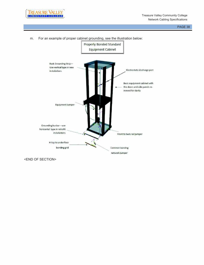


Labeling Term Description
Element !Element" is the generic term for parts of a cabling system and associated infrastructure that
must be labeled. For instance, Telecommunications Spaces are elements.
Telecommunications Grounding Busbars are elements. Cabling Sub-system 1 (horizontal)
are elements.

Labeling Term Description
Component An infrastructure !component" is an individual device in the cabling system or associated
infrastructure that must be named and labeled with a unique identifier.
Identifier An !identifier" is the name given to an element that is used on labels, in records and reports.
Ideally an identifier should !encode" and incorporate information on the element location,
and its relationship to other spaces and elements in the system. An identifier may also be
referred to as the component#s name or !designator".
Records !Records" are collection of information about the system identifiers, how the system is laid
out, and may contain other information like link test results.
Telecommunications Space !Telecommunications Space" is the name for a room containing cabling patch systems.
Often referred to in documentation as a !TS" (telecommunications space) or !TR"
(telecommunications room).
Telecommunications Distributors !Distributor" is a copper or fiber optic patching devices. These are usually patch panels in
the case of copper. Optical patch fields usually have boxes or enclosures mounted behind
the patch field to contain slack.
Equipment Outets The term !Equipment Outlet" (EO) is synonymous with Work Area Outlet and is usually a
mounting appliance for connections, either faceplates or surface boxes.
Facility Class Description
General The ANSI/TIA 606-C labeling standard divides facilities into four !Classes" of dependent
upon size and complexity. This allows for the systematic listing of all components that
must be labeled in each size, or !Class" of facility.
Classes range from single floor, single telecom space installations, to multiple campuses
located in different cities.
Standards compliant labeling should ideally be able to scale as premises grow from
smaller class facilities to larger class facilities, without having to rework the naming and
labeling conventions originally put in place prior to growth.
The description for each Class include the components to be labeled, identifiers, and
records are listed below.
Class 1 Facilities Class 1 addresses the administration needs of a premise that is served by a single
telecommunications space (TS) containing its telecommunications equipment.
Required in Class 1 administration are identifiers for the TS, the telecommunications main
grounding busbar (TMGB), and all elements of the horizontal links.
For a copper horizontal link, the elements to be labeled include:
The connecting hardware (e.g., patch panel port or the section of a punchdown block
terminating a four-pair horizontal cable, or fiber patch fields in the case of fiber-to-the-
desk). A four-pair horizontal cable, or fiber horizontal cable.
A telecommunications outlet/connector terminating a four-pair horizontal cable or fiber
cable in the work area.

Facility Class Description
If a consolidation point (CP) is present, the elements to be labeled include:
The segment of four-pair horizontal cable extending from the TS to the CP connecting
hardware.
The CP connecting hardware or section of a punchdown block terminating a four-pair
horizontal cable.
The segment of four-pair horizontal cable extending from the CP connecting hardware
to the outlet/connector of a multi-user telecommunications outlet assembly (MUTOA) or to
the work area outlet.
If a MUTOA is present, the elements to be labeled include:
A telecommunications outlet/connector in the MUTOA.
For an optical fiber horizontal link, the elements include:
A pair of optical fiber terminations on a patch panel in the TS.
A pair of optical fibers in the fiber cable.
A pair of optical fiber terminations in the work area (equipment outlet).
A telecommunications outlet/connector terminating a pair of optical fibers in the work
area.
If a consolidation point (CP) is present, the elements to be labeled include:
The segment of optical fiber cable extending from the TS (telecommunications space)
to the CP connecting hardware.
The CP connecting hardware or section terminating a pair of optical fibers.
The segment of optical fiber cable extending from the CP connecting hardware to the
outlet/connector of a multi-user telecommunications outlet assembly (MUTOA) or to the
work area outlet.
Class 2 Facilities Class 2 administration provides for telecommunications infrastructure administration
needs of a single building or tenant that is served by a single or multiple TSs within a
single building.
Class 2 administration includes all elements of Class 1 administration, plus identifiers for:
Backbone cabling.
Multiple-element grounding and bonding systems.
Firestopping.
Class 3 Facilities Class 3 administration addresses the needs of a campus, including its buildings and
outside plant elements.
Class 3 administration includes all elements of Class 2 administration, plus:
Identifiers for buildings and interbuilding cabling.
Administration of pathways and spaces.
Outside plant elements.
Class 4 Facilities Class 4 administration addresses the needs of a multi-site system.
Class 4 administration includes all elements of class 3 administration, plus:
An identifier for each site.
Identifiers for wide area network connections.
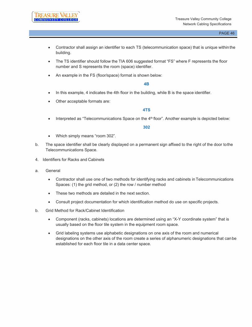
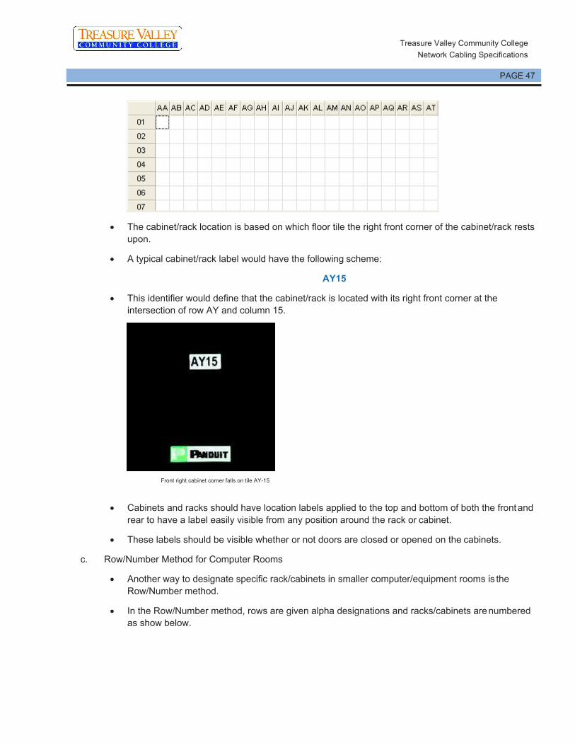
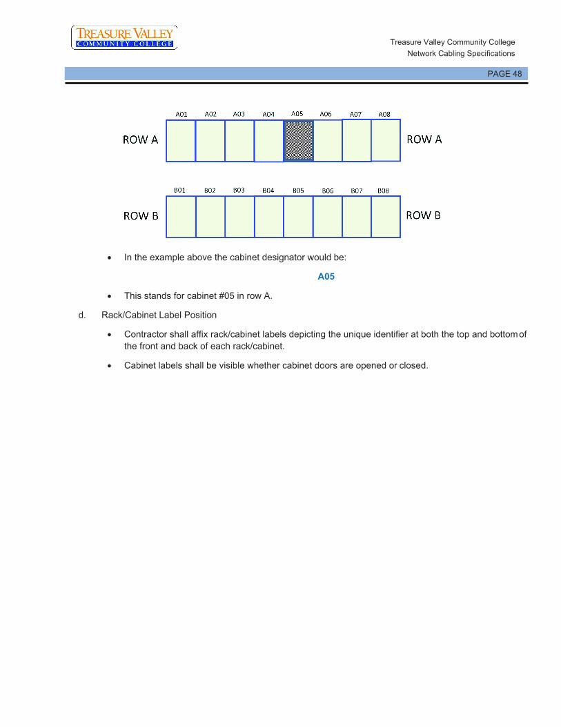


Product Category Part Number Manufacturer Part Description
Copper Cabling
Products
PUP6AV04XX-G Copper Cable, Cat 6A, Vari-MaTriX, 4-Pair, 23
AWG, UTP, CMP, !XX" (color designator), OD
0.250, 1000ft/305m
PUR6AV04XX Riser version be added when released
CJ6X88TG** Category 6A, RJ45, 10 Gb/s, 8-position, 8-wire
universal module. Includes patented MaTriX split
foil tape. For colors, replace, !**", with !BL"
(Black), IW (Off White), with EI (Electric Ivory),
WH (White), AW (Arctic White), IG (International
Gray), OR (Orange), RD (Red), BU (Blue), GR
(Green), YL (Yellow), or VL (Violet).
FP6X88MTG TX6A, Category 6A UTP Field Term RJ45 Plug is
a simple-to-attach plug for field termination of 4-
pair unshielded twisted pair cable.
FPUD6X88MTG TX6A, Category 6A UTP Field Term RJ45 Plug
with 45 degree angle is is a simple-to-attach plug
for field termination of 4-pair unshielded twisted
pair cable.
DP246X88TGY 24 Port CAT6A 10Gb/s 1RU Patch Panel with 24
RJ45 8-position, 8-wire ports.
DP486X88TGY 48 Port CAT6A 10Gb/s 2RU Patch Panel with 48
RJ45 8-position, 8-wire ports.
CFPL2WHY Mini Com Classic series single gang vertical
faceplate accepts two Mini-Com® Modules,
includes label and label cover. White
CFPL4WHY Mini Com Classic series single gang vertical
faceplate accepts four Mini-Com® Modules,
includes label and label cover. White
CFPL6WHY Mini Com Classic series single gang vertical
faceplate accepts six Mini-Com® Modules,
includes label and label cover. White
CMBBL-X Mini-Com® 1-port blank module, reserves space
for future use. For other colors replace suffix BL
(Black) with IW (Off White), EI (Electric Ivory),
WH (White) or IG (International Gray). 10/PK

Product Category Part Number Manufacturer Part Description
UTP28X*^ Category 6A Performance, 28AWG, UTP Patch
Cord, CM/LSZH, * = Length, ^ = Cord color Off
White (default; no designation needed),
BL=Black, BU=Blue, GR=Green, RD=Red,
OR=Orange, VL=Violet, YL=Yellow, GY=Gray
PUO6C04BL-U The copper cable is Category 6 outside plant
(OSP) U/UTP, 4-pair with conductors that are 23
AWG construction with polyolefin insulation. The
cable has a gel-filled construction to prevent
moisture migration in underground and wet
applications. Conductors are twisted in pairs,
separated by a pair separator, and covered by a
UV-resistant and abrasion-resistant polyethylene
(PE) jacket. It is for duct and conduit installations
only, it is not to be used in aerial or direct burial
applications. It is black and 1000' (305m) long.
PUR5525IG-UY Panduit or approved
equal
CAT5e cable 25pr riser rated $ Gray
P110KB1005Y Category 5e 110 Punchdown system kit includes
one 100-pair base with legs, twenty 5-pair
connecting blocks, two label and label holders
Fiber Cabling Products
FSPR924Y 24F OS2 Singlemode Interlocking Armored tight
buffered riser rated OFCR
FSLR924Y 24F OS2 Singlemode Interlocking Armored tight
buffered Indoor/Outdoor riser rated OFCR
FRME1U Opticom® Rack Mount Fiber Enclosure, 1RU,
holds up to 3 FAP or FMP adapter panels with
drawer that slides forward and backward
FLEX4U06 HD Flex® Fiber Enclosure, 4RU, holds up to 48
HD Flex Cassettes, Split front sliding drawers
FLEX-PLATE4U HD Flex Enclosure Trunk Slack Plate - 4 RU
FLEX-OPTI-1RU Opticom® bracket that holds 2 HD Flex Cassettes
FHS9N-12-10P HD Flex LC Splice Cassette preloaded with 12-
fiber OS2 pigtail and Standard IL, 6-port duplex
LC adapters in blue with zirconia sleeves
F92ERQ1Q1SNM001 2 fiber OS2 patch cord, LC push pull to LC push
pull, riser (OFNR) rated, 16mm jacket, Standard
IL 1 meter
Racks, Cabinets, and
Cable Management

Product Category Part Number Manufacturer Part Description
R2P 19% EIA 2-post rack, aluminum. Dimensions:
84.0%H x 20.3%W x 3.0%D
R4P 19% EIA 2-post rack, steel, &12-24 threaded rails
Dimensions: 84.0%H x 23.3%W x 30.0%D
PR2VD08 PatchRunner+ 2 Vertical Cable Manager and
Doors, Dual Sided, 45RU, 83.9 H x 8.0 W x 20.7
D
Bonding and Grounding
ACG24K &6 AWG (16mm2) jumper for armored cable
diameter up to 0.84% (21.3mm); 24% (609.6mm)
length; factory terminated on one end with LCC6
two-hole copper compression lug and the other
end with grounding terminal; provided with two
each &12-24 and M6 thread-forming screws and a
black polypropylene terminal cover
LCC series Panduit two-hole compressing lugs for code
conductors in BICSI hole spacing
HTCT series Panduit HTAPs. Must be selected according
AWG size of run and tap conductors.
CLRCVR series Panduit clear covers for HTAPs. Must be selected
according to HTAP being covered
RGS134-1Y Grounding strip for newly installed racks or
cabinets with screw rails. 78.65% (2m) length; .67%
(17mm) width; .05% (1.27mm) thickness; provided
with .16 oz. (5cc) of antioxidant, one grounding
sticker and three each &12-24 x 1/2% and M6 x
12mm thread-forming screws
RGRB19Y Grounding busbar: 19" (483mm) length; tin-
plated; fourteen holes arranged for flexibility in
mounting; provided with two each &12-24x ½" and
M6 x 12mm thread-forming screws.
RGCBNJ660P22 Jumper kit for bonding individual racks or
cabinets into grounding backbone. &6 AWG
(16mm²) jumper; 60% (1.52m) length; 45° bent lug
on grounding strip side; provided with .16 oz.
(5cc) of antioxidant, two each &12-24 x 1/2%, M6 x
12mm, &10-32 x 1/2% and M5 x 12mm thread
forming screws and a copper compression HTAP*
for connecting to a &6 to &2 awg sized bonding
backbone
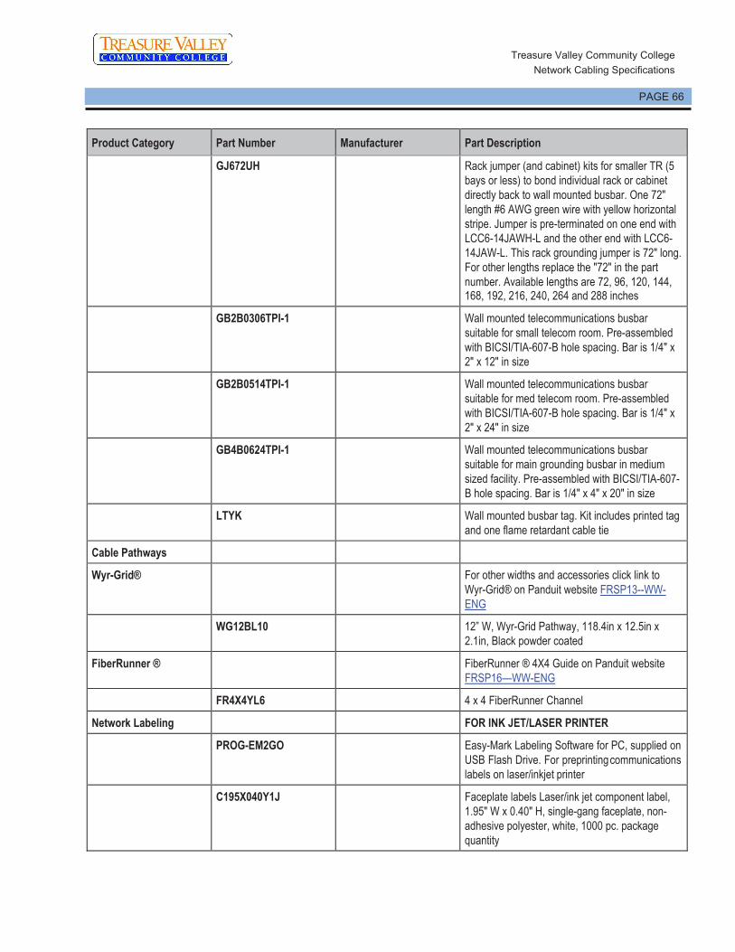
Product Category Part Number Manufacturer Part Description
GJ672UH Rack jumper (and cabinet) kits for smaller TR (5
bays or less) to bond individual rack or cabinet
directly back to wall mounted busbar. One 72%
length &6 AWG green wire with yellow horizontal
stripe. Jumper is pre-terminated on one end with
LCC6-14JAWH-L and the other end with LCC6-
14JAW-L. This rack grounding jumper is 72% long.
For other lengths replace the %72% in the part
number. Available lengths are 72, 96, 120, 144, 168, 192, 216, 240, 264 and 288 inches
GB2B0306TPI-1 Wall mounted telecommunications busbar
suitable for small telecom room. Pre-assembled
with BICSI/TIA-607-B hole spacing. Bar is 1/4% x
2% x 12% in size
GB2B0514TPI-1 Wall mounted telecommunications busbar
suitable for med telecom room. Pre-assembled
with BICSI/TIA-607-B hole spacing. Bar is 1/4% x
2% x 24% in size
GB4B0624TPI-1 Wall mounted telecommunications busbar
suitable for main grounding busbar in medium
sized facility. Pre-assembled with BICSI/TIA-607-
B hole spacing. Bar is 1/4% x 4% x 20% in size
LTYK Wall mounted busbar tag. Kit includes printed tag
and one flame retardant cable tie
Cable Pathways
Wyr-Grid® For other widths and accessories click link to
Wyr-Grid® on Panduit website FRSP13--WW-
ENG
WG12BL10 12" W, Wyr-Grid Pathway, 118.4in x 12.5in x
2.1in, Black powder coated
FiberRunner ® FiberRunner ® 4X4 Guide on Panduit website
FRSP16<WW-ENG
FR4X4YL6 4 x 4 FiberRunner Channel
Network Labeling FOR INK JET/LASER PRINTER
PROG-EM2GO Easy-Mark Labeling Software for PC, supplied on
USB Flash Drive. For preprinting communications
labels on laser/inkjet printer
C195X040Y1J Faceplate labels Laser/ink jet component label,
1.95% W x 0.40% H, single-gang faceplate, non-
adhesive polyester, white, 1000 pc. package
quantity
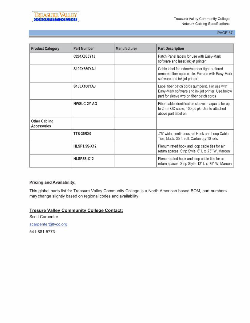
Product Category Part Number Manufacturer Part Description
C261X035Y1J Patch Panel labels for use with Easy-Mark
software and laser/ink jet printer
S100X650YAJ Cable label for indoor/outdoor tight-buffered
armored fiber optic cable. For use with Easy-Mark
software and ink jet printer.
S100X160YAJ Label fiber patch cords (jumpers). For use with
Easy-Mark software and ink jet printer. Use below
part for sleeve wrp on fiber patch cords
NWSLC-2Y-AQ Fiber cable identification sleeve in aqua is for up
to 2mm OD cable, 100 pc pk. Use to attached
above part label on
Other Cabling
Accessories
TTS-35RX0 .75" wide, continuous roll Hook and Loop Cable
Ties, black. 35 ft. roll. Carton qty 10 rolls
HLSP1.5S-X12 Plenum rated hook and loop cable ties for air
return spaces, Strip Style, 6" L x .75" W, Maroon
HLSP3S-X12 Plenum rated hook and loop cable ties for air
return spaces, Strip Style, 12" L x .75" W, Maroon

TREASURE VALLEY COMMUNITY COLLEGE - CTE TVCC_CTE
ONTARIO, OR.
COMMON WORK RESULTS FOR ELECTRONIC SAFETY AND SECURITY 280500 - 1
SECTION 280500 - COMMON WORK RESULTS FOR ELECTRONIC SAFETY AND SECURITY
PART 1 - GENERAL
1.1 RELATED DOCUMENTS
A. Drawings and general provisions of the Contract, including General and Supplementary
Conditions and Division 01 Specification Sections, apply to this Section.
1.2 SUMMARY
A. Section Includes:
1. Electronic safety and security equipment coordination and installation.
2. Sleeves for raceways and cables.
3. Sleeve seals.
4. Grout.
5. Common electronic safety and security installation requirements.
1.3 DEFINITIONS
A. EPDM: Ethylene-propylene-diene terpolymer rubber.
B. NBR: Acrylonitrile-butadiene rubber.
1.4 COORDINATION
A. Coordinate arrangement, mounting, and support of electronic safety and security equipment:
1. To allow maximum possible headroom unless specific mounting heights that reduce
headroom are indicated.
2. To provide for ease of disconnecting the equipment with minimum interference to other
installations.
3. To allow right of way for piping and conduit installed at required slope.
4. So connecting raceways, cables, wireways, cable trays, and busways will be clear of
obstructions and of the working and access space of other equipment.
B. Coordinate installation of required supporting devices and set sleeves in cast-in-place concrete,
masonry walls, and other structural components as they are constructed.
C. Coordinate sleeve selection and application with selection and application of firestopping.

TREASURE VALLEY COMMUNITY COLLEGE - CTE TVCC_CTE
ONTARIO, OR.
COMMON WORK RESULTS FOR ELECTRONIC SAFETY AND SECURITY 280500 - 2
PART 2 - PRODUCTS
2.1 SLEEVES FOR RACEWAYS AND CABLES
A. Steel Pipe Sleeves: ASTM A 53/A 53M, Type E, Grade B, Schedule 40, galvanized steel, plain
ends.
2.2 SLEEVE SEALS
A. Description: Modular sealing device, designed for field assembly, to fill annular space between
sleeve and raceway or cable.
1. Basis-of-Design Product: Subject to compliance with requirements, provide comparable
product by one of the following:
a. Advance Products & Systems, Inc.
b. Calpico, Inc.
c. Metraflex Co.
d. Pipeline Seal and Insulator, Inc.
2. Sealing Elements: EPDM interlocking links shaped to fit surface of cable or conduit.
Include type and number required for material and size of raceway or cable.
3. Pressure Plates: Plastic. Include two for each sealing element.
4. Connecting Bolts and Nuts: Carbon steel with corrosion-resistant coating of length
required to secure pressure plates to sealing elements. Include one for each sealing
element.
2.3 GROUT
A. Nonmetallic, Shrinkage-Resistant Grout: ASTM C 1107, factory-packaged, nonmetallic
aggregate grout, noncorrosive, nonstaining, mixed with water to consistency suitable for
application and a 30-minute working time.
PART 3 - EXECUTION
3.1 COMMON REQUIREMENTS FOR ELECTRONIC SAFETY AND SECURITY
INSTALLATION
A. Comply with NECA 1.
B. Measure indicated mounting heights to bottom of unit for suspended items and to center of unit
for wall-mounting items.
C. Headroom Maintenance: If mounting heights or other location criteria are not indicated,
arrange and install components and equipment to provide maximum possible headroom
consistent with these requirements.
TREASURE VALLEY COMMUNITY COLLEGE - CTE TVCC_CTE
ONTARIO, OR.
COMMON WORK RESULTS FOR ELECTRONIC SAFETY AND SECURITY 280500 - 3
D. Equipment: Install to facilitate service, maintenance, and repair or replacement of components
of both electronic safety and security equipment and other nearby installations. Connect in such
a way as to facilitate future disconnecting with minimum interference with other items in the
vicinity.
E. Right of Way: Give to piping systems installed at a required slope.
3.2 SLEEVE INSTALLATION FOR ELECTRONIC SAFETY AND SECURITY
PENETRATIONS
A. Electronic safety and security penetrations occur when raceways, pathways, cables, wireways,
or cable trays penetrate concrete slabs, concrete or masonry walls, or fire-rated floor and wall
assemblies.
B. Concrete Slabs and Walls: Install sleeves for penetrations unless core-drilled holes or formed
openings are used. Install sleeves during erection of slabs and walls.
C. Use pipe sleeves unless penetration arrangement requires rectangular sleeved opening.
D. Fire-Rated Assemblies: Install sleeves for penetrations of fire-rated floor and wall assemblies
unless openings compatible with firestop system used are fabricated during construction of floor
or wall.
E. Cut sleeves to length for mounting flush with both surfaces of walls.
F. Extend sleeves installed in floors 6 inches above finished floor level.
G. Size pipe sleeves to provide 1/4-inch annular clear space between sleeve and raceway or cable,
unless indicated otherwise.
H. Seal space outside of sleeves with grout for penetrations of concrete and masonry
1. Promptly pack grout solidly between sleeve and wall so no voids remain. Tool exposed
surfaces smooth; protect grout while curing.
I. Interior Penetrations of Non-Fire-Rated Walls and Floors: Seal annular space between sleeve
and raceway or cable, using joint sealant appropriate for size, depth, and location of joint.
Comply with requirements in Division 07 Section "Joint Sealants."
J. Fire-Rated-Assembly Penetrations: Maintain indicated fire rating of walls, partitions, ceilings,
and floors at raceway and cable penetrations. Install sleeves and seal raceway and cable
penetration sleeves with firestop materials.
K. Roof-Penetration Sleeves: Seal penetration of individual raceways and cables with flexible
boot-type flashing units applied in coordination with roofing work.
L. Aboveground, Exterior-Wall Penetrations: Seal penetrations using steel or cast-iron pipe
sleeves and mechanical sleeve seals. Select sleeve size to allow for 1-inch annular clear space
between pipe and sleeve for installing mechanical sleeve seals.

TREASURE VALLEY COMMUNITY COLLEGE - CTE TVCC_CTE
ONTARIO, OR.
COMMON WORK RESULTS FOR ELECTRONIC SAFETY AND SECURITY 280500 - 4
M. Underground, Exterior-Wall Penetrations: Install cast-iron pipe sleeves. Size sleeves to allow
for 1-inch annular clear space between raceway or cable and sleeve for installing mechanical
sleeve seals.
3.3 SLEEVE-SEAL INSTALLATION
A. Install to seal exterior wall penetrations.
B. Use type and number of sealing elements recommended by manufacturer for raceway or cable
material and size. Position raceway or cable in center of sleeve. Assemble mechanical sleeve
seals and install in annular space between raceway or cable and sleeve. Tighten bolts against
pressure plates that cause sealing elements to expand and make watertight seal.
3.4 FIRESTOPPING
A. Apply firestopping to penetrations of fire-rated floor and wall assemblies for electronic safety
and security installations to restore original fire-resistance rating of assembly.
END OF SECTION 280500
TREASURE VALLEY COMMUNITY COLLEGE - CTE TVCC_CTE
ONTARIO, OR.
FIRE DETECTION AND ALARM 283100 - 1
SECTION 283100 - FIRE DETECTION AND ALARM
PART 1 - GENERAL
1.1 RELATED DOCUMENTS
A. Drawings and general provisions of the Contract, including General and Supplementary
Conditions and Division 01 Specification Sections, apply to this Section.
1.2 SUMMARY
A. This Section includes fire alarm systems.
B. Related Sections include the following:
1. Division 26 Electrical.
1.3 DEFINITIONS
A. FACP: Fire alarm control panel.
B. LED: Light-emitting diode.
C. NICET: National Institute for Certification in Engineering Technologies.
D. Definitions in NFPA 72 apply to fire alarm terms used in this Section.
1.4 SYSTEM DESCRIPTION
A. Noncoded, analog-addressable system; automatic sensitivity control of smoke detectors; and
multiplexed signal transmission dedicated to fire alarm service only.
1. Provide new system with all necessary capabilities to perform detection and control
meeting all requirements of NFPA 72 and any local Jurisdictional requirements.
1.5 PERFORMANCE REQUIREMENTS
A. Comply with the latest NFPA 72, NFPA 70 (NEC), IBC/IFC/IMC and ADAAG.
B. Fire alarm signal initiation shall be by one or more of the following devices:
1. Manual stations.
2. Heat detectors.

TREASURE VALLEY COMMUNITY COLLEGE - CTE TVCC_CTE
ONTARIO, OR.
FIRE DETECTION AND ALARM 283100 - 2
3. Smoke detectors.
4. Automatic sprinkler system water flow.
5. Fire extinguishing system operation.
C. Fire alarm signal shall initiate the following actions:
1. Audible and visual alarm notification appliances shall operate continuously.
2. Identify alarm at the FACP and remote annunciators.
3. Transmit an alarm signal to the remote alarm receiving station.
4. Release fire and smoke doors held open by magnetic door holders.
5. Activate voice/alarm communication system.
6. Record events in the system memory.
7. Shutdown of all fans and air-handling equipment with duct detection serving the
building.
D. Supervisory signal initiation shall be by one or more of the following devices or actions:
1. Operation of a fire-protection system valve tamper.
2. Activation of duct mounted smoke detector.
E. System trouble signal initiation shall be by one or more of the following devices or actions:
1. Open circuits, shorts and grounds of wiring for initiating device, signaling line, and
notification-appliance circuits.
2. Opening, tampering, or removal of alarm-initiating and supervisory signal-initiating
devices.
3. Loss of primary power at the FACP.
4. Ground or a single break in FACP internal circuits.
5. Abnormal ac voltage at the FACP.
6. A break in standby battery circuitry.
7. Failure of battery charging.
8. Abnormal position of any switch at the FACP or annunciator.
9. Low-air-pressure switch operation on a dry-pipe or preaction sprinkler system.
F. System Trouble and Supervisory Signal Actions:
1. Ring trouble bell and annunciate at the FACP and remote annunciators.
2. Transmit trouble or supervisory signal to remote supervising station.
1.6 SUBMITTALS
A. Product Data: For each type of product indicated.
1. Specific model numbers of pertinent equipment shall be highlighted for clarity on
datasheets containing information on multiple pieces of equipment.
2. Provide in portable document format (PDF).
B. Shop Drawings:

TREASURE VALLEY COMMUNITY COLLEGE - CTE TVCC_CTE
ONTARIO, OR.
FIRE DETECTION AND ALARM 283100 - 3
1. Shop Drawings are the responsibility of the Contractor and shall be prepared by persons
with the following qualifications:
a. Trained and certified by manufacturer in fire alarm system design.
b. Fire alarm certified by NICET, minimum Level III or as required by the state the
Project is located in.
c. Factory authorized to represent the manufacturer and supply the submitted
manufacturer's equipment.
d. Provide documentation of preparers' qualifications (i.e. certificates of
qualification) and include in shop drawing submittal.
e. Contractor shall not copy original contract drawings and title blocks. Provide new
title block indicating contact information and qualifications for individuals and
firms responsible for providing and installing fire alarm equipment.
f. Shop drawings shall be developed utilizing a standard CAD program. Overlay of
new system layout to the original engineered plans in PDF format is unacceptable
and will be rejected.
2. System Operation Description: Detailed description for this Project, including method of
operation and supervision of each type of circuit and sequence of operations for manually
and automatically initiated system inputs and outputs. Manufacturer's standard
descriptions for generic systems are not acceptable.
3. Device Address List and Input/Output Matrix: Coordinate with final system
programming.
4. Device backbox and other junction box requirements.
5. System riser diagram with device addresses, conduit sizes, and cable and wire types and
sizes.
6. Wiring Diagrams: Power, signal, and control wiring. Include diagrams for equipment
and for system with all terminals and interconnections identified. Show wiring color
code.
7. Batteries: Size calculations based upon standard standby battery load calculations.
8. Duct Smoke Detectors: Performance parameters and installation details for each
detector, verifying that each detector is listed for the complete range of air velocity,
temperature, and humidity possible when air-handling system is operating.
9. Voice/Alarm Signaling Service: Equipment rack or console layout, grounding schematic,
amplifier power calculation, and single-line connection diagram.
10. Floor Plans: Indicate final outlet locations showing address of each addressable device.
Show size and route of cable and conduits.
11. Shop drawing plans shall be developed utilizing a standard AutoCAD© or equivalent
software platform.
12. Contractor shall include specific, personalized title block and project specific
information. Contractor shall not "copy and paste" CTA provided documents into their
submittal.
13. All extraneous information included in documents provided by CTA shall be removed
from plans prior to the Contractor submitting working plans. Only pertinent, project
specific information shall be placed on submittal plans.
C. Qualification Data: For Installer.
D. Qualification Data: Supplier.
E. Field quality-control test reports.

TREASURE VALLEY COMMUNITY COLLEGE - CTE TVCC_CTE
ONTARIO, OR.
FIRE DETECTION AND ALARM 283100 - 4
F. Operation and Maintenance Data: For fire alarm system to include in emergency, operation,
and maintenance manuals. Comply with NFPA 72, Appendix A, recommendations for Owner's
manual. Include abbreviated operating instructions for mounting at the FACP.
G. Submittals to Authorities Having Jurisdiction: In addition to distribution requirements for
submittals specified in Division 01 Section "Submittals," make an identical submittal to
authorities having jurisdiction. This Submittal shall be reviewed and "approved" by the Project
Engineer prior to submitting to the AHJ and shall bear the project design firms Shop Drawing
stamp with signature and indication that the Submittal is approved. To facilitate review,
include copies of annotated Contract Drawings as needed to depict component locations.
Resubmit if required to make clarifications or revisions to obtain approval. On receipt of
comments from authorities having jurisdiction, submit them to Architect for review. Fire
Alarm Contractor shall provide professional stamping of Shop Drawings in jurisdictions where
it is required.
H. Documentation:
1. Approval and Acceptance: Provide the "Record of Completion" form according to
NFPA 72 to Owner, Architect, and authorities having jurisdiction.
2. Record of Completion Documents: Provide the "Permanent Records" according to
NFPA 72 to Owner, Architect, and authorities having jurisdiction. Format of the written
sequence of operation shall be the optional input/output matrix.
a. Hard copies on paper to Owner, Architect, and authorities having jurisdiction.
1.7 QUALITY ASSURANCE
A. Installer Qualifications: Personnel shall be trained and certified by the manufacturer for
installation of units required for this Project.
B. Installer Qualifications: Work of this Section be performed by a UL-listed company.
C. Installer Qualifications: Personnel certified by NICET as Fire Alarm Level II.
D. Electrical Components, Devices, and Accessories: Listed and labeled as defined in NFPA 70,
Article 100, by a testing agency acceptable to authorities having jurisdiction, and marked for
intended use.
E. Supplier Qualifications: Factory authorized to represent, supply and perform service on the
manufacturer's product.
1.8 EXTRA MATERIALS
A. Furnish extra materials described below that match products installed and that are packaged
with protective covering for storage and identified with labels describing contents.
1. Remote Indicating Lamp Units: Quantity equal to 10 percent of amount installed, but not
less than 1 unit.
2. Strobe Units: Quantity equal to 10 percent of amount installed, but not less than 1 unit.

TREASURE VALLEY COMMUNITY COLLEGE - CTE TVCC_CTE
ONTARIO, OR.
FIRE DETECTION AND ALARM 283100 - 5
3. Smoke and Heat Detectors: Quantity equal to 10 percent of amount of each type
installed, but not less than 1 unit of each type.
4. Detector Bases: Quantity equal to 2 percent of amount of each type installed, but not less
than 1 unit of each type.
5. Keys and Tools: One extra set for access to locked and tamper proofed components.
6. Audible and Visual Notification Appliances: One of each type installed.
7. Fuses: Two of each type installed in the system.
PART 2 - PRODUCTS
2.1 MANUFACTURERS
A. Manufacturers: Subject to compliance with requirements, provide products by one of the
following:
1. FACP and Equipment:
a. Edwards Systems Technology Inc.
b. NOTIFIER by Honeywell.
c. Simplex by Johnson Controls Inc.
d. Siemens Building Technology
e. Silent Knight by Honeywell
f. Fire-Lite by Honeywell
2. Wire and Cable:
a. Comtran Corporation.
b. Helix/HiTemp Cables, Inc.
c. Rockbestos-Suprenant Cable Corporation.
d. West Penn Wire/CDT
e. Belden
f. Anixter
2.2 FACP
A. General Description:
1. Sized to accommodate indicated initiation and notification devices plus 20 percent.
2. Modular, power-limited design with electronic modules, UL 864 listed.
3. Addressable initiation devices that communicate device identity and status.
a. Smoke sensors shall additionally communicate sensitivity setting and allow for
adjustment of sensitivity at the FACP.
b. Temperature sensors shall additionally test for and communicate the sensitivity
range of the device.
4. Addressable control circuits for operation of mechanical equipment.

TREASURE VALLEY COMMUNITY COLLEGE - CTE TVCC_CTE
ONTARIO, OR.
FIRE DETECTION AND ALARM 283100 - 6
B. Alphanumeric Display and System Controls: Arranged for interface between human operator
at the FACP and addressable system components including annunciation and supervision.
Display alarm, supervisory, and component status messages and the programming and control
menu.
1. Annunciator and Display: Liquid-crystal type, 80 characters, minimum.
2. Keypad: Arranged to permit entry and execution of programming, display, and control
commands; and to indicate control commands to be entered into the system for control of
smoke-detector sensitivity and other parameters.
C. Circuits:
1. Signaling Line Circuits: NFPA 72, Class B.
a. System Layout: Install separate signaling line circuits per floor.
2. Notification-Appliance Circuits: NFPA 72, Class B.
3. Electrical monitoring for the integrity of wiring external to the FACP for mechanical
equipment shutdown and magnetic door-holding circuits is not required, provided a break
in the circuit will cause doors to close and mechanical equipment to shut down.
D. Notification-Appliance Circuit: Operation shall sound in a temporal pattern, complying with
ANSI S3.41.
E. Power Supply for Supervision Equipment: Supply for audible and visual equipment for
supervision of the ac power shall be from a dedicated dc power supply, and power for the dc
component shall be from the ac supply.
F. Alarm Silencing, Trouble, and Supervisory Alarm Reset: Manual reset at the FACP and remote
annunciators, after initiating devices are restored to normal.
1. Silencing-switch operation halts alarm operation of notification appliances and activates
an "alarm silence" light. Display of identity of the alarm zone or device is retained.
2. Subsequent alarm signals from other devices or zones reactivate notification appliances
until silencing switch is operated again.
3. When alarm-initiating devices return to normal and system reset switch is operated,
notification appliances operate again until alarm silence switch is reset.
G. Walk Test: A test mode to allow one person to test alarm and supervisory features of initiating
devices. Enabling of this mode shall require the entry of a password. The FACP and
annunciators shall display a test indication while the test is underway. If testing ceases while in
walk-test mode, after a preset delay, the system shall automatically return to normal.
H. Remote Smoke-Detector Sensitivity Adjustment: Controls shall select specific addressable
smoke detectors for adjustment, display their current status and sensitivity settings, and control
of changes in those settings. Allow controls to be used to program repetitive, time-scheduled,
and automated changes in sensitivity of specific detector groups. Record sensitivity
adjustments and sensitivity-adjustment schedule changes in system memory.

TREASURE VALLEY COMMUNITY COLLEGE - CTE TVCC_CTE
ONTARIO, OR.
FIRE DETECTION AND ALARM 283100 - 7
I. Transmission to Remote Alarm Receiving Station: Automatically transmit alarm, trouble, and
supervisory signals to a remote alarm station through a digital alarm communicator transmitter
and telephone lines.
J. Voice/Alarm Signaling Service: A central emergency communication system with redundant
microphones, preamplifiers, amplifiers, and tone generators integrated with the main FACP or
provided in a separate cabinet or and under the direct supervision and control of the FACP.
1. Indicated number of alarm channels for automatic, simultaneous transmission of different
announcements to different zones, or for manual transmission of announcements by use
of the central-control microphone. Amplifiers shall be UL 1711 listed.
a. Allow the application of and evacuation signal to indicated number of zones and,
at the same time, allow voice paging to the other zones selectively or in any
combination.
b. Programmable tone and message sequence selection.
c. Standard digitally recorded messages for "Evacuation" and "All Clear."
d. Generate tones to be sequenced with audio messages of the type recommended by
NFPA 72 and that are compatible with tone patterns of the notification-appliance
circuits of the FACP.
2. Notification-Appliance Circuits: NFPA 72, Class B.
3. Status Annunciator: Indicate the status of various voice/alarm speaker zones.
4. Preamplifiers, amplifiers, and tone generators shall automatically transfer to backup
units, on primary equipment failure.
K. Service Modem: Ports shall be RS-232 for system printer and for connection to a dial-in
terminal unit.
1. The dial-in port shall allow remote access to the FACP for programming changes and
system diagnostic routines. Access by a remote terminal shall be by encrypted password
algorithm.
L. Universal Serial Bus (USB) port.
1. The USB port shall allow for computer connection and communications necessary for
programming and downloading digital reports.
M. Primary Power: 24-V dc obtained from 120-V ac service and a power-supply module.
Initiating devices, notification appliances, signaling lines, trouble signal, supervisory signal,
supervisory and digital alarm communicator transmitter shall be powered by the 24-V dc
source.
1. The alarm current draw of the entire fire alarm system shall not exceed 80 percent of the
power-supply module rating.
2. Power supply shall have a dedicated fused safety switch for this connection at the service
entrance equipment. Paint the switch box red and identify it with "FIRE ALARM
SYSTEM POWER."
N. Secondary Power: 24-V dc supply system with batteries and automatic battery charger and an
automatic transfer switch.

TREASURE VALLEY COMMUNITY COLLEGE - CTE TVCC_CTE
ONTARIO, OR.
FIRE DETECTION AND ALARM 283100 - 8
1. Batteries: Rechargeable sealed-lead acid.
2. Battery and Charger Capacity: Comply with NFPA 72.
O. Surge Protection:
1. Install surge protection on normal ac power for the FACP and its accessories.
2. Install surge protectors recommended by FACP manufacturer. Install on all system
wiring external to the building housing the FACP.
P. Instructions: Computer printout or typewritten instruction card mounted behind a plastic or
glass cover in a stainless-steel or aluminum frame. Include interpretation and describe
appropriate response for displays and signals. Briefly describe the functional operation of the
system under normal, alarm, and trouble conditions.
2.3 MANUAL FIRE ALARM BOXES
A. Description: UL 38 listed; finished in red with molded, raised-letter operating instructions in
contrasting color. Station shall show visible indication of operation. Mounted on recessed
outlet box; if indicated as surface mounted, provide manufacturer's surface back box.
1. Double-action mechanism requiring two actions to initiate an alarm, pull-lever type.
With integral addressable module, arranged to communicate manual-station status
(normal, alarm, or trouble) to the FACP.
2. Station Reset: Key- or wrench-operated switch.
3. Indoor Protective Shield (IPS) (only where indicated on the Construction Documents):
Factory-fabricated clear plastic enclosure, hinged at the top to permit lifting for access to
initiate an alarm. Lifting the cover actuates an integral battery-powered audible horn
intended to discourage false-alarm operation.
4. Weatherproof Protective Shield (WP) (only where indicated on the Construction
Documents): Factory-fabricated clear plastic enclosure, hinged at the top to permit lifting
for access to initiate an alarm.
2.4 SYSTEM SMOKE DETECTORS
A. General Description:
1. UL 268 listed, operating at 24-V dc, nominal.
2. Integral Addressable Module: Arranged to communicate detector status (normal, alarm,
or trouble) to the FACP.
3. Plug-in Arrangement: Detector and associated electronic components shall be mounted
in a plug-in module that connects to a fixed base. Provide terminals in the fixed base for
connection of building wiring.
4. Resetable from the fire alarm control panel.
5. Integral Visual-Indicating Light: LED type. Indicating detector has operated and power-
on status.
6. Remote Control: Unless otherwise indicated, detectors shall be analog-addressable type,
individually monitored at the FACP for calibration, sensitivity, and alarm condition, and
individually adjustable for sensitivity from the FACP.

TREASURE VALLEY COMMUNITY COLLEGE - CTE TVCC_CTE
ONTARIO, OR.
FIRE DETECTION AND ALARM 283100 - 9
a. Rate-of-rise temperature characteristic shall be selectable at the FACP for 15 or 20
deg F (8 or 11 deg C) per minute.
b. Fixed-temperature sensing shall be independent of rate-of-rise sensing and shall be
settable at the FACP to operate at 135 or 155 deg F (57 or 68 deg C).
c. Provide multiple levels of detection sensitivity for each sensor.
B. Photoelectric Smoke Detectors:
1. Sensor: LED or infrared light source with matching silicon-cell receiver.
2. Detector Sensitivity: Between 2.5 and 3.5 percent/foot (0.008 and 0.011 percent/mm)
smoke obscuration when tested according to UL 268A.
C. Duct Smoke Detectors:
1. Photoelectric Smoke Detectors:
a. Sensor: LED or infrared light source with matching silicon-cell receiver.
b. Detector Sensitivity: Between 2.5 and 3.5 percent/foot (0.008 and 0.011
percent/mm) smoke obscuration when tested according to UL 268A.
2. UL 268A listed, operating at 24-V dc, nominal.
3. Integral Addressable Module: Arranged to communicate detector status (normal, alarm,
or trouble) to the FACP.
4. Plug-in Arrangement: Detector and associated electronic components shall be mounted
in a plug-in module that connects to a fixed base. The fixed base shall be designed for
mounting directly to the air duct. Provide terminals in the fixed base for connection to
building wiring.
a. Weatherproof Duct Housing Enclosure: UL listed for use with the supplied
detector. The enclosure shall comply with NEMA 250 requirements for Type 4X.
5. Resetable from the fire alarm control panel.
6. Integral Visual-Indicating Light: LED type. Indicating detector has operated and power-
on status. Provide remote status and alarm indicator.
7. Remote Control: Unless otherwise indicated, detectors shall be analog-addressable type,
individually monitored at the FACP for calibration, sensitivity, and alarm condition, and
individually adjustable for sensitivity from the FACP.
8. Each sensor shall have multiple levels of detection sensitivity.
9. Sampling Tubes: Design and dimensions as recommended by manufacturer for the
specific duct size, air velocity, and installation conditions where applied.
10. Relay Fan Shutdown: Rated to interrupt fan motor-control circuit.
2.5 HEAT DETECTORS
A. General: UL 521 listed.
B. Heat Detector, Combination Type: Actuated by either a fixed temperature of 135 deg F (57
deg C) or rate-of-rise of temperature that exceeds 15 deg F (8 deg C) per minute, unless
otherwise indicated.

TREASURE VALLEY COMMUNITY COLLEGE - CTE TVCC_CTE
ONTARIO, OR.
FIRE DETECTION AND ALARM 283100 - 10
1. Mounting: Plug-in base, interchangeable with smoke-detector bases.
2. Integral Addressable Module: Arranged to communicate detector status (normal, alarm,
or trouble) to the FACP.
C. Heat Detector, Fixed-Temperature Type: Actuated by temperature that exceeds a fixed
temperature of 190 deg F (88 deg C), unless otherwise indicated on Construction Documents.
1. Mounting: Plug-in base, interchangeable with smoke-detector bases.
2. Integral Addressable Module: Arranged to communicate detector status (normal, alarm,
or trouble) to the FACP.
2.6 NOTIFICATION APPLIANCES
A. Description: Equipped for mounting as indicated and with screw terminals for system
connections.
1. Combination Devices: Factory-integrated audible and visible devices in a single-
mounting assembly.
B. Horns: Electric-vibrating-polarized type, 24-V dc; with provision for housing the operating
mechanism behind a grille. Horns shall produce a sound-pressure level of 90 dBA, measured
10 feet (3 m) from the horn.
C. Visible Alarm Devices: Xenon strobe lights listed under UL 1971, with clear or nominal white
polycarbonate lens mounted on an aluminum faceplate. The word "FIRE" is engraved in
minimum 1 inch (25 mm) high letters on the lens.
1. Rated Light Output: Performance in accordance with ADA. Light distribution per UL
1971, Candela rating as called out on Drawings with ability to field adjust from 15
Candela to 115 Candela.
D. Voice/Tone Speakers:
1. UL 1480 listed.
2. High-Range Units: Rated 2 to 15 W.
3. Low-Range Units: Rated 1/4 to 2 W.
4. Mounting: Flush, semirecessed, or surface mounted; bidirectional as indicated.
5. Matching Transformers: Tap range matched to the acoustical environment of the speaker
location.
2.7 SPRINKLER SYSTEM REMOTE INDICATORS
A. Remote status and alarm indicator and test stations, with LED indicating lights. Light is
connected to flash when the associated device is in an alarm or trouble mode. Lamp is flush
mounted in a single-gang wall plate. A red, laminated, phenolic-resin identification plate at the
indicating light identifies, in engraved white letters, device initiating the signal and room where
the smoke detector or valve is located. For water-flow switches, the identification plate also
designates protected spaces downstream from the water-flow switch.

TREASURE VALLEY COMMUNITY COLLEGE - CTE TVCC_CTE
ONTARIO, OR.
FIRE DETECTION AND ALARM 283100 - 11
2.8 REMOTE ANNUNCIATOR
A. Description: Duplicate annunciator functions of the FACP for alarm, supervisory, and trouble
indications. Also duplicate manual switching functions of the FACP, including acknowledging,
silencing, resetting, and testing.
1. Mounting: Flush cabinet, NEMA 250, Class 1.
B. Display Type and Functional Performance: Alphanumeric display same as the FACP. Controls
with associated LEDs permit acknowledging, silencing, resetting, and testing functions for
alarm, supervisory, and trouble signals identical to those in the FACP.
2.9 ADDRESSABLE INTERFACE DEVICE
A. Description: Microelectronic monitor module listed for use in providing a system address for
listed alarm-initiating devices for wired applications with normally open, dry contacts.
B. Integral Relay: Capable of providing dry contact closure. Contacts shall be rated for minimum
2A current.
2.10 DIGITAL ALARM COMMUNICATOR TRANSMITTER
A. Listed and labeled according to UL 632.
B. Functional Performance: Unit receives an alarm, supervisory, or trouble signal from the FACP,
and automatically captures one or two telephone lines and dials a preset number for a remote
central station. When contact is made with the central station(s), the signal is transmitted. The
unit supervises up to two telephone lines. Where supervising 2 lines, if service on either line is
interrupted for longer than 45 seconds, the unit initiates a local trouble signal and transmits a
signal indicating loss of telephone line to the remote alarm receiving station over the remaining
line. When telephone service is restored, unit automatically reports that event to the central
station. If service is lost on both telephone lines, the local trouble signal is initiated.
C. Secondary Power: Integral rechargeable battery and automatic charger. Battery capacity is
adequate to comply with NFPA 72 requirements.
D. Self-Test: Conducted automatically every 24 hours with report transmitted to central station.
2.11 GUARDS FOR PHYSICAL PROTECTION (WG)
A. Description: Welded wire mesh of size and shape for the manual station, smoke detector, gong,
or other device requiring protection.
1. Factory fabricated and furnished by manufacturer of the device.
2. Finish: Paint of color to match the protected device.
TREASURE VALLEY COMMUNITY COLLEGE - CTE TVCC_CTE
ONTARIO, OR.
FIRE DETECTION AND ALARM 283100 - 12
2.12 WIRE AND CABLE
A. Wire and cable for fire alarm systems shall be UL listed and labeled as complying with
NFPA 70, Article 760.
B. Signaling Line Circuits: Twisted, shielded pair, not less than No. 18 AWG.
C. Non-Power-Limited Circuits: Solid-copper conductors with 600-V rated, 75 deg C, color-
coded insulation.
1. Low-Voltage Circuits: No. 16 AWG, minimum.
2. Line-Voltage Circuits: No. 12 AWG, minimum.
3. Multiconductor Armored Cable: NFPA 70 Type MC, copper conductors, TFN/THHN
conductor insulation, copper drain wire, copper armor with outer jacket with red
identifier stripe, UL listed for fire alarm and cable tray installation, plenum rated, and
complying with requirements in UL 2196 for a 2-hour rating.
PART 3 - EXECUTION
3.1 EQUIPMENT INSTALLATION
A. Smoke or Heat Detector Spacing:
1. Smooth ceiling spacing shall not exceed 30 feet (9 m).
2. Spacing of heat detectors for irregular areas, for irregular ceiling construction, and for
high ceiling areas, shall be determined according to Appendix A in NFPA 72.
3. Spacing of heat detectors shall be determined based on guidelines and recommendations
in NFPA 72.
B. HVAC: Locate detectors not closer than 3 feet (1 m) from air-supply diffuser or return-air
opening.
C. Duct Smoke Detectors: Comply with latest IMC, NFPA 72. Install sampling tubes so they
extend the full width of the duct.
D. Remote Status and Alarm Indicators: Install near each smoke detector and each sprinkler
water-flow switch and valve-tamper switch that is not readily visible from normal viewing
position.
E. Audible Alarm-Indicating Devices: Install not less than 6 inches (150 mm) below the ceiling.
Install bells and horns on flush-mounted back boxes with the device-operating mechanism
concealed behind a grille. Surface installations shall utilize surface box provided by the Fire
Alarm Supplier and Wiremold 700 raceway.
F. Visible Alarm-Indicating Devices: Install in accordance with ADA and NFPA 72. Surface
installations shall utilize surface box provided by the Fire Alarm Supplier and Wiremold 700
raceway.
G. Device Location-Indicating Lights: Locate in public space near the device they monitor.

TREASURE VALLEY COMMUNITY COLLEGE - CTE TVCC_CTE
ONTARIO, OR.
FIRE DETECTION AND ALARM 283100 - 13
H. FACP: Semi-flush mount with tops of cabinets not more than 72 inches (1830 mm) above the
finished floor.
I. Annunciator: Install semi-flush with top of panel not more than 60 inches (1524 mm) above
the finished floor.
3.2 WIRING INSTALLATION
A. Install wiring according to the following:
1. NECA 1.
2. TIA/EIA 568-A.
B. Wiring Method: Install wiring in metal raceway according to Division 26 Section "Raceways
and Boxes for Electrical Systems."
1. Fire alarm circuits and equipment control wiring associated with the fire alarm system
shall be installed in a dedicated raceway system. This system shall not be used for any
other wire or cable.
2. Initiation Circuits: Class B; Notification Circuits: Class B.
3. Signaling Line Circuits: Power-limited fire alarm cables shall not be installed in the
same cable or raceway as signaling line circuits.
C. Wiring within Enclosures: Separate power-limited and non-power-limited conductors as
recommended by manufacturer. Install conductors parallel with or at right angles to sides and
back of the enclosure. Bundle, lace, and train conductors to terminal points with no excess.
Connect conductors that are terminated, spliced, or interrupted in any enclosure associated with
the fire alarm system to terminal blocks. Mark each terminal according to the system's wiring
diagrams. Make all connections with approved crimp-on terminal spade lugs, pressure-type
terminal blocks, or plug connectors.
D. Cable Taps: Use numbered terminal strips in junction, pull, and outlet boxes, cabinets, or
equipment enclosures where circuit connections are made.
E. Color-Coding: Color-code fire alarm cable jackets differently from the normal building power
wiring. Use one color for alarm SLC circuit wiring and a different color for NAC and auxiliary
power (24vdc) circuits. Paint fire alarm system junction boxes and covers red.
F. Wiring to Remote Alarm Transmitting Device: 1 inch (25 mm) conduit between the FACP and
the transmitter. Install number of conductors and electrical supervision for connecting wiring
as needed to suit monitoring function.
3.3 IDENTIFICATION
A. Identify system components, wiring, cabling, and terminals according to Division 26 Section
"Identification for Electrical Systems."

TREASURE VALLEY COMMUNITY COLLEGE - CTE TVCC_CTE
ONTARIO, OR.
FIRE DETECTION AND ALARM 283100 - 14
B. Install instructions frame in a location visible from the FACP.
C. Paint power-supply disconnect switch red and label "FIRE ALARM."
D. Provide label on all fire alarm devices identifying address or circuit number.
E. Provide label indicating "End of Line Device" at all devices labeled as such on the shop
drawings.
3.4 GROUNDING
A. Ground the FACP and associated circuits; comply with IEEE 1100. Install a ground wire from
main service grounding electrode system to the FACP.
3.5 FIELD QUALITY CONTROL
A. Manufacturer's Field Service: Engage a factory-authorized service representative to
inspect, test, and adjust field-assembled components and equipment installation, including
connections, and to assist in field testing. Report results in writing.
B. Perform the following field tests and inspections and prepare test reports:
1. Before requesting final approval of the installation, submit a written statement using the
form for Record of Completion shown in NFPA 72.
2. Perform each electrical test and visual and mechanical inspection listed in NFPA 72.
Certify compliance with test parameters. All tests shall be conducted under the direct
supervision of a NICET technician certified under the Fire Alarm Systems program at
Level III.
3. Visual Inspection: Conduct a visual inspection before any testing. Use as-built drawings
and system documentation for the inspection. Identify improperly located, damaged, or
nonfunctional equipment, and correct before beginning tests.
4. Testing: Follow procedure and record results complying with requirements in NFPA 72.
a. Detectors that are outside their marked sensitivity range shall be replaced.
5. Test and Inspection Records: Prepare according to NFPA 72, including demonstration of
sequences of operation by using the matrix-style form in Appendix A in NFPA 70.
3.6 ADJUSTING
A. Occupancy Adjustments: When requested within 12 months of date of Substantial Completion,
provide on-site assistance in adjusting system to suit actual occupied conditions. Provide up to
two visits to Project outside normal occupancy hours for this purpose.
TREASURE VALLEY COMMUNITY COLLEGE - CTE TVCC_CTE
ONTARIO, OR.
FIRE DETECTION AND ALARM 283100 - 15
3.7 DEMONSTRATION
A. Engage a factory-authorized service representative to train Owner's maintenance personnel to
adjust, operate, and maintain the fire alarm system, appliances, and devices. Refer to
Division 01 Section "Demonstration and Training."
END OF SECTION 283100

TREASURE VALLEY COMMUNITY COLLEGE - CTE TVCC_CTE
ONTARIO, OR.
FIRE DETECTION AND ALARM 283100 - 16
THIS PAGE INTENTIONALLY LEFT BLANK

TREASURE VALLEY COMMUNITY COLLEGE - CTE TVCC_CTE
ONTARIO, OR
SITE CLEARING 311000 - 1
SECTION 311000 - SITE CLEARING
PART 1 - GENERAL
1.1 SECTION INCLUDES
A. Building demolition excluding removal of hazardous materials and toxic substances.
B. Demolition of existing trees and other exiting site elements within the area planned for new
construction.
PART 2 - PRODUCTS
2.1 MATERIALS
A. Fill Material: As specified on the drawings.
PART 3 - EXECUTION
3.1 SCOPE
A. Remove & dispose of exiting asphalt, paving, concrete and curbing as required to accomplish
work.
B. Remove any other miscellaneous material from this site for a clean site to accept the new
construction.
3.2 GENERAL PROCEDURES AND PROJECT CONDITIONS
A. Comply with applicable codes and regulations for demolition operations and safety of adjacent
structures and the public.
1. Obtain required permits.
2. Take precautions to prevent catastrophic or uncontrolled collapse of structures to be
removed; do not allow worker or public access within range of potential collapse of
unstable structures.
3. Provide, erect, and maintain temporary barriers and security devices.
4. Conduct operations to minimize effects on and interference with adjacent structures and
occupants.
5. Do not close or obstruct roadways or sidewalks without permit.
6. Conduct operations to minimize obstruction of public and private entrances and exits; do
no obstruct required exits at any time; protect persons using entrances and exits from
removal operations.
TREASURE VALLEY COMMUNITY COLLEGE - CTE TVCC_CTE
ONTARIO, OR
SITE CLEARING 311000 - 2
7. Obtain written permission from owners of adjacent properties when demolition
equipment will traverse, infringe upon or limit access to their property.
B. Do not begin site clearing until receipt of notification to proceed from Owner.
C. Minimize production of dust due to demolition operations; do not use water if that will result in
ice, flooding, sedimentation of public waterways or storm sewers, or other pollution.
D. If hazardous materials are discovered during removal operations, stop work and notify the
Owner & Engineer; hazardous materials include but not limited to regulated asbestos
containing materials, lead, PCB's, and mercury.
3.3 EXISTING UTILITIES
A. Coordinate work with utility companies; notify before starting work and comply with their
requirements; obtain required permits.
B. Protect existing utilities to remain from damage.
C. Do not disrupt utilities without permit from authority having jurisdiction.
D. Do not close, shut off, or disrupt existing life safety systems that are in use without at least 7
days prior written notification to Owner.
E. Do not close, shut off, or disrupt existing utility branches or take-offs that are in use without at
least 3 days prior written notification to Owner.
F. Locate and mark utilities to remain; mark using highly visible tags or flags, with identification
of utility type; protect from damage due to subsequent construction, using substantial barricades
if necessary.
G. Remove piping, valves, meters, equipment, supports, and foundations of disconnected and
abandoned utilities.
3.4 DEBRIS AND WASTE REMOVAL
A. Remove debris, junk, and trash from site.
B. Leave site in clean condition, ready for subsequent work.
C. Clean up spillage and wind-blown debris from public and private lands.
END OF SECTION 311000
TREASURE VALLEY COMMUNITY COLLEGE - CTE TVCC_CTE
ONTARIO, OR
EARTH MOVING 312000 - 1
SECTION 312000 - EARTH MOVING
PART 1 GENERAL
1.1 SECTION INCLUDES
A. This Section includes but is not limited to the following: preparation of sub-grade and
installation of strutural fill for buildings, walks, pavements, rough and finish grading.
B. Provide all related materials, equipment, and labor required to complete the Work as specified.
1.2 RELATED SECTIONS
A. Common work Results for Utilities: Section 330500
1.3 QUALITY STANDARDS
A. Provide experienced, well-trained workers competent to complete the work as specified.
B. All work shall comply with governing building and safety codes.
1.4 DEFINITIONS
A. Base: Compacted 3/4-inch minus crushed rock, underlying pavement, building slabs and
sidewalks.
B. Sub-Base: Compacted 3-inch minus pit-run, underlying Base.
C. Sub-Grade: Compacted native non-organic native material underlying Sub-Base.
PART 2 MATERIALS
2.1 AGGREGATE FILL
A. Base: Well graded, clean, sound, durable particles of 3/4-inch minus, crushed rock or pit run
drain rock containing less than 10 percent passing the #200 sieve and shall meet ISPWC
specifications for 3/4 in. (Type I) Crushed Aggregate.
2.2 TOP SOIL
A. Friable loam, free of roots, rock larger than 1/2-inch, subsoil, debris, large weeds, and foreign
matter.

TREASURE VALLEY COMMUNITY COLLEGE - CTE TVCC_CTE
ONTARIO, OR
EARTH MOVING 312000 - 2
PART 3 EXECUTION
3.1 PREPARATION
A. Identify required lines, elevations, levels, contours, grades, and datum necessary to perform
earthwork operations as indicated on the drawings.
B. Examine Project Site with Owner and/or Engineer before the start of earthwork operations to
identify areas of adjacent property subject to rotation, slumping, or cave in. Prepare to brace or
shore areas to prevent dislocation of adjacent soil, pavement, utilities, structures, or other items
to remain.
C. Locate, identify, and protect existing utilities to remain that may be damaged by construction
operations.
1. Notify Engineer and Utility Company immediately of utilities not indicated on the
drawings.
2. Maintain all existing utilities in operating condition.
3. Repair any damage to utilities as directed by the Engineer or utility Owner.
D. Protect benchmarks, property corners, and other survey monuments from damage or
displacement. Where markers are required to be removed, provide removal and reinstallation by
a licensed land surveyor, licensed in the State of Oregon, at no additional cost to the Owner.
3.2 GRADING AND EXCAVATION
A. Provide dewatering, drainage, and ground water management to control moisture of soils when
performing grading operations during periods of wet weather.
B. Provide protection for workers within trench areas in accordance with local, State, and Federal
Occupational Safety and Health requirements/regulations.
C. All Fill Material for Building and Paving Areas shall be approved by the Owner and/or
Engineer.
3.3 FILL AND SUBGRADE PREPARATION
A. The top twelve (12) inches of subgrade shall be scarified, moisture conditioned and re-
compacted to a minimum of ninety-five (95) percent maximum dry density.
B. Fill areas to the elevations indicated on the Drawings with approved material.
C. Place fill in eight (8) inch maximum lifts.
D. Compact each layer/lift to a minimum of ninety-five (95) percent maximum dry density.
E. Controlled fill shall not be constructed when the atmospheric temperature is below thirty-five
(35) degrees F. When the temperature falls below thirty-five (35) degrees F., it shall be the
responsibility of the Contractor to protect all areas of completed surface against any detrimental
TREASURE VALLEY COMMUNITY COLLEGE - CTE TVCC_CTE
ONTARIO, OR
EARTH MOVING 312000 - 3
effects of ground freezing by methods approved by the Engineer. Any areas that are damaged
by freezing shall be reconditioned, reshaped, and compacted by the Contractor if conformance
with the requirements of this specification without additional cost to the Owner.
3.4 SITE MAINTENANCE DURING GRADING AND EXCAVATION
A. Verify finished grades for conformance to the elevations indicated on the Drawings and for
specified conditions for subgrade.
B. Protect finish grade surfaces from excessive wheel loading during construction, including dump
trucks and concrete trucks.
C. Careful construction procedures are critical to the successful grading operation if the native
soils are wet and soft. Earthwork construction during winter and spring months often requires
special construction techniques that may affect timing. Consult the Engineer prior to initiating
wet weather construction.
D. Provide a finish grade surface after hard compaction, uniform, smooth, stable, and true to grade
and cross-section.
3.5 FINISH GRADING
A. Grade areas other than paved areas and building pad areas to finish grade elevations as
indicated on the Drawings.
B. Provide finish grade areas uniform and smooth, free from large rocks, debris, or irregular
surface changes. Provide graded surfaces sloping uniformly between indicated elevations.
3.6 COMPACTION TESTS
A. Perform tests on each type of imported off-site material used for compacted fill.
B. Perform field density tests for in-place materials in accordance to one of the following
standards:
1. Sand-Cone Method: ASTM D 1556
2. Balloon Method: ASTM D 2167
3. Nuclear Method: ASTM D 2922 (Method B-Direct Transmission)
C. If tests indicate the Work does not meet specified requirements, remove Work, replace,
compact, and retest.
3.7 PROTECTION
A. Protect building pad and building related earthwork from damage by construction operations
and erosion.
B. Prohibit vehicles from entering building pad area. Vehicles not permitted.

TREASURE VALLEY COMMUNITY COLLEGE - CTE TVCC_CTE
ONTARIO, OR
EARTH MOVING 312000 - 4
C. Scarify surface, reshape, and compact areas damaged by construction operations or weather
erosion.
END OF SECTION 312000
TREASURE VALLEY COMMUNITY COLLEGE - CTE TVCC_CTE
ONTARIO, OR
ASPHALT PAVING 321216 - 1
SECTION 321216 - ASPHALT PAVING
PART 1 - GENERAL
1.1 SECTION INCLUDES
A. Paving, surface treatments, and hot mix patching
1.2 RELATED DOCUMENTS
A. Drawings and general provisions of the Contract, including General Requirements, Division 01
Specification Sections, apply to this Section.
1.3 REFERENCES
A. The Asphalt Institute - Manual MS-4 - The Asphalt Handbook.
B. The' Asphalt Institute - Manual MS-13 - Asphalt Surface Treatments for Asphalt Penetration
Macadam.
C. ASTM D 692 - Specification for Course Aggregate for Bituminous Paving Mixtures.
D. ASTM D 946 - Specification for Penetration-Graded Asphalt Cement for Use in Pavement
Construction.
E. ASTM D 1073 - Fine Aggregates for Bituminous Paving Mixtures,
F. ASTM D 3381 - Specification for Viscosity-Graded Asphalt Cement for use in Pavement
Construction.
G. ASTM D 3515 - Specification for Hot-Mixed, Hot-Laid Bituminous Paving Mixtures.
H. ISPWC - Section 800 - Aggregate/Asphalt Idaho, Standard Public Works Construction, current
edition.
I. LASTM D 1557 - Test Methods for Moisture-Density Relations of Soil and Soil-Aggregate
Mixtures using 10 lbs (4.54 kg) Rammer and 18" (457 mm) Drop.
J. ISPWC Standard Drawings and Specifications, current edition.
1.4 SUMMARY
A. Section Includes:
1. Hot-mix asphalt patching.

TREASURE VALLEY COMMUNITY COLLEGE - CTE TVCC_CTE
ONTARIO, OR
ASPHALT PAVING 321216 - 2
2. Hot-mix asphalt paving.
B. Related Sections:
1. Section 312000 "Earth Moving" for aggregate subbase and base courses and for
aggregate pavement shoulders.
1.5 DEFINITION
A. Hot-Mix Asphalt Paving Terminology: Refer to ASTM D 8 for definitions of terms.
1.6 SUBMITTALS
A. Product Data: For each type of product indicated. Include technical data and tested physical
and performance properties.
1. Job-Mix Designs: Certification, by authorities having jurisdiction, of approval of each job
mix proposed for the Work.
2. Job-Mix Designs: For each job mix proposed for the Work.
B. Samples: For each paving fabric, 12 by 12 inches minimum.
C. Samples for Verification: For the following products, in manufacturer's standard sizes unless
otherwise indicated:
1. Each paving fabric, 12 by 12 inches minimum.
D. Qualification Data: For qualified manufacturer and Installer.
E. Material Certificates: For each paving `material, from manufacturer.
F. Material Test Reports: For each paving material.
1.7 QUALITY ASSURANCE
A. Manufacturer Qualifications: A -paving-mix manufacturer registered with and approved by
authorities having jurisdiction and the ISPWC and APWA Standards for Public Works
Construction Engage a firm experienced in manufacturing hot mix asphalt paving material
similar to that indicated for this project with.: a five-year record of successful in-service
performance:
B. Installer Qualifications: Asphalt manufacturer's authorized installer who is trained and
approved for installation of asphalt required far this Project. Engage an experienced installer
who has completed hot-mix asphalt paving similar in material similar to that indicated for this
project with a five-year record of successful in-service performance.
C. Testing Agency Qualifications: Qualified according to ASTM D 3666 for testing indicated.
TREASURE VALLEY COMMUNITY COLLEGE - CTE TVCC_CTE
ONTARIO, OR
ASPHALT PAVING 321216 - 3
D. Regulatory Requirements: Comply with materials, workmanship, and other applicable
requirements of ISPWC Standards for Public Works Construction,. Comply with ASTM D
3515.
E. Obtain materials from same source throughout
1.8 PROJECT CONDITIONS
A. Environmental Limitations: Do not apply asphalt materials if subgrade is wet or excessively
damp, if rain is imminent or expected before time required for adequate cure, or if the following
conditions are not met:
1. Prime Coat: Minimum surface temperature of 60 deg F.
2. Tack Coat: Minimum surface temperature of 60 deg F.
3. Slurry Coat: Comply with weather limitations in ASTM D 3910.
4. Asphalt Base Course:. Minimum surface temperature of 40 deg F and rising at time of
placement.
5. Asphalt Surface Course: Minimum surface temperature of 60 deg F at time of placement.
6. Wind less than 10 per hour.
7. Do not place during rainfall, sand or dust storms, or before any imminent storms that
might damage the construction.
8. Place bitumen mixture when temperature is not more than 15 F degrees below bitumen.
supplier's bill of lading and not more than maximum specified temperature.
PART 2 - PRODUCTS
2.1 AGGREGATES
A. General: Use materials and gradations that have performed satisfactorily in previous
installations.
B. Coarse Aggregate: ASTM D 692, sound; angular crushed stone, crushed gravel, or cured,
crushed blast-furnace slag.
C. Fine Aggregate: ASTM D 1073 or AASHTO M 29, sharp-edged natural sand or sand prepared
from stone, gravel, cured blast-furnace slag, or combinations thereof.
1. For hot-mix asphalt, limit natural sand to a maximum of 20 percent by weight of the total
aggregate mass.
D. Mineral Filler: ASTM D 242 or AASHTO M 17, rock or slag dust, hydraulic cement, or other
inert material.
2.2 ASPHALT MATERIALS
A. Asphalt Binder: AASHTO M 320 or AASHTO MP la, PG 58-28.
TREASURE VALLEY COMMUNITY COLLEGE - CTE TVCC_CTE
ONTARIO, OR
ASPHALT PAVING 321216 - 4
B. Asphalt Cement: ASTM D 3381 for viscosity-graded material ASTM D 946 for penetration
graded material.
C. Prime Coat: ASTM D 2027, medium-curing cutback asphalt, MC-250.
D. Prime Coat: Asphalt emulsion prime coat complying with ISPWC Standards for Public Work
Construction requirements.
E. Tack Coat ASTM D 977 or AASHTO M 140 emulsified asphalt, or ASTM D 2397 or
AASHTO M 208 cationic emulsified asphalt, slow setting, diluted in water, of suitable grade
and consistency for application.
F. Water: Potable.
2.3 AUXILIARY-MATERIALS
A. Herbicide: Commercial chemical for weed control, registered by the EPA Provide in granular,
liquid, or wettable powder form.
B. Sand: ASTM D 1073 or AASHTO M 29, Grade Nos. 2 or 3.
C. Paving. Geotextile: AASHTO M 288, nonwoven polypropylene; resistant to chemical attack,
rot, and mildew; and specifically designed for paving applications.
D. Joint Sealant: ASTM D 6690 or AASHTO M 324, hot-applied, single-component, polymer
modified bituminous sealant.
2.4 MIXES
A. Hot-Mix Asphalt Dense, hot-laid, hot-mix asphalt plant mixes approved by authorities having
jurisdiction and designed according with ISPWC for class II Plant Mix Pavement.
1. Provide mixes with a history of satisfactory performance in geographical area where
Project is located.
2. Provide mixes complying with composition, grading, and tolerance requirements in
ASTM D 3515 for the following nominal, maximum aggregate sizes:
B. Emulsified-Asphalt Slurry: ASTM D 3910, Type 1
PART 3 - EXECUTION
3.1 EXAMINATION
A. Verify that subgrade is dry and in suitable condition to begin paving.
B. Proof-roil subgrade below pavements with heavy pneumatic-tired, equipment to identify soft
pockets and areas of excess yielding. Do not proof-roll wet or saturated subgrades.

TREASURE VALLEY COMMUNITY COLLEGE - CTE TVCC_CTE
ONTARIO, OR
ASPHALT PAVING 321216 - 5
1. Completely proof-roll subgrade in one direction, repeating proof-rolling in direction
perpendicular to first direction. Limit vehicle speed to 3 mph.
2. Proof roll with a loaded 10-wheel, tandem-axle dump truck weighing not less than 15
tons.
3. Excavate soft spots, unsatisfactory soils, and areas of excessive pumping or rutting, as
determined by Geotechnical Engineer, and replace with compacted backfill or fill as
directed.
C. Proceed with paving only after unsatisfactory conditions have been corrected.
D. Verify that utilities, traffic loop detectors, and other items requiring a cut and installation
beneath the asphalt surface have been completed and that asphalt surface has been repaired
flush with adjacent asphalt prior to beginning installation of imprinted asphalt.
3.2 PATCHING
A. Hot-Mix Asphalt Pavement: Saw cut perimeter of patch and excavate existing pavement section
to sound base. Excavate rectangular or trapezoidal patches, extending 12 inches into adjacent
sound pavement, unless otherwise indicated. Cut excavation faces vertically. Remove
excavated material. Recompact existing unbound-aggregate base course to form new subgrade.
B. Portland Cement Concrete Pavement: Break cracked slabs and roll as required to reseat
concrete pieces firmly.
1. Pump hot undersealing asphalt under rocking slab until slab is stabilized or, if necessary,
crack slab into pieces and roll to reseat pieces firmly.
2. Remove disintegrated or badly cracked pavement. Excavate rectangular or trapezoidal
patches, extending into adjacent sound pavement,. unless otherwise indicated. Cut
excavation faces vertically. Recompact existing unbound-aggregate base course to form
new subgrade.
C. Tack Coat: Apply uniformly to vertical surfaces abutting or projecting into new, hot-mix
asphalt paving at a rate of 0.05 to 0.15 gal./sq. yd.
1. Allow tack coat to cure undisturbed before applying hot-mix asphalt paving.
2. Avoid smearing or staining adjoining surfaces, appurtenances, and surroundings. Remove
spillages and clean affected surfaces.
D. Patching: Fill excavated pavements with hot-mix asphalt base mix for full thickness of patch
and, while still hot, compact flush with adjacent surface.
E. Patching: Partially fill excavated pavements with hot-mix asphalt base mix and, while still hot,
compact. Cover asphalt base course with compacted, hot-mix surface layer finished flush with
adjacent surfaces.
3.3 REPAIRS
A. Leveling Course: Install and compact leveling course consisting of hot-mix asphalt surface
course to level sags and fill depressions deeper than 1 inch in existing pavements.

TREASURE VALLEY COMMUNITY COLLEGE - CTE TVCC_CTE
ONTARIO, OR
ASPHALT PAVING 321216 - 6
1. Install leveling wedges in compacted lifts not exceeding 3 inches thick.
B. Crack and Joint Filling: Remove existing joint filler material from cracks or joints to a depth of
1/4-inch.
1. Clean cracks and joints in existing hot-mix asphalt pavement.
2. Use emulsified-asphalt slurry to seal cracks and joints less than 1/4-inch wide. Fill flush
with surface of existing pavement and remove excess.
3. Use hot-applied joint sealant to seal cracks and joints more than 1/4-inch wide. Fill flush
with surface of existing pavement and remove excess.
3.4 SURFACE PREPARATION
A. General: Immediately before placing asphalt materials, remove loose and deleterious material
from substrate surfaces. Ensure that prepared subgrade is ready to receive paving.
B. Herbicide Treatment: Apply. Herbicide according to manufacturer's recommended rates and
written application instructions. Apply to dry, prepared subgrade or surface of compacted -
aggregate base before applying paving materials.
1. Mix herbicide with prime coat if formulated by manufacturer for that purpose.
C. Tack Coat: Apply uniformly to surfaces of existing pavement at a rate of 0.05 to 0.15 gal./sq.
yd.
1. Allow tack coat to cure undisturbed before applying hot-mix asphalt paving.
2. Avoid smearing or staining adjoining surfaces, appurtenances, and surroundings. Remove
spillages and clean affected surfaces.
3.5 HOT-MIX ASPHALT PLACING
A. Machine place hot-mix asphalt on prepared surface, spread uniformly, and strike off. Place
asphalt mix by hand to areas inaccessible to equipment in a manner that prevents segregation of
mix. Place each course to required grade, cross section, and thickness when compacted.
1. Place hot-mix asphalt base course in number of lifts and thicknesses indicated.
2. Place hot-mix asphalt surface course in single lift.
3. Spread mix at minimum temperature of 250 deg F.
4. Begin applying mix along centerline of crown for crowned sections and on high side of
one-way slopes unless otherwise indicated.
5. Regulate paver machine speed to obtain smooth, continuous surface free of pulls and
tears in asphalt-paving mat.
B. Place paving in consecutive strips not less than 10 feet wide unless infill edge strips of a lesser
width are required.
1. After first strip has been placed and rolled, place succeeding strips and extend rolling to
overlap previous strips. Complete a section of asphalt base course before placing asphalt
surface course.
TREASURE VALLEY COMMUNITY COLLEGE - CTE TVCC_CTE
ONTARIO, OR
ASPHALT PAVING 321216 - 7
C. Promptly correct surface irregularities in paving course behind paver. Use suitable hand tools to
remove excess material forming high spots. Fill depressions with hot-mix asphalt to prevent
segregation of mix; use suitable hand tools to smooth surface.
3.6 JOINTS
A. Construct joints to ensure a continuous bond between adjoining paving sections. Construct
joints free of depressions, with same texture and smoothness as other sections of hot-mix
asphalt course.
1. Clean contact surfaces and apply tack coat to joints.
2. Offset longitudinal joints, in successive courses, a minimum of 6 inches.
3. Offset transverse joints, in successive courses, a minimum of 24 inches.
4. Construct transverse joints at each point where paver ends a day's work and resumes
work at a subsequent time. Construct these joints using either "bulkhead" or "papered"
method according to Al MS-22, for both "Ending a Lane" and "Resumption of Paving
Operations."
5. Compact joints as soon as hot-mix asphalt will ,bear roller weight without excessive
displacement.
6. Compact asphalt at joints to a density within 2 percent of specified course density,
3.7 COMPACTION
A. General: Begin compaction as soon as placed hot-mix paving will bear roller weight without
excessive displacement. Compact hot-mix paving with hot, hand tampers or with vibratory-
plate compactors in areas inaccessible to rollers.
1. Complete compaction before mix temperature cools to 185 degrees F.
B. Breakdown Rolling: Complete breakdown or initial rolling immediately after rolling joints and
outside edge. Examine surface immediately after breakdown rolling for indicated crown, grade,
and smoothness. Correct lay down and rolling operations to comply with requirements.
C. Intermediate Rolling: Begin intermediate rolling immediately after breakdown rolling while
hot-mix asphalt is still hot enough to achieve specified density. Continue rolling until hot-mix
asphalt course has been uniformly compacted to the following density:
1. Average Density: 92 percent of reference maximum theoretical density according to
ASTM D 2041, but not less than 90 percent nor greater than 96 percent.
D. Finish Rolling: Finish roll paved surfaces to remove roller marks while hot-mix asphalt is still
warm.
E. Edge Shaping: While surface is being compacted and finished, trim edges of pavement to
proper alignment. Bevel edges while asphalt is still hot; compact thoroughly.
F. Repairs: Remove paved areas that are defective or contaminated with foreign materials and
replace with fresh, hot-mix asphalt. Compact by rolling to specified density and surface
smoothness.

TREASURE VALLEY COMMUNITY COLLEGE - CTE TVCC_CTE
ONTARIO, OR
ASPHALT PAVING 321216 - 8
G. Protection: After final rolling, do not permit vehicular traffic on pavement until it has cooled
and hardened.
H. Erect barricades to protect paving from traffic until mixture has cooled enough not to become
marked.
3.8 INSTALLATION TOLERANCES
A. Pavement Thickness: Compact each course to produce the thickness indicated within the
following tolerances:
1. Base Course: Plus or minus 1/2-inch.
2. Surface Course: Plus 1/4-inch, no minus.
B. Pavement Surface. Smoothness: Compact each course to produce a surface. smoothness within
the following tolerances as determined by using a 10-foot straightedge applied transversely or
longitudinally to paved "areas:
1. Base course: 1/4-inch.
2. Surface Course: 1/8-inch.
3. Crowned Surfaces: Test with crowned template centered and at right angle to crown.
Maximum allowable variance from template is 1/4-inch.
3.9 FIELD QUALITY CONTROL
A. Testing Agency: Engage a qualified testing agency to perform tests and inspections.
B. Thickness: In-place compacted thickness of hot-mix asphalt courses will be determined
according to ASTM D 3549.
C. Surface Smoothness: Finished surface of each hot-mix asphalt course will be tested for
compliance with smoothness tolerances.
D. In-Place Density: Testing agency will take samples of uncompacted paving mixtures and
compacted pavement according to ASTM D 979 or AASHTO T 168.
1. Reference maximum theoretical density will be determined by averaging results from
four samples of hot-mix asphalt-paving mixture delivered daily to site, prepared
according to ASTM D 2041, and compacted according to job-mix specifications.
2. In-place density of compacted pavement will be determined by testing core samples
according to ASTM D 1188 or ASTM D 2726.
a. One core sample will be taken for every 1000 sq. yd. or less of installed pavement,
with no fewer than 3 cores taken.
b. Field density of in-place compacted pavement may also be determined by nuclear
method according to ASTM D 2950 and correlated with ASTM D 1188 or ASTM
D 2726.
E. Replace and compact hot-mix asphalt where core tests were taken.

TREASURE VALLEY COMMUNITY COLLEGE - CTE TVCC_CTE
ONTARIO, OR
ASPHALT PAVING 321216 - 9
F. Remove and replace or install additional hot-mix asphalt where test results or measurements
indicate that it does not comply with specified requirements.
G. Protection: Immediately after placement, protect pavement from mechanical injury for 2 days
or until surface temperature is less 'than 140 degrees F.
H. Special Testing: The contractor shall flood test the finished asphalt surface to identify potential
areas for correction. The contractor shall notify the Project Manager and Landscape Architect
for review of the flood testing. Areas that do not drain and pool water deeper than the depth of a
nickel shall be identified and corrected as required.
3.10 DISPOSAL
A. Except for material indicated to be recycled, remove excavated materials from Project site and
legally dispose of them in an EPA-approved landfill.
1. Do not allow milled materials to accumulate on-site.
2. Remove excess base rock from edges of asphalt.
END OF SECTION 321216

TREASURE VALLEY COMMUNITY COLLEGE - CTE TVCC_CTE
ONTARIO, OR
ASPHALT PAVING 321216 - 10
THIS PAGE INTENTIONALLY LEFT BLANK
TREASURE VALLEY COMMUNITY COLLEGE - CTE TVCC_CTE
ONTARIO, OR
CAST-IN-PLACE CONCRETE 321313 - 1
SECTION 321313 - CAST-IN-PLACE CONCRETE
PART 1 GENERAL
1.1 SECTION INCLUDES
A. Exterior cement concrete for walk ways, ramps, pads, valley gutter, and curbs.
B. Provide all related materials, equipment and labor required to complete the Work as specified.
1.2 RELATED SECTIONS
A. Site Clearing: Section 311000
B. Earth Moving: Section 312000
1.3 SUBMITTALS
A. Product Data: For each type of manufactured material and product indicated on the Drawings.
B. Mix Designs: for Each concrete mix, include alternate mix designs when characteristics of
materials, project conditions, weather, test results, or other circumstances warrant adjustments.
C. Reinforcing Steel: Show all locations of concrete steel reinforcement with all bends, type of
placement methods, amounts, lengths etc. for all installation.
D. Material Certificates: Signed by manufacturers certifying that each of the following items
compiles with requirements.
1. Cementitious materials and aggregates
2. Steel reinforcement and accessories
3. admixtures
4. curing materials
5. Floor and slab treatments
6. Bonding agents
7. Adhesives
8. Joint filler strips
1.4 QUALITY ASSURANCE
A. Testing Agency Qualifications: An independent testing agency, acceptable to Authorities
Having Jurisdictions, Qualified according to ASTM C 1077 and ASTM E 329 to conduct the
testing indicated, as documented according to ASTM 548.
B. ACI Publications: Comply with the following, unless more stringent provisions are indicated.

TREASURE VALLEY COMMUNITY COLLEGE - CTE TVCC_CTE
ONTARIO, OR
CAST-IN-PLACE CONCRETE 321313 - 2
1. ACI 301, "Specification for Structural Concrete."
2. ACI 117. "Specifications for Tolerances for Concrete Construction and Materials."
PART 2 PRODUCTS
2.1 FORMS
A. Form Materials: Plywood, metal, metal-framed plywood, or other approved panel-type
materials to provide full-depth, continuous, straight, smooth exposed surfaces. Provide
appropriate form liner material to shape the reveal patterns indicated on the Drawings.
B. Form-Release Agent: Commercially formulated form-release agent that will not bond with,
stain, or adversely affect concrete surfaces and will not impair subsequent treatments of
concrete surfaces.
C. Form Ties - Superior wood con "Snap ties" or equal.
2.2 STEEL REINFORCEMENT
A. Reinforcing and Tie Bars: ASTM A615/A, Grade 60; deformed.
B. Plain Steel Wire: ASTM A82, as drawn.
C. Joint Dowel Bars: Plain steel bars, ASTM A615/A, Grade 60. Cut bars true to length with ends
square and free of burrs.
D. Bar Supports: Bolsters, chairs, spacers, and other devices for spacing, supporting, and fastening
reinforcing bars, welded wire reinforcement, and dowels in place. Manufacture bar supports
according to CRSI's "Manual of Standard Practice" from steel wire, plastic, or precast concrete
of greater compressive strength than concrete.
E. Slip Dowel Sleeves: Proprietary plastic sleeve consisting of a polypropylene plastic sleeve and
a reusable base. Greenstreak, 'Speed Dowel,' or equal.
2.3 CONCRETE MATERIALS
A. Cementitious Material: Use one of the following cementitious materials, of the same type,
brand, and source throughout the Project:
1. Portland Cement: ASTM C 150, Type I or II or I/Il, gray. Supplement with the following:
a. Fly Ash: ASTM C 618, Class C or F.
b. Ground Granulated Blast Furnace Slag: ASTM C 989, Grade 100 or 120.
B. Normal-Weight Aggregates: ASTM C 33, Class 4M coarse aggregate, uniformly graded.
Provide aggregates from a single source.
1. Maximum Coarse-Aggregate Size: Not exceeding 3/4-inch nominal.
TREASURE VALLEY COMMUNITY COLLEGE - CTE TVCC_CTE
ONTARIO, OR
CAST-IN-PLACE CONCRETE 321313 - 3
2. Fine Aggregate: Free of materials with deleterious reactivity to alkali in cement, when
tested in accordance with ASTM C 1260.
C. Water: ASTM C 94.
D. Air-Entraining Admixture: ASTM C 260. Chemical Admixtures: Provide admixtures certified
by manufacturer to be compatible with other admixtures and to contain not more than 0.1
percent water-soluble chloride ions by mass of cementitious material.
1. Water-Reducing Admixture: ASTM C 494, Type A.
2. High Range, Water-Reducing Admixture: ASTM C 494, Type F.
2.4 RELATED MATERIALS
A. Expansion Joint Filler Strips: ASTM D 3575, 1/2-inch closed-cell polyurethane foam backing,
with removable joint cap, Sonneborn Sonolastic Expansion Joint Filler, or approved equal.
B. Joint Primer: ASTM C 920, Type S, Grade P, Class 25. Solvent based primer for preparing
concrete surfaces for adhesion to sealant. Sonneborn Sonolastic Primer 733, or approved equal.
C. Joint Sealant: ASTM C 920, Type S, Grade P, Class 25. Non-priming, single-component,
polyurethane sealant, Sonneborn Sonolastic SL1, or approved equal. Color to be selected by
Owner's Representative from Sonneborn's Full color palette.
D. Backer Rod: Non-gassing, reticulated closed-cell polyethylene rod designed for use with cold-
applied joint sealants where joint depth exceeds manufacturer's recommended depth for joint
sealant. Comply with ASTM C 1330, Type C. Size as required for joint design. Sonneborn
Sonolastic Closed-Cell Backer Rod, or approved equal.
E. Bonding Agent: ASTM C 1059, Type II, non-redispersible, acrylic emulsion or styrene
butadiene.
F. Curing Compounds for Non-Colored Cement Concrete: Clear, ASTM C 309, non- staining.
2.5 CONCRETE MIXTURES
A. Prepare design mixtures, proportioned according to ACI 301, for each type and strength of
normal-weight concrete determined by either laboratory trial mixes or field experience.
1. Use a qualified independent testing agency for preparing and reporting proposed concrete
mixture designs for the trial batch method.
B. Proportion mixtures to provide normal-weight concrete with the following properties:
1. Compressive Strength (28 Days): 3000 psi minimum for sidewalks, valley gutter and
curbing.
2. Maximum Water-Cementitious Materials Ratio at Point of Placement: 0.45.
3. Slump Limit: 4 to 4-1/2 inches without Water-Reducing Admixtures; 5 inches with
Water- Reducing Admixtures.

TREASURE VALLEY COMMUNITY COLLEGE - CTE TVCC_CTE
ONTARIO, OR
CAST-IN-PLACE CONCRETE 321313 - 4
a. Slump Limit for Concrete Containing High-Range Water-Reducing Admixture:
When a high-range water-reducing admixture is used, the maximum limit may be
increased an additional two (2) inches.
C. Add air-entraining admixture at manufacturer's prescribed rate to result in concrete at point of
placement having an air content of 4 to 6 percent.
D. Limit water-soluble, chloride-ion content in hardened concrete to 0.15 percent by weight of
cement.
E. Chemical Admixtures: Use admixtures according to manufacturer's written instructions.
1. Use water-reducing admixture and/or high-range, water-reducing admixture in concrete,
as required, for placement and workability.
2. Use water-reducing and retarding admixture when required by high temperatures, low
humidity, or other adverse placement conditions.
F. Cementitious Materials: Limit percentage, by weight, of cementitious materials other than
Portland Cement according to ACI 301 requirements as follows:
1. Fly Ash or Pozzolans: 25 percent.
2. Ground Granulated Blast-Furnace Slag: 50 percent.
3. Combined Fly Ash or Pozzolans, and Ground Granulated Blast-Furnace Slag: 50 percent,
with fly ash or Pozzolans not exceeding 25 percent.
2.6 CONCRETE MIXING
A. Ready-Mixed Concrete: Measure, batch, and mix concrete materials and concrete according to
ASTM C 94. Furnish batch certificates for each batch discharged and used in the Work.
1. When air temperature is between 85 and 90 degrees Fahrenheit, reduce mixing and
delivery time from 1-1/2 hours to 75 minutes; when air temperature is above 90 degrees
Fahrenheit, reduce mixing and delivery time to 60 minutes.
B. Project-Site Mixing: Comply with requirements and measure, batch, and mix concrete materials
and concrete according to ASTM C 94. Mix concrete materials in appropriate drum-type batch
machine mixer.
1. For concrete mixes of one (1) cubic yard or smaller, continue mixing at least 1-1/2
minutes, but not more than 5 minutes after ingredients are in mixer, before any part of
batch is released.
2. For concrete mixes larger than one (1) cubic yard, increase mixing time by 15 seconds for
each additional cubic yard.
C. Provide batch ticket for each batch discharged and used in the Work, indicating Project
identification name and number, date, mixture type, mixing time, quantity, and amount of water
added.

TREASURE VALLEY COMMUNITY COLLEGE - CTE TVCC_CTE
ONTARIO, OR
CAST-IN-PLACE CONCRETE 321313 - 5
2.7 FREEZE THAW SEALER
A. Freeze Thaw Protection Sealer: Water-based liquid containing sodium that chemically reacts
with the concrete calcium compounds.
B. Available Manufacturers: Subject to compliance with requirements, manufacturers offering
products that may be incorporated in the Work include, but are not limited to the following:
1. Sinak S-102
2. Chem-Trete, Sivento
3. Enviroseal 20, Hydro 20
4. Okon W-2, Okon Inc.
C. Extent of Work: Provide over all exterior surfaces of concrete walks, patios, islands, pads, and
curbs to prevent freeze-thaw damage to concrete.
PART 3 EXECUTION
3.1 EXAMINATION
A. Examine exposed subgrades and sub-base surfaces for compliance with requirements for
dimensional, grading, and elevation tolerances.
B. Proceed with concrete placement operations only after nonconforming conditions have been
corrected.
3.2 PREPARATION
A. Proof-roll prepared sub-base surface to check for unstable areas and verify need for additional
compaction. Proceed with pavement only after nonconforming conditions have been corrected
and subgrade is ready to receive pavement.
B. Remove loose material from compacted sub-base surface immediately before placing concrete.
3.3 EDGE FORMS AND SCREED CONSTRUCTION
A. Formwork: Design, construct, erect, shore, brace, and maintain formwork according to ACI
301.
B. Set, brace, and secure edge forms, bulkheads, and intermediate screed guides for pavement to
required lines, grades, and elevations. Install forms to allow continuous progress of work and so
forms can remain in place at least twenty-four (24) hours after concrete placement.
C. Clean forms after each use and coat with form-release agent to ensure separation from concrete
without damage.
3.4 STEEL REINFORCEMENT

TREASURE VALLEY COMMUNITY COLLEGE - CTE TVCC_CTE
ONTARIO, OR
CAST-IN-PLACE CONCRETE 321313 - 6
A. General: Comply with CRSI's "Manual of Standard Practice" for fabricating, placing, and
supporting reinforcement.
B. Clean reinforcement of loose rust and mill scale, earth, ice, or other bond-reducing materials.
C. Arrange, space, and securely tie bars and bar supports to hold reinforcement in position during
concrete placement. Maintain minimum cover to reinforcement.
D. Install welded wire reinforcement in lengths as long as feasible. Lap adjoining pieces at least
one full mesh, and lace splices with wire. Offset laps of adjoining widths to prevent continuous
laps in either direction.
E. Install fabricated bar mats in lengths as long as feasible. Handle units to keep them flat and free
of distortions. Straighten bends, kinks, and other irregularities, or replace units as required
before placement. Set mats for a minimum 2-inch overlap of adjacent mats.
3.5 JOINTS
A. General: Form construction, isolation, and contraction joints and tool edgings true to line with
faces perpendicular to surface plane of concrete. Construct transverse joints at right angles to
centerline, unless otherwise indicated.
B. Construction Joints: Set construction joints at side and end terminations of pavement and at
locations where pavement operations are stopped for more than 1/2-hour unless pavement
terminates at isolation joints.
1. Continue steel reinforcement across construction joints, unless otherwise indicated.
2. Doweled Expansion Joints: Install dowel bars and support assemblies at expansion joints
in concrete paving indicated as "Vehicular Concrete Paving" on the Drawings. Lubricate,
asphalt-coat, or provide proprietary plastic sleeve per manufacturer's directions, on one-
half of dowel length to prevent concrete bonding to one side of joint.
3. Doweled Joints: Install dowel bars where new concrete paving meets existing concrete
paving. Drill and epoxy one-half of bar into existing paving. Lubricate, asphalt-coat, or
provide proprietary plastic sleeve per manufacturer's directions, on the half of dowel
length embedded in new concrete to prevent concrete bonding to that side of joint.
C. Contraction Joints: Form weakened-plane contraction joints, sectioning concrete into areas as
indicated on the Drawings. Construct contraction joints for a depth equal to at least ¼ of the
concrete thickness, at intervals of ten (10) feet maximum, unless otherwise indicated on the
Drawings, and as follows:
1. Score Joints: Form score joints after initial floating by grooving and finishing each edge
of joint with grooving tool to a 1/4-inch radius. Repeat grooving of score joints after
applying surface finishes. Eliminate groover marks on concrete surfaces. Remove
"shiner" bands.
D. Joints in Curbs and Gutters: Space contraction joints in curbs and gutters at maximum 10-foot
intervals with isolation joints at maximum 30-foot intervals or as shown on the Drawings.
Isolation joints shall be struck vertically and full depth. Align joints in concrete curbs with
joints in finish paving.
TREASURE VALLEY COMMUNITY COLLEGE - CTE TVCC_CTE
ONTARIO, OR
CAST-IN-PLACE CONCRETE 321313 - 7
E. Edging: Tool exposed edges of ramps, sidewalks, walkways and joints in concrete after initial
floating with an edging tool to a 1/2-inch radius. Repeat tooling of edges after applying surface
finishes. Eliminate tool marks on concrete surfaces.
3.6 CONCRETE PLACEMENT
A. Inspection: Before placing concrete, inspect and complete formwork installation, steel
reinforcement, and items to be embedded or cast in-place. Notify other trades to permit
installation of their work.
B. Remove snow, ice, or frost from sub-base surface and reinforcement before placing concrete.
Do not place concrete on frozen surfaces.
C. Moisten sub-base to provide a uniform dampened condition at time concrete is placed. Do not
place concrete around manholes or other structures until they are at required finish elevation
and alignment.
D. Comply with ACI 301 requirements for measuring, mixing, transporting, and placing concrete.
E. Do not add water to concrete during delivery, at Project site, or during placement.
F. Do not add water to fresh concrete after testing.
G. Deposit and spread concrete in a continuous operation between transverse joints. Do not push
or drag concrete into place or use vibrators to move concrete into place.
H. Consolidate concrete according to ACI 301 by mechanical vibrating equipment supplemented
by hand spading, rodding, or tamping.
1. Consolidate concrete along face of forms and adjacent to transverse joints with an
internal vibrator. Keep vibrator away from joint assemblies, reinforcement, or side forms.
Use only square-faced shovels for hand spreading and consolidation. Consolidate with
care to prevent dislocating reinforcement, dowels, and joint devices.
I. Place concrete pavement in two (2) operations; strike off initial pour for entire width of
placement and to the required depth below finish surface. Lay welded wire fabric or fabricated
bar mats immediately in final position. Place top layer of concrete, strike off, and screed.
1. Remove and replace concrete that has been placed for more than fifteen (15) minutes
without being covered by top layer, or use bonding agent if approved by Owner's
Representative.
J. Screed pavement surfaces with a straightedge and strike off. Commence initial floating using
bull floats or darbies to impart an open textured and uniform surface plane before excess
moisture or bleed water appears on the surface. Do not further disturb concrete surfaces before
beginning finishing operations or spreading surface treatments.
K. Curbs and Gutters: When automatic machine placement is used for curb and gutter placement,
submit revised mix design and laboratory test results that meet or exceed requirements. Produce
curbs and gutters to required cross sections, lines, grades, finish, and jointing as specified for

TREASURE VALLEY COMMUNITY COLLEGE - CTE TVCC_CTE
ONTARIO, OR
CAST-IN-PLACE CONCRETE 321313 - 8
formed concrete. If results are not approved by Owner's Representative, remove and replace
with formed concrete at no additional cost to the Owner.
L. When adjoining concrete pavements are placed in separate pours, do not operate equipment on
concrete until pavement has attained 85 percent of its 28-day compressive strength.
M. Cold-Weather Placement: Comply with ACI 306.1 and as follows. Protect concrete work from
physical damage or reduced strength that could be caused by frost, freezing actions, or low
temperatures.
1. When air temperature has fallen to or is expected to fall below forty (40) degrees
Fahrenheit, uniformly heat water and aggregates before mixing to obtain a concrete
mixture temperature of not less than fifty (50) degrees Fahrenheit and not more than
eighty (80) degrees Fahrenheit at point of placement.
2. Do not use frozen materials or materials containing ice or snow.
3. Do not use calcium chloride, salt, or other materials containing antifreeze agents or
chemical accelerators unless otherwise specified and approved in mix designs.
N. Hot-Weather Placement: Comply with ACI 301 and as follows when hot-weather conditions
exist:
1. Cool ingredients before mixing to maintain concrete temperature below ninety (90)
degrees Fahrenheit at time of placement. Chilled mixing water or chopped ice may be
used to control temperature, provided water equivalent of ice is calculated to total amount
of mixing water. Using liquid nitrogen to cool concrete is Contractor's option.
2. Cover steel reinforcement with water-soaked burlap so steel temperature will not exceed
ambient air temperature immediately before embedding in concrete.
3. Fog-spray forms, steel reinforcement, and subgrade just before placing concrete. Keep
subgrade moisture uniform without standing water, soft spots, or dry areas.
3.7 CONCRETE FINISHING
A. General: Wetting of concrete surfaces during screeding, initial floating, or finishing operations
is prohibited.
B. Float Finish: Begin the second floating operation when bleed-water sheen has disappeared and
the concrete surface has stiffened sufficiently to permit operations. Float surface with power-
driven floats, or by hand floating if area is small or inaccessible to power units. Finish surfaces
to true planes. Cut down high spots, and fill low spots. Refloat surface immediately to uniform
granular texture.
1. Medium-to-Light-Textured Broom Finish: Draw a soft bristle broom across float-finished
concrete surface perpendicular to line of traffic to provide a uniform, fine-line texture.
3.8 CONCRETE PROTECTION AND CURING
A. General: Protect freshly placed concrete from premature drying and excessive cold or hot
temperatures.
TREASURE VALLEY COMMUNITY COLLEGE - CTE TVCC_CTE
ONTARIO, OR
CAST-IN-PLACE CONCRETE 321313 - 9
B. Comply with ACI 306.1 for cold-weather protection.
C. Evaporation Retarder: Apply evaporation retarder to concrete surfaces if hot, dry, or windy
conditions cause moisture loss approaching 0.2 Ib/sq.-ft. x h before and during finishing
operations. Apply according to manufacturer's written instructions after placing, screeding, and
bull floating or darbying concrete, but before float finishing.
D. Begin curing after finishing concrete, but not before free water has disappeared from concrete
surface.
E. Curing Methods: Cure concrete by moisture curing, moisture-retaining-cover curing, curing
compound, or a combination of these as follows:
1. Moisture Curing: Keep surfaces continuously moist for not less than seven (7) days with
the following materials:
a. Water.
b. Continuous water-fog spray.
c. Absorptive cover, water saturated and kept continuously wet. Cover concrete
surfaces and edges with 12-inch lap over adjacent absorptive covers.
2. Moisture-Retaining-Cover Curing: Cover concrete surfaces with moisture-retaining cover
for curing concrete, placed in widest practicable width, with sides and ends lapped at
least twelve (12) inches, and sealed by waterproof tape or adhesive. Immediately repair
any holes or tears during curing period using cover material and waterproof tape.
3.9 PAVEMENT TOLERANCES
A. Comply with tolerances of ACl 117 for driveways, roadways, ramps, sidewalks, walkways, and
as follows:
1. Elevation: 1/4-inch.
2. Thickness: Plus 3/8-inch, minus 1/4-inch.
3. Surface; Gap below 10-foot long, unleveled straightedge not to exceed 114 inches.
4. Lateral Alignment and Spacing of Tie Bars and Dowels: 1 inch.
5. Vertical Alignment of Tie Bars and Dowels: 1/4-inch.
6. Alignment of Tie-Bar End Relative to Line Perpendicular to Pavement Edge: 1/2-inch.
7. Alignment of Dowel-Bar End Relative to Line Perpendicular to Pavement Edge: Length
of dowel 114 inches per 12 inches.
8. Joint Spacing: 3 inches.
9. Contraction Joint Depth: Plus 1/4-inch, no minus.
10. Joint Width: Plus 1/8-inch, no minus.
3.10 REPAIRS AND PROTECTION
A. Remove and replace concrete that is broken, damaged, or defective or that does not comply
with requirements in this Section at no additional cost to the Owner.
TREASURE VALLEY COMMUNITY COLLEGE - CTE TVCC_CTE
ONTARIO, OR
CAST-IN-PLACE CONCRETE 321313 - 10
B. Drill test cores, where directed by Owner's Representative, when necessary to determine
magnitude of cracks or defective areas. Fill drilled core holes in satisfactory concrete areas with
Portland cement concrete bonded with epoxy adhesive.
C. Protect concrete from damage. Exclude traffic from pavement for at least fourteen (14) days
after placement. When construction traffic is permitted, maintain pavement as clean as possible
by removing surface stains and spillage of materials as they occur.
D. Maintain concrete pavement free of stains, discoloration, dirt, and other foreign material.
Sweep concrete pavement not more than two (2) days before date scheduled for Substantial
Completion inspections.
3.11 CLEANING
A. Remove all excess material, debris, and equipment from site upon Completion of Work in this
Section. Keep work area clean and in an orderly condition during the course of the Work.
B. Do not dispose of waste concrete or wash out materials on the site unless otherwise directed by
the Owner's Representative. Areas to be paved may be acceptable for concrete truck wash areas
only as approved by the Owner's Representative.
END OF SECTION 321313
TREASURE VALLEY COMMUNITY COLLEGE - CTE TVCC_CTE
ONTARIO, OR
PAVEMENT MARKINGS 321723 - 1
SECTION 321723 - PAVEMENT MARKINGS
PART 1 GENERAL
1.1 SECTION INCLUDES
A. Painted markings applied to asphalt or concrete pavement
1.2 RELATED SECTIONS
A. Asphalt Paving: Section 321216
1.3 QUALITY STANDARDS
A. Provide experienced, well-trained workers competent to complete the work as specified.
B. All work shall comply with governing building and safety codes.
1.4 SUBMITTALS
A. See Section 013300 - Submittal Procedures.
B. Submit drawings of parking lot layout for approval prior start work
C. Material Source: Submit product certification that product meet specifications.
1.5 DELIVERY, STORAGE, AND HANDLING
A. Deliver pavement-marking materials to Project site in original packages with seals unbroken
and bearing manufacturer's labels containing brand name and type of material, date of
manufacture, and directions for storage.
B. Store pavement-marking materials in a clean, dry", protected location within temperature range
required by manufacturer. Protect stored materials from direct sunlight.
1.6 PROJECT CONDITION
A. Pavement-Marking Paint: Proceed with pavement marking only on clean, dry surfaces and at a
minimum ambient or surface temperature of 40 degrees F for oil-based materials 55 deg F for
water based materials, and not exceeding 95 deg F.

TREASURE VALLEY COMMUNITY COLLEGE - CTE TVCC_CTE
ONTARIO, OR
PAVEMENT MARKINGS 321723 - 2
PART 2 MATERIALS
2.1 MARKING PAINT
A. Pavement-Marking Paint shall comply with ISPWC Specifications.
1. Color: White Yellow Blue As indicated on plans.
PART 3 EXECUTION
3.1 PAVEMENT MARKINGS
A. Do not apply pavement-marking paint until layout, colors, and placement have been verified
with Engineer.
B. Allow paving to age for 30 days before starting* pavement marking.
C. Sweep and clean surface to eliminate loose material and dust.
D. Apply paint with mechanical equipment to produce pavement markings, of dimensions
indicated, with uniform, straight edges. Apply at manufacturer's recommended rates to provide
a minimum wet film thickness of 15 mils.
END OF SECTION 321723

TREASURE VALLEY COMMUNITY COLLEGE - CTE TVCC_CTE
ONTARIO, OR.
PLANTING IRRIGATION 328400 - 1
SECTION 328400 - PLANTING IRRIGATION
PART 1 - GENERAL
1.1 RELATED DOCUMENTS
A. Drawings and general provisions of the Contract, including General and Supplementary
Conditions and Division 01 Specification Sections, apply to this Section.
1.2 SUMMARY
A. Section Includes:
1. Piping.
2. Manual valves.
3. Automatic control valves.
4. Transition fittings.
5. Sprinklers.
6. Quick couplers.
7. Drip irrigation specialties.
8. Controllers.
9. Boxes for automatic control valves.
1.3 DEFINITIONS
A. Circuit Piping: Downstream from control valves to sprinklers, specialties, and drain valves.
Piping is under pressure during flow.
B. Drain Piping: Downstream from circuit-piping drain valves. Piping is not under pressure.
C. ET Controllers: Evapo-Transpiration Controllers. Irrigation controllers which use some method
of weather based adjustment of irrigation. These adjusting methods include use of historical
monthly averages of ET; broadcasting of ET measurements; or use of on-site sensors to track
ET.
D. Main Piping: Downstream from point of connection to water distribution piping to, and
including, control valves. Piping is under water-distribution-system pressure.
E. Low Voltage: As defined in NFPA 70 for circuits and equipment operating at less than 50 V or
for remote-control, signaling power-limited circuits.
1.4 PERFORMANCE REQUIREMENTS
A. Irrigation zone control shall be automatic operation with controller and automatic control
valves.

TREASURE VALLEY COMMUNITY COLLEGE - CTE TVCC_CTE
ONTARIO, OR.
PLANTING IRRIGATION 328400 - 2
B. Location of Sprinklers and Specialties: Design location is approximate. Make minor
adjustments necessary to avoid plantings and obstructions such as signs and light standards.
Maintain 100 percent irrigation coverage of areas indicated.
C. Delegated Design: Design 100 percent coverage irrigation system, including comprehensive
engineering analysis by a qualified professional engineer, using performance requirements and
design criteria indicated.
1. Available land records indicate the following soil conditions:
a. Type: Medium.
b. Texture:
1) Sand: 65 percent.
2) Silt: 20 percent.
3) Clay: 15 percent.
c. Particle Size:
1) Sand: 0.6 to 0.2 mm.
2) Silt: 0.075 to 0.005 mm.
3) Clay: <0.005 mm.
d. Structure: Granular.
e. Moisture Content: 32 percent.
f. Infiltration Rate: 6-8" per hr.
D. Minimum Working Pressures: The following are minimum pressure requirements for piping,
valves, and specialties unless otherwise indicated:
1. Irrigation Main Piping: 200 psig.
2. Circuit Piping: 150 psig.
1.5 ACTION SUBMITTALS
A. Product Data: For each type of product indicated. Include rated capacities, operating
characteristics, electrical characteristics, and furnished specialties and accessories.
B. Wiring Diagrams: For power, signal, and control wiring.
C. Delegated-Design Submittal: For irrigation systems indicated to comply with performance
requirements and design criteria, including analysis data signed and sealed by the qualified
professional engineer responsible for their preparation.
1.6 INFORMATIONAL SUBMITTALS
A. Coordination Drawings: Irrigation systems, drawn to scale, on which components are shown
and coordinated with each other, using input from Installers of the items involved. Also include
adjustments necessary to avoid plantings and obstructions such as signs and light standards.

TREASURE VALLEY COMMUNITY COLLEGE - CTE TVCC_CTE
ONTARIO, OR.
PLANTING IRRIGATION 328400 - 3
B. Qualification Data: For qualified Installer.
C. Zoning Chart: Show each irrigation zone and its control valve.
D. Controller Timing Schedule: Indicate timing settings for each automatic controller zone.
E. Field quality-control reports.
1.7 CLOSEOUT SUBMITTALS
A. Operation and Maintenance Data: For sprinklers controllers and automatic control valves to
include in operation and maintenance manuals.
1.8 MAINTENANCE MATERIAL SUBMITTALS
A. Furnish extra materials that match products installed and that are packaged with protective
covering for storage and identified with labels describing contents.
1. Spray Sprinklers: Equal to 10 percent of amount installed for each type and size
indicated, but no fewer than 2 units.
2. Bubblers: Equal to 10 percent of amount installed for each type indicated, but no fewer
than 2 units.
3. Drip-Tube System Tubing (In-Line Emitters): Equal to 10 percent of total length installed
for each type and size indicated, but not less than 100 feet.
1.9 QUALITY ASSURANCE
A. Installer Qualifications: An employer of workers that include a certified irrigation designer
qualified by The Irrigation Association.
B. Electrical Components, Devices, and Accessories: Listed and labeled as defined in NFPA 70, by
a qualified testing agency, and marked for intended location and application.
1.10 DELIVERY, STORAGE, AND HANDLING
A. Deliver piping with factory-applied end caps. Maintain end caps through shipping, storage, and
handling to prevent pipe-end damage and to prevent entrance of dirt, debris, and moisture.
B. Store plastic piping protected from direct sunlight. Support to prevent sagging and bending.
1.11 PROJECT CONDITIONS
A. Interruption of Existing Water Service: Do not interrupt water service to facilities occupied by
Owner or others unless permitted under the following conditions and then only after arranging
to provide temporary water service according to requirements indicated:

TREASURE VALLEY COMMUNITY COLLEGE - CTE TVCC_CTE
ONTARIO, OR.
PLANTING IRRIGATION 328400 - 4
1. Notify Owner no fewer than two days in advance of proposed interruption of water
service.
2. Do not proceed with interruption of water service without Owner's written permission.
PART 2 - PRODUCTS
2.1 PIPES, TUBES, AND FITTINGS
A. Comply with requirements in the piping schedule for applications of pipe, tube, and fitting
materials, and for joining methods for specific services, service locations, and pipe sizes.
B. PE Pipe with Controlled OD: ASTM F771, PE 3408 compound, SDR 11.
1. PE Butt, Heat-Fusion Fittings: ASTM D3261.
2. PE Socket-Type Fittings: ASTM D2683.
C. PVC Pipe: ASTM D1785, PVC 1120 compound, Schedules 40 and 80.
1. PVC Socket Fittings: ASTM D2466, Schedules 40 and 80.
2. PVC Threaded Fittings: ASTM D2464, Schedule 80.
3. PVC Socket Unions: Construction similar to MSS SP-107, except both headpiece and
tailpiece shall be PVC with socket ends.
2.2 PIPING JOINING MATERIALS
A. Solvent Cements for Joining PVC Piping: ASTM D2564. Include primer according to
ASTM F656.
2.3 MANUAL VALVES
A. Bronze Gate Valves:
1. Manufacturers: Subject to compliance with requirements, available manufacturers
offering products that may be incorporated into the Work include, but are not limited to
the following:
a. American Valve, Inc.
2. Description:
a. Standard: MSS SP-80, Type 2.
b. Class: 125.
c. CWP Rating: 200 psig.
d. Body Material: ASTM B62 bronze with integral seat and screw-in bonnet.
e. Ends: Threaded or solder joint.
f. Stem: Bronze, non-rising.
g. Disc: Solid wedge; bronze.
h. Packing: Asbestos free.

TREASURE VALLEY COMMUNITY COLLEGE - CTE TVCC_CTE
ONTARIO, OR.
PLANTING IRRIGATION 328400 - 5
i. Handwheel: Malleable iron, bronze, or aluminum.
2.4 AUTOMATIC CONTROL VALVES
A. Plastic, Automatic Control Valves:
1. Manufacturers: Subject to compliance with requirements, available manufacturers
offering products that may be incorporated into the Work include, but are not limited to
the following:
a. Hunter Industries Incorporated.
b. Netafim USA.
c. Rain Bird Corporation.
2. Description: Molded-plastic body, normally closed, diaphragm type with manual-flow
adjustment, and operated by 24-V ac solenoid.
2.5 TRANSITION FITTINGS
A. General Requirements: Same size as, and with pressure rating at least equal to and with ends
compatible with, piping to be joined.
B. Transition Couplings:
1. Manufacturers: Subject to compliance with requirements, available manufacturers
offering products that may be incorporated into the Work include, but are not limited to
the following:
a. Cascade Waterworks Mfg. Co.
b. Dresser, Inc.
c. Ford Meter Box Company, Inc. (The).
d. JCM Industries, Inc.
e. Smith-Blair, Inc.
f. Viking Johnson.
2. Description: AWWA C219, metal sleeve-type coupling for underground pressure piping.
C. Plastic-to-Metal Transition Fittings:
1. Manufacturers: Subject to compliance with requirements, available manufacturers
offering products that may be incorporated into the Work include, but are not limited to
the following:
a. Harvel Plastics, Inc.
b. Spears Manufacturing Company.
2. Description: PVC one-piece fitting with manufacturer's Schedule 80 equivalent
dimensions; one end with threaded brass insert, and one solvent-cement-socket end.

TREASURE VALLEY COMMUNITY COLLEGE - CTE TVCC_CTE
ONTARIO, OR.
PLANTING IRRIGATION 328400 - 6
D. Plastic-to-Metal Transition Unions:
1. Manufacturers: Subject to compliance with requirements, available manufacturers
offering products that may be incorporated into the Work include, but are not limited to
the following:
a. Colonial Engineering, Inc.
b. NIBCO INC.
c. Spears Manufacturing Company.
2. Description: MSS SP-107, PVC four-part union. Include one brass or stainless-steel
threaded end, one solvent-cement-joint or threaded plastic end, rubber O-ring, and union
nut.
2.6 MISCELLANEOUS PIPING SPECIALTIES
A. Water Hammer Arresters: ASSE 1010 or PDI WH 201, with bellows or piston-type pressurized
cushioning chamber and in sizes complying with PDI WH 201, Sizes A to F.
B. Pressure Gages: ASME B40.1. Include 4-1/2-inch- diameter dial, dial range of two times system
operating pressure, and bottom outlet.
2.7 SPRINKLERS
A. General Requirements: Designed for uniform coverage over entire spray area indicated at
available water pressure.
B. Plastic, Pop-up, Gear-Drive Rotary Sprinklers:
1. Manufacturers: Subject to compliance with requirements, available manufacturers
offering products that may be incorporated into the Work include, but are not limited to
the following:
a. Hunter Industries Incorporated.
b. Rain Bird Corporation.
2. Description:
a. Body Material: ABS.
b. Nozzle: ABS.
c. Retraction Spring: Stainless steel.
d. Internal Parts: Corrosion resistant.
3. Capacities and Characteristics:
a. Flow: Varies.
b. Pop-up Height: 4 inches aboveground to nozzle.
c. Arc: Full Half Quarter circle.
d. Radius: Varies.

TREASURE VALLEY COMMUNITY COLLEGE - CTE TVCC_CTE
ONTARIO, OR.
PLANTING IRRIGATION 328400 - 7
e. Inlet: NPS 1/2 or NPS 3/4.
C. Plastic, Pop-up Spray Sprinklers:
1. Manufacturers: Subject to compliance with requirements, available manufacturers
offering products that may be incorporated into the Work include, but are not limited to
the following:
a. Hunter Industries Incorporated.
b. Rain Bird Corporation.
2. Description:
a. Body Material: ABS.
b. Nozzle: ABS.
c. Retraction Spring: Stainless steel.
d. Internal Parts: Corrosion resistant.
e. Pattern: Fixed, with flow adjustment.
3. Capacities and Characteristics:
a. Nozzle: ABS.
b. Flow: Varies - match precipitation rate.
c. Pop-up Height: 4 inches aboveground to nozzle.
d. Arc: Full Half Quarter circle.
e. Radius: Varies.
f. Inlet: NPS 1/2.
2.8 BUBBLERS
A. General Requirements: Designed for uniform coverage full circle discharge at available water
pressure.
B. Adjustable Flood Bubbler:
1. Manufacturers: Subject to compliance with requirements, available manufacturers
offering products that may be incorporated into the Work include, but are not limited to
the following:
a. Hunter Industries Incorporated.
2. Description:
a. Body Material: Corrosion UV-resistant plastic.
b. Internal Parts: Integral elastomeric flow bushing for maintaining a constant flow
rate.
c. Compatibility: With a plastic filter screen to protect the nozzle from debris in the
water and a stainless steel adjustment screw that can be used to regulate the flow
3. Capacities and Characteristics:
TREASURE VALLEY COMMUNITY COLLEGE - CTE TVCC_CTE
ONTARIO, OR.
PLANTING IRRIGATION 328400 - 8
a. Operating Pressure Range: 20 to 90 PSI.
b. Maximum Flow: 2 GPM
c. Radius: Full.
d. Inlet: 1/2-inch Female National Pipe Thread (FNPT) inlet for connection to a 1/2-
inch male threaded riser
2.9 QUICK COUPLERS
A. Manufacturers: Subject to compliance with requirements, available manufacturers offering
products that may be incorporated into the Work include, but are not limited to the following:
1. Hunter Industries Incorporated.
2. Rain Bird Corporation.
B. Description: Factory-fabricated, bronze or brass, two-piece assembly. Include coupler water-
seal valve; removable upper body with spring-loaded or weighted, rubber-covered cap; hose
swivel with ASME B1.20.7, 3/4-11.5NH threads for garden hose on outlet; and operating key.
1. Locking-Top Option: Vandal-resistant locking feature. Include two matching key(s).
2.10 DRIP IRRIGATION SPECIALTIES
A. Manufacturers: Subject to compliance with requirements, available manufacturers offering
products that may be incorporated into the Work include, but are not limited to the following:
1. Netafim USA.
B. In-Line Emitter Drip Line Tubes:
1. Tubing: Flexible PE with plugged end.
2. Emitters: Devices to deliver water at approximately 20 psig.
a. Body Material: PE or vinyl, with flow control.
b. Mounting: Integral (manufacturer installed) into tubing at set intervals
c. Emitters: Pressure compensating and continuously self-cleaning, with integral
check valve and built-in physical root barrier.
3. Capacities and Characteristics:
a. Tubing Size: NPS 0.66-inch OD.
b. Length: Varies.
c. Emitter Spacing: 18 inches.
d. Emitter Flow: 0.9 gph.
C. Plastic, Automatic Drip Zone Control Kits
1. Manufacturers: Subject to compliance with requirements, provide products by the
following:

TREASURE VALLEY COMMUNITY COLLEGE - CTE TVCC_CTE
ONTARIO, OR.
PLANTING IRRIGATION 328400 - 9
a. Hunter Industries Incorporated.
2. Description: All-in-one, pre-assembled kit with automatic zone valve, filter and pressure
regulator.
a. Automatic Zone Valve: Molded-plastic body, normally closed, diaphragm type
with manual-flow adjustment, and operated by 24-V ac solenoid.
b. Filter: Diaphragm 150 mesh stainless steel filter screen with flush cap.
c. Pressure Regulator: 25 or 40 psi.
D. Manual Line Flushing Valve:
1. Manufacturers: Subject to compliance with requirements, provide products by the
following:
a. Netafim USA
E. Application Pressure Regulators: Brass or plastic housing, NPS 3/4, with corrosion-resistant
internal parts; capable of controlling outlet pressure to approximately 20 psig.
F. Filter Units: Brass or plastic housing, with corrosion-resistant internal parts; of size and capacity
required for devices downstream from unit.
G. Air Relief Valves: Brass or plastic housing, with corrosion-resistant internal parts.
2.11 CONTROLLERS
1. As indicated on drawings
B. Description:
1. Controller Stations for Automatic Control Valves: Each station is variable from
approximately 5 to 60 minutes. Include switch for manual or automatic operation of each
station.
2. Interior Control Enclosures: NEMA 250, Type 12, dripproof, with locking cover and two
matching keys.
a. Body Material: Molded plastic.
b. Mounting: Surface type for wall.
3. Control Transformer: 24-V secondary, with primary fuse.
4. Timing Device: Adjustable, 24-hour, 14-day clock, with automatic operations to skip
operation any day in timer period, to operate every other day, or to operate two or more
times daily.
a. Manual or Semiautomatic Operation: Allows this mode without disturbing preset
automatic operation.
b. Nickel-Cadmium Battery and Trickle Charger: Automatically powers timing
device during power outages.
c. Surge Protection: Metal-oxide-varistor type on each station and primary power.

TREASURE VALLEY COMMUNITY COLLEGE - CTE TVCC_CTE
ONTARIO, OR.
PLANTING IRRIGATION 328400 - 10
5. Moisture Sensor: Adjustable from one to seven days, to shut off water flow during rain.
6. Smart Controllers: Use ET, tested in accordance with IA SWAT Climatological Based
Controllers 8th Draft Testing Protocol and compliant with ASHRAE Standard 189.1.
7. Wiring: UL 493, Type UF multiconductor, with solid-copper conductors; insulated cable;
suitable for direct burial.
a. Feeder-Circuit Cables: No. 12 AWG minimum, between building and controllers.
b. Low-Voltage, Branch-Circuit Cables: No. 14 AWG minimum, between controllers
and automatic control valves; color-coded different from feeder-circuit-cable
jacket color; with jackets of different colors for multiple-cable installation in same
trench.
c. Splicing Materials: Manufacturer's packaged kit consisting of insulating, spring-
type connector or crimped joint and epoxy resin moisture seal; suitable for direct
burial.
C. Weather Sensor:
1. As indicated on Drawings.
2. Description: Calculates evapotranspiration (ET) and adjusts controller zone setting time
daily based on local weather conditions
a. Measures sunlight and temperature, and uses ET to determine the correct seasonal
adjustment percentage value to send to the controller.
b. Receives from controller seasonal adjustment value to modify the actual irrigation
run time for that day
3. Rain and freeze shutoff.
2.12 BOXES FOR AUTOMATIC CONTROL VALVES
A. Plastic Boxes:
1. Manufacturers: Subject to compliance with requirements, available manufacturers
offering products that may be incorporated into the Work include, but are not limited to
the following:
a. Carson Industries LLC.
b. Oldcastle, Inc.
2. Description: Box and cover, with open bottom and openings for piping; designed for
installing flush with grade.
a. Size: As required for valves and service.
b. Shape: Square and Rectangular.
c. Sidewall Material: PE, ABS, or FRP.
d. Cover Material: PE, ABS, or FRP.
1) Lettering: "IRRIGATION."

TREASURE VALLEY COMMUNITY COLLEGE - CTE TVCC_CTE
ONTARIO, OR.
PLANTING IRRIGATION 328400 - 11
B. Drainage Backfill: Cleaned gravel or crushed stone, graded from 3/4-inch minimum to 3 inches
maximum.
PART 3 - EXECUTION
3.1 EARTHWORK
A. Excavating, trenching, and backfilling are specified in Section 312000 "Earth Moving."
B. Install warning tape directly above pressure piping, 12 inches below finished grades, except 6
inches below subgrade under pavement and slabs.
C. Drain Pockets: Excavate to sizes indicated. Backfill with cleaned gravel or crushed stone,
graded from 3/4 to 3 inches, to 12 inches below grade. Cover gravel or crushed stone with sheet
of asphalt-saturated felt and backfill remainder with excavated material.
D. Provide minimum cover over top of underground piping according to the following:
1. Irrigation Main Piping: Minimum depth of 18 inches below finished grade
2. Circuit Piping: 12 inches.
3. Drain Piping: 12 inches.
4. Sleeves: 24 inches.
3.2 PREPARATION
A. Set stakes to identify locations of proposed irrigation system. Obtain Architect's approval before
excavation.
3.3 PIPING INSTALLATION
A. Location and Arrangement: Drawings indicate location and arrangement of piping systems.
Install piping as indicated unless deviations are approved on Coordination Drawings.
B. Install piping at minimum uniform slope of 0.5 percent down toward drain valves.
C. Install piping free of sags and bends.
D. Install groups of pipes parallel to each other, spaced to permit valve servicing.
E. Install fittings for changes in direction and branch connections.
F. Install unions adjacent to valves and to final connections to other components with NPS 2 or
smaller pipe connection.
G. Install flanges adjacent to valves and to final connections to other components with NPS 2-1/2
or larger pipe connection.
H. Install expansion loops in control-valve boxes for plastic piping.

TREASURE VALLEY COMMUNITY COLLEGE - CTE TVCC_CTE
ONTARIO, OR.
PLANTING IRRIGATION 328400 - 12
I. Lay piping on solid subbase, uniformly sloped without humps or depressions.
J. Install PVC piping in dry weather when temperature is above 40 deg F. Allow joints to cure at
least 24 hours at temperatures above 40 deg F before testing.
K. Install water regulators with shutoff valve and strainer on inlet and pressure gage on outlet.
Install shutoff valve on outlet. Install aboveground or in control-valve boxes.
L. Install piping in sleeves under parking lots, roadways, and sidewalks.
M. Install sleeves made of Schedule 40 PVC pipe and socket fittings, and solvent-cemented joints.
N. Install transition fittings for plastic-to-metal pipe connections according to the following:
1. Underground Piping:
a. NPS 1-1/2 and Smaller: Plastic-to-metal transition fittings.
b. NPS 2 and Larger: AWWA transition couplings.
3.4 JOINT CONSTRUCTION
A. Ream ends of pipes and tubes and remove burrs. Bevel plain ends of steel pipe.
B. Remove scale, slag, dirt, and debris from inside and outside of pipe and fittings before
assembly.
C. Threaded Joints: Thread pipe with tapered pipe threads according to ASME B1.20.1. Cut
threads full and clean using sharp dies. Ream threaded pipe ends to remove burrs and restore
full ID. Join pipe fittings and valves as follows:
1. Apply appropriate tape or thread compound to external pipe threads unless dry seal
threading is specified.
2. Damaged Threads: Do not use pipe or pipe fittings with threads that are corroded or
damaged. Do not use pipe sections that have cracked or open welds.
D. PE Piping Heat-Fusion Joints: Clean and dry joining surfaces by wiping with clean cloth or
paper towels. Join according to ASTM D2657.
1. Plain-End PE Pipe and Fittings: Use butt fusion.
2. Plain-End PE Pipe and Socket Fittings: Use socket fusion.
E. PVC Piping Solvent-Cemented Joints: Clean and dry joining surfaces. Join pipe and fittings
according to the following:
1. Comply with ASTM F402 for safe-handling practice of cleaners, primers, and solvent
cements.
2. PVC Pressure Piping: Join schedule number, ASTM D1785, PVC pipe and PVC socket
fittings according to ASTM D2672. Join other-than-schedule-number PVC pipe and
socket fittings according to ASTM D2855.
3. PVC Non-pressure Piping: Join according to ASTM D2855.
TREASURE VALLEY COMMUNITY COLLEGE - CTE TVCC_CTE
ONTARIO, OR.
PLANTING IRRIGATION 328400 - 13
3.5 VALVE INSTALLATION
A. Underground Curb Valves: Install in curb-valve casings with tops flush with grade.
B. Throttling Valves: Install in underground piping in boxes for automatic control valves.
C. Drain Valves: Install in underground piping in boxes for automatic control valves.
D. Air Relief Valves: Install in underground piping in boxes for automatic control valves.
3.6 SPRINKLER INSTALLATION
A. Install sprinklers after hydrostatic test is completed.
B. Install sprinklers at manufacturer's recommended heights.
C. Locate part-circle sprinklers to maintain a minimum distance of 4 inches from walls and 2
inches from other boundaries unless otherwise indicated.
D. Sprinklers are not to spray through fences.
3.7 DRIP IRRIGATION SPECIALTY INSTALLATION
A. Install in-line emitter drip tubes as indicated on drawings on ground, under mulch, or subsurface
B. Install air relief valves and vacuum relief valves in piping, and in control-valve boxes.
3.8 AUTOMATIC IRRIGATION-CONTROL SYSTEM INSTALLATION
A. Equipment Mounting: Install interior controllers on wall.
1. Place and secure anchorage devices. Use setting drawings, templates, diagrams,
instructions, and directions furnished with items to be embedded.
2. Install anchor bolts to elevations required for proper attachment to supported equipment.
B. Install control cable in same trench as irrigation piping and at least 2 inches below or beside
piping. Provide conductors of size not smaller than recommended by controller manufacturer.
Install cable in separate sleeve under paved areas.
C. Weather Sensor
1. Install weather sensor at all weather exposed location on roof top, unobtrusive to patio
activity.

TREASURE VALLEY COMMUNITY COLLEGE - CTE TVCC_CTE
ONTARIO, OR.
PLANTING IRRIGATION 328400 - 14
3.9 CONNECTIONS
A. Comply with requirements for piping specified in Section 221113 "Facility Water Distribution"
for water supply from exterior water service piping, water meters, protective enclosures, and
backflow preventers. Drawings indicate general arrangement of piping, fittings, and specialties.
B. Install piping adjacent to equipment, valves, and devices to allow service and maintenance.
C. Connect wiring between controllers and automatic control valves.
3.10 IDENTIFICATION
A. Identify system components.
B. Equipment Nameplates and Signs: Install engraved plastic-laminate equipment nameplates and
signs on each automatic controller.
1. Text: In addition to identifying unit, distinguish between multiple units, inform operator
of operational requirements, indicate safety and emergency precautions, and warn of
hazards and improper operations.
C. Warning Tapes: Arrange for installation of continuous, underground, detectable warning tapes
over underground piping during backfilling of trenches. See Section 312000 "Earth Moving" for
warning tapes.
3.11 FIELD QUALITY CONTROL
A. Manufacturer's Field Service: Engage a factory-authorized service representative to inspect, test,
and adjust components, assemblies, and equipment installations, including connections.
B. Perform tests and inspections.
1. Manufacturer's Field Service: Engage a factory-authorized service representative to
inspect components, assemblies, and equipment installations, including connections, and
to assist in testing.
C. Tests and Inspections:
1. Leak Test: After installation, charge system and test for leaks. Repair leaks and retest
until no leaks exist.
2. Operational Test: After electrical circuitry has been energized, operate controllers and
automatic control valves to confirm proper system operation.
3. Test and adjust controls and safeties. Replace damaged and malfunctioning controls and
equipment.
D. Any irrigation product will be considered defective if it does not pass tests and inspections.
E. Prepare test and inspection reports.

TREASURE VALLEY COMMUNITY COLLEGE - CTE TVCC_CTE
ONTARIO, OR.
PLANTING IRRIGATION 328400 - 15
3.12 STARTUP SERVICE
A. Perform startup service.
1. Complete installation and startup checks according to manufacturer's written instructions.
2. Verify that controllers are installed and connected according to the Contract Documents.
3. Verify that electrical wiring installation complies with manufacturer's submittal.
3.13 ADJUSTING
A. Adjust settings of controllers.
B. Adjust automatic control valves to provide flow rate at rated operating pressure required for
each sprinkler circuit.
C. Adjust sprinklers and devices, except those intended to be mounted aboveground, so they will
be flush with, or not more than 1/2-inch above, finish grade.
3.14 CLEANING
A. Flush dirt and debris from piping before installing sprinklers and other devices.
3.15 DEMONSTRATION
A. Train Owner's maintenance personnel to adjust, operate, and maintain automatic control valves.
3.16 PIPING SCHEDULE
A. Install components having pressure rating equal to or greater than system operating pressure.
B. Piping in control-valve boxes and aboveground may be joined with flanges or unions instead of
joints indicated.
C. Underground irrigation main piping, NPS 4 and smaller, shall be one of the following:
1. Schedule 40 or Schedule 80, PVC pipe and socket fittings, and solvent-cemented joints.
2. Schedule 80, PVC pipe; Schedule 80, threaded PVC fittings; and threaded joints.
D. Underground irrigation main piping, NPS 5 and larger, shall be one of the following:
1. PE pressure pipe; PE butt, heat-fusion fittings; and heat-fusion joints.
2. Schedule 40 or Schedule 80, PVC pipe and socket fittings; and solvent-cemented joints.
E. Circuit piping (lateral), NPS 2 and smaller, shall be one of the following:
1. DR 11, PE, controlled OD pipe; PE butt, heat-fusion, or PE socket-type fittings; and heat-
fusion joints.
2. Schedule 40, PVC pipe and socket fittings; and solvent-cemented joints.

TREASURE VALLEY COMMUNITY COLLEGE - CTE TVCC_CTE
ONTARIO, OR.
PLANTING IRRIGATION 328400 - 16
F. Underground Branches and Offsets at Sprinklers and Devices: Schedule 80, PVC pipe; threaded
PVC fittings; and threaded joints.
1. Option: Plastic swing-joint assemblies, with offsets for flexible joints, manufactured for
this application.
G. Risers to Aboveground Sprinklers and Specialties: Schedule 80, PVC pipe and socket fittings;
and solvent-cemented joints.
H. Drain piping shall be one of the following:
1. Schedule 40, PVC pipe and socket fittings; and solvent-cemented joints.
3.17 VALVE SCHEDULE
A. Underground, Shutoff-Duty Valves: Use the following:
1. NPS 2 and Smaller: Curb valve, curb-valve casing, and shutoff rod.
B. Throttling-Duty Valves:
1. NPS 2 and Smaller: Plastic automatic control valve.
C. Drain Valves:
1. NPS 1 to NPS 2: Bronze gate valve.
END OF SECTION 328400
TREASURE VALLEY COMMUNITY COLLEGE - CTE TVCC_CTE
ONTARIO, OR.
SOIL PREPARATION 329113 - 1
SECTION 329113 - SOIL PREPARATION
PART 1 - GENERAL
1.1 RELATED DOCUMENTS
A. Drawings and general provisions of the Contract, including General and Supplementary
Conditions and Division 01 Specification Sections, apply to this Section.
1.2 SUMMARY
A. Section includes planting soils and layered soil assemblies specified by composition of the
mixes.
B. Related Requirements:
1. Section 311000 "Site Clearing" for topsoil stripping and stockpiling.
2. Section 329200 "Turf and Grasses" for placing planting soil for turf and grasses.
3. Section 329300 "Plants" for placing planting soil for plantings.
1.3 DEFINITIONS
A. AAPFCO: Association of American Plant Food Control Officials.
B. Backfill: The earth used to replace or the act of replacing earth in an excavation. This can be
amended or un-amended soil as indicated.
C. CEC: Cation exchange capacity.
D. Compost: The product resulting from the controlled biological decomposition of organic
material that has been sanitized through the generation of heat and stabilized to the point that it
is beneficial to plant growth.
E. Duff Layer: A surface layer of soil, typical of forested areas, that is composed of mostly
decayed leaves, twigs, and detritus.
F. Imported Soil: Soil that is transported to Project site for use.
G. Layered Soil Assembly: A designed series of planting soils, layered on each other that together
produce an environment for plant growth.
H. Manufactured Soil: Soil produced by blending soils, sand, stabilized organic soil amendments,
and other materials to produce planting soil.
I. NAPT: North American Proficiency Testing Program. An SSSA program to assist soil-, plant-,
and water-testing laboratories through inter-laboratory sample exchanges and statistical
evaluation of analytical data.
TREASURE VALLEY COMMUNITY COLLEGE - CTE TVCC_CTE
ONTARIO, OR.
SOIL PREPARATION 329113 - 2
J. Organic Matter: The total of organic materials in soil exclusive of un-decayed plant and animal
tissues, their partial decomposition products, and the soil biomass; also called "humus" or "soil
organic matter."
K. Planting Soil: Existing, on-site soil; imported soil; or manufactured soil that has been modified
as specified with soil amendments and perhaps fertilizers to produce a soil mixture best for
plant growth.
L. RCRA Metals: Hazardous metals identified by the EPA under the Resource Conservation and
Recovery Act.
M. SSSA: Soil Science Society of America.
N. Subgrade: Surface or elevation of subsoil remaining after excavation is complete, or the top
surface of a fill or backfill before planting soil is placed.
O. Subsoil: Soil beneath the level of subgrade; soil beneath the topsoil layers of a naturally
occurring soil profile, typified by less than 1 percent organic matter and few soil organisms.
P. Surface Soil: Soil that is present at the top layer of the existing soil profile. In undisturbed areas,
surface soil is typically called "topsoil"; but in disturbed areas such as urban environments, the
surface soil can be subsoil.
Q. USCC: U.S. Composting Council.
1.4 PREINSTALLATION MEETINGS
A. Preinstallation Conference: Conduct conference at Project site.
1.5 ACTION SUBMITTALS
A. Product Data: For each type of product.
1. Include recommendations for application and use.
2. Include test data substantiating that products comply with requirements.
3. Include sieve analyses for aggregate materials.
4. Material Certificates: For each type of imported soil and soil amendment and fertilizer
before delivery to the site, according to the following:
a. Manufacturer's qualified testing agency's certified analysis of standard products.
b. Analysis of fertilizers, by a qualified testing agency, made according to AAPFCO
methods for testing and labeling and according to AAPFCO's SUIP #25.
c. Analysis of nonstandard materials, by a qualified testing agency, made according
to SSSA methods, where applicable.
B. Samples: For each bulk-supplied material, 1-quart volume of each in sealed containers labeled
with content, source, and date obtained. Each Sample shall be typical of the lot of material to be
furnished; provide an accurate representation of composition, color, and texture.

TREASURE VALLEY COMMUNITY COLLEGE - CTE TVCC_CTE
ONTARIO, OR.
SOIL PREPARATION 329113 - 3
1.6 INFORMATIONAL SUBMITTALS
A. Qualification Data: For each testing agency.
B. Preconstruction Test Reports: For preconstruction soil analyses specified in "Preconstruction
Testing" Article.
C. Field quality-control reports.
1.7 QUALITY ASSURANCE
A. Testing Agency Qualifications: An independent, state-operated, or university-operated
laboratory; experienced in soil science, soil testing, and plant nutrition; with the experience and
capability to conduct the testing indicated; and that specializes in types of tests to be performed.
1. Laboratories: Subject to compliance with requirements, provide testing by approved
testing agency:
2. Multiple Laboratories: At Contractor's option, work may be divided among qualified
testing laboratories specializing in physical testing, chemical testing, and fertility testing.
1.8 PRECONSTRUCTION TESTING
A. Preconstruction Testing Service: Engage a qualified testing agency to perform preconstruction
soil analyses on existing, on-site soil imported soil.
B. Preconstruction Soil Analyses: For each un-amended soil type, perform testing on soil samples
and furnish soil analysis and a written report containing soil-amendment and fertilizer
recommendations by a qualified testing agency performing the testing according to "Soil-
Sampling Requirements" and "Testing Requirements" articles.
1. Have testing agency identify and label samples and test reports according to sample
collection and labeling requirements.
1.9 SOIL-SAMPLING REQUIREMENTS
A. General: Extract soil samples according to requirements in this article.
B. Sample Collection and Labeling: Have samples taken and labeled by Contractor under the
direction of the testing agency.
1. Number and Location of Samples: Minimum of three representative soil samples from
varied locations for each soil to be used or amended for landscaping purposes.
2. Procedures and Depth of Samples: As directed by testing agency.
3. Labeling: Label each sample with the date, location keyed to a site plan or other location
system, visible soil condition, and sampling depth.

TREASURE VALLEY COMMUNITY COLLEGE - CTE TVCC_CTE
ONTARIO, OR.
SOIL PREPARATION 329113 - 4
1.10 TESTING REQUIREMENTS
A. General: Perform tests on soil samples according to requirements in this article.
B. Physical Testing:
1. Soil Texture: Soil-particle, size-distribution analysis by one of the following methods
according to SSSA's "Methods of Soil Analysis - Part 1-Physical and Mineralogical
Methods":
a. Sieving Method: Report sand-gradation percentages for very coarse, coarse,
medium, fine, and very fine sand; and fragment-gradation (gravel) percentages for
fine, medium, and coarse fragments; according to USDA sand and fragment sizes.
b. Hydrometer Method: Report percentages of sand, silt, and clay.
2. Total Porosity: Calculate using particle density and bulk density according to SSSA's
"Methods of Soil Analysis - Part 1-Physical and Mineralogical Methods."
3. Water Retention: According to SSSA's "Methods of Soil Analysis - Part 1-Physical and
Mineralogical Methods."
4. Saturated Hydraulic Conductivity: According to SSSA's "Methods of Soil Analysis -
Part 1-Physical and Mineralogical Methods"; at 85 percent compaction according to
ASTM D698 (Standard Proctor).
C. Chemical Testing:
1. CEC: Analysis by sodium saturation at pH 7 according to SSSA's "Methods of Soil
Analysis - Part 3- Chemical Methods."
2. Clay Mineralogy: Analysis and estimated percentage of expandable clay minerals using
CEC by ammonium saturation at pH 7 according to SSSA's "Methods of Soil Analysis -
Part 1- Physical and Mineralogical Methods."
3. Metals Hazardous to Human Health: Test for presence and quantities of RCRA metals
including aluminum, arsenic, barium, copper, cadmium, chromium, cobalt, lead, lithium,
and vanadium. If RCRA metals are present, include recommendations for corrective
action.
4. Phytotoxicity: Test for plant-available concentrations of phytotoxic minerals including
aluminum, arsenic, barium, cadmium, chlorides, chromium, cobalt, copper, lead, lithium,
mercury, nickel, selenium, silver, sodium, strontium, tin, titanium, vanadium, and zinc.
D. Fertility Testing: Soil-fertility analysis according to standard laboratory protocol of
SSSA NAPT WERA-103, including the following:
1. Percentage of organic matter.
2. CEC, calcium percent of CEC, and magnesium percent of CEC.
3. Soil reaction (acidity/alkalinity pH value).
4. Buffered acidity or alkalinity.
5. Nitrogen ppm.
6. Phosphorous ppm.
7. Potassium ppm.
8. Manganese ppm.
9. Manganese-availability ppm.
10. Zinc ppm.
TREASURE VALLEY COMMUNITY COLLEGE - CTE TVCC_CTE
ONTARIO, OR.
SOIL PREPARATION 329113 - 5
11. Zinc availability ppm.
12. Copper ppm.
13. Sodium ppm and sodium absorption ratio.
14. Soluble-salts ppm.
15. Presence and quantities of problem materials including salts and metals cited in the
Standard protocol. If such problem materials are present, provide additional
recommendations for corrective action.
16. Other deleterious materials, including their characteristics and content of each.
E. Organic-Matter Content: Analysis using loss-by-ignition method according to SSSA's "Methods
of Soil Analysis - Part 3- Chemical Methods."
F. Recommendations: Based on the test results, state recommendations for soil treatments and soil
amendments to be incorporated to produce satisfactory planting soil suitable for healthy, viable
plants indicated. Include, at a minimum, recommendations for nitrogen, phosphorous, and
potassium fertilization, and for micronutrients.
1. Fertilizers and Soil Amendment Rates: State recommendations in weight per 1000 sq. ft.
for 6-inch depth of soil.
G. If placing and mixing planting soil over exposed subgrade testing to be performed after mixture
is completed.
1.11 DELIVERY, STORAGE, AND HANDLING
A. Packaged Materials: Deliver packaged materials in original, unopened containers showing
weight, certified analysis, name and address of manufacturer, and compliance with state and
Federal laws if applicable.
B. Bulk Materials:
1. Do not dump or store bulk materials near structures, utilities, walkways and pavements,
or on existing turf areas or plants.
2. Provide erosion-control measures to prevent erosion or displacement of bulk materials,
discharge of soil-bearing water runoff, and airborne dust reaching adjacent properties,
water conveyance systems, or walkways.
3. Do not move or handle materials when they are wet or frozen.
4. Accompany each delivery of bulk fertilizers and soil amendments with appropriate
certificates.

TREASURE VALLEY COMMUNITY COLLEGE - CTE TVCC_CTE
ONTARIO, OR.
SOIL PREPARATION 329113 - 6
PART 2 - PRODUCTS
2.1 MATERIALS
2.2 PLANTING SOILS SPECIFIED BY COMPOSITION
A. General: Soil amendments, fertilizers, and rates of application specified in this article are
guidelines that may need revision based on testing laboratory's recommendations after
preconstruction soil analyses are performed.
B. Planting-Soil Type 'Turf ': Existing, on-site surface soil, with the duff layer, if any, retained; and
stockpiled on-site; modified to produce viable planting soil. Blend existing, on-site surface soil
with the following soil amendments and fertilizers in the following quantities to produce
planting soil:
1. Ratio of Loose Compost to Soil: 1:3 by volume.
2. Weight of Commercial Fertilizer: Weight as recommended by soil testing agency per
1000 sq ft. per 6 inches of soil depth.
3. Weight of Slow-Release Fertilizer: Weight as recommended by soil testing agency per
1000 sq ft. per 6 inches of soil depth.
C. Planting-Soil Type 'Planter': Existing, on-site surface soil, with the duff layer, if any,
retained; and stockpiled on-site; modified to produce viable planting soil. Blend existing, on-site
surface soil with the following soil amendments and fertilizers in the following quantities to
produce planting soil:
1. Ratio of Loose Compost to Soil: 1:3 by volume.
2. Weight of Commercial Fertilizer: Weight as recommended by soil testing agency per
1000 sq ft. per 6 inches of soil depth.
3. Weight of Slow-Release Fertilizer: Weight as recommended by soil testing agency per
1000 sq ft. per 6 inches of soil depth.
D. Planting-Soil Type 'Imported': Imported, naturally formed soil from off-site sources and
consisting of sandy loam soil according to USDA textures; and modified to produce viable
planting soil.
1. Sources: Take imported, unamended soil from sources that are naturally well-drained
sites where topsoil occurs at least 4 inches deep, not from agricultural land, bogs, or
marshes; and that do not contain undesirable organisms; disease-causing plant pathogens;
or obnoxious weeds and invasive plants including, but not limited to, quackgrass,
Johnsongrass, poison ivy, nutsedge, nimblewill, Canada thistle, bindweed, bentgrass,
wild garlic, ground ivy, perennial sorrel, and bromegrass.
2. Additional Properties of Imported Soil before Amending: Soil reaction of pH 6 to 7 and
minimum of 6 percent organic-matter content, friable, and with sufficient structure to
give good tilth and aeration.
3. Unacceptable Properties: Clean soil of the following:
a. Unacceptable Materials: Concrete slurry, concrete layers or chunks, cement,
plaster, building debris, oils, gasoline, diesel fuel, paint thinner, turpentine, tar,

TREASURE VALLEY COMMUNITY COLLEGE - CTE TVCC_CTE
ONTARIO, OR.
SOIL PREPARATION 329113 - 7
roofing compound, acid, and other extraneous materials that are harmful to plant
growth.
b. Unsuitable Materials: Stones, roots, plants, sod, clay lumps, and pockets of coarse
sand that exceed a combined maximum of 8 percent by dry weight of the imported
soil.
c. Large Materials: Stones, clods, roots, clay lumps, and pockets of coarse sand
exceeding 2 inches in any dimension.
4. Amended Soil Composition: Blend imported, unamended soil with the following soil
amendments and fertilizers in the following quantities to produce planting soil:
a. Ratio of Loose Compost to Soil: 1:3 by volume.
a. Weight of Commercial Fertilizer: Weight as recommended by soil testing agency
per 1000 sq. ft. per 6 inches of soil depth.
b. Weight of Slow-Release Fertilizer: Weight as recommended by soil testing agency
per 1000 sq. ft. per 6 inches of soil depth.
2.3 ORGANIC SOIL AMENDMENTS
A. Compost: Well-composted, stable, and weed-free organic matter produced by composting
feedstock, and bearing USCC's "Seal of Testing Assurance," and as follows:
1. Feedstock: Limited to leaves.
2. Reaction: pH of 5.5 to 8.
3. Soluble-Salt Concentration: Less than 4 dS/m.
4. Moisture Content: 35 to 55 percent by weight.
5. Organic-Matter Content: 50 to 60 percent of dry weight.
6. Particle Size: Minimum of 98 percent passing through a 1-inch sieve.
2.4 FERTILIZERS
A. Superphosphate: Commercial, phosphate mixture, soluble; a minimum of 20 percent available
phosphoric acid.
B. Commercial Fertilizer: Commercial-grade complete fertilizer of neutral character, consisting of
fast- and slow-release nitrogen, 50 percent derived from natural organic sources of urea
formaldehyde, phosphorous, and potassium in the following composition:
1. Composition: Nitrogen, phosphorous, and potassium in amounts recommended in soil
reports from a qualified testing agency.
C. Slow-Release Fertilizer: Granular or pelleted fertilizer consisting of 50 percent water-insoluble
nitrogen, phosphorus, and potassium in the following composition:
1. Composition: Nitrogen, phosphorous, and potassium in amounts recommended in soil
reports from a qualified testing agency.
D. Chelated Iron: Commercial-grade FeEDDHA for dicots and woody plants, and commercial-
grade FeDTPA for ornamental grasses and monocots.
TREASURE VALLEY COMMUNITY COLLEGE - CTE TVCC_CTE
ONTARIO, OR.
SOIL PREPARATION 329113 - 8
PART 3 - EXECUTION
3.1 GENERAL
A. Place planting soil and fertilizers according to requirements in other Specification Sections.
B. Verify that no foreign or deleterious material or liquid such as paint, paint washout, concrete
slurry, concrete layers or chunks, cement, plaster, oils, gasoline, diesel fuel, paint thinner,
turpentine, tar, roofing compound, or acid has been deposited in planting soil.
C. Proceed with placement only after unsatisfactory conditions have been corrected.
3.2 PREPARATION OF UNAMENDED, ON-SITE SOIL BEFORE AMENDING
A. Excavation: Excavate soil from designated area(s) to a depth of 6 inches and stockpile until
amended.
B. Unacceptable Materials: Clean soil of concrete slurry, concrete layers or chunks, cement,
plaster, building debris, oils, gasoline, diesel fuel, paint thinner, turpentine, tar, roofing
compound, acid, and other extraneous materials that are harmful to plant growth.
C. Unsuitable Materials: Clean soil to contain a maximum of 8 percent by dry weight of stones,
roots, plants, sod, clay lumps, and pockets of coarse sand.
D. Screening: Pass un-amended soil through a 2-inch sieve to remove large materials.
3.3 PLACING AND MIXING PLANTING SOIL OVER EXPOSED SUBGRADE
A. General: Apply and mix un-amended soil with amendments on-site to produce required planting
soil. Do not apply materials or till if existing soil or subgrade is frozen, muddy, or excessively
wet.
B. Subgrade Preparation: Till subgrade to a minimum depth of 8 inches. Remove stones larger than
1-1/2 inches in any dimension and sticks, roots, rubbish, and other extraneous matter and legally
dispose of them off Owner's property.
1. Apply, add soil amendments, and mix approximately half the thickness of un-amended
soil over prepared, loosened subgrade according to "Mixing" Paragraph below. Mix
thoroughly into top 2 inches of subgrade. Spread remainder of planting soil.
C. Mixing: Spread un-amended soil to total depth of 8 inches, but not less than required to meet
finish grades after mixing with amendments and natural settlement. Do not spread if soil or
subgrade is frozen, muddy, or excessively wet.
1. Amendments: Apply soil amendments and fertilizer, if required, evenly on surface, and
thoroughly blend them with un-amended soil to produce planting soil.
a. Mix fertilizer with planting soil no more than seven days before planting.

TREASURE VALLEY COMMUNITY COLLEGE - CTE TVCC_CTE
ONTARIO, OR.
SOIL PREPARATION 329113 - 9
2. Lifts: Apply and mix un-amended soil and amendments in lifts not exceeding 8 inches in
loose depth for material compacted by compaction equipment, and not more than 4
inches in loose depth for material compacted by hand-operated tampers.
D. Compaction: Compact each blended lift of planting soil to 75 to 82 percent of maximum
Standard Proctor density according to ASTM D698 and tested in-place.
E. Finish Grading: Grade planting soil to a smooth, uniform surface plane with loose, uniformly
fine texture. Roll and rake, remove ridges, and fill depressions to meet finish grades.
3.4 PLACING MANUFACTURED PLANTING SOIL OVER EXPOSED SUBGRADE
A. General: Apply manufactured soil on-site in its final, blended condition. Do not apply materials
or till if existing soil or subgrade is frozen, muddy, or excessively wet.
B. Subgrade Preparation: Till subgrade to a minimum depth of 8 inches. Remove stones larger than
2 inches in any dimension and sticks, roots, rubbish, and other extraneous matter and legally
dispose of them off Owner's property.
1. Apply approximately half the thickness of planting soil over prepared, loosened
subgrade. Mix thoroughly into top 4 inches of subgrade. Spread remainder of planting
soil.
C. Application: Spread planting soil to total depth of 8 inches, but not less than required to meet
finish grades after natural settlement. Do not spread if soil or subgrade is frozen, muddy, or
excessively wet.
1. Lifts: Apply planting soil in lifts not exceeding 8 inches in loose depth for material
compacted by compaction equipment, and not more than 4 inches in loose depth for
material compacted by hand-operated tampers.
D. Compaction: Compact each lift of planting soil to 75 to 82 percent of maximum Standard
Proctor density according to ASTM D698.
E. Finish Grading: Grade planting soil to a smooth, uniform surface plane with loose, uniformly
fine texture. Roll and rake, remove ridges, and fill depressions to meet finish grades.
3.5 PROTECTION
A. Protect areas of in-place soil from additional compaction, disturbance, and contamination.
Prohibit the following practices within these areas except as required to perform planting
operations:
1. Storage of construction materials, debris, or excavated material.
2. Parking vehicles or equipment.
3. Vehicle traffic.
4. Foot traffic.
5. Erection of sheds or structures.
6. Impoundment of water.

TREASURE VALLEY COMMUNITY COLLEGE - CTE TVCC_CTE
ONTARIO, OR.
SOIL PREPARATION 329113 - 10
7. Excavation or other digging unless otherwise indicated.
B. If planting soil or subgrade is over compacted, disturbed, or contaminated by foreign or
deleterious materials or liquids, remove the planting soil and contamination; restore the
subgrade as directed by Architect and replace contaminated planting soil with new planting soil.
3.6 CLEANING
A. Protect areas adjacent to planting-soil preparation and placement areas from contamination.
Keep adjacent paving and construction clean and work area in an orderly condition.
B. Remove surplus soil and waste material including excess subsoil, unsuitable materials, trash,
and debris and legally dispose of them off Owner's property unless otherwise indicated.
1. Dispose of excess subsoil and unsuitable materials on-site where directed by Owner.
END OF SECTION 329113

TREASURE VALLEY COMMUNITY COLLEGE - CTE TVCC_CTE
ONTARIO, OR.
TURF AND GRASSES 329200 - 1
SECTION 329200 - TURF AND GRASSES
PART 1 - GENERAL
1.1 RELATED DOCUMENTS
A. Drawings and general provisions of the Contract, including General and Supplementary
Conditions and Division 01 Specification Sections, apply to this Section.
1.2 SUMMARY
A. Section Includes:
1. Sodding.
B. Related Requirements:
1. Section 329300 "Plants" for trees, shrubs, ground covers, and other plants as well as
border edgings and mow strips.
1.3 DEFINITIONS
A. Finish Grade: Elevation of finished surface of planting soil.
B. Pesticide: A substance or mixture intended for preventing, destroying, repelling, or mitigating a
pest. Pesticides include insecticides, miticides, herbicides, fungicides, rodenticides, and
molluscicides. They also include substances or mixtures intended for use as a plant regulator,
defoliant, or desiccant.
C. Pests: Living organisms that occur where they are not desired or that cause damage to plants,
animals, or people. Pests include insects, mites, grubs, mollusks (snails and slugs), rodents
(gophers, moles, and mice), unwanted plants (weeds), fungi, bacteria, and viruses.
D. Planting Soil: Existing, on-site soil; imported soil; or manufactured soil that has been modified
with soil amendments and perhaps fertilizers to produce a soil mixture best for plant growth.
See Section 329113 "Soil Preparation" and drawing designations for planting soils.
E. Subgrade: The surface or elevation of subsoil remaining after excavation is complete, or the top
surface of a fill or backfill before planting soil is placed.
1.4 PREINSTALLATION MEETINGS
A. Preinstallation Conference: Conduct conference at Project site.

TREASURE VALLEY COMMUNITY COLLEGE - CTE TVCC_CTE
ONTARIO, OR.
TURF AND GRASSES 329200 - 2
1.5 INFORMATIONAL SUBMITTALS
A. Qualification Data: For landscape Installer.
B. Certification of Grass Seed: From seed vendor for each grass-seed mono-stand or mixture,
stating the botanical and common name, percentage by weight of each species and variety, and
percentage of purity, germination, and weed seed. Include the year of production and date of
packaging.
1. Certification of each seed mixture for turf grass sod. Include identification of source and
name and telephone number of supplier.
C. Product Certificates: For fertilizers, from manufacturer.
D. Pesticides and Herbicides: Product label and manufacturer's application instructions specific to
Project.
1.6 CLOSEOUT SUBMITTALS
A. Maintenance Data: Recommended procedures to be established by Owner for maintenance of
turf during a calendar year. Submit before expiration of required maintenance periods.
1.7 QUALITY ASSURANCE
A. Installer Qualifications: A qualified landscape installer whose work has resulted in successful
turf establishment.
1. Professional Membership: Installer shall be a member in good standing of either the
National Association of Landscape Professionals or American Hort.
2. Experience: Three years' experience in turf installation in addition to requirements in
Section 014000 "Quality Requirements."
3. Installer's Field Supervision: Require Installer to maintain an experienced full-time
supervisor on Project site when work is in progress.
4. Pesticide Applicator: State licensed, commercial.
1.8 DELIVERY, STORAGE, AND HANDLING
A. Seed and Other Packaged Materials: Deliver packaged materials in original, unopened
containers showing weight, certified analysis, name and address of manufacturer, and indication
of compliance with state and Federal laws, as applicable.
B. Sod: Harvest, deliver, store, and handle sod according to requirements in "Specifications for
Turf grass Sod Materials" and "Specifications for Turf grass Sod Transplanting and Installation"
sections in TPI's "Guideline Specifications to Turf grass Sodding." Deliver sod within 24 hours
of harvesting and in time for planting promptly. Protect sod from breakage and drying.
C. Bulk Materials:

TREASURE VALLEY COMMUNITY COLLEGE - CTE TVCC_CTE
ONTARIO, OR.
TURF AND GRASSES 329200 - 3
1. Do not dump or store bulk materials near structures, utilities, walkways and pavements,
or on existing turf areas or plants.
2. Provide erosion-control measures to prevent erosion or displacement of bulk materials;
discharge of soil-bearing water runoff; and airborne dust reaching adjacent properties,
water conveyance systems, or walkways.
3. Accompany each delivery of bulk materials with appropriate certificates.
1.9 FIELD CONDITIONS
A. Planting Restrictions: Plant during one of the following periods. Coordinate planting periods
with initial maintenance periods to provide required maintenance from date of Substantial
Completion.
1. Spring Planting: March 1 to April 30.
2. Fall Planting: September 1 through first freeze.
B. Weather Limitations: Proceed with planting only when existing and forecasted weather
conditions permit planting to be performed when beneficial and optimum results may be
obtained. Apply products during favorable weather conditions according to manufacturer's
written instructions.
PART 2 - PRODUCTS
2.1 TURFGRASS SOD
A. Turf grass Sod: Certified, complying with "Specifications for Turf grass Sod Materials" in
TPI's "Guideline Specifications to Turf grass Sodding." Furnish viable sod of uniform density,
color, and texture that is strongly rooted and capable of vigorous growth and development when
planted.
B. Turf grass Species, Cool-Season Grass: Sod of grass species as follows, with not less than 85
percent germination, not less than 95 percent pure seed, and not more than 0.5 percent weed
seed:
1. Sun and Partial Shade: Proportioned by weight as follows:
a. 50 percent Kentucky bluegrass (Poa pratensis).
b. 30 percent chewings red fescue (Festuca rubra variety).
c. 10 percent perennial ryegrass (Lolium perenne).
d. 10 percent redtop (Agrostis alba).
2.2 FERTILIZERS
A. Commercial Fertilizer: Commercial-grade complete fertilizer of neutral character, consisting of
fast- and slow-release nitrogen, 50 percent derived from natural organic sources of urea
formaldehyde, phosphorous, and potassium in the following composition:

TREASURE VALLEY COMMUNITY COLLEGE - CTE TVCC_CTE
ONTARIO, OR.
TURF AND GRASSES 329200 - 4
1. Composition:
a. Nitrogen, phosphorous, and potassium in amounts recommended in soil reports
from a qualified soil-testing laboratory.
B. Slow-Release Fertilizer: Granular or pelleted fertilizer consisting of 50 percent water-insoluble
nitrogen, phosphorus, and potassium in the following composition:
1. Composition:
a. Nitrogen, phosphorous, and potassium in amounts recommended in soil reports
from a qualified soil-testing laboratory.
2.3 MULCHES
A. Fiber Mulch: Biodegradable, dyed-wood, cellulose-fiber mulch; nontoxic and free of plant-
growth or germination inhibitors; with a maximum moisture content of 15 percent and a pH
range of 4.5 to 6.5.
B. Non-asphaltic Tackifier: Colloidal tackifier recommended by fiber-mulch manufacturer for
slurry application; nontoxic and free of plant-growth or germination inhibitors.
2.4 PESTICIDES
A. General: Pesticide, registered and approved by the EPA, acceptable to authorities having
jurisdiction, and of type recommended by manufacturer for each specific problem and as
required for Project conditions and application. Do not use restricted pesticides unless
authorized in writing by authorities having jurisdiction.
B. Pre-Emergent Herbicide (Selective and Nonselective): Effective for controlling the germination
or growth of weeds within planted areas at the soil level directly below the mulch layer.
C. Post-Emergent Herbicide (Selective and Nonselective): Effective for controlling weed growth
that has already germinated.
PART 3 - EXECUTION
3.1 EXAMINATION
A. Examine areas to be planted for compliance with requirements and other conditions affecting
installation and performance of the Work.
1. Verify that no foreign or deleterious material or liquid such as paint, paint washout,
concrete slurry, concrete layers or chunks, cement, plaster, oils, gasoline, diesel fuel,
paint thinner, turpentine, tar, roofing compound, or acid has been deposited in soil within
a planting area.
2. Suspend planting operations during periods of excessive soil moisture until the moisture
content reaches acceptable levels to attain the required results.

TREASURE VALLEY COMMUNITY COLLEGE - CTE TVCC_CTE
ONTARIO, OR.
TURF AND GRASSES 329200 - 5
3. Uniformly moisten excessively dry soil that is not workable or which is dusty.
B. Proceed with installation only after unsatisfactory conditions have been corrected.
C. If contamination by foreign or deleterious material or liquid is present in soil within a planting
area, remove the soil and contamination as directed by Architect and replace with new planting
soil.
3.2 PREPARATION
A. Protect structures; utilities; sidewalks; pavements; and other facilities, trees, shrubs, and
plantings from damage caused by planting operations.
1. Protect adjacent and adjoining areas from hydro-seeding and hydro-mulching overspray.
2. Protect grade stakes set by others until directed to remove them.
B. Install erosion-control measures to prevent erosion or displacement of soils and discharge of
soil-bearing water runoff or airborne dust to adjacent properties and walkways.
3.3 TURF AREA PREPARATION
A. General: Prepare planting area for soil placement and mix planting soil according to
Section 329113 "Soil Preparation."
B. Placing Planting Soil: Place and mix planting soil in place over exposed subgrade Blend
planting soil in place.
1. Reduce elevation of planting soil to allow for soil thickness of sod.
C. Moisten prepared area before planting if soil is dry. Water thoroughly and allow surface to dry
before planting. Do not create muddy soil.
D. Before planting, obtain Architect's acceptance of finish grading; restore planting areas if eroded
or otherwise disturbed after finish grading.
3.4 SODDING
A. Lay sod within 24 hours of harvesting. Do not lay sod if dormant or if ground is frozen or
muddy.
B. Lay sod to form a solid mass with tightly fitted joints. Butt ends and sides of sod; do not stretch
or overlap. Stagger sod strips or pads to offset joints in adjacent courses. Avoid damage to soil
or sod during installation. Tamp and roll lightly to ensure contact with soil, eliminate air
pockets, and form a smooth surface. Work sifted soil or fine sand into minor cracks between
pieces of sod; remove excess to avoid smothering sod and adjacent grass.
1. Lay sod across slopes exceeding 1:3.
2. Anchor sod on slopes exceeding 1:6 with wood pegs spaced as recommended by sod
manufacturer but not less than two anchors per sod strip to prevent slippage.

TREASURE VALLEY COMMUNITY COLLEGE - CTE TVCC_CTE
ONTARIO, OR.
TURF AND GRASSES 329200 - 6
C. Saturate sod with fine water spray within two hours of planting. During first week after
planting, water daily or more frequently as necessary to maintain moist soil to a minimum depth
of 1-1/2 inches below sod.
3.5 TURF RENOVATION
A. Renovate existing turf where indicated.
B. Renovate turf damaged by Contractor's operations, such as storage of materials or equipment
and movement of vehicles.
1. Reestablish turf where settlement or washouts occur or where minor regrading is
required.
2. Install new planting soil as required.
C. Remove sod and vegetation from diseased or unsatisfactory turf areas; do not bury in soil.
D. Remove topsoil containing foreign materials, such as oil drippings, fuel spills, stones, gravel,
and other construction materials resulting from Contractor's operations, and replace with new
planting soil.
E. Mow, dethatch, core aerate, and rake existing turf.
F. Remove weeds before seeding. Where weeds are extensive, apply selective herbicides as
required. Do not use pre-emergence herbicides.
G. Remove waste and foreign materials, including weeds, soil cores, grass, vegetation, and turf,
and legally dispose of them off Owner's property.
H. Till stripped, bare, and compacted areas thoroughly to a soil depth of 6 inches.
I. Apply initial fertilizer required for establishing new turf and mix thoroughly into top 4 inches of
existing soil. Install new planting soil to fill low spots and meet finish grades.
1. Initial Fertilizer: Commercial fertilizer applied according to manufacturer's
recommendations.
J. Apply sod as required for new turf.
K. Water newly planted areas and keep moist until new turf is established.
3.6 TURF MAINTENANCE
A. General: Maintain and establish turf by watering, fertilizing, weeding, mowing, trimming,
replanting, and performing other operations as required to establish healthy, viable turf. Roll,
regrade, and replant bare or eroded areas and re-mulch to produce a uniformly smooth turf.
Provide materials and installation the same as those used in the original installation.
1. Fill in as necessary soil subsidence that may occur because of settling or other processes.
Replace materials and turf damaged or lost in areas of subsidence.

TREASURE VALLEY COMMUNITY COLLEGE - CTE TVCC_CTE
ONTARIO, OR.
TURF AND GRASSES 329200 - 7
2. In areas where mulch has been disturbed by wind or maintenance operations, add new
mulch and anchor as required to prevent displacement.
3. Apply treatments as required to keep turf and soil free of pests and pathogens or disease.
Use integrated pest management practices whenever possible to minimize the use of
pesticides and reduce hazards.
B. Watering: Install and maintain temporary piping, hoses, and turf-watering equipment to convey
water from sources and to keep turf uniformly moist to a depth of 4 inches.
1. Schedule watering to prevent wilting, puddling, erosion, and displacement of seed or
mulch. Lay out temporary watering system to avoid walking over muddy or newly
planted areas.
2. Water turf with fine spray at a minimum rate of 1 inch per week unless rainfall
precipitation is adequate.
C. Mow turf as soon as top growth is tall enough to cut. Repeat mowing to maintain specified
height without cutting more than one-third of grass height. Remove no more than one-third of
grass-leaf growth in initial or subsequent mowings. Do not delay mowing until grass blades
bend over and become matted. Do not mow when grass is wet. Schedule initial and subsequent
mowings to maintain the following grass height:
1. Mow Kentucky bluegrass to a height of 1-1/2 to 2 inches.
D. Turf Post fertilization: Apply commercial fertilizer after initial mowing and when grass is dry.
1. Use fertilizer that provides actual nitrogen of at least 1 lb/1000 sq. ft. to turf area.
3.7 SATISFACTORY TURF
A. Turf installations shall meet the following criteria as determined by Architect:
1. Satisfactory Seeded Turf: At end of maintenance period, a healthy, uniform, close stand
of grass has been established, free of weeds and surface irregularities, with coverage
exceeding 90 percent over any 10 sq. ft. and bare spots not exceeding 5 by 5 inches.
2. Satisfactory Sodded Turf: At end of maintenance period, a healthy, well-rooted, even-
colored, viable turf has been established, free of weeds, open joints, bare areas, and
surface irregularities.
3. Satisfactory Plugged Turf: At end of maintenance period, the required number of plugs
has been established as well-rooted, viable patches of grass, and areas between plugs are
free of weeds and other undesirable vegetation.
4. Satisfactory Sprigged Turf: At end of maintenance period, the required number of sprigs
has been established as well-rooted, viable plants, and areas between sprigs are free of
weeds and other undesirable vegetation.
B. Use specified materials to reestablish turf that does not comply with requirements, and continue
maintenance until turf is satisfactory.

TREASURE VALLEY COMMUNITY COLLEGE - CTE TVCC_CTE
ONTARIO, OR.
TURF AND GRASSES 329200 - 8
3.8 PESTICIDE APPLICATION
A. Apply pesticides and other chemical products and biological control agents according to
requirements of authorities having jurisdiction and manufacturer's written recommendations.
Coordinate applications with Owner's operations and others in proximity to the Work. Notify
Owner before each application is performed.
B. Post-Emergent Herbicides (Selective and Nonselective): Apply only as necessary to treat
already-germinated weeds and according to manufacturer's written recommendations.
3.9 CLEANUP AND PROTECTION
A. Promptly remove soil and debris created by turf work from paved areas. Clean wheels of
vehicles before leaving site to avoid tracking soil onto roads, walks, or other paved areas.
B. Remove surplus soil and waste material, including excess subsoil, unsuitable soil, trash, and
debris, and legally dispose of them off Owner's property.
C. Erect temporary fencing or barricades and warning signs as required to protect newly planted
areas from traffic. Maintain fencing and barricades throughout initial maintenance period and
remove after plantings are established.
D. Remove non-degradable erosion-control measures after grass establishment period.
3.10 MAINTENANCE SERVICE
A. Turf Maintenance Service: Provide full maintenance by skilled employees of landscape
Installer. Maintain as required in "Turf Maintenance" Article. Begin maintenance immediately
after each area is planted and continue until acceptable turf is established, but for not less than
the following periods:
1. Sodded Turf: 30 days from date of Substantial Completion.
END OF SECTION 329200

TREASURE VALLEY COMMUNITY COLLEGE - CTE TVCC_CTE
ONTARIO, OR.
PLANTS 329300 - 1
SECTION 329300 - PLANTS
PART 1 - GENERAL
1.1 RELATED DOCUMENTS
A. Drawings and general provisions of the Contract, including General and Supplementary
Conditions and Division 01 Specification Sections, apply to this Section.
1.2 SUMMARY
A. Section Includes:
1. Plants.
2. Tree stabilization.
3. Tree-watering devices.
4. Landscape edgings.
B. Related Requirements:
1. Section 329200 "Turf and Grasses" for turf (lawn) and meadow planting, hydro-seeding,
and erosion-control materials.
1.3 DEFINITIONS
A. Backfill: The earth used to replace or the act of replacing earth in an excavation.
B. Balled and Burlapped Stock: Plants dug with firm, natural balls of earth in which they were
grown, with a ball size not less than diameter and depth recommended by ANSI Z60.1 for type
and size of plant required; wrapped with burlap, tied, rigidly supported, and drum laced with
twine with the root flare visible at the surface of the ball as recommended by ANSI Z60.1.
C. Balled and Potted Stock: Plants dug with firm, natural balls of earth in which they are grown
and placed, unbroken, in a container. Ball size is not less than diameter and depth recommended
by ANSI Z60.1 for type and size of plant required.
D. Bare-Root Stock: Plants with a well-branched, fibrous-root system developed by transplanting
or root pruning, with soil or growing medium removed, and with not less than the minimum
root spread according to ANSI Z60.1 for type and size of plant required.
E. Container-Grown Stock: Healthy, vigorous, well-rooted plants grown in a container, with a
well-established root system reaching sides of container and maintaining a firm ball when
removed from container. Container shall be rigid enough to hold ball shape and protect root
mass during shipping and be sized according to ANSI Z60.1 for type and size of plant required.
F. Fabric Bag-Grown Stock: Healthy, vigorous, well-rooted plants established and grown in-
ground in a porous fabric bag with well-established root system reaching sides of fabric bag.

TREASURE VALLEY COMMUNITY COLLEGE - CTE TVCC_CTE
ONTARIO, OR.
PLANTS 329300 - 2
Fabric bag size is not less than diameter, depth, and volume required by ANSI Z60.1 for type
and size of plant.
G. Finish Grade: Elevation of finished surface of planting soil.
H. Pesticide: A substance or mixture intended for preventing, destroying, repelling, or mitigating a
pest. Pesticides include insecticides, miticides, herbicides, fungicides, rodenticides, and
molluscicides. They also include substances or mixtures intended for use as a plant regulator,
defoliant, or desiccant. Some sources classify herbicides separately from pesticides.
I. Pests: Living organisms that occur where they are not desired or that cause damage to plants,
animals, or people. Pests include insects, mites, grubs, mollusks (snails and slugs), rodents
(gophers, moles, and mice), unwanted plants (weeds), fungi, bacteria, and viruses.
J. Planting Area: Areas to be planted.
K. Planting Soil: Existing, on-site soil; imported soil; or manufactured soil that has been modified
with soil amendments and perhaps fertilizers to produce a soil mixture best for plant growth.
See Section 329113 "Soil Preparation" for drawing designations for planting soils.
L. Plant; Plants; Plant Material: These terms refer to vegetation in general, including trees, shrubs,
vines, ground covers, ornamental grasses, bulbs, corms, tubers, or herbaceous vegetation.
M. Root Flare: Also called "trunk flare." The area at the base of the plant's stem or trunk where the
stem or trunk broadens to form roots; the area of transition between the root system and the
stem or trunk.
N. Stem Girdling Roots: Roots that encircle the stems (trunks) of trees below the soil surface.
O. Subgrade: The surface or elevation of subsoil remaining after excavation is complete, or the top
surface of a fill or backfill before planting soil is placed.
1.4 COORDINATION
A. Coordination with Turf Areas (Lawns): Plant trees, shrubs, and other plants after finish grades
are established and before planting turf areas unless otherwise indicated.
1. When planting trees, shrubs, and other plants after planting turf areas, protect turf areas,
and promptly repair damage caused by planting operations.
1.5 ACTION SUBMITTALS
A. Product Data: For each type of product.
1. Plant Materials: Include quantities, sizes, quality, and sources for plant materials.
B. Samples for Verification: For each of the following:
1. Organic Mulch: 1-pint volume of each organic mulch required; in sealed plastic bags
labeled with composition of materials by percentage of weight and source of mulch. Each
TREASURE VALLEY COMMUNITY COLLEGE - CTE TVCC_CTE
ONTARIO, OR.
PLANTS 329300 - 3
Sample shall be typical of the lot of material to be furnished; provide an accurate
representation of color, texture, and organic makeup.
2. Mineral Mulch: 2 lb of each mineral mulch required, in sealed plastic bags labeled with
source of mulch. Sample shall be typical of the lot of material to be delivered and
installed on-site; provide an accurate indication of color, texture, and makeup of the
material.
3. Weed Control Barrier: 12 by 12 inches.
4. Edging Materials and Accessories: Manufacturer's standard size, to verify color selected.
1.6 INFORMATIONAL SUBMITTALS
A. Qualification Data: For landscape Installer. Include list of similar projects completed by
Installer demonstrating Installer's capabilities and experience. Include project names, addresses,
and year completed, and include names and addresses of owners' contact persons.
B. Product Certificates: For each type of manufactured product, from manufacturer, and complying
with the following:
1. Manufacturer's certified analysis of standard products.
2. Analysis of other materials by a recognized laboratory made according to methods
established by the Association of Official Analytical Chemists, where applicable.
C. Pesticides and Herbicides: Product label and manufacturer's application instructions specific to
Project.
D. Sample Warranty: For special warranty.
1.7 CLOSEOUT SUBMITTALS
A. Maintenance Data: Recommended procedures to be established by Owner for maintenance of
plants during a calendar year. Submit before expiration of required maintenance periods.
1.8 QUALITY ASSURANCE
A. Installer Qualifications: A qualified landscape installer whose work has resulted in successful
establishment of plants.
1. Professional Membership: Installer shall be a member in good standing of either the
National Association of Landscape Professionals or American Hort.
2. Experience: Three years' experience in landscape installation in addition to requirements
in Section 014000 "Quality Requirements."
3. Installer's Field Supervision: Require Installer to maintain an experienced full-time
supervisor on Project site when work is in progress.
4. Pesticide Applicator: State licensed, commercial.
B. Provide quality, size, genus, species, and variety of plants indicated, complying with applicable
requirements in ANSI Z60.1.
TREASURE VALLEY COMMUNITY COLLEGE - CTE TVCC_CTE
ONTARIO, OR.
PLANTS 329300 - 4
C. Measurements: Measure according to ANSI Z60.1. Do not prune to obtain required sizes.
1. Trees and Shrubs: Measure with branches and trunks or canes in their normal position.
Take height measurements from or near the top of the root flare for field-grown stock and
container-grown stock. Measure main body of tree or shrub for height and spread; do not
measure branches or roots tip to tip. Take caliper measurements 6 inches above the root
flare for trees up to 4-inch caliper size, and 12 inches above the root flare for larger sizes.
2. Other Plants: Measure with stems, petioles, and foliage in their normal position.
D. Plant Material Observation: Architect may observe plant material either at place of growth or at
site before planting for compliance with requirements for genus, species, variety, cultivar, size,
and quality. Architect may also observe trees and shrubs further for size and condition of balls
and root systems, pests, disease symptoms, injuries, and latent defects and may reject
unsatisfactory or defective material at any time during progress of work. Remove rejected trees
or shrubs immediately from Project site.
1. Notify Architect of sources of planting materials seven days in advance of delivery to
site.
1.9 DELIVERY, STORAGE, AND HANDLING
A. Packaged Materials: Deliver packaged materials in original, unopened containers showing
weight, certified analysis, name and address of manufacturer, and indication of compliance with
state and Federal laws if applicable.
B. Bulk Materials:
1. Do not dump or store bulk materials near structures, utilities, walkways and pavements,
or on existing turf areas or plants.
2. Provide erosion-control measures to prevent erosion or displacement of bulk materials;
discharge of soil-bearing water runoff; and airborne dust reaching adjacent properties,
water conveyance systems, or walkways.
3. Accompany each delivery of bulk materials with appropriate certificates.
C. Do not prune trees and shrubs before delivery. Protect bark, branches, and root systems from
sun scald, drying, wind burn, sweating, whipping, and other handling and tying damage. Do not
bend or bind-tie trees or shrubs in such a manner as to destroy their natural shape. Provide
protective covering of plants during shipping and delivery. Do not drop plants during delivery
and handling.
D. Handle planting stock by root ball.
E. Apply anti-desiccant to trees and shrubs using power spray to provide an adequate film over
trunks (before wrapping), branches, stems, twigs, and foliage to protect during digging,
handling, and transportation.
1. If deciduous trees or shrubs are moved in full leaf, spray with anti-desiccant at nursery
before moving and again two weeks after planting.
TREASURE VALLEY COMMUNITY COLLEGE - CTE TVCC_CTE
ONTARIO, OR.
PLANTS 329300 - 5
F. Wrap trees and shrubs with burlap fabric over trunks, branches, stems, twigs, and foliage to
protect from wind and other damage during digging, handling, and transportation.
G. Deliver plants after preparations for planting have been completed, and install immediately. If
planting is delayed more than six hours after delivery, set plants and trees in their appropriate
aspect (sun, filtered sun, or shade), protect from weather and mechanical damage, and keep
roots moist.
1. Set balled stock on ground and cover ball with soil, peat moss, sawdust, or other
acceptable material.
2. Do not remove container-grown stock from containers before time of planting.
3. Water root systems of plants stored on-site deeply and thoroughly with a fine-mist spray.
Water as often as necessary to maintain root systems in a moist, but not overly wet
condition.
1.10 FIELD CONDITIONS
A. Field Measurements: Verify actual grade elevations, service and utility locations, irrigation
system components, and dimensions of plantings and construction contiguous with new
plantings by field measurements before proceeding with planting work.
B. Planting Restrictions: Plant during one of the following periods. Coordinate planting periods
with maintenance periods to provide required maintenance from date of Substantial Completion.
1. Spring Planting: April 15 through July 1.
2. Fall Planting: September 1 through first frost.
C. Weather Limitations: Proceed with planting only when existing and forecasted weather
conditions permit planting to be performed when beneficial and optimum results may be
obtained. Apply products during favorable weather conditions according to manufacturer's
written instructions and warranty requirements.
1.11 WARRANTY
A. Special Warranty: Installer agrees to repair or replace plantings and accessories that fail in
materials, workmanship, or growth within specified warranty period.
1. Failures include, but are not limited to, the following:
a. Death and unsatisfactory growth, except for defects resulting from abuse, lack of
adequate maintenance, or neglect by Owner.
b. Structural failures including plantings falling or blowing over.
c. Faulty performance of tree stabilization and edgings.
d. Deterioration of metals, metal finishes, and other materials beyond normal
weathering.
2. Warranty Periods: From date of Substantial Completion.
a. Trees, Shrubs, Vines, and Ornamental Grasses: 12 months.

TREASURE VALLEY COMMUNITY COLLEGE - CTE TVCC_CTE
ONTARIO, OR.
PLANTS 329300 - 6
b. Ground Covers, Biennials, Perennials, and Other Plants: 12 months.
3. Include the following remedial actions as a minimum:
a. Immediately remove dead plants and replace unless required to plant in the
succeeding planting season.
b. Replace plants that are more than 25 percent dead or in an unhealthy condition at
end of warranty period.
c. A limit of one replacement of each plant is required except for losses or
replacements due to failure to comply with requirements.
d. Provide extended warranty for period equal to original warranty period, for
replaced plant material.
PART 2 - PRODUCTS
2.1 PLANT MATERIAL
A. General: Furnish nursery-grown plants true to genus, species, variety, cultivar, stem form,
shearing, and other features indicated in Plant List, Plant Schedule, or Plant Legend indicated
on Drawings and complying with ANSI Z60.1; and with healthy root systems developed by
transplanting or root pruning. Provide well-shaped, fully branched, healthy, vigorous stock,
densely foliated when in leaf and free of disease, pests, eggs, larvae, and defects such as knots,
sun scald, injuries, abrasions, and disfigurement.
1. Trees with damaged, crooked, or multiple leaders; tight vertical branches where bark is
squeezed between two branches or between branch and trunk ("included bark"); crossing
trunks; cut-off limbs more than 3/4-inch in diameter; or with stem girdling roots are
unacceptable.
2. Collected Stock: Do not use plants harvested from the wild, from native stands, from an
established landscape planting, or not grown in a nursery unless otherwise indicated.
B. Provide plants of sizes, grades, and ball or container sizes complying with ANSI Z60.1 for types
and form of plants required. Plants of a larger size may be used if acceptable to Architect, with a
proportionate increase in size of roots or balls.
C. Root-Ball Depth: Furnish trees and shrubs with root balls measured from top of root ball, which
begins at root flare according to ANSI Z60.1. Root flare shall be visible before planting.
D. Labeling: Label at least one plant of each variety, size, and caliper with a securely attached,
waterproof tag bearing legible designation of common name and full scientific name, including
genus and species. Include nomenclature for hybrid, variety, or cultivar, if applicable for the
plant.
E. If formal arrangements or consecutive order of plants is indicated on Drawings, select stock for
uniform height and spread, and number the labels to assure symmetry in planting.
TREASURE VALLEY COMMUNITY COLLEGE - CTE TVCC_CTE
ONTARIO, OR.
PLANTS 329300 - 7
2.2 FERTILIZERS
A. Planting Tablets: Tightly compressed chip-type, long-lasting, slow-release, commercial-grade
planting fertilizer in tablet form. Tablets shall break down with soil bacteria, converting
nutrients into a form that can be absorbed by plant roots.
1. Size: 10-gram tablets.
2. Nutrient Composition: 20 percent nitrogen, 10 percent phosphorous, and 5 percent
potassium, by weight plus micronutrients.
2.3 MULCHES
A. Organic Mulch: Free from deleterious materials and suitable as a top dressing of trees and
shrubs, consisting of one of the following:
1. Type: Wood and bark chips.
2. Size Range: 3 inches maximum, 1/2-inch minimum.
3. Color: Natural.
B. Mineral Mulch: Hard, durable stone, washed free of loam, sand, clay, and other foreign
substances, of the following type, size range, and color:
1. Type: Rounded riverbed gravel or smooth-faced stone.
2. Size Range: 3/4-inch maximum, 1/4-inch minimum.
3. Color: Match existing on site.
2.4 WEED-CONTROL BARRIERS
A. Nonwoven Geotextile Filter Fabric: Polypropylene or polyester fabric, 3 oz./sq. yd. minimum,
composed of fibers formed into a stable network so that fibers retain their relative position.
Fabric shall be inert to biological degradation and resist naturally encountered chemicals,
alkalis, and acids.
2.5 PESTICIDES
A. General: Pesticide registered and approved by the EPA, acceptable to authorities having
jurisdiction, and of type recommended by manufacturer for each specific problem and as
required for Project conditions and application. Do not use restricted pesticides unless
authorized in writing by authorities having jurisdiction.
B. Pre-Emergent Herbicide (Selective and Nonselective): Effective for controlling the germination
or growth of weeds within planted areas at the soil level directly below the mulch layer.
C. Post-Emergent Herbicide (Selective and Nonselective): Effective for controlling weed growth
that has already germinated.

TREASURE VALLEY COMMUNITY COLLEGE - CTE TVCC_CTE
ONTARIO, OR.
PLANTS 329300 - 8
2.6 LANDSCAPE EDGINGS
A. Steel Edging: Standard commercial-steel edging, fabricated in sections of standard lengths, with
loops stamped from or welded to face of sections to receive stakes.
1. Manufacturers: Subject to compliance with requirements, available manufacturers
offering products that may be incorporated into the Work include, but are not limited to
the following:
a. Border Concepts, Inc.
b. Collier Metal Specialties, Inc.
c. J. D. Russell Company (The).
d. Sure-loc Edging Corporation.
2. Edging Size: 1/4-inch thick by 5 inches deep 1/4-inch thick by 4 inches deep.
3. Stakes: Tapered steel, a minimum of 15 inches long.
4. Accessories: Standard tapered ends, corners, and splicers.
5. Finish: Unfinished.
2.7 MISCELLANEOUS PRODUCTS
A. Anti-desiccant: Water-insoluble emulsion, permeable moisture retarder, film forming, for trees
and shrubs. Deliver in original, sealed, and fully labeled containers and mix according to
manufacturer's written instructions.
B. Burlap: Non-synthetic, biodegradable.
C. Planter Drainage Gravel: Washed, sound crushed stone or gravel complying with ASTM D448
for Size No. 8.
D. Planter Filter Fabric: Nonwoven geotextile manufactured for separation applications and made
of polypropylene, polyolefin, or polyester fibers or combination of them.
PART 3 - EXECUTION
3.1 EXAMINATION
A. Examine areas to receive plants, with Installer present, for compliance with requirements and
conditions affecting installation and performance of the Work.
1. Verify that no foreign or deleterious material or liquid such as paint, paint washout,
concrete slurry, concrete layers or chunks, cement, plaster, oils, gasoline, diesel fuel,
paint thinner, turpentine, tar, roofing compound, or acid has been deposited in soil within
a planting area.
2. Verify that plants and vehicles loaded with plants can travel to planting locations with
adequate overhead clearance.
3. Suspend planting operations during periods of excessive soil moisture until the moisture
content reaches acceptable levels to attain the required results.

TREASURE VALLEY COMMUNITY COLLEGE - CTE TVCC_CTE
ONTARIO, OR.
PLANTS 329300 - 9
4. Uniformly moisten excessively dry soil that is not workable or which is dusty.
B. If contamination by foreign or deleterious material or liquid is present in soil within a planting
area, remove the soil and contamination as directed by Architect and replace with new planting
soil.
C. Proceed with installation only after unsatisfactory conditions have been corrected.
3.2 PREPARATION
A. Protect structures, utilities, sidewalks, pavements, and other facilities and turf areas and existing
plants from damage caused by planting operations.
B. Install erosion-control measures to prevent erosion or displacement of soils and discharge of
soil-bearing water runoff or airborne dust to adjacent properties and walkways.
C. Lay out individual tree and shrub locations and areas for multiple plantings. Stake locations,
outline areas, adjust locations when requested, and obtain Architect's acceptance of layout
before excavating or planting. Make minor adjustments as required.
D. Lay out plants at locations directed by Architect. Stake locations of individual trees and shrubs
and outline areas for multiple plantings.
3.3 PLANTING AREA ESTABLISHMENT
A. General: Prepare planting area for soil placement and mix planting soil according to
Section 329113 "Soil Preparation."
B. Placing Planting Soil: Place and mix planting soil in-place over exposed subgrade.
C. Before planting, obtain Architect's acceptance of finish grading; restore planting areas if eroded
or otherwise disturbed after finish grading.
3.4 EXCAVATION FOR TREES AND SHRUBS
A. Planting Pits and Trenches: Excavate circular planting pits.
1. Excavate planting pits with sides sloping inward at a 45-degree angle. Excavations with
vertical sides are unacceptable. Trim perimeter of bottom leaving center area of bottom
raised slightly to support root ball and assist in drainage away from center. Do not further
disturb base. Ensure that root ball will sit on undisturbed base soil to prevent settling.
Scarify sides of planting pit smeared or smoothed during excavation.
2. Excavate approximately three times as wide as ball diameter for balled and burlapped
stock.
3. Excavate at least 12 inches wider than root spread and deep enough to accommodate
vertical roots for bare-root stock.
4. Do not excavate deeper than depth of the root ball, measured from the root flare to the
bottom of the root ball.

TREASURE VALLEY COMMUNITY COLLEGE - CTE TVCC_CTE
ONTARIO, OR.
PLANTS 329300 - 10
5. If area under the plant was initially dug too deep, add soil to raise it to the correct level
and thoroughly tamp the added soil to prevent settling.
6. Maintain angles of repose of adjacent materials to ensure stability. Do not excavate
subgrades of adjacent paving, structures, hardscapes, or other new or existing
improvements.
7. Maintain supervision of excavations during working hours.
8. Keep excavations covered or otherwise protected when unattended by Installer's
personnel.
9. If drain tile is indicated on Drawings or required under planting areas, excavate to top of
porous backfill over tile.
B. Backfill Soil: Subsoil and topsoil removed from excavations may not be used as backfill soil
unless otherwise indicated.
C. Obstructions: Notify Architect if unexpected rock or obstructions detrimental to trees or shrubs
are encountered in excavations.
1. Hardpan Layer: Drill 6-inch- diameter holes, 24 inches apart, into free-draining strata or
to a depth of 10 feet, whichever is less, and backfill with free-draining material.
D. Drainage: Notify Architect if subsoil conditions evidence unexpected water seepage or retention
in tree or shrub planting pits.
E. Fill excavations with water and allow to percolate away before positioning trees and shrubs.
3.5 TREE, SHRUB, AND VINE PLANTING
A. Inspection: At time of planting, verify that root flare is visible at top of root ball according to
ANSI Z60.1. If root flare is not visible, remove soil in a level manner from the root ball to
where the top-most root emerges from the trunk. After soil removal to expose the root flare,
verify that root ball still meets size requirements.
B. Roots: Remove stem girdling roots and kinked roots. Remove injured roots by cutting cleanly;
do not break.
C. Balled and Burlapped Stock: Set each plant plumb and in center of planting pit or trench with
root flare 1 inch above adjacent finish grades.
1. Backfill: Planting soil. For trees, use excavated soil for backfill.
2. After placing some backfill around root ball to stabilize plant, carefully cut and remove
burlap, rope, and wire baskets from tops of root balls and from sides, but do not remove
from under root balls. Remove pallets, if any, before setting. Do not use planting stock if
root ball is cracked or broken before or during planting operation.
3. Backfill around root ball in layers, tamping to settle soil and eliminate voids and air
pockets. When planting pit is approximately one-half filled, water thoroughly before
placing remainder of backfill. Repeat watering until no more water is absorbed.
4. Place planting tablets equally distributed around each planting pit when pit is
approximately one-half filled. Place tablets beside the root ball about 1 inch from root
tips; do not place tablets in bottom of the hole.

TREASURE VALLEY COMMUNITY COLLEGE - CTE TVCC_CTE
ONTARIO, OR.
PLANTS 329300 - 11
a. Quantity: Three for each caliper inch of plant.
5. Continue backfilling process. Water again after placing and tamping final layer of soil.
D. Container-Grown Stock: Set each plant plumb and in center of planting pit or trench with root
flare 1 inch above adjacent finish grades.
1. Backfill: Planting soil. For trees, use excavated soil for backfill.
2. Carefully remove root ball from container without damaging root ball or plant.
3. Backfill around root ball in layers, tamping to settle soil and eliminate voids and air
pockets. When planting pit is approximately one-half filled, water thoroughly before
placing remainder of backfill. Repeat watering until no more water is absorbed.
4. Place planting tablets equally distributed around each planting pit when pit is
approximately one-half filled. Place tablets beside the root ball about 1 inch from root
tips; do not place tablets in bottom of the hole.
a. Quantity: Two per plant.
5. Continue backfilling process. Water again after placing and tamping final layer of soil.
E. Slopes: When planting on slopes, set the plant so the root flare on the uphill side is flush with
the surrounding soil on the slope; the edge of the root ball on the downhill side will be above
the surrounding soil. Apply enough soil to cover the downhill side of the root ball.
3.6 MECHANIZED TREE-SPADE PLANTING
A. Trees may be planted with an approved mechanized tree spade at the designated locations. Do
not use tree spade to move trees larger than the maximum size allowed for a similar field-
grown, balled-and-burlapped root-ball diameter according to ANSI Z60.1, or larger than
manufacturer's maximum size recommendation for the tree spade being used, whichever is
smaller.
B. Use the same tree spade to excavate the planting hole as will be used to extract and transport the
tree.
C. When extracting the tree, center the trunk within the tree spade and move tree with a solid ball
of earth.
D. Cut exposed roots cleanly during transplanting operations.
E. Plant trees following procedures in "Tree, Shrub, and Vine Planting" Article.
F. Where possible, orient the tree in the same direction as in its original location.
3.7 TREE, SHRUB, AND VINE PRUNING
A. Remove only dead, dying, or broken branches. Do not prune for shape.
B. Prune, thin, and shape trees, shrubs, and vines as directed by Architect.

TREASURE VALLEY COMMUNITY COLLEGE - CTE TVCC_CTE
ONTARIO, OR.
PLANTS 329300 - 12
C. Prune, thin, and shape trees, shrubs, and vines according to standard professional horticultural
and arboricultural practices. Unless otherwise indicated by Architect, do not cut tree leaders;
remove only injured, dying, or dead branches from trees and shrubs; and prune to retain natural
character.
D. Do not apply pruning paint to wounds.
3.8 TREE STABILIZATION
A. Trunk Stabilization by Upright Staking and Tying: Install trunk stabilization as follows unless
otherwise indicated:
1. Upright Staking and Tying:
a. Stake trees with two stakes for trees up to 12 feet high and 2-1/2 inches or less in
caliper; three stakes for trees less than 14 feet high and up to 4 inches in caliper.
Space stakes equally around trees.
2. Support trees with bands of flexible ties at contact points with tree trunk. Allow enough
slack to avoid rigid restraint of tree.
3.9 GROUND COVER AND PLANT PLANTING
A. Set out and space ground cover and plants other than trees, shrubs, and vines as indicated on
Drawings in even rows with triangular spacing.
B. Use planting soil planter for backfill.
C. Dig holes large enough to allow spreading of roots.
D. For rooted cutting plants supplied in flats, plant each in a manner that minimally disturbs the
root system but to a depth not less than two nodes.
E. Work soil around roots to eliminate air pockets and leave a slight saucer indentation around
plants to hold water.
F. Water thoroughly after planting, taking care not to cover plant crowns with wet soil.
G. Protect plants from hot sun and wind; remove protection if plants show evidence of recovery
from transplanting shock.
3.10 PLANTING AREA MULCHING
A. Install weed-control barriers before mulching according to manufacturer's written instructions.
Completely cover area to be mulched, overlapping edges a minimum of 12 inches and secure
seams with galvanized pins.
B. Mulch backfilled surfaces of planting areas and other areas indicated.

TREASURE VALLEY COMMUNITY COLLEGE - CTE TVCC_CTE
ONTARIO, OR.
PLANTS 329300 - 13
1. Trees and Treelike Shrubs in Turf Areas: Apply organic mulch ring of 3-inch average
thickness, with 36-inch radius around trunks or stems. Do not place mulch within 3
inches of trunks or stems.
2. Organic Mulch in Planting Areas: Apply 3-inch average thickness of organic mulch as
indicated on drawings, and finish level with adjacent finish grades. Do not place mulch
within 3 inches of trunks or stems.
3. Mineral Mulch in Planting Areas: Apply 3-inch average thickness of mineral mulch as
indicated on drawing, and finish level with adjacent finish grades. Do not place mulch
within 3 inches of trunks or stems.
3.11 INSTALLATION OF EDGING
A. Steel Edging: Install steel edging where indicated according to manufacturer's written
instructions. Anchor with steel stakes spaced approximately 30 inches apart, driven below top
elevation of edging.
B. Shovel-Cut Edging: Separate mulched areas from turf areas with a 45-degree, 4- to 6-inch-
deep, shovel-cut edge as indicated on Drawings.
3.12 PLANT MAINTENANCE
A. Maintain plantings by pruning, cultivating, watering, weeding, fertilizing, mulching, restoring
planting saucers, adjusting and repairing tree-stabilization devices, resetting to proper grades or
vertical position, and performing other operations as required to establish healthy, viable
plantings.
B. Fill in, as necessary, soil subsidence that may occur because of settling or other processes.
Replace mulch materials damaged or lost in areas of subsidence.
C. Apply treatments as required to keep plant materials, planted areas, and soils free of pests and
pathogens or disease. Use integrated pest management practices when possible to minimize use
of pesticides and reduce hazards. Treatments include physical controls such as hosing off
foliage, mechanical controls such as traps, and biological control agents.
3.13 PESTICIDE APPLICATION
A. Apply pesticides and other chemical products and biological control agents according to
authorities having jurisdiction and manufacturer's written recommendations. Coordinate
applications with Owner's operations and others in proximity to the Work. Notify Owner before
each application is performed.
B. Pre-Emergent Herbicides (Selective and Nonselective): Apply to tree, shrub, and ground-cover
areas according to manufacturer's written recommendations. Do not apply to seeded areas.
C. Post-Emergent Herbicides (Selective and Nonselective): Apply only as necessary to treat
already-germinated weeds and according to manufacturer's written recommendations.

TREASURE VALLEY COMMUNITY COLLEGE - CTE TVCC_CTE
ONTARIO, OR.
PLANTS 329300 - 14
3.14 REPAIR AND REPLACEMENT
A. General: Repair or replace existing or new trees and other plants that are damaged by
construction operations, in a manner approved by Architect.
1. Submit details of proposed pruning and repairs.
2. Perform repairs of damaged trunks, branches, and roots within 24 hours, if approved.
3. Replace trees and other plants that cannot be repaired and restored to full-growth status,
as determined by Architect.
B. Remove and replace trees that are more than 25 percent dead or in an unhealthy
condition before the end of the corrections period or are damaged during construction
operations that Architect determines are incapable of restoring to normal growth pattern.
1. Provide new trees of same size as those being replaced for each tree of 4 inches or
smaller in caliper size.
2. Provide two new tree(s) of 4-inch caliper size for each tree being replaced that measures
more than 4 inches in caliper size.
3. Species of Replacement Trees: Species selected by Architect.
3.15 CLEANING AND PROTECTION
A. During planting, keep adjacent paving and construction clean and work area in an orderly
condition. Clean wheels of vehicles before leaving site to avoid tracking soil onto roads, walks,
or other paved areas.
B. Remove surplus soil and waste material including excess subsoil, unsuitable soil, trash, and
debris and legally dispose of them off Owner's property.
C. Protect plants from damage due to landscape operations and operations of other contractors and
trades. Maintain protection during installation and maintenance periods. Treat, repair, or replace
damaged plantings.
D. After installation and before Substantial Completion, remove nursery tags, nursery stakes, tie
tape, labels, wire, burlap, and other debris from plant material, planting areas, and Project site.
E. At time of Substantial Completion, verify that tree-watering devices are in good working order
and leave them in place. Replace improperly functioning devices.
3.16 MAINTENANCE SERVICE
A. Maintenance Service for Trees and Shrubs: Provide maintenance by skilled employees of
landscape Installer. Maintain as required in "Plant Maintenance" Article. Begin maintenance
immediately after plants are installed and continue until plantings are acceptably healthy and
well established, but for not less than maintenance period below:
1. Maintenance Period: Six months from date of Substantial Completion.
TREASURE VALLEY COMMUNITY COLLEGE - CTE TVCC_CTE
ONTARIO, OR.
PLANTS 329300 - 15
B. Maintenance Service for Ground Cover and Other Plants: Provide maintenance by skilled
employees of landscape Installer. Maintain as required in "Plant Maintenance" Article. Begin
maintenance immediately after plants are installed and continue until plantings are acceptably
healthy and well established, but for not less than maintenance period below:
1. Maintenance Period: Six months from date of Substantial Completion.
END OF SECTION 329300

TREASURE VALLEY COMMUNITY COLLEGE - CTE TVCC_CTE
ONTARIO, OR.
PLANTS 329300 - 16
THIS PAGE INTENTIONALLY LEFT BLANK

TREASURE VALLEY COMMUNITY COLLEGE - CTE TVCC_CTE
ONTARIO, OR
COMMON WORK RESULTS FOR UTILITIES 330500 - 1
SECTION 330500 - COMMON WORK RESULTS FOR UTILITES
PART 1 GENERAL
1.1 SECTION INCLUDES
A. Excavating and back filling for utilities, finish grade, pipe bedding, and compaction of all fill
material(s).
B. Provide all related materials, equipment, and labor required to complete the Work as specified.
1.2 RELATED SECTIONS
A. Facility Water Distribution: Section 221113
B. Facility Sanitary Sewers: Section 221313
C. Earth Moving: Section 312000
D. Storm Utility Drainage: Section 334100
1.3 QUALITY STANDARDS
A. Provide experienced, well-trained workers competent to complete the work as specified.
B. All work shall comply with governing building and safety codes.
1.4 SUBMITTALS
A. See Section 013300 - Submittal Procedures.
B. Submit drawings or details indicating proposed alternate earthwork procedures or proposed
procedures not indicated in the Contract Documents.
C. Material Source: Submit the name of imported materials provider. Provide materials from
same source throughout work. Change of source requires Owner and/or Engineer approval.
PART 2 MATERIALS
2.1 FILL
A. Approval from Owner and/or Engineer required.

TREASURE VALLEY COMMUNITY COLLEGE - CTE TVCC_CTE
ONTARIO, OR
COMMON WORK RESULTS FOR UTILITIES 330500 - 2
B. Base: Well graded, clean, sound, durable particles of 3/4-inch minus, crushed rock or pit run
drain rock containing less than ten (10) percent passing the #200 sieve.
C. Pipe Bedding: Processed sand and gravel free from clay lumps, organic, or other deleterious
material complying with the following gradation requirements:
SIEVE SIZE PERCENT PASSING
1 Inch 100
3/4-Inch 90 to 100
3/8-Inch 20 to 55
No. 4 0 to 10
No. 8 0 to 5
PART 3 EXECUTION
3.1 PREPARATION
A. Identify required lines, elevations, levels, contours, grades, and datum necessary to perform
earthwork operations as indicated on the drawings.
B. Verify that the survey benchmark and intended elevations for the Work are as indicated on the
Drawings.
C. Locate, identify, and protect existing utilities to remain that may be damaged by construction
operations.
1. Notify Engineer and Utility Company immediately of utilities not indicated on the
drawings.
2. Maintain all existing utilities in operating condition.
3. Repair any damage to utilities as directed by the Engineer or utility Owner.
D. Protect benchmarks, property corners, and other survey monuments from damage or
displacement. Where markers are required to be removed, provide removal and reinstallation
by a licensed land surveyor, licensed in the State of Oregon, at no additional cost to the Owner.
3.2 EXCAVATION
A. Excavate for utilities and all other work shown in the Drawings and specified herein.
B. Excavation for Utilities:
1. Excavate trench width and depth required for laying pipe, conduit, or cable. Cut trench
banks vertical. Remove stones from bottom of trench as required to avoid point-bearing.
Over excavate wet or unstable soil, if encountered, from trench bottom as required to
provide suitable base for continuous and uniform bedding.
2. Trench Excavation Side Walls Greater than Five (5) Feet in Depth: Slope, shore, sheet,
brace or otherwise support by means of sufficient strength to protect construction
personnel within excavation in accordance with applicable rules and regulations

TREASURE VALLEY COMMUNITY COLLEGE - CTE TVCC_CTE
ONTARIO, OR
COMMON WORK RESULTS FOR UTILITIES 330500 - 3
established for construction by local, state, and federal Occupational Safety and Health
regulations and by local ordinances.
3. Provide Lateral travel distance to excavation exit ladder or steps maximum twenty-five
(25) feet in trenches four (4) feet or deeper.
4. During excavation, stockpile materials suitable for backfilling away from trench bank to
prevent overloading, slides, or cave-ins.
5. Remove material encountered in trenching operations that is unsuitable for backfilling,
subgrade or foundation purposes as determined by Testing Laboratory and Engineer.
Dispose of materials off-site in an approved manner in accordance with requirements of
Authorities Having Jurisdiction.
6. Prevent surface water from flowing into trenches or other excavations by temporary
grading or other approved methods.
a. Do not allow water to accumulate in excavations.
b. Remove accumulated water in excavations.
c. Provide and maintain pumps, well points, sumps, suction and discharge lines and
other dewatering system components required to remove water from excavations.
7. Open cut excavation using trenching machine or hoe. Do not use dirt clods for backfill
created by use of machines other than ladder or wheel-type trenching machines.
8. Grade trench bottom to provide uniform bearing and support for each section of pipe on
bedding material along entire trench length, except where necessary to excavate the bell
holes, proper scaling of pipe joints, or other required connections. Dig bell holes and
depressions for joints after trench bottom has been graded. Do not excavate trench
deeper, longer, or wider than required to make proper joint connection.
9. Excavate trench width below the top of pipe a minimum of eighteen (18) inches wide and
maximum of six (6) inches wider than outside surface of pipe or conduit installed to
elevations and grades indicated on Drawings. Excavate trench width for other pipe,
conduit, or cable to least practical width allowing for proper compaction of trench
backfill. Water, sewer, and storm trench widths shall be as indicated on Civil Drawings.
10. Excavate trench depth measured from finished grade or paved surface to the following
requirements or applicable codes and ordinances:
a. Water: 48 inches (4 feet) to top of pipe barrel.
b. Sanitary Sewer: Elevations and grades indicated on Drawings.
c. Storm Sewer: Depths, elevations, and grades indicated on Drawings.
11. Provide shoring, sheeting, and bracing, as required, in trenches and other excavations
where protection of construction personnel is required. Sheeting may be removed after
sufficient backfilling to protect against damaging or injurious caving.
12. Warning Tape: Warning tape, such as Terra Tape Extra Stretch 540 or approved equal,
shall he installed in the trench 6 to 8 inches below final grade (ground level). Install
marking tape continuously along total trench length. Tape shall be blue, red, and green in
color, six (6) inches wide and read "CAUTION WATER LINE BURIED BELOW", and
"CAUTION SEWER LINE BURIED BELOW" respectively.
C. Excavation for Pavement:
1. Excavate roadway and pavement areas to line and grade indicated on Drawings.
2. Stockpile excavated material suitable for backfilling on-site.
3. Remove excavated materials not required or not suitable for backfill from site.

TREASURE VALLEY COMMUNITY COLLEGE - CTE TVCC_CTE
ONTARIO, OR
COMMON WORK RESULTS FOR UTILITIES 330500 - 4
4. Over excavate areas of pavement subgrade found to contain unsuitable material. Prepare,
fill with suitable material, and compact as specified.
3.3 PIPE BEDDING
A. Pipe Bedding shall meet ISPWC for Type I Bedding.
B. Excavate Trenches, for water and sewer pipe or conduit to elevations indicated on Drawings,
four (4) inches below bottom of pipe and to width as specified. Place six (6) inches of bedding
material around the sides of the pipe, compact and shape to conform to lower portion of pipe
barrel. After pipe installation, backfill and compact to top of trench.
C. Place twelve (12) inches of 3/4-inch minus material over the water, sewer, and storm sewer
pipe or as indicated on the Civil Drawings.
D. Place geotextile fabric as indicated on Drawings for infiltration swales.
3.4 BACKFILLING AND SUBGRADE PREPARATION
A. Backfilling:
1. Verify that imported off-site fill and stockpiled on-site fill is acceptable as per Owner
and/or Engineer.
B. Areas Exposed by Excavation or Stripping:
1. Proof roll to detect any areas of insufficient compaction by making a minimum of two (2)
complete passes with fully-loaded tandem-axle dump truck, or Engineer approved
equivalent, in each of two (2) perpendicular directions under supervision and direction of
Engineer.
2. Excavate and re-compact areas failing to meet specified requirements.
3. Compaction for water, sewer, and storm trenches shall be as indicated on Drawings.
C. Fill material Placement to follow the minimum requirements.
1. For Base Material 3/4-inch minus, place in eight (8) inch maximum lifts compacted to a
minimum ninety-five (95) percent optimum density in accordance with ASTM D 1557 at
minimum moisture content of one (1) percent below and maximum moisture content of
three (3) percent above optimum moisture content.
2. For pit run Material 3 inches minus, place in eight (8) inch maximum lifts compacted
with a vibratory roller. The roll pattern shall be established by the Engineer and observed
for compliance.
3.5 MAINTENANCE OF FINISH GRADE
A. Verify finished grades for conformance to the elevations indicated on the Drawings and for
specified conditions for subgrade.

TREASURE VALLEY COMMUNITY COLLEGE - CTE TVCC_CTE
ONTARIO, OR
COMMON WORK RESULTS FOR UTILITIES 330500 - 5
B. Protect finish grade from excessive wheel loading during construction, including dump trucks
and concrete trucks.
C. Remove areas of finished grade found to have insufficient compaction density. Replace in a
manner that will comply with compaction requirements as directed by Engineer. Provide hard,
uniform, smooth, stable surface, true to grade and cross-section after completion of
compaction.
D. Careful construction procedures are critical to the successful finish grading operation if the
imported materials are wet and soft. Earthwork construction during winter and spring months
often requires special construction techniques that may affect timing. Consult the Engineer
prior to initiating wet weather construction.
3.6 FIELD QUALITY CONTROL
A. Compaction:
1. Perform complete and thorough compaction of all fill, in a systematic pattern, to assure
complete and consistent work.
3.7 PROTECTION
A. Protect building pad areas and building related earthwork from damage by construction
operations and erosion.
B. Prohibit vehicles from entering building subgrade pad area. Vehicles not permitted.
C. Scarify surface, reshape, and compact areas damaged by construction operations or weather
erosion.
D. Careful construction procedures are critical to the successful grading operation if the imported
materials are wet and soft. Earthwork construction during winter and spring months often
requires special construction techniques that may affect timing. Consult the Engineer prior to
initiating wet weather construction.
END OF SECTION 330500

TREASURE VALLEY COMMUNITY COLLEGE - CTE TVCC_CTE
ONTARIO, OR
COMMON WORK RESULTS FOR UTILITIES 330500 - 6
THIS PAGE INTENTIONALLY LEFT BLANK
TREASURE VALLEY COMMUNITY COLLEGE - CTE TVCC_CTE
ONTARIO, OR
STORM UTILITIES DRAINAGE PIPING 334100 - 1
SECTION 334100 - STORM UTILITY DRAINAGE PIPING
PART 1 GENERAL
1.1 SECTION INCLUDES
A. Gravity and force storm piping, underground structures, and specialties.
1.2 RELATED SECTIONS
A. Common work results for utilities: Section 330500
1.3 QUALITY STANDARDS
A. Provide experienced, well-trained workers competent to complete the work as specified.
B. All work shall comply with governing building and safety codes.
1.4 SUBMITTALS
A. See Section 013300 - Submittal Procedures.
B. Submit manufacture's certification that pipe, fittings, catch basins, manholes, and appurtenance
meet or exceed specified requirements.
C. Submit manufacture's installation instructions and maintain copy at the job site.
1.5 PROJECT RECORD DOCUMENTS
A. Accurately record actual location of constructed pipeline and other appurtenance in relation to
existing permanent benchmarks.
B. Provide copy of record documents to Owner prior to issuance of substantial completion.
1.6 DELIVERY, STORAGE AND HANDLING
A. Handle and store pipe manufacture's recommendations and in a manner which prevents shock,
damage or excessive exposure to sunlight and contamination.
B. Protect gasket material form sunlight and contamination.
PART 2 PRODUCTS
TREASURE VALLEY COMMUNITY COLLEGE - CTE TVCC_CTE
ONTARIO, OR
STORM UTILITIES DRAINAGE PIPING 334100 - 2
2.1 PIPE
A. See Civil, Mechanical and Plumbing Drawings and/or Specifications.
B. Storm Drain pipe with diameter of 4 inches to 15 inches shall be solid wall PVC pipe shall
conform to ASTM D 3034 or SDR 35. Gravity Sewer pipe with diameter of 18 inches to 36
inches shall be solid wall PVC pipe shall conform to ASTM F 679.
2.2 ACCESSORIES
A. See Civil, Mechanical and Plumbing Drawings and/or Specifications.
PART 3 EXECUTION
3.1 EXAMINATION
A. Verify existing conditions before starting work.
B. Verification of conditions: Verify that field measurements, surfaces, substrates and conditions
are as required, and ready to receive work.
C. Report in writing to Owner & Engineer any prevailing conditions that will adversely affect
satisfactory execution of any Work required by this Sections. Do not proceed with Work until
all unsatisfactory conditions have been corrected.
D. By beginning Work, Contractor accepts all conditions and assumes responsibility for correcting
unsuitable conditions encountered at no additional cost to the Owner.
3.2 PREPARATIONS
A. Hand trim excavations to required elevations. Correct over excavation with fine aggregate.
B. Remove large stones or other hard matter which could damage pipe or impede consistent
backfilling.
C. For Services cut pipe ends square, ream pipe and tube ends and remove burrs. For mains, cut
pipe ends square and bevel per manufacturer's recommendations.
D. Remove scale and dirt, on inside and outside, before assembly.
E. Prepare pipe for connections to equipment with flanges, unions, plain end and push-on, or
mechanical joints.
3.3 BEDDING

TREASURE VALLEY COMMUNITY COLLEGE - CTE TVCC_CTE
ONTARIO, OR
STORM UTILITIES DRAINAGE PIPING 334100 - 3
A. Excavate pipe trench and place bedding material in accordance with Section 330500 for work
on the section.
3.4 INSTALLATION - PIPE AND FITTINGS
A. Maintain separation of water main from sanitary and storm sewer piping in accordance with
local or state code.
B. Install pipe and fittings in accordance with AWWA C600 and/or AWWA C605, ASTM C 12,
ASTM C14, manufacture's published instructions and local or state requirements.
C. Install pipe to allow for expansion and contraction without stressing pipe or joints or a specified
by pipe manufacturer.
D. Connections with Existing Pipelines: Where connections are made between new Work and
Existing piping, make connection using suitable fittings for conditions encountered. Make each
connection with existing pipe at time and under conditions which least interfere with operation
of existing pipeline and in accordance with local and state code.
E. Backfill trench in accordance with Section 330500.
3.5 FIELD QUALITY CONTROL
A. A hydrostatic test shall be made on the watertight joint types as proposed. Only on sample joint
of each type selected by Owner representative needs testing. However, if the sample joint fails
because of faulty design or workmanship, an additional sample joint may be tested.
Performance requirements for joints in reinforced concrete pipe shall conform to ASHTO M
198 or ASTM C 443. Test requirements for joints in PVC pipe shall conform to ASTM D 3212
or ASTM C 361.
END OF SECTION 334100

TREASURE VALLEY COMMUNITY COLLEGE - CTE TVCC_CTE
ONTARIO, OR
STORM UTILITIES DRAINAGE PIPING 334100 - 4
THIS PAGE INTENTIONALLY LEFT BLANK